
PDF Reference
second edition
Adobe Portable Document Format
Version 1.3
Adobe Systems Incorporated
ADDISON–WESLEY
Boston • San Francisco • New York • Toronto • Montreal
London • Munich • Paris • Madrid
Capetown • Sydney • Tokyo • Singapore • Mexico City
Library of Congress Cataloging-in-Publication Data
Adobe portable document format, version 1.3 / Adobe Systems Incorporated. — 2nd ed.
p. cm.
Includes bibliographical references and index.
ISBN 0-201-61588-6
1. Text processing (Computer science). 2. Adobe Acrobat. 3. Portable document
software. I. Adobe Systems.
QA76.76.T49 A36 2000
005.7
′
2—dc21
00-040581
© 1985–2000 Adobe Systems Incorporated. All rights reserved.
NOTICE: All information contained herein is the property of Adobe Systems Incorporated.
No part of this publication (whether in hardcopy or electronic form) may be reproduced or
transmitted, in any form or by any means, electronic, mechanical, photocopying, recording,
or otherwise, without the prior written consent of the publisher.
PostScript is a registered trademark of Adobe Systems Incorporated. All instances of the name
PostScript in the text are references to the PostScript language as defined by Adobe Systems
Incorporated unless otherwise stated. The name PostScript also is used as a product trademark
for Adobe Systems’ implementation of the PostScript language interpreter. Except as other-
wise stated, any mention of a “PostScript output device,” “PostScript printer,” “PostScript soft-
ware,” or similar item refers to a product that contains PostScript technology created or
licensed by Adobe Systems Incorporated, not to one that purports to be merely compatible.
Adobe, the Adobe logo, Acrobat, the Acrobat logo, Adobe Garamond, Aldus, Distiller,
Extreme, FrameMaker, Illustrator, InDesign, Minion, Myriad, PageMaker, Photoshop,
Poetica, and PostScript are trademarks of Adobe Systems Incorporated. Apple, Mac, Macin-
tosh, QuickDraw, and TrueType are trademarks of Apple Computer, Inc., registered in the
United States and other countries. ITC Zapf Dingbats is a registered trademark of Interna-
tional Typeface Corporation. Helvetica and Times are registered trademarks of Linotype-Hell
AG and/or its subsidiaries. Microsoft and Windows are either registered trademarks or trade-
marks of Microsoft Corporation in the United States and/or other countries. Times New
Roman is a trademark of The Monotype Corporation registered in the U.S. Patent and Trade-
mark Office and may be registered in certain other jurisdictions. Ryumin Light is a trademark
of Morisawa & Co., Ltd. UNIX is a registered trademark of The Open Group. PANTONE is a
registered trademark and Hexachrome is a trademark of Pantone, Inc. QuarkXPress is a trade-
mark of Quark, Inc. and/or certain of the Quark Affiliated Companies, Reg. U.S. Pat. & Tm.
Off. and in many other countries. Unicode is a registered trademark of Unicode, Inc. All other
trademarks are the property of their respective owners.
This publication and the information herein are furnished AS IS, are subject to change with-
out notice, and should not be construed as a commitment by Adobe Systems Incorporated.
Adobe Systems Incorporated assumes no responsibility or liability for any errors or inaccura-
cies, makes no warranty of any kind (express, implied, or statutory) with respect to this pub-
lication, and expressly disclaims any and all warranties of merchantability, fitness for
particular purposes, and noninfringement of third-party rights.
1 2 3 4 5 6 7 8 9-MA-0403020100
First printing, July 2000

iii
Contents
Preface
xv
Chapter 1: Introduction
1
1.1 About This Book 1
1.2 Introduction to PDF 1.3 Features 3
1.3 Related Publications 4
1.4 Copyright Permission 5
Chapter 2: Overview
7
2.1 Imaging Model 8
2.2 Other General Properties 12
2.3 Using PDF 17
2.4 PDF and the PostScript Language 19
Chapter 3: Syntax
21
3.1 Lexical Conventions 22
3.2 Objects 25
3.3 Details of Filtered Streams 41
3.4 File Structure 55
3.5 Encryption 64
3.6 Document Structure 71
3.7 Content Streams and Resources 82
3.8 Common Data Structures 86
3.9 Functions 95
3.10 File Specifications 107
Chapter 4: Graphics
119
4.1 Graphics Objects 120
4.2 Coordinate Systems 124
4.3 Graphics State 134
4.4 Path Construction and Painting 147
4.5 Color Spaces 157
4.6 Patterns 200
4.7 External Objects 243
4.8 Images 244
4.9 Form XObjects 263
4.10 PostScript XObjects 267

Contents
iv
Chapter 5: Fonts
269
5.1 Organization and Use of Fonts 269
5.2 Text State Parameters and Operators 278
5.3 Text Objects 285
5.4 Introduction to Font Data Structures 291
5.5 Simple Fonts 293
5.6 Composite Fonts 310
5.7 Font Descriptors 330
5.8 Embedded Font Programs 339
5.9 ToUnicode CMaps 342
Chapter 6: Rendering
347
6.1 CIE-Based Color to Device Color 348
6.2 Conversions among Device Color Spaces 350
6.3 Transfer Functions 354
6.4 Halftones 356
6.5 Scan Conversion Details 377
Chapter 7: Interactive Features
383
7.1 Viewer Preferences 383
7.2 Document-Level Navigation 384
7.3 Page-Level Navigation 391
7.4 Annotations 398
7.5 Actions 420
7.6 Interactive Forms 434
7.7 Sounds 468
7.8 Movies 470
Chapter 8: Document Interchange
473
8.1 Procedure Sets 473
8.2 Document Information Dictionary 474
8.3 File Identifiers 476
8.4 Application Data 477
8.5 Web Capture 507
8.6 Prepress Support 524
Appendix A: Operator Summary
539
Appendix B: Operators in Type 4 Functions
543
B.1 Arithmetic Operators 543
B.2 Relational, Boolean, and Bitwise Operators 544
B.3 Conditional Operators 544
B.4 Stack Operators 544

Contents
v
Appendix C: Implementation Limits
545
C.1 General Implementation Limits 546
C.2 Implementation Limits Affecting Web Capture 547
Appendix D: Character Sets and Encodings
549
D.1 Latin Character Set and Encodings 551
D.2 Expert Set and MacExpertEncoding 555
D.3 Symbol Set and Encoding 558
D.4 ZapfDingbats Set and Encoding 561
Appendix E: PDF Name Registry
563
Appendix F: Linearized PDF
565
F.1 Background and Assumptions 567
F.2 Linearized PDF Document Structure 569
F.3 Hint Tables 581
F.4 Access Strategies 591
Appendix G: Example PDF Files
597
G.1 Minimal PDF File 597
G.2 Simple Text String Example 600
G.3 Simple Graphics Example 602
G.4 Page Tree Example 605
G.5 Outline Tree Example 610
G.6 Updating Example 614
Appendix H: Compatibility and Implementation Notes
623
H.1 PDF Version Numbers 624
H.2 Dictionary Keys 625
H.3 Implementation Notes 625
Bibliography
643
Index
649

vii
Figures
2.1
Creating PDF files using PDF Writer 18
2.2
Creating PDF files using Acrobat Distiller 19
3.1
PDF components 22
3.2
Initial structure of a PDF file 55
3.3
Structure of an updated PDF file 63
3.4
Structure of a PDF document 72
3.5
Inheritance of attributes 81
3.6
Mapping with the
Decode
array 101
4.1
Graphics objects 122
4.2
Device space 125
4.3
User space 127
4.4
Relationships among coordinate systems 129
4.5
Effects of coordinate transformations 130
4.6
Effect of transformation order 131
4.7
Miter length 141
4.8
Cubic Bézier curve generated by the
c
operator 151
4.9
Cubic Bézier curves generated by the
v
and
y
operators 151
4.10
Nonzero winding number rule 155
4.11
Even-odd rule 156
4.12
Color specification 158
4.13
Color rendering 159
4.14
Component transformations in a CIE-based
ABC
color space 166
4.15
Component transformations in a CIE-based
A
color space 167
4.16 Quadtone image using
Indexed
DeviceN
193
4.17
Output from Example 4.19 208
4.18
Output from Example 4.20 212
4.19
Radial shading 224
4.20
Starting a new triangle in a free-form Gouraud-shaded triangle mesh 227
4.21
Connecting triangles in a free-form Gouraud-shaded triangle mesh 228
4.22
Varying the value of the edge flag to create different shapes 229
4.23
Lattice-form triangular meshes 230
4.24
Coordinate mapping from a unit square to a four-sided Coons patch 233
4.25
Painted area and boundary of a Coons patch 234
4.26
Color values and edge flags in Coons patch meshes 236
4.27
Edge connections in a Coons patch mesh 237

Contents
viii
4.28
Control points in a tensor-product mesh 239
4.29
Typical sampled image 244
4.30
Source image coordinate system 247
4.31
Mapping the source image 248
5.1
Glyphs painted in 50% gray 273
5.2
Glyph outlines treated as a stroked path 274
5.3
Graphics clipped by a glyph path 275
5.4
Glyph metrics 276
5.5
Metrics for horizontal and vertical writing modes 278
5.6
Character spacing in horizontal writing 281
5.7
Word spacing in horizontal writing 281
5.8
Horizontal scaling 282
5.9
Leading 282
5.10
Text rise 285
5.11
Operation of
TJ
operator in horizontal writing 289
5.12
Output from Example 5.9 304
5.13
Characteristics represented in the
Flags
entry of a font descriptor 333
6.1
Various halftoning effects 363
6.2
Halftone cell with a nonzero angle 369
6.3
Angled halftone cell divided into two squares 370
6.4
Halftone cell and two squares tiled across device space 370
6.5
Tiling of device space in a type 16 halftone 372
6.6
Flatness tolerance 378
6.7
Rasterization without stroke adjustment 381
7.1
Presentation timing 397
7.2
Open annotation 399
7.3
Coordinate adjustment with the NoRotate flag 404
7.4
Square and circle annotations 413
7.5
QuadPoints
specification 414
7.6
FDF file structure 461
8.1
Simple Web Capture file structure 510
8.2
Complex Web Capture file structure 511
8.3
Page boundaries 526
8.4
Trapping example 529
G.1
Visual representation of Example G.3 603
G.2
Page tree for 62-page document 605
G.3
Document outline as displayed in Example G.5 610
G.4
Document outline as displayed in Example G.6 612

ix
Tables
3.1
White-space characters 24
3.2
Escape sequences in literal strings 28
3.3
Examples of literal names using the # character 31
3.4
Entries common to all stream dictionaries 35
3.5
Standard filters 38
3.6
Typical LZW encoding sequence 45
3.7
Optional parameters for
LZWDecode
and
FlateDecode
filters 47
3.8
Predictor values 48
3.9
Optional parameters for the CCITTFaxDecode filter 51
3.10 Optional parameter for the DCTDecode filter 53
3.11 Entries in the trailer dictionary 61
3.12 Entries common to all encryption dictionaries 64
3.13 Additional encryption dictionary entries for the standard security
handler 68
3.14 User password access privileges 68
3.15 Entries in the catalog dictionary 73
3.16 Required entries in a page tree node 76
3.17 Entries in a page object 77
3.18 Entries in the name dictionary 81
3.19 Compatibility operators 84
3.20 Entries in a resource dictionary 85
3.21 PDF data types 87
3.22 Entries in a name tree node dictionary 91
3.23 Example of a name tree 92
3.24 Entries in a number tree node dictionary 95
3.25 Entries common to all function dictionaries 97
3.26 Additional entries specific to a type 0 function dictionary 98
3.27 Additional entries specific to a type 2 function dictionary 102
3.28 Additional entries specific to a type 3 function dictionary 103
3.29 Operators in type 4 functions 105
3.30 Examples of file specifications 110
3.31 Entries in a file specification dictionary 111
3.32 Additional entries in an embedded file stream dictionary 113
3.33 Entries in an embedded file parameter dictionary 113
3.34 Entries in a Macintosh-specific file information dictionary 114

Contents
x
4.1 Operator categories 123
4.2 Device-independent parameters of the graphics state 135
4.3 Device-dependent parameters of the graphics state 136
4.4 Line cap styles 139
4.5 Line join styles 140
4.6 Examples of line dash patterns 142
4.7 Graphics state operators 142
4.8 Entries in a graphics state parameter dictionary 144
4.9 Path construction operators 149
4.10 Path-painting operators 152
4.11 Clipping path operators 156
4.12 Color space families 161
4.13 Entries in a CalGray color space dictionary 168
4.14 Entries in a CalRGB color space dictionary 169
4.15 Entries in a Lab color space dictionary 172
4.16 Entries in an ICC profile stream dictionary 174
4.17 ICC profile types 175
4.18 Ranges for typical ICC color spaces 175
4.19 Rendering intents 180
4.20 Entry in a DeviceN color space attributes dictionary 189
4.21 Color operators 198
4.22 Entries in a type 1 pattern dictionary 203
4.23 Entries in a type 2 pattern dictionary 213
4.24 Shading operator 214
4.25 Entries common to all shading dictionaries 216
4.26 Additional entries specific to a type 1 shading dictionary 219
4.27 Additional entries specific to a type 2 shading dictionary 220
4.28 Additional entries specific to a type 3 shading dictionary 222
4.29 Additional entries specific to a type 4 shading dictionary 226
4.30 Additional entries specific to a type 5 shading dictionary 231
4.31 Additional entries specific to a type 6 shading dictionary 235
4.32 Data values in a Coons patch mesh 238
4.33 Data values in a tensor-product patch mesh 242
4.34 XObject operator 243
4.35 Entries in an image dictionary 249
4.36 Default Decode arrays 254
4.37 Entries in an alternate image dictionary 255
4.38 In-line image operators 260
4.39 Entries in an in-line image object 261
4.40 Additional abbreviations in an in-line image object 261
4.41 Entries in a type 1 form dictionary 264
4.42 Entries in a PostScript XObject dictionary 267

Contents
xi
5.1 Text state parameters 279
5.2 Text state operators 280
5.3 Text rendering modes 284
5.4 Text object operators 286
5.5 Text-positioning operators 287
5.6 Text-showing operators 289
5.7 Font types 292
5.8 Entries in a Type 1 font dictionary 294
5.9 Entries in a Type 3 font dictionary 300
5.10 Type 3 font operators 303
5.11 Entries in an encoding dictionary 307
5.12 Entries in a CIDSystemInfo dictionary 314
5.13 Entries in a CIDFont dictionary 314
5.14 Predefined CJK CMap names 320
5.15 Entries in a CMap dictionary 322
5.16 Entries in a Type 0 font dictionary 327
5.17 Entries common to all font descriptors 330
5.18 Font flags 332
5.19 Additional font descriptor entries for CIDFonts 335
5.20 Character classes in CJK fonts 337
5.21 Embedded font organization for various font types 339
5.22 Additional entries in a FontFile stream dictionary 340
6.1 Predefined spot functions 359
6.2 PDF halftone types 365
6.3 Entries in a type 1 halftone dictionary 366
6.4 Entries in a stream dictionary for a type 6 halftone 368
6.5 Entries in a stream dictionary for a type 10 halftone 371
6.6 Entries in a stream dictionary for a type 16 halftone 373
6.7 Entries in a type 5 halftone dictionary 374
7.1 Entries in a viewer preferences dictionary 383
7.2 Destination syntax 386
7.3 Entries in an outline dictionary 388
7.4 Entries in an outline item dictionary 389
7.5 Entries in a page label dictionary 393
7.6 Entries in a thread dictionary 394
7.7 Entries in a bead dictionary 394
7.8 Entries in a transition dictionary 396
7.9 Entries common to all annotation dictionaries 400
7.10 Annotation flags 402
7.11 Entries in a border style dictionary 405
7.12 Entries in an appearance dictionary 406

Contents
xii
7.13 Annotation types 408
7.14 Additional entries specific to a text annotation 409
7.15 Additional entries specific to a link annotation 410
7.16 Additional entries specific to a free text annotation 411
7.17 Additional entries specific to a line annotation 412
7.18 Additional entries specific to a square or circle annotation 413
7.19 Additional entries specific to markup annotations 414
7.20 Additional entries specific to a rubber stamp annotation 415
7.21 Additional entries specific to an ink annotation 416
7.22 Additional entries specific to a pop-up annotation 416
7.23 Additional entries specific to a file attachment annotation 417
7.24 Additional entries specific to a sound annotation 418
7.25 Additional entries specific to a movie annotation 418
7.26 Additional entries specific to a widget annotation 419
7.27 Entries common to all action dictionaries 421
7.28 Entries in an additional-actions dictionary 422
7.29 Action types 424
7.30 Additional entries specific to a go-to action 425
7.31 Additional entries specific to a remote go-to action 426
7.32 Additional entries specific to a launch action 426
7.33 Windows-specific launch parameters 427
7.34 Additional entries specific to a thread action 428
7.35 Additional entries specific to a URI action 429
7.36 Entry in a URI dictionary 430
7.37 Additional entries specific to a sound action 430
7.38 Additional entries specific to a movie action 431
7.39 Additional entries specific to a hide action 432
7.40 Named actions 433
7.41 Additional entries specific to named actions 433
7.42 Entries in the interactive form dictionary 435
7.43 Signature flags 436
7.44 Entries common to all field dictionaries 437
7.45 Field flags common to all field types 438
7.46 Additional entries common to all fields containing variable text 439
7.47 Entries in an appearance characteristics dictionary 442
7.48 Field flags specific to button fields 444
7.49 Field flags specific to text fields 448
7.50 Additional entry specific to a text field 448
7.51 Field flags specific to choice fields 450
7.52 Additional entries specific to a choice field 450
7.53 Entries in a signature dictionary 452
7.54 Additional entries specific to a submit-form action 454
7.55 Flags for submit-form actions 455

Contents
xiii
7.56 Additional entries specific to a reset-form action 457
7.57 Flag for reset-form actions 458
7.58 Additional entries specific to an import-data action 458
7.59 Additional entries specific to a JavaScript action 459
7.60 Entry in an FDF trailer dictionary 463
7.61 Entry in an FDF catalog dictionary 463
7.62 Entries in an FDF dictionary 463
7.63 Entries in an FDF field dictionary 464
7.64 Entries in an icon fit dictionary 466
7.65 Entries in an FDF page dictionary 467
7.66 Entries in an FDF template dictionary 467
7.67 Entries in an FDF named page reference dictionary 468
7.68 Additional entry for annotation dictionaries in an FDF file 468
7.69 Additional entries specific to a sound object 469
7.70 Entries in a movie dictionary 471
7.71 Entries in a movie activation dictionary 471
8.1 Predefined procedure sets 474
8.2 Entries in a document information dictionary 475
8.3 Entries in a page-piece dictionary 478
8.4 Entries in an application data dictionary 478
8.5 Marked-content operators 480
8.6 Entries in the structure tree root 486
8.7 Entries in a structure element dictionary 487
8.8 Entries in a marked-content reference dictionary 490
8.9 Entries in an object reference dictionary 494
8.10 Additional dictionary entry for structure element access 497
8.11 Entry common to all attribute objects 500
8.12 Entries in a Web Capture information dictionary 508
8.13 Entries common to all content sets 515
8.14 Additional entries specific to a page set 516
8.15 Additional entries specific to an image set 517
8.16 Entries in a source information dictionary 518
8.17 Entries in a URL alias dictionary 519
8.18 Entries in a command dictionary 520
8.19 Web Capture command flags 521
8.20 Entries in a command settings dictionary 522
8.21 Entries in a separation dictionary 528
8.22 Additional entries specific to a trap network annotation 531
8.23 Additional entries specific to a trap network appearance stream 532
8.24 Entry in an OPI version dictionary 534
8.25 Entries in a version 1.3 OPI dictionary 534
8.26 Entries in a version 2.0 OPI dictionary 537

Contents
xiv
A.1 PDF content stream operators 539
C.1 Architectural limits 546
D.1 Latin-text encodings 550
F. 1 Linearization parameters 572
F. 2 Standard hint tables 576
F. 3 Page offset hint table, header section 583
F. 4 Page offset hint table, per-page entry 584
F. 5 Shared objects hint table, header section 586
F. 6 Shared objects hint table, shared object group entry 587
F. 7 Thumbnails hint table, header section 588
F. 8 Thumbnails hint table, per-page entry 589
F. 9 Generic hint table 590
F.10 Interactive form or structure hint table 590
G.1 Objects in minimal example 598
G.2 Objects in simple text string example 600
G.3 Objects in simple graphics example 602
G.4 Object use after adding four text annotations 615
G.5 Object use after deleting two text annotations 618
G.6 Object use after adding three text annotations 620
H.1 Abbreviations for standard filter names 627
H.2 Acrobat behavior with unknown filters 627

xv
Preface
THE ORIGINS OF THE Portable Document Format and the Adobe
®
Acrobat
®
product family date to early 1990. At that time, the PostScript
®
page description
language was rapidly becoming the worldwide standard for the production of the
printed page. PDF builds on the PostScript page description language by layering
a document structure and interactive navigation features on PostScript’s under-
lying imaging model, providing a convenient, efficient mechanism enabling doc-
uments to be reliably viewed and printed anywhere.
The PDF specification was first published at the same time the first Acrobat prod-
ucts were introduced in 1993. Since then, updated versions of the specification
have been and continue to be available from Adobe via the World Wide Web. This
book is the first version of the specification that is completely self-contained,
including the precise documentation of the underlying imaging model from
PostScript along with the PDF-specific features that are combined in version 1.3
of the PDF standard.
Over the past seven years, aided by the explosive growth of the Internet, PDF has
become the de facto standard for the electronic exchange of documents. Well over
100 million copies of the Acrobat Reader application have been distributed
around the world, facilitating efficient electronic access to and sharing of infor-
mation. In addition, PDF is now the industry standard for the intermediate rep-
resentation of printed material in electronic prepress systems for conventional
printing applications. As major corporations, government agencies, and educa-
tional institutions streamline their operations by replacing paper-based workflow
with electronic exchange of information, the impact and opportunity for the ap-
plication of PDF will continue to grow at a rapid pace.
Adobe offers a collection of PDF-based applications, the Adobe Acrobat prod-
ucts, that provide a broad range of capabilities for its customers. Adobe Acrobat
provides the basic tools to create and enhance documents prepared by essentially
any software product on the popular operating system platforms. The Acrobat
Reader, available free of charge for downloading from myriad Web sites (includ-
ing Adobe.com), is frequently bundled with consumer products to provide
paperless documentation that customers can view on-line or print to paper.

xvi
Acrobat Capture converts paper documents into PDF format, using state-of-the-
art character recognition combined with a highly compressed representation of
graphics, enabling the conversion of legacy information into electronic form. A
significant number of third-party developers and systems integrators offer cus-
tomized enhancements and extensions to the core family of products.
The emergence of PDF as a de facto standard for electronic information exchange
is the result of concerted effort by many individuals in both the private and pub-
lic sectors. Without the dedication of Adobe employees, our industry partners,
and our customers, the widespread acceptance of PDF could not have been
achieved. We thank all of you for your continuing support and creative contribu-
tions to the success of PDF.
Chuck Geschke and John Warnock
March 2000

1
CHAPTER 1
1Introduction
THIS BOOK DESCRIBES the Adobe Portable Document Format (PDF), the
native file format of the Adobe
®
Acrobat
®
family of products. The goal of these
products is to enable users to exchange and view electronic documents easily and
reliably, independently of the environment in which they were created. PDF relies
on the imaging model of the PostScript
®
page description language to describe
text and graphics in a device-independent and resolution-independent manner.
To improve performance for interactive viewing, PDF defines a more structured
format than that used by most PostScript language programs. PDF also includes
objects, such as annotations and hypertext links, that are not part of the page it-
self but are useful for interactive viewing and document interchange.
1.1 About This Book
This book provides a description of the PDF file format and is intended primarily
for application developers wishing to develop PDF generator applications that
create PDF files directly. It also contains enough information to allow developers
to write PDF consumer applications that read existing PDF files and interpret or
modify their contents.
Although the PDF specification is independent of any particular software imple-
mentation, some PDF features are best explained by describing the way they are
processed by a typical application program. In such cases, this book uses the
Adobe Acrobat family of PDF viewer applications as its model. (The prototypical
viewer is the fully capable Acrobat product, not the limited Acrobat Reader prod-
uct.) Similarly, Appendix C discusses some implementation limits in the Acrobat
viewer applications, even though these limits are not part of the file format itself.
To provide guidance to implementors of PDF generator and consumer applica-

IntroductionCHAPTER 1
2
tions, implementation notes in Appendix H describe the behavior of Acrobat
viewer applications when they encounter newer features they do not understand.
• Chapter 2, “Overview,” briefly introduces the overall architecture of PDF and
the design considerations behind it, compares it with the PostScript language,
and describes the underlying imaging model that they share.
• Chapter 3, “Syntax,” presents the syntax of PDF at the object, file, and docu-
ment level. It sets the stage for subsequent chapters, which describe how that
information is interpreted as page descriptions, interactive navigational aids,
and application-level logical structure.
• Chapter 4, “Graphics,” describes the graphics operators used to describe the
appearance of pages in a PDF document.
• Chapter 5, “Fonts,” discusses PDF’s special facilities for presenting text in the
form of character shapes, or glyphs, defined by fonts.
• Chapter 6, “Rendering,” considers how device-independent content descrip-
tions are matched to the characteristics of a particular output device.
• Chapter 7, “Interactive Features,” describes those features of PDF that allow a
user to interact with a document on the screen, using the mouse and keyboard.
• Chapter 8, “Document Interchange,” shows how PDF documents can incorpo-
rate higher-level information that is useful for the interchange of documents
among applications.
• Appendix A, “Operator Summary,” lists all the operators used in describing the
visual content of a PDF document.
• Appendix B, “Operators in Type 4 Functions,” summarizes the PostScript oper-
ators that can be used in PostScript calculator functions, which contain code
written in a small subset of the PostScript language.
• Appendix C, “Implementation Limits,” describes typical size and quantity
limits imposed by the Acrobat viewer applications.
• Appendix D, “Character Sets and Encodings,” lists the character sets and en-
codings that are assumed to be predefined in any PDF viewer application.
• Appendix E, “PDF Name Registry,” discusses a registry, maintained for devel-
opers by Adobe Systems, that contains private names and formats used by PDF
producers or Acrobat plug-in extensions.

Introduction to PDF 1.3 Features1.2
3
• Appendix F, “Linearized PDF,” describes a special form of PDF file organiza-
tion designed to work efficiently in network environments.
• Appendix G, “Example PDF Files,” presents several examples showing the
structure of actual PDF files, ranging from one containing a minimal one-page
document to one showing how the structure of a PDF file evolves over the
course of several revisions.
• Appendix H, “Compatibility and Implementation Notes,” provides details on
the behavior of Acrobat viewer applications and describes how viewer applica-
tions should handle PDF files containing features that they do not recognize.
The book concludes with a Bibliography and an Index.
The enclosed CD-ROM contains the entire text of this book in PDF form.
1.2 Introduction to PDF 1.3 Features
This second edition of the PDF Reference describes version 1.3 of the Portable
Document Format. (See implementation note 1 in Appendix H.) Throughout
the book, information specific to particular versions of PDF is marked with indi-
cators of the form (PDF 1.0), (PDF 1.1), (PDF 1.2), or (PDF 1.3). Features so
marked may be new in the indicated version or may have been substantially rede-
fined in that version. Features designated (PDF 1.0) have generally been super-
seded in later versions; unless otherwise stated, features identified as specific to
other versions are understood to be available in later versions as well. PDF viewer
applications designed for a specific PDF version generally ignore newer features
that they do not recognize.
PDF 1.3 adds support for the new features of the Adobe imaging model embod-
ied in PostScript LanguageLevel 3, as well as other new features, including the fol-
lowing:
• Data structures for efficiently mapping strings and numbers to PDF objects
(Sections 3.8.4, “Name Trees,” and 3.8.5, “Number Trees”)
• New types of functions (Section 3.9, “Functions”)
• Embedding of files of any type within a PDF document (Section 3.10.3, “Em-
bedded File Streams”)

IntroductionCHAPTER 1
4
• New color spaces: ICCBased and DeviceN (“ICCBased Color Spaces” on
page 173 and “DeviceN Color Spaces” on page 186)
• Smooth shading (Section 4.6.3, “Shading Patterns”)
• Alternate representations for a single image (“Alternate Images” on page 255)
• Masked images (Section 4.8.5, “Masked Images”)
• Additional support for CIDFonts (Section 5.6, “Composite Fonts”)
• Enhanced page numbering (Section 7.3.1, “Page Labels”)
• Many new annotation types (Section 7.4.5, “Annotation Types”)
• Digital signatures (“Signature Fields” on page 451)
• Support for JavaScript (“JavaScript Actions” on page 458)
• A facility for representing the logical structure of a document independently of
its graphic structure (Section 8.4.3, “Logical Structure”)
• A facility for capturing information from the World Wide Web and converting
it to PDF form (Section 8.5, “Web Capture”)
• Information useful in prepress production workflows (Section 8.6, “Prepress
Support”)
1.3 Related Publications
PDF and the PostScript page description language share the same underlying
Adobe imaging model. A document can be converted straightforwardly between
PDF and the PostScript language; the two representations produce the same out-
put when printed. However, PostScript includes a general-purpose programming
language framework not present in PDF. The PostScript Language Reference is the
comprehensive reference for the PostScript language and its imaging model.
PDF and PostScript support several standard formats for font programs, includ-
ing Adobe Type 1, CFF (Compact Font Format), TrueType
®
, and CID-keyed
fonts. The PDF manifestations of these fonts are documented in this book. How-
ever, the specifications for the font files themselves are published separately,
because they are highly specialized and are of interest to a different user commu-

Copyright Permission1.4
5
nity. A variety of Adobe publications are available on the subject of font formats,
most notably the following:
• Adobe Type 1 Font Format and Adobe Technical Note #5015, Type 1 Font Format
Supplement
• Adobe Technical Note #5176, The Compact Font Format Specification
• Adobe Technical Note #5177, The Type 2 Charstring Format
• Adobe Technical Note #5014, Adobe CMap and CID Font Files Specification
See the Bibliography for additional publications related to PDF and the contents
of this book.
1.4 Copyright Permission
The general idea of using an interchange format for electronic documents is in
the public domain. Anyone is free to devise a set of unique data structures and
operators that define an interchange format for electronic documents. However,
Adobe Systems Incorporated owns the copyright for the particular data struc-
tures and operators and the written specification constituting the interchange
format called the Portable Document Format. Thus, these elements of the Port-
able Document Format may not be copied without Adobe’s permission.
Adobe will enforce its copyright. Adobe’s intention is to maintain the integrity of
the Portable Document Format standard. This enables the public to distinguish
between the Portable Document Format and other interchange formats for elec-
tronic documents. However, Adobe desires to promote the use of the Portable
Document Format for information interchange among diverse products and
applications. Accordingly, Adobe gives copyright permission to anyone to:
• Prepare files whose content conforms to the Portable Document Format
• Write drivers and applications that produce output represented in the Portable
Document Format
• Write software that accepts input in the form of the Portable Document
Format and displays, prints, or otherwise interprets the contents
• Copy Adobe’s copyrighted list of data structures and operators, as well as the
example code and PostScript language function definitions in the written

IntroductionCHAPTER 1
6
specification, to the extent necessary to use the Portable Document Format for
the purposes above
The only condition of such copyright permission is that anyone who uses the
copyrighted list of data structures and operators in this way must include an ap-
propriate copyright notice. This limited right to use the copyrighted list of data
structures and operators does not include the right to copy this book, other copy-
righted material from Adobe, or the software in any of Adobe’s products that use
the Portable Document Format, in whole or in part, nor does it include the right
to use any Adobe patents (except as may be permitted by an official Adobe Patent
Clarification Notice).

7
CHAPTER 2
2Overview
THE ADOBE PORTABLE DOCUMENT FORMAT (PDF) is a file format for rep-
resenting documents in a manner independent of the application software, hard-
ware, and operating system used to create them and of the output device on
which they are to be displayed or printed. A PDF document consists of a collec-
tion of objects that together describe the appearance of one or more pages, possi-
bly accompanied by additional interactive elements and higher-level application
data. A PDF file contains the objects making up a PDF document along with asso-
ciated structural information, all represented as a single self-contained sequence
of bytes.
A document’s pages (and other visual elements) may contain any combination of
text, graphics, and images. A page’s appearance is described by a PDF content
stream, which contains a sequence of graphics objects to be painted on the page.
This appearance is fully specified; all layout and formatting decisions have al-
ready been made by the application that generated the content stream.
In addition to describing the static appearance of pages, a PDF document may
contain interactive elements that are possible only in an electronic representa-
tion. PDF supports annotations of many kinds for such things as text notes,
hypertext links, markup, file attachments, sounds, and movies. A document can
define its own user interface; keyboard and mouse input can trigger actions that
are specified by PDF objects. The document can contain interactive form fields to
be filled in by the user, and can import the values of these fields from or export
them to other applications.
Finally, a PDF document can contain higher-level information that is useful for
interchange among applications. In addition to specifying appearance, a docu-
ment’s content can include identification and structural information that allows
it to be searched, edited, or extracted for reuse elsewhere. PDF is particularly well

OverviewCHAPTER 2
8
suited for representing a document as it moves through successive stages of a pre-
press production workflow.
2.1 Imaging Model
At the heart of PDF is its ability to describe the appearance of sophisticated
graphics and typography. This is achieved through the use of the Adobe imaging
model, the same high-level, device-independent representation used in the Post-
Script page description language.
Although application programs could theoretically describe any page as a full-
resolution pixel array, the resulting file would be bulky, device-dependent, and
impractical for high-resolution devices. A high-level imaging model enables
applications to describe the appearance of pages containing text, graphical
shapes, and sampled images in terms of abstract graphical elements rather than
directly in terms of device pixels. Such a description is economical and device-
independent, and can be used to produce high-quality output on a broad range
of printers and displays.
2.1.1 Page Description Languages
Among its other roles, PDF serves as a page description language: a language for
describing the graphical appearance of pages with respect to an imaging model.
An application program produces output through a two-stage process:
1. The application generates a device-independent description of the desired
output in the page description language.
2. A program controlling a specific output device interprets the description and
renders it on that device.
The two stages may be executed in different places and at different times; the page
description language serves as an interchange standard for the compact, device-
independent transmission and storage of printable or displayable documents.

Imaging Model2.1
9
2.1.2 Adobe Imaging Model
The Adobe imaging model is a simple and unified view of two-dimensional
graphics borrowed from the graphic arts. In this model, “paint” is placed on a
page in selected areas.
• The painted figures may be in the form of character shapes (glyphs), geometric
shapes, lines, or sampled images such as digital representations of photographs.
• The paint may be in color or in black, white, or any shade of gray; it may also
take the form of a repeating pattern (PDF 1.2) or a smooth transition between
colors (PDF 1.3).
• Any of these elements may be clipped to appear within other shapes as they are
placed onto the page.
A page’s content stream contains operands and operators describing a sequence of
graphics objects. A PDF viewer application maintains an implicit current page
that accumulates the marks made by the painting operators. Initially, the current
page is completely blank. For each graphics object encountered in the content
stream, the viewer places marks on the current page, which completely obscure
any previous marks they may overlay (subject to the effects of the overprint
parameter in the graphics state; see Section 4.5.6, “Overprint Control”). This
method is known as a painting model: no matter what color a mark has—white,
black, gray, or color—it is placed on the current page as if it were applied with
opaque paint. Once the page has been completely composed, the accumulated
marks are rendered on the output medium and the current page is cleared to
blank again.
The principal graphics objects (among others) are as follows:
• A path object consists of a sequence of connected and disconnected points,
lines, and curves that together describe shapes and their positions. It is built up
through the sequential application of path construction operators, each of which
appends one or more new elements. The path object is ended by a path-
painting operator, which paints the path on the page in some way. The principal
path-painting operators are
S (stroke), which paints a line along the path, and f
(fill), which paints the interior of the path.
• A text object consists of one or more glyph shapes representing characters of
text. The glyph shapes for the characters are described in a separate data struc-
ture called a font. Like path objects, text objects can be stroked or filled.

OverviewCHAPTER 2
10
• An image object is a rectangular array of sample values, each representing a
color at a particular position within the rectangle. Image objects are typically
used to represent photographs.
The painting operators require various parameters, some explicit and others im-
plicit. Implicit parameters include the current color, current line width, current
font (typeface and size), and many others. Together, these implicit parameters
make up the graphics state. There are operators for setting the value of each im-
plicit parameter in the graphics state; painting operators use the values currently
in effect at the time they are invoked.
One additional implicit parameter in the graphics state modifies the results of
painting graphics objects. The current clipping path outlines the area of the cur-
rent page within which paint can be placed. Although painting operators may
attempt to place marks anywhere on the current page, only those marks falling
within the current clipping path will affect the page; those falling outside it will
not. Initially, the current clipping path encompasses the entire imageable area of
the page. It can temporarily be reduced to the shape defined by a path or text ob-
ject, or to the intersection of multiple such shapes. Marks placed by subsequent
painting operators will then be confined within that boundary.
2.1.3 Raster Output Devices
Much of the power of the Adobe imaging model derives from its ability to deal
with the general class of raster output devices. These encompass such technologies
as laser, dot-matrix, and ink-jet printers, digital imagesetters, and raster-scan
displays. The defining property of a raster output device is that a printed or
displayed image consists of a rectangular array, or raster, of dots called pixels
(picture elements) that can be addressed individually. On a typical bilevel output
device, each pixel can be made either black or white. On some devices, pixels can
be set to intermediate shades of gray or to some color. The ability to set the colors
of individual pixels makes it possible to generate printed or displayed output that
can include text, arbitrary graphical shapes, and reproductions of sampled
images.
The resolution of a raster output device measures the number of pixels per unit of
distance along the two linear dimensions. Resolution is typically—but not neces-
sarily—the same horizontally and vertically. Manufacturers’ decisions on device

Imaging Model2.1
11
technology and price/performance tradeoffs create characteristic ranges of reso-
lution:
• Computer displays have relatively low resolution, typically 75 to 110 pixels per
inch.
• Dot-matrix printers generally range from 100 to 250 pixels per inch.
• Ink-jet and laser-scanned xerographic printing technologies achieve medium-
level resolutions of 300 to 1400 pixels per inch.
• Photographic technology permits high resolutions of 2400 pixels per inch or
more.
Higher resolution yields better quality and fidelity of the resulting output, but is
achieved at greater cost. As the technology improves and computing costs de-
crease, products evolve to higher resolutions.
2.1.4 Scan Conversion
An abstract graphical element (such as a line, a circle, a character glyph, or a
sampled image) is rendered on a raster output device by a process known as scan
conversion. Given a mathematical description of the graphical element, this pro-
cess determines which pixels to adjust and what values to assign to those pixels to
achieve the most faithful rendition possible at the available device resolution.
The pixels on a page can be represented by a two-dimensional array of pixel
values in computer memory. For an output device whose pixels can only be black
or white, a single bit suffices to represent each pixel. For a device that can repro-
duce gray levels or colors, multiple bits per pixel are required.
Note: Although the ultimate representation of a printed or displayed page is logically
a complete array of pixels, its actual representation in computer memory need not
consist of one memory cell per pixel. Some implementations use other representa-
tions, such as display lists. The Adobe imaging model has been carefully designed not
to depend on any particular representation of raster memory.
For each graphical element that is to appear on the page, the scan converter sets
the values of the corresponding pixels. When the interpretation of the page de-
scription is complete, the pixel values in memory represent the appearance of the

OverviewCHAPTER 2
12
page. At this point, a raster output process can render this representation (make it
visible) on a printed page or display screen.
Scan-converting a graphical shape, such as a rectangle or circle, entails determin-
ing which device pixels lie inside the shape and setting their values appropriately
(for example, to black). Because the edges of a shape do not always fall precisely
on the boundaries between pixels, some policy is required for deciding how to set
the pixels along the edges. Scan-converting a glyph representing a text character
is conceptually the same as scan-converting an arbitrary graphical shape; how-
ever, character glyphs are much more sensitive to legibility requirements and
must meet more rigid objective and subjective measures of quality.
Rendering grayscale elements on a bilevel device is accomplished by a technique
known as halftoning. The array of pixels is divided into small clusters according to
some pattern (called the halftone screen). Within each cluster, some pixels are set
to black and some to white in proportion to the level of gray desired at that loca-
tion on the page. When viewed from a sufficient distance, the individual dots be-
come imperceptible and the perceived result is a shade of gray. This enables a
bilevel raster output device to reproduce shades of gray and to approximate natu-
ral images such as photographs. Some color devices use a similar technique.
2.2 Other General Properties
This section describes other notable general properties of PDF, aside from its im-
aging model.
2.2.1 Portability
PDF files are represented as sequences of 8-bit binary bytes. A PDF file is de-
signed to be portable across all platforms and operating systems. The binary rep-
resentation is intended to be generated, transported, and consumed directly,
without translation between native character sets, end-of-line representations, or
other conventions used on various platforms.
Any PDF file can also be represented in a form that uses only 7-bit ASCII (Ameri-
can Standard Code for Information Interchange) character codes. This is useful
for the purpose of exposition, as in this book. However, this representation is not
recommended for actual use, since it is less efficient than the normal binary rep-
resentation. Regardless of which representation is used, PDF files must be trans-

Other General Properties2.2
13
ported and stored as binary files, not as text files; inadvertent changes, such as
conversion between text end-of-line conventions, will damage the file and may
render it unusable.
2.2.2 Compression
To reduce file size, PDF supports a number of industry-standard compression fil-
ters:
• JPEG compression of color and grayscale images
• CCITT Group 3, CCITT Group 4, and run-length compression of mono-
chrome images
• LZW (Lempel-Ziv-Welch) and Flate compression (PDF 1.2) of text, graphics,
and images
Using JPEG compression, color and grayscale images can be compressed by a fac-
tor of 10 or more. Effective compression of monochrome images depends on the
compression filter used and the properties of the image, but reductions of 2:1 to
8:1 are common. LZW or Flate compression of the content streams describing all
other text and graphics in the document results in compression ratios of approxi-
mately 2:1. All of these compression filters produce binary data, which can then
be further converted to ASCII base-85 encoding if a 7-bit ASCII representation is
desired.
2.2.3 Font Management
Managing fonts is a fundamental challenge in document interchange. Generally,
the receiver of a document must have the same fonts that were originally used to
create it. If a different font is substituted, its character set, glyph shapes, and met-
rics may differ from those in the original font. This can produce unexpected and
undesirable results, such as lines of text extending into margins or overlapping
with graphics.

OverviewCHAPTER 2
14
PDF provides various means for dealing with font management:
• The original font programs can be embedded in the PDF file. PDF supports
various font formats, including Type 1, TrueType
®
, and CID-keyed fonts. This
ensures the most predictable and dependable results.
• To conserve space, a font subset can be embedded, containing just the glyph
descriptions for those characters that are actually used in the document. Also,
Type 1 fonts can be represented in a special compact format.
• PDF prescribes a set of 14 standard fonts that can be used without prior defini-
tion. These include four faces of each of three Latin text typefaces (Courier,
Helvetica*, and Times*) and two symbolic fonts (Symbol and ITC Zapf
Dingbats
®
). These fonts, or suitable substitute fonts with the same metrics, are
guaranteed to be available in all PDF viewer applications.
• A PDF file can refer by name to fonts that are not embedded in the PDF file. In
this case, a viewer application will use those fonts if they are available in the
viewer’s environment. This approach suffers from the uncertainties noted
above.
• A PDF file contains a font descriptor for each font that it uses (other than the
standard 14). The font descriptor includes font metrics and style information,
enabling a viewer application to select or synthesize a suitable substitute font if
necessary. Although the glyphs’ shapes will differ from those intended, their
placement will be accurate.
Font management is primarily concerned with producing the correct appearance
of text—that is, the shape and placement of glyphs. However, it is sometimes nec-
essary for a PDF application to extract the meaning of the text, represented in
some standard information encoding such as Unicode
®
. In some cases, this infor-
mation can be deduced from the encoding used to represent the text in the PDF
file. Otherwise, the PDF creator application should specify the mapping explicitly
by including a special object, the
ToUnicode CMap.
2.2.4 Single-Pass File Generation
Because of system limitations and efficiency considerations, it may be necessary
or desirable for an application program to generate a PDF file in a single pass. For
example, the program may have limited memory available or be unable to open
temporary files. For this reason, PDF supports single-pass generation of files.
Although some PDF objects must specify their length in bytes, a mechanism is

Other General Properties2.2
15
provided allowing the length to follow the object itself in the PDF file. In addi-
tion, information such as the number of pages in the document can be written
into the file after all pages have been generated.
A PDF file that is generated in a single pass is generally not ordered for most effi-
cient viewing, particularly when accessing the contents of the file over a network.
When generating a PDF file that is intended to be viewed many times, it is worth-
while to perform a second pass to optimize the order in which objects occur in
the file. PDF specifies a particular file organization, Linearized PDF, which is doc-
umented in Appendix F. Other optimizations are also possible, such as detecting
duplicated sequences of graphics objects and collapsing them to a single shared
sequence that is specified only once.
2.2.5 Random Access
A PDF file should be thought of as a flattened representation of a data structure
consisting of a collection of objects that can refer to each other in any arbitrary
way. The order of the objects’ occurrence in the PDF file has no semantic signifi-
cance. In general, a viewing application should process a PDF file by following
references from object to object, rather than by processing objects sequentially.
This is particularly important for interactive document viewing, or for any appli-
cation in which pages or other objects in the PDF file are accessed out of
sequence.
To support such random access to individual objects, every PDF file contains a
cross-reference table that can be used to locate and directly access pages and other
important objects within the file. The cross-reference table is stored at the end of
the file, allowing applications that generate PDF files in a single pass to store it
easily and applications that read PDF files to locate it easily. Using the cross-
reference table makes the time needed to locate a page or other object nearly in-
dependent of the length of the document. This allows PDF documents containing
hundreds or thousands of pages to be accessed efficiently.

OverviewCHAPTER 2
16
2.2.6 Security
PDF has two security features that can be used, separately or together, in any doc-
ument:
• The document can be encrypted so that only authorized users can access it.
There is separate authorization for the owner of the document and for all other
users; the users’ access can be selectively restricted to allow only certain opera-
tions, such as viewing, printing, or editing.
• The document can be digitally signed to certify its authenticity. The signature
may take many forms, including a document digest that has been encrypted
with a public/private key, a biometric signature such as a fingerprint, and oth-
ers. Any subsequent changes to a signed PDF file will invalidate the signature.
2.2.7 Incremental Update
Applications may allow users to modify PDF documents. Users should not have
to wait for the entire file—which can contain hundreds of pages or more—to be
rewritten each time modifications to the document are saved. PDF allows modifi-
cations to be appended to a file, leaving the original data intact. The addendum
appended when a file is incrementally updated contains only those objects that
were actually added or modified, and includes an update to the cross-reference
table. Incremental update allows an application to save modifications to a PDF
document in an amount of time proportional to the size of the modification in-
stead of the size of the file.
In addition, because the original contents of the document are still present in the
file, it is possible to undo saved changes by deleting one or more addenda. The
ability to recover the exact contents of an original document is critical when digi-
tal signatures have been applied and subsequently need to be verified.
2.2.8 Extensibility
PDF is designed to be extensible. Not only can new features be added, but appli-
cations based on earlier versions of PDF can behave reasonably when they en-
counter newer features that they do not understand. Appendix H describes how a
PDF viewer application should behave in such cases.

Using PDF2.3
17
Additionally, PDF provides means for applications to store their own private in-
formation in a PDF file. This information can be recovered when the file is im-
ported by the same application, but is ignored by other applications. This allows
PDF to serve as an application’s native file format while allowing its documents
be viewed and printed by other applications. Application-specific data can be
stored either as marked content annotating the graphics objects in a PDF content
stream or as entirely separate objects unconnected with the PDF content.
2.3 Using PDF
PDF files may be produced either directly by application programs or indirectly
by conversion from other file formats or imaging models. As PDF documents and
applications that process them become more prevalent, new ways of creating and
using PDF will be invented. One of the goals of this book is to make the file for-
mat accessible so that application developers can expand on the ideas behind
PDF and the applications that initially support it.
Many applications can produce PDF files directly, and some can import them as
well. This is the most desirable approach, since it gives the application access to
the full capabilities of PDF, including the imaging model and the interactive and
document interchange features. Alternatively, existing applications that do not
generate PDF directly can still be used to produce PDF output by indirect meth-
ods. There are two principal ways of doing this:
• The application describes its printable output by making calls to an application
programming interface (API), such as GDI in Microsoft
®
Windows
®
or Quick-
Draw
®
in the Apple
®
Mac
®
OS. A software component called a printer driver in-
tercepts these calls and interprets them to generate output in the form of a PDF
file.
• The application produces printable output directly in some other file format,
such as PostScript, PCL, HPGL, or DVI, which is then converted into PDF by a
separate translation program.
Note, however, that while these indirect strategies are often the easiest way to ob-
tain PDF output from an existing application, the resulting PDF files may not
make the best use of the high-level Adobe imaging model. This is because the in-
formation embodied in the application’s API calls or in the intermediate output
file often describes the desired results at too low a level; any higher-level informa-

OverviewCHAPTER 2
18
tion maintained by the original application has been lost and is not available to
the printer driver or translator.
Figures 2.1 and 2.2 show how Adobe Acrobat products support these indirect ap-
proaches. PDF Writer (Figure 2.1), available on the Windows and Mac OS plat-
forms, acts as a printer driver, intercepting graphics and text operations
generated by a running application program through the operating system’s API.
Instead of converting these operations into printer commands and transmitting
them directly to a printer, however, PDF Writer converts them to equivalent PDF
operators and embeds them in a PDF file. The result is a platform-independent
file that can be viewed and printed by a PDF viewer application, such as Adobe
Acrobat, running on any supported platform—even a different platform from
the one on which the file was originally generated.
FIGURE 2.1 Creating PDF files using PDF Writer
Acrobat
Macintosh application Windows application
PDF Writer
QuickDraw GDI
PDF

PDF and the PostScript Language2.4
19
Instead of describing their printable output via API calls, some applications pro-
duce PostScript page descriptions directly—either because of limitations in the
QuickDraw or GDI imaging models or because the applications run on platforms
such as DOS or UNIX
®
, where there is no system-level printer driver. PostScript
files generated by such applications can be converted into PDF files using the
Acrobat Distiller
®
application (see Figure 2.2). Because PostScript and PDF share
the same Adobe imaging model, Acrobat Distiller can preserve the exact graphi-
cal content of the PostScript file in the translation to PDF. Additionally, Distiller
supports a PostScript language extension, called
pdfmark, that allows the produc-
ing application to embed instructions in the PostScript file for creating hypertext
links, logical structure, and other interactive and document interchange features
of PDF. Again, the resulting PDF file can be viewed with a viewer application,
such as Adobe Acrobat, on any supported platform.
FIGURE 2.2 Creating PDF files using Acrobat Distiller
2.4 PDF and the PostScript Language
The PDF operators for setting the graphics state and painting graphics objects are
similar to the corresponding operators in the PostScript language. Unlike Post-
Script, however, PDF is not a full-scale programming language; it trades reduced
PostScript
page description
Acrobat Exchange or Reader
PDF
Acrobat Distiller

OverviewCHAPTER 2
20
flexibility for improved efficiency and predictability. PDF therefore differs from
PostScript in the following significant ways:
• PDF enforces a strictly defined file structure that allows an application to access
parts of a document in arbitrary order.
• To simplify the processing of content streams, PDF does not include common
programming language features such as procedures, variables, and control con-
structs.
• PDF files contain information such as font metrics to ensure viewing fidelity.
• A PDF file may contain additional information that is not directly connected
with the imaging model, such as hypertext links for interactive viewing and
logical structure information for document interchange.
Because of these differences, a PDF file generally cannot be transmitted directly
to a PostScript output device for printing (although a few such devices do also
support PDF directly). An application printing a PDF document to a PostScript
device must carry out the following steps:
1. Insert procedure sets containing PostScript procedure definitions to implement
the PDF operators.
2. Extract the content for each page. Each content stream is essentially the script
portion of a traditional PostScript program using very specific procedures,
such as
m for moveto and l for lineto.
3. Decode compressed text, graphics, and image data as necessary. The compres-
sion filters used in PDF are compatible with those used in PostScript; they may
or may not be supported, depending on the LanguageLevel of the target out-
put device.
4. Insert any needed resources, such as fonts, into the PostScript file. These can
be either the original fonts themselves or suitable substitute fonts based on the
font metrics in the PDF file. Fonts may need to be converted to a format that
the PostScript interpreter recognizes, such as Type 1 or Type 42.
5. Put the information in the correct order. The result is a traditional PostScript
program that fully represents the visual aspects of the document but no longer
contains PDF elements such as hypertext links, annotations, and bookmarks.
6. Send the PostScript program to the output device.

21
CHAPTER 3
3Syntax
THIS CHAPTER COVERS everything about the syntax of PDF at the object, file,
and document level. It sets the stage for subsequent chapters, which describe how
the contents of a PDF file are interpreted as page descriptions, interactive naviga-
tional aids, and application-level logical structure.
PDF syntax is best understood by thinking of it in four parts, as shown in
Figure 3.1:
• Objects. A PDF document is a data structure composed from a small set of basic
types of data object. Section 3.1, “Lexical Conventions,” describes the character
set used to write objects and other syntactic elements. Section 3.2, “Objects,”
describes the syntax and essential properties of the objects themselves.
Section 3.3, “Details of Filtered Streams,” provides complete details of the most
complex data type, the stream object.
• File structure. The PDF file structure determines how objects are stored in a
PDF file, how they are accessed, and how they are updated. This structure is in-
dependent of the semantics of the objects. Section 3.4, “File Structure,” de-
scribes the file structure. Section 3.5, “Encryption,” describes a file-level
mechanism for protecting a document’s contents from unauthorized access.
• Document structure. The PDF document structure specifies how the basic ob-
ject types are used to represent components of a PDF document: pages, fonts,
annotations, and so forth. Section 3.6, “Document Structure,” describes the
overall document structure; later chapters address the detailed semantics of the
components.
• Content streams. A PDF content stream contains a sequence of instructions de-
scribing the appearance of a page or other graphical entity. These instructions,
while also represented as objects, are conceptually distinct from the objects that

SyntaxCHAPTER 3
22
represent the document structure and are described separately. Section 3.7,
“Content Streams and Resources,” discusses PDF content streams and their as-
sociated resources.
FIGURE 3.1 PDF components
In addition, this chapter describes some data structures, built from basic objects,
that are so widely used that they can almost be considered basic object types in
their own right. These objects are covered in Sections 3.8, “Common Data Struc-
tures”; 3.9, “Functions”; and 3.10, “File Specifications.”
PDF’s object and file syntax is also used as the basis for other file formats. These
include the Forms Data Format (FDF), described in Section 7.6.6, “Forms Data
Format,” and the Portable Job Ticket Format (PJTF), described in Adobe Techni-
cal Note #5620, Portable Job Ticket Format.
3.1 Lexical Conventions
At the most fundamental level, a PDF file is a sequence of 8-bit bytes. These bytes
can be grouped into tokens according to the syntax rules described below. One or
more tokens are then assembled to form higher-level syntactic entities, prin-
cipally objects, which are the basic data values from which a PDF document is
constructed.
PDF can be entirely represented using byte values corresponding to the visible
printable subset of the ASCII character set, plus characters that appear as “white
space,” such as space, tab, carriage return, and line feed characters. ASCII is the
American Standard Code for Information Interchange, a widely used convention
Objects
File
structure
Document
structure
Content
stream

Lexical Conventions3.1
23
for encoding a specific set of 128 characters as binary numbers. However, a PDF
file is not restricted to the ASCII character set; it can contain arbitrary 8-bit bytes,
subject to the following considerations:
• The tokens that delimit objects and that describe the structure of a PDF file are
all written in the ASCII character set, as are all the reserved words and the
names used as keys in standard dictionaries.
• The data values of certain types of object—strings and streams—can be but
need not be written entirely in ASCII. For the purpose of exposition (as in this
book), ASCII representation is preferred. However, in actual practice, data that
is naturally binary, such as sampled images, is represented directly in binary for
the sake of compactness and efficiency.
• A PDF file containing binary data must be transported and stored by means
that preserve all bytes of the file faithfully; that is, as a binary file rather than a
text file. Such a file is not portable to environments that impose reserved char-
acter codes, maximum line lengths, end-of-line conventions, or other restric-
tions.
Note: In this chapter, the term character is synonymous with byte and merely refers
to a particular 8-bit value. This is entirely independent of any logical meaning that
the value may have when it is treated as data in specific contexts, such as represent-
ing human-readable text or selecting a glyph from a font.
3.1.1 Character Set
The PDF character set is divided into three classes, called regular, delimiter, and
white-space characters. This classification determines the grouping of characters
into tokens, except within strings, streams, and comments; different rules apply
in those contexts.
White-space characters (see Table 3.1) separate syntactic constructs such as names
and numbers from each other. All white-space characters are equivalent, except
in comments, strings, and streams. In all other contexts, PDF treats any sequence
of consecutive white-space characters as if there were just one.

SyntaxCHAPTER 3
24
TABLE 3.1 White-space characters
DECIMAL HEXADECIMAL OCTAL NAME
0 00 000 Null (NUL)
9 09 011 Tab (HT)
10 0A 012 Line feed (LF)
12 0C 014 Form feed (FF)
13 0D 015 Carriage return (CR)
32 20 040 Space (SP)
The carriage return (CR) and line feed (LF) characters, also called newline charac-
ters, are treated as end-of-line (EOL) markers. The combination of a carriage
return followed immediately by a line feed is treated as one EOL marker. For the
most part, EOL markers are treated the same as any other white-space characters.
However, there are certain instances in which an EOL marker is required or rec-
ommended—that is, the following token must appear at the beginning of a line.
Note: The examples in this book illustrate a recommended convention for arranging
tokens into lines. However, the examples’ use of white space for indentation is purely
for clarity of exposition and is not recommended for practical use.
The delimiter characters
(, ), <, >, [, ], {, }, /, and % are special. They delimit syntac-
tic entities such as strings, arrays, names, and comments. Any of these characters
terminates the entity preceding it and is not included in the entity.
All characters besides the white-space characters and delimiters are referred to as
regular characters. These include 8-bit binary characters that are outside the
ASCII character set. A sequence of consecutive regular characters comprises a
single token.
Note: PDF is case-sensitive; corresponding uppercase and lowercase letters are con-
sidered distinct.

Objects3.2
25
3.1.2 Comments
Any occurrence of the percent sign character (%) outside a string or stream intro-
duces a comment. The comment consists of all characters between the percent
sign and the end of the line, including regular, delimiter, space, and tab charac-
ters. PDF ignores comments, treating them as if they were single white-space
characters. That is, a comment separates the token preceding it from the one fol-
lowing; thus the PDF fragment
abc% comment {/%) blah blah blah
123
is syntactically equivalent to just the tokens abc and 123.
Comments (other than the
%PDF−1.3 and %%EOF comments described in
Section 3.4, “File Structure”) have no semantics. They are not necessarily pre-
served by applications that edit PDF files (see implementation note 2 in
Appendix H). In particular, there is no PDF equivalent of the PostScript docu-
ment structuring conventions (DSC).
3.2 Objects
PDF supports eight basic types of object:
• Boolean values
• Integer and real numbers
• Strings
• Names
• Arrays
• Dictionaries
• Streams
• The null object
Objects may be labeled so that they can be referred to by other objects. A labeled
object is called an indirect object.

SyntaxCHAPTER 3
26
The following sections describe each object type, as well as how to create and
refer to indirect objects.
3.2.1 Boolean Objects
PDF provides boolean objects with values true and false. The keywords true and
false represent these values. Boolean objects can be used as the values of array
elements and dictionary entries, and can also occur in PostScript calculator func-
tions as the results of boolean and relational operators and as operands to the
conditional operators
if and ifelse (see Section 3.9.4, “Type 4 (PostScript Calcula-
tor) Functions”).
3.2.2 Numeric Objects
PDF provides two types of numeric object: integer and real. Integer objects rep-
resent mathematical integers within a certain interval centered at 0. Real objects
approximate mathematical real numbers, but with limited range and precision;
they are typically represented in fixed-point, rather than floating-point, form.
The range and precision of numbers are limited by the internal representations
used in the machine on which the PDF viewer application is running;
Appendix C gives these limits for typical implementations.
An integer is written one or more decimal digits optionally preceded by a sign:
123 43445 +17 −98 0
The value is interpreted as a signed decimal integer and is converted to an integer
object. If it exceeds the implementation limit for integers, it is converted to a real
object.
A real value is written as one or more decimal digits with an optional sign and a
leading, trailing, or embedded period (decimal point):
34.5 −3.62 +123.6 4. −.002 0.0
The value is interpreted as a real number and is converted to a real object. If it
exceeds the implementation limit for real numbers, an error occurs.

Objects3.2
27
Note: PDF does not support the PostScript syntax for numbers with nondecimal
radices (such as
16#FFFE) or in exponential format (such as 6.02E23).
Throughout this book, the term number refers to an object whose type may be
either integer or real. Wherever a real number is expected, an integer may be used
instead and will be automatically converted to an equivalent real value. For ex-
ample, it is not necessary to write the number
1.0 in real format; the integer 1 will
suffice.
3.2.3 String Objects
A string object consists of a series of bytes—unsigned integer values in the range 0
to 255. The string elements are not integer objects, but are stored in a more com-
pact format. The length of a string is subject to an implementation limit; see
Appendix C.
There are two conventions, described in the following sections, for writing a
string object in PDF:
• As a sequence of literal characters enclosed in parentheses ( )
• As hexadecimal data enclosed in angle brackets < >
This section describes only the basic syntax for writing a string as a sequence of
bytes. Strings can be used for many purposes and can be formatted in a variety of
ways. When a string is used for a specific purpose (to represent a date, for ex-
ample), it is useful to have a standard format for that purpose (see Section 3.8.2,
“Dates”). Such formats are merely conventions for interpreting the contents of a
string and are not in themselves separate object types. The use of a particular for-
mat is described with the definition of the string object that uses that format.
Literal Strings
A literal string is written as an arbitrary number of characters enclosed in paren-
theses. Any characters may appear in a string except unbalanced parentheses and
the backslash, which must be treated specially. Balanced pairs of parentheses
within a string require no special treatment.

SyntaxCHAPTER 3
28
The following are valid literal strings:
(This is a string)
(Strings may contain newlines
and such.)
(Strings may contain balanced parentheses ( ) and
special characters (*!&}^% and so on).)
(The following is an empty string.)
()
(It has zero (0) length.)
Within a literal string, the backslash (\) is used as an escape character for various
purposes, such as to include newline characters, nonprinting ASCII characters,
unbalanced parentheses, or the backslash character itself in the string. The char-
acter immediately following the backslash determines its precise interpretation
(see Table 3.2). If the character following the backslash is not one of those shown
in the table, the backslash is ignored.
TABLE 3.2 Escape sequences in literal strings
SEQUENCE MEANING
\n Line feed
\r Carriage return
\t Horizontal tab
\b Backspace
\f Form feed
\( Left parenthesis
\) Right parenthesis
\\ Backslash
\ddd Character code ddd (octal)
If a string is too long to be conveniently placed on a single line, it may be split
across multiple lines by using the backslash character at the end of a line to indi-

Objects3.2
29
cate that the string continues on the following line. The backslash and the end-
of-line marker following it are not considered part of the string. For example:
(These \
two strings \
are the same.)
(These two strings are the same.)
If an end-of-line marker appears within a literal string without a preceding back-
slash, the result is equivalent to
\n (regardless of whether the end-of-line marker
itself was a carriage return, a line feed, or both). For example:
(This string has an end−of−line at the end of it.
)
(So does this one.\n)
The \ddd escape sequence provides a way to represent characters outside the
printable ASCII character set. For example:
(This string contains \245two octal characters\307.)
The number ddd may consist of one, two, or three octal digits, with high-order
overflow ignored. It is required that three octal digits be used, with leading zeros
as needed, if the next character of the string is also a digit. For example, the literal
(\0053)
denotes a string containing two characters, \005 (Control-E) followed by the digit
3, whereas both
(\053)
and
(\53)
denote strings containing the single character \053, a plus sign (+).
This notation provides a way to specify characters outside the 7-bit ASCII charac-
ter set using ASCII characters only. However, any 8-bit value may appear in a
string. In particular, when a document is encrypted (see Section 3.5, “Encryp-

SyntaxCHAPTER 3
30
tion”), all of its strings are encrypted and often contain arbitrary 8-bit values.
Note that the backslash character is still required as an escape to specify unbal-
anced parentheses or the backslash character itself.
Hexadecimal Strings
Strings may also be written in hexadecimal form; this is useful for including arbi-
trary binary data in a PDF file. A hexadecimal string is written as a sequence of
hexadecimal digits (
0–9 and either A–F or a–f) enclosed within angle brackets
(
< and >):
<4E6F762073686D6F7A206B6120706F702E>
Each pair of hexadecimal digits defines one byte of the string. White-space char-
acters (such as space, tab, carriage return, line feed, and form feed) are ignored.
If the final digit of a hexadecimal string is missing—that is, if there is an odd
number of digits—the final digit is assumed to be
0. For example,
<901FA3>
is a 3-byte string consisting of the characters whose hexadecimal codes are 90, 1F,
and
A3, but
<901FA>
is a 3-byte string containing the characters whose hexadecimal codes are 90, 1F,
and
A0.
3.2.4 Name Objects
A name object is an atomic symbol uniquely defined by a sequence of characters.
Uniquely defined means that any two name objects defined by the same sequence
of characters are identically the same object. Atomic means that a name has no
internal structure; although it is defined by a sequence of characters, those char-
acters are not “elements” of the name.
A slash character (
/) introduces a name. The slash is not part of the name itself,
but a prefix indicating that the following sequence of characters constitutes a
name. There can be no white-space characters between the slash and the first

Objects3.2
31
character in the name. The name may include any regular characters, but not
delimiter or white-space characters (see Section 3.1, “Lexical Conventions”).
Uppercase and lowercase letters are considered distinct;
/A and /a are different
names. The following are examples of valid literal names:
/Name1
/ASomewhatLongerName
/A;Name_With−Various***Characters?
/1.2
/$$
/@pattern
/.notdef
Note: The token / (a slash followed by no regular characters) is a valid name.
In PDF 1.2 and higher, any character except null (character code 0) may be in-
cluded in a name by writing its 2-digit hexadecimal code, preceded by the num-
ber sign character (
#); see implementation notes 3 and 4 in Appendix H. This
syntax is required in order to represent any of the delimiter or white-space char-
acters or the number sign character itself; it is recommended but not required for
characters whose codes are outside the range 33 (
!) to 126 (~). The examples
shown in Table 3.3 are valid literal names in PDF 1.2 and higher.
TABLE 3.3 Examples of literal names using the # character
LITERAL NAME RESULT
/Adobe#20Green Adobe Green
/PANTONE#205757#20CV PANTONE 5757 CV
/paired#28#29parentheses paired()parentheses
/The_Key_of_F#23_Minor The_Key_of_F#_Minor
/A#42 AB
The length of a name is subject to an implementation limit; see Appendix C. The
limit applies to the number of characters in the name’s internal representation.
For example, the name
/A#20B has 4 characters (/, A, space, B), not 6.

SyntaxCHAPTER 3
32
In PDF, name objects always begin with the slash character /, unlike keywords
such as
true, false, and obj. This book follows a typographic convention of writ-
ing names in boldface without the leading slash when they appear in running text
and tables. For example,
Type and DecodeParms denote names that would
actually be written in a PDF file (and in code examples in this book) as
/Type and
/DecodeParms.
3.2.5 Array Objects
An array object is a one-dimensional collection of objects arranged sequentially.
Unlike arrays in many other computer languages, PDF arrays may be hetero-
geneous; that is, an array’s elements may be any combination of numbers, strings,
dictionaries, or any other objects, including other arrays. The number of
elements in an array is subject to an implementation limit; see Appendix C.
An array is written as a sequence of objects enclosed in square brackets (
[ and ]):
[549 3.14 false (Ralph) /SomeName]
PDF directly supports only one-dimensional arrays. Arrays of higher dimension
can be constructed by using arrays as elements of arrays, nested to any depth.
3.2.6 Dictionary Objects
A dictionary object is an associative table containing pairs of objects, known as the
dictionary’s entries. The first element of each entry is the key and the second
element is the value. The key must be a name (unlike dictionary keys in Post-
Script, which may be objects of any type). The value can be any kind of object,
including another dictionary. A dictionary entry whose value is
null (see
Section 3.2.8, “The Null Object”) is equivalent to an absent entry. (Note that this
differs from PostScript, where
null behaves like any other object as the value of a
dictionary entry.) The number of entries in a dictionary is subject to an imple-
mentation limit; see Appendix C.
Note: No two entries in the same dictionary should have the same key. If a key does
appear more than once, its value is undefined.

Objects3.2
33
A dictionary is written as a sequence of key-value pairs enclosed in double angle
brackets (
<< and >>). For example:
<< /Type /Example
/Subtype /DictionaryExample
/Version 0.01
/IntegerItem 12
/StringItem (a string)
/Subdictionary << /Item1 0.4
/Item2 true
/LastItem (not!)
/VeryLastItem (OK)
>>
>>
Note: Do not confuse the double angle brackets with single angle brackets (< and >),
which delimit a hexadecimal string (see “Hexadecimal Strings” on page 30).
Dictionary objects are the main building blocks of a PDF document. They are
commonly used to collect and tie together the attributes of a complex object,
such as a font or a page of the document, with each entry in the dictionary speci-
fying the name and value of an attribute. By convention, the
Type entry of such a
dictionary identifies the type of object the dictionary describes. In some cases, a
Subtype entry (sometimes abbreviated S) is used to further identify a specialized
subcategory of the general type. The value of the
Type or Subtype entry is always
a name. For example, in a font dictionary, the value of the
Type entry is always
Font, whereas that of the Subtype entry may be Type1, TrueType, or one of sever-
al other values.
The value of the
Type entry can almost always be inferred from context. The op-
erand of the
Tf operator, for example, must be a font object, so the Type entry in a
font dictionary serves primarily as documentation and as information for error
checking. The
Type entry is not required unless so stated in its description; how-
ever, if the entry is present, it must have the correct value. In addition, the value
of the
Type entry in any dictionary, even in private data, must be either a name
defined in this book or a registered name; see Appendix E for details.
3.2.7 Stream Objects
A stream object, like a string object, is a sequence of bytes. However, a PDF appli-
cation can read a stream incrementally, while a string must be read in its entirety.

SyntaxCHAPTER 3
34
Furthermore, a stream can be of unlimited length, whereas a string is subject to
an implementation limit. For this reason, objects with potentially large amounts
of data, such as images and page descriptions, are represented as streams.
Note: As with strings, this section describes only the syntax for writing a stream as a
sequence of bytes. What those bytes represent is determined by the context in which
the stream is referenced.
A stream consists of a dictionary that describes a sequence of bytes, followed by
zero or more lines of bytes bracketed between the keywords
stream and end-
stream
:
dictionary
stream
… Zero or more lines of bytes …
endstream
All streams must be indirect objects (see Section 3.2.9, “Indirect Objects”) and
the stream dictionary must be a direct object. The keyword
stream that follows
the stream dictionary should be followed by either a carriage return and a line
feed or by just a line feed, and not by a carriage return alone. The sequence of
bytes that make up a stream lie between the
stream and endstream keywords, or,
in PDF 1.2, may be contained in an external file. If the data is in an external file,
the stream dictionary specifies the file, and any bytes between
stream and end-
stream
are ignored. (See implementation note 5 in Appendix H.)
Note: Without the restriction against following the keyword
stream by a carriage re-
turn alone, it would be impossible to differentiate a stream that uses carriage return
as its end-of-line marker and has a line feed as its first byte of data from one that uses
a carriage return–line feed sequence to denote end-of-line.
Table 3.4 lists the entries common to all stream dictionaries; certain types of
stream may have additional dictionary entries, as indicated where those streams
are described. The optional entries regarding filters for the stream indicate wheth-
er and how the data in the stream must be transformed (“decoded”) before it is
used.

Objects3.2
35
TABLE 3.4 Entries common to all stream dictionaries
KEY TYPE VALUE
Length integer (Required) The number of bytes from the beginning of the line fol-
lowing the keyword
stream to the last byte just before the keyword
endstream. (There may be an additional EOL marker, preceding end-
stream
, that is not included in the count and is not logically part of
the stream data.)
Filter name or array (Optional) The name of a filter to be applied in processing the stream
data found between the keywords
stream and endstream, or an array
of such names. Multiple filters should be specified in the order in
which they are to be applied.
DecodeParms dictionary or array (Optional) A parameter dictionary, or an array of such dictionaries,
used by the filters specified by
Filter. If there is only one filter and that
filter has parameters,
DecodeParms must be set to the filter’s parame-
ter dictionary unless all the filter’s parameters have their default
values, in which case the
DecodeParms entry may be omitted. If there
are multiple filters and any of the filters has parameters set to non-
default values,
DecodeParms must be an array with one entry for
each filter: either the parameter dictionary for that filter, or the null
object if that filter has no parameters (or if all of its parameters have
their default values). If none of the filters have parameters, or if all
their parameters have default values, the
DecodeParms entry may be
omitted. (See implementation note 6 in Appendix H.)
F file specification (Optional; PDF 1.2) The file containing the stream data. If this entry
is present, the bytes between
stream and endstream are ignored, the
filters are specified by
FFilter rather than Filter, and the filter parame-
ters are specified by
FDecodeParms rather than DecodeParms. How-
ever, the
Length entry should still specify the number of those bytes.
(Usually there are no bytes and
Length is 0.)
FFilter name or array (Optional; PDF 1.2) The name of a filter to be applied in processing
the data found in the stream’s external file, or an array of such names.
The same rules apply as for
Filter.
FDecodeParms dictionary or array (Optional; PDF 1.2) A parameter dictionary, or an array of such dic-
tionaries, used by the filters specified by
FFilter. The same rules apply
as for DecodeParms.

SyntaxCHAPTER 3
36
Stream Extent
Every stream dictionary has a Length entry that indicates how many bytes of the
PDF file are used for the stream’s data. (If the stream has a filter,
Length is the
number of bytes of encoded data.) In addition, most filters are defined so that the
data is self-limiting; that is, they use an encoding scheme in which an explicit
end-of-data (EOD) marker delimits the extent of the data. Finally, streams are
used to represent many objects from whose attributes a length can be inferred. All
of these constraints must be consistent.
For example, an image with 10 rows and 20 columns, using a single color compo-
nent and 8 bits per component, requires exactly 200 bytes of image data. If the
stream uses a filter, there must be enough bytes of encoded data in the PDF file to
produce those 200 bytes. An error occurs if
Length is too small, if an explicit EOD
marker occurs too soon, or if the decoded data does not contain 200 bytes.
It is also an error if the stream contains too much data, with the exception that
there may be an extra end-of-line marker in the PDF file before the keyword
end-
stream
.
Filters
A filter is an optional part of the specification of a stream, indicating how the data
in the stream must be decoded before it is used. For example, if a stream has an
ASCIIHexDecode filter, an application reading the data in that stream will trans-
form the ASCII hexadecimal-encoded data in the stream into binary data.
An application program that produces a PDF file can encode certain information
(for example, data for sampled images) to compress it or to convert it to a port-
able ASCII representation. Then an application that reads (“consumes”) the PDF
file can invoke the corresponding decoding filter to convert the information back
to its original form.
The filter or filters for a stream are specified by the
Filter key in the stream’s dic-
tionary (or the
FFilter key if the stream is external). Filters can be cascaded to
form a pipeline that passes the stream through two or more decoding transforma-
tions in sequence. For example, data encoded using LZW and ASCII base-85

Objects3.2
37
encoding (in that order) can be decoded using the following entry in the stream
dictionary:
/Filter [/ASCII85Decode /LZWDecode]
Some filters may take parameters to control how they operate. These optional
parameters are specified by the
DecodeParms entry in the stream’s dictionary (or
the
FDecodeParms entry if the stream is external).
Standard Filters
PDF supports a standard set of filters that fall into two main categories:
• ASCII filters enable arbitrary 8-bit binary data to be represented in the print-
able subset of the ASCII character set. (See Section 3.1, “Lexical Conventions,”
for an explanation of why this might be useful. Note that ASCII filters serve no
useful purpose in a PDF file that is encrypted; see Section 3.5, “Encryption.”)
• Decompression filters enable data to be represented in a compressed form. Com-
pression is particularly valuable for large sampled images, since it reduces stor-
age requirements and transmission time. Note that the compressed data is
always in 8-bit binary format, even if the original data happens to be ASCII
text.
These filters are summarized in Table 3.5, which also indicates whether they
accept any optional parameters. The filters and their parameters (if any) are
described further in Section 3.3, “Details of Filtered Streams.” (See also imple-
mentation notes 7 and 8 in Appendix H.)
Example Encoded Stream
Example 3.1 shows a stream, containing the marking instructions for a page, that
was compressed using the LZW compression method and then encoded in ASCII
base-85 representation. Example 3.2 shows the same stream without any encod-
ing. (The stream’s contents are explained in Section 3.7.1, “Content Streams,” and
the operators used there are further described in Chapter 5.)

SyntaxCHAPTER 3
38
TABLE 3.5 Standard filters
FILTER NAME PARAMETERS? DESCRIPTION
ASCIIHexDecode no Decodes data encoded in an ASCII hexadecimal representation,
reproducing the original binary data.
ASCII85Decode no Decodes data encoded in an ASCII base-85 representation, repro-
ducing the original binary data.
LZWDecode yes Decompresses data encoded using the LZW (Lempel-Ziv-Welch)
adaptive compression method, reproducing the original text or bin-
ary data.
FlateDecode yes (PDF 1.2) Decompresses data encoded using the public-domain zlib/
deflate compression method, reproducing the original text or binary
data. (See implementation note 9 in Appendix H.)
RunLengthDecode no Decompresses data encoded using a byte-oriented run-length encod-
ing algorithm, reproducing the original text or binary data (typically
monochrome image data, or any data that contains frequent long
runs of a single byte value).
CCITTFaxDecode yes Decompresses data encoded using the CCITT facsimile standard,
reproducing the original data (typically monochrome image data at 1
bit per pixel).
DCTDecode yes Decompresses data encoded using a DCT (discrete cosine transform)
technique based on the JPEG standard, reproducing image sample
data that approximates the original data.
Example 3.1
<< /Length 534
/Filter [/ASCII85Decode /LZWDecode]
>>
stream
J..)6T`?p&<!J9%_[umg"B7/Z7KNXbN'S+,*Q/&"OLT'F
LIDK#!n`$"<Atdi`\Vn%b%)&'cA*VnK\CJY(sF>c!Jnl@
RM]WM;jjH6Gnc75idkL5]+cPZKEBPWdR>FF(kj1_R%W_d
&/jS!;iuad7h?[L−F$+]]0A3Ck*$I0KZ?;<)CJtqi65Xb
Vc3\n5ua:Q/=0$W<#N3U;H,MQKqfg1?:lUpR;6oN[C2E4
ZNr8Udn.'p+?#X+1>0Kuk$bCDF/(3fL5]Oq)^kJZ!C2H1
'TO]Rl?Q:&'<5&iP!$Rq;BXRecDN[IJB`,)o8XJOSJ9sD
S]hQ;Rj@!ND)bD_q&C\g:inYC%)&u#:u,M6Bm%IY!Kb1+

Objects3.2
39
":aAa'S`ViJglLb8<W9k6Yl\\0McJQkDeLWdPN?9A'jX*
al>iG1p&i;eVoK&juJHs9%;Xomop"5KatWRT"JQ#qYuL,
JD?M$0QP)lKn06l1apKDC@\qJ4B!!(5m+j.7F790m(Vj8
8l8Q:_CZ(Gm1%X\N1&u!FKHMB~>
endstream
Example 3.2
<< /Length 568 >>
stream
2J
BT
/F1 12 Tf
0Tc
0Tw
72.5 712 TD
[(Unencoded streams can be read easily) 65 (, )] TJ
0 −14 TD
[(b) 20 (ut generally tak) 10 (e more space than \311)] TJ
T* (encoded streams.) Tj
0 −28 TD
[(Se) 25 (v) 15 (eral encoding methods are a) 20 (v) 25 (ailable in PDF) 80 (.)] TJ
0 −14 TD
(Some are used for compression and others simply) Tj
T* [(to represent binary data in an ) 55 (ASCII format.)] TJ
T* (Some of the compression encoding methods are \
suitable ) Tj
T* (for both data and images, while others are \
suitable only ) Tj
T* (for continuous−tone images.) Tj
ET
endstream
3.2.8 The Null Object
The null object is used to fill empty or uninitialized positions in an array or dic-
tionary. There is only one object of type null, denoted by the keyword
null. As
noted in Section 3.2.6, “Dictionary Objects,” specifying the null object as the
value of a dictionary entry is equivalent to omitting the entry entirely.

SyntaxCHAPTER 3
40
3.2.9 Indirect Objects
Any object in a PDF file may be labeled as an indirect object. This gives the object
a unique object identifier by which other objects can refer to it (for example, as an
element of an array or as the value of a dictionary entry). The object identifier
consists of two parts:
• A positive integer object number. Indirect objects are often numbered sequen-
tially within a PDF file, but this is not required; object numbers may be as-
signed in any arbitrary order.
• A nonnegative integer generation number. In a newly created file, all indirect
objects have generation numbers of 0. Nonzero generation numbers may be in-
troduced when the file is later updated; see Sections 3.4.3, “Cross-Reference
Table,” and 3.4.5, “Incremental Updates.”
Together, the combination of an object number and a generation number
uniquely identifies an indirect object. The object retains the same object number
and generation number throughout its existence, even if its value is modified.
The definition of an indirect object in a PDF file consists of its object number and
generation number, followed by the value of the object itself bracketed between
the keywords
obj and endobj. For example, the definition
12 0 obj
(Brillig)
endobj
defines an indirect string object with an object number of 12, a generation num-
ber of 0, and the value
Brillig. The object can then be referred to from elsewhere in
the file by an indirect reference consisting of the object number, the generation
number, and the keyword
R:
12 0 R
An indirect reference to an undefined object is not an error; it is simply treated as
a reference to the null object. For example, if a file contains the indirect reference
17 0 R
but does not contain the corresponding definition

Details of Filtered Streams3.3
41
17 0 obj
…
endobj
then the indirect reference is considered to refer to the null object.
Note: In the data structures that make up a PDF document, certain values are re-
quired to be specified as indirect object references. Except where this is explicitly
called out, any object (other than a stream) may be specified either directly or as an
indirect object reference; the semantics are entirely equivalent. Note in particular
that content streams, which define the visible contents of the document, may not con-
tain indirect references (see Section 3.7.1, “Content Streams”).
Example 3.3 shows the use of an indirect object to specify the length of a stream.
The value of the stream’s
Length entry is an integer object that follows the stream
itself in the file. This allows applications that generate PDF in a single pass to
defer specifying the stream’s length until after its contents have been generated.
Example 3.3
7 0 obj
<< /Length 8 0 R >> % An indirect reference to object 8
stream
BT
/F1 12 Tf
72 712 Td
(A stream with an indirect length) Tj
ET
endstream
endobj
8 0 obj
77 % The length of the preceding stream
endobj
3.3 Details of Filtered Streams
Stream filters are introduced under “Filters” on page 36. This section describes
the semantics of filters in more detail, including specifications of encoding algo-
rithms for some filters.

SyntaxCHAPTER 3
42
3.3.1 ASCIIHexDecode Filter
The ASCIIHexDecode filter decodes data that has been encoded in ASCII hexa-
decimal form. ASCII hexadecimal encoding and ASCII base-85 encoding
(described in the next section) convert binary data, such as image data, to 7-bit
ASCII characters. In general, ASCII base-85 encoding is preferred to ASCII hexa-
decimal encoding because it is more compact: it expands the data by a factor of
4:5, compared with 1:2 for ASCII hexadecimal encoding.
For each pair of ASCII hexadecimal digits (
0–9 and A–F or a–f), the ASCIIHex-
Decode
filter produces one byte of binary data. All white-space characters (see
Section 3.1, “Lexical Conventions”) are ignored. A right angle bracket character
(
>) indicates EOD. Any other characters will cause an error. If the filter encoun-
ters the EOD marker after reading an odd number of hexadecimal digits, it will
behave as if a
0 followed the last digit.
3.3.2 ASCII85Decode Filter
The ASCII85Decode filter decodes data that has been encoded in ASCII base-85
encoding and produces binary data. The following paragraphs describe the pro-
cess for encoding binary data in ASCII base-85; the
ASCII85Decode filter reverses
this process.
The ASCII base-85 encoding uses the characters
! through u and the character z,
with the 2-character sequence
~> as its EOD marker. The ASCII85Decode filter
ignores all white-space characters (see Section 3.1, “Lexical Conventions”). Any
other characters, and any character sequences that represent impossible combi-
nations in the ASCII base-85 encoding, will cause an error.
Specifically, ASCII base-85 encoding produces 5 ASCII characters for every 4
bytes of binary data. Each group of 4 binary input bytes, (b
1
b
2
b
3
b
4
), is convert-
ed to a group of 5 output bytes, (c
1
c
2
c
3
c
4
c
5
), using the relation
In other words, 4 bytes of binary data are interpreted as a base-256 number and
then converted into a base-85 number. The five “digits” of the base-85 number
are then converted to ASCII characters by adding 33 (the ASCII code for the
b
1
256
3
×()b
2
256
2
×()b
3
256
1
×()b
4
+++
=
c
1
85
4
×()
c
2
85
3
×()
c
3
85
2
×()
c
4
85
1
×()
c
5
++++

Details of Filtered Streams
3.3
43
character
!
) to each. The resulting encoded data contains only printable ASCII
characters with codes in the range 33 (
!
) to 117 (
u
). As a special case, if all five
digits are 0, they are represented by the character with code 122 (
z
) instead of by
five exclamation points (
!!!!!
).
If the length of the binary data to be encoded is not a multiple of 4 bytes, the last,
partial group of 4 is used to produce a last, partial group of 5 output characters.
Given
n
(1, 2, or 3) bytes of binary data, the encoder first appends 4
−
n
zero
bytes to make a complete group of 4. It then encodes this group in the usual way,
but without applying the special
z
case. Finally, it writes only the first
n
+
1 char-
acters of the resulting group of 5. These characters are immediately followed by
the
~>
EOD marker.
The following conditions (which never occur in a correctly encoded byte
sequence) will cause errors during decoding:
•
The value represented by a group of 5 characters is greater than 2
32
−
1.
•
A
z
character occurs in the middle of a group.
•
A final partial group contains only one character.
3.3.3 LZWDecode and FlateDecode Filters
The
LZWDecode
and (in PDF 1.2)
FlateDecode
filters have much in common
and so are discussed together in this section. They decode data that has been en-
coded using the LZW or Flate data compression method, respectively.
•
LZW (Lempel-Ziv-Welch) is a variable-length, adaptive compression method
that has been adopted as one of the standard compression methods in the
Ta g
Image File Format
(TIFF) standard. Details on LZW encoding follow in the
next section.
•
The Flate method is based on the public-domain zlib/deflate compression
method, which is a variable-length Lempel-Ziv adaptive compression method
cascaded with adaptive Huffman coding. It is fully defined in Internet
RFCs 1950,
ZLIB Compressed Data Format Specification
, and 1951,
DEFLATE
Compressed Data Format Specification
(see the Bibliography).

Syntax
CHAPTER 3
44
Both of these methods compress either binary data or ASCII text but (like all
compression methods) always produce binary data, even if the original data was
text.
The LZW and Flate compression methods can discover and exploit many pat-
terns in the input data, whether the data is text or images. As described later, both
filters support optional transformation by a
predictor function
, which improves
the compression of sampled image data. Thanks to its cascaded adaptive Huff-
man coding, Flate-encoded output is usually much more compact than LZW-
encoded output for the same input. Flate and LZW decoding speeds are com-
parable, but Flate encoding is considerably slower than LZW encoding.
Usually, both Flate and LZW encodings compress their input substantially. How-
ever, in the worst case (in which no pair of adjacent characters appears twice),
Flate encoding
expands
its input by no more than 11 bytes or a factor of 1.003
(whichever is larger), plus the effects of algorithm tags added by PNG predictors.
For LZW encoding, the best case (all zeros) provides a compression approaching
1365:1 for long files, but the worst-case expansion is at least a factor of 1.125,
which can increase to nearly 1.5 in some implementations (plus the effects of
PNG tags as with Flate encoding).
Details of LZW Encoding
Data encoded using the LZW compression method consists of a sequence of
codes that are 9 to 12 bits long. Each code represents a single character of input
data (0–255), a clear-table marker (256), an EOD marker (257), or a table entry
representing a multiple-character sequence that has been encountered previously
in the input (258 or greater).
Initially, the code length is 9 bits and the LZW table contains only entries for the
258 fixed codes. As encoding proceeds, entries are appended to the table, asso-
ciating new codes with longer and longer sequences of input characters. The en-
coder and the decoder maintain identical copies of this table.
Whenever both the encoder and the decoder independently (but synchronously)
realize that the current code length is no longer sufficient to represent the num-
ber of entries in the table, they increase the number of bits per code by 1. The first
output code that is 10 bits long is the one following the creation of table entry
511, and similarly for 11 (1023) and 12 (2047) bits. Codes are never longer than
12 bits, so entry 4095 is the last entry of the LZW table.

Details of Filtered Streams
3.3
45
The encoder executes the following sequence of steps to generate each output
code:
1. Accumulate a sequence of one or more input characters matching a sequence
already present in the table. For maximum compression, the encoder looks for
the longest such sequence.
2. Emit the code corresponding to that sequence.
3. Create a new table entry for the first unused code. Its value is the sequence
found in step 1 followed by the next input character.
For example, suppose the input consists of the following sequence of ASCII char-
acter codes:
45 45 45 45 45 65 45 45 45 66
Starting with an empty table, the encoder proceeds as shown in Table 3.6.
TABLE 3.6 Typical LZW encoding sequence
INPUT OUTPUT CODE ADDED SEQUENCE REPRESENTED
SEQUENCE CODE TO TABLE BY NEW CODE
– 256 (clear-table) – –
45 45 258 45 45
45 45 258 259 45 45 45
45 45 258 260 45 45 65
65 65 261 65 45
45 45 45 259 262 45 45 45 66
– 257 (EOD) – –
Codes are packed into a continuous bit stream, high-order bit first. This stream is
then divided into 8-bit bytes, high-order bit first. Thus, codes can straddle byte
boundaries arbitrarily. After the EOD marker (code value 257), any leftover bits
in the final byte are set to 0.

SyntaxCHAPTER 3
46
In the example above, all the output codes are 9 bits long; they would pack into
bytes as follows (represented in hexadecimal):
80 0B 60 50 22 0C 0E 02
To adapt to changing input sequences, the encoder may at any point issue a clear-
table code, which causes both the encoder and the decoder to restart with initial
tables and a 9-bit code length. By convention, the encoder begins by issuing a
clear-table code. It must issue a clear-table code when the table becomes full; it
may do so sooner.
Note: The LZW compression method is the subject of United States patent number
4,558,302 and corresponding foreign patents owned by the Unisys Corporation.
Adobe Systems has licensed this patent for use in its Acrobat products; however, inde-
pendent software vendors (ISVs) may be required to license this patent directly from
Unisys to develop software that uses the LZW method to compress data in PDF files.
For information on Unisys licensing policies, send e-mail to <[email protected]>;
or visit the Unisys Web site at <http://www.unisys.com>.
LZWDecode and FlateDecode Parameters
The LZWDecode and FlateDecode filters accept optional parameters to control
the decoding process. Most of these parameters are related to techniques that re-
duce the size of compressed sampled images (rectangular arrays of color values,
described in Section 4.8, “Images”). For example, image data frequently changes
very little from sample to sample; subtracting the values of adjacent samples (a
process called differencing), and encoding the differences rather than the raw
sample values, can reduce the size of the output data. Furthermore, when the
image data contains several color components (red-green-blue or cyan-magenta-
yellow-black) per sample, taking the difference between the values of correspond-
ing components in adjacent samples, rather than between different color compo-
nents in the same sample, often reduces the output data size.
Table 3.7 shows the parameters that can optionally be specified for
LZWDecode
and FlateDecode filters. Except where otherwise noted, all values supplied to the
decoding filter for any optional parameters must match those used when the data
was encoded.

Details of Filtered Streams3.3
47
TABLE 3.7 Optional parameters for LZWDecode and FlateDecode filters
KEY TYPE VALUE
Predictor integer A code that selects the predictor algorithm, if any. If the value of this entry
is 1, the filter assumes that the normal algorithm was used to encode the data,
without prediction. If the value is greater than 1, the filter assumes that the
data was differenced before being encoded, and
Predictor selects the predic-
tor algorithm. For more information regarding
Predictor values greater
than 1, see “LZW and Flate Predictor Functions,” below. Default value: 1.
Colors integer (Used only if Predictor is greater than 1) The number of interleaved color com-
ponents per sample. Valid values are 1 to 4 in PDF 1.2 or earlier, and 1 or
greater in PDF 1.3. Default value: 1.
BitsPerComponent integer (Used only if Predictor is greater than 1) The number of bits used to represent
each color component in a sample. Valid values are 1, 2, 4, and 8. Default
value: 8.
Columns integer (Used only if Predictor is greater than 1) The number of samples in each row.
Default value: 1.
EarlyChange integer (LZWDecode only) An indication of when to increase the code length. If the
value of this entry is 0, code length increases are postponed as long as pos-
sible. If it is 1, they occur one code early. This parameter is included because
LZW sample code distributed by some vendors increases the code length one
code earlier than necessary. Default value: 1.
LZW and Flate Predictor Functions
LZW and Flate encoding compress more compactly if their input data is highly
predictable. One way of increasing the predictability of many continuous-tone
sampled images is to replace each sample with the difference between that sample
and a predictor function applied to earlier neighboring samples. If the predictor
function works well, the postprediction data will cluster toward 0.
Two groups of predictor functions are supported. The first, the TIFF group, con-
sists of the single function that is Predictor 2 in the TIFF standard. (In the TIFF
standard, Predictor 2 applies only to LZW compression, but here it applies to
Flate compression as well.) TIFF Predictor 2 predicts that each color component
of a sample will be the same as the corresponding color component of the sample
immediately to its left.

SyntaxCHAPTER 3
48
The second supported group of predictor functions, the PNG group, consists of
the “filters” of the World Wide Web Consortium’s Portable Network Graphics
recommendation, documented in Internet RFC 2083, PNG (Portable Network
Graphics) Specification (see the Bibliography). The term predictors is used here in-
stead of filters to avoid confusion. There are five basic PNG predictor algorithms
(and a sixth that chooses the optimum predictor function separately for each
row):
None No prediction
Sub Predicts the same as the sample to the left
Up Predicts the same as the sample above
Average Predicts the average of the sample to the left and the sample above
Paeth A nonlinear function of the sample above, the sample to the left,
and the sample to the upper left
The predictor algorithm to be used, if any, is indicated by the
Predictor filter
parameter (see Table 3.7), which can have any of the values listed in Table 3.8.
TABLE 3.8 Predictor values
VALUE MEANING
1 No prediction (the default value)
2 TIFF Predictor 2
10 PNG prediction (on encoding, PNG None on all rows)
11 PNG prediction (on encoding, PNG Sub on all rows)
12 PNG prediction (on encoding, PNG Up on all rows)
13 PNG prediction (on encoding, PNG Average on all rows)
14 PNG prediction (on encoding, PNG Paeth on all rows)
15 PNG prediction (on encoding, PNG optimum)
For LZWDecode and FlateDecode, a Predictor value greater than or equal to 10
merely indicates that a PNG predictor is in use; the specific predictor function
used is explicitly encoded in the incoming data. The value of
Predictor supplied
by the decoding filter need not match the value used when the data was encoded
if they are both greater than or equal to 10.

Details of Filtered Streams3.3
49
The two groups of predictor functions have some commonalities. Both assume
the following:
• Data is presented in order, from the top row to the bottom row and, within a
row, from left to right.
• A row occupies a whole number of bytes, rounded up if necessary.
• Samples and their components are packed into bytes from high-order to low-
order bits.
• All color components of samples outside the image (which are necessary for
predictions near the boundaries) are 0.
The predictor function groups also differ in significant ways:
• The postprediction data for each PNG-predicted row begins with an explicit
algorithm tag, so different rows can be predicted with different algorithms to
improve compression. TIFF Predictor 2 has no such identifier; the same algo-
rithm applies to all rows.
• The TIFF function group predicts each color component from the prior in-
stance of that component, taking into account the number of bits per com-
ponent and components per sample. In contrast, the PNG function group
predicts each byte of data as a function of the corresponding byte of one or
more previous image samples, regardless of whether there are multiple color
components in a byte or whether a single color component spans multiple
bytes. This can yield significantly better speed at the cost of somewhat worse
compression.
3.3.4 RunLengthDecode Filter
The RunLengthDecode filter decodes data that has been encoded in a simple
byte-oriented format based on run length. The encoded data is a sequence of
runs, where each run consists of a length byte followed by 1 to 128 bytes of data. If
the length byte is in the range 0 to 127, the following length + 1 (1 to 128) bytes
are copied literally during decompression. If length is in the range 129 to 255, the
following single byte is to be copied 257 − length (2 to 128) times during decom-
pression. A length value of 128 denotes EOD.

SyntaxCHAPTER 3
50
The compression achieved by run-length encoding depends on the input data. In
the best case (all zeros), a compression of approximately 64:1 is achieved for long
files. The worst case (the hexadecimal sequence
00 alternating with FF) results in
an expansion of 127:128.
3.3.5 CCITTFaxDecode Filter
The CCITTFaxDecode filter decodes image data that has been encoded using
either Group 3 or Group 4 CCITT facsimile (fax) encoding. CCITT encoding is
designed to achieve efficient compression of monochrome (1 bit per pixel) image
data at relatively low resolutions, and so is useful only for bitmap image data, not
for color images, grayscale images, or text.
The CCITT encoding standard is defined by the International Telecommunica-
tions Union (ITU), formerly known as the Comité Consultatif International
Téléphonique et Télégraphique (International Coordinating Committee for Tele-
phony and Telegraphy). The encoding algorithm is not described in detail here,
but can be found in ITU Recommendations T.4 and T.6 (see the Bibliography).
For historical reasons, we refer to these documents as the CCITT standard.
CCITT encoding is bit-oriented, not byte-oriented. This means that, in principle,
encoded or decoded data might not end at a byte boundary. This problem is dealt
with in the following ways:
• Unencoded data is treated as complete scan lines, with unused bits inserted at
the end of each scan line to fill out the last byte. This is compatible with the
PDF convention for sampled image data.
• Encoded data is ordinarily treated as a continuous, unbroken bit stream. The
EncodedByteAlign parameter (described in Table 3.9) can be used to cause
each encoded scan line to be filled to a byte boundary; although this is not pre-
scribed by the CCITT standard and fax machines never do this, some software
packages find it convenient to encode data this way.
• When a filter reaches EOD, it always skips to the next byte boundary following
the encoded data.
If the
CCITTFaxDecode filter encounters improperly encoded source data, an
error will occur. The filter will not perform any error correction or resynchroni-
zation, except as noted for the
DamagedRowsBeforeError parameter in Table 3.9.

Details of Filtered Streams3.3
51
Table 3.9 lists the optional parameters that can be used to control the decoding.
Except where noted otherwise, all values supplied to the decoding filter by any of
these parameters must match those used when the data was encoded.
TABLE 3.9 Optional parameters for the CCITTFaxDecode filter
KEY TYPE VALUE
K integer A code identifying the encoding scheme used:
<0 Pure two-dimensional encoding (Group 4)
0 Pure one-dimensional encoding (Group 3, 1-D)
>0 Mixed one- and two-dimensional encoding (Group 3,
2-D), in which a line encoded one-dimensionally can be
followed by at most
K − 1 lines encoded two-dimensionally
The filter distinguishes among negative, zero, and positive values of
K to determine how to interpret the encoded data; however, it does
not distinguish between different positive
K values. Default value: 0.
EndOfLine boolean A flag indicating whether end-of-line bit patterns are required to be
present in the encoding. The
CCITTFaxDecode filter always accepts
end-of-line bit patterns, but requires them only if
EndOfLine is true.
Default value: false.
EncodedByteAlign boolean A flag indicating whether the filter expects extra 0-bits before each
encoded line so that the line begins on a byte boundary. If true, the
filter skips over encoded bits to begin decoding each line at a byte
boundary. If false, the filter does not expect extra bits in the encod-
ed representation. Default value: false.
Columns integer The width of the image in pixels. If the value is not a multiple of 8,
the filter adjusts the width of the unencoded image to the next mul-
tiple of 8, so that each line starts on a byte boundary. Default value:
1728.
Rows integer The height of the image in scan lines. If the value is 0 or absent, the
image’s height is not predetermined, and the encoded data must be
terminated by an end-of-block bit pattern or by the end of the fil-
ter’s data. Default value: 0.

SyntaxCHAPTER 3
52
EndOfBlock boolean A flag indicating whether the filter expects the encoded data to be
terminated by an end-of-block pattern, overriding the
Rows
parameter. If false, the filter stops when it has decoded the number
of lines indicated by
Rows or when its data has been exhausted,
whichever occurs first. The end-of-block pattern is the CCITT end-
of-facsimile-block (EOFB) or return-to-control (RTC) appropriate
for the
K parameter. Default value: true.
BlackIs1 boolean A flag indicating whether 1-bits are to be interpreted as black pixels
and 0-bits as white pixels, the reverse of the normal PDF conven-
tion for monochrome image data. Default value: false.
DamagedRowsBeforeError integer The number of damaged rows of data to be tolerated before an
error occurs. This entry applies only if
EndOfLine is true and K is
nonnegative. Tolerating a damaged row means locating its end in
the encoded data by searching for an
EndOfLine pattern and then
substituting decoded data from the previous row if the previous
row was not damaged, or a white scan line if the previous row was
also damaged. Default value: 0.
The compression achieved using CCITT encoding depends on the data, as well as
on the value of various optional parameters. For Group 3 one-dimensional en-
coding, in the best case (all zeros), each scan line compresses to 4 bytes, and the
compression factor depends on the length of a scan line. If the scan line is 300
bytes long, a compression ratio of approximately 75:1 is achieved. The worst
case, an image of alternating ones and zeros, produces an expansion of 2:9.
3.3.6 DCTDecode Filter
The DCTDecode filter decodes grayscale or color image data that has been encod-
ed in the JPEG baseline format. (JPEG stands for the Joint Photographic Experts
Group, a group within the International Organization for Standardization that
developed the format; DCT stands for discrete cosine transform, the primary
technique used in the encoding.)
JPEG encoding is a “lossy” compression method, meaning that the data produced
by the decoder is not exactly the same as the data originally presented to the en-
coder. This method is designed specifically for compression of sampled
continuous-tone images, not for general data compression.

Details of Filtered Streams3.3
53
Data to be encoded consists of a stream of image samples, each consisting of one,
two, three, or four color components. The color component values for a particu-
lar sample must appear consecutively. Each component value occupies an 8-bit
byte.
During encoding, several parameters control the algorithm and the information
loss. The values of these parameters, which include the dimensions of the image
and the number of components per sample, are entirely under the control of the
encoder and are stored in the encoded data.
DCTDecode generally obtains the
parameter values it requires directly from the encoded data. However, in one
instance, the parameter might not be present in the encoded data but must be
specified in the filter parameter dictionary; see Table 3.10.
TABLE 3.10 Optional parameter for the DCTDecode filter
KEY TYPE VALUE
ColorTransform integer A code specifying the transformation to be performed on the sample values:
0 No transformation.
1 If the image has three color components, transform RGB values to
YUV before encoding and from YUV to RGB after decoding. If the
image has four components, transform CMYK values to YUVK be-
fore encoding and from YUVK to CMYK after decoding. This option
is ignored if the image has one or two color components.
Note: The RGB and YUV used here have nothing to do with the color spaces de-
fined as part of the Adobe imaging model. The purpose of converting from RGB
to YUV is to separate luminance and chrominance information (see below).
The default value of
ColorTransform is 1 if the image has three components
and 0 otherwise. In other words, conversion between RGB and YUV is per-
formed for all three-component images unless explicitly disabled by setting
ColorTransform to 0. Additionally, the encoding algorithm inserts an Adobe-
defined marker code in the encoded data indicating the
ColorTransform value
used. If present, this marker code overrides the
ColorTransform value given to
DCTDecode. Thus it is necessary to specify ColorTransform only when decod-
ing data that does not contain the Adobe-defined marker code.
The details of the encoding algorithm are not presented here but can be found in
the ISO specification and in JPEG: Still Image Data Compression Standard, by
Pennebaker and Mitchell (see the Bibliography). Briefly, the JPEG algorithm

SyntaxCHAPTER 3
54
breaks an image up into blocks 8 samples wide by 8 high. Each color component
in an image is treated separately. A two-dimensional DCT is performed on each
block. This operation produces 64 coefficients, which are then quantized. Each
coefficient may be quantized with a different step size. It is this quantization that
results in the loss of information in the JPEG algorithm. The quantized coef-
ficients are then compressed.
The encoding algorithm can reduce the information loss by making the step size
in the quantization smaller at the expense of reducing the amount of compres-
sion achieved by the algorithm. The compression achieved by the JPEG algorithm
depends on the image being compressed and the amount of loss that is accept-
able. In general, a compression of 15:1 can be achieved without perceptible loss
of information, and 30:1 compression causes little impairment of the image.
Better compression is often possible for color spaces that treat luminance and
chrominance separately than for those that do not. The RGB-to-YUV conversion
provided by the filters is one attempt to separate luminance and chrominance; it
conforms to CCIR recommendation 601-1. Other color spaces, such as the CIE
1976 L*a*b* space, may also achieve this objective. The chrominance compo-
nents can then be compressed more than the luminance by using coarser sam-
pling or quantization, with no degradation in quality.
The JPEG filter implementation in Adobe Acrobat products does not support fea-
tures of the JPEG standard that are irrelevant to images. In addition, certain
choices have been made regarding reserved marker codes and other optional fea-
tures of the standard. For details, see Adobe Technical Note #5116, Supporting the
DCT Filters in PostScript Level 2.
In addition to the baseline JPEG format, in PDF 1.3 the
DCTDecode filter sup-
ports the progressive JPEG extension. This extension does not add any entries to
the
DCTDecode parameter dictionary; the distinction between baseline and pro-
gressive JPEG is represented in the encoded data.
Note: There is no benefit to using progressive JPEG for stream data that is embedded
in a PDF file. Decoding progressive JPEG is slower and consumes more memory than
baseline JPEG. The purpose of this feature is to enable a stream to refer to an ex-
ternal file whose data happens to be already encoded in progressive JPEG. (See also
implementation note 10 in Appendix H.)

File Structure3.4
55
3.4 File Structure
The preceding sections describe the syntax of individual objects. This section
describes how objects are organized in a PDF file for efficient random access and
incremental update. A canonical PDF file initially consists of four elements (see
Figure 3.2):
• A one-line header identifying the version number of the PDF specification to
which the file conforms
• A body containing the objects that make up the document contained in the file
• A cross-reference table containing information about the indirect objects in the
file
• A trailer giving the location of the cross-reference table and of certain special
objects within the body of the file
FIGURE 3.2 Initial structure of a PDF file
Header
Body
Cross-reference
table
Trailer

SyntaxCHAPTER 3
56
This initial structure may be modified by later updates, which append additional
elements to the end of the file; see Section 3.4.5, “Incremental Updates,” for
details.
As a matter of convention, the tokens in a PDF file are arranged into lines; see
Section 3.1, “Lexical Conventions.” Each line is terminated by an end-of-line
(EOL) marker, which may be a carriage return (character code 13), a line feed
(character code 10), or both. PDF files with binary data may have arbitrarily long
lines. However, to increase compatibility with other applications that process
PDF files, lines that are not part of stream object data are limited to no more than
255 characters (see implementation notes 11 and 12 in Appendix H).
The rules described here are sufficient to produce a well-formed PDF file. How-
ever, there are some additional rules for organizing a PDF file to enable efficient
incremental access to a document’s components in a network environment. This
form of organization, called Linearized PDF, is described in Appendix F.
3.4.1 File Header
The first line of a PDF file is a header identifying the version number of the PDF
specification to which the file conforms. For a file conforming to PDF version 1.3,
the header should be
%PDF−1.3
However, since any file conforming to an earlier version of PDF also conforms to
version 1.3, an application that processes PDF 1.3 can also accept files with any of
the following headers:
%PDF−1.0
%PDF−1.1
%PDF−1.2
(See also implementation notes 13 and 14 in Appendix H.)
Furthermore, under some conditions, a viewer application may be able to process
PDF files conforming to a later version than it was designed to accept. New PDF
features are often introduced in such a way that they can safely be ignored by a
viewer that does not understand them (see Section H.1, “PDF Version Num-
bers”).

File Structure3.4
57
Note: If a PDF file contains binary data, as most do (see Section 3.1, “Lexical Con-
ventions”), it is recommended that the header line be immediately followed by a
comment line containing at least four binary characters—that is, characters whose
codes are 128 or greater. This will ensure proper behavior of file transfer applications
that inspect data near the beginning of a file to determine whether to treat the file’s
contents as text or as binary.
3.4.2 File Body
The body of a PDF file consists of a sequence of indirect objects representing the
contents of a document. The objects, which are of the basic types described in
Section 3.2, “Objects,” represent components of the document such as fonts,
pages, and sampled images.
3.4.3 Cross-Reference Table
The cross-reference table contains information that permits random access to in-
direct objects within the file, so that the entire file need not be read to locate any
particular object. The table contains a one-line entry for each indirect object,
specifying the location of that object within the body of the file.
The cross-reference table is the only part of a PDF file with a fixed format; this
permits entries in the table to be accessed randomly. The table comprises one or
more cross-reference sections. Initially, the entire table consists of a single section;
one additional section is added each time the file is updated (see Section 3.4.5,
“Incremental Updates”).
Each cross-reference section begins with a line containing the keyword
xref. Fol-
lowing this line are one or more cross-reference subsections, which may appear in
any order. The subsection structure is useful for incremental updates, since it
allows a new cross-reference section to be added to the PDF file, containing
entries only for objects that have been added or deleted. For a file that has never
been updated, the cross-reference section contains only one subsection, whose
object numbering begins at 0.

SyntaxCHAPTER 3
58
Each cross-reference subsection contains entries for a contiguous range of object
numbers. The subsection begins with a line containing two numbers, separated
by a space: the object number of the first object in this subsection and the num-
ber of entries in the subsection. For example, the line
28 5
introduces a subsection containing five objects, numbered consecutively from 28
to 32.
Following this line are the cross-reference entries themselves, one per line. Each
entry is exactly 20 bytes long, including the end-of-line marker. There are two
kinds of cross-reference entry: one for objects that are in use and another for ob-
jects that have been deleted and so are free. Both types of entry have similar basic
formats, distinguished by the keyword
n (for an in-use entry) or f (for a free
entry). The format of an in-use entry is as follows:
nnnnnnnnnn ggggg n eol
where
nnnnnnnnnn is a 10-digit byte offset
ggggg is a 5-digit generation number
n is a literal keyword identifying this as an in-use entry
eol is a 2-character end-of-line sequence
The byte offset is a 10-digit number, padded with leading zeros if necessary,
giving the number of bytes from the beginning of the file to the beginning of the
object. It is separated from the generation number by a single space. The genera-
tion number is a 5-digit number, also padded with leading zeros if necessary. Fol-
lowing the generation number is a single space, the keyword
n, and then a
2-character end-of-line sequence. If the file’s end-of-line marker is a single char-
acter (either a carriage return or a line feed), it is preceded by a single space; if the
marker is 2 characters (both a carriage return and a line feed), it is not preceded
by a space. Thus the overall length of the entry is always exactly 20 bytes.

File Structure3.4
59
The cross-reference entry for a free object has essentially the same format, except
that the keyword is
f instead of n and the interpretation of the first item is differ-
ent:
nnnnnnnnnn ggggg f eol
where
nnnnnnnnnn is the 10-digit object number of the next free object
ggggg is a 5-digit generation number
f is a literal keyword identifying this as a free entry
eol is a 2-character end-of-line sequence
The free entries in the cross-reference table form a linked list, with each free entry
containing the object number of the next. The first entry in the table (object
number 0) is always free and has a generation number of 65,535; it is the head of
the linked list of free objects. The last free entry (the tail of the linked list) links
back to object number 0.
Except for object number 0, all objects in the cross-reference table initially have
generation numbers of 0. When an indirect object is deleted, its cross-reference
entry is marked free and it is added to the linked list of free entries. The entry’s
generation number is incremented by 1 to indicate the generation number to be
used the next time an object with that object number is created. Thus each time
the entry is reused, it is given a new generation number. The maximum genera-
tion number is 65,535; when a cross-reference entry reaches this value, it will
never be reused.
The cross-reference table (comprising the original cross-reference section and all
update sections) must contain one entry for each object number from 0 to the
maximum object number used in the file, even if one or more of the object num-
bers in this range do not actually occur in the file.
Example 3.4 shows a cross-reference section consisting of a single subsection
with six entries: four that are in use (objects number 1, 2, 4, and 5) and two that
are free (objects number 0 and 3). Object number 3 has been deleted, and the
next object created with that object number will be given a generation number
of 7.

SyntaxCHAPTER 3
60
Example 3.4
xref
06
0000000003 65535 f
0000000017 00000 n
0000000081 00000 n
0000000000 00007 f
0000000331 00000 n
0000000409 00000 n
Example 3.5 shows a cross-reference section with four subsections, containing a
total of five entries. The first subsection contains one entry, for object number 0,
which is free. The second subsection contains one entry, for object number 3,
which is in use. The third subsection contains two entries, for objects number 23
and 24, both of which are in use. Object number 23 has been reused, as can be
seen from the fact that it has a generation number of 2. The fourth subsection
contains one entry, for object number 30, which is in use.
Example 3.5
xref
01
0000000000 65535 f
31
0000025325 00000 n
23 2
0000025518 00002 n
0000025635 00000 n
30 1
0000025777 00000 n
See Section G.6, “Updating Example,” for a more extensive example of the struc-
ture of a PDF file that has been updated several times.
3.4.4 File Trailer
The trailer of a PDF file enables an application reading the file to quickly find the
cross-reference table and certain special objects. Applications should read a PDF
file from its end. The last line of the file contains only the end-of-file marker,
%%EOF. (See implementation note 15 in Appendix H.) The two preceding lines
contain the keyword
startxref and the byte offset from the beginning of the file to

File Structure3.4
61
the beginning of the xref keyword in the last cross-reference section. The start-
xref
line is preceded by the trailer dictionary, consisting of the keyword trailer fol-
lowed by a series of key-value pairs enclosed in double angle brackets. Thus the
trailer has the following overall structure:
trailer
<< key
1
value
1
key
2
value
2
…
key
n
value
n
>>
startxref
Byte_offset_of_last_cross-reference_section
%%EOF
Table 3.11 shows the contents of the trailer dictionary.
TABLE 3.11 Entries in the trailer dictionary
KEY TYPE VALUE
Size integer (Required) The total number of entries in the file’s cross-reference table, as defined
by the combination of the original section and all update sections. Equivalently, this
value is 1 greater than the highest object number used in the file.
Prev integer (Present only if the file has more than one cross-reference section) The byte offset from
the beginning of the file to the beginning of the previous cross-reference section.
Root dictionary (Required; must be an indirect reference) The catalog object for the PDF document
contained in the file (see Section 3.6.1, “Document Catalog”).
Encrypt dictionary (Required if document is encrypted; PDF 1.1) The document’s encryption dictionary
(see Section 3.5, “Encryption”).
Info dictionary (Optional; must be an indirect reference) The document’s information dictionary
(see Section 8.2, “Document Information Dictionary”).
ID array (Optional; PDF 1.1) An array of two strings, each of which is a file identifier (see
Section 8.3, “File Identifiers”). The first identifier is established permanently when
the file is created; the second is changed each time the file is updated.
Example 3.6 shows an example trailer for a file that has never been updated (as
indicated by the absence of a
Prev entry in the trailer dictionary).

SyntaxCHAPTER 3
62
Example 3.6
trailer
<< /Size 22
/Root 2 0 R
/Info 1 0 R
/ID [ <81b14aafa313db63dbd6f981e49f94f4>
<81b14aafa313db63dbd6f981e49f94f4>
]
>>
startxref
18799
%%EOF
3.4.5 Incremental Updates
The contents of a PDF file can be updated incrementally without rewriting the
entire file. Changes are appended to the end of the file, leaving its original con-
tents intact. Any new or changed objects are appended, a cross-reference section
is added, and a new trailer is inserted. The resulting file has the structure shown
in Figure 3.3. A complete example of an updated file is shown in Section G.6,
“Updating Example.”
The cross-reference section added when a file is updated contains entries only for
objects that have been changed, replaced, or deleted, plus the entry for object 0.
Deleted objects are left unchanged in the file, but are marked as deleted via their
cross-reference entries. The added trailer contains all the entries (perhaps modi-
fied) from the previous trailer, as well as a
Prev entry giving the location of the
previous cross-reference section (see Table 3.11 on page 61). As shown in
Figure 3.3, a file that has been updated several times contains several trailers; note
that each trailer is terminated by its own end-of-file (
%%EOF) marker.
Because updates are appended to PDF files, it is possible to end up with several
copies of an object with the same object identifier (object number and generation
number). This can occur, for example, if a text annotation (see Section 7.4, “An-
notations”) is changed several times, with the file being saved between changes.
Because the text annotation object is not deleted, it retains the same object num-
ber and generation number as before. An updated copy of the object is included
in the new update section added to the file; the update’s cross-reference section
includes a byte offset to this new copy of the object, overriding the old byte offset

File Structure3.4
63
contained in the original cross-reference section. When a viewer application
reads the file, it must build its cross-reference information in such a way that the
most recent copy of each object is the one accessed in the file.
FIGURE 3.3 Structure of an updated PDF file
Header
Original
body
Original
cross-reference
section
Updated trailer n
Body update 1
Cross-reference
section 1
Body update n
Cross-reference
section n
Original trailer
Updated trailer 1

SyntaxCHAPTER 3
64
3.5 Encryption
A PDF document can be encrypted (PDF 1.1) to protect its contents from un-
authorized access. Encryption applies to all strings and streams in the document’s
PDF file, but not to other object types such as integers and boolean values, which
are used primarily to convey information about the document’s structure rather
than its content. Leaving these values unencrypted allows random access to the
objects within a document, while encrypting the strings and streams protects the
document’s substantive contents.
Note: When a PDF stream object (see Section 3.2.7, “Stream Objects”) refers to an
external file, the stream’s contents are not encrypted, since they are not part of the
PDF file itself. However, if the contents of the stream are embedded within the PDF
file (see Section 3.10.3, “Embedded File Streams”), they are encrypted like any other
stream in the file.
Encryption is controlled by an encryption dictionary, which is the value of the
Encrypt entry in the document’s trailer dictionary (see Table 3.11 on page 61). If
this entry is absent from the trailer dictionary, the document is not encrypted.
The entries shown in Table 3.12 are common to all encryption dictionaries.
TABLE 3.12 Entries common to all encryption dictionaries
KEY TYPE VALUE
Filter name (Required) The name of the security handler for this document; see below. Default value:
Standard, for the built-in security handler. (Names for nonstandard security handlers
can be registered using the procedure described in Appendix E.)
V number (Optional) A code specifying the algorithm to be used in encrypting and decrypting the
document:
1 Algorithm 3.1 on page 66
0 An alternate algorithm that is undocumented and no longer supported, and
whose use is strongly discouraged
The default value if this entry is omitted is 0, but a value of 1 is strongly recommended.
Values greater than 1 are not defined for PDF 1.3, and documents specifying such values
cannot be opened by PDF 1.3 viewer applications.

Encryption3.5
65
The encryption dictionary’s Filter entry identifies the file’s security handler, a soft-
ware module that implements various aspects of the encryption process and con-
trols access to the contents of the encrypted document. PDF specifies a standard
security handler that all viewer applications are expected to support, but applica-
tions may optionally substitute alternate security handlers of their own. The re-
maining contents of the encryption dictionary are determined by the security
handler, and may vary from one handler to another. Those for the standard secu-
rity handler are described below in Section 3.5.2, “Standard Security Handler.”
Unlike strings within the body of the document, those in the encryption diction-
ary must be direct objects and are not encrypted by the usual methods. The secu-
rity handler itself is responsible for encrypting and decrypting strings in the
encryption dictionary, using whatever encryption algorithm it chooses.
Note: If the standard encryption methods provided by PDF are not sufficient to their
needs, document creators have two choices: they can provide an alternate, more
secure security handler or they can encrypt whole PDF documents themselves, by-
passing PDF security entirely.
3.5.1 General Encryption Algorithm
PDF’s standard encryption methods use the MD5 message-digest algorithm (de-
scribed in Internet RFC 1321, The MD5 Message-Digest Algorithm; see the Bibli-
ography) and a proprietary encryption algorithm known as RC4. RC4 is a
symmetric stream cipher—the same algorithm is used for both encryption and
decryption, and the algorithm does not change the length of the data.
Note: RC4 is a copyrighted, proprietary algorithm of RSA Security, Inc. Adobe Sys-
tems has licensed this algorithm for use in its Acrobat products. Independent soft-
ware vendors may be required to license RC4 in order to develop software that
encrypts or decrypts PDF documents. For further information, visit the RSA Web site
at <http://www.rsasecurity.com> or send e-mail to <products@rsasecurity.com>.
The encryption of data in a PDF file is based on the use of an encryption key com-
puted by the security handler. Different security handlers can compute the key in
a variety of ways, more or less cryptographically secure. In particular, PDF’s stan-
dard encryption handler limits the key to 5 bytes (40 bits) in length, in accor-
dance with U.S. cryptographic export requirements in effect at the time of initial
publication of the PDF 1.3 specification. Regardless of how the key is computed,
its use in the encryption of data is always the same (see Algorithm 3.1). Because

SyntaxCHAPTER 3
66
the RC4 algorithm is symmetric, this same sequence of steps can be used (given a
key) both to encrypt and to decrypt data.
Algorithm 3.1 Encryption of data using an encryption key
1. Obtain the object number and generation number from the object identifier of
the string or stream to be encrypted (see Section 3.2.9, “Indirect Objects”). If the
string is a direct object, use the identifier of the indirect object containing it.
2. Treating the object number and generation number as binary integers, extend the
original 5-byte key to 10 bytes by appending the low-order 3 bytes of the object
number and the low-order 2 bytes of the generation number in that order, low-
order byte first.
3. Pass the resulting 10-byte string as input to the MD5 hash function.
4. Use the first 10 bytes of the output from the MD5 function as the key for the RC4
encryption function, along with the string or stream data to be encrypted. The
output is the encrypted data to be stored in the PDF file.
Stream data is encrypted after applying all stream encoding filters, and is de-
crypted before applying any stream decoding filters; the number of bytes to be
encrypted or decrypted is given by the
Length entry in the stream dictionary.
Decryption of strings (other than those in the encryption dictionary) is done
after escape-sequence processing and hexadecimal decoding as appropriate to the
string representation described in Section 3.2.3, “String Objects.”
3.5.2 Standard Security Handler
PDF’s standard security handler allows two passwords to be specified for a docu-
ment: an owner password and a user password. Correctly supplying either pass-
word allows a user to open the document, decrypt it, and display it on the screen.
The owner password allows the following additional operations:
• Modifying the document’s contents
• Copying text and graphics from the document
• Adding or modifying text annotations (see Section 7.4, “Annotations”) and
interactive form fields (Section 7.6, “Interactive Forms”)
• Printing the document

Encryption3.5
67
Access to any of these operations may be restricted if the user password is sup-
plied instead of the owner password. Access information in the document’s en-
cryption dictionary specifies which, if any, of these additional operations are
permitted by the user password. The owner password must be supplied in order
to change these restrictions or the passwords themselves.
Note: PDF cannot enforce the document access privileges specified in the encryption
dictionary. It is up to the implementors of PDF viewer applications to respect the in-
tent of the document creator by restricting access to an encrypted PDF file according
to the passwords and permissions contained in the file.
Note: If the owner and user passwords are the same, the document is always opened
with user access privileges. It is therefore impossible in these circumstances to obtain
owner privileges for the document.
Encryption Dictionary
Table 3.13 shows the encryption dictionary entries for the standard security
handler (in addition to those in Table 3.12). The values of the
O and U entries are
used to determine whether a password string supplied by the user is the correct
owner password, user password, or neither. If the user password is supplied, the
P
entry determines which operations are to be permitted. A document is encrypted
if an owner password, user password, or any access restriction was specified when
the document was created. However, the user is prompted for a password on
opening the document only if the document has a user password; this can be de-
termined by testing the empty string as the user password (see Algorithm 3.5 on
page 70).
The value of the encryption dictionary’s
P entry is an unsigned 32-bit integer
containing a set of flags specifying which access privileges should be granted
when the document is opened with the user password. Table 3.14 shows the
meanings of these flags. Bit positions within the flag word are numbered from 1
(low-order) to 32 (high-order); a 1-bit in any position enables the corresponding
access privilege.
Note: PDF integer objects in fact are represented internally in signed twos-
complement form. Since all the reserved high-order flag bits in the encryption
dictionary’s
P value are required to be 1, the value must be specified as a negative
integer. For example, the value -44 allows printing and copying but disallows modi-
fying the content and annotations.

SyntaxCHAPTER 3
68
TABLE 3.13 Additional encryption dictionary entries for the standard security handler
KEY TYPE VALUE
R number (Required) The revision number of the standard security handler that created this diction-
ary. At the time of publication, the current revision number is 2.
O string (Required) A 32-byte string used in determining whether a valid owner password was
entered. Contains an encrypted version of the padded user password (see step 1 of
Algorithm 3.2 below).
U string (Required) A 32-byte string used in determining whether a valid user password was
entered. Contains an encrypted version of the fixed padding string shown in step 1 of
Algorithm 3.2 below.
P integer (Required) A set of flags specifying which operations are permitted when the document is
opened with the user password (see Table 3.14).
TABLE 3.14 User password access privileges
BIT POSITION MEANING
1–2 Reserved; must be 0
3 Print document
4 Modify contents of document (other than text annotations and
interactive form fields)
5 Copy text and graphics from document
6 Add or modify text annotations and interactive form fields
7–32 Reserved; must be 1
Key Generation Algorithms
As noted earlier, one function of a security handler is to generate a 5-byte encryp-
tion key for use in encrypting and decrypting the contents of a document. Given
a password string, the standard security handler computes an encryption key as
shown in Algorithm 3.2.

Encryption3.5
69
Algorithm 3.2 Computing an encryption key
1. Pad or truncate the password string to exactly 32 bytes. If the password string is
more than 32 bytes long, use only its first 32 bytes; if it is less than 32 bytes long,
pad it by appending the required number of additional bytes from the beginning
of the following padding string:
<28BF4E5E4E758A4164004E56FFFA0108
2E 2E 00 B6 D0 68 3E 80 2F 0C A9 FE 64 53 69 7A >
That is, if the password string is n bytes long, append the first 32 − n bytes of the
padding string to the end of the password string. If the password is omitted, treat
it as an empty (zero-length) string and substitute the entire padding string in its
place.
2. Pass the result of step 1 as input to the MD5 hash function, followed by the value
of the encryption dictionary’s
O entry. (Algorithm 3.3 shows how the O value is
computed.)
3. Treat the value of the
P entry as an unsigned 4-byte integer and pass these bytes to
the MD5 hash function, low-order byte first.
4. Pass the first element of the file’s file identifier to the MD5 hash function (see
Section 8.3, “File Identifiers”).
5. The first 5 bytes of the output from the MD5 algorithm constitute the encryption
key.
This algorithm, when applied to the user password, produces the encryption key
used to encrypt or decrypt string and stream data according to Algorithm 3.1 on
page 66. Parts of this algorithm are also used in the algorithms described below.
In addition to the encryption key, the standard security handler must provide the
contents of the encryption dictionary (Tables 3.12 on page 64 and 3.13 on
page 68). The values of the
Filter, R, P, and V entries are straightforward, but the
computation of the
O (owner password) and U (user password) entries requires
further explanation. Algorithms 3.3 and 3.4 show how to compute the values of
these entries.
Algorithm 3.3 Computing the O (owner) value in the encryption dictionary
1. Pad or truncate the owner password string as described in step 1 of Algorithm 3.2.
If there is no owner password, use the user password instead. (See implementa-
tion note 16 in Appendix H.)
2. Pass the result of step 1 as input to the MD5 hash function.

SyntaxCHAPTER 3
70
3. Create an RC4 key using the first 5 bytes of the MD5 output.
4. Pad or truncate the user password string as described in step 1 of Algorithm 3.2.
5. Encrypt the padded user password string with the RC4 algorithm, using the key
obtained in step 3.
6. Store the result of step 5 as the value of the
O entry in the encryption dictionary.
Algorithm 3.4 Computing the U (user) value in the encryption dictionary
1. Create an encryption key based on the user password string, as described in
Algorithm 3.2.
2. Encrypt the 32-byte padding string shown in step 1 of Algorithm 3.2, using the
RC4 algorithm with the encryption key from the preceding step.
3. Store the result of step 2 as the value of the
U entry in the encryption dictionary.
Given a password string supplied by the user, the standard security handler uses
the contents of the encryption dictionary to determine whether the document
should be opened and what access privileges should be granted. If the password
supplied is the correct user password, the document is opened with only the ac-
cess privileges specified by the
P entry in the encryption dictionary. If the pass-
word supplied is the correct owner password (but not the same as the user
password), full access privileges are granted.
The standard security handler uses Algorithms 3.5 and 3.6 to determine whether
a supplied password string is the correct user or owner password.
Algorithm 3.5 Checking the user password
1. Compute an encryption key from the supplied password string, as described in
Algorithm 3.2.
2. Decrypt the value of the encryption dictionary’s
U entry, using the RC4 algorithm
with the encryption key computed in step 1.
3. If the result of step 2 is identical to the fixed padding string shown in step 1 of
Algorithm 3.2, the password supplied is the correct user password. The key ob-
tained in step 1 can be used to decrypt the document using Algorithm 3.1 on
page 66.

Document Structure3.6
71
Algorithm 3.6 Checking the owner password
1. Compute an encryption key from the supplied password string, as described in
steps 1 to 3 of Algorithm 3.3.
2. Decrypt the value of the encryption dictionary’s
O entry, using the RC4 algorithm
with the encryption key computed in step 1.
3. Use Algorithm 3.2 to compute an encryption key from the decrypted value ob-
tained in step 2.
4. Decrypt the value of the encryption dictionary’s
U entry, using the RC4 algorithm
with the encryption key computed in step 3.
5. If the result of step 4 is identical to the fixed padding string shown in step 1 of
Algorithm 3.2, the password supplied is the correct owner password. The key ob-
tained in step 3 can be used to decrypt the document using Algorithm 3.1 on
page 66.
3.6 Document Structure
A PDF document can be regarded as a hierarchy of objects contained in the body
section of a PDF file. At the root of the hierarchy is the document’s catalog dic-
tionary (see Section 3.6.1, “Document Catalog”). Most of the objects in the hier-
archy are dictionaries. For example, each page of the document is represented by
a page object—a dictionary that includes references to the page’s contents and
other attributes, such as its thumbnail image (Section 7.2.3, “Thumbnail Imag-
es”) and any annotations (Section 7.4, “Annotations”) associated with it. The in-
dividual page objects are tied together in a structure called the page tree
(described in Section 3.6.2, “Page Tree”), which in turn is located via an indirect
reference in the document catalog. Parent, child, and sibling relationships within
the hierarchy are defined by dictionary entries whose values are indirect refer-
ences to other dictionaries. Figure 3.4 illustrates the structure of the object hier-
archy.
Note: The data structures described in this section, particularly the catalog and page
dictionaries, combine entries describing document structure with ones dealing with
the detailed semantics of documents and pages. All entries are listed here, but many
of their descriptions are deferred to subsequent chapters.

SyntaxCHAPTER 3
72
FIGURE 3.4 Structure of a PDF document
Outline
entry
Page
Thumbnail
image
Annotations
Bead
Bead
Thread
Outline
entry
Content
stream
Thread
Named
destinations
Article
threads
Interactive
form
Outline
hierarchy
Document catalog
Page
•
•
•
•
•
•
•
•
•
•
•
•
Page
tree
• • •
• • •
• • •
• • •

Document Structure3.6
73
3.6.1 Document Catalog
The root of a document’s object hierarchy is the catalog dictionary, located via the
Root entry in the trailer of the PDF file (see Section 3.4.4, “File Trailer”). The cat-
alog contains references to other objects defining the document’s contents, out-
line, article threads (PDF 1.1), named destinations, and other attributes. In
addition, it contains information about how the document should be displayed
on the screen, such as whether its outline and thumbnail page images should be
displayed automatically and whether some location other than the first page
should be shown when the document is opened.
Table 3.15 shows the entries in the catalog dictionary. (See also implementation
note 17 in Appendix H.)
TABLE 3.15 Entries in the catalog dictionary
KEY TYPE VALUE
Type name (Required) The type of PDF object that this dictionary describes; must
be
Catalog for the catalog dictionary.
Pages dictionary (Required, must be an indirect reference) The page tree node that is the
root of the document’s page tree (see Section 3.6.2, “Page Tree”).
PageLabels number tree (Optional; PDF 1.3) A number tree (see Section 3.8.5, “Number Trees”)
defining the page labeling for the document. The keys in this tree are
page indices; the corresponding values are page label dictionaries (see
Section 7.3.1, “Page Labels”). Each page index denotes the first page to
which the specified page label dictionary applies. The tree must include
a value for page index 0.
Names dictionary (Optional; PDF 1.2) The document’s name dictionary (see Section 3.6.3,
“Name Dictionary”).
Dests dictionary (Optional; PDF 1.1; must be an indirect reference) A dictionary of names
and corresponding destinations (see “Named Destinations” on
page 387).
ViewerPreferences dictionary (Optional; PDF 1.2) A viewer preferences dictionary (see Section 7.1,
“Viewer Preferences”) specifying the way the document is to be dis-
played on the screen. If this entry is absent, viewer applications should
use their own current user preference settings.

SyntaxCHAPTER 3
74
PageLayout name (Optional) A name object specifying the page layout to be used when the
document is opened:
SinglePage Display one page at a time.
OneColumn Display the pages in one column.
TwoColumnLeft Display the pages in two columns, with odd-
numbered pages on the left.
TwoColumnRight Display the pages in two columns, with odd-
numbered pages on the right.
(See implementation note 18 in Appendix H.) Default value:
SinglePage.
PageMode name (Optional) A name object specifying how the document should be dis-
played when opened:
UseNone Neither document outline nor thumbnail im-
ages visible
UseOutlines Document outline visible
UseThumbs Thumbnail images visible
FullScreen Full-screen mode, with no menu bar, window
controls, or any other window visible
Default value:
UseNone.
Outlines dictionary (Optional; must be an indirect reference) The outline dictionary that is
the root of the document’s outline hierarchy (see Section 7.2.2, “Docu-
ment Outline”).
Threads array (Optional; PDF 1.1; must be an indirect reference) An array of thread dic-
tionaries representing the document’s article threads (see Section 7.3.2,
“Articles”).
OpenAction array or (Optional; PDF 1.1) A value specifying a destination to be displayed or
dictionary an action to be performed when the document is opened. The value is
either an array defining a destination (see Section 7.2.1, “Destinations”)
or an action dictionary representing an action (Section 7.5, “Actions”).
If this entry is absent, the document should be opened to the top of the
first page at the default magnification factor.
URI dictionary (Optional) A dictionary containing document-level information for uni-
form resource identifier (URI) actions (see “URI Actions” on page 428).
AcroForm dictionary (Optional; PDF 1.2) The document’s interactive form (AcroForm) dic-
tionary (see Section 7.6.1, “Interactive Form Dictionary”).

Document Structure3.6
75
StructTreeRoot dictionary (Optional; PDF 1.3) The document’s structure tree root dictionary (see
“Structure Hierarchy” on page 486).
SpiderInfo dictionary (Optional; PDF 1.3) A dictionary containing state information used by
the Acrobat Web Capture (AcroSpider) plug-in extension (see
Section 8.5.1, “Web Capture Information Dictionary”).
Example 3.7 shows a sample catalog object.
Example 3.7
1 0 obj
<< /Type /Catalog
/Pages 2 0 R
/Outlines 3 0 R
/PageMode /UseOutlines
>>
endobj
3.6.2 Page Tree
The pages of a document are accessed through a structure known as the page tree,
which defines their ordering within the document. The tree structure allows PDF
viewer applications to quickly open a document containing thousands of pages
using only limited memory. The tree contains nodes of two types—intermediate
nodes, called page tree nodes, and leaf nodes, called page objects—whose form is
described in the sections below. Viewer applications should be prepared to han-
dle any form of tree structure built of such nodes. The simplest structure would
consist of a single page tree node that references all of the document’s page ob-
jects directly; however, to optimize the performance of viewer applications, the
Acrobat Distiller and PDF Writer programs construct trees of a particular form,
known as balanced trees. Further information on this form of tree can be found in
Data Structures and Algorithms, by Aho, Hopcroft, and Ullman (see the Bibliog-
raphy).
Page Tree Nodes
Table 3.16 shows the required entries in a page tree node.

SyntaxCHAPTER 3
76
TABLE 3.16 Required entries in a page tree node
KEY TYPE VALUE
Type name (Required) The type of PDF object that this dictionary describes; must be Pages for
a page tree node.
Parent dictionary (Required except in root node; must be an indirect reference) The page tree node that
is the immediate parent of this one.
Kids array (Required) An array of indirect references to the immediate children of this node.
The children may be page objects or other page tree nodes.
Count integer (Required) The number of leaf nodes (page objects) that are descendants of this
node within the page tree.
Note: The structure of the page tree is not necessarily related to the logical structure
of the document itself; that is, page tree nodes do not represent chapters, sections, and
so forth. (Other data structures are defined for that purpose; see Section 8.4.3, “Log-
ical Structure.”) Applications that consume or produce PDF files are not required to
preserve the existing structure of the page tree.
Example 3.8 illustrates the page tree for a document with three pages. See “Page
Objects,” below, for the contents of the individual page objects, and Section G.4,
“Page Tree Example,” for a more extended example showing the page tree for a
longer document.
Example 3.8
2 0 obj
<< /Type /Pages
/Kids [ 4 0 R
10 0 R
24 0 R
]
/Count 3
>>
endobj
4 0 obj
<< /Type /Page
… Additional entries describing the attributes of this page …
>>
endobj

Document Structure3.6
77
10 0 obj
<< /Type /Page
… Additional entries describing the attributes of this page …
>>
endobj
24 0 obj
<< /Type /Page
… Additional entries describing the attributes of this page …
>>
endobj
In addition to the entries shown in Table 3.16, a page tree node may contain fur-
ther entries defining inherited attributes for the page objects that are its descen-
dants (see “Inheritance of Page Attributes” on page 80).
Page Objects
The leaves of the page tree are page objects, each of which is a dictionary specify-
ing the attributes of a single page of the document. Table 3.17 shows the contents
of this dictionary (see also implementation note 19 in Appendix H). The table
also identifies which attributes a page may inherit from its ancestor nodes in the
page tree, as described under “Inheritance of Page Attributes” on page 80.
Attributes that are not explicitly identified in the table as inheritable cannot be
inherited.
TABLE 3.17 Entries in a page object
KEY TYPE VALUE
Type name (Required) The type of PDF object that this dictionary describes; must be
Page for a page object.
Parent dictionary (Required; must be an indirect reference) The page tree node that is the im-
mediate parent of this page object.
Resources dictionary (Required; inheritable) A dictionary containing any resources required by
the page (see Section 3.7.2, “Resource Dictionaries”). If the page requires
no resources, the value of this entry should be an empty dictionary; omit-
ting the entry entirely, or specifying a null value, indicates that the re-
sources are to be inherited from an ancestor node in the page tree.

SyntaxCHAPTER 3
78
MediaBox rectangle (Required; inheritable) A rectangle (see Section 3.8.3, “Rectangles”), ex-
pressed in default user space units, defining the maximum imageable area
of the physical medium on which the page is to be printed (see
Section 8.6.1, “Page Boundaries”).
CropBox rectangle (Optional; inheritable) A rectangle, expressed in default user space units,
defining the region to which the contents of the page are to be clipped
(cropped) when displayed or printed (see Section 8.6.1, “Page Bound-
aries”). Default value: the value of
MediaBox.
BleedBox rectangle (Optional; PDF 1.3) A rectangle, expressed in default user space units, de-
fining the region to which the contents of the page should be clipped
when output in a production environment (see Section 8.6.1, “Page
Boundaries”). Default value: the value of
CropBox.
TrimBox rectangle (Optional; PDF 1.3) A rectangle, expressed in default user space units, de-
fining the intended dimensions of the finished page after trimming (see
Section 8.6.1, “Page Boundaries”). Default value: the value of
CropBox.
ArtBox rectangle (Optional; PDF 1.3) A rectangle, expressed in default user space units, de-
fining the extent of the page’s meaningful content (including potential
white space) as intended by the page’s creator (see Section 8.6.1, “Page
Boundaries”). Default value: the value of
CropBox.
Contents stream or array (Optional) A content stream (see Section 3.7.1, “Content Streams”) de-
scribing the contents of this page. If this entry is absent, the page is empty.
The value may be either a single stream or an array of streams. If it is an
array, the effect is as if all of the streams in the array were concatenated, in
order, to form a single stream. This allows a program generating a PDF
file to create image objects and other resources as they occur, even though
they interrupt the content stream. The division between streams may
occur only at the boundaries between lexical tokens (see Section 3.1,
“Lexical Conventions”), but is unrelated to the page’s logical content or
organization. Applications that consume or produce PDF files are not re-
quired to preserve the existing structure of the
Contents array.
Rotate integer (Optional; inheritable) The number of degrees by which the page should
be rotated clockwise when displayed or printed. The value must be a mul-
tiple of 90. Default value: 0.
Thumb stream (Optional) A stream object defining the page’s thumbnail image (see
Section 7.2.3, “Thumbnail Images”).
B array (Optional; PDF 1.1; recommended if the page contains article beads) An
array of indirect references to article beads appearing on the page (see
Section 7.3.2, “Articles”; see also implementation note 20 in Appendix H).
The beads are listed in the array in natural reading order.

Document Structure3.6
79
Dur number (Optional; PDF 1.1) The page’s display duration (also called its advance
timing): the maximum length of time, in seconds, that the page will be
displayed during presentations before the viewer application automatical-
ly advances to the next page (see Section 7.3.3, “Presentations”). By de-
fault, the viewer does not advance automatically.
Trans dictionary (Optional; PDF 1.1) A transition dictionary describing the transition
effect to be used when displaying the page during presentations (see
Section 7.3.3, “Presentations”).
Annots array (Optional) An array of annotation dictionaries representing annotations
associated with the page (see Section 7.4, “Annotations”).
AA dictionary (Optional; PDF 1.2) An additional-actions dictionary defining actions to
be performed when the page is opened or closed (see Section 7.5.2, “Trig-
ger Events”; see also implementation note 21 in Appendix H).
PieceInfo dictionary (Optional; PDF 1.3) A page-piece dictionary associated with the page (see
Section 8.4.1, “Page-Piece Dictionaries”).
LastModified date (Optional unless PieceInfo is present; PDF 1.3) The date and time (see
Section 3.8.2, “Dates”) when the page’s contents were most recently mod-
ified.
StructParents integer (Required if the page contains structural content items; PDF 1.3) The inte-
ger key of the page’s entry in the structural parent tree (see “Finding
Structure Elements from Content Items” on page 496).
ID string (Optional; PDF 1.3; indirect reference preferred) The digital identifier of the
page’s parent Web Capture content set (see Section 8.5.5, “Object At-
tributes Related to Web Capture”).
PZ number (Optional; PDF 1.3) The page’s preferred zoom (magnification) factor: the
factor by which it should be scaled to achieve the “natural” display magni-
fication (see Section 8.5.5, “Object Attributes Related to Web Capture”).
SeparationInfo dictionary (Optional; PDF 1.3) A separation dictionary containing information
needed to generate color separations for the page (see Section 8.6.2, “Sep-
aration Dictionaries”).
Example 3.9 shows the definition of a page object with a thumbnail image and
two annotations. The media box specifies that the page is to be printed on letter-
size paper. In addition, the resource dictionary is specified as a direct object and
shows that the page makes use of three fonts, named
F3, F5, and F7.

SyntaxCHAPTER 3
80
Example 3.9
3 0 obj
<< /Type /Page
/Parent 4 0 R
/MediaBox [0 0 612 792]
/Resources << /Font << /F3 7 0 R
/F5 9 0 R
/F7 11 0 R
>>
/ProcSet [/PDF]
>>
/Contents 12 0 R
/Thumb 14 0 R
/Annots [ 23 0 R
24 0 R
]
>>
endobj
Inheritance of Page Attributes
Some of the page attributes shown in Table 3.17 are designated as inheritable. If
such an attribute is omitted from a page object, its value is inherited from an an-
cestor node in the page tree. If the attribute is a required one, a value must be
supplied in an ancestor node; if it is optional and no inherited value is specified,
the default value is used.
An attribute can thus be defined once for a whole set of pages, by specifying it in
an intermediate page tree node and arranging the pages that share the attribute as
descendants of that node. For example, a document might specify the same
media box for all of its pages by including a
MediaBox entry in the root node of
the page tree. If necessary, an individual page object could then override this in-
herited value with a
MediaBox entry of its own.
Note: In a document conforming to the Linearized PDF organization (see
Appendix F), all page attributes must be specified explicitly as entries in the page dic-
tionaries to which they apply; they may not be inherited from an ancestor node.
Figure 3.5 illustrates the inheritance of attributes. In the page tree shown,
pages 1, 2, and 4 are rotated clockwise by 90 degrees, page 3 by 270 degrees,
page 6 by 180 degrees, and pages 5 and 7 not at all (0 degrees).

Document Structure3.6
81
FIGURE 3.5 Inheritance of attributes
3.6.3 Name Dictionary
Some categories of objects in a PDF file can be referred to by name rather than by
object reference. The correspondence between names and objects is established
by the document’s name dictionary (PDF 1.2), located via the
Names entry in the
document’s catalog (see Section 3.6.1, “Document Catalog”). Each entry in this
dictionary designates the root of a name tree (Section 3.8.4, “Name Trees”) de-
fining names for a particular category of objects. Table 3.18 shows the contents of
the name dictionary.
TABLE 3.18 Entries in the name dictionary
KEY TYPE VALUE
Dests name tree (Optional; PDF 1.2) A name tree mapping name strings to destinations (see
“Named Destinations” on page 387).
AP name tree (Optional; PDF 1.3) A name tree mapping name strings to annotation appear-
ance streams (see Section 7.4.4, “Appearance Streams”).
JavaScript name tree (Optional; PDF 1.3) A name tree mapping name strings to document-level Java-
Script actions (see “JavaScript Actions” on page 458).
Pages
PagesPages
/Rotate 90
Pages
/Rotate 180
PagePage Page
/Rotate 0
PagePagePages
Page
/Rotate 90
Page
/Rotate 270
Page 1 Page 2 Page 5 Page 6 Page 7
Page 4Page 3

SyntaxCHAPTER 3
82
Pages name tree (Optional; PDF 1.3) A name tree mapping name strings to visible pages for use
in interactive forms (see Section 7.6.5, “Named Pages”).
Templates name tree (Optional; PDF 1.3) A name tree mapping name strings to invisible pages for use
in interactive forms (see Section 7.6.5, “Named Pages”).
IDS name tree (Optional; PDF 1.3) A name tree mapping content set IDs to Web Capture con-
tent sets (see Section 8.5.3, “Content Sets”).
URLS name tree (Optional; PDF 1.3) A name tree mapping uniform resource locators (URLs) to
Web Capture content sets (see Section 8.5.3, “Content Sets”).
3.7 Content Streams and Resources
Content streams are the primary means for describing the appearance of pages
and other graphical elements. A content stream depends on information con-
tained in an associated resource dictionary; in combination, these two objects
form a self-contained entity. This section describes these objects.
3.7.1 Content Streams
A content stream is a PDF stream object whose data consists of a sequence of
instructions describing the graphical elements to be painted on a page. The in-
structions are represented in the form of PDF objects, using the same object syn-
tax as in the rest of the PDF document. However, whereas the document as a
whole is a static, random-access data structure, the objects in the content stream
are intended to be interpreted and acted upon sequentially.
Each page of a document is represented by one or more content streams. Content
streams are also used to package up sequences of instructions as self-contained
graphical elements, such as forms (see Section 4.9, “Form XObjects”), patterns
(Section 4.6, “Patterns”), certain fonts (Section 5.5.4, “Type 3 Fonts”), and anno-
tation appearances (Section 7.4.4, “Appearance Streams”).
A content stream, after decoding with any specified filters, is interpreted accord-
ing to the PDF syntax rules described in Section 3.1, “Lexical Conventions.” It
consists of PDF objects denoting operands and operators. The operands needed
by an operator precede it in the stream. See Example 3.2 on page 39 for an exam-
ple of a content stream.

Content Streams and Resources3.7
83
An operand is a direct object belonging to any of the basic PDF data types except
a stream. Dictionaries are permitted as operands only by certain specific opera-
tors. Indirect objects and object references are not permitted at all.
An operator is a PDF keyword that specifies some action to be performed, such as
painting a graphical shape on the page. An operator keyword is distinguished
from a name object by the absence of an initial slash character (
/). Operators are
meaningful only inside a content stream.
Note: This “postfix” notation, in which an operator is preceded by its operands, is
superficially the same as in the PostScript language. However, PDF has no concept of
an operand stack as PostScript has. In PDF, all of the operands needed by an operator
must immediately precede that operator. Operators do not return results, and there
may not be operands left over when an operator finishes execution.
Most operators have to do with painting graphical elements on the page or with
specifying parameters that affect subsequent painting operations. The individual
operators are described in the chapters devoted to their functions:
• Chapter 4 describes operators that paint general graphics, such as filled areas,
strokes, and sampled images, and that specify device-independent graphical
parameters, such as color.
• Chapter 5 describes operators that paint text using character glyphs defined in
fonts.
• Chapter 6 describes operators that specify device-dependent rendering param-
eters.
• Chapter 8 describes the marked-content operators that associate higher-level
logical information with objects in the content stream. These operators do not
affect the rendered appearance of the content; rather, they specify information
useful to applications that use PDF for document interchange.
Ordinarily, when a viewer application encounters an operator in a content stream
that it does not recognize, an error will occur. (See implementation note 22 in
Appendix H.) A pair of compatibility operators,
BX and EX (PDF 1.1), modify
this behavior (see Table 3.19). These operators must occur in pairs and may be
nested. They bracket a compatibility section, a portion of a content stream within
which unrecognized operators are to be ignored without error. This mechanism
enables a PDF document to use operators defined in newer versions of PDF with-
out sacrificing compatibility with older viewers; it should be used only in cases

SyntaxCHAPTER 3
84
where ignoring such newer operators is the appropriate thing to do. The BX and
EX operators are not themselves part of any graphics object (see Section 4.1,
“Graphics Objects”) or of the graphics state (Section 4.3, “Graphics State”).
TABLE 3.19 Compatibility operators
OPERANDS OPERATOR DESCRIPTION
— BX (PDF 1.1) Begin a compatibility section. Unrecognized operators (along with their
operands) will be ignored without error until the balancing
EX operator is encoun-
tered.
— EX (PDF 1.1) End a compatibility section begun by a balancing BX operator.
3.7.2 Resource Dictionaries
As stated above, the operands supplied to operators in a content stream may only
be direct objects; indirect objects and object references are not permitted. In
some cases, an operator needs to refer to a PDF object that is defined outside the
content stream, such as a font dictionary or a stream containing image data. This
can be accomplished by defining such objects as named resources and referring to
them by name from within the content stream.
Note: Named resources are meaningful only in the context of a content stream. The
scope of a resource name is local to a particular content stream, and is unrelated to
externally known identifiers for objects such as fonts. References from one object to
another outside of content streams should be made by means of indirect object refer-
ences rather than named resources.
A content stream’s named resources are defined by a resource dictionary, which
enumerates the named resources needed by the operators in the content stream
and the names by which they can be referred to. For example, if a text operator
appearing within the content stream needed a certain font, the content stream’s
resource dictionary might associate the name
F42 with the corresponding font
dictionary. The text operator could then use this name to refer to the font.

Content Streams and Resources3.7
85
A resource dictionary is associated with a content stream in one of the following
ways:
• For a content stream that is the value of a page’s Contents entry (or is an
element of an array that is the value of that entry), the resource dictionary is
designated by the page dictionary’s
Resources entry. (Since a page’s Resources
attribute is inheritable, as described under “Inheritance of Page Attributes” on
page 80, it may actually reside in some ancestor node of the page object.)
• For other content streams, the resource dictionary is specified by the Resources
entry in the stream dictionary of the content stream itself. This applies to con-
tent streams that define form XObjects, patterns, Type 3 fonts, and annotation
appearances.
• A form XObject or a Type 3 font’s glyph description may omit the Resources
entry, in which case resources will be looked up in the Resources entry of the
page on which the form or font is used. This practice is not recommended.
In the context of a given content stream, the term current resource dictionary
refers to the resource dictionary associated with the stream in one of the ways
described above.
Each key in a resource dictionary is the name of a resource type, as shown in
Table 3.20. For most resource types, the corresponding value is a subdictionary
whose keys, in turn, are the names of resources of the given type and whose
values are the PDF objects representing those resources. (For resource type
Proc-
Set
, the value is an array of procedure set names instead of a subdictionary.)
TABLE 3.20 Entries in a resource dictionary
KEY TYPE VALUE
ExtGState dictionary (Optional) A dictionary mapping resource names to graphics state parameter
dictionaries (see Section 4.3.4, “Graphics State Parameter Dictionaries”).
ColorSpace dictionary (Optional) A dictionary mapping each resource name to either the name of a
device-dependent color space or an array describing a color space (see
Section 4.5, “Color Spaces”).
Pattern dictionary (Optional) A dictionary mapping resource names to pattern objects (see
Section 4.6, “Patterns”).
Shading dictionary (Optional; PDF 1.3) A dictionary mapping resource names to shading dic-
tionaries (see “Shading Dictionaries” on page 214).

SyntaxCHAPTER 3
86
XObject stream (Optional) A dictionary mapping resource names to external objects (see
Section 4.7, “External Objects”).
Font dictionary (Optional) A dictionary mapping resource names to font dictionaries (see
Chapter 5).
ProcSet array (Optional) An array of predefined procedure set names (see Section 8.1,
“Procedure Sets”).
Properties dictionary (Optional; PDF 1.2) A dictionary mapping resource names to property list
dictionaries for marked content (see “Property Lists” on page 481).
Example 3.10 shows a resource dictionary containing procedure sets, fonts, and
external objects. The procedure sets are specified by an array, as described in
Section 8.1, “Procedure Sets.” The fonts are specified with a subdictionary associ-
ating the names
F5, F6, F7, and F8 with objects 6, 8, 10, and 12, respectively. Like-
wise, the
XObject subdictionary associates the names Im1 and Im2 with objects 13
and 15, respectively.
Example 3.10
<< /ProcSet [/PDF /ImageB]
/Font << /F5 6 0 R
/F6 8 0 R
/F7 10 0 R
/F8 12 0 R
>>
/XObject << /Im1 13 0 R
/Im2 15 0 R
>>
>>
3.8 Common Data Structures
As mentioned at the beginning of this chapter, there are some general-purpose
data structures that are built from the basic object types described in Section 3.2,
“Objects,” and are used in many places throughout PDF. This section describes
data structures for text strings, dates, rectangles, name trees, and number trees.
The subsequent two sections describe more complex data structures for func-
tions and file specifications.

Common Data Structures3.8
87
All of these data structures are meaningful only as part of the document hier-
archy; they cannot appear within content streams. In particular, the special con-
ventions for interpreting the values of string objects apply only to strings outside
content streams. An entirely different convention is used within content streams
for using strings to select sequences of glyphs to be painted on the page (see
Chapter 5). Table 3.21 summarizes the basic and higher-level data types that are
used throughout this book to describe the values of dictionary entries and other
PDF data values.
TABLE 3.21 PDF data types
TYPE DESCRIPTION SECTION PAGE
array Array object 3.2.5 32
boolean Boolean value 3.2.1 26
date Date (string) 3.8.2 89
dictionary Dictionary object 3.2.6 32
file specification File specification (string or dictionary) 3.10 107
function Function (dictionary or stream) 3.9 95
integer Integer number 3.2.2 26
name Name object 3.2.4 30
name tree Name tree (dictionary) 3.8.4 90
null Null object 3.2.8 39
number Number (integer or real) 3.2.2 26
number tree Number tree (dictionary) 3.8.5 94
rectangle Rectangle (array) 3.8.3 90
stream Stream object 3.2.7 33
string String object 3.2.3 27
text string Text string 3.8.1 88

SyntaxCHAPTER 3
88
3.8.1 Text Strings
Certain strings contain information that is intended to be human-readable, such
as text annotations, bookmark names, article names, document information, and
so forth. Such strings are referred to as text strings. Text strings are encoded in
either
PDFDocEncoding or Unicode character encoding. PDFDocEncoding is a
superset of the ISO Latin 1 encoding and is documented in Appendix D. Unicode
is described in the document The Unicode Standard (see the Bibliography).
For text strings encoded in Unicode, the first two bytes must be 254 followed by
255, representing the Unicode byte order marker,
U+FEFF. (This sequence con-
flicts with the
PDFDocEncoding character sequence thorn ydieresis, which is un-
likely to be a meaningful beginning of a word or phrase.) The remainder of the
string consists of Unicode character codes, according to the UTF-16 encoding
specified in the Unicode standard, version 2.0. Commonly used Unicode values
are represented as 2 bytes per character, with the high-order byte appearing first
in the string.
Anywhere in a Unicode text string, an escape sequence may appear to indicate the
language in which subsequent text is written; this is useful when the language
cannot be determined from the character codes used in the text itself. The escape
sequence consists of the following elements, in order:
1. The Unicode value
U+001B (that is, the byte sequence 0 followed by 27)
2. A 2-character ISO 639 language code—for example,
EN for English or JA for
Japanese
3. (Optional) A 2-character ISO 3166 country code—for example,
US for the
United States or
JP for Japan
4. The Unicode value
U+001B
The complete list of codes defined by ISO 639 and ISO 3166 can be obtained
from the International Organization for Standardization (see the Bibliography).

Common Data Structures3.8
89
3.8.2 Dates
PDF defines a standard date format, which closely follows that of the internation-
al standard ASN.1 (Abstract Syntax Notation One), defined in ISO/IEC 8824 (see
the Bibliography). A date is a string of the form
(D:YYYYMMDDHHmmSSOHH 'mm')
where
YYYY is the year
MM is the month
DD is the day (01–31)
HH is the hour (00–23)
mm is the minute (00–59)
SS is the second (00–59)
O is the relationship of local time to Universal Time (UT), denoted by one of
the characters
+, −, or Z (see below)
HH followed by ' is the absolute value of the offset from UT in hours (00–23)
mm followed by ' is the absolute value of the offset from UT in minutes (00–59)
The quotation mark character (
') after HH and mm is part of the syntax. All fields
after the year are optional. (The prefix
D:, although also optional, is strongly rec-
ommended.) The default values for
MM and DD are both 01; all other numerical
fields default to zero values. A plus sign (
+) as the value of the O field signifies that
local time is later than UT, a minus sign (
−) that local time is earlier than UT, and
the letter
Z that local time is equal to UT. If no UT information is specified, the
relationship of the specified time to UT is considered to be unknown. Whether or
not the time zone is known, the rest of the date should be specified in local time.
For example, December 23, 1998, at 7:52 PM, U.S. Pacific Standard Time, is rep-
resented by the string
D:199812231952−08'00'

SyntaxCHAPTER 3
90
3.8.3 Rectangles
Rectangles are used to describe locations on a page and bounding boxes for a
variety of objects, such as fonts. A rectangle is written as an array of four numbers
giving the coordinates of a pair of diagonally opposite corners. Typically, the
array takes the form
[ll
x
ll
y
ur
x
ur
y
]
specifying the lower-left x, lower-left y, upper-right x, and upper-right y coordi-
nates of the rectangle, in that order.
Note: Although rectangles are conventionally specified by their lower-left and upper-
right corners, it is acceptable to specify any two diagonally opposite corners. Applica-
tions that process PDF should be prepared to normalize such rectangles in situations
where specific corners are required.
3.8.4 Name Trees
A name tree serves a similar purpose to a dictionary—associating keys and
values—but by different means. A name tree differs from a dictionary in the fol-
lowing important ways:
• Unlike the keys in a dictionary, which are name objects, those in a name tree
are strings.
• The keys are ordered.
• The values associated with the keys may be objects of any type, but they must
always be specified via indirect object references.
• The data structure can represent an arbitrarily large collection of key-value
pairs, which can be looked up efficiently without requiring the entire data
structure to be read from the PDF file. (In contrast, a dictionary is subject to an
implementation limit on the number of entries it can contain.)
A name tree is constructed of nodes, each of which is a dictionary object.
Table 3.22 shows the entries in a node dictionary. The nodes are of three kinds,
depending on the specific entries they contain. The tree always has exactly one
root node, which contains a single entry: either
Kids or Names but not both. If the
root node has a
Names entry, it is the only node in the tree. If it has a Kids entry,

Common Data Structures3.8
91
then each of the remaining nodes is either an intermediate node, containing a
Limits entry and a Kids entry, or a leaf node, containing a Limits entry and a
Names entry.
TABLE 3.22 Entries in a name tree node dictionary
KEY TYPE VALUE
Kids array (Root and intermediate nodes only; required in intermediate nodes; present in the root node
if and only if
Names is not present) An array of indirect references to the immediate chil-
dren of this node. The children may be intermediate or leaf nodes.
Names array (Root and leaf nodes only; required in leaf nodes; present in the root node if and only if Kids
is not present) An array of the form
[key
1
value
1
key
2
value
2
… key
n
value
n
]
where each key
i
is a string and the corresponding value
i
is an indirect reference to the ob-
ject associated with that key. The keys are sorted in lexical order, as described below.
Limits array (Intermediate and leaf nodes only; required) An array of two strings, specifying the (lexi-
cally) least and greatest keys included in the
Names array of a leaf node or in the Names
arrays of any leaf nodes that are descendants of an intermediate node.
The Kids entries in the root and intermediate nodes define the tree’s structure by
identifying the immediate children of each node. The
Names entries in the leaf
(or root) nodes contain the tree’s keys and their associated values, arranged in
key-value pairs and sorted lexically in ascending order by key. Shorter keys
appear before longer ones beginning with the same byte sequence. The encoding
of the keys is immaterial as long as it is self-consistent; keys are compared for
equality on a simple byte-by-byte basis.
The keys contained within the various nodes’
Names entries do not overlap; that
is, each
Names entry contains a single contiguous range of all the keys in the tree.
In a leaf node, the
Limits entry specifies the least and greatest keys contained
within the node’s
Names entry; in an intermediate node, it specifies the least and
greatest keys contained within the
Names entries of any of that node’s descen-
dants. The value associated with a given key can thus be found by walking the tree
in order, searching for the leaf node whose
Names entry contains that key.

SyntaxCHAPTER 3
92
Table 3.23 is an abbreviated outline, showing object numbers and nodes, of a
name tree that maps the names of all the chemical elements, from actinium to
zirconium, to their atomic numbers. Example 3.11 shows the representation of
this tree in a PDF file.
TABLE 3.23 Example of a name tree
1: Root node
2: Intermediate node: Actinium to Gold
5: Leaf node: Actinium = 25, …, Astatine = 31
25: Integer: 89
…
31: Integer: 85
…
11: Leaf node: Gadolinium = 56, …, Gold = 59
56: Integer: 64
…
59: Integer: 79
3: Intermediate node: Hafnium to Protactinium
12: Leaf node: Hafnium = 60, …, Hydrogen = 65
60: Integer: 72
…
65: Integer: 1
…
19: Leaf node: Palladium = 92, …, Protactinium = 100
92: Integer: 46
…
100: Integer: 91
4: Intermediate node: Radium to Zirconium
20: Leaf node: Radium = 101, …, Ruthenium = 107
88: Integer: 89
…
44: Integer: 85
…
24: Leaf node: Xenon = 129, …, Zirconium = 133
129: Integer: 54
…
133: Integer: 40

Common Data Structures3.8
93
Example 3.11
1 0 obj
/Kids [ 2 0 R % Root node
3 0 R
4 0 R
]
>>
endobj
2 0 obj
<< /Limits [(Actinium) (Gold)] % Intermediate node
/Kids [ 5 0 R
6 0 R
7 0 R
8 0 R
9 0 R
10 0 R
11 0 R
]
>>
endobj
3 0 obj
<< /Limits [(Hafnium) (Protactinium)] % Intermediate node
/Kids [ 12 0 R
13 0 R
14 0 R
15 0 R
16 0 R
17 0 R
18 0 R
19 0 R
]
>>
endobj
4 0 obj
<< /Limits [(Radium) (Zirconium)] % Intermediate node
/Kids [ 20 0 R
21 0 R
22 0 R
23 0 R
24 0 R
]
>>
endobj

SyntaxCHAPTER 3
94
5 0 obj
<< /Limits [(Actinium) (Astatine)] % Leaf node
/Names [ (Actinium) 25 0 R
(Aluminum) 26 0 R
(Americium) 27 0 R
(Antimony) 28 0 R
(Argon) 29 0 R
(Arsenic) 30 0 R
(Astatine) 31 0 R
]
>>
endobj
…
24 0 obj
<< /Limits [(Xenon) (Zirconium)] % Leaf node
/Names [ (Xenon) 129 0 R
(Ytterbium) 130 0 R
(Yttrium) 131 0 R
(Zinc) 132 0 R
(Zirconium) 133 0 R
]
>>
endobj
25 0 obj
89 % Atomic number (Actinium)
endobj
…
133 0 obj
40 % Atomic number (Zirconium)
endobj
3.8.5 Number Trees
A number tree is similar to a name tree (see Section 3.8.4, “Name Trees”), except
that its keys are integers instead of strings, sorted in ascending numerical order.
The entries in the leaf (or root) nodes containing the key-value pairs are named
Nums instead of Names as in a name tree. Table 3.24 shows the entries in a num-
ber tree’s node dictionaries.

Functions3.9
95
TABLE 3.24 Entries in a number tree node dictionary
KEY TYPE VALUE
Kids array (Root and intermediate nodes only; required in intermediate nodes; present in the root node
if and only if
Nums is not present) An array of indirect references to the immediate chil-
dren of this node. The children may be intermediate or leaf nodes.
Nums array (Root and leaf nodes only; required in leaf nodes; present in the root node if and only if Kids
is not present) An array of the form
[key
1
value
1
key
2
value
2
… key
n
value
n
]
where each key
i
is an integer and the corresponding value
i
is an indirect reference to the
object associated with that key. The keys are sorted in numerical order, analogously to
the arrangement of keys in a name tree as described in Section 3.8.4, “Name Trees.”
Limits array (Intermediate and leaf nodes only; required) An array of two integers, specifying the (nu-
merically) least and greatest keys included in the
Nums array of a leaf node or in the
Nums arrays of any leaf nodes that are descendants of an intermediate node.
3.9 Functions
PDF is not a programming language, and a PDF file is not a program; however,
PDF does provide several types of function object (PDF 1.2) that represent param-
eterized classes of functions, including mathematical formulas and sampled
representations with arbitrary resolution. Functions are used in various ways in
PDF: device-dependent rasterization information for high-quality printing (half-
tone spot functions and transfer functions), color transform functions for certain
color spaces, and specification of colors as a function of position for smooth
shadings.
Functions in PDF represent static, self-contained numerical transformations. A
function to add two numbers has two input values and one output value:
Similarly, a function that computes the arithmetic and geometric mean of two
numbers could be viewed as a function of two input values and two output
values:
fx
0
x
1
,()x
0
x
1
+=
fx
0
x
1
,()
x
0
x
1
+
2
-----------------
x
0
x
1
×,=

SyntaxCHAPTER 3
96
In general, a function can take any number (m) of input values and produce any
number (n) of output values:
In PDF functions, all the input values and all the output values are numbers, and
functions have no side effects.
Each function definition includes a domain, the set of legal values for the input.
Some types of function also define a range, the set of legal values for the output.
Input values passed to the function are clipped to the domain, and output values
produced by the function are clipped to the range. For example, suppose the
function
is defined with a domain of
[−11]. If the function is called with the input value 6,
that value is replaced with the nearest value in the defined domain, 1, before the
function is evaluated; the resulting output value is therefore 3. Similarly, if the
function
is defined with a range of
[0 100], and if the input values −6 and 4 are passed to
the function (and are within its domain), then the output value produced by the
function,
−14, is replaced with 0, the nearest value in the defined range.
A function object may be a dictionary or a stream, depending on the type of
function; the term function dictionary will be used generically in this section to
refer to either a dictionary object or the dictionary portion of a stream object. A
function dictionary specifies the function’s representation, the set of attributes
that parameterize that representation, and the additional data needed by that
representation. Four types of function are available, as indicated by the diction-
ary’s
FunctionType entry:
• (PDF 1.2) A sampled function (type 0) uses a table of sample values to define the
function. Various techniques are used to interpolate values between the sample
values.
• (PDF 1.3) An exponential interpolation function (type 2) defines a set of coef-
ficients for an exponential function.
fx
0
… x
m 1–
,,()y
0
… y
n 1–
,,=
fx() x 2+=
fx
0
x
1
,()3 x
0
× x
1
+=

Functions3.9
97
• (PDF 1.3) A stitching function (type 3) is a combination of other functions, par-
titioned across a domain.
• (PDF 1.3) A PostScript calculator function (type 4) uses operators from the
PostScript language to describe an arithmetic expression.
All function dictionaries share the entries listed in Table 3.25.
TABLE 3.25 Entries common to all function dictionaries
KEY TYPE VALUE
FunctionType integer (Required) The function type:
0 Sampled function
2 Exponential interpolation function
3 Stitching function
4 PostScript calculator function
Domain array (Required) An array of 2 × m numbers, where m is the number of input
values. For each i from 0 to m − 1,
Domain
2i
must be less than or equal to
Domain
2i+1
, and the ith input value, x
i
, must lie in the interval
Domain
2i
≤ x
i
≤ Domain
2i+1
. Input values outside the declared domain are
clipped to the nearest boundary value.
Range array (Required for type 0 and type 4 functions, optional otherwise; see below) An
array of 2 × n numbers, where n is the number of output values. For each j
from 0 to n − 1,
Range
2j
must be less than or equal to Range
2j+1
, and the jth
output value, y
j
, must lie in the interval Range
2j
≤ y
j
≤ Range
2j+1
. Output
values outside the declared range are clipped to the nearest boundary value.
If this entry is absent, no clipping is done.
In addition, each type of function dictionary must include entries appropriate to
the particular function type. The number of output values can usually be inferred
from other attributes of the function; if not (as is always the case for type 0 and
type 4 functions), the
Range entry is required. The dimensionality of the func-
tion implied by the
Domain and Range entries must be consistent with that im-
plied by other attributes of the function.

SyntaxCHAPTER 3
98
3.9.1 Type 0 (Sampled) Functions
Type 0 functions use a sequence of sample values (contained in a stream) to pro-
vide an approximation for functions whose domains and ranges are bounded.
The samples are organized as an m-dimensional table in which each entry has n
components.
Sampled functions are highly general and offer reasonably accurate representa-
tions of arbitrary analytic functions at low expense. For example, a 1-input sinus-
oidal function can be represented over the range
[0 180] with an average error of
only 1 percent, using just ten samples and linear interpolation. Two-input func-
tions require significantly more samples, but usually not a prohibitive number, so
long as the function does not have high frequency variations.
The dimensionality of a sampled function is restricted only by implementation
limits. However, the number of samples required to represent high-dimensionality
functions multiplies rapidly unless the sampling resolution is very low. Also, the
process of multilinear interpolation becomes computationally intensive if the
number of inputs m is greater than 2. The multidimensional spline interpolation
is even more computationally intensive.
In addition to the entries in Table 3.25, a type 0 function dictionary includes
those shown in Table 3.26.
TABLE 3.26 Additional entries specific to a type 0 function dictionary
KEY TYPE VALUE
Size array (Required) An array of m positive integers specifying the number of samples
in each input dimension of the sample table.
BitsPerSample integer (Required) The number of bits used to represent each sample. (If the function
has multiple output values, each one occupies
BitsPerSample bits.) Valid
values are 1, 2, 4, 8, 12, 16, 24, and 32.
Order integer (Optional) The order of interpolation between samples. Valid values are 1
and 3, specifying linear and cubic spline interpolation, respectively. (See im-
plementation note 23 in Appendix H.) Default value: 1.
Encode array (Optional) An array of 2 × m numbers specifying the linear mapping of input
values into the domain of the function’s sample table. Default value:
[0 (Size
0
− 1) 0 (Size
1
− 1) …].

Functions3.9
99
Decode array (Optional) An array of 2 × n numbers specifying the linear mapping of sam-
ple values into the range appropriate for the function’s output values. Default
value: Same as the value of
Range.
other stream (various) (Optional) Other attributes of the stream that provides the sample values, as
attributes appropriate (see Table 3.4 on page 35).
The Domain, Encode, and Size entries determine how the function’s input vari-
able values are mapped into the sample table. For example, if
Size is [21 31], the
default
Encode array is [0 20 0 30], which maps the entire domain into the full
set of sample table entries. Other values of
Encode may be used.
To explain the relationship between
Domain, Encode, Size, Decode, and Range,
we use the following notation:
For a given value of x, Interpolate calculates the y value on the line defined by the
two points (x
min
, y
min
) and (x
max
, y
max
).
When a sampled function is called, each input value x
i
, for 0 ≤ i < m, is clipped to
the domain:
That value is encoded:
That value is clipped to the size of the sample table in that dimension:
The encoded input values are real numbers, not restricted to integers. Interpola-
tion is then used to determine output values from the nearest surrounding values
in the sample table. Each output value r
j
, for 0 ≤ j < n, is then decoded:
y Interpolate xx
min
x
max
y
min
y
max
,,,,)( xx
min
– )(
y
max
y
min
– )(
x
max
x
min
– )(
---------------------------------- y
min
+×==
x
i
′ min max x
i
Domain
2i
,)( Domain
2i 1+
,)(=
e
i
Interpolate x
i
′ Domain
2i
Domain
2i 1+
Encode
2i
Encode
2i 1+
,, ,, )(=
e
i
′ min max e
i
0,)( Size
i
1–,)(=
r
j
′ Interpolate r
j
02
BitsPerSample
1– Decode
2j
Decode
2j 1+
,, , , )(=

SyntaxCHAPTER 3
100
Finally, each decoded value is clipped to the range:
Sample data is represented as a stream of unsigned 8-bit bytes (integers in the
range 0 to 255). The bytes constitute a continuous bit stream, with the high-order
bit of each byte first. Each sample value is represented as a sequence of
BitsPer-
Sample
bits. Successive values are adjacent in the bit stream; there is no padding
at byte boundaries.
For a function with multidimensional input (more than one input variable), the
sample values in the first dimension vary fastest, and the values in the last dimen-
sion vary slowest. For example, for a function f(a, b, c), where a, b, and c vary
from 0 to 9 in steps of 1, the sample values would appear in this order: f(0, 0, 0),
f(1, 0, 0), …, f(9, 0, 0), f(0, 1, 0), f(1, 1, 0), …, f(9, 1, 0), f(0, 2, 0), f(1, 2, 0), …,
f(9, 9, 0), f(0, 0, 1), f(1, 0, 1), and so on.
For a function with multidimensional output (more than one output value), the
values are stored in the same order as
Range.
The stream data must be long enough to contain the entire sample array, as indi-
cated by
Size, Range, and BitsPerSample; see “Stream Extent” on page 36.
Example 3.12 illustrates a sampled function with 4-bit samples in an array con-
taining 21 columns and 31 rows (651 values). The function takes two arguments,
x and y, in the domain
[−1.0 1.0], and returns one value, z, in that same range.
The x argument is linearly transformed by the encoding to the domain
[0 20]
and the y argument to the domain [0 30]. Using bilinear interpolation between
sample points, the function computes a value for z, which (because
BitsPer-
Sample
is 4) will be in the range [0 15], and the decoding transforms z to a num-
ber in the range
[−1.0 1.0] for the result. The sample array is stored in a string of
326 bytes, calculated as follows (rounded up):
326 bytes = 31 rows × 21 samples/row × 4 bits/sample ÷ 8 bits/byte
The first byte contains the sample for the point (−1.0, −1.0) in the high-order 4
bits and the sample for the point (−0.9, −1.0) in the low-order 4 bits.
y
j
min max r
j
′ Range
2j
,)( Range
2j 1+
,)(=

Functions3.9
101
Example 3.12
14 0 obj
<< /FunctionType 0
/Domain [−1.0 1.0 −1.0 1.0]
/Size [21 31]
/Encode [0 20 0 30]
/BitsPerSample 4
/Range [−1.0 1.0]
/Decode [−1.0 1.0]
/Length …
/Filter …
>>
stream
… 651 sample values …
endstream
endobj
The Decode entry can be used creatively to increase the accuracy of encoded
samples corresponding to certain values in the range. For example, if the desired
range of the function is
[−1.0 1.0] and BitsPerSample is 4, the usual value of
Decode would be [−1.0 1.0] and the sample values would be integers in the inter-
val
[0 15] (as shown in Figure 3.6). But if these values were used, the midpoint of
the range, 0.0, would not be represented exactly by any sample value, since it
would fall halfway between 7 and 8. On the other hand, if the
Decode array were
[−1.0 +1.1429] (1.1429 being approximately equal to 16 ÷ 14) and the sample
values supplied were in the interval
[0 14], then the desired effective range of
[−1.0 1.0] would be achieved, and the range value 0.0 would be represented by
the sample value 7.
FIGURE 3.6 Mapping with the Decode array
1
+1
−1
0
2345 789 101112131415
Samples
Range
/Decode [−1 1]
1
+1
−1
0
234 6789 1011121314 15
Samples
Range
/Decode [−1 1.1429]

SyntaxCHAPTER 3
102
The Size value for an input dimension can be 1, in which case all input values in
that dimension will be mapped to the single allowed value. If
Size is less than 4,
cubic spline interpolation is not possible and
Order 3 will be ignored if specified.
3.9.2 Type 2 (Exponential Interpolation) Functions
Type 2 functions (PDF 1.3) include a set of parameters that define an exponential
interpolation of one input value and n output values:
In addition to the entries in Table 3.25 on page 97, a type 2 function dictionary
includes those; listed in Table 3.27. (See implementation note 24 in Appendix H.)
TABLE 3.27 Additional entries specific to a type 2 function dictionary
KEY TYPE VALUE
C0 array (Optional) An array of n numbers defining the function result when x = 0.0 (hence the “0”
in the name). Default value:
[0.0].
C1 array (Optional) An array of n numbers defining the function result when x = 1.0 (hence the “1”
in the name). Default value:
[1.0].
N number (Required) The interpolation exponent. Each input value x will return n values, given by
y
j
= C0
j
+ x
N
× (C1
j
− C0
j
), for 0 ≤ j < n.
Values of Domain must constrain x in such a way that if N is not an integer, all
values of x must be nonnegative, and if
N is negative, no value of x may be zero.
Typically,
Domain will be declared as [0.0 1.0], and N will be a positive number.
The
Range parameter is optional and can be used to clip the output to a desired
range. Note that when
N is 1, the function performs a linear interpolation be-
tween
C0 and C1. This can also be expressed as a sampled function (type 0).
fx() y
0
… y
n 1–
,,=

Functions3.9
103
3.9.3 Type 3 (Stitching) Functions
Type 3 functions (PDF 1.3) define a “stitching” of the subdomains of several
1-input functions to produce a single new 1-input function. Since the resulting
stitching function is a 1-input function, the domain is given by a two-element
array,
[Domain
0
Domain
1
].
In addition to the entries in Table 3.25 on page 97, a type 3 function dictionary
includes those listed in Table 3.28. (See implementation note 25 in Appendix H.)
TABLE 3.28 Additional entries specific to a type 3 function dictionary
KEY TYPE VALUE
Functions array (Required) An array of k 1-input functions making up the stitching function. The out-
put dimensionality of all functions must be the same, and compatible with the value of
Range if Range is present.
Bounds array (Required) An array of k − 1 numbers that, in combination with Domain, define the
intervals to which each function from the
Functions array applies. Bounds elements
must be in order of increasing value, and each value must be within the domain
defined by
Domain.
Encode array (Required) An array of 2 × k numbers that, taken in pairs, map each subset of the do-
main defined by
Domain and the Bounds array to the domain of the corresponding
function.
Domain must be of size 2 (that is, m = 1), and Domain
0
must be strictly less than
Domain
1
unless k = 1. The domain is partitioned into k subdomains, as indicated
by the dictionary’s
Bounds entry, which is an array of k − 1 numbers that obey the
following relationships (with exceptions as noted below):
The
Bounds array describes a series of half-open intervals, closed on the left and
open on the right (except the last, which is closed on the right as well). The value
of the
Functions entry is an array of k functions. The first function applies to x
values in the first subdomain,
Domain
0
≤ x < Bounds
0
; the second function ap-
plies to x values in the second subdomain,
Bounds
0
≤ x < Bounds
1
; and so on.
The last function applies to x values in the last subdomain, which includes the
upper bound:
Bounds
k−2
≤ x ≤ Domain
1
. The value of k may be 1, in which case
Domain
0
Bounds
0
Bounds
1
… Bounds
k 2–
Domain
1
<<<< <

SyntaxCHAPTER 3
104
the Bounds array is empty and the single item in the Functions array applies to all
x values,
Domain
0
≤ x ≤ Domain
1
.
The
Encode array contains 2 × k numbers. A value x from the ith subdomain is
encoded as follows:
for 0 ≤ i < k. In this equation,
Bounds
−1
means Domain
0
, and Bounds
k−1
means
Domain
1
. If the last bound, Bounds
k−2
, is equal to Domain
1
, then x′ is defined to
be
Encode
2i
.
The stitching function is designed to make it easy to combine several functions to
be used within one shading pattern, over different parts of the shading’s domain.
(Shading patterns are discussed in Section 4.6.3, “Shading Patterns.”) The same
effect could be achieved by creating a separate shading dictionary for each of the
functions, with adjacent domains. However, since each shading would have simi-
lar parameters, and because the overall effect is one shading, it is more con-
venient to have a single shading with multiple function definitions.
Also, function type 3 provides a general mechanism for inverting the domains of
1-input functions. For example, consider a function f with a
Domain of [0.0 1.0],
and a stitching function g with a
Domain of [0.0 1.0], a Functions array contain-
ing f, and an
Encode array of [1.0 0.0]. In effect, g(x) = f(1 − x).
3.9.4 Type 4 (PostScript Calculator) Functions
A type 4 function (PDF 1.3), also called a PostScript calculator function, is repre-
sented as a stream containing code written in a small subset of the PostScript lan-
guage. While any function can be sampled (in a type 0 PDF function) and others
can be described with exponential functions (type 2 in PDF), type 4 functions
offer greater flexibility and potentially greater accuracy. For example, a tint
transformation function for a hexachrome (six-component)
DeviceN color space
with an alternate color space of
DeviceCMYK (see “DeviceN Color Spaces” on
page 186) requires a 6-in, 4-out function. If such a function were sampled with m
values for each input variable, the number of samples, 4 × m
6
, could be prohibi-
tively large. In practice, such functions are often written as short, simple Post-
Script functions. (See implementation note 26 in Appendix H.)
x′ Interpolate x
Bounds
i 1–
Bounds
i
Encode
2i
Encode
2i 1+
,,,, )(=

Functions3.9
105
Type 4 functions also make it possible to include a wide variety of halftone spot
functions without the loss of accuracy that comes from sampling, and without
adding to the list of predefined spot functions (see Section 6.4.2, “Spot Func-
tions”). All of the predefined spot functions can be written as type 4 functions.
The language that can be used in a type 4 function contains expressions involving
integers, real numbers, and boolean values only. There are no composite data
structures such as strings or arrays, no procedures, and no variables or names.
Table 3.29 lists the operators that can be used in this type of function. (For more
information on these operators, see Appendix B or the PostScript Language Refer-
ence, Third Edition.) Although the semantics are those of the corresponding
PostScript operators, a PostScript interpreter is not required.
TABLE 3.29 Operators in type 4 functions
OPERATOR TYPE OPERATORS
Arithmetic operators abs cvi floor mod sin
add cvr idiv mul sqrt
atan div ln neg sub
ceiling exp log round truncate
cos
Relational, boolean, and false le not true
and bitwise operators bitshift ge lt or xor
eq gt ne
Conditional operators if ifelse
Stack operators copy exch pop
dup index roll
The operand syntax for type 4 functions follows PDF conventions rather than
PostScript conventions. The entire code stream defining the function is enclosed
in braces
{ }. Braces also delimit expressions that are executed conditionally by the
if and ifelse operators:
boolean {expression}if
boolean {expression
1
}{expression
2
} ifelse
Note that this is a purely syntactic construct; unlike in PostScript, no “procedure
objects” are involved.

SyntaxCHAPTER 3
106
A type 4 function dictionary includes the entries in Table 3.25 on page 97, as well
as other stream attributes as appropriate (see Table 3.4 on page 35). Example 3.13
shows a type 4 function equivalent to the predefined spot function
DoubleDot
(see Section 6.4.2, “Spot Functions”).
Example 3.13
10 0 obj
<< /FunctionType 4
/Domain [−1.0 1.0 −1.0 1.0]
/Range [−1.0 1.0]
/Length 71
>>
stream
{ 360 mul sin
2 div
exch 360 mul sin
2 div
add
}
endstream
endobj
The Domain and Range keys are both required. The input variables constitute the
initial operand stack; the items remaining on the operand stack after execution of
the function are the output variables. It is an error for the number of remaining
operands to differ from the number of output variables specified by
Range, or for
any of them to be objects other than numbers.
Implementations of type 4 functions must provide a stack with room for at least
100 entries. No implementation is required to provide a larger stack, and it is an
error to overflow the stack.
Although any integers or real numbers that may appear in the stream fall under
the same implementation limits (defined in Appendix C) as in other contexts, the
intermediate results in type 4 function computations do not. An implementation
may use a representation that exceeds those limits. Operations on real numbers,
for example, might use single-precision or double-precision floating-point num-
bers. (See implementation note 27 in Appendix H.)

File Specifications3.10
107
Errors in Type 4 Functions
The code that reads a type 4 function (analogous to the PostScript scanner) must
detect and report syntax errors. It may also be able to detect some errors that will
occur when the function is used, although this is not always possible. Any errors
detected by the scanner are considered to be errors in the PDF file itself and are
handled like other errors in the file.
The code that executes a type 4 function (analogous to the PostScript interpreter)
must detect and report errors. PDF does not define a representation for the
errors; those details are provided by the application that processes the PDF file.
The following types of error can occur (among others):
• Stack overflow
• Stack underflow
• A type error (for example, applying not to a real number)
• A range error (for example, applying sqrt to a negative number)
• An undefined result (for example, dividing by 0)
3.10 File Specifications
A PDF file can refer to the contents of another file by using a file specification
(PDF 1.1), which can take either of two forms. A simple file specification gives just
the name of the target file in a standard format, independent of the naming con-
ventions of any particular file system; a full file specification includes information
related to one or more specific file systems. A simple file specification may take
the form of either a string or a dictionary; a full file specification can only be rep-
resented as a dictionary.
Although the file designated by a file specification is normally external to the PDF
file referring to it, PDF 1.3 permits a copy of the external file to be embedded
within the PDF file itself, allowing its contents to be stored or transmitted along
with the PDF file. However, embedding a file does not change the presumption
that it is external to the PDF file. Consequently, in order for the PDF file to be
processed correctly, it may be necessary to copy the embedded files it contains
back into a local file system.

SyntaxCHAPTER 3
108
3.10.1 File Specification Strings
The standard format for representing a simple file specification in string form
divides the string into component substrings separated by the slash character (
/).
The slash is a generic component separator that is mapped to the appropriate
platform-specific separator when generating a platform-dependent file name.
Any of the components may be empty. If a component contains one or more lit-
eral slashes, each must be preceded by a backslash (
\), which in turn must be pre-
ceded by another backslash to indicate that it is part of the string and not an
escape character. For example, the string
(in\\/out)
represents the file name
in/out
The backslashes are removed in processing the string; they are needed only to dis-
tinguish the component values from the component separators. The component
substrings are stored as bytes and are passed to the operating system without in-
terpretation or conversion of any sort.
Absolute and Relative File Specifications
A simple file specification that begins with a slash is an absolute file specification.
The last component is the file name; the preceding components specify its con-
text. In some file specifications, the file name may be empty; for example, URL
(uniform resource locator) specifications can specify directories instead of files. A
file specification that does not begin with a slash is a relative file specification giv-
ing the location of the file relative to that of the PDF file containing it.
In the case of a URL file system, the rules of Internet RFC 1808, Relative Uniform
Resource Locators (see the Bibliography), are used to compute an absolute URL
from a relative file specification and the specification of the PDF file. Prior to this
process, the relative file specification is converted to a relative URL by using the
escape mechanism of RFC 1738, Uniform Resource Locators, to represent any
bytes that would be either “unsafe” according to RFC 1738 or not representable in
7-bit U.S. ASCII. In addition, such URL-based relative file specifications are lim-
ited to paths as defined in RFC 1808; the scheme, network location/login, frag-
ment identifier, query information, and parameter sections are not allowed.

File Specifications3.10
109
In the case of other file systems, a relative file specification is converted to an ab-
solute file specification by removing the file name component from the specifica-
tion of the containing PDF file and appending the relative file specification in its
place. For example, the relative file specification
ArtFiles/Figure1.pdf
appearing in a PDF file whose specification is
/HardDisk/PDFDocuments/AnnualReport/Summary.pdf
yields the absolute specification
/HardDisk/PDFDocuments/AnnualReport/ArtFiles/Figure1.pdf
The special component .. (two periods) can be used in a relative file specification
to move up a level in the file system hierarchy. When the component immediately
preceding
.. is not another .., the two cancel each other; both are eliminated from
the file specification and the process is repeated. Thus in the example above, the
relative file specification
../../ArtFiles/Figure1.pdf
would yield the absolute specification
/HardDisk/ArtFiles/Figure1.pdf
Conversion to Platform-Dependent File Names
The conversion of a file specification into a platform-dependent file name de-
pends on the specific file naming conventions of each platform. For example:
• For the Apple Macintosh
®
, all components are separated by colons (:).
• For UNIX, all components are separated by slashes (/). An initial slash, if
present, is preserved.
• For DOS, the initial component is either a physical or logical drive identifier or
a network resource name as returned by the Microsoft Windows function
WNetGetConnection, and is followed by a colon. A network resource name is
constructed from the first two components; the first component is the server
name and the second is the share name (volume name). All components are

SyntaxCHAPTER 3
110
then separated by backslashes. It is possible to specify an absolute DOS path
without a drive by making the first component empty. (Empty components are
ignored by other platforms.)
Strings used to specify a file name are interpreted in the standard encoding for
the platform on which the document is being viewed. Table 3.30 shows examples
of file specifications on the most common platforms.
TABLE 3.30 Examples of file specifications
SYSTEM SYSTEM-DEPENDENT PATHS WRITTEN FORM
Macintosh Mac HD:PDFDocs:spec.pdf (/Mac HD/PDFDocs/spec.pdf)
DOS \pdfdocs\spec.pdf (no drive) (//pdfdocs/spec.pdf)
r:\pdfdocs\spec.pdf (/r/pdfdocs/spec.pdf)
pclib/eng:\pdfdocs\spec.pdf (/pclib/eng/pdfdocs/spec.pdf)
UNIX /user/fred/pdfdocs/spec.pdf (/user/fred/pdfdocs/spec.pdf)
pdfdocs/spec.pdf (relative) (pdfdocs/spec.pdf)
When creating documents that are to be viewed on multiple platforms, care must
be taken to ensure file name compatibility. Only a subset of the U.S. ASCII char-
acter set should be used in file specifications: the uppercase alphabetic characters
(
A–Z), the numeric characters (0–9), and the underscore (_). The period (.) has
special meaning in DOS and Windows file names, and as the first character in a
Macintosh pathname. In file specifications, the period should be used only to
separate a base file name from a file extension.
Some file systems are case-insensitive, so names within a directory should remain
distinguishable if lowercase letters are changed to uppercase or vice versa. On
DOS and Windows 3.1 systems and on some CD-ROM file systems, file names
are limited to 8 characters plus a 3-character extension. File system software typi-
cally converts long names to short names by retaining the first 6 or 7 characters of
the file name and the first 3 characters after the last period, if any. Since charac-
ters beyond the sixth or seventh are often converted to other values unrelated to
the original value, file names must be distinguishable from the first 6 characters.

File Specifications3.10
111
Multiple-Byte Strings in File Specifications
In PDF 1.2 or higher, a file specification may contain multiple-byte character
codes, represented in hexadecimal form between angle brackets (
< and >). Since
the slash character
<2F> is used as a component delimiter and the backslash
<5C> is used as an escape character, any occurrence of either of these bytes in a
multiple-byte character must be preceded by the ASCII code for the backslash
character. For example, a file name containing the 2-byte character code
<89 5C> must write it as <89 5C 5C>. When the viewer application encounters
this sequence of bytes in a file name, it replaces the sequence with the original
2-byte code.
3.10.2 File Specification Dictionaries
The dictionary form of file specification provides more flexibility than the string
form, allowing different files to be specified for different file systems or platforms,
or for file systems other than the standard ones (Macintosh, DOS/Windows, and
UNIX). Table 3.31 shows the entries in a file specification dictionary. Viewer ap-
plications running on a particular platform should use the appropriate platform-
specific entry (
Mac, DOS, or Unix) if available. If the required platform-specific
entry is not present and there is no file system entry (
FS), the generic F entry
should be used as a simple file specification.
TABLE 3.31 Entries in a file specification dictionary
KEY TYPE VALUE
Type name (Required if an EF or RF entry is present; recommended always) The type of PDF object
that this dictionary describes; must be
Filespec for a file specification dictionary.
FS name (Optional) The name of the file system to be used to interpret this file specification. If
this entry is present, all other entries in the dictionary are interpreted by the desig-
nated file system. PDF defines only one standard file system,
URL (see Section 3.10.4,
“URL Specifications”); a viewer application or plug-in extension can register a differ-
ent one (see Appendix E). Note that this entry is independent of the
F, Mac, DOS, and
Unix entries.
F string (Required if the Mac, DOS, and Unix entries are all absent) A file specification string of
the form described in Section 3.10.1, “File Specification Strings,” or (if the file system
is
URL) a uniform resource locator, as described in Section 3.10.4, “URL Specifica-
tions.”

SyntaxCHAPTER 3
112
Mac string (Optional) A file specification string (see Section 3.10.1, “File Specification Strings”)
representing a Macintosh file name.
DOS string (Optional) A file specification string (see Section 3.10.1, “File Specification Strings”)
representing a DOS file name.
Unix string (Optional) A file specification string (see Section 3.10.1, “File Specification Strings”)
representing a UNIX file name.
ID array (Optional) An array of two strings, each of which is a file identifier (see Section 8.3,
“File Identifiers”) that is also included in the referenced file. The first identifier is es-
tablished permanently when the file is created; the second is changed each time the
file is updated. This improves a viewer application’s chances of finding the intended
file and allows it to warn the user if the file has changed since the link was made.
V boolean (Optional; PDF 1.2) A flag indicating whether the file referenced by the file specifica-
tion is volatile (changes frequently with time). If the value is true, viewer applications
should never cache a copy of the file. For example, a movie annotation referencing a
URL to a live video camera could set this flag to true, notifying the application that it
should reacquire the movie each time it is played. Default value: false.
EF dictionary (Optional; PDF 1.3) A dictionary containing a subset of the file name entries F, Mac,
DOS, and Unix. The value of each such key is an embedded file stream (see
Section 3.10.3, “Embedded File Streams”) containing the corresponding file. This
entry is required if
RF is present. If this entry is present, the Type entry is required and
the file specification dictionary must be indirectly referenced.
RF dictionary (Optional; PDF 1.3) A dictionary with the same structure as the EF dictionary, which
must also be present. Each entry in the
RF dictionary must also be present in the EF
dictionary. Each value is a related files array (see “Related Files Arrays” on page 114)
identifying files that are related to the corresponding file in the
EF dictionary. If this
entry is present, the
Type entry is required and the file specification dictionary must
be indirectly referenced.
3.10.3 Embedded File Streams
File specifications ordinarily refer to files external to the PDF file in which they
occur. To preserve the integrity of the PDF file, this requires that all external files
it refers to must accompany it when it is archived or transmitted. Embedded file
streams (PDF 1.3) address this problem by allowing the contents of the referenced
files to be embedded directly within the body of the PDF file itself. For example, if
the file contains OPI (Open Prepress Interface) dictionaries that refer to external-
ly stored high-resolution images (see Section 8.6.4, “Open Prepress Interface
(OPI)”), the image data can be incorporated into the PDF file with embedded file

File Specifications3.10
113
streams. This makes the PDF file a self-contained unit that can be stored or trans-
mitted as a single entity. (The embedded files are included purely for conve-
nience, and need not be directly processed by any PDF consumer application.)
The stream dictionary describing an embedded file contains the standard entries
for any stream, such as
Length and Filter (see Table 3.4 on page 35), as well as the
additional entries shown in Table 3.32.
TABLE 3.32 Additional entries in an embedded file stream dictionary
KEY TYPE VALUE
Type name (Optional) The type of PDF object that this dictionary describes; if present,
must be
EmbeddedFile for an embedded file stream.
Subtype name (Optional) The subtype of the embedded file. The value of this entry must be
a first-class name, as defined in Appendix E. Names without a registered pre-
fix must conform to the MIME media type names defined in Internet
RFC 2046, Multipurpose Internet Mail Extensions (MIME), Part Two: Media
Typ es (see the Bibliography), with the provision that characters not allowed
in names must use the 2-character hexadecimal code format described in
Section 3.2.4, “Name Objects.”
Params dictionary (Optional) An embedded file parameter dictionary containing additional, file-
specific information (see Table 3.33).
TABLE 3.33 Entries in an embedded file parameter dictionary
KEY TYPE VALUE
Size integer (Optional) The size of the embedded file, in bytes.
CreationDate date (Optional) The date and time when the embedded file was created.
ModDate date (Optional) The date and time when the embedded file was last modified.
Mac dictionary (Optional) A subdictionary containing additional information specific to
Macintosh files (see Table 3.34).
CheckSum string (Optional) A 16-byte string that is the checksum of the bytes of the uncom-
pressed embedded file. The checksum is calculated by applying the standard
MD5 message-digest algorithm (described in Internet RFC 1321, The MD5
Message-Digest Algorithm; see the Bibliography) to the bytes of the embedded
file stream.

SyntaxCHAPTER 3
114
For Macintosh files, the Mac entry in the embedded file parameter dictionary
holds a further subdictionary containing Macintosh-specific file information.
Table 3.34 shows the contents of this subdictionary.
TABLE 3.34 Entries in a Macintosh-specific file information dictionary
KEY TYPE VALUE
Subtype string (Optional) The embedded file’s file type.
Creator string (Optional) The embedded file’s creator signature.
ResFork stream (Optional) The binary contents of the embedded file’s resource fork.
Related Files Arrays
In some circumstances, a PDF file can refer to a group of related files, such as the
set of five files that make up a DCS 1.0 color-separated image. The file specifica-
tion explicitly names only one of the files; the rest are identified by some system-
atic variation of that file name (such as by altering the extension). When such a
file is to be embedded in a PDF file, the related files must be embedded as well.
This is accomplished by including a related files array (PDF 1.3) as the value of the
RF entry in the file specification dictionary. The array has 2 × n elements, which
are paired in the form
[ string
1
stream
1
string
2
stream
2
…
string
n
stream
n
]
The first element of each pair is a string giving the name of one of the related files;
the second element is an embedded file stream holding the file’s contents.
In Example 3.14, objects 21, 31, and 41 are embedded file streams containing the
Macintosh file
Sunset.eps, the DOS file SUNSET.EPS, and the UNIX file
Sunset.eps, respectively. The file specification dictionary’s RF entry specifies an
array, object 20, identifying a set of embedded files related to the Macintosh file,
forming a DCS 1.0 set. The example shows only the first two embedded file
streams in the set; an actual PDF file would of course include all of them.

File Specifications3.10
115
Example 3.14
10 0 obj % File specification dictionary
<< /Type /Filespec
/Mac (Sunset.eps) % Name of the Macintosh file
/DOS (SUNSET.EPS)
/Unix (Sunset.eps )
/EF << /Mac 21 0 R % Embedded Macintosh file
/DOS 31 0 R
/Unix 41 0 R
>>
/RF << /Mac 20 0 R >> % Related files array for the Macintosh file
>>
endobj
20 0 obj % Related files array for the Macintosh file
[ (Sunset.eps) 21 0 R % Includes file Sunset.eps itself
(Sunset.C) 22 0 R
(Sunset.M) 23 0 R
(Sunset.Y) 24 0 R
(Sunset.K) 25 0 R
]
endobj
21 0 obj % Embedded file stream for file Sunset.eps
<< /Type /EmbeddedFile
/Length …
/Filter …
>>
stream
… Data for Sunset.eps …
endstream
endobj
22 0 obj % Embedded file stream for file Sunset.C
<< /Type /EmbeddedFile
/Length …
/Filter …
>>
stream
… Data for Sunset.C …
endstream
endobj

SyntaxCHAPTER 3
116
3.10.4 URL Specifications
When the FS entry in a file specification dictionary has the value URL, the value of
the
F entry in that dictionary is not a file specification string, but a uniform
resource locator (URL) of the form defined in Internet RFC 1738, Uniform
Resource Locators (see the Bibliography). Example 3.15 shows a URL specifica-
tion.
Example 3.15
<< /FS /URL
/F (ftp://www.beatles.com/Movies/AbbeyRoad.mov)
>>
The URL must adhere to the character-encoding requirements specified in
RFC 1738. Because 7-bit U.S. ASCII is a strict subset of
PDFDocEncoding, this
value may also be considered to be in that encoding.
3.10.5 Maintenance of File Specifications
The techniques described in this section can be used to maintain the integrity of
the file specifications within a PDF file during operations such as the following:
• Updating the relevant file specification when a referenced file is renamed
• Determining the complete collection of files that must be copied to a mirror
site
• When creating new links to external files, discovering existing file specifications
that refer to the same files and sharing them
• Finding the file specifications associated with embedded files to be packed or
unpacked
It is not possible, in general, to find all file specification strings in a PDF file, be-
cause there is no way to determine whether a given string is a file specification
string. It is possible, however, to find all file specification dictionaries, provided
that they meet the following conditions:
• They are indirect objects.
• They contain a Type entry whose value is the name Filespec.

File Specifications3.10
117
An application can then locate all of the file specification dictionaries by travers-
ing the PDF file’s cross-reference table (see Section 3.4.3, “Cross-Reference
Table”) and finding all dictionaries with
Type keys whose value is Filespec. For
this reason, it is highly recommended that all file specifications be expressed in
dictionary form and meet the conditions stated above. Note that any file specifi-
cation dictionary specifying embedded files (that is, one that contains an
EF en-
try) must satisfy these conditions (see Table 3.31 on page 111).
Note: It may not be possible to locate file specification dictionaries that are direct ob-
jects, since they are neither self-typed nor necessarily reachable via any standard
path of object references.
Files may be embedded in a PDF file either directly, using the
EF entry in a file
specification dictionary, or indirectly, using related files arrays specified in the
RF
entry. If a file is embedded indirectly, its name is given by the string that precedes
the embedded file stream in the related files array; if it is embedded directly, its
name is obtained from the value of the corresponding entry in the file specifica-
tion dictionary. In Example 3.14 on page 115, for instance, the
EF dictionary has
a
DOS entry identifying object number 31 as an embedded file stream; the name
of the embedded DOS file,
SUNSET.EPS, is given by the DOS entry in the file
specification dictionary.
A given external file may be referenced from more than one file specification.
Therefore, when embedding a file with a given name, it is necessary to check for
other occurrences of the same name as the value associated with the correspond-
ing key in other file specification dictionaries. This requires finding all embed-
dable file specifications and, for each matching key, checking for both of the
following conditions:
• The string value associated with the key matches the name of the file being em-
bedded.
• A value has not already been embedded for the file specification. (If there is
already a corresponding key in the
EF dictionary, then a file has already been
embedded for that use of the file name.)
Note that there is no requirement that the files associated with a given file name
be unique. The same file name, such as
readme.txt, may be associated with differ-
ent embedded files in distinct file specifications.

119
CHAPTER 4
4Graphics
THE GRAPHICS OPERATORS used in PDF content streams describe the ap-
pearance of pages that are to be reproduced on a raster output device. The facili-
ties described in this chapter are intended for both printer and display
applications.
The graphics operators form six main groups:
• Graphics state operators manipulate the data structure called the graphics state,
the global framework within which the other graphics operators execute. The
graphics state includes the current transformation matrix (CTM), which maps
user space coordinates used within a PDF content stream into output device
coordinates. It also includes the current color, the clipping path, and many other
parameters that are implicit operands of the painting operators.
• Path construction operators specify paths, which define shapes, line trajectories,
and regions of various sorts. They include operators for beginning a new path,
adding line segments and curves to it, and closing it.
• Path-painting operators fill a path with a color, paint a stroke along it, or use it
as a clipping boundary.
• Other painting operators paint certain self-describing graphics objects. These
include sampled images, geometrically defined shadings, and entire content
streams that in turn contain sequences of graphics operators.
• Text operators select and paint character glyphs from fonts (descriptions of type-
faces for representing text characters). Because PDF treats glyphs as general
graphical shapes, many of the text operators could be grouped with the graph-
ics state or painting operators. However, the data structures and mechanisms
for dealing with glyph and font descriptions are sufficiently specialized that
Chapter 5 focuses on them.

GraphicsCHAPTER 4
120
• Marked-content operators associate higher-level logical information with ob-
jects in the content stream. This information does not affect the rendered ap-
pearance of the content; it is useful to applications that use PDF for document
interchange. Marked content is described in Section 8.4.2, “Marked Content.”
This chapter presents general information about device-independent graphics in
PDF: how a PDF content stream describes the abstract appearance of a page.
Rendering—the device-dependent part of graphics—is covered in Chapter 6. The
Bibliography lists a number of books that give details of these computer graphics
concepts and their implementation.
4.1 Graphics Objects
As discussed in Section 3.7.1, “Content Streams,” the data in a content stream is
interpreted as a sequence of operators and their operands, expressed as basic data
objects according to standard PDF syntax. A content stream can describe the ap-
pearance of a page, or it can be treated as a graphical element in certain other
contexts.
The operands and operators are written sequentially using postfix notation. This
notation resembles the sequential execution model of the PostScript language.
However, a PDF content stream is not a program to be interpreted; rather, it is a
static description of a sequence of graphics objects. There are specific rules, de-
scribed below, for writing the operands and operators that describe a graphics
object.
PDF provides five types of graphics object:
• A path object is an arbitrary shape made up of straight lines, rectangles, and
cubic Bézier curves. A path may intersect itself and may have disconnected
sections and holes. A path object ends with one or more painting operators
that specify whether the path is filled, stroked, used as a clipping path, or some
combination of these operations.
• A text object consists of one or more character strings that identify sequences of
glyphs to be painted. Like a path, text can be filled, stroked, or used as a clip-
ping path.
• An external object (XObject) is an object defined outside the content stream and
referenced as a named resource (see Section 3.7.2, “Resource Dictionaries”).
The interpretation of an XObject depends on its type. An image XObject defines

Graphics Objects4.1
121
a rectangular array of color samples to be painted; a form XObject is an entire
content stream to be treated as a single graphics object. (There is also a
PostScript XObject, whose use is not recommended.)
• An in-line image object is a means of expressing the data for a small image
directly in the content stream, using a special syntax.
• A shading object describes a geometric shape whose color is an arbitrary func-
tion of position within the shape. (A shading can also be treated as a color
when painting other graphics objects; it is not considered to be a graphics ob-
ject in that case.)
Each graphics object is painted on the page in sequence, obscuring any previously
painted objects that it overlaps, in accordance with the opaque painting model
introduced in Section 2.1.2, “Adobe Imaging Model.” Although this painting
behavior is often attributed to individual operators making up the object, it is
always the object as a whole that is painted. Figure 4.1 shows the ordering rules
for the operations that define graphics objects. Some operations are permitted
only in certain types of graphics object or in the intervals between graphics
objects (called the page description level in the figure). Every content stream
begins at the page description level, where changes can be made to the graphics
state, such as colors and text attributes, as discussed in the following sections.
In the figure, arrows indicate the operators that mark the beginning or end of
each type of graphics object. Some operators are identified individually, others by
general category. Table 4.1 summarizes these categories for all PDF operators. For
example, the path construction operators
m and re signal the beginning of a path
object. Inside the path object, additional path construction operators are permit-
ted, as are the clipping path operators
W and W*, but not general graphics state
operators such as
w or J. A path-painting operator, such as S or f, ends the path
object and returns to the page description level.
Note: A content stream whose operations violate these rules for describing graphics
objects can produce unpredictable behavior, even though it may display and print
correctly. Applications that attempt to extract graphics objects for editing or other
purposes depend on the objects’ being well formed. The rules for graphics objects are
also important for the proper interpretation of marked content (see Section 8.4.2,
“Marked Content”).

GraphicsCHAPTER 4
122
FIGURE 4.1 Graphics objects
Path object
Allowed operators:
• Path construction
Text object
Allowed operators:
• General graphics state
• Color
• Text state
• Text-showing
• Text-positioning
• Marked-content
Page description level
Allowed operators:
• General graphics state
• Special graphics state
• Color
• Text state
• Marked-content
Clipping path object
Allowed operators:
• None
Shading object
Allowed operators:
• None
In-line image object
Allowed operators:
• ID
External object
Allowed operators:
• None
(immediate)
Path-painting
operators
(immediate)
Path-painting
operators
m, re
EI BI Do
sh
BT ET
W, W*

Graphics Objects4.1
123
TABLE 4.1 Operator categories
CATEGORY OPERATORS TABLE PAGE
General graphics state w, J, j, M, d, ri, i, gs 4.7 142
Special graphics state
q, Q, cm 4.7 142
Path construction
m, l, c, v, y, h, re 4.9 149
Path painting
S, s, f, F, f*, B, B*, b, b*, n 4.10 152
Clipping paths
W, W* 4.11 156
Text objects
BT, ET 5.4 286
Text state
Tc, Tw, Tz, TL, Tf, Tr, Ts 5.2 280
Text positioning
Td, TD, Tm, T* 5.5 287
Text showing
Tj, TJ, ', " 5.6 289
Type 3 fonts
d0, d1 5.10 303
Color
cs, CS, sc, scn, SC, SCN, g, G, rg, RG, k, K 4.21 198
Shading patterns
sh 4.24 214
In-line images
BI, ID, EI 4.38 260
XObjects
Do 4.34 243
Marked content
BMC, BDC, EMC, MP, DP 8.5 480
Compatibility BX, EX 3.19 84
A graphics object also implicitly includes all graphics state parameters that affect
its behavior. For instance, a path object depends on the value of the current color
parameter at the moment the path object is defined. The effect is as if this param-
eter were specified as part of the definition of the path object. However, the oper-
ators that are invoked at the page description level to set graphics state
parameters are not considered to belong to any particular graphics object. Graph-
ics state parameters need to be specified only when they change. A graphics
object may depend on parameters that were defined much earlier.
Similarly, the individual character strings within a text object implicitly include
the graphics state parameters on which they depend. Most of these parameters

GraphicsCHAPTER 4
124
may be set either inside or outside the text object. The effect is as if they were sep-
arately specified for each text string.
The important point is that there is no semantic significance to the exact arrange-
ment of graphics state operators. An application that reads and writes a PDF con-
tent stream is not required to preserve this arrangement, but is free to change it to
any other arrangement that achieves the same values of the relevant graphics state
parameters for each graphics object. An application should not infer any higher-
level logical semantics from the arrangement of tokens constituting a graphics
object. A separate mechanism, marked content, allows such higher-level informa-
tion to be explicitly associated with the graphics objects; see Section 8.4.2,
“Marked Content.”
4.2 Coordinate Systems
Coordinate systems define the canvas on which all painting occurs. They deter-
mine the position, orientation, and size of the text, graphics, and images that
appear on a page. This section describes each of the coordinate systems used in
PDF, how they are related, and how transformations among them are specified.
4.2.1 Coordinate Spaces
Paths and positions are defined in terms of pairs of coordinates on the Cartesian
plane. A coordinate pair is a pair of real numbers x and y that locate a point hori-
zontally and vertically within a two-dimensional coordinate space. A coordinate
space is determined by the following properties with respect to the current page:
• The location of the origin
• The orientation of the x and y axes
• The lengths of the units along each axis
PDF defines several coordinate spaces in which the coordinates specifying graph-
ics objects are interpreted. The following sections describe these spaces and the
relationships among them.
Transformations among coordinate spaces are defined by transformation
matrices, which can specify any linear mapping of two-dimensional coordinates,
including translation, scaling, rotation, reflection, and skewing. Transformation

Coordinate Systems4.2
125
matrices are discussed in Sections 4.2.2, “Common Transformations,” and 4.2.3,
“Transformation Matrices.”
Device Space
The contents of a page ultimately appear on a raster output device such as a dis-
play or a printer. Such devices vary greatly in the built-in coordinate systems they
use to address pixels within their imageable areas. A particular device’s coordi-
nate system is called its device space. The origin of the device space on different
devices can fall in different places on the output page; on displays, the origin can
vary depending on the window system. Because the paper or other output me-
dium moves through different printers and imagesetters in different directions,
the axes of their device spaces may be oriented differently; for instance, vertical
(y) coordinates may increase from the top of the page to the bottom on some de-
vices and from bottom to top on others. Finally, different devices have different
resolutions; some even have resolutions that differ in the horizontal and vertical
directions.
If coordinates in a PDF file were specified in device space, the file would be
device-dependent and would appear differently on different devices. For exam-
ple, images specified in the typical device spaces of a 72-pixel-per-inch display
and a 600-dot-per-inch printer would differ in size by more than a factor of 8; an
8-inch line segment on the display would appear less than 1 inch long on the
printer. Figure 4.2 shows how the same graphics object, specified in device space,
can appear drastically different when rendered on different output devices.
FIGURE 4.2 Device space
Device space for
72-dpi screen
Device space for
300-dpi printer

GraphicsCHAPTER 4
126
User Space
To avoid the device-dependent effects of specifying objects in device space, PDF
defines a device-independent coordinate system that always bears the same rela-
tionship to the current page, regardless of the output device on which printing or
displaying will occur. This device-independent coordinate system is called user
space.
The user space coordinate system is initialized to a default state for each page of a
document. Initially, the origin is located at the lower-left corner of the output
page or display window, with the positive x axis extending horizontally to the
right and the positive y axis extending vertically upward, as in standard mathe-
matical practice. The length of a unit along both the x and y axes is 1⁄72 inch.
This coordinate system is the default user space, in which all points on a page have
positive x and y coordinate values.
Note: The unit size in default user space (1⁄72 inch) is approximately the same as a
point, a unit widely used in the printing industry. It is not exactly the same, how-
ever; there is no universal definition of a point.
Conceptually, user space is an infinite plane. Only a small portion of this plane
corresponds to the imageable area of the output device: a rectangular area above
and to the right of the origin in default user space. The region of default user
space that is viewed or printed can be different for each page, and is described in
Section 8.6.1, “Page Boundaries.”
The default user space origin coincides with the lower-left corner of the physical
output medium. Portions of the physical medium may not be imageable on some
output devices; for example, many laser printers cannot place marks at the
extreme edges of the physical sheet of paper. Thus, in particular, it may not be
possible to place marks at or near the default user space origin. However, the cor-
respondence of physical corner to default origin ensures that marks within the
imageable portion of the output page will be consistently positioned with respect
to the edges of the medium.
Note: Because coordinates in user space (as in any other coordinate space) may be
specified as either integers or real numbers, the unit size in default user space does
not constrain positions to any arbitrary grid. The resolution of coordinates in user
space is not related in any way to the resolution of pixels in device space.

Coordinate Systems4.2
127
The transformation from user space to device space is defined by the current
transformation matrix (CTM), an element of the PDF graphics state (see
Section 4.3, “Graphics State”). A PDF viewer application can adjust the CTM for
the native resolution of a particular output device, maintaining the device-
independence of the PDF page description itself. Figure 4.3 shows how this allows
an object specified in user space to appear the same regardless of the device on
which it is rendered.
FIGURE 4.3 User space
The default user space provides a consistent, dependable starting place for PDF
page descriptions regardless of the output device used. If necessary, a PDF con-
tent stream may then modify user space to be more suitable to its needs by apply-
ing the coordinate transformation operator,
cm (see Section 4.3.3, “Graphics State
Operators”). Thus what may appear to be absolute coordinates in a content
stream are not absolute with respect to the current page, because they are
expressed in a coordinate system that may slide around and shrink or expand.
Coordinate system transformation not only enhances device-independence but is
User space
Device space for
72-dpi screen
Device space for
300-dpi printer
CTM

GraphicsCHAPTER 4
128
a useful tool in its own right. For example, a content stream originally composed
to occupy an entire page can be incorporated without change as an element of
another page by shrinking the coordinate system in which it is drawn.
Other Coordinate Spaces
In addition to device space and user space, PDF uses a variety of other coordinate
spaces for specialized purposes:
• The coordinates of text are specified in text space. The transformation from text
space to user space is defined by a text matrix in combination with several text-
related parameters in the graphics state (see Section 5.3.1, “Text-Positioning
Operators”).
• Character glyphs in a font are defined in glyph space (see Section 5.1.3, “Glyph
Positioning and Metrics”). The transformation from glyph space to text space
is defined by the font matrix. For most types of font, this matrix is predefined to
map 1000 units of glyph space to 1 unit of text space; for Type 3 fonts, the font
matrix is given explicitly in the font dictionary (see Section 5.5.4, “Type 3
Fonts”).
• All sampled images are defined in image space. The transformation from image
space to user space is predefined and cannot be changed. All images are 1 unit
wide by 1 unit high in user space, regardless of the number of samples in the
image. To be painted, an image must be mapped to the desired region of the
page by temporarily altering the current transformation matrix (CTM).
Note: In PostScript, unlike PDF, the relationship between image space and user
space can be specified explicitly. The fixed transformation prescribed in PDF corre-
sponds to the convention that is recommended for use in PostScript.
• A form XObject (discussed in Section 4.9, “Form XObjects”) is a self-contained
content stream that can be treated as a graphical element within another con-
tent stream. The space in which it is defined is called form space. The transfor-
mation from form space to user space is specified by a matrix contained in the
form XObject.
• PDF 1.2 defines a type of color known as a pattern, discussed in Section 4.6,
“Patterns.” A pattern is defined either by a content stream that is invoked re-
peatedly to tile an area or by a shading whose color is a function of position.
The space in which a pattern is defined is called pattern space. The transforma-
tion from pattern space to user space is specified by a matrix contained in the
pattern.

Coordinate Systems4.2
129
Relationships among Coordinate Spaces
Figure 4.4 shows the relationships among the coordinate spaces described above.
Each arrow in the figure represents a transformation from one coordinate space
to another. PDF allows modifications to many of these transformations.
FIGURE 4.4 Relationships among coordinate systems
Because PDF coordinate spaces are defined relative to one another, changes made
to one transformation can affect the appearance of objects defined in several
coordinate spaces. For example, a change in the CTM, which defines the trans-
formation from user space to device space, will affect forms, text, images, and
patterns, since they are all “upstream” from user space.
4.2.2 Common Transformations
A transformation matrix specifies the relationship between two coordinate spaces.
By modifying a transformation matrix, objects can be scaled, rotated, translated,
or transformed in other ways.
A transformation matrix in PDF is specified by six numbers, usually in the form
of an array containing six elements. In its most general form, this array is denoted
[abcdef]; it can represent any linear transformation from one coordinate
system to another. This section lists the arrays that specify the most common
transformations; Section 4.2.3, “Transformation Matrices,” discusses more math-
User
space
Device
space
Form
space
Glyph
space
Text
space
Image
space
Pattern
space

GraphicsCHAPTER 4
130
ematical details of transformations, including information on specifying trans-
formations that are combinations of those listed here.
• Translations are specified as [1001t
x
t
y
], where t
x
and t
y
are the distances to
translate the origin of the coordinate system in the horizontal and vertical
dimensions, respectively.
• Scaling is obtained by [s
x
00s
y
00]. This scales the coordinates so that 1
unit in the horizontal and vertical dimensions of the new coordinate system is
the same size as
s
x
and s
y
units, respectively, in the previous coordinate system.
• Rotations are produced by [cos
θ
sin
θ
−sin
θ
cos
θ
00], which has the effect
of rotating the coordinate system axes by an angle
θ
counterclockwise.
• Skew is specified by [1 tan
α
tan
β
100], which skews the x axis by an angle
α
and the y axis by an angle
β
.
Figure 4.5 shows examples of each transformation. The directions of translation,
rotation, and skew shown in the figure correspond to positive values of the array
elements.
FIGURE 4.5 Effects of coordinate transformations
If several transformations are combined, the order in which they are applied is
significant. For example, first scaling and then translating the x axis is not the
t
y
t
x
s
y
s
x
SkewingRotationScalingTranslation
θ
α
β

Coordinate Systems4.2
131
same as first translating and then scaling it. In general, to obtain the expected
results, transformations should be done in the following order:
1. Translate
2. Rotate
3. Scale or skew
Figure 4.6 shows the effect of the order in which transformations are applied. The
figure shows two sequences of transformations applied to a coordinate system.
After each successive transformation, an outline of the letter
n is drawn.
FIGURE 4.6 Effect of transformation order
The transformations shown in the figure are as follows:
• A translation of 10 units in the x direction and 20 units in the y direction
• A rotation of 30 degrees
• A scaling by a factor of 3 in the x direction
Original Step 1: Translation Step 2: Rotation Step 3: Scaling
Original Step 1: Scaling Step 2: Rotation Step 3: Translation

GraphicsCHAPTER 4
132
In the figure, the axes are shown with a dash pattern having a 2-unit dash and a
2-unit gap. In addition, the original (untransformed) axes are shown in a lighter
color for reference. Notice that the scale-rotate-translate ordering results in a
distortion of the coordinate system, leaving the x and y axes no longer perpendic-
ular, while the recommended translate-rotate-scale ordering does not.
4.2.3 Transformation Matrices
This section discusses the mathematics of transformation matrices. It is not
necessary to read this section in order to use the transformations described previ-
ously; the information is presented for the benefit of readers who want to gain a
deeper understanding of the theoretical basis of coordinate transformations.
To understand the mathematics of coordinate transformations in PDF, it is vital
to remember two points:
• Transformations alter coordinate systems, not graphics objects. All objects painted
before a transformation is applied are unaffected by the transformation. Ob-
jects painted after the transformation is applied will be interpreted in the trans-
formed coordinate system.
• Transformation matrices specify the transformation from the new (transformed)
coordinate system to the original (untransformed) coordinate system. All coor-
dinates used after the transformation are expressed in the transformed coordi-
nate system. PDF applies the transformation matrix to find the equivalent
coordinates in the untransformed coordinate system.
Note: Many computer graphics textbooks consider transformations of graphics
objects rather than of coordinate systems. Although either approach is correct and
self-consistent, some details of the calculations differ depending on which point of
view is taken.
PDF represents coordinates in a two-dimensional space. The point (x, y) in such
a space can be expressed in vector form as
[xy1]. The constant third element of
this vector (
1) is needed so that the vector can be used with 3-by-3 matrices in the
calculations described below.

Coordinate Systems4.2
133
The transformation between two coordinate systems is represented by a 3-by-3
transformation matrix written as
Because a transformation matrix has only six elements that can be changed, it is
usually specified in PDF as the six-element array
[abcdef].
Coordinate transformations are expressed as matrix multiplications:
Because PDF transformation matrices specify the conversion from the trans-
formed coordinate system to the original (untransformed) coordinate system, x′
and y′ in this equation are the coordinates in the untransformed coordinate sys-
tem, while x and y are the coordinates in the transformed system. Carrying out
the multiplication, we have
If a series of transformations is carried out, the matrices representing each of the
individual transformations can be multiplied together to produce a single equiv-
alent matrix representing the composite transformation.
Matrix multiplication is not commutative—the order in which matrices are mul-
tiplied is significant. Consider a sequence of two transformations: a scaling trans-
formation applied to the user space coordinate system, followed by a conversion
from the resulting scaled user space to device space. Let M
S
be the matrix specify-
ing the scaling and M
C
the current transformation matrix, which transforms user
space to device space. Recalling that coordinates are always specified in the trans-
formed space, the correct order of transformations must first convert the scaled
ab0
cd0
ef1
x′ y′ 1[]xy1[]
ab0
cd0
ef1
×=
x′ ax× cy× e++=
y′ bx× dy× f++=

GraphicsCHAPTER 4
134
coordinates to default user space and then the default user space coordinates to
device space. This can be expressed as
where
X
D
denotes the coordinates in device space
X
U
denotes the coordinates in default user space
X
S
denotes the coordinates in scaled user space
This shows that when a new transformation is concatenated with an existing one,
the matrix representing it must be multiplied before (premultiplied with) the ex-
isting transformation matrix.
This result is true in general for PDF: when a sequence of transformations is car-
ried out, the matrix representing the combined transformation (M′) is calculated
by premultiplying the matrix representing the additional transformation (M
T
)
with the one representing all previously existing transformations (M):
4.3 Graphics State
A PDF viewer application maintains an internal data structure called the graphics
state that holds current graphics control parameters. These parameters define the
global framework within which the graphics operators execute. For example, the
f (fill) operator implicitly uses the current color parameter, and the S (stroke) op-
erator additionally uses the current line width parameter from the graphics state.
The graphics state is initialized at the beginning of each page, using the default
values specified in Tables 4.2 and 4.3. Table 4.2 lists those graphics state parame-
ters that are device-independent and are appropriate to specify in page descrip-
tions. The parameters listed in Table 4.3 control details of the rendering (scan
conversion) process and are device-dependent; a page description that is intend-
ed to be device-independent should not modify these parameters.
X
D
X
U
M
C
× X
S
M
S
×()M
C
× X
S
M
S
M
C
×()×== =
M′ M
T
M×=

Graphics State4.3
135
TABLE 4.2 Device-independent parameters of the graphics state
PARAMETER TYPE VALUE
CTM array The current transformation matrix, which maps positions from user
coordinates to device coordinates (see Section 4.2, “Coordinate Sys-
tems”). This matrix is modified by each application of the coordi-
nate transformation operator,
cm. Initial value: a matrix that
transforms default user coordinates to device coordinates.
clipping path (internal) A path defining the current clipping boundary against which all out-
put is to be cropped (see Section 4.4.3, “Clipping Path Operators”).
Initial value: the boundary of the entire imageable portion of the
output page.
color space name or array The current color space in which color values are to be interpreted
(see Section 4.5, “Color Spaces”). There are two separate color
space parameters: one for stroking and one for all other painting
operations. Initial value:
DeviceGray.
color (various) The current color to use during painting operations (see Section 4.5,
“Color Spaces”). The type and interpretation of this parameter
depend on the current color space; for most color spaces, a color
value consists of one to four numbers. There are two separate color
parameters: one for stroking and one for all other painting opera-
tions. Initial value: black.
text state (various) A set of eight graphics state parameters that pertain only to the
painting of text. These include parameters that select the font, scale
the glyphs to an appropriate size, and accomplish other effects. The
text state parameters are described in Section 5.2, “Text State
Parameters and Operators.”
line width number The thickness, in user space units, of paths to be stroked (see “Line
Width” on page 139). Initial value: 1.0.
line cap integer A code specifying the shape of the endpoints for any open path that
is stroked (see “Line Cap Style” on page 139). Initial value: 0, for
square butt caps.
line join integer A code specifying the shape of joints between connected segments
of a stroked path (see “Line Join Style” on page 140). Initial value:
0, for mitered joins.
miter limit number The maximum length of mitered line joins for stroked paths (see
“Miter Limit” on page 140). This parameter limits the length of

GraphicsCHAPTER 4
136
“spikes” produced when line segments join at sharp angles. Initial
value: 10.0, for a miter cutoff below approximately 11.5 degrees.
dash pattern array and A description of the dash pattern to be used when paths are
number stroked (see “Line Dash Pattern” on page 141). Initial value: a solid
line.
rendering intent name The rendering intent to use when converting CIE-based colors to
device colors (see “Rendering Intents” on page 179). Default value:
RelativeColorimetric.
stroke adjustment boolean (PDF 1.2) A flag specifying whether to compensate for possible
rasterization effects when stroking a path with a line width that is
small relative to the pixel resolution of the output device (see
Section 6.5.4, “Automatic Stroke Adjustment”). Note that this is
considered a device-independent parameter, even though the
details of its effects are device-dependent. Initial value: false.
TABLE 4.3 Device-dependent parameters of the graphics state
PARAMETER TYPE VALUE
overprint boolean (PDF 1.2) A flag specifying (on output devices that support the
overprint control feature) whether painting in one set of colorants
should cause the corresponding areas of other colorants to be
erased (false) or left unchanged (true); see Section 4.5.6, “Overprint
Control.” In PDF 1.3, there are two separate overprint parameters:
one for stroking and one for all other painting operations. Initial
value: false.
overprint mode number (PDF 1.3) A code specifying whether a color component value of 0
in a
DeviceCMYK color space should erase that component (0) or
leave it unchanged (1) when overprinting (see Section 4.5.6, “Over-
print Control”). Initial value: 0.
black generation function (PDF 1.2) A function that calculates the level of black colorant
or name to use when converting RGB colors to CMYK (see Section 6.2.3,
“Conversion from DeviceRGB to DeviceCMYK”). Initial value:
installation-dependent.
undercolor removal function (PDF 1.2) A function that calculates the reduction in the levels of
or name cyan, magenta, and yellow colorants to compensate for the amount
of black added by black generation (see Section 6.2.3, “Conversion
from DeviceRGB to DeviceCMYK”). Initial value: installation-
dependent.

Graphics State4.3
137
transfer function, (PDF 1.2) A function that adjusts device gray or color component
array, or name levels to compensate for nonlinear response in a particular output
device (see Section 6.3, “Transfer Functions”). Initial value:
installation-dependent.
halftone dictionary, (PDF 1.2) A halftone screen for gray and color rendering, specified
stream, or name as a halftone dictionary or stream (see Section 6.4, “Halftones”).
Initial value: installation-dependent.
flatness number The precision with which curves are to be rendered on the output
device (see Section 6.5.1, “Flatness Tolerance”). The value of this
parameter gives the maximum error tolerance, measured in output
device pixels; smaller numbers give smoother curves at the expense
of more computation and memory use. Initial value: 1.0.
smoothness number (PDF 1.3) The precision with which color gradients are to be
rendered on the output device (see Section 6.5.2, “Smoothness Tol-
erance”). The value of this parameter gives the maximum error
tolerance, expressed as a fraction of the range of each color compo-
nent; smaller numbers give smoother color transitions at the
expense of more computation and memory use. Initial value:
installation-dependent.
Some graphics state parameters are set with specific PDF operators, some are set
by including a particular entry in a graphics state parameter dictionary, and some
can be specified either way. The current line width, for example, can be set either
with the
w operator or (in PDF 1.3) with the LW entry in a graphics state param-
eter dictionary, whereas the current color is set only with specific operators and
the current halftone is set only with a graphics state parameter dictionary. It is ex-
pected that all future graphics state parameters will be specified with new entries
in the graphics state parameter dictionary rather than with new operators.
In general, the operators that set graphics state parameters simply store them un-
changed for later use by the painting operators. However, some parameters have
special properties or behavior:
• Most parameters must be of the correct type or have values that fall within a
certain range.
• Parameters that are numeric values, such as color, line width, and miter limit,
are forced into valid range, if necessary. However, they are not adjusted to re-
flect capabilities of the raster output device, such as resolution or number of

GraphicsCHAPTER 4
138
distinguishable colors. Painting operators perform such adjustments, but the
adjusted values are not stored back into the graphics state.
• Paths are internal objects that are not directly represented in PDF.
Note: As indicated in Tables 4.2 and 4.3, some of the parameters—color space, color,
and overprint—have two values, one used for stroking (of path and text objects) and
one for all other painting operations. The two parameter values can be set indepen-
dently, allowing for operations such as combined filling and stroking of the same path
with different colors. Except where noted, a term such as current color should be in-
terpreted to refer to whichever color parameter applies to the operation being per-
formed. When necessary, the individual color parameters are distinguished explicitly
as the stroking color and the nonstroking color.
4.3.1 Graphics State Stack
A well-structured PDF document typically contains many graphical elements
that are essentially independent of each other and sometimes nested to multiple
levels. The graphics state stack allows these elements to make local changes to the
graphics state without disturbing the graphics state of the surrounding environ-
ment. The stack is a LIFO (last in, first out) data structure in which the contents
of the graphics state can be saved and later restored using the following operators:
• The q operator pushes a copy of the entire graphics state onto the stack.
• The Q operator restores the entire graphics state to its former value by popping
it from the stack.
These operators can be used to encapsulate a graphical element so that it can
modify parameters of the graphics state and later restore them to their previous
values. Occurrences of the
q and Q operators must be balanced within a given
content stream (or within the sequence of streams specified in a page dictionary’s
Contents array).
4.3.2 Details of Graphics State Parameters
This section gives details of several of the device-independent graphics state
parameters listed in Table 4.2 on page 135.

Graphics State4.3
139
Line Width
The line width parameter specifies the thickness of the line used to stroke a path.
It is a nonnegative number expressed in user space units; stroking a path entails
painting all points whose perpendicular distance from the path in user space is
less than or equal to half the line width. The effect produced in device space de-
pends on the current transformation matrix (CTM) in effect at the time the path
is stroked. If the CTM specifies scaling by different factors in the x and y dimen-
sions, the thickness of stroked lines in device space will vary according to their
orientation. The actual line width achieved can differ from the requested width
by as much as 2 device pixels, depending on the positions of lines with respect to
the pixel grid. Automatic stroke adjustment can be used to ensure uniform line
width; see Section 6.5.4, “Automatic Stroke Adjustment.”
A line width of 0 denotes the thinnest line that can be rendered at device resolu-
tion: 1 device pixel wide. However, some devices cannot reproduce 1-pixel lines,
and on high-resolution devices, they are nearly invisible. Since the results of ren-
dering such “zero-width” lines are device-dependent, their use is not recom-
mended.
Line Cap Style
The line cap style specifies the shape to be used at the ends of open subpaths (and
dashes, if any) when they are stroked. Table 4.4 shows the possible values.
TABLE 4.4 Line cap styles
STYLE APPEARANCE DESCRIPTION
0 Butt cap. The stroke is squared off at the endpoint of
the path. There is no projection beyond the end of
the path.
1 Round cap. A semicircular arc with a diameter equal
to the line width is drawn around the endpoint and
filled in.
2 Projecting square cap. The stroke continues beyond
the endpoint of the path for a distance equal to half
the line width and is then squared off.

GraphicsCHAPTER 4
140
Line Join Style
The line join style specifies the shape to be used at the corners of paths that are
stroked. Table 4.5 shows the possible values. Join styles are significant only at
points where consecutive segments of a path connect at an angle; segments that
meet or intersect fortuitously receive no special treatment.
TABLE 4.5 Line join styles
STYLE APPEARANCE DESCRIPTION
0 Miter join. The outer edges of the strokes for the two
segments are extended until they meet at an angle, as
in a picture frame. If the segments meet at too sharp
an angle (as defined by the miter limit parameter—
see “Miter Limit,” below), a bevel join is used instead.
1 Round join. A circle with a diameter equal to the line
width is drawn around the point where the two
segments meet and is filled in, producing a rounded
corner.
Note: If path segments shorter than half the line width
meet at a sharp angle, an unintended “wrong side” of
the circle may appear.
2 Bevel join. The two segments are finished with butt
caps (see “Line Cap Style” on page 139) and the
resulting notch beyond the ends of the segments is
filled with a triangle.
Miter Limit
When two line segments meet at a sharp angle and mitered joins have been spec-
ified as the line join style, it is possible for the miter to extend far beyond the
thickness of the line stroking the path. The miter limit imposes a maximum on
the ratio of the miter length to the line width (see Figure 4.7). When the limit is
exceeded, the join is converted from a miter to a bevel.

Graphics State4.3
141
FIGURE 4.7 Miter length
The ratio of miter length to line width is directly related to the angle
ϕ
between
the segments in user space by the formula
For example, a miter limit of 1.414 converts miters to bevels for
ϕ
less than 90
degrees, a limit of 2.0 converts them for
ϕ
less than 60 degrees, and a limit of 10.0
converts them for
ϕ
less than approximately 11.5 degrees.
Line Dash Pattern
The line dash pattern controls the pattern of dashes and gaps used to stroke paths.
It is specified by a dash array and a dash phase. The dash array’s elements are
numbers that specify the lengths of alternating dashes and gaps; the dash phase
specifies the distance into the dash pattern at which to start the dash. The ele-
ments of both the dash array and the dash phase are expressed in user space units.
Before beginning to stroke a path, the dash array is cycled through, adding up the
lengths of dashes and gaps. When the accumulated length equals the value speci-
fied by the dash phase, stroking of the path begins, using the dash array cyclically
from that point onward. Table 4.6 shows examples of line dash patterns. As can
be seen from the table, an empty dash array and zero phase can be used to restore
the dash pattern to a solid line.
Miter
length
Line width
ϕ
miterLength
lineWidth
----------------------------
1
ϕ
2
---
sin
------------------=

GraphicsCHAPTER 4
142
TABLE 4.6 Examples of line dash patterns
DASH ARRAY
AND PHASE APPEARANCE DESCRIPTION
[ ] 0 No dash; solid, unbroken lines
[3] 0 3 units on, 3 units off, …
[2] 1 1 on, 2 off, 2 on, 2 off, …
[2 1] 0 2 on, 1 off, 2 on, 1 off, …
[3 5] 6 2 off, 3 on, 5 off, 3 on, 5 off, …
[2 3] 11 1 on, 3 off, 2 on, 3 off, 2 on, …
Dashed lines wrap around curves and corners just as solid stroked lines do. The
ends of each dash are treated with the current line cap style, and corners within
dashes are treated with the current line join style. A stroking operation takes no
measures to coordinate the dash pattern with features of the path; it simply dis-
penses dashes and gaps along the path in the pattern defined by the dash array.
When a path consisting of several subpaths is stroked, each subpath is treated in-
dependently—that is, the dash pattern is restarted and the dash phase is reapplied
to it at the beginning of each subpath.
4.3.3 Graphics State Operators
Table 4.7 shows the operators that set the values of parameters in the graphics
state. (See also the color operators listed in Table 4.21 on page 198 and the text
state operators in Table 5.2 on page 280.)
TABLE 4.7 Graphics state operators
OPERANDS OPERATOR DESCRIPTION
— q Save the current graphics state on the graphics state stack (see “Graphics
State Stack” on page 138).
— Q Restore the graphics state by removing the most recently saved state from
the stack and making it the current state (see “Graphics State Stack” on
page 138).

Graphics State4.3
143
abcdef cm Modify the CTM by concatenating the specified matrix (see Section 4.2.1,
“Coordinate Spaces”). Although the operands specify a matrix, they are
written as six separate numbers, not as an array.
lineWidth w Set the line width in the graphics state (see “Line Width” on page 139).
lineCap J Set the line cap style in the graphics state (see “Line Cap Style” on
page 139).
lineJoin j Set the line join style in the graphics state (see “Line Join Style” on
page 140).
miterLimit M Set the miter limit in the graphics state (see “Miter Limit” on page 140).
dashArray dashPhase d Set the line dash pattern in the graphics state (see “Line Dash Pattern” on
page 141).
intent ri (PDF 1.1) Set the color rendering intent in the graphics state (see “Ren-
dering Intents” on page 179).
flatness i Set the flatness tolerance in the graphics state (see Section 6.5.1, “Flatness
Tolerance”).
flatness is a number in the range 0 to 100; a value of 0 speci-
fies the output device’s default flatness tolerance.
dictName gs (PDF 1.2) Set the specified parameters in the graphics state. dictName is
the name of a graphics state parameter dictionary in the
ExtGState sub-
dictionary of the current resource dictionary (see the next section).
4.3.4 Graphics State Parameter Dictionaries
While some parameters in the graphics state can be set with individual operators,
as shown in Table 4.7, others cannot. The latter can only be set with the generic
graphics state operator
gs (PDF 1.2). The operand supplied to this operator is the
name of a graphics state parameter dictionary whose contents specify the values of
one or more graphics state parameters. This name is looked up in the
ExtGState
subdictionary of the current resource dictionary. (The name ExtGState, for
“extended graphics state,” is a vestige of earlier versions of PDF.)
Note: The graphics state parameter dictionary is also used by type 2 patterns, which
do not have a content stream in which the graphics state operators could be invoked
(see Section 4.6.3, “Shading Patterns”).
Each entry in the parameter dictionary specifies the value of an individual graph-
ics state parameter, as shown in Table 4.8. It is not necessary for all entries to be

GraphicsCHAPTER 4
144
present for every invocation of the gs operator; the parameter dictionary sup-
plied may include any desired combination of parameter entries. The results of
gs
are cumulative; parameter values established in previous invocations will persist
until explicitly overridden. Note that some parameters appear in both Tables 4.7
and 4.8; these parameters can be set either with individual graphics state opera-
tors or with
gs. It is expected that any future extensions to the graphics state will
be implemented by adding new keys to the graphics state parameter dictionary,
rather than by introducing new graphics state operators.
TABLE 4.8 Entries in a graphics state parameter dictionary
KEY TYPE DESCRIPTION
Type name (Optional) The type of PDF object that this dictionary describes; must be
ExtGState for a graphics state parameter dictionary.
Font array (Optional; PDF 1.3) An array of the form [font size], where font is an indirect
reference to a font dictionary and
size is a number expressed in text space
units. These two objects correspond to the operands of the
Tf operator (see
Section 5.2, “Text State Parameters and Operators”); however, the first oper-
and is an indirect object reference instead of a resource name.
LW number (Optional; PDF 1.3) The line width (see “Line Width” on page 139).
LC integer (Optional; PDF 1.3) The line cap style (see “Line Cap Style” on page 139).
LJ integer (Optional; PDF 1.3) The line join style (see “Line Join Style” on page 140).
ML number (Optional; PDF 1.3) The miter limit (see “Miter Limit” on page 140).
D array (Optional; PDF 1.3) The line dash pattern, expressed as an array of the form
[dashArray dashPhase], where dashArray is itself an array and dashPhase is an
integer (see “Line Dash Pattern” on page 141).
RI name (Optional; PDF 1.3) The name of the rendering intent (see “Rendering In-
tents” on page 179).
SA boolean (Optional) A flag specifying whether to apply automatic stroke adjustment
(see Section 6.5.4, “Automatic Stroke Adjustment”).
OP boolean (Optional) A flag specifying whether to apply overprint (see Section 4.5.6,
“Overprint Control”). In PDF 1.2 and earlier, there is a single overprint
parameter that applies to all painting operations. In PDF 1.3, there are two
separate overprint parameters: one for stroking and one for all other painting
operations. Specifying an
OP entry sets both parameters unless there is also
an
op entry in the same graphics state parameter dictionary, in which case
the
OP entry sets only the overprint parameter for stroking.

Graphics State4.3
145
op boolean (Optional; PDF 1.3) A flag specifying whether to apply overprint (see
Section 4.5.6, “Overprint Control”) for painting operations other than strok-
ing. If this entry is absent, the
OP entry, if any, sets this parameter.
OPM integer (Optional; PDF 1.3) The overprint mode (see Section 4.5.6, “Overprint Con-
trol”).
BG function (Optional) The black-generation function, which maps the interval [0.0 1.0]
to the interval [0.0 1.0] (see Section 6.2.3, “Conversion from DeviceRGB to
DeviceCMYK”).
BG2 function or name (Optional; PDF 1.3) Same as BG except that the value may also be the name
Default, denoting the black-generation function that was in effect at the start
of the page. If both
BG and BG2 are present, BG2 takes precedence.
UCR function (Optional) The undercolor-removal function, which maps the interval
[0.0 1.0] to the interval [−1.0 1.0] (see Section 6.2.3, “Conversion from
DeviceRGB to DeviceCMYK”).
UCR2 function or name (Optional; PDF 1.3) Same as UCR except that the value may also be the name
Default, denoting the undercolor-removal function that was in effect at the
start of the page. If both
UCR and UCR2 are present, UCR2 takes precedence.
TR function, array, (Optional) The transfer function, which maps the interval [0.0 1.0] to the
or name interval [0.0 1.0] (see Section 6.3, “Transfer Functions”). The value is either
a single function (which applies to all process colorants) or an array of four
functions (which apply to the process colorants individually). The name
Identity may be used to represent the identity function.
TR2 function, array, (Optional; PDF 1.3) Same as TR except that the value may also be the name
or name
Default, denoting the transfer function that was in effect at the start of the
page. If both
TR and TR2 are present, TR2 takes precedence.
HT dictionary, (Optional) The halftone dictionary or stream (see Section 6.4, “Halftones”)
stream, or name or the name
Default, denoting the halftone that was in effect at the start of
the page.
FL number (Optional; PDF 1.3) The flatness tolerance (see Section 6.5.1, “Flatness Toler-
ance”).
SM number (Optional; PDF 1.3) The smoothness tolerance (see Section 6.5.2, “Smooth-
ness Tolerance”).
Example 4.1 shows two graphics state parameter dictionaries. In the first, auto-
matic stroke adjustment is turned on, and the dictionary includes a transfer func-
tion that inverts its value, f(x) = 1 − x. In the second, overprint is turned off, and

GraphicsCHAPTER 4
146
the dictionary includes a parabolic transfer function, f(x) = (2x − 1)
2
, with a
sample of 21 values. The domain of the transfer function, [0.0 1.0], is mapped to
[0 20], and the range of the sample values, [0 255], is mapped to the range of
the transfer function, [0.0 1.0].
Example 4.1
10 0 obj % Page object
<< /Type /Page
/Parent 5 0 R
/Resources 20 0 R
/Contents 40 0 R
>>
endobj
20 0 obj % Resource dictionary for page
<< /ProcSet [/PDF /Text]
/Font << /F1 25 0 R >>
/ExtGState << /GS1 30 0 R
/GS2 35 0 R
>>
>>
endobj
30 0 obj % First graphics state parameter dictionary
<< /Type /ExtGState
/SA true
/TR 31 0 R
>>
endobj
31 0 obj % First transfer function
<< /FunctionType 0
/Domain [0.0 1.0]
/Range [0.0 1.0]
/Size 2
/BitsPerSample 8
/Length 7
/Filter /ASCIIHexDecode
>>
stream
01 00 >
endstream
endobj

Path Construction and Painting4.4
147
35 0 obj % Second graphics state parameter dictionary
<< /Type /ExtGState
/OP false
/TR 36 0 R
>>
endobj
36 0 obj % Second transfer function
<< /FunctionType 0
/Domain [0.0 1.0]
/Range [0.0 1.0]
/Size 21
/BitsPerSample 8
/Length 63
/Filter /ASCIIHexDecode
>>
stream
FF CE A3 7C 5B 3F 28 16 0A 02 00 02 0A 16 28 3F 5B 7C A3 CE FF >
endstream
endobj
4.4 Path Construction and Painting
Paths define shapes, trajectories, and regions of all sorts. They are used to draw
lines, define the shapes of filled areas, and specify boundaries for clipping other
graphics. The graphics state includes a clipping path that defines the clipping
boundary for the current page. At the beginning of each page, the clipping path is
initialized to include the entire page.
A path is composed of straight and curved line segments, which may connect to
one another or may be disconnected. A pair of segments are said to connect only if
they are defined consecutively, with the second segment starting where the first
one ends. Thus the order in which the segments of a path are defined is signifi-
cant. Nonconsecutive segments that meet or intersect fortuitously are not consid-
ered to connect.
A path is made up of one or more disconnected subpaths, each comprising a
sequence of connected segments. The topology of the path is unrestricted: it may
be concave or convex, may contain multiple subpaths representing disjoint areas,
and may intersect itself in arbitrary ways. There is an operator,
h, that explicitly
connects the end of a subpath back to its starting point; such a subpath is said to
be closed. A subpath that has not been explicitly closed is open.

GraphicsCHAPTER 4
148
As discussed in Section 4.1, “Graphics Objects,” a path object is defined by a
sequence of operators to construct the path, followed by one or more operators
to paint the path or to use it as a clipping path. PDF path operators fall into three
categories:
• Path construction operators (Section 4.4.1) define the geometry of a path. A
path is constructed by sequentially applying one or more of these operators.
• Path-painting operators (Section 4.4.2) end a path object, usually causing the
object to be painted on the current page in any of a variety of ways.
• Clipping path operators (Section 4.4.3), invoked immediately prior to a path-
painting operator, cause the path object also to be used for clipping of sub-
sequent graphics objects.
4.4.1 Path Construction Operators
A page description begins with an empty path and builds up its definition by in-
voking one or more path construction operators to add segments to it. The path
construction operators may be invoked in any sequence, but the first one invoked
must be
m or re to begin a new subpath. The path definition concludes with the
application of a path-painting operator such as
S, f, or b (see Section 4.4.2, “Path-
Painting Operators”); this may optionally be preceded by one of the clipping path
operators
W or W* (Section 4.4.3, “Clipping Path Operators”). Note that the path
construction operators in themselves do not place any marks on the page; only
the painting operators do that. A path definition is not complete until a path-
painting operator has been applied to it.
The path currently under construction is called the current path. In PDF (unlike
PostScript), the current path is not part of the graphics state and is not saved and
restored along with the other graphics state parameters. PDF paths are strictly in-
ternal objects with no explicit representation. Once a path has been painted, it is
no longer defined; there is then no current path until a new one is begun with the
m or re operator.
The trailing endpoint of the segment most recently added to the current path is
referred to as the current point. If the current path is empty, the current point is
undefined. Most operators that add a segment to the current path start at the cur-
rent point; if the current point is undefined, they generate an error.
Table 4.9 shows the path construction operators. All operands are numbers de-
noting coordinates in user space.

Path Construction and Painting4.4
149
TABLE 4.9 Path construction operators
OPERANDS OPERATOR DESCRIPTION
xy m Begin a new subpath by moving the current point to coordinates
(
x, y), omitting any connecting line segment. If the previous path
construction operator in the current path was also
m, the new m
overrides it; no vestige of the previous m operation remains in the
path.
xy l (lowercase L) Append a straight line segment from the current point to the point
(
x, y). The new current point is (x, y).
x
1
y
1
x
2
y
2
x
3
y
3
c Append a cubic Bézier curve to the current path. The curve extends
from the current point to the point (
x
3
, y
3
), using (x
1
, y
1
) and
(
x
2
, y
2
) as the Bézier control points (see “Cubic Bézier Curves,” be-
low). The new current point is (
x
3
, y
3
).
x
2
y
2
x
3
y
3
v Append a cubic Bézier curve to the current path. The curve extends
from the current point to the point (
x
3
, y
3
), using the current point
and (
x
2
, y
2
) as the Bézier control points (see “Cubic Bézier Curves,”
below). The new current point is (
x
3
, y
3
).
x
1
y
1
x
3
y
3
y Append a cubic Bézier curve to the current path. The curve extends
from the current point to the point (
x
3
, y
3
), using (x
1
, y
1
) and
(
x
3
, y
3
) as the Bézier control points (see “Cubic Bézier Curves,” be-
low). The new current point is (
x
3
, y
3
).
— h Close the current subpath by appending a straight line segment
from the current point to the starting point of the subpath. This
operator terminates the current subpath; appending another seg-
ment to the current path will begin a new subpath, even if the new
segment begins at the endpoint reached by the
h operation. If the
current subpath is already closed or the current path is empty,
h
does nothing.
x y width height re Append a rectangle to the current path as a complete subpath, with
lower-left corner (
x, y) and dimensions width and height in user
space. The operation
x y width height re
is equivalent to
xym
(x + width) y l
(x + width)(y + height) l
x (y
+ height) l
h

GraphicsCHAPTER 4
150
Cubic Bézier Curves
Curved path segments are specified as cubic Bézier curves. Such curves are defined
by four points: the two endpoints (the current point P
0
and the final point P
3
)
and two control points P
1
and P
2
. Given the coordinates of the four points, the
curve is generated by varying the parameter t from 0.0 to 1.0 in the following
equation:
When t = 0.0, the value of the function R(t) coincides with the current point P
0
;
when t
=
1.0, R(t) coincides with the final point P
3
. Intermediate values of t gen-
erate intermediate points along the curve. The curve does not, in general, pass
through the two control points P
1
and P
2
.
Cubic Bézier curves have two desirable properties:
• The curve can be very quickly split into smaller pieces for rapid rendering.
• The curve is contained within the convex hull of the four points defining the
curve, most easily visualized as the polygon obtained by stretching a rubber
band around the outside of the four points. This property allows rapid testing
of whether the curve lies completely outside the visible region, and hence does
not have to be rendered.
The Bibliography lists several books that describe cubic Bézier curves in more
depth.
The most general PDF operator for constructing curved path segments is
c,
which specifies the coordinates of points P
1
, P
2
, and P
3
explicitly, as shown in
Figure 4.8. (The starting point, P
0
, is defined implicitly by the current point.)
Two more operators,
v and y, each specify one of the two control points implicitly
(see Figure 4.9). In each case, one control point and the final point of the curve
are supplied as operands; the other control point is implied, as follows:
• For the v operator, the first control point coincides with initial point of the
curve.
• For the y operator, the second control point coincides with final point of the
curve.
Rt() 1 t–()
3
P
0
3t 1 t–()
2
P
1
3t
2
1 t–()P
2
t
3
P
3
+++=

Path Construction and Painting4.4
151
FIGURE 4.8 Cubic Bézier curve generated by the c operator
FIGURE 4.9 Cubic Bézier curves generated by the v and y operators
4.4.2 Path-Painting Operators
The path-painting operators end a path object, causing it to be painted on the
current page in the manner that the operator specifies. The principal path-
painting operators are
S (for stroking) and f (for filling). Variants of these opera-
x
1
y
1
x
2
y
2
x
3
y
3
c
P
0
(current point)
P
2
(x
2
,
y
2
)
P
3
(x
3
,
y
3
)
P
1
(x
1
,
y
1
)
x
2
y
2
x
3
y
3
v
Current point
(x
2
,
y
2
)
(x
3
,
y
3
)
x
1
y
1
x
3
y
3
y
Current point
(x
1
,
y
1
)
(x
3
,
y
3
)

GraphicsCHAPTER 4
152
tors combine stroking and filling in a single operation or apply different rules for
determining the area to be filled. Table 4.10 lists all the path-painting operators.
TABLE 4.10 Path-painting operators
OPERANDS OPERATOR DESCRIPTION
— S Stroke the path.
— s Close and stroke the path. This operator has the same effect as the sequence h S.
— f Fill the path, using the nonzero winding number rule to determine the region to fill
(see “Nonzero Winding Number Rule” on page 154).
— F Equivalent to f; included only for compatibility. Although applications that read
PDF files must be able to accept this operator, those that generate PDF files should
use
f instead.
— f* Fill the path, using the even-odd rule to determine the region to fill (see “Even-Odd
Rule” on page 155).
— B Fill and then stroke the path, using the nonzero winding number rule to determine
the region to fill. This produces the same result as constructing two identical path
objects, painting the first with
f and the second with S. Note, however, that the fill-
ing and stroking portions of the operation consult different values of several graph-
ics state parameters, such as the color.
— B* Fill and then stroke the path, using the even-odd rule to determine the region to fill.
This operator produces the same result as
B, except that the path is filled as if with
f* instead of f.
— b Close, fill, and then stroke the path, using the nonzero winding number rule to
determine the region to fill. This operator has the same effect as the sequence
h B.
— b* Close, fill, and then stroke the path, using the even-odd rule to determine the
region to fill. This operator has the same effect as the sequence
h B*.
— n End the path object without filling or stroking it. This operator is a “path-painting
no-op,” used primarily for the side effect of changing the clipping path (see
Section 4.4.3, “Clipping Path Operators”).
Stroking
The S operator paints a line along the current path. The stroked line follows each
straight or curved segment in the path, centered on the segment with sides paral-
lel to it. Each of the path’s subpaths is treated separately.

Path Construction and Painting4.4
153
The results of the S operator depend on the current settings of various
parameters in the graphics state. See Section 4.3, “Graphics State,” for further
information on these parameters.
• The width of the stroked line is determined by the line width parameter (“Line
Width” on page 139).
• The color or pattern of the line is determined by the color and color space
parameters for stroking.
• The line can be painted either solid or with a dash pattern, as specified by the
dash pattern parameter (“Line Dash Pattern” on page 141).
• If a subpath is open, the unconnected ends are treated according to the line cap
parameter, which may be butt, rounded, or square (“Line Cap Style” on
page 139).
• Wherever two consecutive segments are connected, the joint between them is
treated according to the line join parameter, which may be mitered, rounded, or
beveled (“Line Join Style” on page 140). Mitered joins are also subject to the
miter limit parameter (“Miter Limit” on page 140).
Note: Points at which unconnected segments happen to meet or intersect receive no
special treatment. In particular, “closing” a subpath with an explicit
l operator
rather than with
h may result in a messy corner, because line caps will be applied
instead of a line join.
• The stroke adjustment parameter (PDF 1.2) specifies that coordinates and line
widths be adjusted automatically to produce strokes of uniform thickness
despite rasterization effects (Section 6.5.4, “Automatic Stroke Adjustment”).
If a subpath is degenerate (consists of a single-point closed path or of two or
more points at the same coordinates), the
S operator paints it only if round line
caps have been specified, producing a filled circle centered at the single point. If
butt or projecting square line caps have been specified,
S produces no output, be-
cause the orientation of the caps would be indeterminate. A single-point open
subpath (specified by a trailing
m operator) produces no output.

GraphicsCHAPTER 4
154
Filling
The f operator uses the current nonstroking color to paint the entire region en-
closed by the current path. If the path consists of several disconnected subpaths,
f
paints the insides of all subpaths, considered together. Any subpaths that are open
are implicitly closed before being filled.
If a subpath is degenerate (consists of a single-point closed path or of two or
more points at the same coordinates),
f paints the single device pixel lying under
that point; the result is device-dependent and not generally useful. A single-point
open subpath (specified by a trailing
m operator) produces no output.
For a simple path, it is intuitively clear what region lies inside. However, for a
more complex path—for example, a path that intersects itself or has one subpath
that encloses another—the interpretation of “inside” is not always obvious. The
path machinery uses one of two rules for determining which points lie inside a
path: the nonzero winding number rule and the even-odd rule, both discussed in
detail below.
The nonzero winding number rule is more versatile than the even-odd rule and is
the standard rule the
f operator uses. Similarly, the W operator uses this rule to
determine the inside of the current clipping path. The even-odd rule is occasion-
ally useful for special effects or for compatibility with other graphics systems; the
f* and W* operators invoke this rule.
Nonzero Winding Number Rule
The nonzero winding number rule determines whether a given point is inside a
path by conceptually drawing a ray from that point to infinity in any direction
and then examining the places where a segment of the path crosses the ray. Start-
ing with a count of 0, the rule adds 1 each time a path segment crosses the ray
from left to right and subtracts 1 each time a segment crosses from right to left.
After counting all the crossings, if the result is 0 then the point is outside the path;
otherwise it is inside.
Note: The method just described does not specify what to do if a path segment coin-
cides with or is tangent to the chosen ray. Since the direction of the ray is arbitrary,
the rule simply chooses a ray that does not encounter such problem intersections.
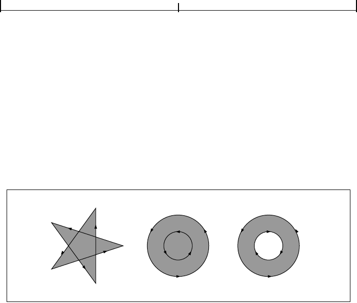
Path Construction and Painting4.4
155
For simple convex paths, the nonzero winding number rule defines the inside and
outside as one would intuitively expect. The more interesting cases are those in-
volving complex or self-intersecting paths like the ones shown in Figure 4.10. For
a path consisting of a five-pointed star, drawn with five connected straight line
segments intersecting each other, the rule considers the inside to be the entire
area enclosed by the star, including the pentagon in the center. For a path com-
posed of two concentric circles, the areas enclosed by both circles are considered
to be inside, provided that both are drawn in the same direction. If the circles are
drawn in opposite directions, only the “doughnut” shape between them is inside,
according to the rule; the “doughnut hole” is outside.
FIGURE 4.10 Nonzero winding number rule
Even-Odd Rule
An alternative to the nonzero winding number rule is the even-odd rule. This rule
determines the “insideness” of a point by drawing a ray from that point in any
direction and simply counting the number of path segments that cross the ray,
regardless of direction. If this number is odd, the point is inside; if even, the point
is outside. This yields the same results as the nonzero winding number rule for
paths with simple shapes, but produces different results for more complex
shapes.
Figure 4.11 shows the effects of applying the even-odd rule to complex paths. For
the five-pointed star, the rule considers the triangular points to be inside the path,
but not the pentagon in the center. For the two concentric circles, only the
“doughnut” shape between the two circles is considered inside, regardless of the
directions in which the circles are drawn.

GraphicsCHAPTER 4
156
FIGURE 4.11 Even-odd rule
4.4.3 Clipping Path Operators
The graphics state contains a clipping path that limits the regions of the page
affected by painting operators. The closed subpaths of this path define the area
that can be painted. Marks falling inside this area will be applied to the page;
those falling outside it will not. (Precisely what is considered to be “inside” a path
is discussed under “Filling,” above.)
The initial clipping path includes the entire page. A clipping path operator (
W or
W*, shown in Table 4.11) may appear after the last path construction operator
and before the path-painting operator that terminates a path object. Although
the clipping path operator appears before the painting operator, it does not alter
the clipping path at the point where it appears. Rather, it modifies the effect of the
succeeding painting operator. After the path has been painted, the clipping path
in the graphics state is set to the intersection of the current clipping path and the
newly constructed path.
TABLE 4.11 Clipping path operators
OPERANDS OPERATOR DESCRIPTION
— W Modify the current clipping path by intersecting it with the current path, using the
nonzero winding number rule to determine which regions lie inside the clipping
path.
— W* Modify the current clipping path by intersecting it with the current path, using the
even-odd rule to determine which regions lie inside the clipping path.
Note: In addition to path objects, text objects can also be used for clipping; see
Section 5.2.5, “Text Rendering Mode.”

Color Spaces4.5
157
The n operator (see Table 4.10 on page 152) is a “no-op” path-painting operator;
it causes no marks to be placed on the page, but it can be used with a clipping
path operator to establish a new clipping path. That is, after a path has been con-
structed, the sequence
W n will intersect that path with the current clipping path
to establish a new clipping path.
There is no way to enlarge the current clipping path or to set a new clipping path
without reference to the current one. However, since the clipping path is part of
the graphics state, its effect can be localized to specific graphics objects by en-
closing the modification of the clipping path and the painting of those objects
between a pair of
q and Q operators (see Section 4.3.1, “Graphics State Stack”).
Execution of the
Q operator causes the clipping path to revert to the value that
was saved by the
q operator, before the clipping path was modified.
4.5 Color Spaces
PDF includes powerful facilities for specifying the colors of graphics objects to be
painted on the current page. The color facilities are divided into two parts:
• Color specification. A PDF file can specify abstract colors in a device-
independent way. Colors can be described in any of a variety of color systems,
or color spaces. Some color spaces are related to device color representation
(grayscale, RGB, CMYK), others to human visual perception (CIE-based). Cer-
tain special features are also modeled as color spaces: patterns, color mapping,
separations, and high-fidelity and multitone color.
• Color rendering. The viewer application reproduces colors on the raster output
device by a multiple-step process that includes some combination of color con-
version, gamma correction, halftoning, and scan conversion. Some aspects of
this process use information that is specified in PDF. However, unlike the facil-
ities for color specification, the color rendering facilities are device-dependent
and ordinarily should not be included in a page description.
Figures 4.12 and 4.13 on pages 158 and 159 illustrate the division between PDF’s
(device-independent) color specification and (device-dependent) color render-
ing facilities. This section describes the color specification features, covering
everything that most PDF documents need in order to specify colors. The facili-
ties for controlling color rendering are described in Chapter 6; a PDF document
should use these facilities only to configure or calibrate an output device or to
achieve special device-dependent effects.
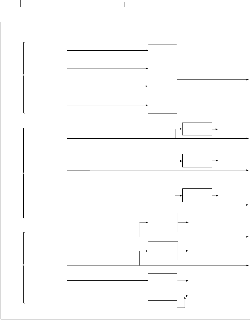
GraphicsCHAPTER 4
158
FIGURE 4.12 Color specification
Color spaces Color values
Sources of
color values
CalRGB
Conversion
to internal
X, Y, Z
values
A, B, C
X, Y, Z
sc, SC, sh,
BI, Do (image XObject)
Alternative
color
transform
tint
Another
color space
scn, SCN, sh,
BI, Do (image XObject)
Indexed
Table
lookup
Another
color space
CIE-
based
color
spaces
Device
color
spaces
Special
color
spaces
Pattern
sc, SC, sh,
BI, Do (image XObject)
scn, SCN
Another
color space
Pattern
dictionary
CalGray
A
sc, SC, sh,
BI, Do (image XObject)
index
pattern
Separation
Lab
A, B, C
sc, SC, sh,
BI, Do (image XObject)
ICCBased
scn, SCN, sh,
BI, Do (image XObject)
DeviceCMYK
C, M, Y, K
k, K, sc, SC, sh,
BI, Do (image XObject)
Another
(4-component)
color space
DeviceGray
gray
g, G, sc, SC, sh,
BI, Do (image XObject)
Another
(1-component)
color space
Alternative
color
transform
n
components
Another
color space
scn, SCN, sh,
BI, Do (image XObject)
DeviceN
DeviceRGB
rg, RG, sc, SC, sh,
BI, Do (image XObject)
R, G, B
DefaultCMYK
DefaultGray
DefaultRGB
Another
(3-component)
color space
n
components

Color Spaces4.5
159
FIGURE 4.13 Color rendering
Conversion
from CIE-based
to device
color space
R, G, B
C, M, Y, K
gray
Device color values
(depending on
results of
conversion)
R, G, B
C, M, Y, K
Conversion
from input
device color
space to
device’s
process color
model
Transfer
functions
(per
component)
Halftones
(per
component)
Any single
device
colorant
Device’s
process
colorant(s)
UCR, BG
TR, HT HT
X, Y, Z
gray
tint
(not specified by PDF)
n
components
Any n device
colorants
Component(s)
of device’s
process
color model

GraphicsCHAPTER 4
160
4.5.1 Color Values
As described in Section 4.4.2, “Path-Painting Operators,” marks placed on the
page by operators such as
f and S have a color that is determined by the current
color parameter of the graphics state. A color value consists of one or more color
components, which are usually numbers. For example, a gray level can be specified
by a single number ranging from 0.0 (black) to 1.0 (white). Full color values can
be specified in any of several ways; a common method uses three numeric values
to specify red, green, and blue components.
Color values are interpreted according to the current color space, another parame-
ter of the graphics state. A PDF content stream first selects a color space by invok-
ing the
cs operator (for the nonstroking color) or the CS operator (for the
stroking color). It then selects color values within that color space with the
sc op-
erator (nonstroking) or the
SC operator (stroking). There are also convenience
operators—
g, G, rg, RG, k, and K—that select both a color space and a color value
within it in a single step. Table 4.21 on page 198 lists all the color-setting opera-
tors.
Sampled images (see Section 4.8, “Images”) specify the color values of individual
samples with respect to a color space designated by the image object itself. While
these values are independent of the current color space and color parameters in
the graphics state, all later stages of color processing treat them in exactly the
same way as color values specified with the
sc or SC operator.
4.5.2 Types of Color Space
Color spaces can be classified into color space families. Spaces within a family
share the same general characteristics; they are distinguished by parameter values
supplied at the time the space is specified. The families, in turn, fall into three
broad categories:
• Device color spaces directly specify colors or shades of gray that the output
device is to produce. They provide a variety of color specification methods,
including gray level, RGB (red-green-blue), and CMYK (cyan-magenta-yellow-
black), corresponding to the color space families
DeviceGray, DeviceRGB, and
DeviceCMYK. Since each of these families consists of just a single color space
with no parameters, they are sometimes loosely referred to as the
DeviceGray,
DeviceRGB, and DeviceCMYK color spaces.

Color Spaces4.5
161
• CIE-based color spaces are based on an international standard for color specifi-
cation created by the Commission Internationale de l’Éclairage (International
Commission on Illumination). These spaces allow colors to be specified in a
way that is independent of the characteristics of any particular output device.
Color space families in this category include
CalGray, CalRGB, Lab, and ICC-
Based
. Individual color spaces within these families are specified by means of
dictionaries containing the parameter values needed to define the space.
• Special color spaces add features or properties to an underlying color space.
They include facilities for patterns, color mapping, separations, and high-
fidelity and multitone color. The corresponding color space families are
Pattern, Indexed, Separation, and DeviceN. Individual color spaces within
these families are specified by means of additional parameters.
Table 4.12 summarizes the color space families supported by PDF. (See imple-
mentation note 28 in Appendix H.)
TABLE 4.12 Color space families
DEVICE CIE-BASED SPECIAL
DeviceGray (PDF 1.1) CalGray (PDF 1.1) Indexed (PDF 1.1)
DeviceRGB (PDF 1.1) CalRGB (PDF 1.1) Pattern (PDF 1.2)
DeviceCMYK (PDF 1.1) Lab (PDF 1.1) Separation (PDF 1.2)
ICCBased (PDF 1.3) DeviceN (PDF 1.3)
A color space is defined by an array object whose first element is a name object
identifying the color space family. The remaining array elements, if any, are
parameters that further characterize the color space; their number and types vary
according to the particular family. For families that do not require parameters,
the color space can be specified simply by the family name itself instead of an
array.
There are two principal ways in which a color space can be specified:
• Within a content stream, the cs or CS operator establishes the color space
parameter in the graphics state. The operand is always a name object, which
either identifies one of the color spaces that need no additional parameters
(
DeviceGray, DeviceRGB, DeviceCMYK, or some cases of Pattern) or is used as a

GraphicsCHAPTER 4
162
key in the ColorSpace subdictionary of the current resource dictionary (see
Section 3.7.2, “Resource Dictionaries”). In the latter case, the value of the dic-
tionary entry is in turn a color space array or name. A color space array is never
permitted in-line within a content stream.
• Outside a content stream, certain objects, such as image XObjects, specify a
color space as an explicit parameter, often associated with the key
ColorSpace.
In this case, the color space array or name is always defined directly as a PDF
object, not by an entry in the
ColorSpace resource subdictionary. This conven-
tion also applies when color spaces are defined in terms of other color spaces.
The following operators set the color space and color value parameters in the
graphics state:
• cs sets the nonstroking color space; CS sets the stroking color space.
• sc and scn set the nonstroking color; SC and SCN set the stroking color.
Depending on the color space, these operators require one or more operands,
each specifying one component of the color value.
• g, rg, and k set the nonstroking color space implicitly and the nonstroking
color as specified by the operands;
G, RG, and K do the same for the stroking
color space and color.
4.5.3 Device Color Spaces
The device color spaces enable a page description to specify color values that are
directly related to their representation on an output device. Color values in these
spaces map directly (or via simple conversions) to the application of device color-
ants, such as quantities of ink or intensities of display phosphors. This enables a
PDF document to control colors precisely for a particular device, but the results
may not be consistent between different devices.
Output devices form colors either by adding light sources together or by sub-
tracting light from an illuminating source. Computer displays and film recorders
typically add colors, while printing inks typically subtract them. These two ways
of forming colors give rise to two complementary forms of color specification,

Color Spaces4.5
163
the additive RGB specification and the subtractive CMYK specification. The cor-
responding device color spaces are as follows:
• DeviceGray controls the intensity of achromatic light, on a scale from black to
white.
• DeviceRGB controls the intensities of red, green, and blue light, the three addi-
tive primary colors used in displays.
• DeviceCMYK controls the concentrations of cyan, magenta, yellow, and black
inks, the four subtractive process colors used in printing.
Although the notion of explicit color spaces is a PDF 1.1 feature, the operators for
specifying colors in the device color spaces—
g, G, rg, RG, k, and K—are available
in all versions of PDF. In PDF 1.2, colors specified in device color spaces can op-
tionally be remapped systematically into other color spaces; see “Default Color
Spaces” on page 177.
DeviceGray Color Space
Black, white, and intermediate shades of gray are special cases of full color. A
grayscale value is represented by a single number in the range 0.0 to 1.0, where
0.0 corresponds to black, 1.0 to white, and intermediate values to different gray
levels. Example 4.2 shows alternative ways to select the
DeviceGray color space
and a specific gray level within that space for nonstroking operations.
Example 4.2
/DeviceGray cs % Set DeviceGray color space
gray sc % Set gray level
gray g % Set both in one operation
The cs and sc operators select the color space and color value separately; g sets
them in combination. (The
CS, SC, and G operators perform the same functions
for stroking operations.) When the specified color space is
DeviceGray, the cs or
CS operator sets the corresponding color value to 0.0.

GraphicsCHAPTER 4
164
DeviceRGB Color Space
Colors in the DeviceRGB color space are specified according to the additive RGB
(red-green-blue) color model, in which color values are defined by three compo-
nents representing the intensities of the additive primary colors red, green, and
blue. Each component is specified by a number in the range 0.0 to 1.0, where 0.0
denotes the complete absence of a primary component and 1.0 denotes maxi-
mum intensity. If all three components have equal intensity, the perceived result
theoretically is a pure gray on the scale from black to white. If the intensities are
not all equal, the result is some color other than a pure gray.
Example 4.3 shows alternative ways to select the
DeviceRGB color space and a
specific color within that space for nonstroking operations.
Example 4.3
/DeviceRGB cs % Set DeviceRGB color space
red green blue sc % Set color
red green blue rg % Set both in one operation
The cs and sc operators select the color space and color value separately; rg sets
them in combination. (The
CS, SC, and RG operators perform the same functions
for stroking operations.) When the specified color space is
DeviceRGB, the cs or
CS operator sets the red, green, and blue components of the corresponding color
value to 0.0.
DeviceCMYK Color Space
The DeviceCMYK color space allows colors to be specified according to the sub-
tractive CMYK (cyan-magenta-yellow-black) model typical of printers and other
paper-based output devices. In theory, each of the three standard process colorants
used in printing (cyan, magenta, and yellow) absorbs one of the additive primary
colors (red, green, and blue, respectively). Black, a fourth standard process color-
ant, absorbs all of the additive primaries in equal amounts. The four components
in a
DeviceCMYK color value represent the concentrations of these process color-
ants. Each component is specified by a number in the range 0.0 to 1.0, where 0.0
denotes the complete absence of a process colorant (that is, absorbs none of the
corresponding additive primary) and 1.0 denotes maximum concentration (ab-
sorbs as much as possible of the additive primary). Note that the sense of these
numbers is opposite to that of RGB color components.

Color Spaces4.5
165
Example 4.4 shows alternative ways to select the DeviceCMYK color space and a
specific color within that space for nonstroking operations.
Example 4.4
/DeviceCMYK cs % Set DeviceCMYK color space
cyan magenta yellow black sc % Set color
cyan magenta yellow black k % Set both in one operation
The cs and sc operators select the color space and color value separately; k sets
them in combination. (The
CS, SC, and K operators perform the same functions
for stroking operations.) When the specified color space is
DeviceCMYK, the cs or
CS operator sets the cyan, magenta, and yellow components of the corresponding
color value to 0.0 and the black component to 1.0.
4.5.4 CIE-Based Color Spaces
Calibrated color in PDF is defined in terms of an international standard used in
the graphic arts, television, and printing industries. CIE-based color spaces en-
able a page description to specify color values in a way that is related to human
visual perception. The goal is for the same color specification to produce consis-
tent results on different output devices, within the limitations of each device.
PDF 1.1 supports three CIE-based color space families, named
CalGray, CalRGB,
and
Lab; PDF 1.3 adds a fourth, named ICCBased.
Note: In PDF 1.1, a color space family named
CalCMYK was partially defined, with
the expectation that its definition would be completed in a future version. However,
this is no longer being considered. PDF 1.3 supports calibrated four-component color
spaces by means of ICC profiles (see “ICCBased Color Spaces” on page 173). PDF
consumer applications should ignore
CalCMYK color space attributes and render
colors specified in this family as if they had been specified using
DeviceCMYK.
The details of the CIE colorimetric system and the theory on which it is based are
beyond the scope of this book; see the Bibliography for sources of further in-
formation. The semantics of CIE-based color spaces are defined in terms of the
relationship between the space’s components and the tristimulus values X, Y, and
Z of the CIE 1931 XYZ space. The
CalRGB and Lab color spaces (PDF 1.1) are
special cases of three-component CIE-based color spaces, known as CIE-based
ABC color spaces. These spaces are defined in terms of a two-stage, nonlinear
transformation of the CIE 1931 XYZ space. The formulation of such color spaces

GraphicsCHAPTER 4
166
models a simple zone theory of color vision, consisting of a nonlinear trichro-
matic first stage combined with a nonlinear opponent-color second stage. This
formulation allows colors to be digitized with minimum loss of fidelity, an im-
portant consideration in sampled images.
Color values in a CIE-based ABC color space have three components, arbitrarily
named A, B, and C. The first stage transforms these components by first forcing
their values to a specified range, then applying decoding functions, and finally
multiplying the results by a 3-by-3 matrix, producing three intermediate com-
ponents arbitrarily named L, M, and N. The second stage transforms these inter-
mediate components in a similar fashion, producing the final X, Y, and Z
components of the CIE 1931 XYZ space (see Figure 4.14).
FIGURE 4.14 Component transformations in a CIE-based ABC color space
Color spaces in the CIE-based families are defined by an array
[name dictionary]
where name is the name of the family and dictionary is a dictionary containing
parameters that further characterize the space. The entries in this dictionary have
specific interpretations that vary depending on the color space; some entries are
required and some are optional.
When any CIE-based color space is established, its initial color value has all com-
ponents set to 0.0 (unless the range of valid values for a given component does
not include 0.0, in which case the nearest valid value is substituted.)
Decode ABC
Decode LMN
A
B
C
Matrix ABC
L
M
N
Matrix LMN
X
Y
Z

Color Spaces4.5
167
Note: The model and terminology used here—CIE-based ABC (above) and CIE-
based A (below)—are derived from the PostScript language, which supports these
classes of spaces in their full generality. PDF supports specific useful cases of CIE-
based ABC and CIE-based A spaces; most others can be represented as
ICCBased
spaces.
CalGray Color Spaces
A CalGray color space (PDF 1.1) is a special case of a single-component CIE-
based color space, known as a CIE-based A color space. This type of space is the
one-dimensional (and usually achromatic) analog of CIE-based ABC spaces.
Color values in a CIE-based A space have a single component, arbitrarily named
A. Figure 4.15 illustrates the transformations of the A component to X, Y, and Z
components of the CIE 1931 XYZ space.
FIGURE 4.15 Component transformations in a CIE-based A color space
A CalGray color space is a CIE-based A color space with only one transformation
stage instead of two. In this type of space, A represents the gray component of a
calibrated gray space. This component must be in the range 0.0 to 1.0. The de-
coding function (denoted by “Decode A” in Figure 4.15) is a gamma function
whose coefficient is specified by the
Gamma entry in the color space dictionary
(see Table 4.13). The transformation matrix denoted by “Matrix A” in the figure
is derived from the dictionary’s
WhitePoint entry, as described below. Since there
is no second transformation stage, “Decode LMN” and “Matrix LMN” are im-
plicitly taken to be identity transformations.
Decode A
Decode LMN
A
L
M
N
Matrix A Matrix LMN
X
Y
Z

GraphicsCHAPTER 4
168
TABLE 4.13 Entries in a CalGray color space dictionary
KEY TYPE VALUE
WhitePoint array (Required) An array of three numbers [X
W
Y
W
Z
W
] specifying the tristimulus
value, in the CIE 1931 XYZ space, of the diffuse white point; see “CalRGB
Color Spaces,” below, for further discussion. The numbers X
W
and Z
W
must
be positive, and Y
W
must be equal to 1.0.
BlackPoint array (Optional) An array of three numbers [X
B
Y
B
Z
B
] specifying the tristimulus
value, in the CIE 1931 XYZ space, of the diffuse black point; see “CalRGB
Color Spaces,” below, for further discussion. All three of these numbers must
be nonnegative. Default value:
[0.0 0.0 0.0].
Gamma array (Optional) A number G defining the gamma for the gray (A) component. G
must be positive and will generally be greater than or equal to 1. Default
value: 1.
The transformation defined by the Gamma and WhitePoint entries is
In other words, the A component is first decoded by the gamma function, and the
result is multiplied by the components of the white point to obtain the L, M, and
N components of the intermediate representation. Since there is no second stage,
these are also the X, Y, and Z components of the final representation.
The following examples illustrate various interesting and useful special cases of
CalGray spaces. Example 4.5 establishes a space consisting of the Y dimension of
the CIE 1931 XYZ space with the CCIR XA/11–recommended D65 white point.
Example 4.5
[ /CalGray
<< /WhitePoint [0.9505 1.0000 1.0890] >>
]
Example 4.6 establishes a calibrated gray space with the CCIR XA/11–
recommended D65 white point and opto-electronic transfer function.
XLX
W
A
G
×==
YMY
W
A
G
×==
ZNZ
W
A
G
×==

Color Spaces4.5
169
Example 4.6
[ /CalGray
<< /WhitePoint [0.9505 1.0000 1.0890]
/Gamma 2.222
>>
]
CalRGB Color Spaces
A CalRGB color space is a CIE-based ABC color space with only one transforma-
tion stage instead of two. In this type of space, A, B, and C represent calibrated
red, green, and blue color values. These three color components must be in the
range 0.0 to 1.0; component values falling outside that range will be adjusted to
the nearest valid value without error indication. The decoding functions
(denoted by “Decode ABC” in Figure 4.14 on page 166) are gamma functions
whose coefficients are specified by the
Gamma entry in the color space dictionary
(see Table 4.14). The transformation matrix denoted by “Matrix ABC” in
Figure 4.14 is defined by the dictionary’s
Matrix entry. Since there is no second
transformation stage, “Decode LMN” and “Matrix LMN” are implicitly taken to
be identity transformations.
TABLE 4.14 Entries in a CalRGB color space dictionary
KEY TYPE VALUE
WhitePoint array (Required) An array of three numbers [X
W
Y
W
Z
W
] specifying the tristimulus value,
in the CIE 1931 XYZ space, of the diffuse white point; see below for further discus-
sion. The numbers X
W
and Z
W
must be positive, and Y
W
must be equal to 1.0.
BlackPoint array (Optional) An array of three numbers [X
B
Y
B
Z
B
] specifying the tristimulus value, in
the CIE 1931 XYZ space, of the diffuse black point; see below for further discussion.
All three of these numbers must be nonnegative. Default value:
[0.0 0.0 0.0].
Gamma array (Optional) An array of three numbers [G
R
G
G
G
B
] specifying the gamma for the red,
green, and blue (A, B, and C) components of the color space. Default value:
[1.0 1.0 1.0].
Matrix array (Optional) An array of nine numbers [X
A
Y
A
Z
A
X
B
Y
B
Z
B
X
C
Y
C
Z
C
] specifying
the linear interpretation of the decoded A, B, and C components of the color space
with respect to the final XYZ representation. Default value: the identity matrix
[100010001].

GraphicsCHAPTER 4
170
The WhitePoint and BlackPoint entries in the color space dictionary control the
overall effect of the CIE-based gamut mapping function described in Section 6.1,
“CIE-Based Color to Device Color.” Typically, the colors specified by
WhitePoint
and BlackPoint are mapped to the nearly lightest and nearly darkest achromatic
colors that the output device is capable of rendering in a way that preserves color
appearance and visual contrast.
WhitePoint is assumed to represent the diffuse achromatic highlight, not a specu-
lar highlight. Specular highlights, achromatic or otherwise, are often reproduced
lighter than the diffuse highlight.
BlackPoint is assumed to represent the diffuse
achromatic shadow; its value is typically limited by the dynamic range of the
input device. In images produced by a photographic system, the values of
White-
Point
and BlackPoint vary with exposure, system response, and artistic intent;
hence, their values are image-dependent.
The transformation defined by the
Gamma and Matrix entries in the CalRGB
color space dictionary is
In other words, the A, B, and C components are first decoded individually by the
gamma functions. The results are treated as a three-element vector and multi-
plied by
Matrix (a 3-by-3 matrix) to obtain the L, M, and N components of the
intermediate representation. Since there is no second stage, these are also the
X
, Y,
and Z components of the final representation.
Example 4.7 shows an example of a
CalRGB color space for the CCIR XA/11–
recommended D65 white point with 1.8 gammas and Sony Trinitron
®
phosphor
chromaticities.
Example 4.7
[ /CalRGB
<< /WhitePoint [0.9505 1.0000 1.0890]
/Gamma [1.8000 1.8000 1.8000]
/Matrix [ 0.4497 0.2446 0.0252
0.3163 0.6720 0.1412
0.1845 0.0833 0.9227
]
>>
]
XLX
A
A
G
R
× X
B
B
G
G
× X
C
C
G
B
×++==
YMY
A
A
G
R
× Y
B
B
G
G
× Y
C
C
G
B
×++==
ZNZ
A
A
G
R
× Z
B
B
G
G
× Z
C
C
G
B
×++==

Color Spaces4.5
171
In some cases, the parameters of a CalRGB color space may be specified in terms
of the CIE 1931 chromaticity coordinates (x
R
, y
R
), (x
G
, y
G
), (x
B
, y
B
) of the red,
green, and blue phosphors, respectively, and the chromaticity (x
W
, y
W
) of the
diffuse white point corresponding to some linear RGB value (R, G, B), where
usually R = G = B = 1.0. Note that standard CIE notation uses lowercase letters to
specify chromaticity coordinates and uppercase letters to specify tristimulus
values. Given this information,
Matrix and WhitePoint can be found as follows:
Lab Color Spaces
A Lab color space is a CIE-based ABC color space with two transformation stages
(see Figure 4.14 on page 166). In a this type of space, A, B, and C represent the L*,
a*, and b* components of a CIE 1976 L*a*b* space. The range of the first (L*)
component is always 0 to 100. The ranges of the second and third (a* and b*)
zy
W
x
G
x
B
–()y
R
× x
R
x
B
–()y
G
×– x
R
x
G
–()y
B
×)+(×=
Y
A
y
R
R
-----
x
G
x
B
–()y
W
× x
W
x
B
–()y
G
× x
W
x
G
–()y
B
×+–
z
------------------------------------------------------------------------------------------------------------------------------
×=
X
A
Y
A
x
R
y
R
------
×= Z
A
Y
A
1 x
R
–
y
R
--------------- 1–
×=
Y
B
y
G
G
------–
x
R
x
B
–()y
W
× x
W
x
B
–()y
R
× x
W
x
R
–()y
B
×+–
z
----------------------------------------------------------------------------------------------------------------------------
×=
X
B
Y
B
x
G
y
G
------
×= Z
B
Y
B
1 x
G
–
y
G
--------------- 1–
×=
Y
C
y
B
B
-----
x
R
x
G
–()y
W
× x
W
x
G
–()y
W
× x
W
x
R
–()y
G
×+–
z
--------------------------------------------------------------------------------------------------------------------------------
×=
X
C
Y
C
x
B
y
B
-----
×= Z
C
Y
C
1 x
B
–
y
B
-------------- 1–
×=
X
W
X
A
R× X
B
G× X
C
B×++=
Y
W
Y
A
R× Y
B
G× Y
C
B×++=
Z
W
Z
A
R× Z
B
G× Z
C
B×++=

GraphicsCHAPTER 4
172
components are defined by the Range entry in the color space dictionary (see
Table 4.15).
TABLE 4.15 Entries in a Lab color space dictionary
KEY TYPE VALUE
WhitePoint array (Required) An array of three numbers [X
W
Y
W
Z
W
] specifying the tristimulus value,
in the CIE 1931 XYZ space, of the diffuse white point; see “CalRGB Color Spaces” on
page 169 for further discussion. The numbers X
W
and Z
W
must be positive, and Y
W
must be equal to 1.0.
BlackPoint array (Optional) An array of three numbers [X
B
Y
B
Z
B
] specifying the tristimulus value, in
the CIE 1931 XYZ space, of the diffuse black point; see “CalRGB Color Spaces” on
page 169 for further discussion. All three of these numbers must be nonnegative.
Default value:
[0.0 0.0 0.0].
Range array (Optional) An array of four numbers [a
min
a
max
b
min
b
max
] specifying the range of
valid values for the a* and b* (B and C) components of the color space—that is,
and
Component values falling outside the specified range will be adjusted to the nearest
valid value without error indication. Default value: [−100 100 −100 100].
A Lab color space does not specify explicit decoding functions or matrix coef-
ficients for either stage of the transformation from L*a*b* space to XYZ space
(denoted by “Decode ABC,” “Matrix ABC,” “Decode LMN,” and “Matrix LMN” in
Figure 4.14 on page 166). Instead, these parameters have constant implicit values.
The first transformation stage is defined by the equations
a
min
a* a
max
≤≤
b
min
b* b
max
≤≤
L
L* 16+
116
------------------
a*
500
--------+=
M
L* 16+
116
------------------=
N
L* 16+
116
------------------
b*
200
--------–=

Color Spaces4.5
173
The second transformation stage is given by
where the function g(x) is defined as
Example 4.8 defines the CIE 1976 L*a*b* space with the CCIR XA/11–
recommended D65 white point. The a* and b* components, although theoreti-
cally unbounded, are defined to lie in the useful range −128 to +127.
Example 4.8
[/Lab
<< /WhitePoint [0.9505 1.0000 1.0890]
/Range [−128 127 −128 127]
>>
]
ICCBased Color Spaces
ICCBased color spaces (PDF 1.3) are based on a cross-platform color profile as
defined by the International Color Consortium (ICC). Unlike the
CalGray, Cal-
RGB
, and Lab color spaces, which are characterized by entries in the color space
dictionary, an
ICCBased color space is characterized by a sequence of bytes in a
standard format. Details of the profile format can be found in the ICC specifica-
tion (see the Bibliography).
An
ICCBased color space is specified as an array:
[/ICCBased stream]
XX
W
gL()×=
YY
W
gM()×=
ZZ
W
gN()×=
gx() x
3
= if x
6
29
-----
≥
gx()
108
841
--------
x
4
29
-----–
×=
otherwise

GraphicsCHAPTER 4
174
The stream contains the ICC profile. Besides the usual entries common to all
streams (see Table 3.4 on page 35), the profile stream has the additional entries
listed in Table 4.16.
TABLE 4.16 Entries in an ICC profile stream dictionary
KEY TYPE VALUE
N integer (Required) The number of color components in the color space described by the ICC
profile data. This number must match the number of components actually in the ICC
profile. In PDF 1.3,
N must be 1, 3, or 4.
Alternate array or (Optional) An alternate color space to be used in case the one specified in the stream
name data is not supported (for example, by viewer applications designed for earlier
versions of PDF). The alternate space may be any valid color space, except a
Pattern
color space, that has the number of components specified by N. If this entry is omit-
ted and the viewer application does not understand the ICC profile data, the color
space used will be
DeviceGray, DeviceRGB, or DeviceCMYK, depending on whether
the value of
N is 1, 3, or 4, respectively.
Note that there is no conversion of color values, such as a tint transformation, when
using the alternate color space. Color values that are within the range of the
ICC-
Based
color space might not be within the range of the alternate color space. In this
case, the nearest values within the range of the alternate space will be substituted.
Range array (Optional) An array of 2 × N numbers [min
0
max
0
min
1
max
1
…] specifying
the minimum and maximum valid values of the corresponding color components.
These values must match the information in the ICC profile. Default value:
[0.0 1.0 0.0 1.0 …].
The ICC specification is an evolving standard. The ICCBased color spaces sup-
ported in PDF 1.3 are based on version 3.3 of the ICC specification. Early ver-
sions of the ICC specification are also supported. (The version number is
available in the ICC profile’s header.)
PDF 1.3 supports only the profile types shown in Table 4.17; other types may be
supported in the future. (In particular, note that XYZ and 16-bit L*a*b* profiles
are not supported.) Each of the indicated fields must have one of the values listed
for that field in the second column of the table. (Profiles must satisfy both the cri-
teria shown in the table.) The terminology is taken from the ICC specifications.

Color Spaces4.5
175
TABLE 4.17 ICC profile types
HEADER FIELD REQUIRED VALUE
deviceClass icSigInputClass ('scnr')
icSigDisplayClass ('mntr')
icSigOutputClass ('prtr')
icSigColorSpaceClass ('spac')
colorSpace icSigGrayData ('GRAY')
icSigRgbData ('RGB ')
icSigCmykData ('CMYK')
icSigLabData ('Lab ')
The terminology used in PDF color spaces and ICC color profiles is similar, but
sometimes the same terms are used with different meanings. For example, the
default value for each component in an
ICCBased color space is 0. The range of
each color component is a function of the color space specified by the profile and
is indicated in the ICC specification. The ranges for several ICC color spaces are
shown in Table 4.18.
TABLE 4.18 Ranges for typical ICC color spaces
ICC COLOR SPACE COMPONENT RANGES
Gray [0.0 1.0]
RGB [0.0 1.0]
CMYK [0.0 1.0]
L*a*b* L*: [0 100]; a* and b*: [−128 127]
Since the ICCBased color space is being used as a source color space, only the “to
CIE” profile information (ATo B in ICC terminology) is used; the “from CIE”
(BToA) information is ignored when present. Additionally, an ICC profile may
specify a rendering intent; however, a PDF viewer application ignores this infor-
mation. The rendering intent is specified in PDF by a separate parameter; see
“Rendering Intents” on page 179.

GraphicsCHAPTER 4
176
The representations of ICCBased color spaces are less compact than CalGray, Cal-
RGB
, and Lab, but can represent a wider range of color spaces. In those cases
where a given color space can be expressed by more than one of the CIE-based
color space families, the resulting colors are expected to be rendered similarly,
regardless of the method selected for representation.
One particular color space is the so-called “standard RGB” or sRGB, defined in
the International Electrotechnical Commission (IEC) document Colour Measure-
ment and Management in Multimedia Systems and Equipment (see the Bibliogra-
phy). In PDF, the sRGB color space can be expressed precisely only as an
ICCBased color space, although it can be approximated by a CalRGB color space.
Example 4.9 shows an
ICCBased color space for a typical three-component RGB
space. The profile’s data has been encoded in hexadecimal representation for
readability; in actual practice, a lossless decompression filter such as
FlateDecode
should be used.
Example 4.9
10 0 obj % Color space
[/ICCBased 15 0 R]
endobj
15 0 obj % ICC profile stream
<< /N 3
/Alternate /DeviceRGB
/Length 1605
/Filter /ASCIIHexDecode
>>
stream
00 00 02 0C 61 70 70 6C 02 00 00 00 6D 6E 74 72
52 47 42 20 58 59 5A 20 07 CB 00 02 00 16 00 0E
00 22 00 2C 61 63 73 70 41 50 50 4C 00 00 00 00
61 70 70 6C 00 00 04 01 00 00 00 00 00 00 00 02
00 00 00 00 00 00 F6 D4 00 01 00 00 00 00 D3 2B
00 00 00 00 00 00 00 00 00 00 00 00 00 00 00 00
00 00 00 00 00 00 00 00 00 00 00 00 00 00 00 00
00 00 00 00 00 00 00 00 00 00 00 00 00 00 00 00
00 00 00 09 64 65 73 63 00 00 00 F0 00 00 00 71
72 58 59 5A 00 00 01 64 00 00 00 14 67 58 59 5A
00 00 01 78 00 00 00 14 62 58 59 5A 00 00 01 8C
00 00 00 14 72 54 52 43 00 00 01 A0 00 00 00 0E
67 54 52 43 00 00 01 B0 00 00 00 0E 62 54 52 43

Color Spaces4.5
177
00 00 01 C0 00 00 00 0E 77 74 70 74 00 00 01 D0
00 00 00 14 63 70 72 74 00 00 01 E4 00 00 00 27
64 65 73 63 00 00 00 00 00 00 00 17 41 70 70 6C
65 20 31 33 22 20 52 47 42 20 53 74 61 6E 64 61
72 64 00 00 00 00 00 00 00 00 00 00 00 17 41 70
70 6C 65 20 31 33 22 20 52 47 42 20 53 74 61 6E
64 61 72 64 00 00 00 00 00 00 00 00 00 00 00 00
00 00 00 00 00 00 00 00 00 00 00 00 00 00 00 00
00 00 00 00 00 00 00 00 00 00 00 00 00 00 00 00
00 58 59 5A 58 59 5A 20 00 00 00 00 00 00 63 0A
00 00 35 0F 00 00 03 30 58 59 5A 20 00 00 00 00
00 00 53 3D 00 00 AE 37 00 00 15 76 58 59 5A 20
00 00 00 00 00 00 40 89 00 00 1C AF 00 00 BA 82
63 75 72 76 00 00 00 00 00 00 00 01 01 CC 63 75
63 75 72 76 00 00 00 00 00 00 00 01 01 CC 63 75
63 75 72 76 00 00 00 00 00 00 00 01 01 CC 58 59
58 59 5A 20 00 00 00 00 00 00 F3 1B 00 01 00 00
00 01 67 E7 74 65 78 74 00 00 00 00 20 43 6F 70
79 72 69 67 68 74 20 41 70 70 6C 65 20 43 6F 6D
70 75 74 65 72 73 20 31 39 39 34 00
endstream
endobj
Default Color Spaces
Specifying colors in a device color space (DeviceGray, DeviceRGB, or Device-
CMYK
) makes them device-dependent. By setting default color spaces (PDF 1.1), a
PDF document can request that such colors be systematically transformed into
device-independent CIE-based color spaces. This capability can be useful in a va-
riety of circumstances, such as the following:
• A document originally intended for one output device is redirected to a differ-
ent device.
• A document is intended to be compatible with viewer applications designed for
earlier versions of PDF, and thus cannot specify CIE-based colors directly.
• Color corrections or rendering intents need to be applied to device colors (see
“Rendering Intents” on page 179).

GraphicsCHAPTER 4
178
A color space is selected for painting each graphics object. This is either the cur-
rent color space parameter in the graphics state or a color space given as an entry
in an image XObject, in-line image, or shading dictionary. Regardless of how the
color space is specified, it may be subject to remapping as described below.
When a device color space is selected, the
ColorSpace subdictionary of the cur-
rent resource dictionary (see Section 3.7.2, “Resource Dictionaries”) is checked
for the presence of an entry designating a corresponding default color space
(
DefaultGray, DefaultRGB, or DefaultCMYK, corresponding to DeviceGray,
DeviceRGB, or DeviceCMYK, respectively). If such an entry is present, its value is
used as the color space for the operation currently being performed. (If the view-
er application does not recognize this color space, no remapping will occur; the
original device color space will be used.)
Color values in the original device color space are passed unchanged to the
default color space, which must have the same number of components as the
original space. The default color space should be chosen to be compatible with
the original, taking into account the components’ ranges and whether the com-
ponents are additive or subtractive. If a color value lies outside the range of the
default color space, it will be adjusted to the nearest valid value.
Note: Any color space other than a
Lab, Indexed, or Pattern color space may be used
as a default color space, provided that it is compatible with the original device color
space as described above.
If the selected space is a special color space based on an underlying device color
space, the default color space will be used in place of the underlying space. This
applies to the following:
• The base color space of an Indexed color space
• The underlying color space of a Pattern color space
• The alternate color space of a Separation or DeviceN color space (but only if
the alternate color space is actually selected)
See Section 4.5.5, “Special Color Spaces,” for details on these color spaces.

Color Spaces4.5
179
Note: Note that there is no conversion of color values, such as a tint transformation,
when using the default color space. Color values that are within the range of the
device color space might not be within the range of the default color space (particu-
larly if the default is an
ICCBased color space). In this case, the nearest values within
the range of the default space will be used. For this reason, a
Lab color space is not
permitted as the
DefaultRGB color space.
Rendering Intents
Although CIE-based color specifications are theoretically device-independent,
they are subject to practical limitations in the color reproduction capabilities of
the output device. Such limitations may sometimes require compromises to be
made among various properties of a color specification when rendering colors for
a given device. Specifying a rendering intent (PDF 1.1) allows a PDF file to set
priorities regarding which of these properties to preserve and which to sacrifice.
For example, the PDF file might request that colors falling within the output
device’s gamut (the range of colors it can reproduce) be rendered exactly while
sacrificing the accuracy of out-of-gamut colors, or that a scanned image such as a
photograph be rendered in a perceptually “pleasing” manner at the cost of strict
colorimetric accuracy.
Rendering intents are specified with the
ri operator and with the Intent entry in
image dictionaries. The value is a name identifying the desired rendering intent.
Table 4.19 lists the standard rendering intents recognized in the initial release of
PDF viewer applications from Adobe Systems. These have been deliberately
chosen to correspond closely to the rendering intents defined by the International
Color Consortium (ICC), an industry organization that has developed standards
for device-independent color. Note, however, that the exact set of rendering in-
tents supported may vary from one output device to another; a particular device
may not support all possible intents, or may support additional ones beyond
those listed in the table. If the viewer application does not recognize the specified
name, it uses the
RelativeColorimetric intent by default. (See implementation
note 29 in Appendix H.)

GraphicsCHAPTER 4
180
TABLE 4.19 Rendering intents
NAME DESCRIPTION
AbsoluteColorimetric Colors are represented solely with respect to the light source; no
correction is made for the output medium’s white point (such as
the color of unprinted paper). Thus, for example, a monitor’s
white point, which is bluish compared to that of a printer’s
paper, would be reproduced with a blue cast. In-gamut colors
are reproduced exactly; out-of-gamut colors are mapped to the
nearest value within the reproducible gamut. This style of
reproduction has the advantage of providing exact color
matches from one output medium to another. It has the
disadvantage of causing colors with Y values between the
medium’s white point and 1.0 to be out of gamut. A typical use
might be for logos and solid colors that require exact
reproduction across different media.
RelativeColorimetric Colors are represented with respect to the combination of the
light source and the output medium’s white point (such as the
color of unprinted paper). Thus, for example, a monitor’s white
point would be reproduced on a printer by simply leaving the
paper unmarked, ignoring color differences between the two
media. In-gamut colors are reproduced exactly; out-of-gamut
colors are mapped to the nearest value within the reproducible
gamut. This style of reproduction has the advantage of adapting
for the varying white points of different output media. It has the
disadvantage of not providing exact color matches from one
medium to another. A typical use might be for vector graphics.
Saturation Colors are represented in a manner that preserves or emphasizes
saturation. Reproduction of in-gamut colors may or may not be
colorimetrically accurate. A typical use might be for business
graphics, where saturation is the most important attribute of the
color.
Perceptual Colors are represented in a manner that provides a pleasing
perceptual appearance. This generally means that both in-gamut
and out-of-gamut colors are modified from their precise
colorimetric values in order to preserve color relationships. A
typical use might be for scanned images.

Color Spaces4.5
181
4.5.5 Special Color Spaces
Special color spaces add features or properties to an underlying color space.
There are four special color space families:
Pattern, Indexed, Separation, and
DeviceN.
Pattern Color Spaces
A Pattern color space (PDF 1.2) enables a PDF content stream to paint an area
with a “color” defined as a pattern, which may be either a tiling pattern
(
PatternType 1) or a shading pattern (PatternType 2). Section 4.6, “Patterns,” dis-
cusses patterns in detail.
Indexed Color Spaces
An Indexed color space allows a PDF content stream to select from a color map or
color table of arbitrary colors in some other space, using small integers as indices.
A PDF viewer application treats each sample value as an index into the color table
and uses the color value it finds there. This technique can considerably reduce the
amount of data required to represent a sampled image—for example, by using
8-bit index values as samples instead of 24-bit RGB color values.
An
Indexed color space is defined by a four-element array, as follows:
[/Indexed base hival lookup]
The first element is the color space family name Indexed. The remaining ele-
ments are parameters that an
Indexed color space requires; their meanings are
discussed below. When the color space is set to an
Indexed color space, the cur-
rent color is set to 0.
The
base parameter is an array or name that identifies the base color space in
which the values in the color table are to be interpreted. It can be any device or
CIE-based color space or (in PDF 1.3) a
Separation or DeviceN space, but not a
Pattern space or another Indexed space. For example, if the base color space is
DeviceRGB, the values in the color table are to be interpreted as red, green, and
blue components; if the base color space is a CIE-based ABC space such as a
Cal-
RGB
or Lab space, the values are to be interpreted as A, B, and C components.

GraphicsCHAPTER 4
182
Note: Attempting to use a Separation or DeviceN color space as the base for an
Indexed color space will generate an error in PDF 1.2.
The
hival parameter is an integer that specifies the maximum valid index value. In
other words, the color table is to be indexed by integers in the range 0 to
hival.
hival can be no greater than 255, which is what would be required to index a table
with 8-bit index values.
The color table is defined by the
lookup parameter, which can be either a stream
or (in PDF 1.2) a string. It provides the mapping between index values and the
corresponding colors in the base color space.
The color table data must be m × (
hival + 1) bytes long, where m is the number of
color components in the base color space. Each byte is an unsigned integer in the
range 0 to 255 that is scaled to the range of the corresponding color component
in the base color space; that is, 0 corresponds to the minimum value in the range
for that component, and 255 corresponds to the maximum value in the range.
Note: This is different from the interpretation of an
Indexed color space’s color table
in PostScript. In PostScript, the component value is always scaled to the range 0.0 to
1.0, regardless of the range of color values in the base color space.
The color components for each entry in the table appear consecutively in the
string or stream. For example, if the base color space is
DeviceRGB and the
indexed color space contains two colors, the order of bytes in the string or stream
is
R
0
G
0
B
0
R
1
G
1
B
1
, where letters denote the color component and numeric
subscripts denote the table entry.
Example 4.10 illustrates the specification of an
Indexed color space that maps
8-bit index values to three-component color values in the
DeviceRGB color space.
Example 4.10
[ /Indexed
/DeviceRGB
255
<000000 FF0000 00FF00 0000FF B57342 …>
]

Color Spaces4.5
183
The example shows only the first five color values in the lookup string; in all, there
should be 256 color values and the string should be 768 bytes long. Having
established this color space, the program can now specify colors using single-
component values in the range 0 to 255. For example, a color value of 4 selects an
RGB color whose components are coded as the hexadecimal integers
B5, 73, and
42. Dividing these by 255 and scaling the results to the range 0.0 to 1.0 yields a
color with red, green, and blue components of 0.710, 0.451, and 0.259, respec-
tively.
Although an
Indexed color space is useful mainly for images, index values can
also be used with the color selection operators
sc, scn, SC, and SCN. For example,
123 sc
selects the same color as does an image sample value of 123. The index value
should be an integer in the range 0 to
hival. If it is a real number, it is rounded to
the nearest integer; if it is outside the range 0 to
hival, it is adjusted to the nearest
value within that range.
Separation Color Spaces
Color output devices produce full color by combining primary or process
colorants in varying amounts. On a display, the primary colorants consist of red,
green, and blue phosphors; on a printer, they typically consist of cyan, magenta,
yellow, and sometimes black inks. In addition, some devices can apply special
colorants, often called spot colorants, to produce effects that cannot be achieved
with the standard process colorants alone. Examples include metallic and fluores-
cent colors and special textures.
When printing a page, most devices produce a single composite page on which all
process colorants (and spot colorants, if any) are combined. However, some
devices, such as imagesetters, produce a separate, monochromatic rendition of
the page, called a separation, for each individual colorant. When the separations
are later combined—on a printing press, for example—and the proper inks or
other colorants are applied to them, a full-color page results.
A
Separation color space (PDF 1.2) provides a means for specifying the use of
additional colorants or for isolating the control of individual color components
of a device color space. When such a space is the current color space, the current

GraphicsCHAPTER 4
184
color is a single-component value, called a tint, that controls the application of
the given colorant or color component only.
Note: The term separation is often misused as a synonym for an individual device
colorant. In the context of this discussion, a printing system that produces separa-
tions generates a separate piece of physical medium (generally film) for each color-
ant. It is these pieces of physical medium that are correctly referred to as separations.
A particular colorant properly constitutes a separation only if the device is generating
physical separations, one of which corresponds to the given colorant. The
Separation
color space is so named for historical reasons, but it has evolved to the broader pur-
pose of controlling the application of individual colorants in general, whether or not
they are actually realized as physical separations.
Note also that the operation of a
Separation color space itself is independent of the
characteristics of any particular output device. Depending on the device, the space
may or may not correspond to a true, physical separation or to an actual colorant.
For example, a
Separation color space could be used to control the application of a
single process colorant (such as cyan) on a composite device that does not produce
physical separations, or could represent a color (such as orange) for which no specific
colorant exists on the device. A
Separation color space provides consistent, predict-
able behavior, even on devices that cannot directly generate the requested color.
A
Separation color space is defined as follows:
[/Separation name alternateSpace tintTransform]
In other words, it is a four-element array whose first element is the color space
family name
Separation. The remaining elements are parameters that a
Separation color space requires; their meanings are discussed below.
A color value in a
Separation color space consists of a single tint component in
the range 0.0 to 1.0. The value 0.0 represents the minimum amount of colorant
that can be applied; 1.0 represents the maximum. Tints are always treated as
subtractive colors, even if the device produces output for the designated compo-
nent by an additive method. Thus a tint value of 0.0 denotes the lightest color
that can be achieved with the given colorant, and 1.0 the darkest. (Note that this
is the same as the convention for
DeviceCMYK color components, but opposite to
the one for
DeviceGray and DeviceRGB.) The scn and SCN operators respectively
set the current fill and stroke color in the graphics state to a tint value; the initial
value in either case is 1.0. A sampled image with single-component samples can
also be used as a source of tint values.

Color Spaces4.5
185
The name parameter in the color space array is a name object specifying the name
of the colorant that this
Separation color space is intended to represent (or one of
the special names
All or None; see below). Such colorant names are arbitrary, and
there can be any number of them, subject to implementation limits.
The special colorant name
All refers collectively to all colorants available on an
output device, including those for the standard process colorants. When a
Separation space with this colorant name is the current color space, painting
operators apply tint values to all available colorants at once. This is useful for
purposes such as painting registration marks in the same place on every separa-
tion. Such marks would typically be painted as the last step in composing a page,
to ensure that they are not overwritten by subsequent painting operations.
The special colorant name
None will never produce any visible output. Painting
operations in a
Separation space with this colorant name have no effect on the
current page.
All devices support
Separation color spaces with the colorant names All and
None, even if they do not support any others. Separation spaces with either of
these colorant names ignore the
alternateSpace and tintTransform parameters (dis-
cussed below), although valid values must still be provided.
At the moment the color space is set to a
Separation space, the viewer application
determines whether the device has an available colorant corresponding to the
name of the requested space. If so, the application ignores the
alternateSpace and
tintTransform parameters; subsequent painting operations within the space will
apply the designated colorant directly, according to the tint values supplied.
If the colorant name associated with a
Separation color space does not cor-
respond to a colorant available on the device, the viewer application arranges
instead for subsequent painting operations to be performed in an alternate color
space. This enables the intended colors to be approximated by colors in some
device or CIE-based color space, which are then rendered using the usual prima-
ry or process colorants. This works as follows:
• The alternateSpace parameter must be an array or name object that identifies
the alternate color space. This can be any device or CIE-based color space, but
not another special color space (
Pattern, Indexed, Separation, or DeviceN).

GraphicsCHAPTER 4
186
• The tintTransform parameter must be a function (see Section 3.9, “Functions”).
During subsequent painting operations, a viewer application will call this
function to transform a tint value into color component values in the alternate
color space. The function is called with the tint value and must return the cor-
responding color component values. That is, the number of components and
the interpretation of their values depend on the alternate color space.
Example 4.11 illustrates the specification of a
Separation color space (object 5)
that is intended to produce a color named
LogoGreen. If the output device has no
colorant corresponding to this color,
DeviceCMYK will be used as the alternate
color space; the tint transformation function provided (object 12) maps tint
values linearly into shades of a CMYK color value approximating the “logo green”
color.
Example 4.11
5 0 obj % Color space
[ /Separation
/LogoGreen
/DeviceCMYK
12 0 R
]
endobj
12 0 obj % Tint transformation function
<< /FunctionType 4
/Domain [0.0 1.0]
/Range [0.0 1.0 0.0 1.0 0.0 1.0 0.0 1.0]
/Length 62
>>
stream
{ dup 0.84 mul
exch 0.00 exch dup 0.44 mul
exch 0.21 mul
}
endstream
endobj
DeviceN Color Spaces
DeviceN color spaces (PDF 1.3) support the use of high-fidelity and multitone
color. High-fidelity color is the use of more than the standard CMYK process

Color Spaces4.5
187
colorants to produce an extended gamut, or range of colors. A popular example
of such a system is the PANTONE
®
Hexachrome™ system, which uses six color-
ants: the usual cyan, magenta, yellow, and black, plus orange and green.
Multitone color systems use a single-component image to specify multiple color
components. In a duotone, for example, a single-component image can be used to
specify both the black component and a spot color component. The tone
reproduction is generally different for the different components; for example, the
black component might be painted with the exact sample data from the single-
component image, while the spot color component might be generated as a non-
linear function of the image data in a manner that emphasizes the shadows.
DeviceN color spaces allow any subset of the available device colorants to be
treated as a device color space with multiple components. This provides greater
flexibility than is possible with standard device color spaces such as
DeviceCMYK
or with individual Separation color spaces. For example, it is possible to create a
DeviceN color space consisting of only the cyan, magenta, and yellow color com-
ponents, while excluding the black component. If overprinting is enabled (see
Section 4.5.6, “Overprint Control”), painting in this color space will leave the
black component unchanged.
A
DeviceN color space is specified as follows:
[/DeviceN names alternateSpace tintTransform]
or
[/DeviceN names alternateSpace tintTransform attributes]
It is a four- or five-element array whose first element is the color space family
name
DeviceN. The remaining elements are parameters that a DeviceN color
space requires; their meanings are discussed below.
Color values in the
DeviceN color space are tint components in the range 0.0 to
1.0. The value 0.0 represents the minimum amount of colorant; 1.0 represents the
maximum. The
scn and SCN operators set the current color in the graphics state
to a set of tint values; the initial value is 1.0 for each tint. A sampled image can
also be treated as a source of tint values.

GraphicsCHAPTER 4
188
A DeviceN color space works almost the same as a Separation color space—in
fact, a
DeviceN color space with only one component is exactly equivalent to a
Separation color space. The following are the only differences between DeviceN
and Separation:
• Color values in a DeviceN color space consist of multiple tint components,
rather than only one. The number of components is subject to an implementa-
tion limit; see Appendix C.
• The names parameter in the color space array is an array of name objects speci-
fying the individual colorants. (The special colorant name
All is not allowed.)
The length of the array determines the number of components, and hence the
number of operands required by the
scn and SCN operators when this space is
the current color space. Operand values supplied to
scn or SCN are interpreted
as color component values in the order in which the colors are given in the
names array.
• At the moment the color space is set to a DeviceN space, the viewer application
will select the requested set of colorants only if all of them are available on the
device; otherwise, it will select the alternate color space designated by the
alternateSpace parameter.
• The tint transformation function is called with n tint values and must return
the corresponding m color component values, where n is the number of com-
ponents needed to specify a color in the
DeviceN color space and m is the num-
ber required by the alternate color space.
In a
DeviceN color space, one or more of the colorant names in the names array
may be the name
None. This indicates that the corresponding color component is
never painted on the page, as in a
Separation color space for the None colorant.
When a
DeviceN color space is painting the named device colorants directly,
color components corresponding to
None colorants are discarded. However,
when the
DeviceN color space reverts to its alternate color space, those com-
ponents are passed to the tint transformation function, which may use them in
any desired manner.
The optional
attributes parameter is a dictionary containing additional informa-
tion about the color space. At the time of publication, only one entry is defined in
this dictionary, as shown in Table 4.20.

Color Spaces4.5
189
TABLE 4.20 Entry in a DeviceN color space attributes dictionary
KEY TYPE VALUE
Colorants dictionary (Optional) A dictionary describing the individual colorants used in the DeviceN
color space. For each entry in this dictionary, the key is a colorant name and the
value is an array defining a
Separation color space for that colorant (see “Separa-
tion Color Spaces” on page 183). The key must match the colorant name given in
that color space. The dictionary need not list all colorants used in the
DeviceN
color space and may list additional colorants.
This dictionary has no effect on the operation of the
DeviceN color space itself or
the appearance that it produces. However, it provides information about the indi-
vidual colorants that may be useful to some applications. In particular, the alter-
nate color space and tint transformation function of a
Separation color space
describe the appearance of that colorant alone, whereas those of a
DeviceN color
space describe only the appearance of its colorants in combination.
Example 4.12 shows a DeviceN color space consisting of three color components
named
Orange, Green, and None. In this example, the DeviceN color space,
object 30, has an attributes dictionary whose
Colorants entry is an indirect refer-
ence to object 45 (which might also be referenced by attributes dictionaries of
other
DeviceN color spaces). tintTransform1, whose definition is not shown, maps
three color components (tints of the colorants
Orange, Green, and None) to four
color components in the alternate color space,
DeviceCMYK. tintTransform2 maps
a single color component (an orange tint) to four components in
DeviceCMYK.
Likewise,
tintTransform3 maps a green tint to DeviceCMYK, and tintTransform4
maps a tint of PANTONE 131 to DeviceCMYK.
Example 4.12
30 0 obj % Color space
[ /DeviceN
[/Orange /Green /None]
/DeviceCMYK
tintTransform1
<< /Colorants 45 0 R >>
]
endobj

GraphicsCHAPTER 4
190
45 0 obj % Colorants dictionary
<< /Orange [ /Separation
/Orange
/DeviceCMYK
tintTransform2
]
/Green [ /Separation
/Green
/DeviceCMYK
tintTransform3
]
/PANTONE#20131 [ /Separation
/PANTONE#20131
/DeviceCMYK
tintTransform4
]
>>
endobj
Multitone Examples
The following examples illustrate various interesting and useful special cases of
the use of
Indexed and DeviceN color spaces in combination to produce multi-
tone colors.
Examples 4.13 and 4.14 illustrate the use of
DeviceN to create duotone color
spaces. In Example 4.13, an
Indexed color space maps index values in the range 0
to 255 to a duotone
DeviceN space in cyan and black. In effect, the index values
are treated as if they were tints of the duotone space, which are then mapped into
tints of the two underlying colorants. Only the beginning of the lookup table
string for the
Indexed color space is shown; the full table would contain 256 two-
byte entries, each specifying a tint value for cyan and black, for a total of 512
bytes. If the alternate color space of the
DeviceN space is selected, the tint trans-
formation function (object 15 in the example) maps the two tint components for
cyan and black to the four components for a
DeviceCMYK color space by supply-
ing zero values for the other two components. Example 4.14 shows the definition
of another duotone color space, this time using black and gold colorants (where
gold is a spot colorant) and using a
CalRGB space as the alternate color space. This
could be defined in the same way as in the preceding example, with a tint trans-
formation function that converts from the two tint components to colors in the
alternate
CalRGB color space.

Color Spaces4.5
191
Example 4.13
10 0 obj % Color space
[ /Indexed
[ /DeviceN
[/Cyan /Black]
/DeviceCMYK
15 0 R
]
255
<6605 6806 6907 6B09 6C0A …>
]
endobj
15 0 obj % Tint transformation function
<< /FunctionType 4
/Domain [0.0 1.0 0.0 1.0]
/Range [0.0 1.0 0.0 1.0 0.0 1.0 0.0 1.0]
/Length 16
>>
stream
{003−1 roll}
endstream
endobj
Example 4.14
30 0 obj % Color space
[ /Indexed
[ /DeviceN
[/Black /Gold]
[ /CalRGB
<< /WhitePoint [1.0 1.0 1.0]
/Gamma [2.2 2.2 2.2]
>>
]
35 0 R % Tint transformation function
]
255
… Lookup table …
]
endobj

GraphicsCHAPTER 4
192
Given a formula for converting any combination of black and gold tints to cali-
brated RGB, a 2-in, 3-out type 4 function could be used for the tint transforma-
tion. Alternatively, a type 0 function could be used, but this would require a large
number of sample points to represent the function accurately; for example, sam-
pling each input variable for 256 tint values between 0.0 and 1.0 would require
256
2
= 65,536 samples. But since the DeviceN color space is being used as the
base of an
Indexed color space, there are actually only 256 possible combinations
of black and gold tint values. A more compact way to represent this information
is to put the alternate color values directly into the lookup table alongside the
DeviceN color values, as in Example 4.15.
Example 4.15
10 0 obj % Color space
[ /Indexed
[ /DeviceN
[/Black /Gold /None /None /None]
[ /CalRGB
<< /WhitePoint [1.0 1.0 1.0]
/Gamma [2.2 2.2 2.2]
>>
]
20 0 R % Tint transformation function
]
255
… Lookup table …
]
endobj
In this example, each entry in the lookup table has five components: two for the
black and gold colorants and three more (specified as
None) for the equivalent
CalRGB color components. If the black and gold colorants are available on the
output device, the
None components will be ignored; if black and gold are not
available, the tint transformation function will be used to convert a five-compo-
nent color into a three-component equivalent in the alternate
CalRGB color
space. But since, by construction, the third, fourth, and fifth components are the
CalRGB components, the tint transformation function can merely discard the first
two components and return the last three. This can be easily expressed with a
type 4 function, as shown in Example 4.16.

Color Spaces4.5
193
Example 4.16
20 0 obj % Tint transformation function
<< /FunctionType 4
/Domain [0.0 1.0 0.0 1.0 0.0 1.0 0.0 1.0 0.0 1.0]
/Range [0.0 1.0 0.0 1.0 0.0 1.0]
/Length 27
>>
stream
{5 3 roll pop pop}
endstream
endobj
For a final example, consider Figure 4.16, which shows a quadtone (four-
component) image produced using
Indexed and DeviceN color spaces by an
extension of the techniques described above. (See implementation note 30 in
Appendix H.)
FIGURE 4.16 Quadtone image using Indexed DeviceN
This example starts with the grayscale image shown on the left and paints it with
four colorants: black and three PANTONE spot colors. The alternate color space
Single-component (grayscale) image
Quadtone image

GraphicsCHAPTER 4
194
is a simple calibrated RGB. Thus the DeviceN color space has seven components:
the four desired colorants plus the three components of the alternate space.
Example 4.17 shows the image XObject (see Section 4.8.4, “Image Dictionaries”)
representing the quadtone image, followed by the color space used to interpret
the image data.
Example 4.17
5 0 obj % Image XObject
<< /Type /XObject
/Subtype /Image
/Width 288
/Height 288
/ColorSpace 10 0 R
/BitsPerComponent 8
/Length 105278
/Filter /ASCII85Decode
>>
stream
… Data for grayscale image …
endstream
endobj
10 0 obj % Indexed color space for image
[ /Indexed
15 0 R % Base color space
255 % Table has 256 entries
30 0 R % Lookup table
]
endobj
15 0 obj % Base color space (DeviceN) for Indexed space
[ /DeviceN
[ /Black % Four colorants (black plus three spot colors)
/PANTONE#20216#20CVC
/PANTONE#20409#20CVC
/PANTONE#202985#20CVC
/None % Three components for alternate space
/None
/None
]
16 0 R % Alternate color space
20 0 R % Tint transformation function
]
endobj

Color Spaces4.5
195
16 0 obj % Alternate color space for DeviceN space
[ /CalRGB
<< /WhitePoint [1.0 1.0 1.0] >>
]
endobj
20 0 obj % Tint transformation function for DeviceN space
<< /FunctionType 4
/Domain [0.0 1.0 0.0 1.0 0.0 1.0 0.0 1.0 0.0 1.0 0.0 1.0 0.0 1.0]
/Range [0.0 1.0 0.0 1.0 0.0 1.0]
/Length 44
>>
stream
{ 7 3 roll % Just discard first four values
pop pop pop pop
}
endstream
endobj
30 0 obj % Lookup table for Indexed color space
<< /Length 1975
/Filter [/ASCII85Decode /FlateDecode]
>>
stream
8;T1BB2"M7*!"psYBt1k\gY1T<D&tO]r*F7Hga*
… Additional data (seven components for each table entry) …
endstream
endobj
4.5.6 Overprint Control
The graphics state contains an overprint parameter, controlled by the op and OP
entries in a graphics state parameter dictionary. Overprint control is useful main-
ly on devices that produce true physical separations, but it is available on some
composite devices as well. Although the operation of this parameter is device-
dependent, it is described here, rather than in the chapter on color rendering,
because it pertains to an aspect of painting in device color spaces that is impor-
tant to many applications.
Any painting operation marks some specific set of device colorants, depending
on the color space in which the painting takes place. In a
Separation or DeviceN
color space, the colorants to be marked are specified explicitly; in a device or CIE-
based color space, they are implied by the process color model of the output

GraphicsCHAPTER 4
196
device (see Chapter 6). The overprint parameter is a boolean flag that determines
how painting operations affect colorants other than those explicitly or implicitly
specified by the current color space.
If the overprint parameter is false (the default value), painting a color in any color
space causes the corresponding areas of unspecified colorants to be erased (paint-
ed with a tint value of 0.0). The effect is that the color at any position on the page
is whatever was painted there last; this is consistent with the normal opaque
painting behavior of the Adobe imaging model.
If the overprint parameter is true and the output device supports overprinting,
no such erasing actions are performed; anything previously painted in other
colorants is left undisturbed. Consequently, the color at a given position on the
page may be a combined result of several painting operations in different color-
ants. The effect produced by such overprinting is device-dependent and is not
defined by the PDF language.
Note: Not all devices support overprinting. Furthermore, many PostScript printers
support it only when separations are being produced, and not for composite output.
If overprinting is not supported, the value of the overprint parameter is ignored.
An additional graphics state parameter, the overprint mode
(PDF 1.3) affects the
interpretation of a tint value of 0.0 for a color component in a
DeviceCMYK color
space when overprinting is enabled. This parameter is controlled by the
OPM
entry in a graphics state parameter dictionary; it has an effect only when the over-
print parameter is true, as described above.
When colors are specified in a
DeviceCMYK color space and the output device has
a native color space that is also
DeviceCMYK, each of the source color com-
ponents controls the corresponding device colorant directly. Ordinarily, each
source color component value replaces the value previously painted for the cor-
responding device colorant, no matter what the new value is; this is the default
behavior, specified by overprint mode 0.
When the overprint mode is 1 (also called nonzero overprint mode), a tint value of
0.0 for a source color component leaves the corresponding component of the
previously painted color unchanged. The effect is equivalent to painting in a
DeviceN color space that includes only those components whose values are non-

Color Spaces4.5
197
zero. For example, if the overprint parameter is true and the overprint mode is 1,
the operation
0.2 0.3 0.0 1.0 k
is equivalent to
0.2 0.3 1.0 scn
in the color space shown in Example 4.18.
Example 4.18
10 0 obj % Color space
[ /DeviceN
[/Cyan /Magenta /Black]
/DeviceCMYK
15 0 R
]
endobj
15 0 obj % Tint transformation function
<< /FunctionType 4
/Domain [0.0 1.0 0.0 1.0 0.0 1.0]
/Range [0.0 1.0 0.0 1.0 0.0 1.0 0.0 1.0]
/Length 13
>>
stream
{0 exch}
endstream
endobj
Nonzero overprint mode applies only to painting operations that use the current
color in the graphics state when the current color space is
DeviceCMYK. It does
not apply to the painting of images or to any colors that are the result of a compu-
tation, such as those in a shading pattern or conversions from some other color
space. It also does not apply if the device’s native color space is not
DeviceCMYK;
in that case, source colors must be converted to the device’s native color space,
and all components participate in the conversion, whatever their values. (This is
shown explicitly in the alternate color space and tint transformation function of
the
DeviceN color space in Example 4.18.)

GraphicsCHAPTER 4
198
4.5.7 Color Operators
Table 4.21 lists the PDF operators that control color spaces and color values. (Also
color-related is the graphics state operator
ri, listed in Table 4.7 on page 142 and
discussed under “Rendering Intents” on page 179.) Color operators may appear
at the page description level or inside text objects (see Figure 4.1 on page 122).
TABLE 4.21 Color operators
OPERANDS OPERATOR DESCRIPTION
name cs (PDF 1.1) Set the color space to use for nonstroking operations. The operand
name must be a name object. If the color space is one that can be specified by a
name and no additional parameters (
DeviceGray, DeviceRGB, DeviceCMYK, and
certain cases of
Pattern), the name may be specified directly. Otherwise, it must
be a name defined in the
ColorSpace subdictionary of the current resource dic-
tionary (see Section 3.7.2, “Resource Dictionaries”); the associated value is an
array describing the color space (see Section 4.5.2, “Types of Color Space”).
The
cs operator also sets the current nonstroking color to its initial value, which
depends on the color space:
• In a device, CalGray, or CalRGB color space, the initial color is black.
• In a Lab or ICCBased color space, the initial color is black unless that falls
outside the intervals specified by the space’s
Range entry, in which case the
nearest valid value is substituted.
• In an Indexed color space, the initial color value is 0.
• In a Separation or DeviceN color space, the initial tint value is 1.0 for all color-
ants.
• In a Pattern color space, the initial color is a pattern object that causes nothing
to be painted.
name CS (PDF 1.1) Same as cs, but for stroking operations.
c
1
… c
n
sc (PDF 1.1) Set the color to use for nonstroking operations in a device, CIE-based
(other than
ICCBased), or Indexed color space. The number of operands re-
quired and their interpretation depends on the current nonstroking color space:
• For DeviceGray, CalGray, and Indexed color spaces, one operand is required
(n = 1).
• For DeviceRGB, CalRGB, and Lab color spaces, three operands are required
(n = 3).
• For DeviceCMYK, four operands are required (n = 4).

Color Spaces4.5
199
c
1
… c
n
scn (PDF 1.2) Same as sc, but also supports Pattern, Separation, DeviceN, and
c
1
… c
n
name
scn ICCBased
color spaces.
If the current nonstroking color space is a
Separation, DeviceN (PDF 1.3), or
ICCBased (PDF 1.3) color space, the operands c
1
… c
n
are numbers. The number
of operands and their interpretation depends on the color space.
If the current nonstroking color space is a
Pattern color space, name is the name
of an entry in the
Pattern subdictionary of the current resource dictionary (see
Section 3.7.2, “Resource Dictionaries”). For an uncolored tiling pattern
(
PatternType = 1 and PaintType = 2), c
1
… c
n
are component values specifying a
color in the pattern’s underlying color space. For other types of pattern, these
operands must not be specified.
c
1
… c
n
SC (PDF 1.1) Same as sc, but for stroking operations.
c
1
… c
n
SCN (PDF 1.2) Same as scn, but for stroking operations.
c
1
… c
n
name
SCN
gray g
Set the color space to DeviceGray (or the DefaultGray color space; see “Default
Color Spaces” on page 177) and set the gray level to use for nonstroking opera-
tions.
gray is a number between 0.0 (black) and 1.0 (white).
gray G Same as g, but for stroking operations.
rgb rg Set the color space to DeviceRGB (or the DefaultRGB color space; see “Default
Color Spaces” on page 177) and set the color to use for nonstroking operations.
Each operand must be a number between 0.0 (minimum intensity) and 1.0
(maximum intensity).
rgb RG Same as rg, but for stroking operations.
cmyk k Set the color space to DeviceCMYK (or the DefaultCMYK color space; see “Default
Color Spaces” on page 177) and set the color to use for nonstroking operations.
Each operand must be a number between 0.0 (zero concentration) and 1.0
(maximum concentration). The behavior of this operator is affected by the over-
print mode (see Section 4.5.6, “Overprint Control”).
cmyk K Same as k, but for stroking operations.

GraphicsCHAPTER 4
200
In certain circumstances, invoking operators that specify colors or other color-
related parameters in the graphics state is not allowed. This restriction occurs
when defining graphical figures whose colors are to be specified separately each
time they are used. Specifically, the restriction applies:
• In any glyph definition that uses the d1 operator (see Section 5.5.4, “Type 3
Fonts”)
• In the content stream of an uncolored tiling pattern (see “Uncolored Tiling
Patterns” on page 209)
In these circumstances, the following will cause an error:
• Invoking any of the following operators:
cs SCN k
CS g K
sc G ri
SC rg sh
scn RG
• Invoking the gs operator with any of the following entries in the graphics state
parameter dictionary:
HT BG UCR
TR BG2 UCR2
TR2
• Painting an image. However, painting an image mask (see “Stencil Masking” on
page 257) is permitted, because it does not specify colors, but rather designates
places where the current color is to be painted.
4.6 Patterns
When operators such as S (stroke), f (fill), and Tj (show text) paint an area of the
page with the current color, they ordinarily apply a single color that covers the
area uniformly. However, it is also possible to apply “paint” that consists of a
repeating graphical figure or a smoothly varying color gradient instead of a sim-
ple color. Such a repeating figure or smooth gradient is called a pattern. Patterns
are quite general, and have many uses; for example, they can be used to create

Patterns4.6
201
various graphical textures, such as weaves, brick walls, sunbursts, and similar
geometrical and chromatic effects. (See implementation note 31 in Appendix H.)
Patterns come in two varieties:
• Tiling patterns consist of a small graphical figure (called a pattern cell) that is
replicated at fixed horizontal and vertical intervals to fill the area to be painted.
The graphics objects to use for tiling are described by a content stream.
• Shading patterns define a gradient fill that produces a smooth transition
between colors across the area. The color to use is specified as a function of
position using any of a variety of methods.
Note: The ability to paint with patterns is a feature of PDF 1.2 (tiling patterns) and
PDF 1.3 (shading patterns). With some effort, it is possible to achieve a limited form
of tiling patterns in PDF 1.1 by defining them as character glyphs in a special font
and painting them repeatedly with the
Tj operator. Another technique, defining
patterns as halftone screens, is not recommended, because the effects produced are
device-dependent.
Patterns are specified in a special family of color spaces named
Pattern, whose
“color values” are pattern objects instead of the numeric component values used
with other color spaces. A pattern object may be a dictionary or a stream, de-
pending on the type of pattern; the term pattern dictionary will be used generical-
ly in this section to refer to either a dictionary object or the dictionary portion of
a stream object. This section describes
Pattern color spaces and the specification
of color values within them; see Section 4.5, “Color Spaces,” for information
about color spaces and color values in general.
4.6.1 General Properties of Patterns
A pattern dictionary contains descriptive information defining the appearance
and properties of a pattern. All pattern dictionaries contain an entry named
PatternType, whose value identifies the kind of pattern the dictionary describes:
type 1 for a tiling pattern or type 2 for a shading pattern. The remaining contents
of the dictionary depend on the pattern type, and are detailed below in the sec-
tions on individual pattern types.

GraphicsCHAPTER 4
202
All patterns are treated as colors; a Pattern color space is established with the cs
or CS operator just like other color spaces, and a particular pattern is installed as
the current color with the
scn or SCN operator (see Table 4.21 on page 198).
A pattern’s appearance is described with respect to its own internal coordinate
system. Every pattern has a pattern matrix, a transformation matrix that maps the
pattern’s internal coordinate system to the default coordinate system of the
pattern’s parent content stream (the content stream in which the pattern is defined
as a resource). The concatenation of the pattern matrix with that of the parent
content stream establishes the pattern coordinate space, within which all graphics
objects in the pattern are interpreted.
For example, if a pattern is used on a page, the pattern will appear in the
Pattern
subdictionary of that page’s resource dictionary, and the pattern matrix maps
pattern space to the default (initial) coordinate space of the page. Changes to the
page’s transformation matrix that occur within the page’s content stream, such as
rotation and scaling, have no effect on the pattern; it maintains its original rela-
tionship to the page no matter where on the page it is used. Similarly, if a pattern
is used within a form XObject (see Section 4.9, “Form XObjects”), the pattern
matrix maps pattern space to the form’s default user space (that is, the form co-
ordinate space at the time the form is painted with the
Do operator). Finally, a
pattern may used within another pattern; the inner pattern’s matrix defines its
relationship to the pattern space of the outer pattern.
Note: PostScript allows a pattern to be defined in one context but used in another.
For example, a pattern might be defined on a page (that is, its pattern matrix maps
the pattern coordinate space to the user space of the page) but be used in a form on
that page, so that its relationship to the page is independent of each individual place-
ment of the form. PDF does not support this feature; in PDF, all patterns are local to
the context in which they are defined.
4.6.2 Tiling Patterns
A tiling pattern consists of a small graphical figure called a pattern cell. Painting
with the pattern replicates the cell at fixed horizontal and vertical intervals to fill
an area. The effect is as if the figure were painted on the surface of a clear glass
tile, identical copies of which were then laid down in an array covering the area
and trimmed to its boundaries. This is called tiling the area.

Patterns4.6
203
The pattern cell can include graphical elements such as filled areas, text, and sam-
pled images. Its shape need not be rectangular, and the spacing of tiles can differ
from the dimensions of the cell itself. When performing painting operations such
as
S (stroke) or f (fill), the viewer application paints the cell on the current page
as many times as necessary to fill an area. The order in which individual tiles
(instances of the cell) are painted is unspecified and unpredictable; it is inad-
visable for the figures on adjacent tiles to overlap.
The appearance of the pattern cell is defined by a content stream containing the
painting operators needed to paint one instance of the cell. Table 4.22 lists the
entries in this stream’s dictionary.
TABLE 4.22 Entries in a type 1 pattern dictionary
KEY TYPE VALUE
Type name (Optional) The type of PDF object that this dictionary describes; if present,
must be
Pattern for a pattern dictionary.
PatternType integer (Required) A code identifying the type of pattern that this dictionary
describes; must be 1 for a tiling pattern.
PaintType integer (Required) A code that determines how the color of the pattern cell is to be
specified:
1 Colored tiling pattern. The pattern’s content stream itself specifies the
colors used to paint the pattern cell. When the content stream begins
execution, the current color is the one that was initially in effect in
the pattern’s parent content stream. (This is similar to the definition
of the pattern matrix; see above.)
2 Uncolored tiling pattern. The pattern’s content stream does not speci-
fy any color information. Instead, the entire pattern cell is painted
with a separately specified color each time the pattern is used. Essen-
tially, the content stream describes a stencil through which the cur-
rent color is to be poured. The content stream must not invoke
operators that specify colors or other color-related parameters in the
graphics state; otherwise, an error will occur (see Section 4.5.7, “Col-
or Operators”). The content stream may paint an image mask, how-
ever, since it does not specify any color information (see “Stencil
Masking” on page 257).

GraphicsCHAPTER 4
204
TilingType integer (Required) A code that controls adjustments to the spacing of tiles relative to
the device pixel grid:
1 Constant spacing. Pattern cells are spaced consistently—that is, by a
multiple of a device pixel. To achieve this, the viewer application may
need to distort the pattern cell slightly by making small adjustments
to
XStep, YStep, and the transformation matrix. The amount of dis-
tortion does not exceed 1 device pixel.
2 No distortion. The pattern cell is not distorted, but the spacing
between pattern cells may vary by as much as 1 device pixel, both
horizontally and vertically, when the pattern is painted. This achieves
the spacing requested by
XStep and YStep on average, but not neces-
sarily for each individual pattern cell.
3 Constant spacing and faster tiling. Pattern cells are spaced consistently
as in tiling type 1, but with additional distortion permitted to enable
a more efficient implementation.
BBox rectangle (Required) An array of four numbers in the pattern coordinate system giving
the coordinates of the left, bottom, right, and top edges, respectively, of the
pattern cell’s bounding box. These boundaries are used to clip the pattern
cell.
XStep number (Required) The desired horizontal spacing between pattern cells, measured in
the pattern coordinate system.
YStep number (Required) The desired vertical spacing between pattern cells, measured in
the pattern coordinate system. Note that
XStep and YStep may differ from
the dimensions of the pattern cell implied by the
BBox entry. This allows
tiling with irregularly shaped figures.
XStep and YStep may be either positive
or negative, but not zero.
Resources dictionary (Required) A resource dictionary containing all of the named resources
required by the pattern’s content stream (see Section 3.7.2, “Resource Dic-
tionaries”).
Matrix array (Optional) An array of six numbers defining the pattern matrix (see
Section 4.6.1, “General Properties of Patterns”). Default value: the identity
matrix [100100].

Patterns4.6
205
The pattern dictionary’s BBox, XStep, and YStep values are interpreted in the pat-
tern coordinate system, and the graphics objects in the pattern’s content stream
are defined with respect to that coordinate system. The placement of pattern cells
in the tiling is based on the location of one key pattern cell, which is then dis-
placed by multiples of
XStep and YStep to replicate the pattern. The origin of the
key pattern cell coincides with the origin of the pattern coordinate system; the
phase of the tiling can be controlled by the translation components of the
Matrix
entry in the pattern dictionary.
The first step in painting with a tiling pattern is to establish the pattern as the cur-
rent color in the graphics state. Subsequent painting operations will tile the
painted areas with the pattern cell described by the pattern’s content stream.
Whenever it needs to obtain the pattern cell, the viewer application does the fol-
lowing:
1. Saves the current graphics state (as if by invoking the
q operator)
2. Installs the graphics state that was in effect at the beginning of the pattern’s
parent content stream, with the current transformation matrix altered by the
pattern matrix as described in Section 4.6.1, “General Properties of Patterns”
3. Paints the graphics objects specified in the pattern’s content stream
4. Restores the saved graphics state (as if by invoking the
Q operator)
Note: The pattern’s content stream should not set any of the device-dependent
parameters in the graphics state (see Table 4.3 on page 136). Doing so may result in
incorrect output.
Colored Tiling Patterns
A colored tiling pattern is one whose color is self-contained. In the course of
painting the pattern cell, the pattern’s content stream explicitly sets the color of
each graphical element it paints. A single pattern cell can contain elements that
are painted different colors; it can also contain sampled grayscale or color images.
This type of pattern is identified by a pattern type of 1 and a paint type of 1 in the
pattern dictionary.
When the current color space is a
Pattern space, a colored tiling pattern can be
selected as the current color by supplying its name as the single operand to the
scn or SCN operator. This name must be the key of an entry in the Pattern sub-

GraphicsCHAPTER 4
206
dictionary of the current resource dictionary (see Section 3.7.2, “Resource Dic-
tionaries”), whose value is the stream object representing the pattern. Since the
pattern defines its own color information, no additional operands representing
color components are specified to
scn or SCN. For example, if P1 is the name of a
pattern resource in the current resource dictionary, the following code establishes
it as the current nonstroking color:
/Pattern cs
/P1 scn
Subsequent executions of nonstroking painting operators, such as f (fill), Tj
(paint text), or Do (paint external object) with an image mask, will use the desig-
nated pattern to tile the areas to be painted.
Example 4.19 defines a page (object 5) that paints a rectangle and a character
glyph using a colored tiling pattern (object 15). Figure 4.17 shows the results.
Example 4.19
5 0 obj % Page object
<< /Type /Page
/Parent 2 0 R
/Resources 10 0 R
/Contents 20 0 R
>>
endobj
10 0 obj % Resource dictionary for page
<< /ProcSet [/PDF /Text]
/Font << /F1 12 0 R >>
/Pattern << /P1 15 0 R >>
>>
endobj
12 0 obj
<< /Type /Font
/Subtype /Type1
/BaseFont /Times−Roman
>>
endobj

Patterns4.6
207
15 0 obj % Pattern definition
<< /Type /Pattern
/PatternType 1 % Tiling pattern
/PaintType 1 % Colored
/TilingType 1
/BBox [0 0 60 60]
/XStep 60
/YStep 60
/Resources 16 0 R
/Length 404
>>
stream
0.3 g % Set color for dark gray stars
15.000 27.000 m % Construct star-shaped path
7.947 5.292 l
26.413 18.708 l
3.587 18.708 l
22.053 5.292 l
f % Fill with dark gray
45.000 57.000 m % Construct star-shaped path
37.947 35.292 l
56.413 48.708 l
33.587 48.708 l
52.053 35.292 l
f % Fill with dark gray
0.7 g % Set color for light gray stars
15.000 57.000 m % Construct star-shaped path
7.947 35.292 l
26.413 48.708 l
3.587 48.708 l
22.053 35.292 l
f % Fill with light gray
45.000 27.000 m % Construct star-shaped path
37.947 5.292 l
56.413 18.708 l
33.587 18.708 l
52.053 5.292 l
f % Fill with light gray
endstream
endobj
16 0 obj % Resource dictionary for pattern
<< /ProcSet [/PDF] >>
endobj

GraphicsCHAPTER 4
208
20 0 obj % Contents of page
<< /Length 246 >>
stream
/Pattern cs % Set pattern color space
/P1 scn % Set star pattern as nonstroking color
0.0 G % Set stroking color to black
120 120 184 120 re % Construct rectangular path
B % Fill and stroke path
BT % Begin text object
/F1 1 Tf % Set font and size
270 0 0 270 160 100 Tm % Set text matrix
0.9 g % Set nonstroking color to light gray
(A) Tj % Fill glyph with gray
/Pattern cs % Set pattern color space
/P1 scn % Set star pattern as nonstroking color
0 0 TD % Return to start of line
(A) Tj % Fill glyph with stars
ET % End text object
endstream
endobj
FIGURE 4.17
Output from Example 4.19
AAAA

Patterns4.6
209
The pattern consists of four stars in two different colors. The pattern’s content
stream specifies the colors of the stars. Several features of Example 4.19 are note-
worthy:
• The rectangle and the glyph representing the letter A are painted with the same
pattern. The pattern cells align, even though the current transformation matrix
is altered between the two uses of the pattern.
• The pattern cell does not completely cover the tile: it leaves the spaces between
the stars unpainted. When the tiling pattern is used as a color, the existing
background shows through these unpainted areas, as the appearance of the
A
glyph in Figure 4.17 demonstrates. The letter is first painted solid gray; when it
is painted again with the star pattern, the gray continues to show between the
stars.
Uncolored Tiling Patterns
An uncolored tiling pattern is one that has no inherent color: the color must be
specified separately whenever the pattern is used. This type of pattern is iden-
tified by a pattern type of 1 and a paint type of 2 in the pattern dictionary. The
pattern’s content stream does not explicitly specify any colors; it can paint an im-
age mask (see “Stencil Masking” on page 257), but no other kind of image. This
provides a way to tile different regions of the page with pattern cells having the
same shape but different colors.
A
Pattern color space representing an uncolored tiling pattern requires a parame-
ter: an object identifying the underlying color space in which the actual color of
the pattern is to be specified. The underlying color space is given as the second
element of the array that defines the
Pattern color space. For example, the array
[/Pattern /DeviceRGB]
defines a Pattern color space with DeviceRGB as its underlying color space.
Note: The underlying color space cannot be another
Pattern color space.
Operands supplied to the
scn or SCN operator in such a color space must include
a color value in the underlying color space, specified by one or more numeric
color components, as well as the name of a pattern object representing an un-
colored tiling pattern. For example, if the current resource dictionary (see

GraphicsCHAPTER 4
210
Section 3.7.2, “Resource Dictionaries”) defines Cs3 as the name of a ColorSpace
resource whose value is the Pattern color space shown above, and P2 as a Pattern
resource denoting an uncolored tiling pattern, then the code
/Cs3 cs
0.30 0.75 0.21 /P2 scn
establishes Cs3 as the current nonstroking color space and P2 as the current non-
stroking color, to be painted in the color represented by the specified components
in the
DeviceRGB color space. Subsequent executions of nonstroking painting
operators, such as
f (fill), Tj (show text), and Do (paint external object) with an
image mask, will use the designated pattern and color to tile the areas to be paint-
ed. The same pattern can be used repeatedly with a different color each time.
Example 4.20 defines an uncolored tiling pattern and then uses it to paint a rec-
tangle and a circle in different colors; Figure 4.18 shows the results.
Example 4.20
5 0 obj % Page object
<< /Type /Page
/Parent 2 0 R
/Resources 10 0 R
/Contents 20 0 R
>>
endobj
10 0 obj % Resource dictionary for page
<< /ProcSet [/PDF]
/ColorSpace << /Cs9 12 0 R >>
/Pattern << /P1 15 0 R >>
>>
endobj
12 0 obj % Color space
[/Pattern /DeviceGray]
endobj
15 0 obj % Pattern definition
<< /Type /Pattern
/PatternType 1 % Tiling pattern
/PaintType 2 % Uncolored
/TilingType 1
/BBox [−12 −12 12 12]

Patterns4.6
211
/XStep 30
/YStep 30
/Resources 16 0 R
/Length 95
>>
stream
0.000 12.000 m % Construct star-shaped path
−7.053 −9.708 l
11.413 3.708 l
−11.413 3.708 l
7.053 −9.708 l
f % Fill with current color
endstream
endobj
16 0 obj % Resource dictionary for pattern
<< /ProcSet [/PDF] >>
endobj
20 0 obj % Contents of page
<< /Length 243 >>
stream
0.9 g % Set nonstroking color to light gray
140 210 170 −100 re % Construct rectangular path
f % Fill with light gray
/Cs9 cs % Set pattern color space
1.0 /P1 scn % Set fill pattern and underlying color (white)
140 110 170 100 re % Construct rectangular path
f % Fill with white stars
0.0 /P1 scn % Set fill pattern and underlying color (black)
0.0 G % Set stroking color to black
285.00 185.04 m % Construct circular path
285.00 218.16 258.12 245.04 225.00 245.04 c
191.88 245.04 165.00 218.16 165.00 185.04 c
165.00 151.92 191.88 125.04 225.00 125.04 c
258.12 125.04 285.00 151.92 285.00 185.04 c
B % Fill and stroke path
endstream
endobj

GraphicsCHAPTER 4
212
FIGURE 4.18 Output from Example 4.20
The pattern consists of a single star, which the pattern paints without specifying a
color. Most of the remarks following Example 4.19 on page 206 also apply to
Example 4.20. Additionally:
• The program paints the rectangle twice, first with light gray and then with the
tiling pattern. To paint with the pattern, it supplies two operands to the
scn
operator: the number 1.0, denoting white in the underlying DeviceGray color
space, and the name of the pattern.
• The program paints the interior of the circle with the same pattern, but with
the underlying color set to 0.0 (black).
4.6.3 Shading Patterns
Shading patterns (PDF 1.3) provide a smooth transition between colors across an
area to be painted, independent of the resolution of any particular output device
and without specifying the number of steps in the color transition. Patterns of
this type are described by pattern dictionaries with a pattern type of 2. Table 4.23
shows the contents of this type of dictionary.

Patterns4.6
213
TABLE 4.23 Entries in a type 2 pattern dictionary
KEY TYPE VALUE
Type integer (Optional) The type of PDF object that this dictionary describes; if present,
must be
Pattern for a pattern dictionary.
PatternType integer (Required) A code identifying the type of pattern that this dictionary de-
scribes; must be 2 for a shading pattern.
Shading dictionary (Required) A shading object (see below) defining the shading pattern’s gradient
or stream fill. The contents of the dictionary consist of the entries in Table 4.25 on
page 216, plus those in one of Tables 4.26 to 4.31 on pages 219 to 235.
Matrix array (Optional) An array of six numbers defining the pattern matrix (see
Section 4.6.1, “General Properties of Patterns”). Default value: the identity
matrix
[100100].
ExtGState dictionary (Optional) A graphics state parameter dictionary (see Section 4.3.4, “Graph-
ics State Parameter Dictionaries”) containing graphics state parameters to be
put into effect temporarily while the shading pattern is painted. Any parame-
ters that are not so specified are inherited from the graphics state that was in
effect at the beginning of the content stream in which the pattern is defined
as a resource.
The most significant additional entry is Shading, whose value is a shading object
defining the properties of the shading pattern’s gradient fill. This is a complex
“paint” that determines the type of color transition the shading pattern produces
when painted across an area. A shading object may be a dictionary or a stream,
depending on the type of shading; the term shading dictionary will be used gener-
ically in this section to refer to either a dictionary object or the dictionary portion
of a stream object.
By setting a shading pattern as the current color in the graphics state, a PDF con-
tent stream can use it with painting operators such as
f (fill), S (stroke), Tj (show
text), or
Do (paint external object) with an image mask to paint a path, character
glyph, or mask with a smooth color transition. When a shading is used in this
way, the geometry of the gradient fill is independent of that of the object being
painted.

GraphicsCHAPTER 4
214
Shading Operator
When the area to be painted is a relatively simple shape whose geometry is the
same as that of the gradient fill itself, the
sh operator can be used instead of the
usual painting operators.
sh accepts a shading dictionary as an operand and
applies the corresponding gradient fill directly to current user space. This opera-
tor does not require the creation of a pattern dictionary or a path and works
without reference to the current color in the graphics state. Table 4.24 describes
the
sh operator.
Note: Patterns defined by type 2 pattern dictionaries do not tile. To create a tiling
pattern containing a gradient fill, invoke the
sh operator from within the content
stream of a type 1 (tiling) pattern.
TABLE 4.24 Shading operator
OPERANDS OPERATOR DESCRIPTION
name sh (PDF 1.3) Paint the shape and color shading described by a shading dictionary, sub-
ject to the current clipping path. The current color in the graphics state is neither
used nor altered. The effect is different from that of painting a path using a shading
pattern as the current color.
name is the name of a shading dictionary resource in the Shading subdictionary of
the current resource dictionary (see Section 3.7.2, “Resource Dictionaries”). All co-
ordinates in the shading dictionary are interpreted relative to the current user
space. (By contrast, when a shading dictionary is used in a type 2 pattern, the
coordinates are expressed in pattern space.) All colors are interpreted in the color
space identified by the shading dictionary’s
ColorSpace entry (see Table 4.25 on
page 216). The
Background entry, if present, is ignored.
This operator should be applied only to bounded or geometrically defined shad-
ings. If applied to an unbounded shading, it will paint the shading’s gradient fill
across the entire clipping region, which may be time-consuming.
Shading Dictionaries
A shading dictionary specifies details of a particular gradient fill, including the
type of shading to be used, the geometry of the area to be shaded, and the geom-

Patterns4.6
215
etry of the gradient fill itself. Various shading types are available, depending on
the value of the dictionary’s
ShadingType entry:
• Function-based shadings (type 1) define the color of every point in the domain
using a mathematical function (not necessarily smooth or continuous).
• Axial shadings (type 2) define a color blend along a line between two points,
optionally extended beyond the boundary points by continuing the boundary
colors.
• Radial shadings (type 3) define a blend between two circles, optionally ex-
tended beyond the boundary circles by continuing the boundary colors. This
type of shading is commonly used to represent three-dimensional spheres and
cones.
• Free-form Gouraud-shaded triangle meshes (type 4) define a common construct
used by many three-dimensional applications to represent complex colored
and shaded shapes. Vertices are specified in free-form geometry.
• Lattice-form Gouraud-shaded triangle meshes (type 5) are based on the same
geometrical construct as type 4, but with vertices specified as a pseudo-
rectangular lattice.
• Coons patch meshes (type 6) construct a shading from one or more color
patches, each bounded by four cubic Bézier curves.
• Tensor-product patch meshes (type 7) are similar to type 6, but with additional
control points in each patch, affording greater control over color mapping.
Table 4.25 shows the entries that all shading dictionaries share in common;
entries specific to particular shading types are described in the relevant sections
below.
Note: The term target coordinate space, used in many of the following descriptions,
refers to the coordinate space into which a shading is painted. For shadings used with
a type 2 pattern dictionary, this is the pattern coordinate space, discussed in
Section 4.6.1, “General Properties of Patterns.” For shadings used directly with the
sh
operator, it is the current user space.

GraphicsCHAPTER 4
216
TABLE 4.25 Entries common to all shading dictionaries
KEY TYPE VALUE
ShadingType integer (Required) The shading type:
1 Function-based shading
2 Axial shading
3 Radial shading
4 Free-form Gouraud-shaded triangle mesh
5 Lattice-form Gouraud-shaded triangle mesh
6 Coons patch mesh
7 Tensor-product patch mesh
ColorSpace name or (Required) The color space in which color values are expressed. This may be
array any device, CIE-based, or special color space except a
Pattern space. See
“Color Space: Special Considerations,” below, for further information.
Background array (Optional) An array of color components appropriate to the color space,
specifying a single background color value. If present, this color is used be-
fore any painting operation involving the shading, to fill the entire area to be
painted. The effect is as if the painting operation were performed twice: first
with the background color and then again with the shading.
BBox rectangle (Optional) An array of four numbers giving the left, bottom, right, and top
coordinates, respectively, of the shading’s bounding box. The coordinates are
interpreted in the shading’s target coordinate space. If present, this bounding
box is applied as a temporary clipping boundary when the shading is painted,
in addition to the current clipping path and any other clipping boundaries in
effect at that time.
AntiAlias boolean (Optional) A flag indicating whether to filter the shading function to prevent
aliasing artifacts. The shading operators sample shading functions at a rate
determined by the resolution of the output device. Aliasing can occur if the
function is not smooth—that is, if it has a high spatial frequency relative to
the sampling rate. Anti-aliasing can be computationally expensive and is usu-
ally unnecessary, since most shading functions are smooth enough, or are
sampled at a high enough frequency, to avoid aliasing effects. Anti-aliasing
may not be implemented on some output devices, in which case this flag is
ignored. Default value: false.

Patterns4.6
217
Shading types 4 to 7 are defined by a stream containing descriptive data charac-
terizing the shading’s gradient fill. In these cases, the shading dictionary is also a
stream dictionary and can contain any of the standard entries common to all
streams (see Table 3.4 on page 35). In particular, it will always include a
Length
entry, which is required for all streams.
In addition, some shading dictionaries also include a
Function entry whose value
is a function (dictionary or stream) defining how colors vary across the area to be
shaded. In such cases, the shading dictionary usually defines the geometry of the
shading, while the function defines the color transitions across that geometry.
The function is required for some types of shading and optional for others. Func-
tions are described in detail in Section 3.9, “Functions.”
Note: Discontinuous color transitions, or those with high spatial frequency, may ex-
hibit aliasing effects when painted at low effective resolutions.
Color Space: Special Considerations
Conceptually, a shading determines a color value for each individual point within
the area to be painted. In practice, however, the shading may actually be used to
compute color values only for some subset of the points in the target area, with
the colors of the intervening points determined by interpolation between the
ones computed. Viewer applications are free to use this strategy as long as the
interpolated color values approximate those defined by the shading to within the
smoothness tolerance specified in the graphics state (see Section 6.5.2, “Smooth-
ness Tolerance”). The
ColorSpace entry common to all shading dictionaries not
only defines the color space in which the shading specifies its color values, but
also determines the color space in which color interpolation is performed.
Note: Some shading types (4 to 7) perform interpolation on a parametric value sup-
plied as input to the shading’s color mapping function, as described in the relevant
sections below. This form of interpolation is conceptually distinct from the interpola-
tion described here, which operates on the output color values produced by the color
mapping function and takes place within the shading’s target color space.
Gradient fills between colors defined by most shadings are implemented using a
variety of interpolation algorithms, and these algorithms are sensitive to the char-
acteristics of the color space. Linear interpolation, for example, may have observ-
ably different results when applied in a
DeviceCMYK color space than in a Lab
color space, even if the starting and ending colors are perceptually identical. The

GraphicsCHAPTER 4
218
difference arises because the two color spaces are not linear relative to each other.
Shadings are rendered according to the following rules:
• If ColorSpace is a device color space different from the native color space of the
output device, color values in the shading will be converted to the native color
space using the standard conversion formulas described in Section 6.2, “Con-
versions among Device Color Spaces.” To optimize performance, these conver-
sions may take place at any time (either before or after any interpolation on the
color values in the shading). Thus, shadings defined with device color spaces
may have color gradient fills that are less accurate and somewhat device-
dependent. (This does not apply to axial and radial shadings—shading types 2
and 3—because those shading types perform gradient fill calculations on a
single variable and then convert to parametric colors.)
• If ColorSpace is a CIE-based color space, all gradient fill calculations will be
performed in that space. Conversion to device colors will occur only after all
interpolation calculations have been performed. Thus, the color gradients will
be device-independent for the colors generated at each point.
• If ColorSpace is a Separation or DeviceN color space and the specified color-
ants are supported, no color conversion calculations are needed. If the specified
colorants are not supported (so that the space’s alternate color space must be
used), gradient fill calculations will be performed in the designated
Separation
or DeviceN color space before conversion to the alternate space. Thus, non-
linear tint transformation functions will be accommodated for the best possi-
ble representation of the shading.
• If ColorSpace is an Indexed color space, all color values specified in the shading
will be immediately converted to the base color space. Depending on whether
the base color space is a device or CIE-based space, gradient fill calculations
will be performed as stated above. Interpolation never occurs in an
Indexed
color space, which is quantized and therefore inappropriate for calculations
that assume a continuous range of colors. For similar reasons, an
Indexed color
space is not allowed in any shading whose color values are generated by a func-
tion; this applies to any shading dictionary that contains a
Function entry.
Shading Types
In addition to the entries listed in Table 4.25 on page 216, all shading dictionaries
have entries specific to the type of shading they represent, as indicated by the

Patterns4.6
219
value of their ShadingType key. The following sections describe the available
shading types and the dictionary entries specific to each.
Type 1 (Function-Based) Shadings
In type 1 (function-based) shadings, the color at every point in the domain is
defined by a specified mathematical function. The function need not be smooth
or continuous. This is the most general of the available shading types, and is use-
ful for shadings that cannot be adequately described with any of the other types.
Table 4.26 shows the shading dictionary entries specific to this type of shading, in
addition to those common to all shading dictionaries (Table 4.25 on page 216).
Note: This type of shading may not be used with an
Indexed color space.
TABLE 4.26 Additional entries specific to a type 1 shading dictionary
KEY TYPE VALUE
Domain array (Optional) An array of four numbers [x
min
x
max
y
min
y
max
] specifying the rec-
tangular domain of coordinates over which the color function(s) are defined.
Default value:
[0.0 1.0 0.0 1.0].
Matrix array (Optional) A transformation matrix mapping the coordinate space specified by
the
Domain entry into the shading’s target coordinate space. For example, to
map the domain rectangle
[0.0 1.0 0.0 1.0] to a 1-inch square with lower-left
corner at coordinates (100, 100) in default user space, the
Matrix value would be
[72 0 0 72 100 100]. Default value: the identity matrix [100100].
Function function (Required) A 2-in, n-out function or an array of n 2-in, 1-out functions (where n
is the number of color components in the shading dictionary’s color space).
Each function’s domain must be a superset of that of the shading dictionary. If
the value returned by the function for a given color component is out of range, it
will be adjusted to the nearest valid value.
The domain rectangle (Domain) establishes an internal coordinate space for the
shading that is independent of the target coordinate space in which it is to be
painted. The color function(s) (
Function) specify the color of the shading at each
point within this domain rectangle. The transformation matrix (
Matrix) then
maps the domain rectangle into a corresponding rectangle or parallelogram in
the target coordinate space. Points within the shading’s bounding box (
BBox)
that fall outside this transformed domain rectangle will be painted with the shad-

GraphicsCHAPTER 4
220
ing’s background color (Background); if the shading dictionary has no
Background entry, such points will be left unpainted. If the function is undefined
at any point within the declared domain rectangle, an error may occur, even if the
corresponding transformed point falls outside the shading’s bounding box.
Type 2 (Axial) Shadings
Type 2 (axial) shadings define a color blend that varies along a linear axis between
two endpoints and extends indefinitely perpendicular to that axis. The shading
may optionally be extended beyond either or both endpoints by continuing the
boundary colors indefinitely. Table 4.27 shows the shading dictionary entries spe-
cific to this type of shading, in addition to those common to all shading diction-
aries (Table 4.25 on page 216).
Note: This type of shading may not be used with an
Indexed color space.
TABLE 4.27 Additional entries specific to a type 2 shading dictionary
KEY TYPE VALUE
Coords array (Required) An array of four numbers [x
0
y
0
x
1
y
1
] specifying the starting and
ending coordinates of the axis, expressed in the shading’s target coordinate
space.
Domain array (Optional) An array of two numbers [t
0
t
1
] specifying the limiting values of a
parametric variable t. The variable is considered to vary linearly between these
two values as the color gradient varies between the starting and ending points of
the axis. The variable t becomes the input argument to the color function(s).
Default value:
[0.0 1.0].
Function function (Required) A 1-in, n-out function or an array of n 1-in, 1-out functions (where
n is the number of color components in the shading dictionary’s color space).
The function(s) are called with values of the parametric variable t in the domain
defined by the
Domain entry. Each function’s domain must be a superset of
that of the shading dictionary. If the value returned by the function for a given
color component is out of range, it will be adjusted to the nearest valid value.
Extend array (Optional) An array of two boolean values specifying whether to extend the
shading beyond the starting and ending points of the axis, respectively. Default
value: [false false].

Patterns4.6
221
The color blend is accomplished by linearly mapping each point (x, y) along
the axis between the endpoints (x
0
, y
0
) and (x
1
, y
1
) to a corresponding point in
the domain specified by the shading dictionary’s
Domain entry. The points (0, 0)
and (1, 0) in the domain correspond respectively to (x
0
, y
0
) and (x
1
, y
1
) on the
axis. Since all points along a line in domain space perpendicular to the line from
(0, 0) to (1, 0) will have the same color, only the new value of x needs to be com-
puted:
The value of the parametric variable t is then determined from x′ as follows:
• For 0 ≤ x′ ≤ 1, t = t
0
+ (t
1
− t
0
) × x′.
• For x′ < 0, if the first element of the Extend array is true, then t = t
0
; otherwise,
t is undefined and the point is left unpainted.
• For x′ > 1, if the second element of the Extend array is true, then t = t
1
; other-
wise, t is undefined and the point is left unpainted.
The resulting value of t is then passed as input to the function(s) defined by the
shading dictionary’s
Function entry, yielding the component values of the color
with which to paint the point (x, y).
Type 3 (Radial) Shadings
Type 3 (radial) shadings define a color blend that varies between two circles.
Shadings of this type are commonly used to depict three-dimensional spheres
and cones. Table 4.28 shows the shading dictionary entries specific to this type of
shading, in addition to those common to all shading dictionaries (Table 4.25 on
page 216).
Note: This type of shading may not be used with an
Indexed color space.
x′
x
1
x
0
–
()
xx
0
–
()
× y
1
y
0
–
()
yy
0
–
()
×+
x
1
x
0
–()
2
y
1
y
0
–()
2
+
----------------------------------------------------------------------------------------------------=

GraphicsCHAPTER 4
222
TABLE 4.28 Additional entries specific to a type 3 shading dictionary
KEY TYPE VALUE
Coords array (Required) An array of six numbers [x
0
y
0
r
0
x
1
y
1
r
1
] specifying the centers and
radii of the starting and ending circles, expressed in the shading’s target coor-
dinate space. The radii r
0
and r
1
must both be greater than or equal to 0. If one
radius is 0, the corresponding circle is treated as a point; if both are 0, nothing is
painted.
Domain array (Optional) An array of two numbers [t
0
t
1
] specifying the limiting values of a
parametric variable t. The variable is considered to vary linearly between these
two values as the color gradient varies between the starting and ending circles.
The variable t becomes the input argument to the color function(s). Default
value:
[0 1].
Function function (Required) A 1-in, n-out function or an array of n 1-in, 1-out functions (where n
is the number of color components in the shading dictionary’s color space). The
function(s) are called with values of the parametric variable t in the domain de-
fined by the shading dictionary’s
Domain entry. Each function’s domain must be
a superset of that of the shading dictionary. If the value returned by the function
for a given color component is out of range, it will be adjusted to the nearest
valid value.
Extend array (Optional) An array of two boolean values specifying whether to extend the
shading beyond the starting and ending circles, respectively. Default value:
[false false].
The color blend is based on a family of blend circles interpolated between the
starting and ending circles that are defined by the shading dictionary’s
Coords
entry. The blend circles are defined in terms of a subsidiary parametric variable
which varies linearly between 0.0 and 1.0 as t varies across the domain from t
0
to
t
1
, as specified by the dictionary’s Domain entry. The center and radius of each
blend circle are given by the parametric equations
s
tt
0
–
t
1
t
0
–
--------------=
x
c
s
()
x
0
sx
1
x
0
–()×+=
y
c
s() y
0
sy
1
y
0
–()×+=
rs() r
0
sr
1
r
0
–()×+=

Patterns4.6
223
Each value of s between 0.0 and 1.0 determines a corresponding value of t, which
is then passed as the input argument to the function(s) defined by the shading
dictionary’s
Function entry. This yields the component values of the color with
which to fill the corresponding blend circle. For values of s not lying between 0.0
and 1.0, the boolean elements of the shading dictionary’s
Extend array determine
whether and how the shading will be extended. If the first of the two elements is
true, the shading is extended beyond the defined starting circle to values of s less
than 0.0; if the second element is true, the shading is extended beyond the defined
ending circle to s values greater than 1.0.
Note that either of the starting and ending circles may be larger than the other. If
the shading is extended at the smaller end, the family of blend circles continues as
far as that value of s for which the radius of the blend circle r(s) = 0; if the shading
is extended at the larger end, the blend circles continue as far as that s value for
which r(s) is large enough to encompass the shading’s entire bounding box
(
BBox). Extending the shading can thus cause painting to extend beyond the
areas defined by the two circles themselves.
Conceptually, all of the blend circles are painted in order of increasing values of s,
from smallest to largest. Blend circles extending beyond the starting circle are
painted in the same color defined by the shading dictionary’s
Function entry for
the starting circle (t = t
0
, s = 0.0); those extending beyond the ending circle are
painted in the color defined for the ending circle (t = t
1
, s = 1.0). The painting is
opaque, with the color of each circle completely overlaying those preceding it;
thus if a point lies within more than one blend circle, its final color will be that of
the last of the enclosing circles to be painted, corresponding to the greatest value
of s. Note the following points:
• If one of the starting and ending circles entirely contains the other, the shading
will depict a sphere.
• If neither circle contains the other, the shading will depict a cone. If the starting
circle is larger, the cone will appear to point out of the page; if the ending circle
is larger, the cone will appear to point into the page.
Example 4.21 paints the leaf-covered branch shown in Figure 4.19. Each leaf is
filled with the same radial shading (object number 5). The color function
(object 10) is a stitching function (described in Section 3.9.3, “Type 3 (Stitching)
Functions”) whose two subfunctions (objects 11 and 12) are both exponential
interpolation functions (see Section 3.9.2, “Type 2 (Exponential Interpolation)

GraphicsCHAPTER 4
224
Functions”). Each leaf is drawn as a path and then filled with the shading, using
code such as that shown in Example 4.22 (where the name
Sh1 is associated with
object 5 by the
Shading subdictionary of the current resource dictionary; see
Section 3.7.2, “Resource Dictionaries”).
FIGURE 4.19 Radial shading
Example 4.21
5 0 obj % Shading dictionary
<< /ShadingType 3
/ColorSpace /DeviceCMYK
/Coords [0.0 0.0 0.096 0.0 0.0 1.000] % Concentric circles
/Function 10 0 R
/Extend [true true]
>>
endobj
10 0 obj % Color function
<< /FunctionType 3
/Domain [0.0 1.0]
/Functions [11 0 R 12 0 R]
/Bounds [0.708]
/Encode [1.0 0.0 0.0 1.0]
>>
endobj

Patterns4.6
225
11 0 obj % First subfunction
<< /FunctionType 2
/Domain [0.0 1.0]
/C0 [0.929 0.357 1.000 0.298]
/C1 [0.631 0.278 1.000 0.027]
/N 1.048
>>
endobj
12 0 obj % Second subfunction
<< /FunctionType 2
/Domain [0.0 1.0]
/C0 [0.929 0.357 1.000 0.298]
/C1 [0.941 0.400 1.000 0.102]
/N 1.374
>>
endobj
Example 4.22
316.789 140.311 m % Move to start of leaf
303.222 146.388 282.966 136.518 279.122 121.983 c % Curved segment
277.322 120.182 l % Straight line
285.125 122.688 291.441 121.716 298.156 119.386 c % Curved segment
336.448 119.386 l % Straight line
331.072 128.643 323.346 137.376 316.789 140.311 c % Curved segment
W n % Set clipping path
q % Save graphics state
27.7843 0 .0000 0.0000 −27.7843 310.2461 121.1521 cm % Set matrix
/Sh1 sh % Paint shading
Q % Restore graphics state
Type 4 Shadings (Free-Form Gouraud-Shaded Triangle Meshes)
Type 4 shadings (free-form Gouraud-shaded triangle meshes) are commonly
used to represent complex colored and shaded three-dimensional shapes. The
area to be shaded is defined by a path composed entirely of triangles. The color at
each vertex of the triangles is specified, and a technique known as Gouraud
interpolation is used to color the interiors. The interpolation functions defining
the shading may be linear or nonlinear. Table 4.29 shows the entries specific to

GraphicsCHAPTER 4
226
this type of shading dictionary, in addition to those common to all shading
dictionaries (Table 4.25 on page 216) and stream dictionaries (Table 3.4 on
page 35).
TABLE 4.29 Additional entries specific to a type 4 shading dictionary
KEY TYPE VALUE
BitsPerCoordinate integer (Required) The number of bits used to represent each vertex coordinate.
Valid values are 1, 2, 4, 8, 12, 16, 24, and 32.
BitsPerComponent integer (Required) The number of bits used to represent each color component.
Valid values are 1, 2, 4, 8, 12, and 16.
BitsPerFlag integer (Required) The number of bits used to represent the edge flag for each ver-
tex (see below). Valid values of
BitsPerFlag are 2, 4, and 8, but only the
least significant 2 bits in each flag value are used. Valid values for the edge
flag itself are 0, 1, and 2.
Decode rectangle (Required) An array of numbers specifying how to map vertex coordinates
and color components into the appropriate ranges of values. The de-
coding method is similar to that used in image dictionaries (see “Decode
Arrays” on page 252). The ranges are specified as follows:
[x
min
x
max
y
min
y
max
c
1,min
c
1,max
… c
n,min
c
n,max
]
Note that only one pair of c values should be specified if a Function entry
is present.
Function function (Optional) A 1-in, n-out function or an array of n 1-in, 1-out functions
(where n is the number of color components in the shading dictionary’s
color space). If this entry is present, the color data for each vertex must be
specified by a single parametric variable rather than by n separate color
components; the designated function(s) will be called with each interpo-
lated value of the parametric variable to determine the actual color at each
point. Each input value will be forced into the range interval specified for
the corresponding color component in the shading dictionary’s
Decode
array. Each function’s domain must be a superset of that interval. If the
value returned by the function for a given color component is out of
range, it will be adjusted to the nearest valid value.
This entry may not be used with an Indexed color space.

Patterns4.6
227
Unlike shading types 1 to 3, types 4 to 7 are represented as streams. Each stream
contains a sequence of vertex coordinates and color data that defines the triangle
mesh. In a type 4 shading, each vertex is specified by the following values, in the
order shown:
f x y c
1
… c
n
where
f is the vertex’s edge flag (discussed below)
x and y are its horizontal and vertical coordinates
c
1
… c
n
are its color components
All vertex coordinates are expressed in the shading’s target coordinate space. If
the shading dictionary includes a
Function entry, then only a single parametric
value, t, is permitted for each vertex in place of the color components c
1
… c
n
.
The edge flag associated with each vertex determines the way it connects to the
other vertices of the triangle mesh. A vertex v
a
with an edge flag value f
a
= 0
begins a new triangle, unconnected to any other. At least two more vertices
(v
b
and v
c
) must be provided, but their edge flags will be ignored. These three
vertices define a triangle (v
a
, v
b
, v
c
), as shown in Figure 4.20.
FIGURE 4.20 Starting a new triangle in a free-form Gouraud-shaded triangle mesh
f
a
=0
(Start new triangle)
Previous
triangle
v
a
v
c
v
b

GraphicsCHAPTER 4
228
Subsequent triangles are defined by a single new vertex combined with two verti-
ces of the preceding triangle. Given triangle (v
a
, v
b
, v
c
), where vertex v
a
precedes
vertex v
b
in the data stream and v
b
precedes v
c
, a new vertex v
d
can form a new
triangle on side v
bc
or side v
ac
, as shown in Figure 4.21. (Side v
ab
is assumed to be
shared with a preceding triangle and so is not available for continuing the mesh.)
If the edge flag is f
d
= 1 (side v
bc
), the next vertex forms the triangle (v
b
, v
c
, v
d
); if
the edge flag is f
d
= 2 (side v
ac
), the next vertex forms the triangle (v
a
, v
c
, v
d
). An
edge flag of f
d
= 0 would start a new triangle, as described above.
FIGURE 4.21 Connecting triangles in a free-form Gouraud-shaded triangle mesh
Complex shapes can be created by using the edge flags to control the edge on
which subsequent triangles are formed. Figure 4.22 shows two simple examples.
Mesh 1 begins with triangle 1 and uses the following edge flags to draw each suc-
ceeding triangle:
Three new
vertices
v
d
v
f
v
e
f
d
=0 f
d
=1
v
a
v
c
v
b
One new
vertex
v
d
v
a
v
c
v
b
f
d
=2
One new
vertex
v
d
v
a
v
c
v
b
1 f
a
f
b
f
c
0===() 7 f
i
2=()
2 f
d
1=() 8 f
j
2=()
3 f
e
1=() 9 f
k
2=()
4 f
f
1=() 10 f
l
1=()
5 f
g
1=() 11 f
m
1=()
6 f
h
1=()
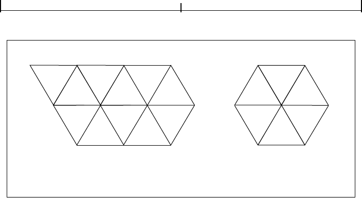
Patterns4.6
229
FIGURE 4.22 Varying the value of the edge flag to create different shapes
Mesh 2 again begins with triangle 1 and uses the edge flags
The stream must provide vertex data for a whole number of triangles with appro-
priate edge flags; otherwise, an error will occur.
The data for each vertex consists of the following items, reading in sequence from
higher-order to lower-order bit positions:
• An edge flag, expressed in BitsPerFlag bits
• A pair of horizontal and vertical coordinates, each expressed in BitsPer-
Coordinate
bits
• A set of n color components (where n is the number of components in the
shading’s color space), each expressed in
BitsPerComponent bits, in the order
expected by the
sc operator
Mesh 1 Mesh 2
v
l
v
j
v
i
v
f
v
e
v
c
v
a
v
e
v
g
v
a
v
h
v
c
v
d
v
k
v
b
v
h
v
g
v
d
v
m
v
m
=
v
b
v
k
=
v
d
v
h
=
v
a
v
f
v
b
1
4
53
62
5
8
97
4
31
10
11
26
1 f
a
f
b
f
c
0===() 4 f
f
2=()
2 f
d
1=() 5 f
g
2=()
3 f
e
2=() 6 f
h
2=()

GraphicsCHAPTER 4
230
Each set of vertex data must occupy a whole number of bytes; if the total number
of bits required is not divisible by 8, the last data byte for each vertex is padded at
the end with extra bits, which are ignored. The coordinates and color values are
decoded according to the
Decode array in the same way as in an image dictionary
(see “Decode Arrays” on page 252).
If the shading dictionary contains a
Function entry, the color data for each vertex
must be specified by a single parametric value t, rather than by n separate color
components. All linear interpolation within the triangle mesh is done using the t
values; after interpolation, the results are passed to the function(s) specified in
the
Function entry to determine the color at each point.
Type 5 Shadings (Lattice-Form Gouraud-Shaded Triangle Meshes)
Type 5 shadings (lattice-form Gouraud-shaded triangle meshes) are similar to
type 4, but instead of using free-form geometry, their vertices are arranged in a
pseudorectangular lattice, which is topologically equivalent to a rectangular grid.
The vertices are organized into rows, which need not be geometrically linear (see
Figure 4.23). Table 4.30 shows the shading dictionary entries specific to this type
of shading, in addition to those common to all shading dictionaries (Table 4.25
on page 216) and stream dictionaries (Table 3.4 on page 35).
FIGURE 4.23 Lattice-form triangular meshes
Ideal lattice
(i, j)(i, j+1)
(i+1, j)(i+1, j+1)
Pseudorectangular lattice

Patterns4.6
231
TABLE 4.30 Additional entries specific to a type 5 shading dictionary
KEY TYPE VALUE
BitsPerCoordinate integer (Required) The number of bits used to represent each vertex coordinate.
Valid values are 1, 2, 4, 8, 12, 16, 24, and 32.
BitsPerComponent integer (Required) The number of bits used to represent each color component.
Valid values are 1, 2, 4, 8, 12, and 16.
VerticesPerRow integer (Required) The number of vertices in each row of the lattice; the value
must be greater than or equal to 2. The number of rows need not be
specified.
Decode array (Required) An array of numbers specifying how to map vertex coordinates
and color components into the appropriate ranges of values. The decod-
ing method is similar to that used in image dictionaries (see “Decode Ar-
rays” on page 252). The ranges are specified as follows:
[x
min
x
max
y
min
y
max
c
1,min
c
1,max
… c
n,min
c
n,max
]
Note that only one pair of c values should be specified if a Function entry
is present.
Function function (Optional) A 1-in, n-out function or an array of n 1-in, 1-out functions
(where n is the number of color components in the shading dictionary’s
color space). If this entry is present, the color data for each vertex must be
specified by a single parametric variable rather than by n separate color
components; the designated function(s) will be called with each interpo-
lated value of the parametric variable to determine the actual color at each
point. Each input value will be forced into the range interval specified for
the corresponding color component in the shading dictionary’s
Decode
array. Each function’s domain must be a superset of that interval. If the
value returned by the function for a given color component is out of
range, it will be adjusted to the nearest valid value.
This entry may not be used with an Indexed color space.
The data stream for a type 5 shading has the same format as for type 4, except
that it does not use edge flags to define the geometry of the triangle mesh. The
data for each vertex thus consists of the following values, in the order shown:
x y c
1
… c
n

GraphicsCHAPTER 4
232
where
x and y are the vertex’s horizontal and vertical coordinates
c
1
… c
n
are its color components
All vertex coordinates are expressed in the shading’s target coordinate space. If
the shading dictionary includes a
Function entry, then only a single parametric
value, t, is permitted for each vertex in place of the color components c
1
… c
n
.
The
VerticesPerRow entry in the shading dictionary gives the number of vertices
in each row of the lattice. All of the vertices in a row are specified sequentially, fol-
lowed by those for the next row. Given m rows of k vertices each, the triangles of
the mesh are constructed using the following triplets of vertices, as shown in
Figure 4.23:
See “Type 4 Shadings (Free-Form Gouraud-Shaded Triangle Meshes)” on
page 225 for further details on the format of the vertex data.
Type 6 Shadings (Coons Patch Meshes)
Type 6 shadings (Coons patch meshes) are constructed from one or more color
patches, each bounded by four cubic Bézier curves. Degenerate Bézier curves are
allowed and are useful for certain graphical effects. At least one complete patch
must be specified.
A Coons patch generally has two independent aspects:
• Colors are specified for each corner of the unit square, and bilinear interpola-
tion is used to fill in colors over the entire unit square.
• Coordinates are mapped from the unit square into a four-sided patch whose
sides are not necessarily linear. The mapping is continuous: the corners of the
unit square map to corners of the patch, and the sides of the unit square map to
sides of the patch, as shown in Figure 4.24.
V
ij,
V
ij 1+,
V
i 1+ j,
,,
()f
or 0
i
m 2–≤≤ 0
jk
2–≤≤,
V
ij 1+,
V
i 1+ j,
V
i 1+ j 1+,
,, )(

Patterns4.6
233
FIGURE 4.24 Coordinate mapping from a unit square to a four-sided Coons patch
The sides of the patch are given by four cubic Bézier curves, C
1
, C
2
, D
1
, and D
2
,
defined over a pair of parametric variables u and v that vary horizontally and ver-
tically across the unit square. The four corners of the Coons patch satisfy the
equations
Two surfaces can be described that are linear interpolations between the boun-
dary curves. Along the u axis, the surface S
C
is defined by
Along the v axis, the surface S
D
is given by
A third surface is the bilinear interpolation of the four corners:
D
1
C
1
D
2
C
2
v
u
C
1
0() D
1
0()=
C
1
1() D
2
0()=
C
2
0() D
1
1()=
C
2
1() D
2
1()=
S
C
uv,() 1 v–()C
1
u()× vC
2
u()×+=
S
D
uv,() 1 u–()D
1
v() uD
2
v()×+×=
S
B
uv,() 1 v–()1 u–()C
1
0()×[ uC
1
1()×+ ]×
v 1 u–()C
2
0()×[ uC
2
1()×]+×+
=

GraphicsCHAPTER 4
234
The coordinate mapping for the shading is given by the surface S, defined as
This defines the geometry of each patch. A patch mesh is constructed from a
sequence of one or more such colored patches.
Patches can sometimes appear to fold over on themselves—for example, if a
boundary curve intersects itself. As the value of parameter u or v increases in
parameter space, the location of the corresponding pixels in device space may
change direction, so that new pixels are mapped onto previous pixels already
mapped. If more than one point (u, v) in parameter space is mapped to the same
point in device space, the point selected will be the one with the largest value of v;
if multiple points have the same v, the one with the largest value of u will be
selected. If one patch overlaps another, the patch that appears later in the data
stream paints over the earlier one.
Note also that the patch is a control surface, rather than a painting geometry. The
outline of a projected square (that is, the painted area) might not be the same as
the patch boundary if, for example, the patch folds over on itself, as shown in
Figure 4.25.
FIGURE 4.25 Painted area and boundary of a Coons patch
SS
C
S
D
S
B
–+=
Appearance Painted area Patch boundary

Patterns4.6
235
Table 4.31 shows the shading dictionary entries specific to this type of shading, in
addition to those common to all shading dictionaries (Table 4.25 on page 216)
and stream dictionaries (Table 3.4 on page 35).
TABLE 4.31 Additional entries specific to a type 6 shading dictionary
KEY TYPE VALUE
BitsPerCoordinate integer (Required) The number of bits used to represent each geometric coordi-
nate. Valid values are 1, 2, 4, 8, 12, 16, 24, and 32.
BitsPerComponent integer (Required) The number of bits used to represent each color component.
Valid values are 1, 2, 4, 8, 12, and 16.
BitsPerFlag integer (Required) The number of bits used to represent the edge flag for each
patch (see below). Valid values of
BitsPerFlag are 2, 4, and 8, but only the
least significant 2 bits in each flag value are used. Valid values for the edge
flag itself are 0, 1, 2, and 3.
Decode array (Required) An array of numbers specifying how to map coordinates and
color components into the appropriate ranges of values. The decoding
method is similar to that used in image dictionaries (see “Decode Arrays”
on page 252). The ranges are specified as follows:
[x
min
x
max
y
min
y
max
c
1,min
c
1,max
… c
n,min
c
n,max
]
Note that only one pair of c values should be specified if a Function entry
is present.
Function function (Optional) A 1-in, n-out function or an array of n 1-in, 1-out functions
(where n is the number of color components in the shading dictionary’s
color space). If this entry is present, the color data for each vertex must be
specified by a single parametric variable rather than by n separate color
components; the designated function(s) will be called with each interpo-
lated value of the parametric variable to determine the actual color at each
point. Each input value will be forced into the range interval specified for
the corresponding color component in the shading dictionary’s
Decode
array. Each function’s domain must be a superset of that interval. If the
value returned by the function for a given color component is out of
range, it will be adjusted to the nearest valid value.
This entry may not be used with an Indexed color space.

GraphicsCHAPTER 4
236
The data stream provides a sequence of Bézier control points and color values
that define the shape and colors of each patch. All of a patch’s control points are
given first, followed by the color values for its corners. Note that this differs from
a triangle mesh (shading types 4 and 5), in which the coordinates and color of
each vertex are given together. All control point coordinates are expressed in the
shading’s target coordinate space.
As in free-form triangle meshes (type 4), each patch has an edge flag that tells
which edge, if any, it shares with the previous patch. An edge flag of 0 begins a
new patch, unconnected to any other. This must be followed by 12 pairs of co-
ordinates, x
1
y
1
x
2
y
2
… x
12
y
12
, which specify the Bézier control points that
define the four boundary curves. Figure 4.26 shows how these control points cor-
respond to the cubic Bézier curves C
1
, C
2
, D
1
, and D
2
identified in Figure 4.24 on
page 233. Color values are then given for the four corners of the patch, in the
same order as the control points corresponding to the corners. Thus, c
1
is the
color at coordinates (x
1
, y
1
), c
2
at (x
4
, y
4
), c
3
at (x
7
, y
7
), and c
4
at (x
10
, y
10
), as
shown in the figure.
FIGURE 4.26 Color values and edge flags in Coons patch meshes
5
3
8
6
7
9
11
12
2
1
4
10
Use this side when next f = 3.
Use this side when next f = 1.
Use this side when next f = 2.
This side already attached
to previous patch. Start a
new patch when next f = 0.
c
1
c
2
c
3
c
4
C
1
C
2
D
2
D
1

Patterns4.6
237
Figure 4.26 also shows how nonzero values of the edge flag (f = 1, 2, or 3) connect
a new patch to one of the edges of the previous patch. In this case, some of the
previous patch’s control points serve implicitly as control points for the new
patch as well (see Figure 4.27), and so are not explicitly repeated in the data
stream. Table 4.32 summarizes the required data values for various values of the
edge flag.
FIGURE 4.27 Edge connections in a Coons patch mesh
When f
B
= 0, start a new patch.
Patch B
f
B
= 1
Patch A
Patch B
f
B
= 3
Patch B
f
B
= 2
2
1
4
5
3
c
1
c
2
12
9
3
4
1
1
2
2
4
3
11
c
1
c
1
c
2
c
4
1
4
7
6
8
2
3
c
3
c
1
c
2
c
2
10

GraphicsCHAPTER 4
238
TABLE 4.32 Data values in a Coons patch mesh
EDGE FLAG NEXT SET OF DATA VALUES
f = 0 x
1
y
1
x
2
y
2
x
3
y
3
x
4
y
4
x
5
y
5
x
6
y
6
x
7
y
7
x
8
y
8
x
9
y
9
x
10
y
10
x
11
y
11
x
12
y
12
c
1
c
2
c
3
c
4
New patch; no implicit values
f = 1 x
5
y
5
x
6
y
6
x
7
y
7
x
8
y
8
x
9
y
9
x
10
y
10
x
11
y
11
x
12
y
12
c
3
c
4
Implicit values:
(x
1
, y
1
) = (x
4
, y
4
) previous c
1
= c
2
previous
(x
2
, y
2
) = (x
5
, y
5
) previous c
2
= c
3
previous
(x
3
, y
3
) = (x
6
, y
6
) previous
(x
4
, y
4
) = (x
7
, y
7
) previous
f = 2 x
5
y
5
x
6
y
6
x
7
y
7
x
8
y
8
x
9
y
9
x
10
y
10
x
11
y
11
x
12
y
12
c
3
c
4
Implicit values:
(x
1
, y
1
) = (x
7
, y
7
) previous c
1
= c
3
previous
(x
2
, y
2
) = (x
8
, y
8
) previous c
2
= c
4
previous
(x
3
, y
3
) = (x
9
, y
9
) previous
(x
4
, y
4
) = (x
10
, y
10
) previous
f = 3 x
5
y
5
x
6
y
6
x
7
y
7
x
8
y
8
x
9
y
9
x
10
y
10
x
11
y
11
x
12
y
12
c
3
c
4
Implicit values:
(x
1
, y
1
) = (x
10
, y
10
) previous c
1
= c
4
previous
(x
2
, y
2
) = (x
11
, y
11
) previous c
2
= c
1
previous
(x
3
, y
3
) = (x
12
, y
12
) previous
(x
4
, y
4
) = (x
1
, y
1
) previous
If the shading dictionary contains a Function entry, the color data for each corner
of a patch must be specified by a single parametric value t, rather than by n sepa-
rate color components c
1
… c
n
. All linear interpolation within the mesh is done
using the t values; after interpolation, the results are passed to the function(s)
specified in the
Function entry to determine the color at each point.

Patterns4.6
239
Type 7 Shadings (Tensor-Product Patch Meshes)
Type 7 shadings (tensor-product patch meshes) are identical to type 6, except
that they are based on a bicubic tensor-product patch defined by 16 control
points, instead of the 12 control points that define a Coons patch. The shading
dictionaries representing the two patch types differ only in the value of the
ShadingType entry and in the number of control points specified for each patch
in the data stream. Although the Coons patch is more concise and easier to use,
the tensor-product patch affords greater control over color mapping.
Note: The data format for type 7 shadings (as for types 4 through 6) is the same in
PDF as it is in PostScript. However, the numbering and order of control points was
described incorrectly in the first printing of the PostScript Language Reference,
Third Edition. That description has been corrected here.
Like the Coons patch mapping, the tensor-product patch mapping is controlled
by the location and shape of four cubic Bézier curves marking the boundaries of
the patch. However, the tensor-product patch has four additional, “internal”
control points to adjust the mapping. The 16 control points can be arranged in a
4-by-4 array indexed by row and column, as follows (see Figure 4.28):
p
03
p
13
p
23
p
33
p
02
p
12
p
22
p
32
p
01
p
11
p
21
p
31
p
00
p
10
p
20
p
30
FIGURE 4.28 Control points in a tensor-product mesh
p
02
p
00
p
01
p
12
p
22
p
21
p
11
p
10
p
20
p
30
p
31
p
32
p
33
p
23
p
13
p
03

GraphicsCHAPTER 4
240
As in a Coons patch mesh, the geometry of the tensor-product patch is described
by a surface defined over a pair of parametric variables, u and v, which vary hori-
zontally and vertically across the unit square. The surface is defined by the equa-
tion
where p
ij
is the control point in column i and row j of the tensor, and B
i
and B
j
are
the Bernstein polynomials
Since each point p
ij
is actually a pair of coordinates (x
ij
, y
ij
), the surface can also
be expressed as
The geometry of the tensor-product patch can be visualized in terms of a cubic
Bézier curve moving from the bottom boundary of the patch to the top. At the
bottom and top, the control points of this curve coincide with those of the patch’s
bottom (p
00
… p
30
) and top (p
03
… p
33
) boundary curves, respectively. As the
curve moves from the bottom edge of the patch to the top, each of its four control
points follows a trajectory that is in turn a cubic Bézier curve defined by the four
control points in the corresponding column of the array. That is, the starting
point of the moving curve follows the trajectory defined by control points
p
00
… p
03
, the trajectory of the ending point is defined by points p
30
… p
33
, and
those of the two intermediate control points by p
10
… p
13
and p
20
… p
23
. Equiva-
lently, the patch can be considered to be traced by a cubic Bézier curve moving
Suv,() p
ij
B
i
u() B
j
v()××
j 0=
3
∑
i 0=
3
∑
=
B
0
t() 1 t–()
3
=
B
1
t() 3t 1 t–()
2
×=
B
2
t() 3t
2
1 t–()×=
B
3
t() t
3
=
xuv,() x
ij
B
i
u() B
j
v()××
j 0=
3
∑
i 0=
3
∑
=
yuv,() y
ij
B
i
u() B
j
v()××
j 0=
3
∑
i 0=
3
∑
=

Patterns4.6
241
from the left edge to the right, with its control points following the trajectories
defined by the rows of the coordinate array instead of the columns.
The Coons patch (type 6) is actually a special case of the tensor-product patch
(type 7) in which the four internal control points (p
11
, p
12
, p
21
, p
22
) are implicit-
ly defined by the boundary curves. The values of the internal control points are
given by the equations
where S is the Coons surface equation
discussed above under “Type 6 Shadings (Coons Patch Meshes)” on page 232. In
the more general tensor-product patch, the values of these four points are un-
restricted.
The coordinates of the control points in a tensor-product patch are actually spec-
ified in the shading’s data stream in the following order:
4567
31415 8
21316 9
1121110
All control point coordinates are expressed in the shading’s target coordinate
space. These are followed by the color values for the four corners of the patch, in
the same order as the corners themselves. If the patch’s edge flag f is 0, all 16
control points and four corner colors must be explicitly specified in the data
stream; if f is 1, 2, or 3, the control points and colors for the patch’s shared edge
are implicitly understood to be the same as those along the specified edge of the
previous patch, and are not repeated in the data stream. Table 4.33 summarizes
the data values for various values of the edge flag f, expressed in terms of the row
and column indices used in Figure 4.28 above.
p
11
S
1
⁄
3
1
⁄
3
,()=
p
12
S
1
⁄
3
2
⁄
3
,()=
p
21
S
2
⁄
3
1
⁄
3
,()=
p
22
S
2
⁄
3
2
⁄
3
,()=
SS
C
S
D
S
B
–+=

GraphicsCHAPTER 4
242
TABLE 4.33 Data values in a tensor-product patch mesh
EDGE FLAG NEXT SET OF DATA VALUES
f = 0 x
00
y
00
x
01
y
01
x
02
y
02
x
03
y
03
x
13
y
13
x
23
y
23
x
33
y
33
x
32
y
32
x
31
y
31
x
30
y
30
x
20
y
20
x
10
y
10
x
11
y
11
x
12
y
12
x
22
y
22
x
21
y
21
c
00
c
03
c
33
c
30
New patch; no implicit values
f = 1 x
13
y
13
x
23
y
23
x
33
y
33
x
32
y
32
x
31
y
31
x
30
y
30
x
20
y
20
x
10
y
10
x
11
y
11
x
12
y
12
x
22
y
22
x
21
y
21
c
33
c
30
Implicit values:
(x
00
, y
00
) = (x
03
, y
03
) previous c
00
= c
03
previous
(x
01
, y
01
) = (x
13
, y
13
) previous c
03
= c
33
previous
(x
02
, y
02
) = (x
23
, y
23
) previous
(x
03
, y
03
) = (x
33
, y
33
) previous
f = 2 x
13
y
13
x
23
y
23
x
33
y
33
x
32
y
32
x
31
y
31
x
30
y
30
x
20
y
20
x
10
y
10
x
11
y
11
x
12
y
12
x
22
y
22
x
21
y
21
c
33
c
30
Implicit values:
(x
00
, y
00
) = (x
33
, y
33
) previous c
00
= c
33
previous
(x
01
, y
01
) = (x
32
, y
32
) previous c
03
= c
30
previous
(x
02
, y
02
) = (x
31
, y
31
) previous
(x
03
, y
03
) = (x
30
, y
30
) previous
f = 3 x
13
y
13
x
23
y
23
x
33
y
33
x
32
y
32
x
31
y
31
x
30
y
30
x
20
y
20
x
10
y
10
x
11
y
11
x
12
y
12
x
22
y
22
x
21
y
21
c
33
c
30
Implicit values:
(x
00
, y
00
) = (x
30
, y
30
) previous c
00
= c
30
previous
(x
01
, y
01
) = (x
20
, y
20
) previous c
03
= c
00
previous
(x
02
, y
02
) = (x
10
, y
10
) previous
(x
03
, y
03
) = (x
00
, y
00
) previous

External Objects4.7
243
4.7 External Objects
An external object (commonly called an XObject) is a graphics object whose con-
tents are defined by a self-contained content stream, separate from the content
stream in which it is used. There are three types of external object:
• An image XObject (Section 4.8.4, “Image Dictionaries”) represents a sampled
visual image such as a photograph.
• A form XObject (Section 4.9, “Form XObjects”) is a self-contained description
of an arbitrary sequence of graphics objects.
• A PostScript XObject (Section 4.10, “PostScript XObjects”) contains a fragment
of code expressed in the PostScript page description language.
Any XObject can be painted as part of another content stream by means of the
Do
operator (see Table 4.34). This operator applies to any type of XObject—image,
form, or PostScript. The syntax is the same in all cases, though details of the op-
erator’s behavior differ depending on the type. (See implementation note 32 in
Appendix H.)
TABLE 4.34 XObject operator
OPERANDS OPERATOR DESCRIPTION
name Do Paint the specified XObject. The operand name must appear as a key in the
XObject subdictionary of the current resource dictionary (see Section 3.7.2, “Re-
source Dictionaries”); the associated value must be a stream whose
Type entry, if
present, is
XObject. The effect of Do depends on the value of the XObject’s
Subtype entry, which may be Image (see Section 4.8.4, “Image Dictionaries”),
Form (Section 4.9, “Form XObjects”), or PS (Section 4.10, “PostScript
XObjects”).

GraphicsCHAPTER 4
244
4.8 Images
PDF’s painting operators include general facilities for dealing with sampled im-
ages. A sampled image (or just image for short) is a rectangular array of sample
values, each representing a color. The image may approximate the appearance of
some natural scene obtained through an input scanner or a video camera, or it
may be generated synthetically.
FIGURE 4.29 Typical sampled image
An image is defined by a sequence of samples obtained by scanning the image
array in row or column order. Each sample in the array consists of as many color
components as are needed for the color space in which they are specified—for
example, one component for
DeviceGray, three for DeviceRGB, four for Device-
CMYK
, or whatever number is required by a particular DeviceN space. Each com-
ponent is a 1-, 2-, 4-, or 8-bit integer, permitting the representation of 2, 4, 16, or
256 distinct values for each component.
PDF provides two means for specifying images:
• An image XObject (described in Section 4.8.4, “Image Dictionaries”) is a stream
object whose dictionary specifies attributes of the image and whose data con-
tains the image samples. Like all external objects, it is painted on the page by
invoking the
Do operator in a content stream (see Section 4.7, “External Ob-
jects”). Image XObjects have other uses as well, such as for alternate images

Images4.8
245
(see “Alternate Images” on page 255), image masks (Section 4.8.5, “Masked Im-
ages”), and thumbnail images (Section 7.2.3, “Thumbnail Images”).
• An in-line image is a small image that is completely defined—both attributes
and data—directly in-line within a content stream. The kinds of image that can
be represented in this way are limited; see Section 4.8.6, “In-Line Images,” for
details.
4.8.1 Image Parameters
The properties of an image—resolution, orientation, scanning order, and so
forth—are entirely independent of the characteristics of the raster output device
on which the image is to be rendered. A PDF viewer application usually renders
images by a sampling technique that attempts to approximate the color values of
the source as accurately as possible. The actual accuracy achieved depends on the
resolution and other properties of the output device.
To paint an image, four interrelated items must be specified:
• The format of the image: number of columns (width), number of rows
(height), number of color components per sample, and number of bits per
color component
• The sample data constituting the image’s visual content
• The correspondence between coordinates in user space and those in the image’s
own internal coordinate space, defining the region of user space that will re-
ceive the image
• The mapping from color component values in the image data to component
values in the image’s color space
All of these items are specified explicitly or implicitly by an image XObject or an
in-line image.
Note: For convenience, the following sections refer consistently to the object defining
an image as an image dictionary. Although this term properly refers only to the
dictionary portion of the stream object representing an image XObject, it should be
understood to apply equally to the stream’s data portion or to the parameters and
data of an in-line image.

GraphicsCHAPTER 4
246
4.8.2 Sample Representation
The source format for an image can be described by four parameters:
• The width of the image in samples
• The height of the image in samples
• The number of color components per sample
• The number of bits per color component
The image dictionary specifies the width, the height, and the number of bits per
component explicitly; the number of color components can be inferred from the
color space specified in the dictionary.
Sample data is represented as a stream of bytes, interpreted as 8-bit unsigned
integers in the range 0 to 255. The bytes constitute a continuous bit stream, with
the high-order bit of each byte first. This bit stream, in turn, is divided into units
of n bits each, where n is the number of bits per component. Byte boundaries are
ignored, except that each row of sample data must begin on a byte boundary. If
the number of data bits per row is not a multiple of 8, the end of the row is pad-
ded with extra bits to fill out the last byte. A PDF viewer application ignores these
padding bits.
Each n-bit unit within the bit stream is interpreted as an unsigned integer in the
range 0 to 2
n
− 1, with the high-order bit first; the image dictionary’s Decode
entry maps this to a color component value, equivalent to what could be used
with color operators such as
sc or g. Color components are interleaved sample by
sample; for example, in a three-component RGB image, the red, green, and blue
components for one sample are followed by the red, green, and blue components
for the next.
Normally, the color samples in an image are interpreted according to the color
space specified in the image dictionary (see Section 4.5, “Color Spaces”), without
reference to the color parameters in the graphics state. However, if the image dic-
tionary’s
ImageMask entry is true, the sample data is interpreted as a stencil mask
for applying the graphics state’s nonstroking color parameters (see “Stencil
Masking” on page 257).

Images4.8
247
4.8.3 Image Coordinate System
Each image has its own internal coordinate system, or image space. The image oc-
cupies a rectangle in image space w units wide and h units high, where w and h
are the width and height of image in samples. Each sample occupies one square
unit. The coordinate origin (0, 0) is at the upper-left corner of the image, with
coordinates ranging from 0 to w horizontally and 0 to h vertically.
The image’s sample data is ordered by row, with the horizontal coordinate vary-
ing most rapidly. This is shown in Figure 4.30, where the numbers inside the
squares indicate the order of the samples, counting from 0. The upper-left corner
of the first sample is at coordinates (0, 0), the second at (1, 0), and so on through
the last sample of the first row, whose upper-left corner is at (w − 1, 0) and whose
upper-right corner is at (w, 0). The next samples after that are at coordinates
(0, 1), (1, 1), and so on, until the final sample of the image, whose upper-left cor-
ner is at (w − 1, h − 1) and whose lower-right corner is at (w, h).
FIGURE 4.30 Source image coordinate system
Note: The image coordinate system and scanning order imposed by PDF do not pre-
clude using different conventions in the actual image. Coordinate transformations
can be used to map from other conventions to the PDF convention.
0
1
h−1
2
h
012 w−1 w
01 w−1
ww+12w−1
(h−1)w (h−1)w+1 hw−1

GraphicsCHAPTER 4
248
The correspondence between image space and user space is constant: the unit
square of user space, bounded by user coordinates (0, 0) and (1, 1), corresponds
to the boundary of the image in image space (see Figure 4.31). Following the
normal convention for user space, the coordinate (0, 0) is at the lower-left corner
of this square, corresponding to coordinates (0, h) in image space. The transfor-
mation from image space to user space could be described by the matrix
[1⁄w 00−1⁄h 01].
FIGURE 4.31 Mapping the source image
An image can be placed on the output page in any desired position, orientation,
and size by using the
cm operator to modify the current transformation matrix
(CTM) so as to map the unit square of user space to the rectangle or parallelo-
gram in which the image is to be painted. Typically, this is done within a pair of
q
and Q operators to isolate the effect of the transformation, which can include
translation, rotation, reflection, and skew (see Section 4.2, “Coordinate Sys-
tems”). For example, if the
XObject subdictionary of the current resource
dictionary defines the name
Image1 to denote an image XObject, the code shown
in Example 4.23 paints the image in a rectangle whose lower-left corner is at
coordinates (100, 200), that is rotated 45 degrees counterclockwise, and that is
150 units wide and 80 units high.
h
0 w
0
(0, 1) (1, 1)
(0, 0) (1, 0)
Unit square
in user space
Current pageSource image
CTM

Images4.8
249
Example 4.23
q % Save graphics state
1 0 0 1 100 200 cm % Translate
0.7071 0.7071 −0.7071 0.7071 0 0 cm % Rotate
150 0 0 80 0 0 cm % Scale
/Image1 Do % Paint image
Q % Restore graphics state
(As discussed in Section 4.2.3, “Transformation Matrices,” these three transfor-
mations could be combined into one.) Of course, if the aspect ratio (width to
height) of the original image in this example is different from 150:80, the result
will be distorted.
4.8.4 Image Dictionaries
Table 4.35 lists the entries in an image dictionary (that is, in the dictionary por-
tion of a stream representing an image XObject). There are many relationships
among these entries, and the current color space may limit the choices for some
of them. Attempting to use an image dictionary whose entries are inconsistent
with each other or with the current color space will cause an error.
Note: The entries described here are those that are appropriate for a base image—
one that is invoked directly with the
Do operator. Some of these entries are not
relevant for images used in other ways, such as for alternate images (see “Alternate
Images” on page 255), image masks (Section 4.8.5, “Masked Images”), or thumbnail
images (Section 7.2.3, “Thumbnail Images”). Except as noted, such irrelevant
entries are simply ignored.
TABLE 4.35 Entries in an image dictionary
KEY TYPE VALUE
Type name (Optional) The type of PDF object that this dictionary describes; if
present, must be
XObject for an image XObject.
Subtype name (Required) The type of XObject that this dictionary describes; must be
Image for an image XObject.
Width integer (Required) The width of the image, in samples.
Height integer (Required) The height of the image, in samples.

GraphicsCHAPTER 4
250
ColorSpace name or (Required except for image masks; not allowed for image masks) The color
array space in which image samples are specified. This may be any type of color
space except
Pattern.
BitsPerComponent integer (Required except for image masks; optional for image masks) The number of
bits used to represent each color component. Only a single value may be
specified; the number of bits is the same for all color components. Valid
values are 1, 2, 4, and 8. If
ImageMask is true, this entry is optional, and if
specified, its value must be 1.
If the image stream uses a filter, the value of
BitsPerComponent must
be consistent with the size of the data samples that the filter delivers. In
particular, a
CCITTFaxDecode filter always delivers 1-bit samples, a Run-
LengthDecode
or DCTDecode filter delivers 8-bit samples, and an LZW-
Decode
or FlateDecode filter delivers samples of a specified size if a
predictor function is used.
Intent name (Optional; PDF 1.1) The name of a color rendering intent to be used in
rendering the image (see “Rendering Intents” on page 179). Default value:
the rendering intent parameter in the graphics state.
ImageMask boolean (Optional) A flag indicating whether the image is to be treated as an image
mask (see Section 4.8.5, “Masked Images”). If this flag is true, the value of
BitsPerComponent must be 1 and Mask and ColorSpace should not be
specified; unmasked areas will be painted using the current nonstroking
color. Default value: false.
Mask stream (Optional except for image masks; not allowed for image masks; PDF 1.3) An
or array image XObject defining an image mask to be applied to this image (see
“Explicit Masking” on page 258), or an array specifying a range of colors
to be applied to it as a color key mask (see “Color Key Masking” on
page 259). If
ImageMask is true, this entry must not be present. (See
implementation note 33 in Appendix H.)
Decode array (Optional) An array of numbers describing how to map image samples
into the range of values appropriate for the image’s color space (see
“Decode Arrays,” below). If
ImageMask is true, the array must be either
[0 1] or [1 0]; otherwise, its length must be twice the number of color
components required by
ColorSpace. Default value: see “Decode Arrays”
on page 252.
Interpolate boolean (Optional) A flag indicating whether image interpolation is to be per-
formed (see “Image Interpolation” on page 255). Default value: false.

Images4.8
251
Alternates array (Optional; PDF 1.3) An array of alternate image dictionaries for this image
(see “Alternate Images” on page 255). The order of elements within the
array has no significance. This entry may not be present in an image
XObject that is itself an alternate image.
Name name (Required in PDF 1.0; optional otherwise) The name by which this image
XObject is referenced in the
XObject subdictionary of the current resource
dictionary (see Section 3.7.2, “Resource Dictionaries”).
Note: This entry is obsolescent and its use is no longer recommended. (See
implementation note 34 in Appendix H.)
StructParents integer (Required if the image is a structural content item; PDF 1.3) The integer key
of the image’s entry in the structural parent tree (see “Finding Structure
Elements from Content Items” on page 496).
ID string (Optional; PDF 1.3; indirect reference preferred) The digital identifier of the
image’s parent Web Capture content set (see Section 8.5.5, “Object At-
tributes Related to Web Capture”).
OPI dictionary (Optional; PDF 1.2) An OPI version dictionary for this image (see
Section 8.6.4, “Open Prepress Interface (OPI)”). If
ImageMask is true, this
entry is ignored.
Example 4.24 defines an image 256 samples wide by 256 high, with 8 bits per
sample in the
DeviceGray color space. It paints the image on a page with its
lower-left corner positioned at coordinates (45, 140) in current user space and
scaled to a width and height of 132 user space units.
Example 4.24
20 0 obj % Page object
<< /Type /Page
/Parent 1 0 R
/Resources 21 0 R
/MediaBox [0 0 612 792]
/Contents 23 0 R
>>
endobj
21 0 obj % Resource dictionary for page
<< /ProcSet [/PDF /ImageB]
/XObject << /Im1 22 0 R >>
>>
endobj

GraphicsCHAPTER 4
252
22 0 obj % Image XObject
<< /Type /XObject
/Subtype /Image
/Width 256
/Height 256
/ColorSpace /DeviceGray
/BitsPerComponent 8
/Length 83183
/Filter /ASCII85Decode
>>
stream
9LhZI9h\GY9i+bb;,p:e;G9SP92/)X9MJ>^:f14d;,U(X8P;cO;G9e];c$=k9Mn\]
… Image data representing 65,536 samples …
8P;cO;G9e];c$=k9Mn\]~>
endstream
endobj
23 0 obj % Contents of page
<< /Length 56 >>
stream
q % Save graphics state
132 0 0 132 45 140 cm % Translate to (45,140) and scale by 132
/Im1 Do % Paint image
Q % Restore graphics state
endstream
endobj
Decode Arrays
An image’s data stream is initially decomposed into integers in the range 0 to
2
n
− 1, where n is the value of the image dictionary’s BitsPerComponent entry.
The image’s
Decode array specifies a linear mapping of each integer component
value to a number that would be appropriate as a component value in the image’s
color space.
Each pair of numbers in a
Decode array specifies the lower and upper values to
which the range of sample values in the image is mapped. A
Decode array con-
tains one pair of numbers for each component in the color space specified by the

Images4.8
253
image’s ColorSpace entry. The mapping for each color component is a linear
transformation. That is, it uses the following formula for linear interpolation:
Generally, this is used to convert a value x between x
min
and x
max
to a cor-
responding value y between y
min
and y
max
, projecting along the line defined by
the points (x
min
, y
min
) and (x
max
, y
max
). While this formula applies to values
outside the range x
min
to x
max
and does not require that
x
min
< x
max
, note that
interpolation used for color conversion, such as the
Decode array, does require
that x
min
< x
max
and “clips” x values to this range, so that y = y
min
for all x ≤ x
min
,
and y = y
max
for all x ≥ x
max
.
For a
Decode array of the form [D
min
D
max
], this can be written as
where
n is the value of
BitsPerComponent
x is the input value, in the range 0 to 2
n
− 1
D
min
and D
max
are the values specified in the Decode array
y is the output value, to be interpreted in the image’s color space
Samples with a value of 0 are mapped to
D
min
, those with a value of 2
n
− 1 are
mapped to
D
max
, and those with intermediate values are mapped linearly
between
D
min
and D
max
. Table 4.36 lists the default Decode arrays for use with the
various color spaces. For most color spaces, the
Decode arrays listed in the table
map into the full range of allowed component values. For an
Indexed color space,
the default
Decode array ensures that component values that index a color table
are passed through unchanged.
y Interpolate xx
min
x
max
y
min
y
max
,,,,)( xx
min
– )(
y
max
y
min
– )(
x
max
x
min
– )(
---------------------------------- y
min
+×==
y Interpolate x 02
n
1– D
min
D
max
,, , , )(=
D
min
x
D
max
D
min
–
2
n
1–
------------------------------
×+=

GraphicsCHAPTER 4
254
TABLE 4.36 Default Decode arrays
COLOR SPACE Decode ARRAY
DeviceGray [0.0 1.0]
DeviceRGB [0.0 1.0 0.0 1.0 0.0 1.0]
DeviceCMYK [0.0 1.0 0.0 1.0 0.0 1.0 0.0 1.0]
CalGray [0.0 1.0]
CalRGB [0.0 1.0 0.0 1.0 0.0 1.0]
Lab [0 100 a
min
a
max
b
min
b
max
] where a
min
, a
max
, b
min
, and b
max
correspond to the values in the Range array of the image’s color
space
ICCBased Same as the value of Range in the image’s color space
DeviceN [ 0.0 1.0 0.0 1.0 … 0.0 1.0] (one pair of elements for each color
component)
Separation [0.0 1.0]
Indexed [0 N]
, where N = 2
n
− 1
Pattern (Not permitted with images)
It is possible to specify a mapping that inverts sample color intensities, by specify-
ing a D
min
value greater than D
max
. For example, if the image’s color space is
DeviceGray and the Decode array is [1.0 0.0], an input value of 0 will be mapped
to 1.0 (white), while an input value of 2
n
− 1 will be mapped to 0.0 (black).
The D
min
and D
max
parameters for a color component are not required to fall
within the range of values allowed for that component. For instance, if an appli-
cation uses 6-bit numbers as its native image sample format, it can represent
those samples in PDF in 8-bit form, setting the two unused high-order bits of
each sample to 0. The image dictionary should then specify a
Decode array of
[0.00000 4.04762], which maps input values from 0 to 63 into the range 0.0 to 1.0
(4.04762 being approximately equal to 255 ÷ 63). If an output value falls outside
the range allowed for a component, it will automatically be adjusted to the near-
est allowed value.

Images4.8
255
Image Interpolation
When the resolution of a source image is significantly lower than that of the out-
put device, each source sample covers many device pixels. This can cause images
to appear “jaggy” or “blocky.” These visual artifacts can be reduced by applying
an image interpolation algorithm during rendering. Instead of painting all pixels
covered by a source sample with the same color, image interpolation attempts to
produce a smooth transition between adjacent sample values. Because it may in-
crease the time required to render the image, image interpolation is disabled by
default; setting the
Interpolate entry in the image dictionary to true enables it.
Note: The interpolation algorithm is implementation-dependent and is not specified
by PDF. Image interpolation may not always be performed for some classes of images
or on some output devices.
Alternate Images
Alternate images (PDF 1.3) provide a straightforward and backward-compatible
way to include multiple versions of an image in a PDF file for different purposes.
These variant representations of the image may differ, for example, in resolution
or in color space. The primary goal is to reduce the need to maintain separate
versions of a PDF document for low-resolution on-screen viewing and high-
resolution printing.
In PDF 1.3, a base image (that is, the image XObject referred to in a resource
dictionary) can contain an
Alternates entry. The value of this entry is an array of
alternate image dictionaries specifying variant representations of the base image.
Each alternate image dictionary contains an image XObject for one variant and
specifies its properties. Table 4.37 shows the contents of an alternate image dic-
tionary.
TABLE 4.37 Entries in an alternate image dictionary
KEY TYPE VALUE
Image stream (Required) The image XObject for the alternate image.
DefaultForPrinting boolean (Optional) A flag indicating whether this alternate image is the default ver-
sion to be used for printing. At most one alternate for a given base image may
be so designated. If no alternate has this entry set to true, the base image itself
is used for printing.

GraphicsCHAPTER 4
256
Example 4.25 shows an image with a single alternate. The base image is a gray-
scale image, and the alternate is a high-resolution RGB image stored on a Web
server.
Example 4.25
10 0 obj % Image XObject
<< /Type /XObject
/Subtype /Image
/Width 100
/Height 200
/ColorSpace /DeviceGray
/BitsPerComponent 8
/Alternates 15 0 R
/Length 2167
/Filter /DCTDecode
>>
stream
… Image data …
endstream
endobj
15 0 obj % Alternate images array
[ << /Image 16 0 R
/DefaultForPrinting true
>>
]
endobj
16 0 obj % Alternate image
<< /Type /XObject
/Subtype /Image
/Width 1000
/Height 2000
/ColorSpace /DeviceRGB
/BitsPerComponent 8
/Length 0 % This is an external stream
/F << /FS /URL
/F (http://www.myserver.mycorp.com/images/exttest.jpg)
>>
/FFilter /DCTDecode
>>
stream
endstream
endobj

Images4.8
257
4.8.5 Masked Images
Ordinarily, images mark all areas they occupy on the page as if with opaque paint.
All portions of the image, whether black, white, gray, or color, completely
obscure any marks that may previously have existed in the same place on the
page. In the graphic arts industry and page layout applications, however, it is
common to crop or “mask out” the background of an image and then place the
masked image on a different background, allowing the existing background to
show through the masked areas. A number of PDF features are available for
achieving such masking effects (see implementation note 35 in Appendix H):
• The ImageMask entry in the image dictionary, available in all versions of PDF,
specifies that the image data is to be used as a stencil mask for painting in the
current color.
• The Mask entry in the image dictionary (PDF 1.3) may specify a separate image
XObject to be used as an explicit mask specifying which areas of the image to
paint and which to mask out.
• Alternatively, the Mask entry (PDF 1.3) may specify a range of colors to be
masked out wherever they occur within the image; this technique is known as
color key masking.
Note: Although the
Mask entry is a PDF 1.3 feature, its effects are commonly simu-
lated in earlier versions of PDF by defining a clipping path enclosing only those of an
image’s samples that are to be painted. However, implementation limits can cause
errors if the clipping path is very complex (or if there is more than one clipping path).
An alternative way to achieve the effect of an explicit mask in PDF 1.2 is to define the
image being clipped as a pattern, make it the current color, and then paint the ex-
plicit mask as an image whose
ImageMask entry is true. In any case, the PDF 1.3
features allow masked images to be placed on the page without regard to the com-
plexity of the clipping path.
Stencil Masking
An image mask (an image XObject whose ImageMask entry is true) is a mono-
chrome image, in which each sample is specified by a single bit. However, instead
of being painted in opaque black and white, the image mask is treated as a stencil
mask that is partly opaque and partly transparent. Sample values in the image do
not represent black and white pixels; rather, they designate places on the page
that should either be marked with the current color or masked out (not marked

GraphicsCHAPTER 4
258
at all). Areas that are masked out retain their former contents. The effect is like
applying paint in the current color through a cut-out stencil, which allows the
paint to reach the page in some places and masks it out in others.
An image mask differs from an ordinary image in the following significant ways:
• The image dictionary does not contain a ColorSpace entry, because sample
values represent masking properties (1 bit per sample) rather than colors.
• The value of the BitsPerComponent entry must be 1.
• The Decode entry determines how the source samples are to be interpreted. If
the
Decode array is [0 1] (the default for an image mask), a sample value of 0
marks the page with the current color and a 1 leaves the previous contents un-
changed; if the
Decode array is [1 0], these meanings are reversed.
One of the most important uses of stencil masking is for painting character
glyphs represented as bitmaps. Using such a glyph as a stencil mask transfers only
its “black” bits to the page, while leaving the “white” bits (which are really just
background) unchanged. For reasons discussed in Section 5.5.4, “Type 3 Fonts,”
an image mask rather than an image should almost always be used to paint glyph
bitmaps.
Note: If image interpolation (see “Image Interpolation” on page 255) is requested
during stencil masking, the effect is to smooth the edges of the mask, not to interpo-
late the painted color values. This can minimize the “jaggy” appearance of a low-
resolution stencil mask.
Explicit Masking
In PDF 1.3, the Mask entry in an image dictionary may be an image mask, as de-
scribed above under “Stencil Masking,” which serves as an explicit mask for the
primary (base) image. The base image and the image mask need not have the
same resolution (
Width and Height values), but since all images are defined on
the unit square in user space, their boundaries on the page will coincide; that is,
they will overlay each other. The image mask indicates which places on the page
are to be painted and which are to be masked out (left unchanged). Unmasked
areas are painted with the corresponding portions of the base image; masked
areas are not.

Images4.8
259
Color Key Masking
In PDF 1.3, the Mask entry in an image dictionary may alternatively be an array
specifying a range of colors to be masked out. Samples in the image that fall with-
in this range are not painted, allowing the existing background to show through.
The effect is similar to that of the video technique known as chroma-key.
For color key masking, the value of the
Mask entry is an array of 2 × n integers,
[min
1
max
1
… min
n
max
n
], where n is the number of color components in the
image’s color space. Each integer must be in the range 0 to 2
BitsPerComponent
− 1,
representing color values before decoding with the
Decode array. An image sam-
ple is masked (not painted) if all of its color components before decoding,
c
1
… c
n
, fall within the specified ranges (that is, if min
i
≤ c
i
≤ max
i
for all
1 ≤ i ≤ n).
Note: When color key masking is specified, the use of a
DCTDecode filter for the
stream is not recommended.
DCTDecode is a “lossy” filter, meaning that the output
is only an approximation of the original input data. This can lead to slight changes
in the color values of image samples, possibly causing samples that were intended to
be masked to be unexpectedly painted instead, in colors slightly different from the
mask color.
4.8.6 In-Line Images
As an alternative to the image XObjects described in Section 4.8.4, “Image Dic-
tionaries,” a sampled image may be specified in the form of an in-line image. This
type of image is defined directly within the content stream in which it will be
painted, rather than as a separate object. Because the in-line format gives the
viewer application less flexibility in managing the image data, it should be used
only for small images (4 KB or less).
An in-line image object is delimited in the content stream by the operators
BI
(begin image), ID (image data), and EI (end image); these operators are summa-
rized in Table 4.38.
BI and ID bracket a series of key-value pairs specifying the
characteristics of the image, such as its dimensions and color space; the image

GraphicsCHAPTER 4
260
data follows between the ID and EI operators. The format is thus analogous to
that of a stream object such as an image XObject:
BI
… Key-value pairs …
ID
… Image data …
EI
TABLE 4.38 In-line image operators
OPERANDS OPERATOR DESCRIPTION
— BI Begin an in-line image object.
— ID Begin the image data for an in-line image object.
— EI End an in-line image object.
In-line image objects may not be nested; that is, two BI operators may not appear
without an intervening
EI to close the first object. Similarly, an ID operator
may appear only between a
BI and its balancing EI. Unless the image uses ASCII-
HexDecode
or ASCII85Decode as one of its filters, the ID operator should be fol-
lowed by a single white-space character; the next character after that is
interpreted as the first byte of image data.
The key-value pairs appearing between the
BI and ID operators are analogous to
those in the dictionary portion of an image XObject (though the syntax is differ-
ent). Table 4.39 shows the entries that are valid for an in-line image, all of which
have the same meanings as in a stream dictionary (Table 3.4 on page 35) or an
image dictionary (Table 4.35 on page 249). Entries other than those listed will be
ignored; in particular, the
Type, Subtype, and Length entries normally found in a
stream or image dictionary are unnecessary. For convenience, the abbreviations
shown in the table may be used in place of the fully spelled-out keys; Table 4.40
shows additional abbreviations that can be used for the names of filters and color
spaces. (Note, however, that these abbreviations are valid only in in-line images;
they may not be used in image XObjects.)

Images4.8
261
TABLE 4.39 Entries in an in-line image object
FULL NAME ABBREVIATION
BitsPerComponent BPC
ColorSpace CS
Decode D
DecodeParms DP
Filter F
Height H
ImageMask IM
Intent
(PDF 1.1) No abbreviation
Interpolate I (uppercase I)
Width W
TABLE 4.40 Additional abbreviations in an in-line image object
FULL NAME ABBREVIATION
DeviceCMYK CMYK
DeviceGray G
DeviceRGB RGB
Indexed I
(uppercase I)
ASCIIHexDecode AHx
ASCII85Decode A85
CCITTFaxDecode CCF
DCTDecode DCT
FlateDecode
(PDF 1.2) Fl (uppercase F, lowercase L)
LZWDecode LZW
RunLengthDecode RL

GraphicsCHAPTER 4
262
The color space specified by the ColorSpace (or CS) entry may be any of the stan-
dard device color spaces (
DeviceGray, DeviceRGB, or DeviceCMYK). It may not be
a CIE-based color space or a special color space, with the exception of a limited
form of
Indexed color space whose base color space is a device space and whose
color table is a specified by a string (see “Indexed Color Spaces” on page 181). In
PDF 1.2, the value of the
ColorSpace entry may also be the name of a color space
in the
ColorSpace subdictionary of the current resource dictionary (see
Section 3.7.2, “Resource Dictionaries”); in this case, the name may designate any
color space that can be used with an image XObject.
The image data in an in-line image may be encoded using any of the standard
PDF filters. The bytes between the
ID and EI operators are treated much the same
as a stream object’s data (see Section 3.2.7, “Stream Objects”), even though they
do not follow the standard stream syntax. (This is an exception to the usual rule
that the data in a content stream is interpreted according to the standard PDF
syntax for objects.)
Example 4.26 shows an in-line image 17 samples wide by 17 high with 8 bits per
component in the
DeviceRGB color space. The image has been encoded using
LZW and ASCII base-85 encoding. The
cm operator is used to scale it to a width
and height of 17 units in user space and position it at coordinates (298, 388). The
q and Q operators encapsulate the cm operation to limit its effect to resizing the
image.
Example 4.26
q % Save graphics state
17 0 0 17 298 388 cm % Scale and translate coordinate space
BI % Begin in-line image object
/W 17 % Width in samples
/H 17 % Height in samples
/CS /RGB % Color space
/BPC 8 % Bits per component
/F [/A85 /LZW] % Filters
ID % Begin image data
J1/gKA>.]AN&J?]-<HW]aRVcg*bb.\eKAdVV%/PcZ
… Omitted data …
R.s(4KE3&d&7hb*7[%Ct2HCqC~>
EI % End in-line image object
Q % Restore graphics state

Form XObjects4.9
263
4.9 Form XObjects
A form XObject is a self-contained description of any sequence of graphics objects
(including path objects, text objects, and sampled images), defined as a PDF
content stream. It may be painted multiple times—either on several pages or at
several locations on the same page—and will produce the same output each time,
subject only to the graphics state at the time it is invoked. Not only is this shared
definition economical to represent in the PDF file, but under suitable circum-
stances, the PDF viewer can optimize execution by caching the results of render-
ing the form XObject for repeated reuse.
Note: The term form also refers to a completely different kind of object, an inter-
active form (sometimes called an AcroForm), discussed in Section 7.6, “Interactive
Forms.” Unlike the form XObjects described in this section, which correspond to the
notion of forms in the PostScript language, interactive forms are the PDF equivalent
of the familiar paper instrument. Any unqualified use of the word form is under-
stood to refer to an interactive form; the type of form described here is always referred
to explicitly as a form XObject.
Form XObjects have various uses:
• As its name suggests, a form XObject can serve as the template for an entire
page. For example, a program that prints filled-in tax forms can first paint the
fixed template as a form XObject and then paint the variable information on
top of it.
• Any graphical element that is to be used repeatedly, such as a company logo or
a standard component in the output from a computer-aided design system, can
be defined as a form XObject.
• Certain document elements that are not part of a page’s contents, such as
annotation appearances (see Section 7.4.4, “Appearance Streams”), are repre-
sented as form XObjects.
The use of form XObjects requires two steps:
1. Define the appearance of the form XObject. A form XObject is a PDF content
stream. The dictionary portion of the stream (called the form dictionary) con-
tains descriptive information about the form XObject, while the body of the
stream describes the graphics objects that produce its appearance.

GraphicsCHAPTER 4
264
2. Paint the form XObject. The Do operator (see Section 4.7, “External Objects”)
paints a form XObject whose name is supplied as an operand. (The name is
defined in the
XObject subdictionary of the current resource dictionary.)
Before invoking this operator, the content stream in which it appears should
set appropriate parameters in the graphics state; in particular, it should alter
the current transformation matrix to control the position, size, and orienta-
tion of the form XObject in user space.
Every form XObject has a form type, which determines the format and meaning
of the entries in its form dictionary. At the time of publication, only one form
type, type 1, has been defined. Table 4.41 shows the contents of the form diction-
ary for this type of form XObject.
TABLE 4.41 Entries in a type 1 form dictionary
KEY TYPE VALUE
Type name (Optional) The type of PDF object that this dictionary describes; if present,
must be
XObject for a form XObject.
Subtype name (Required) The type of XObject that this dictionary describes; must be Form
for a form XObject.
FormType integer (Optional) A code identifying the type of form XObject that this dictionary
describes. The only valid value defined at the time of publication is 1. Default
value: 1.
BBox rectangle (Required) An array of four numbers in the form coordinate system (see
below), giving the coordinates of the left, bottom, right, and top edges,
respectively, of the form XObject’s bounding box. These boundaries are used
to clip the form XObject and to determine its size for caching.
Matrix array (Optional) An array of six numbers specifying a transformation matrix (see
Section 4.2.3, “Transformation Matrices”) that maps form space into user
space. Default value: the identity matrix
[100100].
Resources dictionary (Optional but strongly recommended; PDF 1.2) A dictionary specifying any
resources (such as fonts and images) required by the form XObject (see
Section 3.7, “Content Streams and Resources”).
In PDF 1.1 and earlier, all named resources used in the form XObject must be
included in the resource dictionary of each page object on which the form
XObject appears, whether or not they also appear in the resource dictionary
of the form XObject itself. It can be useful to specify these resources in the
form XObject’s own resource dictionary as well, in order to determine which

Form XObjects4.9
265
resources are used inside the form XObject. If a resource is included in both
dictionaries, it should have the same name in both locations.
In PDF 1.2 and later versions, form XObjects can be independent of the
content streams in which they appear, and this is strongly recommended
although not required. In an independent form XObject, the resource dic-
tionary of the form XObject is required and contains all named resources
used by the form XObject. These resources are not “promoted” to the outer
content stream’s resource dictionary, although that stream’s resource diction-
ary will refer to the form XObject itself.
Name name (Required in PDF 1.0; optional otherwise) The name by which this form
XObject is referenced in the
XObject subdictionary of the current resource
dictionary (see Section 3.7.2, “Resource Dictionaries”).
Note: This entry is obsolescent and its use is no longer recommended. (See
implementation note 36 in Appendix H.)
PieceInfo dictionary (Optional; PDF 1.3) A page-piece dictionary associated with the form
XObject (see Section 8.4.1, “Page-Piece Dictionaries”).
LastModified date (Optional unless PieceInfo is present; PDF 1.3) The date and time (see
Section 3.8.2, “Dates”) when the form XObject’s contents were most recently
modified.
StructParents integer (Required if the form XObject is a structural content item or contains such items;
PDF 1.3) The integer key of the form XObject’s entry in the structural parent
tree (see “Finding Structure Elements from Content Items” on page 496).
OPI dictionary (Optional; PDF 1.2) An OPI version dictionary for this form XObject (see
Section 8.6.4, “Open Prepress Interface (OPI)”).
Each form XObject is defined in its own coordinate system, called form space. The
BBox entry in the form dictionary is expressed in form space, as are any coor-
dinates used in the form XObject’s content stream, such as path coordinates. The
Matrix entry in the form dictionary specifies the mapping from form space to the
current user space; each time the form XObject is painted by the
Do operator, this
matrix is concatenated with the current transformation matrix to define the
mapping from form space to device space. (This is different from the
Matrix entry
in a pattern dictionary, which maps pattern space to the initial user space of the
content stream in which the pattern is used.)

GraphicsCHAPTER 4
266
When the Do operator is applied to a form XObject, it does the following:
1. Saves the current graphics state (as if by invoking the
q operator)
2. Concatenates the matrix from the form dictionary’s
Matrix entry with the cur-
rent transformation matrix (CTM)
3. Clips according to the form dictionary’s
BBox entry
4. Paints the graphics objects specified in the form’s content stream
5. Restores the saved graphics state (as if by invoking the
Q operator)
Except as described above, the initial graphics state for the form is inherited from
the graphics state that is in effect at the time
Do is invoked.
Example 4.27 shows a simple form XObject that paints a filled square 1000 units
on each side.
Example 4.27
6 0 obj % Form XObject
<< /Type /XObject
/Subtype /Form
/FormType 1
/BBox [0 0 1000 1000]
/Matrix[100100]
/Resources << /ProcSet [/PDF] >>
/Length 58
>>
stream
00m
0 1000 l
1000 1000 l
1000 0 l
f
endstream
endobj

PostScript XObjects4.10
267
4.10 PostScript XObjects
In PDF 1.1, a content stream can include PostScript language fragments. These
fragments are used only when printing to a PostScript output device; they have
no effect either when viewing the document on-screen or when printing to a
non-PostScript device. In addition, applications that understand PDF are unlike-
ly to be able to interpret the PostScript fragments. Hence, this capability should
be used with extreme caution and only if there is no other way to achieve the
same result. Inappropriate use of PostScript XObjects can cause PDF files to print
incorrectly.
Note: Since PDF 1.3 encompasses all of the Adobe imaging model features of the
PostScript language, there is no longer any reason to use PostScript XObjects. This
feature is likely to be removed from PDF in a future version.
A PostScript XObject is an XObject stream whose
Subtype entry has the value PS.
Table 4.42 shows the contents of a PostScript XObject stream dictionary.
TABLE 4.42 Entries in a PostScript XObject dictionary
KEY TYPE VALUE
Type name (Optional) The type of PDF object that this dictionary describes; if present, must be
XObject for a PostScript XObject.
Subtype name (Required) The type of XObject that this dictionary describes; must be PS for a
PostScript XObject.
Level1 stream (Optional) A stream whose contents are to be used in place of the PostScript
XObject’s stream when the PDF viewer knows that the target PostScript interpreter
supports only LanguageLevel 1.
When a PDF content stream is translated into the PostScript language, any Do
operation that references a PostScript XObject is replaced by the contents of the
XObject stream itself. The stream is copied without interpretation. The Post-
Script fragment may use Type 1 and TrueType fonts listed in the
Font subdic-
tionary of the current resource dictionary (see Section 3.7.2, “Resource
Dictionaries”), accessing them by their
BaseFont names using the PostScript
findfont operator. The fragment may not use other types of font listed there. It
should not reference the PostScript definitions corresponding to PDF procedure
sets (see Section 8.1, “Procedure Sets”), which are subject to change.

269
CHAPTER 5
5Fonts
THIS CHAPTER DESCRIBES the special facilities in PDF for dealing with text—
specifically, for representing characters with glyphs from fonts. A glyph is a graph-
ical shape and is subject to all graphical manipulations, such as coordinate trans-
formation. Because of the importance of text in most page descriptions, PDF
provides higher-level facilities that permit an application to describe, select, and
render glyphs conveniently and efficiently.
The first section is a general description of how glyphs from fonts are painted on
the page. Subsequent sections cover the following topics in detail:
• Text state. A subset of the graphics state parameters pertain to text, including
parameters that select the font, scale the glyphs to an appropriate size, and
accomplish other graphical effects.
• Text objects and operators. The text operators specify the glyphs to be painted,
represented by string objects whose values are interpreted as sequences of char-
acter codes. A text object encloses a sequence of text operators and associated
parameters.
• Font data structures. Font dictionaries and associated data structures provide
information that a viewer application needs to interpret the text and position
the glyphs properly. The definitions of the glyphs themselves are contained in
font programs, which may be embedded in the PDF file, built into the viewer
application, or obtained from an external font file.
5.1 Organization and Use of Fonts
A character is an abstract symbol, whereas a glyph is a specific graphical rendering
of a character. For example, the glyphs
A, A, and A are renderings of the abstract

FontsCHAPTER 5
270
“A” character. Historically these two terms have often been used interchangeably
in computer typography (as evidenced by the names chosen for some PDF dic-
tionary keys and PostScript operators), but advances in this area have made the
distinction more meaningful in recent times. Consequently, this book distin-
guishes between characters and glyphs, though with some residual names that are
inconsistent.
Glyphs are organized into fonts. A font defines glyphs for a particular character
set; for example, the Helvetica and Times-Roman fonts define glyphs for a set of
standard Latin characters. A font for use with a PDF viewer application is pre-
pared in the form of a program. Such a font program is written in a special-
purpose language, such as the Type 1 or TrueType font format, that is understood
by a specialized font interpreter.
In PDF, the term font refers to a font dictionary, a PDF object that identifies the
font program and contains additional information about it. There are several dif-
ferent types of font, identified by the
Subtype entry of the font dictionary.
For most types of font, the font program itself is defined in a separate font file,
which may be either embedded in a PDF stream object or obtained from an ex-
ternal source. The font program contains glyph descriptions that generate glyphs.
A content stream paints glyphs on the page by specifying a font dictionary and a
string object that is interpreted as a sequence of one or more character codes
identifying glyphs in the font. This operation is called showing the text string. The
glyph description consists of a sequence of graphics operators that produce the
specific shape for that character in this font. To render a glyph, the viewer appli-
cation executes the glyph description.
Programmers who have experience with scan conversion of general shapes may
be concerned about the amount of computation that this description seems to
imply. However, this is only the abstract behavior of glyph descriptions and font
programs, not how they are implemented. In fact, the font machinery works very
efficiently.
5.1.1 The Basics of Showing Text
Example 5.1 illustrates the most straightforward use of a font. It places the text
ABC 10 inches from the bottom of the page and 4 inches from the left edge, using
12-point Helvetica.

Organization and Use of Fonts5.1
271
Example 5.1
BT
/F13 12 Tf
288 720 Td
(ABC) Tj
ET
The five lines of this example perform the following steps:
1. Begin a text object.
2. Set the font and font size to use, installing them as parameters in the text state.
(The font resource identified by the name
F13 specifies the font externally
known as Helvetica.)
3. Specify a starting position on the page, setting parameters in the text object.
4. Paint the glyphs for a string of characters there.
5. End the text object.
The following paragraphs explain these operations in more detail.
To paint glyphs, a content stream must first identify the font to be used. The
Tf
operator specifies the name of a font resource—that is, an entry in the Font
subdictionary of the current resource dictionary. The value of that entry is a font
dictionary. The font dictionary in turn identifies the font’s externally known
name, such as Helvetica, and supplies some additional information that the view-
er application needs to paint glyphs from that font; it optionally provides the def-
inition of the font program itself.
Note: The font resource name presented to the
Tf operator is arbitrary, as are the
names for all kinds of resources. It bears no relationship to an actual font name, such
as Helvetica.
Example 5.2 illustrates an excerpt from the current page’s resource dictionary,
defining the font dictionary that is referenced as
F13 in Example 5.1.

FontsCHAPTER 5
272
Example 5.2
/Resources
<< /Font << /F13 23 0 R >>
>>
23 0 obj
<< /Type /Font
/Subtype /Type1
/BaseFont /Helvetica
>>
endobj
A font defines the glyphs for one standard size. This standard is so arranged that
the nominal height of tightly spaced lines of text is 1 unit. In the default user
coordinate system, this means the standard glyph size is 1 unit in user space, or
1⁄72 inch. The standard-size font must then be scaled to be usable. The scale fac-
tor is specified as the second operand of the
Tf operator, thereby setting the text
font size parameter in the graphics state. Example 5.1 establishes the Helvetica
font with a 12-unit size in the graphics state.
Once the font has been selected and scaled, it can be used to paint glyphs. The
Td
operator adjusts the current text position (actually, the translation components
of the text matrix, as described in Section 5.3.1, “Text-Positioning Operators”).
When executed for the first time after
BT, it establishes the text position in the
current user coordinate system. This determines the position on the page at
which to begin painting glyphs.
The
Tj operator takes a string operand and paints the corresponding glyphs using
the current font and other text-related parameters in the graphics state. In
Example 5.1, the
Tj operator treats each element of the string (an integer in the
range 0 to 255) as a character code. Each code selects a glyph description in the
font, and the glyph description is executed to paint that glyph on the page. This is
the behavior of
Tj for simple fonts, such as ordinary Latin text fonts; interpreta-
tion of the string as a sequence of character codes is more complex for composite
fonts, described in Section 5.6, “Composite Fonts.”
Note: What these steps produce on the page is not a 12-point glyph, but rather a
12-unit glyph, where the unit size is that of the text space at the time the glyphs are
rendered on the page. The actual size of the glyph is determined by the text matrix
(T
m
) in the text object, several text state parameters, and the current transformation

Organization and Use of Fonts5.1
273
matrix (CTM) in the graphics state; see Section 5.3.3, “Text Space Details.” If the
text space is later scaled to make the unit size 1 centimeter, painting glyphs from the
same 12-unit font will generate results that are 12 centimeters high.
5.1.2 Achieving Special Graphical Effects
Normal uses of Tj and other glyph-painting operators cause black-filled glyphs to
be painted. Other effects can be obtained by combining font operators with gen-
eral graphics operators.
The color used for painting glyphs is the current color in the graphics state: either
the nonstroking or the stroking color (or both), depending on the text rendering
mode (see Section 5.2.5, “Text Rendering Mode”). The default color is black, but
other colors can be obtained by executing an appropriate color-setting operator
or operators (see Section 4.5.7, “Color Operators”) before painting the glyphs.
Example 5.3 uses text rendering mode 0 and the
g operator to fill glyphs in 50
percent gray, as shown in Figure 5.1.
Example 5.3
BT
/F13 48 Tf
20 40 Td
0Tr
0.5 g
(ABC) Tj
ET
FIGURE 5.1
Glyphs painted in 50% gray
ABC

FontsCHAPTER 5
274
Other graphical effects can be achieved by treating the glyph outline as a path in-
stead of filling it. The text rendering mode parameter in the graphics state specifies
whether glyph outlines are to be filled, stroked, used as a clipping path, or some
combination of these effects. (This parameter does not apply to Type 3 fonts.)
Example 5.4 treats glyph outlines as a path to be stroked. The
Tr operator sets the
text rendering mode to 1 (stroke). The
w operator sets the line width to 2 units in
user space. Given those graphics state parameters, the
Tj operator strokes the
glyph outlines with a line 2 points thick (see Figure 5.2).
Example 5.4
BT
/F13 48 Tf
20 38 Td
1Tr
2w
(ABC) Tj
ET
FIGURE 5.2
Glyph outlines treated as a stroked path
Example 5.5 treats the glyphs’ outlines as a clipping path. The Tr operator sets the
text rendering mode to 7 (clip), causing the subsequent
Tj operator to impose the
glyph outlines as a clipping path. All subsequent painting operations will mark
the page only within this path, as illustrated in Figure 5.3. This state persists until
some earlier clipping path is reinstated by the
Q operator.
ABC

Organization and Use of Fonts5.1
275
Example 5.5
BT
/F13 48 Tf
20 38 Td
7Tr
(ABC) Tj
ET
… Graphics operators to draw a starburst …
FIGURE 5.3
Graphics clipped by a glyph path
5.1.3 Glyph Positioning and Metrics
A glyph’s width—formally, its horizontal displacement—is the amount of space it
occupies along the baseline of a line of text that is written horizontally. In other
words, it is the distance the current text position moves (by translating text space)
when the glyph is painted. Note that the width is distinct from the dimensions of
the glyph outline.
In some fonts, the width is constant; it does not vary from glyph to glyph. Such
fonts are called fixed-pitch or monospaced. They are used mainly for typewriter-
style printing. However, most fonts used for high-quality typography associate a
different width with each glyph. Such fonts are called proportional or variable-
pitch fonts. In either case, the
Tj operator positions the glyphs for consecutive
characters of a string according to their widths.
The width information for each glyph is stored in the font dictionary. The opera-
tors for showing text are designed on the assumption that glyphs are ordinarily
positioned according to their standard widths. However, means are provided to
ABCABC

FontsCHAPTER 5
276
vary the positioning in certain limited ways. For example, the TJ operator enables
the text position to be adjusted between any consecutive pair of glyphs cor-
responding to characters in a text string. There are graphics state parameters to
adjust character and word spacing systematically.
In addition to width, a glyph has several other metrics that influence glyph posi-
tioning and painting. For most font types, this information is largely internal to
the font program and is not specified explicitly in the PDF font dictionary; how-
ever, in a Type 3 font, all metrics are specified explicitly (see Section 5.5.4,
“Type 3 Fonts”).
The glyph coordinate system is the space in which an individual character’s glyph
is defined. All path coordinates and metrics are interpreted in glyph space. For all
font types except Type 3, the units of glyph space are one-thousandth of a unit of
text space; for a Type 3 font, the transformation from glyph space to text space is
defined by an explicit
FontMatrix entry in the font. Figure 5.4 shows a typical
glyph outline and its metrics.
FIGURE 5.4 Glyph metrics
The glyph origin is the point (0, 0) in the glyph coordinate system. Tj and other
glyph-painting operators position the origin of the first glyph to be painted at the
origin of text space. For example, the code
BT
40 50 Td
(ABC) Tj
ET
Glyph
bounding
box
Next
glyph
origin
Glyph
origin
Glyph width

Organization and Use of Fonts5.1
277
adjusts the origin of text space to (40, 50) in the user coordinate system, and then
places the origin of the
A glyph at that point.
The glyph displacement is the distance from the glyph’s origin to the point at
which the origin of the next glyph should normally be placed when painting the
consecutive glyphs of a line of text. This distance is a vector (called the displace-
ment vector) in the glyph coordinate system; it has x and y components. (A dis-
placement that is horizontal is usually called a width.) Most Indo-European
alphabets, including the Latin alphabet, have a positive x displacement and a zero
y displacement; some Asian writing systems have a nonzero y displacement. In all
cases, the glyph-painting operators transform the displacement vector into text
space and then translate text space by that amount.
The glyph bounding box is the smallest rectangle (oriented with the axes of the
glyph coordinate system) that will just enclose the entire glyph shape. The
bounding box is expressed in terms of its left, bottom, right, and top coordinates
relative to the glyph origin in the glyph coordinate system.
In some writing systems, text is frequently aligned in two different directions. For
example, it is common to write Japanese and Chinese glyphs either horizontally
or vertically. To handle this, a font can optionally contain a second set of metrics
for each glyph. Which set of metrics to use is selected according to a writing
mode, where 0 specifies horizontal writing and 1 specifies vertical writing. This
feature is available only for composite fonts, discussed in Section 5.6, “Composite
Fonts.”
When a glyph has two sets of metrics, each set specifies a glyph origin and a dis-
placement vector for that writing mode. In vertical writing, the glyph position is
described by a position vector from the origin used for horizontal writing
(origin 0) to the origin used for vertical writing (origin 1). Figure 5.5 illustrates
the metrics for the two writing modes, as follows:
• The left diagram illustrates the glyph metrics associated with writing mode 0,
horizontal writing. The coordinates ll and ur specify the bounding box of the
glyph relative to origin 0. w0 is the displacement vector that specifies how the
text position is changed after the glyph is painted in writing mode 0; its y com-
ponent is always 0.

FontsCHAPTER 5
278
• The center diagram illustrates writing mode 1, vertical writing. w1 is the dis-
placement vector for writing mode 1; its x component is always 0.
• In the right diagram, v is a position vector defining the position of origin 1 rela-
tive to origin 0.
FIGURE 5.5 Metrics for horizontal and vertical writing modes
Glyph metric information is also available separately in the form of Adobe font
metrics (AFM) and Adobe composite font metrics (ACFM) files. These files are
for use by application programs that generate PDF page descriptions and must
make formatting decisions based on the widths and other metrics of glyphs. Also
available in the AFM and ACFM files is kerning information, which allows an
application generating a PDF file to determine spacing adjustments between
characters depending on context. Specifications for the AFM and ACFM file for-
mats are available in Adobe Technical Note #5004, Adobe Font Metrics File Format
Specification; the files themselves can be obtained from the ASN Developer Pro-
gram Web site (see the Bibliography).
5.2 Text State Parameters and Operators
The text state comprises those graphics state parameters that only affect text.
There are eight parameters in the text state (see Table 5.1).
New text
position
ur
w0
Origin
0
ll
New text position
Writing mode 0
(horizontal)
Writing mode 1
(vertical)
Mode 1 relative to mode 0
w1
Origin
0
v
Origin 1 Origin 1

Text State Parameters and Operators5.2
279
TABLE 5.1 Text state parameters
PARAMETER DESCRIPTION
T
c
Character spacing
T
w
Word spacing
T
h
Horizontal scaling
T
l
Leading
T
f
Text font
T
fs
Text font size
T
mode
Text rendering mode
T
rise
Text rise
Except for the self-explanatory T
f
and T
fs
, these parameters are discussed further
in the following sections. (As described in Section 5.3, “Text Objects,” three addi-
tional text-related parameters are defined only within a text object: T
m
, the text
matrix; T
LM
, the text line matrix; and T
RM
, the text rendering matrix.) The
values of the text state parameters are consulted when text is positioned and
shown (using the operators described in Sections 5.3.1, “Text-Positioning Opera-
tors,” and 5.3.2, “Text-Showing Operators”). In particular, the spacing and scal-
ing parameters participate in a computation described in Section 5.3.3, “Text
Space Details.” The text state parameters can be set using the operators listed in
Table 5.2.
The text state operators can appear outside text objects, and the values they set
are retained across text objects in a single content stream. Like other graphics
state parameters, these parameters are initialized to their default values at the
beginning of each page.
Note that some of these parameters are expressed in unscaled text space units.
This means that they are specified in a coordinate system that is defined by the
text matrix, T
m
, but is not scaled by the font size parameter, T
fs
.

FontsCHAPTER 5
280
TABLE 5.2 Text state operators
OPERANDS OPERATOR DESCRIPTION
charSpace Tc Set the character spacing, T
c
, to charSpace, which is a number expressed in un-
scaled text space units. Character spacing is used by the
Tj, TJ, and ' operators.
Default value: 0.
wordSpace Tw Set the word spacing, T
w
, to wordSpace, which is a number expressed in unscaled
text space units. Word spacing is used by the
Tj, TJ, and ' operators. Default
value: 0.
scale Tz Set the horizontal scaling, T
h
, to (scale ÷ 100). scale is a number specifying the
percentage of the normal width. Default value: 100 (normal width).
leading TL Set the text leading, T
l
, to leading, which is a number expressed in unscaled text
space units. Text leading is used only by the
T*, ', and " operators. Default
value: 0.
font size Tf Set the font, T
f
, to font and the font size, T
fs
, to size. font is the name of a font
resource in the
Font subdictionary of the current resource dictionary. size is a
number representing a scale factor. There is no default value for either
font or
size; they must be specified using Tf before any text is shown.
render Tr Set the text rendering mode, T
mode
, to render, which is an integer. Default
value: 0.
rise Ts Set the text rise, T
rise
, to rise, which is a number expressed in unscaled text space
units. Default value: 0.
5.2.1 Character Spacing
The character spacing parameter, T
c
, is a number specified in unscaled text space
units (although it is subject to scaling by the T
h
parameter if the writing mode is
horizontal). When the glyph for each character in the string is rendered, T
c
is
added to the x component of the glyph’s displacement in horizontal writing mode
or to the y component of the displacement in vertical writing mode. (See
Section 5.1.3, “Glyph Positioning and Metrics,” for a discussion of glyph dis-
placements.) In the default coordinate system, horizontal coordinates increase
from left to right and vertical coordinates from bottom to top. So for horizontal
writing, a positive value of T
c
has the effect of expanding the distance between
glyphs (see Figure 5.6), whereas for vertical writing, a negative value of T
c
has the
effect of expanding the distance between glyphs.

Text State Parameters and Operators5.2
281
FIGURE 5.6 Character spacing in horizontal writing
5.2.2 Word Spacing
Word spacing works the same way as character spacing, but applies only to the
space character, code 32. The word spacing parameter, T
w
, is added to the glyph’s
x or y displacement (depending on writing mode). For horizontal writing, a pos-
itive value for T
w
has the effect of increasing the spacing between words. For ver-
tical writing, a positive value for T
w
decreases the spacing between words (and a
negative value increases it), since y coordinates increase from bottom to top.
Figure 5.7 illustrates the effect of word spacing in horizontal writing.
FIGURE 5.7 Word spacing in horizontal writing
Note: Word spacing is applied to every occurrence of the single-byte character code
32 in a string. This can occur when using a simple font or a composite font that de-
fines code 32 as a single-byte code. It does not apply to occurrences of the byte value
32 in multiple-byte codes.
Character
Character
T
c
= 0 (default)
T
c
= 0.25
T
w
= 0 (default)
T
w
= 2.5
Word Space
Word Space

FontsCHAPTER 5
282
5.2.3 Horizontal Scaling
The horizontal scaling parameter, T
h
, adjusts the width of glyphs by stretching or
shrinking them in the horizontal direction. Its value is specified as a percentage of
the normal width of the glyphs, with 100 being the normal width. The scaling
always applies to the x coordinate in text space, independently of the writing
mode. It affects both the glyph’s shape and its horizontal displacement (that is, its
displacement vector). If the writing mode is horizontal, it also affects the spacing
parameters T
c
and T
w
, as well as any positioning adjustments performed by the TJ
operator. Figure 5.8 shows the effect of horizontal scaling.
FIGURE 5.8 Horizontal scaling
5.2.4 Leading
The leading parameter, T
l
, is measured in unscaled text space units. It specifies
the vertical distance between the baselines of adjacent lines of text, as shown in
Figure 5.9. The leading parameter is used by the
TD, T*, ', and " operators; see
Table 5.5 on page 287 for a precise description of its effects. This parameter al-
ways applies to the y coordinate in text space, independently of the writing mode.
FIGURE 5.9 Leading
Word
WordWord
T
h
= 100 (default)
T
h
= 50
This is 12-point text with
14.5-point leading
Leading

Text State Parameters and Operators5.2
283
5.2.5 Text Rendering Mode
The text rendering mode, T
mode
, determines whether showing text causes glyph
outlines to be stroked, filled, used as a clipping path, or some combination of
these operations. Stroking, filling, and clipping have the same effects for a text
object as they do for a path object, although they are specified in an entirely dif-
ferent way; see Sections 4.4.2, “Path-Painting Operators,” and 4.4.3, “Clipping
Path Operators.” The graphics state parameters affecting those operations, such
as line width, are interpreted in user space, not in text space.
Note: The text rendering mode has no effect on text displayed in a Type 3 font (see
Section 5.5.4, “Type 3 Fonts”).
If the text rendering mode calls for filling, the current nonstroking color in the
graphics state is used; if it calls for stroking, the current stroking color is used. If it
calls for both filling and stroking, the effect is as if each glyph outline were filled
and then stroked with separate operations.
The text rendering modes are shown in Table 5.3. In the examples, a stroke color
of black and a fill color of light gray are used. For the clipping modes (4 to 7), a
series of lines has been drawn through the glyphs to show where the clipping
occurs.
The behavior of the clipping modes requires further explanation. Glyph outlines
begin accumulating if a
BT operator is executed while the text rendering mode is
set to a clipping mode or if it is set to a clipping mode within a text object. Glyphs
accumulate until the text object is ended by an
ET operator; the text rendering
mode must not be changed back to a nonclipping mode before that point.
At the end of the text object, the accumulated glyph outlines, if any, are combined
into a single path, treating the individual outlines as subpaths of that path and
applying the nonzero winding number rule (see “Nonzero Winding Number
Rule” on page 154). The clipping path in the graphics state is set to the intersec-
tion of this path and the current clipping path. As is the case for path objects, this
clipping occurs after all filling and stroking operations for the text object have
occurred. It remains in effect until some previous clipping path is restored by an
invocation of the
Q operator.
Note: If no glyphs are shown, or if the only glyphs shown have no outlines (in other
words, they are space characters), no clipping occurs.

FontsCHAPTER 5
284
TABLE 5.3 Text rendering modes
MODE EXAMPLE DESCRIPTION
0 Fill text.
1 Stroke text.
2 Fill, then stroke, text.
3 Neither fill nor stroke text (invisible).
4 Fill text and add to path for clipping (see above).
5 Stroke text and add to path for clipping.
6 Fill, then stroke, text and add to path for clipping.
7 Add text to path for clipping.
5.2.6 Text Rise
Text rise, T
rise
, specifies the distance, in unscaled text space units, to move the
baseline up or down from its default location. Positive values of text rise move the
baseline up. Adjustments to the baseline are useful for drawing superscripts or
subscripts. The default location of the baseline can be restored by setting the text
rise to 0. Figure 5.10 illustrates the effect of the text rise. Text rise always applies
to the y coordinate in text space, regardless of the writing mode.
R
R
R
R
R
R
R
R
R
R
R
R
R
R
R
R
R

Text Objects5.3
285
FIGURE 5.10 Text r ise
5.3 Text Objects
A PDF text object consists of operators that can show text strings, move the text
position, and set text state and certain other parameters. In addition, there are
three parameters that are defined only within a text object (and do not persist
from one text object to the next):
• T
m
, the text matrix
• T
LM
, the text line matrix
• T
RM
, the text rendering matrix, actually just an intermediate result that com-
bines the effects of text state parameters, the text matrix (T
m
), and the current
transformation matrix
A text object begins with the
BT operator and ends with the ET operator, as shown
below and described in Table 5.4.
BT
… Zero or more text operators or other allowed operators …
ET
(This text is ) Tj
5 Ts
(superscripted) Tj
(This ) Tj
–5 Ts
(text ) Tj
5 Ts
(moves ) Tj
0 Ts
(around) Tj
(This text is ) Tj
–5 Ts
(subscripted) Tj
This text is
superscripted
This
text
moves
around
This text is
subscripted

FontsCHAPTER 5
286
TABLE 5.4 Text object operators
OPERANDS OPERATOR DESCRIPTION
— BT Begin a text object, initializing the text matrix, T
m
, and the text line matrix, T
LM
, to
the identity matrix. Text objects cannot be nested; a second
BT cannot appear before
an
ET.
— ET End a text object, discarding the text matrix.
The specific categories of text-related operators that can appear in a text object
are:
• Text state operators, described in Section 5.2, “Text State Parameters and
Operators.”
• Text-positioning operators and text-showing operators, described in Sections
5.3.1, “Text-Positioning Operators,” and 5.3.2, “Text-Showing Operators.”
These sections also provide further details about the text object parameters
mentioned above.
The other operators that can appear in a text object are those related to the
general graphics state, color, and marked content, as shown in Figure 4.1 on
page 122.
Note: If a content stream does not contain any text, the
Text procedure set may be
omitted (see Section 8.1, “Procedure Sets”). In those circumstances, no text operators
(including operators that merely set the text state) may be present in the content
stream, since those operators are defined in the same procedure set.
Note: Although text objects cannot be statically nested, text might be shown using a
Type 3 font whose glyph descriptions include any graphics objects, including another
text object. Likewise, the current color might be a pattern whose definition includes a
text object.

Text Objects5.3
287
5.3.1 Text-Positioning Operators
Text space is the coordinate system in which text is shown. It is defined by the text
matrix, T
m
, and the text state parameters T
fs
, T
h
, and T
rise
, which together deter-
mine the transformation from text space to user space. Specifically, the origin of
the first glyph shown by a text-showing operator will be placed at the origin of
text space. If text space has been translated, scaled, or rotated, then the position,
size, or orientation of the glyph in user space will be correspondingly altered.
At the beginning of a text object, T
m
is the identity matrix, so the origin of text
space is initially the same as that of user space. The text-positioning operators, de-
scribed in Table 5.5, alter T
m
and thereby control the placement of glyphs that are
subsequently painted. Also, the text-showing operators, described in Table 5.6 on
page 289, update T
m
(by altering its e and f translation components) to take into
account the horizontal or vertical displacement of each glyph painted as well as
any character or word spacing parameters in the text state.
Additionally, a text object keeps track of a text line matrix, T
LM
, which captures
the value of T
m
at the beginning of a line of text. This is convenient for aligning
evenly spaced lines of text. The text-positioning and text-showing operators read
and set T
LM
on specific occasions mentioned in Tables 5.5 and 5.6.
Note: The text-positioning operators can appear only within text objects.
TABLE 5.5 Text-positioning operators
OPERANDS OPERATOR DESCRIPTION
t
x
t
y
Td Move to the start of the next line, offset from the start of the current line by
(
t
x
, t
y
). t
x
and t
y
are numbers expressed in unscaled text space units. More pre-
cisely, this operator performs the following assignments:
t
x
t
y
TD Move to the start of the next line, offset from the start of the current line by
(
t
x
, t
y
). As a side effect, this operator sets the leading parameter in the text state.
This operator has the same effect as the code
−t
y
TL
t
x
t
y
Td
T
m
T
LM
100
010
t
x
t
y
1
T
LM
×==

FontsCHAPTER 5
288
abcdef Tm Set the text matrix, T
m
, and the text line matrix, T
LM
, as follows:
The operands are all numbers, and the initial value for T
m
and T
LM
is the identi-
ty matrix,
[100100]. Although the operands specify a matrix, they are
passed to
Tm as six separate numbers, not as an array.
The matrix specified by the operands is not concatenated onto the current text
matrix, but replaces it.
—
T* Move to the start of the next line. This operator has the same effect as the code
0 T
l
Td
where T
l
is the leading parameter in the text state.
5.3.2 Text-Showing Operators
The text-showing operators (Table 5.6) show text on the page, repositioning text
space as they do so. All of the operators interpret the text string and apply the text
state parameters as described below.
Note: The text-showing operators can appear only within text objects.
A string operand of a text-showing operator is interpreted as a sequence of char-
acter codes identifying the glyphs to be painted. With most font types, each byte
of the string is treated as a separate character code. The character code is then
looked up in the font’s encoding to select the glyph, as described in Section 5.5.5,
“Character Encoding.”
In PDF 1.2, a string may be shown in a composite font that uses multiple-byte
codes to select some of its glyphs. In that case, one or more consecutive bytes of
the string are treated as a single character code. The code lengths and the map-
pings from codes to glyphs are defined in a data structure called a CMap, de-
scribed in Section 5.6, “Composite Fonts.”
T
m
T
LM
ab0
cd0
ef1
==

Text Objects5.3
289
TABLE 5.6 Text-showing operators
OPERANDS OPERATOR DESCRIPTION
string Tj Show a text string.
string ' Move to the next line and show a text string. This operator has the same effect as
T*
string Tj
a
w
a
c
string " Move to the next line and show a text string, using a
w
as the word spacing and a
c
as the character spacing (setting the corresponding parameters in the text state).
a
w
and a
c
are numbers expressed in unscaled text space units. This operator has
the same effect as
a
w
Tw
a
c
Tc
string '
array TJ
Show one or more text strings, allowing individual glyph positioning (see imple-
mentation note 37 in Appendix H). Each element of
array can be a string or a
number. If the element is a string, this operator shows the string. If it is a num-
ber, the operator adjusts the text position by that amount; that is, it translates
the text matrix, T
m
. The number is expressed in thousandths of a unit of text
space (see Section 5.3.3, “Text Space Details,” and implementation note 38 in
Appendix H). This amount is subtracted from the current x coordinate in hori-
zontal writing mode or from the current y coordinate in vertical writing mode.
In the default coordinate system, a positive adjustment has the effect of moving
the next glyph painted either to the left or down by the given amount.
Figure 5.11 shows an example of the effect of passing offsets to TJ.
FIGURE 5.11 Operation of TJ operator in horizontal writing
[ (AWAY again) ] TJ
AWAY again
[ (A) 120 (W) 120 (A) 95 (Y again) ] TJ
AWAY again

FontsCHAPTER 5
290
The strings must conform to the syntax for string objects. When a string is writ-
ten by enclosing the data in parentheses, bytes whose values are the same as those
of the ASCII characters left parenthesis (40), right parenthesis (41), and backslash
(92) must be preceded by a backslash character. All other byte values between 0
and 255 may be used in a string object. These rules apply to each individual byte
in a string object, regardless of whether the string is interpreted by the text-
showing operators as single-byte or multiple-byte character codes.
Strings presented to the text-showing operators may be of any length—even a
single character per string—and may be placed on the page in any order. How-
ever, the performance of text searching (and other text extraction operations) is
significantly better if the text strings are as long as possible and are shown in nat-
ural reading order.
5.3.3 Text Space Details
As stated in Section 5.3.1, “Text-Positioning Operators,” text is shown in text
space, which is defined by the combination of the text matrix, T
m
, and the text
state parameters T
fs
, T
h
, and T
rise
. This determines how text coordinates are
transformed into user space. Both the glyph’s shape and its displacement (hori-
zontal or vertical) are interpreted in text space.
The entire transformation of the glyph onto the current page can be represented
by a text rendering matrix, T
RM
:
T
RM
is a temporary matrix; conceptually, it is recomputed before each glyph is
painted during a text-showing operation.
After the glyph is painted, the text matrix is updated according to the glyph dis-
placement and any spacing parameters that apply. First, a combined displace-
ment is computed, denoted by either t
x
(in horizontal writing mode) or t
y
(in
T
RM
T
fs
T
h
× 00
0 T
fs
0
0 T
rise
1
T
m
CTM××=

Introduction to Font Data Structures5.4
291
vertical writing mode); the variable corresponding to the other writing mode is
set to 0.
where
w0 and w1 are the glyph’s horizontal and vertical displacements
T
j
is a position adjustment specified by a number in a TJ array, if any
T
c
and T
w
are the character and word spacing parameters in the graphics state,
if applicable
The text matrix is then updated as follows:
5.4 Introduction to Font Data Structures
A font is represented in PDF as a dictionary specifying the type of font, its Post-
Script name, its encoding, and information that can be used to provide a substi-
tute when the font program is not available. Optionally, the font program itself
can be embedded as a stream object in the PDF file.
The font types are distinguished by the
Subtype entry in the font dictionary.
Table 5.7 lists the font types defined in PDF. Type 0 fonts are called composite
fonts; other types of font are called simple fonts. In addition to fonts, PDF sup-
ports two classes of font-related objects, called CIDFonts and CMaps, described
in Section 5.6.1, “CID-Keyed Fonts Overview.” CIDFonts are listed in Table 5.7
because, like fonts, they are collections of glyphs; however, a CIDFont is never
used directly, but only as a component of a Type 0 font.
t
x
w0
T
j
1000
-----------–
T
fs
× T
c
T
w
++
T
h
×=
t
y
w1
T
j
1000
-----------–
T
fs
× T
c
T
w
++=
T
m
100
010
t
x
t
y
1
T
m
×=

FontsCHAPTER 5
292
TABLE 5.7 Font types
TYPE SUBTYPE VALUE DESCRIPTION
Type 0 Type0 (PDF 1.2) A composite font—a font composed of
other fonts, organized hierarchically (see Section 5.6,
“Composite Fonts”)
Type 1
Type1 A font that defines glyph shapes by using a special
encoded format (see Section 5.5.1, “Type 1 Fonts”)
MMType1 A multiple master font—an extension of the Type 1
font that allows the generation of a wide variety of
typeface styles from a single font (see “Multiple
Master Fonts” on page 297)
Type 3
Type3 A font that defines glyphs with streams of PDF
graphics operators (see Section 5.5.4, “Type 3 Fonts”)
TrueType
TrueType A font based on the TrueType font format (see
Section 5.5.2, “TrueType Fonts”)
CIDFont
CIDFontType0 (PDF 1.2) A CIDFont whose glyph descriptions are
based on Type 1 font technology (see Section 5.6.3,
“CIDFonts”)
CIDFontType2 (PDF 1.2) A CIDFont whose glyph descriptions are
based on TrueType font technology (see Section 5.6.3,
“CIDFonts”)
For all font types, the term font dictionary refers to a PDF dictionary containing
information about the font; likewise, a CIDFont dictionary contains information
about a CIDFont. Except for Type 3, this dictionary is distinct from the font pro-
gram that defines the font’s glyphs. That font program may be embedded in the
PDF file as a stream object or be obtained from some external source.
Note: This terminology differs from that used in the PostScript language. In Post-
Script, a font dictionary is a PostScript data structure that is created as a direct result
of interpreting a font program. In PDF, a font program is always treated as if it were
a separate file, even if its contents are embedded in the PDF file. The font program is
interpreted by a specialized font interpreter when necessary; its contents never mate-
rialize as PDF objects.

Simple Fonts5.5
293
Most font programs (and related programs, such as CIDFonts and CMaps) con-
form to external specifications, such as the Adobe Type 1 Font Format. This book
does not include those specifications. See the Bibliography for more information
about the specifications mentioned in this chapter.
The most predictable and dependable results are produced when all font
programs used to show text are embedded in the PDF file. The following sections
describe precisely how to do so. On the other hand, if a PDF file refers to font
programs that are not embedded, the results depend on the availability of fonts in
the viewer application’s environment. The following sections specify some con-
ventions for referring to external font programs; however, some details of font
naming, font substitution, and glyph selection are implementation-dependent
and may vary among different viewer applications and operating system environ-
ments.
5.5 Simple Fonts
There are several types of simple fonts, all of which have the following properties:
• Glyphs in the font are selected by single-byte character codes obtained from a
string that is shown by the text-showing operators. Logically, these codes index
into a table of 256 glyphs; the mapping from codes to glyphs is called the font’s
encoding. Each font program has a built-in encoding. Under some circum-
stances, the encoding can be altered by means described in Section 5.5.5,
“Character Encoding.”
• Each glyph has a single set of metrics, including a horizontal displacement or
width, as described in Section 5.1.3, “Glyph Positioning and Metrics.” That is,
simple fonts support only horizontal writing mode.
• Except for Type 3 fonts and certain standard Type 1 fonts, every font dictionary
contains a subsidiary dictionary, the font descriptor, containing fontwide
metrics and other attributes of the font; see Section 5.7, “Font Descriptors.”
Among those attributes is an optional font file stream containing the font pro-
gram itself.

FontsCHAPTER 5
294
5.5.1 Type 1 Fonts
A Type 1 font program is a stylized PostScript program that describes glyph
shapes. It uses a compact encoding for the glyph descriptions, and it includes hint
information that enables high-quality rendering even at small sizes and low reso-
lutions. Details on this format are provided in a separate book, Adobe Type 1 Font
Format. An alternative, more compact but functionally equivalent representation
of a Type 1 font program is documented in Adobe Technical Note #5176, The
Compact Font Format Specification.
Note: Although a Type 1 font program uses PostScript language syntax, using it does
not require a full PostScript interpreter; a specialized Type 1 font interpreter suffices.
A Type 1 font dictionary contains the entries listed in Table 5.8. Some entries are
optional for the 14 standard fonts listed under “The Standard Type 1 Fonts” on
page 296, but are required otherwise.
TABLE 5.8 Entries in a Type 1 font dictionary
KEY TYPE VALUE
Type name (Required) The type of PDF object that this dictionary describes; must be
Font for a font dictionary.
Subtype name (Required) The type of font; must be Type1.
Name name (Required in PDF 1.0; optional otherwise) The name by which this font is ref-
erenced in the
Font subdictionary of the current resource dictionary.
Note: This entry is obsolescent and its use is no longer recommended. (See
implementation note 39 in Appendix H.)
BaseFont name (Required) The PostScript name of the font. For Type 1 fonts, this is usually
the value of the
FontName entry in the font program; for more information,
see Section 5.2 of the PostScript Language Reference, Third Edition. The Post-
Script name of the font can be used to find the font’s definition in the viewer
application or its environment. It is also the name that will be used when
printing to a PostScript output device.
FirstChar integer (Required except for the 14 standard fonts) The first character code defined in
the font’s
Widths array.
LastChar integer (Required except for the 14 standard fonts) The last character code defined in
the font’s
Widths array.

Simple Fonts5.5
295
Widths array (Required except for the 14 standard fonts; indirect reference preferred) An array
of (
LastChar − FirstChar + 1) widths, each element being the glyph width for
the character whose code is
FirstChar plus the array index. For character
codes outside the range
FirstChar to LastChar, the value of MissingWidth from
the
FontDescriptor entry for this font is used. The glyph widths are measured
in units in which 1000 units corresponds to 1 unit in text space. These widths
must be consistent with the actual widths given in the font program itself.
For more information on glyph widths and other glyph metrics, see
Section 5.1.3, “Glyph Positioning and Metrics.”
FontDescriptor dictionary (Required except for the 14 standard fonts; must be an indirect reference) A font
descriptor describing the font’s metrics other than its glyph widths (see
Section 5.7, “Font Descriptors”).
Encoding name or (Optional) A specification of the font’s character encoding, if different from
dictionary its built-in encoding. The value of
Encoding may be either the name of a
predefined encoding (
MacRomanEncoding, MacExpertEncoding, or WinAnsi-
Encoding
, as described in Appendix D) or an encoding dictionary that speci-
fies differences from the font’s built-in encoding or from a specified
predefined encoding (see Section 5.5.5, “Character Encoding”).
ToUnicode stream (Optional; PDF 1.2) A stream containing a CMap file that maps character
codes to Unicode values (see Section 5.9, “ToUnicode CMaps”).
Example 5.6 shows the font dictionary for the Adobe Garamond™ Semibold
font. The font has an encoding dictionary (object 25), although neither the en-
coding dictionary nor the font descriptor (object 7) is shown in the example.
Example 5.6
14 0 obj
<< /Type /Font
/Subtype /Type1
/BaseFont /AGaramond−Semibold
/FirstChar 0
/LastChar 255
/Widths 21 0 R
/FontDescriptor 7 0 R
/Encoding 25 0 R
>>
endobj

FontsCHAPTER 5
296
21 0 obj
[ 255 255 255 255 255 255 255 255 255 255 255 255 255 255 255 255
255 255 255 255 255 255 255 255 255 255 255 255 255 255 255 255
255 280 438 510 510 868 834 248 320 320 420 510 255 320 255 347
510 510 510 510 510 510 510 510 510 510 255 255 510 510 510 330
781 627 627 694 784 580 533 743 812 354 354 684 560 921 780 792
588 792 656 504 682 744 650 968 648 590 638 320 329 320 510 500
380 420 510 400 513 409 301 464 522 268 259 484 258 798 533 492
516 503 349 346 321 520 434 684 439 448 390 320 255 320 510 255
627 627 694 580 780 792 744 420 420 420 420 420 420 402 409 409
409 409 268 268 268 268 533 492 492 492 492 492 520 520 520 520
486 400 510 510 506 398 520 555 800 800 1044 360 380 549 846 792
713 510 549 549 510 522 494 713 823 549 274 354 387 768 615 496
330 280 510 549 510 549 612 421 421 1000 255 627 627 792 1016 730
500 1000 438 438 248 248 510 494 448 590 100 510 256 256 539 539
486 255 248 438 1174 627 580 627 580 580 354 354 354 354 792 792
790 792 744 744 744 268 380 380 380 380 380 380 380 380 380 380
]
endobj
The Standard Type 1 Fonts
The PostScript names of 14 Type 1 fonts, known as the standard fonts, are as
follows:
Courier Helvetica Times−Roman Symbol
Courier−Bold Helvetica−Bold Times−Bold ZapfDingbats
Courier−Oblique Helvetica−Oblique Times−Italic
Courier−BoldOblique Helvetica−BoldOblique Times−BoldItalic
These fonts, or their font metrics and suitable substitution fonts, are guaranteed
to be available to the viewer application. The character sets and encodings for
these fonts are given in Appendix D. The Adobe font metrics (AFM) files for the
standard 14 fonts are available from the ASN Developer Program Web site (see
the Bibliography). For more information on font metrics, see Adobe Technical
Note #5004, Adobe Font Metrics File Format Specification.
Ordinarily, a font dictionary that refers to one of the standard fonts should omit
the
Widths and FontDescriptor entries. However, it is permissible to override a
standard font by including
Widths and FontDescriptor entries and embedding
the font program in the PDF file. (See implementation note 40 in Appendix H.)

Simple Fonts5.5
297
Multiple Master Fonts
The multiple master font format is an extension of the Type 1 font format that al-
lows the generation of a wide variety of typeface styles from a single font pro-
gram. This is accomplished through the presence of various design dimensions in
the font. Examples of design dimensions are weight (light to extra-bold) and
width (condensed to expanded). Coordinates along these design dimensions
(such as the degree of boldness) are specified by numbers. A particular choice of
numbers selects an instance of the multiple master font. Adobe Technical Note
#5015, Type 1 Font Format Supplement, describes multiple master fonts in detail.
The font dictionary for a multiple master font instance has the same entries as a
Type 1 font dictionary (Table 5.8 on page 294), except note the following:
• The value of Subtype is MMType1.
• If the PostScript name of the instance contains spaces, the spaces are replaced
by underscores in the value of
BaseFont. For instance, as illustrated in
Example 5.7, the name “MinionMM 366 465 11 ” (which ends with a space
character) becomes
/MinionMM_366_465_11_.
Example 5.7
7 0 obj
<< /Type /Font
/Subtype /MMType1
/BaseFont /MinionMM_366_465_11_
/FirstChar 32
/LastChar 255
/Widths 19 0 R
/FontDescriptor 6 0 R
/Encoding 5 0 R
>>
endobj
19 0 obj
[ 187 235 317 430 427 717 607 168 326 326 421 619 219 317 219 282 427
… Omitted data …
569 0 569 607 607 607 239 400 400 400 400 253 400 400 400 400 400
]
endobj

FontsCHAPTER 5
298
This example illustrates a convention for including the numeric values of the
design coordinates as part of the instance’s
BaseFont name. This convention is
commonly used for accessing multiple master font instances from an external
source in the viewer application’s environment; it is documented in Adobe Tech-
nical Note #5088, Font Naming Issues. However, this convention is not prescribed
as part of the PDF specification. In particular, if the font program for this in-
stance is embedded in the PDF file, it must be an ordinary Type 1 font program,
not a multiple master font program. This font program is called a snapshot of the
multiple master font instance, incorporating the chosen values of the design co-
ordinates.
5.5.2 TrueType Fonts
The TrueType font format was developed by Apple Computer and has been
adopted as a standard font format for Microsoft Windows. Specifications for the
TrueType font file format are available in Apple’s TrueType Reference Manual and
Microsoft’s TrueType 1.0 Font Files Technical Specification.
Note: A TrueType font program can be embedded directly in a PDF file as a stream
object. The Type 42 font format that is defined for PostScript does not apply to PDF.
A TrueType font dictionary can contain the same entries as a Type 1 font diction-
ary (Table 5.8 on page 294), except note the following:
• The value of Subtype is TrueType.
• The value of BaseFont is derived differently, as described below.
• The value of Encoding is subject to limitations that are described in
Section 5.5.5, “Character Encoding.”
The PostScript name for the value of
BaseFont is determined in one of two ways:
• Use the PostScript name that is an optional entry in the “name” table of the
TrueType font itself.
• In the absence of such an entry in the “name” table, derive a PostScript name
from the name by which the font is known in the host operating system: on a
Windows system, it is based on the
lfFaceName field in a LOGFONT structure; in
the Mac OS, it is based on the name of the
FOND resource. If the name contains
any spaces, the spaces are removed.

Simple Fonts5.5
299
If the font in a source document uses a bold or italic style, but there is no font
data for that style, the host operating system will synthesize the style. In this case,
a comma and the style name (one of
Bold, Italic, or BoldItalic) are appended to the
font name. For example, for a TrueType font that is a bold variant of the New
York font, the
BaseFont value is written as /NewYork,Bold (as illustrated in
Example 5.8).
Example 5.8
17 0 obj
<< /Type /Font
/Subtype /TrueType
/BaseFont /NewYork,Bold
/FirstChar 0
/LastChar 255
/Widths 23 0 R
/FontDescriptor 7 0 R
/Encoding /MacRomanEncoding
>>
endobj
23 0 obj
[ 0 333 333 333 333 333 333 333 0 333 333 333 333 333 333 333 333 333
… Omitted data …
803 790 803 780 780 780 340 636 636 636 636 636 636 636 636 636 636
]
endobj
Note that for CJK (Chinese, Japanese, and Korean) fonts, the host font system’s
“font name” is often encoded in the host operating system’s script. For instance, a
Japanese font may have a name that is written in Japanese using some (unidenti-
fied) Japanese encoding. Thus, TrueType font names may contain multiple-byte
character codes, each of which requires multiple characters to represent in a PDF
name object (using the
# notation to quote special characters as needed).
5.5.3 Font Subsets
PDF 1.1 permits documents to include subsets of Type 1 and TrueType fonts. The
font and font descriptor that describe a font subset are slightly different from
those of ordinary fonts. These differences allow an application to recognize font
subsets and to merge documents containing different subsets of the same font.
(For more information on font descriptors, see Section 5.7, “Font Descriptors.”)

FontsCHAPTER 5
300
For a font subset, the PostScript name of the font—the value of the font’s
BaseFont entry and the font descriptor’s FontName entry—begins with a tag
followed by a plus sign. The tag consists of exactly six uppercase letters; the choice
of letters is arbitrary, but different subsets in the same PDF file must have differ-
ent tags. For example,
EOODIA+Poetica is the name of a subset of Poetica
®
, a
Type 1 font. (See implementation note 41 in Appendix H.)
5.5.4 Type 3 Fonts
Type 3 fonts differ from the other fonts supported by PDF. A Type 3 font diction-
ary defines the font itself, while the other font dictionaries simply contain infor-
mation about the font and refer to a separate font program for the actual glyph
descriptions. In Type 3 fonts, glyphs are defined by streams of PDF graphics op-
erators. These streams are associated with character names. A separate encoding
entry maps character codes to the appropriate character names for the glyphs.
Type 3 fonts are more flexible than Type 1 fonts, because the glyph descriptions
may contain arbitrary PDF graphics operators. However, Type 3 fonts have no
hinting mechanism for improving output at small sizes or low resolutions. A
Type 3 font dictionary contains the entries listed in Table 5.9.
TABLE 5.9 Entries in a Type 3 font dictionary
KEY TYPE VALUE
Type name (Required) The type of PDF object that this dictionary describes; must be
Font for a font dictionary.
Subtype name (Required) The type of font; must be Type3.
Name name (Required in PDF 1.0; optional otherwise) See Table 5.8 on page 294.
CharProcs dictionary (Required) A dictionary in which each key is a character name and the value
associated with that key is a content stream that constructs and paints the
glyph for that character. The stream must include as its first operator either
d0 or d1. This is followed by operators describing one or more graphics
objects, which may include path, text, or image objects. See below for more
details about Type 3 glyph descriptions.
FontBBox rectangle (Required) A rectangle (see Section 3.8.3, “Rectangles”), expressed in the
glyph coordinate system, specifying the font bounding box. This is the small-
est rectangle enclosing the shape that would result if all of the glyphs of the
font were placed with their origins coincident and then filled.

Simple Fonts5.5
301
If all four elements of the rectangle are zero, no assumptions are made based
on the font bounding box. If any element is nonzero, it is essential that the
font bounding box be accurate; if any glyph’s marks fall outside this bound-
ing box, incorrect behavior may result.
FontMatrix array (Required) An array of six numbers specifying the transformation from glyph
space to text space (see Section 5.1.3, “Glyph Positioning and Metrics”). A
common practice is to define glyphs in terms of a 1000-unit glyph coordinate
system, so the font matrix is
[0.001 0 0 0.001 0 0].
Encoding name or (Required) An encoding dictionary whose Differences array specifies the
dictionary complete character encoding for this font (see Section 5.5.5, “Character En-
coding”; also see implementation note 42 in Appendix H).
FirstChar integer (Required) See Table 5.8 on page 294.
LastChar integer (Required) See Table 5.8 on page 294.
Widths array (Required; indirect reference preferred) An array of (LastChar − FirstChar + 1)
widths, each element being the glyph width for the character whose code is
FirstChar plus the array index. For character codes outside the range FirstChar
to LastChar, the width is 0. These widths are interpreted in glyph space as
specified by
FontMatrix (unlike the widths of a Type 1 font, which are in
thousandths of a unit of text space).
Note: If
FontMatrix specifies a rotation, only the x component of the transformed
width is used. That is, the resulting displacement is always horizontal in text
space, as is the case for all simple fonts.
Resources dictionary (Optional, but strongly recommended; PDF 1.2) A list of the named resources,
such as fonts and images, required by the glyph descriptions in this font (see
Section 3.7.2, “Resource Dictionaries”). If any glyph descriptions refer to
named resources but this dictionary is absent, the names are looked up in the
resource dictionary of the page on which this font is used. (See implementa-
tion note 43 in Appendix H.)
ToUnicode stream (Optional; PDF 1.2) A stream containing a CMap file mapping character
codes to Unicode values (see Section 5.9, “ToUnicode CMaps”).
For each character shown by a text-showing operator using a Type 3 font, the
viewer application does the following:
1. Looks up the character code in the font’s
Encoding entry, as described in
Section 5.5.5, “Character Encoding,” to obtain a character name.

FontsCHAPTER 5
302
2. Looks up the character name in the font’s CharProcs dictionary to obtain a
stream object containing a glyph description. (If the name is not present as a
key in
CharProcs, no glyph is painted.)
3. Invokes the glyph description, as described below. The graphics state is saved
before this invocation and restored afterward, so any changes the glyph de-
scription makes to the graphics state do not persist after it finishes.
When the glyph description begins execution, the current transformation matrix
(CTM) is the concatenation of the font matrix (FontMatrix in the current font
dictionary) and the text space that was in effect at the time the text-showing op-
erator was invoked (see Section 5.3.3, “Text Space Details”). This means that
shapes described in the glyph coordinate system will be transformed into the user
coordinate system and will appear in the appropriate size and orientation on the
page. The glyph description should describe the glyph in terms of absolute coor-
dinates in the glyph coordinate system, placing the glyph origin at (0, 0) in this
space. It should make no assumptions about the initial text position.
Aside from the CTM, the graphics state is inherited from the environment of the
text-showing operator that caused the glyph description to be invoked. To ensure
predictable results, the glyph description must initialize any graphics state
parameters on which it depends. In particular, if it invokes the
S (stroke) opera-
tor, it should explicitly set the line width, line join, line cap, and dash pattern to
appropriate values. Normally, it is unnecessary and undesirable to initialize the
current color parameter, because the text-showing operators are designed to
paint glyphs with the current color.
The glyph description must execute one of the operators described in Table 5.10
to pass width and bounding box information to the font machinery. This must
precede the execution of any path construction or painting operators describing
the glyph.
Note: Type 3 fonts in PDF are very similar to those in PostScript. Some of the infor-
mation provided in Type 3 font dictionaries and glyph descriptions, while seemingly
redundant or unnecessary, is nevertheless required for correct results when a PDF
viewer application prints to a PostScript output device. This applies particularly to
the operands of the
d0 and d1 operators, which in PostScript are named
setcharwidth and setcachedevice. For further explanation, see Section 5.7 of the
PostScript Language Reference, Third Edition.

Simple Fonts5.5
303
TABLE 5.10 Type 3 font operators
OPERANDS OPERATOR DESCRIPTION
w
x
w
y
d0 Set width information for the glyph and declare that the glyph descrip-
tion specifies both its shape and its color. (Note that this operator name
ends in the digit
0.) w
x
specifies the horizontal displacement in the glyph
coordinate system; it must be consistent with the corresponding width
in the font’s
Widths array. w
y
must be 0 (see Section 5.1.3, “Glyph Posi-
tioning and Metrics”). This operator is typically used only if the glyph
description executes operators to set the color explicitly.
w
x
w
y
ll
x
ll
y
ur
x
ur
y
d1 Set width and bounding box information for the glyph and declare that
the glyph description specifies only shape, not color. (Note that this op-
erator name ends in the digit
1.) w
x
specifies the horizontal displacement
in the glyph coordinate system; it must be consistent with the corre-
sponding width in the font’s
Widths array. w
y
must be 0 (see
Section 5.1.3, “Glyph Positioning and Metrics”).
ll
x
and ll
y
are the coordinates of the lower-left corner, and ur
x
an ur
y
the
upper-right corner, of the glyph bounding box. The glyph bounding box
is the smallest rectangle, oriented with the axes of the glyph coordinate
system, that completely encloses all marks placed on the page as a result
of executing the glyph’s description. The declared bounding box must be
correct—in other words, sufficiently large to enclose the entire glyph. If
any marks fall outside this bounding box, the result is unpredictable.
A glyph description that begins with the
d1 operator should not execute
any operators that set the color (or other color-related parameters) in
the graphics state; any use of such operators will be ignored. The glyph
description is executed solely to determine the glyph’s shape; its color is
determined by the graphics state in effect each time this glyph is painted
by a text-showing operator. For the same reason, the glyph description
may not include an image; however, an image mask is acceptable, since it
merely defines a region of the page to be painted with the current color.
Example of a Type 3 Font
Example 5.9 shows the definition of a Type 3 font with only two glyphs—a filled
square and a filled triangle, selected by the characters
a and b. Figure 5.12 shows
the result of showing the string
(ababab) using this font.

FontsCHAPTER 5
304
FIGURE 5.12 Output from Example 5.9
Example 5.9
4 0 obj
<< /Type /Font
/Subtype /Type3
/FontBBox [0 0 750 750]
/FontMatrix [0.001 0 0 0.001 0 0]
/FirstChar 97
/LastChar 98
/Encoding 9 0 R
/CharProcs 10 0 R
/Widths [1000 1000]
>>
endobj
9 0 obj
<< /Type /Encoding
/Differences [97 /square /triangle]
>>
endobj
10 0 obj
<< /square 11 0 R
/triangle 12 0 R
>>
endobj

Simple Fonts5.5
305
11 0 obj
<< /Length 39 >>
stream
1000 0 0 0 750 750 d1
0 0 750 750 re
f
endstream
endobj
12 0 obj
<< /Length 48 >>
stream
1000 0 0 0 750 750 d1
00m
375 750 l
750 0 l
f
endstream
endobj
5.5.5 Character Encoding
A font’s encoding is the association between character codes (obtained from text
strings that are shown) and glyph descriptions. This section describes the charac-
ter encoding scheme used with simple PDF fonts. Composite fonts (Type 0) use a
different character mapping algorithm, as discussed in Section 5.6, “Composite
Fonts.”
Except for Type 3 fonts, every font program has a built-in encoding. Under cer-
tain circumstances, a PDF font dictionary can change a font’s built-in encoding
to match the requirements of the application generating the text being shown.
This flexibility in character encoding is valuable for two reasons:
• It permits showing text that is encoded according to any of the various existing
conventions. For example, the Microsoft Windows and Apple Mac OS oper-
ating systems use different standard encodings for Latin text, and many appli-
cations use their own special-purpose encodings.
• It allows applications to specify how characters selected from a large character
set are to be encoded. Some character sets consist of more than 256 characters,
including ligatures, accented characters, and other symbols required for high-
quality typography or non-Latin writing systems. Different encodings can
select different subsets of the same character set.

FontsCHAPTER 5
306
Latin-text font programs produced by Adobe Systems use the Adobe standard
encoding, often referred to as
StandardEncoding. The name StandardEncoding
has no special meaning in PDF, but this encoding does play a role as a default en-
coding (as shown in Table 5.11 below). The regular encodings used for Latin-text
fonts on Mac OS and Windows systems are named
MacRomanEncoding and Win-
AnsiEncoding
, respectively. Additionally, an encoding named MacExpert-
Encoding
is used with “expert” fonts that contain additional characters useful for
sophisticated typography. Complete details of these encodings and of the charac-
ters present in typical fonts are provided in Appendix D.
In PDF, a font is classified as either nonsymbolic or symbolic according to whether
or not all of its characters are members of the Adobe standard Latin character set.
This is indicated by flags in the font descriptor; see Section 5.7.1, “Font Descrip-
tor Flags.” Symbolic fonts contain other character sets, to which the encodings
mentioned above ordinarily do not apply. Such font programs have built-in en-
codings that are usually unique to each font. The 14 standard fonts include two
symbolic fonts, Symbol and ZapfDingbats, whose encodings and character sets
are documented in Appendix D.
A font program’s built-in encoding can be overridden or altered by including an
Encoding entry in the PDF font dictionary. The possible encoding modifications
depend on the font type, as discussed below. The value of the
Encoding entry is
either a named encoding (the name of one of the predefined encodings
Mac-
RomanEncoding
, MacExpertEncoding, or WinAnsiEncoding) or an encoding dic-
tionary. An encoding dictionary contains the entries listed in Table 5.11.
The value of the
Differences entry is an array of character codes and character
names organized as follows:
code
1
name
1,1
name
1,2
…
code
2
name
2,1
name
2,2
…
…
code
n
name
n,1
name
n,2
…
Each code is the first index in a sequence of characters to be changed. The first
character name after the code becomes the name corresponding to that code.
Subsequent names replace consecutive code indices until the next code appears in
the array or the array ends. These sequences may be specified in any order but
should not overlap.

Simple Fonts5.5
307
TABLE 5.11 Entries in an encoding dictionary
KEY TYPE VALUE
Type name (Optional) The type of PDF object that this dictionary describes; if present, must
be
Encoding for an encoding dictionary.
BaseEncoding name (Optional) The base encoding—that is, the encoding from which the Differences
entry (if present) describes differences—specified as the name of a predefined
encoding
MacRomanEncoding, MacExpertEncoding, or WinAnsiEncoding (see
Appendix D).
If this entry is absent, the
Differences entry describes differences from an im-
plicit base encoding. For a font program that is embedded in the PDF file, the
implicit base encoding is the font program’s built-in encoding, as described
above and further elaborated in the sections on specific font types below. Other-
wise, for a nonsymbolic font, it is
StandardEncoding, and for a symbolic font, it
is the font’s built-in encoding.
Differences array (Optional; not recommended with TrueType fonts) An array describing the differ-
ences from the encoding specified by
BaseEncoding or, if BaseEncoding is ab-
sent, from an implicit base encoding. The Differences array is described above.
For example, in the encoding dictionary in Example 5.10, the name quotesingle
(') is associated with character code 39, Adieresis (Ä) with code 128, Aring (Å)
with 129, and
trademark (™) with 170.
Example 5.10
25 0 obj
<< /Type /Encoding
/Differences
[ 39 /quotesingle
96 /grave
128 /Adieresis /Aring /Ccedilla /Eacute /Ntilde /Odieresis /Udieresis
/aacute /agrave /acircumflex /adieresis /atilde /aring /ccedilla
/eacute /egrave /ecircumflex /edieresis /iacute /igrave /icircumflex
/idieresis /ntilde /oacute /ograve /ocircumflex /odieresis /otilde
/uacute /ugrave /ucircumflex /udieresis /dagger /degree /cent
/sterling /section /bullet /paragraph /germandbls /registered
/copyright /trademark /acute /dieresis
174 /AE /Oslash
177 /plusminus
180 /yen /mu

FontsCHAPTER 5
308
187 /ordfeminine /ordmasculine
190 /ae /oslash /questiondown /exclamdown /logicalnot
196 /florin
199 /guillemotleft /guillemotright /ellipsis
203 /Agrave /Atilde /Otilde /OE /oe /endash /emdash /quotedblleft
/quotedblright /quoteleft /quoteright /divide
216 /ydieresis /Ydieresis /fraction /currency /guilsinglleft /guilsinglright
/fi /fl /daggerdbl /periodcentered /quotesinglbase /quotedblbase
/perthousand /Acircumflex /Ecircumflex /Aacute /Edieresis /Egrave
/Iacute /Icircumflex /Idieresis /Igrave /Oacute /Ocircumflex
241 /Ograve /Uacute /Ucircumflex /Ugrave /dotlessi /circumflex /tilde
/macron /breve /dotaccent /ring /cedilla /hungarumlaut /ogonek
/caron
]
>>
endobj
By convention, the name .notdef can be used to indicate that there is no character
name associated with a given character code.
Encodings for Type 1 Fonts
A Type 1 font program’s glyph descriptions are keyed by character names, not by
character codes. Character names are ordinary PDF name objects. Descriptions of
Latin alphabetic characters are normally associated with names consisting of
single letters, such as
A or a. Other characters are associated with names com-
posed of words, such as
three, ampersand, or parenleft. A Type 1 font’s built-in
encoding is defined by an
Encoding array that is part of the font program itself;
this is not to be confused with the
Encoding entry in the PDF font dictionary.
An
Encoding entry can alter a Type 1 font’s mapping from character codes to
character names. The
Differences array can map a code to the name of any glyph
description that exists in the font program, whether or not that glyph is refer-
enced by the font’s built-in encoding or by the encoding specified in the
BaseEncoding entry.
All Type 1 font programs contain an actual glyph for the character named
.notdef. The effect produced by showing the .notdef character is at the discretion
of the font designer; in Type 1 font programs produced by Adobe, it is the same
as the space character. If an encoding maps to a character name that does not ex-
ist in the Type 1 font program, the
.notdef character is substituted.

Simple Fonts5.5
309
Encodings for Type 3 Fonts
A Type 3 font, like Type 1, contains glyph descriptions that are keyed by character
names; in this case, they appear as explicit keys in the font’s
CharProcs dictionary.
A Type 3 font’s mapping from character codes to character names is entirely de-
fined by its
Encoding entry, which is required in this case.
Encodings for TrueType Fonts
A TrueType font program’s built-in encoding maps directly from character codes
to glyph descriptions, using an internal data structure called a “cmap” (not to be
confused with the CMap described in Section 5.6.4, “CMaps”). A TrueType font
program can contain multiple encodings that are intended for use on different
platforms (such as Mac OS and Windows). The PDF font dictionary’s
Encoding
entry can select among the available encodings; in the absence of this entry, an
implementation-dependent encoding is chosen.
There is no standard support for named characters in TrueType, although some
font programs have an optional “post” table listing character names for the
glyphs. If the viewer application needs to select glyph descriptions by name in a
font program lacking a “post” table, it translates from character names to codes in
one of the encodings given in the font program’s “cmap” table.
Because some aspects of TrueType glyph selection are dependent on the viewer
implementation or the operating system, PDF files that use TrueType fonts
should follow certain guidelines to ensure predictable behavior across all viewer
applications. The font program should be embedded. A nonsymbolic font should
specify
MacRomanEncoding or WinAnsiEncoding as its Encoding entry, with no
Differences array. A symbolic font should not specify an Encoding entry; its font
program’s “cmap” table should contain exactly one encoding. See below for spe-
cific guidelines on the contents of this “cmap” table.
Note: Some popular TrueType font programs contain incorrect encoding informa-
tion. Implementations of TrueType font interpreters have evolved heuristics for deal-
ing with such problems; those heuristics are not described here. For maximum
portability, only well-formed TrueType font programs should be used in PDF files.
The following paragraphs describe the treatment of TrueType font encodings in
PDF 1.3, as implemented in the Acrobat 4.0 viewers. This information does not
necessarily apply to earlier versions or implementations.

FontsCHAPTER 5
310
A TrueType font program’s “cmap” table consists of one or more subtables, each
identified by the combination of a platform ID and a platform-specific
encoding ID. If a named encoding (
WinAnsiEncoding, MacRomanEncoding, or
MacExpertEncoding) is specified in a font dictionary’s Encoding entry or in an
encoding dictionary’s
BaseEncoding entry, a “cmap” subtable is selected and used
as described below.
• If a “cmap” subtable with platform ID 3 and encoding ID 1 (Microsoft Uni-
code) is present, it is used as follows: A character code is first mapped to a char-
acter name as specified by the font’s
Encoding entry. The character name is
then mapped to a Unicode value by consulting the Adobe Glyph List (see the
Bibliography). Finally, the Unicode value is mapped to a glyph description ac-
cording to the (3, 1) subtable.
• If a “cmap” subtable with platform ID 1 and encoding 0 (Macintosh Roman) is
present, it is used as follows: A character code is first mapped to a character
name as specified by the font’s
Encoding entry. The character name is then
mapped back to a character code according to
MacRomanEncoding (see
Appendix D). Finally, the code is mapped to a glyph description according to
the (1, 0) subtable.
• In either of the cases above, if the character name cannot be mapped as speci-
fied, the character name is looked up in the font program’s “post” table (if one
is present) and the associated glyph description is used.
If no
Encoding entry is specified in the font dictionary, the “cmap” subtable with
platform ID 1 and encoding 0 will be used to map directly from character codes
to glyph descriptions, without any consideration of character names. This is the
normal convention for symbolic fonts.
If a character cannot be mapped in any of the ways described above, the results
are implementation-dependent.
5.6 Composite Fonts
A composite font is one whose glyphs are obtained from other fonts or from font-
like objects called CIDFonts, organized hierarchically. In PDF, a composite font is
represented by a font dictionary whose
Subtype value is Type0; this is also called
a Type 0 font. The Type 0 font at the top level of the hierarchy is the root font.
Fonts and CIDFonts immediately below a Type 0 font are called its descendant

Composite Fonts5.6
311
fonts. The Type 0 font immediately above a descendant font is called its parent
font.
When the current font is composite, the text-showing operators behave different-
ly than with simple fonts. Whereas for simple fonts each byte of a string to be
shown selects one character, for composite fonts a sequence of one or more bytes
can be decoded to select a character from any of the descendant fonts or
CIDFonts. This facility supports the use of very large character sets, such as those
for the Japanese and Chinese languages. It also simplifies the organization of
fonts that have complex encoding requirements.
PDF 1.2 introduces a general architecture for composite fonts that theoretically
allows a Type 0 font to have multiple descendants, which might themselves be
Type 0 fonts. However, in versions up to and including PDF 1.3, only a single
descendant is allowed, which must be a CIDFont (not a font). This restriction
may be relaxed in a future PDF version.
Note: Composite fonts in PDF are analogous to composite fonts in PostScript, but
with some limitations. In particular, PDF requires that the character encoding be de-
fined by a CMap (described below), which is only one of several encoding methods
available in PostScript.
This section first introduces the architecture of CID-keyed fonts, which are the
only kind of composite font supported in PDF. Then it describes the CIDFont and
CMap dictionaries, which are the PDF objects that represent the correspondingly
named components of a CID-keyed font. Finally, it describes the Type 0 font dic-
tionary, which combines a CIDFont and a CMap to produce a font whose glyphs
can be accessed by means of variable-length character codes in a string to be
shown.
5.6.1 CID-Keyed Fonts Overview
CID-keyed fonts provide a convenient and efficient method for defining
multiple-byte character encodings, fonts with a large number of glyphs, and fonts
that incorporate glyphs obtained from other fonts. These capabilities provide
great flexibility for representing text in writing systems for languages with large
character sets, such as Chinese, Japanese, and Korean (CJK).
The CID-keyed font architecture specifies the external representation of certain
font programs, called CMap and CIDFont files, along with some conventions for

FontsCHAPTER 5
312
combining and using those files. This architecture is independent of PDF; CID-
keyed fonts can be used in other environments. For complete documentation on
the architecture and the file formats, see Adobe Technical Notes #5092, CID-
Keyed Font Technology Overview, and #5014, Adobe CMap and CIDFont Files
Specification. This section describes only the PDF objects that represent these font
programs.
The term CID-keyed font reflects the fact that CID (character identifier) numbers
are used to index and access the glyph descriptions in the font. This method is
more efficient for large fonts than the method of accessing by character name, as
is used for some simple fonts. CIDs range from 0 to a maximum value that is sub-
ject to an implementation limit (see Appendix C).
A character collection is an ordered set of all characters needed to support one or
more popular character sets for a particular language. The order of the characters
in the character collection determines the CID number for each character. Each
CID-keyed font must explicitly reference the character collection on which its
CID numbers are based; see Section 5.6.2, “CIDSystemInfo Dictionaries.”
A CMap (character map) file specifies the correspondence between character
codes and the CID numbers used to identify characters. It is equivalent to the
concept of an encoding in simple fonts. Whereas a simple font allows a maximum
of 256 characters to be encoded and accessible at one time, a CMap can describe a
mapping from multiple-byte codes to thousands of characters in a large CID-
keyed font. For example, it can describe JIS, one of several widely used encodings
for Japanese, or Unicode, an international standard encoding that covers many
languages.
A CMap can reference an entire character collection, a subset, or multiple charac-
ter collections. It can also reference characters in other fonts by character code or
character name. The CMap mapping yields a font number and a character selector
that can be a CID, a character code, or a character name. Furthermore, a CMap
can incorporate another CMap by reference, without having to duplicate it.
These features enable character collections to be combined or supplemented, and
make all the constituent characters accessible to text-showing operations through
a single encoding.
Note: As mentioned earlier, PDF versions up to and including PDF 1.3 do not sup-
port the entire CID-keyed font architecture. In PDF, a CID-keyed font may have
only a single descendant, whose characters must be referenced by CID.

Composite Fonts5.6
313
A CIDFont file contains the glyph descriptions for a character collection. The
glyph descriptions themselves are typically in a format similar to those used in
simple fonts, such as Type 1. However, they are identified by CIDs rather than by
names, and they are organized differently.
In PDF, the CMap and CIDFont are represented by PDF objects, which are de-
scribed below. The CMap and CIDFont programs themselves can be either refer-
enced by name or embedded as stream objects in the PDF file. As stated earlier,
the external file formats are not documented here, but in Adobe Technical Note
#5014, Adobe CMap and CIDFont Files Specification.
A CID-keyed font, then, is the combination of a CMap with one or more
CIDFonts, simple fonts, or composite fonts containing glyph descriptions. In
PDF, a CID-keyed font is represented as a Type 0 font. It contains an
Encoding
entry whose value is a CMap dictionary, and its DescendantFonts array refer-
ences the CIDFont or font dictionaries with which the CMap has been combined.
5.6.2 CIDSystemInfo Dictionaries
CIDFont and CMap dictionaries contain a CIDSystemInfo entry that specifies the
character collection that the CIDFont assumes—that is, the interpretation of the
CID numbers it uses. A character collection is uniquely identified by the
Registry,
Ordering, and Supplement entries in the CIDSystemInfo dictionary, as described
in Table 5.12. Character collections whose
Registry and Ordering values are the
same are compatible.
In a CIDFont, the
CIDSystemInfo entry is a dictionary that specifies the
CIDFont’s character collection. Note that the CIDFont need not contain glyph
descriptions for all the CIDs in a collection; it can contain a subset. In a CMap,
the
CIDSystemInfo entry is either a single dictionary or an array of dictionaries,
depending on whether it associates codes with a single character collection or
with multiple character collections; see Section 5.6.4, “CMaps.”
For proper behavior, the
CIDSystemInfo entry of a CMap should be compatible
with that of the CIDFont or CIDFonts with which it is used. If they are incompat-
ible, the effects produced will be unpredictable.

FontsCHAPTER 5
314
TABLE 5.12 Entries in a CIDSystemInfo dictionary
KEY TYPE VALUE
Registry string (Required) A string identifying an issuer of character collections—for example,
Adobe. For information about assigning a registry identifier, consult the ASN
Developer Program Web site or contact the Adobe Solutions Network (see the
Bibliography).
Ordering string (Required) A string that uniquely names a character collection issued by a specific
registry—for example,
Japan1.
Supplement integer (Required) The supplement number of the character collection. An original charac-
ter collection has a supplement number of 0. Whenever additional CIDs are
assigned in a character collection, the supplement number is increased. Supple-
ments do not alter the ordering of existing CIDs in the character collection. This
value is not used in determining compatibility between character collections.
5.6.3 CIDFonts
A CIDFont program contains glyph descriptions that are accessed using a CID as
the character selector. There are two types of CIDFont. A Type 0 CIDFont con-
tains glyph descriptions based on Adobe’s Type 1 font format, whereas those in a
Type 2 CIDFont are based on the TrueType font format.
A CIDFont dictionary is a PDF object that contains information about a CID-
Font program. Although its
Type value is Font, a CIDFont is not actually a font. It
does not have an
Encoding entry, it cannot be listed in the Font subdictionary of a
resource dictionary, and it cannot be used as the operand of the
Tf operator. It is
used only as a descendant of a Type 0 font. The CMap in the Type 0 font is what
defines the encoding that maps character codes to CIDs in the CIDFont.
Table 5.13 lists the entries in a CIDFont dictionary.
TABLE 5.13 Entries in a CIDFont dictionary
KEY TYPE VALUE
Type name (Required) The type of PDF object that this dictionary describes; must be
Font for a CIDFont dictionary.
Subtype name (Required) The type of CIDFont; CIDFontType0 or CIDFontType2.

Composite Fonts5.6
315
BaseFont name (Required) The PostScript name of the CIDFont. For Type 0 CIDFonts, this
is usually the value of the
CIDFontName entry in the CIDFont program. For
Type 2 CIDFonts, it is derived the same way as for a simple TrueType font;
see Section 5.5.2, “TrueType Fonts.” In either case, the name can have a sub-
set prefix if appropriate; see Section 5.5.3, “Font Subsets.”
CIDSystemInfo dictionary (Required) A dictionary containing entries that define the character collec-
tion of the CIDFont. See Table 5.12 on page 314.
FontDescriptor dictionary (Required; must be an indirect reference) A font descriptor describing the
CIDFont’s default metrics other than its glyph widths (see Section 5.7,
“Font Descriptors”).
DW integer (Optional) The default width for glyphs in the CIDFont (see “Glyph Met-
rics in CIDFonts” on page 317). Default value: 0.
W array (Optional) A description of the widths for the glyphs in the CIDFont. The
array’s elements have a variable format that can specify individual widths
for consecutive CIDs or one width for a range of CIDs (see “Glyph Metrics
in CIDFonts” on page 317). Default value: none (the
DW value is used for
all glyphs).
DW2 array (Optional; applies only to CIDFonts used for vertical writing) An array of two
numbers specifying the default metrics for vertical writing (see “Glyph
Metrics in CIDFonts” on page 317). Default value:
[880 −1000].
W2 array (Optional; applies only to CIDFonts used for vertical writing) A description of
the metrics for vertical writing for the glyphs in the CIDFont (see “Glyph
Metrics in CIDFonts” on page 317). Default value: none (the
DW2 value is
used for all glyphs).
CIDToGIDMap stream (Optional; Type 2 CIDFonts only) A specification of the mapping from CIDs
or name to glyph indices. If the value is a stream, the bytes in the stream contain the
mapping from CIDs to glyph indices: the glyph index for a particular CID
value c is a 2-byte value stored in bytes 2 × c and 2 × c + 1, where the first
byte is the high-order byte. If the value of
CIDToGIDMap is a name, it must
be
Identity, indicating that the mapping between CIDs and glyph indices is
the identity mapping. Default value:
Identity.
This entry may appear only in a Type 2 CIDFont whose associated True-
Type font program is embedded in the PDF file (see the next section).
Glyph Selection in CIDFonts
Type 0 and Type 2 CIDFonts handle the mapping from CIDs to glyph descrip-
tions in somewhat different ways.

FontsCHAPTER 5
316
For Type 0, the CIDFont program itself contains glyph descriptions that are iden-
tified by CIDs. The CIDFont program identifies the character collection by a
CIDSystemInfo dictionary, which should simply be copied into the PDF CIDFont
dictionary. CIDs are interpreted uniformly in all CIDFont programs supporting a
given character collection, whether the program is embedded in the PDF file or
obtained from an external source.
For Type 2, the CIDFont program is actually a TrueType font program, which has
no native notion of CIDs. In a TrueType font program, glyph descriptions are
identified by glyph index values. Glyph indices are internal to the font and are not
defined consistently from one font to another. Instead, a TrueType font program
contains a “cmap” table that provides mappings directly from character codes to
glyph indices for one or more predefined encodings.
TrueType font programs are integrated with the CID-keyed font architecture in
one of two ways, depending on whether the font program is embedded in the
PDF file.
• If the TrueType font program is embedded, the Type 2 CIDFont dictionary
must contain a
CIDToGIDMap entry that maps CIDs to the glyph indices for the
appropriate glyph descriptions in that font program.
• If the TrueType font program is not embedded but is referenced by name, the
Type 2 CIDFont dictionary must not contain a
CIDToGIDMap entry, since it is
not meaningful to refer to glyph indices in an external font program. In this
case, CIDs do not participate in glyph selection, and only predefined CMaps
may be used with this CIDFont (see Section 5.6.4, “CMaps”). The viewer appli-
cation selects glyphs by translating characters from the encoding specified by
the predefined CMap to one of the encodings given in the TrueType font’s
“cmap” table. The means by which this is accomplished are implementation-
dependent.
Even though the CIDs are sometimes not used to select glyphs in a Type 2 CID-
Font, they are always used to determine the glyph metrics, as described in the
next section.
Every CIDFont must contain a glyph description for CID 0, which is analogous to
the
.notdef character name in simple fonts (see “Handling Undefined Charac-
ters” on page 329).

Composite Fonts5.6
317
Glyph Metrics in CIDFonts
As discussed in Section 5.1.3, “Glyph Positioning and Metrics,” the width of a
glyph refers to the horizontal displacement between the origin of the glyph and
the origin of the next glyph when writing in horizontal mode. In this mode, the
vertical displacement between origins is always 0. Widths for a CIDFont are de-
fined using the
DW and W entries in the CIDFont dictionary. These widths must
be consistent with the actual widths given in the CIDFont program itself.
The
DW entry defines the default width, which is used for all glyphs whose widths
are not specified individually. This entry is particularly useful for Chinese, Japa-
nese, and Korean fonts, in which many of the glyphs have the same width.
The
W array allows the definition of widths for individual CIDs. The elements of
the array are organized in groups of two or three, where each group is in one of
the following two formats:
c [w
1
w
2
… w
n
]
c
first
c
last
w
In the first format, c is an integer specifying a starting CID value; it is followed by
an array of n numbers that specify the widths for n consecutive CIDs, starting
with
c. The second format defines the same width, w, for all CIDs in the range
c
first
to c
last
.
The following is an example of a
W entry:
/W [ 120 [400 325 500]
7080 8032 1000
]
In this example, the glyphs for the characters having CIDs 120, 121, and 122 are
400, 325, and 500 units wide, respectively. CIDs in the range 7080 through 8032
all have a width of 1000 units.
Glyphs from a CIDFont can be shown in vertical writing mode. (This is selected
by the
WMode entry in the associated CMap dictionary; see Section 5.6.4,
“CMaps.”) To be used in this way, the CIDFont must define the vertical dis-
placement for each glyph and the position vector that relates the horizontal and
vertical writing origins.

FontsCHAPTER 5
318
The default position vector and vertical displacement vector are specified by the
DW2 entry in the CIDFont dictionary. DW2 is an array of two values: the y com-
ponent of the position vector v and the y component of the displacement vector
w1 (see Figure 5.5 on page 278). The x component of the position vector is always
half the glyph width, and that of the displacement vector is always 0. For ex-
ample, if the
DW2 entry is
/DW2 [880 −1000]
then a glyph’s position vector and vertical displacement vector are
where w0 is the width (horizontal displacement) for the same glyph. Note that a
negative value for the y component will place the origin of the next glyph below
the current glyph, because y coordinates in a standard coordinate system increase
from bottom to top.
The
W2 array allows the definition of vertical metrics for individual CIDs. The
elements of the array are organized in groups of two or five, where each group is
in one of the following two formats:
c [w1
1y
v
1x
v
1y
w1
2y
v
2x
v
2y
…]
c
first
c
last
w1
1y
v
1x
v
1y
In the first format, c is a starting CID and is followed by an array containing
numbers interpreted in groups of three. Each group consists of the y component
of the vertical displacement vector
w1 (whose x component is always 0) followed
by the x and y components for the position vector
v. Successive groups define the
vertical metrics for consecutive CIDs starting with
c. The second format defines a
range of CIDs from
c
first
to c
last
, followed by three numbers that define the verti-
cal metrics for all CIDs in this range. For example:
/W2 [ 120 [−1000 250 772]
7080 8032 −1000 500 900
]
vw02÷ 880(,)=
w1 0 1000–(, )=

Composite Fonts5.6
319
This W2 entry defines the vertical displacement vector for the character with
CID 120 as (0, −1000) and the position vector as (250, 772). It also defines the
displacement vector for CIDs in the range 7080 through 8032 as (0, −1000) and
the position vector as (500, 900).
5.6.4 CMaps
As stated earlier, a CMap specifies the mapping from character codes to character
selectors (CIDs, character names, or character codes) in one or more associated
fonts or CIDFonts. It serves a function analogous to the
Encoding dictionary for
a simple font. The CMap does not refer directly to specific fonts or CIDFonts;
instead, it is combined with them as part of a CID-keyed font, represented in
PDF as a Type 0 font dictionary (see Section 5.6.5, “Type 0 Font Dictionaries”).
Within the CMap, the character mappings refer to the associated fonts or
CIDFonts by font number, indexing from 0. All of the mappings for a particular
font number must specify the same kind of character selector. If the character
selectors are CIDs, the associated dictionary is expected to be a CIDFont. If the
character selectors are names or codes, the associated dictionary is expected to be
a font.
Note: As mentioned earlier, PDF versions up to and including PDF 1.3 do not sup-
port the entire CID-keyed font architecture. In PDF, a CID-keyed font may have
only a single descendant, selected by font number 0, whose characters must be refer-
enced by CID.
A CMap also specifies the writing mode—horizontal or vertical—for any
CIDFont with which the CMap is combined. This determines which metrics are
to be used when glyphs are painted from that font. (Writing mode is specified as
part of the CMap because some glyphs have different shapes when written hori-
zontally and vertically. In that case, the horizontal and vertical variants of a CMap
specify different CIDs for a given character code.)
A CMap may be specified in two ways:
• As a name object identifying a predefined CMap, whose definition is known to
the viewer application.
• As a stream object whose contents are a CMap file. (See implementation
note 44 in Appendix H.)

FontsCHAPTER 5
320
Predefined CMaps
Table 5.14 lists the predefined CMap names. These CMaps map character codes
to CIDs in a single descendant CIDFont. CMaps whose names end in
H specify
horizontal writing mode; those ending in
V specify vertical writing mode.
TABLE 5.14 Predefined CJK CMap names
NAME DESCRIPTION
Chinese (Simplified)
GB−EUC−H Microsoft Code Page 936 (lfCharSet 0x86), GB 2312-80 character set, EUC-CN encoding
GB−EUC−V Vertical version of GB−EUC−H
GBpc−EUC−H
Macintosh, GB 2312-80 character set, EUC-CN encoding, Script Manager code 2
GBpc−EUC−V Vertical version of GBpc−EUC−H
GBK−EUC−H
Microsoft Code Page 936 (lfCharSet 0x86), GBK character set, GBK encoding
GBK−EUC−V Vertical version of GBK−EUC−H
UniGB−UCS2−H
Unicode (UCS-2) encoding for the Adobe-GB1 character collection
UniGB−UCS2−V Vertical version of UniGB−UCS2−H
Chinese (Traditional)
B5pc−H Macintosh, Big Five character set, Big Five encoding, Script Manager code 2
B5pc−V Vertical version of B5pc−H
ETen−B5−H
Microsoft Code Page 950 (lfCharSet 0x88), Big Five character set with ETen extensions
ETen−B5−V Vertical version of ETen−B5−H
ETenms−B5−H
Same as ETen−B5−H, but replaces half-width Latin characters with proportional forms
ETenms−B5−V Vertical version of ETenms−B5−H
CNS−EUC−H
CNS 11643-1992 character set, EUC-TW encoding
CNS−EUC−V Vertical version of CNS−EUC−H
UniCNS−UCS2−H
Unicode (UCS-2) encoding for the Adobe-CNS1 character collection
UniCNS−UCS2−V Vertical version of UniCNS−UCS2−H
Japanese
83pv−RKSJ−H Macintosh, JIS X 0208 character set with KanjiTalk6 extensions, Shift-JIS encoding,
Script Manager code 1
90ms−RKSJ−H Microsoft Code Page 932 (lfCharSet 0x80), JIS X 0208 character set with NEC and IBM
extensions
90ms−RKSJ−V Vertical version of 90ms−RKSJ−H

Composite Fonts5.6
321
90msp−RKSJ−H Same as 90ms−RKSJ−H, but replaces half-width Latin characters with proportional forms
90msp−RKSJ−V Vertical version of 90msp−RKSJ−H
90pv−RKSJ−H
Macintosh, JIS X 0208 character set with KanjiTalk7 extensions, Shift-JIS encoding,
Script Manager code 1
Add−RKSJ−H JIS X 0208 character set with Fujitsu FMR extensions, Shift-JIS encoding
Add−RKSJ−V Vertical version of Add−RKSJ−H
EUC−H
JIS X 0208 character set, EUC-JP encoding
EUC−V Vertical version of EUC−H
Ext−RKSJ−H
JIS C 6226 (JIS78) character set with NEC extensions, Shift-JIS encoding
Ext−RKSJ−V Vertical version of Ext−RKSJ−H
H
JIS X 0208 character set, ISO-2022-JP encoding
V Vertical version of H
UniJIS−UCS2−H
Unicode (UCS-2) encoding for the Adobe-Japan1 character collection
UniJIS−UCS2−V Vertical version of UniJIS−UCS2−H
UniJIS−UCS2−HW−H
Same as UniJIS−UCS2−H, but replaces proportional Latin characters with half-width
forms
UniJIS−UCS2−HW−V Vertical version of UniJIS−UCS2−HW−H
Korean
KSC−EUC−H KS X 1001:1992 character set, EUC-KR encoding
KSC−EUC−V Vertical version of KSC−EUC−H
KSCms−UHC−H
Microsoft Code Page 949 (lfCharSet 0x81), KS X 1001:1992 character set plus 8822 addi-
tional hangul, Unified Hangul Code (UHC) encoding
KSCms−UHC−V Vertical version of KSCms−UHC−H
KSCms−UHC−HW−H
Same as KSCms−UHC−H, but replaces proportional Latin characters with half-width
forms
KSCms−UHC−HW−V Vertical version of KSCms−UHC−HW−H
KSCpc−EUC−H
Macintosh, KS X 1001:1992 character set with Mac OS KH extensions, Script Manager
Code 3
UniKS−UCS2−H Unicode (UCS-2) encoding for the Adobe-Korea1 character collection
UniKS−UCS2−V Vertical version of UniKS−UCS2−H
Generic
Identity−H The horizontal identity mapping for 2-byte CIDs; may be used with CIDFonts using any
Registry, Ordering, and Supplement values. It maps 2-byte character codes ranging from
0 to 65,535 to the same 2-byte CID value, interpreted high-order byte first (see below).
Identity−V Vertical version of Identity−H. The mapping is the same as for Identity−H.

FontsCHAPTER 5
322
The CMap programs that define all of the predefined CMaps are available
through the Adobe Developer Program and are also provided in conjunction
with the book CJKV Information Processing (see the Bibliography).
The
Identity−H and Identity−V CMaps can be used to refer to characters directly
by their CIDs when showing a text string. When the current font is a Type 0 font
whose
Encoding entry is Identity−H or Identity−V, the string to be shown is inter-
preted as pairs of bytes representing CIDs, high-order byte first. This works with
any CIDFont, independently of its character collection. Additionally, when used
in conjunction with a Type 2 CIDFont whose
CIDToGIDMap entry is Identity, the
2-byte CID values in fact represent glyph indices for the glyph descriptions in the
TrueType font program. This works only if the TrueType font program is embed-
ded in the PDF file.
Embedded CMap Files
For character encodings that are not predefined, the PDF file must contain a
stream that defines the CMap. In addition to the standard entries for stream dic-
tionaries (listed in Table 3.4 on page 35), the stream contains the entries listed in
Table 5.15. The data in the stream defines the mapping from character codes to a
font number and a character selector. The data must follow the syntax defined in
Adobe Technical Note #5014, Adobe CMap and CIDFont Files Specification.
TABLE 5.15 Entries in a CMap dictionary
KEY TYPE VALUE
Type name (Required) The type of PDF object that this dictionary describes; must be
CMap for a CMap dictionary. (Note that although this object is the value of
an entry named
Encoding in a Type 0 font, its type is CMap.)
CMapName name (Required) The PostScript name of the CMap. This should be the same as the
value of
CMapName in the CMap file itself.
CIDSystemInfo dictionary (Required) A dictionary or array containing entries that define the character
or array collection of the CIDFont. If the CMap refers to a single CIDFont, the entry
may be a dictionary; see Table 5.12 on page 314. If the CMap refers to more
than one descendant font, the entry must be an array that is indexed by font
number; if the corresponding descendant font is a CIDFont, the array ele-
ment must be a
CIDSystemInfo dictionary, otherwise the element must be
null.

Composite Fonts5.6
323
Note: In all PDF versions up to and including PDF 1.3, CIDSystemInfo must be
either a dictionary or a one-element array containing a dictionary.
WMode integer (Optional) A code that determines the writing mode of the Type 0 font that
uses this CMap:
0 Horizontal
1 Vertical
Default value: 0.
UseCMap name or (Optional) The name of a predefined CMap, or a stream containing a CMap,
stream that is to be used as the base for this CMap. This allows the CMap to be de-
fined differentially, specifying only the character mappings that differ from
the base CMap.
CMap Example and Operator Summary
The following example of a CMap stream object illustrates and partially explains
the contents of a CMap file. This is fully documented in Adobe Technical Note
#5014, Adobe CMap and CIDFont Files Specification. There are several reasons for
including this material here:
• It documents some restrictions on the contents of a CMap file that can be
embedded in a PDF file.
• It provides background to aid in understanding subsequent material, particu-
larly “CMap Mapping” on page 328.
• It is the basis for a PDF feature, the ToUnicode CMap, which is a minor exten-
sion of the CMap file format. This extension is described in Section 5.9, “To-
Unicode CMaps.”
Example 5.11 is a sample CMap for a Japanese Shift-JIS encoding. Character
codes in this encoding can be either 1 or 2 bytes in length. This CMap maps all
character codes to CIDs in font number 0. It could be used with a CIDFont that
uses the same CID ordering as specified in the
CIDSystemInfo entry. Note that
several of the entries in the stream dictionary are also replicated in the stream
data itself.

FontsCHAPTER 5
324
Example 5.11
22 0 obj
<< /Type /CMap
/CMapName /90ms−RKSJ−H
/CIDSystemInfo << /Registry (Adobe)
/Ordering (Japan1)
/Supplement 2
>>
/WMode 0
/Length 23 0 R
>>
stream
%!PS−Adobe−3.0 Resource−CMap
%%DocumentNeededResources: ProcSet (CIDInit)
%%IncludeResource: ProcSet (CIDInit)
%%BeginResource: CMap (90ms−RKSJ−H)
%%Title: (90ms−RKSJ−H Adobe Japan1 2)
%%Version: 10.001
%%Copyright: Copyright 1990−1998 Adobe Systems Inc.
%%Copyright: All Rights Reserved.
%%EndComments
/CIDInit /ProcSet findresource begin
12 dict begin
begincmap
/CIDSystemInfo
3 dict dup begin
/Registry (Adobe) def
/Ordering (Japan1) def
/Supplement 2 def
end def
/CMapName /90ms−RKSJ−H def
/CMapVersion 10.001 def
/CMapType 1 def
/UIDOffset 950 def
/XUID [1 10 25343] def
/WMode 0 def
4 begincodespacerange
<00> <80>
<8140> <9FFC>
<A0> <DF>
<E040> <FCFC>
endcodespacerange

Composite Fonts5.6
325
1 beginnotdefrange
<00> <1F> 231
endnotdefrange
100 begincidrange
<20> <7D> 231
<7E> <7E> 631
<8140> <817E> 633
<8180> <81AC> 696
<81B8> <81BF> 741
<81C8> <81CE> 749
… Additional ranges …
<FB40> <FB7E> 8518
<FB80> <FBFC> 8581
<FC40> <FC4B> 8706
endcidrange
endcmap
CMapName currentdict /CMap defineresource pop
end
end
%%EndResource
%%EOF
endstream
endobj
As can be seen from this example, a CMap file conforms to PostScript language
syntax; however, a full PostScript interpreter is not needed to interpret it. Aside
from some required boilerplate, the CMap file consists of one or more occur-
rences of several special CMap construction operators, invoked in a specific
order. The following is a summary of these operators.
• begincmap and endcmap enclose the CMap definition.
• usecmap incorporates the code mappings from another CMap file. In PDF, the
other CMap must also be identified in the
UseCMap entry in the CMap dic-
tionary (see Table 5.15 on page 322).
• begincodespacerange and endcodespacerange define codespace ranges—the
valid input character code ranges—by specifying a pair of codes of some partic-
ular length giving the lower and upper bounds of each range; see “CMap Map-
ping” on page 328.

FontsCHAPTER 5
326
• usefont specifies a font number that is an implicit operand of all the character
code mapping operations that follow. In PDF versions up to and including
PDF 1.3, the font number must be 0; since this is the default,
usefont typically
does not appear at all.
• beginbfchar and endbfchar define mappings of individual input character
codes to character codes or character names in the associated font.
begin-
bfrange
and endbfrange do the same, but for ranges of input codes. In PDF
versions up to and including PDF 1.3, these operators may not appear in a
CMap that is used as the
Encoding entry of a Type 0 font; however, they may
appear in the definition of a
ToUnicode CMap (see Section 5.9, “ToUnicode
CMaps”).
• begincidchar and endcidchar define mappings of individual input character
codes to CIDs in the associated CIDFont.
begincidrange and endcidrange do
the same, but for ranges of input codes.
• beginnotdefchar, endnotdefchar, beginnotdefrange, and endnotdefrange
define notdef mappings from character codes to CIDs. As described in the
section “Handling Undefined Characters” on page 329, a notdef mapping is
used if the normal mapping produces a CID for which no glyph is present in
the associated CIDFont.
The
beginrearrangedfont, endrearrangedfont, beginusematrix, and enduse-
matrix
operators, described in Adobe Technical Note #5014, Adobe CMap and
CIDFont Files Specification, may not be used in CMap files embedded in a PDF
file.
5.6.5 Type 0 Font Dictionaries
A Type 0 font dictionary contains the entries listed in Table 5.16. Example 5.12
shows a Type 0 font that refers to a single CIDFont. The CMap used is one of the
predefined CMaps listed in Table 5.14 on page 320, and is referenced by name.

Composite Fonts5.6
327
TABLE 5.16 Entries in a Type 0 font dictionary
KEY TYPE VALUE
Type name (Required) The type of PDF object that this dictionary describes; must be
Font for a font dictionary.
Subtype name (Required) The type of font; must be Type0.
BaseFont name (Required) The PostScript name of the font. In principle, this is an arbitrary
name, since there is no font program associated directly with a Type 0 font
dictionary. The conventions described here ensure maximum compatibility
with existing Acrobat products.
If the descendant is a Type 0 CIDFont, this name should be the concatenation
of the CIDFont’s
BaseFont name, a hyphen, and the CMap name given in the
Encoding entry (or the CMapName entry in the CMap program itself). If the
descendant is a Type 2 CIDFont, this name should be the same as the CID-
Font’s
BaseFont name.
Encoding name or (Required) The name of a predefined CMap, or a stream containing a CMap
stream program, that maps character codes to font numbers and CIDs. If the descen-
dant font is a Type 2 CIDFont whose associated TrueType font program is
not embedded in the PDF file, the
Encoding entry must be a predefined
CMap name (see “Glyph Selection in CIDFonts” on page 315).
DescendantFonts array (Required) An array specifying one or more fonts or CIDFonts that are
descendants of this composite font. This array is indexed by the font number
that is obtained by mapping a character code through the CMap specified in
the
Encoding entry.
Note: In all PDF versions up to and including PDF 1.3,
DescendantFonts must
be a one-element array containing a CIDFont dictionary.
ToUnicode stream (Optional) A stream containing a CMap file that maps character codes to
Unicode values (see Section 5.9, “ToUnicode CMaps”).
Example 5.12
14 0 obj
<< /Type /Font
/Subtype /Type0
/BaseFont /HeiseiMin−W5−90ms−RKSJ−H
/Encoding /90ms−RKSJ−H
/DescendantFonts [15 0 R]
>>
endobj

FontsCHAPTER 5
328
CMap Mapping
When the current font is a Type 0 font, the text-showing operators (such as Tj)
interpret the bytes in the string to be shown according to the CMap specified as
the
Encoding entry of the Type 0 font dictionary. The following paragraphs
describe how the characters in the string are decoded and mapped into character
selectors (which in PDF 1.3 must always be CIDs).
The number of bytes extracted from the string for each successive character is de-
termined exclusively by the codespace ranges in the CMap (delimited by
begin-
codespacerange
and endcodespacerange). A codespace range is specified by a
pair of codes of some particular length giving the lower and upper bounds of that
range. A code is considered to match the range if it is the same length as the
bounding codes and the value of each of its bytes lies between the corresponding
bytes of the lower and upper bounds. The code length cannot exceed the number
of bytes representable in an integer (see Appendix C).
A sequence of one or more bytes is extracted from the string and matched against
the codespace ranges in the CMap. That is, the first byte is matched against 1-byte
codespace ranges; if no match is found, a second byte is extracted, and the 2-byte
code is matched against 2-byte codespace ranges. This continues for successively
longer codes until a match is found or all codespace ranges have been tested.
There will be at most one match, since codespace ranges do not overlap.
The code extracted from the string is then looked up in the character code map-
pings for codes of that length. (These are the mappings defined by
beginbfchar,
endbfchar, begincidchar, endcidchar, and corresponding operators for ranges.)
Failing that, it is looked up in the notdef mappings, as described in the next sec-
tion.
The results of the CMap mapping algorithm are a font number and a character
selector. In PDF 1.3, the font number must always be 0 and the character selector
must always be a CID; this is the only case described here. The font number is
used as an index into the Type 0 font’s
DescendantFonts array, selecting a CID-
Font. The CID is then used to select a glyph in the CIDFont. If the CIDFont con-
tains no glyph for that CID, the notdef mappings are consulted, as described in
the next section.

Composite Fonts5.6
329
Handling Undefined Characters
A CMap mapping operation can fail to select a glyph for any of a variety of rea-
sons. This section describes what happens when that occurs.
If a code maps to a CID for which there is no such glyph in the descendant CID-
Font, the notdef mappings in the CMap are consulted to obtain a substitute char-
acter selector. These mappings (so called by analogy with the
.notdef character
mechanism in simple fonts) are delimited by the operators
beginnotdefchar,
endnotdefchar, beginnotdefrange, and endnotdefrange; they always map to a
CID. If a matching notdef mapping is found, the CID selects a glyph in the asso-
ciated descendant, which must be a CIDFont. If there is no glyph for that CID,
the glyph for CID 0 (which is required to be present) is substituted.
If the CMap does not contain either a character mapping or a notdef mapping for
the code, descendant 0 is selected and the glyph for CID 0 is substituted from the
associated CIDFont.
If the code is invalid—that is, the bytes extracted from the string to be shown do
not match any codespace range in the CMap—a substitute glyph is chosen as just
described. The character mapping algorithm is reset to its original position in the
string, and a modified mapping algorithm chooses the best partially matching
codespace range, as follows:
1. If the first byte extracted from the string to be shown does not match the first
byte of any codespace range, the range having the shortest codes is chosen.
2. Otherwise (that is, if there is a partial match), for each additional byte extract-
ed, the code accumulated so far is matched against the beginnings of all longer
codespace ranges until the longest such partial match has been found. If multi-
ple codespace ranges have partial matches of the same length, the one having
the shortest codes is chosen.
The length of the codes in the chosen codespace range determines the total num-
ber of bytes to consume from the string for the current mapping operation.

FontsCHAPTER 5
330
5.7 Font Descriptors
A font descriptor specifies metrics and other attributes of a simple font or a CID-
Font as a whole, as distinct from the metrics of individual glyphs. These font
metrics provide information that enable a viewing application to synthesize a
substitute font or select a similar font when the font program is unavailable. The
font descriptor may also be used to embed the font program in the PDF file.
(Font descriptors are not used with Type 0 or Type 3 fonts.)
A font descriptor is a dictionary whose entries specify various font attributes. The
entries common to all font descriptors—for both simple fonts and CIDFonts—
are listed in Table 5.17; additional entries in the font descriptor for a CIDFont are
described in Section 5.7.2, “Font Descriptors for CIDFonts.” All integer values are
units in glyph space. The conversion from glyph space to text space is described
in Section 5.1.3, “Glyph Positioning and Metrics.”
TABLE 5.17 Entries common to all font descriptors
KEY TYPE VALUE
Type name (Required) The type of PDF object that this dictionary describes; must be
FontDescriptor for a font descriptor.
Ascent number (Required) The maximum height above the baseline reached by glyphs in this
font, excluding the height of glyphs for accented characters.
CapHeight number (Required) The y coordinate of the top of flat capital letters, measured from
the baseline.
Descent number (Required) The maximum depth below the baseline reached by glyphs in this
font. The value is a negative number.
Flags integer (Required) A collection of flags defining various characteristics of the font
(see Section 5.7.1, “Font Descriptor Flags”).
FontBBox rectangle (Required) A rectangle (see Section 3.8.3, “Rectangles”), expressed in the
glyph coordinate system, specifying the font bounding box. This is the small-
est rectangle enclosing the shape that would result if all of the glyphs of the
font were placed with their origins coincident and then filled.
FontName name (Required) The PostScript name of the font. This should be the same as the
value of
BaseFont in the font or CIDFont dictionary that refers to this font
descriptor.

Font Descriptors5.7
331
ItalicAngle number (Required) The angle, expressed in degrees counterclockwise from the verti-
cal, of the dominant vertical strokes of the font. (For example, the 9-o’clock
position is 90 degrees, and the 3-o’clock position is –90 degrees.) The value is
negative for fonts that slope to the right, as almost all italic fonts do.
StemV number (Required) The width, measured in the x direction, of the dominant vertical
stems of glyphs in the font.
AvgWidth number (Optional) The average width of glyphs in the font. Default value: 0.
FontFile stream (Optional) A stream containing a Type 1 font program (see Section 5.8, “Em-
bedded Font Programs”).
FontFile2 stream (Optional; PDF 1.1) A stream containing a TrueType font program (see
Section 5.8, “Embedded Font Programs”).
FontFile3 stream (Optional; PDF 1.2) A stream containing a font program other than Type 1 or
TrueType. The format of the font program is specified by the
Subtype entry
in the stream dictionary (see Section 5.8, “Embedded Font Programs,” and
implementation note 45 in Appendix H).
Note: At most, only one of the
FontFile, FontFile2, and FontFile3 entries may be
present.
Leading number (Optional) The desired spacing between baselines of consecutive lines of text.
Default value: 0.
MaxWidth number (Optional) The maximum width of glyphs in the font. Default value: 0.
MissingWidth number (Optional) The width to use for character codes whose widths are not speci-
fied in a font dictionary’s
Widths array. This has a predictable effect only if all
such codes map to glyphs whose actual widths are the same as the
Missing-
Width
value. Default value: 0.
StemH number (Optional) The vertical width of the dominant horizontal stems of glyphs in
the font. Default value: 0.
XHeight number (Optional) The y coordinate of the top of flat nonascending lowercase letters,
measured from the baseline. Default value: 0.
CharSet string (Optional; meaningful only in Type 1 fonts; PDF 1.1) A string listing the char-
acter names defined in a subset font. The names in this string must be in PDF
syntax—that is, each name preceded by a slash (
/). The names can appear in
any order. The name
.notdef should be omitted; it is assumed to exist in the
font subset. If this entry is absent, the only indication of a subset font is the
subset tag in the FontName entry (see Section 5.5.3, “Font Subsets”).

FontsCHAPTER 5
332
5.7.1 Font Descriptor Flags
The value of the Flags entry in a font descriptor is an unsigned 32-bit integer
containing flags specifying various characteristics of the font. Bit positions within
the flag word are numbered from 1 (low-order) to 32 (high-order). Table 5.18
shows the meanings of the flags; all undefined flag bits are reserved and must be
set to 0. Figure 5.13 shows examples of fonts with these characteristics.
TABLE 5.18 Font flags
BIT POSITION NAME MEANING
1 FixedPitch All glyphs have the same width (as opposed to propor-
tional or variable-pitch fonts, which have different
widths).
2 Serif Glyphs have serifs, which are short strokes drawn at an
angle on the top and bottom of glyph stems (as op-
posed to sans serif fonts, which do not).
3 Symbolic Font contains characters outside the Adobe standard
Latin character set. Bits 3 and 6 cannot both be 0 or
both be 1 (see below).
4 Script Glyphs resemble cursive handwriting.
6 Nonsymbolic Font uses the Adobe standard Latin character set or a
subset of it (see below).
7 Italic Glyphs have dominant vertical strokes that are slanted.
17 AllCap Font contains no lowercase letters; typically used for
display purposes such as titles or headlines.
18 SmallCap Font contains both uppercase and lowercase letters.
The uppercase letters are similar to ones in the regular
version of the same typeface family. The glyphs for the
lowercase letters have the same shapes as the corre-
sponding uppercase letters, but they are sized and their
proportions adjusted so that they have the same size
and stroke weight as lowercase glyphs in the same
typeface family.
19 ForceBold See below.

Font Descriptors5.7
333
FIGURE 5.13 Characteristics represented in the Flags entry of a font descriptor
The Nonsymbolic flag (bit 6 in the Flags entry) indicates that the font’s character
set is the Adobe standard Latin character set (or a subset of it) and that it uses the
standard names for those characters. The characters in this character set are
shown in Section D.1, “Latin Character Set and Encodings.” If the font uses any
characters outside this set, the Symbolic flag should be set and the Nonsymbolic
flag clear; in other words, any font whose character set is not a subset of the
Adobe standard character set is considered to be symbolic. This influences the
font’s implicit base encoding and may affect a viewer application’s font substitu-
tion strategies.
Note: This classification of nonsymbolic and symbolic fonts is peculiar to PDF. A font
may contain additional characters that are used in Latin writing systems but are
outside the Adobe standard Latin character set; PDF considers such a font to be sym-
bolic. The use of two flags to represent a single binary choice is a historical accident.
The quick brown fox jumped.
The quick brown fox jumped.
The quick brown fox jumped.
✴❈❅ ❑◆❉❃❋ ❂❒❏◗■ ❆❏❘ ❊◆❍❐❅❄✎
The quick brown fox jumped.
The quick brown fox jumped.
The quick brown fox jumped
The quick brown fox jumped.
Fixed-pitch font
Serif font
Sans serif font
Symbolic font
Script font
Italic font
All-cap font
Small-cap font

FontsCHAPTER 5
334
The ForceBold flag (bit 19) determines whether bold glyphs are painted with
extra pixels even at very small text sizes. Typically, when glyphs are painted at
small sizes on very low-resolution devices such as display screens, features of bold
glyphs may appear only one pixel wide. Because this is the minimum feature
width on a pixel-based device, ordinary (nonbold) glyphs also appear with one-
pixel-wide features, and so cannot be distinguished from bold glyphs. If the
ForceBold flag is set, features of bold glyphs may be thickened at small text sizes.
Example 5.13 illustrates a font descriptor whose
Flags entry has the Serif,
Nonsymbolic, and ForceBold flags (bits 2, 6, and 19) set.
Example 5.13
7 0 obj
<< /Type /FontDescriptor
/FontName /AGaramond−Semibold
/Flags 262178 % Bits 2, 6, and 19
/FontBBox [−177 −269 1123 866]
/MissingWidth 255
/StemV 105
/StemH 45
/CapHeight 660
/XHeight 394
/Ascent 720
/Descent −270
/Leading 83
/MaxWidth 1212
/AvgWidth 478
/ItalicAngle 0
>>
endobj
5.7.2 Font Descriptors for CIDFonts
In addition to the entries in Table 5.17 on page 330, the FontDescriptor diction-
aries of CIDFonts may contain the entries listed in Table 5.19.

Font Descriptors5.7
335
TABLE 5.19 Additional font descriptor entries for CIDFonts
KEY TYPE VALUE
Style dictionary (Optional) A dictionary containing entries that describe the style of the glyphs in
the font (see “Style,” below).
Lang name (Optional) A name specifying the language of the font, used for encodings where
the language is not implied by the encoding itself. The possible values are the
2-character codes defined by ISO 639—for example,
EN for English and JA for Jap-
anese. The complete list of these codes be obtained from the International Organi-
zation for Standardization (see the Bibliography).
FD dictionary (Optional) A dictionary whose keys identify a class of characters in a CIDFont. Each
value is a dictionary containing entries that override the corresponding values in
the main font descriptor dictionary for that class of characters (see “FD” on
page 336).
CIDSet stream (Optional) A stream identifying which CIDs are present in the CIDFont file. If this
entry is present, the CIDFont contains only a subset of the glyphs in the character
collection defined by the
CIDSystemInfo dictionary. If it is absent, the only indica-
tion of a subset CIDFont is the subset tag in the
FontName entry (see Section 5.5.3,
“Font Subsets”).
The stream’s data is organized as a table of bits indexed by CID. The bits should be
stored in bytes with the high-order bit first. Each bit corresponds to a CID. The first
bit of the first byte corresponds to CID 0, the next bit to CID 1, and so on.
Style
The Style dictionary contains entries that define style attributes and values for
the CIDFont. Currently, only the
Panose entry is defined. The value of Panose is
a 12-byte string consisting of the following:
• The font family class and subclass ID bytes, given in the sFamilyClass field of the
“OS/2” table in a TrueType font. This field is documented in Microsoft’s
TrueType 1.0 Font Files Technical Specification.

FontsCHAPTER 5
336
• Ten bytes for the PANOSE classification number for the font. The PANOSE
classification system is documented in the PANOSE Classification Metrics
Guide.
See the Bibliography for more information about these documents. The follow-
ing is an example of a
Style entry in the font descriptor:
/Style << /Panose <01 05 02 02 03 00 00 00 00 00 00 00> >>
FD
A CIDFont may be made up of different classes of characters, each class requiring
different sets of the fontwide attributes that appear in font descriptors. Latin
characters, for example, may require different attributes than kanji characters.
The font descriptor defines a set of default attributes that apply to all characters
in the CIDFont; the
FD entry in the font descriptor contains exceptions to these
defaults.
The key for each entry in an
FD dictionary is the name of a class of characters—
that is, a particular subset of the CIDFont’s character collection. The entry’s value
is a font descriptor whose contents are to override the fontwide attributes for that
class only. This font descriptor should contain entries for metric information
only; it should not include
FontFile, FontFile2, FontFile3, or any of the entries
listed in Table 5.19.
It is strongly recommended that the
FD dictionary contain at least the metrics for
the proportional Latin characters. With the information for these characters, a
more accurate substitution font can be created.
The names of the character classes depend on the character collection, as identi-
fied by the
Registry, Ordering, and Supplement values in the CIDSystemInfo
entry of the CIDFont dictionary. Table 5.20 lists the valid keys for the Adobe-
Japan1-2, Adobe-Japan2-0, Adobe-Korea1-1, Adobe-GB1-2, and Adobe-CNS1-0
character collections.

Font Descriptors5.7
337
TABLE 5.20 Character classes in CJK fonts
CHARACTER COLLECTION CLASS CHARACTERS IN CLASS
Adobe-Japan1-2 Alphabetic Full-width Latin, Greek, and Cyrillic characters
AlphaNum Numeric characters
Dingbats Special symbols
Generic Typeface-independent characters, such as line-drawing
HKana Half-width kana (katakana and hiragana) characters
HRoman Half-width Latin characters
Kana Full-width kana (katakana and hiragana) characters
Kanji Full-width kanji (Chinese) characters
Proportional Proportional Latin characters
Adobe-Japan2-0
Alphabetic Full-width Latin, Greek, and Cyrillic characters
Dingbats Special symbols
HojoKanji Full-width kanji characters
Adobe-Korea1-1
Alphabetic Full-width Latin, Greek, and Cyrillic characters
Dingbats Special symbols
Hangul Hangul and jamo characters
Hanja Full-width hanja (Chinese) characters
HRoman Half-width Latin characters
Kana Japanese kana (katakana and hiragana) characters
Proportional Proportional Latin characters
Adobe-GB1-2
Alphabetic Full-width Latin, Greek, and Cyrillic characters
Dingbats Special symbols
Hanzi Full-width hanzi (Chinese) characters
HRoman Half-width Latin characters
Kana Japanese kana (katakana and hiragana) characters
Proportional Proportional Latin characters
Adobe-CNS1-0
Alphabetic Full-width Latin, Greek, and Cyrillic characters
Dingbats Special symbols
Hanzi Full-width hanzi (Chinese) characters
HRoman Half-width Latin characters
Kana Japanese kana (katakana and hiragana) characters
Proportional Proportional Latin characters

FontsCHAPTER 5
338
Example 5.14 illustrates an FD dictionary containing two entries.
Example 5.14
/FD << /Proportional 25 0 R
/HKana 26 0 R
>>
25 0 obj
<< /Type /FontDescriptor
/FontName /HeiseiMin−W3−Proportional
/Flags 2
/AvgWidth 478
/MaxWidth 1212
/MissingWidth 250
/StemV 105
/StemH 45
/CapHeight 660
/XHeight 394
/Ascent 720
/Descent −270
/Leading 83
>>
endobj
26 0 obj
<< /Type /FontDescriptor
/FontName /HeiseiMin−W3−HKana
/Flags 3
/Style << /Panose <01 05 02 02 03 00 00 00 00 00 00 00> >>
/AvgWidth 500
/MaxWidth 500
/MissingWidth 500
/StemV 50
/StemH 75
/Ascent 720
/Descent 0
/Leading 83
>>
endobj

Embedded Font Programs5.8
339
5.8 Embedded Font Programs
A font program can be embedded in a PDF file as data contained in a PDF stream
object. Such a stream object is also called a font file, by analogy with font pro-
grams that are available from sources external to the viewer application. (See also
implementation note 46 in
Appendix H.)
Table 5.21 summarizes the ways in which font programs are embedded in a PDF
file, depending on the representation of the font program. The key is the name
used in the font descriptor to refer to the font file stream; the subtype is the value
of the
Subtype key, if present, in the font file stream dictionary. Further details of
specific font program representations are given below.
TABLE 5.21 Embedded font organization for various font types
KEY SUBTYPE DESCRIPTION
FontFile — Type 1 font program, in the original (noncompact) format described in
Adobe Type 1 Font Format. This entry can appear in the font descriptor for
a
Type1 or MMType1 font dictionary.
FontFile2 — (PDF 1.1) TrueType font program, as described in the TrueType Reference
Manual. This entry can appear in the font descriptor for a
TrueType font
dictionary or (in PDF 1.3) for a
CIDFontType2 CIDFont dictionary.
FontFile3 Type1C (PDF 1.2) Type 1–equivalent font program represented in the Compact
File Format (CFF), as described in Adobe Technical Note #5176, Compact
File Format Specification. This entry can appear in the font descriptor for a
Type1 or MMType1 font dictionary.
CIDFontType0C (PDF 1.3) Type 0 CIDFont program represented in the Compact File For-
mat (CFF), as described in Adobe Technical Note #5176, Compact File
Format Specification. This entry can appear in the font descriptor for a
CIDFontType0 CIDFont dictionary.
other name Font or CIDFont program represented in some future format, identified
by other name as the font file subtype.

FontsCHAPTER 5
340
The stream dictionary for a font file contains the normal entries for a stream,
such as
Length and Filter (listed in Table 3.4 on page 35), plus the additional
entries listed in Table 5.22.
TABLE 5.22 Additional entries in a FontFile stream dictionary
KEY TYPE VALUE
Length1 integer (Required for Type 1 and TrueType fonts) The length in bytes of the ASCII portion of
the Type 1 font program (see below), or the entire TrueType font program, after it
has been decoded using the filters specified by the stream’s
Filter entry, if any.
Length2 integer (Required for Type 1 fonts) The length in bytes of the encrypted portion of the Type 1
font program (see below) after it has been decoded using the filters specified by the
stream’s
Filter entry.
Length3 integer (Required for Type 1 fonts) The length in bytes of the portion of the Type 1 font pro-
gram that contains the 512 zeros, plus the
cleartomark operator, plus any following
data (see below), after it has been decoded using the filters specified by the stream’s
Filter entry. If Length3 is 0, it indicates that the 512 zeros and cleartomark have not
been included in the
FontFile font program and must be added.
Subtype name (Required if referenced from FontFile3; PDF 1.2) A name specifying the format of the
embedded font program. The name must be
Type1C for Type 1 compact fonts or
CIDFontType0C for Type 0 compact CIDFonts. When additional font formats are
added to PDF, more values will be defined for Subtype.
A standard Type 1 font program, as described in Adobe Type 1 Font Format,
consists of three parts: a clear text portion (written using PostScript syntax), an
encrypted portion, and a fixed-content portion. The fixed-content portion con-
tains 512 ASCII zeros followed by a
cleartomark operator, and perhaps followed
by additional data. While the encrypted portion of a standard Type 1 font may be
in binary or ASCII hexadecimal format, PDF supports only the binary format;
however, the entire font program may be encoded using any filters. Example 5.15
shows the structure of an embedded standard Type 1 font.

Embedded Font Programs5.8
341
Example 5.15
12 0 obj
<< /Filter /ASCII85Decode
/Length 41116
/Length1 2526
/Length2 32393
/Length3 570
>>
stream
,p>`rDKJj'E+LaU0eP.@+AH9dBOu$hFD55nC
… Omitted data …
JJQ&Nt')<=^p&mGf(%:%h1%9c//K(/*o=.C>UXkbVGTrr~>
endstream
endobj
As indicated in Table 5.21 above, a Type 1–equivalent font program or a Type 0
CIDFont program can be represented in the Compact Font Format (CFF). The
Length1, Length2, and Length3 entries are not needed in that case. Although
CFF enables multiple font or CIDFont programs to be bundled together in a
single file, an embedded CFF font file in PDF must consist of exactly one font or
CIDFont (as appropriate for the associated font dictionary).
A TrueType font program may be used as part of either a font or a CIDFont.
Although the basic font file format is the same in both cases, there are different
requirements for what information must be present in the font program. The fol-
lowing TrueType tables are always required: “head,” “hhea,” “loca,” “maxp,”
“cvt_,” “prep,” “glyf,” “hmtx,” and “fpgm.” If used with a simple font dictionary,
the font program must additionally contain a “cmap” table defining one or more
encodings, as discussed in Section 5.5.5, “Character Encoding.” If used with a
CIDFont dictionary, the “cmap” table is not needed, since the mapping from
character codes to glyphs is provided separately.
Note: The “vhea” and “vmtx” tables that specify vertical metrics are never used by a
PDF viewer application. The only way to specify vertical metrics in PDF is by means
of the
DW2 and W2 entries in a CIDFont dictionary.
As discussed in Section 5.5.3, “Font Subsets,” an embedded font program may
contain only the subset of glyphs that are used in the PDF document. This may
be indicated by the presence of a
CharSet or CIDSet entry in the font descriptor
that refers to the font file, although subset fonts are not always so identified.

FontsCHAPTER 5
342
5.9 ToUnicode CMaps
The preceding sections describe all the facilities for showing text and causing the
corresponding glyphs to be painted on the page. However, a viewer application
sometimes needs to determine the information content of text—that is, its mean-
ing according to some standard character identification, as opposed to its ren-
dered appearance. This need arises during operations such as searching,
indexing, and exporting of text to other applications.
The Unicode standard defines a system for numbering all of the common charac-
ters used in a large number of languages. It is a suitable scheme for representing
the information content of text, but not its appearance, since Unicode values
identify characters, not glyphs. For information about Unicode, see The Unicode
Standard (see the Bibliography).
If a font’s characters are identified according to a standard character set that is
known to the viewer application, the viewer can easily convert text to Unicode
values with no additional information. This character identification can occur if
either the font uses a standard named encoding or the characters in the font are
identified by standard character names or CIDs. A viewer application can identify
characters if the font with which the text is shown is defined in any of the follow-
ing ways:
• It uses one of the predefined encodings MacRomanEncoding, WinAnsi-
Encoding
, MacExpertEncoding, or any of the predefined CMaps listed in
Table 5.14 on page 320 except
Identity−H and Identity−V.
• It is a Type 1 font whose character names are taken from the Adobe standard
Latin character set and the set of named characters in the Symbol font, docu-
mented in Appendix D.
• It is a Type 0 font whose descendant CIDFont uses the Adobe-Japan1-2,
Adobe-Korea1-1, Adobe-CNS1-0, or Adobe-GB1-2 character collection, as
specified in the
CIDSystemInfo dictionary. (Other supplements of these charac-
ter collections can be used, but only the CIDs that are included in the supple-
ments mentioned above are considered to be standard CIDs.)
If a font is not defined in one of these ways, the viewer application has no way to
identify characters in the text. The glyphs can still be shown, but the characters
cannot be converted to Unicode values without additional information. This in-

ToUnicode CMaps5.9
343
formation can be provided as an optional ToUnicode entry (PDF 1.2) in the font
dictionary, whose value is a stream object containing a special kind of CMap file
that maps character codes to Unicode values.
The CMap defined in the
ToUnicode entry must follow the syntax for CMaps in-
troduced in Section 5.6.4, “CMaps” and fully documented in Adobe Technical
Note #5014, Adobe CMap and CIDFont Files Specification. This CMap differs
from an ordinary one in the following ways:
• In the CMap stream dictionary, no CMap-specific entries are required. The
only pertinent entry from the list in Table 5.15 on page 322 is
UseCMap, which
may be used if the CMap is based on another
ToUnicode CMap.
• The CMap file must contain begincodespacerange and endcodespacerange
operators that are consistent with the encoding that the font uses. In particular,
for a simple font, the codespace must be one byte long.
• It must use the beginbfrange, endbfrange, beginbfchar, and endbfchar opera-
tors to define the mapping from character codes to 2-byte Unicode values, in-
terpreted high-order byte first. These operators have been extended to handle
cases where a single character code maps to one or more Unicode values, as de-
scribed below.
Example 5.16 illustrates a Type 0 font that uses the
Identity−H CMap to map from
character codes to CIDs, and whose descendant CIDFont uses the
Identity map-
ping from CIDs to TrueType glyph indices. Text strings shown using this font
simply use a 2-byte glyph index for each character. In the absence of a
ToUnicode
entry, there would be no information available about what the characters mean.
Example 5.16
14 0 obj
<< /Type /Font
/Subtype /Type0
/BaseFont /Ryumin−Light
/Encoding /Identity−H
/DescendantFonts [15 0 R]
/ToUnicode 16 0 R
>>
endobj

FontsCHAPTER 5
344
15 0 obj
<< /Type /Font
/Subtype /CIDFontType2
/BaseFont /Ryumin−Light
/CIDSystemInfo 17 0 R
/FontDescriptor 18 0 R
/CIDToGIDMap /Identity
>>
endobj
The value of the ToUnicode entry is a stream object that contains the definition of
the CMap, as shown in Example 5.17.
Example 5.17
16 0 obj
<< /Length 433 >>
stream
/CIDInit /ProcSet findresource begin
12 dict begin
begincmap
/CIDSystemInfo
<< /Registry (Adobe)
/Ordering (UCS)
/Supplement 0
>> def
/CMapName /Adobe−Identity−UCS def
/CMapType 2 def
1 begincodespacerange
<0000> <FFFF>
endcodespacerange
2 beginbfrange
<0000> <005E> <0020>
<005F> <0061> [<00660066> <00660069> <00660066006C>]
endbfrange
endcmap
CMapName currentdict /CMap defineresource pop
end
end
endstream
endobj

ToUnicode CMaps5.9
345
The begincodespacerange and endcodespacerange operators in Example 5.17
define the source character code range to be the 2-byte character codes from
<00 00> to <FF FF>. The specific mappings for several of the character codes are
shown. For example,
<00 00> to <00 5E> are mapped to the Unicode values
U+0020 to U+007E (where Unicode values are conventionally written as U+ fol-
lowed by four hexadecimal digits). This is followed by the definition of a map-
ping used where each character code represents more than one Unicode value:
<005F> <0061> [<00660066> <00660069> <00660066006C>]
In this case, the original character codes are the glyph indices for the ligatures ff,
fi, and ffl. The entry defines the mapping from the character codes <00 5F>,
<00 60>, and <00 61> to the string of Unicode values with a code for each char-
acter in the ligature:
U+0066 U+0066 are the Unicode values for the character
sequence
f f, U+0066 U+0069 for f i, and U+0066 U+0066 U+006c for f f l.
Example 5.17 illustrates several extensions to the way destination values can be
defined. To support mappings from a source code to a string of destination codes,
the following extension has been made to the ranges defined after a
beginbfchar
operator:
n beginbfchar
srcCode dstString
endbfchar
where dstString can be a string of up to 512 bytes. Likewise, mappings after the
beginbfrange operator may be defined as:
n beginbfrange
srcCode
1
srcCode
2
dstString
endbfrange
In this case, the last byte of the string will be incremented for each consecutive
code in the source code range. When defining ranges of this type, care must be
taken to ensure that the value of the last byte in the string is less than or equal to
255 − (
srcCode
2
− srcCode
1
). This ensures that the last byte of the string will not
be incremented past 255; otherwise the result of mapping is undefined and an
error occurs.
To support more compact representations of mappings from a range of source
character codes to a discontiguous range of destination codes, the CMaps used

FontsCHAPTER 5
346
for the ToUnicode entry may use the following syntax for the mappings following
a
beginbfrange definition:
n beginbfrange
srcCode
1
srcCode
n
[dstString
1
dstString
2
… dstString
n
]
endbfrange
Consecutive codes starting with srcCode
1
and ending with srcCode
n
are mapped to
the destination strings in the array starting with
dstString
1
and ending with
dstString
n
.

347
CHAPTER 6
6Rendering
THE ADOBE IMAGING MODEL separates graphics (the specification of shapes
and colors) from rendering (controlling a raster output device). Figures 4.12
and 4.13 on pages 158 and 159 illustrate this division. Chapter 4 describes the fa-
cilities for specifying the appearance of pages in a device-independent way. This
chapter describes the facilities for controlling how shapes and colors are rendered
on the raster output device. All of the facilities discussed here depend on the spe-
cific characteristics of the output device; PDF documents that are intended to be
device-independent should limit themselves to the general graphics facilities de-
scribed in Chapter 4.
Nearly all of the rendering facilities that are under the control of a PDF document
have to do with the reproduction of color. Colors are rendered by a multiple-step
process outlined below. (Depending on the current color space and on the char-
acteristics of the device, it is not always necessary to perform every step.)
1. If a color has been specified in a CIE-based color space (see Section 4.5.4,
“CIE-Based Color Spaces”), it must first be transformed to the native color
space of the raster output device (also called its process color model).
2. If a color has been specified in a device color space that is inappropriate for the
output device (for example, RGB color with a CMYK or grayscale device), a
color conversion function is invoked.
3. The device color values are now mapped through transfer functions, one for
each color component. The transfer functions compensate for peculiarities of
the output device, such as nonlinear gray-level response. This step is some-
times called gamma correction.
4. If the device cannot reproduce continuous tones, but only certain discrete
colors such as black and white pixels, a halftone function is invoked, which
approximates the desired colors by means of patterns of pixels.

RenderingCHAPTER 6
348
5. Finally, scan conversion is performed to mark the appropriate pixels of the ras-
ter output device with the requested colors.
Once these operations have been performed for all graphics objects on the page,
the resulting raster data is used to mark the physical medium, such as pixels on a
display or ink on a printed page. A PDF document specifies very little about the
properties of the physical medium on which the output will be produced; that
information is obtained from the following sources:
• The media box and a few other entries in the page dictionary (see Section 8.6.1,
“Page Boundaries”).
• An interactive dialog conducted when the user requests viewing or printing.
• A job ticket, either embedded in the PDF file or provided separately, specifying
detailed instructions for imposing PDF pages onto media and for controlling
special features of the output device. Job tickets are described in Adobe Techni-
cal Note #5620, Portable Job Ticket Format.
Some of the rendering facilities described in this chapter are controlled by device-
dependent graphics state parameters, listed in Table 4.3 on page 136. These
parameters can be changed by invoking the
gs operator with a parameter diction-
ary containing entries shown in Table 4.8 on page 144.
6.1 CIE-Based Color to Device Color
To render CIE-based colors on an output device, the viewer application must
convert from the specified CIE-based color space to the device’s native color
space (typically
DeviceGray, DeviceRGB, or DeviceCMYK), taking into account
the known properties of the device. As discussed in Section 4.5.4, “CIE-Based
Color Spaces,” CIE-based color is based on a model of human color perception.
The goal of CIE-based color rendering is to produce output in the device’s native
color space that accurately reproduces the requested CIE-based color values as
perceived by a human observer. CIE-based color specification and rendering are a
feature of PDF 1.1 (
CalGray, CalRGB, and Lab) and PDF 1.3 (ICCBased).
The conversion from CIE-based color to device color is complex, and the theory
on which it is based is beyond the scope of this book; see the Bibliography for
sources of further information. The algorithm has many parameters, including
an optional, full three-dimensional color lookup table. The color fidelity of the
output depends on having these parameters properly set, usually by a method

CIE-Based Color to Device Color6.1
349
that includes some form of calibration. The colors that a device can produce are
characterized by a device profile, which is usually specified by an ICC profile asso-
ciated with the device (and entirely separate from the profile that is specified in
an
ICCBased color space).
Note: PDF has no equivalent of the PostScript color rendering dictionary. The means
by which a device profile is associated with a viewer application’s output device are
implementation-dependent and cannot be specified in a PDF file. Typically, this is
done through a color management system (CMS) that is provided by the operating
system.
Conversion from a CIE-based color value to a device color value requires two
main operations:
1. Adjust the CIE-based color value according to a CIE-based gamut mapping
function. A gamut is a subset of all possible colors in some color space. A page
description has a source gamut consisting of all the colors it uses. An output
device has a device gamut consisting of all the colors it can reproduce. This step
transforms colors from the source gamut to the device gamut in a way that at-
tempts to preserve color appearance, visual contrast, or some other explicitly
specified rendering intent (see “Rendering Intents” on page 179).
2. Generate a corresponding device color value according to a CIE-based color
mapping function. For a given CIE-based color value, this function computes a
color value in the device’s native color space.
The CIE-based gamut and color mapping functions are applied only to color
values presented in a CIE-based color space. By definition, color values in device
color spaces directly control the device color components (though this can be al-
tered by the
DefaultGray, DefaultRGB, and DefaultCMYK color space resources;
see “Default Color Spaces” on page 177).
The source gamut is specified by a page description when it selects a CIE-based
color space. This specification is device-independent. The corresponding proper-
ties of the output device are given in the device profile associated with the device.
The gamut mapping and color mapping functions are part of the implementa-
tion of the viewer application.

RenderingCHAPTER 6
350
6.2 Conversions among Device Color Spaces
Each raster output device has a native color space, which typically is one of the
standard device color spaces (
DeviceGray, DeviceRGB, or DeviceCMYK). In other
words, most devices support reproduction of colors according to a grayscale
(monochrome), red-green-blue, or cyan-magenta-yellow-black model. If the de-
vice supports continuous-tone output, reproduction occurs directly. Otherwise,
it is accomplished by means of halftoning.
A device’s native color space is also called its process color model. Process colors
are ones that are produced by combinations of one or more standard process
colorants. Colors specified in any device or CIE-based color space are rendered as
process colors. (A device can also support additional spot colorants, which can be
painted only by means of
Separation or DeviceN color spaces. They are not
involved in the rendering of device or CIE-based color spaces, nor are they sub-
ject to the conversions described below.)
Note: Some devices provide a native color space that is not one of the three named
above but consists of a different combination of colorants. In that case, conversion
from the standard device color spaces to the device’s native color space is performed
by device-dependent means.
Knowing the native color space and other output capabilities of the device, the
viewer application can automatically convert the color values specified in a docu-
ment to those appropriate for the device’s native color space. For example, if a
document specifies colors in the
DeviceRGB color space but the device supports
grayscale (such as a monochrome display) or CMYK (such as a color printer), the
viewer application performs the necessary conversions. If the document specifies
colors directly in the device’s native color space, no conversions are necessary.
The algorithms used to convert among device color spaces are very simple. As
perceived by a human viewer, the conversions produce only crude approxima-
tions of the original colors. More sophisticated control over color conversion can
be achieved by means of CIE-based color specification and rendering. Addition-
ally, device color spaces can be remapped into CIE-based color spaces (see “De-
fault Color Spaces” on page 177).

Conversions among Device Color Spaces6.2
351
6.2.1 Conversion between DeviceRGB and DeviceGray
Black, white, and intermediate shades of gray can be considered special cases of
RGB color. A grayscale value is described by a single number: 0.0 corresponds to
black, 1.0 to white, and intermediate values to different gray levels.
A gray level is equivalent to an RGB value with all three components the same. In
other words, the RGB color value equivalent to a specific gray value is simply
The gray value for a given RGB value is computed according to the NTSC video
standard, which determines how a color television signal is rendered on a black-
and-white television set:
6.2.2 Conversion between DeviceCMYK and DeviceGray
Nominally, a gray level is the complement of the black component of CMYK.
Therefore, the CMYK color value equivalent to a specific gray level is simply
To obtain the equivalent gray level for a given CMYK value, the contributions of
all components must be taken into account:
The interactions between the black component and the other three are elaborated
below.
6.2.3 Conversion from DeviceRGB to DeviceCMYK
Conversion of a color value from RGB to CMYK is a two-step process. The first
step is to convert the red-green-blue value to equivalent cyan, magenta, and yel-
re
d
gray=
green gray=
blue gray=
gray 0.3 red× 0.59 green× 0.11 blue×++=
cyan 0.0=
magenta 0.0=
yellow 0.0=
black 1.0 gray–=
gray 1.0 min(1.0 0.3 cyan× 0.59 magenta× 0.11 yellow× black+++),–=

RenderingCHAPTER 6
352
low components. The second step is to generate a black component and alter the
other components to produce a better approximation of the original color.
The subtractive color primaries cyan, magenta, and yellow are the complements
of the additive primaries red, green, and blue. For example, a cyan ink subtracts
the red component of white light. In theory, the conversion is very simple:
For example, a color that is 0.2 red, 0.7 green, and 0.4 blue can also be expressed
as 1.0 − 0.2 = 0.8 cyan, 1.0 − 0.7 = 0.3 magenta, and 1.0 − 0.4 = 0.6 yellow.
Logically, only cyan, magenta, and yellow are needed to generate a printing color.
An equal level of cyan, magenta, and yellow should create the equivalent level of
black. In practice, however, colored printing inks do not mix perfectly; such com-
binations often form dark brown shades instead of true black. To obtain a truer
color rendition on a printer, it is often desirable to substitute true black ink for
the mixed-black portion of a color. Most color printers support a black compo-
nent (the K component of CMYK). Computing the quantity of this component
requires some additional steps:
1. Black generation calculates the amount of black to be used when trying to
reproduce a particular color.
2. Undercolor removal reduces the amounts of the cyan, magenta, and yellow
components to compensate for the amount of black that was added by black
generation.
The complete conversion from RGB to CMYK is as follows, where BG(k) and
UCR(k) are invocations of the black-generation and undercolor-removal func-
tions, respectively:
cyan
1
.
0
re
d
–=
magenta 1.0 green–=
yellow 1.0 blue–=
c 1.0 red–=
m 1.0 green–=
y 1.0 blue–=
k min cmy,,()=
cyan min 1.0 max 0.0 c UCR k()–,(), )(=
magenta min 1.0 max 0.0 m UCR k()–,(), )(=
yellow min 1.0 max 0.0 y UCR k()–,(), )(=
black min 1.0 max 0.0 BG k(),(), )(=

Conversions among Device Color Spaces6.2
353
In PDF 1.2, the black-generation and undercolor-removal functions are defined
as PDF function dictionaries (see Section 3.9, “Functions”) that are parameters in
the graphics state. They are specified as the values of the
BG and UCR (or BG2 and
UCR2) entries in a graphics state parameter dictionary (see Table 4.8 on
page 144). Each function is called with a single numeric operand and is expected
to return a single numeric result.
The input of both functions is k, the minimum of the intermediate c, m, and y
values that have been computed by subtracting the original red, green, and blue
components from 1.0. Nominally, k is the amount of black that can be removed
from the cyan, magenta, and yellow components and substituted as a separate
black component.
The black-generation function computes the black component as a function of
the nominal k value. It can simply return its k operand unchanged or it can re-
turn a larger value for extra black, a smaller value for less black, or 0.0 for no
black at all.
The undercolor-removal function computes the amount to subtract from each of
the intermediate c, m, and y values to produce the final cyan, magenta, and yellow
components. It can simply return its k operand unchanged or it can return 0.0
(so no color is removed), some fraction of the black amount, or even a negative
amount, thereby adding to the total amount of colorant.
The final component values that result after applying black generation and
undercolor removal are expected to be in the range 0.0 to 1.0. If a value falls out-
side this range, the nearest valid value is substituted automatically, without error
indication. This is indicated explicitly by invocations of min and max operations
in the formulas above.
The correct choice of black-generation and undercolor-removal functions de-
pends on the characteristics of the output device—for example, how inks mix.
Each device is configured with default values that are appropriate for that device.

RenderingCHAPTER 6
354
6.2.4 Conversion from DeviceCMYK to DeviceRGB
Conversion of a color value from CMYK to RGB is a simple operation that does
not involve black generation or undercolor removal:
In other words, the black component is simply added to each of the other compo-
nents, which are then converted to their complementary colors by subtracting
them each from 1.0.
6.3 Transfer Functions
In PDF 1.2, a transfer function adjusts the values of color components to compen-
sate for nonlinear response in an output device and in the human eye. Each com-
ponent of a device color space—for example, the red component of the
DeviceRGB space—is intended to represent the perceived lightness or intensity of
that color component in proportion to the component’s numeric value. Many
devices do not actually behave this way, however; the purpose of a transfer func-
tion is to compensate for the device’s actual behavior. This operation is some-
times called gamma correction (not to be confused with the CIE-based gamut
mapping function performed as part of CIE-based color rendering).
In the sequence of steps for processing colors, the viewer application applies the
transfer function after performing any needed conversions between color spaces,
but before applying a halftone function, if necessary. Each color component has
its own separate transfer function; there is no interaction between components.
Transfer functions always operate in the native color space of the output device,
regardless of the color space in which colors were originally specified. For exam-
ple, for a CMYK device, the transfer functions apply to the device’s cyan, magen-
ta, yellow, and black color components, even if the colors were originally
specified in, say, the
DeviceRGB or CalRGB color space.
In PDF 1.2, transfer functions are defined as PDF function dictionaries (see
Section 3.9, “Functions”). There are two ways to specify transfer functions:
• The current transfer function parameter in the graphics state consists of either a
single transfer function or an array of four separate transfer functions, one
red 1.0 min 1.0 cyan black+,)(–=
green 1.0 min 1.0 magenta black+,)(–=
blue 1.0 min 1.0 yellow black+,)(–=

Transfer Functions6.3
355
each for red, green, blue, and gray or their complements cyan, magenta, yellow,
and black. (If only a single function is specified, it applies to all components.)
An RGB device uses the first three; a monochrome device uses the gray transfer
function only; and a CMYK device uses all four. The current transfer function
can be specified as the value of the
TR or TR2 entry in a graphics state parameter
dictionary; see Table 4.8 on page 144.
• The current halftone parameter in the graphics state can specify transfer func-
tions as optional entries in halftone dictionaries (see Section 6.4.4, “Halftone
Dictionaries”). This is the only way to set transfer functions for nonprimary
color components, or for any component in devices whose native color space
uses components other than the ones listed above. A transfer function specified
in a halftone dictionary overrides the corresponding one specified by the cur-
rent transfer function parameter in the graphics state.
A transfer function is called with a numeric operand in the range 0.0 to 1.0 and
must return a number in the same range. The input is the value of a color compo-
nent in the device’s native color space, either specified directly or produced by
conversion from some other color space. The output is the transformed compo-
nent value to be transmitted to the device (after halftoning, if necessary). Both
the input and the output are always interpreted as if the color component were
additive (red, green, blue, or gray): the greater the numeric value, the lighter the
color. If the component is subtractive (cyan, magenta, yellow, black, or a spot
color), it is converted to additive form by subtracting it from 1.0 before it is
passed to the transfer function. The output of the transfer function is always in
additive form, and is passed on to the halftone function in that form.
In addition to their intended use for gamma correction, transfer functions can be
used to produce a variety of special, device-dependent effects. For example, on a
monochrome device, the PostScript calculator function
{1 exch sub}
inverts the output colors, producing a negative rendition of the page. In general,
this method does not work for color devices; inversion can be more complicated
than merely inverting each of the components. Because transfer functions pro-
duce device-dependent effects, a page description that is intended to be device-
independent should not alter them.
Note: When the current color space is
DeviceGray and the output device’s native
color space is
DeviceCMYK, the interpreter uses only the gray transfer function. The

RenderingCHAPTER 6
356
normal conversion from DeviceGray to DeviceCMYK produces 0.0 for the cyan,
magenta, and yellow components. These components are not passed through their
respective transfer functions but are rendered directly, producing output containing
no colored inks. This special case exists for compatibility with existing applications
that use a transfer function to obtain special effects on monochrome devices, and
applies only to colors specified in the
DeviceGray color space.
6.4 Halftones
Halftoning is a process by which continuous-tone colors are approximated on an
output device that can achieve only a limited number of discrete colors. Colors
that the device cannot produce directly are simulated by using patterns of pixels
in the colors available. Perhaps the most familiar example is the rendering of gray
tones with black and white pixels, as in a newspaper photograph.
Some output devices can reproduce continuous-tone colors directly. Halftoning
is not required for such devices; after gamma correction by the transfer functions,
the color components are transmitted directly to the device. On devices that do
require halftoning, it occurs after all color components have been transformed by
the applicable transfer functions. The input to the halftone function consists of
continuous-tone, gamma-corrected color components in the device’s native color
space. Its output consists of pixels in colors the device can reproduce.
PDF provides a high degree of control over details of the halftoning process. For
example, in color printing, independent halftone screens can be specified for each
of several colorants. When rendering on low-resolution displays, fine control over
halftone patterns is needed to achieve the best approximations of gray levels or
colors and to minimize visual artifacts.
Note: Remember that everything pertaining to halftones is, by definition, device-
dependent. In general, when a PDF document provides its own halftone specifica-
tions, it sacrifices portability. Associated with every output device is a default half-
tone definition that is appropriate for most purposes. Only relatively sophisticated
documents need to define their own halftones to achieve special effects.
All halftones are defined in device space, unaffected by the current transforma-
tion matrix. For correct results, a PDF document that defines a new halftone
must make assumptions about the resolution and orientation of device space.
The best choice of halftone parameters often depends on specific physical proper-

Halftones6.4
357
ties of the output device, such as pixel shape, overlap between pixels, and the
effects of electronic or mechanical noise.
6.4.1 Halftone Screens
In general, halftoning methods are based on the notion of a halftone screen, which
divides the array of device pixels into cells that can be modified to produce the
desired halftone effects. A screen is defined by conceptually laying a uniform rec-
tangular grid over the device pixel array. Each pixel belongs to one cell of the grid;
a single cell typically contains many pixels. The screen grid is defined entirely in
device space, and is unaffected by modifications to the current transformation
matrix. This property is essential to ensure that adjacent areas colored by half-
tones are properly stitched together without visible “seams.”
On a bilevel (black-and-white) device, each cell of a screen can be made to ap-
proximate a shade of gray by painting some of the cell’s pixels black and some
white. Numerically, the gray level produced within a cell is the ratio of white pix-
els to the total number of pixels in the cell. A cell containing n pixels can render
n + 1 different gray levels, ranging from all pixels black to all pixels white. A de-
sired gray value g in the range 0.0 to 1.0 is produced by making i pixels white,
where i = floor(g × n).
The foregoing description also applies to color output devices whose pixels con-
sist of primary colors that are either completely on or completely off. Most color
printers, but not color displays, work this way. Halftoning is applied to each color
component independently, producing shades of that color.
Color components are presented to the halftoning machinery in additive form,
regardless of whether they were originally specified additively (RGB or gray) or
subtractively (CMYK or tint). Larger values of a color component represent light-
er colors—greater intensity in an additive device such as a display, or less ink in a
subtractive device such as a printer. Transfer functions produce color values in
additive form; see Section 6.3, “Transfer Functions.”
6.4.2 Spot Functions
A common way of defining a halftone screen is by specifying a frequency, angle,
and spot function. The frequency is the number of halftone cells per inch; the
angle indicates the orientation of the grid lines relative to the device coordinate

RenderingCHAPTER 6
358
system. As a cell’s desired gray level varies from black to white, individual pixels
within the cell change from black to white in a well-defined sequence: if a partic-
ular gray level includes certain white pixels, lighter grays will include the same
white pixels and some additional ones as well. The order in which pixels change
from black to white for increasing gray levels is determined by a spot function,
which specifies that order in an indirect way that minimizes interactions with the
screen frequency and angle.
Consider a halftone cell to have its own coordinate system: the center of the cell is
the origin and the corners are at coordinates ±1.0 horizontally and vertically.
Each pixel in the cell is centered at horizontal and vertical coordinates that both
lie in the range −1.0 to +1.0. For each pixel, the spot function is invoked with the
pixel’s coordinates as input and must return a single number in the range −1.0 to
+1.0, defining the pixel’s position in the whitening order.
The specific values the spot function returns are not significant; all that matters
are the relative values returned for different pixels. As a cell’s gray level varies
from black to white, the first pixel whitened is the one for which the spot function
returns the lowest value, the next pixel is the one with the next higher spot func-
tion value, and so on. If two pixels have the same spot function value, their rela-
tive order is chosen arbitrarily.
PDF provides built-in definitions for many of the most commonly used spot
functions. A halftone can simply specify any of these predefined spot functions by
name instead of giving an explicit function definition. For example, the name
SimpleDot designates a spot function whose value is inversely related to a pixel’s
distance from the center of the halftone cell. This produces a “dot screen” in
which the black pixels are clustered within a circle whose area is inversely pro-
portional to the gray level. The predefined function
Line is a spot function whose
value is the distance from a given pixel to a line through the center of the cell,
producing a “line screen” in which the white pixels grow away from that line.
Table 6.1 shows the predefined spot functions. The table gives the mathematical
definition of each function along with the corresponding PostScript language
code as it would be defined in a PostScript calculator function (see Section 3.9.4,
“Type 4 (PostScript Calculator) Functions”). The image accompanying each
function shows how the relative values of the function are distributed over the
halftone cell, indicating the approximate order in which pixels are whitened; pix-
els corresponding to darker points in the image are whitened later than those cor-
responding to lighter points. (See implementation note 47 in Appendix H.)

Halftones6.4
359
TABLE 6.1 Predefined spot functions
NAME APPEARANCE DEFINITION
SimpleDot 1 − (x
2
+ y
2
)
{ dup mul exch dup mul add 1 exch sub }
InvertedSimpleDot x
2
+ y
2
− 1
{ dup mul exch dup mul add 1 sub }
DoubleDot
{ 360 mul sin 2 div exch 360 mul sin 2 div add }
InvertedDoubleDot
{ 360 mul sin 2 div exch 360 mul sin 2 div add neg }
CosineDot
{ 180 mul cos exch 180 mul cos add 2 div }
360 x×()sin
2
------------------------------
360 y×()sin
2
------------------------------+
360 x×()sin
2
------------------------------
360 y×()sin
2
------------------------------+
–
180 x×()
c
os
2
-
------------------------------
180 y×()cos
2
-------------------------------+

RenderingCHAPTER 6
360
Double
{ 360 mul sin 2 div exch 2 div 360 mul sin 2 div add }
InvertedDouble
{ 360 mul sin 2 div exch 2 div 360 mul sin 2 div add neg }
Line −|y|
{ exch pop abs neg }
LineX x
{ pop }
LineY y
{ exch pop }
360
x
2
--
×
sin
2
-
------------------------------
360 y×()sin
2
------------------------------+
360
x
2
--
×
sin
2
-------------------------------
360 y×()sin
2
------------------------------+
–

Halftones6.4
361
Round if |x| + |y| ≤ 1 then 1 − (x
2
+ y
2
)
else (|x| − 1)
2
+ (|y| − 1)
2
− 1
{ abs exch abs
2 copy add 1 le
{ dup mul exch dup mul add 1 exch sub }
{ 1 sub dup mul exch 1 sub dup mul add 1 sub }
ifelse }
Ellipse let w = (4 × |x|) + (3 × |y|) − 3
if w < 0 then
else if w > 1 then
else 0.5 − w
{ abs exch abs 2 copy 3 mul exch 4 mul add 3 sub dup 0 lt
{ pop dup mul exch .75 div dup mul add
4 div 1 exch sub }
{ dup 1 gt
{ pop 1 exch sub dup mul
exch 1 exch sub .75 div dup mul add
4 div 1 sub }
{ .5 exch sub exch pop exch pop }
ifelse }
ifelse }
EllipseA 1 − (x
2
+ 0.9 × y
2
)
{ dup mul .9 mul exch dup mul add 1 exch sub }
InvertedEllipseA x
2
+ 0.9 × y
2
− 1
{ dup mul .9 mul exch dup mul add 1 sub }
1
x
2
y
0.75
----------
2
+
4
------------------------------–
1 x–()
2
1 y–
0.75
---------------
2
+
4
----------------------------------------------------- 1–

RenderingCHAPTER 6
362
EllipseB
{ dup 5 mul 8 div mul exch dup mul exch add sqrt
1 exch sub }
EllipseC 1 − (0.9 × x
2
+ y
2
)
{ dup mul exch dup mul .9 mul add 1 exch sub }
InvertedEllipseC 0.9 × x
2
+ y
2
− 1
{ dup mul exch dup mul .9 mul add 1 sub }
Square −max(|x|, |y|)
{ abs exch abs 2 copy lt
{ exch }
if
pop neg }
Cross −min(|x|, |y|)
{ abs exch abs 2 copy gt
{ exch }
if
pop neg }
Rhomboid
{ abs exch abs 0.9 mul add 2 div }
1 x
2
5
8
--
y
2
×+–
0.9 x× y+
2
---------------------------------

Halftones6.4
363
Diamond if |x| + |y| ≤ 0.75 then 1 − (x
2
+ y
2
)
else if |x| + |y| ≤ 1.23 then 1 − (0.85 × |x| + |y|)
else (|x| – 1)
2
+ (|y| – 1)
2
– 1
{ abs exch abs 2 copy add .75 le
{ dup mul exch dup mul add 1 exch sub }
{ 2 copy add 1.23 le
{ .85 mul add 1 exch sub }
{ 1 sub dup mul exch 1 sub dup mul add 1 sub }
ifelse }
ifelse }
Figure 6.1 illustrates the effects of some of the predefined spot functions.
FIGURE 6.1 Various halftoning effects
6.4.3 Threshold Arrays
Another way to define a halftone screen is with a threshold array that directly
controls individual device pixels in a halftone cell. This technique provides a high
degree of control over halftone rendering. It also permits halftone cells to be arbi-
trary rectangles, whereas those controlled by a spot function are always square.
150 per inch at 45°
Round dot screen
100 per inch at 45°
Round dot screen
50 per inch at 45°
Round dot screen
75 per inch at 45°
Line screen

RenderingCHAPTER 6
364
A threshold array is much like a sampled image—a rectangular array of pixel
values—but is defined entirely in device space. Depending on the halftone type,
the threshold values occupy 8 or 16 bits each. Threshold values nominally repre-
sent gray levels in the usual way, from 0 for black up to the maximum (255 or
65,535) for white. The threshold array is replicated to tile the entire device space:
each pixel in device space is mapped to a particular sample in the threshold array.
On a bilevel device, where each pixel is either black or white, halftoning with a
threshold array proceeds as follows:
1. For each device pixel that is to be painted with some gray level, consult the
corresponding threshold value from the threshold array.
2. If the requested gray level is less than the threshold value, paint the device pixel
black; otherwise, paint it white. Gray levels in the range 0.0 to 1.0 correspond
to threshold values from 0 to the maximum available (255 or 65,535).
Note: A threshold value of 0 is treated as if it were 1; therefore, a gray level of 0.0
paints all pixels black, regardless of the values in the threshold array.
This scheme easily generalizes to monochrome devices with multiple bits per
pixel. For example, if there are 2 bits per pixel, each pixel can directly represent
one of four different gray levels: black, dark gray, light gray, or white, encoded as
0, 1, 2, and 3, respectively. For any device pixel that is specified with some in-
between gray level, the halftoning algorithm consults the corresponding value in
the threshold array to determine whether to use the next lower or next higher
representable gray level. In this situation, the threshold values do not represent
absolute gray levels, but rather gradations between any two adjacent represent-
able gray levels.
A halftone defined in this way can also be used with color displays that have a
limited number of values for each color component. The red, green, and blue
components are simply treated independently as gray levels, applying the ap-
propriate threshold array to each. (This technique also works for a screen defined
as a spot function, since the spot function is used to compute a threshold array
internally.)
6.4.4 Halftone Dictionaries
In PDF 1.2, the graphics state includes a current halftone parameter, which deter-
mines the halftoning process to be used by the painting operators. The current

Halftones6.4
365
halftone can be specified as the value of the HT entry in a graphics state parameter
dictionary; see Table 4.8 on page 144. It may be defined by either a dictionary or a
stream, depending on the type of halftone; the term halftone dictionary will be
used generically in this section to refer to either a dictionary object or the dic-
tionary portion of a stream object.
Every halftone dictionary must have a
HalftoneType entry whose value is an inte-
ger specifying the overall type of halftone definition. The remaining entries in the
dictionary are interpreted according to this type. PDF supports the halftone types
listed in Table 6.2.
TABLE 6.2 PDF halftone types
TYPE MEANING
1 Defines a single halftone screen by a frequency, angle, and spot function.
5 Defines an arbitrary number of halftone screens, one for each colorant or color
component (including both primary and spot colorants). The keys in this
dictionary are names of colorants; the values are halftone dictionaries of other
types, each defining the halftone screen for a single colorant.
6 Defines a single halftone screen by a threshold array containing 8-bit sample
values.
10 Defines a single halftone screen by a threshold array containing 8-bit sample
values, representing a halftone cell that may have a nonzero screen angle.
16 (PDF 1.3) Defines a single halftone screen by a threshold array containing 16-
bit sample values, representing a halftone cell that may have a nonzero screen
angle.
The dictionaries representing these halftone types contain the same entries as the
corresponding PostScript language halftone dictionaries (as described in
Section 7.4 of the PostScript Language Reference, Third Edition), with the follow-
ing exceptions:
• The PDF dictionaries may contain a Type entry with the value Halftone, identi-
fying the type of PDF object that the dictionary describes.
• Spot functions and transfer functions are represented by function objects in-
stead of PostScript procedures.
• Threshold arrays are specified as streams instead of files.

RenderingCHAPTER 6
366
• In type 5 halftone dictionaries, the keys for colorants must be name objects;
they may not be strings as they may in PostScript.
Halftone dictionaries have an optional entry,
HalftoneName, that identifies the
desired halftone by name. In PDF 1.3, if this entry is present, all other entries,
including
HalftoneType, are optional. At rendering time, if the output device has
a halftone with the specified name, that halftone will be used, overriding any
other halftone parameters specified in the dictionary. This provides a way for
PDF documents to select the proprietary halftones supplied by some device man-
ufacturers, which would not otherwise be accessible because they are not explicit-
ly defined in PDF. If there is no
HalftoneName entry, or if the requested halftone
name does not exist on the device, the halftone’s parameters are defined by the
other entries in the dictionary, if any. If no other entries are present, the default
halftone is used.
Type 1 Halftones
Table 6.3 describes the contents of a halftone dictionary of type 1, which defines a
halftone screen in terms of its frequency, angle, and spot function.
TABLE 6.3 Entries in a type 1 halftone dictionary
KEY TYPE VALUE
Type name (Optional) The type of PDF object that this dictionary describes; if
present, must be
Halftone for a halftone dictionary.
HalftoneType integer (Required) A code identifying the halftone type that this dictionary
describes; must be 1 for this type of halftone.
HalftoneName string (Optional) The name of the halftone dictionary.
Frequency number (Required) The screen frequency, measured in halftone cells per inch in
device space.
Angle number (Required) The screen angle, in degrees of rotation counterclockwise
with respect to the device coordinate system. (Note that most output
devices have left-handed device spaces; on such devices, a counter-
clockwise angle in device space will correspond to a clockwise angle in
default user space and on the physical medium.)
SpotFunction function or name (Required) A function object defining the order in which device pixels
within a screen cell are adjusted for different gray levels, or the name of
one of the predefined spot functions (see Table 6.1 on page 359).

Halftones6.4
367
AccurateScreens boolean (Optional) A flag specifying whether to invoke a special halftone al-
gorithm that is extremely precise, but computationally expensive; see
below for further discussion. Default value: false.
TransferFunction function or name (Optional) A transfer function, which overrides the corresponding
transfer function in the graphics state for the same component. This
entry is required if the dictionary is an element in a type 5 halftone
dictionary (see “Type 5 Halftones” on page 373) and represents either
a nonprimary or nonstandard primary color component (see
Section 6.3, “Transfer Functions”). The name
Identity may be used to
specify the identity function.
If the optional entry AccurateScreens is present with a boolean value of true, a
highly precise halftoning algorithm is substituted in place of the standard one; if
the
AccurateScreens entry is false or is not present, ordinary halftoning is used.
Accurate halftoning achieves the requested screen frequency and angle with very
high accuracy, whereas ordinary halftoning adjusts them so that a single screen
cell is quantized to device pixels. High accuracy is important mainly for making
color separations on high-resolution devices. However, it may be computational-
ly expensive and so is ordinarily disabled.
In principle, PDF permits the use of halftone screens with arbitrarily large cells—
in other words, arbitrarily low frequencies. However, cells that are very large rela-
tive to the device resolution or that are oriented at unfavorable angles may exceed
the capacity of available memory. If this happens, an error will occur. The
AccurateScreens feature often requires very large amounts of memory to achieve
the highest accuracy.
Example 6.1 shows a halftone dictionary for a type 1 halftone.
Example 6.1
28 0 obj
<< /Type /Halftone
/HalftoneType 1
/Frequency 120
/Angle 30
/SpotFunction /CosineDot
/TransferFunction /Identity
>>
endobj

RenderingCHAPTER 6
368
Type 6 Halftones
A type 6 halftone defines a halftone screen with a threshold array. The halftone is
represented as a stream containing the threshold values; the parameters defining
the halftone are specified by entries in the stream dictionary (see Table 6.4). The
Width and Height entries specify the dimensions of the threshold array in device
pixels; the stream must contain
Width × Height bytes, each representing a single
threshold value. Threshold values are defined in device space in the same order as
image samples in image space (see Figure 4.30 on page 247), with the first value
at device coordinates (0, 0) and horizontal coordinates changing faster than
vertical.
TABLE 6.4 Entries in a stream dictionary for a type 6 halftone
KEY TYPE VALUE
Type name (Optional) The type of PDF object that this dictionary describes; if
present, must be
Halftone for a stream dictionary representing a half-
tone.
HalftoneType integer (Required) A code identifying the halftone type that this dictionary
describes; must be 6 for this type of halftone.
HalftoneName string (Optional) The name of the halftone dictionary.
Width integer (Required) The width of the threshold array, in device pixels.
Height integer (Required) The height of the threshold array, in device pixels.
TransferFunction function or name (Optional) A transfer function, which overrides the corresponding
transfer function in the graphics state for the same component. This
entry is required if the dictionary is an element in a type 5 halftone
dictionary (see “Type 5 Halftones” on page 373) and represents either
a nonprimary or nonstandard primary color component (see
Section 6.3, “Transfer Functions”). The name
Identity may be used to
specify the identity function.
Type 10 Halftones
Although type 6 halftones can be used to specify a threshold array with a zero
screen angle, they make no provision for other angles. The type 10 halftone re-
moves this restriction and allows the use of threshold arrays for halftones with
nonzero screen angles as well.

Halftones6.4
369
Halftone cells at nonzero angles can be difficult to specify, because they may not
line up well with scan lines and because it may be difficult to determine where a
given sampled point goes. The type 10 halftone addresses these difficulties by
dividing the halftone cell into a pair of squares that line up at zero angles with the
output device’s pixel grid. The squares contain the same information as the origi-
nal cell, but are much easier to store and manipulate. In addition, they can be
mapped easily into the internal representation used for all rendering.
Figure 6.2 shows a halftone cell with a frequency of 38.4 cells per inch and an
angle of 50.2 degrees, represented graphically in device space at a resolution of
300 dots per inch. Each asterisk in the figure represents a location in device space
that is mapped to a specific location in the threshold array.
FIGURE 6.2 Halftone cell with a nonzero angle
Figure 6.3 shows how the halftone cell can be divided into two squares. If the
squares and the original cell are tiled across device space, the area to the right of
the upper square maps exactly into the empty area of the lower square, and vice
versa (see Figure 6.4). The last row in the first square is immediately adjacent to
the first row in the second and starts in the same column.
**********
********
******
****
**
**********
********
******
****
**
*

RenderingCHAPTER 6
370
FIGURE 6.3 Angled halftone cell divided into two squares
FIGURE 6.4 Halftone cell and two squares tiled across device space
**********
********
******
****
**
**********
********
******
****
**
*
X
Y
aaaaaaaaaa
aaaaaaaa
aaaaaa
aaaa
aa
aaaaaaaaaa
aaaaaaaa
aaaaaa
aaaa
aa
a
bbbbb
*
bbbb
bbbbbbbb
bbbbbb
bbbb
bb
bbbbbbbbbb
bbbbbbbb
bbbbbb
bbbb
bb
b
ccccc
*
cccc
cccccccc
cccccc
cccc
cc
cccccccccc
cccccccc
cccccc
cccc
cc
c
X
X
X
Y
Y
Y
Y

Halftones6.4
371
Any halftone cell can be divided in this way. The side of the upper square (X) is
equal to the horizontal displacement from a point in one halftone cell to the cor-
responding point in the adjacent cell, such as those marked by asterisks in
Figure 6.4. The side of the lower square (Y) is the vertical displacement between
the same two points. The frequency of a halftone screen constructed from squares
with sides X and Y is thus given by
and the angle by
Like a type 6 halftone, a type 10 halftone is represented as a stream containing the
threshold values, with the parameters defining the halftone specified by entries in
the stream dictionary (see Table 6.5); the
Xsquare and Ysquare entries replace the
type 6 halftone’s
Width and Height entries.
TABLE 6.5 Entries in a stream dictionary for a type 10 halftone
KEY TYPE VALUE
Type name (Optional) The type of PDF object that this dictionary describes; if
present, must be
Halftone for a stream dictionary representing a half-
tone.
HalftoneType integer (Required) A code identifying the halftone type that this dictionary
describes; must be 10 for this type of halftone.
HalftoneName string (Optional) The name of the halftone dictionary.
Xsquare integer (Required) The side of square X, in device pixels; see below.
Ysquare integer (Required) The side of square Y, in device pixels; see below.
TransferFunction function or name (Optional) A transfer function, which overrides the corresponding
transfer function in the graphics state for the same component. This
entry is required if the dictionary is an element in a type 5 halftone
dictionary (see “Type 5 Halftones” on page 373) and represents either
a nonprimary or nonstandard primary color component (see
Section 6.3, “Transfer Functions”). The name
Identity may be used to
specify the identity function.
frequency
reso
l
ution
X
2
Y
2
+
-----------------------=
angle
Y
X
---
atan=

RenderingCHAPTER 6
372
The Xsquare and Ysquare entries specify the dimensions of the two squares in
device pixels; the stream must contain
Xsquare
2
+ Ysquare
2
bytes, each repre-
senting a single threshold value. The contents of square X are specified first,
followed by those of square Y. Threshold values within each square are defined in
device space in the same order as image samples in image space (see Figure 4.30
on page 247), with the first value at device coordinates (0, 0) and horizontal
coordinates changing faster than vertical.
Type 16 Halftones
Like type 10, a type 16 halftone (PDF 1.3) defines a halftone screen with a thresh-
old array and allows nonzero screen angles. In type 16, however, each element of
the threshold array is 16 bits wide instead of 8. This allows the threshold array to
distinguish 65,536 levels of color rather than only 256 levels. The threshold array
can consist of either one or two rectangles. If two rectangles are specified, they
will tile the device space as shown in Figure 6.5. The last row in the first rectangle
is immediately adjacent to the first row in the second and starts in the same
column.
FIGURE 6.5 Tiling of device space in a type 16 halftone
A type 16 halftone, like type 6 and type 10, is represented as a stream containing
the threshold values, with the parameters defining the halftone specified by
entries in the stream dictionary (see Table 6.6). The dimensions of the first (or
only) rectangle are defined by the dictionary’s
Width and Height entries; those of
the second, optional rectangle are defined by the optional entries
Width2 and
Height2. Each threshold value is represented as 2 bytes, with the high-order byte
first. The stream must thus contain 2 ×
Width × Height bytes if there is only one
rectangle, or 2 × (
Width × Height + Width2 × Height2) bytes if there are two. The
Width × Height
Height
Height2
Width
Width2 ×
Height2
Width2

Halftones6.4
373
contents of the first rectangle are specified first, followed by those of the second
rectangle. Threshold values within each rectangle are defined in device space in
the same order as image samples in image space (see Figure 4.30 on page 247),
with the first value at device coordinates (0, 0) and horizontal coordinates chang-
ing faster than vertical.
TABLE 6.6 Entries in a stream dictionary for a type 16 halftone
KEY TYPE VALUE
Type name (Optional) The type of PDF object that this dictionary describes; if
present, must be
Halftone for a stream dictionary representing a half-
tone.
HalftoneType integer (Required) A code identifying the halftone type that this dictionary
describes; must be 16 for this type of halftone.
HalftoneName string (Optional) The name of the halftone dictionary.
Width integer (Required) The width of the first (or only) rectangle in the threshold
array, in device pixels.
Height integer (Required) The height of the first (or only) rectangle in the threshold
array, in device pixels.
Width2 integer (Optional) The width of the optional second rectangle in the threshold
array, in device pixels. If this entry is present, the
Height2 entry must
be present as well; if this entry is absent, the
Height2 entry must also be
absent and the threshold array has only one rectangle.
Height2 integer (Optional) The height of the optional second rectangle in the threshold
array, in device pixels.
TransferFunction function or name (Optional) A transfer function, which overrides the corresponding
transfer function in the graphics state for the same component. This
entry is required if the dictionary is an element in a type 5 halftone
dictionary (see “Type 5 Halftones,” below) and represents either a non-
primary or nonstandard primary color component (see Section 6.3,
“Transfer Functions”). The name
Identity may be used to specify the
identity function.
Type 5 Halftones
Some devices, particularly color printers, require separate halftones for each indi-
vidual colorant. Also, devices that can produce named separations may require

RenderingCHAPTER 6
374
individual halftones for each separation. Halftone dictionaries of type 5 allow in-
dividual halftones to be specified for an arbitrary number of colorants or color
components.
A type 5 halftone dictionary (Table 6.7) is a composite dictionary containing in-
dependent halftone definitions for multiple colorants. Its keys are name objects
representing the names of individual colorants or color components. The values
associated with these keys are other halftone dictionaries, each defining the half-
tone screen and transfer function for a single colorant or color component. The
component halftone dictionaries may be of any supported type except 5.
TABLE 6.7 Entries in a type 5 halftone dictionary
KEY TYPE VALUE
Type name (Optional) The type of PDF object that this dictionary describes; if present,
must be
Halftone for a halftone dictionary.
HalftoneType number (Required) A code identifying the halftone type that this dictionary describes;
must be 5 for this type of halftone.
HalftoneName string (Optional) The name of the halftone dictionary.
any colorant dictionary (Required, one per colorant) The halftone corresponding to the colorant or
name or stream color component named by the key. The halftone may be of any type other
than 5. Note that the key must be a name object; strings are not permitted, as
they are in type 5 PostScript halftone dictionaries.
Default dictionary (Required) A halftone to be used for any colorant or color component that
or stream does not have an entry of its own. The value may not be a type 5 halftone. If
there are any nonprimary colorants, the default halftone must have a transfer
function.
The colorants or color components represented in a type 5 halftone dictionary
fall into two categories:
• Primary color components for the standard native device color spaces (Red,
Green, and Blue for DeviceRGB; Cyan, Magenta, Yellow, and Black for Device-
CMYK
; Gray for DeviceGray).
• Nonstandard color components for use as spot colorants in Separation and
DeviceN color spaces. Some of these may also be used as process colorants if the
native color space is nonstandard.

Halftones6.4
375
The dictionary must also contain an entry whose key is Default; the value of this
entry is a halftone dictionary to be used for any color component that does not
have an entry of its own.
When a halftone dictionary of some other type appears as the value of an entry in
a type 5 halftone dictionary, it applies only to the single colorant or color com-
ponent named by that entry’s key. This is in contrast to such a dictionary’s being
used as the current halftone parameter in the graphics state, which applies to all
color components. If nonprimary colorants are requested when the current half-
tone is defined by any means other than a type 5 halftone dictionary, the gray
halftone screen and transfer function are used for all such colorants.
Example 6.2 shows a type 5 halftone dictionary with the primary color compo-
nents for a CMYK device. In this example, the halftone dictionaries for the color
components and for the default all use the same spot function.
Example 6.2
27 0 obj
<< /Type /Halftone
/HalftoneType 5
/Cyan 31 0 R
/Magenta 32 0 R
/Yellow 33 0 R
/Black 34 0 R
/Default 35 0 R
>>
endobj
31 0 obj
<< /Type /Halftone
/HalftoneType 1
/Frequency 89.827
/Angle 15
/SpotFunction /Round
/AccurateScreens true
>>
endobj

RenderingCHAPTER 6
376
32 0 obj
<< /Type /Halftone
/HalftoneType 1
/Frequency 89.827
/Angle 75
/SpotFunction /Round
/AccurateScreens true
>>
endobj
33 0 obj
<< /Type /Halftone
/HalftoneType 1
/Frequency 90.714
/Angle 0
/SpotFunction /Round
/AccurateScreens true
>>
endobj
34 0 obj
<< /Type /Halftone
/HalftoneType 1
/Frequency 89.803
/Angle 45
/SpotFunction /Round
/AccurateScreens true
>>
endobj
35 0 obj
<< /Type /Halftone
/HalftoneType 1
/Frequency 90.000
/Angle 45
/SpotFunction /Round
/AccurateScreens true
>>
endobj

Scan Conversion Details6.5
377
6.5 Scan Conversion Details
The final step of rendering is scan conversion. As discussed in Section 2.1.4, “Scan
Conversion,” the viewer application executes a scan conversion algorithm to
paint graphics, text, and images in the raster memory of the output device.
The specifics of the scan conversion algorithm are not defined as part of PDF.
Different implementations can perform scan conversion in different ways; tech-
niques that are appropriate for one device may be inappropriate for another. Still,
it is useful to have a general understanding of how scan conversion works, partic-
ularly when creating PDF documents intended for viewing on a display. At the
low resolutions typical of displays, variations of even one pixel’s width can have a
noticeable effect on the appearance of painted shapes.
The following sections describe the scan conversion algorithms that are typical of
Adobe Acrobat products. (These details also apply to Adobe PostScript products,
yielding consistent results when a viewer application prints a document on a
PostScript printer.) Most scan conversion details are not under program control,
but a few are; the parameters for controlling them are described here.
6.5.1 Flatness Tolerance
The flatness tolerance controls the maximum permitted distance in device pixels
between the mathematically correct path and an approximation constructed
from straight line segments, as shown in Figure 6.6. Flatness can be specified as
the operand of the
i operator (see Table 4.7 on page 142) or as the value of the FL
entry in a graphics state parameter dictionary (see Table 4.8 on page 144). It must
be a positive number; smaller values yield greater precision at the cost of more
computation.
Note: Although the figure exaggerates the difference between the curved and flat-
tened paths for the sake of clarity, the purpose of the flatness tolerance is to control
the precision of curve rendering, not to draw inscribed polygons. If the parameter’s
value is large enough to cause visible straight line segments to appear, the result is
unpredictable.

RenderingCHAPTER 6
378
FIGURE 6.6 Flatness tolerance
6.5.2 Smoothness Tolerance
The smoothness tolerance (PDF 1.3) controls the quality of smooth shading
(type 2 patterns and the
sh operator), and thus indirectly controls the rendering
performance. Smoothness is the allowable color error between a shading approx-
imated by piecewise linear interpolation and the true value of a (possibly non-
linear) shading function. The error is measured for each color component, and
the maximum error is used. The allowable error (or tolerance) is expressed as a
fraction of the range of the color component, from 0.0 to 1.0. Thus, a smoothness
tolerance of 0.1 represents a tolerance of 10 percent in each color component.
Smoothness can be specified as the value of the
SM entry in a graphics state
parameter dictionary (see Table 4.8 on page 144).
Each output device may have internal limits on the maximum and minimum
tolerances attainable. For example, setting smoothness to 1.0 may result in an in-
ternal smoothness of 0.5 on a high-quality color device, while setting it to 0.0 on
the same device may result in an internal smoothness of 0.01 if an error of that
magnitude is imperceptible on the device.
The smoothness tolerance may also interact with the accuracy of color conver-
sion. In the case of a color conversion defined by a sampled function, the con-
version function is unknown. Thus, the error may be sampled at too low a
frequency, in which case the accuracy defined by the smoothness tolerance can-
not be guaranteed. In most cases, however, where the conversion function is
smooth and continuous, the accuracy should be within the specified tolerance.
Flatness error
tolerance

Scan Conversion Details6.5
379
The effect of the smoothness tolerance is similar to that of the flatness tolerance.
Note, however, that flatness is measured in device-dependent units of pixel
width, whereas smoothness is measured as a fraction of color component range.
6.5.3 Scan Conversion Rules
The following rules determine which device pixels a painting operation will
affect. All references to coordinates and pixels are in device space. A shape is a
path to be painted with the current color or with an image. Its coordinates are
mapped into device space, but not rounded to device pixel boundaries. At this
level, curves have been flattened to sequences of straight lines, and all “inside-
ness” computations have been performed.
Pixel boundaries always fall on integer coordinates in device space. A pixel is a
square region identified by the location of its corner with minimum horizontal
and vertical coordinates. The region is half-open, meaning that it includes its
lower but not its upper boundaries. More precisely, for any point whose real-
number coordinates are (x, y), let i = floor(x) and j = floor(y). The pixel that con-
tains this point is the one identified as (i, j). The region belonging to that pixel is
defined to be the set of points (x′, y′) such that i ≤ x′ < i + 1 and j ≤ y′ < j + 1.
Like pixels, shapes to be painted by filling and stroking operations are also treated
as half-open regions that include the boundaries along their “floor” sides, but not
along their “ceiling” sides.
A shape is scan-converted by painting any pixel whose square region intersects
the shape, no matter how small the intersection is. This ensures that no shape
ever disappears as a result of unfavorable placement relative to the device pixel
grid, as might happen with other possible scan conversion rules. The area covered
by painted pixels is always at least as large as the area of the original shape. This
rule applies both to fill operations and to strokes with nonzero width. Zero-width
strokes are done in a device-dependent manner that may include fewer pixels
than the rule implies.
Note: Normally, the intersection of two regions is defined as the intersection of their
interiors. However, for purposes of scan conversion, a filling region is considered to
intersect every pixel through which its boundary passes, even if the interior of the fill-
ing region is empty. Thus, for example, a zero-width or zero-height rectangle will
paint a line 1 pixel wide.

RenderingCHAPTER 6
380
The region of device space to be painted by a sampled image is determined simi-
larly to that of a filled shape, though not identically. The viewer application trans-
forms the image’s source rectangle into device space and defines a half-open
region, just as for fill operations. However, only those pixels whose centers lie
within the region are painted. The position of the center of such a pixel—in other
words, the point whose coordinate values have fractional parts of one-half—is
mapped back into source space to determine how to color the pixel. There is no
averaging over the pixel area; if the resolution of the source image is higher than
that of device space, some source samples will not be used.
For clipping, the clipping region consists of the set of pixels that would be in-
cluded by a fill operation. Subsequent painting operations affect a region that is
the intersection of the set of pixels defined by the clipping region with the set of
pixels for the region to be painted.
Scan conversion of character glyphs is performed by a different algorithm from
the one above. That font rendering algorithm uses hints in the glyph descriptions
and techniques that are specialized to glyph rasterization.
6.5.4 Automatic Stroke Adjustment
When a stroke is drawn along a path, the scan conversion algorithm may produce
lines of nonuniform thickness because of rasterization effects. In general, the line
width and the coordinates of the endpoints, transformed into device space, are
arbitrary real numbers not quantized to device pixels. A line of a given width can
intersect with different numbers of device pixels, depending on where it is posi-
tioned. Figure 6.7 illustrates this effect.
For best results, it is important to compensate for the rasterization effects to pro-
duce strokes of uniform thickness. This is especially important in low-resolution
display applications. To meet this need, PDF 1.2 provides an optional stroke
adjustment feature. When stroke adjustment is enabled, the line width and the
coordinates of a stroke are automatically adjusted as necessary to produce lines of
uniform thickness. The thickness is as near as possible to the requested line
width—no more than half a pixel different.

Scan Conversion Details6.5
381
FIGURE 6.7 Rasterization without stroke adjustment
Note: If stroke adjustment is enabled and the requested line width, transformed into
device space, is less than half a pixel, the stroke is rendered as a single-pixel line. This
is the thinnest line that can be rendered at device resolution. It is equivalent to the ef-
fect produced by setting the line width to 0 (see Section 6.5.3, “Scan Conversion
Rules”).
Because automatic stroke adjustment can have a substantial effect on the appear-
ance of lines, a PDF document must be able to control whether the adjustment is
to be performed. This can be specified as the value of the
SA entry in a graphics
state parameter dictionary (see Table 4.8 on page 144).
Path
Resulting line
Line width
Resulting line
Line width
Path
1
pixel

383
CHAPTER 7
7Interactive Features
THIS CHAPTER DESCRIBES those features of PDF that allow a user to interact
with a document on the screen, using the mouse and keyboard. These include:
• Preference settings to control the way the document is presented on the screen
• Navigation facilities for moving through the document in a variety of ways
• Annotations for adding text notes, sounds, movies, and other ancillary infor-
mation to the document
• Actions that can be triggered by specified events
• Interactive forms for gathering information from the user
7.1 Viewer Preferences
The ViewerPreferences entry in a document’s catalog (see Section 3.6.1, “Docu-
ment Catalog”) designates a viewer preferences dictionary (PDF 1.2) controlling
the way the document is to be presented on the screen. If no such dictionary is
specified, viewer applications should behave in accordance with their own cur-
rent user preference settings. Table 7.1 shows the contents of the viewer prefer-
ences dictionary. (See implementation note 48 in Appendix H.)
TABLE 7.1 Entries in a viewer preferences dictionary
KEY TYPE VALUE
HideToolbar boolean (Optional) A flag specifying whether to hide the viewer application’s tool
bars when the document is active. Default value: false.
HideMenubar boolean (Optional) A flag specifying whether to hide the viewer application’s
menu bar when the document is active. Default value: false.

Interactive FeaturesCHAPTER 7
384
HideWindowUI boolean (Optional) A flag specifying whether to hide user interface elements in
the document’s window (such as scroll bars and navigation controls),
leaving only the document’s contents displayed. Default value: false.
FitWindow boolean (Optional) A flag specifying whether to resize the document’s window to
fit the size of the first displayed page. Default value: false.
CenterWindow boolean (Optional) A flag specifying whether to position the document’s window
in the center of the screen. Default value: false.
NonFullScreenPageMode name (Optional) The document’s page mode, specifying how to display the
document on exiting full-screen mode:
UseNone Neither document outline nor thumbnail images
visible
UseOutlines Document outline visible
UseThumbs Thumbnail images visible
This entry is meaningful only if the value of the
PageMode entry in the
catalog dictionary (see Section 3.6.1, “Document Catalog”) is
FullScreen;
it is ignored otherwise. Default value:
UseNone.
Direction name (Optional; PDF 1.3) The predominant reading order for text:
L2R Left to right
R2L Right to left (including vertical writing systems
such as Chinese, Japanese, and Korean)
This entry has no direct effect on the document’s contents or page num-
bering, but can be used to determine the relative positioning of pages
when displayed side by side or printed n-up. Default value: L2R.
7.2 Document-Level Navigation
The features described in this section allow a PDF viewer application to present
the user with an interactive, global overview of a document in either of two
forms:
• As a hierarchical outline showing the document’s internal structure
• As a collection of thumbnail images representing the pages of the document in
miniature form
Each item in the outline or each thumbnail image can then be associated with a
corresponding destination in the document, allowing the user to jump directly to
that destination by clicking with the mouse.

Document-Level Navigation7.2
385
7.2.1 Destinations
A destination defines a particular view of a document, consisting of the following:
• The page of the document to be displayed
• The location of the display window on that page
• The magnification (zoom) factor to use when displaying the page
Destinations may be associated with outline items (see Section 7.2.2, “Document
Outline”), annotations (“Link Annotations” on page 410), or actions (“Go-To
Actions” on page 425 and “Remote Go-To Actions” on page 426). In each case,
the destination specifies the view of the document to be presented when the out-
line item or annotation is opened or the action is performed. In addition, the op-
tional
OpenAction entry in a document’s catalog (Section 3.6.1, “Document
Catalog”) may specify a destination to be displayed when the document is
opened. A destination may be specified either explicitly, by an array of parameters
defining its properties, or indirectly by name.
Explicit Destinations
Table 7.2 shows the allowed syntactic forms for specifying a destination explicitly
in a PDF file. In each case,
page is an indirect reference to a page object. All coor-
dinate values (
left, right, top, and bottom) are expressed in the default user space
coordinate system. The page’s bounding box is the smallest rectangle enclosing all
of its contents. (If any side of the bounding box lies outside the page’s crop box,
the corresponding side of the crop box is used instead; see Section 8.6.1, “Page
Boundaries,” for further discussion of the crop box.)
Note: No page object can be specified for a destination associated with a remote go-to
action (see “Remote Go-To Actions” on page 426), because the destination page is in
a different PDF document. In this case, the
page parameter specifies a page number
within the remote document instead of a page object in the current document.

Interactive FeaturesCHAPTER 7
386
TABLE 7.2 Destination syntax
SYNTAX MEANING
[page /XYZ left top zoom] Display the page designated by page, with the coordinates (left, top) posi-
tioned at the top-left corner of the window and the contents of the page mag-
nified by the factor
zoom. A null value for any of the parameters left, top, or
zoom specifies that the current value of that parameter is to be retained un-
changed. A
zoom value of 0 has the same meaning as a null value.
[page /Fit] Display the page designated by page, with its contents magnified just enough
to fit the entire page within the window both horizontally and vertically. If
the required horizontal and vertical magnification factors are different, use
the smaller of the two, centering the page within the window in the other di-
mension.
[page /FitH top] Display the page designated by page, with the vertical coordinate top posi-
tioned at the top edge of the window and the contents of the page magnified
just enough to fit the entire width of the page within the window.
[page /FitV left] Display the page designated by page, with the horizontal coordinate left posi-
tioned at the left edge of the window and the contents of the page magnified
just enough to fit the entire height of the page within the window.
[page /FitR left bottom right top] Display the page designated by page, with its contents magnified just enough
to fit the rectangle specified by the coordinates
left, bottom, right, and top
entirely within the window both horizontally and vertically. If the required
horizontal and vertical magnification factors are different, use the smaller of
the two, centering the rectangle within the window in the other dimension.
[page /FitB] (PDF 1.1) Display the page designated by page, with its contents magnified
just enough to fit its bounding box entirely within the window both hori-
zontally and vertically. If the required horizontal and vertical magnification
factors are different, use the smaller of the two, centering the bounding box
within the window in the other dimension.
[page /FitBH top] (PDF 1.1) Display the page designated by page, with the vertical coordinate
top positioned at the top edge of the window and the contents of the page
magnified just enough to fit the entire width of its bounding box within the
window.
[page /FitBV left] (PDF 1.1) Display the page designated by page, with the horizontal coordi-
nate
left positioned at the left edge of the window and the contents of the
page magnified just enough to fit the entire height of its bounding box within
the window.

Document-Level Navigation7.2
387
Named Destinations
Instead of being defined directly, using the explicit syntax shown in Table 7.2, a
destination may be referred to indirectly, using a name object (PDF 1.1) or a
string (PDF 1.2). This capability is especially useful when the destination is lo-
cated in another PDF document. For example, a link to the beginning of
Chapter 6 in another document might refer to the destination by a name such as
Chap6.begin instead of giving an explicit page number in the other document.
This would allow the location of the chapter opening to change within the other
document without invalidating the link. If an annotation or outline item that re-
fers to a named destination has an associated action, such as a remote go-to
action (see “Remote Go-To Actions” on page 426) or a thread action (“Thread
Actions” on page 428), the destination is in the file specified by the action’s
F
entry, if any; if there is no F entry, the destination is in the current file.
In PDF 1.1, the correspondence between name objects and destinations is
defined by the
Dests entry in the document catalog (see Section 3.6.1, “Docu-
ment Catalog”). The value of this entry is a dictionary in which each key is a des-
tination name and the corresponding value is either an array defining the
destination, using the syntax shown in Table 7.2, or a dictionary with a
D entry
whose value is such an array. (The latter form allows additional attributes to be
associated with the destination.)
In PDF 1.2, the correspondence between strings and destinations is defined by
the
Dests entry in the document’s name dictionary (see Section 3.6.3, “Name
Dictionary”). The value of this entry is a name tree (Section 3.8.4, “Name Trees”)
mapping strings to destinations. (The keys in the name tree may be treated as text
strings for display purposes.)
Note: The use of strings as destination names is a PDF 1.2 feature. If compatibility
with earlier versions of PDF is required, only name objects may be used to refer to
named destinations. Where such compatibility is not a consideration, however, ap-
plications that generate large numbers of named destinations should use the string
form of representation instead, since there are essentially no implementation limits.
7.2.2 Document Outline
A PDF document may optionally display a document outline on the screen, allow-
ing the user to navigate interactively from one part of the document to another.
The outline consists of a tree-structured hierarchy of outline items (sometimes

Interactive FeaturesCHAPTER 7
388
called bookmarks), which serve as a “visual table of contents” to display the docu-
ment’s structure to the user. The user can interactively open and close individual
items by clicking them with the mouse. When an item is open, its immediate chil-
dren in the hierarchy become visible on the screen; each child may in turn be
open or closed, selectively revealing or hiding further parts of the hierarchy.
When an item is closed, all of its descendants in the hierarchy are hidden. Click-
ing the text of any visible item with the mouse activates the item, causing the
viewer application to jump to a destination or trigger an action associated with
the item.
The root of a document’s outline hierarchy is an outline dictionary specified by
the
Outlines entry in the document catalog (see Section 3.6.1, “Document Cata-
log”). Table 7.3 shows the contents of this dictionary. Each individual outline
item within the hierarchy is defined by an outline item dictionary (Table 7.4). The
items at each level of the hierarchy form a linked list, chained together through
their
Prev and Next entries and accessed through the First and Last entries in the
parent item (or in the outline dictionary in the case of top-level items). When dis-
played on the screen, the items at a given level appear in the order in which they
occur in the linked list.
Note: In PDF 1.2, an additional entry in the outline item dictionary, named
AA (ad-
ditional actions), was defined but was never implemented. In PDF 1.3, the
AA entry
is obsolete for outline items and should be ignored.
TABLE 7.3 Entries in an outline dictionary
KEY TYPE VALUE
Type name (Optional) The type of PDF object that this dictionary describes; if present,
must be
Outlines for an outline dictionary.
First dictionary (Required; must be an indirect reference) An outline item dictionary represent-
ing the first top-level item in the outline.
Last dictionary (Required; must be an indirect reference) An outline item dictionary represent-
ing the last top-level item in the outline.
Count integer (Required if the document has any open outline entries) The total number of
open items at all levels of the outline. This entry should be omitted if there
are no open outline items.

Document-Level Navigation7.2
389
TABLE 7.4 Entries in an outline item dictionary
KEY TYPE VALUE
Title text string (Required) The text to be displayed on the screen for this item.
Parent dictionary (Required; must be an indirect reference) The parent of this item in the outline
hierarchy. The parent of a top-level item is the outline dictionary itself.
Prev dictionary (Required for all but the first item at each level; must be an indirect reference)
The previous item at this outline level.
Next dictionary (Required for all but the last item at each level; must be an indirect reference)
The next item at this outline level.
First dictionary (Required if the item has any descendants; must be an indirect reference) The
first of this item’s immediate children in the outline hierarchy.
Last dictionary (Required if the item has any descendants; must be an indirect reference) The
last of this item’s immediate children in the outline hierarchy.
Count integer (Required if the item has any descendants) If the item is open, the total num-
ber of its open descendants at all lower levels of the outline hierarchy. If the
item is closed, a negative integer whose absolute value specifies how many
descendants would appear if the item were reopened.
Dest name, string, (Optional; not permitted if an A entry is present) The destination to be dis-
or array played when this item is activated (see Section 7.2.1, “Destinations”; see also
implementation note 49 in Appendix H).
A dictionary (Optional; PDF 1.1; not permitted if a Dest entry is present) The action to be
performed when this item is activated (see Section 7.5, “Actions”).
SE dictionary (Optional; PDF 1.3; must be an indirect reference) The structure element to
which the item refers (see “Structure Hierarchy” on page 486).
Note: The ability to associate an outline item with a structural element (such as the
beginning of a chapter) is a PDF 1.3 feature. For backward compatibility with earlier
PDF versions, such an item should also specify a destination corresponding to an
area of a page where the contents of the designated structural element are displayed.
Example 7.1 shows a typical outline dictionary and outline item dictionary. See
Appendix G for an example of a complete outline hierarchy.

Interactive FeaturesCHAPTER 7
390
Example 7.1
21 0 obj
<< /Count 6
/First 22 0 R
/Last 29 0 R
>>
endobj
22 0 obj
<< /Title (Chapter 1)
/Parent 21 0 R
/Next 26 0 R
/First 23 0 R
/Last 25 0 R
/Count 3
/Dest [3 0 R /XYZ 0 792 0]
>>
endobj
7.2.3 Thumbnail Images
A PDF document may define thumbnail images representing the contents of its
pages in miniature form. A viewer application can then display these images on
the screen, allowing the user to navigate to a page by clicking its thumbnail image
with the mouse.
Note: Thumbnail images are not required, and may be included for some pages and
not for others.
The thumbnail image for a page is an image XObject specified by the
Thumb
entry in the page object (see “Page Objects” on page 77). It has the usual struc-
ture for an image dictionary (Section 4.8.4, “Image Dictionaries”), but only the
required entries
Width, Height, ColorSpace, and BitsPerComponent are signifi-
cant; all other entries, including
Subtype, are ignored if present. (If Subtype is
specified, its value must be
Image.) The image’s color space must be either
DeviceGray or DeviceRGB, or an Indexed space based on one of these.
Example 7.2 shows a typical thumbnail image definition.

Page-Level Navigation7.3
391
Example 7.2
12 0 obj
<< /Width 76
/Height 99
/ColorSpace /DeviceRGB
/BitsPerComponent 8
/Length 13 0 R
/Filter [/ASCII85Decode /DCTDecode]
>>
stream
s4IA>!"M;*Ddm8XA,lT0!!3,S!/(=R!<E3%!<N<(!WrK*!WrN,
… Omitted data …
endstream
endobj
13 0 obj % Length of stream
…
endobj
7.3 Page-Level Navigation
This section describes PDF facilities that allow the user to navigate from page to
page within a document. These include:
• Page labels for numbering or otherwise identifying individual pages
• Article threads that chain together sequences of content items within the docu-
ment that are logically connected but not physically sequential
• Presentations that display the document in the form of a “slide show,” ad-
vancing from one page to the next either automatically or under user control
For another important form of page-level navigation, see “Link Annotations” on
page 410.
7.3.1 Page Labels
Each page in a PDF document is identified by an integer page index that expresses
the page’s relative position within the document. In addition, a document may
optionally define page labels (PDF 1.3) to identify each page visually on the screen
or in print. Page labels and page indices need not coincide: the indices are fixed,
running consecutively through the document starting from 0 for the first page,

Interactive FeaturesCHAPTER 7
392
but the labels can be specified in any way that is appropriate for the particular
document. For example, if the document begins with 12 pages of front matter
numbered in roman numerals and the remainder of the document is numbered
in arabic, then the first page would have a page index of 0 and a page label of
i, the
twelfth page would have index 11 and label
xii, and the thirteenth page would
have index 12 and label
1.
For purposes of page labeling, a document can be divided into labeling ranges,
each of which is a contiguous set of pages using the same numbering system.
Pages within a range are numbered sequentially in ascending order. A page’s label
consists of a numeric portion based on its position within its labeling range,
optionally preceded by a label prefix denoting the range itself. For example, the
pages in an appendix might be labeled with decimal numeric portions prefixed
with the string
A−; the resulting page labels would be A−1, A−2, and so on.
A document’s labeling ranges are defined by the
PageLabels entry in the docu-
ment catalog (see Section 3.6.1, “Document Catalog”). The value of this entry is a
number tree (Section 3.8.5, “Number Trees”), each of whose keys is the page
index of the first page in a labeling range; the corresponding value is a page label
dictionary defining the labeling characteristics for the pages in that range. The
tree must include a value for page index 0. Table 7.5 shows the contents of a page
label dictionary. (See implementation note 50 in Appendix H.) Example 7.3
shows a document with pages labeled
i, ii, iii, iv, 1, 2, 3, A−8, A−9, …
Example 7.3
1 0 obj
<< /Type /Catalog
/PageLabels << /Nums [ 0 << /S /r >> % A number tree containing
4 << /S /D >> % three page label dictionaries
7<</S/D
/P (A−)
/St 8
>>
]
>>
…
>>
endobj

Page-Level Navigation7.3
393
TABLE 7.5 Entries in a page label dictionary
KEY TYPE VALUE
Type name (Optional) The type of PDF object that this dictionary describes; if present, must be
PageLabel for a page label dictionary.
S name (Optional) The numbering style to be used for the numeric portion of each page label:
D Decimal arabic numerals
R Uppercase roman numerals
r Lowercase roman numerals
A Uppercase letters (A to Z for the first 26 pages, AA to ZZ for the next 26, and so on)
a Lowercase letters (a to z for the first 26 pages, aa to zz for the next 26, and so on)
There is no default numbering style; if no
S entry is present, page labels will consist solely
of a label prefix with no numeric portion. For example, if the
P entry (below) specifies the
label prefix
Contents, each page will simply be labeled Contents with no page number. (If
the
P entry is also missing or empty, the page label will be an empty string.)
P text string (Optional) The label prefix for page labels in this range.
St integer (Optional) The value of the numeric portion for the first page label in the range. Sub-
sequent pages will be numbered sequentially from this value, which must be greater than
or equal to 1. Default value: 1.
7.3.2 Articles
Some types of document may contain sequences of content items that are logical-
ly connected but not physically sequential. For example, a news story may begin
on the first page of a newsletter and run over onto one or more nonconsecutive
interior pages. To represent such sequences of physically discontiguous but logi-
cally related items, a PDF document may define one or more articles (PDF 1.1).
The sequential flow of an article is defined by an article thread; the individual
content items that make up the article are called beads on the thread. PDF viewer
applications can provide navigation facilities to allow the user to follow a thread
from one bead to the next.
The optional
Threads entry in the document catalog (see Section 3.6.1, “Docu-
ment Catalog”) holds an array of thread dictionaries (Table 7.6) defining the doc-
ument’s articles. Each individual bead within a thread is represented by a bead
dictionary (Table 7.7). The thread dictionary’s
F entry points to the first bead in
the thread; the beads are then chained together sequentially in a doubly linked list

Interactive FeaturesCHAPTER 7
394
through their N (next) and V (previous) entries. In addition, for each page on
which article beads appear, the page object (see “Page Objects” on page 77)
should contain a
B entry whose value is an array of indirect references to the
beads on the page, in drawing order.
TABLE 7.6 Entries in a thread dictionary
KEY TYPE VALUE
Type name (Optional) The type of PDF object that this dictionary describes; if present, must be
Thread for a thread dictionary.
F dictionary (Required; must be an indirect reference) The first bead in the thread.
I dictionary (Optional) A thread information dictionary containing information about the
thread, such as its title, author, and creation date. The contents of this dictionary are
similar to those of the document information dictionary (see Section 8.2, “Docu-
ment Information Dictionary”).
TABLE 7.7 Entries in a bead dictionary
KEY TYPE VALUE
Type name (Optional) The type of PDF object that this dictionary describes; if present, must be
Bead for a bead dictionary.
T dictionary (Required for the first bead of a thread; optional for all others; must be an indirect refer-
ence) The thread to which this bead belongs.
Note: In PDF 1.1, this entry is permitted only for the first bead of a thread. In PDF 1.2
and higher, it is permitted for any bead but required only for the first.
N dictionary (Required; must be an indirect reference) The next bead in the thread. In the last bead,
this entry points to the first.
V dictionary (Required; must be an indirect reference) The previous bead in the thread. In the first
bead, this entry points to the last.
P dictionary (Required; must be an indirect reference) The page object representing the page on
which this bead appears.
R rectangle (Required) A rectangle specifying the location of this bead on the page.

Page-Level Navigation7.3
395
Example 7.4 shows a thread with three beads.
Example 7.4
22 0 obj
<< /F 23 0 R
/I << /Title (Man Bites Dog) >>
>>
endobj
23 0 obj
<< /T 22 0 R
/N 24 0 R
/V 25 0 R
/P 8 0 R
/R [158 247 318 905]
>>
endobj
24 0 obj
<< /T 22 0 R
/N 25 0 R
/V 23 0 R
/P 8 0 R
/R [322 246 486 904]
>>
endobj
25 0 obj
<< /T 22 0 R
/N 23 0 R
/V 24 0 R
/P 10 0 R
/R [157 254 319 903]
>>
endobj
7.3.3 Presentations
Some PDF viewer applications may allow a document to be displayed in the form
of a presentation or “slide show,” advancing from one page to the next either auto-
matically or under user control. A page object (see “Page Objects” on page 77)
may contain two optional entries,
Dur and Trans (PDF 1.1), to specify how to dis-
play that page in presentation mode.

Interactive FeaturesCHAPTER 7
396
The Dur entry in the page object specifies the page’s display duration (also called
its advance timing): the maximum length of time, in seconds, that the page will be
displayed before the presentation automatically advances to the next page. (The
user can advance the page manually before the specified time has expired.) If no
Dur key is specified in the page object, the page does not advance automatically.
The
Trans entry in the page object contains a transition dictionary describing the
style and duration of the visual transition to use when moving from another page
to the given page during a presentation. Table 7.8 shows the contents of the tran-
sition dictionary. (Some of the entries shown are needed only for certain transi-
tion styles, as indicated in the table.)
TABLE 7.8 Entries in a transition dictionary
KEY TYPE VALUE
Type name (Optional) The type of PDF object that this dictionary describes; if present, must be
Trans for a transition dictionary.
D number (Optional) The duration of the transition effect, in seconds. Default value: 1.
S name (Optional) The transition style to use when moving to this page from another during a
presentation:
Split Two lines sweep across the screen, revealing the new page. The lines may
be either horizontal or vertical and may move inward from the edges of
the page or outward from the center, as specified by the
Dm and M
entries, respectively.
Blinds Multiple lines, evenly spaced across the screen, synchronously sweep in
the same direction to reveal the new page. The lines may be either hori-
zontal or vertical, as specified by the
Dm entry. Horizontal lines move
downward, vertical lines to the right.
Box A rectangular box sweeps inward from the edges of the page or outward
from the center, as specified by the
M entry, revealing the new page.
Wipe A single line sweeps across the screen from one edge to the other in the
direction specified by the
Di entry, revealing the new page.
Dissolve The old page “dissolves” gradually to reveal the new one.
Glitter Similar to Dissolve, except that the effect sweeps across the page in a
wide band moving from one side of the screen to the other in the direc-
tion specified by the
Di entry.
R The new page simply replaces the old one with no special transition ef-
fect; the
D entry is ignored.
Default value:
R.

Page-Level Navigation7.3
397
Dm name (Optional; Split and Blinds transition styles only) The dimension in which the specified
transition effect occurs:
H Horizontal
V Vertical
Default value:
H.
M name (Optional; Split and Box transition styles only) The direction of motion for the specified
transition effect:
I Inward from the edges of the page
O Outward from the center of the page
Default value:
I.
Di number (Optional; Wipe and Glitter transition styles only) The direction in which the specified
transition effect moves, expressed in degrees counterclockwise starting from a left-to-
right direction. (Note that this differs from the page object’s
Rotate entry, which is
measured clockwise from the top.) Only the following values are valid:
0 Left to right
90 Bottom to top (
Wipe only)
180 Right to left (
Wipe only)
270 Top to bottom
315 Top-left to bottom-right (
Glitter only)
Default value: 0.
Figure 7.1 illustrates the relationship between transition duration (D in the tran-
sition dictionary) and display duration (
Dur in the page object). Note that the
transition duration specified for a page (page 2 in the figure) governs the transi-
tion to that page from another page; the transition from the page is governed by
the next page’s transition duration.
FIGURE 7.1 Presentation timing
Transition from
page 1 to page 2 Page 2 displayed
Transition from
page 2 to page 3
Transition duration
for page 2
Display duration for page 2 Transition duration
for page 3
. . .. . .

Interactive FeaturesCHAPTER 7
398
Example 7.5 shows the presentation parameters for a page to be displayed for 5
seconds. Before the page is displayed, there is a 3.5-second transition in which
two vertical lines sweep outward from the center to the edges of the page.
Example 7.5
10 0 obj
<< /Type /Page
/Parent 4 0 R
/Contents 16 0 R
/Dur 5
/Trans << /Type /Trans
/D 3.5
/S /Split
/Dm /V
/M /O
>>
>>
endobj
7.4 Annotations
An annotation associates an object such as a note, sound, or movie with a loca-
tion on a page of a PDF document, or provides a means of interacting with the
user via the mouse and keyboard. PDF includes a wide variety of standard an-
notation types, described in detail in Section 7.4.5, “Annotation Types.” Many of
them may be displayed in either the open or the closed state. When closed, they
appear on the page in some distinctive form depending on the specific annota-
tion type, such as an icon, a box, or a rubber stamp. When the user activates the
annotation by clicking it with the mouse, it exhibits its associated object, such as
by opening a pop-up window displaying a text note (Figure 7.2) or by playing a
sound or a movie.

Annotations7.4
399
FIGURE 7.2 Open annotation
The behavior of each annotation type is implemented by a software module
called an annotation handler. Handlers for the standard annotation types are built
directly into the PDF viewer application; handlers for additional types can be
supplied as plug-in extensions.
7.4.1 Annotation Dictionaries
The optional Annots entry in a page object (see “Page Objects” on page 77) holds
an array of annotation dictionaries, each representing an annotation associated
with the given page. Table 7.9 shows the required and optional entries that are
common to all annotation dictionaries. The dictionary may contain additional
entries specific to a particular annotation type; see the descriptions of individual
annotation types in Section 7.4.5, “Annotation Types,” for details.
W
E HAVE BEEN TRACKING GREAT EMPLOYEES SINCE
1981,
when we began research on our book The 100 Best
Companies to Work for in America. From our database of
more than 1,000 companies, we selected 238 as the most
viable candidates for this list. Of this group, 161 agreed to
participate. (To be eligible, a company must be at least ten
years old and have a minimum of 500 employees.)
We asked each candidate company to distribute to
225 randomly selected employees the Great Place to Work
Trust Index. This employee survey was designed by the
Great Place to Work Institute of San Francisco to evaluate
trust in management, pride in work/company, and
camaraderie. Responses were returned directly to us.
Each company was also required to fill out the Hewitt
People Practices Inventory, a comprehensive 29-page
questionnaire designed by our partner in this project,
Hewitt Associates of Lincolnshire, Ill., a leading
management consulting firm. Finally we asked each of our
candidates to send us additional corporate materials, such
This is the text associated with the
highlight annotation.
Comment

Interactive FeaturesCHAPTER 7
400
TABLE 7.9 Entries common to all annotation dictionaries
KEY TYPE VALUE
Type name (Optional) The type of PDF object that this dictionary describes; if present,
must be
Annot for an annotation dictionary.
Subtype name (Required) The type of annotation that this dictionary describes; see
Table 7.13 on page 408 for specific values.
P dictionary (Optional; PDF 1.3; not used in FDF files) An indirect reference to the page
object with which this annotation is associated.
Rect rectangle (Required) The annotation rectangle, defining the location of the annotation
on the page in default user space units.
M date or string (Optional; PDF 1.1) The date and time when the annotation was last modi-
fied. The preferred format is a date string as described in Section 3.8.2,
“Dates,” but viewer applications should be prepared to accept and display a
string in any format. (See implementation note 51 in Appendix H.)
F integer (Optional; PDF 1.1) A set of flags specifying various characteristics of the an-
notation (see Section 7.4.2, “Annotation Flags”). Default value: 0.
Border array (Optional) An array specifying the characteristics of the annotation’s border.
The border is specified as a “rounded rectangle.”
In PDF
1.0, the array consists of three numbers defining the horizontal cor-
ner radius, vertical corner radius, and border width, all in default user space
units. If the corner radii are 0, the border has square (not rounded) corners;
if the border width is 0, no border is drawn. (See implementation note 52 in
Appendix H.)
In PDF 1.1, the array may have a fourth element, an optional dash array de-
fining a pattern of dashes and gaps to be used in drawing the border. The
dash array is specified in the same format as in the dash pattern parameter of
the graphics state (see “Line Dash Pattern” on page 141). For example, a
Border value of [0 0 1 [3 2]] specifies a border 1 unit wide, with square cor-
ners, drawn with 3-unit dashes alternating with 2-unit gaps. Note that no
dash phase is specified; the phase is assumed to be 0. (See implementation
note 53 in Appendix H.)
In PDF 1.2 or later, some types of annotation may ignore this entry and use
the
BS entry instead. At the time of publication, all annotation types except
widget annotations use the
Border entry.
Default value:
[0 0 1].

Annotations7.4
401
BS dictionary (Optional; PDF 1.2) A border style dictionary specifying the characteristics of
the annotation’s border (see Section 7.4.3, “Border Styles”; see also imple-
mentation note 54 in Appendix H).
Note: At the time of publication, only widget annotations use this entry to speci-
fy their border styles; all other annotation types use
Border instead. This entry is
used, however, to specify the width and dash pattern for the lines drawn by line,
square, circle, and ink annotations.
AP dictionary (Optional; PDF 1.2) An appearance dictionary specifying how the annotation
is presented visually on the page (see Section 7.4.4, “Appearance Streams”;
see also implementation note 54 in Appendix H).
AS name (Required if the appearance dictionary AP contains one or more subdictionaries;
PDF 1.2) The annotation’s appearance state, which selects the applicable
appearance stream from an appearance subdictionary (see Section 7.4.4,
“Appearance Streams”; see also implementation note 54 in Appendix H).
C array (Optional; PDF 1.1) An array of three numbers in the range 0.0 to 1.0, repre-
senting the components of a color in the
DeviceRGB color space. This color
will be used for the following purposes:
• The background of the annotation’s icon when closed
• The title bar of the annotation’s pop-up window
• The border of a link annotation
T text string (Optional; PDF 1.1) The text label to be displayed in the title bar of the anno-
tation’s pop-up window when open and active.
Popup dictionary (Optional; PDF 1.3) An indirect reference to a pop-up annotation for enter-
ing or editing the text associated with this annotation.
A dictionary (Optional; PDF 1.1) An action to be performed when the annotation is acti-
vated (see Section 7.5, “Actions”).
Note: This entry is not permitted in link annotations if a
Dest entry is present
(see “Link Annotations” on page 410). Also note that the
A entry in movie anno-
tations has a different meaning (see “Movie Annotations” on page 418).
AA dictionary (Optional; PDF 1.2) An additional-actions dictionary defining the anno-
tation’s behavior in response to various trigger events (see Section 7.5.2,
“Trigger Events”). At the time of publication, this entry is used only by wid-
get annotations.
StructParents integer (Required if the annotation is a structural content item; PDF 1.3) The integer
key of the annotation’s entry in the structural parent tree (see “Finding Struc-
ture Elements from Content Items” on page 496).

Interactive FeaturesCHAPTER 7
402
7.4.2 Annotation Flags
The value of the annotation dictionary’s F entry is an unsigned 32-bit integer
containing flags specifying various characteristics of the annotation. Bit positions
within the flag word are numbered from 1 (low-order) to 32 (high-order).
Table 7.10 shows the meanings of the flags; all undefined flag bits are reserved
and must be set to 0.
TABLE 7.10 Annotation flags
BIT POSITION NAME MEANING
1 Invisible If set, do not display the annotation if it does not belong
to one of the standard annotation types and no annota-
tion handler is available. If clear, display such an unknown
annotation using an appearance stream specified by its
appearance dictionary, if any (see Section 7.4.4, “Appear-
ance Streams”).
2 Hidden (PDF 1.2) If set, do not display or print the annotation or
allow it to interact with the user, regardless of its annota-
tion type or whether an annotation handler is available. In
cases where screen space is limited, the ability to hide and
show annotations selectively can be used in combination
with appearance streams (see Section 7.4.4, “Appearance
Streams”) to display auxiliary pop-up information similar
in function to online help systems. (See implementation
note 55 in Appendix H.)
3 Print (PDF 1.2) If set, print the annotation when the page is
printed. If clear, never print the annotation, regardless of
whether it is displayed on the screen. This can be useful,
for example, for annotations representing interactive
pushbuttons, which would serve no meaningful purpose
on the printed page. (See implementation note 55 in
Appendix H.)
4 NoZoom (PDF 1.3) If set, do not scale the annotation’s appearance
to match the magnification of the page. The location of
the annotation on the page (defined by the upper-left cor-
ner of its bounding box) remains fixed, regardless of the
page magnification. See below for further discussion.

Annotations7.4
403
5 NoRotate (PDF 1.3) If set, do not rotate the annotation’s appearance
to match the rotation of the page. The upper-left corner of
the annotation’s bounding box remains in a fixed location
on the page, regardless of the page rotation. See below for
further discussion.
6 NoView (PDF 1.3) If set, do not display the annotation on the
screen or allow it to interact with the user. The annotation
may be printed (depending on the setting of the Print
flag), but should be considered hidden for purposes of
on-screen display and user interaction.
7 ReadOnly (PDF 1.3) If set, do not allow the annotation to interact
with the user. The annotation may be displayed or printed
(depending on the settings of the NoView and Print
flags), but should not respond to mouse clicks or change
its appearance in response to mouse motions.
Note: This flag is ignored for widget annotations; its func-
tion is subsumed by the ReadOnly flag of the associated form
field (see Table 7.45 on page 438).
If the NoZoom flag is set, the annotation always maintains the same fixed size on
the screen and is unaffected by the magnification level at which the page itself is
displayed. Similarly, if the NoRotate flag is set, the annotation retains its original
orientation on the screen when the page is rotated (by changing the
Rotate entry
in the page dictionary; see “Page Objects” on page 77).
In either case, the annotation’s position is determined by the coordinates of the
upper-left corner of its bounding box, as determined from the
Rect entry in the
annotation dictionary and interpreted in the default user space of the page. When
the default user space is scaled or rotated, the positions of the other three corners
of the annotation’s bounding box will be different in the altered user space than
they were in the original user space. The viewer application performs this alter-
ation automatically; however, it does not actually change the annotation’s
Rect
entry, which continues to describe the annotation’s relationship with the un-
scaled, unrotated user space.
For example, Figure 7.3 shows how an annotation whose NoRotate flag is set re-
mains upright when the page it is on is rotated 90 degrees clockwise. The upper-
left corner of the annotation remains at the same point in default user space; the
annotation pivots around that point.
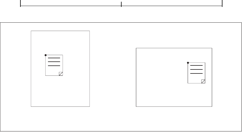
Interactive FeaturesCHAPTER 7
404
FIGURE 7.3 Coordinate adjustment with the NoRotate flag
7.4.3 Border Styles
An annotation may optionally be surrounded by a border when displayed or
printed. If present, the border is drawn completely inside the annotation’s
bounding box. In PDF 1.1, the characteristics of the border are specified by the
Border entry in the annotation dictionary (see Table 7.9 on page 400). Beginning
in PDF 1.2, some types of annotation may instead specify their border character-
istics in a border style dictionary designated by the annotation’s
BS entry.
Table 7.11 summarizes the contents of this dictionary. If neither the
Border nor
the
BS entry is present, the border is drawn as a solid line with a width of 1 point.
Note: At the time of publication, only widget annotations use border style diction-
aries to specify their border styles; all other annotation types use the
Border entry
instead. Border style dictionaries are used, however, to specify the width and dash
pattern for the lines drawn by line, square, circle, and ink annotations.
Before page rotation
abcdefghijklm
nopqrstuvwxyz
(0, 0)
After page rotation
abcdefghijklm
nopqrstuvwxyz
(0, 0)

Annotations7.4
405
TABLE 7.11 Entries in a border style dictionary
KEY TYPE VALUE
Type name (Optional) The type of PDF object that this dictionary describes; if present, must be
Border for a border style dictionary.
W number (Optional) The border width in points. If this value is 0, no border is drawn. Default
value: 1.
S name (Optional) The border style:
S (Solid) A solid rectangle surrounding the annotation.
D (Dashed) A dashed rectangle surrounding the annotation. The dash pattern
is specified by the
D entry (see below).
B (Beveled) A simulated embossed rectangle that appears to be raised above the
surface of the page.
I (Inset) A simulated engraved rectangle that appears to be recessed below the
surface of the page.
U (Underline) A single line along the bottom of the annotation’s bounding box.
Other border styles may be defined in the future. (See implementation note 56 in
Appendix H.) Default value:
S.
D array (Optional) A dash array defining a pattern of dashes and gaps to be used in drawing a
dashed border (border style
D above). The dash array is specified in the same format
as in the line dash pattern parameter of the graphics state (see “Line Dash Pattern” on
page 141). The dash phase is not specified and is assumed to be 0. For example, a
D
entry of [3 2] specifies a border drawn with 3-point dashes alternating with 2-point
gaps. Default value: [3].
7.4.4 Appearance Streams
Beginning in PDF 1.2, an annotation can specify one or more appearance streams
as an alternative to the simple border and color characteristics available in earlier
versions. This allows the annotation to be presented visually on the page in differ-
ent ways to reflect its interactions with the user. Each appearance stream is a form
XObject (see Section 4.9, “Form XObjects”): a self-contained content stream to
be rendered inside the annotation’s bounding box.

Interactive FeaturesCHAPTER 7
406
Before rendering an appearance stream, the viewer application establishes a coor-
dinate system whose origin is at the lower-left corner of the annotation rectangle.
Nominally, the coordinates in this space are in default user space units; however,
the space may be scaled or rotated with respect to the actual page coordinate sys-
tem, depending on the values of the annotation's NoZoom and NoRotate flags
(see Section 7.4.2, “Annotation Flags”). The form XObject's
Matrix entry should
transform the form coordinate system into that of the annotation. The results are
clipped to the annotation’s bounding box. All other elements of the graphics state
are set to their default values.
An annotation can define as many as three separate appearances:
• The normal appearance is used when the annotation is not interacting with the
user. This is also the appearance that is used for printing the annotation.
• The rollover appearance is used when the user moves the cursor into the anno-
tation’s active area without pressing the mouse button.
• The down appearance is used when the mouse button is pressed or held down
within the annotation’s active area.
Note: As used here, the term mouse denotes a generic pointing device that controls
the location of a cursor on the screen and has at least one button that can be pressed,
held down, and released. See Section 7.5.2, “Trigger Events,” for further discussion.
The normal, rollover, and down appearances are defined in an appearance
dictionary, which in turn is the value of the
AP entry in the annotation dictionary
(see Table 7.9 on page 400). Table 7.12 shows the contents of the appearance
dictionary.
TABLE 7.12 Entries in an appearance dictionary
KEY TYPE VALUE
N stream or dictionary (Required) The annotation’s normal appearance.
R stream or dictionary (Optional) The annotation’s rollover appearance. Default value: the value of
the
N entry.
D stream or dictionary (Optional) The annotation’s down appearance. Default value: the value of the
N entry.

Annotations7.4
407
Each entry in the appearance dictionary may contain either a single appearance
stream or an appearance subdictionary. In the latter case, the subdictionary de-
fines multiple appearance streams corresponding to different appearance states of
the annotation. For example, an annotation representing an interactive checkbox
might have two appearance states named
On and Off. Its appearance dictionary
might be defined as follows:
/AP << /N << /On formXObject
1
/Off formXObject
2
>>
/D << /On formXObject
3
/Off formXObject
4
>>
>>
where formXObject
1
and formXObject
2
define the checkbox’s normal appearance in
its checked and unchecked states, while
formXObject
3
and formXObject
4
provide
visual feedback, such as emboldening its outline, when the user clicks it with the
mouse. (No
R entry is defined because no special appearance is needed when the
user moves the cursor over the checkbox without pressing the mouse button.)
The choice between the checked and unchecked appearance states is determined
by the
AS entry in the annotation dictionary (see Table 7.9 on page 400).
Note: Some of the standard PDF annotation types, such as movie annotations—as
well as all custom annotation types defined by third parties—are implemented
through plug-in extensions. If the plug-in for a particular annotation type is not
available, PDF viewer applications should display the annotation with its normal
(
N) appearance. Viewer applications should also attempt to provide reasonable be-
havior (such as displaying nothing at all) if an annotation’s
AS entry designates an
appearance state for which no appearance is defined in the appearance dictionary.
For convenience in managing appearance streams that are used repeatedly, the
AP
entry in a PDF document’s name dictionary (see Section 3.6.3, “Name Diction-
ary”) can contain a name tree that maps names to appearance streams. The
names have no standard meanings; no PDF objects refer to appearance streams
by name.

Interactive FeaturesCHAPTER 7
408
7.4.5 Annotation Types
PDF supports the standard annotation types listed in Table 7.13. The following
sections describe each of these types in detail. Plug-in extensions may add new
annotation types, and further standard types may be added in the future. (See
implementation note 57 in Appendix H.)
TABLE 7.13 Annotation types
ANNOTATION TYPE DESCRIPTION
Text Text annotation
Link Link annotation
FreeText (PDF 1.3) Free text annotation
Line (PDF 1.3) Line annotation
Square (PDF 1.3) Square annotation
Circle (PDF 1.3) Circle annotation
Highlight (PDF 1.3) Highlight annotation
Underline (PDF 1.3) Underline annotation
StrikeOut (PDF 1.3) Strikeout annotation
Stamp (PDF 1.3) Rubber stamp annotation
Ink (PDF 1.3) Ink annotation
Popup (PDF 1.3) Pop-up annotation
FileAttachment (PDF 1.3) File attachment annotation
Sound (PDF 1.2) Sound annotation
Movie (PDF 1.2) Movie annotation
Widget (PDF 1.2) Widget annotation
TrapNet (PDF 1.3) Trap network annotation

Annotations7.4
409
Text Annotations
A text annotation represents a “sticky note” attached to a point in the PDF docu-
ment. When closed, the annotation appears as an icon; when open, it displays a
pop-up window containing the text of the note, in a font and size chosen by the
viewer application. Table 7.14 shows the annotation dictionary entries specific to
this type of annotation.
TABLE 7.14 Additional entries specific to a text annotation
KEY TYPE VALUE
Subtype name (Required) The type of annotation that this dictionary describes; must be Tex t
for a text annotation.
Contents text string (Required) The text to be displayed in the pop-up window when the annotation
is opened. Carriage returns may be used to separate the text into paragraphs.
Open boolean (Optional) A flag specifying whether the annotation should initially be displayed
open. Default value: false (closed).
Name name (Optional) The name of an icon to be used in displaying the annotation. Viewer
applications should provide predefined icon appearances for at least the follow-
ing standard names:
Comment Key Note
Help NewParagraph Paragraph
Insert
Additional names may be supported as well. Default value: Note.
Note: The annotation dictionary’s
AP entry, if present, takes precedence over the
Name entry; see Table 7.9 on page 400 and Section 7.4.4, “Appearance Streams.”
Example 7.6 shows the definition of a text annotation.
Example 7.6
22 0 obj
<< /Type /Annot
/Subtype /Text
/Rect [266 116 430 204]
/Contents (The quick brown fox ate the lazy mouse.)
>>
endobj

Interactive FeaturesCHAPTER 7
410
Link Annotations
A link annotation represents either a hypertext link to a destination elsewhere in
the document (see Section 7.2.1, “Destinations”) or an action to be performed
(Section 7.5, “Actions”). Table 7.15 shows the annotation dictionary entries spe-
cific to this type of annotation.
TABLE 7.15 Additional entries specific to a link annotation
KEY TYPE VALUE
Subtype name (Required) The type of annotation that this dictionary describes; must be Link
for a link annotation.
Dest array, name, (Optional; not permitted if an A entry is present) A destination to be displayed
or string when the annotation is activated (see Section 7.2.1, “Destinations”; see also
implementation note 58 in Appendix H).
H name (Optional; PDF 1.2) The annotation’s highlighting mode, the visual effect to be
used when the mouse button is pressed or held down inside its active area:
N (None) No highlighting.
I (Invert) Invert the contents of the annotation’s bounding box.
O (Outline) Invert the annotation’s border.
P (Push) Display the annotation’s down appearance, if any (see
Section 7.4.4, “Appearance Streams”). If no down appearance is de-
fined, offset the contents of the annotation’s bounding box to appear as
if it were being “pushed” below the surface of the page.
A highlighting mode other than
P overrides any down appearance defined for
the annotation. Default value:
I.
Note: In PDF 1.1, highlighting is always done by inverting colors inside the anno-
tation’s bounding box.
PA dictionary (Optional; PDF 1.3) A URI action (see “URI Actions” on page 428) formerly
associated with this annotation. When Web Capture (Section 8.5, “Web Cap-
ture”) changes an annotation from a URI to a go-to action (“Go-To Actions”
on page 425), it uses this entry to save the data from the original URI action so
that it can be changed back in case the target page for the
GoTo action is subse-
quently deleted.

Annotations7.4
411
Example 7.7 shows a link annotation that jumps to a destination elsewhere in the
document.
Example 7.7
93 0 obj
<< /Type /Annot
/Subtype /Link
/Rect [71 717 190 734]
/Border [16 16 1]
/Dest [3 0 R /FitR –4 399 199 533]
>>
endobj
Free Text Annotations
A free text annotation (PDF 1.3) displays text directly on the page. Unlike an ordi-
nary text annotation (see “Text Annotations” on page 409), a free text annotation
has no open or closed state; instead of being displayed in a pop-up window, the
text is always visible. Table 7.16 shows the annotation dictionary entries specific
to this type of annotation.
TABLE 7.16 Additional entries specific to a free text annotation
KEY TYPE VALUE
Subtype name (Required) The type of annotation that this dictionary describes; must be
FreeText for a free text annotation.
Contents text string (Required) The text to be displayed.
DA string (Required) The default appearance string to be used in formatting the text (see
“Variable Text” on page 439).
Note: The annotation dictionary’s
AP entry, if present, takes precedence over the DA
entry; see Table 7.9 on page 400 and Section 7.4.4, “Appearance Streams.”

Interactive FeaturesCHAPTER 7
412
Line Annotations
A line annotation (PDF 1.3) displays a single straight line on the page. When
opened, it displays a pop-up window containing the text of the associated note.
Table 7.17 shows the annotation dictionary entries specific to this type of annota-
tion.
TABLE 7.17 Additional entries specific to a line annotation
KEY TYPE VALUE
Subtype name (Required) The type of annotation that this dictionary describes; must be Line
for a line annotation.
Contents text string (Required) The text to be displayed in the pop-up window when the annotation
is opened. Carriage returns may be used to separate the text into paragraphs.
L array (Required) An array of four numbers, [x
1
y
1
x
2
y
2
], specifying the starting and
ending coordinates of the line in default user space.
BS dictionary (Optional) A border style (see Table 7.11 on page 405) specifying the width and
dash pattern of the line to be drawn.
Note: The annotation dictionary’s
AP entry, if present, takes precedence over the L
and BS entries; see Table 7.9 on page 400 and Section 7.4.4, “Appearance Streams.”
Square and Circle Annotations
Square and circle annotations (PDF 1.3) display, respectively, a rectangle or an
ellipse on the page. When opened, they display a pop-up window containing the
text of the associated note. The rectangle or ellipse is inscribed within the bound-
ing box defined by the annotation dictionary’s
Rect entry (see Table 7.9 on
page 400); Figure 7.4 shows an example, using a border width of 18 points.
Despite the names square and circle, the width and height of the bounding box
need not be equal. Table 7.18 shows the annotation dictionary entries specific to
these types of annotation.

Annotations7.4
413
FIGURE 7.4 Square and circle annotations
TABLE 7.18 Additional entries specific to a square or circle annotation
KEY TYPE VALUE
Subtype name (Required) The type of annotation that this dictionary describes; must be Square
or Circle for a square or circle annotation, respectively.
Contents text string (Required) The text to be displayed in the pop-up window when the annotation
is opened. Carriage returns may be used to separate the text into paragraphs.
BS dictionary (Optional) A border style (see Table 7.11 on page 405) specifying the line width
and dash pattern for drawing the rectangle or ellipse.
Note: The annotation dictionary’s
AP entry, if present, takes precedence over the
Rect and BS entries; see Table 7.9 on page 400 and Section 7.4.4, “Appearance
Streams.”
Markup Annotations
Markup annotations (PDF 1.3) appear as highlights, underlines, and strikeouts in
the text of a document. When opened, they display a pop-up window containing
the text of the associated note. Table 7.19 shows the annotation dictionary entries
specific to these types of annotation.
18 pt 18 pt
Rect
Square annotation Circle annotation

Interactive FeaturesCHAPTER 7
414
TABLE 7.19 Additional entries specific to markup annotations
KEY TYPE VALUE
Subtype name (Required) The type of annotation that this dictionary describes; must be
Highlight, Underline, or StrikeOut for a highlight, underline, or strikeout
annotation, respectively.
Contents text string (Required) The text to be displayed in the pop-up window when the annota-
tion is opened. Carriage returns may be used to separate the text into para-
graphs.
QuadPoints array (Required) An array of 8 × n numbers specifying the coordinates of n quadri-
laterals in default user space. Each quadrilateral encompasses a word or
group of contiguous words in the text underlying the annotation. The coor-
dinates for each quadrilateral are given in the order
x
1
y
1
x
2
y
2
x
3
y
3
x
4
y
4
specifying the quadrilateral’s four vertices in counterclockwise order (see
Figure 7.5). The text is oriented with respect to the edge connecting points
(x
1
, y
1
) and (x
2
, y
2
). (See implementation note 59 in Appendix H.)
Note: The annotation dictionary’s
AP entry, if present, takes precedence over the
QuadPoints entry; see Table 7.9 on page 400 and Section 7.4.4, “Appearance
Streams.”
FIGURE 7.5 QuadPoints specification
Jupiter
(x
3
,
y
3
)
(x
2
,
y
2
)
(x
1
,
y
1
)
(x
4
,
y
4
)

Annotations7.4
415
Rubber Stamp Annotations
A rubber stamp annotation (PDF 1.3) displays text or graphics intended to look as
if they were stamped on the page with a rubber stamp. When opened, it displays a
pop-up window containing the text of the associated note. Table 7.20 shows the
annotation dictionary entries specific to this type of annotation.
TABLE 7.20 Additional entries specific to a rubber stamp annotation
KEY TYPE VALUE
Subtype name (Required) The type of annotation that this dictionary describes; must be Stamp
for a rubber stamp annotation.
Contents text string (Required) The text to be displayed in the pop-up window when the annotation
is opened. Carriage returns may be used to separate the text into paragraphs.
Name name (Optional) The name of an icon to be used in displaying the annotation. Viewer
applications should provide predefined icon appearances for at least the follow-
ing standard names:
Approved Experimental NotApproved
AsIs Expired NotForPublicRelease
Confidential Final Sold
Departmental ForComment TopSecret
Draft ForPublicRelease
Additional names may be supported as well. Default value: Draft.
Note: The annotation dictionary’s
AP entry, if present, takes precedence over the
Name entry; see Table 7.9 on page 400 and Section 7.4.4, “Appearance Streams.”
Ink Annotations
An ink annotation (PDF 1.3) represents a freehand “scribble” composed of one or
more disjoint paths. When opened, it displays a pop-up window containing the
text of the associated note. Table 7.21 shows the annotation dictionary entries
specific to this type of annotation.

Interactive FeaturesCHAPTER 7
416
TABLE 7.21 Additional entries specific to an ink annotation
KEY TYPE VALUE
Subtype name (Required) The type of annotation that this dictionary describes; must be Ink for
an ink annotation.
Contents text string (Required) The text to be displayed in the pop-up window when the annotation
is opened. Carriage returns may be used to separate the text into paragraphs.
InkList array (Required) An array of n arrays, each representing a stroked path. Each array is a
series of alternating x and y coordinates in default user space, specifying points
along the path. When drawn, the points are connected by straight lines or curves
in an implementation-dependent way. (See implementation note 60 in
Appendix H.)
BS dictionary (Optional) A border style (see Table 7.11 on page 405) specifying the line width
and dash pattern for drawing the paths.
Note: The annotation dictionary’s
AP entry, if present, takes precedence over the
InkList and BS entries; see Table 7.9 on page 400 and Section 7.4.4, “Appearance
Streams.”
Pop-up Annotations
A pop-up annotation (PDF 1.3) displays text in a pop-up window for entry and
editing. It typically does not appear alone, but is associated with another annota-
tion, its parent annotation, and is used for editing the parent’s text. It has no
appearance stream or associated actions of its own, and is identified by the
Popup
entry in the parent’s annotation dictionary (see Table 7.9 on page 400). Table 7.22
shows the annotation dictionary entries specific to this type of annotation.
TABLE 7.22 Additional entries specific to a pop-up annotation
KEY TYPE VALUE
Subtype name (Required) The type of annotation that this dictionary describes; must be Popup
for a pop-up annotation.
Parent dictionary (Optional; must be an indirect reference) The parent annotation with which this
pop-up annotation is associated.
Note: If this entry is present, the parent annotation’s
Contents, T, C, and M entries
(see Table 7.9 on page 400) override those of the pop-up annotation itself.
Open boolean (Optional) A flag specifying whether the pop-up annotation should initially be
displayed open. Default value: false (closed).

Annotations7.4
417
File Attachment Annotations
A file attachment annotation (PDF 1.3) contains a reference to a file, which typi-
cally will be embedded in the PDF file (see Section 3.10.3, “Embedded File
Streams”). For example, a table of data might use a file attachment annotation to
link to a spreadsheet file based on that data; activating the annotation will extract
the embedded file and give the user an opportunity to view it or store it in the file
system. Table 7.23 shows the annotation dictionary entries specific to this type of
annotation.
TABLE 7.23 Additional entries specific to a file attachment annotation
KEY TYPE VALUE
Subtype name (Required) The type of annotation that this dictionary describes; must be
FileAttachment for a file attachment annotation.
FS file specification (Required) The file associated with this annotation.
Contents text string (Required) The text to be displayed in the pop-up window when the annota-
tion is opened. Carriage returns may be used to separate the text into para-
graphs.
Name name (Optional) The name of an icon to be used in displaying the annotation.
Viewer applications should provide predefined icon appearances for at least
the following standard names:
Graph PushPin
Paperclip Tag
Additional names may be supported as well. Default value: PushPin.
Note: The annotation dictionary’s
AP entry, if present, takes precedence over the
Name entry; see Table 7.9 on page 400 and Section 7.4.4, “Appearance Streams.”
Sound Annotations
A sound annotation (PDF 1.2) is analogous to a text annotation, except that in-
stead of a text note, it contains sound recorded from the computer’s microphone
or imported from a file. When the annotation is activated, the sound is played.
The annotation behaves like a text annotation in most ways, with a different icon
(by default, a speaker) to indicate that it represents a sound. Table 7.24 shows the
annotation dictionary entries specific to this type of annotation; sounds them-
selves are discussed in Section 7.7, “Sounds.”

Interactive FeaturesCHAPTER 7
418
TABLE 7.24 Additional entries specific to a sound annotation
KEY TYPE VALUE
Subtype name (Required) The type of annotation that this dictionary describes; must be Sound
for a sound annotation.
Sound stream (Required) A sound object defining the sound to be played when the annotation
is activated (see Section 7.7, “Sounds”).
Contents text string (Optional) The text to be displayed in the annotation’s pop-up window as a de-
scription of the sound.
Name name (Optional) The name of an icon to be used in displaying the annotation. Viewer
applications should provide predefined icon appearances for at least the stan-
dard names
Speaker and Microphone; additional names may be supported as
well. Default value:
Speaker.
Note: The annotation dictionary’s
AP entry, if present, takes precedence over the
Name entry; see Table 7.9 on page 400 and Section 7.4.4, “Appearance Streams.”
Movie Annotations
A movie annotation (PDF 1.2) contains animated graphics and sound to be pre-
sented on the computer screen and through the speakers. When the annotation is
activated, the movie is played. Table 7.25 shows the annotation dictionary entries
specific to this type of annotation; movies themselves are discussed in
Section 7.8, “Movies.” (See also implementation note 61 in Appendix H.)
TABLE 7.25 Additional entries specific to a movie annotation
KEY TYPE VALUE
Subtype name (Required) The type of annotation that this dictionary describes; must be Movie
for a movie annotation.
Movie dictionary (Required) A movie dictionary describing the movie’s static characteristics (see
Section 7.8, “Movies”).
A boolean or (Optional) A flag or dictionary specifying whether and how to play the movie
dictionary when the annotation is activated. If this value is a dictionary, it is a movie activa-
tion dictionary (see Section 7.8, “Movies”) specifying how to play the movie; if it
is the boolean value true, the movie should be played using default activation
parameters; if it is false, the movie should not be played at all. Default value:
true.

Annotations7.4
419
Widget Annotations
Interactive forms (see Section 7.6, “Interactive Forms”) use widget annotations to
represent the appearance of fields and to manage user interactions. As a conve-
nience, when a field has only a single associated widget annotation, the contents
of the field dictionary (Section 7.6.2, “Field Dictionaries”) and the annotation
dictionary may be merged into a single dictionary containing entries that pertain
to both a field and an annotation. (This presents no ambiguity, since the contents
of the two kinds of dictionary do not conflict.) Table 7.26 shows the annotation
dictionary entries specific to this type of annotation; interactive forms and fields
are discussed at length in Section 7.6.
TABLE 7.26 Additional entries specific to a widget annotation
KEY TYPE VALUE
Subtype name (Required) The type of annotation that this dictionary describes; must be Widget
for a widget annotation.
H name (Optional; PDF 1.2) The annotation’s highlighting mode, the visual effect to be
used when the mouse button is pressed or held down inside its active area:
N (None) No highlighting.
I (Invert) Invert the contents of the annotation’s bounding box.
O (Outline) Invert the annotation’s border.
P (Push) Display the annotation’s down appearance, if any (see
Section 7.4.4, “Appearance Streams”). If no down appearance is defined,
offset the contents of the annotation’s bounding box to appear as if it
were being “pushed” below the surface of the page.
T (Toggle) Same as P (which is preferred).
A highlighting mode other than
P overrides any down appearance defined for
the annotation. Default value:
I.
MK dictionary (Optional; PDF 1.2) An appearance characteristics dictionary to be used in con-
structing a dynamic appearance stream specifying the annotation’s visual pre-
sentation on the page; see “Variable Text” on page 439 for further discussion.
Note: The name
MK for this entry is of historical significance only and has no direct
meaning.

Interactive FeaturesCHAPTER 7
420
Trap Network Annotations
A trap network annotation defines the trapping characteristics for a page of a PDF
document. (Trapping is the process of adding marks to a page along color boun-
daries to avoid unwanted visual artifacts resulting from misregistration of color-
ants when the page is printed.) A page may have at most one trap network
annotation, whose
Subtype entry has the value TrapNet and which is always the
last element in the page object’s
Annots array (see “Page Objects” on page 77).
See Section 8.6.3, “Trapping Support,” for further discussion.
7.5 Actions
Instead of simply jumping to a destination in the document, an annotation or
outline item can specify an action (PDF 1.1) for the viewer application to per-
form, such as launching an application, playing a sound, or changing an annota-
tion’s appearance state. The optional
A entry in the annotation or outline item
dictionary (see Tables 7.9 on page 400 and 7.4 on page 389) specifies an action to
be performed when the annotation or outline item is activated; in PDF 1.2, a va-
riety of other circumstances may trigger an action as well (see Section 7.5.2,
“Trigger Events”). In addition, the optional
OpenAction entry in a document’s
catalog (Section 3.6.1, “Document Catalog”) may specify an action to be per-
formed when the document is opened. PDF includes a wide variety of standard
action types, described in detail in Section 7.5.3, “Action Types.”
7.5.1 Action Dictionaries
An action dictionary defines the characteristics and behavior of an action.
Table 7.27 shows the required and optional entries that are common to all action
dictionaries. The dictionary may contain additional entries specific to a particu-
lar action type; see the descriptions of individual action types in Section 7.5.3,
“Action Types,” for details.

Actions7.5
421
TABLE 7.27 Entries common to all action dictionaries
KEY TYPE VALUE
Type name (Optional) The type of PDF object that this dictionary describes; if
present, must be
Action for an action dictionary.
S name (Required) The type of action that this dictionary describes; see Table 7.29
on page 424 for specific values.
Next dictionary or array (Optional; PDF 1.2) The next action, or sequence of actions, to be per-
formed after this one. The value is either a single action dictionary or an
array of action dictionaries to be performed in order; see below for fur-
ther discussion.
The action dictionary’s Next entry (PDF 1.2) allows sequences of actions to be
chained together. For example, the effect of clicking a link annotation with the
mouse might be to play a sound, jump to a new page, and start up a movie. Note
that the
Next entry is not restricted to a single action, but may contain an array of
actions, each of which in turn may have a
Next entry of its own. The actions may
thus form a tree instead of a simple linked list. Actions within each
Next array are
executed in order, each followed in turn by any actions specified in its
Next entry,
and so on recursively. Viewer applications should attempt to provide reasonable
behavior in anomalous situations; for example, self-referential actions should not
be executed more than once, and actions that close the document or otherwise
render the next action impossible should terminate the execution sequence. Ap-
plications should also provide some mechanism for the user to interrupt and
manually terminate a sequence of actions.
Note: No action should modify its own action dictionary or any other in the action
tree in which it resides. The effect of such modification on subsequent execution of
actions in the tree is undefined.
7.5.2 Trigger Events
An annotation, page object, or interactive form field may include an entry named
AA that specifies an additional-actions dictionary (PDF 1.2), extending the set of
events that can trigger the execution of an action. Table 7.28 shows the contents
of such a dictionary. (See implementation notes 62 and 63 in Appendix H.)

Interactive FeaturesCHAPTER 7
422
TABLE 7.28 Entries in an additional-actions dictionary
KEY TYPE VALUE
E dictionary (Optional; annotations only) An action to be performed when the cursor enters the
annotation’s active area.
X dictionary (Optional; annotations only) An action to be performed when the cursor exits the
annotation’s active area.
D dictionary (Optional; annotations only) An action to be performed when the mouse button is
pressed inside the annotation’s active area.
U dictionary (Optional; annotations only) An action to be performed when the mouse button is
released inside the annotation’s active area.
Note: For backward compatibility, the
A entry in an annotation dictionary, if present,
takes precedence over this entry (see Table 7.15 on page 410).
O dictionary (Optional; pages only) An action to be performed when the page is opened (for ex-
ample, when the user navigates to it from the next or previous page or via a link anno-
tation or outline entry). This action is independent of any that may be defined by the
OpenAction entry in the document catalog (see Section 3.6.1, “Document Catalog”),
and is executed after such an action. (See implementation note 64 in Appendix H.)
C dictionary (Optional; pages only) An action to be performed when the page is closed (for example,
when the user navigates to the next or previous page or follows a link annotation or an
outline entry). This action applies to the page being closed, and is executed before any
other page is opened. (See implementation note 64 in Appendix H.)
Fo dictionary (Optional; widget annotations only) An action to be performed when the annotation
receives the input focus.
Bl dictionary (Optional; widget annotations only) An action to be performed when the annotation is
“blurred” (loses the input focus).
K dictionary (Optional; PDF 1.3; form fields only) A JavaScript action to be performed when the user
types a keystroke into a text or combo box or modifies the selection in a scrollable list.
This allows the keystroke to be checked for validity and rejected or modified.
F dictionary (Optional; PDF 1.3; form fields only) A JavaScript action to be performed before the
field is formatted to display its current value. This allows the field’s value to be modi-
fied before formatting.
V dictionary (Optional; PDF 1.3; form fields only) A JavaScript action to be performed when the
field’s value is changed. This allows the new value to be checked for validity.
C dictionary (Optional; PDF 1.3; form fields only) A JavaScript action to be performed when the
value of another field changes, in order to recalculate the value of this field. The order
in which the document’s fields are recalculated is defined by the
CO entry in the inter-
active form dictionary (see Section 7.6.1, “Interactive Form Dictionary”).

Actions7.5
423
Note: Although the table lists two different entries with the same name (C), the two
do not conflict, because they apply to different types of object. The
C entry stands for
“close” for a page object and “calculate” for an interactive form field.
For purposes of the trigger events
E (enter), X (exit), D (down), and U (up), the
term mouse denotes a generic pointing device with the following characteristics:
• A selection button that can be pressed, held down, and released. If there is more
than one mouse button, this is typically the left button.
• A notion of location—that is, an indication of where on the screen the device is
pointing. This is typically denoted by a screen cursor.
• A notion of focus—that is, which element in the document is currently inter-
acting with the user. In many systems, this is denoted by a blinking caret, a
focus rectangle, or a color change.
PDF viewer applications must ensure the presence of such a device in order for
the corresponding actions to be executed correctly. Mouse-related trigger events
are subject to the following constraints:
• An E (enter) event can occur only when the mouse button is up.
• An X (exit) event cannot occur without a preceding E event.
• A U (up) event cannot occur without a preceding E and D event.
• In the case of overlapping or nested annotations, entering a second annota-
tion’s active area causes an
X event to occur for the first annotation.
Note: The field-related trigger events
K (keystroke), F (format), V (validate), and C
(calculate) are not defined for button fields (see “Button Fields” on page 444). Note
that the effects of an action triggered by one of these events are limited only by the ac-
tion itself and can occur outside the described scope of the event. For example, even
though the
F event is used to trigger actions that format field values prior to display,
it is possible for an action triggered by this event to perform a calculation or make
any other modification to the document.

Interactive FeaturesCHAPTER 7
424
Note also that these field-related trigger events can occur either through user interac-
tion or programmatically, such as in response to the
NeedAppearances entry in the
interactive form dictionary (see Section 7.6.1, “Interactive Form Dictionary”), im-
portation of FDF data (Section 7.6.6, “Forms Data Format”), or JavaScript actions
(“JavaScript Actions” on page 458). For example, the user’s modifying a field value
can trigger a cascade of calculations and further formatting and validation for other
fields in the document.
7.5.3 Action Types
PDF supports the standard action types listed in Table 7.29. The following sec-
tions describe each of these types in detail. Plug-in extensions may add new ac-
tion types.
TABLE 7.29 Action types
ACTION TYPE DESCRIPTION
GoTo Go to a destination in the current document.
GoToR (“Go-to remote”) Go to a destination in another document.
Launch Launch an application, usually to open a file.
Thread Begin reading an article thread.
URI Resolve a uniform resource identifier.
Sound (PDF 1.2) Play a sound.
Movie (PDF 1.2) Play a movie.
Hide (PDF 1.2) Set an annotation’s Hidden flag.
Named (PDF 1.2) Execute an action predefined by the viewer application.
SubmitForm (PDF 1.2) Send data to a uniform resource locator.
ResetForm (PDF 1.2) Set fields to their default values.
ImportData (PDF 1.2) Import field values from a file.
JavaScript (PDF 1.3) Execute a JavaScript script.

Actions7.5
425
Note: Previous versions of the PDF specification described an action type known as
the set-state action; this type of action is now considered obsolete and its use is no
longer recommended. An additional action type, the no-op action, was defined in
PDF 1.2 but never implemented; it is no longer defined and should be ignored.
Go-To Actions
A go-to action changes the view to a specified destination (page, location, and
magnification factor). Table 7.30 shows the action dictionary entries specific to
this type of action.
TABLE 7.30 Additional entries specific to a go-to action
KEY TYPE VALUE
S name (Required) The type of action that this dictionary describes; must be GoTo for a
go-to action.
D name, string, (Required) The destination to jump to (see Section 7.2.1, “Destinations”).
or array
Specifying a go-to action in the A entry of a link annotation or outline entry (see
Tables 7.15 on page 410 and 7.4 on page 389) has the same effect as specifying the
destination directly via the
Dest entry. For example, the link annotation shown in
Example 7.8, which uses a go-to action, has the same effect as the one in
Example 7.7 on page 411, which specifies the destination directly. However, the
go-to action is less compact and is not compatible with PDF 1.0, so using a direct
destination is preferable.
Example 7.8
93 0 obj
<< /Type /Annot
/Subtype /Link
/Rect [71 717 190 734]
/Border [16 16 1]
/A << /Type /Action
/S /GoTo
/D [3 0 R /FitR –4 399 199 533]
>>
>>
endobj

Interactive FeaturesCHAPTER 7
426
Remote Go-To Actions
A remote go-to action is similar to an ordinary go-to action, but jumps to a desti-
nation in another PDF file instead of the current file. Table 7.31 shows the action
dictionary entries specific to this type of action.
TABLE 7.31 Additional entries specific to a remote go-to action
KEY TYPE VALUE
S name (Required) The type of action that this dictionary describes; must be GoToR
for a remote go-to action.
F file specification (Required) The file in which the destination is located.
D name, string, (Required) The destination to jump to (see Section 7.2.1, “Destinations”). If
or array the value is an array defining an explicit destination (as described under
“Explicit Destinations” on page 385), its first element must be a page number
within the remote document instead of an indirect reference to a page object
in the current document. The first page is numbered 0.
NewWindow boolean (Optional; PDF 1.2) A flag specifying whether to open the destination docu-
ment in a new window. If this flag is false, the destination document will
replace the current document in the same window. If this entry is absent, the
viewer application should behave in accordance with the current user prefer-
ence.
Launch Actions
A launch action launches an application or opens or prints a document.
Table 7.32 shows the action dictionary entries specific to this type of action.
TABLE 7.32 Additional entries specific to a launch action
KEY TYPE VALUE
S name (Required) The type of action that this dictionary describes; must be Launch
for a launch action.
F file specification (Required if none of the entries Win, Mac, or Unix is present) The application to
be launched or the document to be opened or printed. If this entry is absent
and the viewer application does not understand any of the alternative entries,
it should do nothing.

Actions7.5
427
Win dictionary (Optional) A dictionary containing Windows-specific launch parameters (see
Table 7.33; see also implementation note 65 in Appendix H).
Mac (undefined) (Optional) Macintosh-specific launch parameters; not yet defined.
Unix (undefined) (Optional) UNIX-specific launch parameters; not yet defined.
NewWindow boolean (Optional; PDF 1.2) A flag specifying whether to open the destination docu-
ment in a new window. If this flag is false, the destination document will
replace the current document in the same window. If this entry is absent, the
viewer application should behave in accordance with the current user prefer-
ence. This entry is ignored if the file designated by the
F entry is not a PDF
document.
The optional Win, Mac, and Unix entries allow the action dictionary to include
platform-specific parameters for launching the designated application. If no such
entry is present for the given platform, the
F entry is used instead. Table 7.33
shows the platform-specific launch parameters for the Windows platform; those
for the Macintosh and UNIX platforms are not yet defined at the time of publica-
tion.
TABLE 7.33 Windows-specific launch parameters
KEY TYPE VALUE
F string (Required) The file name of the application to be launched or the document to be
opened or printed, in standard Windows pathname format. If the name string includes a
backslash character (
\), the backslash must itself be preceded by a backslash.
Note: This value must be a simple string; it is not a file specification.
D string (Optional) A string specifying the default directory in standard DOS syntax.
O string (Optional) A string specifying the operation to perform:
open Open a document.
print Print a document.
If the
F entry designates an application instead of a document, this entry is ignored and
the application is launched. Default value:
open.
P string (Optional) A parameter string to be passed to the application designated by the F entry.
This entry should be omitted if F designates a document.

Interactive FeaturesCHAPTER 7
428
Thread Actions
A thread action jumps to a specified bead on an article thread (see Section 7.3.2,
“Articles”), in either the current document or a different one. Table 7.34 shows
the action dictionary entries specific to this type of action.
TABLE 7.34 Additional entries specific to a thread action
KEY TYPE VALUE
S name (Required) The type of action that this dictionary describes; must be Thread
for a thread action.
F file specification (Optional) The file containing the desired thread. If this entry is absent, the
thread is in the current file.
D dictionary, integer, (Required) The desired destination thread, specified in one of the following
or text string forms:
• An indirect reference to a thread dictionary (see Section 7.3.2, “Articles”).
In this case, the thread must be in the current file.
• The index of the thread within the Threads array of its document’s catalog
(see Section 3.6.1, “Document Catalog”). The first thread in the array has
index 0.
• The title of the thread, as specified in its thread information dictionary (see
Table 7.6 on page 394). If two or more threads have the same title, the one
appearing first in the document catalog’s
Threads array will be used.
B dictionary (Optional) The desired bead in the destination thread, specified in one of the
or integer following forms:
• An indirect reference to a bead dictionary (see Section 7.3.2, “Articles”). In
this case, the thread must be in the current file.
• The index of the bead within its thread. The first bead in a thread has
index 0.
URI Actions
A uniform resource identifier (URI) is a string that identifies (resolves to) a re-
source on the Internet—typically a file that is the destination of a hypertext link,
although it can also resolve to a query or other entity. A URI action causes a URI

Actions7.5
429
to be resolved. Table 7.35 shows the action dictionary entries specific to this type
of action. (See implementation notes 66 and 67 in Appendix H.)
TABLE 7.35 Additional entries specific to a URI action
KEY TYPE VALUE
S name (Required) The type of action that this dictionary describes; must be URI for a URI
action.
URI string (Required) The uniform resource identifier to resolve, encoded in 7-bit ASCII.
IsMap boolean (Optional) A flag specifying whether to track the mouse position when the URI is re-
solved (see below). Default value: false.
This entry applies only to actions triggered by the user’s clicking an annotation; it is
ignored for actions associated with outline items or with a document’s
OpenAction
entry.
If the IsMap flag is true and the user has triggered the URI action by clicking an
annotation with the mouse, the coordinates of the mouse position at the time the
action is performed should be transformed from device space to user space and
then offset relative to the upper-left corner of the annotation rectangle (that is,
the value of the
Rect entry in the annotation with which the URI action is associ-
ated). For example, if the mouse coordinates in user space are (x
m
, y
m
) and the
annotation rectangle is extends from (ll
x
, ll
y
) at the lower-left to (ur
x
, ur
y
) at the
upper-right, the final coordinates (x
f
, y
f
) are as follows:
If the resulting coordinates (x
f
, y
f
) are fractional, they should be rounded to the
nearest integer values. They are then appended to the URI to be resolved, separat-
ed by commas and preceded by a question mark. For example:
http://www.adobe.com/intro?100,200
To support URI actions, a PDF document’s catalog (see Section 3.6.1, “Docu-
ment Catalog”) may include a URI dictionary. At the time of publication, only
one entry is defined for such a dictionary (see Table 7.36).
x
f
x
m
ll
x
–=
y
f
ur
y
y
m
–=

Interactive FeaturesCHAPTER 7
430
TABLE 7.36 Entry in a URI dictionary
KEY TYPE VALUE
Base string (Optional) The base URI to be used in resolving relative URI references. URI actions
within the document may specify URIs in partial form, to be interpreted relative to
this base address. If no base URI is specified, such partial URIs will be interpreted rel-
ative to the location of the document itself. The use of this entry is parallel to that of
the body element
<BASE>, as described in section 2.7.2 of Internet RFC 1866, Hyper-
text Markup Language 2.0 Proposed Standard (see the Bibliography).
The Base entry allows the URI of the document itself to be recorded in situations
in which the document may be accessed out of context. For example, if a docu-
ment has been moved to a new location but contains relative links to other docu-
ments that have not, the
Base entry could be used to refer such links to the true
location of the other documents, rather than that of the moved document.
Sound Actions
A sound action (PDF 1.2) plays a sound through the computer’s speakers.
Table 7.37 shows the action dictionary entries specific to this type of action;
sounds themselves are discussed in Section 7.7, “Sounds.”
TABLE 7.37 Additional entries specific to a sound action
KEY TYPE VALUE
S name (Required) The type of action that this dictionary describes; must be Sound
for a sound action.
Sound stream (Required) A sound object defining the sound to be played (see Section 7.7,
“Sounds”; see also implementation note 68 in Appendix H).
Volume number (Optional) The volume at which to play the sound, in the range −1.0 to 1.0.
Higher values denote greater volume; negative values mute the sound. De-
fault value: 1.0.
Synchronous boolean (Optional) A flag specifying whether to play the sound synchronously or
asynchronously. If this flag is true, the viewer application will retain control,
allowing no further user interaction other than canceling the sound, until the
sound has been completely played. Default value: false.

Actions7.5
431
Repeat boolean (Optional) A flag specifying whether to repeat the sound indefinitely. If this
entry is present, the
Synchronous entry is ignored. Default value: false.
Mix boolean (Optional) A flag specifying whether to mix this sound with any other sound
already playing. If this flag is false, any previously playing sound will be
stopped before starting this sound; this can be used to stop a repeating sound
(see Repeat, above). Default value: false.
Movie Actions
A movie action (PDF 1.2) can be used to play a movie in a floating window or
within the rectangle of a movie annotation (see “Movie Annotations” on
page 418 and Section 7.8, “Movies”). The movie annotation must be associated
with the page that is the destination of the link annotation or outline item con-
taining the movie action, or with the page object with which the action is associ-
ated. (See implementation note 69 in Appendix H.)
The contents of a movie action dictionary are identical to those of a movie activa-
tion dictionary (see Table 7.71 on page 471), with the additional entries shown in
Table 7.38. The contents of the activation dictionary associated with the movie
annotation are ignored; the information specified in the movie action dictionary
is used instead.
TABLE 7.38 Additional entries specific to a movie action
KEY TYPE VALUE
S name (Required) The type of action that this dictionary describes; must be Movie
for a movie action.
Annot dictionary (Optional) An indirect reference to a movie annotation identifying the movie
to be played.
T text string (Optional) The title of a movie annotation identifying the movie to be
played.
Note: The dictionary must include either an
Annot or a T entry, but not both.
Operation name (Optional) The operation to be performed on the movie:
Play Start playing the movie, using the play mode specified by the
dictionary’s
Mode entry (see Table 7.70 on page 471). If the
movie is currently paused, it is repositioned to the beginning
before playing (or to the starting point specified by the dic-
tionary’s
Start entry, if present).

Interactive FeaturesCHAPTER 7
432
Stop Stop playing the movie.
Pause Pause a playing movie.
Resume Resume a paused movie.
Default value: Play.
Hide Actions
A hide action (PDF 1.2) hides or shows one or more annotations on the screen by
setting or clearing their Hidden flags (see Section 7.4.2, “Annotation Flags”). This
type of action can be used in combination with appearance streams and trigger
events (Sections 7.4.4, “Appearance Streams,” and 7.5.2, “Trigger Events”) to dis-
play pop-up help information on the screen. For example, the
E (enter) and X
(exit) trigger events in an annotation’s additional-actions dictionary can be used
to show and hide the annotation when the user rolls the cursor in and out of its
active area on the page; this can be used to pop up a help label describing the
effect of clicking the mouse at that location on the page. Table 7.39 shows the
action dictionary entries specific to this type of action. (See implementation
notes 70 and 71 in Appendix H.)
TABLE 7.39 Additional entries specific to a hide action
KEY TYPE VALUE
S name (Required) The type of action that this dictionary describes; must be Hide for a hide
action.
T dictionary, (Required) The annotation or annotations to be hidden or shown, specified in any
string, or array of the following forms:
• An indirect reference to an annotation dictionary
• A string giving the fully qualified field name of an interactive form field whose
associated widget annotation or annotations are to be affected (see “Field
Names” on page 438)
• An array of such dictionaries or strings
H boolean (Optional) A flag indicating whether to hide (true) or show (false) the annotation.
Default value: true.

Actions7.5
433
Named Actions
Table 7.40 lists several named actions (PDF 1.2) that PDF viewer applications are
expected to support; further names may be added in the future. (See implemen-
tation notes 72 and 73 in Appendix H.)
TABLE 7.40 Named actions
NAME ACTION
NextPage Go to the next page of the document.
PrevPage Go to the previous page of the document.
FirstPage Go to the first page of the document.
LastPage Go to the last page of the document.
Note: Viewer applications may support additional, nonstandard named actions, but
any document using them will not be portable. If the viewer encounters a named ac-
tion that is inappropriate for a viewing platform, or if the viewer does not recognize
the name, it should take no action.
Table 7.41 shows the action dictionary entries specific to named actions.
TABLE 7.41 Additional entries specific to named actions
KEY TYPE VALUE
S name (Required) The type of action that this dictionary describes; must be Named for a named
action.
N name (Required) The name of the action to be performed (see Table 7.40).
Form Actions
Four additional action types (submit-form, reset-form, import-data, and
JavaScript) are defined for use with interactive forms. See Section 7.6.4, “Form
Actions,” for details.

Interactive FeaturesCHAPTER 7
434
7.6 Interactive Forms
An interactive form (PDF 1.2)—sometimes referred to as an AcroForm—is a
collection of fields for gathering information interactively from the user. A PDF
document may contain any number of fields appearing on any combination of
pages, all of which make up a single, global interactive form spanning the entire
document. Arbitrary subsets of these fields can be imported or exported from the
document; see Section 7.6.4, “Form Actions.”
Note: Interactive forms should not be confused with form XObjects (see Section 4.9,
“Form XObjects”). Despite the similarity of names, the two are different, unrelated
types of object.
Each field in a document’s interactive form is defined by a field dictionary (see
Section 7.6.2, “Field Dictionaries”). For purposes of definition and naming, the
fields can be organized hierarchically and can inherit attributes from their an-
cestors in the field hierarchy. A field’s children in the hierarchy may also include
widget annotations (see “Widget Annotations” on page 419) that define its ap-
pearance on the page; such a field is called a terminal field.
As a convenience, when a field has only a single associated widget annotation, the
contents of the field dictionary and the annotation dictionary (Section 7.4.1,
“Annotation Dictionaries”) may be merged into a single dictionary containing
entries that pertain to both a field and an annotation. (This presents no ambigu-
ity, since the contents of the two kinds of dictionary do not conflict.) If such an
object defines an appearance stream, the appearance must be consistent with the
object’s current value as a field.
Note: Fields containing text whose contents are not known in advance may need to
construct their appearance streams dynamically instead of defining them statically in
an appearance dictionary; see “Variable Text” on page 439.
7.6.1 Interactive Form Dictionary
The contents and properties of a document’s interactive form are defined by an
interactive form dictionary that is referenced from the
AcroForm entry in the doc-
ument catalog (see Section 3.6.1, “Document Catalog”). Table 7.42 shows the
contents of this dictionary.

Interactive Forms7.6
435
TABLE 7.42 Entries in the interactive form dictionary
KEY TYPE VALUE
Fields array (Required) An array of references to each of the document’s root fields (those
with no ancestors in the field hierarchy).
NeedAppearances boolean (Optional) A flag specifying whether to construct appearance streams and
appearance dictionaries for all widget annotations in the document (see
“Variable Text” on page 439). Default value: false.
SigFlags integer (Optional; PDF 1.3) A set of flags specifying various document-level char-
acteristics related to signature fields (see Table 7.43, below, and “Signature
Fields” on page 451). Default value: 0.
CO array (Required if any fields in the document have additional-actions dictionaries
containing a
C entry; PDF 1.3) An array of indirect references to field dic-
tionaries with calculation actions, defining the calculation order in which
their values will be recalculated when the value of any field changes (see
Section 7.5.2, “Trigger Events”).
DR dictionary (Optional) A document-wide default value for the DR attribute of variable
text fields (see “Variable Text” on page 439).
DA string (Optional) A document-wide default value for the DA attribute of variable
text fields (see “Variable Text” on page 439).
Q integer (Optional) A document-wide default value for the Q attribute of variable
text fields (see “Variable Text” on page 439).
The value of the interactive form dictionary’s SigFlags entry is an unsigned 32-bit
integer containing flags specifying various document-level characteristics related
to signature fields (see “Signature Fields” on page 451). Bit positions within the
flag word are numbered from 1 (low-order) to 32 (high-order). Table 7.43 shows
the meanings of the flags; all undefined flag bits are reserved and must be set to 0.

Interactive FeaturesCHAPTER 7
436
TABLE 7.43 Signature flags
BIT POSITION NAME MEANING
1 SignaturesExist If set, the document contains at least one signature
field. This flag allows a viewer application to enable
user interface items (such as menu items or push-
buttons) related to signature processing without hav-
ing to scan the entire document for the presence of
signature fields.
2 AppendOnly If set, the document contains signatures that may be
invalidated if the file is saved (written) in a way that
alters its previous contents, such as with the “opti-
mize” option. Merely updating the file by appending
new information to the end of the previous version is
safe (see Section G.6, “Updating Example”). Viewer
applications can use this flag to present a user re-
questing an optimized save with an additional alert
box warning that signatures will be invalidated and
requiring explicit confirmation before continuing
with the operation.
7.6.2 Field Dictionaries
Each field in a document’s interactive form is defined by a field dictionary, which
must be an indirect object. The field dictionaries may be organized hierarchically
into one or more tree structures. Many field attributes are inheritable, meaning
that if they are not explicitly specified for a given field, their values are taken from
those of its parent in the field hierarchy. Such inheritable attributes are designated
as such in the tables below; the designation (Required; inheritable) means that an
attribute must be defined for every field, whether explicitly in its own field dic-
tionary or by inheritance from an ancestor in the hierarchy. Table 7.44 shows
those entries that are common to all field dictionaries, regardless of type; those
that pertain only to a particular type of field are described in the relevant sections
below.

Interactive Forms7.6
437
TABLE 7.44 Entries common to all field dictionaries
KEY TYPE VALUE
FT name (Required for terminal fields; inheritable) The type of field that this dictionary
describes:
Btn Button (see “Button Fields” on page 444)
Tx Text (see “Text Fields” on page 448)
Ch Choice (see “Choice Fields” on page 449)
Sig (PDF 1.3) Signature (see “Signature Fields” on page 451)
Note: This entry may be present in a nonterminal field (one whose descendants
are themselves fields) in order to provide an inheritable
FT value. However, a non-
terminal field does not logically have a type of its own; it is merely a container for
inheritable attributes that are intended for descendant terminal fields of any type.
Parent dictionary (Required if this field is the child of another in the field hierarchy; absent other-
wise) The field that is the immediate parent of this one (the field, if any,
whose
Kids array includes this field). A field can have at most one parent; that
is, it can be included in the
Kids array of at most one other field.
Kids array (Optional) An array of indirect references to the immediate children of this
field.
T text string (Optional) The partial field name (see “Field Names,” below; see also imple-
mentation notes 74 and 75 in Appendix H).
TU text string (Optional; PDF 1.3) The user name to be used when generating error or sta-
tus messages for the field.
TM text string (Optional; PDF 1.3) The mapping name to be used when exporting inter-
active form field data from the document.
Ff integer (Optional; inheritable) A set of flags specifying various characteristics of the
field (see Table 7.45). Default value: 0.
V (various) (Optional; inheritable) The field’s value, whose format varies depending on
the field type; see the descriptions of individual field types for further infor-
mation.
DV (various) (Optional; inheritable) The default value to which the field reverts when a
reset-form action is executed (see “Reset-Form Actions” on page 457). The
format of this value is the same as that of
V.
AA dictionary (Optional; PDF 1.2) An additional-actions dictionary defining the field’s be-
havior in response to various trigger events (see Section 7.5.2, “Trigger
Events”). This entry has exactly the same meaning as the
AA entry in an an-
notation dictionary (see Section 7.4.1, “Annotation Dictionaries”).

Interactive FeaturesCHAPTER 7
438
The value of the field dictionary’s Ff entry is an unsigned 32-bit integer contain-
ing flags specifying various characteristics of the field. Bit positions within the
flag word are numbered from 1 (low-order) to 32 (high-order). The flags shown
in Table 7.45 are common to all types of field; flags that apply only to specific
field types are discussed in the sections describing those types. All undefined flag
bits are reserved and must be set to 0.
TABLE 7.45 Field flags common to all field types
BIT POSITION NAME MEANING
1 ReadOnly If set, the user may not change the value of the field.
Any associated widget annotations will not interact
with the user; that is, they will not respond to mouse
clicks or change their appearance in response to
mouse motions. This flag is useful for fields whose
values are computed or imported from a database.
2 Required If set, the field must have a value at the time it is ex-
ported by a submit-form action (see “Submit-Form
Actions” on page 454).
3 NoExport If set, the field must not be exported by a submit-
form action (see “Submit-Form Actions” on
page 454).
Field Names
The T entry in the field dictionary (see Table 7.44 on page 437) holds a text string
defining the field’s partial field name. The fully qualified field name is not explicitly
defined, but is constructed from the partial field names of the field and all of its
ancestors. For a field with no parent, the partial and fully qualified names are the
same; for a field that is the child of another field, the fully qualified name is
formed by appending the child field’s partial name to the parent’s fully qualified
name, separated by a period (
.):
parent’s_full_name.child’s_partial_name
For example, if a field with the partial field name PersonalData has a child whose
partial name is
Address, which in turn has a child with the partial name ZipCode,
then the fully qualified name of this last field would be
PersonalData.Address.ZipCode

Interactive Forms7.6
439
Thus all fields descended from a common ancestor will share the ancestor’s fully
qualified field name as a common prefix in their own fully qualified names.
It is possible for different field dictionaries to have the same fully qualified field
name if they are descendants of a common ancestor with that name and have no
partial field names (
T entries) of their own. Such field dictionaries are different
representations of the same underlying field; they should differ only in properties
that specify their visual appearance. In particular, field dictionaries with the same
fully qualified field name must have the same field type (
FT), value (V), and de-
fault value (
DV).
Variable Text
When the contents and properties of a field are known in advance, its visual ap-
pearance can be specified by an appearance stream defined in the PDF file itself
(see Section 7.4.4, “Appearance Streams,” and “Widget Annotations” on
page 419). In some cases, however, the field may contain text whose value is not
known until viewing time. Examples include text boxes to be filled in with text
typed by the user from the keyboard and scrollable list boxes whose contents are
determined interactively at the time the document is displayed.
In such cases, the PDF document cannot provide a statically defined appearance
stream for displaying the field; rather, the viewer application must construct an
appearance stream dynamically at viewing time. The dictionary entries shown in
Table 7.46 provide general information about the field’s appearance that can be
combined with the specific text it contains to construct an appearance stream.
TABLE 7.46 Additional entries common to all fields containing variable text
KEY TYPE VALUE
DR dictionary (Required; inheritable) A resource dictionary (see Section 3.7.2, “Resource Diction-
aries”) containing default resources (such as fonts, patterns, or color spaces) to be used
by the appearance stream. At a minimum, this dictionary must contain a
Font entry
specifying the resource name and font dictionary of the default font for displaying the
field’s text. (See implementation note 76 in Appendix H.)
DA string (Required; inheritable) The default appearance string, containing a sequence of valid
page-content graphics or text-state operators defining such properties as the field’s text
size and color.

Interactive FeaturesCHAPTER 7
440
Q integer (Optional; inheritable) A code specifying the field’s quadding (text justification)
attribute:
0 Left-justified
1Centered
2 Right-justified
Default value: 0.
The new appearance stream becomes the normal appearance (N) in the ap-
pearance dictionary associated with the field’s widget annotation (see Table 7.12
on page 406). (If the widget annotation has no appearance dictionary, the viewer
application must create one and store it in the annotation dictionary’s
AP entry.)
The appearance stream—which, like all appearance streams, is a form XObject—
has the contents of its form dictionary initialized as follows:
• The resource dictionary (Resources) is set to the value of the field dictionary’s
DR entry.
• The lower-left corner of the bounding box (BBox) is set to coordinates (0, 0) in
the form coordinate system. The box’s top and right coordinates are taken from
the dimensions of the annotation rectangle (the
Rect entry in the widget anno-
tation dictionary).
• All other entries in the appearance stream’s form dictionary are set to their de-
fault values (see Section 4.9, “Form XObjects”).
The contents of the appearance stream are as follows:
/Tx BMC % Begin marked content with tag Tx
q % Save graphics state
… Any required graphics state changes, such as clipping …
BT % Begin text object
… Default appearance string (DA) …
… Text-positioning and text-showing operators to show the variable text …
ET % End text object
Q % Restore graphics state
EMC % End marked content
The BMC (begin marked content) and EMC (end marked content) operators are
discussed in Section 8.4.2, “Marked Content”;
q (save graphics state) and Q

Interactive Forms7.6
441
(restore graphics state) in Section 4.3.3, “Graphics State Operators”; and BT (be-
gin text object) and
ET (end text object) in Section 5.3, “Text Objects.”
The default appearance string (
DA) contains any graphics state or text state oper-
ators needed to establish the graphics state parameters, such as text size and color,
for displaying the field’s variable text. Only operators that are allowed within text
objects may occur in this string (see Figure 4.1 on page 122). At a minimum, the
string must include a
Tf (text font) operator along with its two operands, font and
size. The specified font value must match a resource name in the Font entry of the
default resource dictionary (
DR). A zero value for size means that the font is to be
auto-sized: its size is computed as a function of the height of the annotation rec-
tangle.
The default appearance string should contain at most one
Tm (text matrix) oper-
ator. If this operator is present, the viewer application should replace the x and y
translation components with positioning information it determines to be appro-
priate, based on the field value, the quadding (
Q) attribute, and any layout rules it
employs. If the default appearance string contains no
Tm operator, the viewer
should insert one in the appearance stream, with appropriate x and y translation
components, after the default appearance string and before the text-positioning
and text-showing operators for the variable text.
To update an existing appearance stream to reflect a new field value, the viewer
application should first copy any needed resources from the field’s
DR dictionary
into the stream’s
Resources dictionary. (If the DR and Resources dictionaries con-
tain resources with the same name, the one already in the
Resources dictionary
should be left intact, not replaced with the corresponding value from the
DR dic-
tionary.) The viewer application should then replace the existing contents of the
appearance stream from
/Tx BMC
to the matching
EMC
with the corresponding new contents as shown above. (If the existing appearance
stream contains no marked content with tag
Tx, the new contents should be ap-
pended to the end of the original stream.)

Interactive FeaturesCHAPTER 7
442
The optional MK entry in the field’s widget annotation dictionary (see Table 7.26
on page 419) can be used to provide an appearance characteristics dictionary
(PDF 1.2) containing additional information for constructing the annotation’s
appearance stream. Table 7.47 shows the contents of this dictionary.
TABLE 7.47 Entries in an appearance characteristics dictionary
KEY TYPE VALUE
R integer (Optional) The number of degrees by which the widget annotation is rotated
counterclockwise relative to the page. The value must be a multiple of 90.
Default value: 0.
BC array (Optional) An array of numbers in the range 0.0 to 1.0 specifying the color of the
widget annotation’s border. The number of array elements determines the color
space in which the color is defined:
0 No color; transparent
1
DeviceGray
3 DeviceRGB
4 DeviceCMYK
BG
array (Optional) An array of numbers in the range 0.0 to 1.0 specifying the color of the
widget annotation’s background. The number of array elements determines the
color space, as described above for
BC.
CA text string (Optional; button fields only) The widget annotation’s normal caption, displayed
when it is not interacting with the user.
Note: Unlike the remaining entries listed below, which apply only to widget annota-
tions associated with pushbutton fields (see “Pushbuttons” on page 444), the
CA
entry can be used with any type of button field, including checkboxes (“Checkboxes”
on page 445) and radio buttons (“Radio Buttons” on page 446).
RC text string (Optional; pushbutton fields only) The widget annotation’s rollover caption, dis-
played when the user rolls the cursor into its active area without pressing the
mouse button.
AC text string (Optional; pushbutton fields only) The widget annotation’s alternate (down) cap-
tion, displayed when the mouse button is pressed within its active area.
I stream (Optional; pushbutton fields only; must be an indirect reference) A form XObject
defining the widget annotation’s normal icon, displayed when it is not inter-
acting with the user.
RI stream (Optional; pushbutton fields only; must be an indirect reference) A form XObject
defining the widget annotation’s rollover icon, displayed when the user rolls the
cursor into its active area without pressing the mouse button.

Interactive Forms7.6
443
IX stream (Optional; pushbutton fields only; must be an indirect reference) A form XObject
defining the widget annotation’s alternate (down) icon, displayed when the
mouse button is pressed within its active area.
IF dictionary (Optional; pushbutton fields only) An icon fit dictionary (see Table 7.64 on
page 466) specifying how to display the widget annotation’s icon within its
annotation rectangle. If present, the icon fit dictionary applies to all of the anno-
tation’s icons (normal, rollover, and alternate).
TP integer (Optional; pushbutton fields only) A code indicating where to position the text of
the widget annotation’s caption relative to its icon:
0 No icon; caption only
1 No caption; icon only
2 Caption below the icon
3 Caption above the icon
4 Caption to the right of the icon
5 Caption to the left of the icon
6 Caption overlaid directly on the icon
Default value: 0.
7.6.3 Field Types
Interactive forms support the following field types:
• Button fields represent interactive controls on the screen that the user can ma-
nipulate with the mouse. They include pushbuttons, checkboxes, and radio
buttons.
• Text fields are boxes or spaces in which the user can enter text from the key-
board.
• Choice fields contain several text items, at most one of which may be selected as
the field value. They include scrollable list boxes and combo boxes.
• Signature fields represent electronic “signatures” for authenticating the identity
of a user. They can include purely mathematical authentication methods such
as public/private-key encrypted document digests, or biometric forms of iden-
tification such as handwritten signatures, fingerprints, or retinal scans.
The following sections describe each of these field types in detail. Further types
may be added in the future.

Interactive FeaturesCHAPTER 7
444
Button Fields
A button field (field type Btn) represents an interactive control on the screen that
the user can manipulate with the mouse. It may be any of the following:
• A pushbutton is a purely interactive control that responds immediately to user
input without retaining a permanent value.
• A checkbox toggles between two states, on and off.
• Radio buttons are a set of related toggles, at most one of which may be on at any
given time; selecting any one of the buttons automatically deselects all the
others.
The various types of button field are distinguished by flags in the
Ff entry, as
shown in Table 7.48.
TABLE 7.48 Field flags specific to button fields
BIT POSITION NAME MEANING
17 Pushbutton If set, the field is a pushbutton that does not retain a
permanent value.
16 Radio If set, the field is a set of radio buttons; if clear, the
field is a checkbox. This flag is meaningful only if the
Pushbutton flag is clear.
15 NoToggleToOff (Radio buttons only) If set, exactly one radio button
must be selected at all times; clicking the currently
selected button has no effect. If clear, clicking the se-
lected button deselects it, leaving no button selected.
Pushbuttons
The simplest type of field is a pushbutton field, which has a field type of Btn and
the Pushbutton flag (see Table 7.48) set. Because this type of button retains no
permanent value, it does not use the
V and DV entries in the field dictionary (see
Table 7.44 on page 437).

Interactive Forms7.6
445
Checkboxes
A checkbox field toggles between two states, on and off, when manipulated by the
user with the mouse or keyboard. Its field type is
Btn and its Pushbutton and
Radio flags (see Table 7.48) are both clear. Each state can have a separate appear-
ance, defined by an appearance stream in the appearance dictionary of the field’s
widget annotation (see Section 7.4.4, “Appearance Streams”). The
V entry in the
field dictionary (see Table 7.44 on page 437) holds a name object representing the
checkbox’s appearance state, which is used to select the appropriate appearance
from the appearance dictionary. The appearance for the off state is optional, but
if present must be stored in the appearance dictionary under the name
Off. The
recommended name for the on state is
Yes, but this is not required. Example 7.9
shows a typical checkbox definition.
Example 7.9
1 0 obj
<< /FT /Btn
/T (Urgent)
/V /Yes
/AS /Yes
/AP << /N << /Yes 2 0 R >>
>>
>>
endobj
2 0 obj
<< /Resources 20 0 R
/Length 104
>>
stream
q
001rg
BT
/ZaDb 12 Tf
00Td
(8) Tj
ET
Q
endstream
endobj

Interactive FeaturesCHAPTER 7
446
Radio Buttons
A radio button field is a set of related toggle controls, at most one of which may be
on at any given time; selecting any one of the buttons automatically deselects all
the others. The field type is
Btn, the Pushbutton flag (see Table 7.48 on page 444)
is clear, and the Radio flag is set. This type of button field has an additional flag,
NoToggleToOff, which specifies, if set, that exactly one of the radio buttons must
be selected at all times. In this case, clicking the currently selected button has no
effect; if the NoToggleToOff flag is clear, clicking the selected button deselects it,
leaving no button selected.
The
Kids entry in the radio button field’s field dictionary (see Table 7.44 on
page 437) holds an array of widget annotations representing the individual but-
tons in the set, each of which is a separate checkbox field in its own right. The
parent field’s
V entry holds a name object corresponding to the appearance state
of whichever child field is currently in the on state; the default value for this entry
is
Off. Example 7.10 shows the object definitions for a set of radio buttons.
Example 7.10
10 0 obj % Radio button field
<< /FT /Btn
/Ff … % … Radio flag = 1, Pushbutton = 0 …
/T (Credit card)
/V /MasterCard
/Kids [ 11 0 R
12 0 R
]
>>
endobj
11 0 obj % First checkbox
<< /Parent 10 0 R
/AS /MasterCard
/AP << /N << /MasterCard 8 0 R
/Off 9 0 R
>>
>>
>>
endobj

Interactive Forms7.6
447
12 0 obj % Second checkbox
<< /Parent 10 0 R
/AS /Off
/AP << /N << /Visa 8 0 R
/Off 9 0 R
>>
>>
>>
endobj
8 0 obj % Appearance stream for "on" state
<< /Resources 20 0 R
/Length 104
>>
stream
q
001rg
BT
/ZaDb 12 Tf
00Td
(8) Tj
ET
Q
endstream
endobj
9 0 obj % Appearance stream for "off" state
<< /Resources 20 0 R
/Length 104
>>
stream
q
001rg
BT
/ZaDb 12 Tf
00Td
(4) Tj
ET
Q
endstream
endobj

Interactive FeaturesCHAPTER 7
448
Text Fields
A text field (field type Tx) is a box or space in which the user can enter text from
the keyboard. The text may be restricted to a single line or may be allowed to span
multiple lines, depending on the setting of the Multiline flag in the field diction-
ary’s
Ff entry (see Tables 7.44 on page 437 and 7.49, below).
TABLE 7.49 Field flags specific to text fields
BIT POSITION NAME MEANING
13 Multiline If set, the field may contain multiple lines of text; if
clear, the field’s text is restricted to a single line.
14 Password If set, the field is intended for entering a secure pass-
word that should not be echoed visibly to the screen.
Characters typed from the keyboard should instead
be echoed in some unreadable form, such as asterisks
or bullet characters.
To protect password confidentiality, viewer applica-
tions should never store the value of the text field in
the PDF file if this flag is set.
The field’s text is held in a text string in the V (value) entry of the field dictionary.
The contents of this text string are used to construct an appearance stream for
displaying the field, as described under “Variable Text” on page 439; the text is
presented in a single style (font, size, color, and so forth), as specified by the
DA
(default appearance) string. Besides the usual entries common to all types of field
(see Table 7.44 on page 437), the field dictionary for a text field can contain the
additional entry shown in Table 7.50.
TABLE 7.50 Additional entry specific to a text field
KEY TYPE VALUE
MaxLen integer (Optional, inheritable) The maximum length of the field’s text, in characters.

Interactive Forms7.6
449
Example 7.11 shows the object definitions for a typical text field.
Example 7.11
6 0 obj
<< /FT /Tx
/Ff … % Set Multiline flag
/T (Silly prose)
/DR 21 0 R
/DA (0 0 1 rg /Ti 12 Tf)
/V (The quick brown fox ate the lazy mouse)
/AP << /N 5 0 R >>
>>
endobj
5 0 obj
<< /Resources 21 0 R
/Length 172
>>
stream
/Tx BMC
BT
001rg
/Ti 12 Tf
1 0 0 1 100 100 Tm
00Td
(The quick brown fox ) Tj
0 −13 Td
(ate the lazy mouse.) Tj
ET
EMC
endstream
endobj
Choice Fields
A choice field (field type Ch) contains several text items, at most one of which may
be selected as the field value. The items may be presented to the user in either of
two forms:
• A scrollable list box
• A combo box consisting of a drop list optionally accompanied by an editable
text box in which the user can type a value other than the predefined choices

Interactive FeaturesCHAPTER 7
450
The various types of choice field are distinguished by flags in the Ff entry, as
shown in Table 7.51. Table 7.52 shows the field dictionary entries specific to
choice fields.
TABLE 7.51 Field flags specific to choice fields
BIT POSITION NAME MEANING
18 Combo If set, the field is a combo box; if clear, the field is a list
box.
19 Edit If set, the combo box includes an editable text box as well
as a drop list; if clear, it includes only a drop list. This flag
is meaningful only if the Combo flag is set.
20 Sort If set, the field’s option items should be sorted alphabeti-
cally. This flag is intended for use by form authoring tools,
not by PDF viewer applications; viewers should simply
display the options in the order in which they occur in the
Opt array (see Table 7.52, below).
TABLE 7.52 Additional entries specific to a choice field
KEY TYPE VALUE
Opt array (Required; inheritable) An array of options to be presented to the user. Each element of
the array is either a text string representing one of the available options or a two-element
array consisting of a text string together with a default appearance string for construct-
ing the item’s appearance dynamically at viewing time (see “Variable Text” on page 439;
see also implementation note 77 in Appendix H).
TI integer (Optional, inheritable) For scrollable list boxes, the top index (the index in the Opt array
of the first option visible in the list).
The Opt array specifies the list of options to be presented to the user. Each option
is represented by a text string to be displayed on the screen as the name of the op-
tion. The corresponding element of the
Opt array may contain either this text
string by itself or a two-element array with the text string as its first element. In
the latter case, the second element of the array is a default appearance string to be
used in constructing a dynamic appearance stream, as described under “Variable

Interactive Forms7.6
451
Te x t ” on page 439. The field dictionary’s V (value) entry (see Table 7.44 on
page 437) contains a text string identifying which of the available options is cur-
rently selected.
Example 7.12 shows a typical choice field definition.
Example 7.12
<< /FT /Ch
/Ff …
/T (Body Color)
/V (Blue)
/Opt [ (Red)
(My favorite color)
(Blue)
]
>>
Signature Fields
A signature field (PDF 1.3) represents an electronic “signature” for authenticating
the identity of a user. The signature may be purely mathematical, such as a
public/private-key encrypted document digest, or it may be a biometric form of
identification such as a handwritten signature, fingerprint, or retinal scan. The
specific form of authentication used is implemented by a plug-in signature
handler. Third-party handler writers are encouraged to register their handler
names with Adobe; see Appendix E.
Note: The specification for public-key digital signature authentication is available in
the Adobe document PDF Public-Key Digital Signature and Encryption Specifica-
tion (see the Bibliography).
The field dictionary representing a signature field contains the standard entries
described in Table 7.44 on page 437. The field type (
FT) is Sig, the field value (V)
is a signature dictionary specifying various attributes of the signature field, and
the default value (
DV) is a signature dictionary containing default values for
reinitializing the contents of the
V dictionary in response to a reset-form action
(see “Reset-Form Actions” on page 457). Filling in (“signing”) the signature field
entails updating at least the
V entry, and usually also the AP entry of the associ-
ated widget annotation. Exporting a signature field typically exports the
T, V, and
AP entries.

Interactive FeaturesCHAPTER 7
452
Table 7.53 shows the contents of the signature dictionary. Signature handlers are
free to use or omit those entries that are marked optional in the table, but are en-
couraged to use them in a standard way if they are used at all. In addition, specific
signature handlers may add private entries of their own. To avoid name duplica-
tion, it is suggested that the keys for all such private entries be prefixed with the
registered handler name followed by a period.
TABLE 7.53 Entries in a signature dictionary
KEY TYPE VALUE
Type name (Optional) The type of PDF object that this dictionary describes; if present,
must be
Sig for a signature dictionary.
Filter name (Required; inheritable) The name of the signature handler to be used for
authenticating the field’s contents, such as
Adobe.PPKLite, Entrust.PPKEF,
CICI.SignIt, or VeriSign.PPKVS.
SubFilter name (Optional) The name of a specific submethod of the specified handler.
ByteRange array (Required) An array of pairs of integers (starting byte offset, length in bytes)
describing the exact byte range for the digest calculation. Multiple discontig-
uous byte ranges may be used to describe a digest that does not include the
signature token itself.
Contents string (Required) The encrypted signature token.
Name text string (Optional) The name of the person or authority signing the document.
M date (Optional) The time of signing. Depending on the signature handler, this
may be a normal unverified computer time or a time generated in a verifiable
way from a secure time server.
Location text string (Optional) The CPU host name or physical location of the signing.
Reason text string (Optional) The reason for the signing, such as (I agree…).
The DV (default value) entry in the field dictionary may specify a signature dic-
tionary for an unsigned field that is preloaded with default values for some
entries. Signature handlers are free to use or ignore these values in initializing the
V dictionary for a signed field. The default dictionary may include default values
for private entries belonging to multiple handlers; a given handler should use
only those entries that are pertinent to itself and strip out the others.

Interactive Forms7.6
453
Like any other field, a signature field may actually be described by a widget anno-
tation dictionary containing entries pertaining to an annotation as well as a field
(see “Widget Annotations” on page 419). The annotation rectangle (
Rect) in
such a dictionary gives the position of the field on its page. For signature fields
(such as PPK signatures) that are not intended to be visible, the annotation rec-
tangle may have zero height and width.
The appearance dictionary (
AP) of a signature field’s widget annotation defines
the field’s visual appearance on the page (see Section 7.4.4, “Appearance
Streams”). For a signature field that has not been filled in, the normal appearance
is usually blank. If no plug-in signature handler is available for a given signing
method, the normal appearance for a signature that has been filled in should sim-
ply show an appropriate representation of the signature: text, ink strokes repre-
senting a handwritten signature, a bitmap of a fingerprint, or any other
representation appropriate for the particular signing method. If an appropriate
signature handler is available, three appearances are possible:
• The unvalidated appearance represents a signature that has not yet been vali-
dated by the signature handler.
• The valid appearance represents a signature that has been validated and ac-
cepted by the signature handler.
• The invalid appearance represents a signature that has been validated and re-
jected by the signature handler.
When the signature handler is invoked to validate the signature, it should alter
the signature’s appearance from unvalidated to either valid or invalid. It is sug-
gested that the unvalidated appearance contain an overprinted yellow question
mark, the invalid appearance an overprinted red X, and the valid appearance the
logo of the signature handler underprinted as a watermark.
7.6.4 Form Actions
Interactive forms support four special types of action in addition to those de-
scribed in Section 7.5.3, “Action Types”:
• Submit-form actions transmit the names and values of selected interactive form
fields to a specified uniform resource locator (URL), presumably the address of
a World Wide Web server that will process them and send back a response.

Interactive FeaturesCHAPTER 7
454
• Reset-form actions reset selected interactive form fields to their default values.
• Import-data actions import Forms Data Format (FDF) data into the docu-
ment’s interactive form from a specified file.
• JavaScript actions (PDF 1.3) cause a script to be compiled and executed by the
JavaScript interpreter.
Submit-Form Actions
A submit-form action transmits the names and values of selected interactive form
fields to a specified uniform resource locator (URL), presumably the address of a
World Wide Web server that will process them and send back a response.
Table 7.54 shows the action dictionary entries specific to this type of action.
TABLE 7.54 Additional entries specific to a submit-form action
KEY TYPE VALUE
S name (Required) The type of action that this dictionary describes; must be
SubmitForm for a submit-form action.
F file specification (Required) A URL file specification (see Section 3.10.4, “URL Specifications”)
giving the uniform resource locator (URL) of the script at the Web server that
will process the submission.
Fields array (Optional) An array identifying which fields to include in the submission or
which to exclude, depending on the setting of the Include/Exclude flag in the
Flags entry (see Table 7.55). Each element of the array is either an indirect
reference to a field dictionary or (PDF 1.3) a string representing the fully
qualified name of a field. Elements of both kinds may be mixed in the same
array.
If this entry is omitted, the Include/Exclude flag is ignored; all fields in the
document’s interactive form are submitted except those whose NoExport flag
(see Table 7.45 on page 438) is set. (Fields with no values may also be ex-
cluded, depending on the setting of the IncludeNoValueFields flag; see
Table 7.55.) See the text following Table 7.55 for further discussion.
Flags integer (Optional; inheritable) A set of flags specifying various characteristics of the
action (see Table 7.55). Default value: 0.

Interactive Forms7.6
455
The value of the action dictionary’s Flags entry is an unsigned 32-bit integer con-
taining flags specifying various characteristics of the action. Bit positions within
the flag word are numbered from 1 (low-order) to 32 (high-order). Table 7.55
shows the meanings of the flags; all undefined flag bits are reserved and must be
set to 0.
TABLE 7.55 Flags for submit-form actions
BIT POSITION NAME MEANING
1 Include/Exclude If clear, the Fields array (see Table 7.54) spec-
ifies which fields to include in the submis-
sion. (All descendants of the specified fields
in the field hierarchy are submitted as well.)
If set, the
Fields array tells which fields to ex-
clude; all fields in the document’s interactive
form are submitted except those listed in the
Fields array and those whose NoExport flag
(see Table 7.45 on page 438) is set.
2 IncludeNoValueFields If set, all fields designated by the
Fields array
and the Include/Exclude flag are submitted,
regardless of whether they have a value (
V
entry in the field dictionary); for fields with-
out a value, only the field name is transmit-
ted. If clear, fields without a value are not
submitted.
3 ExportFormat If set, field names and values are submitted in
HTML Form format. If clear, they are sub-
mitted in Forms Data Format (FDF); see
Section 7.6.6, “Forms Data Format.”
4 GetMethod If set, field names and values are submitted
using an HTTP GET request; if clear, they are
submitted using a POST request. This flag is
meaningful only when the ExportFormat flag
is set; if ExportFormat is clear, this flag must
also be clear.

Interactive FeaturesCHAPTER 7
456
5 SubmitCoordinates If set, the coordinates of the mouse click that
caused the submit-form action are transmit-
ted as part of the form data. The coordinate
values are relative to the upper-left corner of
the field’s widget annotation. They are repre-
sented in the data in the format
name.x=xval&name.y=yval
where name is the field’s mapping name (TM
in the field dictionary) if present, otherwise
the field name. If the value of the
TM entry is
a single space character, both the name and
the dot following it are suppressed, resulting
in the format
x=xval&y=yval
This flag is meaningful only when the
ExportFormat flag is set; if ExportFormat is
clear, this flag must also be clear.
The set of fields whose names and values are to be submitted is defined by the
Fields array in the action dictionary (Table 7.54) together with the Include/
Exclude and IncludeNoValueFields flags in the
Flags entry (Table 7.55). Each ele-
ment of the
Fields array identifies an interactive form field, either by an indirect
reference to its field dictionary or (PDF 1.3) by its fully qualified field name (see
“Field Names” on page 438). If the Include/Exclude flag is clear, the submission
consists of all fields listed in the
Fields array, along with any descendants of these
fields in the field hierarchy. If the Include/Exclude flag is set, the submission con-
sists of all fields in the document’s interactive form except those listed in the
Fields array.
Note: The NoExport flag in the field dictionary’s
Ff entry (see Tables 7.44 on
page 437 and 7.45 on page 438) takes precedence over the action’s
Fields array and
Include/Exclude flag. Fields whose NoExport flag is set are never included in a
submit-form action.
Field names and values may be submitted either in HTML Form format or in
Forms Data Format (FDF), depending on the setting of the action’s Export-
Format flag. (HTML Form format is described in Internet RFC 1866, Hypertext
Markup Language 2.0 Proposed Standard; see the Bibliography. FDF is described

Interactive Forms7.6
457
in Section 7.6.6, “Forms Data Format”; see also implementation note 78 in
Appendix H.) The name submitted for each field is its fully qualified name (see
“Field Names” on page 438), and the value is that specified by the
V entry in its
field dictionary.
Note: For pushbutton fields submitted in FDF, the value submitted is that of the
AP
entry in the field’s widget annotation dictionary. If the submit-form action diction-
ary contains no
Fields entry, such pushbutton fields are not submitted at all.
Fields with no value (that is, whose field dictionary does not contain a
V entry)
are ordinarily not included in the submission. The submit-form action’s Include-
NoValueFields flag overrides this behavior; if this flag is set, such valueless fields
are included in the submission by name only, with no associated value.
Reset-Form Actions
A reset-form action resets selected interactive form fields to their default values;
that is, it sets the value of the
V entry in the field dictionary to that of the DV key
(see Table 7.44 on page 437). If no default value is defined for a field, its
V entry is
removed. For fields that can have no value (such as pushbuttons), the action has
no effect. Table 7.56 shows the action dictionary entries specific to this type of
action.
TABLE 7.56 Additional entries specific to a reset-form action
KEY TYPE VALUE
S name (Required) The type of action that this dictionary describes; must be ResetForm for a
reset-form action.
Fields array (Optional) An array identifying which fields to reset or which to exclude from reset-
ting, depending on the setting of the Include/Exclude flag in the
Flags entry (see
Table 7.57). Each element of the array is either an indirect reference to a field diction-
ary or (PDF 1.3) a string representing the fully qualified name of a field. Elements of
both kinds may be mixed in the same array.
If this entry is omitted, the Include/Exclude flag is ignored; all fields in the document’s
interactive form are reset.
Flags integer (Optional; inheritable) A set of flags specifying various characteristics of the action (see
Table 7.57). Default value: 0.

Interactive FeaturesCHAPTER 7
458
The value of the action dictionary’s Flags entry is an unsigned 32-bit integer con-
taining flags specifying various characteristics of the action. Bit positions within
the flag word are numbered from 1 (low-order) to 32 (high-order). At the time of
publication, only one flag is defined for this type of action; Table 7.57 shows its
meaning. All undefined flag bits are reserved and must be set to 0.
TABLE 7.57 Flag for reset-form actions
BIT POSITION NAME MEANING
1 Include/Exclude If clear, the Fields array (see Table 7.54) spec-
ifies which fields to reset. (All descendants of
the specified fields in the field hierarchy are
reset as well.) If set, the
Fields array tells
which fields to exclude from resetting; all
fields in the document’s interactive form are
reset except those listed in the Fields array.
Import-Data Actions
An import-data action imports Forms Data Format (FDF) data into the docu-
ment’s interactive form from a specified file (see Section 7.6.6, “Forms Data For-
mat”). Table 7.58 shows the action dictionary entries specific to this type of
action.
TABLE 7.58 Additional entries specific to an import-data action
KEY TYPE VALUE
S name (Required) The type of action that this dictionary describes; must be ImportData
for an import-data action.
F file specification (Required) The FDF file from which to import the data. (See implementation
notes 79 and 80 in Appendix H.)
JavaScript Actions
A JavaScript action (PDF 1.3) causes a script to be compiled and executed by the
JavaScript interpreter. Depending on the nature of the script, this can cause vari-
ous interactive form fields in the document to update their values or change their

Interactive Forms7.6
459
visual appearances. Netscape’s Client-Side JavaScript Reference and Adobe Tech-
nical Note #5186, Acrobat Forms JavaScript Object Specification (see the Bibliogra-
phy) give details on the contents and effects of JavaScript scripts.
TABLE 7.59 Additional entries specific to a JavaScript action
KEY TYPE VALUE
S name (Required) The type of action that this dictionary describes; must be JavaScript
for a JavaScript action.
JS string or stream (Required) A string or stream containing the JavaScript script to be executed.
Note:
PDFDocEncoding or Unicode encoding (the latter identified by the Unicode
prefix
U
+
FEFF) are used to encode the contents of the string or stream. (See imple-
mentation note 81 in Appendix H.)
To support the use of parameterized function calls in JavaScript scripts, the
JavaScript entry in a PDF document’s name dictionary (see Section 3.6.3, “Name
Dictionary”) can contain a name tree mapping names to document-level Java-
Script actions. When the document is opened, all of the actions in this name tree
are executed, defining JavaScript functions for use by other scripts in the docu-
ment.
Note: The names associated with individual JavaScript actions in the name diction-
ary serve merely as a convenient means for organizing and packaging scripts. The
names are arbitrary and need not bear any relation to the JavaScript name space it-
self.
7.6.5 Named Pages
The optional Pages entry (PDF 1.3) in a document’s name dictionary (see
Section 3.6.3, “Name Dictionary”) contains a name tree that maps names to indi-
vidual pages within the document. Naming a page allows it to be referenced in
two different ways:
• An import-data action can add the named page to the document into which
FDF is being imported, either as a page or as a button appearance.
• A script executed by a JavaScript action can add the named page to the current
document as a regular page.

Interactive FeaturesCHAPTER 7
460
A named page that is to be visible to the user should be left in the page tree (see
Section 3.6.2, “Page Tree”), with a reference to it in the appropriate leaf node of
the name dictionary’s
Pages tree. If the page is not to be displayed by the viewer
application, it should be referenced from the name dictionary’s
Templates tree
instead. Such invisible pages should have an object type of
Template rather than
Page, and should have no Parent or B entry (see Table 3.17 on page 77). Regard-
less of whether the page is named in the
Pages or Templates tree or whether it is
added to a document by an import-data or JavaScript action, the new copy is not
itself named.
7.6.6 Forms Data Format
This section describes Forms Data Format (FDF), the file format used for inter-
active form data (PDF 1.2). FDF is used when submitting form data to a server,
receiving the response, and incorporating it into the interactive form. It can also
be used to export form data to stand-alone files that can be stored, transmitted
electronically, and imported back into the corresponding PDF interactive form.
In addition, beginning in PDF 1.3, it can be used to define a container for anno-
tations that are separate from the PDF document to which they apply.
FDF is based on PDF; it uses the same syntax (see Section 3.1, “Lexical Conven-
tions”) and basic object types (Section 3.2, “Objects”), and has essentially the
same file structure (Section 3.4, “File Structure”). However, it differs from PDF in
the following ways:
• The cross-reference table (Section 3.4.3, “Cross-Reference Table”) is optional.
• FDF files cannot be updated (see Section 3.4.5, “Incremental Updates”); ob-
jects can only be of generation 0, and no two objects can have the same object
number.
• The document structure is much simpler than PDF, since the body of an FDF
document consists of only one required object.
• The length of a stream may not be specified by an indirect object.
FDF uses the MIME type
application/vnd.fdf. On the Windows and UNIX plat-
forms, FDF files have the extension
.fdf; on the Macintosh, they have file type
'FDF '.

Interactive Forms7.6
461
FDF File Structure
An FDF file is structured in essentially the same way as a PDF file, but need con-
tain only those elements required for the export and import of interactive form
and annotation data. It consists of three required and one optional element (see
Figure 7.6):
• A one-line header identifying the version number of the FDF specification to
which the file conforms
• A body containing the objects that make up the content of the file
• An optional cross-reference table containing information about the objects in
the file
• A trailer giving the location of various objects within the body of the file
FIGURE 7.6 FDF file structure
Header
Body
Cross-reference
table (optional)
Trailer

Interactive FeaturesCHAPTER 7
462
FDF Header
The first line of an FDF file is a header identifying the version number of the FDF
specification to which the file conforms. For a file conforming to FDF version 1.2
(the latest version at the time of publication), the header should be
%FDF−1.2
FDF Body
The body of an FDF file consists of a sequence of indirect objects representing the
file’s catalog (see “FDF Catalog” on page 463), together with any additional ob-
jects that the catalog may reference. The objects are of the same basic types de-
scribed in Section 3.2, “Objects.” Just as in PDF, objects in FDF can be direct or
indirect.
FDF Trailer
The trailer of an FDF file enables an application reading the file to find significant
objects quickly within the body of the file. The last line of the file contains only
the end-of-file marker,
%%EOF. This is preceded by the trailer dictionary, consist-
ing of the keyword
trailer followed by a series of one or more key-value pairs en-
closed in double angle brackets. The only required key is
Root, whose value is an
indirect reference to the file’s catalog dictionary (see Table 7.60). The trailer may
optionally contain additional entries for objects that are referenced from within
the catalog.
Thus the trailer has the following overall structure:
trailer
<< Root c 0 R
key
2
value
2
…
key
n
value
n
>>
%%EOF
where c is the object number of the file’s catalog dictionary.

Interactive Forms7.6
463
TABLE 7.60 Entry in an FDF trailer dictionary
KEY TYPE VALUE
Root dictionary (Required; must be an indirect reference) The catalog object for this FDF file (see
“FDF Catalog,” below).
FDF Catalog
The root node of an FDF file’s object hierarchy is the catalog dictionary, located
via the
Root entry in the file’s trailer (see “FDF Trailer,” above). The only required
entry in the catalog is
FDF (see Table 7.61). Its value is an FDF dictionary
(Table 7.62), which in turn contains references to other objects describing the
file’s contents.
TABLE 7.61 Entry in an FDF catalog dictionary
KEY TYPE VALUE
FDF dictionary (Required) The FDF dictionary for this file (see Table 7.62).
TABLE 7.62 Entries in an FDF dictionary
KEY TYPE VALUE
F file specification (Optional) The source file or target file: the PDF document file that this FDF
file was exported from or is intended to be imported into.
ID array (Optional) An array of two strings taken from the ID entry in the trailer
dictionary (see Section 3.4.4, “File Trailer”) of the source or target file desig-
nated by
F. Each string is a file identifier (see Section 8.3, “File Identifiers”).
The first identifier is established permanently when the source or target file is
created; the second is changed each time the file is updated.
Fields array (Optional) An array of FDF field dictionaries (see “FDF Fields,” below) de-
scribing the root fields (those with no ancestors in the field hierarchy) to be
exported or imported. This entry and the
Pages entry may not both be
present.
Status string (Optional) A status string to be displayed indicating the result of an action,
typically a submit-form action (see “Submit-Form Actions” on page 454).
The string is encoded with
PDFDocEncoding. (See implementation note 82 in
Appendix H.) This entry and the
Pages entry may not both be present.

Interactive FeaturesCHAPTER 7
464
Pages array (Optional; PDF 1.3) An array of FDF page dictionaries (see “FDF Pages” on
page 467) describing new pages to be added to a PDF target document. The
Fields and Status entries may not be present together with this entry.
Encoding name (Optional; PDF 1.3) The encoding to be used for any FDF field value or op-
tion (
V or Opt in the field dictionary; see Table 7.63) that is a string and does
not begin with the Unicode prefix
U+FEFF. The default is PDFDocEncoding.
(See implementation note 83 in Appendix H.)
Annots array (Optional; PDF 1.3) An array of FDF annotation dictionaries (see “FDF An-
notation Dictionaries” on page 468).
FDF Fields
Each field in an FDF file is described by an FDF field dictionary. Table 7.63 shows
the contents of this type of dictionary. Most of the entries have the same form
and meaning as the corresponding entries in a field dictionary (Tables 7.44 on
page 437, 7.46 on page 439, 7.50 on page 448, and 7.52 on page 450) or a widget
annotation dictionary (Tables 7.9 on page 400 and 7.26 on page 419). Unless
otherwise indicated in the table, importing a field causes the values of the entries
in the FDF field dictionary to replace those of the corresponding entries in the
field with the same fully qualified name in the target document. (See implemen-
tation notes 84–89 in Appendix H.)
TABLE 7.63 Entries in an FDF field dictionary
KEY TYPE VALUE
Kids array (Optional) An array of indirect references to the immediate children of this field.
T text string (Required) The partial field name (see “Field Names” on page 438).
V (various) (Optional) The field’s value, whose format varies depending on the field type; see
the descriptions of individual field types in Section 7.6.3 for further information.
Ff integer (Optional) A set of flags specifying various characteristics of the field (see Tables
7.45 on page 438, 7.48 on page 444, 7.49 on page 448, and 7.51 on page 450). When
imported into an interactive form, the value of this entry replaces that of the
Ff
entry in the form’s corresponding field dictionary. If this field is present, the SetFf
and ClrFf entries, if any, are ignored.
SetFf integer (Optional) A set of flags to be set (turned on) in the Ff entry of the form’s cor-
responding field dictionary. Bits equal to 1 in
SetFf cause the corresponding bits in
Ff to be set to 1. This entry is ignored if an Ff entry is present in the FDF field dic-
tionary.

Interactive Forms7.6
465
ClrFf integer (Optional) A set of flags to be cleared (turned off) in the Ff entry of the form’s cor-
responding field dictionary. Bits equal to 1 in
ClrFf cause the corresponding bits in
Ff to be set to 0. If a SetFf entry is also present in the FDF field dictionary, it is ap-
plied before this entry. This entry is ignored if an
Ff entry is present in the FDF field
dictionary.
F integer (Optional) A set of flags specifying various characteristics of the field’s widget anno-
tation (see Section 7.4.2, “Annotation Flags”). When imported into an interactive
form, the value of this entry replaces that of the
F entry in the form’s corresponding
annotation dictionary. If this field is present, the
SetF and ClrF entries, if any, are ig-
nored.
SetF integer (Optional) A set of flags to be set (turned on) in the F entry of the form’s corre-
sponding widget annotation dictionary. Bits equal to 1 in
SetF cause the corre-
sponding bits in
F to be set to 1. This entry is ignored if an F entry is present in the
FDF field dictionary.
ClrF integer (Optional) A set of flags to be cleared (turned off) in the F entry of the form’s corre-
sponding widget annotation dictionary. Bits equal to 1 in
ClrF cause the corre-
sponding bits in
F to be set to 0. If a SetF entry is also present in the FDF field
dictionary, it is applied before this entry. This entry is ignored if an
F entry is
present in the FDF field dictionary.
AP dictionary (Optional) An appearance dictionary specifying the appearance of a pushbutton
field (see “Pushbuttons” on page 444). The appearance dictionary’s contents are as
shown in Table 7.12 on page 406, except that the values of the
N, R, and D entries
must all be streams.
APRef dictionary (Optional; PDF 1.3) A dictionary holding references to external PDF files contain-
ing the pages to use for the appearances of a pushbutton field. This dictionary is
similar to an appearance dictionary (see Table 7.12 on page 406), except that the
values of the
N, R, and D entries must all be named page reference dictionaries
(Table 7.67 on page 468). This entry is ignored if an
AP entry is present.
IF dictionary (Optional; PDF 1.3; button fields only) An icon fit dictionary (see Table 7.64) speci-
fying how to display a button field’s icon within the annotation rectangle of its wid-
get annotation.
Opt array (Required; choice fields only) An array of options to be presented to the user. Each
element of the array can take either of two forms:
• A text string representing one of the available options
• A two-element array consisting of a text string representing one of the available
options and a default appearance string for constructing the item’s appearance
dynamically at viewing time (see “Variable Text” on page 439)

Interactive FeaturesCHAPTER 7
466
A dictionary (Optional) An action to be performed when this annotation is activated (see
Section 7.5, “Actions”).
AA dictionary (Optional) An additional-actions dictionary defining the field’s behavior in re-
sponse to various trigger events (see Section 7.5.2, “Trigger Events”).
In an FDF field dictionary representing a button field, the optional IF entry holds
an icon fit dictionary (PDF 1.3) specifying how to display the button’s icon within
the annotation rectangle of its widget annotation. Table 7.64 shows the contents
of this type of dictionary.
TABLE 7.64 Entries in an icon fit dictionary
KEY TYPE VALUE
SW name (Required) The circumstances under which the icon should be scaled inside the annota-
tion rectangle:
A Always scale.
B Scale only when the icon is bigger than the annotation rectangle.
S Scale only when the icon is smaller than the annotation rectangle.
N Never scale.
Default value:
A.
S name (Required) The type of scaling to use:
A Anamorphic scaling: scale the icon to fill the annotation rectangle exactly, with-
out regard to its original aspect ratio (ratio of width to height).
P Proportional scaling: scale the icon to fit the width or height of the annotation
rectangle while maintaining the icon’s original aspect ratio. If the required hori-
zontal and vertical scaling factors are different, use the smaller of the two, cen-
tering the icon within the annotation rectangle in the other dimension.
Default value:
P.
A array (Required) An array of two numbers between 0.0 and 1.0 indicating the fraction of left-
over space to allocate at the left and bottom of the icon. A value of
[0.0 0.0] positions the
icon at the bottom-left corner of the annotation rectangle; a value of
[0.5 0.5] centers it
within the rectangle. This entry is used only if the icon is scaled proportionally. Default
value: [0.5 0.5].

Interactive Forms7.6
467
FDF Pages
The optional Pages field in an FDF dictionary (see Table 7.62 on page 463)
contains an array of FDF page dictionaries (PDF 1.3) describing new pages to be
added to the target document. Table 7.65 shows the contents of this type of dic-
tionary.
TABLE 7.65 Entries in an FDF page dictionary
KEY TYPE VALUE
Templates array (Required) An array of FDF template dictionaries (see Table 7.66) describing the
named pages that serve as templates on the page.
Info dictionary (Optional) An FDF page information dictionary containing additional informa-
tion about the page. At the time of publication, no entries have been defined for
this dictionary.
An FDF template dictionary contains information describing a named page that
serves as a template. Table 7.66 shows the contents of this type of dictionary.
TABLE 7.66 Entries in an FDF template dictionary
KEY TYPE VALUE
TRef dictionary (Required) A named page reference dictionary (see Table 7.67) specifying the lo-
cation of the template.
Fields array (Optional) An array of references to FDF field dictionaries (see Table 7.63) de-
scribing the root fields to be imported (those with no ancestors in the field hier-
archy).
Rename boolean (Optional) A flag specifying whether fields imported from the template may be
renamed in the event of name conflicts with existing fields; see below for further
discussion. Default value: true.
The names of fields imported from a template may sometimes conflict with those
of existing fields in the target document. This can occur, for example, if the same
template page is imported more than once or if two different templates have
fields with the same names. If the
Rename flag in the FDF template dictionary is
true, fields with such conflicting names are renamed to guarantee their unique-

Interactive FeaturesCHAPTER 7
468
ness. If Rename is false, the fields are not renamed; this results in multiple fields
with the same name in the target document. Each time the FDF file provides at-
tributes for a given field name, all fields with that name will be updated. (See im-
plementation notes 90 and 91 in Appendix H.)
The
TRef entry in an FDF template dictionary holds a named page reference dic-
tionary describing the location of external templates or page elements. Table 7.67
shows the contents of this type of dictionary.
TABLE 7.67 Entries in an FDF named page reference dictionary
KEY TYPE VALUE
Name string (Required) The name of the referenced page.
F file specification (Optional) The file containing the named page. If this key is absent, it is as-
sumed that the page resides in the associated PDF file.
FDF Annotation Dictionaries
Each annotation dictionary in an FDF file must have a Page entry (see
Table 7.68) indicating the page of the source document to which the annotation
is attached.
TABLE 7.68 Additional entry for annotation dictionaries in an FDF file
KEY TYPE VALUE
Page integer (Required for annotations in FDF files) The ordinal page number on which
this annotation should appear, where page 0 is the first page.
7.7 Sounds
A sound object (PDF 1.2) is a stream containing sample values that define a sound
to be played through the computer’s speakers. The
Sound entry in a sound anno-
tation or sound action dictionary (see Tables 7.24 on page 418 and 7.37 on
page 430) identifies a sound object representing the sound to be played when the
annotation is activated.

Sounds7.7
469
Since a sound object is a stream, it can contain any of the standard entries com-
mon to all streams, as described in Table 3.4 on page 35. In particular, if it con-
tains an
F (file specification) entry, then the sound is defined in an external file.
This must be a self-describing sound file, containing all information needed to
render the sound; no additional information need be present in the PDF file.
Note: The AIFF, AIFF-C (Macintosh), RIFF (
.wav), and snd (.au) file formats are
all self-describing.
If no
F entry is present, the sound object itself contains the sample data and all
other information needed to define the sound. Table 7.69 shows the additional
dictionary entries specific to a sound object.
TABLE 7.69 Additional entries specific to a sound object
KEY TYPE VALUE
Type name (Optional) The type of PDF object that this dictionary describes; if present, must be
Sound for a sound object.
R number (Required) The sampling rate, in samples per second.
C integer (Optional) The number of sound channels. Default value: 1. (See implementation
note 92 in Appendix H.)
B integer (Optional) The number of bits per sample value per channel. Default value: 8.
E name (Optional) The format of the sample data:
Raw Unspecified or unsigned values in the range 0 to 2
B
− 1
Signed Twos-complement values
muLaw µ-law encoded samples
ALaw A-law encoded samples
Default value:
Raw.
CO name (Optional) The sound compression format used on the sample data. (Note that this is
separate from any stream compression specified by the sound object’s
Filter entry; see
Table 3.4 on page 35 and “Filters” on page 36.) If this entry is absent, then no sound
compression has been used; the data contains sampled waveforms to be played at
R
samples per second per channel.
CP (various) (Optional) Optional parameters specific to the sound compression format used.
Note: At the time of publication, no standard values have been defined for the
CO and CP
entries.

Interactive FeaturesCHAPTER 7
470
Sample values are stored in the stream with the most significant bits first (“big-
endian” order for samples larger than 8 bits). Samples that are not a multiple of 8
bits are packed into consecutive bytes, starting at the most significant end. If a
sample extends across a byte boundary, the most significant bits are placed in the
first byte, followed by less significant bits in subsequent bytes. For dual-channel
stereophonic sounds, the samples are stored in an interleaved format, with each
sample value for the left channel (channel 1) preceding the corresponding sample
for the right (channel 2).
To maximize the portability of PDF documents containing embedded sounds,
Adobe recommends that PDF viewer applications and plug-in extensions sup-
port at least the following formats (assuming the platform has sufficient hard-
ware and OS support to play sounds at all):
R 8000, 11,025, or 22,050 samples per second
C 1 or 2 channels
B 8 or 16 bits per channel
E Raw, Signed, or muLaw encoding
If the encoding (
E) is Raw or Signed, then R must be 11,025 or 22,050 samples per
channel. If the encoding is
muLaw, then R must be 8000 samples per channel, C
must be 1 channel, and B must be 8 bits per channel. Sound players should be
prepared to convert between formats, downsample rates, and combine channels
as necessary to render sound on the target platform.
7.8 Movies
PDF includes the ability to embed movies within a document by means of movie
annotations (see “Movie Annotations” on page 418). Despite the name, a movie
may consist entirely of sound with no visible images to be displayed on the
screen. The
Movie and A (activation) entries in the movie annotation dictionary
refer, respectively, to a movie dictionary (Table 7.70) describing the static charac-
teristics of the movie and a movie activation dictionary (Table 7.71) specifying
how it should be presented.

Movies7.8
471
TABLE 7.70 Entries in a movie dictionary
KEY TYPE VALUE
F file specification (Required) A file specification identifying a self-describing movie file.
Note: The format of a “self-describing movie file” is left unspecified, and there is
no guarantee of portability.
Aspect array (Optional) The width and height of the movie’s bounding box, in pixels,
specified as
[width height]. This entry should be omitted for a movie consist-
ing entirely of sound with no visible images.
Rotate integer (Optional) The number of degrees by which the movie is rotated clockwise
relative to the page. The value must be a multiple of 90. Default value: 0.
Poster boolean or stream (Optional) A flag or stream specifying whether and how to display a poster
image representing the movie. If this value is a stream, it contains an image
XObject (see Section 4.8, “Images”) to be displayed as the poster; if it is the
boolean value true, the poster image should be retrieved from the movie file
itself; if it is false, no poster should be displayed. Default value: false.
TABLE 7.71 Entries in a movie activation dictionary
KEY TYPE VALUE
Start (various) (Optional) The starting time of the movie segment to be played. Movie time
values are expressed in units of time based on a time scale, which defines the
number of units per second; the default time scale is defined in the movie
data itself. The starting time is nominally a 64-bit integer, specified as follows:
• If it is representable as an integer (subject to the implementation limit for
integers, as described in Appendix C), it should be specified as such.
• If it is not representable as an integer, it should be specified as an 8-byte
string representing a 64-bit twos-complement integer, most significant
byte first.
• If it is expressed in a time scale different from that of the movie itself, it is
represented as an array of two values: an integer or string denoting the
starting time, as above, followed by an integer specifying the time scale in
units per second.
If this entry is omitted, the movie is played from the beginning.
Duration (various) (Optional) The duration of the movie segment to be played, specified in the
same form as
Start. Negative values specify that the movie is to be played
backward. If this entry is omitted, the movie is played to the end.

Interactive FeaturesCHAPTER 7
472
Rate number (Optional) The initial speed at which to play the movie. If the value of this
entry is negative, the movie is played backward with respect to
Start and
Duration. Default value: 1.0.
Volume number (Optional) The initial sound volume at which to play the movie, in the range
−1.0 to 1.0. Higher values denote greater volume; negative values mute the
sound. Default value: 1.0.
ShowControls boolean (Optional) A flag specifying whether to display a movie controller bar while
playing the movie. Default value: false.
Mode name (Optional) The play mode for playing the movie:
Once Play once and stop.
Open Play and leave the movie controller bar open.
Repeat Play repeatedly from beginning to end until stopped.
Palindrome Play continuously forward and backward until stopped.
Default value:
Once.
Synchronous boolean (Optional) A flag specifying whether to play the movie synchronously or
asynchronously. If this value is true, the movie player will retain control until
the movie is completed or dismissed by the user; if false, it will return control
to the viewer application immediately after starting the movie. Default value:
false.
FWScale array (Optional) The magnification factor at which to play the movie. The presence
of this entry implies that the movie is to be played in a floating window; if the
entry is absent, it will be played in the annotation rectangle.
The value of the entry is an array of two integers,
[numerator denominator],
denoting a rational magnification factor for the movie. The final window
size, in pixels, is
(
numerator ÷ denominator) × Aspect
where the value of Aspect is taken from the movie dictionary (see
Table 7.70).
FWPosition array (Optional) For floating play windows, the relative position of the window on
the screen. The value is an array of two numbers
[horiz vert]
each in the range 0.0 to 1.0, denoting the relative horizontal and vertical posi-
tion of the movie window with respect to the screen. For example, the value
[0.5 0.5] centers the window on the screen. Default value: [0.5 0.5].

473
CHAPTER 8
8Document Interchange
THE FEATURES DESCRIBED in this chapter do not affect the final appearance
of a document. Rather, they allow it to include higher-level information that is
useful for the interchange of documents among applications. They include:
• Procedure sets that define the implementation of PDF operators
• A document information dictionary containing general information such as the
document’s title, author, and creation and modification dates
• File identifiers for reliable reference from one PDF file to another
• Page-piece dictionaries, marked-content operators, and logical structure facilities,
all of which allow applications that process PDF documents to embed private
data in a document for their own use
• The Web Capture plug-in extension, which creates PDF files from Internet-
based or locally resident HTML, PDF, GIF, JPEG, and ASCII text files
• Facilities supporting prepress production workflows, such as the generation of
color separations, traps, and low-resolution proxies for high-resolution images
8.1 Procedure Sets
The PDF operators used in content streams are grouped into categories of related
operators called procedure sets (see Table 8.1). Each procedure set corresponds to
a named resource containing the implementations of the operators in that pro-
cedure set. The
ProcSet entry in a content stream’s resource dictionary (see
Section 3.7.2, “Resource Dictionaries”) holds an array consisting of the names of
the procedure sets used in that content stream. These procedure sets are used
only when the content stream is printed to a PostScript output device; the names
identify PostScript procedure sets that must be sent to the device to interpret the

Document InterchangeCHAPTER 8
474
PDF operators in the content stream. Each element of this array must be one of
the predefined names shown in Table 8.1. (See implementation note 93 in
Appendix H.)
TABLE 8.1 Predefined procedure sets
NAME CATEGORY OF OPERATORS
PDF Painting and graphics state
Text Te x t
ImageB Grayscale images or image masks
ImageC Color images
ImageI Indexed (color-table) images
Note: This feature is considered obsolescent. Applications that generate PDF should
continue to specify procedure sets for compatibility with existing viewer applications;
however, viewers should not depend on the correctness of this information.
8.2 Document Information Dictionary
A PDF document may include a document information dictionary containing gen-
eral information such as the document’s title, author, and creation and modifica-
tion dates. Such global information about the document itself (as opposed to its
content or structure) is called metadata, and is intended to assist in cataloguing
and searching for documents in external databases.
The document information dictionary is the value of the optional
Info entry in
the trailer of the PDF file (see Section 3.4.4, “File Trailer”); Table 8.2 shows its
contents. Any entry whose value is not known should be omitted from the dic-
tionary, rather than included with an empty string as its value. (See implementa-
tion note 94 in Appendix H.)

Document Information Dictionary8.2
475
TABLE 8.2 Entries in a document information dictionary
KEY TYPE VALUE
Title text string (Optional; PDF 1.1) The document’s title.
Author text string (Optional) The name of the person who created the document.
Subject text string (Optional; PDF 1.1) The subject of the document.
Keywords text string (Optional; PDF 1.1) Keywords associated with the document.
Creator text string (Optional) If the document was converted to PDF from another format, the
name of the application (for example, Adobe FrameMaker
®
) that created the
original document from which it was converted.
Producer text string (Optional) If the document was converted to PDF from another format, the
name of the application (for example, Acrobat Distiller) that converted it to
PDF.
CreationDate date (Optional) The date the document was created, in human-readable form (see
Section 3.8.2, “Dates”).
ModDate date (Optional; PDF 1.1) The date the document was last modified, in human-
readable form (see Section 3.8.2, “Dates”).
Trapped name (Optional; PDF 1.3) A name object indicating whether the document has
been modified to include trapping information (see Section 8.6.3, “Trapping
Support”):
True The document has been fully trapped; no further trapping is
needed. (Note that this is the name
True, not the boolean
value true.)
False The document has not yet been trapped; any desired trap-
ping must still be done. (Note that this is the name
False, not
the boolean value false.)
Unknown Either it is unknown whether the document has been
trapped, or it has been partly but not yet fully trapped; some
additional trapping may still be needed.
Default value:
Unknown.
The value of this entry may be set automatically by the software creating the
document’s trapping information or may only be known to a human opera-
tor and entered manually.

Document InterchangeCHAPTER 8
476
Entries in the document information dictionary may be added or changed by
users or extensions (see implementation note 95 in Appendix H). Some exten-
sions may also choose to permit searches on the contents of the dictionary. To
facilitate browsing and editing, all keys in the dictionary are fully spelled out, not
abbreviated. New keys should be chosen with care so that they make sense to
users.
Note: Although viewer applications can store custom metadata in the document
information dictionary, it is inappropriate to store private content or structural in-
formation there; such information should be stored in the document catalog instead
(see Section 3.6.1, “Document Catalog”).
Example 8.1 shows a typical document information dictionary.
Example 8.1
1 0 obj
<< /Title (PostScript Language Reference, Third Edition)
/Author (Adobe Systems Incorporated)
/Creator (Adobe® FrameMaker® 5.5.3 for Power Macintosh)
/Producer (Acrobat® Distiller™ 3.01 for Power Macintosh)
/CreationDate (D:19970915110347-08'00')
/ModDate (D:19990209153925-08'00')
>>
endobj
8.3 File Identifiers
PDF files may contain references to other PDF files (see Section 3.10, “File Speci-
fications”). Simply storing a file name, however, even in a platform-independent
format, does not guarantee that the file can be found. Even if the file still exists
and its name has not been changed, different server software applications may
identify it in different ways. For example, servers running on DOS platforms
must convert all file names to 8 characters and a 3-character extension; different
servers may use different strategies for converting longer file names to this for-
mat.
External file references can be made more reliable by including a file identifier
(PDF 1.1) in the file itself and using it in addition to the normal platform-based
file designation. Matching the identifier in the file reference with the one in the
file itself confirms whether the desired file was found.

Application Data8.4
477
File identifiers are defined by the optional ID entry in a PDF file’s trailer diction-
ary (see Section 3.4.4, “File Trailer”; see also implementation note 96 in
Appendix H). The value of this entry is an array of two strings. The first string is
a permanent identifier based on the contents of the file at the time it was original-
ly created, and does not change when the file is incrementally updated. The sec-
ond string is a changing identifier based on the file’s contents at the time it was
last updated. When a file is first written, both identifiers are set to the same value.
If both identifiers match when a file reference is resolved, it is very likely that the
correct file has been found; if only the first identifier matches, then a different
version of the correct file has been found.
To help ensure the uniqueness of file identifiers, it is recommend that they be
computed using a message digest algorithm such as MD5 (described in Internet
RFC 1321, The MD5 Message-Digest Algorithm; see the Bibliography), using the
following information (see implementation note 97 in Appendix H):
• The current time
• A string representation of the file’s location, usually a pathname
• The size of the file in bytes
• The values of all entries in the file’s document information dictionary (see
Section 8.2, “Document Information Dictionary”)
8.4 Application Data
The PDF features described in this section allow applications that generate or
process PDF files to embed private data within a document for their own use.
Examples include information on object grouping for a graphics editor or the
layer information used by Adobe Photoshop
®
. Such private data can convey in-
formation meaningful to the application that produces it, but is typically ignored
by general-purpose PDF viewer applications. It can be stored in a PDF document
in any of three ways:
• In a page-piece dictionary (Section 8.4.1) associated with an individual page or
a form XObject
• Embedded in a content stream by means of marked-content operators
(Section 8.4.2)
• In a structure hierarchy global to the entire document (Section 8.4.3)

Document InterchangeCHAPTER 8
478
8.4.1 Page-Piece Dictionaries
The optional PieceInfo entry in a page object or a form dictionary (see
Tables 3.17 on page 77 and 4.41 on page 264) can hold a page-piece dictionary
(PDF 1.3) containing private application data associated with a PDF page or a
form XObject. Applications can use this dictionary as a place to store any private
data they wish in connection with that page or form.
As Table 8.3 shows, a page-piece dictionary may contain any number of entries,
each keyed by the name of a distinct application or of a “well-known” data type
recognized by a family of applications. The value associated with each key is an
application data dictionary containing the private data to be used by the applica-
tion. The
Private entry may have a value of any data type, but typically it will be a
dictionary containing all of the private data needed by the application other than
the actual content of the page or form.
TABLE 8.3 Entries in a page-piece dictionary
KEY TYPE VALUE
any application name dictionary An application data dictionary (see Table 8.4).
or well-known data type
TABLE 8.4 Entries in an application data dictionary
KEY TYPE VALUE
LastModified date (Required) The date and time when the contents of the page or form
were most recently modified by this application.
Private (any) (Optional) Any private data appropriate to the application, typically
in the form of a dictionary.
The LastModified entry indicates when this application last altered the content of
the page or form. If the page-piece dictionary contains several application data
dictionaries, their modification dates can be compared with those in the corre-
sponding entry of the page object or form dictionary (see Tables 3.17 on page 77
and 4.41 on page 264) to ascertain which application data dictionary corresponds
to the current content of the page or form. Because some platforms may use only

Application Data8.4
479
an approximate value for the date and time or may not deal correctly with dif-
fering time zones, modification dates are compared only for equality and not for
sequential ordering.
Note: It is possible for two or more application data dictionaries to have the same
modification date. Applications can use this capability to define multiple or extended
versions of the same data format. For example, suppose that earlier versions of an
application use an application data dictionary named
PictureEdit, while later ver-
sions of the same application extend the data to include additional items not previ-
ously used. The original data could continue to be kept in the
PictureEdit dictionary,
with the additional items placed in a new dictionary named
PictureEditExtended.
This allows the earlier versions of the application to continue to work as before, while
later versions are able to locate and use the extended data items.
8.4.2 Marked Content
Marked-content operators (PDF 1.2) identify a portion of a PDF content stream as
a marked-content element of interest to a particular application or PDF plug-in
extension. Marked-content elements and the operators that mark them fall into
two categories:
• The MP and DP operators designate a single marked-content point in the con-
tent stream.
• The BMC, BDC, and EMC operators bracket a marked-content sequence of ob-
jects within the content stream. Note that this is not simply a sequence of bytes
in the content stream, but of complete graphics objects. Each object is fully
qualified by the parameters of the graphics state in which it is rendered.
A graphics application, for example, might use marked content to identify a set of
related objects as a “group” to be processed as a single unit. A text-processing ap-
plication might use it to maintain a connection between a footnote marker in the
body of a document and the corresponding footnote text at the bottom of the
page. Table 8.5 summarizes the marked-content operators.

Document InterchangeCHAPTER 8
480
TABLE 8.5 Marked-content operators
OPERANDS OPERATOR DESCRIPTION
tag MP Designate a marked-content point. tag is a name object indicating the role or
significance of the point.
tag properties DP Designate a marked-content point with an associated property list. tag is a
name object indicating the role or significance of the point;
properties is
either an in-line dictionary containing the property list or a name object
associated with it in the
Properties subdictionary of the current resource
dictionary (see “Property Lists” on page 481).
tag BMC Begin a marked-content sequence terminated by a balancing EMC operator.
tag is a name object indicating the role or significance of the sequence.
tag properties BDC Begin a marked-content sequence with an associated property list, termi-
nated by a balancing
EMC operator. tag is a name object indicating the role or
significance of the sequence;
properties is either an in-line dictionary contain-
ing the property list or a name object associated with it in the
Properties sub-
dictionary of the current resource dictionary (see “Property Lists” on
page 481).
— EMC End a marked-content sequence begun by a BMC or BDC operator.
All marked-content operators except EMC take a tag operand indicating the role
or significance of the marked-content element to the processing application. All
such tags must be registered with Adobe Systems (see Appendix E) to avoid con-
flicts between different applications marking the same content stream. In addi-
tion to the tag operand, the
DP and BDC operators specify a property list
containing further information associated with the marked content. Property
lists are discussed further under “Property Lists,” below.
Marked-content operators may appear only between graphics objects in the con-
tent stream; they may not occur within a graphics object or between a graphics
state operator and its operands. Marked-content sequences may be nested one
within another, but each sequence must be entirely contained within a single
content stream; it may not cross page boundaries, for example.

Application Data8.4
481
Note: The Contents entry of a page object (see “Page Objects” on page 77), which
may be either a single stream or an array of streams, is considered a single stream
with respect to marked-content sequences.
When the marked-content operators
BMC, BDC, and EMC are combined with the
text object operators
BT and ET (see Section 5.3, “Text Objects”), each pair of
matching operators (
BMC…EMC, BDC…EMC, or BT…ET) must be properly (sep-
arately) nested. That is, the sequences
BMC BT
BT BMC
…
and …
ET EMC
EMC ET
are valid, but
BMC BT
BT BMC
…
and …
EMC ET
BT EMC
are not.
Property Lists
The marked-content operators DP and BDC associate a property list with a
marked-content element within a content stream. This is a dictionary containing
private information meaningful to the program (application or plug-in ex-
tension) creating the marked content. Although the dictionary may contain any
entries the program wishes to place there, it is suggested that any particular pro-
gram use the entries in a consistent way; for example, the values associated with a
given key should always be of the same type (or small set of types).
If all of the values in a property list dictionary are direct objects, the dictionary
may be written in-line in the content stream as a direct object. If any of the values
are indirect references to objects outside the content stream, the property list
dictionary must instead be defined as a named resource in the
Properties sub-

Document InterchangeCHAPTER 8
482
dictionary of the current resource dictionary (see Section 3.7.2, “Resource Dic-
tionaries”) and then referenced by name as the
properties operand of the DP or
BDC operator.
Marked Content and Clipping
Some PDF path and text objects are defined purely for their effect on the current
clipping path, without themselves actually being painted on the page. This occurs
when a path object is defined using the operator sequence
W n or W* n (see
Section 4.4.3, “Clipping Path Operators”) or when a text object is painted in text
rendering mode 7 (see Section 5.2.5, “Text Rendering Mode”). Such clipped,
unpainted path or text objects are called clipping objects. When a clipping object
falls within a marked-content sequence, it is not considered part of the sequence
unless the entire sequence consists only of clipping objects. In Example 8.2,
for instance, the marked-content sequence tagged
Clip includes the text string
(Clip me), but not the rectangular path that defines the clipping boundary.
Example 8.2
/Clip BMC
100 100 10 10 re W n % Clipping path
(Clip me) Tj % Object to be clipped
EMC
Only when a marked-content sequence consists entirely of clipping objects are
the clipping objects considered part of the sequence. In this case, the sequence is
known as a marked clipping sequence. Such sequences may be nested. In
Example 8.3, for instance, multiple lines of text are used to clip a subsequent
graphics object (in this case, a filled path). Each line of text is bracketed within a
separate marked clipping sequence, tagged
Pgf; the entire series is bracketed in
turn by an outer marked clipping sequence, tagged
Clip. Note, however, that the
marked-content sequence tagged
ClippedText is not a marked clipping sequence,
since it contains a filled rectangular path that is not a clipping object. The clip-
ping objects belonging to the
Clip and Pgf sequences are therefore not considered
part of the
ClippedText sequence.

Application Data8.4
483
Example 8.3
/ClippedText BMC
/Clip <<…>>
BDC
BT
7 Tr % Begin text clip mode
/Pgf BMC
(Line 1) Tj
EMC
/Pgf BMC
(Line) '
(2)Tj
EMC
ET % Set current text clip
EMC
100 100 10 10 re f % Filled path
EMC
The precise rules governing marked clipping sequences are as follows:
• A clipping object is a path object ended by the operator sequence W n or W* n or
a text object painted in text rendering mode 7.
• An invisible graphics object is a path object ended by the operator n only (with
no preceding
W or W*) or a text object painted in text rendering mode 3.
• A visible graphics object is a path object ended by any operator other than n, a
text object painted in any text rendering mode other than 3 or 7, or any
XObject invoked by the
Do operator.
• An empty marked-content element is a marked-content point or a marked-
content sequence that encloses no graphics objects.
• A marked clipping sequence is a marked-content sequence that contains at least
one clipping object and no visible graphics objects.
• Clipping objects and marked clipping sequences are considered part of an
enclosing marked-content sequence only if it is a marked clipping sequence.
• Invisible graphics objects and empty marked-content elements are always con-
sidered part of an enclosing marked-content sequence, regardless of whether it
is a marked clipping sequence.
• The q (save) and Q (restore) operators may not occur within a marked clipping
sequence.

Document InterchangeCHAPTER 8
484
Example 8.4 illustrates the application of these rules. Marked-content sequence
S4 is a marked clipping sequence, because it contains a clipping object (clipping
path 2) and no visible graphics objects. Clipping path 2 is therefore considered
part of sequence
S4. Marked-content sequences S1, S2, and S3 are not marked
clipping sequences, since they each include at least one visible graphics object.
Thus clipping paths 1 and 2 are not part of any of these three sequences.
Example 8.4
/S1 BMC
/S2 BMC
/S3 BMC
00m
100 100 l
0 100 l W n % Clipping path 1
00m
200 200 l
0 100 l f % Filled path
EMC
/S4 BMC
00m
300 300 l
0 100 l W n % Clipping path 2
EMC
EMC
100 100 10 10 re f % Filled path
EMC
In Example 8.5, marked-content sequence S1 is a marked clipping sequence, be-
cause the only graphics object it contains is a clipping path. Thus the empty
marked-content sequence
S3 and the marked-content point P1 are both part of
sequence
S2, and S2, S3, and P1 are all part of sequence S1.
Example 8.5
/S1 BMC
… Clipping path …
/S2 BMC
/S3 BMC
EMC
/P1 DP
EMC
EMC

Application Data8.4
485
In Example 8.6, marked-content sequences S1 and S4 are marked clipping
sequences, because the only object they contain is a clipping path. Hence the
clipping path is part of sequences
S1 and S4; S3 is part of S2; and S2, S3, and S4
are all part of S1.
Example 8.6
/S1 BMC
/S2 BMC
/S3 BMC
EMC
EMC
/S4 BMC
… Clipping path …
EMC
EMC
8.4.3 Logical Structure
PDF’s logical structure facilities (PDF 1.3) provide a mechanism for incorporating
structural information about a document’s content into a PDF file. Such in-
formation might include, for example, the organization of the document into
chapters and sections or the identification of special elements such as figures,
tables, and footnotes. The logical structure facilities are extensible, allowing
applications that produce PDF files to choose what structural information to
include and how to represent it, while enabling PDF consumers to navigate a file
without knowing the producer’s structural conventions.
PDF logical structure shares basic features with standard document markup
languages such as HTML, SGML, and XML. A document’s logical structure is
expressed as a hierarchy of structure elements, each represented by a dictionary
object. Like their counterparts in other markup languages, PDF structure
elements can have content and attributes. Their content can consist of references
to document content, references to other structure elements, or both. In PDF,
however, rendered document content takes over the role occupied by text in
HTML, SGML, and XML.

Document InterchangeCHAPTER 8
486
A PDF document’s logical structure is stored separately from its visible content,
with pointers from each to the other. This separation allows the ordering and
nesting of logical elements to be entirely independent of the order and location of
graphics objects on the document’s pages.
Structure Hierarchy
The logical structure of a document is described by a hierarchy of objects called
the structure hierarchy or structure tree. At the root of the hierarchy is a dictionary
object called the structure tree root, located via the
StructTreeRoot entry in the
document catalog (see Section 3.6.1, “Document Catalog”). The remainder of the
hierarchy is formed of intermediate nodes called structure elements. At the leaves
of the tree are individual content items associated with structure elements; these
may be marked-content elements, complete PDF objects, or other structure
elements. Tables 8.6 and 8.7 show the contents of the structure tree root and a
structure element, respectively.
TABLE 8.6 Entries in the structure tree root
KEY TYPE VALUE
Type name (Required) The type of PDF object that this dictionary describes; must
be
StructTreeRoot for a structure tree root.
K dictionary (Optional) The immediate child or children of the structure tree root in
or array the structure hierarchy. The value may be either a dictionary represent-
ing a single structure element or an array of such dictionaries.
IDTree name tree (Required if any structure elements have element identifiers) A name tree
that maps element identifiers (see Table 8.7) to the structure elements
they denote.
ParentTree number tree (Required if any structure element contains PDF objects or marked-content
sequences as content items) A number tree (see Section 3.8.5, “Number
Tre es ”) used in finding the structure elements to which content items
belong. Each integer key in the number tree corresponds to a single page
of the document or to an individual object (such as an annotation or an
XObject) that is a content item in its own right. The integer key is given
as the value of the
StructParents entry in that object (see “Finding Struc-
ture Elements from Content Items” on page 496). For an object that is
a content item, the associated value is an indirect reference to the ob-
ject’s parent element (the structure element that contains it as a content
item). For a page object or content stream containing marked-content

Application Data8.4
487
sequences that are content items, the value is an array of references to
the parent elements of those marked-content sequences. See “Finding
Structure Elements from Content Items” on page 496 for further discus-
sion.
ParentTreeNextKey integer (Optional) An integer greater than any key in the parent tree, to be used
as a key for the next entry added to the tree.
RoleMap dictionary (Optional) A dictionary mapping the names of structure types used in
the document to their approximate equivalents in the proposed set of
standard structure types (see “Structure Types” on page 489).
ClassMap dictionary (Optional) A dictionary mapping name objects designating attribute
classes to the corresponding attribute objects or arrays of attribute ob-
jects (see “Attribute Classes” on page 500).
TABLE 8.7 Entries in a structure element dictionary
KEY TYPE VALUE
Type name (Optional) The type of PDF object that this dictionary describes; if
present, must be
StructElem for a structure element.
S name (Required) The structure type, a name object identifying the nature of the
structure element and its role within the document, such as a chapter,
paragraph, or footnote (see “Structure Types,” below). Names of struc-
ture types must conform to the guidelines described in Appendix E.
P dictionary (Required; must be an indirect reference) The structure element that is the
immediate parent of this one in the structure hierarchy.
ID string (Optional) The element identifier, a string designating this structure
element. The string must be unique among all elements in the docu-
ment’s structure hierarchy. The
IDTree entry in the structure tree root
(see Table 8.6, above) defines the correspondence between element
identifiers and the structure elements they denote.
Pg dictionary (Optional; must be an indirect reference) A page object representing a
page on which some or all of the content items designated by the K entry
are rendered.

Document InterchangeCHAPTER 8
488
K (various) (Optional) The contents of this structure element, which may consist of
one or more marked-content sequences, PDF objects, and other struc-
ture elements. The value of this entry may be any of the following:
• An integer marked-content identifier denoting a marked-content
sequence
• A marked-content reference dictionary denoting a marked-content
sequence
• An object reference dictionary denoting a PDF object
• A structure element dictionary denoting another structure element
• An array, each of whose elements is one of the objects listed above
See “Structure Content” on page 489 for further discussion of each of
these forms of representation.
A (various) (Optional) The attribute object or objects, if any, associated with this
structure element. Each attribute object is either a dictionary or a
stream; the value of this entry may be either a single attribute object or
an array of such objects together with their revision numbers (see
“Structure Attributes” on page 500 and “Attribute Revision Numbers”
on page 501).
C name or array (Optional) The attribute class or classes, if any, to which this structure
element belongs. The value of this entry may be either a single class
name or an array of class names together with their revision numbers
(see “Attribute Classes” on page 500 and “Attribute Revision Numbers”
on page 501).
R integer (Optional) The current revision number of this structure element (see
“Attribute Revision Numbers” on page 501). The value must be a non-
negative integer. Default value: 0.
T text string (Optional) The title of the structure element, a text string representing it
in human-readable form. The title should characterize the specific struc-
ture element, such as
Chapter 1, rather than merely a generic element
type, such as
Chapter.
Alt text string (Optional) An alternate representation of the structure element’s
contents in human-readable form, for use by viewer applications that
cannot process the contents.

Application Data8.4
489
Structure Types
Every structure element has a structure type, a name object that identifies the na-
ture of the structure element and its role within the document (such as a chapter,
paragraph, or footnote). To facilitate data interchange among PDF applications,
Adobe has proposed a set of standard structure types, defined in Adobe Technical
Note #5401, Standard Element Types for Logical Structure in PDF. Applications are
not required to adopt them, however, but may use any names they wish for their
structure types.
Where names other than the standard ones are used, a role map may be provided
in the structure tree root, mapping the structure types used in the document to
their nearest equivalents in the standard set. For example, a structure type named
Chap used in the document might be mapped to the standard type Chapter. The
equivalence need not be exact; the role map merely indicates an approximate
analogy between types, allowing applications other than the one creating a docu-
ment to handle its nonstandard structure elements in a reasonable way.
Note: The same structure type may occur as both a key and a value in the role map,
and circular chains of association are explicitly permitted. A single role map can thus
define a bidirectional mapping. An application using the role map should follow the
chain of associations until it either finds a structure type it recognizes or returns to
one it has already encountered.
Structure Content
The content of a structure element may consist of one or more content items of
any of the following kinds:
• Marked-content sequences embedded within content streams
• Complete PDF objects such as annotations and XObjects
• Other structure elements
The
K entry in a structure element dictionary can have as its value either a single
object denoting one of these items or an array of such objects. Items of any or all
three kinds may be mixed in the same content array. The following sections de-
scribe how each kind of content item is denoted in a structure element’s
K entry.

Document InterchangeCHAPTER 8
490
Marked-Content Sequences as Content Items
For a sequence of graphics operators in a content stream to be included in the
content of a structure element, they must be bracketed as a marked-content
sequence between
BDC and EMC operators (see Section 8.4.2, “Marked Content”).
Furthermore, the marked-content sequence must have a property list (see “Prop-
erty Lists” on page 481) containing an
MCID entry. This entry defines an integer
marked-content identifier that uniquely identifies the marked-content sequence
within its content stream. The structure element can then refer to the sequence by
specifying its content stream and its marked-content identifier within the stream.
Note: Although the tag associated with a marked-content sequence is not directly re-
lated to the document’s logical structure, it should be the same as the structure type of
the associated structure element.
In the general case, a structure element refers to a marked-content sequence by
means of a dictionary object called a marked-content reference. Table 8.8 shows
the contents of this type of dictionary.
TABLE 8.8 Entries in a marked-content reference dictionary
KEY TYPE VALUE
Type name (Required) The type of PDF object that this dictionary describes; must be MCR
for a marked-content reference.
Pg dictionary (Optional; must be an indirect reference) The page object representing the page on
which the graphics objects in the marked-content sequence are rendered. This
entry overrides any
Pg entry in the structure element containing the marked-
content reference; it is required if the structure element has no such entry.
Stm stream (Optional; must be an indirect reference) The content stream containing the
marked-content sequence. This entry is needed only if the marked-content
sequence resides in some other content stream associated with the page—for
example, in a form XObject (see Section 4.9, “Form XObjects”) or an annota-
tion’s appearance stream (Section 7.4.4, “Appearance Streams”). Default value:
the content stream of the page identified by
Pg.
StmOwn (any) (Optional; must be an indirect reference) The PDF object owning the stream
identified by
Stm—for example, the annotation to which an appearance stream
belongs.
MCID integer (Required) The marked-content identifier of the marked-content sequence with-
in its content stream.

Application Data8.4
491
Example 8.7 illustrates the use of a marked-content reference to refer to a
marked-content sequence within the content stream of a page; Example 8.8
shows its use with a marked-content sequence in a different type of content
stream (in this case, a form XObject).
Note: These examples omit required
StructParents entries in the objects used as con-
tent items (see “Finding Structure Elements from Content Items” on page 496).
Example 8.7
1 0 obj % Structure element
<< /Type /StructElem
/S /P % Structure type
/P … % Parent in structure hierarchy
/K << /Type /MCR
/Pg 2 0 R % Page containing the marked-content sequence
/MCID 0 % Marked-content identifier
>>
>>
endobj
2 0 obj % Page object
<< /Type /Page
/Contents 3 0 R % Content stream
…
>>
endobj
3 0 obj % Page's content stream
<< /Length … >>
stream
…
/P << /MCID 0 >> % Start of marked-content sequence
BDC
(Here is some text) TJ
…
EMC % End of marked-content sequence
…
endstream
endobj

Document InterchangeCHAPTER 8
492
Example 8.8
1 0 obj % Structure element
<< /Type /StructElem
/S /P % Structure type
/P … % Parent in structure hierarchy
/K << /Type /MCR
/Pg 2 0 R % Page containing the marked-content sequence
/Stm 4 0 R % Stream containing the marked-content sequence
/MCID 0 % Marked-content identifier
>>
>>
endobj
2 0 obj % Page object
<< /Type /Page
/Resources << /XObject << /Fm4 4 0 R >> % Resource dictionary
>> % containing form XObject
/Contents 3 0 R % Content stream
…
>>
endobj
3 0 obj % Page's content stream
<< /Length … >>
stream
…
/Fm4 Do % Paint form XObject
…
endstream
endobj
4 0 obj % Form XObject
<< /Type /XObject
/Subtype /Form
/Length …
>>
stream
…
/P << /MCID 0 >> % Start of marked-content sequence
BDC
(Here is some text) TJ
…
EMC % End of marked-content sequence
…
endstream
endobj

Application Data8.4
493
In the common case where all or most of the marked-content sequences in a
structure element’s content are on the same page, the
Pg entry identifying the
page can be supplied in the structure element dictionary itself (Table 8.7 on
page 487), rather than in a separate marked-content reference for each sequence.
Often, this allows the marked-content reference to be dispensed with entirely and
the sequence identified in the structure element’s
K entry by simply giving its in-
teger marked-content identifier directly. Example 8.9 shows an illustration.
Example 8.9
1 0 obj % Structure element
<< /Type /StructElem
/S /P % Structure type
/P … % Parent in structure hierarchy
/Pg 2 0 R % Page containing the marked-content sequence
/K 0 % Marked-content identifier
>>
endobj
2 0 obj % Page object
<< /Type /Page
/Contents 3 0 R % Content stream
…
>>
endobj
3 0 obj % Page's content stream
<< /Length … >>
stream
…
/P << /MCID 0 >> % Start of marked-content sequence
BDC
(Here is some text) TJ
…
EMC % End of marked-content sequence
…
endstream
endobj

Document InterchangeCHAPTER 8
494
PDF Objects as Content Items
When a structure element’s content includes an entire PDF object, such as an
XObject or an annotation, that is associated with a page but not directly included
in the page’s content stream, the object is identified in the structure element’s
K
entry by an object reference dictionary (see Table 8.9). Note that this form of refer-
ence is used only for entire objects; if the referenced content forms only part of
the object’s content stream, it is instead handled as a marked-content sequence,
as described in the preceding section.
TABLE 8.9 Entries in an object reference dictionary
KEY TYPE VALUE
Type name (Required) The type of PDF object that this dictionary describes; must be OBJR for an
object reference.
Pg dictionary (Optional; must be an indirect reference) The page object representing the page on
which the object is rendered. This entry overrides any
Pg entry in the structure ele-
ment containing the object reference; it is required if the structure element has no such
entry.
Obj (any) (Required; must be an indirect reference) The referenced object.
Note: If the referenced object is rendered on multiple pages, each rendering requires a
separate object reference; but if it is rendered multiple times on the same page, just a
single object reference suffices to identify all of them. (If it is important to distinguish
between multiple renditions of the same XObject on the same page, they should be
accessed via marked-content sequences enclosing particular invocations of the
Do
operator, rather than via object references.)
Structure Elements as Content Items
One structure element can contain another as a content item simply by referring
to the other structure element in its
K entry. Example 8.10 shows a structure ele-
ment containing other structure elements as content items, along with a marked-
content sequence from a page’s content stream.

Application Data8.4
495
Example 8.10
1 0 obj % Containing structure element
<< /Type /StructElem
/S /MixedContainer % Structure type
/P … % Parent in structure hierarchy
/Pg 2 0 R % Page containing the marked-content sequence
/K [ 4 0 R % Three content items: a structure element
0 % a marked-content sequence
5 0 R % another structure element
]
>>
endobj
2 0 obj % Page object
<< /Type /Page
/Contents 3 0 R % Content stream
…
>>
endobj
3 0 obj % Page's content stream
<< /Length … >>
stream
…
/P << /MCID 0 >> % Start of marked-content sequence
BDC
(Here is some text) TJ
…
EMC % End of marked-content sequence
…
endstream
endobj
4 0 obj % First contained structure element
<< /Type /StructElem
…
>>
endobj
5 0 obj % Second contained structure element
<< /Type /StructElem
…
>>
endobj

Document InterchangeCHAPTER 8
496
Finding Structure Elements from Content Items
Because a stream cannot contain object references, there is no way for content
items that are marked-content sequences to refer directly back to their parent
structure elements (the ones to which they belong as content items). Instead, a
different mechanism, the structural parent tree, is provided for this purpose. For
consistency, content items that are entire PDF objects, such as XObjects, also use
the parent tree to refer to their parent structure elements.
The parent tree is a number tree (see Section 3.8.5, “Number Trees”), accessed via
the
ParentTree entry in a document’s structure tree root (Table 8.6 on page 486).
The tree contains an entry for each object that is a content item of at least one
structure element and for each content stream containing at least one marked-
content sequence that is a content item. The key for each entry is an integer given
as the value of the
StructParents entry in the object (see below). The values of
these entries are as follows:
• For an object identified as a content item by means of an object reference (see
“PDF Objects as Content Items” on page 494), the value is an indirect reference
to the parent structure element.
• For a content stream containing marked-content sequences that are content
items, the value is an array of indirect references to the sequences’ parent struc-
ture elements. The array element corresponding to each sequence is found by
using the sequence’s marked-content identifier as a zero-based index into the
array.
Note: Because marked-content identifiers serve as indices into an array in the struc-
tural parent tree, their assigned values should be as small as possible to conserve
space in the array.
The
ParentTreeNextKey entry in the structure tree root holds an integer value
greater than any that is currently in use as a key in the structural parent tree.
Whenever a new entry is added to the parent tree, it uses the current value of
ParentTreeNextKey as its key; the value is then incremented to prepare for the
next new entry to be added.
To locate the relevant parent tree entry, each object or content stream that is rep-
resented in the tree must contain a special dictionary entry,
StructParents (see
Table 8.10). Depending on the type of content item, this entry may appear in the
page object of a page containing marked-content sequences, in the stream dic-

Application Data8.4
497
tionary of a form or image XObject, in an annotation dictionary, or in any other
type of object dictionary that is included as a content item in a structure element.
Its value is the integer key under which the entry corresponding to the object is to
be found in the structural parent tree.
TABLE 8.10 Additional dictionary entry for structure element access
KEY TYPE VALUE
StructParents integer (Required for all objects that are structural content items or contain such items;
PDF 1.3) The integer key of this object’s entry in the structural parent tree.
For a content item identified by an object reference, the parent structure element
can thus be found by using the value of the
StructParents entry in the item’s
object dictionary as a retrieval key in the structural parent tree (found in the
ParentTree entry of the structure tree root). The corresponding value retrieved
from the parent tree is a reference to the parent structure element (see
Example 8.11).
Example 8.11
1 0 obj % Parent structure element
<< /Type /StructElem
…
/K << /Type /OBJR % Object reference
/Pg 2 0 R % Page containing the form XObject
/Obj 4 0 R % Reference to form XObject
>>
>>
endobj
2 0 obj % Page object
<< /Type /Page
/Resources << /XObject << /Fm4 4 0 R >> % Resource dictionary
>> % containing form XObject
/Contents 3 0 R % Content stream
…
>>
endobj

Document InterchangeCHAPTER 8
498
3 0 obj % Page's content stream
<< /Length … >>
stream
…
/Fm4 Do % Paint form XObject
…
endstream
endobj
4 0 obj % Form XObject
<< /Type /XObject
/Subtype /Form
/Length …
/StructParents 6 % Parent tree key
>>
stream
…
endstream
endobj
100 0 obj % Parent tree (accessed from structure tree root)
<< /Nums [ 0 101 0 R
1 102 0 R
…
6 1 0 R % Entry for page object 2; points back
… % to parent structure element
]
>>
endobj
For a content item that is a marked-content sequence, the retrieval method is
similar but slightly more complicated. Because a marked-content sequence is not
an object in its own right, its parent tree key is found in the
StructParents entry of
the page object or other content stream in which the sequence resides. The value
retrieved from the parent tree is not a reference to the parent structure element
itself, but rather an array of such references—one for each marked-content
sequence contained within that content stream. The parent structure element for
the given sequence is found by using the sequence’s marked-content identifier as
an index in this array (see Example 8.12).

Application Data8.4
499
Example 8.12
1 0 obj % Parent structure element
<< /Type /StructElem
…
/Pg 2 0 R % Page containing the marked-content sequence
/K 0 % Marked-content identifier
>>
endobj
2 0 obj % Page object
<< /Type /Page
/Contents 3 0 R % Content stream
/StructParents 6 % Parent tree key
…
>>
endobj
3 0 obj % Page's content stream
<< /Length … >>
stream
…
/P << /MCID 0 >> % Start of marked-content sequence
BDC
(Here is some text) TJ
…
EMC % End of marked-content sequence
…
endstream
endobj
100 0 obj % Parent tree (accessed from structure tree root)
<< /Nums [ 0 101 0 R
1 102 0 R
…
6 [1 0 R] % Entry for page object 2; array element at index 0
… % points back to parent structure element
]
>>
endobj

Document InterchangeCHAPTER 8
500
Structure Attributes
An application or plug-in extension that processes logical structure can attach
additional information, called attributes, to any structure element. The attribute
information is held in an attribute object associated with the structure element.
Any dictionary or stream can serve as an attribute object by including an
O entry
(see Table 8.11) identifying the application or plug-in that owns the attribute in-
formation; the owner can then add any additional entries it wishes to the object
to hold the attributes.
TABLE 8.11 Entry common to all attribute objects
KEY TYPE VALUE
O name (Required) The name of the application or plug-in extension owning the attribute data.
The name must conform to the guidelines described in Appendix E.
Any application can attach attributes to any structure element, even one created
by another application. Multiple applications can attach attributes to the same
structure element; the
A entry in the structure element dictionary (see Table 8.7
on page 487) can hold either a single attribute object or an array of such objects,
together with revision numbers for coordinating attributes created by different
owners (see “Attribute Revision Numbers” on page 501). An application creating
or destroying the second attribute object for a structure element is responsible for
converting the value of the
A entry from a single object to an array or vice versa,
as well as for maintaining the integrity of the revision numbers. No inherent
order is defined for the attribute objects in an
A array, but it is considered good
form to add new objects at the end of the array so that the first array element is
the one belonging to the application that originally created the structure element.
Attribute Classes
If many structure elements share the same set of attribute values, they can be
defined as an attribute class sharing the identical attribute object. Structure
elements refer to the class by name; the association between class names and
attribute objects is defined by a dictionary called the class map, kept in the
Class-
Map
entry of the structure tree root (see Table 8.6 on page 486). Each key in the
class map is a name object denoting the name of a class; the corresponding value

Application Data8.4
501
is an attribute object or an array of such objects. Class names must conform to
the guidelines described in Appendix E.
Note: Despite the name, PDF attribute classes are unrelated to the concept of a class
in object-oriented programming languages such as Java and C++. Attribute classes
are strictly a mechanism for storing attribute information in a more compact form;
they have no inheritance properties like those of true object-oriented classes.
The
C entry in a structure element dictionary (see Table 8.7 on page 487) con-
tains a class name or an array of class names (typically accompanied by revision
numbers as well; see “Attribute Revision Numbers,” below). For each class named
in the
C entry, the corresponding attribute object or objects are considered to be
attached to the given structure element along with those identified in the
element’s
A entry.
Attribute Revision Numbers
When an application modifies a structure element or its contents, the change may
affect the validity of attribute information attached to that structure element by
other applications. A system of revision numbers allows applications to detect
such changes made by other applications and update their own attribute infor-
mation accordingly.
A structure element’s revision number is kept in the
R entry in the structure
element dictionary (see Table 8.7 on page 487). Initially, the revision number is 0
(the default value if no
R entry is present); each time an application modifies the
structure element or any of its content items, it must signal the change by in-
crementing the revision number. Note that the revision number is not the same
thing as the generation number associated with an indirect object (see
Section 3.2.9, “Indirect Objects”); the two are completely separate concepts.
As described below, each attribute object attached to a structure element carries
an associated revision number. Each time an attribute object is created or modi-
fied, its revision number is set equal to the current value of the structure
element’s
R entry. By comparing the attribute object’s revision number with that
of the structure element, an application can tell whether the contents of the
attribute object are still current or whether they have been outdated by more re-
cent changes in the underlying structure element.

Document InterchangeCHAPTER 8
502
Because a single attribute object may be associated with more than one structure
element (whose revision numbers may differ), the revision number is not stored
directly in the attribute object itself, but rather in the array that associates the
attribute object with the structure element. This allows the same attribute object
to carry different revision numbers with respect to different structure elements.
In the general case, each attribute object in a structure element’s
A array is repre-
sented by a pair of array elements, the first containing the attribute object itself
and the second the integer revision number associated with it in this structure
element. Similarly, the structure element’s
C array contains a pair of elements for
each attribute class, the first containing the class name and the second the associ-
ated revision number. (Revision numbers equal to 0 can be omitted from both
the
A and C arrays; an attribute object or class name that is not followed by an in-
teger array element is understood to have a revision number of 0.)
Note: A structure element’s revision number changes only when the structure
element itself or any of its content items is modified. Changes in an attached
attribute object do not change the structure element’s revision number (though they
may cause the attribute object’s revision number to be updated to match it).
Occasionally, an application may make such extensive changes to a structure
element that they are likely to invalidate all previous attribute information associ-
ated with it. In this case, instead of incrementing the structure element’s revision
number, the application may choose to delete all unknown attribute objects from
its
A and C arrays. These two actions are mutually exclusive: the application
should either increment the structure element’s revision number or remove its
attribute objects, but not both. Note that any application creating attribute ob-
jects must be prepared for the possibility that they may be deleted at any time by
another application.
Example of Logical Structure
Example 8.13 shows portions of a PDF file with a simple document structure.
The structure tree root (object 300) contains elements with structure types
Chap
(object 301) and Para (object 304). The Chap element, titled Chapter 1, contains
elements with types
Head1 (object 302) and Para (object 303). The example also
illustrates the structure of a parent tree (object 400) mapping content items back
to their parent structure elements, and an ID tree (object 403) mapping element
identifiers to the structure elements they denote.

Application Data8.4
503
Example 8.13
1 0 obj % Document catalog
<< /Type /Catalog
/Pages 100 0 R % Page tree
/StructTreeRoot 300 0 R % Structure tree root
>>
endobj
100 0 obj % Page tree
<< /Type /Pages
/Kids [ 101 1 R % First page object
102 0 R % Second page object
]
/Count 2 % Page count
>>
endobj
101 1 obj % First page object
<< /Type /Page
/Parent 100 0 R % Parent is the page tree
/Resources << /Font << /F1 6 0 R % Font resources
/F12 7 0 R
>>
/ProcSet [/PDF /Text] % Procedure sets
>>
/MediaBox [0 0 612 792] % Media box
/Contents 201 0 R % Content stream
/StructParents 0 % Parent tree key
>>
endobj
201 0 obj % Content stream for first page
<< /Length … >>
stream
111rg
0 0 612 792 re f
BT % Start of text object
/Head1 << /MCID 0 >> % Start of marked-content sequence 0
BDC
000rg
/F1 1 Tf
30 0 0 30 18 732 Tm
(This is a first level heading. Hello world: ) Tj
1.1333 TL
T*
(goodbye universe.) Tj
EMC % End of marked-content sequence 0

Document InterchangeCHAPTER 8
504
/Para << /MCID 1 >> % Start of marked-content sequence 1
BDC
/F12 1 Tf
14 0 0 14 18 660.8 Tm
(This is the first paragraph, which spans pages. It has four fairly short and \
concise sentences. This is the next to last ) Tj
EMC % End of marked-content sequence 1
ET % End of text object
endstream
endobj
102 0 obj % Second page object
<< /Type /Page
/Parent 100 0 R % Parent is the page tree
/Resources << /Font << /F1 6 0 R % Font resources
/F12 7 0 R
>>
/ProcSet [/PDF /Text] % Procedure sets
>>
/MediaBox [0 0 612 792] % Media box
/Contents 202 0 R % Content stream
/StructParents 1 % Parent tree key
>>
endobj
202 0 obj % Content stream for second page
<< /Length … >>
stream
111rg
0 0 612 792 re f
BT % Start of text object
/Para << /MCID 0 >> % Start of marked-content sequence 0
BDC
000rg
/F12 1 Tf
14 0 0 14 18 732 Tm
(sentence. This is the very last sentence of the first paragraph.) Tj
EMC % End of marked-content sequence 0
/Para << /MCID 1 >> % Start of marked-content sequence 1
BDC
/F12 1 Tf
14 0 0 14 18 570.8 Tm
(This is the second paragraph. It has four fairly short and concise sentences. \
This is the next to last ) Tj
EMC % End of marked-content sequence 1

Application Data8.4
505
/Para << /MCID 2 >> % Start of marked-content sequence 2
BDC
1.1429 TL
T*
(sentence. This is the very last sentence of the second paragraph.) Tj
EMC % End of marked-content sequence 2
ET % End of text object
endstream
endobj
300 0 obj % Structure tree root
<< /Type /StructTreeRoot
/K [ 301 0 R % Two children: a chapter
304 0 R % and a paragraph
]
/RoleMap << /Chap /Chapter % Mapping to standard structure types
/Head1 /H
/Para /P
>>
/ParentTree 400 0 R % Number tree for parent elements
/ParentTreeNextKey 2 % Next key to use in parent tree
/IDTree 403 0 R % Name tree for element identifiers
>>
endobj
301 0 obj % Structure element for a chapter
<< /Type /StructElem
/S /Chap
/ID (Chap1) % Element identifier
/T (Chapter 1) % Human-readable title
/P 300 0 R % Parent is the structure tree root
/K [ 302 0 R % Two children: a section head
303 0 R % and a paragraph
]
>>
endobj
302 0 obj % Structure element for a section head
<< /Type /StructElem
/S /Head1
/ID (Sec1.1) % Element identifier
/T (Section 1.1) % Human-readable title
/P 301 0 R % Parent is the chapter
/Pg 101 1 R % Page containing content items
/K 0 % Marked-content sequence 0
>>
endobj
Document InterchangeCHAPTER 8
506
303 0 obj % Structure element for a paragraph
<< /Type /StructElem
/S /Para
/ID (Para1) % Element identifier
/P 301 0 R % Parent is the chapter
/Pg 101 1 R % Page containing first content item
/K [ 1 % Marked-content sequence 1
<< /Type /MCR % Marked-content reference to second item
/Pg 102 0 R % Page containing second item
/MCID 0 % Marked-content sequence 0
>>
]
>>
endobj
304 0 obj % Structure element for another paragraph
<< /Type /StructElem
/S /Para
/ID (Para2) % Element identifier
/P 300 0 R % Parent is the structure tree root
/Pg 102 0 R % Page containing content items
/K [1 2] % Marked-content sequences 1 and 2
>>
endobj
400 0 obj % Parent tree
<< /Nums [ 0 401 0 R % Parent elements for first page
1 402 0 R % Parent elements for second page
]
>>
endobj
401 0 obj % Array of parent elements for first page
[ 302 0 R % Parent of marked-content sequence 0
303 0 R % Parent of marked-content sequence 1
]
endobj
402 0 obj % Array of parent elements for second page
[ 303 0 R % Parent of marked-content sequence 0
304 0 R % Parent of marked-content sequence 1
304 0 R % Parent of marked-content sequence 2
]
endobj

Web Capture8.5
507
403 0 obj % ID tree root node
<< /Kids [404 0 R] >> % Reference to leaf node
endobj
404 0 obj % ID tree leaf node
<< /Limits [ (Chap1) (Sec1.3) ] % Least and greatest keys in tree
/Names [ (Chap1) 301 0 R % Mapping from element identifiers
(Sec1.1) 302 0 R % to structure elements
(Sec1.2) 303 0 R
(Sec1.3) 304 0 R
]
>>
endobj
8.5 Web Capture
Web Capture is a PDF 1.3 feature that allows information from Internet-based or
locally resident HTML, PDF, GIF, JPEG, and ASCII text files to be imported into
a PDF file. This feature is implemented in the Adobe Acrobat 4.0 viewer by a Web
Capture plug-in extension (sometimes called AcroSpider). The information in
the Web Capture data structures enables viewer applications to perform the fol-
lowing operations:
• Save locally and preserve the visual appearance of material from the World
Wide Web
• Retrieve additional material from the Web and add it to an existing PDF file
• Update or modify existing material previously captured from the Web
• Find source information for material captured from the Web, such as the URL
(if any) from which it was captured
• Find all material in a PDF file that was generated from a given URL
• Find all material in a PDF file that matches a given digital identifier (MD5
hash)

Document InterchangeCHAPTER 8
508
The information needed to perform these operations is recorded in two data
structures in the PDF file:
• The Web Capture information dictionary holds document-level information re-
lated to Web Capture.
• The Web Capture content database keeps track of the material retrieved by Web
Capture and where it came from, enabling Web Capture to avoid needlessly
downloading material that is already present in the file.
The following sections provide a detailed overview of these structures. See
Appendix C for information about implementation limits in Web Capture.
Note: The following discussion centers on HTML and GIF files, although Web Cap-
ture handles other file types as well.
8.5.1 Web Capture Information Dictionary
The optional SpiderInfo entry in the document catalog (see Section 3.6.1, “Docu-
ment Catalog”) holds an optional Web Capture information dictionary containing
document-level information related to Web Capture. Table 8.12 shows the con-
tents of this dictionary.
TABLE 8.12 Entries in a Web Capture information dictionary
KEY TYPE VALUE
V number (Required) The Web Capture version number. For PDF 1.3, the version number is 1.0.
Note: This value is a single real number, not a major and minor version number. Thus, for ex-
ample, a version number of 1.2 would be considered greater than 1.15.
C array (Optional) An array of indirect references to Web Capture command dictionaries (see
“Command Dictionaries” on page 520) describing commands that were used in building
the PDF file. The commands appear in the array in the order in which they were executed
in building the file.

Web Capture8.5
509
8.5.2 Content Database
Web Capture retrieves HTML files from URLs and converts them into PDF. The
resulting PDF file may contain the contents of multiple HTML pages. Conversely,
since HTML pages do not have a fixed size, a single HTML page may give rise to
multiple PDF pages. To keep track of the correspondences, Web Capture main-
tains a content database mapping URLs and digital identifiers to PDF objects such
as pages and XObjects. By looking up digital identifiers in the database, Web Cap-
ture can determine whether newly downloaded content is identical to content al-
ready retrieved from a different URL. This allows it to perform optimizations
such as storing only one copy of an image that is referenced by multiple HTML
pages.
Web Capture’s content database is organized into content sets. Each content set is
a dictionary holding information about a group of related PDF objects generated
from the same source data. Content sets are of two subtypes: page sets and image
sets. When Web Capture converts an HTML file into PDF pages, for example, it
creates a page set to hold information about the pages. Similarly, when it converts
a GIF image into one or more image XObjects, it creates an image set describing
those XObjects.
The content set corresponding to a given data source can be accessed in either of
two ways:
• By the URL from which it was retrieved
• By a digital identifier generated from the source data itself (see “Digital Identi-
fiers” on page 512)
The
URLS and IDS entries in a PDF document’s name dictionary (see
Section 3.6.3, “Name Dictionary”) contain name trees mapping URLs and digital
identifiers, respectively, to Web Capture content sets. Figure 8.1 shows a simple
example. An HTML file retrieved from the URL <http://www.adobe.com/> has
been converted into three pages in the PDF file. The entry for that URL in the
URLS name tree points to a page set containing the three pages. Similarly, the IDS
name tree contains an entry pointing to the same page set, associated with the
digital identifier calculated from the HTML source (the string shown in the figure
as
904B…1EA2).

Document InterchangeCHAPTER 8
510
FIGURE 8.1 Simple Web Capture file structure
Entries in the URLS and IDS name trees may refer to an array of content sets
instead of just a single content set. The content sets need not have the same sub-
type, but may include both page sets and image sets. In Figure 8.2, for example, a
GIF file has been retrieved from a URL (<http://www.adobe.com/getacro.gif>)
and converted into a single PDF page. As in Figure 8.1, a page set has been created
to hold information about the new page. However, since the retrieval also re-
sulted in a new image XObject, an image set has also been created. Instead of
pointing directly to a single content set, the
URLS and IDS entries point to an
array containing both the page set and the image set.
Name dictionary
URLS IDS
Page set
Name tree
Dictionary
Page Page Page
http://www.adobe.com/ 904B…1EA2
Document catalog

Web Capture8.5
511
FIGURE 8.2 Complex Web Capture file structure
Names dictionary
URLS IDS
Page Image XObject
Content set array
Document catalog
http://www.adobe.com/getacro.gif
Page set Image set
Dictionary
Array
Name tree
BF70…14D8

Document InterchangeCHAPTER 8
512
URL Strings
URLs associated with Web Capture content sets must be reduced to a predictable,
canonical form before being used as keys in the
URLS name tree. The following
steps describe how to perform this reduction, using terminology from Internet
RFCs 1738, Uniform Resource Locators, and 1808, Relative Uniform Resource Loca-
tors (see the Bibliography). This algorithm is relevant for HTTP, FTP, and file
URLs:
1. If the URL is relative, make it absolute.
2. If the URL contains one or more number sign characters (
#), strip the leftmost
number sign and any characters after it.
3. Convert the scheme section to lowercase ASCII.
4. If there is a host section, convert it to lowercase ASCII.
5. If the scheme is
file and the host is localhost, strip the host section.
6. If there is a port section and the port is the default port for the given protocol
(80 for HTTP or 21 for FTP), strip the port section.
7. If the path section contains dot (
.) or double-dot (..) subsequences, transform
the path as described in section 4 of RFC 1808.
Note: Because the percent character (
%) is “unsafe” according to RFC 1738 and is
also the escape character for encoded characters, it is not possible in general to distin-
guish a URL with unencoded characters from one with encoded characters. For ex-
ample, it is impossible to decide whether the sequence
%00 represents a single
encoded null character or a sequence of three unencoded characters. Hence no num-
ber of encoding or decoding passes on a URL will ever cause it to reach a stable state.
Empirically, URLs embedded in HTML files have unsafe characters encoded with
one encoding pass, and Web servers perform one decoding pass on received paths
(though CGI scripts are free to make their own decisions). Canonical URLs are thus
assumed to have undergone one and only one encoding pass. A URL whose initial
encoding state is known can be safely transformed into a URL that has undergone
only one encoding pass.
Digital Identifiers
Digital identifiers associated with Web Capture content sets by the IDS name tree
are generated using the MD5 message-digest algorithm (described in Internet

Web Capture8.5
513
RFC 1321, The MD5 Message-Digest Algorithm; see the Bibliography). The exact
data passed to the algorithm depends on the type of content set and the nature of
the identifier being calculated.
For a page set, the source data itself is passed to the MD5 algorithm first, followed
by strings representing the digital identifiers of any auxiliary data files (such as
images) referenced in the source data, in the order in which they are first refer-
enced. (If an auxiliary file is referenced more than once, its identifier is passed
only the first time.) This produces a composite identifier representing the visual
appearance of the pages in the page set. Two HTML source files that are identical,
but for which the referenced images contain different data—for example, if they
have been generated by a script or are pointed to by relative URLs—will not pro-
duce the same identifier.
Note: When the source data is taken from a PDF file, the identifier will be generated
solely from the contents of that file; there is no auxiliary data. (See also implementa-
tion note 98 in Appendix H.)
A page set can also have a text identifier, calculated by applying the MD5 algo-
rithm to just the rendered text present in the source data. For an HTML file, for
example, the text identifier is based solely on the text between markup tags; no
images are used in the calculation.
For an image set, the digital identifier is calculated by passing the source data for
the original image to the MD5 algorithm. For example, the identifier for an im-
age set created from a GIF image is calculated from the contents of the GIF itself.
Unique Name Generation
In generating PDF pages from a data source, Web Capture converts items such as
hypertext links and HTML form fields into corresponding named destinations
and interactive form fields. These items must have names that do not conflict
with those of existing items in the file. Also, when updating the file, Web Capture
may need to locate all destinations and fields constructed for a given page set.
Accordingly, each destination or field is given a unique name, derived from its
original name but constructed so as to avoid conflicts with similarly named items
in other page sets.
Note: As used here, the term name refers to a string, not a name object.

Document InterchangeCHAPTER 8
514
The unique name is formed by appending an encoded form of the page set’s digi-
tal identifier string to the original name of the destination or field. The identifier
string must be encoded to remove characters that have special meaning in desti-
nations and fields. For example, since the period character (
.) is used as the field
separator in interactive form field names, it must not appear in the identifier por-
tion of the unique name; it is therefore encoded internally as two bytes, 92 and
112, corresponding to the ASCII characters
\p. Note that since the backslash
character (
\) has special meaning for the syntax of string objects, it must be pre-
ceded by another backslash when written in the PDF file. For example, if the orig-
inal digital identifier string were
alpha.beta
this would be encoded internally as
alpha\pbeta
and written in the PDF file as
alpha\\pbeta
Similarly, the null character (character code 0) is encoded internally as the two
bytes 92 and 48, corresponding to the ASCII characters
\0. If the original digital
identifier string were
alphaØbeta
(where Ø denotes the null character), it would be encoded internally as
alpha\0beta
and written in the PDF file as
alpha\\0beta
Finally, the backslash character itself is encoded internally as the two bytes 92 and
92, corresponding to the characters
\\. In written form, each of these in turn re-
quires a preceding backslash. Thus the digital identifier string
alpha\beta

Web Capture8.5
515
would be encoded internally as
alpha\\beta
and written in the PDF file as
alpha\\\\beta
If the name is used for an interactive form field, there is an additional encoding to
ensure uniqueness and compatibility with interactive forms. Each byte in the
source string, encoded as described above, is replaced by two bytes in the destina-
tion string. The first byte in each pair is 65 (corresponding to the ASCII character
A) plus the high-order 4 bits of the source byte; the second byte is 65 plus the low-
order 4 bits of the source byte.
8.5.3 Content Sets
A Web Capture content set is a dictionary describing a set of PDF objects generat-
ed from the same source data. It may include information common to all the ob-
jects in the set as well as about the set itself. Table 8.13 shows the contents of this
type of dictionary.
TABLE 8.13 Entries common to all content sets
KEY TYPE VALUE
Type name (Optional) The type of PDF object that this dictionary describes; if present, must be
SpiderContentSet for a Web Capture content set.
S name (Required) The subtype of content set that this dictionary describes:
SPS (“Spider page set”) A page set
SIS (“Spider image set”) An image set
ID string (Required) The digital identifier of the content set (see “Digital Identifiers” on
page 512). If the content set has been located via the
URLS name tree, this allows its re-
lated entry in the
IDS name tree to be found.
O array (Required) An array of indirect references to the objects belonging to the content set.
The order of objects in the array is undefined in general, but may be restricted by spe-
cific content set subtypes.

Document InterchangeCHAPTER 8
516
SI dictionary (Required) A source information dictionary (see Section 8.5.4, “Source Information”),
or array or an array of such dictionaries, describing the sources from which the objects belong-
ing to the content set were created.
CT string (Optional) The content type, a string characterizing the source from which the objects
belonging to the content set were created. The string should conform to the content
type specification described in Internet RFC 2045, Multipurpose Internet Mail Exten-
sions (MIME) Part One: Format of Internet Message Bodies (see the Bibliography). For
example, for a page set consisting of a group of PDF pages created from an HTML file,
the content type would be
text/html.
TS date (Optional) A time stamp giving the date and time at which the content set was created.
Page Sets
A page set is a content set containing a group of PDF page objects generated from
a common source, such as an HTML file. The pages are listed in the
O array (see
Table 8.13) in the same order in which they were initially added to the file. A
single page object may not belong to more than one page set. Table 8.14 shows
the content set dictionary entries specific to this type of content set.
TABLE 8.14 Additional entries specific to a page set
KEY TYPE VALUE
S name (Required) The subtype of content set that this dictionary describes; must be SPS
(“Spider page set”) for a page set.
T text string (Optional) The title of the page set, a text string representing it in human-readable
form.
TID string (Optional) A text identifier generated from the text of the page set, as described in
“Digital Identifiers” on page 512.
The optional TID (text identifier) entry may be used to store an identifier gener-
ated from the text of the pages belonging to the page set (see “Digital Identifiers”
on page 512). This identifier may be used, for example, to determine whether the
text of a document has changed. A text identifier may not be appropriate for
some page sets (such as those with no text), and should be omitted in these cases.

Web Capture8.5
517
Image Sets
An image set is a content set containing a group of image XObjects generated
from a common source, such as multiple frames of an animated GIF. (Web
Capture 4.0 will always generate a single image XObject for a given image.) A
single XObject may not belong to more than one image set. Table 8.15 shows the
content set dictionary entries specific to this type of content set.
TABLE 8.15 Additional entries specific to an image set
KEY TYPE VALUE
S name (Required) The subtype of content set that this dictionary describes; must be SIS (“Spider
image set”) for an image set.
R integer (Required) The reference counts (see below) for the image XObjects belonging to the
or array image set. For an image set containing a single XObject, the value is simply the integer
reference count for that XObject. If the image set contains multiple XObjects, the value is
an array of reference counts parallel to the
O array (see Table 8.13 on page 515); that is,
each element in the
R array holds the reference count for the image XObject at the corre-
sponding position in the O array.
Each image XObject in an image set has a reference count indicating the number
of PDF pages referring to that XObject. The reference count is incremented
whenever Web Capture creates a new page referring to the XObject (including
copies of already existing pages) and decremented whenever such a page is de-
stroyed. (The reference count is incremented or decremented only once per page,
regardless of the number of times the XObject may be referenced by that same
page.) When the reference count reaches 0, it is assumed that there are no re-
maining pages referring to the XObject, and that it can be removed from the im-
age set’s
O array. (See implementation note 99 in Appendix H.)
8.5.4 Source Information
The SI entry in a content set dictionary (see Table 8.13 on page 515) identifies one
or more source information dictionaries containing information about the loca-
tions from which the source data for the content set was retrieved. Table 8.16
shows the contents of this type of dictionary.

Document InterchangeCHAPTER 8
518
TABLE 8.16 Entries in a source information dictionary
KEY TYPE VALUE
AU string or (Required) A string or URL alias dictionary (see “URL Alias Dictionaries,” below)
dictionary identifying the URLs from which the source data was retrieved.
TS date (Optional) A time stamp giving the most recent date and time at which the content
set’s contents were known to be up to date with the source data.
E date (Optional) An expiration stamp giving the date and time at which the content set’s
contents should be considered out of date with the source data.
S integer (Optional) A code indicating the type of form submission, if any, by which the source
data was accessed (see “Submit-Form Actions” on page 454):
0 Not accessed via a form submission
1 Accessed via an HTTP GET form submission
2 Accessed via an HTTP POST form submission
Should be present only in source information dictionaries associated with page sets.
Default value: 0.
C dictionary (Optional; must be an indirect reference) A command dictionary (see “Command Dic-
tionaries” on page 520) describing the command that caused the source data to be
retrieved. Should be present only in source information dictionaries associated with
page sets.
In the simplest case, the content set’s SI entry just contains a single source infor-
mation dictionary. However, it is not uncommon for the same source data to be
accessible via two or more unrelated URLs. When Web Capture detects such a
condition (by comparing digital identifiers), it generates a single content set from
the source data, containing just one copy of the relevant PDF pages or image
XObjects, but creates multiple source information dictionaries describing the
separate ways in which the original source data can be accessed. It then stores an
array containing these multiple source information dictionaries as the value of
the
SI entry in the content set dictionary.
A source information dictionary’s
AU (aliased URLs) entry identifies the URLs
from which the source data was retrieved. If there is only one such URL, a simple
string suffices as the value of this entry. If multiple URLs map to the same loca-
tion through redirection, the
AU value is a URL alias dictionary representing
them (see “URL Alias Dictionaries,” below).

Web Capture8.5
519
Note: For file size efficiency, it is recommended that the entire URL alias dictionary
(excluding the URL strings) be represented as a direct object, as its internal structure
should never be shared or externally referenced.
The
TS (time stamp) entry allows each source location associated with a content
set to have its own time stamp. This is necessary because the time stamp in the
content set dictionary itself (see Table 8.13 on page 515) merely refers to the cre-
ation date of the content set. A hypothetical “Update Content Set” command
might reset the time stamp in the source information dictionary to the current
time if it found the that the source data had not changed since the time stamp
was last set.
The
E (expiration) entry specifies an expiration date for each source location
associated with a content set. If the current date and time are later than those
specified, the contents of the content set should be considered out of date with
the original source.
URL Alias Dictionaries
When a URL is accessed via HTTP, a response header may be returned indicating
that the requested data is to be found at a different URL. This redirection process
may be repeated in turn at the new URL, and can potentially continue indefinite-
ly. It is not uncommon to find multiple URLs that all lead eventually to the same
destination through one or more redirections. A URL alias dictionary represents
such a set of URL chains leading to a common destination. Table 8.17 shows the
contents of this type of dictionary.
TABLE 8.17 Entries in a URL alias dictionary
KEY TYPE VALUE
U string (Required) The destination URL to which all of the chains specified by the C entry lead.
C array (Optional) An array of one or more arrays of strings, each representing a chain of URLs
leading to the common destination specified by URL.
The C (chains) entry should be omitted if the URL alias dictionary contains only
one URL. If
C is present, its value is an array of arrays, each representing a chain
of URLs leading to the common destination. Within each chain, the URLs are

Document InterchangeCHAPTER 8
520
stored as strings in the order in which they occur in the redirection sequence. The
common destination (the last URL in a chain) may be omitted, since it is already
identified by the
URL entry. (See implementation note 100 in Appendix H.)
Command Dictionaries
A Web Capture command dictionary represents a command executed by Web
Capture to retrieve one or more pieces of source data that were used to create new
pages or modify existing pages. The entries in this dictionary represent parame-
ters that were originally specified interactively by the user who requested that the
Web content be captured. This information is recorded so that the command can
subsequently be repeated to update the captured content. Table 8.18 shows the
contents of this type of dictionary.
TABLE 8.18 Entries in a command dictionary
KEY TYPE VALUE
URL string (Required) The initial URL from which source data was requested.
L integer (Optional) The number of levels of pages retrieved from the initial URL. Default
value: 1.
F integer (Optional) A set of flags specifying various characteristics of the command (see
Table 8.19). Default value: 0.
P string or stream (Optional) Data that was posted to the URL.
CT string (Optional) A content type describing the data posted to the URL. Default value:
application/x−www−form−urlencoded.
H string (Optional) Additional HTTP request headers sent to the URL.
S dictionary (Optional) A command settings dictionary containing settings used in the con-
version process (see “Command Settings” on page 522).
The URL entry specifies the initial URL for the retrieval command. The L (levels)
entry specifies the number of levels of pages requested to be retrieved from this
URL. If the
L entry is omitted, its value is assumed to be 1, denoting retrieval of
the initial URL only.

Web Capture8.5
521
The value of the command dictionary’s F entry is an unsigned 32-bit integer con-
taining flags specifying various characteristics of the command. Bit positions
within the flag word are numbered from 1 (low-order) to 32 (high-order).
Table 8.19 shows the meanings of the flags; all undefined flag bits are reserved
and must be set to 0.
TABLE 8.19 Web Capture command flags
BIT POSITION NAME MEANING
1 SameSite If set, pages were retrieved only from the host specified in
the initial URL.
2 SamePath If set, pages were retrieved only from the path specified in
the initial URL (see below).
3 Submit If set, the command represents a form submission (see
below).
The SamePath flag, if set, indicates that pages were retrieved only if they were in
the same path specified in the initial URL. A page is considered to be in the same
path if its scheme and network location components (as defined in Internet
RFC 1808, Relative Uniform Resource Locators) match those of the initial URL and
its path component matches up to and including the last forward slash (
/) charac-
ter in the initial URL. For example, the URL
http://www.adobe.com/fiddle/faddle/foo.html
is considered to be in the same path as the initial URL
http://www.adobe.com/fiddle/initial.html
The comparison is case-insensitive for the scheme and network location compo-
nents and case-sensitive for the path component.
If the Submit flag is set, the command represents a form submission. If no
P
(posted data) entry is present, the submitted data is encoded in the URL (an
HTTP GET form submission). If
P is present, the command represents an HTTP
POST form submission. In this case, the value of the Submit flag is ignored. If the
posted data is small enough, it may be represented by a string; for large amounts
of data, a stream is recommended, as it can offer compression.

Document InterchangeCHAPTER 8
522
The CT (content type) entry is relevant only for POST requests. It describes the
content type of the posted data, as described in Internet RFC 2045, Multipurpose
Internet Mail Extensions (MIME), Part One: Format of Internet Message Bodies
(see the Bibliography).
The
H (headers) entry specifies additional HTTP request headers that were sent
in the request for the URL. Each header line in the string is terminated with a car-
riage return and a line feed. For example:
(Referer: http://frumble.com\015\012From: veeble@frotz.com\015\012)
The HTTP request header format is specified in Internet RFC 2068, Hypertext
Transfer Protocol—HTTP/1.1 (see the Bibliography).
The
S (settings) entry specifies a command settings dictionary (see the next sec-
tion). holding settings specific to the conversion engines. If this entry is omitted,
default values are assumed. It is recommended that command settings diction-
aries be shared by any command dictionaries that use the same settings.
Command Settings
The S (settings) entry in a command dictionary contains a command settings dic-
tionary, which holds settings for conversion engines used in converting the results
of the command to PDF. Table 8.20 shows the contents of this type of dictionary.
TABLE 8.20 Entries in a command settings dictionary
KEY TYPE VALUE
G dictionary (Optional) A dictionary containing global conversion engine settings relevant to all con-
version engines. If this key is absent, default settings will be used.
C dictionary (Optional) Settings for specific conversion engines. Each key in this dictionary is the in-
ternal name of a conversion engine (see below). The associated value is a dictionary con-
taining the settings associated with that conversion engine. If the settings for a particular
conversion engine are not found in the dictionary, default settings will be used.
Each key in the C dictionary is the internal name of a conversion engine, which
should be a name object of the following form:
/company:product:version:contentType

Web Capture8.5
523
where
company is the name (or abbreviation) of the company that created the conver-
sion engine.
product is the name of the conversion engine. This field may be left blank, but
the trailing colon character is still required.
version is the version of the conversion engine.
contentType is an identifier for the content type that the settings are associated
with. This is required because some converters may handle multiple content-
types.
For example:
/ADBE:H2PDF:1.0:HTML
Note that all fields in the internal name are case-sensitive. The company field
must conform to the naming guidelines described in Appendix E; the values of
the other fields are unrestricted, except that they must not contain a colon (
:).
Note: It must be possible to make a deep copy of a command settings dictionary
without explicit knowledge of the settings it may contain. To facilitate this operation,
the directed graph of PDF objects rooted by the command settings dictionary must be
entirely self-contained; that is, it must not contain any object referred to from else-
where in the PDF file.
8.5.5 Object Attributes Related to Web Capture
A given page object or image XObject can belong to at most one Web Capture
content set, called its parent content set. However, the object has no direct pointer
to its parent content set; such a pointer might present problems for an ap-
plication that traces all pointers from an object to determine, for example, what
resources the object depends on. Instead, the object’s
ID entry (see Tables 3.17 on
page 77 and 4.35 on page 249) contains the digital identifier of the parent content
set, which can be used to locate the parent content set via the
IDS name tree in the
document’s name dictionary. (If the
IDS entry for the identifier contains an array
of content sets, the parent can be found by searching the array for the content set
whose
O entry includes the child object.)

Document InterchangeCHAPTER 8
524
In the course of creating PDF pages from HTML files, Web Capture frequently
scales the contents down to fit on fixed-sized pages. The
PZ (preferred zoom)
entry in a page object (see “Page Objects” on page 77) specifies a magnification
factor by which the page can be scaled to undo the downscaling and view the
page at its original size. That is, when the page is viewed at the preferred magnifi-
cation factor, one unit in default user space will correspond to one original source
pixel.
8.6 Prepress Support
This section describes features of PDF that support prepress production work-
flows:
• The specification of page boundaries governing various aspects of the prepress
process, such as cropping, bleed, and trimming (Section 8.6.1, “Page Bound-
aries”)
• Information for generating color separations for pages in a document
(Section 8.6.2, “Separation Dictionaries”)
• Support for the generation of traps to minimize the visual effects of misregis-
tration between multiple colorants (Section 8.6.3, “Trapping Support”)
• The Open Prepress Interface (OPI) for creating low-resolution proxies for
high-resolution images (Section 8.6.4, “Open Prepress Interface (OPI)”)
8.6.1 Page Boundaries
A PDF page may be prepared either for a finished medium, such as a sheet of
paper, or as part of a prepress process in which the content of the page is placed
on an intermediate medium, such as film or an imposed reproduction plate. In
the latter case, it is important to distinguish between the intermediate page and
the finished page. The intermediate page may often include additional pro-
duction-related content, such as bleeds or printer marks, that falls outside the
boundaries of the finished page. To handle such cases, a PDF page can define as
many as five separate boundaries to control various aspects of the imaging
process:
• The media box defines the maximum imageable area of the physical medium
on which the page is to be printed (equivalent to the PostScript page device
parameter
PageSize). It may include any extended area surrounding the fin-

Prepress Support8.6
525
ished page for bleed, printing marks, or other such purposes. Content falling
outside this boundary can safely be discarded without affecting the meaning of
the PDF file.
• The crop box defines the region to which the contents of the page are to be
clipped (cropped) when displayed or printed. Unlike the other boxes, the crop
box has no defined meaning in terms of physical page geometry or intended
use; it merely imposes clipping on the page contents. The default value is the
page’s media box.
• The bleed box (PDF 1.3) defines the region to which the contents of the page
should be clipped when output in a production environment. This may include
any extra “bleed area” needed to accommodate the physical limitations of cut-
ting, folding, and trimming equipment. The actual printed page may include
printing marks that fall outside the bleed box. The default value is the page’s
crop box.
• The trim box (PDF 1.3) defines the intended dimensions of the finished page
after trimming. It may be smaller than the media box, to allow for production-
related content such as printing instructions, cut marks, or color bars. The de-
fault value is the page’s crop box.
• The art box (PDF 1.3) defines the extent of the page’s meaningful content (in-
cluding potential white space) as intended by the page’s creator. The default
value is the page’s crop box.
These boundaries are specified by the
MediaBox, CropBox, BleedBox, TrimBox,
and
ArtBox entries, respectively, in the page object dictionary (see Table 3.17 on
page 77). All of them are rectangles expressed in default user space units. The
crop, bleed, trim, and art boxes should not ordinarily extend beyond the boun-
daries of the media box; if they do, they will be effectively reduced to their inter-
section with the media box. Figure 8.3 illustrates the relationships among these
boundaries. (The crop box is not shown in the figure because it has no defined
relationship with any of the other boundaries.)

Document InterchangeCHAPTER 8
526
FIGURE 8.3 Page boundaries
How the various boundaries are used depends on the purpose to which the page
is being put. Typical purposes might include the following:
• Placing the content of a page in another application. The art box determines the
boundary of the content that is to be placed in the application. Depending on
This might be a caption
Bleed box
Media box
Art box
Trim box
Bleed: 10.75x8.25
Trim: 10.5x8
Printer’s marks
Headline

Prepress Support8.6
527
the applicable usage conventions, the placed content may be clipped to either
the art box or the bleed box. (For example, a quarter-page advertisement to be
placed on a magazine page might be clipped to the art box on the two sides of
the ad that face into the middle of the page and to the bleed box on the two
sides that bleed over the edge of the page.) The media box and trim box are
ignored.
• Printing a finished page. This case is typical of desktop or shared page printers,
in which the page content is positioned directly on the final output medium.
The art box and bleed box are ignored. The trim box, if present, should be the
same as the media box.
• Printing an intermediate page for use in a prepress process. The art box is ig-
nored. The bleed box defines the boundary of the content to be imaged. The
trim box specifies the positioning of the content on the medium; it may also be
used to generate cut or fold marks outside the bleed box. Content falling within
the media box but outside the bleed box may or may not be imaged, depending
on the specific production process being used.
• Building an imposition of multiple pages on a press sheet. The art box is ignored.
The bleed box defines the clipping boundary of the content to be imaged; con-
tent outside the bleed box will be ignored. The trim box specifies the position-
ing of the page’s content within the imposition. Cut and fold marks are
typically generated for the imposition as a whole.
In the scenarios above, an application that interprets the bleed, trim, and art
boxes for some purpose will typically alter the crop box so as to impose the clip-
ping that those boxes prescribe.
8.6.2 Separation Dictionaries
In high-end printing workflows, pages are ultimately produced as sets of separa-
tions, one per colorant (see “Separation Color Spaces” on page 183). Ordinarily,
each page in a PDF file is treated as a composite page that paints graphics objects
using all the process colorants and perhaps some spot colorants as well. In other
words, all separations for a page are generated from a single PDF description of
that page.
However, in some workflows, pages are pre-separated prior to the generation of
the PDF file. In a pre-separated PDF file, the separations for a page are described
as separate page objects, each painting only a single colorant (usually specified as

Document InterchangeCHAPTER 8
528
DeviceGray). When this is done, additional information is needed to identify the
actual colorant associated with each separation and to group together the page
objects representing all the separations for a given page. This information is con-
tained in a separation dictionary (PDF 1.3) in the
SeparationInfo entry of each
page object (see “Page Objects” on page 77). Table 8.21 shows the contents of this
type of dictionary.
TABLE 8.21 Entries in a separation dictionary
KEY TYPE VALUE
Pages array (Required) An array of indirect references to page objects representing separa-
tions of the same document page. One of the page objects in the array must be
the one with which this separation dictionary is associated, and all of them must
have separation dictionaries (
SeparationInfo entries) containing Pages arrays
identical to this one.
DeviceColorant name or (Required) The name of the device colorant to be used in rendering this
string separation, such as
Cyan or PANTONE 35 CV.
ColorSpace array (Optional) An array defining a color space of type Separation or DeviceN (see
“Separation Color Spaces” on page 183 and “DeviceN Color Spaces” on
page 186). This provides additional information about the color specified by
DeviceColorant—in particular, the alternate color space and tint transform
function that would be used to represent the colorant as a process color. This
information enables a viewer application to preview the separation in a color
that approximates the device colorant.
The value of
DeviceColorant must match the space’s colorant name (if it is a
Separation space) or be one of the space’s colorant names (if it is a DeviceN
space).
8.6.3 Trapping Support
On devices such as offset printing presses, which mark multiple colorants on a
single sheet of physical medium, mechanical limitations of the device can cause
imprecise alignment, or misregistration, between colorants. This can produce un-
wanted visual artifacts such as brightly colored gaps or bands around the edges of
printed objects. In high-quality reproduction of color documents, such artifacts
are commonly avoided by creating an overlap, called a trap, between areas of ad-
jacent color.

Prepress Support8.6
529
Figure 8.4 shows an example of trapping. The light and medium grays represent
two different colorants, which are used to paint the background and the glyph
denoting the letter
A. The first figure shows the intended result, with the two
colorants properly registered. The second figure shows what happens when the
colorants are misregistered. In the third figure, traps have been overprinted along
the boundaries, obscuring the artifacts caused by the misregistration. (For em-
phasis, the traps are shown here in dark gray; in actual practice, their color would
be similar to one of the adjoining colors.)
FIGURE 8.4 Trapping example
Trapping can be implemented by the application generating a PDF file, by some
intermediate application that adds traps to a PDF document, or by the raster
image processor (RIP) that produces final output. In the last two cases, the trap-
ping process is controlled by a set of trapping instructions, which define two kinds
of information:
• Trapping zones within which traps should be created
• Trapping parameters specifying the nature of the traps within each zone
Trapping zones and trapping parameters are discussed fully in sections 6.3.2 and
6.3.3, respectively, of the PostScript Language Reference, Third Edition. Trapping
instructions are not directly specified in a PDF file (as they are in a PostScript
file); instead, they are specified in a job ticket that accompanies the PDF file or can
be embedded within it. Job tickets are described in Adobe Technical Note #5620,
Portable Job Ticket Format.
Intended result Misregistration
with no trap
Misregistration
with trap

Document InterchangeCHAPTER 8
530
When trapping is performed prior to the production of final output, the resulting
traps are placed in the PDF file for subsequent use. The traps themselves are de-
scribed as a content stream in a trap network annotation (see below). The stream
dictionary can include additional entries describing the method that was used to
produce the traps and other information about their appearance.
Trap Network Annotations
A complete set of traps generated for a given page under a specified set of trap-
ping instructions is called a trap network (PDF 1.3). It is a form XObject contain-
ing graphics objects for painting the required traps on the page. A page may have
more than one trap network based on different trapping instructions, presum-
ably intended for different output devices. All of the trap networks for a given
page are contained in a single trap network annotation (see Section 7.4, “Annota-
tions”). There can be at most one trap network annotation per page, which must
be the last element in the page’s
Annots array (see “Page Objects” on page 77).
This ensures that the trap network is printed after all of the page’s other contents.
(See implementation note 101 in Appendix H.)
Individual trap networks associated with the page are defined as appearance
streams in the
N (normal) subdictionary of the trap network annotation’s ap-
pearance dictionary (see Section 7.4.4, “Appearance Streams”). The keys used to
identify trap networks within the
N subdictionary are arbitrary. The trap network
annotation’s
AS (appearance state) entry designates one of them as the current
trap network, the one that the annotation is currently displaying or printing.
Note: The trap network annotation’s appearance dictionary may include
R (rollover)
or
D (down) subdictionaries, but appearances defined in either of these subdiction-
aries will never be printed.
Like all annotations, a trap network annotation is defined by an annotation dic-
tionary (see Section 7.4.1, “Annotation Dictionaries”); its annotation type is
TrapNet. The AP (appearances), AS (appearance state), and F (flags) entries
(which ordinarily are optional) must be present, with the Print and ReadOnly
flags set and all others clear (see Section 7.4.2, “Annotation Flags”). Table 8.22
shows the additional annotation dictionary entries specific to this type of anno-
tation.

Prepress Support8.6
531
TABLE 8.22 Additional entries specific to a trap network annotation
KEY TYPE VALUE
Subtype name (Required) The type of annotation that this dictionary describes; must be
TrapNet for a trap network annotation.
Version array (Required) An unordered array of all objects present in the page description
at the time the trap networks were generated and that, if changed, could af-
fect the appearance of the page. The array must include the following objects:
• All content streams identified in the page object’s Contents entry (see
“Page Objects” on page 77)
• All resource objects (other than procedure sets) in the page’s resource dic-
tionary (see Section 3.7.2, “Resource Dictionaries”)
• All resource objects (other than procedure sets) in the resource diction-
aries of any form XObjects on the page (see Section 4.9, “Form XObjects”)
• All OPI dictionaries associated with XObjects on the page (see
Section 8.6.4, “Open Prepress Interface (OPI)”)
AnnotStates array (Required) An array of name objects representing the appearance states
(value of the
AS entry) for annotations associated with the page. The appear-
ance states must be listed in the same order as the annotations in the page’s
Annots array (see “Page Objects” on page 77). For an annotation with no AS
entry, the corresponding array element should be null. No appearance state
should be included for the trap network annotation itself.
FontFauxing array (Optional) An array of font dictionaries representing fonts that were “fauxed”
(replaced by substitute fonts) during the generation of trap networks for the
page.
The Version array identifies elements of the page’s content that might be changed
by an editing application and thus invalidate its trap networks. Because there is
only one
Version array per trap network annotation (and thus per page), any ap-
plication generating a new trap network must also verify the validity of existing
trap networks by enumerating the objects identified in the array and verifying
that the results exactly match the array’s current contents. Any trap networks
found to be invalid must be regenerated. (See implementation note 102 in
Appendix H.)

Document InterchangeCHAPTER 8
532
Trap Network Appearances
Each entry in the N (normal) subdictionary of a trap network annotation’s
appearance dictionary holds an appearance stream defining a trap network asso-
ciated with the given page. Like all appearances, a trap network is a stream object
defining a form XObject (see Section 4.9, “Form XObjects”). The body of the
stream contains the graphics objects needed to paint the traps making up the trap
network. Its dictionary entries include, besides the standard entries for a form
dictionary, the additional entries shown in Table 8.23.
TABLE 8.23 Additional entries specific to a trap network appearance stream
KEY TYPE VALUE
PCM name (Required) The name of the process color model that was assumed
when this trap network was created; equivalent to the PostScript
page device parameter
ProcessColorModel (see Section 6.2.5 of the
PostScript Language Reference, Third Edition). Valid values are
DeviceGray, DeviceRGB, DeviceCMYK, DeviceCMY, DeviceRGBK,
and
DeviceN.
SeparationColorNames array (Optional) An array of names identifying the colorants that were as-
sumed when this network was created; equivalent to the PostScript
page device parameter of the same name (see Section 6.2.5 of the
PostScript Language Reference, Third Edition). Colorants implied by
the process color model
PCM are available automatically and need
not be explicitly declared. If this entry is absent, the colorants im-
plied by
PCM are assumed.
TrapRegions array (Optional) An array of indirect references to TrapRegion objects
defining the page’s trapping zones and the associated trapping
parameters, as described in Adobe Technical Note #5620, Portable
Job Ticket Format. These references are to objects comprising por-
tions of a job ticket that is embedded in the PDF file. When the
trapping zones and parameters are defined by an external job ticket
(or by some other means), this entry is absent.
TrapStyles text string (Optional) A human-readable text string that applications can use
to describe this trap network to the user (for example, to allow
switching between trap networks).

Prepress Support8.6
533
Note: Separated PDF files (see Section 8.7.1, “Separation Information”) cannot be
trapped, because traps are defined along the borders between different colors and a
separated file uses only one color. Separation must therefore occur after trapping, not
before. An application separating a trapped PDF file is responsible for calculating
new
Version arrays for the separated trap networks.
8.6.4 Open Prepress Interface (OPI)
The workflow in a prepress environment often involves multiple applications in
areas such as graphic design, page layout, word processing, photo manipulation,
and document construction. As pieces of the final document are moved from one
application to another, it is useful to separate the data of high-resolution images,
which can be quite large—in some cases, many times the size of the rest of the
document combined—from that of the document itself. The Open Prepress Inter-
face (OPI) is a mechanism, originally developed by Aldus
®
Corporation, for cre-
ating low-resolution placeholders, or proxies, for such high-resolution images.
The proxy typically consists of a downsampled version of the full-resolution
image, to be used for screen display and proofing. Before the document is print-
ed, it passes through a filter known as an OPI server, which replaces the proxies
with the original full-resolution images.
In PostScript programs, OPI proxies are defined by PostScript code surrounded
by special OPI comments, which specify such information as the placement and
cropping of the image and adjustments to its size, rotation, color, and other
attributes. In PDF, proxies are embedded in a document as image or form
XObjects with an associated OPI dictionary (PDF 1.2) containing the same infor-
mation conveyed in PostScript by the OPI comments. Two versions of OPI are
supported, versions 1.3 and 2.0. In OPI 1.3, a proxy consisting of a single image,
with no changes in the graphics state, may be represented as an image XObject;
otherwise it must be a form XObject. In OPI 2.0, the proxy always entails changes
in the graphics state and hence must be represented as a form XObject. (See im-
plementation notes 103 and 104 in Appendix H.)
An XObject representing an OPI proxy must contain an
OPI entry in its image or
form dictionary (see Tables 4.35 on page 249 and 4.41 on page 264). The value of
this entry is an OPI version dictionary (Table 8.24) identifying the version of OPI
to which the proxy corresponds. This dictionary consists of a single entry, whose
key is the name
1.3 or 2.0 and whose value is the OPI dictionary defining the
proxy’s OPI attributes.

Document InterchangeCHAPTER 8
534
TABLE 8.24 Entry in an OPI version dictionary
KEY TYPE VALUE
version number dictionary (Required; PDF 1.2) An OPI dictionary specifying the attributes of this proxy
(see Tables 8.25 and 8.26). The key for this entry must be the name
1.3 or 2.0,
identifying the version of OPI to which the proxy corresponds.
Note: As in any other PDF dictionary, the key in an OPI version dictionary must be
a name object. The OPI version dictionary would thus be written in the PDF file in
either the form
<< /1.3 d 0 R >> % OPI 1.3 dictionary
or
<< /2.0 d 0 R >> % OPI 2.0 dictionary
where d is the object number of the corresponding OPI dictionary.
Tables 8.25 and 8.26 describe the contents of the OPI dictionaries for OPI 1.3 and
OPI 2.0, respectively, along with the corresponding PostScript OPI comments.
The dictionary entries are listed in the order in which the corresponding OPI
comments should appear in a PostScript program. Complete details on the
meanings of these entries and their effects on OPI servers can be found in
OPI: Open Prepress Interface Specification 1.3 (available from Adobe) and Adobe
Technical Note #5660, Open Prepress Interface (OPI) Specification, Version 2.0.
TABLE 8.25 Entries in a version 1.3 OPI dictionary
KEY TYPE OPI COMMENT VALUE
Type name (Optional) The type of PDF object that this dic-
tionary describes; if present, must be
OPI for an
OPI dictionary.
Version number (Required) The version of OPI to which this dic-
tionary refers; must be the number 1.3 (not the
name
1.3, as in an OPI version dictionary).
F file speci- %ALDImageFilename (Required) The external file containing the image
fication corresponding to this proxy. (See implementa-
tion note 105 in Appendix H.)

Prepress Support8.6
535
ID string %ALDImageID (Optional) An identifying string denoting the
image.
Comments text string %ALDObjectComments (Optional) A human-readable comment, typi-
cally containing instructions or suggestions to
the operator of the OPI server on how to handle
the image.
Size array %ALDImageDimensions (Required) An array of two integers of the form
[pixelsWide pixelsHigh]
specifying the dimensions of the image in pixels.
CropRect rectangle %ALDImageCropRect (Required) An array of four integers of the form
[left top right bottom]
specifying the portion of the image to be used.
CropFixed array %ALDImageCropFixed (Optional) An array with the same form and
meaning as
CropRect, but expressed in real
numbers instead of integers. Default value:
CropRect.
Position array %ALDImagePosition (Required) An array of eight numbers of the
form
[ll
x
ll
y
ul
x
ul
y
ur
x
ur
y
lr
x
lr
y
]
specifying the location on the page of the
cropped image, where (
ll
x
, ll
y
) are the user space
coordinates of the lower-left corner, (
ul
x
, ul
y
)
those of the upper-left corner, (
ur
x
, ur
y
) those of
the upper-right corner, and (
lr
x
, lr
y
) those of the
lower-right corner. The specified coordinates
must define a parallelogram; that is, they must
satisfy the conditions
ul
x
− ll
x
= ur
x
− lr
x
and
ul
y
− ll
y
= ur
y
− lr
y
The combination of Position and CropRect de-
termines the image’s scaling, rotation, reflection,
and skew.

Document InterchangeCHAPTER 8
536
Resolution array %ALDImageResolution (Optional) An array of two numbers of the form
[horizRes vertRes]
specifying the resolution of the image in samples
per inch.
ColorType name %ALDImageColorType (Optional) The type of color specified by the
Color entry. Valid values are Process, Spot, and
Separation. Default value: Spot.
Color array %ALDImageColor (Optional) An array of four numbers and a
string of the form
[CMYKcolorName]
specifying the value and name of the color in
which the image is to be rendered. The values of
C, M, Y, and K must all be in the range 0.0 to 1.0.
Default value:
[0.0 0.0 0.0 1.0 (Black)].
Tint number %ALDImageTint (Optional) A number in the range 0.0 to 1.0
specifying the concentration of the color speci-
fied by
Color in which the image is to be ren-
dered. Default value: 1.0.
Overprint boolean %ALDImageOverprint (Optional) A flag specifying whether the image
is to overprint (true) or knock out (false) under-
lying marks on other separations. Default value:
false.
ImageType array %ALDImageType (Optional) An array of two integers of the form
[samples bits]
specifying the number of samples per pixel and
bits per sample in the image.
GrayMap array %ALDImageGrayMap (Optional) An array of 2
n
integers in the range 0
to 65,535 (where n is the number of bits per
sample) recording changes made to the bright-
ness or contrast of the image.
Transparency boolean %ALDImageTransparency (Optional) A flag specifying whether white pixels
in the image are to be treated as transparent.
Default value: true.

Prepress Support8.6
537
Tags array %ALDImageAsciiTag<NNN> (Optional) An array of pairs of the form
[tagNum
1
tagText
1
… tagNum
n
tagText
n
]
where each tagNum is an integer representing a
TIFF tag number and each
tagText is a string
representing the corresponding ASCII tag value.
TABLE 8.26 Entries in a version 2.0 OPI dictionary
KEY TYPE OPI COMMENT VALUE
Type name (Optional) The type of PDF object that this dic-
tionary describes; if present, must be
OPI for an
OPI dictionary.
Version number (Required) The version of OPI to which this dic-
tionary refers; must be the number 2 or 2.0 (not
the name
2.0, as in an OPI version dictionary).
F file speci- %%ImageFilename (Required) The external file containing the low-
fication resolution proxy image. (See implementation
note 105 in Appendix H.)
MainImage string %%MainImage (Optional) The pathname of the file containing
the full-resolution image corresponding to this
proxy, or any other identifying string that
uniquely identifies the full-resolution image.
Tags array %%TIFFASCIITag (Optional) An array of pairs of the form
[tagNum
1
tagText
1
… tagNum
n
tagText
n
]
where each tagNum is an integer representing a
TIFF tag number and each
tagText is a string or
an array of strings representing the correspond-
ing ASCII tag value.
Size array %%ImageDimensions (Optional; see note below) An array of two num-
bers of the form
[width height]
specifying the dimensions of the image in pixels.
CropRect rectangle %%ImageCropRect (Optional; see note below) An array of four num-
bers of the form
[left top right bottom]
specifying the portion of the image to be used.

Document InterchangeCHAPTER 8
538
Note: The Size and CropRect entries should either
both be present or both absent. If present, they
must satisfy the conditions
0 ≤ left < right ≤ width
and
0 ≤ top < bottom ≤ height
(Note that in this coordinate space, the positive y
axis extends vertically downward; hence the
requirement that
top < bottom.)
Overprint boolean %%ImageOverprint (Optional) A flag specifying whether the image
is to overprint (true) or knock out (false) under-
lying marks on other separations. Default value:
false.
Inks name or array %%ImageInks (Optional) A name object or array specifying the
colorants to be applied to the image. The value
may be the name
full_color or registration or an
array of the form
[/monochrome name
1
tint
1
… name
n
tint
n
]
where each name is a string representing the
name of a colorant and each
tint is a real number
in the range 0.0 to 1.0 specifying the concentra-
tion of that colorant to be applied.
IncludedImageDimensions
array %%IncludedImageDimensions (Optional) An array of two integers of the form
[pixelsWide pixelsHigh]
specifying the dimensions of the included image
in pixels.
IncludedImageQuality
number %%IncludedImageQuality (Optional) A number indicating the quality of
the included image. Valid values are 1, 2, and 3.

539
APPENDIX A
AOperator Summary
THIS APPENDIX LISTS all the operators used in PDF content streams, in alpha-
betical order. Corresponding PostScript language operators are given in Table A.1
only when they are exact or near-exact equivalents of the PDF operators. Table
and page references are to the place in the text where each operator is introduced.
TABLE A.1 PDF content stream operators
POSTSCRIPT
OPERATOR EQUIVALENT DESCRIPTION TABLE PAGE
b closepath, fill, Close, fill, and stroke path using nonzero winding number 4.10 152
stroke rule
B fill, stroke Fill and stroke path using nonzero winding number rule 4.10 152
b* closepath, eofill, Close, fill, and stroke path using even-odd rule 4.10 152
stroke
B* eofill
, stroke Fill and stroke path using even-odd rule 4.10 152
BDC (PDF 1.2) Begin marked-content sequence with property list 8.5 480
BI Begin in-line image object 4.38 260
BMC (PDF 1.2) Begin marked-content sequence 8.5 480
BT Begin text object 5.4 286
BX (PDF 1.1) Begin compatibility section 3.19 84
c curveto Append curved segment to path (three control points) 4.9 149
cm concat Concatenate matrix to current transformation matrix 4.7 143
cs setcolorspace (PDF 1.1) Set color space for nonstroking operations 4.21 198
CS setcolorspace (PDF 1.1) Set color space for stroking operations 4.21 198

Operator SummaryAPPENDIX A
540
d setdash Set line dash pattern 4.7 143
d0 setcharwidth Set glyph width in Type 3 font 5.10 303
d1 setcachedevice Set glyph width and bounding box in Type 3 font 5.10 303
Do Invoke named XObject 4.34 243
DP (PDF 1.2) Define marked-content point with property list 8.5 480
EI End in-line image object 4.38 260
EMC (PDF 1.2) End marked-content sequence 8.5 480
ET End text object 5.4 286
EX (PDF 1.1) End compatibility section 3.19 84
f fill Fill path using nonzero winding number rule 4.10 152
F fill Fill path using nonzero winding number rule (obsolete) 4.10 152
f* eofill Fill path using even-odd rule 4.10 152
g setgray Set gray level for nonstroking operations 4.21 199
G setgray Set gray level for stroking operations 4.21 199
gs (PDF 1.2) Set parameters from graphics state parameter 4.7 143
dictionary
h closepath Close subpath 4.9 149
i setflat Set flatness tolerance 4.7 143
ID Begin in-line image data 4.38 260
j setlinejoin Set line join style 4.7 143
J setlinecap Set line cap style 4.7 143
k setcmykcolor Set CMYK color for nonstroking operations 4.21 199
K setcmykcolor Set CMYK color for stroking operations 4.21 199
l lineto Append straight line segment to path 4.9 149
m moveto Begin new subpath 4.9 149
M setmiterlimit Set miter limit 4.7 143
MP (PDF 1.2) Define marked-content point 8.5 480
n End path without filling or stroking 4.10 152
q gsave Save graphics state 4.7 142

541
Q grestore Restore graphics state 4.7 142
re Append rectangle to path 4.9 149
rg setrgbcolor Set RGB color for nonstroking operations 4.21 199
RG setrgbcolor Set RGB color for stroking operations 4.21 199
ri Set color rendering intent 4.7 143
s closepath, stroke Close and stroke path 4.10 152
S stroke Stroke path 4.10 152
sc setcolor (PDF 1.1) Set color for nonstroking operations 4.21 198
SC setcolor (PDF 1.1) Set color for stroking operations 4.21 199
scn setcolor (PDF 1.2) Set color for nonstroking operations (ICCBased 4.21 199
and special color spaces)
SCN setcolor (PDF 1.2) Set color for stroking operations (ICCBased and 4.21 199
special color spaces)
sh shfill (PDF 1.3) Paint area defined by shading pattern 4.24 214
T* Move to start of next text line 5.5 288
Tc Set character spacing 5.2 280
Td Move text position 5.5 287
TD Move text position and set leading 5.5 287
Tf selectfont Set text font and size 5.2 280
Tj show Show text 5.6 289
TJ Show text, allowing individual glyph positioning 5.6 289
TL Set text leading 5.2 280
Tm Set text matrix and text line matrix 5.5 288
Tr Set text rendering mode 5.2 280
Ts Set text rise 5.2 280
Tw Set word spacing 5.2 280
Tz Set horizontal text scaling 5.2 280
v curveto Append curved segment to path (initial point replicated) 4.9 149
w setlinewidth Set line width 4.7 143
W clip Set clipping path using nonzero winding number rule 4.11 156


543
APPENDIX B
BOperators in Type 4
Functions
THIS APPENDIX SUMMARIZES the PostScript operators that can appear in a
type 4 function, as discussed in Section 3.9.4, “Type 4 (PostScript Calculator)
Functions.” For details on these operators, see the PostScript Language Reference,
Third Edition.
B.1 Arithmetic Operators
num
1
num
2
add sum Return num
1
plus num
2
num
1
num
2
div quotient Return num
1
divided by num
2
int
1
int
2
idiv quotient Return int
1
divided by int
2
as an integer
int
1
int
2
mod remainder Return remainder after dividing int
1
by int
2
num
1
num
2
mul product Return num
1
times num
2
num
1
num
2
sub difference Return num
1
minus num
2
num
1
abs num
2
Return absolute value of num
1
num
1
neg num
2
Return negative of num
1
num
1
ceiling num
2
Return ceiling of num
1
num
1
floor num
2
Return floor of num
1
num
1
round num
2
Round num
1
to nearest integer
num
1
truncate num
2
Remove fractional part of num
1
num sqrt real Return square root of num
num den atan angle
Return arc tangent of num/den in degrees
angle cos real Return cosine of angle degrees
angle sin real Return sine of angle degrees
base exponent exp real Raise base to exponent power
num ln real Return natural logarithm (base e)
num log real Return common logarithm (base 10)
num cvi int Convert to integer
num cvr real Convert to real

Operators in Type 4 FunctionsAPPENDIX B
544
B.2 Relational, Boolean, and Bitwise Operators
any
1
any
2
eq bool Test equal
any
1
any
2
ne bool Test not equal
num
1
num
2
ge bool Test greater than or equal
num
1
num
2
gt bool Test greater than
num
1
num
2
le bool Test less than or equal
num
1
num
2
lt bool Test less than
bool
1
|int
1
bool
2
|int
2
and bool
3
|int
3
Perform logical|bitwise and
bool
1
|int
1
not bool
2
|int
2
Perform logical|bitwise not
bool
1
|int
1
bool
2
|int
2
or bool
3
|int
3
Perform logical|bitwise inclusive or
bool
1
|int
1
bool
2
|int
2
xor bool
3
|int
3
Perform logical|bitwise exclusive or
– true true Return boolean value true
– false false Return boolean value false
int
1
shift bitshift int
2
Perform bitwise shift of int
1
(positive is left)
B.3 Conditional Operators
bool {expr} if – Execute expr if bool is true
bool {expr
1
}{expr
2
} ifelse – Execute expr
1
if bool is true, expr
2
if false
B.4 Stack Operators
any pop – Discard top element
any
1
any
2
exch any
2
any
1
Exchange top two elements
any dup any any Duplicate top element
any
1
… any
n
n copy any
1
… any
n
any
1
… any
n
Duplicate top n elements
any
n
… any
0
n index any
n
… any
0
any
n
Duplicate arbitrary element
any
n
−
1
… any
0
njroll any
(
j
−
1
) mod
n
… any
0
any
n
−
1
… any
j
mod
n
Roll n elements up j times

545
APPENDIX C
CImplementation Limits
IN GENERAL, PDF does not restrict the size or quantity of things described in
the file format, such as numbers, arrays, images, and so on. However, a PDF
viewer application running on a particular processor and in a particular oper-
ating environment does have such limits. If a viewer application attempts to per-
form an action that exceeds one of the limits, it will display an error.
PostScript interpreters also have implementation limits, listed in Appendix B of
the PostScript Language Reference, Third Edition. It is possible to construct a PDF
file that does not violate viewer application limits but will not print on a Post-
Script printer. Keep in mind that these limits vary according to the PostScript
language level, interpreter version, and the amount of memory available to the
interpreter.
This appendix describes typical limits for Acrobat. These limits fall into two main
classes:
• Architectural limits. The hardware on which a viewer application executes im-
poses certain constraints. For example, an integer is usually represented in 32
bits, limiting the range of allowed integers. In addition, the design of the soft-
ware imposes other constraints, such as a limit to the number of elements in an
array or string.
• Memory limits. The amount of memory available to a viewer application limits
the number of memory-consuming objects that can be held simultaneously.
PDF itself has one architectural limit: Because ten digits are allocated to byte off-
sets, the size of a file is limited to 10
10
bytes (approximately 10 gigabytes).

Implementation LimitsAPPENDIX C
546
C.1 General Implementation Limits
Table C.1 describes the architectural limits for Acrobat viewer applications run-
ning on 32-bit machines. Because Acrobat implementations are subject to these
limits, applications producing PDF files are strongly advised to remain within
them. Note, however, that memory limits will often be exceeded before architec-
tural limits (such as the limit on the number of indirect objects) are reached.
TABLE C.1 Architectural limits
QUANTITY LIMIT DESCRIPTION
integer 2,147,483,647 Largest integer value; equal to 2
31
− 1.
−2,147,483,648 Smallest integer value; equal to −2
31
.
real ±32,767 Largest and smallest real values (approximate).
±1
/65,536 Nonzero real values closest to 0 (approximate); equal to ±10
−38
.
Values closer than these are automatically converted to 0.
5 Significant number of decimal digits of precision in fractional
part (approximate).
array 8191 Maximum length of an array, in elements.
dictionary 4095 Maximum capacity of a dictionary, in entries.
string 65,535 Maximum length of a string, in bytes.
name 127 Maximum length of a name, in bytes.
indirect object 8,388,607 Maximum number of indirect objects in a PDF file.
CID 65,535 Maximum value of a CID (character identifier).
DeviceN components 8 Maximum number of colorants or color components in a
DeviceN color space.
Acrobat has some additional architectural limits:
• Thumbnail images may be no larger than 106 by 106 samples, and should be
created at one-eighth scale for 8.5-by-11-inch and A4-size pages.
• The minimum allowed page size in Acrobat 4.0 is 3 by 3 units in default user
space (approximately 0.04 by 0.04 inch); the maximum is 14,400 by 14,400
units (200 by 200 inches). (See implementation note 106 in Appendix H.)

Implementation Limits Affecting WebC.2
547
• The magnification factor of a view is constrained to be between approximately
8 percent and 3200 percent. These limits are not fixed; they vary with the size of
the page being displayed, as well as with the size of the pages previously viewed
within the file.
• When Acrobat reads a PDF file with a damaged or missing cross-reference
table, it attempts to rebuild the table by scanning all the objects in the file.
However, the generation numbers of deleted entries are lost if the cross-
reference table is missing or severely damaged. Reconstruction fails if any ob-
ject identifiers do not appear at the start of a line or if the
endobj keyword does
not appear at the start of a line. Also, reconstruction fails if a stream contains a
line beginning with the word
endstream, aside from the required endstream
that delimits the end of the stream.
Memory limits cannot be characterized as precisely as architectural limits can,
because the amount of available memory and the ways in which it is allocated
vary from one product to another. Memory is automatically reallocated from one
use to another when necessary: when more memory is needed for a particular
purpose, it can be taken away from memory allocated to another purpose if that
memory is currently unused or its use is nonessential (a cache, for example). Al-
so, data is often saved to a temporary file when memory is limited. Because of this
behavior, it is not possible to state limits for such items as the number of pages,
number of text annotations or hypertext links on a page, number of graphics ob-
jects on a page, or number of fonts on a page or in a document.
C.2 Implementation Limits Affecting Web Capture
The data structures constructed by the Web Capture plug-in extension (PDF 1.3;
see Section 8.5) depend on the maximum length of an array, k, which is 8191
elements in the Acrobat 4 implementation.
• A content set array can associate at most k content sets with a given name.
• A content set can reference at most k objects.
• There can be at most k source information dictionaries associated with a single
content set.
• An URL alias dictionary can contain at most k chains, and each chain can con-
tain at most k URLs.

Implementation LimitsAPPENDIX C
548
• A maximum of k command dictionaries can be stored in the C array of the Web
Capture information dictionary.
• There can be at most k ÷ 2 entries in the C dictionary of a Web Capture com-
mand settings dictionary.

549
APPENDIX D
DCharacter Sets and
Encodings
THIS APPENDIX LISTS the character sets and encodings that are assumed to be
predefined in any PDF viewer application. Only simple fonts, encompassing
Latin text and some symbols, are described here. See “Predefined CMaps” on
page 320 for a list of predefined CMaps for CID-keyed fonts.
Section D.1, “Latin Character Set and Encodings,” describes the entire character
set for Adobe’s standard Latin-text fonts. This is the character set supported by
the Times, Helvetica, and Courier font families, which are among the 14 standard
predefined fonts (see “The Standard Type 1 Fonts” on page 296). For each named
character, an octal character code is given in four different encodings:
Standard-
Encoding
, MacRomanEncoding, WinAnsiEncoding, and PDFDocEncoding (see
Table D.1). Unencoded characters are indicated by a dash (—).
Section D.2, “Expert Set and MacExpertEncoding,” describes the so-called
“expert” character set, which contains additional characters useful for sophisti-
cated typography, such as small capitals, ligatures, and fractions. For each named
character, an octal character code is given in
MacExpertEncoding. Note that the
built-in encoding in an expert font program is usually different from
MacExpertEncoding.
Sections D.3, “Symbol Set and Encoding,” and D.4, “ZapfDingbats Set and En-
coding,” describe the character sets and built-in encodings for the Symbol and
ZapfDingbats font programs, which are among the standard 14 predefined fonts.
These fonts have built-in encodings that are unique to each font. (The characters
for ZapfDingbats are ordered by code instead of by name, since the names in that
font are meaningless.)

Character Sets and EncodingsAPPENDIX D
550
TABLE D.1 Latin-text encodings
ENCODING DESCRIPTION
StandardEncoding Adobe standard Latin-text encoding. This is the built-in encoding
defined in Type 1 Latin-text font programs (but generally not in
TrueType font programs). PDF does not have a predefined
encoding named
StandardEncoding. However, it is useful to
describe this encoding, since a font’s built-in encoding can be
used as the base encoding from which differences are specified in
an encoding dictionary.
MacRomanEncoding Mac OS standard encoding for Latin text in western European
languages. PDF has a predefined encoding named
MacRomanEncoding that can be used with both Type 1 and
TrueType fonts.
WinAnsiEncoding Windows code page 1252, often called the “Windows ANSI”
encoding. This is the standard Windows encoding for Latin text in
western European languages. PDF has a predefined encoding
named
WinAnsiEncoding that can be used with both Type 1 and
TrueType fonts.
PDFDocEncoding Encoding for text strings in a PDF document outside the
document’s content streams. This is one of two encodings (the
other being Unicode) that can be used to represent text strings;
see Section 3.8.1, “Text Strings.” PDF does not have a predefined
encoding named
PDFDocEncoding; it is not customary to use this
encoding to show text from fonts.
MacExpertEncoding An encoding for use with expert fonts—ones containing the
expert character set. PDF has a predefined encoding named
MacExpertEncoding. Despite its name, it is not a platform-specific
encoding; however, only certain fonts have the appropriate
character set for use with this encoding. No such fonts are among
the standard 14 predefined fonts.

Latin Character Set and EncodingsD.1
551
D.1 Latin Character Set and Encodings
CHAR CODE (OCTAL) CHAR CODE (OCTAL)
CHAR NAME STD MAC WIN PDF CHAR NAME STD MAC WIN PDF
A A 101 101 101 101
Æ
AE 341 256 306 306
Á Aacute — 347 301 301
 Acircumflex — 345 302 302
Ä Adieresis — 200 304 304
À Agrave — 313 300 300
Å Aring — 201 305 305
à Atilde — 314 303 303
B B 102 102 102 102
C C 103 103 103 103
Ç Ccedilla — 202 307 307
D D 104 104 104 104
E E 105 105 105 105
É Eacute — 203 311 311
Ê Ecircumflex — 346 312 312
Ë Edieresis — 350 313 313
È Egrave — 351 310 310
Ð Eth — — 320 320
€ Euro
1
— — 200 240
F F 106 106 106 106
G G 107 107 107 107
H H 110 110 110 110
I I 111 111 111 111
Í Iacute — 352 315 315
Î Icircumflex — 353 316 316
Ï Idieresis — 354 317 317
Ì Igrave — 355 314 314
J J 112 112 112 112
K K 113 113 113 113
L L 114 114 114 114
Ł Lslash 350 — — 225
M M 115 115 115 115
N N 116 116 116 116
Ñ Ntilde — 204 321 321
O O 117 117 117 117
ΠOE 352 316 214 226
Ó Oacute — 356 323 323
Ô Ocircumflex — 357 324 324
Ö Odieresis — 205 326 326
Ò Ograve — 361 322 322
Ø Oslash 351 257 330 330
Õ Otilde — 315 325 325
P P 120 120 120 120
Q Q 121 121 121 121
R R 122 122 122 122
S S 123 123 123 123
Š Scaron — — 212 227
T T 124 124 124 124
Þ Thorn — — 336 336
U U 125 125 125 125
Ú Uacute — 362 332 332
Û Ucircumflex — 363 333 333
Ü Udieresis — 206 334 334
Ù Ugrave — 364 331 331
V V 126 126 126 126
W W 127 127 127 127
X X 130 130 130 130
Y Y 131 131 131 131
Ý Yacute — — 335 335
Ÿ Ydieresis — 331 237 230
Z Z 132 132 132 132
Ž Zcaron
2
— — 216 231
a a 141 141 141 141
á aacute — 207 341 341
â acircumflex — 211 342 342
´ acute 302 253 264 264
ä adieresis — 212 344 344
æ ae 361 276 346 346
à agrave — 210 340 340
& ampersand 046 046 046 046

Character Sets and EncodingsAPPENDIX D
552
CHAR CODE (OCTAL) CHAR CODE (OCTAL)
CHAR NAME STD MAC WIN PDF CHAR NAME STD MAC WIN PDF
å aring — 214 345 345
^ asciicircum 136 136 136 136
~ asciitilde 176 176 176 176
* asterisk 052 052 052 052
@ at 100 100 100 100
ã atilde — 213 343 343
b b 142 142 142 142
\ backslash 134 134 134 134
| bar 174 174 174 174
{ braceleft 173 173 173 173
} braceright 175 175 175 175
[ bracketleft 133 133 133 133
] bracketright 135 135 135 135
˘ breve 306 371 — 030
¦ brokenbar — — 246 246
• bullet
3
267 245 225 200
c c 143 143 143 143
ˇ caron 317 377 — 031
ç ccedilla — 215 347 347
¸ cedilla 313 374 270 270
¢ cent 242 242 242 242
ˆ circumflex 303 366 210 032
: colon 072 072 072 072
, comma 054 054 054 054
© copyright — 251 251 251
¤ currency
1
250 333 244 244
d d 144 144 144 144
† dagger 262 240 206 201
‡ daggerdbl 263 340 207 202
° degree — 241 260 260
¨ dieresis 310 254 250 250
÷ divide — 326 367 367
$ dollar 044 044 044 044
˙ dotaccent 307 372 — 033
ı dotlessi 365 365 — 232
e e 145 145 145 145
é eacute — 216 351 351
ê ecircumflex — 220 352 352
ë edieresis — 221 353 353
è egrave — 217 350 350
8 eight 070 070 070 070
… ellipsis 274 311 205 203
— emdash 320 321 227 204
– endash 261 320 226 205
= equal 075 075 075 075
ð eth — — 360 360
! exclam 041 041 041 041
¡ exclamdown 241 301 241 241
f f 146 146 146 146
fi fi 256 336 — 223
5 five 065 065 065 065
fl fl 257 337 — 224
ƒ florin 246 304 203 206
4 four 064 064 064 064
⁄ fraction 244 332 — 207
g g 147 147 147 147
ß germandbls 373 247 337 337
` grave 301 140 140 140
> greater 076 076 076 076
« guillemotleft
4
253 307 253 253
» guillemotright
4
273 310 273 273
‹ guilsinglleft 254 334 213 210
› guilsinglright 255 335 233 211
h h 150 150 150 150
˝ hungarumlaut 315 375 — 034
- hyphen
5
055 055 055 055
i i 151 151 151 151
í iacute — 222 355 355
î icircumflex — 224 356 356
ï idieresis — 225 357 357
ì igrave — 223 354 354
j j 152 152 152 152
k k 153 153 153 153
l l 154 154 154 154

Latin Character Set and EncodingsD.1
553
CHAR CODE (OCTAL) CHAR CODE (OCTAL)
CHAR NAME STD MAC WIN PDF CHAR NAME STD MAC WIN PDF
< less 074 074 074 074
¬ logicalnot — 302 254 254
ł lslash 370 — — 233
m m 155 155 155 155
¯ macron 305 370 257 257
− minus — — — 212
µmu — 265 265 265
× multiply — — 327 327
n n 156 156 156 156
9 nine 071 071 071 071
ñ ntilde — 226 361 361
# numbersign 043 043 043 043
o o 157 157 157 157
ó oacute — 227 363 363
ô ocircumflex — 231 364 364
ö odieresis — 232 366 366
œ oe 372 317 234 234
˛ ogonek 316 376 — 035
ò ograve — 230 362 362
1 one 061 061 061 061
½ onehalf — — 275 275
¼ onequarter — — 274 274
¹ onesuperior — — 271 271
ª ordfeminine 343 273 252 252
º ordmasculine 353 274 272 272
ø oslash 371 277 370 370
õ otilde — 233 365 365
p p 160 160 160 160
¶ paragraph 266 246 266 266
( parenleft 050 050 050 050
) parenright 051 051 051 051
% percent 045 045 045 045
. period 056 056 056 056
· periodcentered 264 341 267 267
‰ perthousand 275 344 211 213
+ plus 053 053 053 053
± plusminus — 261 261 261
q q 161 161 161 161
? question 077 077 077 077
¿ questiondown 277 300 277 277
" quotedbl 042 042 042 042
„ quotedblbase 271 343 204 214
“ quotedblleft 252 322 223 215
” quotedblright 272 323 224 216
‘ quoteleft 140 324 221 217
’ quoteright 047 325 222 220
‚ quotesinglbase 270 342 202 221
' quotesingle 251 047 047 047
r r 162 162 162 162
® registered — 250 256 256
˚ ring 312 373 — 036
s s 163 163 163 163
š scaron — — 232 235
§ section 247 244 247 247
; semicolon 073 073 073 073
7 seven 067 067 067 067
6 six 066 066 066 066
/ slash 057 057 057 057
space
6
040 040 040 040
£ sterling 243 243 243 243
t t 164 164 164 164
þ thorn — — 376 376
3 three 063 063 063 063
¾ threequarters — — 276 276
³ threesuperior — — 263 263
˜ tilde 304 367 230 037
™ trademark — 252 231 222
2 two 062 062 062 062
² twosuperior — — 262 262
u u 165 165 165 165
ú uacute — 234 372 372
û ucircumflex — 236 373 373
ü udieresis — 237 374 374
ù ugrave — 235 371 371

Character Sets and EncodingsAPPENDIX D
554
CHAR CODE (OCTAL) CHAR CODE (OCTAL)
CHAR NAME STD MAC WIN PDF CHAR NAME STD MAC WIN PDF
1. In PDF 1.3, the Euro character was added to the Adobe standard Latin character set. It
is encoded as 200 in
WinAnsiEncoding and 240 in PDFDocEncoding, assigning codes
that were previously unused. Apple changed the Mac OS Latin-text encoding for
code 333 from the currency character to the Euro character. However, this incompat-
ible change has not been reflected in PDF’s
MacRomanEncoding, which continues to
map code 333 to currency. If the Euro character is desired, an encoding dictionary can
be used to specify this single difference from
MacRomanEncoding.
2. In PDF 1.3, the existing
Zcaron and zcaron characters were added to WinAnsiEncoding
as the previously unused codes 216 and 236.
3. In
WinAnsiEncoding, all unused codes greater than 40 map to the bullet character.
However, only code 225 is specifically assigned to the bullet character; other codes are
subject to future reassignment.
4. The character names
guillemotleft and guillemotright are misspelled. The correct spell-
ing for this punctuation character is guillemet. However, the misspelled names are the
ones actually used in the fonts and encodings containing these characters.
5. The hyphen character is also encoded as 255 in
WinAnsiEncoding. The meaning of this
duplicate code is “soft hyphen,” but it is typographically the same as hyphen.
6. The space character is also encoded as 312 in
MacRomanEncoding and as 240 in
WinAnsiEncoding. The meaning of this duplicate code is “nonbreaking space,” but it is
typographically the same as space.
This invisible paragraph references MinionExp-Regular (), Symbol (3), and
ZapfDingbats (❁), which are needed in some of the PostScript-generated tables but are
not used anywhere else in the book.
_ underscore 137 137 137 137
v v 166 166 166 166
w w 167 167 167 167
x x 170 170 170 170
y
y 171 171 171 171
ý
yacute — — 375 375
ÿ ydieresis — 330 377 377
¥ yen 245 264 245 245
z z 172 172 172 172
ž zcaron
2
— — 236 236
0 zero 060 060 060 060

Expert Set and MacExpertEncodingD.2
555
D.2 Expert Set and MacExpertEncoding
CHAR NAME CODE CHAR NAME CODE
AEsmall 276
Aacutesmall 207
Acircumflexsmall 211
Acutesmall 047
Adieresissmall 212
Agravesmall 210
Aringsmall 214
Asmall 141
Atildesmall 213
Brevesmall 363
Bsmall 142
Caronsmall 256
Ccedillasmall 215
Cedillasmall 311
Circumflexsmall 136
Csmall 143
Dieresissmall 254
Dotaccentsmall 372
Dsmall 144
Eacutesmall 216
Ecircumflexsmall 220
Edieresissmall 221
Egravesmall 217
Esmall 145
Ethsmall 104
Fsmall 146
Gravesmall 140
Gsmall 147
Hsmall 150
Hungarumlautsmall 042
Iacutesmall 222
Icircumflexsmall 224
Idieresissmall 225
Igravesmall 223
Ismall 151
Jsmall 152
Ksmall 153
Lslashsmall 302
Lsmall 154
Macronsmall 364
Msmall 155
Nsmall 156
Ntildesmall 226
OEsmall 317
Oacutesmall 227
Ocircumflexsmall 231
Odieresissmall 232
Ogoneksmall 362
Ogravesmall 230
Oslashsmall 277
Osmall 157
Otildesmall 233
Psmall 160
Qsmall 161
Ringsmall 373
Rsmall 162
Scaronsmall 247
Ssmall 163
Thornsmall 271
Tildesmall 176
Tsmall 164
Uacutesmall 234
Ucircumflexsmall 236
Udieresissmall 237
Ugravesmall 235
Usmall 165
Vsmall 166
Wsmall 167
Xsmall 170
Yacutesmall 264

Character Sets and EncodingsAPPENDIX D
556
CHAR NAME CODE CHAR NAME CODE
Ydieresissmall 330
Ysmall 171
Zcaronsmall 275
Zsmall 172
ampersandsmall 046
asuperior 201
bsuperior 365
centinferior 251
centoldstyle 043
centsuperior 202
: colon 072
₡ colonmonetary 173
, comma 054
commainferior 262
commasuperior 370
dollarinferior 266
dollaroldstyle 044
dollarsuperior 045
dsuperior 353
₈ eightinferior 245
eightoldstyle 070
⁸ eightsuperior 241
esuperior 344
exclamdownsmall 326
exclamsmall 041
ff ff 126
ffi ffi 131
ffl ffl 132
fi fi 127
‒ figuredash 320
⅝ fiveeighths 114
₅ fiveinferior 260
fiveoldstyle 065
⁵ fivesuperior 336
fl fl 130
₄ fourinferior 242
fouroldstyle 064
⁴ foursuperior 335
⁄ fraction 057
- hyphen 055
hypheninferior 137
hyphensuperior 321
isuperior 351
lsuperior 361
msuperior 367
₉ nineinferior 273
nineoldstyle 071
⁹ ninesuperior 341
ⁿ nsuperior 366
․ onedotenleader 053
⅛ oneeighth 112
onefitted 174
½ onehalf 110
₁ oneinferior 301
oneoldstyle 061
¼ onequarter 107
¹ onesuperior 332
⅓ onethird 116
osuperior 257
₍ parenleftinferior 133
⁽ parenleftsuperior 050
₎ parenrightinferior 135
⁾ parenrightsuperior 051
. period 056
periodinferior 263
periodsuperior 371
questiondownsmall 300
questionsmall 077
rsuperior 345
rupiah 175
; semicolon 073
⅞ seveneighths 115

Expert Set and MacExpertEncodingD.2
557
CHAR NAME CODE CHAR NAME CODE
₇ seveninferior 246
sevenoldstyle 067
⁷ sevensuperior 340
₆ sixinferior 244
sixoldstyle 066
⁶ sixsuperior 337
space 040
ssuperior 352
⅜ threeeighths 113
₃ threeinferior 243
threeoldstyle 063
¾ threequarters 111
threequartersemdash 075
³ threesuperior 334
tsuperior 346
‥ twodotenleader 052
₂ twoinferior 252
twooldstyle 062
² twosuperior 333
⅔ twothirds 117
₀ zeroinferior 274
zerooldstyle 060
⁰ zerosuperior 342

Character Sets and EncodingsAPPENDIX D
558
D.3 Symbol Set and Encoding
CHAR NAME CODE CHAR NAME CODE
Α Alpha 101
Β Beta 102
Χ Chi 103
∆ Delta 104
Ε Epsilon 105
Η Eta 110
€ Euro 240
Γ Gamma 107
ℑ Ifraktur 301
Ι Iota 111
Κ Kappa 113
Λ Lambda 114
Μ Mu 115
Ν Nu 116
Ω Omega 127
Ο Omicron 117
Φ Phi 106
Π Pi 120
Ψ Psi 131
ℜ Rfraktur 302
Ρ Rho 122
Σ Sigma 123
Τ Tau 124
Θ Theta 121
Υ Upsilon 125
ϒ Upsilon1 241
Ξ Xi 130
Ζ Zeta 132
ℵ aleph 300
α alpha 141
& ampersand 046
∠ angle 320
〈 angleleft 341
〉 angleright 361
≈ approxequal 273
↔ arrowboth 253
⇔ arrowdblboth 333
⇓ arrowdbldown 337
⇐ arrowdblleft 334
⇒ arrowdblright 336
⇑ arrowdblup 335
↓ arrowdown 257
arrowhorizex 276
← arrowleft 254
→ arrowright 256
↑ arrowup 255
arrowvertex 275
∗ asteriskmath 052
| bar 174
β beta 142
{ braceleft 173
} braceright 175
bracelefttp 354
braceleftmid 355
braceleftbt 356
bracerighttp 374
bracerightmid 375
bracerightbt 376
braceex 357
[ bracketleft 133
] bracketright 135
bracketlefttp 351
bracketleftex 352
bracketleftbt 353
bracketrighttp 371
bracketrightex 372
bracketrightbt 373
• bullet 267
↵ carriagereturn 277
χ chi 143

Symbol Set and EncodingD.3
559
CHAR NAME CODE CHAR NAME CODE
⊗ circlemultiply 304
⊕ circleplus 305
♣ club 247
: colon 072
, comma 054
≅ congruent 100
copyrightsans 343
copyrightserif 323
° degree 260
δ delta 144
♦ diamond 250
÷ divide 270
⋅ dotmath 327
8 eight 070
∈ element 316
… ellipsis 274
∅ emptyset 306
ε epsilon 145
= equal 075
≡ equivalence 272
η eta 150
! exclam 041
∃ existential 044
5 five 065
ƒ florin 246
4 four 064
⁄ fraction 244
γ gamma 147
∇ gradient 321
> greater 076
≥ greaterequal 263
♥ heart 251
∞ infinity 245
∫ integral 362
⌠ integraltp 363
integralex 364
⌡ integralbt 365
∩ intersection 307
ι iota 151
κ kappa 153
λ lambda 154
< less 074
≤ lessequal 243
∧ logicaland 331
¬ logicalnot 330
∨ logicalor 332
◊ lozenge 340
− minus 055
′ minute 242
µ mu 155
× multiply 264
9 nine 071
∉ notelement 317
≠ notequal 271
⊄ notsubset 313
ν nu 156
# numbersign 043
ω omega 167
ϖ omega1 166
ο omicron 157
1 one 061
( parenleft 050
) parenright 051
parenlefttp 346
parenleftex 347
parenleftbt 350
parenrighttp 366
parenrightex 367
parenrightbt 370
∂ partialdiff 266
% percent 045
. period 056

Character Sets and EncodingsAPPENDIX D
560
CHAR NAME CODE CHAR NAME CODE
⊥ perpendicular 136
φ phi 146
ϕ phi1 152
π pi 160
+ plus 053
± plusminus 261
∏ product 325
⊂ propersubset 314
⊃ propersuperset 311
∝ proportional 265
ψ psi 171
? question 077
√ radical 326
radicalex 140
⊆ reflexsubset 315
⊇ reflexsuperset 312
registersans 342
registerserif 322
ρ rho 162
″ second 262
; semicolon 073
7 seven 067
σ sigma 163
ς sigma1 126
∼ similar 176
6 six 066
/ slash 057
space 040
♠ spade 252
∋ suchthat 047
∑ summation 345
τ tau 164
∴ therefore 134
θ theta 161
ϑ theta1 112
3 three 063
trademarksans 344
trademarkserif 324
2 two 062
_ underscore 137
∪ union 310
∀ universal 042
υ upsilon 165
℘ weierstrass 303
ξ xi 170
0 zero 060
ζ zeta 172

ZapfDingbats Set and EncodingD.4
561
D.4 ZapfDingbats Set and Encoding
CHAR NAME CODE CHAR NAME CODE CHAR NAME CODE CHAR NAME CODE
space 040
✁ a1 041
✂ a2 042
✃ a202 043
✄ a3 044
☎ a4 045
✆ a5 046
✇ a119 047
✈ a118 050
✉ a117 051
☛ a11 052
☞ a12 053
✌ a13 054
✍ a14 055
✎ a15 056
✏ a16 057
✐ a105 060
✑ a17 061
✒ a18 062
✓ a19 063
✔ a20 064
✕ a21 065
✖ a22 066
✗ a23 067
✘ a24 070
✙ a25 071
✚ a26 072
✛ a27 073
✜ a28 074
✝ a6 075
✞ a7 076
✟ a8 077
✠ a9 100
✡ a10 101
✢ a29 102
✣ a30 103
✤ a31 104
✥ a32 105
✦ a33 106
✧ a34 107
★ a35 110
✩ a36 111
✪ a37 112
✫ a38 113
✬ a39 114
✭ a40 115
✮ a41 116
✯ a42 117
✰ a43 120
✱ a44 121
✲ a45 122
✳ a46 123
✴ a47 124
✵ a48 125
✶ a49 126
✷ a50 127
✸ a51 130
✹ a52 131
✺ a53 132
✻ a54 133
✼ a55 134
✽ a56 135
✾ a57 136
✿ a58 137
❀ a59 140
❁ a60 141
❂ a61 142
❃ a62 143
❄ a63 144
❅ a64 145
❆ a65 146
❇ a66 147
❈ a67 150
❉ a68 151
❊ a69 152
❋ a70 153
● a71 154
❍ a72 155
■ a73 156
❏ a74 157
❐ a203 160
❑ a75 161
❒ a204 162
▲ a76 163
▼ a77 164
◆ a78 165
❖ a79 166
◗ a81 167
❘ a82 170
❙ a83 171
❚ a84 172
❛ a97 173
❜ a98 174
❝ a99 175
❞ a100 176
❡ a101 241
❢ a102 242
❣ a103 243
❤ a104 244
❥ a106 245
❦ a107 246
❧ a108 247
♣ a112 250
♦ a111 251
♥ a110 252
♠ a109 253
① a120 254
② a121 255
③ a122 256
④ a123 257
⑤ a124 260
⑥ a125 261
⑦ a126 262
⑧ a127 263
⑨ a128 264
⑩ a129 265
❶ a130 266
❷ a131 267
❸ a132 270
❹ a133 271
❺ a134 272
❻ a135 273
❼ a136 274
❽ a137 275
❾ a138 276
❿ a139 277
➀ a140 300
➁ a141 301
➂ a142 302
➃ a143 303
➄ a144 304
➅ a145 305
➆ a146 306
➇ a147 307
➈ a148 310
➉ a149 311
➊ a150 312
➋ a151 313
➌ a152 314
➍ a153 315

Character Sets and EncodingsAPPENDIX D
562
CHAR NAME CODE CHAR NAME CODE CHAR NAME CODE CHAR NAME CODE
➎ a154 316
➏ a155 317
➐ a156 320
➑ a157 321
➒ a158 322
➓ a159 323
➔ a160 324
→ a161 325
↔ a163 326
↕ a164 327
➘ a196 330
➙ a165 331
➚ a192 332
➛ a166 333
➜ a167 334
➝ a168 335
➞ a169 336
➟ a170 337
➠ a171 340
➡ a172 341
➢ a173 342
➣ a162 343
➤ a174 344
➥ a175 345
➦ a176 346
➧ a177 347
➨ a178 350
➩ a179 351
➪ a193 352
➫ a180 353
➬ a199 354
➭ a181 355
➮ a200 356
➯ a182 357
➱ a201 361
➲ a183 362
➳ a184 363
➴ a197 364
➵ a185 365
➶ a194 366
➷ a198 367
➸ a186 370
➹ a195 371
➺ a187 372
➻ a188 373
➼ a189 374
➽ a190 375
➾ a191 376

563
APPENDIX E
EPDF Name Registry
THIS APPENDIX DISCUSSES a registry, maintained for developers by Adobe
Systems, that contains private names and formats used by PDF producers or
Acrobat plug-in extensions.
Acrobat enables third parties to add private data to PDF documents and to add
plug-in extensions that change viewer behavior based on this data. However,
Acrobat users have certain expectations when opening a PDF document, no mat-
ter what plug-ins are available. PDF enforces certain restrictions on private data
in order to meet these expectations.
A PDF producer or Acrobat viewer plug-in extension may define new types of
action, destination, annotation, security, and file system handlers. If a user opens
a PDF document and the plug-in that implements the new type of object is un-
available, the viewer will behave as described in Appendix H.
A PDF producer or Acrobat plug-in extension may also add keys to any PDF ob-
ject that is implemented as a dictionary, except the trailer dictionary. In addition,
a PDF producer or Acrobat plug-in may create tags that indicate the role of
marked-content operators (PDF 1.2), as described in Section 8.4.2, “Marked
Content.”
To avoid conflicts with third-party names and with future versions of PDF, Adobe
maintains a registry for certain private names and formats. Developers must only
add private data that conforms to the registry rules. The registry includes three
classes:
• First class—names and data formats that are of value to a wide range of de-
velopers. All names defined in any version of the PDF specification are first-
class names. Plug-in extensions that are publicly available should often use

PDF Name RegistryAPPENDIX E
564
first-class names for their private data. First-class names and data formats must
be registered with Adobe and will be made available for all developers to use. To
submit a private name and format for consideration as first-class, contact
Adobe at either of the following addresses:
Adobe Solutions Network
Adobe Systems Incorporated
345 Park Avenue
San Jose, CA 95110-2704
• Second class—names that are applicable to a specific developer. (Adobe does
not register second-class data formats.) Adobe distributes second-class names
by registering developer-specific prefixes, which must be used as the first char-
acters in the names of all private data added by the developer. Adobe will not
register the same prefix to two different developers, thereby ensuring that dif-
ferent developers’ second-class names will not conflict. Each developer must
ensure that it does not itself use the same name in conflicting ways. Contact
Adobe (at either of the addresses listed above) to request a prefix for second-
class names.
• Third class—names that can be used only in files that will never be seen by
other third parties, because they may conflict with third-class names defined by
others. Third-class names all begin with a specific prefix reserved by Adobe for
private plug-in extensions. This prefix, which is
XX, must be used as the first
characters in the names of all private data added by the developer. It is not
necessary to contact Adobe to register third-class names.
Note: New keys for a document’s information dictionary (which the trailer points to)
or a thread information dictionary (in the
I entry of the thread dictionary) need not
be registered.

565
APPENDIX F
FLinearized PDF
A LINEARIZED PDF FILE is one that has been organized in a special way to en-
able efficient incremental access in a network environment. The file is valid PDF
in all respects, and is compatible with all existing viewers and other PDF applica-
tions. Enhanced viewer applications can recognize that a PDF file has been linear-
ized and can take advantage of that organization (as well as added “hint”
information) to enhance viewing performance.
The Linearized PDF file organization is an optional feature available beginning in
PDF 1.2. Its primary goal is to achieve the following behavior:
• When a document is opened, display the first page as quickly as possible. The
first page to be viewed can be an arbitrary page of the document, not neces-
sarily page 0 (though opening at page 0 is most common).
• When the user requests another page of an open document (for example, by
going to the next page or by following a link to an arbitrary page), display that
page as quickly as possible.
• When data for a page is delivered over a slow channel, display the page incre-
mentally as it arrives. To the extent possible, display the most useful data first.
• Permit user interaction, such as following a link, to be performed even before
the entire page has been received and displayed.
This behavior should be achieved for documents of arbitrary size. The total num-
ber of pages in the document should have little or no effect on the user-perceived
performance of viewing any particular page.
The primary focus of Linearized PDF is optimized viewing of read-only PDF
documents. It is intended that the Linearized PDF will be generated once and
read many times. Incremental update is still permitted, but the resulting PDF is

Linearized PDFAPPENDIX F
566
no longer linearized and subsequently will be treated as ordinary PDF. Linear-
izing it again may require reprocessing the entire file; see Section F.4.6, “Accessing
an Updated File,” for details.
Linearized PDF requires two additions to the PDF specification:
• Rules for the ordering of objects in the PDF file
• Additional data structures, called hint tables, that enable efficient navigation
within the document
Both of these additions are relatively simple to describe; however, using them
effectively requires a deeper understanding of their purpose. Consequently, this
appendix goes considerably beyond a simple specification of these PDF exten-
sions, to include background, motivation, and strategies.
• Section F.1, “Background and Assumptions,” provides background informa-
tion about the properties of the World Wide Web that are relevant to the design
of Linearized PDF.
• Section F.2, “Linearized PDF Document Structure,” specifies the file format
and object-ordering requirements of Linearized PDF.
• Section F.3, “Hint Tables,” specifies the detailed representation of the hint
tables.
• Section F.4, “Access Strategies,” outlines strategies for accessing Linearized PDF
over a network, which in turn determine the optimal way to organize the PDF
file itself.
The reader is assumed to be familiar with the basic architecture of the Web, in-
cluding terms such as URL, HTTP, and MIME.

Background and AssumptionsF.1
567
F.1 Background and Assumptions
The principal problem addressed by the Linearized PDF design is the access of
PDF documents through the World Wide Web. This environment has the follow-
ing important properties:
• The access protocol (HTTP) is a transaction consisting of a request and a re-
sponse. The client presents a request in the form of a URL, and the server sends
a response consisting of one or more MIME-tagged data blocks.
• After a transaction has completed, obtaining more data requires a new request-
response transaction. The connection between client and server does not ordi-
narily persist beyond the end of a transaction, although some implementations
may attempt to cache the open connection in order to expedite subsequent
transactions with the same server.
• Round-trip delay can be significant. A request-response transaction can take
up to several seconds, independent of the amount of data requested.
• The data rate may be limited. A typical bottleneck is a slow modem link be-
tween the client and the Internet service provider.
These properties are generally shared by other wide-area network architectures
besides the Web. Also, CD-ROMs share some of these properties, since they have
relatively slow seek times and limited data rates compared to magnetic media.
The remainder of this appendix focuses on the Web.
There are some additional properties of the HTTP protocol that are relevant to
the problem of accessing PDF files efficiently. These properties may not all be
shared by other protocols or network environments.
• When a PDF file is initially accessed (such as by following a URL hyperlink
from some other document), the file type is not known to the client. Therefore,
the client initiates a transaction to retrieve the entire document and then
inspects the MIME tag of the response as it arrives. Only at that point is the
document known to be PDF. Additionally, with a properly configured server
environment, the length of the document becomes known at that time.
• The client can abort a response while the transaction is still in progress, if it de-
cides that the remainder of the data is not of immediate interest. In HTTP,
aborting the transaction requires closing the connection, which will interfere
with the strategy of caching the open connection between transactions.

Linearized PDFAPPENDIX F
568
• The client can request retrieval of portions of a document by specifying one or
more byte ranges (by offset and count) in the HTTP request headers. Each
range can be relative to either the beginning or the end of the file. The client
can specify as many ranges as it wants in the request, and the response will con-
sist of multiple blocks, each properly tagged.
• The client can initiate multiple concurrent transactions in an attempt to obtain
multiple responses in parallel. This is commonly done, for instance, to retrieve
in-line images referenced from an HTML document. This strategy is not always
reliable and may backfire if the transactions interfere with each other by com-
peting for scarce resources in the server or the communication channel.
Note: Extensive experimentation has determined that having multiple concurrent
transactions does not work very well for PDF in some important environments.
Therefore, Linearized PDF is designed to enable good performance to be achieved
using only one transaction at a time. In particular, this means that the client must
have sufficient information to determine the byte ranges for all the objects required
to display a given page of the PDF file, so that it can specify all those byte ranges in
a single request.
Finally, the following additional assumptions are made about the PDF viewer ap-
plication and its local environment:
• The viewer application has plenty of local temporary storage available. It
should rarely need to retrieve a given portion of a PDF document more than
once from the server.
• The viewer application is able to display PDF data quickly once it has been re-
ceived. The performance bottleneck is assumed to be in the transport system
(throughput or round-trip delay), not in the processing of data after it arrives.
The consequence of these assumptions is that it may be advantageous for the cli-
ent to do considerable extra work in order to minimize delays due to communi-
cations. Such work includes maintaining local caches and reordering actions
according to when the needed data becomes available.

Linearized PDF Document StructureF.2
569
F.2 Linearized PDF Document Structure
Except as noted below, all elements of a Linearized PDF file are as specified in
Section 3.4, “File Structure,” and all indirect objects in the file are numbered se-
quentially in two groups, based on their order of appearance in the file.
• The first group consists of the document catalog, certain other document-level
objects, and all objects belonging to the first page of the document. These are
numbered sequentially starting at the first object number after the last number
of the second group. (The stream containing the hint tables, called a hint
stream, may be numbered out of sequence; see Section F.2.5, “Hint Streams
(Parts 5 and 10).”)
• The second group consists of all remaining objects in the document, including
all pages after the first, all shared objects (objects referenced from more than
one page, not counting objects referenced from the first page), and so forth.
These are numbered sequentially starting at 1.
These groups of objects are indexed by precisely two cross-reference table sec-
tions, located as shown in Example F.1. The composition of these groups is dis-
cussed in more detail in the sections that follow (ordered by the part number as
shown in this example, with one section for parts 5 and 10). All objects have a
generation number of 0.
Example F.1
Part 1: Header
%PDF−1.1
% … Binary characters …
Part 2: Linearization parameters
43 0 obj
<< /Linearized 1.0 % Version
/L 54567 % File length
/H [475 598] % Primary hint stream offset and length (part 5)
/O 45 % Object number of first page’s page object (part 6)
/E 5437 % Offset of end of first page
/N 11 % Number of pages in document
/T 52786 % Offset of first entry in main cross-reference table (part 11)
>>
endobj

Linearized PDFAPPENDIX F
570
Part 3: First-page cross-reference table and trailer
xref
43 14
0000000052 00000 n
0000000392 00000 n
0000001073 00000 n
… Cross-reference entries for remaining objects in the first page …
0000000475 00000 n
trailer
<< /Size 57 % Total number of cross-reference table entries in document
/Prev 52776 % Offset of main cross-reference table (part 11)
/Root 44 0 R % Indirect reference to catalog (part 4)
… Any other entries, such as Info and Encrypt … % (part 9)
>>
startxref
0 % Dummy cross-reference table offset
%%EOF
Part 4: Document catalog and other required document-level objects
44 0 obj
<< /Type /Catalog
/Pages 42 0 R
>>
endobj
… Other objects …
Part 5: Primary hint stream (may precede or follow part 6)
56 0 obj
<< /Length 457
… Possibly other stream attributes, such as Filter …
/Prev 52776 % Offset of main cross-reference table (part 11)
/P 0 % Position of page offset hint table
/S 221 % Position of shared objects hint table
… Possibly entries for other hint tables …
>>
stream
… Page offset hint table …
… Shared objects hint table …
… Possibly other hint tables …
endstream
endobj

Linearized PDF Document StructureF.2
571
Part 6: First page (may precede or follow part 5)
45 0 obj
<< /Type /Page
…
>>
endobj
… Outline hierarchy (if the PageMode value in the document catalog is UseOutlines) …
… Objects for first page, including both shared and nonshared objects …
Part 7: Remaining pages
1 0 obj
<< /Type /Page
… Other page attributes, such as MediaBox, Parent, and Contents …
>>
endobj
… Nonshared objects for this page …
… Each successive page followed by its nonshared objects …
… Last page followed by its nonshared objects …
Part 8: Shared objects for all pages except the first
… Shared objects …
Part 9: Objects not associated with pages, if any
… Other objects …
Part 10: Overflow hint stream (optional)
… Overflow hint stream …
Part 11: Main cross-reference table and trailer
xref
043
0000000000 65535 f
… Cross-reference entries for all except first page’s objects …
trailer
/O 45 % Object number of first page’s page object (part 6)
<< /Size 43 >> % Trailer need not contain other entries; in particular,
startxref % it should not have a Prev entry
257 % Offset of first-page cross-reference table (part 3)
%%EOF

Linearized PDFAPPENDIX F
572
F.2.1 Header (Part 1)
The Linearized PDF file begins with the standard header line (see Section 3.4.1,
“File Header”). Linearization is independent of PDF version number and can be
applied to any PDF file of version 1.1 or greater.
The “binary characters” following the percent sign on the second line are charac-
ters with codes 128 or greater, as recommended in Section 3.4.1, “File Header.”
F.2.2 Linearization Parameters (Part 2)
Following the header, the first object in the body of the file (part 2) must be an
indirect dictionary object containing the parameters listed in Table F.1. All values
in this dictionary must be direct objects. Note that there are no references to this
dictionary anywhere in the document. (However, there is a normal entry for it in
the first-page cross-reference table, part 3.)
TABLE F.1 Linearization parameters
PARAMETER TYPE VALUE
Linearized number (Required) A version identification for the linearized format. As usual, a
change in the integer part indicates an incompatible change in the linearized
format, and a change in the fractional part indicates an upward-compatible
change. The current version is 1.0.
L integer (Required) The length of the entire file in bytes. This must be exactly equal to
the actual length of the PDF file. A mismatch indicates that the PDF is not
linearized and must be treated as ordinary PDF, ignoring linearization infor-
mation. (If the mismatch resulted from appending an update, the lineariza-
tion information may still be correct but requires validation; see
Section F.4.6, “Accessing an Updated File,” for details.)
H array (Required) An array of two or four integers, [offset
1
length
1
] or
[offset
1
length
1
offset
2
length
2
]. offset
1
is the offset of the primary hint
stream from the beginning of the file. (This is the beginning of the stream ob-
ject, not the beginning of the stream data.)
length
1
is the length of this stream
(including stream object overhead). If there is an overflow hint stream,
offset
2
and length
2
specify its offset and length. (See implementation note 107 in
Appendix H.)
O integer (Required) The object number of the first page’s page object.

Linearized PDF Document StructureF.2
573
E integer (Required) The offset of the end of the first page (the end of part 6 in
Example F.1), relative to the beginning of the file.
N integer (Required) The number of pages in the document.
T integer (Required) The offset of the first entry of the main cross-reference table (the
entry for object number 0), relative to the beginning of the file. Note that this
differs from the
Prev entry in the first-page trailer, which gives the location of
the
xref line that precedes the table.
P integer (Optional) The page number of the first page (see Section F.2.6, “First Page
(Part 6)”). Default value: 0.
The linearization parameter dictionary must be entirely contained within the
first 1024 bytes of the PDF file. This limits the amount of data a viewer applica-
tion must read before deciding whether the file is linearized.
F.2.3 First-Page Cross-Reference Table and Trailer (Part 3)
Part 3 contains the cross-reference table for all the first page’s objects (discussed
in Section F.2.6, “First Page (Part 6)”) as well as for the document catalog and
document-level objects appearing before the first page (discussed in
Section F.2.4, “Document Catalog and Document-Level Objects (Part 4)”). Ad-
ditionally, it contains entries for the linearization parameter dictionary (at the
beginning) and the primary hint stream (at the end). This table is a valid cross-
reference table as defined in Section 3.4.3, “Cross-Reference Table,” although its
position in the file is rather unconventional. It consists of a single cross-reference
subsection, with no free entries.
Below the table is the first-page trailer. The
startxref line at the end of the trailer
gives the offset of the first-page cross-reference table. The trailer’s
Prev entry gives
the offset of the main cross-reference table near the end of the file. Again, this is
valid PDF, although the trailers are linked in an unusual order. A PDF viewer ap-
plication that is unaware of linearization interprets the first-page cross-reference
table as an update to an original document that is indexed by the main cross-
reference table.
The first-page trailer must contain valid
Size and Root entries, as well as any
other entries needed to display the document. The
Size value must be the com-
bined number of entries in both the first-page cross-reference table and the main
cross-reference table.

Linearized PDFAPPENDIX F
574
The first-page trailer may optionally end with startxref, an integer, and %%EOF,
just as in an ordinary trailer. This information is ignored.
F.2.4 Document Catalog and Document-Level Objects (Part 4)
Following the first-page cross-reference table and trailer are the catalog diction-
ary and other objects that are required when the document is opened. These ob-
jects (constituting part 4) include the document catalog dictionary and the values
of the following entries, if they are present and are indirect objects:
• The PageMode entry in the catalog. (Note that if the value of PageMode is Use-
Outlines
, the outline hierarchy is located in part 6; otherwise, the outline hier-
archy, if any, is located in part 9. See Section F.2.9, “Other Objects (Part 9)” for
details.)
• The Threads entry in the catalog, along with all thread dictionaries it refers to.
This does not include the threads’ information dictionaries or the individual
bead dictionaries belonging to the threads.
• The OpenAction entry in the catalog.
• The AcroForm entry in the catalog. Only the top-level interactive form diction-
ary is needed, not the objects that it refers to.
• The Encrypt entry in the first-page trailer dictionary. All values in the encryp-
tion dictionary must be located here also.
Objects that are not ordinarily needed when the document is opened should not
be located here but instead should be at the end of the file; see Section F.2.9,
“Other Objects (Part 9).” This includes objects of type
Info, Pages, or Dests.
Note that the objects located here are indexed by the first-page cross-reference
table, even though they are not logically part of the first page.
F.2.5 Hint Streams (Parts 5 and 10)
The core of the linearization information is stored in data structures known as
hint tables, whose format is described in Section F.3, “Hint Tables.” They provide
indexing information that enables the client to construct a single request for all
the objects that are needed to display any page of the document or to retrieve cer-
tain other information efficiently. The hint tables may contain additional infor-
mation to optimize access by plug-in extensions to application-specific data.

Linearized PDF Document StructureF.2
575
The hint tables are not logically part of the information content of the document;
they can be derived from the document. Any action that changes the document—
for instance, appending an incremental update—will invalidate the hint tables.
The document will remain a valid PDF file but will no longer be linearized; see
Section F.4.6, “Accessing an Updated File,” for details.
The hint tables are binary data structures that are enclosed in a stream object.
Syntactically, this stream is a normal PDF indirect object. However, there are no
references to the stream anywhere in the document, so it is not logically part of
the document; an operation that regenerates the document may remove the
stream.
Usually, all the hint tables are contained in a single stream, known as the primary
hint stream. Optionally, there may be an additional stream containing more hints,
known as the overflow hint stream. The contents of the two hint streams are to be
concatenated and treated as if they were a single unbroken stream.
The primary hint stream, which is required, is shown as part 5 in Example F.1.
The order of this part and the first-page section, shown as part 6, may be re-
versed; see Section F.4, “Access Strategies,” for considerations on the choice of
placement. The overflow hint stream, part 10, is optional. (See implementation
note 107 in Appendix H.)
The location and length of the primary hint stream, and of the overflow hint
stream if present, are given in the linearization parameter dictionary at the begin-
ning of the file.
The hint streams are assigned the last object numbers in the file—that is, after the
object number for the last object in the first page. Their cross-reference table
entries are at the end of the first-page cross-reference table. This object number
assignment is independent of the physical locations of the hint streams in the file.
(This convention keeps their object numbers out of the way of the numbering of
the linearized objects.)
The values of all entries in the hint streams’ dictionaries must be direct objects,
and may contain no indirect object references.
In addition to the standard stream attributes, the dictionary of the primary hint
stream contains entries giving the position of the beginning of each hint table in
the stream. These positions are given in bytes relative to the beginning of the

Linearized PDFAPPENDIX F
576
stream data (after decoding filters, if any, are applied) and with the overflow hint
stream concatenated if present. The dictionary of the overflow hint stream should
not contain these entries. The keys designating the standard hint tables in the pri-
mary hint stream’s dictionary are listed in Table F.2; Section F.3, “Hint Tables,”
documents the format of these hint tables.
TABLE F.2 Standard hint tables
KEY HINT TABLE
P (Required) Page offset hint table
S (Required) Shared objects hint table
T (Present only if thumbnail images exist) Thumbnails hint table
O (Present only if a document outline exists) Outlines hint table
A (Present only if article threads exist) Thread information hint table
E (Present only if named destinations exist) Named destinations hint table
V (Present only if an interactive form dictionary exists) Interactive form hint table
I (Present only if a document information dictionary exists) Information diction-
ary hint table
C (PDF 1.3; present only if a logical structure hierarchy exists) Logical structure
hint table
L (PDF 1.3) Page label hint table
New keys may be registered for additional hint tables required for new PDF fea-
tures or for application-specific data accessed by plug-in extensions. See
Appendix E for further information.
F.2.6 First Page (Part 6)
As mentioned earlier, this section may either precede or follow the primary hint
stream. The starting file offset and length of this section may be determined from
the hint tables. In addition, the
E entry in the linearization parameter dictionary
specifies the end of the first page (as an offset relative to the beginning of the file),
and the
O entry gives the object number of the first page’s page object.

Linearized PDF Document StructureF.2
577
This part of the file contains all the objects needed to display the first page of the
document. Ordinarily, the “first page” is page 0—that is, the leftmost leaf page
node in the page tree. However, if the document catalog contains an
OpenAction
entry that specifies opening at some page other than page 0, then that page is the
“first page” and should be located here. The page number of the first page is given
in the
P entry of the linearization parameter dictionary. (See also implementation
note 108 in Appendix H.)
The objects contained here should include the following:
• The page object for the first page. This must be the first object in this part of
the file. Its object number is given in the linearization parameter dictionary.
This page object must explicitly specify all required attributes, such as
Resources and MediaBox; the attributes cannot be inherited from ancestor
page tree nodes (
Pages objects).
• The entire outline hierarchy, if the value of the PageMode entry in the catalog
is
UseOutlines. (If the PageMode entry is omitted or has some other value and
the document has an outline hierarchy, the outline hierarchy appears in part 9;
see Section F.2.9, “Other Objects (Part 9)” for details.)
• All objects that the page object refers to, to an arbitrary depth. This includes
objects referred to by its
Contents, Resources, Annots, and B entries, but not
Thumb.
The order of objects referenced from the page object should facilitate early user
interaction and incremental display of the page data as it arrives. The following
order is recommended:
1. The
Annots array and all annotation dictionaries, to a depth sufficient to allow
those annotations to be activated. Information required to draw the annota-
tion can be deferred until later, since annotations are always drawn on top of
(hence after) the contents.
2. The
B (beads) array and all bead dictionaries, if any, for this page. If any beads
exist for this page, the
B array is required to be present in the page dictionary.
Additionally, each bead in the thread (not just the first bead) must contain a
T
entry referring to the associated thread dictionary.
3. The resource dictionary, but not the resource objects contained in the dic-
tionary.

Linearized PDFAPPENDIX F
578
4. Resource objects, other than the types listed below, in the order that they are
first referenced (directly or indirectly) from the content stream. If the contents
are represented as an array of streams, each resource object should precede the
stream in which it is first referenced. Note that
Font, FontDescriptor, and
Encoding resources should be included here, but not substitutable font files
referenced from font descriptors (see the last item below).
5. The page contents (
Contents). If large, this should be represented as an array
of indirect references to content streams, which in turn are interleaved with
the resources they require. If small, the entire contents should be a single con-
tent stream preceding the resources.
6. Image XObjects, in the order that they are first referenced. Images are assumed
to be large and slow to transfer, so the viewer application defers rendering
images until all the other contents have been displayed.
7.
FontFile streams, which contain the actual definitions of embedded fonts.
These are assumed to be large and slow to transfer, so the viewer application
uses substitute fonts until the real ones have arrived. Only those fonts for
which substitution is possible can be deferred in this way. (Currently, this in-
cludes any Type 1 or TrueType font that has a font descriptor with
Flags bit 6
set, indicating the Adobe standard Latin character set).
See Section F.4, “Access Strategies,” for additional discussion about object order
and incremental drawing strategies.
F.2.7 Remaining Pages (Part 7)
Part 7 of the Linearized PDF file contains the page objects and nonshared objects
for all remaining pages of the file, with the objects for each page grouped togeth-
er. The pages are contiguous and are ordered by page number. If the first page of
the file is not page 0, this section starts with page 0 and skips over the first page
when its position in the sequence is reached.
For each page, the objects required to display that page are grouped together,
except for resources and other objects that are shared with other pages. Shared
objects are located in the shared objects section (part 8). The starting file offset
and length of any page can be determined from the hint tables.
The recommended order of objects within a page is essentially the same as in the
first page. In particular, the page object must be the first object in each section.

Linearized PDF Document StructureF.2
579
In most cases, unlike for the first page, there will be little benefit from interleav-
ing contents with resources. This is because most resources other than images—
fonts in particular—are shared among multiple pages and therefore reside in the
shared objects section. Image XObjects usually are not shared, but they should
appear at the end of the page’s section of the file, since rendering of images is de-
ferred.
F.2.8 Shared Objects (Part 8)
Part 8 of the file contains objects, primarily named resources, that are referenced
from more than one page but that are not referenced (directly or indirectly) from
the first page. The hint tables contain an index of these objects. For more infor-
mation on named resources, see Section 3.7.2, “Resource Dictionaries.”
The order of these objects is essentially arbitrary. However, wherever a resource
consists of a multiple-level structure, all components of the structure should be
grouped together. If only the top-level object is referenced from outside the
group, the entire group can be described by a single entry in the shared objects
hint table. This helps to minimize the size of the shared objects hint table and the
number of individual references from entries in the page offset hint table. (See
also implementation note 109 in Appendix H.)
F.2.9 Other Objects (Part 9)
Following the shared objects are any other objects that are part of the document
but are not required for displaying pages. These objects are divided into function-
al categories. Objects within each of these categories should be grouped together.
The relative order of the categories is unimportant.
• The page tree. This can be located here, since the Linearized PDF viewer never
needs to consult it. Note that all
Resources attributes and other inheritable at-
tributes of the page objects must be pushed down and replicated in each of the
leaf page objects (but they may contain indirect references to shared objects).
• Thumbnail images. These should simply be ordered by page number. Note that
the thumbnail image for page 0 should be first, even if the first page of the doc-
ument is some page other than 0. Each thumbnail image consists of one or
more objects, which may refer to objects in the thumbnail shared objects sec-
tion (see the next item).

Linearized PDFAPPENDIX F
580
• Thumbnail shared objects. These are objects that are shared among some or all
thumbnail objects and are not referenced from any other objects.
• The outline hierarchy, if not located in part 6. The order of objects should be
the same as the order in which they are displayed by the viewer application.
This is a preorder traversal of the outline tree, skipping over any subtree that is
closed (that is, whose parent’s
Count value is negative); following that should
be the subtrees that were skipped over, in the order that they would have ap-
peared if they were all open.
• Thread information dictionaries, referenced from the I entries of thread dic-
tionaries. Note that the thread dictionaries themselves are located with the doc-
ument catalog, and the beads with the individual pages.
• Named destinations. These objects include the value of the Dests or Names
entry in the document catalog and all the destination objects that it refers to.
See Section F.4.2, “Opening at an Arbitrary Page.”
• The document information dictionary and the objects contained within it.
• The interactive form field hierarchy. This does not include the top-level inter-
active form dictionary, which is located with the document catalog.
• Other entries in the document catalog that are not referenced from any page.
• (PDF 1.3) The logical structure hierarchy.
F.2.10 Main Cross-Reference and Trailer (Part 11)
Part 11 is the cross-reference table for all objects in the PDF file except those
listed in the first-page cross-reference table (part 3). As indicated earlier, this
cross-reference table plays the role of the original cross-reference table for the file
(before any updates are appended). It must conform to the following rules:
• It consists of a single cross-reference subsection, beginning at object number 0.
• The first entry (for object number 0) must be a free entry.
• The remaining entries are for in-use objects, which are numbered consecutive-
ly starting at 1.
As indicated earlier, the
startxref line gives the offset of the first-page cross-
reference table. The
Prev entry of the first-page trailer gives the offset of the main

Hint TablesF.3
581
cross-reference table. The main trailer has no Prev entry, and in fact does not
need to contain any entries other than
Size.
F.3 Hint Tables
The core of the linearization information is stored in two or more hint tables, as
indicated by the attributes of the primary hint stream (see Section F.2.5, “Hint
Streams (Parts 5 and 10)”). The format of the standard hint tables is described in
this section.
There can be additional hint tables for application-specific data that is accessed
by plug-in extensions. A generic format for such hint tables is defined; see
Section F.3.4, “Generic Hint Tables.” Alternatively, the format of a hint table can
be private to the application; see Appendix E for further information.
Each hint table consists of a portion of the stream, beginning at the position in
the stream indicated by the corresponding stream attribute. (If there is an over-
flow hint stream, its contents are to be appended seamlessly to the primary hint
stream; hint table positions are relative to the beginning of this combined
stream.) In general, this byte stream is treated as a bit stream, high-order bit first,
which is then subdivided into fields of arbitrary width without regard to byte
boundaries. However, each hint table begins at a byte boundary.
The hint tables are designed to encode the required information as compactly as
possible. Interpreting the hint tables requires reading them sequentially; they are
not designed for random access. The client is expected to read and decode the
tables once and retain the information for as long as the document remains open.
A hint table encodes the positions of various objects in the file. The representa-
tion is either explicit (an offset from the beginning of the file) or implicit (accu-
mulated lengths of preceding objects). Regardless of the representation, the
resulting positions must be interpreted as if the primary hint stream itself were
not present. That is, a position greater than the hint stream offset must have the
hint stream length added to it in order to determine the actual offset relative to the
beginning of the file. (The hint stream offset and hint stream length are the values
offset
1
and length
1
in the H array in the linearization parameter dictionary at the
beginning of the file.)
The reason for this rule is that the length of the primary hint stream depends on
the information contained within the hint tables, and this is not known until

Linearized PDFAPPENDIX F
582
after they have been generated. Any information that gets put into the hint tables
must not depend on knowing the primary hint stream’s length in advance.
Note that this rule applies only to offsets given in the hint tables and not to offsets
given in the cross-reference tables or linearization parameter dictionary. Also, the
offset and length of the overflow hint stream, if present, need not be taken into
account, since this object follows all other objects in the file.
F.3.1 Page Offset Hint Table
The page offset hint table provides information required for locating each page.
Additionally, for each page except the first, it also enumerates all shared objects
that the page references, directly or indirectly.
This table begins with a header section, described in Table F.3, followed by one or
more per-page entries, described in Table F.4. Note that the items making up each
per-page entry are not contiguous; they are broken up with items from entries for
other pages. The order of items making up the per-page entries is as follows:
1. Item 1 for all pages, in page order starting with the first page
2. Item 2 for all pages, in page order starting with the first page
3. Item 3 for all pages, in page order starting with the first page
4. Item 4 for all shared objects in the second page, followed by item 4 for all
shared objects in the third page, and so on
5. Item 5 for all shared objects in the second page, followed by item 5 for all
shared objects in the third page, and so on
6. Item 6 for all pages, in page order starting with the first page
7. Item 7 for all pages, in page order starting with the first page
Note: All the “bits needed” items in Table F.3, such as item 3, may have values in the
range 0 through 32. Although that range requires only 6 bits, 16-bit numbers are
used.

Hint TablesF.3
583
TABLE F.3 Page offset hint table, header section
ITEM SIZE (BITS) DESCRIPTION
1 32 The least number of objects in a page (including the page object itself).
2 32 The location of the first page’s page object.
3 16 The number of bits needed to represent the difference between the greatest
and least number of objects in a page.
4 32 The least length of a page in bytes. This is the least length from the beginning
of a page object to the last byte of the last object used by that page.
5 16 The number of bits needed to represent the difference between the greatest
and least length of a page, in bytes.
6 32 The least offset to the start of the content stream. (See implementation
note 110 in Appendix H.)
7 16 The number of bits needed to represent the difference between the greatest
and least offset to the start of the content stream. (See implementation
note 111 in Appendix H.)
8 32 The least content stream length. (See implementation note 112 in
Appendix H.)
9 16 The number of bits needed to represent the difference between the greatest
and least content stream length. (See implementation note 112 in
Appendix H.)
10 16 The number of bits needed to represent the greatest number of shared object
references.
11 16 The number of bits needed to represent the numerically greatest shared ob-
ject identifier used by the pages (discussed further in Table F.4, item 4).
12 16 The number of bits needed to represent the numerator of the fractional posi-
tion for each shared object reference. For each shared object referenced from
a page, there is an indication of where in the page’s content stream the object
is first referenced. That position is given as the numerator of a fraction,
whose denominator is specified once for the entire document (in the next
item in this table). The fraction is explained in more detail in Table F.4,
item 5.
13 16 The denominator of the fractional position for each shared object reference.

Linearized PDFAPPENDIX F
584
TABLE F.4 Page offset hint table, per-page entry
ITEM SIZE (BITS) DESCRIPTION
1 See Table F.3, item 3. A number that, when added to the least number of objects in a page
(Table F.3, item 1), gives the number of objects in the page. The first object of
the first page has an object number that is the value of the
O entry in the
linearization parameter dictionary at the beginning of the file. The first
object of the second page has an object number of 1. Objects numbers for
subsequent pages can be determined by accumulating the number of objects
in all previous pages.
2 See Table F.3, item 5. A number that, when added to the least page length (Table F.3, item 4), gives
the length of the page in bytes. The location of the first object of the first page
can be determined from its object number (the
O entry in the linearization
parameter dictionary) and the cross-reference table entry for that object (see
Section F.2.3, “First-Page Cross-Reference Table and Trailer (Part 3)”). The
locations of subsequent pages can be determined by accumulating the
lengths of all previous pages. Note that it is necessary to skip over the primary
hint stream, wherever it is located.
3 See Table F.3, item 10. The number of shared objects referenced from the page. Note that this must
be 0 for the first page, and that the next two items start with the second page.
4 See Table F.3, item 11. (One item for each shared object referenced from the page) A shared object iden-
tifier—that is, an index into the shared objects hint table (described in
Section F.3.2, “Shared Objects Hint Table”). Note that a single entry in the
shared objects hint table can designate a group of shared objects, only one of
which is referenced from outside the group. That is, shared object identifiers
are not directly related to object numbers.
This identifier combines with the numerators provided in item 5 to form a
shared object reference.
5 See Table F.3, item 12. (One item for each shared object referenced from the page) The numerator of
the fractional position for each shared object reference, in the same order as
the preceding item. The fraction indicates where in the page’s content stream
the shared object is first referenced. This item is interpreted as the numerator
of a fraction whose denominator is specified once for the entire document
(Table F.3, item 13).
If the denominator is d, a numerator ranging from 0 to d − 1 indicates the
corresponding portion of the page’s content stream. For example, if the de-
nominator is 4, a numerator of 0, 1, 2, or 3 indicates that the first reference
lies in the first, second, third, or fourth quarter of the content stream, respec-
tively.

Hint TablesF.3
585
There are two (or more) other possible values for the numerator, which indi-
cate that the shared object is not referenced from the content stream but is
needed by annotations or other objects that are drawn after the contents. The
value d indicates that the shared object is needed before image XObjects and
other nonshared objects that are at the end of the page. A value of d + 1 or
greater indicates that the shared object is needed after those objects.
This method of dividing the page into fractions is only approximate. Deter-
mining the first reference to a shared object entails inspecting the unencoded
content stream. The relationship between positions in the unencoded and
encoded streams is not necessarily linear.
6 See Table F.3, item 7. A number that, when added to the least offset to the start of the content
stream (Table F.3, item 6), gives the offset in bytes of the start of the page’s
content stream, relative to the beginning of the page. This is the offset of the
stream object, not the stream data. (See implementation note 111 in
Appendix H.)
7 See Table F.3, item 9. A number that, when added to the least content stream length (Table F.3,
item 8), gives the length of the page’s content stream in bytes. This includes
object overhead preceding and following the stream data. (See implementa-
tion note 112 in Appendix H.)
F.3.2 Shared Objects Hint Table
The shared objects hint table gives information required to locate shared objects
(see Section F.2.8, “Shared Objects (Part 8)”). Shared objects can be physically
located in either of two places: objects that are referenced from the first page are
located with the first-page objects (part 6); all other shared objects are located in
the shared objects section (part 8).
A single entry in the shared objects hint table can actually describe a group of ad-
jacent objects, under the following condition: Only the first object in the group is
referenced from outside the group; the remaining objects in the group are refer-
enced only from other objects in the same group.
The page offset hint table, interactive form hint table, and logical structure hint
table refer to an entry in the shared objects hint table by a simple index that is its
sequence in the table, counting from 0.
The shared objects hint table consists of a header section, described in Table F.5,
followed by one or more shared object group entries, described in Table F.6.

Linearized PDFAPPENDIX F
586
There are two sequences of shared object group entries: the ones for objects locat-
ed in the first page, followed by the ones for objects located in the shared objects
section. The entries have the same format in both cases. Note that the items mak-
ing up each shared object group entry are not contiguous; they are broken up
with items from entries for other shared object groups. The order of items in each
sequence is as follows:
1. Item 1 for the first group, item 1 for the second group, and so on
2. Item 2 for the first group, item 2 for the second group, and so on
3. Item 3 for the first group, item 3 for the second group, and so on
4. Item 4 for the first group, item 4 for the second group, and so on
For convenience of representation, the first page is treated as if it consisted entire-
ly of shared objects. That is, the first entry refers to the beginning of the first page
and has an object count and length that span all the initial nonshared objects.
The next entry refers to a group of shared objects. Subsequent entries span addi-
tional groups of either shared or nonshared objects consecutively, until all shared
objects in the first page have been enumerated. (Obviously, the entries that refer
to nonshared objects will never be used.)
Note: If there are no shared objects, all of the items in the header section should be
zero.
TABLE F.5 Shared objects hint table, header section
ITEM SIZE (BITS) DESCRIPTION
1 32 The object number of the first object in the shared objects section (part 8).
2 32 The location of the first object in the shared objects section.
3 32 The number of shared object entries for the first page.
4 32 The number of shared object entries for the shared objects section. This in-
cludes the number of shared object entries for the first page.
5 16 The number of bits needed to represent the greatest number of objects in a
shared object group. (See also implementation note 113 in Appendix H.)
6 32 The least length of a shared object group in bytes.
7 16 The number of bits needed to represent the difference between the greatest
and least length of a shared object group, in bytes.

Hint TablesF.3
587
TABLE F.6 Shared objects hint table, shared object group entry
ITEM SIZE (BITS) DESCRIPTION
1 See Table F.5, item 7. A number that, when added to the least shared object group length
(Table F.5, item 6), gives the length of the object group in bytes. The location
of the first object of the first page is given in the page offset hint table, header
section (Table F.3, item 4). The locations of subsequent object groups can be
determined by accumulating the lengths of all previous object groups until
all shared objects in the first page have been enumerated. Following that, the
location of the first object in the shared objects section can be obtained from
the header section of the shared objects hint table (Table F.5, item 2).
21 A flag indicating whether the MD5 signature (item 3) is present; its value is 1
if the signature is present and 0 if it is absent. (See also implementation
note 114 in Appendix H.)
3 128 (Only if item 2 is 1) The MD5 signature, a 16-byte MD5 hash that uniquely
identifies the resource that the group of objects represents. This is intended
to enable the client to substitute a locally cached copy of the resource instead
of reading it from the PDF file. Note that this signature is unrelated to signa-
ture fields in interactive forms, as defined in the section “Signature Fields” on
page 451.
4 See Table F.5, item 5. The number of objects in the group. The first object of the first page is the
one whose object number is given by the
O entry in the linearization param-
eter dictionary at the beginning of the file. Object numbers for subsequent
entries can be determined by accumulating the number of objects in all pre-
vious entries, until all shared objects in the first page have been enumerated.
Following that, the first object in the shared objects section has a number
that can be obtained from the header section of the shared objects hint table
(Table F.5, item 1). (See also implementation note 115 in Appendix H.)
F.3.3 Thumbnails Hint Table
The thumbnails hint table consists of a header section (described in Table F.7),
followed by the thumbnails section, which includes one or more per-page entries
(Table F.8), each of which describes the thumbnail image for a single page. The
entries are in page number order starting with page 0, even if the document cata-
log contains an
OpenAction entry that specifies opening at some page other than
page 0. Thumbnail images may exist for some pages and not for others.

Linearized PDFAPPENDIX F
588
TABLE F.7 Thumbnails hint table, header section
ITEM SIZE (BITS) DESCRIPTION
1 32 The object number of the first thumbnail image (that is, the thumbnail image
that is described by the first entry in the thumbnails section).
2 32 The location of the first thumbnail image, specified as an offset from the be-
ginning of the file to that thumbnail image, minus the length of the thumb-
nails hint table.
3 32 The number of pages that have thumbnail images.
4 16 The number of bits needed to represent the greatest number of consecutive
pages that do not have a thumbnail image.
5 32 The least length of a thumbnail image in bytes.
6 16 The number of bits needed to represent the difference between the greatest
and least length of a thumbnail image.
7 32 The least number of objects in a thumbnail image.
8 16 The number of bits needed to represent the difference between the greatest
and least number of objects in a thumbnail image.
9 32 The object number of the first object in the thumbnail shared objects section
(a subsection of part 8). These are objects (color spaces, for example) that are
referenced from some or all thumbnail objects and are not referenced from
any other objects. The thumbnail shared objects are undifferentiated; there is
no indication of which shared objects are referenced from any given page’s
thumbnail image.
10 32 The location of the first object in the thumbnail shared objects section, spec-
ified as the offset from the beginning of the file to that object, minus the
length of the thumbnails hint table.
11 32 The number of thumbnail shared objects.
12 32 The length of the thumbnail shared objects section in bytes.

Hint TablesF.3
589
TABLE F.8 Thumbnails hint table, per-page entry
ITEM SIZE (BITS) DESCRIPTION
1 See Table F.7, item 4. (Optional) The number of preceding pages lacking a thumbnail image. This
indicates how many pages without a thumbnail image lie between the previ-
ous entry’s page and this one.
2 See Table F.7, item 8. A number that, when added to the least number of objects in a thumbnail
image (Table F.7, item 7), gives the number of objects in this page’s thumb-
nail image.
3 See Table F.7, item 6. A number that, when added to the least length of a thumbnail image
(Table F.7, item 5), gives the length of this page’s thumbnail image in bytes.
The order of items in Table F.8 is as follows:
1. Item 1 for all pages, in page order starting with the first page
2. Item 2 for all pages, in page order starting with the first page
3. Item 3 for all pages, in page order starting with the first page
F.3.4 Generic Hint Tables
Certain categories of objects are associated with the document as a whole rather
than with individual pages (see Section F.2.9, “Other Objects (Part 9)”), and it is
sometimes useful to provide hints for accessing those objects efficiently. For each
category of hints, there is a separate entry in the primary hint stream giving the
starting position of the table within the stream (see Section F.2.5, “Hint Streams
(Parts 5 and 10)”).
There is a generic representation for such hints, specified below. This representa-
tion is useful for some standard categories of objects, such as outlines, threads,
and named destinations. It may also be useful for application-specific objects ac-
cessed by plug-in extensions. It is considerably more convenient for a plug-in to
use the generic hint representation than to specify custom hints.
A generic hint table describes a single group of objects that are located together in
the PDF file. The entries in this table are listed in Table F.9.

Linearized PDFAPPENDIX F
590
TABLE F.9 Generic hint table
ITEM SIZE (BITS) DESCRIPTION
1 32 The object number of the first object in the group.
2 32 The location of the first object in the group.
3 32 The number of objects in the group.
4 32 The length of the object group in bytes.
F.3.5 Interactive Form and Structure Hint Tables
If an interactive form or structure tree root dictionary is present, the interactive
form and structure hint tables refer to the contents of those dictionaries; see
Section F.2.9, “Other Objects (Part 9).” Interactive forms and logical structure
hierarchies can refer to objects that are shared with other parts of the document,
in which case the hint table lists those shared objects.
An interactive form or structure hint table begins with the same entries as in a ge-
neric hint table, followed by three additional entries, as shown in Table F.10.
TABLE F.10 Interactive form or structure hint table
ITEM SIZE (BITS) DESCRIPTION
1 32 The object number of the first object in the group.
2 32 The location of the first object in the group.
3 32 The number of objects in the group.
4 32 The length of the object group in bytes.
5 32 The number of shared object references.
6 16 The number of bits needed to represent the numerically greatest shared ob-
ject identifier used by the interactive form or the logical structure hierarchy.
7… See Table F.3, item 11. Starting with item 7, each of the remaining items in this table is a shared ob-
ject identifier—that is, an index into the shared objects hint table (described
in Section F.3.2, “Shared Objects Hint Table”).

Access StrategiesF.4
591
F.3.6 Other Hint Tables
The outline, thread information, named destinations, page label, and infor-
mation dictionary hint tables use the generic hint table representation; see
Section F.3.4, “Generic Hint Tables.” The objects that they refer to are grouped
together as described in Section F.2.9, “Other Objects (Part 9).”
F.4 Access Strategies
This section outlines how the client can take advantage of the structure of a
Linearized PDF file in order to retrieve and display it efficiently. This material is
not formally a part of the Linearized PDF specification, but it may help explain
the rationale for the organization.
F.4.1 Opening at the First Page
As indicated earlier, when a document is initially accessed, a request is issued to
retrieve the entire file, starting at the beginning. Consequently, Linearized PDF is
organized so that all the data required to display the first page is at the beginning
of the file. This includes all resources that are referenced from the first page,
whether or not they are also referenced from other pages.
The first page is usually but not necessarily page 0. If the document catalog con-
tains an
OpenAction entry that specifies opening at some page other than page 0,
that page will be the one physically located at the beginning of the document.
Thus, opening a document at the default place (rather than a specific destination)
requires simply waiting for the first-page data to arrive; no additional trans-
actions are required.
In an ordinary PDF viewer application, opening a document requires first posi-
tioning to the end to obtain the
startxref line. Since a Linearized PDF file has the
first page’s cross-reference table at the beginning, reading the
startxref line is not
necessary. All that is required is to verify that the file length given in the lineari-
zation parameter dictionary at the beginning of the file matches the actual length
of the file, indicating that no updates have been appended to the PDF file.
The primary hint stream is located either before or after the first-page objects.
This means that it will also be retrieved as part of the initial sequential read of the
file. The client is expected to interpret and retain all the information in the hint

Linearized PDFAPPENDIX F
592
tables. They are reasonably compact and are not designed to be obtained from
the file in random pieces.
The client must now decide whether to continue reading the remainder of the
document sequentially or to abort the initial transaction and access subsequent
pages using separate transactions requesting byte ranges. This decision is a func-
tion of the size of the file, the data rate of the channel, and the overhead cost of a
transaction.
F.4.2 Opening at an Arbitrary Page
The viewer application may be requested to open a PDF file at an arbitrary page.
The page can be specified in one of three ways:
• By page number (remote go-to action, integer page specifier)
• By named destination (remote go-to action, name or string page specifier)
• By thread (thread action)
Additionally, an indexed search results in opening a document by page number.
Handling this case efficiently is considered especially important.
As indicated above, when the document is initially opened, it is retrieved sequen-
tially starting at the beginning. As soon as the hint tables have been received, the
client has sufficient information to request retrieval of any page of the document
given its page number. Therefore, it can abort the initial transaction and issue a
new transaction for the target page, as described in Section F.4.3, “Going to
Another Page of an Open Document.”
The position of the primary hint stream (part 5) with respect to the first-page
objects (part 6) determines how quickly this can be done. If the primary hint
stream precedes the first-page objects, the initial transaction can be aborted very
quickly; however, this is at the cost of increased delay when opening the docu-
ment at the first page. On the other hand, if the primary hint stream follows the
first-page objects, displaying the first page is quicker (since the hint tables are not
needed for that), but opening at an arbitrary page is delayed by the time required
to receive the first page.
At the time a PDF file is linearized, the decision whether to favor opening at the
first page or opening at an arbitrary page must be made.

Access StrategiesF.4
593
If an overflow hint stream exists, obtaining it requires issuing an additional trans-
action. For this reason, inclusion of an overflow hint stream in Linearized PDF,
although permitted, is not recommended. The feature exists to allow the linear-
izer to write the PDF file with space reserved for a primary hint stream of an esti-
mated size, and then go back and fill in the hint tables. If the estimate is too small,
the linearizer can append an overflow stream containing the remaining hint table
data. This enables the PDF file to be written in one pass, which may be an advan-
tage if the performance of writing PDF is considered important.
Opening at a named destination requires the viewer application first to read the
entire
Dests or Names dictionary, for which a hint is present. Using this informa-
tion, it is possible to determine the page containing the specific destination iden-
tified by the name.
Opening at a thread requires the viewer application first to read the entire
Threads array, which is located with the catalog at the beginning of the docu-
ment. Using this information, it is possible to determine the page containing the
first bead of any thread. Opening at other than the first bead of a thread requires
chaining through all the beads until the desired one is reached; there are no hints
to accelerate this.
F.4.3 Going to Another Page of an Open Document
Given a page number and the information in the hint tables, it is now straight-
forward for the client to construct a single request to retrieve any arbitrary page
of the document. The request should include:
• The objects of the page itself, whose byte range can be determined from the
entry in the page offset hint table.
• The portion of the main cross-reference table referring to those objects. This
can be computed from main cross-reference table location (the
T entry in the
linearization parameter dictionary) and the cumulative object number in the
page offset hint table.
• The shared objects referenced from the page, whose byte ranges can be deter-
mined from information in the shared objects hint table.
• The portion or portions of the main cross-reference table referring to those ob-
jects, as described above.

Linearized PDFAPPENDIX F
594
The purpose of the fractions in the page offset hint table is to enable the client to
schedule retrieval of the page in a way that allows incremental display of the data
as it arrives. It accomplishes this by constructing a request that interleaves pieces
of the page contents with the shared resources that the contents refer to. This
serves much the same purpose as the physical interleaving that is done for the
first page.
F.4.4 Drawing a Page Incrementally
The ordering of objects in pages and the organization of the hint tables are in-
tended to allow progressive update of the display and early opportunities for user
interaction when the data is arriving slowly. The viewer application must recog-
nize instances in which the targets of indirect object references have not yet ar-
rived and, where possible, rearrange the order in which it acts on the objects in
the page.
The following sequence of actions is recommended:
1. Activate the annotations, but do not draw them yet. Also activate the cursor
feedback for any article threads in the page.
2. Begin drawing the contents. Whenever there is a reference to an image
XObject that has not yet arrived, skip over it. Whenever there is a reference to a
font whose definition is an embedded font file that has not yet arrived, draw
the text using a substitute font (if that is possible).
3. Draw the annotations.
4. Draw the images as they arrive, together with anything that overlaps them.
5. Once the embedded font definitions have arrived, redraw the text using the
correct fonts, together with anything that overlaps the text.
The last two steps should be done using an off-screen buffer if possible, to avoid
objectionable flashing during the redraw process.
F.4.5 Following an Article Thread
As indicated earlier, the bead dictionaries for any article thread that visits a given
page are located with that page. This enables the bead rectangles to be activated
and proper cursor feedback to be shown.

Access StrategiesF.4
595
If the user follows a thread, the viewer application can obtain the object number
from the
N or P entry of the bead dictionary. This identifies a target bead, which
is located with the page to which it belongs. Given this object number, the viewer
application can then go to that page, as discussed in Section F.4.3, “Going to
Another Page of an Open Document.”
F.4.6 Accessing an Updated File
As stated earlier, if a Linearized PDF file subsequently has an incremental update
appended to it, the linearization and hints are no longer valid. Actually, this is not
necessarily true, but the viewer application must do some additional work to val-
idate them.
When the viewer application sees that the file is longer than the length given in
the linearization parameter dictionary, it must issue an additional transaction to
read everything that was appended. It must then analyze the objects in that up-
date to see whether any of them modify objects that are in the first page or that
are the targets of hints. If so, it must augment its internal data structures as neces-
sary to take the updates into account.
For a PDF file that has received only a small update, this approach may be worth-
while. Accessing the file this way will be quicker than accessing it without hints or
retrieving the entire file before displaying any of it.

597
APPENDIX G
GExample PDF Files
THIS APPENDIX PRESENTS several examples showing the structure of actual
PDF files:
• A minimal file that can serve as a starting point for creating other PDF files
(and that is the basis of later examples)
• A simple example that displays a text string—the classic “Hello World”—and a
simple graphics example that draws lines and shapes
• A fragment of a PDF file that illustrates the structure of the page tree for a large
document and, similarly, two fragments that illustrate the structure of an out-
line tree
• Finally, an example showing the structure of a PDF file as it is updated several
times, illustrating multiple body sections, cross-reference sections, and trailers
Note: The
Length values of stream objects in the examples and the byte addresses in
cross-reference tables are not necessarily accurate.
G.1 Minimal PDF File
Example G.1 is a PDF file that does not draw anything; it is almost the minimum
acceptable PDF file. It is not strictly the minimum acceptable because it contains
an
Outlines object (with a zero count, in which case this object would normally
be omitted), a
Contents object, and a resource dictionary containing a ProcSet
array. These objects were included to make this file useful as a starting point for
creating other, more realistic PDF files.
Table G.1 lists the objects present in this example.

Example PDF FilesAPPENDIX G
598
TABLE G.1 Objects in minimal example
OBJECT NUMBER OBJECT TYPE
1 Catalog
2 Outlines (outline tree root)
3
Pages (page tree node)
4
Page (page object)
5 Content stream
6 Procedure set array
Note: When using Example G.1 as a starting point for creating other files, remember
to update the
ProcSet array as needed (see Section 8.1, “Procedure Sets”). Also, re-
member that the cross-reference table entries may need to have a trailing space (see
Section 3.4.3, “Cross-Reference Table”).
Example G.1
%PDF−1.3
1 0 obj
<< /Type /Catalog
/Outlines 2 0 R
/Pages 3 0 R
>>
endobj
2 0 obj
<< /Type Outlines
/Count 0
>>
endobj
3 0 obj
<< /Type /Pages
/Kids [4 0 R]
/Count 1
>>
endobj

Minimal PDF FileG.1
599
4 0 obj
<< /Type /Page
/Parent 3 0 R
/MediaBox [0 0 612 792]
/Contents 5 0 R
/Resources << /ProcSet 6 0 R >>
>>
endobj
5 0 obj
<< /Length 35 >>
stream
… Page-marking operators …
endstream
endobj
6 0 obj
[/PDF]
endobj
xref
07
0000000000 65535 f
0000000009 00000 n
0000000074 00000 n
0000000120 00000 n
0000000179 00000 n
0000000300 00000 n
0000000384 00000 n
trailer
<< /Size 7
/Root 1 0 R
>>
startxref
408
%%EOF

Example PDF FilesAPPENDIX G
600
G.2 Simple Text String Example
Example G.2 is the classic “Hello World” example built from the preceding exam-
ple. It displays a single line of text consisting of the string
Hello World, illustrating
the use of fonts and several text-related PDF operators. The string is displayed in
24-point Helvetica; because Helvetica is one of the 14 standard fonts, no font de-
scriptor is needed.
Table G.2 lists the objects present in this example.
TABLE G.2 Objects in simple text string example
OBJECT NUMBER OBJECT TYPE
1 Catalog
2 Outlines (outline tree root)
3
Pages (page tree node)
4
Page (page object)
5 Content stream
6 Procedure set array
7 Font (Type 1 font)
Example G.2
%PDF−1.3
1 0 obj
<< /Type /Catalog
/Outlines 2 0 R
/Pages 3 0 R
>>
endobj
2 0 obj
<< /Type /Outlines
/Count 0
>>
endobj

Simple Text String ExampleG.2
601
3 0 obj
<< /Type /Pages
/Kids [4 0 R]
/Count 1
>>
endobj
4 0 obj
<< /Type /Page
/Parent 3 0 R
/MediaBox [0 0 612 792]
/Contents 5 0 R
/Resources << /ProcSet 6 0 R
/Font << /F1 7 0 R >>
>>
>>
endobj
5 0 obj
<< /Length 73 >>
stream
BT
/F1 24 Tf
100 100 Td
(Hello World) Tj
ET
endstream
endobj
6 0 obj
[/PDF /Text]
endobj
7 0 obj
<< /Type /Font
/Subtype /Type1
/Name /F1
/BaseFont /Helvetica
/Encoding /MacRomanEncoding
>>
endobj

Example PDF FilesAPPENDIX G
602
xref
08
0000000000 65535 f
0000000009 00000 n
0000000074 00000 n
0000000120 00000 n
0000000179 00000 n
0000000364 00000 n
0000000466 00000 n
0000000496 00000 n
trailer
<< /Size 8
/Root 1 0 R
>>
startxref
625
%%EOF
G.3 Simple Graphics Example
Example G.3 draws a thin black line segment, a thick black dashed line segment, a
filled and stroked rectangle, and a filled and stroked cubic Bézier curve. Table G.3
lists the objects present in this example, and Figure G.1 shows the resulting out-
put. (Each shape has a red border, and the rectangle is filled with light blue.)
TABLE G.3 Objects in simple graphics example
OBJECT NUMBER OBJECT TYPE
1 Catalog
2 Outlines (outline tree root)
3
Pages (page tree node)
4
Page (page object)
5 Content stream
6 Procedure set array


Example PDF FilesAPPENDIX G
604
4 0 obj
<< /Type /Page
/Parent 3 0 R
/MediaBox [0 0 612 792]
/Contents 5 0 R
/Resources << /ProcSet 6 0 R >>
>>
endobj
5 0 obj
<< /Length 883 >>
stream
% Draw a black line segment, using the default line width.
150 250 m
150 350 l
S
% Draw a thicker, dashed line segment.
4 w % Set line width to 4 points
[4 6] 0 d % Set dash pattern to 4 units on, 6 units off
150 250 m
400 250 l
S
[] 0 d % Reset dash pattern to a solid line
1 w % Reset line width to 1 unit
% Draw a rectangle with a 1−unit red border, filled with light blue.
1.0 0.0 0.0 RG % Red for stroke color
0.5 0.75 1.0 rg % Light blue for fill color
200 300 50 75 re
B
% Draw a curve filled with gray and with a colored border.
0.5 0.1 0.2 RG
0.7 g
300 300 m
300 400 400 400 400 300 c
b
endstream
endobj
6 0 obj
[/PDF]
endobj

Page Tree ExampleG.4
605
xref
07
0000000000 65535 f
0000000009 00000 n
0000000074 00000 n
0000000120 00000 n
0000000179 00000 n
0000000300 00000 n
0000001532 00000 n
trailer
<< /Size 7
/Root 1 0 R
>>
startxref
1556
%%EOF
G.4 Page Tree Example
Example G.4 is a fragment of a PDF file illustrating the structure of the page tree
for a large document. It contains the page tree nodes for a 62-page document;
Figure G.2 shows the structure of this page tree. Numbers in the figure are object
numbers corresponding to the objects in the example.
FIGURE G.2 Page tree for 62-page document
337
335
336
4
43 77 108 139 170
201 232 263 294 325
3
16
21
26
31
37
42
48
53
58
63
70
76
82
87
92
97
102
107
113
118
123
128
133
138
144
149
154
159
164
169
175
180
185
190
195
200
206
211
216
221
226
231
237
242
247
252
257
262
268
273
278
283
288
293
299
304
309
314
319
324
330

Example PDF FilesAPPENDIX G
606
Example G.4
337 0 obj
<< /Type /Pages
/Kids [ 335 0 R
336 0 R
]
/Count 62
>>
endobj
335 0 obj
<< /Type /Pages
/Parent 337 0 R
/Kids [ 4 0 R
43 0 R
77 0 R
108 0 R
139 0 R
170 0 R
]
/Count 36
>>
endobj
336 0 obj
<< /Type /Pages
/Parent 337 0 R
/Kids [ 201 0 R
232 0 R
263 0 R
294 0 R
325 0 R
]
/Count 26
>>
endobj

Page Tree ExampleG.4
607
4 0 obj
<< /Type /Pages
/Parent 335 0 R
/Kids [ 3 0 R
16 0 R
21 0 R
26 0 R
31 0 R
37 0 R
]
/Count 6
>>
endobj
43 0 obj
<< /Type /Pages
/Parent 335 0 R
/Kids [ 42 0 R
48 0 R
53 0 R
58 0 R
63 0 R
70 0 R
]
/Count 6
>>
endobj
77 0 obj
<< /Type /Pages
/Parent 335 0 R
/Kids [ 76 0 R
82 0 R
87 0 R
92 0 R
97 0 R
102 0 R
]
/Count 6
>>
endobj

Example PDF FilesAPPENDIX G
608
108 0 obj
<< /Type /Pages
/Parent 335 0 R
/Kids [ 107 0 R
113 0 R
118 0 R
123 0 R
128 0 R
133 0 R
]
/Count 6
>>
endobj
139 0 obj
<< /Type /Pages
/Parent 335 0 R
/Kids [ 138 0 R
144 0 R
149 0 R
154 0 R
159 0 R
164 0 R
]
/Count 6
>>
endobj
170 0 obj
<< /Type /Pages
/Parent 335 0 R
/Kids [ 169 0 R
175 0 R
180 0 R
185 0 R
190 0 R
195 0 R
]
/Count 6
>>
endobj

Page Tree ExampleG.4
609
201 0 obj
<< /Type /Pages
/Parent 336 0 R
/Kids [ 200 0 R
206 0 R
211 0 R
216 0 R
221 0 R
226 0 R
]
/Count 6
>>
endobj
232 0 obj
<< /Type /Pages
/Parent 336 0 R
/Kids [ 231 0 R
237 0 R
242 0 R
247 0 R
252 0 R
257 0 R
]
/Count 6
>>
endobj
263 0 obj
<< /Type /Pages
/Parent 336 0 R
/Kids [ 262 0 R
268 0 R
273 0 R
278 0 R
283 0 R
288 0 R
]
/Count 6
>>
endobj

Example PDF FilesAPPENDIX G
610
294 0 obj
<< /Type /Pages
/Parent 336 0 R
/Kids [ 293 0 R
299 0 R
304 0 R
309 0 R
314 0 R
319 0 R
]
/Count 6
>>
endobj
325 0 obj
<< /Type /Pages
/Parent 336 0 R
/Kids [ 324 0 R
330 0 R
]
/Count 2
>>
endobj
G.5 Outline Tree Example
This section from a PDF file illustrates the structure of an outline tree with six
entries. Example G.5 shows the outline with all entries open, as illustrated in
Figure G.3.
FIGURE G.3 Document outline as displayed in Example G.5
Document
Section 1
Section 2
Subsection 1
Section 3
Summary
On-screen appearance
Object
number
Count
22
25
26
27
28
29
4
0
1
0
0
0
621

Outline Tree ExampleG.5
611
Example G.5
21 0 obj
<< /Type /Outlines
/First 22 0 R
/Last 29 0 R
/Count 6
>>
endobj
22 0 obj
<< /Title (Document)
/Parent 21 0 R
/Next 29 0 R
/First 25 0 R
/Last 28 0 R
/Count 4
/Dest [3 0 R /XYZ 0 792 0]
>>
endobj
25 0 obj
<< /Title (Section 1)
/Parent 22 0 R
/Next 26 0 R
/Dest [3 0 R /XYZ null 701 null]
>>
endobj
26 0 obj
<< /Title (Section 2)
/Parent 22 0 R
/Prev 25 0 R
/Next 28 0 R
/First 27 0 R
/Last 27 0 R
/Count 1
/Dest [3 0 R /XYZ null 680 null]
>>
endobj

Example PDF FilesAPPENDIX G
612
27 0 obj
<< /Title (Subsection 1)
/Parent 26 0 R
/Dest [3 0 R /XYZ null 670 null]
>>
endobj
28 0 obj
<< /Title (Section 3)
/Parent 22 0 R
/Prev 26 0 R
/Dest [7 0 R /XYZ null 500 null]
>>
endobj
29 0 obj
<< /Title (Summary)
/Parent 21 0 R
/Prev 22 0 R
/Dest [8 0 R /XYZ null 199 null]
>>
endobj
Example G.6 is the same as Example G.5, except that one of the outline items has
been closed in the display. The outline appears as shown in Figure G.4.
FIGURE G.4 Document outline as displayed in Example G.6
On-screen appearance
Object
number
Count
Document
Section 1
Section 2
Section 3
Summary
22
25
26
28
29
3
0
–1
0
0
521

Outline Tree ExampleG.5
613
Example G.6
21 0 obj
<< /Type /Outlines
/First 22 0 R
/Last 29 0 R
/Count 5
>>
endobj
22 0 obj
<< /Title (Document)
/Parent 21 0 R
/Next 29 0 R
/First 25 0 R
/Last 28 0 R
/Count 3
/Dest [3 0 R /XYZ 0 792 0]
>>
endobj
25 0 obj
<< /Title (Section 1)
/Parent 22 0 R
/Next 26 0 R
/Dest [3 0 R /XYZ null 701 null]
>>
endobj
26 0 obj
<< /Title (Section 2)
/Parent 22 0 R
/Prev 25 0 R
/Next 28 0 R
/First 27 0 R
/Last 27 0 R
/Count −1
/Dest [3 0 R /XYZ null 680 null]
>>
endobj

Example PDF FilesAPPENDIX G
614
27 0 obj
<< /Title (Subsection 1)
/Parent 26 0 R
/Dest [3 0 R /XYZ null 670 null]
>>
endobj
28 0 obj
<< /Title (Section 3)
/Parent 22 0 R
/Prev 26 0 R
/Dest [7 0 R /XYZ null 500 null]
>>
endobj
29 0 obj
<< /Title (Summary)
/Parent 21 0 R
/Prev 22 0 R
/Dest [8 0 R /XYZ null 199 null]
>>
endobj
G.6 Updating Example
This example shows the structure of a PDF file as it is updated several times; it
illustrates multiple body sections, cross-reference sections, and trailers. In addi-
tion, it shows that once an object has been assigned an object identifier, it keeps
that identifier until the object is deleted, even if the object is altered. Finally, the
example illustrates the reuse of cross-reference entries for objects that have been
deleted, along with the incrementing of the generation number after an object
has been deleted.
The original file is that shown in Example G.1 on page 598. The updates are di-
vided into four stages, with the file saved after each:
1. Four text annotations are added.
2. The text of one of the annotations is altered.
3. Two of the text annotations are deleted.
4. Three text annotations are added.

Updating ExampleG.6
615
The sections following show the segments added to the file at each stage.
Throughout this example, objects are referred to by their object identifiers, which
are made up of the object number and the generation number, rather than simply
by their object numbers as in earlier examples. This is necessary because the ex-
ample reuses object numbers, so the objects they denote are not unique.
Note: The tables in these sections show only those objects that are modified during
the updating process. Objects from Example G.1 that are not altered during the up-
date are not shown.
G.6.1 Stage 1: Add Four Text Annotations
Four text annotations are added to the initial file and the file is saved. Table G.4
lists the objects involved in this update.
TABLE G.4 Object use after adding four text annotations
OBJECT IDENTIFIER OBJECT TYPE
40 Page (page object)
7 0 Annotation array
80
Annot (annotation dictionary)
90
Annot (annotation dictionary)
10 0
Annot (annotation dictionary)
11 0 Annot (annotation dictionary)
Example G.7 shows the lines added to the file by this update. The page object is
updated because an
Annots entry has been added to it. Note that the file’s trailer
now contains a
Prev entry, which points to the original cross-reference section in
the file, while the
startxref value at the end of the trailer points to the cross-
reference section added by the update.

Example PDF FilesAPPENDIX G
616
Example G.7
4 0 obj
<< /Type /Page
/Parent 3 0 R
/MediaBox [0 0 612 792]
/Contents 5 0 R
/Resources << /ProcSet 6 0 R >>
/Annots 7 0 R
>>
endobj
7 0 obj
[ 8 0 R
9 0 R
10 0 R
11 0 R
]
endobj
8 0 obj
<< /Type /Annot
/Subtype /Text
/Rect [44 616 162 735]
/Contents (Text #1)
/Open true
>>
endobj
9 0 obj
<< /Type /Annot
/Subtype /Text
/Rect [224 668 457 735]
/Contents (Text #2)
/Open false
>>
endobj
10 0 obj
<< /Type /Annot
/Subtype /Text
/Rect [239 393 328 622]
/Contents (Text #3)
/Open true
>>
endobj

Updating ExampleG.6
617
11 0 obj
<< /Type /Annot
/Subtype /Text
/Rect [34 398 225 575]
/Contents (Text #4)
/Open false
>>
endobj
xref
01
0000000000 65535 f
41
0000000632 00000 n
75
0000000810 00000 n
0000000883 00000 n
0000001024 00000 n
0000001167 00000 n
0000001309 00000 n
trailer
<< /Size 12
/Root 1 0 R
/Prev 408
>>
startxref
1452
%%EOF
G.6.2 Stage 2: Modify Text of One Annotation
One text annotation is modified and the file is saved. Example G.8 shows the lines
added to the file by this update. Note that the file now contains two copies of the
object with identifier
10 0 (the text annotation that was modified) and that the
added cross-reference section points to the more recent version of the object.
This added cross-reference section contains one subsection, containing only an
entry for the object that was modified. In addition, the
Prev entry in the file’s
trailer has been updated to point to the cross-reference section added in the pre-
vious stage, while the
startxref value at the end of the trailer points to the newly
added cross-reference section.

Example PDF FilesAPPENDIX G
618
Example G.8
10 0 obj
<< /Type /Annot
/Subtype /Text
/Rect [239 393 328 622]
/Contents (Modified Text #3)
/Open true
>>
endobj
xref
01
0000000000 65535 f
10 1
0000001703 00000 n
trailer
<< /Size 12
/Root 1 0 R
/Prev 1452
>>
startxref
1855
%%EOF
G.6.3 Delete Two Annotations
Two text annotations are deleted and the file is saved. Table G.5 lists the objects
updated.
TABLE G.5 Object use after deleting two text annotations
OBJECT IDENTIFIER OBJECT TYPE
7 0 Annotation array
80 Free
90 Free
The Annots array is the only object that is written in this update. It is updated be-
cause it now contains two fewer annotations.

Updating ExampleG.6
619
Example G.9 shows the lines added when the file was saved. Note that objects
with identifiers
8 0 and 9 0 have been deleted, as can be seen from the fact that
their entries in the cross-reference section end with the letter f.
Example G.9
7 0 obj
[ 10 0 R
11 0 R
]
endobj
xref
01
0000000008 65535 f
73
0000001978 00000 n
0000000009 00001 f
0000000000 00001 f
trailer
<< /Size 12
/Root 1 0 R
/Prev 1855
>>
startxref
2027
%%EOF
The cross-reference section added at this stage contains four entries, representing
object number 0, the
Annots array, and the two deleted text annotations.
• The cross-reference entry for object number 0 is updated because it is the head
of the linked list of free objects and must now point to the entry for the newly
freed object number 8. The entry for object number 8 points to the entry for
object number 9 (the next free entry), while the entry for object number 9 is
the last free entry in the cross-reference table, indicated by the fact that it points
back to object number 0.
• The entries for the two deleted text annotations are marked as free and as
having generation numbers of 1, which will be used for any objects that reuse
these cross-reference entries. Keep in mind that, although the two objects have
been deleted, they are still present in the file. It is the cross-reference table that
records the fact that they have been deleted.

Example PDF FilesAPPENDIX G
620
The Prev entry in the trailer has again been updated, so that it points to the cross-
reference section added in the previous stage, and the
startxref value points to the
newly added cross-reference section.
G.6.4 Stage 4: Add Three Annotations
Finally, three text annotations are added to the file. Table G.6 lists the objects in-
volved in this update.
TABLE G.6 Object use after adding three text annotations
OBJECT IDENTIFIER OBJECT TYPE
7 0 Annotation array
81
Annot (annotation dictionary)
91
Annot (annotation dictionary)
12 0 Annot (annotation dictionary)
Object numbers 8 and 9, which were used for the two annotations deleted in the
previous stage, have been reused; however, the new objects have been given a gen-
eration number of 1. In addition, the third text annotation added has been as-
signed the previously unused object identifier of
12 0.
Example G.10 shows the lines added to the file by this update. The added cross-
reference section contains five entries, corresponding to object number 0, the
Annots array, and the three annotations added. The entry for object number 0 is
updated because the previously free entries for object numbers 8 and 9 have been
reused. The entry for object number 0 now shows that there are no free entries in
the cross-reference table. The
Annots array is updated to reflect the addition of
the three text annotations.
Example G.10
7 0 obj
[ 10 0 R
11 0 R
8 1 R
9 1 R
12 0 R
]
endobj

Updating ExampleG.6
621
8 1 obj
<< /Type /Annot
/Subtype /Text
/Rect [58 657 172 742]
/Contents (New Text #1)
/Open true
>>
endobj
9 1 obj
<< /Type /Annot
/Subtype /Text
/Rect [389 459 570 537]
/Contents (New Text #2)
/Open false
>>
endobj
12 0 obj
<< /Type /Annot
/Subtype /Text
/Rect [44 253 473 337]
/Contents (New Text #3\203a longer text annotation which we will continue \
onto a second line)
/Open true
>>
endobj
xref
01
0000000000 65535 f
73
0000002216 00000 n
0000002302 00001 n
0000002447 00001 n
12 1
0000002594 00000 n
trailer
<< /Size 13
/Root 1 0 R
/Prev 2027
>>
startxref
2814
%%EOF

Example PDF FilesAPPENDIX G
622
The annotation with object identifier 12 0 illustrates splitting a long text string
across multiple lines, as well as the technique for including nonstandard charac-
ters in a string. In this case, the character is an ellipsis (…), which is character
code 203 (octal) in
PDFDocEncoding, the encoding used for text annotations.
As in previous updates, the trailer’s
Prev entry and startxref value have been up-
dated.

623
APPENDIX H
HCompatibility and
Implementation Notes
THE GOAL OF the Adobe Acrobat family of products is to enable people to ex-
change and view electronic documents easily and reliably. Ideally, this means that
any Acrobat viewer application should be able to display the contents of any PDF
file, even if the PDF file was created long before or long after the viewer applica-
tion itself. Of course, new versions of viewer applications are introduced to pro-
vide additional capabilities not present before. Furthermore, beginning with
Acrobat 2.0, viewer applications may accept plug-in extensions, making some
Acrobat 2.0 viewers more capable than others, depending on what extensions are
present.
Both the viewer applications and PDF itself have been designed to enable users to
view everything in the document that the viewer application understands and to
ignore or inform the user about objects not understood. The decision whether to
ignore or inform the user is made on a feature-by-feature basis.
The original PDF specification did not define how a viewer application should
behave when it reads a file that does not conform to the specification. This ap-
pendix provides this information. The PDF version number associated with a file
determines how it should be treated when a viewer application encounters a
problem.
In addition, this appendix includes notes on the Adobe Acrobat implementation
for details that are not strictly defined by the PDF specifications.

Compatibility and Implementation NotesAPPENDIX H
624
H.1 PDF Version Numbers
The header in the first line of a PDF file contains a PDF version number consist-
ing of a major and a minor version. This header takes the form
%PDF−M.m
where M is the major and m the minor version number.
The major version number is incremented when the PDF specification changes in
such a way that existing viewer applications will be unlikely to read a document
without serious errors that prevent pages from being viewed. The minor version
number reflects changes that do not prevent existing viewer applications from
continuing to work, such as the addition of new page description operators.
If PDF changes in a way that existing viewer applications are unlikely to detect,
the version number need not change. Such changes might include the addition of
private data, such as additional entries in the document catalog, that can be
gracefully ignored by applications that do not understand it.
An Acrobat viewer will attempt to read any file with a valid PDF header, even if
the version number is more recent than the viewer itself. It will read without
errors any file that does not require a plug-in extension, even if the version num-
ber is older than the viewer. Some documents may require a plug-in to display an
annotation, follow a link, or execute an action. Viewer behavior in this situation
is described below in Section H.3, “Implementation Notes.” However, a plug-in is
never required to display the contents of a page.
When a viewer application opens a document with a major version number new-
er than it expects, it warns the user that it is unlikely to be able to read the docu-
ment successfully and that the user will not be able to change or save the
document. At the first error related to document processing, the viewer notifies
the user that an error has occurred but that no further errors will be reported.
(Some errors are always reported, including file I/O errors, extension loading
errors, out-of-memory errors, and notifications that a command has failed.)
Processing continues if possible. Acrobat does not permit a document with a
newer major version number to be inserted into another document.

Dictionary KeysH.2
625
If a viewer application opens a document with a minor version number newer
than it expects, it silently remembers the version number. Only if it encounters an
error does it alert the user. At this point it notifies the user that the document is
newer than expected, that an error has occurred, and that no further errors will
be reported. The document may not be incrementally saved but can be saved to a
new file, which will continue to have the new version number. A user may insert a
document with a newer minor version into another document. The resulting
document can be saved; its version number will be that of the original document
or of the document inserted into the original, whichever is greater.
H.2 Dictionary Keys
In general, Acrobat viewers simply ignore dictionary entries that they do not
recognize. Adding entries not described in the PDF specification to dictionary
objects therefore does not affect the viewers’ behavior. See Appendix E for infor-
mation on how to choose key names that are compatible with future versions of
PDF.
If a dictionary object such as an annotation is copied into another document dur-
ing a page insertion (or in Acrobat 2.0 and 3.0 viewers during a page extraction),
all entries are copied. If a value is an indirect reference to another object, that ob-
ject may be copied as well, depending on the entry.
H.3 Implementation Notes
This section gives details of the implementation of Adobe Acrobat, in the same
order in which the corresponding sections appear in the main text.
1.2, “Introduction to PDF 1.3 Features”
1. The native file formats of Adobe Acrobat products are PDF 1.2 for
Acrobat 3.0 and PDF 1.3 for Acrobat 4.0.
3.1.2, “Comments”
2. Acrobat viewers do not preserve comments when saving a file.

Compatibility and Implementation NotesAPPENDIX H
626
3.2.4, “Name Objects”
3. In PDF 1.1, the number sign character (#) could be used as part of a name
(for example,
/A#B), and the specifications did not specifically prohibit
embedded spaces (although Adobe generators did not provide a way to
write names containing them). In PDF 1.2, the number sign became an
escape character, preceding two hexadecimal digits. Thus a 3-character
name
A-space-B can now be written as /A#20B (since 20 is the hexadecimal
code for the space character). This means that the name
/A#B is no longer
valid, since the number sign is not followed by two hexadecimal digits. A
name object with this value must be written as
/A#42B, since 42 is the
hexadecimal code for the character
#.
4. In cases where a PostScript name must be preserved, or where a string is
permitted in PostScript but not in PDF, the Acrobat Distiller application
uses the
# convention as necessary. When an Acrobat viewer generates
PostScript, it “inverts” the convention by writing a string, where that is
permitted, or a name otherwise. For example, if the string
(Adobe Green)
were used as a key in a dictionary, the Distiller program would use the
name
/Adobe#20Green and the viewer would generate (Adobe Green).
3.2.7, “Stream Objects”
5. When a stream specifies an external file, PDF 1.1 parsers ignore the file
and always use the bytes between
stream and endstream.
6. Acrobat viewers accept the name
DP as an abbreviation for the Decode-
Parms
key in any stream dictionary. If both DP and DecodeParms entries
are present,
DecodeParms takes precedence.
3.2.7, “Stream Objects” (Standard Filters)
7. Acrobat viewers accept the abbreviated filter names shown in Table H.1 in
addition to the standard ones. Although the abbreviated names are
intended for use only in the context of in-line images (see Section 4.8.6,
“In-Line Images”), they are also accepted as filter names in any stream
object.

Implementation NotesH.3
627
TABLE H.1 Abbreviations for standard filter names
STANDARD FILTER NAME ABBREVIATION
ASCIIHexDecode AHx
ASCII85Decode A85
LZWDecode LZW
FlateDecode Fl
(uppercase F, lowercase L)
RunLengthDecode RL
CCITTFaxDecode CCF
DCTDecode DCT
8. If an unrecognized filter is encountered, Acrobat viewers report the con-
text in which the filter was found. If errors occur while a page is being dis-
played, only the first error is reported. The subsequent behavior depends
on the context, as described in Table H.2. Acrobat operations that process
pages, such as the Find command and the Create Thumbnails command,
stop as soon as an error occurs.
TABLE H.2 Acrobat behavior with unknown filters
CONTEXT BEHAVIOR
Content stream Page processing stops.
Indexed color space The image does not appear, but page processing continues.
Image resource The image does not appear, but page processing continues.
In-line image Page processing stops.
Thumbnail image An error is reported and no more thumbnail images are
displayed, but the thumbnails can be deleted and created
again.
Form XObject The form does not appear, but page processing continues.
Type 3 glyph description The glyph does not appear, but page processing continues.
The text position is adjusted based on the glyph width.
Embedded font The viewer behaves as if the font is not embedded.

Compatibility and Implementation NotesAPPENDIX H
628
9. Versions of the Acrobat viewer prior to 3.0 do not understand the Flate-
Decode
filter. They display an error message indicating that they are un-
able to process a page.
3.3.6, “DCTDecode Filter”
10. Acrobat 4.0 viewers do not support the combination of the DCTDecode
filter with any other filter if the encoded data uses the progressive JPEG
format. If a version of the Acrobat viewer earlier than 4.0 encounters
DCT-
Decode
data encoded in progressive JPEG format, an error occurs that
will be handled according to Table H.2.
3.4, “File Structure”
11. The restriction on line length is not enforced by any Acrobat viewer.
12. In PDF 1.3, an exception is made to the restriction on line length in the
case of the
Contents string of a signature dictionary (see “Signature
Fields” on page 451).
3.4.1, “File Header”
13. Acrobat viewers require only that the header appear somewhere within
the first 1024 bytes of the file.
14. Acrobat viewers will also accept a header of the form
%!PS−Adobe−N.n PDF−M.m
3.4.4, “File Trailer”
15. Acrobat viewers require only that the %%EOF marker appear somewhere
within the last 1024 bytes of the file.
3.5.2, “Standard Security Handler” (Key Generation Algorithms)
16. In Acrobat 2.0 and 2.1 viewers, the standard security handler uses the
empty string if there is no owner password in step 1 of Algorithm 3.3.

Implementation NotesH.3
629
3.6.1, “Document Catalog”
17. An additional catalog entry, AA, was defined in PDF 1.2, but was never
implemented. In PDF 1.3, this entry is obsolete and should be ignored.
18. An earlier version of this specification documented the
PageLayout entry
as being in the viewer preferences dictionary (see Section 7.1, “Viewer
Preferences”); it is actually implemented in the document catalog instead.
3.6.2, “Page Tree” (Page Objects)
19. An additional catalog entry, Hid, was defined in PDF 1.2, but was never
implemented. In PDF 1.3, this entry is obsolete and should be ignored.
20. In a document containing articles, if the first page with an article bead
does not have a
B entry, Acrobat viewers rebuild the B array for all pages of
the document.
21. In PDF 1.2, additional-actions dictionaries were inheritable; in PDF 1.3,
they no longer are.
3.7.1, “Content Streams”
22. Acrobat viewers report an error the first time they find an unknown oper-
ator or an operator with too few operands, but continue processing the
content stream. No further errors are reported.
3.9.1, “Type 0 (Sampled) Functions”
23. When printing, Acrobat performs only linear interpolation, regardless of
the value of the
Order entry.
3.9.2, “Type 2 (Exponential Interpolation) Functions”
24. Type 2 functions are not defined in PDF 1.2 or earlier versions.
Acrobat 3.0 will report an error, “Invalid Function Resource,” if it encoun-
ters a function of this type.

Compatibility and Implementation NotesAPPENDIX H
630
3.9.3, “Type 3 (Stitching) Functions”
25. Type 3 functions are not defined in PDF 1.2 or earlier versions.
Acrobat 3.0 will report an error, “Invalid Function Resource,” if it encoun-
ters a function of this type.
3.9.4, “Type 4 (PostScript Calculator) Functions”
26. Type 4 functions are not defined in PDF 1.2 or earlier versions.
Acrobat 3.0 will report an error, “Invalid Function Resource,” if it encoun-
ters a function of this type.
27. Acrobat uses single-precision floating-point numbers for all real-number
operations in a type 4 function.
4.5.2, “Types of Color Space”
28. If an Acrobat viewer encounters an unknown color space family name, it
displays an error specifying the name, but reports no further errors there-
after.
4.5.4, “CIE-Based Color Spaces” (Rendering Intents)
29. Because of the large gamut of most displays, Acrobat viewers ignore the
Intent entry and always use the RelativeColorimetric rendering intent.
When printing to a PostScript output device, the Acrobat viewers do not
specify a rendering intent unless one was explicitly requested.
4.5.5, “Special Color Spaces” (Multitone Examples)
30. This method of representing multitones is used by Adobe
Photoshop
®
5.0.2 and subsequent versions when exporting EPS files.
Acrobat 4.0 exports Level 3 EPS files using this method, and can also ex-
port Level 1 EPS files that use the “Level 1 separation” conventions of
Adobe Technical Note #5044, Color Separation Conventions for PostScript
Language Programs. These conventions are used to emit multitone images
as calls to “customcolorimage” with overprinting, which can then be
placed in page layout applications such as Adobe PageMaker
®
, Adobe In-
Design™, and QuarkXPress™.

Implementation NotesH.3
631
4.6, “Patterns”
31. Acrobat viewers prior to 4.0 do not display patterns on the screen,
although they do print them to PostScript output devices.
4.7, “External Objects”
32. If an Acrobat viewer encounters an XObject of an unknown type, it dis-
plays an error specifying the type of XObject, but reports no further errors
thereafter.
4.8.4, “Image Dictionaries”
33. Image XObjects in PDF 1.2 and earlier versions are all implicitly un-
masked images. A PDF consumer that does not recognize the
Mask entry
will treat the image as unmasked without raising an error.
34. All Acrobat viewers ignore the
Name entry in an image dictionary.
4.8.5, “Masked Images”
35. Explicit masking and color key masking are features of PostScript
LanguageLevel 3. Acrobat 4.0 does not attempt to emulate the effect of
masked images when printing to LanguageLevel 1 or LanguageLevel 2
output devices; it prints the base image without the mask.
The Acrobat 4.0 viewer will display masked images, but only when the
amount of data in the mask is below a certain limit. Above that, the viewer
will display the base image without the mask.
4.9, “Form XObjects”
36. All Acrobat viewers ignore the Name entry in a form dictionary.
5.3.2, “Text-Showing Operators”
37. In versions of Acrobat prior to 3.0, the x coordinate of the text position
after the
TJ operator draws a character glyph and moves by any specified
offset must not be less than it was before the glyph was drawn.

Compatibility and Implementation NotesAPPENDIX H
632
38. In Acrobat 4.0 and earlier viewers, position adjustments specified by
numbers in a
TJ array are performed incorrectly if the horizontal scaling
parameter, T
h
, is different from its default value of 100.
5.5.1, “Type 1 Fonts”
39. All Acrobat viewers ignore the Name entry in a font dictionary.
5.5.1, “Type 1 Fonts” (The Standard Type 1 Fonts)
40. Acrobat 3.0 and earlier viewers may ignore attempts to override the stan-
dard fonts. Also, Acrobat 4.0 and earlier viewers incorrectly allow substi-
tution fonts, such as
ArialMT and TimesNewRomanMT, to be specified
without
Widths and FontDescriptor entries.
5.5.3, “Font Subsets”
41. For Acrobat 3.0 and earlier viewers, all font subsets whose BaseFont
names differ only in their tags should have the same font descriptor values
and should map character names to glyphs in the same way; otherwise,
glyphs may be shown unpredictably. This restriction is eliminated in
Acrobat 4.0.
5.5.4, “Type 3 Fonts”
42. In principle, the value of the Encoding entry could also be the name of a
predefined encoding or an encoding dictionary whose
BaseFont entry is a
predefined encoding. However, Acrobat 4.0 and earlier viewers do not im-
plement this correctly.
43. For compatibility with Acrobat 2.0 and 2.1, the names of resources in a
Type 3 font’s resource dictionary must match those in the page object’s re-
source dictionary for all pages in which the font is referenced. If backward
compatibility is not required, any valid names may be used.
5.6.4, “CMaps”
44. Embedded CMap files, other than ToUnicode CMaps, do not work prop-
erly in Acrobat 4.0 viewers; this has been corrected in Acrobat 4.05.

Implementation NotesH.3
633
5.7, “Font Descriptors”
45. Acrobat viewers prior to version 3.0 ignore the FontFile3 entry. If a font
uses the Adobe standard Latin character set (as defined in Section D.1,
“Latin Character Set and Encodings”), Acrobat creates a substitute font.
Otherwise, Acrobat displays an error message (once per document) and
substitutes any characters in the font with the bullet character.
5.8, “Embedded Font Programs”
46. For simple fonts, font substitution is performed using multiple-master
Type 1 fonts. This substitution can be performed only for fonts that use
the Adobe standard Latin character set (as defined in Section D.1, “Latin
Character Set and Encodings”). In Acrobat 3.0.1 and later, Type 0 fonts
that use a CMap whose
CIDSystemInfo dictionary defines the Adobe-
Japan1, Adobe-Korea1, Adobe-GB1, or Adobe-CNS1 character collection
can also be substituted. To make a document portable, it is necessary to
embed fonts that cannot be substituted. The only exceptions are the Sym-
bol and ITC ZapfDingbats fonts, which are assumed to be present.
6.4.2, “Spot Functions”
47. When the Acrobat Distiller encounters a call to the PostScript setscreen or
sethalftone operator that includes a spot function, it compares the Post-
Script code defining the spot function with that of the predefined spot
functions shown in Table 6.1. If the code matches one of the predefined
functions, Distiller puts the name of that function into the halftone dic-
tionary; Acrobat will then use that function when printing the PDF file to
a PostScript output device. If the code does not match any of the pre-
defined spot functions, Distiller samples the specified spot function and
generates a function for the halftone dictionary; when printing to a Post-
Script device, Acrobat will generate a spot function that interpolates
values from that function.
When producing PDF 1.3, Distiller represents the spot function using a
Type 4 (PostScript calculator) function whenever possible (see
Section 3.9.4, “Type 4 (PostScript Calculator) Functions”). In this case,
Acrobat will use this function directly when printing the document.

Compatibility and Implementation NotesAPPENDIX H
634
7.1, “Viewer Preferences”
48. Earlier versions of the PDF specification erroneously described an addi-
tional entry,
PageLayout, as being in the viewer preferences dictionary; it
is actually implemented in the document catalog instead (see
Section 3.6.1, “Document Catalog”).
7.2.2, “Document Outline”
49. Acrobat viewers report an error when a user activates an outline entry
whose destination is of an unknown type.
7.3.1, “Page Labels”
50. Acrobat viewers up to version 3.0 ignore the PageLabels entry and label
pages with decimal numbers starting at 1.
7.4.1, “Annotation Dictionaries”
51. Acrobat viewers update the annotation dictionary’s M entry only for text
annotations.
52. Acrobat viewers ignore the horizontal and vertical corner radii in the an-
notation dictionary’s
Border entry; the border is always drawn with
square corners.
53. Acrobat viewers support a maximum of ten elements in the dash array of
the annotation dictionary’s
Border entry.
54. Acrobat 2.0 and 2.1 viewers ignore the annotation dictionary’s
BS, AP, and
AS entries.
7.4.2, “Annotation Flags”
55. Acrobat viewers prior to version 3.0 ignore an annotation’s Hidden and
Print flags. Annotations that should be hidden are shown; annotations
that should be printed are not printed. Acrobat 3.0 ignores the Print flag
for text and link annotations.

Implementation NotesH.3
635
7.4.3, “Border Styles”
56. If an Acrobat viewer encounters a border style it does not recognize, the
border style defaults to
S (Solid).
7.4.5, “Annotation Types”
57. Acrobat viewers display annotations whose types they do not recognize in
closed form, with an icon containing a question mark. Such an annotation
can be selected, moved, or deleted, but if the user attempts to open it, an
alert appears giving the annotation type and reporting that a required
plug-in is unavailable.
7.4.5, “Annotation Types” (Link Annotations)
58. Acrobat viewers report an error when a user activates a link annotation
whose destination is of an unknown type.
7.4.5, “Annotation Types” (Markup Annotations)
59. In Acrobat 4.0, the text is oriented with respect to the vertex with the
smallest y value (or the leftmost of those, if there are two such vertices)
and the next vertex in a counterclockwise direction, regardless of whether
these are the first two points in the
QuadPoints array.
7.4.5, “Annotation Types” (Ink Annotations)
60. Acrobat viewers always connect the points along each path with straight
lines.
7.4.5, “Annotation Types” (Movie Annotations)
61. Acrobat viewers report the following error when they encounter an anno-
tation of type
Movie: “The Plug-in required by this ‘Movie’ annotation is
unavailable.” The annotation is displayed as a gray rectangle with a ques-
tion mark.

Compatibility and Implementation NotesAPPENDIX H
636
7.5.2, “Trigger Events”
62. In PDF 1.2, the additional-actions dictionary could contain entries named
NP (next page), PP (previous page), FP (first page), and LP (last page). The
actions associated with these entries were never implemented; as of
PDF 1.3, these entries are obsolete and should be ignored.
63. In PDF 1.2, additional-actions dictionaries were inheritable; in PDF 1.3,
they no longer are.
64. In Acrobat 3.0, the
O and C events in a page object’s additional-actions
dictionary are ignored if the display is not in a page-oriented mode. In
Acrobat 4.0, the actions associated with these events are executed if the
viewer is in a page-oriented or single-column mode; they are ignored if it
is in a multiple-column mode.
7.5.3, “Action Types” (Launch Actions)
65. The Acrobat viewer for Windows uses the Windows function ShellExecute
to launch an application. The Win dictionary entries correspond to the
parameters of
ShellExecute.
7.5.3, “Action Types” (URI Actions)
66. URI actions are resolved by the Acrobat WebLink plug-in extension.
67. If the appropriate plug-in extension (WebLink) is not present,
Acrobat viewers report the following error when a link annotation that
uses a URI action is activated: “The plug-in required by this URI action is
not available.”
7.5.3, “Action Types” (Sound Actions)
68. In PDF 1.2, the value of the Sound entry was allowed to be a file specifica-
tion. That is no longer supported, but the same effect can be achieved by
using an external stream.
7.5.3, “Action Types” (Movie Actions)
69. Acrobat viewers prior to version 3.0 report an error when they encounter
an action of type
Movie.

Implementation NotesH.3
637
7.5.3, “Action Types” (Hide Actions)
70. Acrobat viewers prior to version 3.0 report the following error when
encountering an action of type
Hide: “The plug-in needed for this Hide
action is not available.”
71. In Acrobat viewers, the change in an annotation’s Hidden flag as a result of
a hide action is temporary, in the sense that the user can subsequently
close the document without being prompted to save changes, and the
effect of the hide action will be lost. However, if the user does explicitly
save the document before closing, such changes will be saved and will thus
become permanent.
7.5.3, “Action Types” (Named Actions)
72. Acrobat viewers prior to version 3.0 report the following error when en-
countering an action of type
Named: “The plug-in needed for this Named
action is not available.”
73. Acrobat viewers extend the list of named actions in Table 7.40 to include
most of the menu item names available in the viewer. For further details,
see the listing of menu item names in the Acrobat Plug-In Developer’s
SDK.
7.6.2, “Field Dictionaries”
74. Beginning in Acrobat 3.0, partial field names may not contain a period.
75. Acrobat versions 3.0 and later do not support Unicode encoding of field
names.
7.6.2, “Field Dictionaries” (Variable Text)
76. Acrobat viewers may insert additional entries in the DR resource diction-
ary, such as
Encoding, as a convenience for keeping track of objects being
used to construct form fields. Such objects are not actually resources and
are not referenced from the appearance stream.
7.6.3, “Field Types” (Choice Fields)
77. In Acrobat 3.0, the Opt array must be homogenous: its elements must be
either all text strings or all arrays.

Compatibility and Implementation NotesAPPENDIX H
638
7.6.4, “Form Actions” (Submit-Form Actions)
78. In Acrobat viewers, if the response to a submit-form action uses Forms
Data Format (FDF), then the URL must end in
#FDF so that it will be rec-
ognized as such by the Acrobat software and handled properly. Converse-
ly, if the response is in any other format, the URL should not end in
#FDF.
7.6.4, “Form Actions” (Import-Data Actions)
79. Acrobat viewers set the F entry to a relative file specification locating the
FDF file with respect to the current PDF document file. If the designated
FDF file is not found when the import-data action is performed, Acrobat
tries to locate the file in a few “well-known” locations depending on the
host platform. On the Windows platform, for example, it looks in the
directory from which Acrobat was loaded, the current directory, the
System directory, the Windows directory, and any directories listed in the
PAT H environment variable; on the Macintosh, it looks in the Preferences
folder and the Acrobat folder.
80. When performing an import-data action, Acrobat viewers import the
contents of the FDF file into the current document’s interactive form,
ignoring the
F and ID entries in the FDF file itself.
7.6.4, “Form Actions” (JavaScript Actions)
81. Because JavaScript 1.2 is not Unicode-compatible, PDFDocEncoding and
the Unicode encoding are translated to a platform-specific encoding prior
to interpretation by the JavaScript engine.
7.6.6, “Forms Data Format” (FDF Catalog)
82. The Acrobat implementation of interactive forms displays the value of the
Status entry, if any, in an alert note when importing an FDF file.
83. The only
Encoding value supported by Acrobat 4.0 is Shift−JIS. If any
other value is specified, the default,
PDFDocEncoding, will be used.
7.6.6, “Forms Data Format” (FDF Fields)
84. Of all the possible entries shown in Table 7.63 on page 464, Acrobat 3.0
will export only the
V entry when generating FDF, and Acrobat 4.0 will ex-

Implementation NotesH.3
639
port only the V and AP entries. It will, however, import FDF files contain-
ing fields using any of the described entries.
85. If the FDF dictionary in an FDF file received as a result of a submit-form
action contains an
F entry specifying a form other than the one currently
being displayed, Acrobat fetches the specified form before importing the
FDF file.
86. When exporting a form to an FDF file, Acrobat sets the
F entry in the FDF
dictionary to a relative path from the location of the FDF file to that of the
file from which it was exported.
87. If an FDF file being imported contains fields whose fully qualified names
are not present in the form, Acrobat will discard those fields. This feature
can be useful, for example, if an FDF file containing commonly used fields
(such as name and address) is used to populate various types of form, not
all of which necessarily include all of the fields available in the FDF file.
88. As shown in Table 7.63 on page 464, the only required entry in the field
dictionary is
T. One possible use for exporting FDF with fields containing
T entries but no V entries is to indicate to a server which fields are desired
in the FDF files returned in response. For example, a server accessing a
database might use this information to decide whether to transmit all
fields in a record or just some selected ones. As noted in note 87 above, the
Acrobat implementation of interactive forms will ignore fields in the im-
ported FDF file that do not exist in the form.
89. The Acrobat implementation of forms allows the option of submitting the
data in a submit-form action in HTML Form format. This is for the bene-
fit of existing server scripts written to process such forms. Note, however,
that any such existing scripts that generate new HTML forms in response
will need to be modified to generate FDF instead.
7.6.6, “Forms Data Format” (FDF Pages)
90. Acrobat renames fields by prepending a page number, a template name,
and an ordinal number to the field name. The ordinal number cor-
responds to the order in which the template is applied to a page, with 0
being the first template specified for the page. For example, if the first
template used on the fifth page has the name
Template and has the
Rename flag set to true, fields defined in that template will be renamed by
prepending the character string
P5.Template_0. to their field names.

Compatibility and Implementation NotesAPPENDIX H
640
91. Adobe Extreme™ printing systems require that the Rename flag be true.
7.7, “Sounds”
92. Acrobat supports a maximum of two sound channels.
8.1, “Procedure Sets”
93. Acrobat viewers respond to requests for unknown procedure sets by warn-
ing the user that a required procedure set is unavailable and canceling the
printing operation.
8.2, “Document Information Dictionary”
94. Acrobat viewers impose a limit of 255 bytes on any string appearing as a
value in the document information dictionary.
95. Acrobat viewers display the contents of the document information dic-
tionary in the Document Info dialog box.
8.3, “File Identifiers”
96. Although the ID entry is not required, all Adobe applications that produce
PDF files include this entry. Acrobat adds this entry when saving a file if it
is not already present.
97. Adobe applications pass the suggested information to the MD5 message
digest algorithm to calculate file identifiers. Note that the calculation of
the file identifier need not be reproducible; all that matters is that the
identifier is likely to be unique. For example, two implementations of this
algorithm might use different formats for the current time; this will cause
them to produce different file identifiers for the same file created at the
same time, but does not affect the uniqueness of the identifier.
8.5.2, “Content Database” (Digital Identifiers)
98. The Acrobat Web Capture plug-in treats external streams referenced with-
in a PDF file as auxiliary data. Such streams are not used in generating the
digital identifier.

Implementation NotesH.3
641
8.5.3, “Content Sets” (Image Sets)
99. In Acrobat 4.0, if the indirect reference to an image XObject is not re-
moved from the
O array when its reference count reaches 0, the XObject
will never be garbage-collected during a save operation. The image set’s
reference to the XObject may thus be considered a weak one that is rele-
vant only for caching purposes; when the last strong reference goes away,
so does the weak one.
8.5.4, “Source Information” (URL Alias Dictionaries)
100. URL alias dictionaries should use an indirect object reference to a shared
string for each URL. These strings can then be shared among the chains
and with other data structures.
8.6.3, “Trapping Support”
101. Older viewers may fail to maintain the trap network annotation’s required
position at the end of the
Annots array.
102. Older viewers may fail to validate trapping networks before printing.
8.6.4, “Open Prepress Interface (OPI)”
103. The Acrobat 3.0 Distiller application converts OPI comments into OPI
dictionaries; when the Acrobat 3.0 viewer prints a PDF file to a PostScript
file or printer, it converts the OPI dictionary back to OPI comments.
However, the OPI information has no effect on the displayed image or
form XObject.
104. Acrobat viewer and Distiller applications prior to 4.0 do not support
OPI 2.0.
105. In Acrobat 3.0, the value of the
F entry in an OPI dictionary must be a
string.
C.1, “General Implementation Limits”
106. In Acrobat viewers prior to 4.0, the minimum allowed page size is 72 by 72
units in default user space (1 inch by 1 inch); the maximum is 3240 by
3240 units (45 by 45 inches).

Compatibility and Implementation NotesAPPENDIX H
642
F.2.2, “Linearization Parameters (Part 2)“
F.2.5, “Hint Streams (Parts 5 and 10)”
107. Acrobat does not currently support reading or writing files that have an
overflow hint stream.
F.2.6, “First Page (Part 6)”
108. Acrobat always treats page 0 as the first page for linearization, regardless of
the value of
OpenAction.
F.2.8, “Shared Objects (Part 8)”
109. Acrobat does not generate shared object groups containing more than one
object.
F.3.1, “Page Offset Hint Table”
110. Acrobat sets item 6 in the header section of the page offset hint table to 0
when writing a linearized file, and assumes it is 0 when reading a linear-
ized file.
111. In Acrobat, item 7 in the header section of the page offset hint table is un-
used and always set to 1. In addition, item 6 in each per-page entry is set
to 0; thus the byte offset of the start of the content stream is equal to the
least offset to the start of the content stream (item 6 in the header sec-
tion).
112. Acrobat 4.0 always sets item 8 equal to 0. It also sets item 9 equal to the
value of item 5, and sets item 7 of each per-page hint table entry
(Table F.4) to be the same as item 2 of the per-page entry. Acrobat ignores
all of these entries when reading the file. Item 8 in Table F.3 should be set
to the same as item 4 for a valid table.
F.3.2, “Shared Objects Hint Table”
113. In Acrobat, item 5 in the header section of the shared objects hint table is
unused and is always set to 1.
114. MD5 signatures are not implemented in Acrobat; item 2 in a shared object
group entry must be 0.
115. Acrobat does not support more than one shared object in a group; item 4
in a shared object group entry should always be 1.

643
Bibliography
THIS BIBLIOGRAPHY PROVIDES details on books and documents, from both
Adobe Systems and other sources, that are referred to in this book.
Resources from Adobe Systems Incorporated
All of these resources from Adobe Systems are available on the Adobe Solutions
Network (ASN) Developer Program site on the World Wide Web, located at
<http://partners.adobe.com/asn/developer/>
Document version numbers and dates given in this Bibliography are the latest at
the time of publication; more recent versions may be found on the Web site.
The ASN can also be contacted as follows:
Adobe Solutions Network
Adobe Systems Incorporated
345 Park Avenue
San Jose, CA 95110-2704
(800) 685-3510 (from North America)
(206) 675-6145 (from other areas)
Adobe Glyph List, Version 1.2. Available through the document Unicode and Glyph
Names in the Type Technology Forum on the ASN Developer Program Web site.
Adobe Type 1 Font Format, Addison-Wesley, Reading, MA, 1990. Explains the
internal organization of a PostScript Type 1 font program. Also see Adobe Tech-
nical Note #5015, Type 1 Font Format Supplement.
OPI: Open Prepress Interface Specification 1.3. Also see Adobe Technical Note
#5660, Open Prepress Interface (OPI) Specification, Version 2.0.

Bibliography
644
PDF Public-Key Digital Signature and Encryption Specification. Available in the
Adobe Acrobat Software Development Kit (SDK), on either the ASN Developer
Program Web site or the Acrobat SDK CD.
PostScript Language Reference, Third Edition, Addison-Wesley, Reading, MA,
1999.
Technical Notes:
• Technical Note #5001, PostScript Language Document Structuring Conventions
Specification, Version 3.0
• Technical Note #5004, Adobe Font Metrics File Format Specification, Version 4.1
Adobe font metrics (AFM) files are available through the Type Technology
Forum on the ASN Developer Program Web site.
• Technical Note #5014, Adobe CMap and CID Font Files Specification, Version 1.0
• Technical Note #5015, Type 1 Font Format Supplement
• Technical Note #5044, Color Separation Conventions for PostScript Language
Programs
• Technical Note #5088, Font Naming Issues
• Technical Note #5092, CID-Keyed Font Technology Overview
• Technical Note #5116, Supporting the DCT Filters in PostScript Level 2
• Technical Note #5176, The Compact Font Format Specification
• Technical Note #5177, The Type 2 Charstring Format
• Technical Note #5186, Acrobat Forms JavaScript Object Specification, Version
4.05
• Technical Note #5401, Standard Element Types for Logical Structure in PDF
• Technical Note #5620, Portable Job Ticket Format, Version 1.1
• Technical Note #5660, Open Prepress Interface (OPI) Specification, Version 2.0
Other Resources
Aho, A. V., Hopcroft, J. E., and Ullman, J. D., Data Structures and Algorithms,
Addison-Wesley, Reading, MA, 1983. Includes a discussion of balanced trees.

Bibliography
645
Apple Computer, Inc., TrueType Reference Manual. Available on the Web at
<http://fonts.apple.com/TTRefMan/index.html>.
Arvo, J. (ed.), Graphics Gems II, Academic Press, 1994. The section “Geometrical-
ly Continuous Cubic Bézier Curves” by Hans-Peter Seidel describes the mathe-
matics used to smoothly join two cubic Bézier curves.
Fairchild, M. D., Color Appearance Models, Addison-Wesley, Reading, MA, 1997.
Covers color vision, basic colorimetry, color appearance models, cross-media
color reproduction, and the current CIE standards activities. Updates, software,
and color appearance data are available at <http://www.cis.rit.edu/people/
faculty/fairchild/CAM.html>.
Foley, J. D. et al., Computer Graphics: Principles and Practice, Addison-Wesley,
Reading, MA, 1996. (First edition was Foley, J. D. and van Dam, A., Fundamentals
of Interactive Computer Graphics, Addison-Wesley, Reading, MA, 1982.) Covers
many graphics-related topics, including a thorough treatment of the mathe-
matics of Bézier cubics and Gouraud shadings.
Glassner, A. S. (ed.), Graphics Gems, Academic Press, 1993. The section “An Algo-
rithm for Automatically Fitting Digitized Curves” by Philip J. Schneider describes
an algorithm for determining the set of Bézier curves approximating an arbitrary
set of user-provided points. Appendix 2 contains an implementation of the algo-
rithm, written in the C programming language. Other sections relevant to the
mathematics of Bézier curves include “Solving the Nearest-Point-On-Curve
Problem” and “A Bézier Curve-Based Root-Finder,” both by Philip J. Schneider,
and “Some Properties of Bézier Curves” by Ronald Goldman. The source code
appearing in the appendix is available via anonymous FTP, as described in the
preface to Graphics Gems III (edited by D. Kirk; see its entry below).
Hewlett-Packard Corporation, PANOSE Classification Metrics Guide. Available at
<http://www.fonts.com/hp/panose/>.
Hunt, R. W. G., The Reproduction of Colour, 5th ed., Fisher Books, England, 1996.
A comprehensive general reference on color reproduction; includes an introduc-
tion to the CIE system.
International Color Consortium, ICC Profile Format Specification. Available with
related documents at <http://www.color.org>.

Bibliography
646
International Electrotechnical Commission (IEC), IEC/3WD 61966-2.1,
Colour Measurement and Management in Multimedia Systems and Equipment,
Part 2.1: Default RGB Colour Space—sRGB. Available at <http://www.srgb.com/
sRGBstandard.pdf>.
International Organization for Standardization (ISO). The following standards
are available through <http://www.iso.ch>:
• ISO 639, Codes for the Representation of Names of Languages
• ISO 3166, Codes for the Representation of Names of Countries and Their Subdivi-
sions
• ISO/IEC 8824-1, Abstract Syntax Notation One (ASN.1): Specification of Basic
Notation
• ISO/IEC 10918-1, Digital Compression and Coding of Continuous-Tone Still
Images (informally known as the JPEG standard, for the Joint Photographic
Experts Group, the organization that developed the standard)
International Telecommunication Union (ITU), Recommendations T.4 and T.6.
These standards for Group 3 and Group 4 facsimile encoding (which replace
those formerly provided in the CCITT Blue Book, Volume VII.3) can be ordered
from ITU at <http://www.itu.int>.
Internet Engineering Task Force (IETF) Requests for Comments (RFCs). The fol-
lowing RFCs are available through <http://www.rfc-editor.org>:
• RFC 1321, The MD5 Message-Digest Algorithm
• RFC 1738, Uniform Resource Locators
• RFC 1808, Relative Uniform Resource Locators
• RFC 1866, Hypertext Markup Language 2.0 Proposed Standard
• RFC 1950, ZLIB Compressed Data Format Specification, Version 3.3
• RFC 1951, DEFLATE Compressed Data Format Specification, Version 1.3
• RFC 2045, Multipurpose Internet Mail Extensions (MIME) Part One: Format of
Internet Message Bodies
• RFC 2046, Multipurpose Internet Mail Extensions (MIME) Part Two: Media
Types

Bibliography
647
• RFC 2068, Hypertext Transfer Protocol—HTTP/1.1
• RFC 2083, PNG (Portable Network Graphics) Specification, Version 1.0
Kirk, D. (ed.), Graphics Gems III, Academic Press, 1994. The section “Interpola-
tion Using Bézier Curves” by Gershon Elber contains an algorithm for calculating
a Bézier curve that passes through a user-specified set of points. The algorithm
uses not only cubic Bézier curves, which are supported in PDF, but also higher-
order Bézier curves. The appendix contains an implementation of the algorithm,
written in the C programming language. The source code appearing in the ap-
pendix is available via anonymous FTP, as described in the book’s preface.
Lunde, K., CJKV Information Processing, O’Reilly & Associates, Sebastopol, CA,
1999. The CMap programs that define all of the predefined CMaps are available
at <ftp://ftp.oreilly.com/pub/examples/nutshell/cjkv/adobe/>.
Microsoft Corporation, TrueType 1.0 Font Files Technical Specification. Available
at <http://www.microsoft.com/typography/tt/tt.htm>.
Netscape Communications Corporation, Client-Side JavaScript Reference. Avail-
able through Netscape’s developer site at <http://developer.netscape.com>.
Pennebaker, W. B. and Mitchell, J. L., JPEG: Still Image Data Compression Stan-
dard, Van Nostrand Reinhold, New York, 1992.
Unicode Consortium, The Unicode Standard, Version 2.0, Addison-Wesley, Read-
ing, MA, 1996. The latest information is available at <http://www.unicode.org>.

649
Index
.. file name component 109
" text-showing operator 289, 542
' text-showing operator 289, 542
( character 24
delimiting strings 27
) character 24
delimiting strings 27
{ character 24
delimiting functions 105
} character 24
delimiting functions 105
< character 24
delimiting hexadecimal data 27
<< character sequence, delimiting dictionary entries 33
> character 24
delimiting hexadecimal data 27
>> character sequence, delimiting dictionary entries 33
% character 24
delimiting comments 25
in URL strings 512
# character
implementation notes about 626
names using 31
\ character, in literal strings 28, 29, 108, 514
[ character 24
delimiting array objects 32
] character 24
delimiting array objects 32
/ character 24
delimiting file specification strings 108
delimiting name objects 30–32
83pv–RKSJ–H CJK CMap name 320
90ms–RKSJ–H CJK CMap name 320
90ms–RKSJ–V CJK CMap name 320
90msp–RKSJ–H CJK CMap name 321
90msp–RKSJ–V CJK CMap name 321
90pv–RKSJ–H CJK CMap name 321
A
A entry
in annotation dictionary 401, 420
in FDF field dictionary 466
in hint stream dictionary 576
in icon fit dictionary 466
in movie annotation dictionary 418
in outline item dictionary 389
in structure element dictionary 488, 500
A85 filter abbreviation in in-line image object 261, 627
AA entry
in annotation dictionary 401, 421
in catalog dictionary (obsolete) 629
in FDF field dictionary 466
in field dictionary (PDF) 437
in page object 79
abs operator in type 4 functions 105, 543
absolute file specification 108, 109
AbsoluteColorimetric rendering intent 180
AC entry in appearance characteristics dictionary 442
AccurateScreens entry in type 1 halftone dictionary 367
ACFM (Adobe composite font metrics) file 278
Acrobat. See Adobe Acrobat
Acrobat Distiller 19
tree construction by 75
AcroForm entry in catalog dictionary 74, 434
in linearized document 574
AcroForms 263, 434
See also interactive forms
AcroSpider 75, 507
See also Web Capture
action dictionaries 420–421
action types 424–433
implementation notes about 636–637
plug-ins and 424
actions 420
defined 7
trigger events for 421–424
add operator in type 4 functions 105, 543
Add–RKSJ–H CJK CMap name 321
Add–RKSJ–V CJK CMap name 321

Index
650
additional-actions dictionary 421
entries in 422–424
implementation notes about 636
Adobe Acrobat xv–xvi
architectural limits of 545–547
implementation limits of 547, 641
memory limits of 545
native file format of 625
as prototypical PDF viewer 1
Adobe imaging model 8, 9–10
Adobe Portable Document Format. See PDF
Adobe standard encoding 306
See also
StandardEncoding
advance timing 396
AFM (Adobe font metrics) file 278
AHx filter abbreviation in in-line image object 261, 627
AIFF file format 469
AIFF-C file format 469
ALaw format of sound data 469
All colorant name 185
AllCap font flag 332, 333
Alphabetic character class 337
AlphaNum character class 337
Alt entry in structure element dictionary 488
Alternate entry in ICC profile stream dictionary 174
alternate images 255–256
Alternates entry in image dictionary 251, 256
alternateSpace parameter
for
DeviceN color space 188
for
Separation color space 184, 185
anamorphic scaling 466
and operator in type 4 functions 105, 544
angle, of halftone screen 357
Angle entry in type 1 halftone dictionary 366
Annot entry in movie action dictionary 431
annotation dictionaries 399
entries in 400
in FDF file 468
implementation notes about 634
annotation flags 402–403
implementation notes about 634
annotation types 408–420
implementation notes about 635
annotations 398–420
appearances of 406
Annots entry
in FDF dictionary 464
in page object 79, 399
AnnotStates entry in trap network annotation dictionary
531
AntiAlias entry in shading dictionary 216
AP entry
in annotation dictionary 401, 453, 634
in FDF field dictionary 465
in name dictionary 81
APIs (application programming interfaces) 17
appearance characteristics dictionary 442–443
appearance dictionary 406–407
appearance streams 405–406
AppendOnly signature flag 436
Apple Macintosh. See Macintosh
application data 477
logical structure facilities 485–507
marked content 479–485
page-piece dictionaries 478–479
ApRef entry in FDF field dictionary 465
arithmetic operators in type 4 functions 105
summary of 543
array data type 87
array objects 32
maximum size of 546
art box 525
ArtBox entry in page object 78, 525
articles 393
threads in 393–395
AS entry in annotation dictionary 401, 407
implementation notes about 634
Ascent entry in font descriptor 330
ASCII codes 12, 22–23
ASCII filters 37
ASCII85Decode filter 38, 42–43, 261, 627
ASCIIHexDecode filter 38, 42, 261, 627
ASN.1 (Abstract Syntax Notation One) 89
Aspect entry in movie dictionary 471
atan operator in type 4 functions 105, 543
attribute class, in logical structure 500–501
attribute object, in logical structure 500
attributes
represented by dictionary entries 33
See also page attributes; structure attributes
attributes parameter for DeviceN color space 188
AU entry in source information dictionary 518
Author entry in document information dictionary 475
AvgWidth entry in font descriptor 331
axial shading 220–221

Index
651
B
B entry
in page object 78
in sound object 469, 470
in thread action dictionary 428
B path-painting operator 152, 539
b path-painting operator 152, 539
B* path-painting operator 152, 539
b* path-painting operator 152, 539
B5pc–H CJK CMap name 320
B5pc–V CJK CMap name 320
Background entry in shading dictionary 216
backslash, in literal strings 28, 29, 108, 514
balanced tree 75
Base entry in URI dictionary 430
base image 255
base parameter for Indexed color space 181
BaseEncoding entry in encoding dictionary 307
BaseFont entry
in CIDFont dictionary 315
in Type 0 font dictionary 327
in Type 1 font dictionary 294
BBox entry
in shading dictionary 216
in type 1 form dictionary 264
in type 1 pattern dictionary 204, 205
BC entry in appearance characteristics dictionary 442
BDC marked-content operator 479, 480, 481, 539
bead dictionaries 393–394
beginbfchar CMap construction operator 326, 328
beginbfrange CMap construction operator 326, 328
begincidchar CMap construction operator 326, 328
begincidrange CMap construction operator 326, 328
begincmap CMap construction operator 325
begincodespacerange CMap construction operator 325,
328
beginnotdefchar CMap construction operator 326, 329
beginnotdefrange CMap construction operator 326, 329
bevel join, illustrated 140
Bézier curves 150–151, 232
construction of, 149
BG entry
in appearance characteristics dictionary 442
in graphics state parameter dictionary 145
BG2 entry in graphics state parameter dictionary 145
BI in-line image operator 259, 260, 539
bilevel output devices 10
bitshift operator in type 4 functions 105, 544
BitsPerComponent entry
in filter parameter dictionary for
LZWDecode and
FlateDecode 47
in image dictionary 250
in in-line image object 261
in thumbnail image dictionary 390
in type 4 shading dictionary 226, 229
in type 5 shading dictionary 231
in type 6 shading dictionary 235
BitsPerCoordinate entry
in type 4 shading dictionary 226, 229
in type 5 shading dictionary 231
in type 6 shading dictionary 235
BitsPerFlag entry
in type 4 shading dictionary 226, 229
in type 6 shading dictionary 235
BitsPerSample entry in type 0 function dictionary 98, 100
bitwise operators in type 4 functions 105
summary of 544
Bl entry in additional-actions dictionary 422
black generation 352, 353
graphics state parameter 136
BlackIs1 entry in CCITTFaxDecode filter parameter
dictionary 52
BlackPoint entry
in
CalGray color space dictionary 168
in
CalRGB color space dictionary 169, 170
in
Lab color space dictionary 172
bleed box 525
BleedBox entry in page object 78, 525
blend circles 222
Blinds transition style 396
BMC marked-content operator 479, 480, 481, 539
body
of FDF file 461, 462
of PDF file 55, 57
bookmarks 388
boolean data type 87
boolean objects 26
boolean operators in type 4 functions 105
summary of 544
Border entry in annotation dictionary 400, 404
implementation notes about 634
border style dictionary 404
border styles 404
implementation notes about 635
Bounds entry in type 3 function dictionary 103
Box transition style 396
BPC entry in in-line image object 261

Index
652
BS entry
in annotation dictionary 401, 404
in circle annotation dictionary 413
implementation notes about 634
in ink annotation dictionary 416
in line annotation dictionary 412
in square annotation dictionary 413
BT text object operator 286, 481, 539
Btn field type 444, 445, 446
butt cap, illustrated 139
button fields 443, 444–448
BX compatibility operator 83, 84, 539
byte offset 58
in linearized PDF 569–573, 581–591
of object in updated file 62
ByteRange entry in signature dictionary 452
C
C entry
in additional-actions dictionary 422, 423, 636
in annotation dictionary 401
in command settings dictionary 522
in sound object 469, 470
in source information dictionary 518
in structure element dictionary 488, 501
in URL alias dictionary 519
in Web Capture information dictionary 508
c entry in hint stream dictionary 576
c path construction operator 149, 539
C0 entry in type 2 function dictionary 102
C1 entry in type 2 function dictionary 102
CA entry in appearance characteristics dictionary 442
CalCMYK color space family (obsolete) 165
CalGray color space family 161, 165
default
Decode array for 254
described 167–169
CalRGB color space family 161, 165
default
Decode array for 254
described 169–171
CapHeight entry in font descriptor 330
carriage return character (CR) 24
in literal strings 28
case sensitivity 24
catalog dictionary 73, 463
CCF filter abbreviation in in-line image object 261, 627
CCITT Group 3 compression 13
CCITT Group 4 compression 13
CCITTFaxDecode filter 38, 50, 261, 627
parameters for 51–52
ceiling operator in type 4 functions 105, 543
cells. See halftone cells; pattern cells
CenterWindow entry in viewer preferences dictionary 384
Ch field type 449
character collection 312
character encoding 305–310
character glyphs. See glyphs
character identifier. See CID
character selector 312
character sets 23–24, 305–306, 332–333
expert 555–557
Latin 550–554
Symbol 558–560
ZapfDingbats 561–562
character spacing 279
described 280–281
characters
defined 269
scan conversion of 12
types of 23
undefined 329
CharProcs entry in Type 3 font dictionary 300, 309
CharSet entry in font descriptor 331
checkboxes 443, 445
CheckSum entry in embedded file stream dictionary 113
Chinese
character collection 337
CMaps for 320
choice fields 443, 449–451
implementation notes about 637
CID (character identifier) 312
maximum size of 546
CID-keyed fonts 311–313
CIDFont 291, 311, 313
dictionary 292, 314–315
font descriptors for 334–338
glyph metrics in 317–319
glyph selection in 315–316
CIDFontType0 font type 292
CIDFontType0C subtype of FontFile3 339
CIDFontType1 font type 292
CIDSet entry in CIDFont font descriptor 335
CIDSystemInfo dictionary 313–314, 316
CIDSystemInfo entry
in CIDFont dictionary 315, 336
in CMap dictionary 322
CIDToGIDMap entry in CIDFont dictionary 315, 316
CIE-based color, rendering 348–349
CIE-based color mapping functions 349

Index
653
CIE-based color spaces 158, 161
decoding and transformation in 166
described 165–180
implementation notes about 630
CIE-based gamut mapping functions 349, 354
cipher, symmetric stream 65
circle annotations 412, 413
CJK fonts 299, 311
character classes in 337
class map 500
ClassMap entry in structure tree root 487, 500
cleartomark PostScript operator 340
clip PostScript operator 541
clipping 9
marked content and 482
clipping boundary 135
clipping objects and marked content 482, 483
clipping path 119, 135, 147
graphics state parameter 135
clipping path operators
described 156–157
function of 148
listed 156
clipping region, for scan conversion 380
clipping with text object, 283
closed annotation 398
closed subpath 147
closepath PostScript operator 539, 540, 541
ClrF entry in FDF field dictionary 465
ClrFf entry in FDF field dictionary 465
cm graphics state operator 127, 143, 248, 262, 539
“cmap” TrueType table 341
CMapName entry in CMap dictionary 322
CMaps 291, 311
defined 312
embedded 322–323
example of 324–325
implementation notes about 632
mapping of 328
operators for 325–326
predefined 320–322
specification of 319
CMYK color space abbreviation in in-line image object 261
CMYK
ICCBased color space, range for 175
CNS–EUC–H CJK CMap name 320
CNS–EUC–V CJK CMap name 320
CO entry
in interactive form dictionary 435
in sound object 469
CO entry (continued)
in type 2 function dictionary. See
C0 entry in type 2
function dictionary
codespace ranges 325
color components 160
mapping of 253
maximum size of 546
color conversion functions 347
Color entry in version 1.3 OPI dictionary 536
color graphics state parameters 134, 135, 138
stroking and 153
color key masking 259
color management system (CMS) 349
color map 181
color mapping functions, CIE-based 349
color operators 198–200
improper use of 200
color patches 232
color rendering 157, 159, 347–348
CIE-based 348–349
color rendering dictionary, PostScript 349
color separation, implementation notes about 630
color space graphics state parameters 135, 138
stroking and 153
color spaces 157
CIE-based 158, 161, 165–180
default 177–179
device 158, 160, 162–165
families of 160
implementation notes about 630
special 158, 161, 181–195
underlying 209
color specification 157, 158
color table 181
color values 160
color vision, zone theory of 166
colorant 183
colorant name in type 5 halftone dictionary 374
Colorants entry in DeviceN color space attributes
dictionary 189
colored tiling patterns 205–209
Colors entry in filter parameter dictionary for LZWDecode
or
FlateDecode 47
ColorSpace entry
in image dictionary 250
in in-line image object 261, 262
in resource dictionary 85, 162
in separation dictionary 528
in shading dictionary 216, 217–218
in thumbnail image dictionary 390

Index
654
ColorTransform entry in DCTDecode filter parameter
dictionary 53
ColorType entry in version 1.3 OPI dictionary 536
Columns entry
in
CCITTFaxDecode filter parameter dictionary 51
in filter parameter dictionary for
LZWDecode or
FlateDecode 47
combo boxes 443, 449
Combo choice field flag 450
command dictionary 520–522
command flags, Web Capture 521
command settings dictionary 522–523
comments 25, 625
Comments entry in version 1.3 OPI dictionary 535
compatibility operators 83–84
composite fonts 291, 292
defined 310
described 310–311
in PostScript 311
types of 310–329
composite page 183
compression filters 13
concat PostScript operator 539
conditional operators in type 4 functions 105
summary of 544
connected path segments 147
content. See marked content
content databases
implementation notes about 640
Web Capture 508, 509–515
content set 515
implementation notes about 641
parent 523
size limitations of 547
types of 516–517
content set array, size limitations of 547
content streams 21
defined 7, 82
implementation notes about 629
interpretation of 82–84
content type in Web Capture content set 516
Contents entry
in circle annotation dictionary 413
in file attachment annotation dictionary 417
in free text annotation dictionary 411
in ink annotation dictionary 416
in line annotation dictionary 412
in markup annotation dictionary 414
in page object 78, 85
in rubber stamp annotation dictionary 415
in signature dictionary 452
Contents entry (continued)
in sound annotation dictionary 418
in square annotation dictionary 413
in text annotation dictionary 409
control points, of Bézier curves 150
Coons patch meshes 232–238
coordinate spaces 124–128
relationships among 129
coordinate systems 124–134
coordinate transformation. See transformation, coordinate
coordinate transformation operator. See
cm graphics state
operator
coordinates 124
Coords entry
in type 2 shading dictionary 220
in type 3 shading dictionary 222
copy operator in type 4 functions 105, 544
copyright issues 5–6
cos operator in type 4 functions 105, 543
CosineDot spot function 359
Count entry
in outline dictionary 388
in outline item dictionary 389
in page tree node dictionary 76
country code 88
CP entry in sound object 469
CreationDate entry
in document information dictionary 475
in embedded file stream dictionary 113
Creator entry
in document information dictionary 475
in Macintosh-specific file information directory 114
crop box 525
CropBox entry in page object 78, 525
CropFixed entry in version 1.3 OPI dictionary 535
CropRect entry
in version 1.3 OPI dictionary 535
in version 2.0 OPI dictionary 537–538
cross-reference sections 57, 59
examples of 60
of updated file 62
cross-reference table 15, 55, 57–60
examples of 60
of FDF file 461
in linearized document 580–581
reconstruction of 547
Cross spot function 362
CS color operator 160, 161, 162, 198, 202, 539
cs color operator 160, 161, 162, 198, 202, 539
CS entry in in-line image object 261, 262

Index
655
CT entry
in command dictionary 520, 522
in Web Capture content set 516
CTM. See current transformation matrix (CTM)
Cubic Bézier curves. See Bézier curves
current clipping path 10, 135
current color graphics state parameter 119, 135, 160
current color space graphics state parameter 135, 160
current halftone graphics state parameter 355, 364
current page 9
current path 148
current point 148
current resource dictionary 85
current transfer function graphics state parameter 354–
355
current transformation matrix (CTM) 119, 127, 135
graphics state parameter 135
current trap network 530
curveto PostScript operator 539, 541, 542
cvi operator in type 4 functions 105, 543
cvr operator in type 4 functions 105, 543
“cvt_” TrueType table 341
D
D entry
in additional-actions dictionary 422, 423
in appearance dictionary 406
in border style dictionary 405
in go-to action dictionary 425
in graphics state parameter dictionary 144
in in-line image object 261
in remote go-to action dictionary 426
in thread action dictionary 428
in transition dictionary 396
in trap network annotation dictionary 530
in Windows-specific launch parameter dictionary 427
d graphics state operator 143, 540
d0 Type 3 font operator 302, 303, 540
d1 Type 3 font operator 200, 302, 303, 540
DA entry
in free text annotation dictionary 411
in interactive form dictionary 435
in variable text field dictionary 439, 440, 441
DamagedRowsBeforeError entry in CCITTFaxDecode filter
parameter dictionary 50, 52
dash array 141
dash pattern graphics state parameter 136
stroking and 153
dash phase 141
data structures 86–87
types of 87–94
data types 87–94
date data type 87
syntax of 89
DCT filter abbreviation in in-line image object 261, 627
DCTDecode filter 38, 52–54, 261, 627
compatibility issues 628
Decode array 252–255
default 254
Decode entry
in image dictionary 246, 250
in in-line image object 261
in type 0 function dictionary 99, 101
in type 4 shading dictionary 226, 230
in type 5 shading dictionary 231
in type 6 shading dictionary 235
DecodeParms entry
in in-line image object 261
in stream dictionary 35, 37
decompression filters 37
default appearance string 439, 441
default color spaces 177–179
Default entry in type 5 halftone dictionary 372, 374, 375
default user space 126
DefaultCMYK color space resource 178
DefaultForPrinting entry in alternate image dictionary 255
DefaultGray color space resource 178
DefaultRGB color space resource 178
DEFLATE Compressed Data Format Specification (RFC
1951) 43
delimiter characters 24
descendant fonts 310–311
DescendantFonts entry in Type 0 font dictionary 327, 328
Descent entry in font descriptor 330
Dest entry
in link annotation dictionary 410
in outline item dictionary 389
destinations 384–385
explicit 385
named 387
syntax of 386
Dests entry
in catalog dictionary 73
in name dictionary 81, 387
device color spaces 158, 160
conversions among 350–354
described 162–165
device gamut 349
device space 125

Index
656
DeviceCMYK color space family 104, 160, 161, 163, 261
conversion of CIE-based color to 348
conversion to other device color space 350, 351–354
default
Decode array for 254
described 164–165
specifying colors in 177
DeviceColorant entry in separation dictionary 528
DeviceGray color space family 160, 161, 261
conversion of CIE-based color to 348
conversion to other device color space 350, 351
default
Decode array for 254
described 163
specifying colors in 177
DeviceN color space family 104, 161
caveats about 182
default
Decode array for 254
described 186–190
examples of 190–195
specified 187
and spot colorants 350
DeviceRGB color space family 160, 161, 163, 261
conversion of CIE-based color to 348
conversion to other device color space 350, 351–352,
354
default
Decode array for 254
described 164
specifying colors in 177
Di entry in transition dictionary 397
Diamond spot function 363
dictionaries
compatibility issues regarding 625
maximum size of 546
See also specific types of dictionaries
dictionary data type 87
dictionary objects 32–33
Differences entry in encoding dictionary 307, 308
digital identifiers 512–513
implementation notes about 640
Dingbats character class 337
Direction entry in viewer preferences dictionary 384
displacement, of glyph 277
horizontal 275, 293, 317–319
vertical 317–319
displacement vector 277
display duration 396
related to transition duration 397
Dissolve transition style 396
div operator in type 4 functions 105, 543
division by zero 107
Dm entry in transition dictionary 397
Do XObject operator 243, 540
document 7–8
document catalog 71, 73–75
implementation notes about 629
document information dictionary 474, 476
entries in 475
example of 476
implementation notes about 640
document interchange
application data 477–507
document information dictionary 474–476
file identifiers 476–477
prepress support 524–538
procedure sets 473–474
Web Capture 507–524
document-level navigation 384–391
document outline 387–389
implementation notes about 634
document structure 21, 71–72
document catalog 71, 73–75
name dictionary 81–82
page tree 71, 75–81
See also logical structure
domain, of function 96
Domain entry
in function dictionary 97
in type 0 function dictionary 99
in type 1 shading dictionary 219
in type 2 function dictionary 102
in type 2 shading dictionary 220
in type 3 function dictionary 103–104
in type 3 shading dictionary 222
in type 4 function dictionary 106
DOS, file specifications for 109, 110
DOS entry in file specification dictionary 112
Double spot function 360
DoubleDot spot function 106, 359
down appearance, for annotation 406
DP entry in in-line image object 261
DP marked-content operator 479, 480, 481, 540
DR entry
in interactive form dictionary 435
in variable text field dictionary 439
duotone 187
dup operator in type 4 functions 105, 544
Dur entry in page object 79, 395, 396, 397
Duration entry in movie activation dictionary 471
DV entry in field dictionary 437, 452
DW entry in CIDFont dictionary 315, 317
DW2 entry in CIDFont dictionary 315, 318, 341

Index
657
E
E entry
in additional-actions dictionary 422, 423
in hint stream dictionary 576
in sound object 469, 470
in source information dictionary 518
E linearization parameter 573, 576
EarlyChange entry in LZWDecode filter parameter diction-
ary 47
edge flag 227, 229
Edit choice field flag 450
EF entry in file specification dictionary 112
EI in-line image operator 259, 260, 540
element identifier 487
elements, structure 486, 487–488
Ellipse spot function 361
EllipseA spot function 361
EllipseB spot function 362
EllipseC spot function 362
embedded file streams 112–114
embedded font programs 339–341
implementation notes about 633
EMC marked-content operator 479, 480, 481, 540
empty marked-content elements 483
Encode entry
in type 0 function dictionary 98, 99
in type 3 function dictionary 103
EncodedByteAlign entry in CCITTFaxDecode filter parame-
ter dictionary 50, 51
encoding
character 305–310
font 293
for TrueType fonts 309–310
for Type 1 fonts 308
for Type 3 fonts 309
encoding dictionary 306
entries in 307
Encoding entry
in FDF dictionary 464
in Type 0 font dictionary 327
in Type 1 font dictionary 295, 308
in Type 3 font dictionary 301, 309
Encrypt entry in trailer dictionary 61, 64
in linearized document 574
encryption 16, 64–65
general algorithm for 65–66
key for 65, 66
encryption dictionary 64–65
entries for 68
encryption key 65
generation of 68–69
use of 66
end-of-line marker (EOL) 24, 29
endbfchar CMap construction operator 326, 328
endbfrange CMap construction operator 326, 328
endcidchar CMap construction operator 326, 328
endcidrange CMap construction operator 326, 328
endcmap CMap construction operator 325
endcodespacerange CMap construction operator 325, 328
endnotdefchar CMap construction operator 326, 329
endnotdefrange CMap construction operator 326, 329
endobj keyword 40
EndOfBlock entry in CCITTFaxDecode filter parameter
dictionary 52
EndOfLine entry in CCITTFaxDecode filter parameter
dictionary 51
endstream keyword 34, 35
entries, dictionary 32
eoclip PostScript operator 542
eofill PostScript operator 539, 540
EOL (end-of-line) marker 24, 29
eq operator in type 4 functions 105, 544
escape sequences 28
ET text object operator 286, 481, 540
ETen–B5–H CJK CMap name 320
ETen–B5–V CJK CMap name 320
ETenms–B5–H CJK CMap name 320
ETenms–B5–V CJK CMap name 320
EUC–H CJK CMap name 321
EUC–V CJK CMap name 321
even-odd rule 154, 155–156
EX compatibility operator 83, 84, 540
exch operator in type 4 functions 105, 544
exp operator in type 4 functions 105, 543
expert character set and encoding 555–557
See also MacExpertEncoding
explicit destinations 385
explicit masking 259
exponential interpolation functions. See type 2 functions
ExportFormat flag for submit-form action 455
Ext–RKSJ–H CJK CMap name 321
Ext–RKSJ–V CJK CMap name 321
Extend entry
in type 2 shading dictionary 220, 221
in type 3 shading dictionary 222
extensibility 16

Index
658
external objects 243
implementation notes about 631
See also XObjects
ExtGState entry
in resource dictionary 85, 143
in type 2 pattern dictionary 213
F
F entry
in additional-actions dictionary 422, 423
in annotation dictionary 400, 402–403
in command dictionary 520, 521
in FDF dictionary 463, 465, 638
in FDF named page reference dictionary 468
in file specification dictionary 111
in import-data action dictionary 458
in in-line image object 261
in launch action dictionary 426
in movie dictionary 471
in remote go-to action dictionary 426
in stream dictionary 35
in submit-form action dictionary 454
in thread action dictionary 428
in thread dictionary 394
in version 1.3 OPI dictionary 534
in version 2.0 OPI dictionary 537
in Windows-specific launch parameter dictionary 427
f keyword in cross-reference table 58, 59
F path-painting operator 152, 540
f path-painting operator 9, 121, 134, 148, 152, 200, 540
results of 154
f* path-painting operator 152, 154, 540
false keyword 26, 32
false operator in type 4 functions 105, 544
FD entry in CIDFont font descriptor 335, 336, 338
FDecodeParms entry in stream dictionary 35, 37
FDF (Forms Data Format) 22, 460–468
elements of 460
file structure of 461–463
implementation notes about 638–640
FDF annotation dictionary 468
FDF catalog 463
implementation notes about 638
FDF dictionary 463–464
FDF entry in FDF catalog dictionary 463
FDF field dictionary 464–466
implementation notes about 638–639
FDF page dictionary 467–468
implementation notes about 639–640
FDF page information dictionary 467
FDF template dictionary 467
Ff entry
in FDF field dictionary 464
in PDF field dictionary 437, 438
FFilter entry in stream dictionary 35, 36
field dictionary, FDF 464–466
field dictionary, PDF 434, 436
entries in 437–438
implementation notes about 637
field flags 438
field names 438–439
field types 443–453
implementation notes about 637
Fields entry
in FDF dictionary 463
in FDF template dictionary 467
in interactive form dictionary 435
in reset-form action dictionary 457
in submit-form action dictionary 454
fields in interactive forms 434
file 7
header of 55, 56–67, 628
file attachment annotations 417
file header 55, 56–67
implementation notes about 628
file identifiers 476–477
implementation notes about 640
file specification data type 87
file specification dictionary 111–112
file specifications
conversion of 109–110
maintenance of 116–117
multibyte codes in 111
syntax of 108
types of 107, 108–109
file streams, embedded 112–114
file structure 21, 55–63
implementation notes about 628
file trailer 55, 60–62
implementation notes about 628
file updates 62–63
fill PostScript operator 539, 540
filling 153
filling region, for scan conversion 379
Filter entry
in embedded file stream dictionary 113
in encryption dictionary 64, 65
in in-line image object 261
in signature dictionary 452
in stream dictionary 35, 36
filtered streams 41–54

Index
659
filters 36
ASCII 37
decompression 37
example of 38–39
implementation notes about 626–628
standard 37–38
findfont PostScript operator 267
first-class name registry 563–564
First entry
in outline dictionary 388
in outline item dictionary 389
first page, implementation notes about 642
FirstChar entry
in Type 1 font dictionary 294
in Type 3 font dictionary 301
FirstPage named action 433
FitWindow entry in viewer preferences dictionary 384
fixed-pitch fonts 275
FixedPitch font flag 332, 333
FL entry in graphics state parameter dictionary 145
Fl filter abbreviation in in-line image object 261, 627
flags. See specific types of flag
Flags entry
in font descriptor 330
in reset-form action dictionary 457
in submit-form action dictionary 454
Flate compression 13, 43–44
FlateDecode filter 38, 43, 46, 261, 627
parameters for 47
predictor functions for 47–49
flatness graphics state parameter 137
flatness tolerance 377–378
floor operator in type 4 functions 105, 543
Fo entry in additional-actions dictionary 422
focus for pointing device 423
font data structures 269, 291–293
font descriptors 14, 293
for CIDFonts 334–338
defined 330
entries for 330–331
flags for 332–334
implementation notes about 633
font dictionary 270, 292, 296
Font entry
in graphics state parameter dictionary 144
in resource dictionary 86
font file 270, 293
font matrix 128
font metrics 296
font number 312, 319
font programs 269, 270, 292–293
embedded 339–341
font subsets 299–300
implementation notes about 632
font substitution 292, 330
implementation notes about 633
FontBBox entry
in font descriptor 330
in Type 3 font dictionary 300
FontDescriptor entry
in CIDFont dictionary 315
in Type 1 font dictionary 295
FontFauxing entry in trap network annotation dictionary
531
FontFile entry in font descriptor 331, 339
FontFile2 entry in font descriptor 331, 339
FontFile3 entry in font descriptor 331, 339
implementation notes about 633
FontMatrix entry in Type 3 font dictionary 276, 301
FontName entry in font descriptor 330
fonts 269–346
CJK 299
composite 310–329
defined 9, 269–270
embedding of 14
encoding of 293, 308–310
implementation notes about 632
management of 13–14
organization of 269–270
simple 293–310
size of 272
specifying 278–279
standard 14, 296, 632
subsets of 299–300
types of 291–293
uses of 270–273
ForceBold font flag 332, 334
form, interactive 434–468
form actions
implementation notes about 638
import-data 454, 458
JavaScript 454, 458–459
reset-form 454, 457–458
submit-form 453, 454–457
form feed character (FF) 24
in literal strings 28
form space 128, 265
form type 264
form XObjects 85, 121, 243
distinguished from interactive forms 434
implementation notes about 631
procedure for using 263–264

Index
660
form XObjects (continued)
uses of 263–266
Forms Data Format. See FDF
FormType entry in type 1 form dictionary 264
FP additional-actions dictionary entry (obsolete) 636
“fpgm” TrueType table 341
free entries in cross-reference table 58, 59
free-form Gouraud-shaded triangle meshes 225–230
FreeText annotation 408, 411
frequency, of halftone screen 357, 371
Frequency entry in type 1 halftone dictionary 366
FS entry
in file attachment annotation dictionary 417
in file specification dictionary 111
FT entry in field dictionary 437
full file specification 107
FullScreen value of PageMode in catalog dictionary 74
fully qualified field name 438
function-based shading 219–220
function data type 87
function dictionary 96–97
Function entry in shading dictionary 217
in type 1 shading dictionary 219
in type 2 shading dictionary 220
in type 3 shading dictionary 222, 223
in type 4 shading dictionary 226, 227
in type 5 shading dictionary 231, 232
in type 6 shading dictionary 235, 238
function objects 95, 96
implementation notes about 629–630
types of 96–107
Functions entry in type 3 function dictionary 103
FunctionType entry in function dictionary 96, 97
FWPosition entry in movie activation dictionary 472
FWScale entry in movie activation dictionary 472
G
G color operator 160, 162, 199, 540
g color operator 160, 162, 199, 273, 540
G color space abbreviation in in-line image object 261
G entry in command settings dictionary 522
gamma correction 347, 354
Gamma entry
in
CalGray color space dictionary 167, 168
in
CalRGB color space dictionary 169, 170
gamut 187, 349
GB–EUC–H CJK CMap name 320
GB–EUC–V CJK CMap name 320
GBK–EUC–H CJK CMap name 320
GBK–EUC–V CJK CMap name 320
GBpc–EUC–H CJK CMap name 320
GBpc–EUC–V CJK CMap name 320
GDI 17
ge operator in type 4 functions 105, 544
generation number 40
Generic character class 337
GetMethod flag for submit-form action 455
Glitter transition style 396
“glyf” TrueType table 341
glyph bounding box 277
glyph coordinate system 276
glyph descriptions 270
glyph origin 276
glyph space 128
glyphs 9
defined 269
generated from fonts 119
graphical effects on 273–275
organization of 270
positioning and metrics of 275–278, 315–319
scan conversion of 12, 380
width of 275
go-to actions 425
remote 426
Gouraud interpolation 225
Gouraud-shaded triangle meshes 225–230
gradient fill 201, 213, 217
graphical effects on glyphs 273–275
graphics
distinguished from rendering 347
scan conversion of 12
graphics example 602–605
graphics objects 120, 123–124
types of 9–10, 120–121
visible vs. invisible 483
graphics operators
categories of 123
types of 119–120
graphics state 10, 119, 124
dictionaries 143–147
operators 119, 142–143
parameters of 135–142
graphics state parameter dictionary 143–144
entries in 144–145
example of 145–147
graphics state stack 138
Gray
ICCBased color space, range for 175
GrayMap entry in version 1.3 OPI dictionary 536

Index
661
grayscale, rendering of 12
grestore PostScript operator 541
gs graphics state operator 143, 144, 200, 540
gsave PostScript operator 540
gt operator in type 4 functions 105, 544
H
H CJK CMap name 321
H entry
in command dictionary 520, 522
in hide action dictionary 432
in in-line image object 261
in link annotation dictionary 410
in widget annotation dictionary 419
H linearization parameter 572
h path construction operator 147, 149, 153, 540
half-open 379
halftone cells 357
angled 370
with nonzero angle 369
size of 367
tiling of 370
halftone dictionaries 364–376
halftone graphics state parameter 137
halftone screens 12, 357
HalftoneName entry
in type 1 halftone dictionary 366
in type 5 halftone dictionary 374
in type 6 halftone stream dictionary 368
in type 10 halftone stream dictionary 371
in type 16 halftone stream dictionary 373
HalftoneType entry
in type 1 halftone dictionary 366
in type 5 halftone dictionary 374
in type 6 halftone stream dictionary 368
in type 10 halftone stream dictionary 371
in type 16 halftone stream dictionary 373
halftoning 12, 347
defined 356
spot functions and 357–363
threshold arrays and 363–364
types of 365–376
Hangul character class 337
Hanja character class 337
“head” TrueType table 341
header
of FDF file 461, 462
of PDF file 55, 56–57
Height entry
in image dictionary 249
in in-line image object 261
in thumbnail image dictionary 390
in type 6 halftone stream dictionary 368
in type 16 halftone stream dictionary 372, 373
Height2 entry in type 16 halftone stream dictionary 372,
373
hexadecimal strings 30
“hhea” TrueType table 341
Hid catalog dictionary entry (obsolete), implementation
notes about 629
Hidden annotation flag 402
hide actions 432
implementation notes about 637
HideMenubar entry in viewer preferences dictionary 383
HideToolbar entry in viewer preferences dictionary 383
HideWindowUI entry in viewer preferences dictionary 384
high-fidelity color 186–187
highlight annotations 413
hint streams 575
implementation notes about 642
hint tables 574–575
generic 589–590
types of 582–591
hival parameter for Indexed color space 182
HKana character class 337
“hmtx” TrueType table 341
HojoKanji character class 337
horizontal displacement 275, 293
horizontal scaling 279, 282
horizontal tab, in literal strings 28
HRoman character class 337
HT entry in graphics state parameter dictionary 145, 365
Huffman coding 43
Hypertext Markup Language 2.0 Proposed Standard (RFC
1866) 456
I
I color space abbreviation in in-line image object 261
I entry
in appearance characteristics dictionary 442
in hint stream dictionary 576
in in-line image object 261
in thread dictionary 394
i graphics state operator 143, 540

Index
662
ICCBased color space family 161
default
Decode array for 254
described 173–177
profile types 175
ranges for 175
icon fit dictionary 466
ID entry
in FDF dictionary 463
in file specification dictionary 112
in image dictionary 251
in page object 79
in structure element dictionary 487
in trailer dictionary 61
in version 1.3 OPI dictionary 535
in Web Capture content set 515
ID in-line image operator 259, 260, 540
Identity–H CJK CMap name 321
Identity–V CJK CMap name 321
idiv operator in type 4 functions 105, 543
IDS entry in name dictionary 82, 509, 510, 512
IDTree entry in structure tree root 486
IF entry
in appearance characteristics dictionary 443
in FDF field dictionary 465
if operator in type 4 functions 26, 105, 544
ifelse operator in type 4 functions 26, 105, 544
IM entry in in-line image object 261
image dictionary 245, 249–256
implementation notes about 631
Image entry in alternate image dictionary 255
image object 10
image sets 517
implementation notes about 641
image space 128, 247
image XObjects 120–121, 243
uses of 244–245
ImageB procedure set 474
ImageC procedure set 474
ImageI procedure set 474
ImageMask entry
in image dictionary 246, 250, 257
in in-line image object 261
images
alternate 255–256
base 255
coordinate system for 247–249
in-line 245
interpolation of 255
masked 257–259
parameters of 245–246
specifying 244–245
ImageType entry in version 1.3 OPI dictionary 536
imaging model. See Adobe imaging model
import-data actions 458
implementation notes about 638
in-line image objects 121, 245, 259
entries and other abbreviations in 261
example of 262
operators for 260
in-use entries in cross-reference table 58
Include/Exclude flag
for reset-form action 458
for submit-form action 455
IncludedImageDimensions entry in version 2.0 OPI
dictionary 538
IncludedImageQuality entry in version 2.0 OPI dictionary
538
IncludeNoValueFields flag for submit-form action 455
incremental updates 16, 62–63
index operator in type 4 functions 105, 544
Indexed color space family 161, 261
default
Decode array for 254
defined 181
example of 191, 192, 193
parameters of 181–182
indirect objects 25, 40–41
maximum number of 546
indirect reference 40–41
Info entry
in FDF page dictionary 467
in trailer dictionary 61
inheritance
of field attributes 436
of page attributes 77, 80–81
ink annotations 408, 415–416
implementation notes about 635
InkList entry in ink annotation dictionary 416
Inks entry in version 2.0 OPI dictionary 538
integer data type 87
integer objects 26
maximum number of 546
intent, rendering 179–180, 630
Intent entry
in image dictionary 250
in in-line image object 261
interactive features
actions 420–433
annotations 398–420
document-level navigation 384–391
interactive forms 434–460
movies 470–472
page-level navigation 391–398

Index
663
interactive features (continued)
sounds 468–470
viewer preferences 383–384
interactive form 434–460
contrasted with form XObject, 263
dictionary 434–436
fields of 434
interactive form hint table 590
intermediate nodes, of name tree 91
Interpolate entry
in image dictionary 250, 255
in in-line image object 261
interpolation, of images 255
interpreter, PostScript 107
invalid signature 453
InvertedDouble spot function 360
InvertedDoubleDot spot function 359
InvertedEllipseA spot function 361
InvertedEllipseC spot function 362
InvertedSimpleDot spot function 359
Invisible annotation flag 402
invisible graphics objects 483
IsMap entry for URI action 429
ISO 639 language codes 88
ISO 3166 country codes 88
ISO/IEC 8824 89
ISO Latin 1 encoding 88
Italic font flag 332, 333
ItalicAngle entry in font descriptor 331
IX entry in appearance characteristics dictionary 443
J
J graphics state operator 121, 143, 540
j graphics state operator 143, 540
Japanese
character collection 337
CMaps for 320–321
JavaScript actions 458–459
entries specific to 459
implementation notes about 638
JavaScript entry in name dictionary 81
job ticket 348, 529
JPEG compression 13
details of 52–54
progressive 54
See also
DCTDecode filter
JS entry in JavaScript action dictionary 459
K
K color operator 160, 162, 199, 540
k color operator 160, 162, 199, 540
K entry
in additional-actions dictionary 422, 423
in
CCITTFaxDecode filter parameter dictionary 51
in structure element dictionary 488, 489, 493, 494
in structure tree root 486
Kana character class 337
Kanji character class 337
key, part of dictionary object 32
Keywords entry in document information dictionary 475
Kids entry
in FDF field dictionary 464
in field dictionary (PDF) 437, 446
in name tree node dictionary 90, 91
in number tree node dictionary 95
in page tree node dictionary 76
Korean
character collection 337
CMaps for 321
KSC–EUC–H CJK CMap name 321
KSC–EUC–V CJK CMap name 321
KSCms–UHC–H CJK CMap name 321
KSCms–UHC–HW–H CJK CMap name 321
KSCms–UHC–HW–V CJK CMap name 321
KSCms–UHC–V CJK CMap name 321
KSCpc–EUC–H CJK CMap name 321
L
L entry
in command dictionary 520
in hint stream dictionary 576
in line annotation dictionary 412
L linearization parameter 572
l path construction operator 20, 149, 153, 540
L2R value of Direction in viewer preferences dictionary 74
Lab color space family 161, 165
default
Decode array for 254
described 171–173
L*a*b* ICCBased color space, range for 175
label prefix 392
labeling ranges 392
labels. See page labels
Lang entry in CIDFont font descriptor 335
language code 88

Index
664
Last entry
in outline dictionary 388
in outline item dictionary 389
LastChar entry
in Type 1 font dictionary 294
in Type 3 font dictionary 301
LastModified entry
in application data dictionary 478
in page object 79
in type 1 form dictionary 265
LastPage named action 433
Latin character set and encodings 550–554
lattice-form Gouraud-shaded triangle meshes 230–232
launch actions 426–427
implementation notes about 636
Windows-specific 427
LC entry in graphics state parameter dictionary 144
le operator in type 4 functions 105, 544
leading 279
described 282
Leading entry in font descriptor 331
leaf nodes, of name tree 91
left parenthesis, in literal strings 28
Length entry in stream dictionary 35, 41
Length1 entry in FontFile stream dictionary 340
Length2 entry in FontFile stream dictionary 340
Length3 entry in FontFile stream dictionary 340
Level1 entry in PostScript XObject dictionary 267
lexical conventions 22–25
Limits entry
in name tree node dictionary 91
in number tree node dictionary 95
line annotations 408, 412
line cap graphics state parameter 135, 139
stroking and 153
line dash pattern 141–142
line feed character (LF) 24
in literal strings 28
line join graphics state parameter 135, 140
stroking and 153
Line spot function 360
line width graphics state parameter 134, 135
stroking and 153
Linearized linearization parameter 572
implementation notes about 642
Linearized PDF 15, 565–595
access to 591–595
cross-reference table and trailer of 580–581
focus of 565–566, 567–568
Linearized PDF (continued)
hint tables for 574–575, 582–591
objects in 579–580
page objects in 577–578
shared objects in 579
specifications of 566
structure of 569–581
threaded 594–595
updated 595
lineto PostScript operator 540
LineX spot function 360
LineY spot function 360
link annotations 410–411
implementation notes about 635
list boxes 443, 449
literal strings 27–30
LJ entry in graphics state parameter dictionary 144
ln operator in type 4 functions 105, 543
“loca” TrueType table 341
Location entry in signature dictionary 452
location for pointing device 423
log operator in type 4 functions 105, 543
logical structure
attributes of 500–502
example of 502–507
features of 485–496
hierarchy of 486–488
types of 489
See also document structure
lookup parameter for Indexed color space 182
LP additional-actions dictionary entry (obsolete) 636
lt operator in type 4 functions 105, 544
LW entry in graphics state parameter dictionary 137, 144
LZW (Lempel-Ziv-Welch) compression 13, 43–44
details of 44–46
patent of 46
LZW filter abbreviation in in-line image object 261, 627
LZWDecode filter 38, 43, 46, 261, 627
parameters for 47
predictor functions for 47–49
M
M entry
in annotation dictionary 400, 634
in signature dictionary 452
in transition dictionary 397
M graphics state operator 143, 540
m path construction operator 121, 148, 149, 153, 154, 540

Index
665
Mac entry
in embedded file stream dictionary 113, 114
in file specification dictionary 112
in launch action dictionary 427
MacExpertEncoding 306, 549, 550
list of codes 555–557
Macintosh
file specifications for 109, 110
launch parameters for 427
MacRomanEncoding 306, 549, 550
list of codes 555–557
magnification factor, size limits of 547
MainImage entry in version 2.0 OPI dictionary 537
marked clipping sequences 482, 483, 484
marked content 17, 479–482
and clipping 482–485
marked-content elements 479
marked-content operators 120, 479–481
marked-content points 479
marked-content sequences 479, 484
as structure content 490–493
markup annotations 413–414
implementation notes about 635
Mask entry in image dictionary 250, 257
masking 257
color key 259
explicit 258
implementation notes about 631
stencil 257–258
Matrix entry
in
CalRGB color space dictionary 169, 170, 171
in type 1 form dictionary 264
in type 1 pattern dictionary 204
in type 1 shading dictionary 219
in type 2 pattern dictionary 213
matrix multiplication 133–134
MaxLen entry in text field dictionary 448
“maxp” TrueType table 341
MaxWidth entry in font descriptor 331
MCID entry in marked-content reference dictionary 490
MD5 Message-Digest Algorithm (RFC 1321) 65, 513
media box 524–525
MediaBox entry in page object 78, 80, 525
metadata 474
misregistration 528
illustrated 529
MissingWidth entry in font descriptor 331
miter join, illustrated 140
miter length 141
miter limit graphics state parameter 135–136, 140–141
stroking and 153
Mix entry in sound action dictionary 431
MK entry in widget annotation dictionary 419, 442
ML entry in graphics state parameter dictionary 144
MMType1 font type 292
mod operator in type 4 functions 105, 543
ModDate entry
in document information dictionary 475
in embedded file stream dictionary 113
Mode entry in movie activation dictionary 472
monospaced fonts 275
moveto PostScript operator 540
moveto procedure 20
movie action dictionary 470
movie actions 424, 431–432
implementation notes about 636
movie annotations 418
implementation notes about 635
movie dictionary 470
Movie entry in movie annotation dictionary 418
movies, embedded 470
MP marked-content operator 479, 480, 540
mul operator in type 4 functions 105, 543
muLaw format of sound data 469
Multiline text field flag 448
multiple master fonts 292, 297–298
multiplication, matrix 133–134
Multipurpose Internet Mail Extensions (MIME) Part One
(RFC 2045) 516
multitone color systems
defined 187
examples of 190–195
implementation notes about 630
N
N entry
in appearance dictionary 406
in bead dictionary 394
in ICC profile stream dictionary 174
in named action dictionary 433
in type 2 function dictionary 102
n keyword in cross-reference table 58, 59
N linearization parameter 573
n path-painting operator 152, 157, 540
name data type 87
name dictionary 81–82

Index
666
Name entry
in FDF named page reference dictionary 468
in file attachment annotation dictionary 417
in image dictionary (obsolete) 251, 631
in rubber stamp annotation dictionary 415
in signature dictionary 452
in sound annotation dictionary 418
in text annotation dictionary 409
in Type 1 font dictionary 294
in type 1 form dictionary (obsolete) 265
in Type 3 font dictionary 300
name generation, unique 513–515
name objects 30–32
implementation notes about 626
maximum size of 546
name parameter for Separation color space 184, 185
name registry, classes of 563–564
name tree data type 87
characteristics of 90
example of 92–94
name tree node dictionary 91
named actions 433
implementation notes about 637
named destinations 387
named page reference dictionary 468
named pages 459–460
named resources 84
Names entry
in catalog dictionary 73, 81
in name tree node dictionary 90, 91
names parameter for DeviceN color space 188
native color space 347
conversion of 350
navigation
document-level 384–391
page-level 391–398
ne operator in type 4 functions 105, 544
NeedAppearances entry in interactive form dictionary 435
neg operator in type 4 functions 105, 543
newline character 24
NewWindow entry
in launch action dictionary 427
in remote go-to action dictionary 426
Next entry
in action dictionary 421
in outline item dictionary 389
NextPage named action 433
nodes, of name tree 90
NoExport field flag 438
None colorant name 185
NonFullScreenPageMode entry in viewer preferences
dictionary 384
Nonsymbolic font flag 332, 333
nonsymbolic fonts 306
nonzero winding number rule 154–155
normal appearance, of annotation 406
NoRotate annotation flag 403, 404
not operator in type 4 functions 105, 544
NoToggleToOff button field flag 444
NoView annotation flag 403
NoZoom annotation flag 402
NP additional-actions dictionary entry (obsolete) 636
null character (NUL) 24
null data type 87
null keyword 32
null object 39
number data type 87
number tree data type 87, 94–95
number tree node dictionary 95
numbers, PDF treatment of 26–27
numeric objects 26
Nums entry in number tree node dictionary 94, 95
O
O entry
in additional-actions dictionary 422, 636
in attribute object 500
in encryption dictionary 67, 68, 69–70
in hint stream dictionary 576
in Web Capture content set 515
in Windows-specific launch parameter dictionary 427
O linearization parameter 572, 576
Obj entry in object reference dictionary 494
obj keyword 32, 40
object identifier 40
object number 40
object reference dictionary 494
objects 21, 22
as content items 494
defined 7
types of 25–41
octal character code, in literal strings 28, 29
Once play mode 472
OneColumn value of PageLayout in catalog dictionary 74
OP entry in graphics state parameter dictionary 144, 195
op entry in graphics state parameter dictionary 145, 195
open annotations 398, 399

Index
667
Open entry
in pop-up annotation dictionary 416
in text annotation dictionary 409
Open play mode 472
Open Prepress Interface (OPI) 533
dictionaries for 534–538
implementation notes about 641
open subpath 147
OpenAction entry in catalog dictionary 74, 420
in linearized document 574
operand 9
defined 83
Operation entry in movie action dictionary 431
operators 9
clipping path 156
color 198–200
compatibility 83–84
defined 83
general graphics state 142–143
in-line image 259, 260
marked content 479–481
path construction 149
path painting 152
shading pattern 214
special graphics state 142
text object 286
text-positioning 287–288
text-showing 288–290
text state 280
Type 3 font 303
in type 4 functions, 105, 539–542
XObject 243
OPI. See Open Prepress Interface
OPI entry
in image dictionary 251, 533
in type 1 form dictionary 265, 533
OPM entry in graphics state parameter dictionary 145, 195
Opt entry
in choice field dictionary 450, 637
in FDF field dictionary 465
or operator in type 4 functions 105, 544
Order entry in type 0 function dictionary 98, 99
Ordering entry in CIDSystemInfo dictionary 314
outline, document 384, 387–389, 634
example 610–614
outline dictionary 388
outline item dictionary 388–389
outline items 387
Outlines entry in catalog dictionary 74, 388
overflow hint stream 575
implementation notes about 642
overprint control 195–197
Overprint entry
in version 1.3 OPI dictionary 536
in version 2.0 OPI dictionary 538
overprint graphics state parameter 9, 136, 138
overprint mode graphics state parameter 136
owner password 66
checking 71
P
P entry
in annotation dictionary 400
in bead dictionary 394
in command dictionary 520, 521
in encryption dictionary 67, 68, 69, 70
in hint stream dictionary 576
in page label dictionary 393
in structure element dictionary 487
in Windows-specific launch parameter dictionary 427
P linearization parameter 573
PA entry in link annotation dictionary 410
page attributes 77–81
inherited 77, 80–81
page boundaries 524–527
illustrated 526
page description language 8
page description level 121
Page entry in FDF annotation dictionary 468
page index 391
page label dictionary 392–393
page labels 391–393
page-level navigation 391–398
page objects 71
entries in 77–79
example of 79–80
implementation notes about 629
in linearized document 577–578
page offset hint table 582–585
implementation notes about 642
page-piece dictionary 478–479
page sets 516
page size, limits of 546
page tree 71, 75–81
example of 605–610
implementation notes about 629
page tree nodes 75
entries in 76
example of 76–77

Index
668
PageLabels entry in catalog dictionary 73, 392
implementation notes about 634
PageLayout entry in catalog dictionary 74
implementation notes about 629
PageMode entry in catalog dictionary 74
in linearized document 574
Pages entry
in catalog dictionary 73
in FDF dictionary 464
in name dictionary 82, 459
in separation dictionary 528
painting model 9
painting operators 9
parameters of 10
PaintType entry in type 1 pattern dictionary 203
Palindrome play mode 472
Panose entry in Style dictionary 335–336
Params entry in embedded file stream dictionary 113
parent annotation 416
parent content set 523
parent content stream for pattern 202
Parent entry
in field dictionary 437
in outline item dictionary 389
in page object 77
in page tree node dictionary 76
in pop-up annotation dictionary 416
parent font 311
ParentTree entry in structure tree root 486–487, 496
ParentTreeNextKey entry in structure tree root 487, 496
partial field name 438
Password text field flag 448
passwords
owner 66, 71
user 66, 67, 68, 70
path construction operators 119
defined 9
function of 148
listed 149
path objects 120
defined 9
path-painting operators 9, 119
function of 148, 151–152
listed 152
paths 119
described 147
subpaths of 147
pattern cells 201, 202
Pattern color space family 161, 181
default
Decode array for 254
pattern coordinate space 202
pattern dictionary 201
Pattern entry in resource dictionary 85
pattern matrix 202
pattern objects 201
pattern space 128
patterns 9, 128, 200
implementation notes about 631
properties of 201
types of 201
PatternType entry
in type 1 pattern dictionary 203
in type 2 pattern dictionary 213
Pause operation for movie action 432
PCM entry in trap network appearance stream dictionary
532
PDF
compatibility issues of 623–642
copyright issues 5–6
described 7–17
extensibility of 16
features of version 1.3 3–4
history of xv–xvi
lexical conventions of 22–25
linearized 15, 565–595
name registry of 563–564
and PostScript 19–20
resources available from Adobe Systems 645–646
resources available regarding 646–649
specifications for 1
as standard xv
structure of 22
syntax of 21–117
using 17–19
version numbers of 623–625
PDF files
cross-reference table in 15
direct generation of 19
example graphics file 602–605
example minimal file 597–599
example outline tree 610–614
example page tree 605–610
example text string file 600–601
example of updating 614–622
incremental updating of 16
indirect generation of 17–18
portability of 12–13
private information in 17
random access to 15
security of 16, 64–65
single-pass generation of 14–15
structure of 55–63
updating of 62–63
PDF procedure set 474

Index
669
PDF Writer 18
tree construction by 75
PDFDocEncoding 88, 116, 306, 549, 550
implementation notes about 638
pdfmark extension 19
Perceptual rendering intent 180
permissions, copyright 5–6
Pg entry
in marked-content reference dictionary 490
in object reference dictionary 494
in structure element dictionary 487, 493
PieceInfo entry
in page object 79, 478
in type 1 form dictionary 265, 478
pipelines 36
play mode, for movie 472
Play operation for movie action 431
PNG (Portable Network Graphics) Specification (RFC
2083) 48
pop operator in type 4 functions 105, 544
pop-up annotations 416
Popup entry in annotation dictionary 401, 416
Portable Document Format. See PDF
Portable Job Ticket Format 22
Position entry in version 1.3 OPI dictionary 535
position vector 277, 278
Poster entry in movie dictionary 471
postfix notation 83
PostScript
PDF and 19–20
PostScript calculator functions. See type 4 functions
PostScript Language Reference 4, 644
PostScript XObjects 121, 243
use of 267
PP additional-actions dictionary entry (obsolete) 636
Predictor entry
in
CCITTFaxDecode filter parameter dictionary 48
in filter parameter dictionary for
LZWDecode or
FlateDecode 47
predictor functions 47, 48
“prep” TrueType table 341
prepress support
Open Prepress Interface (OPI) 533–538
page boundaries 524–527
separation dictionary 527–528
trapping support 528–533
presentations 395
Prev entry in outline item dictionary 389
Prev entry in trailer dictionary 61
in linearized document 573
of updated file 62
PrevPage named action 433
primary colorants 183
primary hint stream 575
Print annotation flag 402
Private entry in application data dictionary 478
private information, stored in PDF files 17
procedure sets 20, 475–476
implementation notes about 640
predefined 476
process color model 347, 350
process colorants 164, 183
ProcSet entry in resource dictionary 86, 473
Producer entry in document information dictionary 475
progressive JPEG 54
projecting square cap, illustrated 139
Properties entry in resource dictionary 86
property lists 481–482
Proportional character class 337
proportional pitch 275
proportional scaling 466
proxy images 533
pseudorectangular lattices 230
Pushbutton button field flag 444
pushbuttons 443, 444
PZ entry in page object 79, 524
Q
Q entry
in interactive form dictionary 435
in variable text field dictionary 440
Q graphics state operator 138, 142, 157, 248, 251
and clipping path 157
q graphics state operator 138, 142, 157, 248, 540
and clipping path 157
Quadpoints entry in markup annotation dictionary 414
quadtone images 193–195
QuickDraw 17
R
R entry
in appearance characteristics dictionary 442
in appearance dictionary 406
in bead dictionary 394
in encryption dictionary 68, 69
in sound object 469, 470
in structure element dictionary 488, 501
in trap network annotation dictionary 530
in Web Capture image set 517

Index
670
R transition style 396
R2L value of Direction in viewer preferences dictionary 74
radial shading 221–225
Radio button field flag 444
radio buttons 443, 446–447
random access 15
range, of function 96
Range entry
in ICC profile stream dictionary 174
in
Lab color space dictionary 172
in type 0 function dictionary 99, 100
in type 2 function dictionary 102
in type 3 function dictionary 103
in type 4 function dictionary 106
raster output devices 10–11
Rate entry in movie activation dictionary 472
Raw format of sound data 469
RC entry in appearance characteristics dictionary 442
RC4 encryption 65
re path construction operator 121, 148, 149, 541
ReadOnly
annotation flag 403
field flag 438
real objects 26
maximum value of 546
Reason entry in signature dictionary 452
Rect entry in annotation dictionary 400, 412
rectangle data type 87, 90
redirection 519
Registry entry in CIDSystemInfo dictionary 314
regular characters 24
related files array 114
example of 115
relational operators in type 4 functions 105
summary of 544
relative file specification 108
Relative Uniform Resource Locators (RFC 1808) 108, 512,
521
RelativeColorimetric rendering intent 179, 180
remote go-to actions 426
Rename entry in FDF template dictionary 467, 468
rendering 8, 120
of color 157, 159, 347–348
color space conversions 350–354
of grayscale 12
of halftones 356–376
of intents 179–180, 630
scan conversion 377–381
transfer functions 354–356
rendering intent 179–180, 349
graphics state parameter 136
implementation notes about 630
Repeat entry in sound action dictionary 431
Repeat play mode 472
Required field flag 438
reset-form actions 457–458
entries specific to 457
flags for 458
ResFork entry in Macintosh-specific file information
directory 114
Resolution entry in version 1.3 OPI dictionary 536
resource dictionary 84–85
entries in 85–86
example of 86
Resources entry
in page object 77, 85
in type 1 form dictionary 264–265
in type 1 pattern dictionary 204
in Type 3 font dictionary 301
Resume operation for movie action 432
revision numbers 500, 501–502
RF entry in file specification dictionary 112, 114
RG color operator 160, 162, 199, 541
rg color operator 160, 162, 199, 541
RGB color space abbreviation in in-line image object 261
RGB
ICCBased color space, range for 175
Rhomboid spot function 362
RI entry
in appearance characteristics dictionary 442
in graphics state parameter dictionary 144
ri graphics state operator 143, 179, 541
RIFF file format 469
right parenthesis, in literal strings 28
RL filter abbreviation in in-line image object 261, 627
RoleMap entry in structure tree root 487
roll operator in type 4 functions 105, 544
rollover appearance, for annotation 406
root, structure tree 486–487
Root entry in FDF trailer dictionary 463
Root entry in trailer dictionary (PDF) 61, 73
in linearized document 573
root font 310
root node, of name tree 90
Rotate entry
in movie dictionary 471
in page object 78
rotation coordinate transformation 130
round cap, illustrated 139

Index
671
round join, illustrated 140
round operator in type 4 functions 105, 543
Round spot function 361
Rows entry in CCITTFaxDecode filter parameter 51
RSA Security, Inc. 65
rubber stamp annotations 415
run-length compression 13
RunLengthDecode filter 38, 49–50, 261, 627
S
S entry
in action dictionary 421
in border style dictionary 405
in command dictionary 520, 522
in go-to action dictionary 425
in hide action dictionary 432
in hint stream dictionary 576
in icon fit dictionary 466
in import-data action dictionary 458
in JavaScript action dictionary 459
in launch action dictionary 426
in movie action dictionary 431
in named action dictionary 433
in page label dictionary 393
in remote go-to action dictionary 426
in reset-form action dictionary 457
in sound action dictionary 430
in source information dictionary 518
in structure element dictionary 487
in submit-form action dictionary 454
in thread action dictionary 428
in transition dictionary 396
in URI action dictionary 429
in Web Capture content set 515
in Web Capture image set 517
in Web Capture page set 516
S path-painting operator 9, 121, 134, 148, 152, 200, 541
results of 153
s path-painting operator 152, 541
SA entry in graphics state parameter dictionary 144
SamePath Web Capture command flag 521
SameSite Web Capture command flag 521
sample values 96, 98, 244
sampled functions. See type 0 functions
sampled images
color values of 160
parameters of 246
See also images
sampling rate 469
Saturation rendering intent 180
SC color operator 160, 162, 199, 541
sc color operator 160, 162, 198, 541
scaling coordinate transformation 130
scan conversion 10–11, 270, 348
automatic stroke adjustment in 380–381
flatness tolerance 377–378
of glyphs 12, 380
rules for 379–380
smoothness tolerance 378–379
scanner, PostScript 107
SCN color operator 162, 199, 202, 541
scn color operator 162, 199, 202, 541
Script font flag 332, 333
SE entry in outline item dictionary 389
second-class name registry 564
security
encryption 16, 64–71
signed files 16, 451–453
security handler 65
encryption dictionary entries for 68
implementation notes about 628
standard 66–71
selectfont PostScript operator 541
separation 527
defined 183
and trapping 533
Separation color space family 161
caveats about 182
default
Decode array for 254
defined 184
described 183–186
and spot colorants 350
separation dictionary 527–528
SeparationColorNames entry in trap network appearance
stream dictionary 532
SeparationInfo entry in page object 79
Serif font flag 332, 333
set-state actions (obsolete) 425
setcachedevice PostScript operator 302, 540
setcharwidth PostScript operator 302, 540
setcmykcolor PostScript operator 540
setcolor PostScript operator 541
setcolorspace PostScript operator 539
setdash PostScript operator 540
SetF entry in FDF field dictionary 465
SetFf entry in FDF field dictionary 464
setflat PostScript operator 540
setgray PostScript operator 540
setlinecap PostScript operator 540
setlinejoin PostScript operator 540

Index
672
setlinewidth PostScript operator 541
setmiterlimit PostScript operator 540
setrgbcolor PostScript operator 541
sh shading operator 214, 541
shading dictionaries 214–215
entries common to 216
Shading entry
in resource dictionary 85
in type 2 pattern dictionary 213
shading objects 121, 213
shading operators 214
shading patterns 181, 201, 212–213, 217
ColorSpace and 217–218
types of 218–242
ShadingType entry in shading dictionary 216, 239
shape 379
scan conversion of 379–380
shared objects, implementation notes about 642
shared objects hint table 585–586
implementation notes about 642
shfill PostScript operator 541
show PostScript operator 541
ShowControls entry in movie activation dictionary 472
showing of text 270
SI entry in Web Capture content set 516, 517–518
Sig field type 451
SigFlags entry in interactive form dictionary 435
signature, for files 16
signature dictionary 451–453
signature fields 443, 451–453
signature flags 436
signature handler 451
appearances possible in 453
SignaturesExist signature flag 436
Signed format of sound data 469
simple file specification 107
simple fonts 291
types of 293–310
SimpleDot spot function 359
sin operator in type 4 functions 105, 543
single-pass generation of PDF files 14–15
SinglePage value of PageLayout in catalog dictionary 74
Size entry
in embedded file stream dictionary 113
in linearized document’s trailer dictionary 573
in trailer dictionary 61, 573
in type 0 function dictionary 98, 99, 100
in version 1.3 OPI dictionary 535
in version 2.0 OPI dictionary 537
skew coordinate transformation 130–131
slide shows 395
SM entry in graphics state parameter dictionary 145, 378
SmallCap font flag 332, 333
smoothness graphics state parameter 137
described 378–379
snapshot, of font 298
snd file format 469
Sort choice field flag 450
sound actions 430–431
implementation notes about 636
sound annotations 417–418
sound compression 469
Sound entry
in sound action dictionary 430
in sound annotation dictionary 418, 468
sound objects 468–470
embedding of 470
entries specific to 469
implementation notes about 640
source file in FDF dictionary 463
source gamut 349
source image
coordinate system for 247
mapping of 248
source information, implementation notes about 641
source information dictionary 517–518
space character (SP) 24
special color spaces 158, 161
described 181–195
SpiderInfo entry in catalog dictionary 75
Split transition style 396
spot colorants 183, 350
spot functions 357–359
effects of 363
implementation notes about 633
predefined 359–363
SpotFunction entry in type 1 halftone dictionary 366
sqrt operator in type 4 functions 105, 543
square annotations 408, 412, 413
Square spot function 362
St entry in page label dictionary 393
stack operators in type 4 functions 105
summary of 544
stamp annotation 408, 415
standard fonts 14, 296
implementation notes about 632
standard security handler 66–71
StandardEncoding 306, 549, 550

Index
673
Start entry in movie activation dictionary 471
startxref keyword 60–61
in linearized document 573
Status entry in FDF dictionary 463
StemH entry in font descriptor 331
StemV entry in font descriptor 331
stencil masking 257–258
stitching functions. See type 3 functions
Stm entry in marked-content reference dictionary 490
StmOwn entry in marked-content reference dictionary 490
Stop operation for movie action 432
stream data type 87
stream dictionaries 34–36
entries common to 35
stream keyword 34, 35
stream objects 33–35
ASCII representation of 23
filters and 36–39, 41–54
implementation notes about 626
strikeout annotations 408, 413
string data type 87
string objects 27
ASCII representation of 23
hexadecimal 30
literal 27–30
maximum size of 546
stroke adjustment 380–381
graphics state parameter 136, 153
stroke PostScript operator 539, 541
stroking 152–153
StructParents entry
in annotation dictionary 401
in image dictionary 251
in object reference dictionary 496, 497, 498
in page object 79
in type 1 form dictionary 265
StructTreeRoot entry in catalog dictionary 75
structural parent tree 496
structure. See document structure; file structure; logical
structure
structure attributes 500–502
defined 500
revision numbers of 501–502
structure content 489
marked-content sequences as 490–493
PDF objects as 494
structure elements as 494–495
structure elements 485, 486, 487–488
as content items 494–495
finding from content items 496–499
structure hint table 590
structure tree 486
structure tree root 486–487
structure type 487, 488
Style entry in CIDFont font descriptor 335
sub operator in type 4 functions 105, 543
SubFilter entry in signature dictionary 452
Subject entry in document information dictionary 475
submit-form actions 453–457
entries specific to 454
flags for 455–456
implementation notes about 638
Submit Web Capture command flag 521
SubmitCoordinates flag for submit-form action 456
subpaths 147
subscripted text 285
subtractive colors 184
Subtype entry 33
in annotation dictionary 400
in CIDFont dictionary 314
in circle annotation dictionary 413
in embedded file stream dictionary 113
in file attachment annotation dictionary 417
in
FontFile stream dictionary 340
in free text annotation dictionary 411
in image dictionary 249
in ink annotation dictionary 416
in line annotation dictionary 412
in link annotation dictionary 410
in Macintosh-specific file information directory 114
in markup annotation dictionary 414
in movie annotation dictionary 418
in pop-up annotation dictionary 416
in PostScript XObject dictionary 267
in rubber stamp annotation dictionary 415
in sound annotation dictionary 418
in square annotation dictionary 413
in text annotation dictionary 409
in trap network annotation dictionary 531
in Type 0 font dictionary 327
in Type 1 font dictionary 294
in type 1 form dictionary 264
in Type 3 font dictionary 300
in widget annotation dictionary 419
superscripted text 285
Supplement entry in CIDSystemInfo dictionary 314
SW entry in icon fit dictionary 466
Symbol character set and encoding 306, 558–560
Symbolic font flag 332, 333
symbolic fonts 306
symmetric stream cipher 65

Index
674
Synchronous entry
in movie activation dictionary 472
in sound action dictionary 430
syntax
of content streams and resources 82–86
of data structures 86–94
of document structure 71–82
of file specifications 107–117
of file structure 55–64
of filtered streams 41–54
of functions 95–107
lexical conventions 22–23
of objects 25–41
T
T entry
in annotation dictionary 401
in bead dictionary 394
in FDF field dictionary 464
in field dictionary (PDF) 437
in hide action dictionary 432
in hint stream dictionary 576
in movie action dictionary 431
in structure element dictionary 488
in Web Capture page set 516
T linearization parameter 573
T* text-positioning operator 288, 541
tab character (HT) 24
in literal strings 28
Tags entry
in version 1.3 OPI dictionary 537
in version 2.0 OPI dictionary 537
target coordinate space 215
target file in FDF dictionary 463
Tc text state operator 280, 541
TD text-positioning operator 287, 541
Td text-positioning operator 272, 287, 541
Templates entry
in FDF page dictionary 467
in name dictionary 82, 459
tensor product patch meshes 239–241
control points for 239
data values for 242
terminal field 434
text annotations 408, 409
text fields 443, 448–449
text font 279
text font size 272, 279
text identifiers 513
text line matrix 285
text matrix 128, 285, 290–291
text objects 120
defined 9, 269
elements of 285
text operators 119
defined 269
text-positioning operators 286, 287–288
Tex t procedure set 474
text rendering matrix 285, 290
text rendering mode 274, 279
described 283
examples of 284
text rise 279
described 284–285
text-showing operators 286, 288–290
implementation notes about 631
text space 128, 290–291
text state operators 280, 286
text state parameters 135, 278–279
text string, example file 600–601
text string data type 87
syntax of 88
Tf text state operator 33, 271–272, 280, 541
third-class name registry 564
thread actions 424, 428
thread dictionaries 393–394
threads 393
dictionaries of 393–394
example of 395
Threads entry in catalog dictionary 74, 393
in linearized document 574
threshold arrays 363–364
defining halftone with 368–374
Thumb entry in page object 78, 390
thumbnail images 384, 390
example of 391
maximum size of 546
thumbnails hint table 587–589
TI entry in choice field dictionary 450
TID entry in Web Capture page set 516
TIFF (Tag Image File Format) 43
predictor functions for 47, 49
tiling patterns 181, 201, 202–205
colored 205–209
uncolored 209–212
TilingType entry in type 1 pattern dictionary 204
Tint entry in version 1.3 OPI dictionary 536
tintTransform parameter
for
DeviceN color space 188
for
Separation color space 184, 185, 186

Index
675
Title entry
in document information dictionary 475
in outline item dictionary 389
TJ text-showing operator 276, 289, 541
implementation notes about 631, 632
Tj text-showing operator 200, 201, 272, 274, 289, 541
TL text state operator 280, 541
TM entry in field dictionary 437
Tm text-positioning operator 287, 541
tokens 22
ASCII representation of 23
ToUnicode CMap 323
described 342–344
example of 344–346
ToUnicode entry 343
in Type 0 font dictionary 327
in Type 1 font dictionary 295
in Type 3 font dictionary 301
TP entry in appearance characteristics dictionary 443
TR entry in graphics state parameter dictionary 145
Tr text state operator 274, 280, 541
TR2 entry in graphics state parameter dictionary 145
trailer
of FDF file 461, 462
of PDF file 55, 60–62
trailer dictionary
of FDF file 61
of PDF file 462
trailer keyword 61
Trans entry in page object 79, 395, 396
transfer functions 347, 354–356
current 354
transfer graphics state parameter 137
TransferFunction entry
in type 1 halftone dictionary 367
in type 6 halftone stream dictionary 368
in type 10 halftone stream dictionary 371
in type 16 halftone stream dictionary 373
transformation, coordinate
characteristics of 132
as matrix multiplication 133
order of 131
types of 130
transformation matrices 124
described 129–130
effects of 130
mathematics of 132–134
transition dictionary 396–398
transition duration 396
related to display duration 397
transition style 396
translation coordinate transformation 130–132
Transparency entry in version 1.3 OPI dictionary 536
trap network 530
trap network annotations 420, 530
trap network appearances 532–533
Trapped entry in document information dictionary 475
trapping, of misregistration 528–533
trapping instructions 529
trapping parameters 529
trapping support 528–533
implementation notes about 641
trapping zones 529
TrapRegions entry in trap network appearance stream
dictionary 532
TrapStyles entry in trap network appearance stream
dictionary 532
TRef entry in FDF template dictionary 467, 468
trigger events 421–424
implementation notes about 636
trim box 525
TrimBox entry in page object 78, 525
true keyword 26, 32
true operator in type 4 functions 105, 544
TrueType font type 292
TrueType fonts 298–299
“cmap” table of 310
embedding of 341
encoding bugs in 309
encodings for 309–310
integrated with CID-keyed font architecture 316
subsets of 299–300
truncate operator in type 4 functions 105, 543
TS entry
in source information dictionary 518, 519
in Web Capture content set 516
Ts text state operator 280, 541
TU entry in field dictionary 437
Tw text state operator 280, 541
TwoColumnLeft value of PageLayout in catalog dictionary
74
TwoColumnRight value of PageLayout in catalog dictionary
74
Tx field type 448
Type dictionary entry 33
Type 0 CIDFonts 314
glyph metrics in 317–319
glyph selection in 316

Index
676
Type 0 font dictionary 326–327
type 0 functions 96, 98–102
example of 101
implementation notes about 629
Type 1 fonts 294–296
encodings for 308
implementation notes about 632
multiple master 297–298
standard 296
subsets of 299–300
type 1 halftones 366–367
type 1 shading 219–220
type 2 functions 96, 102
implementation notes about 629
type 2 shading 220–221
Type 3 CIDFonts 314
glyph metrics in 317–319
glyph selection in 316–317
Type 3 fonts 300–302
encodings for 309
example of 303–305
implementation notes about 632
operators for 303
type 3 functions 97, 103–104
implementation notes about 630
type 3 shading 221–225
type 4 functions 97, 104–106
errors in 107
example of 106
implementation notes about 630
operators in 105
type 4 shading 225–230
type 5 halftones 373–376
colorants of 374
type 5 shading 230–232
type 6 halftones 368
type 6 shading 232–237
color values and edge flags for 236
coordinate mapping for 233
data values for 238
edge connections in 237
type 7 shading 239–241
control points for 239
data values for 242
type 10 halftones 368–372
type 16 halftones 372–373
Type0 font type 292
Type1 font type 292
Type1C subtype of FontFile3 339
Type3 font type 292
Tz text state operator 280, 541
U
U entry
in additional-actions dictionary 422, 423
in encryption dictionary 67, 68, 69, 70
in URL alias dictionary 519
UCR entry in graphics state parameter dictionary 145
UCR2 entry in graphics state parameter dictionary 145
uncolored tiling patterns 209–212
undefined characters, handling of 329
undercolor removal 352, 353
graphics state parameter 136
underline annotations 408, 413
underlying color space 209
UniCNS–UC52–H CJK CMap name 320
UniCNS–UC52–V CJK CMap name 320
Unicode 99, 342
uniform resource identifier (URI) 428
uniform resource locators. See URL entries
Uniform Resource Locators (RFC 1738) 108, 116, 512
UniGB–UCS2–H CJK CMap name 320
UniGB–UCS2–V CJK CMap name 320
UniJIS–UC52–H CJK CMap name 321
UniJIS–UC52–HW–H CJK CMap name 321
UniJIS–UC52–HW–V CJK CMap name 321
UniJIS–UC52–V CJK CMap name 321
UniKS–UC52–H CJK CMap name 321
UniKS–UC52–V CJK CMap name 321
Unisys 46
UNIX
file specifications for 109, 110
launch parameters for 427
Unix entry in file specification dictionary 112
unvalidated signature 453
updating
example of 614–622
incremental 16, 62–63
URI actions 424, 428–430
implementation notes about 636
URI dictionary 429
URI entry
in catalog dictionary 74
in URI action dictionary 429
URL alias dictionary 519–520
implementation notes about 641
size limitations of 547
URL entry in command dictionary 520
URLs 512
specifications for 116

Index
677
URLS entry in name dictionary 82, 509, 510, 512
usecmap CMap construction operator 325
UseCMap entry in CMap dictionary 323, 325
usefont CMap construction operator 326
UseNone value of PageMode in catalog dictionary 74
UseOutlines value of PageMode in catalog dictionary 74
user password 66, 67
access privileges for 68
checking 70
user space 126
coordinates in 126–127
UseThumbs value of PageMode in catalog dictionary 74
V
V CJK CMap name 321
V entry
in additional-actions dictionary 422, 423
in bead dictionary 394
in encryption dictionary 64, 69
in FDF field dictionary 464
in field dictionary (PDF) 437
in file specification dictionary 112
in hint stream dictionary 576
in Web Capture information dictionary 508
v path construction operator 149, 150, 541
valid signature 453
value, part of dictionary object 32
variable pitch 275
variable text 439–442
implementation notes about 637
Version entry
in trap network annotation dictionary 531
in version 1.3 OPI dictionary 534
in version 2.0 OPI dictionary 537
VerticesPerRow entry in type 5 shading dictionary 231, 232
“vhea” TrueType table 341
ViewerPreferences entry in catalog dictionary 73, 383
implementation notes about 634
visible graphics objects 483
“vmtx” TrueType table 341
Volume entry
in movie activation dictionary 472
in sound action dictionary 430
W
W clipping path operator 121, 154, 156, 483, 541
W entry
in border style dictionary 405
in CIDFont dictionary 315, 317
in in-line image object 261
w graphics state operator 121, 137, 143, 274, 541
W* clipping path operator 121, 154, 156, 483, 542
W2 entry in CIDFont dictionary 315, 318–319, 341
Web Capture 507
command flags 521
content database 508, 509–515
file structure of 510–511
implementation limits affecting 547–548
object attributes related to 523–524
Web Capture command settings dictionary 522–523
size limitations of 548
Web Capture content set 515
entries in 515
types of 516–517
Web Capture information dictionary 508
size limitations of 548
white space 22, 23
characters listed 24
WhitePoint entry
in
CalGray color space dictionary 167, 168
in
CalRGB color space dictionary 169, 170, 171
in
Lab color space dictionary 172
widget annotations 403, 408, 419
width, of glyph 275, 277, 293
Width entry
in image dictionary 249
in in-line image object 261
in thumbnail image dictionary 390
in type 6 halftone stream dictionary 368
in type 16 halftone stream dictionary 372, 373
Width2 entry in type 16 halftone stream dictionary 372,
373
Widths entry
in Type 1 font dictionary 295
in Type 3 font dictionary 301
Win entry in launch action dictionary 427
WinAnsiEncoding 306, 549, 550
Windows, launch parameters for 427
Wipe transition style 396
WMode entry in CMap dictionary 317, 323
WNetGetConnection 109
word spacing 279
described 281
writing mode 277

Index
678
X
X entry in additional-actions dictionary 422, 423
XHeight entry in font descriptor 331
XObject entry in resource dictionary 86
XObjects
implementation notes about 631
operations on 243
types of 120–121, 243
See also form XObjects; image XObjects; PostScript
XObjects
xor operator in type 4 functions 105, 544
xref keyword in cross-reference table 57
XSquare entry in type 10 halftone stream dictionary 371,
372
XStep entry in type 1 pattern dictionary 204, 205
Y
y path construction operator 149, 150, 542
YSquare entry in type 10 halftone stream dictionary 371,
372
YStep entry in type 1 pattern dictionary 204, 205
Z
ZapfDingbats character set and encoding 306, 561–562
ZLIB Compressed Data Format Specification (RFC 1950) 43
zone theory, of color vision 166

679
Colophon
THIS BOOK WAS PRODUCED using Adobe
®
FrameMaker
®
, Adobe Illustrator
®
,
Adobe Photoshop
®
, Adobe Acrobat
®
Distiller
®
, and other application software
packages that support the PostScript
®
page description language and Type 1
fonts. The type used is from the Adobe Minion
®
and Myriad
®
families. Heads are
set in Myriad MM 565 Semibold, 600 Normal, and the body text is set in 10.5-
on-13-point Minion.
Authors—Jim Meehan, Ed Taft, Steve Chernicoff, Caroline Rose
Key Contributors—Nabeel Al-Shamma, Steven Kelley Amerige, Tim Bienz,
Richard Cohn, Matt Foley, Ron Gentile, Jim King, Bennett Leeds, Carl Orthlieb,
Roberto Perelman, Paul Rovner, Ed Rowe, Craig Rublee, Mike Schuster, John
Warnock, Bob Wulff, Steve Zilles
Reviewers—L. Peter Deutsch, Mark Donohoe, Martin Fox, David Gelphman,
Brian Havlin, John Nash, Terry O'Donnell, Jim Pravetz, Dick Sites, Lydia Stang,
and numerous others at Adobe Systems and elsewhere
Editing and Book Production—Steve Chernicoff, Caroline Rose
Index—Michael Loo
Illustrations—Carl Yoshihara, Wendy Bell, Dayna Porterfield, Lisa Ferdinandsen,
Carol Keller, Kim Arney
Book Design—Sharon Anderson
Publication Management—Robert Morrish, Susan Walton
