
ISSN: 2277-3754
ISO 9001:2008 Certified
International Journal of Engineering and Innovative Technology (IJEIT)
Volume 3, Issue 6, December 2013
210
Abstract— Chemical machining has a considerable value in
the solution of machining problems that are constantly arising
due to introduction of new materials and requirement for high
surface finish and dimensional accuracy, complicated shape and
special size which cannot be achieved by the conventional
machining processes. The present work is aimed at studying the
effect of machining temperature, machining time, and previous
cold working on the metal removal rate and the surface finish of
chemically machined samples of stainless steel 420 using a
mixture of acids (H
2
O + HCl + HNO
3
+ HF + HCOOH) as an
etchant. Alloy samples of (44.5×44.5×3mm) dimensions and cold
rolled alloy samples with the same dimensions were chemically
machined. Four machining temperatures (45, 50, 55, and 58
o
C)
for each of which five machining times (2, 4, 6, 8, and 10min)
were used as machining conditions. The results show that
machining time, machining temperature and previous cold
working have significant effect on chemical machining products,
among these variables machining temperature has the largest
effect. Surface roughness increases with the machining
temperature and machining time, while it decreases with the
previous cold working. Metal removal rate increases with
machining temperature and decreases with previous cold
working. Stainless steel 420 rolled samples can be chemically
machined in [H2O + HCl + HNO3 + HF + HCOOH] etchants in
optimum conditions at 40ºC for 6 min, while at 40 ºC for 6 min
for the samples without cold working. An assessment of CHM
was achieved by empirical modelsfor selecting the appropriate
machining conditions for the required surface roughness and
metal removal rate. The models were designed basing on multiple
regression method via Mtb14 software.
Keywords-CHM, stainless steel, cold rolling, roughness,
metal removal, regression.
I. INTRODUCTION
The advancement of technology causes to the
development of many hard-to-machine materials due to their
high hardness, strength, brittleness, toughness and low
machining properties. Many machined components require
high surface finish and dimensional accuracy, complicated
shape and special size which cannot be achieved by the
conventional machining processes (Benedict.G.F, 1987).
Moreover, the rise in temperature and the residual stresses
generated in the work piece due to traditional machining
processes may not be acceptable. These requirements have
led to the development of non- traditional machining (NTM)
processes, one of which is the chemical machining (CHM).
This process is a precision contouring of metal into any size,
shape or form without use of physical force, by a controlled
chemical reaction. Material is removed by microscopic
electrochemical cell action, as occurs in corrosion or
chemical dissolution of a metal.
Chemical machining offers virtually unlimited scope for
engineering and design ingenuity. To gain the most from its
unique characteristics, it should be approached with the idea
that this industrial tool can do jobs not practical or possible
with any other metal working methods (Langworthy M.,
1994). It has a considerable value in the solution of
problems that are constantly arising as the result of the
introduction of new materials.
All the common metals including aluminum, copper, zinc,
steel, lead, and nickel can be chemically machined. Many
exotic metals such as titanium, molybdenum, and zirconium,
as well as nonmetallic materials including glass, ceramics,
and some plastics, can also be used with the process
(Blak.JT, DeGarmo, 2007). Chemical machining is an
effective method for the machining of shallow holes and
depressions, for profiling of the edges of sheet-metal, and
for machining of shallow cavities of large surface areas
particularly in light alloys (Drozda.T.J, 1989). CHM
applications range from large aluminum alloy airplane wing
parts to minute integrated circuit chips.
The performance of the chemical machining process is
affected by several parameters, the more important of which
are: the type of etchant solution and its concentration, the
maskant and its application, machining temperature,
machining time, and the previous cold working of the part to
be machined. Such parameters have direct effect on the
machining processes and on the characteristics of the
machined parts concerning the machining rate, production
tolerance, and surface finish. Limited efforts have been
directed towards improving the efficiency of the process.
FadaeiTehrani A. in 2004 reported that increasing of
machining temperature of stainless steel 304 causes an
increase in its machining rate and a good surface finish can
be achieved by adding triethanolamine to the etchant. David
M. Allen in 2004 showed that variations in etchant's specific
gravity, machining temperature, and oxidation–reduction
potential can affect the rate of etch with a change in etched
dimensions and surface finish. Ho S. in 2008 showed that
the rate of metal removal is up to six times greater for
nanocrystalline Ni than conventional polycrystalline Ni and
shorter working times are needed. Yao Fua in 2009 showed
that increasing the cold work level (up to 60%) steadily
decreased the corrosion resistance of the high nitrogen
stainless steel in a 3.5% NaCl solution. Kurc A. in 2010
found that Cold rolled samples shows a little lower
resistance on corrosion in artificial sea water than material
in delivery state.
There appear to need more research contribution to develop
modification of the CHM process to enhance its
performance. The present work is aimed at studying the
effect of machining temperature, machining time, and
previous cold working on the metal removal rate and the
Variables Affecting the Chemical Machining of
Stainless Steel 420
Dr. Haydar A. H. Al-Ethari, Dr. Kadhim Finteel Alsultani, Nasreen Dakhil F.
ISSN: 2277-3754
ISO 9001:2008 Certified
International Journal of Engineering and Innovative Technology (IJEIT)
Volume 3, Issue 6, December 2013
211
surface finish of chemically machined alloy samples of
stainless steel 420. Each factor will take several levels in
this study. The factor's levels represent the real work
environment. Mathematical predictive models which can be
used to optimize these variables will be designed.
II. MATERIALS USED IN THE PRESENT STUDY
A. Alloy under study
A sheet (1000×1000×3 mm) of stainless steel 420 with
chemical composition shown in table (1) was used in this
work. The analyses of the chemical composition was carried
out in the State Company for Inspection and Engineering
Rehabilitation, S.I.E.R/Baghdad-Iraq.
TABLE (1) CHEMICAL COMPOSITION OF THE ALLOY UNDER STUDY
Stainles
s Steel
Alloy
C%
Si
%
Mn
%
Cr%
Mo
%
Ni
%
V%
Fe
%
0.09
0.3
9.7
15.6
6
0.00
2
0.6
0.08
Bal
To study the effect of previous cold working, 20% cold
rolled samples had been prepared. All samples were cut to
dimensions of (44.5×44.5mm).
B. Maskant material
Depending on the used alloy, methylethylketone
peroxide was selected to prepare the maskant (El-
Hofy.H.A.-G, 2005).
C. Etchant solution
The used etchant was a mixture of acids with
concentrations demonstrated in table (2), as such chemical
composition and concentration are effective to chemically
machine the stainless steel used as a work piece
(FadaeiTehrani.A, 2004).
TABLE (2) CHEMICAL COMPOSITION AND CONCENTRATION OF THE
USED ETCHANT SOLUTION
Chemical composition
Etchant concentration (ml)
H
2
O + HCl+ HNO
3
+ HF +
HCOOH
1500 + 106 + 83 + 9 + 82
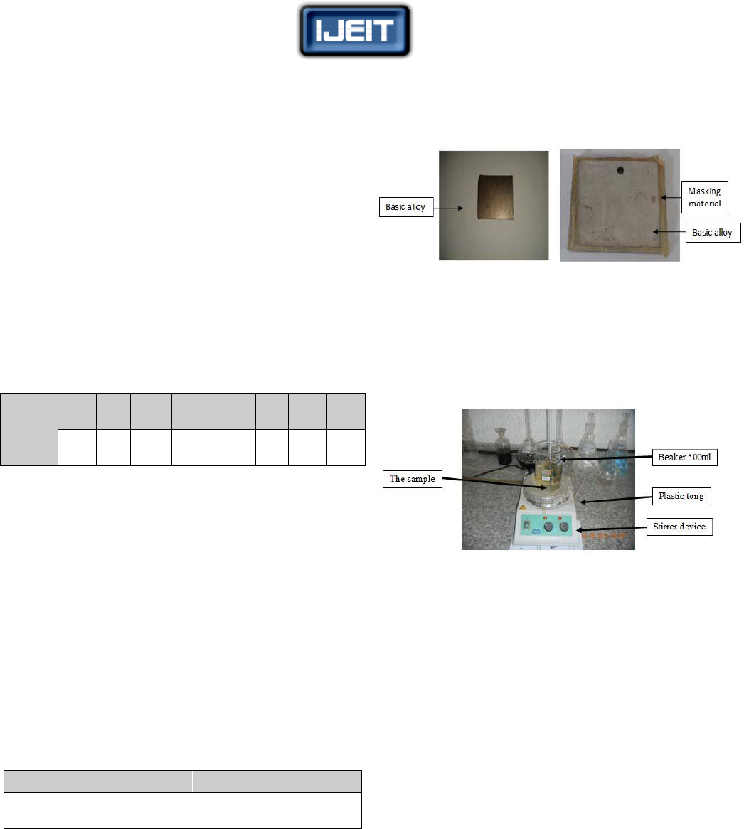
III. SAMPLES PREPARATION
A. Samples Preparation for CHM
Before coating with maskant material, the samples were
cleaned from dirt, dust, fats, oils and organic compounds
using alcohol (ethanol 98%). A specially designed glass
mold was used for coating the samples. After pouring the
polymeric masking material, the mold was kept in an oven
at 80 ºC for 30 min for drying. One side (face) of a sample
was left without coating, which represents the area to be
machined. A hole of 2 mm diameter was drilled in each
sample for the purpose of suspension in the etchant solution
by using plastic tongs during the machining process. Figure
(1) shows samples before and after the coating.
a. Sample before coating b. Sample after coating
FIG. (1) SAMPLES BEFORE AND AFTER COATING
The machining process was achieved via magnetic stirrer
thermostat (made in England). It contains a thermostat to
regulate the temperature of etchant during the machining
operation and controller on velocity of stirrer as shown in
Figure (2).
FIG. (2) CHEMICAL MACHINING SYSTEM
B. Samples Preparation for tests
Hardness test: Digital Display Micro Hardness Tester,
Model HVS - 1000 (China made) was used. Suitable
grinding papers (400, 800, 1000 and 2000) grit and
polishing with alumina were used to prepare the surface of
the samples. A load of 200 g with 10 seconds period for
testing was regarded. The average of three readings was
recorded.
Tafel test: Wenking M – Lab (Bank Electronik –
Intelligent controls GmbH GlessenerStrasse 60) was used in
this test to measure corrosion current, corrosion potential for
samples of (20×20mm) dimensions.
Microstructure test: Microstructure tests of the samples
were carried out by using Scanning Probe Microscope
AA3000 Scanning Probe Microscope (Angstrom Advanced
Inc, USA) that used for surface topography, microstructure
and measure surface roughness testing.
IV. CHEMICAL MACHINING PROGRAM
The alloy samples (with and without cold working) were
chemically machined according to a program included
different machining conditions. Four machining
temperatures (45, 50, 55, and 58
o
C) for each of which five
machining times (2, 4, 6, 8, and 10min.) were used as the
machining conditions. After each machining process, the
surface roughness, weight loss and the metal removal rate,
were recorded. The metal removal rate (MRR) was
calculated basing on the weight loss after each experiment.
The weight was measured via Sensitive weighing balance:

ISSN: 2277-3754
ISO 9001:2008 Certified
International Journal of Engineering and Innovative Technology (IJEIT)
Volume 3, Issue 6, December 2013
212
ACCULAB Balance (made in china) with accuracy
±0.0001.
V. RESULTS AND DISCUSSION
A. Results of the Hardness tests
The hardness tests were carried out for the base alloy
sample and for the cold worked alloy samples before and
after the machining process. The results are demonstrated in
table (3).
TABLE (3) RESULTS OF THE VICKERS HARDNESS TESTS
Alloy sample
Vickers hardness
before CHM(g/µm
2
)
Vickers hardness
after CHM(g/µm
2
)
Without cold working
323.32
319.37
With 20% cold
working
415.96
413.74
The results indicate that the hardness of all samples does
not affected by the chemical machining process, as no
change in crystalline structure, no stresses induced by the
process, as neither mechanical deformation nor exposure to
high temperatures is involved.
B. Results of the Tafel tests
This test was used to determine the current and the
potential needed to start corrosion. All tests were carried out
with identical conditions of 40 ºC and 16 minutes duration.
Figure (3) represent the Tafel curves obtained due to this
test. The results of Tafel curves shown in table (4).
TABLE (4) RESULTS OF THE TAFEL TESTS
Alloy sample
I
corrosion
(mA)
E
corrosion
(mv)
Without cold working
0.732
-441.3
With 20% cold working
1.09
-436.8
The results indicate the following:
The required current to start the corrosion in CHM of
alloy sample without cold working is less than that in the
deformed alloy samples. Cold working leads to increase the
value of the corrosion current density and deviation of
corrosion potential in the negative direction which is more
effective and least noble that is because of distortion in
crystals lattice of cold worked samples by plastic
deformation.
Infer from corrosion current and potential of corrosion,
the values of machining temperature must be little greater
than the temperature at which Tafel test was carried out.
(a) With 20% cold working (b) without cold working
Fig. (3) tafel curve for the alloy sample
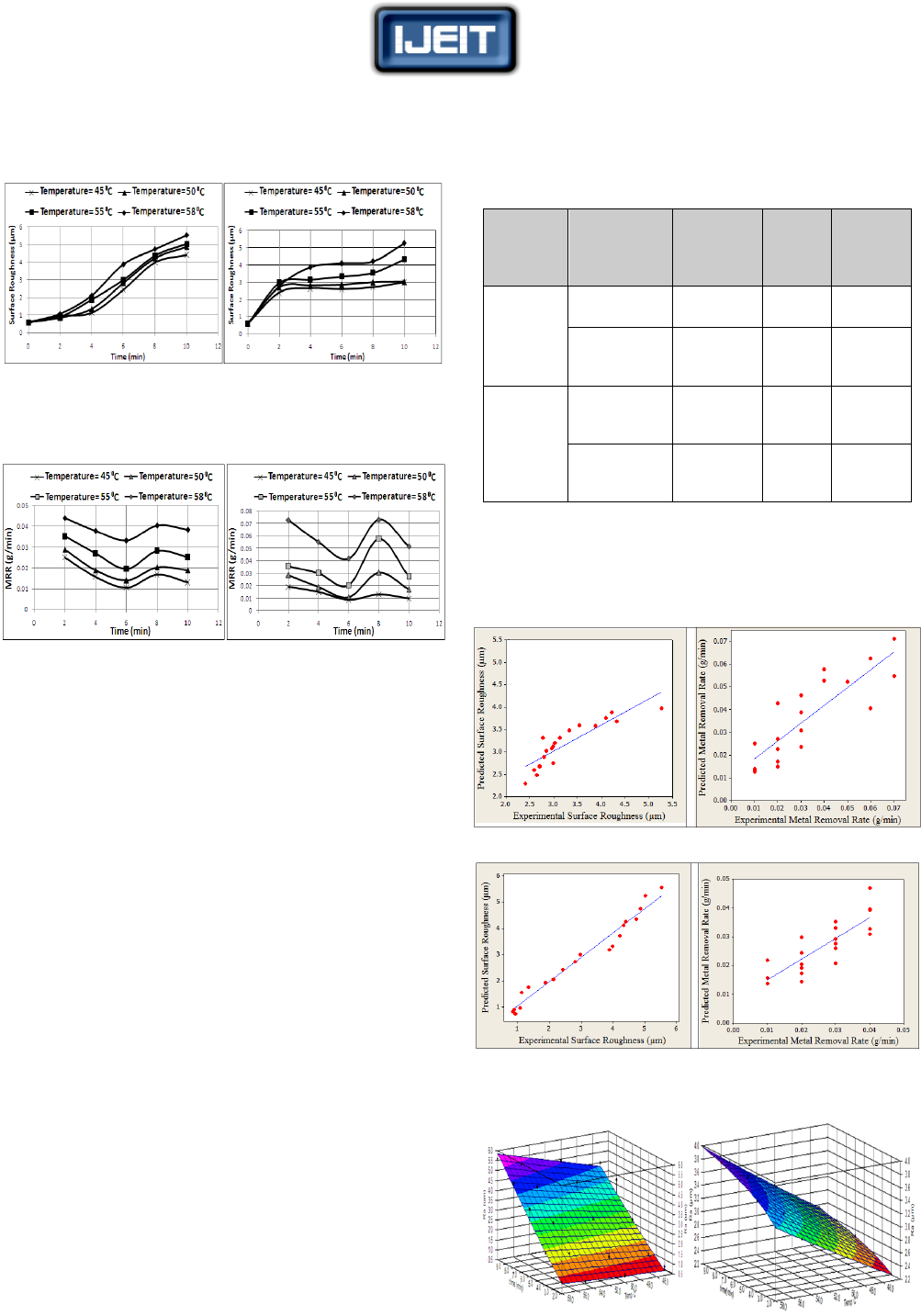
C. Effect of Machining Time on Ra and MRR
Figure (4) show the effect of the machining time on the
surface roughness of the machined samples at different
machining temperatures, while Figures (5) show how the
machining time affects the metal removal rate for the same
samples. The figures indicate the following:
Increasing machining time leads to increase in surface
roughness (Ra). This can be explained on the basis of the
variety of the elements in the composition of the alloy.
Increasing the machining time leads to increase dissolving
the alloy to ions, active metal (the anode) corrodes at an
accelerated rate and the more noble metal (the cathode)
corrodes at a retarded rate and both share in the chemical
reaction with the components of the etchant as shown in
the following reactions:
Fe → Fe
-2
+2e
-
…………………………………..(1)
HCl → H
+
+ Cl
-
…………………………………..(2)
HNO
3
→ H
+
+ NO
3
-
……………………………...(3)
HF → H
+
+ F
-
…………………………………....(4)
2H
+
+ 2e
-
→ H
2
………………………………......(5)
During metallographic etching, twin and grain boundaries
are preferentially attacked even the grain boundaries in very
high purity. Metals are slightly grooved by appropriate
etchants, the grain boundaries in impure metals and alloys
are generally much more readily etched, primarily as a result
of segregation to them the impurities and alloying additions.
Grain-boundary regions may be preferentially attacked
either because segregation makes them more active or
because segregation makes them more noble; the grain
boundary itself acts as a local cathode as stated in (Philip A.
Schweitzer, 2010).
Cold working leads to reduce surface roughness produced
by machining for certain duration and at a certain
temperature due to distortion of the grains and their
orientation towards the rolling in sample structure.
Decrease in metal removal rate can be noticed up to a
machining time of 6 minutes and then suddenly rises and
fall again due to increased dissolved metallic ions and its
concentrations in the etchant.
Metal removal rates for samples without cold working are
lower than that for deformed samples for a certain
machining time and machining temperature (2and 4min.
at 45 and 50 ͦC), therefore increasing degree of cold
working leads to increase metal removal rate due to
increase in the amount of deformation, higher formation
of dislocation and their interaction with each other, which
worsen corrosion resistance.
Increase in machining temperature leads to increase in
surface roughness. Machining temperature increases
corrosion rate as a result of high power oxidization and
mobility of ions. Also it has an effect on the etchant’s
ability to hold the dissolved metal content in solution.
ISSN: 2277-3754
ISO 9001:2008 Certified
International Journal of Engineering and Innovative Technology (IJEIT)
Volume 3, Issue 6, December 2013
213
(a) 20% cold worked sample (b) base alloy sample
FIG. (4) EFFECT OF MACHINING TIME ON SURFACE ROUGHNESS FOR
THE ALLOY SAMPLES MACHINED AT DIFFERENT MACHINING
TEMPERATURES
(a)20% cold worked sample(b) base alloy sample
FIG. (5) EFFECT OF MACHINING TIME ON METAL REMOVAL RATE
FOR THE ALLOY SAMPLES MACHINED AT DIFFERENT MACHINING
TEMPERATURES
VI. OPTIMIZATION OF THE MACHINING CONDITIONS
The results of the machining experiments showed that
machining temperature, machining time and cold working
have significant and interaction effects on the roughness of
the machined surface and on the metal removal rate.
Optimum combination at these variables can be obtained by
designing mathematical models representing their relations
with the required output of the machining process –
roughness and metal removal rate.
Such models were constructed basing on the statistical
data of the carried out machining experiments. Mtb15
software was used for constructing these models basing on
the analyses of regression.
Table (5) demonstrates the constructed mathematical
models and the values of the statistical coefficients, while
Fig. (6) shows the matching between the experimental
values of surface roughness, Ra, and metal removal rate,
MRR, and their predicted values due to the designed
models. The constructed empirical models indicate the
following:
Machining temperature has a greater effect on Ra and
MRR in comparison with the machining time and this is
independent of the cold working
Machining for a larger duration increases the roughness of
the produced surfaces and reduces the metal removal rate,
and this is not affected by amount of cold working.
Previous cold working reduces Ra and also MRR but at a
certain temperature for a certain time.
TABLE (5) EMPIRICAL MODELS FOR RA AND MRR
Percenta
ge of
C.W%
Empirical
model
R
2
Square
Root of
SME
F
Tests
to Fit
S
Standard
deviations
0
Ra = 0.0085
*
t
0.113
*
T
1.45
88
50.74
0.026
MRR = 10
-
11
*
t
-0.191
*
T
5.62
85
41.56
0.116
20
Ra =
0.0061
*
t
1.09
*
T
1.06
99.4
1001.8
0.023
MRR =12.8
*
10
-8
*
t
-0.261
*
T
3.2
72
19.65
0.105
*
t- Machining Time in min. ; T- Machining Temperature in
ͦ
C
Fig (6) shows that the predicated values of the surface
roughness and the metal removal rate basing on the designed
models are close match of their experimental values.
(a) For 0% cold working
(b) For 20% cold working
FIG (6) SCATTER PLOT OF THE EXPERIMENTAL AND EMPIRICAL
VALUES OF RA AND MRR
(a) (b)
FIG. (7) RELATION BETWEEN SURFACE ROUGHNESS (RA),
MACHINING TIME AND MACHINING TEMPERATURE FOR SAMPLES:
(A) WITH 20% COLD WORKING, AND (B) WITHOUT COLD WORKING.
ISSN: 2277-3754
ISO 9001:2008 Certified
International Journal of Engineering and Innovative Technology (IJEIT)
Volume 3, Issue 6, December 2013
214
(a) (b)
FIG.(8) RELATION BETWEEN METAL REMOVAL RATE, MACHINING
TIME AND MACHINING TEMPERATURE FOR SAMPLES: (A) WITH
20% COLD WORKING, AND (B) WITHOUT COLD WORKING.
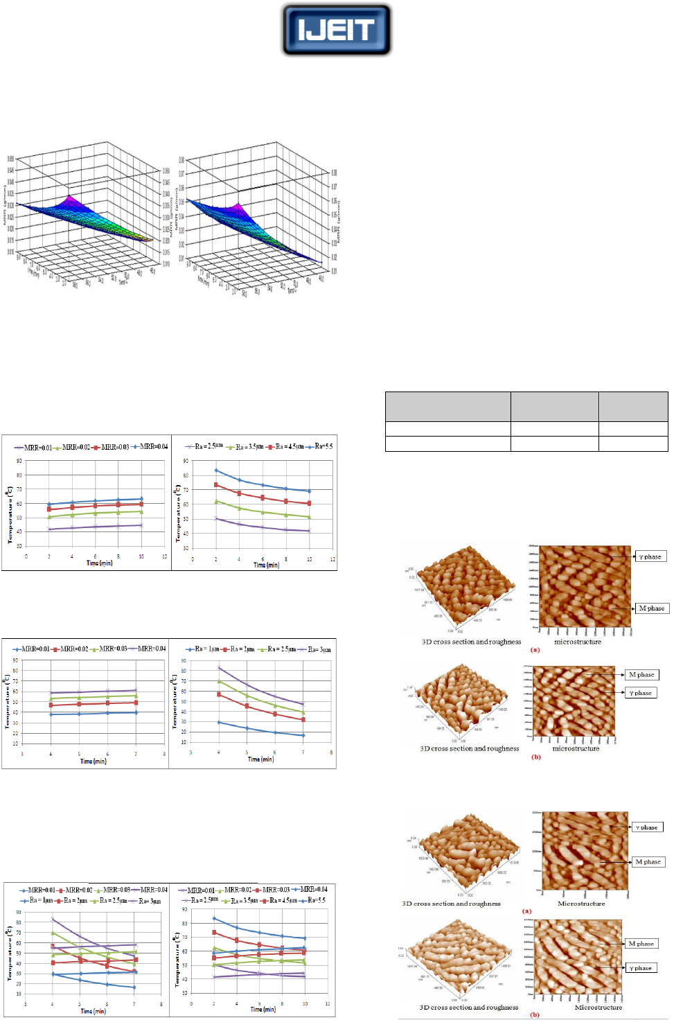
Figure (9) and Fig. (10) were constructed basing on the
designed mathematical models .The figures represent the
values of the surface roughness and the metal removal rate
in the machining temperature – machining time plane.
(a) (b)
FIG.(9) MACHINING TEMPERATURE – MACHINING TIME PLANE FOR
SAMPLES WITHOUT COLD WORKING: (A)SURFACE ROUGHNESS (B)
METAL REMOVAL RATE
(a) (b)
FIG.(10) MACHINING TEMPERATURE – MACHINING TIME PLANE
FOR SAMPLES WITH 20% COLD WORKING: (A)SURFACE
ROUGHNESS (B) METAL REMOVAL RATE
Figure (11) were constructed by superimposing the values
of the surface roughness and the metal removal rate contours
in the machining temperature – machining time plane.
(a) For cold worked sample (b)For sample without cold
working
FIG. (11) SURFACE ROUGHNESS AND METAL REMOVAL RATE IN A
TEMPERATURE – TIME PLANE
Figure (11) give an ability to select an optimum combination
of machining temperature and machining time to obtain
required values for surface roughness and metal removal
rate. Finally, the results of optimum conditions for each
degree of cold working are shown in table (6).
VII. RESULTS OF TESTS BY SCANNING PROBE
MICROSCOPE
Scanning Probe Microscope was used to test samples
before and after the chemical machining. Machining
conditions were used according to the methodology
discussed and basing on Figure (11). These conditions are
demonstrated in table (6) .
TABLE (6) CHEMICAL MACHINING CONDITIONS FOR SAMPLES
TESTED BY SPM
Degree of cold
working
Temperature
ºC
time (min)
0% cold working
45
6
20% cold working
43
6
Figures (12) and Fig.(13) show microstructure, topography
and surface roughness for the tested sample by using
Scanning Probe Microscope with/without cold working
before and after chemical machining. The image size is
1994×1978 nm.
FIG. (12) SURFACE ROUGHNESS AND MICROSTRUCTURE FOR THE
SAMPLE WITHOUT COLD WORKING (A) BEFORE CHM (B) AFTER
CHM
FIG. (13) SURFACE ROUGHNESS AND MICROSTRUCTURE FOR THE
SAMPLE WITH 20% COLD WORKING (A) BEFORE CHM (B) AFTER
CHM

ISSN: 2277-3754
ISO 9001:2008 Certified
International Journal of Engineering and Innovative Technology (IJEIT)
Volume 3, Issue 6, December 2013
215
The figures indicate the following:
All grains of the deformed samples were elongated in the
direction of cold rolling. This elongation is not affected by
the chemical machining process.
Average of measured surface roughness of the machined
samples without cold working is 2 µm, which is too close
to that can be calculated by the designed empirical model
where Ra =2.5µm and MRR=0.01 g/min. The average
surface roughness for machined samples with 20% cold
working was 1.68µm, which is also close to that can be
calculated by the designed empirical model, where Ra =
2µm and MRR=0.01 g/min. This indicates the confidence
of the designed empirical models.
There are no metallurgical defects on the machined
surfaces due to chemical machining process.
Microstructure is consisting of two phases (γ + M), dark
and light color, austenite phase (γ) and martensite phase
(M). After chemical machining, there is no change in
microstructure, but an increase in martesite phase (M) had
been occurred. For samples with 20% cold working the
microstructure before chemical machining contains
elongated martensite (M) within matrix of austenite phase
(γ) in crystal lattice, as the transformation of the induced
plasticity causes the grain size to be decreased.
VIII. CONCLUSIONS
Based on the detailed results the following conclusions can
be stated:
1. Machining time, machining temperature and previous
cold working are important variables that affect on
chemical machining products; among these variables
machining temperature has the largest effect.
2. Surface roughness of chemically machined parts
increases with the machining temperature and machining
time.
3. Surface roughness of chemically machined parts
decreases with the previous cold working of the work
piece.
4. Metal removal rate increases with machining
temperature and decreases with previous cold working.
5. Products of stainless steel 420 without cold working can
be chemically machined in [H
2
O + HCl + HNO
3
+ HF +
HCOOH] etchants in optimum conditions at temperature
45ºC and time 6 min.
6. Products of stainless steel 420 with 20% cold working
can be chemically machined in [H
2
O + HCl + HNO
3
+
HF + HCOOH] etchants in optimum conditions at
temperature 40 ºC and time 6 min.
7. An assessment of CHM can be achieved by empirical
modelsfor selecting the appropriate machining
conditions for the required surface roughness and metal
removal rate.
REFERENCES
[1] Abu Khalid Rivai, 2012, "Effect of Cold Working on The
Corrosion Resistance of JPCA Stainless Steel in Flowing"Pb–
Bi at 450◦C, Journal of Nuclear Materials 431, PP (97–104).
[2] Benedict.G.F, 1987, "Nontraditional Manufacturing
Processes", Mercel Decker Inc., New York, USA.
[3] Blak.JT, DeGarmo, 2007, "Materials and Processes in
Manufacturing", John Wiley & Sons, Inc, Tenth ed.
[4] David M. Allen, 2004, "Characterization of Aqueous Ferric
Chloride Etchant Used in Industrial Photochemical
Machining", School of Industrial and Manufacturing Science,
Cranfield University, UK.
[5] Drozda.T.J, 1989, "Tool and Manufacturing Engineers",
Handbook (Chapter 14: Nontraditional Machining), SME
Publishing.
[6] El-Hofy.H.A.-G, 2005, "Advanced Machining Processes",
Black lick, OH, USA, McGraw-Hill Companies.
[7] FadaeiTehrani.A, 2004, "A New Etchant For The Chemical
Machining of St304", Journal of Materials Processing
Technology 149, PP (404–408), Isfahan University of
Technology, Isfahan, Iran.
[8] Ho S., 2008, "Chemical Machining of Nanocrystalline Ni",
Department of Materials Science and Engineering, University
of Toronto, 184 College Street, Toronto, Canada.
[9] Kurc A. , 2010, "Influence of Cold Rolling on The Corrosion
Resistance of Austenitic Steel", Journal of Achievements in
Materials and Manufacturing Engineering, Volume 38 Issue 2.
[10] Langworthy M., 1994, "Chemical Milling By Nontraditional
machining process", Machining ASM Handbook.
[11] Philip A. Schweitzer, 2010, "Fundamentals of Corrosion,
Mechanisms", Causes and Preventative Methods, CRC Press
© by Taylor and Francis Group, LLC
[12] SeropeKalpakjian, 2006, "Manufacturing, Engineering &
Technology, Fifth Edition", Pearson Education, Inc., Upper
Saddle River, NJ.
[13] SumanSamanta, 2011, "Parametric Optimization of Some
Non-traditional Machining Processes Using Artificial Bee
Colony Algorithm, Department of Production Engineering",
Jadavpur University, Kolkata, India.
[14] Yao Fu, 2009, "Effects of Cold Work and Sensitization
Treatment on The Corrosion Resistance of High Nitrogen
Stainless Steel in Chloride Solutions", ElectrochimicaActa 54,
PP (1618–1629).
AUTHOR BIOGRAPHY
Prof. Dr. Haydar A.H. Alethari
Department of Materials Engineering,
Babylon University,
Hilla-Najaf Road, P.O. 4- Al-Hilla, Iraq
E-amail: draletharihah@yahoo.com
Dr.Eng.Alethari@uobabylon.edu.iq
Haydar A.H. Alethari obtained his BSc. in Mechanical
Engineering from Mosul University-Iraq in 1981.
Then, he obtained his MS and PhD degrees from
Kharkov University (USSR-Ukraine) in 1988 and
1991, respectively. He is interested and a researcher in manufacturing,
traditional and advanced cutting processes of composites and metals.
Currently, he is a team leader of MSc. students in Materials Engineering,

ISSN: 2277-3754
ISO 9001:2008 Certified
International Journal of Engineering and Innovative Technology (IJEIT)
Volume 3, Issue 6, December 2013
216
Babylon University, Iraq to develop mechanical and physical
characteristics of advanced materials.
• The number of master's students who have been supervising them (14.
• The number of the many local conferences.
• The number of international conferences in which the participant research
(14).
• Chairman of the international auditors. Arica British institution
• Dr. Kadhim F. Abdulhussein Al-sultani.
• Degree: Associate Professor.
• Marital Status – Married
• The number of children – 7.
• Bachelor of Chemical Engineering - University of
Technology - Baghdad. Materials Engineering
1990.
• Master of Chemical Engineering - University of Technology - Baghdad.
Industrial units 1999.
• PhD in Chemical Engineering - University of Technology - Baghdad.
Corrosion Engineering 2003.
• Dean of Materials Engineering College.
• Number of research published and accepted for publication more than 30
papers. Including 8 research published in international journals.
• The No. Patented – (1).
