
St. Cloud State University
theRepository at St. Cloud State
/'($).$)",*% .-$) #)$')
)/!./,$)")"$) ,$)"
+,.( ).*! #)$'))/!./,$)"
)"$) ,$)"
Migrating Legacy System to Pega Rules Process
Commander v7.1
Kartheek Kalluri
St. Cloud State University
*''*1.#$-)$.$*)'1*,&-. #6+-, +*-$.*,3-.'*/-.. /(( .-
5$-.,, + ,$-,*/"#..*3*/!*,!, )*+ ) --3.# +,.( ).*! #)$'))/!./,$)")"$) ,$)"..# +*-$.*,3..
'*/.. .#- ) +. !*,$)'/-$*)$)/'($).$)",*% .-$) #)$'))/!./,$)")"$) ,$)"3)/.#*,$4 ($)$-.,.*,
*!.# +*-$.*,3..'*/.. *,(*, $)!*,(.$*)+' - *).. ,-1 2 '/(-.'*/-.. /
*(( ) $..$*)
''/,$,.# &$",.$)" "33-. (.* "/' -,* --*(() ,0 Culminating Projects in Mechanical and
Manufacturing Engineering
#6+-, +*-$.*,3-.'*/-.. /(( .-

1
Migrating Legacy System to Pega Rules Process Commander v7.1
by
Kartheek Kalluri
A Starred Paper
Submitted to the Graduate Faculty of
St. Cloud State University
in Partial Fulfillment of the Requirements
for the Degree
Master of Engineering Management
December, 2015
Starred Paper Committee:
Hiral Shah, Chairperson
Ben Baliga
Balasubrahmanian Kasi
2
Abstract
Asurion is an independent company based in Nashville, Tennessee provides
device protection and support services for smartphones, tablets, and consumer
electronics etc. Asurion is serving its 280 million customers by having its Contact
Center application and Web application in place. Reducing the data redundancy by
merging both the systems into a single system thereby increasing the application
performance is all about Horizon System.
3
Acknowledgements
This project document wouldn’t have been possible without the valuable
guidance and support from many individuals and organization.
I would like to take this opportunity to thank Dr. Hiral Shah, Associate
Professor, for Engineering Management Program, at St. Cloud State University
without whose support, encouragement, and guidance this project would not have
been a reality.
It gives me an immense pleasure to thank Dr. Ben Baliga, Professor and
Graduate Director for Engineering Management Program, at St. Cloud State
University for his support and guidance.
Also, I would like to thank Prof. Balasubrahmanian Kasi for serving on the
committee and support throughout the project.
4
Table of Contents
Page
List of Figures ...................................................................................................... 6
Chapter
1. Introduction ............................................................................................... 7
Introduction ......................................................................................... 7
Problem Statement ............................................................................. 8
Nature and Significance of the Problem .............................................. 8
Objective of the Project ....................................................................... 10
Project Questions/Hypotheses ............................................................ 10
Limitations of the Project ..................................................................... 10
Definition of Terms .............................................................................. 10
Summary ............................................................................................. 11
2. Background and Review of Literature ...................................................... 12
Introduction ......................................................................................... 12
Background Related to the Problem ................................................... 12
Literature Related to the Problem ....................................................... 12
Literature Related to the Methodology ................................................ 16
Summary ............................................................................................. 17
3. Methodology ............................................................................................. 18
Introduction ......................................................................................... 18
Design of the Study ............................................................................. 18
5
Chapter Page
Data Collection .................................................................................... 19
Data Analysis ...................................................................................... 21
Timeline .............................................................................................. 21
Summary ............................................................................................. 21
4. Data Presentation and Analysis ............................................................... 22
Introduction ......................................................................................... 22
Data Presentation ............................................................................... 22
Data Analysis ...................................................................................... 25
Summary ............................................................................................. 28
5. Results, Conclusion, and Recommendations ........................................... 29
Introduction ......................................................................................... 29
Results ................................................................................................ 29
Conclusion .......................................................................................... 29
Recommendations .............................................................................. 30
References .......................................................................................................... 31
6
List of Figures
Figure Page
1. Draft Flow of Speed Claim ........................................................................ 15
2. Draft Ul ..................................................................................................... 15
3. Application Structure ................................................................................ 16
4. Horizon Data Presentation ....................................................................... 22
5. Class Structure of Horizon Applicant ........................................................ 23
6. Rulesets Hierarchy ................................................................................... 24
7. Data Class Hierarchy ............................................................................... 24
8. Connect-SQL ............................................................................................ 25
9. Activities Used for Data Analysis .............................................................. 26
10. Eligibility Engine Outline ........................................................................... 26
11. Eligibility Engine ....................................................................................... 27
12. Fulfillment Engine ..................................................................................... 28
7
Chapter 1: Introduction
Introduction
Asurion in an independent company based in Nashville, Tennessee that
provides device protection and support services for smartphones, tablets, consumer
electronics, appliances, satellite receivers and jewelry. At present Asurion is serving
280 million customers worldwide. Company services are sold through mobile phone
carriers, direct broadcast satellite service providers and retailers such as AT&T,
Verizon Wireless, Sprint, NTT DoCoMo, DirecTV and Wal-Mart. Asurion has an A+
rating with the Better Business Bureau. The Consumer Electronics Association
recognized Asurion in 2015 with a CES Innovation award for its support and
protection application that combines live support, notifications to keep devices
running and mobile security.
This capstone project proposal will focus on upgrading the Device Protection
Insurance project to Pega Rules Process Commander v7.1.7. As a process of up
gradation, it focuses on the process of filing new claims through agent channel and
web channel for mobiles, smartphones and tablets, sending correspondence like
email, fax and messages to customers regarding the status of the claim they made
and also tracking capability once the claim is approved and the device is shipped.
This project involves integration with other systems, to get the data of customer and
to verify the authorization of the user and hence UAT (User Acceptance Testing) and
Integration testing are added to testing phase for maintaining consistency. This
8
document includes problem statement, objective of the project and also nature and
significance of the problem.
Problem Statement
The issue with Asurion legacy systems is that, there are two separate systems
maintained for the claims made by reaching the customer care center (through phone
or chat) and another system for the customers to file a claim over the web. The issue
is, there is no synchronization between the two systems pertaining to the customer
data when claims are made and the customer has to provide their details multiple
times when they want to resume the claim over the different channels. Henceforth
there is lot of redundant data in the application and it is becoming overload to the
client system to manage existing customers and also the new customers who are
keep on growing rapidly. Hence the performance of the application is downgrading
and turnaround time for completing a claim process is increasing which is leading to
lot of problems. As number of network provider clients is increasing, the legacy
application is not able to handle the increasing number of customers and provide
better service to their customers.
Nature and Significance of the Problem
Asurion provides their customers two possible ways for filing a claim. First
option is through Agent (Calling a Customer care center) by phone and completing
the claim process on the phone. Second option is to file a claim through Web
channel, Asurion claim application is accessible to all the customers throughout the

9
world and they all can file a claim through the same URL ‘www.phoneclaim.com’
(Asurion Insurance Services, 1994).
Once the customer calls the care center to file a claim, the request is raised
and will be routed to the Asurion customer service agent who will help the customer
to complete the claim. In the process of making the claim complete, the customer has
to provide all the details like device information, incident information like “when,
where and what” along with the account information. Just in case if the customer
wants to stop the claim process on the phone and wanted to resume the claims over
the different channel (Through Web), there is no other option for the customer to
resume the claim process instead they have to start the a new claim and have to
provide all the information again, because there is no synchronization between the
agent system and the web system. If the customer wishes to resume their claim
process, they can do so but only through the same channel. This is leading to
customer frustration as he has to provide the details multiple times if he wants to
choose different channel for their claim process.
Another potential problem includes the performance of the application.
Because of the redundancy in the application it is becoming over head to the legacy
application in handling the clients and customers effectively and hence they are
losing their business.
The scope of the project is to migrate the legacy system to PRPC v7.1 by
adding more capabilities to the application and merging two systems into one system
(Agent + Web) would solve all the problems addressed in best possible way.
10
Objective of the Project
Implementing a new system called ‘Horizon’ using Pega Rules Process
Commander v7.1 ML7 with more capabilities to handle increasing number of
customers by improve performance, eliminate data redundancy and reducing
maintenance. Horizon system allows their customers to file a claim easily either by
contacting customer care center or by Web without providing the details multiple
times.
Project Questions/Hypotheses
1. What is the need for implementing Horizon and what are its benefits?
2. What is the need of using Pega Rules Process Commander v7.1 ML7?
3. What is the feasibility of using other methodologies compare to ASM?
4. What is the means of communication between Development, Functional,
Testing and Business teams?
Limitations of the Project
Implementation of Horizon systems is now limited to only Device Protection
coverage for both the Web and Agent channel. It later expands to retail customers.
Definition of Terms
UAT: User Acceptance Testing is performed post completion of developing the
application. This part of testing is done using the legacy application customer base as
the input data for the newly built application and is given for testing to the Business
Users with live data.

11
Agent: Agent in Horizon refers to the Contact Center Operations.
Web: Web in Horizon refers to the www.phoneclaim.com.
Summary
We have covered the Problem Statement, Objective of the project, Nature and
Significance of the project. In later part of the report, we will cover the background
and literature review, which lead to rise of Horizon platform as an integrated
application of Asurion Claims Service System.
12
Chapter 2: Background and Review of Literature
Introduction
Major focus of this chapter is towards the background and the literature review
of the project along with the literature review related to the methodology.
Background Related to the Problem
Asurion legacy systems have separate systems maintained for the claims
made by reaching the customer care center (through phone or chat) and another
system for the customers to file a claim over the web. The issue is, there is no
synchronization between the two systems pertaining to the customer data when
claims are made and the customer has to provide their details multiple times when
they want to resume the claim over the different channels. Henceforth there is lot of
redundant data in the application and it is becoming overload to the client system to
manage existing customers and also the new customers who are keep on growing
rapidly. Hence the performance of the application is downgrading and turnaround
time for completing a claim process is increasing which is leading to lot of problems.
As number of network provider clients is increasing, the legacy application is not able
to handle the increasing number of customers and provide better service to their
customers.
Literature Related to the Problem
Horizon helps the customer by anticipating the needs of the customer by
simplifying the steps for the claim process. Horizon achieves it by maintaining the
synchronization of data between the two systems (Agent and Web). Customers
13
across the globe will connect to the Horizon to resolve their issues. So Horizon
should focus on their customers with unified platform, to help their customers in best
possible ways. This way, no matter how customers contact either by phone or by web
or by means of both and which employee they interact with, Asurion should always
deliver an efficient and accurate customer service experience by using Horizon
system.
Direct capture of objective meeting. DCO is the process of capturing the
business requirements, organizing them into appropriate rules and then saving them
in PRPC. It includes both the functional and non-functional business requirements.
An example of a functional requirement is that the system should automatically send
an email to the manager if the purchase request is not approved in two days. An
example of a non-functional requirement is that the system should render each
screen within three seconds. In this phase, the business use-cases are divided into
atomic use cases.
DCO sessions are conducted with the client to capture details of the
application.
The main task in a DCO session is for the client to articulate the business use
cases, and then divide that into atomic use cases. Designing draft flows and draft UIs
for the business to view the partially functional application is followed.
1. Prep and Review–The DCO team reviews all the business requirements,
interface requirements, and all other supplied documentation that is
14
provided to them. They then build the draft flows and draft UI’s ahead of
the DCO session using this information.
2. White Board and Review–In this session, the draft flows and User
interfaces are drawn on the white board. The SSA then recreates them in
PRPC as flow rules and draft UIs, which are subsequently reviewed in
another session.
3. Real-time capture–In this DCO session, the team member uses PRPC as a
tool to capture the details as the discussion happens. The business team
can see the changes immediately.
Draft flow. It is the responsibility of the SSA to create the Draft Flows in DCO
sessions. SSA builds the draft flows in Designer Studio with all the available shapes
and necessary for him. When a Draft flow is initially build, typically it contains a single
assignment bounded by start and end shape. SSA then recreates this basic flow with
the shapes available to him and based on the requirements to the Draft Flow.
Designing draft flows well before will help eliminate re-work when the development of
the application is started.
Draft UI. Draft UI’s are built based on the business requirements using Flow
Actions, Sections and are shown to the business to seek the approval. Once the flow
is confirmed, flow action and sections can be added in the draft UI stage. The UI is
called draft since the UI fields do not reference any properties. Most of the controls in
the UI design canvas can be added into the section without referencing any
properties. The draft UI is not functional and it does not display the accurate data in

15
these fields. It is mainly used to validate the look and feel of the UI. SSA’s creates
them as a part of DCO sessions.
Figure 1: Draft Flow of Speed Claim
Figure 2: Draft UI

16
Figure 3: Application Structure
Literature Related to the Methodology
Define the scope of the project and the sliver by capturing high level
processes and business requirements for the sliver. Discuss is made on the work
types that are needed and high-level use cases for the work types.
DCO sessions are then conducted. Teams meet and gather details around all
the business requirements. This stage also involves deciding the work types and all
the relevant use cases and requirements belonging to each work type. The QA team
works on getting the test plans.
17
The primary flow is developed first and demonstrated to the business. The
secondary flows and the exception path is then developed. And then the UI, external
interfaces and reporting requirements are developed. Discussions are held with the
IT team to talk about performance metrics and to ensure the application meets the
enterprise standards.
Summary
Background work like conducting the Direct Capture of Objectives sessions,
designing the draft flows, draft UI are explained in this chapter. Also the background
related to the problem and literature related to the methodology also explained. Next
chapter walks through the actual methodology enforced in the project.
18
Chapter 3: Methodology
Introduction
In this chapter, various steps were involved to make progress towards the
accomplished objective. The ASM (Agile Scrum Methodology) gives particulars about
the every step of the development process. Main steps involved in the Project are the
Inception, Elaboration of requirements, the methods used in gathering the necessary
data and the development of application.
Design of the Study
ASM is an iterative and incremental process model with main focus on
application readiness and working towards the target end dates. The progress will be
monitored and next steps are planned for proper delivery of product.
Agile methodology breaks the application development into small iterations.
Typically each iteration lasts for about four weeks. Of them 11 days are for
development and 8 days are for QA. Every iteration involves Product owner team,
business process analyst team, development team, QA team work simultaneously on
areas like grooming the user stories, analyzing them, design, coding, unit test an user
acceptance testing.
Grooming: Requirements are converted to user stories and point estimation
will be done in grooming session. The members of the team would do analysis of the
user stories with inputs from the product owner (Business Team). Project approach
would also be planned in grooming session. The outcome of the grooming session
19
would be the readiness of the user stories, which are then assigned to the
developers and are ready for the development.
Building: Actual development of the application is built in this stage. If there is
a perfect design, it makes the development work easier. Once the coding of the
particular user story is completed, every developer has to come up with Tech Note
about the user story he worked on and also including the details like ‘Approach
followed and Rules used’. Developer has then have to perform the Unit Testing to
ensure his user story meets the acceptance criteria.
Testing: In this stage, testing of the application is performed and the bugs are
raised (If found), tracked, fixed and retested. After successful testing of the product,
then the application goes to Go-Live stage.
Go-live and production support: Once the application is completed, here
migration completion from legacy system to PRPC system, the teams should make
sure the system is stable and performs up to the expectations and also check the
customer needs are met
Data Collection
The data model is a critical part of every PRPC application. The data model
defines the attributes and relationships that make up the objects that PRPC uses to
process work and manipulate data.
The process of defining the data model is critical to a successful application. A
good data model should define entities that can represent business objects in a way
20
that can be reused by other applications. In the end the model will be the roadmap
for the classes and properties that will be used by the rest of the application.
Classes are the fundamental building blocks of almost everything in PRPC.
Classes define the logical entities or objects that an application will work with. While
many rules can apply to a class it is the property rules that define the attributes of the
class and are critical to data collection.
Properties can be as simple as a single value, for example, First Name.
Properties can also be complex and represent a list or another class all together.
A page is always defined as being of a specific class type. The class type defines the
properties that can be defined on the page. Pages can be top-level pages or
embedded pages. The term top-level page refers to pages that have a name and are
not embedded in any other pages.
Embedded pages are embedded into other pages as properties themselves.
When trying to understand the relationship of a class and a page it is important to
remember that the class is the definition and does not contain values for its
properties whereas the page is the actual instance.
First we define the Data class that will hold our properties. Since we will
instantiate but not persist these pages we can define them as concrete and not
belonging to a class group. In the data model, the embedded page or page list
properties is a “has a” relationship.(Add figures of Property Rule form, Class Rule
form, pages and page list from App explorer and Data Class hierarchy from Data
Explorer).

21
Data Analysis
Data collected as a part of the application process, is then analyzed using
Eligibility Engine. If the outcome of the Eligibility Engine is a valid, it then passed to
Fulfillment Engine where in the DAX operations are performed and PCI Token is
generated and further proceedings will be evaluated.
Timeline
Activity
Timeline
Comments
Project Preparation and
Requirement Gathering
March 2015
Design and Development
March 2015 – August
2015
Testing
August 2015 – September
2015
Final Deployment
September 2015
Production
October 2015
Final Defense
November 2015
Summary
This chapter focuses on explaining in detail about the process of the project
life cycle. It explains in detail the stages involved in the project implementation. The
implementation and analysis techniques which best suited the project scope were
detailed.
22
Chapter 4: Data Presentation and Analysis
Introduction
Primary focus of this chapter would be on the data presentation and strategies
used to analyze the data efficiently collected as a part of the application and further
decide the customer can proceed with a claim.
Data Presentation
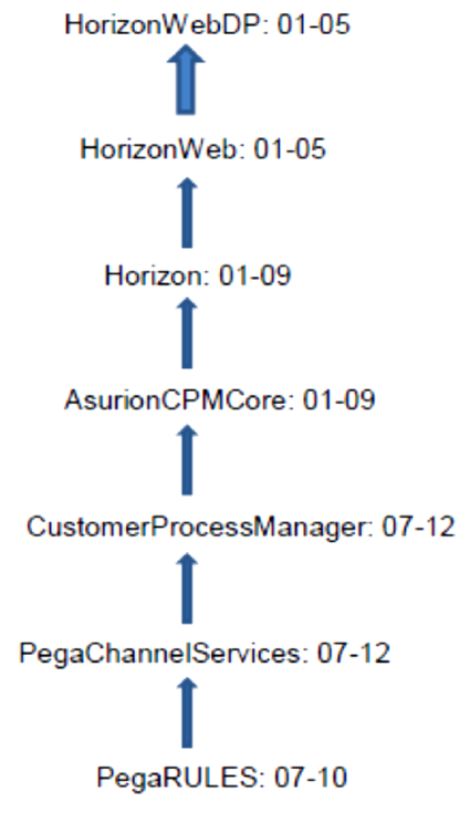
To facilitate the synchronization between the two systems, below is Figure 4
for representation followed for Horizon system:
Figure 4: Horizon Data Presentation

23
PegaChannelServices, CustomerProcessManager, AsurionCPMCore contains
all the rules that handle the customers who contact the care center for claim process
over phone or chat interaction. Horizon, HorizonWeb, HorizonWebDP contains all the
rules that handle the customers who start their claim process over Web channel. This
structure also facilitates the parent child relationship between the layers such that
child layers can user their parent data without creating them again such that there
would be no redundancy in data. Data provided by the customer over agent channel
can be propagated to the web channel eliminating the redundancy.
Below is Figure 5 showing Class Structure:
Figure 5: Class Structure of Horizon Application

24
Below is Figure 6 showing the Ruleset Hierarchy:
Figure 6: Rulesets Hierarchy
Below is Figure 7 showing Data Classes hierarchy:
Figure 7: Data Class Hierarchy

25
Below is Figure 8 for Connect-SQL:
Figure 8: Connect-SQL
Data Analysis
Data is collected at various parts of the application like Device Make, Model,
followed by Incident Details. Then the customer demographic information like first
and last name, additional phone number, email, shipping address are collected and
sent to Eligibility Engine. Rigorous eligibility tests are performed by Eligibility Engine
and if the outcome of the Eligibility Engine is passed and then the customer becomes
eligible to perform a claim. Here a part of data collection is performed again like
collecting the shipping address details, gathering the payment information. Once the
payment information is validated and if it passes the validation then the device is
shipped by DAX system from Asurion Fulfillment Center.
Below is Figure 9 for Activities, which are responsible primarily for performing
data analysis at various steps throughout the flow process.

26
Figure 9: Activities Used for Data Analysis
Below is Figure 10 representing the Outline of Eligibility Engine.
Figure 10: Eligibility Engine Outline

27
A series of steps like checking the Agreement, validating the incident type
given by customer, Reship scenario are performed in Eligibility Engine to decide the
outcome. Below, Figure 11 represents the Eligibility Engine, where data analysis is
performed on the data collected and decides the Eligibility outcome.
Figure 11: Eligibility Engine
Once the outcome of Eligibility Engine is passed, then the data is now sent to
Fulfillment Engine where the address standardization is performed, payment-
processing information is gathered and validated and finally the data is routed to DAX
system. DAX system then analyzes the received information and then it ships the
approved device from Asurion fulfillment center. All these series of steps are
performed as a part of Fulfillment Engine. Below is Figure 12, which shows the series
of steps, performed as a part of Fulfillment Engine.

28
Figure 12: Fulfillment Engine
Summary
This chapter helps us in evaluation the process of claim made by the
customer. We process the data collected as part of this application through Eligibility
Engine and determine the claims eligibility. Then it needs to pass through the
Fulfillment Engine and determine the outcomes of the DAX operations and further
proceedings also included.
29
Chapter 5: Results, Conclusion, and Recommendations
Introduction
This chapter focuses on providing the final result of the project. Subsequently,
the project questions raised before conducting this study are answered briefly.
Possible recommendations are made based on the result and conclusion for further
possible improvement opportunities.
Results
The implementation of Horizon system was successfully completed using
PRPC v7.1.7 has no redundant data as this process maintains synchronization
between the Agent Channel and the Web Channel.
Conclusion
The implementation of Horizon system reduces the redundancy, improves the
performance and saves budget for Asurion from huge liabilities. Horizon helps
customers to file a claim in Web and resume it by calling CCO without giving them
the information repeatedly.
The Scrum model that was implemented in the Horizon project resulted in a
Complex, flexible and a robust application.
Horizon Web application is user friendly and very handy for all the users who
file a claim over Web. Horizon Agent application is highly reliable and highly
performed application and is flexible in usage by Agents who work at Asurion CCO.
30
Recommendations
1. The Security level can be increased based on the user requirements by
providing condition at the DAX Filters in the Manage Roles.
2. Maintain a single code base for all the clients of Asurion and have their
specific requirements implemented on top of that core code base.
3. DAL services can be improved by introducing the XREF while creating a
DAL service.
4. Session Timeouts for Horizon Web application can be handled in a better
way.
5. Implement the Google No Captcha ReCaptcha to determine a Human
making a claim or by a Robot.
6. Introduce Internet Authentication Composer to embedded the Pega
application into HTML file.
