Z
Z
S
S
S
S
e
e
n
n
s
s
o
o
r
r
A
A
p
p
p
p
l
l
i
i
c
c
a
a
t
t
i
i
o
o
n
n
s
s
G
G
u
u
i
i
d
d
e
e
CARRIER CORPORATION ©2020 · Catalog No. 11-808-504-01 · 6/11/2020

Verify that you have the most current version of this document from
www.hvacpartners.com
or
www.accounts.ivusystems.com
or your local Carrier office.
Important changes are listed in
Document revision history
at the end of this document.
CARRIER CORPORATION ©2020. All rights reserved throughout the world. i-Vu is a registered trademark of Carrier
Corporation. All other trademarks are the property of their respective owners.

Contents
Introduction .................................................................................................................................................................. 1
This document ....................................................................................................................................................... 3
ZS Sensor screens ................................................................................................................................................ 4
Creating Snap control programs for ZS Sensors ....................................................................................................... 5
Step 1: Add a Sensor Binder microblock ......................................................................................................... 5
Step 2: Add Analog Sensed Value Input microblocks .................................................................................... 6
Step 3: Add Binary Sensed Value Input microblocks if using ZS Pro motion sensor ............................... 9
Step 4: Add a BACnet Setpoint microblock .................................................................................................. 11
Step 5: Add a BACnet Time Clock microblock ............................................................................................. 13
Step 6: Add optional values, statuses, and icons ........................................................................................ 14
Step 7: Set the order of information displayed on a sensor ...................................................................... 14
Icons and text indicators ........................................................................................................................................... 15
Outside air icon .................................................................................................................................................. 16
Energy saving mode icon .................................................................................................................................. 17
Alarm icon ........................................................................................................................................................... 17
Maintenance icon .............................................................................................................................................. 18
Programming specific applications ......................................................................................................................... 20
Generating alarms ............................................................................................................................................. 20
Fan status and control ...................................................................................................................................... 21
Zone HVAC modes ............................................................................................................................................. 23
Hospitality Mode ................................................................................................................................................ 26
Clean room application ..................................................................................................................................... 26
External Scheduling ........................................................................................................................................... 27
Setting Setpoint Adjust Limit from an external source ............................................................................... 27
Modifying temperature display units on ZS Sensors ................................................................................... 28
To use values from individual sensors in your control program ............................................................................ 29
Appendix A: Rnet tags .............................................................................................................................................. 32
Adding custom Rnet tags ................................................................................................................................. 36
Appendix B: ZS Pro and Pro-F Sensor screen fields ............................................................................................... 37
Appendix C: Converting a control program with an RS Pro to a ZS Pro ............................................................... 38
Step 1: Update run conditions with ZS sensor microblocks ...................................................................... 38
Step 2: Make Alarm icon display on a ZS Pro .............................................................................................. 40
Step 3: Make Fan icon display on a ZS Pro .................................................................................................. 40
Step 4: Change sensed zone humidity from an AI to the ZS Sensor ........................................................ 42
Document revision history ........................................................................................................................................ 43
ZS Sensor CARRIER CORPORATION ©2020
Applications Guide All rights reserved
1
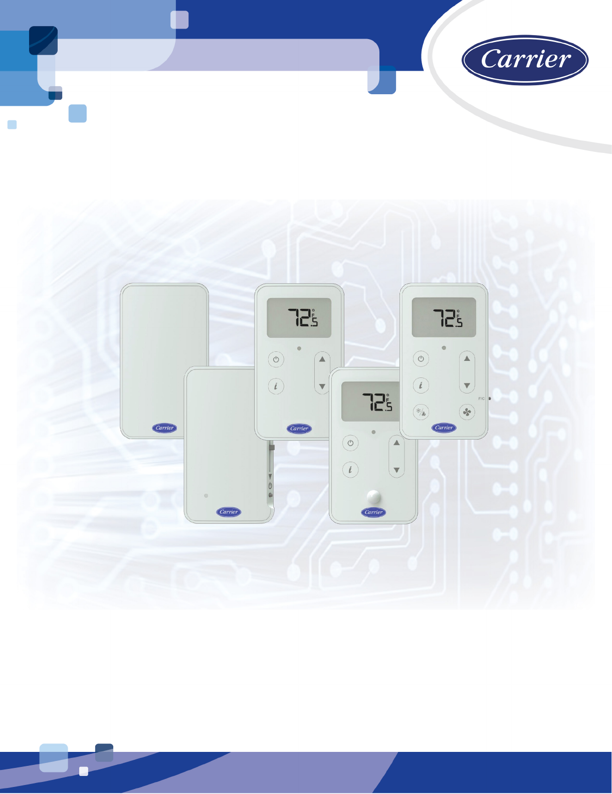
The ZS line of sensors consists of the following thermistor-based temperature sensors. The zone sensors come in
a variety of configurations that can include humidity, CO
2
, VOC, and motion sensing.
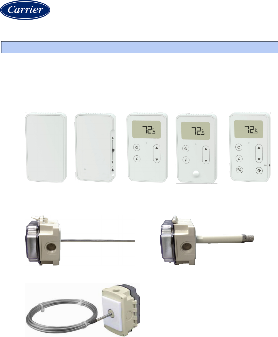
Zone Sensors:
ZS Standard
ZS Plus
ZS Pro
ZS Pro with
motion sensor
ZS Pro-F
Duct Sensors:
Temperature sensor
Temperature/humidity sensor
Temperature averaging sensor
Introduction

Introduction
ZS Sensor CARRIER CORPORATION ©2020
Applications Guide All rights reserved
2
Pipe Sensor:
Clamp-on temperature sensor
Immersion Sensor:
Temperature sensor
Outdoor Air Sensors:
Temperature sensor
Temperature/humidity sensor

Introduction
ZS Sensor CARRIER CORPORATION ©2020
Applications Guide All rights reserved
3
Remote Sensor:
Temperature sensor
ZS Sensors communicate with the HVAC system through the Rnet.
A ZS zone sensor's functionality is determined by:
• The ZS sensor model (Standard, Plus, Pro, Pro-F)
• The sensor's sensing capabilities (temperature, humidity, CO
2
, VOC, or motion)
• The control program that runs the associated equipment
REQUIREMENTS
• All ZS Sensors except the ZS Pro with motion sensor require:
• The i-Vu® v6.0 or later application
• v6.0 driver (drv_xxxxxx_6-00-082 or later). Check Carrier Control Systems Support Site
http://www.hvacpartners.com/, https://accounts.ivusystems.com/ for the latest driver.
• The ZS Pro with motion sensor requires:
• The i-Vu® v6.5 or later application
• v6-00a or later controller driver
• A BSVI microblock in the control program (even if it is not used)
This document
This document describes how to create control programs for ZS sensors in the Snap application. To use this guide,
you need a working knowledge of control programs and the Snap application.
See the ZS Sensors Installation Guide to mount, wire, and communicate with the sensors.
See the ZS Sensor User Guide to use the sensors.

Introduction
ZS Sensor CARRIER CORPORATION ©2020
Applications Guide All rights reserved
4
ZS Sensor screens
Before you begin to create a control program in the Snap application, decide:
• How you want users to interact with the ZS zone sensors
• What information you want your ZS Pro and ZS Pro-F sensors to display
• Which screens should display what information
The ZS Pro and ZS Pro-F sensors have the following screens that you can assign information to.
Home Screen
: This is the initial screen that a user sees. It typically displays the zone temperature. We
recommend that you keep the Home Screen simple and uncluttered. However, if you assign more than one value
to the Home screen, the values cycle from one to the next. Typically, the first item displays for 10 seconds and any
other items display for 3 seconds each.
Information Screen
: This screen displays when the user presses the sensor's button. The user then taps the
button to cycle through the information that you assign to this screen.
Diagnostics Screen
: This screen displays when the user holds the sensor's button for at least 3 seconds. The
user then taps the button to cycle through the information that you assign to this screen.
Setpoint Adjustment Screen
: When a user presses the or button, this screen displays allowing the user to
adjust setpoints. Options that you select in the BACnet Setpoint microblock affect how this screen looks.
To understand what can be displayed on a screen, see:
Icons and text indicators (page 15)
Appendix B: ZS Sensor screen fields (page 37)
Creating Snap control programs for ZS Sensors
ZS Sensor CARRIER CORPORATION ©2020
Applications Guide All rights reserved
5
If a controller supports:
• Only one control program, you can wire up to 5 ZS sensors to its
Rnet
port.
• Multiple control programs, you can wire up to 15 ZS sensors to its
Rnet
port. A control program can use no
more than 5 ZS Sensors, so you must use multiple control programs if your Rnet network has more than 5
sensors.
Do the following to create your control program:
Step 1: Add a Sensor Binder microblock. (page 5)
Step 2: Add Analog Sensed Value Input microblocks. (page 6)
Step 3: Add Binary Sensed Value Input microblocks. (page 9)
Step 4: Add a BACnet Setpoint microblock. (page 11)
Step 5: Add a BACnet Time Clock microblock. (page 13)
Step 6: Add optional values, status, and icons. (page 14)
Step 7: Set the order of information displayed on a sensor. (page 14)
See the Microblock Reference Help for a full description of each of the above microblocks.
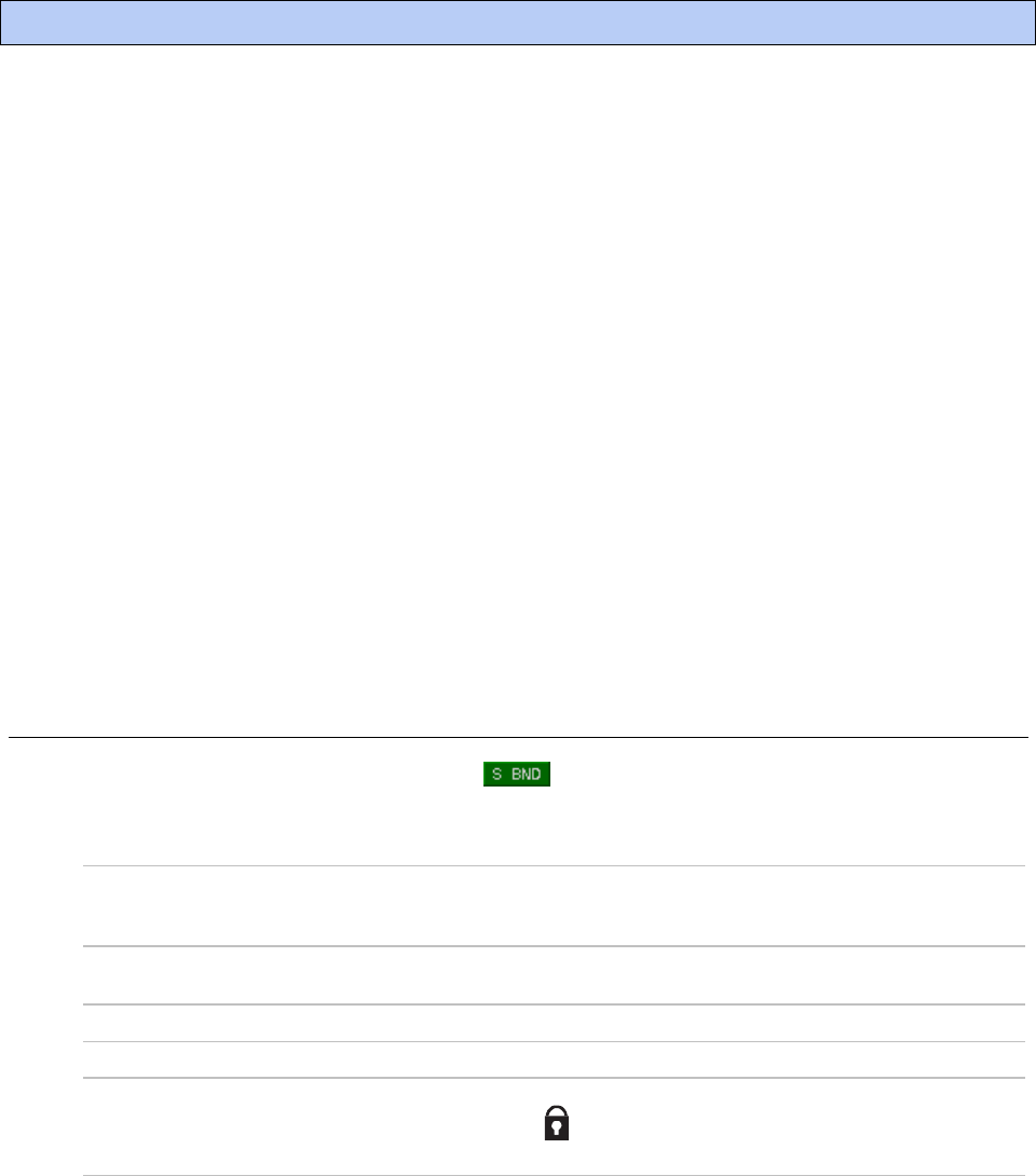
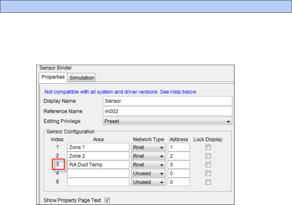
Step 1: Add a Sensor Binder microblock
From the Snap
Net I/O
microblock menu, add 1
Sensor Binder
microblock to the workspace to enable
communication between microblocks in the control program and up to 5 ZS Sensors. Enter the following
information in the Property Editor.
Sensor Configuration
The Index number is a reference number for each sensor that you define in
this microblock. ASVI and BSVI microblocks will refer to the sensors by their
index number.
Area
Type an intuitive name for the ZS sensor's location. This name will appear in
the ASVI, BSVI, and Setpoint microblocks in the i-Vu interface.
Network Type
Select Rnet for each ZS Sensor that you define.
Address
The physical address (0–14) set on the ZS sensor's DIP switches.
Lock Display
Check to lock a ZS Pro or ZS Pro-F sensor's buttons. The sensor's Home
screen will display a icon. The lock can be overridden in the i-Vu interface
or at the sensor by a user that knows the override procedure.
Creating Snap control programs for ZS Sensors
Creating Snap control programs for ZS Sensors
ZS Sensor CARRIER CORPORATION ©2020
Applications Guide All rights reserved
6
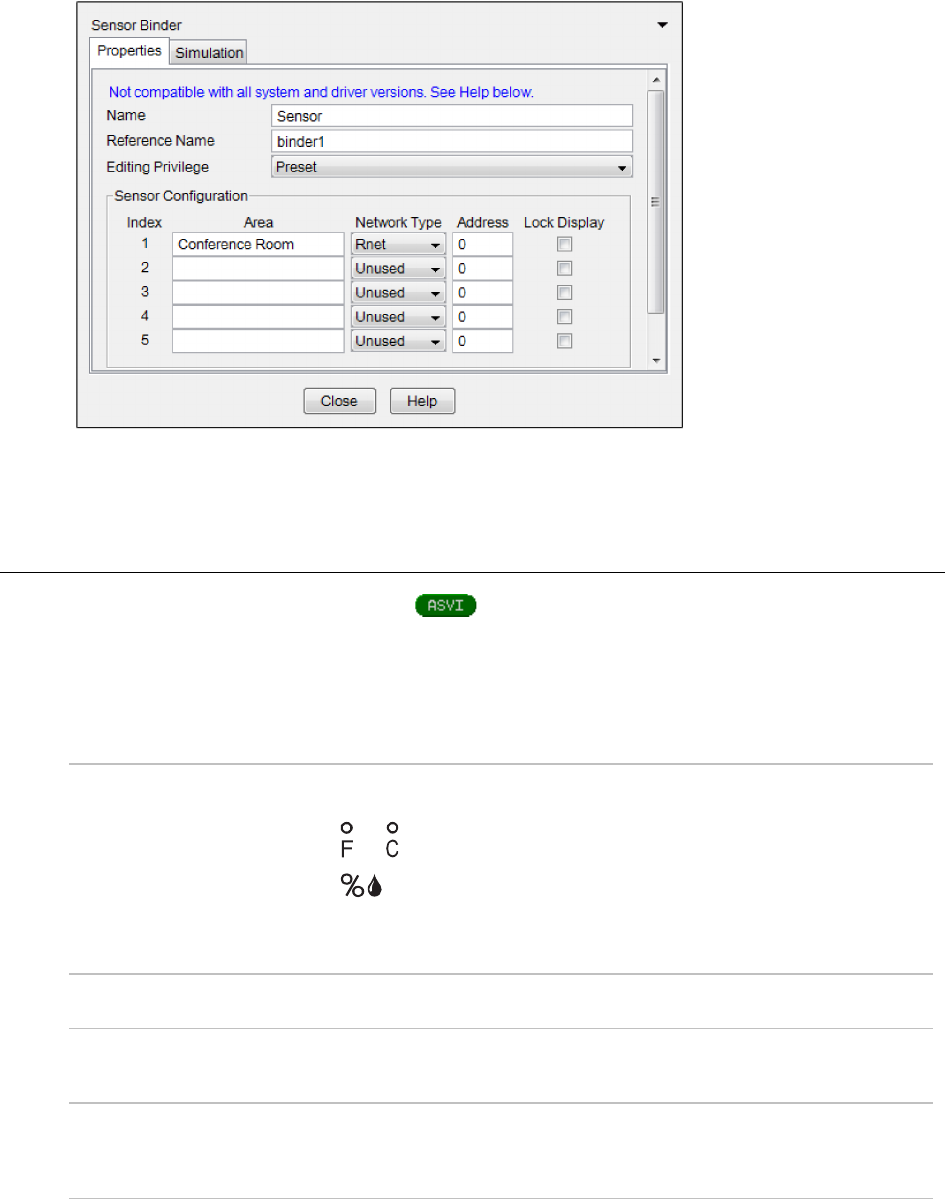
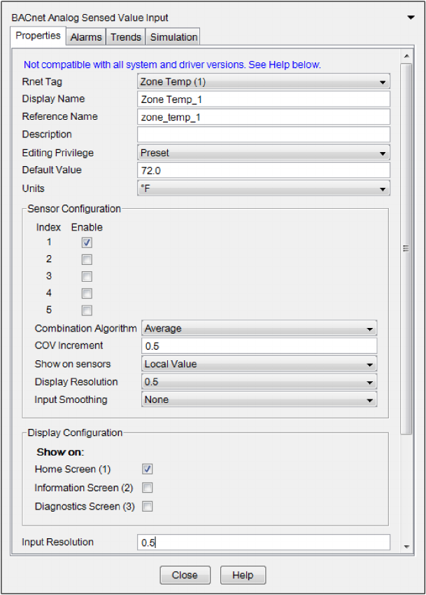
Step 2: Add Analog Sensed Value Input microblocks
From the
Net I/O
microblock menu, add one
Analog Sensed Value Input
(
ASVI
) microblock for each type
of sensed value (temperature, humidity, CO2, or VOC) that you want to retrieve from the ZS sensor(s). For
example, the first ASVI may retrieve temperature, and the second may retrieve humidity, etc. A control program
can have only one ASVI for each type of sensed value. Enter the following information in the Property Editor.
NOTE
If your control program needs to retrieve temperature or humidity values from ZS zone sensors and ZS duct
or pipe sensors, use the same ASVI microblock and select the
Zone Temp
or
Zone Humidity
Rnet tag.
Rnet Tag
The Rnet tag determines which value (Temperature, Humidity, CO2, or VOC)
is retrieved from the ZS Sensor. A zone sensor's screen will display:
or for Zone Temp
Zone Humidity
CO2
for Zone CO2
UOC
for Zone VOC
Default Value
The value that the microblock outputs when communication with all enabled
sensors fails or during sensor startup.
Units
The unit of measurement of the microblock's present value. Select from the
BACnet engineering units in this droplist. For some microblocks, you can
customize the droplist by selecting
Options
>
Preferences
>
Droplist Options
.
Index/Enable
The Index number corresponds to the ZS sensors defined in the Sensor
Binder microblock. Check
Enable
for each sensor that you want to include in
the combination algorithm used to determine the output value of the
microblock.
Creating Snap control programs for ZS Sensors
ZS Sensor CARRIER CORPORATION ©2020
Applications Guide All rights reserved
7
Combination Algorithm
If using more than 1 sensor, select how the enabled sensors' values are to
be combined to determine the microblock's output value. When the
calculation is performed, only sensors with a valid value are included.
COV Increment
To reduce Rnet traffic, you can force the microblock to update its output only
when the sensed value changes by more than the
COV Increment
.
Show on Sensors
Select
Local Value
to have each enabled sensor display its individual sensed
value, or
Calculated Value
to have each sensor display the value determined
by the
Combination Algorithm
.
Display Resolution
Defines the resolution of the value to be displayed on the sensor. For
example, 1 displays only integers (example: 74) and 0.5 displays values to
the nearest 0.5 (example: 74.5).
Input Smoothing
If the raw value from the sensor changes frequently, you can select one of
the following options to send out an average of several readings on the
output wire.
Select...
To send out the...
None
Minimum
Medium
Maximum
Raw value
Average of the last 2 readings
Average of the last 5 readings
Average of the last 9 readings
Show on
Check the zone sensor screen(s) that you want this microblock's value
displayed on.
Input Resolution
The increment by which the microblock updates the value on its output wire
in a running system.
The
Resolution
format is used to truncate the microblock’s actual value. For
example, if you enter a value from:
• 0.1 to 0.9, the wire displays 1 digit to the right of the decimal
• 0.01 to 0.99, the wire displays 2 digits to the right of the decimal
• 1 or greater, the wire displays a whole number
The
Resolution
value determines the increment by which the present value is
updated. For example, if you enter:
• .2, the wire displays 8.4, 8.6, 8.8, ...
• .03, the wire displays 5.09, 5.12, 5.15, ...
• 10, the wire displays 30, 40, 50, ...
Creating Snap control programs for ZS Sensors
ZS Sensor CARRIER CORPORATION ©2020
Applications Guide All rights reserved
8
Creating Snap control programs for ZS Sensors
ZS Sensor CARRIER CORPORATION ©2020
Applications Guide All rights reserved
9
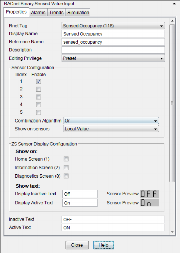
Step 3: Add Binary Sensed Value Input microblocks if using ZS Pro
motion sensor
From the
Net I/O
microblock menu, add one
Binary Sensed Value Input
(
BSVI
) microblock that will read a
binary value from up to 5 ZS motion sensors, and makes the value available to the control program on an output
wire. If the Rnet has more than one ZS motion sensor, the microblock's combination algorithm determines
whether the output value is based on a single sensor or all sensors having the same value.
Rnet Tag
All values from a ZS Sensor must have an Rnet tag that defines what type of
information this microblock's value represents.
NOTE
If the Rnet tag droplist does not have the tag you want, you can create
a custom tag in Snap.
Index/Enable
The Index number corresponds to the ZS sensors defined in the Sensor
Binder microblock. Check
Enable
for each sensor that you want to include in
the combination algorithm used to determine the output value of the
microblock.
Combination Algorithm
If using more than 1 sensor, select how the enabled sensors' values are to
be combined to determine the microblock's output value. Select:
And
to output 1 if all sensors have a value of 1, otherwise output 0
Or
to
output 1 if any sensor has a value of 1, otherwise output 0
Show on Sensors
Select
Local Value
to have each enabled ZS Pro or Pro-F sensor display its
individual sensed value, or
Calculated Value
to have each ZS sensor display
the value determined by the
Combination Algorithm
.
Show on
Check the ZS Pro or Pro-F sensor screen(s) that you want this microblock's
value displayed on.
Show text
Enter the text that the ZS sensor's display will show with the microblock's
output is off or false (inactive) or when it is on or true (active).
Inactive Text
The
Inactive Text
your system displays when the microblock's output is off, or
false.
Active Text
The
Active Text
your system displays when the microblock's output is on, or
true.
Creating Snap control programs for ZS Sensors
ZS Sensor CARRIER CORPORATION ©2020
Applications Guide All rights reserved
10

Creating Snap control programs for ZS Sensors
ZS Sensor CARRIER CORPORATION ©2020
Applications Guide All rights reserved
11
Step 4: Add a BACnet Setpoint microblock
The BACnet Setpoint microblock allows you to define the setpoint adjustment functionality for a ZS sensor and
allows a ZS Pro or Pro-F to display setpoint values that can be edited from the sensor.
From the
Control
microblock menu, add a
BACnet Setpoint
microblock to determine how the user will
interact with the sensor's Setpoint Adjustment screen. Enter the following information in the Property Editor.
Enable Rnet
Check to allow this microblock to communicate its value(s) to and from a ZS
sensor.
Setpoint Adjust Limit (+/-)
The maximum amount (degrees) by which the user can adjust the zone's
setpoints from a zone sensor if an
Adjust setpoint offset
option is selected
under
Sensor Setpoint Adjust Option
.
Clear adjustment on transition
to unoccupied
ZS Pro and Pro-F sensors - Check to have the Setpoint microblock reset the
sensor's setpoint adjustment value to 0 each time the microblock's OCC
input changes to false (off) and leave it at 0 when the OCC input changes
again to true (on) or when the zone enters a timed local override condition.
If this field is not checked, the Setpoint microblock will not reset the sensor's
adjusted value for the next occupied period.
ZS Plus sensor - This field does not apply. The Setpoint microblock cannot
reset the sensor's adjusted value.
NOTE
The Setpoint microblock does not use adjusted values during
unoccupied periods.
Edit Increment
The amount (degrees) that the zone temperature setpoint is adjusted by
each press of a ZS Pro sensor's or button. For a ZS Plus sensor, slider
adjustments are read to the nearest increment.
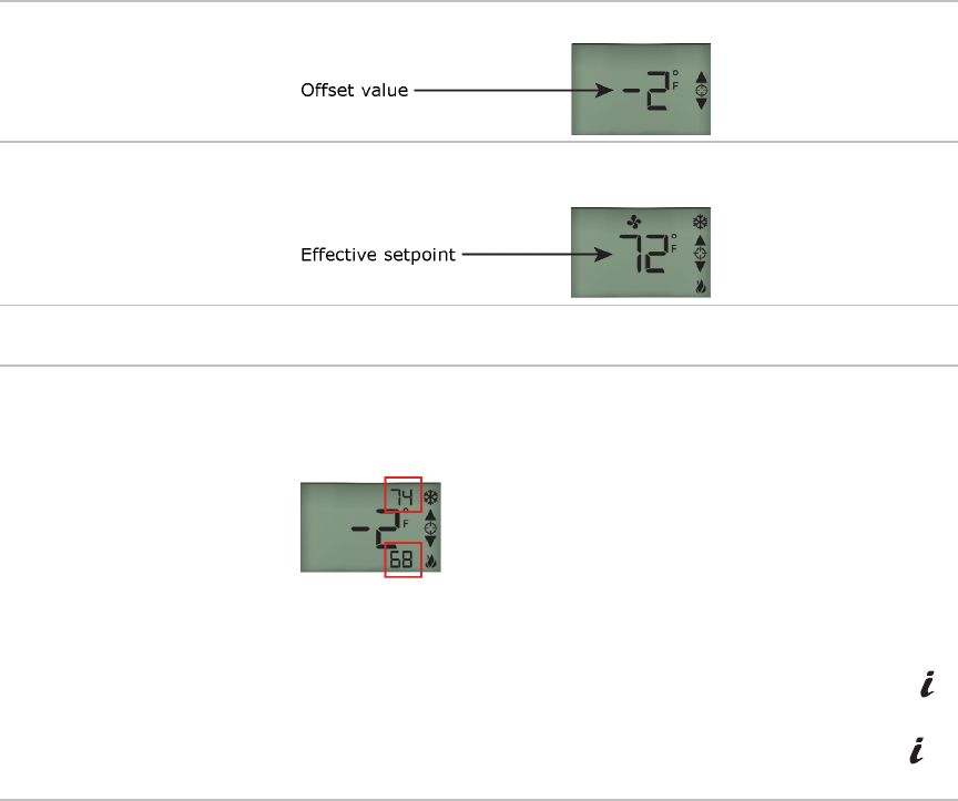
Sensor Setpoint Adjust Option
Select how you want to see and adjust setpoints on a ZS sensor.
Disabled
Prevents editing the setpoints at the sensor.
1.
Adjust setpoint offset.
Center display=Zone
Temp. Show effective
setpoints.
Example of sensor display:
2.
Adjust base setpoint.
Center display=Zone
Temp. Show effective
setpoints.
Example of sensor display:
3.
Adjust setpoint offset.
Center display=Offset
value. Show effective
setpoints.
Example of sensor display:
Creating Snap control programs for ZS Sensors
ZS Sensor CARRIER CORPORATION ©2020
Applications Guide All rights reserved
12
4.
Adjust setpoint offset.
Center display=Offset
value. Hide effective
setpoints.
Example of sensor display:
5.
Hospitality mode
Displays only the active effective setpoint or the average of the heating and
cooling setpoints if the mode is auto. The effective setpoint is adjustable.
Editable
Check under
Occupied
or
Unoccupied
to make each setpoint editable on a
ZS Sensor.
Show on
Check the sensor screen(s) that you want
Occupied
,
Unoccupied
and
Effective Setpoints
displayed on.
Home Screen (1)
: Effective Setpoints are displayed on the Home screen in
the following locations:
On the Information or Diagnostics screen, effective setpoints cycle through in
the primary value field and show
EFF
in the Rnet tag field. See Appendix B:
ZS Sensor screen fields (page
37).
Information Screen (2)
: This screen is accessed by pressing the sensor's
button.
Diagnostics Screen (3)
: This screen is accessed by holding the sensor's
button for at least 3 seconds.
NOTE
To enable/disable the setpoint adjustment functionality of specific sensors on the Rnet, double-click the
BACnet Setpoint microblock on the
Logic
page in a running system. On the
Sensor
tab, check/uncheck a sensor's
Allow Setpoint Adjust
checkbox.
Creating Snap control programs for ZS Sensors
ZS Sensor CARRIER CORPORATION ©2020
Applications Guide All rights reserved
13
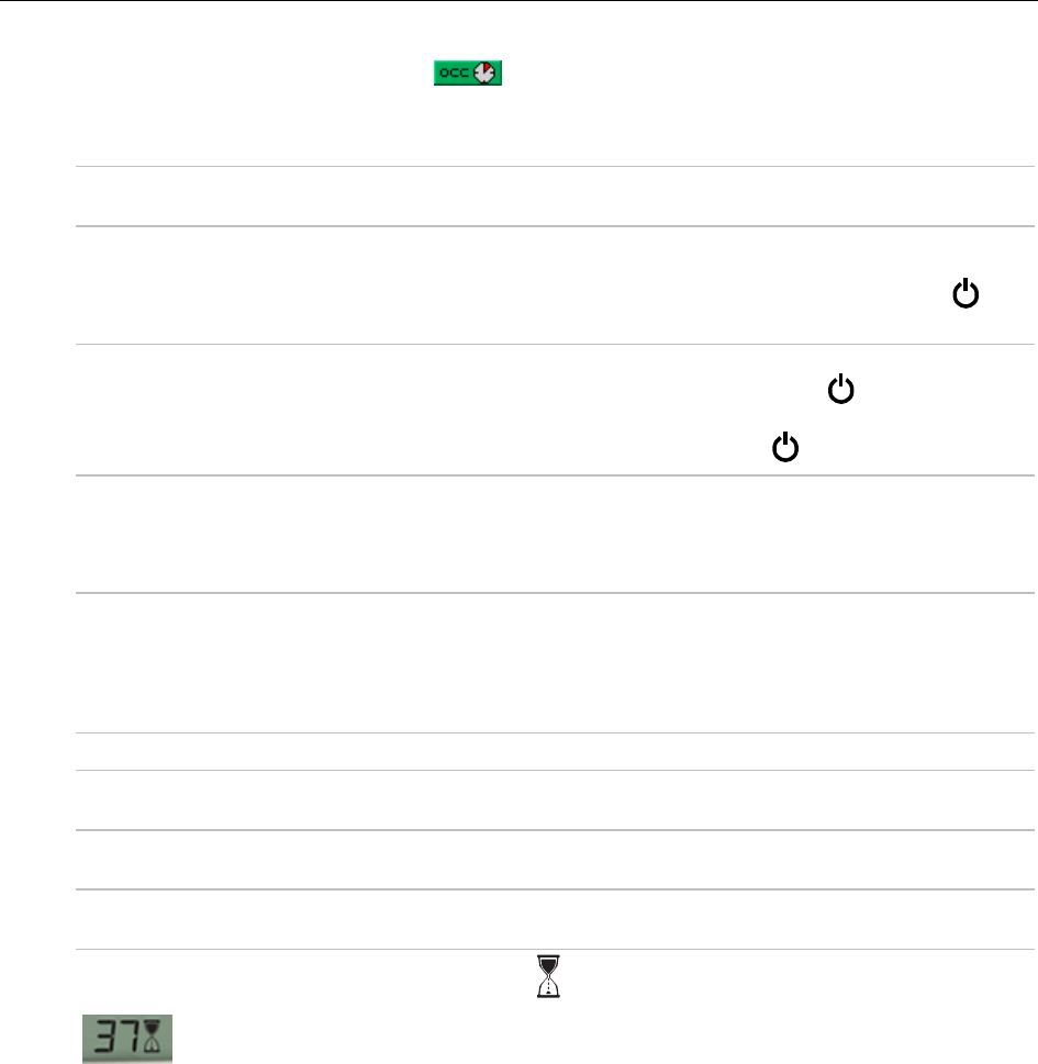
Step 5: Add a BACnet Time Clock microblock
The BACnet Time Clock microblock enables the ZS Sensor's override function and controls its green Occupied LED.
From the
Control
microblock menu, add a
BACnet Time Clock with TLO and Override Status
microblock
to determine how the user can interact with your schedule through the ZS Sensor. Enter the following information
in the Property Editor.
Enable Rnet
Check to allow this microblock to communicate its value(s) to and from a ZS
sensor.
Allow 'Continuous' Override
Check to allow a user to force a zone into an occupied state for an indefinite
amount of time. The override remains in effect until the schedule transitions
to occupied or until a user manually clears it by pressing the sensor's
button twice.
Allow Force Unoccupied
Check to allow a user to save energy by forcing the zone into an unoccupied
state. To force unoccupied, a user holds a ZS sensor's
button for at least 3
seconds. This override state remains in effect until the schedule transitions to
unoccupied or until a user presses the sensor's
button.
Force Unoccupied without
Delay
Check to allow a user to force a zone to unoccupied immediately instead of
the normal 3-second delay.
NOTE
This feature is unavailable if
Allow TLO Set During Occupied
is
checked.
Allow TLO Set During Occupied
Check to allow a user to activate a timed local override while the zone is
scheduled occupied. This allows a user to extend the zone's occupied time
without the zone having to go unoccupied first.
NOTE
This feature is unavailable if
Force Unoccupied without Delay
is
checked.
Timed Local Override
Increment
Minutes the microblock adds to the zone's occupied time for each press of the
zone's local override button or switch.
Maximum Duration
Maximum value (up to 960 minutes) the microblock outputs regardless of
additional pulses from the controller's input.
Optional
tab -
Allow for External
Scheduling
See External Scheduling.
During an override, the bottom of the screen will show and the minutes remaining in the override.

Creating Snap control programs for ZS Sensors
ZS Sensor CARRIER CORPORATION ©2020
Applications Guide All rights reserved
14
Step 6: Add optional values, statuses, and icons
Use the following microblocks for optional icons, values, or statuses that you want to display on the sensors.
Individual uses are discussed throughout this document. See the Microblock Reference Help for a full description
of each microblock.
BACnet Analog Value Parameter
BACnet Binary Value Parameter
BACnet Multi-State Value Parameter
BACnet Analog Value Status
BACnet Binary Value Status
BACnet Multi-State Value Status
On each microblock's
Rnet
tab, you must check the
Enable Rnet
field to have the microblock communicate values
with the ZS Sensors, and you must select the appropriate
Rnet Tag
.
See Icons and text indicators (page
15) for instructions on adding specific optional icons.
Step 7: Set the order of information displayed on a sensor
To program the display order and rotation time of information on each screen, select
Reorder
>
Sensor Display
Order
. In this example, Zone Temp displays on the Home Screen for 10 seconds, then Zone Humidity, Zone CO2,
and Zone VOC each display for 10 seconds.
To change the display order, select the microblock(s) you want to move, then click or .
Icons and text indicators
ZS Sensor CARRIER CORPORATION ©2020
Applications Guide All rights reserved
15
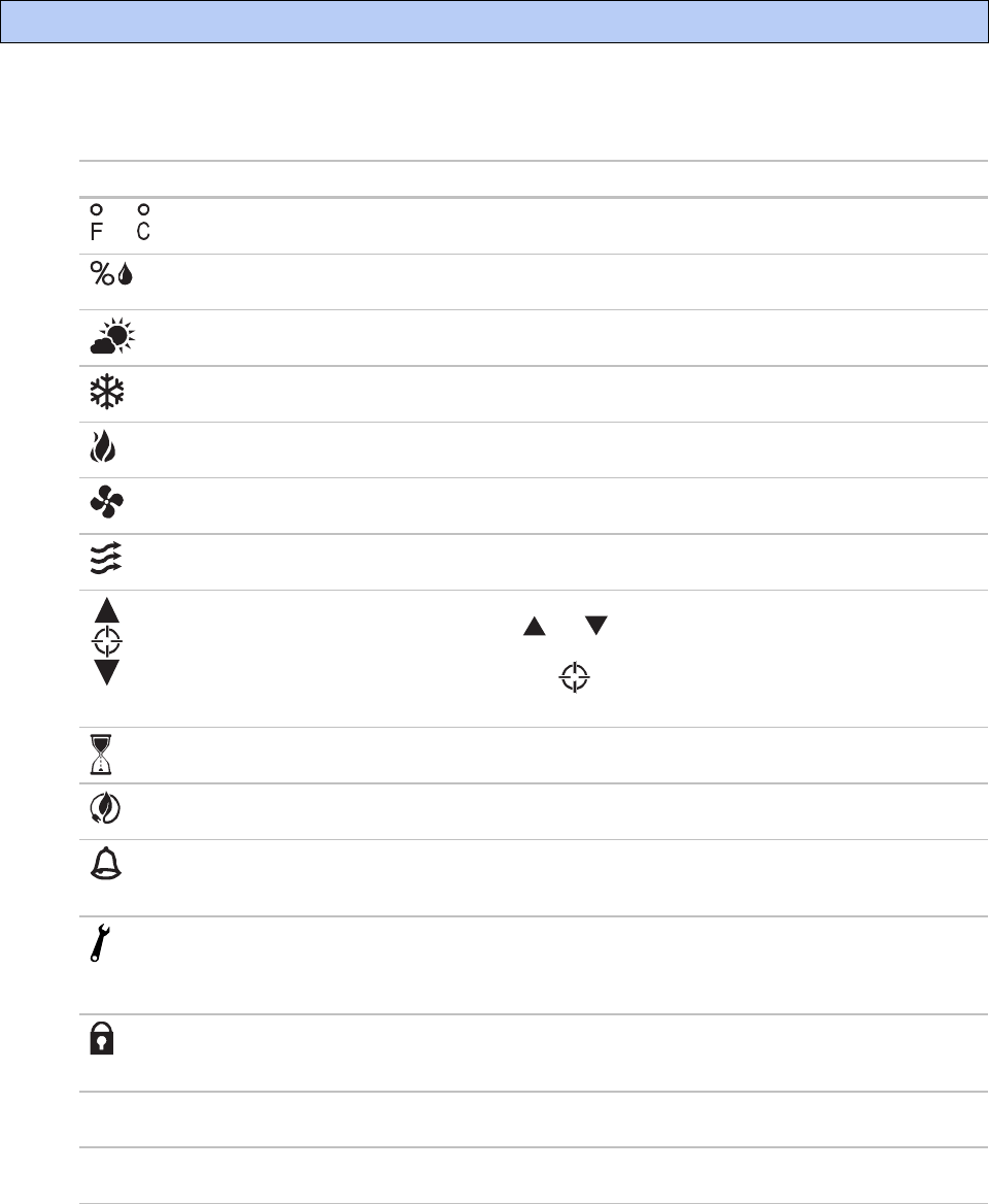
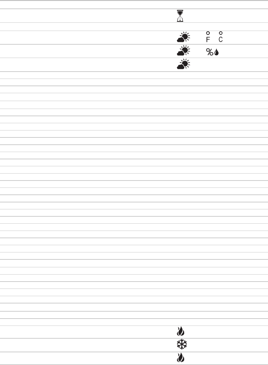
The following table shows all icons that can display on a ZS Sensor display. The image below the table shows the
location of each icon on the sensor's screen. See Appendix A: Rnet Tags (page 32) to see which tags are
associated with each icon or text indicator.
This item...
Indicates...
Notes
or
The temperature is Fahrenheit or Celsius.
Shown for any temperature that has
°F
or
°C
selected in the
Units
field.
The value shown is percent relative humidity. Shown for any humidity value that has
%RH
selected in the
Units
field.
The value shown is outside air temperature
or humidity.
See Outside air icon (page 16) to program.
Cooling See Zone HVAC Modes (page 23) to
program.
Heating See Zone HVAC Modes (page 23) to
program.
The zone's fan is running. See Fan status and control (page 21) to
program.
The fan speed. See Fan status and control (page 21) to
program.
The value(s) in the display, typically
setpoints, are editable using the and
buttons. If the control program specifies that
the value is not editable, you will see
without arrows.
For AVP, BVP, or MSVP values, or the
Setpoint adjust value from the BACnet
Setpoint microblock.
The sensor is in a timed override. Automatically generated by the BACnet
Time Clock microblock.
The equipment is running in an energy
saving mode defined in the control program.
See Energy saving mode icon (page 17) to
program.
An alarm condition exists. If programmed,
the Information screen or Diagnostic Screen
may provide details on the alarm.
See Alarm icon (page 17) to program.
A maintenance condition exists. If
programmed, the Information screen or
Diagnostic Screen may provide details on the
maintenance condition.
See Maintenance icon (page 18) to
program.
The sensor's buttons are locked by the
control program or because a user locked
them at the sensor.
See Step 1: Add a Sensor Binder
microblock (page 5).
OCC
The displayed setpoint is an occupied
setpoint.
Automatically generated by the BACnet
Setpoint microblock.
UnOCC
The displayed setpoint is an unoccupied
setpoint.
Automatically generated by the BACnet
Setpoint microblock.
Icons and text indicators
Icons and text indicators
ZS Sensor CARRIER CORPORATION ©2020
Applications Guide All rights reserved
16
This item...
Indicates...
Notes
CO2
The value shown is CO
2
. Shown for a CO
2
Rnet tag.
UOC
The value shown is VOC. Shown for a VOC Rnet tag.
EFF
The value shown is the effective setpoint. Automatically generated by the BACnet
Setpoint microblock.
EI
Environmental Index Shown for EI Rnet tag.
TIPS
• Rnet Tag numbers seen on a sensor are not intuitive. We recommend that you use the display text to clearly
identify a value.
NOTE
The following letters do not display on a sensor screen: K, M, Q, V, W, X
• We recommend that you limit the information displayed on the Home screen. Use the Information screen or
Diagnostic screen to display any values that require display text to describe them.
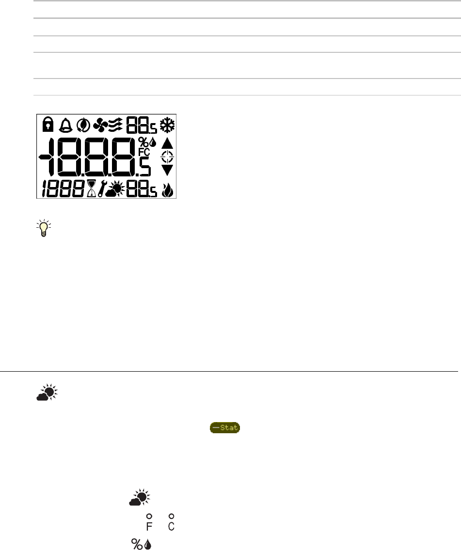
Outside air icon
To display this icon with the outside air temperature, humidity, or CO
2
:
1 From the
Sys Out
microblock menu, add a
BACnet Analog Value Status
microblock.
2 On the Property Editor's
Rnet
tab, check
Enable Rnet
.
3 Select an Outside Air option from the
Rnet Tag
drop-down list.
4 Check a
Show on
screen to display the value and icon.
NOTE
In addition to :
○ Temperature shows or .
○ Humidity shows .
○ CO
2
shows
CO2.
Icons and text indicators
ZS Sensor CARRIER CORPORATION ©2020
Applications Guide All rights reserved
17
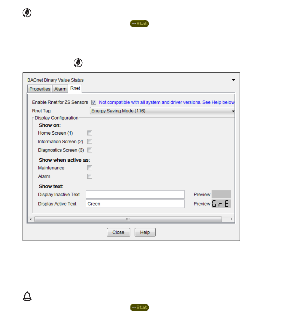
Energy saving mode icon
1 From the
Sys Out
microblock menu, add a
BACnet Binary Value Status
microblock.
2 On the Property Editor's
Rnet
tab, check
Enable Rnet
.
3 Select
Energy Saving Mode (116)
from the
Rnet Tag
drop-down list.
In the example below, will display on the Home screen when in the Energy Saving mode.
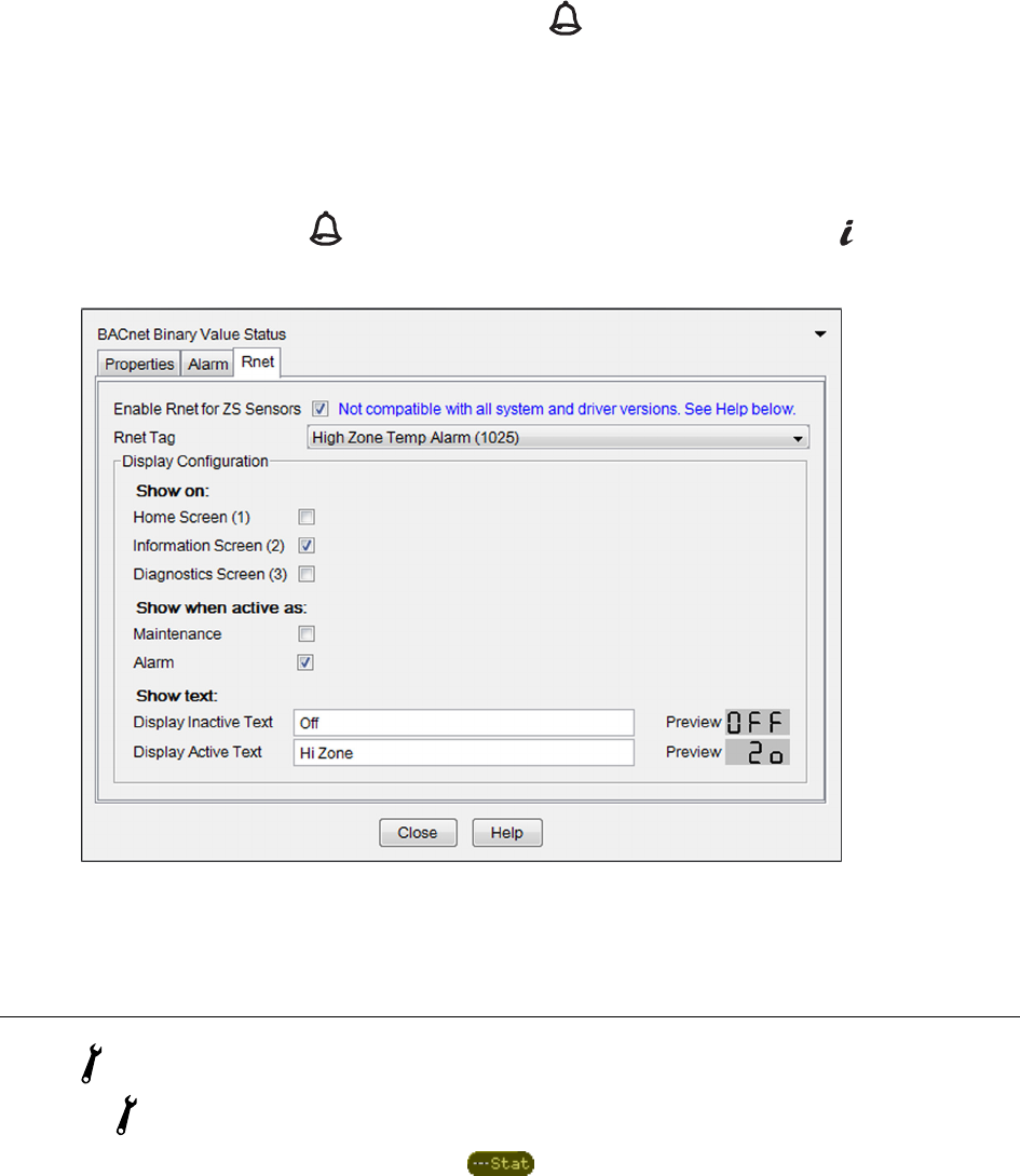
Alarm icon
1 From the
Sys Out
microblock menu, add a
BACnet Binary Value Status
microblock.
2 On the Property Editor's
Rnet
tab, check
Enable Rnet
.
3 Select a pre-defined alarm (1XXX) from the
Rnet Tag
drop-down list.
Icons and text indicators
ZS Sensor CARRIER CORPORATION ©2020
Applications Guide All rights reserved
18
4 Under
Show when active as
, check
Alarm
to display on the Home screen and any other selected screen.
5 Optional: To display details about the active alarm, check a
Show on
screen to display the
Active Text
and
Rnet tag.
NOTE
When active, alarm information will automatically display first on the assigned screen, regardless of
the display order you define.
In the example below, the Rnet tag for
High Zone Temp Alarm (1025)
is set to show on the
Information screen
.
Because
Alarm
is checked, will display on the Home screen. When the user presses the button, the
Information screen will show the icon, the Rnet Tag
1025
, and the Active Text
Hi Zone
.
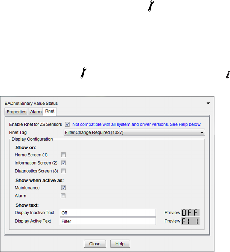
Maintenance icon
The
indicates a maintenance condition versus an alarm condition.
1 From the
Sys Out
microblock menu, add a
BACnet Binary Value Status
microblock.
2 On the Property Editor's
Rnet
tab, check
Enable Rnet
.
3 Select a pre-defined maintenance condition (1XXX) from the
Rnet Tag
drop-down list.
Icons and text indicators
ZS Sensor CARRIER CORPORATION ©2020
Applications Guide All rights reserved
19
4 Under
Show when active as
, check
Maintenance
to display on the Home screen and any other selected
screen.
5 Optional: To display details about the active maintenance condition, check a
Show on
screen to display the
Active Text
and Rnet tag.
NOTE
When active, maintenance condition information will automatically display first on the assigned
screen, regardless of the display order you define.
In the example below, the Rnet tag for
Filter Change Required (1027)
is set to show on the
Information screen
.
Because
Maintenance
is checked, will display on the Home screen. When the user presses the button, the
Information screen will show the icon, the Rnet tag
1027
, and the Display Active Text
Filter
.
Programming specific applications
ZS Sensor CARRIER CORPORATION ©2020
Applications Guide All rights reserved
20
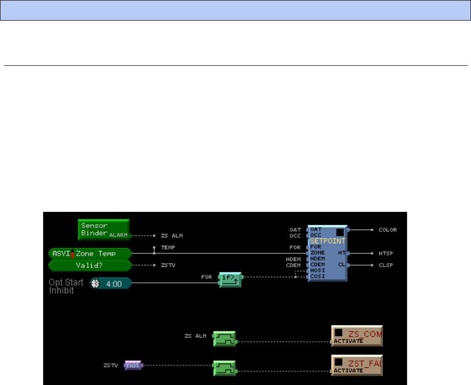
Generating alarms
You can add logic to a control program to generate an alarm for the following conditions:
• A sensor has stopped communicating
• A sensor is not sending a valid value
Alarming for loss of communications
1 Tie the Sensor Binder microblock's
Alarm
output to an Alarm microblock. The
Alarm
output will be true when
any sensor is in alarm.
2 Add a
Delay On Make microblock to prevent nuisance alarms during startup or power failure.
Alarming for sensed values
1 To detect if a sensor's value is no longer valid, do the following:
2 Assign only one sensor to an ASVI or BSVI microblock.
3 Tie the
Valid
output to a not microblock since the valid output will be false when in alarm.
4 Attach an
Alarm microblock to notify the user if the sensor in the ASVI or BSVI microblock has gone into error.
5 Add a Delay On Make microblock to prevent nuisance alarms during startup or power failure.
See the Microblock Reference for details of each microblock's alarming conditions.
Programming specific applications
Programming specific applications
ZS Sensor CARRIER CORPORATION ©2020
Applications Guide All rights reserved
21
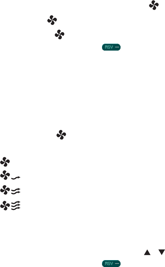
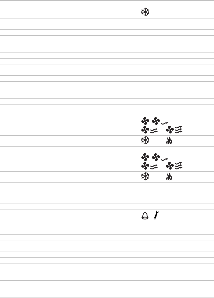
Fan status and control
A ZS Pro or ZS Pro-F sensor can:
• Show fan status (
when on)
• Show fan speed ( Low, Medium, High)
• Let the user manually control fan speed
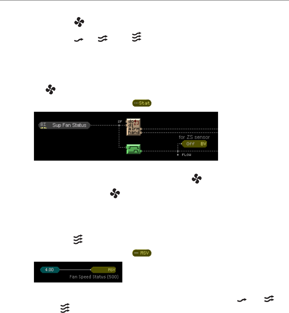
To show on the Home screen when the fan is on
1 From the
Sys Out
microblock menu, add a
BACnet Binary Value Status
microblock.
2 On the Property Editor's
Rnet
tab, check
Enable Rnet
.
3 Select
Fan Status (100)
from the
Rnet Tag
drop-down list to display on the Home screen.
4 Do not check a
Show on
screen. displays on the Home screen when active.
To show fan speed on the Home screen
1 From the
Sys Out
microblock menu, add a
BACnet Multi-State Value Status
microblock.
2 On the Property Editor's
Rnet
tab, check
Enable Rnet
.
3 Select
Fan Speed Status (500)
from the
Rnet Tag
drop-down list to show the fan speed (Low),
(Medium),
(High) on the Home screen.
4 Do not check a
Show on
screen. The appropriate fan speed icon displays on the Home screen based on the
microblock's value.
Programming specific applications
ZS Sensor CARRIER CORPORATION ©2020
Applications Guide All rights reserved
22
ZS Pro-F: To program manual fan speed control using the button
NOTE
The ZS Pro-F's button works only when the zone is occupied (green LED is on).
To program the sensor's
button:
1 From the
Sys In
microblock menu, add a
BACnet Multi-State Value Parameter
microblock.
2 On the Property Editor's
Rnet
tab, check
Enable Rnet
.
3 Select the
Fan Speed Request (600)
from the
Rnet Tag
drop-down list.
4 Check
Editable
.
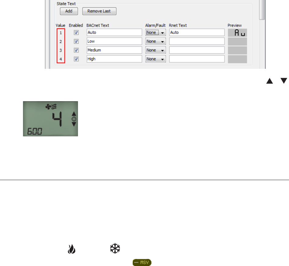
5 On the
Properties
tab in the
Rnet Text
fields, type the text that you want to a sensor to show for each fan
speed.
NOTES
○ The letters K, M, Q, W, X do not display on a screen.
○ If you do not enter text, the sensor will show the Value number for the fan speed.
When a user presses the
button, the screen initially shows the current fan speed. With each press of the
button, the display shows one of the following options:
Auto. The control program determines the speed.
Low speed
Medium speed
High speed
ZS Pro: To program manual fan speed control using the or button
1 From the
Sys In
microblock menu, add a
BACnet Multi-State Value Parameter
microblock.
2 On the Property Editor's
Rnet
tab, check
Enable Rnet
.
3 Select the
Fan Speed Request (600)
from the
Rnet Tag
drop-down list.
4 Check
Editable
.
Programming specific applications
ZS Sensor CARRIER CORPORATION ©2020
Applications Guide All rights reserved
23
5 Select
Show on
the
Information Screen
or
Diagnostics Screen
.
6 On the
Properties
tab in the
Rnet Text
fields, type the text that you want to a sensor to show for each fan
speed.
NOTES
○ The letters K, M, Q, W, X do not display on a screen.
○ If you do not enter text, the sensor will show the Value number for the fan speed.
When a user goes to the information screen, it will initially show the current fan speed. The user taps the
or
button to cycle through the fan speed options. The screen below shows High speed indicated by the icons and the
number 4 (no text was entered for that speed in the Property Editor).
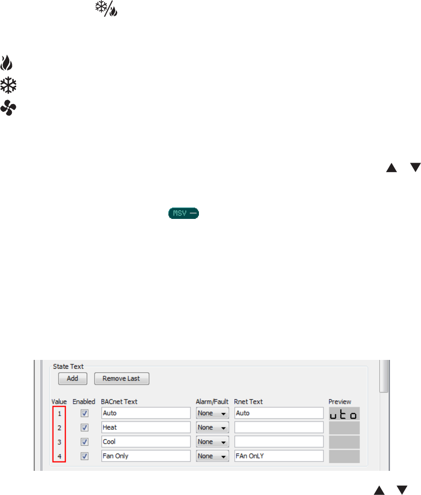
Zone HVAC modes
A ZS Pro or ZS Pro-F sensor can:
• Show heating or cooling status
• Let the user manually run heating only, cooling only, or fan only
To show Heating and Cooling status
1 From the
Sys Out
microblock menu, add a
BACnet Multi-State Value Status
microblock.
2 On the Property Editor's
Rnet
tab, check
Enable Rnet
.
3 Select
Zone Mode Status (501)
from the
Rnet Tag
drop-down list.
Programming specific applications
ZS Sensor CARRIER CORPORATION ©2020
Applications Guide All rights reserved
24
4 Do not check a
Show on
screen. and display on the Home screen when active.
5 Configure the logic going to the MSV microblock so that it generates a
2
when the unit is in heating mode to
display
, and
3
when the unit is in cooling mode to display . When the logic generates
1
or
4
, neither
icon displays.
ZS Pro-F: To program manual HVAC control (fan only, cooling only, or heating only) using the
button
NOTE
The ZS Pro-F's button works only when the zone is occupied (green LED is on).
To program the sensor's button:
1 From the
Sys In
microblock menu, add a
BACnet Multi-State Value Parameter
microblock.
2 On the Property Editor's
Rnet
tab, check
Enable Rnet
.
3 Select the
Zone Mode Request (601)
from the
Rnet Tag
drop-down list.
4 Check
Editable
.
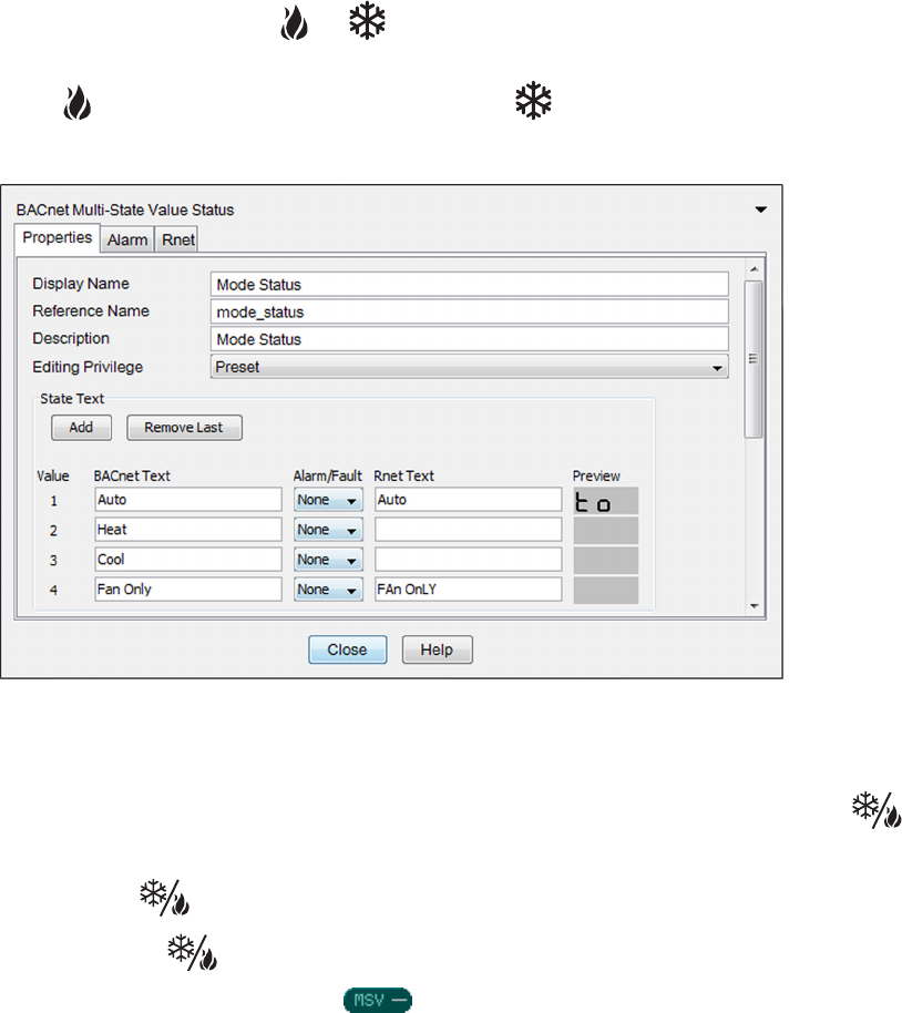
5 On the
Properties
tab in the
Rnet Text
fields, type the text that you want a sensor to show for each mode.
NOTES
○ The letters K, M, Q, W, X do not display on a screen.
○ If you do not enter text, the sensor will show the Value number for the mode.
Programming specific applications
ZS Sensor CARRIER CORPORATION ©2020
Applications Guide All rights reserved
25
When a user presses the button, the screen initially shows the current zone HVAC mode. With each press of
the button, the display shows one of the following options:
Auto
The control program determines the mode.
Heating only
Cooling only
Fan only
ZS Pro: To program manual HVAC control (fan only, cooling only, or heating only) using the or
button
1 From the
Sys In
microblock menu, add a
BACnet Multi-State Value Parameter
microblock.
2 On the Property Editor's
Rnet
tab, check
Enable Rnet
.
3 Select the
Zone Mode Request (601)
from the
Rnet Tag
drop-down list.
4 Check
Editable
.
5 Select
Show on
the
Information Screen
or
Diagnostics Screen
.
6 On the
Properties
tab in the
Rnet Text
fields, type the text that you want a sensor to show for each mode.
NOTES
○ The letters K, M, Q, W, X do not display on a screen.
○ If you do not enter text, the sensor will show the Value number for the mode.
When a user goes to the information screen, it will initially show the current mode. The user taps the
or
button to cycle through the mode options.
Programming specific applications
ZS Sensor CARRIER CORPORATION ©2020
Applications Guide All rights reserved
26
Hospitality Mode
Hospitality mode is typically used for hotel/motel rooms. The Home screen always displays the active effective
setpoint or the average of the heating and cooling setpoints if the mode is auto. The effective setpoint is
adjustable. The sensor also displays any active status icons.
To use this mode, select
Hospitality mode
on the
Rnet
tab of the BACnet Setpoint microblock.
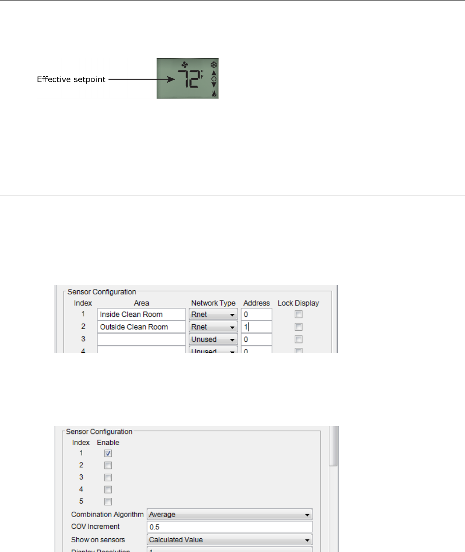
Clean room application
This application requires two display sensors, one inside the clean room and one on the outside. While both
sensors have temperature sensing ability, only the temperature on the inside of the clean room should be used for
control. Both sensors should display the sensed temperature on the inside of the clean room.
You set up this scenario in the Sensor Binder microblock and the ASVI microblock for Zone Temp.
1 Define the 2 sensors in the Sensor Binder microblock.
2 In the Zone Temp ASVI microblock:
a) Check
Enable
for the first sensor (Index 1). Only that sensor's temperature value will be used.
b) Set
Show on sensors
to
Calculated Value
.
Programming specific applications
ZS Sensor CARRIER CORPORATION ©2020
Applications Guide All rights reserved
27
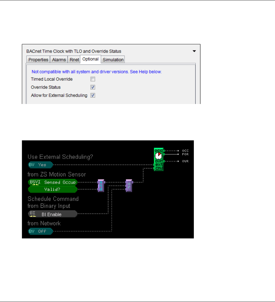
External Scheduling
The BACnet Time Clock microblock has 2 optional binary inputs that allow you to use an external schedule instead
of the built-in scheduling of the i-Vu® system. This method is used with the BSVI to schedule based on sensed
occupancy.
Check
Allow for External Scheduling
on the microblock's
Optional
tab to enable the
ext
and
cmd
inputs.
The
ext
input tells the Schedule Microblock to use the external "commanded to" input instead of the internal
schedule. When the top BV is on, the
cmd
input determines the schedule status and the sensor's green occupied
LED. See example below.
NOTE
The override and force unoccupied features of the ZS sensors will still work as normal when the Time Clock
microblock uses external schedules.
Setting Setpoint Adjust Limit from an external source
The BACnet Setpoint microblock has an optional analog input called
Setpoint Adjust Limit (-/+)
that takes over the
role of the built-in parameter of the same name found on the microblock's
Rnet
tab in the Property Editor. Check
Setpoint Adjust Limit (-/+)
on the
Optional
tab to expose the
SPADJ
input. When this input is activated, the built-in
parameter no longer works. For example, if the input value is 3, the user can adjust the zone setpoint up or down
3 degrees from the base. The adjustment applies to the cooling and heating setpoints.
Programming specific applications
ZS Sensor CARRIER CORPORATION ©2020
Applications Guide All rights reserved
28
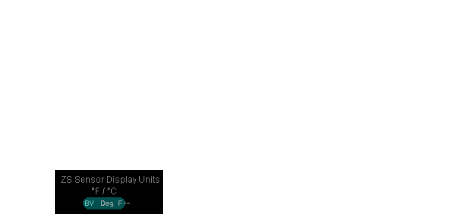
Modifying temperature display units on ZS Sensors
A ZS Pro does not have an
F/C
button like the ZS Pro-F to switch displayed temperature units (°F or °C). To
accomplish this through the control program, you can use a BACnet Binary Value Parameter microblock to control
the units that a ZS Pro sensor will display. This affects only the display, not the units used in the control program.
1 On the BACnet Binary Value Parameter microblock's
Rnet
tab, select
Sensor Temperature Units Display (800)
in the
Rnet Tag
field.
2 If you want to be able to change this microblock's value on the ZS Pro, check
Show on
the
Information
Screen
or
Diagnostics Screen
, and check the
Editable
box.
3 Type:
DEG F in the
Display Inactive Text
field
DEG C in the
Display Active Text
field
4 On the
Properties
tab, type the following so that you can recognize them in the i-Vu interface:
DEG F in the
Inactive Text
field
Deg C in the
Active Text
field
NOTE
We recommend that you do not use this scheme with a ZS Pro-F sensor. If you do and a user then presses
the
F/C
button on the side of the sensor, the units will reverse the effect of the microblock.
To use values from individual sensors in your control program
ZS Sensor CARRIER CORPORATION ©2020
Applications Guide All rights reserved
29
When using multiple ZS Sensors on a single Rnet, an ASVI microblock outputs the average, minimum, or
maximum value of the sensors. However, if you need to use the value of just one of the sensors, you can use an
Analog Network Input (ANI) microblock that addresses a specific ZS Sensor.
1 In the Snap application, select the Sensor Binder microblock and note the
Index
number for the sensor
whose value you want to use.
2 Verify that the sensor in enabled in the ASVI microblock.
To use values from individual sensors in your control program
To use values from individual sensors in your control program
ZS Sensor CARRIER CORPORATION ©2020
Applications Guide All rights reserved
30
NOTES
○ To retrieve the temperature from a ZS duct sensor, use an ASVI microblock with the
Rnet tag
set to
Zone
Temp
.
○ By default, the microblock's
Display Name
and
Reference Name
are based on the Rnet tag, but you can
change these if you want. In this example, the Display Name has been changed to
Temperature
.
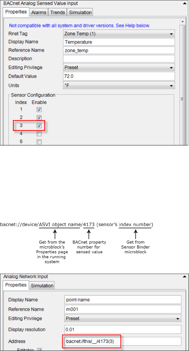
3 In the ANI microblock, enter the
Address
in the following format, but leave out the ASVI object name. See
example of address in the image below.
To use values from individual sensors in your control program
ZS Sensor CARRIER CORPORATION ©2020
Applications Guide All rights reserved
31
4 Select the controller on i-Vu's navigation tree.
5 Go to the
Properties
page >
Control Program
tab and expand
Configuration
>
Unit Configuration
. Ctrl+click
on the ZS property name to open the ASVI popup.
6 In the popup, on the
Properties
page >
Details
tab, scroll down to the
BACnet Configuration
section to get
the
Object Name
.
7 On the zone's
Properties
page >
Network Points
tab, enter the Object Name in the ANI's address. For this
example, the address would be:
bacnet://this/zone_temp_1/4173(3)
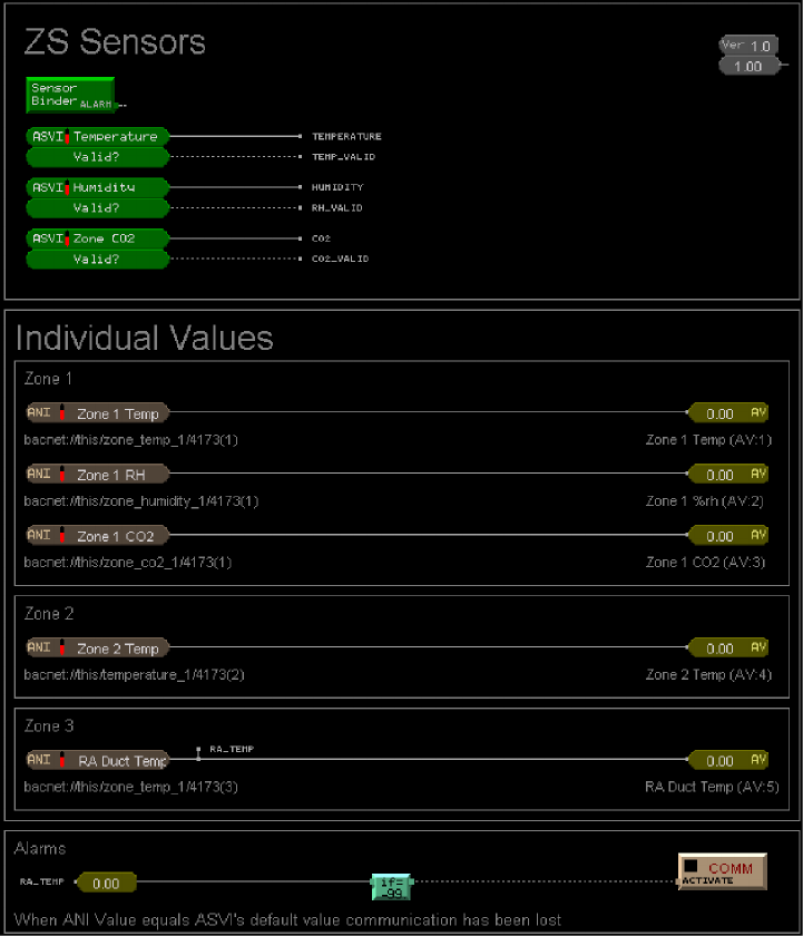
Example program:
Appendix A: Rnet tags
ZS Sensor CARRIER CORPORATION ©2020
Applications Guide All rights reserved
32
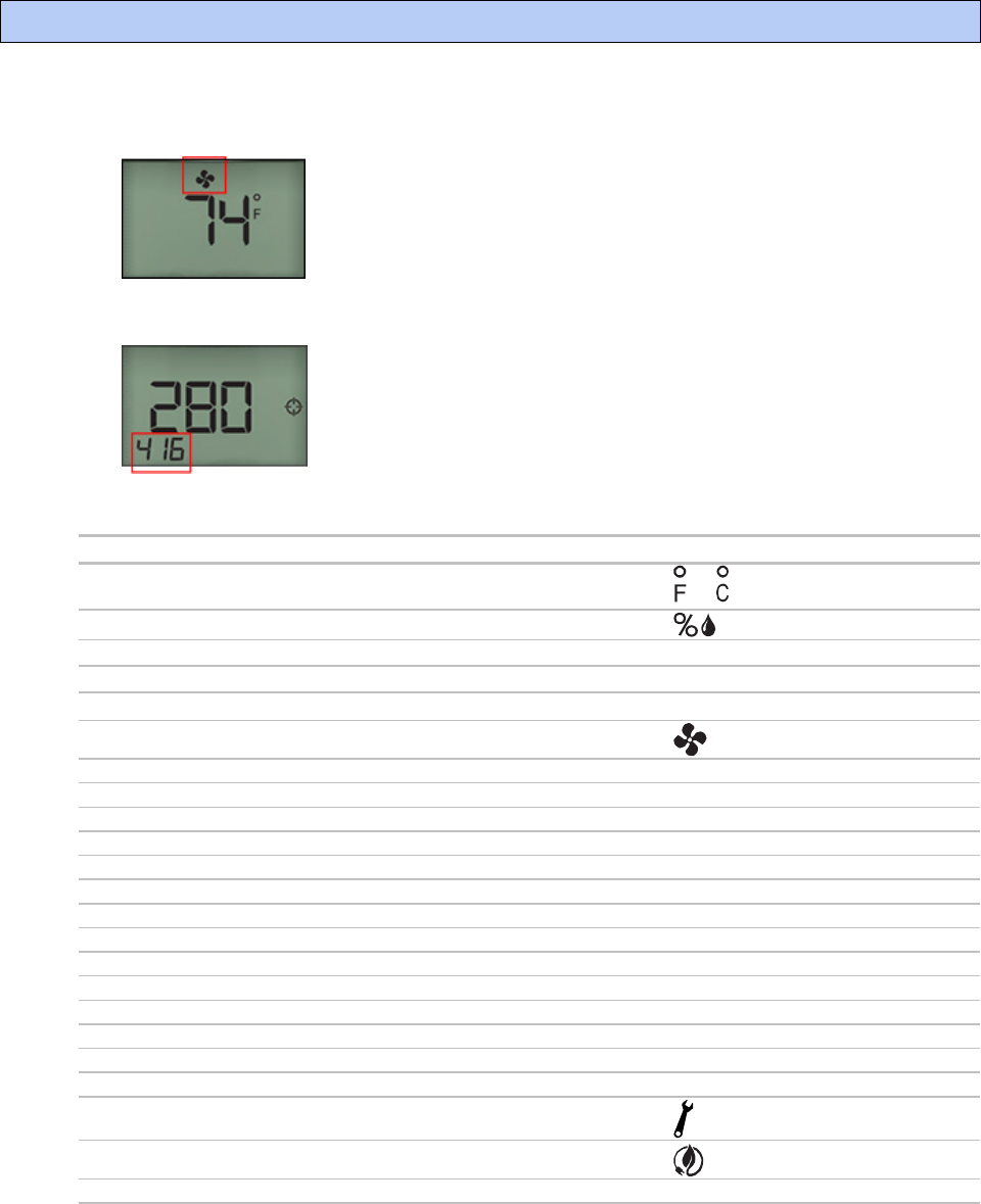
Rnet tags are numbers that identify types of system values, and determine how a ZS sensor will display the value.
• Some Rnet tags display an icon that indicates the type of information. For example, Rnet tag 100 indicates
Fan Status. The sensor will display a fan icon when the microblock is active.
• Rnet tags that do not display an icon will display the actual Rnet tag number in the lower left corner of the
sensor's display. For example, Rnet tag 416 indicates Air Flow Setpoint.
See the table below to find out the type of value an Rnet tag number represents.
Rnet tag number...
Indicates this type of value...
And displays...
001
Zone Temp
or
002
Zone Humidity
003
Zone CO2
CO2
004
Zone VOC
UOC
100
Fan Status
101
Fan Command
The tag number
102
Cool Stage 1
The tag number
103
Cool Stage 2
The tag number
104
Cool Stage 3
The tag number
105
Cool Stage 4
The tag number
106
Heat Stage 1
The tag number
107
Heat Stage 2
The tag number
108
Heat Stage 3
The tag number
109
Heat Stage 4
The tag number
110
Hot Gas Bypass
The tag number
111
Reheat
The tag number
112
Reversing Valve
The tag number
113
Enthalpy Wheel Status
The tag number
114
Dehum Wheel Status
The tag number
115
Filter Status
116
Energy Save Mode
117
Occupied Status
The tag number
Appendix A: Rnet tags
Appendix A: Rnet tags
ZS Sensor CARRIER CORPORATION ©2020
Applications Guide All rights reserved
33
Rnet tag number...
Indicates this type of value...
And displays...
121
Override Status
300
Outside Air Temp
plus or
301
Outside Air Humidity
plus
302
Outside Air CO2
plus
CO2
303
Mixed Air Temp
The tag number
304
Supply Air Temp
The tag number
305
Return Air Temp
The tag number
306
Effective Cooling Setpoint
EFF
307
Effective Heating Setpoint
EFF
308
Air Flow
The tag number
309
Primary Damper Position
The tag number
310
Cooling Stage
The tag number
311
Heating Stage
The tag number
312
Cooling Valve
The tag number
313
Heating Valve
The tag number
314
Reheat
The tag number
315
Secondary Damper Position
The tag number
316
Supply Air Humidity
The tag number
317
Return Air Humidity
The tag number
318
Entering Water Temp
The tag number
319
Leaving Water Temp
The tag number
320
Supply Air Static Pressure
The tag number
321
Return Air Static Pressure
The tag number
322
Building Static Pressure
The tag number
323
OA Dampers
The tag number
324
RA Dampers
The tag number
325
EA Dampers
The tag number
326
SA Dampers
The tag number
327
Economizer
The tag number
328
Time Remaining Until Transition
The tag number
329
Environmental Index
EI
330
Demand Level
The tag number
331
Cooling Airflow
The tag number
332
Cooling Damper Position
The tag number
333
Hearing Airflow
The tag number
334
Heating Damper Position
The tag number
400
Heating Setpoint Adjust
The tag number
401
Cooling Setpoint Adjust
The tag number
402
Occupied Heating Setpoint
plus
OCC
403
Occupied Cooling Setpoint
plus
OCC
404
Unoccupied Heating Setpoint
plus
UnOCC
Appendix A: Rnet tags
ZS Sensor CARRIER CORPORATION ©2020
Applications Guide All rights reserved
34
Rnet tag number...
Indicates this type of value...
And displays...
405
Unoccupied Cooling Setpoint
plus
UnOCC
406
Occupied Humidity Setpoint
The tag number
407
Unoccupied Humidity Setpoint
The tag number
408
Occupied CO2 Setpoint
The tag number
409
Unoccupied CO2 Setpoint
The tag number
410
Minimum OA Damper %
The tag number
411
Static Pressure Setpoint
The tag number
412
OA Temp Cooling Lockout
The tag number
413
OA Temp Heating Lockout
The tag number
414
Changeover Temp
The tag number
416
Air Flow Setpoint
The tag number
417
Occupied VOC Setpoint
The tag number
418
Unoccupied VOC Setpoint
The tag number
419
Supply Air Temp Setpoint
The tag number
420
Setpoint Adjust Limit
The tag number
421
Cooling Airflow Setpoint
The tag number
422
Heating Airflow Setpoint
The tag number
500
Fan Speed Status
, ,
, or
501
HVAC Zone Mode Status
and/or
600
Fan Speed Mode Request
, ,
, or
601
HVAC Zone Mode Request
and/or
800
Temperature units (°F/°C) displayed on sensor
The tag number
Rnet tag number...
Indicates this type of alarm...
And displays...
1024
Generic Alarm
or on the
Home screen, and
the tag number on
the Info screen
1025
High Zone Temp
"
1026
Low Zone Temp
"
1027
Filter Change Required
"
1028
High Discharge Air Temp
"
1029
Low Discharge Air Temp
"
1030
Supply Fan Failure
"
1031
Supply Fan in Hand
"
1032
Supply Fan Runtime Exceeded
"
1033
Exhaust Fan Failure
"
1034
Exhaust Fan in Hand
"
1035
Exhaust Fan Runtime Exceeded
"

Appendix A: Rnet tags
ZS Sensor CARRIER CORPORATION ©2020
Applications Guide All rights reserved
35
Rnet tag number...
Indicates this type of alarm...
And displays...
1036
Supply Fan VFD Fault
"
1037
Cooling Coil Pump Failure
"
1038
Cooling Coil Pump in Hand
"
1039
Cooling Coil Pump Runtime Exceeded
"
1040
Heating Coil Pump Failure
"
1041
Heating Coil Pump in Hand
"
1042
Heating Coil Pump Runtime Exceeded
"
1043
High Zone CO@ Concentration
"
1044
High Zone Humidity
"
1045
Low Zone Humidity
"
1046
Smoke Alarm
"
1047
Sensor Failure
"
1048
Freezestat
"
1049
Emergency Shutdown
"
1050
Compressor 1 Runtime Exceeded
"
1051
Compressor 2 Runtime Exceeded
"
1052
OA Damper Failure
"
1053
OA Damper in Hand
"
1054
Enthalpy Wheel Failure
"
1055
Enthalpy Wheel in Hand
"
1056
Enthalpy Wheel Runtime Exceeded
"
1057
Enthalpy Wheel High Discharge Air Temp
"
1058
Enthalpy Wheel Low Discharge Air Temp
"
1059
Enthalpy Wheel High Return Air Temp
"
1060
Enthalpy Wheel Low Return Air Temp
"
1061
Enthalpy Wheel High Exhaust Air Temp
"
1062
Enthalpy Wheel Low Exhaust Air Temp
"
1063
High Supply Air Humidity
"
1064
Low Supply Air Humidity
"
1065
High Mixed Air Temp
"
1066
Low Mixed Air Temp
"
1067
High Return Air Humidity
"
1068
Low Return Air Humidity
"
1069
High Return Air Temp
"
1070
Low Return Air Temp
"
Rnet tag numbers 1100–1999 are custom tags. See Adding custom Rnet tags (page 36).
A custom Rnet tag
number beginning with...
Indicates...
11xx
A binary tag
13xx
An analog tag
15xx
A multi-state tag
Appendix A: Rnet tags
ZS Sensor CARRIER CORPORATION ©2020
Applications Guide All rights reserved
36
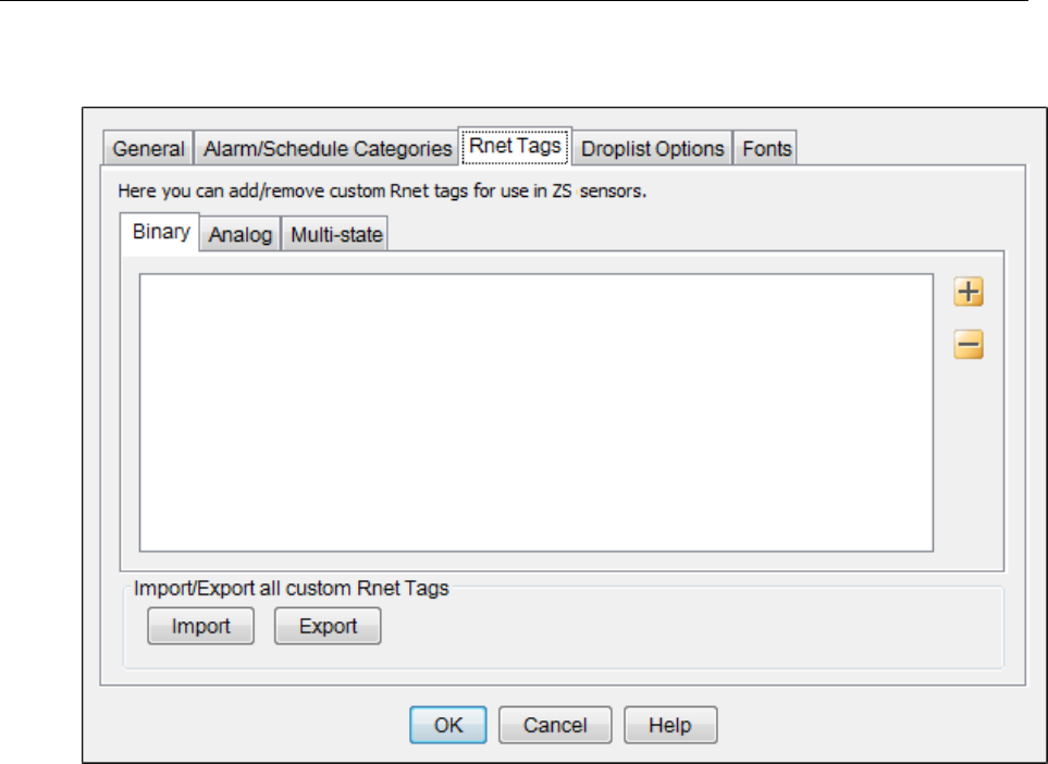
Adding custom Rnet tags
You add custom Rnet tags in the Snap application. Select
Options
>
Preferences
>
Rnet Tags
tab. Do not
duplicate tag names or numbers.
After you create a custom tag number, it automatically appears on the
Rnet Tag
drop-down list for that point type.
If you open a control program with custom Rnet tags on a different machine than the one it was created on, the
custom tags automatically appear in the
Rnet Tag
drop-down list.
NOTE
To copy all custom Rnet tags to another computer, click
Export
, then save the file. On the other computer,
click
Import
, then select the exported file.
Appendix B: ZS Pro and Pro-F Sensor screen fields
ZS Sensor CARRIER CORPORATION ©2020
Applications Guide All rights reserved
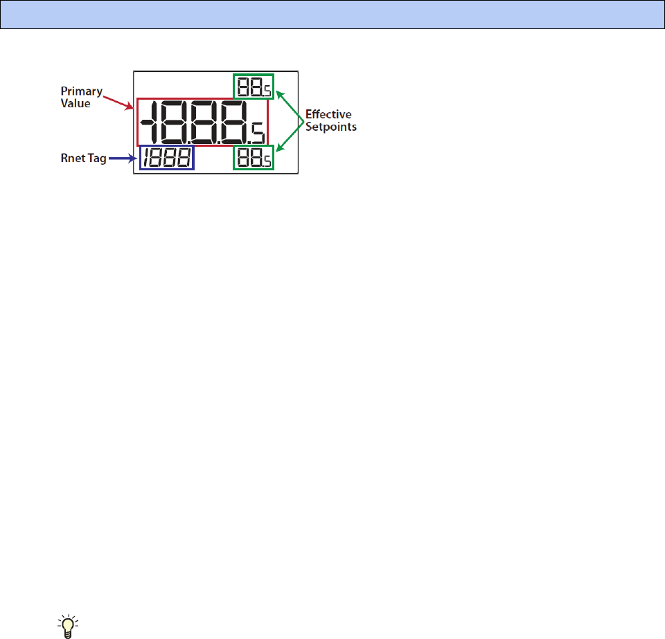
37
Primary Value Field
The primary value field displays numeric values that are exposed to the ZS sensors or displays text for binary or
multi-state value objects.
Numeric values
- This field can display:
• A negative symbol
• Up to 2 decimal places defined by the
Display Resolution
field in an ASVI or AV microblock. If the resolution is
0.5, a small .5 appears as shown above. Any other resolution that shows a decimal uses the decimals
between the large numbers in the Primary Value field.
• Up to 4 significant digits. The maximum value that can be displayed is 1999.5. If the value to be displayed
exceeds the maximum value, the primary value field will flash the maximum value to indicate the value is
outside of range.
Display text
- 3 alpha characters can be displayed on the screen in the 888 position of the Primary Value field
shown above. Display text can be up to 8 characters, but anything over 3 characters will scroll. The letters K, M, Q,
W, X do not display on a screen.
Effective Setpoints Fields
These fields display the effective setpoint values. They can display a maximum value of 99 or 99.5 if the
Edit
Increment
is set to 0.5. If the effective setpoint exceeds this maximum value or if the
Edit Increment
is set to 0.1,
the value will flash.
TIP
If you need an Edit Increment of 0.1, put the effective setpoints on the Information screen in the Primary
Value field. Hide the effective setpoints on the Home screen by selecting
Sensor Setpoint Adjust Option 4
on the
BACnet Setpoint
microblock's
Rnet
tab.
Rnet Tag Field
The Rnet tag field displays a text indicator (such as
OCC
) or an Rnet tag number (up to 1999) that defines what is
being displayed in the Primary Value field. See:
Icons and text indicators (page
15)
Appendix A: Rnet tags (page 32)
Appendix B: ZS Pro and Pro-F Sensor screen fields
Appendix C: Converting a control program with an RS Pro to a ZS Pro
ZS Sensor CARRIER CORPORATION ©2020
Applications Guide All rights reserved
38
Step 1: Update run conditions with ZS sensor microblocks
Before
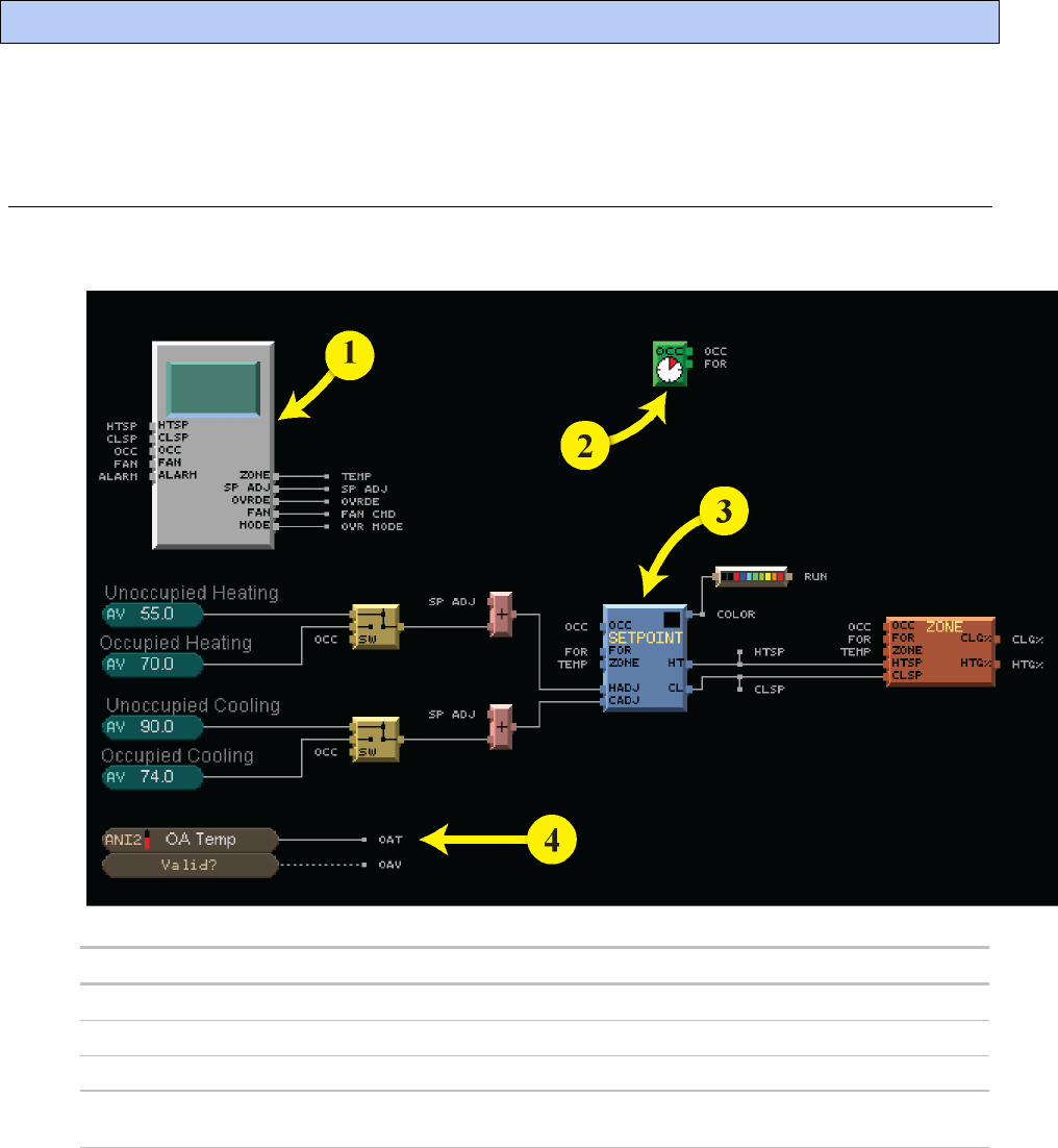
Step
Remove this microblock ...
Add this microblock...
1. RS Zone Sensor Sensor Binder and ASVI
2. Time Clock BACnet Time Clock with TLO and Override Status
3. Setpoint BACnet Setpoint
4.
BACnet Analog Value Status to expose Outside Air Temp to the
ZS sensor
See Microblock Reference Help for information on each of the above microblocks.
Appendix C: Converting a control program with an RS Pro to a ZS Pro
Appendix C: Converting a control program with an RS Pro to a ZS Pro
ZS Sensor CARRIER CORPORATION ©2020
Applications Guide All rights reserved
39
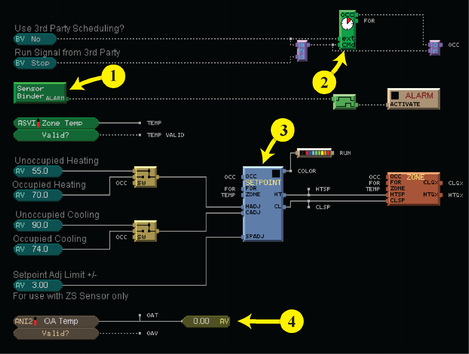
After
Appendix C: Converting a control program with an RS Pro to a ZS Pro
ZS Sensor CARRIER CORPORATION ©2020
Applications Guide All rights reserved
40
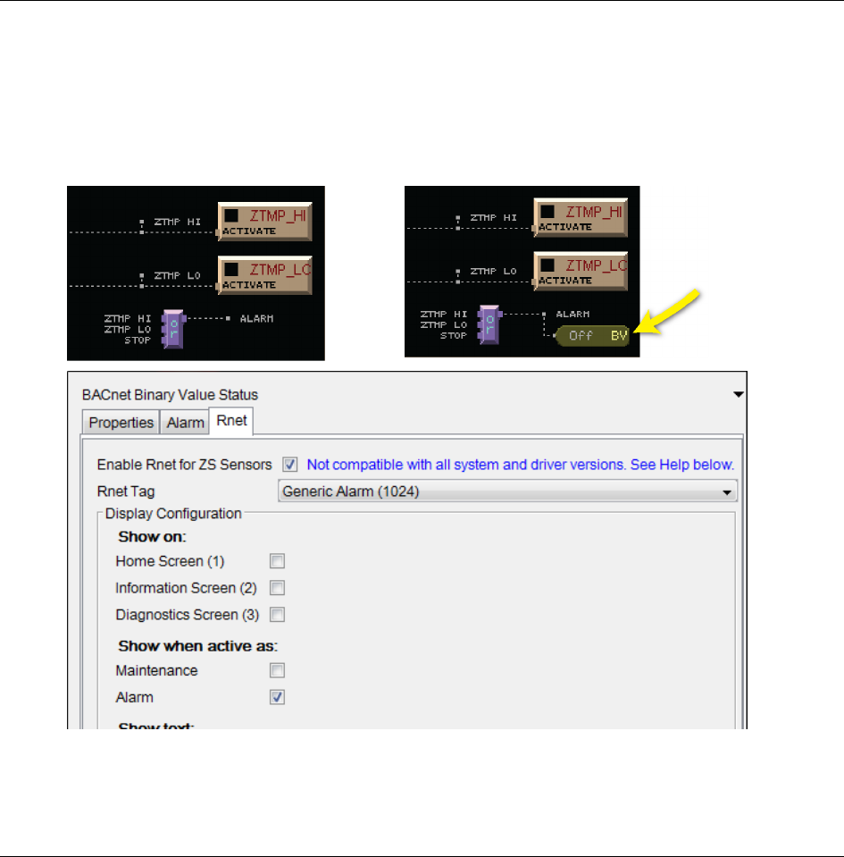
Step 2: Make Alarm icon display on a ZS Pro
Place a BACnet Binary Value Status microblock and select
Generic Alarm (1024)
in the
Rnet Tag
field. See image
below. The setup shown will make the alarm bell icon show on the Home screen when the BV status is active.
NOTE
To include information about the active alarm on the Information screen, check that screen in the
Show On
field and enter
Display Active Text
.
Before After
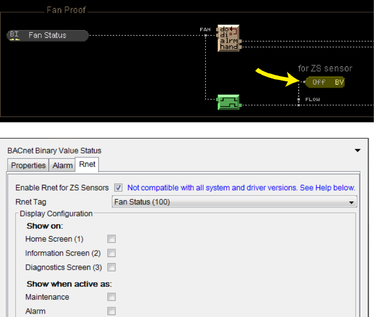
Step 3: Make Fan icon display on a ZS Pro
Place a BACnet Binary Value Status microblock and select
Fan Status (100)
in the
Rnet Tag
field. See image
below. The setup shown will make the fan icon show on the Home screen when the BV status is active.
NOTE
Do not check the Home screen in the
Show On
field. Checking that option causes the fan status to show up
in the rotation of the primary value field, and that is not needed.
Appendix C: Converting a control program with an RS Pro to a ZS Pro
ZS Sensor CARRIER CORPORATION ©2020
Applications Guide All rights reserved
41
After
Appendix C: Converting a control program with an RS Pro to a ZS Pro
ZS Sensor CARRIER CORPORATION ©2020
Applications Guide All rights reserved
42
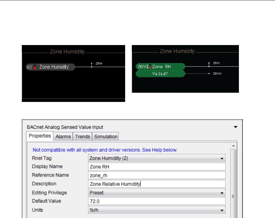
Step 4: Change sensed zone humidity from an AI to the ZS Sensor
Remove existing AI microblock for sensing humidity. Place an ASVI microblock and select
Zone Humidity (2)
in the
Rnet Tag
field. See image below. See Microblock Reference Help for more information on this microblock.
Before After
Document revision history
ZS Sensor CARRIER CORPORATION ©2020
Applications Guide All rights reserved
43
Important changes to this document are listed below. Minor changes such as typographical or formatting errors are not
listed.
Date
Topic
Change description
Code*
6/11/20
Introduction
Added Remote Sensor
X-PM-IM-E-IM
3/3/20
Cover
Updated logos
C-D
8/29/19
Introduction
Added requirement for BSVI microblock in the control program
X-TS-RD-E
1/9/18
Introduction
Topic changed to show new zone sensor design
X-D
1/18/18
Introduction
Major revisions to add a motion sensor to a ZS Pro, duct
sensors, pipe sensor, immersion sensor, and outdoor air
sensors.
X-O-PK
Creating Snap control programs for
ZS Sensors
Revised this entire section to include Step 3: Add Binary Sensed
Value Input microblocks in using ZS Pro motion sensor.
External Scheduling
Revised to use BSVI microblock.
To use values from individual sensors
in your control program
Completely revised this topic for clarification.
11/1/16
Generating alarms
New topic
X-O-JD-AE
10/21/16
Step 3: Add a BACnet Setpoint
microblock
Reworded first paragraph and added note at end of topic
regarding enabling/disabling the setpoint adjustment
functionality of specific sensors.
X-R-DP-E-JD
10/4/16
Appendix A: Rnet tags
Added Rnet tag 115, Filter Status
X-O-AE-O
12/1/15
To use values from individual sensors
in your control program
Wording correction.
C-TS-E-RD
* For internal use only
Document revision history

CARRIER CORPORATION ©2020 · Catalog No. 11-808-504-01 · 6/11/2020
