
Version 5.1
INSTRUCTION MANUAL

I
SAFETY NOTES
• RC model helicopters aren’t toys! The rotor blades rotate at high speeds. Improper use can lead to
potential risks and serious injuries. It is mandatory that general safety rules in dealing with RC
models as well as local laws and regulations are observed. Further information can be found at
model aviation clubs in your area or model airplane organizations.
• Take care of your own safety as well as the safety of others in your environment when using our
product. Fly only in free areas, far away from other people. Never use RC ight models in close
proximity to residential areas or crowds. Do not y above people. Due to a variety of reasons RC
model aircraft may crash, such as poor maintenance, pilot errors or radio interference, resulting in
serious accidents. The pilots are fully responsible for their actions and for damage caused by the
operation of their model aircraft and injury.
• Read the following instructions thoroughly before using NANOBEAST the rst time and carefully
adjust the system according to the given instructions. Take enough time and check every step for
correctness. Also pay attention to a proper and awless mechanical construction of your model
helicopter. An incorrectly adjusted system can cause severe accidents and damage to the model.
• RC models consist of many electronic precision components. It is important to keep the model away
from moisture and other foreign substances. If the model is exposed to moisture of any kind, this
can cause malfunctions and lead to crashes. Never y in rain or extreme Humidity!
• When operating the helicopter with NANOBEAST pay attention to a suciently dimensioned and
loadable receiver power supply. Due to the direct linkage of the rotor blade holders to the servos,
increased forces let the power consumption get extremely high compared to a helicopter with a y
bar and rotor head mixer!
• Do not expose the NANOBEAST to extreme temperature uctuations before and during operation.
Allow some time for the electronics to acclimatize before turning it on.
• The NANOBEAST consists of highly sensitive electrical components that may fail under strong
vibrations or electrostatic discharges. Should you have such factors on your model, the use of the
NANOBEAST must be stopped until the external inuences were eliminated.
• When operating electric models with „single-line“ receivers, it is important to ensure that during the
adjustment work the electric motor can’t be started inadvertently. Do not connect the electric
motor to the motor controller or remove the motor from the main gear before performing the
adjustment work. Also make sure that the motor does not start if the transmitter unit fails (e.g. by
using the failsafe function of receiver and NANOBEAST).

II
• The NANOBEAST PROEDITION comes with the AttitudeControl function (optionally available horizontal
stabilization) which serves as a ight aid for beginners by restricting the freedom of movement of the
helicopter. However, this does not ensure that the helicopter can be always own safely! Due to
incorrect control inputs the helicopter may crash anyway, even when using AttitudeControl. In addition,
the helicopter can drift away from external inuences and it is not guaranteed that the articial horizon
of the device will stabilize the helicopter in every situation. By external inuences like strong
temperature uctuations or vibrations the sensors may produce false readings which will falsify the
position calculation of the system. It is not guaranteed that the system will always be working correct
under any circumstance. The pilot is responsible for the control of the helicopter and thus for the use of
the helicopter system. Also note that the system will not keep the helicopter in absolute place for
technical reasons. The unstable tendency of a helicopter will cause the model y away in a certain
direction. By external inuences such as wind or similar this eect can be even stronger. In addition,
there are measurement inaccuracies of the sensors, which can falsify the orientation. Make sure you’re
always able to turn o the system and take over complete control of the helicopter.
• Contact an experienced model pilot who will advise you on how to control and handle model
helicopters. A ight training by using a model ight simulation on the PC can help to get started in the
air model sport. Contact the local retailer for technical advice or in case problems arise during operation
with our product.
• The AttitudeControl rescue function (optional) is designed to facilitate the ying of model helicopters.
Control can be temporarily passed to the system if the pilot loses his orientation. Using the built-in
articial horizon, the system can bring the helicopter in an almost horizontal position, so the pilot gains
time to reorient himself. Anyhow, it can’t be guaranteed that the model will do so under any
circumstance. Depending on the current attitude and speed and depending on how quickly the
AttitudeControl is turned on, the model may crash nevertheless. Be sure to follow the general safety
rules for handling RC models. The pilot is responsible for the control of the helicopter and thus also for
the use of the system. He always has to be able to turn o the system and take over full control of the
helicopter.

III
0719
STUDIOX.BEASTX.COM BEASTX.COM WIKI.BEASTX.COM

1
Dear customer,
We congratulate you on your purchase! NANOBEAST is a control unit for small and very small RC model
helicopters without mechanical fly bar. The integrated gyro elements stabilize the helicopter as much as
possible, so that it’ll only follow the control commands of the pilot. The steering feel can be tuned easily from
tame to extremly agile. Thus, the model can meet almost any requirements of the pilots, no matter if you’re a
beginner pilot or 3D aerobatic professional.
By paid firmware upgrade the system can be extended to „PROEDITION“. This offers additional functions
like AttitudeControl for position stabilization and rescuing the model in difficult positions, as well as a bank
switching that allows to switch between different parameter sets in flight.
For basic setup and tuning of the system a computer (Windows / mac) or smartphone/tablet (iOS / Android)
with Bluetooth LE is required. Depending on the technology used, a USB2SYS (for computer) or BLE2SYS (for
Smartphone / Tablet) interface is required as additional accessory. This is not included and must be purchased
separately! The configuration then takes place via the StudioX Software, which is offered for free download:
This manual is a short guide to getting started. The operation of the StudioX software and configuration of
the helicopter is explained by references in the software itself and via web links. Detailed instructions for
configuring the helicopter, as well as for installation and use of the software additionally can be found at:
STUDIOX.BEASTX.COM
WIKI.BEASTX.COM
Technical specications
Dimensions: 32 x 20 x 10 mm
Weight: 5,8 g
Receiver connections: Spektrum® / JR® single satellite, serial wire connection for Graupner® HOTT,
Futaba® SBus, Jeti® exBus, FlySky® iBus, FrSky® SRXL, Multiplex® SRXL,
JR® XBus (B), Spectrum® SRXL, Align® iBus, SPPM composite signal
Input voltage: 4,8 - 6 Volt
Helicopter size: 180 - 250 electric heli

2
Required accessories
Links to available apps can be found at STUDIOX.BEASTX.COM.
Box contents
• NANOBEAST control unit
• Patch cable for serial signal receiver
• 3M adhesive pad
• Instruction manual
With the NANO Servo Connection Kit, you can connect
servos with normal sized servo plugs to NANOBEAST.
Please note that the tiny white plugs and the thin
cables are not capable of transferring high currents!
With the separately available NANO Light Programmer
you can adjust some settings quickly on the airfield.
Further information can be found in the detailed
instructions at
WIKI.BEASTX.COM.
Art.-Nr.: BXA76901 Art.-Nr.: BXA76902
USB2SYS USB interface for the
configuration by PC / mac
BLE2SYS Bluetooth LE interface
for the configuration by tablet or
smartphone (Android / iOS)
Art.-Nr.: BXA76007 Art.-Nr.: BXA76015
Designed for
Optional accessories

3
1. INSTALLATION
In total there are 8 possible mounting positions:
flat, plugs showing to front, LED on top upright, plugs showing to front, LED on top
Use one of the enclosed 3M adhesive pads to attach. Later, when laying out the cables, make sure that the cable are fixed
free of tension!
flat, plugs showing to back, LED on top
upright, plugs showing to back, LED on top
flat, plugs showing to front, LED on bottom upright, plugs showing to front, LED on bottom
flat, plugs showing to back, LED on bottom upright, plugs showing to back, LED on bottom
The NANOBEAST can be installed either flat or upright.
The white connector strip must point either to the front or to the back of the heli. The sensor axes (edges of the device
housing) must be aligned absolutely parallel to the three rotation axes. Anyhow, the device can be mounted laterally
offset, it does not have to be exactly on the axes of rotation.
Links to available apps can be found at STUDIOX.BEASTX.COM.

4
Supported receiver types / transmission protocols
• SRXL: JR® XBus (Mode B), Multiplex® SRXL (V1+V2), Jeti® UDI, Graupner/SJ® HOTT SUMD, Spektrum® SRXL
• Futaba® SBUS
• Single satellite (Spektrum® DSM2 / DSMX, JR® RJ-01 DMSS)
• Jeti® EXBUS
• ALIGN/FlySky iBus
• PPM serial signal (SPPM)
Attach the receiver to the helicopter and make sure that the cables and antennas will not get into rotating parts. Plug the
motor controller into the connection [1] for BEC power supply. Pay attention to maintain the correct polarity! Also make
sure the BEC voltage is in the range of 4.8 - 6.0 volts!
2. RECEIVER CONNECTION
Receivers with serial signal output transmit all control commands / channels by one wire. Connect the signal output from
the receiver with the signal input DI on the
NANOBEAST (using the enclosed patch cable). If you use a SPEKTRUM® or
JR® single satellite, you can plug it into the SAT socket directly. In this case, use the cable supplied by the manufacturer (the pin
assignment at the SAT connection corresponds to the Spektrum® standard).
DI = serial signal receiver
DSMX/DMSS (RJ01)
satellite receiver
1 = ESC
-
+
s
-+
s
STATUS
To trigger the binding process on a Spektrum® single satellite, attach the Bind-Plug to the [SYS] connector. Then turn
on power, the yellow LED on the satellite should now flash quickly. Perform the binding process on the transmitter. After
successful bind, remove the bind plug. The JR® RJ01 single satellite can be bound directly using the transmitter only. The
satellite will automatically go into bind mode when powering on the receiver before switching on the radio.
To bind the other types of receivers, follow the instructions of the manufacturer!

5
3. PREPARING THE TRANSMITTER
For safety reasons, remove the motor from the main gear during adjustment! In addition, disable the motor
channel using the autorotation switch (Throttle HOLD), so that the motor does not start when the thrust stick is moved.
No mixing functions must be active on the channel outputs. In particular, disable the mixing of the swashplate servos in
the radio. Also disable all unnecessary control channels. In the basic configuration only collective, aileron, elevator, rudder,
motor and a channel for the gyro is required.
Create a new model memory in your remote-control transmitter. It should provide multiple flight modes in order to control
engine, collective and gyro in different flight situations.
Only the pitch channel is
allowed to be controlled,
if thrust stick is moved.
The same applies to
aileron, elevator and
rudder.
Each control function must serve exactly one servo output. The servo travel must be at 100% and no trimming must
be used. Do not change the pitch curves for the adjustments. The throttle curves and settings of the motor channel can be
adjusted according to the model. However, for the basic setup of the system you should be able to block the motor channel!

6
4. STUDIOX
The NANOBEAST has a serial interface marked with the letter [SYS]. Use a standard servo cable to connect this
port with your USB or Bluetooth interface (sold separately). Watch out for correct polarity! Note that the interface
does not supply the
NANOBEAST with power. The supply comes from the BEC of the motor controller, which is
connected to the connector [1].
Status
USB2SYS
WWW.BEASTX.COM
STATUS
STATUS
SYS = programming interface
1 = motor controller (ESC)
Download the appropriate app for your computer or smartphone / tablet and install it on the device.
Go to the website
STUDIOX.BEASTX.COM. There you will also nd a link to WIKI.BEASTX.COM where you
can nd detailed instructions for installing the apps and putting the interface into operation.
Start StudioX now. If the USB2SYS interface is plugged into the computer, make sure that its port name is selected in the
selection box. If you did not plug in the interface when the software was started, click on SEARCH to update the list. Usually,
the appropriate port is automatically selected.
If you do not know which the correct port is, unplug the interface, wait a moment and click SEARCH to delete the list. Plug
it in again, wait a moment and click SEARCH. Now the correct port should be selected. Then connect the USB2SYS to the
[SYS] port of your
NANOBEAST and turn it on. Now click CONNECT to read the device and access the individual
conguration options.
Connect the BLE2SYS interface to the [SYS] port of
NANOBEAST and turn it on. Start the StudioXm app. The BLE2SYS
interface should automatically appear in the selection box. If not, click on the selection box in the middle of the screen and
choose BLE2SYS. If you can‘t nd a suitable entry, press the SEARCH button and wait until the process is completed. This
can take a few seconds to a few minutes. If the box is empty again immediately then it is likely that the Bluetooth feature on
your smartphone / tablet is disabled or the app does not have access to the Bluetooth functionality! In this case, check the
settings of the smartphone/tablet.

7
5. RADIO SETUP
As first setup step we have to teach the receiver type / remote control system and the assignment of the
control functions to the system. To do so, select CONTROL SIGNAL on the StudioX overview page.
Download the appropriate app for your computer or smartphone / tablet and install it on the device.
Go to the website
STUDIOX.BEASTX.COM. There you will also nd a link to WIKI.BEASTX.COM where you
can nd detailed instructions for installing the apps and putting the interface into operation.
Start StudioX now. If the USB2SYS interface is plugged into the computer, make sure that its port name is selected in the
selection box. If you did not plug in the interface when the software was started, click on SEARCH to update the list. Usually,
the appropriate port is automatically selected.
If you do not know which the correct port is, unplug the interface, wait a moment and click SEARCH to delete the list. Plug
it in again, wait a moment and click SEARCH. Now the correct port should be selected. Then connect the USB2SYS to the
[SYS] port of your
NANOBEAST and turn it on. Now click CONNECT to read the device and access the individual
conguration options.
Connect the BLE2SYS interface to the [SYS] port of
NANOBEAST and turn it on. Start the StudioXm app. The BLE2SYS
interface should automatically appear in the selection box. If not, click on the selection box in the middle of the screen and
choose BLE2SYS. If you can‘t nd a suitable entry, press the SEARCH button and wait until the process is completed. This
can take a few seconds to a few minutes. If the box is empty again immediately then it is likely that the Bluetooth feature on
your smartphone / tablet is disabled or the app does not have access to the Bluetooth functionality! In this case, check the
settings of the smartphone/tablet.

8
Automatic detection of the remote-control system
In order to recognize the connected receiver type, the remote-control transmitter must be switched on and bound to the
receiver. Also make sure that the default setup of the transmitter was performed as described in chapter 3. Press SCAN to
start the search. The colour of the Status LED and in the display indicate which receiver type is currently being searched for.
THR
AIL ELE RUD GER AX1 AX2
Motor Aileron Elevator Rudder Gyro Pitch Rescue*
Spektrum® DSM2/DSMX oder JR RJ-01 DMSS Einzelsatellit
1 2 3 4 5 6 7
Pitch Aileron Elevator Rudder Rescue* Motor Gyro
Graupner® SUMD
1 2 3 4 5 6 7
Aileron Elevator Motor Rudder Gyro Pitch Rescue*
Futaba® SBus/SBus2 kompatibler Empfänger
1 2 3 4 5 6 7
Aileron Elevator Rudder Pitch Motor Gyro Rescue*
Multiplex® SRXL v1 und v2, JR® XBUS Mode B, JETI® UDI 12 + 16ch
Assignment of the control functions
As soon as the corresponding type has been detected, a query opens on how the function assignment should be performed.
Here you have the choice between loading a PRESET or the manual assignment (if you later learn the receiver type again, you
can also skip the function assignment without change). The preconfigured function assignments depend on the recognized
signal protocol and remote-control system. These are as follows:
9
1 2 3 4 5 6 7
Pitch Aileron Elevator Rudder Gyro Motor Rescue*
PPM Summensignal (SPPM)
ATTENTION: For failsafe setting, the throttle output [1] is active. So the motor could start when the throttle is
in the wrong position! If you are not sure which position is the right one or in case you want to program the ESC at this
point using the throttle stick, remove the motor from the main gear for safety reason.
THR
AIL ELE RUD GER AX1 AX2
Motor Aileron Elevator Rudder Gyro Pitch Rescue*
Spektrum® SRXL
In case the preset does not match to your radio system or you have another switch assignment wishes, you can train the
functions in sequence. Choose TEACH and then move the sticks / switches according to the display in the app. Note that you
must always only move one channel at once. Otherwise,
NANOBEAST can‘t recognize which channel you want to use for
this function. This applies in particular to the throttle and collective pitch channel, which are usually controlled simultaneously by
the thrust stick in helicopter models. To learn these two functions separately, block the motor channel (i. e. with the autorotation
switch) to teach the pitch first, then release the throttle channel in order to be able to move the throttle afterwards (the pitch will
not be taken into account then, because it was already assigned to another function before).
Throttle failsafe
Last but not least, the failsafe position for the throttle has to be set. Bring the throttle channel to the position where the
motor is off. Then (after setting the function assignment) confirm the question to teach failsafe position with CONTINUE
and store the failsafe position by clicking SET at the bottom of the display
Move collective Move Aileron
...
* rescue function (AttitudeControl) only available with PROEDITION firmware

10
6. BASIC SETTING
Select the BASIC SETTING button to start with the basic helicopter setup (as long as the initialization sequence is not
finished, some buttons are locked in the overview screen!).
Device orientation
Set the installation position in StudioX so that it corresponds to the actual position of your NANOBEAST on your
helicopter. Then choose NEXT.
After initial power up or after finishing the receiver setup, wait until the initialization sequence is completed.
If you do not know the optimum or maximum drive frequency of the servos, never exceed 50Hz! The higher
the driving frequency, the better the flight performance of NANOBEAST. However, it must be ensured that the servos
are allowed to be operated with an increased drive frequency. Otherwise the servos could be damaged!
At WIKI.BEASTX.COM we have a list of data on the most popular servo types. Always use a pulse width
of 1520 μs, unless you use a special gyro servo which must be operated with reduced pulse width (only such servos
can be driven with extremely high frequencies up to 560 Hz!).
Control frequencies and pulse length of the servos
Set the drive frequency for the swashplate servos, the pulse width for the rudder servo, as well as the drive frequency for the
rudder servo at the appropriate points. Press NEXT to go to the next menu item.
Calibrating stick
center positions
Status LED flashes red
Don‘t move the sticks!
STATUS
Calibrating sensor
rest positions
Status LED lights red
Don‘t move helicopter!
STATUS
Status LED flashes
blue or purple
Operating mode
STATUS

11
Rudder servo and tail rotor
1. Connect the rudder servo to the output [2] of NANOBEAST and mount the rudder horn/servo cross as good as
possible at a 90 ° angle to the tail linkage rod. Adjust the linkage so that the tail slider is positioned correctly. Ideally, in the
90 ° position of the servo the slider is centered on the tail rotor shaft and the tail rotor blades have a slightly positive angle of
attack against the rotor torque in this position (e.g. 5° to the right on a helicopter with clockwise rotating rotor).
2. Carefully steer the tail using the rudder stick and check the direction of movement. When the stick direction is wrong, you
can reverse the rudder channel’s direction by using the servo reverse function of your transmitter.
Correct Wrong
Move rudder to the right
Rotor must push the tail to the left,
the helicopter would turn right
Rotor pushes the tail to the right,
the helicopter would turn left
If the joystick controls the tail incorrectly, reverse the control
direction by using the servo revere function in your transmitter.
3. As soon as the servo moves in the correct direction when steering, the internal control direction of NANOBEAST
must be checked and adjusted if necessary: When the rudder stick is moved to the right, the Status LED must light up in blue
color and in the software must be displayed „right“. If the rudder stick is steered to the left, the Status LED must light up red
and the software must display „left“. If this is upside down, (i.e. red = right and blue = left) reverse the internal control direction
by selecting NORMAL or REVERESED.
Control frequencies and pulse length of the servos
Set the drive frequency for the swashplate servos, the pulse width for the rudder servo, as well as the drive frequency for the
rudder servo at the appropriate points. Press NEXT to go to the next menu item.

12
For most helicopters, the default setting of 120 ° can remain. The required swash plate mixing is mentioned in the helicopter‘s instruction
manual.
[1] = speed controler (ESC) [2] = rudder servo [3] =elevator servo [4] = roll servo left [5] = roll servo right
Be sure to follow the given order! Always set the correct servo and stick direction rst, then check the control
direction of NANOBEAST. The internal control direction does not change the servo direction! This only
serves to ensure that the gyro is moving the rudder to to correct direction. When checking and adjusting the
control directions, be very conscientious. A wrong control direction can lead to a crash!
4. Now set the servo limit. To do this, carefully move the servo to the end positions by rudder stick input and reduce / increase
the two values for right and left, so that the travel is adjusted optimally, i.e. the servo should move just as far as the tail pitch
slider is not binding and the servo is not blocked. If the tail rotor allows extreme tail pitch values, even less servo movement
can be useful!
5. If you move the rudder stick fully to the right or left, the Status LED on the
NANOBEAST should be lit permanently
and the label „right“ or „left“ should be highlighted in the appropriate colour. When the stick doesn’t move far enough, the
message „Increase!“ will appear. In this case, increase the control deflection/servo travel in the remote-control transmitter
for both directions until the point at which the Status LED just changes from flashing to being lit permanently and the label
„OK“ is shown in the software when the stick reaches the maximum position. Note: Do not set the servo travel too large. If
the LED lights permanently long before the maximum stick position is reached, reduce the servo throw in the transmitter
accordingly.
Move rudder to the right
Move rudder to the right
Wrong

13
Swashplate mixing
For most helicopters, the default setting of 120 ° can remain. The required swash plate mixing is mentioned in the helicopter‘s instruction
manual.
Never use the swashplate mix of the remote-control transmitter, even if the helicopter requires an electronic
mixing! Disable any kind of mixing of the swashplate servos in the transmitter. Choose a mechanical mixer (often referred
to as „normal“, „H1“ or „1 servo“) if applicable. Each stick of the transmitter must drive exactly one control output. Only
NANOBEAST is responsible for the swashplate mixing!
Then connect the servos to the outputs [3] to [5] as shown below. With electronic mixing the two roll servos connect at [4]
(= left) and [5] (= right). On mechanically mixed helicopters (mCCPM), the roll servo connects to [4] and the collective pitch
servo to [5]. The elevator servo is always connected at port [3].
120°
140°
flight direction
90°
mCCPM eCCPM
When laying out the wiring make sure that it rests on the NANOBEAST without tension. Lay it out in a loose
loop and fasten it after approx. 5 - 7 cm at the chassis of the model. Don’t use shrink tube or fabric hose in the
immediate vicinity to the point where the cables are plugged into NANOBEAST. This makes the cables sti and
inexible and can cause vibrations being transferred to NANOBEAST.
[1] = speed controler (ESC) [2] = rudder servo [3] =elevator servo [4] = roll servo left [5] = roll servo right
STATUS
-+
s
4
5
3
4
5
3
4 5
4
5
3 3

14
If the servos are perfectly trimmed, adjust the linkages
according to the instructions of the helicopter so that the
swash plate sits in the middle of and horizontal aligned
with the main rotor shaft. In this position the rotor blades
must have 0 degrees of pitch. Work your way from the
bottom up. Adjust the lower servo linkages rst, making
the swashplate being perfectly aligned, then adjust the
pitch linkage rods.
Driver is horizontal
Swash plate horizontal
0 degrees of pitch
Swashplate has the same
amount of space in both
directions
If applicable, make sure the swashplate driver is aligned
correctly, so that the arms are horizontal and the linkage
balls are positioned in one line with the connection joint
of the rotor blade holdersat the 90 degrees position.
Linkage balls at inner ring
and at blade holders in one
line to each other
Alignment of the swashplate servos
In the next step we trim the servo centre positions so that the servo arms form a perfect 90 degrees angle with the linkage rods.
This is necessary because usually the servo drive trains are not accurate enough, so the servo arms fit as good as possible from
the beginning. If all servos are aligned properly, perform the basic mechanical setting of the rotor head, then press NEXT again.
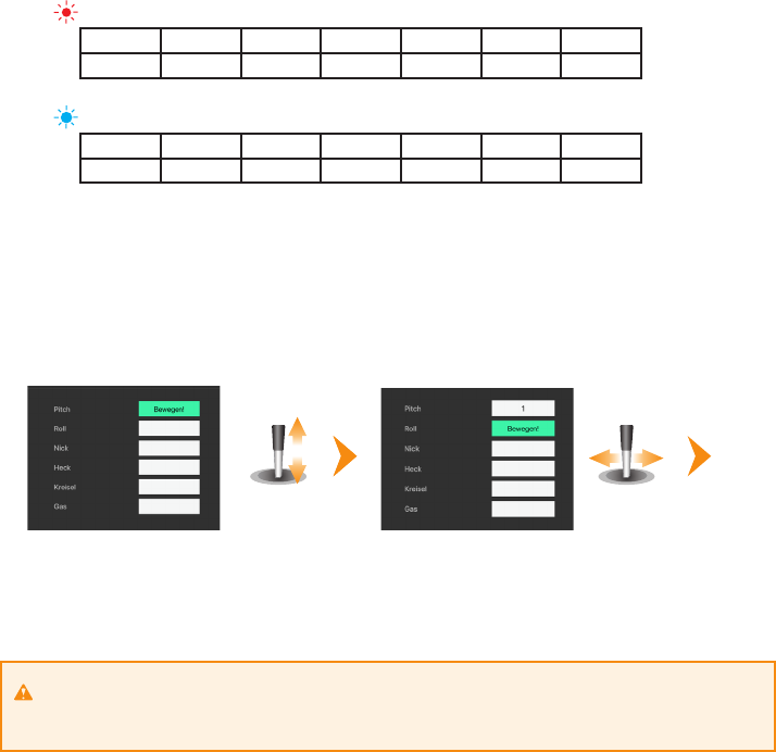
Movement directions of the swashplate servos
Move the thrust stick and check whether the swashplate moves up and down. If this is not the case, you can reverse the
direction of movement for each servo individually in the StudioX app.
Make sure the pitch control direction is correct. This results either directly by correctly adjusting the servo directions, or you
can also reverse the direction of the collective pitch channel using the servo reverse function of the transmitter.
Move thrust
back and forth
Richtig Falsch

15
Note: You can’t reverse the individual servo directions with the reverse function of the transmitter! The transmitter only
gives control commands to
NANOBEAST, but does not directly control the servos! When a control channel in the
transmitter is reversed, the function as a whole will be reversed, not the direction of one single servo (except when using a
mechanical swash plate mixture).
Throw adjustment of the swash plate
At the next setup step, the available (cyclic) control resolution is learned. For the adjustment procedure turn the rotor head
so that one of the rotor blades is parallel to the tail boom / to the longitudinal axis of the helicopter. Then attach a pitch
gauge at this rotor blade and set it to 0° (if you have correctly done the mechanical rotor head and servo setup before,
actually the blade must have 0° of pitch).
Now press the MEASURE button in the app. NANOBEAST will then move the swash into roll direction a little (the
actual direction is irrelevant). In this position, the rotor blades should show exactly 6.0° of pitch. If this is not the case, adjust
the given value in the app just until you get the desired amount of pitch.
0°
6°
If your heli is too small for a commercial pitch gauge, you can determine the pitch angle mathematically by folding the rotor blades by
90 degrees to the same side. At 0° of pitch, the blades should be parallel to each other when looking at them from the side.
In measuring position you can calculate the blade pitch from the resulting distance between the blades according to the formula:
angle = arcsine (distance / 2 / rotor blade length)
The required distance at which you get 6° of pitch calculates as follows:
distance = (sin 6°) * 2 * rotor blade length
Alignment of the swashplate servos
In the next step we trim the servo centre positions so that the servo arms form a perfect 90 degrees angle with the linkage rods.
This is necessary because usually the servo drive trains are not accurate enough, so the servo arms fit as good as possible from
the beginning. If all servos are aligned properly, perform the basic mechanical setting of the rotor head, then press NEXT again.

16
4. Leave the thrust stick in maximum position and now set the desired maximum pitch with the buttons + and - in the app.
Then bring the stick to the lowest position and set negative pitch accordingly.
2. Then check the colour of the Status LED or the display in the app: if the pitch is positive, the LED must light in blue colour
and the bars in the app move upwards towards positive, with negative pitch the LED must light red and the bar moves
down towards negative. If the LED display is wrong (red = positive and blue = negative) and the bar is moving in the wrong
direction, change the internal control direction by clicking the buttons in the app.
Collective pitch adjustment
1. Move collective pitch up and down and verify the control direction on the rotor head. Reverse the pitch channel using
the servo reverse function of your transmitter, in case the direction is incorrect.
3. When the thrust stick is at maximum position and the display for positive and negative pitch shows “Increase!” in the app,
then increase the stick throw/servo travel in the transmitter for the collective pitch channel just as far until the message
disappears and „OK“ is displayed (or the Status LED on the device changes from flashing state to a steady light). But do not
set the amount of travel too high. If the directions are displayed long before the maximum stick position is reached, reduce
the throw in the transmitter accordingly.
Move thrust up
and down
Thrust maximum
positive
Thrust maximum
positive

17
Maximum swash deection
You can remove the pitch gauge now! Steer collective, aileron and elevator simultaneously and carefully to the maximum
positions and check whether the servos jam at any point or stop to be controlled at all, or the linkage rods or the swash
plate are jammed at some specific position. Reduce or enlarge the swash deflection just until no binding occurs while trying
to get as much swash deflection as possible. Do not reduce further than necessary to make sure that the system can work
optimally!
Control direction of the swash plate
1. If not already done, steer aileron and elevator and make sure the swashplate is moved in the correct direction. It must
exactly follow the stick directions: elevator forward tilts the swash plate forward, roll to the right tilts the swash plate to
the right, etc. If the swashplate tilts in the opposite direction, use the servo reverse function of your transmitter and
inverse the servo direction (=control direction) for the aileron or elevator channel.
2. Now set the internal control direction of
NANOBEAST: If you move elevator forward, the Status LED lights in blue
colour while the bar for elevator moves to the right in the app. If you pull elevator back, the Status LED must light in red
and the bar in the app should move to the left. When rolling to the right, the Status LED must light up in blue and the bar
in the app for roll must move to the right. Roll to the left, the Status LED must be red and the bar in the app moves left. If
the displayed direction is wrong, change control direction for each axis in the app.
3. If the stick(s) are in maximum position and the direction indicator of StudioX doesn’t appear but displays „Increase!“
instead, then increase the control travel / servo throw in your transmitter for the respective control channel just as far until
„OK!“ is displayed for each direction (or the Status LED on the device changes from ashing to permanently lit). But do not
set the throw too large. If the „OK!“ display comes up long before the maximum stick position is reached, reduce the servo
throw in the transmitter accordingly!
Carefully move thrust, aileron and
elevator stick to maximum position!
Make sure to follow the given order! Always set the control direction with the transmitter rst, then check the
internal control direction of
NANOBEAST. The internal control direction does not change the servo
directions! This only serves to ensure that the system knows the correct control directions for stabilizing the
helicopter. When checking and adjusting the control directions, be very conscientious. A wrong control direction will
most likely lead to a crash!
4. Leave the thrust stick in maximum position and now set the desired maximum pitch with the buttons + and - in the app.
Then bring the stick to the lowest position and set negative pitch accordingly.
2. Then check the colour of the Status LED or the display in the app: if the pitch is positive, the LED must light in blue colour
and the bars in the app move upwards towards positive, with negative pitch the LED must light red and the bar moves
down towards negative. If the LED display is wrong (red = positive and blue = negative) and the bar is moving in the wrong
direction, change the internal control direction by clicking the buttons in the app.
3. When the thrust stick is at maximum position and the display for positive and negative pitch shows “Increase!” in the app,
then increase the stick throw/servo travel in the transmitter for the collective pitch channel just as far until the message
disappears and „OK“ is displayed (or the Status LED on the device changes from flashing state to a steady light). But do not
set the amount of travel too high. If the directions are displayed long before the maximum stick position is reached, reduce
the throw in the transmitter accordingly.

18
Tail gyro response
With this parameter you can adjust how abruptly the tail gyro responds to sudden control inputs. Increasing the gyro response will
cause a harder stop and quicker response to rudder stick inputs. But if the response is too high, the tail will bounce back after a hard
stop and rudder will feel spongy when making fast direction changes. If the response is set too low on the other hand, the rudder
control feels dull and stopping might be too soft. Ideally the tail should stop perfectly to the point without making any flapping
noises. Before adjusting the gyro response find and set the maximum possible tail gyro gain (see chapter 6)! Then after adjusting
the tail gyro response you may have to adjust the tail gyro gain once again, as these parameters interact to each other.
Cyclic gain
In general the higher the gain, the harder the helicopter will stop after cyclic moves and the more stable and exact the helicopter
will fly. But if the gain is too high, the helicopter will tend to oscillate at high frequency especially on the elevator axis. On the other
hand, in case the gain is too low, the helicopter does not stop precisely and overshoots the more or less after a cyclic movement.
Additionally, it feels unstable and sluggish in fast forward flight and when hovering.
7. ADJUSTING THE TAIL GYRO
Before the first flight, you have to set up the tail gyro control in the transmitter. The gyro operation mode and
responsiveness is controlled by the deflection of the auxiliary gyro channel. The direction in which the gyro control
channel is moved determines the operating mode of the tail gyro. The height of deflection determines the gyro gain. This
adjust how far the servo will be moved when the gyro corrects the current positioning in case it has been changed from
external effects, and how hard it will try to keep the actual position. The operation mode and approximate amount of gain
is displayed immediately after the initialization process, based on the colour and number of flashing signals of the Status
To start with, we recommend to set the gain in the transmitter just as high, so that the tail gyro gain is 50 in the Heading-
Lock mode (Status LED shows 4 blue flashes).
-160 +160
0
Tail gyro gain
(Gyro channel deflection)
Normal mode
(Status LED: purple)
Heading-Lock mode
(Status LED: blue)
STATUS
Status LED ashes four times repeatedly
... ...
If later in flight (or when trying to take off the first time) the tail begins to swing quickly („whimper“), reduce the amount of
gain immediately! On the other hand, if the rudder reacts in a very gregarious manner in flight and the tail breaks out and
does not hold the position, increase the gyro gain stepwise, just until the tail holds well and the gyro does not overreact
as described before. Usually it is necessary to readjust the gain when the rotor speed changes. For this, use the flight mode
switch of your radio system and set the gain for each flight mode individually. Use the highest gain in the phase with the
lowest rotor speed and reduce it in flight modes, with higher rotor speeds. Make sure to check the LED display before the
first flight, whether the gain changes in the flight phases accordingly. Follow the display of the
NANOBEAST and do
not rely to the percentages or signs of the values set in the transmitter!

19
8. OTHER PARAMETERS
Under the menu item PARAMETER you will find settings with which the flight behaviour of the helicopter and the reaction of
the system can be adapted to the needs of the pilot. You can find a detailed description for the individual parameters in the
online manual. At this point, we only want to mention the most important parameters which you should know and which
you may possibly adjust before or after the first flight.
Control style
The stick movements of aileron, elevator and rudder are transferred by NANOBEAST into a specific rate of rotation. When
the sticks are in middle position (i.e. 0% throw on the servo monitor), this means „do not turn the helicopter“. On the other hand, it
is not clear from the start how fast the helicopter will turn at a given stick position. Here the parameter „Control style“ comes into
play, which offers the possibility to choose between different rotation rates and stick sensitivities. This includes the maximum rate
of rotation of the helicopter and how sensitive
NANOBEAST will react to aileron, elevator and rudder stick movements.
Go to the page „Bank 1 - Control style“ in the PARAMETER menu by pressing the NEXT button or using the Drop-Down above. Here
you see the rotation rates and expo values currently stored in the device. The rate of rotation is set in degrees per second (i.e. if you
like that your helicopter performs one full turn around in one second at full stick deflection, you set the value to 360). The Expo
value is usually given as percentage value. At 0 no Expo is added and the incoming control signal is passed linearly to the output.
The control of the helicopter will feel very sensitive and it will be very hard to hold the model in place. By increasing the Expo value,
you can soften the control around the centre area and make it less sensitive.
Gain adjustments
In the PARAMETER menu on the page „Bank 1 - Gains“ you will find some parameters which, besides of the setting of the tail gyro
gain, have significant influence on the flight behaviour of the system. Basically, only small modifications should be necessary here
if the model has been set up correctly and the basic setting has been performed well. Depending on rotor blades, servos, play
in the mechanics, rotor head geometry and other factors, however, it may be necessary to readjust these settings. Furthermore,
experienced pilots can get the absolute best out of their model through specific customization.
Tail gyro response
With this parameter you can adjust how abruptly the tail gyro responds to sudden control inputs. Increasing the gyro response will
cause a harder stop and quicker response to rudder stick inputs. But if the response is too high, the tail will bounce back after a hard
stop and rudder will feel spongy when making fast direction changes. If the response is set too low on the other hand, the rudder
control feels dull and stopping might be too soft. Ideally the tail should stop perfectly to the point without making any flapping
noises. Before adjusting the gyro response find and set the maximum possible tail gyro gain (see chapter 6)! Then after adjusting
the tail gyro response you may have to adjust the tail gyro gain once again, as these parameters interact to each other.
Cyclic gain
In general the higher the gain, the harder the helicopter will stop after cyclic moves and the more stable and exact the helicopter
will fly. But if the gain is too high, the helicopter will tend to oscillate at high frequency especially on the elevator axis. On the other
hand, in case the gain is too low, the helicopter does not stop precisely and overshoots the more or less after a cyclic movement.
Additionally, it feels unstable and sluggish in fast forward flight and when hovering.
Cyclic feed forward
This part mixes some amount of stick input directly to the servos, bypassing the control loop. If correctly adjusted, the feed forward
relieves the control loop so it will work more efficiently by only having to make residual corrections. In case the cyclic feed forward is
set too high, the stick input will over control the cyclic input from the control loop. Eventually the control loop needs then to steer back
and compensate the unwanted cyclic movement. Even though you get the impression to have a more direct and immediate control
over the servos with high feed forward values, unwanted side effects may appear, like pitching back on cyclic stops and imprecise fast
forward flight. Ideally you can increase the feed forward just as high as possible without any negative effects happening.

20
9. FLYING
Make a detailed functional test before the first flight. Check if control stick of the transmitter move the swashplate as
expected and steer the rudder properly. Also check whether the control system counteracts when the helicopter is tilted
and turned by hand.
Immediately before takeoff make sure the swashplate is straight and the tail pitch slider is centred, so that the helicopter
does not flip over by accident when the rotor is started up. As soon as the rotor turns sufficiently, slowly add collective
and then quickly lift the helicopter into the air when you realize that it is about to get off the ground. Make small control
commands on roll and elevator and try to keep the helicopter in the balance. Put it back on the ground immediately when
you realize that you can’t keep it straight in the air. As an advanced pilot, fly a little higher and start in fast forward flight.
If tail starts to oscillate heavily during takeo or when performing fast forward ight, land immediately and reduce
the tail gyro as described in Chapter 6. If the helicopter swings / shakes on the rotor pane, land and adjust the cyclic
gain (Chapter 7).
10. PROEDITION FIRMWARE
NANOBEAST can be upgraded to the paid PROEDITION firmware. With this you get additional functions from your
device like flight assistance for beginners and advanced adjustability for experienced pilots. The exchange of the firmware
runs like a normal firmware update from the StudioX software/app. The firmware is available in the StudioX soon after
purchase (and usually automatic activation).
Firmware update
To perform a firmware update an Internet connection is required (costs may arise, especially if you carry out the update with
a smartphone!). In the Main Overview choose FIRMWARE UPDATE. To request updates, you must log in to the freakware
Network and link your
NANOBEAST with your account. If not already done, create a freakware Network account first
by entering a password and a valid email address. After confirmation of the email you can log in to the update function
(Note: The freakware network account is not identical with the freakware web shop login!). Now you have to link the
NANOBEAST with your account to confirm that the device belongs to you. From now on you will see all available
firmware updates, free ones as well as paid upgrades. You can immediately request the free updates and then clicking
download to flash it to your
NANOBEAST. For paid updates, you must first upgrade your device to PROEDITION in
order to be able to download them.

21
ATTITUDECONTROL (Rescue function)
AttitudeControl is a position stabilization that brings the helicopter into the hover position at the push of a button. There are
various ways in which this affects in detail:
Quad Mode - In this mode, the helicopter flies similar to a multicopter. The pitch can be controlled „normally“, but if you
move aileron or elevator, then the helicopter is tilted by a specific angle (but will not roll at a given speed). This greatly
facilitates helicopter flying, because the helicopter can’t turn into a „difficult position „. The maximum tilt angle is limited by
the maximum possible stick deflection.
Rescue Mode - When the rescue mode is activated, the helicopter is returned to the hover position. It does not matter
how the helicopter flies at the moment, vertically or even inverted. It will always be positioned in the (reasonably) safe
horizontal position so that you can regain control. If you use „rescue with pitch“, the system even controls the pitch, so that
the helicopter is also in the vertical direction more or less stable.
3D Mode - This mode works much the same as Rescue Mode, except that the helicopter will be moved into both hovering
positions, normal as well as inverted. The system recognizes which position is closer and moves the helicopter there, without
completely turning it over. This is an advantage if you want to practice (3D) aerobatic manoeuvres, i.e. inverted flight, push
overs or TicTocs.
To activate the AttitudeControl simply select the desired mode in the PARAMETER menu on the page „Bank 1 - AttitudeControl“.

22
If you pull the rescue switch, the status LED should briefly flash in red colour. The number of flashing signals shows how
strong the effect of salvation is. If the red LED flashes once again, then the rescue is out if you seven times flashes, then the
effect of the rescue function is maximum and the helicopter is held very firmly in neutral position and led very abruptly there.
Ideally, the rescue switch has two positions: once Rescue Off (LED flashes simply red) and once rescue at medium power (LED
flashes four times red).
If no free switching channel on the transmitter for the AttitudeControl is available, then you can instead just take
the channel from the tail gyro for the AttitudeControl. Activation of the AttitudeControl in flight works quite similar, as
on the separate switching channel: if the channel for the tail gyroscope in one direction is moved / activated then the
AttitudeControl / attitude stabilization is activated and the height of the Rash determines how strong the stabilization
works. If the switching channel is controlled in the other direction, then is the position stabilization off. The difference here
is that the control channel now also the strength of the Heckkeisels certainly. And exactly in the switch position when the
AttitudeControl is off. In this switching direction determines the Height of the control excursion, how strong the tail gyro
affects (while he is in the Heading Lock mode). So we have one, for example Switches for the gyroscope function and set as
switching values once -50% for one direction and once + 60% for the other direction. (In principle, the AttitudeControl will be
in Normal mode instead of the tail gyro setting.) This Mode can be activated via the menu CONTROL SIGNALS by performing
a manual function assignment, and skipped the assignment of a separate control channel for the AttitudeControl. You can
find more information in the online manual under
WIKI.BEASTX.COM.
Switching channel for the AttitudeControl
Usually a free switching channel is used on the remote control transmitter to activate the AttitudeControl function in flight. If
this switching channel is moved / switched in one direction, then the function is off, switching in the other direction activates
position stabilization. The amount of channel deflection determines how hard the system tries to bring the helicopters in the
neutral position and to keep there. This also includes how fast the helicopter turns into the hover position and how difficult it
is to oversteer the system. So a switch is needed that operates a free control channel in both directions (the channel number
is determined in the function assignment under CONTROL SIGNALS!). In the switch position „stabilization off“, the channel
is moved into negative directions, i.e. -100%. If you flip the switch, the channel will move in the other direction and thereby
the AttitudeControl is switched on. Here the channel should not move to maximum deflection. 50% should be enough,
then AttitudeControl will work with 50% strength. You will find out the exact percentage later when using it in flight. In case
you like the system not react so strong and make oversteering easier, i.e. to train 3D manoeuvres with 3D mode activated,
then you may reduce the value even more, for example to 30%. If the on the other hand, you want a very firm and quick
stabilization, then you will use higher values, like 60% or above.
Assign a switch to the AttitudeControl channel
(here Aux2 or channel 7)...
...we use switch H, for example
In the servo monitor you can see how the switch
Controls the channel. + 100% = AttitudeControl on
-100% = AttitudeControl o
If necessary, inverse the switching direction by using
the servo reversing function of the transmitter
Reduce the servo throw to 50% in the direction
where the AttitudeControl is on

23
STATUS
Status LED ashes four times repeatedly
... ...
Status LED ashes once repeatedly
... ...
STATUS
rescue on rescue o
If you pull the rescue switch, the status LED should briefly flash in red colour. The number of flashing signals shows how
strong the effect of salvation is. If the red LED flashes once again, then the rescue is out if you seven times flashes, then the
effect of the rescue function is maximum and the helicopter is held very firmly in neutral position and led very abruptly there.
Ideally, the rescue switch has two positions: once Rescue Off (LED flashes simply red) and once rescue at medium power (LED
flashes four times red).
If no free switching channel on the transmitter for the AttitudeControl is available, then you can instead just take
the channel from the tail gyro for the AttitudeControl. Activation of the AttitudeControl in flight works quite similar, as
on the separate switching channel: if the channel for the tail gyroscope in one direction is moved / activated then the
AttitudeControl / attitude stabilization is activated and the height of the Rash determines how strong the stabilization
works. If the switching channel is controlled in the other direction, then is the position stabilization off. The difference here
is that the control channel now also the strength of the Heckkeisels certainly. And exactly in the switch position when the
AttitudeControl is off. In this switching direction determines the Height of the control excursion, how strong the tail gyro
affects (while he is in the Heading Lock mode). So we have one, for example Switches for the gyroscope function and set as
switching values once -50% for one direction and once + 60% for the other direction. (In principle, the AttitudeControl will be
in Normal mode instead of the tail gyro setting.) This Mode can be activated via the menu CONTROL SIGNALS by performing
a manual function assignment, and skipped the assignment of a separate control channel for the AttitudeControl. You can
find more information in the online manual under
WIKI.BEASTX.COM.
Switching channel for the AttitudeControl
Usually a free switching channel is used on the remote control transmitter to activate the AttitudeControl function in flight. If
this switching channel is moved / switched in one direction, then the function is off, switching in the other direction activates
position stabilization. The amount of channel deflection determines how hard the system tries to bring the helicopters in the
neutral position and to keep there. This also includes how fast the helicopter turns into the hover position and how difficult it
is to oversteer the system. So a switch is needed that operates a free control channel in both directions (the channel number
is determined in the function assignment under CONTROL SIGNALS!). In the switch position „stabilization off“, the channel
is moved into negative directions, i.e. -100%. If you flip the switch, the channel will move in the other direction and thereby
the AttitudeControl is switched on. Here the channel should not move to maximum deflection. 50% should be enough,
then AttitudeControl will work with 50% strength. You will find out the exact percentage later when using it in flight. In case
you like the system not react so strong and make oversteering easier, i.e. to train 3D manoeuvres with 3D mode activated,
then you may reduce the value even more, for example to 30%. If the on the other hand, you want a very firm and quick
stabilization, then you will use higher values, like 60% or above.

24
BANK SWITCHING
Bank switching allows you to switch between three sets of parameters in flight instead of always to fly with one and the
same settings. So you can connect the system to different flight situations and / or Adjust rotor speeds, i.e. for hovering,
sightseeing flight, speed flight, for landing, etc. Or you can very specific change individual parameters, i.e. to be able to
switch between different rescue modes in flight or the Impact of a parameter on the flight style test.
When bank switching is enabled, the gyro gain control channel is used between the banks switch. Therefore, the potency
must be set firmly in the software for each bank. The AttitudeControl (Rescue function), however, can still be triggered via a
separate switching channel. Only if in the menu CONTROL SIGNALS no control channel is assigned to the AttitudeControl, the
power for the AttitudeControl for each Bank is set separately in the software and the AttitudeControl activates, depending
on the amount of set Strength in the bank.
If the tail gyro channel is in centre position, then Bank 2 is active, the channel will make a control swing in positive Bank 1
is active in the direction, Bank 3 is active in the negative direction. The currently active bank is controlled by the Blinking
number of blue LED displayed.
• Please make sure before the ight how and which ight phases can be selected via the transmitter and needed. If a
bank is not needed, make sure that it is not selected by the broadcaster can at least copy the parameters of another
bank into this bank, so that is not inadvertently in an unpredictable state is switched.
• If bank switching is deactivated, then the values set under Bank 1 always apply!
STATUS
Status LED ashes once repeatedly
... ...
Bank 1
Status LED ashes twice repeatedly
... ...
STATUS
Bank 2
Status LED ashes three times repeatedly
... ...
STATUS
Bank 3

25
DECLARATION
We
BEASTX GmbH
Karl-Ferdinand-Braun-Str. 33
50170 Kerpen
Deutschland
hereby declare that the NANOBEAST control unit meets all the essential requirements of Directives 2004/108 / EC and
2011/65 / EU conforming to the following standards:
EN 61000-6-1:2007
EN 61000-6-3:2007 + A1:2011 + AC:2012
The product carries the CE mark:
The above mentioned product meets all requirements according to REACH (1907/2006 / EC) and RoHS (2011/65 / EC), as far as
applicable. Furthermore, the product and its packaging do not contain any substances from the current approval candidate list
(SVHC list) under Article 33 REACH and Article 59 (1) and (10) REACH more than 0.1% by mass. A regular monitoring of the candidate
list and its update is guaranteed. The product also contains no substances that are subject to authorization or restriction (Annexes
XIV and XVII to REACH).
Kerpen, 01.12.2018 Markus Schaack, Geschäftsführer/CEO
Place and date Name and signature
DISCLAIMER
All information in this document has been carefully checked. We can’t guarantee for the correctness, completeness and
can‘t take on topicality. We therefore are not liable for damages in respect to the use of this content. We are grateful to
all senders for suggestions. Just send us an e-mail to [email protected].
The contents of this publication are protected by copyright. All rights reserved.
BEASTX, NANOBEAST
and SRXL are registered trademarks.

WWW.BEASTX.COM
©2019
