
July 2020July 2020
www.nrel.gov/usaid-partnership
Key Challenges and Potential Solutions
Distributed Solar Quality
and Safety in India

Authors
Arvind Karandikar, Nexus Energytech Pvt Ltd; Pune, Maharashtra, India
Ingrid Repins, Alexandra Aznar, and Carishma Gokhale-Welch, National Renewable Energy Laboratory;
Golden, CO USA
Ronnie Khanna and Devina Anand, Tetra Tech; Delhi, India
July 2020
A product of the USAID-NREL Partnership
Contract No. IAG-17-2050
Key Challenges and Potential Solutions
Distributed Solar Quality
and Safety in India
www.nrel.gov/usaid-partnership

NOTICE
This work was authored, in part, by the National Renewable Energy Laboratory (NREL), operated by Alliance for
Sustainable Energy, LLC, for the U.S. Department of Energy (DOE) under Contract No. DE-AC36-08GO28308. Funding
provided by the United States Agency for International Development (USAID) under Contract No. IAG-17-2050. The
views expressed in this report do not necessarily represent the views of the DOE or the U.S. Government, or any agency
thereof, including USAID.
This report is available at no cost from the National Renewable Energy Laboratory (NREL) at www.nrel.gov/publications.
U.S. Department of Energy (DOE) reports produced after 1991 and a growing number of pre-1991 documents are available
free via www.OSTI.gov.
Prepared by
Cover photo from iStock 956955560
NREL prints on paper that contains recycled content.
Acknowledgments
The authors thank Anurag Mishra from the U.S. Agency for International Development (USAID)-India
and Sarah Lawson from the USAID Office of Energy and Infrastructure for their support of this work. We
also wish to thank the following individuals for their detailed review comments, insights, and
contributions to this report: Andy Walker, Teresa Barnes, Andrea Watson, Adam Warren (National
Renewable Energy Laboratory [NREL]), Prakhar Goel, Rakesh Kumar Goyal, Ujjwal
Bhattacharjee (Tetra Tech), Akhilesh Magal (Gujarat Energy Management Institute [GERMI]), Omkar
Jani (Kanoda Energy Systems Pvt Ltd), Anjali Garg, and Brendon Mendonca (International Finance
Corporation).
The authors would also like to acknowledge and thank Britton Marchese, Isabel McCan, Terri Marshburn,
Liz Craig, Judy Powers, Liz Breazeale, Nathan Lee (NREL), Joginder Singh, and Yogeeta Sharma (Tetra
Tech) for their editorial and design support.
i
This report is available at no cost from the National Renewable Energy Laboratory (NREL) at www.nrel.gov/publications.
List of Acronyms
AC alternating current
BIS Bureau of Indian Standards
C&I commercial and industrial
CAPEX capital expenditure
CEA Central Electricity Authority of India
CEI Chief Electrical Inspectorate
CERC Central Electricity Regulatory Commission
CII Confederation of Indian Industry
DC direct current
Discom distribution company
DPV distributed photovoltaics
EL electroluminescence
EPC engineering, procurement, and construction
GERMI Gujarat Energy Research and Management Institute
IEC International Electrotechnical Commission
IECRE IEC System for Certification to Standards Relating to Equipment for Use in Renewable
Energy Applications
IEEE Institute of Electrical and Electronic Engineers
IIT Indian Institute of Technology
IP Intellectual Property
IP Ingress Protection
LID light induced degradation
LPS lightning protection system
MNRE Ministry of New and Renewable Energy, Government of India
MPPT maximum power point tracking
MQT module quality testing
NABCEP North American Board of Certified Energy Professionals
NEC National Electric Code
NGO nongovernmental organization
NISE National Institute of Solar Energy (India)
NREL National Renewable Energy Laboratory (U.S.A.)
NSM National Solar Mission
OD operational documents
OPEX operating expenditure
PID potential induced degradation
PPA power purchase agreement
PSU public sector unit
PV photovoltaic
QA quality assurance
QAF Quality Assurance Framework
R&D research and development
RESCO renewable energy service company
RTPV rooftop photovoltaic
SERC State Electricity Regulatory Commission
SLD single line diagram
SNA State Nodal Agency
SPD surge-protection device
TERI The Energy Resources Institute
TÜV TÜV Rhineland
ii
This report is available at no cost from the National Renewable Energy Laboratory (NREL) at www.nrel.gov/publications.
Executive Summary
In India, the quality and safety of solar photovoltaic (PV) systems—and their installation—have become a
concern for investors, regulators, consumers, and distribution companies (discoms). The lack of quality
standards and a push for low prices has led to the installation of poor-quality products and inferior system
design and execution on site (Devi et al. 2018). These low-quality systems deliver less energy than
expected and have a lower overall lifespan, which are serious issues for developers and investors whose
return on investment depends on the amount of power generated from these solar systems for the expected
life of the project. Equipment that does not conform to minimum quality standards also creates safety
risks for business and homeowners. Overall, both performance and safety concerns lower investor and
consumer confidence in solar products, threatening to slow market development, and are likely key
contributing factors in slowing rooftop photovoltaic (RTPV) installations in India, particularly small-
capacity systems (less than 100kW). Technical issues such as the absence of standards or monitoring
systems, and the penetration of inferior-quality products in the market hamper the performance of the
solar system and create a poor reputation for PV systems and the technology (Devi et al. 2018).
India is not alone; the solar quality and safety issues it faces mirror global experiences. Worldwide,
residential RTPV consumers are typically unable to distinguish between low- and high-quality systems.
RTPV system components vary in quality, and inadequate training leads to poor installation practices.
Many inspection checklists and certification procedures to rectify these issues are already available in
India, however, they are not always used because they are not mandatory, or the workforce is not aware
of them, or may not have the technical capacity to comply. Demonstrations of quality products and
installation practices are more effective if the information reaches the consumer in a clear way. A
successful approach to improving residential RTPV system quality is likely to include an assortment of
strategies by different stakeholders, as discussed later in this report.
This report provides solar quality and safety information and best practices that can help increase
confidence in RTPV in India, particularly for small-capacity systems, and thus accelerate the growth of
that sector. New data stemming from expert interviews and a stakeholder workshop shed light on
common quality and safety technical issues at various stages of an RTPV system’s life (Figure ES- 1) and
potential solutions for addressing them. To achieve the goal of a low-cost system with high energy yield,
best practices must be followed at each stage of system life.
iv
This report is available at no cost from the National Renewable Energy Laboratory (NREL) at www.nrel.gov/publications.

Figure ES- 1. Key RTPV quality and safety issues identified by stakeholders
Note: Common problems occur at all stages of an RTPV system’s life, as indicated by the vertical levels of the
pyramid. Issues that can result in a safety hazard or severe underproduction of energy are marked with colored
icons (see legend)
The new data and analysis are used to identify a prioritized approach to addressing the most common
RTPV issues. This approach takes the form of a quality-assurance framework comprising: 1) a Module
Quality Assurance program, 2) a Safety Quality Assurance program, and 3) a Vendor Rating Framework
(VRF) which are discussed further in Section 5 of the report. We propose that the development of a VRF
is likely the next best step to focus initial efforts to improve quality and safety of RTPV installations in
India. There are currently no mechanisms in place to monitor, evaluate, and rate vendors (engineering,
v
This report is available at no cost from the National Renewable Energy Laboratory (NREL) at www.nrel.gov/publications.
procurement, and construction contractors or installers) in India. Establishing a VRF would help measure
the quality of systems, as well as ensure compliance of those systems to established standards. As vendors
and suppliers are held accountable for component and installation quality using this framework, a VRF
would also provide an effective mechanism to link quality systems to market share by putting in place a
procedure to evaluate, rate, and certify vendors based on their track record of designing, developing, and
deploying systems.
vi
This report is available at no cost from the National Renewable Energy Laboratory (NREL) at www.nrel.gov/publications.
Table of Contents
Executive Summary.................................................................................................................................................. iv
1 Introduction ............................................................................................................................................................ 1
1.1 Solar Energy Targets and Growth in India .............................................................................2
1.2 Key Challenges of RTPV Deployment...................................................................................2
1.3 Key Stakeholders and Their Roles in Ensuring RTPV Quality and Safety ............................3
1.4 Rooftop Solar Implementation Models and their Impact on Quality and Safety....................4
1.5 Need for Quality and Safety Standards and Implementation Framework ..............................6
2 An International Perspective: U.S. and Other Global Experiences With Solar Quality and Safety Issues.... 7
2.1 Site Inspections.......................................................................................................................7
2.2 Standards for Systems—IECRE .............................................................................................9
2.3 Education and Developing Best Practices ............................................................................10
2.4 Industry-Wide Reports on Rooftop PV Quality....................................................................11
2.5 Looking Forward—Important Conclusions and Possible Paths ...........................................11
3 Research Methodology ......................................................................................................................................... 14
3.1 Literature Review..................................................................................................................14
3.2 Stakeholder Interviews: Methodology..................................................................................15
3.3 Stakeholder Workshop..........................................................................................................15
4 Key Findings: Quality and Safety Aspects of RTPV Systems in India ............................................................ 17
4.1 RTPV Project Development Cycle .......................................................................................17
4.2 Key Challenges in RTPV Quality and Safety.......................................................................18
4.2.1 System Design-Related Quality Issues .................................................................... 19
4.2.2 Component-Related Quality Issues.......................................................................... 20
4.2.3 Installation- and O&M-Related Quality Issues........................................................ 21
4.3 Key Drivers of Poor-Quality and Unsafe Systems ...............................................................23
4.3.1 Gaps in Existing Quality Standards ......................................................................... 23
4.3.2 Focus on Capital Cost Rather Than Cost per Electrical Unit .................................. 23
4.3.3 Competition in Pricing and Speed of Work............................................................. 23
4.3.4 Lack of Training for Installers—No Eligibility Criteria.......................................... 23
4.3.5 Lack of Customer Awareness .................................................................................. 24
4.3.6 Lack of Proper Inspection During and After Installation ........................................ 24
4.3.7 Absence of Mandatory Requirements for Supervision and Audit ........................... 24
5 Prioritized Solutions and Implementation Framework for Quality and Safety Issues in RTPV................... 25
5.1.1 Module Quality Assurance ...................................................................................... 27
5.1.2
Safety Quality Assurance......................................................................................... 29
5.1.3 Vendor Rating Framework ...................................................................................... 30
6 Next Steps .............................................................................................................................................................. 34
References ................................................................................................................................................................ 35
Appendix A – Referenced Published Reports ....................................................................................................... 38
Appendix B – MNRE Published List of Standards............................................................................................... 39
Appendix C – Schematic of Key Parameters for Vendor Rating Framework ................................................... 42
Appendix D – Summary List of Issues Analyzed by RTPV Project Development Stage .................................. 43
Appendix E – Complete List of Issues and Possible Corrective Actions............................................................. 45
vii
This report is available at no cost from the National Renewable Energy Laboratory (NREL) at www.nrel.gov/publications.
List of Figures
Figure ES- 1. Key RTPV quality and safety issues identified by stakeholders ............................................ v
Figure 3. Design, component procurement, and installation related quality challenges based on feedback
Figure 5. Opportunities and constraints for recommended solutions to quality and safety issues in India’s
Figure 1. Key institutions and their roles in quality and safety in solar rooftop systems in India................ 4
Figure 2. Stages in the development of a RTPV project............................................................................. 18
from stakeholders........................................................................................................................................ 19
Figure 4. Key quality and safety issues, and potential solutions. ............................................................... 26
RTPV systems............................................................................................................................................. 27
Figure 6. Implementation Framework for Module Quality Assurance....................................................... 29
Figure 7. Recommended safety quality assurance process. ........................................................................ 30
Figure 8. Process for developing and implementing a vendor rating framework....................................... 33
List of Tables
Table 1. Summary of Stages Relevant to PV-System Installation, Desired Characteristics at Each Stage,
and Standards that Describe How to Achieve these Characteristics........................................................... 10
Table 2. Desired Characteristics, Observed Problems, and Possible Solutions Based on Work at NREL
and in Literature.......................................................................................................................................... 13
Table 3. Common Findings at Various Stages of PV System Installation in India .................................... 14
Table 4. Key Quality and Safety Issues, Their Impact on Project Returns, and Potential Solutions.......... 22
Table B1. Published List of Standards........................................................................................................ 39
Table D1. Design, Component and Installation Related Quality and Safety Issues ................................... 43
Table E1. Complete List of Issues and Possible Corrective Actions.......................................................... 45
viii
This report is available at no cost from the National Renewable Energy Laboratory (NREL) at www.nrel.gov/publications.

1 Introduction
In India, the quality and safety of solar PV systems—and their installation—have become concerns for
investors, regulators, consumers, and distribution companies (discoms). Apart from some existing
component-related standards, design and installation standards are either lacking or not adopted by the
Indian market. The lack of quality standards and a push for low prices has led to the installation of poor-
quality products and inferior system design and execution on site (Devi et al. 2018). Existing literature,
reports from field studies that are later referred to in this report, and stakeholder interviews support this
claim. These inferior products deliver less energy than expected or have a lower overall lifespan than has
been reported in the literature—all of which are serious issues for developers and investors whose return
on investment depends on the amount of power generated from these solar systems for the expected life
of the project. Equipment that does not conform to minimum quality standards also creates safety risks for
the distribution network. Performance and safety concerns lower investor and consumer confidence in
solar products, threatening to slow market development. This is apparent in the slow growth of the
rooftop photovoltaic (RTPV)
1
segment in India despite being economically viable to many conventional
electricity consumers. These concerns are more prevalent with distributed solar systems where developers
and consumers have little awareness and technical competence to judge the quality of equipment and
installation, let alone the appropriateness of system design. Given the nature of these projects (small
capacity and large numbers), Indian states, discoms, and lenders have limited capacity to monitor and
enforce existing standards and guidelines for equipment and installation.
Against this backdrop, this report presents a series of best practices and priorities for use by concerned
authorities in India to improve the quality and safety of RTPV systems. Prepared under the USAID-
NREL Partnership, and in collaboration with USAID-India’s Partnership to Advance Clean Energy-
Development (PACE-D) 2.0, this report uses primary and secondary resources to help understand the
current state of solar quality and safety in India and to provide the basis for future recommendations. An
overview of issues and lessons learned about solar quality and safety issues from the United States and
other global experiences was also conducted. The report concludes with a series of potential solutions and
identify those parties that could most aptly lead change.
This report is organized into six sections:
1. Introduction—solar energy targets, key challenges of RTPV deployment, stakeholders involved,
and need for quality and safety standards
2. International Perspective—experiences from the United States and other places globally on solar
quality, safety issues, and solutions
3. Research Methodology—how information from key stakeholders was obtained and analyzed
4. Key Findings: Quality and Safety Aspects of RTPV Systems in India—key design, component,
and installation challenges, and key drivers of poor quality and safety standards
5. Prioritized Solutions and Implementation Framework—potential solutions for addressing issues
6. Next Steps
1
Throughout this report, we will use the term rooftop photovoltaic (RTPV) to denote small-scale PV systems
adopted primarily by residential and commercial customers and connected to the distribution system (also referred to
as distributed solar, or distributed PV in other contexts). RTPV is the term commonly used in India even though
these types of systems are not necessarily located on roof tops.
1
This report is available at no cost from the National Renewable Energy Laboratory (NREL) at www.nrel.gov/publications.

1.1 Solar Energy Targets and Growth in India
The Government of India launched the National Solar Mission (NSM) in January 2010 with the goal of
establishing India as a global leader in solar energy deployment. Its ambitious target is to deploy 20 GW
of grid-connected solar power by 2022. The NSM aimed to reduce the cost of solar and achieve grid
parity by 2022 through:
• Developing a long-term policy
• Deploying solar on a large scale
• Conducting aggressive research and development (R&D)
• Producing critical raw materials, components, and products domestically.
In 2014, India increased the target for the NSM fivefold, from 20 GW to 100 GW of grid-connected solar
power by 2022 (Ministry of New and Renewable Energy [MNRE] 2014). The government also
segregated this target into ground-mounted and rooftop segments, specifying a 60% versus 40% split for
ground-mounted and RTPV systems, respectively (MNRE 2019).
Though the NSM included targets for both ground-mounted MW-level systems and RTPV systems, the
initial emphasis from the market was on installations of the former; hence, growth in that sector has been
larger and currently exceeds that of RTPV deployment. According to the MNRE, as of May 2020,
installed capacity of ground-mounted systems was 32.2 GW
2
; installed capacity of RTPV systems in
December 2019 was 5.4 GW (Bridge to India 2019). In 2015, the MNRE developed state-specific targets
based on solar resource potential (MNRE 2015). In response, certain states developed road maps outlining
a framework for achieving these targets. In addition, many State Electricity Regulatory Commissions
(SERCs) announced regulations for net metering of RTPV systems based on technical specifications and
guidance provided by the central government. Despite these efforts, RTPV deployment has been slow in
India.
1.2 Key Challenges of RTPV Deployment
Several factors have contributed to the slow adoption of RTPV in India, including:
• Cost of generation: Solar rooftop deployment is accomplished by thousands of consumers installing
these systems on their property. These systems are typically small, with higher deployment costs
(compared to ground-mounted systems), and with higher transaction costs for financing and
installation. In the current regulatory framework, RTPV is economically viable mostly for high tariff-
paying consumer categories such as commercial and industrial (C&I) (Josey et al. 2018; Jaiswal et al.
2017). Residential consumers usually pay much lower tariffs, making RTPV less attractive to them
(Patel et al. forthcoming). Higher transaction costs coupled with limited understanding of the
technology and quality of the system, further act as deterrents to residential consumers who own a
significant portion of rooftop space. In some cases, capital subsidies (central financial assistance)
available as an incentive to residential consumers have exacerbated issues due to delayed
disbursement, complex procedures, intermittent availability and long pending overdues.
• Institutional financing: Most banks either do not want to fund such small transactions or lack
familiarity with the technology to feel comfortable financing RTPV systems. These systems are often
owned by third-party developers or financed through personal savings, making it challenging to
deploy RTPV at scale.
2
https://mnre.gov.in/the-ministry/physical-progress
2
This report is available at no cost from the National Renewable Energy Laboratory (NREL) at www.nrel.gov/publications.
• Utility caution and cumbersome deployment process: To date, most rooftop systems in India are
deployed by C&I consumers (Bridge to India 2019). These consumers also contribute to a high
percentage of the margins and revenues of the distribution utilities. Utilities perceive this as a
potential revenue loss and are not incentivized to develop a streamlined process (Jaiswal et al. 2017).
Utilities would benefit from additional PV technology capacity building and training, especially
regarding the safety requirements on the DC side.
• Complexity and lack of standards: The complexity of the installation process, the large number of
system components, the wide range in quality of available options, and the limitations in defining a
single national standard for these systems are barriers to the deployment of high-quality RTPV
installations. Most consumers are unable to effectively evaluate the quality of these installations to
make informed decisions.
• Quality and safety: Stakeholders have limited understanding of the quality and safety requirements
associated with RTPV and this further complicates the adoption process. Furthermore, quality and
safety considerations are particularly important to facilitate lender confidence in this investment-
intensive sector. For example, a significant portion of the overall life cycle costs come as an up-front
investment during the deployment of the systems. To recover the investment, it is critical that the
systems perform as expected. The success and sustainability of these investments, as well as the
achievement of national renewable energy targets, depend to a large extent on the performance of
these systems which, in turn, depends upon the quality of the systems, their components, the
workmanship during installation, operations and maintenance during the life of the system, and the
safety of the financed energy systems.
Over the past few years, the drastic reduction in the cost of solar coupled with a supply glut in the market
has led to a suppliers’ competition. This has forced engineering, procurement, and construction (EPC)
contractors, installers, and suppliers to cut prices to win orders—often sacrificing basic quality and safety
requirements. EPC contractors and installers may compromise on the quality of the components, the
systems, and the workmanship to keep costs low. This has created a certain amount of scepticism in the
market on the long-term performance and sustainability of the systems. To ensure the long-term health of
the sector, grow the market, and achieve India’s ambitious policy targets, there is a need for a system that
facilitates quality in these solar rooftop systems, especially for residential consumers who will make up
the bulk of the market in the future and who are most at risk.
1.3 Key Stakeholders and Their Roles in Ensuring RTPV Quality and
Safety
Ensuring quality and safety of RTPV systems falls under the domain of several central- and state-level
institutions that develop policies, regulations, rules, and guidelines for the power sector in general and for
the solar and RTPV sectors specifically. Figure 1 presents the key actors responsible for the development
of the RTPV sector in India and highlights some of the major quality and safety initiatives undertaken by
each of them.
3
This report is available at no cost from the National Renewable Energy Laboratory (NREL) at www.nrel.gov/publications.

Figure 1. Key institutions and their roles in quality and safety in solar rooftop systems in India.
The model regulations for net metering developed by the central Forum of Regulators, and informed by
guidelines and specifications developed by the Central Electricity Authority (CEA) and the MNRE, are
the basis on which SERCs have developed their net metering guidelines. State regulations are key drivers
for RTPV deployment, with states dictating technical, quality, and compliance requirements. This
includes the technical parameters and specifications for RTPV systems and for grid integration, as well as
identifying the various limits, checks, and approval timelines. Some state regulators provide detailed
technical specifications while others refer to those specifications published by the central authorities, such
as the MNRE and CEA. Ambiguous and loosely defined technical parameters related to design,
installation, and safety aspects, and the lack of standardization have an impact on the quality and safety of
systems being installed across states. The state-level Chief Electrical Inspectorate (CEI) and the state
electricity distribution utility are responsible for the implementation of these technical and safety
guidelines and ensuring that all systems conform to the standards laid down by the SERCs, MNRE, and
CEA.
1.4 Rooftop Solar Implementation Models and their Impact on Quality
and Safety
RTPV systems in India are primarily financed and developed in one of two ways: capital investments by
consumers (owners of rooftop) or capital investments by third-party RTPV developers, also known as
Renewable Energy Service Companies (RESCOs):
• Capital expenditures (CAPEX) model—the consumer purchases an RTPV system and either
consumes electricity through net metering or sells electricity to discoms through gross metering. Most
residential RTPV systems and most small-capacity systems (less than 100 kW) are built using this
model. Normally, the smaller residential customer hires an EPC agency to manage the project from
the beginning to the end, including design, supply, and installation. These systems are susceptible to
low quality and safety hazards
because of low-level customer awareness coupled with an emphasis on
reducing capital costs.
4
This report is available at no cost from the National Renewable Energy Laboratory (NREL) at www.nrel.gov/publications.
• RESCO or operational expenditures (OPEX) model—the RESCO invests in, operates, and maintains
the RTPV system, and the customer provides the rooftop and purchases energy generated from the
system. This model is common with C&I customers and public sector systems (for example,
government buildings) that have larger loads and rooftop area and higher system capacities (100 kW
and more). The quality and safety of such systems are better managed and maintained because the
developer is more experienced, has access to quality control and inspections, and directly benefits
from the higher revenue from better performing systems.
As of December 2019, total installed RTPV capacity in India was 5,440 MW (1,523 MW OPEX and
3,917 MW CAPEX), of which C&I customers represented 3,964 MW, public sector government
buildings represented 728 MW, and residential systems amounted to 750 MW (Bridge to India 2019).
Currently, the large C&I and public sector systems are developed under either of these models. These
consumer types and agencies have the wherewithal to develop quality systems that are safe and perform
per guidelines. However, small CAPEX-based systems and investments are likely to be the most
dominant investment model for residential consumers because RESCOs do not find it economical to
service this segment, or are prohibited from participating. Owing to improvements in technology,
economic incentives, and intermediate subsidies, it is likely that there will be an upward trend in the
deployment of RTPVs in the future. Therefore, it is critical to develop a framework and implement
solutions that address the quality and safety concerns currently prevalent with these solar PV systems.
Though limited in number, the larger solar developers in India, take measures to ensure that appropriate
quality and safety are built into the development of solar PV systems. For example, these developers
usually have a well-established team of quality-control personnel who work with component suppliers to
ensure the quality of the components. These developers also ensure that downstream work is carried out
according to their very strict quality and safety requirements.
These larger developers can implement quality measures because they have the financial resources to buy
in bulk (allowing them to dictate quality requirements to component suppliers), employ qualified
technical personnel to ensure quality of installations and components, and track quality throughout
operations to help them make future development decisions. However, most of these developers work
primarily on large grid-connected, ground-mounted systems (larger than 5 MW) and RESCO-based
distributed and solar rooftop installations. Acting as RESCOs, these developers assume performance risks
associated with their systems; this, in turn, creates an incentive to design and install high-quality systems.
In the RTPV space, these larger developers cater to either large C&I clients or participate in large RESCO
bids for institutional players (such as municipal corporations), public sector undertakings, and other
similar government establishments with high financial ratings. Small and medium establishments and the
residential sector are typically not covered by most developers under the RESCO model because of
contract security risks. These electricity consumers rely mostly on self-financed systems or on systems
developed through smaller, local RESCOs. This leads to the following issues:
• Consumers developing self-owned systems usually lack an understanding of the quality and safety
challenges associated with these systems; they tend to invest in the cheapest system available,
resulting in suboptimal performance, potential safety concerns, and impacted investment returns.
• Suboptimal performance of systems has downstream impacts on the industry and results in lower
adoption rates by other consumers because of negative word-of-mouth publicity; fewer banks are
willing to provide loans.
Price reductions and increased competition in the market will continue to make quality and safety
significant challenges for the industry. These challenges can stall the development of the distributed solar
and solar rooftop markets, especially for small and medium enterprises, and the residential sector.
5
This report is available at no cost from the National Renewable Energy Laboratory (NREL) at www.nrel.gov/publications.
1.5 Need for Quality and Safety Standards and Implementation
Framework
Implementing quality and safety measures requires adhering to international and national standards for
component manufacturing as well as design, installation, and workmanship. It also requires a framework
that allows stakeholders to examine whether these standards have been followed, which includes a
rigorous system of testing, monitoring, and performance mapping.
Policymakers and regulators in India have developed and prescribed standards for solar PV projects—for
both large grid-connected solar projects as well as RTPV projects (Appendix B). However, most of these
are component-level standards and do not address workmanship issues. Moreover, the adoptions and
enforcement of these standards have been left to stakeholders, such as the distribution utilities, banks,
project developers, or consumers. Project developers and EPC companies tend not to enforce these
standards under price pressures, while banks and consumers often lack the knowledge to implement these
standards. This is especially true for RTPV projects because of their large numbers, high transaction
costs, lack of knowledge among consumers and banks, and the small size of individual investments.
Therefore, to ensure quality through standards, implementing a framework is critical to enforcing
standards and associated services, such as testing, inspection, and calibration.
The key challenge lies in understanding and recognizing where quality compromises occur. For example,
during the design phase, it is critical to understand the nuances of designing strings to match the
maximum output current of strings, requirements for the design of strings to match inverters, or the use of
appropriate fasteners keeping in view the wind profile of the area to name a few. Similarly, compromises
may occur when the module manufacturers’ bill of material does not conform to prescribed standards, or
if specific standards are not adhered to during the manufacturing stage. In addition to prescribing
standards, there is also a need for on the ground support through inspections and audits.
Technical issues such as the gaps in standards or monitoring systems and the penetration of inferior
quality products in the market hamper the performance of the solar system and create a poor reputation
for PV systems and the technology (Devi et al. 2018). Developing a framework that will facilitate
developers (RESCOs and EPCs) to buy the right components, as well as ensure that the components have
been tested for quality and safety, is an urgent need. A framework will also provide developers standards
to conform to, and allow consumers to see that systems are installed in a manner prescribed by standards
and best practices.
6
This report is available at no cost from the National Renewable Energy Laboratory (NREL) at www.nrel.gov/publications.
2 An International Perspective: U.S. and Other Global
Experiences With Solar Quality and Safety Issues
India’s unique context influences how solar quality and safety issues manifest on the ground in terms of
their specific type, frequency, and prevalence. At the same time, India is not alone in facing such
challenges. Solar safety and quality issues have persisted worldwide from the technology’s early
deployment (1980s and earlier) to today. Over time, researchers have cataloged common solar quality and
safety issues and developed best practices for overcoming them—a process that is ongoing. Since its
inception, the U.S. Department of Energy’s National Renewable Energy Laboratory (NREL) has focused
on PV reliability and system performance research to improve these technologies. NREL’s PV Reliability
Group, in particular, has been involved in several efforts related to PV system quality; the group’s
experiences and lessons learned that are relevant to India are summarized below.
2.1 Site Inspections
NREL’s PV Reliability Group regularly performs PV site inspections to directly observe possible
reliability issues (or lack thereof) and help guide research. NREL also interviews system owners. The
majority of site inspections are performed on ground-mounted systems, but some are on residential
rooftop systems. Nevertheless, important commonalities have been observed. Major observed trends over
the years, and current issues with rooftop installations, are described below.
Failures in early PV systems were dominated by component failures, often in the modules and inverters.
Some examples of common failures in older PV systems include browning, cracked wires and connectors,
and compromised solder bonds. The incidents of such failures have decreased dramatically because of
improved PV component testing and standards. Programs such as the Jet Propulsion Lab block buys
between 1975 and 1985 provided guidance on which accelerated tests could reproduce observed failures.
Such tests were subsequently incorporated into component standards, such as International
Electrotechnical Commission (IEC) 61730 for module safety and IEC 61215 for module design
qualification. Qualification to international component standards has become a minimum requirement for
many large system procurements. In rare cases where modules are not designed to meet these standards,
NREL has observed a recurrence of these early problems. Based on discussions with stakeholders in India
(and outlined further in Section 4), a majority of the quality and safety issues was identified to be module
related. While standards have been developed and adopted for ensuring module quality, implementation is
lacking in India.
System downtime because of inverter failures and nuisance trips was also widespread in early systems.
Inverter issues have been slower to resolve than the majority of early module failures but are decreasing
in frequency with wider applications of revised or new inverter standards, such as IEC 62109 for safety
and 62093 for design qualification in natural environments. Benefiting from the newer inverter standards
developed and adopted, few survey respondents reported issues with inverters in India (Section 4).
Laws (codes) in the United States cover PV system safety quite thoroughly, but there are few
requirements for PV system performance: a system and components must be safe, but system energy
generation is not strictly mandated. For example, module certification to IEC 61730/UL 61730 (a safety
standard) is required via the national electric code (NEC). The NEC and building codes also govern
system wiring and grid connection, fire resistance requirements, and mechanical loads. Only within the
last year have governments started to require performance standards, such as the state of California
adding a requirement that modules meet IEC 61215/UL 61215 design qualification to receive state
incentives.
7
This report is available at no cost from the National Renewable Energy Laboratory (NREL) at www.nrel.gov/publications.
System energy generation can be compromised by poor choices in any aspect of the system construction.
Some system owners have cited an overemphasis on physical system completion rather than quality and
energy generation, which they believe was due to developers receiving tax incentives at physical system
completion. Thus, despite substantially improving module reliability, other factors may impact system
performance severely. An example is a system where the trackers were not certified or tested for PV
usage; most became stuck within a year of initial operation.
Some owners of large systems are more focused on return on investment through long-term energy
generation. These project owners and designers have become very technically savvy in the areas of
component certification, module degradation rates, and system construction requirements. The RTPV
consumer unknowingly benefits from this technical know-how because high-quality (certified) PV
components have become widely available.
Poor system design and installation are much more common in rooftop systems than in large ground-
mounted systems. For example, NREL has seen many rooftop systems inadvertently installed with
significant shading. Systems have been installed facing north (in the northern hemisphere) with the
designer seeing only that the location is not shaded. In other cases, installers have misinterpreted claims
about microinverters to mean that the modules can perform adequately in the shade if microinverters are
used. NREL has also seen multiple cases where installers flush-mounted modules to the roof, which
decreases performance and longevity because of hot temperatures, without discussing or explaining
higher-performance configurations to the homeowner.
These quality-related observations connected to system size are relevant for the Indian context, where
business models for RTPV deployment can further amplify these issues as discussed in Section 1.4.
A key stumbling block in U.S. rooftop system quality is that the consumer usually cannot distinguish
between a high- and low-quality system. While there are some quality marks that are discernible to a
subject-area expert (e.g., IEC component certification and North American Board of Certified Energy
Practitioners training of installers), these valid indications of quality are not well known. Instead, cost-
per-watt and customer recommendations are often used to select an installer. Even some government
websites that purport to compare installers only provide cost-per-watt information. Customer
recommendations may be misleading. Such recommendations are more likely to be based on the
installer’s personality or punctuality because most consumers cannot evaluate PV system quality. NREL
inspected a system with significant shading (using a string inverter), code violations, flush-mounted
modules, no warranty, and inoperable data transfer from the inverter, where the installer was highly
recommended by the homeowner’s friend.
When a homeowner suspects a problem with the PV system operation, it may be difficult to obtain
warranty benefits. While a part (such as a prematurely failed inverter) may be covered, the homeowner
may still be required to pay for shipping and labor. NREL encountered two cases where homeowners
were able to detect module performance problems and experienced a great deal of resistance from the
manufacturers in obtaining replacement modules (although they did eventually succeed).
Installers cite some challenges unique to rooftop installations. Some believe that they are shipped lower-
quality modules than those shipped to large sites because they cannot afford random-sample module
testing like the larger users. These installers believe that they may be shipped modules with cell cracks
and other flaws that are not visible to the eye. Some installers have also cited unhelpful inspections that
can delay the project by days. It is important to remain sensitive to these issues in thinking about quality
requirements.
8
This report is available at no cost from the National Renewable Energy Laboratory (NREL) at www.nrel.gov/publications.

2.2 Standards for Systems—IECRE
To improve system quality and provide solutions to the issues raised in the previous section, NREL
worked with teams of international experts to develop the PV portion of the IEC System for Certification
to Standards Relating to Equipment for Use in Renewable Energy Applications (IECRE) for PV system
certification
(https://www.iecre.org/about/what-it-is.htm, https://www.iecre.org/sectors/solarpvenergy/).
This effort involved identifying the characteristics and actions associated with high-quality PV systems,
coming to international consensus on these items, then updating or creating more than 30 standards,
technical specifications, and operational documents to reflect this content.
A general description of requirements for a high-quality system at each stage of its life is included in the
IECRE operational documents (ODs). The ODs reference standards for the details of various procedures.
For example, the OD describing system commissioning (OD-401) requires that components be of high
quality and that appropriate inspection of the installation occur before the system is considered to be
complete. The specifics of component testing and site inspection are not described in the ODs.
Component testing is accomplished via manufacturer certification of products to standards, such as IEC
61215 and 61730. Operational Document 401 describes which components must be certified to which
standards. For the details of system inspection at commissioning time, OD-401 references IEC 62446-1.
Where different requirements for different size systems are logical (e.g., onsite irradiance monitoring for
large systems versus use of online climate data for residential systems), the standards specify different
classes of systems. Table 1 summarizes the ODs used for different stages in PV installation, the desired
characteristics ensured by the OD, and the standards referenced to detail the procedures. ODs are
available free of charge at
https://www.iecre.org/documents/refdocs/
. The names of PV ODs begin with
OD-4. IEC standards may be purchased from the IEC website or through an institutional library
subscription.
The IECRE PV certification system, with certified inspection bodies and all necessary ODs and standards,
was first operational in 2017. Some aspects of the system were adopted quickly. In particular, module
manufacturers were eager to demonstrate their quality-management systems through certification to IEC
62941. Inspections and quality certificates were issued for some large PV systems. However, the
community has not yet begun to include IECRE system certifications regularly in procurement or
commissioning requirements.
9
This report is available at no cost from the National Renewable Energy Laboratory (NREL) at www.nrel.gov/publications.
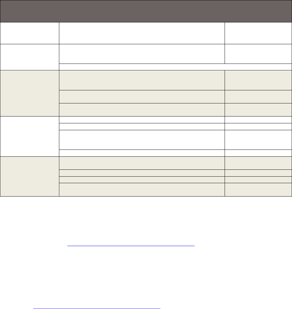
-Table 1. Summary of Stages Relevant to PV System Installation, Desired Characteristics at Each
Stage, and Standards that Describe How to Achieve these Characteristics
Stage in PV
System Life
(Document #)
Desired Characteristic
Standard Where the
Requirements Are
Specified in Detail
Choosing a Module
Manufacturer
(OD 405-x)
The module manufacturer has a quality-management system in
place that covers product design, purchasing, customer
relations, monitoring, and measuring.
IEC TS 62941
Note: This step evaluates the manufacturer, not a specific product.
Choosing an
Installer
(OD 410-x)
The installer keeps records of projects and trains employees.
Training, continual improvement (including evaluating energy
production via 61724).
IEC TS 63049
The installer follows best practices for array design (including
shading, mechanical loads, etc.).
IEC 62548
IEC TS 62738
The installer follows best practices for commissioning (including
system documentation for customer, testing, and inspection).
IEC 62446-1
Commissioning—
PV System is
Complete (OD 401)
Modules are designed to be safe and durable.
IEC 61730, IEC 61215
Power electronics are safe.
IEC 62109, IEC 62093
Commissioning: System documentation is provided to
customer. Testing and inspections appropriate for residential
systems are performed.
IEC 62446-1
Performance and capacity are clearly understood.
IEC 61724-2
Checking System
Performance
(OD 402)
Compare predicted and actual irradiance this year with
accuracy appropriate to residential systems.
IEC 61724-1
Compare predicted versus actual energy production this year.
IEC 61724-3
Compare predicted versus actual system downtime this year.
IEC 61724-3
Compare predicted versus actual operations and maintenance
costs this year.
2.3 Education and Developing Best Practices
NREL has worked in industry-wide collaborations to develop best-practices guides for several topics
related to photovoltaics. Most relevant to India is a best-practices guide for PV system installation (Doyle
et al. 2015), available at https://www.nrel.gov/docs/fy15osti/63234.pdf
. This guide includes best practices
for several aspects of installation, including requirements for personnel training, company experience and
solvency, shading analysis, shading packages, and system production estimates. Requirements are
organized into a short checklist in each section of the guide. Some requirements in the guide (e.g., a
collection of roof dimensions and type) may be of only minor importance to Indian stakeholders.
NREL has also produced a best practices guide regarding how to plan and deliver effective O&M Best
Practices for Operations and Maintenance of Photovoltaic and Energy Storage Systems; 3rd Edition
available at https://www.nrel.gov/docs/fy19osti/73822.pdf
.
Also available online are best-practices guides for commercial and industrial PV installations (Doyle et al.
2015), operations and maintenance (Doyle et al. 2015; NREL et al. 2016), solar resource assessment
(Sengupta et al. 2015), and development of renewable portfolio standards (Heeter, Speer, and Glick
2019).
NREL promoted an education program for authorities having jurisdiction. These authorities are the state
and local officials responsible for inspections and enforcing codes related to PV system installations. The
goal of the program was to maintain high system quality but minimize costs to the installer that might be
associated with jurisdictional authorities that have not previously specialized in solar, or low-value
10
This report is available at no cost from the National Renewable Energy Laboratory (NREL) at www.nrel.gov/publications.
inspections. Authorities having jurisdiction were educated on important points and common failures and
how approvals are typically handled in high-volume solar areas. Installers reported a significant
improvement in how efficiently inspections and approvals were executed in areas where jurisdictional
authorities participated in an education program.
2.4 Industry-Wide Reports on Rooftop PV Quality
A number of papers and online reports document observations and recommendations for PV system
quality internationally (IRENA 2017) or in specific countries such as the United States and India (IRENA
2017; Chattopadhyay et al. 2017; N 2018), Australia (IRENA 2017; Arthur et al. 2017), and Kenya
(Jacobson and Kammen 2007; Mills et al. 2014; Duke, Jacobson, and Kammen 2002; Turman-Bryant et
al. 2015). These reports contain observations of quality issues (IRENA 2017; Jacobson and Kammen
2007; Mills et al. 2014; Duke, Jacobson, and Kammen 2002), recommendations to solve quality issues
(IRENA 2017; Arthur et al. 2017; Duke, Jacobson, and Kammen 2002; Jason S. Trager 2018),
instructions and checklists (Turman-Bryant et al. 2015; IBTS 2019.; Stanfield and Hughes 2018;
Interstate Renewable Energy Council (IREC) 2010; Brooks and James Dunlop 2016; Energy Market
Authority 2011; California Energy Commission 2001) for system design and construction, consumer
guides (Energy Market Authority 2011; California Energy Commission 2001; SEIA 2018; Chace and
Clay Mitchell 2018), and a study of successful quality improvement (Jacobson and Kammen 2007;
Turman-Bryant et al. 2015). The study of PV lighting quality in Kenya is particularly interesting because
strategies were effective, and considerable quality improvements were observed (Turman-Bryant et al.
2015).
2.5 Looking Forward—Important Conclusions and Possible Paths
Experience at NREL, and that described in the literature, is consistent in its recommendations regarding
best practices for improving quality and safety of RTPV systems in India and elsewhere. Table 2 shows a
brief summary of desired characteristics, observed problems, and possible solutions based on work at
NREL and in the literature.
Listed below are five key considerations for improving quality and safety of RTPV systems as identified
from the review of this broad collection of studies:
1. Most of the time, residential RTPV consumers are unable to distinguish between low- and high-
quality systems. The purchase of a PV system represents a complicated one-time occurrence for
many consumers, many of whom have no prior experience with this technology. System quality
contains many technical details, any of which can lead to a system failure or underperformance.
Even third-party information (including some consumer guides) tends to overemphasize the
importance of initial cost per watt, most likely because there is not a readily available
quantification of quality. Products change approximately every six months, so a useful guide
must be updated frequently. Even after the system is installed, consumers do not know if the
system is producing as expected because of the complexities of temperature, irradiance, inverter
functions, and data reporting. These situations make warranty claims particularly difficult.
2. Demonstrations of quality (installers or components) are only effective if the information reaches
the customer in a clear way.
3. Many inspection checklists and certification procedures are already available. Some checklists
focus on different aspects of the PV system (e.g., components, roofing and construction, safety,
and energy generation).
11
This report is available at no cost from the National Renewable Energy Laboratory (NREL) at www.nrel.gov/publications.
4. Residential systems often lack long-term monitoring or effective operational indicators. A
homeowner should be able to easily see if their system is operating properly or if it requires
attention.
5. A successful approach to improving residential PV system quality is likely to include an
assortment of strategies. Up-to-date and accessible communication to customers is very important
because customers drive the market. Also important are installer training and certification, use of
certified components, inspections, and incentives, warranties, and financing that encourages the
purchase of high-quality systems.
12
This report is available at no cost from the National Renewable Energy Laboratory (NREL) at www.nrel.gov/publications.

Table 2. Desired Characteristics, Observed Problems, and Possible Solutions Based on Work at
NREL and in Literature
Desired
Characteristic
Observed
Problems
Possible Solutions
High-quality
components
Early life component
failure
• IEC component certifications—minimal cost to consumer
because manufacturer performs test once per product
• Publicize components that meet requirements online to
customers
Counterfeit
components
• Import control and random testing of products at market with
consumer-accessible online publication of results
• Development of national certification labs when possible
Installers buy poor-
• Provide channels of communication between installers and
quality components
distributors or manufacturers so those up the supply chain
because they are
know about the problems and buyer preferences.
most readily
available
Competent
installation
professionals
Mistakes made
because of lack of
training or
experience
• Make relevant training programs more accessible
• Publicize system designers and installers who meet training
or certification requirements to consumers
• Require training or certification for installers to participate in
certain types of financing or incentive programs
• Require system inspections by third parties or government
agencies. A large investment is required to make sure all
inspectors are expert enough to add value and that a lack of
inspectors does not delay projects.
Highest-quality
systems are
purchased
Consumers purchase
a low-quality system
because the initial
cost was the lowest
• Educate consumers that initial cost is not the only important
metric. Life-cycle costs are also important
• Publicize from a trusted source, both online and in stores,
components and installers that demonstrate exceptional
quality—and those that have demonstrated poor quality
• Provide incentives to customers that participate in quality
programs
• Make available a good warranty that installers may use and
customers may look for online
• Make available financing options (e.g., system lease) that
provide incentives for both the customer and the installer to
consider quality.
Confident buyers
Consumers decide
not to buy a system
because they’ve
• A trusted third-party provider continuously updates
information online that allows consumers to know they are
selecting high-quality components and installers. The
information must be publicized so that consumers are aware
of the resource
heard about some
problems
• Make available a good warranty that installers may use and
customers may look for online
• Make available financing options (e.g., system lease) that
provide incentives for both the customer and the installer to
consider quality.
13
This report is available at no cost from the National Renewable Energy Laboratory (NREL) at www.nrel.gov/publications.

3 Research Methodology
To gain a better understanding of quality and safety issues in India, this research effort was conducted in
three stages, starting with a literature review of solar quality and safety in India, followed by interviews
with various stakeholders in the sector, and an in-person workshop.
3.1 Literature Review
Few reports are available from previous studies undertaken to evaluate quality and safety aspects of solar
PV deployment in India. Those available are based on actual field visits and tests conducted on installed
and commissioned plants in various regions in India. Similar to the global experience described in Section
2, the majority of these studies are based on ground-mounted, MW-scale systems, and only parts of some
of these studies include rooftop systems. Nevertheless, important similarities can be observed, and
recommendations for MW-scale systems are applicable to RTPV systems as well. Common findings from
these reports are corroborated by stakeholder interviews conducted for this research and are presented in
Table 3. A list of reports, including those from non-Indian regions studied for this project, is also
presented in Appendix A.
The most frequently mentioned issue in these reports is the solar module, which represents the major cost
component of the system and most affects system life and performance. These solar modules are reported
to be of varying quality from different suppliers.
Table 3. Common Findings at Various Stages of PV System Installation in India
Stage of RTPV Project Common Findings
Solar module issues Early degradation, microcracks, potential induced degradation (PID),
snail trails
Safety and protections Incorrect earthing, insufficient lightning protection systems (LPSs),
underrated fuses and surge-protection devices (SPDs), disregard for
fire-handling systems
Installation methods Partial shadows on array, long runs of direct current (DC) cables,
loose connections and wear and tear of cables, corrosion in structure
parts
Commissioning Absence of independent inspection, lack of commissioning tests
Performance Lower energy generation, intermittent monitoring of systems, slow or
no follow up on corrective actions prompted by monitoring
O&M Inadequate maintenance, no schedule for preventive maintenance
Documentation Absence of proper documents with customers, planning and design
documents not shared with customers, power purchase agreements
(PPAs) or contracts unclear in many aspects.
These findings are attributed to some common probable reasons as presented in these reports and
corroborated by stakeholder interviews:
• Lack of awareness of these module problems by all stakeholders involved in PV power projects
• Absence of independent supervision, inspection, and audit framework
14
This report is available at no cost from the National Renewable Energy Laboratory (NREL) at www.nrel.gov/publications.

• Lack of documentation and reporting framework
• Focus on initial cost of power plant rather than levelized cost of energy
• Cost pressures that result in low-quality and unsafe PV systems.
3.2 Stakeholder Interviews: Methodology
To gain a comprehensive understanding of quality and safety of rooftop PV systems in India and the
sector status in general, a series of interviews with different stakeholders was conducted, including EPC
companies, installers, developers, component manufacturers, and others. Authorities, financiers, and
consultants were also interviewed to provide insights from their experiences in the field. As the agencies
actually responsible for onsite quality and safety, the EPC companies and installers were included in
larger numbers as compared to others. This particular group of interviewees was selected by categorizing
them into large, medium, and small players because the issues, reasons, and possible solutions would
likely be different across such segments.
Next, a questionnaire was designed and used to conduct interviews with different stakeholders in person,
over the telephone, and via written responses. Questions focused on the role of the interviewee, reasons
for poor or high solar quality and safety, impacts of low-quality systems, strategies for improving quality,
and insight on specific categories (e.g., components and humanpower).
In-person interviews were conducted with 13 stakeholders and telephone interviews with three
stakeholders from June to September 2019. In November 2019, another 8 in-person interviews were
conducted. Both of these types of interviews lasted for an average of 1.5 hours each. Several other
respondents provided written responses. In keeping with the questions used in the interviews, these
stakeholders identified current issues based on their own experiences and provided suggestions for
addressing such issues and improving the quality and safety of RTPV systems.
Interview responses were compiled and summarized by categories used in the questionnaires, which
included component, manpower, commissioning, inspection, documentation, operations and maintenance,
tools, site, installation standards, and safety. Some of these categories, such as tools, humanpower, and
site did not receive substantial responses and, hence, were combined into an “other” category for this
report. A summary list of issues, along with frequency of occurrence and impact on project development
is listed in Appendix D; a complete list of issues and possible corrective actions is listed in Appendix E.
3.3 Stakeholder Workshop
The United States Agency for International Development (USAID) PACE-D 2.0
3
held a solar quality and
safety workshop on January 21, 2020, in New Delhi, India, to confirm issues raised by stakeholder
interviews and to get feedback on potential solutions. Participants included representatives from key
government agencies, technical institutions, quality monitoring centers, multilateral development
agencies, utilities and distribution companies, local and regional banks, solar PV vendors and developers,
EPC companies, O&M companies, and central- and state-level policymakers. The day-long workshop
included panel discussions and breakout sessions to review and discuss three potential solutions to
improve quality and safety of RTPV in India
• Module quality certification
• Electrical safety quality assurance
3
https://www.pace-d.com/
15
This report is available at no cost from the National Renewable Energy Laboratory (NREL) at www.nrel.gov/publications.
• Vendor rating framework.
Inputs and findings from these discussions were used to further refine the solutions proposed in Section 5
of this report. There was support and general agreement that the development of a vendor rating
framework as a mechanism to evaluate, monitor, and rate RTPV vendors based on certain established
standards was a timely next step for India.
16
This report is available at no cost from the National Renewable Energy Laboratory (NREL) at www.nrel.gov/publications.
4 Key Findings: Quality and Safety Aspects of RTPV
Systems in India
The stakeholders interviewed in the survey identified major and frequently observed issues related to the
quality and safety of grid connected RTPV systems in India, much of which corroborated existing
literature and the authors’ extensive field experience. Figure ES- 1 captures some of the most severe and
frequent solar quality and safety issues organized by category or stages of RTPV system life: site
analysis, system design, installation, commissioning, and operations and maintenance. While some issues
may have a relatively low impact on energy generation, their impact on safety can be high (denoted by the
colored icons).
4.1 RTPV Project Development Cycle
The development of a RTPV project can be divided into three broad stages: design, procurement and
installation (including O&M).
• Design: the design stage includes site assessment activities, system sizing and design, component
selection and procurement planning, and scheduling the installation.
• Component procurement: the component procurement process involves contracting for the
component, including putting in place performance guarantees, specifications and standards that the
components must conform to, specifying the particular tests that the components must go through
before being dispatched from the manufacturing facility, and the specific test results that the
developer or EPC contractor would like to see before finally receiving the components.
• Installation and O&M: The final installation stage involves receiving components at the site, site
preparation, storing material, installing the system, and completing the commissioning. This stage
usually lacks standards and is more dependent on the skills and training of the installers.
Figure 2 shows the three stages and the broad set of activities they encompass.
17
This report is available at no cost from the National Renewable Energy Laboratory (NREL) at www.nrel.gov/publications.

Figure 2. Stages in the development of a RTPV project.
4.2 Key Challenges in RTPV Quality and Safety
Stakeholders raised concerns with component-related quality issues that span several stages of RTPV
system life, including the system design and installation phases. Most of the quality and safety issues
occurred either at the component procurement stage (about 50% of quality and safety issues experienced)
or the installation stage (about 35% of quality and safety issues experienced); the design stage contributed
to the balance 15% of quality and safety issues experienced. Within the different stages, some specific
areas caused a high proportion of challenges (Figure 3). For example, in the case of system design quality,
almost half of the quality challenges stemmed from the wrong array layout, followed by string inverter
mismatch and site access. In the case of component quality, the major area of concern was the modules
and the module mounting structures, followed by junction boxes; in the installation phase, the main
quality issues were related to fasteners, handling of modules, and earthing. Given the emphasis on issues
related to system design, component procurement, and installation and O&M, this report expands on
those topics in Sections 4.2.1-4.2.3. A summary list of issues, along with frequency of occurrence and
impact on project development is listed in Appendix D; a complete list of issues and possible corrective
actions is listed in Appendix E.
18
This report is available at no cost from the National Renewable Energy Laboratory (NREL) at www.nrel.gov/publications.

Figure 3. Design, component procurement, and installation related quality challenges based on
feedback from stakeholders.
4.2.1 System Design-Related Quality Issues
The biggest challenge identified by respondents in the design phase of RTPV development is the
difference in array layout in the installed systems versus the design layout derived after conducting a
shadow analysis using software such as PV Syst or PV Sol. For some reason, installers or EPC
contractors change the array layout on the ground, resulting in loss of generation and, in some cases, hot
spots
4
due to shadows that fall on part of the array. Incorrect array layout is a major error during the
design phase and can result in lower performance, which can significantly impact lifetime returns. This
issue can either be corrected or can be identified in a post-installation inspection (i.e., by checking if the
array layout on the ground conforms to the array layout on the design drawings). Similarly, our analysis
found another significant design problem that arose from the designer not matching the string voltage
with the maximum power point tracking (MPPT) voltage range of the inverter. Here again this issue can
lead to a loss of the returns of the system and can be rectified by checking if the string voltage is beyond
the inverter’s MPPT voltage range.
Another key issue identified during the design phase was the site access issue, which impacts O&M and
the quality of installation. In a number of cases, the site was not easily accessible, and workers had to take
unnecessary risks to get to the site for installation, or the site was developed in such a way that although it
was aesthetically attractive, the installation experienced generation losses due to alignment issues. Simple
precautions, such as ensuring permanent and easy access to equipment, could be incorporated during the
design phase. This issue is more apparent with arrays on superstructures where module cleaning may be
more challenging, thereby affecting performance adversely. A planned stormwater run-off system
4
Defects characterized by local overheating of solar cells.
19
This report is available at no cost from the National Renewable Energy Laboratory (NREL) at www.nrel.gov/publications.
integrated into the surrounding stormwater run-off system is also essential to avoid flooding, erosion of
foundations, and muddy ground which can prevent access.
In addition to these key concerns, other design-related issues involved improper cleaning methods for
modules, inadequate earthing provisions, and inadequate structural considerations for withstanding
weather conditions. These can have a significant impact on the life cycle returns of the project; however,
most of these issues can be avoided with good quality control, timely feedback, better training, and
awareness. A summary list of issues, along with frequency of occurrence and impact on project
development is listed in Appendix D; a complete list of issues and possible corrective actions is listed in
Appendix E.
4.2.2 Component-Related Quality Issues
Specifications and standards during the design stage dictate the identification and procurement of
components for the RTPV system. Based on discussions with stakeholders, it was found that almost 50%
of all quality issues resulted from procuring faulty or substandard components. A majority of the quality
and safety issues occurred with the module and the structure, followed by junction boxes.
In the case of structures, respondents agreed that full energy loss or complete system damage was
possible if a faulty structure was not rectified. Respondents felt that structure quality was difficult to map
and ensure but was critical for the long-term viability and sustainability of the systems. Some of the
specific quality issues highlighted by stakeholders for structures were:
• Material damage and defects (of both galvanized iron and aluminum structures)
• Poorly installed fasteners and mismatched component sizes
• Improper anchoring on sloped roofs
• Poor practices and incorrect equipment used in fixing modules onto a structure
• Design errors that result in an inability to withstand estimated dead load and wind pressure
• Post-construction inadequate finishing/ cleaning-up and waterproofing
• Lack of due diligence to determine base roof strength and quality
• Incomplete, ineffective, or nonexistent certifications.
While several standards have been developed and adopted for ensuring module quality, implementation is
lacking. In terms of structures, due to the varied nature of sites, standardization is a major challenge, and
this is coupled with the fact that most of the players are small and medium industries with limited design
capabilities. This makes ensuring quality of structures a challenge, especially for small RTPV projects
installed in small towns and cities. One of the most critical components in solar PV systems is the
inverter, but few survey respondents reported issues with inverters. This may be because the market is
dominated by a few large manufacturers who may view quality as critical to gaining and maintaining
market share.
Procurement of modules and certification of structures is key to addressing these component-related
issues. Module certification is an evolving topic, and several banks, developers, and EPC companies have
learned how to manage it efficiently. However, small EPC companies and developers often lack the
technical and financial strength to undertake this certification. There are existing tests that are critical for
certifying these components and for ensuring their high quality. These include acceptance testing at a lab
or at the module manufacturer’s site (through tests such as Flash, electroluminescence (EL), light induced
20
This report is available at no cost from the National Renewable Energy Laboratory (NREL) at www.nrel.gov/publications.
degradation (LID), and visual inspection and strict monitoring of the bill of materials). Structures have
two issues:
• Certifying the manufacturing of structures—this can be done by testing and certifying their structure
designs.
• Certifying joints and fasteners—this requires a different type of certification (e.g., finite element
analysis or wind tunnel testing) that is only possible for a limited number of standard structures that
are used across multiple locations.
In addition to the structures and modules, the junction boxes were identified as a key challenge. When
junction boxes don’t meet safety criteria, the result could be a total loss of the system from accidents.
Stakeholders also identified specific issues related to the structure, modules, and junction boxes, which
occur during the development and commissioning of RTPV systems. These issues include nonuniform
galvanization of steel, lack of certifications, rusting, no due diligence on roof strength adequacy, and the
use of poor-quality module subcomponents during manufacturing. A summary list of issues, along with
frequency of occurrence and impact on project development is listed in Appendix D; a complete list of
issues and possible corrective actions is listed in Appendix E.
4.2.3 Installation- and O&M-Related Quality Issues
The installation and O&M stages accounted for numerous quality issues identified by the stakeholders
across the life cycle of an RTPV system. Most of these quality issues relate to the installation of the
systems and their subcomponents, their packaging, transport, storage, onsite handling, and monitoring. A
key challenge was the quality of fasteners used in the structure. As discussed earlier, structure designs
need to go through a thorough wind tunnel test before being adopted. However, the biggest challenge for
the Indian market is that almost all structures are unique to match the site’s requirements; therefore, it
becomes impossible to test and certify every site for each new system or project.
Two other key issues around installation quality and safety are earthing and lightning (E&L) protection
and the handling of the modules. For example, in the case of E&L protection, some of the specific quality
issues highlighted by stakeholders were:
• Use of improper cables—wrong size and wrong type of cables are used; mismatch in cable connectors
used.
• Use of improper protection devices or no protection devices—lack of fuses and use of wrong surge
protectors.
• Inadequate or improper lightning-protection systems—improper selection and installation of lightning
arrestors.
• Inadequate earthing provisions—lower-than-necessary earthing pits or rods.
Some of the specific quality issues highlighted by stakeholders for the handling of modules were:
• Material damage and defects (revealed only over the period of installation) in cells, laminates, back
sheets, and junction box components.
• Transportation mismanagement (e.g., loosely and/or poorly packed, inappropriately loading and/or
unloading of components that causes damage).
• Invalid and mismatching module certificates.
21
This report is available at no cost from the National Renewable Energy Laboratory (NREL) at www.nrel.gov/publications.

• Poor installation of modules without referring to the manufacturer’s instruction manual.
• Ineffective cleaning methods by installers that are harmful to the modules.
Additionally, stakeholders also identified structural hardware issues and lack of inspections by qualified
personnel. A summary list of issues, along with frequency of occurrence and impact on project
development is listed in Appendix D; a complete list of issues and possible corrective actions is listed in
Appendix E.
Table 4 summarizes the key quality and safety issues experienced by most projects between the design
and implementation stages, and highlights potential solutions that can be adopted to address these specific
issues.
Table 4. Key Quality and Safety Issues, Their Impact on Project Returns, and Potential Solutions
Stage of Project
Development
Key Issue Potential Solutions
Design
Incorrect array layout
• Array layout to conform to shadow analysis drawing (check
drawing with actual layout)
String to inverter
voltage mismatch
• PV Syst/ PV Sol reports should be used to verify proper
matching of strings to MPPT range of inverter (onsite
matching; post installation check)
Absence of safe
structural and site
access
• Maintain pathway next to array for O&M
• Easy access to modules without the need of specialized
equipment
• Provision of lifeline for safety for sloping roof installations
Components
Poor design and
incorrect selection of
structural material
• Structure design certification to match wind zone of the
location
• Proper material treatment (selection of aluminum alloy or
galvanization thickness of galvanized iron)
Low quality modules
• Confirm that supplied module bill of materials matches the
tested and certified IEC 61215 bill of materials
• Acceptance testing by buyer at manufacturing facility
o Flash test
o EL test
o LID
o Visual inspection
Improper design of
junction boxes
• Integrate with inverter or test all protection devices
Installation and O&M
Incomplete E&L
protection
• Lightning arrestors effective radius should cover array
• Ensure minimum number of earthing (3 per system)
• Soil resistivity in each earth pit (< 5 ohms)
Improper handling of
modules
• Thermal imaging test (post installation to check if micro
cracks have developed in handling)
Incorrect module
fixing hardware
• Well defined hardware specifications; fasteners, clamping
and hardening requirements
In Section 5, a comprehensive, multipronged quality assurance framework is presented that aims to
address the major design, component, installation, and O&M issues identified by stakeholders, and help
improve the overall long-term quality and safety of RTPV systems in India.
22
This report is available at no cost from the National Renewable Energy Laboratory (NREL) at www.nrel.gov/publications.
4.3 Key Drivers of Poor-Quality and Unsafe Systems
Survey respondents offered the following list of possible reasons for poor-quality and unsafe rooftop PV
systems in India, which corroborates the authors’ extensive expertise, other literature, and experience in
the field.
4.3.1 Gaps in Existing Quality Standards
The MNRE has listed various mandatory standards applicable to different components within grid-
connected RTPV systems (Appendix B). However, these standards only pertain to components; there are
no mandatory standards for workmanship, installation, and grid integration. So, while the components
may adhere to the mandatory standards, those standards alone are not sufficient to ensure high-quality and
safe RTPV systems.
4.3.2 Focus on Capital Cost Rather Than Cost per Electrical Unit
The most common cause for various issues in RTPV systems is overemphasizing the capital cost rather
than the cost of generation or cost per generated unit. In practice, stakeholders involved in any RTPV
system installation have a singular focus—that of reducing the capital cost. In doing so, they may
compromise on various quality aspects and safety features that are essential for a high-performing system.
Because of very low entry barriers into this particular segment, many new entrepreneurs and small
agencies enter this business and compete heavily with each other solely on the basis of capital cost rather
than long-term system performance and the levelized cost of energy. Unfortunately, customers also tend
to focus on low initial cost rather than studying technical features and considering life-cycle costs.
Moreover, it is common for customers to demand pricing similar to ground-mounted, megawatt-level
projects because they incorrectly interpret the limited information available, and they lack the knowledge
to differentiate between ground-mounted and rooftop PV systems.
4.3.3 Competition in Pricing and Speed of Work
Fierce competition in the market compels the system integrator and installer to use low-priced
components as well as to cut costs by either omitting completely or undersupplying required features
within the system. Because the solar module contributes to more than 50% of the system’s cost, the focus
is usually on procuring the lowest-priced solar module rather than looking at the quality aspects, such as
the bill of material, construction quality, and track record of the module manufacturer. Basic and
mandatory standards for solar modules are easily met by all manufacturers present in the market.
However, there is also a gap in checking whether such module standard certificates are applicable to the
particular module bill of materials that is being purchased, and whether this certificate is valid at the time
of procurement. System components, other than the module and inverter, are primarily procured from
local suppliers, and may be of low quality and sometimes may not even meet mandatory standards or
requirements due to a lack of awareness, knowledge and training.
Cost cutting during system installation also happens in the balance of systems components; these can be
missing from the system or the quality may be undesirable. This can have serious impacts on the safety of
personnel, on the rooftop and building, as well as on the system and the grid. The components most
commonly used to cut costs have to do with protections, such as earthing and lightning protection, as well
as disconnect switches, overcurrent protection, and surge-protection devices. Neither grid engineers nor
customers are fully able to confirm if the supplied components are essential and/or present in RTPV
systems.
4.3.4 Lack of Training for Installers—No Eligibility Criteria
In India, the RTPV sector is at a nascent stage; hence, various stakeholders lack the proper knowledge or
experience to achieve quality systems and installations. RTPV systems are quickly becoming a
23
This report is available at no cost from the National Renewable Energy Laboratory (NREL) at www.nrel.gov/publications.
commodity product and, similar to other products purchased by customers for their private use, customers
fully depend on the expertise of the system provider, which is the only agency they are in contact with
while choosing a system and when the system is being commissioned on their rooftop. Some
entrepreneurs are new to the field, are not extensively educated about the technology, and may not
appreciate the importance of quality, resulting in higher failure rates of small-capacity systems often
executed by these entrepreneurs. Similarly, the grid engineer who inspects the installation, primarily from
the point of view of grid safety rather than system performance, may not be well equipped to advise
installers and customers on the quality of the system.
Currently, there are few mandatory eligibility criteria for installers and system integrators for
commissioning RTPV systems. Also, the states, either through the State Nodal Agency (SNA) or
discoms, do not opt for empanelment of system integrators and suppliers because they fear the extra
burden in case of a dissatisfied customer.
4.3.5 Lack of Customer Awareness
Rooftop systems can be broadly categorized into large-capacity systems for C&I customers and small-
capacity systems for residential customers. Currently, C&I consumers primarily opt for using the OPEX
model wherein the system is designed, installed, owned, and maintained by the developer or RESCO, and
the customer is happy to pay for the energy generated from the system. Such systems typically perform
better compared to residential RTPV systems because the revenue for the developers depends on energy
generation. In small-capacity residential systems, customers may not have experience or knowledge about
system performance or expected energy generation. Most customers are happy about savings achieved in
their electricity bills even when these savings are far below the potential savings that could be achieved
by their system.
4.3.6 Lack of Proper Inspection During and After Installation
Another missing activity in the overall framework of grid connected RTPV systems is the lack of
inspections by an independent agency that is experienced, professional, and capable of identifying issues
as well as recommending corrective actions. Often, it is left to the system integrator—or sometimes only
to the installer—to commission the system. Many times, the only inspection carried out on site is by the
grid engineer, who primarily inspects the grid-integration aspect of the system, not the direct-current side
that can have a larger impact on system performance. When systems are financed by a bank or third-party
investor, these agencies have some checks and balances in place if the investor is an experienced, serious
player in the RTPV sector; currently, such investors are few in number. Bankers may depend on the
lenders’ engineers whom they would appoint only for systems above a certain capacity. Many small-
capacity systems may be inspected only by the bank officer who is generally unaware of the technical
aspects because this sector is completely new for financing professionals.
4.3.7 Absence of Mandatory Requirements for Supervision and Audit
Systems installed under a RESCO model (primarily C&I customers), may get an inhouse inspection as
well as commissioning tests conducted by an experienced engineer. There are no standards for these tests
to be conducted before declaring the system commissioned and before synchronizing the system with the
grid—either by the company engineer or by a utility-grid engineer.
24
This report is available at no cost from the National Renewable Energy Laboratory (NREL) at www.nrel.gov/publications.
5 Prioritized Solutions and Implementation
Framework for Quality and Safety Issues in RTPV
Possible government-led efforts to improve RTPV quality and safety can be as simple as providing good
quality metrics to consumers, or as complex as detailed mandatory inspections, required by law, on each
system. To evaluate which measure to implement, one must weigh the expected impact against the
expense, resources and efforts. A progressive approach from the simplest, least-expensive solutions,
toward the more complex ones, can maximize benefits per investment, allow gradual development of
infrastructure and workforce, and provide time and experience to tailor policies before implementing the
most expensive steps. As discussed earlier in this report, in addition to adhering to prescribed standards
during the design, manufacturing, and installation of RTPV systems, there is a need for a framework that
allows stakeholders to examine whether these standards have been followed, which includes a rigorous
system of testing, monitoring, and performance mapping.
With these principles in mind, given the issues identified in this report and international best practices
reviewed, a multipronged approach to address long-term quality and safety through the implementation of
a Quality Assurance Framework (QAF) is suggested. The QAF aims to:
• Ensure market focus on developing quality systems and not solely on low upfront cost systems
• Enhance and improve customer understanding of the need for quality and safety in RTPV
• Facilitate the design, development, and deployment of standardized systems and products in the
Indian RTPV market
• Facilitate the development and adoption of industry-wide best practices for the design, procurement,
installation, and maintenance of RTPV systems
• Provide resources (information, tools) to help system owners and asset managers plan an effective
O&M program, estimate a budget for on-going O&M requirements, and effectively monitor
performance and take action based on monitoring results.
The QAF focuses on three main components (Figure 4):
• Module Quality Assurance Program: This process would focus on the components and help ensure
module quality. It would also help small-capacity and dispersed systems to adhere to certain
standards. It could be implemented by a Module Quality Certification Agency (to be established).
• Electrical Safety Quality Assurance Program: This process would certify for safety during the
design phase by ensuring adequate site access, provide design certification during the component
stage, and help ensure adequate electrical and lightning protection during the installation phase.
Distribution utilities and Electrical Inspectors could play a role in ensuring that all safety standards
for the RTPV system were followed.
• Vendor Rating Framework: Implementing a VRF may help evaluate the quality of work undertaken
by EPC companies and installers. The ratings from this framework would allow the consumer,
investor, or developer to identify the best providers and their capacity to install quality RTPV
systems. This would require establishing a Vendor Rating Agency (VRA) to oversee the
implementation of this process.
25
This report is available at no cost from the National Renewable Energy Laboratory (NREL) at www.nrel.gov/publications.

Figure 4. Key quality and safety issues, and potential solutions.
Each component is described in the following sections, with particular emphasis on the VRF because
stakeholders identified this concept as useful and easier to implement in the short term. At this initial
stage, it is proposed that separate agencies manage each of these components until a VRF has been
established and attained scale. Once established, and as the market matures, all three components could be
implemented by a single agency—the VRA—which could act as a central authority addressing quality-
related issues in the long term.
There are unique opportunities and constraints related to the design and implementation of the three
components discussed below (Figure 5).
26
This report is available at no cost from the National Renewable Energy Laboratory (NREL) at www.nrel.gov/publications.

Figure 5. Opportunities and constraints for recommended solutions
to quality and safety issues in India’s RTPV systems.
5.1.1 Module Quality Assurance
Modules, which still make up almost half of the total cost of the project in India, need to meet basic
quality standards for each project. Although several global standards and design qualification tests (e.g.,
IEC 61215, IEC 61730, and IEC 62804) have been developed to ensure the safe operation, service life,
reliability, and durability of PV modules, these standards alone have not been adequate in ensuring that
modules conform to these standards in India. Most manufacturers get a few of their modules tested for
these design standard certifications. However, modules being produced on each run do not necessarily
conform to the same requirements as outlined in the tests. The only way to ensure that the modules
conform to these requirements is through a set of tests on a random sample of the modules produced as a
part of the production run, making it important to address module quality issues at the manufacturing
facility or as close to it as possible.
While subjecting each production run to these rigorous module quality tests makes sense from a quality
perspective, this type of testing is not available for small developers and EPC companies that purchase
modules in small quantities from module producers. Large buyers often have their own staff or engage a
third-party quality assurance company at production centers to ensure quality because of their purchase
volume. However, the transaction costs are too high for small RTPV developers, and most module
manufacturers will not allow these developers to run these tests.
Module quality issues could be addressed through:
• Third-party testing and aggregated procurement in the short term: Aggregating and
procuring modules through larger distributors will help support testing module quality at the
production site at a lower cost. This would involve EPC companies and developers, especially
small vendors procuring modules through a single entity. This would result in better purchasing
power and economies of scale at the module manufacturer’s end as well as result in lower
transaction costs for testing.
The first step is to develop a strategy for aggregating module procurement. Costs of
implementing module quality testing (MQT) will remain relatively high unless the modules to be
27
This report is available at no cost from the National Renewable Energy Laboratory (NREL) at www.nrel.gov/publications.
tested are aggregated. This step will include developing a demand aggregation strategy to pool
demand from solar PV rooftop module developers and EPC companies. It will also include
identifying the mechanisms by which this will be undertaken, including how costs and results can
be shared. A second step is creating a module procurement aggregator. This step includes
identifying an agency to coordinate aggregation of orders from the RTPV industry in India.
Aggregation at an agency level will lead to a number of downstream benefits:
o Economies of scale for procuring modules
o Bargaining power with module manufacturers
o Improved quality control
o Lower cost of module quality testing.
• Mandating module quality testing by the distribution utility over the medium term: Module
quality testing can also be mandated by discoms and can be implemented using a third-party testing
and validation agency. This agency would provide certification for specific lots of modules produced
that would be checked by the discom at the time of commissioning. However, costs of testing will
remain high unless conducted in large batches. Discoms would be a suitable agency to implement this
at the initial stage because they are the only government agency that visits each solar rooftop project
site. This would allow testing and certification of modules before project development.
Developing a module quality testing and certification protocol is a key step in this process. MQT is a
standard process for most large developers who either have trained technical staff or hire the services
of laboratories, such as Underwriters Laboratories (UL) and TÜV Rheinland (TÜV), to undertake
MQT. Designing an MQT protocol would include putting a standardized process with requirements in
place. It will outline the testing parameters that will be evaluated, the sampling methodology that will
be used, and the manner in which the results will be provided and interpreted. The MQT will provide
guidance to developers, EPC companies, and consumers on component quality used in manufacturing
the modules, the quality acceptance tests performed on these modules, and the results of these tests,
including details of how these tests were performed.
• Rating of module quality as a part of the VRF over the long term: Rating by an independent
agency as part of the VRF would also allow developers, banks, and consumers to understand the
quality of the modules from various module manufacturers. This would be done after commissioning
and would be time-consuming because a huge amount of data would have to be collected, analyzed,
and released. Implementing module quality certification might work more effectively once the market
matures
Figure 6 shows how this framework can be implemented.
28
This report is available at no cost from the National Renewable Energy Laboratory (NREL) at www.nrel.gov/publications.

Figure 6. Implementation Framework for Module Quality Assurance
5.1.2 Safety Quality Assurance
Protection and safety are major concerns for utilities and, although time consuming, RTPV protection and
safety issues should be addressed by the distribution utility during the commissioning process. Currently,
safety checks are largely ignored, and some safety features are not mandated. This is exacerbated by a
lack of consumer awareness. Small RTPV projects are often not a priority for discom engineers in India,
especially when site inspection and report generation are time consuming, and most engineers do not have
access to tools and adequate training. Some state regulations mandate safety features that discoms must
uphold (e.g., the Bangalore Electricity Supply Company (BESCOM) has interconnection process
mandates and audit safety features, and Kerala CEI has published standardized single-line diagrams that
include safety device specifications), but there is room for improvement.
Based on the major safety issues discussed in this report, utilities are the best stakeholders to ensure that
junction boxes and electrical and lightning protections meet the required standards, that site access is
adequate, and to provide design certification of structures. Figure 7 shows how this process can be
facilitated.
29
This report is available at no cost from the National Renewable Energy Laboratory (NREL) at www.nrel.gov/publications.

Figure 7. Recommended safety quality assurance process.
Note:the utility plays a major role in safety checks.
Utility personnel are often overburdened; it is important to provide the necessary tools and training to
support this process and make it more efficient. There is a need for IT-based tools and applications that
can be used to certify these requirements and generate reports, allowing utility personnel the speed and
flexibility to capture all of these requirements online. This process would also ensure improved
compliance with quality and safety standards prescribed in the regulations.
5.1.3 Vendor Rating Framework
There are currently no mechanisms in place to monitor, evaluate, and rate RTPV vendors in India. A VRF
can help measure the quality of systems as well as ensure compliance of these systems to certain
established standards. Vendor rating is a procedure whereby a VRA provides solar EPC companies and
installers a score or ranking based on factors such as the quality of onsite work (design, components,
installation) and the performance of their systems. A VRF can be used as a single point of reference for
all stakeholders, including consumers, financial institutions, and developers, to identify top-quality
vendors for future solar system installations, operations, and maintenance. As vendors (including EPC
companies or installers) and suppliers are held responsible for component and installation quality using
this framework, a VRF can provide an effective mechanism to link quality systems to market share by
putting in place a procedure to evaluate, rate, and certify vendors based on their track records of
designing, developing, and deploying systems. As such, an effective VRF may accelerate the adoption
rate of RTPV by providing confidence to customers and discoms that reputed vendors sell high-quality
solar products.
An effective VRF would identify all relevant criteria for assessing vendors. It would also provide vendors
with information about their performance weaknesses so they can take corrective action. A VRF could
provide continuous review of standards for vendors, thus supporting continuous improvement of vendor
performance. The main types of vendor requirements would include:
30
This report is available at no cost from the National Renewable Energy Laboratory (NREL) at www.nrel.gov/publications.
• Standard quality assurance (QA) plans of vendors: consumers and the VRA should check the QA
plan of vendors, which should include incoming material quality checks, in-process checks,
quantitative methods of random testing, final system testing, and acceptable or passing levels.
• Component procurement guidelines: these would be a major component of the QA plan.
Guidelines will confirm that materials and components used in the system comply with all
certifications and confirm that these have gone through thorough and rigorous checks before
deploying into the system.
• Installation and commissioning checklists for inspection and sign off: the vendor must conduct
independent pre- and post-commissioning inspection checks, which would occur at varying levels of
detail and technicalities. These checks and their results should be available to the consumers and the
rating agency.
• Design approach guidelines: VRA should review the entire process of survey and design adopted by
the vendor, the tools used by the vendor (for shadow-analysis, structure analysis, generation
estimation, etc.), the vendor's approach for developing designs (e.g. string sizing, allowable shadow
loss, etc.), and qualifications of vendor staff to conduct these jobs.
5.1.3.1 Benefits of a VRF by Stakeholder
A VRF will provide benefits for each of the stakeholder groups involved with solar PV in India:
• Vendor Rating Agency: To develop a comprehensive framework for ranking vendors and designing
a business model to make this financially viable, a specialized agency with extensive experience in
undertaking ratings across India must be identified. The VRA needs excellent working relationships
with industry and experience in training and building capacity. The VRA would develop requirements
for rating vendors on appropriate criteria in collaboration with the MNRE and discoms. Technical and
research-focused organizations, such as the Confederation of Indian Industry, the Energy and
Resources Institute, or Gujarat Energy Research and Management Institute (GERMI), could serve as
the VRA.
• Vendors: For vendors that volunteer to participate, the VRF will assess their performance and
identify their strengths and weaknesses, enabling them to make improvements. Vendors can also use
this tool to benchmark quality.
• Developers: The VRF will help developers evaluate the performance of vendors, EPC companies,
and installers, and identify high-quality vendors. It will provide a platform to access the performance
of a specific vendor’s solar PV system in real-world conditions. The quality of construction may vary
significantly from one EPC company to another. Hence, the reputation, track record, industry
expertise, and bankability of the EPC contractor are critical when assessing the quality of a project.
With this framework in place, developers can distinguish the best from the rest. Selection of top-
ranked vendors will also provide better performance and workmanship guarantees. Developers
operate within an environment of extreme pricing pressure brought on by a competitive-bid process.
A VRF will provide developers the ability to make decisions based on quality, price, and vendor
reputation.
• Customers: The VRF will ultimately enhance the quality of systems installed by customers. It will
also promote awareness among customers about the risks of poor-quality solar installations,
operations, and deployment, highlight those vendors that have been rated as providing higher-quality
services and systems, and weed out low-quality vendors.
• Investors/Financiers: The VRF will help investors by providing preliminary assurance of the quality
and capabilities of vendors whose systems are to be financed. This will provide financiers with the
support needed to identify high-quality vendors and systems without expending much effort. Once the
31
This report is available at no cost from the National Renewable Energy Laboratory (NREL) at www.nrel.gov/publications.
rating system is mature, financiers may also devise a system where highly rated vendors receive some
benefit in loan processing or interest rates.
5.1.3.2 Proposed VRF Operational Approach
This section outlines a potential approach to operating a VRF. Initially, the vendor rating mechanism
would be voluntary for vendors—some vendors would see the benefit of ratings through increased sales.
An eventual aim of a VRF is to make certification required for every RTPV vendor (EPC company or
installer) using an NABCEP-like framework, in order to compete in the market.
The VRF would look at a vendor’s systems and processes as well as sample installations to arrive at a
rating. The rating would be time bound and restructured as requirements change. Sampling of systems
will allow vendors to take action if issues arise and continuously improve ratings. The VRA would use
the framework to establish an internal process and standardized terms and conditions for vendor
assessment, adaptable for use by all Indian states. The VRF would also include guidelines for vendor
empanelment, tendering, O&M, and after-sales support by vendors. It will create a stringent compliance
and monitoring framework to evaluate the services provided by vendors on a regular basis and determine
penalties, such as lowering a vendor’s rating. Key parameters for rating vendors and evaluating their
performance would fall into three categories
• Financial strength—vendor’s sales trends and basic financial ratios as an indicator of growth and
acceptance in the market by customers
• Technical capacity—assessed through documentation such as standard purchase/work orders,
customer handover documents, design and engineering documents.
• Systems and processes—implementation of quality and safety would be reviewed through technical
inspections of randomly selected actual system installations covering design, component, installation
and O&M aspects. System performance and customer feedback would also be considered. Of the
three categories listed here, reviewing a vendor’s systems and processes would carry the highest
weight.
Appendix C provides a schematic of key parameters on which vendors may be rated.
The process of developing, finalizing, and deploying a VRF will involve this sequence of activities
(Figure 8):
1. Develop a rating methodology and key parameters for rating vendors: Define the parameters
based on which the vendors would be rated. These would focus on the technical and financial
strength of the vendors, their systems and processes to manage and maintain quality, the quality
of their manpower, and the quality of the installations developed by these vendors. A sample
between 5% and 20% of all systems developed by a vendor would be surveyed based on the
criteria and quality to be mapped and rated.
2. Create an IT application to facilitate the vendor rating: The rating methodology and the
parameters will be combined with an IT application that will provide a score once the rating has
been undertaken.
3. Identify a Vendor Rating Agency: Identify the agency that will manage the VRF once it is
developed. This would include piloting the process and rolling it out. This step would also
include developing a business plan and capacity development plan for the agency as well as
understanding the scope of services the agency can provide.
32
This report is available at no cost from the National Renewable Energy Laboratory (NREL) at www.nrel.gov/publications.

4. Train rating agency/rating professionals: Define the learning and training objectives for
undertaking a vendor rating and create a training and certification program for the professionals
who would rate these vendors.
5. Market the VRF: Define the usability of the VRF, including key benefits the VRF will provide
to stakeholders. Be sure to include how the VRF will help raise customer awareness levels about
the need for high-quality and safe solar PV systems in India.
Figure 8. Process for developing and implementing a vendor rating framework
33
This report is available at no cost from the National Renewable Energy Laboratory (NREL) at www.nrel.gov/publications.
6 Next Steps
A multipronged quality assurance framework is outlined in this report that includes:
1. Module quality assurance through a Module Testing and Certification Agency
2.
Electrical safety assurance through utility inspections
3.
Quality of system design and implementation through a Vendor Rating Framework.
A detailed path forward for implementing a VRF is presented. Future work is needed to develop a plan
for implementing other components of a quality assurance framework that include key institutions and
their responsibilities, timelines, and other necessary resources. Ensuring electrical safety will depend
heavily on utilities (discoms) that will have to confirm mandatory safety parameters for each system
through inspections and sanctioning procedures. An app or similar online tool could help build discom
engineer capacity to accomplish these tasks. Module quality assurance through testing and certification
would require identification of inspection and certification bodies that would work in tandem with module
aggregators, whereby costs of such a certification would be bearable even for small EPC companies and
installers.
This prioritized approach is based on the input from Indian stakeholders as well as reports of earlier
studies conducted on some sample site inspections. Given the increased involvement of different
stakeholders suggested in this report, agencies may have to adapt to evolving roles and responsibilities in
the Indian rooftop and distributed PV sector. In addition to the enhanced engagement with these
stakeholders through deliberations and interactions, it will be useful if the USAID PACE-D 2.0 program
familiarizes these stakeholders to the similar roles being played by agencies in other regions of the world.
There may be numerous things to learn from experience elsewhere and this will contribute substantially to
these agencies adopting roles in ensuring high-quality and safer PV systems in India.
34
This report is available at no cost from the National Renewable Energy Laboratory (NREL) at www.nrel.gov/publications.
References
Arthur, Daniel, Conor Hoey, Tess Lafer, and Brian Westgate. 2017. “A Comprehensive Methodology for
Assessing the Quality of Solar Photovoltaic System.” https://web.wpi.edu/Pubs/E-
project/Available/E-project-050117-211109/unrestricted/Assessing_Solar_PV_Quality_-
_Full_Report.pdf.
Bridge to India. 2019. “India Solar Rooftop Map.” Gurugram, India: Bridge to India.
https://bridgetoindia.com/report/india-solar-rooftop-map-december-2019/.
Brooks, William, and James Dunlop. 2016. “NABCEP PV Installation Professional Resource Guide.”
http://www.nabcep.org/wp-content/uploads/2016/10/NABCEP-PV-Resource-Guide-10-4-16-
W.pdf.
California Energy Commission. 2001. “A Guide to Photovoltaic (PV) System Design and Installation.”
https://pdf.wholesalesolar.com/guide.pv.installation.pdf.
Chace, Diana, and Clay Mitchell. 2018. “A Vermonter’s Guide to Residential Solar.” Clean Energy States
Alliance. https://www.cesa.org/assets/2016-Files/VT-Solar-Guide.pdf.
Chattopadhyay, Shashwata, Rajeev Dubey, Vivek Kuthanazhi, Sachin Zachariah, Sonali Bhaduri,
Chiranjibi Mahapatra, Sugguna Rambabu, et al. 2017. All-India Survey of Photovoltaic Module
Reliability: 2016.
Devi, Amala, Narayan Uttara, and Mandal Tirthankar. 2015. “Here Comes the Sun: Residential
Consumers’ Experiences with Rooftop Solar PV in Five Indian Cities.”
https://shaktifoundation.in/wp-content/uploads/2018/11/Here-Comes-the-Sun.pdf
Doyle, C, A. Truitt, D. Inda, R. Lawrence, R. Lockhart, and M. Golden. 2015. “SAPC Best Practices in
PV System Installation, Version 1.0.” Subcontract Report NREL/SR-6A20-63234.
https://www.nrel.gov/docs/fy15osti/63234.pdf.
Doyle, Chris, Len Loomans, Andrew Truitt, Robert Lockhart, Matt Golden, Kareem Dabbagh, and
Richard Lawrence. 2015. “Best Practices in Commercial and Industrial (C&I) Solar Photovoltaic
System Installation.” NREL/SR--6A20-65286, 1234506. https://doi.org/10.2172/1234506.
Duke, Richard D., Arne Jacobson, and Daniel M. Kammen. 2002. “Photovoltaic Module Quality in the
Kenyan Solar Home Systems Market.” Energy Policy 30 (6): 477–99.
https://doi.org/10.1016/S0301-4215(01)00108-2.
Energy Market Authority. 2011. “Handbook for Solar Photovoltaic (PV) Systems.”
https://policy.asiapacificenergy.org/sites/default/files/Solar_Handbook_Apr2011.pdf.
Heeter, Jenny S, Bethany K Speer, and Mark B. Glick. 2019. “International Best Practices for
Implementing and Designing Renewable Portfolio Standard (RPS) Policies.” NREL/TP-6A20-
72798, 1507986. https://doi.org/10.2172/1507986.
IBTS 2019. “Solar Inspection Checklist.” Insitufe for Building Technology Safety (blog). Accessed
August 23, 2019. https://www.ibts.org/solar-inspection-checklist/.
Interstate Renewable Energy Council (IREC). 2010. “Field Inspection Guideline for PV Systems.”
http://brooksolar.com/files/PV-Field-Inspection-Guide-June-2010-F-1.pdf.
35
This report is available at no cost from the National Renewable Energy Laboratory (NREL) at www.nrel.gov/publications.
IRENA. 2017. “Boosting Solar PV Markets: The Role of Quality Infrastructure.” International Renewable
Energy Agency.
Jacobson, Arne, and Daniel M. Kammen. 2007. “Engineering, Institutions, and the Public Interest:
Evaluating Product Quality in the Kenyan Solar Photovoltaics Industry.” Energy Policy 35 (5):
2960–68. https://doi.org/10.1016/j.enpol.2006.10.024.
Jason S. Trager. 2018. “Solar Needs a Total Quality Revolution.” Blog. Greentech Media. March 28,
2018. https://www.greentechmedia.com/articles/read/solar-needs-a-total-quality-revolution.
Mills, Evan, Jennifer L. Tracy, Peter Alstone, Arne Jacobson, and Patrick Avato. 2014. “Low-Cost Led
Flashlights and Market Spoiling in Kenya’s Off-Grid Lighting Market.” Energy Efficiency 8
(April). https://doi.org/10.1007/s12053-014-9294-2.
N, Sushma U. 2018. “India’s Booming Solar Sector Has One Major Flaw: Poor Quality.” Quartz India.
August 1, 2008. https://qz.com/india/1345508/poor-quality-solar-panels-may-ruin-indias-
renewable-energy-boom/.
NREL, Sandia, Sunspec Alliance SuNLamp, and PV O&M Working Group. 2016. “Best Practices in
Photovoltaic System Operations and Maintenance, 2nd Edition.” NREL/TP--7A40-67553,
1336898. https://doi.org/10.2172/1336898.
SEIA. 2018. “Residential Consumer Guide to Solar Power.” Solar Industries Energy Association (SEIA).
https://www.seia.org/research-resources/residential-consumer-guide-solar-power.
Sengupta, M., S. Kurtz, A. Dobos, S. Wilbert, E. Lorenz, D. Renné, D. Myers, S. Wilcox, P. Blanc, and
R. Perez. 2015. “Best Practices Handbook for the Collection and Use of Solar Resource Data for
Solar Energy Applications.” IEA Solar Heating and Cooling Programme.
https://doi.org/10.18777/ieashc-task46-2015-0001.
Stanfield, Sky, and Don Hughes. 2018. “Model Inspection Checklist for Rooftop PV Systems.”
http://www.irecusa.org/wp-content/uploads/2013/09/Model-Inspection-Checklist.pdf.
Turman-Bryant, Nick, Peter Alstone, Dimitry Gershenson, Daniel M. Kammen, and Arne Jacobson.
2015. “Quality Communication: Quality Assurance in Kenya’s Off-Grid Lighting Market.”
https://www.lightingglobal.org/resource/quality-communication-quality-assurance-in-kenyas-off-
grid-lighting-market/.
———. 2015. “The Rise of Solar: Market Evolution of Off-Grid Lighting in Three Kenyan Towns.”
Lighting Global Market Research Report. https://www.lightingglobal.org/resource/the-rise-of-
solar-market-evolution-of-off-grid-lighting-in-three-kenyan-towns/.
MNRE. 2019. “Guidelines on Implementation of Phase-II of Grid Connected Rooftop Solar Programme
for Achieving 40 GW Capacity from Rooftop Solar by the Year 2022. Office Memorandum.”
Vol. No. 318/331/2017. https://mnre.gov.in/sites/default/files/schemes/Notification-20082019-
184419.pdf.
MNRE. 2014. “Off-Grid and Decentralized Solar Application Scheme: Operational Guidelines for Grid
Connected Rooftop and Small Solar Power Plants Programme. Annexure.” Vol. 30/11/2012-
13/NSM. https://mnre.gov.in/file-manager/UserFiles/Scheme-Grid-Connected-Rooftop-&-small-
solar-power-plants.pdf.
36
This report is available at no cost from the National Renewable Energy Laboratory (NREL) at www.nrel.gov/publications.
MNRE. 2015. “State Wise and Year Wise Targets for Installation of 40,000 MW Grid Connected Solar
Rooftop Systems.” Vol. D.O. No. 03/13/2015-16/GCRT.
https://mnre.gov.in/sites/default/files/webform/notices/State-wise-and-year-wise-target-for-
installation-of-40000MWp-GCRT-systems_0.pdf.
Jaiswal, Shantanu, Atin Jain, Itamar Orlandi, and Ashish Sethia. 2017. “Accelerating India’s Clean
Energy Transition.” Bloomberg New Energy Finance.
https://data.bloomberglp.com/professional/sites/10/BNEF_Accelerating-Indias-Clean-Energy-
Transition_Nov-2017.pdf.
Josey, Ann, Shantanu Dixit, Ashwini Chitnis, and Ashwin Gambhir. 2018. “Electricity Distribution
Companies in India: Preparing for an Uncertain Future.” Pune, India: Prayas Energy Group.
http://www.prayaspune.org/peg/publications/item/377.
Jaiswal, Shantanu, Atin Jain, Itamar Orlandi, and Ashish Sethia. 2017. “Accelerating India’s Clean
Energy Transition.” Bloomberg New Energy Finance.
https://data.bloomberglp.com/professional/sites/10/BNEF_Accelerating-Indias-Clean-Energy-
Transition_Nov-2017.pdf.
Patel, Dheer, Joni Sliger, and Ranjit Bharvirkar. forthcoming. “Demand Flexibility and Distributed
Energy Resources: Examining Four Options for India’s Power Distribution Sector to Become
Cleaner, More Affordable, and More Reliable.” Montpelier, VT: Regulatory Assistance Project.
37
This report is available at no cost from the National Renewable Energy Laboratory (NREL) at www.nrel.gov/publications.
Appendix A – Referenced Published Reports
Studies in India on commissioned PV plants
• Pilot Study on Quality Aspects of PV Plants in India – Strengthening quality infrastructure for solar
industry - India
• By PI Berlin, September 2017
• All India Survey of Photovoltaic Module Reliability: 2016
• NCPRE, IIT Bombay & NISE
• UL Engineering challenge 2015 – Team 1
• UL Engineering challenge 2015 – Team 2
Similar Studies in Non-Indian Regions
• 2018 Solar Industry Business and Technology Trends
• Solar Under Storm by Rocky Mountain Institute, October 2017
• Review of Failures of Photovoltaic ModulesBy Photovoltaic Power Systems Program, International
Energy Agency 2014
Best Practices and Developers’ Guides
• Best Practices Manual and Guide by USAID PACE-D TA and GERMI funded by MNRE
• Interconnection and Inspection of Grid Connected Rooftop Photovoltaic Systems – A Guide for
Utility Grid Engineers by USAID PACE-D TA and SCGJ
• Greening the Roofs – A Guide for Solar Entrepreneurs by USAID PACE-D TA and SCGJ
• Evaluation of Solar Proposals – A Guide for Financial Institutions, Solar Developers and EPCs by
USAID PACE-D TA and SCGJ
• Utility scale solar photovoltaic plants – a project developer’s guide by IFC 2015
• SAPC Best Practices in PV System Installation by NREL, 2015
• Guidelines for GRPV – UL
Quality Component Report
• Module reliability scorecard by DNV GL 2018
38
This report is available at no cost from the National Renewable Energy Laboratory (NREL) at www.nrel.gov/publications.

Appendix B – MNRE Published List of Standards
Quality Certification, Standards, and Testing for Grid-Connected Rooftop Solar PV
Systems / Power Plants
Quality certification and standards for grid-connected rooftop solar PV systems are essential for the
successful implementation of this technology. It is also imperative to put in place an efficient and rigorous
monitoring mechanism, adherence to these standards. Hence, all components of grid-connected rooftop
solar PV system/ plant must conform to the relevant standards and certifications given below:
Table B1. Published List of Standards
Solar Module
IEC 61215/ IS
14286
Design Qualification and Type Approval for Crystalline Silicon
Terrestrial
Photovoltaic (PV) Modules
IEC 61701
Salt Mist Corrosion Testing of Photovoltaic (PV) Modules
IEC 61853
- Part 1/ IS
16170: Part 1
Photovoltaic (PV) module performance testing and energy
rating: irradiance and
temperature
performance measurements, and power rating
IEC 62716
Photovoltaic (PV) Modules
– Ammonia (NH3) Corrosion Testing
(As per the site condition like dairies, toilets)
IEC 61730
-1,2
Photovoltaic (PV) Module Safety Qualification
– Part 1: Requirements for
Construction, Part 2: Requirements for
Testing
IEC 62804
Photovoltaic (PV) modules
- Test methods for the detection of potential-induced
degradation. IEC TS 62804
-1: Part 1: Crystalline silicon
(Mandatory for applications where the
system voltage is >600 VDC and advisory for
installations where the system
voltage is < 600 VDC)
IEC 62759
-1
Photovoltaic (PV) modules
– Transportation testing, Part 1: transportation and
shipping of module package units
Solar PV Inverters
IEC
62109-1, IEC 62109-2
Safety of power converters for use in photovoltaic power
systems –
Part 1: General requirements, and Safety of power converters for use in photovoltaic
power systems
Part 2: Particular requirements for inverters. Safety
compliance (Protection degree
IP 65 for outdoor mounting, IP
54 for indoor mounting)
IEC/IS 61683
(as
applicable)
Photovoltaic Systems
– Power conditioners: Procedure for Measuring Efficiency
(10%, 25%, 50%, 75% & 90
-100% Loading Conditions)
BS EN 50530
(as
applicable)
Overall efficiency of grid
-connected photovoltaic inverters: this European Standard
provides a procedure for the
measurement of the accuracy of the maximum power
point
tracking (MPPT) of inverters, which are used in grid-connected photovoltaic
systems. In that case the inverter
energizes a low voltage grid of stable AC voltage
and
constant frequency. Both the static and dynamic MPPT efficiency is considered.
IEC 62116/ UL
1741/ IEEE
1547
(as applicable)
Utility
-interconnected Photovoltaic Inverters - Test Procedure
of Islanding Prevention
Measures
IEC 60255
-27
Measuring relays and protection equipment
– Part 27: Product safety requirements
39
This report is available at no cost from the National Renewable Energy Laboratory (NREL) at www.nrel.gov/publications.

IEC 60068
-2 (1, 2, 14, 27,
30 & 64)
Environmental Testing of
PV System – Power Conditioners and Inverters
a) IEC 60068
-2-1: Environmental testing - Part 2-1: Tests - Test A: Cold
b) IEC 60068
-2-2: Environmental testing - Part 2-2: Tests - Test B: Dry heat
c) IEC 60068
-2-14: Environmental testing - Part 2-14: Tests - Test N: Change of
temperature
d) IEC 60068
-2-27: Environmental testing - Part 2-27: Tests -
Test Ea and guidance:
Shock
e) IEC 60068
-2-30: Environmental testing - Part 2-30: Tests - Test Db: Damp heat,
cyclic (12 h + 12 h cycle)
f) IEC 60068
-2-64: Environmental testing - Part 2-64: Tests - Test Fh: Vibration,
broadband random and guidance
IEC 61000
– 2,3,5 (as
applicable)
Electromagnetic Interference (EMI) and Electromagnetic Compatibility (EMC) testing
of PV Inverters
Fuses
IS/IEC 60947 (Part
1, 2 &
3), EN
50521
General safety requirements for connectors, switches, circuit
breakers (AC/DC):
a) Low
-voltage Switchgear and Control-gear, Part 1: General rules
b) Low
-Voltage Switchgear and Control-gear, Part 2: Circuit Breakers
c) Low
-voltage switchgear and Control-gear, Part 3: Switches, disconnectors,
switch
-disconnectors and fuse-combination units
d) EN 50521: Connectors for photovoltaic systems
– Safety requirements and tests
IEC 60269
-6
Low
-voltage fuses - Part 6: Supplementary requirements for fuse-links for the
protection of solar photovoltaic energy
systems
Surge Arrestors
IEC 62305
-4
Lightening Protection Standard
IEC 60364
-5-53/IS 15086-5
(SPD)
Electrical installations of buildings
- Part 5-53: Selection and erection of electrical
equipment
- Isolation, switching and control
IEC 61643
- 11:2011
Low
-voltage surge protective devices - Part 11: Surge protective devices connected
to low
-voltage power systems - Requirements and test methods
Cables
IEC
60227/IS 694, IEC
60502/IS 1554
(Part 1 & 2)/
IEC69947
General test and measuring method for PVC (Polyvinyl
chloride) insulated cables
(for working voltages up to and
including 1100 V, and UV resistant for outdoor
installation)
BS EN 50618
Electric cables
for photovoltaic systems (BT(DE/NOT)258), mainly for DC Cables
Earthing /Lightning
IEC 62561 Series
(Chemical
earthing)
IEC 62561
-1: Lightning protection system components (LPSC) - Part 1:
Requirements for connection components
IEC 62561
-2: Lightning protection system components (LPSC) - Part 2:
Requirements for conductors and earth electrodes
IEC 62561
-7: Lightning protection system components (LPSC) - Part 7:
Requirements for earthing enhancing compounds
Junction Boxes
IEC 60529
Junction boxes and solar panel terminal boxes shall be of the
thermo-plastic type
with IP 65 protection for outdoor use, and
IP 54 protection for indoor use
Energy Meter
40
This report is available at no cost from the National Renewable Energy Laboratory (NREL) at www.nrel.gov/publications.

IS 16444 or as
specified by
the
DISCOMs
A.C. Static direct connected
watt-hour Smart Meter Class 1 and 2 — Specification
(with Import & Export/Net energy
measurements)
Solar PV Roof Mounting Structure
IS 2062/IS 4759
Material for the structure mounting
Note: Equivalent standards may be used for different system components of the plants. In case of
clarification the following person/agencies may be contacted.
• Ministry of New and Renewable Energy (Govt. of India)
• National Institute of Solar Energy
• The Energy & Resources Institute
• TÜV Rhineland
• UL (Underwriters Laboratory)
41
This report is available at no cost from the National Renewable Energy Laboratory (NREL) at www.nrel.gov/publications.

Appendix C – Schematic of Key Parameters for Vendor Rating Framework
Technical
Capability
Parameters 30%
Assets
3%
Work
experience of at
least 3 years.
3%
Experience in
designing
systems
3%
Number of
technical
workforce
3%
Number of
certified
3%
Certifications
3%
Use of system
related
software
3%
Number of
Qualified
Engineers
3%
Experience in
providing supply
integration and
installation,
O&M and other
services for
atleast three
years.
3%
At least one
project out of
the aggregate 1
MW should
have a capacity
equal to or
greater than
100 kW.
3%
System and
Process
Parameters 50%
Procurement policy of the firm 2%
Quality checks as per standards and norms
2%
Installation checks as per standards and norms
2%
Consumer feedback
2%
modules
2%
Quality / certifications and gaurantee for
inverters
2%
Commissioning
2%
Overvoltage protection
2%
Lightning protection 2%
Manufacturer guarantees
2%
Minimal shadowing effect 2%
Roof perforations in accordance with technical
rules and standards
2%
PV system / surge protection / protection
against electrical shock
2%
The wiring system was chosen and installed that
it will withstand the expected external forces
such as wind, ice, temperature and sun
radiation
2%
All electric circuits, protective devices, switches
and connection terminals are labeled
2%
A schematic circuit diagram displayed on site
2%
A general overview displayed for emergency
workers
2%
All symbols and labels are suitably and
permanently fastened
2%
PV modules are, in accordance with
manufacturer’s guidelines, properly fastened
and stable, and rooftop connection
components are weather-resistant
2%
Daily monitoring of the inverter - check
operation display
2%
Yield contract guarantee insurance
2%
Cleaning of the modules twice a year during the
contract period
2%
42
This report is available at no cost from the National Renewable Energy Laboratory (NREL) at www.nrel.gov/publications.

Appendix D – Summary List of Issues Analyzed by
RTPV Project Development Stage
Table D1. Design, Component and Installation Related Quality and Safety Issues
Design Related Quality and Safety Issues Frequency Impact
Respondent
(%)
Part or full shadow on the array throughout the year or some days of the
year
H H 60
Inclined array on super structure or on sloping roofs looks good but is
difficult to clean and maintain and repair
H M 75
Wrong enclosures of JB / SCB / DCDB / ACDB
H
H
70
Under specifications of protection devices like isolators, MCBs, MCCBs
H
H
60
Structure not able to withstand high wind pressure due to wrong material,
loosely fixed members and modules, wrong design; not suitable for wind
zone according to the standard
H H 90
Provision of insufficient (or lack of) working space in form of walkways,
railings, staircases, lifelines
H H 60
Inadequate earthing provision
H
M
80
Over estimation of energy and emphasis on capital cost
H
H
70
Designing array without shadow considerations
H
H
75
String design exceeds MPPT voltage range of
inverter H H 60
String mismatch
H H 50
Component Related Quality and Safety Issues Frequency Impact
Respondent
(%)
Mild steel used for structure
- rusting (even with anti-rust paint) H H 70
Low
-quality module mounting structures - design errors that result in an
inability to withstand estimated dead load and wind pressure
H H 90
Lack of due diligence to determine base roof strength and quality
H H 70
Incomplete, ineffective, or nonexistent certifications
H
H
70
Galvanizing not uniform, not of required thickness; leading to corrosion
H H 70
Low gap between ridge of the corrugated metal sheet roofing and module
back surface; increase in module temperature
H H 60
Too thin
structure components (angles, tubes, squares, C or I section)
resulting in warping and bending of structure
H M 70
Structure Certificate not submitted; Certificate is incomplete; Certificate
does not serve the purpose
H M 70
Poor quality components (cells, EVA, back sheet, JB, etc.) used in module
manufacturing
H M 90
Missing module certificates (or invalid / mismatching)
H M 70
Procurement of modules without due diligence and inspections
H H 90
Installation and O&M Related Quality and Safety Issues Frequency Impact
Respondent
(%)
Lack of inspection by qualified and experienced engineer leaves many
areas for improvement that cannot be rectified later
H H 90
43
This report is available at no cost from the National Renewable Energy Laboratory (NREL) at www.nrel.gov/publications.

Structure components, hardware and fixing to the roof
H
H
90
Walkways, railings, earth pits are not checked
H
M
90
CEIG / Discom inspection does not completely cover PV side aspects
H
M
70
Handling of modules prone to accidents and unseen module damage
H
M
60
Modules tightened at different torques producing stress on modules and
exposing to damage under high wind conditions
H M 70
In O&M, SPDs not periodically inspected to check if these have been
sacrificed and need replacement
H M 60
44
This report is available at no cost from the National Renewable Energy Laboratory (NREL) at www.nrel.gov/publications.

Appendix E – Complete List of Issues and Possible Corrective Actions
It is to be noted that in the field responses and observations, as EPC or installers are party to all the identified issues as well as best practices, the
parties to take corrective actions do not include these two stakeholders. However, it is understood that all these actions are to be implemented by
EPC and installers only. The party mentioned in the ‘party to take corrective action’ is over and above these two.
Table E1. Complete List of Issues and Possible Corrective Actions
CATEGORY
COMPONENT Subcomponent Issue Definition
Corrective Action
Envisaged
Party to Take Corrective Action
Guidelines/Mandates Checks/Inspection
PV Modules Material Cells Cells not selected
through incoming
material quality
checks during
manufacturing
QA plan of module
manufacturer must be
documented with buyer
Industry Independent
inspector
Cells Develop micro-
cracks during
manufacturing
EL testing report of each
finished module must be
taken with each
purchased module
MNRE Customer
Cells Damaged /
chipped cells in
the modules
Visual inspection of at
least sample lot of
consignment must be
done by buyer
Industry Customer
Laminate Wrong or lower
quality EVA used
in manufacturing
Bill of Material must be
taken with each
consignment along with
internal laboratory EVA
test report
Industry Independent
inspector
Laminate Expired material
used in
manufacturing
Bill of Material must be
taken with each
consignment along with
internal laboratory EVA
test report
Industry Independent
inspector
Back sheet Wrong or lower
quality back sheet
Bill of Material must be
taken with each
Industry Independent
inspector
45
This report is available at no cost from the National Renewable Energy Laboratory (NREL) at www.nrel.gov/publications.

used in
manufacturing
consignment along with
internal laboratory back
sheet test report
Expired material
used in
manufacturing
Bill of Material must be
taken with each
consignment along with
internal laboratory back
sheet test report
Industry Independent
inspector
Junction box JB with wrong
casing material
IEC certification BOM
must be supplied
Industry Independent
inspector
Transportation
and on-site
handling
Loose modules
transportation
Modules packed
without padding
material and
without properly
designed
movement-
resisting container
Manufacturer must
comply with IEC 62759
Part 1
Industry Customer
Loose modules
transportation
Loose modules,
unpacked from
manufacturer’s
packing, stacked
wrongly
(horizontally) by
supplier / dealer
during
transportation
Only vertically stacked
and properly packed,
with spacers in between,
modules must be
transported to the
purchaser or site
Industry Customer
Loading and
Unloading
Manual operations
prone to accidents
and damage to
modules and
persons
Material lifting equipment
must be used for loading,
unloading as well as
lifting to the installation
roof site
Industry Customer
Lifting modules to
roof installation
area
Single person
carrying packed or
unpacked module
or two persons
carrying stack of
modules has high
possibility of
Handling must be
according to the
manufacturer’s manual
and at least two persons
must carry module, if
done manually
Industry Customer
46
This report is available at no cost from the National Renewable Energy Laboratory (NREL) at www.nrel.gov/publications.

damage and
warranty being
void
Certificates Invalid /
Mismatching
certificates
Different models
supply than as
listed in the
certificate
Valid IEC certificates for
the supplied module type
/ model to be submitted
as part of the record
MNRE Customer
Invalid / Expired time Valid IEC certificates for MNRE Customer
Mismatching validity the supplied module type
certificates / model to be submitted
as part of the record
Invalid / Different Bill of IEC test report along with Industry Independent
Mismatching Material than certificate must be inspector
certificates certificate supplied with the module
type so that the BOM
also can be verified
Installation of Unlevelled Creates stress on Alignment of structure as Industry Customer
modules surface or
misaligned
structure
modules well as modules must be
ensured in tandem with
module manufacturer's
installation manual
Too low a tilt Nearly horizontal Minimum 8 degrees tilt Industry Customer
angle (less than 8 installation makes must be mandatory for
degrees) surface drainage
of water
impossible
any array installation
Tightening torque Modules tightened The proper tightening Industry Independent
not maintained at different torque
produce stress on
modules and also
expose these to
damage in high
wind conditions
torque must be applied to
each module according
to the manufacturer's
manual
inspector
Module
cleaning
method
Walking on
modules for
washing
O&M persons
walking on
modules
Proper walkways and
pathways must be
installed to avoid
Industry Customer
47
This report is available at no cost from the National Renewable Energy Laboratory (NREL) at www.nrel.gov/publications.

standing or walking on
the modules
Only water sprays
on module
Waste of water
and only water
does not always
clean the modules
thoroughly
Pressurized water along
with manual (wipers)
cleaning must be used
Industry Customer
Use of chemicals
for washing
Corrosive
chemicals react
with glass surface
and can also
impact module
frame
Only pure soft water or
tested chemical must be
used for module washing
Industry Customer
Hard brushes Scratching of
modules
Brushes used in module
cleaning must be soft
and made up of nylon
bristles
Industry Customer
Time gap
between washing
and cleaning with
wipers
Longer time
between these two
activities allows
water to evaporate
and dust again
sticks to the glass
Cycle should be
managed in such a way
that module is wiped
before it becomes dry
Industry Customer
Module
Mounting
Structure
Material Galvanized Iron
(GI) not used
Rusting due to use
of MS with anti-
rust paint, which
wears out over a
(short) period
Use of HDG only MNRE Customer
Material GI used for
structure
Galvanizing is not
uniform, is not of
required thickness
and hence
possibility of
rusting
Galvanizing of 80
microns and uniform
galvanizing
Industry Independent
inspector
48
This report is available at no cost from the National Renewable Energy Laboratory (NREL) at www.nrel.gov/publications.

Material GI used for
structure
Structure
members are
worked upon after
galvanizing, which
leads to exposed
non-galvanized
area for corrosion
HDG only after all work
and on finished members
only
Industry Customer
Material Aluminum
structure
Wrong
composition alloy
used because
many extruders
use older scrap
material
Aluminum extruder's
certificate of product
MNRE Independent
inspector
Material Aluminum
structure
Wrong grade of
Aluminum may be
used
Aluminum of minimum
6063 or better strength
alloy must be used
MNRE Independent
inspector
Material Aluminum
structure
Un-anodized
aluminum used
All aluminum structure
components must be
anodized
MNRE Customer
Design Supporting dead
load of modules
over the lifetime
Low thickness
components or
wrong choice of
components may
result in
deformation or
twisting or warping
of structure
Minimum 2 mm HDG
structure components
must be used
Industry Customer
Design Withstanding wind
pressure
Structure may not
withstand the high
velocity winds due
to wrong material,
loosely fixed
members and
modules, wrong
design. Designs
may not be
complying to IS
800 / 801 / 802;
Each design or its
original base design
must have design
certificate of withstanding
wind pressure according
to wind zones of IS875;
Anywhere minimum
withstanding capacity
must be 150 KMPH
MNRE Independent
inspector
49
This report is available at no cost from the National Renewable Energy Laboratory (NREL) at www.nrel.gov/publications.

may not be
suitable for
particular wind
zone according to
the standard
Design Easy replacement Structure is not
modular in nature
and hence any
repairs or
replacement of
structure
component or
module requires
higher downtime
of system in
addition to higher
cost
Design must show easy
replacement modularity
of module as well any
structure component or
part thereof
Industry Customer
Material Combination of
galvanizing
process and
material thickness
120 microns
uniform
galvanizing is
possible only if
thickness is higher
than 5 mm;
Structure of
minimum 2 mm
thickness should
be compulsory
with 80 microns
galvanizing; even
3 mm thick GI is
also too high for
most of the
structures, unless
it is super
structure
Minimum 2 mm thickness
of GI structure
component with hot
dipped galvanizing of 80
microns
MNRE Independent
inspector
Fasteners Fasteners Fasteners are not
SS304, any other
material exposed
to environment
immediately rusts
and fasteners
become lose
All fasteners must be SS
304 grade only
MNRE Independent
inspector
50
This report is available at no cost from the National Renewable Energy Laboratory (NREL) at www.nrel.gov/publications.

Anchoring Anchoring on
sloping roofs
Pastes, Glues or
Solutions used in
non-penetrating
methods may
weaken due to
atmospheric
exposure
In case pasting solution
is opted for fixing
structure to the roof, it
must be with specially
produced glue or paste
or solution and
manufacturer must have
had aging tests
performed, which must
be submitted
Industry Customer
Anchoring Anchoring on
sloping roofs
Less distance
between ridge of
the corrugated
metal sheet
roofing and
module back
surface
Minimum distance
between ridge of
corrugated type roof and
bottom of module must
be 100 mm
Industry Customer
Anchoring Anchoring on
sloping roofs
Provision of
insufficient (or nil)
working space in
form of walkways,
railings,
staircases,
lifelines, etc.
Design must incorporate
walkways after every 2
rows of modules in
portrait type and 4 rows
of landscape type
installation
Industry Independent
inspector
Anchoring Anchoring on
sloping roofs
Water leakage
tests before and
after installation
and water proofing
if necessary
Water leakage test pre
installation of structure
and post installation of
PV array must be carried
out with both parties
signing the report
Industry Customer
Anchoring Anchoring on flat
RCC roofs
unsuitable method
for old age
terraces and
different types of
waterproofed
surfaces
In case even chipping is
not allowed on the flat
terrace, the foundation /
grouting designed must
be wide enough to
anchor the structure legs
properly to the surface
Industry Independent
inspector
51
This report is available at no cost from the National Renewable Energy Laboratory (NREL) at www.nrel.gov/publications.

Super Structure Super (raised)
structure
Raised to 4 M
height with direct
module fitting with
silicon sealing
between modules
may wear out over
the period thereby
water leaking
through the array
area
If raised structure with
only PV array installation
is decided, the design
must have proper water
drainage above and
between modules and
also the sealant must be
replied periodically
depending on the type
used
Industry Independent
inspector
Super Structure Super (raised)
structure
Raised to 4 M
height with tin
sheets and
modules fixed
above many a
time does not
have O&M access
and areas
Any raised structure also
must have walkways as
stated earlier and also a
permanent type staircase
/ fixed ladder for easy
approach during O&M
Industry Independent
inspector
Module Fixing modules on Wrong nut-bolts / Clamp wherever used, MNRE Customer
mounting structure clamps / brackets
may cast shadow
on part of module
surface
must be at least 3 mm
thick, must have
minimum 5 mm overlap
with the module and the
length covered on each
module must be at least
40 mm
Module Fixing modules on Drilling new holes Module manufacturer's Industry Customer
mounting structure in module frame
for fixing nut-bolts
installation manual must
be strictly followed. No
new drilling is permitted
on the module frame
Module Fixing modules on Not using washers As there are more than Industry Customer
mounting structure / non-reactive
separators
between different
metal of structure
members / module
frame
one metal type involved
in rooftop installation,
proper use of washers or
separators that are non-
reactive to the metals
must be mandatory
52
This report is available at no cost from the National Renewable Energy Laboratory (NREL) at www.nrel.gov/publications.

Module Fixing modules on Wrong assumption Earthing between Industry Independent
mounting structure that any design of modules must be carried inspector
clamp / bracket
provides
conductivity
between modules
out with specially
designed clamps or nut
bolts or directly using the
provided earthing holes
and structures and
therefore not
doing actual
earthing for
on the frame
modules
Module Fixing modules on Not following Module manufacturer's MNRE Independent
mounting structure module installation manual must inspector
manufacturer's be strictly followed.
installation manual
Base Roof Base roof
strength
Roof itself may be
weak and may
For a building older than
10 years or where there
Industry Independent
inspector
certification collapse due to
new load over time
period
exists doubt about the
strength of the building or
where there is a sheet
metal roof with an
underlying structure, a
base roof strength
certificate of withstanding
the additional loads
created due to module
installation, with respect
to dead load, wind load /
uplift, etc. must be
mandatory by qualified
structural engineer or
chartered engineer
Certification Testing and
Certification
Certificate not
submitted;
Certificate is
incomplete;
Certificate does
not serve the
All certificates mentioned
in the procedure must be
shared with the customer
and this must be
maintained as record
MNRE Independent
inspector
purpose
53
This report is available at no cost from the National Renewable Energy Laboratory (NREL) at www.nrel.gov/publications.

System design String design String voltage
beyond the
inverter MPPT
range or border
cases where at
different
temperatures
voltage may go
beyond MPPT
range
Low efficiency
functioning of
inverter
Number of modules
should be decided as per
inverter highest efficiency
voltage at particular
temperature and design
document should be
available for approval
Industry Independent
inspector
Unbalanced
strings to an
inverter that does
not allow
unbalanced inputs
Lower generation
by inverter due to
imbalance
String design document
and matching with
inverter should be
available for checking
Industry Independent
inspector
Strings not Higher losses in Structure should be Industry Independent
matching cables and effect designed after electrical inspector
structure table on full string; stringing is decided
design thereby possibility of based on inverter and
requiring jumping loosening of module selection
string cable connectors
between tables
Array layout Array layout
design ignoring
shadows during
the year
Loss of generation
and long-term
effect of hotspots
and degradation
Full year shadow
analysis must be carried
out and document must
be available and shared
Industry Independent
inspector
Modules of Overall energy System design document Industry Independent
different output would be must be available, and inspector
orientation and / as low as lowest must clearly show that
or tilt angles generating design has considered
connected on modules differently oriented and
same MPPT tilted modules or include
a justification and
estimated energy loss if
this cannot be avoided
Design not This demotivates Proper access from MNRE Customer
accounting for O&M personnel existing entry point in
easy access to from carrying out building must be
array and necessary designed and permanent
maintenance
preventive and
54
This report is available at no cost from the National Renewable Energy Laboratory (NREL) at www.nrel.gov/publications.

movements over
lifetime
corrective
maintenance
access must be provided
as part of the system
Inclined array on
super structure
aesthetically good
looking but
difficult to clean
and maintain and
repair
Modules at edge
may not be
cleaned properly
and may be very
difficult to replace
when necessary
Access to raised
structure with safe
passages and ladders
must be provided and
approved by customer
and O&M persons
Industry Customer
Combiner
boxes
Wrong enclosures
of JB / SCB /
DCDB / ACDB
Possibility of fire
spread
Fire retardant material
according to IEC
standard only must be
used
Industry Independent
inspector
Too tightly packed
boxes
The protection
devices would
work at very high
temperature and
hence possibility
of damages
Proper design with
enough breathing space
to be left in the boxes
Industry Independent
inspector
Wrong choice of
protection devices
like isolators,
MCBs, MCCBs
Improperly rated
(higher or lower)
devices may not
offer required
protection in case
of faults
Protection devices like
must be designed with
proper safety factor
based on conductor
current
SERC / Discom Independent
inspector
Inverter fixing Inverter fixed on
wooden or
plywood or any
such material
Fire spread would
be quick on this
material
Inverter must be installed
on fire resistant material
MNRE Customer
Inverter fixed
without enough
space for
ventilation or
access for fan
repairs
Temperature rise
in the inverter
would reduce
efficiency and
lower the life of
components
Inverter manufacturer's
instructions must be
followed
MNRE Customer
55
This report is available at no cost from the National Renewable Energy Laboratory (NREL) at www.nrel.gov/publications.

Inspections During
installation
Lack of inspection
by qualified and
experienced
engineer leaves
many areas for
improvement that
cannot be
rectified later
System
performance not
tested and hence
customer may be
at loss; plus,
safety may be
compromised
Inspection by customer MNRE Customer
During
installation
Module inspection
is not done on
arrival before
fitting
Micro cracks,
visible faults like
chipped cells,
corrosion of
module frame or
damaged shape of
module is not
noticed
Inspection by
developer/customer for
installer's work and
incoming material
MNRE Developer / Customer
During
installation
Structure
components,
hardware and
fixing to the roof
Corrosion, wear
and tear may lead
to loosening of
structure and
possibility of
accidents
Inspect for material,
workmanship, and
methods
Industry Developer / Customer
During
installation
Cables and their
conduits and
routing are not
checked
Routing and fixing
of cables to walls
and floors can be
faulty and not as
per design or pre-
accepted norms
Inspection by customer Industry Customer
During
installation
Walkways,
railings, earth pits
are not checked
Very difficult to
change the pay-
out post-
installation and the
mistake remains
for lifetime thereby
increasing
accidents
possibility
Inspection by customer
and O&M contractor
MNRE Customer
56
This report is available at no cost from the National Renewable Energy Laboratory (NREL) at www.nrel.gov/publications.

During
installation
Safety
precautions and
use of personal
protection
equipment (PPE)
by installer are
not checked
Unsafe work and
high possibility of
accident
Inspection by developer
for installer's work
Industry Developer / Customer
Post-installation Tests are not
performed by
inspector - self
checks are not
sufficient -
System
performance not
tested and hence
customer may be
at loss
Doer - Checker _
Approver chain needs to
be established
Industry Developer / Customer
Post-installation Electrical
Inspectorate
inspection not for
all system
capacities
Safety may be
compromised
Training to CEIG for
overall system safety and
operation
CEIG CEIG
Post-installation Electrical
Inspectorate
inspection does
not completely
cover PV side
aspects
System
performance not
tested and hence
customer may be
at loss
Inspection needs to be
done by independent
inspector for overall
system safety and
operation
CEIG CEIG
For
Synchronization
Discom engineer
inspection many a
time does not
cover all aspects
Safety risk to the
system and to the
building assets
Training to Discom
engineers for complete
checking
Discom Discom
During O&M Surge Protection
Devices (SPDs)
utilized and
burned
Safety may be
compromised
Inspection by customer Industry Customer
Documentation
and
Communication
Offer stage
communication
with customer
Over estimation of
energy
Dissatisfied
customer due to
lower than
promised
generation
Standardized offer
document with energy
estimates and variable
that may affect
generation
Industry Customer
57
This report is available at no cost from the National Renewable Energy Laboratory (NREL) at www.nrel.gov/publications.

Offer stage
communication
with customer
Wrong promise of
timelines
Time over run
leading to
dissatisfaction and
delayed payments
Correct timeline
projection for different
types and capacities of
systems
Industry Customer
Offer stage
communication
with customer
Over emphasis on
capital cost
Lack of focus on
quality and safety
of system,
customers not
reporting low
generation or
complete
stoppage of
system
Awareness campaign for
potential customers
MNRE Industry
Offer stage
communication
with customer
ignoring O&M role
of customer
Wrong notion of
fit-it-forget-it!
Customers not
cleaning modules
Standardized offer
document with complete
O&M requirements
Industry Customer
Reports of
Inspections
Conformity to
design and
drawings is not
established
Customer comes
to know about an
issue only after
something gone
wrong
Customer and EPC sign
off on set of documents
including diagrams,
design documents,
certificates and so on
Industry Customer
Warranty
certificates of
components
Customer comes
to know that he
had received nil
or wrong
document as
warranty
certificate
No warranty
claims entertained
Warranty certificates of
different components
samples provided in
awareness campaign
Industry Customer
SLDs or 'as is
drawings'
Absence of these
drawings makes
O&M and repairs
difficult for
different agency
Difficulty for O&M
person attending
to the system after
a time gap when
installers are not
traceable
Customer and EPC sign
off on set of documents
including diagrams,
design documents,
certificates and so on
Industry Customer
Signages and
Markings
Component
markings and
signages
Absence of
signages and
markings
O&M persons,
different than
installers, find it
difficult to
understand all
Signages made standard
and mandatory
SERC Discom
58
This report is available at no cost from the National Renewable Energy Laboratory (NREL) at www.nrel.gov/publications.

components and
specifications
Component Low quality Difficulty in Signages made standard SERC Discom
markings and stickers - peeling identification and and mandatory
signages off or fading over
time
understanding of
technical
specifications
Markings Absence of
ferrules
Cable replacement
or testing and
checking becomes
difficult
Cable management
standards made public
Industry Customer
Cables DC cables Wrong type of
cables
Early wear and
tear of cables due
to exposure and
temperature
Cable specifications and
certificates made
mandatory and checked
SERC Independent
inspector
DC cables Wrong size
(thickness) of
cables
Heavy losses over
the system and
that too increasing
over years due to
degradation
Cable specifications and
certificates made
mandatory and checked
Industry Independent
inspector
Cable routing Longer routes
than optimal
Heavy losses over
the system
Correct cable routing
principles
Industry Customer
Cable routing Cables
obstructing water
flow (drainage) on
the terrace or roof
Waterlogging due
to obstructions
leading to damage
to cables and
joints
Correct cable routing
principles
Industry Customer
Cable routing Restricts
movement of
persons for O&M
Possibility of
accidents and
avoidance from
persons in going
to some areas of
the plant
Correct cable routing
principles
Industry Customer
59
This report is available at no cost from the National Renewable Energy Laboratory (NREL) at www.nrel.gov/publications.

Cable fixing Fixing at roof level
without spacers
Waterlogging due
to obstructions
leading to damage
to cables and
joints
Cable fixing methods and
principles document
Industry Customer
Cable fixing Fixing at walls
and parapets with
loose fittings
Cables
disengaging from
walls and hanging
cables, Stress on
joints
Cable fixing methods and
principles document
Industry Customer
Cable joints Wrong selection
of connectors –
so called
‘compatible’!
Loosening of
connections, short
circuit or sparks
Clear guidelines for types
of cable jointings;
mandating only one
make and model of
connectors to be used in
the plant same to the
ones used in the module
MNRE Independent
inspector
Cable joints Nil or wrong
crimping of cable
ends
Cable disengaging
from joints, short
circuit or sparks
Mandatory use of
crimping tool and
guideline for cable
jointings
MNRE Independent
inspector
Cable
enclosures
PVC pipes or
other wrong
material of casing
Wear and tear of
casing thereby
exposing cables to
atmosphere
Standards for cable
casings
Industry Customer
Protections Surge
protection
devices
Wrong election of
type of SPD
No real protection
from surges in
voltage
Clear guidelines for use
of type of SPD
SERC Independent
inspector
Surge
protection
devices
SPDs are not
periodically
inspected to
check if these
have been
sacrificed due to a
fault and if these
need replacement
Protection is
absent after one
use of SPD
Procedure of periodical
checking of SPDs
Discom Discom
60
This report is available at no cost from the National Renewable Energy Laboratory (NREL) at www.nrel.gov/publications.

Over current Not used on Very unsafe DC Regulations and SERC Discom
protection individual string or side of the system guidelines must include
devices none at all on DC
side
and any fault can
cause fire,
damage
clear mention of OCP
devises
Isolators Periodical testing
of operation not
carried out
May not work
(really isolate)
when needed
most
Procedural guidelines
within Discom for
periodic checklists
SERC Discom
Anti-Islanding No periodic A fault may Procedural guidelines SERC Discom
protection of testing develop, and within Discom for
inverter inverter protection
can malfunction
periodic checklists
Lightning Inadequate Use of small size May not cover the LPS design to be SERC Discom
protection coverage area LA or right LA entire array area standardized and
system of lightning
arrestor
installed at lower
height
and hence no
protection against
lightning in that
part
information made
available
Conductor Fault may In case of actual Correct way of fixing Industry Customer
fixing touching connect with lightning the conductor from LA to
the building building or part of equipment and earth pit must form part
surfaces it and may not
provide path to
ground / earth
assets may get
damaged
of guidelines
Earthing Provision Inadequate
earthing provision
In actual fault
conditions
equipment or
assets may get
damaged
Clear guidelines for
number and type of
earthing
SERC Discom
Testing No testing of
earthing after
installation
Earthing may not
be the lowest
resistive path to
fault current
Clear guidelines for
number and type of
earthing
SERC Discom
Testing No periodic
testing
Earth resistance
may be higher and
so the fault may
not be grounded
Procedural guidelines
within Discom for
periodic checklists
SERC Discom
61
This report is available at no cost from the National Renewable Energy Laboratory (NREL) at www.nrel.gov/publications.

System Shadow Part or full Lower generation Shadow analysis Industry -
installation shadow on the
array throughout
the year or some
days of the year
and long-term
effect on module
degradation or cell
burning
document must be part
of the communication
between customer and
EPC
Inverter Fixing method Accident prone Follow inverter Industry Customer
installation installation and
difficulty in
maintenance
manufacturer's manual
Inverter Enclosure Higher Well ventilated but Industry Customer
installation temperature
thereby degrading
inverter
performance
protective housing or
enclosure suitable to site
condition
Inverter Settings on site Electrical settings Settings guidelines for Industry Discom
installation on site that do not
comply with CEA
regulations
inverter models
Operation & cleaning of water quality Hard water forms Only soft water to be Industry Customer
maintenance modules depositions on
module glass
used; if not available,
softener must be
installed and maintained
water quality Hard water affects
module frame
Only soft water to be
used; if not available,
softener must be
installed and maintained
Industry Customer
time of cleaning Cleaning with
water during high
temperature of
glass during
daytime may crack
the glass
O&M guidelines must
include module cleaning
methodology
Industry Customer
Frequency of Low frequency of O&M guidelines must Industry Customer
cleaning cleaning leads to
low generation
and also burning
of cells
include module cleaning
methodology
62
This report is available at no cost from the National Renewable Energy Laboratory (NREL) at www.nrel.gov/publications.

Method of
cleaning
Use of excessive
water - wastage of
precious water
O&M guidelines must
include module cleaning
methodology
Industry Customer
Method of
cleaning
Wrong material
may form
scratches on glass
O&M guidelines must
include module cleaning
methodology
Industry Customer
63
This report is available at no cost from the National Renewable Energy Laboratory (NREL) at www.nrel.gov/publications.

www.nrel.gov/usaid-partnership
Jeremy Foster
U.S. Agency for International Development
Email: [email protected]
Sarah Lawson
U.S. Agency for International Development
Email: slawson@usaid.gov
Andrea Watson
National Renewable Energy Laboratory
Email: andrea.watson@nrel.gov
The USAID-NREL Partnership addresses critical challenges to scaling up advanced energy systems
through global tools and technical assistance, including the Renewable Energy Data Explorer, Greening the
Grid, the International Jobs and Economic Development Impacts tool, and the Resilient Energy Platform.
More information can be found at: www.nrel.gov/usaid-partnership.
This work was authored, in part, by the National Renewable
Energy Laboratory (NREL), operated by Alliance for Sustainable
Energy, LLC, for the U.S. Department of Energy (DOE) under
Contract No. DE-AC36-08GO28308. Funding provided by the
United States Agency for International Development (USAID)
under Contract No. IAG-17-2050. The views expressed in this
report do not necessarily represent the views of the DOE or the
U.S. Government, or any agency thereof, including USAID.
NREL/TP-7A40-74833 | July 2020
NREL prints on paper that contains recycled content.
