
DATA AND COMPUTER COMMUNICATIONS, EIGHTH EDITION
A comprehensive survey that has become the standard in the field, covering
(1) data communications, including transmission, media, signal encoding, link
control, and multiplexing; (2) communication networks, including circuit- and
packet-switched, frame relay, ATM, and LANs; (3) the TCP/IP protocol suite,
including IPv6, TCP, MIME, and HTTP, as well as a detailed treatment of
network security. Received the 2007 Text and Academic Authors Association
(TAA) award for the best Computer Science and Engineering Textbook of the
year. ISBN 0-13-243310-9
COMPUTER ORGANIZATION AND ARCHITECTURE,
EIGHTH EDITION
A unified view of this broad field. Covers fundamentals such as CPU, control
unit, microprogramming, instruction set, I/O, and memory. Also covers
advanced topics such as RISC, superscalar, and parallel organization. Fourth
and fifth editions received the TAA award for the best Computer Science and
Engineering Textbook of the year. ISBN 978-0-13-607373-4
OPERATING SYSTEMS, SIXTH EDITION
A state-of-the art survey of operating system principles. Covers fundamental
technology as well as contemporary design issues, such as threads,
microkernels, SMPs, real-time systems, multiprocessor scheduling, embedded
OSs, distributed systems, clusters, security, and object-oriented design.
Received the 2009 Text and Academic Authors Association (TAA) award
for the best Computer Science and Engineering Textbook of the year.
ISBN 978-0-13-600632-9
BUSINESS DATA COMMUNICATIONS, SIXTH EDITION
A comprehensive presentation of data communications and
telecommunications from a business perspective. Covers voice, data, image,
and video communications and applications technology and includes a number
of case studies. ISBN 978-0-13-606741-2
COMPUTER NETWORKS WITH INTERNET PROTOCOLS
AND TECHNOLOGY
An up-to-date survey of developments in the area of Internet-based protocols
and algorithms. Using a top-down approach, this book covers applications,
transport layer, Internet QoS, Internet routing, data link layer and computer
networks, security, and network management. ISBN 0-13141098-9
THE WILLIAM STALLINGS BOOKS ON COMPUTER
NETWORK SECURITY ESSENTIALS, FOURTH EDITION
A tutorial and survey on network security technology. The book covers
important network security tools and applications, including S/MIME, IP
Security, Kerberos, SSL/TLS, SET, and X509v3. In addition, methods for
countering hackers and viruses are explored.
COMPUTER SECURITY (with Lawrie Brown)
A comprehensive treatment of computer security technology, including
algorithms, protocols, and applications. Covers cryptography, authentication,
access control, database security, intrusion detection and prevention, malicious
software, denial of service, firewalls, software security, physical security, human
factors, auditing, legal and ethical aspects, and trusted systems. Received the
2008 Text and Academic Authors Association (TAA) award for the best
Computer Science and Engineering Textbook of the year. ISBN 0-13-600424-5
WIRELESS COMMUNICATIONS AND NETWORKS, Second Edition
A comprehensive, state-of-the art survey. Covers fundamental wireless
communications topics, including antennas and propagation, signal encoding
techniques, spread spectrum, and error correction techniques. Examines
satellite, cellular, wireless local loop networks and wireless LANs, including
Bluetooth and 802.11. Covers Mobile IP and WAP. ISBN 0-13-191835-4
HIGH-SPEED NETWORKS AND INTERNETS, SECOND EDITION
A state-of-the art survey of high-speed networks. Topics covered include TCP
congestion control, ATM traffic management, Internet traffic management,
differentiated and integrated services, Internet routing protocols and multicast
routing protocols, resource reservation and RSVP, and lossless and lossy
compression. Examines important topic of self-similar data traffic.
ISBN 0-13-03221-0
AND DATA COMMUNICATIONS TECHNOLOGY

CRYPTOGRAPHY AND
NETWORK SECURITY
PRINCIPLES AND PRACTICE
FIFTH EDITION
William Stallings
Prentice Hall
Boston Columbus Indianapolis New York San Francisco
Upper Saddle River Amsterdam Cape Town Dubai London Madrid
Milan Munich Paris Montreal Toronto Delhi Mexico City Sao Paulo
Sydney Hong Kong Seoul Singapore Taipei Tokyo

Vice President and Editorial Director, ECS:
Marcia Horton
Executive Editor: Tracy Dunkelberger
Associate Editor: Melinda Haggerty
Editorial Assistant: Allison Michael
Senior Managing Editor: Scott Disanno
Production Editor: Rose Kernan
Senior Operations Supervisor: Alan Fischer
Operations Specialist: Lisa McDowell
Cover Design: Black Horse Designs
Art Director: Kristine Carney
Director, Image Resource Center: Melinda
Patelli
Manager, Rights and Permissions: Zina Arabia
Senior Marketing Manager: Erin Davis
Manager,Visual Research: Beth Brenzel
Manager, Cover Visual Research & Permissions:
Karen Sanatar
Composition: Integra
Printer/Binder: Edwards Brothers
Credits and acknowledgments borrowed from other sources and reproduced, with permission, in this textbook
appear on appropriate page within text.
If you purchased this book within the United States or Canada you should be aware that it has been
wrongfully imported without the approval of the Publisher or the Author.
Copyright © 2011, 2006 Pearson Education, Inc., publishing as Prentice Hall. All rights reserved.
Manufactured in the United States of America.This publication is protected by Copyright, and permission
should be obtained from the publisher prior to any prohibited reproduction, storage in a retrieval system, or
transmission in any form or by any means, electronic, mechanical, photocopying, recording, or likewise.To
obtain permission(s) to use material from this work, please submit a written request to Pearson Education, Inc.,
Permissions Department, 1 Lake Street, Upper Saddle River, NY 07458
Many of the designations by manufacturers and seller to distinguish their products are claimed as trademarks.
Where those designations appear in this book, and the publisher was aware of a trademark claim, the
designations have been printed in initial caps or all caps.
10987654321
ISBN 10: 0-13-609704-9
ISBN 13: 978-0-13-609704-4
Library of Congress Cataloging-in-Publication Data On File
To Antigone never
dull never boring
the smartest
person I know
This page intentionally left blank

CONTENTS
Notation xiii
Preface xv
About the Author xxiii
Chapter 0 Reader’s Guide 1
0.1 Outline of This Book 2
0.2 A Roadmap for Readers and Instructors 2
0.3 Internet and Web Resources 4
0.4 Standards 5
Chapter 1 Overview 7
1.1 Computer Security Concepts 9
1.2 The OSI Security Architecture 14
1.3 Security Attacks 15
1.4 Security Services 19
1.5 Security Mechanisms 23
1.6 A Model for Network Security 25
1.7 Recommended Reading and Web Sites 27
1.8 Key Terms, Review Questions, and Problems 29
PART ONE SYMMETRIC CIPHERS 31
Chapter 2 Classical Encryption Techniques 31
2.1 Symmetric Cipher Model 33
2.2 Substitution Techniques 38
2.3 Transposition Techniques 53
2.4 Rotor Machines 55
2.5 Steganography 57
2.6 Recommended Reading and Web Sites 59
2.7 Key Terms, Review Questions, and Problems 60
Chapter 3 Block Ciphers and the Data Encryption Standard 66
3.1 Block Cipher Principles 68
3.2 The Data Encryption Standard (DES) 77
3.3 A DES Example 85
3.4 The Strength of DES 88
3.5 Differential and Linear Cryptanalysis 89
3.6 Block Cipher Design Principles 92
3.7 Recommended Reading and Web Site 96
3.8 Key Terms, Review Questions, and Problems 97
Chapter 4 Basic Concepts in Number Theory and Finite Fields 101
4.1 Divisibility and the Division Algorithm 103
4.2 The Euclidean Algorithm 105
v
vi CONTENTS
4.3 Modular Arithmetic 108
4.4 Groups, Rings, and Fields 116
4.5 Finite Fields of the Form GF(p) 120
4.6 Polynomial Arithmetic 122
4.7 Finite Fields of the Form GF(2
n
) 129
4.8 Recommended Reading and Web Sites 141
4.9 Key Terms, Review Questions, and Problems 141
Appendix 4A The Meaning of mod 144
Chapter 5 Advanced Encryption Standard 47
5.1 The Origins AES 148
5.2 AES Structure 150
5.3 AES Round Functions 155
5.4 AES Key Expansion 166
5.5 An AES Example 169
5.6 AES Implementation 174
5.7 Recommended Reading and Web Sites 178
5.8 Key Terms, Review Questions, and Problems 179
Appendix 5A Polynomials with Coefficients in GF(2
8
) 180
Appendix 5B Simplified AES 183
Chapter 6 Block Cipher Operation 192
6.1 Multiple Encryption and Triple DES 193
6.2 Electronic Codebook Mode 198
6.3 Cipher Block Chaining Mode 201
6.4 Cipher Feedback Mode 203
6.5 Output Feedback Mode 205
6.6 Counter Mode 206
6.7 XTS Mode for Block-Oriented Storage Devices 210
6.8 Recommended Web Site 214
6.9 Key Terms, Review Questions, and Problems 214
Chapter 7 Pseudorandom Number Generation and Stream Ciphers 218
7.1 Principles of Pseudorandom Number Generation 219
7.2 Pseudorandom Number Generators 226
7.3 Pseudorandom Number Generation Using a Block Cipher 229
7.4 Stream Ciphers 232
7.5 RC4 234
7.6 True Random Numbers 237
7.7 Recommended Reading 238
7.8 Key Terms, Review Questions, and Problems 239
PART TWO ASYMMETRIC CIPHERS 243
Chapter 8 More Number Theory 243
8.1 Prime Numbers 245
8.2 Fermat’s and Euler’s Theorems 248
8.3 Testing for Primality 251
8.4 The Chinese Remainder Theorem 254
CONTENTS vii
8.5 Discrete Logarithms 257
8.6 Recommended Reading and Web Sites 262
8.7 Key Terms, Review Questions, and Problems 263
Chapter 9 Public-Key Cryptography and RSA 266
9.1 Principles of Public-Key Cryptosystems 269
9.2 The RSA Algorithm 277
9.3 Recommended Reading and Web Sites 291
9.4 Key Terms, Review Questions, and Problems 291
Appendix 9A Proof of the RSA Algorithm 296
Appendix 9B The Complexity of Algorithms 297
Chapter 10 Other Public-Key Cryptosystems 300
10.1 Diffie-Hellman Key Exchange 301
10.2 ElGamal Cryptosystem 305
10.3 Elliptic Curve Arithmetic 308
10.4 Elliptic Curve Cryptography 317
10.5 Pseudorandom Number Generation Based on an Asymmetric Cipher 321
10.6 Recommended Reading and Web Sites 323
10.7 Key Terms, Review Questions, and Problems 324
PART THREE CRYPTOGRAPHIC DATA INTEGRITY ALGORITHMS 327
Chapter 11 Cryptographic Hash Functions 327
11.1 Applications of Cryptographic Hash Functions 329
11.2 Two Simple Hash Functions 333
11.3 Requirements and Security 335
11.4 Hash Functions Based on Cipher Block Chaining 341
11.5 Secure Hash Algorithm (SHA) 342
11.6 SHA-3 352
11.7 Recommended Reading and Web Sites 353
11.8 Key Terms, Review Questions, and Problems 353
Appendix 11A Mathematical Basis of Birthday Attack 356
Chapter 12 Message Authentication Codes 362
12.1 Message Authentication Requirements 364
12.2 Message Authentication Functions 365
12.3 Message Authentication Codes 372
12.4 Security of MACs 374
12.5 MACs Based on Hash Functions: HMAC 375
12.6 MACs Based on Block Ciphers: DAA and CMAC 380
12.7 Authenticated Encryption: CCM and GCM 383
12.8 Pseudorandom Number Generation Using Hash Functions and MACs 389
12.9 Recommended Reading 392
12.10 Key Terms, Review Questions, and Problems 393
Chapter 13 Digital Signatures 395
13.1 Digital Signatures 396
13.2 ElGamal Digital Signature Scheme 400
viii CONTENTS
13.3 Schnorr Digital Signature Scheme 402
13.4 Digital Signature Standard (DSS) 403
13.5 Recommended Reading and Web Sites 406
13.6 Key Terms, Review Questions, and Problems 407
PART FOUR MUTUAL TRUST 410
Chapter 14 Key Management and Distribution 410
14.1 Symmetric Key Distribution Using Symmetric Encryption 412
14.2 Symmetric Key Distribution Using Asymmetric Encryption 421
14.3 Distribution of Public Keys 423
14.4 X.509 Certificates 428
14.5 Public Key Infrastructure 436
14.6 Recommended Reading and Web Sites 438
14.7 Key Terms, Review Questions, and Problems 439
Chapter 15 User Authentication Protocols 444
15.1 Remote User Authentication Principles 445
15.2 Remote User Authentication Using Symmetric Encryption 448
15.3 Kerberos 452
15.4 Remote User Authentication Using Asymmetric Encryption 470
15.5 Federated Identity Management 472
15.6 Recommended Reading and Web Sites 478
15.7 Key Terms, Review Questions, and Problems 479
Appendix 15A Kerberos Encryption Techniques 481
PART FIVE NETWORK AND INTERNET SECURITY 485
Chapter 16 Transport-Level Security 485
16.1 Web Security Issues 486
16.2 Secure Sockets Layer (SSL) 489
16.3 Transport Layer Security (TLS) 502
16.4 HTTPS 506
16.5 Secure Shell (SSH) 508
16.6 Recommended Reading and Web Sites 519
16.7 Key Terms, Review Questions, and Problems 519
Chapter 17 Wireless Network Security 521
17.1 IEEE 802.11 Wireless LAN Overview 523
17.2 IEEE 802.11i Wireless LAN Security 529
17.3 Wireless Application Protocol Overview 543
17.4 Wireless Transport Layer Security 550
17.5 WAP End-to-End Security 560
17.6 Recommended Reading and Web Sites 563
17.7 Key Terms, Review Questions, and Problems 563
Chapter 18 Electronic Mail Security 567
18.1 Pretty Good Privacy (PGP) 568
18.2 S/MIME 587
CONTENTS ix
18.3 DomainKeys Identified Mail (DKIM) 603
18.4 Recommended Web Sites 610
18.5 Key Terms, Review Questions, and Problems 611
Appendix 18A Radix-64 Conversion 612
Chapter 19 IP Security 615
19.1 IP Security Overview 616
19.2 IP Security Policy 622
19.3 Encapsulating Security Payload 627
19.4 Combining Security Associations 634
19.5 Internet Key Exchange 638
19.6 Cryptographic Suites 647
19.7 Recommended Reading and Web Sites 648
19.8 Key Terms, Review Questions, and Problems 649
APPENDICES 651
Appendix A Projects for Teaching Cryptography and Network Security 651
A.1 Sage Computer Algebra Projects 652
A.2 Hacking Project 653
A.3 Block Cipher Projects 653
A.4 Laboratory Exercises 654
A.5 Research Projects 654
A.6 Programming Projects 655
A.7 Practical Security Assessments 655
A.8 Writing Assignments 655
A.9 Reading/Report Assignments 656
Appendix B Sage Examples 657
B.1 Chapter 2: Classical Encryption Techniques 659
B.2 Chapter 3: Block Ciphers and the Data Encryption Standard 662
B.3 Chapter 4: Basic Concepts in Number Theory and Finite Fields 666
B.4 Chapter 5:Advanced Encryption Standard 673
B.5 Chapter 6: Pseudorandom Number Generation and Stream Ciphers 678
B.6 Chapter 8: Number Theory 680
B.6 Chapter 9: Public-Key Cryptography and RSA 685
B.7 Chapter 10: Other Public-Key Cryptosystems 688
B.8 Chapter 11: Cryptographic Hash Functions 693
B.9 Chapter 13: Digital Signatures 695
References 699
Index 711
ONLINE CHAPTERS
PART SIX SYSTEM SECURITY
Chapter 20 Intruders
20.1 Intruders
20.2 Intrusion Detection
x CONTENTS
20.3 Password Management
20.4 Recommended Reading and Web Sites
20.5 Key Terms, Review Questions, and Problems
Appendix 20A The Base-Rate Fallacy
Chapter 21 Malicious Software
21.1 Types of Malicious Software
21.2 Viruses
21.3 Virus Countermeasures
21.4 Wo r m s
21.5 Distributed Denial of Service Attacks
21.6 Recommended Reading and Web Sites
21.7 Key Terms, Review Questions, and Problems
Chapter 22 Firewalls
22.1 The Need for Firewalls
22.2 Firewall Characteristics
22.3 Types of Firewalls
22.4 Firewall Basing
22.5 Firewall Location and Configurations
22.6 Recommended Reading and Web Sites
22.7 Key Terms, Review Questions, and Problems
PART SEVEN LEGAL AND ETHICAL ISSUES
Chapter 23 Legal and Ethical Issues
23.1 Cybercrime and Computer Crime
23.2 Intellectual Property
23.3 Privacy
23.4 Ethical Issues
23.5 Recommended Reading and Web Sites
23.6 Key Terms, Review Questions, and Problems
ONLINE APPENDICES
WilliamStallings.com/Crypto/Crypto5e.html
Appendix C Sage Problems
C.1 Getting Started with Sage
C.2 Programming with Sage
C.3 Chapter 2: Classical Encryption Techniques
C.4 Chapter 3: Block Ciphers and the Data Encryption Standard
C.5 Chapter 4: Basic Concepts in Number Theory and Finite Fields
C.6 Chapter 5:Advanced Encryption Standard
C.7 Chapter 7: Pseudorandom Number Generation and Stream Ciphers
C.8 Chapter 8: Number Theory
C.9 Chapter 9: Public-Key Cryptography and RSA
C.10 Chapter 10: Other Public-Key Cryptosystems
C.11 Chapter 11: Cryptographic Hash Functions
C.12 Chapter 13: Digital Signatures
CONTENTS xi
Appendix D Standards and Standards-Setting Organizations
D.1 The Importance of Standards
D.2 Internet Standards and the Internet Society
D.3 National Institute of Standards and Technology
Appendix E Basic Concepts from Linear Algebra
E.1 Operations on Vectors and Matrices
E.2 Linear Algebra Operations over Z
n
Appendix F Measures of Security and Secrecy
F. 1 Perfect Secrecy
F. 2 Information and Entropy
F. 3 Entropy and Secrecy
Appendix G Simplified DES
G.1 Overview
G.2 S-DES Key Generation
G.3 S-DES Encryption
G.4 Analysis of Simplified DES
G.5 Relationship to DES
Appendix H Evaluation Criteria for AES
H.1 The Origins of AES
H.2 AES Evaluation
Appendix I More on Simplified AES
I.1 Arithmetic in GF(2
4
)
I.2 The Mix Column Function
Appendix J Knapsack Public-Key Algorithm
J.1 The Knapsack Problem
J.2 The Knapsack Cryptosystem
J.3 Example
Appendix K Proof of the Digital Signature Algorithm
Appendix L TCP/IP and OSI
L.1 Protocols and Protocol Architectures
L.2 The TCP/IP Protocol Architecture
L.3 The Role of an Internet Protocol
L.4 IPv4
L.5 IPv6
L.6 The OSI Protocol Architecture
Appendix M Java Cryptographic APIs
M.1 Introduction
M.2 JCA and JCE Architecture
M.3 JCA Classes
M.4 JCE Classes
M.5 Conclusion and References
xii CONTENTS
M.6 Using the Cryptographic Application
M.7 JCA/JCE Cryptography Example
Appendix N The Whirlpool Hash Function
N.1 Whirlpool Hash Structure
N.2 Block Cipher W
N.3 Performance of Whirlpool
Appendix O Data Compression Using ZIP
O.1 Compression Algorithm
O.2 Decompression Algorithm
Appendix P PGP Random Number Generation
P. 1 True Random Numbers
P. 2 Pseudorandom Numbers
Appendix Q International Reference Alphabet
Glossary

NOTATION
Symbol Expression Meaning
D, K D1K, Y2
Symmetric decryption of ciphertext using secret key KY
D, PR
a
D1PR
a
, Y2 Asymmetric decryption of ciphertext using A’s private key PR
a
Y
D, PU
a
D1PU
a
, Y2 Asymmetric decryption of ciphertext using A’s public key PU
a
Y
E, K E1K, X2
Symmetric encryption of plaintext using secret key KX
E, PR
a
E( , )XPR
a
Asymmetric encryption of plaintext using A’s private key PR
a
X
E, PU
a
E( , )XPU
a
Asymmetric encryption of plaintext using A’s public key PU
a
X
K
Secret key
PR
a
Private key of user A
PU
a
Public key of user A
MAC,
K
MAC(K, X)
Message authentication code of message using secret key
KX
GF(p)
The finite field of order , where is prime. The field is defined as
the set together with the arithmetic operations modulo .pZ
p
pp
GF(2
n
)
The finite field of order 2
n
Z
n
Set of nonnegative integers less than n
gcd
gcd( )i, j
Greatest common divisor; the largest positive integer that divides
both and with no remainder on division.ji
mod mod ma Remainder after division of by ma
mod, K
(mod )ma K b mod mod mm = ba
mod, [
(mod )ma [ b mod mod mm Z ba
dlog
dlog
a, p
(b) Discrete logarithm of the number for the base (mod )pab
w
f(n)
The number of positive integers less than and relatively prime to .
This is Euler’s totient function.
nn
©
a
n
i = 1
a
i
a
1
+ a
2
+
Á
+ a
n
ß
q
n
i = 1
a
i
a
1
* a
2
*
Á
* a
n
Even the natives have difficulty mastering this peculiar vocabulary.
—The Golden Bough, Sir James George Frazer
xiii

xiv NOTATION
| i | j
i divides , which means that there is no remainder when is divided
by i
jj
|, | | a |
Absolute value of a
|| x || y
concatenated with yx
L x L y
is approximately equal to yx
䊝
x
䊝
y
Exclusive-OR of and for single-bit variables;
Bitwise exclusive-OR of and for multiple-bit variablesyx
yx
:,;:x;
The largest integer less than or equal to x
僆
x 僆 S
The element is contained in the set S.x
·
Á , a
k
2
A
·
(a
1
, a
2
,
The integer A corresponds to the sequence of integers
(, )a
2
, Á , a
k
a
1

xv
PREFACE
“The tie, if I might suggest it, sir, a shade more tightly knotted. One aims at the
perfect butterfly effect. If you will permit me —”
“What does it matter, Jeeves, at a time like this? Do you realize that
Mr. Little’s domestic happiness is hanging in the scale?”
“There is no time, sir, at which ties do not matter.”
—Very Good, Jeeves! P. G.Wodehouse
In this age of universal electronic connectivity, of viruses and hackers, of electronic eaves-
dropping and electronic fraud, there is indeed no time at which security does not matter.Two
trends have come together to make the topic of this book of vital interest. First, the explosive
growth in computer systems and their interconnections via networks has increased the
dependence of both organizations and individuals on the information stored and communi-
cated using these systems. This, in turn, has led to a heightened awareness of the need to
protect data and resources from disclosure, to guarantee the authenticity of data and
messages, and to protect systems from network-based attacks. Second, the disciplines of
cryptography and network security have matured, leading to the development of practical,
readily available applications to enforce network security.
OBJECTIVES
It is the purpose of this book to provide a practical survey of both the principles and practice
of cryptography and network security. In the first part of the book, the basic issues to be
addressed by a network security capability are explored by providing a tutorial and survey of
cryptography and network security technology. The latter part of the book deals with the
practice of network security: practical applications that have been implemented and are in
use to provide network security.
The subject, and therefore this book, draws on a variety of disciplines. In particular, it is
impossible to appreciate the significance of some of the techniques discussed in this book
without a basic understanding of number theory and some results from probability theory.
Nevertheless, an attempt has been made to make the book self-contained.The book presents
not only the basic mathematical results that are needed but provides the reader with an
intuitive understanding of those results. Such background material is introduced as needed.
This approach helps to motivate the material that is introduced, and the author considers
this preferable to simply presenting all of the mathematical material in a lump at the begin-
ning of the book.
INTENDED AUDIENCE
The book is intended for both academic and a professional audiences. As a textbook, it is
intended as a one-semester undergraduate course in cryptography and network security for
computer science, computer engineering, and electrical engineering majors. It covers the

xvi PREFACE
material in IAS2 Security Mechanisms, a core area in the Information Technology body of
knowledge; NET4 Security, another core area in the Information Technology body of knowl-
edge; and IT311, Cryptography, an advanced course; these subject areas are part of the
ACM/IEEE Computer Society Computing Curricula 2005.
The book also serves as a basic reference volume and is suitable for self-study.
PLAN OF THE BOOK
The book is divided into seven parts (see Chapter 0 for an overview):
• Symmetric Ciphers
• Asymmetric Ciphers
• Cryptographic Data Integrity Algorithms
• Mutual Trust
• Network and Internet Security
• System Security
• Legal and Ethical Issues
The book includes a number of pedagogic features, including the use of the computer
algebra system Sage and numerous figures and tables to clarify the discussions. Each chapter
includes a list of key words, review questions, homework problems, suggestions for further
reading, and recommended Web sites. The book also includes an extensive glossary, a list
of frequently used acronyms, and a bibliography. In addition, a test bank is available to
instructors.
ONLINE DOCUMENTS FOR STUDENTS
For this new edition, a tremendous amount of original supporting material has been made
available online, in the following categories.
• Online chapters: To limit the size and cost of the book, four chapters of the book
are provided in PDF format. This includes three chapters on computer security and
one on legal and ethical issues. The chapters are listed in this book’s table of
contents.
• Online appendices: There are numerous interesting topics that support material
found in the text but whose inclusion is not warranted in the printed text. A total of
fifteen online appendices cover these topics for the interested student. The appen-
dices are listed in this book’s table of contents.
• Homework problems and solutions: To aid the student in understanding the material,
a separate set of homework problems with solutions are available. These enable the
students to test their understanding of the text.
• Key papers: Twenty-four papers from the professional literature, many hard to find,
are provided for further reading.
• Supporting documents: A variety of other useful documents are referenced in the text
and provided online.
• Sage code: The Sage code from the examples in Appendix B in case the student wants
to play around with the examples.

PREFACE xvii
Purchasing this textbook now grants the reader six months of access to this online
material. See the access card bound into the front of this book for details.
INSTRUCTIONAL SUPPORT MATERIALS
To support instructors, the following materials are provided:
• Solutions Manual: Solutions to end-of-chapter Review Questions and Problems.
• Projects Manual: Suggested project assignments for all of the project categories listed
below.
• PowerPoint Slides: A set of slides covering all chapters, suitable for use in lecturing.
• PDF Files: Reproductions of all figures and tables from the book.
• Test Bank: A chapter-by-chapter set of questions.
All of these support materials are available at the Instructor Resource Center
(IRC) for this textbook, which can be reached via personhighered.com/stallings or by
clicking on the button labeled “Book Info and More Instructor Resources” at this book’s
Web Site WilliamStallings.com/Crypto/Crypto5e.html. To gain access to the IRC,
please contact your local Prentice Hall sales representative via pearsonhighered.com/
educator/replocator/requestSalesRep.page or call Prentice Hall Faculty Services at
1-800-526-0485.
INTERNET SERVICES FOR INSTRUCTORS AND STUDENTS
There is a Web site for this book that provides support for students and instructors. The site
includes links to other relevant sites, transparency masters of figures and tables in the book
in PDF (Adobe Acrobat) format, and PowerPoint slides. The Web page is at
WilliamStallings.com/Crypto/Crypto5e.html. For more information, see Chapter 0.
New to this edition is a set of homework problems with solutions available at this Web
site. Students can enhance their understanding of the material by working out the solutions
to these problems and then checking their answers.
An Internet mailing list has been set up so that instructors using this book can
exchange information, suggestions, and questions with each other and with the author. As
soon as typos or other errors are discovered, an errata list for this book will be available at
WilliamStallings.com. In addition, the Computer Science Student Resource site at
WilliamStallings.com/StudentSupport.html provides documents, information, and useful
links for computer science students and professionals.
PROJECTS AND OTHER STUDENT EXERCISES
For many instructors, an important component of a cryptography or security course is a pro-
ject or set of projects by which the student gets hands-on experience to reinforce concepts
from the text. This book provides an unparalleled degree of support, including a projects
component in the course. The IRC not only includes guidance on how to assign and structure

xviii PREFACE
the projects, but it also includes a set of project assignments that covers a broad range of
topics from the text.
• Sage Projects: Described in the next section.
• Hacking Project: This exercise is designed to illuminate the key issues in intrusion
detection and prevention.
• Block Cipher Projects: This is a lab that explores the operation of the AES encryption
algorithm by tracing its execution, computing one round by hand, and then exploring
the various block cipher modes of use. The lab also covers DES. In both cases, an
online Java applet is used (or can be downloaded) to execute AES or DES.
• Lab Exercises: A series of projects that involve programming and experimenting with
concepts from the book.
• Research Projects: A series of research assignments that instruct the student to
research a particular topic on the Internet and write a report.
• Programming Projects: A series of programming projects that cover a broad range of
topics and that can be implemented in any suitable language on any platform.
• Practical Security Assessments: A set of exercises to examine current infrastructure
and practices of an existing organization.
• Writing Assignments: A set of suggested writing assignments organized by chapter.
• Reading/Report Assignments: A list of papers in the literature — one for each
chapter — that can be assigned for the student to read and then write a short report.
See Appendix A for details.
THE SAGE COMPUTER ALGEBRA SYSTEM
One of the most important new features for this edition is the use of Sage for cryptographic
examples and homework assignments. Sage is an open-source, multiplatform, freeware pack-
age that implements a very powerful, flexible, and easily learned mathematics and computer
algebra system. Unlike competing systems (such as Mathematica, Maple, and MATLAB),
there are no licensing agreements or fees involved. Thus, Sage can be made available on
computers and networks at school, and students can individually download the software to
their own personal computers for use at home. Another advantage of using Sage is that
students learn a powerful, flexible tool that can be used for virtually any mathematical
application, not just cryptography.
The use of Sage can make a significant difference to the teaching of the mathematics
of cryptographic algorithms. This book provides a large number of examples of the use of
Sage covering many cryptographic concepts in Appendix B.
Appendix C lists exercises in each of these topic areas to enable the student to gain
hands-on experience with cryptographic algorithms. This appendix is available to instruc-
tors at the IRC for this book. Appendix C includes a section on how to download and get
started with Sage, a section on programming with Sage, and includes exercises that can be
assigned to students in the following categories:
• Chapter 2 — Classical Encryption: Affine ciphers and the Hill cipher.
• Chapter 3 — Block Ciphers And The Data Encryption Standard: Exercises based on
SDES.

PREFACE xix
• Chapter 4 — Basic Concepts In Number Theory And Finite Fields: Euclidean and
extended Euclidean algorithms, polynomial arithmetic, and GF(24).
• Chapter 5 — Advanced Encryption Standard: Exercise based on SAES.
• Chapter 6 — Pseudorandom Number Generation And Stream Ciphers: Blum Blum
Shub, linear congruential generator, and ANSI X9.17 PRNG.
• Chapter 8 — Number Theory: Euler’s Totient function, Miller Rabin, factoring, modular
exponentiation, discrete logarithm, and Chinese remainder theorem.
• Chapter 9 — Public-Key Cryptography And RSA: RSA encrypt/decrypt and signing.
• Chapter 10 — Other Public-Key Cryptosystems: Diffie-Hellman, elliptic curve
• Chapter 11 — Cryptographic Hash Functions: Number-theoretic hash function.
• Chapter 13 — Digital Signatures: DSA.
WHAT’S NEW IN THE FIFTH EDITION
The changes for this new edition of Cryptography and Network Security are more substantial
and comprehensive than those for any previous revision.
In the three years since the fourth edition of this book was published, the field has seen
continued innovations and improvements. In this new edition, I try to capture these changes
while maintaining a broad and comprehensive coverage of the entire field. To begin this
process of revision, the fourth edition was extensively reviewed by a number of professors
who teach the subject. In addition, a number of professionals working in the field reviewed
individual chapters. The result is that, in many places, the narrative has been clarified and
tightened, and illustrations have been improved. Also, a large number of new “field-tested”
problems have been added.
One obvious change to the book is a revision in the organization, which makes for a
clearer presentation of related topics. There is a new Part Three, which pulls together all of
the material on cryptographic algorithms for data integrity, including cryptographic hash
functions, message authentication codes, and digital signatures.The material on key manage-
ment and exchange, previously distributed in several places in the book, is now organized in
a single chapter, as is the material on user authentication.
Beyond these refinements to improve pedagogy and user friendliness, there have been
major substantive changes throughout the book. Highlights include:
• Euclidean and extended Euclidean algorithms (revised): These algorithms are impor-
tant for numerous cryptographic functions and algorithms. The material on the
Euclidean and extended Euclidean algorithms for integers and for polynomials has
been completely rewritten to provide a clearer and more systematic treatment.
• Advanced Encryption Standard (revised): AES has emerged as the dominant symmetric
encryption algorithm, used in a wide variety of applications. Accordingly, this edition has
dramatically expanded the resources for learning about and understanding this impor-
tant standard.The chapter on AES has been revised and expanded, with additional illus-
trations and a detailed example, to clarify the presentation. Examples and assignments
using Sage have been added.And the book now includes an AES cryptography lab,
which enables the student to gain hands-on experience with AES cipher internals and
modes of use. The lab makes use of an AES calculator applet, available at this book’s
Web site, that can encrypt or decrypt test data values using the AES block cipher.
xx PREFACE
• Block Cipher Modes of Operation (revised): The material in Chapter 6 on modes of
operation has been expanded and the illustrations redrawn for greater clarity.
• Pseudorandom number generation and pseudorandom functions (revised): The treat-
ment of this important topic has been expanded, with the addition of new material on
the use of symmetric encryption algorithms and cryptographic hash functions to con-
struct pseudorandom functions.
• ElGamal encryption and digital signature (new): New sections have been added on
this popular public-key algorithm.
• Cryptographic hash functions and message authentication codes (revised): The mater-
ial on hash functions and MAC has been revised and reorganized to provide a clearer
and more systematic treatment.
• SHA-3 (new): Although the SHA-3 algorithm has yet to be selected, it is important
for the student to have a grasp of the design criteria for this forthcoming cryptograph-
ic hash standard.
• Authenticated encryption (new): The book covers the important new algorithms,
CCM and GCM, which simultaneously provide confidentiality and data integrity.
• Key management and distribution (revised): In the fourth edition, these topics were
scattered across three chapters. In the fifth edition, the material is revised and consoli-
dated into a single chapter to provide a unified, systematic treatment.
• Remote user authentication (revised): In the fourth edition, this topic was covered in
parts of two chapters. In the fifth edition the material is revised and consolidated into
a single chapter to provide a unified, systematic treatment.
• Federated identity (new): A new section covers this common identity management
scheme across multiple enterprises and numerous applications and supporting many
thousands, even millions, of users.
• HTTPS (new): A new section covers this protocol for providing secure communica-
tion between Web browser and Web server.
• Secure shell (new): SSH, one of the most pervasive applications of encryption tech-
nology, is covered in a new section.
• DomainKeys Identified Mail (new): A new section covers DKIM, which has become
the standard means of authenticating e-mail to counter spam.
• Wireless network security (new): A new chapter covers this important area of net-
work security. The chapter deals with the IEEE 802.11 (WiFi) security standard for
wireless local area networks; and the Wireless Application Protocol (WAP) security
standard for communication between a mobile Web browser and a Web server.
• IPsec (revised): The chapter on IPsec has been almost completely rewritten. It now
covers IPsecv3 and IKEv2. In addition, the presentation has been revised to improve
clarity and breadth.
• Legal and ethical issues (new): A new online chapter covers these important
topics.
• Online appendices (new): Fifteen online appendices provide additional breadth and
depth for the interested student on a variety of topics.
• Sage examples and problems (new): As mentioned, this new edition makes use of the
open-source, freeware Sage computer algebra application to enable students to have
hands-on experience with a variety of cryptographic algorithms.

PREFACE xxi
With each new edition it is a struggle to maintain a reasonable page count while adding
new material. In part, this objective is realized by eliminating obsolete material and tighten-
ing the narrative. For this edition, chapters and appendices that are of less general interest
have been moved online as individual PDF files. This has allowed an expansion of material
without the corresponding increase in size and price.
ACKNOWLEDGEMENTS
This new edition has benefited from review by a number of people who gave generously of
their time and expertise. The following people reviewed all or a large part of the manuscript:
Marius Zimand (Towson State University), Shambhu Upadhyaya (University of Buffalo),
Nan Zhang (George Washington University), Dongwan Shin (New Mexico Tech), Michael
Kain (Drexel University), William Bard (University of Texas), David Arnold (Baylor Uni-
versity), Edward Allen (Wake Forest University), Michael Goodrich (UC-Irvine), Xunhua
Wang (James Madison University), Xianyang Li (Illinois Institute of Technology), and Paul
Jenkins (Brigham Young University).
Thanks also to the many people who provided detailed technical reviews of one or
more chapters: Martin Bealby, Martin Hlavac (Department of Algebra, Charles University
in Prague, Czech Republic), Martin Rublik (BSP Consulting and University of Economics in
Bratislava), Rafael Lara (President of Venezuela’s Association for Information Security and
Cryptography Research), Amitabh Saxena, and Michael Spratte (Hewlett-Packard Com-
pany). I would especially like to thank Nikhil Bhargava (IIT Delhi) for providing detailed
reviews of various chapters of the book.
Joan Daemen kindly reviewed the chapter on AES. Vincent Rijmen reviewed the
material on Whirlpool. Edward F. Schaefer reviewed the material on simplified AES.
Nikhil Bhargava (IIT Delhi) developed the set of online homework problems and
solutions. Dan Shumow of Microsoft and the University of Washington developed all of the
Sage examples and assignments in Appendices B and C. Professor Sreekanth Malladi of
Dakota State University developed the hacking exercises. Lawrie Brown of the Australian
Defence Force Academy provided the AES/DES block cipher projects and the security
assessment assignments.
Sanjay Rao and Ruben Torres of Purdue University developed the laboratory exercis-
es that appear in the IRC.The following people contributed project assignments that appear
in the instructor’s supplement: Henning Schulzrinne (Columbia University); Cetin Kaya Koc
(Oregon State University); and David Balenson (Trusted Information Systems and George
Washington University). Kim McLaughlin developed the test bank.
Finally, I would like to thank the many people responsible for the publication of the
book, all of whom did their usual excellent job.This includes my editor Tracy Dunkelberger,
her assistant Melinda Hagerty, and production manager Rose Kernan. Also, Jake Warde of
Warde Publishers managed the reviews.
With all this assistance, little remains for which I can take full credit. However, I am
proud to say that, with no help whatsoever, I selected all of the quotations.
This page intentionally left blank

ABOUT THE AUTHOR
William Stallings has made a unique contribution to understanding the broad sweep of tech-
nical developments in computer security, computer networking and computer architecture.
He has authored 17 titles, and counting revised editions, a total of 42 books on various
aspects of these subjects. His writings have appeared in numerous ACM and IEEE publica-
tions, including the Proceedings of the IEEE and ACM Computing Reviews.
He has 11 times received the award for the best Computer Science textbook of the
year from the Text and Academic Authors Association.
In over 30 years in the field, he has been a technical contributor, technical manager,
and an executive with several high-technology firms. He has designed and implemented both
TCP/IP-based and OSI-based protocol suites on a variety of computers and operating
systems, ranging from microcomputers to mainframes. As a consultant, he has advised
government agencies, computer and software vendors, and major users on the design, selec-
tion, and use of networking software and products.
He created and maintains the Computer Science Student Resource Site at WilliamStalI-
ings.com/StudentSupport.html.This site provides documents and links on a variety of subjects
of general interest to computer science students (and professionals). He is a member of the
editorial board of Cryptologia, a scholarly journal devoted to all aspects of cryptology.
Dr. Stallings holds a PhD from M.I.T. in Computer Science and a B.S. from Notre
Dame in electrical engineering.
xxiii
This page intentionally left blank


2 CHAPTER 0 / READER’S GUIDE
The art of war teaches us to rely not on the likelihood of the enemy’s not coming, but
on our own readiness to receive him; not on the chance of his not attacking, but rather
on the fact that we have made our position unassailable.
—The Art of War, Sun Tzu
This book, with its accompanying Web site, covers a lot of material. Here we give the
reader an overview.
0.1 OUTLINE OF THIS BOOK
Following an introductory chapter, Chapter 1, the book is organized into seven parts:
Part One: Symmetric Ciphers: Provides a survey of symmetric encryption, including clas-
sical and modern algorithms. The emphasis is on the two most important algo-
rithms, the Data Encryption Standard (DES) and the Advanced Encryption
Standard (AES). This part also covers the most important stream encryption
algorithm, RC4, and the important topic of pseudorandom number generation.
Part Two: Asymmetric Ciphers: Provides a survey of public-key algorithms,
including RSA (Rivest-Shamir-Adelman) and elliptic curve.
Part Three: Cryptographic Data Integrity Algorithms: Begins with a survey of crypto-
graphic hash functions. This part then covers two approaches to data
integrity that rely on cryptographic hash functions: message authentica-
tion codes and digital signatures.
Part Four: Mutual Trust: Covers key management and key distribution topics and
then covers user authentication techniques.
Part Five: Network Security and Internet Security: Examines the use of cryptographic
algorithms and security protocols to provide security over networks and the
Internet. Topics covered include transport-level security, wireless network
security, e-mail security, and IP security.
Part Six: System Security: Deals with security facilities designed to protect a
computer system from security threats, including intruders, viruses, and
worms. This part also looks at firewall technology.
Part Seven: Legal and Ethical Issues: Deals with the legal and ethical issues related
to computer and network security.
A number of online appendices at this book’s Web site cover additional topics
relevant to the book.
0.2 A ROADMAP FOR READERS AND INSTRUCTORS
Subject Matter
The material in this book is organized into four broad categories:
• Cryptographic algorithms: This is the study of techniques for ensuring the
secrecy and/or authenticity of information. The three main areas of study in
0.2 / A ROADMAP FOR READERS AND INSTRUCTORS 3
this category are: (1) symmetric encryption, (2) asymmetric encryption, and
(3) cryptographic hash functions, with the related topics of message authenti-
cation codes and digital signatures.
• Mutual trust: This is the study of techniques and algorithms for providing
mutual trust in two main areas. First, key management and distribution deals
with establishing trust in the encryption keys used between two communicating
entities. Second, user authentication deals with establishing trust in the identity
of a communicating partner.
• Network security: This area covers the use of cryptographic algorithms in
network protocols and network applications.
• Computer security: In this book, we use this term to refer to the security of
computers against intruders (e.g., hackers) and malicious software (e.g.,
viruses). Typically, the computer to be secured is attached to a network, and
the bulk of the threats arise from the network.
The first two parts of the book deal with two distinct cryptographic approaches:
symmetric cryptographic algorithms and public-key, or asymmetric, cryptographic
algorithms. Symmetric algorithms make use of a single key shared by two parties.
Public-key algorithms make use of two keys: a private key known only to one party
and a public key available to other parties.
Topic Ordering
This book covers a lot of material. For the instructor or reader who wishes a shorter
treatment, there are a number of opportunities.
To thoroughly cover the material in the first three parts, the chapters should be
read in sequence. With the exception of the Advanced Encryption Standard (AES),
none of the material in Part One requires any special mathematical background. To
understand AES, it is necessary to have some understanding of finite fields. In turn,
an understanding of finite fields requires a basic background in prime numbers and
modular arithmetic.Accordingly, Chapter 4 covers all of these mathematical prelim-
inaries just prior to their use in Chapter 5 on AES. Thus, if Chapter 5 is skipped, it is
safe to skip Chapter 4 as well.
Chapter 2 introduces some concepts that are useful in later chapters of Part
One. However, for the reader whose sole interest is contemporary cryptography,
this chapter can be quickly skimmed. The two most important symmetric crypto-
graphic algorithms are DES and AES, which are covered in Chapters 3 and 5,
respectively.
Chapter 6 covers specific techniques for using what are known as block sym-
metric ciphers. Chapter 7 covers stream ciphers and random number generation.
These two chapters may be skipped on an initial reading, but this material is refer-
enced in later parts of the book.
For Part Two, the only additional mathematical background that is needed is in
the area of number theory, which is covered in Chapter 8.The reader who has skipped
Chapters 4 and 5 should first review the material on Sections 4.1 through 4.3.
The two most widely used general-purpose public-key algorithms are RSA
and elliptic curve, with RSA enjoying wider acceptance.The reader may wish to skip
the material on elliptic curve cryptography in Chapter 10, at least on a first reading.

4 CHAPTER 0 / READER’S GUIDE
In Part Three, the topics in Sections 12.6 and 12.7 are of lesser importance.
Parts Four, Five, and Six are relatively independent of each other and can be
read in any order.These three parts assume a basic understanding of the material in
Parts One, Two, and Three. The four chapters of Part Five, on network and Internet
security, are relatively independent of one another and can be read in any order.
0.3 INTERNET AND WEB RESOURCES
There are a number of resources available on the Internet and the Web to support
this book and to help readers keep up with developments in this field.
Web Sites for This Book
There is a Web page for this book at WilliamStallings.com/Crypto/Crypto5e.html.
The site includes the following:
• Useful Web sites: There are links to other relevant Web sites, organized by
chapter, including the sites listed throughout this book.
• Errata sheet: An errata list for this book will be maintained and updated as
needed. Please e-mail any errors that you spot to me. Errata sheets for my
other books are at WilliamStallings.com.
• Figures: All of the figures in this book are provided in PDF (Adobe Acrobat)
format.
• Tables: All of the tables in this book are provided in PDF format.
• Slides: A set of PowerPoint slides are provided, organized by chapter.
• Cryptography and network security courses: There are links to home pages for
courses based on this book; these pages may be useful to other instructors in
providing ideas about how to structure their course.
I also maintain the Computer Science Student Resource Site, at William
Stallings.com/StudentSupport.html. The purpose of this site is to provide docu-
ments, information, and links for computer science students and professionals. Links
and documents are organized into six categories:
• Math: Includes a basic math refresher, a queuing analysis primer, a number
system primer, and links to numerous math sites
• How-to: Advice and guidance for solving homework problems, writing techni-
cal reports, and preparing technical presentations
• Research resources: Links to important collections of papers, technical
reports, and bibliographies
• Miscellaneous: A variety of other useful documents and links.
• Computer science careers: Useful links and documents for those considering a
career in computer science.
• Humor and other diversions: You have to take your mind off your work once
in a while.

0.4 / STANDARDS 5
Other Web Sites
There are numerous Web sites that provide information related to the topics of this
book. In subsequent chapters, pointers to specific Web sites can be found in the
Recommended Reading and Web Sites section. Because the addresses for Web sites
tend to change frequently, the book does not provide URLs. For all of the Web sites
listed in the book, the appropriate link can be found at this book’s Web site. Other
links not mentioned in this book will be added to the Web site over time.
Newsgroups and Forums
A number of USENET newsgroups are devoted to some aspect of cryptography or
network security. As with virtually all USENET groups, there is a high noise-to-signal
ratio, but it is worth experimenting to see if any meet your needs. The most relevant
are as follows:
• sci.crypt.research: The best group to follow. This is a moderated newsgroup
that deals with research topics; postings must have some relationship to the
technical aspects of cryptology.
• sci.crypt: A general discussion of cryptology and related topics.
• sci.crypt.random-numbers: A discussion of cryptographic-strength random
number generators.
• alt.security: A general discussion of security topics.
• comp.security.misc: A general discussion of computer security topics.
• comp.security.firewalls: A discussion of firewall products and technology.
• comp.security.announce: News and announcements from CERT.
• comp.risks: A discussion of risks to the public from computers and users.
• comp.virus: A moderated discussion of computer viruses.
In addition, there are a number of forums dealing with cryptography available
on the Internet. Among the most worthwhile are
• Security and Cryptography forum: Sponsored by DevShed. Discusses issues
related to coding, server applications, network protection, data protection,
firewalls, ciphers, and the like.
• Cryptography forum: On Topix. Fairly good focus on technical issues.
• Security forums: On WindowsSecurity.com. Broad range of forums, including
cryptographic theory, cryptographic software, firewalls, and malware.
Links to these forums are provided at this book’s Web site.
0.4 STANDARDS
Many of the security techniques and applications described in this book have
been specified as standards. Additionally, standards have been developed to
cover management practices and the overall architecture of security mechanisms

6 CHAPTER 0 / READER’S GUIDE
and services. Throughout this book, we describe the most important standards in
use or being developed for various aspects of cryptography and network security.
Various organizations have been involved in the development or promotion of
these standards. The most important (in the current context) of these organiza-
tions are as follows:
• National Institute of Standards and Technology: NIST is a U.S. federal agency
that deals with measurement science, standards, and technology related to U.S.
government use and to the promotion of U.S. private-sector innovation.
Despite its national scope, NIST Federal Information Processing Standards
(FIPS) and Special Publications (SP) have a worldwide impact.
• Internet Society: ISOC is a professional membership society with worldwide
organizational and individual membership. It provides leadership in address-
ing issues that confront the future of the Internet and is the organization
home for the groups responsible for Internet infrastructure standards,
including the Internet Engineering Task Force (IETF) and the Internet
Architecture Board (IAB). These organizations develop Internet standards
and related specifications, all of which are published as Requests for
Comments (RFCs).
• ITU-T: The International Telecommunication Union (ITU) is an international
organization within the United Nations System in which governments and the
private sector coordinate global telecom networks and services The ITU
Telecommunication Standardization Sector (ITU-T) is one of the three sectors
of the ITU. ITU-T’s mission is the production of standards covering all fields of
telecommunications. ITU-T standards are referred to as Recommendations.
• ISO: The International Organization for Standardization (ISO)
1
is a world-
wide federation of national standards bodies from more than 140 countries,
one from each country. ISO is a nongovernmental organization that pro-
motes the development of standardization and related activities with a view
to facilitating the international exchange of goods and services and to devel-
oping cooperation in the spheres of intellectual, scientific, technological, and
economic activity. ISO’s work results in international agreements that are
published as International Standards.
A more detailed discussion of these organizations is contained in Appendix D.
1
ISO is not an acronym (in which case it would be IOS), but it is a word derived from the Greek, meaning
equal.

OVERVIEW
1.1 Computer Security Concepts
A Definition of Computer Security
Examples
The Challenges of Computer Security
1.2 The OSI Security Architecture
1.3 Security Attacks
Passive Attacks
Active Attacks
1.4 Security Services
Authentication
Access Control
Data Confidentiality
Data Integrity
Nonrepudiation
Availability Service
1.5 Security Mechanisms
1.6 A Model for Network Security
1.7 Recommended Reading and Web Sites
1.8 Key Terms, Review Questions, and Problems
CHAPTER
7

8 CHAPTER 1 / OVERVIEW
KEY POINTS
◆ The Open Systems Interconnection (OSI) security architecture provides
a systematic framework for defining security attacks, mechanisms, and
services.
◆ Security attacks are classified as either passive attacks, which include
unauthorized reading of a message of file and traffic analysis or active
attacks, such as modification of messages or files, and denial of service.
◆ A security mechanism is any process (or a device incorporating such a
process) that is designed to detect, prevent, or recover from a security attack.
Examples of mechanisms are encryption algorithms, digital signatures, and
authentication protocols.
◆ Security services include authentication, access control, data confidentiality,
data integrity, nonrepudiation, and availability.
This book focuses on two broad areas: cryptographic algorithms and protocols, which
have a broad range of applications; and network and Internet security, which rely
heavily on cryptographic techniques.
Cryptographic algorithms and protocols can be grouped into four main areas:
• Symmetric encryption: Used to conceal the contents of blocks or streams of
data of any size, including messages, files, encryption keys, and passwords.
• Asymmetric encryption: Used to conceal small blocks of data, such as encryption
keys and hash function values, which are used in digital signatures.
• Data integrity algorithms: Used to protect blocks of data, such as messages,
from alteration.
• Authentication protocols: These are schemes based on the use of cryptographic
algorithms designed to authenticate the identity of entities.
The field of network and Internet security consists of measures to deter, prevent,
detect, and correct security violations that involve the transmission of informa-
tion. That is a broad statement that covers a host of possibilities. To give you a
feel for the areas covered in this book, consider the following examples of
security violations:
1. User A transmits a file to user B. The file contains sensitive information
(e.g., payroll records) that is to be protected from disclosure. User C, who is
The combination of space, time, and strength that must be considered as the
basic elements of this theory of defense makes this a fairly complicated matter.
Consequently, it is not easy to find a fixed point of departure.
—On War, Carl Von Clausewitz

1.1 / COMPUTER SECURITY CONCEPTS 9
not authorized to read the file, is able to monitor the transmission and capture
a copy of the file during its transmission.
2. A network manager, D, transmits a message to a computer, E, under its man-
agement. The message instructs computer E to update an authorization file to
include the identities of a number of new users who are to be given access to
that computer. User F intercepts the message, alters its contents to add or
delete entries, and then forwards the message to computer E, which accepts
the message as coming from manager D and updates its authorization file
accordingly.
3. Rather than intercept a message, user F constructs its own message with the
desired entries and transmits that message to computer E as if it had come
from manager D. Computer E accepts the message as coming from manager D
and updates its authorization file accordingly.
4. An employee is fired without warning. The personnel manager sends a
message to a server system to invalidate the employee’s account. When the
invalidation is accomplished, the server is to post a notice to the employee’s
file as confirmation of the action. The employee is able to intercept the
message and delay it long enough to make a final access to the server to
retrieve sensitive information. The message is then forwarded, the action
taken, and the confirmation posted. The employee’s action may go
unnoticed for some considerable time.
5. A message is sent from a customer to a stockbroker with instructions for
various transactions. Subsequently, the investments lose value and the
customer denies sending the message.
Although this list by no means exhausts the possible types of network security
violations, it illustrates the range of concerns of network security.
1.1 COMPUTER SECURITY CONCEPTS
A Definition of Computer Security
The NIST Computer Security Handbook [NIST95] defines the term computer security
as follows:
COMPUTER SECURITY
The protection afforded to an automated information system in order to attain the
applicable objectives of preserving the integrity, availability, and confidentiality of
information system resources (includes hardware, software, firmware, information/
data, and telecommunications).

10 CHAPTER 1 / OVERVIEW
This definition introduces three key objectives that are at the heart of
computer security:
• Confidentiality: This term covers two related concepts:
Data
1
confidentiality: Assures that private or confidential information is
not made available or disclosed to unauthorized individuals.
Privacy: Assures that individuals control or influence what information
related to them may be collected and stored and by whom and to whom
that information may be disclosed.
• Integrity: This term covers two related concepts:
Data integrity: Assures that information and programs are changed only in
a specified and authorized manner.
System integrity: Assures that a system performs its intended function in an
unimpaired manner, free from deliberate or inadvertent unauthorized
manipulation of the system.
• Availability: Assures that systems work promptly and service is not denied to
authorized users.
These three concepts form what is often referred to as the CIA triad
(Figure 1.1). The three concepts embody the fundamental security objectives for
both data and for information and computing services. For example, the NIST
standard FIPS 199 (Standards for Security Categorization of Federal Information
Confidentiality
Data
and
services
Integrity
Availability
Figure 1.1 The Security Requirements
Triad
1
RFC 2828 defines information as “facts and ideas, which can be represented (encoded) as various
forms of data,” and data as “information in a specific physical representation, usually a sequence
of symbols that have meaning; especially a representation of information that can be processed or
produced by a computer.” Security literature typically does not make much of a distinction, nor does
this book.

1.1 / COMPUTER SECURITY CONCEPTS 11
and Information Systems) lists confidentiality, integrity, and availability as the three
security objectives for information and for information systems. FIPS 199 provides a
useful characterization of these three objectives in terms of requirements and the
definition of a loss of security in each category:
• Confidentiality: Preserving authorized restrictions on information access
and disclosure, including means for protecting personal privacy and propri-
etary information. A loss of confidentiality is the unauthorized disclosure of
information.
• Integrity: Guarding against improper information modification or destruc-
tion, including ensuring information nonrepudiation and authenticity.
A loss of integrity is the unauthorized modification or destruction of
information.
• Availability: Ensuring timely and reliable access to and use of information.
A loss of availability is the disruption of access to or use of information or an
information system.
Although the use of the CIA triad to define security objectives is well established,
some in the security field feel that additional concepts are needed to present a complete
picture. Two of the most commonly mentioned are as follows:
• Authenticity: The property of being genuine and being able to be verified and
trusted; confidence in the validity of a transmission, a message, or message
originator. This means verifying that users are who they say they are and that
each input arriving at the system came from a trusted source.
• Accountability: The security goal that generates the requirement for actions
of an entity to be traced uniquely to that entity. This supports nonrepudia-
tion, deterrence, fault isolation, intrusion detection and prevention, and
after-action recovery and legal action. Because truly secure systems are not
yet an achievable goal, we must be able to trace a security breach to
a responsible party. Systems must keep records of their activities to permit
later forensic analysis to trace security breaches or to aid in transaction
disputes.
Examples
We now provide some examples of applications that illustrate the requirements just
enumerated.
2
For these examples, we use three levels of impact on organizations or
individuals should there be a breach of security (i.e., a loss of confidentiality,
integrity, or availability). These levels are defined in FIPS PUB 199:
• Low: The loss could be expected to have a limited adverse effect on organiza-
tional operations, organizational assets, or individuals. A limited adverse effect
means that, for example, the loss of confidentiality, integrity, or availability
2
These examples are taken from a security policy document published by the Information Technology
Security and Privacy Office at Purdue University.
12 CHAPTER 1 / OVERVIEW
might (i) cause a degradation in mission capability to an extent and duration
that the organization is able to perform its primary functions, but the effec-
tiveness of the functions is noticeably reduced; (ii) result in minor damage to
organizational assets; (iii) result in minor financial loss; or (iv) result in minor
harm to individuals.
• Moderate: The loss could be expected to have a serious adverse effect on
organizational operations, organizational assets, or individuals. A serious
adverse effect means that, for example, the loss might (i) cause a significant
degradation in mission capability to an extent and duration that the organi-
zation is able to perform its primary functions, but the effectiveness of
the functions is significantly reduced; (ii) result in significant damage to
organizational assets; (iii) result in significant financial loss; or (iv) result in
significant harm to individuals that does not involve loss of life or serious,
life-threatening injuries.
• High: The loss could be expected to have a severe or catastrophic adverse
effect on organizational operations, organizational assets, or individuals.
A severe or catastrophic adverse effect means that, for example, the loss
might (i) cause a severe degradation in or loss of mission capability to an
extent and duration that the organization is not able to perform one or
more of its primary functions; (ii) result in major damage to organizational
assets; (iii) result in major financial loss; or (iv) result in severe or cata-
strophic harm to individuals involving loss of life or serious, life-threatening
injuries.
C
ONFIDENTIALITY Student grade information is an asset whose confidentiality
is considered to be highly important by students. In the United States, the release
of such information is regulated by the Family Educational Rights and Privacy
Act (FERPA). Grade information should only be available to students, their
parents, and employees that require the information to do their job. Student
enrollment information may have a moderate confidentiality rating. While still
covered by FERPA, this information is seen by more people on a daily basis, is
less likely to be targeted than grade information, and results in less damage if
disclosed. Directory information, such as lists of students or faculty or
departmental lists, may be assigned a low confidentiality rating or indeed no
rating. This information is typically freely available to the public and published
on a school’s Web site.
INTEGRITY Several aspects of integrity are illustrated by the example of a hospital
patient’s allergy information stored in a database. The doctor should be able to trust
that the information is correct and current. Now suppose that an employee (e.g., a
nurse) who is authorized to view and update this information deliberately falsifies
the data to cause harm to the hospital. The database needs to be restored to a
trusted basis quickly, and it should be possible to trace the error back to the person
responsible. Patient allergy information is an example of an asset with a high
requirement for integrity. Inaccurate information could result in serious harm or
death to a patient and expose the hospital to massive liability.
1.1 / COMPUTER SECURITY CONCEPTS 13
An example of an asset that may be assigned a moderate level of integrity
requirement is a Web site that offers a forum to registered users to discuss some
specific topic. Either a registered user or a hacker could falsify some entries or
deface the Web site. If the forum exists only for the enjoyment of the users, brings in
little or no advertising revenue, and is not used for something important such as
research, then potential damage is not severe. The Web master may experience
some data, financial, and time loss.
An example of a low integrity requirement is an anonymous online poll. Many
Web sites, such as news organizations, offer these polls to their users with very few
safeguards. However, the inaccuracy and unscientific nature of such polls is well
understood.
A
VAILABILITY The more critical a component or service, the higher is the level of
availability required. Consider a system that provides authentication services for
critical systems, applications, and devices. An interruption of service results in the
inability for customers to access computing resources and staff to access
the resources they need to perform critical tasks. The loss of the service
translates into a large financial loss in lost employee productivity and potential
customer loss.
An example of an asset that would typically be rated as having a moderate
availability requirement is a public Web site for a university; the Web site provides
information for current and prospective students and donors. Such a site is not a
critical component of the university’s information system, but its unavailability will
cause some embarrassment.
An online telephone directory lookup application would be classified as a
low availability requirement.Although the temporary loss of the application may be
an annoyance, there are other ways to access the information, such as a hardcopy
directory or the operator.
The Challenges of Computer Security
Computer and network security is both fascinating and complex. Some of the reasons
follow:
1. Security is not as simple as it might first appear to the novice. The require-
ments seem to be straightforward; indeed, most of the major requirements
for security services can be given self-explanatory, one-word labels: confi-
dentiality, authentication, nonrepudiation, or integrity. But the mechanisms
used to meet those requirements can be quite complex, and understanding
them may involve rather subtle reasoning.
2. In developing a particular security mechanism or algorithm, one must always
consider potential attacks on those security features. In many cases, successful
attacks are designed by looking at the problem in a completely different way,
therefore exploiting an unexpected weakness in the mechanism.
3. Because of point 2, the procedures used to provide particular services are often
counterintuitive. Typically, a security mechanism is complex, and it is not obvious
from the statement of a particular requirement that such elaborate measures are

14 CHAPTER 1 / OVERVIEW
needed. It is only when the various aspects of the threat are considered that
elaborate security mechanisms make sense.
4. Having designed various security mechanisms, it is necessary to decide where
to use them. This is true both in terms of physical placement (e.g., at what
points in a network are certain security mechanisms needed) and in a logical
sense [e.g., at what layer or layers of an architecture such as TCP/IP
(Transmission Control Protocol/Internet Protocol) should mechanisms be
placed].
5. Security mechanisms typically involve more than a particular algorithm or
protocol. They also require that participants be in possession of some secret
information (e.g., an encryption key), which raises questions about the
creation, distribution, and protection of that secret information. There also
may be a reliance on communications protocols whose behavior may compli-
cate the task of developing the security mechanism. For example, if the proper
functioning of the security mechanism requires setting time limits on the
transit time of a message from sender to receiver, then any protocol or
network that introduces variable, unpredictable delays may render such time
limits meaningless.
6. Computer and network security is essentially a battle of wits between a perpetrator
who tries to find holes and the designer or administrator who tries to close them.
The great advantage that the attacker has is that he or she need only find a single
weakness, while the designer must find and eliminate all weaknesses to achieve
perfect security.
7. There is a natural tendency on the part of users and system managers to perceive
little benefit from security investment until a security failure occurs.
8. Security requires regular, even constant, monitoring, and this is difficult in today’s
short-term, overloaded environment.
9. Security is still too often an afterthought to be incorporated into a system after
the design is complete rather than being an integral part of the design process.
10. Many users and even security administrators view strong security as an imped-
iment to efficient and user-friendly operation of an information system or use
of information.
The difficulties just enumerated will be encountered in numerous ways as we
examine the various security threats and mechanisms throughout this book.
1.2 THE OSI SECURITY ARCHITECTURE
To assess effectively the security needs of an organization and to evaluate and choose
various security products and policies, the manager responsible for security needs
some systematic way of defining the requirements for security and characterizing the
approaches to satisfying those requirements. This is difficult enough in a centralized
data processing environment; with the use of local and wide area networks, the
problems are compounded.

1.3 / SECURITY ATTACKS 15
ITU-T
3
Recommendation X.800, Security Architecture for OSI, defines such a
systematic approach.
4
The OSI security architecture is useful to managers as a way
of organizing the task of providing security. Furthermore, because this architecture
was developed as an international standard, computer and communications vendors
have developed security features for their products and services that relate to this
structured definition of services and mechanisms.
For our purposes, the OSI security architecture provides a useful, if abstract,
overview of many of the concepts that this book deals with. The OSI security archi-
tecture focuses on security attacks, mechanisms, and services. These can be defined
briefly as
• Security attack: Any action that compromises the security of information
owned by an organization.
• Security mechanism: A process (or a device incorporating such a process) that
is designed to detect, prevent, or recover from a security attack.
• Security service: A processing or communication service that enhances the
security of the data processing systems and the information transfers of an
organization. The services are intended to counter security attacks, and they
make use of one or more security mechanisms to provide the service.
In the literature, the terms threat and attack are commonly used to mean more
or less the same thing. Table 1.1 provides definitions taken from RFC 2828, Internet
Security Glossary.
1.3 SECURITY ATTACKS
A useful means of classifying security attacks, used both in X.800 and RFC 2828, is
in terms of passive attacks and active attacks. A passive attack attempts to learn or
make use of information from the system but does not affect system resources. An
active attack attempts to alter system resources or affect their operation.
3
The International Telecommunication Union (ITU) Telecommunication Standardization Sector (ITU-T)
is a United Nations-sponsored agency that develops standards, called Recommendations, relating to
telecommunications and to open systems interconnection (OSI).
4
The OSI security architecture was developed in the context of the OSI protocol architecture, which is
described in Appendix L. However, for our purposes in this chapter, an understanding of the OSI protocol
architecture is not required.
Table 1.1 Threats and Attacks (RFC 2828)
Threat
A potential for violation of security, which exists when there is a circumstance, capability, action,
or event that could breach security and cause harm. That is, a threat is a possible danger that
might exploit a vulnerability.
Attack
An assault on system security that derives from an intelligent threat; that is, an intelligent act that is a
deliberate attempt (especially in the sense of a method or technique) to evade security services and
violate the security policy of a system.
16 CHAPTER 1 / OVERVIEW
Passive Attacks
Passive attacks are in the nature of eavesdropping on, or monitoring of, transmis-
sions. The goal of the opponent is to obtain information that is being transmitted.
Two types of passive attacks are the release of message contents and traffic
analysis.
The release of message contents is easily understood (Figure 1.2a).A telephone
conversation, an electronic mail message, and a transferred file may contain sensitive
or confidential information.We would like to prevent an opponent from learning the
contents of these transmissions.
A second type of passive attack, traffic analysis, is subtler (Figure 1.2b).
Suppose that we had a way of masking the contents of messages or other
information traffic so that opponents, even if they captured the message, could
not extract the information from the message. The common technique for
masking contents is encryption. If we had encryption protection in place, an
opponent might still be able to observe the pattern of these messages. The
opponent could determine the location and identity of communicating hosts and
could observe the frequency and length of messages being exchanged. This
information might be useful in guessing the nature of the communication that
was taking place.
Passive attacks are very difficult to detect, because they do not involve any
alteration of the data.Typically, the message traffic is sent and received in an appar-
ently normal fashion, and neither the sender nor receiver is aware that a third party
has read the messages or observed the traffic pattern. However, it is feasible to pre-
vent the success of these attacks, usually by means of encryption. Thus, the empha-
sis in dealing with passive attacks is on prevention rather than detection.
Active Attacks
Active attacks involve some modification of the data stream or the creation of a false
stream and can be subdivided into four categories: masquerade, replay, modification
of messages, and denial of service.
A masquerade takes place when one entity pretends to be a different entity
(Figure 1.3a). A masquerade attack usually includes one of the other forms of active
attack. For example, authentication sequences can be captured and replayed after a
valid authentication sequence has taken place, thus enabling an authorized entity
with few privileges to obtain extra privileges by impersonating an entity that has
those privileges.
Replay involves the passive capture of a data unit and its subsequent retrans-
mission to produce an unauthorized effect (Figure 1.3b).
Modification of messages simply means that some portion of a legitimate
message is altered, or that messages are delayed or reordered, to produce an unau-
thorized effect (Figure 1.3c). For example, a message meaning “Allow John Smith
to read confidential file accounts” is modified to mean “Allow Fred Brown to read
confidential file accounts.”
The denial of service prevents or inhibits the normal use or management of
communications facilities (Figure 1.3d). This attack may have a specific target; for
example, an entity may suppress all messages directed to a particular destination

1.3 / SECURITY ATTACKS 17
(a) Release of message contents
Bob
Darth
Alice
Read contents of
message from Bob
to Alice
(b) Traffic analysis
Bob
Darth
Alice
Observe pattern of
messages from Bob
to Alice
Internet or
other comms facility
Internet or
other comms facility
Figure 1.2 Passive Attacks
(e.g., the security audit service).Another form of service denial is the disruption of an
entire network, either by disabling the network or by overloading it with messages so
as to degrade performance.
Active attacks present the opposite characteristics of passive attacks. Whereas
passive attacks are difficult to detect, measures are available to prevent their success.
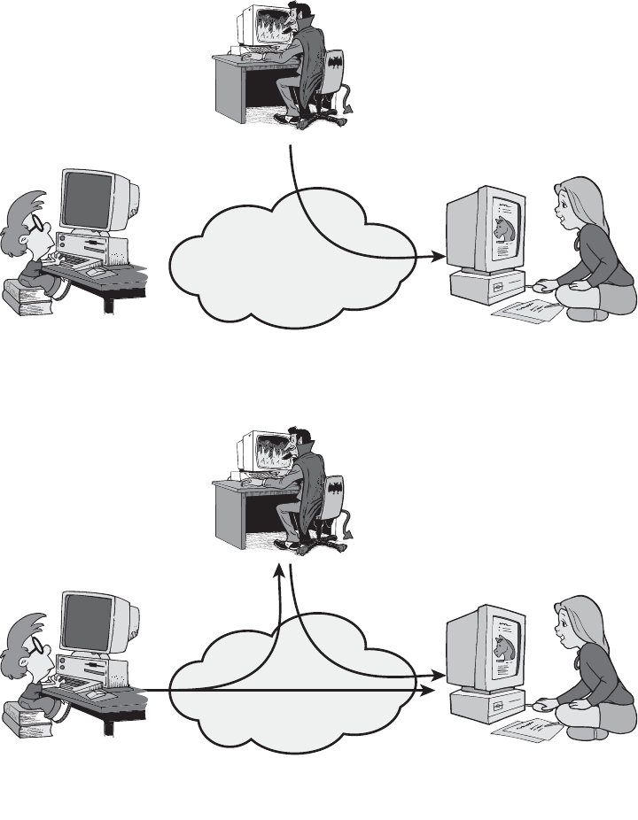
18 CHAPTER 1 / OVERVIEW
On the other hand, it is quite difficult to prevent active attacks absolutely because of
the wide variety of potential physical, software, and network vulnerabilities. Instead,
the goal is to detect active attacks and to recover from any disruption or
delays caused by them. If the detection has a deterrent effect, it may also contribute
to prevention.
(a) Masquerade
Bob
Darth
Alice
Alice
Message from Darth
that appears to be
from Bob
(b) Replay
Bob
Darth
Capture message from
Bob to Alice; later
replay message to Alice
Internet or
other comms facility
Internet or
other comms facility
Figure 1.3 Active attacks (Continued)

1.4 / SECURITY SERVICES 19
(c) Modification of messages
Bob
Darth
Alice
Darth modifies
message from Bob
to Alice
(d) Denial of service
Bob
Darth
Server
Darth disrupts service
provided by server
Internet or
other comms facility
Internet or
other comms facility
Figure 1.3 Active attacks
1.4 SECURITY SERVICES
X.800 defines a security service as a service that is provided by a protocol layer of
communicating open systems and that ensures adequate security of the systems or
of data transfers. Perhaps a clearer definition is found in RFC 2828, which provides
the following definition: a processing or communication service that is provided by

20 CHAPTER 1 / OVERVIEW
a system to give a specific kind of protection to system resources; security services
implement security policies and are implemented by security mechanisms.
X.800 divides these services into five categories and fourteen specific services
(Table 1.2). We look at each category in turn.
5
5
There is no universal agreement about many of the terms used in the security literature. For example,
the term integrity is sometimes used to refer to all aspects of information security.The term authentication
is sometimes used to refer both to verification of identity and to the various functions listed under
integrity in this chapter. Our usage here agrees with both X.800 and RFC 2828.
Table 1.2 Security Services (X.800)
AUTHENTICATION
The assurance that the communicating entity is the
one that it claims to be.
Peer Entity Authentication
Used in association with a logical connection to
provide confidence in the identity of the entities
connected.
Data-Origin Authentication
In a connectionless transfer, provides assurance that
the source of received data is as claimed.
ACCESS CONTROL
The prevention of unauthorized use of a resource
(i.e., this service controls who can have access to a
resource, under what conditions access can occur,
and what those accessing the resource are allowed
to do).
DATA CONFIDENTIALITY
The protection of data from unauthorized
disclosure.
Connection Confidentiality
The protection of all user data on a connection.
Connectionless Confidentiality
The protection of all user data in a single data block
Selective-Field Confidentiality
The confidentiality of selected fields within the user
data on a connection or in a single data block.
Traffic-Flow Confidentiality
The protection of the information that might be
derived from observation of traffic flows.
DATA INTEGRITY
The assurance that data received are exactly as
sent by an authorized entity (i.e., contain no
modification, insertion, deletion, or replay).
Connection Integrity with Recovery
Provides for the integrity of all user data on a
connection and detects any modification, insertion,
deletion, or replay of any data within an entire data
sequence, with recovery attempted.
Connection Integrity without Recovery
As above, but provides only detection without recovery.
Selective-Field Connection Integrity
Provides for the integrity of selected fields within the
user data of a data block transferred over a connec-
tion and takes the form of determination of whether
the selected fields have been modified, inserted,
deleted, or replayed.
Connectionless Integrity
Provides for the integrity of a single connectionless
data block and may take the form of detection of
data modification. Additionally, a limited form of
replay detection may be provided.
Selective-Field Connectionless Integrity
Provides for the integrity of selected fields within a single
connectionless data block; takes the form of determina-
tion of whether the selected fields have been modified.
NONREPUDIATION
Provides protection against denial by one of the
entities involved in a communication of having
participated in all or part of the communication.
Nonrepudiation, Origin
Proof that the message was sent by the specified party.
Nonrepudiation, Destination
Proof that the message was received by the specified
party.
1.4 / SECURITY SERVICES 21
Authentication
The authentication service is concerned with assuring that a communication is
authentic. In the case of a single message, such as a warning or alarm signal, the
function of the authentication service is to assure the recipient that the message is
from the source that it claims to be from. In the case of an ongoing interaction, such
as the connection of a terminal to a host, two aspects are involved. First, at the time
of connection initiation, the service assures that the two entities are authentic, that
is, that each is the entity that it claims to be. Second, the service must assure that the
connection is not interfered with in such a way that a third party can masquerade as
one of the two legitimate parties for the purposes of unauthorized transmission or
reception.
Two specific authentication services are defined in X.800:
• Peer entity authentication: Provides for the corroboration of the identity
of a peer entity in an association. Two entities are considered peers if
they implement to same protocol in different systems; e.g., two TCP mod-
ules in two communicating systems. Peer entity authentication is provided
for use at the establishment of, or at times during the data transfer phase
of, a connection. It attempts to provide confidence that an entity is not
performing either a masquerade or an unauthorized replay of a previous
connection.
• Data origin authentication: Provides for the corroboration of the source
of a data unit. It does not provide protection against the duplication or
modification of data units. This type of service supports applications like
electronic mail, where there are no prior interactions between the commu-
nicating entities.
Access Control
In the context of network security, access control is the ability to limit and control
the access to host systems and applications via communications links. To achieve
this, each entity trying to gain access must first be identified, or authenticated, so
that access rights can be tailored to the individual.
Data Confidentiality
Confidentiality is the protection of transmitted data from passive attacks. With
respect to the content of a data transmission, several levels of protection can be
identified.The broadest service protects all user data transmitted between two users
over a period of time. For example, when a TCP connection is set up between two
systems, this broad protection prevents the release of any user data transmitted over
the TCP connection. Narrower forms of this service can also be defined, including
the protection of a single message or even specific fields within a message. These
refinements are less useful than the broad approach and may even be more complex
and expensive to implement.
The other aspect of confidentiality is the protection of traffic flow from analysis.
This requires that an attacker not be able to observe the source and destination,
frequency, length, or other characteristics of the traffic on a communications facility.
22 CHAPTER 1 / OVERVIEW
Data Integrity
As with confidentiality, integrity can apply to a stream of messages, a single message,
or selected fields within a message. Again, the most useful and straightforward
approach is total stream protection.
A connection-oriented integrity service, one that deals with a stream of
messages, assures that messages are received as sent with no duplication, inser-
tion, modification, reordering, or replays. The destruction of data is also covered
under this service. Thus, the connection-oriented integrity service addresses both
message stream modification and denial of service. On the other hand, a connec-
tionless integrity service, one that deals with individual messages without regard
to any larger context, generally provides protection against message modification
only.
We can make a distinction between service with and without recovery. Because
the integrity service relates to active attacks, we are concerned with detection rather
than prevention. If a violation of integrity is detected, then the service may simply
report this violation, and some other portion of software or human intervention is
required to recover from the violation.Alternatively, there are mechanisms available
to recover from the loss of integrity of data, as we will review subsequently.
The incorporation of automated recovery mechanisms is, in general, the more
attractive alternative.
Nonrepudiation
Nonrepudiation prevents either sender or receiver from denying a transmitted
message. Thus, when a message is sent, the receiver can prove that the alleged
sender in fact sent the message. Similarly, when a message is received, the sender can
prove that the alleged receiver in fact received the message.
Availability Service
Both X.800 and RFC 2828 define availability to be the property of a system or a
system resource being accessible and usable upon demand by an authorized
system entity, according to performance specifications for the system (i.e., a
system is available if it provides services according to the system design whenever
users request them). A variety of attacks can result in the loss of or reduction in
availability. Some of these attacks are amenable to automated countermeasures,
such as authentication and encryption, whereas others require some sort of
physical action to prevent or recover from loss of availability of elements of a
distributed system.
X.800 treats availability as a property to be associated with various security
services. However, it makes sense to call out specifically an availability service. An
availability service is one that protects a system to ensure its availability.This service
addresses the security concerns raised by denial-of-service attacks. It depends on
proper management and control of system resources and thus depends on access
control service and other security services.

1.5 / SECURITY MECHANISMS 23
1.5 SECURITY MECHANISMS
Table 1.3 lists the security mechanisms defined in X.800. The mechanisms are
divided into those that are implemented in a specific protocol layer, such as TCP or
an application-layer protocol, and those that are not specific to any particular
protocol layer or security service. These mechanisms will be covered in the appro-
priate places in the book. So we do not elaborate now, except to comment on the
Table 1.3 Security Mechanisms (X.800)
SPECIFIC SECURITY MECHANISMS
May be incorporated into the appropriate protocol
layer in order to provide some of the OSI security
services.
Encipherment
The use of mathematical algorithms to transform
data into a form that is not readily intelligible. The
transformation and subsequent recovery of the
data depend on an algorithm and zero or more
encryption keys.
Digital Signature
Data appended to, or a cryptographic transformation
of, a data unit that allows a recipient of the data unit
to prove the source and integrity of the data unit and
protect against forgery (e.g., by the recipient).
Access Control
A variety of mechanisms that enforce access rights to
resources.
Data Integrity
A variety of mechanisms used to assure the integrity
of a data unit or stream of data units.
Authentication Exchange
A mechanism intended to ensure the identity of an
entity by means of information exchange.
Traffic Padding
The insertion of bits into gaps in a data stream to
frustrate traffic analysis attempts.
Routing Control
Enables selection of particular physically secure
routes for certain data and allows routing changes,
especially when a breach of security is suspected.
Notarization
The use of a trusted third party to assure certain
properties of a data exchange.
PERVASIVE SECURITY MECHANISMS
Mechanisms that are not specific to any particular
OSI security service or protocol layer.
Trusted Functionality
That which is perceived to be correct with respect to
some criteria (e.g., as established by a security policy).
Security Label
The marking bound to a resource (which may be a
data unit) that names or designates the security
attributes of that resource.
Event Detection
Detection of security-relevant events.
Security Audit Trail
Data collected and potentially used to facilitate a
security audit, which is an independent review and
examination of system records and activities.
Security Recovery
Deals with requests from mechanisms, such as event
handling and management functions, and takes
recovery actions.

Table 1.4 Relationship Between Security Services and Mechanisms
Mechanism
Service Encipherment
Digital
Signature
Access
Control
Data
Integrity
Authentication
Exchange
Traffic
Padding
Routing
Control
Notarization
Peer Entity Authentication
Y Y Y
Data Origin Authentication Y Y
Access Control Y
Confidentiality Y Y
Traffic Flow Confidentiality Y Y Y
Data Integrity Y Y Y
Nonrepudiation Y Y Y
Availability Y Y
24

1.6 / A MODEL FOR NETWORK SECURITY 25
definition of encipherment. X.800 distinguishes between reversible encipherment
mechanisms and irreversible encipherment mechanisms. A reversible encipherment
mechanism is simply an encryption algorithm that allows data to be encrypted and
subsequently decrypted. Irreversible encipherment mechanisms include hash algo-
rithms and message authentication codes, which are used in digital signature and
message authentication applications.
Table 1.4, based on one in X.800, indicates the relationship between security
services and security mechanisms.
1.6 A MODEL FOR NETWORK SECURITY
A model for much of what we will be discussing is captured, in very general terms, in
Figure 1.4. A message is to be transferred from one party to another across some sort
of Internet service. The two parties, who are the principals in this transaction, must
cooperate for the exchange to take place. A logical information channel is estab-
lished by defining a route through the Internet from source to destination and by the
cooperative use of communication protocols (e.g., TCP/IP) by the two principals.
Security aspects come into play when it is necessary or desirable to protect
the information transmission from an opponent who may present a threat to confi-
dentiality, authenticity, and so on. All the techniques for providing security have
two components:
• A security-related transformation on the information to be sent. Examples
include the encryption of the message, which scrambles the message so that it is
unreadable by the opponent, and the addition of a code based on the contents
of the message, which can be used to verify the identity of the sender.
Information
channel
Security-related
transformation
Sender
Secret
information
Message
Message
Secure
message
Secure
message
Recipient
Opponent
Trusted third party
(e.g., arbiter, distributer
of secret information)
Security-related
transformation
Secret
information
Figure 1.4 Model for Network Security

26 CHAPTER 1 / OVERVIEW
• Some secret information shared by the two principals and, it is hoped,
unknown to the opponent. An example is an encryption key used in conjunc-
tion with the transformation to scramble the message before transmission and
unscramble it on reception.
6
A trusted third party may be needed to achieve secure transmission. For
example, a third party may be responsible for distributing the secret information to
the two principals while keeping it from any opponent. Or a third party may be
needed to arbitrate disputes between the two principals concerning the authenticity
of a message transmission.
This general model shows that there are four basic tasks in designing a particular
security service:
1. Design an algorithm for performing the security-related transformation.
The algorithm should be such that an opponent cannot defeat its purpose.
2. Generate the secret information to be used with the algorithm.
3. Develop methods for the distribution and sharing of the secret information.
4. Specify a protocol to be used by the two principals that makes use of the security
algorithm and the secret information to achieve a particular security service.
Parts One through Five of this book concentrate on the types of security mecha-
nisms and services that fit into the model shown in Figure 1.4. However, there are other
security-related situations of interest that do not neatly fit this model but are consid-
ered in this book. A general model of these other situations is illustrated by Figure 1.5,
which reflects a concern for protecting an information system from unwanted access.
Most readers are familiar with the concerns caused by the existence of hackers, who
attempt to penetrate systems that can be accessed over a network. The hacker can
be someone who, with no malign intent, simply gets satisfaction from breaking and
entering a computer system. The intruder can be a disgruntled employee who wishes
to do damage or a criminal who seeks to exploit computer assets for financial gain
(e.g., obtaining credit card numbers or performing illegal money transfers).
6
Part Two discusses a form of encryption, known as a symmetric encryption, in which only one of the two
principals needs to have the secret information.
Computing resources
(processor, memory, I/O)
Data
Processes
Software
Internal security controls
Information system
Gatekeeper
function
Opponent
—human (e.g., hacker)
—software (e.g., virus, worm)
Access channel
Figure 1.5 Network Access Security Model

1.7 / RECOMMENDED READING AND WEB SITES 27
Another type of unwanted access is the placement in a computer system of
logic that exploits vulnerabilities in the system and that can affect application pro-
grams as well as utility programs, such as editors and compilers. Programs can pre-
sent two kinds of threats:
• Information access threats: Intercept or modify data on behalf of users who
should not have access to that data.
• Service threats: Exploit service flaws in computers to inhibit use by legitimate
users.
Viruses and worms are two examples of software attacks. Such attacks can be
introduced into a system by means of a disk that contains the unwanted logic con-
cealed in otherwise useful software. They can also be inserted into a system across a
network; this latter mechanism is of more concern in network security.
The security mechanisms needed to cope with unwanted access fall into two
broad categories (see Figure 1.5). The first category might be termed a gatekeeper
function. It includes password-based login procedures that are designed to deny
access to all but authorized users and screening logic that is designed to detect and
reject worms, viruses, and other similar attacks. Once either an unwanted user or
unwanted software gains access, the second line of defense consists of a variety of
internal controls that monitor activity and analyze stored information in an
attempt to detect the presence of unwanted intruders. These issues are explored in
Part Six.
1.7 RECOMMENDED READING AND WEB SITES
[STAL02] provides a broad introduction to both computer and network security. [SCHN00]
is valuable reading for any practitioner in the field of computer or network security: It
discusses the limitations of technology, and cryptography in particular, in providing security
and the need to consider the hardware, the software implementation, the networks, and the
people involved in providing and attacking security.
It is useful to read some of the classic tutorial papers on computer security; these
provide a historical perspective from which to appreciate current work and thinking. The
papers to read are [WARE79], [BROW72], [SALT75], [SHAN77], and [SUMM84]. Two
more recent, short treatments of computer security are [ANDR04] and [LAMP04].
[NIST95] is an exhaustive (290 pages) treatment of the subject. Another good treatment is
[NRC91]. Also useful is [FRAS97].
ANDR04 Andrews, M., and Whittaker, J. “Computer Security.” IEEE Security and
Privacy, September/October 2004.
BROW72 Browne, P. “Computer Security—A Survey.” ACM SIGMIS Database, Fall
1972.
FRAS97 Fraser, B. Site Security Handbook. RFC 2196, September 1997.
LAMP04 Lampson, B. “Computer Security in the Real World,” Computer, June 2004.
NIST95 National Institute of Standards and Technology. An Introduction to Computer
Security: The NIST Handbook. Special Publication 800–12, October 1995.

28 CHAPTER 1 / OVERVIEW
7
Because URLs sometimes change, they are not included. For all of the Web sites listed in this and
subsequent chapters, the appropriate link is at this book’s Web site at williamstallings.com/Crypto/
Crypto5e.html.
NRC91 National Research Council. Computers at Risk: Safe Computing in the
Information Age. Washington, D.C.: National Academy Press, 1991.
SALT75 Saltzer, J., and Schroeder, M. “The Protection of Information in Computer
Systems.” Proceedings of the IEEE, September 1975.
SCHN00 Schneier, B. Secrets and Lies: Digital Security in a Networked World. New York:
Wiley, 2000.
SHAN77 Shanker, K. “The Total Computer Security Problem: An Overview.” Computer,
June 1977.
STAL08 Stallings, W., and Brown, L. Computer Security. Upper Saddle River, NJ:
Prentice Hall, 2008.
SUMM84 Summers, R. “An Overview of Computer Security.” IBM Systems Journal,
Vol. 23, No. 4, 1984.
WARE79 Ware, W., ed. Security Controls for Computer Systems. RAND Report 609–1.
October 1979. http://www.rand.org/pubs/reports/R609-1/R609.1.html
Recommended Web Sites:
The following Web sites
7
are of general interest related to cryptography and network security:
• IETF Security Area: Material related to Internet security standardization efforts.
• The Cryptography FAQ: Lengthy and worthwhile FAQ covering all aspects of cryptog-
raphy.
• Tom Dunigan’s Security page: An excellent list of pointers to cryptography and net-
work security Web sites.
• Peter Gutmann’s home page: Good collection of cryptography material.
• Helgar Lipma’s Cryptology Pointers: Another excellent list of pointers to cryptography
and network security Web sites.
• Cryptology ePrint archive: Provides rapid access to recent research in cryptology; con-
sists of a collection of unrefereed papers.
• IEEE Technical Committee on Security and Privacy: Copies of their newsletter and
information on IEEE-related activities.
• Computer Security Resource Center: Maintained by the National Institute of
Standards and Technology (NIST); contains a broad range of information on security
threats, technology, and standards.
• Computer and Network Security Reference Index: A good index to vendor and commer-
cial products, FAQs, newsgroup archives, papers, and other Web sites.
• Security Focus: A wide variety of security information, with an emphasis on vendor
products and end-user concerns.
• SANS Institute: Similar to Security Focus. Extensive collection of white papers.

1.8 / KEY TERMS, REVIEW QUESTIONS, AND PROBLEMS 29
• Risks Digest: Forum on risks to the public in computers and related systems.
• Institute for Security and Open Methodologies: An open, collaborative security
research community. Lots of interesting information.
• Center for Internet Security: Provides freeware benchmark and scoring tools for eval-
uating security of operating systems, network devices, and applications. Includes case
studies and technical papers.
1.8 KEY TERMS, REVIEW QUESTIONS, AND PROBLEMS
Key Terms
access control
active threat
authentication
authenticity
availability
data confidentiality
data integrity
denial of service
encryption
integrity
intruder
masquerade
nonrepudiation
OSI security architecture
passive threat
replay
security attacks
security mechanisms
security services
traffic analysis
Review Questions
1.1 What is the OSI security architecture?
1.2 What is the difference between passive and active security threats?
1.3 List and briefly define categories of passive and active security attacks.
1.4 List and briefly define categories of security services.
1.5 List and briefly define categories of security mechanisms.
Problems
1.1 Consider an automated teller machine (ATM) in which users provide a personal
identification number (PIN) and a card for account access. Give examples of confi-
dentiality, integrity, and availability requirements associated with the system and, in
each case, indicate the degree of importance of the requirement.
1.2 Repeat Problem 1.1 for a telephone switching system that routes calls through a
switching network based on the telephone number requested by the caller.
1.3 Consider a desktop publishing system used to produce documents for various
organizations.
a. Give an example of a type of publication for which confidentiality of the stored
data is the most important requirement.
b. Give an example of a type of publication in which data integrity is the most
important requirement.
c. Give an example in which system availability is the most important requirement.
1.4 For each of the following assets, assign a low, moderate, or high impact level for the
loss of confidentiality, availability, and integrity, respectively. Justify your answers.
a. An organization managing public information on its Web server.
b. A law enforcement organization managing extremely sensitive investigative
information.
30 CHAPTER 1 / OVERVIEW
c. A financial organization managing routine administrative information (not privacy-
related information).
d. An information system used for large acquisitions in a contracting organization
contains both sensitive, pre-solicitation phase contract information and routine
administrative information.Assess the impact for the two data sets separately and
the information system as a whole.
e. A power plant contains a SCADA (supervisory control and data acquisition) system
controlling the distribution of electric power for a large military installation. The
SCADA system contains both real-time sensor data and routine administrative
information. Assess the impact for the two data sets separately and the information
system as a whole.
1.5 Draw a matrix similar to Table 1.4 that shows the relationship between security services
and attacks.
1.6 Draw a matrix similar to Table 1.4 that shows the relationship between security
mechanisms and attacks.

CLASSICAL ENCRYPTION TECHNIQUES
2.1 Symmetric Cipher Model
Cryptography
Cryptanalysis and Brute-Force Attack
2.2 Substitution Techniques
Caesar Cipher
Monoalphabetic Ciphers
Playfair Cipher
Hill Cipher
Polyalphabetic Ciphers
One-Time Pad
2.3 Transposition Techniques
2.4 Rotor Machines
2.5 Steganography
2.6 Recommended Reading and Web Sites
2.7 Key Terms, Review Questions, and Problems
31
PART 1: SYMMETRIC CIPHERS
CHAPTER

32 CHAPTER 2 / CLASSICAL ENCRYPTION TECHNIQUES
“I am fairly familiar with all the forms of secret writings, and am myself the
author of a trifling monograph upon the subject, in which I analyze one hundred
and sixty separate ciphers,” said Holmes.
—The Adventure of the Dancing Men, Sir Arthur Conan Doyle
KEY POINTS
◆ Symmetric encryption is a form of cryptosystem in which encryption and
decryption are performed using the same key. It is also known as conven-
tional encryption.
◆ Symmetric encryption transforms plaintext into ciphertext using a secret
key and an encryption algorithm. Using the same key and a decryption
algorithm, the plaintext is recovered from the ciphertext.
◆ The two types of attack on an encryption algorithm are cryptanalysis,
based on properties of the encryption algorithm, and brute-force, which
involves trying all possible keys.
◆ Traditional (precomputer) symmetric ciphers use substitution and/or
transposition techniques. Substitution techniques map plaintext elements
(characters, bits) into ciphertext elements. Transposition techniques sys-
tematically transpose the positions of plaintext elements.
◆ Rotor machines are sophisticated precomputer hardware devices that use
substitution techniques.
◆ Steganography is a technique for hiding a secret message within a larger
one in such a way that others cannot discern the presence or contents of the
hidden message.
Symmetric encryption, also referred to as conventional encryption or single-key
encryption, was the only type of encryption in use prior to the development of public-
key encryption in the 1970s. It remains by far the most widely used of the two types of
encryption. Part One examines a number of symmetric ciphers. In this chapter, we
begin with a look at a general model for the symmetric encryption process; this will
enable us to understand the context within which the algorithms are used. Next, we
examine a variety of algorithms in use before the computer era. Finally, we look briefly
at a different approach known as steganography. Chapters 3 and 5 examine the two
most widely used symmetric cipher: DES and AES.
Before beginning, we define some terms. An original message is known as the
plaintext, while the coded message is called the ciphertext. The process of converting
from plaintext to ciphertext is known as enciphering or encryption; restoring the plain-
text from the ciphertext is deciphering or decryption. The many schemes used for
encryption constitute the area of study known as cryptography. Such a scheme is
known as a cryptographic system or a cipher. Techniques used for deciphering a

2.1 / SYMMETRIC CIPHER MODEL 33
message without any knowledge of the enciphering details fall into the area of
cryptanalysis. Cryptanalysis is what the layperson calls “breaking the code.” The areas
of cryptography and cryptanalysis together are called cryptology.
2.1 SYMMETRIC CIPHER MODEL
A symmetric encryption scheme has five ingredients (Figure 2.1):
• Plaintext: This is the original intelligible message or data that is fed into the
algorithm as input.
• Encryption algorithm: The encryption algorithm performs various substitu-
tions and transformations on the plaintext.
• Secret key: The secret key is also input to the encryption algorithm. The key is
a value independent of the plaintext and of the algorithm. The algorithm will
produce a different output depending on the specific key being used at the
time. The exact substitutions and transformations performed by the algorithm
depend on the key.
• Ciphertext: This is the scrambled message produced as output. It depends on
the plaintext and the secret key. For a given message, two different keys will
produce two different ciphertexts. The ciphertext is an apparently random
stream of data and, as it stands, is unintelligible.
• Decryption algorithm: This is essentially the encryption algorithm run in
reverse. It takes the ciphertext and the secret key and produces the original
plaintext.
There are two requirements for secure use of conventional encryption:
1. We need a strong encryption algorithm. At a minimum, we would like the
algorithm to be such that an opponent who knows the algorithm and has
access to one or more ciphertexts would be unable to decipher the ciphertext
or figure out the key. This requirement is usually stated in a stronger form:The
Plaintext
input
Y = E(K, X) X = D[K, Y]
X
KK
Transmitted
ciphertext
Plaintext
output
Secret key shared by
sender and recipient
Secret key shared by
sender and recipient
Encryption algorithm
(e.g., AES)
Decryption algorithm
(reverse of encryption
algorithm)
Figure 2.1 Simplified Model of Symmetric Encryption

34 CHAPTER 2 / CLASSICAL ENCRYPTION TECHNIQUES
opponent should be unable to decrypt ciphertext or discover the key even if he
or she is in possession of a number of ciphertexts together with the plaintext
that produced each ciphertext.
2. Sender and receiver must have obtained copies of the secret key in a secure
fashion and must keep the key secure. If someone can discover the key and
knows the algorithm, all communication using this key is readable.
We assume that it is impractical to decrypt a message on the basis of the
ciphertext plus knowledge of the encryption/decryption algorithm. In other words,
we do not need to keep the algorithm secret; we need to keep only the key secret.
This feature of symmetric encryption is what makes it feasible for widespread use.
The fact that the algorithm need not be kept secret means that manufacturers can
and have developed low-cost chip implementations of data encryption algorithms.
These chips are widely available and incorporated into a number of products. With
the use of symmetric encryption, the principal security problem is maintaining the
secrecy of the key.
Let us take a closer look at the essential elements of a symmetric encryp-
tion scheme, using Figure 2.2. A source produces a message in plaintext,
. The elements of are letters in some finite alphabet.
Traditionally, the alphabet usually consisted of the 26 capital letters. Nowadays,
the binary alphabet {0, 1} is typically used. For encryption, a key of the form
is generated. If the key is generated at the message source,
then it must also be provided to the destination by means of some secure chan-
nel. Alternatively, a third party could generate the key and securely deliver it to
both source and destination.
K = [K
1
, K
2
, Á , K
J
]
XMX = [X
1
, X
2
, Á , X
M
]
Message
source
Cryptanalyst
Key
source
Destination
X
X
X
^
K
^
Y = E(K, X)
Secure channel
K
Encryption
algorithm
Decryption
algorithm
Figure 2.2 Model of Symmetric Cryptosystem
2.1 / SYMMETRIC CIPHER MODEL 35
With the message and the encryption key as input, the encryption algo-
rithm forms the ciphertext . We can write this as
This notation indicates that is produced by using encryption algorithm E as a
function of the plaintext , with the specific function determined by the value of
the key .
The intended receiver, in possession of the key, is able to invert the
transformation:
An opponent, observing but not having access to or , may attempt to
recover or or both and . It is assumed that the opponent knows the encryption
(E) and decryption (D) algorithms. If the opponent is interested in only this particular
message, then the focus of the effort is to recover by generating a plaintext estimate
. Often, however, the opponent is interested in being able to read future messages as
well, in which case an attempt is made to recover by generating an estimate .
Cryptography
Cryptographic systems are characterized along three independent dimensions:
1. The type of operations used for transforming plaintext to ciphertext. All
encryption algorithms are based on two general principles: substitution, in
which each element in the plaintext (bit, letter, group of bits or letters) is
mapped into another element, and transposition, in which elements in the
plaintext are rearranged. The fundamental requirement is that no informa-
tion be lost (that is, that all operations are reversible). Most systems,
referred to as product systems, involve multiple stages of substitutions and
transpositions.
2. The number of keys used. If both sender and receiver use the same key, the
system is referred to as symmetric, single-key, secret-key, or conventional encryp-
tion. If the sender and receiver use different keys, the system is referred to as
asymmetric, two-key, or public-key encryption.
3. The way in which the plaintext is processed. A block cipher processes the
input one block of elements at a time, producing an output block for each
input block. A stream cipher processes the input elements continuously,
producing output one element at a time, as it goes along.
Cryptanalysis and Brute-Force Attack
Typically, the objective of attacking an encryption system is to recover the key in use
rather than simply to recover the plaintext of a single ciphertext.There are two gen-
eral approaches to attacking a conventional encryption scheme:
• Cryptanalysis: Cryptanalytic attacks rely on the nature of the algorithm plus
perhaps some knowledge of the general characteristics of the plaintext or
K
N
K
X
N
X
KXKX
XKY
X = D(K, Y)
K
X
Y
Y = E(K, X)
Y = [Y
1
, Y
2
, Á , Y
N
]
KX

36 CHAPTER 2 / CLASSICAL ENCRYPTION TECHNIQUES
even some sample plaintext–ciphertext pairs. This type of attack exploits the
characteristics of the algorithm to attempt to deduce a specific plaintext or to
deduce the key being used.
• Brute-force attack: The attacker tries every possible key on a piece of cipher-
text until an intelligible translation into plaintext is obtained. On average, half
of all possible keys must be tried to achieve success.
If either type of attack succeeds in deducing the key, the effect is catastrophic:
All future and past messages encrypted with that key are compromised.
We first consider cryptanalysis and then discuss brute-force attacks.
Table 2.1 summarizes the various types of cryptanalytic attacks based on the
amount of information known to the cryptanalyst.The most difficult problem is pre-
sented when all that is available is the ciphertext only. In some cases, not even the
encryption algorithm is known, but in general, we can assume that the opponent
does know the algorithm used for encryption. One possible attack under these cir-
cumstances is the brute-force approach of trying all possible keys. If the key space is
very large, this becomes impractical. Thus, the opponent must rely on an analysis of
the ciphertext itself, generally applying various statistical tests to it. To use this
approach, the opponent must have some general idea of the type of plaintext that is
concealed, such as English or French text, an EXE file, a Java source listing, an
accounting file, and so on.
Table 2.1 Types of Attacks on Encrypted Messages
Type of Attack Known to Cryptanalyst
Ciphertext Only
• Encryption algorithm
• Ciphertext
Known Plaintext • Encryption algorithm
• Ciphertext
• One or more plaintext–ciphertext pairs formed with the secret key
Chosen Plaintext • Encryption algorithm
• Ciphertext
• Plaintext message chosen by cryptanalyst, together with its corresponding ciphertext
generated with the secret key
Chosen Ciphertext • Encryption algorithm
• Ciphertext
• Ciphertext chosen by cryptanalyst, together with its corresponding decrypted
plaintext generated with the secret key
Chosen Text • Encryption algorithm
• Ciphertext
• Plaintext message chosen by cryptanalyst, together with its corresponding
ciphertext generated with the secret key
• Ciphertext chosen by cryptanalyst, together with its corresponding decrypted
plaintext generated with the secret key
2.1 / SYMMETRIC CIPHER MODEL 37
The ciphertext-only attack is the easiest to defend against because the oppo-
nent has the least amount of information to work with. In many cases, however, the
analyst has more information. The analyst may be able to capture one or more
plaintext messages as well as their encryptions. Or the analyst may know that cer-
tain plaintext patterns will appear in a message. For example, a file that is encoded
in the Postscript format always begins with the same pattern, or there may be a
standardized header or banner to an electronic funds transfer message, and so on.
All these are examples of known plaintext.With this knowledge, the analyst may be
able to deduce the key on the basis of the way in which the known plaintext is
transformed.
Closely related to the known-plaintext attack is what might be referred to as a
probable-word attack. If the opponent is working with the encryption of some gen-
eral prose message, he or she may have little knowledge of what is in the message.
However, if the opponent is after some very specific information, then parts of the
message may be known. For example, if an entire accounting file is being transmitted,
the opponent may know the placement of certain key words in the header of the file.
As another example, the source code for a program developed by Corporation X
might include a copyright statement in some standardized position.
If the analyst is able somehow to get the source system to insert into the
system a message chosen by the analyst, then a chosen-plaintext attack is possible.
An example of this strategy is differential cryptanalysis, explored in Chapter 3. In
general, if the analyst is able to choose the messages to encrypt, the analyst may
deliberately pick patterns that can be expected to reveal the structure of the key.
Table 2.1 lists two other types of attack: chosen ciphertext and chosen text.
These are less commonly employed as cryptanalytic techniques but are nevertheless
possible avenues of attack.
Only relatively weak algorithms fail to withstand a ciphertext-only attack.
Generally, an encryption algorithm is designed to withstand a known-plaintext
attack.
Two more definitions are worthy of note. An encryption scheme is
unconditionally secure if the ciphertext generated by the scheme does not con-
tain enough information to determine uniquely the corresponding plaintext, no
matter how much ciphertext is available. That is, no matter how much time an
opponent has, it is impossible for him or her to decrypt the ciphertext simply
because the required information is not there. With the exception of a scheme
known as the one-time pad (described later in this chapter), there is no encryp-
tion algorithm that is unconditionally secure. Therefore, all that the users of an
encryption algorithm can strive for is an algorithm that meets one or both of the
following criteria:
• The cost of breaking the cipher exceeds the value of the encrypted information.
• The time required to break the cipher exceeds the useful lifetime of the
information.
An encryption scheme is said to be computationally secure if either of the
foregoing two criteria are met. Unfortunately, it is very difficult to estimate the
amount of effort required to cryptanalyze ciphertext successfully.

38 CHAPTER 2 / CLASSICAL ENCRYPTION TECHNIQUES
All forms of cryptanalysis for symmetric encryption schemes are designed to
exploit the fact that traces of structure or pattern in the plaintext may survive
encryption and be discernible in the ciphertext. This will become clear as we exam-
ine various symmetric encryption schemes in this chapter. We will see in Part Two
that cryptanalysis for public-key schemes proceeds from a fundamentally different
premise, namely, that the mathematical properties of the pair of keys may make it
possible for one of the two keys to be deduced from the other.
A brute-force attack involves trying every possible key until an intelligible
translation of the ciphertext into plaintext is obtained. On average, half of all possi-
ble keys must be tried to achieve success. Table 2.2 shows how much time is involved
for various key spaces. Results are shown for four binary key sizes. The 56-bit key
size is used with the Data Encryption Standard (DES) algorithm, and the 168-bit
key size is used for triple DES. The minimum key size specified for Advanced
Encryption Standard (AES) is 128 bits. Results are also shown for what are called
substitution codes that use a 26-character key (discussed later), in which all possible
permutations of the 26 characters serve as keys. For each key size, the results are
shown assuming that it takes 1 μs to perform a single decryption, which is a reason-
able order of magnitude for today’s machines. With the use of massively parallel
organizations of microprocessors, it may be possible to achieve processing rates
many orders of magnitude greater. The final column of Table 2.2 considers the
results for a system that can process 1 million keys per microsecond.As you can see,
at this performance level, DES can no longer be considered computationally secure.
2.2 SUBSTITUTION TECHNIQUES
In this section and the next, we examine a sampling of what might be called classical
encryption techniques. A study of these techniques enables us to illustrate the basic
approaches to symmetric encryption used today and the types of cryptanalytic
attacks that must be anticipated.
The two basic building blocks of all encryption techniques are substitution and
transposition.We examine these in the next two sections. Finally, we discuss a system
that combines both substitution and transposition.
Table 2.2 Average Time Required for Exhaustive Key Search
Key Size (bits)
Number of
Alternative Keys
Time Required at 1
Decryption/μs
Time Required at
10
6
Decryptions/μs
32
2
32
= 4.3 * 10
9
2
31
ms = 35.8 minutes
2.15 milliseconds
56
2
56
= 7.2 * 10
16
2
55
ms = 1142 years
10.01 hours
128
2
128
= 3.4 * 10
38
2
127
ms = 5.4 * 10
24
years 5.4 * 10
18
years
168
2
168
= 3.7 * 10
50
2
167
ms = 5.9 * 10
36
years 5.9 * 10
30
years
26 characters
(permutation)
26! = 4 * 10
26
2 * 10
26
ms = 6.4 * 10
12
years 6.4 * 10
6
years

2.2 / SUBSTITUTION TECHNIQUES 39
A substitution technique is one in which the letters of plaintext are replaced
by other letters or by numbers or symbols.
1
If the plaintext is viewed as a sequence
of bits, then substitution involves replacing plaintext bit patterns with ciphertext bit
patterns.
Caesar Cipher
The earliest known, and the simplest, use of a substitution cipher was by Julius
Caesar.The Caesar cipher involves replacing each letter of the alphabet with the let-
ter standing three places further down the alphabet. For example,
plain: meet me after the toga party
cipher: PHHW PH DIWHU WKH WRJD SDUWB
Note that the alphabet is wrapped around, so that the letter following Z is A.
We can define the transformation by listing all possibilities, as follows:
plain: a b c d e f g h i j k l m n o p q r s t u v w x y z
cipher: D E F G H I J K L M N O P Q R S T U V W X Y Z A B C
Let us assign a numerical equivalent to each letter:
1
When letters are involved, the following conventions are used in this book. Plaintext is always in lowercase;
ciphertext is in uppercase; key values are in italicized lowercase.
ab cdefgh i j k l m
0 1 2 3 4 5 6 7 8 9 10 11 12
nopqrstuvwx y z
13 14 15 16 17 18 19 20 21 22 23 24 25
Then the algorithm can be expressed as follows. For each plaintext letter , substi-
tute the ciphertext letter :
2
A shift may be of any amount, so that the general Caesar algorithm is
(2.1)
where takes on a value in the range 1 to 25. The decryption algorithm is simply
(2.2)p = D(k, C) = (C - k) mod 26
k
C = E(k, p) = (p + k) mod 26
C = E(3, p) = (p + 3) mod 26
C
p
2
We define a mod n to be the remainder when a is divided by n. For example, 11 mod 7 = 4. See Chapter 4
for a further discussion of modular arithmetic.

40 CHAPTER 2 / CLASSICAL ENCRYPTION TECHNIQUES
If it is known that a given ciphertext is a Caesar cipher, then a brute-force
cryptanalysis is easily performed: simply try all the 25 possible keys. Figure 2.3
shows the results of applying this strategy to the example ciphertext. In this case, the
plaintext leaps out as occupying the third line.
Three important characteristics of this problem enabled us to use a brute-
force cryptanalysis:
1. The encryption and decryption algorithms are known.
2. There are only 25 keys to try.
3. The language of the plaintext is known and easily recognizable.
In most networking situations, we can assume that the algorithms are known.
What generally makes brute-force cryptanalysis impractical is the use of an algo-
rithm that employs a large number of keys. For example, the triple DES algorithm,
examined in Chapter 6, makes use of a 168-bit key, giving a key space of or
greater than possible keys.3.7 * 10
50
2
168
PHHW PH DIWHU WKH WRJD SDUWB
KEY
1 oggv og chvgt vjg vqic rctva
2 nffu nf bgufs uif uphb qbsuz
3 meet me after the toga party
4 ldds ld zesdq sgd snfz ozqsx
5 kccr kc ydrcp rfc rmey nyprw
6 jbbq jb xcqbo qeb qldx mxoqv
7 iaap ia wbpan pda pkcw lwnpu
8 hzzo hz vaozm ocz ojbv kvmot
9 gyyn gy uznyl nby niau julns
10 fxxm fx tymxk max mhzt itkmr
11 ewwl ew sxlwj lzw lgys hsjlq
12 dvvk dv rwkvi kyv kfxr grikp
13 cuuj cu qvjuh jxu jewq fqhjo
14 btti bt puitg iwt idvp epgin
15 assh as othsf hvs hcuo dofhm
16 zrrg zr nsgre gur gbtn cnegl
17 yqqf yq mrfqd ftq fasm bmdfk
18 xppe xp lqepc esp ezrl alcej
19 wood wo kpdob dro dyqk zkbdi
20 vnnc vn jocna cqn cxpj yjach
21 ummb um inbmz bpm bwoi xizbg
22 tlla tl hmaly aol avnh whyaf
23 skkz sk glzkx znk zumg vgxze
24 rjjy rj fkyjw ymj ytlf ufwyd
25 qiix qi ejxiv xli xske tevxc
Figure 2.3 Brute-Force Cryptanalysis of Caesar
Cipher

2.2 / SUBSTITUTION TECHNIQUES 41
The third characteristic is also significant. If the language of the plaintext is
unknown, then plaintext output may not be recognizable. Furthermore, the
input may be abbreviated or compressed in some fashion, again making recogni-
tion difficult. For example, Figure 2.4 shows a portion of a text file compressed
using an algorithm called ZIP. If this file is then encrypted with a simple substi-
tution cipher (expanded to include more than just 26 alphabetic characters),
then the plaintext may not be recognized when it is uncovered in the brute-force
cryptanalysis.
Monoalphabetic Ciphers
With only 25 possible keys, the Caesar cipher is far from secure.A dramatic increase
in the key space can be achieved by allowing an arbitrary substitution. Before pro-
ceeding, we define the term permutation.A permutation of a finite set of elements
is an ordered sequence of all the elements of , with each element appearing exactly
once. For example, if , there are six permutations of :
In general, there are ! permutations of a set of elements, because the first
element can be chosen in one of n ways, the second in ways, the third in
ways, and so on.
Recall the assignment for the Caesar cipher:
plain: a b c d e f g h i j k l m n o p q r s t u v w x y z
cipher: D E F G H I J K L M N O P Q R S T U V W X Y Z A B C
If, instead, the “cipher” line can be any permutation of the 26 alphabetic characters,
then there are 26! or greater than possible keys. This is 10 orders of magni-
tude greater than the key space for DES and would seem to eliminate brute-force
techniques for cryptanalysis. Such an approach is referred to as a monoalphabetic
substitution cipher, because a single cipher alphabet (mapping from plain alphabet
to cipher alphabet) is used per message.
There is, however, another line of attack. If the cryptanalyst knows the
nature of the plaintext (e.g., noncompressed English text), then the analyst can
exploit the regularities of the language. To see how such a cryptanalysis might
4 * 10
26
n - 2n - 1
nn
abc, acb, bac, bca, cab, cba
SS = {a, b, c}
S
S
Figure 2.4 Sample of Compressed Text

42 CHAPTER 2 / CLASSICAL ENCRYPTION TECHNIQUES
proceed, we give a partial example here that is adapted from one in [SINK66].
The ciphertext to be solved is
UZQSOVUOHXMOPVGPOZPEVSGZWSZOPFPESXUDBMETSXAIZ
VUEPHZHMDZSHZOWSFPAPPDTSVPQUZWYMXUZUHSX
EPYEPOPDZSZUFPOMBZWPFUPZHMDJUDTMOHMQ
As a first step, the relative frequency of the letters can be determined and
compared to a standard frequency distribution for English, such as is shown in
Figure 2.5 (based on [LEWA00]). If the message were long enough, this technique
alone might be sufficient, but because this is a relatively short message, we cannot
expect an exact match. In any case, the relative frequencies of the letters in the
ciphertext (in percentages) are as follows:
0
2
4
6
8
10
12
14
A
8.167
1.492
2.782
4.253
12.702
2.228
2.015
6.094
6.996
0.153
0.772
4.025
2.406
6.749
7.507
1.929
0.095
5.987
6.327
9.056
2.758
0.978
2.360
0.150
1.974
0.074
B C D E F G H I J K L M N
Relative frequency (%)
O P Q R S T U V W X Y Z
Figure 2.5 Relative Frequency of Letters in English Text
P 13.33 H 5.83 F 3.33 B 1.67 C 0.00
Z 11.67 D 5.00 W 3.33 G 1.67 K 0.00
S 8.33 E 5.00 Q 2.50 Y 1.67 L 0.00
U 8.33 V 4.17 T 2.50 I 0.83 N 0.00
O 7.50 X 4.17 A 1.67 J 0.83 R 0.00
M 6.67
2.2 / SUBSTITUTION TECHNIQUES 43
Comparing this breakdown with Figure 2.5, it seems likely that cipher letters
P and Z are the equivalents of plain letters e and t, but it is not certain which is
which.The letters S, U, O, M, and H are all of relatively high frequency and probably
correspond to plain letters from the set {a, h, i, n, o, r, s}. The letters with the lowest
frequencies (namely, A, B, G, Y, I, J) are likely included in the set {b, j, k, q, v, x, z}.
There are a number of ways to proceed at this point. We could make some
tentative assignments and start to fill in the plaintext to see if it looks like a reasonable
“skeleton” of a message. A more systematic approach is to look for other regularities.
For example, certain words may be known to be in the text. Or we could look for
repeating sequences of cipher letters and try to deduce their plaintext equivalents.
A powerful tool is to look at the frequency of two-letter combinations, known
as digrams.A table similar to Figure 2.5 could be drawn up showing the relative fre-
quency of digrams. The most common such digram is th. In our ciphertext, the most
common digram is ZW, which appears three times. So we make the correspondence
of Z with t and W with h. Then, by our earlier hypothesis, we can equate P with e.
Now notice that the sequence ZWP appears in the ciphertext, and we can translate
that sequence as “the.” This is the most frequent trigram (three-letter combination)
in English, which seems to indicate that we are on the right track.
Next, notice the sequence ZWSZ in the first line. We do not know that these
four letters form a complete word, but if they do, it is of the form th_t. If so, S
equates with a.
So far, then, we have
UZQSOVUOHXMOPVGPOZPEVSGZWSZOPFPESXUDBMETSXAIZ
t a e e te a that e e a a
VUEPHZHMDZSHZOWSFPAPPDTSVPQUZWYMXUZUHSX
e t ta t ha e ee a e th t a
EPYEPOPDZSZUFPOMBZWPFUPZHMDJUDTMOHMQ
e e e tat e the t
Only four letters have been identified, but already we have quite a bit of the
message. Continued analysis of frequencies plus trial and error should easily yield a
solution from this point. The complete plaintext, with spaces added between words,
follows:
it was disclosed yesterday that several informal but
direct contacts have been made with political
representatives of the viet cong in moscow
Monoalphabetic ciphers are easy to break because they reflect the frequency
data of the original alphabet. A countermeasure is to provide multiple substitutes,
known as homophones, for a single letter. For example, the letter e could be assigned
a number of different cipher symbols, such as 16, 74, 35, and 21, with each homo-
phone assigned to a letter in rotation or randomly. If the number of symbols assigned
to each letter is proportional to the relative frequency of that letter, then single-letter
frequency information is completely obliterated. The great mathematician Carl

44 CHAPTER 2 / CLASSICAL ENCRYPTION TECHNIQUES
Friedrich Gauss believed that he had devised an unbreakable cipher using homo-
phones. However, even with homophones, each element of plaintext affects only one
element of ciphertext, and multiple-letter patterns (e.g., digram frequencies) still
survive in the ciphertext, making cryptanalysis relatively straightforward.
Two principal methods are used in substitution ciphers to lessen the extent to
which the structure of the plaintext survives in the ciphertext: One approach is to
encrypt multiple letters of plaintext, and the other is to use multiple cipher alphabets.
We briefly examine each.
Playfair Cipher
The best-known multiple-letter encryption cipher is the Playfair, which treats digrams
in the plaintext as single units and translates these units into ciphertext digrams.
3
The Playfair algorithm is based on the use of a 5 × 5 matrix of letters con-
structed using a keyword. Here is an example, solved by Lord Peter Wimsey in
Dorothy Sayers’s Have His Carcase:
4
3
This cipher was actually invented by British scientist Sir Charles Wheatstone in 1854, but it bears the name
of his friend Baron Playfair of St. Andrews, who championed the cipher at the British foreign office.
4
The book provides an absorbing account of a probable-word attack.
MO N AR
CHYBD
E F G I/J K
LPQST
UVWXZ
In this case, the keyword is monarchy. The matrix is constructed by filling in
the letters of the keyword (minus duplicates) from left to right and from top to bot-
tom, and then filling in the remainder of the matrix with the remaining letters in
alphabetic order. The letters I and J count as one letter. Plaintext is encrypted two
letters at a time, according to the following rules:
1. Repeating plaintext letters that are in the same pair are separated with a filler
letter, such as x, so that balloon would be treated as ba lx lo on.
2. Two plaintext letters that fall in the same row of the matrix are each replaced by
the letter to the right, with the first element of the row circularly following the
last. For example, ar is encrypted as RM.
3. Two plaintext letters that fall in the same column are each replaced by the letter
beneath, with the top element of the column circularly following the last. For
example, mu is encrypted as CM.
4. Otherwise, each plaintext letter in a pair is replaced by the letter that lies in its
own row and the column occupied by the other plaintext letter. Thus, hs
becomes BP and ea becomes IM (or JM, as the encipherer wishes).
The Playfair cipher is a great advance over simple monoalphabetic ciphers.
For one thing, whereas there are only 26 letters, there are 26 × 26 = 676 digrams, so

2.2 / SUBSTITUTION TECHNIQUES 45
that identification of individual digrams is more difficult. Furthermore, the relative
frequencies of individual letters exhibit a much greater range than that of digrams,
making frequency analysis much more difficult. For these reasons, the Playfair
cipher was for a long time considered unbreakable. It was used as the standard field
system by the British Army in World War I and still enjoyed considerable use by the
U.S. Army and other Allied forces during World War II.
Despite this level of confidence in its security, the Playfair cipher is relatively
easy to break, because it still leaves much of the structure of the plaintext language
intact. A few hundred letters of ciphertext are generally sufficient.
One way of revealing the effectiveness of the Playfair and other ciphers is shown
in Figure 2.6, based on [SIMM93]. The line labeled plaintext plots the frequency distri-
bution of the more than 70,000 alphabetic characters in the Encyclopaedia Britannica
article on cryptology.
5
This is also the frequency distribution of any monoalphabetic
substitution cipher, because the frequency values for individual letters are the same,
just with different letters substituted for the original letters. The plot was developed in
the following way: The number of occurrences of each letter in the text was counted
and divided by the number of occurrences of the letter e (the most frequently used
letter).As a result, e has a relative frequency of 1, t of about 0.76, and so on. The points
on the horizontal axis correspond to the letters in order of decreasing frequency.
Figure 2.6 also shows the frequency distribution that results when the text is
encrypted using the Playfair cipher.To normalize the plot, the number of occurrences
of each letter in the ciphertext was again divided by the number of occurrences of e
0
10
20
30
40
50
60
70
80
90
100
246810121416 22242618 20
Frequency ranked letters
Plaintext
Playfair cipher
Vigenère cipher
Random polyalphabetic cipher
Figure 2.6 Relative Frequency of Occurrence of Letters
5
I am indebted to Gustavus Simmons for providing the plots and explaining their method of construction.

46 CHAPTER 2 / CLASSICAL ENCRYPTION TECHNIQUES
in the plaintext.The resulting plot therefore shows the extent to which the frequency
distribution of letters, which makes it trivial to solve substitution ciphers, is masked
by encryption. If the frequency distribution information were totally concealed in the
encryption process, the ciphertext plot of frequencies would be flat, and cryptanalysis
using ciphertext only would be effectively impossible. As the figure shows, the
Playfair cipher has a flatter distribution than does plaintext, but nevertheless, it
reveals plenty of structure for a cryptanalyst to work with.
Hill Cipher
6
Another interesting multiletter cipher is the Hill cipher, developed by the mathe-
matician Lester Hill in 1929.
CONCEPTS FROM LINEAR ALGEBRA Before describing the Hill cipher, let us briefly
review some terminology from linear algebra. In this discussion, we are concerned
with matrix arithmetic modulo 26. For the reader who needs a refresher on matrix
multiplication and inversion, see Appendix E.
We define the inverse of a square matrix M by the equation
, where I is the identity matrix. I is a square matrix that is all
zeros except for ones along the main diagonal from upper left to lower right. The
inverse of a matrix does not always exist, but when it does, it satisfies the preceding
equation. For example,
To explain how the inverse of a matrix is computed, we begin by with the con-
cept of determinant. For any square matrix (m × ), the determinant equals the sum
of all the products that can be formed by taking exactly one element from each row
and exactly one element from each column, with certain of the product terms pre-
ceded by a minus sign. For a 2 × 2 matrix,
the determinant is . For a matrix, the value of the determi-
nant is .
If a square matrix A has a nonzero determinant, then the inverse of the matrix is
k
11
k
22
k
33
+ k
21
k
32
k
13
+ k
31
k
12
k
23
- k
31
k
22
k
13
- k
21
k
12
k
33
- k
11
k
32
k
23
3 * 3k
11
k
22
- k
12
k
21
a
k
11
k
12
k
21
k
22
b
m
= a
53 130
156 79
b mod 26 = a
10
01
b
AA
- 1
= a
(5 * 9) + (8 * 1) (5 * 2) + (8 * 15)
(17 * 9) + (3 * 1) (17 * 2) + (3 * 15)
b
A = a
58
17 3
b A
- 1
mod 26 = a
92
115
b
M(M
- 1
) = M
- 1
M = I
M
- 1
6
This cipher is somewhat more difficult to understand than the others in this chapter, but it illustrates an
important point about cryptanalysis that will be useful later on. This subsection can be skipped on a first
reading.

2.2 / SUBSTITUTION TECHNIQUES 47
computed as , where ( ) is the subdeterminant
formed by deleting the th row and the th column of A, det(A) is the determinant
of A, and (det is the multiplicative inverse of (det A) mod 26.
Continuing our example,
We can show that , because (see
Chapter 4 or Appendix E). Therefore, we compute the inverse of A as
THE HILL ALGORITHM This encryption algorithm takes successive plaintext letters
and substitutes for them ciphertext letters. The substitution is determined by
linear equations in which each character is assigned a numerical value
. For , the system can be described as
This can be expressed in terms of row vectors and matrices:
7
or
where C and P are row vectors of length 3 representing the plaintext and ciphertext,
and K is a matrix representing the encryption key. Operations are performed
mod 26.
For example, consider the plaintext “paymoremoney” and use the encryp-
tion key
K =
£
17 17 5
21 18 21
2219
≥
3 * 3
C = PK mod 26
(c
1
c
2
c
3
) = (p p
2
p
3
)
£
k
11
k
12
k
13
k
21
k
22
k
23
k
31
k
32
k
33
≥mod 26
c
3
= (k
31
p
1
+ k
32
p
2
+ k
33
p
3
)mod 26
c
2
= (k
21
p
1
+ k
22
p
2
+ k
23
p
3
)mod 26
c
1
= (k
11
p
1
+ k
12
p
2
+ k
13
p
3
)mod 26
m = 3(a = 0, b = 1, Á , z = 25)
mm
m
A
- 1
mod 26 = 3a
3 -8
-17 5
b = 3a
318
95
b = a
954
27 15
b = a
92
115
b
A = a
58
17 3
b
9 * 3 = 27 mod 26 = 19
- 1
mod 26 = 3
det a
58
17 3
b = (5 * 3) - (8 * 17) =-121 mod 26 = 9
A)
- 1
ij
D
ji
[A
-1
]
ij
= (det A)
-1
(-1)
i + j
(D
ji
)
7
Some cryptography books express the plaintext and ciphertext as column vectors, so that the column
vector is placed after the matrix rather than the row vector placed before the matrix. Sage uses row vectors,
so we adopt that convention.
48 CHAPTER 2 / CLASSICAL ENCRYPTION TECHNIQUES
The first three letters of the plaintext are represented by the vector . Then
. Continuing in this fash-
ion, the ciphertext for the entire plaintext is RRLMWBKASPDH.
Decryption requires using the inverse of the matrix K. We can compute
, and therefore, . We can then compute the
inverse as
This is demonstrated as
It is easily seen that if the matrix is applied to the ciphertext, then the
plaintext is recovered.
In general terms, the Hill system can be expressed as
As with Playfair, the strength of the Hill cipher is that it completely hides
single-letter frequencies. Indeed, with Hill, the use of a larger matrix hides more fre-
quency information. Thus, a Hill cipher hides not only single-letter but also
two-letter frequency information.
Although the Hill cipher is strong against a ciphertext-only attack, it is
easily broken with a known plaintext attack. For an Hill cipher, suppose
we have plaintext–ciphertext pairs, each of length . We label the pairs
such that for 1 …… and
for some unknown key matrix K. Now define two matrices and
. Then we can form the matrix equation Y = XK. If X has an inverse, then
we can determine . If X is not invertible, then a new version of X can
be formed with additional plaintext–ciphertext pairs until an invertible X is
obtained.
Consider this example. Suppose that the plaintext “hillcipher” is encrypted
using a Hill cipher to yield the ciphertext HCRZSSXNSP.Thus, we know that
; ; and so on. Using the first two
plaintext–ciphertext pairs, we have
The inverse of X can be computed:
a
78
11 11
b
- 1
= a
25 22
123
b
a
72
17 25
b = a
78
11 11
bK mod 26
(1111)K mod 26 = (17 25)(78)K mod 26 = (7 2)
2 * 2
K = X
- 1
Y
Y = (c
ij
)
X = (p
ij
)m * m
mjC
j
= P
j
KP
j
= (p
1j
p
1j
Á
p
mj
)and C
j
= (c
1j
c
1j
Á
c
mj
)
mm
m * m
3 * 3
P = D(K, C) = CK
- 1
mod 26 = PKK
- 1
= P
C = E(K, P) = PK mod 26
K
- 1
£
17 17 5
21 18 21
2219
≥
£
4915
15 17 6
24 0 17
≥=
£
443 442 442
858 495 780
494 52 365
≥mod 26 =
£
100
010
001
≥
K
-1
=
4 9 15
£
15 17 6
24 0 17
≥
(det K)
-1
mod 26 = 17 det K = 23
(15 0 24)K = (303 303 531) mod 26 = (17 17 11) = RRL
(15 0 24)
2.2 / SUBSTITUTION TECHNIQUES 49
so
This result is verified by testing the remaining plaintext–ciphertext pairs.
Polyalphabetic Ciphers
Another way to improve on the simple monoalphabetic technique is to use different
monoalphabetic substitutions as one proceeds through the plaintext message. The
general name for this approach is polyalphabetic substitution cipher.All these tech-
niques have the following features in common:
1. A set of related monoalphabetic substitution rules is used.
2. A key determines which particular rule is chosen for a given transformation.
VIGEN
`
ERE CIPHER The best known, and one of the simplest, polyalphabetic ciphers
is the Vigenère cipher. In this scheme, the set of related monoalphabetic substitution
rules consists of the 26 Caesar ciphers with shifts of 0 through 25. Each cipher
is denoted by a key letter, which is the ciphertext letter that substitutes for
the plaintext letter a. Thus, a Caesar cipher with a shift of 3 is denoted by the key
value .
We can express the Vigenère cipher in the following manner. Assume a
sequence of plaintext letters and a key consisting of the
sequence of letters , where typically < . The sequence of
ciphertext letters is calculated as follows:
Thus, the first letter of the key is added to the first letter of the plaintext, mod 26, the
second letters are added, and so on through the first letters of the plaintext. For
the next letters of the plaintext, the key letters are repeated. This process contin-
ues until all of the plaintext sequence is encrypted. A general equation of the
encryption process is
(2.3)
Compare this with Equation (2.1) for the Caesar cipher. In essence, each
plaintext character is encrypted with a different Caesar cipher, depending on the
corresponding key character. Similarly, decryption is a generalization of
Equation (2.2):
(2.4)
To encrypt a message, a key is needed that is as long as the message. Usually,
the key is a repeating keyword. For example, if the keyword is deceptive, the
message “we are discovered save yourself” is encrypted as
p
i
= (C
i
- k
i mod m
)mod 26
C
i
= (p
i
+ k
i mod m
)mod 26
m
m
C = C
0
, C
1
, C
2
, Á , C
n - 1
= E(K, P) = E[(k
0
, k
1
, k
2
, Á , k
m - 1
), (p
0
, p
1
, p
2
, Á , p
n - 1
)]
= (p
0
+ k
0
)mod 26, (p
1
+ k
1
)mod 26, Á , (p
m - 1
+ k
m - 1
)mod 26,
(p
m
+ k
0
)mod 26, (p
m + 1
+ k
1
)mod 26, Á , (p
2m - 1
+ k
m - 1
)mod 26, Á
C = C
0
, C
1
, C
2
, Á , C
n - 1
nmK = k
0
, k
1
, k
2
, Á , k
m - 1
P = p
0
, p
1
, p
2
, Á , p
n - 1
d
K = a
25 22
123
ba
72
17 25
b = a
549 600
398 577
bmod 26 = a
32
85
b

50 CHAPTER 2 / CLASSICAL ENCRYPTION TECHNIQUES
key:
deceptivedeceptivedeceptive
plaintext: wearediscoveredsaveyourself
ciphertext: ZICVTW
QNGRZGVTWAVZHCQYGLMGJ
Expressed numerically, we have the following result.
key 3 4 2 4 15 19 8 21 4 3 4 2 4 15
plaintext 22 4 0 17 4 3 8 18 2 14 21 4 17 4
ciphertext 25 8 2 21 19 22 16 13 6 17 25 6 21 19
key 19 8 21 4 3 4 2 4 15 19 8 21 4
plaintext 3 18 0 21 4 24 14 20 17 18 4 11 5
ciphertext 22 0 21 25 7 2 16 24 6 11 12 6 9
The strength of this cipher is that there are multiple ciphertext letters for each
plaintext letter, one for each unique letter of the keyword.Thus, the letter frequency
information is obscured. However, not all knowledge of the plaintext structure is
lost. For example, Figure 2.6 shows the frequency distribution for a Vigenère cipher
with a keyword of length 9. An improvement is achieved over the Playfair cipher,
but considerable frequency information remains.
It is instructive to sketch a method of breaking this cipher, because the method
reveals some of the mathematical principles that apply in cryptanalysis.
First, suppose that the opponent believes that the ciphertext was encrypted
using either monoalphabetic substitution or a Vigenère cipher. A simple test can
be made to make a determination. If a monoalphabetic substitution is used, then
the statistical properties of the ciphertext should be the same as that of the
language of the plaintext. Thus, referring to Figure 2.5, there should be one cipher
letter with a relative frequency of occurrence of about 12.7%, one with about
9.06%, and so on. If only a single message is available for analysis, we would not
expect an exact match of this small sample with the statistical profile of the plain-
text language. Nevertheless, if the correspondence is close, we can assume a
monoalphabetic substitution.
If, on the other hand, a Vigenère cipher is suspected, then progress depends on
determining the length of the keyword, as will be seen in a moment. For now, let us con-
centrate on how the keyword length can be determined.The important insight that leads
to a solution is the following: If two identical sequences of plaintext letters occur at a dis-
tance that is an integer multiple of the keyword length, they will generate identical
ciphertext sequences. In the foregoing example, two instances of the sequence “red” are
separated by nine character positions. Consequently, in both cases, r is encrypted using
key letter , e is encrypted using key letter , and d is encrypted using key letter . Thus,
in both cases, the ciphertext sequence is VTW.We indicate this above by underlining the
relevant ciphertext letters and shading the relevant ciphertext numbers.
An analyst looking at only the ciphertext would detect the repeated sequences
VTW at a displacement of 9 and make the assumption that the keyword is either
three or nine letters in length. The appearance of VTW twice could be by chance
tpe

2.2 / SUBSTITUTION TECHNIQUES 51
and not reflect identical plaintext letters encrypted with identical key letters.
However, if the message is long enough, there will be a number of such repeated
ciphertext sequences. By looking for common factors in the displacements of the
various sequences, the analyst should be able to make a good guess of the keyword
length.
Solution of the cipher now depends on an important insight. If the keyword
length is , then the cipher, in effect, consists of monoalphabetic substitution
ciphers. For example, with the keyword DECEPTIVE, the letters in positions 1, 10,
19, and so on are all encrypted with the same monoalphabetic cipher. Thus, we can
use the known frequency characteristics of the plaintext language to attack each of
the monoalphabetic ciphers separately.
The periodic nature of the keyword can be eliminated by using a nonrepeating
keyword that is as long as the message itself. Vigenère proposed what is referred to
as an autokey system, in which a keyword is concatenated with the plaintext itself to
provide a running key. For our example,
key:
deceptivewearediscoveredsav
plaintext: wearediscoveredsaveyourself
ciphertext: ZICVTWQNGKZEIIGASXSTSLVVWLA
Even this scheme is vulnerable to cryptanalysis. Because the key and the plain-
text share the same frequency distribution of letters, a statistical technique can be
applied. For example, e enciphered by , by Figure 2.5, can be expected to occur with a
frequency of , whereas t enciphered by would occur only about half
as often. These regularities can be exploited to achieve successful cryptanalysis.
8
VERNAM CIPHER The ultimate defense against such a cryptanalysis is to choose a
keyword that is as long as the plaintext and has no statistical relationship to it. Such
a system was introduced by an AT&T engineer named Gilbert Vernam in 1918. His
system works on binary data (bits) rather than letters. The system can be expressed
succinctly as follows (Figure 2.7):
where
th binary digit of plaintext
th binary digit of key
th binary digit of ciphertext
= exclusive-or (XOR) operation
Compare this with Equation (2.3) for the Vigenère cipher.
䊝
c
i
= i
k
i
= i
p
i
= i
c
i
= p
i
䊝
k
i
t(0.127)
2
L 0.016
e
mm
8
Although the techniques for breaking a Vigen `ere cipher are by no means complex, a 1917 issue of
Scientific American characterized this system as “impossible of translation.” This is a point worth remem-
bering when similar claims are made for modern algorithms.
52 CHAPTER 2 / CLASSICAL ENCRYPTION TECHNIQUES
Thus, the ciphertext is generated by performing the bitwise XOR of the plain-
text and the key. Because of the properties of the XOR, decryption simply involves
the same bitwise operation:
which compares with Equation (2.4).
The essence of this technique is the means of construction of the key.
Vernam proposed the use of a running loop of tape that eventually repeated the
key, so that in fact the system worked with a very long but repeating keyword.
Although such a scheme, with a long key, presents formidable cryptanalytic diffi-
culties, it can be broken with sufficient ciphertext, the use of known or probable
plaintext sequences, or both.
One-Time Pad
An Army Signal Corp officer, Joseph Mauborgne, proposed an improvement to the
Vernam cipher that yields the ultimate in security. Mauborgne suggested using a
random key that is as long as the message, so that the key need not be repeated. In
addition, the key is to be used to encrypt and decrypt a single message, and then is
discarded. Each new message requires a new key of the same length as the new mes-
sage. Such a scheme, known as a one-time pad, is unbreakable. It produces random
output that bears no statistical relationship to the plaintext. Because the ciphertext
contains no information whatsoever about the plaintext, there is simply no way to
break the code.
An example should illustrate our point. Suppose that we are using a
Vigenère scheme with 27 characters in which the twenty-seventh character is the
space character, but with a one-time key that is as long as the message. Consider
the ciphertext
ANKYODKYUREPFJBYOJDSPLREYIUNOFDOIUERFPLUYTS
We now show two different decryptions using two different keys:
ciphertext: ANKYODKYUREPFJBYOJDSPLREYIUNOFDOIUERFPLUYTS
key:
pxlmvmsydofuyrvzwc tnlebnecvgdupahfzzlmnyih
plaintext: mr mustard with the candlestick in the hall
p
i
= c
i
䊝
k
i
Key stream
generator
Cryptographic
bit stream ( k
i
)
Cryptographic
bit stream ( k
i
)
Plaintext
( p
i
)
Plaintext
( p
i
)
Ciphertext
( c
i
)
Key stream
generator
Figure 2.7 Vernam Cipher

2.3 / TRANSPOSITION TECHNIQUES 53
ciphertext: ANKYODKYUREPFJBYOJDSPLREYIUNOFDOIUERFPLUYTS
key:
mfugpmiydgaxgoufhklllmhsqdqogtewbqfgyovuhwt
plaintext: miss scarlet with the knife in the library
Suppose that a cryptanalyst had managed to find these two keys.Two plausible
plaintexts are produced. How is the cryptanalyst to decide which is the correct
decryption (i.e., which is the correct key)? If the actual key were produced in a truly
random fashion, then the cryptanalyst cannot say that one of these two keys is more
likely than the other.Thus, there is no way to decide which key is correct and there-
fore which plaintext is correct.
In fact, given any plaintext of equal length to the ciphertext, there is a key that
produces that plaintext. Therefore, if you did an exhaustive search of all possible
keys, you would end up with many legible plaintexts, with no way of knowing which
was the intended plaintext. Therefore, the code is unbreakable.
The security of the one-time pad is entirely due to the randomness of the key.
If the stream of characters that constitute the key is truly random, then the stream of
characters that constitute the ciphertext will be truly random. Thus, there are no
patterns or regularities that a cryptanalyst can use to attack the ciphertext.
In theory, we need look no further for a cipher. The one-time pad offers com-
plete security but, in practice, has two fundamental difficulties:
1. There is the practical problem of making large quantities of random keys.Any
heavily used system might require millions of random characters on a regular
basis. Supplying truly random characters in this volume is a significant task.
2. Even more daunting is the problem of key distribution and protection. For
every message to be sent, a key of equal length is needed by both sender and
receiver.Thus, a mammoth key distribution problem exists.
Because of these difficulties, the one-time pad is of limited utility and is useful
primarily for low-bandwidth channels requiring very high security.
The one-time pad is the only cryptosystem that exhibits what is referred to as
perfect secrecy. This concept is explored in Appendix F.
2.3 TRANSPOSITION TECHNIQUES
All the techniques examined so far involve the substitution of a ciphertext symbol
for a plaintext symbol. A very different kind of mapping is achieved by performing
some sort of permutation on the plaintext letters. This technique is referred to as a
transposition cipher.
The simplest such cipher is the rail fence technique, in which the plaintext is
written down as a sequence of diagonals and then read off as a sequence of rows. For
example, to encipher the message “meet me after the toga party” with a rail fence of
depth 2, we write the following:
m e m a t r h t g p r y
e t e f e t e o a a t
54 CHAPTER 2 / CLASSICAL ENCRYPTION TECHNIQUES
The encrypted message is
This sort of thing would be trivial to cryptanalyze. A more complex scheme is
to write the message in a rectangle, row by row, and read the message off, column by
column, but permute the order of the columns. The order of the columns then
becomes the key to the algorithm. For example,
Key: 4 3 1 2 5 6 7
Plaintext: a t t a c k p
o s t p o n e
d u n t i l t
w o a m x y z
Ciphertext: TTNAAPTMTSUOAODWCOIXKNLYPETZ
Thus, in this example, the key is 4312567. To encrypt, start with the column that
is labeled 1, in this case column 3.Write down all the letters in that column. Proceed to
column 4, which is labeled 2, then column 2, then column 1, then columns 5, 6, and 7.
A pure transposition cipher is easily recognized because it has the same letter
frequencies as the original plaintext. For the type of columnar transposition just
shown, cryptanalysis is fairly straightforward and involves laying out the ciphertext in
a matrix and playing around with column positions. Digram and trigram frequency
tables can be useful.
The transposition cipher can be made significantly more secure by performing
more than one stage of transposition.The result is a more complex permutation that
is not easily reconstructed. Thus, if the foregoing message is reencrypted using the
same algorithm,
Key: 4 3 1 2 5 6 7
Input: t t n a a p t
m t s u o a o
d w c o i x k
n l y p e t z
Output: NSCYAUOPTTWLTMDNAOIEPAXTTOKZ
To visualize the result of this double transposition, designate the letters in
the original plaintext message by the numbers designating their position. Thus,
with 28 letters in the message, the original sequence of letters is
01 02 03 04 05 06 07 08 09 10 11 12 13 14
15 16 17 18 19 20 21 22 23 24 25 26 27 28
After the first transposition, we have
03 10 17 24 04 11 18 25 02 09 16 23 01 08
15 22 05 12 19 26 06 13 20 27 07 14 21 28
MEMATRHTGPRYETEFETEOAAT

2.4 / ROTOR MACHINES 55
which has a somewhat regular structure. But after the second transposition, we have
17 09 05 27 24 16 12 07 10 02 22 20 03 25
15 13 04 23 19 14 11 01 26 21 18 08 06 28
This is a much less structured permutation and is much more difficult to cryptanalyze.
2.4 ROTOR MACHINES
The example just given suggests that multiple stages of encryption can produce an
algorithm that is significantly more difficult to cryptanalyze. This is as true of substi-
tution ciphers as it is of transposition ciphers. Before the introduction of DES, the
most important application of the principle of multiple stages of encryption was a
class of systems known as rotor machines.
9
The basic principle of the rotor machine is illustrated in Figure 2.8. The
machine consists of a set of independently rotating cylinders through which electri-
cal pulses can flow. Each cylinder has 26 input pins and 26 output pins, with internal
wiring that connects each input pin to a unique output pin. For simplicity, only three
of the internal connections in each cylinder are shown.
If we associate each input and output pin with a letter of the alphabet, then a
single cylinder defines a monoalphabetic substitution. For example, in Figure 2.8,
if an operator depresses the key for the letter A, an electric signal is applied to the
first pin of the first cylinder and flows through the internal connection to the
twenty-fifth output pin.
Consider a machine with a single cylinder.After each input key is depressed, the
cylinder rotates one position, so that the internal connections are shifted accordingly.
Thus, a different monoalphabetic substitution cipher is defined. After 26 letters of
plaintext, the cylinder would be back to the initial position. Thus, we have a poly-
alphabetic substitution algorithm with a period of 26.
A single-cylinder system is trivial and does not present a formidable cryptana-
lytic task. The power of the rotor machine is in the use of multiple cylinders, in which
the output pins of one cylinder are connected to the input pins of the next. Figure 2.8
shows a three-cylinder system.The left half of the figure shows a position in which the
input from the operator to the first pin (plaintext letter a) is routed through the three
cylinders to appear at the output of the second pin (ciphertext letter B).
With multiple cylinders, the one closest to the operator input rotates one pin
position with each keystroke. The right half of Figure 2.8 shows the system’s config-
uration after a single keystroke. For every complete rotation of the inner cylinder,
the middle cylinder rotates one pin position. Finally, for every complete rotation
of the middle cylinder, the outer cylinder rotates one pin position. This is the
same type of operation seen with an odometer. The result is that there are
different substitution alphabets used before the system26 * 26 * 26 = 17,576
9
Machines based on the rotor principle were used by both Germany (Enigma) and Japan (Purple)
in World War II. The breaking of both codes by the Allies was a significant factor in the war’s outcome.

24
25
26
1
2
3
4
5
6
7
8
9
10
11
12
13
14
15
16
17
18
19
20
21
22
23
21
3
15
1
19
10
14
26
20
8
16
7
22
4
11
5
17
9
12
23
18
2
25
6
24
13
A
B
C
D
E
F
G
H
I
J
K
L
M
N
O
P
Q
R
S
T
U
V
W
X
Y
Z
26
1
2
3
4
5
6
7
8
9
10
11
12
13
14
15
16
17
18
19
20
21
22
23
24
25
20
1
6
4
15
3
14
12
23
5
16
2
22
19
11
18
25
24
13
7
10
8
21
9
26
17
1
2
3
4
5
6
7
8
9
10
11
12
13
14
15
16
17
18
19
20
21
22
23
24
25
26
8
18
26
17
20
22
10
3
13
11
4
23
5
24
9
12
25
16
19
6
15
21
2
7
1
14
A
B
C
D
E
F
G
H
I
J
K
L
M
N
O
P
Q
R
S
T
U
V
W
X
Y
Z
Direction of motion
Direction of motion
Fast rotor Medium rotor Slow rotor Fast rotor Medium rotor
Slow rotor
(a) Initial setting
(b) Setting after one keystroke
A
B
C
D
E
F
G
H
I
J
K
L
M
N
O
P
Q
R
S
T
U
V
W
X
Y
Z
23
24
25
26
1
2
3
4
5
6
7
8
9
10
11
12
13
14
15
16
17
18
19
20
21
22
13
21
3
15
1
19
10
14
26
20
8
16
7
22
4
11
5
17
9
12
23
18
2
25
6
24
26
1
2
3
4
5
6
7
8
9
10
11
12
13
14
15
16
17
18
19
20
21
22
23
24
25
20
1
6
4
15
3
14
12
23
5
16
2
22
19
11
18
25
24
13
7
10
8
21
9
26
17
1
2
3
4
5
6
7
8
9
10
11
12
13
14
15
16
17
18
19
20
21
22
23
24
25
26
8
18
26
17
20
22
10
3
13
11
4
23
5
24
9
12
25
16
19
6
15
21
2
7
1
14
A
B
C
D
E
F
G
H
I
J
K
L
M
N
O
P
Q
R
S
T
U
V
W
X
Y
Z
Figure 2.8 Three-Rotor Machine with Wiring Represented by Numbered Contacts
56

2.5 / STEGANOGRAPHY 57
repeats. The addition of fourth and fifth rotors results in periods of 456,976
and 11,881,376 letters, respectively. As David Kahn eloquently put it, referring to a
five-rotor machine [KAHN96, page 413]:
A period of that length thwarts any practical possibility of a
straightforward solution on the basis of letter frequency. This
general solution would need about 50 letters per cipher alphabet,
meaning that all five rotors would have to go through their com-
bined cycle 50 times. The ciphertext would have to be as long as
all the speeches made on the floor of the Senate and the House
of Representatives in three successive sessions of Congress. No
cryptanalyst is likely to bag that kind of trophy in his lifetime;
even diplomats, who can be as verbose as politicians, rarely scale
those heights of loquacity.
The significance of the rotor machine today is that it points the way to the most
widely used cipher ever: the Data Encryption Standard (DES). This we examine in
Chapter 3.
2.5 STEGANOGRAPHY
We conclude with a discussion of a technique that (strictly speaking), is not encryp-
tion, namely, steganography.
A plaintext message may be hidden in one of two ways. The methods of
steganography conceal the existence of the message, whereas the methods of cryp-
tography render the message unintelligible to outsiders by various transformations
of the text.
10
A simple form of steganography, but one that is time-consuming to construct,
is one in which an arrangement of words or letters within an apparently innocuous
text spells out the real message. For example, the sequence of first letters of each
word of the overall message spells out the hidden message. Figure 2.9 shows an
example in which a subset of the words of the overall message is used to convey the
hidden message. See if you can decipher this; it’s not too hard.
Various other techniques have been used historically; some examples are the
following [MYER91]:
• Character marking: Selected letters of printed or typewritten text are over-
written in pencil. The marks are ordinarily not visible unless the paper is held
at an angle to bright light.
• Invisible ink: A number of substances can be used for writing but leave no
visible trace until heat or some chemical is applied to the paper.
10
Steganography was an obsolete word that was revived by David Kahn and given the meaning it has
today [KAHN96].

58 CHAPTER 2 / CLASSICAL ENCRYPTION TECHNIQUES
• Pin punctures: Small pin punctures on selected letters are ordinarily not visi-
ble unless the paper is held up in front of a light.
• Typewriter correction ribbon: Used between lines typed with a black ribbon, the
results of typing with the correction tape are visible only under a strong light.
Although these techniques may seem archaic, they have contemporary equiv-
alents. [WAYN93] proposes hiding a message by using the least significant bits of
frames on a CD. For example, the Kodak Photo CD format’s maximum resolution is
2048 3072 pixels, with each pixel containing 24 bits of RGB color information.The
least significant bit of each 24-bit pixel can be changed without greatly affecting the
quality of the image. The result is that you can hide a 2.3-megabyte message in a
single digital snapshot. There are now a number of software packages available that
take this type of approach to steganography.
Steganography has a number of drawbacks when compared to encryption. It
requires a lot of overhead to hide a relatively few bits of information, although using a
scheme like that proposed in the preceding paragraph may make it more effective.Also,
once the system is discovered, it becomes virtually worthless. This problem, too, can be
overcome if the insertion method depends on some sort of key (e.g., see Problem 2.20).
Alternatively, a message can be first encrypted and then hidden using steganography.
The advantage of steganography is that it can be employed by parties who
have something to lose should the fact of their secret communication (not necessar-
ily the content) be discovered. Encryption flags traffic as important or secret or may
identify the sender or receiver as someone with something to hide.
Figure 2.9 A Puzzle for Inspector Morse
(From The Silent World of Nicholas Quinn, by Colin Dexter)

2.6 / RECOMMENDED READING AND WEB SITES 59
2.6 RECOMMENDED READING AND WEB SITES
For anyone interested in the history of code making and code breaking, the book to read is
[KAHN96]. Although it is concerned more with the impact of cryptology than its technical
development, it is an excellent introduction and makes for exciting reading. Another excel-
lent historical account is [SING99].
A short treatment covering the techniques of this chapter, and more, is [GARD72].
There are many books that cover classical cryptography in a more technical vein; one of the
best is [SINK66]. [KORN96] is a delightful book to read and contains a lengthy section on
classical techniques. Two cryptography books that contain a fair amount of technical material
on classical techniques are [GARR01] and [NICH99]. For the truly interested reader, the
two-volume [NICH96] covers numerous classical ciphers in detail and provides many cipher-
texts to be cryptanalyzed, together with the solutions.
An excellent treatment of rotor machines, including a discussion of their cryptanalysis
is found in [KUMA97].
[KATZ00] provides a thorough treatment of steganography. Another good source is
[WAYN96].
GARD72 Gardner, M. Codes, Ciphers, and Secret Writing. New York: Dover, 1972.
GARR01 Garrett, P. Making, Breaking Codes: An Introduction to Cryptology. Upper
Saddle River, NJ: Prentice Hall, 2001.
KAHN96 Kahn, D. The Codebreakers: The Story of Secret Writing. New York: Scribner,
1996.
KATZ00 Katzenbeisser, S., ed. Information Hiding Techniques for Steganography and
Digital Watermarking. Boston: Artech House, 2000.
KORN96 Korner, T. The Pleasures of Counting. Cambridge, England: Cambridge
University Press, 1996.
KUMA97 Kumar, I. Cryptology. Laguna Hills, CA: Aegean Park Press, 1997.
NICH96 Nichols, R. Classical Cryptography Course. Laguna Hills, CA: Aegean Park
Press, 1996.
NICH99 Nichols, R., ed. ICSA Guide to Cryptography. New York: McGraw-Hill, 1999.
SING99 Singh, S. The Code Book: The Science of Secrecy from Ancient Egypt to
Quantum Cryptography. New York: Anchor Books, 1999.
SINK66 Sinkov, A. Elementary Cryptanalysis: A Mathematical Approach. Washington,
D.C.: The Mathematical Association of America, 1966.
WAYN96 Wayner, P. Disappearing Cryptography. Boston: AP Professional Books, 1996.
Recommended Web Sites:
• American Cryptogram Association: An association of amateur cryptographers.
The Web site includes information and links to sites concerned with classical
cryptography.

60 CHAPTER 2 / CLASSICAL ENCRYPTION TECHNIQUES
Review Questions
2.1 What are the essential ingredients of a symmetric cipher?
2.2 What are the two basic functions used in encryption algorithms?
2.3 How many keys are required for two people to communicate via a cipher?
2.4 What is the difference between a block cipher and a stream cipher?
2.5 What are the two general approaches to attacking a cipher?
2.6 List and briefly define types of cryptanalytic attacks based on what is known to the
attacker.
2.7 What is the difference between an unconditionally secure cipher and a computation-
ally secure cipher?
2.8 Briefly define the Caesar cipher.
2.9 Briefly define the monoalphabetic cipher.
2.10 Briefly define the Playfair cipher.
2.11 What is the difference between a monoalphabetic cipher and a polyalphabetic
cipher?
2.12 What are two problems with the one-time pad?
2.13 What is a transposition cipher?
2.14 What is steganography?
Problems
2.1 A generalization of the Caesar cipher, known as the affine Caesar cipher, has the
following form: For each plaintext letter , substitute the ciphertext letter :
C = E([a, b], p) = (ap + b) mod 26
Cp
block cipher
brute-force attack
Caesar cipher
cipher
ciphertext
computationally secure
conventional encryption
cryptanalysis
cryptographic system
cryptography
cryptology
deciphering
decryption
digram
enciphering
encryption
Hill cipher
monoalphabetic cipher
one-time pad
plaintext
Playfair cipher
polyalphabetic cipher
rail fence cipher
single-key encryption
steganography
stream cipher
symmetric encryption
transposition cipher
unconditionally secure
Vigenère cipher
• Crypto Corner: Simon Singh’s Web site. Lots of good information, plus interactive tools
for learning about cryptography.
• Steganography: Good collection of links and documents.
2.7 KEY TERMS, REVIEW QUESTIONS, AND PROBLEMS
Key Terms
2.7 / KEY TERMS, REVIEW QUESTIONS, AND PROBLEMS 61
A basic requirement of any encryption algorithm is that it be one-to-one. That is, if
, then . Otherwise, decryption is impossible, because more
than one plaintext character maps into the same ciphertext character. The affine
Caesar cipher is not one-to-one for all values of . For example, for and ,
then .
a. Are there any limitations on the value of ? Explain why or why not.
b. Determine which values of are not allowed.
c. Provide a general statement of which values of are and are not allowed. Justify
your statement.
2.2 How many one-to-one affine Caesar ciphers are there?
2.3 A ciphertext has been generated with an affine cipher.The most frequent letter of the
ciphertext is ‘B’, and the second most frequent letter of the ciphertext is ‘U’. Break
this code.
2.4 The following ciphertext was generated using a simple substitution algorithm.
53‡‡†305))6*;4826)4‡.)4‡);806*;48†8¶60))85;;]8*;:‡*8†83
(88)5*†;46(;88*96*?;8)*‡(;485);5*†2:*‡(;4956*2(5*—4)8¶8*
;4069285);)6†8)4‡‡;1(‡9;48081;8:8‡1;48†85;4)485†528806*81
(‡9;48;(88;4(‡?34;48)4‡;161;:188;‡?;
Decrypt this message.
Hints:
1. As you know, the most frequently occurring letter in English is e. Therefore, the
first or second (or perhaps third?) most common character in the message is likely
to stand for e. Also, e is often seen in pairs (e.g., meet, fleet, speed, seen, been,
agree, etc.). Try to find a character in the ciphertext that decodes to e.
2. The most common word in English is “the.” Use this fact to guess the characters
that stand for t and h.
3. Decipher the rest of the message by deducing additional words.
Warning: The resulting message is in English but may not make much sense on a first
reading.
2.5 One way to solve the key distribution problem is to use a line from a book that both
the sender and the receiver possess. Typically, at least in spy novels, the first sentence
of a book serves as the key. The particular scheme discussed in this problem is from
one of the best suspense novels involving secret codes, Talking to Strange Men,by
Ruth Rendell. Work this problem without consulting that book!
Consider the following message:
SIDKHKDM AF HCRKIABIE SHIMC KD LFEAILA
This ciphertext was produced using the first sentence of The Other Side of Silence
(a book about the spy Kim Philby):
The snow lay thick on the steps and the snowflakes driven by the wind
looked black in the headlights of the cars.
A simple substitution cipher was used.
a. What is the encryption algorithm?
b. How secure is it?
c. To make the key distribution problem simple, both parties can agree to use the
first or last sentence of a book as the key. To change the key, they simply need to
agree on a new book. The use of the first sentence would be preferable to the use
of the last. Why?
2.6 In one of his cases, Sherlock Holmes was confronted with the following message.
534 C2 13 127 36 31 4 17 21 41
DOUGLAS 109 293 5 37 BIRLSTONE
26 BIRLSTONE 9 127 171
a
a
b
E([a, b], 13) = 3E([a, b], 0) =
b = 3a = 2a
E(k, p) Z E(k, q)p Z q
62 CHAPTER 2 / CLASSICAL ENCRYPTION TECHNIQUES
Although Watson was puzzled, Holmes was able immediately to deduce the type of
cipher. Can you?
2.7 This problem uses a real-world example, from an old U.S. Special Forces manual (public
domain). A copy is available at this book’s Web site.
a. Using the two keys (memory words) cryptographic and network security, encrypt
the following message:
Be at the third pillar from the left outside the lyceum theatre tonight at seven.
If you are distrustful bring two friends.
Make reasonable assumptions about how to treat redundant letters and excess
letters in the memory words and how to treat spaces and punctuation. Indicate
what your assumptions are. Note: The message is from the Sherlock Holmes
novel, The Sign of Four.
b. Decrypt the ciphertext. Show your work.
c. Comment on when it would be appropriate to use this technique and what its
advantages are.
2.8 A disadvantage of the general monoalphabetic cipher is that both sender and
receiver must commit the permuted cipher sequence to memory. A common tech-
nique for avoiding this is to use a keyword from which the cipher sequence can be
generated. For example, using the keyword CIPHER, write out the keyword
followed by unused letters in normal order and match this against the plaintext
letters:
plain: a b c d e f g h i j k l m n o p q r s t u v w x y z
cipher: C I P H E R A B D F G J K L M N O Q S T U V W X Y Z
If it is felt that this process does not produce sufficient mixing, write the remaining
letters on successive lines and then generate the sequence by reading down the
columns:
C I P H E R
A B D F G J
K L M N O Q
S T U V W X
Y Z
This yields the sequence:
C A K S Y I B L T Z P D M U H F N V E G O W R J Q X
Such a system is used in the example in Section 2.2 (the one that begins “it was dis-
closed yesterday”). Determine the keyword.
2.9 When the PT-109 American patrol boat, under the command of Lieutenant John F.
Kennedy, was sunk by a Japanese destroyer, a message was received at an Australian
wireless station in Playfair code:
KXJEY UREBE ZWEHE WRYTU HEYFS
KREHE GOYFI WTTTU OLKSY CAJPO
BOTEI ZONTX BYBNT GONEY CUZWR
GDSON SXBOU YWRHE BAAHY USEDQ
The key used was royal new zealand navy. Decrypt the message. Translate TT
into tt.
2.10 a. Construct a Playfair matrix with the key largest.
b. Construct a Playfair matrix with the key occurrence. Make a reasonable assump-
tion about how to treat redundant letters in the key.

2.7 / KEY TERMS, REVIEW QUESTIONS, AND PROBLEMS 63
2.11 a. Using this Playfair matrix:
M F H I/J K
UNO P Q
ZVWXY
ELARG
DST B C
Encrypt this message:
Must see you over Cadogan West. Coming at once.
Note: The message is from the Sherlock Holmes story, The Adventure of the Bruce-
Partington Plans.
b. Repeat part (a) using the Playfair matrix from Problem 2.10a.
c. How do you account for the results of this problem? Can you generalize your
conclusion?
2.12 a. How many possible keys does the Playfair cipher have? Ignore the fact that some
keys might produce identical encryption results. Express your answer as an
approximate power of 2.
b. Now take into account the fact that some Playfair keys produce the same encryp-
tion results. How many effectively unique keys does the Playfair cipher have?
2.13 What substitution system results when we use a 25 × 1 Playfair matrix?
2.14 a. Encrypt the message “meet me at the usual place at ten rather than eight oclock”
using the Hill cipher with the key . Show your calculations and the result.
b. Show the calculations for the corresponding decryption of the ciphertext to
recover the original plaintext.
2.15 We have shown that the Hill cipher succumbs to a known plaintext attack if sufficient
plaintext–ciphertext pairs are provided. It is even easier to solve the Hill cipher if a
chosen plaintext attack can be mounted. Describe such an attack.
2.16 It can be shown that the Hill cipher with the matrix requires that
is relatively prime to 26; that is, the only common positive integer factor of
and 26 is 1. Thus, if or is even, the matrix is not allowed. Determine
the number of different (good) keys there are for a 2 × 2 Hill cipher without counting
them one by one, using the following steps:
a. Find the number of matrices whose determinant is even because one or both rows
are even. (A row is “even” if both entries in the row are even.)
b. Find the number of matrices whose determinant is even because one or both
columns are even. (A column is “even” if both entries in the column are even.)
c. Find the number of matrices whose determinant is even because all of the entries
are odd.
d. Taking into account overlaps, find the total number of matrices whose determi-
nant is even.
e. Find the number of matrices whose determinant is a multiple of 13 because the
first column is a multiple of 13.
f. Find the number of matrices whose determinant is a multiple of 13 where the
first column is not a multiple of 13 but the second column is a multiple of the first
modulo 13.
g. Find the total number of matrices whose determinant is a multiple of 13.
h. Find the number of matrices whose determinant is a multiple of 26 because they
fit cases parts (a) and (e), (b) and (e), (c) and (e), (a) and (f), and so on.
i. Find the total number of matrices whose determinant is neither a multiple of 2 nor
a multiple of 13.
(ad - bc) = 13
(ad - bc)
(ad - bc)a
ab
cd
b
a
94
57
b

64 CHAPTER 2 / CLASSICAL ENCRYPTION TECHNIQUES
2.17 Using the Vigenère cipher, encrypt the word “explanation” using the key leg.
2.18 This problem explores the use of a one-time pad version of the Vigenère cipher. In
this scheme, the key is a stream of random numbers between 0 and 26. For example, if
the key is 3 19 5...,then the first letter of plaintext is encrypted with a shift of 3 letters,
the second with a shift of 19 letters, the third with a shift of 5 letters, and so on.
a. Encrypt the plaintext sendmoremoney with the key stream
9 0 1 7 23 15 21 14 11 11 2 8 9
b. Using the ciphertext produced in part (a), find a key so that the cipher text
decrypts to the plaintext cashnotneeded.
2.19 What is the message embedded in Figure 2.9?
2.20 In one of Dorothy Sayers’s mysteries, Lord Peter is confronted with the message
shown in Figure 2.10. He also discovers the key to the message, which is a sequence of
integers:
a. Decrypt the message. Hint: What is the largest integer value?
b. If the algorithm is known but not the key, how secure is the scheme?
c. If the key is known but not the algorithm, how secure is the scheme?
Programming Problems
2.21 Write a program that can encrypt and decrypt using the general Caesar cipher, also
known as an additive cipher.
2.22 Write a program that can encrypt and decrypt using the affine cipher described in
Problem 2.1.
787656543432112343456567878878765654
3432112343456567878878765654433211234
Figure 2.10 A Puzzle for Lord Peter
2.7 / KEY TERMS, REVIEW QUESTIONS, AND PROBLEMS 65
2.23 Write a program that can perform a letter frequency attack on an additive cipher
without human intervention. Your software should produce possible plaintexts in
rough order of likelihood. It would be good if your user interface allowed the user to
specify “give me the top 10 possible plaintexts.”
2.24 Write a program that can perform a letter frequency attack on any monoalphabetic
substitution cipher without human intervention. Your software should produce possi-
ble plaintexts in rough order of likelihood. It would be good if your user interface
allowed the user to specify “give me the top 10 possible plaintexts.”
2.25 Create software that can encrypt and decrypt using a 2 × 2 Hill cipher.
2.26 Create software that can perform a fast known plaintext attack on a Hill cipher, given
the dimension . How fast are your algorithms, as a function of ?mm

BLOCK CIPHERS AND THE DATA
ENCRYPTION STANDARD
3.1 Block Cipher Principles
Stream Ciphers and Block Ciphers
Motivation for the Feistel Cipher Structure
The Feistel Cipher
3.2 The Data Encryption Standard
DES Encryption
DES Decryption
3.3 A Des Example
Results
The Avalanche Effect
3.4 The Strength of Des
The Use of 56-Bit Keys
The Nature of the DES Algorithm
Timing Attacks
3.5 Differential and Linear Cryptanalysis
Differential Cryptanalysis
Linear Cryptanalysis
3.6 Block Cipher Design Principles
DES Design Criteria
Number of Rounds
Design of Function F
Key Schedule Algorithm
3.7 Recommended Reading and Web Site
3.8 Key Terms, Review Questions, and Problems
CHAPTER
66

3.1 / BLOCK CIPHER PRINCIPLES 67
All the afternoon Mungo had been working on Stern’s code, principally with the
aid of the latest messages which he had copied down at the Nevin Square drop.
Stern was very confident. He must be well aware London Central knew about
that drop. It was obvious that they didn’t care how often Mungo read their
messages, so confident were they in the impenetrability of the code.
—Talking to Strange Men, Ruth Rendell
KEY POINTS
◆ A block cipher is an encryption/decryption scheme in which a block of
plaintext is treated as a whole and used to produce a ciphertext block of
equal length.
◆ Many block ciphers have a Feistel structure. Such a structure consists of a
number of identical rounds of processing. In each round, a substitution is
performed on one half of the data being processed, followed by a permu-
tation that interchanges the two halves. The original key is expanded so
that a different key is used for each round.
◆ The Data Encryption Standard (DES) has been the most widely used
encryption algorithm until recently. It exhibits the classic Feistel structure.
DES uses a 64-bit block and a 56-bit key.
◆ Two important methods of cryptanalysis are differential cryptanalysis and
linear cryptanalysis. DES has been shown to be highly resistant to these two
types of attack.
The objective of this chapter is to illustrate the principles of modern symmetric
ciphers. For this purpose, we focus on the most widely used symmetric cipher: the
Data Encryption Standard (DES). Although numerous symmetric ciphers have been
developed since the introduction of DES, and although it is destined to be replaced by
the Advanced Encryption Standard (AES), DES remains the most important such
algorithm. Furthermore, a detailed study of DES provides an understanding of the
principles used in other symmetric ciphers.
This chapter begins with a discussion of the general principles of symmetric
block ciphers, which are the type of symmetric ciphers studied in this book (with the
exception of the stream cipher RC4 in Chapter 7). Next, we cover full DES.
Following this look at a specific algorithm, we return to a more general discussion of
block cipher design.
Compared to public-key ciphers, such as RSA, the structure of DES and most
symmetric ciphers is very complex and cannot be explained as easily as RSA and simi-
lar algorithms. Accordingly, the reader may wish to begin with a simplified version of
DES, which is described in Appendix G. This version allows the reader to perform
encryption and decryption by hand and gain a good understanding of the working of

68 CHAPTER 3 / BLOCK CIPHERS AND THE DATA ENCRYPTION STANDARD
the algorithm details. Classroom experience indicates that a study of this simplified
version enhances understanding of DES.
1
3.1 BLOCK CIPHER PRINCIPLES
Many symmetric block encryption algorithms in current use are based on a struc-
ture referred to as a Feistel block cipher [FEIS73]. For that reason, it is important to
examine the design principles of the Feistel cipher. We begin with a comparison of
stream ciphers and block ciphers. Then we discuss the motivation for the Feistel
block cipher structure. Finally, we discuss some of its implications.
Stream Ciphers and Block Ciphers
A stream cipher is one that encrypts a digital data stream one bit or one byte at a time.
Examples of classical stream ciphers are the autokeyed Vigenère cipher and the
Vernam cipher. In the ideal case, a one-time pad version of the Vernam cipher would
be used (Figure 2.7), in which the keystream is as long as the plaintext bit stream
. If the cryptographic keystream is random, then this cipher is unbreakable by any
means other than acquiring the keystream. However, the keystream must be provided
to both users in advance via some independent and secure channel. This introduces
insurmountable logistical problems if the intended data traffic is very large.
Accordingly, for practical reasons, the bit-stream generator must be imple-
mented as an algorithmic procedure, so that the cryptographic bit stream can be
produced by both users. In this approach (Figure 3.1a), the bit-stream generator is a
key-controlled algorithm and must produce a bit stream that is cryptographically
strong. Now, the two users need only share the generating key, and each can produce
the keystream.
A block cipher is one in which a block of plaintext is treated as a whole and
used to produce a ciphertext block of equal length. Typically, a block size of 64 or
128 bits is used.As with a stream cipher, the two users share a symmetric encryption
key (Figure 3.1b). Using some of the modes of operation explained in Chapter 6, a
block cipher can be used to achieve the same effect as a stream cipher.
Far more effort has gone into analyzing block ciphers. In general, they seem
applicable to a broader range of applications than stream ciphers. The vast majority
of network-based symmetric cryptographic applications make use of block ciphers.
Accordingly, the concern in this chapter, and in our discussions throughout the book
of symmetric encryption, will primarily focus on block ciphers.
Motivation for the Feistel Cipher Structure
A block cipher operates on a plaintext block of n bits to produce a ciphertext
block of n bits. There are possible different plaintext blocks and, for
the encryption to be reversible (i.e., for decryption to be possible), each must
2
n
(p
i
)
(k
i
)
1
However, you may safely skip Appendix G, at least on a first reading. If you get lost or bogged down in
the details of DES, then you can go back and start with simplified DES.

3.1 / BLOCK CIPHER PRINCIPLES 69
produce a unique ciphertext block. Such a transformation is called reversible, or
nonsingular. The following examples illustrate nonsingular and singular transfor-
mations for .n = 2
Bit-stream
generation
algorithm
Bit-stream
generation
algorithm
(a) Stream cipher using algorithmic bit-stream generator
(b) Block cipher
Cryptographic
bit stream ( k
i
)
Cryptographic
bit stream ( k
i
)
Plaintext
( p
i
)
Plaintext
( p
i
)
Ciphertext
( c
i
)
Key
( K )
Encryption
algorithm
Plaintext
b bits
b bits
Key
(K)
Key
( K )
Ciphertext
Figure 3.1 Stream Cipher and Block Cipher
2
The reasoning is as follows: For the first plaintext, we can choose any of ciphertext blocks. For the
second plaintext, we choose from among remaining ciphertext blocks, and so on.2
n
- 1
2
n
Reversible Mapping Irreversible Mapping
Plaintext Ciphertext Plaintext Ciphertext
00 11 00 11
01 10 01 10
10 00 10 01
11 01 11 01
In the latter case, a ciphertext of 01 could have been produced by one of two plain-
text blocks. So if we limit ourselves to reversible mappings, the number of different
transformations is !.
2
Figure 3.2 illustrates the logic of a general substitution cipher for .
A 4-bit input produces one of 16 possible input states, which is mapped by the
substitution cipher into a unique one of 16 possible output states, each of which is
represented by 4 ciphertext bits. The encryption and decryption mappings can be
n = 4
2
n

70 CHAPTER 3 / BLOCK CIPHERS AND THE DATA ENCRYPTION STANDARD
defined by a tabulation, as shown in Table 3.1. This is the most general form of block
cipher and can be used to define any reversible mapping between plaintext and
ciphertext. Feistel refers to this as the ideal block cipher, because it allows for the max-
imum number of possible encryption mappings from the plaintext block [FEIS75].
4-bit input
4 to 16 decoder
16 to 4 encoder
4-bit output
0123456789101112131415
0123456789101112131415
Figure 3.2 General n-bit-n-bit Block Substitution (shown with n = 4)
Table 3.1 Encryption and Decryption Tables for Substitution
Cipher of Figure 3.2
Plaintext Ciphertext
0000
1110
0001 0100
0010 1101
0011 0001
0100 0010
0101 1111
0110 1011
0111 1000
1000 0011
1001 1010
1010 0110
1011 1100
1100 0101
1101 1001
1110 0000
1111 0111
Ciphertext Plaintext
0000 1110
0001 0011
0010 0100
0011 1000
0100 0001
0101 1100
0110 1010
0111 1111
1000 0111
1001 1101
1010 1001
1011 0110
1100 1011
1101 0010
1110 0000
1111 0101
3.1 / BLOCK CIPHER PRINCIPLES 71
But there is a practical problem with the ideal block cipher. If a small block
size, such as , is used, then the system is equivalent to a classical substitution
cipher. Such systems, as we have seen, are vulnerable to a statistical analysis of the
plaintext. This weakness is not inherent in the use of a substitution cipher but
rather results from the use of a small block size. If is sufficiently large and an
arbitrary reversible substitution between plaintext and ciphertext is allowed, then
the statistical characteristics of the source plaintext are masked to such an extent
that this type of cryptanalysis is infeasible.
An arbitrary reversible substitution cipher (the ideal block cipher) for a large
block size is not practical, however, from an implementation and performance point
of view. For such a transformation, the mapping itself constitutes the key. Consider
again Table 3.1, which defines one particular reversible mapping from plaintext to
ciphertext for . The mapping can be defined by the entries in the second
column, which show the value of the ciphertext for each plaintext block. This, in
essence, is the key that determines the specific mapping from among all possible
mappings. In this case, using this straightforward method of defining the key, the
required key length is . In general, for an -bit ideal
block cipher, the length of the key defined in this fashion is bits. For a 64-bit
block, which is a desirable length to thwart statistical attacks, the required key
length is bits.
In considering these difficulties, Feistel points out that what is needed is an
approximation to the ideal block cipher system for large n, built up out of compo-
nents that are easily realizable [FEIS75]. But before turning to Feistel’s approach,
let us make one other observation. We could use the general block substitution
cipher but, to make its implementation tractable, confine ourselves to a subset of the
! possible reversible mappings. For example, suppose we define the mapping in
terms of a set of linear equations. In the case of , we have
where the are the four binary digits of the plaintext block, the are the four
binary digits of the ciphertext block, the are the binary coefficients, and arith-
metic is mod 2. The key size is just , in this case 16 bits. The danger with this
kind of formulation is that it may be vulnerable to cryptanalysis by an attacker
that is aware of the structure of the algorithm. In this example, what we have is
essentially the Hill cipher discussed in Chapter 2, applied to binary data rather
than characters. As we saw in Chapter 2, a simple linear system such as this is
quite vulnerable.
The Feistel Cipher
Feistel proposed [FEIS73] that we can approximate the ideal block cipher by utilizing
the concept of a product cipher, which is the execution of two or more simple ciphers
in sequence in such a way that the final result or product is cryptographically stronger
than any of the component ciphers. The essence of the approach is to develop a block
n
2
k
ij
y
i
x
i
y
1
= k
11
x
1
+ k
12
x
2
+ k
13
x
3
+ k
14
x
4
y
2
= k
21
x
1
+ k
22
x
2
+ k
23
x
3
+ k
24
x
4
y
3
= k
31
x
1
+ k
32
x
2
+ k
33
x
3
+ k
34
x
4
y
4
= k
41
x
1
+ k
42
x
2
+ k
43
x
3
+ k
44
x
4
n = 4
2
n
64 * 2
64
= 2
70
L 10
21
n * 2
n
n(4 bits) * (16 rows) = 64 bits
n = 4
n
n = 4

72 CHAPTER 3 / BLOCK CIPHERS AND THE DATA ENCRYPTION STANDARD
cipher with a key length of k bits and a block length of bits, allowing a total of
possible transformations, rather than the ! transformations available with the ideal
block cipher.
In particular, Feistel proposed the use of a cipher that alternates substitutions
and permutations, where these terms are defined as follows:
• Substitution: Each plaintext element or group of elements is uniquely
replaced by a corresponding ciphertext element or group of elements.
• Permutation: A sequence of plaintext elements is replaced by a permutation
of that sequence. That is, no elements are added or deleted or replaced in the
sequence, rather the order in which the elements appear in the sequence is
changed.
In fact, Feistel’s is a practical application of a proposal by Claude Shannon to
develop a product cipher that alternates confusion and diffusion functions
[SHAN49].
3
We look next at these concepts of diffusion and confusion and then
present the Feistel cipher. But first, it is worth commenting on this remarkable fact:
The Feistel cipher structure, which dates back over a quarter century and which, in
turn, is based on Shannon’s proposal of 1945, is the structure used by many signifi-
cant symmetric block ciphers currently in use.
DIFFUSION AND CONFUSION The terms diffusion and confusion were introduced by
Claude Shannon to capture the two basic building blocks for any cryptographic
system [SHAN49]. Shannon’s concern was to thwart cryptanalysis based on
statistical analysis. The reasoning is as follows. Assume the attacker has some
knowledge of the statistical characteristics of the plaintext. For example, in a
human-readable message in some language, the frequency distribution of the
various letters may be known. Or there may be words or phrases likely to appear in
the message (probable words). If these statistics are in any way reflected in the
ciphertext, the cryptanalyst may be able to deduce the encryption key, part of the
key, or at least a set of keys likely to contain the exact key. In what Shannon refers
to as a strongly ideal cipher, all statistics of the ciphertext are independent of the
particular key used. The arbitrary substitution cipher that we discussed previously
(Figure 3.2) is such a cipher, but as we have seen, it is impractical.
4
Other than recourse to ideal systems, Shannon suggests two methods for frus-
trating statistical cryptanalysis: diffusion and confusion. In diffusion, the statistical
structure of the plaintext is dissipated into long-range statistics of the ciphertext.
This is achieved by having each plaintext digit affect the value of many ciphertext
digits; generally, this is equivalent to having each ciphertext digit be affected by
2
n
2
k
n
3
The paper is available at this book’s Web site. Shannon’s 1949 paper appeared originally as a classified
report in 1945. Shannon enjoys an amazing and unique position in the history of computer and informa-
tion science. He not only developed the seminal ideas of modern cryptography but is also responsible for
inventing the discipline of information theory. Based on his work in information theory, he developed a
formula for the capacity of a data communications channel, which is still used today. In addition, he
founded another discipline, the application of Boolean algebra to the study of digital circuits; this last he
managed to toss off as a master’s thesis.
4
Appendix F expands on Shannon’s concepts concerning measures of secrecy and the security of
cryptographic algorithms.

3.1 / BLOCK CIPHER PRINCIPLES 73
many plaintext digits. An example of diffusion is to encrypt a message
of characters with an averaging operation:
adding successive letters to get a ciphertext letter . One can show that the statis-
tical structure of the plaintext has been dissipated.Thus, the letter frequencies in the
ciphertext will be more nearly equal than in the plaintext; the digram frequencies
will also be more nearly equal, and so on. In a binary block cipher, diffusion can be
achieved by repeatedly performing some permutation on the data followed by
applying a function to that permutation; the effect is that bits from different
positions in the original plaintext contribute to a single bit of ciphertext.
5
Every block cipher involves a transformation of a block of plaintext into a
block of ciphertext, where the transformation depends on the key. The mechanism
of diffusion seeks to make the statistical relationship between the plaintext and
ciphertext as complex as possible in order to thwart attempts to deduce the key. On
the other hand, confusion seeks to make the relationship between the statistics of
the ciphertext and the value of the encryption key as complex as possible, again to
thwart attempts to discover the key. Thus, even if the attacker can get some handle
on the statistics of the ciphertext, the way in which the key was used to produce that
ciphertext is so complex as to make it difficult to deduce the key. This is achieved by
the use of a complex substitution algorithm. In contrast, a simple linear substitution
function would add little confusion.
As [ROBS95b] points out, so successful are diffusion and confusion in captur-
ing the essence of the desired attributes of a block cipher that they have become the
cornerstone of modern block cipher design.
FEISTEL CIPHER STRUCTURE The left-hand side of Figure 3.3 depicts the structure
proposed by Feistel. The inputs to the encryption algorithm are a plaintext block of
length bits and a key . The plaintext block is divided into two halves, and .
The two halves of the data pass through rounds of processing and then combine to
produce the ciphertext block. Each round has as inputs and derived from
the previous round, as well as a subkey derived from the overall . In general,
the subkeys are different from and from each other. In Figure 3.3, 16 rounds
are used, although any number of rounds could be implemented.
All rounds have the same structure. A substitution is performed on the left
half of the data. This is done by applying a round function F to the right half of the
data and then taking the exclusive-OR of the output of that function and the left
half of the data. The round function has the same general structure for each round
but is parameterized by the round subkey . Another way to express this is to say
that F is a function of right-half block of bits and a subkey of bits, which pro-
duces an output value of length w bits: . Following this substitution, aF(RE
i
, K
i + 1
)
yw
K
i
KK
i
KK
i
R
i - 1
L
i - 1
i
n
R
0
L
0
K2w
y
n
k
y
n
= a
a
k
i = 1
m
n + i
bmod 26
M = m
1
, m
2
, m
3
, ...
5
Some books on cryptography equate permutation with diffusion.This is incorrect. Permutation, by itself,
does not change the statistics of the plaintext at the level of individual letters or permuted blocks. For
example, in DES, the permutation swaps two 32-bit blocks, so statistics of strings of 32 bits or less are
preserved.

74 CHAPTER 3 / BLOCK CIPHERS AND THE DATA ENCRYPTION STANDARD
permutation is performed that consists of the interchange of the two halves of the
data.
6
This structure is a particular form of the substitution-permutation network
(SPN) proposed by Shannon.
Output (ciphertext)
K
1
LD
0
= RE
16
RD
0
= LE
16
LD
2
= RE
14
RD
2
= LE
14
LD
14
= RE
2
RD
14
= LE
2
LD
16
= RE
0
LD
17
= RE
0
RD
16
= LE
0
RD
17
= LE
0
RD
1
= LE
15
LD
1
= RE
15
RD
15
= LE
1
LD
15
= RE
1
Input (ciphertext)
Output (plaintext)
Round 1
K
1
K
2
K
15
K
16
K
2
K
15
K
16
F
LE
0
RE
0
Input (plaintext)
LE
1
RE
1
LE
2
RE
2
F
F
LE
14
RE
14
LE
15
RE
15
LE
16
RE
16
LE
17
RE
17
F
F
F
F
F
Round 2Round 15Round 16
Round 16Round 15Round 2Round 1
Figure 3.3 Feistel Encryption and Decryption (16 rounds)
6
The final round is followed by an interchange that undoes the interchange that is part of the final round.
One could simply leave both interchanges out of the diagram, at the sacrifice of some consistency of
presentation. In any case, the effective lack of a swap in the final round is done to simplify the implemen-
tation of the decryption process, as we shall see.
3.1 / BLOCK CIPHER PRINCIPLES 75
The exact realization of a Feistel network depends on the choice of the following
parameters and design features:
• Block size: Larger block sizes mean greater security (all other things being
equal) but reduced encryption/decryption speed for a given algorithm. The
greater security is achieved by greater diffusion. Traditionally, a block size of
64 bits has been considered a reasonable tradeoff and was nearly universal in
block cipher design. However, the new AES uses a 128-bit block size.
• Key size: Larger key size means greater security but may decrease encryption/
decryption speed. The greater security is achieved by greater resistance to
brute-force attacks and greater confusion. Key sizes of 64 bits or less are now
widely considered to be inadequate, and 128 bits has become a common size.
• Number of rounds: The essence of the Feistel cipher is that a single round
offers inadequate security but that multiple rounds offer increasing security.
A typical size is 16 rounds.
• Subkey generation algorithm: Greater complexity in this algorithm should
lead to greater difficulty of cryptanalysis.
• Round function F: Again, greater complexity generally means greater resistance
to cryptanalysis.
There are two other considerations in the design of a Feistel cipher:
• Fast software encryption/decryption: In many cases, encryption is embedded
in applications or utility functions in such a way as to preclude a hardware
implementation. Accordingly, the speed of execution of the algorithm
becomes a concern.
• Ease of analysis: Although we would like to make our algorithm as difficult as
possible to cryptanalyze, there is great benefit in making the algorithm easy to
analyze. That is, if the algorithm can be concisely and clearly explained, it is
easier to analyze that algorithm for cryptanalytic vulnerabilities and therefore
develop a higher level of assurance as to its strength. DES, for example, does
not have an easily analyzed functionality.
F
EISTEL DECRYPTION ALGORITHM The process of decryption with a Feistel cipher is
essentially the same as the encryption process. The rule is as follows: Use the
ciphertext as input to the algorithm, but use the subkeys in reverse order.That is,
use in the first round, in the second round, and so on, until is used in the
last round. This is a nice feature, because it means we need not implement two
different algorithms; one for encryption and one for decryption.
To see that the same algorithm with a reversed key order produces the correct
result, Figure 3.3 shows the encryption process going down the left-hand side and
the decryption process going up the right-hand side for a 16-round algorithm. For
clarity, we use the notation and for data traveling through the encryption
algorithm and and for data traveling through the decryption algorithm.
The diagram indicates that, at every round, the intermediate value of the decryption
process is equal to the corresponding value of the encryption process with the two
halves of the value swapped. To put this another way, let the output of the ith
RD
i
LD
i
RE
i
LE
i
K
1
K
n - 1
K
n
K
i
76 CHAPTER 3 / BLOCK CIPHERS AND THE DATA ENCRYPTION STANDARD
encryption round be ( concatenated with ).Then the corresponding
output of the (16 – i)th decryption round is or, equivalently, .
Let us walk through Figure 3.3 to demonstrate the validity of the preceding
assertions. After the last iteration of the encryption process, the two halves of the
output are swapped, so that the ciphertext is . The output of that round is
the ciphertext. Now take that ciphertext and use it as input to the same algorithm.
The input to the first round is , which is equal to the 32-bit swap of the
output of the sixteenth round of the encryption process.
Now we would like to show that the output of the first round of the decryption
process is equal to a 32-bit swap of the input to the sixteenth round of the encryption
process. First, consider the encryption process. We see that
On the decryption side,
The XOR has the following properties:
Thus, we have and . Therefore, the output of the first
round of the decryption process is , which is the 32-bit swap of the input
to the sixteenth round of the encryption. This correspondence holds all the way
through the 16 iterations, as is easily shown. We can cast this process in general
terms. For the ith iteration of the encryption algorithm,
Rearranging terms:
Thus, we have described the inputs to the ith iteration as a function of the outputs, and
these equations confirm the assignments shown in the right-hand side of Figure 3.3.
Finally, we see that the output of the last round of the decryption process is
. A 32-bit swap recovers the original plaintext, demonstrating the validity
of the Feistel decryption process.
Note that the derivation does not require that F be a reversible function. To
see this, take a limiting case in which F produces a constant output (e.g., all ones)
regardless of the values of its two arguments. The equations still hold.
RE
0
7
LE
0
LE
i - 1
= RE
i
{
F(RE
i - 1
, K
i
) = RE
i
{
F(LE
i
, K
i
)
RE
i - 1
= LE
i
RE
i
= LE
i - 1
{
F(RE
i - 1
, K
i
)
LE
i
= RE
i - 1
RE
15
7
LE
15
RD
1
= LE
15
LD
1
= RE
15
E
{
0 = E
D
{
D = 0
[ A
{
B]
{
C = A
{
[B
{
C]
= [LE
15
{
F(RE
15
, K
16
)]
{
F(RE
15
, K
16
)
= RE
16
{
F(RE
15
, K
16
)
RD
1
= LD
0
{
F(RD
0
, K
16
)
LD
1
= RD
0
= LE
16
= RE
15
RE
16
= LE
15
{
F(RE
15
, K
16
)
LE
16
= RE
15
RE
16
7
LE
16
RE
16
7
LE
16
LD
16 - i
7
RD
16 - i
RE
i
7
LE
i
RE
i
LE
i
LE
i
7
RE
i

3.2 / THE DATA ENCRYPTION STANDARD 77
To help clarify the preceding concepts, let us look at a specific example (Figure 3.4)
and focus on the fifteenth round of encryption, corresponding to the second round of
decryption. Suppose that the blocks at each stage are 32 bits (two 16-bit halves) and that
the key size is 24 bits. Suppose that at the end of encryption round fourteen, the value of
the intermediate block (in hexadecimal) is DE7F03A6. Then and
. Also assume that the value of is 12DE52. After round 15, we have
= 03A6 and .
Now let’s look at the decryption.We assume that and ,
as shown in Figure 3.3, and we want to demonstrate that and
. So, we start with and .
Then, from Figure 3.3, and
[F(03A6, 12DE52) DE7F]= DE7F = LE
14
.
3.2 THE DATA ENCRYPTION STANDARD
The most widely used encryption scheme is based on the Data Encryption Standard
(DES) adopted in 1977 by the National Bureau of Standards, now the National
Institute of Standards and Technology (NIST), as Federal Information Processing
Standard 46 (FIPS PUB 46). The algorithm itself is referred to as the Data
Encryption Algorithm (DEA).
7
For DES, data are encrypted in 64-bit blocks using
a 56-bit key. The algorithm transforms 64-bit input in a series of steps into a 64-bit
output. The same steps, with the same key, are used to reverse the encryption.
The DES enjoys widespread use. It has also been the subject of much controversy
concerning how secure the DES is. To appreciate the nature of the controversy, let us
quickly review the history of the DES.
{
RD
2
= F(03A6, 12DE52)
{
LD
2
= 03A6 = RE
14
RD
1
= 03A6LD
1
= F(03A6, 12DE52)
{
DE7FRD
2
= LE
14
LD
2
= RE
14
RD
1
= LE
15
LD
1
= RE
15
RE
15
= F(03A6, 12DE52)
{
DE7FLE
15
K
15
RE
14
= 03A6
LE
14
= DE7F
12DE52
12DE52
F
DE7F 03A6
Encryption round Decryption round
03A6
03A6 03A6F(03A6, 12DE52) DE7F
F(03A6, 12DE52) DE7F
F(03A6, 12DE52)
[F(03A6, 12DE52) DE7F]
= DE7F
F
Round 15
Round 2
Figure 3.4 Feistel Example
7
The terminology is a bit confusing. Until recently, the terms DES and DEA could be used interchange-
ably. However, the most recent edition of the DES document includes a specification of the DEA
described here plus the triple DEA (TDEA) described in Chapter 6. Both DEA and TDEA are part of
the Data Encryption Standard. Further, until the recent adoption of the official term TDEA, the triple
DEA algorithm was typically referred to as triple DES and written as 3DES. For the sake of convenience,
we will use the term 3DES.

78 CHAPTER 3 / BLOCK CIPHERS AND THE DATA ENCRYPTION STANDARD
In the late 1960s, IBM set up a research project in computer cryptography led by
Horst Feistel. The project concluded in 1971 with the development of an algorithm
with the designation LUCIFER [FEIS73], which was sold to Lloyd’s of London for
use in a cash-dispensing system, also developed by IBM. LUCIFER is a Feistel block
cipher that operates on blocks of 64 bits, using a key size of 128 bits. Because of the
promising results produced by the LUCIFER project, IBM embarked on an effort to
develop a marketable commercial encryption product that ideally could be imple-
mented on a single chip. The effort was headed by Walter Tuchman and Carl Meyer,
and it involved not only IBM researchers but also outside consultants and technical
advice from the National Security Agency (NSA). The outcome of this effort was a
refined version of LUCIFER that was more resistant to cryptanalysis but that had a
reduced key size of 56 bits, in order to fit on a single chip.
In 1973, the National Bureau of Standards (NBS) issued a request for proposals
for a national cipher standard. IBM submitted the results of its Tuchman–Meyer
project. This was by far the best algorithm proposed and was adopted in 1977 as the
Data Encryption Standard.
Before its adoption as a standard, the proposed DES was subjected to intense
criticism, which has not subsided to this day. Two areas drew the critics’ fire. First,
the key length in IBM’s original LUCIFER algorithm was 128 bits, but that of the
proposed system was only 56 bits, an enormous reduction in key size of 72 bits.
Critics feared that this key length was too short to withstand brute-force attacks.
The second area of concern was that the design criteria for the internal structure of
DES, the S-boxes, were classified. Thus, users could not be sure that the internal
structure of DES was free of any hidden weak points that would enable NSA to
decipher messages without benefit of the key. Subsequent events, particularly the
recent work on differential cryptanalysis, seem to indicate that DES has a very
strong internal structure. Furthermore, according to IBM participants, the only
changes that were made to the proposal were changes to the S-boxes, suggested by
NSA, that removed vulnerabilities identified in the course of the evaluation process.
Whatever the merits of the case, DES has flourished and is widely used, especially
in financial applications. In 1994, NIST reaffirmed DES for federal use for another five
years; NIST recommended the use of DES for applications other than the protection of
classified information. In 1999, NIST issued a new version of its standard (FIPS PUB
46-3) that indicated that DES should be used only for legacy systems and that triple
DES (which in essence involves repeating the DES algorithm three times on the plain-
text using two or three different keys to produce the ciphertext) be used.We study triple
DES in Chapter 6. Because the underlying encryption and decryption algorithms are
the same for DES and triple DES, it remains important to understand the DES cipher.
DES Encryption
The overall scheme for DES encryption is illustrated in Figure 3.5. As with any
encryption scheme, there are two inputs to the encryption function: the plaintext to
be encrypted and the key. In this case, the plaintext must be 64 bits in length and the
key is 56 bits in length.
8
8
Actually, the function expects a 64-bit key as input. However, only 56 of these bits are ever used; the
other 8 bits can be used as parity bits or simply set arbitrarily.

3.2 / THE DATA ENCRYPTION STANDARD 79
Looking at the left-hand side of the figure, we can see that the processing of
the plaintext proceeds in three phases. First, the 64-bit plaintext passes through an
initial permutation (IP) that rearranges the bits to produce the permuted input.
This is followed by a phase consisting of sixteen rounds of the same function,
which involves both permutation and substitution functions. The output of the last
(sixteenth) round consists of 64 bits that are a function of the input plaintext and
the key. The left and right halves of the output are swapped to produce the
preoutput. Finally, the preoutput is passed through a permutation that is the
inverse of the initial permutation function, to produce the 64-bit ciphertext. With
the exception of the initial and final permutations, DES has the exact structure of
a Feistel cipher, as shown in Figure 3.3.
The right-hand portion of Figure 3.5 shows the way in which the 56-bit key
is used. Initially, the key is passed through a permutation function. Then, for each
of the sixteen rounds, a subkey ( ) is produced by the combination of a leftK
i
[IP
-1
]
Initial permutation
Permuted choice 2Round 1
32-bit swap
Inverse initial
permutation
Permuted choice 1
Round 2
Round 16
64-bit plaintext
64-bit key
K
1
K
2
K
16
64-bit ciphertext
Left circular shift
Permuted choice 2
Left circular shift
Permuted choice 2
Left circular shift
64 56
56
56
56
48
48
48
56
64
64 bits
••••••••• •••••••••
•••••••••
Figure 3.5 General Depiction of DES Encryption Algorithm

80 CHAPTER 3 / BLOCK CIPHERS AND THE DATA ENCRYPTION STANDARD
circular shift and a permutation. The permutation function is the same for each
round, but a different subkey is produced because of the repeated shifts of the
key bits.
I
NITIAL PERMUTATION The initial permutation and its inverse are defined by tables,
as shown in Tables 3.2a and 3.2b, respectively. The tables are to be interpreted as
follows.The input to a table consists of 64 bits numbered from 1 to 64.The 64 entries
in the permutation table contain a permutation of the numbers from 1 to 64. Each
Table 3.2 Permutation Tables for DES
(a) Initial Permutation (IP)
58 50 42 34 26 18 10 2
60 52 44 36 28 20 12 4
62 54 46 38 30 22 14 6
64 56 48 40 32 24 16 8
57 49 41 33 25 17 9 1
59 51 43 35 27 19 11 3
61 53 45 37 29 21 13 5
63 55 47 39 31 23 15 7
(b) Inverse Initial Permutation (IP
–1
)
40 8 48 16 56 24 64 32
39 7 47 15 55 23 63 31
38 6 46 14 54 22 62 30
37 5 45 13 53 21 61 29
36 4 44 12 52 20 60 28
35 3 43 11 51 19 59 27
34 2 42 10 50 18 58 26
33 1 41 9 49 17 57 25
(c) Expansion Permutation (E)
32 1 2 3 45
4 5 6 7 89
8 9 10 11 12 13
12 13 14 15 16 17
16 17 18 19 20 21
20 21 22 23 24 25
24 25 26 27 28 29
28 29 30 31 32 1
(d) Permutation Function (P)
16 7 20 21 29 12 28 17
1 15 23 26 5 18 31 10
2 8 24 14 32 27 3 9
19 13 30 6 22 11 4 25
3.2 / THE DATA ENCRYPTION STANDARD 81
entry in the permutation table indicates the position of a numbered input bit in the
output, which also consists of 64 bits.
To see that these two permutation functions are indeed the inverse of each
other, consider the following 64-bit input :
where is a binary digit. Then the permutation is as follows:
If we then take the inverse permutation , it can be
seen that the original ordering of the bits is restored.
D
ETAILS OF SINGLE ROUND Figure 3.6 shows the internal structure of a single round.
Again, begin by focusing on the left-hand side of the diagram. The left and right
halves of each 64-bit intermediate value are treated as separate
32-bit quantities, labeled L (left) and R (right). As in any classic Feistel cipher, the
overall processing at each round can be summarized in the following formulas:
The round key is 48 bits. The input is 32 bits. This input is first
expanded to 48 bits by using a table that defines a permutation plus an expansion
that involves duplication of 16 of the bits (Table 3.2c). The resulting 48 bits are
XORed with . This 48-bit result passes through a substitution function that
produces a 32-bit output, which is permuted as defined by Table 3.2d.
The role of the S-boxes in the function F is illustrated in Figure 3.7. The substi-
tution consists of a set of eight S-boxes, each of which accepts 6 bits as input and
produces 4 bits as output. These transformations are defined in Table 3.3, which is
K
i
R
RRK
i
R
i
= L
i - 1
{
F(R
i - 1
, K
i
)
L
i
= R
i - 1
Y = IP
-1
(X) = IP
-1
(IP(M))
M
58
M
50
M
42
M
34
M
26
M
18
M
10
M
2
M
60
M
52
M
44
M
36
M
28
M
20
M
12
M
4
M
62
M
54
M
46
M
38
M
30
M
22
M
14
M
6
M
64
M
56
M
48
M
40
M
32
M
24
M
16
M
8
M
57
M
49
M
41
M
33
M
25
M
17
M
9
M
1
M
59
M
51
M
43
M
35
M
27
M
19
M
11
M
3
M
61
M
53
M
45
M
37
M
29
M
21
M
13
M
5
M
63
M
55
M
47
M
39
M
31
M
23
M
15
M
7
X = (IP(M)M
i
M
1
M
2
M
3
M
4
M
5
M
6
M
7
M
8
M
9
M
10
M
11
M
12
M
13
M
14
M
15
M
16
M
17
M
18
M
19
M
20
M
21
M
22
M
23
M
24
M
25
M
26
M
27
M
28
M
29
M
30
M
31
M
32
M
33
M
34
M
35
M
36
M
37
M
38
M
39
M
40
M
41
M
42
M
43
M
44
M
45
M
46
M
47
M
48
M
49
M
50
M
51
M
52
M
53
M
54
M
55
M
56
M
57
M
58
M
59
M
60
M
61
M
62
M
63
M
64
M

82 CHAPTER 3 / BLOCK CIPHERS AND THE DATA ENCRYPTION STANDARD
interpreted as follows: The first and last bits of the input to box form a 2-bit binary
number to select one of four substitutions defined by the four rows in the table for .
The middle four bits select one of the sixteen columns. The decimal value in the cell
selected by the row and column is then converted to its 4-bit representation to pro-
duce the output. For example, in S
1
, for input 011001, the row is 01 (row 1) and the
column is 1100 (column 12). The value in row 1, column 12 is 9, so the output is 1001.
Each row of an S-box defines a general reversible substitution. Figure 3.2 may
be useful in understanding the mapping.The figure shows the substitution for row 0
of box .
The operation of the S-boxes is worth further comment. Ignore for the moment
the contribution of the key ( ). If you examine the expansion table, you see that the
32 bits of input are split into groups of 4 bits and then become groups of 6 bits by taking
the outer bits from the two adjacent groups. For example, if part of the input word is
... efgh ijkl mnop ...
this becomes
... defghi hijklm lmnopq ...
K
i
S
1
S
i
S
i
28 bits
Expansion/permutation
(E table)
C
iⴚ1
R
iⴚ1
L
iⴚ1
D
iⴚ1
32 bits
28 bits
Left shift(s)
Permutation/contraction
(Permuted choice 2)
XOR
48
48
Substitution/choice
(S-box)
Permutation
(P)
32
XOR
Left shift(s)
L
i
R
i
C
i
D
i
48
32
K
i
F
32 bits
Figure 3.6 Single Round of DES Algorithm

3.2 / THE DATA ENCRYPTION STANDARD 83
The outer two bits of each group select one of four possible substitutions (one row
of an S-box). Then a 4-bit output value is substituted for the particular 4-bit input
(the middle four input bits). The 32-bit output from the eight S-boxes is then
permuted, so that on the next round, the output from each S-box immediately
affects as many others as possible.
KEY GENERATION Returning to Figures 3.5 and 3.6, we see that a 64-bit key is used
as input to the algorithm.The bits of the key are numbered from 1 through 64; every
eighth bit is ignored, as indicated by the lack of shading in Table 3.4a. The key is first
subjected to a permutation governed by a table labeled Permuted Choice One
(Table 3.4b). The resulting 56-bit key is then treated as two 28-bit quantities, labeled
and . At each round, and are separately subjected to a circular left
shift or (rotation) of 1 or 2 bits, as governed by Table 3.4d. These shifted values serve
as input to the next round. They also serve as input to the part labeled Permuted
Choice Two (Table 3.4c), which produces a 48-bit output that serves as input to the
function .
DES Decryption
As with any Feistel cipher, decryption uses the same algorithm as encryption, except
that the application of the subkeys is reversed.
F(R
i - 1
, K
i
)
D
i - 1
C
i - 1
D
0
C
0
S
1
S
2
S
3
S
4
S
5
S
6
S
7
S
8
R (32 bits)
48 bits
E
K (48 bits)
P
32 bits
Figure 3.7 Calculation of F(R, K)

84 CHAPTER 3 / BLOCK CIPHERS AND THE DATA ENCRYPTION STANDARD
Table 3.3 Definition of DES S-Boxes
14 4 13 1 2 15 11 8 3 10 6 12 5 9 0 7
S
1
0 15 7 4 14 2 13 1 10 6 12 11 9 5 3 8
4 1 14 8 13 6 2 11 15 12 9 7 3 10 5 0
15 12 8 2 4 9 1 7 5 11 3 14 10 0 6 13
15 1 8 14 6 11 3 4 9 7 2 13 12 0 5 10
S
2
3 13 4 7 15 2 8 14 12 0 1 10 6 9 11 5
0 14 7 11 10 4 13 1 5 8 12 6 9 3 2 15
13 8 10 1 3 15 4 2 11 6 7 12 0 5 14 9
10 0 9 14 6 3 15 5 1 13 12 7 11 4 2 8
S
3
13 7 0 9 3 4 6 10 2 8 5 14 12 11 15 1
13 6 4 9 8 15 3 0 11 1 2 12 5 10 14 7
1 10 13 0 6 9 8 7 4 15 14 3 11 5 2 12
7 13 14 3 0 6 9 10 1 2 8 5 11 12 4 15
S
4
13 8 11 5 6 15 0 3 4 7 2 12 1 10 14 9
10 6 9 0 12 11 7 13 15 1 3 14 5 2 8 4
3 15 0 6 10 1 13 8 9 4 5 11 12 7 2 14
2 12 4 1 7 10 11 6 8 5 3 15 13 0 14 9
S
5
14 11 2 12 4 7 13 1 5 0 15 10 3 9 8 6
4 2 1 11 10 13 7 8 15 9 12 5 6 3 0 14
11 8 12 7 1 14 2 13 6 15 0 9 10 4 5 3
12 1 10 15 9 2 6 8 0 13 3 4 14 7 5 11
S
6
10 15 4 2 7 12 9 5 6 1 13 14 0 11 3 8
9 14 15 5 2 8 12 3 7 0 4 10 1 13 11 6
4 3 2 12 9 5 15 10 11 14 1 7 6 0 8 13
4 11 2 14 15 0 8 13 3 12 9 7 5 10 6 1
S
7
13 0 11 7 4 9 1 10 14 3 5 12 2 15 8 6
1 4 11 13 12 3 7 14 10 15 6 8 0 5 9 2
6 11 13 8 1 4 10 7 9 5 0 15 14 2 3 12
13 2 8 4 6 15 11 1 10 9 3 14 5 0 12 7
S
8
1 15 13 8 10 3 7 4 12 5 6 11 0 14 9 2
7 11 4 1 9 12 14 2 0 6 10 13 15 3 5 8
2 1 14 7 4 10 8 13 15 12 9 0 3 5 6 11

3.3 / A DES EXAMPLE 85
3.3 A DES EXAMPLE
We now work through an example and consider some of its implications. Although
you are not expected to duplicate the example by hand, you will find it informative
to study the hex patterns that occur from one step to the next.
For this example, the plaintext is a hexadecimal palindrome.The plaintext, key,
and resulting ciphertext are as follows:
Plaintext:
02468aceeca86420
Key:
0f1571c947d9e859
Ciphertext:
da02ce3a89ecac3b
Table 3.4 DES Key Schedule Calculation
(a) Input Key
12345678
910111213141516
17 18 19 20 21 22 23 24
25 26 27 28 29 30 31 32
33 34 35 36 37 38 39 40
41 42 43 44 45 46 47 48
49 50 51 52 53 54 55 56
57 58 59 60 61 62 63 64
(b) Permuted Choice One (PC-1)
57 49 41 33 25 17 9
158 5042 34 2618
10 2 59 51 43 35 27
19 11 3 60 52 44 36
63 55 47 39 31 23 15
762 5446 38 3022
14 6 61 53 45 37 29
21 13 5 28 20 12 4
(c) Permuted Choice Two (PC-2)
14 17 11 24 1 5 3 28
15 62110231912 4
26 8 16 7 27 20 13 2
41 52 31 37 47 55 30 40
51 45 33 48 44 49 39 56
34 53 46 42 50 36 29 32
(d) Schedule of Left Shifts
Round Number 1 2 3 4 5 6 7 8 9 10 11 12 13 14 15 16
Bits Rotated 1 1 2 2 2 2 2 2 1 2 2 2 2 2 2 1

86 CHAPTER 3 / BLOCK CIPHERS AND THE DATA ENCRYPTION STANDARD
Results
Table 3.5 shows the progression of the algorithm. The first row shows the 32-bit
values of the left and right halves of data after the initial permutation. The next
16 rows show the results after each round. Also shown is the value of the 48-bit
subkey generated for each round. Note that .The final row shows the left-
and right-hand values after the inverse initial permutation. These two values com-
bined form the ciphertext.
The Avalanche Effect
A desirable property of any encryption algorithm is that a small change in either the
plaintext or the key should produce a significant change in the ciphertext. In partic-
ular, a change in one bit of the plaintext or one bit of the key should produce a
change in many bits of the ciphertext. This is referred to as the avalanche effect. If
the change were small, this might provide a way to reduce the size of the plaintext or
key space to be searched.
Using the example from Table 3.5, Table 3.6 shows the result when the fourth
bit of the plaintext is changed, so that the plaintext is 12468aceeca86420.The
second column of the table shows the intermediate 64-bit values at the end of each
round for the two plaintexts. The third column shows the number of bits that differ
between the two intermediate values. The table shows that, after just three rounds,
18 bits differ between the two blocks. On completion, the two ciphertexts differ in
32 bit positions.
L
i
= R
i - 1
Table 3.5 DES Example
Round K
i
L
i
R
i
IP
5a005a00 3cf03c0f
1
1e030f03080d2930 3cf03c0f bad22845
2
0a31293432242318 bad22845 99e9b723
3
23072318201d0c1d 99e9b723 0bae3b9e
4
05261d3824311a20 0bae3b9e 42415649
5
3325340136002c25 42415649 18b3fa41
6
123a2d0d04262a1c 18b3fa41 9616fe23
7
021f120b1c130611 9616fe23 67117cf2
8
1c10372a2832002b 67117cf2 c11bfc09
9
04292a380c341f03 c11bfc09 887fbc6c
10
2703212607280403 887fbc6c 600f7e8b
11
2826390c31261504 600f7e8b f596506e
12
12071c241a0a0f08 f596506e 738538b8
13
300935393c0d100b 738538b8 c6a62c4e
14
311e09231321182a c6a62c4e 56b0bd75
15
283d3e0227072528 56b0bd75 75e8fd8f
16
2921080b13143025 75e8fd8f 25896490
IP
–1
da02ce3a 89ecac3b
Note: DES subkeys are shown as eight 6-bit values in hex format

3.3 / A DES EXAMPLE 87
Table 3.6 Avalanche Effect in DES: Change in Plaintext
Round
␦
02468aceeca86420
12468aceeca86420
1
1
3cf03c0fbad22845
3cf03c0fbad32845
1
2
bad2284599e9b723
bad3284539a9b7a3
5
3
99e9b7230bae3b9e
39a9b7a3171cb8b3
18
4
0bae3b9e42415649
171cb8b3ccaca55e
34
5
4241564918b3fa41
ccaca55ed16c3653
37
6
18b3fa419616fe23
d16c3653cf402c68
33
7
9616fe2367117cf2
cf402c682b2cefbc
32
8
67117cf2c11bfc09
2b2cefbc99f91153
33
Table 3.7 shows a similar test using the original plaintext of with two keys that
differ in only the fourth bit position: the original key, 0f1571c947d9e859, and the
altered key, 1f1571c947d9e859. Again, the results show that about half of the bits in
the ciphertext differ and that the avalanche effect is pronounced after just a few rounds.
Round
␦
9
c11bfc09887fbc6c
99f911532eed7d94
32
10
887fbc6c600f7e8b
2eed7d94d0f23094
34
11
600f7e8bf596506e
d0f23094455da9c4
37
12
f596506e738538b8
455da9c47f6e3cf3
31
13
738538b8c6a62c4e
7f6e3cf34bc1a8d9
29
14
c6a62c4e56b0bd75
4bc1a8d91e07d409
33
15
56b0bd7575e8fd8f
1e07d4091ce2e6dc
31
16
75e8fd8f25896490
1ce2e6dc365e5f59
32
IP
–1
da02ce3a89ecac3b
057cde97d7683f2a
32
Table 3.7 Avalanche Effect in DES: Change in Key
Round
␦
02468aceeca86420
02468aceeca86420
0
1
3cf03c0fbad22845
3cf03c0f9ad628c5
3
2
bad2284599e9b723
9ad628c59939136b
11
3
99e9b7230bae3b9e
9939136b768067b7
25
4
0bae3b9e42415649
768067b75a8807c5
29
5
4241564918b3fa41
5a8807c5488dbe94
26
6
18b3fa419616fe23
488dbe94aba7fe53
26
7
9616fe2367117cf2
aba7fe53177d21e4
27
8
67117cf2c11bfc09
177d21e4548f1de4
32
Round
␦
9
c11bfc09887fbc6c
548f1de471f64dfd
34
10
887fbc6c600f7e8b
71f64dfd4279876c
36
11
600f7e8bf596506e
4279876c399fdc0d
32
12
f596506e738538b8
399fdc0d6d208dbb
28
13
738538b8c6a62c4e
6d208dbbb9bdeeaa
33
14
c6a62c4e56b0bd75
b9bdeeaad2c3a56f
30
15
56b0bd7575e8fd8f
d2c3a56f2765c1fb
33
16
75e8fd8f25896490
2765c1fb01263dc4
30
IP
–1
da02ce3a89ecac3b
ee92b50606b62b0b
30

88 CHAPTER 3 / BLOCK CIPHERS AND THE DATA ENCRYPTION STANDARD
3.4 THE STRENGTH OF DES
Since its adoption as a federal standard, there have been lingering concerns about
the level of security provided by DES. These concerns, by and large, fall into two
areas: key size and the nature of the algorithm.
The Use of 56-Bit Keys
With a key length of 56 bits, there are possible keys, which is approximately
keys. Thus, on the face of it, a brute-force attack appears impractical.
Assuming that, on average, half the key space has to be searched, a single machine
performing one DES encryption per microsecond would take more than a thousand
years (see Table 2.2) to break the cipher.
However, the assumption of one encryption per microsecond is overly conser-
vative. As far back as 1977, Diffie and Hellman postulated that the technology
existed to build a parallel machine with 1 million encryption devices, each of which
could perform one encryption per microsecond [DIFF77]. This would bring the
average search time down to about 10 hours. The authors estimated that the cost
would be about $20 million in 1977 dollars.
DES finally and definitively proved insecure in July 1998, when the Electronic
Frontier Foundation (EFF) announced that it had broken a DES encryption using a
special-purpose “DES cracker” machine that was built for less than $250,000.
The attack took less than three days. The EFF has published a detailed description of
the machine, enabling others to build their own cracker [EFF98].And, of course, hard-
ware prices will continue to drop as speeds increase, making DES virtually worthless.
It is important to note that there is more to a key-search attack than simply
running through all possible keys. Unless known plaintext is provided, the analyst
must be able to recognize plaintext as plaintext. If the message is just plain text in
English, then the result pops out easily, although the task of recognizing English
would have to be automated. If the text message has been compressed before
encryption, then recognition is more difficult. And if the message is some more gen-
eral type of data, such as a numerical file, and this has been compressed, the prob-
lem becomes even more difficult to automate. Thus, to supplement the brute-force
approach, some degree of knowledge about the expected plaintext is needed, and
some means of automatically distinguishing plaintext from garble is also needed.
The EFF approach addresses this issue as well and introduces some automated
techniques that would be effective in many contexts.
Fortunately, there are a number of alternatives to DES, the most important of
which are AES and triple DES, discussed in Chapters 5 and 6, respectively.
The Nature of the DES Algorithm
Another concern is the possibility that cryptanalysis is possible by exploiting the
characteristics of the DES algorithm. The focus of concern has been on the eight
substitution tables, or S-boxes, that are used in each iteration. Because the design
criteria for these boxes, and indeed for the entire algorithm, were not made public,
there is a suspicion that the boxes were constructed in such a way that cryptanalysis
7.2 * 10
16
2
56

3.5 / DIFFERENTIAL AND LINEAR CRYPTANALYSIS 89
9
At least, no one has publicly acknowledged such a discovery.
is possible for an opponent who knows the weaknesses in the S-boxes.This assertion
is tantalizing, and over the years a number of regularities and unexpected behaviors
of the S-boxes have been discovered. Despite this, no one has so far succeeded in
discovering the supposed fatal weaknesses in the S-boxes.
9
Timing Attacks
We discuss timing attacks in more detail in Part Two, as they relate to public-key
algorithms. However, the issue may also be relevant for symmetric ciphers.
In essence, a timing attack is one in which information about the key or the plaintext
is obtained by observing how long it takes a given implementation to perform
decryptions on various ciphertexts. A timing attack exploits the fact that an encryp-
tion or decryption algorithm often takes slightly different amounts of time on
different inputs. [HEVI99] reports on an approach that yields the Hamming weight
(number of bits equal to one) of the secret key. This is a long way from knowing the
actual key, but it is an intriguing first step. The authors conclude that DES appears
to be fairly resistant to a successful timing attack but suggest some avenues to
explore. Although this is an interesting line of attack, it so far appears unlikely that
this technique will ever be successful against DES or more powerful symmetric
ciphers such as triple DES and AES.
3.5 DIFFERENTIAL AND LINEAR CRYPTANALYSIS
For most of its life, the prime concern with DES has been its vulnerability
to brute-force attack because of its relatively short (56 bits) key length. However,
there has also been interest in finding cryptanalytic attacks on DES. With
the increasing popularity of block ciphers with longer key lengths, including
triple DES, brute-force attacks have become increasingly impractical. Thus,
there has been increased emphasis on cryptanalytic attacks on DES and other
symmetric block ciphers. In this section, we provide a brief overview of the two
most powerful and promising approaches: differential cryptanalysis and linear
cryptanalysis.
Differential Cryptanalysis
One of the most significant advances in cryptanalysis in recent years is differential
cryptanalysis. In this section, we discuss the technique and its applicability to DES.
HISTORY Differential cryptanalysis was not reported in the open literature until
1990. The first published effort appears to have been the cryptanalysis of a block
cipher called FEAL by Murphy [MURP90]. This was followed by a number of
papers by Biham and Shamir, who demonstrated this form of attack on a variety of
encryption algorithms and hash functions; their results are summarized in
[BIHA93].
90 CHAPTER 3 / BLOCK CIPHERS AND THE DATA ENCRYPTION STANDARD
The most publicized results for this approach have been those that have
application to DES. Differential cryptanalysis is the first published attack that is
capable of breaking DES in less than encryptions. The scheme, as reported in
[BIHA93], can successfully cryptanalyze DES with an effort on the order of
encryptions, requiring chosen plaintexts. Although is certainly significantly
less than , the need for the adversary to find chosen plaintexts makes this
attack of only theoretical interest.
Although differential cryptanalysis is a powerful tool, it does not do very well
against DES. The reason, according to a member of the IBM team that designed
DES [COPP94], is that differential cryptanalysis was known to the team as early as
1974. The need to strengthen DES against attacks using differential cryptanalysis
played a large part in the design of the S-boxes and the permutation P. As evidence
of the impact of these changes, consider these comparable results reported in
[BIHA93]. Differential cryptanalysis of an eight-round LUCIFER algorithm
requires only 256 chosen plaintexts, whereas an attack on an eight-round version of
DES requires chosen plaintexts.
D
IFFERENTIAL CRYPTANALYSIS ATTACK The differential cryptanalysis attack is complex;
[BIHA93] provides a complete description. The rationale behind differential
cryptanalysis is to observe the behavior of pairs of text blocks evolving along each
round of the cipher, instead of observing the evolution of a single text block. Here, we
provide a brief overview so that you can get the flavor of the attack.
We begin with a change in notation for DES. Consider the original plaintext
block to consist of two halves . Each round of DES maps the right-hand
input into the left-hand output and sets the right-hand output to be a function of the
left-hand input and the subkey for this round. So, at each round, only one new 32-bit
block is created. If we label each new block , then the intermediate
message halves are related as follows:
In differential cryptanalysis, we start with two messages, and , with a
known XOR difference , and consider the difference between the
intermediate message halves: . Then we have
Now, suppose that many pairs of inputs to f with the same difference yield the
same output difference if the same subkey is used. To put this more precisely, let us
say that may cause Y with probability , if for a fraction of the pairs in which the
input XOR is , the output XOR equals . We want to suppose that there are a
number of values of that have high probability of causing a particular output
difference. Therefore, if we know and with high probability, then we
know with high probability. Furthermore, if a number of such differences are
determined, it is feasible to determine the subkey used in the function f.
The overall strategy of differential cryptanalysis is based on these considerations
for a single round. The procedure is to begin with two plaintext messages and m¿m
¢m
i + 1
¢m
i
¢m
i - 1
X
YX
ppX
=¢m
i - 1
{
[f(m
i
, K
i
)
{
f(m¿
i
, K
i
)]
= [m
i - 1
{
f(m
i
, K
i
)]
{
[m¿
i - 1
{
f(m¿
i
, K
i
)]
¢m
i + 1
= m
i + 1
{
m¿
i + 1
¢m
i
= m
i
{
m¿
i
¢m = m
{
m¿
m¿m
m
i + 1
= m
i - 1
{
f(m
i
, K
i
), i = 1, 2, Á , 16
m
i
(2 … i … 17)
m
0
, m
1
m
2
14
2
47
2
55
2
47
2
47
2
47
2
55
3.5 / DIFFERENTIAL AND LINEAR CRYPTANALYSIS 91
f
f(m
i
) 40 08 00 00
f(m
i1
) 00 00 00 00
f(m
i2
) 40 08 00 00
m
i3
|| m
i2
40 08 00 00 04 00 00 00
m
i1
00 00 00 00
m
i2
04 00 00 00
m
i
04 00 00 00
f
p 0.25
p 1.0
f
p 0.25
m
i1
|| m
i
40 08 00 00 04 00 00 00
Figure 3.8 Differential Propagation through Three Rounds of DES
(numbers in hexadecimal)
with a given difference and trace through a probable pattern of differences after each
round to yield a probable difference for the ciphertext. Actually, there are two proba-
ble patterns of differences for the two 32-bit halves: . Next, we submit
and for encryption to determine the actual difference under the unknown key and
compare the result to the probable difference. If there is a match,
then we suspect that all the probable patterns at all the intermediate rounds are
correct. With that assumption, we can make some deductions about the key bits.
This procedure must be repeated many times to determine all the key bits.
Figure 3.8, based on a figure in [BIHA93], illustrates the propagation of differ-
ences through three rounds of DES. The probabilities shown on the right refer to
the probability that a given set of intermediate differences will appear as a function
E(K, m)
{
E(K, m¿) = (¢m
17
7
¢m
16
)
m¿
m(¢m
17
7
¢m
16
)

92 CHAPTER 3 / BLOCK CIPHERS AND THE DATA ENCRYPTION STANDARD
of the input differences. Overall, after three rounds, the probability that the output
difference is as shown is equal to .
Linear Cryptanalysis
A more recent development is linear cryptanalysis, described in [MATS93].This attack
is based on finding linear approximations to describe the transformations performed in
DES. This method can find a DES key given known plaintexts, as compared to
chosen plaintexts for differential cryptanalysis. Although this is a minor improvement,
because it may be easier to acquire known plaintext rather than chosen plaintext, it still
leaves linear cryptanalysis infeasible as an attack on DES. So far, little work has been
done by other groups to validate the linear cryptanalytic approach.
We now give a brief summary of the principle on which linear cryptanalysis is
based. For a cipher with -bit plaintext and ciphertext blocks and an -bit key, let
the plaintext block be labeled , the cipher text block ,
and the key . Then define
The objective of linear cryptanalysis is to find an effective linear equation of
the form:
(where ; and where the terms represent
fixed, unique bit locations) that holds with probability . The further is from
0.5, the more effective the equation. Once a proposed relation is determined, the pro-
cedure is to compute the results of the left-hand side of the preceding equation for a
large number of plaintext–ciphertext pairs. If the result is 0 more than half the time,
assume . If it is 1 most of the time, assume .
This gives us a linear equation on the key bits.Try to get more such relations so that we
can solve for the key bits. Because we are dealing with linear equations, the problem
can be approached one round of the cipher at a time, with the results combined.
3.6 BLOCK CIPHER DESIGN PRINCIPLES
Although much progress has been made in designing block ciphers that are crypto-
graphically strong, the basic principles have not changed all that much since the
work of Feistel and the DES design team in the early 1970s. It is useful to begin this
discussion by looking at the published design criteria used in the DES effort. Then
we look at three critical aspects of block cipher design: the number of rounds, design
of the function F, and key scheduling.
DES Design Criteria
The criteria used in the design of DES, as reported in [COPP94], focused on the
design of the S-boxes and on the P function that takes the output of the S-boxes
(Figure 3.7). The criteria for the S-boxes are as follows.
K[g
1
, g
2
, Á , g
c
] = 1K[g
1
, g
2
, Á , g
c
] = 0
pp Z 0.5
a, b, and gx = 0 or 1; 1 … a; b … n; c … m
P[a
1
, a
2
, Á , a
a
]
{
C[b
1
, b
2
, Á , b
b
] = K[g
1
, g
2
, Á , g
c
]
A[i, j, Á , k] = A[i]
{
A[ j]
{
Á
{
A[k]
K[1], Á , K[m]
C[1], Á C[n]P[1], Á P[n]
mn
2
47
2
43
0.25 * 1 * 0.25 = 0.0625
3.6 / BLOCK CIPHER DESIGN PRINCIPLES 93
1. No output bit of any S-box should be too close a linear function of the
input bits. Specifically, if we select any output bit and any subset of the
six input bits, the fraction of inputs for which this output bit equals
the XOR of these input bits should not be close to 0 or 1, but rather should
be near 1/2.
2. Each row of an S-box (determined by a fixed value of the leftmost and right-
most input bits) should include all 16 possible output bit combinations.
3. If two inputs to an S-box differ in exactly one bit, the outputs must differ in at
least two bits.
4. If two inputs to an S-box differ in the two middle bits exactly, the outputs must
differ in at least two bits.
5. If two inputs to an S-box differ in their first two bits and are identical in their last
two bits, the two outputs must not be the same.
6. For any nonzero 6-bit difference between inputs, no more than eight of the
32 pairs of inputs exhibiting that difference may result in the same output
difference.
7. This is a criterion similar to the previous one, but for the case of three
S-boxes.
Coppersmith pointed out that the first criterion in the preceding list was
needed because the S-boxes are the only nonlinear part of DES. If the S-boxes
were linear (i.e., each output bit is a linear combination of the input bits), the
entire algorithm would be linear and easily broken. We have seen this phenome-
non with the Hill cipher, which is linear. The remaining criteria were primarily
aimed at thwarting differential cryptanalysis and at providing good confusion
properties.
The criteria for the permutation P are as follows.
1. The four output bits from each S-box at round are distributed so that two of
them affect (provide input for) “middle bits” of round and the other
two affect end bits. The two middle bits of input to an S-box are not shared
with adjacent S-boxes. The end bits are the two left-hand bits and the two
right-hand bits, which are shared with adjacent S-boxes.
2. The four output bits from each S-box affect six different S-boxes on the next
round, and no two affect the same S-box.
3. For two S-boxes , , if an output bit from affects a middle bit of on the
next round, then an output bit from cannot affect a middle bit of . This
implies that, for , an output bit from must not affect a middle bit of .
These criteria are intended to increase the diffusion of the algorithm.
Number of Rounds
The cryptographic strength of a Feistel cipher derives from three aspects of the
design: the number of rounds, the function F, and the key schedule algorithm. Let us
look first at the choice of the number of rounds.
S
j
S
j
j = k
S
j
S
k
S
k
S
j
kj
(i + 1)
i

94 CHAPTER 3 / BLOCK CIPHERS AND THE DATA ENCRYPTION STANDARD
The greater the number of rounds, the more difficult it is to perform crypt-
analysis, even for a relatively weak F. In general, the criterion should be that the
number of rounds is chosen so that known cryptanalytic efforts require greater
effort than a simple brute-force key search attack. This criterion was certainly used
in the design of DES. Schneier [SCHN96] observes that for 16-round DES, a differ-
ential cryptanalysis attack is slightly less efficient than brute force: The differential
cryptanalysis attack requires operations,
10
whereas brute force requires . If
DES had 15 or fewer rounds, differential cryptanalysis would require less effort
than a brute-force key search.
This criterion is attractive, because it makes it easy to judge the strength of an
algorithm and to compare different algorithms. In the absence of a cryptanalytic
breakthrough, the strength of any algorithm that satisfies the criterion can be
judged solely on key length.
Design of Function F
The heart of a Feistel block cipher is the function F. As we have seen, in DES, this
function relies on the use of S-boxes. This is also the case for many other symmetric
block ciphers. However, we can make some general comments about the criteria for
designing F. After that, we look specifically at S-box design.
DESIGN CRITERIA FOR F The function F provides the element of confusion in a
Feistel cipher. Thus, it must be difficult to “unscramble” the substitution performed
by F. One obvious criterion is that F be nonlinear, as we discussed previously. The
more nonlinear F, the more difficult any type of cryptanalysis will be. There are
several measures of nonlinearity, which are beyond the scope of this book. In rough
terms, the more difficult it is to approximate F by a set of linear equations, the more
nonlinear F is.
Several other criteria should be considered in designing F. We would like
the algorithm to have good avalanche properties. Recall that, in general,
this means that a change in one bit of the input should produce a change in many
bits of the output. A more stringent version of this is the strict avalanche
criterion (SAC) [WEBS86], which states that any output bit of an S-box should
change with probability 1/2 when any single input bit is inverted for all , .
Although SAC is expressed in terms of S-boxes, a similar criterion could be
applied to F as a whole. This is important when considering designs that do not
include S-boxes.
Another criterion proposed in [WEBS86] is the bit independence criterion
(BIC), which states that output bits and should change independently when any
single input bit is inverted for all , , and . The SAC and BIC criteria appear to
strengthen the effectiveness of the confusion function.
S-BOX DESIGN One of the most intense areas of research in the field of symmetric
block ciphers is that of S-box design. The papers are almost too numerous to
kjii
kj
jii
j
2
55
2
55.1
10
Recall that differential cryptanalysis of DES requires chosen plaintext. If all you have to work with
is known plaintext, then you must sort through a large quantity of known plaintext–ciphertext pairs look-
ing for the useful ones. This brings the level of effort up to .2
55.1
2
47

3.6 / BLOCK CIPHER DESIGN PRINCIPLES 95
count.
11
Here we mention some general principles. In essence, we would like any
change to the input vector to an S-box to result in random-looking changes to the
output. The relationship should be nonlinear and difficult to approximate with
linear functions.
One obvious characteristic of the S-box is its size. An S-box has input
bits and output bits. DES has 6 4 S-boxes. The encryption algorithm Blowfish,
has 8 32 S-boxes. Larger S-boxes, by and large, are more resistant to differential
and linear cryptanalysis [SCHN96]. On the other hand, the larger the dimension ,
the (exponentially) larger the lookup table. Thus, for practical reasons, a limit of
equal to about 8 to 10 is usually imposed.Another practical consideration is that the
larger the S-box, the more difficult it is to design it properly.
S-boxes are typically organized in a different manner than used in DES. An
S-box typically consists of rows of bits each. The bits of input select
one of the rows of the S-box, and the bits in that row are the output. For example,
in an S-box, if the input is 00001001, the output consists of the 32 bits in
row 9 (the first row is labeled row 0).
Mister and Adams [MIST96] propose a number of criteria for S-box design.
Among these are that the S-box should satisfy both SAC and BIC.They also suggest
that all linear combinations of S-box columns should be bent. Bent functions are a
special class of Boolean functions that are highly nonlinear according to certain
mathematical criteria [ADAM90]. There has been increasing interest in designing
and analyzing S-boxes using bent functions.
A related criterion for S-boxes is proposed and analyzed in [HEYS95]. The
authors define the guaranteed avalanche (GA) criterion as follows: An S-box satisfies
GA of order if, for a 1-bit input change, at least output bits change. The authors
conclude that a GA in the range of order 2 to order 5 provides strong diffusion
characteristics for the overall encryption algorithm.
For larger S-boxes, such as , the question arises as to the best method
of selecting the S-box entries in order to meet the type of criteria we have been
discussing. Nyberg, who has written a lot about the theory and practice of S-box
design, suggests the following approaches (quoted in [ROBS95b]):
• Random: Use some pseudorandom number generation or some table of random
digits to generate the entries in the S-boxes. This may lead to boxes with undesir-
able characteristics for small sizes (e.g., ) but should be acceptable for large
S-boxes (e.g., ).
• Random with testing: Choose S-box entries randomly, then test the results
against various criteria, and throw away those that do not pass.
• Human-made: This is a more or less manual approach with only simple mathe-
matics to support it. It is apparently the technique used in the DES design. This
approach is difficult to carry through for large S-boxes.
• Math-made: Generate S-boxes according to mathematical principles. By using
mathematical construction, S-boxes can be constructed that offer proven security
against linear and differential cryptanalysis, together with good diffusion.
8 * 32
6 * 4
8 * 32
gg
8 * 32
m
nm2
n
n * m
n
n
m
nn * m
11
A good summary of S-box design studies through early 1996 can be found in [SCHN96].

96 CHAPTER 3 / BLOCK CIPHERS AND THE DATA ENCRYPTION STANDARD
A variation on the first technique is to use S-boxes that are both random and key
dependent. An example of this approach is Blowfish, which starts with S-boxes filled
with pseudorandom digits and then alters the contents using the key. A tremendous
advantage of key-dependent S-boxes is that, because they are not fixed, it is impossible
to analyze the S-boxes ahead of time to look for weaknesses.
Key Schedule Algorithm
A final area of block cipher design, and one that has received less attention than
S-box design, is the key schedule algorithm. With any Feistel block cipher, the key is
used to generate one subkey for each round. In general, we would like to select
subkeys to maximize the difficulty of deducing individual subkeys and the difficulty
of working back to the main key. No general principles for this have yet been
promulgated.
Hall suggests [ADAM94] that, at minimum, the key schedule should guarantee
key/ciphertext Strict Avalanche Criterion and Bit Independence Criterion.
3.7 RECOMMENDED READING AND WEB SITE
There is a wealth of information on symmetric encryption. Some of the more worthwhile
references are listed here. An essential reference work is [SCHN96]. This remarkable work
contains descriptions of virtually every cryptographic algorithm and protocol published up
to the time of the writing of the book. The author pulls together results from journals, con-
ference proceedings, government publications, and standards documents and organizes
these into a comprehensive and comprehensible survey. Another worthwhile and detailed
survey is [MENE97]. A rigorous mathematical treatment is [STIN06].
The foregoing references provide coverage of public-key as well as symmetric encryption.
Perhaps the most detailed description of DES is [SIMO95]; the book also contains an
extensive discussion of differential and linear cryptanalysis of DES. [BARK91] provides a
readable and interesting analysis of the structure of DES and of potential cryptanalytic
approaches to DES. [EFF98] details the most effective brute-force attack on DES. [COPP94]
looks at the inherent strength of DES and its ability to stand up to cryptanalysis. The reader
may also find the following document useful: “The DES Algorithm Illustrated” by J. Orlin
Grabbe, which is available at this book’s Web site. An excellent description of linear and
differential cryptanalysis is in [HEYS02].
BARK91 Barker, W. Introduction to the Analysis of the Data Encryption Standard
(DES). Laguna Hills, CA: Aegean Park Press, 1991.
COPP94 Coppersmith, D. “The Data Encryption Standard (DES) and Its Strength
Against Attacks.” IBM Journal of Research and Development, May 1994.
EFF98 Electronic Frontier Foundation. Cracking DES: Secrets of Encryption Research,
Wiretap Politics, and Chip Design. Sebastopol, CA: O’Reilly, 1998.
HEYS02 Heys, H. “A Tutorial on Linear and Differential Cryptanalysis.” Cryptologia,
July 2002.
MENE97 Menezes, A.; van Oorschot, P.; and Vanstone, S. Handbook of Applied
Cryptography. Boca Raton, FL: CRC Press, 1997.

3.8 / KEY TERMS, REVIEW QUESTIONS, AND PROBLEMS 97
SCHN96 Schneier, B. Applied Cryptography. New York: Wiley, 1996.
SIMO95 Simovits, M. The DES: An Extensive Documentation and Evaluation. Laguna
Hills, CA: Aegean Park Press, 1995.
STIN06 Stinson, D. Cryptography: Theory and Practice. Boca Raton, FL: Chapman &
Hall, 2006.
Recommended Web Site:
• Block Cipher Hospital: Contains links to papers and theses on block cipher cryptanalysis.
3.8 KEY TERMS, REVIEW QUESTIONS, AND PROBLEMS
Key Terms
avalanche effect
block cipher
confusion
Data Encryption Standard
(DES)
differential cryptanalysis
diffusion
Feistel cipher
irreversible mapping
key
linear cryptanalysis
permutation
product cipher
reversible mapping
round
round function
subkey
substitution
Review Questions
3.1 Why is it important to study the Feistel cipher?
3.2 What is the difference between a block cipher and a stream cipher?
3.3 Why is it not practical to use an arbitrary reversible substitution cipher of the kind
shown in Table 3.1?
3.4 What is a product cipher?
3.5 What is the difference between diffusion and confusion?
3.6 Which parameters and design choices determine the actual algorithm of a Feistel cipher?
3.7 What is the purpose of the S-boxes in DES?
3.8 Explain the avalanche effect.
3.9 What is the difference between differential and linear cryptanalysis?
Problems
3.1 a. In Section 3.1, under the subsection on the motivation for the Feistel cipher
structure, it was stated that, for a block of bits, the number of different
reversible mappings for the ideal block cipher is . Justify.
b. In that same discussion, it was stated that for the ideal block cipher, which allows all
possible reversible mappings, the size of the key is bits. But, if there are 2
n
!n * 2
n
2
n
!
n
98 CHAPTER 3 / BLOCK CIPHERS AND THE DATA ENCRYPTION STANDARD
possible mappings, it should take bits to discriminate among the different
mappings, and so the key length should be . However, .
Explain the discrepancy.
3.2 Consider a Feistel cipher composed of sixteen rounds with a block length of 128 bits
and a key length of 128 bits. Suppose that, for a given , the key scheduling algorithm
determines values for the first eight round keys, , and then sets
Suppose you have a ciphertext . Explain how, with access to an encryption oracle,
you can decrypt and determine using just a single oracle query. This shows that
such a cipher is vulnerable to a chosen plaintext attack. (An encryption oracle can be
thought of as a device that, when given a plaintext, returns the corresponding cipher-
text. The internal details of the device are not known to you and you cannot break
open the device. You can only gain information from the oracle by making queries to
it and observing its responses.)
3.3 Consider a block encryption algorithm that encrypts blocks of length , and let .
Say we have plaintext–ciphertext pairs , where we assume that the
key selects one of the possible mappings. Imagine that we wish to find by exhaus-
tive search. We could generate key and test whether for . If 1 … i … tC
i
= E(K¿, P
i
)K¿
KN!K
P
i
, C
i
= E(K, P
i
)t
N = 2
n
n
mc
c
k
9
= k
8
, k
10
= k
7
, k
11
= k
6
, Á , k
16
= k
1
k
1
, k
2
, Á k
8
k
log
2
2
n
! 6 n * 2
n
log
2
2
n
!
log
2
2
n
!
encrypts each to its proper , then we have evidence that . However, it may K = K¿C
i
P
i
K¿
b. What is the probability that and agree on another plaintext–
ciphertext pairs where
3.4 Let be a permutation of the integers , such that gives the
permuted value of . Put another way, maps the set of -bit integers
into itself and no two integers map into the same integer. DES is such a permutation
for 64-bit integers. We say that has a fixed point at if . That is, if is an
encryption mapping, then a fixed point corresponds to a message that encrypts to
itself. We are interested in the probability that has no fixed points. Show the some-
what unexpected result that over 60% of mappings will have at least one fixed point.
3.5 Consider the substitution defined by row 1 of S-box in Table 3.3. Show a block dia-
gram similar to Figure 3.2 that corresponds to this substitution.
3.6 Compute the bits number 1, 16, 33, and 48 at the output of the first round of the DES
decryption, assuming that the ciphertext block is composed of all ones and the exter-
nal key is composed of all ones.
3.7 Suppose the DES F function mapped every 32-bit input R, regardless of the value of
the input K, to
a. 32-bit string of ones
b. bitwise complement of R
Hint: Use the following properties of the XOR operation:
1. What function would DES then compute?
2. What would the decryption look like?
where
are -bit strings of bits
0 is an -bit string of zeros
1 is an -bit string of onen
n
nA,B,C
A
{
1 = bitwise complement of A
A
{
0 = A
A
{
A = 0
( A
{
B)
{
C = A
{
(B
{
C)
S
1
p
pp(m) = mmp
npm, 0 … m 6 2
n
p(m)0, 1, 2, Á , (2
n
- 1)p
0 … t¿…N - t?
t¿E(K¿,
#
)E(K,
#
)
be the case that the mappings and exactly agree on the plaintext–
cipher text pairs , and agree on no other pairs.
a. What is the probability that and are in fact distinct mappings?E(K¿,
#
)E(K,
#
)
C
i
P
i
tE(K¿,
#
)E(K,
#
)
3.8 / KEY TERMS, REVIEW QUESTIONS, AND PROBLEMS 99
3.8 This problem provides a numerical example of encryption using a one-round version
of DES. We start with the same bit pattern for the key and the plaintext, namely:
0123456789ABCDEF
a. Derive , the first-round subkey.
b. Derive , .
c. Expand to get , where is the expansion function of Table 3.2.
d. Calculate .
e. Group the 48-bit result of (d) into sets of 6 bits and evaluate the corresponding
S-box substitutions.
f. Concatenate the results of (e) to get a 32-bit result, .
g. Apply the permutation to get .
h. Calculate .
i. Write down the ciphertext.
3.9 Show that DES decryption is, in fact, the inverse of DES encryption.
3.10 The 32-bit swap after the sixteenth iteration of the DES algorithm is needed to make
the encryption process invertible by simply running the ciphertext back through the
algorithm with the key order reversed. This was demonstrated in Problem 3.7.
However, it still may not be entirely clear why the 32-bit swap is needed. To demon-
strate why, solve the following exercises. First, some notation:
a. Show that the composition is equivalent to the
transformation that interchanges the 32-bit halves, and . That is, show that
b. Now suppose that we did away with the final 32-bit swap in the encryption algo-
rithm. Then we would want the following equality to hold:
Does it?
3.11 Compare the initial permutation table (Table 3.2a) with the permuted choice one
table (Table 3.4b). Are the structures similar? If so, describe the similarities. What
conclusions can you draw from this analysis?
3.12 When using the DES algorithm for decryption, the 16 keys are
used in reverse order. Therefore, the right-hand side of Figure 3.5 is not valid for
decryption. Design a key-generation scheme with the appropriate shift schedule
(analogous to Table 3.4d) for the decryption process.
3.13 a. Let be the bitwise complement of . Prove that if the complement of the plain-
text block is taken and the complement of an encryption key is taken, then the
result of DES encryption with these values is the complement of the original
ciphertext. That is,
XX¿
(K
1
, K
2
, Á , K
16
)
TD
1
(IP(IP
-1
(T
16
(L
15
7
R
15
)))) = L
15
7
R
15
TD
1
(IP(IP
-1
(T
17
(T
16
(L
15
7
R
15
))))) = R
15
7
L
15
R
15
L
15
TD
1
(IP(IP
- 1
(T
17
(T
16
(L
15
7
R
15
)))))
of the encryption algorithm
T
17
(R
7
L) = L
7
R, where this transformation occurs after the sixteenth iteration
algorithm for 1 … I … 16
TD
i
(R
7
L) = the transformation defined by the ith iteration of the encryption
algorithm for 1 … I … 16
T
i
(R
7
L) = the transformation defined by the ith iteration of the encryption
A
7
B = the concatenation of the bit strings A and B
R
1
= P(B)
{
L
0
P(B)
B
A = E[R
0
]
{
K
1
E[
#
]E[R
0
]R
0
R
0
L
0
K
1
Binary notation: 0000 0001 0010 0011 0100 0101 0110 0111
1000 1001 1010 1011 1100 1101 1110 1111
Hexadecimal notation:
K
Hint: Begin by showing that for any two bit strings of equal length, and ,
.
b. It has been said that a brute-force attack on DES requires searching a key space
of keys. Does the result of part (a) change that?
3.14 Show that in DES the first 24 bits of each subkey come from the same subset of 28
bits of the initial key and that the second 24 bits of each subkey come from a disjoint
subset of 28 bits of the initial key.
3.15 For any block cipher, the fact that it is a nonlinear function is crucial to its security. To
see this, suppose that we have a linear block cipher EL that encrypts 128-bit blocks of
plaintext into 128-bit blocks of ciphertext. Let denote the encryption of a
128-bit message under a key (the actual bit length of is irrelevant). Thus,
Describe how, with 128 chosen ciphertexts, an adversary can decrypt any ciphertext
without knowledge of the secret key . (A “chosen ciphertext” means that an adversary
has the ability to choose a ciphertext and then obtain its decryption. Here, you have 128
plaintext/ciphertext pairs to work with and you have the ability to chose the value of the
ciphertexts.)
Note: The following problems refer to simplified DES, described in Appendix G.
3.16 Refer to Figure G.2, which depicts key generation for S-DES.
a. How important is the initial P10 permutation function?
b. How important are the two LS-1 shift functions?
3.17 The equations for the variables and for S-DES are defined in the section on
S-DES analysis. Provide the equations for and .
3.18 Using S-DES, decrypt the string (
10100010) using the key (0111111101) by hand.
Show intermediate results after each function . Then decode the
first 4 bits of the plaintext string to a letter and the second 4 bits to another letter where
we encode A through P in base 2 (i.e., A = 0000, B = 0001, ..., P = 1111). Hint: As a mid-
way check, after the application of SW, the string should be (
00010011).
Programming Problems
3.19 Create software that can encrypt and decrypt using a general substitution block
cipher.
3.20 Create software that can encrypt and decrypt using S-DES. Test data: use plaintext,
ciphertext, and key of Problem 3.18.
(IP,
F
K
,SW,F
K
,IP
-1
)
ts
rq
k
EL(k,[m
1
{
m
2
]) = EL(k, m
1
)
{
EL(k,m
2
)for all 128-bit patterns m
1
, m
2
kkm
EL (k, m)
2
56
(A
{
B)¿=A¿
{
B
BA
If Y = E(K, X)
Then Y¿=E(K¿, X¿)
100 CHAPTER 3 / BLOCK CIPHERS AND THE DATA ENCRYPTION STANDARD

BASIC CONCEPTS IN NUMBER THEORY
AND
FINITE FIELDS
4.1 Divisibility and The Division Algorithm
4.2 The Euclidean Algorithm
4.3 Modular Arithmetic
4.4 Groups, Rings, and Fields
4.5 Finite Fields of the Form
4.6 Polynomial Arithmetic
4.7 Finite Fields of the Form
4.8 Recommended Reading and Web Site
4.9 Key Terms, Review Questions, and Problems
Appendix 4A The Meaning of Mod
GF(2
n
)
GF(p)
101
CHAPTER

102 CHAPTER 4 / BASIC CONCEPTS IN NUMBER THEORY AND FINITE FIELDS
The next morning at daybreak, Star flew indoors, seemingly keen for a lesson.
I said,“Tap eight.” She did a brilliant exhibition, first tapping it in 4, 4, then giving
me a hasty glance and doing it in 2, 2, 2, 2, before coming for her nut.
It is astonishing that Star learned to count up to 8 with no difficulty, and of
her own accord discovered that each number could be given with various differ-
ent divisions, this leaving no doubt that she was consciously thinking each num-
ber. In fact, she did mental arithmetic, although unable, like humans, to name the
numbers. But she learned to recognize their spoken names almost immediately
and was able to remember the sounds of the names. Star is unique as a wild bird,
who of her own free will pursued the science of numbers with keen interest and
astonishing intelligence.
—Living with Birds, Len Howard
KEY POINTS
◆ Modular arithmetic is a kind of integer arithmetic that reduces all numbers
to one of a fixed set for some number . Any integer outside
this range is reduced to one in this range by taking the remainder after divi-
sion by .
◆ The greatest common divisor of two integers is the largest positive integer
that exactly divides both integers.
◆ A field is a set of elements on which two arithmetic operations (addition and
multiplication) have been defined and which has the properties of ordinary
arithmetic, such as closure, associativity, commutativity, distributivity, and
having both additive and multiplicative inverses.
◆ Finite fields are important in several areas of cryptography. A finite field is
simply a field with a finite number of elements. It can be shown that the
order of a finite field (number of elements in the field) must be a power of
a prime , where is a positive integer.
◆ Finite fields of order can be defined using arithmetic mod .
◆ Finite fields of order , for , can be defined using arithmetic over
polynomials.
n > 1p
n
pp
np
n
n
n[0, . . . , n - 1]
Finite fields have become increasingly important in cryptography.A number of crypto-
graphic algorithms rely heavily on properties of finite fields, notably the Advanced
Encryption Standard (AES) and elliptic curve cryptography. Other examples include
the message authentication code CMAC and the authenticated encryption scheme
GMC.
This chapter provides the reader with sufficient background on the concepts
of finite fields to be able to understand the design of AES and other cryptographic
algorithms that use finite fields. The first three sections introduce basic concepts

4.1 / DIVISIBILITY AND THE DIVISION ALGORITHM 103
from number theory that are needed in the remainder of the chapter; these
include divisibility, the Euclidian algorithm, and modular arithmetic. Next comes a
brief overview of the concepts of group, ring, and field. This section is somewhat
abstract; the reader may prefer to quickly skim this section on a first reading. We
are then ready to discuss finite fields of the form , where is a prime num-
ber. Next, we need some additional background, this time in polynomial arith-
metic. The chapter concludes with a discussion of finite fields of the form ,
where is a positive integer.
The concepts and techniques of number theory are quite abstract, and it is often
difficult to grasp them intuitively without examples. Accordingly, this chapter and
Chapter 8 include a number of examples, each of which is highlighted in a shaded box.
4.1 DIVISIBILITY AND THE DIVISION ALGORITHM
Divisibility
We say that a nonzero divides if for some , where , , and are
integers. That is, divides if there is no remainder on division. The notation is
commonly used to mean divides . Also, if , we say that is a divisor of .abb
ƒ
aab
b
ƒ
aab
mbama = mbab
n
GF(2
n
)
p GF(p)
The positive divisors of 24 are 1, 2, 3, 4, 6, 8, 12, and 24.
13
ƒ
182; -5
ƒ
30; 17
ƒ
289; -3
ƒ
33; 17
ƒ
0
Subsequently, we will need some simple properties of divisibility for integers,
which are as follows:
• If , then .
• If and , then .
• Any 0 divides 0.
• If and , then :a
ƒ
cb
ƒ
ca
ƒ
b
Zb
a =;bb
ƒ
aa
ƒ
b
a =;1a
ƒ
1
11
ƒ
66 and 66
ƒ
198 = 11
ƒ
198
• If and , then for arbitrary integers and .
To see this last point, note that
• If , then is of the form for some integer .
• If , then is of the form for some integer .
So
mg + nh = mbg
1
+ nbh
1
= b * (mg
1
+ nh
1
)
h
1
h = b * h
1
hb
ƒ
h
g
1
g = b * g
1
gb
ƒ
g
nmb
ƒ
(mg + nh)b
ƒ
hb
ƒ
g

104 CHAPTER 4 / BASIC CONCEPTS IN NUMBER THEORY AND FINITE FIELDS
.
To show ,
we have ,
and it is obvious that .7
ƒ
(7(3 * 2 + 2 * 9))
(3 * 14 + 2 * 63) = 7(3 * 2 + 2 * 9)
7
ƒ
(3 * 14 + 2 * 63)
7
ƒ
14 and 7
ƒ
63
b = 7; g = 14; h = 63; m = 3; n = 2
The Division Algorithm
Given any positive integer and any nonnegative integer , if we divide by , we
get an integer quotient and an integer remainder that obey the following rela-
tionship:
(4.1)
where is the largest integer less than or equal to . Equation (4.1) is referred to
as the division algorithm.
1
Figure 4.1a demonstrates that, given and positive , it is always possible to
find and that satisfy the preceding relationship. Represent the integers on the
number line; will fall somewhere on that line (positive is shown, a similar
demonstration can be made for negative ). Starting at 0, proceed to , 2 , up to
, such that . The distance from to is , and we
have found the unique values of and . The remainder is often referred to as a
residue.
rrq
raqnqn … a and (q + 1)n 7 aqn
nna
aa
rq
na
x:x;
a = qn + r 0 … r 6 n; q = :a/n ;
rq
naan
and therefore .b divides mg + nh
1
Equation 4.1 expresses a theorem rather than an algorithm, but by tradition, this is referred to as the
division algorithm.
0
n 2n 3n qn (q + 1)na
n
r
(a) General relationship
015
15
10
30
= 2 15
70
(b) Example: 70 = (4 15) + 10
45
= 3 15
60
= 4 15
75
= 5 15
Figure 4.1 The Relationship a = qn + r;0 ≤ r < n

4.2 / THE EUCLIDEAN ALGORITHM 105
Figure 4.1b provides another example.
a = 11; n = 7; 11 = 1 * 7 + 4; r = 4 q = 1
a =-11; n = 7; -11 = (-2) * 7 + 3; r = 3 q =-2
4.2 THE EUCLIDEAN ALGORITHM
One of the basic techniques of number theory is the Euclidean algorithm, which is a
simple procedure for determining the greatest common divisor of two positive integers.
First, we need a simple definition: Two integers are relatively prime if their only
common positive integer factor is 1.
Greatest Common Divisor
Recall that nonzero is defined to be a divisor of if for some , where , ,
and are integers. We will use the notation gcd( , ) to mean the greatest common
divisor of and . The greatest common divisor of and is the largest integer that
divides both and . We also define gcd(0, 0) = 0.
More formally, the positive integer is said to be the greatest common divisor
of and if
1. is a divisor of and of .
2. Any divisor of and is a divisor of .
An equivalent definition is the following:
Because we require that the greatest common divisor be positive,
. In general, .gcd(a, b) = gcd(
ƒ
a
ƒ
,
ƒ
b
ƒ
)gcd(-a, b) = gcd(-a,-b)gcd(a, -b) =
gcd(a, b) =
gcd(a, b) = max[k, such that k
ƒ
a and k
ƒ
b]
cba
bac
ba
c
ba
baba
bam
bama = mbab
gcd(60, 24) = gcd(60, -24) = 12
Also, because all nonzero integers divide 0, we have .
We stated that two integers and are relatively prime if their only common
positive integer factor is 1. This is equivalent to saying that and are relatively
prime if .gcd(a, b) = 1
ba
ba
gcd(a, 0) =
ƒ
a
ƒ
8 and 15 are relatively prime because the positive divisors of 8 are 1, 2, 4, and 8, and
the positive divisors of 15 are 1, 3, 5, and 15. So 1 is the only integer on both lists.
Finding the Greatest Common Divisor
We now describe an algorithm credited to Euclid for easily finding the greatest
common divisor of two integers. This algorithm has significance subsequently in
this chapter. Suppose we have integers , such that . Becaused = gcd(a, b)ba
106 CHAPTER 4 / BASIC CONCEPTS IN NUMBER THEORY AND FINITE FIELDS
, there is no harm in assuming . Now dividing
by and applying the division algorithm, we can state:
(4.2)
If it happens that , then and . But if , we can state
that . This is due to the basic properties of divisibility: the relations and
together imply that , which is the same as . Before proceeding with the
Euclidian algorithm, we need to answer the question: What is the ? We know
that and . Now take any arbitrary integer that divides both and .
Therefore, . Because divides both and , we must have ,
which is the greatest common divisor of and . Therefore .
Let us now return to Equation (4.2) and assume that . Because ,
we can divide by and apply the division algorithm to obtain:
As before, if , then and if , then . The division
process continues until some zero remainder appears, say, at the th stage
where is divided by . The result is the following system of equations:
(4.3)
At each iteration, we have until finally .
Thus, we can find the greatest common divisor of two integers by repetitive
application of the division algorithm. This scheme is known as the Euclidean
algorithm.
We have essentially argued from the top down that the final result is the
. We can also argue from the bottom up. The first step is to show that
divides and . It follows from the last division in Equation (4.3) that
. The next to last division shows that because it
divides both terms on the right. Successively, one sees that divides all ’s and
finally and . It remains to show that is the largest divisor that divides and
. If we take any arbitrary integer that divides and , it must also divide , as
explained previously. We can follow the sequence of equations in Equation (4.3)
down and show that must divide all ’s. Therefore must divide , so that
.r
n
= gcd(a, b)
r
n
cr
i
c
r
1
bab
ar
n
ba
r
i
r
n
r
n
divides r
n - 2
r
n
divides r
n - 1
bar
n
gcd(a, b)
d = gcd(r
n
, 0) = r
n
d = gcd(r
i
, r
i + 1
)
a = q
1
b + r
1
0 6 r
1
6 b
b = q
2
r
1
+ r
2
0 6 r
2
6 r
1
r
1
= q
3
r
2
+ r
3
0 6 r
3
6 r
2
##
##
##
r
n - 2
= q
n
r
n - 1
+ r
n
0 6 r
n
6 r
n - 1
r
n - 1
= q
n + 1
r
n
+ 0
d = gcd(a, b) = r
n
y
r
n
r
n - 1
(n + 1)
d = gcd(r
1
, r
2
)r
2
Z 0d = r
1
r
2
= 0
b = q
2
r
1
+ r
2
0 … r
2
6 r
1
r
1
b
b 7 r
1
r
1
Z 0
d = gcd(b, r
1
)ba
c … dbacc
ƒ
(q
1
b + r
1
) = a
r
1
bcd
ƒ
r
1
d
ƒ
b
gcd(b, r
1
)
d
ƒ
r
1
d
ƒ
(a - q
1
b)
d
ƒ
bd
ƒ
ad
ƒ
r
1
r
1
Z 0d = gcd(a, b) = bb
ƒ
ar
1
= 0
a = q
1
b + r
1
0 … r
1
6 b
b
aa Ú b 7 0gcd(
ƒ
a
ƒ
,
ƒ
b
ƒ
) = gcd(a, b)

Table 4.1 Euclidean Algorithm Example
Dividend Divisor Quotient Remainder
a = 1160718174
b = 316258250 q
1
=
3 r
1
= 211943424
b = 316258250
r
1
=
211943434 q
2
=
1 r
2
= 104314826
r
1
= 211943424
r
2
=
104314826 q
3
=
2 r
3
=
3313772
r
2
= 104314826
r
3
=
3313772 q
4
= 31 r
4
=
1587894
r
3
= 3313772
r
4
=
1587894 q
5
=
2 r
5
=
137984
r
4
= 1587894
r
5
=
137984 q
6
= 11 r
6
=
70070
r
5
= 137984
r
6
=
70070 q
7
=
1 r
7
=
67914
r
6
= 70070
r
7
=
67914 q
8
=
1 r
8
=
2156
r
7
= 67914
r
8
=
2156 q
9
= 31 r
9
=
1078
r
8
= 2156
r
9
=
1078 q
10
=
2 r
10
=
0
4.2 / THE EUCLIDEAN ALGORITHM 107
Let us now look at an example with relatively large numbers to see the power
of this algorithm:
In this example, we begin by dividing 1160718174 by 316258250, which gives 3
with a remainder of 211943424. Next we take 316258250 and divide it by 211943424.
The process continues until we get a remainder of 0, yielding a result of 1078.
It will be helpful in what follows to recast the above computation in tabular form.
For every step of the iteration, we have , where is the dividend,
is the divisor, is the quotient, and is the remainder. Table 4.1 summarizes the results.r
i
q
i
r
i - 1
r
i - 2
r
i - 2
= q
i
r
i - 1
+ r
i
To find d = gcd (a,b) = gcd (1160718174, 316258250)
a = q
1
b + r
1
1160718174 = 3 * 316258250 + 211943424
211943424)
d = gcd(316258250,
b = q
2
r
1
+ r
2
316258250 = 1 * 211943424 + 104314826
104314826)
d = gcd(211943424,
r
1
= q
3
r
2
+ r
3
211943424 = 2 * 104314826 + 3313772
3313772)
d = gcd(104314826,
r
2
= q
4
r
3
+ r
4
104314826 = 31 * 3313772 + 1587894
1587894)
d = gcd(3313772,
r
3
= q
5
r
4
+ r
5
3313772 = 2 * 1587894 + 137984
137984)
d = gcd(1587894,
r
4
= q
6
r
5
+ r
6
1587894 = 11 * 137984 + 70070
d = gcd(137984, 70070)
r
5
= q
7
r
6
+ r
7
137984 = 1 * 70070 + 67914
d = gcd(70070, 67914)
r
6
= q
8
r
7
+ r
8
70070 = 1 * 67914 + 2156
d = gcd(67914, 2156)
r
7
= q
9
r
8
+ r
9
67914 = 31 * 2516 + 1078
d = gcd(2156, 1078)
r
8
= q
10
r
9
+ r
10
2156 = 2 * 1078 + 0
d = gcd(1078, 0) = 1078
Therefore, d = gcd(1160718174,
316258250) = 1078

108 CHAPTER 4 / BASIC CONCEPTS IN NUMBER THEORY AND FINITE FIELDS
4.3 MODULAR ARITHMETIC
The Modulus
If is an integer and is a positive integer, we define mod to be the remainder
when is divided by . The integer is called the modulus. Thus, for any integer ,
we can rewrite Equation (4.1) as follows:
a = :a/n; * n + (a mod n)
a = qn + r 0 … r 6 n; q = :a/n;
anna
nana
11 mod 7 = 4; - 11 mod 7 = 3
Two integers and are said to be congruent modulo n, if
. This is written as .
2
a K b (mod n)(b mod n)
(a mod n) =ba
73
‚
4 (mod 23); 21
‚
-9 (mod 10)
Note that if , then .
Properties of Congruences
Congruences have the following properties:
1. if .
2. implies .
3. and imply .
To demonstrate the first point, if , then for some .
So we can write Therefore,
.divided by n) = (remainder when b is divided by n) = (b mod n)
(a mod n) = (remainder when b + kn isa = b + kn.
k(a - b) = knn
ƒ
(a - b)
a K c (mod n)b K c (mod n)a K b (mod n)
b K a (mod n)a K b (mod n)
n
ƒ
(a - b)a K b (mod n)
n
ƒ
aa K 0 (mod n)
2
We have just used the operator in two different ways: first as a binary operator that produces a
remainder, as in the expression mod ; second as a congruence relation that shows the equivalence of
two integers, as in the expression . See Appendix 4A for a discussion.K b(mod n)a
ba
mod
23 K 8 (mod 5) because 23 - 8 = 15 = 5 * 3
-11 K 5 (mod 8) because -11 - 5 =-16 = 8 * (-2)
81 K 0 (mod 27) because 81 - 0 = 81 = 27 * 3
The remaining points are as easily proved.
Modular Arithmetic Operations
Note that, by definition (Figure 4.1), the (mod ) operator maps all integers into the set
of integers { }. This suggests the question: Can we perform arithmetic0, 1, Á , (n - 1)
n

4.3 / MODULAR ARITHMETIC 109
operations within the confines of this set? It turns out that we can; this technique is
known as modular arithmetic.
Modular arithmetic exhibits the following properties:
1.
2.
3.
We demonstrate the first property. Define and .
Then we can write for some integer and for some integer
. Then
The remaining properties are proven as easily. Here are examples of the three
properties:
= [(a mod n) + (b mod n)]mod n
= (r
a
+ r
b
) mod n
= (r
a
+ r
b
+ (k + j)n) mod n
( a + b) mod n = (r
a
+ jn + r
b
+ kn) mod n
k
b = r
b
+ knja = r
a
+ jn
(b mod n) = r
b
(a mod n) = r
a
[(a mod n) * (b mod n)] mod n = (a * b) mod n
[(a mod n) - (b mod n)] mod n = (a - b) mod n
[(a mod n) + (b mod n)] mod n = (a + b) mod n
(11 * 15) mod 8 = 165 mod 8 = 5
[(11 mod 8) * (15 mod 8)] mod 8 = 21 mod 8 = 5
(11 - 15) mod 8 =-4 mod 8 = 4
[(11 mod 8) - (15 mod 8)] mod 8 =-4 mod 8 = 4
(11 + 15) mod 8 = 26 mod 8 = 2
[(11 mod 8) + (15 mod 8)] mod 8 = 10 mod 8 = 2
11 mod 8 = 3; 15 mod 8 = 7
Exponentiation is performed by repeated multiplication, as in ordinary arith-
metic. (We have more to say about exponentiation in Chapter 8.)
To find 11
7
mod 13, we can proceed as follows:
11
7
K 11 * 4 * 3 K 132 K 2 (mod 13)
11
4
= (11
2
)
2
K 4
2
K 3 (mod 13)
11
2
= 121 K 4 (mod 13)
Thus, the rules for ordinary arithmetic involving addition, subtraction, and
multiplication carry over into modular arithmetic.
Table 4.2 provides an illustration of modular addition and multiplication
modulo 8. Looking at addition, the results are straightforward, and there is a regular
pattern to the matrix. Both matrices are symmetric about the main diagonal in
conformance to the commutative property of addition and multiplication. As in
ordinary addition, there is an additive inverse, or negative, to each integer in modu-
lar arithmetic. In this case, the negative of an integer is the integer such thatyx

110 CHAPTER 4 / BASIC CONCEPTS IN NUMBER THEORY AND FINITE FIELDS
mod 8 = 0.To find the additive inverse of an integer in the left-hand column,
scan across the corresponding row of the matrix to find the value 0; the integer at
the top of that column is the additive inverse; thus, . Similarly, the
entries in the multiplication table are straightforward. In ordinary arithmetic, there
is a multiplicative inverse, or reciprocal, to each integer. In modular arithmetic mod 8,
the multiplicative inverse of is the integer such that .
Now, to find the multiplicative inverse of an integer from the multiplication table,
scan across the matrix in the row for that integer to find the value 1; the integer at
the top of that column is the multiplicative inverse; thus, . Note
that not all integers mod 8 have a multiplicative inverse; more about that later.
Properties of Modular Arithmetic
Define the set as the set of nonnegative integers less than :
This is referred to as the set of residues, or residue classes . To be more
precise, each integer in represents a residue class.We can label the residue classes
, where
[r] = {a: a is an integer, a K r (mod n)}
(mod n)as [0], [1], [2], Á , [n - 1]
Z
n
(mod n)
Z
n
= {0, 1, Á , (n - 1)}
nZ
n
(3 * 3) mod 8 = 1
(x * y) mod 8 = 1 mod 8yx
(2 + 6) mod 8 = 0
(x + y)
Table 4.2 Arithmetic Modulo 8
+
01234567
001234567
112345670
223456701
334567012
445670123
556701234
667012345
770123456
(a) Addition modulo 8
× 01234567
000000000
101234567
202460246
303614725
404040404
505274163
606420642
707654321
(b) Multiplication modulo 8
w - w
w
- 1
0 0—
1 7 1
2 6—
3 5 3
4 4—
5 3 5
6 2—
7 1 7
(c) Additive and multiplicative
inverses modulo 8

4.3 / MODULAR ARITHMETIC 111
Of all the integers in a residue class, the smallest nonnegative integer is the
one used to represent the residue class. Finding the smallest nonnegative integer to
which is congruent modulo is called reducing k modulo n.
If we perform modular arithmetic within , the properties shown in Table 4.3
hold for integers in .We show in the next section that this implies that is a com-
mutative ring with a multiplicative identity element.
There is one peculiarity of modular arithmetic that sets it apart from ordinary
arithmetic. First, observe that (as in ordinary arithmetic) we can write the following:
(4.4)if (a + b) K (a + c) (mod n) then b K c (mod n)
Z
n
Z
n
Z
n
nk
The residue classes (mod 4) are
[3] = { Á , -13, -9, -5, -1, 3, 7, 11, 15, 19, Á }
[2] = { Á , -14, -10, -6, -2, 2, 6, 10, 14, 18, Á }
[1] = { Á , -15, -11, -7, -3, 1, 5, 9, 13, 17, Á }
[0] = { Á , -16, -12, -8, -4, 0, 4, 8, 12, 16, Á }
(5 + 23) K (5 + 7) (mod 8); 23 K 7(mod 8)
Equation (4.4) is consistent with the existence of an additive inverse. Adding
the additive inverse of to both sides of Equation (4.4), we have
However, the following statement is true only with the attached condition:
(4.5)
Recall that two integers are relatively prime if their only common positive integer
factor is 1. Similar to the case of Equation (4.4), we can say that Equation (4.5) is
if (a * b) K (a * c)
(mod n) then b K c (mod n) if a is relatively prime to n
((-a) + a + b) K ((-a) + a + c) (mod n)
b K c (mod n)
a
Table 4.3 Properties of Modular Arithmetic for Integers in Z
n
Property
Expression
Commutative Laws
(w * x) mod n = (x + w) mod n
(w + x) mod n = (x + w) mod n
Associative Laws
[(w * x) * y] mod n = [w * (x * y)] mod n
[(w + x) + y] mod n = [w + (x + y)] mod n
Distributive Law
[w * (x + y)] mod n = [(w * x) + (w * y)] mod n
Identities
(1 * w) mod n = w mod n
(0 + w) mod n = w mod n
Additive Inverse (– )w
For each , there exists a such that w + z K 0 mod na zw H Z
n

112 CHAPTER 4 / BASIC CONCEPTS IN NUMBER THEORY AND FINITE FIELDS
consistent with the existence of a multiplicative inverse. Applying the multiplicative
inverse of to both sides of Equation (4.5), we have
((a
- 1
)ab) K ((a
- 1
)ac) (mod n)
b K c
(mod n)
a
The reason for this strange result is that for any general modulus , a multiplier
that is applied in turn to the integers 0 through will fail to produce a complete
set of residues if and have any factors in common.na
(n - 1)
an
To see this, consider an example in which the condition of Equation (4.5) does
not hold. The integers 6 and 8 are not relatively prime, since they have the
common factor 2. We have the following:
Yet 3 7 (mod 8).[
6 * 7 = 42 K 2 (mod 8)
6 * 3 = 18 K 2 (mod 8)
With and ,
Because we do not have a complete set of residues when multiplying by 6,
more than one integer in maps into the same residue. Specifically,
; and so on. Because
this is a many-to-one mapping, there is not a unique inverse to the multiply
operation.
However, if we take and , whose only common factor is 1,
The line of residues contains all the integers in , in a different order.Z
8
Z
8
01 2 3 4 5 6 7
Multiply by 505101520253035
Residues 0 5 2 7 4 1 6 3
n = 8a = 5
6 * 0 mod 8 = 6 * 4 mod 8; 6 * 1 mod 8 = 6 * 5 mod 8
Z
8
Z
8
01 2 3 4 5 6 7
Multiply by 606 12 18 24 30 36 42
Residues 0 6 4 2 0 6 4 2
n = 8a = 6
In general, an integer has a multiplicative inverse in if that integer is relatively
prime to . Table 4.2c shows that the integers 1, 3, 5, and 7 have a multiplicative inverse
in ; but 2, 4, and 6 do not.
Euclidean Algorithm Revisited
The Euclidean algorithm can be based on the following theorem: For any nonnegative
integer and any positive integer ,
(4.6)gcd(a, b) = gcd(b, a mod b)
ba
Z
8
n
Z
n

4.3 / MODULAR ARITHMETIC 113
To see that Equation (4.6) works, let . Then, by the definition of
gcd, and . For any positive integer , we can express as
with , integers. Therefore, for some integer . But because , it
also divides kb.We also have .Therefore, d .This shows that is a common
divisor of b and (a mod b). Conversely, if is a common divisor of and ( mod ), then
and thus , which is equivalent to .Thus, the set of common
divisors of and is equal to the set of common divisors of and ( mod ).Therefore, the
gcd of one pair is the same as the gcd of the other pair, proving the theorem.
babba
d
ƒ
ad
ƒ
[kb + (a mod b)]d
ƒ
kb
babd
d
ƒ
(a mod b)d
ƒ
a
d
ƒ
bk(a mod b) = a - kbrk
a = kb + r K r (mod b)
a mod b = r
abd
ƒ
bd
ƒ
a
d = gcd(a, b)
gcd(55, 22) = gcd(22, 55 mod 22) = gcd(22, 11) = 11
gcd(11, 10) = gcd(10, 1) = gcd(1, 0) = 1
gcd(18, 12) = gcd(12, 6) = gcd(6, 0) = 6
This is the same scheme shown in Equation (4.3), which can be rewritten in the
following way.
Euclidean Algorithm
Calculate Which satisfies
r
1
= a mod b a = q
1
b + r
1
r
2
= b mod r
1
b = q
2
r
1
+ r
2
r
3
= r
1
mod r
2
r
1
= q
3
r
2
+ r
3
• •
• •
• •
r
n
= r
n - 2
mod r
n - 1
r
n - 2
= q
n
r
n - 1
+ r
n
r
n + 1
= r
n - 1
mod r
n
= 0
d = gcd(a, b) = r
n
r
n - 1
= q
n + 1
r
n
+ 0
We can define the Euclidean algorithm concisely as the following recursive
function.
Euclid(a,b)
if (b=0) then return a;
else return Euclid(b, a mod b);
The Extended Euclidean Algorithm
We now proceed to look at an extension to the Euclidean algorithm that will be impor-
tant for later computations in the area of finite fields and in encryption algorithms,
such as RSA. For given integers and , the extended Euclidean algorithm not only
calculate the greatest common divisor but also two additional integers and that
satisfy the following equation.
yxd
ba
Equation (4.6) can be used repetitively to determine the greatest common divisor.

114 CHAPTER 4 / BASIC CONCEPTS IN NUMBER THEORY AND FINITE FIELDS
(4.7)
It should be clear that and will have opposite signs. Before examining the
algorithm, let us look at some of the values of and when and .
Note that . Here is a partial table of values
3
for .42x + 30ygcd(42, 30) = 6
b = 30a = 42yx
yx
ax + by = d = gcd(a, b)
3
This example is taken from [SILV06].
x
y
–3 –2 –1 0 1 2 3
–3 –216 –174 –132 –90 –48 –6 36
–2 –186 –144 –102 –60 –18 24 66
–1 –156 –114 –72 –30 12 54 96
0 –126 –84 –42 0 42 84 126
1 –96 –54 –12 30 72 114 156
2 –66 –24 18 60 102 144 186
3 –36 6 48 90 132 174 216
Observer that all of the entries are divisible by 6. This is not surprising,
because both 42 and 30 are divisible by 6, so every number of the form
is a multiple of 6. Note also that appears
in the table. In general, it can be shown that for given integers and , the smallest
positive value of is equal to .
Now let us show how to extend the Euclidean algorithm to determine
given and . We again go through the sequence of divisions indicated in Equation
(4.3), and we assume that at each step we can find integers and that satisfy
. We end up with the following sequence.
Now, observe that we can rearrange terms to write
(4.8)
Also, in rows and , we find the values
Substituting into Equation (4.8), we have
r
i
= (ax
i - 2
+ by
i - 2
) - (ax
i - 1
+ by
i - 1
)q
i
= a(x
i - 2
- q
i
x
i - 1
) + b(y
i - 2
- q
i
y
i - 1
)
r
i - 2
= ax
i - 2
+ by
i - 2
and r
i - 1
= ax
i - 1
+ by
i - 1
i - 2i - 1
r
i
= r
i - 2
- r
i - 1
q
i
a = q
1
b + r
1
r
1
= ax
1
+ by
1
b = q
2
r
1
+ r
2
r
2
= ax
2
+ by
2
r
1
= q
3
r
2
+ r
3
r
3
= ax
3
+ by
3
##
##
##
r
n - 2
= q
n
r
n - 1
+ r
n
r
n
= ax
n
+ by
n
r
n - 1
= q
n + 1
r
n
+ 0
r
i
= ax
i
+ by
i
y
i
x
i
i
ba
(x, y, d)
gcd(a, b)ax + by
ba
gcd(42, 30) = 642x + 30y = 6(7x + 5y)

4.3 / MODULAR ARITHMETIC 115
But we have already assumed that . Therefore,
We now summarize the calculations:
x
i
= x
i - 2
- q
i
x
i - 1
and y
i
= y
i - 2
- q
i
y
i - 1
r
i
= ax
i
+ by
i
Extended Euclidean Algorithm
Calculate Which satisfies Calculate Which satisfies
r
- 1
= a x
- 1
= 1; y
- 1
= 0
a = ax
- 1
+ by
- 1
r
0
= b
x
0
= 0; y
0
= 1
b = ax
0
+ by
0
q
1
= :a/b;
r
1
= a mod b
a = q
1
b + r
1
y
1
= y
- 1
- q
1
y
0
=-q
1
x
1
= x
- 1
- q
1
x
0
= 1
r
1
= ax
1
+ by
1
q
2
= :b/r
1
;
r
2
= b mod r
1
b = q
2
r
1
+ r
2
y
2
= y
0
- q
2
y
1
x
2
= x
0
- q
2
x
1
r
2
= ax
2
+ by
2
r
3
= r
1
mod r
2
r
1
= q
3
r
2
+ r
3
x
3
= x
1
- q
3
x
2
r
3
= ax
3
+ by
3
q
3
= :r
1
/r
2
;
y
3
= y
1
- q
3
y
2
• • • •
• • • •
• • • •
q
n
= :r
n - 2
/r
n - 3
;
r
n
= r
n - 2
mod r
n - 1
r
n - 2
= q
n
r
n - 1
+ r
n
y
n
= y
n - 2
- q
n
y
n - 1
x
n
= x
n - 2
- q
n
x
n - 1
r
n
= ax
n
+ by
n
r
n + 1
= r
n - 1
mod r
n
= 0 r
n - 1
= q
n + 1
r
n
+ 0
d = gcd(a, b) = r
n
q
n + 1
= :r
n - 1
/r
n - 2
;
x = x
n
; y = y
n
We need to make several additional comments here. In each row, we calculate
a new remainder based on the remainders of the previous two rows, namely
and . To start the algorithm, we need values for and , which are just and .
It is then straightforward to determine the required values for , , , and .
We know from the original Euclidean algorithm that the process ends with a
remainder of zero and that the greatest common divisor of and is
. But we also have determined that .
Therefore, in Equation (4.7), and .
As an example, let us use and and solve for
. The results are shown in Table 4.4. Thus, we have
1759 × (–111) + 550 × 355 = –195249 + 195250 = 1.
1759x + 550y = gcd(1759, 550)
b = 550a = 1759
y = y
n
x = x
n
d = r
n
= ax
n
+ by
n
d = gcd(a, b) = r
n
ba
y
0
x
0
y
- 1
x
- 1
bar
- 1
r
0
r
i - 2
r
i - 1
r
i
Table 4.4 Extended Euclidean Algorithm Example
i
r
i
q
i
x
i
y
i
–1 1759 1 0
0 550 0 1
1 109 3 1 –3
2 5 5 –5 16
3 4 21 106 –339
4 1 1 –111 355
5 0 4
Result: ; ; y = 355x =-111d = 1

116 CHAPTER 4 / BASIC CONCEPTS IN NUMBER THEORY AND FINITE FIELDS
4.4 GROUPS, RINGS, AND FIELDS
Groups, rings, and fields are the fundamental elements of a branch of mathematics
known as abstract algebra, or modern algebra. In abstract algebra, we are concerned
with sets on whose elements we can operate algebraically; that is, we can combine
two elements of the set, perhaps in several ways, to obtain a third element of the set.
These operations are subject to specific rules, which define the nature of the set. By
convention, the notation for the two principal classes of operations on set elements
is usually the same as the notation for addition and multiplication on ordinary num-
bers. However, it is important to note that, in abstract algebra, we are not limited to
ordinary arithmetical operations. All this should become clear as we proceed.
Groups
A group , sometimes denoted by , is a set of elements with a binary operation
denoted by that associates to each ordered pair (a, b) of elements in an element
in , such that the following axioms are obeyed:
4
G(a
#
b)
G
#
{G,
#
}G
4
The operator • is generic and can refer to addition, multiplication, or some other mathematical operation.
5
This is equivalent to the definition of permutation in Chapter 2, which stated that a permutation of a finite
set of elements is an ordered sequence of all the elements of , with each element appearing exactly once.SS
(A1) Closure:
If and belong to , then is also in .Ga
#
bGba
(A2) Associative:
for all , , in .Gcbaa
#
(b
#
c) = (a
#
b)
#
c
(A3) Identity element: There is an element e in such
that for all in .Gaa
#
e = e
#
a = a
G
(A4) Inverse element: For each in , there is an element in
such that .a
#
a¿=a¿
#
a = e
Ga¿Ga
Let denote a set of distinct symbols that, for convenience, we represent as
{}.A permutation of distinct symbols is a one-to-one mapping from
to .
5
Define to be the set of all permutations of distinct symbols. Each
element of is represented by a permutation of the integers in . It is
easy to demonstrate that is a group:
A1: If , then the composite mapping is formed by per-
muting the elements of
ρ
according to the permutation
π
. For exam-
ple, . Clearly, .
A2: The composition of mappings is also easily seen to be associative.
A3: The identity mapping is the permutation that does not alter the
order of the elements. For , the identity element is .
A4: For any , the mapping that undoes the permutation defined by
is the inverse element for . There will always be such an inverse.
For example .{2, 3, 1}
#
{3, 1, 2} = {1, 2, 3}
pp
p H S
n
{1, 2, Á , n}S
n
n
p
#
r H S
n
{3, 2, 1}
#
{1, 3, 2} = {2, 3, 1}
p
#
r(p, r H S
n
)
S
n
1, 2, Á , np S
n
nS
n
N
n
N
n
n1, 2, Á , n
nN
n

4.4 / GROUPS, RINGS, AND FIELDS 117
If a group has a finite number of elements, it is referred to as a finite group,
and the order of the group is equal to the number of elements in the group.
Otherwise, the group is an infinite group.
A group is said to be abelian if it satisfies the following additional condition:
(A5) Commutative: for all , in .Gbaa
#
b = b
#
a
The set of integers (positive, negative, and 0) under addition is an abelian group.
The set of nonzero real numbers under multiplication is an abelian group.The set
from the preceding example is a group but not an abelian group for .n 7 2S
n
When the group operation is addition, the identity element is 0; the inverse
element of is – ; and subtraction is defined with the following rule:
.
C
YCLIC GROUP We define exponentiation within a group as a repeated appli-
cation of the group operator, so that . Furthermore, we define
as the identity element, and , where is the inverse element of
within the group. A group is cyclic if every element of is a power ( is an
integer) of a fixed element . The element is said to generate the group
or to be a generator of G. A cyclic group is always abelian and may be finite or
infinite.
Gaa H G
ka
k
GG
aa¿a
- n
= (a¿)
n
a
0
= ea
3
= a
#
a
#
a
a - b = a + (-b)
aa
The additive group of integers is an infinite cyclic group generated by the
element 1. In this case, powers are interpreted additively, so that is the nth
power of 1.
n
Rings
A ring , sometimes denoted by , is a set of elements with two binary
operations, called and ,
6
such that for all , , in the
following axioms are obeyed.
Rcbamultiplicationaddition
{R, +, *}R
(A1–A5) is an abelian group with respect to addition; that is, satisfies
axioms A1 through A5. For the case of an additive group, we denote
the identity element as 0 and the inverse of as – .aa
RR
(M1) Closure under multiplication: If and belong to , then is also
in .R
abRba
(M2) Associativity of multiplication: for all , , in .Rcbaa(bc) = (ab)c
(M3) Distributive laws: for all , , in .Rcbaa(b + c) = ab + ac
for all , , in .Rcba(a + b)c = ac + bc
6
Generally, we do not use the multiplication symbol, ×, but denote multiplication by the concatenation of
two elements.
In essence, a ring is a set in which we can do addition, subtraction
, and multiplication without leaving the set.[a - b = a + (-b)]

118 CHAPTER 4 / BASIC CONCEPTS IN NUMBER THEORY AND FINITE FIELDS
A ring is said to be commutative if it satisfies the following additional condition:
Fields
A field , sometimes denoted by , is a set of elements with two binary opera-
tions, called and , such that for all , , in the following
axioms are obeyed.
(A1–M6) is an integral domain; that is, satisfies axioms A1 through A5 and
M1 through M6.
FF
Fcbamultiplicationaddition
{F, +, *}F
Let be the set of even integers (positive, negative, and 0) under the usual opera-
tions of addition and multiplication. is a commutative ring.The set of all -square
matrices defined in the preceding example is not a commutative ring.
The set of integers , together with the arithmetic operations
modulo , is a commutative ring (Table 4.3).n
{0, 1, Á , n - 1}Z
n
nS
S
Let be the set of integers, positive, negative, and 0, under the usual operations
of addition and multiplication. is an integral domain.S
S
Familiar examples of fields are the rational numbers, the real numbers, and the
complex numbers. Note that the set of all integers is not a field, because not
every element of the set has a multiplicative inverse; in fact, only the elements 1
and –1 have multiplicative inverses in the integers.
(M4) Commutativity of multiplication: for all , in .Rbaab = ba
Next, we define an integral domain, which is a commutative ring that obeys the
following axioms.
(M5) Multiplicative identity: There is an element 1 in such
that for all in .Raa1 = 1a = a
R
(M6) No zero divisors: If , in and , then either
or .
b = 0
a = 0
ab = 0Rba
(M7) Multiplicative inverse: For each in , except 0, there is an element
in such that .aa
- 1
= (a
- 1
)a = 1Fa
- 1
Fa
In essence, a field is a set in which we can do addition, subtraction, multiplication,
and division without leaving the set. Division is defined with the following rule:
.a/b = a(b
- 1
)
With respect to addition and multiplication, the set of all -square matrices over
the real numbers is a ring.
n
Figure 4.2 summarizes the axioms that define groups, rings, and fields.

(A1) Closure under addition: If a and b belong to S, then a b is also in S
(A2) Associativity of addition: a (b c) (a b) c for all a, b, c in S
(A3) Additive identity: There is an element 0 in R such that
a 0 0 a a for all a in S
(A4) Additive inverse: For each a in S there is an element a in S
such that a (a) (a) a 0
(A5) Commutativity of addition: a b b a for all a, b in S
(M1) Closure under multiplication: If a and b belong to S, then ab is also in S
(M2) Associativity of multiplication: a(bc) (ab)c for all a, b, c in S
(M3) Distributive laws: a(b c) ab ac for all a, b, c in S
(a b)c ac bc for all a, b, c in S
(M4) Commutativity of multiplication: ab ba for all a, b in S
(M5) Multiplicative identity: There is an element 1 in S such that
a1 1a a for all a in S
(M6) No zero divisors: If a, b in S and ab 0, then either
a 0 or b 0
(M7) Multiplicative inverse: If a belongs to S and a 0, there is an
element a
1
in S such that aa
1
a
1
a 1
Group
Abelian group
Ring
Commutative ring
Integral domain
Field
Figure 4.2 Groups, Ring, and Field
119

120 CHAPTER 4 / BASIC CONCEPTS IN NUMBER THEORY AND FINITE FIELDS
4.5 FINITE FIELDS OF THE FORM GF(p)
In Section 4.4, we defined a field as a set that obeys all of the axioms of Figure 4.2
and gave some examples of infinite fields. Infinite fields are not of particular interest
in the context of cryptography. However, finite fields play a crucial role in many
cryptographic algorithms. It can be shown that the order of a finite field (number of
elements in the field) must be a power of a prime , where is a positive integer.
We discuss prime numbers in detail in Chapter 8. Here, we need only say that a
prime number is an integer whose only positive integer factors are itself and 1. That
is, the only positive integers that are divisors of are and 1.
The finite field of order is generally written ; GF stands for Galois
field, in honor of the mathematician who first studied finite fields. Two special cases
are of interest for our purposes. For , we have the finite field ; this finite
field has a different structure than that for finite fields with and is studied in
this section. In Section 4.7, we look at finite fields of the form .
Finite Fields of Order p
For a given prime, , we define the finite field of order , , as the set of
integers together with the arithmetic operations modulo .
Recall that we showed in Section 4.3 that the set of integers
, together with the arithmetic operations modulo , is a commuta-
tive ring (Table 4.3). We further observed that any integer in has a multiplicative
inverse if and only if that integer is relatively prime to [see discussion of
Equation (4.5)]
7
If is prime, then all of the nonzero integers in are relatively prime
to , and therefore there exists a multiplicative inverse for all of the nonzero integers
in . Thus, for we can add the following properties to those listed in Table 4.3:Z
p
Z
n
n
Z
n
n
n
Z
n
n{0, 1, Á , n - 1}
Z
n
p{0, 1, Á , p - 1}
Z
p
GF(p)pp
GF(2
n
)
n 7 1
GF(p)n = 1
GF(p
n
)p
n
pp
np
n
Because is relatively prime to , if we multiply all the elements of by , the
resulting residues are all of the elements of permuted. Thus, exactly one of the
residues has the value 1. Therefore, there is some integer in that, when multiplied
by , yields the residue 1. That integer is the multiplicative inverse of , designated
.Therefore, is in fact a finite field. Furthermore, Equation (4.5) is consistent with
the existence of a multiplicative inverse and can be rewritten without the condition:
(4.9)
Multiplying both sides of Equation (4.9) by the multiplicative inverse of , we have
b K c (mod p)
((a
- 1
) * a * b) K ((a
- 1
) * a * c) (mod p)
a
if (a * b) K (a * c)(mod p) then b K c (mod p)
Z
p
w
- 1
ww
Z
p
Z
p
wZ
p
pw
7
As stated in the discussion of Equation (4.5), two integers are relatively prime if their only common
positive integer factor is 1.
Multiplicative inverse (w
- 1
)
For each there exists
such that w * z K 1 (mod p)z H Z
p
a w H Z
p
, w Z 0,

4.5 / FINITE FIELDS OF THE FORM GF(p) 121
The simplest finite field is . Its arithmetic operations are easily summarized:
Addition Multiplication Inverses
In this case, addition is equivalent to the exclusive-OR (XOR) operation, and
multiplication is equivalent to the logical AND operation.
w -ww
-1
00 —
11 1
* 01
000
101
+ 01
001
110
GF(2)
Table 4.5 shows arithmetic operations in . This is a field of order 7 using
modular arithmetic modulo 7. As can be seen, it satisfies all of the properties
required of a field (Figure 4.2). Compare this table with Table 4.2. In the latter
case, we see that the set , using modular arithmetic modulo 8, is not a field. Later
in this chapter, we show how to define addition and multiplication operations on
in such a way as to form a finite field.Z
8
Z
8
GF(7)
Finding the Multiplicative Inverse in
It is easy to find the multiplicative inverse of an element in for small values of
. You simply construct a multiplication table, such as shown in Table 4.5b, and the
desired result can be read directly. However, for large values of , this approach is
not practical.
p
p
GF(p)
GF(p)
× 0123456
00000000
10123456
20246135
30362514
40415263
50531642
60654321
(b) Multiplication modulo 7
w -w
w
- 1
00 —
16 1
25 4
34 5
43 2
52 3
61 6
(c) Additive and multiplicative
inverses modulo 7
Table 4.5 Arithmetic in GF(7)
+0123456
00123456
11234560
22345601
33456012
44560123
55601234
66012345
(a) Addition modulo 7

122 CHAPTER 4 / BASIC CONCEPTS IN NUMBER THEORY AND FINITE FIELDS
If and are relatively prime, then has a multiplicative inverse modulo .That
is, if , then has a multiplicative inverse modulo . That is, for positive
integer , there exists a such that . If is a prime number
and , then clearly and are relatively prime and have a greatest common
divisor of 1. We now show that we can easily compute using the extended
Euclidean algorithm.
We repeat here Equation (4.7), which we showed can be solved with the
extended Euclidean algorithm:
Now, if , then we have . Using the basic equalities of mod-
ular arithmetic, defined in Section 4.3, we can say
But if , then . Thus, applying the extended Euclidean
algorithm to Equation (4.7) yields the value of the multiplicative inverse of if
. Consider the example that was shown in Table 4.4. Here we have
, which is a prime number, and . The solution of the equation
yields a value of . Thus, .To verify, we calculate
550 × 355 mod 1759 = 195250 mod 1759 = 1.
More generally, the extended Euclidean algorithm can be used to find a multi-
plicative inverse in for any . If we apply the extended Euclidean algorithm to
the equation , and the algorithm yields , then in .
Summary
In this section, we have shown how to construct a finite field of order , where is
prime. Specifically, we defined with the following properties.
1. consists of elements.
2. The binary operations + and × are defined over the set. The operations of addi-
tion, subtraction, multiplication, and division can be performed without leav-
ing the set. Each element of the set other than 0 has a multiplicative inverse.
We have shown that the elements of are the integers
and that the arithmetic operations are addition and multiplication mod .
4.6 POLYNOMIAL ARITHMETIC
Before continuing our discussion of finite fields, we need to introduce the interest-
ing subject of polynomial arithmetic.We are concerned with polynomials in a single
variable , and we can distinguish three classes of polynomial arithmetic.
• Ordinary polynomial arithmetic, using the basic rules of algebra.
• Polynomial arithmetic in which the arithmetic on the coefficients is performed
modulo ; that is, the coefficients are in .GF(p)p
x
p
{0, 1, Á , p - 1}GF(p)
pGF(p)
GF(p)
pp
Z
n
y = b
- 1
d = 1nx + by = d
nZ
n
b
- 1
= 355y = 3551759x + 550y = d
b = 550a = 1759
gcd(a, b) = 1
b
y = b
- 1
by mod a = 1
0 + (by mod a) = 1
[(ax mod a) + (by mod a)] mod a = 1 mod a
ax + by = 1gcd(a, b) = 1
ax + by = d = gcd(a, b)
b
- 1
bab 6 a
abb
- 1
= 1 mod ab
- 1
6 ab 6 a
abgcd(a, b) = 1
abba
4.6 / POLYNOMIAL ARITHMETIC 123
• Polynomial arithmetic in which the coefficients are in , and the polynomials
are defined modulo a polynomial whose highest power is some integer .
This section examines the first two classes, and the next section covers the
last class.
Ordinary Polynomial Arithmetic
A polynomial of degree (integer ) is an expression of the form
where the are elements of some designated set of numbers , called the
coefficient set, and . We say that such polynomials are defined over the
coefficient set .
A zero-degree polynomial is called a constant polynomial and is simply an
element of the set of coefficients. An nth-degree polynomial is said to be a monic
polynomial if .
In the context of abstract algebra, we are usually not interested in evaluating a
polynomial for a particular value of [e.g., ]. To emphasize this point, the variable
is sometimes referred to as the indeterminate.
Polynomial arithmetic includes the operations of addition, subtraction, and
multiplication. These operations are defined in a natural way as though the variable
was an element of . Division is similarly defined, but requires that be a field.
Examples of fields include the real numbers, rational numbers, and for prime.
Note that the set of all integers is not a field and does not support polynomial division.
Addition and subtraction are performed by adding or subtracting corresponding
coefficients. Thus, if
then addition is defined as
and multiplication is defined as
where
In the last formula, we treat as zero for and as zero for . Note that
the degree of the product is equal to the sum of the degrees of the two polynomials.
i 7 mb
i
i 7 na
i
c
k
= a
0
b
k
+ a
1
b
k - 1
+
Á
+ a
k - 1
b
1
+ a
k
b
0
f(x) * g(x) =
a
n + m
i = 0
c
i
x
i
f(x) + g(x) =
a
m
i = 0
(a
i
+ b
i
)x
i
+
a
n
i = m + 1
a
i
x
i
f(x) =
a
n
i = 0
a
i
x
i
; g(x) =
a
m
i = 0
b
i
x
i
; n Ú m
pZ
p
SS
x
x
f(7)x
a
n
= 1
S
a
n
Z 0
Sa
i
f(x) = a
n
x
n
+ a
n - 1
x
n - 1
+
Á
+ a
1
x + a
0
=
a
n
i = 0
a
i
x
i
n Ú 0n
nm(x)
GF(p)

124 CHAPTER 4 / BASIC CONCEPTS IN NUMBER THEORY AND FINITE FIELDS
Polynomial Arithmetic with Coefficients in
Let us now consider polynomials in which the coefficients are elements of some
field F; we refer to this as a polynomial over the field F. In that case, it is easy to
show that the set of such polynomials is a ring, referred to as a polynomial ring.
That is, if we consider each distinct polynomial to be an element of the set, then
that set is a ring.
8
When polynomial arithmetic is performed on polynomials over a field, then
division is possible. Note that this does not mean that exact division is possible. Let
us clarify this distinction. Within a field, given two elements and , the quotient
is also an element of the field. However, given a ring that is not a field, inRa/b
ba
Z
p
8
In fact, the set of polynomials whose coefficients are elements of a commutative ring forms a polynomial
ring, but that is of no interest in the present context.
As an example, let and , where S is the set
of integers. Then
Figures 4.3a through 4.3c show the manual calculations.We comment on division
subsequently.
f(x) * g(x) = x
5
+ 3x
2
- 2x + 2
f(x) - g(x) = x
3
+ x + 1
f(x) + g(x) = x
3
+ 2x
2
- x + 3
g(x) = x
2
- x + 1f(x) = x
3
+ x
2
+ 2
x
3
x
3
++x
2
+2x
2
x
2
x
2
+–+( )
× ()
–( )
x–
1
+3
(a) Addition
noisiviD )d(noitacilpitluM )c(
x
3
x
3
++x
2
+ x
2
x
2
x
2
x
3
x 2
+
+
+x
2
x
3
– x
2
2x
2
+ x
– x
x
2
+2
2x
2
–2x +2
x
4
–––x
3
2x
–2x
x
5
++x
4
2x
2
x
5
+3x
2
+–1
x
2
x +–1
+2
+2
x
3
x
3
++x
2
x
2
x
2
+–
x+
1
+1
(b) Subtraction
Figure 4.3 Examples of Polynomial Arithmetic

4.6 / POLYNOMIAL ARITHMETIC 125
Consider the division 5/3 within a set . If is the set of rational numbers,
which is a field, then the result is simply expressed as 5/3 and is an element
of . Now suppose that is the field Z
7
. In this case, we calculate (using
Table 4.5c)
which is an exact solution. Finally, suppose that is the set of integers, which
is a ring but not a field. Then 5/3 produces a quotient of 1 and a remainder
of 2:
Thus, division is not exact over the set of integers.
5 = 1 * 3 + 2
5/3 = 1 + 2/3
S
5/3 = (5 * 3
- 1
) mod 7 = (5 * 5) mod 7 = 4
SS
SS
If the coefficient set is the integers, then does not have a solution,
because it would require a coefficient with a value of 5/3, which is not in the coef-
ficient set. Suppose that we perform the same polynomial division over . Then
we have , which is a valid polynomial over .Z
7
(5x
2
)/(3x) = 4x
Z
7
(5x
2
)/(3x)
general, division will result in both a quotient and a remainder; this is not exact
division.
However, as we demonstrate presently, even if the coefficient set is a field, poly-
nomial division is not necessarily exact. In general, division will produce a quotient and
a remainder. We can restate the division algorithm of Equation (4.1) for polynomials
over a field as follows. Given polynomials of degree and of degree ( ),
, if we divide by , we get a quotient and a remainder that
obey the relationship
(4.10)
with polynomial degrees:
Degree
Degree
Degree
Degree
With the understanding that remainders are allowed, we can say that polynomial
division is possible if the coefficient set is a field.
In an analogy to integer arithmetic, we can write for the remain-
der in Equation (4.10). That is, . If there is no remainder
[i.e., ], then we can say divides , written as . Equivalently,
we can say that is a factor of or is a divisor of .f(x)g(x)f(x)g(x)
g(x)
ƒ
f(x)f(x)g(x)r(x) = 0
r(x) = f(x) mod g(x)r(x)
f(x) mod g(x)
r(x) … m - 1
q(x) = n - m
g(x) = m
f(x) = n
f(x) = q(x)g(x) + r(x)
r(x)q(x)g(x)f(x)(n Ú m)
mg(x)nf(x)
Now, if we attempt to perform polynomial division over a coefficient set that is
not a field, we find that division is not always defined.

126 CHAPTER 4 / BASIC CONCEPTS IN NUMBER THEORY AND FINITE FIELDS
9
In the remainder of this chapter, unless otherwise noted, all examples are of polynomials over .
GF(2)
Consider the polynomial . It is clear by inspection that is not
a factor of . We easily show that is not a factor of :
Thus, has no factors of degree 1. But it is clear by inspection that if is
reducible, it must have one factor of degree 2 and one factor of degree 1.
Therefore, is irreducible.f(x)
f(x)f(x)
x
2
+ x
x + 1>
>
x
3
+ x + 1
x
3
+ x
2
x
2
+ x
x
2
+ x
1
f(x)x + 1f(x)
xf(x) = x
3
+ x + 1
For the preceding example
produces a quotient of and a remainder , as shown in
Figure 4.3d. This is easily verified by noting that
= x
3
+ x
2
+ 2 = f(x)
q(x)g(x) + r(x) = (x + 2)(x
2
- x + 1) + x = (x
3
+ x
2
- x + 2) + x
r(x) = xq(x) = x + 2
[f(x) = x
3
+ x
2
+ 2 and g(x) = x
2
- x + 1], f(x)/g(x)
For our purposes, polynomials over are of most interest. Recall
from Section 4.5 that in , addition is equivalent to the XOR operation, and multi-
plication is equivalent to the logical AND operation. Further, addition and subtraction
are equivalent .0 + 1 = 0 - 1 = 1mod 2: 1 + 1 = 1 - 1 = 0; 1 + 0 = 1 - 0 = 1;
GF(2)
GF(2)
Figure 4.4 shows an example of polynomial arithmetic over
.
For
and , the figure shows
and . Note that .g(x) | f(x)f(x)/g(x)f(x) + g(x); f(x) - g(x); f(x) * g(x);
g(x) = (x
3
+ x + 1)f(x) = (x
7
+ x
5
+ x
4
+ x
3
+ x + 1)
GF(2)
The polynomial
9
over is reducible, because
.(x + 1)(x
3
+ x
2
+ x + 1)x
4
+ 1 =
GF(2)f(x) = x
4
+ 1
A polynomial over a field is called irreducible if and only if cannot
be expressed as a product of two polynomials, both over , and both of degree lower
than that of . By analogy to integers, an irreducible polynomial is also called a
prime polynomial.
f(x)
F
f(x)Ff(x)

4.6 / POLYNOMIAL ARITHMETIC 127
x
4
x
5
++x
7
xx
3
x
3
x
4
++x
5
++x
7
+x 1
x
3
x
4
++x
5
++x
7
+x 1
+++( )1
(a) Addition
(c) Multiplication
(d) Division
x
4
x
5
++x
7
x
3
x
x
3
x
4
++x
5
++
++
x
7
x
4
x
5
x
7
+x 1
x
3
++x 1
x
3
++x 1
x
3
+++x 1
+1
x
5
x
6
++x
8
x
4
+++x
2
+ x
2
x
x
7
x
8
++x
10
x
6
+++x
4
x
10
+ x
4
x
3
++×( )1
x
3
x
4
++x
5
++x
7
x
4
x
5
++x
7
+x
x
3
x
1
++–( )1
x
4
1+
x
3
x ++1
(b) Subtraction
Figure 4.4 Examples of Polynomial Arithmetic over GF(2)
Finding the Greatest Common Divisor
We can extend the analogy between polynomial arithmetic over a field and integer
arithmetic by defining the greatest common divisor as follows. The polynomial
is said to be the greatest common divisor of and if the following are true.
1. divides both and .
2. Any divisor of and is a divisor of .
An equivalent definition is the following: is the polynomial of
maximum degree that divides both and .
We can adapt the Euclidean algorithm to compute the greatest common divi-
sor of two polynomials. The equality in Equation (4.6) can be rewritten as the fol-
lowing theorem.
b(x)a(x)
gcd[a(x), b(x)]
c(x)b(x)a(x)
b(x)a(x)c(x)
b(x)a(x)
c(x)

128 CHAPTER 4 / BASIC CONCEPTS IN NUMBER THEORY AND FINITE FIELDS
(4.11)
Equation (4.11) can be used repetitively to determine the greatest common
divisor. Compare the following scheme to the definition of the Euclidean algorithm
for integers.
gcd[a(x), b(x)] = gcd[b(x), a(x) mod b(x)]
Euclidean Algorithm for Polynomials
Calculate Which satisfies
r
1
(x) = a(x) mod b(x) a(x) = q
1
(x)b(x) + r
1
(x)
r
2
(x) = b(x) mod r
1
(x) b(x) = q
2
(x)r
1
(x) + r
2
(x)
r
3
(x) = r
1
(x) mod r
2
(x) r
1
(x) = q
3
(x)r
2
(x) + r
3
(x)
• •
• •
• •
r
n
(x) = r
n - 2
(x) mod r
n - 1
(x) r
n - 2
(x) = q
n
(x)r
n - 1
(x) + r
n
(x)
r
n + 1
(x) = r
n - 1
(x) mod r
n
(x) = 0
r
n - 1
(x) = q
n + 1
(x)r
n
(x) + 0
d(x) = gcd(a(x), b(x)) = r
n
(x)
Find for and
. First, we divide by :
This yields and q
1
(x) = x
2
+ x.
Then, we divide by .
This yields and .
Therefore, .gcd[a(x), b(x)] = r
1
(x) = x
3
+ x
2
+ 1
q
2
(x) = x + 1r
2
(x) = 0
x + 1
x
3
+ x
2
+ 1
>
>
x
4
+ x
2
+ x + 1
x
4
+ x
3
+ x
x
3
+ x
2
+ 1
x
3
+ x
2
+ 1
r
1
(x)b(x)
r
1
(x) = x
3
+ x
2
+ 1
x
2
+ x
x
4
+ x
2
+ x + 1
>
>
x
6
+ x
5
+ x
4
+ x
3
+ x
2
+ x + 1
x
6
+ x
4
+ x
3
+ x
2
x
5
+ x + 1
x
5
+ x
3
+ x
2
+ x
x
3
+ x
2
+ 1
b(x)a(x)x
4
+ x
2
+ x + 1
b(x) =a(x) = x
6
+ x
5
+ x
4
+ x
3
+ x
2
+ x + 1gcd[a(x), b(x)]
At each iteration, we have until finally
. Thus, we can find the greatest common divisor of two integers
by repetitive application of the division algorithm. This is the Euclidean algorithm
for polynomials. The algorithm assumes that the degree of is greater than the
degree of .b(x)
a(x)
gcd(r
n
(x), 0) = r
n
(x)
d(x) =d(x) = gcd(r
i + 1
(x), r
i
(x))

4.7 / FINITE FIELDS OF THE FORM GF(2
n
) 129
Suppose we wish to define a conventional encryption algorithm that operates on
data 8 bits at a time, and we wish to perform division.With 8 bits, we can represent
integers in the range 0 through 255. However, 256 is not a prime number, so that if
arithmetic is performed in (arithmetic modulo 256), this set of integers will
not be a field. The closest prime number less than 256 is 251. Thus, the set ,
using arithmetic modulo 251, is a field. However, in this case the 8-bit patterns
representing the integers 251 through 255 would not be used, resulting in
inefficient use of storage.
Z
251
Z
256
Summary
We began this section with a discussion of arithmetic with ordinary polynomials. In
ordinary polynomial arithmetic, the variable is not evaluated; that is, we do not plug
a value in for the variable of the polynomials. Instead, arithmetic operations are per-
formed on polynomials (addition, subtraction, multiplication, division) using the
ordinary rules of algebra. Polynomial division is not allowed unless the coefficients
are elements of a field.
Next, we discussed polynomial arithmetic in which the coefficients are elements
of . In this case, polynomial addition, subtraction, multiplication, and division
are allowed. However, division is not exact; that is, in general division results in a
quotient and a remainder.
Finally, we showed that the Euclidean algorithm can be extended to find the
greatest common divisor of two polynomials whose coefficients are elements of a field.
All of the material in this section provides a foundation for the following section,
in which polynomials are used to define finite fields of order .
4.7 FINITE FIELDS OF THE FORM GF(2
n
)
Earlier in this chapter, we mentioned that the order of a finite field must be of the
form , where is a prime and is a positive integer. In Section 4.5, we looked at
the special case of finite fields with order . We found that, using modular arith-
metic in
,
all of the axioms for a field (Figure 4.2) are satisfied. For polynomials
over , with , operations modulo do not produce a field. In this section,
we show what structure satisfies the axioms for a field in a set with elements and
concentrate on .
Motivation
Virtually all encryption algorithms, both symmetric and public key, involve arith-
metic operations on integers. If one of the operations that is used in the algorithm
is division, then we need to work in arithmetic defined over a field. For conve-
nience and for implementation efficiency, we would also like to work with inte-
gers that fit exactly into a given number of bits with no wasted bit patterns. That
is, we wish to work with integers in the range 0 through , which fit into an
n-bit word.
2
n
- 1
GF(2
n
)
p
n
p
n
n 7 1p
n
Z
p
p
npp
n
p
n
GF(p)

130 CHAPTER 4 / BASIC CONCEPTS IN NUMBER THEORY AND FINITE FIELDS
As the preceding example points out, if all arithmetic operations are to be
used and we wish to represent a full range of integers in n bits, then arithmetic
modulo will not work. Equivalently, the set of integers modulo 2
n
for , is
not a field. Furthermore, even if the encryption algorithm uses only addition and
multiplication, but not division, the use of the set is questionable, as the follow-
ing example illustrates.
Z
2
n
n 7 12
n
Suppose we wish to use 3-bit blocks in our encryption algorithm and use only the
operations of addition and multiplication. Then arithmetic modulo 8 is well
defined, as shown in Table 4.2. However, note that in the multiplication table, the
nonzero integers do not appear an equal number of times. For example, there are
only four occurrences of 3, but twelve occurrences of 4. On the other hand, as
was mentioned, there are finite fields of the form , so there is in particular
a finite field of order 2
3
= 8.Arithmetic for this field is shown in Table 4.6. In this
case, the number of occurrences of the nonzero integers is uniform for
multiplication. To summarize,
For the moment, let us set aside the question of how the matrices of Table 4.6
were constructed and instead make some observations.
1. The addition and multiplication tables are symmetric about the main
diagonal, in conformance to the commutative property of addition and
multiplication.This property is also exhibited in Table 4.2, which uses
arithmetic.
2. All the nonzero elements defined by Table 4.6 have a multiplicative inverse,
unlike the case with Table 4.2.
3. The scheme defined by Table 4.6 satisfies all the requirements for a finite
field.Thus, we can refer to this scheme as .
4. For convenience, we show the 3-bit assignment used for each of the ele-
ments of .GF(2
3
)
GF(2
3
)
mod 8
Integer 1234 567
Occurrences in Z
8
48412484
Occurrences in GF(2
3
)7777 777
GF(2
n
)
Intuitively, it would seem that an algorithm that maps the integers unevenly
onto themselves might be cryptographically weaker than one that provides a uniform
mapping. Thus, the finite fields of the form are attractive for cryptographic
algorithms.
To summarize, we are looking for a set consisting of elements, together with
a definition of addition and multiplication over the set that define a field. We can
assign a unique integer in the range 0 through to each element of the set.2
n
- 1
2
n
GF(2
n
)

000 001 010 011 100 101 110 111
×
01234567
000000000000
001 1 0
1234567
010202463
175
0113036574
12
100404376251
101 5 0 5
142736
110 6 0 6 7 15324
11170752
1643
(b) Multiplication
Table 4.6 Arithmetic in GF(2
3
)
000 001 010 011 100 101 110 111
+01234567
000 0
01234567
001 1 1 0325476
010 2 2 3 016745
011 3 3 2 1
07654
100 4 4 5 6 7
0123
101 5 5 4 7 6 1
032
110 6 6 7 4 5 2 3
01
111 7
7 6 5 4 3 2 1 0
(a) Addition
4.7 / FINITE FIELDS OF THE FORM GF(2
n
) 131
Keep in mind that we will not use modular arithmetic, as we have seen that this does
not result in a field. Instead, we will show how polynomial arithmetic provides a
means for constructing the desired field.
Modular Polynomial Arithmetic
Consider the set of all polynomials of degree or less over the field . Thus,
each polynomial has the form
where each takes on a value in the set . There are a total of
different polynomials in .S
p
n
{0, 1, Á , p - 1}a
i
f(x) = a
n - 1
x
n - 1
+ a
n - 2
x
n - 2
+
Á
+ a
1
x + a
0
=
a
n - 1
i = 0
a
i
x
i
Z
p
n - 1S
(c) Additive and multiplicative
inverses
w -w
w
- 1
0 0—
1 1 1
2 2 5
3 3 6
4 4 7
5 5 2
6 6 3
7 7 4

132 CHAPTER 4 / BASIC CONCEPTS IN NUMBER THEORY AND FINITE FIELDS
The Advanced Encryption Standard (AES) uses arithmetic in the finite field ,
with the irreducible polynomial . Consider the two polyno-
mials and . Then
x
13
x
9
x
8
x
6
x
5
x
11
x
4
x
3
x
11
x
7
x
6
x
4
x
3
x
7
x
6
1
Therefore, .f(x) * g(x) mod m(x) = x
7
+ x
6
+ 1
x
8
+ x
4
+ x
3
+ x + 1>
>
x
13
+ x
11
+ x
9
+ x
8
+ x
7
+ x
6
+ x
5
+ x
4
+ x
3
+ 1
x
5
+ x
3
f(x) * g(x) = x
13
+ x
11
+ x
9
+ x
8
+ x
7
+ x
7
+ x
5
+ x
3
+ x
2
+ x
+ x
6
+ x
4
+ x
2
+ x + 1
= x
13
+ x
11
+ x
9
+ x
8
+ x
6
+ x
5
+ x
4
+ x
3
+ 1
f(x) + g(x) = x
6
+ x
4
+ x
2
+ x + 1 + x
7
+ x + 1
= x
7
+ x
6
+ x
4
+ x
2
g(x) = x
7
+ x + 1f(x) = x
6
+ x
4
+ x
2
+ x + 1
m(x) = x
8
+ x
4
+ x
3
+ x + 1
GF(2
8
)
With the appropriate definition of arithmetic operations, each such set is a
finite field. The definition consists of the following elements.
1. Arithmetic follows the ordinary rules of polynomial arithmetic using the basic
rules of algebra, with the following two refinements.
2. Arithmetic on the coefficients is performed modulo . That is, we use the rules of
arithmetic for the finite field .
3. If multiplication results in a polynomial of degree greater than , then the
polynomial is reduced modulo some irreducible polynomial of degree .
That is, we divide by and keep the remainder. For a polynomial , the
remainder is expressed as .r(x) = f(x) mod m(x)
f(x)m(x)
nm(x)
n - 1
Z
p
p
S
For and , the polynomials in the set are
For and , the polynomials in the set are
0 x + 1 x
2
+ x
1 x
2
x
2
+ x + 1
x x
2
+ 1
2
3
= 8n = 3p = 2
0 x 2x
1 x + 1 2x + 1
2 x + 2 2x + 2
3
2
= 9n = 2p = 3

4.7 / FINITE FIELDS OF THE FORM GF(2
n
) 133
The residue class , , consists of all polynomials such that
. Equivalently, the residue class consists of all
polynomials that satisfy the equality .a(x)
mod m(x) = x + 1a(x)
[x + 1](mod m(x))a(x) K (x + 1)
a(x)(mod
m(x))[x + 1]
To construct the finite field , we need to choose an irreducible polynomial
of degree 3. There are only two such polynomials: and
. Using the latter, Table 4.7 shows the addition and multiplication
tables for . Note that this set of tables has the identical structure to
those of Table 4.6. Thus, we have succeeded in finding a way to define a field of
order .
We can now read additions and multiplications from the table easily. For exam-
ple, consider binary . This is equivalent to . Also consider
, which is equivalent to and reduces to .x + 1x
2
* x = x
3
100 * 010 = 011
x
2
+ x100 + 010 = 110
2
3
GF(2
3
)
(x
3
+ x + 1)
(x
3
+ x
2
+ 1)
GF(2
3
)
As with ordinary modular arithmetic, we have the notion of a set of residues in
modular polynomial arithmetic. The set of residues modulo , an nth-degree
polynomial, consists of elements. Each of these elements is represented by one of
the polynomials of degree .m 6 np
n
p
n
m(x)
It can be shown that the set of all polynomials modulo an irreducible nth-degree
polynomial satisfies the axioms in Figure 4.2, and thus forms a finite field.
Furthermore, all finite fields of a given order are isomorphic; that is, any two finite-
field structures of a given order have the same structure, but the representation or
labels of the elements may be different.
m(x)
Finding the Multiplicative Inverse
Just as the Euclidean algorithm can be adapted to find the greatest common divisor
of two polynomials, the extended Euclidean algorithm can be adapted to find the
multiplicative inverse of a polynomial. Specifically, the algorithm will find the multi-
plicative inverse of modulo if the degree of is less than the degree of
and . If is an irreducible polynomial, then it has no
factor other than itself or 1, so that .The algorithm can be charac-
terized in the same way as we did for the extended Euclidean algorithm for integers.
Given polynomials and with the degree of greater than the degree of
, we wish to solve the following equation for the values , , and , where
:
If , then is the multiplicative inverse of modulo .The calculations
are as follows.
a(x)b(x)w(x)d(x) = 1
a(x)v(x) + b(x)w(x) = d(x)
d(x) = gcd[a(x), b(x)]
d(x)w(x)v(x)b(x)
a(x)b(x)a(x)
gcd[a(x), b(x)] = 1
a(x)gcd[a(x), b(x)] = 1a(x)
b(x)a(x)b(x)
4.7 / FINITE FIELDS OF THE FORM GF(2
n
) 133

Table 4.7 Polynomial Arithmetic Modulo (x
3
+ x + 1)
000 001 010 011 100 101 110 111
+01x
x + 1
x
2
x
2
+ 1
x
2
+ x
x
2
+ x + 1
000
001x
x + 1
x
2
x
2
+ 1 x
2
+ 1 x
2
+ x + 1
001 1 1 0
x + 1
x
x
2
+ 1 x
2
x
2
+ x + 1 x
2
+ x
010 x
x
x + 1
01
x
2
+ xx
2
+ x + 1 x
2
x
2
+ 1
011
x + 1 x + 1
x 10
x
2
+ x + 1 x
2
+ xx
2
+ 1 x
2
100
x
2
x
2
x
2
+ 1 x
2
+ xx
2
+ x + 1
01x
x + 1
101
x
2
+ 1 x
2
+ 1 x
2
x
2
+ x + 1 x
2
+ x
10
x + 1
x
110
x
2
+ xx
2
+ xx
2
+ x + 1 x
2
x
2
+ 1
x
x + 1
01
111
x
2
+ x + 1 x
2
+ x + 1 x
2
+ xx
2
+ 1 x
2
x + 1
x10
(a) Addition
000 001 010 011 100 101 110 111
× 01x
x + 1
x
2
x
2
+ 1
x
2
+ x
x
2
+ x + 1
000000000000
001101x
x + 1
x
2
x
2
+ 1 x
2
+ xx
2
+ x + 1
010 x 0 x
x
2
x
2
+ x
x + 1
1
x
2
+ x + 1 x
2
+ 1
011
x + 1
0
x + 1
x
2
+ xx
2
+ 1 x
2
+ x + 1 x
2
1 x
100
x
2
0
x
2
x + 1
x
2
+ x + 1 x
2
+ x
x
x
2
+ 1
1
101
x
2
+ 1
0
x
2
+ 1
1
x
2
x
x
2
+ x + 1
x + 1
x
2
+ x
110
x
2
+ x
0
x
2
+ xx
2
+ x + 1
1
x
2
+ 1
x + 1
x
x
2
111
x
2
+ x + 1
0
x
2
+ x + 1 x
2
+ 1
x 1
x
2
+ 1 x
2
x + 1
(b) Multiplication
134

Computational Considerations
A polynomial in
can be uniquely represented by the sequence of its binary coefficients
. Thus, every polynomial in can be represented by an n-bit number.GF(2
n
)Á , a
0
)
(a
n - 1
, a
n - 2
, n
f(x) = a
n - 1
x
n - 1
+ a
n - 2
x
n - 2
+
Á
+ a
1
x + a
0
=
a
n - 1
i = 0
a
i
x
i
GF(2
n
)f(x)
Table 4.8 shows the calculation of the multiplicative inverse of
. The result is that . That is,
.+ x + 1))(x
7
+ x + 1)(x
7
) K 1( mod (x
8
+ x
4
+ x
3
= (x
7
)(x
7
+ x + 1)
- 1
mod (x
8
+ x
4
+ x
3
+ x + 1)
(x
7
+ x + 1)
Extended Euclidean Algorithm for Polynomials
Calculate Which satisfies Calculate Which satisfies
r
- 1
(x) = a(x) v
- 1
(x) = 1; w
- 1
(x) = 0
a(x) = a(x)v
- 1
(x) +
bw
- 1
(x)
r
0
(x) = b(x) v
0
(x) = 0; w
0
(x) = 1
b(x) = a(x)v
0
(x) +
b(x)w
0
(x)
a(x)/b(x)
q
1
(x) = quotient of
r
1
(x) = a(x) mod b(x)
r
1
(x)
a(x) = q
1
(x)b(x) +
v
1
(x) = v
- 1
(x) -
q
1
(x)v
0
(x) = 1
w
1
(x) = w
- 1
(x) -
q
1
(x)w
0
(x) =-q
1
(x)
r
1
(x) = a(x)v
1
(x) +
b(x)w
1
(x)
b(x)/r
1
(x)
q
2
(x) = quotient of
r
2
(x) = b(x) mod r
1
(x)
r
2
(x)
b(x) = q
2
(x)r
1
(x) + v
2
(x) = v
0
(x) -
q
2
(x)v
1
(x)
w
2
(x) = w
0
(x) -
q
2
(x)w
1
(x)
r
2
(x) = a(x)v
2
(x) +
b(x)w
2
(x)
r
1
(x)/r
2
(x)
q
3
(x) = quotient of
r
3
(x) = r
1
(x) mod r
2
(x)
r
3
(x)
r
1
(x) = q
3
(x)r
2
(x) + v
3
(x) = v
1
(x) -
q
3
(x)v
2
(x)
w
3
(x) = w
1
(x) -
q
3
(x)w
2
(x)
r
3
(x) = a(x)v
3
(x) +
b(x)w
3
(x)
• • • •
• • • •
• • • •
r
n
(x) = r
n - 2
(x) mod
r
n - 1
(x)
q
n
(x) = quotient of
r
n - 2
(x)/r
n - 3
(x)
r
n - 2
(x) = q
n
(x)r
n - 1
(x)
+ r
n
(x)
v
n
(x) = v
n - 2
(x) -
q
n
(x)v
n - 1
(x)
w
n
(x) = w
n - 2
(x) -
q
n
(x)w
n - 1
(x)
r
n
(x) = a(x)v
n
(x) +
b(x)w
n
(x)
r
n + 1
(x) = r
n - 1
(x) mod
r
n
(x) = 0
q
n + 1
(x) = quotient of
r
n - 1
(x)/r
n - 2
(x)
r
n - 1
(x) = q
n + 1
(x)r
n
(x)
+ 0
d(x) = gcd(a(x),
b(x)) = r
n
(x)
v(x) = v
n
(x); w(x) =
w
n
(x)
4.7 / FINITE FIELDS OF THE FORM GF(2
n
) 135

136 CHAPTER 4 / BASIC CONCEPTS IN NUMBER THEORY AND FINITE FIELDS
10
A basic refresher on number systems (decimal, binary, hexadecimal) can be found at the Computer
Science Student Resource Site at WilliamStallings.com/StudentSupport.html. Here each of two groups
of 4 bits in a byte is denoted by a single hexadecimal character, and the two characters are enclosed in
brackets.
Tables 4.6 and 4.7 show the addition and multiplication tables for modulo
. Table 4.6 uses the binary representation, and Table 4.7 uses
the polynomial representation.
m(x) = (x
3
+ x + 1)
GF(2
3
)
ADDITION We have seen that addition of polynomials is performed by adding
corresponding coefficients, and, in the case of polynomials over , addition is just the
XOR operation. So, addition of two polynomials in corresponds to a bitwise
XOR operation.
GF(2
n
)
Z
2
Consider the two polynomials in from our earlier example:
and .
(x
6
+ x
4
+ x
2
+ x + 1) + (x
7
+ x + 1) = x
7
+ x
6
+ x
4
+ x
2
(polynomial notation)
(01010111)
䊝
(10000011) = (11010100) (binary notation)
{57}
䊝
{83} = {D4} (hexadecimal notation)
10
g(x) = x
7
+ x + 1f(x) = x
6
+ x
4
+ x
2
+ x + 1
GF(2
8
)
MULTIPLICATION There is no simple XOR operation that will accomplish
multiplication in . However, a reasonably straightforward, easily implemented
technique is available. We will discuss the technique with reference to using
, which is the finite field used in AES. The technique
readily generalizes to .
The technique is based on the observation that
(4.12)x
8
mod m(x) = [m(x) - x
8
] = (x
4
+ x
3
+ x + 1)
GF(2
n
)
m(x) = x
8
+ x
4
+ x
3
+ x + 1
GF(2
8
)
GF(2
n
)
Table 4.8 Extended Euclid [(x
8
+ x
4
+ x
3
+ x + 1), (x
7
+ x + 1)]
Initialization
b(x) = x
7
+ x + 1; v
0
(x) = 0; w
0
(x) = 1
a(x) = x
8
+ x
4
+ x
3
+ x + 1; v
- 1
(x) = 1; w
- 1
(x) = 0
Iteration 1
v
1
(x) = 1; w
1
(x) = x
q
1
(x) = x; r
1
(x) = x
4
+ x
3
+ x
2
+ 1
Iteration 2
v
2
(x) = x
3
+ x
2
+ 1; w
2
(x) = x
4
+ x
3
+ x + 1
q
2
(x) = x
3
+ x
2
+ 1; r
2
(x) = x
Iteration 3
v
3
(x) = x
6
+ x
2
+ x + 1; w
3
(x) = x
7
q
3
(x) = x
3
+ x
2
+ x; r
3
(x) = 1
Iteration 4
v
4
(x) = x
7
+ x + 1; w
4
(x) = x
8
+ x
4
+ x
3
+ x + 1
q
4
(x) = x; r
4
(x) = 0
Result
w(x) = w
3
(x) = (x
7
+ x + 1)
- 1
mod (x
8
+ x
4
+ x
3
+ x + 1) = x
7
d(x) = r
3
(x) = gcd(a(x), b(x)) = 1

4.7 / FINITE FIELDS OF THE FORM GF(2
n
) 137
In an earlier example, we showed that for ,
, and , we have .
Redoing this in binary arithmetic, we need to compute . First, we
determine the results of multiplication by powers of :
So,
which is equivalent to .x
7
+ x
6
+ 1
(01010111) * (10000011) = (01010111) * [(00000001)
䊝
(00000010)
䊝
(10000000)]
= (01010111)
䊝
(10101110)
䊝
(00111000) = (11000001)
(01010111) * (00000010) = (10101110)
(01010111) * (00000100) = (01011100)
䊝
(00011011) = (01000111)
(01010111) * (00001000) = (10001110)
(01010111) * (00010000) = (00011100)
䊝
(00011011) = (00000111)
(01010111) * (00100000) = (00001110)
(01010111) * (01000000) = (00011100)
(01010111) * (10000000) = (00111000)
x
(01010111) * (10000011)
x
6
+ 1 m(x) = x
7
+f(x) * g(x) modm(x) = x
8
+ x
4
+ x
3
+ x + 1x + 1
x
7
+g(x) =f(x) = x
6
+ x
4
+ x
2
+ x + 1
A moment’s thought should convince you that Equation (4.12) is true; if you
are not sure, divide it out. In general, in with an nth-degree polynomial ,
we have .
Now, consider a polynomial in , which has the form
. If we multiply by , we have
(4.13)
If , then the result is a polynomial of degree less than 8, which is already
in reduced form, and no further computation is necessary. If , then reduction
modulo is achieved using Equation (4.12):
It follows that multiplication by (i.e., 00000010) can be implemented as a 1-bit left
shift followed by a conditional bitwise XOR with (00011011), which represents
. To summarize,
(4.14)
Multiplication by a higher power of can be achieved by repeated application
of Equation (4.14). By adding intermediate results, multiplication by any constant in
can be achieved.GF(2
8
)
x
x * f(x) = e
(b
6
b
5
b
4
b
3
b
2
b
1
b
0
0) if b
7
= 0
(b
6
b
5
b
4
b
3
b
2
b
1
b
0
0)
䊝
(00011011) if b
7
= 1
(x
4
+ x
3
+ x + 1)
x
+ (x
4
+ x
3
+ x + 1)
x * f(x) = (b
6
x
7
+ b
5
x
6
+ b
4
x
5
+ b
3
x
4
+ b
2
x
3
+ b
1
x
2
+ b
0
x)
m(x)
b
7
= 1
b
7
= 0
+ b
2
x
3
+ b
1
x
2
+ b
0
x) mod m(x)
x * f(x) = (b
7
x
8
+ b
6
x
7
+ b
5
x
6
+ b
4
x
5
+ b
3
x
4
xb
5
x
5
+ b
4
x
4
+ b
3
x
3
+ b
2
x
2
+ b
1
x + b
0
f(x) = b
7
x
7
+ b
6
x
6
+GF(2
8
)
x
n
mod p(x) = [p(x) - x
n
]
p(x)GF(2
n
)
4.7 / FINITE FIELDS OF THE FORM GF(2
n
) 137

138 CHAPTER 4 / BASIC CONCEPTS IN NUMBER THEORY AND FINITE FIELDS
Using a Generator
An equivalent technique for defining a finite field of the form , using the
same irreducible polynomial, is sometimes more convenient. To begin, we need two
definitions: A generator of a finite field F of order (contains elements) is an
element whose first powers generate all the nonzero elements of F. That is,
the elements of F consist of . Consider a field F defined by a
polynomial . An element contained in F is called a root of the polynomial if
. Finally, it can be shown that a root of an irreducible polynomial is a
generator of the finite field defined on that polynomial.
gf(b) = 0
bf(x)
0, g
0
, g
1
, Á , g
q - 2
q - 1
qqg
GF(2
n
)
Let us consider the finite field , defined over the irreducible polynomial
, discussed previously. Thus, the generator must satisfy
. Keep in mind, as discussed previously, that we need not
find a numerical solution to this equality. Rather, we deal with polynomial arith-
metic in which arithmetic on the coefficients is performed modulo 2. Therefore,
the solution to the preceding equality is . We now show
that g in fact generates all of the polynomials of degree less than 3. We have the
following.
We see that the powers of generate all the nonzero polynomials in .
Also, it should be clear that for any integer . Table 4.9 shows the
power representation, as well as the polynomial and binary representations.
kg
k
= g
k mod7
GF(2
3
)g
g
4
= g(g
3
) = g(g + 1) = g
2
+ g
g
5
= g(g
4
) = g(g
2
+ g) = g
3
+ g
2
= g
2
+ g + 1
g
6
= g(g
5
) = g(g
2
+ g + 1) = g
3
+ g
2
+ g = g
2
+ g + g + 1 = g
2
+ 1
g
7
= g(g
6
) = g(g
2
+ 1) = g
3
+ g = g + g + 1 = 1 = g
0
g
3
=-g - 1 = g + 1
f(g) = g
3
+ g + 1 = 0
gx
3
+ x + 1
GF(2
3
)
(Continued)
Table 4.9 Generator for using x
3
+ x + 1GF(2
3
)
Power
Representation
Polynomial
Representation
Binary
Representation
Decimal (Hex)
Representation
0
0 000 0
g
0
( = g
7
)
1 001 1
g
1
g 010 2
g
2
g
2
100 4
g
3
g + 1
011 3
g
4
g
2
+ g
110 6
g
5
g
2
+ g + 1
111 7
g
6
g
2
+ 1
101 5

This power representation makes multiplication easy. To multiply in the
power notation, add exponents modulo 7. For example,
. The same result is achieved using polynomial arithmetic: We have
and . Then, .
Next, we need to determine by division:
We get a result of , which agrees with the result obtained using the power
representation.
Table 4.10 shows the addition and multiplication tables for using
the power representation. Note that this yields the identical results to the
polynomial representation (Table 4.7) with some of the rows and columns
interchanged.
GF(2
3
)
g + 1
g + 1
g
3
+ g + 1>
>
g
4
+ g
3
+ g
2
+ g
g
4
+ g
2
+ g
g
3
g
3
+ g + 1
g + 1
(g
3
+ g + 1)(g
4
+ g
3
+ g
2
+ 1) mod
g
4
+ g
3
+ g
2
+ 1(g
2
+ g) * (g
2
+ 1) =g
6
= g
2
+ 1g
4
= g
2
+ g
g
3
= g + 1
g
4
+ g
6
= g
(10 mod7)
=
(Continued)
In general, for with irreducible polynomial
,
determine
. Then calculate all of the powers of from through . Theg
2
n
- 2
g
n + 1
gg
n
= f(g) - g
n
f(x)
GF(2
n
)
elements of the field correspond to the powers of from through plus the
value 0. For multiplication of two elements in the field, use the equality
for any integer .
Summary
In this section, we have shown how to construct a finite field of order . Specifically,
we defined with the following properties.
1. consists of elements.
2. The binary operations + and × are defined over the set. The operations of addi-
tion, subtraction, multiplication, and division can be performed without leav-
ing the set. Each element of the set other than 0 has a multiplicative inverse.
We have shown that the elements of can be defined as the set of all
polynomials of degree or less with binary coefficients. Each such polynomial
can be represented by a unique -bit value. Arithmetic is defined as polynomial
arithmetic modulo some irreducible polynomial of degree . We have also seen that
an equivalent definition of a finite field makes use of a generator and that
arithmetic is defined using powers of the generator.
GF(2
n
)
n
n
n - 1
GF(2
n
)
2
n
GF(2
n
)
GF(2
n
)
2
n
kg
k
= g
k mod(2
n
- 1)
g
2
n
- 2
g
0
g
4.7 / FINITE FIELDS OF THE FORM GF(2
n
) 139

000 001 010 100 011 110 111 101
*
01
G
g
2
g
3
g
4
g
5
g
6
000 0 0 0 0 0 0 0 0 0
001 1 0 1
G
g
2
g + 1
g
2
+ gg
2
+ g + 1
g
2
+ 1
010
g
0
g
g
2
g + 1
g
2
+ gg
2
+ g + 1 g
2
+ 1
1
100
g
2
0
g
2
g + 1
g
2
+ gg
2
+ g + 1 g
2
+ 1
1
g
011
g
3
0
g + 1
g
2
+ gg
2
+ g + 1 g
2
+ 1
1
g
g
2
110
g
4
0
g
2
+ gg
2
+ g + 1 g
2
+ 1
1
g
g
2
g + 1
111
g
5
0
g
2
+ g + 1 g
2
+ 1
1
g
g
2
g + 1
g
2
+ g
101
g
6
0
g
2
+ 1
1 g
g
2
g + 1
g
2
+ g
g
2
+ g + 1
(b) Multiplication
Table 4.10 GF Arithmetic Using Generator for the Polynomial (x
3
+ x + 1)(2
3
)
000 001 010 100 011 110 111 101
+0 1
G
g
2
g
3
g
4
g
5
g
6
000 0 0 1 G
g
2
g + 1
g
2
+ gg
2
+ g + 1
g
2
+ 1
001 1 1 0
g + 1
g
2
+ 1
g
g
2
+ g + 1
g
2
+ gg
2
010
gg
g + 1
0
g
2
+ g
1
g
2
g
2
+ 1 g
2
+ g + 1
100
g
2
g
2
g
2
+ 1 g
2
+ g
0
g
2
+ g + 1
g
g + 1
1
011
g
3
g + 1
g 1
g
2
+ g + 1
0
g
2
+ 1 g
2
g
2
+ g
110
g
4
g
2
+ gg
2
+ g + 1 g
2
g
g
2
+ 1
01
g + 1
111
g
5
g
2
+ g + 1 g
2
+ gg
2
+ 1
g + 1
g
2
10g
101
g
6
g
2
+ 1 g
2
g
2
+ g + 1
1
g
2
+ g
g + 1
g 0
(a) Addition
140

4.9 / KEY TERMS, REVIEW QUESTIONS, AND PROBLEMS 141
4.9 KEY TERMS, REVIEW QUESTIONS, AND PROBLEMS
Key Terms
4.8 RECOMMENDED READING AND WEB SITE
[HERS75], still in print, is the classic treatment of abstract algebra; it is readable and
rigorous. [DESK92] is another good resource. [KNUT98] provides good coverage of polyno-
mial arithmetic.
One of the best treatments of the topics of this chapter is [BERL84], still in print.
[GARR01] also has extensive coverage. A thorough and rigorous treatment of finite fields is
[LIDL94].Another solid treatment is [MURP00]. [HORO71] is a good overview of the topics
of this chapter.
BERL84 Berlekamp, E. Algebraic Coding Theory. Laguna Hills, CA: Aegean Park Press,
1984.
DESK92 Deskins, W. Abstract Algebra. New York: Dover, 1992.
GARR01 Garrett, P. Making, Breaking Codes: An Introduction to Cryptology. Upper
Saddle River, NJ: Prentice Hall, 2001.
HERS75 Herstein, I. Topics in Algebra. New York: Wiley, 1975.
HORO71 Horowitz, E. “Modular Arithmetic and Finite Field Theory: A Tutorial.”
Proceedings of the Second ACM Symposium and Symbolic and Algebraic
Manipulation, March 1971.
KNUT98 Knuth, D. The Art of Computer Programming, Volume 2: Seminumerical
Algorithms. Reading, MA: Addison-Wesley, 1998.
LIDL94 Lidl, R. and Niederreiter, H. Introduction to Finite Fields and Their Applications.
Cambridge: Cambridge University Press, 1994.
MURP00 Murphy, T. Finite Fields. University of Dublin, Trinity College, School of
Mathematics. 2000. Document available at this book’s Web site.
Recommended Web Site:
• PascGalois Project: Contains a clever set of examples and projects to aid in giving stu-
dents a visual understanding of key concepts in abstract algebra.
divisor
Euclidean algorithm
field
commutative
commutative ring
cyclic group
abelian group
associative
coefficient set

142 CHAPTER 4 / BASIC CONCEPTS IN NUMBER THEORY AND FINITE FIELDS
Review Questions
4.1 Briefly define a group.
4.2 Briefly define a ring.
4.3 Briefly define a field.
4.4 What does it mean to say that is a divisor of ?
4.5 What is the difference between modular arithmetic and ordinary arithmetic?
4.6 List three classes of polynomial arithmetic.
Problems
4.1 For the group of all permutations of distinct symbols,
a. what is the number of elements in ?
b. show that is not abelian for .
4.2 Does the set of residue classes ( ) form a group
a. with respect to modular addition?
b. with respect to modular multiplication?
4.3 Consider the set with addition and multiplication defined by the following
tables.
ab ab
aab aaa
bba bab
Is a ring? Justify your answer.
4.4 Reformulate Equation (4.1), removing the restriction that is a nonnegative integer.
That is, let be any integer.
4.5 Draw a figure similar to Figure 4.1 for .
4.6 For each of the following equations, find an integer that satisfies the equation.
a.
b.
c.
4.7 In this text, we assume that the modulus is a positive integer. But the definition of
the expression also makes perfect sense if is negative. Determine the
following:
a.
b.
c.
d. - 5 mod -3
-5 mod 3
5 mod -3
5 mod 3
na mod n
9x K 8 (mod 7)
7x K 6 (mod 5)
5x K 4 (mod 3)
x
a 6 0
a
a
S
*+
S = {a, b}
mod3
n 7 2S
n
S
n
nS
n
ab
finite field
finite group
finite ring
generator
greatest common divisor
group
identity element
infinite field
infinite group
infinite ring
integral domain
inverse element
irreducible polynomial
modular arithmetic
modular polynomial arithmetic
modulo operator
modulus
monic polynomial
order
polynomial
polynomial arithmetic
polynomial ring
prime number
prime polynomial
relatively prime
residue
ring

4.9 / KEY TERMS, REVIEW QUESTIONS, AND PROBLEMS 143
4.8 A modulus of 0 does not fit the definition but is defined by convention as follows:
. With this definition in mind, what does the following expression mean:
?
4.9 In Section 4.3, we define the congruence relationship as follows: Two integers and
are said to be congruent modulo if . We then proved that
. Some texts on number theory use this latter relation-
ship as the definition of congruence: Two integers and are said to be congruent
modulo if . Using this latter definition as the starting point, prove that, if
, then divides .
4.10 What is the smallest positive integer that has exactly divisors, for ?
4.11 Prove the following:
a. implies
b. and imply
4.12 Prove the following:
a.
b.
4.13 Find the multiplicative inverse of each nonzero element in .
4.14 Show that an integer is congruent modulo 9 to the sum of its decimal digits. For
example, ( ). This is the basis for the
familiar procedure of “casting out 9’s” when checking computations in arithmetic.
4.15 a. Determine .
b. Determine .
4.16 The purpose of this problem is to set an upper bound on the number of iterations of
the Euclidean algorithm.
a. Suppose that with and . Show that .
b. Let be the value of in the Euclidean algorithm after the ith iteration. Show that
c. Show that if , , and are integers with , then the Euclidean
algorithm takes at most steps to find .
4.17 The Euclidean algorithm has been known for over 2000 years and has always been a
favorite among number theorists. After these many years, there is now a potential
competitor, invented by J. Stein in 1961. Stein’s algorithms is as follows. Determine
with .
STEP 1 Set
STEP 2 n (1) If stop.
(2) If and are both even, set
(3) If is even and is odd, set
(4) If is odd and is even, set
(5) If and are both odd, set ,
Continue to step .
a. To get a feel for the two algorithms, compute using both the
Euclidean and Stein’s algorithm.
b. What is the apparent advantage of Stein’s algorithm over the Euclidean algorithm?
4.18 a. Show that if Stein’s algorithm does not stop before the nth step, then
b. Show that if the algorithm does not stop before step , then
A
n + 2
B
n + 2
…
A
n
B
n
2
(n - 1)
C
n + 1
* gcd(A
n + 1
, B
n + 1
) = C
n
* gcd(A
n
, B
n
)
gcd(2152, 764)
n + 1
C
n + 1
= C
n
B
n + 1
= min (B
n
, A
n
),A
n + 1
=
ƒ
A
n
- B
n
|B
n
A
n
A
n + 1
= A
n
, B
n + 1
= B
n
/2, C
n + 1
= C
n
B
n
A
n
A
n + 1
= A
n
/2, B
n + 1
= B
n
, C
n + 1
= C
n
B
n
A
n
A
n + 1
= A
n
/2, B
n + 1
= B
n
/2, C
n + 1
= 2C
n
B
n
A
n
gcd(A, B) = A
n
C
n
A
n
= B
n
A
1
= A, B
1
= B, C
1
= 1
A, B Ú 1gcd(A, B)
gcd(m, n)2N
(1 … m, n, … 2
N
)Nnm
A
i + 2
6
A
i
2
AA
i
m/2 7 r0 … r 6 nq 7 0m = qn + r
gcd(4655, 12075)
gcd(24140, 16762)
mod 9475 K 4 + 7 + 5 K 16 K 1 + 6 K 7
N
Z
5
[(a mod n) * (b mod n)] mod n = (a * b) mod n
[(a mod n) - (b mod n)] mod n = (a - b) mod n
a K c (mod n)b K c (mod n)a K b (mod n)
b K a (mod n)a K b (mod n)
1 … k … 6k
(a - b)n(a mod n) = (b mod n)
n
ƒ
(a - b)n
b
a
a K b (mod n) if n
ƒ
(a - b)
(a mod n) = (b mod n)n
ba
a K b (mod 0)
a mod 0 = a

144 CHAPTER 4 / BASIC CONCEPTS IN NUMBER THEORY AND FINITE FIELDS
c. Show that if , then Stein’s algorithm takes at most steps to find
. Thus, Stein’s algorithm works in roughly the same number of steps as
the Euclidean algorithm.
d. Demonstrate that Stein’s algorithm does indeed return .
4.19 Using the extended Euclidean algorithm, find the multiplicative inverse of
a.
b.
c.
4.20 Develop a set of tables similar to Table 4.5 for .
4.21 Demonstrate that the set of polynomials whose coefficients form a field is a ring.
4.22 Demonstrate whether each of these statements is true or false for polynomials
over a field.
a. The product of monic polynomials is monic.
b. The product of polynomials of degrees and has degree .
c. The sum of polynomials of degrees and has degree .
4.23 For polynomial arithmetic with coefficients in , perform the following
calculations.
a.
b.
4.24 Determine which of the following are reducible over .
a.
b.
c. (be careful)
4.25 Determine the gcd of the following pairs of polynomials.
a. and over
b. and over
c. and over
d. and over GF(101)
4.26 Develop a set of tables similar to Table 4.7 for with .
4.27 Determine the multiplicative inverse of in with
.
4.28 Develop a table similar to Table 4.9 for with .
Programming Problems
4.29 Write a simple four-function calculator in . You may use table lookups for the
multiplicative inverses.
4.30 Write a simple four-function calculator in . You should compute the multi-
plicative inverses on the fly.
APPENDIX 4A THE MEANING OF MOD
The operator mod is used in this book and in the literature in two different ways: as
a binary operator and as a congruence relation. This appendix explains the distinc-
tion and precisely defines the notation used in this book regarding parentheses. This
notation is common but, unfortunately, not universal.
GF(2
8
)
GF(2
4
)
m(x) = x
4
+ x + 1GF(2
4
)
m(x) = x
4
+ x + 1
GF(2
4
)x
3
+ x + 1
m(x) = x
2
+ x + 1 GF(4)
x
3
+ 97x
2
+ 40x + 38x
5
+ 88x
4
+ 73x
3
+ 83x
2
+ 51x + 67
GF(3)x
3
+ x
2
+ x + 1x
5
+ x
4
+ x
3
- x
2
- x + 1
GF(3)x
2
+ 1x
3
- x + 1
GF(2)x
2
+ x + 1x
3
+ x + 1
x
4
+ 1
x
3
+ x
2
+ 1
x
3
+ 1
GF(2)
(6x
2
+ x + 3) * (5x
2
+ 2)
(7x + 2) - (x
2
+ 5)
Z
10
max [m, n]nm
m + nnm
GF(5)
550 mod 1769
24140 mod 40902
1234 mod 4321
gcd(A, B)
gcd(m, n)
4N1 … A, B … 2
N
APPENDIX 4A / THE MEANING OF MOD 145
The Binary Operator mod
If is an integer and is a nonzero integer, we define to be the remainder
when is divided by . The integer is called the modulus, and the remainder is
called the residue. Thus, for any integer , we can always write
Formally, we define the operator mod as
As a binary operation, mod takes two integer arguments and returns the
remainder. For example, . The arguments may be integers, integer
variables, or integer variable expressions. For example, all of the following are
valid, with the obvious meanings:
where all of the variables are integers. In each case, the left-hand term is divided by
the right-hand term, and the resulting value is the remainder. Note that if either the
left- or right-hand argument is an expression, the expression is parenthesized. The
operator mod is not inside parentheses.
In fact, the mod operation also works if the two arguments are arbitrary real
numbers, not just integers. In this book, we are concerned only with the integer
operation.
The Congruence Relation mod
As a congruence relation, mod expresses that two arguments have the same
remainder with respect to a given modulus. For example, expresses
the fact that both 7 and 4 have a remainder of 1 when divided by 3. The following
two expressions are equivalent:
Another way of expressing it is to say that the expression is the same
as saying that is an integral multiple of . Again, all the arguments may be
integers, integer variables, or integer variable expressions. For example, all of the
following are valid, with the obvious meanings:
(x
2
+ y + 1) K (a + 1) (mod [m + n])
x K y (mod m)
7 K 4 (mod 3)
ma - b
a K b (mod m)
a K b (mod m) 3 a mod m = b mod m
7 K 4 (mod 3)
(x
2
+ y + 1) mod (2m + n)
x mod m
x mod 3
7 mod m
7 mod 3
7 mod 3 = 1
a mod n = a - :a/n; * n for n Z 0
a = :a/n ; * n + (a mod n)
a
nna
a mod nna
146 CHAPTER 4 / BASIC CONCEPTS IN NUMBER THEORY AND FINITE FIELDS
where all of the variables are integers. Two conventions are used. The congruence
sign is The modulus for the relation is defined by placing the mod operator fol-
lowed by the modulus in parentheses.
The congruence relation is used to define residue classes. Those numbers that
have the same remainder when divided by form a residue class ( ). There
are residue classes ( ). For a given remainder , the residue class to which it
belongs consists of the numbers
According to our definition, the congruence
signifies that the numbers and differ by a multiple of . Consequently, the
congruence can also be expressed in the terms that and belong to the same
residue class ( ).mod m
ba
mba
a K b (mod m)
r, r ; m, r ; 2m, Á
rmod mm
mod mmr
K.

ADVANCED ENCRYPTION STANDARD
5.1 Finite Field Arithmetic
5.2 AES Structure
General Structure
Detailed Structure
5.3 AES Transformation Functions
Substitute Bytes Transformation
ShiftRows Transformation
MixColumns Transformation
AddRoundKey Transformation
5.4 AES Key Expansion
Key Expansion Algorithm
Rationale
5.5 An AES Example
Results
Avalanche Effect
5.6 AES Implementation
Equivalent Inverse Cipher
Implementation Aspects
5.7 Recommended Reading and Web Sites
5.8 Key Terms, Review Questions, and Problems
Appendix 5A Polynomials With Coefficients In
Appendix 5B Simplified AES
GF(2
8
)
147
CHAPTER

148 CHAPTER 5 / ADVANCED ENCRYPTION STANDARD
“It seems very simple.”
“It is very simple. But if you don’t know what the key is it’s virtually indecipherable.”
—Talking to Strange Men, Ruth Rendell
KEY POINTS
◆ AES is a block cipher intended to replace DES for commercial applica-
tions. It uses a 128-bit block size and a key size of 128, 192, or 256 bits.
◆ AES does not use a Feistel structure. Instead, each full round consists of
four separate functions: byte substitution, permutation, arithmetic opera-
tions over a finite field, and XOR with a key.
The Advanced Encryption Standard (AES) was published by the National Institute of
Standards and Technology (NIST) in 2001. AES is a symmetric block cipher that is
intended to replace DES as the approved standard for a wide range of applications.
Compared to public-key ciphers such as RSA, the structure of AES and most
symmetric ciphers is quite complex and cannot be explained as easily as many other
cryptographic algorithms. Accordingly, the reader may wish to begin with a simplified
version of AES, which is described in Appendix 5B. This version allows the reader to
perform encryption and decryption by hand and gain a good understanding of the
working of the algorithm details. Classroom experience indicates that a study of this
simplified version enhances understanding of AES.
1
One possible approach is to read
the chapter first, then carefully read Appendix 5B, and then re-read the main body of
the chapter.
Appendix H looks at the evaluation criteria used by NIST to select from among
the candidates for AES, plus the rationale for picking Rijndael, which was the winning
candidate. This material is useful in understanding not just the AES design but the
criteria by which to judge any symmetric encryption algorithm.
5.1 FINITE FIELD ARITHMETIC
In AES, all operations are performed on 8-bit bytes. In particular, the arithmetic
operations of addition, multiplication, and division are performed over the finite
field . Section 4.7 discusses such operations in some detail. For the reader
who has not studied Chapter 4, and as a quick review for those who have, this
section summarizes the important concepts.
In essence, a field is a set in which we can do addition, subtraction, multipli-
cation, and division without leaving the set. Division is defined with the following
GF(2
8
)
1
However, you may safely skip Appendix 5B, at least on a first reading. If you get lost or bogged down in
the details of AES, then you can go back and start with simplified AES.
5.1 / FINITE FIELD ARITHMETIC 149
rule: . An example of a finite field (one with a finite number of ele-
ments) is the set consisting of all the integers , where is a
prime number and in which arithmetic is carried out modulo .
Virtually all encryption algorithms, both conventional and public-key, involve
arithmetic operations on integers. If one of the operations used in the algorithm is
division, then we need to work in arithmetic defined over a field; this is because divi-
sion requires that each nonzero element have a multiplicative inverse. For conve-
nience and for implementation efficiency, we would also like to work with integers
that fit exactly into a given number of bits, with no wasted bit patterns. That is, we
wish to work with integers in the range 0 through , which fit into an -bit
word. Unfortunately, the set of such integers, , using modular arithmetic, is not a
field. For example, the integer 2 has no multiplicative inverse in , that is, there is
no integer , such that .
There is a way of defining a finite field containing elements; such a field is
referred to as GF( ). Consider the set, , of all polynomials of degree or less
with binary coefficients. Thus, each polynomial has the form
where each takes on the value 0 or 1. There are a total of different polynomials
in . For , the polynomials in the set are
With the appropriate definition of arithmetic operations, each such set is a
finite field. The definition consists of the following elements.
1. Arithmetic follows the ordinary rules of polynomial arithmetic using the basic
rules of algebra with the following two refinements.
2. Arithmetic on the coefficients is performed modulo 2. This is the same as the
XOR operation.
3. If multiplication results in a polynomial of degree greater than , then the
polynomial is reduced modulo some irreducible polynomial of degree .
That is, we divide by and keep the remainder. For a polynomial , the
remainder is expressed as . A polynomial is called
irreducible if and only if cannot be expressed as a product of two poly-
nomials, both of degree lower than that of .
For example, to construct the finite field GF( ), we need to choose an irre-
ducible polynomial of degree 3. There are only two such polynomials:
and . Addition is equivalent to taking the XOR of like terms. Thus,
.
A polynomial in GF( ) can be uniquely represented by its binary coeffi-
cients .Therefore, every polynomial in GF( ) can be represented by
an -bit number. Addition is performed by taking the bitwise XOR of the two -bit
elements. There is no simple XOR operation that will accomplish multiplication in
nn
2
n
(a
n - 1
a
n - 2
Á a
0
)
n2
n
(x + 1) + x = 1
(x
3
+ x + 1)
(x
3
+ x
2
+ 1)
2
3
m(x)
m(x)
m(x)r(x) = f(x) mod m(x)
f(x)m(x)
nm(x)
n - 1
S
0 xx
2
x
2
+ x
1 x + 1 x
2
+ 1 x
2
+ x + 1
2
3
= 8n = 3S
2
n
a
i
f(x) = a
n - 1
x
n - 1
+ a
n - 2
x
n - 2
+
Á
+ a
1
x + a
0
=
a
n - 1
i = 0
a
i
x
i
n - 1S2
n
2
n
2b mod 2
n
= 1b
Z
2
n
Z
2
n
n2
n
- 1
p
p{0, 1, Á , p - 1}Z
p
a/b = a(b
- 1
)

150 CHAPTER 5 / ADVANCED ENCRYPTION STANDARD
GF( ). However, a reasonably straightforward, easily implemented, technique is
available. In essence, it can be shown that multiplication of a number in GF( ) by 2
consists of a left shift followed by a conditional XOR with a constant. Multiplication
by larger numbers can be achieved by repeated application of this rule.
For example, AES uses arithmetic in the finite field with the irreducible
polynomial . Consider two elements
and . The sum , where .
The multiplication equals if and equals
if .
To summarize,AES operates on 8-bit bytes.Addition of two bytes is defined as
the bitwise XOR operation. Multiplication of two bytes is defined as multiplication
in the finite field , with the irreducible polynomial
2
. The developers of Rijndael give as their motivation for selecting this one of
the 30 possible irreducible polynomials of degree 8 that it is the first one on the list
given in [LIDL94].
5.2 AES STRUCTURE
General Structure
Figure 5.1 shows the overall structure of the AES encryption process. The cipher
takes a plaintext block size of 128 bits, or 16 bytes. The key length can be 16, 24, or 32
bytes (128, 192, or 256 bits). The algorithm is referred to as AES-128, AES-192, or
AES-256, depending on the key length.
The input to the encryption and decryption algorithms is a single 128-bit block.
In FIPS PUB 197, this block is depicted as a square matrix of bytes. This block
is copied into the State array, which is modified at each stage of encryption or decryp-
tion. After the final stage, State is copied to an output matrix. These operations are
depicted in Figure 5.2a. Similarly, the key is depicted as a square matrix of bytes. This
key is then expanded into an array of key schedule words. Figure 5.2b shows the
expansion for the 128-bit key. Each word is four bytes, and the total key schedule is
44 words for the 128-bit key. Note that the ordering of bytes within a matrix is by col-
umn. So, for example, the first four bytes of a 128-bit plaintext input to the encryption
cipher occupy the first column of the in matrix, the second four bytes occupy the
second column, and so on. Similarly, the first four bytes of the expanded key, which
form a word, occupy the first column of the w matrix.
The cipher consists of rounds, where the number of rounds depends on the
key length: 10 rounds for a 16-byte key, 12 rounds for a 24-byte key, and 14 rounds
for a 32-byte key (Table 5.1). The first rounds consist of four distinct trans-
formation functions: SubBytes, ShiftRows, MixColumns, and AddRoundKey, which
are described subsequently. The final round contains only three transformations,
and there is a initial single transformation (AddRoundKey) before the first round,
N - 1
N
4 * 4
x + 1
m(x) = x
8
+ x
4
+ x
3
+GF(2
8
)
a
7
= 1(a
6
Á a
1
a
0
0)
䊝
(00011011)
a
7
= 0(a
6
Á a
1
a
0
0){02}
#
A
c
i
= a
i
䊝
b
i
A + B = (c
7
c
6
Á c
1
c
0
)B = (b
7
b
6
Á b
1
b
0
)
A = (a
7
a
6
Á a
1
a
0
)m(x) = x
8
+ x
4
+ x
3
+ x + 1
GF(2
8
)
2
n
2
n
2
In the remainder of this discussion, references to refer to the finite field defined with this
polynomial.
GF(2
8
)

5.2 / AES STRUCTURE 151
Initial transformation
Key expansion
Plaintext—16 bytes (128 bits) Key—M bytes
Key
(M bytes)
Round 0 key
(16 bytes)
Round 1 key
(16 bytes)
Round N – 1 key
(16 bytes)
Round N key
(16 bytes)
Cipehertext—16 bytes (128 bits)
No. of
rounds
10 16
Key
Length
(bytes)
Input state
(16 bytes)
State after
initial
transformation
(16 bytes)
Final state
(16 bytes)
Round N – 1
output state
(16 bytes)
Round 1
output state
(16 bytes)
Round 1
(4 transformations)
Round N – 1
(4 transformations)
Round N
(3 transformations)
12 24
14 32
Figure 5.1 AES Encryption Process
which can be considered Round 0. Each transformation takes one or more
matrices as input and produces a matrix as output. Figure 5.1 shows that the
output of each round is a matrix, with the output of the final round being the
ciphertext. Also, the key expansion function generates round keys, each of
which is a distinct matrix. Each round key serve as one of the inputs to the
AddRoundKey transformation in each round.
4 * 4
N + 1
4 * 4
4 * 4
4 * 4

in
0
in
4
in
8
in
12
in
1
in
5
in
9
in
13
in
2
in
6
in
10
in
14
in
3
in
7
in
11
in
15
k
0
w
0
w
1
w
2
• • • w
43
w
42
k
4
k
8
k
12
k
1
k
5
k
9
k
13
k
2
k
6
k
10
k
14
k
3
k
7
k
11
k
15
out
0
out
4
out
8
out
12
out
1
out
5
out
9
out
13
out
2
out
6
out
10
out
14
out
3
out
7
out
11
out
15
s
0,0
s
1,0
s
2,0
s
3,0
s
0,1
s
1,1
s
2,1
s
3,1
s
0,2
s
1,2
s
2,2
s
3,2
s
0,3
s
1,3
s
2,3
s
3,3
s
0,0
s
1,0
s
2,0
s
3,0
s
0,1
s
1,1
s
2,1
s
3,1
s
0,2
s
1,2
s
2,2
s
3,2
s
0,3
s
1,3
s
2,3
s
3,3
(a) Input, state array, and output
(b) Ke
y
and ex
p
anded ke
y
Figure 5.2 AES Data Structures
152

Table 5.1 AES Parameters
Key Size (words/bytes/bits)
4/16/128 6/24/192 8/32/256
Plaintext Block Size (words/bytes/bits)
4/16/128 4/16/128 4/16/128
Number of Rounds
10 12 14
Round Key Size (words/bytes/bits)
4/16/128 4/16/128 4/16/128
Expanded Key Size (words/bytes) 44/176 52/208 60/240
5.2 / AES STRUCTURE 153
Detailed Structure
Figure 5.3 shows the AES cipher in more detail, indicating the sequence of transfor-
mations in each round and showing the corresponding decryption function. As was
done in Chapter 3, we show encryption proceeding down the page and decryption
proceeding up the page.
Before delving into details, we can make several comments about the overall
AES structure.
1. One noteworthy feature of this structure is that it is not a Feistel structure.
Recall that, in the classic Feistel structure, half of the data block is used to
modify the other half of the data block and then the halves are swapped. AES
instead processes the entire data block as a single matrix during each round
using substitutions and permutation.
2. The key that is provided as input is expanded into an array of forty-four 32-bit
words, w[i]. Four distinct words (128 bits) serve as a round key for each round;
these are indicated in Figure 5.3.
3. Four different stages are used, one of permutation and three of substitution:
• Substitute bytes: Uses an S-box to perform a byte-by-byte substitution of
the block
• ShiftRows: A simple permutation
• MixColumns: A substitution that makes use of arithmetic over
• AddRoundKey: A simple bitwise XOR of the current block with a portion
of the expanded key
4. The structure is quite simple. For both encryption and decryption, the cipher
begins with an AddRoundKey stage, followed by nine rounds that each includes
all four stages, followed by a tenth round of three stages. Figure 5.4 depicts the
structure of a full encryption round.
5. Only the AddRoundKey stage makes use of the key. For this reason, the cipher
begins and ends with an AddRoundKey stage. Any other stage, applied at the
beginning or end, is reversible without knowledge of the key and so would add
no security.
6. The AddRoundKey stage is, in effect, a form of Vernam cipher and by itself
would not be formidable. The other three stages together provide confusion,
diffusion, and nonlinearity, but by themselves would provide no security because
they do not use the key.We can view the cipher as alternating operations of XOR
GF(2
8
)

154 CHAPTER 5 / ADVANCED ENCRYPTION STANDARD
encryption (AddRoundKey) of a block, followed by scrambling of the block (the
other three stages), followed by XOR encryption, and so on. This scheme is both
efficient and highly secure.
7. Each stage is easily reversible. For the Substitute Byte, ShiftRows, and
MixColumns stages, an inverse function is used in the decryption algorithm. For
the AddRoundKey stage, the inverse is achieved by XORing the same round key
to the block, using the result that .
8. As with most block ciphers, the decryption algorithm makes use of the
expanded key in reverse order. However, the decryption algorithm is not
A
䊝
B
䊝
B = A
Add round key
w[4, 7]
Plaintext
(16 bytes)
Plaintext
(16 bytes)
Substitute bytes
Expand key
Shift rows
Mix columns
Round 1Round 9Round 10
Add round key
•
•
•
Substitute bytes
Shift rows
Mix columns
Add round key
Substitute bytes
Shift rows
Add round key
Ciphertext
(16 bytes)
(a) Encryption
Key
(16 bytes)
Add round key
Inverse sub bytes
Inverse shift rows
Inverse mix cols
Round 10Round 9Round 1
Add round key
•
•
•
Inverse sub bytes
Inverse shift rows
Inverse mix cols
Add round key
Inverse sub bytes
Inverse shift rows
Add round key
Ciphertext
(16 bytes)
(b) Decryption
w[36, 39]
w[40, 43]
w[0, 3]
Figure 5.3 AES Encryption and Decryption

5.3 / AES TRANSFORMATION FUNCTIONS 155
S
SubBytes
State
State
State
State
State
ShiftRows
MixColumns
AddRoundKey
S S S S S S S S S S S S S S S
M M M M
r
0
r
1
r
2
r
3
r
4
r
5
r
6
r
7
r
8
r
9
r
10
r
11
r
12
r
13
r
14
r
15
Figure 5.4 AES Encryption Round
identical to the encryption algorithm. This is a consequence of the particular
structure of AES.
9. Once it is established that all four stages are reversible, it is easy to verify that
decryption does recover the plaintext. Figure 5.3 lays out encryption and
decryption going in opposite vertical directions. At each horizontal point
(e.g., the dashed line in the figure), State is the same for both encryption and
decryption.
10. The final round of both encryption and decryption consists of only three
stages. Again, this is a consequence of the particular structure of AES and is
required to make the cipher reversible.
5.3 AES TRANSFORMATION FUNCTIONS
We now turn to a discussion of each of the four transformations used in AES. For
each stage, we describe the forward (encryption) algorithm, the inverse (decryption)
algorithm, and the rationale for the stage.

156 CHAPTER 5 / ADVANCED ENCRYPTION STANDARD
Substitute Bytes Transformation
FORWARD AND INVERSE TRANSFORMATIONS The forward substitute byte
transformation, called SubBytes, is a simple table lookup (Figure 5.5a). AES
defines a matrix of byte values, called an S-box (Table 5.2a), that
contains a permutation of all possible 256 8-bit values. Each individual byte of
State is mapped into a new byte in the following way: The leftmost 4 bits of the
byte are used as a row value and the rightmost 4 bits are used as a column value.
These row and column values serve as indexes into the S-box to select a unique 8-bit
output value. For example, the hexadecimal value
3
references row 9, column 5{95}
16 * 16
3
In FIPS PUB 197, a hexadecimal number is indicated by enclosing it in curly brackets. We use that
convention in this chapter.
s
0,0
s
0,1
s
0,2
s
0,3
s
1,0
s
1,2
s
1,3
s
2,0
s
2,1
s
2,2
s
2,3
s
3,0
s
3,1
s
3,2
s
3,3
s
0,0
s
0,1
s
0,2
s
0,3
s
1,0
s
1,2
s
1,3
s
2,0
s
2,1
s
2,2
s
2,3
s
3,0
s
3,1
s
3,2
s
3,3
(b) Add round key transformation
(a) Substitute byte transformation
S-box
x
y
''''
'''
''''
''''
s
1,1
s
0,0
w
i
w
i+2
w
i+3
s
0,2
s
0,3
s
1,0
s
1,2
s
1,3
=
s
2,0
s
2,2
s
2,3
s
3,0
s
3,2
s
3,3
'
s
1,1
s
0,0
s
0,2
s
0,3
s
1,0
s
1,2
s
1,3
s
2,0
s
2,2
s
2,3
s
3,0
s
3,2
s
3,3
'''
'''
'''
'''
s
1,1
s
0,1
s
2,1
s
3,1
w
i+1
s
0,1
s
2,1
s
3,1
s
1,1
'
'
'
'
Figure 5.5 AES Byte-Level Operations

Table 5.2 AES S-Boxes
y
x
0123456789ABCDEF
0 63 7C 77 7B F2 6B 6F C5 30 01 67 2B FE D7 AB 76
1
CA 82 C9 7D FA 59 47 F0 AD D4 A2 AF 9C A4 72 C0
2
B7 FD 93 26 36 3F F7 CC 34 A5 E5 F1 71 D8 31 15
3
04 C7 23 C3 18 96 05 9A 07 12 80 E2 EB 27 B2 75
4
09 83 2C 1A 1B 6E 5A A0 52 3B D6 B3 29 E3 2F 84
5
53 D1 00 ED 20 FC B1 5B 6A CB BE 39 4A 4C 58 CF
6
D0 EF AA FB 43 4D 33 85 45 F9 02 7F 50 3C 9F A8
7
51 A3 40 8F 92 9D 38 F5 BC B6 DA 21 10 FF F3 D2
8
CD 0C 13 EC 5F 97 44 17 C4 A7 7E 3D 64 5D 19 73
9
60 81 4F DC 22 2A 90 88 46 EE B8 14 DE 5E 0B DB
A
E0 32 3A 0A 49 06 24 5C C2 D3 AC 62 91 95 E4 79
B
E7 C8 37 6D 8D D5 4E A9 6C 56 F4 EA 65 7A AE 08
C
BA 78 25 2E 1C A6 B4 C6 E8 DD 74 1F 4B BD 8B 8A
D
70 3E B5 66 48 03 F6 0E 61 35 57 B9 86 C1 1D 9E
E
E1 F8 98 11 69 D9 8E 94 9B 1E 87 E9 CE 55 28 DF
F
8C A1 89 0D BF E6 42 68 41 99 2D 0F B0 54 BB 16
(a) S-box
5.3 / AES TRANSFORMATION FUNCTIONS 157
y
x
0123456789ABCDEF
0
52 09 6A D5 30 36 A5 38 BF 40 A3 9E 81 F3 D7 FB
1
7C E3 39 82 9B 2F FF 87 34 8E 43 44 C4 DE E9 CB
2
54 7B 94 32 A6 C2 23 3D EE 4C 95 0B 42 FA C3 4E
3
08 2E A1 66 28 D9 24 B2 76 5B A2 49 6D 8B D1 25
4
72 F8 F6 64 86 68 98 16 D4 A4 5C CC 5D 65 B6 92
5 6C 70 48 50 FD ED B9 DA 5E 15 46 57 A7 8D 9D 84
6
90 D8 AB 00 8C BC D3 0A F7 E4 58 05 B8 B3 45 06
7
D0 2C 1E 8F CA 3F 0F 02 C1 AF BD 03 01 13 8A 6B
8 3A 91 11 41 4F 67 DC EA 97 F2 CF CE F0 B4 E6 73
9
96 AC 74 22 E7 AD 35 85 E2 F9 37 E8 1C 75 DF 6E
A 47 F1 1A 71 1D 29 C5 89 6F B7 62 0E AA 18 BE 1B
B FC 56 3E 4B C6 D2 79 20 9A DB C0 FE 78 CD 5A F4
C
1F DD A8 33 88 07 C7 31 B1 12 10 59 27 80 EC 5F
D 60 51 7F A9 19 B5 4A 0D 2D E5 7A 9F 93 C9 9C EF
E A0 E0 3B 4D AE 2A F5 B0 C8 EB BB 3C 83 53 99 61
F
17 2B 04 7E BA 77 D6 26 E1 69 14 63 55 21 0C 7D
(b) Inverse S-box

158 CHAPTER 5 / ADVANCED ENCRYPTION STANDARD
of the S-box, which contains the value . Accordingly, the value is mapped
into the value .
Here is an example of the SubBytes transformation:
EA 04 65 85 87 F2 4D 97
83 45 5D 96 EC 6E 4C 90
5C 33 98 B0 4A C3 46 E7
F0 2D AD C5 8C D8 95 A6
The S-box is constructed in the following fashion (Figure 5.6a).
:
{2A}
{95}{2A}
b
0
b
1
b
2
b
3
b
4
b
5
b
6
b
7
=
10001111
11000111
11100011
11110001
11111000
01111100
00111110
00011111
b
0
b
1
b
2
b
3
b
4
b
5
b
6
b
7
+
1
1
0
0
0
1
1
0
Inverse
in GF(2
8
)
Byte to bit
column vector
Bit column
vector to byte
Byte at row y,
column x
initialized to yx
yx
S(yx)
(a) Calculation of byte at
row y, column x of S-box
(a) Calculation of byte at
row y, column x of IS-box
Inverse
in GF(2
8
)
Byte to bit
column vector
Bit column
vector to byte
Byte at row y,
column x
initialized to yx
yx
b
0
′
b
′
b
′
b
′
1
2
3
b
4
b
5
b
6
b
7
=
00100101
10010010
01001001
10100100
01010010
00101001
10010100
01001010
b
0
b
1
b
2
b
3
b
4
b
5
b
6
b
7
+
1
0
1
0
0
0
0
0
IS(yx)
′
′
′
′
′
′
′
′
′
′
′
′
Figure 5.6 Constuction of S-Box and IS-Box

5.3 / AES TRANSFORMATION FUNCTIONS 159
1. Initialize the S-box with the byte values in ascending sequence row by row.
The first row contains ; the second row contains
, etc.; and so on. Thus, the value of the byte at row , column is .
2. Map each byte in the S-box to its multiplicative inverse in the finite field ;
the value is mapped to itself.
3. Consider that each byte in the S-box consists of 8 bits labeled
. Apply the following transformation to each bit of each byte in the
S-box:
(5.1)
where is the ith bit of byte with the value ; that is,
. The prime indicates that the variable is to be updated by the
value on the right. The AES standard depicts this transformation in matrix form
as follows.
(5.2)
Equation (5.2) has to be interpreted carefully. In ordinary matrix multiplica-
tion,
4
each element in the product matrix is the sum of products of the elements of
one row and one column. In this case, each element in the product matrix is the
bitwise XOR of products of elements of one row and one column. Furthermore, the
final addition shown in Equation (5.2) is a bitwise XOR. Recall from Section 4.7
that the bitwise XOR is addition in .
As an example, consider the input value . The multiplicative inverse in
is , which is 10001010 in binary. Using Equation (5.2),
H
10001111
11000111
11100011
11110001
11111000
01111100
00111110
00011111
XH
0
1
0
1
0
0
0
1
X
䊝
H
1
1
0
0
0
1
1
0
X= H
1
0
0
1
0
0
1
0
X
䊝
H
1
1
0
0
0
1
1
0
X= H
0
1
0
1
0
1
0
0
X
{95}
- 1
= {8A}GF(2
8
)
{95}
GF(2
8
)
H
b¿
0
b
1
¿
b
2
¿
b
3
¿
b
4
¿
b
5
¿
b
6
¿
b
7
¿
X= H
10001111
11000111
11100011
11110001
11111000
01111100
00111110
00011111
XH
b
0
b
1
b
2
b
3
b
4
b
5
b
6
b
7
X+ H
1
1
0
0
0
1
1
0
X
(¿)(01100011)
(c
7
c
6
c
5
c
4
c
3
c
2
c
1
c
0
) ={63}cc
i
b¿
i
= b
i
䊝
b
(i + 4) mod 8
䊝
b
(i + 5) mod 8
䊝
b
(i + 6) mod 8
䊝
b
(i + 7) mod 8
䊝
c
i
b
2
, b
1
, b
0
)
(b
7
, b
6
, b
5
, b
4
, b
3
,
{00}
GF(2
8
)
{yx}xy{10}, {11}
{00}, {01}, {02}, Á , {0F}
4
For a brief review of the rules of matrix and vector multiplication, refer to Appendix E.
160 CHAPTER 5 / ADVANCED ENCRYPTION STANDARD
The result is , which should appear in row column of the S-box.
This is verified by checking Table 5.2a.
The inverse substitute byte transformation, called InvSubBytes, makes use
of the inverse S-box shown in Table 5.2b. Note, for example, that the input
produces the output , and the input to the S-box produces . The
inverse S-box is constructed (Figure 5.6b) by applying the inverse of the transfor-
mation in Equation (5.1) followed by taking the multiplicative inverse in .
The inverse transformation is
where byte , or 00000101. We can depict this transformation as follows.
To see that InvSubBytes is the inverse of SubBytes, label the matrices in
SubBytes and InvSubBytes as and , respectively, and the vector versions of con-
stants c and d as and , respectively. For some 8-bit vector , Equation (5.2)
becomes . We need to show that To multiply
out, we must show This becomes
H
00100101
10010010
01001001
10100100
01010010
00101001
10010100
01001010
XH
1
1
0
0
0
1
1
0
X
䊝
H
1
0
1
0
0
0
0
0
X=
H
00100101
10010010
01001001
10100100
01010010
00101001
10010100
01001010
XH
10001111
11000111
11100011
11110001
11111000
01111100
00111110
00011111
XH
b
0
b
1
b
2
b
3
b
4
b
5
b
6
b
7
X
䊝
YXB
䊝
YC
䊝
D = B.
Y(XB
䊝
C)
䊝
D = B.B¿=XB
䊝
C
BDC
BX
H
b
0
¿
b
1
¿
b
2
¿
b
3
¿
b
4
¿
b
5
¿
b
6
¿
b
7
¿
X= H
00100101
10010010
01001001
10100100
01010010
00101001
10010100
01001010
XH
b
0
b
1
b
2
b
3
b
4
b
5
b
6
b
7
X+ H
1
0
1
0
0
0
0
0
X
d = {05}
b¿
i
= b
(i + 2) mod 8
䊝
b
(i + 5) mod 8
䊝
b
(i + 7) mod 8
䊝
d
i
GF(2
8
)
{2A}{95}{95}
{2A}
{05}{09}{2A}

5.3 / AES TRANSFORMATION FUNCTIONS 161
We have demonstrated that equals the identity matrix, and the ,
so that equals the null vector.
RATIONALE The S-box is designed to be resistant to known cryptanalytic attacks.
Specifically, the Rijndael developers sought a design that has a low correlation
between input bits and output bits and the property that the output is not a linear
mathematical function of the input [DAEM01].The nonlinearity is due to the use
of the multiplicative inverse. In addition, the constant in Equation (5.1) was
chosen so that the S-box has no fixed points and no “opposite
fixed points” , where is the bitwise complement of .
Of course, the S-box must be invertible, that is, .
However, the S-box does not self-inverse in the sense that it is not true that
. For example, , but .
ShiftRows Transformation
FORWARD AND INVERSE TRANSFORMATIONS The forward shift row transformation,
called ShiftRows, is depicted in Figure 5.7a. The first row of State is not altered. For
the second row, a 1-byte circular left shift is performed. For the third row, a 2-byte
circular left shift is performed. For the fourth row, a 3-byte circular left shift is
performed. The following is an example of ShiftRows.
87 F2 4D 97 87 F2 4D 97
EC 6E 4C 90 6E 4C 90 EC
4A C3 46 E7 46 E7 4A C3
8C D8 95 A6 A6 8C D8 95
The inverse shift row transformation, called InvShiftRows, performs the circu-
lar shifts in the opposite direction for each of the last three rows, with a 1-byte
circular right shift for the second row, and so on.
RATIONALE The shift row transformation is more substantial than it may first
appear.This is because the State, as well as the cipher input and output, is treated
as an array of four 4-byte columns. Thus, on encryption, the first 4 bytes of the
plaintext are copied to the first column of State, and so on. Furthermore, as
will be seen, the round key is applied to State column by column. Thus, a row
shift moves an individual byte from one column to another, which is a linear
:
IS-box({95}) = {AD}S-box({95}) = {2A}IS-box(a)S-box(a) =
IS-box[S-box(a)] = a
aa[S-box(a) = a
]
[S-box(a) = a]
YC
䊝
D
YC = DYX
H
10000000
01000000
00100000
00010000
00001000
00000100
00000010
00000001
XH
b
0
b
1
b
2
b
3
b
4
b
5
b
6
b
7
X
䊝
H
1
0
1
0
0
0
0
0
X
䊝
H
1
0
1
0
0
0
0
0
X= H
b
0
b
1
b
2
b
3
b
4
b
5
b
6
b
7
X

162 CHAPTER 5 / ADVANCED ENCRYPTION STANDARD
distance of a multiple of 4 bytes. Also note that the transformation ensures that
the 4 bytes of one column are spread out to four different columns. Figure 5.4
illustrates the effect.
MixColumns Transformation
FORWARD AND INVERSE TRANSFORMATIONS The forward mix column transformation,
called MixColumns, operates on each column individually. Each byte of a column is
mapped into a new value that is a function of all four bytes in that column. The
transformation can be defined by the following matrix multiplication on State
(Figure 5.7b):
(5.3)
Each element in the product matrix is the sum of products of elements of one row and
one column. In this case, the individual additions and multiplications
5
are performed
D
02 03 01 01
01 02 03 01
01 01 02 03
03 01 01 02
TD
s
0,0
s
0,1
s
0,2
s
0,3
s
1,0
s
1,1
s
1,2
s
1,3
s
2,0
s
2,1
s
2,2
s
2,3
s
3,0
s
3,1
s
3,2
s
3,3
T= D
s¿
0,0
s¿
0,1
s¿
0,2
s¿
0,3
s¿
1,0
s¿
1,1
s¿
1,2
s¿
1,3
s¿
2,0
s¿
2,1
s¿
2,2
s¿
2,3
s¿
3,0
s¿
3,1
s¿
3,2
s¿
3,3
T
s
0,0
s
0,1
s
0,2
s
0,3
s
1,0
s
1,1
s
1,2
s
1,3
s
2,0
s
2,1
s
2,2
s
2,3
s
3,0
s
3,1
s
3,2
s
3,3
s
0,0
s
0,1
s
0,2
s
0,3
s
1,0
s
1,1
s
1,2
s
1,3
s
2,0
s
2,1
s
2,2
s
2,3
s
3,0
s
3,1
s
3,2
s
3,3
s
0,0
s
0,1
s
0,2
s
0,3
s
1,0
s
1,1
s
1,2
s
1,3
s
2,0
s
2,1
s
2,2
s
2,3
s
3,0
s
3,1
s
3,2
s
3,3
s
0,0
s
0,1
s
0,2
s
0,3
s
1,1
s
1,2
s
1,3
s
1,0
s
2,2
s
2,3
s
2,0
s
2,1
s
3,3
s
3,0
s
3,1
s
3,2
(a) Shift row transformation
(b) Mix column transformation
2 3 1 1
1 2 3 1
1 1 2 3
3 1 1 2
''''
''''
''''
''''
Figure 5.7 AES Row and Column Operations
5
We follow the convention of FIPS PUB 197 and use the symbol
•
to indicate multiplication over the
finite field and to indicate bitwise XOR, which corresponds to addition in .GF(2
8
)
䊝
GF(2
8
)

5.3 / AES TRANSFORMATION FUNCTIONS 163
in GF(2
8
). The MixColumns transformation on a single column of State can be
expressed as
(5.4)
The following is an example of MixColumns:
87 F2 4D 97 47 40 A3 4C
6E 4C 90 EC 37 D4 70 9F
46 E7 4A C3 94 E4 3A 42
A6 8C D8 95 ED A5 A6 BC
Let us verify the first column of this example. Recall from Section 4.7 that, in
, addition is the bitwise XOR operation and that multiplication can be per-
formed according to the rule established in Equation (4.14). In particular, multipli-
cation of a value by (i.e., by {02}) can be implemented as a 1-bit left shift followed
by a conditional bitwise XOR with (0001 1011) if the leftmost bit of the original
value (prior to the shift) is 1. Thus, to verify the MixColumns transformation on the
first column, we need to show that
For the first equation, we have
and
. Then,
The other equations can be similarly verified.
The inverse mix column transformation, called InvMixColumns, is defined by
the following matrix multiplication:
(5.5)D
0E 0B 0D 09
09 0E 0B 0D
0D 09 0E 0B
0B 0D 09 0E
TD
s
0,0
s
0,1
s
0,2
s
0,3
s
1,0
s
1,1
s
1,2
s
1,3
s
2,0
s
2,1
s
2,2
s
2,3
s
3,0
s
3,1
s
3,2
s
3,3
T= D
s¿
0,0
s¿
0,1
s¿
0,2
s¿
0,3
s¿
1,0
s¿
1,1
s¿
1,2
s¿
1,3
s¿
2,0
s¿
2,1
s¿
2,2
s¿
2,3
s¿
3,0
s¿
3,1
s¿
3,2
s¿
3,3
T
{02}
#
{87} = 0001 0101
{03}
#
{6E} = 1011 0010
{46} = 0100 0110
{A6} = 1010 0110
0100 0111 = { 47}
(10110010)
{03}
#
{6E} = {6E}
䊝
({02}
#
{6E}) = (0110 1110)
䊝
(1101 1100) =(0001 0101)
{02}
#
{87} = (0000 1110)
䊝
(0001 1011) =
({02}
#
{87})
䊝
({03}
#
{6E})
䊝
{46}
䊝
{A6} = {47}
{87}
䊝
({02}
#
{6E})
䊝
({03}
#
{46})
䊝
{A6} = {37}
{87}
䊝
{6E}
䊝
({02}
#
{46})
䊝
({03}
#
{A6}) = {94}
({03}
#
{87})
䊝
{6E}
䊝
{46}
䊝
({02}
#
{A6}) = {ED}
x
GF(2
8
)
:
s¿
3, j
= (3
#
s
0, j
)
䊝
s
1, j
䊝
s
2, j
䊝
(2
#
s
3, j
)
s¿
2, j
= s
0, j
䊝
s
1, j
䊝
(2
#
s
2, j
)
䊝
(3
#
s
3, j
)
s¿
1, j
= s
0, j
䊝
(2
#
s
1, j
)
䊝
(3
#
s
2, j
)
䊝
s
3, j
s¿
0, j
= (2
#
s
0, j
)
䊝
(3
#
s
1, j
)
䊝
s
2, j
䊝
s
3, j

164 CHAPTER 5 / ADVANCED ENCRYPTION STANDARD
It is not immediately clear that Equation (5.5) is the inverse of Equation (5.3).
We need to show
which is equivalent to showing
(5.6)
That is, the inverse transformation matrix times the forward transformation
matrix equals the identity matrix. To verify the first column of Equation (5.6), we
need to show
For the first equation, we have and
. Then
The other equations can be similarly verified.
The AES document describes another way of characterizing the MixColumns
transformation, which is in terms of polynomial arithmetic. In the standard,
MixColumns is defined by considering each column of State to be a four-term poly-
nomial with coefficients in . Each column is multiplied modulo by
the fixed polynomial , given by
(5.7)
Appendix 5A demonstrates that multiplication of each column of State by
can be written as the matrix multiplication of Equation (5.3). Similarly, it
can be seen that the transformation in Equation (5.5) corresponds to treating
a(x)
a(x) = {03}x
3
+ {01}x
2
+ {01}x + {02}
a(x)
(x
4
+ 1)GF(2
8
)
{0E}
#
{02} = 00011100
{0B} = 00001011
{0D} = 00001101
{09}
#
{03} = 00011011
00000001
{09}
䊝
({09}
#
{02}) = 00001001
䊝
00010010 = 00011011
{09}
#
{03} ={0E}
#
{02} = 00011100
({0E}
#
{02})
䊝
{0B}
䊝
{0D}
䊝
({09}
#
{03}) = {01}
({09}
#
{02})
䊝
{0E}
䊝
{0B}
䊝
({0D}
#
{03}) = {00}
({0D}
#
{02})
䊝
{09}
䊝
{0E}
䊝
({0B}
#
{03}) = {00}
({0B}
#
{02})
䊝
{0D}
䊝
{09}
䊝
({0E}
#
{03}) = {00}
D
0E 0B 0D 09
09 0E 0B 0D
0D 09 0E 0B
0B 0D 09 0E
TD
02 03 01 01
01 02 03 01
01 01 02 03
03 01 01 02
T= D
1000
0100
0010
0001
T
D
0E 0B 0D 09
09 0E 0B 0D
0D 09 0E 0B
0B 0D 09 0E
TD
02 03 01 01
01 02 03 01
01 01 02 03
03 01 01 02
TD
s
0,0
s
0,1
s
0,2
s
0,3
s
1,0
s
1,1
s
1,2
s
1,3
s
2,0
s
2,1
s
2,2
s
2,3
s
3,0
s
3,1
s
3,2
s
3,3
T= D
s
0,0
s
0,1
s
0,2
s
0,3
s
1,0
s
1,1
s
1,2
s
1,3
s
2,0
s
2,1
s
2,2
s
2,3
s
3,0
s
3,1
s
3,2
s
3,3
T

5.3 / AES TRANSFORMATION FUNCTIONS 165
each column as a four-term polynomial and multiplying each column by ,
given by
(5.8)
It readily can be shown that .
R
ATIONALE The coefficients of the matrix in Equation (5.3) are based on a linear
code with maximal distance between code words, which ensures a good mixing
among the bytes of each column.The mix column transformation combined with the
shift row transformation ensures that after a few rounds all output bits depend on
all input bits. See [DAEM99] for a discussion.
In addition, the choice of coefficients in MixColumns, which are all ,
or , was influenced by implementation considerations. As was discussed, multi-
plication by these coefficients involves at most a shift and an XOR. The coefficients
in InvMixColumns are more formidable to implement. However, encryption was
deemed more important than decryption for two reasons:
1. For the CFB and OFB cipher modes (Figures 6.5 and 6.6; described in Chapter 6),
only encryption is used.
2. As with any block cipher, AES can be used to construct a message authentica-
tion code (Chapter 12), and for this, only encryption is used.
AddRoundKey Transformation
FORWARD AND INVERSE TRANSFORMATIONS In the forward add round key transfor-
mation, called AddRoundKey, the 128 bits of State are bitwise XORed with the
128 bits of the round key. As shown in Figure 5.5b, the operation is viewed as a
columnwise operation between the 4 bytes of a State column and one word of the
round key; it can also be viewed as a byte-level operation. The following is an
example of AddRoundKey:
47 40 A3 4C AC 19 28 57 EB 59 8B 1B
37 D4 70 9F 77 FA D1 5C 40 2E A1 C3
94 E4 3A 42 66 DC 29 00 F2 38 13 42
ED A5 A6 BC F3 21 41 6A 1E 84 E7 D6
The first matrix is State, and the second matrix is the round key.
The inverse add round key transformation is identical to the forward add
round key transformation, because the XOR operation is its own inverse.
RATIONALE The add round key transformation is as simple as possible and affects
every bit of State. The complexity of the round key expansion, plus the complexity
of the other stages of AES, ensure security.
Figure 5.8 is another view of a single round of AES, emphasizing the mecha-
nisms and inputs of each transformation.
=
䊝
{ 03}
{01}, { 02}
b(x) = a
- 1
(x) mod (x
4
+ 1)
b(x) = {0B}x
3
+ {0D}x
2
+ {09}x + {0E}
b(x)

166 CHAPTER 5 / ADVANCED ENCRYPTION STANDARD
5.4 AES KEY EXPANSION
Key Expansion Algorithm
The AES key expansion algorithm takes as input a four-word (16-byte) key and pro-
duces a linear array of 44 words (176 bytes).This is sufficient to provide a four-word
round key for the initial AddRoundKey stage and each of the 10 rounds of the
cipher.The pseudocode on the next page describes the expansion.
The key is copied into the first four words of the expanded key. The remain-
der of the expanded key is filled in four words at a time. Each added word
depends on the immediately preceding word, , and the word four posi-
tions back, . In three out of four cases, a simple XOR is used. For a word
whose position in the w array is a multiple of 4, a more complex function is used.
Figure 5.9 illustrates the generation of the expanded key, using the symbol g to
represent that complex function. The function g consists of the following
subfunctions.
w[i - 4]
w[i - 1]
w[i]
SubBytes
State matrix
at beginning
of round
State matrix
at end
of round
MixColumns matrix
Round
key
Variable inputConstant inputs
ShiftRows
MixColumns
AddRoundKey
S-box
02 03 01 01
01 02 03 01
01 01 02 03
03 01 01 02
Figure 5.8 Inputs for Single AES Round

5.4 / AES KEY EXPANSION 167
KeyExpansion (byte key[16], word w[44])
{
word temp
for (i = 0; i < 4; i++) w[i] = (key[4*i], key[4*i+1],
key[4*i+2],
key[4*i+3]);
for (i = 4; i < 44; i++)
{
temp = w[i – 1];
if (i mod 4 = 0) temp = SubWord (RotWord (temp))
Rcon[i/4];
w[i] = w[i–4] temp
}
}
䊝
䊝
k
3
(a) Overall algorithm
(b) Function g
k
7
k
11
k
15
k
2
k
6
k
10
k
14
k
1
k
5
k
9
k
13
k
0
k
4
k
8
k
12
w
0
w
1
w
2
w
3
g
w
4
w
5
w
6
w
7
w
44
w
45
w
46
w
47
g
B
0
B
1
B
2
B
3
w
w'
B
1
B
2
B
3
B
0
0 0 0
B
1
SS
B
2
''
B
3
SS
B
0
''
RC
j
Figure 5.9 AES Key Expansion

i (decimal) temp
After
RotWord
After
SubWord
Rcon (9)
After XOR
with Rcon
w[i- 4]
䊝
w[i- 4]
w[i] = temp
36 7F8D292F 8D292F7F 5DA515D2 1B000000 46A515D2 EAD27321 AC7766F3
j 1 2 3 4 5 6 7 8 9 10
RC[j]
01 02 04 08 10 20 40 80 1B 36
168 CHAPTER 5 / ADVANCED ENCRYPTION STANDARD
1. RotWord performs a one-byte circular left shift on a word. This means that an
input word is transformed into .
2. SubWord performs a byte substitution on each byte of its input word, using the
S-box (Table 5.2a).
3. The result of steps 1 and 2 is XORed with a round constant, .
The round constant is a word in which the three rightmost bytes are always 0.
Thus, the effect of an XOR of a word with Rcon is to only perform an XOR on the left-
most byte of the word.The round constant is different for each round and is defined as
, with , and with multiplica-
tion defined over the field .The values of in hexadecimal areRC[j]GF(2
8
)
RC[j] = 2
#
RC[j-1]RC[1] = 1Rcon[j] = (RC[j], 0, 0, 0)
Rcon[j]
[B
1
, B
2
, B
3
, B
0
][B
0
, B
1
, B
2
, B
3
]
For example, suppose that the round key for round 8 is
Then the first 4 bytes (first column) of the round key for round 9 are calculated as
follows:
EA D2 73 21 B5 8D BA D2 31 2B F5 60 7F 8D 29 2F
Rationale
The Rijndael developers designed the expansion key algorithm to be resistant to
known cryptanalytic attacks. The inclusion of a round-dependent round constant
eliminates the symmetry, or similarity, between the ways in which round keys
are generated in different rounds. The specific criteria that were used are [DAEM99]
• Knowledge of a part of the cipher key or round key does not enable calcula-
tion of many other round-key bits.
• An invertible transformation [i.e., knowledge of any consecutive words of
the expanded key enables regeneration the entire expanded key
].
• Speed on a wide range of processors.
• Usage of round constants to eliminate symmetries.
• Diffusion of cipher key differences into the round keys; that is, each key bit
affects many round key bits.
• Enough nonlinearity to prohibit the full determination of round key differ-
ences from cipher key differences only.
• Simplicity of description.
size in words)
(Nk = key
Nk

Table 5.3 Key Expansion for AES Example
Key Words Auxiliary Function
w0 = 0f 15 71 c9
w1 = 47 d9 e8 59
w2 = 0c b7 ad
w3 = af 7f 67 98
RotWord (w3) = 7f 67 98 af = x1
SubWord (x1) = d2 85 46 79 = y1
Rcon (1) = 01 00 00 00
y1
䊝
Rcon (1) = d3 85 46 79 = z1
w4 = w0
䊝
z1 = dc 90 37 b0
w5 = w4
䊝
w1 = 9b 49 df e9
w6 = w5
䊝
w2 = 97 fe 72 3f
w7 = w6
䊝
w3 = 38 81 15 a7
RotWord (w7) = 81 15 a7 38 = x2
SubWord (x4) = 0c 59 5c 07 = y2
Rcon (2) = 02 00 00 00
y2
䊝
Rcon (2) = 0e 59 5c 07 = z2
w8 = w4
䊝
z2 = d2 c9 6b b7
w9 = w8
䊝
w5 = 49 80 b4 5e
w10 = w9
䊝
w6 = de 7e c6 61
w11 = w10
䊝
w7 = e6 ff d3 c6
RotWord (w11) = ff d3 c6 e6 = x3
SubWord (x2) = 16 66 b4 83 = y3
Rcon (3) = 04 00 00 00
y3
䊝
Rcon (3) = 12 66 b4 8e = z3
w12 = w8
䊝
z3 = c0 af df 39
w13 = w12
䊝
w9 = 89 2f 6b 67
w14 = w13
䊝
w10 = 57 51 ad 06
w15 = w14
䊝
w11 = b1 ae 7e c0
RotWord (w15) = ae 7e c0 b1 = x4
SubWord (x3) = e4 f3 ba c8 = y4
Rcon (4) = 08 00 00 00
y4
䊝
Rcon (4) = ec f3 ba c8 = 4
5.5 / AN AES EXAMPLE 169
The authors do not quantify the first point on the preceding list, but the idea is
that if you know less than consecutive words of either the cipher key or one of
the round keys, then it is difficult to reconstruct the remaining unknown bits. The
fewer bits one knows, the more difficult it is to do the reconstruction or to determine
other bits in the key expansion.
5.5 AN AES EXAMPLE
We now work through an example and consider some of its implications. Although
you are not expected to duplicate the example by hand, you will find it informative
to study the hex patterns that occur from one step to the next.
For this example, the plaintext is a hexadecimal palindrome.The plaintext, key,
and resulting ciphertext are
Nk
Results
Table 5.3 shows the expansion of the 16-byte key into 10 round keys. As previously
explained, this process is performed word by word, with each four-byte word occupy-
ing one column of the word round-key matrix. The left-hand column shows the four
round-key words generated for each round. The right-hand column shows the steps
(Continued)
Plaintext:
0123456789abcdeffedcba9876543210
Key:
0f1571c947d9e8590cb7add6af7f6798
Ciphertext:
ff0b844a0853bf7c6934ab4364148fb9

Key Words Auxiliary Function
w16 = w12
䊝
z4 = 2c 5c 65 f1
w17 = w16
䊝
w13 = a5 73 0e 96
w18 = w17
䊝
w14 = f2 22 a3 90
w19 = w18
䊝
w15 = 43 8c dd 50
RotWord(w19) = 8c dd 50 43 = x5
SubWord(x4) = 64 c1 53 1a = y5
Rcon(5) = 10 00 00 00
y5
䊝
Rcon(5) = 74 c1 53 1a = z5
w20 = w16
䊝
z5 = 58 9d 36 eb
w21 = w20
䊝
w17 = fd ee 38 7d
w22 = w21
䊝
w18 = 0f cc 9b ed
w23 = w22
䊝
w19 = 4c 40 46 bd
RotWord (w23) = 40 46 bd 4c = x6
SubWord (x5) = 09 5a 7a 29 = y6
Rcon(6) = 20 00 00 00
y6
䊝
Rcon(6) = 29 5a 7a 29 = z6
w24 = w20
䊝
z6 = 71 c7 4c c2
w25 = w24
䊝
w21 = 8c 29 74 bf
w26 = w25
䊝
w22 = 83 e5 ef 52
w27 = w26
䊝
w23 = cf a5 a9 ef
RotWord (w27) = a5 a9 ef cf = x7
SubWord (x6) = 06 d3 bf 8a = y7
Rcon (7) = 40 00 00 00
y7
䊝
Rcon(7) = 46 d3 df 8a = z7
w28 = w24
䊝
z7 = 37 14 93 48
w29 = w28
䊝
w25 = bb 3d e7 f7
w30 = w29
䊝
w26 = 38 d8 08 a5
w31 = w30
䊝
w27 = f7 7d a1 4a
RotWord (w31) = 7d a1 4a f7 = x8
SubWord (x7) = ff 32 d6 68 = y8
Rcon (8) = 80 00 00 00
y8
䊝
Rcon(8) = 7f 32 d6 68 = z8
w32 = w28
䊝
z8 = 48 26 45 20
w33 = w32
䊝
w29 = f3 1b a2 d7
w34 = w33
䊝
w30 = cb c3 aa 72
w35 = w34
䊝
w32 = 3c be 0b 3
RotWord (w35) = be 0b 38 3c = x9
SubWord (x8) = ae 2b 07 eb = y9
Rcon (9) = 1B 00 00 00
y9
䊝
Rcon (9) = b5 2b 07 eb = z9
w36 = w32
䊝
z9 = fd 0d 42 cb
w37 = w36
䊝
w33 = 0e 16 e0 1c
w38 = w37
䊝
w34 = c5 d5 4a 6e
w39 = w38
䊝
w35 = f9 6b 41 56
RotWord (w39) = 6b 41 56 f9 = x10
SubWord (x9) = 7f 83 b1 99 = y10
Rcon (10) = 36 00 00 00
y10
䊝
Rcon (10) = 49 83 b1 99 = z10
w40 = w36
䊝
z10 = b4 8e f3 52
w41 = w40
䊝
w37 = ba 98 13 4e
w42 = w41
䊝
w38 = 7f 4d 59 20
w43 = w42
䊝
w39 = 86 26 18 76
170 CHAPTER 5 / ADVANCED ENCRYPTION STANDARD
Table 5.3 Continued
used to generate the auxiliary word used in key expansion. We begin, of course, with
the key itself serving as the round key for round 0.
Next, Table 5.4 shows the progression of State through the AES encryption
process. The first column shows the value of State at the start of a round. For the first
row, State is just the matrix arrangement of the plaintext.The second, third, and fourth
columns show the value of State for that round after the SubBytes, ShiftRows, and
MixColumns transformations, respectively. The fifth column shows the round key.
You can verify that these round keys equate with those shown in Table 5.3. The first
column shows the value of State resulting from the bitwise XOR of State after the
preceding MixColumns with the round key for the preceding round.
Avalanche Effect
If a small change in the key or plaintext were to produce a corresponding small
change in the ciphertext, this might be used to effectively reduce the size of the

Start of Round
After SubBytes After ShiftRows After MixColumns Round Key
01 89 fe 76
23 ab dc 54
45 cd ba 32
67 ef 98 10
0f 47 0c af
15 d9 b7 7f
71 e8 ad 67
c9 59 d6 98
0e ce f2 d9
36 72 6b 2b
34 25 17 55
ae b6 4e 88
ab 8b 89 35
05 40 7f f1
18 3f f0 fc
e4 4e 2f c4
ab 8b 89 35
40 7f f1 05
f0 fc 18 3f
c4 e4 4e 2f
b9 94 57 75
e4 8e 16 51
47 20 9a 3f
c5 d6 f5 3b
dc 9b 97 38
90 49 fe 81
37 df 72 15
b0 e9 3f a7
65 0f c0 4d
74 c7 e8 d0
70 ff e8 2a
75 3f ca 9c
4d 76 ba e3
92 c6 9b 70
51 16 9b e5
9d 75 74 de
4d 76 ba e3
c6 9b 70 92
9b e5 51 16
de 9d 75 74
8e 22 db 12
b2 f2 dc 92
df 80 f7 c1
2d c5 1e 52
d2 49 de e6
c9 80 7e ff
6b b4 c6 d3
b7 5e 61 c6
5c 6b 05 f4
7b 72 a2 6d
b4 34 31 12
9a 9b 7f 94
4a 7f 6b bf
21 40 3a 3c
8d 18 c7 c9
b8 14 d2 22
4a 7f 6b bf
40 3a 3c 21
c7 c9 8d 18
22 b8 14 d2
b1 c1 0b cc
ba f3 8b 07
f9 1f 6a c3
1d 19 24 5c
c0 89 57 b1
af 2f 51 ae
df 6b ad 7e
39 67 06 c0
71 48 5c 7d
15 dc da a9
26 74 c7 bd
24 7e 22 9c
a3 52 4a ff
59 86 57 d3
f7 92 c6 7a
36 f3 93 de
a3 52 4a ff
86 57 d3 59
c6 7a f7 92
de 36 f3 93
d4 11 fe 0f
3b 44 06 73
cb ab 62 37
19 b7 07 ec
2c a5 f2 43
5c 73 22 8c
65 0e a3 dd
f1 96 90 50
f8 b4 0c 4c
67 37 24 ff
ae a5 c1 ea
e8 21 97 bc
41 8d fe 29
85 9a 36 16
e4 06 78 87
9b fd 88 65
41 8d fe 29
9a 36 16 85
78 87 e4 06
65 9b fd 88
2a 47 c4 48
83 e8 18 ba
84 18 27 23
eb 10 0a f3
58 fd 0f 4c
9d ee cc 40
36 38 9b 46
eb 7d ed bd
72 ba cb 04
1e 06 d4 fa
b2 20 bc 65
00 6d e7 4e
40 f4 1f f2
72 6f 48 2d
37 b7 65 4d
63 3c 94 2f
40 f4 1f f2
6f 48 2d 72
65 4d 37 b7
2f 63 3c 94
7b 05 42 4a
1e d0 20 40
94 83 18 52
94 c4 43 fb
71 8c 83 cf
c7 29 e5 a5
4c 74 ef a9
c2 bf 52 ef
0a 89 c1 85
d9 f9 c5 e5
d8 f7 f7 fb
56 7b 11 14
67 a7 78 97
35 99 a6 d9
61 68 68 0f
b1 21 82 fa
67 a7 78 97
99 a6 d9 35
68 0f 61 68
fa b1 21 82
ec 1a c0 80
0c 50 53 c7
3b d7 00 ef
b7 22 72 e0
37 bb 38 f7
14 3d d8 7d
93 e7 08 a1
48 f7 a5 4a
db a1 f8 77
18 6d 8b ba
a8 30 08 4e
ff d5 d7 aa
b9 32 41 f5
ad 3c 3d f4
c2 04 30 2f
16 03 0e ac
b9 32 41 f5
3c 3d f4 ad
30 2f c2 04
ac 16 03 0e
b1 1a 44 17
3d 2f ec b6
0a 6b 2f 42
9f 68 f3 b1
48 f3 cb 3c
26 1b c3 be
45 a2 aa 0b
20 d7 72 38
5.5 / AN AES EXAMPLE 171
(Continued)
Table 5.4 AES Example

Start of Round
After SubBytes After ShiftRows After MixColumns Round Key
f9 e9 8f 2b
1b 34 2f 08
4f c9 85 49
bf bf 81 89
99 1e 73 f1
af 18 15 30
84 dd 97 3b
08 08 0c a7
99 1e 73 f1
18 15 30 af
97 3b 84 dd
a7 08 08 0c
31 30 3a c2
ac 71 8c c4
46 65 48 eb
6a 1c 31 62
fd 0e c5 f9
0d 16 d5 6b
42 e0 4a 41
cb 1c 6e 56
cc 3e ff 3b
a1 67 59 af
04 85 02 aa
a1 00 5f 34
4b b2 16 e2
32 85 cb 79
f2 97 77 ac
32 63 cf 18
4b b2 16 e2
85 cb 79 32
77 ac f2 97
18 32 63 cf
4b 86 8a 36
b1 cb 27 5a
fb f2 f2 af
cc 5a 5b cf
b4 8e f3 52
ba 98 13 4e
7f 4d 59 20
86 26 18 76
ff 08 69 64
0b 53 34 14
84 bf ab 8f
4a 7c 43 b9
Table 5.5 Avalanche Effect in AES: Change in Plaintext
Round
Number of Bits
that Differ
0123456789abcdeffedcba9876543210
0023456789abcdeffedcba9876543210
1
0
0e3634aece7225b6f26b174ed92b5588
0f3634aece7225b6f26b174ed92b5588
1
1
657470750fc7ff3fc0e8e8ca4dd02a9c
c4a9ad090fc7ff3fc0e8e8ca4dd02a9c
20
2
5c7bb49a6b72349b05a2317ff46d1294
fe2ae569f7ee8bb8c1f5a2bb37ef53d5
58
172 CHAPTER 5 / ADVANCED ENCRYPTION STANDARD
plaintext (or key) space to be searched. What is desired is the avalanche effect, in
which a small change in plaintext or key produces a large change in the ciphertext.
Using the example from Table 5.4, Table 5.5 shows the result when the eighth
bit of the plaintext is changed. The second column of the table shows the value of
the State matrix at the end of each round for the two plaintexts. Note that after just
one round, 20 bits of the State vector differ. After two rounds, close to half the bits
differ. This magnitude of difference propagates through the remaining rounds.
A bit difference in approximately half the positions in the most desirable outcome.
Clearly, if almost all the bits are changed, this would be logically equivalent to
almost none of the bits being changed. Put another way, if we select two plaintexts
at random, we would expect the two plaintexts to differ in about half of the bit
positions and the two ciphertexts to also differ in about half the positions.
Table 5.6 shows the change in State matrix values when the same plaintext
is used and the two keys differ in the eighth bit. That is, for the second case, the
key is 0e1571c947d9e8590cb7add6af7f6798. Again, one round produces a
Table 5.4 Continued
(Continued)

Round
Number of Bits
that Differ
3
7115262448dc747e5cdac7227da9bd9c
ec093dfb7c45343d689017507d485e62
59
4
f867aee8b437a5210c24c1974cffeabc
43efdb697244df808e8d9364ee0ae6f5
61
5
721eb200ba06206dcbd4bce704fa654e
7b28a5d5ed643287e006c099bb375302
68
6
0ad9d85689f9f77bc1c5f71185e5fb14
3bc2d8b6798d8ac4fe36a1d891ac181a
64
7
db18a8ffa16d30d5f88b08d777ba4eaa
9fb8b5452023c70280e5c4bb9e555a4b
67
8
f91b4fbfe934c9bf8f2f85812b084989
20264e1126b219aef7feb3f9b2d6de40
65
9
cca104a13e678500ff59025f3bafaa34
b56a0341b2290ba7dfdfbddcd8578205
61
10
ff0b844a0853bf7c6934ab4364148fb9
612b89398d0600cde116227ce72433f0
58
5.5 / AN AES EXAMPLE 173
Table 5.5 Continued
Table 5.6 Avalanche Effect in AES: Change in Key
Round
Number of Bits
that Differ
0123456789abcdeffedcba9876543210
0123456789abcdeffedcba9876543210
0
0
0e3634aece7225b6f26b174ed92b5588
0f3634aece7225b6f26b174ed92b5588
1
1
657470750fc7ff3fc0e8e8ca4dd02a9c
c5a9ad090ec7ff3fc1e8e8ca4cd02a9c
22
2
5c7bb49a6b72349b05a2317ff46d1294
90905fa9563356d15f3760f3b8259985
58
3
7115262448dc747e5cdac7227da9bd9c
18aeb7aa794b3b66629448d575c7cebf
67
4
f867aee8b437a5210c24c1974cffeabc
f81015f993c978a876ae017cb49e7eec
63
5
721eb200ba06206dcbd4bce704fa654e
5955c91b4e769f3cb4a94768e98d5267
81
6
0ad9d85689f9f77bc1c5f71185e5fb14
dc60a24d137662181e45b8d3726b2920
70
7
db18a8ffa16d30d5f88b08d777ba4eaa
fe8343b8f88bef66cab7e977d005a03c
74
8
f91b4fbfe934c9bf8f2f85812b084989
da7dad581d1725c5b72fa0f9d9d1366a
67
9
cca104a13e678500ff59025f3bafaa34
0ccb4c66bbfd912f4b511d72996345e0
59
10
ff0b844a0853bf7c6934ab4364148fb9
fc8923ee501a7d207ab670686839996b
53

174 CHAPTER 5 / ADVANCED ENCRYPTION STANDARD
significant change, and the magnitude of change after all subsequent rounds is
roughly half the bits. Thus, based on this example, AES exhibits a very strong
avalanche effect.
Note that this avalanche effect is stronger than that for DES (Table 3.5),
which requires three rounds to reach a point at which approximately half
the bits are changed, both for a bit change in the plaintext and a bit change in
the key.
5.6 AES IMPLEMENTATION
Equivalent Inverse Cipher
As was mentioned, the AES decryption cipher is not identical to the encryption
cipher (Figure 5.3). That is, the sequence of transformations for decryption differs
from that for encryption, although the form of the key schedules for encryption and
decryption is the same. This has the disadvantage that two separate software or
firmware modules are needed for applications that require both encryption and
decryption. There is, however, an equivalent version of the decryption algorithm
that has the same structure as the encryption algorithm. The equivalent version has
the same sequence of transformations as the encryption algorithm (with transfor-
mations replaced by their inverses). To achieve this equivalence, a change in key
schedule is needed.
Two separate changes are needed to bring the decryption structure in line
with the encryption structure. As illustrated in Figure 5.3, an encryption round has
the structure SubBytes, ShiftRows, MixColumns, AddRoundKey. The standard
decryption round has the structure InvShiftRows, InvSubBytes, AddRoundKey,
InvMixColumns. Thus, the first two stages of the decryption round need to
be interchanged, and the second two stages of the decryption round need to be
interchanged.
INTERCHANGING INVSHIFTROWS AND INVSUBBYTES InvShiftRows affects the sequence
of bytes in State but does not alter byte contents and does not depend on byte
contents to perform its transformation. InvSubBytes affects the contents of bytes
in State but does not alter byte sequence and does not depend on byte sequence
to perform its transformation. Thus, these two operations commute and can be
interchanged. For a given State ,
INTERCHANGING ADDROUNDKEY AND INVMIXCOLUMNS The transformations Add-
RoundKey and InvMixColumns do not alter the sequence of bytes in State. If we
view the key as a sequence of words, then both AddRoundKey and InvMixColumns
operate on State one column at a time. These two operations are linear with respect
to the column input. That is, for a given State and a given round key ,
InvMixColumns (S
i
䊝
w
j
) = [InvMixColumns (S
i
)]
䊝
[InvMixColumns (w
j
)]
w
j
S
i
InvShiftRows [InvSubBytes (S
i
)] = InvSubBytes [InvShiftRows (S
i
)]
S
i
5.6 / AES IMPLEMENTATION 175
To see this, suppose that the first column of State is the sequence
and the first column of the round key is . Then we
need to show
Let us demonstrate that for the first column entry. We need to show
This equation is valid by inspection.Thus, we can interchange AddRoundKey and
InvMixColumns, provided that we first apply InvMixColumns to the round key.
Note that we do not need to apply InvMixColumns to the round key for the input to the
first AddRoundKey transformation (preceding the first round) nor to the last
AddRoundKey transformation (in round 10).This is because these two AddRoundKey
transformations are not interchanged with InvMixColumns to produce the equivalent
decryption algorithm.
Figure 5.10 illustrates the equivalent decryption algorithm.
Implementation Aspects
The Rijndael proposal [DAEM99] provides some suggestions for efficient imple-
mentation on 8-bit processors, typical for current smart cards, and on 32-bit proces-
sors, typical for PCs.
8-BIT PROCESSOR AES can be implemented very efficiently on an 8-bit processor.
AddRoundKey is a bytewise XOR operation. ShiftRows is a simple byte-shifting
operation. SubBytes operates at the byte level and only requires a table of 256 bytes.
The transformation MixColumns requires matrix multiplication in the field
, which means that all operations are carried out on bytes. MixColumns only
requires multiplication by and , which, as we have seen, involved simple
shifts, conditional XORs, and XORs. This can be implemented in a more efficient
way that eliminates the shifts and conditional XORs. Equation set (5.4) shows the
equations for the MixColumns transformation on a single column. Using the iden-
tity , we can rewrite Equation set (5.4) as follows.
(5.9)
Equation set (5.9) is verified by expanding and eliminating terms.
s¿
3, j
= s
3, j
䊝
Tmp
䊝
[2
#
(s
3, j
䊝
s
0, j
)]
s¿
2, j
= s
2, j
䊝
Tmp
䊝
[2
#
(s
2, j
䊝
s
3, j
)]
s¿
1, j
= s
1, j
䊝
Tmp
䊝
[2
#
(s
1, j
䊝
s
2, j
)]
s¿
0, j
= s
0, j
䊝
Tmp
䊝
[2
#
(s
0, j
䊝
s
1, j
)]
Tmp = s
0, j
䊝
s
1, j
䊝
s
2, j
䊝
s
3, j
{03}
#
x = ({02}
#
x)
䊝
x
{03}{02}
GF(2
8
)
[{0E}
#
(y
0
䊝
k
0
)]
䊝
[{0B}
#
(y
1
䊝
k
1
)]
䊝
[{0D}
#
(y
2
䊝
k
2
)]
䊝
[{09}
#
(y
3
䊝
k
3
)]
= [{0E}
#
y
0
]
䊝
[{0B}
#
y
1
]
䊝
[{0D}
#
y
2
]
䊝
[{09}
#
y
3
]
䊝
[{0E}
#
k
0
]
䊝
[{0B}
#
k
1
]
䊝
[{0D}
#
k
2
]
䊝
[{09}
#
k
3
]
D
0E 0B 0D 09
09 0E 0B 0D
0D 09 0E 0B
0B 0D 09 0E
TD
y
0
䊝
k
0
y
1
䊝
k
1
y
2
䊝
k
2
y
3
䊝
k
3
T= D
0E 0B 0D 09
09 0E 0B 0D
0D 09 0E 0B
0B 0D 09 0E
TD
y
0
y
1
y
2
y
3
T
䊝
D
0E 0B 0D 09
09 0E 0B 0D
0D 09 0E 0B
0B 0D 09 0E
TD
k
0
k
1
k
2
k
3
T
(k
0
, k
1
, k
2
, k
3
)w
j
(y
0
, y
1
, y
2
, y
3
)
S
i
176 CHAPTER 5 / ADVANCED ENCRYPTION STANDARD
Add round key
w[36, 39]
w[40, 43]
Ciphertext
Inverse sub bytes
Inverse shift rows
Inverse mix cols
Round 1Round 9Round 10
Add round keyInverse mix cols
•
•
•
Inverse sub bytes
Inverse shift rows
Inverse mix cols
Add round keyInverse mix cols
Inverse sub bytes
Inverse shift rowsExpand key
Add round key
PlaintextKey
w[4, 7]
w[0, 3]
Figure 5.10 Equivalent Inverse Cipher
The multiplication by involves a shift and a conditional XOR. Such an imple-
mentation may be vulnerable to a timing attack of the sort described in Section 3.4. To
counter this attack and to increase processing efficiency at the cost of some storage, the
multiplication can be replaced by a table lookup. Define the 256-byte table X2, such
that . Then Equation set (5.9) can be rewritten as
s¿
3, j
= s
3, j
䊝
Tmp
䊝
X2[s
3, j
䊝
s
0, j
]
s¿
2, c
= s
2, j
䊝
Tmp
䊝
X2[s
2, j
䊝
s
3, j
]
s¿
1, c
= s
1, j
䊝
Tmp
䊝
X2[s
1, j
䊝
s
2, j
]
s¿
0, j
= s
0, j
䊝
Tmp
䊝
X2[s
0, j
䊝
s
1, j
]
Tmp = s
0, j
䊝
s
1, j
䊝
s
2, j
䊝
s
3, j
X2[i] = {02}
#
i
{02}

SubBytes b
i, j
= S[a
i, j
]
ShiftRows D
c
0, j
c
1, j
c
2, j
c
3, j
T= D
b
0, j
b
1, j - 1
b
2, j- 2
b
3, j - 3
T
MixColumns D
d
0, j
d
1, j
d
2, j
d
3, j
T= D
02 03 01 01
01 02 03 01
01 01 02 03
03 01 01 02
TD
c
0, j
c
1, j
c
2, j
c
3, j
T
AddRoundKey D
e
0, j
e
1, j
e
2, j
e
3, j
T= D
d
0, j
d
1, j
d
2, j
d
3, j
T
䊝
D
k
0, j
k
1, j
k
2, j
k
3, j
T
5.6 / AES IMPLEMENTATION 177
32-BIT PROCESSOR The implementation described in the preceding subsection uses
only 8-bit operations. For a 32-bit processor, a more efficient implementation can be
achieved if operations are defined on 32-bit words. To show this, we first define the
four transformations of a round in algebraic form. Suppose we begin with a State
matrix consisting of elements and a round-key matrix consisting of elements .
Then the transformations can be expressed as follows.
k
i, j
a
i, j
In the ShiftRows equation, the column indices are taken mod 4. We can com-
bine all of these expressions into a single equation:
In the second equation, we are expressing the matrix multiplication as a linear com-
bination of vectors. We define four 256-word (1024-byte) tables as follows.
䊝
§D
01
01
03
02
T
#
S[a
3, j-3
]¥
䊝
D
k
0, j
k
1, j
k
2, j
k
3, j
T
= §D
02
01
01
03
T
#
S[a
0, j
]¥
䊝
§D
03
02
01
01
T
#
S[a
1, j-1
]¥
䊝
§D
01
03
02
01
T
#
S[a
2, j-2
]¥
D
e
0, j
e
1, j
e
2, j
e
3, j
T= D
02 03 01 01
01 02 03 01
01 01 02 03
03 01 01 02
TD
S[a
0, j
]
S[a
1, j - 1
]
S[a
2, j - 2
]
S[a
3, j - 3
]
T
䊝
D
k
0, j
k
1, j
k
2, j
k
3, j
T

T
0
[x] = §D
02
01
01
03
T
#
S[x]¥T
1
[x] = §D
03
02
01
01
T
#
S[x]¥T
2
[x] = §D
01
03
02
01
T
#
S[x]¥T
3
[x] = §D
01
01
03
02
T
#
S[x]¥
178 CHAPTER 5 / ADVANCED ENCRYPTION STANDARD
DAEM01 Daemen, J., and Rijmen, V. “Rijndael: The Advanced Encryption Standard.”
Dr. Dobb’s Journal, March 2001.
DAEM02 Daemen, J., and Rijmen, V. The Design of Rijndael: The Wide Trail Strategy
Explained. New York: Springer-Verlag, 2002.
LAND04 Landau, S. “Polynomials in the Nation’s Service: Using Algebra to Design the
Advanced Encryption Standard.” American Mathematical Monthly, February 2004.
Thus, each table takes as input a byte value and produces a column vector (a 32-bit
word) that is a function of the S-box entry for that byte value. These tables can be
calculated in advance.
We can define a round function operating on a column in the following fashion.
As a result, an implementation based on the preceding equation requires only
four table lookups and four XORs per column per round, plus 4 Kbytes to store the
table. The developers of Rijndael believe that this compact, efficient implementation
was probably one of the most important factors in the selection of Rijndael for AES.
5.7 RECOMMENDED READING AND WEB SITES
The most thorough description of AES so far available is the book by the developers of AES,
[DAEM02]. The authors also provide a brief description and design rationale in [DAEM01].
[LAND04] is a rigorous mathematical treatment of AES and its cryptanalysis.
Another worked-out example of AES operation, authored by instructors at Massey U.,
New Zealand is available at this book’s Web site.
D
s¿
0, j
s¿
1, j
s¿
2, j
s¿
3, j
T= T
0
[s
0, j
]
䊝
T
1
[s
1,j - 1
]
䊝
T
2
[s
2,j - 2
]
䊝
T
3
[s
3,j - 3
]
䊝
D
k
0, j
k
1, j
k
2, j
k
3, j
T
Recommended Web Sites:
• AES home page: NIST’s page on AES. Contains the standard plus a number of other
relevant documents.
• The AES Lounge: Contains a comprehensive bibliography of documents and papers
on AES, with access to electronic copies.

5.8 / KEY TERMS, REVIEW QUESTIONS, AND PROBLEMS 179
5.8 KEY TERMS, REVIEW QUESTIONS, AND PROBLEMS
Key Terms
Advanced Encryption Standard (AES)
National Institute of Standards and Technology (NIST)
power analysis
Rijndael
S-box
Review Questions
5.1 What was the original set of criteria used by NIST to evaluate candidate AES ciphers?
5.2 What was the final set of criteria used by NIST to evaluate candidate AES ciphers?
5.3 What is the difference between Rijndael and AES?
5.4 What is the purpose of the State array?
5.5 How is the S-box constructed?
5.6 Briefly describe SubBytes.
5.7 Briefly describe ShiftRows.
5.8 How many bytes in State are affected by ShiftRows?
5.9 Briefly describe MixColumns.
5.10 Briefly describe AddRoundKey.
5.11 Briefly describe the key expansion algorithm.
5.12 What is the difference between SubBytes and SubWord?
5.13 What is the difference between ShiftRows and RotWord?
5.14 What is the difference between the AES decryption algorithm and the equivalent
inverse cipher?
Problems
5.1 In the discussion of MixColumns and InvMixColumns, it was stated that
where and
. Show that this is true.
5.2 a. What is in GF ?
b. Verify the entry for in the S-box.
5.3 Show the first eight words of the key expansion for a 128-bit key of all zeros.
5.4 Given the plaintext {000102030405060708090A0B0C0D0E0F} and the key
{01010101010101010101010101010101}:
a. Show the original contents of State, displayed as a 4 × 4 matrix.
b. Show the value of State after initial AddRoundKey.
c. Show the value of State after SubBytes.
d. Show the value of State after ShiftRows.
e. Show the value of State after MixColumns.
5.5 Verify Equation (5.11). That is, show that .
5.6 Compare AES to DES. For each of the following elements of DES, indicate the com-
parable element in AES or explain why it is not needed in AES.
a. XOR of subkey material with the input to the f function
b. XOR of the f function output with the left half of the block
c. f function
x
i
mod (x
4
+ 1) = x
i mod4
{01}
(2
8
){01}
- 1
{0E}
b(x) = {0B}x
3
+ {0D}x
2
+ {09}x +a(x) = {03}x
3
+ {01}x
2
+ {01}x + {02}
b(x) = a
- 1
(x)mod(x
4
+ 1)

180 CHAPTER 5 / ADVANCED ENCRYPTION STANDARD
d. permutation P
e. swapping of halves of the block
5.7 In the subsection on implementation aspects, it is mentioned that the use of tables
helps thwart timing attacks. Suggest an alternative technique.
5.8 In the subsection on implementation aspects, a single algebraic equation is developed
that describes the four stages of a typical round of the encryption algorithm. Provide
the equivalent equation for the tenth round.
5.9 Compute the output of the MixColumns transformation for the following sequence
of input bytes “67 89 AB CD”. Apply the InvMixColumns transformation to the
obtained result to verify your calculations. Change the first byte of the input from ‘67’
to ‘77’, perform the MixColumns transformation again for the new input, and deter-
mine how many bits have changed in the output.
Note: You can perform all calculations by hand or write a program supporting these
computations. If you choose to write a program, it should be written entirely by you;
no use of libraries or public domain source code is allowed in this assignment.
5.10 Use the key 1010 0111 0011 1011 to encrypt the plaintext “ok” as expressed in ASCII
as 0110 1111 0110 1011. The designers of S-AES got the ciphertext 0000 0111 0011
1000. Do you?
5.11 Show that the matrix given here, with entries in , is the inverse of the matrix
used in the MixColumns step of S-AES.
5.12 Carefully write up a complete decryption of the ciphertext 0000 0111 0011 1000 using
the key 1010 0111 0011 1011 and the S-AES algorithm. You should get the plaintext
we started with in Problem 5.10. Note that the inverse of the S-boxes can be done
with a reverse table lookup. The inverse of the MixColumns step is given by the
matrix in the previous problem.
5.13 Demonstrate that Equation (5.9) is equivalent to Equation (5.4).
Programming Problems
5.14 Create software that can encrypt and decrypt using S-AES. Test data: A binary plaintext
of 0110 1111 0110 1011 encrypted with a binary key of 1010 0111 0011 1011 should give
a binary ciphertext of 0000 0111 0011 1000. Decryption should work correspondingly.
5.15 Implement a differential cryptanalysis attack on 1-round S-AES.
APPENDIX 5A POLYNOMIALS WITH COEFFICIENTS IN GF(2
8
)
In Section 4.5, we discussed polynomial arithmetic in which the coefficients are in
and the polynomials are defined modulo a polynomial whose highest power is
some integer . In this case, addition and multiplication of coefficients occurred within
the field ; that is, addition and multiplication were performed modulo .
The AES document defines polynomial arithmetic for polynomials of degree 3
or less with coefficients in . The following rules apply.
1. Addition is performed by adding corresponding coefficients in .As was
pointed out Section 4.5, if we treat the elements of as 8-bit strings, then
addition is equivalent to the XOR operation. So, if we have
(5.10)a(x) = a
3
x
3
+ a
2
x
2
+ a
1
x + a
0
GF(2
8
)
GF(2
8
)
GF(2
8
)
pZ
p
n
M(x)
Z
p
a
x
3
+ 1 x
xx
3
+ 1
b
GF(2
4
)
APPENDIX 5A / POLYNOMIALS WITH COEFFICIENTS IN GF(2
8
) 181
and
(5.11)
then
2. Multiplication is performed as in ordinary polynomial multiplication with two
refinements:
a. Coefficients are multiplied in .
b.
The resulting polynomial is reduced .
We need to keep straight which polynomial we are talking about. Recall
from Section 4.6 that each element of is a polynomial of degree 7 or less
with binary coefficients, and multiplication is carried out modulo a polynomial of
degree 8. Equivalently, each element of can be viewed as an 8-bit byte
whose bit values correspond to the binary coefficients of the corresponding poly-
nomial. For the sets defined in this section, we are defining a polynomial ring in
which each element of this ring is a polynomial of degree 3 or less with coefficients
in , and multiplication is carried out modulo a polynomial of degree 4.
Equivalently, each element of this ring can be viewed as a 4-byte word whose byte
values are elements of that correspond to the 8-bit coefficients of the cor-
responding polynomial.
We denote the modular product of and by . To com-
pute , the first step is to perform a multiplication without the
modulo operation and to collect coefficients of like powers. Let us express this as
. Then
(5.12)
where
The final step is to perform the modulo operation
That is, must satisfy the equation
such that the degree of is 3 or less.
A practical technique for performing multiplication over this polynomial ring
is based on the observation that
(5.13)x
i
mod(x
4
+ 1) = x
i mod4
d(x)
c(x) = [(x
4
+ 1) * q(x)]
䊝
d(x)
d(x)
d(x) = c(x) mod (x
4
+ 1)
c
0
= a
0
#
b
0
c
4
= (a
3
#
b
1
)
䊝
(a
2
#
b
2
)
䊝
(a
1
#
b
3
)
c
1
= (a
1
#
b
0
)
䊝
(a
0
#
b
1
) c
5
= (a
3
#
b
2
)
䊝
(a
2
#
b
3
)
c
2
= (a
2
#
b
0
)
䊝
(a
1
#
b
1
)
䊝
(a
0
#
b
2
) c
6
= a
3
#
b
3
c
3
= (a
3
#
b
0
)
䊝
(a
2
#
b
1
)
䊝
(a
1
#
b
2
)
䊝
(a
0
#
b
3
)
c(x) = c
6
x
6
+ c
5
x
5
+ c
4
x
4
+ c
3
x
3
+ c
2
x
2
+ c
1
x + c
0
c(x) = a(x) * b(x)
d(x) = a(x)
䊟
b(x)
a(x)
䊟
b(x)b(x)a(x)
GF(2
8
)
GF(2
8
)
GF(2
8
)
GF(2
8
)
mod (x
4
+ 1)
GF(2
8
)
a(x) + b(x) = (a
3
䊝
b
3
)x
3
+ (a
2
䊝
b
2
)x
2
+ (a
1
䊝
b
1
)x + (a
0
䊝
b
0
)
b(x) = b
3
x
3
+ b
2
x
2
+ b
1
x + b
0
182 CHAPTER 5 / ADVANCED ENCRYPTION STANDARD
If we now combine Equations (5.12) and (5.13), we end up with
Expanding the coefficients, we have the following equations for the coefficients
of .
This can be written in matrix form:
(5.14)
MixColumns Transformation
In the discussion of MixColumns, it was stated that there were two equivalent ways
of defining the transformation. The first is the matrix multiplication shown in
Equation (5.3), which is repeated here:
D
02 03 01 01
01 02 03 01
01 01 02 03
03 01 01 02
TD
s
0, 0
s
0, 1
s
0, 2
s
0, 3
s
1, 0
s
1, 1
s
1, 2
s
1, 3
s
2, 0
s
2, 1
s
2, 2
s
2, 3
s
3, 0
s
3, 1
s
3, 2
s
3, 3
T= D
s¿
0, 0
s¿
0, 1
s¿
0, 2
s¿
0, 3
s¿
1, 0
s¿
1, 1
s¿
1, 2
s¿
1, 3
s¿
2, 0
s¿
2, 1
s¿
2, 2
s¿
2, 3
s¿
3, 0
s¿
3, 1
s¿
3, 2
s¿
3, 3
T
D
d
0
d
1
d
2
d
3
T= D
a
0
a
3
a
2
a
1
a
1
a
0
a
3
a
2
a
2
a
1
a
0
a
3
a
3
a
2
a
1
a
0
TD
b
0
b
1
b
2
b
3
T
d
3
= (a
3
#
b
0
)
䊝
(a
2
#
b
1
)
䊝
(a
1
#
b
2
)
䊝
(a
0
#
b
3
)
d
2
= (a
2
#
b
0
)
䊝
(a
1
#
b
1
)
䊝
(a
0
#
b
2
)
䊝
(a
3
#
b
3
)
d
1
= (a
1
#
b
0
)
䊝
(a
0
#
b
1
)
䊝
(a
3
#
b
2
)
䊝
(a
2
#
b
3
)
d
0
= (a
0
#
b
0
)
䊝
(a
3
#
b
1
)
䊝
(a
2
#
b
2
)
䊝
(a
1
#
b
3
)
d(x)
c
i
= c
3
x
3
+ (c
2
䊝
c
6
)x
2
+ (c
1
䊝
c
5
)x + (c
0
䊝
c
4
)
= [c
6
x
6
+ c
5
x
5
+ c
4
x
4
+ c
3
x
3
+ c
2
x
2
+ c
1
x + c
0
] mod (x
4
+ 1)
d(x) = c(x) mod (x
4
+ 1)
The second method is to treat each column of State as a four-term polynomial
with coefficients in . Each column is multiplied modulo by the fixed
polynomial , given by
From Equation (5.10), we have ; ; ; and .
For the th column of State, we have the polynomial
. Substituting into Equation (5.14), we can express
as
which is equivalent to Equation (5.3).
D
d
0
d
1
d
2
d
3
T= D
a
0
a
3
a
2
a
1
a
1
a
0
a
3
a
2
a
2
a
1
a
0
a
3
a
3
a
2
a
1
a
0
TD
s
0, j
s
1, j
s
2, j
s
3, j
T= D
02 03 01 01
01 02 03 01
01 01 02 03
03 01 01 02
TD
s
0, j
s
1, j
s
2, j
s
3, j
T
d(x) = a(x) * col
j
(x)
s
2, j
x
2
+ s
1, j
x + s
0, j
col
j
(x) = s
3, j
x
3
+
j
a
0
= {02}a
1
= {01}a
2
= {01}a
3
= {03}
a(x) = {03}x
3
+ {01}x
2
+ {01}x + {02}
a(x)
(x
4
+ 1)GF(2
8
)

APPENDIX 5B / SIMPLIFIED AES 183
Multiplication by x
Consider the multiplication of a polynomial in the ring by .We have
Thus, multiplication by corresponds to a 1-byte circular left shift of the 4 bytes in
the word representing the polynomial. If we represent the polynomial as a 4-byte
column vector, then we have
APPENDIX 5B SIMPLIFIED AES
Simplified AES (S-AES) was developed by Professor Edward Schaefer of Santa Clara
University and several of his students [MUSA03]. It is an educational rather than a
secure encryption algorithm. It has similar properties and structure to AES with much
smaller parameters. The reader might find it useful to work through an example by
hand while following the discussion in this appendix.A good grasp of S-AES will make
it easier for the student to appreciate the structure and workings of AES.
Overview
Figure 5.11 illustrates the overall structure of S-AES. The encryption algorithm
takes a 16-bit block of plaintext as input and a 16-bit key and produces a 16-bit
block of ciphertext as output.The S-AES decryption algorithm takes an 16-bit block
of ciphertext and the same 16-bit key used to produce that ciphertext as input and
produces the original 16-bit block of plaintext as output.
The encryption algorithm involves the use of four different functions, or trans-
formations: add key , nibble substitution (NS), shift row (SR), and mix column
(MC), whose operation is explained subsequently.
We can concisely express the encryption algorithm as a composition
6
of functions:
so that is applied first.
The encryption algorithm is organized into three rounds. Round 0 is simply an add
key round; round 1 is a full round of four functions;and round 2 contains only 3 functions.
Each round includes the add key function, which makes use of 16 bits of key. The initial
16-bit key is expanded to 48 bits, so that each round uses a distinct 16-bit round key.
A
K
0
A
K
2
ⴰ SR ⴰ NS ⴰ A
K
1
ⴰ MC ⴰ SR ⴰ NS ⴰ A
K
0
(A
K
)
D
c
0
c
1
c
2
c
3
T= D
00 00 00 01
01 00 00 00
00 01 00 00
00 00 01 00
TD
b
0
b
1
b
2
b
3
T
x
c(x) = x
䊟
b(x) = [x * (b
3
x
3
+ b
2
x
2
+ b
1
x + b
0
] mod (x
4
+ 1)
= (b
3
x
4
+ b
2
x
3
+ b
1
x
2
+ b
0
x) mod (x
4
+ 1)
= b
2
x
3
+ b
1
x
2
+ b
0
x + b
3
x: c(x) = x
䊝
b(x)
6
Definition: If and are two functions, then the function F with the equation is
called the composition of and and is denoted as .F = g ⴰ fgf
y = F(x) = g[f(x)]gf

184 CHAPTER 5 / ADVANCED ENCRYPTION STANDARD
S
1,0
S
1,1
S
0,0
S
0,1
b
0
b
1
b
2
b
3
b
8
b
9
b
10
b
11
b
4
b
5
b
6
b
7
b
12
b
13
b
14
b
15
Bit representation
Bit representation
Byte representation
k
0
k
1
k
2
k
3
k
4
k
5
k
6
k
7
k
8
k
9
k
10
k
11
k
12
k
13
k
14
k
15
Nibble representation
Original key Key expansion
(a) State matrix
(b) Key
w
0
K
0
w
1
w
2
w
3
w
4
w
5
K
1
K
2
Figure 5.12 S-AES Data Structures
Add round key
w[2, 3]
w[0, 1]
16-bit plaintext
Nibble substitution Expand key
Shift row
Mix columns
Round 1Round 2
Add round key
Nibble substitution
Shift row
Add round key
16-bit ciphertext
16-bit key
Add round key
16-bit plaintext
ENCRYPTION DECRYPTION
Inverse nibble sub
Inverse shift row
Inverse mix cols
Round 2Round 1
Add round key
Inverse nibble sub
Inverse shift row
Add round key
16-bit ciphertext
w[4, 5]
Figure 5.11 S-AES Encryption and Decryption
Each function operates on a 16-bit state, treated as a matrix of nibbles,
where one nibble equals 4 bits. The initial value of the State matrix is the 16-bit plain-
text; State is modified by each subsequent function in the encryption process, produc-
ing after the last function the 16-bit ciphertext. As Figure 5.12a shows, the ordering of
nibbles within the matrix is by column. So, for example, the first 8 bits of a 16-bit
2 * 2
APPENDIX 5B / SIMPLIFIED AES 185
plaintext input to the encryption cipher occupy the first column of the matrix, and the
second 8 bits occupy the second column. The 16-bit key is similarly organized, but it is
somewhat more convenient to view the key as two bytes rather than four nibbles
(Figure 5.12b). The expanded key of 48 bits is treated as three round keys, whose bits
are labeled as follows: ; ; and .
Figure 5.13 shows the essential elements of a full round of S-AES.
Decryption is also shown in Figure 5.11 and is essentially the reverse of encryption:
in which three of the functions have a corresponding inverse function: inverse
nibble substitution (INS), inverse shift row (ISR), and inverse mix column (IMC).
S-AES Encryption and Decryption
We now look at the individual functions that are part of the encryption algorithm.
ADD KEY The add key function consists of the bitwise XOR of the 16-bit State matrix
and the 16-bit round key. Figure 5.14 depicts this as a columnwise operation, but it can
also be viewed as a nibble-wise or bitwise operation. The following is an example.
A4 2 5 8 1
79 D5 AC
State matrix Key
The inverse of the add key function is identical to the add key function,
because the XOR operation is its own inverse.
NIBBLE SUBSTITUTION The nibble substitution function is a simple table lookup
(Figure 5.14). AES defines a matrix of nibble values, called an S-box
(Table 5.7a), that contains a permutation of all possible 4-bit values. Each individual
nibble of State is mapped into a new nibble in the following way: The leftmost 2 bits of
the nibble are used as a row value, and the rightmost 2 bits are used as a column value.
These row and column values serve as indexes into the S-box to select a unique 4-bit
output value. For example, the hexadecimal value A references row 2, column 2 of the
S-box, which contains the value 0. Accordingly, the value A is mapped into the value 0.
Here is an example of the nibble substitution transformation.
81 64
AC 0 C
The inverse nibble substitution function makes use of the inverse S-box shown
in Table 5.7b. Note, for example, that the input 0 produces the output A, and the
input A to the S-box produces 0.
SHIFT ROW The shift row function performs a one-nibble circular shift of the second
row of State the first row is not altered (Figure 5.14). The following is an example.
64 64
0C C0
:
:
4 * 4
=
䊝
A
K
0
ⴰ INS ⴰ ISR ⴰ IMC ⴰ A
K
1
ⴰ INS ⴰ ISR ⴰ A
K
2
K
2
= k
32
... k
47
K
1
= k
16
... k
31
K
0
= k
0
... k
15

S
M
r
0
State State State State State
Nibble
substitution
Shift
row
Mix
column
Add key
S
S
S
M
r
1
r
2
r
3
S
0,0
S
1,0
S
0,1
S
1,1
S
0,0
S
1,0
S
0,1
S
1,1
S
0,0
S
1,0
S
0,1
S
1,1
S
0,0
S
1,0
S
0,1
S
1,1
S
0,0
S
1,0
S
0,1
S
1,1
Figure 5.13 S-AES Encryption Round
186

APPENDIX 5B / SIMPLIFIED AES 187
Table 5.7 S-AES S-Boxes
j
00 01 10 11
i
00
9 4 A B
01
D 1 8 5
10
6 2 0 3
11
C E F 7
(a) S-Box
j
00 01
10
11
i
00
A 5 9 B
01 1 7 8 F
10
6 0 2 3
11
C 4 D E
(b) Inverse S-Box
Note: Hexadecimal numbers in shaded boxes; binary numbers in unshaded boxes.
s
0,0
s
0,1
s
1,0
s
0,0
s
0,1
s
1,0
x
Nibble
substitution
Shift
row
Mix
column
Add
key
''
'
s
1,1
'
s
1,1
s
0,0
s
0,1
s
1,0
s
1,1
s
0,0
s
0,1
s
1,1
s
1,0
s
0,0
s
0,1
s
1,0
s
1,1
1 4
4 1
s
0,0
s
0,1
s
1,0
s
1,1
''
''
w
i
w
i+1
s
0,0
s
1,1
s
0,1
s
1,0
s
0,0
s
0,1
s
1,0
'
s
1,1
'
'
'
Figure 5.14 S-AES Transformations
The inverse shift row function is identical to the shift row function, because it
shifts the second row back to its original position.
MIX COLUMN The mix column function operates on each column individually.
Each nibble of a column is mapped into a new value that is a function of both
188 CHAPTER 5 / ADVANCED ENCRYPTION STANDARD
nibbles in that column. The transformation can be defined by the following matrix
multiplication on State (Figure 5.14):
Performing the matrix multiplication, we get
Where arithmetic is performed in , and the symbol • refers to multiplica-
tion in . Appendix I provides the addition and multiplication tables. The
following is an example.
The inverse mix column function is defined as
We demonstrate that we have indeed defined the inverse in the following fashion.
The preceding matrix multiplication makes use of the following results in
and . These operations
can be verified using the arithmetic tables in Appendix I or by polynomial arithmetic.
The mix column function is the most difficult to visualize. Accordingly, we
provide an additional perspective on it in Appendix I.
K
EY EXPANSION For key expansion, the 16 bits of the initial key are grouped into a
row of two 8-bit words. Figure 5.15 shows the expansion into six words, by the calcu-
lation of four new words from the initial two words. The algorithm is
Rcon is a round constant, defined as follows: , so that
and . forms the left-
most nibble of a byte, with the rightmost nibble being all zeros. Thus,
and .
For example, suppose the key is .
Then
2D55 = 0010 1101 0101 0101 = w
0
w
1
Rcon(2) = 00110000Rcon(1) = 10000000
RC[i]RC[2] = x
4
mod(x
4
+ x + 1) = x + 1 = 0011x
3
= 1000
RC[1] =RC[i] = x
i + 2
w
5
= w
4
䊝
w
3
w
4
= w
2
䊝
g1w
3
2 = w
2
䊝
Rcon122
䊝
SubNib1RotNib1w
3
22
w
3
= w
2
䊝
w
1
w
2
= w
0
䊝
g1w
1
2 = w
0
䊝
Rcon112
䊝
SubNib1RotNib1w
1
22
(9
#
4) + 2 = 2 + 2 = 0GF(2
4
): 9 + (2
#
4) = 9 + 8 = 1
c
92
29
dc
14
41
dc
s
0,0
s
0,1
s
1,0
s
1,1
d = c
10
01
dc
s
0,0
s
0,1
s
1,0
s
1,1
d = c
s
0,0
s
0,1
s
1,0
s
1,1
d
c
92
29
dc
s
0, 0
s
0,1
s
1,0
s
1,1
d = c
s¿
0, 0
s¿
0,1
s¿
1, 0
s¿
1, 1
d
c
14
41
dc
64
C0
d = c
34
73
d
GF(2
4
)
GF(2
4
)
S
1,1
œ
= 14
#
S
0,1
2
䊝
S
1,1
S
0,1
œ
= S
0,1
䊝
14
#
S
1,1
2
S
1,0
œ
= 14
#
S
0,0
2
䊝
S
1,0
S
0,0
œ
= S
0,0
䊝
14
#
S
1,0
2
c
14
41
dc
s
0,0
s
0,1
s
1,0
s
1,1
d = c
s¿
0, 0
s¿
0, 1
s¿
1,0
s¿
1,1
d

APPENDIX 5B / SIMPLIFIED AES 189
The S-Box
The S-box is constructed as follows:
1. Initialize the S-box with the nibble values in ascending sequence row by row.
The first row contains the hexadecimal values ; the second row
contains ; and so on. Thus, the value of the nibble at row , column is
.4i + j
ji(4, 5, 6, 7)
(0, 1, 2, 3)
w
2
= 00101101
䊝
10000000
䊝
SubNib(01010101)
= 00101101
䊝
10000000
䊝
00010001 = 10111100
w
3
= 10111100
䊝
01010101 = 11101001
w
4
= 10111100
䊝
00110000
䊝
SubNib(10011110)
= 10111100
䊝
00110000
䊝
00101111 = 10100011
w
5
= 10100011
䊝
11101001 = 01001010
(b) Function g
g
N
0
N
1
w
w'
N
1
N
0
x
i+2
0
N
1
SS
'
N
0
'
(a) Overall algorithm
w
0
w
1
g
w
2
w
3
g
w
4
w
5
Figure 5.15 S-AES Key Expansion
190 CHAPTER 5 / ADVANCED ENCRYPTION STANDARD
2. Treat each nibble as an element of the finite field modulo .
Each nibble represents a polynomial of degree 3.
3. Map each byte in the S-box to its multiplicative inverse in the finite field
modulo ; the value 0 is mapped to itself.
4. Consider that each byte in the S-box consists of 4 bits labeled .
Apply the following transformation to each bit of each byte in the S-box. The
AES standard depicts this transformation in matrix form as
5. The prime ( ) indicates that the variable is to be updated by the value on the
right. Remember that addition and multiplication are being calculated modulo 2.
Table 5.7a shows the resulting S-box. This is a nonlinear, invertible matrix. The
inverse S-box is shown in Table 5.7b.
S-AES Structure
We can now examine several aspects of interest concerning the structure of AES.
First, note that the encryption and decryption algorithms begin and end with the
add key function. Any other function, at the beginning or end, is easily reversible
without knowledge of the key and so would add no security but just a processing
overhead. Thus, there is a round 0 consisting of only the add key function.
The second point to note is that round 2 does not include the mix column func-
tion. The explanation for this in fact relates to a third observation, which is that
although the decryption algorithm is the reverse of the encryption algorithm, as
clearly seen in Figure 5.11, it does not follow the same sequence of functions. Thus,
From an implementation point of view, it would be desirable to have the
decryption function follow the same function sequence as encryption.This allows the
decryption algorithm to be implemented in the same way as the encryption
algorithm, creating opportunities for efficiency.
Note that if we were able to interchange the second and third functions, the
fourth and fifth functions, and the sixth and seventh functions in the decryption
sequence, we would have the same structure as the encryption algorithm. Let’s see if
this is possible. First, consider the interchange of INS and ISR. Given a state con-
sisting of the nibbles , the transformation proceeds as
Where IS refers to the inverse S-Box. Reversing the operations, the transfor-
mation proceeds asISR(INS(N)
a
N
0
N
2
N
1
N
3
b : a
N
0
N
2
N
3
N
1
b : a
IS[N
0
] IS[N
2
]
IS[N
3
] IS[N
1
]
b
INS(ISR(N))(N
0
, N
1
, N
2
, N
3
)
N
Decryption: A
K
0
ⴰ INS ⴰ ISR ⴰ IMC ⴰ A
K
1
ⴰ INS ⴰ ISR ⴰ A
K
2
Encryption: A
K
2
ⴰ SR ⴰ NS ⴰ A
K
1
ⴰ MC ⴰ SR ⴰ NS ⴰ A
K
0
¿
D
b¿
0
b¿
1
b¿
2
b¿
3
T= D
1011
1101
1110
0111
TD
b
0
b
1
b
2
b
3
T
䊝
D
1
0
0
1
T
(b
0
, b
1
, b
2
, b
3
)
x
4
+ x + 1GF(2
4
)
a
0
a
1
a
2
a
3
x
4
+ x + 1(2
4
)
APPENDIX 5B / SIMPLIFIED AES 191
which is the same result. Thus, .
Now consider the operation of inverse mix column followed by add key
where the round key consists of the nibbles .
Then
All of these steps make use of the properties of finite field arithmetic. The result
is that . Now let us define the inverse round
key for round 1 to be and the inverse add key operation to be the
bitwise XOR of the inverse round key with the state vector. Then we have
. As a result, we can write the following:
Encryption:
Decryption:
Decryption:
Both encryption and decryption now follow the same sequence. Note that this
derivation would not work as effectively if round 2 of the encryption algorithm
included the MC function. In that case, we would have
Encryption:
Decryption:
There is now no way to interchange pairs of operations in the decryption algo-
rithm so as to achieve the same structure as the encryption algorithm.
A
K
0
ⴰ INS ⴰ ISR ⴰ IMC ⴰ A
K
1
ⴰ INS ⴰ ISR ⴰ IMC ⴰ A
K
2
A
K
2
ⴰ MC ⴰ SR ⴰ NS ⴰ A
K
1
ⴰ MC ⴰ SR ⴰ NS ⴰ A
K
0
A
K
0
ⴰ ISR ⴰ INS ⴰ A
IMC(K
1
)
ⴰ IMC ⴰ ISR ⴰ INS ⴰ A
K
2
A
K
0
ⴰ INS ⴰ ISR ⴰ IMC ⴰ A
K
1
ⴰ INS ⴰ ISR ⴰ A
K
2
A
K
2
ⴰ SR ⴰ NS ⴰ A
K
1
ⴰ MC ⴰ SR ⴰ NS ⴰ A
K
0
IMC(A
K
1
(N)) = IA
K
1
(IMC(N))
IA
K
1
IMC(K
1
)
IMC(A
K
1
(N)) = IMC(K
1
)
䊝
IMC(N)
= a
92
29
ba
k
0,0
k
0,1
k
1,0
k
1,1
b
䊝
a
92
29
ba
N
0
N
2
N
1
N
3
b
= a
19k
0,0
䊝
2k
1,0
219k
0,1
䊝
2k
1,1
2
12k
0,0
䊝
9k
1,0
212k
0,1
䊝
9k
1,1
2
b
䊝
a
19N
0
䊝
2N
1
219N
2
䊝
2N
3
2
12N
0
䊝
9N
1
212N
2
䊝
9N
3
2
b
= a
19k
0,0
䊝
2k
1,0
2
䊝
19N
0
䊝
2N
1
219k
0,1
䊝
2k
1,1
2
䊝
19N
2
䊝
2N
3
2
12k
0,0
䊝
9k
1,0
2
䊝
12N
0
䊝
9N
1
212k
0,1
䊝
9k
1,1
2
䊝
12N
2
䊝
9N
3
2
b
= a
91k
0,0
䊝
N
0
2
䊝
21K
1,0
䊝
N
1
2 91k
0,1
䊝
N
2
2
䊝
21K
1,1
䊝
N
3
2
21k
0,0
䊝
N
0
2
䊝
91K
1,0
䊝
N
1
2 21k
0,1
䊝
N
2
2
䊝
91K
1,1
䊝
N
3
2
b
a
92
29
baa
k
0,0
k
0,1
k
1,0
k
1,1
b
䊝
a
N
0
N
2
N
1
N
3
bb = a
92
29
ba
k
0,0
䊝
N
0
k
0,1
䊝
N
2
k
1,0
䊝
N
1
k
1,1
䊝
N
3
b
(k
0,0
, k
1,0
, k
0,1
, k
1,1
)K
1
IMC1A
K
1
(N)2
INS(ISR(N)) = ISR(INS(N))
a
N
0
N
2
N
1
N
3
b : a
IS[N
0
] IS[N
2
]
IS[N
1
] IS[N
3
]
b : a
IS[N
0
]IS[N
2
]
IS[N
3
]IS[N
1
]
b

CHAPTER
BLOCK CIPHER OPERATION
6.1 Multiple Encryption and Triple DES
Double DES
Triple DES with Two Keys
Triple DES with Three Keys
6.2 Electronic Code Book
6.3 Cipher Block Chaining Mode
6.4 Cipher Feedback Mode
6.5 Output Feedback Mode
6.6 Counter Mode
6.7 XTS-AES Mode for Block-Oriented Storage Devices
Storage Encryption Requirements
Operation on a Single Block
Operation on a Sector
6.8 Recommended Web Site
6.9 Key Terms, Review Questions, and Problems
192

6.1 / MULTIPLE ENCRYPTION AND TRIPLE DES 193
Many savages at the present day regard their names as vital parts of themselves,
and therefore take great pains to conceal their real names, lest these should give
to evil-disposed persons a handle by which to injure their owners.
—The Golden Bough, Sir James George Frazer
This chapter continues our discussion of symmetric ciphers. We begin with the topic of
multiple encryption, looking in particular at the most widely used multiple-encryption
scheme: triple DES.
The chapter next turns to the subject of block cipher modes of operation.We find
that there are a number of different ways to apply a block cipher to plaintext, each with
its own advantages and particular applications.
6.1 MULTIPLE ENCRYPTION AND TRIPLE DES
Given the potential vulnerability of DES to a brute-force attack, there has been
considerable interest in finding an alternative. One approach is to design a
completely new algorithm, of which AES is a prime example. Another alternative,
which would preserve the existing investment in software and equipment, is to
use multiple encryption with DES and multiple keys. We begin by examining the
KEY POINTS
◆ Multiple encryption is a technique in which an encryption algorithm is used
multiple times. In the first instance, plaintext is converted to ciphertext
using the encryption algorithm. This ciphertext is then used as input and
the algorithm is applied again. This process may be repeated through any
number of stages.
◆ Triple DES makes use of three stages of the DES algorithm, using a total
of two or three distinct keys.
◆ A mode of operation is a technique for enhancing the effect of a crypto-
graphic algorithm or adapting the algorithm for an application, such as
applying a block cipher to a sequence of data blocks or a data stream.
◆ Five modes of operation have been standardized by NIST for use with
symmetric block ciphers such as DES and AES: electronic codebook
mode, cipher block chaining mode, cipher feedback mode, output feed-
back mode, and counter mode.
◆ Another important mode, XTS-AES, has been standardized by the IEEE
Security in Storage Working Group (P1619). The standard describes a
method of encryption for data stored in sector-based devices where the
threat model includes possible access to stored data by the adversary.
194 CHAPTER 6 / BLOCK CIPHER OPERATION
EE
K
1
P
K
2
C
X
Encryption
DD
K
2
C
K
1
P
X
Decryption
(a) Double encryption
EDE
K
1
P
K
2
K
1
C
AB
Encryption
DED
K
1
C
K
2
K
1
P
Decryption
(b) Triple encryption
BA
Figure 6.1 Multiple Encryption
simplest example of this second alternative. We then look at the widely accepted
triple DES (3DES) approach.
Double DES
The simplest form of multiple encryption has two encryption stages and two keys
(Figure 6.1a). Given a plaintext and two encryption keys and , ciphertext
is generated as
Decryption requires that the keys be applied in reverse order:
For DES, this scheme apparently involves a key length of bits, result-
ing in a dramatic increase in cryptographic strength. But we need to examine the
algorithm more closely.
56 * 2 = 112
P = D(K
1
, D(K
2
, C))
C = E(K
2
, E(K
1
, P))
CK
2
K
1
P
6.1 / MULTIPLE ENCRYPTION AND TRIPLE DES 195
REDUCTION TO A SINGLE STAGE Suppose it were true for DES, for all 56-bit key values,
that given any two keys and , it would be possible to find a key such that
(6.1)
If this were the case, then double encryption, and indeed any number of stages of
multiple encryption with DES, would be useless because the result would be equiv-
alent to a single encryption with a single 56-bit key.
On the face of it, it does not appear that Equation (6.1) is likely to hold.
Consider that encryption with DES is a mapping of 64-bit blocks to 64-bit blocks. In
fact, the mapping can be viewed as a permutation. That is, if we consider all pos-
sible input blocks, DES encryption with a specific key will map each block into a
unique 64-bit block. Otherwise, if, say, two given input blocks mapped to the same
output block, then decryption to recover the original plaintext would be impossible.
With possible inputs, how many different mappings are there that generate a
permutation of the input blocks? The value is easily seen to be
On the other hand, DES defines one mapping for each different key, for a total
number of mappings:
Therefore, it is reasonable to assume that if DES is used twice with different keys, it
will produce one of the many mappings that are not defined by a single application
of DES. Although there was much supporting evidence for this assumption, it was
not until 1992 that the assumption was proven [CAMP92].
M
EET-IN-THE-MIDDLE ATTACK Thus, the use of double DES results in a mapping
that is not equivalent to a single DES encryption. But there is a way to attack this
scheme, one that does not depend on any particular property of DES but that will
work against any block encryption cipher.
The algorithm, known as a meet-in-the-middle attack, was first described in
[DIFF77]. It is based on the observation that, if we have
then (see Figure 6.1a)
Given a known pair, , the attack proceeds as follows. First, encrypt for all
possible values of . Store these results in a table and then sort the table by the
values of . Next, decrypt using all possible values of .As each decryption is
produced, check the result against the table for a match. If a match occurs, then test
the two resulting keys against a new known plaintext–ciphertext pair. If the two
keys produce the correct ciphertext, accept them as the correct keys.
For any given plaintext , there are possible ciphertext values that could
be produced by double DES. Double DES uses, in effect, a 112-bit key, so that
2
64
P
K
2
2
56
CX
K
1
2
56
P(P, C)
X = E(K
1
, P) = D(K
2
, C)
C = E(K
2
, E(K
1
, P))
2
56
6 10
17
(2
64
)! = 10
347380000000000000000
7 (10
10
20
)
2
64
2
64
E(K
2
, E(K
1
, P)) = E(K
3
, P)
K
3
K
2
K
1

196 CHAPTER 6 / BLOCK CIPHER OPERATION
there are possible keys. Therefore, on average, for a given plaintext , the
number of different 112-bit keys that will produce a given ciphertext is
. Thus, the foregoing procedure will produce about false alarms
on the first pair.A similar argument indicates that with an additional 64 bits
of known plaintext and ciphertext, the false alarm rate is reduced to .
Put another way, if the meet-in-the-middle attack is performed on two blocks of
known plaintext–ciphertext, the probability that the correct keys are determined
is . The result is that a known plaintext attack will succeed against double
DES, which has a key size of 112 bits, with an effort on the order of , which is
not much more than the required for single DES.
Triple DES with Two Keys
An obvious counter to the meet-in-the-middle attack is to use three stages of
encryption with three different keys. This raises the cost of the meet-in-the-middle
attack to , which is beyond what is practical now and far into the future.
However, it has the drawback of requiring a key length of bits, which
may be somewhat unwieldy.
As an alternative, Tuchman proposed a triple encryption method that uses
only two keys [TUCH79]. The function follows an encrypt-decrypt-encrypt (EDE)
sequence (Figure 6.1b):
There is no cryptographic significance to the use of decryption for the second
stage. Its only advantage is that it allows users of 3DES to decrypt data encrypted by
users of the older single DES:
3DES with two keys is a relatively popular alternative to DES and has been
adopted for use in the key management standards ANS X9.17 and ISO 8732.
1
Currently, there are no practical cryptanalytic attacks on 3DES. Coppersmith
[COPP94] notes that the cost of a brute-force key search on 3DES is on the order of
and estimates that the cost of differential cryptanalysis suffers an
exponential growth, compared to single DES, exceeding .
It is worth looking at several proposed attacks on 3DES that, although not
practical, give a flavor for the types of attacks that have been considered and that
could form the basis for more successful future attacks.
The first serious proposal came from Merkle and Hellman [MERK81]. Their
plan involves finding plaintext values that produce a first intermediate value of A = 0
10
52
2
112
L (5 * 10
33
)
P = D(K
1
, E(K
1
, D(K
1
, C))) = D(K
1
, C)
C = E(K
1
, D(K
1
, E(K
1
, P))) = E(K
1
, P)
P = D(K
1
, E(K
2
, D(K
1
, C)))
C = E(K
1
, D(K
2
, E(K
1
, P)))
56 * 3 = 168
2
112
2
55
2
56
1 - 2
- 16
2
48 - 64
= 2
- 16
(P, C)
2
48
2
112
/2
64
= 2
48
C
P2
112
1
American National Standard (ANS): Financial Institution Key Management (Wholesale). From its title,
X9.17 appears to be a somewhat obscure standard. Yet a number of techniques specified in this standard
have been adopted for use in other standards and applications, as we shall see throughout this book.

6.1 / MULTIPLE ENCRYPTION AND TRIPLE DES 197
(Figure 6.1b) and then using the meet-in-the-middle attack to determine the two keys.
The level of effort is , but the technique requires chosen plaintext–ciphertext
pairs, which is a number unlikely to be provided by the holder of the keys.
A known-plaintext attack is outlined in [VANO90]. This method is an
improvement over the chosen-plaintext approach but requires more effort.
The attack is based on the observation that if we know and (Figure 6.1b),
then the problem reduces to that of an attack on double DES. Of course,
the attacker does not know , even if and are known, as long as the two keys
are unknown. However, the attacker can choose a potential value of and then
try to find a known pair that produces . The attack proceeds as follows.
1. Obtain pairs.This is the known plaintext. Place these in a table (Table 1)
sorted on the values of (Figure 6.2b).
2. Pick an arbitrary value for , and create a second table (Figure 6.2c) with
entries defined in the following fashion. For each of the possible keys ,
calculate the plaintext value that produces :
For each that matches an entry in Table 1, create an entry in Table 2 consisting of
the value and the value of that is produced for the pair from Table 1,
assuming that value of :
At the end of this step, sort Table 2 on the values of .B
B = D(i, C)
K
1
(P, C)BK
1
P
i
P
i
= D(i, a)
aP
i
K
1
= i2
56
Aa
P
n (P, C)
A(P, C)
A
CPA
CA
2
56
2
56
EDE
i
ji
C
i
a
B
j
(a) Two-key triple encryption with candidate pair of keys
P
i
P
i
C
i
(b) Table of n known
plaintext-ciphertext
pairs, sorted on P
B
j
Key i
(c) Table of intermediate
values and candidate
keys
Figure 6.2 Known-Plaintext Attack on Triple DES

198 CHAPTER 6 / BLOCK CIPHER OPERATION
3. We now have a number of candidate values of in Table 2 and are in a position
to search for a value of . For each of the possible keys , calculate the
second intermediate value for our chosen value of :
At each step, look up in Table 2. If there is a match, then the corresponding key
from Table 2 plus this value of are candidate values for the unknown keys
.Why? Because we have found a pair of keys that produce a known
pair (Figure 6.2a).
4. Test each candidate pair of keys on a few other plaintext–ciphertext pairs.
If a pair of keys produces the desired ciphertext, the task is complete. If no pair
succeeds, repeat from step 1 with a new value of .
For a given known , the probability of selecting the unique value of
that leads to success is . Thus, given pairs, the probability of success
for a single selected value of is . A basic result from probability theory
is that the expected number of draws required to draw one red ball out of a
bin containing red balls and green balls is if the balls
are not replaced. So the expected number of values of that must be tried is,
for large ,
Thus, the expected running time of the attack is on the order of
Triple DES with Three Keys
Although the attacks just described appear impractical, anyone using two-key 3DES
may feel some concern. Thus, many researchers now feel that three-key 3DES is the
preferred alternative (e.g., [KALI96a]). Three-key 3DES has an effective key length
of 168 bits and is defined as
Backward compatibility with DES is provided by putting or .
A number of Internet-based applications have adopted three-key 3DES,
including PGP and S/MIME, both discussed in Chapter 18.
6.2 ELECTRONIC CODE BOOK
A block cipher takes a fixed-length block of text of length bits and a key as input
and produces a -bit block of ciphertext. If the amount of plaintext to be encrypted is
greater than bits, then the block cipher can still be used by breaking the plaintextb
b
b
K
1
= K
2
K
3
= K
2
C = E(K
3
, D(K
2
, E(K
1
, P)))
A
2
56
B
2
64
n
= 2
120 - log
2
n
2
64
+ 1
n + 1
L
2
64
n
n
a
(N + 1)/(n + 1)N - nn
n/2
64
a
n (P, C)1/2
64
a(P, C)
a
(i, j)
(P, C)
(i, j)(K
1
, K
2
)
ji
B
j
B
j
= D(j, a)
a
K
2
= j2
56
K
2
K
1

6.2 / ELECTRONIC CODE BOOK 199
Table 6.1 Block Cipher Modes of Operation
Mode Description Typical Application
Electronic Codebook (ECB)
Each block of 64 plaintext bits
is encoded independently using
the same key.
• Secure transmission of
single values (e.g., an
encryption key)
Cipher Block Chaining (CBC) The input to the encryption
algorithm is the XOR of the next
64 bits of plaintext and the
preceding 64 bits of ciphertext.
• General-purpose block-
oriented transmission
• Authentication
Cipher Feedback (CFB) Input is processed bits at a time.
Preceding ciphertext is used as
input to the encryption algorithm
to produce pseudorandom output,
which is XORed with plaintext to
produce next unit of ciphertext.
s • General-purpose stream-
oriented transmission
• Authentication
Output Feedback (OFB) Similar to CFB, except that the
input to the encryption algorithm
is the preceding encryption output,
and full blocks are used.
• Stream-oriented
transmission over noisy
channel (e.g., satellite
communication)
Counter (CTR) Each block of plaintext is XORed
with an encrypted counter.The
counter is incremented for each
subsequent block.
• General-purpose block-
oriented transmission
• Useful for high-speed
requirements
up into -bit blocks. When multiple blocks of plaintext are encrypted using the same
key, a number of security issues arise. To apply a block cipher in a variety of applica-
tions, five modes of operation have been defined by NIST (SP 800-38A). In essence,
a mode of operation is a technique for enhancing the effect of a cryptographic
algorithm or adapting the algorithm for an application, such as applying a block
cipher to a sequence of data blocks or a data stream. The five modes are intended to
cover a wide variety of applications of encryption for which a block cipher could be
used. These modes are intended for use with any symmetric block cipher, including
triple DES and AES. The modes are summarized in Table 6.1 and described in this
and the following sections.
The simplest mode is the electronic codebook (ECB) mode, in which plaintext
is handled one block at a time and each block of plaintext is encrypted using the
same key (Figure 6.3). The term codebook is used because, for a given key, there is
a unique ciphertext for every -bit block of plaintext. Therefore, we can imagine
a gigantic codebook in which there is an entry for every possible -bit plaintext
pattern showing its corresponding ciphertext.
For a message longer than bits, the procedure is simply to break the mes-
sage into -bit blocks, padding the last block if necessary. Decryption is per-
formed one block at a time, always using the same key. In Figure 6.3, the plaintext
(padded as necessary) consists of a sequence of -bit blocks, ; theP
1
, P
2
, Á , P
N
b
b
b
b
b
b

200 CHAPTER 6 / BLOCK CIPHER OPERATION
C
1
P
1
Encrypt
K
P
2
C
2
Encrypt
K
P
N
C
N
Encrypt
K
(a) Encryption
P
1
C
1
Decrypt
K
C
2
P
2
Decrypt
K
C
N
P
N
Decrypt
K
(b) Decryption
Figure 6.3 Electronic Codebook (ECB) Mode
The ECB method is ideal for a short amount of data, such as an encryption
key. Thus, if you want to transmit a DES or AES key securely, ECB is the appropri-
ate mode to use.
The most significant characteristic of ECB is that if the same -bit block of
plaintext appears more than once in the message, it always produces the same
ciphertext.
For lengthy messages, the ECB mode may not be secure. If the message is highly
structured, it may be possible for a cryptanalyst to exploit these regularities. For exam-
ple, if it is known that the message always starts out with certain predefined fields, then
the cryptanalyst may have a number of known plaintext–ciphertext pairs to work with.
If the message has repetitive elements with a period of repetition a multiple of bits,
then these elements can be identified by the analyst. This may help in the analysis or
may provide an opportunity for substituting or rearranging blocks.
b
b
ECB
C
j
= E(K, P
j
) j = 1, Á , N P
j
= D(K, C
j
) j = 1, Á , N
corresponding sequence of ciphertext blocks is . We can define
ECB mode as follows.
C
1
, C
2
, Á , C
N

6.3 / CIPHER BLOCK CHAINING MODE 201
6.3 CIPHER BLOCK CHAINING MODE
To overcome the security deficiencies of ECB, we would like a technique in which
the same plaintext block, if repeated, produces different ciphertext blocks. A simple
way to satisfy this requirement is the cipher block chaining (CBC) mode (Figure 6.4).
In this scheme, the input to the encryption algorithm is the XOR of the current plain-
text block and the preceding ciphertext block; the same key is used for each block. In
effect, we have chained together the processing of the sequence of plaintext blocks.
The input to the encryption function for each plaintext block bears no fixed relation-
ship to the plaintext block.Therefore, repeating patterns of bits are not exposed.As
with the ECB mode, the CBC mode requires that the last block be padded to a full
bits if it is a partial block.
For decryption, each cipher block is passed through the decryption algorithm.
The result is XORed with the preceding ciphertext block to produce the plaintext
block. To see that this works, we can write
C
j
= E(K, [C
j - 1
䊝
P
j
])
b
b
C
1
P
1
Encrypt
I
V
K
P
2
C
2
Encrypt
K
P
N
C
N
C
N–1
Encrypt
K
(a) Encryption
P
1
C
1
Decrypt
I
V
K
C
2
P
2
Decrypt
K
C
N
P
N
C
N–1
Decrypt
K
(b) Decryption
Figure 6.4 Cipher Block Chaining (CFB) Mode

202 CHAPTER 6 / BLOCK CIPHER OPERATION
CBC
C
j
= E(K, [P
j
䊝
C
j - 1
]) j = 2, Á , N
C
1
= E(K, [P
1
䊝
IV])
P
j
= D(K, C
j
)
䊝
C
j - 1
j = 2, Á , N
P
1
= D(K, C
1
)
䊝
IV
Then
To produce the first block of ciphertext, an initialization vector (IV) is XORed
with the first block of plaintext. On decryption, the IV is XORed with the output of
the decryption algorithm to recover the first block of plaintext. The IV is a data
block that is that same size as the cipher block. We can define CBC mode as
C
j - 1
䊝
D(K, C
j
) = C
j - 1
䊝
C
j - 1
䊝
P
j
= P
j
D(K, C
j
) = C
j - 1
䊝
P
j
D(K, C
j
) = D(K, E(K, [C
j - 1
䊝
P
j
]))
The IV must be known to both the sender and receiver but be unpredictable
by a third party. In particular, for any given plaintext, it must not be possible to pre-
dict the IV that will be associated to the plaintext in advance of the generation of
the IV. For maximum security, the IV should be protected against unauthorized
changes. This could be done by sending the IV using ECB encryption. One reason
for protecting the IV is as follows: If an opponent is able to fool the receiver into
using a different value for IV, then the opponent is able to invert selected bits in the
first block of plaintext. To see this, consider
Now use the notation that denotes the th bit of the -bit quantity X. Then
Then, using the properties of XOR, we can state
where the prime notation denotes bit complementation. This means that if an oppo-
nent can predictably change bits in IV, the corresponding bits of the received value
of can be changed.
For other possible attacks based on prior knowledge of IV, see [VOYD83].
So long as it is unpredictable, the specific choice of IV is unimportant.
Sp800-38a recommends two possible methods: The first method is to apply the
encryption function, under the same key that is used for the encryption of the plain-
text, to a nonce.
2
The nonce must be a data block that is unique to each execution of
the encryption operation. For example, the nonce may be a counter, a timestamp, or
P
1
P
1
[i]¿=IV[i]¿
䊝
D(K, C
1
)[i]
P
1
[i] = IV[i]
䊝
D(K, C
1
)[i]
biX[i]
P
1
= IV
䊝
D(K, C
1
)
C
1
= E(K, [IV
䊝
P
1
])
2
NIST SP-800-90 (Recommendation for Random Number Generation Using Deterministic Random Bit
Generators) defines nonce as follows:A time-varying value that has at most a negligible chance of repeat-
ing, e.g., a random value that is generated anew for each use, a timestamp, a sequence number, or some
combination of these.

6.4 / CIPHER FEEDBACK MODE 203
a message number. The second method is to generate a random data block using
a random number generator.
In conclusion, because of the chaining mechanism of CBC, it is an appropriate
mode for encrypting messages of length greater than bits.
In addition to its use to achieve confidentiality, the CBC mode can be used for
authentication. This use is described in Chapter 12.
6.4 CIPHER FEEDBACK MODE
For AES, DES, or any block cipher, encryption is performed on a block of bits. In
the case of DES, and in the case of AES, . However, it is possible to
convert a block cipher into a stream cipher, using one of the three modes to be dis-
cussed in this and the next two sections: cipher feedback (CFB) mode, output feed-
back (OFB) mode, and counter (CTR) mode. A stream cipher eliminates the need
to pad a message to be an integral number of blocks. It also can operate in real time.
Thus, if a character stream is being transmitted, each character can be encrypted and
transmitted immediately using a character-oriented stream cipher.
One desirable property of a stream cipher is that the ciphertext be of the same
length as the plaintext.Thus, if 8-bit characters are being transmitted, each character
should be encrypted to produce a ciphertext output of 8 bits. If more than 8 bits are
produced, transmission capacity is wasted.
Figure 6.5 depicts the CFB scheme. In the figure, it is assumed that the unit of
transmission is bits; a common value is . As with CBC, the units of plaintext
are chained together, so that the ciphertext of any plaintext unit is a function of all
the preceding plaintext. In this case, rather than blocks of bits, the plaintext is
divided into segments of bits.
First, consider encryption. The input to the encryption function is a -bit shift
register that is initially set to some initialization vector (IV). The leftmost (most sig-
nificant) bits of the output of the encryption function are XORed with the first
segment of plaintext to produce the first unit of ciphertext , which is then
transmitted. In addition, the contents of the shift register are shifted left by bits,
and is placed in the rightmost (least significant) bits of the shift register. This
process continues until all plaintext units have been encrypted.
For decryption, the same scheme is used, except that the received ciphertext
unit is XORed with the output of the encryption function to produce the plaintext
unit. Note that it is the encryption function that is used, not the decryption func-
tion. This is easily explained. Let be defined as the most significant bits
of . Then
Therefore, by rearranging terms:
The same reasoning holds for subsequent steps in the process.
We can define CFB mode as follows.
P
1
= C
1
䊝
MSB
s
[E(K, IV)]
C
1
= P
1
䊝
MSB
s
[E(K, IV)]
X
sMSB
s
(X)
sC
1
s
C
1
P
1
s
b
s
b
s = 8s
b = 128b = 64
b
b

CFB
C
j
= P
j
䊝
MSB
s
(O
j
) j = 1, Á , N
O
j
= E(K, I
j
) j = 1, Á , N
I
j
= LSB
b - s
(I
j - 1
)
7
C
j - 1
j = 2, Á , N
I
1
= IV
P
j
= C
j
䊝
MSB
s
(O
j
) j = 1, Á , N
O
j
= E(K, I
j
) j = 1, Á , N
I
j
= LSB
b - s
(I
j - 1
)
7
C
j - 1
j = 2, Á , N
I
1
= IV
204 CHAPTER 6 / BLOCK CIPHER OPERATION
C
1
IV
P
1
Encrypt
Select
s bits
Discard
b – s bits
K
(a) Encryption
C
N–1
(b) Decryption
s bits
s bits s bits
C
2
P
2
Encrypt
Select
s bits
Discard
b – s bits
K
s bits
s bitsb – s bits
Shift register
s bits
C
N
P
N
Encrypt
Select
s bits
Discard
b – s bits
K
s bits
s bitsb – s bits
Shift register
P
1
IV
C
1
Encrypt
Select
s bits
Discard
b – s bits
K
C
N–1
s bits
C
2
s bits
C
N
s bits
s bits s bits
P
2
Encrypt
Select
s bits
Discard
b – s bits
K
s bitsb – s bits
Shift register
s bitsb – s bits
Shift register
s bits
P
N
Encrypt
Select
s bits
Discard
b – s bits
K
Figure 6.5 s-bit Cipher Feedback (CFB) Mode
Although CFB can be viewed as a stream cipher, it does not conform to the
typical construction of a stream cipher. In a typical stream cipher, the cipher takes as
input some initial value and a key and generates a stream of bits, which is then
XORed with the plaintext bits (see Figure 3.1). In the case of CFB, the stream of bits
that is XORed with the plaintext also depends on the plaintext.

6.5 / OUTPUT FEEDBACK MODE 205
6.5 OUTPUT FEEDBACK MODE
The output feedback (OFB) mode is similar in structure to that of CFB. As can be
seen in Figure 6.6, it is the output of the encryption function that is fed back to the
shift register in OFB, whereas in CFB, the ciphertext unit is fed back to the shift reg-
ister.The other difference is that the OFB mode operates on full blocks of plaintext
and ciphertext, not on an -bit subset. Encryption can be expressed as
By rearranging terms, we can demonstrate that decryption works.
P
j
= C
j
䊝
E(K, [C
j - 1
䊝
P
j - 1
])
C
j
= P
j
䊝
E(K, [C
j - i
䊝
P
j - 1
])
s
(a) Encryption
P
1
C
1
Nonce
Encrypt
K
P
2
P
N
C
2
Encrypt
K
C
N
Encrypt
K
(b) Decryption
C
1
P
1
Nonce
Encrypt
K
C
2
C
N
P
2
Encrypt
K
P
N
Encrypt
K
Figure 6.6 Output Feedback (OFB) Mode

206 CHAPTER 6 / BLOCK CIPHER OPERATION
We can define OFB mode as follows.
Let the size of a block be . If the last block of plaintext contains bits (indi-
cated by *), with , the most significant bits of the last output block are used
for the XOR operation; the remaining bits of the last output block are discarded.
As with CBC and CFB, the OFB mode requires an initialization vector. In the
case of OFB, the IV must be a nonce; that is, the IV must be unique to each execu-
tion of the encryption operation. The reason for this is that the sequence of encryp-
tion output blocks, , depends only on the key and the IV and does not depend on
the plaintext. Therefore, for a given key and IV, the stream of output bits used to
XOR with the stream of plaintext bits is fixed. If two different messages had an
identical block of plaintext in the identical position, then an attacker would be able
to determine that portion of the stream.
One advantage of the OFB method is that bit errors in transmission do not
propagate. For example, if a bit error occurs in , only the recovered value of is
affected; subsequent plaintext units are not corrupted. With CFB, also serves as
input to the shift register and therefore causes additional corruption downstream.
The disadvantage of OFB is that it is more vulnerable to a message stream
modification attack than is CFB. Consider that complementing a bit in the cipher-
text complements the corresponding bit in the recovered plaintext. Thus, controlled
changes to the recovered plaintext can be made. This may make it possible for an
opponent, by making the necessary changes to the checksum portion of the message
as well as to the data portion, to alter the ciphertext in such a way that it is not
detected by an error-correcting code. For a further discussion, see [VOYD83].
OFB has the structure of a typical stream cipher, because the cipher generates
a stream of bits as a function of an initial value and a key, and that stream of bits is
XORed with the plaintext bits (see Figure 3.1). The generated stream that is
XORed with the plaintext is itself independent of the plaintext; this is highlighted
by dashed boxes in Figure 6.6. One distinction from the stream ciphers we discuss in
Chapter 7 is that OFB encrypts plaintext a full block at a time, where typically a
block is 64 or 128 bits. Many stream ciphers encrypt one byte at a time.
6.6 COUNTER MODE
Although interest in the counter (CTR) mode has increased recently with applica-
tions to ATM (asynchronous transfer mode) network security and IP sec (IP security),
this mode was proposed early on (e.g., [DIFF79]).
Figure 6.7 depicts the CTR mode.A counter equal to the plaintext block size is
used. The only requirement stated in SP 800-38A is that the counter value must be
C
1
P
1
C
1
O
i
O
i
b-u
O
N
uu 6 b
ub
OFB
C
*
N
= P
*
N
䊝
MSB
u
(O
N
)
C
j
= P
j
䊝
O
j
j = 1, Á , N - 1
O
j
= E(K, I
j
) j = 1, Á , N
I
j
= O
j - 1
j = 2, Á , N
I
1
= Nonce
P
*
N
= C
*
N
䊝
MSB
u
(O
N
)
P
j
= C
j
䊝
O
j
j = 1, Á , N - 1
O
j
= E(K, I
j
) j = 1, Á , N
I
j
= LSB
b - s
(I
j - 1
)
7
C
j - 1
j = 2, Á , N
I
1
= Nonce

6.6 / COUNTER MODE 207
(a) Encryption
P
1
C
1
Counter 1
Encrypt
K
Counter 2 Counter N
P
2
P
N
C
2
Encrypt
K
C
N
Encrypt
K
(b) Decryption
C
1
P
1
Counter 1
Encrypt
K
Counter 2 Counter N
C
2
C
N
P
2
Encrypt
K
P
N
Encrypt
K
Figure 6.7 Counter (CTR) Mode
different for each plaintext block that is encrypted.Typically, the counter is initialized
to some value and then incremented by 1 for each subsequent block (modulo ,
where is the block size). For encryption, the counter is encrypted and then XORed
with the plaintext block to produce the ciphertext block; there is no chaining. For
decryption, the same sequence of counter values is used, with each encrypted counter
XORed with a ciphertext block to recover the corresponding plaintext block. Thus,
the initial counter value must be made available for decryption. Given a sequence of
counters we can define CTR mode as follows.T
1
, T
2
, Á , T
N
,
b
2
b
CTR
C
*
N
= P
*
N
䊝
MSB
u
[E(K, T
N
)]
C
j
= P
j
䊝
E(K, T
j
) j = 1, Á , N - 1
P
*
N
= C
*
N
䊝
MSB
u
[E(K, T
N
)]
P
j
= C
j
䊝
E(K, T
j
) j = 1, Á , N - 1
208 CHAPTER 6 / BLOCK CIPHER OPERATION
For the last plaintext block, which may be a partial block of bits, the most sig-
nificant bits of the last output block are used for the XOR operation; the remaining
bits are discarded. Unlike the ECB, CBC, and CFB modes, we do not need to
use padding because of the structure of the CTR mode.
As with the OFB mode, the initial counter value must be a nonce; that is,
must be different for all of the messages encrypted using the same key. Further, all
values across all messages must be unique. If, contrary to this requirement, a counter
value is used multiple times, then the confidentiality of all of the plaintext blocks
corresponding to that counter value may be compromised. In particular, if any plain-
text block that is encrypted using a given counter value is known, then the output of
the encryption function can be determined easily from the associated ciphertext
block. This output allows any other plaintext blocks that are encrypted using the
same counter value to be easily recovered from their associated ciphertext blocks.
One way to ensure the uniqueness of counter values is to continue to incre-
ment the counter value by 1 across messages. That is, the first counter value of the
each message is one more than the last counter value of the preceding message.
[LIPM00] lists the following advantages of CTR mode.
• Hardware efficiency: Unlike the three chaining modes, encryption (or
decryption) in CTR mode can be done in parallel on multiple blocks of plain-
text or ciphertext. For the chaining modes, the algorithm must complete the
computation on one block before beginning on the next block. This limits the
maximum throughput of the algorithm to the reciprocal of the time for one
execution of block encryption or decryption. In CTR mode, the throughput is
only limited by the amount of parallelism that is achieved.
• Software efficiency: Similarly, because of the opportunities for parallel execu-
tion in CTR mode, processors that support parallel features, such as aggressive
pipelining, multiple instruction dispatch per clock cycle, a large number of reg-
isters, and SIMD instructions, can be effectively utilized.
• Preprocessing: The execution of the underlying encryption algorithm does not
depend on input of the plaintext or ciphertext. Therefore, if sufficient memory
is available and security is maintained, preprocessing can be used to prepare
the output of the encryption boxes that feed into the XOR functions, as in
Figure 6.7. When the plaintext or ciphertext input is presented, then the only
computation is a series of XORs. Such a strategy greatly enhances throughput.
• Random access: The th block of plaintext or ciphertext can be processed in
random-access fashion. With the chaining modes, block cannot be com-
puted until the – 1 prior block are computed. There may be applications in
which a ciphertext is stored and it is desired to decrypt just one block; for such
applications, the random access feature is attractive.
• Provable security: It can be shown that CTR is at least as secure as the other
modes discussed in this section.
• Simplicity: Unlike ECB and CBC modes, CTR mode requires only the imple-
mentation of the encryption algorithm and not the decryption algorithm. This
matters most when the decryption algorithm differs substantially from the
encryption algorithm, as it does for AES. In addition, the decryption key
scheduling need not be implemented.
i
C
i
i
T
i
T
1
b-u
u
u

6.6 / COUNTER MODE 209
Note that, with the exception of ECB, all of the NIST-approved block cipher
modes of operation involve feedback. This is clearly seen in Figure 6.8. To highlight
the feedback mechanism, it is useful to think of the encryption function as taking
input from a input register whose length equals the encryption block length and
with output stored in an output register.The input register is updated one block at a
time by the feedback mechanism. After each update, the encryption algorithm is
executed, producing a result in the output register. Meanwhile, a block of plaintext
is accessed. Note that both OFB and CTR produce output that is independent of
both the plaintext and the ciphertext. Thus, they are natural candidates for stream
ciphers that encrypt plaintext by XOR one full block at a time.
Plaintext block
Plaintext block
Encrypt
Input register
Output register
Ciphertext
Ciphertext
(a) Cipher block chaining (CBC) mode
Key
Encrypt
Input register
Output register
Key
(b) Cipher feedback (CFB) mode
Plaintext block
Ciphertext
Key
Encrypt
Input register
Output register
(c) Output feedback (OFB) mode
Plaintext block
Ciphertext
Key
Encrypt
Input register
Output register
Counter
(d) Counter (CTR) mode
Figure 6.8 Feedback Characteristic of Modes of Operation

210 CHAPTER 6 / BLOCK CIPHER OPERATION
6.7 XTS-AES MODE FOR BLOCK-ORIENTED
STORAGE DEVICES
NIST is currently in the process of approving an additional block cipher mode of
operation, XTS-AES. This mode is also an IEEE standard, IEEE Std 1619-2007,
which was developed by the IEEE Security in Storage Working Group (P1619).The
standard describes a method of encryption for data stored in sector-based devices
where the threat model includes possible access to stored data by the adversary.
The XTS-AES mode is based on the concept of a tweakable block cipher,
introduced in [LISK02]. The form of this concept used in XTS-AES was first
described in [ROGA04].The standard has received widespread industry support.
Storage Encryption Requirements
The requirements for encrypting stored data, also referred to as “data at rest” differ
somewhat from those for transmitted data. The P1619 standard was designed to
have the following characteristics:
1. The ciphertext is freely available for an attacker. Among the circumstances
that lead to this situation:
a. A group of users has authorized access to a database. Some of the records
in the database are encrypted so that only specific users can successfully
read/write them. Other users can retrieve an encrypted record but are
unable to read it without the key.
b. An unauthorized user manages to gain access to encrypted records.
c. A data disk or laptop is stolen, giving the adversary access to the encrypted
data.
2. The data layout is not changed on the storage medium and in transit. The
encrypted data must be the same size as the plaintext data.
3. Data are accessed in fixed sized blocks, independently from each other.That is, an
authorized user may access one or more blocks in any order.
4. Encryption is performed in 16-byte blocks, independently from other blocks (except
the last two plaintext blocks of a sector, if its size is not a multiple of 16 bytes).
5. There are no other metadata used, except the location of the data blocks within
the whole data set.
6. The same plaintext is encrypted to different ciphertexts at different locations, but
always to the same ciphertext when written to the same location again.
7. A standard conformant device can be constructed for decryption of data
encrypted by another standard conformant device.
The P1619 group considered some of the existing modes of operation for use with
stored data. For CTR mode, an adversary with write access to the encrypted media can
flip any bit of the plaintext simply by flipping the corresponding ciphertext bit.
Next, consider requirement 6 and the use of CBC.To enforce the requirement
that the same plaintext encrypt to different ciphertext in different locations, the IV
could be derived from the sector number. Each sector contains multiple blocks. An
adversary with read/write access to the encrypted disk can copy a ciphertext sector

6.7 / XTS-AES MODE FOR BLOCK-ORIENTED STORAGE DEVICES 211
Key
2
Key
1
AES
Encrypt
i
T
CC
PP
P
j
C
j
AES
Encrypt
(a) Encryption
(b) Decryption
j
Key
2
Key
1
AES
Encrypt
i
T
CC
PP
C
j
P
j
AES
Decrypt
j
Figure 6.9 XTS-AES Operation on Single Block
from one position to another, and an application reading the sector off the new loca-
tion will still get the same plaintext sector (except perhaps the first 128 bits). For
example, this means that an adversary that is allowed to read a sector from the sec-
ond position but not the first can find the content of the sector in the first position
by manipulating the ciphertext. Another weakness is that an adversary can flip any
bit of the plaintext by flipping the corresponding ciphertext bit of the previous
block, with the side-effect of “randomizing” the previous block.
Operation on a Single Block
Figure 6.9 shows the encryption and decryption of a single block. The operation
involves two instances of the AES algorithm with two keys. The following parame-
ters are associated with the algorithm.

212 CHAPTER 6 / BLOCK CIPHER OPERATION
In essence, the parameter functions much like the counter in CTR mode. It
assures that if the same plaintext block appears at two different positions within a
data unit, it will encrypt to two different ciphertext blocks. The parameter functions
much like a nonce at the data unit level. It assures that, if the same plaintext block
appears at the same position in two different data units, it will encrypt to two differ-
ent ciphertext blocks. More generally, it assures that the same plaintext data unit will
encrypt to two different ciphertext data units for two different data unit positions.
The encryption and decryption of a single block can be described as
i
j
XTS-AES block
operation
C = CC
䊝
T
CC = E(K
1
, PP)
PP = P
䊝
T
T = E(K
2
, i)
䊟
a
j
P = PP
䊝
T
PP = D(K
1
, CC)
CC = C
䊝
T
T = E(K
2
, i)
䊟
a
j
To see that decryption recovers the plaintext, let us expand the last line of both
encryption and decryption. For encryption, we have
and for decryption, we have
Now, we substitute for C:
= (P
䊝
T)
䊝
T = P
= D(K
1
, E(K
1
, P
䊝
T))
䊝
T
= D(K
1
, [E(K
1
, P
䊝
T)
䊝
T]
䊝
T)
䊝
T
P = D(K
1
, C
䊝
T)
䊝
T
P = PP
䊝
T = D(K
1
, CC)
䊝
T = D(K
1
, C
䊝
T)
䊝
T
C = CC
䊝
T = E(K
1
, PP)
䊝
T = E(K
1
, P
䊝
T)
䊝
T
Key
The 256 or 512 bit XTS-AES key; this is parsed as a concatenation of two
fields of equal size called and , such that .Key = Key
1
7
Key
2
Key
2
Key
1
P
j
The th block of plaintext. All blocks except possibly the final block
have a length of 128 bits. A plaintext data unit, typically a disk sector,
consists of a sequence of plaintext blocks .P
1
, P
2
, Á , P
m
j
C
j
The th block of ciphertext. All blocks except possibly the final block
have a length of 128 bits.
j
j
The sequential number of the 128-bit block inside the data unit.
i
The value of the 128-bit tweak. Each data unit (sector) is assigned a
tweak value that is a nonnegative integer.The tweak values are
assigned consecutively, starting from an arbitrary nonnegative integer.
a
A primitive element of GF( ) that corresponds to polynomial
(i.e., ).0000 Á 010
2
x2
128
a
j
multiplied by itself times, in GF( ).2
128
ja
䊝
Bitwise XOR.
䊟
Modular multiplication of two polynomials with binary coefficients
modulo .Thus, this is multiplication in GF( ).2
128
x
128
+ x
7
+ x
2
+ x + 1

6.7 / XTS-AES MODE FOR BLOCK-ORIENTED STORAGE DEVICES 213
Operation on a Sector
The plaintext of a sector or data unit is organized into blocks of 128 bits. Blocks are
labeled .The last block my be null or may contain from 1 to 127 bits. In
other words, the input to the XTS-AES algorithm consists of 128-bit blocks and
possibly a final partial block.
For encryption and decryption, each block is treated independently and
encrypted/decrypted as shown in Figure 6.9. The only exception occurs when the last
block has less than 128 bits. In that case, the last two blocks are encrypted/decrypted
using a ciphertext-stealing technique instead of padding. Figure 6.10 shows the
scheme. is the last full plaintext block, and is the final plaintext block, which
contains bits with . is the last full ciphertext block, and is the
final ciphertext block, which contains bits.s
C
m
C
m-1
1 … s … 127s
P
m
P
m-1
m
P
0
, P
1
, Á , P
m
C
0
P
0
XTS-AES
block
encryption
Key
i, 0
C
1
P
1
XTS-AES
block
encryption
Key
i, 1
CP
XX
XX
YY
YY
C
m
CPP
m
P
m–1
XTS-AES
block
encryption
Key
i, m–1
C
m–1
C
m–1
XTS-AES
block
encryption
Key
i, m
C
m
(a) Encryption
(b) Decryption
P
0
C
0
XTS-AES
block
decryption
Key
i, 0
P
1
C
1
XTS-AES
block
decryption
Key
i, 1
CPP
m
CPC
m
C
m–1
XTS-AES
block
decryption
Key
i, m
P
m–1
P
m–1
XTS-AES
block
decryption
Key
i, m–1
P
m
Figure 6.10 XTS-AES Mode

214 CHAPTER 6 / BLOCK CIPHER OPERATION
As can be seen, XTS-AES mode, like CTR mode, is suitable for parallel
operation. Because there is no chaining, multiple blocks can be encrypted or
decrypted simultaneously. Unlike CTR mode, XTS-AES mode includes a nonce
(the parameter ) as well as a counter (parameter ).
6.8 RECOMMENDED WEB SITE
Recommended Web Site:
• Block cipher modes of operation: NIST page with full information on NIST-
approved modes of operation.
6.9 KEY TERMS, REVIEW QUESTIONS, AND PROBLEMS
Key Terms
ji
XTS-AES mode with null
final block
C
j
= XTS-AES-blockEnc(K, P
j
, i, j) j = 0, Á , m - 1
P
j
= XTS-AES-blockEnc(K, C
j
, i, j) j = 0, Á , m - 1
XTS-AES mode with final
block containing bitss
P
m
= MSB
s
(YY)
P
m - 1
= XTS-AES-blockDec(K, XX, i, m)
XX = C
m
7
CP
CP = LSB
128 - s
(YY)
YY = XTS-AES-blockDec(K, C
m - 1
, i, m - 1)
P
j
= XTS-AES-blockDec(K, C
j
, i, j) j = 0, Á , m - 2
C
m
= MSB
s
(XX)
C
m - 1
= XTS-AES-blockEnc(K, YY, i, m)
YY = P
m
7
CP
CP = LSB
128 - s
(XX)
XX = XTS-AES-blockEnc(K, P
m - 1
, i, m - 1)
C
j
= XTS-AES-blockEnc(K, P
j
, i, j) j = 0, Á , m - 2
Let us label the block encryption and decryption algorithms of Figure 6.9 as
Block encryption: XTS-AES-blockEnc
Block decryption: XTS-AES-blockDec
Then, if the final block is null, XTS-AES mode is defined as follows:
(K, C
j
, i, j)
(K, P
j
, i, j)
Block cipher modes of
operation
cipher block chaining
mode (CBC)
cipher feedback mode (CFB)
ciphertext stealing
counter mode (CTR)
electronic codebook
mode (ECB)
meet-in-the-middle attack
nonce
output feedback
mode (OFB)
Triple DES (3DES)
XTS-AES mode

6.9 / KEY TERMS, REVIEW QUESTIONS, AND PROBLEMS 215
Review Questions
6.1 What is triple encryption?
6.2 What is a meet-in-the-middle attack?
6.3 How many keys are used in triple encryption?
6.4 Why is the middle portion of 3DES a decryption rather than an encryption?
6.5 Why do some block cipher modes of operation only use encryption while others use
both encryption and decryption?
Problems
6.1 You want to build a hardware device to do block encryption in the cipher block
chaining (CBC) mode using an algorithm stronger than DES. 3DES is a good can-
didate. Figure 6.11 shows two possibilities, both of which follow from the definition
of CBC.Which of the two would you choose:
a. For security?
b. For performance?
6.2 Can you suggest a security improvement to either option in Figure 6.11, using only
three DES chips and some number of XOR functions? Assume you are still limited to
two keys.
P
n
K
1
E
A
n1
A
n
K
2
D
K
3
E
B
n1
B
n
C
n1
C
n
(b) Three-loop CBC
P
n
K
1
, K
2
EDE
C
n1
C
n
(b) One-loop CBC
Figure 6.11 Use of Triple DES in CBC Mode
216 CHAPTER 6 / BLOCK CIPHER OPERATION
6.3 The Merkle-Hellman attack on 3DES begins by assuming a value of (Figure
6.1b). Then, for each of the possible values of , the plaintext that produces
is determined. Describe the rest of the algorithm.
6.4 With the ECB mode, if there is an error in a block of the transmitted ciphertext, only
the corresponding plaintext block is affected. However, in the CBC mode, this error
propagates. For example, an error in the transmitted (Figure 6.4) obviously
corrupts and .
a. Are any blocks beyond affected?
b. Suppose that there is a bit error in the source version of . Through how
many ciphertext blocks is this error propagated? What is the effect at the
receiver?
6.5 Is it possible to perform encryption operations in parallel on multiple blocks of plain-
text in CBC mode? How about decryption?
6.6 CBC-Pad is a block cipher mode of operation used in the RC5 block cipher, but it
could be used in any block cipher. CBC-Pad handles plaintext of any length.
The ciphertext is longer then the plaintext by at most the size of a single block.
Padding is used to assure that the plaintext input is a multiple of the block length.
It is assumed that the original plaintext is an integer number of bytes. This plain-
text is padded at the end by from 1 to bytes, where equals the block size
in bytes. The pad bytes are all the same and set to a byte that represents the
number of bytes of padding. For example, if there are 8 bytes of padding, each byte
has the bit pattern 00001000. Why not allow zero bytes of padding? That is, if the
original plaintext is an integer multiple of the block size, why not refrain from
padding?
6.7 For the ECB, CBC, and CFB modes, the plaintext must be a sequence of one or
more complete data blocks (or, for CFB mode, data segments). In other words, for
these three modes, the total number of bits in the plaintext must be a positive
multiple of the block (or segment) size. One common method of padding, if
needed, consists of a 1 bit followed by as few zero bits, possibly none, as are nec-
essary to complete the final block. It is considered good practice for the sender to
pad every message, including messages in which the final message block is already
complete. What is the motivation for including a padding block when padding is
not needed?
6.8 If a bit error occurs in the transmission of a ciphertext character in 8-bit CFB mode,
how far does the error propagate?
6.9 In discussing OFB, it was mentioned that if it was known that two different messages
had an identical block of plaintext in the identical position, it is possible to recover the
corresponding block. Show the calculation.
6.10 In discussing the CTR mode, it was mentioned that if any plaintext block that
is encrypted using a given counter value is known, then the output of the encryption
function can be determined easily from the associated ciphertext block. Show the
calculation.
6.11 Padding may not always be appropriate. For example, one might wish to store the
encrypted data in the same memory buffer that originally contained the plaintext. In
that case, the ciphertext must be the same length as the original plaintext. A mode for
that purpose is the ciphertext stealing (CTS) mode. Figure 6.12a shows an implemen-
tation of this mode.
a. Explain how it works.
b. Describe how to decrypt and .
6.12 Figure 6.12b shows an alternative to CTS for producing ciphertext of equal length to
the plaintext when the plaintext is not an integer multiple of the block size.
a. Explain the algorithm.
b. Explain why CTS is preferable to this approach illustrated in Figure 6.12b.
C
n
C
n-1
O
i
bbbb
P
1
P
2
P
2
P
1
C
1
A = 0
PK
1
2
56
A = 0

6.9 / KEY TERMS, REVIEW QUESTIONS, AND PROBLEMS 217
Programming Problems
6.13 Create software that can encrypt and decrypt in cipher block chaining mode using one
of the following ciphers: affine modulo 256, Hill modulo 256, S-DES, DES.
Test data for S-DES using a binary initialization vector of 1010 1010. A binary plain-
text of 0000 0001 0010 0011 encrypted with a binary key of 01111 11101 should give a
binary plaintext of 1111 0100 0000 1011. Decryption should work correspondingly.
6.14 Create software that can encrypt and decrypt in 4-bit cipher feedback mode using one
of the following ciphers: additive modulo 256, affine modulo 256, S-DES;
or
8-bit cipher feedback mode using one of the following ciphers: 2 2 Hill modulo 256.
Test data for S-DES using a binary initialization vector of 1010 1011. A binary plain-
text of 0001 0010 0011 0100 encrypted with a binary key of 01111 11101 should give a
binary plaintext of 1110 1100 1111 1010. Decryption should work correspondingly.
6.15 Create software that can encrypt and decrypt in counter mode using one of the fol-
lowing ciphers: affine modulo 256, Hill modulo 256, S-DES.
Test data for S-DES using a counter starting at 0000 0000. A binary plaintext of 0000 0001
0000 0010 0000 0100 encrypted with a binary key of 01111 11101 should give a binary
plaintext of 0011 1000 0100 1111 0011 0010. Decryption should work correspondingly.
6.16 Implement a differential cryptanalysis attack on 3-round S-DES.
IV
P
1
C
1
K K K K
P
N2
C
N2
C
N3
• • •
Encrypt
Encrypt Encrypt
Encrypt
Encrypt
Encrypt
(a) Ciphertext stealing mode
(b) Alternative method
Encrypt
Encrypt
C
N
X
P
N1
C
N1
P
N
00…0
IV
P
1
(bb bits)
C
1
(bb bits)
K K K K
P
N2
(bb bits)
C
N2
(bb bits)
C
N3
• • •
select
leftmost
j bits
P
N1
(bb bits)
C
N1
(bb bits)
P
N
(j bits)
C
N
(j bits)
Figure 6.12 Block Cipher Modes for Plaintext not a Multiple of Block Size

CHAPTER
PSEUDORANDOM NUMBER
GENERATION AND STREAM CIPHERS
7.1 Principles of Pseudorandom Number Generation
The Use of Random Numbers
TRNGs, PRNGs, and PRFs
PRNG Requirements
Algorithm Design
7.2 Pseudorandom Number Generators
Linear Congruential Generators
Blum Blum Shub Generator
7.3 Pseudorandom Number Generation Using a Block Cipher
PRNG Using Block Cipher Modes of Operation
ANSI X9.17 PRNG
7.4 Stream Ciphers
7.5 RC4
Initialization of S
Stream Generation
Strength of RC4
7.6 True Random Number Generators
Entropy Sources
Skew
7.7 Recommended Reading and Web Sites
7.8 Key Terms, Review Questions, and Problems
218

7.1 / PRINCIPLES OF PSEUDORANDOM NUMBER GENERATION 219
The comparatively late rise of the theory of probability shows how hard it is to
grasp, and the many paradoxes show clearly that we, as humans, lack a well
grounded intuition in this matter.
In probability theory there is a great deal of art in setting up the model, in solving
the problem, and in applying the results back to the real world actions that will follow.
—The Art of Probability, Richard Hamming
KEY POINTS
◆ A capability with application to a number of cryptographic functions is
random or pseudorandom number generation. The principle requirement
for this capability is that the generated number stream be unpredictable.
◆ A stream cipher is a symmetric encryption algorithm in which ciphertext
output is produced bit-by-bit or byte-by-byte from a stream of plaintext
input. The most widely used such cipher is RC4.
An important cryptographic function is cryptographically strong pseudorandom num-
ber generation. Pseudorandom number generators (PRNGs) are used in a variety of
cryptographic and security applications. We begin the chapter with a look at the basic
principles of PRNGs and contrast these with true random number generators
(TRNGs).
1
Next, we look at some common PRNGs, including PRNGs based on the
use of a symmetric block cipher.
The chapter then moves on to the topic of symmetric stream ciphers, which are
based on the use of a PRNG. The chapter next examines the most important stream
cipher, RC4. Finally, we examine TRNGs.
7.1 PRINCIPLES OF PSEUDORANDOM NUMBER GENERATION
Random numbers play an important role in the use of encryption for various net-
work security applications. In this section, we provide a brief overview of the use of
random numbers in cryptography and network security and then focus on the prin-
ciples of pseudorandom number generation.
The Use of Random Numbers
A number of network security algorithms and protocols based on cryptography
make use of random binary numbers. For example,
1
A note on terminology. Some standards documents, notably NIST and ANSI, refer to a TRNG as a
nondeterministic random number generator (NRNG) and a PRNG as a deterministic random number
generator (DRNG).

220 CHAPTER 7 / PSEUDORANDOM NUMBER GENERATION AND STREAM CIPHERS
• Key distribution and reciprocal authentication schemes, such as those discussed
in Chapters 14 and 15. In such schemes, two communicating parties cooperate
by exchanging messages to distribute keys and/or authenticate each other. In
many cases, nonces are used for handshaking to prevent replay attacks. The use
of random numbers for the nonces frustrates an opponent’s efforts to deter-
mine or guess the nonce.
• Session key generation. We will see a number of protocols in this book where
a secret key for symmetric encryption is generated for use for a short period of
time. This key is generally called a session key.
• Generation of keys for the RSA public-key encryption algorithm (described
in Chapter 9).
• Generation of a bit stream for symmetric stream encryption (described in this
chapter).
These applications give rise to two distinct and not necessarily compatible
requirements for a sequence of random numbers: randomness and unpredictability.
R
ANDOMNESS Traditionally, the concern in the generation of a sequence of allegedly
random numbers has been that the sequence of numbers be random in some well-
defined statistical sense. The following two criteria are used to validate that a
sequence of numbers is random:
• Uniform distribution: The distribution of bits in the sequence should be
uniform; that is, the frequency of occurrence of ones and zeros should be
approximately equal.
• Independence: No one subsequence in the sequence can be inferred from the
others.
Although there are well-defined tests for determining that a sequence of bits
matches a particular distribution, such as the uniform distribution, there is no such
test to “prove” independence. Rather, a number of tests can be applied to demon-
strate if a sequence does not exhibit independence. The general strategy is to apply
a number of such tests until the confidence that independence exists is sufficiently
strong.
In the context of our discussion, the use of a sequence of numbers that appear
statistically random often occurs in the design of algorithms related to cryptography.
For example, a fundamental requirement of the RSA public-key encryption scheme
discussed in Chapter 9 is the ability to generate prime numbers. In general, it is dif-
ficult to determine if a given large number is prime. A brute-force approach
would be to divide by every odd integer less than . If is on the order, say, of
, which is a not uncommon occurrence in public-key cryptography, such a
brute-force approach is beyond the reach of human analysts and their computers.
However, a number of effective algorithms exist that test the primality of a number
by using a sequence of randomly chosen integers as input to relatively simple
computations. If the sequence is sufficiently long (but far, far less than ), the
primality of a number can be determined with near certainty. This type of approach,
known as randomization, crops up frequently in the design of algorithms. In essence,
if a problem is too hard or time-consuming to solve exactly, a simpler, shorter
210
150
10
150
N1NN
N
7.1 / PRINCIPLES OF PSEUDORANDOM NUMBER GENERATION 221
approach based on randomization is used to provide an answer with any desired
level of confidence.
UNPREDICTABILITY In applications such as reciprocal authentication, session key
generation, and stream ciphers, the requirement is not just that the sequence of
numbers be statistically random but that the successive members of the sequence
are unpredictable. With “true” random sequences, each number is statistically
independent of other numbers in the sequence and therefore unpredictable.
However, as is discussed shortly, true random numbers are seldom used; rather,
sequences of numbers that appear to be random are generated by some algorithm.
In this latter case, care must be taken that an opponent not be able to predict future
elements of the sequence on the basis of earlier elements.
TRNGs, PRNGs, and PRFs
Cryptographic applications typically make use of algorithmic techniques for ran-
dom number generation. These algorithms are deterministic and therefore produce
sequences of numbers that are not statistically random. However, if the algorithm is
good, the resulting sequences will pass many reasonable tests of randomness. Such
numbers are referred to as pseudorandom numbers.
You may be somewhat uneasy about the concept of using numbers generated
by a deterministic algorithm as if they were random numbers. Despite what might
be called philosophical objections to such a practice, it generally works. As one
expert on probability theory puts it [HAMM91]:
For practical purposes we are forced to accept the awkward concept
of “relatively random” meaning that with regard to the proposed
use we can see no reason why they will not perform as if they were
random (as the theory usually requires). This is highly subjective
and is not very palatable to purists, but it is what statisticians regu-
larly appeal to when they take “a random sample” —they hope that
any results they use will have approximately the same properties as
a complete counting of the whole sample space that occurs in their
theory.
Figure 7.1 contrasts a true random number generator (TRNG) with two forms
of pseudorandom number generators. A TRNG takes as input a source that is effec-
tively random; the source is often referred to as an entropy source. We discuss such
sources in Section 7.6. In essence, the entropy source is drawn from the physical
environment of the computer and could include things such as keystroke timing
patterns, disk electrical activity, mouse movements, and instantaneous values of the
system clock. The source, or combination of sources, serve as input to an algorithm
that produces random binary output. The TRNG may simply involve conversion of
an analog source to a binary output. The TRNG may involve additional processing
to overcome any bias in the source; this is discussed in Section 7.6.
In contrast, a PRNG takes as input a fixed value, called the seed, and produces
a sequence of output bits using a deterministic algorithm. Typically, as shown, there
is some feedback path by which some of the results of the algorithm are fed back as
222 CHAPTER 7 / PSEUDORANDOM NUMBER GENERATION AND STREAM CIPHERS
Conversion
to binary
Source of
true
randomness
Random
bit stream
(a) TRNG
TRNG = true random number generator
PRNG = pseudorandom number generator
PRF = pseudorandom function
Deterministic
algorithm
Seed
Pseudorandom
bit stream
(b) PRNG
Deterministic
algorithm
Seed
Pseudorandom
value
(c) PRF
Context-
specific
values
Figure 7.1 Random and Pseudorandom Number Generators
input as additional output bits are produced. The important thing to note is that the
output bit stream is determined solely by the input value or values, so that an adver-
sary who knows the algorithm and the seed can reproduce the entire bit stream.
Figure 7.1 shows two different forms of PRNGs, based on application.
• Pseudorandom number generator: An algorithm that is used to produce an
open-ended sequence of bits is referred to as a PRNG.A common application
for an open-ended sequence of bits is as input to a symmetric stream cipher, as
discussed in Section 7.4. Also, see Figure 3.1a.
• Pseudorandom function (PRF): A PRF is used to produced a pseudorandom
string of bits of some fixed length. Examples are symmetric encryption keys
and nonces. Typically, the PRF takes as input a seed plus some context specific
values, such as a user ID or an application ID. A number of examples of PRFs
will be seen throughout this book, notably in Chapters 16 and 17.
Other than the number of bits produced, there is no difference between a
PRNG and a PRF. The same algorithms can be used in both applications. Both
require a seed and both must exhibit randomness and unpredictability. Further, a
PRNG application may also employ context-specific input. In what follows, we
make no distinction between these two applications.
PRNG Requirements
When a PRNG or PRF is used for a cryptographic application, then the basic
requirement is that an adversary who does not know the seed is unable to deter-
mine the pseudorandom string. For example, if the pseudorandom bit stream is
7.1 / PRINCIPLES OF PSEUDORANDOM NUMBER GENERATION 223
used in a stream cipher, then knowledge of the pseudorandom bit stream would
enable the adversary to recover the plaintext from the ciphertext. Similarly, we
wish to protect the output value of a PRF. In this latter case, consider the following
scenario. A 128-bit seed, together with some context-specific values, are used to
generate a 128-bit secret key that is subsequently used for symmetric encryption.
Under normal circumstances, a 128-bit key is safe from a brute-force attack.
However, if the PRF does not generate effectively random 128-bit output values, it
may be possible for an adversary to narrow the possibilities and successfully use a
brute force attack.
This general requirement for secrecy of the output of a PRNG or PRF leads to
specific requirements in the areas of randomness, unpredictability, and the character-
istics of the seed. We now look at these in turn.
R
ANDOMNESS In terms of randomness, the requirement for a PRNG is that the
generated bit stream appear random even though it is deterministic. There is no
single test that can determine if a PRNG generates numbers that have the
characteristic of randomness. The best that can be done is to apply a sequence of
tests to the PRNG. If the PRNG exhibits randomness on the basis of multiple tests,
then it can be assumed to satisfy the randomness requirement. NIST SP 800-22
(A Statistical Test Suite for Random and Pseudorandom Number Generators for
Cryptographic Applications) specifies that the tests should seek to establish the
following three characteristics.
• Uniformity: At any point in the generation of a sequence of random or
pseudorandom bits, the occurrence of a zero or one is equally likely, i.e., the
probability of each is exactly 1/2. The expected number of zeros (or ones) is
, where = the sequence length.
• Scalability: Any test applicable to a sequence can also be applied to subse-
quences extracted at random. If a sequence is random, then any such extracted
subsequence should also be random. Hence, any extracted subsequence
should pass any test for randomness.
• Consistency: The behavior of a generator must be consistent across starting
values (seeds). It is inadequate to test a PRNG based on the output from a sin-
gle seed or an TRNG on the basis of an output produced from a single physi-
cal output
SP 800-22 lists 15 separate tests of randomness. An understanding of these
tests requires a basic knowledge of statistical analysis, so we don’t attempt a techni-
cal description here. Instead, to give some flavor for the tests, we list three of the
tests and the purpose of each test, as follows.
• Frequency test: This is the most basic test and must be included in any test
suite. The purpose of this test is to determine whether the number of ones and
zeros in a sequence is approximately the same as would be expected for a truly
random sequence.
• Runs test: The focus of this test is the total number of runs in the sequence,
where a run is an uninterrupted sequence of identical bits bounded before and
after with a bit of the opposite value.The purpose of the runs test is to determine
nn/2
224 CHAPTER 7 / PSEUDORANDOM NUMBER GENERATION AND STREAM CIPHERS
whether the number of runs of ones and zeros of various lengths is as expected
for a random sequence.
• Maurer’s universal statistical test: The focus of this test is the number of bits
between matching patterns (a measure that is related to the length of a com-
pressed sequence). The purpose of the test is to detect whether or not the
sequence can be significantly compressed without loss of information. A signifi-
cantly compressible sequence is considered to be non-random.
UNPREDICTABILITY A stream of pseudorandom numbers should exhibit two forms
of unpredictability:
• Forward unpredictability: If the seed is unknown, the next output bit in the
sequence should be unpredictable in spite of any knowledge of previous bits in
the sequence.
• Backward unpredictability: It should also not be feasible to determine the
seed from knowledge of any generated values. No correlation between a seed
and any value generated from that seed should be evident; each element of the
sequence should appear to be the outcome of an independent random event
whose probability is 1/2.
The same set of tests for randomness also provide a test of unpredictability. If
the generated bit stream appears random, then it is not possible to predict some bit
or bit sequence from knowledge of any previous bits. Similarly, if the bit sequence
appears random, then there is no feasible way to deduce the seed based on the bit
sequence. That is, a random sequence will have no correlation with a fixed value
(the seed).
S
EED REQUIREMENTS For cryptographic applications, the seed that serves as input to
the PRNG must be secure. Because the PRNG is a deterministic algorithm, if the
adversary can deduce the seed, then the output can also be determined. Therefore,
the seed must be unpredictable. In fact, the seed itself must be a random or
pseudorandom number.
Typically, the seed is generated by a TRNG, as shown in Figure 7.2. This is
the scheme recommended by SP800-90. The reader may wonder, if a TRNG is
available, why it is necessary to use a PRNG. If the application is a stream cipher,
then a TRNG is not practical. The sender would need to generate a keystream of
bits as long as the plaintext and then transmit the keystream and the ciphertext
securely to the receiver. If a PRNG is used, the sender need only find a way to
deliver the stream cipher key, which is typically 54 or 128 bits, to the receiver in a
secure fashion.
Even in the case of a PRF application, in which only a limited number of bits is
generated, it is generally desirable to use a TRNG to provide the seed to the PRF
and use the PRF output rather then use the TRNG directly. As is explained in a
Section 7.6, a TRNG may produce a binary string with some bias. The PRF would
have the effect of “randomizing” the output of the TRNG so as to eliminate that bias.
Finally, the mechanism used to generate true random numbers may not be
able to generate bits at a rate sufficient to keep up with the application requiring the
random bits.

7.1 / PRINCIPLES OF PSEUDORANDOM NUMBER GENERATION 225
Algorithm Design
Cryptographic PRNGs have been the subject of much research over the years,
and a wide variety of algorithms have been developed. These fall roughly into
two categories.
• Purpose-built algorithms: These are algorithms designed specifically and solely
for the purpose of generating pseudorandom bit streams. Some of these algo-
rithms are used for a variety of PRNG applications; several of these are described
in the next section. Others are designed specifically for use in a stream cipher.
The most important example of the latter is RC4, described in Section 7.5.
• Algorithms based on existing cryptographic algorithms: Cryptographic algo-
rithms have the effect of randomizing input. Indeed, this is a requirement of
such algorithms. For example, if a symmetric block cipher produced ciphertext
that had certain regular patterns in it, it would aid in the process of cryptanalysis.
Thus, cryptographic algorithms can serve as the core of PRNGs. Three broad
categories of cryptographic algorithms are commonly used to create PRNGs:
—Symmetric block ciphers: This approach is discussed in Section 7.3.
—Asymmetric ciphers: The number theoretic concepts used for an asymmetric
cipher can also be adapted for a PRNG; this approach is examined in Chapter 10.
—Hash functions and message authentication codes: This approach is examined
in Chapter 12.
Any of these approaches can yield a cryptographically strong PRNG. A
purpose-built algorithm may be provided by an operating system for general use.
For applications that already use certain cryptographic algorithms for encryption or
authentication, it makes sense to reuse the same code for the PRNG. Thus, all of
these approaches are in common use.
Entropy
source
Pseudorandom
number generator
(PRNG)
Seed
Pseudorandom
bit stream
True random
number generator
(TRNG)
Figure 7.2 Generation of Seed Input to PRNG

226 CHAPTER 7 / PSEUDORANDOM NUMBER GENERATION AND STREAM CIPHERS
7.2 PSEUDORANDOM NUMBER GENERATORS
In this section, we look at two types of algorithms for PRNGs.
Linear Congruential Generators
A widely used technique for pseudorandom number generation is an algorithm first
proposed by Lehmer [LEHM51], which is known as the linear congruential method.
The algorithm is parameterized with four numbers, as follows:
The sequence of random numbers is obtained via the following iterative
equation:
If , , , and are integers, then this technique will produce a sequence of integers
with each integer in the range .
The selection of values for , , and is critical in developing a good random
number generator. For example, consider . The sequence produced is
obviously not satisfactory. Now consider the values , , ,
and . This generates the sequence , which is also
clearly unsatisfactory. Of the 32 possible values, only four are used; thus, the
sequence is said to have a period of 4. If, instead, we change the value of to 5,
then the sequence is , which increases the
period to 8.
We would like to be very large, so that there is the potential for producing a
long series of distinct random numbers. A common criterion is that be nearly
equal to the maximum representable nonnegative integer for a given computer.
Thus, a value of near to or equal to is typically chosen.
[PARK88a] proposes three tests to be used in evaluating a random number
generator:
2
31
m
m
m
55, 25, 29, 17, 21, 9, 13, 1, 5, etc.6
a
57, 17, 23, 1, 7, etc.6X
0
= 1
m = 32c = 0a = 7
a = c = 1
mca
0 … X
n
6 m
X
0
cam
X
n + 1
= (aX
n
+ c)mod m
{X
n
}
m
the modulus
m 7 0
a
the multiplier
0 6 a 6 m
c
the increment
0 … c 6 m
X
0
the starting value, or seed
0 … X
0
6 m
:T
1
The function should be a full-period generating function. That is, the
function should generate all the numbers between 0 and before repeating.m
:T
2
The generated sequence should appear random.
:T
3
The function should implement efficiently with 32-bit arithmetic.
With appropriate values of , , and , these three tests can be passed. With
respect to , it can be shown that if is prime and , then for certain values of
the period of the generating function is , with only the value 0 missing. Form - 1a
c = 0mT
1
mca
7.2 / PSEUDORANDOM NUMBER GENERATORS 227
32-bit arithmetic, a convenient prime value of is . Thus, the generating
function becomes
Of the more than 2 billion possible choices for , only a handful of multipliers
pass all three tests. One such value is , which was originally selected
for use in the IBM 360 family of computers [LEWI69].This generator is widely used
and has been subjected to a more thorough testing than any other PRNG. It is
frequently recommended for statistical and simulation work (e.g., [JAIN91]).
The strength of the linear congruential algorithm is that if the multiplier and
modulus are properly chosen, the resulting sequence of numbers will be statistically
indistinguishable from a sequence drawn at random (but without replacement)
from the set . But there is nothing random at all about the algorithm,
apart from the choice of the initial value . Once that value is chosen, the remain-
ing numbers in the sequence follow deterministically. This has implications for
cryptanalysis.
If an opponent knows that the linear congruential algorithm is being used
and if the parameters are known (e.g., , , ), then once a
single number is discovered, all subsequent numbers are known. Even if the oppo-
nent knows only that a linear congruential algorithm is being used, knowledge of
a small part of the sequence is sufficient to determine the parameters of the algo-
rithm. Suppose that the opponent is able to determine values for , , , and
. Then
These equations can be solved for , , and .
Thus, although it is nice to be able to use a good PRNG, it is desirable to make
the actual sequence used nonreproducible, so that knowledge of part of the sequence
on the part of an opponent is insufficient to determine future elements of the
sequence. This goal can be achieved in a number of ways. For example, [BRIG79]
suggests using an internal system clock to modify the random number stream. One
way to use the clock would be to restart the sequence after every numbers using
the current clock value as the new seed. Another way would be simply to
add the current clock value to each random number .
Blum Blum Shub Generator
A popular approach to generating secure pseudorandom numbers is known as the
Blum, Blum, Shub (BBS) generator, named for its developers [BLUM86]. It has
perhaps the strongest public proof of its cryptographic strength of any purpose-built
algorithm. The procedure is as follows. First, choose two large prime numbers, and
that both have a remainder of 3 when divided by 4. That is,
p K q K 3(mod 4)
q,
p
(mod m)
(mod m)
N
mca
X
1
= (aX
0
+ c) mod m
X
2
= (aX
1
+ c) mod m
X
3
= (aX
2
+ c) mod m
X
3
X
2
X
1
X
0
m = 2
31
- 1c = 0a = 7
5
X
0
1, 2, Á , m - 1
a = 7
5
= 16807
a
X
n + 1
= (aX
n
) mod (2
31
- 1)
2
31
- 1m

228 CHAPTER 7 / PSEUDORANDOM NUMBER GENERATION AND STREAM CIPHERS
This notation, explained more fully in Chapter 4, simply means that
. For example, the prime numbers 7 and 11 satisfy
. Let . Next, choose a random number , such that is
relatively prime to ; this is equivalent to saying that neither nor is a factor of .
Then the BBS generator produces a sequence of bits according to the following
algorithm:
Thus, the least significant bit is taken at each iteration. Table 7.1, shows an example
of BBS operation. Here, , and the seed .
The BBS is referred to as a cryptographically secure pseudorandom bit
generator (CSPRBG). A CSPRBG is defined as one that passes the next-bit test,
which, in turn, is defined as follows [MENE97]: A pseudorandom bit generator is
said to pass the next-bit test if there is not a polynomial-time algorithm
2
that, on
input of the first bits of an output sequence, can predict the bit with
probability significantly greater than 1/2. In other words, given the first bits of the
sequence, there is not a practical algorithm that can even allow you to state that the
next bit will be 1 (or 0) with probability greater than 1/2. For all practical purposes,
the sequence is unpredictable. The security of BBS is based on the difficulty of
factoring . That is, given , we need to determine its two prime factors and .qpnn
k
(k + 1)stk
s = 101355n = 192649 = 383 * 503
X
0
= s
2
mod n
for i = 1 to
q
X
i
= (X
i - 1
)
2
mod n
B
i
= X
i
mod 2
B
i
sqpn
ssn = p * q7 K 11 K 3(mod 4)
(p mod 4) = (q mod 4) = 3
2
A polynomial-time algorithm of order is one whose running time is bounded by a polynomial of
order .k
k
iX
i
B
i
0
20749
1 143135 1
2 177671 1
3 97048 0
4 89992 0
5 174051 1
6 80649 1
7 45663 1
8 69442 0
9 186894 0
10 177046 0
Table 7.1 Example Operation of BBS Generator
iX
i
B
i
11 137922 0
12 123175 1
13 8630 0
14 114386 0
15 14863 1
16 133015 1
17 106065 1
18 45870 0
19 137171 1
20 48060 0

7.3 / PSEUDORANDOM NUMBER GENERATION USING A BLOCK CIPHER 229
7.3 PSEUDORANDOM NUMBER GENERATION USING
A BLOCK CIPHER
A popular approach to PRNG construction is to use a symmetric block cipher as the
heart of the PRNG mechanism. For any block of plaintext, a symmetric block cipher
produces an output block that is apparently random.That is, there are no patterns or
regularities in the ciphertext that provide information that can be used to deduce
the plaintext. Thus, a symmetric block cipher is a good candidate for building a
pseudorandom number generator.
If an established, standardized block cipher is used, such as DES or AES, then
the security characteristics of the PRNG can be established. Further, many applica-
tions already make use of DES or AES, so the inclusion of the block cipher as part
of the PRNG algorithm is straightforward.
PRNG Using Block Cipher Modes of Operation
Two approaches that use a block cipher to build a PNRG have gained widespread
acceptance: the CTR mode and the OFB mode. The CTR mode is recommended in
SP 800-90, in the ANSI standard X9.82 (Random Number Generation), and in RFC
4086. The OFB mode is recommended in X9.82 and RFC 4086.
Figure 7.3 illustrates the two methods. In each case, the seed consists of two
parts: the encryption key value and a value that will be updated after each block
of pseudorandom numbers is generated. Thus, for AES-128, the seed consists of a
128-bit key and a 128-bit value. In the CTR case, the value of is incremented
by 1 after each encryption. In the case of OFB, the value of is updated to equal
the value of the preceding PRNG block. In both cases, pseudorandom bits are
produced one block at a time (e.g., for AES, PRNG bits are generated 128 bits at
a time).
V
VV
V
(a) CTR mode
V
Encrypt
Pseudorandom bits
K
1
+
(b) OFB mode
V
Encrypt
Pseudorandom bits
K
Figure 7.3 PRNG Mechanisms Based on Block Ciphers

230 CHAPTER 7 / PSEUDORANDOM NUMBER GENERATION AND STREAM CIPHERS
Table 7.2 Example Results for PRNG Using OFB
Output Block
Fraction of One
Bits
Fraction of Bits that
Match with
Preceding Block
1786f4c7ff6e291dbdfdd90ec3453176
0.57 —
5e17b22b14677a4d66890f87565eae64
0.51 0.52
fd18284ac82251dfb3aa62c326cd46cc
0.47 0.54
c8e545198a758ef5dd86b41946389bd5
0.50 0.44
fe7bae0e23019542962e2c52d215a2e3
0.47 0.48
14fdf5ec99469598ae0379472803accd
0.49 0.52
6aeca972e5a3ef17bd1a1b775fc8b929
0.57 0.48
f7e97badf359d128f00d9b4ae323db64
0.55 0.45
Key:
cfb0ef3108d49cc4562d5810b0a9af60
V:
4c89af496176b728ed1e2ea8ba27f5a4
The CTR algorithm for PRNG can be summarized as follows.
while (len (temp) < requested_number_of_bits) do
V = (V + 1) mod 2
128
.
output_block = E(Key, V)
temp = temp || ouput_block
The OFB algorithm can be summarized as follows.
while (len (temp) < requested_number_of_bits) do
V = E(Key, V)
temp = temp || V
To get some idea of the performance of these two PRNGs, consider the fol-
lowing short experiment. A random bit sequence of 256 bits was obtained from
random.org, which uses three radios tuned between stations to pick up atmospheric
noise. These 256 bits form the seed, allocated as
The total number of one bits in the 256-bit seed is 124, or a fraction of 0.48,
which is reassuringly close to the ideal of 0.5.
For the OFB PRNG, Table 7.2 shows the first eight output blocks (1024 bits)
with two rough measures of security. The second column shows the fraction of one
bits in each 128-bit block.This corresponds to one of the NIST tests.The results indi-
cate that the output is split roughly equally between zero and one bits. The third
column shows the fraction of bits that match between adjacent blocks. If this num-
ber differs substantially from 0.5, that suggests a correlation between blocks, which
could be a security weakness. The results suggest no correlation.

7.3 / PSEUDORANDOM NUMBER GENERATION USING A BLOCK CIPHER 231
Table 7.3 Example Results for PRNG Using CTR
Output Block
Fraction of One
Bits
Fraction of Bits that
Match with
Preceding Block
1786f4c7ff6e291dbdfdd90ec3453176
0.57 —
60809669a3e092a01b463472fdcae420
0.41 0.41
d4e6e170b46b0573eedf88ee39bff33d
0.59 0.45
5f8fcfc5deca18ea246785d7fadc76f8
0.59 0.52
90e63ed27bb07868c753545bdd57ee28
0.53 0.52
0125856fdf4a17f747c7833695c52235
0.50 0.47
f4be2d179b0f2548fd748c8fc7c81990
0.51 0.48
1151fc48f90eebac658a3911515c3c66
0.47 0.45
Table 7.3 shows the results using the same key and V values for CTR mode.
Again, the results are favorable.
ANSI X9.17 PRNG
One of the strongest (cryptographically speaking) PRNGs is specified in ANSI
X9.17. A number of applications employ this technique, including financial security
applications and PGP (the latter described in Chapter 18).
Figure 7.4 illustrates the algorithm, which makes use of triple DES for
encryption. The ingredients are as follows.
• Input: Two pseudorandom inputs drive the generator. One is a 64-bit repre-
sentation of the current date and time, which is updated on each number
generation. The other is a 64-bit seed value; this is initialized to some arbitrary
value and is updated during the generation process.
EDE
EDE
EDE
K
1
, K
2
DT
i
V
i
V
i1
R
i
Figure 7.4 ANSI X9.17 Pseudorandom Number Generator

232 CHAPTER 7 / PSEUDORANDOM NUMBER GENERATION AND STREAM CIPHERS
• Keys: The generator makes use of three triple DES encryption modules. All
three make use of the same pair of 56-bit keys, which must be kept secret and
are used only for pseudorandom number generation.
• Output: The output consists of a 64-bit pseudorandom number and a 64-bit
seed value.
Let us define the following quantities.
DT
i
Date/time value at the beginning of th generation stagei
V
i
Seed value at the beginning of th generation stagei
R
i
Pseudorandom number produced by the th generation stagei
K
1
, K
2
DES keys used for each stage
Then
where refers to the sequence encrypt-decrypt-encrypt using two-
key triple DES to encrypt .
Several factors contribute to the cryptographic strength of this method. The
technique involves a 112-bit key and three EDE encryptions for a total of nine DES
encryptions. The scheme is driven by two pseudorandom inputs, the date and time
value, and a seed produced by the generator that is distinct from the pseudorandom
number produced by the generator.Thus, the amount of material that must be com-
promised by an opponent is overwhelming. Even if a pseudorandom number
were compromised, it would be impossible to deduce the from the , because
an additional EDE operation is used to produce the .
7.4 STREAM CIPHERS
A typical stream cipher encrypts plaintext one byte at a time, although a stream
cipher may be designed to operate on one bit at a time or on units larger than a byte
at a time. Figure 7.5 is a representative diagram of stream cipher structure. In this
structure, a key is input to a pseudorandom bit generator that produces a stream of
8-bit numbers that are apparently random. The output of the generator, called a
keystream, is combined one byte at a time with the plaintext stream using the bit-
wise exclusive-OR (XOR) operation. For example, if the next byte generated by the
generator is 01101100 and the next plaintext byte is 11001100, then the resulting
ciphertext byte is
11001100 plaintext
01101100 key stream
10100000 ciphertext
䊝
V
i + 1
R
i
V
i + 1
R
i
X
EDE([K
1
,K
2
],X)
R
i
= EDE([K
1
,K
2
],[V
i
䊝
EDE([K
1
,K
2
],DT
i
)])
V
i + 1
= EDE([K
1
,K
2
],[R
i
䊝
EDE([K
1
,K
2
],DT
i
)])

7.4 / STREAM CIPHERS 233
Decryption requires the use of the same pseudorandom sequence:
10100000 ciphertext
01101100 key stream
11001100 plaintext
The stream cipher is similar to the one-time pad discussed in Chapter 2. The
difference is that a one-time pad uses a genuine random number stream, whereas a
stream cipher uses a pseudorandom number stream.
[KUMA97] lists the following important design considerations for a stream
cipher.
1. The encryption sequence should have a large period. A pseudorandom num-
ber generator uses a function that produces a deterministic stream of bits that
eventually repeats. The longer the period of repeat the more difficult it will be
to do cryptanalysis. This is essentially the same consideration that was
discussed with reference to the Vigenère cipher, namely that the longer the
keyword the more difficult the cryptanalysis.
2. The keystream should approximate the properties of a true random number
stream as close as possible. For example, there should be an approximately equal
number of 1s and 0s. If the keystream is treated as a stream of bytes, then all of
the 256 possible byte values should appear approximately equally often. The
more random-appearing the keystream is, the more randomized the ciphertext is,
making cryptanalysis more difficult.
3. Note from Figure 7.5 that the output of the pseudorandom number generator
is conditioned on the value of the input key. To guard against brute-force
attacks, the key needs to be sufficiently long. The same considerations that
apply to block ciphers are valid here. Thus, with current technology, a key
length of at least 128 bits is desirable.
䊝
Pseudorandom byte
generator
(key stream generator)
Plaintext
byte stream
M
Key
K
Key
K
k
Plaintext
byte stream
M
Ciphertext
byte stream
C
ENCRYPTION
Pseudorandom byte
generator
(key stream generator)
DECRYPTION
k
Figure 7.5 Stream Cipher Diagram

234 CHAPTER 7 / PSEUDORANDOM NUMBER GENERATION AND STREAM CIPHERS
Table 7.4 Speed Comparisons of Symmetric Ciphers on a Pentium II
Cipher Key Length Speed (Mbps)
DES
56 9
3DES 168 3
RC2 Variable 0.9
RC4 Variable 45
With a properly designed pseudorandom number generator, a stream cipher
can be as secure as a block cipher of comparable key length. A potential advantage
of a stream cipher is that stream ciphers that do not use block ciphers as a building
block are typically faster and use far less code than do block ciphers.The example in
this chapter, RC4, can be implemented in just a few lines of code. Table 7.4, using
data from [RESC01], compares execution times of RC4 with three symmetric block
ciphers. One advantage of a block cipher is that you can reuse keys. In contrast, if
two plaintexts are encrypted with the same key using a stream cipher, then crypt-
analysis is often quite simple [DAWS96]. If the two ciphertext streams are XORed
together, the result is the XOR of the original plaintexts. If the plaintexts are text
strings, credit card numbers, or other byte streams with known properties, then
cryptanalysis may be successful.
For applications that require encryption/decryption of a stream of data, such
as over a data communications channel or a browser/Web link, a stream cipher
might be the better alternative. For applications that deal with blocks of data, such
as file transfer, e-mail, and database, block ciphers may be more appropriate.
However, either type of cipher can be used in virtually any application.
A stream cipher can be constructed with any cryptographically strong
PRNG, such as the ones discussed in Sections 7.2 and 7.3. In the next section, we
look at a stream cipher that uses a PRNG designed specifically for the stream
cipher.
7.5 RC4
RC4 is a stream cipher designed in 1987 by Ron Rivest for RSA Security. It is a vari-
able key size stream cipher with byte-oriented operations. The algorithm is based on
the use of a random permutation.Analysis shows that the period of the cipher is over-
whelmingly likely to be greater than [ROBS95a]. Eight to sixteen machine oper-
ations are required per output byte, and the cipher can be expected to run very
quickly in software. RC4 is used in the Secure Sockets Layer/Transport Layer Security
(SSL/TLS) standards that have been defined for communication between Web
browsers and servers. It is also used in the Wired Equivalent Privacy (WEP) protocol
and the newer WiFi Protected Access (WPA) protocol that are part of the IEEE
802.11 wireless LAN standard. RC4 was kept as a trade secret by RSA Security. In
September 1994, the RC4 algorithm was anonymously posted on the Internet on the
Cypherpunks anonymous remailers list.
10
100
7.5 / RC4 235
The RC4 algorithm is remarkably simple and quite easy to explain. A vari-
able-length key of from 1 to 256 bytes (8 to 2048 bits) is used to initialize a 256-byte
state vector S, with elements . At all times, contains a permu-
tation of all 8-bit numbers from 0 through 255. For encryption and decryption, a
byte (see Figure 7.5) is generated from S by selecting one of the 255 entries in a
systematic fashion. As each value of is generated, the entries in S are once again
permuted.
Initialization of S
To begin, the entries of are set equal to the values from 0 through 255 in ascending
order; that is, . A temporary vector, T, is also
created. If the length of the key is 256 bytes, then is transferred to T. Otherwise,
for a key of length keylen bytes, the first keylen elements of T are copied from K,
and then K is repeated as many times as necessary to fill out T. These preliminary
operations can be summarized as
/* Initialization */
for i = 0 to 255 do
S[i] = i;
T[i] = K[i mod keylen];
Next we use T to produce the initial permutation of S. This involves starting
with and going through to , and for each , swapping with another
byte in according to a scheme dictated by :
/* Initial Permutation of S */
j = 0;
for i = 0 to 255 do
j = (j + S[i] + T[i]) mod 256;
Swap (S[i], S[j]);
Because the only operation on S is a swap, the only effect is a permutation.
S still contains all the numbers from 0 through 255.
Stream Generation
Once the S vector is initialized, the input key is no longer used. Stream generation
involves cycling through all the elements of , and for each , swapping with
another byte in S according to a scheme dictated by the current configuration of S.
After is reached, the process continues, starting over again at :
/* Stream Generation */
i, j = 0;
while (true)
i = (i + 1) mod 256;
j = (j + S[i]) mod 256;
S[0]S[255]
S[i]S[i]S[i]
T[i]S
S[i]S[i]S[255]S[0]
TK
S[0] = 0, S[1] = 1, Á , S[255] = 255
S
k
k
SS[0],S[1], Á , S[255]

236 CHAPTER 7 / PSEUDORANDOM NUMBER GENERATION AND STREAM CIPHERS
25525425343210S
T
S
(a) Initial state of S and T
(b) Initial permutation of S
Swap
T
K
T[i]
j = j + S[i] + T[i]
t = S[i] + S[j]
]j[S]i[S
Keylen
i
S
(c) Stream generation
Swap
j = j + S[i]
]t[S]j[S]i[S
k
i
Figure 7.6 RC4
Swap (S[i], S[j]);
t = (S[i] + S[j]) mod 256;
k = S[t];
To encrypt, XOR the value with the next byte of plaintext. To decrypt, XOR
the value with the next byte of ciphertext.
Figure 7.6 illustrates the RC4 logic.
Strength of RC4
A number of papers have been published analyzing methods of attacking RC4
(e.g., [KNUD98], [MIST98], [FLUH00], [MANT01]). None of these approaches is
practical against RC4 with a reasonable key length, such as 128 bits. A more serious
problem is reported in [FLUH01]. The authors demonstrate that the WEP proto-
col, intended to provide confidentiality on 802.11 wireless LAN networks, is
vulnerable to a particular attack approach. In essence, the problem is not with RC4
itself but the way in which keys are generated for use as input to RC4. This partic-
ular problem does not appear to be relevant to other applications using RC4 and
k
k

7.6 / TRUE RANDOM NUMBER GENERATORS 237
can be remedied in WEP by changing the way in which keys are generated. This
problem points out the difficulty in designing a secure system that involves both
cryptographic functions and protocols that make use of them.
7.6 TRUE RANDOM NUMBER GENERATORS
Entropy Sources
A true random number generator (TRNG) uses a nondeterministic source to
produce randomness. Most operate by measuring unpredictable natural processes,
such as pulse detectors of ionizing radiation events, gas discharge tubes, and leaky
capacitors. Intel has developed a commercially available chip that samples thermal
noise by amplifying the voltage measured across undriven resistors [JUN99].
LavaRnd is an open source project for creating truly random numbers using
inexpensive cameras, open source code, and inexpensive hardware. The system uses
a saturated CCD in a light-tight can as a chaotic source to produce the seed.
Software processes the result into truly random numbers in a variety of formats.
RFC 4086 lists the following possible sources of randomness that, with care,
easily can be used on a computer to generate true random sequences.
• Sound/video input: Many computers are built with inputs that digitize some
real-world analog source, such as sound from a microphone or video input
from a camera.The “input” from a sound digitizer with no source plugged in or
from a camera with the lens cap on is essentially thermal noise. If the system
has enough gain to detect anything, such input can provide reasonably high
quality random bits.
• Disk drives: Disk drives have small random fluctuations in their rotational
speed due to chaotic air turbulence [JAKO98]. The addition of low-level disk
seek-time instrumentation produces a series of measurements that contain
this randomness. Such data is usually highly correlated, so significant process-
ing is needed. Nevertheless, experimentation a decade ago showed that, with
such processing, even slow disk drives on the slower computers of that day
could easily produce 100 bits a minute or more of excellent random data.
There is also an online service (random.org), which can deliver random
sequences securely over the Internet.
Skew
A TRNG may produce an output that is biased in some way, such as having more
ones than zeros or vice versa. Various methods of modifying a bit stream to reduce
or eliminate the bias have been developed. These are referred to as deskewing
algorithms. One approach to deskew is to pass the bit stream through a hash func-
tion, such as MD5 or SHA-1 (described in Chapter 11). The hash function produces
an -bit output from an input of arbitrary length. For deskewing, blocks of input
bits, with , can be passed through the hash function. RFC 4086 recommends
collecting input from multiple hardware sources and then mixing these using a hash
function to produce random output.
m Ú n
mn

238 CHAPTER 7 / PSEUDORANDOM NUMBER GENERATION AND STREAM CIPHERS
Operating systems typically provide a built-in mechanism for generating ran-
dom numbers. For example, Linux uses four entropy sources: mouse and keyboard
activity, disk I/O operations, and specific interrupts. Bits are generated from these
four sources and combined in a pooled buffer. When random bits are needed, the
appropriate number of bits are read from the buffer and passed through the SHA-1
hash function [GUTT06].
7.7 RECOMMENDED READING AND WEB SITES
Perhaps the best treatment of PRNGs is found in [KNUT98]. An alternative to the standard
linear congruential algorithm, known as the linear recurrence algorithm, is explained in some
detail in [BRIG79]. [ZENG91] assesses various PRNG algorithms for use in generating
variable-length keys for Vernam types of ciphers.
An excellent survey of PRNGs, with an extensive bibliography, is [RITT91].
[MENE97] also provides a good discussions of secure PRNGs. Another good treatment, with
an emphasis on practical implementation issues, is RFC 4086 [EAST05]. This RFC also
describes a number of deskewing techniques. [KELS98] is a good survey of secure PRNG
techniques and cryptanalytic attacks on them. SP 800-90 [BARK07] provides a useful treat-
ment of a variety of PRNGs recommended by NIST. SP 800-22 [RUKH08] defines and dis-
cusses the 15 statistical tests of randomness recommended by NIST.
[KUMA97] contains an excellent and lengthy discussion of stream cipher design prin-
ciples. Another good treatment, quite mathematical, is [RUEP92]. [ROBS95a] is an interest-
ing and worthwhile examination of many design issues related to stream ciphers.
BARK07 Barker, E., and Kelsey, J. Recommendation for Random Number Generation
Using Deterministic Random Bit Generators. NIST SP 800-90, March 2007.
BRIG79 Bright, H., and Enison, R. “Quasi-Random Number Sequences from Long-
Period TLP Generator with Remarks on Application to Cryptography.” Computing
Surveys, December 1979.
EAST05 Eastlake, D.; Schiller, J.; and Crocker, S. Randomness Requirements for Security.
RFC 4086, June 2005.
KELS98 Kelsey, J.; Schneier, B.; and Hall, C. “Cryptanalytic Attacks on Pseudorandom
Number Generators.” Proceedings, Fast Software Encryption, 1998. http://
www.schneier.com/paper-prngs.html
KNUT98 Knuth, D. The Art of Computer Programming, Volume 2: Seminumerical
Algorithms. Reading, MA: Addison-Wesley, 1998.
KUMA97 Kumar, I. Cryptology. Laguna Hills, CA: Aegean Park Press, 1997.
MENE97 Menezes, A.; Oorshcot, P.; and Vanstone, S. Handbook of Applied
Cryptography. Boca Raton, FL: CRC Press, 1997.
ROBS95a Robshaw, M. Stream Ciphers. RSA Laboratories Technical Report TR-701,
July 1995.
RITT91 Ritter, T. “The Efficient Generation of Cryptographic Confusion Sequences.”
Cryptologia, vol. 15 no. 2, 1991. www.ciphersbyritter.com/ARTS/CRNG2ART.HTM
RUEP92 Rueppel, T. “Stream Ciphers.” In [SIMM92].

7.8 / KEY TERMS, REVIEW QUESTIONS, AND PROBLEMS 239
RUKH08 Rukhin, A., et al. A Statistical Test Suite for Random and Pseudorandom
Number Generators for Cryptographic Applications. NIST SP 800-22, August 2008.
SIMM92 Simmons, G., ed. Contemporary Cryptology: The Science of Information
Integrity. Piscataway, NJ: IEEE Press, 1992.
ZENG91 Zeng, K.; Yang, C.; Wei, D.; and Rao, T. “Pseudorandom Bit Generators in
Stream-Cipher Cryptography.” Computer, February 1991.
Review Questions
7.1 What is the difference between statistical randomness and unpredictability?
7.2 List important design considerations for a stream cipher.
7.3 Why is it not desirable to reuse a stream cipher key?
7.4 What primitive operations are used in RC4?
Recommended Web Sites:
• NIST Random Number Generation Technical Working Group: Contains documents
and tests developed by NIST that related to PRNGs for cryptographic applications.
Also has useful set of links.
• NIST Random Number Generation Cryptographic Toolkit: Another useful NIST site
with documents and links.
• LavaRnd: LavaRnd is an open source project that uses a chaotic source to generate
truly random numbers. The site also has background information on random numbers
in general.
• Quantum Random Numbers: You can access quantum random numbers on the
fly here.
• RandomNumber.org: Another source of random numbers.
• A Million Random Digits: Compiled by the RAND Corporation.
7.8 KEY TERMS, REVIEW QUESTIONS, AND PROBLEMS
Key Terms
backward unpredictability
Blum, Blum, Shub generator
deskewing
entropy source
forward unpredictability
keystream
linear congruential generator
pseudorandom function
(PRF)
pseudorandom number
generator (PRNG)
randomness
RC4
seed
stream cipher
skew
true random number
generator (TRNG)
unpredictability
240 CHAPTER 7 / PSEUDORANDOM NUMBER GENERATION AND STREAM CIPHERS
Problems
7.1 If we take the linear congruential algorithm with an additive component of 0,
Then it can be shown that if is prime and if a given value of produces the maxi-
mum period of , then will also produce the maximum period, provided that
is less than and that and are relatively prime. Demonstrate this by using
and and producing the sequences for , , , and .
7.2 a. What is the maximum period obtainable from the following generator?
b. What should be the value of ?
c. What restrictions are required on the seed?
7.3 You may wonder why the modulus was chosen for the linear congruen-
tial method instead of simply , because this latter number can be represented with
no additional bits and the mod operation should be easier to perform. In general, the
modulus is preferable to . Why is this so?
7.4 With the linear congruential algorithm, a choice of parameters that provides a full
period does not necessarily provide a good randomization. For example, consider the
following two generators:
Write out the two sequences to show that both are full period. Which one appears
more random to you?
7.5 In any use of pseudorandom numbers, whether for encryption, simulation, or statis-
tical design, it is dangerous to trust blindly the random number generator that
happens to be available in your computer’s system library. [PARK88] found that
many contemporary textbooks and programming packages make use of flawed
algorithms for pseudorandom number generation. This exercise will enable you to
test your system.
The test is based on a theorem attributed to Ernesto Cesaro (see [KNUT98] for
a proof), which states the following: Given two randomly chosen integers, and ,
the probability that is . Use this theorem in a program to deter-
mine statistically the value of . The main program should call three subprograms:
the random number generator from the system library to generate the random inte-
gers; a subprogram to calculate the greatest common divisor of two integers using
Euclid’s Algorithm; and a subprogram that calculates square roots. If these latter
two programs are not available, you will have to write them as well. The main pro-
gram should loop through a large number of random numbers to give an estimate of
the aforementioned probability. From this, it is a simple matter to solve for your
estimate of .
If the result is close to 3.14, congratulations! If not, then the result is probably low,
usually a value of around 2.7. Why would such an inferior result be obtained?
7.6 Suppose you have a true random bit generator where each bit in the generated
stream has the same probability of being a 0 or 1 as any other bit in the stream and
that the bits are not correlated; that is the bits are generated from identical indepen-
dent distribution. However, the bit stream is biased. The probability of a 1 is
and the probability of a 0 is , where . A simple deskewing
algorithm is as follows: Examine the bit stream as a sequence of non-overlapping
pairs. Discard all 00 and 11 pairs. Replace each 01 pair with 0 and each 10 pair with 1.
a. What is the probability of occurrence of each pair in the original sequence?
b. What is the probability of occurrence of 0 and 1 in the modified sequence?
c. What is the expected number of input bits to produce output bits?x
0 60 60.5n0.5 +0
p
p
6/p
2
gcd(x,y) = 1
yx
X
n + 1
= (7X
n
)mod 13
X
n + 1
= (6X
n
)mod 13
2
k
2
k
- 1
2
31
m = 2
31
- 1
a
X
n + 1
= (aX
n
)mod 2
4
3
4
3
3
3
2
a
k
= 3m = 31X
0
= 1
m - 1kmk
a
k
m - 1
am
X
n + 1
= (aX
n
) mod m
7.8 / KEY TERMS, REVIEW QUESTIONS, AND PROBLEMS 241
d. Suppose that the algorithm uses overlapping successive bit pairs instead of
nonoverlapping successive bit pairs. That is, the first output bit is based on input
bits 1 and 2, the second output bit is based on input bits 2 and 3, and so on. What
can you say about the output bit stream?
7.7 Another approach to deskewing is to consider the bit stream as a sequence of non-
overlapping groups of bits each and output the parity of each group. That is, if a
group contains an odd number of ones, the output is 1; otherwise the output is 0.
a. Express this operation in terms of a basic Boolean function.
b. Assume, as in the preceding problem, that the probability of a 1 is . If each
group consists of 2 bits, what is the probability of an output of 1?
c. If each group consists of 4 bits, what is the probability of an output of 1?
d. Generalize the result to find the probability of an output of 1 for input groups of
bits.
7.8 What RC4 key value will leave S unchanged during initialization? That is, after the
initial permutation of S, the entries of S will be equal to the values from 0 through 255
in ascending order.
7.9 RC4 has a secret internal state which is a permutation of all the possible values of the
vector S and the two indices and .
a. Using a straightforward scheme to store the internal state, how many bits are
used?
b. Suppose we think of it from the point of view of how much information is repre-
sented by the state. In that case, we need to determine how may different states
there are, then take the log to base 2 to find out how many bits of information this
represents. Using this approach, how many bits would be needed to represent the
state?
7.10 Alice and Bob agree to communicate privately via email using a scheme based on
RC4, but they want to avoid using a new secret key for each transmission. Alice and
Bob privately agree on a 128-bit key . To encrypt a message , consisting of a string
of bits, the following procedure is used.
1. Choose a random 80-bit value
2. Generate the ciphertext
3. Send the bit string
a. Suppose Alice uses this procedure to send a message to Bob. Describe how Bob
can recover the message from using .k(v
‘
c)m
m
(v
‘
c)
c = RC4(v
‘
k)
䊝
m
v
mk
ji
n
0.5 +0
n
b. If an adversary observes several values transmitted between (v
1
‘
c
1
),(v
2
‘
c
2
),...
Alice and Bob, how can he/she determine when the same key stream has been
used to encrypt two messages?
c. Approximately how many messages can Alice expect to send before the same key
stream will be used twice? Use the result from the birthday paradox described in
Appendix 11A [Equation (11.7)].
d. What does this imply about the lifetime of the key (i.e., the number of messages
that can be encrypted using )?k
k
This page intentionally left blank

8.1 Prime Numbers
8.2 Fermat’s and Euler’s Theorems
Fermat’s Theorem
Euler’s Totient Function
Euler’s Theorem
8.3 Testing for Primality
Miller-Rabin Algorithm
A Deterministic Primality Algorithm
Distribution of Primes
8.4 The Chinese Remainder Theorem
8.5 Discrete Logarithms
The Powers of an Integer, Modulo n
Logarithms for Modular Arithmetic
Calculation of Discrete Logarithms
8.6 Recommended Reading and Web Site
8.7 Key Terms, Review Questions, and Problems
243
INTRODUCTION TO NUMBER
THEORY
CHAPTER
PART 2: ASYMMETRIC CIPHERS

244 CHAPTER 8 / INTRODUCTION TO NUMBER THEORY
The Devil said to Daniel Webster: “Set me a task I can’t carry out, and I’ll give
you anything in the world you ask for.”
Daniel Webster: “Fair enough. Prove that for greater than 2, the equation
has no non-trivial solution in the integers.”
They agreed on a three-day period for the labor, and the Devil
disappeared.
At the end of three days, the Devil presented himself, haggard, jumpy, biting
his lip. Daniel Webster said to him, “Well, how did you do at my task? Did you
prove the theorem?”
“Eh? No ... no, I haven’t proved it.”
“Then I can have whatever I ask for? Money? The Presidency?”
“What? Oh, that—of course. But listen! If we could just prove the following
two lemmas—”
—The Mathematical Magpie, Clifton Fadiman
a
n
+ b
n
= c
n
n
KEY POINTS
◆ A prime number is an integer that can only be divided without remainder
by positive and negative values of itself and 1. Prime numbers play a
critical role both in number theory and in cryptography.
◆ Two theorems that play important roles in public-key cryptography are
Fermat’s theorem and Euler’s theorem.
◆ An important requirement in a number of cryptographic algorithms is the
ability to choose a large prime number.An area of ongoing research is the
development of efficient algorithms for determining if a randomly chosen
large integer is a prime number.
◆ Discrete logarithms are fundamental to a number of public-key algorithms.
Discrete logarithms are analogous to ordinary logarithms but are defined
using modular arithmetic.
A number of concepts from number theory are essential in the design of public-key
cryptographic algorithms. This chapter provides an overview of the concepts referred
to in other chapters. The reader familiar with these topics can safely skip this chapter.
The reader should also review Sections 4.1 through 4.3 before proceeding with this
chapter.
As with Chapter 4, this chapter includes a number of examples, each of which is
highlighted in a shaded box.

8.1 / PRIME NUMBERS 245
8.1 PRIME NUMBERS
1
A central concern of number theory is the study of prime numbers. Indeed, whole
books have been written on the subject (e.g., [CRAN01], [RIBE96]). In this section,
we provide an overview relevant to the concerns of this book.
An integer is a prime number if and only if its only divisors
2
are and
. Prime numbers play a critical role in number theory and in the techniques dis-
cussed in this chapter. Table 8.1 shows the primes less than 2000. Note the way the
primes are distributed. In particular, note the number of primes in each range of 100
numbers.
Any integer can be factored in a unique way as
(8.1)
where are prime numbers and where each is a positive integer.
This is known as the fundamental theorem of arithmetic; a proof can be found in any
text on number theory.
It is useful for what follows to express this another way. If P is the set of all prime
numbers, then any positive integer can be written uniquely in the following form:
The right-hand side is the product over all possible prime numbers ; for any partic-
ular value of , most of the exponents will be 0.
The value of any given positive integer can be specified by simply listing all the
nonzero exponents in the foregoing formulation.
a
p
a
p
a =
q
p僆 P
p
a
p
where each a
p
Ú 0
a
11011 = 7 * 11
2
* 13
3600 = 2
4
* 3
2
* 5
2
91 = 7 * 13
a
i
p
1
6 p
2
6Á6p
t
a = p
1
a
1
* p
2
a
2
*
Á
* p
t
a
t
a 7 1
; p
;1p 7 1
1
In this section, unless otherwise noted, we deal only with the nonnegative integers. The use of negative
integers would introduce no essential differences.
2
Recall from Chapter 4 that integer is said to be a divisor of integer if there is no remainder on divi-
sion. Equivalently, we say that divides .ba
ba
The integer 12 is represented by .
The integer 18 is represented by .
The integer 91 is represented by .{a
7
= 1, a
13
= 1}
{a
2
= 1, a
3
= 2}
{a
2
= 2, a
3
= 1}
Multiplication of two numbers is equivalent to adding the corresponding expo-
nents. Given . Define . We know that the integer k = aba =
q
p僆 P
p
a
p
, b =
q
p僆 P
p
b
p

Table 8.1 Primes Under 2000
2
101 211 307 401 503 601 701 809 907 1009 1103 1201 1301 1409 1511 1601 1709 1801 1901
3 103 223 311 409 509 607 709 811 911 1013 1109 1213 1303 1423 1523 1607 1721 1811 1907
5 107 227 313 419 521 613 719 821 919 1019 1117 1217 1307 1427 1531 1609 1723 1823 1913
7 109 229 317 421 523 617 727 823 929 1021 1123 1223 1319 1429 1543 1613 1733 1831 1931
11 113 233 331 431 541 619 733 827 937 1031 1129 1229 1321 1433 1549 1619 1741 1847 1933
13 127 239 337 433 547 631 739 829 941 1033 1151 1231 1327 1439 1553 1621 1747 1861 1949
17 131 241 347 439 557 641 743 839 947 1039 1153 1237 1361 1447 1559 1627 1753 1867 1951
19 137 251 349 443 563 643 751 853 953 1049 1163 1249 1367 1451 1567 1637 1759 1871 1973
23 139 257 353 449 569 647 757 857 967 1051 1171 1259 1373 1453 1571 1657 1777 1873 1979
29 149 263 359 457 571 653 761 859 971 1061 1181 1277 1381 1459 1579 1663 1783 1877 1987
31 151 269 367 461 577 659 769 863 977 1063 1187 1279 1399 1471 1583 1667 1787 1879 1993
37 157 271 373 463 587 661 773 877 983 1069 1193 1283 1481 1597 1669 1789 1889 1997
41 163 277 379 467 593 673 787 881 991 1087 1289 1483 1693 1999
43 167 281 383 479 599 677 797 883 997 1091 1291 1487 1697
47 173 283 389 487 683 887 1093 1297 1489 1699
53 179 293 397 491 691 1097 1493
59 181 499 1499
61 191
67 193
71 197
73 199
79
83
89
97
246

8.1 / PRIME NUMBERS 247
216 = 2
3
* 3
3
= 8 * 27
k
2
= 2 + 1 = 3; k
3
= 1 + 2 = 3
k = 12 * 18 = (2
2
* 3) * (2 * 3
2
) = 216
can be expressed as the product of powers of primes: . It follows thatk =
q
p僆 P
p
k
p
k
What does it mean, in terms of the prime factors of and , to say that divides ?
Any integer of the form can be divided only by an integer that is of a lesser
or equal power of the same prime number, with . Thus, we can say the
following.
Given
If a|b, then a
p
… b
p
for all p.
a =
q
p僆 P
p
a
p
, b =
q
p僆 P
p
b
p
j … np
j
p
n
baba
Thus, the inequality is satisfied for all prime numbers.a
p
… b
p
a
3
= 1 … 2 = b
3
a
2
= 2 = b
2
12 = 2
2
* 3; 36 = 2
2
* 3
2
a = 12; b = 36; 12|36
It is easy to determine the greatest common divisor
3
of two positive integers if
we express each integer as the product of primes.
gcd(18, 300) = 2
1
* 3
1
* 5
0
= 6
18 = 2
1
* 3
2
300 = 2
2
* 3
1
* 5
2
The following relationship always holds:
Determining the prime factors of a large number is no easy task, so the pre-
ceding relationship does not directly lead to a practical method of calculating the
greatest common divisor.
If k = gcd(a, b), then k
p
= min(a
p
, b
p
) for all p.
3
Recall from Chapter 4 that the greatest common divisor of integers and , expressed ( , ), is an
integer that divides both and without remainder and that any divisor of and is a divisor of cbabac
bgcd aba
for all .p 僆 Pk
p
= a
p
+ b
p

248 CHAPTER 8 / INTRODUCTION TO NUMBER THEORY
8.2 FERMAT’S AND EULER’S THEOREMS
Two theorems that play important roles in public-key cryptography are Fermat’s
theorem and Euler’s theorem.
Fermat’s Theorem
4
Fermat’s theorem states the following: If is prime and is a positive integer not
divisible by , then
(8.2)
Proof: Consider the set of positive integers less than and
multiply each element by , modulo , to get the set
. None of the elements of X is equal to zero because
does not divide . Furthermore, no two of the integers in are equal. To see this,
assume that ), where . Because is relatively
prime
5
to , we can eliminate from both sides of the equation [see Equation (4.3)]
resulting in . This last equality is impossible, because and are both
positive integers less than .Therefore, we know that the elements of are
all positive integers with no two elements equal. We can conclude the consists of
the set of integers in some order. Multiplying the numbers in both
sets ( and ) and taking the result mod yields
We can cancel the ( term because it is relatively prime to [see Equation
(4.5)]. This yields Equation (8.2), which completes the proof.
p(p - 1)!
a
p - 1
(p - 1)! K (p - 1)! (mod p)
a * 2a *Á*(p - 1)a K [(1 * 2 *Á*(p - 1)] (mod p)
pXp
{1, 2, Á , p - 1}
X
X(p - 1)p
kjj K k (mod p)
ap
a1 … j 6 k … p - 1ja K ka (mod p)
Xap
2a mod p, Á , (p - 1)a mod p}
X = {a mod p, pa
p: {1, 2, Á , p - 1}
a
p - 1
K 1 (mod p)
p
ap
4
This is sometimes referred to as Fermat’s little theorem.
5
Recall from Chapter 4 that two numbers are relatively prime if they have no prime factors in common;
that is, their only common divisor is 1. This is equivalent to saying that two numbers are relatively prime
if their greatest common divisor is 1.
a
p - 1
= 7
18
= 7
16
* 7
2
K 7 * 11 K 1 (mod 19)
7
16
K 121 K 7 (mod 19)
7
8
K 49 K 11 (mod 19)
7
4
K 121 K 7 (mod 19)
7
2
= 49 K 11 (mod 19)
a = 7, p = 19
An alternative form of Fermat’s theorem is also useful: If is prime and is a
positive integer, then
(8.3)a
p
K a(mod p)
ap

8.2 / FERMAT’S AND EULER’S THEOREMS 249
Note that the first form of the theorem [Equation (8.2)] requires that be relatively
prime to , but this form does not.p
a
p = 5, a = 10 a
p
= 10
5
= 100000 K 10(mod 5) K 0(mod 5) = a(mod p)
p = 5, a = 3 a
p
= 3
5
= 243 K 3(mod 5) = a(mod p)
Euler’s Totient Function
Before presenting Euler’s theorem, we need to introduce an important quantity in
number theory, referred to as Euler’s totient function, written , and defined as
the number of positive integers less than and relatively prime to . By convention,
.f(1)
= 1
nn
f(n)
DETERMINE AND .
Because 37 is prime, all of the positive integers from 1 through 36 are rela-
tively prime to 37. Thus .
To determine , we list all of the positive integers less than 35 that are rela-
tively prime to it:
There are 24 numbers on the list, so .f(35) = 24
19, 22, 23, 24, 26, 27, 29, 31, 32, 33, 34
1, 2, 3, 4, 6, 8, 9, 11, 12, 13, 16, 17, 18
f(35)
f(37) = 36
f(35)f(37)
Table 8.2 lists the first 30 values of .The value is without meaning but
is defined to have the value 1.
It should be clear that, for a prime number ,
Now suppose that we have two prime numbers and with . Then we can
show that, for ,
To see that , consider that the set of positive integers less that
is the set . The integers in this set that are not relatively prime to
are the set and the set . Accordingly,
= f(p) * f(q)
= (p - 1) * (q - 1)
= pq - (p + q) + 1
f(n) = (pq - 1) - [(q - 1) + (p - 1)]
{q, 2q, Á , (p - 1)q}{p, 2p, Á , (q - 1)p}
n{1, Á , (pq - 1)}
nf(n) = f(p) * f(q)
f(n) = f(pq) = f(p) * f(q) = (p - 1) * (q - 1)
n = pq
p Z qqp
f(p) = p - 1
p
f(1)f(n)

250 CHAPTER 8 / INTRODUCTION TO NUMBER THEORY
Table 8.2 Some Values of Euler’s Totient Function f(n)
11
21
32
42
54
62
76
84
96
10 4
f(n)n
11 10
12 4
13 12
14 6
15 8
16 8
17 16
18 6
19 18
20 8
f(n)n
21 12
22 10
23 22
24 8
25 20
26 12
27 18
28 12
29 28
30 8
f(n)n
Euler’s Theorem
Euler’s theorem states that for every and that are relatively prime:
(8.4)
Proof: Equation (8.4) is true if is prime, because in that case,
and Fermat’s theorem holds. However, it also holds for any integer . Recall that
is the number of positive integers less than that are relatively prime to .
Consider the set of such integers, labeled as
That is, each element of is a unique positive integer less than with
. Now multiply each element by , modulo :
The set is a permutation
6
of , by the following line of reasoning:
1. Because is relatively prime to and is relatively prime to , must also
be relatively prime to . Thus, all the members of are integers that are less
than and that are relatively prime to .nn
Sn
ax
i
nx
i
na
RS
S = {(ax
1
mod n), (ax
2
mod n), Á , (ax
f(n)
mod n)}
nagcd(x
i
, n) = 1
nRx
i
R = {x
1
, x
2
, Á , x
f(n)
}
nnf(n)
n
f(n) = (n - 1)n
a
f(n)
K 1(mod n)
na
where the 12 integers are {1, 2, 4, 5, 8, 10, 11, 13, 16, 17, 19, 20}.
f(21) = f(3) * f(7) = (3 - 1) * (7 - 1) = 2 * 6 = 12
6
Recall from Chapter 2 that a permutation of a finite set of elements is an ordered sequence of all the
elements of , with each element appearing exactly once.S
S

8.3 / TESTING FOR PRIMALITY 251
2. There are no duplicates in . Refer to Equation (4.5). If
Therefore,
which completes the proof. This is the same line of reasoning applied to the proof of
Fermat’s theorem.
a
f(n)
K 1 (mod n)
a
f(n)
*
J
q
f(n)
i = 1
x
i
K
K
q
f(n)
i = 1
x
i
(mod n)
q
f(n)
i = 1
ax
i
K
q
f(n)
i = 1
x
i
(mod n)
q
f(n)
i = 1
(ax
i
mod n) =
q
f(n)
i = 1
x
i
= ax
j
mod n, then x
i
= x
j
.
ax
i
mod nS
a = 2; n = 11; f(11) = 10 a
f(n)
= 2
10
= 1024 = 1 (mod 11) = 1 (mod n)
a = 3; n = 10; f(10) = 4 a
f(n)
= 3
4
= 81 = 1 (mod 10) = 1 (mod n)
As is the case for Fermat’s theorem, an alternative form of the theorem is also
useful:
(8.5)
Again, similar to the case with Fermat’s theorem, the first form of Euler’s theorem
[Equation (8.4)] requires that be relatively prime to , but this form does not.
8.3 TESTING FOR PRIMALITY
For many cryptographic algorithms, it is necessary to select one or more very large
prime numbers at random. Thus, we are faced with the task of determining whether
a given large number is prime. There is no simple yet efficient means of accomplish-
ing this task.
In this section, we present one attractive and popular algorithm. You may be
surprised to learn that this algorithm yields a number that is not necessarily a
prime. However, the algorithm can yield a number that is almost certainly a prime.
This will be explained presently. We also make reference to a deterministic algo-
rithm for finding primes. The section closes with a discussion concerning the distri-
bution of primes.
na
a
f(n) + 1
K a (mod n)

252 CHAPTER 8 / INTRODUCTION TO NUMBER THEORY
Miller-Rabin Algorithm
7
The algorithm due to Miller and Rabin [MILL75, RABI80] is typically used to test a
large number for primality. Before explaining the algorithm, we need some back-
ground. First, any positive odd integer can be expressed as
To see this, note that is an even integer. Then, divide by 2 until the
result is an odd number , for a total of divisions. If is expressed as a binary num-
ber, then the result is achieved by shifting the number to the right until the rightmost
digit is a 1, for a total of shifts. We now develop two properties of prime numbers
that we will need.
T
WO PROPERTIES OF PRIME NUMBERS The first property is stated as follows: If is
prime and is a positive integer less than , then if and only if either
. By the rules of modular arithmetic
. Thus, if either
. Conversely, if , then , which is true
only for
The second property is stated as follows: Let be a prime number greater
than 2. We can then write . Let be any integer in
the range . Then one of the two following conditions is true.
1. is congruent to 1 modulo . That is, , or equivalently,
.
2. One of the numbers is congruent to modulo . That
is, there is some number j in the range such that
or equivalently, .
Proof: Fermat’s theorem [Equation (8.2)] states that if is
prime. We have . Thus, we know that .
Thus, if we look at the sequence of numbers
(8.6)
we know that the last number in the list has value 1. Further, each number in the list
is the square of the previous number. Therefore, one of the following possibilities
must be true.
1. The first number on the list, and therefore all subsequent numbers on the list,
equals 1.
2. Some number on the list does not equal 1, but its square mod does equal 1.
By virtue of the first property of prime numbers defined above, we know that
the only number that satisfies this condition is . So, in this case, the list
contains an element equal to .
This completes the proof.
p - 1
p - 1
p
a
q
mod p, a
2q
mod p, a
4q
mod p, Á , a
2
k - 1
q
mod p, a
2
k
q
mod p
a
p - 1
mod p = a
2
k
q
modp = 1p - 1 = 2
k
q
na
n - 1
K 1 (mod n)
a
2
j - 1
q
K-1(mod p)mod p = p - 1mod p =-1
a
2
j - 1
q
(1 … j … k)
p
-1
a
q
, a
2q
, a
4q
, Á , a
2
k - 1
q
a
q
= 1(mod p)
a
q
modp = 1pa
q
1 6 a 6 p - 1
ap - 1 = 2
k
q with k 7 0, q odd
p
a mod p = 1 or a mod p =-1
(a mod p)
2
= 1a
2
modp = 1thena
2
mod p = 1
a modp = 1ora mod p =-1,(a mod p)(a mod p) = a
2
modp
a mod p = 1or a mod p =-1 mod p = p - 1
a
2
modp = 1pa
p
k
nkq
(n - 1)n - 1
n - 1 = 2
k
q with k 7 0, q odd
n Ú 3
7
Also referred to in the literature as the Rabin-Miller algorithm, or the Rabin-Miller test, or the Miller-
Rabin test.

8.3 / TESTING FOR PRIMALITY 253
DETAILS OF THE ALGORITHM These considerations lead to the conclusion that, if is
prime, then either the first element in the list of residues, or remainders,
modulo equals 1; or some element in the list equals
; otherwise is composite (i.e., not a prime). On the other hand, if the
condition is met, that does not necessarily mean that is prime. For example, if
. We compute , so
that 2047 meets the condition but is not prime.
We can use the preceding property to devise a test for primality.The procedure
TEST takes a candidate integer as input and returns the result composite if is
definitely not a prime, and the result inconclusive if may or may not be a prime.
TEST ( )
1. Find integers , , with , odd, so that
;
2. Select a random integer ;
3. if then return( inconclusive );
4. for to do
5. if then return( inconclusive );
6. return( composite );
""
""
a
2
j
q
mod n = n - 1
k - 1j = 0
""a
q
mod n = 1
a, 1 6 a 6 n - 1
(n - 1 = 2
k
q)
qk 7 0qk
n
n
nn
2
1023
mod 2047 = 1n = 2047 = 23 * 89, then n - 1 = 2 * 1023
n
n(n - 1)
n1a
q
, a
2q
, Á , a
2
k - 1
q
, a
2
k
q
2
n
Let us apply the test to the prime number . We have
. First, let us try . We compute
, which is neither , so we continue the test.The next calcu-
lation finds that , and the test returns inconclusive (i.e., 29
may be prime). Let’s try again with . We have the following calculations:
; ; and the test again returns inconclusive.If
we perform the test for all integers in the range 1 through 28, we get the same
inconclusive result, which is compatible with being a prime number.
Now let us apply the test to the composite number .
Then . Let us try . Then we have
, which is neither . Because we
have used all values of (i.e., and ) in line 4 of the TEST algorithm,
the test returns composite, indicating that 221 is definitely a composite num-
ber. But suppose we had selected . Then we have ;
; and the test returns inconclusive, indicating that 221
may be prime. In fact, of the 218 integers from 2 through 219, four of these will
return an inconclusive result, namely 21, 47, 174, and 200.
(21
55
)
2
mod 221 = 220
21
55
mod 221 = 200a = 21
j = 1j = 0j
1 nor 220 (5
55
)
2
mod 221 = 1685
55
mod 221 = 112
a = 5(n -1) = 220 = 2
2
(55) = 2
k
q
n = 13 * 17 = 221
n
a
2
14
mod 29 = 282
7
mod 29 = 12
a = 2
(10
7
)
2
mod 29 = 28
1 nor 2810
7
mod 29 = 17
a = 10(n - 1) = 28 = 2
2
(7) = 2
k
q
n = 29
REPEATED USE OF THE MILLER-RABIN ALGORITHM How can we use the Miller-
Rabin algorithm to determine with a high degree of confidence whether or not an
integer is prime? It can be shown [KNUT98] that given an odd number that is not
prime and a randomly chosen integer, with , the probability that
TEST will return inconclusive (i.e., fail to detect that is not prime) is less than
1/4. Thus, if different values of are chosen, the probability that all of them willat
n
1 6 a 6 n - 1a
n

254 CHAPTER 8 / INTRODUCTION TO NUMBER THEORY
pass TEST (return inconclusive) for is less than . For example, for , the
probability that a nonprime number will pass all ten tests is less than . Thus, for
a sufficiently large value of , we can be confident that is prime if Miller’s test
always returns inconclusive.
This gives us a basis for determining whether an odd integer is prime with a rea-
sonable degree of confidence. The procedure is as follows: Repeatedly invoke TEST
( ) using randomly chosen values for . If, at any point, TEST returns composite,
then is determined to be nonprime. If TEST continues to return inconclusive for
tests, then for a sufficiently large value of , assume that is prime.
A Deterministic Primality Algorithm
Prior to 2002, there was no known method of efficiently proving the primality of
very large numbers. All of the algorithms in use, including the most popular
(Miller-Rabin), produced a probabilistic result. In 2002, Agrawal, Kayal, and
Saxena [AGRA02] developed a relatively simple deterministic algorithm that effi-
ciently determines whether a given large number is a prime. The algorithm, known
as the AKS algorithm, does not appear to be as efficient as the Miller-Rabin algorithm.
Thus far, it has not supplanted this older, probabilistic technique [BORN03].
Distribution of Primes
It is worth noting how many numbers are likely to be rejected before a prime number
is found using the Miller-Rabin test, or any other test for primality.A result from num-
ber theory, known as the prime number theorem, states that the primes near are
spaced on the average one every (ln ) integers. Thus, on average, one would have to
test on the order of ln( ) integers before a prime is found. Because all even integers
can be immediately rejected, the correct figure is 0.5 ln( ). For example, if a prime on
the order of magnitude of were sought, then about 0.5 ln trials would
be needed to find a prime. However, this figure is just an average. In some places along
the number line, primes are closely packed, and in other places there are large gaps.
(2
200
) = 692
200
n
n
n
n
ntt
n
an
n
nt
10
-6
t = 10(1/4)
t
n
8
The CRT is so called because it is believed to have been discovered by the Chinese mathematician
Sun-Tsu in around 100 A.D.
The two consecutive odd integers 1,000,000,000,061 and 1,000,000,000,063 are both
prime. On the other hand,
is a sequence of 1000 consecutive composite integers.
1001! + 2, 1001! + 3, ... , 1001! + 1000, 1001! + 1001
8.4 THE CHINESE REMAINDER THEOREM
One of the most useful results of number theory is the Chinese remainder theorem
(CRT).
8
In essence, the CRT says it is possible to reconstruct integers in a certain
range from their residues modulo a set of pairwise relatively prime moduli.

8.4 / THE CHINESE REMAINDER THEOREM 255
The CRT can be stated in several ways. We present here a formulation that is
most useful from the point of view of this text. An alternative formulation is
explored in Problem 8.17. Let
where the are pairwise relatively prime; that is, for ,
and .We can represent any integer in by a -tuple whose elements are in
using the following correspondence:
(8.7)
where , and for . The CRT makes two
assertions.
1. The mapping of Equation (8.7) is a one-to-one correspondence (called a
bijection) between and the Cartesian product .
That is, for every integer such that , there is a unique -tuple
with that represents it, and for every such -tuple
, there is a unique integer in .
2. Operations performed on the elements of can be equivalently performed
on the corresponding -tuples by performing the operation independently in
each coordinate position in the appropriate system.
Let us demonstrate the first assertion. The transformation from to
, is obviously unique; that is, each is uniquely calculated as
Computing from can be done as follows. Let
. Note that
for all .Then let
(8.8)
By the definition of , it is relatively prime to and therefore has a unique multi-
plicative inverse mod . So Equation (8.8) is well defined and produces a unique
value . We can now compute
(8.9)A K
£
a
k
i - 1
a
i
c
i
≥(mod M)
c
i
m
i
m
i
M
i
c
i
= M
i
*
A
M
i
-1
mod m
i
B
for 1 … i … k
j Z i* m
k
, so that M
i
K 0 (mod m
j
)
M
i
= m
1
* m
2
*Á*m
i - 1
* m
i + 1
*ÁM
i
= M/m
i
for 1 … i … k
(a
1
, a
2
, Á , a
k
)Aa
i
= A mod m
i
.
a
i
(a
1
, a
2
, Á , a
k
)
A
k
Z
M
Z
M
A(a
1
, a
2
, Á , a
k
)
k0 … a
i
6 m
i
(a
1
, a
2
, Á , a
k
)
k0 … A … MA
Z
m
1
* Z
m
2
*Á*Z
m
k
Z
M
1 … i … ka
i
= A mod m
i
A 僆 Z
M
, a
i
僆 Z
m
i
A 4 (a
1
, a
2
, Á , a
k
)
Z
m
i
kZ
M
Ai Z j
1 … i, j … kgcd(m
i
,
m
j
) = 1m
i
M =
q
k
i = 1
m
i
The 10 integers in , that is the integers 0 through 9, can be reconstructed from
their two residues modulo 2 and 5 (the relatively prime factors of 10). Say the
known residues of a decimal digit ; that is,
and . Therefore, is an even integer in whose remainder, on
division by 5, is 3. The unique solution is .x = 8
Z
10
xx mod 5 = 3
x mod 2 = 0x are r
2
= 0 and r
5
= 3
Z
10

256 CHAPTER 8 / INTRODUCTION TO NUMBER THEORY
To show that the value of produced by Equation (8.9) is correct, we must
show that for . Note that if ,
and that . It follows that .
The second assertion of the CRT, concerning arithmetic operations, follows from
the rules for modular arithmetic.That is, the second assertion can be stated as follows: If
then
One of the useful features of the Chinese remainder theorem is that it pro-
vides a way to manipulate (potentially very large) numbers mod in terms of
tuples of smaller numbers. This can be useful when is 150 digits or more.
However, note that it is necessary to know beforehand the factorization of .M
M
M
(A * B) mod M 4 ((a
1
* b
1
) mod m
1
, Á , (a
k
* b
k
) mod m
k
)
(A - B) mod M 4 ((a
1
- b
1
) mod m
1
, Á , (a
k
- b
k
) mod m
k
)
(A + B) mod M 4 ((a
1
+ b
1
) mod m
1
, Á , (a
k
+ b
k
) mod m
k
)
B 4 (b
1
, b
2
, Á , b
k
)
A 4 (a
1
, a
2
, Á , a
k
)
a
i
= A mod m
i
c
i
K 1 (mod m
i
)
j Z ic
j
K M
j
K 0 (mod m
i
)1 … i … ka
i
= A mod m
i
A
To represent 973 mod 1813 as a pair of numbers mod 37 and 49, define
9
We also have and . Using the extended Euclidean algorithm,
we compute and . (Note that we only need
to compute each and each once.) Taking residues modulo 37 and 49, our
representation of 973 is (11, 42), because 973 mod 37 = 11 and 973 mod 49 = 42.
Now suppose we want to add 678 to 973. What do we do to (11, 42)? First
we compute . Then we add the
tuples element-wise and reduce .
To verify that this has the correct effect, we compute
and check that it is equal to (973 + 678) mod 1813 = 1651. Remember that in the
above derivation, is the multiplicative inverse of modulo modulo is
the multiplicative inverse of modulo .m
2
M
2
M
2
-1
m
1
M
1
M
i
-1
= 1651
= 43350 mod 1813
= [(23)(49)(34) + (34)(37)(4)] mod 1813
(23, 34) 4 a
1
M
1
M
1
-1
+ a
2
M
2
M
2
-1
mod M
(11 + 12 mod 37, 42 + 41 mod 49) = (23, 34)
(678) 4 (678 mod 37, 678 mod 49) = (12, 41)
M
i
-1
M
i
M
2
-1
= 4 mod m
2
M
1
-1
= 34 mod m
1
M
2
= 37M
1
= 49
m
1
= 37
m
2
= 49
M = 1813
A = 973
9
This example was provided by Professor Ken Calvert of Georgia Tech.

8.5 / DISCRETE LOGARITHMS 257
8.5 DISCRETE LOGARITHMS
Discrete logarithms are fundamental to a number of public-key algorithms, includ-
ing Diffie-Hellman key exchange and the digital signature algorithm (DSA). This
section provides a brief overview of discrete logarithms. For the interested reader,
more detailed developments of this topic can be found in [ORE67] and [LEVE90].
The Powers of an Integer, Modulo n
Recall from Euler’s theorem [Equation (8.4)] that, for every and that are rela-
tively prime,
where , Euler’s totient function, is the number of positive integers less than
and relatively prime to . Now consider the more general expression:
(8.10)
If and are relatively prime, then there is at least one integer that satisfies
Equation (8.10), namely, . The least positive exponent for which
Equation (8.10) holds is referred to in several ways:
• The order of
• The exponent to which
• The length of the period generated by a
a belongs (mod n)
a (mod n)
mM = f(n)
mna
a
m
K 1 (mod n)
n
nf(n)
a
f(n)
K 1 (mod n)
na
Suppose we want to multiply by 73. We multiply (23, 34)
by 73 and reduce to get . It is eas-
ily verified that
= 1651 * 73 mod 1813
= 865
(14, 32) 4 [(14)(49)(34) + (32)(37)(4)] mod 1813
(23 * 73 mod 37, 34 * 73 mod 49) = (14, 32)
1651 (mod 1813)
To see this last point, consider the powers of 7, modulo 19:
7
1
K 7 (mod 19)
7
2
= 49 = 2 * 19 + 11 K 11 (mod 19)
7
3
= 343 = 18 * 19 + 1 K 1 (mod 19)
7
4
= 2401 = 126 * 19 + 7 K 7 (mod 19)
7
5
= 16807 = 884 * 19 + 11 K 11 (mod 19)

258 CHAPTER 8 / INTRODUCTION TO NUMBER THEORY
Table 8.3 shows all the powers of , modulo 19 for all positive .The length
of the sequence for each base value is indicated by shading. Note the following:
1. All sequences end in 1. This is consistent with the reasoning of the preceding
few paragraphs.
2. The length of a sequence divides . That is, an integral number of
sequences occur in each row of the table.
3. Some of the sequences are of length 18. In this case, it is said that the base inte-
ger generates (via powers) the set of nonzero integers modulo 19. Each such
integer is called a primitive root of the modulus 19.
a
f(19) = 18
a 6 19a
There is no point in continuing because the sequence is repeating. This can be
proven by noting that , and therefore, ,
and hence, any two powers of 7 whose exponents differ by 3 (or a multiple of 3)
are congruent to each other (mod 19). In other words, the sequence is periodic,
and the length of the period is the smallest positive exponent such that
.7
m
K 1(mod 19)
m
7
3 + j
K 7
3
7
j
K 7
j
(mod 19)7
3
K 1(mod 19)
Table 8.3 Powers of Integers, Modulo 19
a
2
a
3
a
4
a
5
a
6
a
7
a
8
a
9
a
10
a
11
a
12
a
13
a
14
a
15
a
16
a
17
a
18
a
1
11111111111111111
2 4 8 16 13 7 14 9 18 17 15 11 3 6 12 5 10 1
3 9 8 5 15 7 2 6 18 16 10 11 14 4 12 17 13 1
4 16 7 9 17 11 6 5 1 4 16 7 9 17 11 6 5 1
5 6 11 17 9 7 16 4 1 5 6 11 17 9 7 16 4 1
6 17 7 4 5 11 9 16 1617745119161
7 11 1 7 11 1 7 11 1 7 11 1 7 11 1 7 11 1
8 7 18 11 12 1 8 7 18 11 12 1 8 7 18 11 12 1
9 5 7 6 16 11 4 17 1957616114171
10 5 12 6 3 11 15 17 18 9 14 7 13 16 8 4 2 1
11 7 1117 1117 1117 1117 11171
12 11 18 7 8 1 12 11 18 7 8 1 12 11 18 7 8 1
13 17 12 4 14 11 10 16 18 6 2 7 15 5 8 9 3 1
14 6 8 17 10 7 3 4 18 5 13 11 2 9 12 16 15 1
15 16 12 9 2 11 13 5 18 4 3 7 10 17 8 6 14 1
16 9 11 5 4 7 17 6 1169115 4 71761
17 4 11 16 6 7 5 9 1174111667591
18 1181181181181181181181181
8.5 / DISCRETE LOGARITHMS 259
More generally, we can say that the highest possible exponent to which a num-
ber can belong is . If a number is of this order, it is referred to as a
primitive root of . The importance of this notion is that if is a primitive root of ,
then its powers
are distinct and are all relatively prime to . In particular, for a prime num-
ber , if is a primitive root of , then
are distinct . For the prime number 19, its primitive roots are 2, 3, 10, 13, 14,
and 15.
Not all integers have primitive roots. In fact, the only integers with primitive
roots are those of the form , where is any odd prime and is a
positive integer. The proof is not simple but can be found in many number theory
books, including [ORE76].
Logarithms for Modular Arithmetic
With ordinary positive real numbers, the logarithm function is the inverse of expo-
nentiation. An analogous function exists for modular arithmetic.
Let us briefly review the properties of ordinary logarithms. The logarithm of a
number is defined to be the power to which some positive base (except 1) must be
raised in order to equal the number.That is, for base and for a value ,
The properties of logarithms include
(8.11)
(8.12)
Consider a primitive root for some prime number (the argument can be
developed for nonprimes as well). Then we know that the powers of from 1
through produce each integer from 1 through exactly once.We also
know that any integer satisfies
by the definition of modular arithmetic. It follows that for any integer and a prim-
itive root of prime number , we can find a unique exponent such that
b K a
i
(mod p) where 0 … i … (p - 1)
ipa
b
b K r (mod p) for some r, where 0 … r … (p - 1)
b
(p - 1)(p - 1)
a
pa
log
x
(y
r
) = r * log
x
(y)
log
x
(yz) = log
x
(y) + log
x
(z)
log
x
(1) = 0
log
x
(x) = 1
y = x
log
x
(y)
yx
ap2, 4, p
a
, and 2p
a
(mod p)
a, a
2
, Á , a
p - 1
pap
n(mod n)
a, a
2
, Á , a
f(n)
nan
f(n)(mod n)

260 CHAPTER 8 / INTRODUCTION TO NUMBER THEORY
This exponent is referred to as the discrete logarithm of the number for the base
. We denote this value as .
10
Note the following:
(8.13)
(8.14) dlog
a,p
(a) = 1 because a
1
mod p = a
dlog
a,p
(1) = 0 because a
0
mod p = 1 mod p = 1
dlog
a,p
(b)a (mod p)
bi
Now consider
Using the rules of modular multiplication,
But now consider Euler’s theorem, which states that, for every and that are
relatively prime,
a
f(n)
K 1 (mod n)
na
=
A
a
dlog
a,p
(x)+ dlog
a,p
(y)
B
mod p
a
dlog
a,p
(xy)
mod p =
CA
a
dlog
a,p
(x)
mod p
BA
a
dlog
a,p
(y)
mod p
BD
mod p
xy mod p = [(x mod p)(y mod p)]mod p
x = a
dlog
a,p
(x)
mod py= a
dlog
a,p
(y)
mod p
xy = a
dlog
a,p
(xy)
mod p
Here is an example using a nonprime modulus, . Here and
is a primitive root. We compute the various powers of and find
This gives us the following table of the numbers with given discrete logarithms
for the root :
To make it easy to obtain the discrete logarithms of a given number, we
rearrange the table:
Number 124578
Logarithm012543
Logarithm012345
Number 124875
a = 2(mod 9)
2
0
= 12
4
K 7 (mod 9)
2
1
= 22
5
K 5 (mod 9)
2
2
= 42
6
K 1 (mod 9)
2
3
= 8
aa = 2
f(n) = 6n = 9
10
Many texts refer to the discrete logarithm as the index. There is no generally agreed notation for this
concept, much less an agreed name.

8.5 / DISCRETE LOGARITHMS 261
Any positive integer can be expressed in the form , with
. Therefore, by Euler’s theorem,
Applying this to the foregoing equality, we have
and generalizing,
This demonstrates the analogy between true logarithms and discrete logarithms.
Keep in mind that unique discrete logarithms mod to some base exist only
if is a primitive root of .
Table 8.4, which is directly derived from Table 8.3, shows the sets of discrete
logarithms that can be defined for modulus 19.
ma
am
dlog
a,p
(y
r
) K [r * dlog
a,p
(y)](mod f(p))
dlog
a,p
(xy) K [dlog
a,p
(x) + dlog
a,p
(y)](modf(p))
a
z
K a
q
(mod n)ifz K q mod f(n)
0 … q 6 f(n)
z = q + kf(n)z
Table 8.4 Tables of Discrete Logarithms, Modulo 19
(a) Discrete logarithms to the base 2, modulo 19
a
1 2 3 4 5 6 7 8 9 10 11 12 13 14 15 16 17 18
log
2,19
(a)
18 1 13 2 16 14 6 3 8 17 12 15 5 7 11 4 10 9
(b) Discrete logarithms to the base 3, modulo 19
a 1 2 3 4 5 6 7 8 9 10 11 12 13 14 15 16 17 18
log
3,19
(a)
18 7 1 14 4 8 6 3 2 11 12 15 17 13 5 10 16 9
(c) Discrete logarithms to the base 10, modulo 19
a 1 2 3 4 5 6 7 8 9 10 11 12 13 14 15 16 17 18
log
10,19
(a)
18 17 5 16 2 4 12 15 10 1 6 3 13 11 7 14 8 9
(d) Discrete logarithms to the base 13, modulo 19
a 1 2 3 4 5 6 7 8 9 10 11 12 13 14 15 16 17 18
log
13,19
(a)
18 11 17 4 14 10 12 15 16 7 6 3 1 5 13 8 2 9
(e) Discrete logarithms to the base 14, modulo 19
a 1 2 3 4 5 6 7 8 9 10 11 12 13 14 15 16 17 18
log
14,19
(a)
18 13 7 8 10 2 6 3 14 5 12 15 11 1 17 16 4 9
(f) Discrete logarithms to the base 15, modulo 19
a
1 2 3 4 5 6 7 8 9 10 11 12 13 14 15 16 17 18
log
15,19
(a)
18 5 11 10 8 16 12 15 4 13 6 3 7 17 1 2 14 9

Recommended Web Site:
• The Prime Pages: Prime number research, records, and resources.
262 CHAPTER 8 / INTRODUCTION TO NUMBER THEORY
Calculation of Discrete Logarithms
Consider the equation
Given , , and , it is a straightforward matter to calculate . At the worst, we must
perform repeated multiplications, and algorithms exist for achieving greater effi-
ciency (see Chapter 9).
However, given , , and , it is, in general, very difficult to calculate (take the
discrete logarithm). The difficulty seems to be on the same order of magnitude as
that of factoring primes required for RSA. At the time of this writing, the asymptoti-
cally fastest known algorithm for taking discrete logarithms modulo a prime number
is on the order of [BETH91]:
which is not feasible for large primes.
8.6 RECOMMENDED READING AND WEB SITE
There are many basic texts on the subject of number theory that provide far more detail than
most readers of this book will desire.An elementary but nevertheless useful short introduction
is [ORE67]. For the reader interested in a more in-depth treatment, two excellent textbooks
on the subject are [KUMA98] and [ROSE05]. [LEVE90] is a readable and detailed account as
well. All of these books include problems with solutions, enhancing their value for self-study.
For readers willing to commit the time, perhaps the best way to get a solid grasp of the
fundamentals of number theory is to work their way through [BURN97], which consists
solely of a series of exercises with solutions that lead the student step-by-step through the
concepts of number theory; working through all of the exercises is equivalent to completing
an undergraduate course in number theory.
e
(
(ln p)
1/3
(ln(ln p))
2/3
)
)
xpgy
x
ypxg
y = g
x
mod p
BURN97 Burn, R. A Pathway to Number Theory. Cambridge, England: Cambridge
University Press, 1997.
KUMA98 Kumanduri, R., and Romero, C. Number Theory with Computer Applications.
Upper Saddle River, NJ: Prentice Hall, 1998.
LEVE90 Leveque, W. Elementary Theory of Numbers. New York: Dover, 1990.
ORE67 Ore, O. Invitation to Number Theory. Washington, D.C.: The Mathematical
Association of America, 1967.
ROSE05 Rosen, K. Elementary Number Theory and its Applications. Reading, MA:
Addison-Wesley, 2000.

8.7 / KEY TERMS, REVIEW QUESTIONS, AND PROBLEMS 263
bijection
composite number
Chinese remainder theorem
discrete logarithm
Euler’s theorem
Euler’s totient function
Fermat’s theorem
index
order
prime number
primitive root
Review Questions
8.1 What is a prime number?
8.2 What is the meaning of the expression divides ?
8.3 What is Euler’s totient function?
8.4 The Miller-Rabin test can determine if a number is not prime but cannot determine if
a number is prime. How can such an algorithm be used to test for primality?
8.5 What is a primitive root of a number?
8.6 What is the difference between an index and a discrete logarithm?
Problems
8.1 The purpose of this problem is to determine how many prime numbers there are.
Suppose there are a total of prime numbers, and we list these in order:
.
a. Define . That is, is equal to one plus the product of all the
primes. Can we find a prime number that divides ?
b. What can you say about ?
c. Deduce that the total number of primes cannot be finite.
d. Show that .
8.2 The purpose of this problem is to demonstrate that the probability that two random
numbers are relatively prime is about 0.6.
a. Let . Show that . Hint:
Consider the quantity gcd .
b. The sum of the result of part (a) over all possible values of is 1. That is
. Use this equality to determine the value of P. Hint:
Use the identity .
8.3 Why is for two consecutive integers and ?
8.4 Using Fermat’s theorem, find .
8.5 Use Fermat’s theorem to find a number between 0 and 72 with congruent to 9794
modulo 73.
8.6 Use Fermat’s theorem to find a number between 0 and 28 with congruent to 6
modulo 29. (You should not need to use any brute-force searching.)
8.7 Use Euler’s theorem to find a number between 0 and 9 such that is congruent to
modulo 10. (Note: This is the same as the last digit of the decimal expansion of .)7
1000
7
1000
aa
x
85
x
aa
3
201
mod 11
n + 1ngcd(n, n + 1) = 1
a
q
i = 1
1
i
2
=
p
2
6
g
d Ú 1
Pr[gcd(a, b) = d] = 1
d
a
a
d
,
b
d
b
P = Pr[gcd(a, b) = d] = P/d
2
P = Pr[gcd(a, b) = 1]
P
n + 1
… 1 + p
1
p
2
Á p
n
m
XP
m
XX = 1 + p
1
p
2
Á p
n
p
1
= 2 6 p
2
= 3 6 p
3
= 5 6Á6p
n
n
ba
8.7 KEY TERMS, REVIEW QUESTIONS, AND PROBLEMS
Key Terms
264 CHAPTER 8 / INTRODUCTION TO NUMBER THEORY
8.8 Use Euler’s theorem to find a number between 0 and 28 with congruent to 6
modulo 35. (You should not need to use any brute-force searching.)
8.9 Notice in Table 8.2 that is even for . This is true for all . Give a con-
cise argument why this is so.
8.10 Prove the following: If is prime, then . Hint: What numbers have a
factor in common with ?
8.11 It can be shown (see any book on number theory) that if then
. Using this property, the property developed in the preceding
problem, and the property that for prime, it is straightforward to
determine the value of for any . Determine the following:
a. b. c. d.
8.12 It can also be shown that for arbitrary positive integer , is given by
where is given by Equation (8.1), namely: . Demonstrate this
result.
8.13 Consider the function: = number of elements in the set
. What is this function?
8.14 Although ancient Chinese mathematicians did good work coming up with their
remainder theorem, they did not always get it right. They had a test for primality. The
test said that is prime if and only if divides .
a. Give an example that satisfies the condition using an odd prime.
b. The condition is obviously true for . Prove that the condition is true if is an
odd prime (proving the if condition)
c. Give an example of an odd that is not prime and that does not satisfy the condition.
You can do this with nonprime numbers up to a very large value. This misled the
Chinese mathematicians into thinking that if the condition is true then is prime.
d. Unfortunately, the ancient Chinese never tried , which is nonprime
, yet 341 divides without remainder. Demonstrate that
(disproving the only if condition). Hint: It is not necessary to
calculate ; play around with the congruences instead.
8.15 Show that, if is an odd composite integer, then the Miller-Rabin test will return
inconclusive for and .
8.16 If is composite and passes the Miller-Rabin test for the base , then is called
a strong pseudoprime to the base . Show that 2047 is a strong pseudoprime to
the base 2.
8.17 A common formulation of the Chinese remainder theorem (CRT) is as follows: Let
be integers that are pairwise relatively prime for and .
Define to be the product of all the s. Let be integers. Then the set of
congruences:
has a unique solution modulo . Show that the theorem stated in this form is true.M
x K a
k
(mod m
k
)
#
#
#
x K a
2
(mod m
2
)
x K a
1
(mod m
1
)
a
1
, Á , a
k
m
i
¿M
i Z j1 … i, j … k,m
1
, Á , m
k
a
nan
a = (n - 1)a = 1
n
2
341
2341 K 2 (mod 341)
2
341
- 2(341 = 11 * 31)
n = 341
n
n
nn = 2
(2
n
- 2)nn
{a: 0 … a 6 n and gcd(a, n) = 1}
f(n)
a = P
1
a
1
P
2
a
2
Á P
t
a
t
a
f(a) =
q
t
i = 1
[p
i
a
i
- 1
(p
i
- 1)]
f(a)a
f(440)f(231)f(27)f(41)
nf(n)
pf(p) = p - 1
f(mn) = f(m)f(n)
gcd(m, n) = 1
p
i
f(p
i
) = p
i
- p
i - 1
p
n 7 2n 7 2f(n)
x
85
x
8.7 / KEY TERMS, REVIEW QUESTIONS, AND PROBLEMS 265
8.18 The example used by Sun-Tsu to illustrate the CRT was
Solve for .
8.19 Six professors begin courses on Monday, Tuesday, Wednesday, Thursday, Friday, and
Saturday, respectively, and announce their intentions of lecturing at intervals of 2, 3, 4,
1, 6, and 5 days, respectively. The regulations of the university forbid Sunday lectures
(so that a Sunday lecture must be omitted). When first will all six professors find
themselves compelled to omit a lecture? Hint: Use the CRT.
8.20 Find all primitive roots of 25.
8.21 Given 2 as a primitive root of 29, construct a table of discrete logarithms, and use it to
solve the following congruences.
a.
b.
c.
Programming Problems
8.22 Write a computer program that implements fast exponentiation (successive squaring)
modulo .
8.23 Write a computer program that implements the Miller-Rabin algorithm for a user-
specified . The program should allow the user two choices: (1) specify a possible
witness to test using the Witness procedure or (2) specify a number of random
witnesses for the Miller-Rabin test to check.
sa
n
n
x
7
K 17 (mod 29)
x
2
- 4x - 16 K 0 (mod 29)
17x
2
K 10 (mod 29)
x
x K 2 (mod 3); x K 3 (mod 5); x K 2 (mod 7)

CHAPTER
PUBLIC-KEY CRYPTOGRAPHY
AND
RSA
9.1 Principles Of Public-Key Cryptosystems
Public-Key Cryptosystems
Applications for Public-Key Cryptosystems
Requirements for Public-Key Cryptography
Public-Key Cryptanalysis
9.2 The RSA Algorithm
Description of the Algorithm
Computational Aspects
The Security of RSA
9.3 Recommended Reading and Web Site
9.4 Key Terms, Review Questions, and Problems
Appendix 9A Proof Of the RSA Algorithm
Appendix 9B The Complexity Of Algorithms
266

9.1 / PRINCIPLES OF PUBLIC-KEY CRYPTOSYSTEMS 267
Every Egyptian received two names, which were known respectively as the true
name and the good name, or the great name and the little name; and while the
good or little name was made public, the true or great name appears to have been
carefully concealed.
—The Golden Bough, Sir James George Frazer
KEY POINTS
◆ Asymmetric encryption is a form of cryptosystem in which encryption
and decryption are performed using the different keys—one a public key
and one a private key. It is also known as public-key encryption.
◆ Asymmetric encryption transforms plaintext into ciphertext using a one of
two keys and an encryption algorithm. Using the paired key and a decryp-
tion algorithm, the plaintext is recovered from the ciphertext.
◆ Asymmetric encryption can be used for confidentiality, authentication,
or both.
◆ The most widely used public-key cryptosystem is RSA. The difficulty of
attacking RSA is based on the difficulty of finding the prime factors of a com-
posite number.
The development of public-key cryptography is the greatest and perhaps the only
true revolution in the entire history of cryptography. From its earliest beginnings
to modern times, virtually all cryptographic systems have been based on the ele-
mentary tools of substitution and permutation. After millennia of working with
algorithms that could be calculated by hand, a major advance in symmetric crypto-
graphy occurred with the development of the rotor encryption/decryption machine.
The electromechanical rotor enabled the development of fiendishly complex cipher
systems. With the availability of computers, even more complex systems were
devised, the most prominent of which was the Lucifer effort at IBM that culminated
in the Data Encryption Standard (DES). But both rotor machines and DES,
although representing significant advances, still relied on the bread-and-butter tools
of substitution and permutation.
Public-key cryptography provides a radical departure from all that has gone
before. For one thing, public-key algorithms are based on mathematical functions
rather than on substitution and permutation. More important, public-key cryptography
is asymmetric, involving the use of two separate keys, in contrast to symmetric encryp-
tion, which uses only one key. The use of two keys has profound consequences in the
areas of confidentiality, key distribution, and authentication, as we shall see.
Before proceeding, we should mention several common misconceptions con-
cerning public-key encryption. One such misconception is that public-key encryption is
more secure from cryptanalysis than is symmetric encryption. In fact, the security of
any encryption scheme depends on the length of the key and the computational work

268 CHAPTER 9 / PUBLIC-KEY CRYPTOGRAPHY AND RSA
involved in breaking a cipher. There is nothing in principle about either symmetric or
public-key encryption that makes one superior to another from the point of view of
resisting cryptanalysis.
A second misconception is that public-key encryption is a general-purpose tech-
nique that has made symmetric encryption obsolete. On the contrary, because of the
computational overhead of current public-key encryption schemes, there seems no
foreseeable likelihood that symmetric encryption will be abandoned. As one of the
inventors of public-key encryption has put it [DIFF88], “the restriction of public-key
cryptography to key management and signature applications is almost universally
accepted.”
Finally, there is a feeling that key distribution is trivial when using public-key
encryption, compared to the rather cumbersome handshaking involved with key distri-
bution centers for symmetric encryption. In fact, some form of protocol is needed,
generally involving a central agent, and the procedures involved are not simpler nor
any more efficient than those required for symmetric encryption (e.g., see analysis in
[NEED78]).
This chapter and the next provide an overview of public-key cryptography. First,
we look at its conceptual framework. Interestingly, the concept for this technique was
developed and published before it was shown to be practical to adopt it. Next, we
examine the RSA algorithm, which is the most important encryption/decryption algo-
rithm that has been shown to be feasible for public-key encryption. Other important
public-key cryptographic algorithms are covered in Chapter 10.
Much of the theory of public-key cryptosystems is based on number theory. If
one is prepared to accept the results given in this chapter, an understanding of number
theory is not strictly necessary. However, to gain a full appreciation of public-key
algorithms, some understanding of number theory is required. Chapter 8 provides the
necessary background in number theory.
Table 9.1 defines some key terms.
Table 9.1 Terminology Related to Asymmetric Encryption
Asymmetric Keys
Two related keys, a public key and a private key, that are used to perform complementary operations, such as
encryption and decryption or signature generation and signature verification.
Public Key Certificate
A digital document issued and digitally signed by the private key of a Certification Authority that binds the
name of a subscriber to a public key.The certificate indicates that the subscriber identified in the certificate has
sole control and access to the corresponding private key.
Public Key (Asymmetric) Cryptographic Algorithm
A cryptographic algorithm that uses two related keys, a public key and a private key. The two keys have the
property that deriving the private key from the public key is computationally infeasible.
Public Key Infrastructure (PKI)
A set of policies, processes, server platforms, software and workstations used for the purpose of administer-
ing certificates and public-private key pairs, including the ability to issue, maintain, and revoke public key
certificates.
Source: Glossary of Key Information Security Terms, NIST IR 7298 [KISS06]

9.1 / PRINCIPLES OF PUBLIC-KEY CRYPTOSYSTEMS 269
9.1 PRINCIPLES OF PUBLIC-KEY CRYPTOSYSTEMS
The concept of public-key cryptography evolved from an attempt to attack two of
the most difficult problems associated with symmetric encryption.The first problem
is that of key distribution, which is examined in some detail in Chapter 14.
As Chapter 14 discusses, key distribution under symmetric encryption requires
either (1) that two communicants already share a key, which somehow has been dis-
tributed to them; or (2) the use of a key distribution center. Whitfield Diffie, one of
the discoverers of public-key encryption (along with Martin Hellman, both at
Stanford University at the time), reasoned that this second requirement negated the
very essence of cryptography: the ability to maintain total secrecy over your own
communication. As Diffie put it [DIFF88], “what good would it do after all to
develop impenetrable cryptosystems, if their users were forced to share their keys
with a KDC that could be compromised by either burglary or subpoena?”
The second problem that Diffie pondered, and one that was apparently
unrelated to the first, was that of digital signatures. If the use of cryptography was
to become widespread, not just in military situations but for commercial and
private purposes, then electronic messages and documents would need the equiv-
alent of signatures used in paper documents. That is, could a method be devised
that would stipulate, to the satisfaction of all parties, that a digital message had
been sent by a particular person? This is a somewhat broader requirement than
that of authentication, and its characteristics and ramifications are explored in
Chapter 13.
Diffie and Hellman achieved an astounding breakthrough in 1976
[DIFF76 a, b] by coming up with a method that addressed both problems and was
radically different from all previous approaches to cryptography, going back over
four millennia.
1
In the next subsection, we look at the overall framework for public-key cryp-
tography. Then we examine the requirements for the encryption/decryption algo-
rithm that is at the heart of the scheme.
Public-Key Cryptosystems
Asymmetric algorithms rely on one key for encryption and a different but related
key for decryption. These algorithms have the following important characteristic.
• It is computationally infeasible to determine the decryption key given only
knowledge of the cryptographic algorithm and the encryption key.
1
Diffie and Hellman first publicly introduced the concepts of public-key cryptography in 1976. Hellman
credits Merkle with independently discovering the concept at that same time, although Merkle did not
publish until 1978 [MERK78a]. In fact, the first unclassified document describing public-key distribution
and public-key cryptography was a 1974 project proposal by Merkle (http://merkle.com/1974). However,
this is not the true beginning. Admiral Bobby Inman, while director of the National Security Agency
(NSA), claimed that public-key cryptography had been discovered at NSA in the mid-1960s [SIMM93].
The first documented introduction of these concepts came in 1970, from the Communications-Electronics
Security Group, Britain’s counterpart to NSA, in a classified report by James Ellis [ELLI70]. Ellis
referred to the technique as nonsecret encryption and describes the discovery in [ELLI99].

270 CHAPTER 9 / PUBLIC-KEY CRYPTOGRAPHY AND RSA
In addition, some algorithms, such as RSA, also exhibit the following characteristic.
• Either of the two related keys can be used for encryption, with the other used
for decryption.
A public-key encryption scheme has six ingredients (Figure 9.1a; compare
with Figure 2.1).
Plaintext
input
Bobs's
public key
ring
Transmitted
ciphertext
Plaintext
output
Encryption algorithm
(e.g., RSA)
Decryption algorithm
Joy
Mike
Mike
Bob
Ted
Alice
Alice's public
key
Alice's private
key
(a) Encryption with public key
Plaintext
input
Transmitted
ciphertext
Plaintext
output
Encryption algorithm
(e.g., RSA)
Decryption algorithm
Bob's private
key
Bob
Bob's public
key
Alice's
public key
ring
Joy
Ted
(b) Encryption with private key
X
X
PU
a
PU
b
PR
a
PR
b
Y = E[PU
a
, X]
Y = E[PR
b
, X]
X =
D[PR
a
, Y]
X =
D[PU
b
, Y]
Alice
Bob Alice
Figure 9.1 Public-Key Cryptography

9.1 / PRINCIPLES OF PUBLIC-KEY CRYPTOSYSTEMS 271
• Plaintext: This is the readable message or data that is fed into the algorithm as
input.
• Encryption algorithm: The encryption algorithm performs various transfor-
mations on the plaintext.
• Public and private keys: This is a pair of keys that have been selected so that if
one is used for encryption, the other is used for decryption. The exact transfor-
mations performed by the algorithm depend on the public or private key that
is provided as input.
• Ciphertext: This is the scrambled message produced as output. It depends on
the plaintext and the key. For a given message, two different keys will produce
two different ciphertexts.
• Decryption algorithm: This algorithm accepts the ciphertext and the matching
key and produces the original plaintext.
The essential steps are the following.
1. Each user generates a pair of keys to be used for the encryption and decryp-
tion of messages.
2. Each user places one of the two keys in a public register or other accessible file.
This is the public key.The companion key is kept private.As Figure 9.1a suggests,
each user maintains a collection of public keys obtained from others.
3. If Bob wishes to send a confidential message to Alice, Bob encrypts the message
using Alice’s public key.
4. When Alice receives the message, she decrypts it using her private key. No
other recipient can decrypt the message because only Alice knows Alice’s
private key.
With this approach, all participants have access to public keys, and private
keys are generated locally by each participant and therefore need never be distrib-
uted. As long as a user’s private key remains protected and secret, incoming com-
munication is secure. At any time, a system can change its private key and publish
the companion public key to replace its old public key.
Table 9.2 summarizes some of the important aspects of symmetric and public-
key encryption. To discriminate between the two, we refer to the key used in sym-
metric encryption as a secret key. The two keys used for asymmetric encryption
are referred to as the public key and the private key.
2
Invariably, the private key is
kept secret, but it is referred to as a private key rather than a secret key to avoid
confusion with symmetric encryption.
Let us take a closer look at the essential elements of a public-key encryption
scheme, using Figure 9.2 (compare with Figure 2.2). There is some source A that
2
The following notation is used consistently throughout. A secret key is represented by K
m
, where m is
some modifier; for example, K
a
is a secret key owned by user A. A public key is represented by PU
a
, for
user A, and the corresponding private key is PR
a
. Encryption of plaintext X can be performed with a
secret key, a public key, or a private key, denoted by E(K
a
, X), E(PU
a
, X), and E(PR
a
, X), respectively.
Similarly, decryption of ciphertext C can be performed with a secret key, a public key, or a private key,
denoted by D(K
a
, X), D(PU
a
, X), and D(PR
a
, X), respectively.

272 CHAPTER 9 / PUBLIC-KEY CRYPTOGRAPHY AND RSA
Table 9.2 Conventional and Public-Key Encryption
Conventional Encryption Public-Key Encryption
Needed to Work:
Needed to Work:
1. The same algorithm with the same key is used
for encryption and decryption.
2. The sender and receiver must share the
algorithm and the key.
Needed for Security:
1. The key must be kept secret.
2. It must be impossible or at least impractical
to decipher a message if no other information
is available.
3. Knowledge of the algorithm plus samples of
ciphertext must be insufficient to determine
the key.
1. One algorithm is used for encryption and
decryption with a pair of keys, one for encryption
and one for decryption.
2. The sender and receiver must each have one of
the matched pair of keys (not the same one).
Needed for Security:
1. One of the two keys must be kept secret.
2. It must be impossible or at least impractical
to decipher a message if no other information
is available.
3. Knowledge of the algorithm plus one of the keys
plus samples of ciphertext must be insufficient
to determine the other key.
produces a message in plaintext, X = [X
1
, X
2
, ...,X
M
]. The M elements of X are
letters in some finite alphabet. The message is intended for destination B. B gener-
ates a related pair of keys: a public key, PU
b
, and a private key, PR
b
. PR
b
is known
only to B, whereas PU
b
is publicly available and therefore accessible by A.
With the message X and the encryption key PU
b
as input, A forms the
ciphertext Y = [Y
1
, Y
2
,...,Y
N
]:
Y = E(PU
b
, X)
Message
source
Cryptanalyst
Key pair
source
Destination
X
^
PR
b
PU
b
Encryption
algorithm
Decryption
algorithm
PR
b
^
X
Source A Destination B
Y = E[PU
b
, X]
X =
D[PR
b
, Y]
Figure 9.2 Public-Key Cryptosystem: Secrecy

9.1 / PRINCIPLES OF PUBLIC-KEY CRYPTOSYSTEMS 273
The intended receiver, in possession of the matching private key, is able to invert the
transformation:
X = D(PR
b
, Y)
An adversary, observing Y and having access to PU
b
, but not having access to PR
b
or X, must attempt to recover X and/or PR
b
. It is assumed that the adversary does
have knowledge of the encryption (E) and decryption (D) algorithms. If the adver-
sary is interested only in this particular message, then the focus of effort is to
recover X by generating a plaintext estimate X
ˆ
. Often, however, the adversary is
interested in being able to read future messages as well, in which case an attempt is
made to recover PR
b
by generating an estimate PR
ˆ
b
.
We mentioned earlier that either of the two related keys can be used for
encryption, with the other being used for decryption. This enables a rather different
cryptographic scheme to be implemented. Whereas the scheme illustrated in
Figure 9.2 provides confidentiality, Figures 9.1b and 9.3 show the use of public-key
encryption to provide authentication:
Y = E(PR
a
, X)
X = D(PU
a
, Y)
In this case, A prepares a message to B and encrypts it using A’s private key
before transmitting it. B can decrypt the message using A’s public key. Because the
message was encrypted using A’s private key, only A could have prepared the
message. Therefore, the entire encrypted message serves as a digital signature.In
addition, it is impossible to alter the message without access to A’s private key, so
the message is authenticated both in terms of source and in terms of data integrity.
Message
source
Cryptanalyst
Key pair
source
Destination
X
^
PR
a
PR
a
PU
a
Encryption
algorithm
Decryption
algorithm
Source A Destination B
Y = E[PR
a
, X]
X =
D[PU
a
, Y]
Figure 9.3 Public-Key Cryptosystem:Authentication

274 CHAPTER 9 / PUBLIC-KEY CRYPTOGRAPHY AND RSA
In the preceding scheme, the entire message is encrypted, which, although
validating both author and contents, requires a great deal of storage. Each docu-
ment must be kept in plaintext to be used for practical purposes. A copy also must
be stored in ciphertext so that the origin and contents can be verified in case of a
dispute. A more efficient way of achieving the same results is to encrypt a small
block of bits that is a function of the document. Such a block, called an authentica-
tor, must have the property that it is infeasible to change the document without
changing the authenticator. If the authenticator is encrypted with the sender’s
private key, it serves as a signature that verifies origin, content, and sequencing.
Chapter 13 examines this technique in detail.
It is important to emphasize that the encryption process depicted in Figures 9.1b
and 9.3 does not provide confidentiality. That is, the message being sent is safe from
alteration but not from eavesdropping.This is obvious in the case of a signature based
on a portion of the message, because the rest of the message is transmitted in the
clear. Even in the case of complete encryption, as shown in Figure 9.3, there is no
protection of confidentiality because any observer can decrypt the message by using
the sender’s public key.
It is, however, possible to provide both the authentication function and confi-
dentiality by a double use of the public-key scheme (Figure 9.4):
Z = E(PU
b
,E(PR
a
, X))
X = D(PU
a
,D(PR
b
, Z))
In this case, we begin as before by encrypting a message, using the sender’s private
key. This provides the digital signature. Next, we encrypt again, using the receiver’s
public key. The final ciphertext can be decrypted only by the intended receiver,
who alone has the matching private key. Thus, confidentiality is provided. The
Message
source
Message
dest.
X
Encryption
algorithm
Key pair
source
PU
b
PR
b
Source A Destination B
Key pair
source
PR
a
PU
a
Y
Encryption
algorithm
Z
Decryption
algorithm
Y
Decryption
algorithm
X
Figure 9.4 Public-Key Cryptosystem:Authentication and Secrecy

9.1 / PRINCIPLES OF PUBLIC-KEY CRYPTOSYSTEMS 275
disadvantage of this approach is that the public-key algorithm, which is complex,
must be exercised four times rather than two in each communication.
Applications for Public-Key Cryptosystems
Before proceeding, we need to clarify one aspect of public-key cryptosystems that is
otherwise likely to lead to confusion. Public-key systems are characterized by
the use of a cryptographic algorithm with two keys, one held private and one avail-
able publicly. Depending on the application, the sender uses either the sender’s
private key or the receiver’s public key, or both, to perform some type of crypto-
graphic function. In broad terms, we can classify the use of public-key cryptosystems
into three categories
• Encryption /decryption: The sender encrypts a message with the recipient’s
public key.
• Digital signature: The sender “signs” a message with its private key. Signing is
achieved by a cryptographic algorithm applied to the message or to a small
block of data that is a function of the message.
• Key exchange: Two sides cooperate to exchange a session key. Several different
approaches are possible, involving the private key(s) of one or both parties.
Some algorithms are suitable for all three applications, whereas others can be
used only for one or two of these applications. Table 9.3 indicates the applications
supported by the algorithms discussed in this book.
Requirements for Public-Key Cryptography
The cryptosystem illustrated in Figures 9.2 through 9.4 depends on a cryptographic
algorithm based on two related keys. Diffie and Hellman postulated this system
without demonstrating that such algorithms exist. However, they did lay out the
conditions that such algorithms must fulfill [DIFF76b].
1. It is computationally easy for a party B to generate a pair (public key PU
b
,
private key PR
b
).
2. It is computationally easy for a sender A, knowing the public key and the
message to be encrypted, M, to generate the corresponding ciphertext:
C = E(PU
b
, M)
Table 9.3 Applications for Public-Key Cryptosystems
Algorithm Encryption/Decryption Digital Signature Key Exchange
RSA
Yes Yes Yes
Elliptic Curve Yes Yes Yes
Diffie-Hellman No No Yes
DSS No Yes No

276 CHAPTER 9 / PUBLIC-KEY CRYPTOGRAPHY AND RSA
3. It is computationally easy for the receiver B to decrypt the resulting ciphertext
using the private key to recover the original message:
M = D(PR
b
, C) = D[PR
b
,E(PU
b
, M)]
4. It is computationally infeasible for an adversary, knowing the public key, PU
b
,to
determine the private key, PR
b
.
5. It is computationally infeasible for an adversary, knowing the public key, PU
b
,
and a ciphertext, C, to recover the original message, M.
We can add a sixth requirement that, although useful, is not necessary for all
public-key applications:
6. The two keys can be applied in either order:
M = D[PU
b
,E(PR
b
, M)] = D[PR
b
,E(PU
b
, M)]
These are formidable requirements, as evidenced by the fact that only a few
algorithms (RSA, elliptic curve cryptography, Diffie-Hellman, DSS) have received
widespread acceptance in the several decades since the concept of public-key cryp-
tography was proposed.
Before elaborating on why the requirements are so formidable, let us first
recast them. The requirements boil down to the need for a trap-door one-way func-
tion. A one-way function
3
is one that maps a domain into a range such that every
function value has a unique inverse, with the condition that the calculation of the
function is easy, whereas the calculation of the inverse is infeasible:
Generally, easy is defined to mean a problem that can be solved in polynomial
time as a function of input length. Thus, if the length of the input is n bits, then the
time to compute the function is proportional to n
a
, where a is a fixed constant. Such
algorithms are said to belong to the class P. The term infeasible is a much fuzzier
concept. In general, we can say a problem is infeasible if the effort to solve it grows
faster than polynomial time as a function of input size. For example, if the length of
the input is n bits and the time to compute the function is proportional to 2
n
, the
problem is considered infeasible. Unfortunately, it is difficult to determine if a
particular algorithm exhibits this complexity. Furthermore, traditional notions of
computational complexity focus on the worst-case or average-case complexity of an
algorithm. These measures are inadequate for cryptography, which requires that it
be infeasible to invert a function for virtually all inputs, not for the worst case or
even average case. A brief introduction to some of these concepts is provided in
Appendix 9B.
X = f
- 1
(Y) infeasible
Y = f(X) easy
3
Not to be confused with a one-way hash function, which takes an arbitrarily large data field as its
argument and maps it to a fixed output. Such functions are used for authentication (see Chapter 11).

9.2 / THE RSA ALGORITHM 277
We now turn to the definition of a trap-door one-way function, which is easy to
calculate in one direction and infeasible to calculate in the other direction unless
certain additional information is known. With the additional information the
inverse can be calculated in polynomial time. We can summarize as follows: A trap-
door one-way function is a family of invertible functions f
k
, such that
Thus, the development of a practical public-key scheme depends on discovery of a
suitable trap-door one-way function.
Public-Key Cryptanalysis
As with symmetric encryption, a public-key encryption scheme is vulnerable to a
brute-force attack. The countermeasure is the same: Use large keys. However, there
is a tradeoff to be considered. Public-key systems depend on the use of some sort of
invertible mathematical function.The complexity of calculating these functions may
not scale linearly with the number of bits in the key but grow more rapidly than that.
Thus, the key size must be large enough to make brute-force attack impractical but
small enough for practical encryption and decryption. In practice, the key sizes
that have been proposed do make brute-force attack impractical but result in
encryption/decryption speeds that are too slow for general-purpose use. Instead,
as was mentioned earlier, public-key encryption is currently confined to key man-
agement and signature applications.
Another form of attack is to find some way to compute the private key given
the public key. To date, it has not been mathematically proven that this form of
attack is infeasible for a particular public-key algorithm. Thus, any given algorithm,
including the widely used RSA algorithm, is suspect. The history of cryptanalysis
shows that a problem that seems insoluble from one perspective can be found to
have a solution if looked at in an entirely different way.
Finally, there is a form of attack that is peculiar to public-key systems. This is,
in essence, a probable-message attack. Suppose, for example, that a message were
to be sent that consisted solely of a 56-bit DES key. An adversary could encrypt all
possible 56-bit DES keys using the public key and could discover the encrypted
key by matching the transmitted ciphertext. Thus, no matter how large the key size
of the public-key scheme, the attack is reduced to a brute-force attack on a 56-bit
key. This attack can be thwarted by appending some random bits to such simple
messages.
9.2 THE RSA ALGORITHM
The pioneering paper by Diffie and Hellman [DIFF76b] introduced a new approach
to cryptography and, in effect, challenged cryptologists to come up with a crypto-
graphic algorithm that met the requirements for public-key systems. A number of
X = f
k
- 1
(Y) infeasible, if Y is known but k is not known
X = f
k
- 1
(Y) easy, if k and Y are known
Y = f
k
(X) easy, if k and X are known

278 CHAPTER 9 / PUBLIC-KEY CRYPTOGRAPHY AND RSA
algorithms have been proposed for public-key cryptography. Some of these, though
initially promising, turned out to be breakable.
4
One of the first successful responses to the challenge was developed in 1977 by
Ron Rivest, Adi Shamir, and Len Adleman at MIT and first published in 1978
[RIVE78].
5
The Rivest-Shamir-Adleman (RSA) scheme has since that time reigned
supreme as the most widely accepted and implemented general-purpose approach
to public-key encryption.
The RSA scheme is a block cipher in which the plaintext and ciphertext are
integers between 0 and n - 1 for some n. A typical size for n is 1024 bits, or 309 dec-
imal digits. That is, n is less than 2
1024
. We examine RSA in this section in some
detail, beginning with an explanation of the algorithm. Then we examine some of
the computational and cryptanalytical implications of RSA.
Description of the Algorithm
RSA makes use of an expression with exponentials. Plaintext is encrypted in
blocks, with each block having a binary value less than some number n. That is, the
block size must be less than or equal to log
2
(n) + 1; in practice, the block size is i
bits, where 2
i
6 n ≤ 2
i+1
. Encryption and decryption are of the following form, for
some plaintext block M and ciphertext block C.
Both sender and receiver must know the value of n. The sender knows the
value of e, and only the receiver knows the value of d. Thus, this is a public-key
encryption algorithm with a public key of PU = {e, n} and a private key of PR = {d, n}.
For this algorithm to be satisfactory for public-key encryption, the following require-
ments must be met.
1. It is possible to find values of e, d, n such that M
ed
mod n = M for all M < n.
2. It is relatively easy to calculate M
e
mod n and C
d
mod n for all values of M < n.
3. It is infeasible to determine d given e and n.
For now, we focus on the first requirement and consider the other questions
later.We need to find a relationship of the form
M
ed
mod n = M
The preceding relationship holds if e and d are multiplicative inverses modulo
φ
(n), where
φ
(n) is the Euler totient function. It is shown in Chapter 8 that for p,
q prime,
φ
(pq) = (p - 1)(q - 1). The relationship between e and d can be
expressed as
ed mod
φ
(n) = 1 (9.1)
M = C
d
mod n = 1M
e
2
d
mod n = M
ed
mod n
C = M
e
mod n
4
The most famous of the fallen contenders is the trapdoor knapsack proposed by Ralph Merkle. We
describe this in Appendix J.
5
Apparently, the first workable public-key system for encryption/decryption was put forward by Clifford
Cocks of Britain’s CESG in 1973 [COCK73]; Cocks’ method is virtually identical to RSA.
9.2 / THE RSA ALGORITHM 279
This is equivalent to saying
That is, e and d are multiplicative inverses mod f(n). Note that, according to the rules
of modular arithmetic, this is true only if d (and therefore e) is relatively prime to
f(n). Equivalently, gcd(f(n), d) = 1. See Appendix 9A for a proof that Equation (9.1)
satisfies the requirement for RSA.
We are now ready to state the RSA scheme. The ingredients are the following:
d K e
- 1
mod f1n2
ed K 1 mod f1n2
The private key consists of {d, n} and the public key consists of {e, n}. Suppose
that user A has published its public key and that user B wishes to send the message
M to A. Then B calculates C = M
e
mod n and transmits C. On receipt of this cipher-
text, user A decrypts by calculating M = C
d
mod n.
Figure 9.5 summarizes the RSA algorithm. It corresponds to Figure 9.1a:Alice
generates a public/private key pair; Bob encrypts using Alice’s public key; and Alice
decrypts using her private key. An example from [SING99] is shown in Figure 9.6.
For this example, the keys were generated as follows.
1. Select two prime numbers, p = 17 and q = 11.
2. Calculate n = pq = 17 × 11 = 187.
3. Calculate f(n) = (p - 1)(q - 1) = 16 × 10 = 160.
4. Select e such that e is relatively prime to f(n) = 160 and less than f(n); we
choose e = 7.
5. Determine d such that de K 1 (mod 160) and d < 160.The correct value is d = 23,
because 23 × 7 = 161 = (1 × 160) + 1; d can be calculated using the extended
Euclid’s algorithm (Chapter 4).
The resulting keys are public key PU = {7, 187} and private key PR = {23, 187}.
The example shows the use of these keys for a plaintext input of M = 88. For encryp-
tion, we need to calculate C = 88
7
mod 187. Exploiting the properties of modular
arithmetic, we can do this as follows.
88
7
mod 187 = [(88
4
mod 187) × (88
2
mod 187)
× (88
1
mod 187)] mod 187
88
1
mod 187 = 88
88
2
mod 187 = 7744 mod 187 = 77
88
4
mod 187 = 59,969,536 mod 187 = 132
88
7
mod 187 = (88 × 77 × 132) mod 187 = 894,432 mod 187 = 11
p, q, two prime numbers (private, chosen)
n = pq
(public, calculated)
e, with gcd(f(n), e) = 1; 1 < e < f(n)
(public, chosen)
d K e
-1
(mod f(n))
(private, calculated)

280 CHAPTER 9 / PUBLIC-KEY CRYPTOGRAPHY AND RSA
For decryption, we calculate M = 11
23
mod 187:
11
23
mod 187 = [(11
1
mod 187) × (11
2
mod 187) × (11
4
mod 187)
× (11
8
mod 187) × (11
8
mod 187)] mod 187
11
1
mod 187 = 11
11
2
mod 187 = 121
11
4
mod 187 = 14,641 mod 187 = 55
11
8
mod 187 = 214,358,881 mod 187 = 33
11
23
mod 187 = (11 × 121 × 55 × 33 × 33) mod 187 = 79,720,245 mod 187 = 88
Figure 9.5 The RSA Algorithm
Key Generation Alice
Select p, qpand q both prime, p Z q
Calculate n
=
p
*
q
Calcuate f(n) = (p - 1)(q - 1)
Select integer e gcd (f(n), e) = 1; 1 < e < f(n)
Calculate ddK e
-1
(mod f(n))
Public key PU = {e, n}
Private key PR = {d, n}
Encryption by Bob with Alice’s Public Key
Plaintext: M 6 n
Ciphertext: C = M
e
mod n
Decryption by Alice with Alice’s Public Key
Ciphertext: C
Plaintext: M = C
d
mod n
Encryption
Plaintext
88
Plaintext
88
Ciphertext
11
88 mod 187 11
PU 7, 187
Decryption
7
11 mod 187 88
PR 23, 187
23
Figure 9.6 Example of RSA Algorithm

9.2 / THE RSA ALGORITHM 281
We now look at an example from [HELL79], which shows the use of RSA
to process multiple blocks of data. In this simple example, the plaintext is an
alphanumeric string. Each plaintext symbol is assigned a unique code of two
decimal digits (e.g., a = 00, A = 26).
6
A plaintext block consists of four decimal
digits, or two alphanumeric characters. Figure 9.7a illustrates the sequence
of events for the encryption of multiple blocks, and Figure 9.7b gives a specific
example. The circled numbers indicate the order in which operations are
performed.
6
The complete mapping of alphanumeric characters to decimal digits is at this book’s Website in the
document RSAexample.pdf.
Plaintext P
Decimal string
Sender
Receiver
(a) General approach (b) Example
Blocks of numbers
Transmit
P
1
, P
2
,
P
1
= C
1
d
mod n
P
2
= C
2
d
mod n
Ciphertext C
C
1
= P
1
e
mod n
C
2
= P
2
e
mod n
Recovered
decimal text
n = pq
Random number
generator
e, p, q
Private key
d, n
Public key
e, n
How_are_you?
33 14 22 62 00 17 04 62 24 14 20 66
Sender
Receiver
Transmit
P
1
= 3314 P
2
= 2262 P
3
= 0017
P
4
= 0462 P
5
= 2414 P
6
= 2066
C
1
= 3314
11
mod 11023 = 10260
C
2
= 2262
11
mod 11023 = 9489
C
3
= 17
11
mod 11023 = 1782
C
4
= 462
11
mod 11023 = 727
C
5
= 2414
11
mod 11023 = 10032
C
6
= 2006
11
mod 11023 = 2253
P
1
= 10260
5891
mod 11023 = 3314
P
2
= 9489
5891
mod 11023 = 2262
P
3
= 1782
5891
mod 11023 = 0017
P
4
= 727
5891
mod 11023 = 0462
P
5
= 10032
5891
mod 11023 = 2414
P
6
= 2253
5891
mod 11023 = 2006
11023 = 73 151
5891 = 11
–1
mod 10800
10800 = (73 – 1)(151 – 1)
11023 = 73 51
Random number
generator
e = 11
n = 11023
d = 5891
n = 11023
e = 11
p = 73, q = 151
1
2
6
3
4
5
7
1
2
6
3
4
5
7
d = e
–1
mod φ(n)
φ(n) = (p – 1)(q – 1)
n = pq
Figure 9.7 RSA Processeing of Multiple Blocks

282 CHAPTER 9 / PUBLIC-KEY CRYPTOGRAPHY AND RSA
Computational Aspects
We now turn to the issue of the complexity of the computation required to use RSA.
There are actually two issues to consider: encryption/decryption and key genera-
tion. Let us look first at the process of encryption and decryption and then consider
key generation.
EXPONENTIATION IN MODULAR ARITHMETIC Both encryption and decryption in
RSA involve raising an integer to an integer power, mod n. If the exponentiation is
done over the integers and then reduced modulo n, the intermediate values would
be gargantuan. Fortunately, as the preceding example shows, we can make use of a
property of modular arithmetic:
Thus, we can reduce intermediate results modulo n. This makes the calculation
practical.
Another consideration is the efficiency of exponentiation, because with RSA,
we are dealing with potentially large exponents. To see how efficiency might be
increased, consider that we wish to compute x
16
. A straightforward approach
requires 15 multiplications:
x
16
= x * x * x * x * x * x * x * x * x * x * x * x * x * x * x * x
However, we can achieve the same final result with only four multiplications if we
repeatedly take the square of each partial result, successively forming (x
2
, x
4
, x
8
, x
16
).
As another example, suppose we wish to calculate x
11
mod n for some integers x and
n. Observe that x
11
= x
1+2+8
= (x)(x
2
)(x
8
). In this case, we compute x mod n, x
2
mod n,
x
4
mod n, and x
8
mod n and then calculate [(x mod n) × (x
2
mod n) × (x
8
mod n)] mod n.
More generally, suppose we wish to find the value a
b
with a and m positive
integers. If we express b as a binary number b
k
b
k-1
...b
0
, then we have
Therefore,
We can therefore develop the algorithm
7
for computing a
b
mod n, shown in
Figure 9.8. Table 9.4 shows an example of the execution of this algorithm. Note that
the variable c is not needed; it is included for explanatory purposes. The final value
of c is the value of the exponent.
a
b
mod n = c
q
b
i
Z 0
a
12
i
2
dmod n = a
q
b
i
Z 0
ca
12
i
2
mod n dbmod n
a
b
= a
a
a
b
i
Z 0
2
i
b
=
q
b
i
Z 0
a
12
i
2
b =
a
b
i
Z 0
2
i
[(a mod n) * (b mod n)] mod n = (a * b) mod n
7
The algorithm has a long history; this particular pseudocode expression is from [CORM04].

9.2 / THE RSA ALGORITHM 283
Table 9.4 Result of the Fast Modular Exponentiation Algorithm for a
b
mod n, where a = 7,
b = 560 = 1000110000, and n = 561
i 9876543210
b
i
1 0 0 0 1 1 0 0 0 0
c
1 2 4 8 17 35 70 140 280 560
f
7 49 157 526 160 241 298 166 67 1
EFFICIENT OPERATION USING THE PUBLIC KEY To speed up the operation of the
RSA algorithm using the public key, a specific choice of e is usually made. The most
common choice is 65537 (2
16
+ 1); two other popular choices are 3 and 17. Each of
these choices has only two 1 bits, so the number of multiplications required to
perform exponentiation is minimized.
However, with a very small public key, such as e = 3, RSA becomes vulnerable
to a simple attack. Suppose we have three different RSA users who all use the value
e = 3 but have unique values of n, namely (n
1
, n
2
, n
3
). If user A sends the same
encrypted message M to all three users, then the three ciphertexts are C
1
= M
3
mod n
1
,
C
2
= M
3
mod n
2
, and C
3
= M
3
mod n
3
. It is likely that n
1
, n
2
, and n
3
are pairwise rela-
tively prime. Therefore, one can use the Chinese remainder theorem (CRT) to com-
pute M
3
mod (n
1
n
2
n
3
). By the rules of the RSA algorithm, M is less than each of the
n
i
; therefore M
3
< n
1
n
2
n
3
. Accordingly, the attacker need only compute the cube
root of M
3
. This attack can be countered by adding a unique pseudorandom bit
string as padding to each instance of M to be encrypted. This approach is discussed
subsequently.
The reader may have noted that the definition of the RSA algorithm (Figure 9.5)
requires that during key generation the user selects a value of e that is relatively prime
to f(n).Thus, if a value of e is selected first and the primes p and q are generated, it may
turn out that gcd(f(n), e) . In that case, the user must reject the p, q values and
generate a new p, q pair.
Z 1
Note: The integer b is expressed as a
binary number b
k
b
k
-
1
...b
0
.
Figure 9.8 Algorithm for Computing a
b
mod n
c 0; f 1
c 2 cdo
b
i
1
then c c 1
if
f (f f) mod n
f (f a) mod n
for i k downto 0
return f
284 CHAPTER 9 / PUBLIC-KEY CRYPTOGRAPHY AND RSA
EFFICIENT OPERATION USING THE PRIVATE KEY We cannot similarly choose a small
constant value of d for efficient operation.A small value of d is vulnerable to a brute-
force attack and to other forms of cryptanalysis [WIEN90]. However, there is a way to
speed up computation using the CRT. We wish to compute the value M = C
d
mod n.
Let us define the following intermediate results:
Following the CRT using Equation (8.8), define the quantities
The CRT then shows, using Equation (8.9), that
Furthermore, we can simplify the calculation of V
p
and V
q
using Fermat’s
theorem, which states that a
p-1
K 1 (mod p) if p and a are relatively prime. Some
thought should convince you that the following are valid.
The quantities d mod (p - 1) and d mod (q - 1) can be precalculated. The end
result is that the calculation is approximately four times as fast as evaluating M = C
d
mod n directly [BONE02].
KEY GENERATION Before the application of the public-key cryptosystem, each
participant must generate a pair of keys. This involves the following tasks.
• Determining two prime numbers, p and q.
• Selecting either e or d and calculating the other.
First, consider the selection of p and q. Because the value of n = pq will be
known to any potential adversary, in order to prevent the discovery of p and q by
exhaustive methods, these primes must be chosen from a sufficiently large set (i.e., p
and q must be large numbers). On the other hand, the method used for finding large
primes must be reasonably efficient.
At present, there are no useful techniques that yield arbitrarily large primes,
so some other means of tackling the problem is needed. The procedure that is
generally used is to pick at random an odd number of the desired order of magni-
tude and test whether that number is prime. If not, pick successive random numbers
until one is found that tests prime.
A variety of tests for primality have been developed (e.g., see [KNUT98]
for a description of a number of such tests). Almost invariably, the tests are prob-
abilistic. That is, the test will merely determine that a given integer is probably
prime. Despite this lack of certainty, these tests can be run in such a way as to
make the probability as close to 1.0 as desired. As an example, one of the more
efficient and popular algorithms, the Miller-Rabin algorithm, is described in
Chapter 8. With this algorithm and most such algorithms, the procedure for test-
ing whether a given integer n is prime is to perform some calculation that
involves n and a randomly chosen integer a. If n “fails” the test, then n is not
prime. If n “passes” the test, then n may be prime or nonprime. If n passes many
V
p
= C
d
mod p = C
d mod (p - 1)
mod pV
q
= C
d
mod q = C
d mod (q - 1)
mod q
M = (V
p
X
p
+ V
q
X
q
) mod n
X
p
= q * (q
- 1
mod p) X
q
= p * (p
- 1
mod q)
V
p
= C
d
mod pV
q
= C
d
mod q
9.2 / THE RSA ALGORITHM 285
such tests with many different randomly chosen values for a, then we can have
high confidence that n is, in fact, prime.
In summary, the procedure for picking a prime number is as follows.
1. Pick an odd integer n at random (e.g., using a pseudorandom number generator).
2. Pick an integer a < n at random.
3. Perform the probabilistic primality test, such as Miller-Rabin, with a as a parameter.
If n fails the test, reject the value n and go to step 1.
4. If n has passed a sufficient number of tests, accept n; otherwise, go to step 2.
This is a somewhat tedious procedure. However, remember that this process is
performed relatively infrequently: only when a new pair (PU, PR) is needed.
It is worth noting how many numbers are likely to be rejected before a prime
number is found.A result from number theory, known as the prime number theorem,
states that the primes near N are spaced on the average one every (ln N) integers.
Thus, on average, one would have to test on the order of ln(N) integers before a
prime is found. Actually, because all even integers can be immediately rejected, the
correct figure is ln(N)/2. For example, if a prime on the order of magnitude of 2
200
were sought, then about ln(2
200
)/2 = 70 trials would be needed to find a prime.
Having determined prime numbers p and q, the process of key generation is
completed by selecting a value of e and calculating d or, alternatively, selecting a
value of d and calculating e. Assuming the former, then we need to select an e such
that gcd(f(n), e) = 1 and then calculate d K e
-1
(mod f(n)). Fortunately, there is a
single algorithm that will, at the same time, calculate the greatest common divisor of
two integers and, if the gcd is 1, determine the inverse of one of the integers modulo
the other. The algorithm, referred to as the extended Euclid’s algorithm, is
explained in Chapter 4. Thus, the procedure is to generate a series of random num-
bers, testing each against f(n) until a number relatively prime to f(n) is found.
Again, we can ask the question: How many random numbers must we test to find a
usable number, that is, a number relatively prime to f(n)? It can be shown easily
that the probability that two random numbers are relatively prime is about 0.6; thus,
very few tests would be needed to find a suitable integer (see Problem 8.2).
The Security of RSA
Four possible approaches to attacking the RSA algorithm are
• Brute force: This involves trying all possible private keys.
• Mathematical attacks: There are several approaches, all equivalent in effort to
factoring the product of two primes.
• Timing attacks: These depend on the running time of the decryption algorithm.
• Chosen ciphertext attacks: This type of attack exploits properties of the RSA
algorithm.
The defense against the brute-force approach is the same for RSA as for other
cryptosystems, namely, to use a large key space. Thus, the larger the number of bits
in d, the better. However, because the calculations involved, both in key generation

286 CHAPTER 9 / PUBLIC-KEY CRYPTOGRAPHY AND RSA
and in encryption/decryption, are complex, the larger the size of the key, the slower
the system will run.
In this subsection, we provide an overview of mathematical and timing attacks.
T
HE FACTORING PROBLEM We can identify three approaches to attacking RSA
mathematically.
1. Factor n into its two prime factors. This enables calculation of f(n) = (p - 1) ×
(q - 1), which in turn enables determination of d K e
-1
(mod f(n)).
2. Determine f(n) directly, without first determining p and q. Again, this enables
determination of d K e
-1
(mod f(n)).
3. Determine d directly, without first determining f(n).
Most discussions of the cryptanalysis of RSA have focused on the task of fac-
toring n into its two prime factors. Determining f(n) given n is equivalent to factor-
ing n [RIBE96]. With presently known algorithms, determining d given e and n
appears to be at least as time-consuming as the factoring problem [KALI95]. Hence,
we can use factoring performance as a benchmark against which to evaluate the
security of RSA.
For a large n with large prime factors, factoring is a hard problem, but it is not as
hard as it used to be. A striking illustration of this is the following. In 1977, the three
inventors of RSA dared Scientific American readers to decode a cipher they printed in
Martin Gardner’s “Mathematical Games” column [GARD77]. They offered a $100
reward for the return of a plaintext sentence, an event they predicted might not occur
for some 40 quadrillion years. In April of 1994, a group working over the Internet
claimed the prize after only eight months of work [LEUT94]. This challenge used a
public key size (length of n) of 129 decimal digits, or around 428 bits. In the meantime,
just as they had done for DES, RSA Laboratories had issued challenges for the RSA
cipher with key sizes of 100, 110, 120, and so on, digits. The latest challenge to be met is
the RSA-200 challenge with a key length of 200 decimal digits, or about 663 bits.
Table 9.5 shows the results to date. The level of effort is measured in MIPS-years: a
Table 9.5 Progress in Factorization
Number of
Decimal Digits
Approximate
Number of Bits
Date
Achieved MIPS-Years Algorithm
100
332 April 1991 7 Quadratic sieve
110 365 April 1992 75 Quadratic sieve
120 398 June 1993 830 Quadratic sieve
129 428 April 1994 5000 Quadratic sieve
130 431 April 1996 1000 Generalized number field sieve
140 465 February 1999 2000 Generalized number field sieve
155 512 August 1999 8000 Generalized number field sieve
160 530 April 2003 — Lattice sieve
174 576 December 2003 — Lattice sieve
200 663 May 2005 — Lattice sieve
9.2 / THE RSA ALGORITHM 287
million-instructions-per-second processor running for one year, which is about 3 × 10
13
instructions executed.A 1 GHz Pentium is about a 250-MIPS machine.
A striking fact about Table 9.5 concerns the method used. Until the mid-1990s,
factoring attacks were made using an approach known as the quadratic sieve. The
attack on RSA-130 used a newer algorithm, the generalized number field sieve
(GNFS), and was able to factor a larger number than RSA-129 at only 20% of the
computing effort.
The threat to larger key sizes is twofold: the continuing increase in computing
power and the continuing refinement of factoring algorithms. We have seen that the
move to a different algorithm resulted in a tremendous speedup.We can expect further
refinements in the GNFS, and the use of an even better algorithm is also a possibility.
In fact, a related algorithm, the special number field sieve (SNFS), can factor numbers
with a specialized form considerably faster than the generalized number field sieve.
Figure 9.9 compares the performance of the two algorithms. It is reasonable to expect a
breakthrough that would enable a general factoring performance in about the same
time as SNFS, or even better [ODLY95]. Thus, we need to be careful in choosing a key
size for RSA. For the near future, a key size in the range of 1024 to 2048 bits seems
reasonable.
In addition to specifying the size of n, a number of other constraints have been
suggested by researchers. To avoid values of n that may be factored more easily, the
algorithm’s inventors suggest the following constraints on p and q.
1. p and q should differ in length by only a few digits. Thus, for a 1024-bit key (309
decimal digits), both p and q should be on the order of magnitude of 10
75
to 10
100
.
2. Both (p - 1) and (q - 1) should contain a large prime factor.
3. gcd(p - 1, q - 1) should be small.
In addition, it has been demonstrated that if e < n and d < n
1/4
, then d can be easily
determined [WIEN90].
TIMING ATTACKS If one needed yet another lesson about how difficult it is to assess
the security of a cryptographic algorithm, the appearance of timing attacks provides
a stunning one. Paul Kocher, a cryptographic consultant, demonstrated that a
snooper can determine a private key by keeping track of how long a computer takes
to decipher messages [KOCH96, KALI96b]. Timing attacks are applicable not just to
RSA, but to other public-key cryptography systems. This attack is alarming for two
reasons: It comes from a completely unexpected direction, and it is a ciphertext-only
attack.
A timing attack is somewhat analogous to a burglar guessing the combination
of a safe by observing how long it takes for someone to turn the dial from number to
number. We can explain the attack using the modular exponentiation algorithm of
Figure 9.8, but the attack can be adapted to work with any implementation that does
not run in fixed time. In this algorithm, modular exponentiation is accomplished bit
by bit, with one modular multiplication performed at each iteration and an addi-
tional modular multiplication performed for each 1 bit.
As Kocher points out in his paper, the attack is simplest to understand in an
extreme case. Suppose the target system uses a modular multiplication function that is
very fast in almost all cases but in a few cases takes much more time than an entire
average modular exponentiation. The attack proceeds bit-by-bit starting with the
288 CHAPTER 9 / PUBLIC-KEY CRYPTOGRAPHY AND RSA
leftmost bit, b
k
. Suppose that the first j bits are known (to obtain the entire exponent,
start with j = 0 and repeat the attack until the entire exponent is known). For a given
ciphertext, the attacker can complete the first j iterations of the for loop. The operation
of the subsequent step depends on the unknown exponent bit. If the bit is set, d (d × a)
mod n will be executed. For a few values of a and d, the modular multiplication will be
extremely slow, and the attacker knows which these are.Therefore, if the observed time
to execute the decryption algorithm is always slow when this particular iteration is slow
with a 1 bit, then this bit is assumed to be 1. If a number of observed execution times for
the entire algorithm are fast, then this bit is assumed to be 0.
In practice, modular exponentiation implementations do not have such
extreme timing variations, in which the execution time of a single iteration can
exceed the mean execution time of the entire algorithm. Nevertheless, there is
enough variation to make this attack practical. For details, see [KOCH96].
;
10
22
MIPS-years needed to factor
200018001600140012001000800600
Bits
General number
field sieve
Special number
field sieve
10
20
10
18
10
16
10
14
10
12
10
10
10
8
10
6
10
4
10
2
10
0
Figure 9.9 MIPS-years Needed to Factor
9.2 / THE RSA ALGORITHM 289
Although the timing attack is a serious threat, there are simple countermea-
sures that can be used, including the following.
• Constant exponentiation time: Ensure that all exponentiations take the same
amount of time before returning a result. This is a simple fix but does degrade
performance.
• Random delay: Better performance could be achieved by adding a random
delay to the exponentiation algorithm to confuse the timing attack. Kocher
points out that if defenders don’t add enough noise, attackers could still succeed
by collecting additional measurements to compensate for the random delays.
• Blinding: Multiply the ciphertext by a random number before performing
exponentiation. This process prevents the attacker from knowing what cipher-
text bits are being processed inside the computer and therefore prevents the
bit-by-bit analysis essential to the timing attack.
RSA Data Security incorporates a blinding feature into some of its products.
The private-key operation M = C
d
mod n is implemented as follows.
1. Generate a secret random number r between 0 and n - 1.
2. Compute C = C(r
e
) mod n, where e is the public exponent.
3. Compute M = (C )
d
mod n with the ordinary RSA implementation.
4. Compute M = Mr
-1
mod n. In this equation, r
-1
is the multiplicative inverse of
r mod n; see Chapter 4 for a discussion of this concept. It can be demonstrated
that this is the correct result by observing that r
ed
mod n = r mod n.
RSA Data Security reports a 2 to 10% performance penalty for blinding.
CHOSEN CIPHERTEXT ATTACK AND OPTIMAL ASYMMETRIC ENCRYPTION PADDING The
basic RSA algorithm is vulnerable to a chosen ciphertext attack (CCA). CCA is
defined as an attack in which the adversary chooses a number of ciphertexts and is
then given the corresponding plaintexts, decrypted with the target’s private key. Thus,
the adversary could select a plaintext, encrypt it with the target’s public key, and then
be able to get the plaintext back by having it decrypted with the private key. Clearly,
this provides the adversary with no new information. Instead, the adversary exploits
properties of RSA and selects blocks of data that, when processed using the target’s
private key, yield information needed for cryptanalysis.
A simple example of a CCA against RSA takes advantage of the following
property of RSA:
E(PU, M
1
) × E(PU, M
2
) = E(PU,[M
1
× M
2
]) (9.2)
We can decrypt C = M
e
mod n using a CCA as follows.
1. Compute X = (C × 2
e
) mod n.
2. Submit X as a chosen ciphertext and receive back Y = X
d
mod n.
But now note that
= (2M)
e
mod n
= (M
e
mod n) * (2
e
mod n)
X = (C mod n) * (2
e
mod n)
¿
¿¿
¿

290 CHAPTER 9 / PUBLIC-KEY CRYPTOGRAPHY AND RSA
Therefore, Y = (2M) mod n. From this, we can deduce M. To overcome this
simple attack, practical RSA-based cryptosystems randomly pad the plaintext prior
to encryption. This randomizes the ciphertext so that Equation (9.2) no longer
holds. However, more sophisticated CCAs are possible, and a simple padding with a
random value has been shown to be insufficient to provide the desired security. To
counter such attacks, RSA Security Inc., a leading RSA vendor and former holder
of the RSA patent, recommends modifying the plaintext using a procedure known
as optimal asymmetric encryption padding (OAEP). A full discussion of the threats
and OAEP are beyond our scope; see [POIN02] for an introduction and [BELL94a]
for a thorough analysis. Here, we simply summarize the OAEP procedure.
Figure 9.10 depicts OAEP encryption. As a first step, the message M to be
encrypted is padded.A set of optional parameters, P, is passed through a hash function,
H.
8
The output is then padded with zeros to get the desired length in the overall data
Seed
Maskedseed
DB
MaskedDB
M
EM
Padding
H(P)
MGF
MGF
P
P encoding parameters
M message to be encoded
H hash function
DB data block
MGF mask generating function
EM encoded message
Figure 9.10 Encryption Using Optimal Assymetric
Encryption Padding (OAEP)
8
A hash function maps a variable-length data block or message into a fixed-length value called a hash
code. Hash functions are discussed in depth in Chapter 11.

9.4 / KEY TERMS, REVIEW QUESTIONS, AND PROBLEMS 291
Recommended Web Site:
RSA Laboratories: Extensive collection of technical material on RSA and other topics
in cryptography.
9.4 KEY TERMS, REVIEW QUESTIONS, AND PROBLEMS
Key Terms
BONE99 Boneh, D. “Twenty Years of Attacks on the RSA Cryptosystem.” Notices of
the American Mathematical Society, February 1999.
CORM04 Cormen,T.; Leiserson, C.; Rivest, R.; and Stein, C. Introduction to Algorithms.
Cambridge, MA: MIT Press, 2004.
DIFF88 Diffie,W. “The First Ten Years of Public-Key Cryptography.” Proceedings of the
IEEE, May 1988.
SHAM03 Shamir, A., and Tromer, E. “On the Cost of Factoring RSA-1024.”
CryptoBytes, Summer 2003. http://www.rsasecurity.com/rsalabs
block (DB). Next, a random seed is generated and passed through another hash func-
tion, called the mask generating function (MGF). The resulting hash value is bit-by-bit
XORed with DB to produce a maskedDB. The maskedDB is in turn passed through
the MGF to form a hash that is XORed with the seed to produce the masked seed.The
concatenation of the maskedseed and the maskedDB forms the encoded message EM.
Note that the EM includes the padded message, masked by the seed, and the seed,
masked by the maskedDB.The EM is then encrypted using RSA.
9.3 RECOMMENDED READING AND WEB SITE
The recommended treatments of encryption listed in Chapter 3 cover public-key as well as
symmetric encryption.
[DIFF88] describes in detail the several attempts to devise secure two-key cryptoalgo-
rithms and the gradual evolution of a variety of protocols based on them. [CORM04] provides a
concise but complete and readable summary of all of the algorithms relevant to the verification,
computation, and cryptanalysis of RSA. [BONE99] discusses various cryptanalytic attacks on
RSA.A more recent discussion is [SHAM03].
chosen ciphertext attack (CCA)
digital signature
key exchange
one-way function
optimal asymmetric encryption
padding (OAEP)
private key
public key
public-key cryptography
public-key cryptosystems
public-key encryption
RSA
time complexity
timing attack
trap-door one-way function

292 CHAPTER 9 / PUBLIC-KEY CRYPTOGRAPHY AND RSA
Review Questions
9.1 What are the principal elements of a public-key cryptosystem?
9.2 What are the roles of the public and private key?
9.3 What are three broad categories of applications of public-key cryptosystems?
9.4 What requirements must a public key cryptosystems fulfill to be a secure algorithm?
9.5 What is a one-way function?
9.6 What is a trap-door one-way function?
9.7 Describe in general terms an efficient procedure for picking a prime number.
Problems
9.1 Prior to the discovery of any specific public-key schemes, such as RSA, an existence
proof was developed whose purpose was to demonstrate that public-key encryption is
possible in theory. Consider the functions f
1
(x
1
) = z
1
;f
2
(x
2
, y
2
) = z
2
;f
3
(x
3
, y
3
) = z
3
,
where all values are integers with 1 ≤ x
i
, y
i
, z
i
≤ N. Function f
1
can be represented by a
vector M1 of length N, in which the kth entry is the value of f
1
(k). Similarly, f
2
and f
3
can be represented by N × N matrices M2 and M3. The intent is to represent the
encryption/decryption process by table lookups for tables with very large values of N.
Such tables would be impractically huge but could be constructed in principle. The
scheme works as follows: Construct M1 with a random permutation of all integers
between 1 and N; that is, each integer appears exactly once in M1. Construct M2 so
that each row contains a random permutation of the first N integers. Finally, fill in M3
to satisfy the following condition:
To summarize,
1. M1 takes an input k and produces an output x.
2. M2 takes inputs x and p giving output z.
3. M3 takes inputs z and k and produces p.
The three tables, once constructed, are made public.
a. It should be clear that it is possible to construct M3 to satisfy the preceding condi-
tion. As an example, fill in M3 for the following simple case:
Convention: The ith element of M1 corresponds to k = i. The ith row of M2
corresponds to x = i; the jth column of M2 corresponds to p = j. The ith row of
M3 corresponds to z = i; the jth column of M3 corresponds to k = j.
b. Describe the use of this set of tables to perform encryption and decryption
between two users.
c. Argue that this is a secure scheme.
9.2 Perform encryption and decryption using the RSA algorithm, as in Figure 9.5, for the
following:
a. p = 3; q = 11, e = 7; M = 5
b. p = 5; q =
11, e = 3; M = 9
c. p = 7; q = 11, e = 17; M = 8
M1 =
5
4
2
3
1
M2 =
52341
42513
13245
31425
25341
M3 =
for all k, p with 1 … k, p … Nf
3
(f
2
(f
1
(k), p), k) = p
9.4 / KEY TERMS, REVIEW QUESTIONS, AND PROBLEMS 293
d. p = 11; q = 13, e = 11; M = 7
e. p = 17; q = 31, e = 7; M = 2
Hint: Decryption is not as hard as you think; use some finesse.
9.3 In a public-key system using RSA, you intercept the ciphertext C = 10 sent to a user
whose public key is e = 5, n = 35. What is the plaintext M?
9.4 In an RSA system, the public key of a given user is e = 31, n = 3599.What is the private
key of this user? Hint: First use trial-and-error to determine p and q; then use the
extended Euclidean algorithm to find the multiplicative inverse of 31 modulo f(n).
9.5 In using the RSA algorithm, if a small number of repeated encodings give back the
plaintext, what is the likely cause?
9.6 Suppose we have a set of blocks encoded with the RSA algorithm and we don’t have the
private key. Assume n = pq, e is the public key. Suppose also someone tells us they know
one of the plaintext blocks has a common factor with n. Does this help us in any way?
9.7 In the RSA public-key encryption scheme, each user has a public key, e, and a private
key, d. Suppose Bob leaks his private key. Rather than generating a new modulus, he
decides to generate a new public and a new private key. Is this safe?
9.8 Suppose Bob uses the RSA cryptosystem with a very large modulus n for which the
factorization cannot be found in a reasonable amount of time. Suppose Alice sends a
message to Bob by representing each alphabetic character as an integer between 0
and 25 and then encrypting each number separately using RSA
with large e and large n. Is this method secure? If not, describe the most efficient
attack against this encryption method.
9.9 Using a spreadsheet (such as Excel) or a calculator, perform the operations described
below. Document results of all intermediate modular multiplications. Determine a
number of modular multiplications per each major transformation (such as encryp-
tion, decryption, primality testing, etc.).
a. Test all odd numbers in the range from 233 to 241 for primality using the Miller-
Rabin test with base 2.
b.
Encrypt the message block M = 2 using RSA with the following parameters: e = 23
and n = 233 × 241.
c. Compute a private key (d, p, q) corresponding to the given above public key (e, n).
d. Perform the decryption of the obtained ciphertext
1. without using the Chinese Remainder Theorem, and
2. using the Chinese Remainder Theorem.
9.10 Assume that you generate an authenticated and encrypted message by first applying
the RSA transformation determined by your private key, and then enciphering the
message using recipient’s public key (note that you do NOT use hash function
before the first transformation). Will this scheme work correctly [i.e., give the possi-
bility to reconstruct the original message at the recipient’s side, for all possible
relations between the sender’s modulus n
S
and the recipient’s modulus n
R
(n
S
> n
R
,
n
S
< n
R
, n
S
= n
R
)]? Explain your answer. In case your answer is “no,” how would you
correct this scheme?
9.11 “I want to tell you, Holmes,” Dr. Watson’s voice was enthusiastic, “that your recent
activities in network security have increased my interest in cryptography. And just
yesterday I found a way to make one-time pad encryption practical.”
“Oh, really?” Holmes’ face lost its sleepy look.
“Yes, Holmes. The idea is quite simple. For a given one-way function F, I gener-
ate a long pseudorandom sequence of elements by applying F to some standard
sequence of arguments.The cryptanalyst is assumed to know F and the general nature
of the sequence, which may be as simple as S, S + 1, S + 2,...,but not secret S. And
due to the one-way nature of F, no one is able to extract S given F(S + i) for some i,
thus even if he somehow obtains a certain segment of the sequence, he will not be
able to determine the rest.”
1A : 0, Á , Z : 252

“I am afraid,Watson, that your proposal isn’t without flaws and at least it needs
some additional conditions to be satisfied by F. Let’s consider, for instance, the RSA
encryption function, that is F(M) = M
K
mod N, K is secret.This function is believed to
be one-way, but I wouldn’t recommend its use, for example, on the sequence M = 2, 3,
4, 5, 6, . . .”
“But why, Holmes?” Dr. Watson apparently didn’t understand. “Why do you
think that the resulting sequence 2
K
mod N,3
K
mod N,4
K
mod N, . . . is not appro-
priate for one-time pad encryption if K is kept secret?”
“Because it is—at least partially—predictable, dear Watson, even if K is kept
secret.You have said that the cryptanalyst is assumed to know F and the general nature
of the sequence. Now let’s assume that he will obtain somehow a short segment of the
output sequence. In crypto circles this assumption is generally considered to be a viable
one. And for this output sequence, knowledge of just the first two elements will allow
him to predict quite a lot of the next elements of the sequence, even if not all of them,
thus this sequence can’t be considered to be cryptographically strong. And with the
knowledge of a longer segment he could predict even more of the next elements of the
sequence. Look, knowing the general nature of the sequence and its first two elements
2
K
mod N and 3
K
mod N, you can easily compute its following elements.”
Show how this can be done.
9.12 Show how RSA can be represented by matrices M1, M2, and M3 of Problem 9.1.
9.13 Consider the following scheme:
1. Pick an odd number, E.
2. Pick two prime numbers, P and Q, where (P - 1)(Q - 1) -1 is evenly divisible by E.
3. Multiply P and Q to get N.
4. Calculate
Is this scheme equivalent to RSA? Show why or why not.
9.14 Consider the following scheme by which B encrypts a message for A.
1. A chooses two large primes P and Q that are also relatively prime to (P - 1)
and (Q - 1).
2. A publishes N = PQ as its public key.
3. A calculates P and Q such that PP
K 1 (mod Q - 1) and QQ K 1 (mod P - 1).
4. B encrypts message M as C = M
N
mod N.
5. A finds M by solving M
K C (mod Q) and M K C (mod P).
a. Explain how this scheme works.
b. How does it differ from RSA?
c. Is there any particular advantage to RSA compared to this scheme?
d. Show how this scheme can be represented by matrices M1, M2, and M3 of
Problem 9.1.
9.15 “This is a very interesting case, Watson,” Holmes said. “The young man loves a girl,
and she loves him too. However, her father is a strange fellow who insists that his
would-be son-in-law must design a simple and secure protocol for an appropriate
public-key cryptosystem he could use in his company’s computer network.The young
man came up with the following protocol for communication between two parties.
For example, user A wishing to send message M to user B: (messages exchanged are
in the format sender’s name, text, receiver’s name)”
1. A sends B the following block: (A,E(PU
b
,[M, A]), B).
2. B acknowledges receipt by sending to A the following block: (B,E(PU
a
,[M,B]), A).
“You can see that the protocol is really simple. But the girl’s father claims that the
young man has not satisfied his call for a simple protocol, because the proposal con-
tains a certain redundancy and can be further simplified to the following:”
1. A sends B the block: (A,E(PU
b
, M), B).
2. B acknowledges receipt by sending to A the block: (B,E(PU
a
, M), A).
Q
¿
P
¿
¿¿¿¿
D =
(P - 1)(Q - 1)(E - 1) + 1
E
294 CHAPTER 9 / PUBLIC-KEY CRYPTOGRAPHY AND RSA
9.4 / KEY TERMS, REVIEW QUESTIONS, AND PROBLEMS 295
“On the basis of that, the girl’s father refuses to allow his daughter to marry the young
man, thus making them both unhappy. The young man was just here to ask me for
help.”
“Hmm, I don’t see how you can help him.”Watson was visibly unhappy with the
idea that the sympathetic young man has to lose his love.
“Well, I think I could help.You know, Watson, redundancy is sometimes good to
ensure the security of protocol. Thus, the simplification the girl’s father has proposed
could make the new protocol vulnerable to an attack the original protocol was able to
resist,” mused Holmes. “Yes, it is so,Watson. Look, all an adversary needs is to be one
of the users of the network and to be able to intercept messages exchanged between
A and B. Being a user of the network, he has his own public encryption key and is able
to send his own messages to A or to B and to receive theirs. With the help of the sim-
plified protocol, he could then obtain message M user A has previously sent to B
using the following procedure:”
Complete the description.
9.16 Use the fast exponentiation algorithm of Figure 9.8 to determine 5
596
mod 1234. Show
the steps involved in the computation.
9.17 Here is another realization of the fast exponentiation algorithm. Demonstrate that it
is equivalent to the one in Figure 9.8.
1.
f 1; T a; E b
2. if odd(e) then f f * T
3. E [ E/2 ]
4. T T * T
5. if E > 0 then goto 2
6. output f
9.18 The problem illustrates a simple application of the chosen ciphertext attack. Bob inter-
cepts a ciphertext C intended for Alice and encrypted with Alice’s public key e. Bob
wants to obtain the original message M = C
d
mod n. Bob chooses a random value r less
than n and computes
Z = r
e
mod n
X = ZC mod n
t = r
-1
mod n
Next, Bob gets Alice to authenticate (sign) X with her private key (as in Figure 9.3),
thereby decrypting X. Alice returns Y = X
d
mod n. Show how Bob can use the infor-
mation now available to him to determine M.
9.19 Show the OAEP decoding operation used for decryption that corresponds to the
encoding operation of Figure 9.10.
9.20 Improve on algorithm P1 in Appendix 9B.
a. Develop an algorithm that requires 2n multiplications and n + 1 additions.
Hint: x
i+1
= x
i
× x.
b. Develop an algorithm that requires only n + 1 multiplications and n + 1 additions.
Hint: P(x) = a
0
+ x × q(x), where q(x) is a polynomial of degree (n - 1).
The remaining problems concern the knapsack public-key algorithm described in
Appendix J.
9.21 What items are in the knapsack in Figure F.1?
9.22 Perform encryption and decryption using the knapsack algorithm for the following:
a. a = (1, 3, 5, 10); w = 7; m = 20; x = 1101
b. a = (1, 3, 5, 11, 23, 46, 136, 263); w = 203; m = 491; x = 11101000
c. a = (2, 3, 6, 12, 25); w = 46; m = 53; x = 11101
d. a = (15, 92, 108, 279, 563, 1172, 2243, 4468); w = 2393; m = 9291; x = 10110001¿
¿
¿
¿
;
;
;
;;;
9.23 Why is it a requirement that m 7
a
n
1 = 1
a¿
i
?

APPENDIX 9A PROOF OF THE RSA ALGORITHM
The basic elements of the RSA algorithm can be summarized as follows. Given two
prime numbers p and q, with n = pq and a message block M < n, two integers e and
d are chosen such that
M
ed
mod n = M
We state in Section 9.2 that the preceding relationship holds if e and d are multi-
plicative inverses modulo f(n), where f(n) is the Euler totient function. It is shown
in Chapter 8 that for p, q prime, f(pq) = (p - 1)(q - 1). The relationship between e
and d can be expressed as
ed mod f(n) = 1
Another way to state this is that there is an integer k such that ed = kf(n) + 1. Thus,
we must show that
(9.3)
Basic Results
Before proving Equation (9.3), we summarize some basic results. In Chapter 4, we
showed that a property of modular arithmetic is
[(a mod n) × (b mod n)] mod n = (a × b) mod n
From this, it should be easy to see that if we have x mod n = 1, then x
2
mod n = 1 and,
for any integer y, we have x
y
mod n = 1. Similarly, if we have x mod n = 0 for any
integer y, we have x
y
mod n = 0.
Another property of modular arithmetic is
[(a mod n) - (b mod n)] mod n = (a - b) mod n
The other result we need is Euler’s theorem, which was developed in Chapter
8. If integers a and n are relatively prime, then a
f(n)
mod n = 1.
Proof
First we show that M
k(p - 1)(q - 1)+1
mod p = M mod p.There are two cases to consider.
Case 1: M and p are not relatively prime; that is, p divides M. In this case, M
mod p = 0 and therefore M
k(p - 1)(q - 1)+1
mod p = 0.Thus, M
k(p - 1)(q - 1)+1
mod
p = M mod p.
Case 2: If M and p are relatively prime, by Euler’s theorem, M
f(p)
mod p = 1.
We proceed as
(by Euler’s theorem)
= M mod p
= (M mod p) * (1)
k(q - 1)
= (M mod p) * [(M
f(p)
) mod p]
k(q - 1)
= [(M)(M
f(p)
)
k(q - 1)
] mod p
= [(M)(M
(p - 1)
)
k(q - 1)
] mod p
M
k(p - 1)(q - 1) + 1
mod p = [(M)M
k(p - 1)(q - 1)1
] mod p
M
kf(n) + 1
mod n = M
k(p - 1)(q - 1) + 1
mod n = M
296 CHAPTER 9 / PUBLIC-KEY CRYPTOGRAPHY AND RSA

APPENDIX 9B / THE COMPLEXITY OF ALGORITHMS 297
We now observe that
Thus, p divides [M
k(p-1)(q-1)+1
- M]. By the same reasoning, we can show that
q divides [M
k(p-1)(q-1)+1
- M]. Because p and q are distinct primes, there must exist
an integer r that satisfies
[M
k(p-1)(q-1)+1
- M] = (pq)r = nr
Therefore, n divides [M
k(p-1)(q-1)+1
- M], and so M
kf(n)+1
mod n = M
k(p-1)(q-1)+1
mod n = M.
APPENDIX 9B THE COMPLEXITY OF ALGORITHMS
The central issue in assessing the resistance of an encryption algorithm to crypt-
analysis is the amount of time that a given type of attack will take. Typically, one can-
not be sure that one has found the most efficient attack algorithm. The most that
one can say is that, for a particular algorithm, the level of effort for an attack is of a
particular order of magnitude. One can then compare that order of magnitude to
the speed of current or predicted processors to determine the level of security of a
particular algorithm.
A common measure of the efficiency of an algorithm is its time complexity.
We define the time complexity of an algorithm to be f(n) if, for all n and all
inputs of length n, the execution of the algorithm takes at most f(n) steps. Thus,
for a given size of input and a given processor speed, the time complexity is an
upper bound on the execution time.
There are several ambiguities here. First, the definition of a step is not pre-
cise. A step could be a single operation of a Turing machine, a single processor
machine instruction, a single high-level language machine instruction, and so on.
However, these various definitions of step should all be related by simple multi-
plicative constants. For very large values of n, these constants are not important.
What is important is how fast the relative execution time is growing. For example,
if we are concerned about whether to use 50-digit (n = 10
50
) or 100-digit (n =
10
100
) keys for RSA, it is not necessary (or really possible) to know exactly how
long it would take to break each size of key. Rather, we are interested in ballpark
figures for level of effort and in knowing how much extra relative effort is
required for the larger key size.
A second issue is that, generally speaking, we cannot pin down an exact for-
mula for f(n). We can only approximate it. But again, we are primarily interested in
the rate of change of f(n) as n becomes very large.
There is a standard mathematical notation, known as the “big-O” notation, for
characterizing the time complexity of algorithms that is useful in this context. The
definition is as follows: f(n) = O(g(n)) if and only if there exist two numbers a and M
such that
(9.4)
ƒ
f(n)
ƒ
… a *
ƒ
g(n)
ƒ
, n Ú M
[M
k(p - 1)(q - 1) + 1
- M] mod p = [M
k(p - 1)(q - 1) + 1
mod p] - [M mod p] = 0

An example helps clarify the use of this notation. Suppose we wish to evaluate a
general polynomial of the form
The following simple-minded algorithm is from [POHL81].
algorithm P1;
n, i, j: integer; x, polyval: real;
a, S: array [0..100] of real;
begin
read(x, n);
for i := 0 upto n do
begin
S[i] := 1; read(a[i]);
for j := 1 upto i do S[i] := x × S[i];
S[i] := a[i] × S[i]
end;
polyval := 0;
for i := 0 upto n do polyval := polyval + S[i];
write (’value at’, x, ’is’, polyval)
end.
In this algorithm, each subexpression is evaluated separately. Each S[i]
requires (i + 1) multiplications: i multiplications to compute S[i] and one to multiply
by a[i]. Computing all n terms requires
multiplications. There are also (n + 1) additions, which we can ignore relative to the
much larger number of multiplications. Thus, the time complexity of this algorithm is
f(n) = (n + 2)(n + 1)/2.We now show that f(n) = O(n
2
). From the definition of Equation
(9.4), we want to show that for a = 1 and M = 4 the relationship holds for g(n) = n
2
.
We do this by induction on n. The relationship holds for n = 4 because (4 + 2)
(4 + 1)/2 = 15 < 4
2
= 16. Now assume that it holds for all values of n up to k [i.e.,
(k + 2)(k + 1)/2 < k
2
].Then, with n = k + 1,
Therefore, the result is true for n = k + 1.
… k
2
+ 2k + 1 = (k + 1)
2
= n
2
… k
2
+ k + 2
=
(k + 2)(k + 1)
2
+ k + 2
(n + 2)(n + 1)
2
=
(k + 3)(k + 2)
2
a
n
i = 0
(i + 1) =
(n + 2)(n + 1)
2
P(x) = a
n
x
n
+ a
n - 1
x
n - 1
+
Á
+ a
1
x + a
0
298 CHAPTER 9 / PUBLIC-KEY CRYPTOGRAPHY AND RSA

APPENDIX 9B / THE COMPLEXITY OF ALGORITHMS 299
In general, the big-O notation makes use of the term that grows the fastest.
For example,
1. O[ax
7
+ 3x
3
+ sin(x)] = O(ax
7
) = O(x
7
)
2. O(e
n
+ an
10
) = O(e
n
)
3. O(n! + n
50
) = O(n!)
There is much more to the big-O notation, with fascinating ramifications.
For the interested reader, two of the best accounts are in [GRAH94] and
[KNUT97].
An algorithm with an input of size n is said to be
• Linear: If the running time is O(n)
• Polynomial: If the running time is O(n
t
) for some constant t
• Exponential: If the running time is O(t
h(n)
) for some constant t and polyno-
mial h(n)
Generally, a problem that can be solved in polynomial time is considered fea-
sible, whereas anything worse than polynomial time, especially exponential time, is
considered infeasible. But you must be careful with these terms. First, if the size of
the input is small enough, even very complex algorithms become feasible. Suppose,
for example, that you have a system that can execute 1012 operations per unit time.
Table 9.6 shows the size of input that can be handled in one time unit for algorithms
of various complexities. For algorithms of exponential or factorial time, only very
small inputs can be accommodated.
The second thing to be careful about is the way in which the input is
characterized. For example, the complexity of cryptanalysis of an encryption
algorithm can be characterized equally well in terms of the number of possible
keys or the length of the key. For the Advanced Encryption Standard (AES),
for example, the number of possible keys is 2
128
, and the length of the key is 128
bits. If we consider a single encryption to be a “step” and the number of possible
keys to be N = 2
n
, then the time complexity of the algorithm is linear in terms
of the number of keys [O(N)] but exponential in terms of the length of the
key [O(2
n
)].
Table 9.6 Level of Effort for Various Levels of Complexity
Complexity Size Operations
log
2
n
2
10
12
= 10
3 * 10
11
10
12
N 10
12
10
12
n
2
10
6
10
12
n
6
10
2
10
12
2
n
39 10
12
n! 15 10
12

CHAPTER
OTHER PUBLIC-KEY
CRYPTOSYSTEMS
10.1 Diffie-Hellman Key Exchange
The Algorithm
Key Exchange Protocols
Man-in-the-Middle Attack
10.2 Elgamal Cryptographic System
10.3 Elliptic Curve Arithmetic
Abelian Groups
Elliptic Curves over Real Numbers
Elliptic Curves over
Elliptic Curves over
10.4 Elliptic Curve Cryptography
Analog of Diffie-Hellman Key Exchange
Elliptic Curve Encryption/Decryption
Security of Elliptic Curve Cryptography
10.5 Pseudorandom Number Generation Based on an Asymmetric Cipher
PRNG Based on RSA
PRNG Based on Elliptic Curve Cryptography
10.6 Recommended Reading and Web Site
10.7 Key Terms, Review Questions, and Problems
GF(2
m
)
Z
p
300

10.1 / DIFFIE-HELLMAN KEY EXCHANGE 301
Amongst the tribes of Central Australia every man, woman, and child has a secret
or sacred name which is bestowed by the older men upon him or her soon after
birth, and which is known to none but the fully initiated members of the group.
This secret name is never mentioned except upon the most solemn occasions; to
utter it in the hearing of men of another group would be a most serious breach of
tribal custom. When mentioned at all, the name is spoken only in a whisper, and
not until the most elaborate precautions have been taken that it shall be heard by
no one but members of the group. The native thinks that a stranger knowing his
secret name would have special power to work him ill by means of magic.
—The Golden Bough, Sir James George Frazer
KEY POINTS
◆ A simple public-key algorithm is Diffie-Hellman key exchange. This pro-
tocol enables two users to establish a secret key using a public-key
scheme based on discrete logarithms. The protocol is secure only if the
authenticity of the two participants can be established.
◆ Elliptic curve arithmetic can be used to develop a variety of elliptic curve
cryptography (ECC) schemes, including key exchange, encryption, and
digital signature.
◆ For purposes of ECC, elliptic curve arithmetic involves the use of an elliptic
curve equation defined over a finite field. The coefficients and variables in
the equation are elements of a finite field. Schemes using and
have been developed.
GF(2
m
)Z
p
This chapter begins with a description of one of the earliest and simplest PKCS: Diffie-
Hellman key exchange. The chapter then looks at another important scheme, the
ElGamal PKCS. Next, we look at the increasingly important PKCS known as elliptic
curve cryptography. Finally, the use of public-key algorithms for pseudorandom num-
ber generation is examined.
10.1 DIFFIE-HELLMAN KEY EXCHANGE
The first published public-key algorithm appeared in the seminal paper by Diffie
and Hellman that defined public-key cryptography [DIFF76b] and is generally
referred to as Diffie-Hellman key exchange.
1
A number of commercial products
employ this key exchange technique.
1
Williamson of Britain’s CESG published the identical scheme a few months earlier in a classified docu-
ment [WILL76] and claims to have discovered it several years prior to that; see [ELLI99] for a discussion.
302 CHAPTER 10 / OTHER PUBLIC-KEY CRYPTOSYSTEMS
The purpose of the algorithm is to enable two users to securely exchange a key
that can then be used for subsequent encryption of messages. The algorithm itself is
limited to the exchange of secret values.
The Diffie-Hellman algorithm depends for its effectiveness on the difficulty of
computing discrete logarithms. Briefly, we can define the discrete logarithm in the
following way. Recall from Chapter 8 that a primitive root of a prime number as
one whose powers modulo generate all the integers from 1 to . That is, if is
a primitive root of the prime number , then the numbers
are distinct and consist of the integers from 1 through in some permutation.
For any integer and a primitive root of prime number , we can find a
unique exponent such that
The exponent is referred to as the discrete logarithm of for the base , mod .We
express this value as . See Chapter 8 for an extended discussion of discrete
logarithms.
The Algorithm
Figure 10.1 summarizes the Diffie-Hellman key exchange algorithm. For this
scheme, there are two publicly known numbers: a prime number and an integer
α
that is a primitive root of . Suppose the users A and B wish to exchange a key. User
A selects a random integer and computes Similarly, user
B independently selects a random integer and computes .
Each side keeps the value private and makes the value available publicly to the
other side. User A computes the key as and user B computes the
key as . These two calculations produce identical results:
The result is that the two sides have exchanged a secret value. Furthermore,
because and are private, an adversary only has the following ingredients to
work with: , , , and .Thus, the adversary is forced to take a discrete logarithm
to determine the key. For example, to determine the private key of user B, an adver-
sary must compute
The adversary can then calculate the key in the same manner as user B calculates it.K
X
B
= dlog
a,q
(Y
B
)
Y
B
Y
A
aq
X
B
X
A
= (Y
A
)
X
B
modq
= (a
X
A
modq)
X
B
modq
= (a
X
A
)
X
B
modq
= a
X
B
X
A
mod q
= (a
X
B
)
X
A
mod q by the rules of modular arithmetic
= (a
X
B
modq)
X
A
mod q
K = (Y
B
)
X
A
modq
K = (Y
A
)
X
B
mod q
K = (Y
B
)
X
A
mod q
YX
Y
B
= a
X
B
modqX
B
6 q
Y
A
= a
X
A
modq.X
A
6 q
q
q
dlog
a,p
(b)
pabi
b K a
i
(mod p) where 0 … i … (p - 1)
i
pab
p - 1
a mod p, a
2
mod p, Á , a
p - 1
mod p
p
ap - 1p
p

10.1 / DIFFIE-HELLMAN KEY EXCHANGE 303
Global Public Elements
prime number
αα
< q
q
and
α
a primitive root of q
User B Key Generation
Select private X
B
X
B
< q
Calculate public Y
B
Y
B
=
α
XB
mod q
Calculation of Secret Key by User A
K = (Y
B
)
XA
mod q
Calculation of Secret Key by User B
K = (Y
A
)
XB
mod q
User A Key Generation
Select private X
A
X
A
<
q
Calculate public Y
A
Y
A
=
α
XA
mod q
Figure 10.1 The Diffie-Hellman Key Exchange Algorithm
The security of the Diffie-Hellman key exchange lies in the fact that, while it is
relatively easy to calculate exponentials modulo a prime, it is very difficult to calcu-
late discrete logarithms. For large primes, the latter task is considered infeasible.
Here is an example. Key exchange is based on the use of the prime number
and a primitive root of 353, in this case . A and B select secret keys
, respectively. Each computes its public key:
A computes .
B computes .
After they exchange public keys, each can compute the common secret key:
A computes
B computes
We assume an attacker would have available the following information:
q = 353; a = 3; Y
A
= 40; Y
B
= 248
K = (Y
A
)
X
B
mod 353 = 40
233
mod 353 = 160.
K = (Y
B
)
X
A
mod 353 = 248
97
mod 353 = 160.
Y
B
= 3
233
mod 353 = 248
Y
A
= 3
97
mod 353 = 40
X
A
= 97 and X
B
= 233
a = 3q = 353

304 CHAPTER 10 / OTHER PUBLIC-KEY CRYPTOSYSTEMS
In this simple example, it would be possible by brute force to determine the secret
key 160. In particular, an attacker E can determine the common key by discovering
a solution to the equation or the equation . The
brute-force approach is to calculate powers of 3 modulo 353, stopping when the
result equals either 40 or 248. The desired answer is reached with the exponent
value of 97, which provides .
With larger numbers, the problem becomes impractical.
Key Exchange Protocols
Figure 10.2 shows a simple protocol that makes use of the Diffie-Hellman calcula-
tion. Suppose that user A wishes to set up a connection with user B and use a secret
key to encrypt messages on that connection. User A can generate a one-time private
key , calculate , and send that to user B. User B responds by generating a pri-
vate value , calculating , and sending to user A. Both users can now calcu-
late the key. The necessary public values and would need to be known ahead of
time. Alternatively, user A could pick values for and and include those in the
first message.
As an example of another use of the Diffie-Hellman algorithm, suppose that a
group of users (e.g., all users on a LAN) each generate a long-lasting private value
(for user ) and calculate a public value . These public values, together with
global public values for and α, are stored in some central directory. At any time,
user can access user ’s public value, calculate a secret key, and use that to send an
encrypted message to user A. If the central directory is trusted, then this form of
communication provides both confidentiality and a degree of authentication.
Because only and can determine the key, no other user can read the message
(confidentiality). Recipient knows that only user could have created a message
using this key (authentication). However, the technique does not protect against
replay attacks.
ji
ji
ij
q
Y
i
iX
i
aq
aq
Y
B
Y
B
X
B
Y
A
X
A
3
97
mod 353 = 40
3
b
mod 353 = 2483
a
mod 353 = 40
Y
A
Y
B
User A User B
Generate
random X
A
q;
Calculate
Y
A
a
X
A
mod q
Generate
random X
B
q;
Calculate
Y
B
a
X
B
mod q;
Calculate
K (Y
A
)
X
B
mod q
Calculate
K (Y
B
)
X
A
mod q
Figure 10.2 Diffie-Hellman Key Exchange

10.2 / ELGAMAL CRYPTOGRAPHIC SYSTEM 305
Man-in-the-Middle Attack
The protocol depicted in Figure 10.2 is insecure against a man-in-the-middle attack.
Suppose Alice and Bob wish to exchange keys, and Darth is the adversary. The
attack proceeds as follows.
1. Darth prepares for the attack by generating two random private keys and
and then computing the corresponding public keys and .
2. Alice transmits to Bob.
3. Darth intercepts and transmits to Bob. Darth also calculates
.
4. Bob receives and calculates .
5. Bob transmits to Alice.
6. Darth intercepts and transmits to Alice. Darth calculates
.
7. Alice receives and calculates .
At this point, Bob and Alice think that they share a secret key, but instead Bob
and Darth share secret key and Alice and Darth share secret key . All future
communication between Bob and Alice is compromised in the following way.
1. Alice sends an encrypted message .
2. Darth intercepts the encrypted message and decrypts it to recover .
3. Darth sends Bob , where is any message. In the
first case, Darth simply wants to eavesdrop on the communication without
altering it. In the second case, Darth wants to modify the message going
to Bob.
The key exchange protocol is vulnerable to such an attack because it does
not authenticate the participants. This vulnerability can be overcome with the use
of digital signatures and public-key certificates; these topics are explored in
Chapters 13 and 14.
10.2 ELGAMAL CRYPTOGRAPHIC SYSTEM
In 1984, T. Elgamal announced a public-key scheme based on discrete logarithms,
closely related to the Diffie-Hellman technique [ELGA84, ELGA85]. The
ElGamal
2
cryptosystem is used in some form in a number of standards including the
digital signature standard (DSS), which is covered in Chapter 13, and the S/MIME
e-mail standard (Chapter 18).
M¿E(K1, M) or E(K1, M¿)
M
M: E(K2, M)
K2K1
K2 = (Y
D2
)
X
A
mod qY
D2
K1 = (Y
B
)
X
D1
mod q
Y
D2
Y
B
Y
B
K1 = (Y
D1
)
X
B
mod qY
D1
K2 = (Y
A
)
X
D2
mod q
Y
D1
Y
A
Y
A
Y
D2
Y
D1
X
D2
X
D1
2
For no apparent reason, everyone calls this the ElGamal system although Mr. Elgamal’s last name does
not have a capital letter G.
306 CHAPTER 10 / OTHER PUBLIC-KEY CRYPTOSYSTEMS
As with Diffie-Hellman, the global elements of ElGamal are a prime number
and , which is a primitive root of . User A generates a private/public key pair as
follows:
1. Generate a random integer , such that .
2. Compute .
3. A’s private key is ; A’s pubic key is .
Any user B that has access to A’s public key can encrypt a message as follows:
1. Represent the message as an integer in the range . Longer
messages are sent as a sequence of blocks, with each block being an integer
less than .
2. Choose a random integer such that .
3. Compute a one-time key .
4. Encrypt as the pair of integers where
User A recovers the plaintext as follows:
1. Recover the key by computing .
2. Compute .
These steps are summarized in Figure 10.3. It corresponds to Figure 9.1a:Alice
generates a public/private key pair; Bob encrypts using Alice’s public key; and Alice
decrypts using her private key.
Let us demonstrate why the ElGamal scheme works. First, we show how is
recovered by the decryption process:
Next, using , we recover the plaintext as
We can restate the ElGamal process as follows, using Figure 10.3.
1. Bob generates a random integer .
2. Bob generates a one-time key using Alice’s public-key components , , and .
3. Bob encrypts using the public-key component
α
, yielding . provides suffi-
cient information for Alice to recover .
4. Bob encrypts the plaintext message using .
5. Alice recovers from using her private key.
6. Alice uses to recover the plaintext message from .C
2
K
-1
C
1
K
KM
K
C
1
C
1
k
kqY
A
K
k
( C
2
K
-1
) mod q = KMK
-1
mod q = M mod q = M
C
2
= KM mod q
K
K = (C
1
)
X
A
mod q substitute using C
1
= a
k
mod q
K = a
kX
A
mod q by the rules of modular arithmetic
K = (a
X
A
mod q)
k
mod q substitute using Y
A
= a
X
A
mod q
K = (Y
A
)
k
mod qKis defined during the encryption process
K
M = (C
2
K
-1
) mod q
K = (C
1
)
X
A
mod q
C
1
= a
k
mod q; C
2
= KM mod q
(C
1
, C
2
)M
K = (Y
A
)
k
mod q
1 … k … q - 1k
q
0 … M … q - 1M
{q, a, Y
A
}X
A
Y
A
= a
X
A
mod q
1 6 X
A
6 q - 1X
A
qaq

10.2 / ELGAMAL CRYPTOGRAPHIC SYSTEM 307
Global Public Elements
q prime number
αα
< q and
α
a primitive root of q
Encryption by Bob with Alice’s Public Key
Plaintext: M < q
Select random integer kk< q
Calculate KK= (Y
A
)
k
mod q
Calculate C
1
C
1
=
α
k
mod q
Calculate C
2
C
2
= KM mod q
Ciphertext: (C
1
, C
2
)
Decryption by Alice with Alice’s Private Key
Ciphertext: (C
1
, C
2
)
Calculate KK= (C
1
)
XA
mod q
Plaintext: M = (C
2
K
–1
) mod q
Key Generation by Alice
Select private X
A
X
A
< q – 1
Calculate Y
A
Y
A
=
α
XA
mod q
Public key PU = {q,
α
, Y
A
}
Private key X
A
Figure 10.3 The ElGamal Cryptosystem
Thus, functions as a one-time key, used to encrypt and decrypt the message.
For example, let us start with the prime field GF(19); that is, q 19. It has
primitive roots {2, 3, 10, 13, 14, 15}, as shown in Table 8.3. We choose .
Alice generates a key pair as follows:
1. Alice chooses
2. Then mod q mod 19 3 (see Table 8.3).
3. Alice’s private key is 5; Alice’s pubic key is {19, 10, 3}.{q, a, Y
A
} =
=a
5
=Y
A
= a
X
A
X
A
= 5.
a = 10
=
K

308 CHAPTER 10 / OTHER PUBLIC-KEY CRYPTOSYSTEMS
Suppose Bob wants to send the message with the value M 17. Then,
1. Bob chooses k 6.
2. Then mod mod 19 729 mod 19 7.
3. So
C
1
mod mod 19 11
C
2
KM mod mod 19 119 mod 19 5
4. Bob sends the ciphertext (11, 5).
For decryption:
1. Alice calculates mod q mod 19 161051 mod 19 7.
2. Then in GF(19) is mod 19 11.
3. Finally, mod mod 19 55 mod 19 17.
If a message must be broken up into blocks and sent as a sequence of
encrypted blocks, a unique value of should be used for each block. If is used for
more than one block, knowledge of one block of the message enables the user to
compute other blocks as follows. Let
Then,
If is known, then is easily computed as
The security of ElGamal is based on the difficulty of computing discrete
logarithms. To recover A’s private key, an adversary would have to compute
. Alternatively, to recover the one-time key , an adversary
would have to determine the random number k, and this would require comput-
ing the discrete logarithm . [STIN06] points out that these calcu-
lations are regarded as infeasible if is at least 300 decimal digits and has
at least one “large” prime factor.
10.3 ELLIPTIC CURVE ARITHMETIC
Most of the products and standards that use public-key cryptography for encryp-
tion and digital signatures use RSA. As we have seen, the key length for secure
RSA use has increased over recent years, and this has put a heavier processing load
on applications using RSA. This burden has ramifications, especially for electronic
commerce sites that conduct large numbers of secure transactions. A competing
q - 1p
k = dlog
a,q
(C
1
)
KX
A
= dlog
a,q
(Y
A
)
M
2
= (C
2,1
)
-1
C
2,2
M
1
mod q
M
2
M
1
C
2,1
C
2,2
=
KM
1
mod q
KM
2
mod q
=
M
1
mod q
M
2
mod q
C
1,2
= a
k
mod q; C
2,2
= KM
2
mod q
C
1,1
= a
k
mod q; C
2,1
= KM
1
mod q
m
1
kk
==q = 5 * 11M = (C
2
K
- 1
)
=7
-1
K
-1
=== 11
5
K = (C
1
)
X
A
==q = 7 * 17=
=q = a
6
= a
k
==q = 3
6
K = (Y
A
)
k
=
=

10.3 / ELLIPTIC CURVE ARITHMETIC 309
system challenges RSA: elliptic curve cryptography (ECC). ECC is showing up in
standardization efforts, including the IEEE P1363 Standard for Public-Key
Cryptography.
The principal attraction of ECC, compared to RSA, is that it appears to offer
equal security for a far smaller key size, thereby reducing processing overhead. On
the other hand, although the theory of ECC has been around for some time, it is
only recently that products have begun to appear and that there has been sustained
cryptanalytic interest in probing for weaknesses. Accordingly, the confidence level
in ECC is not yet as high as that in RSA.
ECC is fundamentally more difficult to explain than either RSA or Diffie-
Hellman, and a full mathematical description is beyond the scope of this book.
This section and the next give some background on elliptic curves and ECC. We
begin with a brief review of the concept of abelian group. Next, we examine the
concept of elliptic curves defined over the real numbers. This is followed by a look
at elliptic curves defined over finite fields. Finally, we are able to examine elliptic
curve ciphers.
The reader may wish to review the material on finite fields in Chapter 4 before
proceeding.
Abelian Groups
Recall from Chapter 4 that an abelian group , sometimes denoted by , is a
set of elements with a binary operation, denoted by , that associates to each
ordered pair of elements in an element in , such that the following
axioms are obeyed:
3
G(a
#
b)G(a, b)
#
{G,
#
}G
(A1) Closure: If and belong to , then is also in .Ga
#
bGba
(A2) Associative: for all , , in .Gcbaa
#
(b
#
c) = (a
#
b)
#
c
(A3) Identity element: There is an element e in such that for
all in .Ga
a
#
e = e
#
a = aG
(A4) Inverse element: For each in there is an element in such that
.a
#
a¿=a¿
#
a = e
Ga¿Ga
(A5) Commutative: for all , in .Gbaa
#
b = b
#
a
A number of public-key ciphers are based on the use of an abelian group. For
example, Diffie-Hellman key exchange involves multiplying pairs of nonzero inte-
gers modulo a prime number . Keys are generated by exponentiation over the
group, with exponentiation defined as repeated multiplication. For example,
To attack Diffie-Hellman, the attacker must a
k
mod q = 1a * a *Á*a2mod q.
q
i
k times
determine given and ; this is the discrete logarithm problem.a
k
ak
3
The operator • is generic and can refer to addition, multiplication, or some other mathematical
operation.

310 CHAPTER 10 / OTHER PUBLIC-KEY CRYPTOSYSTEMS
For elliptic curve cryptography, an operation over elliptic curves, called addi-
tion, is used. Multiplication is defined by repeated addition. For example,
a * k = 1a + a +Á+a2
i
k times
where the addition is performed over an elliptic curve. Cryptanalysis involves deter-
mining given and .
An elliptic curve is defined by an equation in two variables with coefficients. For
cryptography, the variables and coefficients are restricted to elements in a finite field,
which results in the definition of a finite abelian group. Before looking at this, we first
look at elliptic curves in which the variables and coefficients are real numbers. This
case is perhaps easier to visualize.
Elliptic Curves over Real Numbers
Elliptic curves are not ellipses. They are so named because they are described by
cubic equations, similar to those used for calculating the circumference of an ellipse.
In general, cubic equations for elliptic curves take the following form, known as a
Weierstrass equation:
where are real numbers and and take on values in the real numbers.
4
For our purpose, it is sufficient to limit ourselves to equations of the form
(10.1)
Such equations are said to be cubic, or of degree 3, because the highest expo-
nent they contain is a 3.Also included in the definition of an elliptic curve is a single
element denoted and called the point at infinity or the zero point, which we
discuss subsequently. To plot such a curve, we need to compute
For given values of and , the plot consists of positive and negative values of for
each value of . Thus, each curve is symmetric about . Figure 10.4 shows two
examples of elliptic curves. As you can see, the formula sometimes produces weird-
looking curves.
Now, consider the set of points consisting of all of the points that
satisfy Equation (10.1) together with the element . Using a different value of the
pair results in a different set . Using this terminology, the two curves in
Figure 10.4 depict the sets and , respectively.
GEOMETRIC DESCRIPTION OF ADDITION It can be shown that a group can be defined
based on the set for specific values of and in Equation (10.1), provided
the following condition is met:
(10.2)4a
3
+ 27b
2
Z 0
baE(a, b)
E(1, 1)E(-1, 0)
E(a, b)(a, b)
O
(x, y)E(a, b)
y = 0x
yba
y = 2x
3
+ ax + b
O
y
2
= x
3
+ ax + b
yxa, b, c, d, e
y
2
+ axy + by = x
3
+ cx
2
+ dx + e
(a * k)ak
4
Note that and are true variables, which take on values. This is in contrast to our discussion of poly-
nomial rings and fields in Chapter 4, where was treated as an indeterminate.x
yx

10.3 / ELLIPTIC CURVE ARITHMETIC 311
To define the group, we must define an operation, called addition and denoted by +,
for the set , where and satisfy Equation (10.2). In geometric terms, the
rules for addition can be stated as follows: If three points on an elliptic curve lie on
a straight line, their sum is . From this definition, we can define the rules of addi-
tion over an elliptic curve.
1. serves as the additive identity. Thus for any point on the elliptic
curve, . In what follows, we assume and .
2. The negative of a point is the point with the same coordinate but the negative
of the coordinate; that is, if , then Note that these two
points can be joined by a vertical line. Note that .P + (-P) = P - P = O
-P = (x, -y).P = (x, y)y
xP
Q Z OP Z OP + O = P
PO =-O;O
O
baE(a, b)
4
2
0
2
4
4
2
0
2
4
54321012
54321012
(a) y
2
x
3
x
(b) y
2
x
3
x 1
P
P
Q
Q
(P Q)
(P Q)
(P Q)
(P Q)
Figure 10.4 Example of Elliptic Curves

312 CHAPTER 10 / OTHER PUBLIC-KEY CRYPTOSYSTEMS
3. To add two points and with different coordinates, draw a straight line
between them and find the third point of intersection . It is easily seen that
there is a unique point that is the point of intersection (unless the line is tan-
gent to the curve at either or , in which case we take or ,
respectively). To form a group structure, we need to define addition on these
three points: . That is, we define to be the mirror image
(with respect to the axis) of the third point of intersection. Figure 10.4 illustrates
this construction.
4. The geometric interpretation of the preceding item also applies to two points,
and , with the same coordinate. The points are joined by a vertical line,
which can be viewed as also intersecting the curve at the infinity point.We there-
fore have , which is consistent with item (2).
5. To double a point , draw the tangent line and find the other point of inter-
section . Then .
With the preceding list of rules, it can be shown that the set is an
abelian group.
A
LGEBRAIC DESCRIPTION OF ADDITION In this subsection, we present some results
that enable calculation of additions over elliptic curves.
5
For two distinct points,
and , that are not negatives of each other, the slope of the
line that joins them is . There is exactly one other point
where intersects the elliptic curve, and that is the negative of the sum of and .
After some algebraic manipulation, we can express the sum as
(10.3)
We also need to be able to add a point to itself: . When
, the expressions are
(10.4)
Elliptic Curves over Z
p
Elliptic curve cryptography makes use of elliptic curves in which the variables and
coefficients are all restricted to elements of a finite field. Two families of elliptic
curves are used in cryptographic applications: prime curves over and binary
curves over . For a prime curve over , we use a cubic equation in which the
variables and coefficients all take on values in the set of integers from 0 through
and in which calculations are performed modulo . For a binary curve definedpp - 1
Z
p
GF(2
m
)
Z
p
y
R
= a
3x
P
2
+ a
2y
P
b1x
P
- x
R
2 - y
P
x
R
= a
3x
2
P
+ a
2y
P
b
2
-2x
P
y
P
Z 0
P + P = 2P = R
y
R
=-y
P
+¢(x
P
- x
R
)
x
R
=¢
2
- x
P
- x
Q
R = P + Q
QPl
¢=(y
Q
- y
P
)>(x
Q
- x
P
)l
Q = (x
Q
, y
Q
)P = (x
P
, y
P
)
E(a, b)
Q + Q = 2Q =-SS
Q
P + (-P) = O
x-P
P
x
P + QP + Q =-R
R = QR = PQP
R
R
xQP
5
For derivations of these results, see [KOBL94] or other mathematical treatments of elliptic curves.

10.3 / ELLIPTIC CURVE ARITHMETIC 313
over , the variables and coefficients all take on values in and in cal-
culations are performed over . [FERN99] points out that prime curves are
best for software applications, because the extended bit-fiddling operations needed
by binary curves are not required; and that binary curves are best for hardware
applications, where it takes remarkably few logic gates to create a powerful, fast
cryptosystem. We examine these two families in this section and the next.
There is no obvious geometric interpretation of elliptic curve arithmetic over
finite fields. The algebraic interpretation used for elliptic curve arithmetic over real
numbers does readily carry over, and this is the approach we take.
For elliptic curves over , as with real numbers, we limit ourselves to equa-
tions of the form of Equation (10.1), but in this case with coefficients and variables
limited to :
(10.5)
For example, Equation (10.5) is satisfied for , , , ,
3 = 3
49 mod 23 = 739 mod 23
7
2
mod 23 = 19
3
+ 9 + 12 mod 23
p = 23:
a = 1y = 7x = 9b = 1a = 1
y
2
modp = (x
3
+ ax + b) mod p
Z
p
Z
p
GF(2
m
)
GF(2
m
)GF(2
m
)
Now consider the set consisting of all pairs of integers that sat-
isfy Equation (10.5), together with a point at infinity . The coefficients and and
the variables and are all elements of .Z
p
yx
baO
(x, y)E
p
(a, b)
For example, let and consider the elliptic curve . In
this case, . Note that this equation is the same as that of Figure 10.4b.
The figure shows a continuous curve with all of the real points that satisfy the
equation. For the set , we are only interested in the nonnegative integers
in the quadrant from (0, 0) through that satisfy the equation mod
. Table 10.1 lists the points (other than ) that are part of . Figure 10.5
plots the points of ; note that the points, with one exception, are symmetric
about .y = 11.5
E
23
(1, 1)
E
23
(1, 1)Op
(p - 1, p - 1)
E
23
(1, 1)
a = b = 1
y
2
= x
3
+ x + 1p = 23
Table 10.1 Points on the Elliptic Curve E
23
(1,1)
(0, 1)
(6, 4) (12, 19)
(0, 22) (6, 19) (13, 7)
(1, 7) (7, 11) (13, 16)
(1, 16) (7, 12) (17, 3)
(3, 10) (9, 7) (17, 20)
(3, 13) (9, 16) (18, 3)
(4, 0) (11, 3) (18, 20)
(5, 4) (11, 20) (19, 5)
(5, 19) (12, 4) (19, 18)

314 CHAPTER 10 / OTHER PUBLIC-KEY CRYPTOSYSTEMS
It can be shown that a finite abelian group can be defined based on the set
provided that has no repeated factors. This is equiva-
lent to the condition
(10.6)
Note that Equation (10.6) has the same form as Equation (10.2).
(4a
3
+ 27b
2
) modp Z 0 mod p
(x
3
+ ax + b) mod pE
p
(a, b)
0
0
1
2
3
4
5
6
7
8
9
10
11
12
13
14
15
16
17
18
19
20
21
22
1234567891011
x
y
12 13 14 15 16 17 18 19 20 21 22
Figure 10.5 The Elliptic Curve E
23
(1, 1)
The rules for addition over , correspond to the algebraic technique
described for elliptic curves defined over real numbers. For all points :
1. .
2. If , then The point is the negative
of , denoted as . For example, in , for , we have
. But . Therefore, , which is also
in .
3. If and with , then is
determined by the following rules:
y
R
= (l(x
P
- x
R
) - y
P
) mod p
x
R
= (l
2
- x
P
- x
Q
) mod p
R = P + Q = (x
R
, y
R
)P Z-QQ = (x
Q
,y
Q
)P = (x
p
,y
p
)
E
23
(1, 1)
-P = (13, 16)-7 mod 23 = 16-P = (13, -7)
P = (13, 7)E
23
(1, 1)-PP
(x
P
,-y
P
)P + (x
P
,-y
P
) = O.P = (x
P
, y
P
)
P + O = P
P, Q 僆 E
p
(a, b)
E
p
(a, b)

10.3 / ELLIPTIC CURVE ARITHMETIC 315
where
4. Multiplication is defined as repeated addition; for example,
For example, let and in . Then
So . To find ,
The last step in the preceding equation involves taking the multiplicative
inverse of . This can be done using the extended Euclidean algorithm defined
in Section 4.4. To confirm, note that .
and .
For determining the security of various elliptic curve ciphers, it is of some inter-
est to know the number of points in a finite abelian group defined over an elliptic
curve. In the case of the finite group , the number of points is bounded by
Note that the number of points in is approximately equal to the number of
elements in , namely elements.
Elliptic Curves over GF(2
m
)
Recall from Chapter 4 that a finite field consists of elements, together
with addition and multiplication operations that can be defined over polynomials.
For elliptic curves over GF , we use a cubic equation in which the variables and
coefficients all take on values in GF for some number and in which calcula-
tions are performed using the rules of arithmetic in .
It turns out that the form of cubic equation appropriate for cryptographic appli-
cations for elliptic curves is somewhat different for than for . The form is
(10.7)y
2
+ xy = x
3
+ ax
2
+ b
Z
p
GF(2
m
)
GF(2
m
)
m(2
m
)
(2
m
)
2
m
GF(2
m
)
pZ
p
E
p
(a, b)
p + 1 - 22p … N … p + 1 + 22p
NE
P
(a, b)
2P = (7, 12)
y
R
= (6(3 - 7) - 10) mod 23 = (-34) mod 23 = 12
x
R
= (6
2
- 3 - 3) mod 23 = 30 mod 23 = 7
(6 * 4) mod 23 = 24 mod 23 = 1
4inZ
23
l = a
313
2
2 + 1
2 * 10
b mod 23 = a
5
20
b mod 23 = a
1
4
b mod 23 = 6
2PP + Q = (17, 20)
y
R
= (11(3 - 17) - 10) mod 23 =-164 mod 23 = 20
x
R
= (11
2
- 3 - 9) mod 23 = 109 mod 23 = 17
l = a
7 - 10
9 - 3
bmod 23 = a
-3
6
bmod 23 = a
-1
2
bmod 23 = 11
E
23
(1, 1)Q = (9, 7)P = (3, 10)
P + P + P + P.
4P =
l = e
a
y
Q
- y
P
x
Q
- x
P
b mod p if P Z Q
a
3x
P
2
+ a
2y
P
b mod p if P = Q

Table 10.2 Points on the Elliptic Curve E
2
4
(g
4
, 1)
(0, 1)
(g
5
, g
3
) (g
9
, g
13
)
(1, g
6)
(g
5
, g
11
) (g
10
, g)
(1, g
13
) (g
6
, g
8
) (g
10
, g
8
)
(g
3
, g
8
) (g
6
, g
14
) (g
12
, 0)
(g
3
, g
13
) (g
9
, g
10
) (g
12
, g
12
)
316 CHAPTER 10 / OTHER PUBLIC-KEY CRYPTOSYSTEMS
where it is understood that the variables and and the coefficients and are
elements of and that calculations are performed in .
Now consider the set consisting of all pairs of integers that
satisfy Equation (10.7), together with a point at infinity .
For example, let us use the finite field with the irreducible polynomial
. This yields a generator that satisfies with a value of
, or in binary, . We can develop the powers of as follows.gg = 0010g
4
= g + 1
f(g) = 0gf(x) = x
4
+ x + 1
GF(2
4
)
O
(x, y)E
2
m
(a, b)
GF(2
m
)GF(2
m
)
bayx
g
0
= 0001 g
4
= 0011 g
8
= 0101 g
12
= 1111
g
1
= 0010
g
5
= 0110
g
9
= 1010 g
13
= 1101
g
2
= 0100
g
6
= 1100
g
10
= 0111 g
14
= 1001
g
3
= 1000 g
7
= 1011 g
11
= 1110
g
15
= 0001
For example,
Now consider the elliptic curve . In this case,
and . One point that satisfies this equation is :
Table 10.2 lists the points (other than ) that are part of . Figure 10.6 plots
the points of .
It can be shown that a finite abelian group can be defined based on the set
, provided that .The rules for addition can be stated as follows. For all
points , :
1. .
2. If , then The point is the
negative of , which is denoted as .
3. If and with and , then
is determined by the following rules:
y
R
= l(x
P
+ x
R
) + x
R
+ y
P
x
R
= l
2
+ l + x
P
+ x
Q
+ a
R = P + Q = (x
R
, y
R
)
P Z QP Z-QQ = (x
Q
, y
Q
)P = (x
P
, y
P
)
-PP
(x
P
, x
P
+ y
P
)P + (x
P
, x
P
+ y
P
) = O.P = (x
P
, y
P
)
P + O = P
Q 僆 E
2
m
1a, b2P
b Z 0E
2
m
(a, b)
E
2
4
1g
4
, 12
E
2
4
1g
4
, 12O
1001 = 1001
1100 + 0101 = 0001 + 1001 + 0001
g
6
+ g
8
= g
15
+ g
14
+ 1
(g
3
)
2
+ (g
5
)(g
3
) = (g
5
)
3
+ (g
4
)(g
5
)
2
+ 1
(g
5
, g
3
)b = g
0
= 1
a = g
4
y
2
+ xy = x
3
+ g
4
x
2
+ 1
g
5
= 1g
4
21g2 = g
2
+ g = 0110.

10.4 / ELLIPTIC CURVE CRYPTOGRAPHY 317
where
4. If then is determined by the following rules:
where
10.4 ELLIPTIC CURVE CRYPTOGRAPHY
The addition operation in ECC is the counterpart of modular multiplication in
RSA, and multiple addition is the counterpart of modular exponentiation.To form a
cryptographic system using elliptic curves, we need to find a “hard problem” corre-
sponding to factoring the product of two primes or taking the discrete logarithm.
Consider the equation where , and . It is rela-
tively easy to calculate given and , but it is relatively hard to determine given
and . This is called the discrete logarithm problem for elliptic curves.
We give an example taken from the Certicom Web site (www.certicom.com).
Consider the group . This is the group defined by the equation
.What is the discrete logarithm of Q = (4, 5)ky
2
mod 23 = (x
3
+ 9x + 17) mod 23
E
23
(9,17)
PQ
kPkQ
k 6 pP 僆 E
P
(a, b)QQ = kP
l = x
P
+
y
P
x
P
y
R
= x
P
2
+ (l + 1x)
R
x
R
= l
2
+ l + a
R = 2P = (x
R
, y
R
)P = (x
P
, y
P
)
l =
y
Q
+ y
P
x
Q
+ x
P
1
1
g
g
2
g
3
g
4
g
5
g
6
g
7
g
8
g
9
g
10
g
11
g
12
g
13
g
14
0
gg
2
g
3
g
4
g
5
g
6
g
7
g
8
g
9
g
10
g
11
x
y
g
12
g
13
g
14
0
Figure 10.6 The Elliptic Curve E
2
4
(g
4
, 1)

318 CHAPTER 10 / OTHER PUBLIC-KEY CRYPTOSYSTEMS
to the base ? The brute-force method is to compute multiples of until
is found. Thus,
Because , the discrete logarithm to the base
is . In a real application, would be so large as to make the brute-
force approach infeasible.
In the remainder of this section, we show two approaches to ECC that give the
flavor of this technique.
Analog of Diffie-Hellman Key Exchange
Key exchange using elliptic curves can be done in the following manner. First pick a
large integer , which is either a prime number or an integer of the form , and
elliptic curve parameters and for Equation (10.5) or Equation (10.7). This
defines the elliptic group of points . Next, pick a base point in
whose order is a very large value . The order of a point on an elliptic
curve is the smallest positive integer such that and are parameters of
the cryptosystem known to all participants.
A key exchange between users A and B can be accomplished as follows
(Figure 10.7).
1. A selects an integer less than . This is A’s private key. A then generates a
public key ; the public key is a point in .
2. B similarly selects a private key and computes a public key .
3. A generates the secret key . B generates the secret key
.
The two calculations in step 3 produce the same result because
To break this scheme, an attacker would need to be able to compute given
and , which is assumed to be hard.
As an example,
6
take ; E
p
(0, 4), which is equivalent to the curve
; and . One can calculate that . A’s private key is
, so A’s public key is . B’s private key
is , so B’s public key is . The shared secret key is
.
Note that the secret key is a pair of numbers. If this key is to be used as
a session key for conventional encryption, then a single number must be gener-
ated. We could simply use the coordinates or some simple function of the
coordinate.
xx
121(130, 203) = 203(115, 48) = (161, 69)
203(2, 3) = (130, 203)nB = 203
P
A
= 121(2, 2) = (115, 48)n
A
= 121
240G = OG = (2, 2)y
2
= x
3
- 4
-p = 211
kG
Gk
n
A
* P
B
= n
A
* (n
B
* G) = n
B
* (n
A
* G) = n
B
* P
A
k = n
B
* P
A
k = n
A
* P
B
P
B
n
B
E
q
(a, b)P
A
= n
A
* G
nn
A
GnG = 0n
GnnE
p
(a, b)
G = (x
1
, y
1
)E
q
(a, b)
ba
2
m
pq
kk = 9P = (16, 5)
Q = (4, 5)9P = (4, 5) = Q
8P = (12, 17); 9P = (4, 5)6P = 17, 32; 7P = 18, 72;
P = (16, 5); 2P = (20, 20); 3P = (14, 14); 4P = (19, 20); 5P = (13, 10);
Q
PP = (16, 5)
6
Provided by Ed Schaefer of Santa Clara University.

10.4 / ELLIPTIC CURVE CRYPTOGRAPHY 319
Elliptic Curve Encryption/Decryption
Several approaches to encryption/decryption using elliptic curves have been ana-
lyzed in the literature. In this subsection, we look at perhaps the simplest. The first
task in this system is to encode the plaintext message to be sent as an – point
. It is the point that will be encrypted as a ciphertext and subsequently
decrypted. Note that we cannot simply encode the message as the or coordinate
of a point, because not all such coordinates are in ; for example, see Table
10.1. Again, there are several approaches to this encoding, which we will not
address here, but suffice it to say that there are relatively straightforward tech-
niques that can be used.
As with the key exchange system, an encryption/decryption system requires a
point and an elliptic group as parameters. Each user A selects a private
key and generates a public key .P
A
= n
A
* Gn
A
E
q
(a, b)G
E
q
(a, b)
yx
P
m
P
m
yxm
Figure 10.7 ECC Diffie-Hellman Key Exchange
User A Key Generation
Select private n
A
n
A
< n
Calculate public P
A
P
A
=
n
A
× G
Calculation of Secret Key by User A
K = n
A
× P
B
Calculation of Secret Key by User B
K = n
B
× P
A
User B Key Generation
Select private n
B
n
B
< n
Calculate public P
B
P
B
= n
B
× G
Global Public Elements
E
q
(a, b) elliptic curve with parameters a, b, and q, where q is a
prime or an integer of the form 2
m
G point on elliptic curve whose order is large value n

320 CHAPTER 10 / OTHER PUBLIC-KEY CRYPTOSYSTEMS
To encrypt and send a message to B, A chooses a random positive integer
and produces the ciphertext consisting of the pair of points:
Note that A has used B’s public key . To decrypt the ciphertext, B multiplies the
first point in the pair by B’s secret key and subtracts the result from the second
point:
A has masked the message by adding to it. Nobody but A knows the
value of , so even though is a public key, nobody can remove the mask .
However, A also includes a “clue,” which is enough to remove the mask if one
knows the private key . For an attacker to recover the message, the attacker
would have to compute given and , which is assumed to be hard.
As an example of the encryption process (taken from [KOBL94]), take
, which is equivalent to the curve ; and
. Suppose that A wishes to send a message to B that is encoded in the
elliptic point and that A selects the random number . B’s
public key is . We have , and
. Thus, A sends the cipher text .
Security of Elliptic Curve Cryptography
The security of ECC depends on how difficult it is to determine given and .
This is referred to as the elliptic curve logarithm problem. The fastest known tech-
nique for taking the elliptic curve logarithm is known as the Pollard rho method.
Table 10.3 compares various algorithms by showing comparable key sizes in terms
of computational effort for cryptanalysis. As can be seen, a considerably smaller key
size can be used for ECC compared to RSA. Furthermore, for equal key lengths, the
computational effort required for ECC and RSA is comparable [JURI97]. Thus,
there is a computational advantage to using ECC with a shorter key length than a
comparably secure RSA.
PkPk
{(676, 558), (385, 328)}386(201, 5) = (385, 328)
(562, 201) +386(0, 376) = (676, 558)P
B = (201, 5)
k = 386P
m
= (562, 201)
G = (0, 376)
y
2
= x
3
- x + 188p = 751; E
p
(-1, 188)
kGGk
n
B
kP
B
P
b
k
kP
B
P
m
P
m
+ kP
B
- n
B
(kG) = P
m
+ k(n
B
G) - n
B
(kG) = P
m
P
B
C
m
= {kG, P
m
+ kP
B
}
C
m
kP
m
Table 10.3 Comparable Key Sizes in Terms of Computational Effort for Cryptanalysis
Symmetric Scheme
(key size in bits)
ECC-Based Scheme
(size of n in bits)
RSA/DSA
(modulus size in bits)
56
112 512
80 160 1024
112 224 2048
128 256 3072
192 384 7680
256 512 15360
Source: Certicom

10.5 / PSEUDORANDOM NUMBER GENERATION 321
10.5 PSEUDORANDOM NUMBER GENERATION BASED
ON AN ASYMMETRIC CIPHER
We noted in Chapter 7 that because a symmetric block cipher produces an appar-
ently random output, it can serve as the basis of a pseudorandom number generator
(PRNG). Similarly, an asymmetric encryption algorithm produces apparently
random output and can be used to build a PRNG. Because asymmetric algorithms
are typically much slower than symmetric algorithms, asymmetric algorithms are
not used to generate open-ended PRNG bit streams. Rather, the asymmetric
approach is useful for creating a pseudorandom function (PRF) for generating a
short pseudorandom bit sequence.
In this section, we examine two PRNG designs based on pseudorandom
functions.
PRNG Based on RSA
For a sufficient key length, the RSA algorithm is considered secure and is a good
candidate to form the basis of a PRNG. Such a PRNG, known as the Micali-Schnorr
PRNG [MICA91], is recommended in the ANSI standard X9.82 (Random Number
Generation) and in the ISO standard 18031 (Random Bit Generation).
The PRNG is illustrated in Figure 10.8.As can be seen, this PRNG has much the
same structure as the output feedback (OFB) mode used as a PRNG (see Figure 7.3b
and the portion of Figure 6.6a enclosed with a dashed box). In this case, the encryp-
tion algorithm is RSA rather than a symmetric block cipher. Also, a portion of the
output is fed back to the next iteration of the encryption algorithm and the remain-
der of the output is used as pseudorandom bits.The motivation for this separation of
the output into two distinct parts is so that the pseudorandom bits from one stage do
not provide input to the next stage. This separation should contribute to forward
unpredictability.
Seed = x
0
x
1
= r most
significant bits
z
1
= k least
significant bits
y
1
= x
0
mod n
e
n
, e, r, k n, e, r, k n, e, r, k
x
2
= r most
significant bits
z
2
= k least
significant bits
x
3
= r most
significant bits
z
3
= k least
significant bits
y
2
= x
1
mod n
e
y
3
= x
2
mod n
e
Encrypt Encrypt Encrypt
Figure 10.8 Micali-Schnorr Pseudorandom Bit Generator

322 CHAPTER 10 / OTHER PUBLIC-KEY CRYPTOSYSTEMS
The parameters , , , and are selected to satisfy the following six
requirements.
kern
Setup
Select , primes; . Select such that
. These are the standard RSA setup selections (see
Figure 9.5). In addition, let (the bitlength of ). Select
, such that .r + k = Nkr
nN = :log
2
n; + 1
gcd(e, f(n)) = 1
en = pq; f(n) = (p - 1)(q - 1)qp
Seed Select a random seed of bitlength .rx
0
Generate
Generate a pseudorandom sequence of length using the loop
for from 1 to do
z
i
= k least significant bits of y
i
x
i
= r most significant bits of y
i
y
i
= x
i - 1
e
mod n
mi
k * m
Output
The output sequence is .z
1
|| z
2
|| Á || z
m
We can define the PRNG as follows.
1. n = pq is chosen as the product of two primes to have
the cryptographic strength required of RSA.
n
2. 1 6 e 6 f(n); gcd (e, f (n)) = 1
Ensures that the mapping
is 1 to 1.
s : s
e
mod n
3. re Ú 2N
Ensures that the exponentiation requires a full
modular reduction.
4. r Ú 2 strength
Protects against a cryptographic attacks.
5. , are multiples of 8rk
An implementation convenience.
6. k Ú 8; r + k = N
All bits are used.
The variable strength in requirement 4 is defined in NIST SP 800-90 as follows:
A number associated with the amount of work (that is, the number of operations)
required to break a cryptographic algorithm or system; a security strength is speci-
fied in bits and is a specific value from the set (112, 128, 192, 256) for this
Recommendation. The amount of work needed is .
There is clearly a tradeoff between and . Because RSA is computation-
ally intensive compared to a block cipher, we would like to generate as many
pseudorandom bits per iteration as possible and therefore would like a large
value of . However, for cryptographic strength, we would like to be as large as
possible.
For example, if and , then we have the inequality ,
yielding a minimum required size for of 683 bits. For set to that size, bits
are generated for each exponentiation (each RSA encryption). In this case, each
exponentiation requires only one modular squaring of a 683-bit number and one
modular multiplication. That is, we need only calculate .1x
i
* 1x
i
2
mod n22mod n
k = 341rr
3r 7 1024N = 1024e = 3
rk
kr
2
strength

10.6 / RECOMMENDED READING AND WEB SITE 323
PRNG Based on Elliptic Curve Cryptography
In this subsection, we briefly summarize a technique developed by the U.S. National
Security Agency (NSA) known as dual elliptic curve PRNG (DEC PRNG). This
technique is recommended in NIST SP 800-90, the ANSI standard X9.82, and the
ISO standard 18031. There has been some controversy regarding both the security
and efficiency of this algorithm compared to other alternatives (e.g., see [SCHO06],
[BROW07]).
[SCHO06] summarizes the algorithm as follows: Let P and Q be two known
points on a given elliptic curve. The seed of the DEC PRNG is a random integer
, where E(GF(p)) denotes the number of points
on the curve. Let x denote a function that gives the -coordinate of a point of the curve.
Let denote the least significant bits of an integer . The DEC PRNG trans-
forms the seed into the pseudorandom sequence of length , , as follows.
for i = 1 to
k
do
Set
s
i
x(
s
i
-1
P)
Set
r
i
lsb
240
(x(
s
i
Q))
end for
Return
r
1
, ... ,
r
k
Given the security concerns expressed for this PRNG, the only motivation for
its use would be that it is used in a system that already implements ECC but does
not implement any other symmetric, asymmetric, or hash cryptographic algorithm
that could be used to build a PRNG.
10.6 RECOMMENDED READING AND WEB SITE
A quite readable treatment of elliptic curve cryptography is [ROSI99]; the emphasis is on
software implementation. Another readable, but rigorous, book is [HANK04]. Two other
good treatments, both of which contain some rather stiff mathematics, are [BLAK99] and
[ENGE99]. There are also good but more concise descriptions in [KUMA98], [STIN06], and
[KOBL94]. Two interesting survey treatments are [FERN99] and [JURI97].
;
;
k 7 0240k
silsb
i
1s2
x
Ⲇs
0
僆 {0, 1, Á , Ⲇ E(GF(p)) - 1}
BLAK99 Blake, I.; Seroussi, G.; and Smart, N. Elliptic Curves in Cryptography.
Cambridge: Cambridge University Press, 1999.
ENGE99 Enge, A. Elliptic Curves and Their Applications to Cryptography. Norwell, MA:
Kluwer Academic Publishers, 1999.
FERN99 Fernandes, A. “Elliptic Curve Cryptography.” Dr. Dobb’s Journal, December
1999.
HANK04 Hankerson, D.; Menezes, A.; and Vanstone, S. Guide to Elliptic Curve
Cryptography. New York: Springer, 2004.
JURI97 Jurisic, A., and Menezes, A. “Elliptic Curves and Cryptography.” Dr. Dobb’s
Journal, April 1997.
324 CHAPTER 10 / OTHER PUBLIC-KEY CRYPTOSYSTEMS
KOBL94 Koblitz, N. A Course in Number Theory and Cryptography. New York: Springer-
Verlag, 1994.
KUMA98 Kumanduri, R., and Romero, C. Number Theory with Computer Applications.
Upper Saddle River, NJ: Prentice Hall, 1998.
ROSI99 Rosing, M. Implementing Elliptic Curve Cryptography. Greeenwich, CT:
Manning Publications, 1999.
STIN06 Stinson, D. Cryptography: Theory and Practice. Boca Raton, FL: CRC Press, 2006.
Recommended Web Site:
• Certicom: Extensive collection of technical material on elliptic curve cryptography and
other topics in cryptography.
10.7 KEY TERMS, REVIEW QUESTIONS, AND PROBLEMS
Key Terms
abelian group
binary curve
cubic equation
Diffie-Hellman key exchange
discrete logarithm
elliptic curve
elliptic curve arithmetic
elliptic curve cryptography
finite field
man-the-middle attack
Micali-Schnorr
prime curve
primitive root
zero point
Review Questions
10.1 Briefly explain Diffie-Hellman key exchange.
10.2 What is an elliptic curve?
10.3 What is the zero point of an elliptic curve?
10.4 What is the sum of three points on an elliptic curve that lie on a straight line?
Problems
10.1 Users A and B use the Diffie-Hellman key exchange technique with a common prime
and a primitive root .
a. If user A has private key , what is A’s public key ?
b. If user B has private key , what is B’s public key ?
c. What is the shared secret key?
10.2 Consider a Diffie-Hellman scheme with a common prime and a primitive root
.
a. Show that 2 is a primitive root of 11.
b. If user A has public key , what is A’s private key ?
c. If user B has public key , what is the secret key shared with A?KY
B
= 3
X
A
Y
A
= 9
a = 2
q = 11
Y
B
X
B
= 12
Y
A
X
A
= 5
a = 7q = 71

10.7 / KEY TERMS, REVIEW QUESTIONS, AND PROBLEMS 325
10.3 In the Diffie-Hellman protocol, each participant selects a secret number and sends
the other participant mod for some public number . What would happen if the
participants sent each other for some public number instead? Give at least one
method Alice and Bob could use to agree on a key. Can Eve break your system with-
out finding the secret numbers? Can Eve find the secret numbers?
10.4 This problem illustrates the point that the Diffie-Hellman protocol is not secure with-
out the step where you take the modulus; i.e. the “Indiscrete Log Problem” is not a
hard problem! You are Eve and have captured Alice and Bob and imprisoned them.
You overhear the following dialog.
ax
a
aqa
x
x
Bob: Oh, let’s not bother with the prime in the Diffie-Hellman protocol, it will
make things easier.
Alice: Okay, but we still need a base α to raise things to. How about ?g = 3
Bob: All right, then my result is 27.
Alice: And mine is 243.
What is Bob’s secret and Alice’s secret ? What is their secret combined key?
(Don’t forget to show your work.)
10.5 Section 10.2 describes a man-in-the-middle attack on the Diffie-Hellman key
exchange protocol in which the adversary generates two public–private key pairs for
the attack. Could the same attack be accomplished with one pair? Explain.
10.6 Consider an ElGamal scheme with a common prime and a primitive root
.
a. If B has public key and A chose the random integer , what is the
ciphertext of ?
b. If A now chooses a different value of so that the encoding of is
, what is the integer
10.7 Rule (5) for doing arithmetic in elliptic curves over real numbers states that to double
a point , draw the tangent line and find the other point of intersection S. Then
. If the tangent line is not vertical, there will be exactly one point
of intersection. However, suppose the tangent line is vertical? In that case, what is the
value ? What is the value ?
10.8 Demonstrate that the two elliptic curves of Figure 10.4 each satisfy the conditions for
a group over the real numbers.
10.9 Is (4, 7) a point on the elliptic curve over real numbers?
10.10 On the elliptic curve over the real numbers , let and
. Find and .
10.11 Does the elliptic curve equation define a group over ?
10.12 Consider the elliptic curve (1, 6); that is, the curve is defined by
with a modulus of Determine all of the points in . Hint: Start by cal-
culating the right-hand side of the equation for all values of .
10.13 What are the negatives of the following elliptic curve points over ? P = (5, 8); Q =
(3, 0); R = (0, 6).
10.14 For , consider the point . Compute the multiples of from
through .
10.15 This problem performs elliptic curve encryption/decryption using the scheme out-
lined in Section 10.4. The cryptosystem parameters are and . B’s
secret key is .
a. Find B’s public key .
b. A wishes to encrypt the message and chooses the random value
. Determine the ciphertext .
c. Show the calculation by which B recovers from .C
m
P
m
C
m
k = 3
P
m
= (10, 9)
P
B
n
B
= 7
G = (2, 7)E
11
(1, 6)
13G
2GGG = (2, 7)E
11
(1, 6)
Z
17
x
E
11
(1, 6)p = 11.
y
2
= x
3
+ x + 6E
11
Z
17
y
2
= x
3
+ 10x + 5
2PP + QQ = (-2.5, 8.5)
P = (-3.5, 9.5)y
2
= x
3
- 36x
y
2
= x
3
- 5x + 5
3Q2Q
Q + Q = 2Q =-S
Q
2
C
2
?C = (59, C
2
)
M = 30k
M = 30
k = 2Y
B
= 3
a = 7
q = 71
X
A
X
B
326 CHAPTER 10 / OTHER PUBLIC-KEY CRYPTOSYSTEMS
10.16 The following is a first attempt at an elliptic curve signature scheme. We have a global
elliptic curve, prime , and “generator” . Alice picks a private signing key and
forms the public verifying key . To sign a message :
• Alice picks a value .
• Alice sends Bob and the signature .
• Bob verifies that .
a. Show that this scheme works. That is, show that the verification process produces
an equality if the signature is valid.
b. Show that the scheme is unacceptable by describing a simple technique for forg-
ing a user’s signature on an arbitrary message.
10.17 Here is an improved version of the scheme given in the previous problem. As before,
we have a global elliptic curve, prime , and “generator” . Alice picks a private sign-
ing key and forms the public verifying key . To sign a message :
• Bob picks a value .
• Bob sends Alice .
• Alice sends Bob and the signature .
• Bob verifies that .
a. Show that this scheme works. That is, show that the verification process produces
an equality if the signature is valid.
b. Show that forging a message in this scheme is as hard as breaking (ElGamal)
elliptic curve cryptography. (Or find an easier way to forge a message?)
c. This scheme has an extra “pass” compared to other cryptosystems and signature
schemes we have looked at. What are some drawbacks to this?
M = S + kY
A
S = M - X
A
C
1
M
C
1
= kG
k
MY
A
= X
A
GX
A
Gp
M = S + kY
A
S = M - kX
A
GM, k
k
MY
A
= X
A
G
X
A
Gp

11.1 Applications of Cryptographic Hash Functions
Message Authentication
Digital Signatures
Other Applications
11.2 Two Simple Hash Functions
11.3 Requirements and Security
Security Requirements for Cryptographic Hash Functions
Brute-Force Attacks
Cryptanalysis
11.4 Hash Functions Based on Cipher Block Chaining
11.5 Secure Hash Algorithm (SHA)
SHA-512 Logic
SHA-512 Round Function
Example
11.6 SHA-3
11.7 Recommended Reading and Web Sites
11.8 Key Terms, Review Questions, and Problems
Appendix 11A Mathematical Basis of the Birthday Attack
327
CRYPTOGRAPHIC HASH
FUNCTIONS
PART 3: CRYPTOGRAPHIC DATA INTEGRITY
ALGORITHMS
CHAPTER

328 CHAPTER 11 / CRYPTOGRAPHIC HASH FUNCTIONS
Each of the messages, like each one he had ever read of Stern’s commands, began
with a number and ended with a number or row of numbers. No efforts on the part
of Mungo or any of his experts had been able to break Stern’s code, nor was there
any clue as to what the preliminary number and those ultimate numbers signified.
—Talking to Strange Men, Ruth Rendell
The Douglas Squirrel has a distinctive eating habit. It usually eats pine cones
from the bottom end up. Partially eaten cones can indicate the presence of these
squirrels if they have been attacked from the bottom first. If, instead, the cone has
been eaten from the top end down, it is more likely to have been a crossbill finch
that has been doing the dining.
—Squirrels: A Wildlife Handbook, Kim Long
KEY POINTS
◆ A hash function maps a variable-length message into a fixed-length hash
value, or message digest.
◆ Virtually all cryptographic hash functions involve the iterative use of a
compression function.
◆ The compression function used in secure hash algorithms falls into one of
two categories: a function specifically designed for the hash function or an
algorithm based on a symmetric block cipher. SHA and Whirlpool are
examples of these two approaches, respectively.
A hash function H accepts a variable-length block of data as input and produces
a fixed-size hash value .A “good” hash function has the property that the
results of applying the function to a large set of inputs will produce outputs that are
evenly distributed and apparently random. In general terms, the principal object of
a hash function is data integrity. A change to any bit or bits in results, with high
probability, in a change to the hash code.
The kind of hash function needed for security applications is referred to as a
cryptographic hash function. A cryptographic hash function is an algorithm for which
it is computationally infeasible (because no attack is significantly more efficient than
brute force) to find either (a) a data object that maps to a pre-specified hash result
(the one-way property) or (b) two data objects that map to the same hash result
(the collision-free property). Because of these characteristics, hash functions are often
used to determine whether or not data has changed.
Figure 11.1 depicts the general operation of a cryptographic hash function.
Typically, the input is padded out to an integer multiple of some fixed length (e.g., 1024
bits), and the padding includes the value of the length of the original message in bits. The
length field is a security measure to increase the difficulty for an attacker to produce an
alternative message with the same hash value.
M
h = H(M)
M

11.1 / APPLICATIONS OF CRYPTOGRAPHIC HASH FUNCTIONS 329
Message or data block M (variable length)
L
L bits
Hash value h
(fixed length)
H
Figure 11.1 Black Diagram of Cryptographic
Hash Function; h = H(M)
This chapter begins with a discussion of the wide variety of applications for
cryptographic hash functions. Next, we look at the security requirements for such
functions. Then we look at the use of cipher block chaining to implement a crypto-
graphic hash function. The remainder of the chapter is devoted to the most impor-
tant and widely used family of cryptographic hash functions, the Secure Hash
Algorithm (SHA) family.
Appendix N describes Whirlpool, another popular cryptographic hash function.
11.1 APPLICATIONS OF CRYPTOGRAPHIC HASH FUNCTIONS
Perhaps the most versatile cryptographic algorithm is the cryptographic hash function.
It is used in a wide variety of security applications and Internet protocols. To better
understand some of the requirements and security implications for cryptographic hash
functions, it is useful to look at the range of applications in which it is employed.
Message Authentication
Message authentication is a mechanism or service used to verify the integrity of a
message. Message authentication assures that data received are exactly as sent
(i.e., contain no modification, insertion, deletion, or replay). In many cases, there is
a requirement that the authentication mechanism assures that purported identity
of the sender is valid. When a hash function is used to provide message authenti-
cation, the hash function value is often referred to as a message digest.
Figure 11.2 illustrates a variety of ways in which a hash code can be used to
provide message authentication, as follows.

330 CHAPTER 11 / CRYPTOGRAPHIC HASH FUNCTIONS
E
K
M
H
| |
D
K
M
H(M)
H
Compare
(a)
M
H
| |
K
(b)
M
D
H
Compare
K
E
E(K, [M || H(M)])
E(K, H(M))
Destination BSource A
| |
S
M
H
| |
S
(c)
| |
M
H(M || S)
H(M || S)
H
Compare
M
H
| |
S
(d)
| |
E
K
| |
S
H
Compare
M
D
K
E(K, [M || H(M || S)])
Figure 11.2 Simplified Examples of the Use of a Hash Function for Message Authentication
a.
The message plus concatenated hash code is encrypted using symmetric
encryption. Because only A and B share the secret key, the message must have
come from A and has not been altered. The hash code provides the structure
or redundancy required to achieve authentication. Because encryption is
applied to the entire message plus hash code, confidentiality is also provided.
b. Only the hash code is encrypted, using symmetric encryption. This reduces the
processing burden for those applications that do not require confidentiality.
c. It is possible to use a hash function but no encryption for message authentication.
The technique assumes that the two communicating parties share a common
secret value .A computes the hash value over the concatenation of and andSMS
11.1 / APPLICATIONS OF CRYPTOGRAPHIC HASH FUNCTIONS 331
appends the resulting hash value to . Because B possesses , it can recompute
the hash value to verify. Because the secret value itself is not sent, an opponent
cannot modify an intercepted message and cannot generate a false message.
d. Confidentiality can be added to the approach of method (c) by encrypting the
entire message plus the hash code.
When confidentiality is not required, method (b) has an advantage over methods
(a) and (d), which encrypts the entire message, in that less computation is required.
Nevertheless, there has been growing interest in techniques that avoid encryption
(Figure 11.2c). Several reasons for this interest are pointed out in [TSUD92].
• Encryption software is relatively slow. Even though the amount of data to be
encrypted per message is small, there may be a steady stream of messages into
and out of a system.
• Encryption hardware costs are not negligible. Low-cost chip implementations
of DES are available, but the cost adds up if all nodes in a network must have
this capability.
• Encryption hardware is optimized toward large data sizes. For small blocks of
data, a high proportion of the time is spent in initialization/invocation overhead.
• Encryption algorithms may be covered by patents, and there is a cost associated
with licensing their use.
More commonly, message authentication is achieved using a message authentica-
tion code (MAC), also known as a keyed hash function. Typically, MACs are used
between two parties that share a secret key to authenticate information exchanged
between those parties. A MAC function takes as input a secret key and a data block
and produces a hash value, referred to as the MAC. This can then be transmitted with
or stored with the protected message. If the integrity of the message needs to be
checked, the MAC function can be applied to the message and the result compared
with the stored MAC value.An attacker who alters the message will be unable to alter
the MAC value without knowledge of the secret key. Note that the verifying party also
knows who the sending party is because no one else knows the secret key.
Note that the combination of hashing and encryption results in an overall
function that is, in fact, a MAC (Figure 11.2b). That is, E( , H( )) is a function of a
variable-length message and a secret key , and it produces a fixed-size output
that is secure against an opponent who does not know the secret key. In practice,
specific MAC algorithms are designed that are generally more efficient than an
encryption algorithm.
We discuss MACs in Chapter 12.
Digital Signatures
Another important application, which is similar to the message authentication
application, is the digital signature. The operation of the digital signature is similar
to that of the MAC. In the case of the digital signature, the hash value of a message
is encrypted with a user’s private key. Anyone who knows the user’s public key can
verify the integrity of the message that is associated with the digital signature. In this
KM
MK
SM

332 CHAPTER 11 / CRYPTOGRAPHIC HASH FUNCTIONS
M
H
| |
E
PR
a
PU
a
E
K
D
K
M
D
H
Compare
(b)
E(PR
a
, H(M))
E(K,
[M || E(PR
a
, H(M))])
Destination BSource A
PR
a
PU
a
M
H
| |
(a)
M
E
D
H
Compare
E(PR
a
, H(M))
Figure 11.3 Simplified Examples of Digital Signatures
case, an attacker who wishes to alter the message would need to know the user’s
private key. As we shall see in Chapter 14, the implications of digital signatures go
beyond just message authentication.
Figure 11.3 illustrates, in a simplified fashion, how a hash code is used to
provide a digital signature.
a. The hash code is encrypted, using public-key encryption with the sender’s pri-
vate key. As with Figure 11.2b, this provides authentication. It also provides a
digital signature, because only the sender could have produced the encrypted
hash code. In fact, this is the essence of the digital signature technique.
b. If confidentiality as well as a digital signature is desired, then the message plus
the private-key-encrypted hash code can be encrypted using a symmetric
secret key. This is a common technique.
Other Applications
Hash functions are commonly used to create a one-way password file. Chapter 20
explains a scheme in which a hash of a password is stored by an operating system
rather than the password itself. Thus, the actual password is not retrievable by a hacker
who gains access to the password file. In simple terms, when a user enters a password,
the hash of that password is compared to the stored hash value for verification. This
approach to password protection is used by most operating systems.
Hash functions can be used for intrusion detection and virus detection. Store
H(F) for each file on a system and secure the hash values (e.g., on a CD-R that is

11.2 / TWO SIMPLE HASH FUNCTIONS 333
kept secure). One can later determine if a file has been modified by recomputing
H(F). An intruder would need to change F without changing H(F).
A cryptographic hash function can be used to construct a pseudorandom func-
tion (PRF) or a pseudorandom number generator (PRNG). A common application
for a hash-based PRF is for the generation of symmetric keys. We discuss this appli-
cation in Chapter 12.
11.2 TWO SIMPLE HASH FUNCTIONS
To get some feel for the security considerations involved in cryptographic hash
functions, we present two simple, insecure hash functions in this section. All hash
functions operate using the following general principles. The input (message, file,
etc.) is viewed as a sequence of -bit blocks. The input is processed one block at a
time in an iterative fashion to produce an -bit hash function.
One of the simplest hash functions is the bit-by-bit exclusive-OR (XOR) of
every block. This can be expressed as
where
th bit of the hash code, 1 … i … niC
i
=
C
i
= b
i1
䊝
b
i2
䊝
Á
䊝
b
im
n
n
number of -bit blocks in the input
th bit in th block
XOR operation
This operation produces a simple parity for each bit position and is known as
a longitudinal redundancy check. It is reasonably effective for random data as a
data integrity check. Each -bit hash value is equally likely. Thus, the probability
that a data error will result in an unchanged hash value is . With more
predictably formatted data, the function is less effective. For example, in most
normal text files, the high-order bit of each octet is always zero. So if a 128-bit
hash value is used, instead of an effectiveness of , the hash function on this
type of data has an effectiveness of .
A simple way to improve matters is to perform a one-bit circular shift, or rota-
tion, on the hash value after each block is processed. The procedure can be summa-
rized as follows.
1. Initially set the -bit hash value to zero.
2. Process each successive -bit block of data as follows:
a. Rotate the current hash value to the left by one bit.
b. XOR the block into the hash value.
This has the effect of “randomizing” the input more completely and overcoming any
regularities that appear in the input. Figure 11.4 illustrates these two types of hash
functions for 16-bit hash values.
Although the second procedure provides a good measure of data integrity, it is
virtually useless for data security when an encrypted hash code is used with a plaintext
n
n
2
-112
2
-128
2
-n
n
䊝
=
jib
ij
=
nm =

334 CHAPTER 11 / CRYPTOGRAPHIC HASH FUNCTIONS
XOR of every 16-bit blockXOR with 1-bit rotation to the right
16 bits
Figure 11.4 Two Simple Hash Functions
message, as in Figures 11.2b and 11.3a. Given a message, it is an easy matter to
produce a new message that yields that hash code: Simply prepare the desired
alternate message and then append an -bit block that forces the new message plus
block to yield the desired hash code.
Although a simple XOR or rotated XOR (RXOR) is insufficient if only the
hash code is encrypted, you may still feel that such a simple function could be
useful when the message together with the hash code is encrypted (Figure 11.2a).
But you must be careful.A technique originally proposed by the National Bureau
of Standards used the simple XOR applied to 64-bit blocks of the message and
then an encryption of the entire message that used the cipher block chaining
(CBC) mode. We can define the scheme as follows: Given a message consisting
of a sequence of 64-bit blocks , define the hash code as
the block-by-block XOR of all blocks and append the hash code as the final
block:
h = X
N+1
= X
1
䊝
X
2
䊝
Á
䊝
X
N
h = H(M)X
1
, X
2
, Á , X
N
M
n

11.3 / REQUIREMENTS AND SECURITY 335
Next, encrypt the entire message plus hash code using CBC mode to produce the
encrypted message . [JUEN85] points out several ways in which the
ciphertext of this message can be manipulated in such a way that it is not detectable
by the hash code. For example, by the definition of CBC (Figure 6.4), we have
But is the hash code:
Because the terms in the preceding equation can be XORed in any order, it follows
that the hash code would not change if the ciphertext blocks were permuted.
11.3 REQUIREMENTS AND SECURITY
Before proceeding, we need to define two terms. For a hash value , we say
that is the preimage of . That is, is a data block whose hash function, using the
function H, is . Because H is a many-to-one mapping, for any given hash value ,
there will in general be multiple preimages. A collision occurs if we have and
. Because we are using hash functions for data integrity, collisions are
clearly undesirable.
Let us consider how many preimages are there for a given hash value, which is
a measure of the number of potential collisions for a given hash value. Suppose the
length of the hash code is bits, and the function H takes as input messages or data
blocks of length bits with . Then, the total number of possible messages is
and the total number of possible hash values is . On average, each hash value
corresponds to preimages. If H tends to uniformly distribute hash values then, in
fact, each hash value will have close to preimages. If we now allow inputs of
arbitrary length, not just a fixed length of some number of bits, then the number of
preimages per hash value is arbitrarily large. However, the security risks in the use
of a hash function are not as severe as they might appear from this analysis.
To understand better the security implications of cryptographic hash functions, we
need precisely define their security requirements.
Security Requirements for Cryptographic Hash Functions
Table 11.1 lists the generally accepted requirements for a cryptographic hash function.
The first three properties are requirements for the practical application of a hash
function.
The fourth property, preimage resistant, is the one-way property: it is easy to
generate a code given a message, but virtually impossible to generate a message
given a code. This property is important if the authentication technique involves the
use of a secret value (Figure 11.2c). The secret value itself is not sent. However, if the
2
b/n
2
b/n
2
n
2
b
b 7 nb
n
H(x) = H(y)
x Z y
hh
xhx
h = H(x)
= IV
䊝
D(K, Y
1
)]
䊝
[Y
1
䊝
D(K, Y
2
)]
䊝
Á
䊝
[Y
N - 1
䊝
D(K, Y
N
)]
X
N+1
= X
1
䊝
X
2
䊝
Á
䊝
X
N
X
N+1
X
N+1
= Y
N
䊝
D(K, Y
N+1
)
X
i
= Y
i - 1
䊝
D(K, Y
i
)
X
1
= IV
䊝
D(K, Y
1
)
Y
1
, Y
2
, Á , Y
N+1

Table 11.1 Requirements for a Cryptographic Hash Function H
Requirement Description
Variable input size
H can be applied to a block of data of any size.
Fixed output size H produces a fixed-length output.
Efficiency H( ) is relatively easy to compute for any given ,
making both hardware and software implementa-
tions practical.
xx
Preimage resistant (one-way property)
For any given hash value , it is computationally
infeasible to find such that .H(y) = hy
h
Second preimage resistant (weak collision
resistant)
For any given block , it is computationally
infeasible to find with .H(y) = H(x)y Z x
x
Collision resistant (strong collision resistant) It is computationally infeasible to find any pair
( , ) such that .H(x) = H(y)yx
Pseudorandomness Output of H meets standard tests for
pseudorandomness.
336 CHAPTER 11 / CRYPTOGRAPHIC HASH FUNCTIONS
hash function is not one way, an attacker can easily discover the secret value: If the
attacker can observe or intercept a transmission, the attacker obtains the message
, and the hash code . The attacker then inverts the hash function to
obtain . Because the attacker now has both and , it is
a trivial matter to recover .
The fifth property, second preimage resistant, guarantees that it is impossible to
find an alternative message with the same hash value as a given message. This pre-
vents forgery when an encrypted hash code is used (Figure 11.2b and Figure 11.3a).
If this property were not true, an attacker would be capable of the following
sequence: First, observe or intercept a message plus its encrypted hash code; second,
generate an unencrypted hash code from the message; third, generate an alternate
message with the same hash code.
A hash function that satisfies the first five properties in Table 11.1 is referred
to as a weak hash function. If the sixth property, collision resistant, is also satisfied,
then it is referred to as a strong hash function. A strong hash function protects
against an attack in which one party generates a message for another party to sign.
For example, suppose Bob writes an IOU message, sends it to Alice, and she signs
it. Bob finds two messages with the same hash, one of which requires Alice to pay a
small amount and one that requires a large payment. Alice signs the first message,
and Bob is then able to claim that the second message is authentic.
Figure 11.5 shows the relationships among the three resistant properties.
A function that is collision resistant is also second preimage resistant, but the
reverse is not necessarily true. A function can be collision resistant but not preimage
resistant and vice versa. A function can be collision resistant but not second
preimage resistant and vice versa. See [MENE97] for a discussion.
Table 11.2 shows the resistant properties required for various hash function
applications.
S
AB
S
AB
7
MMS
7
M = H
-1
(MD
M
)
h = H(S
7
M)M

11.3 / REQUIREMENTS AND SECURITY 337
The final requirement in Table 11.1, pseudorandomness, has not traditionally
been listed as a requirement of cryptographic hash functions but is more or less
implied. [JOHN05] points out that cryptographic hash functions are commonly used
for key derivation and pseudorandom number generation, and that in message
integrity applications, the three resistant properties depend on the output of the
hash function appearing to be random. Thus, it makes sense to verify that in fact a
given hash function produces pseudorandom output.
Brute-Force Attacks
As with encryption algorithms, there are two categories of attacks on hash functions:
brute-force attacks and cryptanalysis. A brute-force attack does not depend on the
specific algorithm but depends only on bit length. In the case of a hash function, a
brute-force attack depends only on the bit length of the hash value. A cryptanalysis,
in contrast, is an attack based on weaknesses in a particular cryptographic algorithm.
We look first at brute-force attacks.
Second
preimage resistant
Preimage
resistant
Collision
resistant
Figure 11.5 Relationship Among Hash Function
Properties
Table 11.2 Hash Function Resistance Properties Required for Various Data Integrity
Applications
Preimage Resistant Second Preimage
Resistant
Collision Resistant
Hash + digital signature
yes yes yes*
Intrusion detection and virus
detection
yes
Hash + symmetric encryption
One-way password file yes
MAC yes yes
yes*
* Resistance required if attacker is able to mount a chosen message attack

338 CHAPTER 11 / CRYPTOGRAPHIC HASH FUNCTIONS
PREIMAGE AND SECOND PREIMAGE ATTACKS For a preimage or second preimage
attack, an adversary wishes to find a value such that H( ) is equal to a given hash
value . The brute-force method is to pick values of at random and try each value
until a collision occurs. For an -bit hash value, the level of effort is proportional to
. Specifically, the adversary would have to try, on average, values of y to find
one that generates a given hash value . This result is derived in Appendix 11A
[Equation (11.1)].
COLLISION RESISTANT ATTACKS For a collision resistant attack, an adversary
wishes to find two messages or data blocks, x and , that yield the same hash
function: . This turns out to require considerably less effort than a
preimage or second preimage attack. The effort required is explained by a
mathematical result referred to as the birthday paradox. In essence, if we choose
random variables from a uniform distribution in the range 0 through , then
the probability that a repeated element is encountered exceeds 0.5 after
choices have been made. Thus, for an -bit hash value, if we pick data blocks at
random, we can expect to find two data blocks with the same hash value within
attempts. The mathematical derivation of this result is found in
Appendix 11A.
Yuval proposed the following strategy to exploit the birthday paradox in a
collision resistant attack [YUVA79].
1. The source, A, is prepared to sign a legitimate message by appending the
appropriate -bit hash code and encrypting that hash code with A’s private
key (Figure 11.3a).
2. The opponent generates variations of , all of which convey essentially the
same meaning, and stores the messages and their hash values.
3. The opponent prepares a fraudulent message for which A’s signature is desired.
4. The opponent generates minor variations of y, all of which convey essentially
the same meaning. For each , the opponent computes , checks for
matches with any of the values, and continues until a match is found. That
is, the process continues until a is generated with a hash value equal to the hash
value of one of the values.
5. The opponent offers the valid variation to A for signature. This signature can
then be attached to the fraudulent variation for transmission to the intended
recipient. Because the two variations have the same hash code, they will
produce the same signature; the opponent is assured of success even though
the encryption key is not known.
Thus, if a 64-bit hash code is used, the level of effort required is only on the
order of [see Appendix 11A, Equation (11.7)].
The generation of many variations that convey the same meaning is not difficult.
For example, the opponent could insert a number of “space-space-backspace” charac-
ter pairs between words throughout the document. Variations could then be gener-
ated by substituting “space-backspace-space” in selected instances. Alternatively, the
2
32
x¿
y¿
H(x¿)
H(y¿)y¿
y¿
y
xx¿2
m/2
m
x
22
m
= 2
m/2
m
1N
N - 1
H(x) = H(y)
y
h
2
m - 1
2
m
m
yh
yy

11.3 / REQUIREMENTS AND SECURITY 339
Preimage resistant
2
m
Second preimage resistant
2
m
Collision resistant
2
m/2
Figure 11.6 A Letter in Variation [DAVI89]2
37
opponent could simply reword the message but retain the meaning. Figure 11.6
[DAVI89] provides an example.
To summarize, for a hash code of length , the level of effort required, as we
have seen, is proportional to the following.
m

340 CHAPTER 11 / CRYPTOGRAPHIC HASH FUNCTIONS
If collision resistance is required (and this is desirable for a general-purpose
secure hash code), then the value determines the strength of the hash
code against brute-force attacks. Van Oorschot and Wiener [VANO94] presented a
design for a $10 million collision search machine for MD5, which has a 128-bit hash
length, that could find a collision in 24 days. Thus, a 128-bit code may be viewed as
inadequate. The next step up, if a hash code is treated as a sequence of 32 bits, is a
160-bit hash length. With a hash length of 160 bits, the same search machine would
require over four thousand years to find a collision. With today’s technology, the
time would be much shorter, so that 160 bits now appears suspect.
Cryptanalysis
As with encryption algorithms, cryptanalytic attacks on hash functions seek to
exploit some property of the algorithm to perform some attack other than an
exhaustive search. The way to measure the resistance of a hash algorithm to crypt-
analysis is to compare its strength to the effort required for a brute-force attack.
That is, an ideal hash algorithm will require a cryptanalytic effort greater than or
equal to the brute-force effort.
In recent years, there has been considerable effort, and some successes, in devel-
oping cryptanalytic attacks on hash functions. To understand these, we need to look at
the overall structure of a typical secure hash function, indicated in Figure 11.7. This
structure, referred to as an iterated hash function, was proposed by Merkle [MERK79,
MERK89] and is the structure of most hash functions in use today, including SHA,
which is discussed later in this chapter. The hash function takes an input message and
partitions it into fixed-sized blocks of bits each. If necessary, the final block is
padded to bits.The final block also includes the value of the total length of the input
to the hash function. The inclusion of the length makes the job of the opponent more
difficult. Either the opponent must find two messages of equal length that hash to the
same value or two messages of differing lengths that, together with their length values,
hash to the same value.
The hash algorithm involves repeated use of a compression function, f, that
takes two inputs (an -bit input from the previous step, called the chaining variable,
and a -bit block) and produces an -bit output.At the start of hashing, the chaining
variable has an initial value that is specified as part of the algorithm. The final value
nb
n
b
bL
2
m/2
ff
n
n
n
IV
CV
0
CV
1
b
n
CV
L1
CV
L
n
b
Y
0
Y
1
Y
L1
IV Initial value
CV
i
Chaining variable
Y
i
ith input block
f Compression algorithm
L Number of input blocks
n Length of hash code
b Length of input block
b
f
Figure 11.7 General Structure of Secure Hash Code

11.4 / HASH FUNCTIONS BASED ON CIPHER BLOCK CHAINING 341
of the chaining variable is the hash value. Often, hence the term
compression. The hash function can be summarized as
where the input to the hash function is a message consisting of the blocks
.
The motivation for this iterative structure stems from the observation by Merkle
[MERK89] and Damgard [DAMG89] that if the compression function is collision resis-
tant, then so is the resultant iterated hash function.
1
Therefore, the structure can be used
to produce a secure hash function to operate on a message of any length. The problem
of designing a secure hash function reduces to that of designing a collision-resistant
compression function that operates on inputs of some fixed size.
Cryptanalysis of hash functions focuses on the internal structure of f and is
based on attempts to find efficient techniques for producing collisions for a single
execution of f. Once that is done, the attack must take into account the fixed value of
IV. The attack on f depends on exploiting its internal structure. Typically, as with
symmetric block ciphers, f consists of a series of rounds of processing, so that the
attack involves analysis of the pattern of bit changes from round to round.
Keep in mind that for any hash function there must exist collisions, because we
are mapping a message of length at least equal to twice the block size (because we
must append a length field) into a hash code of length , where . What is
required is that it is computationally infeasible to find collisions.
The attacks that have been mounted on hash functions are rather complex
and beyond our scope here. For the interested reader, [DOBB96] and [BELL97]
are recommended.
11.4 HASH FUNCTIONS BASED ON CIPHER BLOCK CHAINING
A number of proposals have been made for hash functions based on using a cipher
block chaining technique, but without using the secret key. One of the first such
proposals was that of Rabin [RABI78]. Divide a message into fixed-size blocks
and use a symmetric encryption system such as DES to compute
the hash code as
This is similar to the CBC technique, but in this case, there is no secret key. As with any
hash code, this scheme is subject to the birthday attack, and if the encryption algorithm
is DES and only a 64-bit hash code is produced, then the system is vulnerable.
G = H
N
H
i
= E(M
i
, H
i - 1
)
H
0
= initial value
G
M
1
, M
2
, Á , M
N
M
b Ú nn
b
Y
0
, Y
1
, Á , Y
L - 1
M
H(M) = CV
L
CV
i
= f(CV
i - 1
, Y
i - 1
) 1 … i … L
CV
0
= IV = initial n-bit value
b 7 n;
1
The converse is not necessarily true.

342 CHAPTER 11 / CRYPTOGRAPHIC HASH FUNCTIONS
Furthermore, another version of the birthday attack can be used even if the
opponent has access to only one message and its valid signature and cannot
obtain multiple signings. Here is the scenario: We assume that the opponent
intercepts a message with a signature in the form of an encrypted hash code and
that the unencrypted hash code is bits long.
1. Use the algorithm defined at the beginning of this subsection to calculate the
unencrypted hash code .
2. Construct any desired message in the form .
3. Compute for .
4. Generate random blocks; for each block , compute . Generate
an additional random blocks; for each block , compute D( , ), where D is
the decryption function corresponding to E.
5. Based on the birthday paradox, with high probability there will be an and
such that .
6. Form the message , , . This message has the hash code
and therefore can be used with the intercepted encrypted signature.
This form of attack is known as a meet-in-the-middle-attack. A number
of researchers have proposed refinements intended to strengthen the basic
block chaining approach. For example, Davies and Price [DAVI89] describe the
variation:
Another variation, proposed in [MEYE88], is
However, both of these schemes have been shown to be vulnerable to a variety
of attacks [MIYA90]. More generally, it can be shown that some form of birthday
attack will succeed against any hash scheme involving the use of cipher block chain-
ing without a secret key, provided that either the resulting hash code is small enough
(e.g., 64 bits or less) or that a larger hash code can be decomposed into independent
subcodes [JUEN87].
Thus, attention has been directed at finding other approaches to hashing.
Many of these have also been shown to have weaknesses [MITC92].
11.5 SECURE HASH ALGORITHM (SHA)
In recent years, the most widely used hash function has been the Secure Hash
Algorithm (SHA). Indeed, because virtually every other widely used hash func-
tion had been found to have substantial cryptanalytic weaknesses, SHA was more
or less the last remaining standardized hash algorithm by 2005. SHA was devel-
oped by the National Institute of Standards and Technology (NIST) and published
H
i
= E(H
i - 1
, M
i
)
䊝
M
i
H
i
= E(M
i
, H
i - 1
)
䊝
H
i - 1
GYXQ
1
, Q
2
, Á , Q
N - 2
E(X, H
N - 2
) = D(Y, G)
YX
GYY2
m/2
E(X, H
N - 2
)X2
m/2
1 … i … (N - 2)H
i
= E(Q
i
, H
i - 1
)
Q
1
, Q
2
, Á , Q
N - 2
G
m

11.5 / SECURE HASH ALGORITHM (SHA) 343
as a federal information processing standard (FIPS 180) in 1993. When weak-
nesses were discovered in SHA, now known as SHA-0, a revised version was
issued as FIPS 180-1 in 1995 and is referred to as SHA-1. The actual standards
document is entitled “Secure Hash Standard.” SHA is based on the hash function
MD4, and its design closely models MD4. SHA-1 is also specified in RFC
3174, which essentially duplicates the material in FIPS 180-1 but adds a C code
implementation.
SHA-1 produces a hash value of 160 bits. In 2002, NIST produced a revised
version of the standard, FIPS 180-2, that defined three new versions of SHA, with
hash value lengths of 256, 384, and 512 bits, known as SHA-256, SHA-384, and
SHA-512, respectively. Collectively, these hash algorithms are known as SHA-2.
These new versions have the same underlying structure and use the same types of
modular arithmetic and logical binary operations as SHA-1. A revised document
was issued as FIP PUB 180-3 in 2008, which added a 224-bit version (Table 11.3).
SHA-2 is also specified in RFC 4634, which essentially duplicates the material in
FIPS 180-3 but adds a C code implementation.
In 2005, NIST announced the intention to phase out approval of SHA-1 and
move to a reliance on SHA-2 by 2010. Shortly thereafter, a research team described
an attack in which two separate messages could be found that deliver the same
SHA-1 hash using operations, far fewer than the operations previously
thought needed to find a collision with an SHA-1 hash [WANG05]. This result
should hasten the transition to SHA-2.
In this section, we provide a description of SHA-512. The other versions are
quite similar.
SHA-512 Logic
The algorithm takes as input a message with a maximum length of less than bits
and produces as output a 512-bit message digest. The input is processed in 1024-bit
blocks. Figure 11.8 depicts the overall processing of a message to produce a digest.
This follows the general structure depicted in Figure 11.7.The processing consists of
the following steps.
2
128
2
80
2
69
Table 11.3 Comparison of SHA Parameters
SHA-1 SHA-224 SHA-256 SHA-384 SHA-512
Message
Digest Size
160 224 256 384 512
Message Size
< 2
64
< 2
64
< 2
64
< 2
128
< 2
128
Block Size 512 512 512 1024 1024
Word Size 32 32 32 64 64
Number of Steps 80 64 64 80 80
Note: All sizes are measured in bits.

344 CHAPTER 11 / CRYPTOGRAPHIC HASH FUNCTIONS
Step 1 Append padding bits. The message is padded so that its length is congruent
to 896 modulo 1024 . Padding is always added,
even if the message is already of the desired length. Thus, the number of
padding bits is in the range of 1 to 1024. The padding consists of a single 1
bit followed by the necessary number of 0 bits.
Step 2 Append length. A block of 128 bits is appended to the message. This block is
treated as an unsigned 128-bit integer (most significant byte first) and contains
the length of the original message (before the padding).
The outcome of the first two steps yields a message that is an integer
multiple of 1024 bits in length. In Figure 11.8, the expanded message is repre-
sented as the sequence of 1024-bit blocks , so that the total
length of the expanded message is .
Step 3 Initialize hash buffer. A 512-bit buffer is used to hold intermediate and final
results of the hash function. The buffer can be represented as eight 64-bit reg-
isters (a, b, c, d, e, f, g, h). These registers are initialized to the following 64-bit
integers (hexadecimal values):
N * 1024 bits
M
1
, M
2
, Á , M
N
[length K 896(mod 1024)]
N 1024 bits
M
1
H
1
M
2
M
N
F
IV = H
0
Message
hash code
1024 bits
512 bits 512 bits 512 bits
1024 bits 1024 bits
L bits
L
128 bits
1000000, . . . ,0
+
H
2
F
+
H
N
F
+
+
= word-by-word addition mod 2
64
Figure 11.8 Message Digest Generation Using SHA-512
a = 6A09E667F3BCC908 e = 510E527FADE682D1
b = BB67AE8584CAA73B f = 9B05688C2B3E6C1F
c = 3C6EF372FE94F82B g = 1F83D9ABFB41BD6B
d = A54FF53A5F1D36F1 h = 5BE0CD19137E2179

11.5 / SECURE HASH ALGORITHM (SHA) 345
These values are stored in big-endian format, which is the most significant
byte of a word in the low-address (leftmost) byte position. These words were
obtained by taking the first sixty-four bits of the fractional parts of the square
roots of the first eight prime numbers.
Step 4 Process message in 1024-bit (128-word) blocks. The heart of the algorithm
is a module that consists of 80 rounds; this module is labeled F in Figure 11.8.
The logic is illustrated in Figure 11.9.
Each round takes as input the 512-bit buffer value, abcdefgh, and updates
the contents of the buffer.At input to the first round, the buffer has the value of
the intermediate hash value, . Each round makes use of a 64-bit value ,
derived from the current 1024-bit block being processed . These values are
derived using a message schedule described subsequently. Each round also
makes use of an additive constant , where indicates one of the
80 rounds. These words represent the first 64 bits of the fractional parts of the
cube roots of the first 80 prime numbers.The constants provide a “randomized”
set of 64-bit patterns, which should eliminate any regularities in the input data.
Table 11.4 shows these constants in hexadecimal format (from left to right).
The output of the eightieth round is added to the input to the first round
to produce .The addition is done independently for each of the eightH
i
(H
i - 1
)
0 … t … 79K
t
(M
i
)
W
t
tH
i - 1
64
M
i
W
t
H
i
H
i1
W
0
W
79
K
t
K
0
K
79
a b c
Round 0
d e f g
h
a b c
Round t
d e f g h
Message
schedule
a b c
Round 79
d e f g h
Figure 11.9 SHA-512 Processing of a Single 1024-Bit Block
346 CHAPTER 11 / CRYPTOGRAPHIC HASH FUNCTIONS
words in the buffer with each of the corresponding words in , using addi-
tion modulo .
Step 5 Output. After all 1024-bit blocks have been processed, the output from
the th stage is the 512-bit message digest.
We can summarize the behavior of SHA-512 as follows:
where
IV initial value of the abcdefgh buffer, defined in step 3
the output of the last round of processing of the th message
block
the number of blocks in the message (including padding and
length fields)
addition modulo performed separately on each word of the
pair of inputs
MD final message digest value
SHA-512 Round Function
Let us look in more detail at the logic in each of the 80 steps of the processing of
one 512-bit block (Figure 11.10). Each round is defined by the following set of
equations:
where
step number;
the conditional function: If then else gfe
Ch(e, f, g) = (e AND f)
䊝
(NOT e AND g)
0 … t … 79=t
a = T
1
+ T
2
b = a
c = b
d = c
e = d + T
1
f = e
g = f
h = g
T
2
=
A
a
512
0
a
B
+ Maj(a, b, c)
T
1
= h + Ch(e, f, g) +
A
a
512
1
e
B
+ W
t
+ K
t
=
2
64
=SUM
64
=N
i=abcdefgh
i
=
MD = H
N
H
i
= SUM
64
(H
i - 1
, abcdefgh
i
)
H
0
= IV
N
N
2
64
H
i - 1

11.5 / SECURE HASH ALGORITHM (SHA) 347
Table 11.4 SHA-512 Constants
428a2f98d728ae22
7137449123ef65cd b5c0fbcfec4d3b2f e9b5dba58189dbbc
3956c25bf348b538 59f111f1b605d019 923f82a4af194f9b ab1c5ed5da6d8118
d807aa98a3030242 12835b0145706fbe 243185be4ee4b28c 550c7dc3d5ffb4e2
72be5d74f27b896f 80deb1fe3b1696b1 9bdc06a725c71235 c19bf174cf692694
e49b69c19ef14ad2 efbe4786384f25e3 0fc19dc68b8cd5b5 240ca1cc77ac9c65
2de92c6f592b0275 4a7484aa6ea6e483 5cb0a9dcbd41fbd4 76f988da831153b5
983e5152ee66dfab a831c66d2db43210 b00327c898fb213f bf597fc7beef0ee4
c6e00bf33da88fc2 d5a79147930aa725 06ca6351e003826f 142929670a0e6e70
27b70a8546d22ffc 2e1b21385c26c926 4d2c6dfc5ac42aed 53380d139d95b3df
650a73548baf63de 766a0abb3c77b2a8 81c2c92e47edaee6 92722c851482353b
a2bfe8a14cf10364 a81a664bbc423001 c24b8b70d0f89791 c76c51a30654be30
d192e819d6ef5218 d69906245565a910 f40e35855771202a 106aa07032bbd1b8
19a4c116b8d2d0c8 1e376c085141ab53 2748774cdf8eeb99 34b0bcb5e19b48a8
391c0cb3c5c95a63 4ed8aa4ae3418acb 5b9cca4f7763e373 682e6ff3d6b2b8a3
748f82ee5defb2fc 78a5636f43172f60 84c87814a1f0ab72 8cc702081a6439ec
90befffa23631e28 a4506cebde82bde9 bef9a3f7b2c67915 c67178f2e372532b
ca273eceea26619c d186b8c721c0c207 eada7dd6cde0eb1e f57d4f7fee6ed178
06f067aa72176fba 0a637dc5a2c898a6 113f9804bef90dae 1b710b35131c471b
28db77f523047d84 32caab7b40c72493 3c9ebe0a15c9bebc 431d67c49c100d4c
4cc5d4becb3e42b6 597f299cfc657e2a 5fcb6fab3ad6faec 6c44198c4a475817
the function is true only of the majority (two or three) of the
arguments are true
circular right shift (rotation) of the 64-bit argument by bits
a 64-bit word derived from the current 512-bit input block
a 64-bit additive constant
addition modulo
Two observations can be made about the round function.
1. Six of the eight words of the output of the round function involve simply per-
mutation ( , , , , , ) by means of rotation. This is indicated by shading in
Figure 11.10.
2. Only two of the output words ( , ) are generated by substitution. Word is a
function of input variables ( , , , , ), as well as the round word and the
constant . Word is a function of all of the input variables except d, as well
as the round word and the constant .K
t
W
t
aK
t
W
t
hgfed
eea
hgfdcb
2
64
=+
=K
t
=W
t
nxROTR
n
(x) =
A
a
512
1
e
B
= ROTR
14
(e)
䊝
ROTR
18
(e)
䊝
ROTR
41
(e)
A
a
512
0
a
B
= ROTR
28
(a)
䊝
ROTR
34
(a)
䊝
ROTR
39
(a)
Maj(a, b, c) = (a AND b)
䊝
(a AND c)
䊝
(b AND c)

348 CHAPTER 11 / CRYPTOGRAPHIC HASH FUNCTIONS
a b c d e f
g
h
a b c d
512 bits
e f
g
h
Ch
K
t
W
t
Maj
+
+
+
+
+
+
+
Figure 11.10 Elementary SHA-512 Operation (single round)
It remains to indicate how the 64-bit word values are derived from the
1024-bit message. Figure 11.11 illustrates the mapping. The first 16 values of are
taken directly from the 16 words of the current block. The remaining values are
defined as
where
circular right shift (rotation) of the 64-bit argument by bits
left shift of the 64-bit argument by bits with padding by
zeros on the right
addition modulo 2
64
+=
nx SHR
n
(x) =
nx ROTR
n
(x) =
s
1
512
(x) = ROTR
19
(x)
䊝
ROTR
61
(x)
䊝
SHR
6
(x)
s
0
512
(x) = ROTR
1
(x)
䊝
ROTR
8
(x)
䊝
SHR
7
(x)
W
t
= s
1
512
(W
t - 2
)+W
t - 7
+s
0
512
(W
t - 15
)+W
t - 16
W
t
W
t
1024 bits
64 bits
W
t–16
W
0
W
1
W
9
W
14
W
63
W
65
W
71
W
76
W
t–15
W
t–7
W
t–2
W
0
W
1
W
15
W
16
W
t
M
i
W
79
+
σ
0
σ
1
σ
0
σ
1
σ
0
σ
1
++
Figure 11.11 Creation of 80-word Input Sequence for SHA-512 Processing of Single Block
11.5 / SECURE HASH ALGORITHM (SHA) 349
Thus, in the first 16 steps of processing, the value of is equal to the corre-
sponding word in the message block. For the remaining 64 steps, the value of
consists of the circular left shift by one bit of the XOR of four of the preceding
values of , with two of those values subjected to shift and rotate operations. This
introduces a great deal of redundancy and interdependence into the message blocks
that are compressed, which complicates the task of finding a different message
block that maps to the same compression function output.
Figure 11.12 summarizes the SHA-512 logic.
The SHA-512 algorithm has the property that every bit of the hash code is a
function of every bit of the input. The complex repetition of the basic function F
produces results that are well mixed; that is, it is unlikely that two messages chosen
at random, even if they exhibit similar regularities, will have the same hash code.
Unless there is some hidden weakness in SHA-512, which has not so far been
published, the difficulty of coming up with two messages having the same message
digest is on the order of operations, while the difficulty of finding a message
with a given digest is on the order of operations.
Example
We include here an example based on one in FIPS 180.We wish to hash a one-block
message consisting of three ASCII characters: “abc”, which is equivalent to the fol-
lowing 24-bit binary string:
01100001 01100010 01100011
Recall from step 1 of the SHA algorithm, that the message is padded to a
length congruent to 896 modulo 1024. In this case of a single block, the padding
consists of , consisting of a “1” bit followed by 871 “0” bits.
Then a 128-bit length value is appended to the message, which contains the length
of the original message (before the padding). The original length is 24 bits, or a
hexadecimal value of 18. Putting this all together, the 1024-bit message block, in
hexadecimal, is
6162638000000000 0000000000000000 0000000000000000 0000000000000000
0000000000000000 0000000000000000 0000000000000000 0000000000000000
0000000000000000 0000000000000000 0000000000000000 0000000000000000
0000000000000000 0000000000000000 0000000000000000 0000000000000018
This block is assigned to the words of the message schedule,
which appears as follows.
W
9
= 0000000000000000W
4
= 0000000000000000
W
8
= 0000000000000000W
3
= 0000000000000000
W
7
= 0000000000000000W
2
= 0000000000000000
W
6
= 0000000000000000W
1
= 0000000000000000
W
5
= 0000000000000000W
0
= 6162638000000000
W0, Á ,W15
896 - 24 = 872 bits
2
512
2
256
W
t
W
t
W
t

350 CHAPTER 11 / CRYPTOGRAPHIC HASH FUNCTIONS
As indicated in Figure 11.12, the eight 64-bit variables, through , are initial-
ized to values through .The following table shows the initial values of these
variables and their values after each of the first two rounds.
H
0,7
H
0,0
ha
W
15
= 0000000000000018W
12
= 0000000000000000
W
14
= 0000000000000000W
11
= 0000000000000000
W
13
= 0000000000000000W
10
= 0000000000000000
a
6a09e667f3bcc908 f6afceb8bcfcddf5 1320f8c9fb872cc0
b
bb67ae8584caa73b 6a09e667f3bcc908 f6afceb8bcfcddf5
c
3c6ef372fe94f82b bb67ae8584caa73b 6a09e667f3bcc908
d
a54ff53a5f1d36f1 3c6ef372fe94f82b bb67ae8584caa73b
e
510e527fade682d1 58cb02347ab51f91 c3d4ebfd48650ffa
f
9b05688c2b3e6c1f 510e527fade682d1 58cb02347ab51f91
g
1f83d9abfb41bd6b 9b05688c2b3e6c1f 510e527fade682d1
h
5be0cd19137e2179 1f83d9abfb41bd6b 9b05688c2b3e6c1f
Note that in each of the rounds, six of the variables are copied directly from
variables from the preceding round.
The process continues through 80 rounds. The output of the final round is
73a54f399fa4b1b2 10d9c4c4295599f6 d67806db8b148677 654ef9abec389ca9
d08446aa79693ed7 9bb4d39778c07f9e 25c96a7768fb2aa3 ceb9fc3691ce8326
The hash value is then calculated as
The resulting 512-bit message digest is
ddaf35a193617aba cc417349ae204131 12e6fa4e89a97ea2 0a9eeee64b55d39a
2192992a274fc1a8 36ba3c23a3feebbd 454d4423643ce80e 2a9ac94fa54ca49f
H
1,7
= 5be0cd19137e2179 + ceb9fc3691ce8326 = 2a9ac94fa54ca49f
H
1,6
= 1f83d9abfb41bd6b + 25c96a7768fb2aa3 = 454d4423643ce80e
H
1,5
= 9b05688c2b3e6c1f + 9bb4d39778c07f9e = 36ba3c23a3feebbd
H
1,4
= 510e527fade682d1 + d08446aa79693ed7 = 2192992a274fc1a8
H
1,3
= a54ff53a5f1d36f1 + 654ef9abec389ca9 = 0a9eeee64b55d39a
H
1,2
= 3c6ef372fe94f82b + d67806db8b148677 = 12e6fa4e89a97ea2
H
1,1
= bb67ae8584caa73b + 10d9c4c4295599f6 = cc417349ae204131
H
1,0
= 6a09e667f3bcc908 + 73a54f399fa4b1b2 = ddaf35a193617aba

11.5 / SECURE HASH ALGORITHM (SHA) 351
Figure 11.12 SHA-512 Logic
The padded message consists blocks M
1
, M
2
,…,M
N
. Each message block M
i
consists of 16 64-bit words M
i,0
, M
i,1,
…, M
i,15
. All addition is performed
modulo 2
64
.
H
0,0
6A09E667F3BCC908 H
0,4
510E527FADE682D1
H
0,1
BB67AE8584CAA73B H
0,5
9B05688C2B3E6C1F
H
0,2
3C6EF372FE94F82B H
0,6
1F83D9ABFB41BD6B
H
0,3
A54FF53A5F1D36F1 H
0,7
5BE0CDI9137E2179
for i 1 to N
1. Prepare the message schedule W
for t 0 to 15
W
t
M
i,t
for t 16 to 79
2. Initialize the working variables
a H
i–1,0
e H
i–1,4
b H
i–1,1
f H
i–1,5
c H
i–1,2
g H
i–1,6
d H
i–1,3
h H
i–1,7
3. Perform the main hash computation
for t 0 to 79
T
1
h + Ch(e, f, g) + + W
t
+ K
t
T
2
+ Maj(a, b, c)
h g
g f
f e
e d + T
1
d c
c b
b a
a T
1
+ T
2
4. Compute the inermediate hash value
H
i,0
a + H
i–1,0
H
i,4
a + H
i–1,4
H
i,1
a + H
i–1,1
H
i,5
a + H
i–1,5
H
i,2
a + H
i–1,2
H
i,6
a + H
i–1,6
H
i,3
a + H
i–1,3
H
i,7
a + H
i–1,7
return {H
N,0
|| H
N,1
|| H
N,2
|| H
N,3
|| H
N,4
|| H
N,5
|| H
N,6
|| H
N,7
}
a
a
512
0
ab
a
a
512
1
eb
W
t
= s
1
512
1W
t - 2
2 + W
t - 7
+ s
0
512
1W
t - 15
2 + W
t - 16

352 CHAPTER 11 / CRYPTOGRAPHIC HASH FUNCTIONS
Suppose now that we change the input message by one bit, from “abc” to
“cbc”. Then, the 1024-bit message block is
6362638000000000 0000000000000000 0000000000000000 0000000000000000
0000000000000000 0000000000000000 0000000000000000 0000000000000000
0000000000000000 0000000000000000 0000000000000000 0000000000000000
0000000000000000 0000000000000000 0000000000000000 0000000000000018
And the resulting 512-bit message digest is
531668966ee79b70 0b8e593261101354 4273f7ef7b31f279 2a7ef68d53f93264
319c165ad96d9187 55e6a204c2607e27 6e05cdf993a64c85 ef9e1e125c0f925f
The number of bit positions that differ between the two hash values is 253,
almost exactly half the bit positions, indicating that SHA-512 has a good avalanche
effect.
11.6 SHA-3
As of this writing, SHA-1 has not yet been “broken.”That is, no one has demonstrated
a technique for producing collisions in less than brute-force time. However, because
SHA-1 is very similar in structure and in the basic mathematical operations used to
MD5 and SHA-0, both of which have been broken, SHA-1 is considered insecure and
has been phased out for SHA-2.
SHA-2, particularly the 512-bit version, would appear to provide unassailable
security. However, SHA-2 shares the same structure and mathematical operations
as its predecessors, and this is a cause for concern. Because it will take years to find
a suitable replacement for SHA-2, should it become vulnerable, NIST decided to
begin the process of developing a new hash standard.
Accordingly, NIST announced in 2007 a competition to produce the next
generation NIST hash function, to be called SHA-3. NIST would like to have a new
standard in place by the end of 2012, but emphasizes that this is not a fixed timeline
and that the schedule could slip well beyond that date. The basic requirements that
must be satisfied by any candidate for SHA-3 are the following.
1. It must be possible to replace SHA-2 with SHA-3 in any application by a simple
drop-in substitution. Therefore, SHA-3 must support hash value lengths of 224,
256, 384, and 512 bits.
2. SHA-3 must preserve the online nature of SHA-2. That is, the algorithm must
process comparatively small blocks (512 or 1024 bits) at a time instead of
requiring that the entire message be buffered in memory before processing it.
Beyond these basic requirements, NIST has defined a set of evaluation criteria.
These criteria are designed to reflect the requirements for the main applications sup-
ported by SHA-2, which include digital signatures, hashed message authentication

11.8 / KEY TERMS, REVIEW QUESTIONS, AND PROBLEMS 353
codes, key generation, and pseudorandom number generation. The evaluation crite-
ria for the new hash function, in decreasing order of importance, are as follows.
• Security: The security strength of SHA-3 should be close to the theoretical
maximum for the different required hash sizes and for both preimage resis-
tance and collision resistance. SHA-3 algorithms must be designed to resist
any potentially successful attack on SHA-2 functions. In practice, this probably
means that SHA-3 must be fundamentally different than the SHA-1, SHA-2,
and MD5 algorithms in either structure, mathematical functions, or both.
• Cost: SHA-3 should be both time and memory efficient over a range of hard-
ware platforms.
• Algorithm and implementation characteristics: Consideration will be given
to such characteristics as flexibility (e.g., tunable parameters for security/
performance tradeoffs, opportunity for parallelization, and so on) and simplic-
ity. The latter characteristic makes it easier to analyze the security properties
of the algorithm
11.7 RECOMMENDED READING AND WEB SITES
[PREN99] is a good survey of cryptographic hash functions. [GILB03] examines the security
of SHA-256 through SHA-512.
Recommended Web Sites:
• NIST Secure Hashing Page: SHA FIPS and related documents.
•
Cryptographic Hash Algorithm Competition: NIST page on its competition
for a new standardized hash algorithm, to be called SHA-3.
11.8 KEY TERMS, REVIEW QUESTIONS, AND PROBLEMS
Key Terms
big endian
birthday attack
birthday paradox
collision resistant
compression function
cryptographic hash function
GILB03 Gilbert, H. and Handschuh, H. “Security Analysis of SHA-256 and Sisters.”
“Proceedings, CRYPTO ’03, 2003; published by Springer-Verlag.
PREN99 Preneel, B.“The State of Cryptographic Hash Functions.” Proceedings, EURO-
CRYPT ’96, 1996; published by Springer-Verlag.

354 CHAPTER 11 / CRYPTOGRAPHIC HASH FUNCTIONS
hash code
hash function
hash value
keyed hash function
little endian
message authentication code
(MAC)
MD4
MD5
message digest
one-way hash function
preimage resistant
second preimage resistant
SHA-1
SHA-224
SHA-256
SHA-384
SHA-512
strong collision resistance
weak collision resistance
Review Questions
11.1 What characteristics are needed in a secure hash function?
11.2 What is the difference between weak and strong collision resistance?
11.3 What is the role of a compression function in a hash function?
11.4 What is the difference between little-endian and big-endian format?
11.5 What basic arithmetical and logical functions are used in SHA?
Problems
11.1 The high-speed transport protocol XTP (Xpress Transfer Protocol) uses a 32-bit
checksum function defined as the concatenation of two 16-bit functions: XOR and
RXOR, defined in Section 11.4 as “two simple hash functions” and illustrated in
Figure 11.4.
a. Will this checksum detect all errors caused by an odd number of error bits?
Explain.
b. Will this checksum detect all errors caused by an even number of error bits? If
not, characterize the error patterns that will cause the checksum to fail.
c. Comment on the effectiveness of this function for use as a hash function for
authentication.
11.2a. Consider the Davies and Price hash code scheme described in Section 11.4 and
assume that DES is used as the encryption algorithm:
Recall the complementarity property of DES (Problem 3.14): If ,
then . Use this property to show how a message consisting of
blocks can be altered without altering its hash code.
b. Show that a similar attack will succeed against the scheme proposed in [MEYE88]:
11.3a. Consider the following hash function. Messages are in the form of a sequence of
numbers in , . The hash value is calculated as for
some predefined value . Does this hash function satisfy any of the requirements
for a hash function listed in Table 11.1? Explain your answer.
b. Repeat part (a) for the hash function .
c. Calculate the hash function of part (b) for and
.
11.4 It is possible to use a hash function to construct a block cipher with a structure similar
to DES. Because a hash function is one way and a block cipher must be reversible (to
decrypt), how is it possible?
n = 989
M = (189, 632, 900, 722, 349)
h = a
a
t
i = 1
(a
i
)
2
b mod n
n
a
a
t
i = 1
a
i
bhM = 1a
1
, a
2
, Á a
t
2Z
n
H
i
= M
i
{
E1H
i - 1
, M
i
2
M
1
, M
2
, Á , M
N
Y¿=E(K¿, X¿)
Y = E(K, X)
H
i
= H
i - 1
䊝
E1M
i
, H
i - 1
2

11.8 / KEY TERMS, REVIEW QUESTIONS, AND PROBLEMS 355
11.5 Now consider the opposite problem: using an encryption algorithm to construct a one-
way hash function. Consider using RSA with a known key. Then process a message
consisting of a sequence of blocks as follows: Encrypt the first block, XOR the result
with the second block and encrypt again, etc. Show that this scheme is not secure by
solving the following problem. Given a two-block message B1, B2, and its hash
Given an arbitrary block C1, choose C2 so that .Thus,
the hash function does not satisfy weak collision resistance.
11.6 Suppose H( ) is a collision-resistant hash function that maps a message of arbitrary
bit length into an -bit hash value. Is it true that, for all messages with , we
have Explain your answer.
11.7 In Figure 11.11, it is assumed that an array of 80 64-bit words is available to store the
values of , so that they can be precomputed at the beginning of the processing of a
block. Now assume that space is at a premium.As an alternative, consider the use of a
16-word circular buffer that is initially loaded with through . Design an algo-
rithm that, for each step , computes the required input value .
11.8 For SHA-512, show the equations for the values of , and .
11.9 State the value of the padding field in SHA-512 if the length of the message is
a. 1919 bits
b. 1920 bits
c. 1921 bits
11.10 State the value of the length field in SHA-512 if the length of the message is
a. 1919 bits
b. 1920 bits
c. 1921 bits
11.11 Suppose are the 4 bytes in a 32-bit word. Each can be viewed as an integer
in the range 0 to 255, represented in binary. In a big-endian architecture, this word
represents the integer
In a little-endian architecture, this word represents the integer
a. Some hash functions, such as MD5, assume a little-endian architecture. It is impor-
tant that the message digest be independent of the underlying architecture.
Therefore, to perform the modulo 2 addition operation of MD5 or RIPEMD-160
on a big-endian architecture, an adjustment must be made. Suppose
and . Show how the MD5 addition operation would be
carried out on a big-endian machine.
b. SHA assumes a big-endian architecture. Show how the operation for
SHA would be carried out on a little-endian machine.
11.12 This problem introduces a hash function similar in spirit to SHA that operates on
letters instead of binary data. It is called the toy tetragraph hash (tth).
2
Given a mes-
sage consisting of a sequence of letters, tth produces a hash value consisting of four
letters. First, tth divides the message into blocks of 16 letters, ignoring spaces, punctu-
ation, and capitalization. If the message length is not divisible by 16, it is padded out
with nulls. A four-number running total is maintained that starts out with the value
(0, 0, 0, 0); this is input to the compression function for processing the first block.
The compression function consists of two rounds.
Round 1 Get the next block of text and arrange it as a row-wise block of text
and covert it to numbers , etc.). For example, for the block
ABCDEFGHIJKLMNOP, we have
(A = 0, B = 1
4 * 4
(X + Y)
(X + Y)Y = y
1
y
2
y
3
y
4
X = x
1
x
2
x
3
x
4
a
4
2
24
+ a
3
2
16
+ a
2
2
8
+ a
1
a
1
2
24
+ a
2
2
16
+ a
3
2
8
+ a
4
a
i
a
1
a
2
a
3
a
4
W
19
W
16
, W
17
, W
18
W
t
t
W
15
W
0
W
t
H(x) Z H(x¿)
x Z x¿x, x¿n
m
RSAH(B1, B2)RSAH(C1, C2) =
RSAH1B
1
, B
2
2 = RSA1RSA1B12
䊝
B22
2
I thank William K. Mason, of the magazine staff of The Cryptogram, for providing this example.

356 CHAPTER 11 / CRYPTOGRAPHIC HASH FUNCTIONS
Then, add each column mod 26 and add the result to the running total, mod 26. In
this example, the running total is (24, 2, 6, 10).
Round 2 Using the matrix from round 1, rotate the first row left by 1, second row left by 2,
third row left by 3, and reverse the order of the fourth row.
In our example:
Now, add each column mod 26 and add the result to the running total. The new
running total is (5, 7, 9, 11). This running total is now the input into the first round
of the compression function for the next block of text. After the final block is
processed, convert the final running total to letters. For example, if the message is
ABCDEFGHIJKLMNOP, then the hash is FHJL.
a. Draw figures comparable to Figures 11.8 and 11.9 to depict the overall tth logic
and the compression function logic.
b. Calculate the hash function for the 48-letter message “I leave twenty million dol-
lars to my friendly cousin Bill.”
c. To demonstrate the weakness of tth, find a 48-letter block that produces the same
hash as that just derived. Hint: Use lots of A’s.
The remaining problems deal with the hash function Whirlpool, described in Appendix N.
11.13 Develop a table similar to Table 4.9 for with .
11.14 Show the E and mini-boxes in Table N.2 in the traditional S-box square matrix
format, such as that of Table 5.4.
11.15 Verify that Figure N.5 is a valid implementation of the S-box shown in Table N.2a. Do
this by showing the calculations involved for three input values: 00, 55, 1E.
11.16 Provide a Boolean expression that defines the S-box functionality of Figure N.5.
E
- 1
m(x) = x
8
+ x
4
+ x
3
+ x
2
+ 1GF(2
8
)
A B C D
E F G H
I J K L
M N O P
0 1 2 3
4 5 6 7
8 9 10 11
12 13 14 15
B C D A
G H E F
L I J K
P O N M
1 2 3 0
6 7 4 5
11 8 9 10
15 14 13 12
11.17 Whirlpool makes use of the construction . Another
construction that was shown by Preneel to be secure is . Now
notice that the key schedule for Whirlpool resembles encryption of the cipher key
under a pseudo-key defined by the round constants, so that the core of the hashing
process could be formally viewed as two interacting encryption lines. Consider the
encryption . We could write the final round key for this block as
. Now show that the two hash constructions are essentially equiv-
alent because of the way that the key schedule is defined.
APPENDIX 11A MATHEMATICAL BASIS OF THE BIRTHDAY
ATTACK
In this appendix, we derive the mathematical justification for the birthday attack.
We begin with a related problem and then look at the problem from which the name
“birthday attack” is derived.
K
10
= E1RC, H
i - 1
2
E1H
i - 1
, M
i
2
H
i
= E1H
i - 1
, M
i
2
䊝
M
i
H
i
= E1H
i - 1
, M
i
2
䊝
H
i - 1
䊝
M
i

APPENDIX 11A / MATHEMATICAL BASIS OF THE BIRTHDAY ATTACK 357
Related Problem
A general problem relating to hash functions is the following. Given a hash func-
tion H, with possible outputs and a specific value H( ), if H is applied to ran-
dom inputs, what must be the value of so that the probability that at least one
input satisfies is 0.5?
For a single value of , the probability that is just 1/ .
Conversely, the probability that is . If we generate ran-
dom values of , then the probability that none of them match is just the product of
the probabilities that each individual value does not match, or .Thus, the
probability that there is at least one match is .
The binomial theorem can be stated as
For very small values of , this can be approximated as .Thus, the probabil-
ity of at least one match is approximated as
. For a probability of 0.5, we have .
In particular, for an -bit hash code, the number of possible codes is and
the value of that produces a probability of one-half is
(11.1)
The Birthday Paradox
The birthday paradox is often presented in elementary probability courses to
demonstrate that probability results are sometimes counterintuitive. The prob-
lem can be stated as follows. What is the minimum value of such that the prob-
ability is greater than 0.5 that at least two people in a group of people have the
same birthday? Ignore February 29 and assume that each birthday is equally
likely.
We can reason to the answer as follows. The probability that the birthdays
of any two people are not alike is clearly 364/365 (since there is only one chance
in 365 that one person’s birthday will coincide with another’s). The probability
that a third person’s birthday will differ from the other two is 363/365; a fourth
person’s, 362/365; and so on, until we reach the 24th person (342/365). We thus
obtain a series of 23 fractions which must be multiplied together to reach the
probability that all 24 birthdays are different. The product is a fraction that
reduces to about 0.507, or slightly better than 1/2, for a coincidence among 23
people.
To derive this answer formally, let us define
Pr[at least one duplicate in items, with each item able to take on
one of equally likely values between 1 and
Thus, we are looking for the smallest value of such that . It is
easier first to derive the probability that there are no duplicates, which we designate
as . If , then it is impossible for all values to be different. So we
assume . Now consider the number of different ways, , that we can have kNk … 365
k 7 365Q(365, k)
P(365, k) Ú 0.5k
nn
kP1n, k2 =
k
k
k = 2
1m - 12
k
2
m
m
k = n/21 - [1 - (k/n)] = k/n
1 - [1 - (1/n)]
k
L
(1 - ka)a
11 - a2
k
= 1 - ka +
k1k - 12
2!
a
2
-
k1k - 121k - 22
3!
a
3
Á
1 - [1 - (1/n)]
k
[1 - (1/n)]
k
y
k[1 - 11/n)]H(y) Z H(x)
nH(y) = H(x)y
H(y) = H(x)y
k
kxn

358 CHAPTER 11 / CRYPTOGRAPHIC HASH FUNCTIONS
values with no duplicates.We may choose any of the 365 values for the first item, any
of the remaining 364 numbers for the second item, and so on. Hence, the number of
different ways is
(11.2)
If we remove the restriction that there are no duplicates, then each item can be
any of 365 values, and the total number of possibilities is 365
k
. So the probability of
no duplicates is simply the fraction of sets of values that have no duplicates out of all
possible sets of values:
and
(11.3)
This function is plotted in Figure 11.13. The probabilities may seem surpris-
ingly large to anyone who has not considered the problem before. Many people
would guess that to have a probability greater than 0.5 that there is at least one
duplicate, the number of people in the group would have to be about 100. In fact, the
number is 23, with . For , the probability of at least one
duplicate is 0.9999997.
k = 100P(365, 23) = 0.5073
P(365, k) = 1 - Q(365, k) = 1 -
365!
(365 - k)!(365)
k
Q(365, k) =
365!/(365 - k)!
(365)
k
=
365!
(365 - k)!(365)
k
N = 365 * 364 *Á1365 - k + 12 =
365!
1365 - k2!
1.0
0.9
0.8
0.7
0.6
0.5
0.4
0.3
0.2
0.1
0.0
706050403020100
k
P(365, k)
Figure 11.13 The Birthday Paradox

APPENDIX 11A / MATHEMATICAL BASIS OF THE BIRTHDAY ATTACK 359
Perhaps the reason that the result seems so surprising is that if you consider a
particular person in a group, the probability that some other person in the group has
the same birthday is small. But the probability that we are concerned with is the
probability that any pair of people in the group has the same birthday. In a group of
23, there are different pairs of people. Hence the high proba-
bilities.
Useful Inequality
Before developing a generalization of the birthday problem, we derive an inequality
that will be needed:
(11.4)
Figure 11.14 illustrates the inequality. To see that the inequality holds, note that
the lower line is the tangent to at . The slope of that line is just the derivative
of at :
The tangent is a straight line of the form with , and the tangent
at must equal . Thus, the tangent is the function , confirming
the inequality of Equation (11.4). Furthermore, note that for small , we have
.(1 - x) L e
- x
x
(1 - x)e
- 0
= 1x = 0
a =-1ax + b
f¿(0) =-1
f¿(x) =
d
dx
e
- x
=-e
- x
f(x) = e
- x
x = 0e
- x
x = 0e
- x
(1 - x) … e
-x
for all x Ú 0
(23(23 - 1))/2 = 253
1.0
0.8
0.6
0.4
0.2
0.0
1.00.80.60.40.20.0
e
x
1 x
Figure 11.14 A Useful Inequality

360 CHAPTER 11 / CRYPTOGRAPHIC HASH FUNCTIONS
The General Case of Duplications
The birthday problem can be generalized to the following problem. Given a random
variable that is an integer with uniform distribution between 1 and and a selection
of instances of the random variable, what is the probability, P( , ), that
there is at least one duplicate? The birthday problem is just the special case with
. By the same reasoning as before, we have the following generalization of
Equation (11.3):
(11.5)
We can rewrite this as
Using the inequality of Equation (11.4),
Now let us pose the question: What value of is required such that P( , )
0.5? To satisfy the requirement, we have
For large , we can replace by , and we get
(11.6)
As a reality check, for , we get , which is
very close to the correct answer of 23.
We can now state the basis of the birthday attack in the following terms.
Suppose we have a function H, with possible outputs (i.e., an -bit output). If
H is applied to random inputs, what must be the value of so that there is the
probability of at least one duplicate [i.e., for some inputs , )]?
Using the approximation in Equation (11.6),
(11.7)k = 22
m
= 2
m>2
yxH(x) = H(y)
kk
m2
m
k = 1.18 * 1365 = 22.54n = 365
k = 12(ln2)n = 1.181n L 1n
k
2
k * (k - 1)k
In 2 =
k * (k - 1)
2n
2 = e
(k * (k - 1))>2n
1>2 = 1 - e
- (k * (k - 1))>2n
7knk
7 1 - e
-
A
k * (k - 1)
B
>2n
7 1 - e
- [(1/n)+(2/n) +Á+11k - 12>n2]
P(n, k) 7 1 - [(e
- 1/n
) * (e
- 2/n
) *
Á
* (e
- (k - 1)/n
)]
= 1 - ca1 -
1
n
b * a1 -
2
n
b *
Á
* a1 -
k - 1
n
bd
= 1 - c
n - 1
n
*
n - 2
n
*
Á
*
n - k + 1
n
d
P(n, k2 = 1 -
n * (n - 1) *
Á
* (n - k + 1)
n
k
P(n, k) = 1 -
n!
(n - k)!n
k
n = 365
kn(k … n)k
n

APPENDIX 11A / MATHEMATICAL BASIS OF THE BIRTHDAY ATTACK 361
Overlap between Two Sets
There is a problem related to the general case of duplications that is also of rele-
vance for our discussions. The problem is this: Given an integer random variable
with uniform distribution between 1 and and two sets of instances of the
random variable, what is the probability, R( , ), that the two sets are not disjoint;
that is, what is the probability that there is at least one value found in both sets?
Let us call the two sets X and Y, with elements and
, respectively. Given the value of , the probability that is
just 1/ , and therefore the probability that does not match is . If we
generate the random values in , the probability that none of these values is equal
to is . Thus, the probability that there is at least one match to is
.
To proceed, let us make the assumption that all the elements of are distinct.
If is large and if is also large (e.g., on the order of ), then this is a good
approximation. In fact, there may be a few duplications, but most of the values will
be distinct. With that assumption, we can make the following derivation:
Using the inequality of Equation (11.4),
Let us pose the question:What value of is required such that R( , ) 0.5? To sat-
isfy the requirement, we have
(11.8)
We can state this in terms related to birthday attacks as follows. Suppose we have
a function H with possible outputs (i.e., an -bit output). Apply H to random
inputs to produce the set X and again to additional random inputs to produce the set
Y. What must be the value of so that there is the probability of at least 0.5 that there is
a match between the two sets i.e., for some inputs Using
the approximation in Equation (11.8):
k = 22
m
= 2
m>2
x H X, y H Y)?H(x) = H(y)(
k
k
km2
m
k = 1(ln(2))n = 0.831n L 1n
ln(2) =
k
2
n
2 = e
k
2
>n
1 >2 = 1 - (e
- k
2
>n
)
7knk
R(n, k) 7 1 -
A
e
-k
2
>n
B
R(n, k) 7 1 -
A
e
-1>n
B
k
2
R(n, k) = Pr[at least one match in Y to X] = 1 - a1 -
1
n
b
k
2
Pr[no match in Y to X] =
¢
a1 -
1
n
b
k
≤
k
= a1 -
1
n
b
k
2
Pr[no match in Y to x
1
] = a1 -
1
n
b
k
1nkn
X
1 - [1 - (1/n)]
k
x
1
[1 - (1/n)]
k
x
1
Yk
[1 - (1/n)]x
1
y
1
n
y
1
= x
1
x
1
{y
1
, y
2
, . . . , y
k
}
{x
1
, x
2
, . . . , x
k
}
kn
(k … n)kn

CHAPTER
MESSAGE AUTHENTICATION CODES
12.1 Message Authentication Requirements
12.2 Message Authentication Functions
Message Encryption
Message Authentication Code
12.3 Requirements for Message Authentication Codes
12.4 Security of MACs
Brute-Force Attacks
Cryptanalysis
12.5 MACs Based on Hash Functions: HMAC
HMAC Design Objectives
HMAC Algorithm
Security of HMAC
12.6 MACs Based on Block Ciphers: DAA and CMAC
Data Authentication Algorithm
Cipher-Based Message Authentication Code (CMAC)
12.7 Authenticated Encryption: CCM and GCM
Counter with Cipher Block Chaining-Message Authentication Code
Galois/Counter Mode
12.8 Pseudorandom Number Generation Using Hash Functions and Macs
PRNG Based on Hash function
PRNG Based on MAC function
12.9 Recommended Reading and Web Site
12.10 Key Terms, Review Questions, and Problems
362

12.1 / MESSAGE AUTHENTICATION REQUIREMENTS 363
At cats’ green on the Sunday he took the message from the inside of the pillar
and added Peter Moran’s name to the two names already printed there in
the “Brontosaur” code. The message now read: “Leviathan to Dragon: Martin
Hillman, Trevor Allan, Peter Moran: observe and tail.” What was the good of it
John hardly knew. He felt better, he felt that at last he had made an attack on
Peter Moran instead of waiting passively and effecting no retaliation. Besides,
what was the use of being in possession of the key to the codes if he never took
advantage of it?
—Talking to Strange Men, Ruth Rendell
KEY POINTS
◆ Message authentication is a mechanism or service used to verify the
integrity of a message. Message authentication assures that data received
are exactly as sent by (i.e., contain no modification, insertion, deletion, or
replay) and that the purported identity of the sender is valid.
◆ Symmetric encryption provides authentication among those who share the
secret key.
◆ A message authentication code (MAC) is an algorithm that requires the
use of a secret key. A MAC takes a variable-length message and a secret
key as input and produces an authentication code. A recipient in posses-
sion of the secret key can generate an authentication code to verify the
integrity of the message.
◆ One means of forming a MAC is to combine a cryptographic hash function
in some fashion with a secret key.
◆ Another approach to constructing a MAC is to use a symmetric block
cipher in such a way that it produces a fixed-length output for a variable-
length input.
One of the most fascinating and complex areas of cryptography is that of message
authentication and the related area of digital signatures. It would be impossible, in
anything less than book length, to exhaust all the cryptographic functions and pro-
tocols that have been proposed or implemented for message authentication and dig-
ital signatures. Instead, the purpose of this chapter and the next is to provide a broad
overview of the subject and to develop a systematic means of describing the various
approaches.
This chapter begins with an introduction to the requirements for authentica-
tion and digital signature and the types of attacks to be countered. Then the basic
approaches are surveyed. The remainder of the chapter deals with the fundamental
approach to message authentication known as the message authentication code
(MAC). Following an overview of this topic, the chapter looks at security considera-
tions for MACs. This is followed by a discussion of specific MACs in two categories:
those built from cryptographic hash functions and those built using a block cipher

364 CHAPTER 12 / MESSAGE AUTHENTICATION CODES
mode of operation. Next, we look at a relatively recent approach known as authen-
ticated encryption. Finally, we look at the use of cryptographic hash functions and
MACs for pseudorandom number generation.
12.1 MESSAGE AUTHENTICATION REQUIREMENTS
In the context of communications across a network, the following attacks can be
identified.
1. Disclosure: Release of message contents to any person or process not possess-
ing the appropriate cryptographic key.
2. Traffic analysis: Discovery of the pattern of traffic between parties. In a
connection-oriented application, the frequency and duration of connections
could be determined. In either a connection-oriented or connectionless environ-
ment, the number and length of messages between parties could be determined.
3. Masquerade: Insertion of messages into the network from a fraudulent source.
This includes the creation of messages by an opponent that are purported to
come from an authorized entity. Also included are fraudulent acknowledg-
ments of message receipt or nonreceipt by someone other than the message
recipient.
4. Content modification: Changes to the contents of a message, including insertion,
deletion, transposition, and modification.
5. Sequence modification: Any modification to a sequence of messages between
parties, including insertion, deletion, and reordering.
6. Timing modification: Delay or replay of messages. In a connection-oriented
application, an entire session or sequence of messages could be a replay of some
previous valid session, or individual messages in the sequence could be delayed
or replayed. In a connectionless application, an individual message (e.g., data-
gram) could be delayed or replayed.
7. Source repudiation: Denial of transmission of message by source.
8. Destination repudiation: Denial of receipt of message by destination.
Measures to deal with the first two attacks are in the realm of message confi-
dentiality and are dealt with in Part One. Measures to deal with items (3) through
(6) in the foregoing list are generally regarded as message authentication.
Mechanisms for dealing specifically with item (7) come under the heading of digital
signatures. Generally, a digital signature technique will also counter some or all of
the attacks listed under items (3) through (6). Dealing with item (8) may require a
combination of the use of digital signatures and a protocol designed to counter this
attack.
In summary, message authentication is a procedure to verify that received
messages come from the alleged source and have not been altered. Message
authentication may also verify sequencing and timeliness. A digital signature is an
authentication technique that also includes measures to counter repudiation by the
source.

12.2 / MESSAGE AUTHENTICATION FUNCTIONS 365
12.2 MESSAGE AUTHENTICATION FUNCTIONS
Any message authentication or digital signature mechanism has two levels of func-
tionality. At the lower level, there must be some sort of function that produces an
authenticator: a value to be used to authenticate a message. This lower-level func-
tion is then used as a primitive in a higher-level authentication protocol that enables
a receiver to verify the authenticity of a message.
This section is concerned with the types of functions that may be used to pro-
duce an authenticator.These may be grouped into three classes.
• Hash function: A function that maps a message of any length into a fixed-
length hash value, which serves as the authenticator
• Message encryption: The ciphertext of the entire message serves as its authen-
ticator
• Message authentication code (MAC): A function of the message and a secret
key that produces a fixed-length value that serves as the authenticator
Hash functions, and how they may serve for message authentication, are dis-
cussed in Chapter 11. The remainder of this section briefly examines the remaining
two topics. The remainder of the chapter elaborates on the topic of MACs.
Message Encryption
Message encryption by itself can provide a measure of authentication. The analysis
differs for symmetric and public-key encryption schemes.
SYMMETRIC ENCRYPTION Consider the straightforward use of symmetric encryption
(Figure 12.1a). A message transmitted from source A to destination B is
encrypted using a secret key shared by A and B. If no other party knows the key,
then confidentiality is provided: No other party can recover the plaintext of the
message.
In addition, B is assured that the message was generated by A. Why? The mes-
sage must have come from A, because A is the only other party that possesses and
therefore the only other party with the information necessary to construct cipher-
text that can be decrypted with . Furthermore, if is recovered, B knows that
none of the bits of have been altered, because an opponent that does not know
would not know how to alter bits in the ciphertext to produce the desired changes in
the plaintext.
So we may say that symmetric encryption provides authentication as well as
confidentiality. However, this flat statement needs to be qualified. Consider exactly
what is happening at B. Given a decryption function D and a secret key , the
destination will accept input and produce output . If is the
ciphertext of a legitimate message produced by the corresponding encryption
function, then is some plaintext message . Otherwise, will likely be a
meaningless sequence of bits. There may need to be some automated means of
determining at B whether is legitimate plaintext and therefore must have come
from A.
Y
YMY
M
XY = D(K, X)Xany
K
KM
MK
K
K
M

366 CHAPTER 12 / MESSAGE AUTHENTICATION CODES
Destination BSource A
M
K K
E
(a) Symmetric encryption: confidentiality and authentication
D
M
PU
b
(b) Public-key encryption: confidentiality
E(K, M)
M
E D
M
E(PU
b
, M)
E(PRa, M)E(PRa, M)
E(PU
b
, E(PRa, M))
M
E D
M
(c) Public-key encryption: authentication and signature
(d) Public-key encryption: confidentiality, authentication, and signature
E D
PR
b
PR
a
M
E D
M
E(PRa, M)
PR
a
PU
a
PU
a
PU
b
PR
b
Figure 12.1 Basic Uses of Message Encryption
The implications of the line of reasoning in the preceding paragraph are pro-
found from the point of view of authentication. Suppose the message can be any
arbitrary bit pattern. In that case, there is no way to determine automatically, at the
destination, whether an incoming message is the ciphertext of a legitimate message.
This conclusion is incontrovertible: If can be any bit pattern, then regardless of
the value of , the value is bit pattern and therefore must be
accepted as authentic plaintext.
Thus, in general, we require that only a small subset of all possible bit pat-
terns be considered legitimate plaintext. In that case, any spurious ciphertext is
unlikely to produce legitimate plaintext. For example, suppose that only one bit
pattern in is legitimate plaintext. Then the probability that any randomly cho-
sen bit pattern, treated as ciphertext, will produce a legitimate plaintext message
is only .
For a number of applications and encryption schemes, the desired conditions
prevail as a matter of course. For example, suppose that we are transmitting English-
language messages using a Caesar cipher with a shift of one (K 1). A sends the
following legitimate ciphertext:
nbsftfbupbutboeepftfbupbutboemjuumfmbnctfbujwz
10
- 6
10
6
someY = D(K, X)X
M
M

12.2 / MESSAGE AUTHENTICATION FUNCTIONS 367
B decrypts to produce the following plaintext:
mareseatoatsanddoeseatoatsandlittlelambseativy
A simple frequency analysis confirms that this message has the profile of ordinary
English. On the other hand, if an opponent generates the following random
sequence of letters:
zuvrsoevgqxlzwigamdvnmhpmccxiuureosfbcebtqxsxq
this decrypts to
ytuqrndufpwkyvhfzlcumlgolbbwhttqdnreabdaspwrwp
which does not fit the profile of ordinary English.
It may be difficult to determine if incoming ciphertext decrypts
to intelligible plaintext. If the plaintext is, say, a binary object file or digitized X-rays,
determination of properly formed and therefore authentic plaintext may be diffi-
cult. Thus, an opponent could achieve a certain level of disruption simply by issuing
messages with random content purporting to come from a legitimate user.
One solution to this problem is to force the plaintext to have some structure
that is easily recognized but that cannot be replicated without recourse to the
encryption function. We could, for example, append an error-detecting code, also
known as a frame check sequence (FCS) or checksum, to each message before
encryption, as illustrated in Figure 12.2a. A prepares a plaintext message and
then provides this as input to a function F that produces an FCS. The FCS is
appended to and the entire block is then encrypted. At the destination, BM
M
automatically
(b) External error control
Destination BSource A
K K
M
| |
F
(a) Internal error control
M
D
F
Compare
EM
F(M)F(M)
E(K, [M || F(M)])
M
| |
E
D
K
F
Compare
K
F
E(K, M)
F(E(K, M))
E(K, M)
M
Figure 12.2 Internal and External Error Control

368 CHAPTER 12 / MESSAGE AUTHENTICATION CODES
decrypts the incoming block and treats the results as a message with an appended
FCS. B applies the same function F to attempt to reproduce the FCS. If the calcu-
lated FCS is equal to the incoming FCS, then the message is considered authentic. It
is unlikely that any random sequence of bits would exhibit the desired relationship.
Note that the order in which the FCS and encryption functions are performed
is critical. The sequence illustrated in Figure 12.2a is referred to in [DIFF79]
as internal error control, which the authors contrast with external error control
(Figure 12.2b). With internal error control, authentication is provided because an
opponent would have difficulty generating ciphertext that, when decrypted, would
have valid error control bits. If instead the FCS is the outer code, an opponent can
construct messages with valid error-control codes. Although the opponent cannot
know what the decrypted plaintext will be, he or she can still hope to create confu-
sion and disrupt operations.
An error-control code is just one example; in fact, any sort of structuring
added to the transmitted message serves to strengthen the authentication capability.
Such structure is provided by the use of a communications architecture consisting of
layered protocols. As an example, consider the structure of messages transmitted
using the TCP/IP protocol architecture. Figure 12.3 shows the format of a TCP seg-
ment, illustrating the TCP header. Now suppose that each pair of hosts shared a
unique secret key, so that all exchanges between a pair of hosts used the same key,
regardless of application. Then we could simply encrypt all of the datagram except
the IP header. Again, if an opponent substituted some arbitrary bit pattern for the
encrypted TCP segment, the resulting plaintext would not include a meaningful
header. In this case, the header includes not only a checksum (which covers the
header) but also other useful information, such as the sequence number. Because
successive TCP segments on a given connection are numbered sequentially, encryp-
tion assures that an opponent does not delay, misorder, or delete any segments.
P
UBLIC-KEY ENCRYPTION The straightforward use of public-key encryption
(Figure 12.1b) provides confidentiality but not authentication. The source (A) uses
the public key of the destination (B) to encrypt . Because only B has theMPU
b
Source port Destination port
Checksum Urgent pointer
Sequence number
Acknowledgment number
Options padding
Application data
Reserved Flags Window
Data
offset
0Bit: 4 10 16 31
20 octets
Figure 12.3 TCP Segment

12.2 / MESSAGE AUTHENTICATION FUNCTIONS 369
corresponding private key , only B can decrypt the message. This scheme
provides no authentication, because any opponent could also use B’s public key to
encrypt a message and claim to be A.
To provide authentication,A uses its private key to encrypt the message, and B
uses A’s public key to decrypt (Figure 12.1c). This provides authentication using the
same type of reasoning as in the symmetric encryption case: The message must have
come from A because A is the only party that possesses and therefore the only
party with the information necessary to construct ciphertext that can be decrypted
with . Again, the same reasoning as before applies: There must be some internal
structure to the plaintext so that the receiver can distinguish between well-formed
plaintext and random bits.
Assuming there is such structure, then the scheme of Figure 12.1c does provide
authentication. It also provides what is known as digital signature.
1
Only A could
have constructed the ciphertext because only A possesses . Not even B, the
recipient, could have constructed the ciphertext. Therefore, if B is in possession of
the ciphertext, B has the means to prove that the message must have come from A.
In effect, A has “signed” the message by using its private key to encrypt. Note that
this scheme does not provide confidentiality. Anyone in possession of A’s public key
can decrypt the ciphertext.
To provide both confidentiality and authentication, A can encrypt first
using its private key, which provides the digital signature, and then using B’s public
key, which provides confidentiality (Figure 12.1d). The disadvantage of this
approach is that the public-key algorithm, which is complex, must be exercised four
times rather than two in each communication.
Message Authentication Code
An alternative authentication technique involves the use of a secret key to generate
a small fixed-size block of data, known as a cryptographic checksum or MAC, that is
appended to the message. This technique assumes that two communicating parties,
say A and B, share a common secret key . When A has a message to send to B, it
calculates the MAC as a function of the message and the key:
where
= input message
C = MAC function
= shared secret key
MAC = message authentication code
The message plus MAC are transmitted to the intended recipient.The recipient per-
forms the same calculation on the received message, using the same secret key, to
K
M
MAC = MAC(K, M)
K
M
PR
a
PU
a
PR
a
PR
b
1
This is not the way in which digital signatures are constructed, as we shall see, but the principle is the
same.

370 CHAPTER 12 / MESSAGE AUTHENTICATION CODES
Destination BSource A
M
| |
K
C
(a) Message authentication
M
E
| |
(c) Messa
g
e authentication and confidentialit
y
; authentication tied to ciphertext
M
C(K, M)
E(K
2
, [M || C(K
1
, M)])
C(K
1
, E(K
2
, M))
E(K
2
, M)
C
Compare
K
E
M
| |
K
1
K
1
K
2
K
2
K
2
K
1
K
1
K
2
C
(b) Message authentication and confidentiality; authentication tied to plaintext
M
D
C
Compare
C
C
Compare
D
M
C(K
1
, M)
Figure 12.4 Basic Uses of Message Authentication code (MAC)
generate a new MAC. The received MAC is compared to the calculated MAC
(Figure 12.4a). If we assume that only the receiver and the sender know the identity
of the secret key, and if the received MAC matches the calculated MAC, then
1. The receiver is assured that the message has not been altered. If an attacker
alters the message but does not alter the MAC, then the receiver’s calculation
of the MAC will differ from the received MAC. Because the attacker is
assumed not to know the secret key, the attacker cannot alter the MAC to cor-
respond to the alterations in the message.
2. The receiver is assured that the message is from the alleged sender. Because no
one else knows the secret key, no one else could prepare a message with a proper
MAC.
3. If the message includes a sequence number (such as is used with HDLC, X.25,
and TCP), then the receiver can be assured of the proper sequence because an
attacker cannot successfully alter the sequence number.
A MAC function is similar to encryption. One difference is that the MAC
algorithm need not be reversible, as it must be for decryption. In general, the MAC
function is a many-to-one function. The domain of the function consists of messages
of some arbitrary length, whereas the range consists of all possible MACs and all
possible keys. If an -bit MAC is used, then there are possible MACs, whereas2
n
n
12.2 / MESSAGE AUTHENTICATION FUNCTIONS 371
there are possible messages with . Furthermore, with a -bit key, there
are possible keys.
For example, suppose that we are using 100-bit messages and a 10-bit MAC.
Then, there are a total of different messages but only different MACs. So, on
average, each MAC value is generated by a total of different mes-
sages. If a 5-bit key is used, then there are different mappings from the set of
messages to the set of MAC values.
It turns out that, because of the mathematical properties of the authentication
function, it is less vulnerable to being broken than encryption.
The process depicted in Figure 12.4a provides authentication but not confiden-
tiality, because the message as a whole is transmitted in the clear. Confidentiality can
be provided by performing message encryption either after (Figure 12.4b) or before
(Figure 12.4c) the MAC algorithm. In both these cases, two separate keys are needed,
each of which is shared by the sender and the receiver. In the first case, the MAC is
calculated with the message as input and is then concatenated to the message. The
entire block is then encrypted. In the second case, the message is encrypted first.
Then the MAC is calculated using the resulting ciphertext and is concatenated to the
ciphertext to form the transmitted block.Typically, it is preferable to tie the authenti-
cation directly to the plaintext, so the method of Figure 12.4b is used.
Because symmetric encryption will provide authentication and because it is
widely used with readily available products, why not simply use this instead of a sep-
arate message authentication code? [DAVI89] suggests three situations in which a
message authentication code is used.
1. There are a number of applications in which the same message is broadcast to
a number of destinations. Examples are notification to users that the network
is now unavailable or an alarm signal in a military control center. It is cheaper
and more reliable to have only one destination responsible for monitoring
authenticity. Thus, the message must be broadcast in plaintext with an associ-
ated message authentication code. The responsible system has the secret key
and performs authentication. If a violation occurs, the other destination
systems are alerted by a general alarm.
2. Another possible scenario is an exchange in which one side has a heavy load
and cannot afford the time to decrypt all incoming messages. Authentication
is carried out on a selective basis, messages being chosen at random for
checking.
3. Authentication of a computer program in plaintext is an attractive service. The
computer program can be executed without having to decrypt it every time,
which would be wasteful of processor resources. However, if a message authenti-
cation code were attached to the program, it could be checked whenever assur-
ance was required of the integrity of the program.
Three other rationales may be added.
4. For some applications, it may not be of concern to keep messages secret, but it is
important to authenticate messages. An example is the Simple Network
Management Protocol Version 3 (SNMPv3), which separates the functions of
2
5
= 32
2
100
/2
10
= 2
90
2
10
2
100
2
k
kN 77 2
n
N

372 CHAPTER 12 / MESSAGE AUTHENTICATION CODES
confidentiality and authentication. For this application, it is usually important for
a managed system to authenticate incoming SNMP messages, particularly if the
message contains a command to change parameters at the managed system. On
the other hand, it may not be necessary to conceal the SNMP traffic.
5. Separation of authentication and confidentiality functions affords architectural
flexibility. For example, it may be desired to perform authentication at the appli-
cation level but to provide confidentiality at a lower level, such as the transport
layer.
6. A user may wish to prolong the period of protection beyond the time of recep-
tion and yet allow processing of message contents. With message encryption,
the protection is lost when the message is decrypted, so the message is pro-
tected against fraudulent modifications only in transit but not within the target
system.
Finally, note that the MAC does not provide a digital signature, because both
sender and receiver share the same key.
12.3 REQUIREMENTS FOR MESSAGE AUTHENTICATION CODES
A MAC, also known as a cryptographic checksum, is generated by a function C of
the form
where is a variable-length message, is a secret key shared only by sender and
receiver, and MAC( , ) is the fixed-length authenticator, sometimes called a tag.
The tag is appended to the message at the source at a time when the message is
assumed or known to be correct. The receiver authenticates that message by recom-
puting the tag.
When an entire message is encrypted for confidentiality, using either sym-
metric or asymmetric encryption, the security of the scheme generally depends on
the bit length of the key. Barring some weakness in the algorithm, the opponent
must resort to a brute-force attack using all possible keys. On average, such an
attack will require attempts for a -bit key. In particular, for a ciphertext-
only attack, the opponent, given ciphertext , performs for all pos-
sible key values until a is produced that matches the form of acceptable
plaintext.
In the case of a MAC, the considerations are entirely different. In general, the
MAC function is a many-to-one function, due to the many-to-one nature of the
function. Using brute-force methods, how would an opponent attempt to discover a
key? If confidentiality is not employed, the opponent has access to plaintext mes-
sages and their associated MACs. Suppose ; that is, suppose that the key size is
greater than the MAC size. Then, given a known and , with
, the cryptanalyst can perform for all possi-
ble key values . At least one key is guaranteed to produce a match of .
Note that a total of tags will be produced, but there are only different tag
values. Thus, a number of keys will produce the correct tag and the opponent has no
2
n
6 2
k
2
k
T
i
= T
1
k
i
T
i
= MAC(K
i
, M
1
)T
1
= MAC(K, M
1
)
T
1
M
1
k 7 n
P
i
K
i
P
i
= D(K
i
, C)C
k2
(k - 1)
MK
KM
T = MAC(K, M)

12.3 / REQUIREMENTS FOR MESSAGE AUTHENTICATION CODES 373
way of knowing which is the correct key. On average, a total of keys
will produce a match. Thus, the opponent must iterate the attack.
2
k
/2
n
= 2
(k - n)
And so on. On average, α rounds will be needed if . For example, if an
80-bit key is used and the tab is 32 bits, then the first round will produce about
possible keys. The second round will narrow the possible keys to about possibili-
ties. The third round should produce only a single key, which must be the one used
by the sender.
If the key length is less than or equal to the tag length, then it is likely that a
first round will produce a single match. It is possible that more than one key will
produce such a match, in which case the opponent would need to perform the same
test on a new (message, tag) pair.
Thus, a brute-force attempt to discover the authentication key is no less effort
and may be more effort than that required to discover a decryption key of the same
length. However, other attacks that do not require the discovery of the key are
possible.
Consider the following MAC algorithm. Let be a
message that is treated as a concatenation of 64-bit blocks . Then define
where is the exclusive-OR (XOR) operation and the encryption algorithm is
DES in electronic codebook mode. Thus, the key length is 56 bits, and the tag length
is 64 bits. If an opponent observes , a brute-force attempt to{M || MAC(K, M)}
䊝
¢(M) = X
1
䊝
X
2
䊝
Á
䊝
X
m
MAC(K, M) = E(K, ¢(M))
X
i
M = (X
1
|| X
2
|| Á || X
m
)
2
16
2
48
k = a * n
• Round 1
Given: M
1
, T
1
= MAC(K, M
1
)
Compute for all keys2
k
T
i
= MAC(K
i
, M
1
)
Number of matches ≈ 2
(k - n)
• Round 2
Given: M
2
, T
2
= MAC(K, M
2
)
Compute for the keys resulting from Round 12
1k - n)
T
i
= MAC(K
i
, M
2
)
Number of matches ≈ 2
1k - 2 * n)
determine will require at least encryptions. But the opponent can attack the
system by replacing through with any desired values through and
replacing with , where is calculated as
The opponent can now concatenate the new message, which consists of
through , using the original tag to form a message that will be accepted as authen-
tic by the receiver. With this tactic, any message of length bits can be
fraudulently inserted.
Thus, in assessing the security of a MAC function, we need to consider the
types of attacks that may be mounted against it. With that in mind, let us state the
requirements for the function.Assume that an opponent knows the MAC function
64 * (m - 1)
Y
m
Y
1
Y
m
= Y
1
䊝
Y
2
䊝
Á
䊝
Y
m - 1
䊝
¢(M)
Y
m
Y
m
X
m
Y
m - 1
Y
1
X
m - 1
X
1
2
56
K

374 CHAPTER 12 / MESSAGE AUTHENTICATION CODES
but does not know . Then the MAC function should satisfy the following
requirements.
1. If an opponent observes and , it should be computationally
infeasible for the opponent to construct a message such that
2. should be uniformly distributed in the sense that for randomly cho-
sen messages, and , the probability that is
, where is the number of bits in the tag.
3. Let be equal to some known transformation on . That is, . For
example, f may involve inverting one or more specific bits. In that case,
The first requirement speaks to the earlier example, in which an opponent is
able to construct a new message to match a given tag, even though the opponent
does not know and does not learn the key. The second requirement deals with the
need to thwart a brute-force attack based on chosen plaintext. That is, if we assume
that the opponent does not know but does have access to the MAC function and
can present messages for MAC generation, then the opponent could try various
messages until finding one that matches a given tag. If the MAC function exhibits
uniform distribution, then a brute-force method would require, on average,
attempts before finding a message that fits a given tag.
The final requirement dictates that the authentication algorithm should not be
weaker with respect to certain parts or bits of the message than others. If this were
not the case, then an opponent who had and could attempt varia-
tions on at the known “weak spots” with a likelihood of early success at produc-
ing a new message that matched the old tags.
12.4 SECURITY OF MACS
Just as with encryption algorithms and hash functions, we can group attacks on
MACs into two categories: brute-force attacks and cryptanalysis.
Brute-Force Attacks
A brute-force attack on a MAC is a more difficult undertaking than a brute-force
attack on a hash function because it requires known message-tag pairs. Let us see
why this is so. To attack a hash code, we can proceed in the following way. Given a
fixed message with -bit hash code , a brute-force method of finding a
collision is to pick a random bit string and check if . The attacker can
do this repeatedly off line. Whether an off-line attack can be used on a MAC algo-
rithm depends on the relative size of the key and the tag.
To proceed, we need to state the desired security property of a MAC algo-
rithm, which can be expressed as follows.
• Computation resistance: Given one or more text-MAC pairs ,
it is computationally infeasible to compute any text-MAC pair
for any new input .x Z x
i
[x, MAC(K, x)]
[x
i
, MAC(K, x
i
)]
H(y) = H(x)y
h = H(x)nx
M
MAC(K, M)M
2
(n - 1)
K
Pr [MAC(K, M) = MAC(K, M¿)] = 2
- n
M¿=f(M)MM¿
n2
- n
MAC(K, M) = MAC(K, M¿)M¿M
MAC(K, M)
MAC(K, M¿) = MAC(K, M)
M¿
MAC(K, M)M
K

12.5 / MACS BASED ON HASH FUNCTIONS: HMAC 375
In other words, the attacker would like to come up with the valid MAC code for a
given message . There are two lines of attack possible: attack the key space and
attack the MAC value. We examine each of these in turn.
If an attacker can determine the MAC key, then it is possible to generate a
valid MAC value for any input . Suppose the key size is bits and that the attacker
has one known text–tag pair. Then the attacker can compute the -bit tag on the
known text for all possible keys. At least one key is guaranteed to produce the cor-
rect tag, namely, the valid key that was initially used to produce the known text–tag
pair. This phase of the attack takes a level of effort proportional to (that is, one
operation for each of the possible key values). However, as was described earlier,
because the MAC is a many-to-one mapping, there may be other keys that produce
the correct value. Thus, if more than one key is found to produce the correct value,
additional text–tag pairs must be tested. It can be shown that the level of effort
drops off rapidly with each additional text–MAC pair and that the overall level of
effort is roughly [MENE97].
An attacker can also work on the tag without attempting to recover the
key. Here, the objective is to generate a valid tag for a given message or to find a
message that matches a given tag. In either case, the level of effort is comparable
to that for attacking the one-way or weak collision-resistant property of a hash
code, or . In the case of the MAC, the attack cannot be conducted off line
without further input; the attacker will require chosen text–tag pairs or knowl-
edge of the key.
To summarize, the level of effort for brute-force attack on a MAC algorithm
can be expressed as min . The assessment of strength is similar to that for
symmetric encryption algorithms. It would appear reasonable to require that the
key length and tag length satisfy a relationship such as min , where is
perhaps in the range of 128 bits.
Cryptanalysis
As with encryption algorithms and hash functions, cryptanalytic attacks on MAC
algorithms seek to exploit some property of the algorithm to perform some attack
other than an exhaustive search. The way to measure the resistance of a MAC
algorithm to cryptanalysis is to compare its strength to the effort required for a
brute-force attack. That is, an ideal MAC algorithm will require a cryptanalytic
effort greater than or equal to the brute-force effort.
There is much more variety in the structure of MACs than in hash functions, so
it is difficult to generalize about the cryptanalysis of MACs. Furthermore, far less
work has been done on developing such attacks. A useful survey of some methods
for specific MACs is [PREN96].
12.5 MACS BASED ON HASH FUNCTIONS: HMAC
Later in this chapter, we look at examples of a MAC based on the use of a symmet-
ric block cipher. This has traditionally been the most common approach to
constructing a MAC. In recent years, there has been increased interest in developing
N(k, n) Ú N
(2
k
, 2
n
)
2
n
2
k
2
k
2
k
n
kx
x
376 CHAPTER 12 / MESSAGE AUTHENTICATION CODES
a MAC derived from a cryptographic hash function. The motivations for this
interest are
1. Cryptographic hash functions such as MD5 and SHA generally execute faster
in software than symmetric block ciphers such as DES.
2. Library code for cryptographic hash functions is widely available.
With the development of AES and the more widespread availability of code
for encryption algorithms, these considerations are less significant, but hash-based
MACs continue to be widely used.
A hash function such as SHA was not designed for use as a MAC and cannot
be used directly for that purpose, because it does not rely on a secret key.There have
been a number of proposals for the incorporation of a secret key into an existing
hash algorithm. The approach that has received the most support is HMAC
[BELL96a, BELL96b]. HMAC has been issued as RFC 2104, has been chosen as the
mandatory-to-implement MAC for IP security, and is used in other Internet proto-
cols, such as SSL. HMAC has also been issued as a NIST standard (FIPS 198).
HMAC Design Objectives
RFC 2104 lists the following design objectives for HMAC.
• To use, without modifications, available hash functions. In particular, to use
hash functions that perform well in software and for which code is freely and
widely available.
• To allow for easy replaceability of the embedded hash function in case faster
or more secure hash functions are found or required.
• To preserve the original performance of the hash function without incurring a
significant degradation.
• To use and handle keys in a simple way.
• To have a well understood cryptographic analysis of the strength of the
authentication mechanism based on reasonable assumptions about the
embedded hash function.
The first two objectives are important to the acceptability of HMAC. HMAC
treats the hash function as a “black box.” This has two benefits. First, an existing
implementation of a hash function can be used as a module in implementing
HMAC. In this way, the bulk of the HMAC code is prepackaged and ready to use
without modification. Second, if it is ever desired to replace a given hash function in
an HMAC implementation, all that is required is to remove the existing hash func-
tion module and drop in the new module. This could be done if a faster hash func-
tion were desired. More important, if the security of the embedded hash function
were compromised, the security of HMAC could be retained simply by replacing
the embedded hash function with a more secure one (e.g., replacing SHA with
SHA ).
The last design objective in the preceding list is, in fact, the main advantage of
HMAC over other proposed hash-based schemes. HMAC can be proven secure
-3
-2

12.5 / MACS BASED ON HASH FUNCTIONS: HMAC 377
provided that the embedded hash function has some reasonable cryptographic
strengths. We return to this point later in this section, but first we examine the struc-
ture of HMAC.
HMAC Algorithm
Figure 12.5 illustrates the overall operation of HMAC. Define the following terms.
H = embedded hash function (e.g., MD5, SHA-1, RIPEMD-160)
IV = initial value input to hash function
M = message input to HMAC (including the padding specified in the embed-
ded hash function)
Y
i
i th block of M,0 i (L – 1)
L number of blocks in M
b number of bits in a block
n length of hash code produced by embedded hash function
K secret key; recommended length is n; if key length is greater than b,
the key is input to the hash function to produce an n-bit key
K
S
i
S
o
Y
0
Y
1
Y
L1
b bits
b bits
b bits
b bits
䊝
ipad
K
opad
HashIV
n bits
n bits
Pad to b bits
HashIV
n bits
n bits
HMAC(K, M)
H(S
i
|| M)
䊝
Figure 12.5 HMAC Structure
378 CHAPTER 12 / MESSAGE AUTHENTICATION CODES
K
+
K padded with zeros on the left so that the result is b bits in length
ipad 00110110 (36 in hexadecimal) repeated b/8 times
opad 01011100 (5C in hexadecimal) repeated b/8 times
Then HMAC can be expressed as
We can describe the algorithm as follows.
1. Append zeros to the left end of to create a -bit string (e.g., if is of
length 160 bits and , then will be appended with 44 zeroes).
2. XOR (bitwise exclusive-OR) with ipad to produce the -bit block .
3. Append to .
4. Apply H to the stream generated in step 3.
5. XOR with opad to produce the b-bit block .
6. Append the hash result from step 4 to .
7. Apply H to the stream generated in step 6 and output the result.
Note that the XOR with ipad results in flipping one-half of the bits of .
Similarly, the XOR with opad results in flipping one-half of the bits of , using a dif-
ferent set of bits. In effect, by passing and through the compression function of
the hash algorithm, we have pseudorandomly generated two keys from .
HMAC should execute in approximately the same time as the embedded hash
function for long messages. HMAC adds three executions of the hash compression
function (for , , and the block produced from the inner hash).
A more efficient implementation is possible, as shown in Figure 12.6. Two
quantities are precomputed:
where is the compression function for the hash function, which takes as
arguments a chaining variable of bits and a block of bits and produces a chaining
variable of bits. These quantities only need to be computed initially and every time
the key changes. In effect, the precomputed quantities substitute for the initial value
( ) in the hash function. With this implementation, only one additional instance of
the compression function is added to the processing normally produced by the hash
function. This more efficient implementation is especially worthwhile if most of the
messages for which a MAC is computed are short.
Security of HMAC
The security of any MAC function based on an embedded hash function depends
in some way on the cryptographic strength of the underlying hash function. The
appeal of HMAC is that its designers have been able to prove an exact relationship
between the strength of the embedded hash function and the strength of HMAC.
IV
n
bn
f(cv, block)
f(IV, (K
+
䊝
opad))
f(IV, (K
+
䊝
ipad))
S
o
S
i
K
S
o
S
i
K
K
S
o
S
o
K
+
S
i
M
S
i
bK
+
Kb = 512
KK
+
bK
HMAC(K, M) = H[(K
+
䊝
opad) || H[(K
+
䊝
ipad) || M]]

12.5 / MACS BASED ON HASH FUNCTIONS: HMAC 379
The security of a MAC function is generally expressed in terms of the proba-
bility of successful forgery with a given amount of time spent by the forger and a
given number of message–tag pairs created with the same key. In essence, it is
proved in [BELL96a] that for a given level of effort (time, message–tag pairs) on
messages generated by a legitimate user and seen by the attacker, the probability of
successful attack on HMAC is equivalent to one of the following attacks on the
embedded hash function.
1. The attacker is able to compute an output of the compression function even
with an that is random, secret, and unknown to the attacker.
2. The attacker finds collisions in the hash function even when the is random
and secret.
In the first attack, we can view the compression function as equivalent to the
hash function applied to a message consisting of a single -bit block. For this attack,
the of the hash function is replaced by a secret, random value of bits.An attack
on this hash function requires either a brute-force attack on the key, which is a level
of effort on the order of , or a birthday attack, which is a special case of the second
attack, discussed next.
2
n
nIV
b
IV
IV
b bits b bits
b bits
Precomputed Computed per message
Hash
I
V
n bits
b bits
n bits
Pad to b bits
n bits
n bits
HMAC(K, M)
f
IV
b bits
ff
K
S
i
S
o
Y
0
Y
1
ipad
K
opad
Y
L1
H(S
i
|| M)
䊝
䊝
Figure 12.6 Efficient Implementation of HMAC

380 CHAPTER 12 / MESSAGE AUTHENTICATION CODES
In the second attack, the attacker is looking for two messages and that
produce the same hash: . This is the birthday attack discussed in
Chapter 11. We have shown that this requires a level of effort of for a hash
length of . On this basis, the security of MD5 is called into question, because a level
of effort of looks feasible with today’s technology. Does this mean that a 128-bit
hash function such as MD5 is unsuitable for HMAC? The answer is no, because of
the following argument.To attack MD5, the attacker can choose any set of messages
and work on these off line on a dedicated computing facility to find a collision.
Because the attacker knows the hash algorithm and the default , the attacker can
generate the hash code for each of the messages that the attacker generates.
However, when attacking HMAC, the attacker cannot generate message/code pairs
off line because the attacker does not know . Therefore, the attacker must observe
a sequence of messages generated by HMAC under the same key and perform the
attack on these known messages. For a hash code length of 128 bits, this requires
observed blocks generated using the same key. On a 1-Gbps link, one
would need to observe a continuous stream of messages with no change in key for
about 150,000 years in order to succeed. Thus, if speed is a concern, it is fully accept-
able to use MD5 rather than SHA-1 as the embedded hash function for HMAC.
12.6 MACS BASED ON BLOCK CIPHERS: DAA AND CMAC
In this section, we look at two MACs that are based on the use of a block cipher
mode of operation. We begin with an older algorithm, the Data Authentication
Algorithm (DAA), which is now obsolete. Then we examine CMAC, which is
designed to overcome the deficiencies of DAA.
Data Authentication Algorithm
The Data Authentication Algorithm (DAA), based on DES, has been one of the
most widely used MACs for a number of years. The algorithm is both a FIPS publi-
cation (FIPS PUB 113) and an ANSI standard (X9.17). However, as we discuss sub-
sequently, security weaknesses in this algorithm have been discovered, and it is
being replaced by newer and stronger algorithms.
The algorithm can be defined as using the cipher block chaining (CBC) mode of
operation of DES (Figure 6.4) with an initialization vector of zero.The data (e.g., mes-
sage, record, file, or program) to be authenticated are grouped into contiguous 64-bit
blocks: . If necessary, the final block is padded on the right with zeroes
to form a full 64-bit block. Using the DES encryption algorithm E and a secret key ,
a data authentication code (DAC) is calculated as follows (Figure 12.7).
O
1
= E(K, D)
O
2
= E(K, [D
2
䊝
O
1
])
O
3
= E(K, [D
3
䊝
O
2
])
#
#
#
O
N
= E(K, [D
N
䊝
O
N - 1
])
K
D
1
, D
2
, Á , D
N
(2
72
bits)
2
64
K
IV
2
64
n
2
n/2
H(M) = H(M¿)
M¿M

12.6 / MACS BASED ON BLOCK CIPHERS: DAA AND CMAC 381
The DAC consists of either the entire block or the leftmost bits of the
block, with .
Cipher-Based Message Authentication Code (CMAC)
As was mentioned, DAA has been widely adopted in government and industry.
[BELL00] demonstrated that this MAC is secure under a reasonable set of security
criteria, with the following restriction. Only messages of one fixed length of bits
are processed, where is the cipher block size and is a fixed positive integer.As a
simple example, notice that given the CBC MAC of a one-block message , say
, the adversary immediately knows the CBC MAC for the two-
block message since this is once again .
Black and Rogaway [BLAC00] demonstrated that this limitation could be
overcome using three keys: one key of length to be used at each step of the
cipher block chaining and two keys of length , where is the key length and is
the cipher block length. This proposed construction was refined by Iwata and
Kurosawa so that the two -bit keys could be derived from the encryption key,
rather than being provided separately [IWAT03]. This refinement, adopted by
NIST, is the Ci pher-based Message Authentication Code (CMAC) mode of oper-
ation for use with AES and triple DES. It is specified in NIST Special Publication
800-38B.
First, let us define the operation of CMAC when the message is an integer
multiple of the cipher block length . For AES, , and for triple DES,
. The message is divided into blocks ( ). The algorithm
makes use of a -bit encryption key and an -bit constant, . For AES, the key
size is 128, 192, or 256 bits; for triple DES, the key size is 112 or 168 bits. CMAC is
calculated as follows (Figure 12.8).
k
K
1
nKk
M
1
, M
2
, . . . , M
n
nb = 64
b = 128bn
n
nkn
K
TX || (X
{
T)
T = MAC(K, X)
X
mn
mn
16 … M … 64
MO
N
Time 1
DES
encrypt
K
(56 bits)
Time 2
K
K K
Time NTime N 1
O
1
(64 bits)
O
2
D
1
(64 bits)
D
2
D
N1
O
N
D
N
O
N1
DAC
(16 to 64 bits)
DES
encrypt
DES
encrypt
DES
encrypt
Figure 12.7 Data Authentication Algorithm (FIPS PUB 113)

382 CHAPTER 12 / MESSAGE AUTHENTICATION CODES
where
If the message is not an integer multiple of the cipher block length, then the
final block is padded to the right (least significant bits) with a 1 and as many 0s as
necessary so that the final block is also of length . The CMAC operation then pro-
ceeds as before, except that a different -bit key is used instead of .K
1
K
2
n
b
T = message authetication code, also referred to as the tag
Tlen = bit length of T
MSB
s
(X) = the s leftmost bitsof the bit string X
C
1
= E(K, M
1
)
C
2
= E(K, [M
2
䊝
C
1
])
C
3
= E(K, [M
3
䊝
C
2
])
#
#
#
C
n
= E(K, [M
n
䊝
C
n - 1
䊝
K
1
])
T = MSB
Tlen
(C
n
)
Encrypt
KK K
T
Encrypt Encrypt
MSB(Tlen)
M
1
K
1
K
2
M
2
M
n
(a) Message length is integer multiple of block size
Encrypt
KK K
T
Encrypt Encrypt
MSB(Tlen)
10...0
(b) Messa
g
e len
g
th is not inte
g
er multi
p
le of block size
b
k
M
n
M
1
M
2
Figure 12.8 Cipher-Based Message Authentication Code (CMAC)

12.7 / AUTHENTICATED ENCRYPTION: CCM AND GCM 383
The two -bit keys are derived from the -bit encryption key as follows.
where multiplication ( ) is done in the finite field and and are first- and
second-order polynomials that are elements of . Thus, the binary representa-
tion of consists of zeros followed by 10; the binary representation of con-
sists of zeros followed by 100. The finite field is defined with respect to an
irreducible polynomial that is lexicographically first among all such polynomials
with the minimum possible number of nonzero terms. For the two approved block
sizes, the polynomials are and .
To generate and , the block cipher is applied to the block that consists
entirely of 0 bits. The first subkey is derived from the resulting ciphertext by a left
shift of one bit and, conditionally, by XORing a constant that depends on the block
size. The second subkey is derived in the same manner from the first subkey. This
property of finite fields of the form was explained in the discussion of
MixColumns in Chapter 5.
12.7 AUTHENTICATED ENCRYPTION: CCM AND GCM
Authenticated encryption (AE) is a term used to describe encryption systems that
simultaneously protect confidentiality and authenticity (integrity) of communica-
tions. Many applications and protocols require both forms of security, but until
recently the two services have been designed separately.
[BLAC05] discussed four common approaches to providing both confidential-
ity and encryption for a message .
• HtE: Hash-then-encrypt. First compute the cryptographic hash function over
. Then encrypt the message plus hash function: .
• MtE: MAC-then-encrypt. Use two keys. First authenticate the plaintext by
computing the MAC value as . Then encrypt the message
plus tag: . This approach is taken by the SSL/TLS protocols
(Chapter 16).
• EtM: Encrypt-then-MAC. Use two keys. First encrypt the message to yield the
ciphertext . Then authenticate the ciphertext with
to yield the pair . This approach is used in the IPsec
protocol (Chapter 19).
• E&M: Encrypt-and-MAC. Use two keys. Encrypt the message to yield the
ciphertext . Authenticate the plaintext with
to yield the pair . These operations can be performed in either order.
This approach is used by the SSH protocol (Chapter 16).
Both decryption and verification are straightforward for each approach. For
HtE, MtE, and E&M, decrypt first, then verify. For EtM, verify first, then decrypt.
There are security vulnerabilities with all of these approaches. The HtE approach is
(C, T)
T = MAC(K
1
, M)C = E(K
2
, M)
(C, T)T = MAC(K
1
, C)
C = E(K
2
, M)
E(K
2
, (M || T)
T = MAC(K
1
, M)
E(K, (M||h))M as h = H(M)
M
GF(2
n
)
K
2
K
1
x
128
+ x
7
+ x
2
+ x + 1x
64
+ x
4
+ x
3
+ x + 1
n - 3
x
2
n - 2x
GF(2
n
)
x
2
xGF(2
n
)
#
L = E(K, 0
n
)
K
1
= L
#
x
K
2
= L
#
x
2
= (L
#
x)
#
x
kn
384 CHAPTER 12 / MESSAGE AUTHENTICATION CODES
used in the Wired Equivalent Privacy (WEP) protocol to protect WiFi networks. This
approach had fundamental weaknesses and led to the replacement of the WEP proto-
col. [BLAC05] and [BELL00] point out that there security concerns in each of the
three encryption/MAC approaches listed above. Nevertheless, with proper design, any
of these approaches can provide a high level of security. This is the goal of the two
approaches discussed in this section, both of which have been standardized by NIST.
Counter with Cipher Block Chaining-Message
Authentication Code
The CCM mode of operation was standardized by NIST specifically to support
the security requirements of IEEE 802.11 WiFi wireless local area networks
(Chapter 17), but can be used in any networking application requiring authenticated
encryption. CCM is a variation of the encrypt-and-MAC approach to authenticated
encryption. It is defined in NIST SP 800-38C.
The key algorithmic ingredients of CCM are the AES encryption algorithm
(Chapter 5), the CTR mode of operation (Chapter 6), and the CMAC authentica-
tion algorithm (Section 12.6). A single key is used for both encryption and MAC
algorithms. The input to the CCM encryption process consists of three elements.
1. Data that will be both authenticated and encrypted. This is the plaintext
message of data block.
2. Associated data that will be authenticated but not encrypted. An example is
a protocol header that must be transmitted in the clear for proper protocol
operation but which needs to be authenticated.
3. A nonce that is assigned to the payload and the associated data. This is a
unique value that is different for every instance during the lifetime of a proto-
col association and is intended to prevent replay attacks and certain other
types of attacks.
Figure 12.9 illustrates the operation of CCM. For authentication, the input
includes the nonce, the associated data, and the plaintext. This input is formatted as
a sequence of blocks through . The first block contains the nonce plus some
formatting bits that indicate the lengths of the elements. This is fol-
lowed by zero or more blocks that contain , followed by zero of more blocks that
contain . The resulting sequence of blocks serves as input to the CMAC algorithm,
which produces a MAC value with length , which is less than or equal to the
block length (Figure 12.9a).
For encryption, a sequence of counters is generated that must be independent
of the nonce. The authentication tag is encrypted in CTR mode using the single
counter . The most significant bits of the output are XORed with the tag to
produce an encrypted tag. The remaining counters are used for the CTR mode
encryption of the plaintext (Figure 6.7). The encrypted plaintext is concatenated
with the encrypted tag to form the ciphertext output (Figure 12.9b).
SP 800-38C defines the authentication/encryption process as follows.
1. Apply the formatting function to to produce the blocks
.
2. Set .Y
0
= E(K, B
0
)
B
0
, B
1
, Á , B
r
(N, A, P)
TlenCtr
0
Tlen
P
A
N, A, and P
B
r
B
0
N
A
P
K

12.7 / AUTHENTICATED ENCRYPTION: CCM AND GCM 385
3. For , do .
4. Set .
5. Apply the counter generation function to generate the counter blocks
, where
6. For , do .
7. Set .
8. Return .C = (P
䊝
MSB
Plen
(S)) || (T
䊝
MSB
Tlen
(S
0
))
S = S
1
|| S
2
||
Á
|| S
m
S
j
= E(K, Ctr
j
)j = 0 to m
m =
<
Plen/128
=
.Ctr
0
, Ctr
1
, Á , Ctr
m
T = MSB
Tlen
(Y
r
)
Y
i
= E(K, (B
i
{
Y
i - 1
))i = 1 to r
(a) Authentication
(b) Encryption
B
0
Ctr
0
B
1
B
2
B
r
Tag
Tag
Nonce Plaintext
Plaintext
Ciphertext
Ass. Data
K
CMAC
MSB(Tlen)
K
CTR
Ctr
1
, Ctr
2
, ..., Ctr
m
Encrypt
K
Figure 12.9 Counter with Cipher Block Chaining-Message Authentication Code (CCM)
386 CHAPTER 12 / MESSAGE AUTHENTICATION CODES
For decryption and verification, the recipient requires the following input: the
ciphertext , the nonce , the associated data , the key , and the initial counter
. The steps are as follows.
1. If ≤ , then return INVALID.
2. Apply the counter generation function to generate the counter blocks
, where .
3. For , do .
4. Set .
5. Set .
6. Set .
7. Apply the formatting function to to produce the blocks
.
8. Set .
9. For , do .
10. If , then return INVALID, else return .
CCM is a relatively complex algorithm. Note that it requires two complete
passes through the plaintext, once to generate the MAC value, and once for encryp-
tion. Further, the details of the specification require a tradeoff between the length of
the nonce and the length of the tag, which is an unnecessary restriction.Also note that
the encryption key is used twice with the CTR encryption mode: once to generate the
tag and once to encrypt the plaintext plus tag. Whether these complexities add to the
security of the algorithm is not clear. In any case, two analyses of the algorithm
([JONS02] and [ROGA03]) conclude that CCM provides a high level of security.
Galois/Counter Mode
The GCM mode of operation, standardized by NIST in NIST SP 800-38D, is
designed to be parallelizable so that it can provide high throughput with low cost
and low latency. In essence, the message is encrypted in variant of CTR mode. The
resulting ciphertext is multiplied with key material and message length information
over to generate the authenticator tag. The standard also specifies a mode
of operation that supplies the MAC only, known as GMAC.
The GCM mode makes use of two functions: GHASH, which is a keyed hash
function, and GCTR, which is essentially the CTR mode with the counters deter-
mined by a simple increment by one operation.
takes a input the hash key and a bit string such that
bits for some positive integer and produces a 128-bit MAC value.
The function may be specified as follows (Figure 12.10a).
1. Let denote the unique sequence of blocks such that
.
2. Let be a block of 128 zeros, designated as .
3. For , let , where designates multiplication
in
4. Return .Y
m
GF(2
128
).
#
Y
i
= (Y
i - 1
䊝
X
i
)
#
Hi = 1, Á , m
0
128
Y
0
X = X
1
|| X
2
|| Á || X
m - 1
|| X
m
X
1
, X
2
, Á , X
m - 1
, X
m
mlen(X) = 128m
XHGHASH
H
(X)
GF(2
128
)
PT Z MSB
Tlen
(Y
r
)
Y
i
= E(K, (B
i
{
Y
i - 1
))i = 1 to r
Y
0
= E(K, B
0
)
B
0
, B
1
, Á , B
r
(N, A, P)
T = LSB
Tlen
(C)
{
MSB
Tlen
(S
0
)
P = MSB
Clen - Tlen
(C)
{
MSB
Clen - Tlen
(S)
S = S
1
|| S
2
|| Á || S
m
S
j
= E(K, Ctr
j
)j = 0 to m
m =
<
Clen/128
=
Ctr
0
, Ctr
1
, Á, Ctr
m
TlenClen
Ctr
0
KANC

12.7 / AUTHENTICATED ENCRYPTION: CCM AND GCM 387
The function can be expressed as
This formulation has desirable performance implications. If the same hash key
is to be used to authenticate multiple messages, then the values can be
precalculated one time for use with each message to be authenticated. Then, the
blocks of the data to be authenticated can be processed in parallel,
because the computations are independent of one another.
takes a input a secret key and a bit string arbitrary
length and returns a ciphertext of bit length . The function may be specified
as follows (Figure 12.10b).
1. If X is the empty string, then return the empty string as Y.
2. Let . That is, is the smallest integer greater than or equal
to .len(X)/128
n
n =
<
(len(X)/128)
=
len(X)Y
XKGCTR
K
(ICB, X)
(X
1
, X
2
, Á , X
m
)
H
2
, H
3
, Á
(X
1
#
H
m
)
䊝
(X
2
#
H
m - 1
)
䊝
Á
䊝
(X
m - 1
#
H
2
)
䊝
(X
m
#
H)
GHASH
H
(X)
(a) GHASH
H
(X
1
|| X
2
|| . . . || X
m
) = Y
m
(b) GCTR
K
(ICB, X
1
|| X
2
|| . . . || X
n
) = Y
n
X
1
X
1
X
2
ICB
X
m
Y
1
Y
1
Y
2
Y
m
H
E
inc
H H
K
X
2
CB
2
Y
2
E
K
X
n–1
CB
n–1
Y
n–1
E
inc
K
X
n
CB
n
Y
n
E
MSB
K
*
**
*
Figure 12.10 GCM Authentication and Encryption Functions

388 CHAPTER 12 / MESSAGE AUTHENTICATION CODES
3. Let denote the unique sequence of bit strings such that
are complete 128-bit blocks.
4. Let .
5. For, let , where the function incre-
ments the rightmost 32 bits of by , and the remaining bits are
unchanged.
6. For , do .
7. Let .
8. Let
9. Return .
Note that the counter values can be quickly generated and that the encryption
operations can be performed in parallel.
We can now define the overall authenticated encryption function (Figure 12.11).
The input consists of a secret key , an initialization vector , a plaintext , and PIVK
Y
X = X
1
|| X
2
||
Á
|| X
n - 1
|| Y
n
*
Y
n
*
= X
n
*
䊝
MSB
len(X
n
*
)
(E(K, CB
n
))
Y
i
= X
i
䊝
E(K, CB
i
)i = 1 to n - 1
1 mod 2
32
S
inc
32
(S)CB
i
= inc
32
(CB
i - 1
)i = 2 to n
CB
1
= ICB
X = X
1
|| X
2
|| Á ||X
n - 1
|| X
n
*
;
X
1
, X
2
, Á , X
n - 1
X
1
, X
2
, Á , X
n - 1
, X
n
*
IV
J
0
J
0
Plaintext
K
K
GCTR
encode
incr
GCTR
Tag
GHASH
A = Ass. Data C = Ciphertext [len(A)]
64
[len(C)]
64
0
v
0
u
MSB
t
E
K
H
0
Figure 12.11 Galois Counter— Message Authentication Code (GCM)

12.8 / PSEUDORANDOM NUMBER GENERATION USING HASH FUNCTIONS 389
additional authenticated data A. The notation means the s-bit binary representa-
tion of the nonnegative integer . The steps are as follows.
1. Let .
2. Define a block, , as
If , then let .
If , then let , and let
.
3. Let .
4. Let and
5. Define a block, S, as
6. Let where is the supported tag length.
7. Return .
In step 1, the hash key is generated by encrypting a block of all zeros with the
secret key . In step 2, the pre-counter block ( ) is generated from the . In par-
ticular, when the length of the is 96 bits, then the padding string is
appended to the to form the pre-counter block. Otherwise, the is padded
with the minimum number of 0 bits, possibly none, so that the length of the result-
ing string is a multiple of 128 bits (the block size); this string in turn is appended
with 64 additional 0 bits, followed by the 64-bit representation of the length of the
, and the GHASH function is applied to the resulting string to form the pre-
counter block.
Thus, GCM is based on the CTR mode of operation and adds a MAC that
authenticates both the message and additional data that requires only authentica-
tion. The function that computes the hash uses only multiplication in a Galois field.
This choice was made because the operation of multiplication is easy to perform
within a Galois field and is easily implemented in hardware [MCGR05].
[MCGR04] examines the available block cipher modes of operation and
shows that a CTR-based authenticated encryption approach is the most efficient
mode of operation for high-speed packet networks. The paper further demonstrates
that GCM meets a high level of security requirements.
12.8 PSEUDORANDOM NUMBER GENERATION USING HASH
FUNCTIONS AND MACS
The essential elements of any pseudorandom number generator (PRNG) are a seed
value and a deterministic algorithm for generating a stream of pseudorandom bits.
If the algorithm is used as a pseudorandom function (PRF) to produce a required
value, such as a session key, then the seed should only be known to the user of the
PRF. If the algorithm is used to produce a stream encryption function, then the seed
has the role of a secret key that must be known to the sender and the receiver.
IV
IVIV
0
31
|| 1IV
IVJ
0
K
(C, T)
tT = MSB
t
1GCTR
K
1J
0
, S22,
S = GHASH
H
(A || 0
v
|| C || 0
u
|| [len(A)]
64
|| [len(C)]
64
)
let v = 128
<
len(A)/128
=
- len(A).u = 128
<
len(C)/128
=
- len(C)
C = GCTR
K
(inc
32
(J
0
), P)
J
0
= GHASH
H
(IV || 0
s + 64
|| [len(IV)]
64
)
s = 128
<
len(IV)/128
=
- len(IV)len (IV) Z 96
J
0
= IV || 0
31
|| 1len(IV) = 96
J
0
H = E(K, 0
128
)
x
[x]
s

390 CHAPTER 12 / MESSAGE AUTHENTICATION CODES
We noted in Chapters 7 and 10 that, because an encryption algorithm pro-
duces an apparently random output, it can serve as the basis of a (PRNG). Similarly,
a hash function or MAC produces apparently random output and can be used to
build a PRNG. Both ISO standard 18031 ( ) and NIST SP
800-90 (Recommendation for Random Number Generation Using Deterministic
Random Bit Generators) define an approach for random number generation using a
cryptographic hash function. SP 800-90 also defines a random number generator
based on HMAC.We look at these two approaches in turn.
PRNG Based on Hash Function
Figure 12.12a shows the basic strategy for a hash-based PRNG specified in SP 800-90
and ISO 18031. The algorithm takes as input:
, where is a desired security level
expressed in bits
= desired number of output bitsn
kseedlen = bit length of V Ú k + 64
V = seed
Random Bit Generation
(a) PRNG using cryptographic hash function
(b) PRNG using HMAC
V
K
Cryptographic
hash function
Pseudorandom
output
+1
V
HMAC
Pseudorandom
output
Figure 12.12 Basic Structure of Hash-Based PRNGs (SP 800-90)
12.8 / PSEUDORANDOM NUMBER GENERATION USING HASH FUNCTIONS 391
The algorithm uses the cryptographic hash function H with an hash value out-
put of bits. The basic operation of the algorithm is
= /outlen
data =
= the null string
For = 1 to
w
i
= H( )
= ||
= ( + 1) mod
Return leftmost bits of Wn
2
seedlen
datadata
w
i
WW
data
mi
W
V
=
n
<
m
outlen
Thus, the pseudorandom bit stream is with the final block
truncated if required.
The SP 800-90 specification also provides for periodically updating to
enhance security. The specification also indicates that there are no known or sus-
pected weaknesses in the hash-based approach for a strong cryptographic hash
algorithm, such as SHA-2.
PRNG Based on MAC Function
Although there are no known or suspected weaknesses in the use of a cryptographic
hash function for a PRNG in the manner of Figure 12.12a, a higher degree of confi-
dence can be achieved by using a MAC. Almost invariably, HMAC is used for
constructing a MAC-based PRNG. This is because HMAC is a widely used stan-
dardized MAC function and is implemented in many protocols and applications. As
SP 800-90 points out, the disadvantage of this approach compared to the hash-based
approach is that the execution time is twice as long, because HMAC involves two
executions of the underlying hash function for each output block. The advantage of
the HMAC approach is that it provides a greater degree of confidence in its security,
compared to a pure hash-based approach.
For the MAC-based approach, there are two inputs: a key and a seed . In
effect, the combination of and form the overall seed for the PRNG specified in
SP 800-90. Figure 12.12b shows the basic structure of the PRNG mechanism, and the
leftmost column of Figure 12.13 shows the logic. Note that the key remains the same
for each block of output, and the data input for each block is equal to the tag output
of the previous block. The SP 800-90 specification also provides for periodically
updating and to enhance security.
It is instructive to compare the SP 800-90 recommendation with the use of
HMAC for a PRNG in some applications, and this is shown in Figure 12.13. For the
IEEE 802.11i wireless LAN security standard (Chapter 17), the data input consists
of the seed concatenated with a counter. The counter is incremented for each block
of output. This approach would seem to offer enhanced security compared to the
SP 800-90 approach. Consider that for SP 800-90, the data input for output block
is just the output of the previous execution of HMAC. Thus, an opponent who
is able to observe the pseudorandom output knows both the input and output of
w
i - 1
w
i
w
i
VK
VK
VK
V
w
1
|| w
2
|| Á || w
m

392 CHAPTER 12 / MESSAGE AUTHENTICATION CODES
HMAC. Even so, with the assumption that HMAC is secure, knowledge of the input
and output should not be sufficient to recover K and hence not sufficient to predict
future pseudorandom bits.
The approach taken by the Transport Layer Security protocol (Chapter 16)
and the Wireless Transport Layer Security Protocol (Chapter 17) involves invoking
HMAC twice for each block of output . As with IEEE 802.11, this is done in such
a way that the output does not yield direct information about the input. The double
use of HMAC doubles the execution burden and would seem to be security overkill.
12.9 RECOMMENDED READING AND WEB SITE
[JUEN85] and [JUEN87] provide a good background on message authentication with a focus
on cryptographic MACs and hash functions. Overviews of HMAC can be found in
[BELL96a] and [BELL96b].
w
i
w
0
VWthe null string A(0) V
W the null string For i 1 to mWthe null string
For i 1 to mw
i
MAC(K,(V || i)) For i 1 to m
w
i
MAC(K, w
i–1
) WW|| w
i
A(i)MAC(K,A(i–1))
WW|| w
i
Return leftmost n bits of Ww
i
MAC(K, (A(i) || V)
Return leftmost n bits of WWW|| w
i
Return leftmost n bits of W
NIST SP 800-90 IEEE 802.11i TLS/WTLS
=
==
===
===
===
===
m =
<
n/outlen
=
m =
<
n/outlen
=
m =
<
n/outlen
=
Figure 12.13 Three PRNGs Based on HMAC
BELL96a Bellare, M.; Canetti, R.; and Krawczyk, H. “Keying Hash Functions for
Message Authentication.” Proceedings, CRYPTO ’96, August 1996; published by
Springer-Verlag. An expanded version is available at http://www-cse.ucsd.
edu/users/mihir.
BELL96b Bellare, M.; Canetti, R.; and Krawczyk, H. “The HMAC Construction.”
CryptoBytes, Spring 1996.
JUEN85 Jueneman, R.; Matyas, S.; and Meyer, C. “Message Authentication.” IEEE
Communications Magazine, September 1988.
JUEN87 Jueneman, R. “Electronic Document Authentication.” IEEE Network
Magazine, April 1987.

12.10 / KEY TERMS, REVIEW QUESTIONS, AND PROBLEMS 393
Recommended Web Site:
• Block cipher modes of operation: NIST page with full information on CMAC, CCM,
and GCM.
12.10 KEY TERMS, REVIEW QUESTIONS, AND PROBLEMS
Key Terms
authenticator
Cipher-Based Message
Authentication Code
(CMAC)
CMAC
Counter with Cipher Block
Chaining-Message
Authentication Code
(CCM)
cryptographic checksum
cryptographic hash function
Data Authentication
Algorithm (DAA)
Galois/Counter Mode (GCM)
HMAC
message authentication
message authentication code
(MAC)
Review Questions
12.1 What types of attacks are addressed by message authentication?
12.2 What two levels of functionality comprise a message authentication or digital signa-
ture mechanism?
12.3 What are some approaches to producing message authentication?
12.4 When a combination of symmetric encryption and an error control code is used for
message authentication, in what order must the two functions be performed?
12.5 What is a message authentication code?
12.6 What is the difference between a message authentication code and a one-way hash
function?
12.7 In what ways can a hash value be secured so as to provide message authentication?
12.8 Is it necessary to recover the secret key in order to attack a MAC algorithm?
12.9 What changes in HMAC are required in order to replace one underlying hash func-
tion with another?
Problems
12.1 If F is an error-detection function, either internal or external use (Figure 12.2) will
provide error-detection capability. If any bit of the transmitted message is altered, this
will be reflected in a mismatch of the received FCS and the calculated FCS, whether
the FCS function is performed inside or outside the encryption function. Some codes
also provide an error-correction capability. Depending on the nature of the function,

394 CHAPTER 12 / MESSAGE AUTHENTICATION CODES
if one or a small number of bits is altered in transit, the error-correction code contains
sufficient redundant information to determine the errored bit or bits and correct
them. Clearly, an error-correction code will provide error correction capability when
used external to the encryption function. Will it also provide this capability if used
internal to the encryption function?
12.2 The data authentication algorithm, described in Section 12.6, can be defined as using
the cipher block chaining (CBC) mode of operation of DES with an initialization vec-
tor of zero (Figure 12.7). Show that the same result can be produced using the cipher
feedback mode.
12.3 At the beginning of Section 12.6, it was noted that given the CBC MAC of a one-
block message , say = MAC( , ), the adversary immediately knows the CBC
MAC for the two-block message || ( ) since this is once again . Justify this
statement.
12.4 In this problem, we demonstrate that for CMAC, a variant that XORs the second key
after applying the final encryption doesn’t work. Let us consider this for the case
of the message being an integer multiple of the block size. Then, the variant
can be expressed as . Now suppose an adversary
is able to ask for the MACs of three messages: the message , where is
the cipher block size; the message ; and the message . As a result of these
three queries, the adversary gets and
. Show that the adversary can compute the correct
MAC for the (unqueried) message .
12.5 In the discussion of subkey generation in CMAC, it states that the block cipher is
applied to the block that consists entirely of 0 bits.The first subkey is derived from the
resulting string by a left shift of one bit and, conditionally, by XORing a constant that
depends on the block size.The second subkey is derived in the same manner from the
first subkey.
a. What constants are needed for block sizes of 64 and 128 bits?
b. Explain how the left shift and XOR accomplishes the desired result.
12.6 Section 12.6 listed three general approaches to authenticated encryption: MtE, EtM,
and E&M.
a. Which approach is used by CCM?
b. Which approach is used by GCM?
12.7 Show that the GHASH function calculates
12.8 Draw a figure similar to Figure 12.11 that shows authenticated decryption.
12.9 Alice want to send a single bit of information (a yes or a no) to Bob by means of a
word of length 2.Alice and Bob have four possible keys avialable to perform message
authentication. The following matrix shows the 2-bit word sent for each message
under each key:
(X
1
#
H
m
)
䊝
(X
2
#
H
m - 1
)
䊝
Á
䊝
(X
m - 1
#
H
2
)
䊝
(X
m
#
H)
0 || (T
0
䊝
T
1
)
T
2
= CBC(K, [CBC(K, 1)])
䊝
K
1
T
0
= CBC(K, 0)
䊝
K
1
; T
1
= CBC(K, 1)
䊝
K
1
1 || 01 = 1
n
n0 = 0
n
VMAC(K, M) = CBC(K, M)
䊝
K
1
TT
䊝
XX
XKTX
Message
Key 0 1
1 00 01
2 10 00
3 01 11
4 11 10
a. The preceding matrix is in a useful form for Alice. Construct a matrix with the
same information that would be more useful for Bob.
b. What is the probability that someone else can successfully impersonate Alice?
c. What is the probability that someone can replace an intercepted message with
another message successfully?

DIGITAL SIGNATURES
13.1 Digital Signatures
Properties
Attacks and Forgeries
Digital Signature Requirements
Direct Digital Signature
13.2 ElGamal Digital Signature Scheme
13.3 Schnorr Digital Signature Scheme
13.4 Digital Signature Standard
The DSS Approach
The Digital Signature Algorithm
13.5 Recommended Reading and Web Site
13.6 Key Terms, Review Questions, and Problems
395
CHAPTER

396 CHAPTER 13 / DIGITAL SIGNATURES
To guard against the baneful influence exerted by strangers is therefore an
elementary dictate of savage prudence. Hence before strangers are allowed to
enter a district, or at least before they are permitted to mingle freely with the
inhabitants, certain ceremonies are often performed by the natives of the coun-
try for the purpose of disarming the strangers of their magical powers, or of
disinfecting, so to speak, the tainted atmosphere by which they are supposed to
be surrounded.
—The Golden Bough, Sir James George Frazer
KEY POINTS
◆ A digital signature is an authentication mechanism that enables the
creator of a message to attach a code that acts as a signature. Typically
the signature is formed by taking the hash of the message and encrypting
the message with the creator’s private key. The signature guarantees the
source and integrity of the message.
◆ The digital signature standard (DSS) is an NIST standard that uses the
secure hash algorithm (SHA).
The most important development from the work on public-key cryptography is the
digital signature. The digital signature provides a set of security capabilities that would
be difficult to implement in any other way.
Figure 13.1 is a generic model of the process of making and using digital signa-
tures. Bob can sign a message using a digital signature generation algorithm.The inputs
to the algorithm are the message and Bob’s private key. Any other user, say Alice, can
verify the signature using a verification algorithm, whose inputs are the message, the
signature, and Bob’s public key. In simplified terms, the essence of the digital signature
mechanism is shown in Figure 13.2. This repeats the logic shown in Figure 11.3.
A worked-out example, using RSA, is available at this book’s Web site.
We begin this chapter with an overview of digital signatures. Then, we introduce
the Digital Signature Standard (DSS).
13.1 DIGITAL SIGNATURES
Properties
Message authentication protects two parties who exchange messages from any third
party. However, it does not protect the two parties against each other. Several forms
of dispute between the two are possible.

13.1 / DIGITAL SIGNATURES 397
Digital
signature
generation
algorithm
Bob’s
private
key
Bob’s
public
key
Bob’s
signature
for M
S
Message M
Digital
signature
verification
algorithm
Return
signature
valid or not valid
Bob Transmit Alice
S
Message M
Figure 13.1 Generic Model of Digital Signature Process
For example, suppose that John sends an authenticated message to Mary,
using one of the schemes of Figure 12.1. Consider the following disputes that
could arise.
1. Mary may forge a different message and claim that it came from John. Mary
would simply have to create a message and append an authentication code
using the key that John and Mary share.
2. John can deny sending the message. Because it is possible for Mary to
forge a message, there is no way to prove that John did in fact send the
message.
Both scenarios are of legitimate concern. Here is an example of the first sce-
nario:An electronic funds transfer takes place, and the receiver increases the amount
of funds transferred and claims that the larger amount had arrived from the sender.
An example of the second scenario is that an electronic mail message contains
instructions to a stockbroker for a transaction that subsequently turns out badly. The
sender pretends that the message was never sent.

398 CHAPTER 13 / DIGITAL SIGNATURES
Encrypt
Compare
Bob’s
private
key
Bob’s
public
key
Bob’s
signature
for M
S
Message M
Bob Alice
Cryptographic
hash
function
h
Message M
Cryptographic
hash
function
h
Decrypt
h
’
S
Return
signature
valid or not valid
Figure 13.2 Simplified Depiction of Essential Elements of Digital Signature Process
In situations where there is not complete trust between sender and receiver,
something more than authentication is needed. The most attractive solution to
this problem is the digital signature. The digital signature must have the following
properties:
• It must verify the author and the date and time of the signature.
• It must authenticate the contents at the time of the signature.
• It must be verifiable by third parties, to resolve disputes.
Thus, the digital signature function includes the authentication function.
Attacks and Forgeries
[GOLD88] lists the following types of attacks, in order of increasing severity. Here
A denotes the user whose signature method is being attacked, and C denotes the
attacker.
13.1 / DIGITAL SIGNATURES 399
• Key-only attack: C only knows A’s public key.
• Known message attack: C is given access to a set of messages and their
signatures.
• Generic chosen message attack: C chooses a list of messages before attempt-
ing to breaks A’s signature scheme, independent of A’s public key. C then
obtains from A valid signatures for the chosen messages. The attack is generic,
because it does not depend on A’s public key; the same attack is used against
everyone.
• Directed chosen message attack: Similar to the generic attack, except that the
list of messages to be signed is chosen after C knows A’s public key but before
any signatures are seen.
• Adaptive chosen message attack: C is allowed to use A as an “oracle.” This
means the A may request signatures of messages that depend on previously
obtained message–signature pairs.
[GOLD88] then defines success at breaking a signature scheme as an outcome
in which C can do any of the following with a non-negligible probability:
• Total break: C determines A’s private key.
• Universal forgery: C finds an efficient signing algorithm that provides an
equivalent way of constructing signatures on arbitrary messages.
• Selective forgery: C forges a signature for a particular message chosen
by C.
• Existential forgery: C forges a signature for at least one message. C has
no control over the message. Consequently, this forgery may only be a minor
nuisance to A.
Digital Signature Requirements
On the basis of the properties and attacks just discussed, we can formulate the fol-
lowing requirements for a digital signature.
• The signature must be a bit pattern that depends on the message being
signed.
• The signature must use some information unique to the sender to prevent
both forgery and denial.
• It must be relatively easy to produce the digital signature.
• It must be relatively easy to recognize and verify the digital signature.
• It must be computationally infeasible to forge a digital signature, either by
constructing a new message for an existing digital signature or by constructing
a fraudulent digital signature for a given message.
• It must be practical to retain a copy of the digital signature in storage.
A secure hash function, embedded in a scheme such as that of Figure 13.2, provides
a basis for satisfying these requirements. However, care must be taken in the design
of the details of the scheme.

400 CHAPTER 13 / DIGITAL SIGNATURES
Direct Digital Signature
The term direct digital signature refers to a digital signature scheme that involves
only the communicating parties (source, destination). It is assumed that the destina-
tion knows the public key of the source.
Confidentiality can be provided by encrypting the entire message plus signa-
ture with a shared secret key (symmetric encryption). Note that it is important to
perform the signature function first and then an outer confidentiality function. In
case of dispute, some third party must view the message and its signature. If the
signature is calculated on an encrypted message, then the third party also needs
access to the decryption key to read the original message. However, if the signature
is the inner operation, then the recipient can store the plaintext message and its sig-
nature for later use in dispute resolution.
The validity of the scheme just described depends on the security of the
sender’s private key. If a sender later wishes to deny sending a particular message,
the sender can claim that the private key was lost or stolen and that someone else
forged his or her signature. Administrative controls relating to the security of pri-
vate keys can be employed to thwart or at least weaken this ploy, but the threat is
still there, at least to some degree. One example is to require every signed message
to include a timestamp (date and time) and to require prompt reporting of compro-
mised keys to a central authority.
Another threat is that some private key might actually be stolen from X at
time T. The opponent can then send a message signed with X’s signature and
stamped with a time before or equal to T.
The universally accepted technique for dealing with these threats is the
use of a digital certificate and certificate authorities. We defer a discussion
of this topic until Chapter 14, and focus in this chapter on digital signature
algorithms.
13.2 ELGAMAL DIGITAL SIGNATURE SCHEME
Before examining the NIST Digital Signature standard, it will be helpful to under-
stand the ElGamal and Schnorr signature schemes. Recall from Chapter 10, that the
ElGamal encryption scheme is designed to enable encryption by a user’s public key
with decryption by the user’s private key. The ElGamal signature scheme involves
the use of the private key for encryption and the public key for decryption
[ELGA84, ELGA85].
Before proceeding, we need a result from number theory. Recall from Chapter 8
that for a prime number , if is a primitive root of , then
are distinct . It can be shown that, if is a primitive root of , then
1. For any integer , if and only if .
2. For any integers, , , if and only if .i K j(mod q - 1)a
i
K a
j
(mod q)ji
m K 0 (mod q - 1)a
m
K 1 (mod q)m
qa(modq)
a, a
2
, . . . , a
q - 1
qaq
13.2 / ELGAMAL DIGITAL SIGNATURE SCHEME 401
As with ElGamal encryption, the global elements of ElGamal digital signature
are a prime number and α, which is a primitive root of . User A generates a
private/public key pair as follows.
1. Generate a random integer , such that .
2. Compute .
3. A’s private key is ; A’s pubic key is .
To sign a message , user A first computes the hash , such that
is an integer in the range . A then forms a digital signature as
follows.
1. Choose a random integer such that and .
That is, is relatively prime to .
2. Compute . Note that this is the same as the computation of
for ElGamal encryption.
3. Compute . That is, compute the inverse of modulo .
4. Compute .
5. The signature consists of the pair .
Any user B can verify the signature as follows.
1. Compute .
2. Compute .
The signature is valid if . Let us demonstrate that this is so. Assume
that the equality is true. Then we have
For example, let us start with the prime field GF(19); that is, q = 19. It has
primitive roots {2, 3, 10, 13, 14, 15}, as shown in Table 8.3. We choose
Alice generates a key pair as follows:
1. Alice chooses .
2. Then .
3. Alice’s private key is 16; Alice’s pubic key is
Suppose Alice wants to sign a message with hash value .
1. Alice chooses , which is relatively prime to .
2. (see Table 8.3).S
1
= a
K
mod q = 10
5
mod 19 = 3
q - 1 = 18K = 5
m = 14
{q, a, Y
A
} = {19, 10, 4}.
Y
A
= a
X
A
mod q = a
16
mod 19 = 4
X
A
= 16
a = 10.
a
m
mod q = 1Y
A
2
S
1
1S
1
2
S
2
mod q
assume V
1
= V
2
a
m
mod q = a
X
A
S
1
a
KS
2
mod q substituting for Y
A
and S
1
a
m - X
A
S
1
mod q = a
KS
2
mod q rearranging terms
m - X
A
S
1
K KS
2
mod (q - 1) property of primitive roots
m - X
A
S
1
K KK
- 1
(m - X
A
S
1
) mod (q - 1) substituting for S
2
V
1
= V
2
V
2
= 1Y
A
2
S
1
1S
1
2
S
2
mod q
V
1
= a
m
mod q
(S
1
, S
2
)
S
2
= K
- 1
(m - X
A
S
1
)mod (q - 1)
q - 1KK
- 1
mod(q - 1)
C
1
S
1
= a
K
mod q
q - 1K
gcd(K, q - 1) = 11 … K … q - 1K
0 … m … q - 1
mm = H(M)M
{q, a, Y
A
}X
A
Y
A
= a
X
A
modq
1 6 X
A
6 q - 1X
A
qq

402 CHAPTER 13 / DIGITAL SIGNATURES
3. .
4.
.
Bob can verify the signature as follows.
1. .
2. .
Thus, the signature is valid.
13.3 SCHNORR DIGITAL SIGNATURE SCHEME
As with the ElGamal digital signature scheme, the Schnorr signature scheme
is based on discrete logarithms [SCHN89, SCHN91]. The Schnorr scheme
minimizes the message-dependent amount of computation required to generate a
signature. The main work for signature generation does not depend on the message
and can be done during the idle time of the processor. The message-dependent part
of the signature generation requires multiplying a -bit integer with an -bit
integer.
The scheme is based on using a prime modulus , with having a prime
factor of appropriate size; that is, . Typically, we use
and . Thus, is a 1024-bit number, and is a 160-bit number, which is also
the length of the SHA-1 hash value.
The first part of this scheme is the generation of a private/public key pair,
which consists of the following steps.
1. Choose primes and , such that is a prime factor of .
2. Choose an integer , such that . The values , , and comprise a
global public key that can be common to a group of users.
3. Choose a random integer with . This is the user’s private key.
4. Calculate . This is the user’s public key.
A user with private key and public key generates a signature as
follows.
1. Choose a random integer with and compute . This
computation is a preprocessing stage independent of the message to be
signed.
2. Concatenate the message with and hash the result to compute the value :
3. Compute . The signature consists of the pair .(e, y)y = (r + se) mod q
e = H(M || x)
ex
M
x = a
r
mod p0 6 r 6 qr
vs
v = a
- s
mod p
0 6 s 6 qs
qpaa
q
= 1 mod pa
p - 1qqp
qpq L 2
160
p L 2
1024
p - 1 K (mod q)q
p - 1p
n2n
V
2
= (Y
A
)
S
1
(S
1
)
S
2
mod q = (4
3
)(3
4
)mod 19 = 5184 mod 19 = 16
V
1
= a
m
mod q = 10
14
mod 19 = 16
mod 18 = 4
S
2
= K
- 1
(m - X
A
S
1
)mod (q - 1) = 11(14 - (16)(3))mod 18 =-374
K
- 1
mod (q - 1) = 5
- 1
mod 18 = 11

13.4 / DIGITAL SIGNATURE STANDARD 403
Any other user can verify the signature as follows.
1. Compute .
2. Verify that .
To see that the verification works, observe that
Hence, .
13.4 DIGITAL SIGNATURE STANDARD
The National Institute of Standards and Technology (NIST) has published Federal
Information Processing Standard FIPS 186, known as the Digital Signature
Standard (DSS). The DSS makes use of the Secure Hash Algorithm (SHA)
described in Chapter 12 and presents a new digital signature technique, the Digital
Signature Algorithm (DSA). The DSS was originally proposed in 1991 and revised
in 1993 in response to public feedback concerning the security of the scheme. There
was a further minor revision in 1996. In 2000, an expanded version of the standard
was issued as FIPS 186-2, subsequently updated to FIPS 186-3 in 2009. This latest
version also incorporates digital signature algorithms based on RSA and on elliptic
curve cryptography. In this section, we discuss the original DSS algorithm.
The DSS Approach
The DSS uses an algorithm that is designed to provide only the digital signature
function. Unlike RSA, it cannot be used for encryption or key exchange.
Nevertheless, it is a public-key technique.
Figure 13.3 contrasts the DSS approach for generating digital signatures to
that used with RSA. In the RSA approach, the message to be signed is input to a
hash function that produces a secure hash code of fixed length. This hash code is
then encrypted using the sender’s private key to form the signature. Both the mes-
sage and the signature are then transmitted. The recipient takes the message and
produces a hash code. The recipient also decrypts the signature using the sender’s
public key. If the calculated hash code matches the decrypted signature, the signa-
ture is accepted as valid. Because only the sender knows the private key, only the
sender could have produced a valid signature.
The DSS approach also makes use of a hash function. The hash code is pro-
vided as input to a signature function along with a random number generated for
this particular signature. The signature function also depends on the sender’s private
key and a set of parameters known to a group of communicating principals.
We can consider this set to constitute a global public key .
1
The result is a sig-
nature consisting of two components, labeled and .rs
(PU
G
)
(PR
a
)
k
H(M || x¿) = H(M || x)
x¿Ka
y
v
e
K a
y
a
- se
K a
y - se
K a
r
K x (mod p)
e = H(M || x¿)
x¿=a
y
v
e
mod p
1
It is also possible to allow these additional parameters to vary with each user so that they are a part of a
user’s public key. In practice, it is more likely that a global public key will be used that is separate from
each user’s public key.
404 CHAPTER 13 / DIGITAL SIGNATURES
(a) RSA approach
M
H
| |
M
Sig
Ve r
H
Compare
k
s
r
(b) DSS a
pp
roach
M
H
| |
M
E
D
H
Compare
PR
a
PR
a
PU
G
PU
a
PU
G
PU
a
E(PR
a
, H(M)]
Figure 13.3 Two Approaches to Digital Signatures
At the receiving end, the hash code of the incoming message is generated. This
plus the signature is input to a verification function. The verification function also
depends on the global public key as well as the sender’s public key , which is
paired with the sender’s private key. The output of the verification function is a
value that is equal to the signature component if the signature is valid. The signa-
ture function is such that only the sender, with knowledge of the private key, could
have produced the valid signature.
We turn now to the details of the algorithm.
The Digital Signature Algorithm
The DSA is based on the difficulty of computing discrete logarithms (see Chapter 8)
and is based on schemes originally presented by ElGamal [ELGA85] and Schnorr
[SCHN91].
Figure 13.4 summarizes the algorithm.There are three parameters that are pub-
lic and can be common to a group of users.A 160-bit prime number is chosen. Next,
a prime number is selected with a length between 512 and 1024 bits such that
divides . Finally, is chosen to be of the form where is an h
h
(p - 1)/q
mod p,
g(p - 1)
qp
q
r
(PU
a
)
2
In number-theoretic terms, is of order ; see Chapter 8.q mod pg
integer between 1 and with the restriction that must be greater than 1.
2
Thus, the global public-key components of DSA have the same for as in the Schnorr
signature scheme.
With these numbers in hand, each user selects a private key and generates a
public key. The private key must be a number from 1 to and should be cho-
sen randomly or pseudorandomly. The public key is calculated from the private key
as . The calculation of given is relatively straightforward. However,
given the public key , it is believed to be computationally infeasible to determine ,
which is the discrete logarithm of to the base , (see Chapter 8).modpgy
xy
xyy = g
x
mod p
(q - 1)x
g(p - 1)

13.4 / DIGITAL SIGNATURE STANDARD 405
To create a signature, a user calculates two quantities, and , that are func-
tions of the public key components , the user’s private key , the hash
code of the message , and an additional integer that should be generated
randomly or pseudorandomly and be unique for each signing.
At the receiving end, verification is performed using the formulas shown in
Figure 13.4.The receiver generates a quantity that is a function of the public key com-
ponents, the sender’s public key, and the hash code of the incoming message. If this
quantity matches the component of the signature, then the signature is validated.
Figure 13.5 depicts the functions of signing and verifying.
The structure of the algorithm, as revealed in Figure 13.5, is quite interesting.
Note that the test at the end is on the value , which does not depend on the message
at all. Instead, is a function of and the three global public-key components. The
multiplicative inverse of is passed to a function that also has as inputs the
message hash code and the user’s private key. The structure of this function is such
that the receiver can recover using the incoming message and signature, the public
key of the user, and the global public key. It is certainly not obvious from Figure 13.4
or Figure 13.5 that such a scheme would work. A proof is provided in Appendix K.
Given the difficulty of taking discrete logarithms, it is infeasible for an oppo-
nent to recover from or to recover from .
Another point worth noting is that the only computationally demanding task
in signature generation is the exponential calculation . Because this value
does not depend on the message to be signed, it can be computed ahead of time.
g
k
mod p
sxrk
r
k (mod q)
kr
r
r
v
kH(M)
(x)(p, q, g)
sr
Global Public-Key Components
p prime number where 2
L 1
p 2
L
for 512 L 1024 and L a multiple of 64;
i.e., bit length of between 512 and 1024 bits
in increments of 64 bits
q
prime divisor of (p 1), where 2
159
q 2
160
;
i.e., bit length of 160 bits
g h
(p 1)/q
mod p,
where h is any integer with 1 h (p 1)
such that h
(p 1)/q
mod p 1
Signing
r (g
k
mod p) mod q
s
[k
1
(H(M) xr)] mod q
Signature (r, s )
Verifying
w (s)
1
mod q
u
1
[H(M)w] mod q
u
2
(r)w mod q
v
[(g
u1
y
u2
) mod p] mod q
TEST: v r
M message to be signed
H(M) hash of M using SHA-1
M, r, s received versions of M, r, s
User’s Private Key
x random or pseudorandom integer with 0 x q
User’s Public Key
y g
x
mod p
User's Per-Message Secret Number
k random or pseudorandom integer with 0 k q
Figure 13.4 The Digital Signature Algorithm (DSA)

406 CHAPTER 13 / DIGITAL SIGNATURES
M
H
f
2
f
1
pqg
x
q
k
r
s
(a) Si
g
nin
g
(b) Verif
y
in
g
s f
1
(H(M), k, x, r, q) (k
1
(H(M) xr)) mod q
r f
2
(k, p, q, g) (g
k
mod p) mod q
((g
(H(M)w) mod q
y
rw mod q
) mod p) mod q
w f
3
(s, q) = (s)
1
mod q
v f
4
(y, q, g, H(M), w, r)
M
s
r
H
yqg
q
Compare
v
f
3
f
4
Figure 13.5 DSS Signing and Verifying
AKL83 Akl, S. “Digital Signatures: A Tutorial Survey.” Computer, February 1983.
MITC92 Mitchell, C.; Piper, F. ; and Wild, P. “Digital Signatures.” In [SIMM92a].
Indeed, a user could precalculate a number of values of to be used to sign
documents as needed. The only other somewhat demanding task is the determina-
tion of a multiplicative inverse, . Again, a number of these values can be
precalculated.
13.5 RECOMMENDED READING AND WEB SITE
[AKL83] is the classic paper on digital signatures and is still highly relevant. A more recent,
and excellent, survey is [MITC92].
k
- 1
r
Recommended Web Site:
• Digital Signatures: NIST page with information on NIST-approved digital signature
options.

13.6 / KEY TERM, REVIEW QUESTIONS, AND PROBLEMS 407
13.6 KEY TERM, REVIEW QUESTIONS, AND PROBLEMS
Key Terms
direct digital signature
digital signature
digital signature algorithm
(DSA)
digital signature standard
(DSS)
ElGamal digital signature
Schnorr digital signature
timestamp
Review Questions
13.1 List two disputes that can arise in the context of message authentication.
13.2 What are the properties a digital signature should have?
13.3 What requirements should a digital signature scheme satisfy?
13.4 What is the difference between direct and arbitrated digital signature?
13.5 In what order should the signature function and the confidentiality function be
applied to a message, and why?
13.6 What are some threats associated with a direct digital signature scheme?
Problems
13.1 Dr. Watson patiently waited until Sherlock Holmes finished. “Some interesting prob-
lem to solve, Holmes?” he asked when Holmes finally logged out.
“Oh, not exactly. I merely checked my e-mail and then made a couple of net-
work experiments instead of my usual chemical ones. I have only one client now and
I have already solved his problem. If I remember correctly, you once mentioned cryp-
tology among your other hobbies, so it may interest you.”
“Well, I am only an amateur cryptologist, Holmes. But of course I am interested
in the problem. What is it about?”
“My client is Mr. Hosgrave, director of a small but progressive bank. The bank
is fully computerized and of course uses network communications extensively. The
bank already uses RSA to protect its data and to digitally sign documents that are
communicated. Now the bank wants to introduce some changes in its procedures; in
particular, it needs to digitally sign some documents by two signatories.
1. The first signatory prepares the document, forms its signature, and passes the doc-
ument to the second signatory.
2. The second signatory as a first step must verify that the document was really
signed by the first signatory. She then incorporates her signature into the docu-
ment’s signature so that the recipient, as well as any member of the public, may
verify that the document was indeed signed by both signatories. In addition, only
the second signatory has to be able to verify the document’s signature after the
first step; that is, the recipient (or any member of the public) should be able to
verify only the complete document with signatures of both signatories, but not the
document in its intermediate form where only one signatory has signed it.
Moreover, the bank would like to make use of its existing modules that support
RSA-style digital signatures.”
“Hm, I understand how RSA can be used to digitally sign documents by one signa-
tory, Holmes. I guess you have solved the problem of Mr. Hosgrave by appropriate
generalization of RSA digital signatures.”

408 CHAPTER 13 / DIGITAL SIGNATURES
“Exactly, Watson,” nodded Sherlock Holmes. “Originally, the RSA digital sig-
nature was formed by encrypting the document by the signatory’s private decryption
key ‘d’, and the signature could be verified by anyone through its decryption using
publicly known encryption key ‘e’. One can verify that the signature S was formed by
the person who knows d, which is supposed to be the only signatory. Now the problem
of Mr. Hosgrave can be solved in the same way by slight generalization of the process,
that is ...”
Finish the explanation.
13.2 DSA specifies that if the signature generation process results in a value of , a
new value of should be generated and the signature should be recalculated. Why?
13.3 What happens if a value used in creating a DSA signature is compromised?
13.4 The DSS document includes a recommended algorithm for testing a number for
primality.
1. [Choose w] Let be a random odd integer. Then is even and can be
expressed in the form with odd. That is, is the largest power of 2 that
divides .
2. [Generate b] Let be a random integer in the range .
3. [Exponentiate] Set and .
4. [Done?] If and , or if , then passes the test and may be
prime; go to step 8.
5. [Terminate?] If and , then is not prime; terminate algorithm for
this .
6. [Increase j] Set . If , set and go to step 4.
7. [Terminate] is not prime; terminate algorithm for this .
8. [Test again?] If enough random values of have been tested, then accept as
prime and terminate algorithm; otherwise, go to step 2.
a. Explain how the algorithm works.
b. Show that it is equivalent to the Miller-Rabin test described in Chapter 8.
13.5 With DSS, because the value of is generated for each signature, even if the same
message is signed twice on different occasions, the signatures will differ. This is not
true of RSA signatures. What is the practical implication of this difference?
13.6 Consider the problem of creating domain parameters for DSA. Suppose we have
already found primes and such that . Now we need to find with
of order . Consider the following two algorithms:q
mod p
gg H Z
p
q|(p - 1)qp
k
wb
ww
z = z
2
modwj 6 aj = j + 1
w
wz = 1j 7 0
wz = w - 1z = 1j = 0
z = b
m
mod wj = 0
1 6 b 6 wb
(w - 1)
2
a
m2
a
m
(w - 1)w
k
k
s = 0
Algorithm 1 Algorithm 2
repeat repeat
select g 僆 Z
p
select h 僆 Z
p
h ; g
q
mod p
g ; h
(p - l)/p
mod p
until ( and )g Z 1h = 1 until (g Z 1)
return g return g
a. Prove that the value returned by Algorithm 1 has order .
b. Prove that the value returned by Algorithm 2 has order .
c. Suppose and . How many loop iterations do you expect
Algorithm 1 to make before it finds a generator?
d. If is 1024 bits and is 160 bits, would you recommend using Algorithm 1 to find ?
Explain.
e. Suppose and . What is the probability that Algorithm 2 com-
putes a generator in its very first loop iteration? (If it is helpful, you may use the
fact that when answering this question.)
a
d
ƒ
n
w1d2 = n
q = 157p = 40193
gqp
q = 157p = 40193
q
q

13.6 / KEY TERM, REVIEW QUESTIONS, AND PROBLEMS 409
Public elements:
aa6 q and a is a primitive root of q
q prime number
Private key: XX6 q
Public key:
Y = a
X
mod q
13.7 It is tempting to try to develop a variation on Diffie-Hellman that could be used as a
digital signature. Here is one that is simpler than DSA and that does not require a
secret random number in addition to the private key.
To sign a message , compute , which is the hash code of the message. We
require that . If not, append the hash to the message and calculate a
new hash. Continue this process until a hash code is produced that is
relatively prime to . Then calculate to satisfy . The
signature of the message is . To verify the signature, a user verifies that
.
a. Show that this scheme works. That is, show that the verification process produces
an equality if the signature is valid.
b. Show that the scheme is unacceptable by describing a simple technique for forg-
ing a user’s signature on an arbitrary message.
13.8 An early proposal for a digital signature scheme using symmetric encryption is based
on the following.To sign an -bit message, the sender randomly generates in advance
56-bit cryptographic keys:
which are kept private. The sender prepares in advance two sets of corresponding
non-secret 64-bit validation parameters, which are made public:
where
The message is signed as follows. For the th bit of the message, either or is
attached to the message, depending on whether the message bit is 0 or 1. For example,
if the first three bits of the message are 011, then the first three keys of the signature
are , , .
a. How does the receiver validate the message?
b. Is the technique secure?
c. How many times can the same set of secret keys be safely used for different
messages?
d. What, if any, practical problems does this scheme present?
K3K2k1
KikiiM
vi = E(ki, ui), Vi = E(ki, Ui)
u1, U1, u2, U2, . . . , un, Un and v1, V1, v2, V2, . . . , vn, Vn
k1, K1, k2, K2, . . . , kn, Kn
2n
n
Y = (a
Z
)
h
= a
X
mod q
a
Z
Z * h K X(mod q - 1)Z(q - 1)
gcd(h, q - 1) = 1
h = H(M)M
This page intentionally left blank

14.1 Symmetric Key Distribution Using Symmetric Encryption
A Key Distribution Scenario
Hierarchical Key Control
Session Key Lifetime
A Transparent Key Control Scheme
Decentralized Key Control
Controlling Key Usage
14.2 Symmetric Key Distribution Using Asymmetric Encryption
Simple Secret Key Distribution
Secret Key Distribution with Confidentiality and Authentication
A Hybrid Scheme
14.3 Distribution Of Public Keys
Public Announcement of Public Keys
Publicly Available Directory
Public-Key Authority
Public-Key Certificates
14.4 X.509 Certificates
Certificates
X.509 Version 3
14.5 Public-Key Infrastructure
PKIX Management Functions
PKIX Management Protocols
14.6 Recommended Reading and Web Sites
14.7 Key Terms, Review Questions, and Problems
KEY MANAGEMENT
AND
DISTRIBUTION
PART 4: MUTUAL TRUST
CHAPTER
411

412 CHAPTER 14 / KEY MANAGEMENT AND DISTRIBUTION
No Singhalese, whether man or woman, would venture out of the house without
a bunch of keys in his hand, for without such a talisman he would fear that some
devil might take advantage of his weak state to slip into his body.
—The Golden Bough, Sir James George Frazer
John wrote the letters of the alphabet under the letters in its first lines and tried
it against the message. Immediately he knew that once more he had broken the
code. It was extraordinary the feeling of triumph he had. He felt on top of the
world. For not only had he done it, had he broken the July code, but he now
had the key to every future coded message, since instructions as to the source
of the next one must of necessity appear in the current one at the end of each
month.
—Talking to Strange Men, Ruth Rendall
KEY POINTS
◆ Key distribution is the function that delivers a key to two parties who
wish to exchange secure encrypted data. Some sort of mechanism or pro-
tocol is needed to provide for the secure distribution of keys.
◆ Key distribution often involves the use of master keys, which are infre-
quently used and are long lasting, and session keys, which are generated
and distributed for temporary use between two parties.
◆ Public-key encryption schemes are secure only if the authenticity of the
public key is assured. A public-key certificate scheme provides the neces-
sary security.
◆ X.509 defines the format for public-key certificates. This format is widely
used in a variety of applications.
◆ A public-key infrastructure (PKI) is defined as the set of hardware,
software, people, policies, and procedures needed to create, manage,
store, distribute, and revoke digital certificates based on asymmetric
cryptography.
◆ Typically, PKI implementations make use of X.509 certificates.
The topics of cryptographic key management and cryptographic key distribution are
complex, involving cryptographic, protocol, and management considerations. The pur-
pose of this chapter is to give the reader a feel for the issues involved and a broad sur-
vey of the various aspects of key management and distribution. For more information,
the place to start is the three-volume NIST SP 800-57, followed by the recommended
readings listed at the end of this chapter.

14.1 / SYMMETRIC KEY DISTRIBUTION USING SYMMETRIC ENCRYPTION 413
14.1 SYMMETRIC KEY DISTRIBUTION
USING SYMMETRIC ENCRYPTION
For symmetric encryption to work, the two parties to an exchange must share the
same key, and that key must be protected from access by others. Furthermore, fre-
quent key changes are usually desirable to limit the amount of data compromised if
an attacker learns the key. Therefore, the strength of any cryptographic system
rests with the key distribution technique, a term that refers to the means of deliver-
ing a key to two parties who wish to exchange data without allowing others to see
the key. For two parties A and B, key distribution can be achieved in a number of
ways, as follows:
1. A can select a key and physically deliver it to B.
2. A third party can select the key and physically deliver it to A and B.
3. If A and B have previously and recently used a key, one party can transmit the
new key to the other, encrypted using the old key.
4. If A and B each has an encrypted connection to a third party C, C can deliver
a key on the encrypted links to A and B.
Options 1 and 2 call for manual delivery of a key. For link encryption, this is a
reasonable requirement, because each link encryption device is going to be exchang-
ing data only with its partner on the other end of the link. However, for end-to-end
encryption over a network, manual delivery is awkward. In a distributed system, any
given host or terminal may need to engage in exchanges with many other hosts and
terminals over time. Thus, each device needs a number of keys supplied dynamically.
The problem is especially difficult in a wide-area distributed system.
The scale of the problem depends on the number of communicating pairs that
must be supported. If end-to-end encryption is done at a network or IP level, then a
key is needed for each pair of hosts on the network that wish to communicate. Thus,
if there are hosts, the number of required keys is . If encryption is
done at the application level, then a key is needed for every pair of users or
processes that require communication. Thus, a network may have hundreds of hosts
but thousands of users and processes. Figure 14.1 illustrates the magnitude of the
key distribution task for end-to-end encryption.
1
A network using node-level
encryption with 1000 nodes would conceivably need to distribute as many as half a
million keys. If that same network supported 10,000 applications, then as many as
50 million keys may be required for application-level encryption.
Returning to our list, option 3 is a possibility for either link encryption or end-
to-end encryption, but if an attacker ever succeeds in gaining access to one key, then
all subsequent keys will be revealed. Furthermore, the initial distribution of poten-
tially millions of keys still must be made.
[N(N - 1)]/2N
1
Note that this figure uses a log-log scale, so that a linear graph indicates exponential growth. A basic
review of log scales is in the math refresher document at the Computer Science Student Resource Site at
WilliamStallings.com/StudentSupport.html.

414 CHAPTER 14 / KEY MANAGEMENT AND DISTRIBUTION
10
9
10
8
10
7
10
6
10
3
10
4
10
5
Number of keys
5 6 7 8 9
2 3 4 5 6 7 8 9 2 3 4 5 6 7 8 9
Number of endpoints
Figure 14.1 Number of Keys Required to Support Arbitrary Connections
between Endpoints
For end-to-end encryption, some variation on option 4 has been widely
adopted. In this scheme, a key distribution center is responsible for distributing keys
to pairs of users (hosts, processes, applications) as needed. Each user must share a
unique key with the key distribution center for purposes of key distribution.
The use of a key distribution center is based on the use of a hierarchy of keys.
At a minimum, two levels of keys are used (Figure 14.2). Communication between
end systems is encrypted using a temporary key, often referred to as a session key.
Typically, the session key is used for the duration of a logical connection, such as a
frame relay connection or transport connection, and then discarded. Each session
key is obtained from the key distribution center over the same networking facilities
used for end-user communication. Accordingly, session keys are transmitted in
encrypted form, using a master key that is shared by the key distribution center and
an end system or user.
For each end system or user, there is a unique master key that it shares with
the key distribution center. Of course, these master keys must be distributed in some
fashion. However, the scale of the problem is vastly reduced. If there are entities
that wish to communicate in pairs, then, as was mentioned, as many as
session keys are needed at any one time. However, only master keys are required,
one for each entity. Thus, master keys can be distributed in some noncryptographic
way, such as physical delivery.
N
[N(N - 1)]/2
N

14.1 / SYMMETRIC KEY DISTRIBUTION USING SYMMETRIC ENCRYPTION 415
Data Cryptographic
protection
Session keys Cryptographic
protection
Master keys Non-cryptographic
protection
Figure 14.2 The Use of a Key Hierarchy
A Key Distribution Scenario
The key distribution concept can be deployed in a number of ways. A typical sce-
nario is illustrated in Figure 14.3, which is based on a figure in [POPE79]. The sce-
nario assumes that each user shares a unique master key with the key distribution
center (KDC).
(1)
ID
A
||
ID
B
|| N
1
Key distribution
steps
Authentication
steps
Initiator
A
Responder
B
Key
Distribution
Center (KDC)
(2) E(K
a
, [K
s
|| ID
A
||
ID
B
|| N
1
]) || E(K
b
, [K
s
|| ID
A
])
(4) E(K
s
, N
2
)
(5) E(K
s
, f(N
2
))
(3) E(K
b
, [K
s
|| ID
A
])
Figure 14.3 Key Distribution Scenario
416 CHAPTER 14 / KEY MANAGEMENT AND DISTRIBUTION
Let us assume that user A wishes to establish a logical connection with B and
requires a one-time session key to protect the data transmitted over the connection.
A has a master key, , known only to itself and the KDC; similarly, B shares the
master key with the KDC.The following steps occur.
1. A issues a request to the KDC for a session key to protect a logical connection
to B.The message includes the identity of A and B and a unique identifier, ,
for this transaction, which we refer to as a nonce. The nonce may be a time-
stamp, a counter, or a random number; the minimum requirement is that it dif-
fers with each request. Also, to prevent masquerade, it should be difficult for
an opponent to guess the nonce. Thus, a random number is a good choice for a
nonce.
2. The KDC responds with a message encrypted using . Thus, A is the only one
who can successfully read the message, and A knows that it originated at the
KDC.The message includes two items intended for A:
• The one-time session key, , to be used for the session
• The original request message, including the nonce, to enable A to match
this response with the appropriate request
Thus, A can verify that its original request was not altered before reception by
the KDC and, because of the nonce, that this is not a replay of some previous
request.
In addition, the message includes two items intended for B:
• The one-time session key, , to be used for the session
• An identifier of A (e.g., its network address),
These last two items are encrypted with (the master key that the KDC shares
with B).They are to be sent to B to establish the connection and prove A’s identity.
3. A stores the session key for use in the upcoming session and forwards to B the
information that originated at the KDC for B, namely,
Because this information is encrypted with , it is protected from eavesdrop-
ping. B now knows the session key , knows that the other party is A (from
), and knows that the information originated at the KDC (because it is
encrypted using ).
At this point, a session key has been securely delivered to A and B, and
they may begin their protected exchange. However, two additional steps are
desirable:
4. Using the newly minted session key for encryption, B sends a nonce, , to A.
5. Also, using ,A responds with , where f is a function that performs some
transformation on (e.g., adding one).
These steps assure B that the original message it received (step 3) was not a
replay.
Note that the actual key distribution involves only steps 1 through 3, but that
steps 4 and 5, as well as step 3, perform an authentication function.
N
2
f(N
2
)K
s
N
2
K
b
ID
A
(K
s
)
K
b
E(K
b
,[K
s
ƒƒ
ID
A
]).
K
b
ID
A
K
s
K
s
K
a
N
1
K
b
K
a
14.1 / SYMMETRIC KEY DISTRIBUTION USING SYMMETRIC ENCRYPTION 417
Hierarchical Key Control
It is not necessary to limit the key distribution function to a single KDC. Indeed, for
very large networks, it may not be practical to do so.As an alternative, a hierarchy of
KDCs can be established. For example, there can be local KDCs, each responsible
for a small domain of the overall internetwork, such as a single LAN or a single
building. For communication among entities within the same local domain, the local
KDC is responsible for key distribution. If two entities in different domains desire a
shared key, then the corresponding local KDCs can communicate through a global
KDC. In this case, any one of the three KDCs involved can actually select the key.
The hierarchical concept can be extended to three or even more layers, depending
on the size of the user population and the geographic scope of the internetwork.
A hierarchical scheme minimizes the effort involved in master key distribu-
tion, because most master keys are those shared by a local KDC with its local enti-
ties. Furthermore, such a scheme limits the damage of a faulty or subverted KDC to
its local area only.
Session Key Lifetime
The more frequently session keys are exchanged, the more secure they are, because
the opponent has less ciphertext to work with for any given session key. On the
other hand, the distribution of session keys delays the start of any exchange and
places a burden on network capacity. A security manager must try to balance these
competing considerations in determining the lifetime of a particular session key.
For connection-oriented protocols, one obvious choice is to use the same ses-
sion key for the length of time that the connection is open, using a new session key
for each new session. If a logical connection has a very long lifetime, then it would
be prudent to change the session key periodically, perhaps every time the PDU
(protocol data unit) sequence number cycles.
For a connectionless protocol, such as a transaction-oriented protocol, there is
no explicit connection initiation or termination. Thus, it is not obvious how often
one needs to change the session key. The most secure approach is to use a new ses-
sion key for each exchange. However, this negates one of the principal benefits of
connectionless protocols, which is minimum overhead and delay for each transac-
tion. A better strategy is to use a given session key for a certain fixed period only or
for a certain number of transactions.
A Transparent Key Control Scheme
The approach suggested in Figure 14.3 has many variations, one of which is
described in this subsection.The scheme (Figure 14.4) is useful for providing end-to-
end encryption at a network or transport level in a way that is transparent to the end
users. The approach assumes that communication makes use of a connection-ori-
ented end-to-end protocol, such as TCP. The noteworthy element of this approach is
a session security module (SSM), which may consist of functionality at one protocol
layer, that performs end-to-end encryption and obtains session keys on behalf of its
host or terminal.

418
Key
distribution
center
Network
1. Host sends packet requesting connection.
2. Security service buffers packet; asks
KDC for session key.
3. KDC distributes session key to both hosts.
4. Buffered packet transmitted.
HOST
Application
Security
service
HOST
Application
Security
service
2
3
4
1
Figure 14.4 Automatic Key Distribution for Connection-Oriented Protocol

14.1 / SYMMETRIC KEY DISTRIBUTION USING SYMMETRIC ENCRYPTION 419
The steps involved in establishing a connection are shown in Figure 14.4.
When one host wishes to set up a connection to another host, it transmits a connec-
tion-request packet (step 1). The SSM saves that packet and applies to the KDC for
permission to establish the connection (step 2). The communication between the
SSM and the KDC is encrypted using a master key shared only by this SSM and the
KDC. If the KDC approves the connection request, it generates the session key and
delivers it to the two appropriate SSMs, using a unique permanent key for each SSM
(step 3). The requesting SSM can now release the connection request packet, and a
connection is set up between the two end systems (step 4). All user data exchanged
between the two end systems are encrypted by their respective SSMs using the one-
time session key.
The automated key distribution approach provides the flexibility and dynamic
characteristics needed to allow a number of terminal users to access a number of
hosts and for the hosts to exchange data with each other.
Decentralized Key Control
The use of a key distribution center imposes the requirement that the KDC be
trusted and be protected from subversion. This requirement can be avoided if key
distribution is fully decentralized. Although full decentralization is not practical for
larger networks using symmetric encryption only, it may be useful within a local
context.
A decentralized approach requires that each end system be able to communi-
cate in a secure manner with all potential partner end systems for purposes of ses-
sion key distribution. Thus, there may need to be as many as master
keys for a configuration with end systems.
A session key may be established with the following sequence of steps
(Figure 14.5).
1. A issues a request to B for a session key and includes a nonce, .
2. B responds with a message that is encrypted using the shared master key. The
response includes the session key selected by B, an identifier of B, the value ,
and another nonce, .
3. Using the new session key, A returns to B.f(N
2
)
N
2
f(N
1
)
N
1
n
[n(n - 1)]/2
(1)
ID
A
||
N
1
(2) E(K
m
, [K
s
|| ID
A
|| ID
B
|| f(N
1
) || N
2
])
Initiator
A
Responder
B
(3) E(K
s
, f(N
2
))
Figure 14.5 Decentralized Key Distribution
420 CHAPTER 14 / KEY MANAGEMENT AND DISTRIBUTION
Thus, although each node must maintain at most master keys, as many
session keys as required may be generated and used. Because the messages trans-
ferred using the master key are short, cryptanalysis is difficult. As before, session
keys are used for only a limited time to protect them.
Controlling Key Usage
The concept of a key hierarchy and the use of automated key distribution
techniques greatly reduce the number of keys that must be manually managed and
distributed. It also may be desirable to impose some control on the way in which
automatically distributed keys are used. For example, in addition to separating mas-
ter keys from session keys, we may wish to define different types of session keys on
the basis of use, such as
• Data-encrypting key, for general communication across a network
• PIN-encrypting key, for personal identification numbers (PINs) used in elec-
tronic funds transfer and point-of-sale applications
• File-encrypting key, for encrypting files stored in publicly accessible locations
To illustrate the value of separating keys by type, consider the risk that a
master key is imported as a data-encrypting key into a device. Normally, the mas-
ter key is physically secured within the cryptographic hardware of the key distrib-
ution center and of the end systems. Session keys encrypted with this master key
are available to application programs, as are the data encrypted with such session
keys. However, if a master key is treated as a session key, it may be possible for an
unauthorized application to obtain plaintext of session keys encrypted with that
master key.
Thus, it may be desirable to institute controls in systems that limit the ways in
which keys are used, based on characteristics associated with those keys. One simple
plan is to associate a tag with each key ([JONE82]; see also [DAVI89]). The pro-
posed technique is for use with DES and makes use of the extra 8 bits in each 64-bit
DES key. That is, the eight non-key bits ordinarily reserved for parity checking form
the key tag.The bits have the following interpretation:
• One bit indicates whether the key is a session key or a master key.
• One bit indicates whether the key can be used for encryption.
• One bit indicates whether the key can be used for decryption.
• The remaining bits are spares for future use.
Because the tag is embedded in the key, it is encrypted along with the key when that
key is distributed, thus providing protection. The drawbacks of this scheme are
1. The tag length is limited to 8 bits, limiting its flexibility and functionality.
2. Because the tag is not transmitted in clear form, it can be used only at the
point of decryption, limiting the ways in which key use can be controlled.
A more flexible scheme, referred to as the control vector, is described in
[MATY91a and b]. In this scheme, each session key has an associated control vector
(n - 1)
14.1 / SYMMETRIC KEY DISTRIBUTION USING SYMMETRIC ENCRYPTION 421
consisting of a number of fields that specify the uses and restrictions for that session
key. The length of the control vector may vary.
The control vector is cryptographically coupled with the key at the time of
key generation at the KDC.The coupling and decoupling processes are illustrated
in Figure 14.6. As a first step, the control vector is passed through a hash function
that produces a value whose length is equal to the encryption key length. Hash
functions are discussed in detail in Chapter 11. In essence, a hash function maps
values from a larger range into a smaller range with a reasonably uniform spread.
Thus, for example, if numbers in the range 1 to 100 are hashed into numbers in the
range 1 to 10, approximately 10% of the source values should map into each of the
target values.
The hash value is then XORed with the master key to produce an output that
is used as the key input for encrypting the session key. Thus,
where is the master key and is the session key. The session key is recovered in
plaintext by the reverse operation:
D([K
m
䊝
H], E([K
m
䊝
H], K
s
))
K
s
K
m
Ciphertext = E([K
m
䊝
H], K
s
)
Key input = K
m
䊝
H
Hash value = H = h(CV)
Control
vector
Master
key
Session
key
Hashing
Function
Key
input
Key
input
Ciphertext
input
Plaintext
input
Encryption
Function
Encrypted
session key
(a) Control vector encryption
Control
vector
Master
key
Encrypted
session key
Hashing
Function
Decryption
Function
Session key
(b) Control vector decryption
Figure 14.6 Control Vector Encryption and Decryption

422 CHAPTER 14 / KEY MANAGEMENT AND DISTRIBUTION
When a session key is delivered to a user from the KDC, it is accompanied
by the control vector in clear form. The session key can be recovered only by
using both the master key that the user shares with the KDC and the control
vector. Thus, the linkage between the session key and its control vector is
maintained.
Use of the control vector has two advantages over use of an 8-bit tag. First,
there is no restriction on length of the control vector, which enables arbitrarily com-
plex controls to be imposed on key use. Second, the control vector is available in
clear form at all stages of operation. Thus, control of key use can be exercised in
multiple locations.
14.2 SYMMETRIC KEY DISTRIBUTION USING
ASYMMETRIC ENCRYPTION
Because of the inefficiency of public key cryptosystems, they are almost never used
for the direct encryption of sizable block of data, but are limited to relatively small
blocks. One of the most important uses of a public-key cryptosystem is to encrypt
secret keys for distribution.We see many specific examples of this in Part Five. Here,
we discuss general principles and typical approaches.
Simple Secret Key Distribution
An extremely simple scheme was put forward by Merkle [MERK79], as illustrated
in Figure 14.7. If A wishes to communicate with B, the following procedure is
employed:
1. A generates a public/private key pair and transmits a message to B
consisting of and an identifier of
2. B generates a secret key, , and transmits it to A, which is encrypted with A’s
public key.
3. A computes to recover the secret key. Because only A can
decrypt the message, only A and B will know the identity of .
4. A discards and and B discards .
A and B can now securely communicate using conventional encryption and
the session key . At the completion of the exchange, both A and B discard .K
s
K
s
PU
a
PR
a
PU
a
K
s
D(PR
a
, E(PU
a
, K
s
))
K
s
A, ID
A
.PU
a
{PU
a
, PR
a
}
A
B
(1) PU
a
|| ID
A
(2) E(PU
a
, K
s
)
Figure 14.7 Simple Use of Public-Key Encryption to Establish a Session Key

14.2 / SYMMETRIC KEY DISTRIBUTION USING ASYMMETRIC ENCRYPTION 423
Despite its simplicity, this is an attractive protocol. No keys exist before the start of
the communication and none exist after the completion of communication.Thus, the
risk of compromise of the keys is minimal. At the same time, the communication is
secure from eavesdropping.
The protocol depicted in Figure 14.7 is insecure against an adversary who can
intercept messages and then either relay the intercepted message or substitute
another message (see Figure 1.3c). Such an attack is known as a man-in-the-middle
attack [RIVE84]. In this case, if an adversary, E, has control of the intervening com-
munication channel, then E can compromise the communication in the following
fashion without being detected.
1. A generates a public/private key pair and transmits a message
intended for B consisting of and an identifier of A, .
2. E intercepts the message, creates its own public/private key pair and
transmits to B.
3. B generates a secret key, , and transmits .
4. E intercepts the message and learns by computing
5. E transmits to A.
The result is that both A and B know and are unaware that has also
been revealed to E. A and B can now exchange messages using . E no longer
actively interferes with the communications channel but simply eavesdrops.
Knowing , E can decrypt all messages, and both A and B are unaware of the
problem.Thus, this simple protocol is only useful in an environment where the only
threat is eavesdropping.
Secret Key Distribution with Confidentiality
and Authentication
Figure 14.8, based on an approach suggested in [NEED78], provides protection
against both active and passive attacks. We begin at a point when it is assumed that
A and B have exchanged public keys by one of the schemes described subsequently
in this chapter.Then the following steps occur.
K
s
K
s
K
s
K
s
E(PU
a
, K
s
)
D(PR
e
, E(PU
e
, K
s
)).K
s
E(PU
e
, K
s
)K
s
PU
e
ƒƒ
ID
A
{PU
e
, PR
e
}
ID
A
PU
a
{PU
a
, PR
a
}
Initiator
A
Responder
B
(1) E(PU
b
, [N
1
|| ID
A
])
(4) E(PU
b
, E(PR
a
, K
s
))
(3) E(PU
b
, N
2
)
(2) E(PU
a
, [N
1
|| N
2
])
Figure 14.8 Public-Key Distribution of Secret Keys

424 CHAPTER 14 / KEY MANAGEMENT AND DISTRIBUTION
1. A uses B’s public key to encrypt a message to B containing an identifier of
and a nonce , which is used to identify this transaction uniquely.
2. B sends a message to A encrypted with and containing A’s nonce as
well as a new nonce generated by B . Because only B could have
decrypted message (1), the presence of in message (2) assures A that the
correspondent is B.
3. A returns , encrypted using B’s public key, to assure B that its correspondent
is A.
4. A selects a secret key and sends to B. Encryption
of this message with B’s public key ensures that only B can read it; encryption
with A’s private key ensures that only A could have sent it.
5. B computes to recover the secret key.
The result is that this scheme ensures both confidentiality and authentication
in the exchange of a secret key.
A Hybrid Scheme
Yet another way to use public-key encryption to distribute secret keys is a hybrid
approach in use on IBM mainframes [LE93]. This scheme retains the use of a key
distribution center (KDC) that shares a secret master key with each user and
distributes secret session keys encrypted with the master key.A public key scheme is
used to distribute the master keys. The following rationale is provided for using this
three-level approach:
• Performance: There are many applications, especially transaction-oriented
applications, in which the session keys change frequently. Distribution of ses-
sion keys by public-key encryption could degrade overall system performance
because of the relatively high computational load of public-key encryption
and decryption. With a three-level hierarchy, public-key encryption is used
only occasionally to update the master key between a user and the KDC.
• Backward compatibility: The hybrid scheme is easily overlaid on an existing
KDC scheme with minimal disruption or software changes.
The addition of a public-key layer provides a secure, efficient means of distrib-
uting master keys. This is an advantage in a configuration in which a single KDC
serves a widely distributed set of users.
14.3 DISTRIBUTION OF PUBLIC KEYS
Several techniques have been proposed for the distribution of public keys. Virtually
all these proposals can be grouped into the following general schemes:
• Public announcement
• Publicly available directory
• Public-key authority
• Public-key certificates
D(PU
a
, D(PR
b
, M))
M = E(PU
b
, E(PR
a
, K
s
))K
s
N
2
N
1
(N
2
)
(N
1
)PU
a
(N
1
)A(ID
A
)

14.3 / DISTRIBUTION OF PUBLIC KEYS 425
Public Announcement of Public Keys
On the face of it, the point of public-key encryption is that the public key is public.
Thus, if there is some broadly accepted public-key algorithm, such as RSA, any par-
ticipant can send his or her public key to any other participant or broadcast the key
to the community at large (Figure 14.9). For example, because of the growing pop-
ularity of PGP (pretty good privacy, discussed in Chapter 18), which makes use of
RSA, many PGP users have adopted the practice of appending their public key to
messages that they send to public forums, such as USENET newsgroups and
Internet mailing lists.
Although this approach is convenient, it has a major weakness. Anyone can
forge such a public announcement. That is, some user could pretend to be user A
and send a public key to another participant or broadcast such a public key. Until
such time as user A discovers the forgery and alerts other participants, the forger is
able to read all encrypted messages intended for A and can use the forged keys for
authentication (see Figure 9.3).
Publicly Available Directory
A greater degree of security can be achieved by maintaining a publicly available
dynamic directory of public keys. Maintenance and distribution of the public direc-
tory would have to be the responsibility of some trusted entity or organization
(Figure 14.10). Such a scheme would include the following elements:
1. The authority maintains a directory with a {name, public key} entry for each
participant.
2. Each participant registers a public key with the directory authority.
Registration would have to be in person or by some form of secure authenti-
cated communication.
3. A participant may replace the existing key with a new one at any time, either
because of the desire to replace a public key that has already been used for a
large amount of data, or because the corresponding private key has been com-
promised in some way.
PU
a
PU
a
PU
a
PU
a
PU
b
PU
b
PU
b
PU
b
A
B
Figure 14.9 Uncontrolled Public-Key Distribution

426 CHAPTER 14 / KEY MANAGEMENT AND DISTRIBUTION
4. Participants could also access the directory electronically. For this purpose,
secure, authenticated communication from the authority to the participant is
mandatory.
This scheme is clearly more secure than individual public announcements but
still has vulnerabilities. If an adversary succeeds in obtaining or computing the
private key of the directory authority, the adversary could authoritatively pass out
counterfeit public keys and subsequently impersonate any participant and eaves-
drop on messages sent to any participant. Another way to achieve the same end is
for the adversary to tamper with the records kept by the authority.
Public-Key Authority
Stronger security for public-key distribution can be achieved by providing tighter
control over the distribution of public keys from the directory. A typical scenario is
illustrated in Figure 14.11, which is based on a figure in [POPE79]. As before, the
scenario assumes that a central authority maintains a dynamic directory of public
keys of all participants. In addition, each participant reliably knows a public key for
the authority, with only the authority knowing the corresponding private key. The
following steps (matched by number to Figure 14.11) occur.
1. A sends a timestamped message to the public-key authority containing a
request for the current public key of B.
2. The authority responds with a message that is encrypted using the authority’s pri-
vate key, .Thus,A is able to decrypt the message using the authority’s pub-
lic key.Therefore,A is assured that the message originated with the authority.The
message includes the following:
• B’s public key, , which A can use to encrypt messages destined for B
• The original request used to enable A to match this response with the cor-
responding earlier request and to verify that the original request was not
altered before reception by the authority
PU
b
PR
auth
Public-key
directory
PU
a
PU
b
A B
Figure 14.10 Public-Key Publication

14.3 / DISTRIBUTION OF PUBLIC KEYS 427
• The original timestamp given so A can determine that this is not an old mes-
sage from the authority containing a key other than B’s current public key
3. A stores B’s public key and also uses it to encrypt a message to B containing an
identifier of and a nonce , which is used to identify this transaction
uniquely.
4, 5. B retrieves A’s public key from the authority in the same manner as A
retrieved B’s public key.
At this point, public keys have been securely delivered to A and B, and they
may begin their protected exchange. However, two additional steps are desirable:
6. B sends a message to A encrypted with and containing A’s nonce as
well as a new nonce generated by . Because only B could have
decrypted message (3), the presence of in message (6) assures A that the
correspondent is B.
7. A returns , which is encrypted using B’s public key, to assure B that its cor-
respondent is A.
Thus, a total of seven messages are required. However, the initial four mes-
sages need be used only infrequently because both A and B can save the other’s
public key for future use—a technique known as caching. Periodically, a user should
request fresh copies of the public keys of its correspondents to ensure currency.
Public-Key Certificates
The scenario of Figure 14.11 is attractive, yet it has some drawbacks. The public-key
authority could be somewhat of a bottleneck in the system, for a user must appeal to
N
2
N
1
B (N
2
)
(N
1
)PU
a
(N
1
)A (ID
A
)
(1) Request || T
1
(4) Request || T
2
Initiator
A
Public-Key
Authority
Responder
B
(5) E(PR
auth
, [PU
a
|| Request || T
2
])
(2) E(PR
auth
, [PU
b
|| Request || T
1
])
(3) E(PU
b
, [ ID
A
|| N
1
])
(6) E(PU
a
, [ N
1
|| N
2
])
(7) E(PU
b
, N
2
)
Figure 14.11 Public-Key Distribution Scenario

428 CHAPTER 14 / KEY MANAGEMENT AND DISTRIBUTION
the authority for a public key for every other user that it wishes to contact. As
before, the directory of names and public keys maintained by the authority is vul-
nerable to tampering.
An alternative approach, first suggested by Kohnfelder [KOHN78], is to use
certificates that can be used by participants to exchange keys without contacting a
public-key authority, in a way that is as reliable as if the keys were obtained
directly from a public-key authority. In essence, a certificate consists of a public
key, an identifier of the key owner, and the whole block signed by a trusted third
party. Typically, the third party is a certificate authority, such as a government
agency or a financial institution, that is trusted by the user community. A user can
present his or her public key to the authority in a secure manner and obtain a cer-
tificate. The user can then publish the certificate. Anyone needing this user’s pub-
lic key can obtain the certificate and verify that it is valid by way of the attached
trusted signature. A participant can also convey its key information to another by
transmitting its certificate. Other participants can verify that the certificate was
created by the authority. We can place the following requirements on this scheme:
1. Any participant can read a certificate to determine the name and public key of
the certificate’s owner.
2. Any participant can verify that the certificate originated from the certificate
authority and is not counterfeit.
3. Only the certificate authority can create and update certificates.
These requirements are satisfied by the original proposal in [KOHN78]. Denning
[DENN83] added the following additional requirement:
4. Any participant can verify the currency of the certificate.
A certificate scheme is illustrated in Figure 14.12. Each participant applies to
the certificate authority, supplying a public key and requesting a certificate.
(1) C
A
(2) C
B
PU
a
PU
b
A B
Certificate
Authority
C
A
E(PR
auth
, [T
1
|| ID
A
|| PU
a
])
C
B
E(PR
auth
, [T
2
|| ID
B
|| PU
b
])
Figure 14.12 Exchange of Public-Key Certificates

14.4 / X.509 CERTIFICATES 429
Application must be in person or by some form of secure authenticated communi-
cation. For participant A, the authority provides a certificate of the form
where is the private key used by the authority and is a timestamp. A may
then pass this certificate on to any other participant, who reads and verifies the cer-
tificate as follows:
The recipient uses the authority’s public key, , to decrypt the certifi-
cate. Because the certificate is readable only using the authority’s public key, this
verifies that the certificate came from the certificate authority. The elements
and provide the recipient with the name and public key of the certificate’s
holder. The timestamp validates the currency of the certificate. The timestamp
counters the following scenario. A’s private key is learned by an adversary. A gen-
erates a new private/public key pair and applies to the certificate authority for a
new certificate. Meanwhile, the adversary replays the old certificate to B. If B then
encrypts messages using the compromised old public key, the adversary can read
those messages.
In this context, the compromise of a private key is comparable to the loss of a
credit card. The owner cancels the credit card number but is at risk until all possible
communicants are aware that the old credit card is obsolete. Thus, the timestamp
serves as something like an expiration date. If a certificate is sufficiently old, it is
assumed to be expired.
One scheme has become universally accepted for formatting public-key cer-
tificates: the X.509 standard. X.509 certificates are used in most network security
applications, including IP security, transport layer security (TLS), and S/MIME,
all of which are discussed in Part Five. X.509 is examined in detail in the next
section.
14.4 X.509 CERTIFICATES
ITU-T recommendation X.509 is part of the X.500 series of recommendations that
define a directory service. The directory is, in effect, a server or distributed set of
servers that maintains a database of information about users. The information
includes a mapping from user name to network address, as well as other attributes
and information about the users.
X.509 defines a framework for the provision of authentication services by the
X.500 directory to its users. The directory may serve as a repository of public-key
certificates of the type discussed in Section 14.3. Each certificate contains the public
key of a user and is signed with the private key of a trusted certification authority. In
addition, X.509 defines alternative authentication protocols based on the use of
public-key certificates.
X.509 is an important standard because the certificate structure and authenti-
cation protocols defined in X.509 are used in a variety of contexts. For example, the
T
PU
a
ID
A
PU
auth
D(PU
auth
, C
A
) = D(PU
auth
, E(PR
auth
, [T
ƒƒ
ID
A
ƒƒ
PU
a
])) = (T
ƒƒ
ID
A
ƒƒ
PU
a
)
TPR
auth
C
A
= E(PR
auth
, [T
ƒƒ
ID
A
ƒƒ
PU
a
])

430 CHAPTER 14 / KEY MANAGEMENT AND DISTRIBUTION
X.509 certificate format is used in S/MIME (Chapter 18), IP Security (Chapter 19),
and SSL/TLS (Chapter 16).
X.509 was initially issued in 1988. The standard was subsequently revised
to address some of the security concerns documented in [IANS90] and
[MITC90]; a revised recommendation was issued in 1993. A third version was
issued in 1995 and revised in 2000.
X.509 is based on the use of public-key cryptography and digital signatures. The
standard does not dictate the use of a specific algorithm but recommends RSA.The dig-
ital signature scheme is assumed to require the use of a hash function. Again, the stan-
dard does not dictate a specific hash algorithm.The 1988 recommendation included the
description of a recommended hash algorithm; this algorithm has since been shown to
be insecure and was dropped from the 1993 recommendation. Figure 14.13 illustrates
the generation of a public-key certificate.
Certificates
The heart of the X.509 scheme is the public-key certificate associated with each
user. These user certificates are assumed to be created by some trusted certifica-
tion authority (CA) and placed in the directory by the CA or by the user. The
directory server itself is not responsible for the creation of public keys or for the
certification function; it merely provides an easily accessible location for users to
obtain certificates.
Figure 14.14a shows the general format of a certificate, which includes the fol-
lowing elements.
Unsigned certificate:
contains user ID,
user's public key
Signed certificate
Recipient can verify
signature by comparing
hash code values
Generate hash
code of unsigned
certificate
Encrypt hash code
with CA's private key
to form signature
H
H
Bob's ID
information
CA
information
Bob's public key
E D
Decrypt signature
with CA's public key
to recover hash code
Use certificate to
verif
y
Bob's public ke
y
Create signed
di
g
ital certificate
Figure 14.13 Public-Key Certificate Use

14.4 / X.509 CERTIFICATES 431
• Version: Differentiates among successive versions of the certificate format; the
default is version 1. If the issuer unique identifier or subject unique identifier
are present, the value must be version 2. If one or more extensions are present,
the version must be version 3.
• Serial number: An integer value unique within the issuing CA that is unam-
biguously associated with this certificate.
• Signature algorithm identifier: The algorithm used to sign the certificate
together with any associated parameters. Because this information is
repeated in the signature field at the end of the certificate, this field has little,
if any, utility.
• Issuer name: X.500 is the name of the CA that created and signed this certificate.
• Period of validity: Consists of two dates: the first and last on which the certifi-
cate is valid.
• Subject name: The name of the user to whom this certificate refers.That is, this
certificate certifies the public key of the subject who holds the corresponding
private key.
• Subject’s public-key information: The public key of the subject, plus an identi-
fier of the algorithm for which this key is to be used, together with any associ-
ated parameters.
• Issuer unique identifier: An optional-bit string field used to identify uniquely
the issuing CA in the event the X.500 name has been reused for different entities.
Certificate
serial number
Version
Issuer name
Signature
algorithm
identifier
Subject name
Extensions
Issuer unique
identifier
Subject unique
identifier
Algorithm
Parameters
Not before
Algorithms
Parameters
Key
Algorithms
Parameters
Encrypted hash
(a) X.509 certificate
Not after
Subject's
public key
info
Signature
Period of
validity
Version 1
Version 2
Version 3
All
versions
Issuer Name
This update date
Next update date
•
•
•
Signature
algorithm
identifier
Algorithm
Parameters
User certificate serial #
(b) Certificate revocation list
Revocation date
Algorithms
Parameters
Encrypted
Signature
Revoked
certificate
User certificate serial #
Revocation date
Revoked
certificate
Figure 14.14 X.509 Formats
432 CHAPTER 14 / KEY MANAGEMENT AND DISTRIBUTION
• Subject unique identifier: An optional-bit string field used to identify uniquely
the subject in the event the X.500 name has been reused for different entities.
• Extensions: A set of one or more extension fields. Extensions were added in
version 3 and are discussed later in this section.
• Signature: Covers all of the other fields of the certificate; it contains the hash
code of the other fields encrypted with the CA’s private key. This field includes
the signature algorithm identifier.
The unique identifier fields were added in version 2 to handle the possible
reuse of subject and/or issuer names over time. These fields are rarely used.
The standard uses the following notation to define a certificate:
where
the certificate of user X issued by certification authority Y
the signing of I by Y. It consists of I with an encrypted hash
code appended
version of the certificate
serial number of the certificate
identifier of the algorithm used to sign the certificate
name of certificate authority
optional unique identifier of the CA
name of user A
optional unique identifier of the user A
public key of user A
period of validity of the certificate
The CA signs the certificate with its private key. If the corresponding public
key is known to a user, then that user can verify that a certificate signed by the CA
is valid. This is the typical digital signature approach illustrated in Figure 13.2.
O
BTAINING A USER’S CERTIFICATE User certificates generated by a CA have the
following characteristics:
• Any user with access to the public key of the CA can verify the user public key
that was certified.
• No party other than the certification authority can modify the certificate with-
out this being detected.
Because certificates are unforgeable, they can be placed in a directory without the
need for the directory to make special efforts to protect them.
If all users subscribe to the same CA, then there is a common trust of that CA.
All user certificates can be placed in the directory for access by all users. In addition,
a user can transmit his or her certificate directly to other users. In either case, once
B is in possession of A’s certificate, B has confidence that messages it encrypts with
A’s public key will be secure from eavesdropping and that messages signed with A’s
private key are unforgeable.
T
A
=
Ap =
UA =
A =
UCA =
CA =
AI =
SN =
V =
Y {I} =
Y
V
XW=
CA
V
A W= CA {V, SN, AI, CA, UCA, A, UA, Ap, T
A
}
14.4 / X.509 CERTIFICATES 433
If there is a large community of users, it may not be practical for all users to
subscribe to the same CA. Because it is the CA that signs certificates, each par-
ticipating user must have a copy of the CA’s own public key to verify signatures.
This public key must be provided to each user in an absolutely secure (with
respect to integrity and authenticity) way so that the user has confidence in the
associated certificates. Thus, with many users, it may be more practical for there
to be a number of CAs, each of which securely provides its public key to some
fraction of the users.
Now suppose that A has obtained a certificate from certification authority
and B has obtained a certificate from CA . If A does not securely know the pub-
lic key of , then B’s certificate, issued by , is useless to A. A can read B’s certifi-
cate, but A cannot verify the signature. However, if the two CAs have securely
exchanged their own public keys, the following procedure will enable A to obtain
B’s public key.
Step 1 A obtains from the directory the certificate of signed by . Because A
securely knows ’s public key, A can obtain ’s public key from its cer-
tificate and verify it by means of ’s signature on the certificate.
Step 2 A then goes back to the directory and obtains the certificate of B signed by
X
2
. Because A now has a trusted copy of X
2
’s public key, A can verify the
signature and securely obtain B’s public key.
A has used a chain of certificates to obtain B’s public key. In the notation of
X.509, this chain is expressed as
In the same fashion, B can obtain A’s public key with the reverse chain:
This scheme need not be limited to a chain of two certificates. An arbitrarily
long path of CAs can be followed to produce a chain. A chain with elements
would be expressed as
In this case, each pair of CAs in the chain must have created certifi-
cates for each other.
All these certificates of CAs by CAs need to appear in the directory, and the
user needs to know how they are linked to follow a path to another user’s public-
key certificate. X.509 suggests that CAs be arranged in a hierarchy so that naviga-
tion is straightforward.
Figure 14.15, taken from X.509, is an example of such a hierarchy. The con-
nected circles indicate the hierarchical relationship among the CAs; the associated
boxes indicate certificates maintained in the directory for each CA entry. The direc-
tory entry for each CA includes two types of certificates:
• Forward certificates: Certificates of X generated by other CAs
• Reverse certificates: Certificates generated by X that are the certificates of
other CAs
(X
i
, X
i+1
)
X
1
V
X
2
W X
2
V
X
3
WÁ X
N
V
B W
N
X
2
V
X
1
W X
1
V
A W
X
1
V
X
2
W X
2
V
B W
X
1
X
2
X
1
X
1
X
2
X
2
X
2
X
2
X
1

434 CHAPTER 14 / KEY MANAGEMENT AND DISTRIBUTION
In this example, user A can acquire the following certificates from the direc-
tory to establish a certification path to B:
When A has obtained these certificates, it can unwrap the certification path in
sequence to recover a trusted copy of B’s public key. Using this public key, A can
send encrypted messages to B. If A wishes to receive encrypted messages back from
B, or to sign messages sent to B, then B will require A’s public key, which can be
obtained from the following certification path:
B can obtain this set of certificates from the directory, or A can provide them
as part of its initial message to B.
REVOCATION OF CERTIFICATES Recall from Figure 14.14 that each certificate
includes a period of validity, much like a credit card. Typically, a new certificate is
issued just before the expiration of the old one. In addition, it may be desirable
on occasion to revoke a certificate before it expires, for one of the following
reasons.
Z
V
Y W Y
V
V W V
V
W W W
V
X W X
V
A W
X
V
W W W
V
V W V
V
Y W Y
V
Z W Z
V
B W
Figure 14.15 X.509 Hierarchy: A Hypothetical Example
U
V
W
Y
Z
B
X
C
A
U<<V>>
V<<U>>
V<<W>>
W<<V>>
V<<Y>>
Y<<V>>
W<<X>>
X<<W>>
X<<Z>>
Y<<Z>>
Z<<Y>>
Z<<X>>
X<<C>>
X<<A>>
Z<<B>>
14.4 / X.509 CERTIFICATES 435
1. The user’s private key is assumed to be compromised.
2. The user is no longer certified by this CA. Reasons for this include that the sub-
ject’s name has changed, the certificate is superseded, or the certificate was not
issued in conformance with the CA’s policies.
3. The CA’s certificate is assumed to be compromised.
Each CA must maintain a list consisting of all revoked but not expired certifi-
cates issued by that CA, including both those issued to users and to other CAs.
These lists should also be posted on the directory.
Each certificate revocation list (CRL) posted to the directory is signed by the
issuer and includes (Figure 14.14b) the issuer’s name, the date the list was created,
the date the next CRL is scheduled to be issued, and an entry for each revoked cer-
tificate. Each entry consists of the serial number of a certificate and revocation date
for that certificate. Because serial numbers are unique within a CA, the serial num-
ber is sufficient to identify the certificate.
When a user receives a certificate in a message, the user must determine
whether the certificate has been revoked. The user could check the directory each
time a certificate is received.To avoid the delays (and possible costs) associated with
directory searches, it is likely that the user would maintain a local cache of certifi-
cates and lists of revoked certificates.
X.509 Version 3
The X.509 version 2 format does not convey all of the information that recent
design and implementation experience has shown to be needed. [FORD95] lists the
following requirements not satisfied by version 2.
1. The subject field is inadequate to convey the identity of a key owner to a
public-key user. X.509 names may be relatively short and lacking in obvious
identification details that may be needed by the user.
2. The subject field is also inadequate for many applications, which typically recog-
nize entities by an Internet e-mail address, a URL, or some other Internet-related
identification.
3. There is a need to indicate security policy information. This enables a security
application or function, such as IPSec, to relate an X.509 certificate to a given
policy.
4. There is a need to limit the damage that can result from a faulty or malicious CA
by setting constraints on the applicability of a particular certificate.
5. It is important to be able to identify different keys used by the same owner at
different times. This feature supports key lifecycle management: in particular,
the ability to update key pairs for users and CAs on a regular basis or under
exceptional circumstances.
Rather than continue to add fields to a fixed format, standards developers felt
that a more flexible approach was needed. Thus, version 3 includes a number of
optional extensions that may be added to the version 2 format. Each extension consists
of an extension identifier, a criticality indicator, and an extension value. The criticality
436 CHAPTER 14 / KEY MANAGEMENT AND DISTRIBUTION
indicator indicates whether an extension can be safely ignored. If the indicator has a
value of TRUE and an implementation does not recognize the extension, it must treat
the certificate as invalid.
The certificate extensions fall into three main categories: key and policy infor-
mation, subject and issuer attributes, and certification path constraints.
K
EY AND POLICY INFORMATION These extensions convey additional information
about the subject and issuer keys, plus indicators of certificate policy. A certificate
policy is a named set of rules that indicates the applicability of a certificate to a
particular community and/or class of application with common security
requirements. For example, a policy might be applicable to the authentication of
electronic data interchange (EDI) transactions for the trading of goods within a
given price range.
This area includes:
• Authority key identifier: Identifies the public key to be used to verify the
signature on this certificate or CRL. Enables distinct keys of the same
CA to be differentiated. One use of this field is to handle CA key pair
updating.
• Subject key identifier: Identifies the public key being certified. Useful for sub-
ject key pair updating. Also, a subject may have multiple key pairs and, corre-
spondingly, different certificates for different purposes (e.g., digital signature
and encryption key agreement).
• Key usage: Indicates a restriction imposed as to the purposes for which, and
the policies under which, the certified public key may be used. May indicate
one or more of the following: digital signature, nonrepudiation, key encryp-
tion, data encryption, key agreement, CA signature verification on certificates,
CA signature verification on CRLs.
• Private-key usage period: Indicates the period of use of the private key corre-
sponding to the public key. Typically, the private key is used over a different
period from the validity of the public key. For example, with digital signature
keys, the usage period for the signing private key is typically shorter than that
for the verifying public key.
• Certificate policies: Certificates may be used in environments where multiple
policies apply. This extension lists policies that the certificate is recognized as
supporting, together with optional qualifier information.
• Policy mappings: Used only in certificates for CAs issued by other CAs. Policy
mappings allow an issuing CA to indicate that one or more of that issuer’s
policies can be considered equivalent to another policy used in the subject
CA’s domain.
CERTIFICATE SUBJECT AND ISSUER ATTRIBUTES These extensions support alternative
names, in alternative formats, for a certificate subject or certificate issuer and can
convey additional information about the certificate subject to increase a certificate
user’s confidence that the certificate subject is a particular person or entity. For
example, information such as postal address, position within a corporation, or
picture image may be required.

14.5 / PUBLIC-KEY INFRASTRUCTURE 437
The extension fields in this area include:
• Subject alternative name: Contains one or more alternative names, using any
of a variety of forms.This field is important for supporting certain applications,
such as electronic mail, EDI, and IPSec, which may employ their own name
forms.
• Issuer alternative name: Contains one or more alternative names, using any of
a variety of forms.
• Subject directory attributes: Conveys any desired X.500 directory attribute
values for the subject of this certificate.
CERTIFICATION PATH CONSTRAINTS These extensions allow constraint specifications
to be included in certificates issued for CAs by other CAs. The constraints may
restrict the types of certificates that can be issued by the subject CA or that may
occur subsequently in a certification chain.
The extension fields in this area include:
• Basic constraints: Indicates if the subject may act as a CA. If so, a certification
path length constraint may be specified.
• Name constraints: Indicates a name space within which all subject names in
subsequent certificates in a certification path must be located.
• Poli cy constraints: Specifies constraints that may require explicit certificate
policy identification or inhibit policy mapping for the remainder of the certifi-
cation path.
14.5 PUBLIC-KEY INFRASTRUCTURE
RFC 2822 (Internet Security Glossary) defines public-key infrastructure (PKI) as
the set of hardware, software, people, policies, and procedures needed to create,
manage, store, distribute, and revoke digital certificates based on asymmetric cryp-
tography. The principal objective for developing a PKI is to enable secure, conve-
nient, and efficient acquisition of public keys. The Internet Engineering Task Force
(IETF) Public Key Infrastructure X.509 (PKIX) working group has been the dri-
ving force behind setting up a formal (and generic) model based on X.509 that is
suitable for deploying a certificate-based architecture on the Internet. This section
describes the PKIX model.
Figure 14.16 shows the interrelationship among the key elements of the PKIX
model. These elements are
• End entity: A generic term used to denote end users, devices (e.g., servers,
routers), or any other entity that can be identified in the subject field of a pub-
lic key certificate. End entities typically consume and/or support PKI-related
services.
• Certification authority (CA): The issuer of certificates and (usually) certificate
revocation lists (CRLs). It may also support a variety of administrative
functions, although these are often delegated to one or more Registration
Authorities.

438 CHAPTER 14 / KEY MANAGEMENT AND DISTRIBUTION
• Registration authority (RA): An optional component that can assume a num-
ber of administrative functions from the CA.The RA is often associated with the
end entity registration process but can assist in a number of other areas as well.
• CRL issuer: An optional component that a CA can delegate to publish CRLs.
• Repository: A generic term used to denote any method for storing certificates
and CRLs so that they can be retrieved by end entities.
PKIX Management Functions
PKIX identifies a number of management functions that potentially need to be sup-
ported by management protocols. These are indicated in Figure 14.16 and include
the following:
• Registration: This is the process whereby a user first makes itself known to a
CA (directly or through an RA), prior to that CA issuing a certificate or cer-
tificates for that user. Registration begins the process of enrolling in a PKI.
Registration usually involves some offline or online procedure for mutual
authentication. Typically, the end entity is issued one or more shared secret
keys used for subsequent authentication.
• Initialization: Before a client system can operate securely, it is necessary to
install key materials that have the appropriate relationship with keys stored
End entity
Certificate/CRL retrieval
Certificate
publication
Certificate/CRL
publication
CRL
publication
Cross
certification
Certificate/CRL Repository
Certificate
authority
Registration
authority
Certificate
authority
Registration,
initialization,
certification,
key pair recovery,
key pair update
revocation request
PKI
users
PKI
management
entities
CRL issuer
Figure 14.16 PKIX Architectural Model

14.6 / RECOMMENDED READING AND WEB SITES 439
elsewhere in the infrastructure. For example, the client needs to be securely
initialized with the public key and other assured information of the trusted
CA(s), to be used in validating certificate paths.
• Certification: This is the process in which a CA issues a certificate for a user’s
public key, returns that certificate to the user’s client system, and/or posts that
certificate in a repository.
• Key pair recovery: Key pairs can be used to support digital signature creation
and verification, encryption and decryption, or both. When a key pair is used for
encryption/decryption, it is important to provide a mechanism to recover the nec-
essary decryption keys when normal access to the keying material is no longer
possible, otherwise it will not be possible to recover the encrypted data. Loss of
access to the decryption key can result from forgotten passwords/PINs, corrupted
disk drives, damage to hardware tokens, and so on. Key pair recovery allows end
entities to restore their encryption/decryption key pair from an authorized key
backup facility (typically, the CA that issued the end entity’s certificate).
• Key pair update: All key pairs need to be updated regularly (i.e., replaced with
a new key pair) and new certificates issued. Update is required when the cer-
tificate lifetime expires and as a result of certificate revocation.
• Revocation request: An authorized person advises a CA of an abnormal situa-
tion requiring certificate revocation. Reasons for revocation include private-
key compromise, change in affiliation, and name change.
• Cross certification: Two CAs exchange information used in establishing a
cross-certificate. A cross-certificate is a certificate issued by one CA to another
CA that contains a CA signature key used for issuing certificates.
PKIX Management Protocols
The PKIX working group has defines two alternative management protocols
between PKIX entities that support the management functions listed in the preced-
ing subsection. RFC 2510 defines the certificate management protocols (CMP).
Within CMP, each of the management functions is explicitly identified by specific
protocol exchanges. CMP is designed to be a flexible protocol able to accommodate
a variety of technical, operational, and business models.
RFC 2797 defines certificate management messages over CMS (CMC), where
CMS refers to RFC 2630, cryptographic message syntax. CMC is built on earlier work
and is intended to leverage existing implementations. Although all of the PKIX func-
tions are supported, the functions do not all map into specific protocol exchanges.
14.6 RECOMMENDED READING AND WEB SITES
An exhaustive and essential resource on the topics of this chapter is the three-volume NIST SP800-
57 [BARK07b. BARK07c, BARK08]. [FUMY93] is a good survey of key management principles.
Another interesting survey, which looks at many key management techniques, is [HEGL06].
[PERL99] reviews various trust models that can be used in a PKI. [GUTM02] high-
lights difficulties in PKI use and recommends approaches for an effective PKI.

440 CHAPTER 14 / KEY MANAGEMENT AND DISTRIBUTION
BARK07b Barker, E., et al. Recommendation for Key Management—Part 1: General.
NIST SP800-57, March 2007.
BARK07c Barker, E., et al. Recommendation for Key Management—Part 2: Best Practices
for Key Management Organization. NIST SP800-57, March 2007.
BARK08 Barker, E., et al. Recommendation for Key Management—Part 3: Specific Key
Management Guidance. NIST SP800-57,August 2008.
FUMY93 Fumy, S., and Landrock, P. “Principles of Key Management.” IEEE Journal on
Selected Areas in Communications, June 1993.
GUTM02 Gutmann, P. “PKI: It’s Not Dead, Just Resting.” Computer, August 2002.
HEGL06 Hegland, A., et al. “A Survey of Key Management in Ad Hoc Networks.” IEEE
Communications Surveys & Tutorials.3
rd
Quarter 2006.
PERL99 Perlman, R. “An Overview of PKI Trust Models.” IEEE Network, November/
December 1999.
Recommended Web Sites:
• Public-Key Infrastructure Working Group: IETF group developing standards based on
X.509v3.
• Ve risign: A leading commercial vendor of X.509-related products; white papers and
other worthwhile material at this site.
• NIST PKI Program: Good source of information.
Review Questions
14.1 List ways in which secret keys can be distributed to two communicating parties.
14.2 What is the difference between a session key and a master key?
14.3 What is a nonce?
14.4 What is a key distribution center?
14.5 What are two different uses of public-key cryptography related to key distribution?
14.6 List four general categories of schemes for the distribution of public keys.
14.7 What are the essential ingredients of a public-key directory?
14.7 KEY TERMS, REVIEW QUESTIONS, AND PROBLEMS
Key Terms
end-to-end encryption
key distribution
key distribution center (KDC)
key management
man-the-middle attack
master key
nonce
public-key certificate
public-key directory
X.509 certificate

14.7 / KEY TERMS, REVIEW QUESTIONS, AND PROBLEMS 441
Key
Distribution
Center (KDC)
B A
(1) A, E(K
a
, N
a
)
(2) ID
A
, E(K
a
, N
a
), ID
B
, E(K
b
, N
b
)
(4) E(K
a
, [K
s
, ID
B
, N
a
])
(3) E(K
b
, [K
s
, ID
A
, N
b
]), E(K
a
, [K
s
, ID
B
, N
a
])
Figure 14.17 Figure for Problem 14.1
14.8 What is a public-key certificate?
14.9 What are the requirements for the use of a public-key certificate scheme?
14.10 What is the purpose of the X.509 standard?
14.11 What is a chain of certificates?
14.12 How is an X.509 certificate revoked?
Problems
14.1 One local area network vendor provides a key distribution facility, as illustrated in
Figure 14.17.
a. Describe the scheme.
b. Compare this scheme to that of Figure 14.3. What are the pros and cons?
14.2 “We are under great pressure, Holmes.” Detective Lestrade looked nervous. “We
have learned that copies of sensitive government documents are stored in computers
of one foreign embassy here in London. Normally these documents exist in electronic
form only on a selected few government computers that satisfy the most stringent
security requirements. However, sometimes they must be sent through the network
connecting all government computers. But all messages in this network are encrypted
using a top-secret encryption algorithm certified by our best crypto experts. Even the
NSA and the KGB are unable to break it. And now these documents have appeared
in hands of diplomats of a small, otherwise insignificant, country.And we have no idea
how it could happen.”
“But you do have some suspicion who did it, do you?” asked Holmes.
“Yes, we did some routine investigation. There is a man who has legal access to
one of the government computers and has frequent contacts with diplomats from the
embassy. But the computer he has access to is not one of the trusted ones where these
documents are normally stored. He is the suspect, but we have no idea how he could
obtain copies of the documents. Even if he could obtain a copy of an encrypted docu-
ment, he couldn’t decrypt it.”

442 CHAPTER 14 / KEY MANAGEMENT AND DISTRIBUTION
“Hmm, please describe the communication protocol used on the network.”
Holmes opened his eyes, thus proving that he had followed Lestrade’s talk with an
attention that contrasted with his sleepy look.
“Well, the protocol is as follows. Each node N of the network has been assigned
a unique secret key . This key is used to secure communication between the node
and a trusted server.That is, all the keys are stored also on the server. User A, wishing
to send a secret message to user B, initiates the following protocol:
1. A generates a random number and sends to the server his name A, destination
B, and .
2. Server responds by sending to A.
3. A sends together with to B.
4. B knows , thus decrypts , to get and will subsequently use to
decrypt to get .
You see that a random key is generated every time a message has to be sent. I admit
the man could intercept messages sent between the top-secret trusted nodes, but I see
no way he could decrypt them.”
“Well, I think you have your man, Lestrade. The protocol isn’t secure because
the server doesn’t authenticate users who send him a request. Apparently designers
of the protocol have believed that sending implicitly authenticates user X as
the sender, as only X (and the server) knows . But you know that can be
intercepted and later replayed. Once you understand where the hole is, you will be
able to obtain enough evidence by monitoring the man’s use of the computer he has
access to. Most likely he works as follows. After intercepting and E( , )
(see steps 1 and 3 of the protocol), the man, let’s denote him as Z, will continue by
pretending to be A and ...
Finish the sentence for Holmes.
14.3 The 1988 version of X.509 lists properties that RSA keys must satisfy to be secure
given current knowledge about the difficulty of factoring large numbers. The discus-
sion concludes with a constraint on the public exponent and the modulus :
It must be ensured that to prevent attack by taking the eth root
mod to disclose the plaintext.
Although the constraint is correct, the reason given for requiring it is incorrect. What
is wrong with the reason given and what is the correct reason?
14.4 Find at least one intermediate certification authority’s certificate and one trusted root
certification authority’s certificate on your computer (e.g. in the browser). Print
screenshots of both the general and details tab for each certificate.
14.5 NIST defines the term cryptoperiod as the time span during which a specific key is
authorized for use or in which the keys for a given system or application may remain
in effect. One document on key management uses the following time diagram for a
shared secret key.
n
e 7 log
2
(n)
n
MRE(K
a
, R)
E(K
x
, R)K
x
E(K
x
, R)
ME(R, M)
RRE(K
b
, R)K
b
E(K
b
, R)E(R, M)
E(K
b
, R)
E(K
a
, R)
R
M
K
n
Originator Usage Period
Recipient Usage Period
Cryptoperiod
14.7 / KEY TERMS, REVIEW QUESTIONS, AND PROBLEMS 443
Explain the overlap by giving an example application in which the originator’s usage
period for the shared secret key begins before the recipient’s usage period and also
ends before the recipients usage period.
14.6 Consider the following protocol, designed to let A and B decide on a fresh, shared
session key . We assume that they already share a long-term key .
1. .
2.
3.
a. We first try to understand the protocol designer’s reasoning:
—Why would A and B believe after the protocol ran that they share with the
other party?
—Why would they believe that this shared key is fresh?
In both cases, you should explain both the reasons of both A and B, so your
answer should complete the sentences
A believes that she shares with B since...
B believes that he shares with A since...
A believes that is fresh since...
B believes that is fresh since...
b. Assume now that A starts a run of this protocol with B. However, the connection
is intercepted by the adversary C. Show how C can start a new run of the protocol
using reflection, causing A to believe that she has agreed on a fresh key with B (in
spite of the fact that she has only been communicating with C).Thus, in particular,
the belief in (a) is false.
c. Propose a modification of the protocol that prevents this attack.
14.7 What are the core components of a PKI? Briefly describe each component.
14.8 Explain the problems with key management and how it affects symmetric cryptography.
Note: The remaining problems deal with the a cryptographic product developed by IBM,
which is briefly described in a document at this book’s Web site (IBMCrypto.pdf). Try these
problems after reviewing the document.
14.9 What is the effect of adding the instruction EMKi
14.10 Suppose N different systems use the IBM Cryptographic Subsystem with host master
keys . Devise a method for communicating between systems
without requiring the system to either share a common host master key or to divulge
their individual host master keys. Hint: each system needs three variants of its host
master key.
14.11 The principal objective of the IBM Cryptographic Subsystem is to protect transmis-
sions between a terminal and the processing system. Devise a procedure, perhaps
adding instructions, which will allow the processor to generate a session key KS and
distribute it to Terminal i and Terminal j without having to store a key-equivalent
variable in the host.
KMH[i](i = 1, 2, Á N)
EMK
i
: X : E(KMH
i,
X) i = 0, 1
K
œ
AB
K
œ
AB
K
œ
AB
K
œ
AB
K
œ
AB
A : B:E(K
œ
AB
, N
A
)
B : A:E(K
AB
, [N
A
, K
œ
AB
])
A : B:A, N
A
K
AB
K
œ
AB

CHAPTER
USER AUTHENTICATION
15.1 Remote User-Authentication Principles
Mutual Authentication
One-Way Authentication
15.2 Remote User-Authentication Using Symmetric Encryption
Mutual Authentication
One-Way Authentication
15.3 Kerberos
Motivation
Kerberos Version 4
Kerberos Version 5
15.4 Remote User Authentication Using Asymmetric Encryption
Mutual Authentication
One-Way Authentication
15.5 Federated Identity Management
Identity Management
Identity Federation
15.6 Recommended Reading and Web Sites
15.7 Key Terms, Review Questions, and Problems
Appendix 15A Kerberos Encryption Techniques
444

15.1 / REMOTE USER-AUTHENTICATION PRINCIPLES 445
We cannot enter into alliance with neighboring princes until we are acquainted
with their designs.
—The Art of War, Sun Tzu
KEY POINTS
◆ Mutual authentication protocols enable communicating parties to satisfy
themselves mutually about each other’s identity and to exchange session
keys.
◆ Kerberos is an authentication service designed for use in a distributed
environment.
◆ Kerberos provides a trusted third-party authentication service that enables
clients and servers to establish authenticated communication.
◆ Identity management is a centralized, automated approach to provide
enterprise-wide access to resources by employees and other authorized
individuals.
◆ Identity federation is, in essence, an extension of identity management to
multiple security domains.
This chapter examines some of the authentication functions that have been developed
to support network-based use authentication. The chapter begins with an introduction
to some of the concepts and key considerations for user authentication over a network
or the Internet. The next section examines user-authentication protocols that rely on
symmetric encryption. This is followed by a section on one of the earliest and also one
of the most widely used authentication services: Kerberos. Next, the chapter looks at
user-authentication protocols that rely on asymmetric encryption. This is followed by a
discussion of the X.509 user-authentication protocol. Finally, the concept of federated
identity is introduced.
15.1 REMOTE USER-AUTHENTICATION PRINCIPLES
In most computer security contexts, user authentication is the fundamental building
block and the primary line of defense. User authentication is the basis for most
types of access control and for user accountability. RFC 2828 defines user authenti-
cation as shown on the following page.
For example, user Alice Toklas could have the user identifier ABTOKLAS.
This information needs to be stored on any server or computer system that Alice
wishes to use and could be known to system administrators and other users. A typi-
cal item of authentication information associated with this user ID is a password,
which is kept secret (known only to Alice and to the system). If no one is able to

446 CHAPTER 15 / USER AUTHENTICATION
obtain or guess Alice’s password, then the combination of Alice’s user ID and
password enables administrators to set up Alice’s access permissions and audit her
activity. Because Alice’s ID is not secret, system users can send her e-mail, but
because her password is secret, no one can pretend to be Alice.
In essence, identification is the means by which a user provides a claimed iden-
tity to the system; user authentication is the means of establishing the validity of the
claim. Note that user authentication is distinct from message authentication. As
defined in Chapter 12, message authentication is a procedure that allows communi-
cating parties to verify that the contents of a received message have not been
altered and that the source is authentic. This chapter is concerned solely with user
authentication.
There are four general means of authenticating a user’s identity, which can be
used alone or in combination:
• Something the individual knows: Examples include a password, a
personal identification number (PIN), or answers to a prearranged set of
questions.
• Something the individual possesses: Examples include cryptographic keys,
electronic keycards, smart cards, and physical keys. This type of authenticator
is referred to as a token.
• Something the individual is (static biometrics): Examples include recognition
by fingerprint, retina, and face.
• Something the individual does (dynamic biometrics): Examples include recog-
nition by voice pattern, handwriting characteristics, and typing rhythm.
All of these methods, properly implemented and used, can provide secure user
authentication. However, each method has problems. An adversary may be able to
guess or steal a password. Similarly, an adversary may be able to forge or steal a
token. A user may forget a password or lose a token. Furthermore, there is a signifi-
cant administrative overhead for managing password and token information on
systems and securing such information on systems. With respect to biometric
authenticators, there are a variety of problems, including dealing with false positives
and false negatives, user acceptance, cost, and convenience. For network-based user
authentication, the most important methods involve cryptographic keys and some-
thing the individual knows, such as a password.
The process of verifying an identity claimed by or for a system entity. An
authentication process consists of two steps:
• Identification step: Presenting an identifier to the security system.
(Identifiers should be assigned carefully, because authenticated identities
are the basis for other security services, such as access control service.)
• Ve rification step: Presenting or generating authentication information that
corroborates the binding between the entity and the identifier.
15.1 / REMOTE USER-AUTHENTICATION PRINCIPLES 447
Mutual Authentication
An important application area is that of mutual authentication protocols. Such
protocols enable communicating parties to satisfy themselves mutually about each
other’s identity and to exchange session keys.This topic was examined in Chapter 14.
There, the focus was key distribution. We return to this topic here to consider the
wider implications of authentication.
Central to the problem of authenticated key exchange are two issues: confiden-
tiality and timeliness. To prevent masquerade and to prevent compromise of session
keys, essential identification and session-key information must be communicated in
encrypted form. This requires the prior existence of secret or public keys that can be
used for this purpose. The second issue, timeliness, is important because of the threat of
message replays. Such replays, at worst, could allow an opponent to compromise a ses-
sion key or successfully impersonate another party.At minimum, a successful replay can
disrupt operations by presenting parties with messages that appear genuine but are not.
[GONG93] lists the following examples of replay attacks:
• Simple replay: The opponent simply copies a message and replays it later.
• Repetition that can be logged: An opponent can replay a timestamped message
within the valid time window.
• Repetition that cannot be detected: This situation could arise because the
original message could have been suppressed and thus did not arrive at its
destination; only the replay message arrives.
• Backward replay without modification: This is a replay back to the message
sender. This attack is possible if symmetric encryption is used and the sender
cannot easily recognize the difference between messages sent and messages
received on the basis of content.
One approach to coping with replay attacks is to attach a sequence number to
each message used in an authentication exchange. A new message is accepted only if
its sequence number is in the proper order. The difficulty with this approach is that
it requires each party to keep track of the last sequence number for each claimant it
has dealt with. Because of this overhead, sequence numbers are generally not used
for authentication and key exchange. Instead, one of the following two general
approaches is used:
• Timestamps: Party A accepts a message as fresh only if the message contains a
timestamp that, in A’s judgment, is close enough to A’s knowledge of current
time. This approach requires that clocks among the various participants be
synchronized.
• Challenge/response: Party A, expecting a fresh message from B, first sends B a
nonce (challenge) and requires that the subsequent message (response)
received from B contain the correct nonce value.
It can be argued (e.g., [LAM92a]) that the timestamp approach should not be
used for connection-oriented applications because of the inherent difficulties with
this technique. First, some sort of protocol is needed to maintain synchronization
among the various processor clocks. This protocol must be both fault tolerant, to

448 CHAPTER 15 / USER AUTHENTICATION
cope with network errors, and secure, to cope with hostile attacks. Second, the oppor-
tunity for a successful attack will arise if there is a temporary loss of synchronization
resulting from a fault in the clock mechanism of one of the parties. Finally, because of
the variable and unpredictable nature of network delays, distributed clocks cannot
be expected to maintain precise synchronization. Therefore, any timestamp-based
procedure must allow for a window of time sufficiently large to accommodate net-
work delays yet sufficiently small to minimize the opportunity for attack.
On the other hand, the challenge-response approach is unsuitable for a con-
nectionless type of application, because it requires the overhead of a handshake
before any connectionless transmission, effectively negating the chief characteristic
of a connectionless transaction. For such applications, reliance on some sort of
secure time server and a consistent attempt by each party to keep its clocks in syn-
chronization may be the best approach (e.g., [LAM92b]).
One-Way Authentication
One application for which encryption is growing in popularity is electronic mail
(e-mail). The very nature of electronic mail, and its chief benefit, is that it is not
necessary for the sender and receiver to be online at the same time. Instead, the
e-mail message is forwarded to the receiver’s electronic mailbox, where it is
buffered until the receiver is available to read it.
The “envelope” or header of the e-mail message must be in the clear, so that
the message can be handled by the store-and-forward e-mail protocol, such as the
Simple Mail Transfer Protocol (SMTP) or X.400. However, it is often desirable that
the mail-handling protocol not require access to the plaintext form of the message,
because that would require trusting the mail-handling mechanism. Accordingly, the
e-mail message should be encrypted such that the mail-handling system is not in
possession of the decryption key.
A second requirement is that of authentication. Typically, the recipient wants
some assurance that the message is from the alleged sender.
15.2 REMOTE USER-AUTHENTICATION USING
SYMMETRIC ENCRYPTION
Mutual Authentication
As was discussed in Chapter 14, a two-level hierarchy of symmetric encryption keys
can be used to provide confidentiality for communication in a distributed environ-
ment. In general, this strategy involves the use of a trusted key distribution center
(KDC). Each party in the network shares a secret key, known as a master key, with
the KDC. The KDC is responsible for generating keys to be used for a short time
over a connection between two parties, known as session keys, and for distributing
those keys using the master keys to protect the distribution. This approach is quite
common. As an example, we look at the Kerberos system in Section 15.3. The
discussion in this subsection is relevant to an understanding of the Kerberos
mechanisms.
Figure 14.3 illustrates a proposal initially put forth by Needham and
Schroeder [NEED78] for secret key distribution using a KDC that, as was

15.2 / REMOTE USER-AUTHENTICATION USING SYMMETRIC ENCRYPTION 449
mentioned in Chapter 14, includes authentication features. The protocol can be
summarized as follows.
1
1.
2.
3.
4.
5.
Secret keys and are shared between A and the KDC and B and the
KDC, respectively. The purpose of the protocol is to distribute securely a session key
to A and B. A securely acquires a new session key in step 2. The message in step 3
can be decrypted, and hence understood, only by B. Step 4 reflects B’s knowledge of
, and step 5 assures B of A’s knowledge of and assures B that this is a fresh mes-
sage because of the use of the nonce . Recall from our discussion in Chapter 14
that the purpose of steps 4 and 5 is to prevent a certain type of replay attack. In par-
ticular, if an opponent is able to capture the message in step 3 and replay it, this might
in some fashion disrupt operations at B.
Despite the handshake of steps 4 and 5, the protocol is still vulnerable to a form
of replay attack. Suppose that an opponent, X, has been able to compromise an old ses-
sion key. Admittedly, this is a much more unlikely occurrence than that an opponent
has simply observed and recorded step 3. Nevertheless, it is a potential security risk. X
can impersonate A and trick B into using the old key by simply replaying step 3. Unless
B remembers indefinitely all previous session keys used with A, B will be unable to
determine that this is a replay. If X can intercept the handshake message in step 4, then
it can impersonate A’s response in step 5. From this point on, X can send bogus mes-
sages to B that appear to B to come from A using an authenticated session key.
Denning [DENN81, DENN82] proposes to overcome this weakness by a mod-
ification to the Needham/Schroeder protocol that includes the addition of a time-
stamp to steps 2 and 3. Her proposal assumes that the master keys, and , are
secure, and it consists of the following steps.
1.
2.
3.
4.
5.
T is a timestamp that assures A and B that the session key has only just been
generated. Thus, both A and B know that the key distribution is a fresh exchange. A
and B can verify timeliness by checking that
where is the estimated normal discrepancy between the KDC’s clock and the local
clock (at A or B) and is the expected network delay time. Each node can set its¢t
2
¢t
1
ƒ
Clock - T
ƒ
6¢t
1
+¢t
2
E(K
s
, f(N
1
))A : B:
E(K
s
, N
1
)B : A:
E(K
b
, [K
s
‘
ID
A
‘
T])A : B:
E(K
a
, [K
s
ƒƒ
ID
B
ƒƒ
T
ƒƒ
E(K
b
, [K
s
ƒƒ
ID
A
ƒƒ
T])])KDC : A:
ID
A
||ID
B
A : KDC:
K
b
K
a
N
2
K
s
K
s
K
s
K
b
K
a
E(K
s
, f(N
2
))A : B:
E(K
s
, N
2
)B : A:
E(K
b
, [K
s
ƒƒ
ID
A
])A : B:
E(K
a
, [K
s
ƒƒ
ID
B
ƒƒ
N
1
ƒƒ
E(K
b
, [K
s
ƒƒ
ID
A
])])KDC : A:
ID
A
‘
ID
B
‘
N
1
A : KDC:
1
The portion to the left of the colon indicates the sender and receiver; the portion to the right indicates
the contents of the message; the symbol indicates concatenation.
‘

450 CHAPTER 15 / USER AUTHENTICATION
clock against some standard reference source. Because the timestamp is encrypted
using the secure master keys, an opponent, even with knowledge of an old session key,
cannot succeed because a replay of step 3 will be detected by B as untimely.
A final point: Steps 4 and 5 were not included in the original presentation
[DENN81] but were added later [DENN82]. These steps confirm the receipt of the
session key at B.
The Denning protocol seems to provide an increased degree of security
compared to the Needham/Schroeder protocol. However, a new concern is
raised: namely, that this new scheme requires reliance on clocks that are synchro-
nized throughout the network. [GONG92] points out a risk involved. The risk is
based on the fact that the distributed clocks can become unsynchronized as a
result of sabotage on or faults in the clocks or the synchronization mechanism.
2
The problem occurs when a sender’s clock is ahead of the intended recipient’s
clock. In this case, an opponent can intercept a message from the sender and
replay it later when the timestamp in the message becomes current at the recipi-
ent’s site. This replay could cause unexpected results. Gong refers to such attacks
as suppress-replay attacks.
One way to counter suppress-replay attacks is to enforce the requirement that
parties regularly check their clocks against the KDC’s clock. The other alternative,
which avoids the need for clock synchronization, is to rely on handshaking protocols
using nonces. This latter alternative is not vulnerable to a suppress-replay attack,
because the nonces the recipient will choose in the future are unpredictable to the
sender. The Needham/Schroeder protocol relies on nonces only but, as we have
seen, has other vulnerabilities.
In [KEHN92], an attempt is made to respond to the concerns about suppress-
replay attacks and at the same time fix the problems in the Needham/Schroeder
protocol. Subsequently, an inconsistency in this latter protocol was noted and an
improved strategy was presented in [NEUM93a].
3
The protocol is
1.
2.
3.
4.
Let us follow this exchange step by step.
1. A initiates the authentication exchange by generating a nonce, , and
sending that plus its identifier to B in plaintext. This nonce will be returned
to A in an encrypted message that includes the session key, assuring A of its
timeliness.
2. B alerts the KDC that a session key is needed. Its message to the KDC includes
its identifier and a nonce, . This nonce will be returned to B in an encrypted
message that includes the session key, assuring B of its timeliness. B’s message to
N
b
N
a
E(K
b
,[ID
A
‘
K
s
‘
T
b
])
‘
E(K
s
, N
b
)A : B:
E(K
a
, [ID
B
ƒƒ
N
a
ƒƒ
K
s
ƒƒ
T
b
])
‘
E(K
b
, [ID
A
‘
K
s
‘
T
b
])
‘
N
b
KDC : A:
ID
B
||N
b
||E(K
b
,[ID
A
||N
a
||T
b
])B : KDC:
ID
A
||N
a
A : B:
T
2
Such things can and do happen. In recent years, flawed chips were used in a number of computers and
other electronic systems to track the time and date. The chips had a tendency to skip forward one day.
[NEUM90].
3
It really is hard to get these things right.
15.2 / REMOTE USER-AUTHENTICATION USING SYMMETRIC ENCRYPTION 451
the KDC also includes a block encrypted with the secret key shared by B and the
KDC. This block is used to instruct the KDC to issue credentials to A; the block
specifies the intended recipient of the credentials, a suggested expiration time for
the credentials, and the nonce received from A.
3. The KDC passes on to A B’s nonce and a block encrypted with the secret key
that B shares with the KDC.The block serves as a “ticket” that can be used by A
for subsequent authentications, as will be seen. The KDC also sends to A a block
encrypted with the secret key shared by A and the KDC.This block verifies that
B has received A’s initial message ( ) and that this is a timely message and not
a replay ( ), and it provides A with a session key ( ) and the time limit on its
use ( ).
4. A transmits the ticket to B, together with the B’s nonce, the latter encrypted
with the session key. The ticket provides B with the secret key that is used to
decrypt to recover the nonce. The fact that B’s nonce is encrypted
with the session key authenticates that the message came from A and is not a
replay.
This protocol provides an effective, secure means for A and B to establish a
session with a secure session key. Furthermore, the protocol leaves A in possession
of a key that can be used for subsequent authentication to B, avoiding the need to
contact the authentication server repeatedly. Suppose that A and B establish a ses-
sion using the aforementioned protocol and then conclude that session.
Subsequently, but within the time limit established by the protocol, A desires a new
session with B. The following protocol ensues:
1.
2.
3.
When B receives the message in step 1, it verifies that the ticket has not expired.The
newly generated nonces and assure each party that there is no replay attack.
In all the foregoing, the time specified in T
b
is a time relative to B’s clock.
Thus, this timestamp does not require synchronized clocks, because B checks only
self-generated timestamps.
One-Way Authentication
Using symmetric encryption, the decentralized key distribution scenario illustrated
in Figure 14.5 is impractical. This scheme requires the sender to issue a request to
the intended recipient, await a response that includes a session key, and only then
send the message.
With some refinement, the KDC strategy illustrated in Figure 14.3 is a candi-
date for encrypted electronic mail. Because we wish to avoid requiring that the
recipient (B) be on line at the same time as the sender (A), steps 4 and 5 must be
eliminated. For a message with content , the sequence is as follows:
1.
2.
3. E(K
b
, [K
s
‘
ID
A
])
‘
E(K
s
,M)A : B:
E(K
a
, [K
s
‘
ID
B
‘
N
1
‘
E(K
b
, [K
s
‘
ID
A
])])KDC : A:
ID
A
||ID
B
||N
1
A : KDC:
M
N¿
b
N¿
a
E(K
s
, N¿
b
)A : B:
N¿
b
‘
E(K
s
, N¿
a
)B : A:
E(K
b
,[ID
A
‘
K
s
‘
T
b
])
‘
N¿
a
A : B:
E(K
s
, N
b
)
T
b
K
s
N
a
ID
B

452 CHAPTER 15 / USER AUTHENTICATION
This approach guarantees that only the intended recipient of a message will be
able to read it. It also provides a level of authentication that the sender is A. As
specified, the protocol does not protect against replays. Some measure of defense
could be provided by including a timestamp with the message. However, because
of the potential delays in the e-mail process, such timestamps may have limited
usefulness.
15.3 KERBEROS
Kerberos
4
is an authentication service developed as part of Project Athena at MIT.
The problem that Kerberos addresses is this: Assume an open distributed environ-
ment in which users at workstations wish to access services on servers distributed
throughout the network. We would like for servers to be able to restrict access to
authorized users and to be able to authenticate requests for service. In this environ-
ment, a workstation cannot be trusted to identify its users correctly to network ser-
vices. In particular, the following three threats exist:
1. A user may gain access to a particular workstation and pretend to be another
user operating from that workstation.
2. A user may alter the network address of a workstation so that the requests sent
from the altered workstation appear to come from the impersonated workstation.
3. A user may eavesdrop on exchanges and use a replay attack to gain entrance
to a server or to disrupt operations.
In any of these cases, an unauthorized user may be able to gain access to services
and data that he or she is not authorized to access. Rather than building in elabo-
rate authentication protocols at each server, Kerberos provides a centralized
authentication server whose function is to authenticate users to servers and
servers to users. Unlike most other authentication schemes described in this book,
Kerberos relies exclusively on symmetric encryption, making no use of public-key
encryption.
Two versions of Kerberos are in common use. Version 4 [MILL88, STEI88]
implementations still exist. Version 5 [KOHL94] corrects some of the security
deficiencies of version 4 and has been issued as a proposed Internet Standard
(RFC 4120).
5
We begin this section with a brief discussion of the motivation for the
Kerberos approach. Then, because of the complexity of Kerberos, it is best to start
with a description of the authentication protocol used in version 4. This enables us
to see the essence of the Kerberos strategy without considering some of the details
required to handle subtle security threats. Finally, we examine version 5.
4
“In Greek mythology, a many headed dog, commonly three, perhaps with a serpent’s tail, the guardian of
the entrance of Hades.” From Dictionary of Subjects and Symbols in Art, by James Hall, Harper & Row,
1979. Just as the Greek Kerberos has three heads, the modern Kerberos was intended to have three com-
ponents to guard a network’s gate: authentication, accounting, and audit. The last two heads were never
implemented.
5
Versions 1 through 3 were internal development versions. Version 4 is the “original” Kerberos.

15.3 / KERBEROS 453
Motivation
If a set of users is provided with dedicated personal computers that have no network
connections, then a user’s resources and files can be protected by physically securing
each personal computer.When these users instead are served by a centralized time-
sharing system, the time-sharing operating system must provide the security. The
operating system can enforce access-control policies based on user identity and use
the logon procedure to identify users.
Today, neither of these scenarios is typical. More common is a distributed archi-
tecture consisting of dedicated user workstations (clients) and distributed or central-
ized servers. In this environment, three approaches to security can be envisioned.
1. Rely on each individual client workstation to assure the identity of its user or
users and rely on each server to enforce a security policy based on user identi-
fication (ID).
2. Require that client systems authenticate themselves to servers, but trust the client
system concerning the identity of its user.
3. Require the user to prove his or her identity for each service invoked. Also
require that servers prove their identity to clients.
In a small, closed environment in which all systems are owned and operated by
a single organization, the first or perhaps the second strategy may suffice.
6
But in a
more open environment in which network connections to other machines are
supported, the third approach is needed to protect user information and resources
housed at the server. Kerberos supports this third approach. Kerberos assumes a
distributed client/server architecture and employs one or more Kerberos servers to
provide an authentication service.
The first published report on Kerberos [STEI88] listed the following
requirements.
• Secure: A network eavesdropper should not be able to obtain the necessary
information to impersonate a user. More generally, Kerberos should be strong
enough that a potential opponent does not find it to be the weak link.
• Reliable: For all services that rely on Kerberos for access control, lack of
availability of the Kerberos service means lack of availability of the supported
services. Hence, Kerberos should be highly reliable and should employ a
distributed server architecture with one system able to back up another.
• Transparent: Ideally, the user should not be aware that authentication is taking
place beyond the requirement to enter a password.
• Scalable: The system should be capable of supporting large numbers of clients
and servers. This suggests a modular, distributed architecture.
To support these requirements, the overall scheme of Kerberos is that of a
trusted third-party authentication service that uses a protocol based on that pro-
posed by Needham and Schroeder [NEED78], which was discussed in Section 15.2.
6
However, even a closed environment faces the threat of attack by a disgruntled employee.

454 CHAPTER 15 / USER AUTHENTICATION
It is trusted in the sense that clients and servers trust Kerberos to mediate their
mutual authentication. Assuming the Kerberos protocol is well designed, then the
authentication service is secure if the Kerberos server itself is secure.
7
Kerberos Version 4
Version 4 of Kerberos makes use of DES, in a rather elaborate protocol, to pro-
vide the authentication service. Viewing the protocol as a whole, it is difficult to
see the need for the many elements contained therein.Therefore, we adopt a strat-
egy used by Bill Bryant of Project Athena [BRYA88] and build up to the full
protocol by looking first at several hypothetical dialogues. Each successive dia-
logue adds additional complexity to counter security vulnerabilities revealed in
the preceding dialogue.
After examining the protocol, we look at some other aspects of version 4.
A SIMPLE AUTHENTICATION DIALOGUE In an unprotected network environment,
any client can apply to any server for service. The obvious security risk is that of
impersonation. An opponent can pretend to be another client and obtain
unauthorized privileges on server machines. To counter this threat, servers must be
able to confirm the identities of clients who request service. Each server can be
required to undertake this task for each client/server interaction, but in an open
environment, this places a substantial burden on each server.
An alternative is to use an authentication server (AS) that knows the pass-
words of all users and stores these in a centralized database. In addition, the AS
shares a unique secret key with each server. These keys have been distributed
physically or in some other secure manner. Consider the following hypothetical
dialogue:
(1)
(2)
(3)
where
C client
AS authentication server
V server
identifier of user on C=ID
C
=
=
=
Ticket = E(K
v
, [ID
C
‘
AD
C
‘
ID
V
])
ID
C
‘
TicketC : V:
TicketAS : C:
ID
C
‘
P
C
‘
ID
V
C : AS:
7
Remember that the security of the Kerberos server should not automatically be assumed but must be
guarded carefully (e.g., in a locked room). It is well to remember the fate of the Greek Kerberos, whom
Hercules was ordered by Eurystheus to capture as his Twelfth Labor: “Hercules found the great dog on its
chain and seized it by the throat.At once the three heads tried to attack, and Kerberos lashed about with his
powerful tail. Hercules hung on grimly, and Kerberos relaxed into unconsciousness. Eurystheus may have
been surprised to see Hercules alive—when he saw the three slavering heads and the huge dog they
belonged to he was frightened out of his wits, and leapt back into the safety of his great bronze jar.” From
The Hamlyn Concise Dictionary of Greek and Roman Mythology, by Michael Stapleton, Hamlyn, 1982.
15.3 / KERBEROS 455
identifier of V
password of user on C
network address of C
secret encryption key shared by AS and V
In this scenario, the user logs on to a workstation and requests access to server V.
The client module C in the user’s workstation requests the user’s password and
then sends a message to the AS that includes the user’s ID, the server’s ID, and the
user’s password. The AS checks its database to see if the user has supplied the
proper password for this user ID and whether this user is permitted access to
server V. If both tests are passed, the AS accepts the user as authentic and must
now convince the server that this user is authentic.To do so, the AS creates a ticket
that contains the user’s ID and network address and the server’s ID. This ticket is
encrypted using the secret key shared by the AS and this server.This ticket is then
sent back to C. Because the ticket is encrypted, it cannot be altered by C or by an
opponent.
With this ticket, C can now apply to V for service. C sends a message to V con-
taining C’s ID and the ticket. V decrypts the ticket and verifies that the user ID in
the ticket is the same as the unencrypted user ID in the message. If these two match,
the server considers the user authenticated and grants the requested service.
Each of the ingredients of message (3) is significant. The ticket is encrypted to
prevent alteration or forgery. The server’s ID is included in the ticket so that
the server can verify that it has decrypted the ticket properly. is included in the
ticket to indicate that this ticket has been issued on behalf of C. Finally, serves
to counter the following threat.An opponent could capture the ticket transmitted in
message (2), then use the name and transmit a message of form (3) from
another workstation. The server would receive a valid ticket that matches the user
ID and grant access to the user on that other workstation.To prevent this attack, the
AS includes in the ticket the network address from which the original request came.
Now the ticket is valid only if it is transmitted from the same workstation that ini-
tially requested the ticket.
A M
ORE SECURE AUTHENTICATION DIALOGUE Although the foregoing scenario
solves some of the problems of authentication in an open network environment,
problems remain. Two in particular stand out. First, we would like to minimize the
number of times that a user has to enter a password. Suppose each ticket can be
used only once. If user C logs on to a workstation in the morning and wishes to
check his or her mail at a mail server, C must supply a password to get a ticket for
the mail server. If C wishes to check the mail several times during the day, each
attempt requires reentering the password. We can improve matters by saying that
tickets are reusable. For a single logon session, the workstation can store the mail
server ticket after it is received and use it on behalf of the user for multiple accesses
to the mail server.
However, under this scheme, it remains the case that a user would need a new
ticket for every different service. If a user wished to access a print server, a mail
server, a file server, and so on, the first instance of each access would require a new
ticket and hence require the user to enter the password.
ID
C
AD
C
ID
C
(ID
V
)
=K
v
=AD
C
=P
C
=ID
V
456 CHAPTER 15 / USER AUTHENTICATION
The second problem is that the earlier scenario involved a plaintext transmis-
sion of the password [message (1)]. An eavesdropper could capture the password
and use any service accessible to the victim.
To solve these additional problems, we introduce a scheme for avoiding plain-
text passwords and a new server, known as the ticket-granting server (TGS). The
new (but still hypothetical) scenario is as follows.
Once per user logon session:
(1)
(2)
Once per type of service:
(3)
(4)
Once per service session:
(5)
The new service, TGS, issues tickets to users who have been authenticated to
AS. Thus, the user first requests a ticket-granting ticket ( ) from the AS. The
client module in the user workstation saves this ticket. Each time the user requires
access to a new service, the client applies to the TGS, using the ticket to authenticate
itself. The TGS then grants a ticket for the particular service. The client saves each
service-granting ticket and uses it to authenticate its user to a server each time a
particular service is requested. Let us look at the details of this scheme:
1. The client requests a ticket-granting ticket on behalf of the user by sending its
user’s ID to the AS, together with the TGS ID, indicating a request to use the
TGS service.
2. The AS responds with a ticket that is encrypted with a key that is derived from
the user’s password ( ), which is already stored at the AS.When this response
arrives at the client, the client prompts the user for his or her password, gener-
ates the key, and attempts to decrypt the incoming message. If the correct pass-
word is supplied, the ticket is successfully recovered.
Because only the correct user should know the password, only the correct user
can recover the ticket. Thus, we have used the password to obtain credentials from
Kerberos without having to transmit the password in plaintext. The ticket itself
consists of the ID and network address of the user, and the ID of the TGS. This cor-
responds to the first scenario. The idea is that the client can use this ticket to request
multiple service-granting tickets. So the ticket-granting ticket is to be reusable.
However, we do not wish an opponent to be able to capture the ticket and use it.
Consider the following scenario: An opponent captures the login ticket and waits
until the user has logged off his or her workstation. Then the opponent either gains
K
c
Ticket
tgs
Ticket
tgs
= E(K
tgs
, [ID
C
‘
AD
C
‘
ID
tgs
‘
TS
1
‘
Lifetime
1
])
Ticket
v
= E(K
v
, [ID
C
‘
AD
C
‘
ID
v
‘
TS
2
‘
Lifetime
2
])
C : V: ID
C
|| Ticket
v
Ticket
v
TGS : C:
ID
C
‘
ID
V
‘
Ticket
tgs
C : TGS:
E(K
c
, Ticket
tgs
)AS : C:
ID
C
‘
ID
tgs
C : AS:
access to that workstation or configures his workstation with the same network
address as that of the victim. The opponent would be able to reuse the ticket to
spoof the TGS. To counter this, the ticket includes a timestamp, indicating the date
and time at which the ticket was issued, and a lifetime, indicating the length of time
for which the ticket is valid (e.g., eight hours). Thus, the client now has a reusable
ticket and need not bother the user for a password for each new service request.
Finally, note that the ticket-granting ticket is encrypted with a secret key known
only to the AS and the TGS. This prevents alteration of the ticket.The ticket is reen-
crypted with a key based on the user’s password. This assures that the ticket can be
recovered only by the correct user, providing the authentication.
Now that the client has a ticket-granting ticket, access to any server can be
obtained with steps 3 and 4.
3. The client requests a service-granting ticket on behalf of the user. For this pur-
pose, the client transmits a message to the TGS containing the user’s ID, the
ID of the desired service, and the ticket-granting ticket.
4. The TGS decrypts the incoming ticket using a key shared only by the AS and
the TGS ( ) and verifies the success of the decryption by the presence of its
ID. It checks to make sure that the lifetime has not expired. Then it compares
the user ID and network address with the incoming information to authenti-
cate the user. If the user is permitted access to the server V, the TGS issues a
ticket to grant access to the requested service.
The service-granting ticket has the same structure as the ticket-granting ticket.
Indeed, because the TGS is a server, we would expect that the same elements are
needed to authenticate a client to the TGS and to authenticate a client to an appli-
cation server. Again, the ticket contains a timestamp and lifetime. If the user wants
access to the same service at a later time, the client can simply use the previously
acquired service-granting ticket and need not bother the user for a password. Note
that the ticket is encrypted with a secret key ( ) known only to the TGS and the
server, preventing alteration.
Finally, with a particular service-granting ticket, the client can gain access to
the corresponding service with step 5.
5. The client requests access to a service on behalf of the user. For this purpose,
the client transmits a message to the server containing the user’s ID and the
service-granting ticket. The server authenticates by using the contents of the
ticket.
This new scenario satisfies the two requirements of only one password query
per user session and protection of the user password.
T
HE VERSION 4 AUTHENTICATION DIALOGUE Although the foregoing scenario
enhances security compared to the first attempt, two additional problems remain.
The heart of the first problem is the lifetime associated with the ticket-granting
ticket. If this lifetime is very short (e.g., minutes), then the user will be repeatedly
asked for a password. If the lifetime is long (e.g., hours), then an opponent has a
greater opportunity for replay. An opponent could eavesdrop on the network and
K
v
K
tgs
15.3 / KERBEROS 457

458 CHAPTER 15 / USER AUTHENTICATION
capture a copy of the ticket-granting ticket and then wait for the legitimate user to
log out. Then the opponent could forge the legitimate user’s network address and
send the message of step (3) to the TGS. This would give the opponent unlimited
access to the resources and files available to the legitimate user.
Similarly, if an opponent captures a service-granting ticket and uses it before it
expires, the opponent has access to the corresponding service.
Thus, we arrive at an additional requirement. A network service (the TGS or
an application service) must be able to prove that the person using a ticket is the
same person to whom that ticket was issued.
The second problem is that there may be a requirement for servers to authen-
ticate themselves to users.Without such authentication, an opponent could sabotage
the configuration so that messages to a server were directed to another location.The
false server would then be in a position to act as a real server and capture any infor-
mation from the user and deny the true service to the user.
We examine these problems in turn and refer to Table 15.1, which shows the
actual Kerberos protocol.
First, consider the problem of captured ticket-granting tickets and the need to
determine that the ticket presenter is the same as the client for whom the ticket was
issued.The threat is that an opponent will steal the ticket and use it before it expires.
To get around this problem, let us have the AS provide both the client and the TGS
with a secret piece of information in a secure manner. Then the client can prove its
identity to the TGS by revealing the secret information—again in a secure manner.
An efficient way of accomplishing this is to use an encryption key as the secure
information; this is referred to as a session key in Kerberos.
Table 15.1 Summary of Kerberos Version 4 Message Exchanges
(1)
C : AS ID
c
|| ID
tgs
|| TS
1
(2)
AS : C E1K
c
, [K
c, tgs
|| ID
tgs
|| TS
2
|| Lifetime
2
|| Ticket
tgs
]2
Ticket
tgs
= E(K
tgs
, [K
c, tgs
|| ID
C
|| AD
C
|| ID
tgs
|| TS
2
|| Lifetime
2
])
(a) Authentication Service Exchange to obtain ticket-granting ticket
(3)
C : TGS ID
v
|| Ticket
tgs
|| Authenticator
c
(4)
TGS : C E1K
c, tgs
, [K
c, v
|| ID
v
|| TS
4
|| Ticket
v
]2
Ticket
tgs
= E(K
tgs
, [K
c, tgs
|| ID
C
|| AD
C
|| ID
tgs
|| TS
2
|| Lifetime
2
])
Ticket
v
= E(K
v
, [K
c, v
|| ID
C
|| AD
C
|| ID
v
|| TS
4
|| Lifetime
4
])
Authenticator
c
= E1K
c, tgs
, [ID
C
|| AD
C
|| TS
3
]2
(b) Ticket-Granting Service Exchange to obtain service-granting ticket
(5)
C : V Ticket
v
|| Authenticator
c
(6)
V : C E1K
c,v
, [TS
5
+ 1]2 1for mutual authentication2
Ticket
v
= E(K
v
, [K
c, v
|| ID
C
|| AD
C
|| ID
v
|| TS
4
|| Lifetime
4
])
Authenticator
c
= E 1K
c, v
, [ID
C
|| AD
C
|| TS
5
]2
(c) Client/Server Authentication Exchange to obtain service
15.3 / KERBEROS 459
Table 15.1a shows the technique for distributing the session key. As before,
the client sends a message to the AS requesting access to the TGS.The AS responds
with a message, encrypted with a key derived from the user’s password ( ), that
contains the ticket. The encrypted message also contains a copy of the session key,
, where the subscripts indicate that this is a session key for C and TGS.
Because this session key is inside the message encrypted with , only the user’s
client can read it. The same session key is included in the ticket, which can be read
only by the TGS. Thus, the session key has been securely delivered to both C and
the TGS.
Note that several additional pieces of information have been added to this
first phase of the dialogue. Message (1) includes a timestamp, so that the AS knows
that the message is timely. Message (2) includes several elements of the ticket in a
form accessible to C.This enables C to confirm that this ticket is for the TGS and to
learn its expiration time.
Armed with the ticket and the session key, C is ready to approach the TGS.As
before, C sends the TGS a message that includes the ticket plus the ID of the
requested service (message (3) in Table 15.1b). In addition, C transmits an authenti-
cator, which includes the ID and address of C’s user and a timestamp. Unlike the
ticket, which is reusable, the authenticator is intended for use only once and has a
very short lifetime. The TGS can decrypt the ticket with the key that it shares
with the AS. This ticket indicates that user C has been provided with the session key
. In effect, the ticket says,“Anyone who uses must be C.”The TGS uses the
session key to decrypt the authenticator. The TGS can then check the name and
address from the authenticator with that of the ticket and with the network address
of the incoming message. If all match, then the TGS is assured that the sender of the
ticket is indeed the ticket’s real owner. In effect, the authenticator says, “At time
I hereby use .” Note that the ticket does not prove anyone’s identity but is
a way to distribute keys securely. It is the authenticator that proves the client’s iden-
tity. Because the authenticator can be used only once and has a short lifetime, the
threat of an opponent stealing both the ticket and the authenticator for presentation
later is countered.
The reply from the TGS in message (4) follows the form of message (2). The
message is encrypted with the session key shared by the TGS and C and includes a
session key to be shared between C and the server V, the ID of V, and the timestamp
of the ticket. The ticket itself includes the same session key.
C now has a reusable service-granting ticket for V.When C presents this ticket,
as shown in message (5), it also sends an authenticator. The server can decrypt the
ticket, recover the session key, and decrypt the authenticator.
If mutual authentication is required, the server can reply as shown in message (6)
of Table 15.1. The server returns the value of the timestamp from the authenticator,
incremented by 1, and encrypted in the session key. C can decrypt this message to
recover the incremented timestamp. Because the message was encrypted by the session
key, C is assured that it could have been created only by V.The contents of the message
assure C that this is not a replay of an old reply.
Finally, at the conclusion of this process, the client and server share a secret
key. This key can be used to encrypt future messages between the two or to
exchange a new random session key for that purpose.
K
c,tgs
TS
3
,
K
c,tgs
K
c,tgs
K
c
K
c,tgs
K
c

460 CHAPTER 15 / USER AUTHENTICATION
Table 15.2 summarizes the justification for each of the elements in the
Kerberos protocol, and Figure 15.1 provides a simplified overview of the action.
Table 15.2 Rationale for the Elements of the Kerberos Version 4 Protocol
Message (1)
Client requests ticket-granting ticket.
ID
C
Tells AS identity of user from this client.
ID
tgs
Tells AS that user requests access to TGS.
TS
1
Allows AS to verify that client’s clock is synchronized with that of AS.
Message (2) AS returns ticket-granting ticket.
K
c
Encryption is based on user’s password, enabling AS and client to verify
password, and protecting contents of message (2).
K
c, tgs
Copy of session key accessible to client created by AS to permit secure
exchange between client and TGS without requiring them to share a
permanent key.
ID
tgs
Confirms that this ticket is for the TGS.
TS
2
Informs client of time this ticket was issued.
Lifetime
2
Informs client of the lifetime of this ticket.
Ticket
tgs
Ticket to be used by client to access TGS.
(a) Authentication Service Exchange
Message (3) Client requests service-granting ticket.
ID
V
Tells TGS that user requests access to server V.
Ticket
tgs
Assures TGS that this user has been authenticated by AS.
Authenticator
c
Generated by client to validate ticket.
Message (4) TGS returns service-granting ticket.
K
c, tgs
Key shared only by C and TGS protects contents of message (4).
K
c, v
Copy of session key accessible to client created by TGS to permit secure
exchange between client and server without requiring them to share
a permanent key.
ID
V
Confirms that this ticket is for server V.
TS
4
Informs client of time this ticket was issued.
Ticket
V
Ticket to be used by client to access server V.
Ticket
tgs
Reusable so that user does not have to reenter password.
K
tgs
Ticket is encrypted with key known only to AS and TGS, to prevent
tampering.
K
c, tgs
Copy of session key accessible to TGS used to decrypt authenticator,
thereby authenticating ticket.
ID
C
Indicates the rightful owner of this ticket.
AD
C
Prevents use of ticket from workstation other than one that initially
requested the ticket.
ID
tgs
Assures server that it has decrypted ticket properly.
TS
2
Informs TGS of time this ticket was issued.
Lifetime
2
Prevents replay after ticket has expired.
Authenticator
c
Assures TGS that the ticket presenter is the same as the client for whom
the ticket was issued has very short lifetime to prevent replay.

15.3 / KERBEROS 461
Table 15.2 Rationale for the Elements of the Kerberos Version 4 Protocol
K
c,tgs
Authenticator is encrypted with key known only to client and TGS, to pre-
vent tampering.
ID
C
Must match ID in ticket to authenticate ticket.
AD
C
Must match address in ticket to authenticate ticket.
TS
3
Informs TGS of time this authenticator was generated.
(b) Ticket-Granting Service Exchange
Message (5) Client requests service.
Ticket
V
Assures server that this user has been authenticated by AS.
Authenticator
c
Generated by client to validate ticket.
Message (6) Optional authentication of server to client.
K
c,v
Assures C that this message is from V.
TS
5
+ 1
Assures C that this is not a replay of an old reply.
Ticket
v
Reusable so that client does not need to request a new ticket from TGS
for each access to the same server.
K
v
Ticket is encrypted with key known only to TGS and server, to prevent
tampering.
K
c,v
Copy of session key accessible to client; used to decrypt authenticator,
thereby authenticating ticket.
ID
C
Indicates the rightful owner of this ticket.
AD
C
Prevents use of ticket from workstation other than one that initially
requested the ticket.
ID
V
Assures server that it has decrypted ticket properly.
TS
4
Informs server of time this ticket was issued.
Lifetime
4
Prevents replay after ticket has expired.
Authenticator
c
Assures server that the ticket presenter is the same as the client for whom
the ticket was issued; has very short lifetime to prevent replay.
K
c,v
Authenticator is encrypted with key known only to client and server, to
prevent tampering.
ID
C
Must match ID in ticket to authenticate ticket.
AD
C
Must match address in ticket to authenticate ticket.
TS
5
Informs server of time this authenticator was generated.
(c) Client/Server Authentication Exchange
KERBEROS REALMS AND MULTIPLE KERBERI A full-service Kerberos environment
consisting of a Kerberos server, a number of clients, and a number of application
servers requires the following:
1. The Kerberos server must have the user ID and hashed passwords of all partic-
ipating users in its database. All users are registered with the Kerberos server.
2. The Kerberos server must share a secret key with each server. All servers are
registered with the Kerberos server.

462 CHAPTER 15 / USER AUTHENTICATION
Such an environment is referred to as a Kerberos realm. The concept of
realm can be explained as follows. A Kerberos realm is a set of managed nodes
that share the same Kerberos database. The Kerberos database resides on the
Kerberos master computer system, which should be kept in a physically secure
room. A read-only copy of the Kerberos database might also reside on other
Kerberos computer systems. However, all changes to the database must be made
on the master computer system. Changing or accessing the contents of a
Kerberos database requires the Kerberos master password. A related concept is
that of a Kerberos principal, which is a service or user that is known to the
Kerberos system. Each Kerberos principal is identified by its principal name.
Principal names consist of three parts: a service or user name, an instance name,
and a realm name
Networks of clients and servers under different administrative organiza-
tions typically constitute different realms. That is, it generally is not practical or
does not conform to administrative policy to have users and servers in one
administrative domain registered with a Kerberos server elsewhere. However,
users in one realm may need access to servers in other realms, and some servers
Authentication
server (AS)
Ticket-
granting
server (TGS)
Request ticket-
granting ticket
Once per
user logon
session
1. User logs on to
workstation and
requests service on host.
3. Workstation prompts
user for password and
uses password to decrypt
incoming message, then
sends ticket and
authenticator that
contains user's name,
network address, and
time to TGS.
Ticket
session key
Request service-
granting ticket
Ticket
session key
Once per
type of service
4. TGS decrypts ticket and
authenticator, verifies request,
then creates ticket for requested
server.
Kerberos
5. Workstation sends
ticket and authenticator
to server.
6. Server verifies that
ticket and authenticator
match, then grants access
to service. If mutual
authentication is
required, server returns
an authenticator.
Request service
Provide server
authenticator
Once per
service session
2. AS verifies user's access right in
database, creates ticket-granting ticket
and session key. Results are encrypted
using key derived from user's password.
Figure 15.1 Overview of Kerberos

15.3 / KERBEROS 463
may be willing to provide service to users from other realms, provided that those
users are authenticated.
Kerberos provides a mechanism for supporting such interrealm authentication.
For two realms to support interrealm authentication, a third requirement is added:
3. The Kerberos server in each interoperating realm shares a secret key with the
server in the other realm.The two Kerberos servers are registered with each other.
The scheme requires that the Kerberos server in one realm trust the Kerberos
server in the other realm to authenticate its users. Furthermore, the participating
servers in the second realm must also be willing to trust the Kerberos server in the
first realm.
With these ground rules in place, we can describe the mechanism as follows
(Figure 15.2): A user wishing service on a server in another realm needs a ticket for
that server. The user’s client follows the usual procedures to gain access to the local
TGS and then requests a ticket-granting ticket for a remote TGS (TGS in another
realm).The client can then apply to the remote TGS for a service-granting ticket for
the desired server in the realm of the remote TGS.
The details of the exchanges illustrated in Figure 15.2 are as follows (compare
Table 15.1).
(1)
(2)
(3)
(4)
(5)
(6)
(7)
The ticket presented to the remote server ( ) indicates the realm in which
the user was originally authenticated. The server chooses whether to honor the
remote request.
One problem presented by the foregoing approach is that it does not scale well to
many realms. If there are realms, then there must be secure key
exchanges so that each Kerberos realm can interoperate with all other Kerberos realms.
Kerberos Version 5
Kerberos version 5 is specified in RFC 4120 and provides a number of improve-
ments over version 4 [KOHL94]. To begin, we provide an overview of the changes
from version 4 to version 5 and then look at the version 5 protocol.
DIFFERENCES BETWEEN VERSIONS 4 AND 5 Version 5 is intended to address the
limitations of version 4 in two areas: environmental shortcomings and technical
deficiencies. Let us briefly summarize the improvements in each area.
8
N(N - 1)/2N
V
rem
C : V
rem
: Ticket
vrem
|| Authenticator
c
TGS
rem
: C: E1K
c,tgsrem
, [K
c, vrem
|| ID
vrem
|| TS
6
|| Ticket
vrem
]2
C : TGS
rem
: ID
vrem
|| Ticket
tgsrem
|| Authenticator
c
TGS : C: E1K
c,tgs
, [K
c, tgsrem
|| ID
tgsrem
|| TS
4
|| Ticket
tgsrem
]2
C : TGS: ID
tgsrem
|| Ticket
tgs
|| Authenticator
c
AS : C: E1K
c
, [K
c, tgs
|| ID
tgs
|| TS
2
|| Lifetime
2
|| Ticket
tgs
]2
C : AS: ID
c
|| ID
tgs
|| TS
1
8
The following discussion follows the presentation in [KOHL94].

464 CHAPTER 15 / USER AUTHENTICATION
AS
TGS
Kerberos
Client
Realm A
AS
TGS
Kerberos
Server
Realm B
1. Request ticket for local TGS
2. Ticket for local TGS
3. Request ticket for remote TGS
4. Ticket for remote TGS
5. Request ticket for remote server
6. Ticket for remote server
7. Request remote service
Figure 15.2 Request for Service in Another Realm
Kerberos version 4 was developed for use within the Project Athena environ-
ment and, accordingly, did not fully address the need to be of general purpose. This
led to the following environmental shortcomings.
1. Encryption system dependence: Version 4 requires the use of DES. Export
restriction on DES as well as doubts about the strength of DES were thus of
concern. In version 5, ciphertext is tagged with an encryption-type identifier
so that any encryption technique may be used. Encryption keys are tagged
with a type and a length, allowing the same key to be used in different

15.3 / KERBEROS 465
algorithms and allowing the specification of different variations on a given
algorithm.
2. Internet protocol dependence: Version 4 requires the use of Internet Protocol
(IP) addresses. Other address types, such as the ISO network address, are not
accommodated. Version 5 network addresses are tagged with type and length,
allowing any network address type to be used.
3. Message byte ordering: In version 4, the sender of a message employs a byte
ordering of its own choosing and tags the message to indicate least significant
byte in lowest address or most significant byte in lowest address. This tech-
niques works but does not follow established conventions. In version 5, all mes-
sage structures are defined using Abstract Syntax Notation One (ASN.1) and
Basic Encoding Rules (BER), which provide an unambiguous byte ordering.
4. Ticket lifetime: Lifetime values in version 4 are encoded in an 8-bit quantity in
units of five minutes. Thus, the maximum lifetime that can be expressed is
minutes (a little over 21 hours).This may be inadequate for some
applications (e.g., a long-running simulation that requires valid Kerberos creden-
tials throughout execution). In version 5, tickets include an explicit start time and
end time, allowing tickets with arbitrary lifetimes.
5. Authentication forwarding: Version 4 does not allow credentials issued to one
client to be forwarded to some other host and used by some other client. This
capability would enable a client to access a server and have that server access
another server on behalf of the client. For example, a client issues a request to a
print server that then accesses the client’s file from a file server, using the client’s
credentials for access. Version 5 provides this capability.
6. Interrealm authentication: In version 4, interoperability among realms
requires on the order of Kerberos-to-Kerberos relationships, as described
earlier. Version 5 supports a method that requires fewer relationships, as
described shortly.
Apart from these environmental limitations, there are technical deficiencies in
the version 4 protocol itself. Most of these deficiencies were documented in [BELL90],
and version 5 attempts to address these. The deficiencies are the following.
1. Double encryption: Note in Table 15.1 [messages (2) and (4)] that tickets pro-
vided to clients are encrypted twice—once with the secret key of the target
server and then again with a secret key known to the client. The second
encryption is not necessary and is computationally wasteful.
2. PCBC encryption: Encryption in version 4 makes use of a nonstandard mode of
DES known as propagating cipher block chaining (PCBC).
9
It has been demon-
strated that this mode is vulnerable to an attack involving the interchange of
ciphertext blocks [KOHL89]. PCBC was intended to provide an integrity check as
part of the encryption operation.Version 5 provides explicit integrity mechanisms,
allowing the standard CBC mode to be used for encryption. In particular, a check-
sum or hash code is attached to the message prior to encryption using CBC.
N
2
N
2
8
* 5 = 1280
9
This is described in Appendix 15A.

466 CHAPTER 15 / USER AUTHENTICATION
3. Session keys: Each ticket includes a session key that is used by the client to
encrypt the authenticator sent to the service associated with that ticket. In addi-
tion, the session key may subsequently be used by the client and the server to
protect messages passed during that session. However, because the same ticket
may be used repeatedly to gain service from a particular server, there is the risk
that an opponent will replay messages from an old session to the client or the
server. In version 5, it is possible for a client and server to negotiate a subsession
key, which is to be used only for that one connection. A new access by the client
would result in the use of a new subsession key.
4. Password attacks: Both versions are vulnerable to a password attack.The mes-
sage from the AS to the client includes material encrypted with a key based on
the client’s password.
10
An opponent can capture this message and attempt to
decrypt it by trying various passwords. If the result of a test decryption is of the
proper form, then the opponent has discovered the client’s password and may
subsequently use it to gain authentication credentials from Kerberos. This is
the same type of password attack described in Chapter 20, with the same kinds
of countermeasures being applicable. Version 5 does provide a mechanism
known as preauthentication, which should make password attacks more diffi-
cult, but it does not prevent them.
THE VERSION 5 AUTHENTICATION DIALOGUE Table 15.3 summarizes the basic
version 5 dialogue. This is best explained by comparison with version 4 (Table 15.1).
Table 15.3 Summary of Kerberos Version 5 Message Exchanges
(1)
C : AS Options || ID
c
||
Realm
c
||
ID
tgs
||
Times || Nonce
1
(2)
AS : C Realm
C
||
ID
C
||
Ticket
tgs
||
E(K
c
, [K
c,tgs
||
Times || Nonce
1
||
Realm
tgs
||
ID
tgs
])
Ticket
tgs
= E1K
tgs
, [Flags || K
c,tgs
|| Realm
c
|| ID
C
|| AD
C
|| Times]2
(a) Authentication Service Exchange to obtain ticket-granting ticket
(3)
C : TGS Options || ID
v
||
Times
||
Nonce
2
|| Ticket
tgs
||
Authenticator
c
(4)
TGS : C Realm
c
||
ID
C
||
Ticket
v
||
E(K
c,tgs
, [K
c,v
||
Times || Nonce
2
||
Realm
v
||
ID
v
])
Ticket
tgs
= E1K
tgs
, [Flags || K
c,tgs
|| Realm
c
|| ID
C
|| AD
C
|| Times]2
Ticket
v
= E1K
v
, [Flags || K
c,v
|| Realm
c
|| ID
C
|| AD
C
|| Times]2
Authenticator
c
= E(K
c,tgs
, [ID
C
||
Realm
c
||
TS
1
])
(b) Ticket-Granting Service Exchange to obtain service-granting ticket
(5)
C : V Options || Ticket
v
|| Authenticator
c
(6)
V : C E
K
c,v
[TS
2
|| Subkey || SeqZ ]
Ticket
v
= E(K
v
, [Flag || K
c,v
|| Realm
c
|| ID
C
|| AD
C
|| Times])
Authenticator
c
= E1K
c,v
, [ID
C
|| Relam
c
|| TS
2
|| Subkey || SeqZ ]2
(c) Client/Server Authentication Exchange to obtain service
10
Appendix 15A describes the mapping of passwords to encryption keys.
15.3 / KERBEROS 467
First, consider the authentication service exchange. Message (1) is a client
request for a ticket-granting ticket. As before, it includes the ID of the user and the
TGS. The following new elements are added:
• Realm: Indicates realm of user
• Options: Used to request that certain flags be set in the returned ticket
• Times: Used by the client to request the following time settings in the ticket:
—from: the desired start time for the requested ticket
—till: the requested expiration time for the requested ticket
—rtime: requested renew-till time
• Nonce: A random value to be repeated in message (2) to assure that the
response is fresh and has not been replayed by an opponent
Message (2) returns a ticket-granting ticket, identifying information for the
client, and a block encrypted using the encryption key based on the user’s password.
This block includes the session key to be used between the client and the TGS, times
specified in message (1), the nonce from message (1), and TGS identifying informa-
tion. The ticket itself includes the session key, identifying information for the client,
the requested time values, and flags that reflect the status of this ticket and the
requested options. These flags introduce significant new functionality to version 5.
For now, we defer a discussion of these flags and concentrate on the overall struc-
ture of the version 5 protocol.
Let us now compare the ticket-granting service exchange for versions 4 and
5. We see that message (3) for both versions includes an authenticator, a ticket,
and the name of the requested service. In addition, version 5 includes requested
times and options for the ticket and a nonce—all with functions similar to those of
message (1). The authenticator itself is essentially the same as the one used in
version 4.
Message (4) has the same structure as message (2). It returns a ticket plus
information needed by the client, with the information encrypted using the session
key now shared by the client and the TGS.
Finally, for the client/server authentication exchange, several new features
appear in version 5. In message (5), the client may request as an option that mutual
authentication is required. The authenticator includes several new fields:
• Subkey: The client’s choice for an encryption key to be used to protect this
specific application session. If this field is omitted, the session key from the
ticket ( ) is used.
• Sequence number: An optional field that specifies the starting sequence num-
ber to be used by the server for messages sent to the client during this session.
Messages may be sequence numbered to detect replays.
If mutual authentication is required, the server responds with message (6).
This message includes the timestamp from the authenticator. Note that in version 4,
the timestamp was incremented by one. This is not necessary in version 5, because
the nature of the format of messages is such that it is not possible for an opponent
to create message (6) without knowledge of the appropriate encryption keys.
The subkey field, if present, overrides the subkey field, if present, in message (5).
K
c,v

468 CHAPTER 15 / USER AUTHENTICATION
The optional sequence number field specifies the starting sequence number to be
used by the client.
TICKET FLAGS The flags field included in tickets in version 5 supports expanded
functionality compared to that available in version 4. Table 15.4 summarizes the
flags that may be included in a ticket.
The INITIAL flag indicates that this ticket was issued by the AS, not by the
TGS. When a client requests a service-granting ticket from the TGS, it presents a
ticket-granting ticket obtained from the AS. In version 4, this was the only way to
obtain a service-granting ticket.Version 5 provides the additional capability that the
client can get a service-granting ticket directly from the AS. The utility of this is as
follows: A server, such as a password-changing server, may wish to know that the
client’s password was recently tested.
The PRE-AUTHENT flag, if set, indicates that when the AS received the ini-
tial request [message (1)], it authenticated the client before issuing a ticket. The
exact form of this preauthentication is left unspecified. As an example, the MIT
implementation of version 5 has encrypted timestamp preauthentication, enabled
by default. When a user wants to get a ticket, it has to send to the AS a preauthenti-
cation block containing a random confounder, a version number, and a timestamp
all encrypted in the client’s password-based key. The AS decrypts the block and will
not send a ticket-granting ticket back unless the timestamp in the preauthentication
block is within the allowable time skew (time interval to account for clock drift and
network delays). Another possibility is the use of a smart card that generates
Table 15.4 Kerberos Version 5 Flags
INITIAL
This ticket was issued using the AS protocol and not issued based on a ticket-
granting ticket.
PRE-AUTHENT During initial authentication, the client was authenticated by the KDC before
a ticket was issued.
HW-AUTHENT The protocol employed for initial authentication required the use of hard-
ware expected to be possessed solely by the named client.
RENEWABLE Tells TGS that this ticket can be used to obtain a replacement ticket that
expires at a later date.
MAY-POSTDATE Tells TGS that a postdated ticket may be issued based on this ticket-granting
ticket.
POSTDATED Indicates that this ticket has been postdated; the end server can check the
authtime field to see when the original authentication occurred.
INVALID This ticket is invalid and must be validated by the KDC before use.
PROXIABLE Tells TGS that a new service-granting ticket with a different network address
may be issued based on the presented ticket.
PROXY Indicates that this ticket is a proxy.
FORWARDABLE Tells TGS that a new ticket-granting ticket with a different network address
may be issued based on this ticket-granting ticket.
FORWARDED Indicates that this ticket has either been forwarded or was issued based on
authentication involving a forwarded ticket-granting ticket.

15.3 / KERBEROS 469
continually changing passwords that are included in the preauthenticated messages.
The passwords generated by the card can be based on a user’s password but be
transformed by the card so that, in effect, arbitrary passwords are used. This pre-
vents an attack based on easily guessed passwords. If a smart card or similar device
was used, this is indicated by the HW-AUTHENT flag.
When a ticket has a long lifetime, there is the potential for it to be stolen and
used by an opponent for a considerable period. If a short lifetime is used to lessen
the threat, then overhead is involved in acquiring new tickets. In the case of a ticket-
granting ticket, the client would either have to store the user’s secret key, which is
clearly risky, or repeatedly ask the user for a password. A compromise scheme is the
use of renewable tickets. A ticket with the RENEWABLE flag set includes two
expiration times: one for this specific ticket and one that is the latest permissible
value for an expiration time. A client can have the ticket renewed by presenting it to
the TGS with a requested new expiration time. If the new time is within the limit of
the latest permissible value, the TGS can issue a new ticket with a new session time
and a later specific expiration time. The advantage of this mechanism is that the
TGS may refuse to renew a ticket reported as stolen.
A client may request that the AS provide a ticket-granting ticket with the
MAY-POSTDATE flag set.The client can then use this ticket to request a ticket that
is flagged as POSTDATED and INVALID from the TGS. Subsequently, the client
may submit the postdated ticket for validation. This scheme can be useful for run-
ning a long batch job on a server that requires a ticket periodically. The client can
obtain a number of tickets for this session at once, with spread out time values. All
but the first ticket are initially invalid. When the execution reaches a point in time
when a new ticket is required, the client can get the appropriate ticket validated.
With this approach, the client does not have to repeatedly use its ticket-granting
ticket to obtain a service-granting ticket.
In version 5, it is possible for a server to act as a proxy on behalf of a client, in
effect adopting the credentials and privileges of the client to request a service from
another server. If a client wishes to use this mechanism, it requests a ticket-granting
ticket with the PROXIABLE flag set. When this ticket is presented to the TGS, the
TGS is permitted to issue a service-granting ticket with a different network address;
this latter ticket will have its PROXY flag set.An application receiving such a ticket
may accept it or require additional authentication to provide an audit trail.
11
The proxy concept is a limited case of the more powerful forwarding proce-
dure. If a ticket is set with the FORWARDABLE flag, a TGS can issue to the
requestor a ticket-granting ticket with a different network address and the FOR-
WARDED flag set. This ticket then can be presented to a remote TGS. This capa-
bility allows a client to gain access to a server on another realm without requiring
that each Kerberos maintain a secret key with Kerberos servers in every other
realm. For example, realms could be structured hierarchically. Then a client could
walk up the tree to a common node and then back down to reach a target realm.
Each step of the walk would involve forwarding a ticket-granting ticket to the next
TGS in the path.
11
For a discussion of some of the possible uses of the proxy capability, see [NEUM93b].

470 CHAPTER 15 / USER AUTHENTICATION
15.4 REMOTE USER AUTHENTICATION USING
ASYMMETRIC ENCRYPTION
Mutual Authentication
In Chapter 14, we presented one approach to the use of public-key encryption for
the purpose of session-key distribution (Figure 14.8). This protocol assumes that
each of the two parties is in possession of the current public key of the other. It may
not be practical to require this assumption.
A protocol using timestamps is provided in [DENN81]:
1.
2.
3.
In this case, the central system is referred to as an authentication server (AS),
because it is not actually responsible for secret-key distribution. Rather, the AS pro-
vides public-key certificates. The session key is chosen and encrypted by A; hence,
there is no risk of exposure by the AS. The timestamps protect against replays of
compromised keys.
This protocol is compact but, as before, requires the synchronization of clocks.
Another approach, proposed by Woo and Lam [WOO92a], makes use of nonces.
The protocol consists of the following steps.
1.
2.
3.
4.
5.
6.
7.
In step 1, A informs the KDC of its intention to establish a secure connection
with B. The KDC returns to A a copy of B’s public-key certificate (step 2). Using B’s
public key, A informs B of its desire to communicate and sends a nonce (step 3). In
step 4, B asks the KDC for A’s public-key certificate and requests a session key; B
includes A’s nonce so that the KDC can stamp the session key with that nonce. The
nonce is protected using the KDC’s public key. In step 5, the KDC returns to B a copy
of A’s public-key certificate, plus the information This information basi-
cally says that is a secret key generated by the KDC on behalf of B and tied to ;
the binding of and will assure A that is fresh. This triple is encrypted using
the KDC’s private key to allow B to verify that the triple is in fact from the KDC. It is
also encrypted using B’s public key so that no other entity may use the triple in an
attempt to establish a fraudulent connection with A. In step 6, the triple
still encrypted with the KDC’s private key, is relayed to A, together with a nonce
generated by B. All the foregoing are encrypted using A’s public key. A retrieves the
N
b
{N
a
, K
s
, ID
B
},
K
s
N
a
K
s
N
a
K
s
{N
a
, K
s
, ID
B
}.
N
a
A : B: E1K
s
, N
b
2
B : A: E1PU
a
, [E1PR
auth
, [1N
a
|| K
s
|| ID
B
2]2 || N
b
]2
KDC : B: E(PR
auth
, [ID
A
|| PU
a
]) || E(PU
b
, E(PR
auth
, [N
a
|| K
s
|| ID
B
]))
B : KDC: ID
A
|| ID
B
|| E(PU
auth
, N
a
)
A : B: E1PU
b
, [N
a
|| ID
A
]2
KDC : A: E1PR
auth
, [ID
B
|| PU
b
]2
A : KDC: ID
A
|| ID
B
E1PU
b
, E1PR
a
, [K
s
|| T]22
A : B: E1PR
as
, [ID
A
|| PU
a
|| T]2 || E1PR
as
, [ID
B
|| PU
b
|| T]2 ||
AS : A: E1PR
as
, [ID
A
|| PU
a
|| T]2 || E1PR
as
, [ID
B
|| PU
b
|| T]2
A : AS: ID
A
|| ID
B
15.4 / REMOTE USER AUTHENTICATION USING ASYMMETRIC ENCRYPTION 471
session key , uses it to encrypt , and returns it to B.This last message assures B of
A’s knowledge of the session key.
This seems to be a secure protocol that takes into account the various attacks.
However, the authors themselves spotted a flaw and submitted a revised version of
the algorithm in [WOO92b]:
1.
2.
3.
4.
5.
6.
7.
The identifier of A, , is added to the set of items encrypted with the KDC’s
private key in steps 5 and 6.This binds the session key to the identities of the two
parties that will be engaged in the session.This inclusion of accounts for the fact
that the nonce value is considered unique only among all nonces generated by A,
not among all nonces generated by all parties. Thus, it is the pair that
uniquely identifies the connection request of A.
In both this example and the protocols described earlier, protocols that
appeared secure were revised after additional analysis.These examples highlight the
difficulty of getting things right in the area of authentication.
One-Way Authentication
We have already presented public-key encryption approaches that are suited to
electronic mail, including the straightforward encryption of the entire message for
confidentiality (Figure 12.1b), authentication (Figure 12.1c), or both (Figure 12.1d).
These approaches require that either the sender know the recipient’s public key
(confidentiality), the recipient know the sender’s public key (authentication), or
both (confidentiality plus authentication). In addition, the public-key algorithm
must be applied once or twice to what may be a long message.
If confidentiality is the primary concern, then the following may be more
efficient:
In this case, the message is encrypted with a one-time secret key. A also encrypts this
one-time key with B’s public key. Only B will be able to use the corresponding
private key to recover the one-time key and then use that key to decrypt the mes-
sage. This scheme is more efficient than simply encrypting the entire message with
B’s public key.
If authentication is the primary concern, then a digital signature may suffice, as
was illustrated in Figure 13.2:
A : B: M
‘
E(PR
a
, H(M))
A : B: E(PU
b
, K
s
)
‘
E(K
s
, M)
{ID
A
, N
a
}
N
a
ID
A
K
s
ID
A
A : B: E1K
s
, N
b
2
B : A: E1PU
a
, [E1PR
auth
, [1N
a
|| K
s
|| ID
A
|| ID
B
2 || N
b
]22
ID
A
|| ID
B
]22
KDC : B: E(PR
auth
, [ID
A
|| PU
a
]) || E(PU
b
, E(PR
auth
, [N
a
|| K
s
||
B : KDC: ID
A
|| ID
B
|| E1PU
auth
, N
a
2
A : B: E1PU
b
, [N
a
|| ID
A
]2
KDC : A: E1PR
auth
, [ID
B
|| PU
b
]2
A : KDC: ID
A
|| ID
B
N
b
K
s

472 CHAPTER 15 / USER AUTHENTICATION
This method guarantees that A cannot later deny having sent the message.
However, this technique is open to another kind of fraud. Bob composes a message
to his boss Alice that contains an idea that will save the company money. He
appends his digital signature and sends it into the e-mail system. Eventually, the
message will get delivered to Alice’s mailbox. But suppose that Max has heard of
Bob’s idea and gains access to the mail queue before delivery. He finds Bob’s mes-
sage, strips off his signature, appends his, and requeues the message to be delivered
to Alice. Max gets credit for Bob’s idea.
To counter such a scheme, both the message and signature can be encrypted
with the recipient’s public key:
The latter two schemes require that B know A’s public key and be convinced
that it is timely. An effective way to provide this assurance is the digital certificate,
described in Chapter 14. Now we have
In addition to the message, A sends B the signature encrypted with A’s private
key and A’s certificate encrypted with the private key of the authentication server.
The recipient of the message first uses the certificate to obtain the sender’s public
key and verify that it is authentic and then uses the public key to verify the message
itself. If confidentiality is required, then the entire message can be encrypted with
B’s public key. Alternatively, the entire message can be encrypted with a one-time
secret key; the secret key is also transmitted, encrypted with B’s public key. This
approach is explored in Chapter 18.
15.5 FEDERATED IDENTITY MANAGEMENT
Federated identity management is a relatively new concept dealing with the use of a
common identity management scheme across multiple enterprises and numerous
applications and supporting many thousands, even millions, of users. We begin our
overview with a discussion of the concept of identity management and then examine
federated identity management.
Identity Management
Identity management is a centralized, automated approach to provide enterprise-
wide access to resources by employees and other authorized individuals. The focus
of identity management is defining an identity for each user (human or process),
associating attributes with the identity, and enforcing a means by which a user can
verify identity. The central concept of an identity management system is the use of
single sign-on (SSO). SSO enables a user to access all network resources after a sin-
gle authentication.
[PELT07] lists the following as the principal elements of an identity manage-
ment system.
A : B: M || E1PR
a
, H1M22 || E1PR
as
, [T || ID
A
|| PU
a
]2
A : B: E1PU
b
, [M || E1PR
a
, H1M22]2

15.5 / FEDERATED IDENTITY MANAGEMENT 473
• Authentication: Confirmation that a user corresponds to the user name
provided.
• Authorization: Granting access to specific services and/or resources based on
the authentication.
• Accounting: A process for logging access and authorization.
• Provisioning: The enrollment of users in the system.
• Workflow automation: Movement of data in a business process.
• Delegated administration: The use of role-based access control to grant
permissions.
• Password synchronization: Creating a process for single sign-on (SSO) or
reduced sign-on (RSO). Single sign-on enables a user to access all network
resources after a single authentication. RSO may involve multiple sign-ons but
requires less user effort than if each resource and service maintained its own
authentication facility.
• Self-servi ce password reset: Enables the user to modify his or her password.
• Federation: A process where authentication and permission will be passed on
from one system to another—usually across multiple enterprises, thereby
reducing the number of authentications needed by the user.
Note that Kerberos contains a number of the elements of an identity manage-
ment system.
Figure 15.3 [LINN06] illustrates entities and data flows in a generic identity
management architecture. A principal is an identity holder. Typically, this is a human
Principal
Principal
Administrator
Administrator
Data consumer
Identity control
interface
Principals provide
attributes
Principals
authenticate,
manage their
identity elements
Administrators
provide
attributes
Data consumers apply
references to obtain
attribute data
Data consumers obtain
identifiers, attribute
references
Identity Provider
Attribute
locator
Principal
authentication
Identifier
translation
Data consumer
Attribute service
Attribute service
Attribute service
Principal
Figure 15.3 Generic Identity Management Architecture
474 CHAPTER 15 / USER AUTHENTICATION
user that seeks access to resources and services on the network. User devices, agent
processes, and server systems may also function as principals. Principals authenticate
themselves to an identity provider. The identity provider associates authentication
information with a principal, as well as attributes and one or more identifiers.
Increasingly, digital identities incorporate attributes other than simply an identi-
fier and authentication information (such as passwords and biometric information).
An attribute service manages the creation and maintenance of such attributes. For
example, a user needs to provide a shipping address each time an order is placed at a
new Web merchant, and this information needs to be revised when the user moves.
Identity management enables the user to provide this information once, so that it is
maintained in a single place and released to data consumers in accordance with autho-
rization and privacy policies. Users may create some of the attributes to be associated
with their digital identity, such as an address. Administrators may also assign attrib-
utes to users, such as roles, access permissions, and employee information.
Data consumers are entities that obtain and employ data maintained and
provided by identity and attribute providers, which are often used to support autho-
rization decisions and to collect audit information. For example, a database server
or file server is a data consumer that needs a client’s credentials so as to know what
access to provide to that client.
Identity Federation
Identity federation is, in essence, an extension of identity management to multiple
security domains. Such domains include autonomous internal business units, exter-
nal business partners, and other third-party applications and services. The goal is to
provide the sharing of digital identities so that a user can be authenticated a single
time and then access applications and resources across multiple domains. Because
these domains are relatively autonomous or independent, no centralized control is
possible. Rather, the cooperating organizations must form a federation based on
agreed standards and mutual levels of trust to securely share digital identities.
Federated identity management refers to the agreements, standards, and tech-
nologies that enable the portability of identities, identity attributes, and entitlements
across multiple enterprises and numerous applications and supporting many thou-
sands, even millions, of users.When multiple organizations implement interoperable
federated identity schemes, an employee in one organization can use a single sign-
on to access services across the federation with trust relationships associated with
the identity. For example, an employee may log onto her corporate intranet and be
authenticated to perform authorized functions and access authorized services on
that intranet. The employee could then access their health benefits from an outside
health-care provider without having to reauthenticate.
Beyond SSO, federated identity management provides other capabilities. One
is a standardized means of representing attributes. Increasingly, digital identities
incorporate attributes other than simply an identifier and authentication informa-
tion (such as passwords and biometric information). Examples of attributes include
account numbers, organizational roles, physical location, and file ownership. A user
may have multiple identifiers; for example, each identifier may be associated with a
unique role with its own access permissions.

15.5 / FEDERATED IDENTITY MANAGEMENT 475
Another key function of federated identity management is identity mapping.
Different security domains may represent identities and attributes differently.
Further, the amount of information associated with an individual in one domain
may be more than is necessary in another domain. The federated identity manage-
ment protocols map identities and attributes of a user in one domain to the require-
ments of another domain.
Figure 15.4 illustrates entities and data flows in a generic federated identity
management architecture.
The identity provider acquires attribute information through dialogue and pro-
tocol exchanges with users and administrators. For example, a user needs to provide
a shipping address each time an order is placed at a new Web merchant, and this
information needs to be revised when the user moves. Identity management enables
the user to provide this information once, so that it is maintained in a single place and
released to data consumers in accordance with authorization and privacy policies.
Service providers are entities that obtain and employ data maintained and
provided by identity providers, often to support authorization decisions and to
collect audit information. For example, a database server or file server is a data
consumer that needs a client’s credentials so as to know what access to provide to
User
1
Identity Provider
(source domain)
Service Provider
(destination domain)
1
End user's browser or other application engages
in an authentication dialogue with identity provider
in the same domain. End user also provides attribute
values associated with user's identity.
2
Some attributes associated with an identity, such as
allowable roles, may be provided by an administrator
in the same domain.
3
A service provider in a remote domain, which the use
r
wishes to access, obtains identity information,
authentication information, and associated attributes
from the identity provider in the source domain.
4
Service provider opens session with remote user and
enforces access control restrictions based on user's
identity and attributes.
Administrator
2
3
4
Figure 15.4 Federated Identity Operation
476 CHAPTER 15 / USER AUTHENTICATION
that client.A service provider can be in the same domain as the user and the identity
provider.The power of this approach is for federated identity management, in which
the service provider is in a different domain (e.g., a vendor or supplier network).
S
TANDARDS Federated identity management uses a number of standards as the
building blocks for secure identity exchange across different domains or hetero-
geneous systems. In essence, organizations issue some form of security tickets for
their users that can be processed by cooperating partners. Identity federation
standards are thus concerned with defining these tickets, in terms of content and
format, providing protocols for exchanging tickets and performing a number of
management tasks. These tasks include configuring systems to perform attribute
transfers and identity mapping, and performing logging and auditing functions.
The principal underlying standard for federated identity is the Security
Assertion Markup Language (SAML), which defines the exchange of security infor-
mation between online business partners. SAML conveys authentication informa-
tion in the form of assertions about subjects. Assertions are statements about the
subject issued by an authoritative entity.
SAML is part of a broader collection of standards being issued by OASIS
(Organization for the Advancement of Structured Information Standards) for feder-
ated identity management. For example, WS-Federation enables browser-based
federation; it relies on a security token service to broker trust of identities, attributes,
and authentication between participating Web services.
The challenge with federated identity management is to integrate multiple
technologies, standards, and services to provide a secure, user-friendly utility. The
key, as in most areas of security and networking, is the reliance on a few mature
standards widely accepted by industry. Federated identity management seems to
have reached this level of maturity.
EXAMPLES To get some feel for the functionality of identity federation, we look at
three scenarios, taken from [COMP06].
In the first scenario (Figure 15.5a), Workplace.com contracts with Health.com
to provide employee health benefits. An employee uses a Web interface to sign on to
Workplace.com and goes through an authentication procedure there. This enables
the employee to access authorized services and resources at Workplace.com. When
the employee clicks on a link to access health benefits, her browser is redirected to
Health.com. At the same time, the Workplace.com software passes the user’s identi-
fier to Health.com in a secure manner.The two organizations are part of a federation
that cooperatively exchanges user identifiers. Health.com maintains user identities
for every employee at Workplace.com and associates with each identity health-
benefits information and access rights. In this example, the linkage between the two
companies is based on account information and user participation is browser based.
Figure 15.5b shows a second type of browser-based scheme. PartsSupplier.com
is a regular supplier of parts to Workplace.com. In this case, a role-based access-
control (RBAC) scheme is used for access to information. An engineer of
Workplace.com authenticates at the employee portal at Workplace.com and clicks on
a link to access information at PartsSupplier.com. Because the user is authenticated
in the role of an engineer, he is taken to the technical documentation and trou-
bleshooting portion of PartsSupplier.com’s Web site without having to sign on.

477
User store
(a) Federation based on account linking
(b) Chained Web services
Workplace.com
(employee portal)
Name
Joe
Jane
Ravi
ID
1213
1410
1603
User store
Name
Joe
Jane
Ravi
ID
1213
1410
1603
Links:
health benefits
etc.
Health.com
Workplace.com
End user
(employee)
Initial
authentication
User store
(b) Federation based on roles
Workplace.com
(employee portal)
Name
Joe
Jane
Ravi
ID
1213
1410
1603
Dept
Eng
Purch
Purch
User store
Role
Engineer
Purchaser
Links:
parts supplier
etc.
PartsSupplier.com
Welcome Joe!
Technical doc.
Troubleshooting
End user
(employee)
Initial
authentication
Procurement
application
End user
Soap
message
Initial message
authentication
Soap
message
PinSupplies.com
Purchasing
Web service
E-ship.com
Shipping
Web service
Figure 15.5 Federated Identity Scenarios

478 CHAPTER 15 / USER AUTHENTICATION
Similarly, an employee in a purchasing role signs on at Workplace.com and is
authorized, in that role, to place purchases at PartsSupplier.com without having to
authenticate to PartsSupplier.com. For this scenario, PartsSupplier.com does not
have identity information for individual employees at Workplace.com. Rather, the
linkage between the two federated partners is in terms of roles.
The scenario illustrated in Figure 15.5c can be referred to as document based
rather than browser based. In this third example, Workplace.com has a purchasing
agreement with PinSupplies.com, and PinSupplies.com has a business relationship
with E-Ship.com. An employee of WorkPlace.com signs on and is authenticated to
make purchases.The employee goes to a procurement application that provides a list
of WorkPlace.com’s suppliers and the parts that can be ordered. The user clicks on
the PinSupplies button and is presented with a purchase order Web page (HTML
page).The employee fills out the form and clicks the submit button.The procurement
application generates an XML/SOAP document that it inserts into the envelope
body of an XML-based message. The procurement application then inserts the user’s
credentials in the envelope header of the message, together with Workplace.com’s
organizational identity. The procurement application posts the message to the
PinSupplies.com’s purchasing Web service. This service authenticates the incoming
message and processes the request. The purchasing Web service then sends a
SOAP message to its shipping partner to fulfill the order. The message includes a
PinSupplies.com security token in the envelope header and the list of items to be
shipped as well as the end user’s shipping information in the envelope body.The ship-
ping Web service authenticates the request and processes the shipment order.
15.6 RECOMMENDED READING AND WEB SITES
A painless way to get a grasp of Kerberos concepts is found in [BRYA88]. One of the best treat-
ments of Kerberos is [KOHL94]. [TUNG99] describes Kerberos from a user’s point of view.
[SHIM05] provides a brief overview of federated identity management and examines
one approach to standardization. [BHAT07] describes an integrated approach to federated
identity management coupled with management of access control privileges.
BHAT07 Bhatti, R.; Bertino, E.; and Ghafoor, A. “An Integrated Approach to Federated
Identity and Privilege Management in Open Systems.” Communications of the
ACM, February 2007.
BRYA88 Bryant, W. Designing an Authentication System: A Dialogue in Four Scenes.
Project Athena document, February 1988.Available at http://web.mit.edu/kerberos/
www/dialogue.html.
KOHL94 Kohl, J.; Neuman, B.; and Ts’o, T. “The Evolution of the Kerberos
Authentication Service.” in Brazier, F., and Johansen, D. Distributed Open Systems.
Los Alamitos, CA: IEEE Computer Society Press, 1994. Available at
http://web.mit.edu/kerberos/www/papers.html.
SHIM05 Shim, S.; Bhalla, G.; and Pendyala, V. “Federated Identity Management.”
Computer, December 2005.
TUNG99 Tung, B. Kerberos: A Network Authentication System. Reading, MA: Addison-
Wesley, 1999.

15.7 / KEY TERMS, REVIEW QUESTIONS, AND PROBLEMS 479
Recommended Web Sites:
• MIT Kerberos Site: Information about Kerberos, including the FAQ, papers and
documents, and pointers to commercial product sites.
• MIT Kerberos Consortium: Created to establish Kerberos as the universal authentica-
tion platform for the world’s computer networks.
• USC/ISI Kerberos Page: Another good source of Kerberos material.
• Kerberos Working Group: IETF group developing standards based on Kerberos.
15.7 KEY TERMS, REVIEW QUESTIONS, AND PROBLEMS
Key Terms
authentication
authentication server
federated identity
management
identity management
Kerberos
Kerberos realm
mutual authentication
nonce
one-way authentication
propagating cipher block
chaining (PCBC) mode
realm
replay attack
suppress-replay attack
ticket
ticket-granting server (TGS)
timestamp
Review Questions
15.1 Give examples of replay attacks.
15.2 List three general approaches to dealing with replay attacks.
15.3 What is a suppress-replay attack?
15.4 What problem was Kerberos designed to address?
15.5 What are three threats associated with user authentication over a network or
Internet?
15.6 List three approaches to secure user authentication in a distributed environment.
15.7 What four requirements were defined for Kerberos?
15.8 What entities constitute a full-service Kerberos environment?
15.9 In the context of Kerberos, what is a realm?
15.10 What are the principal differences between version 4 and version 5 of Kerberos?
Problems
15.1 In Section 15.4, we outlined the public-key scheme proposed in [WOO92a] for the
distribution of secret keys. The revised version includes in steps 5 and 6. What
attack, specifically, is countered by this revision?
15.2 The protocol referred to in Problem 15.1 can be reduced from seven steps to five, hav-
ing the following sequence:
1.
2. A : KDC:
A : B:
ID
A

480 CHAPTER 15 / USER AUTHENTICATION
3.
4.
5.
Show the message transmitted at each step. Hint: The final message in this protocol is
the same as the final message in the original protocol.
15.3 Reference the suppress-replay attack described in Section 15.2 to answer the
following.
a. Give an example of an attack when a party’s clock is ahead of that of the KDC.
b. Give an example of an attack when a party’s clock is ahead of that of another
party.
15.4 There are three typical ways to use nonces as challenges. Suppose is a nonce gen-
erated by A, A and B share key K, and f() is a function (such as an increment). The
three usages are
N
a
A : B:
B : A:
KDC : B:
Usage 1 Usage 2 Usage 3
(1) A : B: N
a
(2) B : A: E(K, N
a
)
(1) A : B: E(K, N
a
)
(2) B : A: N
a
(1) A : B: E(K, N
a
)
(2) B : A: E(K, f(N
a
))
Describe situations for which each usage is appropriate.
15.5 Show that a random error in one block of ciphertext is propagated to all subsequent
blocks of plaintext in PCBC mode (See Figure 15.7 in Appendix 15A).
15.6 Suppose that, in PCBC mode, blocks and are interchanged during transmis-
sion. Show that this affects only the decrypted blocks and but not subsequent
blocks.
15.7 In addition to providing a standard for public-key certificate formats, X.509 specifies
an authentication protocol. The original version of X.509 contains a security flaw.The
essence of the protocol is as follows.
where and are timestamps, and are nonces and the notation indicates
that the message Y is transmitted, encrypted, and signed by X.
The text of X.509 states that checking timestamps t
A
and t
B
is optional for
three-way authentication. But consider the following example: Suppose A and B have
used the preceding protocol on some previous occasion, and that opponent C has
intercepted the preceding three messages. In addition, suppose that timestamps are
not used and are all set to 0. Finally, suppose C wishes to impersonate A to B. C ini-
tially sends the first captured message to B:
B responds, thinking it is talking to A but is actually talking to C:
C meanwhile causes A to initiate authentication with C by some means. As a result, A
sends C the following:
C responds to A using the same nonce provided to C by B:
A responds with
A : C: A {r¿
B
}
C : A: C {0, r¿
B
, ID
A
, r¿
A
}
A : C: A {0, r¿
A
, ID
C
}
B : C: B {0, r¿
B
, ID
A
, r
A
}
C : B: A {0, r
A
, ID
B
}
X {Y}r
B
r
A
t
B
t
A
A : B: A {r
B
}
B : A: B {t
B
, r
B
, ID
A
, r
A
}
A : B: A {t
A
, r
A
, ID
B
}
P
i + 1
P
i
C
i + 1
C
i

APPENDIX 15A / KERBEROS ENCRYPTION TECHNIQUES 481
This is exactly what C needs to convince B that it is talking to A, so C now repeats the
incoming message back out to B.
So B will believe it is talking to A whereas it is actually talking to C. Suggest a simple
solution to this problem that does not involve the use of timestamps.
15.8 Consider a one-way authentication technique based on asymmetric encryption:
a. Explain the protocol.
b. What type of attack is this protocol susceptible to?
15.9 Consider a one-way authentication technique based on asymmetric encryption:
a. Explain the protocol.
b. What type of attack is this protocol susceptible to?
15.10 In Kerberos, when Bob receives a Ticket from Alice, how does he know it is genuine?
15.11 In Kerberos, when Bob receives a Ticket from Alice, how does he know it came from Alice?
15.12 In Kerberos, when Alice receives a reply, how does she know it came from Bob (that
it’s not a replay of an earlier message from Bob)?
15.13 In Kerberos, what does the Ticket contain that allows Alice and Bob to talk
securely?
APPENDIX 15A KERBEROS ENCRYPTION TECHNIQUES
Kerberos includes an encryption library that supports various encryption-related
operations. These were included in the Kerberos version 5 specification and are
common in commercial implementations. In February 2005, IETF issued RFCs 3961
and 3962, which expand the options of cryptographic techniques. In this appendix,
we describe the original techniques.
Password-to-Key Transformation
In Kerberos, passwords are limited to the use of the characters that can be repre-
sented in a 7-bit ASCII format. This password, of arbitrary length, is converted into
an encryption key that is stored in the Kerberos database. Figure 15.6 illustrates the
procedure.
First, the character string, s, is packed into a bit string, b, such that the first charac-
ter is stored in the first 7 bits, the second character in the second 7 bits, and so on. This
can be expressed as
b[7i + m] = bit m of s[i]0… m … 6
Á
b[7] = bit 0 of s[1]
b[6] = bit 6 of s[0]
Á
b[0] = bit 0 of s[0]
A : B: R
2
B : A: E1PU
a
, R
2
2
A : B: ID
A
A : B: E1PR
a
, R
1
2
B : A: R
1
A : B: ID
A
C : B: A {r¿
B
}

482 CHAPTER 15 / USER AUTHENTICATION
Next, the bit string is compacted to 56 bits by aligning the bits in “fanfold” fash-
ion and performing a bitwise XOR. For example, if the bit string is of length 59, then
This creates a 56-bit DES key. To conform to the expected 64-bit key format, the
string is treated as a sequence of eight 7-bit blocks and is mapped into eight 8-bit
blocks to form an input key .
Finally, the original password is encrypted using the cipher block chaining
(CBC) mode of DES with key . The last 64-bit block returned from this process,
known as the CBC checksum, is the output key associated with this password.
The entire algorithm can be viewed as a hash function that maps an arbitrary
password into a 64-bit hash code.
K
pw
K
pw
b[55] = b[55]
䊝
b[56]
b[54] = b[54]
䊝
b[57]
b[53] = b[53]
䊝
b[58]
-
1 character
-
s[1]
-
s[2]
Password in
7-bit ASCII
(n characters)
Flattened bit
stream (7 n bits)
(a) Convert password to bit stream
s[0]
(b) Convert bit stream to input key
Fanfold onto
56 bits
Bitwise XOR
64-bit
input key K
pw
56 bits
s[0] through s[7]
s[8] through s[15]
DES DES
s[n 8] through s[n 1]
Output key
K
c
(c) Generate DES CBC checksum of password
K
pw
K
pw
K
pw
DES
Figure 15.6 Generation of Encryption Key from Password

APPENDIX 15A / KERBEROS ENCRYPTION TECHNIQUES 483
Propagating Cipher Block Chaining Mode
Recall from Chapter 6 that, in the CBC mode of DES, the input to the DES algo-
rithm at each stage consists of the XOR of the current plaintext block and the pre-
ceding ciphertext block with the same key used for each block (Figure 6.4). The
advantage of this mode over the electronic codebook (ECB) mode, in which each
plaintext block is independently encrypted, is this: With CBC, the same plaintext
block produces different ciphertext blocks if repeated.
CBC has the property that if an error occurs in transmission of ciphertext
block , then this error propagates to the recovered plaintext blocks and .
Version 4 of Kerberos uses an extension to CBC called the propagating CBC
(PCBC) mode [MEYE82]. This mode has the property that an error in one cipher-
text block is propagated to all subsequent decrypted blocks of the message, render-
ing each block useless. Thus, data encryption and integrity are combined in one
operation. (For an exception, see Problem 15.6).
PCBC is illustrated in Figure 15.7. In this scheme, the input to the encryption
algorithm is the XOR of the current plaintext block, the preceding cipher text block,
and the preceding plaintext block:
C
n
= E(K, [C
n - 1
䊝
P
n - 1
䊝
P
n
])
P
I + 1
P
I
C
I
Time 1
P
1
P
2
P
N
P
1
P
2
P
N
C
1
C
2
C
N
C
1
C
2
C
N
P
N 1
C
N 1
C
N 1
P
N 1
IV
(a) Encryption
K
Time 2
K
Time N
K
IV
(b) Decr
y
ption
K K K
DES
encrypt
DES
encrypt
DES
encrypt
DES
decrypt
DES
decrypt
DES
decrypt
Figure 15.7 Propagating Cipher Block Chaining (PCBC) Mode
484 CHAPTER 15 / USER AUTHENTICATION
On decryption, each ciphertext block is passed through the decryption algo-
rithm. Then the output is XORed with the preceding ciphertext block and the pre-
ceding plaintext block. We can demonstrate that this scheme works, as follows.
C
n - 1
䊝
P
n - 1
䊝
D1K, C
n
2 = P
n
D(K, C
n
) = C
n - 1
䊝
P
n - 1
䊝
P
n
D(K, C
n
) = D1K, E1K, [C
n - 1
䊝
P
n - 1
䊝
P
n
]))

485
TRANSPORT-LEVEL SECURITY
PART 5: NETWORK AND INTERNET SECURITY
CHAPTER
16.1 Web Security Considerations
Web Security Threats
Web Traffic Security Approaches
16.2 Secure Socket Layer and Transport Layer Security
SSL Architecture
SSL Record Protocol
Change Cipher Spec Protocol
Alert Protocol
Handshake Protocol
Cryptographic Computations
16.3 Transport Layer Security
Version Number
Message Authentication Code
Pseudorandom Function
Alert Codes
Cipher Suites
Client Certificate Types
Certificate_Verify and Finished Messages
Cryptographic Computations
Padding
16.4 HTTPS
Connection Initiation
Connection Closure
16.5 Secure Shell (SSH)
Transport Layer Protocol
User Authentication Protocol
Connection Protocol
16.6 Recommended Reading and Web Sites
16.7 Key Terms, Review Questions, and Problems

486 CHAPTER 16 / TRANSPORT-LEVEL SECURITY
Use your mentality
Wake up to reality
—From the song,“I’ve Got You Under My Skin” by Cole Porter
KEY POINTS
◆ Secure Socket Layer (SSL) provides security services between TCP and
applications that use TCP. The Internet standard version is called Transport
Layer Service (TLS).
◆ SSL/TLS provides confidentiality using symmetric encryption and message
integrity using a message authentication code.
◆ SSL/TLS includes protocol mechanisms to enable two TCP users to deter-
mine the security mechanisms and services they will use.
◆ HTTPS (HTTP over SSL) refers to the combination of HTTP and SSL to
implement secure communication between a Web browser and a Web server.
◆ Secure Shell (SSH) provides secure remote logon and other secure
client/server facilities.
Virtually all businesses, most government agencies, and many individuals now have
Web sites. The number of individuals and companies with Internet access is expanding
rapidly and all of these have graphical Web browsers.As a result, businesses are enthu-
siastic about setting up facilities on the Web for electronic commerce. But the reality is
that the Internet and the Web are extremely vulnerable to compromises of various
sorts. As businesses wake up to this reality, the demand for secure Web services grows.
The topic of Web security is a broad one and can easily fill a book. In this
chapter, we begin with a discussion of the general requirements for Web security
and then focus on three standardized schemes that are becoming increasingly
important as part of Web commerce and that focus on security at the transport
layer: SSL/TLS, HTTPS, and SSH.
16.1 WEB SECURITY CONSIDERATIONS
The World Wide Web is fundamentally a client/server application running over the
Internet and TCP/IP intranets. As such, the security tools and approaches discussed
so far in this book are relevant to the issue of Web security. But, as pointed out in
[GARF02], the Web presents new challenges not generally appreciated in the con-
text of computer and network security.
• The Internet is two-way. Unlike traditional publishing environments—even
electronic publishing systems involving teletext, voice response, or fax-back—
the Web is vulnerable to attacks on the Web servers over the Internet.
16.1 / WEB SECURITY CONSIDERATIONS 487
• The Web is increasingly serving as a highly visible outlet for corporate and
product information and as the platform for business transactions. Reputations
can be damaged and money can be lost if the Web servers are subverted.
• Although Web browsers are very easy to use, Web servers are relatively easy
to configure and manage, and Web content is increasingly easy to develop, the
underlying software is extraordinarily complex. This complex software may
hide many potential security flaws. The short history of the Web is filled with
examples of new and upgraded systems, properly installed, that are vulnerable
to a variety of security attacks.
• A Web server can be exploited as a launching pad into the corporation’s or
agency’s entire computer complex. Once the Web server is subverted, an
attacker may be able to gain access to data and systems not part of the Web
itself but connected to the server at the local site.
• Casual and untrained (in security matters) users are common clients for
Web-based services. Such users are not necessarily aware of the security
risks that exist and do not have the tools or knowledge to take effective
countermeasures.
Web Security Threats
Table 16.1 provides a summary of the types of security threats faced when using the
Web. One way to group these threats is in terms of passive and active attacks.
Passive attacks include eavesdropping on network traffic between browser and
server and gaining access to information on a Web site that is supposed to be
restricted. Active attacks include impersonating another user, altering messages in
transit between client and server, and altering information on a Web site.
Another way to classify Web security threats is in terms of the location of the
threat: Web server, Web browser, and network traffic between browser and server.
Issues of server and browser security fall into the category of computer system secu-
rity; Part Four of this book addresses the issue of system security in general but is
also applicable to Web system security. Issues of traffic security fall into the category
of network security and are addressed in this chapter.
Web Traffic Security Approaches
A number of approaches to providing Web security are possible. The various
approaches that have been considered are similar in the services they provide and,
to some extent, in the mechanisms that they use, but they differ with respect to their
scope of applicability and their relative location within the TCP/IP protocol stack.
Figure 16.1 illustrates this difference. One way to provide Web security is to
use IP security (IPsec) (Figure 16.1a). The advantage of using IPsec is that it is trans-
parent to end users and applications and provides a general-purpose solution.
Furthermore, IPsec includes a filtering capability so that only selected traffic need
incur the overhead of IPsec processing.
Another relatively general-purpose solution is to implement security just
above TCP (Figure 16.1b). The foremost example of this approach is the Secure

488 CHAPTER 16 / TRANSPORT-LEVEL SECURITY
SMTPHTTP
TCP
IP/IPSec
(a) Network level
FTP
SMTPHTTP
TCP
SSL or TLS
IP
(b) Transport level
FTP
IP
S/MIME
HTTPKerberos
UDP
SMTP
(c) Application level
TCP
Figure 16.1 Relative Location of Security Facilities in the TCP/IP Protocol Stack
Sockets Layer (SSL) and the follow-on Internet standard known as Transport Layer
Security (TLS).At this level, there are two implementation choices. For full general-
ity, SSL (or TLS) could be provided as part of the underlying protocol suite and
therefore be transparent to applications. Alternatively, SSL can be embedded in
specific packages. For example, Netscape and Microsoft Explorer browsers come
equipped with SSL, and most Web servers have implemented the protocol.
Application-specific security services are embedded within the particular appli-
cation. Figure 16.1c shows examples of this architecture. The advantage of this
approach is that the service can be tailored to the specific needs of a given application.
Table 16.1 A Comparison of Threats on the Web
Threats Consequences Countermeasures
Integrity
• Modification of user data
• Trojan horse browser
• Modification of memory
• Modification of message
traffic in transit
• Loss of information
• Compromise of machine
• Vulnerabilty to all other
threats
Cryptographic
checksums
Confidentiality
• Eavesdropping on the net
• Theft of info from server
• Theft of data from client
• Info about network
configuration
• Info about which client
talks to server
• Loss of information
• Loss of privacy
Encryption, Web
proxies
Denial of
Service
• Killing of user threads
• Flooding machine with
bogus requests
• Filling up disk or memory
• Isolating machine by DNS
attacks
• Disruptive
• Annoying
• Prevent user from getting
work done
Difficult to prevent
Authentication
• Impersonation of legitimate
users
• Data forgery
• Misrepresentation of user
• Belief that false information
is valid
Cryptographic
techniques

16.2 / SECURE SOCKET LAYER AND TRANSPORT LAYER SECURITY 489
IP
TCP
SSL Record Protocol
SSL
Handshake
Protocol
SSL Change
Cipher Spec
Protocol
SSL Alert
Protocol
HTTP
Figure 16.2 SSL Protocol Stack
16.2 SECURE SOCKET LAYER AND TRANSPORT
LAYER SECURITY
Netscape originated SSL. Version 3 of the protocol was designed with public review
and input from industry and was published as an Internet draft document.
Subsequently, when a consensus was reached to submit the protocol for Internet
standardization, the TLS working group was formed within IETF to develop a com-
mon standard. This first published version of TLS can be viewed as essentially an
SSLv3.1 and is very close to and backward compatible with SSLv3.
This section is devoted to a discussion of SSLv3. In the next section, the principal
differences between SSLv3 and TLS are described.
SSL Architecture
SSL is designed to make use of TCP to provide a reliable end-to-end secure service.
SSL is not a single protocol but rather two layers of protocols, as illustrated in
Figure 16.2.
The SSL Record Protocol provides basic security services to various higher-
layer protocols. In particular, the Hypertext Transfer Protocol (HTTP), which pro-
vides the transfer service for Web client/server interaction, can operate on top of
SSL. Three higher-layer protocols are defined as part of SSL: the Handshake
Protocol,The Change Cipher Spec Protocol, and the Alert Protocol.These SSL-spe-
cific protocols are used in the management of SSL exchanges and are examined
later in this section.
Two important SSL concepts are the SSL session and the SSL connection,
which are defined in the specification as follows.
• Connection: A connection is a transport (in the OSI layering model defini-
tion) that provides a suitable type of service. For SSL, such connections are
peer-to-peer relationships. The connections are transient. Every connection is
associated with one session.
• Session: An SSL session is an association between a client and a server. Sessions
are created by the Handshake Protocol. Sessions define a set of cryptographic
490 CHAPTER 16 / TRANSPORT-LEVEL SECURITY
security parameters which can be shared among multiple connections. Sessions
are used to avoid the expensive negotiation of new security parameters for
each connection.
Between any pair of parties (applications such as HTTP on client and server),
there may be multiple secure connections. In theory, there may also be multiple
simultaneous sessions between parties, but this feature is not used in practice.
There are a number of states associated with each session. Once a session is
established, there is a current operating state for both read and write (i.e., receive
and send). In addition, during the Handshake Protocol, pending read and write
states are created. Upon successful conclusion of the Handshake Protocol, the
pending states become the current states.
A session state is defined by the following parameters.
• Session identifier: An arbitrary byte sequence chosen by the server to identify
an active or resumable session state.
• Peer certificate: An X509.v3 certificate of the peer. This element of the state
may be null.
• Compression method: The algorithm used to compress data prior to encryption.
• Cipher spec: Specifies the bulk data encryption algorithm (such as null, AES,
etc.) and a hash algorithm (such as MD5 or SHA-1) used for MAC calculation.
It also defines cryptographic attributes such as the hash_size.
• Master secret: 48-byte secret shared between the client and server.
• Is resumable: A flag indicating whether the session can be used to initiate new
connections.
A connection state is defined by the following parameters.
• Server and client random: Byte sequences that are chosen by the server and
client for each connection.
• Server write MAC secret: The secret key used in MAC operations on data
sent by the server.
• Client write MAC secret: The secret key used in MAC operations on data
sent by the client.
• Server write key: The secret encryption key for data encrypted by the server
and decrypted by the client.
• Client write key: The symmetric encryption key for data encrypted by the
client and decrypted by the server.
• Initializati
on vectors: When a block cipher in CBC mode is used, an initializa-
tion vector (IV) is maintained for each key. This field is first initialized by the
SSL Handshake Protocol. Thereafter, the final ciphertext block from each
record is preserved for use as the IV with the following record.
• Sequence numbers: Each party maintains separate sequence numbers for
transmitted and received messages for each connection.When a party sends or
receives a change cipher spec message, the appropriate sequence number is set
to zero. Sequence numbers may not exceed 2
64
– 1.

16.2 / SECURE SOCKET LAYER AND TRANSPORT LAYER SECURITY 491
SSL Record Protocol
The SSL Record Protocol provides two services for SSL connections:
• Confi dentiality: The Handshake Protocol defines a shared secret key that is
used for conventional encryption of SSL payloads.
• Message Integrity: The Handshake Protocol also defines a shared secret key
that is used to form a message authentication code (MAC).
Figure 16.3 indicates the overall operation of the SSL Record Protocol. The
Record Protocol takes an application message to be transmitted, fragments the data
into manageable blocks, optionally compresses the data, applies a MAC, encrypts,
adds a header, and transmits the resulting unit in a TCP segment. Received data are
decrypted, verified, decompressed, and reassembled before being delivered to
higher-level users.
The first step is fragmentation. Each upper-layer message is fragmented
into blocks of 2
14
bytes (16384 bytes) or less. Next, compression is optionally
applied. Compression must be lossless and may not increase the content
length by more than 1024 bytes.
1
In SSLv3 (as well as the current version of TLS),
no compression algorithm is specified, so the default compression algorithm
is null.
The next step in processing is to compute a message authentication code over
the compressed data. For this purpose, a shared secret key is used. The calculation is
defined as
1
Of course, one hopes that compression shrinks rather than expands the data. However, for very short
blocks, it is possible, because of formatting conventions, that the compression algorithm will actually
provide output that is longer than the input.
Application data
Fragment
Compress
Add MAC
Encrypt
Append SSL
record header
Figure 16.3 SSL Record Protocol Operation

492 CHAPTER 16 / TRANSPORT-LEVEL SECURITY
Block Cipher Stream Cipher
Algorithm Key Size Algorithm Key Size
AES 128, 256 RC4-40 40
IDEA 128 RC4-128 128
RC2-40 40
DES-40 40
DES 56
3DES 168
Fortezza 80
hash(MAC_write_secret || pad_2||
hash(MAC_write_secret || pad_1||seq_num ||
SSLCompressed.type || SSLCompressed.length ||
SSLCompressed.fragment))
where
|| = concatenation
MAC_write_secret = shared secret key
hash = cryptographic hash algorithm; either
MD5 or SHA-1
pad_1 = the byte 0x36 (0011 0110) repeated
48 times (384 bits) for MD5 and 40
times (320 bits) for SHA-1
pad_2 = the byte 0x5C (0101 1100) repeated 48
times for MD5 and 40 times for SHA-1
seq_num = the sequence number for this message
SSLCompressed.type = the higher-level protocol used to process
this fragment
SSLCompressed.length = the length of the compressed fragment
SSLCompressed.fragment = the compressed fragment (if compression
is not used, this is the plaintext fragment)
Note that this is very similar to the HMAC algorithm defined in Chapter 12. The
difference is that the two pads are concatenated in SSLv3 and are XORed in HMAC.
The SSLv3 MAC algorithm is based on the original Internet draft for HMAC, which
used concatenation.The final version of HMAC (defined in RFC 2104) uses the XOR.
Next, the compressed message plus the MAC are encrypted using symmetric
encryption. Encryption may not increase the content length by more than 1024
bytes, so that the total length may not exceed 2
14
+ 2048. The following encryption
algorithms are permitted:
Fortezza can be used in a smart card encryption scheme.
For stream encryption, the compressed message plus the MAC are encrypted.
Note that the MAC is computed before encryption takes place and that the MAC
is then encrypted along with the plaintext or compressed plaintext.
For block encryption, padding may be added after the MAC prior to encryp-
tion.The padding is in the form of a number of padding bytes followed by a one-byte

16.2 / SECURE SOCKET LAYER AND TRANSPORT LAYER SECURITY 493
indication of the length of the padding. The total amount of padding is the smallest
amount such that the total size of the data to be encrypted (plaintext plus MAC plus
padding) is a multiple of the cipher’s block length. An example is a plaintext (or
compressed text if compression is used) of 58 bytes, with a MAC of 20 bytes (using
SHA-1), that is encrypted using a block length of 8 bytes (e.g., DES). With the
padding-length byte, this yields a total of 79 bytes. To make the total an integer
multiple of 8, one byte of padding is added.
The final step of SSL Record Protocol processing is to prepare a header
consisting of the following fields:
• Content Type (8 bits): The higher-layer protocol used to process the enclosed
fragment.
• Major Version (8 bits): Indicates major version of SSL in use. For SSLv3, the
value is 3.
• Minor Version (8 bits): Indicates minor version in use. For SSLv3, the value is 0.
• Compressed Length (16 bits): The length in bytes of the plaintext fragment (or
compressed fragment if compression is used). The maximum value is .
The content types that have been defined are change_cipher_spec,
alert, handshake, and application_data. The first three are the SSL-specific
protocols, discussed next. Note that no distinction is made among the various appli-
cations (e.g., HTTP) that might use SSL; the content of the data created by such
applications is opaque to SSL.
Figure 16.4 illustrates the SSL record format.
Change Cipher Spec Protocol
The Change Cipher Spec Protocol is one of the three SSL-specific protocols that use
the SSL Record Protocol, and it is the simplest. This protocol consists of a single
message (Figure 16.5a), which consists of a single byte with the value 1.The sole pur-
pose of this message is to cause the pending state to be copied into the current state,
which updates the cipher suite to be used on this connection.
2
14
+2048
Content
type
Major
version
Minor
version
Compressed
length
Plaintext
(optionally
compressed)
MAC (0, 16, or 20 bytes)
Encrypted
Figure 16.4 SSL Record Format

494 CHAPTER 16 / TRANSPORT-LEVEL SECURITY
1
(a) Change Cipher Spec Protocol
1 byte
Type
(c) Handshake Protocol
1 byte
Length
3 bytes
Content
0 bytes
(d) Other Upper-Layer Protocol (e.g., HTTP)
Opaque content
1 byte
Level
(b) Alert Protocol
1 byte 1 byte
Alert
Figure 16.5 SSL Record Protocl Payload
Alert Protocol
The Alert Protocol is used to convey SSL-related alerts to the peer entity. As with
other applications that use SSL, alert messages are compressed and encrypted, as
specified by the current state.
Each message in this protocol consists of two bytes (Figure 16.5b). The first
byte takes the value warning (1) or fatal (2) to convey the severity of the message. If
the level is fatal, SSL immediately terminates the connection. Other connections on
the same session may continue, but no new connections on this session may be
established. The second byte contains a code that indicates the specific alert. First,
we list those alerts that are always fatal (definitions from the SSL specification):
• unexpected_message: An inappropriate message was received.
• bad_record_mac: An incorrect MAC was received.
• decompression_failure: The decompression function received improper
input (e.g., unable to decompress or decompress to greater than maximum
allowable length).
• handshake_failure: Sender was unable to negotiate an acceptable set of
security parameters given the options available.
• illegal_parameter: A field in a handshake message was out of range or
inconsistent with other fields.
The remaining alerts are the following.
• close_notify: Notifies the recipient that the sender will not send any
more messages on this connection. Each party is required to send a
close_notify alert before closing the write side of a connection.
• no_certificate: May be sent in response to a certificate request if no
appropriate certificate is available.
• bad_certificate: A received certificate was corrupt (e.g., contained a
signature that did not verify).
• unsupported_certificate: The type of the received certificate is not
supported.
• certificate_revoked: A certificate has been revoked by its signer.
• certificate_expired: A certificate has expired.

16.2 / SECURE SOCKET LAYER AND TRANSPORT LAYER SECURITY 495
• certificate_unknown: Some other unspecified issue arose in processing
the certificate, rendering it unacceptable.
Handshake Protocol
The most complex part of SSL is the Handshake Protocol. This protocol allows the
server and client to authenticate each other and to negotiate an encryption and
MAC algorithm and cryptographic keys to be used to protect data sent in an SSL
record. The Handshake Protocol is used before any application data is transmitted.
The Handshake Protocol consists of a series of messages exchanged by client
and server. All of these have the format shown in Figure 16.5c. Each message has
three fields:
• Type (1 byte): Indicates one of 10 messages. Table 16.2 lists the defined
message types.
• Length (3 bytes): The length of the message in bytes.
• Content ( bytes): The parameters associated with this message; these are
listed in Table 16.2.
Figure 16.6 shows the initial exchange needed to establish a logical connection
between client and server.The exchange can be viewed as having four phases.
PHASE 1. ESTABLISH SECURITY CAPABILITIES This phase is used to initiate a logical
connection and to establish the security capabilities that will be associated with it.
The exchange is initiated by the client, which sends a client_hello message with
the following parameters:
• Version: The highest SSL version understood by the client.
• Random: A client-generated random structure consisting of a 32-bit timestamp
and 28 bytes generated by a secure random number generator. These values
serve as nonces and are used during key exchange to prevent replay attacks.
Ú 0
Table 16.2 SSL Handshake Protocol Message Types
Message Type Parameters
hello_request
null
client_hello
version, random, session id, cipher suite, compression method
server_hello
version, random, session id, cipher suite, compression method
certificate
chain of X.509v3 certificates
server_key_exchange parameters, signature
certificate_request type, authorities
server_done null
certificate_verify signature
client_key_exchange parameters, signature
finished hash value

496 CHAPTER 16 / TRANSPORT-LEVEL SECURITY
• Session ID: A variable-length session identifier. A nonzero value indicates
that the client wishes to update the parameters of an existing connection or to
create a new connection on this session. A zero value indicates that the client
wishes to establish a new connection on a new session.
• CipherSuite: This is a list that contains the combinations of cryptographic
algorithms supported by the client, in decreasing order of preference. Each
element of the list (each cipher suite) defines both a key exchange algorithm
and a CipherSpec; these are discussed subsequently.
Client Server
Phase 1
Establish security capabilities, including
protocol version, session ID, cipher suite,
compression method, and initial random
numbers.
Phase 2
Server may send certificate, key exchange,
and request certificate. Server signals end
of hello message phase.
Phase 3
Client sends certificate if requested. Client
sends key exchange. Client may send
certificate verification.
Phase 4
Change cipher suite and finish
handshake protocol.
Note: Shaded transfers are
optional or situation-dependent
messa
g
es that are not alwa
y
s sent.
finished
change_cipher_spec
finished
change_cipher_spec
certificate_verify
client_key_exchange
certificate
server_hello_done
certificate_request
server_key_exchange
certificate
server_hello
client_hello
Time
Figure 16.6 Handshake Protocol Action
16.2 / SECURE SOCKET LAYER AND TRANSPORT LAYER SECURITY 497
• Compression Method: This is a list of the compression methods the client
supports.
After sending the client_hello message, the client waits for the
server_hello message, which contains the same parameters as the
client_hello message. For the server_hello message, the following conven-
tions apply. The Version field contains the lower of the versions suggested by the
client and the highest supported by the server. The Random field is generated by
the server and is independent of the client’s Random field. If the SessionID field of
the client was nonzero, the same value is used by the server; otherwise the server’s
SessionID field contains the value for a new session. The CipherSuite field contains
the single cipher suite selected by the server from those proposed by the client. The
Compression field contains the compression method selected by the server from
those proposed by the client.
The first element of the CipherSuite parameter is the key exchange method
(i.e., the means by which the cryptographic keys for conventional encryption and
MAC are exchanged). The following key exchange methods are supported.
• RSA: The secret key is encrypted with the receiver’s RSA public key.A public-
key certificate for the receiver’s key must be made available.
• Fixed Diffie-Hellman: This is a Diffie-Hellman key exchange in which the
server’s certificate contains the Diffie-Hellman public parameters signed by
the certificate authority (CA). That is, the public-key certificate contains the
Diffie-Hellman public-key parameters. The client provides its Diffie-Hellman
public-key parameters either in a certificate, if client authentication is
required, or in a key exchange message. This method results in a fixed secret
key between two peers based on the Diffie-Hellman calculation using the
fixed public keys.
• Ephemeral Diffie-Hellman: This technique is used to create ephemeral
(temporary, one-time) secret keys. In this case, the Diffie-Hellman public
keys are exchanged, signed using the sender’s private RSA or DSS key.
The receiver can use the corresponding public key to verify the signature.
Certificates are used to authenticate the public keys. This would appear to
be the most secure of the three Diffie-Hellman options, because it results in a
temporary, authenticated key.
• Anonymous Diffie-Hellman: The base Diffie-Hellman algorithm is used with
no authentication.That is, each side sends its public Diffie-Hellman parameters
to the other with no authentication. This approach is vulnerable to man-in-the-
middle attacks, in which the attacker conducts anonymous Diffie-Hellman with
both parties.
• Fortezza: The technique defined for the Fortezza scheme.
Following the definition of a key exchange method is the CipherSpec, which
includes the following fields.
• CipherAlgorithm: Any of the algorithms mentioned earlier: RC4, RC2, DES,
3DES, DES40, IDEA, or Fortezza
498 CHAPTER 16 / TRANSPORT-LEVEL SECURITY
• MACAlgorithm: MD5 or SHA-1
• CipherType: Stream or Block
• IsExportable: True or False
• HashSize: 0, 16 (for MD5), or 20 (for SHA-1) bytes
• Key Material: A sequence of bytes that contain data used in generating the
write keys
• IV Size: The size of the Initialization Value for Cipher Block Chaining (CBC)
encryption
PHASE 2. SERVER AUTHENTICATION AND KEY EXCHANGE The server begins this phase
by sending its certificate if it needs to be authenticated; the message contains one or
a chain of X.509 certificates. The certificate message is required for any agreed-on
key exchange method except anonymous Diffie-Hellman. Note that if fixed Diffie-
Hellman is used, this certificate message functions as the server’s key exchange
message because it contains the server’s public Diffie-Hellman parameters.
Next, a server_key_exchange message may be sent if it is required. It
is not required in two instances: (1) The server has sent a certificate with fixed
Diffie-Hellman parameters or (2) a RSA key exchange is to be used. The
server_key_exchange message is needed for the following:
• Anonymous Diffie-Hellman: The message content consists of the two global
Diffie-Hellman values (a prime number and a primitive root of that number)
plus the server’s public Diffie-Hellman key (see Figure 10.1).
• Ephemeral Diffie-Hellman: The message content includes the three Diffie-
Hellman parameters provided for anonymous Diffie-Hellman plus a signature
of those parameters.
• RSA key exchange (in which the server is using RSA but has a signature-only
RSA key): Accordingly, the client cannot simply send a secret key encrypted
with the server’s public key. Instead, the server must create a temporary RSA
public/private key pair and use the server_key_exchange message to send
the public key. The message content includes the two parameters of the
temporary RSA public key (exponent and modulus; see Figure 9.5) plus a
signature of those parameters.
• Fortezza
Some further details about the signatures are warranted. As usual, a signature
is created by taking the hash of a message and encrypting it with the sender’s private
key. In this case, the hash is defined as
hash(ClientHello.random || ServerHello.random ||
ServerParams)
So the hash covers not only the Diffie-Hellman or RSA parameters but also the two
nonces from the initial hello messages. This ensures against replay attacks and
misrepresentation. In the case of a DSS signature, the hash is performed using the
16.2 / SECURE SOCKET LAYER AND TRANSPORT LAYER SECURITY 499
SHA-1 algorithm. In the case of an RSA signature, both an MD5 and an SHA-1
hash are calculated, and the concatenation of the two hashes (36 bytes) is encrypted
with the server’s private key.
Next, a nonanonymous server (server not using anonymous Diffie-Hellman)
can request a certificate from the client. The certificate_request message
includes two parameters: certificate_type and certificate_authorities.
The certificate type indicates the public-key algorithm and its use:
• RSA, signature only
• DSS, signature only
• RSA for fixed Diffie-Hellman; in this case the signature is used only for
authentication, by sending a certificate signed with RSA
• DSS for fixed Diffie-Hellman; again, used only for authentication
• RSA for ephemeral Diffie-Hellman
• DSS for ephemeral Diffie-Hellman
• Fortezza
The second parameter in the certificate_request message is a list of the
distinguished names of acceptable certificate authorities.
The final message in phase 2, and one that is always required, is the
server_done message, which is sent by the server to indicate the end of the
server hello and associated messages. After sending this message, the server will
wait for a client response. This message has no parameters.
P
HASE 3. CLIENT AUTHENTICATION AND KEY EXCHANGE Upon receipt of the
server_done message, the client should verify that the server provided a valid
certificate (if required) and check that the server_hello parameters are acceptable.
If all is satisfactory, the client sends one or more messages back to the server.
If the server has requested a certificate, the client begins this phase by sending
a certificate message. If no suitable certificate is available, the client sends a
no_certificate alert instead.
Next is the client_key_exchange message, which must be sent in this
phase. The content of the message depends on the type of key exchange, as follows.
• RSA: The client generates a 48-byte pre-master secret and encrypts with the
public key from the server’s certificate or temporary RSA key from a
server_key_exchange message. Its use to compute a master secret is
explained later.
• Ephemeral or Anonymous Diffie-Hellman: The client’s public Diffie-Hellman
parameters are sent.
• Fixed Diffie-Hellman: The client’s public Diffie-Hellman parameters were
sent in a certificate message, so the content of this message is null.
• Fortezza: The client’s Fortezza parameters are sent.
Finally, in this phase, the client may send a certificate_verify message
to provide explicit verification of a client certificate. This message is only sent fol-
lowing any client certificate that has signing capability (i.e., all certificates except
500 CHAPTER 16 / TRANSPORT-LEVEL SECURITY
those containing fixed Diffie-Hellman parameters). This message signs a hash code
based on the preceding messages, defined as
CertificateVerify.signature.md5_hash=
MD5(master_secret || pad_2 || MD5(handshake_messages ||
master_secret || pad_1));
CertificateVerify.signature.sha_hash=
SHA(master_secret || pad_2 || SHA(handshake_messages ||
master_secret || pad_1));
where pad_1 and pad_2 are the values defined earlier for the MAC,
handshake_messages refers to all Handshake Protocol messages sent or
received starting at client_hello but not including this message, and
master_secret is the calculated secret whose construction is explained later in
this section. If the user’s private key is DSS, then it is used to encrypt the SHA-1
hash. If the user’s private key is RSA, it is used to encrypt the concatenation of the
MD5 and SHA-1 hashes. In either case, the purpose is to verify the client’s owner-
ship of the private key for the client certificate. Even if someone is misusing the
client’s certificate, he or she would be unable to send this message.
P
HASE 4. FINISH This phase completes the setting up of a secure connection. The
client sends a change_cipher_spec message and copies the pending CipherSpec
into the current CipherSpec. Note that this message is not considered part of the
Handshake Protocol but is sent using the Change Cipher Spec Protocol. The client
then immediately sends the finished message under the new algorithms, keys, and
secrets. The finished message verifies that the key exchange and authentication
processes were successful.The content of the finished message is the concatenation of
two hash values:
MD5(master_secret || pad2 || MD5(handshake_messages ||
Sender || master_secret || pad1))
SHA(master_secret || pad2 || SHA(handshake_messages ||
Sender || master_secret || pad1))
where Sender is a code that identifies that the sender is the client and
handshake_messages is all of the data from all handshake messages up to but
not including this message.
In response to these two messages, the server sends its own
change_cipher_spec message, transfers the pending to the current CipherSpec,
and sends its finished message. At this point, the handshake is complete and the
client and server may begin to exchange application-layer data.
Cryptographic Computations
Two further items are of interest: (1) the creation of a shared master secret by means
of the key exchange and (2) the generation of cryptographic parameters from the
master secret.
16.2 / SECURE SOCKET LAYER AND TRANSPORT LAYER SECURITY 501
MASTER SECRET CREATION The shared master secret is a one-time 48-byte value
(384 bits) generated for this session by means of secure key exchange. The creation
is in two stages. First, a pre_master_secret is exchanged. Second, the
master_secret is calculated by both parties. For pre_master_secret
exchange, there are two possibilities.
• RSA: A 48-byte pre_master_secret is generated by the client, encrypted
with the server’s public RSA key, and sent to the server. The server decrypts
the ciphertext using its private key to recover the pre_master_secret.
• Diffie-Hellman: Both client and server generate a Diffie-Hellman public key.
After these are exchanged, each side performs the Diffie-Hellman calculation
to create the shared pre_master_secret.
Both sides now compute the master_secret as
master_secret = MD5(pre_master_secret || SHA('A' ||
pre_master_secret || ClientHello.random ||
ServerHello.random))||
MD5(pre_master_secret || SHA('BB' ||
pre_master_secret || ClientHello.random ||
ServerHello.random)) ||
MD5(pre_master_secret || SHA('CCC' ||
pre_master_secret || ClientHello.random ||
ServerHello.random))
where ClientHello.random and ServerHello.random are the two
nonce values exchanged in the initial hello messages.
G
ENERATION OF CRYPTOGRAPHIC PARAMETERS CipherSpecs require a client write
MAC secret, a server write MAC secret, a client write key, a server write key, a client
write IV, and a server write IV, which are generated from the master secret in that
order.These parameters are generated from the master secret by hashing the master
secret into a sequence of secure bytes of sufficient length for all needed parameters.
The generation of the key material from the master secret uses the same format
for generation of the master secret from the pre-master secret as
key_block = MD5(master_secret || SHA('A' || master_secret ||
ServerHello.random || ClientHello.random))||
MD5(master_secret || SHA('BB' || master_secret ||
ServerHello.random || ClientHello.random))||
MD5(master_secret || SHA('CCC' || master_secret ||
ServerHello.random || ClientHello.random))||...
until enough output has been generated. The result of this algorithmic structure is a
pseudorandom function. We can view the master_secret as the pseudorandom
seed value to the function. The client and server random numbers can be viewed as
salt values to complicate cryptanalysis (see Chapter 20 for a discussion of the use of
salt values).

502 CHAPTER 16 / TRANSPORT-LEVEL SECURITY
16.3 TRANSPORT LAYER SECURITY
TLS is an IETF standardization initiative whose goal is to produce an Internet
standard version of SSL. TLS is defined as a Proposed Internet Standard in RFC
5246. RFC 5246 is very similar to SSLv3. In this section, we highlight the
differences.
Version Number
The TLS Record Format is the same as that of the SSL Record Format
(Figure 16.4), and the fields in the header have the same meanings. The one differ-
ence is in version values. For the current version of TLS, the major version is 3 and
the minor version is 3.
Message Authentication Code
There are two differences between the SSLv3 and TLS MAC schemes: the actual
algorithm and the scope of the MAC calculation. TLS makes use of the HMAC
algorithm defined in RFC 2104. Recall from Chapter 12 that HMAC is defined as
HMAC
K
(
M
)= H[(
K
+
opad)||H[(
K
+
ipad)||
M
]]
where
H = embedded hash function (for TLS, either MD5 or SHA-1)
M
= message input to HMAC
K
+
= secret key padded with zeros on the left so that the result is equal
to the block length of the hash code (for MD5 and SHA-1, block
length = 512 bits)
ipad = 00110110 (36 in hexadecimal) repeated 64 times (512 bits)
opad = 01011100 (5C in hexadecimal) repeated 64 times (512 bits)
SSLv3 uses the same algorithm, except that the padding bytes are
concatenated with the secret key rather than being XORed with the secret key
padded to the block length. The level of security should be about the same in
both cases.
For TLS, the MAC calculation encompasses the fields indicated in the following
expression:
MAC(MAC_write_secret,seq_num || TLSCompressed.type ||
TLSCompressed.version || TLSCompressed.length ||
TLSCompressed.fragment)
The MAC calculation covers all of the fields covered by the SSLv3 calculation,
plus the field TLSCompressed.version, which is the version of the protocol
being employed.
䊝䊝

16.3 / TRANSPORT LAYER SECURITY 503
Pseudorandom Function
TLS makes use of a pseudorandom function referred to as PRF to expand secrets
into blocks of data for purposes of key generation or validation. The objective is to
make use of a relatively small shared secret value but to generate longer blocks of
data in a way that is secure from the kinds of attacks made on hash functions and
MACs. The PRF is based on the data expansion function (Figure 16.7) given as
P_hash(secret, seed)= HMAC_hash(secret,A(1) || seed) ||
HMAC_hash(secret, A(2) || seed) ||
HMAC_hash(secret, A(3) || seed) ||...
where A() is defined as
A(0) = seed
A(
i
) = HMAC_hash(secret, A(i – 1))
Secret
Seed
Seed
A(1)
HMAC
Secret
Secret
Len
g
th hash size
Secret
Seed
A(2)
HMAC
HMAC
Secret
Seed
A(3)
HMAC
HMAC
Secret
HMAC
Figure 16.7 TLS Function P_hash(secret, seed)
504 CHAPTER 16 / TRANSPORT-LEVEL SECURITY
The data expansion function makes use of the HMAC algorithm with either MD5
or SHA-1 as the underlying hash function. As can be seen, P_hash can be
iterated as many times as necessary to produce the required quantity of data. For
example, if P_SHA-1 was used to generate 64 bytes of data, it would have to be
iterated four times, producing 80 bytes of data of which the last 16 would be dis-
carded. In this case, P_MD5 would also have to be iterated four times, producing
exactly 64 bytes of data. Note that each iteration involves two executions of
HMAC—each of which in turn involves two executions of the underlying hash
algorithm.
To make PRF as secure as possible, it uses two hash algorithms in a way
that should guarantee its security if either algorithm remains secure. PRF is
defined as
PRF(secret, label, seed) = P_hash(S1,label || seed)
PRF takes as input a secret value, an identifying label, and a seed value and
produces an output of arbitrary length.
Alert Codes
TLS supports all of the alert codes defined in SSLv3 with the exception of
no_certificate. A number of additional codes are defined in TLS; of these, the
following are always fatal.
• record_overflow: A TLS record was received with a payload (ciphertext)
whose length exceeds bytes, or the ciphertext decrypted to a length
of greater than bytes.
• unknown_ca: A valid certificate chain or partial chain was received, but the
certificate was not accepted because the CA certificate could not be located or
could not be matched with a known, trusted CA.
• access_denied: A valid certificate was received, but when access control
was applied, the sender decided not to proceed with the negotiation.
• decode_error: A message could not be decoded, because either a field
was out of its specified range or the length of the message was incorrect.
• protocol_version: The protocol version the client attempted to negoti-
ate is recognized but not supported.
• insufficient_security: Returned instead of handshake_failure
when a negotiation has failed specifically because the server requires ciphers
more secure than those supported by the client.
• unsupported_extension: Sent by clients that receive an extended server
hello containing an extension not in the corresponding client hello.
• internal_error: An internal error unrelated to the peer or the correct-
ness of the protocol makes it impossible to continue.
• decrypt_error: A handshake cryptographic operation failed, including
being unable to verify a signature, decrypt a key exchange, or validate a fin-
ished message.
2
14
+1024
2
14
+2048
16.3 / TRANSPORT LAYER SECURITY 505
The remaining alerts include the following.
• user_canceled: This handshake is being canceled for some reason unre-
lated to a protocol failure.
• no_renegotiation: Sent by a client in response to a hello request or by
the server in response to a client hello after initial handshaking. Either
of these messages would normally result in renegotiation, but this alert
indicates that the sender is not able to renegotiate. This message is always a
warning.
Cipher Suites
There are several small differences between the cipher suites available under SSLv3
and under TLS:
• Key Exchange: TLS supports all of the key exchange techniques of SSLv3
with the exception of Fortezza.
• Symmetric Encryption Algorithms: TLS includes all of the symmetric encryp-
tion algorithms found in SSLv3, with the exception of Fortezza.
Client Certificate Types
TLS defines the following certificate types to be requested in a
certificate_request message: rsa_sign, dss_sign, rsa_fixed_dh, and
dss_fixed_dh. These are all defined in SSLv3. In addition, SSLv3 includes
rsa_ephemeral_dh, dss_ephemeral_dh, and fortezza_kea. Ephemeral
Diffie-Hellman involves signing the Diffie-Hellman parameters with either RSA or
DSS. For TLS, the rsa_sign and dss_sign types are used for that function; a
separate signing type is not needed to sign Diffie-Hellman parameters. TLS does
not include the Fortezza scheme.
certificate_verify and Finished Messages
In the TLS certificate_verify message, the MD5 and SHA-1 hashes are
calculated only over handshake_messages. Recall that for SSLv3, the hash
calculation also included the master secret and pads. These extra fields were felt to
add no additional security.
As with the finished message in SSLv3, the finished message in TLS is a hash
based on the shared master_secret, the previous handshake messages, and a
label that identifies client or server.The calculation is somewhat different. For TLS,
we have
PRF(master_secret,finished_label,MD5(handshake_messages)||
SHA-1(handshake_messages))
where finished_label is the string “client finished” for the client and “server
finished” for the server.

506 CHAPTER 16 / TRANSPORT-LEVEL SECURITY
Cryptographic Computations
The pre_master_secret for TLS is calculated in the same way as in SSLv3.As in
SSLv3, the master_secret in TLS is calculated as a hash function of the
pre_master_secret and the two hello random numbers. The form of the TLS
calculation is different from that of SSLv3 and is defined as
master_secret= PRF(pre_master_secret,"master secret",
ClientHello.random||ServerHello.random)
The algorithm is performed until 48 bytes of pseudorandom output are produced.
The calculation of the key block material (MAC secret keys, session encryption
keys, and IVs) is defined as
key_block = PRF(master_secret, "key expansion",
SecurityParameters.server_random||
SecurityParameters.client_random)
until enough output has been generated. As with SSLv3, the key_block is a func-
tion of the master_secret and the client and server random numbers, but for
TLS, the actual algorithm is different.
Padding
In SSL, the padding added prior to encryption of user data is the minimum
amount required so that the total size of the data to be encrypted is a multiple
of the cipher’s block length. In TLS, the padding can be any amount that results
in a total that is a multiple of the cipher’s block length, up to a maximum of 255
bytes. For example, if the plaintext (or compressed text if compression is used)
plus MAC plus padding.length byte is 79 bytes long, then the padding length
(in bytes) can be 1, 9, 17, and so on, up to 249. A variable padding length may be
used to frustrate attacks based on an analysis of the lengths of exchanged
messages.
16.4 HTTPS
HTTPS (HTTP over SSL) refers to the combination of HTTP and SSL to imple-
ment secure communication between a Web browser and a Web server.The HTTPS
capability is built into all modern Web browsers. Its use depends on the Web server
supporting HTTPS communication. For example, search engines do not support
HTTPS.
The principal difference seen by a user of a Web browser is that URL (uni-
form resource locator) addresses begin with https:// rather than http://. A normal
HTTP connection uses port 80. If HTTPS is specified, port 443 is used, which
invokes SSL.
16.4 / HTTPS 507
When HTTPS is used, the following elements of the communication are
encrypted:
• URL of the requested document
• Contents of the document
• Contents of browser forms (filled in by browser user)
• Cookies sent from browser to server and from server to browser
• Contents of HTTP header
HTTPS is documented in RFC 2818, HTTP Over TLS. There is no fundamen-
tal change in using HTTP over either SSL or TLS, and both implementations are
referred to as HTTPS.
Connection Initiation
For HTTPS, the agent acting as the HTTP client also acts as the TLS client. The
client initiates a connection to the server on the appropriate port and then sends the
TLS ClientHello to begin the TLS handshake. When the TLS handshake has fin-
ished, the client may then initiate the first HTTP request. All HTTP data is to be
sent as TLS application data. Normal HTTP behavior, including retained connec-
tions, should be followed.
We need to be clear that there are three levels of awareness of a connection in
HTTPS. At the HTTP level, an HTTP client requests a connection to an HTTP
server by sending a connection request to the next lowest layer. Typically, the next
lowest layer is TCP, but it also may be TLS/SSL. At the level of TLS, a session is
established between a TLS client and a TLS server. This session can support one or
more connections at any time. As we have seen, a TLS request to establish a con-
nection begins with the establishment of a TCP connection between the TCP entity
on the client side and the TCP entity on the server side.
Connection Closure
An HTTP client or server can indicate the closing of a connection by including the
following line in an HTTP record: Connection: close. This indicates that the
connection will be closed after this record is delivered.
The closure of an HTTPS connection requires that TLS close the connection
with the peer TLS entity on the remote side, which will involve closing the underly-
ing TCP connection. At the TLS level, the proper way to close a connection is for
each side to use the TLS alert protocol to send a close_notify alert. TLS imple-
mentations must initiate an exchange of closure alerts before closing a connection.
A TLS implementation may, after sending a closure alert, close the connection with-
out waiting for the peer to send its closure alert, generating an “incomplete close”.
Note that an implementation that does this may choose to reuse the session. This
should only be done when the application knows (typically through detecting HTTP
message boundaries) that it has received all the message data that it cares about.
HTTP clients also must be able to cope with a situation in which the underlying
TCP connection is terminated without a prior close_notify alert and without a
Connection: close indicator. Such a situation could be due to a programming

508 CHAPTER 16 / TRANSPORT-LEVEL SECURITY
error on the server or a communication error that causes the TCP connection to drop.
However, the unannounced TCP closure could be evidence of some sort of attack. So
the HTTPS client should issue some sort of security warning when this occurs.
16.5 SECURE SHELL (SSH)
Secure Shell (SSH) is a protocol for secure network communications designed to be
relatively simple and inexpensive to implement.The initial version, SSH1 was focused
on providing a secure remote logon facility to replace TELNET and other remote
logon schemes that provided no security. SSH also provides a more general
client/server capability and can be used for such network functions as file transfer and
e-mail. A new version, SSH2, fixes a number of security flaws in the original scheme.
SSH2 is documented as a proposed standard in IETF RFCs 4250 through 4256.
SSH client and server applications are widely available for most operating sys-
tems. It has become the method of choice for remote login and X tunneling and is
rapidly becoming one of the most pervasive applications for encryption technology
outside of embedded systems.
SSH is organized as three protocols that typically run on top of TCP
(Figure 16.8):
• Transport Layer Protocol: Provides server authentication, data confidentiality,
and data integrity with forward secrecy (i.e., if a key is compromised during
one session, the knowledge does not affect the security of earlier sessions).The
transport layer may optionally provide compression.
SSH User
Authentication Protocol
SSH Transport Layer Protocol
TCP
IP
Internet protocol provides datagram delivery across
multiple networks.
Transmission control protocol provides reliable, connection-
oriented end-to-end delivery.
Provides server authentication, confidentiality, and integrity.
It may optionally also provide compression.
Authenticates the client-side
user to the server.
SSH
Connection Protocol
Multiplexes the encrypted
tunnel into several logical
channels.
Figure 16.8 SSH Protocol Stack
16.5 / SECURE SHELL (SSH) 509
• User Authentication Protocol: Authenticates the user to the server.
• Connection Protocol: Multiplexes multiple logical communications channels
over a single, underlying SSH connection.
Transport Layer Protocol
HOST KEYS Server authentication occurs at the transport layer, based on the server
possessing a public/private key pair. A server may have multiple host keys using
multiple different asymmetric encryption algorithms. Multiple hosts may share the
same host key. In any case, the server host key is used during key exchange to
authenticate the identity of the host. For this to be possible, the client must have a
priori knowledge of the server’s public host key. RFC 4251 dictates two alternative
trust models that can be used:
1. The client has a local database that associates each host name (as typed by
the user) with the corresponding public host key. This method requires no
centrally administered infrastructure and no third-party coordination. The
downside is that the database of name-to-key associations may become
burdensome to maintain.
2. The host name-to-key association is certified by a trusted certification author-
ity (CA). The client only knows the CA root key and can verify the validity of
all host keys certified by accepted CAs.This alternative eases the maintenance
problem, since ideally, only a single CA key needs to be securely stored on the
client. On the other hand, each host key must be appropriately certified by a
central authority before authorization is possible.
PACKET EXCHANGE Figure 16.9 illustrates the sequence of events in the SSH
Transport Layer Protocol. First, the client establishes a TCP connection to the
server. This is done via the TCP protocol and is not part of the Transport Layer
Protocol. Once the connection is established, the client and server exchange data,
referred to as packets, in the data field of a TCP segment. Each packet is in the
following format (Figure 16.10).
• Packet length: Length of the packet in bytes, not including the packet length
and MAC fields.
• Padding length: Length of the random padding field.
• Payload: Useful contents of the packet. Prior to algorithm negotiation, this
field is uncompressed. If compression is negotiated, then in subsequent pack-
ets, this field is compressed.
• Random padding: Once an encryption algorithm has been negotiated, this
field is added. It contains random bytes of padding so that that total length of
the packet (excluding the MAC field) is a multiple of the cipher block size, or
8 bytes for a stream cipher.
• Message authentication code (MAC): If message authentication has been
negotiated, this field contains the MAC value. The MAC value is computed
over the entire packet plus a sequence number, excluding the MAC field. The
sequence number is an implicit 32-bit packet sequence that is initialized to

510 CHAPTER 16 / TRANSPORT-LEVEL SECURITY
zero for the first packet and incremented for every packet.The sequence num-
ber is not included in the packet sent over the TCP connection.
Once an encryption algorithm has been negotiated, the entire packet (exclud-
ing the MAC field) is encrypted after the MAC value is calculated.
The SSH Transport Layer packet exchange consists of a sequence of steps
(Figure 16.9). The first step, the identification string exchange, begins with the client
sending a packet with an identification string of the form:
SSH-protoversion-softwareversion SP comments CR LF
where SP, CR, and LF are space character, carriage return, and line feed, respectively.
An example of a valid string is SSH-2.0-billsSSH_3.6.3q3<CR><LF>.The
server responds with its own identification string.These strings are used in the Diffie-
Hellman key exchange.
Next comes algorithm negotiation. Each side sends an SSH_MSG_KEXINIT con-
taining lists of supported algorithms in the order of preference to the sender. There is
one list for each type of cryptographic algorithm.The algorithms include key exchange,
encryption, MAC algorithm, and compression algorithm. Table 16.3 shows the allow-
able options for encryption, MAC, and compression. For each category, the algorithm
chosen is the first algorithm on the client’s list that is also supported by the server.
Client
Server
SSH-protoversion-softwareversion
Identification string
exchange
Algorithm
negotiation
End of
key exchange
Service
request
SSH-protoversion-softwareversion
SSH_MSG_KEXINIT
SSH_MSG_KEXINIT
SSH_MSG_NEWKEYS
SSH_MSG_NEWKEYS
SSH_MSG_SERVICE_REQUEST
Establish TCP Connection
Key Exchange
Figure 16.9 SSH Transport Layer Protocol Packet Exchanges

16.5 / SECURE SHELL (SSH) 511
The next step is key exchange. The specification allows for alternative methods
of key exchange, but at present, only two versions of Diffie-Hellman key exchange are
specified. Both versions are defined in RFC 2409 and require only one packet in each
direction. The following steps are involved in the exchange. In this, C is the client; S is
the server; is a large safe prime; is a generator for a subgroup of GF( ); is the
order of the subgroup; V_S is S’s identification string; V_C is C’s identification string;
K_S is S’s public host key; I_C is C’s SSH_MSG_KEXINIT message and I_S is S’s
SSH_MSG_KEXINIT message that have been exchanged before this part begins. The
values of , , and are known to both client and server as a result of the algorithm
selection negotiation. The hash function hash() is also decided during algorithm
negotiation.
1. C generates a random number and computes . C
sends to S.
2. S generates a random number and computes .
S receives . It computes mod ,
, and signature on with its private host key. S sends
to C. The signing operation may involve a second hashing
operation.
(K_S || f || s)
HsK_S || e || f || K)
H = hash(V_C || V_S || I_C || I_S ||pK = e
y
e
f = g
y
mod py(0 6 y 6 q)
e
e = g
x
mod px(1 6 x 6 q)
qgp
qpgp
pdlpktl
pktl = packet length
pdl = padding length
seq # padding
Payload
SSH Packet
Compressed payload
Ciphertext
COMPRESS
ENCRYPT MAC
Figure 16.10 SSH Transport Layer Protocol Packet Formation

512 CHAPTER 16 / TRANSPORT-LEVEL SECURITY
3. C verifies that really is the host key for S (e.g., using certificates or a
local database). C is also allowed to accept the key without verification;
however, doing so will render the protocol insecure against active attacks
(but may be desirable for practical reasons in the short term in many
environments). C then computes ,
, and verifies the signature on .
As a result of these steps, the two sides now share a master key K. In addition,
the server has been authenticated to the client, because the server has used its pri-
vate key to sign its half of the Diffie-Hellman exchange. Finally, the hash value H
serves as a session identifier for this connection. Once computed, the session identi-
fier is not changed, even if the key exchange is performed again for this connection
to obtain fresh keys.
The end of key exchange is signaled by the exchange of SSH_MSG_NEWKEYS
packets. At this point, both sides may start using the keys generated from , as dis-
cussed subsequently.
K
HsI_C || I_S || K_S || e || f || K)
H = hash(V_C || V_S ||K = f
x
mod p
K_S
Table 16.3 SSH Transport Layer Cryptographic Algorithms
Cipher MAC algorithm
3des-cbc*
Three-key 3DES in
CBC mode
hmac-sha1* HMAC-SHA1; digest length =
key length = 20
blowfish-cbc Blowfish in CBC mode
hmac-sha1-96** First 96 bits of HMAC-SHA1;
digest length = 12; key length = 20
twofish256-cbc Twofish in CBC mode
with a 256-bit key
hmac-md5 HMAC-SHA1; digest length =
key length = 16
twofish192-cbc Twofish with a 192-bit key hmac-md5-96 First 96 bits of HMAC-SHA1;
digest length = 12; key length = 16
twofish128-cbc Twofish with a 128-bit key
aes256-cbc AES in CBC mode with a
256-bit key
Compression algorithm
aes192-cbc
AES with a 192-bit key
none*
No compression
aes128-cbc** AES with a 128-bit key
zlib
Defined in RFC 1950 and
RFC 1951
Serpent256-cbc Serpent in CBC mode
with a 256-bit key
Serpent192-cbc Serpent with a 192-bit key
Serpent128-cbc Serpent with a 128-bit key
arcfour RC4 with a 128-bit key
cast128-cbc CAST-128 in CBC mode
* = Required
** = Recommended
16.5 / SECURE SHELL (SSH) 513
The final step is service request. The client sends an SSH_MSG_
SERVICE_REQUEST packet to request either the User Authentication or the
Connection Protocol. Subsequent to this, all data is exchanged as the payload of an
SSH Transport Layer packet, protected by encryption and MAC.
K
EY GENERATION The keys used for encryption and MAC (and any needed IVs)
are generated from the shared secret key , the hash value from the key exchange
, and the session identifier, which is equal to unless there has been a subsequent
key exchange after the initial key exchange. The values are computed as follows.
• Initial IV client to server: ""
• Initial IV server to client: ""
• Encryption key client to server: ""
• Encryption key server to client: ""
• Integrity key client to server: ""
• Integrity key server to client: ""
where HASH() is the hash function determined during algorithm negotiation.
User Authentication Protocol
The User Authentication Protocol provides the means by which the client is authen-
ticated to the server.
MESSAGE TYPES AND FORMATS Three types of messages are always used in the User
Authentication Protocol. Authentication requests from the client have the format:
byte SSH_MSG_USERAUTH_REQUEST (50)
string user name
string service name
string method name
... method specific fields
where user name is the authorization identity the client is claiming, service name
is the facility to which the client is requesting access (typically the SSH
Connection Protocol), and method name is the authentication method being used
in this request. The first byte has decimal value 50, which is interpreted as
SSH_MSG_USERAUTH_REQUEST.
If the server either (1) rejects the authentication request or (2) accepts the
request but requires one or more additional authentication methods, the server
sends a message with the format:
byte SSH_MSG_USERAUTH_FAILURE (51)
name-list authentications that can continue
boolean partial success
where the name-list is a list of methods that may productively continue the dialog. If
the server accepts authentication, it sends a single byte message: SSH_MSG_
USERAUTH_SUCCESS (52).
|| session_id)FHASH(K || H ||
|| session_id)EHASH(K || H ||
|| session_id)DHASH(K || H ||
|| session_id)CHASH(K || H ||
|| session_id)BHASH(K || H ||
|| session_id)AHASH(K || H ||
HH
K

514 CHAPTER 16 / TRANSPORT-LEVEL SECURITY
MESSAGE EXCHANGE The message exchange involves the following steps.
1. The client sends a SSH_MSG_USERAUTH_REQUEST with a requested method
of none.
2. The server checks to determine if the user name is valid. If not, the server returns
SSH_MSG_USERAUTH_FAILURE with the partial success value of false. If the
user name is valid, the server proceeds to step 3.
3. The server returns SSH_MSG_USERAUTH_FAILURE with a list of one or more
authentication methods to be used.
4. The client selects one of the acceptable authentication methods and sends a
SSH_MSG_USERAUTH_REQUEST with that method name and the required
method-specific fields. At this point, there may be a sequence of exchanges to
perform the method.
5. If the authentication succeeds and more authentication methods are required, the
server proceeds to step 3, using a partial success value of true. If the authentication
fails, the server proceeds to step 3, using a partial success value of false.
6. When all required authentication methods succeed, the server sends a
SSH_MSG_USERAUTH_SUCCESS message, and the Authentication Protocol is
over.
A
UTHENTICATION METHODS The server may require one or more of the following
authentication methods.
• publickey: The details of this method depend on the public-key algorithm
chosen. In essence, the client sends a message to the server that contains the
client’s public key, with the message signed by the client’s private key. When
the server receives this message, it checks whether the supplied key is accept-
able for authentication and, if so, it checks whether the signature is correct.
• password: The client sends a message containing a plaintext password,
which is protected by encryption by the Transport Layer Protocol.
• hostbased: Authentication is performed on the client’s host rather than the
client itself. Thus, a host that supports multiple clients would provide authenti-
cation for all its clients. This method works by having the client send a signa-
ture created with the private key of the client host. Thus, rather than directly
verifying the user’s identity, the SSH server verifies the identity of the client
host—and then believes the host when it says the user has already authenti-
cated on the client side.
Connection Protocol
The SSH Connection Protocol runs on top of the SSH Transport Layer Protocol and
assumes that a secure authentication connection is in use.
2
That secure authentication
2
RFC 4254, The Secure Shell (SSH) Connection Protocol, states that the Connection Protocol runs on top
of the Transport Layer Protocol and the User Authentication Protocol. RFC 4251, SSH Protocol
Architecture, states that the Connection Protocol runs over the User Authentication Protocol. In fact, the
Connection Protocol runs over the Transport Layer Protocol, but assumes that the User Authentication
Protocol has been previously invoked.
16.5 / SECURE SHELL (SSH) 515
connection, referred to as a tunnel, is used by the Connection Protocol to multiplex a
number of logical channels.
CHANNEL MECHANISM All types of communication using SSH, such as a terminal
session, are supported using separate channels. Either side may open a channel. For
each channel, each side associates a unique channel number, which need not be the
same on both ends. Channels are flow controlled using a window mechanism. No
data may be sent to a channel until a message is received to indicate that window
space is available.
The life of a channel progresses through three stages: opening a channel, data
transfer, and closing a channel.
When either side wishes to open a new channel, it allocates a local number for
the channel and then sends a message of the form:
byte SSH_MSG_CHANNEL_OPEN
string channel type
uint32 sender channel
uint32 initial window size
uint32 maximum packet size
.... channel type specific data follows
where uint32 means unsigned 32-bit integer.The channel type identifies the applica-
tion for this channel, as described subsequently. The sender channel is the local
channel number. The initial window size specifies how many bytes of channel data
can be sent to the sender of this message without adjusting the window. The maxi-
mum packet size specifies the maximum size of an individual data packet that can
be sent to the sender. For example, one might want to use smaller packets for inter-
active connections to get better interactive response on slow links.
If the remote side is able to open the channel, it returns a SSH_MSG_
CHANNEL_OPEN_CONFIRMATION message, which includes the sender channel
number, the recipient channel number, and window and packet size values for
incoming traffic. Otherwise, the remote side returns a SSH_MSG_CHANNEL_
OPEN_FAILURE message with a reason code indicating the reason for failure.
Once a channel is open, data transfer is performed using a SSH_MSG_
CHANNEL_DATA message, which includes the recipient channel number and a block
of data. These messages, in both directions, may continue as long as the channel
is open.
When either side wishes to close a channel, it sends a SSH_MSG_
CHANNEL_CLOSE message, which includes the recipient channel number.
Figure 16.11 provides an example of Connection Protocol Message Exchange.
C
HANNEL TYPES Four channel types are recognized in the SSH Connection
Protocol specification.
• session: The remote execution of a program. The program may be a shell, an
application such as file transfer or e-mail, a system command, or some built-in
subsystem. Once a session channel is opened, subsequent requests are used to
start the remote program.

516 CHAPTER 16 / TRANSPORT-LEVEL SECURITY
Client
Server
SSH_MSG_CHANNEL_OPEN
Open a
channel
Data
transfer
Close a
channel
SSH_MSG_CHANNEL_OPEN_CONFIRMATION
SSH_MSG_CHANNEL_DATA
SSH_MSG_CHANNEL_DATA
SSH_MSG_CHANNEL_DATA
SSH_MSG_CHANNEL_DATA
SSH_MSG_CHANNEL_CLOSE
Establish Authenticated Transport Layer Connection
Figure 16.11 Example SSH Connection Protocol Message
Exchange
• x11: This refers to the X Window System, a computer software system and net-
work protocol that provides a graphical user interface (GUI) for networked
computers. X allows applications to run on a network server but to be displayed
on a desktop machine.
• forwarded-tcpip: This is remote port forwarding, as explained in the next sub-
section.
• direct-tcpip: This is local port forwarding, as explained in the next subsection.
PORT FORWARDING One of the most useful features of SSH is port forwarding. In
essence, port forwarding provides the ability to convert any insecure TCP connection
into a secure SSH connection. This is also referred to as SSH tunneling. We need to
know what a port is in this context. A port is an identifier of a user of TCP. So, any
application that runs on top of TCP has a port number. Incoming TCP traffic is
delivered to the appropriate application on the basis of the port number.An application
may employ multiple port numbers. For example, for the Simple Mail Transfer Protocol
(SMTP), the server side generally listens on port 25, so an incoming SMTP request uses
TCP and addresses the data to destination port 25.TCP recognizes that this is the SMTP
server address and routes the data to the SMTP server application.

16.5 / SECURE SHELL (SSH) 517
Figure 16.12 illustrates the basic concept behind port forwarding. We have a
client application that is identified by port number and a server application identi-
fied by port number . At some point, the client application invokes the local TCP
entity and requests a connection to the remote server on port . The local TCP entity
negotiates a TCP connection with the remote TCP entity, such that the connection
links local port to remote port .
To secure this connection, SSH is configured so that the SSH Transport Layer
Protocol establishes a TCP connection between the SSH client and server entities
with TCP port numbers and , respectively. A secure SSH tunnel is established
over this TCP connection. Traffic from the client at port is redirected to the localx
ba
yx
y
y
x
Client
Server
Client
application
Unsecure TCP connection
(a) Connection via TCP
TCP
entity
x y
Server
application
TCP
entity
Client
application
Secure SSH Tunnel
(b) Connection via SSH tunnel
SSH
entity
x y
Server
application
SSH
entity
Unsecure TCP connection
TCP
entity
a b
TCP
entity
Figure 16.12 SSH Transport Layer Packet Exchanges
518 CHAPTER 16 / TRANSPORT-LEVEL SECURITY
SSH entity and travels through the tunnel where the remote SSH entity delivers the
data to the server application on port . Traffic in the other direction is similarly
redirected.
SSH supports two types of port forwarding: local forwarding and remote for-
warding. Local forwarding allows the client to set up a “hijacker” process. This will
intercept selected application-level traffic and redirect it from an unsecured TCP
connection to a secure SSH tunnel. SSH is configured to listen on selected ports.
SSH grabs all traffic using a selected port and sends it through an SSH tunnel. On
the other end, the SSH server sends the incoming traffic to the destination port dic-
tated by the client application.
The following example should help clarify local forwarding. Suppose you have
an e-mail client on your desktop and use it to get e-mail from your mail server via
the Post Office Protocol (POP). The assigned port number for POP3 is port 110. We
can secure this traffic in the following way:
1. The SSH client sets up a connection to the remote server.
2. Select an unused local port number, say 9999, and configure SSH to accept
traffic from this port destined for port 110 on the server.
3. The SSH client informs the SSH server to create a connection to the destina-
tion, in this case mailserver port 110.
4. The client takes any bits sent to local port 9999 and sends them to the server
inside the encrypted SSH session. The SSH server decrypts the incoming bits
and sends the plaintext to port 110.
5. In the other direction, the SSH server takes any bits received on port 110
and sends them inside the SSH session back to the client, who decrypts and
sends them to the process connected to port 9999.
With remote forwarding, the user’s SSH client acts on the server’s behalf.
The client receives traffic with a given destination port number, places the traffic
on the correct port and sends it to the destination the user chooses. A typical
example of remote forwarding is the following. You wish to access a server at
work from your home computer. Because the work server is behind a firewall, it
will not accept an SSH request from your home computer. However, from work
you can set up an SSH tunnel using remote forwarding. This involves the follow-
ing steps.
1. From the work computer, set up an SSH connection to your home
computer. The firewall will allow this, because it is a protected outgoing
connection.
2. Configure the SSH server to listen on a local port, say 22, and to deliver data
across the SSH connection addressed to remote port, say 2222.
3. You can now go to your home computer, and configure SSH to accept traffic
on port 2222.
4. You now have an SSH tunnel that can be used for remote logon to the work
server.
y

16.7 / KEY TERMS, REVIEW QUESTIONS, AND PROBLEMS 519
16.6 RECOMMENDED READING AND WEB SITES
[RESC01] is a good detailed treatment of SSL and TLS. [BARR05] provides a thorough
treatment of SSH. The original version (SSH-1) of SSH was introduced in [YLON96].
BARR05 Barrett, D.; Silverman, R.; and Byrnes, R. SSH The Secure Shell: The Definitive
Guide. Sebastopol, CA: O’Reilly, 2005.
RESC01 Rescorla, E. SSL and TLS: Designing and Building Secure Systems. Reading,
MA: Addison-Wesley, 2001.
YLON96 Ylonen, T. “SSH - Secure Login Connections over the Internet.” Proceedings,
Sixth USENIX Security Symposium, July 1996.
Recommended Web Sites:
• Transport Layer Security Charter: Latest RFCs and Internet drafts for TLS.
• OpenSSL Project: Project to develop open-source SSL and TLS software. Site includes
documents and links.
16.7 KEY TERMS, REVIEW QUESTIONS, AND PROBLEMS
Key Terms
Alert protocol
Change Cipher Spec protocol
Handshake protocol
HTTPS (HTTP over SSL)
Master Secret
Secure Shell (SSH)
Secure Socket Layer (SSL)
Transport Layer Security
(TLS)
Review Questions
16.1 What are the advantages of each of the three approaches shown in Figure 16.1?
16.2 What protocols comprise SSL?
16.3 What is the difference between an SSL connection and an SSL session?
16.4 List and briefly define the parameters that define an SSL session state.
16.5 List and briefly define the parameters that define an SSL session connection.
16.6 What services are provided by the SSL Record Protocol?
16.7 What steps are involved in the SSL Record Protocol transmission?
16.8 What is the purpose of HTTPS?
16.9 For what applications is SSH useful?
16.10 List and briefly define the SSH protocols.
520 CHAPTER 16 / TRANSPORT-LEVEL SECURITY
Problems
16.1 In SSL and TLS, why is there a separate Change Cipher Spec Protocol rather than
including a
change_cipher_spec message in the Handshake Protocol?
16.2 What purpose does the MAC serve during the change cipher spec SSL exchange?
16.3 Consider the following threats to Web security and describe how each is countered by
a particular feature of SSL.
a. Brute-Force Cryptanalytic Attack: An exhaustive search of the key space for a
conventional encryption algorithm.
b. Known Plaintext Dictionary Attack: Many messages will contain predictable
plaintext, such as the HTTP GET command. An attacker constructs a dictionary
containing every possible encryption of the known-plaintext message. When an
encrypted message is intercepted, the attacker takes the portion containing the
encrypted known plaintext and looks up the ciphertext in the dictionary. The
ciphertext should match against an entry that was encrypted with the same secret
key. If there are several matches, each of these can be tried against the full cipher-
text to determine the right one.This attack is especially effective against small key
sizes (e.g., 40-bit keys).
c. Replay Attack: Earlier SSL handshake messages are replayed.
d. Man-in-the-Middle Attack: An attacker interposes during key exchange, acting as
the client to the server and as the server to the client.
e. Password Sniffing: Passwords in HTTP or other application traffic are eaves-
dropped.
f. IP Spoofing: Uses forged IP addresses to fool a host into accepting bogus data.
g. IP Hijacking: An active, authenticated connection between two hosts is disrupted
and the attacker takes the place of one of the hosts.
h. SYN Flooding:An attacker sends TCP SYN messages to request a connection but
does not respond to the final message to establish the connection fully. The
attacked TCP module typically leaves the “half-open connection” around for a
few minutes. Repeated SYN messages can clog the TCP module.
16.4 Based on what you have learned in this chapter, is it possible in SSL for the receiver
to reorder SSL record blocks that arrive out of order? If so, explain how it can be
done. If not, why not?
16.5 For SSH packets, what is the advantage, if any, of not including the MAC in the scope
of the packet encryption?

WIRELESS NETWORK SECURITY
17.1 IEEE 802.11 Wireless LAN Overview
The Wi-Fi Alliance
IEEE 802 Protocol Architecture
IEEE 802.11 Network Components and Architectural Model
IEEE 802.11 Services
17.2 IEEE 802.11i Wireless LAN Security
IEEE 802.11i Services
IEEE 802.11i Phases of Operation
Discovery Phase
Authentication Phase
Key Management Phase
Protected Data Transfer Phase
The IEEE 802.11i Pseudorandom Function
17.3 Wireless Application Protocol Overview
Operational Overview
Wireless Markup Language
WAP Architecture
Wireless Application Environment
WAP Protocol Architecture
17.4 Wireless Transport Layer Security
WTLS Sessions and Connections
WTLS Protocol Architecture
Cryptographic Algorithms
17.5 WAP End-to-End Security
17.6 Recommended Reading and Web Sites
17.7 Key Terms, Review Questions, and Problems
521
CHAPTER

522 CHAPTER 17 / WIRELESS NETWORK SECURITY
Investigators have published numerous reports of birds taking turns vocalizing;
the bird spoken to gave its full attention to the speaker and never vocalized at the
same time, as if the two were holding a conversation.
Researchers and scholars who have studied the data on avian communication
carefully write (a) the communication code of birds, such as crows, has not been
broken by any means; (b) probably all birds have wider vocabularies than any-
one realizes; and (c) greater complexity and depth are recognized in avian com-
munication as research progresses.
—The Human Nature of Birds, Theodore Barber
KEY POINTS
◆ IEEE 802.11 is a standard for wireless LANs. Interoperable standards-
compliant implementations are referred to as Wi-Fi.
◆ IEEE 802.11i specifies security standards for IEEE 802.11 LANs, includ-
ing authentication, data integrity, data confidentiality, and key manage-
ment. Interoperable implementations are also referred to as Wi-Fi
Protected Access (WPA).
◆ The Wireless Application Protocol (WAP) is a standard to provide mobile
users of wireless phones and other wireless terminals access to telephony
and information services, including the Internet and the Web.
◆ WAP security is primarily provided by the Wireless Transport Layer Secu-
rity (WTLS), which provides security services between the mobile device
and the WAP gateway to the Internet.
◆ There are several approaches to WAP end-to-end security. One notable
approach assumes that the mobile device implements TLS over TCP/IP
and the wireless network supports transfer of IP packets.
This chapter looks at two important wireless network security schemes. First, we look
at the IEEE 802.11i standard for wireless LAN security. This standard is part of IEEE
802.11, also referred to as Wi-Fi. We begin the discussion with an overview of IEEE
802.11, and we then look in some detail at IEEE 802.11i.
The remainder of the chapter is devoted to security standards for Web access
from mobile wireless devices, such as cell phones.We begin this part of the chapter with
an overview of the Wireless Application Protocol (WAP), which is a set of standards
for communication between mobile devices attached to a cellular network and a Web
server. Then we examine the Wireless Transport Layer Security (WTLS) protocol,
which provides security between the mobile device and a gateway that operates
between the cellular network and the Internet. Finally, we cover end-to-end security
services between WAP devices and Web servers.

17.1 / IEEE 802.11 WIRELESS LAN OVERVIEW 523
Table 17.1 IEEE 802.11 Terminology
Access point (AP)
Any entity that has station functionality and provides access to the distribution
system via the wireless medium for associated stations.
Basic service set (BSS) A set of stations controlled by a single coordination function.
Coordination function The logical function that determines when a station operating within a BSS is per-
mitted to transmit and may be able to receive PDUs.
Distribution system
(DS)
A system used to interconnect a set of BSSs and integrated LANs to create an
ESS.
Extended service set
(ESS)
A set of one or more interconnected BSSs and integrated LANs that appear as a
single BSS to the LLC layer at any station associated with one of these BSSs.
MAC protocol data unit
(MPDU)
The unit of data exchanged between two peer MAC entities using the services of
the physical layer.
MAC service data unit
(MSDU)
Information that is delivered as a unit between MAC users.
Station Any device that contains an IEEE 802.11 conformant MAC and physical layer.
17.1 IEEE 802.11 WIRELESS LAN OVERVIEW
IEEE 802 is a committee that has developed standards for a wide range of local area
networks (LANs). In 1990, the IEEE 802 Committee formed a new working group,
IEEE 802.11, with a charter to develop a protocol and transmission specifications
for wireless LANs (WLANs). Since that time, the demand for WLANs at different
frequencies and data rates has exploded. Keeping pace with this demand, the IEEE
802.11 working group has issued an ever-expanding list of standards. Table 17.1
briefly defines key terms used in the IEEE 802.11 standard.
The Wi-Fi Alliance
The first 802.11 standard to gain broad industry acceptance was 802.11b. Although
802.11b products are all based on the same standard, there is always a concern
whether products from different vendors will successfully interoperate. To meet this
concern, the Wireless Ethernet Compatibility Alliance (WECA), an industry con-
sortium, was formed in 1999. This organization, subsequently renamed the Wi-Fi
(Wireless Fidelity) Alliance, created a test suite to certify interoperability for
802.11b products. The term used for certified 802.11b products is Wi-Fi. Wi-Fi certi-
fication has been extended to 802.11g products,. The Wi-Fi Alliance has also devel-
oped a certification process for 802.11a products, called Wi-Fi5. The Wi-Fi Alliance
is concerned with a range of market areas for WLANs, including enterprise, home,
and hot spots.
More recently, the Wi-Fi Alliance has developed certification procedures for
IEEE 802.11 security standards, referred to as Wi-Fi Protected Access (WPA). The
most recent version of WPA, known as WPA2, incorporates all of the features of the
IEEE 802.11i WLAN security specification.

524 CHAPTER 17 / WIRELESS NETWORK SECURITY
Logical Link
Control
Medium Access
Control
Physical
Encoding/decoding of signals
Bit transmission/reception
Transmission medium
Assemble data into frame
Addressing
Error detection
Medium access
Flow control
Error control
General IEEE 802
functions
Specific IEEE 802.11
functions
Frequency band definition
Wireless signal encoding
Reliable data delivery
Wireless access control protocols
Figure 17.1 IEEE 802.11 Protocol Stack
IEEE 802 Protocol Architecture
Before proceeding, we need to briefly preview the IEEE 802 protocol architecture.
IEEE 802.11 standards are defined within the structure of a layered set of protocols.
This structure, used for all IEEE 802 standards, is illustrated in Figure 17.1.
PHYSICAL LAYER The lowest layer of the IEEE 802 reference model is the physical
layer, which includes such functions as encoding/decoding of signals and bit
transmission/reception. In addition, the physical layer includes a specification of the
transmission medium. In the case of IEEE 802.11, the physical layer also defines
frequency bands and antenna characteristics.
MEDIA ACCESS CONTROL All LANs consist of collections of devices that share the
network’s transmission capacity. Some means of controlling access to the
transmission medium is needed to provide an orderly and efficient use of that
capacity. This is the function of a media access control (MAC) layer.The MAC layer
receives data from a higher-layer protocol, typically the Logical Link Control (LLC)
layer, in the form of a block of data known as the MAC service data unit (MSDU).
In general, the MAC layer performs the following functions:
• On transmission, assemble data into a frame, known as a MAC protocol data
unit (MPDU) with address and error-detection fields.
• On reception, disassemble frame, and perform address recognition and error
detection.
• Govern access to the LAN transmission medium.

17.1 / IEEE 802.11 WIRELESS LAN OVERVIEW 525
MAC
Control
reliart CAMredaeh CAM
Destination
MAC Address
Source
MAC Address
MAC Service Data Unit (MSDU) CRC
Figure 17.2 General IEEE 802 MPDU Format
The exact format of the MPDU differs somewhat for the various MAC proto-
cols in use. In general, all of the MPDUs have a format similar to that of Figure 17.2.
The fields of this frame are as follows.
• MAC Control: This field contains any protocol control information needed for
the functioning of the MAC protocol. For example, a priority level could be
indicated here.
• Destination MAC Address: The destination physical address on the LAN for
this MPDU.
• Source MAC Address: The source physical address on the LAN for this
MPDU.
• MAC Service Data Unit: The data from the next higher layer.
• CRC: The cyclic redundancy check field; also known as the Frame Check
Sequence (FCS) field. This is an error-detecting code, such as that which is
used in other data-link control protocols. The CRC is calculated based on the
bits in the entire MPDU. The sender calculates the CRC and adds it to the
frame. The receiver performs the same calculation on the incoming MPDU
and compares that calculation to the CRC field in that incoming MPDU. If the
two values don’t match, then one or more bits have been altered in transit.
The fields preceding the MSDU field are referred to as the MAC header, and
the field following the MSDU field is referred to as the MAC trailer.The header and
trailer contain control information that accompany the data field and that are used
by the MAC protocol.
LOGICAL LINK CONTROL In most data-link control protocols, the data-link protocol
entity is responsible not only for detecting errors using the CRC, but for recovering
from those errors by retransmitting damaged frames. In the LAN protocol
architecture, these two functions are split between the MAC and LLC layers. The
MAC layer is responsible for detecting errors and discarding any frames that
contain errors. The LLC layer optionally keeps track of which frames have been
successfully received and retransmits unsuccessful frames.
IEEE 802.11 Network Components and Architectural Model
Figure 17.3 illustrates the model developed by the 802.11 working group.The smallest
building block of a wireless LAN is a basic service set (BSS), which consists of wireless
stations executing the same MAC protocol and competing for access to the same
shared wireless medium. A BSS may be isolated, or it may connect to a backbone

526 CHAPTER 17 / WIRELESS NETWORK SECURITY
STA 2
STA 3
STA4
STA 1
STA 6
STA 7
STA 8
AP 2
AP 1
Basic Service
Set (BSS)
Basic Service
Set (BSS)
Distribution System
Figure 17.3 IEEE 802.11 Extended Service Set
distribution system (DS) through an access point (AP). The AP functions as a bridge
and a relay point. In a BSS, client stations do not communicate directly with one
another. Rather, if one station in the BSS wants to communicate with another station
in the same BSS, the MAC frame is first sent from the originating station to the AP
and then from the AP to the destination station. Similarly, a MAC frame from a sta-
tion in the BSS to a remote station is sent from the local station to the AP and then
relayed by the AP over the DS on its way to the destination station.The BSS generally
corresponds to what is referred to as a cell in the literature. The DS can be a switch, a
wired network, or a wireless network.
When all the stations in the BSS are mobile stations that communicate directly
with one another (not using an AP), the BSS is called an independent BSS (IBSS).
An IBSS is typically an ad hoc network. In an IBSS, the stations all communicate
directly, and no AP is involved.
A simple configuration is shown in Figure 17.3, in which each station belongs
to a single BSS; that is, each station is within wireless range only of other stations
within the same BSS. It is also possible for two BSSs to overlap geographically, so
that a single station could participate in more than one BSS. Furthermore, the asso-
ciation between a station and a BSS is dynamic. Stations may turn off, come within
range, and go out of range.
An extended service set (ESS) consists of two or more basic service sets
interconnected by a distribution system.The extended service set appears as a single
logical LAN to the logical link control (LLC) level.

17.1 / IEEE 802.11 WIRELESS LAN OVERVIEW 527
Table 17.2 IEEE 802.11 Services
Service Provider Used to support
Association
Distribution system MSDU delivery
Authentication Station LAN access and security
Deauthentication Station LAN access and security
Disassociation Distribution system MSDU delivery
Distribution Distribution system MSDU delivery
Integration Distribution system MSDU delivery
MSDU delivery Station MSDU delivery
Privacy Station LAN access and security
Reassociation Distribution system MSDU delivery
IEEE 802.11 Services
IEEE 802.11 defines nine services that need to be provided by the wireless LAN to
achieve functionality equivalent to that which is inherent to wired LANs. Table 17.2
lists the services and indicates two ways of categorizing them.
1. The service provider can be either the station or the DS. Station services are
implemented in every 802.11 station, including AP stations. Distribution ser-
vices are provided between BSSs; these services may be implemented in an AP
or in another special-purpose device attached to the distribution system.
2. Three of the services are used to control IEEE 802.11 LAN access and confi-
dentiality. Six of the services are used to support delivery of MSDUs between
stations. If the MSDU is too large to be transmitted in a single MPDU, it may
be fragmented and transmitted in a series of MPDUs.
Following the IEEE 802.11 document, we next discuss the services in an order
designed to clarify the operation of an IEEE 802.11 ESS network. MSDU delivery,
which is the basic service, already has been mentioned. Services related to security
are introduced in Section 17.2.
D
ISTRIBUTION OF MESSAGES WITHIN A DS The two services involved with the
distribution of messages within a DS are distribution and integration. Distribution is
the primary service used by stations to exchange MPDUs when the MPDUs must
traverse the DS to get from a station in one BSS to a station in another BSS. For
example, suppose a frame is to be sent from station 2 (STA 2) to station 7 (STA 7) in
Figure 17.3. The frame is sent from STA 2 to AP 1, which is the AP for this BSS. The
AP gives the frame to the DS, which has the job of directing the frame to the AP
associated with STA 7 in the target BSS. AP 2 receives the frame and forwards it to
STA 7. How the message is transported through the DS is beyond the scope of the
IEEE 802.11 standard.
If the two stations that are communicating are within the same BSS, then the
distribution service logically goes through the single AP of that BSS.
528 CHAPTER 17 / WIRELESS NETWORK SECURITY
The integration service enables transfer of data between a station on an IEEE
802.11 LAN and a station on an integrated IEEE 802.x LAN. The term integrated
refers to a wired LAN that is physically connected to the DS and whose stations
may be logically connected to an IEEE 802.11 LAN via the integration service. The
integration service takes care of any address translation and media conversion logic
required for the exchange of data.
ASSOCIATION-RELATED SERVICES The primary purpose of the MAC layer is to
transfer MSDUs between MAC entities; this purpose is fulfilled by the
distribution service. For that service to function, it requires information about
stations within the ESS that is provided by the association-related services. Before
the distribution service can deliver data to or accept data from a station, that
station must be associated. Before looking at the concept of association, we need
to describe the concept of mobility. The standard defines three transition types,
based on mobility:
• No transition: A station of this type is either stationary or moves only within
the direct communication range of the communicating stations of a single BSS.
• BSS transition: This is defined as a station movement from one BSS to
another BSS within the same ESS. In this case, delivery of data to the station
requires that the addressing capability be able to recognize the new location
of the station.
• ESS transition: This is defined as a station movement from a BSS in one ESS
to a BSS within another ESS. This case is supported only in the sense that the
station can move. Maintenance of upper-layer connections supported by
802.11 cannot be guaranteed. In fact, disruption of service is likely to occur.
To deliver a message within a DS, the distribution service needs to know
where the destination station is located. Specifically, the DS needs to know the
identity of the AP to which the message should be delivered in order for that mes-
sage to reach the destination station. To meet this requirement, a station must
maintain an association with the AP within its current BSS. Three services relate to
this requirement:
• Association: Establishes an initial association between a station and an AP.
Before a station can transmit or receive frames on a wireless LAN, its identity
and address must be known. For this purpose, a station must establish an asso-
ciation with an AP within a particular BSS. The AP can then communicate this
information to other APs within the ESS to facilitate routing and delivery of
addressed frames.
• Reassociation: Enables an established association to be transferred from one
AP to another, allowing a mobile station to move from one BSS to another.
• Disassociation: A notification from either a station or an AP that an existing
association is terminated.A station should give this notification before leaving
an ESS or shutting down. However, the MAC management facility protects
itself against stations that disappear without notification.

17.2 / IEEE 802.11i WIRELESS LAN SECURITY 529
17.2 IEEE 802.11i WIRELESS LAN SECURITY
There are two characteristics of a wired LAN that are not inherent in a wireless LAN.
1. In order to transmit over a wired LAN, a station must be physically connected
to the LAN. On the other hand, with a wireless LAN, any station within radio
range of the other devices on the LAN can transmit. In a sense, there is a form
of authentication with a wired LAN in that it requires some positive and
presumably observable action to connect a station to a wired LAN.
2. Similarly, in order to receive a transmission from a station that is part of a
wired LAN, the receiving station also must be attached to the wired LAN. On
the other hand, with a wireless LAN, any station within radio range can
receive. Thus, a wired LAN provides a degree of privacy, limiting reception of
data to stations connected to the LAN.
These differences between wired and wireless LANs suggest the increased
need for robust security services and mechanisms for wireless LANs. The original
802.11 specification included a set of security features for privacy and authentication
that were quite weak. For privacy, 802.11 defined the Wired Equivalent Privacy
(WEP) algorithm.The privacy portion of the 802.11 standard contained major weak-
nesses. Subsequent to the development of WEP, the 802.11i task group has developed
a set of capabilities to address the WLAN security issues. In order to accelerate the
introduction of strong security into WLANs, the Wi-Fi Alliance promulgated Wi-Fi
Protected Access (WPA) as a Wi-Fi standard. WPA is a set of security mechanisms
that eliminates most 802.11 security issues and was based on the current state of the
802.11i standard. The final form of the 802.11i standard is referred to as Robust
Security Network (RSN).The Wi-Fi Alliance certifies vendors in compliance with the
full 802.11i specification under the WPA2 program.
IEEE 802.11i Services
The 802.11i RSN security specification defines the following services.
• Authentication: A protocol is used to define an exchange between a user and
an AS that provides mutual authentication and generates temporary keys to
be used between the client and the AP over the wireless link.
• Access control:
1
This function enforces the use of the authentication function,
routes the messages properly, and facilitates key exchange. It can work with a
variety of authentication protocols.
• Privacy with message integrity: MAC-level data (e.g., an LLC PDU) are
encrypted along with a message integrity code that ensures that the data have
not been altered.
Figure 17.4a indicates the security protocols used to support these services,
while Figure 17.4b lists the cryptographic algorithms used for these services.
1
In this context, we are discussing access control as a security function. This is a different function than
media access control (MAC) as described in Section 17.1. Unfortunately, the literature and the standards
use the term access control in both contexts.

530 CHAPTER 17 / WIRELESS NETWORK SECURITY
IEEE 802.11i Phases of Operation
The operation of an IEEE 802.11i RSN can be broken down into five distinct phases
of operation. The exact nature of the phases will depend on the configuration and
the end points of the communication. Possibilities include (see Figure 17.3):
1. Two wireless stations in the same BSS communicating via the access point
(AP) for that BSS.
2. Two wireless stations (STAs) in the same ad hoc IBSS communicating directly
with each other.
3. Two wireless stations in different BSSs communicating via their respective APs
across a distribution system.
4. A wireless station communicating with an end station on a wired network via
its AP and the distribution system.
Access Control
ServicesProtocols
ServicesAlgorithms
IEEE 802.1
Port-based
Access Control
Extensible
Authentication
Protocol (EAP)
Authentication
and Key
Generation
(a) Services and protocols
Confidentiality, Data
Origin Authentication
and Integrity and
Replay Protection
TKIP CCMP
Robust Security Network (RSN)
Confidentiality
TKIP
(Michael
MIC)
CCM
(AES-
CBC-
MAC)
CCM
(AES-
CTR)
NIST
Key
Wrap
HMAC-
MD5
HMAC-
SHA-1
Integrity and
Data Origin
Authentication
(b) Cryptographic algorithms
Key
Generation
TKIP
(RC4)
Robust Security Network (RSN)
HMAC-
SHA-1
RFC
1750
CBC-MAC = Cipher Block Block Chaining Message Authentication Code (MAC)
CCM = Counter Mode with Cipher Block Chaining Message Authentication Code
CCMP = Counter Mode with Cipher Block Chaining MAC Protocol
TKIP = Temporal Key Integrity Protocol
Figure 17.4 Elements of IEEE 802.11i
17.2 / IEEE 802.11i WIRELESS LAN SECURITY 531
IEEE 802.11i security is concerned only with secure communication between
the STA and its AP. In case 1 in the preceding list, secure communication is assured
if each STA establishes secure communications with the AP. Case 2 is similar, with
the AP functionality residing in the STA. For case 3, security is not provided across
the distribution system at the level of IEEE 802.11, but only within each BSS. End-
to-end security (if required) must be provided at a higher layer. Similarly, in case 4,
security is only provided between the STA and its AP.
With these considerations in mind, Figure 17.5 depicts the five phases of oper-
ation for an RSN and maps them to the network components involved. One new
component is the authentication server (AS). The rectangles indicate the exchange
of sequences of MPDUs. The five phases are defined as follows.
• Discovery: An AP uses messages called Beacons and Probe Responses to
advertise its IEEE 802.11i security policy. The STA uses these to identify an
AP for a WLAN with which it wishes to communicate. The STA associates
with the AP, which it uses to select the cipher suite and authentication mecha-
nism when the Beacons and Probe Responses present a choice.
• Authentication: During this phase, the STA and AS prove their identities to
each other.The AP blocks non-authentication traffic between the STA and AS
until the authentication transaction is successful. The AP does not participate
in the authentication transaction other than forwarding traffic between the
STA and AS.
Phase 1 - Discovery
noitatSdnESAPAATS
Phase 5 - Connection Termination
Phase 3 - Key Management
Phase 4 - Protected Data Transfer
Phase 2 - Authentication
Figure 17.5 IEEE 802.11i Phases of Operation
532 CHAPTER 17 / WIRELESS NETWORK SECURITY
• Key generation and distribution: The AP and the STA perform several opera-
tions that cause cryptographic keys to be generated and placed on the AP and
the STA. Frames are exchanged between the AP and STA only.
• Protected data transfer: Frames are exchanged between the STA and the end
station through the AP. As denoted by the shading and the encryption module
icon, secure data transfer occurs between the STA and the AP only; security is
not provided end-to-end.
• Connection termination: The AP and STA exchange frames. During this
phase, the secure connection is torn down and the connection is restored to the
original state.
Discovery Phase
We now look in more detail at the RSN phases of operation, beginning with the
discovery phase, which is illustrated in the upper portion of Figure 17.6.The purpose
of this phase is for an STA and an AP to recognize each other, agree on a set of secu-
rity capabilities, and establish an association for future communication using those
security capabilities.
SECURITY CAPABILITIES During this phase, the STA and AP decide on specific
techniques in the following areas:
• Confidentiality and MPDU integrity protocols for protecting unicast traffic
(traffic only between this STA and AP)
• Authentication method
• Cryptography key management approach
Confidentiality and integrity protocols for protecting multicast/broadcast traf-
fic are dictated by the AP, since all STAs in a multicast group must use the same pro-
tocols and ciphers. The specification of a protocol, along with the chosen key length
(if variable) is known as a cipher suite. The options for the confidentiality and
integrity cipher suite are
• WEP, with either a 40-bit or 104-bit key, which allows backward compatibility
with older IEEE 802.11 implementations
• TKIP
• CCMP
• Vendor-specific methods
The other negotiable suite is the authentication and key management (AKM)
suite, which defines (1) the means by which the AP and STA perform mutual
authentication and (2) the means for deriving a root key from which other keys may
be generated. The possible AKM suites are
• IEEE 802.1X
• Pre-shared key (no explicit authentication takes place and mutual authentica-
tion is implied if the STA and AP share a unique secret key)
• Vendor-specific methods

17.2 / IEEE 802.11i WIRELESS LAN SECURITY 533
STA AP AS
Probe request
Station sends a request
to join network.
AP sends possible
security parameter
(security capabilities set
per the security policy).
AP performs
null authentication.
AP sends the associated
security parameters.
Station sends a
request to perform
null authentication.
Station sends a request to
associate with AP with
security parameters.
Station sets selected
security parameters.
Open system
authentication request
Probe response
802.1x EAP request
Access request
(EAP request)
802.1x EAP response
Accept/EAP-success
key material
802.1x EAP success
Association request
Association response
Open system
authentication response
802.1X controlled port blocked
802.1X controlled port blocked
Extensible Authentication Protocol Exchange
Figure 17.6 IEEE 802.11i Phases of Operation: Capability Discovery,
Authentication, and Association
MPDU EXCHANGE The discovery phase consists of three exchanges.
• Network and security capability discovery: During this exchange, STAs dis-
cover the existence of a network with which to communicate. The AP either
periodically broadcasts its security capabilities (not shown in figure), indicated
by RSN IE (Robust Security Network Information Element), in a specific
channel through the Beacon frame; or responds to a station’s Probe Request
through a Probe Response frame. A wireless station may discover available
access points and corresponding security capabilities by either passively mon-
itoring the Beacon frames or actively probing every channel.
• Open system authentication: The purpose of this frame sequence, which pro-
vides no security, is simply to maintain backward compatibility with the
534 CHAPTER 17 / WIRELESS NETWORK SECURITY
IEEE 802.11 state machine, as implemented in existing IEEE 802.11 hard-
ware. In essence, the two devices (STA and AP) simply exchange identifiers.
• Association: The purpose of this stage is to agree on a set of security capabili-
ties to be used. The STA then sends an Association Request frame to the AP.
In this frame, the STA specifies one set of matching capabilities (one authenti-
cation and key management suite, one pairwise cipher suite, and one group-
key cipher suite) from among those advertised by the AP. If there is no match
in capabilities between the AP and the STA, the AP refuses the Association
Request. The STA blocks it too, in case it has associated with a rogue AP or
someone is inserting frames illicitly on its channel.As shown in Figure 17.6, the
IEEE 802.1X controlled ports are blocked, and no user traffic goes beyond the
AP. The concept of blocked ports is explained subsequently.
Authentication Phase
As was mentioned, the authentication phase enables mutual authentication between
an STA and an authentication server (AS) located in the DS. Authentication is
designed to allow only authorized stations to use the network and to provide the
STA with assurance that it is communicating with a legitimate network.
IEEE 802.1X ACCESS CONTROL APPROACH IEEE 802.11i makes use of another
standard that was designed to provide access control functions for LANs. The
standard is IEEE 802.1X, Port-Based Network Access Control. The authentication
protocol that is used, the Extensible Authentication Protocol (EAP), is defined in
the IEEE 802.1X standard. IEEE 802.1X uses the terms supplicant, authenticator,
and authentication server (AS). In the context of an 802.11 WLAN, the first two
terms correspond to the wireless station and the AP. The AS is typically a separate
device on the wired side of the network (i.e., accessible over the DS) but could also
reside directly on the authenticator.
Before a supplicant is authenticated by the AS using an authentication proto-
col, the authenticator only passes control or authentication messages between the
supplicant and the AS; the 802.1X control channel is unblocked, but the 802.11 data
channel is blocked. Once a supplicant is authenticated and keys are provided, the
authenticator can forward data from the supplicant, subject to predefined access
control limitations for the supplicant to the network. Under these circumstances, the
data channel is unblocked.
As indicated in Figure 17.7, 802.1X uses the concepts of controlled and uncon-
trolled ports. Ports are logical entities defined within the authenticator and refer to
physical network connections. For a WLAN, the authenticator (the AP) may have
only two physical ports: one connecting to the DS and one for wireless communica-
tion within its BSS. Each logical port is mapped to one of these two physical ports.
An uncontrolled port allows the exchange of PDUs between the supplicant and the
other AS, regardless of the authentication state of the supplicant. A controlled port
allows the exchange of PDUs between a supplicant and other systems on the LAN
only if the current state of the supplicant authorizes such an exchange.
The 802.1X framework, with an upper-layer authentication protocol, fits nicely
with a BSS architecture that includes a number of wireless stations and an AP.

17.2 / IEEE 802.11i WIRELESS LAN SECURITY 535
Figure 17.7 802.1X Access Control
However, for an IBSS, there is no AP. For an IBSS, 802.11i provides a more complex
solution that, in essence, involves pairwise authentication between stations on the
IBSS.
MPDU EXCHANGE The lower part of Figure 17.6 shows the MPDU exchange
dictated by IEEE 802.11 for the authentication phase. We can think of
authentication phase as consisting of the following three phases.
• Connect to AS: The STA sends a request to its AP (the one with which it has
an association) for connection to the AS. The AP acknowledges this request
and sends an access request to the AS.
• EAP exchange: This exchange authenticates the STA and AS to each other.
A number of alternative exchanges are possible, as explained subsequently.
• Secure key delivery: Once authentication is established, the AS generates a
master session key (MSK), also known as the Authentication,
Authorization, and Accounting (AAA) key and sends it to the STA.
As explained subsequently, all the cryptographic keys needed by the STA
for secure communication with its AP are generated from this MSK. IEEE
802.11i does not prescribe a method for secure delivery of the MSK but
relies on EAP for this. Whatever method is used, it involves the transmis-
sion of an MPDU containing an encrypted MSK from the AS, via the AP, to
the AS.
EAP EXCHANGE As mentioned, there are a number of possible EAP exchanges
that can be used during the authentication phase. Typically, the message flow
536 CHAPTER 17 / WIRELESS NETWORK SECURITY
between STA and AP employs the EAP over LAN (EAPOL) protocol, and the
message flow between the AP and AS uses the Remote Authentication Dial In User
Service (RADIUS) protocol, although other options are available for both STA-to-
AP and AP-to-AS exchanges. [FRAN07] provides the following summary of the
authentication exchange using EAPOL and RADIUS.
1. The EAP exchange begins with the AP issuing an EAP-Request/Identity
frame to the STA.
2. The STA replies with an EAP-Response/Identity frame, which the
AP receives over the uncontrolled port. The packet is then encapsulated
in RADIUS over EAP and passed on to the RADIUS server as a
RADIUS-Access-Request packet.
3. The AAA server replies with a RADIUS-Access-Challenge packet, which is
passed on to the STA as an EAP-Request. This request is of the appropriate
authentication type and contains relevant challenge information.
4. The STA formulates an EAP-Response message and sends it to the AS. The
response is translated by the AP into a Radius-Access-Request with the
response to the challenge as a data field. Steps 3 and 4 may be repeated multi-
ple times, depending on the EAP method in use. For TLS tunneling methods,
it is common for authentication to require 10 to 20 round trips.
5. The AAA server grants access with a Radius-Access-Accept packet. The
AP issues an EAP-Success frame. (Some protocols require confirmation of
the EAP success inside the TLS tunnel for authenticity validation.) The
controlled port is authorized, and the user may begin to access the network.
Note from Figure 17.6 that the AP controlled port is still blocked to general
user traffic.Although the authentication is successful, the ports remain blocked until
the temporal keys are installed in the STA and AP, which occurs during the 4-Way
Handshake.
Key Management Phase
During the key management phase, a variety of cryptographic keys are generated
and distributed to STAs.There are two types of keys: pairwise keys used for commu-
nication between an STA and an AP and group keys used for multicast communica-
tion. Figure 17.8, based on [FRAN07], shows the two key hierarchies, and Table 17.3
defines the individual keys.
PAIRWISE KEYS Pairwise keys are used for communication between a pair of
devices, typically between an STA and an AP. These keys form a hierarchy
beginning with a master key from which other keys are derived dynamically and
used for a limited period of time.
At the top level of the hierarchy are two possibilities.A pre-shared key (PSK)
is a secret key shared by the AP and a STA and installed in some fashion outside
the scope of IEEE 802.11i. The other alternative is the master session key (MSK),
also known as the AAAK, which is generated using the IEEE 802.1X protocol dur-
ing the authentication phase, as described previously. The actual method of key
generation depends on the details of the authentication protocol used. In either

17.2 / IEEE 802.11i WIRELESS LAN SECURITY 537
Out-of-band path EAP method path
Pre-shared key
EAPOL key confirmation key EAPOL key encryption key Temporal key
PSK
256 bits
384 bits (CCMP)
512 bits (TKIP)
128 bits (CCMP)
256 bits (TKIP)
40 bits, 104 bits (WEP)
128 bits (CCMP)
256 bits (TKIP)
256 bits
128 bits
No modification
Legend
Possible truncation
PRF (pseudo-random
function) using
HMAC-SHA-1
128 bits
User-defined
cryptoid
EAP
authentication
Following EAP authentication
or PSK
During 4-way handshake
These keys are
components of the PTK
≥ 256 bits
PMK
KCK
PTK
KTKEK
AAAK or MSK
Pairwise master key
(b) Group key hierarchy
(a) Pairwise key hierarchy
AAA key
Pairwise transient key
256 bits
Changes periodically
or if compromised
Changes based on
policy (dissaciation,
deauthentication)
GMK (generated by AS)
GTK
Group master key
Group temporal key
Figure 17.8 IEEE 802.11i Key Hierarchies
case (PSK or MSK), there is a unique key shared by the AP with each STA with
which it communicates. All the other keys derived from this master key are also
unique between an AP and an STA. Thus, each STA, at any time, has one set of
keys, as depicted in the hierarchy of Figure 17.8a, while the AP has one set of such
keys for each of its STAs.
The pairwise master key (PMK) is derived from the master key. If a PSK is
used, then the PSK is used as the PMK; if a MSK is used, then the PMK is derived
from the MSK by truncation (if necessary). By the end of the authentication phase,
marked by the 802.1x EAP Success message (Figure 17.6), both the AP and the STA
have a copy of their shared PMK.

538 CHAPTER 17 / WIRELESS NETWORK SECURITY
Table 17.3 IEEE 802.11i Keys for Data Confidentiality and Integrity Protocols
Abbrev-
iation
Name Description / Purpose Size (bits) Type
AAA
Key
Authentication,
Accounting, and
Authorization Key
Used to derive the PMK. Used with
the IEEE 802.1X authentication and
key management approach. Same as
MMSK.
256Ú
Key generation
key, root key
PSK Pre-shared Key Becomes the PMK in pre-shared
key environments.
256 Key generation
key, root key
PMK Pairwise Master Key Used with other inputs to derive the
PTK.
256 Key generation
key
GMK Group Master Key Used with other inputs to derive the
GTK.
128 Key generation
key
PTK Pair-wise Transient
Key
Derived from the PMK. Comprises
the EAPOL-KCK, EAPOL-KEK,
and TK and (for TKIP) the MIC
key.
512 (TKIP)
384 (CCMP)
Composite key
TK Temporal Key Used with TKIP or CCMP to pro-
vide confidentiality and integrity
protection for unicast user traffic.
256 (TKIP)
128 (CCMP)
Traffic key
GTK Group Temporal
Key
Derived from the GMK. Used to
provide confidentiality and integrity
protection for multicast/broadcast
user traffic.
256 (TKIP)
128 (CCMP)
40, 104 (WEP)
Traffic key
MIC
Key
Message Integrity
Code Key
Used by TKIP’s Michael MIC to
provide integrity protection of
messages.
64 Message
integrity key
EAPOL-
KCK
EAPOL-Key
Confirmation Key
Used to provide integrity protection
for key material distributed during
the 4-Way Handshake.
128 Message
integrity key
EAPOL-
KEK
EAPOL-Key
Encryption Key
Used to ensure the confidentiality of
the GTK and other key material in
the 4-Way Handshake.
128 Traffic key /
key encryption
key
WEP
Key
Wired Equivalent
Privacy Key
Used with WEP. 40, 104 Traffic key
The PMK is used to generate the pairwise transient key (PTK), which in fact
consists of three keys to be used for communication between an STA and AP after
they have been mutually authenticated. To derive the PTK, the HMAC-SHA-1
function is applied to the PMK, the MAC addresses of the STA and AP, and nonces
generated when needed. Using the STA and AP addresses in the generation of the
PTK provides protection against session hijacking and impersonation; using nonces
provides additional random keying material.

17.2 / IEEE 802.11i WIRELESS LAN SECURITY 539
The three parts of the PTK are as follows.
• EAP Over LAN (EAPOL) Key Confirmation Key (EAPOL-KCK): Supports
the integrity and data origin authenticity of STA-to-AP control frames during
operational setup of an RSN. It also performs an access control function:
proof-of-possession of the PMK. An entity that possesses the PMK is autho-
rized to use the link.
• EAPOL Key Encryption Key (EAPOL-KEK): Protects the confidentiality of
keys and other data during some RSN association procedures.
• Temporal Key (TK): Provides the actual protection for user traffic.
GROUP KEYS Group keys are used for multicast communication in which one STA
sends MPDU’s to multiple STAs. At the top level of the group key hierarchy is the
group master key (GMK). The GMK is a key-generating key used with other inputs
to derive the group temporal key (GTK). Unlike the PTK, which is generated using
material from both AP and STA, the GTK is generated by the AP and transmitted
to its associated STAs. Exactly how this GTK is generated is undefined. IEEE
802.11i, however, requires that its value is computationally indistinguishable from
random. The GTK is distributed securely using the pairwise keys that are already
established. The GTK is changed every time a device leaves the network.
P
AIRWISE KEY DISTRIBUTION The upper part of Figure 17.9 shows the MPDU
exchange for distributing pairwise keys. This exchange is known as the 4-way
handshake. The STA and SP use this handshake to confirm the existence of the
PMK, verify the selection of the cipher suite, and derive a fresh PTK for the
following data session. The four parts of the exchange are as follows.
• : Message includes the MAC address of the AP and a nonce
(Anonce)
• : The STA generates its own nonce (Snonce) and uses both nonces
and both MAC addresses, plus the PMK, to generate a PTK. The STA then
sends a message containing its MAC address and Snonce, enabling the AP to
generate the same PTK. This message includes a message integrity code (MIC)
2
using HMAC-MD5 or HMAC-SHA-1-128. The key used with the MIC is KCK.
• : The AP is now able to generate the PTK. The AP then sends a
message to the STA, containing the same information as in the first message,
but this time including a MIC.
• : This is merely an acknowledgment message, again protected by a
MIC.
GROUP KEY DISTRIBUTION For group key distribution, the AP generates a GTK and
distributes it to each STA in a multicast group.The two-message exchange with each
STA consists of the following:
• : This message includes the GTK, encrypted either with RC4 or
with AES. The key used for encryption is KEK. A MIC value is appended.
AP : STA
STA : AP
AP : STA
STA : AP
AP : STA
2
While MAC is commonly used in cryptography to refer to a Message Authentication Code, the term
MIC is used instead in connection with 802.11i because MAC has another standard meaning, Media
Access Control, in networking.

540 CHAPTER 17 / WIRELESS NETWORK SECURITY
Figure 17.9 IEEE 802.11i Phases of Operation: Four-Way Handshake and Group Key
Handshake
• : The STA acknowledges receipt of the GTK. This message
includes a MIC value.
Protected Data Transfer Phase
IEEE 802.11i defines two schemes for protecting data transmitted in 802.11
MPDUs: the Temporal Key Integrity Protocol (TKIP), and the Counter Mode-CBC
MAC Protocol (CCMP).
STA : AP
17.2 / IEEE 802.11i WIRELESS LAN SECURITY 541
TKIP TKIP is designed to require only software changes to devices that are
implemented with the older wireless LAN security approach called Wired
Equivalent Privacy (WEP).TKIP provides two services:
• Message integrity: TKIP adds a message integrity code (MIC) to the 802.11
MAC frame after the data field. The MIC is generated by an algorithm, called
Michael, that computes a 64-bit value using as input the source and destination
MAC address values and the Data field, plus key material.
• Data confidentiality: Data confidentiality is provided by encrypting the
MPDU plus MIC value using RC4.
The 256-bit TK (Figure 17.8) is employed as follows. Two 64-bit keys are used
with the Michael message digest algorithm to produce a message integrity code.
One key is used to protect STA-to-AP messages, and the other key is used to protect
AP-to-STA messages.The remaining 128 bits are truncated to generate the RC4 key
used to encrypt the transmitted data.
For additional protection, a monotonically increasing TKIP sequence counter
(TSC) is assigned to each frame. The TSC serves two purposes. First, the TSC is
included with each MPDU and is protected by the MIC to protect against replay
attacks. Second, the TSC is combined with the session TK to produce a dynamic
encryption key that changes with each transmitted MPDU, thus making cryptanaly-
sis more difficult.
CCMP CCMP is intended for newer IEEE 802.11 devices that are equipped with
the hardware to support this scheme. As with TKIP, CCMP provides two services:
• Message integrity: CCMP uses the cipher-block-chaining message authentica-
tion code (CBC-MAC), described in Chapter 12.
• Data confidentiality: CCMP uses the CTR block cipher mode of operation
with AES for encryption. CTR is described in Chapter 6.
The same 128-bit AES key is used for both integrity and confidentiality. The
scheme uses a 48-bit packet number to construct a nonce to prevent replay
attacks.
The IEEE 802.11i Pseudorandom Function
At a number of places in the IEEE 802.11i scheme, a pseudorandom function
(PRF) is used. For example, it is used to generate nonces, to expand pairwise keys,
and to generate the GTK. Best security practice dictates that different pseudoran-
dom number streams be used for these different purposes. However, for implemen-
tation efficiency, we would like to rely on a single pseudorandom number
generator function.
The PRF is built on the use of HMAC-SHA-1 to generate a pseudorandom bit
stream. Recall that HMAC-SHA-1 takes a message (block of data) and a key of
length at least 160 bits and produces a 160-bit hash value. SHA-1 has the property
that the change of a single bit of the input produces a new hash value with no appar-
ent connection to the preceding hash value. This property is the basis for pseudoran-
dom number generation.
542 CHAPTER 17 / WIRELESS NETWORK SECURITY
The IEEE 802.11i PRF takes four parameters as input and produces the
desired number of random bits.The function is of the form PRF( , , , Len), where
= a secret key
= a text string specific to the application (e.g., nonce generation or pair-
wise key expansion)
= some data specific to each case
Len = desired number of pseudorandom bits
For example, for the pairwise transient key for CCMP:
PTK = PRF(PMK, "Pairwise key expansion", min(AP–
Addr, STA–Addr)|| max(AP–Addr, STA–Addr) || min
(Anonce, Snonce) || max(Anonce, Snonce), 384)
So, in this case, the parameters are
= PMK
= the text string "Pairwise key expansion"
= a sequence of bytes formed by concatenating the two MAC addresses
and the two nonces
Len = 384 bits
Similarly, a nonce is generated by
Nonce = PRF(Random Number, "Init Counter", MAC || Time, 256)
where Time is a measure of the network time known to the nonce generator.
The group temporal key is generated by
GTK = PRF(GMK, "Group key expansion", MAC || Gnonce, 256)
Figure 17.10 illustrates the function PRF( , , , Len). The parameter
serves as the key input to HMAC. The message input consists of four items concate-
nated together: the parameter , a byte with value 0, the parameter , and a counter .
The counter is initialized to 0. The HMAC algorithm is run once, producing a 160-bit
hash value. If more bits are required, HMAC is run again with the same inputs,
except that is incremented each time until the necessary number of bits is gener-
ated. We can express the logic as
PRF(
K
,
A
,
B
,
Len
)
R
‹-- null string
for
i
‹-- 0 to ((
Len
+ 159)/160 – 1) do
R
‹--
R
|| HMAC–SHA–1(
K
,
A
||0 ||
B
||
i
)
Return Truncate–to–Len(
R
,
Len
)
i
iBA
KBAK
B
A
K
B
A
K
BAK

17.3 / WIRELESS APPLICATION PROTOCOL OVERVIEW 543
17.3 WIRELESS APPLICATION PROTOCOL OVERVIEW
The Wireless Application Protocol (WAP) is a universal, open standard developed
by the WAP Forum to provide mobile users of wireless phones and other wireless
terminals such as pagers and personal digital assistants (PDAs) access to telephony
and information services, including the Internet and the Web. WAP is designed to
work with all wireless network technologies (e.g., GSM, CDMA, and TDMA).WAP
is based on existing Internet standards, such as IP, XML, HTML, and HTTP, as much
as possible. It also includes security facilities. At the time of this writing, the current
release of the WAP specification is version 2.0.
Strongly affecting the use of mobile phones and terminals for data services are
the significant limitations of the devices and the networks that connect them. The
devices have limited processors, memory, and battery life. The user interface is also
limited, and the displays small. The wireless networks are characterized by relatively
low bandwidth, high latency, and unpredictable availability and stability compared to
wired connections. Moreover, all of these features vary widely from terminal device
to terminal device and from network to network. Finally, mobile, wireless users have
different expectations and needs from other information systems users. For instance,
mobile terminals must be extremely easy to use — much easier than workstations
and personal computers. WAP is designed to deal with these challenges. The WAP
specification includes:
• A programming model based on the WWW Programming Model
• A markup language, the Wireless Markup Language, adhering to XML
• A specification of a small browser suitable for a mobile, wireless terminal
• A lightweight communications protocol stack
• A framework for wireless telephony applications (WTAs)
HMAC-SHA-1
| |
K
A 0 Bi
R = HMAC-SHA-1( K, A || 0 || B || i)
+ 1
Figure 17.10 IEEE 802.11i Pseudorandom Function

544 CHAPTER 17 / WIRELESS NETWORK SECURITY
Operational Overview
The WAP Programming Model is based on three elements: the client, the gateway, and
the original server (Figure 17.11). HTTP is used between the gateway and the original
server to transfer content. The gateway acts as a proxy server for the wireless domain.
Its processor(s) provide services that offload the limited capabilities of the hand-held,
mobile, wireless terminals. For example, the gateway provides DNS services, converts
between WAP protocol stack and the WWW stack (HTTP and TCP/IP), encodes infor-
mation from the Web into a more compact form that minimizes wireless communica-
tion, and in the other direction, decodes the compacted form into standard Web com-
munication conventions. The gateway also caches frequently requested information.
Figure 17.12 illustrates key components in a WAP environment. Using WAP, a
mobile user can browse Web content on an ordinary Web server. The Web server
provides content in the form of HTML-coded pages that are transmitted using the
standard Web protocol stack (HTTP/TCP/IP). The HTML content must go through
an HTML filter, which either may be colocated with the WAP proxy or in a separate
physical module. The filter translates the HTML content into WML content. If the fil-
ter is separate from the proxy, HTTP/TCP/IP is used to deliver the WML to the proxy.
The proxy converts the WML to a more compact form known as binary WML and
delivers it to the mobile user over a wireless network using the WAP protocol stack.
If the Web server is capable of directly generating WML content, then the
WML is delivered using HTTP/TCP/IP to the proxy, which converts the WML to
binary WML and then delivers it to the mobile node using WAP protocols.
The WAP architecture is designed to cope with the two principal limitations of
wireless Web access: the limitations of the mobile node (small screen size, limited
input capability) and the low data rates of wireless digital networks. Even with the
introduction of 3G wireless networks, which provide broadband data rates, the small
hand-held mobile nodes continue to have limited input and display capabilities.
Thus, WAP or a similar capability will be needed for the indefinite future.
Wireless Markup Language
WML was designed to describe content and format for presenting data on devices with
limited bandwidth, limited screen size, and limited user input capability. It is designed to
work with telephone keypads, styluses, and other input devices common to mobile,
wireless communication. WML permits the scaling of displays for use on two-line
screens found in some small devices, as well as the larger screens found on smart phones.
WAE
User
Agent
Encoders
and
Decoders
CGI
Scripts
etc.
Encoded requests
Client Gateway Original Server
Requests
Response (content)Encoded response
Content
Figure 17.11 The WAP Programming Model

17.3 / WIRELESS APPLICATION PROTOCOL OVERVIEW 545
Ordinary
Web server
HTML over
HTTP/TCP/IP
WML over
HTTP/TCP/IP
WML-capable
Web server
Mobile
terminal
HTML
filter
WA P
proxy
Internet
Wireless
Network
Wireless
palmtop
WML over
HTTP/TCP/IP
Binary WML
over WAP
Binary WML
over WAP
Figure 17.12 WAP Infrastructure
For an ordinary PC, a Web browser provides content in the form of Web pages
coded with the Hypertext Markup Language (HTML). To translate an HTML-
coded Web page into WML with content and format suitable for wireless devices,
much of the information, especially graphics and animation, must be stripped away.
WML presents mainly text-based information that attempts to capture the essence
of the Web page and that is organized for easy access for users of mobile devices.
Important features of WML include:
• Text and image support: Formatting and layout commands are provided for
text and limited image capability.
• Deck/card organizational metaphor: WML documents are subdivided into
small, well-defined units of user interaction called cards. Users navigate by
moving back and forth between cards. A card specifies one or more units of
interaction (a menu, a screen of text, or a text-entry field). A WML deck is
similar to an HTML page in that it is identified by a Web address (URL) and
is the unit of content transmission.

546 CHAPTER 17 / WIRELESS NETWORK SECURITY
• Support for navigation among cards and decks: WML includes provisions for
event handling, which is used for navigation or executing scripts.
In an HTML-based Web browser, a user navigates by clicking on links. At a
WML-capable mobile device, a user interacts with cards, moving forward and back
through the deck.
WAP Architecture
Figure 17.13, from the WAP architecture document, illustrates the overall stack
architecture implemented in a WAP client. In essence, this is a five-layer model.
Each layer provides a set of functions and/or services to other services and applica-
tions through a set of well-defined interfaces. Each of the layers of the architecture
is accessible by the layers above, as well as by other services and applications. Many
of the services in the stack may be provided by more than one protocol. For exam-
ple, either HTTP or WSP may provide the Hypermedia Transfer service.
Common to all five layers are sets of services that are accessible by multiple
layers. These common services fall into two categories: security services and service
discovery.
Service
Discovery
Security
Crypto
libraries
Auth.
Identity
PKI
Secure
transport
Secure
bearer
EFI
Pro-
visioning
Navigation
Discovery
Service
lookup
Push
Content Formats
WEA/WTA user agent(s)
Multimedia messaging
Push-OTA
Synchronisation
Cookies
Capability negotiation
Session
Services
Application
Framework
Protocol Framework
IPv6
IPv4
MPAK
SOS
ReFLEX
FLEX
GUTS
GHOST
USSD
SMS
Bearer
Networks
Datagrams
Transport
Services
Hypermedia
transfer
Streaming
Message
transfer
Transfer
Services
Connections
Figure 17.13 WAP Architecture
17.3 / WIRELESS APPLICATION PROTOCOL OVERVIEW 547
SECURITY SERVICES The WAP specification includes mechanisms to provide
confidentiality, integrity, authentication, and nonrepudiation. The security services
include the following.
• Cryptographic libraries: This application framework level library provides ser-
vices for signing of data for integrity and non-repudiation purposes.
• Authentication: WAP provides various mechanisms for client and server
authentication. At the Session Services layer, HTTP Client Authentication
(RFC2617) may be used to authenticate clients to proxies and application
servers. At the Transport Services layer, WTLS and TLS handshakes may be
used to authenticate clients and servers.
• Identity: The WAP Identity Module (WIM) provides the functions
that store and process information needed for user identification and
authentication.
• PKI: The set of security services that enable the use and management of
public-key cryptography and certificates.
• Secure transport: The Transport Services layer protocols are defined for
secure transport over datagrams and connections. WTLS is defined for secure
transport over datagrams and TLS is defined for secure transport over
connections (i.e., TCP).
• Secure bearer: Some bearer networks provide bearer-level security. For
example, IP networks (especially in the context of IPv6) provide bearer-level
security with IPsec.
S
ERVICE DISCOVERY There is a collection of service discovery services that enable
the WAP client and the Web server to determine capabilities and services. Examples
of service discovery services include the following.
• EFI: The External Functionality Interface (EFI) allows applications to
discover what external functions/services are available on the device.
• Provisioning: This service allows a device to be provisioned with the parame-
ters necessary to access network services.
• Navigation discovery: This service allows a device to discover new network
services (e.g., secure pull proxies) during the course of navigation such as
when downloading resources from a hypermedia server. The WAP Transport-
Level End-to-End Security specification, described in Section 17.5, defines
one navigation discovery protocol.
• Service lookup: This service provides for the discovery of a service’s parame-
ters through a directory lookup by name. One example of this is the Domain
Name System (DNS).
Wireless Application Environment
The WAE specifies an application framework for wireless devices such as mobile
telephones, pagers, and PDAs. In essence, the WAE consists of tools and formats

548 CHAPTER 17 / WIRELESS NETWORK SECURITY
that are intended to ease the task of developing applications and devices supported
by WAP. The major elements of the WAE model (Figure 17.13) are
• WAE user agents: Software that executes in the user’s wireless device and that
provides specific functionality (e.g., display content) to the end user.
• Wireless telephony applications (WTA): A collection of telephony-specific
extensions for call and feature control mechanisms that provide authors
advanced mobile network services. Using WTA, applications developers can
use the microbrowser to originate telephone calls and to respond to events
from the telephone network.
• Standard content encoding: Defined to allow a WAE user agent (e.g., a
browser) to conveniently navigate Web content. On the server side are content
generators. These are applications (or services) on origin servers (e.g., CGI
scripts) that produce standard content formats in response to requests from
user agents in the mobile terminal. WAE does not specify any standard
content generators but expects that there will be a variety available running
on typical HTTP origin servers commonly used in WWW today.
• Push: A service to receive push transmissions from the server, i.e., transmis-
sions that are not in response to a Web client request but are sent on the
initiative of the server.This service is supported by the Push-OTA (Push Over
The Air) session service.
• Multimedia messaging: Provides for the transfer and processing of multimedia
messages, such as e-mail and instant messages, to WAP devices.
WAP Protocol Architecture
The WAP architecture illustrated in Figure 17.13 dictates a collection of services at
each level and provides interface specifications at the boundary between each pair
of layers. Because several of the services in the WAP stack can be provided using
different protocols based on the circumstances, there are more than one possible
stack configurations. Figure 17.14 depicts a common protocol stack configuration in
which a WAP client device connects to a Web server via a WAP gateway. This con-
figuration is common with devices that implement version 1 of the WAP specifica-
tion but is also used in version 2 devices (WAP2) if the bearer network does not
support TCP/IP.
Bearer
WDP
WTLS
WTP
WSP
IP
TCP
TLS
HTTP
WAP Gateway
Bearer
WDP
WTLS
WTP
WSP
WAE
WAP Device
IP
TCP
TLS
WAE
Web Server
HTTP
Figure 17.14 WTP 1.x Gateway
17.3 / WIRELESS APPLICATION PROTOCOL OVERVIEW 549
In the remainder of this subsection, we provide an overview of the WAP
protocols, with the exception of WTLS, which is treated in Section 17.4.
W
IRELESS SESSION PROTOCOL WSP provides applications with an interface for two
session services.The connection-oriented session service operates above WTP, and the
connectionless session service operates above the unreliable transport protocol WDP.
In essence, WSP is based on HTTP with some additions and modifications to optimize
its use over wireless channels. The principal limitations addressed are low data rate
and susceptibility to loss of connection due to poor coverage or cell overloading.
WSP is a transaction-oriented protocol based on the concept of a request and
a reply. Each WSP protocol data unit (PDU) consists of a body, which may contain
WML, WMLScript, or images; and a header, which contains information about the
data in the body and about the transaction. WSP also defines a server push opera-
tion, in which the server sends unrequested content to a client device. This may be
used for broadcast messages or for services, such as news headlines or stock quotes,
that may be tailored to each client device.
WIRELESS TRANSACTION PROTOCOL WTP manages transactions by conveying
requests and responses between a user agent (such as a WAP browser) and an
application server for such activities as browsing and e-commerce transactions.
WTP provides a reliable transport service but dispenses with much of the overhead
of TCP, resulting in a lightweight protocol that is suitable for implementation in
“thin” clients (e.g., mobile nodes) and suitable for use over low-bandwidth wireless
links. WTP includes the following features.
• Three classes of transaction service.
• Optional user-to-user reliability: WTP user triggers the confirmation of each
received message.
• Optional out-of-band data on acknowledgments.
• PDU concatenation and delayed acknowledgment to reduce the number of
messages sent.
• Asynchronous transactions.
WTP is transaction oriented rather than connection oriented.With WTP, there is
no explicit connection setup or teardown but rather a reliable connectionless service.
WTP provides three transaction classes that may be invoked by WSP or
another higher layer protocol:
• Class 0: Unreliable invoke message with no result message
• Class 1: Reliable invoke message with no result message
• Class 2: Unreliable invoke message with one reliable result message
Class 0 provides an unreliable datagram service, which can be used for an unre-
liable push operation. Data from a WTP user are encapsulated by WTP (the initiator,
or client) in an invoke PDU and transmitted to the target WTP (the responder, or
server) with no acknowledgment. The responder WTP delivers the data to the target
WTP user.

550 CHAPTER 17 / WIRELESS NETWORK SECURITY
Class 1 provides a reliable datagram service, which can be used for a reliable
push operation. Data from an initiator are encapsulated in an invoke PDU and
transmitted to the responder. The responder delivers the data to the target WTP
user and acknowledges receipt of the data by sending back an ACK PDU to the
WTP entity on the initiator side, which confirms the transaction to the source WTP
user. The responder WTP maintains state information for some time after the ACK
has been sent to handle possible retransmission of the ACK if it gets lost and/or the
initiator retransmits the invoke PDU.
Class 2 provides a request/response transaction service and supports the execu-
tion of multiple transactions during one WSP session. Data from an initiator are
encapsulated in an invoke PDU and transmitted to the responder, which delivers
the data to the target WTP user. The target WTP user prepares response data, which
are handed down to the local WTP entity. The responder WTP entity sends these data
back in a result PDU. If there is a delay in generating the response data beyond a timer
threshold, the responder may send an ACK PDU before sending the result PDU. This
prevents the initiator from unnecessarily retransmitting the invoke message.
W
IRELESS DATAGRAM PROTOCOL WDP is used to adapt a higher-layer WAP
protocol to the communication mechanism (called the bearer) used between the
mobile node and the WAP gateway. Adaptation may include partitioning data into
segments of appropriate size for the bearer and interfacing with the bearer network.
WDP hides details of the various bearer networks from the other layers of WAP. In
some instances, WAP is implemented on top of IP.
17.4 WIRELESS TRANSPORT LAYER SECURITY
WTLS provides security services between the mobile device (client) and the WAP
gateway. WTLS is based on the industry-standard Transport Layer Security (TLS)
Protocol,
3
which is a refinement of the Secure Sockets Layer (SSL) protocol. TLS is
the standard security protocol used between Web browsers and Web servers. WTLS
is more efficient that TLS, requiring fewer message exchanges. To provide end-to-
end security, WTLS is used between the client and the gateway, and TLS is used
between the gateway and the target server (Figure 17.14). WAP systems translate
between WTLS and TLS within the WAP gateway. Thus, the gateway is a point of
vulnerability and must be given a high level of security from external attacks.
WTLS provides the following features.
• Data integrity: Uses message authentication to ensure that data sent between
the client and the gateway are not modified.
• Privacy: Uses encryption to ensure that the data cannot be read by a third party.
• Authentication: Uses digital certificates to authenticate the two parties.
• Denial-of-service protection: Detects and rejects messages that are replayed
or not successfully verified.
3
See Chapter 16 for a discussion of SSL/TLS. However, the discussion in this section is self-contained;
you do not need to read a description of TLS first.
17.4 / WIRELESS TRANSPORT LAYER SECURITY 551
WTLS Sessions and Connections
Two important WTLS concepts are the secure session and the secure connection,
which are defined in the specification as:
• Secure connection: A connection is a transport (in the OSI layering model def-
inition) that provides a suitable type of service. For SSL, such connections are
peer-to-peer relationships. The connections are transient. Every connection is
associated with one session.
• Secure session: An SSL session is an association between a client and a server.
Sessions are created by the Handshake Protocol. Sessions define a set of cryp-
tographic security parameters, which can be shared among multiple connec-
tions. Sessions are used to avoid the expensive negotiation of new security
parameters for each connection.
Between any pair of parties (applications such as HTTP on client and server),
there may be multiple secure connections. In theory, there may also be multiple
simultaneous sessions between parties, but this feature is not used in practice.
There are a number of states associated with each session. Once a session is
established, there is a current operating state for both read and write (i.e., receive
and send). In addition, during the Handshake Protocol, pending read and write
states are created. Upon successful conclusion of the Handshake Protocol, the
pending states become the current states.
A session state is defined by the following parameters:
• Session identifier: An arbitrary byte sequence chosen by the server to identify
an active or resumable session state.
• Protocol version: WTLS protocol version number.
• Peer certificate: Certificate of the peer. This element of the state may be null.
• Compression method: The algorithm used to compress data prior to
encryption.
• Cipher spec: Specifies the bulk data encryption algorithm (such as null,
RC5, DES, etc.) and a hash algorithm (such as MD5 or SHA-1) used for
MAC calculation. It also defines cryptographic attributes such as the
hash_size.
• Master secret: A 20-byte secret shared between the client and server.
• Sequence number: Which sequence numbering scheme (off, implicit, or
explicit) is used in this secure connection.
• Key refresh: Defines how often some connection state values (encryption key,
MAC secret, and IV) calculations are performed.
• Is resumable: A flag indicating whether the session can be used to initiate new
connections.
The connection state is the operating environment of the record protocol. It
includes all parameters that are needed for the cryptographic operations (encryp-
tion/decryption and MAC calculation/verification). Each secure connection has a
connection state, which is defined by the following parameters.

552 CHAPTER 17 / WIRELESS NETWORK SECURITY
• Connection end: Whether this entity is considered a client or a server in this
secure session.
• Bulk cipher algorithm: Includes the key size of this algorithm, how much of
that key is secret, whether it is a block or stream cipher, and the block size of
the cipher (if appropriate).
• MAC algorithm: Includes the size of the key used for MAC calculation and
the size of the hash which is returned by the MAC algorithm.
• Compression algorithm: Includes all information the algorithm requires to do
compression.
• Master secret: A 20-byte secret shared between the client and server.
• Client random: A 16-byte value provided by the client.
• Server random: A 16-byte value provided by the server.
• Sequence number mode: Which scheme is used to communicate sequence
numbers in this secure connection.
• Key refresh: Defines how often some connection state parameters (encryption
key, MAC secret, and IV) are updated. New keys are calculated at every
messages, that is, when the sequence number is 0, , , etc.
WTLS Protocol Architecture
WTLS is not a single protocol but rather two layers of protocols, as illustrated in
Figure 17.15. The WTLS Record Protocol provides basic security services to various
higher-layer protocols. In particular, the Hypertext Transfer Protocol (HTTP),
which provides the transfer service for Web client/server interaction, can operate on
top of WTLS. Three higher-layer protocols are defined as part of WTLS: the
Handshake Protocol, The Change Cipher Spec Protocol, and the Alert Protocol.
These WTLS-specific protocols are used in the management of WTLS exchanges
and are examined subsequently in this section.
WTLS RECORD PROTOCOL The WTLS Record Protocol takes user data from the
next higher layer (WTP, WTLS Handshake Protocol, WTLS Alert Protocol, and
WTLS Change Cipher Spec Protocol) and encapsulates these data in a PDU. The
following steps occur (Figure 17.16).
3
n
2
n
n = 2
key_refresh
WDP or UDP/IP
WTLS Record Protocol
WTLS
Handshake
Protocol
WTLS Change
Cipher Spec
Protocol
WTLS Alert
Protocol
WTP
Figure 17.15 WTLS Protocol Stack

17.4 / WIRELESS TRANSPORT LAYER SECURITY 553
Step 1. The payload is compressed using a lossless compression algorithm.
Step 2. A message authentication code (MAC) is computed over the compressed
data, using HMAC. One of several hash algorithms can be used with HMAC,
including MD-5 and SHA-1. The length of the hash code is 0, 5, or 10 bytes.
The MAC is added after the compressed data.
Step 3. The compressed message plus the MAC code are encrypted using a symmetric
encryption algorithm. The allowable encryption algorithms are DES, triple
DES, RC5, and IDEA.
Step 4. The Record Protocol prepends a header to the encrypted payload.
The Record Protocol header consists of the following fields (Figure 17.17).
• Record type (8 bits): Consisting of the subfields:
–Record length field indicator (1 bit): Indicates whether a record length field
is present.
–Sequence number field indi cator (1 bit): Indicates whether a sequence
number field is present.
–Cipher spec indicator (1 bit): If this bit is zero, it indicates that no compression,
MAC protection, or encryption is used.
–Content type (4 bits): The higher-layer protocol above the WTLS Record
Protocol.
• Sequence number (16 bits): A sequence number associated with this record.
This provides reliability over an unreliable transport service.
• Record length (16 bits):The length in bytes of the plaintext data (or compressed
data if compression is used).
CHANGE CIPHER SPEC PROTOCOL Associated with the current transaction is a
cipher spec, which specifies the encryption algorithm, the hash algorithm used as
User Data
Compress
Add MAC
Encrypt
Append WTLS
Record Header
Figure 17.16 WTLS Record Protocol Operation

554 CHAPTER 17 / WIRELESS NETWORK SECURITY
part of HMAC, and cryptographic attributes, such as MAC code size. There are
two states associated with each session. Once a session is established, there is a
current operating state for both read and write (i.e., receive and send). In addition,
during the Handshake Protocol, pending read and write states are created.
The Change Cipher Spec Protocol is one of the three WTLS-specific protocols
that use the WTLS Record Protocol, and it is the simplest. This protocol consists of
a single message, which consists of a single byte with the value 1.The sole purpose of
this message is to cause the pending state to be copied into the current state, which
updates the cipher suite to be used on this connection. Thus, when the Change
Cipher Spec message arrives, the sender of the message sets the current write state
to the pending state and the receiver sets the current read state to the pending state.
ALERT PROTOCOL The Alert Protocol is used to convey WTLS-related alerts to the
peer entity. As with other applications that use WTLS, alert messages are
compressed and encrypted, as specified by the current state.
r = reserved
C = cipher spec indicator
S = sequence number field indicator
L = record length field indicator
MAC = message authentication code
Content type
Sequence number
Record length
rCSL
Plaintext
(optionally
compressed)
MAC (0, 16, or 20 bytes)
Encrypted
Scope of MAC
Figure 17.17 WTLS Record Format
17.4 / WIRELESS TRANSPORT LAYER SECURITY 555
Each message in this protocol consists of 2 bytes. The first byte takes the value
warning(1), critical(2), or fatal(3) to convey the severity of the message. The second
byte contains a code that indicates the specific alert. If the level is fatal, WTLS
immediately terminates the connection. Other connections on the same session may
continue, but no new connections on this session may be established. A critical alert
message results in termination of the current secure connection. Other connections
using the secure session may continue and the secure identifier may also be used for
establishing new secure connections.
The connection is closed using the alert messages. Either party may initiate the
exchange of the closing messages. If a closing message is received, then any data after
this message is ignored. It is also required that the notified party verifies termination
of the session by responding to the closing message.
Error handling in the WTLS is based on the alert messages. When an error is
detected, the detecting party sends an alert message containing the occurred error.
Further procedures depend on the level of the error that occurred.
Examples of fatal alerts:
• session_close_notify: notifies the recipient that the sender will
not send any more messages using this connection state or the secure
session.
• unexpected_message: An inappropriate message was received.
• bad_record_mac: An incorrect MAC was received.
• decompression_failure: The decompression function received
improper input (e.g., unable to decompress or decompress to greater than
maximum allowable length).
• handshake_failure: Sender was unable to negotiate an acceptable set of
security parameters given the options available.
• illegal_parameter: A field in a handshake message was out of range or
inconsistent with other fields.
Examples of nonfatal alerts:
• connection_close_notify: Notifies the recipient that the sender will
not send any more messages using this connection state.
• bad_certificate: A received certificate was corrupt (e.g., contained a sig-
nature that did not verify).
• unsupported_certificate: The type of the received certificate is not
supported.
• certificate_revoked: A certificate has been revoked by its signer.
• certificate_expired: A certificate has expired.
• certificate_unknown: Some other unspecified issue arose in processing
the certificate, rendering it unacceptable.
H
ANDSHAKE PROTOCOL The most complex part of WTLS is the Handshake
Protocol. This protocol allows the server and client to authenticate each other and
to negotiate an encryption and MAC algorithms and cryptographic keys to be

556 CHAPTER 17 / WIRELESS NETWORK SECURITY
used to protect data sent in a WTLS record. The Handshake Protocol is used
before any application data are transmitted. An important function of the
Handshake Protocol is the generation of a pre-master secret, which in turn is used
to generate a master secret. The master secret is then used to generate various
cryptographic keys.
The Handshake Protocol consists of a series of messages exchanged by client
and server. Figure 17.18 shows the initial exchange needed to establish a logical
server_key_exchange
Client Server
Time
client_hello
certificate
client_key_exchange
c
ertificate_
ver
ify
ch
ang
e_cipher_spec
fi
nished
server_hello
certificate
certificate_request
server_hello_done
change_cipher_spe
c
f
i
n
ished
Establish security capabilities, including
protocol version, session ID, cipher suite,
compression method, and initial random
numbers.
Server may send certificate, key exchange,
and request certificate. Server signals end
of hello message phase.
Client sends certificate if requested. Client
sends key exchange. Client may send
certificate verification.
Change cipher suite and finish
handshake protocol.
Note: Shaded transfers are
optional or situation-dependent
messages that are not always sent.
Figure 17.18 WTLS Handshake Protocol Action
17.4 / WIRELESS TRANSPORT LAYER SECURITY 557
connection between client and server. The exchange can be viewed as having four
phases.
The first phase is used to initiate a logical connection and to establish the
security capabilities that will be associated with it. The exchange is initiated by the
client. The client sends a client_hello message that includes a session ID and a
list of cryptographic and compression algorithms supported by the client (in
decreasing order of preference for each algorithm type). After sending the
client_hello message, the client waits for the server_hello message. This
message indicates which cryptographic and compression algorithms will be used
for the exchange.
The second phase is used for server authentication and key exchange. The
server begins this phase by sending its public-key certificate if it needs to be
authenticated. Next, a server_key_exchange message may be sent if it is
required. This message is needed for certain public-key algorithms used for
symmetric key exchange. Next, the server can request a public-key certificate from
the client, using the certificate_request message. The final message in phase
2 (and one that is always required) is the server_hello_done message, which is
sent by the server to indicate the end of the server hello and associated messages.
After sending this message, the server will wait for a client response. This message
has no parameters.
The third phase is used for client authentication and key exchange. Upon
receipt of the server_hello_done message, the client should verify that the
server provided a valid certificate if required and check that the server_hello
parameters are acceptable. If all is satisfactory, the client sends one or more mes-
sages back to the server. If the server has requested a certificate, the client sends a
certificate message. Next is the client_key_exchange message, which must be
sent in this phase. The content of the message depends on the type of key exchange.
Finally, in this phase, the client may send a certificate_verify message to pro-
vide explicit verification of a client certificate.
The fourth phase completes the setting up of a secure connection.The client
sends a change_cipher_spec message and copies the pending CipherSpec
into the current CipherSpec. Note that this message is not considered part of the
Handshake Protocol but is sent using the Change Cipher Spec Protocol. The
client then immediately sends the finished message under the new algorithms,
keys, and secrets. The finished message verifies that the key exchange and
authentication processes were successful. In response to these two messages, the
server sends its own change_cipher_spec message, transfers the pending to
the current CipherSpec, and sends its finished message. At this point, the hand-
shake is complete, and the client and server may begin to exchange application
layer data.
Cryptographic Algorithms
AUTHENTICATION Authentication in the WTLS is carried out with certificates.
Authentication can occur either between the client and the server or when the client
only authenticates the server. The latter procedure can happen only if the server
allows it to occur.The server can require the client to authenticate itself to the server.
558 CHAPTER 17 / WIRELESS NETWORK SECURITY
However, the WTLS specification defines that authentication is an optional
procedure. Currently, X.509v3, X9.68, and WTLS certificates are supported. The
WTLS certificate is optimized for size, and consists of the following elements
(compare with Figure 14.14).
• Certificate_version: Version of the certificate.
• Signature_algorithm: Algorithm used to sign the certificate.
• Issuer: Defines the party who has signed the certificate, usually some CA.
• Valid_not_before: The beginning of validity period of the certificate.
• Valid_not_after: The point of time after the certificate is no longer valid.
• Subject: Owner of the key, associated with the public key being certified.
• Public_key_type: Type (algorithm) of the public key.
• Parameter_specifier: Specifies parameter relevant for the public key.
• Public key: The public key being certified.
• Signature: Signed with the CA’s private key.
K
EY EXCHANGE The purpose of the WTLS protocol is for the client and server to
generate a mutually shared pre-master key. This key is then used to generate as
master key, as explained subsequently. A number of key exchange protocols are
supported by WTLS. They can be grouped into those protocols that include
a server_key_exchange message as part of the Handshake Protocol
(Figure 17.18) and those that don’t.
The server_key_exchange message is sent by the server only when the
server certificate message (if sent) does not contain enough data to allow the client
to exchange a pre-master secret. The following three methods require the use of the
server_key_exchange message.
• DH_anon: The conventional Diffie-Hellman computation is performed
anonymously (without authentication). The negotiated key (Z) is used as the
pre_master_secret.
• ECDH_anon: The elliptic curve Diffie-Hellman computation is performed.
The negotiated key (Z) is used as the pre_master_secret.
• RSA_anon: This is an RSA key exchange without authentication. The server
sends its RSA public key. In this method, a 20-byte secret value is generated
by the client, encrypted under the server’s public key, and sent to the
server. The server uses its private key to decrypt the secret value. The
pre_master_secret is the secret value appended with the server’s
public key.
The server key exchange message is not sent for the following key exchange
methods.
• ECDH_ECDSA: Elliptic curve Diffie-Hellman key exchange with ECDSA-
based certificates. The server sends a certificate that contains its ECDH
public key. The server certificate is signed with ECDSA by a third party
17.4 / WIRELESS TRANSPORT LAYER SECURITY 559
trusted by the client. Depending whether the client is to be authenticated or
not, it sends its certificate containing its ECDH public key signed with
ECDSA by a third party trusted by the server or just its (temporary) ECDH
public key. Each party calculates the pre-master secret based on one’s own
private key and counterpart’s public key received as such or contained in a
certificate.
• RSA: RSA key exchange with RSA-based certificates. The server sends a
certificate that contains its RSA public key. The server certificate is signed
with RSA by a third party trusted by the client. The client extracts the
server’s public key from the received certificate, generates a secret value,
encrypts it with the server’s public key, and sends it to the server. The pre-
master secret is the secret value appended with the server’s public key. If the
client is to be authenticated, it signs some data (messages sent during the
handshake) with its RSA private key and sends its certificate and the signed
data.
P
SEUDORANDOM FUNCTION(PRF) The PRF is used for a number of purposes in
WTLS. The PRF takes as input a secret value, a seed, and an identifying label and
produces an output of arbitrary length. In the TLS standard, two hash algorithms
were used in order to make the PRF as secure as possible. In order to save
resources, WTLS can be implemented using only one hash algorithm. Which hash
algorithm is actually used is agreed on during the handshake as a part of the
cipher spec.
The PRF is based on the data expansion function
P_hash(secret, seed) = HMAC_hash(secret, A(1)|| seed)||
HMAC_hash(secret, A(2)|| seed)||
HMAC_hash(secret, A(3)|| seed)|| ...
where || indicates concatenation and A() is defined as
A(0) = seed
A(
i
) = HMAC_hash(secret, A(
i
– 1))
Then,
PRF(secret, label, seed) = P_hash(secret, label || seed)
MASTER KEY GENERATION The shared master secret is a one-time 20-byte value
(160 bits) generated for this session by means of secure key exchange.The creation is in
two stages. First, a pre_master_secret is exchanged. Second, the master_secret
is calculated by both parties, using the function

560 CHAPTER 17 / WIRELESS NETWORK SECURITY
Wireless
network
WAP
device
WAP
gateway
Web
server
Wired IP
network
WTLS protection domain TLS protection domain
Figure 17.19 Security Zones Using Standard Security Services
Algorithm Key Size (bits)
RC5 40, 56, 64, 128
DES 192
3DES 40
IDEA 40, 56
master_secret = PRF(pre_master_secret, "master secret",
ClientHello.random || ServerHello.random)
where ClientHello.random and ServerHello.random are the random
numbers exchanged during the first phase of the handshake protocol.
The MAC and encryption keys are then derived from the master key. The
MAC calculation uses the HMAC algorithm (Chapter 12) and encompasses the
fields indicated in the expression
HMAC_hash (MAC_secret, seq_number || WTLSCompressed.
record_type|| WTLSCompressed.length || WTLS
Compressed.fragment)
where WTLSCompressed.fragment refers to the (optionally) compressed plain-
text data field.
Either MD5 or SHA-1 may be used for the HMAC hash function.
Encryption is applied to all of the WTLS record, except the header. The
following encryption algorithms are permitted.
17.5 WAP END-TO-END SECURITY
The basic WAP transmission model involving a WAP client, a WAP gateway, and
a Web server results in a security gap, as illustrated in Figure 17.19.This figure corre-
sponds to the protocol architecture shown in Figure 17.14. The mobile device estab-
lishes a secure WTLS session with the WAP gateway. The WAP gateway, in turn,

17.5 / WAP END-TO-END SECURITY 561
establishes a secure SSL or TLS session with the Web server. Within the gateway,
data are not encrypted during the translation process. The gateway is thus a point at
which the data may be compromised.
There are a number of approaches to providing end-to-end security
between the mobile client and the Web server. In the WAP version 2 (known as
WAP2) architecture document, the WAP forum defines several protocol arrange-
ments that allow for end-to-end security.
Version 1 of WAP assumed a simplified set of protocols over the wireless
network and assumed that the wireless network did not support IP. WAP2
provides the option for the mobile device to implement full TCP/IP-based
protocols and operate over an IP-capable wireless network. Figure 17.20
shows two ways in which this IP capability can be exploited to provide end-to-
end security. In both approaches, the mobile client implements TCP/IP and
HTTP.
The first approach (Figure 17.20a) is to make use of TLS between client and
server. A secure TLS session is set up between the endpoints. The WAP gateway
acts as a TCP-level gateway and splices together two TCP connections to carry the
traffic between the endpoints. However, the TCP user data field (TLS records)
remains encrypted as it passes through the gateway, so end-to-end security is
maintained.
Wireless
IP
TCP
Wired
IP
TCP
WAP Gateway
(a) TLS-based security
Wireless
IP
TCP
TLS
HTTP
IP
TCP
TLS
HTTP
WAE
WAP Device
Wired
WAE
Web Server
Wireless
IP
Wired
IP
WAP Gateway
(b) IPSec-based security
Wireless
IP
TCP
HTTP
IP
TCP
HTTP
WAE
WAP Device
Wired
WAE
Web Server
Figure 17.20 WAP2 End-to-End Security Approaches

562 CHAPTER 17 / WIRELESS NETWORK SECURITY
Another possible approach is shown in Figure 17.20b. Here we assume that the
WAP gateway acts as a simple Internet router. In this case, end-to-end security can
be provided at the IP level using IPsec (discussed in Chapter 19).
Yet another, somewhat more complicated, approach has been defined in
more specific terms by the WAP forum in specification entitled “WAP Transport
Layer End-to-End Security.” This approach is illustrated in Figure 17.21, which is
based on a figure in [ASHL01]. In this scenario, the WAP client connects to its
usual WAP gateway and attempts to send a request through the gateway to a
secure domain. The secure content server determines the need for security that
requires that the mobile client connect to its local WAP gateway rather than its
default WAP gateway.The Web server responds to the initial client request with an
HTTP redirect message that redirects the client to a WAP gateway that is part of
the enterprise network. This message passes back through the default gateway,
which validates the redirect and sends it to the client. The client caches the redirect
information and establishes a secure session with the enterprise WAP gateway
using WTLS. After the connection is terminated, the default gateway is reselected
and used for subsequent communication to other Web servers. Note that this
approach requires that the enterprise maintain a WAP gateway on the wireless net-
work that the client is using.
Figure 17.22, from the WAP specification, illustrates the dialogue.
WAP Service Provider
1
2
Default
WAP GW
Web
server
Application
server
Enterprise
Subordinate
WAP GW
Figure 17.21 WAP2 End-to-End Security Scheme

17.6 / RECOMMENDED READING AND WEB SITES 563
CHEN05 Chen, J.; Jiang, M.; and Liu, Y. “Wireless LAN Security and IEEE 802.11i.”
IEEE Wireless Communications, February 2005.
FRAN07 Frankel, S.; Eydt, B.; Owens, L.; and Scarfone, K. Establishing Wireless Robust
Security Networks: A Guide to IEEE 802.11i. NIST Special Publication SP 800-97,
February 2007.
ROSH04 Roshan, P., and Leary, J. 802.11 Wireless LAN Fundamentals. Indianapolis:
Cisco Press, 2004.
STAL07 Stallings, W. Data and Computer Communications, Eighth Edition. Upper
Saddle River, NJ: Prentice Hall, 2007.
User
Validation
CACHE: URL set to secure proxy mapping
Click: Bank
Establish Secure WTLS session (if not present)
Error 300: Body= XML Navigation Document
Error 300: Body= XML Navigation Document
GET:
http://bank.com/...
GET:
http://bank.com/...
GET:
http://bank.com/...
GET: http://bank.com/...
Display wml deck
secure.bank.com/xx.wml
User-Agent
Trusted
Master/Default
Pull Proxy OS
Secure Subordinate
Pull Proxy
OS (Secure
Domain)
Figure 17.22 WAP Transport Layer End-to-End Security Example
17.6 RECOMMENDED READING AND WEB SITES
The IEEE 802.11 and WiFi specifications are covered in more detail in [STAL07]. A good
book-length treatment is [ROSH04]. [FRAN07] is an excellent, detailed treatment of IEEE
802.11i. [CHEN05] provides an overview of IEEE 802.11i.

564 CHAPTER 17 / WIRELESS NETWORK SECURITY
Review Questions
17.1 What is the basic building block of an 802.11 WLAN?
17.2 Define an extended service set.
17.3 List and briefly define IEEE 802.11 services.
17.4 Is a distribution system a wireless network?
17.5 How is the concept of an association related to that of mobility?
Recommended Web Sites:
• The IEEE 802.11 Wireless LAN Working Group: Contains working group documents
plus discussion archives.
• Wi-Fi Alliance: An industry group promoting the interoperability of 802.11 products
with each other and with Ethernet.
• Wireless LAN Association: Gives an introduction to the technology, including a discus-
sion of implementation considerations and case studies from users. Links to related sites.
• Extensible Authentication Protocol (EAP) Working Group: IETF working group
responsible for EAP and related issues. Site includes RFCs and Internet drafts.
• Open Mobile Alliance: Consolidation of the WAP Forum and the Open Mobile
Architecture Initiative. Provides WAP technical specifications and industry links.
17.7 KEY TERMS, REVIEW QUESTIONS, AND PROBLEMS
Key Terms
Wireless Application Protocol
(WAP)
Wireless Datagram Protocol
(WDP)
wireless LAN (WLAN)
Wireless Markup Language
(WML)
Wireless Session Protocol
(WSP)
Wireless Transaction Protocol
(WTP)
Wireless Transport Layer
Security (WTLS)
Wi-Fi
Wi-Fi Protected Access
(WPA)
WTLS Record Protocol
media access control (MAC)
MAC protocol data unit
(MPDU)
MAC service data unit
(MSDU)
message integrity code (MIC)
Michael
pairwise keys
pseudorandom function
Robust Security Network
(RSN)
Temporal Key Integrity
Protocol (TKIP)
Wired Equivalent Privacy
(WEP)
Wireless Application
Environment (WAE)
4-way handshake
access point (AP)
Alert Protocol
basic service set (BSS)
Change Cipher Spec
Protocol
Counter Mode-CBC MAC
Protocol (CCMP)
distribution system (DS)
extended service set (ESS)
group keys
Handshake Protocol
IEEE 802.1X
IEEE 802.11
IEEE 802.11i
independent BSS (IBSS)
logical link control (LLC)

17.7 / KEY TERMS, REVIEW QUESTIONS, AND PROBLEMS 565
PAATS
Request
Station sends a request
for authentication.
AP sends challenge message
containing 128-bit random
number.
AP decrypts challenge response.
If match, send authentication
success message.
Station responds
with encrypted version
of challenge number.
Response
Challenge
Success
Figure 17.23 WEP Authentication
17.6 What security areas are addressed by IEEE 802.11i?
17.7 Briefly describe the four IEEE 802.11i phases of operation.
17.8 What is the difference between TKIP and CCMP?
17.9 What is the difference between an HTML filter and a WAP proxy?
17.10 What services are provided by WSP?
17.11 When would each of the three WTP transaction classes be used?
17.12 List and briefly define the security services provided by WTLS.
17.13 Briefly describe the four protocol elements of WTLS.
17.14 List and briefly define all of the keys used in WTLS.
17.15 Describe three alternative approaches to providing WAP end-to-end security.
Problems
17.1 In IEEE 802.11, open system authentication simply consists of two commu-
nications. An authentication is requested by the client, which contains the
station ID (typically the MAC address). This is followed by an authentica-
tion response from the AP/router containing a success or failure message.
An example of when a failure may occur is if the client’s MAC address is
explicitly excluded in the AP/router configuration.
a. What are the benefits of this authentication scheme?
b. What are the security vulnerabilities of this authentication scheme?
17.2 Prior to the introduction of IEEE 802.11i, the security scheme for IEEE
802.11 was Wired Equivalent Privacy (WEP). WEP assumed all devices in
the network share a secret key. The purpose of the authentication scenario is
for the STA to prove that it possesses the secret key. Authentication pro-
ceeds as shown in Figure 17.23.The STA sends a message to the AP request-
ing authentication. The AP issues a challenge, which is a sequence of 128
random bytes sent as plaintext. The STA encrypts the challenge with the
shared key and returns it to the AP.The AP decrypts the incoming value and
compares it to the challenge that it sent. If there is a match, the AP confirms
that authentication has succeeded.
566 CHAPTER 17 / WIRELESS NETWORK SECURITY
a. What are the benefits of this authentication scheme?
b. This authentication scheme is incomplete. What is missing and why is this impor-
tant? Hint: The addition of one or two messages would fix the problem.
c. What is a cryptographic weakness of this scheme?
17.3 For WEP, data integrity and data confidentiality are achieved using the RC4 stream
encryption algorithm. The transmitter of an MPDU performs the following steps,
referred to as encapsulation:
1. The transmitter selects an initial vector (IV) value.
2. The IV value is concatenated with the WEP key shared by transmitter and
receiver to form the seed, or key input, to RC4.
3. A 32-bit cyclic redundancy check (CRC) is computed over all the bits of the
MAC data field and appended to the data field. The CRC is a common
error-detection code used in data link control protocols. In this case, the
CRC serves as a integrity check value (ICV).
4. The result of step 3 is encrypted using RC4 to form the ciphertext block.
5. The plaintext IV is prepended to the ciphertext block to form the encapsu-
lated MPDU for transmission.
a. Draw a block diagram that illustrates the encapsulation process.
b. Describe the steps at the receiver end to recover the plaintext and per-
form the integrity check.
c. Draw a block diagram that illustrates part b.
17.4 A potential weakness of the CRC as an integrity check is that it is a linear function.
This means that you can predict which bits of the CRC are changed if a single bit of
the message is changed. Furthermore, it is possible to determine which combination
of bits could be flipped in the message so that the net result is no change in the CRC.
Thus, there are a number of combinations of bit flippings of the plaintext message
that leave the CRC unchanged, so message integrity is defeated. However, in WEP, if
an attacker does not know the encryption key, the attacker does not have access to
the plaintext, only to the ciphertext block. Does this mean that the ICV is protected
from the bit flipping attack? Explain.
17.5 One potential weakness in WTLS is the use of CBC mode cipher encryption. The
standard states that for CBC mode block ciphers, the IV (initialization vector) for
each record is calculated in the following way: , where IV is the
original IV and S is obtained by concatenating the 2-byte sequence number of the
record the needed number of times to obtain as many bytes as in IV. Thus, if the IV is
8 bytes long, the sequence number of the record is concatenated with itself four times.
Now, in CBC mode, the first block of plaintext for a record with sequence number
would be encrypted as (Figure 6.4)
where P
s
,
1
is the first block of plaintext of a record with sequence number and is
the concatenated version of . Consider a terminal application (such as telnet), where
each keypress is sent as an individual record. Alice enters her password into this
application, and Eve captures these encrypted records. Note that the sequence
number is known to Eve, because this portion of the record is not encrypted
(Figure 17.17). Now somehow Eve gets hold of Alice’s channel, perhaps through an
echo feature in some application. This means that Eve can present unencrypted
records to the channel and view the encrypted result. Suggest a brute-force method
by which Eve can guess password letters in Alice’s password. Hint: Exploit these
properties of exclusive-OR: .
17.6 An earlier version of WTLS supported a 40-bit XOR MAC and also supported RC4
stream encryption. The XOR MAC works by padding the message with zeros, divid-
ing it into 5-byte blocks and XORing these blocks together. Show that this scheme
does not provide message integrity protection.
x
䊝
x = 1; x
䊝
1 = x
s
Ss
C
1
= E(K, [IV
䊝
S
䊝
P
s, 1
])
i
record_IV = IV
䊝
S

ELECTRONIC MAIL SECURITY
18.1 Pretty Good Privacy
Notation
Operational Description
Cryptographic Keys and Key Rings
Public-Key Management
18.2 S/MIME
RFC 5322
Multipurpose Internet Mail Extensions
S/MIME Functionality
S/MIME Messages
S/MIME Certificate Processing
Enhanced Security Services
18.3 DomainKeys Identified Mail
Internet Mail Architecture
E-mail Threats
DKIM Strategy
DKIM Functional Flow
18.4 Recommended Reading and Web Sites
18.5 Key Terms, Review Questions, and Problems
Appendix 18A Radix-64 Conversion
567
CHAPTER

568 CHAPTER 18 / ELECTRONIC MAIL SECURITY
Despite the refusal of VADM Poindexter and LtCol North to appear, the Board’s
access to other sources of information filled much of this gap. The FBI provided
documents taken from the files of the National Security Advisor and relevant
NSC staff members, including messages from the PROF system between VADM
Poindexter and LtCol North. The PROF messages were conversations by com-
puter, written at the time events occurred and presumed by the writers to be pro-
tected from disclosure. In this sense, they provide a first-hand, contemporaneous
account of events.
—The Tower Commission Report to President Reagan on the
Iran-Contra Affair, 1987
KEY POINTS
◆ PGP is an open-source, freely available software package for e-mail secu-
rity. It provides authentication through the use of digital signature, confi-
dentiality through the use of symmetric block encryption, compression
using the ZIP algorithm, and e-mail compatibility using the radix-64
encoding scheme.
◆ PGP incorporates tools for developing a public-key trust model and
public-key certificate management.
◆ S/MIME is an Internet standard approach to e-mail security that incorporates
the same functionality as PGP.
◆ DKIM is a specification used by e-mail providers for cryptographically
signing e-mail messages on behalf of the source domain.
In virtually all distributed environments, electronic mail is the most heavily
used network-based application. Users expect to be able to, and do, send
e-mail to others who are connected directly or indirectly to the Internet,
regardless of host operating system or communications suite. With the explo-
sively growing reliance on e-mail, there grows a demand for authentication
and confidentiality services. Two schemes stand out as approaches that enjoy
widespread use: Pretty Good Privacy (PGP) and S/MIME. Both are examined
in this chapter. The chapter closes with a discussion of DomainKeys Identified
Mail.
18.1 PRETTY GOOD PRIVACY
PGP is a remarkable phenomenon. Largely the effort of a single person, Phil
Zimmermann, PGP provides a confidentiality and authentication service that can
be used for electronic mail and file storage applications. In essence, Zimmermann
has done the following:
18.1 / PRETTY GOOD PRIVACY 569
1. Selected the best available cryptographic algorithms as building blocks.
2. Integrated these algorithms into a general-purpose application that is inde-
pendent of operating system and processor and that is based on a small set of
easy-to-use commands.
3. Made the package and its documentation, including the source code, freely
available via the Internet, bulletin boards, and commercial networks such as
AOL (America On Line).
4. Entered into an agreement with a company (Viacrypt, now Network
Associates) to provide a fully compatible, low-cost commercial version of PGP.
PGP has grown explosively and is now widely used. A number of reasons can
be cited for this growth.
1. It is available free worldwide in versions that run on a variety of platforms,
including Windows, UNIX, Macintosh, and many more. In addition, the commer-
cial version satisfies users who want a product that comes with vendor support.
2. It is based on algorithms that have survived extensive public review and are con-
sidered extremely secure. Specifically, the package includes RSA, DSS, and
Diffie-Hellman for public-key encryption; CAST-128, IDEA, and 3DES for sym-
metric encryption; and SHA-1 for hash coding.
3. It has a wide range of applicability, from corporations that wish to select and
enforce a standardized scheme for encrypting files and messages to individuals
who wish to communicate securely with others worldwide over the Internet and
other networks.
4. It was not developed by, nor is it controlled by, any governmental or standards
organization. For those with an instinctive distrust of “the establishment,” this
makes PGP attractive.
5. PGP is now on an Internet standards track (RFC 3156; MIME Security with
OpenPGP). Nevertheless, PGP still has an aura of an antiestablishment
endeavor.
We begin with an overall look at the operation of PGP. Next, we examine
how cryptographic keys are created and stored. Then, we address the vital issue of
public-key management.
Notation
Most of the notation used in this chapter has been used before, but a few terms are new.
It is perhaps best to summarize those at the beginning.The following symbols are used.
session key used in symmetric encryption scheme
private key of user A, used in public-key encryption scheme
public key of user A, used in public-key encryption scheme
public-key encryption
public-key decryption
symmetric encryption
symmetric decryptionDC =
EC =
DP =
EP =
PU
a
=
PR
a
=
K
s
=

570 CHAPTER 18 / ELECTRONIC MAIL SECURITY
hash function
concatenation
compression using ZIP algorithm
conversion to radix 64 ASCII format
1
The PGP documentation often uses the term secret key to refer to a key paired
with a public key in a public-key encryption scheme. As was mentioned earlier, this
practice risks confusion with a secret key used for symmetric encryption. Hence, we
use the term private key instead.
Operational Description
The actual operation of PGP, as opposed to the management of keys, consists of four
services: authentication, confidentiality, compression, and e-mail compatibility
(Table 18.1). We examine each of these in turn.
AUTHENTICATION Figure 18.1a illustrates the digital signature service provided by
PGP. This is the digital signature scheme discussed in Chapter 13 and illustrated in
Figure 13.2. The sequence is as follows.
1. The sender creates a message.
2. SHA-1 is used to generate a 160-bit hash code of the message.
3. The hash code is encrypted with RSA using the sender’s private key, and the
result is prepended to the message.
4. The receiver uses RSA with the sender’s public key to decrypt and recover the
hash code.
5. The receiver generates a new hash code for the message and compares it with
the decrypted hash code. If the two match, the message is accepted as authentic.
R64 =
Z =
ƒƒ
=
H =
Table 18.1 Summary of PGP Services
Function Algorithms Used Description
Digital
signature
DSS/SHA or RSA/SHA
A hash code of a message is created using
SHA-1. This message digest is encrypted using
DSS or RSA with the sender’s private key and
included with the message.
Message
encryption
CAST or IDEA or Three-key
Triple DES with Diffie-Hellman
or RSA
A message is encrypted using CAST-128 or
IDEA or 3DES with a one-time session key
generated by the sender.The session key is
encrypted using Diffie-Hellman or RSA with
the recipient’s public key and included with
the message.
Compression
ZIP
A message may be compressed for storage or
transmission using ZIP.
E-mail
compatibility
Radix-64 conversion
To provide transparency for e-mail applica-
tions, an encrypted message may be converted
to an ASCII string using radix-64 conversion.
1
The American Standard Code for Information Interchange (ASCII) is described in Appendix Q.

571
M
(c) Confidentialit
y
and authentication
H
M
H
DP
Compare
PU
a
| |
PR
a
EP Z
EP
PU
b
| |
EC
K
s
DC
DP
PR
b
Z
1
M
(b) Confidentiality only
DP
PR
b
DC
M
EP
PU
b
EC | |
K
s
Z
Z
1
H
||
PR
a
EP
M
(a) Authentication only
Z
Z
1
H
DP
Compare
PU
a
M
E[PR
a
, H(M)]
E[PR
a
, H(M)]
Source A Destination B
E[PU
b
, K
s
]
E[PU
b
, K
s
]
Figure 18.1 PGP Cryptographic Functions
572 CHAPTER 18 / ELECTRONIC MAIL SECURITY
The combination of SHA-1 and RSA provides an effective digital signature
scheme. Because of the strength of RSA, the recipient is assured that only the pos-
sessor of the matching private key can generate the signature. Because of the
strength of SHA-1, the recipient is assured that no one else could generate a new
message that matches the hash code and, hence, the signature of the original
message.
As an alternative, signatures can be generated using DSS/SHA-1.
Although signatures normally are found attached to the message or file that
they sign, this is not always the case: Detached signatures are supported.A detached
signature may be stored and transmitted separately from the message it signs.This is
useful in several contexts.A user may wish to maintain a separate signature log of all
messages sent or received. A detached signature of an executable program can
detect subsequent virus infection. Finally, detached signatures can be used when
more than one party must sign a document, such as a legal contract. Each person’s
signature is independent and therefore is applied only to the document. Otherwise,
signatures would have to be nested, with the second signer signing both the docu-
ment and the first signature, and so on.
C
ONFIDENTIALITY Another basic service provided by PGP is confidentiality, which
is provided by encrypting messages to be transmitted or to be stored locally as files.
In both cases, the symmetric encryption algorithm CAST-128 may be used.
Alternatively, IDEA or 3DES may be used. The 64-bit cipher feedback (CFB) mode
is used.
As always, one must address the problem of key distribution. In PGP, each
symmetric key is used only once. That is, a new key is generated as a random 128-bit
number for each message. Thus, although this is referred to in the documentation as
a session key, it is in reality a one-time key. Because it is to be used only once, the
session key is bound to the message and transmitted with it. To protect the key, it is
encrypted with the receiver’s public key. Figure 18.1b illustrates the sequence, which
can be described as follows.
1. The sender generates a message and a random 128-bit number to be used as
a session key for this message only.
2. The message is encrypted using CAST-128 (or IDEA or 3DES) with the ses-
sion key.
3. The session key is encrypted with RSA using the recipient’s public key and is
prepended to the message.
4. The receiver uses RSA with its private key to decrypt and recover the session
key.
5. The session key is used to decrypt the message.
As an alternative to the use of RSA for key encryption, PGP provides an
option referred to as Diffie-Hellman. As was explained in Chapter 10, Diffie-
Hellman is a key exchange algorithm. In fact, PGP uses a variant of Diffie-Hellman
that does provide encryption/decryption, known as ElGamal (Chapter 10).
Several observations may be made. First, to reduce encryption time, the combi-
nation of symmetric and public-key encryption is used in preference to simply using
18.1 / PRETTY GOOD PRIVACY 573
RSA or ElGamal to encrypt the message directly: CAST-128 and the other symmet-
ric algorithms are substantially faster than RSA or ElGamal. Second, the use of the
public-key algorithm solves the session-key distribution problem, because only the
recipient is able to recover the session key that is bound to the message. Note that
we do not need a session-key exchange protocol of the type discussed in Chapter 14, because
we are not beginning an ongoing session. Rather, each message is a one-time inde-
pendent event with its own key. Furthermore, given the store-and-forward nature of
electronic mail, the use of handshaking to assure that both sides have the same
session key is not practical. Finally, the use of one-time symmetric keys strengthens
what is already a strong symmetric encryption approach. Only a small amount of
plaintext is encrypted with each key, and there is no relationship among the keys.
Thus, to the extent that the public-key algorithm is secure, the entire scheme is
secure. To this end, PGP provides the user with a range of key size options from 768
to 3072 bits (the DSS key for signatures is limited to 1024 bits).
C
ONFIDENTIALITY AND AUTHENTICATION As Figure 18.1c illustrates, both services
may be used for the same message. First, a signature is generated for the plaintext
message and prepended to the message. Then the plaintext message plus signature is
encrypted using CAST-128 (or IDEA or 3DES), and the session key is encrypted
using RSA (or ElGamal). This sequence is preferable to the opposite: encrypting
the message and then generating a signature for the encrypted message. It is
generally more convenient to store a signature with a plaintext version of a message.
Furthermore, for purposes of third-party verification, if the signature is performed
first, a third party need not be concerned with the symmetric key when verifying the
signature.
In summary, when both services are used, the sender first signs the message
with its own private key, then encrypts the message with a session key, and finally
encrypts the session key with the recipient’s public key.
COMPRESSION As a default, PGP compresses the message after applying the
signature but before encryption. This has the benefit of saving space both for e-mail
transmission and for file storage.
The placement of the compression algorithm, indicated by Z for compression
and Z
–1
for decompression in Figure 18.1, is critical.
1. The signature is generated before compression for two reasons:
a. It is preferable to sign an uncompressed message so that one can store only
the uncompressed message together with the signature for future verifica-
tion. If one signed a compressed document, then it would be necessary either
to store a compressed version of the message for later verification or to
recompress the message when verification is required.
b. Even if one were willing to generate dynamically a recompressed message
for verification, PGP’s compression algorithm presents a difficulty. The algo-
rithm is not deterministic; various implementations of the algorithm achieve
different tradeoffs in running speed versus compression ratio and, as a result,
produce different compressed forms. However, these different compression
algorithms are interoperable because any version of the algorithm can
correctly decompress the output of any other version. Applying the hash
574 CHAPTER 18 / ELECTRONIC MAIL SECURITY
function and signature after compression would constrain all PGP imple-
mentations to the same version of the compression algorithm.
2. Message encryption is applied after compression to strengthen cryptographic
security. Because the compressed message has less redundancy than the
original plaintext, cryptanalysis is more difficult.
The compression algorithm used is ZIP, which is described in Appendix O.
E-
MAIL COMPATIBILITY When PGP is used, at least part of the block to be transmitted
is encrypted. If only the signature service is used, then the message digest is
encrypted (with the sender’s private key). If the confidentiality service is used, the
message plus signature (if present) are encrypted (with a one-time symmetric key).
Thus, part or all of the resulting block consists of a stream of arbitrary 8-bit octets.
However, many electronic mail systems only permit the use of blocks consisting of
ASCII text. To accommodate this restriction, PGP provides the service of converting
the raw 8-bit binary stream to a stream of printable ASCII characters.
The scheme used for this purpose is radix-64 conversion. Each group of three
octets of binary data is mapped into four ASCII characters. This format also
appends a CRC to detect transmission errors. See Appendix 18A for a description.
The use of radix 64 expands a message by 33%. Fortunately, the session key
and signature portions of the message are relatively compact, and the plaintext mes-
sage has been compressed. In fact, the compression should be more than enough to
compensate for the radix-64 expansion. For example, [HELD96] reports an average
compression ratio of about 2.0 using ZIP. If we ignore the relatively small signature
and key components, the typical overall effect of compression and expansion of a
file of length would be .Thus, there is still an overall
compression of about one-third.
One noteworthy aspect of the radix-64 algorithm is that it blindly converts the
input stream to radix-64 format regardless of content, even if the input happens to
be ASCII text. Thus, if a message is signed but not encrypted and the conversion is
applied to the entire block, the output will be unreadable to the casual observer,
which provides a certain level of confidentiality. As an option, PGP can be config-
ured to convert to radix-64 format only the signature portion of signed plaintext
messages. This enables the human recipient to read the message without using PGP.
PGP would still have to be used to verify the signature.
Figure 18.2 shows the relationship among the four services so far discussed.
On transmission (if it is required), a signature is generated using a hash code of the
uncompressed plaintext. Then the plaintext (plus signature if present) is com-
pressed. Next, if confidentiality is required, the block (compressed plaintext or com-
pressed signature plus plaintext) is encrypted and prepended with the public-key-
encrypted symmetric encryption key. Finally, the entire block is converted to
radix-64 format.
On reception, the incoming block is first converted back from radix-64 format
to binary. Then, if the message is encrypted, the recipient recovers the session key
and decrypts the message. The resulting block is then decompressed. If the message
is signed, the recipient recovers the transmitted hash code and compares it to its
own calculation of the hash code.
1.33 * 0.5 * X = 0.665 * XX

575
(a) Generic transmission dia
g
ram (from A) (b) Generic reception dia
g
ram (to B)
Confidentiality
required?
Confidentiality
required?
Yes
No
Yes
No
X
file
Convert to radix 64
X
R64[X]
Encrypt key, X
X E(PU
b
, K
s
) || E(K
s
, X)
Generate signature
X signature || X
Compress
XZ(X)
Decrypt key, X
Yes
No
Signature
required?
Signature
required?
Decompress
X Z
1
(X)
Strip signature from X
verify signature
Yes
No
K
s
D(PR
b
, E(PU
b
, K
s
))
X D(K
s
, E(K
s
, X))
Convert from radix 64
X R64
1
[X]
Figure 18.2 Transmission and Reception of PGP Messages
576 CHAPTER 18 / ELECTRONIC MAIL SECURITY
Cryptographic Keys and Key Rings
PGP makes use of four types of keys: one-time session symmetric keys, public keys,
private keys, and passphrase-based symmetric keys (explained subsequently). Three
separate requirements can be identified with respect to these keys.
1. A means of generating unpredictable session keys is needed.
2. We would like to allow a user to have multiple public-key/private-key pairs. One
reason is that the user may wish to change his or her key pair from time to time.
When this happens, any messages in the pipeline will be constructed with an
obsolete key. Furthermore, recipients will know only the old public key until an
update reaches them. In addition to the need to change keys over time, a user
may wish to have multiple key pairs at a given time to interact with different
groups of correspondents or simply to enhance security by limiting the amount of
material encrypted with any one key. The upshot of all this is that there is not a
one-to-one correspondence between users and their public keys. Thus, some
means is needed for identifying particular keys.
3. Each PGP entity must maintain a file of its own public/private key pairs as
well as a file of public keys of correspondents.
We examine each of these requirements in turn.
S
ESSION KEY GENERATION Each session key is associated with a single message and
is used only for the purpose of encrypting and decrypting that message. Recall that
message encryption/decryption is done with a symmetric encryption algorithm.
CAST-128 and IDEA use 128-bit keys; 3DES uses a 168-bit key. For the following
discussion, we assume CAST-128.
Random 128-bit numbers are generated using CAST-128 itself. The input to
the random number generator consists of a 128-bit key and two 64-bit blocks that
are treated as plaintext to be encrypted. Using cipher feedback mode, the CAST-128
encrypter produces two 64-bit cipher text blocks, which are concatenated to form
the 128-bit session key. The algorithm that is used is based on the one specified in
ANSI X12.17.
The “plaintext” input to the random number generator, consisting of two
64-bit blocks, is itself derived from a stream of 128-bit randomized numbers. These
numbers are based on keystroke input from the user. Both the keystroke timing and
the actual keys struck are used to generate the randomized stream. Thus, if the user
hits arbitrary keys at his or her normal pace, a reasonably “random” input will
be generated. This random input is also combined with previous session key output
from CAST-128 to form the key input to the generator. The result, given the
effective scrambling of CAST-128, is to produce a sequence of session keys that is
effectively unpredictable.
Appendix P discusses PGP random number generation techniques in more
detail.
K
EY IDENTIFIERS As we have discussed, an encrypted message is accompanied by
an encrypted form of the session key that was used for message encryption. The
session key itself is encrypted with the recipient’s public key. Hence, only the

18.1 / PRETTY GOOD PRIVACY 577
recipient will be able to recover the session key and therefore recover the message.
If each user employed a single public/private key pair, then the recipient would
automatically know which key to use to decrypt the session key: the recipient’s
unique private key. However, we have stated a requirement that any given user may
have multiple public/private key pairs.
How, then, does the recipient know which of its public keys was used to
encrypt the session key? One simple solution would be to transmit the public key
with the message. The recipient could then verify that this is indeed one of its public
keys, and proceed. This scheme would work, but it is unnecessarily wasteful of space.
An RSA public key may be hundreds of decimal digits in length. Another solution
would be to associate an identifier with each public key that is unique at least within
one user.That is, the combination of user ID and key ID would be sufficient to iden-
tify a key uniquely. Then only the much shorter key ID would need to be transmit-
ted. This solution, however, raises a management and overhead problem: Key IDs
must be assigned and stored so that both sender and recipient could map from key
ID to public key. This seems unnecessarily burdensome.
The solution adopted by PGP is to assign a key ID to each public key that is,
with very high probability, unique within a user ID.
2
The key ID associated with
each public key consists of its least significant 64 bits. That is, the key ID of public
key is ( mod ). This is a sufficient length that the probability of duplicate
key IDs is very small.
A key ID is also required for the PGP digital signature. Because a sender may
use one of a number of private keys to encrypt the message digest, the recipient
must know which public key is intended for use. Accordingly, the digital signature
component of a message includes the 64-bit key ID of the required public key.When
the message is received, the recipient verifies that the key ID is for a public key that
it knows for that sender and then proceeds to verify the signature.
Now that the concept of key ID has been introduced, we can take a more
detailed look at the format of a transmitted message, which is shown in Figure 18.3.
A message consists of three components: the message component, a signature
(optional), and a session key component (optional).
The message component includes the actual data to be stored or transmitted,
as well as a filename and a timestamp that specifies the time of creation.
The signature component includes the following.
• Timestamp: The time at which the signature was made.
• Message digest: The 160-bit SHA-1 digest encrypted with the sender’s private
signature key. The digest is calculated over the signature timestamp concate-
nated with the data portion of the message component. The inclusion of the
signature timestamp in the digest insures against replay types of attacks. The
exclusion of the filename and timestamp portions of the message component
ensures that detached signatures are exactly the same as attached signatures
2
64
PU
a
PU
a
2
We have seen this introduction of probabilistic concepts before, in Section 8.3, for determining whether
a number is prime. It is often the case in designing algorithms that the use of probabilistic techniques
results in a less time-consuming, a less complex solution, or both.

578 CHAPTER 18 / ELECTRONIC MAIL SECURITY
Content
Session key
component
Signature
Message
Leading two octets
of message digest
Key ID of sender's
public key (PU
a
)
Key ID of recipient's
public key (PU
b
)
Session key (K
s
)
Timestamp
Message Digest
Filename
Timestamp
Data
Operation
E(PU
b
, •)
E(PR
a
, •)
E(K
s
, •)
Notation:
E(PU
b
, •) encryption with user b's public key
E(PR
a
, •) encryption with user a's private key
E(K
s
, •) encryption with session key
ZIP Zip compression function
R64 Radix-64 conversion function
ZIP
R64
Figure 18.3 General Format PGP Message (from A to B)
prefixed to the message. Detached signatures are calculated on a separate file
that has none of the message component header fields.
• Leading two octets of message digest: Enables the recipient to determine if
the correct public key was used to decrypt the message digest for authentica-
tion by comparing this plaintext copy of the first two octets with the first two
octets of the decrypted digest. These octets also serve as a 16-bit frame check
sequence for the message.
• Key ID of sender’s public key: Identifies the public key that should be used to
decrypt the message digest and, hence, identifies the private key that was used
to encrypt the message digest.
The message component and optional signature component may be com-
pressed using ZIP and may be encrypted using a session key.

18.1 / PRETTY GOOD PRIVACY 579
The session key component includes the session key and the identifier of the
recipient’s public key that was used by the sender to encrypt the session key.
The entire block is usually encoded with radix-64 encoding.
KEY RINGS We have seen how key IDs are critical to the operation of PGP and that
two key IDs are included in any PGP message that provides both confidentiality
and authentication. These keys need to be stored and organized in a systematic way
for efficient and effective use by all parties. The scheme used in PGP is to provide a
pair of data structures at each node, one to store the public/private key pairs owned
by that node and one to store the public keys of other users known at this node.
These data structures are referred to, respectively, as the private-key ring and the
public-key ring.
Figure 18.4 shows the general structure of a private-key ring. We can view the
ring as a table in which each row represents one of the public/private key pairs
owned by this user. Each row contains the entries:
• Timestamp: The date/time when this key pair was generated.
• Key ID: The least significant 64 bits of the public key for this entry.
• Public key: The public-key portion of the pair.
• Private key: The private-key portion of the pair; this field is encrypted.
Key ID* Encrypted
Private Key
•• •
•• •
•• •
T
i
PU
i
mod 2
64
E(H(P
i
), PR
i
)
•• •
•• •
•• •
Key ID* Public Key Owner Trust Key
Legitimacy
Signature(s) Signature
Trust(s)
•• • •• •
•• • •• •
•• • •• •
PU
i
mod 2
64
PU
i
trust_flag
i
trust_flag
i
•• • •• •
•• • •••
••• •••
Private-Key Ring
Public-Key Ring
* field used to index table
Timestamp
Timestamp
•
•
•
T
i
•
•
•
User ID*
•
•
•
User i
•
•
•
Public Key
•
•
•
PU
i
•
•
•
User ID*
•
•
•
User i
•
•
•
Figure 18.4 General Structure of Private- and Public-Key Rings
580 CHAPTER 18 / ELECTRONIC MAIL SECURITY
However, the user may choose to associate a different name with each pair
(e.g., Stallings, WStallings, WilliamStallings, etc.) or to reuse the same User ID
more than once.
The private-key ring can be indexed by either User ID or Key ID; later we will
see the need for both means of indexing.
Although it is intended that the private-key ring be stored only on the
machine of the user that created and owns the key pairs and that it be accessible
only to that user, it makes sense to make the value of the private key as secure as
possible. Accordingly, the private key itself is not stored in the key ring. Rather, this
key is encrypted using CAST-128 (or IDEA or 3DES). The procedure is as follows:
1. The user selects a passphrase to be used for encrypting private keys.
2. When the system generates a new public/private key pair using RSA, it asks
the user for the passphrase. Using SHA-1, a 160-bit hash code is generated
from the passphrase, and the passphrase is discarded.
3. The system encrypts the private key using CAST-128 with the 128 bits of
the hash code as the key.The hash code is then discarded, and the encrypted
private key is stored in the private-key ring.
Subsequently, when a user accesses the private-key ring to retrieve a pri-
vate key, he or she must supply the passphrase. PGP will retrieve the encrypted
private key, generate the hash code of the passphrase, and decrypt the encrypted
private key using CAST-128 with the hash code.
This is a very compact and effective scheme. As in any system based on pass-
words, the security of this system depends on the security of the password. To avoid
the temptation to write it down, the user should use a passphrase that is not easily
guessed but that is easily remembered.
Figure 18.4 also shows the general structure of a public-key ring. This data
structure is used to store public keys of other users that are known to this user. For
the moment, let us ignore some fields shown in the figure and describe the following
fields.
• Timestamp: The date/time when this entry was generated.
• Key ID: The least significant 64 bits of the public key for this entry.
• Public Key: The public key for this entry.
• User ID: Identifies the owner of this key. Multiple user IDs may be associated
with a single public key.
The public-key ring can be indexed by either User ID or Key ID; we will see
the need for both means of indexing later.
We are now in a position to show how these key rings are used in message
transmission and reception. For simplicity, we ignore compression and radix-64 con-
version in the following discussion. First consider message transmission (Figure 18.5)
and assume that the message is to be both signed and encrypted. The sending PGP
entity performs the following steps.

18.1 / PRETTY GOOD PRIVACY 581
Private-key ring
Select
Encrypted
private key
DC
Message
M
Key ID
Message
I
D
A
H
Message
digest
EP
| |
Private key
PR
a
EC
RNG
Session key
K
s
Signature
message
EP
Public-key ring
ID
B
Select
Public key
PU
b
| |
Encrypted
signature
message
Key ID
Output
H
Passphrase
Figure 18.5 PGP Message Generation (from User A to User B: no compression or radix-64
conversion)
1. Signing the message:
a. PGP retrieves the sender’s private key from the private-key ring using
your_userid as an index. If your_userid was not provided in the
command, the first private key on the ring is retrieved.
b. PGP prompts the user for the passphrase to recover the unencrypted private
key.
c. The signature component of the message is constructed.
2. Encrypting the message:
a. PGP generates a session key and encrypts the message.
b. PGP retrieves the recipient’s public key from the public-key ring using
her_userid as an index.
c. The session key component of the message is constructed.
The receiving PGP entity performs the following steps (Figure 18.6).
1. Decrypting the message:
a. PGP retrieves the receiver’s private key from the private-key ring using the
Key ID field in the session key component of the message as an index.
b. PGP prompts the user for the passphrase to recover the unencrypted
private key.
c. PGP then recovers the session key and decrypts the message.

582 CHAPTER 18 / ELECTRONIC MAIL SECURITY
Public-key ring
H
Private key
PR
b
Select
Passphrase
Private-key ring
Select
Encrypted
private key
DC
Encrypted
message
signature
Encrypted
session key
Receiver's
Key ID
DP
Session key
K
s
DC
Encrypted
digest
Sender's
Key ID
Message
Compare
H
Public key
PU
a
DP
Figure 18.6 PGP Message Reception (from User A to User B; no compression or radix-64
conversion)
2. Authenticating the message:
a. PGP retrieves the sender’s public key from the public-key ring using the Key
ID field in the signature key component of the message as an index.
b. PGP recovers the transmitted message digest.
c. PGP computes the message digest for the received message and compares it
to the transmitted message digest to authenticate.
Public-Key Management
As can be seen from the discussion so far, PGP contains a clever, efficient, interlock-
ing set of functions and formats to provide an effective confidentiality and authenti-
cation service. To complete the system, one final area needs to be addressed, that
of public-key management. The PGP documentation captures the importance of
this area:
This whole business of protecting public keys from tampering is the
single most difficult problem in practical public key applications. It
is the “Achilles heel” of public key cryptography, and a lot of soft-
ware complexity is tied up in solving this one problem.
18.1 / PRETTY GOOD PRIVACY 583
PGP provides a structure for solving this problem with several suggested
options that may be used. Because PGP is intended for use in a variety of formal
and informal environments, no rigid public-key management scheme is set up, such
as we will see in our discussion of S/MIME later in this chapter.
A
PPROACHES TO PUBLIC-KEY MANAGEMENT The essence of the problem is this: User
A must build up a public-key ring containing the public keys of other users to
interoperate with them using PGP. Suppose that A’s key ring contains a public key
attributed to B, but in fact the key is owned by C.This could happen, for example, if
A got the key from a bulletin board system (BBS) that was used by B to post the
public key but that has been compromised by C. The result is that two threats now
exist. First, C can send messages to A and forge B’s signature so that A will accept
the message as coming from B. Second, any encrypted message from A to B can be
read by C.
A number of approaches are possible for minimizing the risk that a user’s
public-key ring contains false public keys. Suppose that A wishes to obtain a reliable
public key for B. The following are some approaches that could be used.
1. Physically get the key from B. B could store her public key on a floppy
disk and hand it to A. A could then load the key into his system from the
floppy disk.This is a very secure method but has obvious practical limitations.
2. Verify a key by telephone. If A can recognize B on the phone, A could call B and
ask her to dictate the key, in radix-64 format, over the phone.As a more practical
alternative, B could transmit her key in an e-mail message to A. A could have
PGP generate a 160-bit SHA-1 digest of the key and display it in hexadecimal
format; this is referred to as the “fingerprint” of the key. A could then call B and
ask her to dictate the fingerprint over the phone. If the two fingerprints match,
the key is verified.
3. Obtain B’s public key from a mutual trusted individual D. For this purpose, the
introducer, D, creates a signed certificate. The certificate includes B’s public key,
the time of creation of the key, and a validity period for the key. D generates an
SHA-1 digest of this certificate, encrypts it with her private key, and attaches the
signature to the certificate. Because only D could have created the signature, no
one else can create a false public key and pretend that it is signed by D. The
signed certificate could be sent directly to A by B or D, or it could be posted on a
bulletin board.
4. Obtain B’s public key from a trusted certifying authority. Again, a public-key
certificate is created and signed by the authority. A could then access the
authority, providing a user name and receiving a signed certificate.
For cases 3 and 4, A already would have to have a copy of the introducer’s
public key and trust that this key is valid. Ultimately, it is up to A to assign a level of
trust to anyone who is to act as an introducer.
THE USE OF TRUST Although PGP does not include any specification for establishing
certifying authorities or for establishing trust, it does provide a convenient means of
using trust, associating trust with public keys, and exploiting trust information.
(PU
b
)

584 CHAPTER 18 / ELECTRONIC MAIL SECURITY
The basic structure is as follows. Each entry in the public-key ring is a public-
key certificate, as described in the preceding subsection. Associated with each such
entry is a key legitimacy field that indicates the extent to which PGP will trust that
this is a valid public key for this user; the higher the level of trust, the stronger is the
binding of this user ID to this key. This field is computed by PGP. Also associated
with the entry are zero or more signatures that the key ring owner has collected that
sign this certificate. In turn, each signature has associated with it a signature trust
field that indicates the degree to which this PGP user trusts the signer to certify pub-
lic keys. The key legitimacy field is derived from the collection of signature trust
fields in the entry. Finally, each entry defines a public key associated with a particu-
lar owner, and an owner trust field is included that indicates the degree to which this
public key is trusted to sign other public-key certificates; this level of trust is
assigned by the user. We can think of the signature trust fields as cached copies of
the owner trust field from another entry.
The three fields mentioned in the previous paragraph are each contained in a
structure referred to as a trust flag byte. The content of this trust flag for each of
these three uses is shown in Table 18.2. Suppose that we are dealing with the public-
key ring of user A. We can describe the operation of the trust processing as follows.
1. When A inserts a new public key on the public-key ring, PGP must assign
a value to the trust flag that is associated with the owner of this public key. If
the owner is A, and therefore this public key also appears in the private-key
ring, then a value of ultimate trust is automatically assigned to the trust field.
Table 18.2 Contents of Trust Flag Byte
(a) Trust Assigned to
Public-Key Owner
(appears after key packet;
user defined)
(b) Trust Assigned to Public
Key/User ID Pair (appears after
User ID packet; computed
by PGP)
(c) Trust Assigned to Signature
(appears after signature packet;
cached copy of OWNERTRUST
for this signator)
OWNERTRUST Field
—undefined trust
—unknown user
—usually not trusted to sign
other keys
—usually trusted to sign
other keys
—always trusted to sign
other keys
—this key is present in
secret key ring
(ultimate trust)
KEYLEGIT Field
—unknown or undefined trust
—key ownership not trusted
—marginal trust in key ownership
—complete trust in key ownership
SIGTRUST Field
—undefined trust
—unknown user
—usually not trusted to sign other
keys
—usually trusted to sign other keys
—always trusted to sign other keys
—this key is present in secret key
ring (ultimate trust)
BUCKSTOP bit
—set if this key appears in
secret key ring
WARNONLY bit
—set if user wants only to be
warned when key that is not fully
validated is used for encryption
CONTIG bit
—set if signature leads up a
contiguous trusted certification
path back to the ultimately
trusted key ring owner

18.1 / PRETTY GOOD PRIVACY 585
Otherwise, PGP asks A for his assessment of the trust to be assigned to the
owner of this key, and A must enter the desired level. The user can specify
that this owner is unknown, untrusted, marginally trusted, or completely
trusted.
2. When the new public key is entered, one or more signatures may be attached to
it. More signatures may be added later. When a signature is inserted into the
entry, PGP searches the public-key ring to see if the author of this signature is
among the known public-key owners. If so, the OWNERTRUST value for this
owner is assigned to the SIGTRUST field for this signature. If not, an unknown
user value is assigned.
3. The value of the key legitimacy field is calculated on the basis of the signature
trust fields present in this entry. If at least one signature has a signature trust
value of ultimate, then the key legitimacy value is set to complete. Otherwise,
PGP computes a weighted sum of the trust values. A weight of 1/X is given to
signatures that are always trusted and to signatures that are usually
trusted, where and are user-configurable parameters. When the total of
weights of the introducers of a Key/UserID combination reaches 1, the bind-
ing is considered to be trustworthy, and the key legitimacy value is set to com-
plete. Thus, in the absence of ultimate trust, at least signatures that are
always trusted, signatures that are usually trusted, or some combination is
needed.
Periodically, PGP processes the public-key ring to achieve consistency. In
essence, this is a top-down process. For each OWNERTRUST field, PGP scans the
ring for all signatures authored by that owner and updates the SIGTRUST field to
equal the OWNERTRUST field. This process starts with keys for which there is ulti-
mate trust. Then all KEYLEGIT fields are computed on the basis of the attached
signatures.
Figure 18.7 provides an example of the way in which signature trust and key
legitimacy are related.
3
The figure shows the structure of a public-key ring. The user
has acquired a number of public keys—some directly from their owners and some
from a third party such as a key server.
The node labeled “You” refers to the entry in the public-key ring correspond-
ing to this user. This key is legitimate, and the OWNERTRUST value is ultimate
trust. Each other node in the key ring has an OWNERTRUST value of undefined
unless some other value is assigned by the user. In this example, this user has speci-
fied that it always trusts the following users to sign other keys: D, E, F, L. This user
partially trusts users A and B to sign other keys.
So the shading, or lack thereof, of the nodes in Figure 18.7 indicates the level
of trust assigned by this user. The tree structure indicates which keys have been
signed by which other users. If a key is signed by a user whose key is also in this key
ring, the arrow joins the signed key to the signatory. If the key is signed by a user
whose key is not present in this key ring, the arrow joins the signed key to a question
mark, indicating that the signatory is unknown to this user.
Y
X
YX
1/Y
3
Figure provided to the author by Phil Zimmermann.

586 CHAPTER 18 / ELECTRONIC MAIL SECURITY
You
ABCDEF
GHI J K L MNO
P
Q
R
S
?
?
?
?
?
?
?
?
X
Y
X is signed by Y
key's owner is trusted by you to sign keys
key's owner is partly trusted by you to sign keys
key is deemed legitimate by you
unknown signatory
Figure 18.7 PGP Trust Model Example
Several points are illustrated in Figure 18.7.
1. Note that all keys whose owners are fully or partially trusted by this user have
been signed by this user, with the exception of node L. Such a user signature is
not always necessary, as the presence of node L indicates, but in practice, most
users are likely to sign the keys for most owners that they trust. So, for exam-
ple, even though E’s key is already signed by trusted introducer F, the user
chose to sign E’s key directly.
2. We assume that two partially trusted signatures are sufficient to certify a key.
Hence, the key for user H is deemed legitimate by PGP because it is signed by A
and B, both of whom are partially trusted.
3. A key may be determined to be legitimate because it is signed by one fully
trusted or two partially trusted signatories, but its user may not be trusted to sign
other keys. For example, N’s key is legitimate because it is signed by E, whom this
user trusts, but N is not trusted to sign other keys because this user has not
assigned N that trust value. Therefore, although R’s key is signed by N, PGP does
not consider R’s key legitimate. This situation makes perfect sense. If you wish to
send a private message to some individual, it is not necessary that you trust that
individual in any respect. It is only necessary that you are sure that you have the
correct public key for that individual.
4. Figure 18.7 also shows an example of a detached “orphan” node S, with two
unknown signatures. Such a key may have been acquired from a key server.

18.2 / S/MIME 587
PGP cannot assume that this key is legitimate simply because it came from a
reputable server. The user must declare the key legitimate by signing it or by
telling PGP that it is willing to trust fully one of the key’s signatories.
A final point: Earlier it was mentioned that multiple user IDs may be associ-
ated with a single public key on the public-key ring. This could be because a person
has changed names or has been introduced via signature under multiple names, indi-
cating different e-mail addresses for the same person, for example. So we can think of
a public key as the root of a tree. A public key has a number of user IDs associating
with it, with a number of signatures below each user ID. The binding of a particular
user ID to a key depends on the signatures associated with that user ID and that key,
whereas the level of trust in this key (for use in signing other keys) is a function of all
the dependent signatures.
R
EVOKING PUBLIC KEYS A user may wish to revoke his or her current public key
either because compromise is suspected or simply to avoid the use of the same key for
an extended period. Note that a compromise would require that an opponent
somehow had obtained a copy of your unencrypted private key or that the opponent
had obtained both the private key from your private-key ring and your passphrase.
The convention for revoking a public key is for the owner to issue a key revo-
cation certificate, signed by the owner. This certificate has the same form as a nor-
mal signature certificate but includes an indicator that the purpose of this certificate
is to revoke the use of this public key. Note that the corresponding private key must
be used to sign a certificate that revokes a public key. The owner should then
attempt to disseminate this certificate as widely and as quickly as possible to enable
potential correspondents to update their public-key rings.
Note that an opponent who has compromised the private key of an owner can
also issue such a certificate. However, this would deny the opponent as well as the
legitimate owner the use of the public key, and therefore, it seems a much less likely
threat than the malicious use of a stolen private key.
18.2 S/MIME
Secure/Multipurpose Internet Mail Extension (S/MIME) is a security enhancement
to the MIME Internet e-mail format standard based on technology from RSA Data
Security. Although both PGP and S/MIME are on an IETF standards track, it
appears likely that S/MIME will emerge as the industry standard for commercial and
organizational use, while PGP will remain the choice for personal e-mail security for
many users. S/MIME is defined in a number of documents—most importantly RFCs
3370, 3850, 3851, and 3852.
To understand S/MIME, we need first to have a general understanding of the
underlying e-mail format that it uses, namely MIME. But to understand the signifi-
cance of MIME, we need to go back to the traditional e-mail format standard, RFC
822, which is still in common use. The most recent version of this format specifica-
tion is RFC 5322 (Internet Message Format). Accordingly, this section first provides
an introduction to these two earlier standards and then moves on to a discussion of
S/MIME.
588 CHAPTER 18 / ELECTRONIC MAIL SECURITY
RFC 5322
RFC 5322 defines a format for text messages that are sent using electronic mail. It has
been the standard for Internet-based text mail messages and remains in common use.
In the RFC 5322 context, messages are viewed as having an envelope and contents.The
envelope contains whatever information is needed to accomplish transmission and
delivery. The contents compose the object to be delivered to the recipient. The RFC
5322 standard applies only to the contents. However, the content standard includes a
set of header fields that may be used by the mail system to create the envelope, and the
standard is intended to facilitate the acquisition of such information by programs.
The overall structure of a message that conforms to RFC 5322 is very simple.
A message consists of some number of header lines (the header) followed by unre-
stricted text (the body). The header is separated from the body by a blank line. Put
differently, a message is ASCII text, and all lines up to the first blank line are
assumed to be header lines used by the user agent part of the mail system.
A header line usually consists of a keyword, followed by a colon, followed by
the keyword’s arguments; the format allows a long line to be broken up into several
lines.The most frequently used keywords are From, To, Subject, and Date. Here is an
example message:
Date: October 8, 2009 2:15:49 PM EDT
From: William Stallings <[email protected]>
Subject: The Syntax in RFC 5322
Hello. This section begins the actual
message body, which is delimited from the
message heading by a blank line.
Another field that is commonly found in RFC 5322 headers is Message-ID.
This field contains a unique identifier associated with this message.
Multipurpose Internet Mail Extensions
Multipurpose Internet Mail Extension (MIME) is an extension to the RFC 5322
framework that is intended to address some of the problems and limitations of the
use of Simple Mail Transfer Protocol (SMTP), defined in RFC 821, or some other
mail transfer protocol and RFC 5322 for electronic mail. [PARZ06] lists the follow-
ing limitations of the SMTP/5322 scheme.
1. SMTP cannot transmit executable files or other binary objects. A number of
schemes are in use for converting binary files into a text form that can be used
by SMTP mail systems, including the popular UNIX UUencode/UUdecode
scheme. However, none of these is a standard or even a de facto standard.
2. SMTP cannot transmit text data that includes national language characters,
because these are represented by 8-bit codes with values of 128 decimal or
higher, and SMTP is limited to 7-bit ASCII.
""
18.2 / S/MIME 589
3. SMTP servers may reject mail message over a certain size.
4. SMTP gateways that translate between ASCII and the character code EBCDIC
do not use a consistent set of mappings, resulting in translation problems.
5. SMTP gateways to X.400 electronic mail networks cannot handle nontextual
data included in X.400 messages.
6. Some SMTP implementations do not adhere completely to the SMTP standards
defined in RFC 821. Common problems include:
• Deletion, addition, or reordering of carriage return and linefeed
• Truncating or wrapping lines longer than 76 characters
• Removal of trailing white space (tab and space characters)
• Padding of lines in a message to the same length
• Conversion of tab characters into multiple space characters
MIME is intended to resolve these problems in a manner that is compatible
with existing RFC 5322 implementations. The specification is provided in RFCs
2045 through 2049.
O
VERVIEW The MIME specification includes the following elements.
1. Five new message header fields are defined, which may be included in an RFC
5322 header. These fields provide information about the body of the message.
2. A number of content formats are defined, thus standardizing representations
that support multimedia electronic mail.
3. Transfer encodings are defined that enable the conversion of any content for-
mat into a form that is protected from alteration by the mail system.
In this subsection, we introduce the five message header fields. The next two
subsections deal with content formats and transfer encodings.
The five header fields defined in MIME are
• MIME-Version: Must have the parameter value 1.0. This field indicates that
the message conforms to RFCs 2045 and 2046.
• Content-Type: Describes the data contained in the body with sufficient detail
that the receiving user agent can pick an appropriate agent or mechanism to
represent the data to the user or otherwise deal with the data in an appropri-
ate manner.
• Content-Transfer-Encoding: Indicates the type of transformation that has
been used to represent the body of the message in a way that is acceptable for
mail transport.
• Content-ID: Used to identify MIME entities uniquely in multiple contexts.
• Content-Description: A text description of the object with the body; this is
useful when the object is not readable (e.g., audio data).
Any or all of these fields may appear in a normal RFC 5322 header.A compliant
implementation must support the MIME-Version, Content-Type, and Content-
Transfer-Encoding fields; the Content-ID and Content-Description fields are optional
and may be ignored by the recipient implementation.

590 CHAPTER 18 / ELECTRONIC MAIL SECURITY
MIME CONTENT TYPES The bulk of the MIME specification is concerned with the
definition of a variety of content types. This reflects the need to provide
standardized ways of dealing with a wide variety of information representations in a
multimedia environment.
Table 18.3 lists the content types specified in RFC 2046.There are seven different
major types of content and a total of 15 subtypes. In general, a content type declares the
general type of data, and the subtype specifies a particular format for that type of data.
For the text type of body, no special software is required to get the full meaning
of the text aside from support of the indicated character set. The primary subtype is
plain text, which is simply a string of ASCII characters or ISO 8859 characters. The
enriched subtype allows greater formatting flexibility.
The multipart type indicates that the body contains multiple, independent
parts. The Content-Type header field includes a parameter (called a boundary) that
defines the delimiter between body parts. This boundary should not appear in any
parts of the message. Each boundary starts on a new line and consists of two
hyphens followed by the boundary value. The final boundary, which indicates the
end of the last part, also has a suffix of two hyphens. Within each part, there may be
an optional ordinary MIME header.
Table 18.3 MIME Content Types
Type Subtype Description
Text
Plain Unformatted text; may be ASCII or ISO 8859.
Enriched Provides greater format flexibility.
Multipart Mixed The different parts are independent but are to be transmitted together. They
should be presented to the receiver in the order that they appear in the mail
message.
Parallel Differs from Mixed only in that no order is defined for delivering the parts to
the receiver.
Alternative The different parts are alternative versions of the same information. They are
ordered in increasing faithfulness to the original, and the recipient’s mail
system should display the “best” version to the user.
Digest Similar to Mixed, but the default type/subtype of each part is message/rfc822.
Message rfc822 The body is itself an encapsulated message that conforms to RFC 822.
Partial Used to allow fragmentation of large mail items, in a way that is transparent
to the recipient.
External-body Contains a pointer to an object that exists elsewhere.
Image jpeg The image is in JPEG format, JFIF encoding.
gif The image is in GIF format.
Video mpeg MPEG format.
Audio Basic Single-channel 8-bit ISDN mu-law encoding at a sample rate of 8 kHz.
Application PostScript Adobe Postscript format.
octet-stream General binary data consisting of 8-bit bytes.
18.2 / S/MIME 591
Here is a simple example of a multipart message containing two parts—both
consisting of simple text (taken from RFC 2046).
From: Nathaniel Borenstein <[email protected]>
To: Ned Freed <[email protected]>
Subject: Sample message
MIME-Version: 1.0
Content-type: multipart/mixed; boundary="simple
boundary"
This is the preamble. It is to be ignored, though it
is a handy place for mail composers to include an
explanatory note to non-MIME conformant readers.
—simple boundary
This is implicitly typed plain ASCII text. It does NOT
end with a linebreak.
—simple boundary
Content-type: text/plain; charset=us-ascii
This is explicitly typed plain ASCII text. It DOES end
with a linebreak.
—simple boundary—
This is the epilogue. It is also to be ignored.
There are four subtypes of the multipart type, all of which have the same over-
all syntax. The multipart/mixed subtype is used when there are multiple indepen-
dent body parts that need to be bundled in a particular order. For the
multipart/parallel subtype, the order of the parts is not significant. If the recipient’s
system is appropriate, the multiple parts can be presented in parallel. For example, a
picture or text part could be accompanied by a voice commentary that is played
while the picture or text is displayed.
For the multipart/alternative subtype, the various parts are different represen-
tations of the same information. The following is an example:
From: Nathaniel Borenstein <[email protected]>
To: Ned Freed <[email protected]>
Subject: Formatted text mail
MIME-Version: 1.0
Content-Type: multipart/alternative;
boundary=boundary42
—boundary42
Content-Type: text/plain; charset=us-ascii
...plain text version of message goes here....
592 CHAPTER 18 / ELECTRONIC MAIL SECURITY
—boundary42
Content-Type: text/enriched
.... RFC 1896 text/enriched version of same message
goes here ...
—boundary42—
In this subtype, the body parts are ordered in terms of increasing preference.
For this example, if the recipient system is capable of displaying the message in the
text/enriched format, this is done; otherwise, the plain text format is used.
The multipart/digest subtype is used when each of the body parts is inter-
preted as an RFC 5322 message with headers. This subtype enables the construction
of a message whose parts are individual messages. For example, the moderator of a
group might collect e-mail messages from participants, bundle these messages, and
send them out in one encapsulating MIME message.
The message type provides a number of important capabilities in MIME. The
message/rfc822 subtype indicates that the body is an entire message, including
header and body. Despite the name of this subtype, the encapsulated message may
be not only a simple RFC 5322 message but also any MIME message.
The message/partial subtype enables fragmentation of a large message into a
number of parts, which must be reassembled at the destination. For this subtype,
three parameters are specified in the Content-Type: Message/Partial field: an id
common to all fragments of the same message, a sequence number unique to each
fragment, and the total number of fragments.
The message/external-body subtype indicates that the actual data to be con-
veyed in this message are not contained in the body. Instead, the body contains the
information needed to access the data. As with the other message types, the mes-
sage/external-body subtype has an outer header and an encapsulated message with
its own header. The only necessary field in the outer header is the Content-Type
field, which identifies this as a message/external-body subtype. The inner header is
the message header for the encapsulated message. The Content-Type field in the
outer header must include an access-type parameter, which indicates the method of
access, such as FTP (file transfer protocol).
The application type refers to other kinds of data, typically either uninter-
preted binary data or information to be processed by a mail-based application.
MIME TRANSFER ENCODINGS The other major component of the MIME
specification, in addition to content type specification, is a definition of transfer
encodings for message bodies. The objective is to provide reliable delivery across
the largest range of environments.
The MIME standard defines two methods of encoding data. The Content-
Transfer-Encoding field can actually take on six values, as listed in Table 18.4.
However, three of these values (7bit, 8bit, and binary) indicate that no encoding has
been done but provide some information about the nature of the data. For SMTP
transfer, it is safe to use the 7bit form. The 8bit and binary forms may be usable in
other mail transport contexts. Another Content-Transfer-Encoding value is x-token,

18.2 / S/MIME 593
which indicates that some other encoding scheme is used for which a name is to be
supplied. This could be a vendor-specific or application-specific scheme. The two
actual encoding schemes defined are quoted-printable and base64. Two schemes are
defined to provide a choice between a transfer technique that is essentially human
readable and one that is safe for all types of data in a way that is reasonably compact.
The quoted-printable transfer encoding is useful when the data consists
largely of octets that correspond to printable ASCII characters. In essence, it
represents nonsafe characters by the hexadecimal representation of their code and
introduces reversible (soft) line breaks to limit message lines to 76 characters.
The base64 transfer encoding, also known as radix-64 encoding, is a common
one for encoding arbitrary binary data in such a way as to be invulnerable to the
processing by mail-transport programs. It is also used in PGP and is described in
Appendix 18A.
A MULTIPART EXAMPLE Figure 18.8, taken from RFC 2045, is the outline of a
complex multipart message. The message has five parts to be displayed serially: two
introductory plain text parts, an embedded multipart message, a richtext part, and a
closing encapsulated text message in a non-ASCII character set. The embedded
multipart message has two parts to be displayed in parallel: a picture and an audio
fragment.
CANONICAL FORM An important concept in MIME and S/MIME is that of
canonical form. Canonical form is a format, appropriate to the content type, that is
standardized for use between systems. This is in contrast to native form, which is a
format that may be peculiar to a particular system. Table 18.5, from RFC 2049,
should help clarify this matter.
S/MIME Functionality
In terms of general functionality, S/MIME is very similar to PGP. Both offer the
ability to sign and/or encrypt messages. In this subsection, we briefly summarize
S/MIME capability.We then look in more detail at this capability by examining mes-
sage formats and message preparation.
Table 18.4 MIME Transfer Encodings
7bit
The data are all represented by short lines of ASCII characters.
8bit The lines are short, but there may be non-ASCII characters (octets with the
high-order bit set).
binary Not only may non-ASCII characters be present, but the lines are not necessar-
ily short enough for SMTP transport.
quoted-printable Encodes the data in such a way that if the data being encoded are mostly
ASCII text, the encoded form of the data remains largely recognizable by
humans.
base64 Encodes data by mapping 6-bit blocks of input to 8-bit blocks of output, all of
which are printable ASCII characters.
x-token A named nonstandard encoding.

594 CHAPTER 18 / ELECTRONIC MAIL SECURITY
MIME-Version: 1.0
From: Nathaniel Borenstein <[email protected]>
To: Ned Freed <[email protected]>
Subject: A multipart example
Content-Type: multipart/mixed;
boundary=unique-boundary-1
This is the preamble area of a multipart message. Mail readers that understand multipart format should ignore
this preamble. If you are reading this text, you might want to consider changing to a mail reader that understands
how to properly display multipart messages.
--unique-boundary-1
...Some text appears here...
[Note that the preceding blank line means no header fields were given and this is text, with charset US ASCII.
It could have been done with explicit typing as in the next part.]
--unique-boundary-1
Content-type: text/plain; charset=US-ASCII
This could have been part of the previous part, but illustrates explicit versus implicit typing of body parts.
--unique-boundary-1
Content-Type: multipart/parallel; boundary=unique-boundary-2
--unique-boundary-2
Content-Type: audio/basic
Content-Transfer-Encoding: base64
... base64-encoded 8000 Hz single-channel mu-law-format audio data goes here....
--unique-boundary-2
Content-Type: image/jpeg
Content-Transfer-Encoding: base64
... base64-encoded image data goes here....
--unique-boundary-2--
--unique-boundary-1
Content-type: text/enriched
This is <bold><italic>richtext.</italic></bold> <smaller>as defined in RFC 1896</smaller>
Isn't it <bigger><bigger>cool?</bigger></bigger>
--unique-boundary-1
Content-Type: message/rfc822
From: (mailbox in US-ASCII)
To: (address in US-ASCII)
Subject: (subject in US-ASCII)
Content-Type: Text/plain; charset=ISO-8859-1
Content-Transfer-Encoding: Quoted-printable
... Additional text in ISO-8859-1 goes here ...
--unique-boundar
y
-1--
Figure 18.8 Example MIME Message Structure

18.2 / S/MIME 595
FUNCTIONS S/MIME provides the following functions.
• Enveloped data: This consists of encrypted content of any type and encrypted-
content encryption keys for one or more recipients.
• Signed data: A digital signature is formed by taking the message digest of the
content to be signed and then encrypting that with the private key of the signer.
The content plus signature are then encoded using base64 encoding. A signed
data message can only be viewed by a recipient with S/MIME capability.
• Clear-signed data: As with signed data, a digital signature of the content is
formed. However, in this case, only the digital signature is encoded using
base64.As a result, recipients without S/MIME capability can view the message
content, although they cannot verify the signature.
• Signed and enveloped data: Signed-only and encrypted-only entities may be
nested, so that encrypted data may be signed and signed data or clear-signed
data may be encrypted.
CRYPTOGRAPHIC ALGORITHMS Table 18.6 summarizes the cryptographic algorithms
used in S/MIME. S/MIME uses the following terminology taken from RFC 2119 (Key
Words for use in RFCs to Indicate Requirement Levels) to specify the requirement level:
• MUST: The definition is an absolute requirement of the specification. An
implementation must include this feature or function to be in conformance
with the specification.
• SHOULD: There may exist valid reasons in particular circumstances to ignore
this feature or function, but it is recommended that an implementation include
the feature or function.
S/MIME incorporates three public-key algorithms. The Digital Signature
Standard (DSS) described in Chapter 13 is the preferred algorithm for digital
signature. S/MIME lists Diffie-Hellman as the preferred algorithm for encrypting
session keys; in fact, S/MIME uses a variant of Diffie-Hellman that does provide
Table 18.5 Native and Canonical Form
Native
Form
The body to be transmitted is created in the system’s native format.The native char-
acter set is used and, where appropriate, local end-of-line conventions are used as
well. The body may be a UNIX-style text file, or a Sun raster image, or a VMS
indexed file, or audio data in a system-dependent format stored only in memory, or
anything else that corresponds to the local model for the representation of some
form of information. Fundamentally, the data is created in the “native” form that
corresponds to the type specified by the media type.
Canonical
Form
The entire body, including “out-of-band” information such as record lengths and pos-
sibly file attribute information, is converted to a universal canonical form. The spe-
cific media type of the body as well as its associated attributes dictate the nature of
the canonical form that is used. Conversion to the proper canonical form may
involve character set conversion, transformation of audio data, compression, or vari-
ous other operations specific to the various media types. If character set conversion
is involved, however, care must be taken to understand the semantics of the media
type, which may have strong implications for any character set conversion (e.g., with
regard to syntactically meaningful characters in a text subtype other than “plain”).

596 CHAPTER 18 / ELECTRONIC MAIL SECURITY
Table 18.6 Cryptographic Algorithms Used in S/MIME
Function Requirement
Create a message digest to be used in
forming a digital signature.
MUST support SHA-1.
Receiver SHOULD support MD5 for backward compatibility.
Encrypt message digest to form a digital
signature.
Sending and receiving agents MUST support DSS.
Sending agents SHOULD support RSA encryption.
Receiving agents SHOULD support verification of RSA
signatures with key sizes 512 bits to 1024 bits.
Encrypt session key for transmission with
a message.
Sending and receiving agents SHOULD support Diffie-Hellman.
Sending and receiving agents MUST support RSA encryption
with key sizes 512 bits to 1024 bits.
Encrypt message for transmission with a
one-time session key.
Sending and receiving agents MUST support encryption with
tripleDES.
Sending agents SHOULD support encryption with AES.
Sending agents SHOULD support encryption with RC2/40.
Create a message authentication code. Receiving agents MUST support HMAC with SHA-1.
Sending agents SHOULD support HMAC with SHA-1.
encryption/decryption, known as ElGamal (Chapter 10). As an alternative, RSA,
described in Chapter 9, can be used for both signatures and session key encryption.
These are the same algorithms used in PGP and provide a high level of security. For
the hash function used to create the digital signature, the specification requires the
160-bit SHA-1 but recommends receiver support for the 128-bit MD5 for backward
compatibility with older versions of S/MIME. As we discussed in Chapter 11, there
is justifiable concern about the security of MD5, so SHA-1 is clearly the preferred
alternative.
For message encryption, three-key triple DES (tripleDES) is recommended,
but compliant implementations must support 40-bit RC2. The latter is a weak
encryption algorithm but allows compliance with U.S. export controls.
The S/MIME specification includes a discussion of the procedure for deciding
which content encryption algorithm to use. In essence, a sending agent has two deci-
sions to make. First, the sending agent must determine if the receiving agent is capa-
ble of decrypting using a given encryption algorithm. Second, if the receiving agent
is only capable of accepting weakly encrypted content, the sending agent must
decide if it is acceptable to send using weak encryption. To support this decision
process, a sending agent may announce its decrypting capabilities in order of prefer-
ence for any message that it sends out.A receiving agent may store that information
for future use.
The following rules, in the following order, should be followed by a sending
agent.
1. If the sending agent has a list of preferred decrypting capabilities from an
intended recipient, it SHOULD choose the first (highest preference) capabil-
ity on the list that it is capable of using.
18.2 / S/MIME 597
2. If the sending agent has no such list of capabilities from an intended recipient but
has received one or more messages from the recipient, then the outgoing mes-
sage SHOULD use the same encryption algorithm as was used on the last signed
and encrypted message received from that intended recipient.
3. If the sending agent has no knowledge about the decryption capabilities of the
intended recipient and is willing to risk that the recipient may not be able to
decrypt the message, then the sending agent SHOULD use triple DES.
4. If the sending agent has no knowledge about the decryption capabilities of the
intended recipient and is not willing to risk that the recipient may not be able
to decrypt the message, then the sending agent MUST use RC2/40.
If a message is to be sent to multiple recipients and a common encryption
algorithm cannot be selected for all, then the sending agent will need to send two
messages. However, in that case, it is important to note that the security of the mes-
sage is made vulnerable by the transmission of one copy with lower security.
S/MIME Messages
S/MIME makes use of a number of new MIME content types, which are shown in
Table 18.7. All of the new application types use the designation PKCS. This refers to
a set of public-key cryptography specifications issued by RSA Laboratories and
made available for the S/MIME effort.
We examine each of these in turn after first looking at the general procedures
for S/MIME message preparation.
SECURING A MIME ENTITY S/MIME secures a MIME entity with a signature,
encryption, or both. A MIME entity may be an entire message (except for the
RFC 5322 headers), or if the MIME content type is multipart, then a MIME entity is
one or more of the subparts of the message. The MIME entity is prepared according
to the normal rules for MIME message preparation. Then the MIME entity plus
some security-related data, such as algorithm identifiers and certificates, are
processed by S/MIME to produce what is known as a PKCS object. A PKCS object
is then treated as message content and wrapped in MIME (provided with
appropriate MIME headers). This process should become clear as we look at
specific objects and provide examples.
In all cases, the message to be sent is converted to canonical form. In particu-
lar, for a given type and subtype, the appropriate canonical form is used for the mes-
sage content. For a multipart message, the appropriate canonical form is used for
each subpart.
The use of transfer encoding requires special attention. For most cases, the result
of applying the security algorithm will be to produce an object that is partially or totally
represented in arbitrary binary data. This will then be wrapped in an outer MIME
message, and transfer encoding can be applied at that point, typically base64. However,
in the case of a multipart signed message (described in more detail later), the message
content in one of the subparts is unchanged by the security process. Unless that content
is 7bit, it should be transfer encoded using base64 or quoted-printable so that there is
no danger of altering the content to which the signature was applied.
We now look at each of the S/MIME content types.

Table 18.7 S/MIME Content Types
Type Subtype smime Parameter Description
Multipart
Signed A clear-signed message in two parts: one is the
message and the other is the signature.
Application pkcs7-mime signedData A signed S/MIME entity.
pkcs7-mime envelopedData
An encrypted S/MIME entity.
pkcs7-mime degenerate
signedData
An entity containing only public-key certificates.
pkcs7-mime CompressedData
A compressed S/MIME entity.
pkcs7-
signature
signedData The content type of the signature subpart of a
multipart/signed message.
598 CHAPTER 18 / ELECTRONIC MAIL SECURITY
ENVELOPEDDATA An application/pkcs7-mime subtype is used for one of four
categories of S/MIME processing, each with a unique smime-type parameter. In all
cases, the resulting entity (referred to as an object) is represented in a form known
as Basic Encoding Rules (BER), which is defined in ITU-T Recommendation
X.209. The BER format consists of arbitrary octet strings and is therefore binary
data. Such an object should be transfer encoded with base64 in the outer MIME
message. We first look at envelopedData.
The steps for preparing an envelopedData MIME entity are
1. Generate a pseudorandom session key for a particular symmetric encryp-
tion algorithm (RC2/40 or triple DES).
2. For each recipient, encrypt the session key with the recipient’s public RSA key.
3. For each recipient, prepare a block known as RecipientInfo that contains
an identifier of the recipient’s public-key certificate,
4
an identifier of the algo-
rithm used to encrypt the session key, and the encrypted session key.
4. Encrypt the message content with the session key.
The RecipientInfo blocks followed by the encrypted content constitute
the envelopedData. This information is then encoded into base64. A sample
message (excluding the RFC 5322 headers) is
Content-Type: application/pkcs7-mime; smime-type=enveloped-
data; name=smime.p7m
Content-Transfer-Encoding: base64
Content-Disposition: attachment; filename=smime.p7m
rfvbnj756tbBghyHhHUujhJhjH77n8HHGT9HG4VQpfyF467GhIGfHfYT6
7n8HHGghyHhHUujhJh4VQpfyF467GhIGfHfYGTrfvbnjT6jH7756tbB9H
f8HHGTrfvhJhjH776tbB9HG4VQbnj7567GhIGfHfYT6ghyHhHUujpfyF4
0GhIGfHfQbnj756YT64V
4
This is an X.509 certificate, discussed later in this section.
18.2 / S/MIME 599
To recover the encrypted message, the recipient first strips off the base64
encoding.Then the recipient’s private key is used to recover the session key. Finally,
the message content is decrypted with the session key.
S
IGNEDDATA The signedData smime-type can be used with one or more signers.
For clarity, we confine our description to the case of a single digital signature. The
steps for preparing a signedData MIME entity are
1. Select a message digest algorithm (SHA or MD5).
2. Compute the message digest (hash function) of the content to be signed.
3. Encrypt the message digest with the signer’s private key.
4. Prepare a block known as SignerInfo that contains the signer’s public-
key certificate, an identifier of the message digest algorithm, an identifier of
the algorithm used to encrypt the message digest, and the encrypted mes-
sage digest.
The signedData entity consists of a series of blocks, including a message
digest algorithm identifier, the message being signed, and SignerInfo.The
signedData entity may also include a set of public-key certificates sufficient to
constitute a chain from a recognized root or top-level certification authority to the
signer. This information is then encoded into base64. A sample message (excluding
the RFC 5322 headers) is
Content-Type: application/pkcs7-mime; smime-type=signed-
data; name=smime.p7m
Content-Transfer-Encoding: base64
Content-Disposition: attachment; filename=smime.p7m
567GhIGfHfYT6ghyHhHUujpfyF4f8HHGTrfvhJhjH776tbB9HG4VQbnj7
77n8HHGT9HG4VQpfyF467GhIGfHfYT6rfvbnj756tbBghyHhHUujhJhjH
HUujhJh4VQpfyF467GhIGfHfYGTrfvbnjT6jH7756tbB9H7n8HHGghyHh
6YT64V0GhIGfHfQbnj75
To recover the signed message and verify the signature, the recipient first
strips off the base64 encoding. Then the signer’s public key is used to decrypt the
message digest. The recipient independently computes the message digest and com-
pares it to the decrypted message digest to verify the signature.
C
LEAR SIGNING Clear signing is achieved using the multipart content type with a
signed subtype. As was mentioned, this signing process does not involve
transforming the message to be signed, so that the message is sent “in the clear.”
Thus, recipients with MIME capability but not S/MIME capability are able to read
the incoming message.
A multipart/signed message has two parts. The first part can be any MIME
type but must be prepared so that it will not be altered during transfer from source
to destination.This means that if the first part is not 7bit, then it needs to be encoded
600 CHAPTER 18 / ELECTRONIC MAIL SECURITY
using base64 or quoted-printable. Then this part is processed in the same manner as
signedData, but in this case an object with signedData format is created that
has an empty message content field. This object is a detached signature. It is then
transfer encoded using base64 to become the second part of the multipart/signed
message. This second part has a MIME content type of application and a subtype of
pkcs7-signature. Here is a sample message:
Content-Type: multipart/signed;
protocol="application/pkcs7-signature";
micalg=sha1; boundary=boundary42
—boundary42
Content-Type: text/plain
This is a clear-signed message.
—boundary42
Content-Type: application/pkcs7-signature; name=smime.p7s
Content-Transfer-Encoding: base64
Content-Disposition: attachment; filename=smime.p7s
ghyHhHUujhJhjH77n8HHGTrfvbnj756tbB9HG4VQpfyF467GhIGfHfYT6
4VQpfyF467GhIGfHfYT6jH77n8HHGghyHhHUujhJh756tbB9HGTrfvbnj
n8HHGTrfvhJhjH776tbB9HG4VQbnj7567GhIGfHfYT6ghyHhHUujpfyF4
7GhIGfHfYT64VQbnj756
—boundary42—
The protocol parameter indicates that this is a two-part clear-signed entity.
The micalg parameter indicates the type of message digest used. The receiver can
verify the signature by taking the message digest of the first part and comparing this
to the message digest recovered from the signature in the second part.
R
EGISTRATION REQUEST Typically, an application or user will apply to a certification
authority for a public-key certificate. The application/pkcs10 S/MIME entity is used to
transfer a certification request. The certification request includes certification
RequestInfo block, followed by an identifier of the public-key encryption
algorithm, followed by the signature of the certificationRequestInfo block
made using the sender’s private key. The certificationRequestInfo block
includes a name of the certificate subject (the entity whose public key is to be
certified) and a bit-string representation of the user’s public key.
CERTIFICATES-ONLY MESSAGE A message containing only certificates or a certificate
revocation list (CRL) can be sent in response to a registration request. The message
is an application/pkcs7-mime type/subtype with an smime-type parameter of
degenerate. The steps involved are the same as those for creating a signedData
message, except that there is no message content and the signerInfo field
is empty.
18.2 / S/MIME 601
S/MIME Certificate Processing
S/MIME uses public-key certificates that conform to version 3 of X.509
(see Chapter 14). The key-management scheme used by S/MIME is in some ways a
hybrid between a strict X.509 certification hierarchy and PGP’s web of trust.
As with the PGP model, S/MIME managers and/or users must configure each client
with a list of trusted keys and with certificate revocation lists. That is, the responsi-
bility is local for maintaining the certificates needed to verify incoming signatures
and to encrypt outgoing messages. On the other hand, the certificates are signed by
certification authorities.
USER AGENT ROLE An S/MIME user has several key-management functions to
perform.
• Key generation: The user of some related administrative utility (e.g., one asso-
ciated with LAN management) MUST be capable of generating separate
Diffie-Hellman and DSS key pairs and SHOULD be capable of generating
RSA key pairs. Each key pair MUST be generated from a good source of non-
deterministic random input and be protected in a secure fashion. A user agent
SHOULD generate RSA key pairs with a length in the range of 768 to 1024 bits
and MUST NOT generate a length of less than 512 bits.
• Registration: A user’s public key must be registered with a certification
authority in order to receive an X.509 public-key certificate.
• Certificate storage and retrieval: A user requires access to a local list of certifi-
cates in order to verify incoming signatures and to encrypt outgoing messages.
Such a list could be maintained by the user or by some local administrative
entity on behalf of a number of users.
V
ERISIGN CERTIFICATES There are several companies that provide certification authority
(CA) services. For example, Nortel has designed an enterprise CA solution and can
provide S/MIME support within an organization.There are a number of Internet-based
CAs, including VeriSign, GTE, and the U.S. Postal Service. Of these, the most widely
used is the VeriSign CA service, a brief description of which we now provide.
VeriSign provides a CA service that is intended to be compatible with S/MIME
and a variety of other applications.VeriSign issues X.509 certificates with the product
name VeriSign Digital ID. As of early 1998, over 35,000 commercial Web sites were
using VeriSign Server Digital IDs, and over a million consumer Digital IDs had been
issued to users of Netscape and Microsoft browsers.
The information contained in a Digital ID depends on the type of Digital ID
and its use. At a minimum, each Digital ID contains
• Owner’s public key
• Owner’s name or alias
• Expiration date of the Digital ID
• Serial number of the Digital ID
• Name of the certification authority that issued the Digital ID
• Digital signature of the certification authority that issued the Digital ID

602 CHAPTER 18 / ELECTRONIC MAIL SECURITY
Digital IDs can also contain other user-supplied information, including
• Address
• E-mail address
• Basic registration information (country, zip code, age, and gender)
VeriSign provides three levels, or classes, of security for public-key certificates,
as summarized in Table 18.8. A user requests a certificate online at VeriSign’s Web
site or other participating Web sites. Class 1 and Class 2 requests are processed
on line, and in most cases take only a few seconds to approve. Briefly, the following
procedures are used.
• For Class 1 Digital IDs, VeriSign confirms the user’s e-mail address by sending
a PIN and Digital ID pick-up information to the e-mail address provided in
the application.
• For Class 2 Digital IDs, VeriSign verifies the information in the application
through an automated comparison with a consumer database in addition to
Table 18.8 Verisign Public-Key Certificate Classes
Class 1 Class 2 Class 3
Summary of
Confirmation
of Identity
Automated unam-
biguous name and
e-mail address search.
Same as Class 1, plus
automated enrollment infor-
mation check and automated
address check.
Same as Class 1, plus personal
presence and ID documents
plus Class 2 automated ID
check for individuals; business
records (or filings) for
organizations.
IA Private Key
Protection
PCA: trustworthy
hardware; CA: trust-
worthy software or
trustworthy hardware.
PCA and CA: trustworthy
hardware.
PCA and CA: trustworthy
hardware.
Certificate
Applicant and
Subscriber
Private Key
Protection
Encryption software
(PIN protected)
recommended but not
required.
Encryption software (PIN
protected) required.
Encryption software (PIN
protected) required; hardware
token recommended but not
required.
Applications
Implemented or
Contemplated
by Users
Web-browsing and
certain e-mail usage.
Individual and intra- and
inter-company e-mail, online
subscriptions, password
replacement, and software
validation.
E-banking, corp. database
access, personal banking,
membership-based online
services, content integrity
services, e-commerce server,
software validation; authenti-
cation of LRAAs; and strong
encryption for certain servers.
IA = Issuing Authority
CA = Certification Authority
PCA = VeriSign public primary certification authority
PIN = Personal Identification Number
LRAA = Local Registration Authority Administrator

18.3 / DOMAINKEYS IDENTIFIED MAIL 603
performing all of the checking associated with a Class 1 Digital ID. Finally,
confirmation is sent to the specified postal address alerting the user that a
Digital ID has been issued in his or her name.
• For Class 3 Digital IDs, VeriSign requires a higher level of identity assurance.
An individual must prove his or her identity by providing notarized creden-
tials or applying in person.
Enhanced Security Services
As of this writing, three enhanced security services have been proposed in an
Internet draft. The details of these may change, and additional services may be
added. The three services are
• Signed receipts: A signed receipt may be requested in a SignedData object.
Returning a signed receipt provides proof of delivery to the originator of a
message and allows the originator to demonstrate to a third party that the
recipient received the message. In essence, the recipient signs the entire origi-
nal message plus the original (sender’s) signature and appends the new signa-
ture to form a new S/MIME message.
• Security labels: A security label may be included in the authenticated attrib-
utes of a SignedData object. A security label is a set of security information
regarding the sensitivity of the content that is protected by S/MIME encapsu-
lation. The labels may be used for access control, by indicating which users are
permitted access to an object. Other uses include priority (secret, confidential,
restricted, and so on) or role based, describing which kind of people can see
the information (e.g., patient’s health-care team, medical billing agents, etc.).
• Secure mailing lists: When a user sends a message to multiple recipients, a cer-
tain amount of per-recipient processing is required, including the use of each
recipient’s public key. The user can be relieved of this work by employing the
services of an S/MIME Mail List Agent (MLA). An MLA can take a single
incoming message, perform the recipient-specific encryption for each recipi-
ent, and forward the message. The originator of a message need only send the
message to the MLA with encryption performed using the MLA’s public key.
18.3 DOMAINKEYS IDENTIFIED MAIL
DomainKeys Identified Mail (DKIM) is a specification for cryptographically signing
e-mail messages, permitting a signing domain to claim responsibility for a message in
the mail stream. Message recipients (or agents acting in their behalf) can verify the
signature by querying the signer’s domain directly to retrieve the appropriate public
key and thereby can confirm that the message was attested to by a party in posses-
sion of the private key for the signing domain. DKIM is a proposed Internet
Standard (RFC 4871: DomainKeys Identified Mail (DKIM) Signatures). DKIM has
been widely adopted by a range of e-mail providers, including corporations, govern-
ment agencies, gmail, yahoo, and many Internet Service Providers (ISPs).
604 CHAPTER 18 / ELECTRONIC MAIL SECURITY
This section provides an overview of DKIM. Before beginning our discussion
of DKIM, we introduce the standard Internet mail architecture. Then we look at the
threat that DKIM is intended to address, and finally provide an overview of DKIM
operation.
Internet Mail Architecture
To understand the operation of DKIM, it is useful to have a basic grasp of the
Internet mail architecture, which is currently defined in [CROC09]. This subsection
provides an overview of the basic concepts.
At its most fundamental level, the Internet mail architecture consists of a user
world in the form of Message User Agents (MUA), and the transfer world, in the
form of the Message Handling Service (MHS), which is composed of Message
Transfer Agents (MTA). The MHS accepts a message from one user and delivers it
to one or more other users, creating a virtual MUA-to-MUA exchange environ-
ment. This architecture involves three types of interoperability. One is directly
between users: messages must be formatted by the MUA on behalf of the message
author so that the message can be displayed to the message recipient by the destina-
tion MUA. There are also interoperability requirements between the MUA and the
MHS—first when a message is posted from an MUA to the MHS and later when it
is delivered from the MHS to the destination MUA. Interoperability is required
among the MTA components along the transfer path through the MHS.
Figure 18.9 illustrates the key components of the Internet mail architecture,
which include the following.
• Message User Agent (MUA): Works on behalf of user actors and user applica-
tions. It is their representative within the e-mail service.Typically, this function is
housed in the user’s computer and is referred to as a client e-mail program or a
local network e-mail server. The author MUA formats a message and performs
initial submission into the MHS via a MSA. The recipient MUA processes
received mail for storage and/or display to the recipient user.
• Mail Submission Agent (MSA): Accepts the message submitted by an MUA
and enforces the policies of the hosting domain and the requirements of
Internet standards. This function may be located together with the MUA or as
a separate functional model. In the latter case, the Simple Mail Transfer
Protocol (SMTP) is used between the MUA and the MSA.
• Message Transfer Agent (MTA): Relays mail for one application-level hop.
It is like a packet switch or IP router in that its job is to make routing assess-
ments and to move the message closer to the recipients. Relaying is performed
by a sequence of MTAs until the message reaches a destination MDA. An
MTA also adds trace information to the message header. SMTP is used
between MTAs and between an MTA and an MSA or MDA.
• Mail Delivery Agent (MDA): Responsible for transferring the message from
the MHS to the MS.
• Message Store (MS): An MUA can employ a long-term MS. An MS can be
located on a remote server or on the same machine as the MUA. Typically, an
MUA retrieves messages from a remote server using POP (Post Office
Protocol) or IMAP (Internet Message Access Protocol).

18.3 / DOMAINKEYS IDENTIFIED MAIL 605
Two other concepts need to be defined. An administrati ve management
domain (ADMD) is an Internet e-mail provider. Examples include a department
that operates a local mail relay (MTA), an IT department that operates an enterprise
mail relay, and an ISP that operates a public shared e-mail service. Each ADMD can
have different operating policies and trust-based decision making. One obvious
example is the distinction between mail that is exchanged within an organization and
mail that is exchanged between independent organizations. The rules for handling
the two types of traffic tend to be quite different.
The Domain Name System (DNS) is a directory lookup service that provides
a mapping between the name of a host on the Internet and its numerical address.
E-mail Threats
RFC 4684 (Analysis of Threats Motivating DomainKeys Identified Mail) describes
the threats being addressed by DKIM in terms of the characteristics, capabilities,
and location of potential attackers.
CHARACTERISTICS RFC characterizes the range of attackers on a spectrum of three
levels of threat.
1. At the low end are attackers who simply want to send e-mail that a recipient
does not want to receive. The attacker can use one of a number of commercially
available tools that allow the sender to falsify the origin address of messages.
This makes it difficult for the receiver to filter spam on the basis of originating
address or domain.
Message User
Agent (MUA)
Message
author
Message
recipient
SMTP
SMTP
SMTP SMTP
(SMTP,
local)
(SMTP,
local)
(IMAP, POP,
local)
Mail Submission
Agent (MSA)
Message Transfer
Agent (MTA)
Message Transfer
Agent (MTA)
Message handling
system (MHS)
Message Transfer
Agent (MTA)
Mail Delivery
Agent (MDA)
Message Store
(MS)
Message User
Agent (MUA)
Figure 18.9 Function Modules and Standardized Protocols for the Internet
606 CHAPTER 18 / ELECTRONIC MAIL SECURITY
2. At the next level are professional senders of bulk spam mail. These attackers
often operate as commercial enterprises and send messages on behalf of third
parties. They employ more comprehensive tools for attack, including Mail
Transfer Agents (MTAs) and registered domains and networks of compromised
computers (zombies) to send messages and (in some cases) to harvest addresses
to which to send.
3. The most sophisticated and financially motivated senders of messages are those
who stand to receive substantial financial benefit, such as from an e-mail-based
fraud scheme. These attackers can be expected to employ all of the above
mechanisms and additionally may attack the Internet infrastructure itself,
including DNS cache-poisoning attacks and IP routing attacks.
C
APABILITIES RFC 4686 lists the following as capabilities that an attacker might
have.
1. Submit messages to MTAs and Message Submission Agents (MSAs) at
multiple locations in the Internet.
2. Construct arbitrary Message Header fields, including those claiming to be
mailing lists, resenders, and other mail agents.
3. Sign messages on behalf of domains under their control.
4. Generate substantial numbers of either unsigned or apparently signed messages
that might be used to attempt a denial-of-service attack.
5. Resend messages that may have been previously signed by the domain.
6. Transmit messages using any envelope information desired.
7. Act as an authorized submitter for messages from a compromised computer.
8. Manipulation of IP routing. This could be used to submit messages from specific
IP addresses or difficult-to-trace addresses, or to cause diversion of messages to a
specific domain.
9. Limited influence over portions of DNS using mechanisms such as cache
poisoning.This might be used to influence message routing or to falsify adver-
tisements of DNS-based keys or signing practices.
10. Access to significant computing resources, for example, through the conscription of
worm-infected “zombie” computers. This could allow the “bad actor” to perform
various types of brute-force attacks.
11. Ability to eavesdrop on existing traffic, perhaps from a wireless network.
LOCATION DKIM focuses primarily on attackers located outside of the administrative
units of the claimed originator and the recipient.These administrative units frequently
correspond to the protected portions of the network adjacent to the originator and
recipient. It is in this area that the trust relationships required for authenticated
message submission do not exist and do not scale adequately to be practical.
Conversely, within these administrative units, there are other mechanisms (such as
authenticated message submission) that are easier to deploy and more likely to be
used than DKIM. External “bad actors” are usually attempting to exploit the “any-
to-any” nature of e-mail that motivates most recipient MTAs to accept messages from
anywhere for delivery to their local domain. They may generate messages without

18.3 / DOMAINKEYS IDENTIFIED MAIL 607
signatures, with incorrect signatures, or with correct signatures from domains with
little traceability. They may also pose as mailing lists, greeting cards, or other agents
that legitimately send or resend messages on behalf of others.
DKIM Strategy
DKIM is designed to provide an e-mail authentication technique that is transparent
to the end user. In essence, a user’s e-mail message is signed by a private key of the
administrative domain from which the e-mail originates. The signature covers all of
the content of the message and some of the RFC 5322 message headers. At the
receiving end, the MDA can access the corresponding public key via a DNS and ver-
ify the signature, thus authenticating that the message comes from the claimed
administrative domain.Thus, mail that originates from somewhere else but claims to
come from a given domain will not pass the authentication test and can be rejected.
This approach differs from that of S/MIME and PGP, which use the originator’s pri-
vate key to sign the content of the message. The motivation for DKIM is based on
the following reasoning.
5
1. S/MIME depends on both the sending and receiving users employing S/MIME.
For almost all users, the bulk of incoming mail does not use S/MIME, and the
bulk of the mail the user wants to send is to recipients not using S/MIME.
2. S/MIME signs only the message content. Thus, RFC 5322 header information
concerning origin can be compromised.
3. DKIM is not implemented in client programs (MUAs) and is therefore transpar-
ent to the user; the user need take no action.
4. DKIM applies to all mail from cooperating domains.
5. DKIM allows good senders to prove that they did send a particular message
and to prevent forgers from masquerading as good senders.
Figure 18.10 is a simple example of the operation of DKIM. We begin with a
message generated by a user and transmitted into the MHS to an MSA that is within
the users administrative domain.An e-mail message is generated by an e-mail client
program. The content of the message, plus selected RFC 5322 headers, is signed by
the e-mail provider using the provider’s private key. The signer is associated with a
domain, which could be a corporate local network, an ISP, or a public e-mail facility
such as gmail. The signed message then passes through the Internet via a sequence
of MTAs. At the destination, the MDA retrieves the public key for the incoming
signature and verifies the signature before passing the message on to the destination
e-mail client. The default signing algorithm is RSA with SHA-256. RSA with
SHA-1 also may be used.
DKIM Functional Flow
Figure 18.11 provides a more detailed look at the elements of DKIM operation.
Basic message processing is divided between a signing Administrative Management
Domain (ADMD) and a verifying ADMD. At its simplest, this is between the
5
The reasoning is expressed in terms of the use of S/MIME. The same argument applies to PGP.

608 CHAPTER 18 / ELECTRONIC MAIL SECURITY
Mail origination
network
Mail delivery
network
DNS public-key query/response
DNS = Domain Name System
MDA = Mail Delivery Agent
MSA = Mail Submission Agent
MTA = Message Transfer Agent
MUA = Message User Agent
SMTP
MUA
MUA
SMTP
SMTP
Signer
Verifier
SMTP
POP, IMAP
MTAMSA
MTAMDA
DNS
Figure 18.10 Simple Example of DKIM Deployment
originating ADMD and the delivering ADMD, but it can involve other ADMDs in
the handling path.
Signing is performed by an authorized module within the signing ADMD and
uses private information from a Key Store. Within the originating ADMD, this
might be performed by the MUA, MSA, or an MTA. Verifying is performed by an
authorized module within the verifying ADMD. Within a delivering ADMD, verify-
ing might be performed by an MTA, MDA, or MUA. The module verifies the signa-
ture or determines whether a particular signature was required. Verifying the signa-
ture uses public information from the Key Store. If the signature passes, reputation
information is used to assess the signer and that information is passed to the mes-
sage filtering system. If the signature fails or there is no signature using the author’s
domain, information about signing practices related to the author can be retrieved
remotely and/or locally, and that information is passed to the message filtering sys-
tem. For example, if the sender (e.g., gmail) uses DKIM but no DKIM signature is
present, then the message may be considered fraudulent.
The signature is inserted into the RFC 5322 message as an additional header
entry, starting with the keyword Dkim-Signature. You can view examples from
your own incoming mail by using the View Long Headers (or similar wording)
option for an incoming message. Here is an example:

18.3 / DOMAINKEYS IDENTIFIED MAIL 609
Originating or Relaying ADMD:
Sign Message with SDID
RFC 5322 Message
Yes
Pass Fail
No
Relaying or Delivering ADMD
Message signed?
Relaying or Delivering ADMD:
Message signed?
Verify
signature
Private
key
store
(paired)
Public
key
store
Remote
sender
practices
Local info
on sender
practices
Reputation/
accreditation
information
Assessments
Message
filtering
engine
Check
signing
practices
Internet
Figure 18.11 DKIM Functional Flow
Dkim-Signature: v=1; a=rsa-sha256; c=relaxed/relaxed;
d=gmail.com; s=gamma; h=domainkey-signa-
ture:mime-version:received:date:message-
id:subject :from:to:content-type:con-
tent-transfer-encoding;
bh=5mZvQDyCRuyLb1Y28K4zgS2MPOemFToDBgvbJ
7GO90s=;
b=PcUvPSDygb4ya5Dyj1rbZGp/VyRiScuaz7TTG
J5qW5slM+klzv6kcfYdGDHzEVJW+Z
FetuPfF1ETOVhELtwH0zjSccOyPkEiblOf6gILO
bm3DDRm3Ys1/FVrbhVOlA+/jH9Aei
uIIw/5iFnRbSH6qPDVv/beDQqAWQfA/wF7O5k=

610 CHAPTER 18 / ELECTRONIC MAIL SECURITY
Before a message is signed, a process known as canonicalization is per-
formed on both the header and body of the RFC 5322 message. Canonicalization
is necessary to deal with the possibility of minor changes in the message made en
route, including character encoding, treatment of trailing white space in message
lines, and the “folding” and “unfolding” of header lines. The intent of canonical-
ization is to make a minimal transformation of the message (for the purpose of
signing; the message itself is not changed, so the canonicalization must be per-
formed again by the verifier) that will give it its best chance of producing the
same canonical value at the receiving end. DKIM defines two header canonical-
ization algorithms (“simple” and “relaxed”) and two for the body (with the same
names). The simple algorithm tolerates almost no modification, while the relaxed
tolerates common modifications.
The signature includes a number of fields. Each field begins with a tag consist-
ing of a tag code followed by an equals sign and ends with a semicolon. The fields
include the following:
• DKIM version.
• Algorithm used to generate the signature; must be either rsa-sha1 or
rsa-sha256.
• Canonicalization method used on the header and the body.
• A domain name used as an identifier to refer to the identity of a respon-
sible person or organization. In DKIM, this identifier is called the Signing
Domain IDentifier (SDID). In our example, this field indicates that the sender
is using a gmail address.
• In order that different keys may be used in different circumstances for
the same signing domain (allowing expiration of old keys, separate depart-
mental signing, or the like), DKIM defines a selector (a name associated with
a key), which is used by the verifier to retrieve the proper key during signature
verification.
• Signed Header fields. A colon-separated list of header field names that
identify the header fields presented to the signing algorithm. Note that in our
example above, the signature covers the domainkey-signature field. This refers
to an older algorithm (since replaced by DKIM) that is still in use.
• The hash of the canonicalized body part of the message. This provides
additional information for diagnosing signature verification failures.
• The signature data in base64 format; this is the encrypted hash code.
18.4 RECOMMENDED READING AND WEB SITES
[LEIB07] provides an overview of DKIM.
b =
bh =
h =
s =
d =
c =
a =
v =
LEIB07 Leiba, B., and Fenton, J. “DomainKeys Identified Mail (DKIM): Using Digital
Signatures for Domain Verification.” Proceedings of Fourth Conference on E-mail
and Anti-Spam (CEAS 07), 2007.

18.5 / KEY TERMS, REVIEW QUESTIONS, AND PROBLEMS 611
Recommended Web Sites:
• PGP Home Page: PGP Web site by PGP Corp., the leading PGP commercial vendor.
• International PGP Home Page: Designed to promote worldwide use of PGP. Contains
documents and links of interest.
• PGP Charter: Latest RFCs and Internet drafts for Open Specification PGP.
• S/MIME Charter: Latest RFCs and Internet drafts for S/MIME.
• DKIM: Website hosted by Mutual Internet Practices Association, this site contains a
wide range of documents and information related to DKIM.
• DKIM Charter: Latest RFCs and Internet drafts for DKIM.
18.5 KEY TERMS, REVIEW QUESTIONS, AND PROBLEMS
Key Terms
detached signature
DomainKeys Identified Mail
(DKIM)
electronic mail
Multipurpose Internet Mail
Extensions (MIME)
Pretty Good Privacy (PGP)
radix 64
session key
S/MIME
trust
ZIP
Review Questions
18.1 What are the five principal services provided by PGP?
18.2 What is the utility of a detached signature?
18.3 Why does PGP generate a signature before applying compression?
18.4 What is R64 conversion?
18.5 Why is R64 conversion useful for an e-mail application?
18.6 How does PGP use the concept of trust?
18.7 What is RFC 5322?
18.8 What is MIME?
18.9 What is S/MIME?
18.10 What is DKIM?
Problems
18.1 PGP makes use of the cipher feedback (CFB) mode of CAST-128, whereas most sym-
metric encryption applications (other than key encryption) use the cipher block
chaining (CBC) mode. We have
CFB: C
i
= P
i
䊝
E(K, C
i - 1
); P
i
= C
i
䊝
E(K, C
i - 1
)
CBC: C
i
= E(K, [C
i - 1
䊝
P
i
]); P
i
= C
i - 1
䊝
D(K, C
i
)

612 CHAPTER 18 / ELECTRONIC MAIL SECURITY
These two appear to provide equal security. Suggest a reason why PGP uses the CFB
mode.
18.2 In the PGP scheme, what is the expected number of session keys generated before a
previously created key is produced?
18.3 In PGP, what is the probability that a user with public keys will have at least one
duplicate key ID?
18.4 The first 16 bits of the message digest in a PGP signature are translated in the clear.
a. To what extent does this compromise the security of the hash algorithm?
b. To what extent does it in fact perform its intended function, namely, to help deter-
mine if the correct RSA key was used to decrypt the digest?
18.5 In Figure 18.4, each entry in the public-key ring contains an Owner Trust field that
indicates the degree of trust associated with this public-key owner. Why is that not
enough? That is, if this owner is trusted and this is supposed to be the owner’s public
key, why is that trust not enough to permit PGP to use this public key?
18.6 What is the basic difference between X.509 and PGP in terms of key hierarchies and
key trust?
18.7 Phil Zimmermann chose IDEA, three-key triple DES, and CAST-128 as symmetric
encryption algorithms for PGP. Give reasons why each of the following symmetric
encryption algorithms described in this book is suitable or unsuitable for PGP: DES,
two-key triple DES, and AES.
18.8 Consider radix-64 conversion as a form of encryption. In this case, there is no key. But
suppose that an opponent knew only that some form of substitution algorithm was
being used to encrypt English text and did not guess that it was R64. How effective
would this algorithm be against cryptanalysis?
18.9 Encode the text “plaintext” using the following techniques. Assume characters are
stored in 8-bit ASCII with zero parity.
a. Radix-64
b. Quoted-printable
APPENDIX 18A RADIX-64 CONVERSION
Both PGP and S/MIME make use of an encoding technique referred to as radix-64 conver-
sion. This technique maps arbitrary binary input into printable character output. The form of
encoding has the following relevant characteristics:
1.
The range of the function is a character set that is universally representable at
all sites, not a specific binary encoding of that character set. Thus, the characters
themselves can be encoded into whatever form is needed by a specific system.
For example, the character “E” is represented in an ASCII-based system as
hexadecimal 45 and in an EBCDIC-based system as hexadecimal C5.
2. The character set consists of 65 printable characters, one of which is used for
padding.With available characters, each character can be used to rep-
resent 6 bits of input.
3. No control characters are included in the set. Thus, a message encoded in radix 64
can traverse mail-handling systems that scan the data stream for control characters.
4. The hyphen character “-” is not used. This character has significance in the RFC 5322
format and should therefore be avoided.
2
6
= 64
N

APPENDIX 18A / RADIX-64 CONVERSION 613
Table 18.9 Radix-64 Encoding
6-bit
Value
Character
Encoding
6-bit
Value
Character
Encoding
6-bit
Value
Character
Encoding
6-bit
Value
Character
Encoding
0
A 16 Q 32 g 48 w
1 B 17 R 33 h 49 x
2 C 18 S 34 i 50 y
3 D 19 T 35 j 51 z
4 E 20 U 36 k 52 0
5 F 21 V 37 l 53 1
6 G 22 W 38 m 54 2
7 H 23 X 39 n 55 3
8 I 24 Y 40 o 56 4
9 J 25 Z 41 p 57 5
10 K 26 a 42 q 58 6
11 L 27 b 43 r 59 7
12 M 28 c 44 s 60 8
13 N 29 d 45 t 61 9
14 O 30 e 46 u 62
15 P 31 f 47 v 63 /
(pad)
Table 18.9 shows the mapping of 6-bit input values to characters.The character set con-
sists of the alphanumeric characters plus “ ” and “/”. The “ ” character is used as the
padding character.
Figure 18.12 illustrates the simple mapping scheme. Binary input is processed in blocks
of 3 octets (24 bits). Each set of 6 bits in the 24-bit block is mapped into a character. In the fig-
ure, the characters are shown encoded as 8-bit quantities. In this typical case, each 24-bit input
is expanded to 32 bits of output.
For example, consider the 24-bit raw text sequence 00100011 01011100 10010001, which
can be expressed in hexadecimal as 235C91. We arrange this input in blocks of 6 bits:
The extracted 6-bit decimal values are 8, 53, 50, and 17. Looking these up in Table 18.9
yields the radix-64 encoding as the following characters: I1yR. If these characters are stored
in 8-bit ASCII format with parity bit set to zero, we have
01001001 00110001 01111001 01010010
001000 110101 110010 010001
=+

614 CHAPTER 18 / ELECTRONIC MAIL SECURITY
Input Data
Binary representation 00100011 01011100 10010001
Hexadecimal representation 235C91
Radix-64 Encoding of Input Data
Character representation I1yR
ASCII code (8 bit, zero parity) 01001001 00110001 01111001 01010010
Hexadecimal representation 49317952
24 bits
R64 R64 R64 R64
4 characters = 32 bits
Figure 18.12 Printable Encoding of Binary Data into
Radix-64 Format
In hexadecimal, this is 49317952. To summarize:

IP SECURITY
19.1 IP Security Overview
Applications of IPsec
Benefits of IPsec
Routing Applications
IPsec Documents
IPsec Services
Transport and Tunnel Modes
19.2 IP Security Policy
Security Associations
Security Association Database
Security Policy Database
IP Traffic Processing
19.3 Encapsulating Security Payload
ESP Format
Encryption and Authentication Algorithms
Padding
Anti-Replay Service
Transport and Tunnel Modes
19.4 Combining Security Associations
Authentication Plus Confidentiality
Basic Combinations of Security Associations
19.5 Internet Key Exchange
Key Determination Protocol
Header and Payload Formats
19.6 Cryptographic Suites
19.7 Recommended Reading and Web Sites
19.8 Key Terms, Review Questions, and Problems
615
CHAPTER

616 CHAPTER 19 / IP SECURITY
If a secret piece of news is divulged by a spy before the time is ripe, he must be put
to death, together with the man to whom the secret was told.
—The Art of War, Sun Tzu
KEY POINTS
◆ IP security (IPsec) is a capability that can be added to either current version
of the Internet Protocol (IPv4 or IPv6) by means of additional headers.
◆ IPsec encompasses three functional areas: authentication, confidentiality,
and key management.
◆ Authentication makes use of the HMAC message authentication code.
Authentication can be applied to the entire original IP packet (tunnel
mode) or to all of the packet except for the IP header (transport mode).
◆ Confidentiality is provided by an encryption format known as encapsulating
security payload. Both tunnel and transport modes can be accommodated.
◆ IKE defines a number of techniques for key management.
There are application-specific security mechanisms for a number of application
areas, including electronic mail (S/MIME, PGP), client/server (Kerberos), Web
access (Secure Sockets Layer), and others. However, users have security concerns
that cut across protocol layers. For example, an enterprise can run a secure, private
IP network by disallowing links to untrusted sites, encrypting packets that leave the
premises, and authenticating packets that enter the premises. By implementing
security at the IP level, an organization can ensure secure networking not only for
applications that have security mechanisms but also for the many security-ignorant
applications.
IP-level security encompasses three functional areas: authentication, confiden-
tiality, and key management. The authentication mechanism assures that a received
packet was, in fact, transmitted by the party identified as the source in the packet
header. In addition, this mechanism assures that the packet has not been altered in
transit.The confidentiality facility enables communicating nodes to encrypt messages
to prevent eavesdropping by third parties. The key management facility is concerned
with the secure exchange of keys.
We begin this chapter with an overview of IP security (IPsec) and an introduction
to the IPsec architecture. We then look at each of the three functional areas in detail.
Appendix L reviews Internet protocols.
19.1 IP SECURITY OVERVIEW
In 1994, the Internet Architecture Board (IAB) issued a report titled “Security in
the Internet Architecture” (RFC 1636). The report identified key areas for
security mechanisms. Among these were the need to secure the network
19.1 / IP SECURITY OVERVIEW 617
infrastructure from unauthorized monitoring and control of network traffic
and the need to secure end-user-to-end-user traffic using authentication and
encryption mechanisms.
To provide security, the IAB included authentication and encryption as
necessary security features in the next-generation IP, which has been issued as
IPv6. Fortunately, these security capabilities were designed to be usable both
with the current IPv4 and the future IPv6. This means that vendors can begin
offering these features now, and many vendors now do have some IPsec capabil-
ity in their products. The IPsec specification now exists as a set of Internet
standards.
Applications of IPsec
IPsec provides the capability to secure communications across a LAN, across private
and public WANs, and across the Internet. Examples of its use include:
• Secure branch office connectivity over the Internet: A company can build a
secure virtual private network over the Internet or over a public WAN. This
enables a business to rely heavily on the Internet and reduce its need for
private networks, saving costs and network management overhead.
• Secure remote access over the Internet: An end user whose system is equipped
with IP security protocols can make a local call to an Internet Service Provider
(ISP) and gain secure access to a company network.This reduces the cost of toll
charges for traveling employees and telecommuters.
• Establishing extranet and intranet connectivity with partners: IPsec can be
used to secure communication with other organizations, ensuring authentica-
tion and confidentiality and providing a key exchange mechanism.
• Enhancing electronic commerce security: Even though some Web and electronic
commerce applications have built-in security protocols, the use of IPsec enhances
that security. IPsec guarantees that all traffic designated by the network adminis-
trator is both encrypted and authenticated, adding an additional layer of security
to whatever is provided at the application layer.
The principal feature of IPsec that enables it to support these varied applica-
tions is that it can encrypt and/or authenticate all traffic at the IP level. Thus, all dis-
tributed applications (including remote logon, client/server, e-mail, file transfer, Web
access, and so on) can be secured.
Figure 19.1 is a typical scenario of IPsec usage. An organization maintains
LANs at dispersed locations. Nonsecure IP traffic is conducted on each LAN. For
traffic offsite, through some sort of private or public WAN, IPsec protocols are used.
These protocols operate in networking devices, such as a router or firewall, that con-
nect each LAN to the outside world. The IPsec networking device will typically
encrypt and compress all traffic going into the WAN and decrypt and decompress
traffic coming from the WAN; these operations are transparent to workstations and
servers on the LAN. Secure transmission is also possible with individual users who
dial into the WAN. Such user workstations must implement the IPsec protocols to
provide security.

618
IP
Header
IP
Payload
IP
Header
IPsec
Header
Secure IP
Payload
IP
Header
IPsec
Header
Secure IP
Payload
IP
Header
IPsec
Header
Secure IP
Payload
IP
Header
IP
Payload
Networking device
with IPsec
Ethernet
switch
Ethernet
switch
User system
with IPsec
Networking device
with IPsec
Public (Internet)
or Private
Network
Figure 19.1 An IP Security Scenario
19.1 / IP SECURITY OVERVIEW 619
Benefits of IPsec
Some of the benefits of IPsec:
• When IPsec is implemented in a firewall or router, it provides strong security
that can be applied to all traffic crossing the perimeter.Traffic within a company
or workgroup does not incur the overhead of security-related processing.
• IPsec in a firewall is resistant to bypass if all traffic from the outside must use
IP and the firewall is the only means of entrance from the Internet into the
organization.
• IPsec is below the transport layer (TCP, UDP) and so is transparent to
applications. There is no need to change software on a user or server system
when IPsec is implemented in the firewall or router. Even if IPsec is
implemented in end systems, upper-layer software, including applications, is
not affected.
• IPsec can be transparent to end users.There is no need to train users on security
mechanisms, issue keying material on a per-user basis, or revoke keying material
when users leave the organization.
• IPsec can provide security for individual users if needed. This is useful for offsite
workers and for setting up a secure virtual subnetwork within an organization
for sensitive applications.
Routing Applications
In addition to supporting end users and protecting premises systems and networks,
IPsec can play a vital role in the routing architecture required for internetworking.
[HUIT98] lists the following examples of the use of IPsec. IPsec can assure that
• A router advertisement (a new router advertises its presence) comes from an
authorized router.
• A neighbor advertisement (a router seeks to establish or maintain a neighbor
relationship with a router in another routing domain) comes from an autho-
rized router.
• A redirect message comes from the router to which the initial IP packet was sent.
• A routing update is not forged.
Without such security measures, an opponent can disrupt communications
or divert some traffic. Routing protocols such as Open Shortest Path First (OSPF)
should be run on top of security associations between routers that are defined
by IPsec.
IPsec Documents
IPsec encompasses three functional areas: authentication, confidentiality, and key
management. The totality of the IPsec specification is scattered across dozens of
RFCs and draft IETF documents, making this the most complex and difficult to grasp
of all IETF specifications. The best way to grasp the scope of IPsec is to consult the
620 CHAPTER 19 / IP SECURITY
latest version of the IPsec document roadmap, which as of this writing is [FRAN09].
The documents can be categorized into the following groups.
• Architecture: Covers the general concepts, security requirements, definitions,
and mechanisms defining IPsec technology. The current specification is RFC
4301, Security Architecture for the Internet Protocol.
• Authentication Header (AH): AH is an extension header to provide message
authentication. The current specification is RFC 4302, IP Authentication
Header. Because message authentication is provided by ESP, the use of AH is
deprecated. It is included in IPsecv3 for backward compatibility but should
not be used in new applications. We do not discuss AH in this chapter.
• Encapsulating Security Payload (ESP): ESP consists of an encapsulating header
and trailer used to provide encryption or combined encryption/authentication.
The current specification is RFC 4303, IP Encapsulating Security Payload (ESP).
• Internet Key Exchange (IKE): This is a collection of documents describing
the key management schemes for use with IPsec. The main specification is
RFC 4306, Internet Key Exchange (IKEv2) Protocol, but there are a number of
related RFCs.
• Cryptographic algorithms: This category encompasses a large set of docu-
ments that define and describe cryptographic algorithms for encryption, mes-
sage authentication, pseudorandom functions (PRFs), and cryptographic key
exchange.
• Other: There are a variety of other IPsec-related RFCs, including those deal-
ing with security policy and management information base (MIB) content.
IPsec Services
IPsec provides security services at the IP layer by enabling a system to select
required security protocols, determine the algorithm(s) to use for the service(s), and
put in place any cryptographic keys required to provide the requested services. Two
protocols are used to provide security: an authentication protocol designated by the
header of the protocol, Authentication Header (AH); and a combined encryption/
authentication protocol designated by the format of the packet for that protocol,
Encapsulating Security Payload (ESP). RFC 4301 lists the following services:
• Access control
• Connectionless integrity
• Data origin authentication
• Rejection of replayed packets (a form of partial sequence integrity)
• Confidentiality (encryption)
• Limited traffic flow confidentiality
Transport and Tunnel Modes
Both AH and ESP support two modes of use: transport and tunnel mode.The oper-
ation of these two modes is best understood in the context of a description of ESP,
which is covered in Section 19.3. Here we provide a brief overview.

19.1 / IP SECURITY OVERVIEW 621
TRANSPORT MODE Transport mode provides protection primarily for upper-layer
protocols. That is, transport mode protection extends to the payload of an IP
packet.
1
Examples include a TCP or UDP segment or an ICMP packet, all of which
operate directly above IP in a host protocol stack. Typically, transport mode is used
for end-to-end communication between two hosts (e.g., a client and a server, or two
workstations). When a host runs AH or ESP over IPv4, the payload is the data that
normally follow the IP header. For IPv6, the payload is the data that normally follow
both the IP header and any IPv6 extensions headers that are present, with the
possible exception of the destination options header, which may be included in
the protection.
ESP in transport mode encrypts and optionally authenticates the IP payload
but not the IP header. AH in transport mode authenticates the IP payload and
selected portions of the IP header.
T
UNNEL MODE Tunnel mode provides protection to the entire IP packet. To
achieve this, after the AH or ESP fields are added to the IP packet, the entire
packet plus security fields is treated as the payload of new outer IP packet with a
new outer IP header. The entire original, inner, packet travels through a tunnel
from one point of an IP network to another; no routers along the way are able to
examine the inner IP header. Because the original packet is encapsulated, the new,
larger packet may have totally different source and destination addresses, adding
to the security. Tunnel mode is used when one or both ends of a security association
(SA) are a security gateway, such as a firewall or router that implements IPsec.
With tunnel mode, a number of hosts on networks behind firewalls may engage in
secure communications without implementing IPsec. The unprotected packets
generated by such hosts are tunneled through external networks by tunnel mode
SAs set up by the IPsec software in the firewall or secure router at the boundary of
the local network.
Here is an example of how tunnel mode IPsec operates. Host A on a network
generates an IP packet with the destination address of host B on another network.
This packet is routed from the originating host to a firewall or secure router at the
boundary of A’s network. The firewall filters all outgoing packets to determine the
need for IPsec processing. If this packet from A to B requires IPsec, the firewall
performs IPsec processing and encapsulates the packet with an outer IP header.The
source IP address of this outer IP packet is this firewall, and the destination address
may be a firewall that forms the boundary to B’s local network. This packet is now
routed to B’s firewall, with intermediate routers examining only the outer IP
header. At B’s firewall, the outer IP header is stripped off, and the inner packet is
delivered to B.
ESP in tunnel mode encrypts and optionally authenticates the entire inner IP
packet, including the inner IP header. AH in tunnel mode authenticates the entire
inner IP packet and selected portions of the outer IP header.
Table 19.1 summarizes transport and tunnel mode functionality.
1
In this chapter, the term IP packet refers to either an IPv4 datagram or an IPv6 packet.

622 CHAPTER 19 / IP SECURITY
SPD SPD
SAD
IKEv2 IKEv2
IPsecv3
IPsecv3
Security
association
database
Key exchange
IKE SA
IPsec SA Pair
ESP protects data
Security
association
database
Security
policy
database
Security
policy
database
SAD
Figure 19.2 IPsec Architecture
19.2 IP SECURITY POLICY
Fundamental to the operation of IPsec is the concept of a security policy applied
to each IP packet that transits from a source to a destination. IPsec policy is
determined primarily by the interaction of two databases, the security association
database (SAD) and the security policy database (SPD). This section provides
an overview of these two databases and then summarizes their use during IPsec
operation. Figure 19.2 illustrates the relevant relationships.
Security Associations
A key concept that appears in both the authentication and confidentiality mecha-
nisms for IP is the security association (SA).An association is a one-way logical con-
nection between a sender and a receiver that affords security services to the traffic
carried on it. If a peer relationship is needed for two-way secure exchange, then two
security associations are required. Security services are afforded to an SA for the
use of AH or ESP, but not both.
Table 19.1 Tunnel Mode and Transport Mode Functionality
Transport Mode SA Tunnel Mode SA
AH
Authenticates IP payload and selected
portions of IP header and IPv6
extension headers.
Authenticates entire inner IP packet (inner
header plus IP payload) plus selected portions
of outer IP header and outer IPv6 extension
headers.
ESP
Encrypts IP payload and any IPv6 exten-
sion headers following the ESP header.
Encrypts entire inner IP packet.
ESP with
Authentication
Encrypts IP payload and any IPv6
extension headers following the ESP
header.Authenticates IP payload but
not IP header.
Encrypts entire inner IP packet. Authenticates
inner IP packet.

19.2 / IP SECURITY POLICY 623
A security association is uniquely identified by three parameters.
• Security Parameters Index (SPI): A bit string assigned to this SA and having
local significance only.The SPI is carried in AH and ESP headers to enable the
receiving system to select the SA under which a received packet will be
processed.
• IP Destination Address: This is the address of the destination endpoint of the
SA, which may be an end-user system or a network system such as a firewall or
router.
• Security Protocol Identifi er: This field from the outer IP header indicates
whether the association is an AH or ESP security association.
Hence, in any IP packet, the security association is uniquely identified by the
Destination Address in the IPv4 or IPv6 header and the SPI in the enclosed exten-
sion header (AH or ESP).
Security Association Database
In each IPsec implementation, there is a nominal
2
Security Association Database
that defines the parameters associated with each SA. A security association is nor-
mally defined by the following parameters in an SAD entry.
• Security Parameter Index: A 32-bit value selected by the receiving end of an
SA to uniquely identify the SA. In an SAD entry for an outbound SA, the SPI
is used to construct the packet’s AH or ESP header. In an SAD entry for an
inbound SA, the SPI is used to map traffic to the appropriate SA.
• Sequence Number Counter: A 32-bit value used to generate the Sequence
Number field in AH or ESP headers, described in Section 19.3 (required for all
implementations).
• Sequence Counter Overflow: A flag indicating whether overflow of the
Sequence Number Counter should generate an auditable event and prevent
further transmission of packets on this SA (required for all implementations).
• Anti-Replay Window: Used to determine whether an inbound AH or ESP
packet is a replay, described in Section 19.3 (required for all implementations).
• AH Information: Authentication algorithm, keys, key lifetimes, and related
parameters being used with AH (required for AH implementations).
• ESP Information: Encryption and authentication algorithm, keys, initializa-
tion values, key lifetimes, and related parameters being used with ESP
(required for ESP implementations).
• Lifetime of this Security Association: A time interval or byte count after
which an SA must be replaced with a new SA (and new SPI) or terminated,
plus an indication of which of these actions should occur (required for all
implementations).
2
Nominal in the sense that the functionality provided by a Security Association Database must be
present in any IPsec implementation, but the way in which that functionality is provided is up to the
implementer.
624 CHAPTER 19 / IP SECURITY
• IPsec Protocol Mode: Tunnel, transport, or wildcard.
• Path MTU: Any observed path maximum transmission unit (maximum size
of a packet that can be transmitted without fragmentation) and aging
variables (required for all implementations).
The key management mechanism that is used to distribute keys is coupled to
the authentication and privacy mechanisms only by way of the Security Parameters
Index (SPI). Hence, authentication and privacy have been specified independent of
any specific key management mechanism.
IPsec provides the user with considerable flexibility in the way in which IPsec
services are applied to IP traffic. As we will see later, SAs can be combined in a
number of ways to yield the desired user configuration. Furthermore, IPsec provides
a high degree of granularity in discriminating between traffic that is afforded IPsec
protection and traffic that is allowed to bypass IPsec, as in the former case relating
IP traffic to specific SAs.
Security Policy Database
The means by which IP traffic is related to specific SAs (or no SA in the case of traffic
allowed to bypass IPsec) is the nominal Security Policy Database (SPD). In its sim-
plest form, an SPD contains entries, each of which defines a subset of IP traffic and
points to an SA for that traffic. In more complex environments, there may be multiple
entries that potentially relate to a single SA or multiple SAs associated with a single
SPD entry.The reader is referred to the relevant IPsec documents for a full discussion.
Each SPD entry is defined by a set of IP and upper-layer protocol field values,
called selectors. In effect, these selectors are used to filter outgoing traffic in order to
map it into a particular SA. Outbound processing obeys the following general
sequence for each IP packet.
1. Compare the values of the appropriate fields in the packet (the selector fields)
against the SPD to find a matching SPD entry, which will point to zero or
more SAs.
2. Determine the SA if any for this packet and its associated SPI.
3. Do the required IPsec processing (i.e., AH or ESP processing).
The following selectors determine an SPD entry:
• Remote IP Address: This may be a single IP address, an enumerated list or range
of addresses, or a wildcard (mask) address.The latter two are required to support
more than one destination system sharing the same SA (e.g., behind a firewall).
• Local IP Address: This may be a single IP address, an enumerated list or range
of addresses, or a wildcard (mask) address. The latter two are required to sup-
port more than one source system sharing the same SA (e.g., behind a firewall).
• Next Layer Protocol: The IP protocol header (IPv4, IPv6, or IPv6 Extension)
includes a field (Protocol for IPv4, Next Header for IPv6 or IPv6 Extension)
that designates the protocol operating over IP. This is an individual protocol
number, ANY, or for IPv6 only, OPAQUE. If AH or ESP is used, then this IP
protocol header immediately precedes the AH or ESP header in the packet.

19.2 / IP SECURITY POLICY 625
• Name: A user identifier from the operating system.This is not a field in the IP
or upper-layer headers but is available if IPsec is running on the same operat-
ing system as the user.
• Local and Remote Ports: These may be individual TCP or UDP port values,
an enumerated list of ports, or a wildcard port.
Table 19.2 provides an example of an SPD on a host system (as opposed to a
network system such as a firewall or router).This table reflects the following config-
uration:A local network configuration consists of two networks.The basic corporate
network configuration has the IP network number 1.2.3.0/24. The local configura-
tion also includes a secure LAN, often known as a DMZ, that is identified as
1.2.4.0/24. The DMZ is protected from both the outside world and the rest of the
corporate LAN by firewalls. The host in this example has the IP address 1.2.3.10,
and it is authorized to connect to the server 1.2.4.10 in the DMZ.
The entries in the SPD should be self-explanatory. For example, UDP port 500
is the designated port for IKE. Any traffic from the local host to a remote host for
purposes of an IKE exchange bypasses the IPsec processing.
IP Traffic Processing
IPsec is executed on a packet-by-packet basis. When IPsec is implemented, each
outbound IP packet is processed by the IPsec logic before transmission, and each
inbound packet is processed by the IPsec logic after reception and before passing
the packet contents on to the next higher layer (e.g., TCP or UDP). We look at the
logic of these two situations in turn.
OUTBOUND PACKETS Figure 19.3 highlights the main elements of IPsec processing
for outbound traffic. A block of data from a higher layer, such as TCP, is passed
down to the IP layer and an IP packet is formed, consisting of an IP header and an
IP body. Then the following steps occur:
1. IPsec searches the SPD for a match to this packet.
2. If no match is found, then the packet is discarded and an error message is
generated.
Table 19.2 Host SPD Example
Protocol Local IP Port Remote IP Port Action Comment
UDP
1.2.3.101 500 * 500 BYPASS IKE
ICMP 1.2.3.101 * * * BYPASS Error messages
* 1.2.3.101 * 1.2.3.0/24 * PROTECT: ESP
intransport-mode
Encrypt intranet traffic
TCP 1.2.3.101 * 1.2.4.10 80 PROTECT: ESP
intransport-mode
Encrypt to server
TCP 1.2.3.101 * 1.2.4.10 443 BYPASS TLS: avoid double encryption
* 1.2.3.101 * 1.2.4.0/24 * DISCARD Others in DMZ
* 1.2.3.101 * * * BYPASS Internet

626 CHAPTER 19 / IP SECURITY
Search
security policy
database
Search
security association
database
Determine
policy
Outbound IP packet
(e.g., from TCP or UDP)
Discard
packet
No match
found
No match
found
Match found
Match
found
DISCARD PROTECT
BYPASS
Forward
packet via
IP
Internet
key
exchange
Process
(AH/ESP)
Figure 19.3 Processing Model for Outbound Packets
3. If a match is found, further processing is determined by the first matching
entry in the SPD. If the policy for this packet is DISCARD, then the packet is
discarded. If the policy is BYPASS, then there is no further IPsec processing;
the packet is forwarded to the network for transmission.
4. If the policy is PROTECT, then a search is made of the SAD for a matching
entry. If no entry is found, then IKE is invoked to create an SA with the appro-
priate keys and an entry is made in the SA.
5. The matching entry in the SAD determines the processing for this packet.
Either encryption, authentication, or both can be performed, and either
transport or tunnel mode can be used. The packet is then forwarded to the
network for transmission.
INBOUND PACKETS Figure 19.4 highlights the main elements of IPsec processing for
inbound traffic. An incoming IP packet triggers the IPsec processing. The following
steps occur:
1. IPsec determines whether this is an unsecured IP packet or one that has
ESP or AH headers/trailers, by examining the IP Protocol field (IPv4) or
Next Header field (IPv6).

19.3 / ENCAPSULATING SECURITY PAYLOAD 627
Search
security policy
database
Search
security association
database
Packet
type
Inbound IP packet
(from Internet)
Discard
packet
No match
found
IP IPsec
Not
BYPASS
Match
found
BYPASS
Deliver packet
to higher layer
(e.g. TCP, UDP)
Process
(AH/ESP)
Figure 19.4 Processing Model for Inbound Packets
2. If the packet is unsecured, IPsec searches the SPD for a match to this packet.
If the first matching entry has a policy of BYPASS, the IP header is processed
and stripped off and the packet body is delivered to the next higher layer, such
as TCP. If the first matching entry has a policy of PROTECT or DISCARD, or
if there is no matching entry, the packet is discarded.
3. For a secured packet, IPsec searches the SAD. If no match is found, the
packet is discarded. Otherwise, IPsec applies the appropriate ESP or AH
processing.Then, the IP header is processed and stripped off and the packet
body is delivered to the next higher layer, such as TCP.
19.3 ENCAPSULATING SECURITY PAYLOAD
ESP can be used to provide confidentiality, data origin authentication, connection-
less integrity, an anti-replay service (a form of partial sequence integrity), and (lim-
ited) traffic flow confidentiality. The set of services provided depends on options
selected at the time of Security Association (SA) establishment and on the location
of the implementation in a network topology.
ESP can work with a variety of encryption and authentication algorithms,
including authenticated encryption algorithms such as GCM.

628 CHAPTER 19 / IP SECURITY
ESP Format
Figure 19.5a shows the top-level format of an ESP packet. It contains the following
fields.
• Security Parameters Index (32 bits): Identifies a security association.
• Sequence Number (32 bits): A monotonically increasing counter value; this
provides an anti-replay function, as discussed for AH.
• Payload Data (variable): This is a transport-level segment (transport mode)
or IP packet (tunnel mode) that is protected by encryption.
• Padding (0 – 255 bytes): The purpose of this field is discussed later.
• Pad Length (8 bits): Indicates the number of pad bytes immediately preceding
this field.
• Next Header (8 bits): Identifies the type of data contained in the payload data
field by identifying the first header in that payload (for example, an extension
header in IPv6, or an upper-layer protocol such as TCP).
Encrypted
(b) Substructure of payload data
Security parameters index (SPI)
Sequence number
Initialization value - IV (optional)
Padding (0 - 255 bytes)
TFC padding (optional, variable)
Pad length Next header
Rest of payload data (variable)
Integrity check value - ICV (variable)
ICV coverage
Payload
Security parameters index (SPI)
32 bits
Sequence number
Padding (0 - 255 bytes)
Pad length Next header
Payload data (variable)
Integrity check value - ICV (variable)
ICV coverage
Encrypted
(a) Top-level format of an ESP Packet
Figure 19.5 ESP Packet Format
19.3 / ENCAPSULATING SECURITY PAYLOAD 629
• Integrity Check Value (variable): A variable-length field (must be an integral
number of 32-bit words) that contains the Integrity Check Value computed
over the ESP packet minus the Authentication Data field.
When any combined mode algorithm is employed, the algorithm itself is
expected to return both decrypted plaintext and a pass/fail indication for the
integrity check. For combined mode algorithms, the ICV that would normally
appear at the end of the ESP packet (when integrity is selected) may be omitted.
When the ICV is omitted and integrity is selected, it is the responsibility of the com-
bined mode algorithm to encode within the Payload Data an ICV-equivalent means
of verifying the integrity of the packet.
Two additional fields may be present in the payload (Figure 19.5b). An
initialization value (IV), or nonce, is present if this is required by the encryption or
authenticated encryption algorithm used for ESP. If tunnel mode is being used, then
the IPsec implementation may add traffic flow confidentiality (TFC) padding after
the Payload Data and before the Padding field, as explained subsequently.
Encryption and Authentication Algorithms
The Payload Data, Padding, Pad Length, and Next Header fields are encrypted by
the ESP service. If the algorithm used to encrypt the payload requires crypto-
graphic synchronization data, such as an initialization vector (IV), then these data
may be carried explicitly at the beginning of the Payload Data field. If included,
an IV is usually not encrypted, although it is often referred to as being part of
the ciphertext.
The ICV field is optional. It is present only if the integrity service is selected
and is provided by either a separate integrity algorithm or a combined mode algo-
rithm that uses an ICV.The ICV is computed after the encryption is performed.This
order of processing facilitates rapid detection and rejection of replayed or bogus
packets by the receiver prior to decrypting the packet, hence potentially reducing
the impact of denial of service (DoS) attacks. It also allows for the possibility of par-
allel processing of packets at the receiver, i.e., decryption can take place in parallel
with integrity checking. Note that because the ICV is not protected by encryption, a
keyed integrity algorithm must be employed to compute the ICV.
Padding
The Padding field serves several purposes:
• If an encryption algorithm requires the plaintext to be a multiple of some
number of bytes (e.g., the multiple of a single block for a block cipher), the
Padding field is used to expand the plaintext (consisting of the Payload Data,
Padding, Pad Length, and Next Header fields) to the required length.
• The ESP format requires that the Pad Length and Next Header fields be right
aligned within a 32-bit word. Equivalently, the ciphertext must be an integer
multiple of 32 bits. The Padding field is used to assure this alignment.
• Additional padding may be added to provide partial traffic-flow confidential-
ity by concealing the actual length of the payload.

630 CHAPTER 19 / IP SECURITY
Anti-Replay Service
A replay attack is one in which an attacker obtains a copy of an authenticated
packet and later transmits it to the intended destination. The receipt of duplicate,
authenticated IP packets may disrupt service in some way or may have some other
undesired consequence. The Sequence Number field is designed to thwart such
attacks. First, we discuss sequence number generation by the sender, and then we
look at how it is processed by the recipient.
When a new SA is established, the sender initializes a sequence number
counter to 0. Each time that a packet is sent on this SA, the sender increments the
counter and places the value in the Sequence Number field. Thus, the first value to
be used is 1. If anti-replay is enabled (the default), the sender must not allow the
sequence number to cycle past 2
32
– 1 back to zero. Otherwise, there would be
multiple valid packets with the same sequence number. If the limit of 2
32
– 1 is
reached, the sender should terminate this SA and negotiate a new SA with a new key.
Because IP is a connectionless, unreliable service, the protocol does not guar-
antee that packets will be delivered in order and does not guarantee that all packets
will be delivered. Therefore, the IPsec authentication document dictates that the
receiver should implement a window of size , with a default of . The right
edge of the window represents the highest sequence number, , so far received for
a valid packet. For any packet with a sequence number in the range from
to that has been correctly received (i.e., properly authenticated), the
corresponding slot in the window is marked (Figure 19.6). Inbound processing
proceeds as follows when a packet is received:
1. If the received packet falls within the window and is new, the MAC is checked.
If the packet is authenticated, the corresponding slot in the window is marked.
2. If the received packet is to the right of the window and is new, the MAC is
checked. If the packet is authenticated, the window is advanced so that this
sequence number is the right edge of the window, and the corresponding slot in
the window is marked.
3. If the received packet is to the left of the window or if authentication fails, the
packet is discarded; this is an auditable event.
NN - W + 1
N
W = 64W
Fixed window size W
N
N 1N W
Marked if valid
packet received
Unmarked if valid
packet not yet received
• • •
Advance window if
valid packet to the
right is received
Figure 19.6 Anti-replay Mechanism

19.3 / ENCAPSULATING SECURITY PAYLOAD 631
Transport and Tunnel Modes
Figure 19.7 shows two ways in which the IPsec ESP service can be used. In the upper
part of the figure, encryption (and optionally authentication) is provided directly
between two hosts. Figure 19.7b shows how tunnel mode operation can be used to set
up a virtual private network. In this example, an organization has four private
networks interconnected across the Internet. Hosts on the internal networks use the
Internet for transport of data but do not interact with other Internet-based hosts. By
terminating the tunnels at the security gateway to each internal network, the configu-
ration allows the hosts to avoid implementing the security capability. The former
technique is supported by a transport mode SA, while the latter technique uses a
tunnel mode SA.
In this section, we look at the scope of ESP for the two modes. The consid-
erations are somewhat different for IPv4 and IPv6. We use the packet formats of
Figure 19.8a as a starting point.
T
RANSPORT MODE ESP Transport mode ESP is used to encrypt and optionally
authenticate the data carried by IP (e.g., a TCP segment), as shown in Figure 19.8b.
(a) Transport-level security
(b) A virtual private network via tunnel mode
Internal
network
External
network
Encrypted
TCP session
Internet
Corporate
network
Corporate
network
Corporate
network
Corporate
network
Encrypted tunnels
carrying IP traffic
Figure 19.7 Transport-Mode versus Tunnel-Mode Encryption
632 CHAPTER 19 / IP SECURITY
For this mode using IPv4, the ESP header is inserted into the IP packet immediately
prior to the transport-layer header (e.g., TCP, UDP, ICMP), and an ESP trailer
(Padding, Pad Length, and Next Header fields) is placed after the IP packet. If
authentication is selected, the ESP Authentication Data field is added after the ESP
trailer. The entire transport-level segment plus the ESP trailer are encrypted.
Authentication covers all of the ciphertext plus the ESP header.
Orig IP
hdr
Hop-by-hop, dest,
routing, fragment
IPv6
Orig IP
hdr
IPv4
New IP
hdr
IPv4
(b) Transport Mode
New IP
hdr
Ext
headers
IPv6
authenticated
encrypted
authenticated
encrypted
authenticated
encrypted
authenticated
encrypted
(c) Tunnel Mode
Orig IP
hdr
Ext
headers
TCP Data
ESP
trlr
ESP
auth
ESP
hdr
ESP
auth
Orig IP
hdr
TCP Data
ESP
trlr
ESP
auth
ESP
hdr
Dest TCP Data
TCP Data
ESP
trlr
ESP
auth
ESP
trlr
ESP
hdr
ESP
hdr
Orig IP
hdr
Extension headers
(if present)
TCP DataIPv6
Orig IP
hdr
TCP DataIPv4
(a) Before Applying ESP
Figure 19.8 Scope of ESP Encryption and Authentication
19.3 / ENCAPSULATING SECURITY PAYLOAD 633
In the context of IPv6, ESP is viewed as an end-to-end payload; that is, it is not
examined or processed by intermediate routers. Therefore, the ESP header appears
after the IPv6 base header and the hop-by-hop, routing, and fragment extension
headers. The destination options extension header could appear before or after the
ESP header, depending on the semantics desired. For IPv6, encryption covers
the entire transport-level segment plus the ESP trailer plus the destination options
extension header if it occurs after the ESP header. Again, authentication covers the
ciphertext plus the ESP header.
Transport mode operation may be summarized as follows.
1. At the source, the block of data consisting of the ESP trailer plus the entire
transport-layer segment is encrypted and the plaintext of this block is replaced
with its ciphertext to form the IP packet for transmission. Authentication is
added if this option is selected.
2. The packet is then routed to the destination. Each intermediate router needs to
examine and process the IP header plus any plaintext IP extension headers but
does not need to examine the ciphertext.
3. The destination node examines and processes the IP header plus any plaintext
IP extension headers. Then, on the basis of the SPI in the ESP header, the
destination node decrypts the remainder of the packet to recover the plaintext
transport-layer segment.
Transport mode operation provides confidentiality for any application that
uses it, thus avoiding the need to implement confidentiality in every individual
application. One drawback to this mode is that it is possible to do traffic analysis on
the transmitted packets.
T
UNNEL MODE ESP Tunnel mode ESP is used to encrypt an entire IP packet
(Figure 19.8c). For this mode, the ESP header is prefixed to the packet and then
the packet plus the ESP trailer is encrypted. This method can be used to counter
traffic analysis.
Because the IP header contains the destination address and possibly source
routing directives and hop-by-hop option information, it is not possible simply to
transmit the encrypted IP packet prefixed by the ESP header. Intermediate routers
would be unable to process such a packet. Therefore, it is necessary to encapsulate
the entire block (ESP header plus ciphertext plus Authentication Data, if present)
with a new IP header that will contain sufficient information for routing but not for
traffic analysis.
Whereas the transport mode is suitable for protecting connections between
hosts that support the ESP feature, the tunnel mode is useful in a configuration that
includes a firewall or other sort of security gateway that protects a trusted network
from external networks. In this latter case, encryption occurs only between an exter-
nal host and the security gateway or between two security gateways. This relieves
hosts on the internal network of the processing burden of encryption and simplifies
the key distribution task by reducing the number of needed keys. Further, it thwarts
traffic analysis based on ultimate destination.
Consider a case in which an external host wishes to communicate with a host
on an internal network protected by a firewall, and in which ESP is implemented in

634 CHAPTER 19 / IP SECURITY
the external host and the firewalls. The following steps occur for transfer of a trans-
port-layer segment from the external host to the internal host.
1. The source prepares an inner IP packet with a destination address of the
target internal host. This packet is prefixed by an ESP header; then the
packet and ESP trailer are encrypted and Authentication Data may
be added. The resulting block is encapsulated with a new IP header (base
header plus optional extensions such as routing and hop-by-hop options for
IPv6) whose destination address is the firewall; this forms the outer IP
packet.
2. The outer packet is routed to the destination firewall. Each intermediate
router needs to examine and process the outer IP header plus any outer IP
extension headers but does not need to examine the ciphertext.
3. The destination firewall examines and processes the outer IP header plus
any outer IP extension headers. Then, on the basis of the SPI in the ESP
header, the destination node decrypts the remainder of the packet to
recover the plaintext inner IP packet. This packet is then transmitted in the
internal network.
4. The inner packet is routed through zero or more routers in the internal
network to the destination host.
Figure 19.9 shows the protocol architecture for the two modes.
19.4 COMBINING SECURITY ASSOCIATIONS
An individual SA can implement either the AH or ESP protocol but not both.
Sometimes a particular traffic flow will call for the services provided by both AH
and ESP. Further, a particular traffic flow may require IPsec services between hosts
and, for that same flow, separate services between security gateways, such as fire-
walls. In all of these cases, multiple SAs must be employed for the same traffic flow
to achieve the desired IPsec services.The term security association bundle refers to a
sequence of SAs through which traffic must be processed to provide a desired set of
IPsec services. The SAs in a bundle may terminate at different endpoints or at the
same endpoints.
Security associations may be combined into bundles in two ways:
• Transport adjacency: Refers to applying more than one security protocol to
the same IP packet without invoking tunneling. This approach to combining
AH and ESP allows for only one level of combination; further nesting yields
no added benefit since the processing is performed at one IPsec instance: the
(ultimate) destination.
• Iterated tunneling: Refers to the application of multiple layers of security
protocols effected through IP tunneling. This approach allows for multiple
levels of nesting, since each tunnel can originate or terminate at a different
IPsec site along the path.

19.4 / COMBINING SECURITY ASSOCIATIONS 635
Data
Data
TCP
hdr
Data
TCP
hdr
Data
Orig IP
hdr
TCP
hdr
Data
ESP
trlr
ESP
hdr
Orig IP
hdr
ESP
auth
New IP
hdr
TCP
hdr
Data
ESP
trlr
ESP
hdr
Orig IP
hdr
ESP
auth
TCP
hdr
Data
Orig IP
hdr
TCP
hdr
Data
Orig IP
hdr
TCP
hdr
Data
(a) Transport mode
(b) Tunnel mode
ESP
trlr
ESP
hdr
ESP
auth
Application
TCP
IP
IPsec
Application
TCP
IP
IPsec
IP
Figure 19.9 Protocol Operation for ESP
The two approaches can be combined, for example, by having a transport SA
between hosts travel part of the way through a tunnel SA between security gateways.
One interesting issue that arises when considering SA bundles is the order in
which authentication and encryption may be applied between a given pair of endpoints
and the ways of doing so. We examine that issue next. Then we look at combinations of
SAs that involve at least one tunnel.
636 CHAPTER 19 / IP SECURITY
Authentication Plus Confidentiality
Encryption and authentication can be combined in order to transmit an IP packet
that has both confidentiality and authentication between hosts. We look at several
approaches.
ESP WITH AUTHENTICATION OPTION This approach is illustrated in Figure 19.8. In
this approach, the user first applies ESP to the data to be protected and then
appends the authentication data field. There are actually two subcases:
• Transport mode ESP: Authentication and encryption apply to the IP payload
delivered to the host, but the IP header is not protected.
• Tunnel mode ESP: Authentication applies to the entire IP packet delivered
to the outer IP destination address (e.g., a firewall), and authentication is
performed at that destination. The entire inner IP packet is protected by the
privacy mechanism for delivery to the inner IP destination.
For both cases, authentication applies to the ciphertext rather than the plaintext.
T
RANSPORT ADJACENCY Another way to apply authentication after encryption is to
use two bundled transport SAs, with the inner being an ESP SA and the outer being
an AH SA. In this case, ESP is used without its authentication option. Because the
inner SA is a transport SA, encryption is applied to the IP payload. The resulting
packet consists of an IP header (and possibly IPv6 header extensions) followed by an
ESP. AH is then applied in transport mode, so that authentication covers the ESP plus
the original IP header (and extensions) except for mutable fields. The advantage of
this approach over simply using a single ESP SA with the ESP authentication option
is that the authentication covers more fields, including the source and destination IP
addresses. The disadvantage is the overhead of two SAs versus one SA.
TRANSPORT-TUNNEL BUNDLE The use of authentication prior to encryption might
be preferable for several reasons. First, because the authentication data are
protected by encryption, it is impossible for anyone to intercept the message and
alter the authentication data without detection. Second, it may be desirable to store
the authentication information with the message at the destination for later
reference. It is more convenient to do this if the authentication information applies
to the unencrypted message; otherwise the message would have to be reencrypted
to verify the authentication information.
One approach to applying authentication before encryption between two
hosts is to use a bundle consisting of an inner AH transport SA and an outer ESP
tunnel SA. In this case, authentication is applied to the IP payload plus the IP
header (and extensions) except for mutable fields. The resulting IP packet is then
processed in tunnel mode by ESP; the result is that the entire, authenticated inner
packet is encrypted and a new outer IP header (and extensions) is added.
Basic Combinations of Security Associations
The IPsec Architecture document lists four examples of combinations of SAs that
must be supported by compliant IPsec hosts (e.g., workstation, server) or security
gateways (e.g. firewall, router). These are illustrated in Figure 19.10. The lower part

637
Internet
Tunnel SA
One or two SAs
Local
Intranet
Local
Intranet
Host* Host*
Security
gateway*
Security
gateway*
(c) Case 3
Internet
Tunnel SA
Local
Intranet
Local
Intranet
Host Host
Security
gateway*
Security
gateway*
(b) Case 2
* implements IPsec
Internet
One or More SAs
Local
Intranet
Local
Intranet
Host*
Host*
Router Router
(a) Case 1
Internet
Local
Intranet
Host* Host*
Security
gateway*
(d) Case 4
Tunnel SA
One or two SAs
Figure 19.10 Basic Combinations of Security Associations

638 CHAPTER 19 / IP SECURITY
of each case in the figure represents the physical connectivity of the elements; the
upper part represents logical connectivity via one or more nested SAs. Each SA can
be either AH or ESP. For host-to-host SAs, the mode may be either transport or
tunnel; otherwise it must be tunnel mode.
Case 1. All security is provided between end systems that implement IPsec.
For any two end systems to communicate via an SA, they must share the appropri-
ate secret keys. Among the possible combinations are
a. AH in transport mode
b. ESP in transport mode
c. ESP followed by AH in transport mode (an ESP SA inside an AH SA)
d. Any one of a, b, or c inside an AH or ESP in tunnel mode
We have already discussed how these various combinations can be used to
support authentication, encryption, authentication before encryption, and authenti-
cation after encryption.
Case 2. Security is provided only between gateways (routers, firewalls, etc.)
and no hosts implement IPsec. This case illustrates simple virtual private network
support.The security architecture document specifies that only a single tunnel SA is
needed for this case. The tunnel could support AH, ESP, or ESP with the authenti-
cation option. Nested tunnels are not required, because the IPsec services apply to
the entire inner packet.
Case 3. This builds on case 2 by adding end-to-end security. The same combi-
nations discussed for cases 1 and 2 are allowed here. The gateway-to-gateway tunnel
provides either authentication, confidentiality, or both for all traffic between end
systems. When the gateway-to-gateway tunnel is ESP, it also provides a limited form
of traffic confidentiality. Individual hosts can implement any additional IPsec ser-
vices required for given applications or given users by means of end-to-end SAs.
Case 4. This provides support for a remote host that uses the Internet to reach an
organization’s firewall and then to gain access to some server or workstation behind
the firewall. Only tunnel mode is required between the remote host and the firewall.As
in case 1, one or two SAs may be used between the remote host and the local host.
19.5 INTERNET KEY EXCHANGE
The key management portion of IPsec involves the determination and distribution of
secret keys. A typical requirement is four keys for communication between two
applications: transmit and receive pairs for both integrity and confidentiality. The
IPsec Architecture document mandates support for two types of key management:
• Manual: A system administrator manually configures each system with its
own keys and with the keys of other communicating systems. This is practical
for small, relatively static environments.
• Automated: An automated system enables the on-demand creation of keys
for SAs and facilitates the use of keys in a large distributed system with an
evolving configuration.
19.5 / INTERNET KEY EXCHANGE 639
The default automated key management protocol for IPsec is referred to as
ISAKMP/Oakley and consists of the following elements:
• Oakley Key Determination Protocol: Oakley is a key exchange protocol based
on the Diffie-Hellman algorithm but providing added security. Oakley is
generic in that it does not dictate specific formats.
• Internet Security Association and Key Management Protocol (ISAKMP):
ISAKMP provides a framework for Internet key management and provides the
specific protocol support, including formats, for negotiation of security attributes.
ISAKMP by itself does not dictate a specific key exchange algorithm; rather,
ISAKMP consists of a set of message types that enable the use of a variety of key
exchange algorithms. Oakley is the specific key exchange algorithm mandated for
use with the initial version of ISAKMP.
In IKEv2, the terms Oakley and ISAKMP are no longer used, and there are
significant differences from the use of Oakley and ISAKMP in IKEv1. Nevertheless,
the basic functionality is the same. In this section, we describe the IKEv2 specification.
Key Determination Protocol
IKE key determination is a refinement of the Diffie-Hellman key exchange algo-
rithm. Recall that Diffie-Hellman involves the following interaction between users
A and B. There is prior agreement on two global parameters: , a large prime num-
ber; and , a primitive root of .A selects a random integer as its private key and
transmits to B its public key . Similarly, B selects a random integer
as its private key and transmits to A its public key . Each side
can now compute the secret session key:
The Diffie-Hellman algorithm has two attractive features:
• Secret keys are created only when needed. There is no need to store secret
keys for a long period of time, exposing them to increased vulnerability.
• The exchange requires no pre-existing infrastructure other than an agreement
on the global parameters.
However, there are a number of weaknesses to Diffie-Hellman, as pointed out in
[HUIT98].
• It does not provide any information about the identities of the parties.
• It is subject to a man-in-the-middle attack, in which a third party C imperson-
ates B while communicating with A and impersonates A while communicating
with B. Both A and B end up negotiating a key with C, which can then listen to
and pass on traffic.The man-in-the-middle attack proceeds as
1. B sends his public key in a message addressed to A (see Figure 10.2).
2. The enemy (E) intercepts this message. E saves B’s public key and sends a
message to A that has B’s User ID but E’s public key . This message isY
E
Y
B
K = (
B
)
X
A
mod q = (
A
)
X
B
mod q = a
X
A
X
B
mod q
B
= a
X
B
mod qX
B
A
= a
X
A
mod q
X
A
qa
q
640 CHAPTER 19 / IP SECURITY
sent in such a way that it appears as though it was sent from B’s host system.
A receives E’s message and stores E’s public key with B’s User ID. Similarly,
E sends a message to B with E’s public key, purporting to come from A.
3. B computes a secret key based on B’s private key and . A computes a
secret key based on A’s private key and . E computes using E’s
secret key and and computers using and .
4. From now on, E is able to relay messages from A to B and from B to A,
appropriately changing their encipherment en route in such a way that
neither A nor B will know that they share their communication with E.
• It is computationally intensive.As a result, it is vulnerable to a clogging attack,
in which an opponent requests a high number of keys. The victim spends
considerable computing resources doing useless modular exponentiation
rather than real work.
IKE key determination is designed to retain the advantages of Diffie-
Hellman, while countering its weaknesses.
F
EATURES OF IKE KEY DETERMINATION The IKE key determination algorithm is
characterized by five important features:
1. It employs a mechanism known as cookies to thwart clogging attacks.
2. It enables the two parties to negotiate a group; this, in essence, specifies the global
parameters of the Diffie-Hellman key exchange.
3. It uses nonces to ensure against replay attacks.
4. It enables the exchange of Diffie-Hellman public key values.
5. It authenticates the Diffie-Hellman exchange to thwart man-in-the-middle
attacks.
We have already discussed Diffie-Hellman. Let us look at the remainder of
these elements in turn. First, consider the problem of clogging attacks. In this attack,
an opponent forges the source address of a legitimate user and sends a public Diffie-
Hellman key to the victim. The victim then performs a modular exponentiation to
compute the secret key. Repeated messages of this type can clog the victim’s system
with useless work. The cookie exchange requires that each side send a pseudoran-
dom number, the cookie, in the initial message, which the other side acknowledges.
This acknowledgment must be repeated in the first message of the Diffie-Hellman
key exchange. If the source address was forged, the opponent gets no answer. Thus,
an opponent can only force a user to generate acknowledgments and not to perform
the Diffie-Hellman calculation.
IKE mandates that cookie generation satisfy three basic requirements:
1. The cookie must depend on the specific parties.This prevents an attacker from
obtaining a cookie using a real IP address and UDP port and then using it to
swamp the victim with requests from randomly chosen IP addresses or ports.
2. It must not be possible for anyone other than the issuing entity to generate cook-
ies that will be accepted by that entity. This implies that the issuing entity will use
local secret information in the generation and subsequent verification of a
Y
A
X
E
K
2
Y
B
X
E
K
1
Y
E
K
2
Y
E
K
1
19.5 / INTERNET KEY EXCHANGE 641
cookie. It must not be possible to deduce this secret information from any partic-
ular cookie. The point of this requirement is that the issuing entity need not save
copies of its cookies, which are then more vulnerable to discovery, but can verify
an incoming cookie acknowledgment when it needs to.
3. The cookie generation and verification methods must be fast to thwart attacks
intended to sabotage processor resources.
The recommended method for creating the cookie is to perform a fast hash
(e.g., MD5) over the IP Source and Destination addresses, the UDP Source and
Destination ports, and a locally generated secret value.
IKE key determination supports the use of different groups for the Diffie-
Hellman key exchange. Each group includes the definition of the two global parame-
ters and the identity of the algorithm.The current specification includes the following
groups.
• Modular exponentiation with a 768-bit modulus
• Modular exponentiation with a 1024-bit modulus
• Modular exponentiation with a 1536-bit modulus
• Parameters to be determined
• Elliptic curve group over
• Generator (hexadecimal):
• Elliptic curve parameters (hexadecimal):
• Elliptic curve group over
• Generator (hexadecimal):
• Elliptic curve parameters (hexadecimal):
The first three groups are the classic Diffie-Hellman algorithm using modular
exponentiation. The last two groups use the elliptic curve analog to Diffie-Hellman,
which was described in Chapter 10.
IKE key determination employs nonces to ensure against replay attacks. Each
nonce is a locally generated pseudorandom number. Nonces appear in responses
and are encrypted during certain portions of the exchange to secure their use.
Three different authentication methods can be used with IKE key determination:
• Digital signatures: The exchange is authenticated by signing a mutually
obtainable hash; each party encrypts the hash with its private key. The hash is
generated over important parameters, such as user IDs and nonces.
• Public-key encryption: The exchange is authenticated by encrypting parame-
ters such as IDs and nonces with the sender’s private key.
A = 0, Y = 1EE9
X = 18, Y = D
2
185
A = 0, Y = 7338F
X = 7B, Y = 1C8
2
155
a = 2
q = 2
1024
- 2
960
- 1 + 2
64
* (:2
894
* p; + 129093)
a = 2
q = 2
768
- 2
704
- 1 + 2
64
* (:2
638
* p; + 149686)

642 CHAPTER 19 / IP SECURITY
• Symmetric-key encryption: A key derived by some out-of-band mechanism
can be used to authenticate the exchange by symmetric encryption of exchange
parameters.
IKE
V2 EXCHANGES The IKEv2 protocol involves the exchange of messages in
pairs. The first two pairs of exchanges are referred to as the initial exchanges
(Figure 19.11a). In the first exchange, the two peers exchange information
concerning cryptographic algorithms and other security parameters they are willing
to use along with nonces and Diffie-Hellman (DH) values. The result of this
exchange is to set up a special SA called the IKE SA (see Figure 19.2). This SA
defines parameters for a secure channel between the peers over which subsequent
message exchanges take place. Thus, all subsequent IKE message exchanges are
protected by encryption and message authentication. In the second exchange, the
two parties authenticate one another and set up a first IPsec SA to be placed in
the SADB and used for protecting ordinary (i.e. non-IKE) communications between
the peers. Thus, four messages are needed to establish the first SA for general use.
HDR, SAi1, KEi, Ni
rednopseRrotaitinI
(a) Initial exchanges
HDR, SAr1, KEr, Nr, [CERTREQ]
HDR, SK {IDi, [CERT,] [CERTREQ,] [IDr,] AUTH, SAi2, TSi, TSr}
HDR, SK {IDr, [CERT,] AUTH, SAr2, TSi, TSr}
HDR, SK {[N], SA, Ni, [KEi], [TSi, TSr]}
(b) CREATE_CHILD_SA exchange
HDR, SK {SA, Nr, [KEr], [TSi, TSr]}
HDR, SK {[N,] [D,] [CP,] ...}
(c) Informational exchange
HDR, SK {[N,] [D,] [CP], ...}
HDR = IKE header
SAx1 = offered and chosen algorithms, DH group
KEx = Diffie-Hellman public key
Nx= nonces
CERTREQ = Certificate request
IDx = identity
CERT = certificate
SK {...} = MAC and encrypt
AUTH = Authentication
SAx2 = algorithms, parameters for IPsec SA
TSx = traffic selectors for IPsec SA
N = Notify
D = Delete
CP = Configuration
Figure 19.11 IKEv2 Exchanges

19.5 / INTERNET KEY EXCHANGE 643
The CREATE_CHILD_SA exchange can be used to establish further SAs for
protecting traffic. The informational exchange is used to exchange management
information, IKEv2 error messages, and other notifications.
Header and Payload Formats
IKE defines procedures and packet formats to establish, negotiate, modify, and
delete security associations. As part of SA establishment, IKE defines payloads for
exchanging key generation and authentication data. These payload formats provide
a consistent framework independent of the specific key exchange protocol, encryp-
tion algorithm, and authentication mechanism.
IKE HEADER FORMAT An IKE message consists of an IKE header followed by one or
more payloads. All of this is carried in a transport protocol. The specification dictates
that implementations must support the use of UDP for the transport protocol.
Figure 19.12a shows the header format for an IKE message. It consists of the
following fields.
• Initiator SPI (64 bits): A value chosen by the initiator to identify a unique
IKE security association (SA).
• Responder SPI (64 bits): A value chosen by the responder to identify a
unique IKE SA.
• Next Payload (8 bits): Indicates the type of the first payload in the message;
payloads are discussed in the next subsection.
• Major Version (4 bits): Indicates major version of IKE in use.
• Minor Version (4 bits): Indicates minor version in use.
MjVer MnVer Exchange Type Flags
Next Payload
Message ID
Length
(a) IKE header
(b) Generic Payload header
Initiator’s Security Parameter Index (SPI)
Responder’s Security Parameter Index (SPI)
0Bit: 8
16 24
31
RESERVED Payload LengthNext Payload C
0Bit: 8
16
31
Figure 19.12 IKE Formats

Table 19.3 IKE Payload Types
Type Parameters
Security Association
Proposals
Key Exchange DH Group #, Key Exchange Data
Identification ID Type, ID Data
Certificate Cert Encoding, Certificate Data
Certificate Request Cert Encoding, Certification Authority
Authentication Auth Method, Authentication Data
Nonce Nonce Data
Notify Protocol-ID, SPI Size, Notify Message Type, SPI, Notification Data
Delete Protocol-ID, SPI Size, # of SPIs, SPI (one or more)
Vendor ID Vendor ID
Traffic Selector Number of TSs, Traffic Selectors
Encrypted IV, Encrypted IKE payloads, Padding, Pad Length, ICV
Configuration CFG Type, Configuration Attributes
Extensible Authentication
Protocol
EAP Message
644 CHAPTER 19 / IP SECURITY
• Exchange Type (8 bits): Indicates the type of exchange; these are discussed
later in this section.
• Flags (8 bits): Indicates specific options set for this IKE exchange. Three bits are
defined so far.The initiator bit indicates whether this packet is sent by the SA ini-
tiator. The version bit indicates whether the transmitter is capable of using a
higher major version number than the one currently indicated. The response bit
indicates whether this is a response to a message containing the same message ID.
• Message ID (32 bits): Used to control retransmission of lost packets and
matching of requests and responses.
• Length (32 bits): Length of total message (header plus all payloads) in octets.
IKE P
AYLOAD TYPES All IKE payloads begin with the same generic payload header
shown in Figure 19.12b. The Next Payload field has a value of 0 if this is the last
payload in the message; otherwise its value is the type of the next payload. The
Payload Length field indicates the length in octets of this payload, including the
generic payload header.
The critical bit is 0 if the sender wants the recipient to skip this payload if it
does not understand the payload type code in the Next Payload field of the previous
payload. It is set to 1 if the sender wants the recipient to reject this entire message if
it does not understand the payload type.
Table 19.3 summarizes the payload types defined for IKE and lists the fields,
or parameters, that are part of each payload. The SA payload is used to begin
19.5 / INTERNET KEY EXCHANGE 645
the establishment of an SA. The payload has a complex, hierarchical structure. The
payload may contain multiple proposals. Each proposal may contain multiple proto-
cols. Each protocol may contain multiple transforms. And each transform may
contain multiple attributes. These elements are formatted as substructures within
the payload as follows.
• Proposal: This substructure includes a proposal number, a protocol ID
(AH, ESP, or IKE), an indicator of the number of transforms, and then a
transform substructure. If more than one protocol is to be included in a
proposal, then there is a subsequent proposal substructure with the same pro-
posal number.
• Transform: Different protocols support different transform types. The trans-
forms are used primarily to define cryptographic algorithms to be used with a
particular protocol.
• Attribute: Each transform may include attributes that modify or complete the
specification of the transform. An example is key length.
The Key Exchange payload can be used for a variety of key exchange tech-
niques, including Oakley, Diffie-Hellman, and the RSA-based key exchange used by
PGP. The Key Exchange data field contains the data required to generate a session
key and is dependent on the key exchange algorithm used.
The Identification payload is used to determine the identity of communicating
peers and may be used for determining authenticity of information.Typically the ID
Data field will contain an IPv4 or IPv6 address.
The Certificate payload transfers a public-key certificate. The Certificate
Encoding field indicates the type of certificate or certificate-related information,
which may include the following:
• PKCS #7 wrapped X.509 certificate
• PGP certificate
• DNS signed key
• X.509 certificate—signature
• X.509 certificate—key exchange
• Kerberos tokens
• Certificate Revocation List (CRL)
• Authority Revocation List (ARL)
• SPKI certificate
At any point in an IKE exchange, the sender may include a Certificate
Request payload to request the certificate of the other communicating entity. The
payload may list more than one certificate type that is acceptable and more than
one certificate authority that is acceptable.
The Authentication payload contains data used for message authentication
purposes.The authentication method types so far defined are RSA digital signature,
shared-key message integrity code, and DSS digital signature.

646 CHAPTER 19 / IP SECURITY
The Delete payload indicates one or more SAs that the sender has deleted
from its database and that therefore are no longer valid.
The Vendor ID payload contains a vendor-defined constant. The constant is
used by vendors to identify and recognize remote instances of their implementa-
tions. This mechanism allows a vendor to experiment with new features while
maintaining backward compatibility.
The Traffic Selector payload allows peers to identify packet flows for process-
ing by IPsec services.
The Encrypted payload contains other payloads in encrypted form. The
encrypted payload format is similar to that of ESP. It may include an IV if the
encryption algorithm requires it and an ICV if authentication is selected.
The Configuration payload is used to exchange configuration information
between IKE peers.
The Extensible Authentication Protocol (EAP) payload allows IKE SAs to be
authenticated using EAP, which was discussed in Chapter 17.
Error Messages Status Messages
Unsupported Critical Initial Contact
Payload Set Window Size
Invalid IKE SPI Additional TS Possible
Invalid Major Version IPCOMP Supported
Invalid Syntax NAT Detection Source IP
Invalid Payload Type NAT Detection Destination IP
Invalid Message ID Cookie
Invalid SPI Use Transport Mode
No Proposal Chosen HTTP Cert Lookup Supported
Invalid KE Payload Rekey SA
Authentication Failed ESP TFC Padding Not Supported
Single Pair Required Non First Fragments Also
No Additional SAS
Internal Address Failure
Failed CP Required
TS Unacceptable
Invalid Selectors
The Nonce payload contains random data used to guarantee liveness during
an exchange and to protect against replay attacks.
The Notify payload contains either error or status information associated
with this SA or this SA negotiation. The following table lists the IKE notify
messages.

19.6 / CRYPTOGRAPHIC SUITES 647
19.6 CRYPTOGRAPHIC SUITES
The IPsecv3 and IKEv3 protocols rely on a variety of types of cryptographic algo-
rithms. As we have seen in this book, there are many cryptographic algorithms of
each type, each with a variety of parameters, such as key size.To promote interoper-
ability, two RFCs define recommended suites of cryptographic algorithms and para-
meters for various applications.
RFC 4308 defines two cryptographic suites for establishing virtual private net-
works. Suite VPN-A matches the commonly used corporate VPN security used in
older IKEv1 implementations at the time of the issuance of IKEv2 in 2005. Suite
VPN-B provides stronger security and is recommended for new VPNs that imple-
ment IPsecv3 and IKEv2.
Table 19.4a lists the algorithms and parameters for the two suites. There
are several points to note about these two suites. Note that for symmetric
Table 19.4 Cryptographic Suites for IPsec
VPN-A VPN-B
ESP encryption
3DES-CBC AES-CBC (128-bit key)
ESP integrity
HMAC-SHA1-96 AES-XCBC-MAC-96
IKE encryption 3DES-CBC AES-CBC (128-bit key)
IKE PRF
HMAC-SHA1 AES-XCBC-PRF-128
IKE Integrity
HMAC-SHA1-96 AES-XCBC-MAC-96
IKE DH group
1024-bit MODP 2048-bit MODP
(a) Virtual private networks (RFC 4308)
GCM-128 GCM-256 GMAC-128 GMAC-256
ESP
encryption/Integrity
AES-GCM (128-
bit key)
AES-GCM
(256-bit key)
Null Null
ESP integrity Null Null AES-GMAC
(128-bit key)
AES-GMAC
(256-bit key)
IKE encryption AES-CBC (128-
bit key)
AES-CBC (256-
bit key)
AES-CBC (128-bit
key)
AES-CBC
(256-bit key)
IKE PRF HMAC-SHA-256 HMAC-SHA-384 HMAC-SHA-256 HMAC-SHA-384
IKE Integrity HMAC-SHA-256-
128
HMAC-SHA-384-
192
HMAC-SHA-256-
128
HMAC-SHA-
384-192
IKE DH group 256-bit random
ECP
384-bit random
ECP
256-bit random
ECP
384-bit random
ECP
IKE authentication ECDSA-256 ECDSA-384 ECDSA-256 ECDSA-384
(b) NSA Suite B (RFC 4869)

648 CHAPTER 19 / IP SECURITY
cryptography, VPN-A relies on 3DES and HMAC, while VPN-B relies exclu-
sively on AES. Three types of secret-key algorithms are used:
• Encryption: For encryption, the cipher block chaining (CBC) mode is used.
• Message authentication: For message authentication, VPN-A relies on HMAC
with SHA-1 with the output truncated to 96 bits. VPN-B relies on a variant of
CMAC with the output truncated to 96 bits.
• Pseudorandom function: IKEv2 generates pseudorandom bits by repeated
use of the MAC used for message authentication.
RFC 4869 defines four optional cryptographic suites that are compatible with
the United States National Security Agency’s Suite B specifications. In 2005, the
NSA issued Suite B, which defined the algorithms and strengths needed to protect
both sensitive but unclassified (SBU) and classified information for use in its
Cryptographic Modernization program [LATT09]. The four suites defined in
RFC 4869 provide choices for ESP and IKE. The four suites are differentiated by
the choice of cryptographic algorithm strengths and a choice of whether ESP is to
provide both confidentiality and integrity or integrity only. All of the suites offer
greater protection than the two VPN suites defined in RFC 4308.
Table 19.4b lists the algorithms and parameters for the two suites. As with
RFC 4308, three categories of secret key algorithms are listed:
• Encryption: For ESP, authenticated encryption is provided using the GCM
mode with either 128-bit or 256-bit AES keys. For IKE encryption, CBC is
used, as it was for the VPN suites.
• Message authentication: For ESP, if only authentication is required, then
GMAC is used.As discussed in Chapter 12, GMAC is simply the authentication
portion of GMC. For IKE, message authentication is provided using HMAC
with one of the SHA-3 hash functions.
• Pseudorandom function: As with the VPN suites, IKEv2 in these suites gener-
ates pseudorandom bits by repeated use of the MAC used for message
authentication.
For the Diffie-Hellman algorithm, the use of elliptic curve groups modulo a
prime is specified. For authentication, elliptic curve digital signatures are listed. The
original IKEv2 documents used RSA-based digital signatures. Equivalent or greater
strength can be achieved using ECC with fewer key bits.
19.7 RECOMMENDED READING AND WEB SITES
IPv6 and IPv4 are covered in more detail in [STAL07]. [CHEN98] provides a good
discussion of an IPsec design. [FRAN05] is a more comprehensive treatment of IPsec.
[PATE06] is a useful overview of IPsecv3 and IKEv2 with an emphasis on cryptographic
aspects.

19.8 / KEY TERMS, REVIEW QUESTIONS, AND PROBLEMS 649
Recommended Web Sites:
• NIST IPsec Project: Contains papers, presentations, and reference implemen-
tations.
• IPsec Maintenance and Extensions Charter: Latest RFCs and internet drafts
for IPsec.
19.8 KEY TERMS, REVIEW QUESTIONS, AND PROBLEMS
Key Terms
anti-replay service
Authentication Header (AH)
Encapsulating Security
Payload (ESP)
Internet Security Association
and Key Management
Protocol (ISAKMP)
Internet Key Exchange (IKE)
IP Security (IPsec)
IPv4
IPv6
Oakley key determination
protocol
replay attack
security association (SA)
transport mode
tunnel mode
Review Questions
19.1 Give examples of applications of IPsec.
19.2 What services are provided by IPsec?
19.3 What parameters identify an SA and what parameters characterize the nature of a
particular SA?
19.4 What is the difference between transport mode and tunnel mode?
19.5 What is a replay attack?
19.6 Why does ESP include a padding field?
19.7 What are the basic approaches to bundling SAs?
19.8 What are the roles of the Oakley key determination protocol and ISAKMP
in IPsec?
CHEN98 Cheng, P., et al. “A Security Architecture for the Internet Protocol.” IBM
Systems Journal, Number 1, 1998.
FRAN05 Frankel, S., et al. Guide to IPsec VPNs. NIST SP 800-77, 2005.
PATE06 Paterson, K. “A Cryptographic Tour of the IPsec Standards.” “ Cryptology
ePrint Archive: Report 2006/097, April 2006.
STAL07 Stallings, W. Data and Computer Communications, Eighth Edition. Upper
Saddle River, NJ: Prentice Hall, 2007.
650 CHAPTER 19 / IP SECURITY
Problems
19.1 Describe and explain each of the entries in Table 19.2.
19.2 Draw a figure similar to Figure 19.8 for AH.
19.3 List the major security services provided by AH and ESP, respectively.
19.4 In discussing AH processing, it was mentioned that not all of the fields in an IP header
are included in MAC calculation.
a. For each of the fields in the IPv4 header, indicate whether the field is immutable,
mutable but predictable, or mutable (zeroed prior to ICV calculation).
b. Do the same for the IPv6 header.
c. Do the same for the IPv6 extension headers.
In each case, justify your decision for each field.
19.5 Suppose that the current replay window spans from 120 to 530.
a. If the next incoming authenticated packet has sequence number 105, what will the
receiver do with the packet, and what will be the parameters of the window after
that?
b. If instead the next incoming authenticated packet has sequence number 440, what
will the receiver do with the packet, and what will be the parameters of the
window after that?
c. If instead the next incoming authenticated packet has sequence number 540, what
will the receiver do with the packet, and what will be the parameters of the
window after that?
19.6 When tunnel mode is used, a new outer IP header is constructed. For both IPv4 and
IPv6, indicate the relationship of each outer IP header field and each extension
header in the outer packet to the corresponding field or extension header of the inner
IP packet. That is, indicate which outer values are derived from inner values and
which are constructed independently of the inner values.
19.7 End-to-end authentication and encryption are desired between two hosts. Draw
figures similar to Figure 19.8 that show each of the following.
a. Transport adjacency with encryption applied before authentication.
b. A transport SA bundled inside a tunnel SA with encryption applied before
authentication.
c. A transport SA bundled inside a tunnel SA with authentication applied before
encryption.
19.8 The IPsec architecture document states that when two transport mode SAs are bun-
dled to allow both AH and ESP protocols on the same end-to-end flow, only one
ordering of security protocols seems appropriate: performing the ESP protocol
before performing the AH protocol. Why is this approach recommended rather than
authentication before encryption?
19.9 For the IKE key exchange, indicate which parameters in each message go in which
ISAKMP payload types.
19.10 Where does IPsec reside in a protocol stack?

APPENDIX A
PROJECTS FOR TEACHING CRYPTOGRAPHY
AND
NETWORK SECURITY
A.1 Sage Computer Algebra Projects
A.2 Hacking Project
A.3 Block Cipher Projects
A.4 Laboratory Exercises
A.5 Research Projects
A.6 Programming Projects
A.7 Practical Security Assessments
A.8 Writing Assignments
A.9 Reading/Report Assignments
651

652 APPENDIX A / PROJECTS FOR TEACHING CRYPTOGRAPHY
Analysis and observation, theory and experience must never disdain or exclude each other; on the
contrary, they support each other.
—On War, Carl Von Clausewitz
Many instructors believe that research or implementation projects are crucial to the
clear understanding of cryptography and network security. Without projects, it may
be difficult for students to grasp some of the basic concepts and interactions among
components. Projects reinforce the concepts introduced in the book, give the stu-
dent a greater appreciation of how a cryptographic algorithm or protocol works, and
can motivate students and give them confidence that they are capable of not only
understanding but implementing the details of a security capability.
In this text, I have tried to present the concepts of cryptography and network
security as clearly as possible and have provided numerous homework problems to
reinforce those concepts. However, many instructors will wish to supplement this
material with projects. This appendix provides some guidance in that regard and
describes support material available in the Instructor’s Resource Center (IRC) for
this book, accessible to instructors from Prentice Hall. The support material covers
nine types of projects:
• Sage computer algebra projects
• Hacking project
• Block cipher projects
• Laboratory exercises
• Research projects
• Programming projects
• Practical security assessments
• Writing assignments
• Reading/report assignments
A.1 SAGE COMPUTER ALGEBRA PROJECTS
One of the most important new features for this edition is the use of Sage for cryp-
tographic examples and homework assignments. Sage is an open-source, multiplat-
form, freeware package that implements a very powerful, flexible, and easily learned
mathematics and computer algebra system. A computer algebra system (CAS) is
software that can perform symbolic as well as numerical calculations. CASs have
been used for teaching since their inception some decades ago, and there is now a
considerable literature on their use. A CAS is a natural tool for extending the learn-
ing experience in a cryptography course.
Unlike competing systems such as Mathematica, Maple, and MATLAB, there
are no licensing agreements or fees involved with Sage. Thus, Sage can be made
available on computers and networks at school, and students can individually
download the software to their own personal computers for use at home. Another
advantage of using Sage is that students learn a powerful, flexible tool that can
be used for virtually any mathematical application, not just cryptography. The Sage
Web site (http://www.sagemath.org) provides considerable documentation on how

A.3 / BLOCK CIPHER PROJECTS 653
to install, set up, and use Sage on a variety of computers and how to use it online via
the Web.
The use of Sage can make a significant difference to the teaching of the mathe-
matics of cryptographic algorithms. Appendix B provides a large number of
examples of the use of Sage covering many cryptographic concepts. Appendix C lists
exercises in each of these topic areas to enable the student to gain hands-on experi-
ence with cryptographic algorithms. Copies of both appendices are available online
so that students do not have to key in lines of code that are printed in the appendices.
The IRC contains solutions to all of the exercises in Appendix C.
Dan Shumow of Microsoft and the University of Washington developed all of
the examples and assignments in Appendices B and C.
A.2 HACKING PROJECT
The aim of this project is to hack into a corporation’s network through a series of
steps. The Corporation is named Extreme In Security Corporation. As the name in-
dicates, the corporation has some security holes in it, and a clever hacker is able to
access critical information by hacking into its network. The IRC includes what is
needed to set up the Web site. The student’s goal is to capture the secret information
about the price on the quote the corporation is placing next week to obtain a con-
tract for a governmental project.
The student should start at the Web site and find his or her way into the net-
work. At each step, if the student succeeds, there are indications as to how to pro-
ceed on to the next step as well as the grade until that point.
The project can be attempted in three ways:
1. Without seeking any sort of help
2. Using some provided hints
3. Using exact directions
The IRC includes the files needed for this project:
1. Web Security project
2. Web Hacking exercises (XSS and Script-attacks) covering client-side and serv-
er-side vulnerability exploitations respectively
3. Documentation for installation and use for the above
4. A PowerPoint file describing Web hacking. This file is crucial to understanding
how to use the exercises since it clearly explains the operation using screen
shots.
This project was designed and implemented by Professor Sreekanth Malladi
of Dakota State University.
A.3 BLOCK CIPHER PROJECTS
This is a lab that explores the operation of the AES encryption algorithm by tracing
its execution, computing one round by hand, and then exploring the various block
cipher modes of use. The lab also covers DES. In both cases, an online Java applet is
used (or can be downloaded) to execute AES or DES.

654 APPENDIX A / PROJECTS FOR TEACHING CRYPTOGRAPHY
For both AES and DES, the lab is divided into three separate parts:
• Block cipher internals: This part involves encrypting plaintext and analyzing
the intermediate results after each round. There is an online calculator for
both AES and DES that provides the intermediate results and the final
ciphertext.
• Block cipher round: This part involves calculating one round by hand and
comparing the results to those produced by the calculator.
• Block cipher modes of use: Enables the student to compare the operation of
CBC and CFB modes.
The IRC contains the .html and .jar files needed to set up these labs on
your own Web site. Alternatively, the material is available from the Student
Resources section of this book’s Web site. Click on the rotating globe.
Lawrie Brown of the Australian Defence Force Academy developed these
projects.
A.4 LABORATORY EXERCISES
Professor Sanjay Rao and Ruben Torres of Purdue University have prepared a set
of laboratory exercises that are included in the IRC.These are implementation pro-
jects designed to be programmed on Linux but could be adapted for any Unix envi-
ronment. These laboratory exercises provide realistic experience in implementing
security functions and applications.
A.5 RESEARCH PROJECTS
An effective way of reinforcing basic concepts from the course and for teaching stu-
dents research skills is to assign a research project. Such a project could involve a lit-
erature search as well as an Internet search of vendor products, research lab
activities, and standardization efforts. Projects could be assigned to teams or, for
smaller projects, to individuals. In any case, it is best to require some sort of project
proposal early in the term, giving the instructor time to evaluate the proposal for
appropriate topic and appropriate level of effort. Student handouts for research
projects should include
• A format for the proposal
• A format for the final report
• A schedule with intermediate and final deadlines
• A list of possible project topics
The students can select one of the topics listed in the IRC or devise their own
comparable project. The IRC includes a suggested format for the proposal and final
report as well as a list of fifteen possible research topics.

A.8 / WRITING ASSIGNMENTS 655
A.6 PROGRAMMING PROJECTS
The programming project is a useful pedagogical tool. There are several attractive
features of stand-alone programming projects that are not part of an existing security
facility:
1. The instructor can choose from a wide variety of cryptography and network
security concepts to assign projects.
2. The projects can be programmed by the students on any available computer
and in any appropriate language; they are platform and language independent.
3. The instructor need not download, install, and configure any particular infra-
structure for stand-alone projects.
There is also flexibility in the size of projects. Larger projects give students
more a sense of achievement, but students with less ability or fewer organizational
skills can be left behind. Larger projects usually elicit more overall effort from the
best students. Smaller projects can have a higher concepts-to-code ratio and,
because more of them can be assigned, the opportunity exists to address a variety of
different areas.
Again, as with research projects, the students should first submit a proposal.
The student handout should include the same elements listed in the preceding sec-
tion. The IRC includes a set of twelve possible programming projects.
The following individuals have supplied the research and programming
projects suggested in the IRC: Henning Schulzrinne of Columbia University; Cetin
Kaya Koc of Oregon State University; and David M. Balenson of Trusted Informa-
tion Systems and George Washington University.
A.7 PRACTICAL SECURITY ASSESSMENTS
Examining the current infrastructure and practices of an existing organization is
one of the best ways of developing skills in assessing its security posture. The IRC
contains a list of such activities. Students, working either individually or in small
groups, select a suitable small- to medium-sized organization. They then interview
some key personnel in that organization in order to conduct a suitable selection of
security risk assessment and review tasks as it relates to the organization’s IT infra-
structure and practices. As a result, they can then recommend suitable changes,
which can improve the organization’s IT security. These activities help students
develop an appreciation of current security practices and the skills needed to review
these and recommend changes.
Lawrie Brown of the Australian Defence Force Academy developed these
projects.
A.8 WRITING ASSIGNMENTS
Writing assignments can have a powerful multiplier effect in the learning process in
a technical discipline such as cryptography and network security. Adherents of the
Writing Across the Curriculum (WAC) movement (http://wac.colostate.edu/) report

656 APPENDIX A / PROJECTS FOR TEACHING CRYPTOGRAPHY
substantial benefits of writing assignments in facilitating learning. Writing assign-
ments lead to more detailed and complete thinking about a particular topic. In addi-
tion, writing assignments help to overcome the tendency of students to pursue a
subject with a minimum of personal engagement, just learning facts and problem-
solving techniques without obtaining a deep understanding of the subject matter.
The IRC contains a number of suggested writing assignments, organized by
chapter. Instructors may ultimately find that this is an important part of their
approach to teaching the material. I would greatly appreciate any feedback on this
area and any suggestions for additional writing assignments.
A.9 READING/REPORT ASSIGNMENTS
Another excellent way to reinforce concepts from the course and to give students
research experience is to assign papers from the literature to be read and analyzed.
The student is then asked to write a brief report on the assigned paper. The IRC
includes a suggested list of papers, one or two per chapter, to be assigned. The IRC
provides a PDF copy of each of the papers. The IRC also includes a suggested
assignment wording.

APPENDIX B
SAGE EXAMPLES
By Dan Shumow
University of Washington
B.1 Linear Algebra and Matrix Functionality . . . . . . . . . . . . . . . . . . . . . . . . . . . . 658
B.2 Chapter 2: Classical Encryption . . . . . . . . . . . . . . . . . . . . . . . . . . . . . . . . . . . . 659
B.3 Chapter 3: Block Ciphers and the Data Encryption Standard . . . . . . . . . . . 662
B.4 Chapter 4: Basic Concepts in Number Theory and Finite Fields . . . . . . . . . 666
B.5 Chapter 5: Advanced Encryption Standard. . . . . . . . . . . . . . . . . . . . . . . . . . . 673
B.6 Chapter 6: Pseudorandom Number Generation and Stream Ciphers . . . . . 678
B.7 Chapter 8: Number Theory . . . . . . . . . . . . . . . . . . . . . . . . . . . . . . . . . . . . . . . . 680
B.8 Chapter 9: Public-Key Cryptography and RSA . . . . . . . . . . . . . . . . . . . . . . . 685
B.9 Chapter 10: Other Public-Key Cryptosystems . . . . . . . . . . . . . . . . . . . . . . . . 688
B.10 Chapter 11: Cryptographic Hash Functions . . . . . . . . . . . . . . . . . . . . . . . . . . 693
B.11 Chapter 13: Digital Signatures. . . . . . . . . . . . . . . . . . . . . . . . . . . . . . . . . . . . . . 695
657

658 APPENDIX B / SAGE EXAMPLES
This appendix contains a number of examples that illustrate cryptographic concepts,
organized by the chapter in which those concepts were discussed. All the examples
are in Sage.
1
See Appendix C for how to get started using Sage and for a brief intro-
duction to Sage syntax and operations. We begin with a brief introduction to some
basic Sage matrix and linear algebra operations.
You should be able to follow the examples in this section as written. However,
if you have difficulty interpreting the Sage code, please refer to Section C.2 in
Appendix C.
B.1 LINEAR ALGEBRA AND MATRIX FUNCTIONALITY
Sage includes linear algebra and matrix functionality. The following shows some of
the basic functionality applicable to cryptography.
In Sage you specify a matrix as a list of lists of numbers, passed to the matrix
function. For example, passing a list of lists of integers as follows:
sage: M = matrix([[1, 3],[7,9]]); M
[1 3]
[7 9]
Alternately, passing a list of lists of rationals as follows:
sage: M = matrix([[1/2, 2/3, 3/4],[5, 7, 8]]); M
[1/2 2/3 3/4]
[ 5 7 8]
You can specify that the input should be reduced by a modulus, using the
IntegerModRing (functionality to be described later)
Sage: R = IntegerModRing(100)
sage: M = matrix(R, [[1],[102],[1003]]); M
[1]
[2]
[3]
Or that the input should be considered in a finite field (also to be described
later.)
sage: F = GF(2);
sage: M = matrix(F, [[1, 2, 0, 3]]); M
[1 0 0 1]
1
All of the Sage code in this appendix is available online at this book’s Web site in .sage files, so that you
can load and execute the programs if you wish. See Preface for access information.

B.2 / CLASSICAL ENCRYPTION 659
Sage also supports multiplication, addition, and inversion of matrices as follows:
sage: M1 = matrix([[1, 2],[3,4]]);
sage: M2 = matrix([[1,-1],[1, 1]]);
sage: M1*M2
[3 1]
[7 1]
sage: M1 + M2
[2 1]
[4 5]
sage: M2^-1
[ 1/2 1/2]
[-1/2 1/2]
B.2 CHAPTER 2: CLASSICAL ENCRYPTION
The following functions are useful for classical cipher examples and exercises:
en_alphabet = "abcdefghijklmnopqrstuvwxyz"
#
# This function returns true if and only if the character
c is an
# alphabetic character
#
def is_alphabetic_char(c):
return (c.lower() in en_alphabet)
#
# This function converts a single character into its
numeric value
#
def char_to_num(c):
return en_alphabet.index(c.lower())
#
# This function returns the character corresponding to x
mod 26
# in the English alphabet
#
def num_to_char(x):
return en_alphabet[x % 26]
Example 1: Implement Sage encryption/decryption functions that take a key
(as an integer in 0, 1, 2, ... , 25), and a string. The function should only operate
on the characters ‘a’, ‘b’, ... ‘z’ (both upper and lower case), and it should leave
any other characters unchanged.
660 APPENDIX B / SAGE EXAMPLES
Solution:
def CaesarEncrypt(k, plaintext):
ciphertext = ""
for j in xrange(len(plaintext)):
p = plaintext[j]
if is_alphabetic_char(p):
x = (k + char_to_num(p)) % 26
c = num_to_char(x)
else:
c = p
ciphertext += c
return ciphertext
def CaesarDecrypt(k, ciphertext):
plaintext = ""
for j in xrange(len(ciphertext)):
c = ciphertext[j]
if is_alphabetic_char(c):
x = (char_to_num(c) - k) % 26
p = num_to_char(x)
else:
p = c
plaintext += p
return plaintext
Example 2: Implement a function that performs a brute force attack on a
ciphertext, it should print a list of the keys and associated decryptions. It
should also take an optional parameter that takes a substring and only prints
out potential plaintexts that contain that decryption.
Solution:
def BruteForceAttack(ciphertext, keyword=None):
for k in xrange(26):
plaintext = CaesarDecrypt(k, ciphertext)
if (None==keyword) or (keyword in plaintext):
print "key", k, "decryption", plaintext
return
B.2 / CLASSICAL ENCRYPTION 661
Example 3: Show the output of your encrypt function (Example 1) on the fol-
lowing (key, plaintext) pairs:
• plaintext = “Get me a vanilla ice cream, make it a double.”
• plaintext = “I don’t much care for Leonard Cohen.”
• plaintext = “I like root beer floats.”
Solution:
sage: k = 6; plaintext = 'Get me a vanilla ice cream,
make it a double.'
sage: CaesarEncrypt(k, plaintext)
'mkz sk g bgtorrg oik ixkgs, sgqk oz g juahrk.'
sage: k = 15; plaintext = "I don’t much care for
Leonard Cohen."
sage: CaesarEncrypt(k, plaintext)
"x sdc'i bjrw rpgt udg atdcpgs rdwtc."
sage: k = 16; plaintext = "I like root beer floats."
sage: CaesarEncrypt(k, plaintext)
'y byau heej ruuh vbeqji.'
Example 4: Show the output of your decrypt function (Example 1) on the
following (key, ciphertext) pairs:
• ciphertext = ‘nduzs ftq buzq oazqe.’
• ciphertext = “fdhvdu qhhgv wr orvh zhljkw.”
• ciphertext = “ufgihxm uly numnys.”
Solution:
sage: k = 12; ciphertext = "nduzs ftq buzq oazqe."
sage: CaesarDecrypt(k, ciphertext)
'bring the pine cones.'
sage: k = 3; ciphertext = "fdhvdu qhhgv wr orvh
zhljkw."
sage: CaesarDecrypt(k, ciphertext)
'caesar needs to lose weight.'
sage: k = 20; ciphertext = "ufgihxm uly numnys."
sage: CaesarDecrypt(k, ciphertext)
'almonds are tastey.'
Example 5: Show the output of your attack function (Example 2) on the following
ciphertexts, if an optional keyword is specified, pass that to your attack function:
• ciphertext = ‘gryy guru gob tab gb nzoebfr puncry.’ keyword = ‘chapel’
• ciphertext = ‘wziv kyv jyfk nyve kyv tpdsrcj tirjy.’ keyword = ‘cymbal’
• ciphertext = ‘baeeq klwosjl osk s esf ozg cfwo lgg emuz.’ no keyword
k = 20
k = 3
k = 12
k = 16
k = 15
k = 16

662 APPENDIX B / SAGE EXAMPLES
Solution:
sage: ciphertext = 'gryy gurz gb tb gb nzoebfr puncry.'
sage: BruteForceAttack(ciphertext, 'chapel')
key 13 decryption tell them to go to ambrose chapel.
sage: ciphertext = 'wziv kyv jyfk nyve kyv tpdsrcj tirjy.'
sage: BruteForceAttack(ciphertext, 'cymbal')
key 17 decryption fire the shot when the cymbals crash.
sage: ciphertext = 'baeeq klwosjl osk s esf ozg cfwo lgg emuz.'
sage: BruteForceAttack(ciphertext)
key 0 decryption baeeq klwosjl osk s esf ozg cfwo lgg emuz.
key 1 decryption azddp jkvnrik nrj r dre nyf bevn kff dlty.
key 2 decryption zycco ijumqhj mqi q cqd mxe adum jee cksx.
key 3 decryption yxbbn hitlpgi lph p bpc lwd zctl idd bjrw.
key 4 decryption xwaam ghskofh kog o aob kvc ybsk hcc aiqv.
key 5 decryption wvzzl fgrjneg jnf n zna jub xarj gbb zhpu.
key 6 decryption vuyyk efqimdf ime m ymz ita wzqi faa ygot.
key 7 decryption utxxj dephlce hld l xly hsz vyph ezz xfns.
key 8 decryption tswwi cdogkbd gkc k wkx gry uxog dyy wemr.
key 9 decryption srvvh bcnfjac fjb j vjw fqx twnf cxx vdlq.
key 10 decryption rquug abmeizb eia i uiv epw svme bww uckp.
key 11 decryption qpttf zaldhya dhz h thu dov ruld avv tbjo.
key 12 decryption posse yzkcgxz cgy g sgt cnu qtkc zuu sain.
key 13 decryption onrrd xyjbfwy bfx f rfs bmt psjb ytt rzhm.
key 14 decryption nmqqc wxiaevx aew e qer als oria xss qygl.
key 15 decryption mlppb vwhzduw zdv d pdq zkr nqhz wrr pxfk.
key 16 decryption lkooa uvgyctv ycu c ocp yjq mpgy vqq owej.
key 17 decryption kjnnz tufxbsu xbt b nbo xip lofx upp nvdi.
key 18 decryption jimmy stewart was a man who knew too much.
key 19 decryption ihllx rsdvzqs vzr z lzm vgn jmdv snn ltbg.
key 20 decryption hgkkw qrcuypr uyq y kyl ufm ilcu rmm ksaf.
key 21 decryption gfjjv pqbtxoq txp x jxk tel hkbt qll jrze.
key 22 decryption feiiu opaswnp swo w iwj sdk gjas pkk iqyd.
key 23 decryption edhht nozrvmo rvn v hvi rcj fizr ojj hpxc.
key 24 decryption dcggs mnyquln qum u guh qbi ehyq nii gowb.
key 25 decryption cbffr lmxptkm ptl t ftg pah dgxp mhh fnva.
B.3 CHAPTER 3: BLOCK CIPHERS AND THE DATA
ENCRYPTION STANDARD
Example 1: This example implements simplified DES, which is described in
Appendix G.
#
# The Expansions/Permutations are stored as lists of
bit positions
#
B.3 / BLOCK CIPHERS AND THE DATA ENCRYPTION STANDARD 663
P10_data = [3, 5, 2, 7, 4, 10, 1, 9, 8, 6];
P8_data = [6, 3, 7, 4, 8, 5, 10, 9];
LS1_data = [2, 3, 4, 5, 1];
LS2_data = [3, 4, 5, 1, 2];
IP_data = [2, 6, 3, 1, 4, 8, 5, 7];
IPinv_data = [4, 1, 3, 5, 7, 2, 8, 6];
EP_data = [4, 1, 2, 3, 2, 3, 4, 1];
P4_data = [2, 4, 3, 1];
SW_data = [5, 6, 7, 8, 1, 2, 3, 4];
#
# SDES lookup tables
#
S0_data = [[1, 0, 3, 2],
[3, 2, 1, 0],
[0, 2, 1, 3],
[3, 1, 3, 2]];
S1_data = [[0, 1, 2, 3],
[2, 0, 1, 3],
[3, 0, 1, 0],
[2, 1, 0, 3]];
def ApplyPermutation(X, permutation):
r"""
This function takes a permutation list (list of
bit positions.)
And outputs a bit list with the bits taken from X.
"""
# permute the list X
l = len(permutation);
return [X[permutation[j]-1] for j in xrange(l)];
def ApplySBox(X, SBox):
r"""
This function Applies the SDES SBox (by table
look up
"""
r = 2*X[0] + X[3];
c = 2*X[1] + X[2];
o = SBox[r][c];
return [o & 2, o & 1];
664 APPENDIX B / SAGE EXAMPLES
#
# Each of these functions uses ApplyPermutation
# and a permutation list to perform an SDES
# Expansion/Permutation
#
def P10(X):
return ApplyPermutation(X, P10_data);
def P8(X):
return ApplyPermutation(X, P8_data);
def IP(X):
return ApplyPermutation(X, IP_data);
def IPinv(X):
return ApplyPermutation(X, IPinv_data);
def EP(X):
return ApplyPermutation(X, EP_data);
def P4(X):
return ApplyPermutation(X, P4_data);
def SW(X):
return ApplyPermutation(X, SW_data);
def LS1(X):
return ApplyPermutation(X, LS1_data);
def LS2(X):
return ApplyPermutation(X, LS2_data);
#
# These two functions perform the SBox substitutions
#
def S0(X):
return ApplySBox(X, S0_data);
def S1(X):
return ApplySBox(X, S1_data);
def concatenate(left, right):
r"""
Joins to bit lists together.
"""
ret = [left[j] for j in xrange(len(left))];
ret.extend(right);
return ret;
def LeftHalfBits(block):
r"""
Returns the left half bits from block.
"""
B.3 / BLOCK CIPHERS AND THE DATA ENCRYPTION STANDARD 665
l = len(block);
return [block[j] for j in xrange(l/2)];
def RightHalfBits(block):
r"""
Returns the right half bits from block.
"""
l = len(block);
return [block[j] for j in xrange(l/2, l)];
def XorBlock(block1, block2):
r"""
Xors two blocks together.
"""
l = len(block1);
if (l != len(block2)):
raise ValueError, "XorBlock arguments must be
same length"
return [(block1[j]+block2[j]) % 2 for j in
xrange(l)];
def SDESKeySchedule(K):
r"""
Expands an SDES Key (bit list) into the two round
keys.
"""
temp_K = P10(K);
left_temp_K = LeftHalfBits(temp_K);
right_temp_K = RightHalfBits(temp_K);
K1left = LS1(left_temp_K);
K1right = LS1(right_temp_K);
K1temp = concatenate(K1left, K1right);
K1 = P8(K1temp);
K2left = LS2(K1left);
K2right = LS2(K1right);
K2temp = concatenate(K2left, K2right);
K2 = P8(K2temp);
return (K1, K2);
def f_K(block, K):
r"""
Performs the f_K function supplied block and K.
"""
left_block = LeftHalfBits(block);
right_block = RightHalfBits(block);

666 APPENDIX B / SAGE EXAMPLES
temp_block1 = EP(right_block);
temp_block2 = XorBlock(temp_block1, K);
left_temp_block2 = LeftHalfBits(temp_block2);
right_temp_block2 = RightHalfBits(temp_block2);
S0_out = S0(left_temp_block2);
S1_out = S1(right_temp_block2);
temp_block3 = concatenate(S0_out, S1_out);
temp_block4 = P4(temp_block3)
temp_block5 = XorBlock(temp_block4, left_block);
output_block = concatenate(temp_block5,
right_block)
return output_block;
def SDESEncrypt(plaintext_block, K):
r"""
Performs a single SDES plaintext block encryption.
(Given plaintext and key as bit lists.)
"""
(K1, K2) = SDESKeySchedule(K);
temp_block1 = IP(plaintext_block);
temp_block2 = f_K(temp_block1, K1);
temp_block3 = SW(temp_block2);
temp_block4 = f_K(temp_block3, K2);
output_block = IPinv(temp_block4);
return output_block;
B.4 CHAPTER 4: BASIC CONCEPTS IN NUMBER THEORY AND
FINITE FIELDS
Example 1: The Euclidean algorithm for the greatest common divisor
def EUCLID(a,b):
r"""
The Euclidean algorithm for finding the gcd of a and b.
This algorithm assumes that a > b => 0
INPUT:
a - positive integer
b - nonnegative integer less than a
B.4 / BASIC CONCEPTS IN NUMBER THEORY AND FINITE FIELDS 667
OUTPUT:
g - greatest common divisor of a and b
"""
if (b < 0) or ( a <= b):
raise ValueError, "Expected 0 < a < b"
(A, B) = (a,b);
while (True):
if (0 == B):
return A;
R = A % B;
A = B;
B = R;
Example 2: The extended Euclidean algorithm for the greatest common
divisor
def EXTENDED_EUCLID(m,b):
r"""
The extended Euclidean algorithm to find gcd(m,b).
The input is expected to be such that 0 <= b < m.
INPUT:
m - positive integer
b - nonnegative integer less than m
OUTPUT:
(g, b_inv) - g is the gcd of m and b, b_inv is
the multiplicative inverse of b mod m.
"""
if (m < b) or (b < 0):
raise ValueError, "Expected input (0 < b < m)"
(A1,A2,A3) = (1,0,m);
(B1,B2,B3) = (0,1,b);
while (True):
if (0 == B3):
return (A3, None)
if (1 == B3):
return (B3, B2)
Q = floor(A3/B3)
(T1,T2,T3) = (A1-Q*B1, A2-Q*B2, A3-Q*B3)
668 APPENDIX B / SAGE EXAMPLES
(A1, A2, A3) = (B1, B2, B3)
(B1, B2, B3) = (T1, T2, T3)
Example 3: Euclidean algorithm to find gcd of polynomials (with coefficients
in a field)
def POLYNOMIAL_EUCLID(A, B):
r"""
Euclidian algorithm for polynomial GCD:
Given two polynomials over the same base field,
Assuming degree(A) => degree(B) => 0.
INPUT:
A - polynomial over a field.
B - polynomial over the same field as A, and 0 <=
degree(B) <= degree(A).
OUTPUT:
G - greatest common divisor of A and B.
"""
degA = A.degree();
degB = B.degree();
if ((degB < 0) or (degA < degB)):
raise ValueError, "Expected 0 <= degree(B) <= de-
gree(A)"
while(True):
if (0 == B):
return A;
R = A % B;
A = B;
B = R;
Example 4: Extended Euclidean algorithm for the gcd of two polynomials
(with coefficients in the same field)
def POLYNOMIAL_EXTENDED_EUCLID(m, b):
r"""
Extended Euclidian algorithm for polynomial GCD:
Given two polynomials over the same base field,
Assuming degree(m) => degree(b) => 0
INPUT:
m - polynomial over a field.
B.4 / BASIC CONCEPTS IN NUMBER THEORY AND FINITE FIELDS 669
b - polynomial over the same field as A, and 0 <=
degree(B) <= degree(M).
OUTPUT:
(g,b_inv) - the pair where:
g - greatest common divisor of m and b.
m_inv - is None if G is not of degree 0,
and otherwise it is the polynomial such
that b(X)*b_inv(X) = 1 mod m(X)
"""
degm = m.degree();
degb = b.degree();
if(degb < 0) or (degm < degb):
raise ValueError, "expected 0 <= degree(b) <=
degree(m)"
(A1, A2, A3) = (1, 0, m);
(B1, B2, B3) = (0, 1, b);
while (True):
if (0 == B3):
return (A3, None);
if (0 == B3.degree()):
return (B3/B3, B2/B3);
Q = A3.quo_rem(B3)[0];
(T1, T2, T3) = (A1 - Q*B1, A2 - Q*B2, A3 - Q*B3);
(A1, A2, A3) = (B1, B2, B3);
(B1, B2, B3) = (T1, T2, T3);
Example 5: Sage has built in functionality for the gcd function. The regular
greatest common divisor function can simply be called as:
sage: gcd(15,100)
5
sage: gcd(90,65311)
1
You can also call it as a method on Integer objects:
sage: x = 10456890
sage: x.gcd(100)
10
The extended Euclidean algorithm for the greatest common divisor is also
built into Sage. Calling xgcd(a,b) returns a tuple, the first element is the gcd,
670 APPENDIX B / SAGE EXAMPLES
the second and third elements are coefficients such that
. This can be called as:
sage: xgcd(17,31)
(1, 11, -6)
sage: xgcd(10, 115)
(5, -11, 1)
This can also be called as a method on Integer objects
sage: x = 300
sage: x.xgcd(36)
(12, 1, -8)
Example 6: Sage includes robust support for working with finite fields and
performing finite field arithmetic. To initialize a finite field with prime order,
use the GF command passing the order as the parameter.
sage: F = GF(2)
sage: F
Finite Field of size 2
sage: F = GF(37)
sage: F
Finite Field of size 37
sage: p = 95131
sage: K = GF(p)
sage: K
Finite Field of size 95131
To initialize a field with a prime power order use the GF command with the
following syntax (to keep track of the primitive element of the extension field.)
sage: F.<a> = GF(128)
sage: F
Finite Field in a of size 2^7
To do arithmetic in finite fields use the following syntax:
sage: K = GF(37)
sage: a = K(3)
sage: b = K(18)
sage: a - b
22
sage: a + b
21
sage: a * b
17
sage: a/b
31
gcd(a,b) = u* a + v* b
u,v
B.4 / BASIC CONCEPTS IN NUMBER THEORY AND FINITE FIELDS 671
sage: a^-1
25
sage: 1/a
25
To do arithmetic in a finite field with a prime power order, specify ele-
ments using the primitive element:
sage: F.<a> = GF(128)
sage: b = a^2 + 1
sage: c = a^5 + a^3 + 1
sage: b - c
a^5 + a^3 + a^2
sage: b + c
a^5 + a^3 + a^2
sage: b*c
a^3 + a^2 + a
sage: b/c
a^5 + a^3 + a^2 + a
sage: b^-1
a^5 + a^3 + a
sage: 1/b
a^5 + a^3 + a
Example 7: With Sage you can create rings of polynomials over finite fields
and do arithmetic with them. To create polynomial rings over finite fields do
the following:
sage: R.<x> = GF(2)[]
sage: R
Univariate Polynomial Ring in x over Finite Field of
size 2 (using NTL)
sage: R.<x> = GF(101)[]
sage: R
sage: R.<x> = F[]
sage: R
Univariate Polynomial Ring in x over Finite Field in
a of size 2^7
After initializing a polynomial ring, you can then just perform arithmetic
as you would expect:
sage: R.<x> = GF(2)[]
sage: f = x^3 + x + 1
sage: g = x^5 + x
sage: f + g
x^5 + x^3 + 1
sage: f*g
x^8 + x^6 + x^5 + x^4 + x^2 + x
672 APPENDIX B / SAGE EXAMPLES
Division is accomplished by the quo_rem function:
sage: g.quo_rem(f)
(x^2 + 1, x^2 + 1)
You can also compute the greatest common divisor:
sage: f.gcd(g)
1
sage: g.gcd(g^2)
x^5 + x
sage: R.<x> = GF(17)[]
sage: f = 3*x^3 + 2*x^2 + x
sage: g = x^2 + 5
sage: f - g
3*x^3 + x^2 + x + 12
sage: f * g
3*x^5 + 2*x^4 + 16*x^3 + 10*x^2 + 5*x
sage: f.quo_rem(g)
(3*x + 2, 3*x + 7)
And computing gcds in this polynomial ring we see:
sage: f.gcd(g)
1
sage: f.gcd(x^2 + x)
x
When creating a Sage finite field with a prime power order, Sage finds an irre-
ducible polynomial for you. For example:
sage: F.<a> = GF(32)
a^5 + a^2 + 1
However, there are many irreducible polynomials over GF(2) of degree 5,
such as . Suppose that you want to create your own extension
of the binary field with degree 5, and an irreducible polynomial of your choice.
Then you can do so as follows:
sage: R.<x> = GF(2)[]
sage: F = GF(2).extension(x^5 + x^3 + 1, 'a')
sage: a = F.gen()
You need to do this last step to inject the primitive element into the in-
terpreter’s name space. This is done automatically when using the GF func-
tion to create an extension field, but not when you use the member function
extension on a field object.
x
¿
5 + x
¿
3 + 1

B.5 / ADVANCED ENCRYPTION STANDARD 673
B.5 CHAPTER 5: ADVANCED ENCRYPTION STANDARD
Example 1: Simplified AES.
#
# These structures are the underlying
# Galois Field and corresponding Vector Space
# of the field used in the SAES algorithm
# These structures allow us to easily compute with these fields.
#
F = GF(2);
L.<a> = GF(2^4);
V = L.vector_space();
VF8 = VectorSpace(F, 8);
#
# The MixColumns and its Inverse matrices are stored
# as 2x2 matrices with elements in GF(2^4) (as are state matrices.)
# The MixColumns operation (and its inverse) are performed by
# matrix multiplication.
#
MixColumns_matrix = Matrix(L, [[1,a^2],[a^2,1]]);
InverseMixColumns_matrix = MixColumns_matrix.inverse();
SBox_matrix = Matrix(L,
[
[ 1 + a^3, a^2, a + a^3, 1 + a + a^3],
[ 1 + a^2 + a^3, 1, a^3, 1 + a^2],
[ a + a^2, 0, a, 1 + a],
[ a^2 + a^3, a + a^2 + a^3, 1 + a + a^2 + a^3, 1 + a + a^2]
]);
InverseSBox_matrix = Matrix(L,
[
[ a + a^3, 1 + a^2, 1 + a^3, 1 + a + a^3],
[ 1, 1 + a + a^2, a^3, 1 + a + a^2 + a^3],
[ a + a^2, 0, a, 1 + a],
[ a^2 + a^3, a^2, 1 + a^2 + a^3, a + a^2 + a^3]
]);
RCON = [
VF8([F(0), F(0), F(0), F(0), F(0), F(0), F(0), F(1)]),
VF8([F(0), F(0), F(0), F(0), F(1), F(1), F(0), F(0)])
];
674 APPENDIX B / SAGE EXAMPLES
def SAES_ToStateMatrix(block):
r"""
Converts a bit list into an SAES state matrix.
"""
B = block;
# form the plaintext block into a matrix of GF(2^n)
elements
S00 = L(V([B[0], B[1], B[2], B[3]]));
S01 = L(V([B[4], B[5], B[6], B[7]]));
S10 = L(V([B[8], B[9], B[10], B[11]]));
S11 = L(V([B[12], B[13], B[14], B[15]]));
state_matrix = Matrix(L, [[S00,S01],[S10,S11]]);
return state_matrix;
def SAES_FromStateMatrix(State Matrix):
r"""
Converts an SAES State Matrix to a bit list.
"""
output = [];
# convert State Matrix back into bit list
for r in xrange(2):
for c in xrange(2):
v = V(State Matrix[r,c]);
for j in xrange(4):
output.append(Integer(v[j]));
return output;
def SAES_AddRoundKey(state_matrix, K):
r"""
Adds a round key to an SAES state matrix.
"""
K_matrix = SAES_ToStateMatrix(K);
next_state_matrix = K_matrix + state_matrix;
return next_state_matrix;
def SAES_MixColumns(state_matrix):
r"""
Performs the Mix Columns operation.
"""
next_state_matrix = MixColumns_matrix*state_matrix;
return next_state_matrix;
B.5 / ADVANCED ENCRYPTION STANDARD 675
def SAES_InverseMixColumns(state_matrix):
r"""
Performs the Inverse Mix Columns operation.
"""
next_state_matrix = InverseMixColumns_matrix*
state_matrix;
return next_state_matrix;
def SAES_ShiftRow(state_matrix):
r"""
Performs the Shift Row operation.
"""
M = state_matrix;
next_state_matrix = Matrix(L, [
[M[0,0], M[0,1]],
[M[1,1], M[1,0]]
]);
return next_state_matrix;
def SAES_SBox(nibble):
r"""
Performs the SAES SBox look up in the SBox matrix
(lookup table.)
"""
v = nibble._vector_();
c = Integer(v[0]) + 2*Integer(v[1]);
r = Integer(v[2]) + 2*Integer(v[3]);
return SBox_matrix[r,c];
def SAES_NibbleSubstitution(state_matrix):
r"""
Performs the SAES SBox on each element of an SAES state
matrix.
"""
M = state_matrix;
next_state_matrix = Matrix(L,
[ [ SAES_SBox(M[0,0]), SAES_SBox(M[0,1])],
[ SAES_SBox(M[1,0]), SAES_SBox(M[1,1])] ]);
return next_state_matrix;
def SAES_InvSBox(nibble):
r"""
Performs the SAES Inverse SBox look up in the SBox
matrix (lookup table.)
"""
v = nibble._vector_();
c = Integer(v[0]) + 2*Integer(v[1]);
r = Integer(v[2]) + 2*Integer(v[3]);
return InverseSBox_matrix[r,c];
676 APPENDIX B / SAGE EXAMPLES
def SAES_InvNibbleSub(state_matrix):
r"""
Performs the SAES Inverse SBox on each element of an
SAES state matrix.
"""
M = state_matrix;
next_state_matrix = Matrix(L,
[ [ SAES_InvSBox(M[0,0]), SAES_InvSBox(M[0,1])],
[ SAES_InvSBox(M[1,0]), SAES_InvSBox(M[1,1])] ]);
return next_state_matrix;
def RotNib(w):
r"""
Splits an 8 bit list into two elements of GF(2^4)
"""
N_0 = L(V([w[j] for j in xrange(4)]));
N_1 = L(V([w[j] for j in xrange(4,8)]));
return (N_1, N_0);
def SAES_g(w, i):
r"""
Performs the SAES g function on the 8 bit list w.
"""
(N0, N1) = RotNib(w);
N0 = V(SAES_SBox(N0));
N1 = V(SAES_SBox(N1));
temp1 = VF8( [ N0[0], N0[1], N0[2], N0[3],
N1[0], N1[1], N1[2], N1[3] ] );
output = temp1 + RCON[i];
return output;
def SAES_KeyExpansion(K):
r"""
Expands an SAES key into two round keys.
"""
w0 = VF8([K[j] for j in xrange(8)]);
w1 = VF8([K[j] for j in xrange(8,16)]);
w2 = w0 + SAES_g(w1, 0);
w3 = w1 + w2;
w4 = w2 + SAES_g(w3, 1);
w5 = w3 + w4;
K0 = [w0[j] for j in xrange(8)];
K0.extend([w1[j] for j in xrange(8)]);
K1 = [w2[j] for j in xrange(8)];
K1.extend([w3[j] for j in xrange(8)]);
B.5 / ADVANCED ENCRYPTION STANDARD 677
K2 = [w4[j] for j in xrange(8)];
K2.extend([w4[j] for j in xrange(8)]);
return (K0, K1, K2);
#
# Encrypts one plaintext block with key K
#
def SAES_Encrypt(plaintext, K):
r"""
Performs a SAES encryption on a single plaintext
block.
(Both block and key passed as bit lists.)
"""
# get the key schedule
(K0, K1, K2) = SAES_KeyExpansion(K);
state_matrix0 = SAES_ToStateMatrix(plaintext);
state_matrix1 = SAES_AddRoundKey(state_matrix0, K0);
state_matrix2 = SAES_NibbleSubstitution
(state_matrix1);
state_matrix3 = SAES_ShiftRow(state_matrix2);
state_matrix4 = SAES_MixColumns(state_matrix3);
state_matrix5 = SAES_AddRoundKey(state_matrix4, K1);
state_matrix6 = SAES_NibbleSubstitution
(state_matrix5);
state_matrix7 = SAES_ShiftRow(state_matrix6);
state_matrix8 = SAES_AddRoundKey(state_matrix7, K2);
output = SAES_FromStateMatrix(state_matrix8);
return output;
#
# Decrypts one ciphertext block with key K
#
def SAES_Decrypt(ciphertext, K):
r"""
Performs a single SAES decryption operation on a
ciphertext block.
(Both block and key passed as bit lists.)
"""
# perform key expansion
(K0, K1, K2) = SAES_KeyExpansion(K);

678 APPENDIX B / SAGE EXAMPLES
# form the ciphertext block into a matrix of GF(2^n)
elements
state_matrix0 = SAES_ToStateMatrix(ciphertext);
state_matrix1 = SAES_AddRoundKey(state_matrix0, K2);
state_matrix2 = SAES_ShiftRow(state_matrix1);
state_matrix3 = SAES_InvNibbleSub(state_matrix2);
state_matrix4 = SAES_AddRoundKey(state_matrix3, K1);
state_matrix5 = SAES_InverseMixColumns
(state_matrix4);
state_matrix6 = SAES_ShiftRow(state_matrix5);
state_matrix7 = SAES_InvNibbleSub(state_matrix6);
state_matrix8 = SAES_AddRoundKey(state_matrix7, K0);
output = SAES_FromStateMatrix(state_matrix8);
return output;
B.6 CHAPTER 6: PSEUDORANDOM NUMBER GENERATION
AND STREAM CIPHERS
Example 1: Blum Blum Shub RNG
def BlumBlumShub_Initialize(bitlen, seed):
r"""
Initializes a Blum-Blum-Shub RNG State.
A BBS-RNG State is a list with two elements:
[N, X]
N is a 2*bitlen modulus (product of two primes)
X is the current state of the PRNG.
INPUT:
bitlen - the bit length of each of the prime
factors of n
seed - a large random integer to start out the prng
OUTPUT:
state - a BBS-RNG internal state
"""
# note that this is not the most cryptographically
secure
B.6 / PSEUDORANDOM NUMBER GENERATION AND STREAM CIPHERS 679
# way to generate primes, because we do not know how the
# internal sage random_prime function works.
p = 3;
while (p < 2^(bitlen-1)) or (3 != (p % 4)):
p = random_prime(2^bitlen);
q = 3;
while (q < 2^(bitlen-1)) or (3 != (q % 4)):
q = random_prime(2^bitlen);
N = p*q;
X = (seed^2 % N)
state = [N, X]
return state;
def BlumBlumShub_Generate(num_bits, state):
r"""
Blum-Blum-Shum random number generation function.
INPUT:
num_bits - the number of bits (iterations) to
generate with this RNG.
state - an internal state of the BBS-RNG (a
list [N, X].)
OUTPUT:
random_bits - a num_bits length list of random
bits.
"""
random_bits = [];
N = state[0]
X = state[1]
for j in xrange(num_bits):
X = X^2 % N
random_bits.append(X % 2)
# update the internal state
state[1] = X;
return random_bits;
Example 2: Linear Congruential RNG
def LinearCongruential_Initialize(a, c, m, X0):

680 APPENDIX B / SAGE EXAMPLES
r"""
This functional initializes a linear congruential
RNG state.
This state is a list of four integers: [a, c, m, X]
a,c,m are the parameters of the linear congruential
instantiation X is the current state of the PRNG.
INPUT:
a - The coefficient
c - The offset
m - The modulus
X0 - The initial state
OUTPUT:
state - The initial internal state of the RNG
"""
return [a,c,m,X0]
def LinearCongruential_Generate(state):
r"""
Generates a single linear congruential RNG output
and updates the state.
INPUT:
state - an internal RNG state.
OUTPUT:
X - a single output of the linear congruential
RNG.
"""
a = state[0]
c = state[1]
m = state[2]
X = state[3]
X_next = (a*X + c) % m
state[3] = X_next
return X_next
B.7 CHAPTER 8: NUMBER THEORY
Example 1: Chinese Remainder Theorem.
def chinese_remainder_theorem(moduli, residues):
r"""
B.7 / NUMBER THEORY 681
Function that implements the chinese remainder
theorem.
INPUT:
moduli - list or positive integers.
residues - list of remainders such that remainder
at position j results when divided by the corresponding
modulus at position j in moduli.
OUTPUT:
x - integer such that division by moduli[j] gives
remainder residue[j].
"""
if (len(moduli) != len(residues)):
raise ValueError, "expected len(moduli) ==
len(residues)"
M = prod(moduli);
x = 0;
for j in xrange(len(moduli)):
Mj = moduli[j]
Mpr = M/Mj
(Mj_Mpr_gcd, Mpr_inv, Mj_inv) = xgcd(Mpr, Mj)
Mpr_inv = Mpr_inv
if (Mj_Mpr_gcd != 1):
raise ValueError, "Expected all moduli are
coprime."
x += residues[j]*Mpr*Mpr_inv;
return x;
Example 2: Miller Rabin Primality Test.
r"""
EXAMPLES:
sage: MILLER_RABIN_TEST(101)
False
sage: MILLER_RABIN_TEST(592701729979)
True
"""
682 APPENDIX B / SAGE EXAMPLES
def MILLER_RABIN_TEST(n):
r"""
This function implements the Miller-Rabin Test.
It either returns "inconclusive" or "composite."
INPUT:
n - positive integer to probabilistically deter-
mine the primality of.
OUTPUT:
If the function returns False, then the test was
inconclusive.
If the function returns True, then the test was
conclusive and n is composite.
"""
R = IntegerModRing(n); # object for integers mod n
# (1) Find integers k, q w/ k > 0 and q odd so that
(n-1) == 2^k * q
q = n-1
k = 0
while (1 == (q % 2)):
k += 1
q = q.quo_rem(2)[0] # q/2 but with result of type
Integer
# (2) select random a in 1 < a < n-1
a = randint(1,n-1)
a = R(a) # makes it so modular exponentiation is
done fast
# if a^q mod n == 1 then return inconclusive
if (1 == a^q):
return False
# (3) for j = 0 to k-1 do: if a^(2^j * q) mod n =
n-1 return inconclusive
e = q
for j in xrange(k):
if (n-1) == (a^e):
return False
e = 2*e
# (4) if you’ve made it here return composite.
B.7 / NUMBER THEORY 683
return True
Example 3: Modular Exponentiation (Square and Multiply).
def ModExp(x,e,N):
r"""
Calculates x^e mod N using square and multiply.
INPUT:
x - an integer.
e - a nonnegative integer.
N - a positive integer modulus.
OUTPUT:
y - x^e mod N
"""
e_bits = e.bits()
e_bitlen = len(e_bits)
y = 1
for j in xrange(e_bitlen):
y = y^2 % N
if (1 == e_bits[e_bitlen-1-j]):
y = x*y % N
return y
Example 4: Using built-in Sage functionality for CRT.
Sage has built in functions to perform the Chinese Remainder Theorem.
There are several functions that produce a wide array of CRT functionality.
The simplest function performs the CRT with two modulii. Specifically CRT
(or the lowercase crt) when called as:
crt(a,b,m,n)
will return a number that is simultaneously congruent to a mod m and b mod
n. All parameters are assumed to be Integers and the parameters m, n must be
relatively prime. Some examples of this function are:
sage: CRT(8, 16, 17, 49)
-3120
sage: CRT(1,2,5,7)
16
sage: CRT(50,64,101,127)
-62166
If you want to perform the CRT with a list of residues and moduli, Sage
includes the function CRT_list.
684 APPENDIX B / SAGE EXAMPLES
CRT_list(v, modulii)
requires that v and modulii be lists of Integers of the same length. Further-
more, the elements of modulii must be relatively prime. Then the output is an
integer that reduces to v[i] mod modulii[i] (for i in range(len(v))). For exam-
ple, the last call to CRT would have been
sage: CRT_list([50,64],[101,127])
1969
Note that this answer is different. However, you can check that both answers
satisfy the requirements of the CRT. Here are examples with longer lists:
sage: CRT_list([8, 20, 13], [49, 101, 127])
608343
sage: CRT_list([10,11,12,13,14],[29,31,37,41,43])
36657170
The function CRT_basis can be used to precompute the values associated to
the given set of modulii. If modulii is a list of relatively prime modulii, then
CRT_basis(modulii) returns a list a. This list a is such that if x is a list of
residues of the modulii, then the output of the CRT can be found by summing:
a[0]*x[0] + a[1]*x[1] + ... + a[len(a)-1]*x[len(a)-1]
In the case of the modulii used in the last call to CRT_list this function returns
as follows:
sage: CRT_basis([29,31,37,41,43])
[32354576, 20808689, 23774055, 17163708, 23184311]
The last CRT function that Sage provides is CRT_vectors. This function per-
forms CRT_list on several different lists (with the same set of modulii) and re-
turns a list of the simultaneous answers. It is efficient in that it uses CRT_basis
and does not recompute those values for each list. For example:
sage:
CRT_vectors([[1,10],[2,11],[3,12],[4,13],[5,14]],
[29,31,37,41,43])
[36657161, 36657170]
Example 5: Using built-in Sage functionality for Modular Exponentiation.
Sage can perform modular exponentiation using fast algorithms (like
square and multiply) and without allowing the intermediate computations to
become huge. This is done through IntegerModRing objects. Specifically,
creating an IntegerModRing object indicates that arithmetic should be done
with a modulus. Then you cast your integers in this ring to indicate that all
arithmetic should be done with the modulus.Then for elements of this ring, ex-
ponentiation is done efficiently. For example:
sage: R = IntegerModRing(101)

B.8 / PUBLIC-KEY CRYPTOGRAPHY AND RSA 685
sage: x = R(10)
sage: x^99
91
sage: R = IntegerModRing(1024)
sage: x = R(111)
sage: x^345
751
sage: x = R(100)
sage: x^200
0
sage: N = 127*101
sage: R = IntegerModRing(N)
sage: x = R(54)
sage: x^95
9177
Creating an IntegerModRing is similar to creating a FiniteField with GF(...)
except that the modulus can be a general composite.
Example 6: Using built-in Sage functionality for Euler’s totient.
Sage has the Euler totient functionality built in. The function is called
euler_phi because of the convention of using the Greek letter phi to represent
this function. The operation of this function is simple. Just call euler_phi on an
integer and it computes the totient function. This function factors the input,
and hence requires exponential time.
sage: euler_phi(101)
100
sage: euler_phi(1024)
512
sage: euler_phi(333)
216
sage: euler_phi(125)
100
sage: euler_phi(423)
276
B.8 CHAPTER 9: PUBLIC-KEY CRYPTOGRAPHY AND RSA
Example 1: Using Sage we can simulate an RSA encryption and decryption.
sage: # randomly select some prime numbers
sage: p = random_prime(1000); p
191
686 APPENDIX B / SAGE EXAMPLES
sage: q = random_prime(1000); q
601
sage: # compute the modulus
sage: N = p*q
sage: R = IntegerModRing(N)
sage: phi_N = (p-1)*(q-1)
sage: # we can choose the encrypt key to be anything
sage: # relatively prime to phi_N
sage: e = 17
sage: gcd(d, phi_N)
1
sage: # the decrypt key is the multiplicative inverse
sage: # of d mod phi_N
sage: d = xgcd(d, phi_N)[1] % phi_N
sage: d
60353
sage: # Now we will encrypt/decrypt some random 7
digit numbers
sage: P = randint(1,127); P
97
sage: # encrypt
sage: C = R(P)^e; C
46685
sage: # decrypt
sage: R(C)^d
97
sage: P = randint(1,127); P
46
sage: # encrypt
sage: C = R(P)^e; C
75843
sage: # decrypt
sage: R(C)^d
46
sage: P = randint(1,127); P
3
sage: # encrypt
sage: C = R(P)^e; C
288
sage: # decrypt
sage: R(C)^d
3
Also, Sage can just as easily do much larger numbers:
sage: p = random_prime(1000000000); p
B.8 / PUBLIC-KEY CRYPTOGRAPHY AND RSA 687
114750751
sage: q = random_prime(1000000000); q
8916569
sage: N = p*q
sage: R = IntegerModRing(N)
sage: phi_N = (p-1)*(q-1)
sage: e = 2^16 + 1
sage: d = xgcd(e, phi_N)[1] % phi_N
sage: d
237150735093473
sage: P = randint(1,1000000); P
955802
sage: C = R(P)^e
sage: R(C)^d
955802
Example 2: In Sage, we can also see an example of RSA signing/verifying.
sage: p = random_prime(10000); p
1601
sage: q = random_prime(10000); q
4073
sage: N = p*q
sage: R = IntegerModRing(N)
sage: phi_N = (p-1)*(q-1)
sage: e = 47
sage: gcd(e, phi_N)
1
sage: d = xgcd(e,phi_N)[1] % phi_N
sage: # Now by exponentiating with the private key
sage: # we are effectively signing the data
sage: # a few examples of this
sage: to_sign = randint(2,2^10); to_sign
650
sage: # the signature is checked by exponentiating
sage: # and checking vs the to_sign value
sage: signed = R(to_sign)^d; signed
2910116
sage: to_sign == signed^e
True
sage: to_sign = randint(2,2^10); to_sign
362
sage: signed = R(to_sign)^d; signed
546132
sage: to_sign == signed^e
True

688 APPENDIX B / SAGE EXAMPLES
sage: # we can also see what happens if we try to
verify a bad signature
sage: to_sign = randint(2,2^10); to_sign
605
sage: signed = R(to_sign)^d; signed
1967793
sage: bad_signature = signed - randint(2,100)
sage: to_sign == bad_signature^e
False
B.9 CHAPTER 10: OTHER PUBLIC-KEY CRYPTOSYSTEMS
Example 1: Here is an example of Alice and Bob performing a Diffie-Hellman
Key Exchange done in Sage:
sage: # Alice and Bob agree on the domain parameters:
sage: p = 619
sage: F = GF(p)
sage: g = F(2)
sage: # Alice picks a random value x in 1...618
sage: x = randint(1,618); x
571
sage: # Alice computes X = g^x and sends this to Bob
sage: X = g^571; X
591
sage: # Bob picks a random value y in 1...618
sage: y = randint(1,618);y
356
sage: # Bob computes Y = g^y and sends this to Alice
sage: Y = g^y; Y
199
sage: # Alice computes Y^x
sage: Y^x
563
sage: # Bob computes X^y
sage: X^y
563
sage: # Alice and Bob now share a secret value
Example 2: In reality to prevent what is known as small subgroup attacks,
the prime is chosen so that where is a prime as well.
sage: q = 761
sage: p = 2*q + 1
sage: is_prime(q)
True
pp - 2q + 1p
B.9 / OTHER PUBLIC-KEY CRYPTOSYSTEMS 689
sage: is_prime(p)
True
sage: F = GF(p)
sage: g = F(3)
sage: g^q
1
sage: # note that g^q = 1 implies g is of order q
sage: # Alice picks a random value x in 2...q-1
sage: x = randint(2,q-1); x
312
sage: # Alice computes X = g^x and sends it to Bob
sage: X = g^x; X
26
sage: # Bob computes a random value y in 2...q-1
sage: y = randint(2,q-1); y
24
sage: # Bob computes Y = g^y and sends it to Alice
sage: Y = g^y; Y
1304
sage: # Alice computes Y^x
sage: Y^x
541
sage: # Bob computes X^y
sage: X^y
541
sage: # Alice and Bob now share the secret value 541
Example 3: Sage has a significant amount of support for elliptic curves. This
functionality can be very useful when learning, because it allows you to
easily calculate things and get the big picture. Doing the examples by hand
may cause you to get mired in the details. First you instantiate an elliptic
curve, by specifying the field that it is over, and the coefficients of the
defining Weierstrass equation. For this purpose, we write the Weierstrass
equation as
Then the Sage function EllipticCurve(R, [a1, a2, a3, a4, a6]) creates the elliptic
curve over the ring R.
sage: E = EllipticCurve(GF(17), [1,2,3,4,5])
sage: E
Elliptic Curve defined by y^2 + x*y + 3*y = x^3 +
2*x^2 + 4*x + 5 over Finite Field of size 17
sage: E = EllipticCurve(GF(29), [0,0,0,1,1])
sage: E
Elliptic Curve defined by y^2 = x^3 + x + 1 over
Finite Field of size 29
y
2
+ a
1
xy + a
3
y = x
3
+ a
2
x
2
+ a
4
x + a
6
690 APPENDIX B / SAGE EXAMPLES
sage: E = EllipticCurve(GF(127), [0,0,0,2,17])
sage: E
Elliptic Curve defined by y^2 = x^3 + 2*x + 17 over
Finite Field of size 127
sage: F.<theta> = GF(2^10)
sage: E = EllipticCurve(F, [1,0,0,1,0])
sage: E
Elliptic Curve defined by y^2 + x*y = x^3 + x over
Finite Field in theta of size 2^10
Example 4: Koblitz curves. A Koblitz curve is an elliptic curve over a binary
field defined by an equation of the form
where or 1. FIPS 186-3 recommends a number of Koblitz curves for use
with the Digital Signature Standard (DSS). Here we give an example of a
curve of similar form to the Koblitz curves:
sage: F.<theta> = GF(2^17)
sage: E = EllipticCurve(F,[1,0,0,theta,1])
sage: E
Elliptic Curve defined by y^2 + y = x^3 + theta* x^2 = 1
over Finite Field in theta of size 2^17
Example 5: Sage can even easily instantiate curves of cryptographic sizes, like
K163, which is one of the FIPS 186-3 curves.
sage: F.<theta> = GF(2^163)
sage: E = EllipticCurve(F, [1,0,0,1,1])
sage: E
Elliptic Curve defined by y^2 + x*y = x^3 + x^2 + 1
over Finite Field in theta of size 2^163
However, you should be careful that when instantiating a curve of crypto-
graphic sizes, some of the functions on the curve object will not work because
they require exponential time to run.While you can compute some things with
these objects, it is best to leave your experimentation to the smaller sized
curves.
You can calculate some values of the curve, such as the number of points:
sage: E = EllipticCurve(GF(107), [0,0,0,1,0])
sage: E.order()
108
You can also determine the generators of a curve:
sage: E = EllipticCurve(GF(101), [0,0,0,1,0])
sage: E.gens()
((7 : 42 : 1), (36 : 38 : 1))
a = 0
y
2
+ xy = x
3
+ ax
2
+ 1
B.9 / OTHER PUBLIC-KEY CRYPTOSYSTEMS 691
Note that this output is printed . This is a minor technical consideration
because Sage stores points in what is known as “projective coordinates.” The
precise meaning is not important, because for non-infinite points the value z will
always be 1 and the first two values in a coordinate will be the x and y coordi-
nates, exactly as you would expect.This representation is useful because it allows
the point at infinity to be specified as a point with the z coordinate equal to 0:
sage: E(0)
(0 : 1 : 0)
This shows how you can recognize a point at infinity as well as specify it. If you
want to get the x and y coordinates out of a point on the curve, you can do so
as follows:
sage: P = E.random_point(); P
(62 : 38 : 1)
sage: (x,y) = P.xy(); (x,y)
(62, 38)
You can specify a point on the curve by casting an ordered pair to the curve as:
sage: P = E((62,-38)); P
(62 : 63 : 1)
Now that you can find the generators on a curve and specify points you can
experiment with these points and do arithmetic as well. Continuing to use E as
the curve instantiated in the previous example, we can set G1 and G2 to the
generators:
sage: (G1, G2) = E.gens()
sage: P = E.random_point(); P
(49 : 29 : 1)
You can compute the sum of two points as in the following examples:
sage: G1 + G2 + P
(69 : 96 : 1)
sage: G1 + P
(40 : 62 : 1)
sage: P + P + G2
(84 : 25 : 1)
You can compute the inverse of a point using the unary minus (–) operator:
sage: -P
(49 : 72 : 1)
sage: -G1
(7 : 59 : 1)
You can also compute repeated point addition (adding a point to itself many
times) with the * operator:
sage: 13*G1
(x : y: z)
692 APPENDIX B / SAGE EXAMPLES
(72 : 23 : 1)
sage: 2*G2
(9 : 58 : 1)
sage: 88*P
(87 : 75 : 1)
And for curves over small finite fields you can also compute the order
(discrete log of the point at infinity with respect to that point).
sage: G1.order()
10
sage: G2.order()
10
sage: P.order()
10
Example 6: Using the Sage elliptic curve functionality to perform a simulated
elliptic curve Diffie-Hellman (ECDH) key exchange.
sage: # calculate domain parameters
sage: F = GF(127)
sage: E = EllipticCurve(F, [0, 0, 0, 3, 4])
sage: G = E.gen(0); G
(94 : 6 : 1)
sage: q = E.order(); q
122
sage: # Alice computes a secret value x in 2...
q-1
sage: x = randint(2,q-1); x
33
sage: # Alice computes a public value X = x*G
sage: X = x*G; X
(55 : 89 : 1)
sage: # Bob computes a secret value y in 2...q-1
sage: y = randint(2,q-1); y
55
sage: # Bob computes a public value Y = y*G
sage: Y = y*G; Y
(84 : 39 : 1)
sage: # Alice computes the shared value
sage: x*Y
(91 : 105 : 1)
sage: # Bob computes the shared value
sage: y*X
(91 : 105 : 1)

B.10 / CRYPTOGRAPHIC HASH FUNCTIONS 693
However, in practice most curves that are used have a prime order:
sage: # Calculate the domain parameters
sage: F = GF(101)
sage: E = EllipticCurve(F, [0, 0, 0, 25, 7])
sage: G = E((97,34))
sage: q = E.order()
sage: # Alice computes a secret values x in 2...q-1
sage: x = randint(2,q-1)
sage: # Alice computes a public value X = x*G
sage: X = x*G
sage: # Bob computes a secret value y in 2...q-1
sage: y = randint(2,q-1)
sage: # Bob computes a public value Y = y*G
sage: Y = y*G
sage: # Alice computes the shared secret value
sage: x*Y
(23 : 15 : 1)
sage: # Bob computes the shared secret value
sage: y*X
(23 : 15 : 1)
B.10 CHAPTER 11: CRYPTOGRAPHIC HASH FUNCTIONS
Example 1: The following is an example of the MASH hash function in
Sage. MASH is a function based on the use of modular arithmetic. It involves
use of an RSA-like modulus M, whose bit length affects the security.
M should be difficult to factor, and for M of unknown factorization, the
security is based in part on the difficulty of extracting modular roots. M also
determines the block size for processing messages. In essence, MASH is
defined as:
where
A = 0xFF00...00
= the largest prime less than M
= the th digit of the base expansion of input . That is, we express
as a number of base M. Thus:
The following is an example of the MASH hash function in Sage
#
# This function generates a mash modulus
# takes a bit length, and returns a Mash
# modulus l or l-1 bits long (if n is odd)
n = x
0
+ x
1
M + x
2
M
2
+Á
nnMix
i
H
i - 1
H
i
= ((x
i
{
H
i - 1
)
2
ORH
i - 1
)(modM)
694 APPENDIX B / SAGE EXAMPLES
# returns p, q, and the product N
#
def generate_mash_modulus(l):
m = l.quo_rem(2)[0]
p = 1
while (p < 2^(m-1)):
p = random_prime(2^m)
q = 1
while (q < 2^(m-1)):
q = random_prime(2^m)
N = p*q
return (N, p, q)
#
# Mash Hash
# the value n is the data to be hashed.
# the value N is the modulus
# Returns the hash value.
#
def MASH(n, N):
H = previous_prime(N)
q = n
while (0 != q):
(q, a) = q.quo_rem(N)
H = ((H+a)^2 + H) % N
return H
The output of these functions running;
sage: data = ZZ(randint(1,2^1000))
sage: (N, p, q) = generate_mash_modulus(20)
sage: MASH(data, N)
220874
sage: (N, p, q) = generate_mash_modulus(50)
sage: MASH(data, N)
455794413217080
sage: (N, p, q) = generate_mash_modulus(100)
sage: MASH(data, N)
268864504538508517754648285037
sage: data = ZZ(randint(1,2^1000))
sage: MASH(data, N)
236862581074736881919296071248

B.11 / DIGITAL SIGNATURES 695
sage: data = ZZ(randint(1,2^1000))
sage: MASH(data, N)
395463068716770866931052945515
B.11 CHAPTER 13: DIGITAL SIGNATURES
Example 1: Using Sage, we can perform a DSA sign and verify:
sage: # First we generate the domain parameters
sage: # Generate a 16 bit prime q
sage: q = 1;
sage: while (q < 2^15): q = random_prime(2^16)
....:
sage: q
42697
sage: # Generate a 64 bit p, such that q divides (p-1)
sage: p = 1
sage: while (not is_prime(p)):
....: p = (2^48 + randint(1,2^46)*2)*q + 1
....:
sage: p
12797003281321319017
sage: # Generate h and g
sage: h = randint(2,p-2)
sage: h
5751574539220326847
sage: F = GF(p)
sage: g = F(h)^((p-1)/q)
sage: g
9670562682258945855
sage: # Generate a user public / private key
sage: # private key
sage: x = randint(2,q-1)
sage: x
20499
sage: # public key
sage: y = F(g)^x
sage: y
7955052828197610751
sage: # Sign and verify a random value
sage: H = randint(2,p-1)
sage: # Signing
sage: # random blinding value
696 APPENDIX B / SAGE EXAMPLES
sage: k = randint(2,q-1)
sage: r = F(g)^k % q
sage: r = F(g)^k
sage: r = r.lift() % q
sage: r
6805
sage: kinv = xgcd(k,q)[1] % q
sage: s = kinv*(H + x*r) % q
sage: s
26026
sage: # Verifying
sage: w = xgcd(s,q)[1]; w
12250
sage: u1 = H*w % q; u1
6694
sage: u2 = r*w % q; u2
16706
sage: v = F(g)^u1 * F(y)^u2
sage: v = v.lift() % q
sage: v
6805
sage: v == r
True
sage: # Sign and verify another random value
sage: H = randint(2,p-1)
sage: k = randint(2,q-1)
sage: r = F(g)^k
sage: r = r.lift() % q
sage: r
3284
sage: kinv = xgcd(k,q)[1] % q
sage: s = kinv*(H + x*r) % q
sage: s
2330
sage: # Verifying
sage: w = xgcd(s,q)[1]; w
4343
sage: u1 = H*w % q; u1
32191
sage: u2 = r*w % q; u2
1614
sage: v = F(g)^u1 * F(y)^u2
sage: v = v.lift() % q
sage: v
B.11 / DIGITAL SIGNATURES 697
3284
sage: v == r
True
Example 2: The following functions implement DSA domain parameter gen-
eration, key generation, and DSA Signing:
#
# Generates a 16 bit q and 64 bit p, both prime
# such that q divides p-1
#
def DSA_generate_domain_parameters():
g = 1
while (1 == g):
# first find a q
q = 1
while (q < 2^15): q = random_prime(2^16)
# next find a p
p = 1
while (not is_prime(p)):
p = (2^47 + randint(1,2^45)*2)*q + 1
F = GF(p)
h = randint(2,p-1)
g = (F(h)^((p-1)/q)).lift()
return (p, q, g)
#
# Generates a users private and public key
# given domain parameters p, q, and g
#
def DSA_generate_keypair(p, q, g):
x = randint(2,q-1)
F = GF(p)
y = F(g)^x
y = y.lift()
return (x,y)
#
# Given domain parameters p, q and g
# as well as a secret key x
# and a hash value H
# this performs the DSA signing algorithm
#
698 APPENDIX B / SAGE EXAMPLES
def DSA_sign(p, q, g, x, H):
k = randint(2,q-1)
F = GF(p)
r = F(g)^k
r = r.lift() % q
kinv = xgcd(k,q)[1] % q
s = kinv*(H + x*r) % q
return (r, s)

699
REFERENCES
In matters of this kind everyone feels he is justified in writing and publishing the first thing that
comes into his head when he picks up a pen, and thinks his own idea as axiomatic as the fact
that two and two make four. If critics would go to the trouble of thinking about the subject for
years on end and testing each conclusion against the actual history of war, as I have done, they
would undoubtedly be more careful of what they wrote.
—On War Carl von Clausewitz
ABBREVIATIONS
ACM Association for Computing Machinery
IBM International Business Machines Corporation
IEEE Institute of Electrical and Electronics Engineers
ACM04 The Association for Computing Machinery. USACM Policy Brief: Digital Millennium
Copyright Act (DMCA). February 6, 2004. acm.org/usacm/Issues/DMCA.htm
ADAM90 Adams, C., and Tavares, S. “Generating and Counting Binary Bent Sequences.” IEEE
Transactions on Information Theory, 1990.
AGRA02 Agrawal, M.; Keyal, N.; and Saxena, N. “PRIMES is in P.” IIT Kanpur, Preprint, August
2002. http://www.cse.iitk.ac.in/news/primality.pdf.
ANDR04 Andrews, M., and Whittaker, J. “Computer Security.” IEEE Security and Privacy,
September/October 2004.
AKL83 Akl, S. “Digital Signatures: A Tutorial Survey.” Computer, February 1983.
ALVA90 Alvare,A. “How Crackers Crack Passwords or What Passwords to Avoid.” Proceedings,
UNIX Security Workshop II, August 1990.
ANDE80 Anderson, J. Computer Security Threat Monitoring and Surveillance. Fort Washington,
PA: James P. Anderson Co., April 1980.
ANDE93 Anderson, R., et al. “Using the New ACM Code of Ethics in Decision Making.”
Communications of the ACM, February 1993.
ANTE06 Ante, S., and Grow, B. “Meet the Hackers.” Business Week, May 29, 2006.
ASHL01 Ashley, P.; Hinton, H.; and Vandenwauver, M. “Wired versus Wireless Security: The
Internet, WAP and iMode for E-Commerce.” Proceedings, Annual Computer Security
Applications Conference, 2001.
AUDI04 Audin, G. “Next-Gen Firewalls: What to Expect.” Business Communications Review,
June 2004.
AXEL00 Axelsson, S. “The Base-Rate Fallacy and the Difficulty of Intrusion Detection.” ACM
Transactions and Information and System Security, August 2000.
AYCO06 Aycock, J. Computer Viruses and Malware. New York: Springer, 2006.
BACE00 Bace, R. Intrusion Detection. Indianapolis, IN: Macmillan Technical Publishing, 2000.
BARK91 Barker,W. Introduction to the Analysis of the Data Encryption Standard (DES). Laguna
Hills, CA: Aegean Park Press, 1991.
BARK07a Barker, E., and Kelsey, J. Recommendation for Random Number Generation Using
Deterministic Random Bit Generators. NIST SP 800-90, March 2007.
BARK07b Barker, E., et al. Recommendation for Key Management — Part 1: General. NIST
SP800-57, March 2007.
BARK07c Barker, E., et al. Recommendation for Key Management — Part 2: Best Practices for Key
Management Organization. NIST SP800-57, March 2007.
BARK08 Barker, E., et al. Recommendation for Key Management — Part 3: Specific Key Man-
agement Guidance. NIST SP800-57, August 2008.
BARR05 Barrett, D.; Silverman, R.; and Byrnes, R. SSH The Secure Shell: The Definitive Guide.
Sebastopol, CA; O’Reilly, 2005.
700 REFERENCES
BAUE88 Bauer, D., and Koblentz, M. “NIDX—An Expert System for Real-Time Network Intru-
sion Detection.” Proceedings, Computer Networking Symposium, April 1988.
BELL90 Bellovin, S., and Merritt, M. “Limitations of the Kerberos Authentication System.”
Computer Communications Review, October 1990.
BELL94a Bellare, M, and Rogaway, P.“Optimal Asymmetric Encryption — How to Encrypt with
RSA.” Proceedings, Eurocrypt ’94, 1994.
BELL94b Bellovin, S., and Cheswick, W. “Network Firewalls.” IEEE Communications Magazine,
September 1994.
BELL96a Bellare, M.; Canetti, R.; and Krawczyk, H. “Keying Hash Functions for Message
Authentication.” Proceedings, CRYPTO ’96, August 1996; published by Springer-
Verlag. An expanded version is available at http://www-cse.ucsd.edu/users/mihir.
BELL96b Bellare, M.; Canetti, R.; and Krawczyk, H. “The HMAC Construction.” CryptoBytes,
Spring 1996.
BELL97 Bellare, M., and Rogaway, P. “Collision-Resistant Hashing:Towards Making UOWHF’s
Practical.” Proceedings, CRYPTO ’97, 1997; published by Springer-Verlag.
BELL00 Bellare, M.; Kilian, J.; and Rogaway, P.“The Security of the Cipher Block Chaining Mes-
sage Authentication Code.” Journal of Computer and System Sciences, December 2000.
BERL84 Berlekamp, E. Algebraic Coding Theory. Laguna Hills, CA: Aegean Park Press, 1984.
BETH91 Beth,T.; Frisch, M.; and Simmons, G. eds. Public-Key Cryptography: State of the Art and
Future Directions. New York: Springer-Verlag, 1991.
BHAT03 Bhatkar, S.; DuVarney, D.; and Sekar, R. “Address Obfuscation: An Efficient Approach
to Combat a Broad Range of Memory Error Exploits.” Proceedings, 12th Unix Security
Symposium, 2003.
BHAT07 Bhatti, R.; Bertino, E.; and Ghafoor, A. “An Integrated Approach to Federated Iden-
tity and Privilege Management in Open Systems.” Communications of the ACM,Feb-
ruary 2007.
BIHA93 Biham, E., and Shamir, A. Differential Cryptanalysis of the Data Encryption Standard.
New York: Springer-Verlag, 1993.
BLAC00 Black, J., and Rogaway, P.; and Shrimpton, T. “ CBC MACs for Arbitrary-Length Mes-
sages: The Three-Key Constructions.” Advances in Cryptology – CRYPTO ’00, 2000.
BLAC05 Black, J. “Authenticated Encryption.” Encyclopedia of Cryptography and Security,
Springer, 2005.
BLAK99 Blake, I.; Seroussi, G.; and Smart, N. Elliptic Curves in Cryptography. Cambridge: Cam-
bridge University Press, 1999.
BLOO70 Bloom, B. “Space/time Trade-offs in Hash Coding with Allowable Errors.”
Communications of the ACM, July 1970.
BLUM86 Blum, L.; Blum, M.; and Shub, M. “A Simple Unpredictable Pseudo-Random Number
Generator.” SIAM Journal on Computing, No. 2, 1986.
BONE99 Boneh, D. “Twenty Years of Attacks on the RSA Cryptosystem.” Notices of the
American Mathematical Society, February 1999.
BONE02 Boneh, D., and Shacham, H. “Fast Variants of RSA.” CryptoBytes, Winter/Spring 2002.
http://www.rsasecurity.com/rsalabs.
BORN03
Bornemann, F. “PRIMES is in P: A Breakthrough for Everyman.” Notices of the
American Mathematical Society, May 2003.
BRAU01 Braunfeld, R., and Wells, T. “Protecting Your Most Valuable Asset: Intellectual
Property.” IT Pro, March/April 2000.
BRIG79 Bright, H., and Enison, R. “Quasi-Random Number Sequences from Long-Period TLP
Generator with Remarks on Application to Cryptography.” Computing Surveys,
December 1979.
BROW07 Brown, D., an d Gjosteen, K.“ A Security Analysis of the NIST SP 800-90 Elliptic Curve
Random Number Generator.” Proceedings, Crypto 07, 2007.
BRYA88 Bryant, W. Designing an Authentication System: A Dialogue in Four Scenes. Project
Athena document, February 1988. Available at http://web.mit.edu/kerberos/www/
dialogue.html.
BURN97 Burn, R. A Pathway to Number Theory. Cambridge: Cambridge University Press,
1997.
REFERENCES 701
BURR08 Burr, W. “A New Hash Competition.” IEEE Security & Privacy, May/June 2008.
BROW72 Browne, P. “Computer Security — A Survey.” ACM SIGMIS Database, Fall 1972.
CAMP92 Campbell, K., and Wiener, M. “Proof that DES is not a Group.” Proceedings, Crypto ’92,
1992; published by Springer-Verlag.
CAMP03 Camp, L. “ First Principles of Copyright for DRM Design.” IEEE Internet Computing,
May/June 2003.
CASS01 Cass, S. “Anatomy of Malice.” IEEE Spectrum, November 2001.
CERT01 CERT Coordination Center.“Denial of Service Attacks.” June 2001. http://www.cert.org/
tech_tips/denial_of_service.html
CHAN02 Chang, R.“Defending Against Flooding-Based Distributed Denial-of-Service Attacks:
A Tutorial.” IEEE Communications Magazine, October 2002.
CHAP00 Chapman, D., and Zwicky, E. Building Internet Firewalls. Sebastopol, CA: O’Reilly,
2000.
CHAP06 Chapman, C. “Fundamental Ethics in Information Systems.” Proceedings of the 39th
Hawaii International Conference on System Sciences, 2006.
CHEN98 Cheng, P., et al. “A Security Architecture for the Internet Protocol.” IBM Systems
Journal, Number 1, 1998.
CHEN04 Chen, S., and Tang, T. “Slowing Down Internet Worms,” Proceedings of the 24th
International Conference on Distributed Computing Systems, 2004.
CHEN05 Chen, J.; Jiang, M.; and Liu, Y. “Wireless LAN Security and IEEE 802.11i.” IEEE
Wireless Communications, February 2005.
CHES97 Chess, D. “The Future of Viruses on the Internet.” Proceedings, Virus Bulletin Interna-
tional Conference, October 1997.
CHES03 Cheswick,W., and Bellovin, S. Firewalls and Internet Security: Repelling the Wily Hacker.
Reading, MA: Addison-Wesley, 2003.
CHIN05 Chinchani, R., and Berg, E. “A Fast Static Analysis Approach to Detect Exploit Code
Inside Network Flows.” Recent Advances in Intrusion Detection, 8th International
Symposium, 2005.
COCK73 Cocks, C. A Note on Non-Secret Encryption. CESG Report, November 1973.
COHE94 Cohen, F. A Short Course on Computer Viruses. New York: Wiley, 1994.
COMP06 Computer Associates International. The Business Value of Identity Federation. White
Paper, January 2006.
CONR02 Conry-Murray, A. “Behavior-Blocking Stops Unknown Malicious Code.” Network
Magazine, June 2002.
COPP94 Coppersmith, D. “The Data Encryption Standard (DES) and Its Strength Against
Attacks.” IBM Journal of Research and Development, May 1994.
CORM04 Cormen, T.; Leiserson, C.; Rivest, R.; and Stein, C. Introduction to Algorithms.
Cambridge, MA: MIT Press, 2004.
COST05 Costa, M., et al. “Vigilante: End-to-end Containment of Internet Worms.” ACM
Symposium on Operating Systems Principles. 2005.
CRAN01 Crandall, R., and Pomerance, C. Prime Numbers: A Computational Perspective. New
York: Springer-Verlag, 2001.
CROC09 Crocker, D. Internet Mail Architecture. Internet draft draft-crocker-email-arch-13, May
15, 2009.
CYMR06 Team Cymru, “Cybercrime: An Epidemic.” ACM Queue, November 2006.
DAEM99 Daemen, J., and Rijmen, V. AES Proposal: Rijndael, Version 2. Submission to NIST,
March 1999. http://csrc.nist.gov/encryption/aes.
DAEM01 Daemen, J., and Rijmen, V.“Rijndael: The Advanced Encryption Standard.” Dr. Dobb’s
Journal, March 2001.
DAEM02 Daemen, J., and Rijmen, V. The Design of Rijndael: The Wide Trail Strategy Explained.
New York: Springer-Verlag, 2002.
DAMG89 Damgard, I. “A Design Principle for Hash Functions.” Proceedings, CRYPTO ’89, 1989;
published by Springer-Verlag.
DAVI89 Davies, D., and Price, W. Security for Computer Networks. New York: Wiley, 1989.
DAVI93 Davies, C., and Ganesan, R. “BApasswd: A New Proactive Password Checker.”
Proceedings, 16th National Computer Security Conference, September 1993.
702 REFERENCES
DAWS96 Dawson, E., and Nielsen, L. “Automated Cryptoanalysis of XOR Plaintext Strings.”
Cryptologia, April 1996.
DENN81 Denning, D.“Timestamps in Key Distribution Protocols.” Communications of the ACM,
August 1981.
DENN82 Denning, D. Cryptography and Data Security. Reading, MA: Addison-Wesley, 1982.
DENN87 Denning, D. “An Intrusion-Detection Model.” IEEE Transactions on Software
Engineering, February 1987.
DESK92 Deskins, W. Abstract Algebra. New York: Dover, 1992.
DIFF76a Diffie, W., and Hellman, M. “New Directions in Cryptography.” Proceedings of the
AFIPS National Computer Conference, June 1976.
DIFF76b Diffie, W., and Hellman, M. “Multiuser Cryptographic Techniques.” IEEE Transactions
on Information Theory, November 1976.
DIFF77 Diffie, W., and Hellman, M. “Exhaustive Cryptanalysis of the NBS Data Encryption
Standard.” Computer, June 1977.
DIFF79 Diffie, W., and Hellman, M. “Privacy and Authentication: An Introduction to Cryptog-
raphy.” Proceedings of the IEEE, March 1979.
DIFF88 Diffie, W. “The First Ten Years of Public-Key Cryptography.” Proceedings of the IEEE,
May 1988.
DOBB96 Dobbertin, H.“The Status of MD5 After a Recent Attack.” CryptoBytes, Summer 1996.
DOJ00 U.S. Department of Justice. The Electronic Frontier: The Challenge of Unlawful Con-
duct Involving the Use of the Internet. March 2000. usdoj.gov/criminal/cybercrime/
unlawful.htm
EAST05 Eastlake, D.’ Schiller, J.; and Crocker, S. Randomness Requirements for Security. RFC
4086, June 2005.
EFF98 Electronic Frontier Foundation. Cracking DES: Secrets of Encryption Research,Wiretap
Politics, and Chip Design. Sebastopol, CA: O’Reilly, 1998.
ELGA84 Elgamal, T. A Public Key Cryptosystem and a Signature Scheme Based on Discrete
Logarithms.” Proceedings, Crypto 84, 1984.
ELGA85 Elgamal, T. A Public Key Cryptosystem and a Signature Scheme Based on Discrete
Logarithms.” IEEE Transactions on Information Theory, July 1985.
ELLI70 Ellis, J. The Possibility of Secure Non-Secret Digital Encryption. CESG Report, January
1970.
ELLI99 Ellis, J. “The History of Non-Secret Encryption.” Cryptologia, July 1999.
ENGE80 Enger, N., and Howerton, P. Computer Security. New York: Amacom, 1980.
ENGE99 Enge, A. Elliptic Curves and Their Applications to Cryptography. Norwell, MA: Kluwer
Academic Publishers, 1999.
FEIS73 Feistel, H. “Cryptography and Computer Privacy.” Scientific American, May 1973.
FEIS75 Feistel, H.; Notz, W.; and Smith, J. “Some Cryptographic Techniques for Machine-
to-Machine Data Communications.”
Proceedings of the IEEE, November 1975.
FERN99 Fernandes, A. “Elliptic Curve Cryptography.” Dr. Dobb’s Journal, December 1999.
FLUH00 Fluhrer, S., and McGrew, D. “Statistical Analysis of the Alleged RC4 Key Stream
Generator.” Proceedings, Fast Software Encryption 2000, 2000.
FLUH01 Fluhrer, S.; Mantin, I.; and Shamir, A. “Weakness in the Key Scheduling Algorithm of
RC4.” Proceedings, Workshop in Selected Areas of Cryptography,2001.
FORR97 Forrest, S.; Hofmeyr, S.; and Somayaji, A. “Computer Immunology.” Communications
of the ACM, October 1997.
FRAN05 Frankel, S., et al. Guide to IPsec VPNs. NIST SP 800-77, 2005.
FRAN07 Frankel, S.; Eydt, B.; Owens, L.; and Scarfone, K. Establishing Wireless Robust Security
Networks: A Guide to IEEE 802.11i. NIST Special Publication SP 800-97, February
2007.
FRAN09 Frankel, S., and Krishnan, S. IP Security (IPsec) and Internet Key Exchange (IKE)
Document Roadmap. draft-ietf-ipsecme-roadmap-01.txt, March 6, 2009.
FRAS97 Fraser, B. Site Security Handbook. RFC 2196, September 1997.
FUMY93 Fumy, S., and Landrock, P. “Principles of Key Management.” IEEE Journal on Selected
Areas in Communications, June 1993.
GARD72 Gardner, M. Codes, Ciphers, and Secret Writing. New York: Dover, 1972.
REFERENCES 703
GARD77 Gardner, M. “A New Kind of Cipher That Would Take Millions of Years to Break.”
Scientific American, August 1977.
GARF02 Garfinkel, S., and Spafford, G. Web Security, Privacy & Commerce. Sebastapol, CA:
O’Reilly, 2002.
GARR01 Garrett, P. Making, Breaking Codes: An Introduction to Cryptology. Upper Saddle
River, NJ: Prentice Hall, 2001.
GAUD00 Gaudin, S. “The Omega Files.” Network World, June 26, 2000.
GIBB00 Gibbs, J. “The Digital Millennium Copyright Act.” ACM Ubiquity, August 2000.
GILB03 Gilbert, H. and Handschuh, H. “Security Analysis of SHA-256 and Sisters.”
“Proceedings, CRYPTO ’03, 2003; published by Springer-Verlag.
GOLD88 Goldwasser, S.; Micali, S.; and Rivest, R. “A Digital Signature Scheme Secure Against
Adaptive Chosen-Message Attacks.” SIAM Journal on Computing, April 1988.
GONG92 Gong, L. “A Security Risk of Depending on Synchronized Clocks.” Operating Systems
Review, January 1992.
GONG93 Gong, L. “Variations on the Themes of Message Freshness and Replay.” Proceedings,
IEEE Computer Security Foundations Workshop, June 1993.
GOTT99 Gotterbarn, D. “ How the New Software Engineering Code of Ethics Affects You.”
IEEE Software, November/ December 1999.
GRAH94 Graham, R.; Knuth, D.; and Patashnik, O. Concrete Mathematics: A Foundation for
Computer Science. Reading, MA: Addison-Wesley, 1994.
GRAN04 Grance, T.; Kent, K.; and Kim, B. Computer Security Incident Handling Guide. NIST
Special Publication SP 800-61, January 2004.
GUTM02 Gutmann, P. “PKI: It’s Not Dead, Just Resting.” Computer, August 2002.
GUTT06 Gutterman, Z.; Pinkas, B.; and Reinman, T. “ Analysis of the Linux Random Number
Generator.” Proceedings, 2006 IEEE Symposium on Security and Privacy, 2006.
HAMM91 Hamming, R. The Art of Probability for Scientists and Engineers. Reading, MA:
Addison-Wesley, 1991.
HANK04 Hankerson, D.; Menezes, A.; and Vanstone, S. Guide to Elliptic Curve Cryptography.
New York: Springer, 2004.
HARR90 Harrington, S., and McCollum, R. “Lessons from Corporate America Applied to Train-
ing in Computer Ethics.” Proceedings of the ACM Conference on Computers and the
Quality of Life (SIGCAS and SIGCAPH), September 1990.
HEBE92 Heberlein, L.; Mukherjee, B.; and Levitt, K. “Internetwork Security Monitor: An
Intrusion-Detection System for Large-Scale Networks.” Proceedings, 15th National
Computer Security Conference, October 1992.
HEGL06 Hegland, A., et al. “A Survey of Key Management in Ad Hoc Networks.” IEEE
Communications Surveys & Tutorials. 3rd Quarter 2006.
HELD96 Held, G. Data and Image Compression: Tools and Techniques. New York: Wiley, 1996.
HELL79 Hellman, M. “The Mathematics of Public-Key Cryptography.” Scientific American,
August 1970.
HEVI99
Hevia, A., and Kiwi, M. “Strength of Two Data Encryption Standard Implementations
Under Timing Attacks.” ACM Transactions on Information and System Security,
November 1999.
HERS75 Herstein, I. Topics in Algebra. New York: Wiley, 1975.
HEYS95 Heys, H., and Tavares, S. “Avalanche Characteristics of Substitution-Permutation
Encryption Networks.” IEEE Transactions on Computers, September 1995.
HEYS02 Heys, H. “A Tutorial on Linear and Differential Cryptanalysis.” Cryptologia, July 2002.
HONE01 The Honeynet Project. Know Your Enemy: Revealing the Security Tools, Tactics, and
Motives of the Blackhat Community. Reading, MA: Addison-Wesley, 2001.
HORO71 Horowitz, E. “Modular Arithmetic and Finite Field Theory:A Tutorial.” Proceedings of
the Second ACM Symposium and Symbolic and Algebraic Manipulation, March 1971.
HUIT98 Huitema, C. IPv6: The New Internet Protocol. Upper Saddle River, NJ: Prentice Hall,
1998.
HYPP06 Hypponen, M. “Malware Goes Mobile.” Scientific American, November 2006.
IANN06 Iannella, R. “Digital Rights Management.” In Bidgoli, H., editor. Handbook of
Information Security. New York: Wiley, 2006.
704 REFERENCES
IANS90 I’Anson, C., and Mitchell, C. “Security Defects in CCITT Recommendation X.509–The
Directory Authentication Framework” Computer Communications Review, April 1990.
ILGU93 Ilgun, K. “USTAT: A Real-Time Intrusion Detection System for UNIX.” Proceedings,
1993 IEEE Computer Society Symposium on Research in Security and Privacy, May 1993.
ISAT02 Information Science and Technology Study Group. “Security with Privacy,” DARPA
Briefing on Security and Privacy, Dec. 2002. www.cs.berkeley.edu/~tygar/papers/ISAT-
final-briefing.pdf
IWAT03 Iwata, T., and Kurosawa, K. “OMAC: One-Key CBC MAC.” Proceedings, Fast Software
Encryption, FSE ’03, 2003.
JAIN91 Jain, R. The Art of Computer Systems Performance Analysis: Techniques for Experi-
mental Design, Measurement, Simulation, and Modeling. New York: Wiley, 1991.
JAKO98 Jakobsson, M.; Shriver, E.; Hillyer, B.; and Juels,A. “A practical secure physical random
bit generator.” Proceedings of The Fifth ACM Conference on Computer and Commu-
nications Security, November 1998.
JANS01 Jansen, W. Guidelines on Active Content and Mobile Code. NIST Special Publication SP
800-28, October 2001.
JAVI91 Javitz, H., and Valdes,A. “The SRI IDES Statistical Anomaly Detector.” Proceedings, 1991
IEEE Computer Society Symposium on Research in Security and Privacy, May 1991.
JHI07 Jhi, Y., and Liu, P. “PWC: A Proactive Worm Containment Solution for Enterprise Net-
works.” Third International Conference on Security and Privacy in Communications
Networks, 2007.
JOHN05 Johnson, D. “Hash Functions and Pseudorandomness.” Proceedings, First NIST Cryp-
tographic Hash Workshop, 2005.
JONS02 Jonsson, J. “On the Security of CTR + CBC-MAC.” Proceedings of Selected Areas in
Cryptography – SAC 2002. 2002.
JUDY09 Judy, H.. et al. “Privacy in Cyberspace: U.S. and European Perspectives.” In Bosworth,
S. et al., eds. Computer Security Handbook. New York: Wiley, 2009.
JUEN85 Jueneman, R.; Matyas, S.; and Meyer, C. “Message Authentication.” IEEE Communi-
cations Magazine, September 1988.
JUEN87 Jueneman, R. “Electronic Document Authentication.” IEEE Network Magazine, April
1987.
JUN99 Jun, B., and Kocher, P. The Intel Random Number Generator. Intel White Paper, April
22, 1999.
JUNG04 Jung, J.; et al. “Fast Portscan Detection Using Sequential Hypothesis Testing,”
Proceedings, IEEE Symposium on Security and Privacy, 2004.
JURI97 Jurisic, A., and Menezes, A. “Elliptic Curves and Cryptography.” Dr. Dobb’s Journal,
April 1997.
KAHN96 Kahn, D. The Codebreakers: The Story of Secret Writing. New York: Scribner, 1996.
KALI95 Kaliski, B., and Robshaw, M. “The Secure Use of RSA.” CryptoBytes, Autumn 1995.
KALI96a Kaliski, B., and Robshaw, M. “Multiple Encryption: Weighing Security and Perfor-
mance.” Dr. Dobb’s Journal, January 1996.
KALI96b Kaliski, B. “Timing Attacks on Cryptosystems.” RSA Laboratories Bulletin, January
1996. http://www.rsasecurity.com/rsalabs.
KATZ00 Katzenbeisser, S., ed. Information Hiding Techniques for Steganography and Digital
Watermarking. Boston: Artech House, 2000.
KEHN92 Kehne, A.; Schonwalder, J.; and Langendorfer, H. “A Nonce-Based Protocol for Multi-
ple Authentications.” Operating Systems Review, October 1992.
KELS98 Kelsey, J.; Schneier, B.; and Hall, C. “Cryptanalytic Attacks on Pseudorandom Number
Generators.” Proceedings, Fast Software Encryption, 1998. http://www.schneier.com/
paper-prngs.html.
KENT00 Kent, S.“On the Trail of Intrusions into Information Systems.” IEEE Spectrum, Decem-
ber 2000.
KEPH97a Kephart, J.; Sorkin, G.; Chess, D.; and White, S. “Fighting Computer Viruses.” Scientific
American, November 1997.
KEPH97b Kephart, J.; Sorkin, G.; Swimmer, B.; and White, S. “Blueprint for a Computer Immune
System.” Proceedings, Virus Bulletin International Conference, October 1997.
REFERENCES 705
KIRK06 Kirk, J. “Tricky New Malware Challenges Vendors.” Network World, October 30, 2006.
KISS06 Kissel, R., ed. Glossary of Key Information Security Terms. NIST IR 7298, 25 April 2006.
KLEI90 Klein, D. “Foiling the Cracker: A Survey of, and Improvements to, Password Security.”
Proceedings, UNIX Security Workshop II, August 1990.
KNUD98 Knudsen, L., et al.“Analysis Method for Alleged RC4.” Proceedings, ASIACRYPT ’98,
1998.
KNUT97 Knuth, D. The Art of Computer Programming, Volume 1: Fundamental Algorithms.
Reading, MA: Addison-Wesley, 1997.
KNUT98 Knuth, D. The Art of Computer Programming, Volume 2: Seminumerical Algorithms.
Reading, MA: Addison-Wesley, 1998.
KOBL92 Koblas, D., and Koblas, M. “SOCKS.” Proceedings, UNIX Security Symposium III,
September 1992.
KOBL94 Koblitz, N. A Course in Number Theory and Cryptography. New York: Springer-Verlag,
1994.
KOCH96 Kocher, P. “Timing Attacks on Implementations of Diffie-Hellman, RSA, DSS, and
Other Systems.” Proceedings, Crypto ’96, August 1996.
KOHL89 Kohl, J.“The Use of Encryption in Kerberos for Network Authentication.” Proceedings,
Crypto ’89, 1989; published by Springer-Verlag.
KOHL94 Kohl, J.; Neuman, B.; and Ts’o, T. “The Evolution of the Kerberos Authentication Ser-
vice.” in Brazier, F., and Johansen, D. Distributed Open Systems. Los Alamitos, CA:
IEEE Computer Society Press, 1994. Available at http://web.mit.edu/kerberos/www/
papers.html.
KONH81 Konheim, A. Cryptography: A Primer. New York: Wiley, 1981.
KORN96 Korner, T. The Pleasures of Counting. Cambridge: Cambridge University Press, 1996.
KSHE06 Kshetri, N. “The Simple Economics of Cybercrimes.” IEEE Security and Privacy,
January/February 2006.
KUMA97 Kumar, I. Cryptology. Laguna Hills, CA: Aegean Park Press, 1997.
KUMA98 Kumanduri, R., and Romero, C. Number Theory with Computer Applications. Upper
Saddle River, NJ: Prentice Hall, 1998.
LAM92a Lam, K., and Gollmann, D. “Freshness Assurance of Authentication Protocols.”
Proceedings, ESORICS 92, 1992; published by Springer-Verlag.
LAM92b Lam, K., and Beth, T. “Timely Authentication in Distributed Systems.” Proceedings,
ESORICS 92, 1992; published by Springer-Verlag.
LAMP04 Lampson, B. “Computer Security in the Real World.” Computer, June 2004.
LAND04 Landau, S.“Polynomials in the Nation’s Service: Using Algebra to Design the Advanced
Encryption Standard.” American Mathematical Monthly, February 2004.
LATT09 Lattin, B. “Upgrade to Suite B Security Algorithms.” Network World, June 1, 2009.
LEHM51 Lehmer, D. “Mathematical Methods in Large-Scale Computing.” Proceedings, 2nd
Symposium on Large-Scale Digital Calculating Machinery, Cambridge: Harvard
University Press, 1951.
LEIB07 Leiba, B., and Fenton, J. “DomainKeys Identified Mail (DKIM): Using Digital Signa-
tures for Domain Verification.” Proceedings of Fourth Conference on Email and Anti-
Spam (CEAS 07), 2007.
LEUT94 Leutwyler, K. “Superhack.” Scientific American, July 1994.
LEVE90 Leveque, W. Elementary Theory of Numbers. New York: Dover, 1990.
LEWA00 Lewand, R. Cryptological Mathematics. Washington, DC: Mathematical Association of
America, 2000.
LEWI69 Lewis, P.; Goodman, A.; and Miller, J. “A Pseudo-Random Number Generator for the
System/360.” IBM Systems Journal, No. 2, 1969.
LIDL94 Lidl, R., and Niederreiter, H. Introduction to Finite Fields and Their Applications.
Cambridge: Cambridge University Press, 1994.
LINN06 Linn, J. “Identity Management.” In Bidgoli, H., editor. Handbook of Information
Security. New York: Wiley, 2006.
LIPM00 Lipmaa, H.; Rogaway, P.; and Wagner, D. “CTR Mode Encryption.” NIST First Modes
of Operation Workshop, October 2000. http://csrc.nist.gov/encryption/modes.
706 REFERENCES
LISK02 Liskov, M.: Rivest, R.; and Wagner, D. “Tweakable Block Ciphers.” Advances in
Cryptology—CRYPTO ’02. Lecture Notes in Computer Science, Vol. 2442, pp. 31–46.
Springer-Verlag, 2002.
LIU03 Liu, Q.; Safavi-Naini, R.; and Sheppard, N. “Digital Rights Management for Content
Distribution.” Proceedings, Australasian Information Security Workshop 2003
(AISW2003), 2003.
LODI98 Lodin, S., and Schuba, C.“Firewalls Fend Off Invasions from the Net.” IEEE Spectrum,
February 1998.
LUNT88 Lunt, T., and Jagannathan, R. “A Prototype Real-Time Intrusion-Detection Expert
System.” Proceedings, 1988 IEEE Computer Society Symposium on Research in Secu-
rity and Privacy, April 1988.
MADS93 Madsen, J. “World Record in Password Checking.” Usenet, comp.security.misc news-
group, August 18, 1993.
MANT01 Mantin, I., Shamir, A. “A Practical Attack on Broadcast RC4.” Proceedings, Fast Soft-
ware Encryption, 2001.
MATS93 Matsui, M. “Linear Cryptanalysis Method for DES Cipher.” Proceedings, EURO-
CRYPT ’93, 1993; published by Springer-Verlag.
MCGR04 McGrew, D., and Viega, J. “The Security and Performance of the Galois/Counter Mode
(GCM) of Operation.” Proceedings, Indocrypt 2004.
MCGR05 McGrew, D., and Viega, J. “ Flexible and Efficient Message Authentication in Hardware
and Software.” 2005. http://www.cryptobarn.com/gcm/gcm-paper.pdf.
MCHU00 McHugh, J.; Christie, A.; and Allen, J.“The Role of Intrusion Detection Systems.” IEEE
Software, September/October 2000.
MEIN01 Meinel, C. “Code Red for the Web.” Scientific American, October 2001.
MENE97 Menezes, A.; van Oorschot, P.; and Vanstone, S. Handbook of Applied Cryptography.
Boca Raton, FL: CRC Press, 1997.
MERK78a Merkle, Ra. “Secure Communication Over an Insecure Channel.” Communications of
the ACM, March 1978.
MERK78b Merkle, R., and Hellman, M. “Hiding Information and Signatures in Trap Door Knap-
sacks.” IEEE Transactions on Information Theory, September 1978.
MERK79 Merkle, R. Secrecy,Authentication, and Public Key Systems. Ph.D. Thesis, Stanford Uni-
versity, June 1979.
MERK81 Merkle, R., and Hellman, M. “On the Security of Multiple Encryption.”
Communications of the ACM, July 1981.
MERK89 Merkle, R.“One Way Hash Functions and DES.” Proceedings, CRYPTO ’89, 1989; pub-
lished by Springer-Verlag.
MEYE82 Meyer, C., and Matyas, S. Cryptography: A New Dimension in Computer Data Security.
New York: Wiley, 1982.
MEYE88 Meyer, C., and Schilling, M. “Secure Program Load with Modification Detection Code.”
Proceedings, SECURICOM 88, 1988.
MICA91 Micali, S., and Schnorr, C.“Efficient, Perfect Polynomial Random Number Generators.”
Journal of Cryptology, January 1991.
MILL75 Miller, G. “Riemann’s Hypothesis and Tests for Primality.” Proceedings of the Seventh
Annual ACM Symposium on the Theory of Computing, May 1975.
MILL88 Miller, S.; Neuman, B.; Schiller, J.; and Saltzer, J. “Kerberos Authentication and Autho-
rization System.” Section E.2.1, Project Athena Technical Plan, M.I.T. Project Athena,
Cambridge, MA, 27 October 1988.
MIRK04 Mirkovic, J., and Relher, P. “A Taxonomy of DDoS Attack and DDoS Defense Mecha-
nisms.” ACM SIGCOMM Computer Communications Review, April 2004.
MIST96 Mister, S., and Adams, C. “Practical S-Box Design.” Proceedings, Workshop in Selected
Areas of Cryptography, SAC’ 96, 1996.
MITC92 Mitchell, C.; Piper, F. ; and Wild, P. “Digital Signatures.” in [SIMM92].
MIYA90 Miyaguchi, S.; Ohta, K.; and Iwata, M.“Confirmation that Some Hash Functions Are Not
Collision Free.” Proceedings, EUROCRYPT ’90, 1990; published by Springer-Verlag.
MOOR01 Moore, M. “ Inferring Internet Denial-of-Service Activity.” Proceedings of the 10th
USENIX Security Symposium, 2001.
REFERENCES 707
MURP90 Murphy, S. “The Cryptanalysis of FEAL-4 with 20 Chosen Plaintexts.” Journal of Cryp-
tology, No. 3, 1990.
MURP00 Murphy, T. Finite Fields. University of Dublin, Trinity College, School of Mathematics,
2000. Document available at this book’s Web site.
MUSA03 Musa, M.; Schaefer, E.; and Wedig, S. “A Simplified AES Algorithm and Its Linear and
Differential Cryptanalyses.” Cryptologia, April 2003.
MYER91 Myers, L. Spycomm: Covert Communication Techniques of the Underground. Boulder,
CO: Paladin Press, 1991.
NACH97 Nachenberg, C. “Computer Virus-Antivirus Coevolution.” Communications of the
ACM, January 1997.
NACH02 Nachenberg, C. “Behavior Blocking: The Next Step in Anti-Virus Protection.” White
Paper, SecurityFocus.com, March 2002.
NEED78 Needham, R., and Schroeder, M. “Using Encryption for Authentication in Large
Networks of Computers.” Communications of the ACM, December 1978.
NEUM93a Neuman, B., and Stubblebine, S. “A Note on the Use of Timestamps as Nonces.”
Operating Systems Review, April 1993.
NEUM93b Neuman, B. “Proxy-Based Authorization and Accounting for Distributed Systems.”
Proceedings of the 13th International Conference on Distributed Computing Systems,
May 1993.
NEWS05 Newsome, J.; Karp, B.; and Song, D. “Polygraph: Automatically Generating Signatures
for Polymorphic Worms.”IEEE Symposium on Security and Privacy, 2005.
NICH96 Nichols, R. Classical Cryptography Course. Laguna Hills, CA: Aegean Park Press, 1996.
NICH99 Nichols, R. ed., ICSA Guide to Cryptography. New York: McGraw-Hill, 1999.
NING04 Ning, P., et al. “Techniques and Tools for Analyzing Intrusion Alerts.” ACM Transac-
tions on Information and System Security, May 2004.
NIST95 National Institute of Standards and Technology. An Introduction to Computer Security:
The NIST Handbook. Special Publication 800-12. October 1995.
NRC91 National Research Council. Computers at Risk: Safe Computing in the Information Age.
Washington, D.C.: National Academy Press, 1991.
ODLY95 Odlyzko, A. “The Future of Integer Factorization.” CryptoBytes, Summer 1995.
OPPL97 Oppliger, R. “Internet Security: Firewalls and Beyond.” Communications of the ACM,
May 1997.
ORE67 Ore, O. Invitation to Number Theory. Washington, D.C.:The Mathematical Association
of America, 1967.
ORMA03 Orman, H. “The Morris Worm: A Fifteen-Year Perspective.” IEEE Security and Pri-
vacy, September/October 2003.
PARK88a Park, S., and Miller, K. “Random Number Generators: Good Ones are Hard to Find.”
Communications of the ACM, October 1988.
PARK88b Parker, D.; Swope, S.; and Baker, B. Ethical Conflicts in Information and Computer Sci-
ence, Technology and Business. Final Report, SRI Project 2609, SRI International1988.
PARZ06 Parziale, L., et al.
TCP/IP Tutorial and Technical Overview. ibm.com/redbooks, 2006.
PATE06 Paterson, K. “A Cryptographic Tour of the IPsec Standards.” Cryptology ePrint Archive:
Report 2006/097, April 2006.
PATR04 Patrikakis, C.; Masikos, M.; and Zouraraki, O. “Distributed Denial of Service Attacks.”
The Internet Protocol Journal, December 2004.
PELT07 Peltier, J. “Identity Management.” SC Magazine, February 2007.
PERL99 Perlman, R. “An Overview of PKI Trust Models.” IEEE Network, November/Decem-
ber 1999.
PIAT91 Piattelli-Palmarini, M. “Probability: Neither Rational nor Capricious.” Bostonia, March
1991.
POHL81 Pohl, I., and Shaw,A. The Nature of Computation: An Introduction to Computer Science.
Rockville, MD: Computer Science Press, 1981.
POIN02 Pointcheval, D. “How to Encrypt Properly with RSA.” CryptoBytes, Winter/Spring
2002. http://www.rsasecurity.com/rsalabs.
POPP06 Popp, R., and Poindexter, J. “Countering Terrorism through Information and Privacy
Protection Technologies.” IEEE Security and Privacy, November/December 2006.
708 REFERENCES
PORR92 Porras, P. STAT: A State Transition Analysis Tool for Intrusion Detection. Master’s The-
sis, University of California at Santa Barbara, July 1992.
PREN96 Preneel, B., and Oorschot, P. “On the Security of Two MAC Algorithms.” Lecture Notes
in Computer Science 1561; Lectures on Data Security, 1999; published by Springer-Verlag.
PREN99 Preneel, B. “The State of Cryptographic Hash Functions.” Proceedings, EUROCRYPT
’96, 1996; published by Springer-Verlag.
PROC01 Proctor, P., The Practical Intrusion Detection Handbook. Upper Saddle River, NJ: Pren-
tice Hall, 2001.
RABI78 Rabin, M. “Digitalized Signatures.” Foundations of Secure Computation, DeMillo, R.;
Dobkin, D.; Jones, A.; and Lipton, R., eds. New York: Academic Press, 1978.
RABI80 Rabin, M. “Probabilistic Algorithms for Primality Testing.” Journal of Number Theory,
December 1980.
RADC04 Radcliff, D. “What Are They Thinking?” Network World, March 1, 2004.
RESC01 Rescorla, E. SSL and TLS: Designing and Building Secure Systems. Reading, MA:Addi-
son-Wesley, 2001.
RIBE96 Ribenboim, P. The New Book of Prime Number Records. New York: Springer-Verlag,
1996.
RIVE78 Rivest, R.; Shamir, A.; and Adleman, L. “A Method for Obtaining Digital Signatures
and Public Key Cryptosystems.” Communications of the ACM, February 1978.
ROBS95a Robshaw, M. Stream Ciphers. RSA Laboratories Technical Report TR-701, July 1995.
http://www.rsasecurity.com/rsalabs.
ROBS95b Robshaw, M. Block Ciphers. RSA Laboratories Technical Report TR-601,August 1995.
http://www.rsasecurity.com/rsalabs.
ROBS95c Robshaw, M. MD2, MD4, MD5, SHA and Other Hash Functions. RSA Laboratories
Technical Report TR-101, July 1995. http://www.rsasecurity.com/rsalabs.
ROGA03 Rogaway, P., and Wagner, A. “A Critique of CCM.” Cryptology ePrint Archive: Report
2003/070, April 2003.
ROGA04 Rogaway, P. “Efficient Instantiations of Tweakable Blockciphers and Refinements to
Modes OCB and PMAC.” Advances in Cryptology—Asiacrypt 2004. Lecture Notes in
Computer Science, Vol. 3329. Springer-Verlag, 2004.
ROSE05 Rosen, K. Elementary Number Theory and its Applications. Reading, MA: Addison-
Wesley, 2000.
ROSH04 Roshan, P., and Leary, J. 802.11 Wireless LAN Fundamentals. Indianapolis: Cisco Press,
2004.
ROSI99 Rosing, M. Implementing Elliptic Curve Cryptography. Greenwich, CT: Manning
Publications, 1999.
RITT91 Ritter, T. “The Efficient Generation of Cryptographic Confusion Sequences.”
Cryptologia, Vol. 15, No. 2, 1991. www.ciphersbyritter.com/ARTS/CRNG2ART.HTM.
RUEP92 Rueppel, T. “Stream Ciphers.” In [SIMM92].
RUKH08 Rukhin, A., et al. A Statistical Test Suite for Random and Pseudorandom Number
Generators for Cryptographic Applications. NIST SP 800-22, August 2008.
SALT75 Saltzer, J., and Schroeder, M. “The Protection of Information in Computer Systems.”
Proceedings of the IEEE, September 1975.
SCAR07 Scarfone, K., and Mell, P. Guide to Intrusion Detection and Prevention Systems. NIST
Special Publication SP 800-94, February 2007.
SCHN89 Schnorr, C. “Efficient Identification and Signatures for Smart Cards.” EUROCRYPT,
1988.
SCHN91 Schnorr, C. “Efficient Signature Generation by Smart Cards.” Journal of Cryptology,
No. 3, 1991.
SCHN96 Schneier, B. Applied Cryptography. New York: Wiley, 1996.
SCHN00 Schneier, B. Secrets and Lies: Digital Security in a Networked World. New York: Wiley
2000.
SCHO06 Schoenmakers, B., and Sidorenki, A. “Cryptanalysis of the Dual Elliptic Curve Pseudo-
random Generator.” Cryptology ePrint Archive, Report 2006/190, 2006. eprint.iacr.org.
SHAM03 Shamir, A., and Tromer, E. “On the Cost of Factoring RSA-1024.” CryptoBytes, Sum-
mer 2003. http://www.rsasecurity.com/rsalabs.
REFERENCES 709
SHAN49 Shannon, C.“Communication Theory of Secrecy Systems.” Bell Systems Technical Jour-
nal, No. 4, 1949.
SHAN77 Shanker, K.“The Total Computer Security Problem:An Overview.” Computer, June 1977.
SHIM05 Shim, S.; Bhalla, G.; and Pendyala, V. “Federated Identity Management.” Computer,
December 2005.
SIDI05 Sidiroglou, S., and Keromytis, A. “Countering Network Worms Through Automatic
Patch Generation.” IEEE Security and Privacy, November-December 2005.
SILV06 Silverman, J. A Friendly Introduction to Number Theory. Upper Saddle River, NJ: Pren-
tice Hall, 2006.
SIMM92 Simmons, G., ed. Contemporary Cryptology: The Science of Information Integrity.
Piscataway, NJ: IEEE Press, 1992.
SIMM93 Simmons, G. “Cryptology.” Encyclopaedia Britannica, Fifteenth Edition, 1993.
SIMO95 Simovits, M. The DES:An Extensive Documentation and Evaluation. Laguna Hills, CA:
Aegean Park Press, 1995.
SING99 Singh, S. The Code Book: The Science of Secrecy from Ancient Egypt to Quantum Cryp-
tography. New York: Anchor Books, 1999.
SINK66 Sinkov,A. Elementary Cryptanalysis: A Mathematical Approach. Washington, D.C.:The
Mathematical Association of America, 1966.
SMIT97 Smith, R. Internet Cryptography. Reading, MA: Addison-Wesley, 1997.
SNAP91 Snapp, S., et al. “A System for Distributed Intrusion Detection.” Proceedings, COMP-
CON Spring ’91, 1991.
SPAF92a Spafford, E. “Observing Reusable Password Choices.” Proceedings, UNIX Security
Symposium III, September 1992.
SPAF92b Spafford, E.“OPUS: Preventing Weak Password Choices.” Computers and Security,No.
3, 1992.
STAL07 Stallings,W. Data and Computer Communications, Eighth Edition. Upper Saddle River,
NJ: Prentice Hall, 2007.
STAL08 Stallings, W., and Brown, L. Computer Security. Englewood Cliffs, NJ, 2008.
STEI88 Steiner, J.; Neuman, C.; and Schiller, J. “Kerberos: An Authentication Service for Open
Networked Systems.” Proceedings of the Winter 1988 USENIX Conference, February
1988.
STEP93 Stephenson, P. “Preventive Medicine.” LAN Magazine, November 1993.
STIN06 Stinson, D. Cryptography: Theory and Practice. Boca Raton, FL: Chapman & Hall, 2006.
SUMM84 Summers, R. “An Overview of Computer Security.” IBM Systems Journal, Vol. 23, No.
4, 1984.
SYMA01 Symantec Corp. The Digitial Immune System, Symantec Technical Brief, 2001.
SYMA07
Symantec. “Security Implications of Microsoft Windows Vista.” Symantec Research
Paper, 2007. symantec.com
SZOR05 Szor, P., The Art of Computer Virus Research and Defense. Reading, MA: Addison-
Wesley, 2005.
TAVA00 Tavani, H. “ Defining the Boundaries of Computer Crime: Piracy, Break-Ins, and Sab-
otage in Cyberspace.” Computers and Society, September 2000.
THOM84 Thompson, K. “Reflections on Trusting Trust (Deliberate Software Bugs).”
Communications of the ACM, August 1984.
TIME90 Time, Inc. Computer Security, Understanding Computers Series. Alexandria, VA: Time-
Life Books, 1990.
TSUD92 Tsudik, G. “Message Authentication with One-Way Hash Functions.” Proceedings,
INFOCOM ’92, May 1992.
TUCH79 Tuchman, W. “Hellman Presents No Shortcut Solutions to DES.” IEEE Spectrum, July
1979.
TUNG99 Tung, B. Kerberos:A Network Authentication System. Reading, MA:Addison-Wesley, 1999.
VACC89 Vaccaro, H., and Liepins, G. “Detection of Anomalous Computer Session Activity.”
Proceedings of the IEEE Symposium on Research in Security and Privacy, May 1989.
VANO94 van Oorschot, P., and Wiener, M. “Parallel Collision Search with Application to Hash
Functions and Discrete Logarithms.” Proceedings, Second ACM Conference on Com-
puter and Communications Security, 1994.
710 REFERENCES
VANO90 van Oorschot, P., and Wiener, M. “A Known-Plaintext Attack on Two-Key Triple
Encryption.” Proceedings, EUROCRYPT ’90, 1990; published by Springer-Verlag.
VERN26 Vernam, G “Cipher Printing Telegraph Systems for Secret Wire and Radio Telegraphic
Communications.” Journal AIEE, 1926.
VIJA02 Vijayan, J. “Denial-of-Service Attacks Still a Threat.” ComputerWorld, April 8, 2002.
VOYD83 Voydock, V., and Kent., S. “Security Mechanisms in High-Level Network Protocols.”
Computing Surveys, June 1983.
WACK02 Wack, J.; Cutler, K.; and Pole, J. Guidelines on Firewalls and Firewall Policy. NIST Spe-
cial Publication SP 800-41, January 2002.
WAGN00 Wagner, D., and Goldberg, I.“Proofs of Security for the UNIX Password Hashing Algo-
rithm.” Proceedings, ASIACRYPT ’00, 2000.
WANG05 Wang, X.; Yin, Y.; and Yu, H. “Finding Collisions in the Full SHA-1.” Proceedings,
Crypto ’05, 2005; published by Springer-Verlag.
WARE79 Ware, W., ed. Security Controls for Computer Systems. RAND Report 609-1. October
1979. http://www.rand.org/pubs/reports/R609-1/R609.1.html.
WAYN96 Wayner, P. Disappearing Cryptography. Boston: AP Professional Books, 1996.
WEAV03 Weaver, N., et al. “A Taxonomy of Computer Worms.” The First ACM Workshop on
Rapid Malcode (WORM), 2003
WEBS86 Webster, A., and Tavares, S. “On the Design of S-Boxes.” Proceedings, Crypto ’85, 1985;
published by Springer-Verlag.
WHIT99 White, S. Anatomy of a Commercial-Grade Immune System. IBM Research White
Paper, 1999.
WIEN90 Wiener, M. “Cryptanalysis of Short RSA Secret Exponents.” IEEE Transactions on
Information Theory, Vol. IT-36, 1990.
WILS05 Wilson, J. “The Future of the Firewall.”Business Communications Review, May 2005.
WOO92a Woo, T., and Lam, S.“Authentication for Distributed Systems.” Computer, January 1992.
WOO92b Woo, T., and Lam, S. “ ‘Authentication’ Revisited.” Computer, April 1992.
YLON96 Ylonen, T. “SSH - Secure Login Connections over the Internet.” Proceedings, Sixth
USENIX Security Symposium, July 1996.
YUVA79 Yuval, G. “How to Swindle Rabin.” Cryptologia, July 1979.
ZENG91 Zeng. K.; Yang, C.; Wei, D.; and Rao, T. “Pseudorandom Bit Generators in Stream-
Cipher Cryptography.” Computer, February 1991.
ZOU05 Zou, C., et al. “The Monitoring and Early Detection of Internet Worms.” IEEE/ACM
Transactions on Networking, October 2005.

711
A
Abelian groups, 117, 309–310
Access control, 20–21
Access point (AP), IEEE 802.11, 526, 528
Active attacks, 15–19
Add key (A
K
) function, S-AES, 184–186
AddRoundKey transformation, AES, 150–151, 153–155,
165–166
Administrators, identity management, 474
Advanced Encryption Standard (AES), 67, 102, 132–133,
147–191
AddRoundKey transformation, 150–151, 153–155, 165–166
arithmetic operations for, 148–150
avalanche effect, 170–174
data structures, 152, 184
decryption (inverse), 153–155, 174–176, 183–188
8-bit processor implementation, 175–176
encryption, 153–155, 183–188
equivalent inverse cipher of, 174–176
finite fields of, 102, 132–133, 148–150
implementation, 174–178
interchanging decryption rounds for, 174–175
interchanging rounds in, 174–175
irreducible polynomial of, 149–150
key expansion algorithm, 166–170
MixColumns transformation, 150, 153–155, 162–165, 182
multiplication by x, 182–183
polynomial arithmetic with GF(2
8
), 180–183
S-boxes, 156–161, 188–191
ShiftRows transformation, 150, 153–155, 161–162
simplified (S-AES), 183–191
State array of, 150, 155
structure of, 150–155
SubBytes (substitute bytes) transformation, 150, 153–155,
156–161
transformation functions, 155–166, 182
12-bit processor implementation, 177–178
AES, see Advanced Encryption Standard (AES)
AKS (deterministic primality) algorithm, 254
Alert codes, TLS, 504–505
Alert Protocol, 489, 494–495, 554–555
Algorithms, 2–3, 33, 47–49, 75–77, 88–89, 95–96, 104–107,
112–115, 128–129, 166–170, 188–189, 222, 225–228,
252–254, 277–291, 296–299, 302–304, 327–409, 557–560,
595–597, 629
AES key expansion, 166–170
AKS (deterministic primality) algorithm, 254
big-O notation for, 297–299
Blowfish, 95–96
Blum Blum Shub (BBS) generator, 227–228
cryptographic, 2–3, 33, 557–560, 595–597
data authentication (DAA), 380–381
data encryption (DEA), 88–89
data integrity, 8, 327–409
decryption, 33
DES key schedule, 96
Diffie-Hellman key exchange, 302–304
digital signature (DSA), 403–406
division, 104–105
encryption, 33
ESP, 629
Euclidian, 105–107, 112–115, 128–129
exponential, 299
Feistel decryption, 75–77
Hill, 47–49
HMAC, 377–378
linear congruential number generators, 226–227
linear, 299
Miller-Rabin, 252–254
polynomial, 299
pseudorandom number generation (PRNG),
222, 225–228
RSA, 277–291, 296–297
S-AES key expansion, 188–189
S/MIME, 595–597
time complexity of, 297–299
WTLS, 557–560
American National Standard (ANS), 196
ANSI X9.17 PRNG, 231–232
Anti-replay service, ESP, 630
Asymmetric ciphers, 8, 243–299, 300–326, 422–424, 470–472
big-O notation, 297–299
Diffie-Hellman key exchange, 301–305, 318–319
ElGamal cryptographic system, 305–308
elliptic curve cryptography (ECC), 308–320, 323
encryption, 8, 269–277, 422–424
number theory, 243–265
pseudorandom number generation (PRNG), 321–323
public-key cryptography, 266–299, 300–326
Rivest-Shamir-Adleman (RSA) algorithm, 277–291,
296–297, 321–322
symmetric key distribution, 422–424
time complexity of algorithms, 297–299
user authentication (remote) using, 470–472
Asymmetric keys, 268
Attacks, 8, 15–19, 35–38, 89–92, 195–196, 285–291, 337–341,
374–375, 398–399, 447–448, 450, 466. See also
Cryptanalysis
active, 15–19
brute-force, 36, 38, 285, 337–340, 374–375
chosen ciphertext (CCA), 36, 285, 289–291
chosen plaintext, 36–37
cryptanalytic, 33, 35–38, 89–92, 277, 340–341, 375
denial of service, 16–17
DES, on, 89–92, 195–196
differential cryptanalysis, 90–92
digital signatures and, 398–399
hash function security and, 337–341
linear cryptanalysis, 92
masquerade, 16
mathematical, 285–287
meet-in-the-middle, 195–196, 305, 342
modification of messages, 16
passive, 15–17
password, 466
release of message contents, 16
replay, 16, 447–448, 450
RSA security and, 285–291
threats and, 15
timing, 89, 285, 287–289
traffic analysis, 16
Attribute service, 474
Authentication, 8, 20–21, 329–331, 364–372, 444–484, 498–500,
531, 534–536, 557–558, 570–573, 579–580, 636, 641–642.
See also Message authentication codes (MAC)
data-origin, 20–21
federated identity management, 472–478
IEEE 802.11i phase, 531, 534–536
IKE key determination, 641–642
Internet Protocol (IP), 636
Kerberos, 452–469
key exchange client and server, SSL, 498–500
message, 329–331, 364–372, 579–580
mutual, 447–451, 470–471
one-way, 448, 451–452, 471–472
peer entity, 20–21
pretty good privacy (PGP), 570–573, 579–580
protocols, 8
Index
712 INDEX
Authentication (Continued)
security services, 20–21
timestamp, 447–448, 579–580
user, 444–484
WTLS, 557–558
Authenticated encryption (AE), 383–389
approaches of, 383–384
cipher block chaining–message (CCM) authentication code,
384–386
counter (CTR) mode with, 384–389
Galois counter–message (GCM) authentication code,
386–389
Authentication server (AS), Kerberos, 454–455, 458, 460, 467
Autokey system, 51
Availability of service, 10–13, 22
Avalanche effect, 86–87, 170–174
B
Base-64 (radix-64) transfer encoding, 593
Basic service set (BSS), IEEE 802.11, 525–526
Big-O notation, 297–299
Bijection, defined, 255
Binary operator, 108
Birthday attack, 338, 341–342, 356–361
cipher block chaining (CBC) mode for, 341–342
collision resistant requirements for, 338–340
duplications and, 359–360
inequality of, 359
mathematical basis of, 356–361
overlap between two sets, 360–361
paradox, 338, 357–358
Bit independence criterion (BIC), 94
Bit-by-bit exclusive-OR (XOR) hash function, 333–335
Block ciphers, 35, 66–100, 192–217, 229–232, 380–383
ANSI X9.17 PRNG, 231–232
cipher-based message authentication code (CMAC),
381–383
cipher block chaining (CBC) mode, 201–203
cipher feedback (CFB) mode, 203–204
conversion to stream ciphers (modes), 203–209
counter (CTR) mode, 203, 206–209, 229–231
data authentication algorithm (DAA), 380–381
Data Encryption Standard (DES), 67–68, 77–96
electronic code book (ECB) mode, 198–200
Feistel, 68–77
message authentication codes (MAC) based on, 380–383
multiple DES encryption, 193–198
operation, 192–217
output feedback (OFB) mode, 203, 205–206, 229–230
pseudorandom number generation (PRNG) using, 229–232
Shannon diffusion/confusion concepts, 72–73,
stream ciphers and, 68–69, 203–209
substitution/permutation network (SPN), 72–75
XTS-AES mode for storage encryption, 210–214
Blowfish, 95–96
Blum Blum Shub (BBS) number generator, 227–228
Brute-force attacks, 36, 38, 40–41, 285, 337–340, 374–375
birthday paradox, 338–340
Caesar cipher example of, 40–41
collision resistant, 338–340
encryption and, 36, 38
hash functions and, 337–340
message authentication code (MAC), 374–375
preimage, 338
RSA algorithms and, 258
C
Caesar cipher, 39–41
Canonical form, MIME and S/MIME, 593
Certificates, 268, 427–439, 498–500, 505–506, 600–603
authority (CA), 430–434, 437, 601
enhanced security services, 603
end entity, 437
key and policy information, 436
key distribution and, 427–439
path constraints, 437
public-key, 268, 427–429
public-key infrastructure (PKI), 437–439
registration authority (RA), 438
repository, 438
revocation lists (CRL), 434–435, 438, 600
S/MIME, 600–603
SSL messages for key exchange, 498–500
subject and issuer attributes, 436–437
TLS client types, 505–506
user, 432–434, 601
VeriSign, 601–603
X.509, 429–439
Certificates-only message, S/MIME, 600
Change Cipher Spec Protocol, 489, 493–494, 500, 553–554
Channels, SSH, 515–516
Chinese remainder theorem, 254–257
Chosen ciphertext attack (CCA), 36, 285, 289–291
Chosen plaintext attack, 36–37. See also Differential
cryptanalysis
CIA triad, 10–11
Cipher-based message authentication code (CMAC), 381–383
Cipher block chaining–message (CCM) authentication code,
384–386
Cipher block chaining (CBC) mode, 201–203, 334–335,
341–342, 465, 483–484
block cipher use of, 201–203
hash functions based on, 334–335, 341–342
propagating (PCBC), Kerberos, 465, 483–484
Cipher feedback (CFB) mode, 203–204
Cipher suites, TLS, 505
Ciphers, 35, 38–55, 66–100, 174–176, 192–217, 218–241
block, 35, 66–100, 192–217
Caesar, 39–41
equivalent inverse, AES, 174–176
Hill, 46–49
monoalphabetic, 41–44
Playfair, 44–46
polyalphabetic, 49–52
rail fence, 53–54
stream, 35, 68–69, 218–241
substitution techniques, 38–53
transposition techniques, 53–55
Vernam, 51–52
Vigenère, 49–51
Ciphertext, 32–33, 36–53, 271
asymmetric encryption, 271
brute-force attacks, 36–37
substitution techniques using, 38–53
symmetric encryption, 32–33, 36–53
Ciphertext-stealing technique, 213–214
Clear signing, S/MIME, 599–600
Client/server authentication, Kerberos, 457–460, 467
Coefficient set of integers (S), 123
Collision, hash functions, 335–336, 338–340
Commutative ring, 118
Compression, 340–341, 491, 573–574
hash function (f), 340–341
PGP, 573–574
SSL, 491
Computational resistance, MAC security, 374–375
Confidentiality, 10–12, 20–21, 571–573, 629, 636
connection and connectionless, 20
data, 10, 20–21
Internet Protocol (IP), 629, 636
pretty good privacy (PGP), 571–573
privacy and, 10
selective-field, 20
traffic flow (TFC), 20, 629
Confusion concept, 72–73
Congruent modulo (mod n), 108, 257–259
Connection, SSL, 489
INDEX 713
Connection confidentiality and integrity, 20
Connection Protocol, SSH, 509, 514–518
Connectionless confidentiality and integrity, 20
Constant polynomial, 123
Cookie exchange, 640–641
Counter (CTR) mode, 203, 206–209, 229–231, 384–389
authenticated encryption (AE) using, 384–389
block to stream cipher conversion, 203, 206–209
cipher block chaining–message (CCM) authentication code,
384–386
Galois counter–message (GCM) authentication code,
386–389
pseudorandom number generation (PRNG), 229–231
Cryptanalysis, 33, 35–38, 89–92, 277, 340–341, 375
Data Encryption Standard (DES) and, 89–92
differential, 89–92
encryption and, 33, 35–38
hash functions, 340–341
linear, 92
message authentication code (MAC), 375
public-key, 277
Cryptographic algorithms, 2–3. See also Algorithms
Cryptographic checksum, 369–372. See also Message
authentication code (MAC)
Cryptographic computations, 500–501, 506
Cryptographic systems, see Ciphers
Cryptographically secure pseudorandom bit generator
(CSPRBG), 228
Cryptography, 32, 35, 266–299, 300–326
Cryptology, 33
Cyclic group, 117
D
Data authentication algorithm (DAA), 380–381
Data authentication code (DAC), 380–381
Data consumers, identity management, 474
Data Encryption Algorithm (DEA), 77, 88–89
Data Encryption Standard (DES), 67–68, 77–96, 193–198
algorithm (DEA), 88–89
avalanche effect, 86–87
block cipher operation for, 193–198
design principles, 92–96
differential cryptanalysis and, 89–92
double, 194–196
F function, 94–96
56-bit keys for, 88
initial permutation (IP), 79–81
multiple encryption, 193–198
rounds in, 93–94
S-boxes, 81–83, 92–96
single round details, 81–83
timing attacks, 89
triple (3DES), 77, 196–198
triple algorithm (TDEA), 77
Data integrity algorithms, 8, 20, 22, 327–394, 394–409
authenticated encryption (AE), 383–389
cipher-based message authentication code (CMAC),
381–383
data authentication algorithm (DAA), 380–381
digital signatures, 331–332, 395–409
hash functions, 327–361, 365, 375–380, 390–391
message authentication codes (MAC), 331, 362–394
pseudorandom number generation (PRNG), 333, 389–392
secure hash algorithm (SHA), 342–353
security service and, 20, 22
Data-origin authentication, 20–21
Decentralized key control, 419–420
Decryption, 32–33, 83–85, 153–155, 174–176, 183–188, 271,
275–277
Advanced Encryption Standard (AES) inverse functions,
153–155, 174–176
algorithm, 33
asymmetric ciphers and, 271, 275–277
cryptanalysis, 32–33
Data Encryption Standard (DES), 83–85
equivalent inverse cipher, 174–176
simplified AES (S-AES) inverse functions, 183–188
symmetric ciphers and, 32–33, 83–85, 153–155, 174–176,
183–188
Denial of service, 16–17
Deskewing algorithms, 237
Determinant, 46–47
Deterministic primality (AKS) algorithm, 254
Differential cryptanalysis, 89–92
Diffie-Hellman key exchange, 301–305, 318–319, 497, 501
algorithm, 302–304
anonymous, 497
elliptic curve cryptography (ECC) analog of, 318–319
ephemeral, 497
fixed, 497
man-in-the-middle attack, 305
protocols, 304
SSL Handshake Protocol, 497, 501
Diffusion concept, 72–73
Digital signatures, 269, 273, 275, 331–332, 395–409
algorithm (DSA), 403–406
attacks and forgeries, 398–399
ElGamal scheme, 400–402
hash functions used for, 331–332
properties, 396–398
public-key cryptography and, 269, 273, 275
Schnorr scheme, 402–403
standard (DSS), 403–406
Digrams, 43
Direct digital signatures, 400
Discovery phase, IEEE 802.11i, 531–534
Discrete logarithms, 257–262, 302
calculation of, 262
Diffie-Hellmann key exchange, 302
modular arithmetic, 259–261
powers of modulo n (mod n), 257–259
Distribution system (DS), IEEE 802.11, 526–528
Divisibility, 103–104
Division algorithm, 104–105
Divisor, 103, 125
DomainKeys Identified Mail (DKIM), 603–610
e-mail threats, 605–607
functional flow, 607–610
Internet mail architecture, 604–605
Double DES, 194–196
E
ECC, see Elliptic curve cryptography (ECC)
8-bit processor,AES implementation of, 175–176
Electronic code book (ECB) mode, 198–200
Electronic mail security, 567–650
DomainKeys Identified Mail (DKIM), 603–610
pretty good privacy (PGP), 568–587
radix-64 conversion, 612–614
Secure/Multipurpose Internet Mail Extension (S/MIME),
568, 587–603
ElGamal encryption, 305–308, 400–402
Elliptic curve cryptography (ECC), 308–320, 323
abelian groups for, 309–310
binary curve over GF(2
m
), 312–313, 315–317
Diffie–Hellman key exchange analog for, 318–319
encryption/decryption system for, 319–320
prime curve over Z
p
, 312–315
pseudorandom number generation (PRNG), 323
real numbers and, 310–312
security of, 320
Encapsulating security payload (ESP), 627–634
algorithms, 629
anti-replay service, 630
format, 628–629
padding, 629
transport mode, 631–633
tunnel mode, 631–634
714 INDEX
Encryption, 8, 31–100, 153–155, 183–188, 210–214, 269–277,
305–308, 365–368, 400–402, 413–424.
See also Asymmetric ciphers; Block ciphers;
Stream ciphers; Symmetric ciphers
Advanced Encryption Standard (AES), 153–155, 183–188
algorithm, 33, 271
asymmetric, 8, 269–277, 422–424
brute-force attack, 36, 38, 40–41
ciphers, 39–52, 66–100
ciphertext, 32–33, 36, 38–53, 271
computationally secure, 37
cryptanalysis, 33, 35–38
cryptography, 32, 35
Data Encryption Standard (DES), 67–68, 77–96
digital signature, 269, 273, 275
ElGamal, 305–308, 400–402
end-to-end, 413–415
key distribution, 413–422
plaintext, 32–33, 35, 38–55, 271
private key, 271–275
public key, 269–277
rotor machines, 55–57
secret key, 33–34, 271
simplified AES (S-AES), 183–188
steganography, 57–58
substitution cipher techniques, 38–53
symmetric, 8, 33–38, 66–100, 365–368, 413–422
transposition cipher techniques, 53–55
unconditionally secure, 37
XTS-AES for storage, 210–214
Encryption/decryption system, ECC, 319–320
End entity, PKIX, 437
End-to-end encryption, 413–415, 560–563
Entropy source, TRNG, 221, 237
EnvelopedData, S/MIME, 598–599
Equivalent inverse cipher, 174–176
Error control, internal and external, 368
ESP, see Encapsulating security payload (ESP)
Euclidian algorithm, 105–107, 112–115, 128–129, 133–137
extended, 113–115, 133–137
greatest common divisor (gcd), 105–107, 128–129
modular arithmetic and, 112–115
modular polynomial arithmetic and, 133–137
multiplicative inverse, 133–135
polynomial arithmetic of, 128–129
Euler’s theorem, 250–251
Euler’s totient function f(n), 249–250
Exponential algorithm, 299
Exponentiation in modular arithmetic, RSA, 282–283
Extended basic service set (EBSS), IEEE 802.11, 526
External Functionality Interface (EFI), WAP, 547
F
F function, DES, 94–96
Federal Information Processing Standards (FIPS), 6
Federated identity management, 472–478
Feistel cipher, 68–77
algorithm, 75–77
ideal, 70–77
Shannon diffusion/confusion concepts, 72–73
structure, 68–71
substitution/permutation network (SPN), 72–75
Fermat’s theorem, 248–249
Fields (F), 118–119
Finite fields, 102, 120–122, 126–127, 129–140, 149–150
addition in, 136
Advanced Encryption Standard (AES) in, 102, 132–133,
149–150
extended Euclidian algorithm for,133–137
generator (g) of, 138–140
modular polynomial arithmetic over, 131–140
modulo operations GF(p
n
), 129–140
multiplication in, 136–137
multiplicative inverse, 121–122, 133–135
number theory and, 120–122, 129–140
polynomial arithmetic over, 126–127
prime p order GF(p), 120–122
root (b) of, 138
Forgeries, digital signatures and, 398–399
Fortezza key exchange, 497–499, 501
Fragmentation, SSL, 491
Frame check sequence (FCS), 367–368
Frequency test, PRNG, 223
G
Galois counter–message (GCM) authentication code, 386–389
Generator (a), 117, 138–140
Greatest common divisor (gcd), 105–107, 127–129
Group master key (PMK), IEEE 802.11i, 538–539
Groups (G), 116–117, 119
Guaranteed avalanche (GA), 95
H
Handshake Protocol, 489, 495–500, 555–557
Hash functions, 327–361, 365, 375–380, 390–391
birthday attack, 338–342, 356–361
bit-by-bit exclusive–OR (XOR) method, 333–335
brute-force attacks, 337–340
cipher block chaining (CBC) mode for, 334–335, 341–342
collision properties, 335–336, 338–340
compression function (f), 340–341
cryptanalysis, 340–341
cryptographic, 328–329
digital signatures, 331–332
hash value (h), 328–329
keyed, 331
message authentication code (HMAC), 331, 375–380
message digest for authentication, 329–331, 365
one-bit rotation method, 333–335
preimage properties, 335–336,338
pseudorandom number generation (PRNG) based on,
333, 390–391
pseudorandomness, 337
secure hash algorithm (SHA), 342–353
security requirements, 335–341
Hill cipher, 46–49
HMAC, 331, 375–380
algorithm, 377–378
design objectives, 376–377
keyed hash function of, 331
security, 378–380
Host keys, SSH, 509
HTTPS, 486, 506–508
I
Identity federation, 474–478
Identity management, 472–474
IEEE 802.11 LAN, 523–528
association-related services, 528
message distribution, 527–528
network components, 525–526
protocol architecture, 524–525
IEEE 802.11i LAN, 529–543
authentication phase, 531, 534–536
characteristics of, 529
connection termination, 532
discovery phase, 531–534
key management phase, 532, 536–540
phases of operation, 530–532
protected data transfer phase, 532, 540–541
pseudorandom function (PRF), 541–543
Robust Security Network (RSN), 529–530
services, 529–530
Independent basic service set (IBSS), IEEE 802.11, 526
Indeterminate variable, 123
Information access threats, 27
INDEX 715
Initial permutation (IP), 79–81
Institute of Electrical and Electronics Engineers (IEEE), 210
Integral domain, 118
Integrity, 10–13, 20, 22–23
Interchanging rounds in AES, 174–175
International Organization for Standardization (ISO), 6
International Telecommunication Union (ITU), 6
Internet Architecture Board (IAB), 6, 616–617
Internet Engineering Task Force (ITEF), 6
Internet key exchange (IKE), 638–646
cookies, 640–641
header and payload formats, 643–646
IKEv5 message exchange, 642–643
key determination protocol, 639–646
Internet protocol (IP), 487–488, 615–649
authentication plus confidentiality, 636
combining security associations (SA), 634–638
cryptographic suites, 647–648
encapsulating security payload (ESP), 627–634
Internet key exchange (IKE), 638–646
security (IPsec), 616–621
security association database (SAD), 622–624
security policy database (SPD), 622, 624–625
traffic processing, 625–627
Internet Protocol security (IPsec), 616–625
documents, 619–620
packets, 625–627
policy, 622–625
routing, 619
transport mode, 620–622
tunnel mode, 620–622
Internet security, 8–9, 482–520, 567–650, 651–649
electronic mail, 567–650
Internet protocol (IP), 487–488, 615–649
network security and, 8–9
Transport Layer Security (TLS), 486, 488
transport-level, 485–520
Internet Security Association and Key Management Protocol
(ISAKMP), 639
Internet Society (ISOC), 6
Intrusion detection, hash functions for, 332–333
Inverse S–boxes (IS), AES, 157–158, 160–165
Irreducible polynomial, 126, 149–150
ITU Telecommunication Standardization Sector (ITU-T), 6, 15
K
Kerberos, 452–469, 481–484
authentication dialogues, 454–461, 466–468
authentication server (AS), 454–455, 458, 460, 467
client/server authentication, 457–460, 467
environmental shortcomings, 464–465
password–to–key transformation, 481–482
principle, 462
propagating cipher block chaining (PCBC), 465, 483–484
protocol, 454–461
realms, 461–463
technical deficiencies, 465–466
ticket flags, 468–469
ticket-granting server (TGS), 456–461, 467
user authentication and, 452–469
version 4, 454–463
version 5, 463–469
Key distribution, 411–443, 532, 536–540, 576–587
asymmetric encryption used for, 422–424
center (KDC), 415–417, 424
certificates, 427–439
decentralized key control, 419–420
hierarchy, 415, 417, 537
IEEE 802.11i management phase, 532, 536–540
key identifiers, 576–579
key rings, 579–582
key usage control, 420–422
master key, 414–415
pretty good privacy (PGP), 576–587
private key, 579–580
public key, 424–429, 580–587
public–key infrastructure (PKI), 437–439
secret key, 422–424
session key, 417, 576–579
symmetric encryption used for, 413–422
symmetric, 413–422
transparent key control, 417–419
wireless network security, 536–540
X.509 certificates, 429–437
Key exchange, 275, 301–305, 318–319, 497–500, 511–512,
558–559, 638–646
certificate messages for, 498–500
client authentication and, 499–500
Diffie–Hellman, 301–305, 318–319, 497, 558–559
Fortezza, 497–499
Internet (IKE) key determination protocol, 639–646
Internet, 638–646
RSA, 497, 558–559
server authentication and, 498–499
SSH Transport Layer Protocol, 511–512
SSL Handshake Protocol, 497–500
WTLS, 558–559
Key expansion algorithm, AES, 166–170, 188–189
Key generation, 83, 284–285, 513, 559–560, 576
DES, 83
PGP, 576
RSA, 284–285
SSH, 513
WTLS, 559–560
Key identifiers (key ID), PGP, 576–579
Key management, see Key distribution
Key rings, PGP, 579–582
Key schedule algorithm, DES, 96
Keyed hash function, see Message authentication code (MAC)
L
Linear algorithm, 299
Linear congruential number generators, 226–227
Linear cryptanalysis, 92
Logic link control (LLC) layer, IEEE 802, 525
M
MAC protocol data unit (MPDU), IEEE 802, 524–525, 527,
533–536
MAC service data unit (MSDU), IEEE 802, 524–525, 527
Masquerade attacks, 16
Master key, 414–415, 559–560
Master secret creation, 501, 506
Master session key (MSK), IEEE 802.11i, 536
Mathematical attacks, RSA, 285–287
Maurer’s universal statistical test, 224
Media access control (MAC) layer, IEEE 802, 524–525
Meet-in-the-middle attack, 195–196, 305, 342. See also
Birthday attack
Message authentication, 329–331, 364–372
code (MAC), 369–372
encryption, 365–369
functions, 365–372
hash functions, 329–331, 365
Message authentication codes (MAC), 331, 362–394,
491–493, 502
authenticated encryption (AE), 383–389
block-cipher based, 380–383
brute-force attacks, 374–375
cipher-based (CMAC), 381–383
cryptanalysis, 375
cryptographic checksum method of, 369–372
data authentication algorithm (DAA), 380–381
data authentication code (DAC), 380–381
hash-function based (HMAC), 331, 375–380
pseudorandom number generation (PRNG) based on,
391–392
716 INDEX
Message authentication codes (MAC), (Continued)
security, 374–375
SSL, 491–493
tag, 372–374
TLS, 502
Message digest, 329–331
Messages, 16, 52–53, 365–372, 513–514, 576–582, 597–600,
642–643
authentication code (MAC), 369–372
frame check sequence (FCS), 367–368
IKEv5 exchange, 642–643
internal and external error control, 368
key rings for, 576–582
modification of, 16
one-time pad encryption, 52–53
pretty good privacy (PGP), 576–582
public-key encryption, 368–369
release of contents, 16
Secure/Multipurpose Internet Mail Extension (S/MIME),
597–600
SSH exchange, 513–514
symmetric encryption, 365–368
Miller-Rabin algorithm, 252–254
Mix column (MC) function, S-AES, 184–185, 187–188
MixColumns transformation, AES, 150, 153–155, 162–165, 182
Modification of messages, 16
Modular arithmetic, 108–115, 131–137, 257–261, 282–283
congruence (mod n), properties of, 108, 257–259
discrete logarithms of, 257–261
Euclidian algorithm and, 112–115, 133–137
exponentiation in, RSA, 282–283
operations, 108–110
polynomials, 131–137
properties of, 110–112
residue (r) classes (Z
n
), 110–111
Modulus (n), 108
Monic polynomial, 123
Monoalphabetic ciphers, 41–44
Multiplicative inverse, 118, 121–122, 133–135
Multipurpose Internet Mail Extensions (MIME), 588–593
canonical form, 593
content types, 590–592
transfer encodings, 592–593
Mutual authentication, 447–451, 470–471
Mutual Trust, 3, 411–484. See also Key distribution; User
authentication
N
National Institute of Standards and Technology (NIST),
6, 77, 210, 342–343
National Security Agency (NSA), 269
Network access security model, 26–27
Network security, 3, 8–9, 485–520–566
Internet security and, 8–9
transport–level, 485–520
wireless, 521–566
Secure Socket Layer (SSL), 486, 488–501
Secure Shell (SSH), 486, 508–518
HTTPS, 486, 506–508
Next-bit test, 228
Nibble substitution (NS) function, S-AES, 184–185, 187
Nonce, 202–203, 641
Nonrepudiation, 20, 22
Nonsecret encryption, see Public–key cryptography
Number theory, 101–146
asymmetric ciphers, 243–265
Chinese remainder theorem, 254–257
discrete logarithms, 257–262
divisibility, 103–104
division algorithm, 104–105
Euclidian algorithm, 105–107, 112–115, 128–129, 133–137
Euler’s theorem, 250–251
Euler’s totient function f(n), 249–250
Fermat’s theorem, 248–249
fields (F), 118–119
finite fields and, 120–122, 126–127, 129–140
generator (a), 117, 138–140
greatest common divisor (gcd), 105–107, 127–129
groups (G), 116–117, 119
Miller-Rabin algorithm, 252–254
modular arithmetic, 108–115, 259–261
multiplicative inverse, 118, 121–122, 133–135
polynomial arithmetic, 122–129, 131–134
prime numbers, 245–254
rings (R), 117–119
symmetric ciphers, 101–146
O
Oakley Key Determination Protocol, 637
One-bit rotation hash function, 333–335
One-time pad, 52–53
One-way authentication, 448, 451–452, 471–472
One-way encryption function, 276
One-way password file, hash functions for, 332
Open Systems Interconnection (OSI), 8, 14–25
security attacks, 8, 15–19
security mechanism, 8, 23–25
security services, 8, 19–22
Optimal asymmetric encryption padding (OAEP), 290–291
Output feedback (OFB) mode, 203, 205–206, 229–230
P
Packet exchange, SSH, 509–511
Packets, IPsec, 625–627
Padding, 506, 629
Pairwise master key (PMK), IEEE 802.11i, 537–538
Pairwise transient key (PTK), IEEE 802.11i, 538–539
Passive attacks, 15–17
Passwords, 446, 466, 473, 481–482
attacks, 466
authentication use of, 446, 473
Kerberos password-to-key transformation, 481–482
synchronization, 473
Path constraints, X.509 certificates, 437
Peer entity authentication, 20–21
Permutation, 41, 72, 93, 116
Personal identification number (PIN), 446
Physical layer, IEEE 802, 524
Plaintext, 32–33, 35, 38–55, 271
asymmetric encryption, 271
chosen, 37
known, 37
substitution (ciphertext) techniques, 38–53
symmetric encryption, 32–33, 35, 38–55
transposition techniques, 53–55
Playfair cipher, 44–46
Polyalphabetic ciphers, 49–52
Polynomial algorithm, 299
Polynomial arithmetic, 122–129, 131–134, 180–183
AES coefficients in GF(2
8
), 180–183
coefficient set of integers (S), 123
Euclidian algorithm for, 128–129, 133–136
finite fields GF(n), over, 126–127, 131–137
greatest common divisor (gcd) in, 127–129
MixColumns transformations and, 182
modular, 131–137
multiplication by x, 182–183
polynomial ring, 124–127
Port forwarding, SSH, 516–518
Preimage, hash functions, 335–336, 338
Preoutput, DES, 79
Pre-shared key (PSK), IEEE 802.11i, 536
Pretty good privacy (PGP), 568–587
authentication, 570–573
compression, 573–574
confidentiality, 571–573
e-mail compatibility, 574–575
INDEX 717
key identifiers, 576–579
key rings, 579–582
notation for, 569–570
private key, 579–580
public-key, 580–587
session key, 576–579
trust, fields for, 583–587
Prime numbers, 245–254
AKS (deterministic primality) algorithm, 254
distribution of, 254
Euler’s theorem, 250–251
Euler’s totient function f(n), 249–250
Fermat’s theorem, 248–249
fundamental theorem of arithmetic, 245–247
Miller-Rabin algorithm, 252–254
properties of, 252
testing for, 251–254
Prime polynomial, 126
Principle, identity management and, 473–474
Principle, Kerberos, 462
Private key, 268, 270–275, 284, 579–580
digital signatures using, 273, 275
encryption, 270–275
pretty good privacy (PGP), 579–580
public key and, 268
ring, 579–580
RSA efficiency using, 284
Propagating cipher block chaining (PCBC), 465, 483–484
Protected data transfer phase, IEEE 802.11i, 540–541
Pseudorandom function (PRF), 222–225, 333, 390–391,
502–504, 541–543, 559
hash functions for, 333, 390–391
IEEE 802.11i, 541–543
PRNG requirements, 222–225
TLS, 502–504
WTLS, 559
Pseudorandom number generation (PRNG), 218–241,
321–323, 333, 390–392
algorithms, 222, 225–228
ANSI X9.17, 231–232
asymmetric ciphers, 321–323
block cipher modes of operation for, 229–232
Blum Blum Shub (BBS) generator, 227–228
elliptic curve cryptography (ECC) based, 323
hash functions for, 333, 390–391
linear congruential generators, 226–227
MAC functions for, 391–392
pseudorandom function (PRF), 222–225, 333
random numbers for, 219–221
randomness criteria, 220–221, 223–224
RC4, 234–237
RSA-based, 321–322
seed, 221–222, 224–225
stream cipher modes of operation for, 232–237
symmetric ciphers for, 218–241
true random number generator (TRNG), 219, 221–222,
237–238
unpredictability criteria, 221, 224–225
Pseudorandomness, hash functions, 337
Public key, 268, 271–273, 283, 424–429, 437–439, 580–587
authority, 426–427
certificates, 268, 427–429, 437–439
directory of, 425–426
distribution, 424–429
encryption, 270–275
infrastructure (PKI), 437–439
key exchange, 275
management, 582–587
pretty good privacy (PGP), 580–587
private key and, 268
public announcement of, 425
revoking, 587
ring, 579–582
RSA efficiency using, 283
trust, PGP fields, 583–587
Public–key cryptography, 266–326, 368–369
asymmetric keys, 268
big-O notation, 297–299
cryptanalysis, 277
cryptographic algorithm, 268
digital signatures and, 269, 273, 275
encryption, 269–277, 368–369
infrastructure (PKI), 268
key exchange, 275
message confidentiality, 368–369
misconceptions of, 267–268
principles of, 269–277
Rivest-Shamir-Adleman (RSA) algorithm, 277–291,
296–297
time complexity of algorithms, 297–299
trap-door one-way function, 276–277
Public-key infrastructure (PKI), 437–439
Q
Quoted-printable transfer encoding, 593
R
Radix-64 conversion, 612–614
Rail fence cipher, 43–54
Random numbers, 219–221
Randomness criteria, PRNG, 220–221, 223–224
RC4 stream cipher, PRNG, 234–237
Realms, Kerberos, 461–463
Record Protocol, 489, 491–493, 552–553
Recovery, integrity and, 20
Reduced sign–on (RSO), 473
Registration authority (RA), PKIX, 438
Relatively prime integers, 105, 111, 120
Release of message contents, 16
Remote user authentication, 445–452, 470–472
Replay attacks, 16, 447–448, 450, 630
Repository, PKIX, 438
Requests for Comments (RFC), 6, 15, 588, 605–606
RFC 5322, S/MIME, 588
RFC 6484, e-mail threats, 605–606
RFC 2828, threats and attacks, 15
Residue (r), 104–105, 110–111
Rijndael, 148, 168, 175–178
Rings (R), 117–119
Rivest-Shamir-Adleman (RSA) algorithm, 277–291, 296–297,
321–322, 497, 501, 558–559
chosen ciphertext attacks, 285, 289–291
computational aspects of, 282–285
description of, 278–281
exponentiation in modular arithmetic, 282–283
key exchange, 497, 501, 558–559
key generation, 284–285
mathematical attacks, 285–287
proof of, 296–297
pseudorandom number generation (PRNG), 321–322
security of, 285–291
SSL Handshake Protocol, 497, 501
timing attacks, 285, 287–289
WTLS, 558–559
Rotor machines, 55–57
Rounds, DES, 81–83, 93–94
Routing, IPsec, 619
RSA algorithm, see Rivest-Shamir-Adleman (RSA) algorithm
Runs test, PRNG, 223–224
S
S-AES, see Simplified Advanced Encryption Standard (S-AES)
S-boxes, 81–83, 92–96, 156–161, 188–191
AES, 156–161
DES, 81–83, 92–96
inverse (IS), 157–158, 160–165
S-AES, 188–191
Sage projects and examples, 651–698
718 INDEX
Schnorr digital signature scheme, 402–403
Secret key, 33–34, 271, 422–424
distribution, 422–424
hybrid distribution scheme, 424
symmetric encryption using, 33–34, 271
Secure hash algorithm (SHA), 342–353
logic, 343–346
round function, 346–349
SHA-512 algorithm, 343–346
SHA-3 algorithm, 352–353
Secure Shell (SSH), 486, 508–518
channels, 515–516
Connection Protocol, 509, 514–518
host keys, 509
key exchange and generation, 511–513
message exchange, 513–514
packet exchange, 509–511
port forwarding, 516–518
Transport Layer Protocol, 508–513
User Authentication Protocol, 509, 513–514
Secure Socket Layer (SSL), 486, 488–501
Alert Protocol, 489, 494–495
architecture, 489–490
Change Cipher Spec Protocol, 489, 493–494, 500
cryptographic computations, 500–501
Handshake Protocol, 489, 495–500
Hypertext Transfer Protocol (HTTP), 489,
master secret, 501
message authentication code (MAC), 491–493
Record Protocol, 489, 491–493
session, 489–490
Secure/Multipurpose Internet Mail Extension (S/MIME),
568, 587–603
certificate processing, 601–603
clear signing, 599–600
cryptographic algorithms, 595–597
functionality, 593–597
messages, 597–600
Multipurpose Internet Mail Extensions (MIME), 588–593
Security, 3, 5–30, 285–291, 320, 335–351, 374–375, 378–380.
See also Attacks; Authentication; Cryptanalysis; Internet
security
attacks, 8, 15–19
authentication, 8, 20–21
availability, 10–13, 22
challenges of, 13–14
CIA triad, 10–11
confidentiality, 10–12, 20–21
cryptographic algorithms and protocols, 8
elliptic curve cryptography (ECC), 320
hash function requirements, 335–341
HMAC, 378–380
integrity, 10–13, 20, 22–23
mechanism, 8, 23–25
message authentication code (MAC), 374–375
models for, 25–27
network, 3, 8–9, 25–27
NIST definition of, 9–10
Open Systems Interconnection (OSI) security architecture,
8, 14–25
Rivest-Shamir-Adleman (RSA) algorithm, 285–291
services, 8, 19–22, 24–25
standards, 5–6
threats, 15, 27
Security Assertion Markup Language (SAML), 476
Security association (SA), IP, 622–624, 634–638
Security association database (SAD), 622–624
Security policy database (SPD), 622, 624–625
Seed, PRNG, 221–222, 224–225
Selective–field confidentiality and integrity, 20
Service request, SSH, 513
Service threats, 27
Session, SSL, 489–490
Session key, 417, 466, 576–579
Session security module (SSM), 417–419
Shannon diffusion/confusion concepts, 72–73
Shift row (SR) function, S-AES, 184–185, 187
ShiftRows transformation, AES, 150, 153–155, 161–162
SignedData, S/MIME, 599
Simplified Advanced Encryption Standard (S-AES), 183–191
add key (A
K
) function, 184–186
decryption (inverse), 183–188
encryption, 183–188
key expansion algorithm, 188–189
mix column (MC) function, 184–185, 187–188
nibble substitution (NS) function, 184–185, 187
S-box construction, 188–191
shift row (SR) function, 184–185, 187
structure of, 190–191
Single round, DES, 81–83
Single sign-on (SSO), 472–473
Skew, TRNG, 237–238
Special Publications (SP), 6
SSH, see Secure Shell (SSH)
SSL, see Secure Socket Layer (SSL)
State array, 150, 155
State vector (S) initialization, RC4, 235
Steganography, 57–58
Storage encryption, XTS-AES for, 210–214
Stream ciphers, 35, 68–69, 203–209, 232–237
block ciphers and, 68–69, 203–209
cipher feedback (CFB) mode, 203–204
conversion from block ciphers (modes), 203–209
counter (CTR) mode, 203, 206–209
keystream, 232–233
output feedback (OFB) mode, 203, 205–206
pseudorandom number generators (PRNG), 232–237
RC4, 234–237
Strict avalanche criterion (SAC), 94
SubBytes (substitute bytes) transformation, AES,
150, 153–161
Substitution cipher techniques, 38–53, 68–77
autokey system, 51
Caesar cipher, 39–41
determinant, 46–47
Feistel cipher, 68–77
Hill cipher, 46–49
monoalphabetic ciphers, 41–44
one-time pad, 52–53
permutation and, 41, 72
Playfair cipher, 44–46
polyalphabetic ciphers, 49–52
Substitution/permutation network (SPN), 72–75
Supress-replay attacks, 450
Symmetric ciphers, 8, 33–38, 66–240, 365–368, 413–422,
448–452
Advanced Encryption Standard (AES), 67, 102, 132–133,
147–191
block ciphers, 35, 66–100, 192–217, 229–232
cryptosystem model, 34–35
Data Encryption Standard (DES), 67–68, 77–96
encryption, 8, 33–38, 66–100, 365–368, 413–422, 448–452
key distribution using, 413–422
message authentication and confidentiality, 365–368
model for, 33–34
modular arithmetic for, 108–115, 131–137
number theory of, 101–146
plaintext, 33, 35
polynomial arithmetic for, 122–129, 131–134, 180–183
pseudorandom number generation (PRNG), 218–241
secret key for encryption, 33–34
stream ciphers, 35, 68–69, 203–209, 232–237
substitution techniques, 68–77
user authentication (remote) using, 448–452
Symmetric key distribution, 413–422
asymmetric encryption used for, 422–424
decentralized key control, 419–420
end-to-end encryption, 413–415
key control hierarchy, 415, 417
key distribution center (KDC), 415–417, 424
INDEX 719
key usage control, 420–422
symmetric encryption used for, 413–422
transparent key control, 417–419
T
Tag, MAC authenticator, 372–374
Threats, 15, 27, 605–607. See also Attacks
Ticket flags, Kerberos, 468–469
Ticket, Kerberos, 455
Ticket-granting server (TGS), 456–461, 467
Time complexity of algorithms, 297–299
Timestamp authentication, 447–448, 577, 579–580
Timing attacks, 89, 285, 287–289
TLS, see Transport Layer Security (TLS)
Traffic analysis, 16
Traffic flow confidentiality (TFC), 20, 629
Traffic processing, IP, 625–627
Transformation functions, AES, 155–166, 182
AddRoundKey, 150–151, 153–155, 165–166
forward, 156–163, 165
inverse, 157–158, 160–165
MixColumns transformation, 150, 153–155, 162–165, 182
ShiftRows transformation, 150, 153–155, 161–162
SubBytes (substitute bytes) transformation,
150, 153–161
Transparent key control, 417–419
Transport Layer Protocol, SSH, 508–513
Transport Layer Security (TLS), 486, 488, 502–506
alert codes, 504–505
certificate types (client), 505–506
cipher suites, 505
cryptographic computations, 506
message authentication code (MAC), 502
padding, 506
pseudorandom function (PRF), 502–504
Transport-level security, 485–520
HTTPS, 486, 506–508
Secure Shell (SSH), 486, 508–518
Secure Socket Layer (SSL), 486, 488–501
Transport Layer Security (TLS), 486, 488, 502–506
Web considerations, 486–488
Transport mode, IP, 620–622, 631–636
Transposition cipher techniques, 53–55
Trap-door one-way function, 276–277
Triple data encryption algorithm (TDEA), 77
Triple data encryption standard (3DES), 77, 196–198
True random number generator (TRNG), 219, 221–222,
237–238
Trust, PGP fields, 583–587
Tunnel, SSH, 515–516
Tunnel mode, IP, 620–622, 631–636
12-bit processor,AES implementation of, 177–178
U
Uniform distribution of bits, 220
Unpredictability criteria, PRNG, 221, 224–225
User Authentication Protocol, SSH, 509, 513–514
User authentication, 444–484
asymmetric encryption used for, 470–472
federated identity management, 472–478
Kerberos, 452–469, 481–484
mutual, 447–451, 470–471
one-way, 448, 451–452, 471–472
principles of, 445–446
remote, 445–452, 470–472
replay attacks and, 447–448, 450
symmetric encryption used for, 448–452
User certificates, X.509, 432–434
V
VeriSign certificates, S/MIME, 601–603
Vernam cipher, 51–52
Version number,TLS, 502
Vigenère cipher, 49–51
Virus detection, hash functions for, 332–333
W
WAP, see Wireless Application Protocol (WAP)
Web resources, 4–5
Web security, 485–488, 506–507. See also Internet security
Wi–Fi Protected Access (WPA), 522–523, 529
Wireless application environment (WAE), WAP, 547–548
Wireless Application Protocol (WAP), 522, 543–550,
560–563
architecture, 546–547
end-to-end security, 560–563
programming model, 544
protocol, 543–550
security discovery and services, 547
wireless application environment (WAE), 547–548
wireless markup language (WML), 544–546
wireless session protocol (WSP), 549
wireless transaction protocol (WTP), 549–550
Wireless Ethernet Compatibility Alliance (WECA), 523
Wireless markup language (WML), WAP, 544–546
Wireless network security, 521–566
IEEE 802.11 LAN, 523–528
IEEE 802.11i LAN, 529–543
Robust Security Network (RSN), 529–530
Wi-Fi Protected Access (WPA), 522–523, 529
Wired Equivalent Privacy (WEP), 529
Wireless Application Protocol (WAP), 522, 543–550,
560–563
Wireless Transport Layer Security (WTLS),
522, 550–560
Wireless session protocol (WSP), WAP, 549
Wireless transaction protocol (WTP), WAP, 549–550
Wireless Transport Layer Security (WTLS), 522, 550–560
Alert Protocol, 554–555
authentication, 557–558
Change Cipher Spec Protocol, 553–554
cryptographic algorithms, 557–560
Handshake Protocol, 555–557
key exchange, 558–559
master key generation, 559–560
protocol architecture, 552–557
pseudorandom function (PRF), 559
Record Protocol, 552–553
sessions and connections, 551–552
X
X.509 ITU-T recommendation, 429–439
certificate authority (CA), 430–434, 437
certificates, 429–437
public–key infrastructure (PKIX), 437–439
version 3 format, 435–437
X.800 ITU-T Recommendation, 15, 19–25
active and passive attacks, 15
security mechanism, 23–25
security services, 19–22
XTS-AES mode, 210–214
block-oriented storage devices using, 210–214
ciphertext–stealing technique, 213–214
sector (data unit) operation, 213–214
single-block operation, 211–212
storage encryption requirements, 210–211
This page intentionally left blank

INTRUDERS
20.1 Intruders
Intruder Behavior Patterns
Intrusion Techniques
20.2 Intrusion Detection
Audit Records
Statistical Anomaly Detection
Rule-Based Intrusion Detection
The Base-Rate Fallacy
Distributed Intrusion Detection
Honeypots
Intrusion Detection Exchange Format
20.3 Password Management
Password Protection
Password Selection Strategies
20.4 Recommended Reading and Web Sites
20.5 Key Terms, Review Questions, and Problems
Appendix 20A The Base-Rate Fallacy
20-1
CHAPTER
PART 6: SYSTEM SECURITY

20-2 CHAPTER 20 / INTRUDERS
They agreed that Graham should set the test for Charles Mabledene. It was nei-
ther more nor less than that Dragon should get Stern’s code. If he had the ‘in’ at
Utting which he claimed to have this should be possible, only loyalty to Moscow
Centre would prevent it. If he got the key to the code he would prove his loyalty
to London Central beyond a doubt.
—Talking to Strange Men, Ruth Rendell
KEY POINTS
◆ Unauthorized intrusion into a computer system or network is one of the
most serious threats to computer security.
◆ Intrusion detection systems have been developed to provide early warning
of an intrusion so that defensive action can be taken to prevent or mini-
mize damage.
◆ Intrusion detection involves detecting unusual patterns of activity or
patterns of activity that are known to correlate with intrusions.
◆ One important element of intrusion prevention is password management,
with the goal of preventing unauthorized users from having access to the
passwords of others.
A significant security problem for networked systems is hostile, or at least
unwanted, trespass by users or software. User trespass can take the form of unau-
thorized logon to a machine or, in the case of an authorized user, acquisition of priv-
ileges or performance of actions beyond those that have been authorized. Software
trespass can take the form of a virus, worm, or Trojan horse.
All these attacks relate to network security because system entry can be
achieved by means of a network. However, these attacks are not confined to net-
work-based attacks. A user with access to a local terminal may attempt trespass
without using an intermediate network. A virus or Trojan horse may be introduced
into a system by means of an optical disc. Only the worm is a uniquely network phe-
nomenon.Thus, system trespass is an area in which the concerns of network security
and computer security overlap.
Because the focus of this book is network security, we do not attempt a com-
prehensive analysis of either the attacks or the security countermeasures related
to system trespass. Instead, in this Part we present a broad overview of these
concerns.
This chapter covers the subject of intruders. First, we examine the nature of
the attack and then look at strategies intended for prevention and, failing that,
detection. Next we examine the related topic of password management.

20.1 / INTRUDERS 20-3
20.1 INTRUDERS
One of the two most publicized threats to security is the intruder (the other is
viruses), often referred to as a hacker or cracker. In an important early study of
intrusion, Anderson [ANDE80] identified three classes of intruders:
• Masquerader: An individual who is not authorized to use the computer and
who penetrates a system’s access controls to exploit a legitimate user’s account
• Misfeasor: A legitimate user who accesses data, programs, or resources for
which such access is not authorized, or who is authorized for such access but
misuses his or her privileges
• Clandestine user: An individual who seizes supervisory control of the system
and uses this control to evade auditing and access controls or to suppress audit
collection
The masquerader is likely to be an outsider; the misfeasor generally is an insider;
and the clandestine user can be either an outsider or an insider.
Intruder attacks range from the benign to the serious.At the benign end of the
scale, there are many people who simply wish to explore internets and see what is
out there. At the serious end are individuals who are attempting to read privileged
data, perform unauthorized modifications to data, or disrupt the system.
[GRAN04] lists the following examples of intrusion:
• Performing a remote root compromise of an e-mail server
• Defacing a Web server
• Guessing and cracking passwords
• Copying a database containing credit card numbers
• Viewing sensitive data, including payroll records and medical information,
without authorization
• Running a packet sniffer on a workstation to capture usernames and pass-
words
• Using a permission error on an anonymous FTP server to distribute pirated
software and music files
• Dialing into an unsecured modem and gaining internal network access
• Posing as an executive, calling the help desk, resetting the executive’s e-mail
password, and learning the new password
• Using an unattended, logged-in workstation without permission
Intruder Behavior Patterns
The techniques and behavior patterns of intruders are constantly shifting, to exploit
newly discovered weaknesses and to evade detection and countermeasures. Even
so, intruders typically follow one of a number of recognizable behavior patterns, and
these patterns typically differ from those of ordinary users. In the following, we look

20-4 CHAPTER 20 / INTRUDERS
Table 20.1 Some Examples of Intruder Patterns of Behavior
(a) Hacker
1. Select the target using IP lookup tools such as NSLookup, Dig, and others.
2. Map network for accessible services using tools such as NMAP.
3. Identify potentially vulnerable services (in this case, pcAnywhere).
4. Brute force (guess) pcAnywhere password.
5. Install remote administration tool called DameWare.
6. Wait for administrator to log on and capture his password.
7. Use that password to access remainder of network.
(b) Criminal Enterprise
1. Act quickly and precisely to make their activities harder to detect.
2. Exploit perimeter through vulnerable ports.
3. Use Trojan horses (hidden software) to leave back doors for reentry.
4. Use sniffers to capture passwords.
5. Do not stick around until noticed.
6. Make few or no mistakes.
(c) Internal Threat
1. Create network accounts for themselves and their friends.
2. Access accounts and applications they wouldn’t normally use for their daily jobs.
3. E-mail former and prospective employers.
4. Conduct furtive instant-messaging chats.
5. Visit Web sites that cater to disgruntled employees, such as f’dcompany.com.
6. Perform large downloads and file copying.
7. Access the network during off hours.
at three broad examples of intruder behavior patterns, to give the reader some feel
for the challenge facing the security administrator. Table 20.1, based on [RADC04],
summarizes the behavior.
HACKERS Traditionally, those who hack into computers do so for the thrill of it or
for status. The hacking community is a strong meritocracy in which status is
determined by level of competence. Thus, attackers often look for targets of
opportunity and then share the information with others. A typical example is a
break-in at a large financial institution reported in [RADC04]. The intruder took
advantage of the fact that the corporate network was running unprotected services,
some of which were not even needed. In this case, the key to the break-in was the
pcAnywhere application. The manufacturer, Symantec, advertises this program as a
remote control solution that enables secure connection to remote devices. But the
attacker had an easy time gaining access to pcAnywhere; the administrator used the
same three-letter username and password for the program. In this case, there was no
intrusion detection system on the 700-node corporate network. The intruder was
only discovered when a vice president walked into her office and saw the cursor
moving files around on her Windows workstation.
20.1 / INTRUDERS 20-5
Benign intruders might be tolerable, although they do consume resources and
may slow performance for legitimate users. However, there is no way in advance to
know whether an intruder will be benign or malign. Consequently, even for systems
with no particularly sensitive resources, there is a motivation to control this problem.
Intrusion detection systems (IDSs) and intrusion prevention systems (IPSs)
are designed to counter this type of hacker threat. In addition to using such systems,
organizations can consider restricting remote logons to specific IP addresses and/or
use virtual private network technology.
One of the results of the growing awareness of the intruder problem has been
the establishment of a number of computer emergency response teams (CERTs).
These cooperative ventures collect information about system vulnerabilities and
disseminate it to systems managers. Hackers also routinely read CERT reports.
Thus, it is important for system administrators to quickly insert all software patches
to discovered vulnerabilities. Unfortunately, given the complexity of many IT
systems, and the rate at which patches are released, this is increasingly difficult to
achieve without automated updating. Even then, there are problems caused by
incompatibilities resulting from the updated software. Hence the need for multiple
layers of defense in managing security threats to IT systems.
C
RIMINALS Organized groups of hackers have become a widespread and common
threat to Internet-based systems. These groups can be in the employ of a corpo-
ration or government but often are loosely affiliated gangs of hackers. Typically,
these gangs are young, often Eastern European, Russian, or southeast Asian
hackers who do business on the Web [ANTE06]. They meet in underground forums
with names like DarkMarket.org and theftservices.com to trade tips and data and
coordinate attacks. A common target is a credit card file at an e-commerce server.
Attackers attempt to gain root access. The card numbers are used by organized
crime gangs to purchase expensive items and are then posted to carder sites, where
others can access and use the account numbers; this obscures usage patterns and
complicates investigation.
Whereas traditional hackers look for targets of opportunity, criminal hackers
usually have specific targets, or at least classes of targets in mind. Once a site is pene-
trated, the attacker acts quickly, scooping up as much valuable information as possi-
ble and exiting.
IDSs and IPSs can also be used for these types of attackers, but may be less
effective because of the quick in-and-out nature of the attack. For e-commerce
sites, database encryption should be used for sensitive customer information, espe-
cially credit cards. For hosted e-commerce sites (provided by an outsider service),
the e-commerce organization should make use of a dedicated server (not used to
support multiple customers) and closely monitor the provider’s security services.
INSIDER ATTACKS Insider attacks are among the most difficult to detect and prevent.
Employees already have access and knowledge about the structure and content of
corporate databases. Insider attacks can be motivated by revenge or simply a feeling
of entitlement. An example of the former is the case of Kenneth Patterson, fired
from his position as data communications manager for American Eagle Outfitters.
Patterson disabled the company’s ability to process credit card purchases during
five days of the holiday season of 2002. As for a sense of entitlement, there have
20-6 CHAPTER 20 / INTRUDERS
always been many employees who felt entitled to take extra office supplies for
home use, but this now extends to corporate data. An example is that of a vice
president of sales for a stock analysis firm who quit to go to a competitor. Before she
left, she copied the customer database to take with her. The offender reported
feeling no animus toward her former employee; she simply wanted the data because
it would be useful to her.
Although IDS and IPS facilities can be useful in countering insider attacks,
other more direct approaches are of higher priority. Examples include the following:
• Enforce least privilege, only allowing access to the resources employees need
to do their job.
• Set logs to see what users access and what commands they are entering.
• Protect sensitive resources with strong authentication.
• Upon termination, delete employee’s computer and network access.
• Upon termination, make a mirror image of employee’s hard drive before reis-
suing it. That evidence might be needed if your company information turns up
at a competitor.
In this section, we look at the techniques used for intrusion. Then we examine
ways to detect intrusion.
Intrusion Techniques
The objective of the intruder is to gain access to a system or to increase the range of
privileges accessible on a system. Most initial attacks use system or software vulner-
abilities that allow a user to execute code that opens a back door into the system.
Alternatively, the intruder attempts to acquire information that should have been
protected. In some cases, this information is in the form of a user password. With
knowledge of some other user’s password, an intruder can log in to a system and
exercise all the privileges accorded to the legitimate user.
Typically, a system must maintain a file that associates a password with each
authorized user. If such a file is stored with no protection, then it is an easy matter to
gain access to it and learn passwords. The password file can be protected in one of
two ways:
• One-way function: The system stores only the value of a function based on the
user’s password. When the user presents a password, the system transforms
that password and compares it with the stored value. In practice, the system
usually performs a one-way transformation (not reversible) in which the
password is used to generate a key for the one-way function and in which a
fixed-length output is produced.
• Access control: Access to the password file is limited to one or a very few
accounts.
If one or both of these countermeasures are in place, some effort is needed for
a potential intruder to learn passwords. On the basis of a survey of the literature and
20.1 / INTRUDERS 20-7
interviews with a number of password crackers, [ALVA90] reports the following
techniques for learning passwords:
1. Try default passwords used with standard accounts that are shipped with the
system. Many administrators do not bother to change these defaults.
2. Exhaustively try all short passwords (those of one to three characters).
3. Try words in the system’s online dictionary or a list of likely passwords. Examples
of the latter are readily available on hacker bulletin boards.
4. Collect information about users, such as their full names, the names of their
spouse and children, pictures in their office, and books in their office that are
related to hobbies.
5. Try users’ phone numbers, Social Security numbers, and room numbers.
6. Try all legitimate license plate numbers for this state.
7. Use a Trojan horse (described in Chapter 21) to bypass restrictions on access.
8. Tap the line between a remote user and the host system.
The first six methods are various ways of guessing a password. If an intruder has
to verify the guess by attempting to log in, it is a tedious and easily countered means of
attack. For example, a system can simply reject any login after three password attempts,
thus requiring the intruder to reconnect to the host to try again. Under these circum-
stances, it is not practical to try more than a handful of passwords. However, the
intruder is unlikely to try such crude methods. For example, if an intruder can gain
access with a low level of privileges to an encrypted password file, then the strategy
would be to capture that file and then use the encryption mechanism of that particular
system at leisure until a valid password that provided greater privileges was discovered.
Guessing attacks are feasible, and indeed highly effective, when a large num-
ber of guesses can be attempted automatically and each guess verified, without the
guessing process being detectable. Later in this chapter, we have much to say about
thwarting guessing attacks.
The seventh method of attack listed earlier, the Trojan horse, can be particularly
difficult to counter. An example of a program that bypasses access controls was cited
in [ALVA90]. A low-privilege user produced a game program and invited the system
operator to use it in his or her spare time. The program did indeed play a game, but in
the background it also contained code to copy the password file, which was unen-
crypted but access protected, into the user’s file. Because the game was running under
the operator’s high-privilege mode, it was able to gain access to the password file.
The eighth attack listed, line tapping, is a matter of physical security.
Other intrusion techniques do not require learning a password. Intruders can
get access to a system by exploiting attacks such as buffer overflows on a program
that runs with certain privileges. Privilege escalation can be done this way as well.
We turn now to a discussion of the two principal countermeasures: detection
and prevention. Detection is concerned with learning of an attack, either before or
after its success. Prevention is a challenging security goal and an uphill battle at all
times.The difficulty stems from the fact that the defender must attempt to thwart all
possible attacks, whereas the attacker is free to try to find the weakest link in the
defense chain and attack at that point.

20-8 CHAPTER 20 / INTRUDERS
20.2 INTRUSION DETECTION
Inevitably, the best intrusion prevention system will fail. A system’s second line of
defense is intrusion detection, and this has been the focus of much research in
recent years. This interest is motivated by a number of considerations, including the
following:
1. If an intrusion is detected quickly enough, the intruder can be identified and
ejected from the system before any damage is done or any data are compro-
mised. Even if the detection is not sufficiently timely to preempt the intruder,
the sooner that the intrusion is detected, the less the amount of damage and
the more quickly that recovery can be achieved.
2. An effective intrusion detection system can serve as a deterrent, so acting to pre-
vent intrusions.
3. Intrusion detection enables the collection of information about intrusion tech-
niques that can be used to strengthen the intrusion prevention facility.
Intrusion detection is based on the assumption that the behavior of the
intruder differs from that of a legitimate user in ways that can be quantified. Of
course, we cannot expect that there will be a crisp, exact distinction between an
attack by an intruder and the normal use of resources by an authorized user. Rather,
we must expect that there will be some overlap.
Figure 20.1 suggests, in very abstract terms, the nature of the task confronting
the designer of an intrusion detection system. Although the typical behavior of an
Overlap in observed
or expected behavio
r
Profile of
intruder behavior
Profile of
authorized user
behavior
Measurable behavior
parameter
Average behavior
of intruder
Average behavior
of authorized user
Probability
density function
Figure 20.1 Profiles of Behavior of Intruders and Authorized Users
20.2 / INTRUSION DETECTION 20-9
intruder differs from the typical behavior of an authorized user, there is an overlap
in these behaviors.Thus, a loose interpretation of intruder behavior, which will catch
more intruders, will also lead to a number of “false positives,” or authorized users
identified as intruders. On the other hand, an attempt to limit false positives by a
tight interpretation of intruder behavior will lead to an increase in false negatives, or
intruders not identified as intruders. Thus, there is an element of compromise and
art in the practice of intrusion detection.
In Anderson’s study [ANDE80], it was postulated that one could, with reason-
able confidence, distinguish between a masquerader and a legitimate user. Patterns
of legitimate user behavior can be established by observing past history, and signifi-
cant deviation from such patterns can be detected. Anderson suggests that the task
of detecting a misfeasor (legitimate user performing in an unauthorized fashion) is
more difficult, in that the distinction between abnormal and normal behavior may
be small. Anderson concluded that such violations would be undetectable solely
through the search for anomalous behavior. However, misfeasor behavior might
nevertheless be detectable by intelligent definition of the class of conditions that
suggest unauthorized use. Finally, the detection of the clandestine user was felt to be
beyond the scope of purely automated techniques. These observations, which were
made in 1980, remain true today.
[PORR92] identifies the following approaches to intrusion detection:
1. Statistical anomaly detection: Involves the collection of data relating to the
behavior of legitimate users over a period of time. Then statistical tests
are applied to observed behavior to determine with a high level of confidence
whether that behavior is not legitimate user behavior.
a. Threshold detection: This approach involves defining thresholds, inde-
pendent of user, for the frequency of occurrence of various events.
b. Profile based: A profile of the activity of each user is developed and used
to detect changes in the behavior of individual accounts.
2. Rule-based detection: Involves an attempt to define a set of rules that can be
used to decide that a given behavior is that of an intruder.
a. Anomaly detection: Rules are developed to detect deviation from previ-
ous usage patterns.
b. Penetration identification: An expert system approach that searches for
suspicious behavior.
In a nutshell, statistical approaches attempt to define normal, or expected, behavior,
whereas rule-based approaches attempt to define proper behavior.
In terms of the types of attackers listed earlier, statistical anomaly detection is
effective against masqueraders, who are unlikely to mimic the behavior patterns of
the accounts they appropriate. On the other hand, such techniques may be unable to
deal with misfeasors. For such attacks, rule-based approaches may be able to recog-
nize events and sequences that, in context, reveal penetration. In practice, a system
may exhibit a combination of both approaches to be effective against a broad range
of attacks.
20-10 CHAPTER 20 / INTRUDERS
Audit Records
A fundamental tool for intrusion detection is the audit record. Some record of
ongoing activity by users must be maintained as input to an intrusion detection
system. Basically, two plans are used:
• Native audit records: Virtually all multiuser operating systems include
accounting software that collects information on user activity. The advantage
of using this information is that no additional collection software is needed.
The disadvantage is that the native audit records may not contain the needed
information or may not contain it in a convenient form.
• Detection-specific audit records: A collection facility can be implemented that
generates audit records containing only that information required by the
intrusion detection system. One advantage of such an approach is that it could
be made vendor independent and ported to a variety of systems. The disad-
vantage is the extra overhead involved in having, in effect, two accounting
packages running on a machine.
A good example of detection-specific audit records is one developed by
Dorothy Denning [DENN87]. Each audit record contains the following fields:
• Subject: Initiators of actions. A subject is typically a terminal user but might
also be a process acting on behalf of users or groups of users. All activity arises
through commands issued by subjects. Subjects may be grouped into different
access classes, and these classes may overlap.
• Action: Operation performed by the subject on or with an object; for example,
login, read, perform I/O, execute.
• Object: Receptors of actions. Examples include files, programs, messages,
records, terminals, printers, and user- or program-created structures. When a
subject is the recipient of an action, such as electronic mail, then that subject is
considered an object. Objects may be grouped by type. Object granularity may
vary by object type and by environment. For example, database actions may be
audited for the database as a whole or at the record level.
• Exception-Condition: Denotes which, if any, exception condition is raised on
return.
• Resource-Usage: A list of quantitative elements in which each element gives
the amount used of some resource (e.g., number of lines printed or displayed,
number of records read or written, processor time, I/O units used, session
elapsed time).
• Time-Stamp: Unique time-and-date stamp identifying when the action took
place.
Most user operations are made up of a number of elementary actions. For
example, a file copy involves the execution of the user command, which includes
doing access validation and setting up the copy, plus the read from one file, plus the
write to another file. Consider the command
COPY GAME.EXE TO <Libray>GAME.EXE

20.2 / INTRUSION DETECTION 20-11
issued by Smith to copy an executable file GAME from the current directory to the
<Library> directory. The following audit records may be generated:
In this case, the copy is aborted because Smith does not have write permission to
<Library>.
The decomposition of a user operation into elementary actions has three
advantages:
1. Because objects are the protectable entities in a system, the use of elementary
actions enables an audit of all behavior affecting an object. Thus, the system
can detect attempted subversions of access controls (by noting an abnormal-
ity in the number of exception conditions returned) and can detect successful
subversions by noting an abnormality in the set of objects accessible to the
subject.
2. Single-object, single-action audit records simplify the model and the implemen-
tation.
3. Because of the simple, uniform structure of the detection-specific audit
records, it may be relatively easy to obtain this information or at least part of
it by a straightforward mapping from existing native audit records to the
detection-specific audit records.
Statistical Anomaly Detection
As was mentioned, statistical anomaly detection techniques fall into two broad
categories: threshold detection and profile-based systems. Threshold detection
involves counting the number of occurrences of a specific event type over an inter-
val of time. If the count surpasses what is considered a reasonable number that one
might expect to occur, then intrusion is assumed.
Threshold analysis, by itself, is a crude and ineffective detector of even moder-
ately sophisticated attacks. Both the threshold and the time interval must be deter-
mined. Because of the variability across users, such thresholds are likely to generate
either a lot of false positives or a lot of false negatives. However, simple threshold
detectors may be useful in conjunction with more sophisticated techniques.
Profile-based anomaly detection focuses on characterizing the past behavior
of individual users or related groups of users and then detecting significant devia-
tions. A profile may consist of a set of parameters, so that deviation on just a single
parameter may not be sufficient in itself to signal an alert.
The foundation of this approach is an analysis of audit records. The audit
records provide input to the intrusion detection function in two ways. First, the
designer must decide on a number of quantitative metrics that can be used to mea-
sure user behavior.An analysis of audit records over a period of time can be used to
Smith execute
<Library>COPY.EXE
0 CPU = 00002 11058721678
Smith read
<Smith>GAME.EXE
0 RECORDS = 0 11058721679
Smith execute
<Library>COPY.EXE
write-viol RECORDS = 0 11058721680
20-12 CHAPTER 20 / INTRUDERS
determine the activity profile of the average user. Thus, the audit records serve to
define typical behavior. Second, current audit records are the input used to detect
intrusion. That is, the intrusion detection model analyzes incoming audit records to
determine deviation from average behavior.
Examples of metrics that are useful for profile-based intrusion detection are
the following:
• Counter: A nonnegative integer that may be incremented but not decre-
mented until it is reset by management action. Typically, a count of certain
event types is kept over a particular period of time. Examples include the
number of logins by a single user during an hour, the number of times a given
command is executed during a single user session, and the number of pass-
word failures during a minute.
• Gauge: A nonnegative integer that may be incremented or decremented.
Typically, a gauge is used to measure the current value of some entity.
Examples include the number of logical connections assigned to a user appli-
cation and the number of outgoing messages queued for a user process.
• Interval timer: The length of time between two related events. An example is
the length of time between successive logins to an account.
• Resource utilization: Quantity of resources consumed during a specified
period. Examples include the number of pages printed during a user session
and total time consumed by a program execution.
Given these general metrics, various tests can be performed to determine
whether current activity fits within acceptable limits. [DENN87] lists the following
approaches that may be taken:
• Mean and standard deviation
• Multivariate
• Markov process
• Time series
• Operational
The simplest statistical test is to measure the mean and standard deviation of a
parameter over some historical period. This gives a reflection of the average behav-
ior and its variability.The use of mean and standard deviation is applicable to a wide
variety of counters, timers, and resource measures. But these measures, by them-
selves, are typically too crude for intrusion detection purposes.
A multivariate model is based on correlations between two or more variables.
Intruder behavior may be characterized with greater confidence by considering
such correlations (for example, processor time and resource usage, or login fre-
quency and session elapsed time).
A Markov process model is used to establish transition probabilities among
various states. As an example, this model might be used to look at transitions
between certain commands.
20.2 / INTRUSION DETECTION 20-13
A time series model focuses on time intervals, looking for sequences of events
that happen too rapidly or too slowly. A variety of statistical tests can be applied to
characterize abnormal timing.
Finally, an operational model is based on a judgment of what is considered
abnormal, rather than an automated analysis of past audit records. Typically, fixed
limits are defined and intrusion is suspected for an observation that is outside the
limits. This type of approach works best where intruder behavior can be deduced
from certain types of activities. For example, a large number of login attempts over
a short period suggests an attempted intrusion.
As an example of the use of these various metrics and models, Table 20.2
shows various measures considered or tested for the Stanford Research Institute
(SRI) intrusion detection system (IDES) [DENN87, JAVI91, LUNT88].
The main advantage of the use of statistical profiles is that a prior knowledge of
security flaws is not required.The detector program learns what is “normal” behavior
and then looks for deviations. The approach is not based on system-dependent
characteristics and vulnerabilities.Thus, it should be readily portable among a variety
of systems.
Rule-Based Intrusion Detection
Rule-based techniques detect intrusion by observing events in the system and
applying a set of rules that lead to a decision regarding whether a given pattern of
activity is or is not suspicious. In very general terms, we can characterize all
approaches as focusing on either anomaly detection or penetration identification,
although there is some overlap in these approaches.
Rule-based anomaly detection is similar in terms of its approach and strengths
to statistical anomaly detection. With the rule-based approach, historical audit
records are analyzed to identify usage patterns and to generate automatically rules
that describe those patterns. Rules may represent past behavior patterns of users,
programs, privileges, time slots, terminals, and so on. Current behavior is then
observed, and each transaction is matched against the set of rules to determine if it
conforms to any historically observed pattern of behavior.
As with statistical anomaly detection, rule-based anomaly detection does not
require knowledge of security vulnerabilities within the system. Rather, the scheme
is based on observing past behavior and, in effect, assuming that the future will be
like the past. In order for this approach to be effective, a rather large database of
rules will be needed. For example, a scheme described in [VACC89] contains any-
where from 10
4
to 10
6
rules.
Rule-based penetration identification takes a very different approach to intru-
sion detection. The key feature of such systems is the use of rules for identifying
known penetrations or penetrations that would exploit known weaknesses. Rules
can also be defined that identify suspicious behavior, even when the behavior is
within the bounds of established patterns of usage. Typically, the rules used in these
systems are specific to the machine and operating system. The most fruitful
approach to developing such rules is to analyze attack tools and scripts collected on
the Internet. These rules can be supplemented with rules generated by knowledge-
able security personnel. In this latter case, the normal procedure is to interview

Table 20.2 Measures That May Be Used for Intrusion Detection
Measure Model Type of Intrusion Detected
Login and Session Activity
Login frequency by day and
time
Mean and standard
deviation
Intruders may be likely to log in during off-hours.
Frequency of login at different
locations
Mean and standard
deviation
Intruders may log in from a location that a particu-
lar user rarely or never uses.
Time since last login Operational Break-in on a “dead” account.
Elapsed time per session Mean and standard
deviation
Significant deviations might indicate masquerader.
Quantity of output to location Mean and standard
deviation
Excessive amounts of data transmitted to remote
locations could signify leakage of sensitive data.
Session resource utilization Mean and standard
deviation
Unusual processor or I/O levels could signal an
intruder.
Password failures at login Operational Attempted break-in by password guessing.
Failures to login from specified
terminals
Operational Attempted break-in.
Command or Program Execution Activity
Execution frequency Mean and standard
deviation
May detect intruders, who are likely to use different
commands, or a successful penetration by a legiti-
mate user, who has gained access to privileged
commands.
Program resource utilization Mean and standard
deviation
An abnormal value might suggest injection of a
virus or Trojan horse, which performs side-effects
that increase I/O or processor utilization.
Execution denials Operational model May detect penetration attempt by individual user
who seeks higher privileges.
File Access Activity
Read, write, create, delete
frequency
Mean and standard
deviation
Abnormalities for read and write access for individ-
ual users may signify masquerading or browsing.
Records read, written Mean and standard
deviation
Abnormality could signify an attempt to obtain sen-
sitive data by inference and aggregation.
Failure count for read, write,
create, delete
Operational May detect users who persistently attempt to access
unauthorized files.
20-14 CHAPTER 20 / INTRUDERS
system administrators and security analysts to collect a suite of known penetration
scenarios and key events that threaten the security of the target system.
A simple example of the type of rules that can be used is found in NIDX, an
early system that used heuristic rules that can be used to assign degrees of suspicion
to activities [BAUE88]. Example heuristics are the following:
1. Users should not read files in other users’ personal directories.
2. Users must not write other users’ files.

20.2 / INTRUSION DETECTION 20-15
3. Users who log in after hours often access the same files they used earlier.
4. Users do not generally open disk devices directly but rely on higher-level operat-
ing system utilities.
5. Users should not be logged in more than once to the same system.
6. Users do not make copies of system programs.
The penetration identification scheme used in IDES is representative of the
strategy followed. Audit records are examined as they are generated, and they are
matched against the rule base. If a match is found, then the user’s suspicion rating is
increased. If enough rules are matched, then the rating will pass a threshold that
results in the reporting of an anomaly.
The IDES approach is based on an examination of audit records. A weak-
ness of this plan is its lack of flexibility. For a given penetration scenario, there
may be a number of alternative audit record sequences that could be produced,
each varying from the others slightly or in subtle ways. It may be difficult to pin
down all these variations in explicit rules. Another method is to develop a higher-
level model independent of specific audit records. An example of this is a state
transition model known as USTAT [ILGU93]. USTAT deals in general actions
rather than the detailed specific actions recorded by the UNIX auditing mecha-
nism. USTAT is implemented on a SunOS system that provides audit records on
239 events. Of these, only 28 are used by a preprocessor, which maps these onto
10 general actions (Table 20.3). Using just these actions and the parameters that
are invoked with each action, a state transition diagram is developed that charac-
terizes suspicious activity. Because a number of different auditable events
map into a smaller number of actions, the rule-creation process is simpler.
Furthermore, the state transition diagram model is easily modified to accommo-
date newly learned intrusion behaviors.
Table 20.3 USTAT Actions versus SunOS Event Types
USTAT Action SunOS Event Type
Read
open_r, open_rc, open_rtc, open_rwc, open_rwtc, open_rt, open_rw,
open_rwt
Write truncate, ftruncate, creat, open_rtc, open_rwc, open_rwtc, open_rt,
open_rw, open_rwt, open_w, open_wt, open_wc, open_wct
Create mkdir, creat, open_rc, open_rtc, open_rwc, open_rwtc, open_wc,
open_wtc, mknod
Delete rmdir, unlink
Execute exec, execve
Exit exit
Modify_Owner chown, fchown
Modify_Perm chmod, fchmod
Rename rename
Hardlink link
20-16 CHAPTER 20 / INTRUDERS
The Base-Rate Fallacy
To be of practical use, an intrusion detection system should detect a substantial
percentage of intrusions while keeping the false alarm rate at an acceptable level.
If only a modest percentage of actual intrusions are detected, the system provides
a false sense of security. On the other hand, if the system frequently triggers an
alert when there is no intrusion (a false alarm), then either system managers will
begin to ignore the alarms, or much time will be wasted analyzing the false
alarms.
Unfortunately, because of the nature of the probabilities involved, it is very
difficult to meet the standard of high rate of detections with a low rate of false
alarms. In general, if the actual numbers of intrusions is low compared to the
number of legitimate uses of a system, then the false alarm rate will be high unless
the test is extremely discriminating.A study of existing intrusion detection systems,
reported in [AXEL00], indicated that current systems have not overcome the prob-
lem of the base-rate fallacy. See Appendix 20A for a brief background on the math-
ematics of this problem.
Distributed Intrusion Detection
Until recently, work on intrusion detection systems focused on single-system stand-
alone facilities. The typical organization, however, needs to defend a distributed
collection of hosts supported by a LAN or internetwork. Although it is possible to
mount a defense by using stand-alone intrusion detection systems on each host, a
more effective defense can be achieved by coordination and cooperation among
intrusion detection systems across the network.
Porras points out the following major issues in the design of a distributed
intrusion detection system [PORR92]:
• A distributed intrusion detection system may need to deal with different audit
record formats. In a heterogeneous environment, different systems will
employ different native audit collection systems and, if using intrusion detec-
tion, may employ different formats for security-related audit records.
• One or more nodes in the network will serve as collection and analysis points
for the data from the systems on the network. Thus, either raw audit data or
summary data must be transmitted across the network. Therefore, there is a
requirement to assure the integrity and confidentiality of these data. Integrity
is required to prevent an intruder from masking his or her activities by altering
the transmitted audit information. Confidentiality is required because the
transmitted audit information could be valuable.
• Either a centralized or decentralized architecture can be used. With a central-
ized architecture, there is a single central point of collection and analysis of all
audit data. This eases the task of correlating incoming reports but creates a
potential bottleneck and single point of failure. With a decentralized architec-
ture, there are more than one analysis centers, but these must coordinate their
activities and exchange information.

20.2 / INTRUSION DETECTION 20-17
Central manager
LAN monitor
Host Host
Agent
module
Router
WA N
Manager
module
Figure 20.2 Architecture for Distributed Intrusion Detection
A good example of a distributed intrusion detection system is one developed
at the University of California at Davis [HEBE92, SNAP91]. Figure 20.2 shows the
overall architecture, which consists of three main components:
• Host agent module: An audit collection module operating as a background
process on a monitored system. Its purpose is to collect data on security-
related events on the host and transmit these to the central manager.
• LAN monitor agent module: Operates in the same fashion as a host
agent module except that it analyzes LAN traffic and reports the results to the
central manager.
• Central manager module: Receives reports from LAN monitor and host
agents and processes and correlates these reports to detect intrusion.
The scheme is designed to be independent of any operating system or system
auditing implementation. Figure 20.3 [SNAP91] shows the general approach that is
taken. The agent captures each audit record produced by the native audit collection
system.A filter is applied that retains only those records that are of security interest.
These records are then reformatted into a standardized format referred to as the
host audit record (HAR). Next, a template-driven logic module analyzes the
records for suspicious activity. At the lowest level, the agent scans for notable events
that are of interest independent of any past events. Examples include failed file
accesses, accessing system files, and changing a file’s access control. At the next
higher level, the agent looks for sequences of events, such as known attack patterns
(signatures). Finally, the agent looks for anomalous behavior of an individual user
based on a historical profile of that user, such as number of programs executed,
number of files accessed, and the like.

20-18 CHAPTER 20 / INTRUDERS
OS audit
information
Filter
Host audit
record
Logic
Central
manager
Agent
protocol
machine
Templates
Notable activity
Signatures
Noteworthy sessions
Modifications
Alerts
Query/
response
Figure 20.3 Agent Architecture
When suspicious activity is detected, an alert is sent to the central manager.
The central manager includes an expert system that can draw inferences from
received data. The manager may also query individual systems for copies of HARs
to correlate with those from other agents.
The LAN monitor agent also supplies information to the central manager.The
LAN monitor agent audits host-host connections, services used, and volume of traf-
fic. It searches for significant events, such as sudden changes in network load, the use
of security-related services, and network activities such as rlogin.
The architecture depicted in Figures 20.2 and 20.3 is quite general and flexible.
It offers a foundation for a machine-independent approach that can expand from
stand-alone intrusion detection to a system that is able to correlate activity from a
number of sites and networks to detect suspicious activity that would otherwise
remain undetected.
Honeypots
A relatively recent innovation in intrusion detection technology is the honeypot.
Honeypots are decoy systems that are designed to lure a potential attacker away
from critical systems. Honeypots are designed to
• divert an attacker from accessing critical systems
• collect information about the attacker’s activity
• encourage the attacker to stay on the system long enough for administrators
to respond

20.3 / PASSWORD MANAGEMENT 20-19
These systems are filled with fabricated information designed to appear valu-
able but that a legitimate user of the system wouldn’t access. Thus, any access to the
honeypot is suspect. The system is instrumented with sensitive monitors and event
loggers that detect these accesses and collect information about the attacker’s activ-
ities. Because any attack against the honeypot is made to seem successful, adminis-
trators have time to mobilize and log and track the attacker without ever exposing
productive systems.
Initial efforts involved a single honeypot computer with IP addresses designed
to attract hackers. More recent research has focused on building entire honeypot
networks that emulate an enterprise, possibly with actual or simulated traffic and
data. Once hackers are within the network, administrators can observe their behav-
ior in detail and figure out defenses.
Intrusion Detection Exchange Format
To facilitate the development of distributed intrusion detection systems that can
function across a wide range of platforms and environments, standards are needed
to support interoperability. Such standards are the focus of the IETF Intrusion
Detection Working Group. The purpose of the working group is to define data for-
mats and exchange procedures for sharing information of interest to intrusion
detection and response systems and to management systems that may need to inter-
act with them. The outputs of this working group include:
1. A requirements document, which describes the high-level functional require-
ments for communication between intrusion detection systems and requirements
for communication between intrusion detection systems and with management
systems, including the rationale for those requirements. Scenarios will be used to
illustrate the requirements.
2. A common intrusion language specification, which describes data formats that
satisfy the requirements.
3. A framework document, which identifies existing protocols best used for com-
munication between intrusion detection systems, and describes how the
devised data formats relate to them.
As of this writing, all of these documents are in an Internet-draft document stage.
20.3 PASSWORD MANAGEMENT
Password Protection
The front line of defense against intruders is the password system. Virtually all
multiuser systems require that a user provide not only a name or identifier (ID) but
also a password. The password serves to authenticate the ID of the individual log-
ging on to the system. In turn, the ID provides security in the following ways:
• The ID determines whether the user is authorized to gain access to a system.
In some systems, only those who already have an ID filed on the system are
allowed to gain access.
20-20 CHAPTER 20 / INTRUDERS
• The ID determines the privileges accorded to the user. A few users may have
supervisory or “superuser” status that enables them to read files and perform
functions that are especially protected by the operating system. Some systems
have guest or anonymous accounts, and users of these accounts have more
limited privileges than others.
• The ID is used in what is referred to as discretionary access control. For exam-
ple, by listing the IDs of the other users, a user may grant permission to them
to read files owned by that user.
T
HE VULNERABILITY OF PASSWORDS To understand the nature of the threat to
password-based systems, let us consider a scheme that is widely used on UNIX, in
which passwords are never stored in the clear. Rather, the following procedure is
employed (Figure 20.4a). Each user selects a password of up to eight printable
characters in length. This is converted into a 56-bit value (using 7-bit ASCII) that
serves as the key input to an encryption routine. The encryption routine, known as
crypt(3), is based on DES.The DES algorithm is modified using a 12-bit “salt” value.
Typically, this value is related to the time at which the password is assigned to the
user. The modified DES algorithm is exercised with a data input consisting of a
64-bit block of zeros. The output of the algorithm then serves as input for a second
encryption.This process is repeated for a total of 25 encryptions.The resulting 64-bit
output is then translated into an 11-character sequence. The hashed password is
then stored, together with a plaintext copy of the salt, in the password file for the
corresponding user ID. This method has been shown to be secure against a variety
of cryptanalytic attacks [WAGN00].
The salt serves three purposes:
• It prevents duplicate passwords from being visible in the password file. Even if
two users choose the same password, those passwords will be assigned at dif-
ferent times. Hence, the “extended” passwords of the two users will differ.
• It effectively increases the length of the password without requiring the user
to remember two additional characters. Hence, the number of possible pass-
words is increased by a factor of 4096, increasing the difficulty of guessing a
password.
• It prevents the use of a hardware implementation of DES, which would ease
the difficulty of a brute-force guessing attack.
When a user attempts to log on to a UNIX system, the user provides an ID and
a password. The operating system uses the ID to index into the password file and
retrieve the plaintext salt and the encrypted password. The salt and user-supplied
password are used as input to the encryption routine. If the result matches the
stored value, the password is accepted.
The encryption routine is designed to discourage guessing attacks. Software
implementations of DES are slow compared to hardware versions, and the use of
25 iterations multiplies the time required by 25. However, since the original design
of this algorithm, two changes have occurred. First, newer implementations of the
algorithm itself have resulted in speedups. For example, the Morris worm described
in Chapter 21 was able to do online password guessing of a few hundred passwords

20.3 / PASSWORD MANAGEMENT 20-21
User id
11 characters
salt
12 bits 56 bits
password
Load
Select
(a) Loading a new password
(b) Verifying a password
salt
•
•
•
Password File
E(pwd, [salt, 0])
E(pwd, [salt, 0])
User id
User id
salt
Password File
crypt (3)
salt
hashed password
password
crypt (3)
compare
Figure 20.4 UNIX Password Scheme
in a reasonably short time by using a more efficient encryption algorithm than the
standard one stored on the UNIX systems that it attacked. Second, hardware per-
formance continues to increase, so that any software algorithm executes more
quickly.
Thus, there are two threats to the UNIX password scheme. First, a user can
gain access on a machine using a guest account or by some other means and then
run a password guessing program, called a password cracker, on that machine. The
attacker should be able to check hundreds and perhaps thousands of possible pass-
words with little resource consumption. In addition, if an opponent is able to obtain
a copy of the password file, then a cracker program can be run on another machine

20-22 CHAPTER 20 / INTRUDERS
at leisure. This enables the opponent to run through many thousands of possible
passwords in a reasonable period.
As an example, a password cracker was reported on the Internet in August
1993 [MADS93]. Using a Thinking Machines Corporation parallel computer, a
performance of 1560 encryptions per second per vector unit was achieved.With four
vector units per processing node (a standard configuration), this works out to
800,000 encryptions per second on a 128-node machine (which is a modest size) and
6.4 million encryptions per second on a 1024-node machine.
Even these stupendous guessing rates do not yet make it feasible for an
attacker to use a dumb brute-force technique of trying all possible combinations of
characters to discover a password. Instead, password crackers rely on the fact that
some people choose easily guessable passwords.
Some users, when permitted to choose their own password, pick one that is
absurdly short.The results of one study at Purdue University are shown in Table 20.4.
The study observed password change choices on 54 machines, representing approxi-
mately 7000 user accounts. Almost 3% of the passwords were three characters or
fewer in length. An attacker could begin the attack by exhaustively testing all possi-
ble passwords of length 3 or fewer. A simple remedy is for the system to reject any
password choice of fewer than, say, six characters or even to require that all pass-
words be exactly eight characters in length. Most users would not complain about
such a restriction.
Password length is only part of the problem. Many people, when permitted to
choose their own password, pick a password that is guessable, such as their own
name, their street name, a common dictionary word, and so forth. This makes the job
of password cracking straightforward. The cracker simply has to test the password
file against lists of likely passwords. Because many people use guessable passwords,
such a strategy should succeed on virtually all systems.
One demonstration of the effectiveness of guessing is reported in [KLEI90].
From a variety of sources, the author collected UNIX password files, containing
nearly 14,000 encrypted passwords. The result, which the author rightly characterizes
Table 20.4 Observed Password Lengths [SPAF92a]
Length Number Fraction of Total
1
55 .004
2 87 .006
3 212 .02
4 449 .03
5 1260 .09
6 3035 .22
7 2917 .21
8 5772 .42
Total 13787 1.0

20.3 / PASSWORD MANAGEMENT 20-23
as frightening, is shown in Table 20.5. In all, nearly one-fourth of the passwords were
guessed. The following strategy was used:
1. Try the user’s name, initials, account name, and other relevant personal infor-
mation. In all, 130 different permutations for each user were tried.
2. Try words from various dictionaries. The author compiled a dictionary of over
60,000 words, including the online dictionary on the system itself, and various
other lists as shown.
Table 20.5 Passwords Cracked from a Sample Set of 13,797 Accounts [KLEI90]
Type of Password Search Size Number of
Matches
Percentage of Passwords
Matched
Cost/Benefit
Ratio
a
User/account name 130 368 2.7% 2.830
Character sequences 866 22 0.2% 0.025
Numbers 427 9 0.1% 0.021
Chinese 392 56 0.4% 0.143
Place names 628 82 0.6% 0.131
Common names 2239 548 4.0% 0.245
Female names 4280 161 1.2% 0.038
Male names 2866 140 1.0% 0.049
Uncommon names 4955 130 0.9% 0.026
Myths & legends 1246 66 0.5% 0.053
Shakespearean 473 11 0.1% 0.023
Sports terms 238 32 0.2% 0.134
Science fiction 691 59 0.4% 0.085
Movies and actors 99 12 0.1% 0.121
Cartoons 92 9 0.1% 0.098
Famous people 290 55 0.4% 0.190
Phrases and patterns 933 253 1.8% 0.271
Surnames 33 9 0.1% 0.273
Biology 58 1 0.0% 0.017
System dictionary 19683 1027 7.4% 0.052
Machine names 9018 132 1.0% 0.015
Mnemonics 14 2 0.0% 0.143
King James bible 7525 83 0.6% 0.011
Miscellaneous words 3212 54 0.4% 0.017
Yiddish words 56 0 0.0% 0.000
Asteroids 2407 19 0.1% 0.007
TOTAL 62727 3340 24.2% 0.053
a
Computed as the number of matches divided by the search size. The more words that needed to be tested for
a match, the lower the cost/benefit ratio.
20-24 CHAPTER 20 / INTRUDERS
3. Try various permutations on the words from step 2. This included making the
first letter uppercase or a control character, making the entire word uppercase,
reversing the word, changing the letter “o” to the digit “zero,” and so on. These
permutations added another 1 million words to the list.
4. Try various capitalization permutations on the words from step 2 that were not
considered in step 3. This added almost 2 million additional words to the list.
Thus, the test involved in the neighborhood of 3 million words. Using the fastest
Thinking Machines implementation listed earlier, the time to encrypt all these
words for all possible salt values is under an hour. Keep in mind that such a thor-
ough search could produce a success rate of about 25%, whereas even a single hit
may be enough to gain a wide range of privileges on a system.
A
CCESS CONTROL One way to thwart a password attack is to deny the opponent
access to the password file. If the encrypted password portion of the file is accessible
only by a privileged user, then the opponent cannot read it without already knowing
the password of a privileged user. [SPAF92a] points out several flaws in this strategy:
• Many systems, including most UNIX systems, are susceptible to unanticipated
break-ins. Once an attacker has gained access by some means, he or she may
wish to obtain a collection of passwords in order to use different accounts for
different logon sessions to decrease the risk of detection. Or a user with
an account may desire another user’s account to access privileged data or to
sabotage the system.
• An accident of protection might render the password file readable, thus com-
promising all the accounts.
• Some of the users have accounts on other machines in other protection domains,
and they use the same password.Thus, if the passwords could be read by anyone
on one machine, a machine in another location might be compromised.
Thus, a more effective strategy would be to force users to select passwords that are
difficult to guess.
Password Selection Strategies
The lesson from the two experiments just described (Tables 20.4 and 20.5) is that,
left to their own devices, many users choose a password that is too short or too easy
to guess. At the other extreme, if users are assigned passwords consisting of eight
randomly selected printable characters, password cracking is effectively impossible.
But it would be almost as impossible for most users to remember their passwords.
Fortunately, even if we limit the password universe to strings of characters that are
reasonably memorable, the size of the universe is still too large to permit practical
cracking. Our goal, then, is to eliminate guessable passwords while allowing the user
to select a password that is memorable. Four basic techniques are in use:
• User education
• Computer-generated passwords
20.3 / PASSWORD MANAGEMENT 20-25
• Reactive password checking
• Proactive password checking
Users can be told the importance of using hard-to-guess passwords and can be
provided with guidelines for selecting strong passwords. This user education strat-
egy is unlikely to succeed at most installations, particularly where there is a large
user population or a lot of turnover. Many users will simply ignore the guidelines.
Others may not be good judges of what is a strong password. For example, many
users (mistakenly) believe that reversing a word or capitalizing the last letter makes
a password unguessable.
Computer-generated passwords also have problems. If the passwords are quite
random in nature, users will not be able to remember them. Even if the password is
pronounceable, the user may have difficulty remembering it and so be tempted to
write it down. In general, computer-generated password schemes have a history of
poor acceptance by users. FIPS PUB 181 defines one of the best-designed auto-
mated password generators. The standard includes not only a description of the
approach but also a complete listing of the C source code of the algorithm.The algo-
rithm generates words by forming pronounceable syllables and concatenating them
to form a word. A random number generator produces a random stream of charac-
ters used to construct the syllables and words.
A reactive password checking strategy is one in which the system periodically
runs its own password cracker to find guessable passwords. The system cancels any
passwords that are guessed and notifies the user. This tactic has a number of draw-
backs. First, it is resource intensive if the job is done right. Because a determined
opponent who is able to steal a password file can devote full CPU time to the task
for hours or even days, an effective reactive password checker is at a distinct disad-
vantage. Furthermore, any existing passwords remain vulnerable until the reactive
password checker finds them.
The most promising approach to improved password security is a proactive
password checker. In this scheme, a user is allowed to select his or her own pass-
word. However, at the time of selection, the system checks to see if the password is
allowable and, if not, rejects it. Such checkers are based on the philosophy that,
with sufficient guidance from the system, users can select memorable passwords
from a fairly large password space that are not likely to be guessed in a dictionary
attack.
The trick with a proactive password checker is to strike a balance between
user acceptability and strength. If the system rejects too many passwords, users will
complain that it is too hard to select a password. If the system uses some simple
algorithm to define what is acceptable, this provides guidance to password crackers
to refine their guessing technique. In the remainder of this subsection, we look at
possible approaches to proactive password checking.
The first approach is a simple system for rule enforcement. For example, the
following rules could be enforced:
• All passwords must be at least eight characters long.
• In the first eight characters, the passwords must include at least one each of
uppercase, lowercase, numeric digits, and punctuation marks.

20-26 CHAPTER 20 / INTRUDERS
These rules could be coupled with advice to the user. Although this approach is
superior to simply educating users, it may not be sufficient to thwart password
crackers. This scheme alerts crackers as to which passwords not to try but may still
make it possible to do password cracking.
Another possible procedure is simply to compile a large dictionary of possible
“bad” passwords. When a user selects a password, the system checks to make sure
that it is not on the disapproved list. There are two problems with this approach:
• Space: The dictionary must be very large to be effective. For example, the dic-
tionary used in the Purdue study [SPAF92a] occupies more than 30 megabytes
of storage.
• Time: The time required to search a large dictionary may itself be large. In
addition, to check for likely permutations of dictionary words, either those
words most be included in the dictionary, making it truly huge, or each search
must also involve considerable processing.
Two techniques for developing an effective and efficient proactive password
checker that is based on rejecting words on a list show promise. One of these develops
a Markov model for the generation of guessable passwords [DAVI93]. Figure 20.5
shows a simplified version of such a model.This model shows a language consisting of
an alphabet of three characters. The state of the system at any time is the identity of
the most recent letter. The value on the transition from one state to another repre-
sents the probability that one letter follows another.Thus, the probability that the next
letter is b, given that the current letter is a, is 0.5.
a
c
b
0.0
0.0
0.5
0.5
0.2
0.4
1.0
0.4
0.0
M {3, {a, b, c} , T, 1 } where
0.0 0.5 0.5
T 0.2 0.4 0.4
1.0 0.0 0.0
e.g., string probably from this language: abbcacaba
e.g., string probably not from this language: aacccbaaa
Figure 20.5 An Example Markov Model

20.3 / PASSWORD MANAGEMENT 20-27
In general, a Markov model is a quadruple , where is the number
of states in the model, is the state space, is the matrix of transition probabilities,
and is the order of the model. For a kth-order model, the probability of making a
transition to a particular letter depends on the previous letters that have been gen-
erated. Figure 20.5 shows a simple first-order model.
The authors report on the development and use of a second-order model. To
begin, a dictionary of guessable passwords is constructed. Then the transition matrix
is calculated as follows:
1. Determine the frequency matrix f, where is the number of occurrences
of the trigram consisting of the ith, jth, and kth character. For example, the
password parsnips yields the trigrams par, ars, rsn, sni, nip, and ips.
2. For each bigram , calculate as the total number of trigrams beginning
with . For example, would be the total number of trigrams of the form
aba, abb, abc, and so on.
3. Compute the entries of T as follows:
The result is a model that reflects the structure of the words in the dictionary.
With this model, the question “Is this a bad password?” is transformed into the
question “Was this string (password) generated by this Markov model?” For a given
password, the transition probabilities of all its trigrams can be looked up. Some stan-
dard statistical tests can then be used to determine if the password is likely or
unlikely for that model. Passwords that are likely to be generated by the model are
rejected. The authors report good results for a second-order model. Their system
catches virtually all the passwords in their dictionary and does not exclude so many
potentially good passwords as to be user unfriendly.
A quite different approach has been reported by Spafford [SPAF92a,
SPAF92b]. It is based on the use of a Bloom filter [BLOO70]. To begin, we explain
the operation of the Bloom filter. A Bloom filter of order consists of a set of
independent hash functions , where each function maps a
password into a hash value in the range 0 to . That is,
where
th word in password dictionary
number of words in password dictionary
The following procedure is then applied to the dictionary:
1. A hash table of bits is defined, with all bits initially set to 0.
2. For each password, its hash values are calculated, and the corresponding bits
in the hash table are set to 1.Thus, if for some , then the sixty-
seventh bit of the hash table is set to 1; if the bit already has the value 1, it
remains at 1.
(i, j)H
i
(X
j
) = 67
k
N
D =
jX
j
=
H
i
(X
j
) = y 1 … i … k;1… j … D;0… y … N - 1
N - 1
H
1
(x), H
2
(x), Á , H
k
(x)
kk
T1i, j, k2 =
f1i, j, k2
f1i, j, q2
f(a, b, q)ij
f(i, j, q)ij
f(i, j, k)
k
k
TA
m[m, A, T, k]

20-28 CHAPTER 20 / INTRUDERS
When a new password is presented to the checker, its hash values are calcu-
lated. If all the corresponding bits of the hash table are equal to 1, then the password
is rejected. All passwords in the dictionary will be rejected. But there will also be
some “false positives” (that is, passwords that are not in the dictionary but that pro-
duce a match in the hash table). To see this, consider a scheme with two hash func-
tions. Suppose that the passwords undertaker and hulkhogan are in the dictionary,
but is not. Further suppose that
If the password is presented to the system, it will be rejected even
though it is not in the dictionary. If there are too many such false positives, it will be
difficult for users to select passwords. Therefore, we would like to design the hash
scheme to minimize false positives. It can be shown that the probability of a false
positive can be approximated by:
or, equivalently,
where
number of hash functions
number of bits in hash table
number of words in dictionary
, ratio of hash table size (bits) to dictionary size (words)
Figure 20.6 plots as a function of for various values of . Suppose we have
a dictionary of 1 million words and we wish to have a 0.01 probability of rejecting a
password not in the dictionary. If we choose six hash functions, the required ratio is
. Therefore, we need a hash table of or about 1.2 MBytes of
storage. In contrast, storage of the entire dictionary would require on the order of
8 MBytes. Thus, we achieve a compression of almost a factor of 7. Furthermore,
password checking involves the straightforward calculation of six hash functions
and is independent of the size of the dictionary, whereas with the use of the full
dictionary, there is substantial searching.
1
9.6 * 10
6
bitsR = 9.6
kRP
R = N/D
D =
N =
k =
R L
-k
ln11 - P
1/k
2
P L a1 - e
kD/N
b
k
= a1 - e
k/R
b
k
xG%#jj98
H
2
1undertaker2 = 998 H
2
1hulkhogan2 = 665 H
2
1xG%#jj982 = 998
H
1
1undertaker2 = 25 H
1
1hulkhogan2 = 83 H
1
1xG%#jj982 = 665
xG%#jj98
k
1
Both the Markov model and the Bloom filter involve the use of probabilistic techniques. In the case of
the Markov model, there is a small probability that some passwords in the dictionary will not be caught
and a small probability that some passwords not in the dictionary will be rejected. In the case of the
Bloom filter, there is a small probability that some passwords not in the dictionary will be rejected. Again
we see that taking a probabilistic approach simplifies the solution (e.g., see the Miller-Rabin algorithm in
Chapter 8).
20.4 / RECOMMENDED READING AND WEB SITES 20-29
20.4 RECOMMENDED READING AND WEB SITES
Two thorough treatments of intrusion detection are [BACE00] and [PROC01]. A more
concise but very worthwhile treatment is [SCAR07]. Two short but useful survey articles on
the subject are [KENT00] and [MCHU00]. [NING04] surveys recent advances in intrusion
detection techniques. [HONE01] is the definitive account on honeypots and provides a
detailed analysis of the tools and methods of hackers.
0.001
0.01
0.1
1
Pr[false positive]
20151050
Ratio of hash table size (bits) to dictionary size (words)
4 hash functions
2 hash functions
6 hash functions
Figure 20.6 Performance of Bloom Filter
BACE00 Bace, R. Intrusion Detection. Indianapolis, IN: Macmillan Technical
Publishing, 2000.
HONE01 The Honeynet Project. Know Your Enemy: Revealing the Security Tools, Tactics,
and Motives of the Blackhat Community. Reading, MA: Addison-Wesley, 2001.
KENT00 Kent, S. “On the Trail of Intrusions into Information Systems.” IEEE
Spectrum, December 2000.
MCHU00 McHugh, J.; Christie, A.; and Allen, J. “The Role of Intrusion Detection
Systems.” IEEE Software, September/October 2000.
NING04 Ning, P., et al. “Techniques and Tools for Analyzing Intrusion Alerts.” ACM
Transactions on Information and System Security, May 2004.
PROC01 Proctor, P., The Practical Intrusion Detection Handbook. Upper Saddle River,
NJ: Prentice Hall, 2001.
SCAR07 Scarfone, K., and Mell, P. Guide to Intrusion Detection and Prevention Systems.
NIST Special Publication SP 800-94, February 2007.
20-30 CHAPTER 20 / INTRUDERS
Recommended Web Sites:
• CERT Coordination Center: The organization that grew from the computer
emergency response team formed by the Defense Advanced Research Projects
Agency. Site provides good information on Internet security threats, vulnerabilities,
and attack statistics.
• Packet Storm: Resource of up-to-date and historical security tools, exploits, and
advisories.
• Honeynet Project: A research project studying the techniques of predatory hackers
and developing honeypot products.
• Honeypots: A good collection of research papers and technical articles.
• Intrusion Detection Working Group: IETF group developing standards for exchange
formats and exchange procedures for intrusion detection systems. Includes RFCs and
Internet drafts.
• STAT Project: A research and open-source project at the U. of California, Santa
Barbara that focuses on signature-based intrusion detection tools for hosts, applica-
tions, and networks.
• Password Usage and Generation: NIST documents on this topic.
20.5 KEY TERMS, REVIEW QUESTIONS, AND PROBLEMS
Key Terms
audit record
Bayes’ Theorem
base-rate fallacy
honeypot
intruder
intrusion detection
intrusion detection exchange
format
password
rule-based intrusion detection
salt
statistical anomaly detection
Review Questions
20.1 List and briefly define three classes of intruders.
20.2 What are two common techniques used to protect a password file?
20.3 What are three benefits that can be provided by an intrusion detection system?
20.4 What is the difference between statistical anomaly detection and rule-based intrusion
detection?
20.5 What metrics are useful for profile-based intrusion detection?
20.6 What is the difference between rule-based anomaly detection and rule-based pene-
tration identification?
20.7 What is a honeypot?
20.8 What is a salt in the context of UNIX password management?
20.9 List and briefly define four techniques used to avoid guessable passwords.

20.5 / KEY TERMS, REVIEW QUESTIONS, AND PROBLEMS 20-31
Problems
20.1 In the context of an IDS, we define a false positive to be an alarm generated by an
IDS in which the IDS alerts to a condition that is actually benign. A false negative
occurs when an IDS fails to generate an alarm when an alert-worthy condition is in
effect. Using the following diagram, depict two curves that roughly indicate false
positives and false negatives, respectively.
Conservativeness
of signatures
Frequency
of alerts
More specific
or stricter
Less specific
or looser
20.2 The overlapping area of the two probability density functions of Figure 20.1 repre-
sents the region in which there is the potential for false positives and false negatives.
Further, Figure 20.1 is an idealized and not necessarily representative depiction of the
relative shapes of the two density functions. Suppose there is 1 actual intrusion for
every 1000 authorized users, and the overlapping area covers 1% of the authorized
users and 50% of the intruders.
a. Sketch such a set of density functions and argue that this is not an unreasonable
depiction.
b. What is the probability that an event that occurs in this region is that of an autho-
rized user? Keep in mind that 50% of all intrusions fall in this region.
20.3 An example of a host-based intrusion detection tool is the tripwire program. This is a
file integrity checking tool that scans files and directories on the system on a regular
basis and notifies the administrator of any changes. It uses a protected database of
cryptographic checksums for each file checked and compares this value with that
recomputed on each file as it is scanned. It must be configured with a list of files and
directories to check, and what changes, if any, are permissible to each. It can allow, for
example, log files to have new entries appended, but not for existing entries to be
changed. What are the advantages and disadvantages of using such a tool? Consider
the problem of determining which files should only change rarely, which files may
change more often and how, and which change frequently and hence cannot be
checked. Hence consider the amount of work in both the configuration of the pro-
gram and on the system administrator monitoring the responses generated.
20.4 A taxicab was involved in a fatal hit-and-run accident at night. Two cab companies,
the Green and the Blue, operate in the city. You are told that:
• 85% of the cabs in the city are Green and 15% are Blue.
• A witness identified the cab as Blue.
The court tested the reliability of the witness under the same circumstances that
existed on the night of the accident and concluded that the witness was correct in
identifying the color of the cab 80% of the time. What is the probability that the cab
involved in the incident was Blue rather than Green?
20.5 Explain the suitability or unsuitability of the following passwords:
a. YK 334 b. mfmitm (for “my favorite c. Natalie1 d. Washington
movie is tender mercies)
e. Aristotle f. tv9stove g. 12345678 h. dribgib

20-32 CHAPTER 20 / INTRUDERS
20.6 An early attempt to force users to use less predictable passwords involved computer-
supplied passwords. The passwords were eight characters long and were taken from
the character set consisting of lowercase letters and digits. They were generated by a
pseudorandom number generator with possible starting values. Using the technol-
ogy of the time, the time required to search through all character strings of length 8
from a 36-character alphabet was 112 years. Unfortunately, this is not a true reflection
of the actual security of the system. Explain the problem.
20.7 Assume that passwords are selected from four-character combinations of 26 alpha-
betic characters. Assume that an adversary is able to attempt passwords at a rate of
one per second.
a. Assuming no feedback to the adversary until each attempt has been completed,
what is the expected time to discover the correct password?
b. Assuming feedback to the adversary flagging an error as each incorrect character
is entered, what is the expected time to discover the correct password?
20.8 Assume that source elements of length are mapped in some uniform fashion into a
target elements of length . If each digit can take on one of values, then the number
of source elements is and the number of target elements is the smaller number .
A particular source element is mapped to a particular target element .
a. What is the probability that the correct source element can be
selected by an adversary on one try?
b. What is the probability that a different source element that results in
the same target element, , could be produced by an adversary?
c. What is the probability that the correct target element can be produced by an
adversary on one try?
20.9 A phonetic password generator picks two segments randomly for each six-letter pass-
word. The form of each segment is CVC (consonant, vowel, consonant), where
and .
a. What is the total password population?
b. What is the probability of an adversary guessing a password correctly?
20.10 Assume that passwords are limited to the use of the 95 printable ASCII characters
and that all passwords are 10 characters in length.Assume a password cracker with an
encryption rate of 6.4 million encryptions per second. How long will it take to test
exhaustively all possible passwords on a UNIX system?
20.11 Because of the known risks of the UNIX password system, the SunOS-4.0 documen-
tation recommends that the password file be removed and replaced with a publicly
readable file called /etc/publickey. An entry in the file for user A consists of a user’s
identifier , the user’s public key, , and the corresponding private key . This
private key is encrypted using DES with a key derived from the user’s login password
. When A logs in, the system decrypts to obtain .
a. The system then verifies that was correctly supplied. How?
b. How can an opponent attack this system?
20.12 The encryption scheme used for UNIX passwords is one way; it is not possible to
reverse it. Therefore, would it be accurate to say that this is, in fact, a hash code rather
than an encryption of the password?
20.13 It was stated that the inclusion of the salt in the UNIX password scheme increases the
difficulty of guessing by a factor of 4096. But the salt is stored in plaintext in the same
entry as the corresponding ciphertext password. Therefore, those two characters are
known to the attacker and need not be guessed. Why is it asserted that the salt
increases security?
20.14 Assuming that you have successfully answered the preceding problem and under-
stand the significance of the salt, here is another question. Wouldn’t it be possible to
thwart completely all password crackers by dramatically increasing the salt size to,
say, 24 or 48 bits?
20.15 Consider the Bloom filter discussed in Section 20.3. Define number of hash func-
tions; number of bits in hash table; and number of words in dictionary.D =N =
k =
P
a
PR
a
E(P
a
, PR
a
)P
a
PR
a
PU
a
ID
A
C = VV =6a, e, i, o, u7
y
j
x
k
(x
i
Z x
k
)
y
j
x
i
r
p
r
k
rp
k
2
15

APPENDIX 20A / THE BASE-RATE FALLACY 20-33
a. Show that the expected number of bits in the hash table that are equal to zero is
expressed as
b. Show that the probability that an input word, not in the dictionary, will be falsely
accepted as being in the dictionary is
c. Show that the preceding expression can be approximated as
20.16 Design a file access system to allow certain users read and write access to a file,
depending on authorization set up by the system. The instructions should be of the
format:
READ (F, User A): attempt by User A to read file F
READ (F, User A): attempt by User A to store a possibly modified copy of F
Each file has a header record, which contains authorization privileges; that is, a list of
users who can read and write.The file is to be encrypted by a key that is not shared by
the users but known only to the system.
APPENDIX 20A THE BASE-RATE FALLACY
We begin with a review of important results from probability theory, then demon-
strate the base-rate fallacy.
Conditional Probability and Independence
We often want to know a probability that is conditional on some event.The effect of the
condition is to remove some of the outcomes from the sample space. For example, what
is the probability of getting a sum of 8 on the roll of two dice, if we know that the face of
at least one die is an even number? We can reason as follows. Because one die is even
and the sum is even, the second die must show an even number. Thus, there are three
equally likely successful outcomes: (2, 6), (4, 4) and (6, 2), out of a total set of possibilities
of . The resulting
probability is .
Formally, the conditional probability of an event assuming the event has
occurred, denoted by , is defined as the ratio
where we assume is not zero.
In our example, and . The quantity
encompasses all of those outcomes in which the sum is 8 and at least one
die is even. As we have seen, there are three such outcomes. Thus,
. A moment’s thought should convince you that .
We can now calculate
Pr[B] = 3/4Pr[AB] = 3/36 = 1/12
Pr[AB]
B = {at least one die even}A = {sum of 8}
Pr[B]
Pr[A | B] =
Pr[AB]
Pr[B]
Pr[A| B]
BA
3/27 = 1/9
faces odd)] = 36-(3 * 3) = 27[36-(number of events with both
P L a1 - e
-kD/N
b
k
P = (1 - f)
k
f = a1 -
k
N
b
D

20-34 CHAPTER 20 / INTRUDERS
This agrees with our previous reasoning.
Two events and are called independent if . It can eas-
ily be seen that if and are independent, and .
Bayes’Theorem
One of the most important results from probability theory is known as Bayes’ theo-
rem. First we need to state the total probability formula. Given a set of mutually
exclusive events , such that the union of these events covers all possi-
ble outcomes, and given an arbitrary event , then it can be shown that
(20.1)
Bayes’ theorem may be stated as follows:
(20.2)
Figure 20.7a illustrates the concepts of total probability and Bayes’ theorem.
Bayes’ theorem is used to calculate “posterior odds,” that is, the probability
that something really is the case, given evidence in favor of it. For example, suppose
we are transmitting a sequence of zeroes and ones over a noisy transmission line.
Let S0 and S1 be the events a zero is sent at a given time and a one is sent, respec-
tively, and R0 and R1 be the events that a zero is received and a one is received.
Suppose we know the probabilities of the source, namely and
. Now the line is observed to determine how frequently an error
occurs when a one is sent and when a zero is sent, and the following probabilities are
calculated: and . If a zero is received, we can thenPr[R1|S0] = p
b
Pr[R0|S0] = p
a
Pr[S0] = 1 - p
Pr[S1] = p
Pr[E
i
|A] =
Pr[A|E
i
]P[E
i
]
Pr[A]
=
Pr[A|E
i
]P[E
i
]
a
n
j = 1
Pr[A|E
j
]Pr[E
j
]
Pr[A] =
a
n
i = 1
Pr[A|E
i
]Pr[E
i
]
A
E
1
, E
2
, Á , E
n
Pr[B|A] = Pr[B]Pr[A|B] = Pr[A]BA
Pr[AB] = Pr[A]Pr[B]BA
Pr[A | B] =
1/12
3/4
=
1
9
A
E
1
E
2
E
3
E
4
S0; 0 sent
S1; 1 sent
R0; 0 received
R1; 1 received
(b) Example(a) Diagram to illustrate concepts
Figure 20.7 Illustration of Total Probability and Bayes’ Theorem

APPENDIX 20A / THE BASE-RATE FALLACY 20-35
calculate the conditional probability of an error, namely the conditional probability
that a one was sent given that a zero was received, using Bayes’ theorem:
Figure 20.7b illustrates the preceding equation. In the figure, the sample space is
represented by a unit square. Half of the square corresponds to S0 and half to S1, so
. Similarly, half of the square corresponds to R0 and half to R1, so
.Within the area representing S0, 1/4 of that area corresponds to
R1, so . Other conditional probabilities are similarly evident.
The Base-Rate Fallacy Demonstrated
Consider the following situation. A patient has a test for some disease that comes
back positive (indicating he has the disease). You are told that
• The accuracy of the test is 87% (i.e., if a patient has the disease, 87% of the
time, the test yields the correct result, and if the patient does not have the dis-
ease, 87% of the time, the test yields the correct result).
• The incidence of the disease in the population is 1%.
Given that the test is positive, how probable is it that the patient does not have
the disease? That is, what is the probability that this is a false alarm? We need Bayes’
theorem to get the correct answer:
Thus, in the vast majority of cases, when a disease condition is detected, it is a
false alarm.
This problem, used in a study [PIAT91], was presented to a number of people.
Most subjects gave the answer 13%. The vast majority, including many physicians,
gave a number below 50%. Many physicians who guessed wrong lamented, “If you
are right, there is no point in making clinical tests!” The reason most people get it
wrong is that they do not take into account the basic rate of incidence (the base rate)
when intuitively solving the problem. This error is known as the base-rate fallacy.
How could this problem be fixed? Suppose we could drive both of the correct
result rates to 99.9%. That is, suppose we have and
. Plugging these numbers into the Equation (20.2), we get
. Thus, if we can accurately detect disease and accurately
detect lack of disease at a level of 99.9%, then the rate of false alarms will be 9%.
This is much better, but still not ideal. Moreover, again assume 99.9% accuracy, but
now suppose that the incidence of the disease in the population is only
. We then end up with a rate of false alarms of 91%. In actual situ-
ations, [AXEL00] found that the probabilities associated with intrusion detection
systems were such that the false alarm rate was unsatisfactory.
1/10000 = 0.0001
positive] = 0.09Pr[well/
well] = 0.999Pr[negative/
Pr[positive/disease] = 0.999
=
(0.13)(0.99)
(0.87)(0.01) + (0.13)(0.99)
= 0.937
Pr[well/positive] =
Pr[positive/well]Pr[well]
Pr[positive/disease]Pr[disease] + Pr[positive/well]Pr[well]
Pr[R1/S0] = 0.25
Pr[R0] = Pr[R1] = 0.5
Pr[S0] = Pr[S1] = 0.5
Pr[S1 | R0] =
Pr[R0 | S1]Pr[S1]
Pr[R0 | S1]Pr[S1] + Pr[R0 | S0]Pr[S0]
=
p
a
p
p
a
p + (1 - p
b
)(1 - p)
This page intentionally left blank

CHAPTER
MALICIOUS SOFTWARE
21.1 Types Of Malicious Software
Backdoor
Logic Bomb
Trojan Horses
Mobile Code
Multiple-Threat Malware
21.2 Viruses
The Nature of Viruses
Viruses Classification
Virus Kits
Macro Viruses
E-Mail Viruses
21.3 Virus Countermeasures
Antivirus Approaches
Advanced Antivirus Techniques
21.4 Worms
The Morris Worm
Worm Propagation Model
Recent Worm Attacks
State of Worm Technology
Mobile Phone Worms
Worm Countermeasures
21.5 Distributed Denial Of Service Attacks
DDoS Attack Description
Constructing the Attack Network
DDoS Countermeasures
21.6 Recommended Reading And Web Sites
21.7 Key Terms, Review Questions, And Problems
21-1

21-2 CHAPTER 21 / MALICIOUS SOFTWARE
What is the concept of defense: The parrying of a blow. What is its characteristic
feature: Awaiting the blow.
—On War, Carl Von Clausewitz
KEY POINTS
◆ Malicious software is software that is intentionally included or inserted in
a system for a harmful purpose.
◆ A virus is a piece of software that can “infect” other programs by modify-
ing them; the modification includes a copy of the virus program, which can
then go on to infect other programs.
◆ A worm is a program that can replicate itself and send copies from com-
puter to computer across network connections. Upon arrival, the worm
may be activated to replicate and propagate again. In addition to propaga-
tion, the worm usually performs some unwanted function.
◆ A denial of service (DoS) attack is an attempt to prevent legitimate users
of a service from using that service.
◆ A distributed denial of service attack is launched from multiple coordinated
sources.
Perhaps the most sophisticated types of threats to computer systems are presented by
programs that exploit vulnerabilities in computing systems. Such threats are referred to
as malicious software, or malware. In this context, we are concerned with threats to
application programs as well as utility programs, such as editors and compilers, and
kernel-level programs.
This chapter examines malicious software, with a special emphasis on viruses
and worms. The chapter begins with a survey of various types of malware, with a
more detailed look at the nature of viruses and worms. We then turn to distributed
denial-of-service attacks. Throughout, the discussion presents both threats and
countermeasures.
21.1 TYPES OF MALICIOUS SOFTWARE
The terminology in this area presents problems because of a lack of universal agree-
ment on all of the terms and because some of the categories overlap. Table 21.1 is a
useful guide.
Malicious software can be divided into two categories: those that need a host
program, and those that are independent. The former, referred to as parasitic, are
essentially fragments of programs that cannot exist independently of some
actual application program, utility, or system program. Viruses, logic bombs,

21.1 / TYPES OF MALICIOUS SOFTWARE 21-3
Table 21.1 Terminology of Malicious Programs
Name Description
Virus
Malware that, when executed, tries to replicate itself into other executable code; when it
succeeds the code is said to be infected. When the infected code is executed, the virus also
executes.
Worm A computer program that can run independently and can propagate a complete working
version of itself onto other hosts on a network.
Logic bomb A program inserted into software by an intruder. A logic bomb lies dormant until a prede-
fined condition is met; the program then triggers an unauthorized act.
Trojan horse A computer program that appears to have a useful function, but also has a hidden and
potentially malicious function that evades security mechanisms, sometimes by exploiting
legitimate authorizations of a system entity that invokes the Trojan horse program.
Backdoor
(trapdoor)
Any mechanism that bypasses a normal security check; it may allow unauthorized access
to functionality.
Mobile code Software (e.g., script, macro, or other portable instruction) that can be shipped unchanged
to a heterogeneous collection of platforms and execute with identical semantics.
Exploits Code specific to a single vulnerability or set of vulnerabilities.
Downloaders Program that installs other items on a machine that is under attack. Usually, a downloader
is sent in an e-mail.
Auto-rooter Malicious hacker tools used to break into new machines remotely.
Kit (virus
generator)
Set of tools for generating new viruses automatically.
Spammer
programs
Used to send large volumes of unwanted e-mail.
Flooders Used to attack networked computer systems with a large volume of traffic to carry out a
denial-of-service (DoS) attack.
Keyloggers Captures keystrokes on a compromised system.
Rootkit Set of hacker tools used after attacker has broken into a computer system and gained
root-level access.
Zombie, bot Program activated on an infected machine that is activated to launch attacks on other
machines.
Spyware Software that collects information from a computer and transmits it to another system.
Adware Advertising that is integrated into software. It can result in pop-up ads or redirection of a
browser to a commercial site.
and backdoors are examples. Independent malware is a self-contained program
that can be scheduled and run by the operating system. Worms and bot programs
are examples.
We can also differentiate between those software threats that do not repli-
cate and those that do. The former are programs or fragments of programs that
are activated by a trigger. Examples are logic bombs, backdoors, and bot pro-
grams. The latter consist of either a program fragment or an independent
program that, when executed, may produce one or more copies of itself to be
21-4 CHAPTER 21 / MALICIOUS SOFTWARE
activated later on the same system or some other system. Viruses and worms are
examples.
In the remainder of this section, we briefly survey some of the key categories
of malicious software, deferring discussion on the key topics of viruses and worms
until the following sections.
Backdoor
A backdoor, also known as a trapdoor, is a secret entry point into a program that
allows someone who is aware of the backdoor to gain access without going through
the usual security access procedures. Programmers have used backdoors legiti-
mately for many years to debug and test programs; such a backdoor is called a
maintenance hook. This usually is done when the programmer is developing an
application that has an authentication procedure, or a long setup, requiring the user
to enter many different values to run the application. To debug the program, the
developer may wish to gain special privileges or to avoid all the necessary setup and
authentication. The programmer may also want to ensure that there is a method of
activating the program should something be wrong with the authentication proce-
dure that is being built into the application. The backdoor is code that recognizes
some special sequence of input or is triggered by being run from a certain user ID or
by an unlikely sequence of events.
Backdoors become threats when unscrupulous programmers use them to
gain unauthorized access. The backdoor was the basic idea for the vulnerability
portrayed in the movie War Games. Another example is that during the develop-
ment of Multics, penetration tests were conducted by an Air Force “tiger team”
(simulating adversaries). One tactic employed was to send a bogus operating
system update to a site running Multics. The update contained a Trojan horse
(described later) that could be activated by a backdoor and that allowed the
tiger team to gain access. The threat was so well implemented that the Multics
developers could not find it, even after they were informed of its presence
[ENGE80].
It is difficult to implement operating system controls for backdoors.
Security measures must focus on the program development and software update
activities.
Logic Bomb
One of the oldest types of program threat, predating viruses and worms, is the
logic bomb. The logic bomb is code embedded in some legitimate program that is
set to “explode” when certain conditions are met. Examples of conditions that
can be used as triggers for a logic bomb are the presence or absence of certain
files, a particular day of the week or date, or a particular user running the appli-
cation. Once triggered, a bomb may alter or delete data or entire files, cause a
machine halt, or do some other damage. A striking example of how logic bombs
can be employed was the case of Tim Lloyd, who was convicted of setting a logic
bomb that cost his employer, Omega Engineering, more than $10 million,
derailed its corporate growth strategy, and eventually led to the layoff of 80

21.1 / TYPES OF MALICIOUS SOFTWARE 21-5
workers [GAUD00]. Ultimately, Lloyd was sentenced to 41 months in prison and
ordered to pay $2 million in restitution.
Trojan Horses
A Trojan horse
1
is a useful, or apparently useful, program or command procedure
containing hidden code that, when invoked, performs some unwanted or harmful
function.
Trojan horse programs can be used to accomplish functions indirectly that an
unauthorized user could not accomplish directly. For example, to gain access to the
files of another user on a shared system, a user could create a Trojan horse program
that, when executed, changes the invoking user’s file permissions so that the files are
readable by any user. The author could then induce users to run the program by
placing it in a common directory and naming it such that it appears to be a useful
utility program or application. An example is a program that ostensibly produces a
listing of the user’s files in a desirable format. After another user has run the
program, the author of the program can then access the information in the user’s
files. An example of a Trojan horse program that would be difficult to detect is a
compiler that has been modified to insert additional code into certain programs as
they are compiled, such as a system login program [THOM84]. The code creates a
backdoor in the login program that permits the author to log on to the system using
a special password. This Trojan horse can never be discovered by reading the source
code of the login program.
Another common motivation for the Trojan horse is data destruction. The
program appears to be performing a useful function (e.g., a calculator program), but
it may also be quietly deleting the user’s files. For example, a CBS executive was
victimized by a Trojan horse that destroyed all information contained in his com-
puter’s memory [TIME90]. The Trojan horse was implanted in a graphics routine
offered on an electronic bulletin board system.
Trojan horses fit into one of three models:
• Continuing to perform the function of the original program and additionally
performing a separate malicious activity
• Continuing to perform the function of the original program but modifying the
function to perform malicious activity (e.g., a Trojan horse version of a login
program that collects passwords) or to disguise other malicious activity (e.g., a
Trojan horse version of a process listing program that does not display certain
processes that are malicious)
• Performing a malicious function that completely replaces the function of the
original program
1
In Greek mythology, the Trojan horse was used by the Greeks during their siege of Troy. Epeios
constructed a giant hollow wooden horse in which thirty of the most valiant Greek heroes concealed
themselves. The rest of the Greeks burned their encampment and pretended to sail away but actually hid
nearby. The Trojans, convinced the horse was a gift and the siege over, dragged the horse into the city.
That night, the Greeks emerged from the horse and opened the city gates to the Greek army. A blood-
bath ensued, resulting in the destruction of Troy and the death or enslavement of all its citizens.
21-6 CHAPTER 21 / MALICIOUS SOFTWARE
Mobile Code
Mobile code refers to programs (e.g., script, macro, or other portable instruction)
that can be shipped unchanged to a heterogeneous collection of platforms and
execute with identical semantics [JANS01]. The term also applies to situations
involving a large homogeneous collection of platforms (e.g., Microsoft Windows).
Mobile code is transmitted from a remote system to a local system and then
executed on the local system without the user’s explicit instruction. Mobile code
often acts as a mechanism for a virus, worm, or Trojan horse to be transmitted to the
user’s workstation. In other cases, mobile code takes advantage of vulnerabilities to
perform its own exploits, such as unauthorized data access or root compromise.
Popular vehicles for mobile code include Java applets, ActiveX, JavaScript, and
VBScript.The most common ways of using mobile code for malicious operations on
local system are cross-site scripting, interactive and dynamic Web sites, e-mail
attachments, and downloads from untrusted sites or of untrusted software.
Multiple-Threat Malware
Viruses and other malware may operate in multiple ways. The terminology is far
from uniform; this subsection gives a brief introduction to several related concepts
that could be considered multiple-threat malware.
A multipartite virus infects in multiple ways. Typically, the multipartite virus is
capable of infecting multiple types of files, so that virus eradication must deal with
all of the possible sites of infection.
A blended attack uses multiple methods of infection or transmission, to maxi-
mize the speed of contagion and the severity of the attack. Some writers characterize
a blended attack as a package that includes multiple types of malware.An example of
a blended attack is the Nimda attack, erroneously referred to as simply a worm.
Nimda uses four distribution methods:
• E-mail: A user on a vulnerable host opens an infected e-mail attachment;
Nimda looks for e-mail addresses on the host and then sends copies of itself to
those addresses.
• Windows shares: Nimda scans hosts for unsecured Windows file shares; it can
then use NetBIOS86 as a transport mechanism to infect files on that host in
the hopes that a user will run an infected file, which will activate Nimda on
that host.
• Web servers: Nimda scans Web servers, looking for known vulnerabilities in
Microsoft IIS. If it finds a vulnerable server, it attempts to transfer a copy of
itself to the server and infect it and its files.
• Web clients: If a vulnerable Web client visits a Web server that has been
infected by Nimda, the client’s workstation will become infected.
Thus, Nimda has worm, virus, and mobile code characteristics. Blended attacks
may also spread through other services, such as instant messaging and peer-to-peer
file sharing.

21.2 / VIRUSES 21-7
21.2 VIRUSES
The Nature of Viruses
A computer virus is a piece of software that can “infect” other programs by modifying
them; the modification includes injecting the original program with a routine to make
copies of the virus program, which can then go on to infect other programs. Computer
viruses first appeared in the early 1980s, and the term itself is attributed to Fred Cohen
in 1983. Cohen is the author of a groundbreaking book on the subject [COHE94].
Biological viruses are tiny scraps of genetic code—DNA or RNA—that can
take over the machinery of a living cell and trick it into making thousands of flaw-
less replicas of the original virus. Like its biological counterpart, a computer virus
carries in its instructional code the recipe for making perfect copies of itself. The
typical virus becomes embedded in a program on a computer. Then, whenever the
infected computer comes into contact with an uninfected piece of software, a fresh
copy of the virus passes into the new program. Thus, the infection can be spread
from computer to computer by unsuspecting users who either swap disks or send
programs to one another over a network. In a network environment, the ability to
access applications and system services on other computers provides a perfect cul-
ture for the spread of a virus.
A virus can do anything that other programs do. The difference is that a virus
attaches itself to another program and executes secretly when the host program is
run. Once a virus is executing, it can perform any function, such as erasing files and
programs that is allowed by the privileges of the current user.
A computer virus has three parts [AYCO06]:
• Infection mechanism: The means by which a virus spreads, enabling it to repli-
cate. The mechanism is also referred to as the infection vector.
• Trigger: The event or condition that determines when the payload is activated
or delivered.
• Payload: What the virus does, besides spreading. The payload may involve
damage or may involve benign but noticeable activity.
During its lifetime, a typical virus goes through the following four phases:
• Dormant phase: The virus is idle. The virus will eventually be activated by
some event, such as a date, the presence of another program or file, or the
capacity of the disk exceeding some limit. Not all viruses have this stage.
• Propagation phase: The virus places a copy of itself into other programs or into
certain system areas on the disk. The copy may not be identical to the propa-
gating version; viruses often morph to evade detection. Each infected program
will now contain a clone of the virus, which will itself enter a propagation phase.
• Triggering phase: The virus is activated to perform the function for which it
was intended. As with the dormant phase, the triggering phase can be caused
by a variety of system events, including a count of the number of times that
this copy of the virus has made copies of itself.

21-8 CHAPTER 21 / MALICIOUS SOFTWARE
• Execution phase: The function is performed. The function may be harmless,
such as a message on the screen, or damaging, such as the destruction of
programs and data files.
Most viruses carry out their work in a manner that is specific to a particular oper-
ating system and, in some cases, specific to a particular hardware platform. Thus, they
are designed to take advantage of the details and weaknesses of particular systems.
VIRUS STRUCTURE A virus can be prepended or postpended to an executable
program, or it can be embedded in some other fashion. The key to its operation is
that the infected program, when invoked, will first execute the virus code and then
execute the original code of the program.
A very general depiction of virus structure is shown in Figure 21.1 (based on
[COHE94]). In this case, the virus code,V, is prepended to infected programs, and it
is assumed that the entry point to the program, when invoked, is the first line of the
program.
The infected program begins with the virus code and works as follows.The first
line of code is a jump to the main virus program. The second line is a special marker
that is used by the virus to determine whether or not a potential victim program has
already been infected with this virus. When the program is invoked, control is imme-
diately transferred to the main virus program. The virus program may first seek out
uninfected executable files and infect them. Next, the virus may perform some
action, usually detrimental to the system. This action could be performed every time
the program is invoked, or it could be a logic bomb that triggers only under certain
conditions. Finally, the virus transfers control to the original program. If the infection
program V :
1234567;
subroutine infect-executable :
{loop:
file : get-random-executable-file;
if (first-line-of-file 1234567)
then goto loop
else prepend V to file; }
subroutine do-damage :
{whatever damage is to be done}
subroutine trigger-pulled :
{return true if some condition holds}
main: main-program :
{infect-executable;
if trigger-pulled then do-damage;
goto next;}
next:
}
{goto main;
Figure 21.1 A Simple Virus

21.2 / VIRUSES 21-9
program CV :
{goto main;
01234567;
subroutine infect-executable :
{loop:
file : get-random-executable-file;
if (first-line-of-file 01234567) then goto loop;
(1) compress file;
(2) prepend CV to file;
}
main: main-program :
{if ask-permission then infect-executable;
(3) uncompress rest-of-file;
(4) run uncompressed file;}
}
Figure 21.2 Logic for a Compression Virus
CV
P
1
ⴕ P
1
ⴕ P
2
ⴕ
P
1
t
1
t
0
P
2
P
2
CV CV
1
2
3
4
Figure 21.3 A Compression Virus
phase of the program is reasonably rapid, a user is unlikely to notice any difference
between the execution of an infected and an uninfected program.
A virus such as the one just described is easily detected because an infected
version of a program is longer than the corresponding uninfected one. A way to
thwart such a simple means of detecting a virus is to compress the executable file so
that both the infected and uninfected versions are of identical length. Figure 21.2
[COHE94] shows in general terms the logic required. The key lines in this virus are
numbered, and Figure 21.3 [COHE94] illustrates the operation. We assume that
program P1 is infected with the virus CV. When this program is invoked, control
passes to its virus, which performs the following steps:
1. For each uninfected file P
2
that is found, the virus first compresses that file to
produce , which is shorter than the original program by the size of the virus.
2. A copy of the virus is prepended to the compressed program.
3. The compressed version of the original infected program, , is uncompressed.
4. The uncompressed original program is executed.
P¿
1
P¿
2
21-10 CHAPTER 21 / MALICIOUS SOFTWARE
In this example, the virus does nothing other than propagate. As previously
mentioned, the virus may include a logic bomb.
I
NITIAL INFECTION Once a virus has gained entry to a system by infecting a single
program, it is in a position to potentially infect some or all other executable files on
that system when the infected program executes. Thus, viral infection can be
completely prevented by preventing the virus from gaining entry in the first place.
Unfortunately, prevention is extraordinarily difficult because a virus can be part of
any program outside a system.Thus, unless one is content to take an absolutely bare
piece of iron and write all one’s own system and application programs, one is
vulnerable. Many forms of infection can also be blocked by denying normal users
the right to modify programs on the system.
The lack of access controls on early PCs is a key reason why traditional
machine code based viruses spread rapidly on these systems. In contrast, while it is
easy enough to write a machine code virus for UNIX systems, they were almost
never seen in practice because the existence of access controls on these systems pre-
vented effective propagation of the virus. Traditional machine code based viruses
are now less prevalent, because modern PC OSs do have more effective access con-
trols. However, virus creators have found other avenues, such as macro and e-mail
viruses, as discussed subsequently.
Viruses Classification
There has been a continuous arms race between virus writers and writers of
antivirus software since viruses first appeared. As effective countermeasures are
developed for existing types of viruses, newer types are developed. There is no
simple or universally agreed upon classification scheme for viruses, In this section,
we follow [AYCO06] and classify viruses along two orthogonal axes: the type of
target the virus tries to infect and the method the virus uses to conceal itself from
detection by users and antivirus software.
A virus classification by target includes the following categories:
• Boot sector infector: Infects a master boot record or boot record and spreads
when a system is booted from the disk containing the virus.
• File infector: Infects files that the operating system or shell consider to be
executable.
• Macro virus: Infects files with macro code that is interpreted by an applica-
tion.
A virus classification by concealment strategy includes the following categories:
• Encrypted virus: A typical approach is as follows. A portion of the virus cre-
ates a random encryption key and encrypts the remainder of the virus.The key
is stored with the virus. When an infected program is invoked, the virus uses
the stored random key to decrypt the virus. When the virus replicates, a differ-
ent random key is selected. Because the bulk of the virus is encrypted with a
different key for each instance, there is no constant bit pattern to observe.
21.2 / VIRUSES 21-11
• Stealth virus: A form of virus explicitly designed to hide itself from detection
by antivirus software. Thus, the entire virus, not just a payload is hidden.
• Polymorphic virus: A virus that mutates with every infection, making detec-
tion by the “signature” of the virus impossible.
• Metamorphic virus: As with a polymorphic virus, a metamorphic virus mutates
with every infection. The difference is that a metamorphic virus rewrites itself
completely at each iteration, increasing the difficulty of detection.
Metamorphic viruses may change their behavior as well as their appearance.
One example of a stealth virus was discussed earlier: a virus that uses com-
pression so that the infected program is exactly the same length as an uninfected
version. Far more sophisticated techniques are possible. For example, a virus can
place intercept logic in disk I/O routines, so that when there is an attempt to read
suspected portions of the disk using these routines, the virus will present back the
original, uninfected program.Thus, stealth is not a term that applies to a virus as such
but, rather, refers to a technique used by a virus to evade detection.
A polymorphic virus creates copies during replication that are functionally
equivalent but have distinctly different bit patterns. As with a stealth virus, the pur-
pose is to defeat programs that scan for viruses. In this case, the “signature” of the
virus will vary with each copy. To achieve this variation, the virus may randomly
insert superfluous instructions or interchange the order of independent instructions.
A more effective approach is to use encryption. The strategy of the encryption virus
is followed. The portion of the virus that is responsible for generating keys and
performing encryption/decryption is referred to as the mutation engine. The muta-
tion engine itself is altered with each use.
Virus Kits
Another weapon in the virus writers’ armory is the virus-creation toolkit. Such a
toolkit enables a relative novice to quickly create a number of different viruses.
Although viruses created with toolkits tend to be less sophisticated than viruses
designed from scratch, the sheer number of new viruses that can be generated using
a toolkit creates a problem for antivirus schemes.
Macro Viruses
In the mid-1990s, macro viruses became by far the most prevalent type of virus.
Macro viruses are particularly threatening for a number of reasons:
1. A macro virus is platform independent. Many macro viruses infect Microsoft
Word documents or other Microsoft Office documents. Any hardware plat-
form and operating system that supports these applications can be infected.
2. Macro viruses infect documents, not executable portions of code. Most of the
information introduced onto a computer system is in the form of a document
rather than a program.
3. Macro viruses are easily spread. A very common method is by electronic mail.
4. Because macro viruses infect user documents rather than system programs, tra-
ditional file system access controls are of limited use in preventing their spread.

21-12 CHAPTER 21 / MALICIOUS SOFTWARE
Macro viruses take advantage of a feature found in Word and other office
applications such as Microsoft Excel, namely the macro. In essence, a macro is an
executable program embedded in a word processing document or other type of file.
Typically, users employ macros to automate repetitive tasks and thereby save
keystrokes. The macro language is usually some form of the Basic programming
language. A user might define a sequence of keystrokes in a macro and set it up so
that the macro is invoked when a function key or special short combination of keys
is input.
Successive releases of MS Office products provide increased protection
against macro viruses. For example, Microsoft offers an optional Macro Virus
Protection tool that detects suspicious Word files and alerts the customer to the
potential risk of opening a file with macros. Various antivirus product vendors have
also developed tools to detect and correct macro viruses. As in other types of
viruses, the arms race continues in the field of macro viruses, but they no longer are
the predominant virus threat.
E-Mail Viruses
A more recent development in malicious software is the e-mail virus. The first
rapidly spreading e-mail viruses, such as Melissa, made use of a Microsoft Word
macro embedded in an attachment. If the recipient opens the e-mail attachment, the
Word macro is activated. Then
1. The e-mail virus sends itself to everyone on the mailing list in the user’s e-mail
package.
2. The virus does local damage on the user’s system.
In 1999, a more powerful version of the e-mail virus appeared. This newer
version can be activated merely by opening an e-mail that contains the virus rather
than opening an attachment. The virus uses the Visual Basic scripting language
supported by the e-mail package.
Thus we see a new generation of malware that arrives via e-mail and uses e-mail
software features to replicate itself across the Internet. The virus propagates itself as
soon as it is activated (either by opening an e-mail attachment or by opening the
e-mail) to all of the e-mail addresses known to the infected host. As a result, whereas
viruses used to take months or years to propagate, they now do so in hours.This makes
it very difficult for antivirus software to respond before much damage is done.
Ultimately, a greater degree of security must be built into Internet utility and applica-
tion software on PCs to counter the growing threat.
21.3 VIRUS COUNTERMEASURES
Antivirus Approaches
The ideal solution to the threat of viruses is prevention: Do not allow a virus to get
into the system in the first place, or block the ability of a virus to modify any files
containing executable code or macros. This goal is, in general, impossible to achieve,
21.3 / VIRUS COUNTERMEASURES 21-13
although prevention can reduce the number of successful viral attacks.The next best
approach is to be able to do the following:
• Detection: Once the infection has occurred, determine that it has occurred
and locate the virus.
• Identification: Once detection has been achieved, identify the specific virus
that has infected a program.
• Removal: Once the specific virus has been identified, remove all traces of the
virus from the infected program and restore it to its original state. Remove the
virus from all infected systems so that the virus cannot spread further.
If detection succeeds but either identification or removal is not possible, then the
alternative is to discard the infected file and reload a clean backup version.
Advances in virus and antivirus technology go hand in hand. Early viruses
were relatively simple code fragments and could be identified and purged with
relatively simple antivirus software packages. As the virus arms race has evolved,
both viruses and, necessarily, antivirus software have grown more complex and
sophisticated.
[STEP93] identifies four generations of antivirus software:
• First generation: simple scanners
• Second generation: heuristic scanners
• Third generation: activity traps
• Fourth generation: full-featured protection
A first-generation scanner requires a virus signature to identify a virus. The
virus may contain “wildcards” but has essentially the same structure and bit pattern
in all copies. Such signature-specific scanners are limited to the detection of known
viruses. Another type of first-generation scanner maintains a record of the length of
programs and looks for changes in length.
A second-generation scanner does not rely on a specific signature. Rather, the
scanner uses heuristic rules to search for probable virus infection. One class of such
scanners looks for fragments of code that are often associated with viruses. For
example, a scanner may look for the beginning of an encryption loop used in a poly-
morphic virus and discover the encryption key. Once the key is discovered, the
scanner can decrypt the virus to identify it, then remove the infection and return
the program to service.
Another second-generation approach is integrity checking. A checksum can
be appended to each program. If a virus infects the program without changing the
checksum, then an integrity check will catch the change. To counter a virus that is
sophisticated enough to change the checksum when it infects a program, an
encrypted hash function can be used. The encryption key is stored separately from
the program so that the virus cannot generate a new hash code and encrypt that. By
using a hash function rather than a simpler checksum, the virus is prevented from
adjusting the program to produce the same hash code as before.
Third-generation programs are memory-resident programs that identify a
virus by its actions rather than its structure in an infected program. Such programs
21-14 CHAPTER 21 / MALICIOUS SOFTWARE
have the advantage that it is not necessary to develop signatures and heuristics for a
wide array of viruses. Rather, it is necessary only to identify the small set of actions
that indicate an infection is being attempted and then to intervene.
Fourth-generation products are packages consisting of a variety of antivirus
techniques used in conjunction. These include scanning and activity trap compo-
nents. In addition, such a package includes access control capability, which limits the
ability of viruses to penetrate a system and then limits the ability of a virus to update
files in order to pass on the infection.
The arms race continues. With fourth-generation packages, a more compre-
hensive defense strategy is employed, broadening the scope of defense to more
general-purpose computer security measures.
Advanced Antivirus Techniques
More sophisticated antivirus approaches and products continue to appear. In this
subsection, we highlight some of the most important.
GENERIC DECRYPTION Generic decryption (GD) technology enables the antivirus
program to easily detect even the most complex polymorphic viruses while
maintaining fast scanning speeds [NACH97]. Recall that when a file containing a
polymorphic virus is executed, the virus must decrypt itself to activate. In order to
detect such a structure, executable files are run through a GD scanner, which
contains the following elements:
• CPU emulator: A software-based virtual computer. Instructions in an exe-
cutable file are interpreted by the emulator rather than executed on the
underlying processor. The emulator includes software versions of all registers
and other processor hardware, so that the underlying processor is unaffected
by programs interpreted on the emulator.
• Virus signature scanner: A module that scans the target code looking for
known virus signatures.
• Emulation control module: Controls the execution of the target code.
At the start of each simulation, the emulator begins interpreting instructions
in the target code, one at a time.Thus, if the code includes a decryption routine that
decrypts and hence exposes the virus, that code is interpreted. In effect, the virus
does the work for the antivirus program by exposing the virus. Periodically, the con-
trol module interrupts interpretation to scan the target code for virus signatures.
During interpretation, the target code can cause no damage to the actual per-
sonal computer environment, because it is being interpreted in a completely con-
trolled environment.
The most difficult design issue with a GD scanner is to determine how long to
run each interpretation. Typically, virus elements are activated soon after a program
begins executing, but this need not be the case. The longer the scanner emulates a
particular program, the more likely it is to catch any hidden viruses. However, the
antivirus program can take up only a limited amount of time and resources before
users complain of degraded system performance.
21.3 / VIRUS COUNTERMEASURES 21-15
DIGITAL IMMUNE SYSTEM The digital immune system is a comprehensive approach
to virus protection developed by IBM [KEPH97a, KEPH97b, WHIT99] and
subsequently refined by Symantec [SYMA01].The motivation for this development
has been the rising threat of Internet-based virus propagation. We first say a few
words about this threat and then summarize IBM’s approach.
Traditionally, the virus threat was characterized by the relatively slow spread of
new viruses and new mutations. Antivirus software was typically updated on a
monthly basis, and this was sufficient to control the problem. Also traditionally, the
Internet played a comparatively small role in the spread of viruses. But as [CHES97]
points out, two major trends in Internet technology have had an increasing impact on
the rate of virus propagation in recent years:
• Integrated mail systems: Systems such as Lotus Notes and Microsoft Outlook
make it very simple to send anything to anyone and to work with objects that
are received.
• Mobile-program systems: Capabilities such as Java and ActiveX allow
programs to move on their own from one system to another.
In response to the threat posed by these Internet-based capabilities, IBM has
developed a prototype digital immune system. This system expands on the use of
program emulation discussed in the preceding subsection and provides a general-
purpose emulation and virus-detection system. The objective of this system is to
provide rapid response time so that viruses can be stamped out almost as soon as
they are introduced. When a new virus enters an organization, the immune system
automatically captures it, analyzes it, adds detection and shielding for it, removes it,
and passes information about that virus to systems running IBM AntiVirus so that it
can be detected before it is allowed to run elsewhere.
Figure 21.4 illustrates the typical steps in digital immune system operation:
1. A monitoring program on each PC uses a variety of heuristics based on system
behavior, suspicious changes to programs, or family signature to infer that a
virus may be present.The monitoring program forwards a copy of any program
thought to be infected to an administrative machine within the organization.
2. The administrative machine encrypts the sample and sends it to a central virus
analysis machine.
3. This machine creates an environment in which the infected program can be
safely run for analysis.Techniques used for this purpose include emulation, or the
creation of a protected environment within which the suspect program can be
executed and monitored. The virus analysis machine then produces a prescrip-
tion for identifying and removing the virus.
4. The resulting prescription is sent back to the administrative machine.
5. The administrative machine forwards the prescription to the infected client.
6. The prescription is also forwarded to other clients in the organization.
7. Subscribers around the world receive regular antivirus updates that protect
them from the new virus.

21-16 CHAPTER 21 / MALICIOUS SOFTWARE
The success of the digital immune system depends on the ability of the virus
analysis machine to detect new and innovative virus strains. By constantly analyzing
and monitoring the viruses found in the wild, it should be possible to continually
update the digital immune software to keep up with the threat.
BEHAVIOR-BLOCKING SOFTWARE Unlike heuristics or fingerprint-based scanners,
behavior-blocking software integrates with the operating system of a host computer
and monitors program behavior in real-time for malicious actions [CONR02,
NACH02].The behavior blocking software then blocks potentially malicious actions
before they have a chance to affect the system. Monitored behaviors can include
• Attempts to open, view, delete, and/or modify files;
• Attempts to format disk drives and other unrecoverable disk operations;
• Modifications to the logic of executable files or macros;
• Modification of critical system settings, such as start-up settings;
• Scripting of e-mail and instant messaging clients to send executable content; and
• Initiation of network communications.
Figure 21.5 illustrates the operation of a behavior blocker. Behavior-blocking
software runs on server and desktop computers and is instructed through policies
set by the network administrator to let benign actions take place but to intercede
when unauthorized or suspicious actions occur. The module blocks any suspicious
software from executing. A blocker isolates the code in a sandbox, which restricts
the code’s access to various OS resources and applications. The blocker then sends
an alert.
Because a behavior blocker can block suspicious software in real-time, it has an
advantage over such established antivirus detection techniques as fingerprinting or
Derive
prescription
Extract
signature
Virus
analysis
machine
3
2
1
Analyze virus
behavior and
structure
Administrative
machine
Administrative
machine
Individual
user
Virus-
infected
client
machine
Client
machine
Client
Client
Client
Client
machine
Client
machine
Private
network
Other
private
network
5
6
4
7
Figure 21.4 Digital Immune System

21.4 / WORMS 21-17
Internet
Firewall
Server running
behavior-blocking
software
Administrator
Sandbox
1. Administrator sets
acceptable software behavior
policies and uploads them to
a server. Policies can also be
uploaded to desktops.
3. Behavior-blocking
software at server flags
suspicious code. The
blocker"sandboxes" the
suspicious software to
prevent it from proceeding
2. Malicious software
manages to make it
through the firewall.
4. Server alerts administrator
that suspicious code has been
identified and sandboxed,
awaiting administrator's
decision on whether the code
should be removed or allowed
to run.
!
Figure 21.5 Behavior-Blocking Software Operation
heuristics. While there are literally trillions of different ways to obfuscate and
rearrange the instructions of a virus or worm, many of which will evade detection by a
fingerprint scanner or heuristic, eventually malicious code must make a well-defined
request to the operating system. Given that the behavior blocker can intercept all such
requests, it can identify and block malicious actions regardless of how obfuscated the
program logic appears to be.
Behavior blocking alone has limitations. Because the malicious code must run
on the target machine before all its behaviors can be identified, it can cause harm
before it has been detected and blocked. For example, a new virus might shuffle a
number of seemingly unimportant files around the hard drive before infecting a sin-
gle file and being blocked. Even though the actual infection was blocked, the user
may be unable to locate his or her files, causing a loss to productivity or possibly
worse.
21.4 WORMS
A worm is a program that can replicate itself and send copies from computer to
computer across network connections. Upon arrival, the worm may be activated to
replicate and propagate again. In addition to propagation, the worm usually
performs some unwanted function. An e-mail virus has some of the characteristics
of a worm because it propagates itself from system to system. However, we can still
21-18 CHAPTER 21 / MALICIOUS SOFTWARE
classify it as a virus because it uses a document modified to contain viral macro
content and requires human action. A worm actively seeks out more machines to
infect and each machine that is infected serves as an automated launching pad for
attacks on other machines.
The concept of a computer worm was introduced in John Brunner’s 1975 SF
novel The Shockwave Rider. The first known worm implementation was done in
Xerox Palo Alto Labs in the early 1980s. It was nonmalicious, searching for idle
systems to use to run a computationally intensive task.
Network worm programs use network connections to spread from system to
system. Once active within a system, a network worm can behave as a computer
virus or bacteria, or it could implant Trojan horse programs or perform any number
of disruptive or destructive actions.
To replicate itself, a network worm uses some sort of network vehicle.
Examples include the following:
• Electronic mail facility: A worm mails a copy of itself to other systems, so that
its code is run when the e-mail or an attachment is received or viewed.
• Remote execution capability: A worm executes a copy of itself on another
system, either using an explicit remote execution facility or by exploiting a
program flaw in a network service to subvert its operations.
• Remote login capability: A worm logs onto a remote system as a user and then
uses commands to copy itself from one system to the other, where it then
executes.
The new copy of the worm program is then run on the remote system where, in
addition to any functions that it performs at that system, it continues to spread in the
same fashion.
A network worm exhibits the same characteristics as a computer virus: a
dormant phase, a propagation phase, a triggering phase, and an execution phase.The
propagation phase generally performs the following functions:
1. Search for other systems to infect by examining host tables or similar reposi-
tories of remote system addresses.
2. Establish a connection with a remote system.
3. Copy itself to the remote system and cause the copy to be run.
The network worm may also attempt to determine whether a system has
previously been infected before copying itself to the system. In a multiprogramming
system, it may also disguise its presence by naming itself as a system process or using
some other name that may not be noticed by a system operator.
As with viruses, network worms are difficult to counter.
The Morris Worm
Until the current generation of worms, the best known was the worm released onto
the Internet by Robert Morris in 1988 [ORMA03].The Morris worm was designed to
spread on UNIX systems and used a number of different techniques for propagation.

21.4 / WORMS 21-19
When a copy began execution, its first task was to discover other hosts known to this
host that would allow entry from this host.The worm performed this task by examin-
ing a variety of lists and tables, including system tables that declared which other
machines were trusted by this host, users’ mail forwarding files, tables by which users
gave themselves permission for access to remote accounts, and from a program that
reported the status of network connections. For each discovered host, the worm tried
a number of methods for gaining access:
1. It attempted to log on to a remote host as a legitimate user. In this method, the
worm first attempted to crack the local password file and then used the
discovered passwords and corresponding user IDs. The assumption was that
many users would use the same password on different systems. To obtain the
passwords, the worm ran a password-cracking program that tried
a. Each user’s account name and simple permutations of it
b. A list of 432 built-in passwords that Morris thought to be likely
candidates
2
c. All the words in the local system dictionary
2. It exploited a bug in the UNIX finger protocol, which reports the whereabouts of
a remote user.
3. It exploited a trapdoor in the debug option of the remote process that receives
and sends mail.
If any of these attacks succeeded, the worm achieved communication with the
operating system command interpreter. It then sent this interpreter a short boot-
strap program, issued a command to execute that program, and then logged off. The
bootstrap program then called back the parent program and downloaded the
remainder of the worm. The new worm was then executed.
Worm Propagation Model
[ZOU05] describes a model for worm propagation based on an analysis of recent
worm attacks. The speed of propagation and the total number of hosts infected
depend on a number of factors, including the mode of propagation, the vulnerability
or vulnerabilities exploited, and the degree of similarity to preceding attacks. For
the latter factor, an attack that is a variation of a recent previous attack may be
countered more effectively than a more novel attack. Figure 21.6 shows the dynam-
ics for one typical set of parameters. Propagation proceeds through three phases. In
the initial phase, the number of hosts increases exponentially. To see that this is so,
consider a simplified case in which a worm is launched from a single host and infects
two nearby hosts. Each of these hosts infects two more hosts, and so on. This results
in exponential growth. After a time, infecting hosts waste some time attacking
already infected hosts, which reduces the rate of infection. During this middle phase,
growth is approximately linear, but the rate of infection is rapid. When most vulner-
able computers have been infected, the attack enters a slow finish phase as the
worm seeks out those remaining hosts that are difficult to identify.
2
The complete list is provided at this book’s Web site.

21-20 CHAPTER 21 / MALICIOUS SOFTWARE
0.5
100
Slow start
phase
Slow finish
phase
Fast spread
phase
200 300
Time t (minutes)
Number of infected hosts
400 500 600
1
1.5
2
2.5
3
3.5
4
5.5
5
10
5
Figure 21.6 Worm Propagation Model
Clearly, the objective in countering a worm is to catch the worm in its slow
start phase, at a time when few hosts have been infected.
Recent Worm Attacks
The contemporary era of worm threats began with the release of the Code Red
worm in July of 2001. Code Red exploits a security hole in the Microsoft Internet
Information Server (IIS) to penetrate and spread. It also disables the system file
checker in Windows.The worm probes random IP addresses to spread to other hosts.
During a certain period of time, it only spreads. It then initiates a denial-of-service
attack against a government Web site by flooding the site with packets from numer-
ous hosts. The worm then suspends activities and reactivates periodically. In the
second wave of attack, Code Red infected nearly 360,000 servers in 14 hours. In addi-
tion to the havoc it caused at the targeted server, Code Red consumed enormous
amounts of Internet capacity, disrupting service.
Code Red II is a variant that targets Microsoft IISs. In addition, this newer
worm installs a backdoor, allowing a hacker to remotely execute commands on
victim computers.
In early 2003, the SQL Slammer worm appeared. This worm exploited a buffer
overflow vulnerability in Microsoft SQL server. The Slammer was extremely com-
pact and spread rapidly, infecting 90% of vulnerable hosts within 10 minutes. Late
2003 saw the arrival of the Sobig.f worm, which exploited open proxy servers to turn
infected machines into spam engines. At its peak, Sobig.f reportedly accounted for
one in every 17 messages and produced more than one million copies of itself within
the first 24 hours.
21.4 / WORMS 21-21
Mydoom is a mass-mailing e-mail worm that appeared in 2004. It followed a
growing trend of installing a backdoor in infected computers, thereby enabling
hackers to gain remote access to data such as passwords and credit card numbers.
Mydoom replicated up to 1000 times per minute and reportedly flooded the
Internet with 100 million infected messages in 36 hours.
A recent worm that rapidly became prevalent in a variety of versions is the
Warezov family of worms [KIRK06]. When the worm is launched, it creates several
executable in system directories and sets itself to run every time Windows starts, by
creating a registry entry. Warezov scans several types of files for e-mail addresses
and sends itself as an e-mail attachment. Some variants are capable of downloading
other malware, such as Trojan horses and adware. Many variants disable security
related products and/or disable their updating capability.
State of Worm Technology
The state of the art in worm technology includes the following:
• Multiplatform: Newer worms are not limited to Windows machines but can
attack a variety of platforms, especially the popular varieties of UNIX.
• Multi-exploit: New worms penetrate systems in a variety of ways, using
exploits against Web servers, browsers, e-mail, file sharing, and other network-
based applications.
• Ultrafast spreading: One technique to accelerate the spread of a worm is to
conduct a prior Internet scan to accumulate Internet addresses of vulnerable
machines.
• Polymorphic: To evade detection, skip past filters, and foil real-time analysis,
worms adopt the virus polymorphic technique. Each copy of the worm has
new code generated on the fly using functionally equivalent instructions and
encryption techniques.
• Metamorphic: In addition to changing their appearance, metamorphic worms
have a repertoire of behavior patterns that are unleashed at different stages of
propagation.
• Transport vehicles: Because worms can rapidly compromise a large number of
systems, they are ideal for spreading other distributed attack tools, such as
distributed denial of service bots.
• Zero-day exploit: To achieve maximum surprise and distribution, a worm
should exploit an unknown vulnerability that is only discovered by the general
network community when the worm is launched.
Mobile Phone Worms
Worms first appeared on mobile phones in 2004. These worms communicate
through Bluetooth wireless connections or via the multimedia messaging service
(MMS). The target is the smartphone, which is a mobile phone that permits users to
install software applications from sources other than the cellular network operator.
Mobile phone malware can completely disable the phone, delete data on the phone,
or force the device to send costly messages to premium-priced numbers.
21-22 CHAPTER 21 / MALICIOUS SOFTWARE
An example of a mobile phone worm is CommWarrior, which was launched in
2005. This worm replicates by means of Bluetooth to other phones in the receiving
area. It also sends itself as an MMS file to numbers in the phone’s address book and
in automatic replies to incoming text messages and MMS messages. In addition, it
copies itself to the removable memory card and inserts itself into the program
installation files on the phone.
Worm Countermeasures
There is considerable overlap in techniques for dealing with viruses and worms.
Once a worm is resident on a machine, antivirus software can be used to detect it. In
addition, because worm propagation generates considerable network activity, net-
work activity and usage monitoring can form the basis of a worm defense.
To begin, let us consider the requirements for an effective worm countermea-
sure scheme:
• Generality: The approach taken should be able to handle a wide variety of
worm attacks, including polymorphic worms.
• Timeliness: The approach should respond quickly so as to limit the number of
infected systems and the number of generated transmissions from infected
systems.
• Resiliency: The approach should be resistant to evasion techniques employed
by attackers to evade worm countermeasures.
• Minimal denial-of-service costs: The approach should result in minimal reduc-
tion in capacity or service due to the actions of the countermeasure software.
That is, in an attempt to contain worm propagation, the countermeasure
should not significantly disrupt normal operation.
• Transparency: The countermeasure software and devices should not require
modification to existing (legacy) OSs, application software, and hardware.
• Global and local coverage: The approach should be able to deal with attack
sources both from outside and inside the enterprise network.
No existing worm countermeasure scheme appears to satisfy all these require-
ments. Thus, administrators typically need to use multiple approaches in defending
against worm attacks.
COUNTERMEASURE APPROACHES Following [JHI07], we list six classes of worm
defense:
A. Signature-based worm scan filtering: This type of approach generates a worm
signature, which is then used to prevent worm scans from entering/leaving a
network/host. Typically, this approach involves identifying suspicious flows
and generating a worm signature. This approach is vulnerable to the use of
polymorphic worms: Either the detection software misses the worm or, if it is
sufficiently sophisticated to deal with polymorphic worms, the scheme may
take a long time to react. [NEWS05] is an example of this approach.
B. Filter-based worm containment: This approach is similar to class A but focuses
on worm content rather than a scan signature. The filter checks a message to
21.4 / WORMS 21-23
determine if it contains worm code. An example is Vigilante [COST05], which
relies on collaborative worm detection at end hosts. This approach can be quite
effective but requires efficient detection algorithms and rapid alert dissemination.
C. Payload-classification-based worm containment: These network-based tech-
niques examine packets to see if they contain a worm.Various anomaly detection
techniques can be used, but care is needed to avoid high levels of false positives
or negatives. An example of this approach is reported in [CHIN05], which looks
for exploit code in network flows. This approach does not generate signatures
based on byte patterns but rather looks for control and data flow structures that
suggest an exploit.
D. Threshold random walk (TRW) scan detection: TRW exploits randomness
in picking destinations to connect to as a way of detecting if a scanner is in
operation [JUNG04]. TRW is suitable for deployment in high-speed, low-cost
network devices. It is effective against the common behavior seen in worm
scans.
E. Rate limiting: This class limits the rate of scanlike traffic from an infected host.
Various strategies can be used, including limiting the number of new machines a
host can connect to in a window of time, detecting a high connection failure rate,
and limiting the number of unique IP addresses a host can scan in a window of
time. [CHEN04] is an example. This class of countermeasures may introduce
longer delays for normal traffic. This class is also not suited for slow, stealthy
worms that spread slowly to avoid detection based on activity level.
F. Rate halting: This approach immediately blocks outgoing traffic when a
threshold is exceeded either in outgoing connection rate or diversity of con-
nection attempts [JHI07]. The approach must include measures to quickly
unblock mistakenly blocked hosts in a transparent way. Rate halting can inte-
grate with a signature- or filter-based approach so that once a signature or fil-
ter is generated, every blocked host can be unblocked. Rate halting appears to
offer a very effective countermeasure. As with rate limiting, rate halting tech-
niques are not suitable for slow, stealthy worms.
We look now at two approaches in more detail.
P
ROACTIVE WORM CONTAINMENT The PWC scheme [JHI07] is host based rather
than being based on network devices such as honeypots, firewalls, and network
IDSs. PWC is designed to address the threat of worms that spread rapidly. The
software on a host looks for surges in the rate of frequency of outgoing connection
attempts and the diversity of connections to remote hosts. When such a surge is
detected, the software immediately blocks its host from further connection
attempts. The developers estimate that only a few dozen infected packets may be
sent out to other systems before PWC quarantines that attack. In contrast, the
Slammer worm on average sent out 4000 infected packets per second.
A deployed PWC system consists of a PWC manager and PWC agents in
hosts. Figure 21.7 is an example of an architecture that includes PWC. In this exam-
ple, the security manager, signature extractor, and PWC manager are implemented
in a single network device. In practice, these three modules could be implemented as
two or three separate devices.

21-24 CHAPTER 21 / MALICIOUS SOFTWARE
The operation of the PWC architecture can be described as follows:
A. A PWC agent monitors outgoing traffic for scan activity, determined by a
surge in UDP or TCP connection attempts to remote hosts. If a surge is
detected, the agent performs the following actions: (1) issues an alert to local
system; (2) blocks all outgoing connection attempts; (3) transmits the alert to
the PWC manager; and (4) starts a relaxation analysis, described in D.
B. A PWC manager receives an alert. The PWC propagates the alert to all other
agents (beside the originating agent).
C. The host receives an alert. The agent must decide whether to ignore the alert, in
the following way. If the time since the last incoming packet has been sufficiently
long so that the agent would have detected a worm if infected, then the alert is
ignored. Otherwise, the agent assumes that it might be infected and performs the
following actions: (1) blocks all outgoing connection attempts from the specific
alerting port; and (2) starts a relaxation analysis, described in D.
D. Relaxation analysis is performed as follows.An agent monitors outgoing activ-
ity for a fixed window of time to see if outgoing connections exceed a thresh-
old. If so, blockage is continued and relaxation analysis is performed for
another window of time. This process continues until the outgoing connection
rate drops below the threshold, at which time the agent removes the block. If
the threshold continues to be exceeded over a sufficient number of relaxation
windows, the agent isolates the host and reports to the PWC manager.
Internet
external
firewall
Worm management center
—Security manager
—Signature extractor
—PWC manager
hosts
hosts
router
LAN switch
LAN switch
Figure 21.7 Example PWC Deployment
21.4 / WORMS 21-25
Meanwhile, a separate aspect of the worm defense system is in operation. The
signature extractor functions as a passive sensor that monitors all traffic and
attempts to detect worms by signature analysis. When a new worm is detected, its
signature is sent by the security manager to the firewall to filter out any more copies
of the worm. In addition, the PWC manager sends the signature to PWC agents,
enabling them to immediately recognize infection and disable the worm.
N
ETWORK-BASED WORM DEFENSE The key element of a network-based worm
defense is worm monitoring software. Consider an enterprise network at a site,
consisting of one or an interconnected set of LANs. Two types of monitoring
software are needed:
• Ingress monitors: These are located at the border between the enterprise net-
work and the Internet.They can be part of the ingress filtering software of a bor-
der router or external firewall or a separate passive monitor. A honeypot can
also capture incoming worm traffic.An example of a detection technique for an
ingress monitor is to look for incoming traffic to unused local IP addresses.
• Egress monitors: These can be located at the egress point of individual LANs
on the enterprise network as well as at the border between the enterprise net-
work and the Internet. In the former case, the egress monitor can be part of
the egress filtering software of a LAN router or switch. As with ingress moni-
tors, the external firewall or a honeypot can house the monitoring software.
Indeed, the two types of monitors can be collocated. The egress monitor is
designed to catch the source of a worm attack by monitoring outgoing traffic
for signs of scanning or other suspicious behavior.
Worm monitors can act in the manner of intrusion detection systems and gen-
erate alerts to a central administrative system. It is also possible to implement a sys-
tem that attempts to react in real time to a worm attack, so as to counter zero-day
exploits effectively. This is similar to the approach taken with the digital immune
system (Figure 21.4).
Figure 21.8 shows an example of a worm countermeasure architecture [SIDI05].
The system works as follows (numbers in figure refer to numbers in the following list):
1. Sensors deployed at various network locations detect a potential worm. The
sensor logic can also be incorporated in IDS sensors.
2. The sensors send alerts to a central server that correlates and analyzes the incom-
ing alerts. The correlation server determines the likelihood that a worm attack is
being observed and the key characteristics of the attack.
3. The server forwards its information to a protected environment, where the
potential worm may be sandboxed for analysis and testing.
4. The protected system tests the suspicious software against an appropriately
instrumented version of the targeted application to identify the vulnerability.
5. The protected system generates one or more software patches and tests these.
6. If the patch is not susceptible to the infection and does not compromise the
application’s functionality, the system sends the patch to the application host
to update the targeted application.

Internet
Remote sensor
Honeypot
Passive
sensor
Firewall
sensor
Correlation
server
Application
server
Instrumented applications
Sandboxed
environment
Enterprise network
Hypothesis testing
and analysis
Patch
generation
3. Forward
features
5. Possible fix generation
6. Application update
4. Vulnerability
testing and
identification
1. Worm scans or
infection attempts
2. Notifications
Figure 21.8 Placement of Worm Monitors
The success of such an automated patching system depends on maintaining a
current list of potential attacks and developing general tools for patching software
to counter such attacks. Examples of approaches are as follows:
• Increasing the size of buffers
• Using minor code-randomization techniques [BHAT03] so that the infection
no longer works because the code to be attacked is no longer in the same form
and location
• Adding filters to the application that enable it to recognize and ignore an attack
21.5 DISTRIBUTED DENIAL OF SERVICE ATTACKS
Distributed denial of service (DDoS) attacks present a significant security threat to
corporations, and the threat appears to be growing [VIJA02]. In one study, covering
a three-week period in 2001, investigators observed more than 12,000 attacks
against more than 5000 distinct targets, ranging from well-known ecommerce com-
panies such as Amazon and Hotmail to small foreign ISPs and dial-up connections
[MOOR01]. DDoS attacks make computer systems inaccessible by flooding servers,
networks, or even end user systems with useless traffic so that legitimate users can
no longer gain access to those resources. In a typical DDoS attack, a large number of
21-26 CHAPTER 21 / MALICIOUS SOFTWARE
21.5 / DISTRIBUTED DENIAL OF SERVICE ATTACKS 21-27
compromised hosts are amassed to send useless packets. In recent years, the attack
methods and tools have become more sophisticated, effective, and more difficult to
trace to the real attackers, while defense technologies have been unable to with-
stand large-scale attacks [CHAN02].
A denial of service (DoS) attack is an attempt to prevent legitimate users of a
service from using that service. When this attack comes from a single host or net-
work node, then it is simply referred to as a DoS attack. A more serious threat is
posed by a DDoS attack. In a DDoS attack, an attacker is able to recruit a number
of hosts throughout the Internet to simultaneously or in a coordinated fashion
launch an attack upon the target.This section is concerned with DDoS attacks. First,
we look at the nature and types of attacks. Next, we examine means by which an
attacker is able to recruit a network of hosts for attack launch. Finally, this section
looks at countermeasures.
DDoS Attack Description
A DDoS attack attempts to consume the target’s resources so that it cannot provide
service. One way to classify DDoS attacks is in terms of the type of resource that is
consumed. Broadly speaking, the resource consumed is either an internal host
resource on the target system or data transmission capacity in the local network to
which the target is attacked.
A simple example of an internal resource attack is the SYN flood attack.
Figure 21.9a shows the steps involved:
1. The attacker takes control of multiple hosts over the Internet, instructing
them to contact the target Web server.
2. The slave hosts begin sending TCP/IP SYN (synchronize/initialization) packets,
with erroneous return IP address information, to the target.
3. Each SYN packet is a request to open a TCP connection. For each such
packet, the Web server responds with a SYN/ACK (synchronize/acknowl-
edge) packet, trying to establish a TCP connection with a TCP entity at a spu-
rious IP address. The Web server maintains a data structure for each SYN
request waiting for a response back and becomes bogged down as more traffic
floods in. The result is that legitimate connections are denied while the victim
machine is waiting to complete bogus “half-open” connections.
The TCP state data structure is a popular internal resource target but by no
means the only one. [CERT01] gives the following examples:
1. In many systems, a limited number of data structures are available to hold
process information (process identifiers, process table entries, process slots, etc.).
An intruder may be able to consume these data structures by writing a simple
program or script that does nothing but repeatedly create copies of itself.
2. An intruder may also attempt to consume disk space in other ways, including
• generating excessive numbers of mail messages
• intentionally generating errors that must be logged
• placing files in anonymous ftp areas or network-shared areas

SYN
packets
Attack
machine
Attack
machine
Reflector
machines
Slave
servers
1
1
2
2
3
3
(a) Distributed SYN flood attack
(a) Distributed ICMP attack
Internet
Target Web
server
Target
router
SYN
packets
SYN/ACK
packets
Figure 21.9 Examples of Simple DDoS Attacks
21-28

21.5 / DISTRIBUTED DENIAL OF SERVICE ATTACKS 21-29
Figure 21.9b illustrates an example of an attack that consumes data transmis-
sion resources. The following steps are involved:
1. The attacker takes control of multiple hosts over the Internet, instructing
them to send ICMP ECHO packets
3
with the target’s spoofed IP address to a
group of hosts that act as reflectors, as described subsequently.
2. Nodes at the bounce site receive multiple spoofed requests and respond by send-
ing echo reply packets to the target site.
3. The target’s router is flooded with packets from the bounce site, leaving no
data transmission capacity for legitimate traffic.
Another way to classify DDoS attacks is as either direct or reflector DDoS
attacks. In a direct DDoS attack (Figure 21.10a), the attacker is able to implant zom-
bie software on a number of sites distributed throughout the Internet. Often, the
DDoS attack involves two levels of zombie machines: master zombies and slave zom-
bies. The hosts of both machines have been infected with malicious code.The attacker
coordinates and triggers the master zombies, which in turn coordinate and trigger
the slave zombies.The use of two levels of zombies makes it more difficult to trace the
attack back to its source and provides for a more resilient network of attackers.
A reflector DDoS attack adds another layer of machines (Figure 21.10b). In
this type of attack, the slave zombies construct packets requiring a response that
contains the target’s IP address as the source IP address in the packet’s IP header.
These packets are sent to uninfected machines known as reflectors. The uninfected
machines respond with packets directed at the target machine. A reflector DDoS
attack can easily involve more machines and more traffic than a direct DDoS attack
and hence be more damaging. Further, tracing back the attack or filtering out the
attack packets is more difficult because the attack comes from widely dispersed
uninfected machines.
Constructing the Attack Network
The first step in a DDoS attack is for the attacker to infect a number of machines
with zombie software that will ultimately be used to carry out the attack. The essen-
tial ingredients in this phase of the attack are the following:
1. Software that can carry out the DDoS attack. The software must be able to run
on a large number of machines, must be able to conceal its existence, must be
able to communicate with the attacker or have some sort of time-triggered
mechanism, and must be able to launch the intended attack toward the target.
2. A vulnerability in a large number of systems.The attacker must become aware of
a vulnerability that many system administrators and individual users have failed
to patch and that enables the attacker to install the zombie software.
3. A strategy for locating vulnerable machines, a process known as scanning.
3
The Internet Control Message Protocol (ICMP) is an IP-level protocol for the exchange of control pack-
ets between a router and a host or between hosts. The ECHO packet requires the recipient to respond
with an echo reply to check that communication is possible between entities.
21-30 CHAPTER 21 / MALICIOUS SOFTWARE
(a) Direct DDoS Attack
Attacker
Attacker
Reflectors
Victim
Victim
Master
zombies
Master
zombies
Slave
zombies
Slave
zombies
(b) Reflector DDoS Attack
Figure 21.10 Types of Flooding-Based DDoS Attacks
In the scanning process, the attacker first seeks out a number of vulnerable
machines and infects them. Then, typically, the zombie software that is installed in
the infected machines repeats the same scanning process, until a large distributed
network of infected machines is created. [MIRK04] lists the following types of scan-
ning strategies:
• Random: Each compromised host probes random addresses in the IP address
space, using a different seed. This technique produces a high volume of

21.6 / RECOMMENDED READING AND WEB SITES 21-31
Internet traffic, which may cause generalized disruption even before the actual
attack is launched.
• Hit-List: The attacker first compiles a long list of potential vulnerable
machines. This can be a slow process done over a long period to avoid detec-
tion that an attack is underway. Once the list is compiled, the attacker begins
infecting machines on the list. Each infected machine is provided with a
portion of the list to scan. This strategy results in a very short scanning period,
which may make it difficult to detect that infection is taking place.
• Topological: This method uses information contained on an infected victim
machine to find more hosts to scan.
• Local subnet: If a host can be infected behind a firewall, that host then looks
for targets in its own local network. The host uses the subnet address structure
to find other hosts that would otherwise be protected by the firewall.
DDoS Countermeasures
In general, there are three lines of defense against DDoS attacks [CHAN02]:
• Attack prevention and preemption (before the attack): These mechanisms
enable the victim to endure attack attempts without denying service to legiti-
mate clients. Techniques include enforcing policies for resource consumption
and providing backup resources available on demand. In addition, prevention
mechanisms modify systems and protocols on the Internet to reduce the possi-
bility of DDoS attacks.
• Attack detection and filtering (during the attack): These mechanisms attempt to
detect the attack as it begins and respond immediately.This minimizes the impact
of the attack on the target. Detection involves looking for suspicious patterns of
behavior. Response involves filtering out packets likely to be part of the attack.
• Attack source traceback and identification (during and after the attack): This
is an attempt to identify the source of the attack as a first step in preventing
future attacks. However, this method typically does not yield results fast
enough, if at all, to mitigate an ongoing attack.
The challenge in coping with DDoS attacks is the sheer number of ways in
which they can operate. Thus DDoS countermeasures must evolve with the threat.
21.6 RECOMMENDED READING AND WEB SITES
For a thorough understanding of viruses, the book to read is [SZOR05]. Another excellent
treatment is [AYCO06]. Good overview articles on viruses and worms are [CASS01],
[FORR97], [KEPH97a], and [NACH97]. [MEIN01] provides a good treatment of the Code
Red worm. [WEAV03] is a comprehensive survey of worm characteristics. [HYPP06] dis-
cusses worm attacks on mobile phones.
[PATR04] is a worthwhile survey of DDoS attacks. [MIRK04] is a thorough description
of the variety of DDoS attacks and countermeasures. [CHAN02] is a good examination of
DDoS defense strategies.

AYCO06 Aycock, J. Computer Viruses and Malware. New York: Springer, 2006.
CASS01 Cass, S. “Anatomy of Malice.” IEEE Spectrum, November 2001.
CHAN02 Chang, R. “Defending Against Flooding-Based Distributed Denial-of-Service
Attacks: A Tutorial.” IEEE Communications Magazine, October 2002.
FORR97 Forrest, S.; Hofmeyr, S.; and Somayaji, A. “Computer Immunology.”
Communications of the ACM, October 1997.
HYPP06 Hypponen, M. “Malware Goes Mobile.” Scientific American, November 2006.
KEPH97a Kephart, J.; Sorkin, G.; Chess, D.; and White, S. “Fighting Computer Viruses.”
Scientific American, November 1997.
MEIN01 Meinel, C. “Code Red for the Web.” Scientific American, October 2001.
MIRK04 Mirkovic, J., and Relher, P. “A Taxonomy of DDoS Attack and DDoS Defense
Mechanisms.” ACM SIGCOMM Computer Communications Review, April 2004.
NACH97 Nachenberg, C. “Computer Virus-Antivirus Coevolution.” Communications
of the ACM, January 1997.
PATR04 Patrikakis, C.; Masikos, M.; and Zouraraki, O. “Distributed Denial of Service
Attacks.” The Internet Protocol Journal, December 2004.
SZOR05 Szor, P., The Art of Computer Virus Research and Defense. Reading, MA:
Addison-Wesley, 2005.
WEAV03 Weaver, N., et al. “A Taxonomy of Computer Worms.” The First ACM
Workshop on Rapid Malcode (WORM), 2003.
Recommended Web Sites:
• AntiVirus Online: IBM’s site on virus information.
• Vmyths: Dedicated to exposing virus hoaxes and dispelling misconceptions about real
viruses.
• VirusList: Site maintained by commercial antivirus software provider. Good collection
of useful information.
• DDoS Attacks/Tools: Extensive list of links and documents.
21.7 KEY TERMS, REVIEW QUESTIONS, AND PROBLEMS
Key Terms
backdoor
behavior-blocking software
blended attack
boot-sector virus
digital immune system
direct DDoS attack
distributed denial of service
(DDoS)
downloaders
e-mail virus
flooder
logic bomb
macro virus
malicious software
malware
metamorphic virus
mobile code
parasitic virus
21-32 CHAPTER 21 / MALICIOUS SOFTWARE

21.7 / KEY TERMS, REVIEW QUESTIONS, AND PROBLEMS 21-33
Review Questions
21.1 What is the role of compression in the operation of a virus?
21.2 What is the role of encryption in the operation of a virus?
21.3 What are typical phases of operation of a virus or worm?
21.4 What is a digital immune system?
21.5 How does behavior-blocking software work?
21.6 In general terms, how does a worm propagate?
21.7 Describe some worm countermeasures.
21.8 What is a DDoS?
Problems
21.1 There is a flaw in the virus program of Figure 21.1. What is it?
21.2 The question arises as to whether it is possible to develop a program that can analyze
a piece of software to determine if it is a virus. Consider that we have a program D
that is supposed to be able to do that. That is, for any program P, if we run D(P), the
result returned is TRUE (P is a virus) or FALSE (P is not a virus). Now consider the
following program:
Program CV :=
{ ...
main-program :=
{if D(CV) then goto next:
else infect-executable;
}
next:
}
In the preceding program, infect-executable is a module that scans memory for exe-
cutable programs and replicates itself in those programs. Determine if D can correctly
decide whether CV is a virus.
21.3 The point of this problem is to demonstrate the type of puzzles that must be solved in
the design of malicious code and therefore, the type of mindset that one wishing to
counter such attacks must adopt.
a. Consider the following C program:
begin
print (*begin print (); end.*);
end
What do you think the program was intended to do? Does it work?
b. Answer the same questions for the following program:
char [] = {'0', ' ', '}', ';', 'm', 'a', 'i', 'n',
'(', ')', '{', and so on... 't', ')', '0'};
main ()
{
int I;
printf(*char t[] = (*);
polymorphic virus
reflector DDoS attack
scanning
stealth virus
trapdoor
Trojan horse
virus
worm
zero-day exploit

21-34 CHAPTER 21 / MALICIOUS SOFTWARE
for (i=0; t[i]!=0; i=i+1)
printf("%d, ", t[i]);
printf("%s", t);
}
c. What is the specific relevance of this problem to this chapter?
21.4 Consider the following fragment:
legitimate code
if data is Friday the 13th;
crash_computer();
legitimate code
What type of malicious software is this?
21.5 Consider the following fragment in an authentication program:
username = read_username();
password = read_password();
if username is "133t h4ck0r"
return ALLOW_LOGIN;
if username and password are valid
return ALLOW_LOGIN
else return DENY_LOGIN
What type of malicious software is this?
21.6 The following code fragments show a sequence of virus instructions and a metamor-
phic version of the virus. Describe the effect produced by the metamorphic code.
Original Code Metamorphic Code
mov eax, 5
add eax, ebx
call [eax]
mov eax, 5
push ecx
pop ecx
add eax, ebx
swap eax, ebx
swap ebx, eax
call [eax]
nop
21.7 The list of passwords used by the Morris worm is provided at this book’s Web site.
a. The assumption has been expressed by many people that this list represents words
commonly used as passwords. Does this seem likely? Justify your answer.
b. If the list does not reflect commonly used passwords, suggest some approaches
that Morris may have used to construct the list.
21.8 Suggest some methods of attacking the PWC worm defense that could be used by
worm creators and suggest countermeasures to these methods.

CHAPTER
FIREWALLS
22.1 The Need for Firewalls
22.2 Firewall Characteristics
22.3 Types of Firewalls
Packet Filtering Firewall
Stateful Inspection Firewalls
Application-Level Gateway
Circuit-Level Gateway
22.4 Firewall Basing
Bastion Host
Host-Based Firewalls
Personal Firewall
22.5 Firewall Location and Configurations
DMZ Networks
Virtual Private Networks
Distributed Firewalls
Summary of Firewall Locations and Topologies
22.6 Recommended Reading and Web Site
22.7 Key Terms, Review Questions, and Problems
22-1

22-2 CHAPTER 22 / FIREWALLS
The function of a strong position is to make the forces holding it practically
unassailable.
—On War, Carl Von Clausewitz
On the day that you take up your command, block the frontier passes, destroy the
official tallies, and stop the passage of all emissaries.
—The Art of War, Sun Tzu
KEY POINTS
◆ A firewall forms a barrier through which the traffic going in each direction
must pass. A firewall security policy dictates which traffic is authorized to
pass in each direction.
◆ A firewall may be designed to operate as a filter at the level of IP packets,
or may operate at a higher protocol layer.
Firewalls can be an effective means of protecting a local system or network of systems
from network-based security threats while at the same time affording access to the out-
side world via wide area networks and the Internet.
22.1 THE NEED FOR FIREWALLS
Information systems in corporations, government agencies, and other organizations
have undergone a steady evolution. The following are notable developments:
• Centralized data processing system, with a central mainframe supporting a
number of directly connected terminals
• Local area networks (LANs) interconnecting PCs and terminals to each other
and the mainframe
• Premises network, consisting of a number of LANs, interconnecting PCs,
servers, and perhaps a mainframe or two
• Enterprise-wide network, consisting of multiple, geographically distributed
premises networks interconnected by a private wide area network (WAN)
• Internet connectivity, in which the various premises networks all hook into the
Internet and may or may not also be connected by a private WAN
Internet connectivity is no longer optional for organizations. The information
and services available are essential to the organization. Moreover, individual users
within the organization want and need Internet access, and if this is not provided via
their LAN, they will use dial-up capability from their PC to an Internet service
provider (ISP). However, while Internet access provides benefits to the organization,

it enables the outside world to reach and interact with local network assets. This
creates a threat to the organization. While it is possible to equip each workstation
and server on the premises network with strong security features, such as intrusion
protection, this may not be sufficient and in some cases is not cost-effective. Consider
a network with hundreds or even thousands of systems, running various operating
systems, such as different versions of UNIX and Windows. When a security flaw is
discovered, each potentially affected system must be upgraded to fix that flaw. This
requires scaleable configuration management and aggressive patching to function
effectively. While difficult, this is possible and is necessary if only host-based security
is used. A widely accepted alternative or at least complement to host-based security
services is the firewall.The firewall is inserted between the premises network and the
Internet to establish a controlled link and to erect an outer security wall or perime-
ter.The aim of this perimeter is to protect the premises network from Internet-based
attacks and to provide a single choke point where security and auditing can be
imposed. The firewall may be a single computer system or a set of two or more
systems that cooperate to perform the firewall function.
The firewall, then, provides an additional layer of defense, insulating the inter-
nal systems from external networks. This follows the classic military doctrine of
“defense in depth,” which is just as applicable to IT security.
22.2 FIREWALL CHARACTERISTICS
[BELL94b] lists the following design goals for a firewall:
1. All traffic from inside to outside, and vice versa, must pass through the firewall.
This is achieved by physically blocking all access to the local network except
via the firewall. Various configurations are possible, as explained later in this
chapter.
2. Only authorized traffic, as defined by the local security policy, will be allowed to
pass. Various types of firewalls are used, which implement various types of secu-
rity policies, as explained later in this chapter.
3. The firewall itself is immune to penetration.This implies the use of a hardened
system with a secured operating system.Trusted computer systems are suitable
for hosting a firewall and often required in government applications.
[SMIT97] lists four general techniques that firewalls use to control access and
enforce the site’s security policy. Originally, firewalls focused primarily on service
control, but they have since evolved to provide all four:
• Service control: Determines the types of Internet services that can be
accessed, inbound or outbound. The firewall may filter traffic on the basis of
IP address, protocol, or port number; may provide proxy software that receives
and interprets each service request before passing it on; or may host the server
software itself, such as a Web or mail service.
• Direction control: Determines the direction in which particular service
requests may be initiated and allowed to flow through the firewall.
22.2 / FIREWALL CHARACTERISTICS 22-3
22-4 CHAPTER 22 / FIREWALLS
• User control: Controls access to a service according to which user is attempt-
ing to access it. This feature is typically applied to users inside the firewall
perimeter (local users). It may also be applied to incoming traffic from exter-
nal users; the latter requires some form of secure authentication technology,
such as is provided in IPsec (Chapter 19).
• Behavior control: Controls how particular services are used. For example, the
firewall may filter e-mail to eliminate spam, or it may enable external access to
only a portion of the information on a local Web server.
Before proceeding to the details of firewall types and configurations, it is best
to summarize what one can expect from a firewall. The following capabilities are
within the scope of a firewall:
1. A firewall defines a single choke point that keeps unauthorized users out of
the protected network, prohibits potentially vulnerable services from entering
or leaving the network, and provides protection from various kinds of IP
spoofing and routing attacks.The use of a single choke point simplifies security
management because security capabilities are consolidated on a single system
or set of systems.
2. A firewall provides a location for monitoring security-related events. Audits and
alarms can be implemented on the firewall system.
3. A firewall is a convenient platform for several Internet functions that are not
security related. These include a network address translator, which maps local
addresses to Internet addresses, and a network management function that audits
or logs Internet usage.
4. A firewall can serve as the platform for IPsec. Using the tunnel mode capabil-
ity described in Chapter 19, the firewall can be used to implement virtual
private networks.
Firewalls have their limitations, including the following:
1. The firewall cannot protect against attacks that bypass the firewall. Internal
systems may have dial-out capability to connect to an ISP. An internal LAN
may support a modem pool that provides dial-in capability for traveling
employees and telecommuters.
2. The firewall may not protect fully against internal threats, such as a disgruntled
employee or an employee who unwittingly cooperates with an external
attacker.
3. An improperly secured wireless LAN may be accessed from outside the organi-
zation. An internal firewall that separates portions of an enterprise network
cannot guard against wireless communications between local systems on differ-
ent sides of the internal firewall.
4. A laptop, PDA, or portable storage device may be used and infected outside
the corporate network, and then attached and used internally.

22.3 / TYPES OF FIREWALLS 22-5
22.3 TYPES OF FIREWALLS
A firewall may act as a packet filter. It can operate as a positive filter, allowing to
pass only packets that meet specific criteria, or as a negative filter, rejecting any
packet that meets certain criteria. Depending on the type of firewall, it may examine
one or more protocol headers in each packet, the payload of each packet, or the pat-
tern generated by a sequence of packets. In this section, we look at the principal
types of firewalls.
Packet Filtering Firewall
A packet filtering firewall applies a set of rules to each incoming and outgoing IP
packet and then forwards or discards the packet (Figure 22.1b). The firewall is typi-
cally configured to filter packets going in both directions (from and to the internal
network). Filtering rules are based on information contained in a network packet:
• Source IP address: The IP address of the system that originated the IP packet
(e.g., 192.178.1.1)
• Destination IP address: The IP address of the system the IP packet is trying to
reach (e.g., 192.168.1.2)
• Source and destination transport-level address: The transport-level (e.g., TCP
or UDP) port number, which defines applications such as SNMP or TELNET
• IP protocol field: Defines the transport protocol
• Interface: For a firewall with three or more ports, which interface of the fire-
wall the packet came from or which interface of the firewall the packet is des-
tined for
The packet filter is typically set up as a list of rules based on matches to fields
in the IP or TCP header. If there is a match to one of the rules, that rule is invoked
to determine whether to forward or discard the packet. If there is no match to any
rule, then a default action is taken. Two default policies are possible:
• Default = discard: That which is not expressly permitted is prohibited.
• Default = forward: That which is not expressly prohibited is permitted.
The default discard policy is more conservative. Initially, everything is
blocked, and services must be added on a case-by-case basis. This policy is more
visible to users, who are more likely to see the firewall as a hindrance. However,
this is the policy likely to be preferred by businesses and government organiza-
tions. Further, visibility to users diminishes as rules are created. The default for-
ward policy increases ease of use for end users but provides reduced security; the
security administrator must, in essence, react to each new security threat as it
becomes known. This policy may be used by generally more open organizations,
such as universities.
Table 22.1, from [BELL94b], gives some examples of packet filtering rulesets.
In each set, the rules are applied top to bottom. The “*” in a field is a wildcard

22-6 CHAPTER 22 / FIREWALLS
External (untrusted) network
(e.g., Internet)
Internal (protected) network
(e.g., enterprise network)
Firewall
(a) General model
(d) Application proxy firewall
Physical
Network
access
Internet
Transport
Application
Physical
Network
access
Internet
Transport
Application
Application proxy
External
transport
connection
Internal
transport
connection
(b) Packet filtering firewall
Physical
Network
access
Internet
Transport
Application
End-to-end
transport
connection
End-to-end
transport
connection
(c) Stateful inspection firewall
Physical
Network
access
Internet
Transport
Application
End-to-end
transport
connection
End-to-end
transport
connection
(e) Circuit-level proxy firewall
Physical
Network
access
Internet
Transport
Application
Physical
Network
access
Internet
Transport
Application
Circuit-level proxy
External
transport
connection
Internal
transport
connection
State
info
Figure 22.1 Types of Firewalls

22.3 / TYPES OF FIREWALLS 22-7
Table 22.1 Packet-Filtering Examples
Rule Set A
action ourhost port theirhost port comment
block
* * SPIGOT * we don’t trust these people
allow OUR-GW 25 * * connection to our SMTP port
Rule Set B
action ourhost port theirhost port comment
block * * * * default
Rule Set C
action ourhost port theirhost port comment
allow * * * 25 connection to their SMTP port
Rule Set D
action src port dest port flags comment
allow {our hosts} * * 25 our packets to their SMTP port
allow * 25 * * ACK their replies
Rule Set E
action src port dest port flags comment
allow {our hosts} * * * our outgoing calls
allow * * * * ACK replies to our calls
allow * * * >1024 traffic to nonservers
designator that matches everything. We assume that the default = discard policy is
in force.
A. Inbound mail is allowed (port 25 is for SMTP incoming), but only to a gateway
host. However, packets from a particular external host, SPIGOT, are blocked
because that host has a history of sending massive files in e-mail messages.
B. This is an explicit statement of the default policy. All rulesets include this rule
implicitly as the last rule.
C. This ruleset is intended to specify that any inside host can send mail to the out-
side. A TCP packet with a destination port of 25 is routed to the SMTP server on
the destination machine. The problem with this rule is that the use of port 25 for
SMTP receipt is only a default; an outside machine could be configured to have
some other application linked to port 25.As this rule is written, an attacker could
gain access to internal machines by sending packets with a TCP source port num-
ber of 25.
D. This ruleset achieves the intended result that was not achieved in C. The rules
take advantage of a feature of TCP connections. Once a connection is set up, the
ACK flag of a TCP segment is set to acknowledge segments sent from the other
side. Thus, this ruleset states that it allows IP packets where the source IP address
22-8 CHAPTER 22 / FIREWALLS
is one of a list of designated internal hosts and the destination TCP port number
is 25. It also allows incoming packets with a source port number of 25 that include
the ACK flag in the TCP segment. Note that we explicitly designate source and
destination systems to define these rules explicitly.
E. This ruleset is one approach to handling FTP connections. With FTP, two TCP
connections are used: a control connection to set up the file transfer and a data
connection for the actual file transfer. The data connection uses a different port
number that is dynamically assigned for the transfer. Most servers, and hence
most attack targets, use low-numbered ports; most outgoing calls tend to use a
higher-numbered port, typically above 1023. Thus, this ruleset allows
— Packets that originate internally
— Reply packets to a connection initiated by an internal machine
— Packets destined for a high-numbered port on an internal machine
This scheme requires that the systems be configured so that only the appropriate
port numbers are in use.
Rule set E points out the difficulty in dealing with applications at the packet-
filtering level.Another way to deal with FTP and similar applications is either state-
ful packet filters or an application-level gateway, both described subsequently in this
section.
One advantage of a packet filtering firewall is its simplicity. Also, packet filters
typically are transparent to users and are very fast. [WACK02] lists the following
weaknesses of packet filter firewalls:
• Because packet filter firewalls do not examine upper-layer data, they cannot
prevent attacks that employ application-specific vulnerabilities or functions.
For example, a packet filter firewall cannot block specific application
commands; if a packet filter firewall allows a given application, all functions
available within that application will be permitted.
• Because of the limited information available to the firewall, the logging func-
tionality present in packet filter firewalls is limited. Packet filter logs normally
contain the same information used to make access control decisions (source
address, destination address, and traffic type).
• Most packet filter firewalls do not support advanced user authentication
schemes. Once again, this limitation is mostly due to the lack of upper-layer
functionality by the firewall.
• Packet filter firewalls are generally vulnerable to attacks and exploits that
take advantage of problems within the TCP/IP specification and protocol
stack, such as network layer address spoofing. Many packet filter firewalls
cannot detect a network packet in which the OSI Layer 3 addressing informa-
tion has been altered. Spoofing attacks are generally employed by intruders to
bypass the security controls implemented in a firewall platform.
• Finally, due to the small number of variables used in access control decisions,
packet filter firewalls are susceptible to security breaches caused by improper
configurations. In other words, it is easy to accidentally configure a packet
22.3 / TYPES OF FIREWALLS 22-9
filter firewall to allow traffic types, sources, and destinations that should be
denied based on an organization’s information security policy.
Some of the attacks that can be made on packet filtering firewalls and the
appropriate countermeasures are the following:
• IP address spoofing: The intruder transmits packets from the outside with a
source IP address field containing an address of an internal host. The attacker
hopes that the use of a spoofed address will allow penetration of systems that
employ simple source address security, in which packets from specific trusted
internal hosts are accepted. The countermeasure is to discard packets with an
inside source address if the packet arrives on an external interface. In fact, this
countermeasure is often implemented at the router external to the firewall.
• Source routing attacks: The source station specifies the route that a packet
should take as it crosses the Internet, in the hopes that this will bypass security
measures that do not analyze the source routing information. The counter-
measure is to discard all packets that use this option.
• Tiny fragment attacks: The intruder uses the IP fragmentation option to create
extremely small fragments and force the TCP header information into a sepa-
rate packet fragment. This attack is designed to circumvent filtering rules that
depend on TCP header information. Typically, a packet filter will make a fil-
tering decision on the first fragment of a packet. All subsequent fragments of
that packet are filtered out solely on the basis that they are part of the packet
whose first fragment was rejected.The attacker hopes that the filtering firewall
examines only the first fragment and that the remaining fragments are passed
through. A tiny fragment attack can be defeated by enforcing a rule that the
first fragment of a packet must contain a predefined minimum amount of
the transport header. If the first fragment is rejected, the filter can remember
the packet and discard all subsequent fragments.
Stateful Inspection Firewalls
A traditional packet filter makes filtering decisions on an individual packet basis
and does not take into consideration any higher layer context.To understand what is
meant by context and why a traditional packet filter is limited with regard to con-
text, a little background is needed. Most standardized applications that run on top of
TCP follow a client/server model. For example, for the Simple Mail Transfer
Protocol (SMTP), e-mail is transmitted from a client system to a server system. The
client system generates new e-mail messages, typically from user input. The server
system accepts incoming e-mail messages and places them in the appropriate user
mailboxes. SMTP operates by setting up a TCP connection between client and
server, in which the TCP server port number, which identifies the SMTP server
application, is 25. The TCP port number for the SMTP client is a number between
1024 and 65535 that is generated by the SMTP client.
In general, when an application that uses TCP creates a session with a remote
host, it creates a TCP connection in which the TCP port number for the remote
(server) application is a number less than 1024 and the TCP port number for the local

22-10 CHAPTER 22 / FIREWALLS
Table 22.2 Example Stateful Firewall Connection State Table [WACK02]
Source Address Source Port Destination
Address
Destination Port Connection
State
192.168.1.100
1030 210.22.88.29 80 Established
192.168.1.102 1031 216.32.42.123 80 Established
192.168.1.101 1033 173.66.32.122 25 Established
192.168.1.106 1035 177.231.32.12 79 Established
223.43.21.231 1990 192.168.1.6 80 Established
2122.22.123.32 2112 192.168.1.6 80 Established
210.922.212.18 3321 192.168.1.6 80 Established
24.102.32.23 1025 192.168.1.6 80 Established
223.21.22.12 1046 192.168.1.6 80 Established
(client) application is a number between 1024 and 65535.The numbers less than 1024
are the “well-known” port numbers and are assigned permanently to particular
applications (e.g., 25 for server SMTP). The numbers between 1024 and 65535 are
generated dynamically and have temporary significance only for the lifetime of a
TCP connection.
A simple packet filtering firewall must permit inbound network traffic on all
these high-numbered ports for TCP-based traffic to occur.This creates a vulnerabil-
ity that can be exploited by unauthorized users.
A stateful inspection packet firewall tightens up the rules for TCP traffic by
creating a directory of outbound TCP connections, as shown in Table 22.2. There is
an entry for each currently established connection. The packet filter will now allow
incoming traffic to high-numbered ports only for those packets that fit the profile of
one of the entries in this directory.
A stateful packet inspection firewall reviews the same packet information as a
packet filtering firewall, but also records information about TCP connections
(Figure 22.1c). Some stateful firewalls also keep track of TCP sequence numbers to
prevent attacks that depend on the sequence number, such as session hijacking. Some
even inspect limited amounts of application data for some well-known protocols like
FTP, IM and SIPS commands, in order to identify and track related connections.
Application-Level Gateway
An application-level gateway, also called an application proxy, acts as a relay of
application-level traffic (Figure 22.1d). The user contacts the gateway using a
TCP/IP application, such as Telnet or FTP, and the gateway asks the user for the
name of the remote host to be accessed. When the user responds and provides a
valid user ID and authentication information, the gateway contacts the application
on the remote host and relays TCP segments containing the application data
between the two endpoints. If the gateway does not implement the proxy code for a
specific application, the service is not supported and cannot be forwarded across the
firewall. Further, the gateway can be configured to support only specific features of
22.3 / TYPES OF FIREWALLS 22-11
an application that the network administrator considers acceptable while denying
all other features.
Application-level gateways tend to be more secure than packet filters. Rather
than trying to deal with the numerous possible combinations that are to be allowed
and forbidden at the TCP and IP level, the application-level gateway need only
scrutinize a few allowable applications. In addition, it is easy to log and audit all
incoming traffic at the application level.
A prime disadvantage of this type of gateway is the additional processing
overhead on each connection. In effect, there are two spliced connections between
the end users, with the gateway at the splice point, and the gateway must examine
and forward all traffic in both directions.
Circuit-Level Gateway
A fourth type of firewall is the circuit-level gateway or circuit-level proxy
(Figure 22.1e). This can be a stand-alone system or it can be a specialized func-
tion performed by an application-level gateway for certain applications. As with
an application gateway, a circuit-level gateway does not permit an end-to-end
TCP connection; rather, the gateway sets up two TCP connections, one between
itself and a TCP user on an inner host and one between itself and a TCP user on
an outside host. Once the two connections are established, the gateway typically
relays TCP segments from one connection to the other without examining the
contents. The security function consists of determining which connections will be
allowed.
A typical use of circuit-level gateways is a situation in which the system admin-
istrator trusts the internal users. The gateway can be configured to support applica-
tion-level or proxy service on inbound connections and circuit-level functions for
outbound connections. In this configuration, the gateway can incur the processing
overhead of examining incoming application data for forbidden functions but does
not incur that overhead on outgoing data.
An example of a circuit-level gateway implementation is the SOCKS package
[KOBL92]; version 5 of SOCKS is specified in RFC 1928. The RFC defines SOCKS
in the following fashion:
The protocol described here is designed to provide a framework for
client-server applications in both the TCP and UDP domains to
conveniently and securely use the services of a network firewall.
The protocol is conceptually a “shim-layer” between the application
layer and the transport layer, and as such does not provide network-
layer gateway services, such as forwarding of ICMP messages.
SOCKS consists of the following components:
• The SOCKS server, which often runs on a UNIX-based firewall. SOCKS is
also implemented on Windows systems.
• The SOCKS client library, which runs on internal hosts protected by the
firewall.

22-12 CHAPTER 22 / FIREWALLS
• SOCKS-ified versions of several standard client programs such as FTP and
TELNET. The implementation of the SOCKS protocol typically involves
either the recompilation or relinking of TCP-based client applications, or the
use of alternate dynamically loaded libraries, to use the appropriate encapsu-
lation routines in the SOCKS library.
When a TCP-based client wishes to establish a connection to an object that is
reachable only via a firewall (such determination is left up to the implementa-
tion), it must open a TCP connection to the appropriate SOCKS port on the
SOCKS server system.The SOCKS service is located on TCP port 1080. If the con-
nection request succeeds, the client enters a negotiation for the authentication
method to be used, authenticates with the chosen method, and then sends a relay
request. The SOCKS server evaluates the request and either establishes the
appropriate connection or denies it. UDP exchanges are handled in a similar fash-
ion. In essence, a TCP connection is opened to authenticate a user to send and
receive UDP segments, and the UDP segments are forwarded as long as the TCP
connection is open.
22.4 FIREWALL BASING
It is common to base a firewall on a stand-alone machine running a common oper-
ating system, such as UNIX or Linux. Firewall functionality can also be imple-
mented as a software module in a router or LAN switch. In this section, we look at
some additional firewall basing considerations.
Bastion Host
A bastion host is a system identified by the firewall administrator as a critical strong
point in the network’s security. Typically, the bastion host serves as a platform for an
application-level or circuit-level gateway. Common characteristics of a bastion host
are as follows:
• The bastion host hardware platform executes a secure version of its operating
system, making it a hardened system.
• Only the services that the network administrator considers essential are
installed on the bastion host. These could include proxy applications for DNS,
FTP, HTTP, and SMTP.
• The bastion host may require additional authentication before a user is
allowed access to the proxy services. In addition, each proxy service may
require its own authentication before granting user access.
• Each proxy is configured to support only a subset of the standard application’s
command set.
• Each proxy is configured to allow access only to specific host systems. This
means that the limited command/feature set may be applied only to a subset of
systems on the protected network.
22.4 / FIREWALL BASING 22-13
• Each proxy maintains detailed audit information by logging all traffic, each
connection, and the duration of each connection. The audit log is an essential
tool for discovering and terminating intruder attacks.
• Each proxy module is a very small software package specifically designed for
network security. Because of its relative simplicity, it is easier to check such
modules for security flaws. For example, a typical UNIX mail application may
contain over 20,000 lines of code, while a mail proxy may contain fewer
than 1000.
• Each proxy is independent of other proxies on the bastion host. If there is a
problem with the operation of any proxy, or if a future vulnerability is discov-
ered, it can be uninstalled without affecting the operation of the other proxy
applications. Also, if the user population requires support for a new service,
the network administrator can easily install the required proxy on the
bastion host.
• A proxy generally performs no disk access other than to read its initial config-
uration file. Hence, the portions of the file system containing executable code
can be made read only. This makes it difficult for an intruder to install Trojan
horse sniffers or other dangerous files on the bastion host.
• Each proxy runs as a nonprivileged user in a private and secured directory on
the bastion host.
Host-Based Firewalls
A host-based firewall is a software module used to secure an individual host.
Such modules are available in many operating systems or can be provided as an
add-on package. Like conventional stand-alone firewalls, host-resident firewalls
filter and restrict the flow of packets. A common location for such firewalls is a
server. There are several advantages to the use of a server-based or workstation-
based firewall:
• Filtering rules can be tailored to the host environment. Specific corporate
security policies for servers can be implemented, with different filters for
servers used for different application.
• Protection is provided independent of topology. Thus both internal and exter-
nal attacks must pass through the firewall.
• Used in conjunction with stand-alone firewalls, the host-based firewall pro-
vides an additional layer of protection. A new type of server can be added to
the network, with its own firewall, without the necessity of altering the net-
work firewall configuration.
Personal Firewall
A personal firewall controls the traffic between a personal computer or workstation
on one side and the Internet or enterprise network on the other side. Personal fire-
wall functionality can be used in the home environment and on corporate intranets.
Typically, the personal firewall is a software module on the personal computer. In a

22-14 CHAPTER 22 / FIREWALLS
home environment with multiple computers connected to the Internet, firewall
functionality can also be housed in a router that connects all of the home computers
to a DSL, cable modem, or other Internet interface.
Personal firewalls are typically much less complex than either server-based
firewalls or stand-alone firewalls.The primary role of the personal firewall is to deny
unauthorized remote access to the computer.The firewall can also monitor outgoing
activity in an attempt to detect and block worms and other malware.
An example of a personal firewall is the capability built in to the Mac OS X
operating system. When the user enables the personal firewall in Mac OS X,
all inbound connections are denied except for those the user explicitly permits.
Figure 22.2 shows this simple interface. The list of inbound services that can be
selectively reenabled, with their port numbers, includes the following:
• Personal file sharing (548, 427)
• Windows sharing (139)
• Personal Web sharing (80, 427)
• Remote login - SSH (22)
• FTP access (20-21, 1024-64535 from 20-21)
• Remote Apple events (3031)
• Printer sharing (631, 515)
• IChat Rendezvous (5297, 5298)
• ITunes Music Sharing (3869)
• CVS (2401)
Figure 22.2 Example Personal Firewall Interface

22.5 / FIREWALL LOCATION AND CONFIGURATIONS 22-15
• Gnutella/Limewire (6346)
• ICQ (4000)
• IRC (194)
• MSN Messenger (6891-6900)
• Network Time (123)
• Retrospect (497)
• SMB (without netbios-445)
• Timbuktu (407)
• VNC (5900-5902)
• WebSTAR Admin (1080, 1443)
When FTP access is enabled, ports 20 and 21 on the local machine are opened
for FTP; if others connect to this computer from ports 20 or 21, the ports 1024
through 64535 are open.
For increased protection, advanced firewall features are available through
easy-to-configure checkboxes. Stealth mode hides the Mac on the Internet by drop-
ping unsolicited communication packets, making it appear as though no Mac is
present. UDP packets can be blocked, restricting network traffic to TCP packets
only for open ports. The firewall also supports logging, an important tool for check-
ing on unwanted activity.
22.5 FIREWALL LOCATION AND CONFIGURATIONS
As Figure 22.1a indicates, a firewall is positioned to provide a protective barrier
between an external, potentially untrusted source of traffic and an internal network.
With that general principle in mind, a security administrator must decide on the
location and on the number of firewalls needed. In this section, we look at some
common options.
DMZ Networks
Figure 22.3 suggests the most common distinction, that between an internal and an
external firewall. An external firewall is placed at the edge of a local or enterprise
network, just inside the boundary router that connects to the Internet or some wide
area network (WAN). One or more internal firewalls protect the bulk of the enter-
prise network. Between these two types of firewalls are one or more networked
devices in a region referred to as a DMZ (demilitarized zone) network. Systems
that are externally accessible but need some protections are usually located on
DMZ networks. Typically, the systems in the DMZ require or foster external con-
nectivity, such as a corporate Web site, an e-mail server, or a DNS (domain name
system) server.
The external firewall provides a measure of access control and protection for
the DMZ systems consistent with their need for external connectivity. The external

22-16 CHAPTER 22 / FIREWALLS
Workstations
Application and database servers
Web
server(s)
Email
server
Internal DMZ network
Boundary
router
External
firewall
LAN
switch
LAN
switch
Internal
firewall
Internal protected network
DNS
server
Internet
Figure 22.3 Example Firewall Configuration
firewall also provides a basic level of protection for the remainder of the enterprise
network. In this type of configuration, internal firewalls serve three purposes:
1. The internal firewall adds more stringent filtering capability, compared to the
external firewall, in order to protect enterprise servers and workstations from
external attack.
2. The internal firewall provides two-way protection with respect to the DMZ. First,
the internal firewall protects the remainder of the network from attacks launched
from DMZ systems. Such attacks might originate from worms, rootkits, bots, or
other malware lodged in a DMZ system. Second, an internal firewall can protect
the DMZ systems from attack from the internal protected network.
22.5 / FIREWALL LOCATION AND CONFIGURATIONS 22-17
3. Multiple internal firewalls can be used to protect portions of the internal
network from each other. For example, firewalls can be configured so that
internal servers are protected from internal workstations and vice versa.
A common practice is to place the DMZ on a different network interface on
the external firewall from that used to access the internal networks.
Virtual Private Networks
In today’s distributed computing environment, the virtual private network (VPN)
offers an attractive solution to network managers. In essence, a VPN consists of a set
of computers that interconnect by means of a relatively unsecure network and that
make use of encryption and special protocols to provide security. At each corporate
site, workstations, servers, and databases are linked by one or more local area net-
works (LANs). The Internet or some other public network can be used to intercon-
nect sites, providing a cost savings over the use of a private network and offloading
the wide area network management task to the public network provider.That same
public network provides an access path for telecommuters and other mobile
employees to log on to corporate systems from remote sites.
But the manager faces a fundamental requirement: security. Use of a public
network exposes corporate traffic to eavesdropping and provides an entry point for
unauthorized users. To counter this problem, a VPN is needed. In essence, a VPN
uses encryption and authentication in the lower protocol layers to provide a secure
connection through an otherwise insecure network, typically the Internet. VPNs are
generally cheaper than real private networks using private lines but rely on having
the same encryption and authentication system at both ends.The encryption may be
performed by firewall software or possibly by routers. The most common protocol
mechanism used for this purpose is at the IP level and is known as IPsec.
An organization maintains LANs at dispersed locations. A logical means of
implementing an IPsec is in a firewall, as shown in Figure 22.4, which essentially
repeats Figure 19.1. If IPsec is implemented in a separate box behind (internal to)
the firewall, then VPN traffic passing through the firewall in both directions is
encrypted. In this case, the firewall is unable to perform its filtering function or
other security functions, such as access control, logging, or scanning for viruses.
IPsec could be implemented in the boundary router, outside the firewall. However,
this device is likely to be less secure than the firewall and thus less desirable as an
IPsec platform.
Distributed Firewalls
A distributed firewall configuration involves stand-alone firewall devices plus host-
based firewalls working together under a central administrative control. Figure 22.5
suggests a distributed firewall configuration. Administrators can configure host-
resident firewalls on hundreds of servers and workstations as well as configure
personal firewalls on local and remote user systems. Tools let the network adminis-
trator set policies and monitor security across the entire network. These firewalls
protect against internal attacks and provide protection tailored to specific machines
and applications. Stand-alone firewalls provide global protection, including internal
firewalls and an external firewall, as discussed previously.

22-18 CHAPTER 22 / FIREWALLS
IP
Header
IP
Payload
IP
Header
IPsec
Header
Secure IP
Payload
IP
Header
IPsec
Header
Secure IP
Payload
IP
Header
IPsec
Header
Secure IP
Payload
IP
Header
IP
Payload
Firewall
with IPsec
Ethernet
switch
Ethernet
switch
User system
with IPsec
Firewall
with IPsec
Public (Internet)
or Private
Network
Figure 22.4 A VPN Security Scenario
With distributed firewalls, it may make sense to establish both an internal and
an external DMZ. Web servers that need less protection because they have less
critical information on them could be placed in an external DMZ, outside the exter-
nal firewall. What protection is needed is provided by host-based firewalls on these
servers.
An important aspect of a distributed firewall configuration is security moni-
toring. Such monitoring typically includes log aggregation and analysis, firewall
statistics, and fine-grained remote monitoring of individual hosts if needed.
Summary of Firewall Locations and Topologies
We can now summarize the discussion from Sections 22.4 and 22.5 to define a
spectrum of firewall locations and topologies. The following alternatives can be
identified:
• Host-resident firewall: This category includes personal firewall software and
firewall software on servers. Such firewalls can be used alone or as part of an
in-depth firewall deployment.
• Screening router: A single router between internal and external networks with
stateless or full packet filtering. This arrangement is typical for small
office/home office (SOHO) applications.

22.5 / FIREWALL LOCATION AND CONFIGURATIONS 22-19
Workstations
Application and database servers
Web
server(s)
Email
server
Internal DMZ network
Boundary
router
External
firewall
LAN
switch
LAN
switch
host-resident
firewall
Internal
firewall
Internal protected network
DNS
server
Internet
Web
server(s)
External
DMZ network
Remote
users
Figure 22.5 Example Distributed Firewall Configuration
• Single bastion inline: A single firewall device between an internal and external
router (e.g., Figure 22.1a). The firewall may implement stateful filters and/or
application proxies. This is the typical firewall appliance configuration for
small to medium-sized organizations.
22-20 CHAPTER 22 / FIREWALLS
• Single bastion T: Similar to single bastion inline but has a third network
interface on bastion to a DMZ where externally visible servers are placed.
Again, this is a common appliance configuration for medium to large
organizations.
• Double bastion inline: Figure 22.3 illustrates this configuration, where the
DMZ is sandwiched between bastion firewalls. This configuration is common
for large businesses and government organizations.
• Double bastion T: The DMZ is on a separate network interface on the bastion
firewall. This configuration is also common for large businesses and govern-
ment organizations and may be required. For example, this configuration is
required for Australian government use (Australian Government Information
Technology Security Manual - ACSI33).
• Distributed firewall configuration: Illustrated in Figure 22.5. This configura-
tion is used by some large businesses and government organizations.
22.6 RECOMMENDED READING AND WEB SITE
A classic treatment of firewalls is [CHES03]. [LODI98], [OPPL97], and [BELL94b] are good
overview articles on the subject. [WACK02] is an excellent overview of firewall technology
and firewall policies. [AUDI04] and [WILS05] provide useful discussions of firewalls.
AUDI04 Audin, G. “Next-Gen Firewalls: What to Expect.” Business Communications
Review, June 2004.
BELL94b Bellovin, S., and Cheswick, W. “Network Firewalls.” IEEE Communications
Magazine, September 1994.
CHAP00 Chapman, D., and Zwicky, E. Building Internet Firewalls. Sebastopol, CA:
O’Reilly, 2000.
CHES03 Cheswick, W., and Bellovin, S. Firewalls and Internet Security: Repelling the
Wily Hacker. Reading, MA: Addison-Wesley, 2003.
LODI98 Lodin, S., and Schuba, C. “Firewalls Fend Off Invasions from the Net.” IEEE
Spectrum, February 1998.
OPPL97 Oppliger, R. “Internet Security: Firewalls and Beyond.” Communications of
the ACM, May 1997.
WACK02 Wack, J.; Cutler, K.; and Pole, J. Guidelines on Firewalls and Firewall Policy.
NIST Special Publication SP 800-41, January 2002.
WILS05 Wilson, J.“The Future of the Firewall.”Business Communications Review, May
2005.
Recommended Web Site:
• Firewall.com: Numerous links to firewall references and software resources.

22.7 / KEY TERMS, REVIEW QUESTIONS, AND PROBLEMS 22-21
22.7 KEY TERMS, REVIEW QUESTIONS, AND PROBLEMS
Key Terms
Review Questions
22.1 List three design goals for a firewall.
22.2 List four techniques used by firewalls to control access and enforce a security policy.
22.3 What information is used by a typical packet filtering firewall?
22.4 What are some weaknesses of a packet filtering firewall?
22.5 What is the difference between a packet filtering firewall and a stateful inspection
firewall?
22.6 What is an application-level gateway?
22.7 What is a circuit-level gateway?
22.8 What are the differences among the firewalls of Figure 22.1?
22.9 What are the common characteristics of a bastion host?
22.10 Why is it useful to have host-based firewalls?
22.11 What is a DMZ network and what types of systems would you expect to find on such
networks?
22.12 What is the difference between an internal and an external firewall?
Problems
22.1 As was mentioned in Section 22.3, one approach to defeating the tiny fragment attack
is to enforce a minimum length of the transport header that must be contained in the
first fragment of an IP packet. If the first fragment is rejected, all subsequent frag-
ments can be rejected. However, the nature of IP is such that fragments may arrive
out of order. Thus, an intermediate fragment may pass through the filter before the
initial fragment is rejected. How can this situation be handled?
22.2 In an IPv4 packet, the size of the payload in the first fragment, in octets, is equal to
Total Length – (4 × IHL). If this value is less than the required minimum (8 octets for
TCP), then this fragment and the entire packet are rejected. Suggest an alternative
method of achieving the same result using only the Fragment Offset field.
22.3 RFC 791, the IPv4 protocol specification, describes a reassembly algorithm that
results in new fragments overwriting any overlapped portions of previously received
fragments. Given such a reassembly implementation, an attacker could construct a
series of packets in which the lowest (zero-offset) fragment would contain innocuous
data (and thereby be passed by administrative packet filters), and in which some sub-
sequent packet having a non-zero offset would overlap TCP header information (des-
tination port, for instance) and cause it to be modified. The second packet would be
passed through most filter implementations because it does not have a zero fragment
offset. Suggest a method that could be used by a packet filter to counter this attack.
application-level gateway
bastion host
circuit-level gateway
distributed firewalls
DMZ
firewall
host-based firewall
IP address spoofing
IP security (IPsec)
packet filtering firewall
personal firewall
proxy
stateful inspection firewall
tiny fragment attack
virtual private network (VPN)

22-22 CHAPTER 22 / FIREWALLS
22.4 Table 22.3 shows a sample of a packet filter firewall ruleset for an imaginary network
of IP address that range from 192.168.1.0 to 192.168.1.254. Describe the effect of each
rule.
22.5 SMTP (Simple Mail Transfer Protocol) is the standard protocol for transferring mail
between hosts over TCP. A TCP connection is set up between a user agent and a
server program. The server listens on TCP port 25 for incoming connection requests.
The user end of the connection is on a TCP port number above 1023. Suppose you
wish to build a packet filter rule set allowing inbound and outbound SMTP traffic.
You generate the following ruleset:
Table 22.3 Sample Packet Filter Firewall Ruleset
Source Address Source Port Dest Address Dest Port Action
1
Any Any 192.168.1.0 > 1023 Allow
2 192.168.1.1 Any Any Any Deny
3 Any Any 192.168.1.1 Any Deny
4 192.168.1.0 Any Any Any Allow
5 Any Any 192.168.1.2 SMTP Allow
6 Any Any 192.168.1.3 HTTP Allow
7 Any Any Any Any Deny
Rule Direction Src Addr Dest Addr Protocol Dest Port Action
A In External Internal TCP 25 Permit
B Out Internal External TCP >1023 Permit
C Out Internal External TCP 25 Permit
D In External Internal TCP >1023 Permit
E Either Any Any Any Any Deny
Packet Direction Src Addr Dest Addr Protocol Dest Port Action
1 In 192.168.3.4 172.16.1.1 TCP 25 ?
2 Out 172.16.1.1 192.168.3.4 TCP 1234 ?
3 Out 172.16.1.1 192.168.3.4 TCP 25 ?
4 In 192.168.3.4 172.16.1.1 TCP 1357 ?
a. Describe the effect of each rule.
b. Your host in this example has IP address 172.16.1.1. Someone tries to send e-mail
from a remote host with IP address 192.168.3.4. If successful, this generates an
SMTP dialogue between the remote user and the SMTP server on your host con-
sisting of SMTP commands and mail. Additionally, assume that a user on your
host tries to send e-mail to the SMTP server on the remote system. Four typical
packets for this scenario are as shown:
Indicate which packets are permitted or denied and which rule is used in each
case.

22.7 / KEY TERMS, REVIEW QUESTIONS, AND PROBLEMS 22-23
c. Someone from the outside world (10.1.2.3) attempts to open a connection from
port 5150 on a remote host to the Web proxy server on port 8080 on one of your
local hosts (172.16.3.4), in order to carry out an attack. Typical packets are as
follows:
Will the attack succeed? Give details.
22.6 To provide more protection, the ruleset from the preceding problem is modified as
follows:
a. Describe the change.
b. Apply this new ruleset to the same six packets of the preceding problem. Indicate
which packets are permitted or denied and which rule is used in each case.
22.7 A hacker uses port 25 as the client port on his or her end to attempt to open a con-
nection to your Web proxy server.
a. The following packets might be generated:
Explain why this attack will succeed, using the ruleset of the preceding problem.
b. When a TCP connection is initiated, the ACK bit in the TCP header is not set.
Subsequently, all TCP headers sent over the TCP connection have the ACK bit
set. Use this information to modify the ruleset of the preceding problem to
prevent the attack just described.
22.8 A common management requirement is that “all external Web traffic must flow via
the organization’s Web proxy.” However, that requirement is easier stated than imple-
mented. Discuss the various problems and issues, possible solutions, and limitations
with supporting this requirement. In particular consider issues such as identifying
exactly what constitutes “Web traffic” and how it may be monitored, given the large
range of ports and various protocols used by Web browsers and servers.
22.9 Consider the threat of “theft/breach of proprietary or confidential information held in
key data files on the system.” One method by which such a breach might occur is
the accidental/deliberate e-mailing of information to a user outside to the organiza-
tion. A possible countermeasure to this is to require all external e-mail to be given a
Packet Direction Src Addr Dest Addr Protocol Dest Port Action
5 In 10.1.2.3 172.16.3.4 TCP 8080 ?
6 Out 172.16.3.4 10.1.2.3 TCP 5150 ?
Rule Direction Src Addr Dest Addr Protocol Src Port Dest Port Action
A In External Internal TCP >1023 25 Permit
B Out Internal External TCP 25 >1023 Permit
C Out Internal External TCP >1023 25 Permit
D In External Internal TCP 25 >1023 Permit
E Either Any Any Any Any Any Deny
Packet Direction Src Addr Dest Addr Protocol Src Port Dest Port Action
7 In 10.1.2.3 172.16.3.4 TCP 25 8080 ?
8 Out 172.16.3.4 10.1.2.3 TCP 8080 25 ?
22-24 CHAPTER 22 / FIREWALLS
sensitivity tag (classification if you like) in its subject and for external e-mail to have
the lowest sensitivity tag. Discuss how this measure could be implemented in a firewall
and what components and architecture would be needed to do this.
22.10 You are given the following “informal firewall policy” details to be implemented
using a firewall like that in Figure 22.3:
1. E-mail may be sent using SMTP in both directions through the firewall, but it
must be relayed via the DMZ mail gateway that provides header sanitization and
content filtering. External e-mail must be destined for the DMZ mail server.
2. Users inside may retrieve their e-mail from the DMZ mail gateway, using either
POP3 or POP3S, and authenticate themselves.
3. Users outside may retrieve their e-mail from the DMZ mail gateway, but only if
they use the secure POP3 protocol, and authenticate themselves
4. Web requests (both insecure and secure) are allowed from any internal user out
through the firewall but must be relayed via the DMZ Web proxy, which provides
content filtering (noting this is not possible for secure requests), and users must
authenticate with the proxy for logging.
5. Web requests (both insecure and secure) are allowed from anywhere on the
Internet to the DMZ Web server
6. DNS lookup requests by internal users allowed via the DMZ DNS server, which
queries to the Internet.
7. External DNS requests are provided by the DMZ DNS server.
8. Management and update of information on the DMZ servers is allowed using
secure shell connections from relevant authorized internal users (may have differ-
ent sets of users on each system as appropriate).
9. SNMP management requests are permitted from the internal management hosts
to the firewalls, with the firewalls also allowed to send management traps (i.e.,
notification of some event occurring) to the management hosts
Design suitable packet filter rulesets (similar to those shown in Table 22.1) to be
implemented on the “External Firewall” and the “Internal Firewall” to satisfy the
aforementioned policy requirements.

CHAPTER
LEGAL AND ETHICAL ASPECTS
23.1 Cybercrime and Computer Crime
Types of Computer Crime
Law Enforcement Challenges
Working With Law Enforcement
23.2 Intellectual Property
Types of Intellectual Property
Intellectual Property Relevant to Network and Computer Security
Digital Millennium Copyright Act
Digital Rights Management
23.3 Privacy
Privacy Law and Regulation
Organizational Response
Privacy and Data Surveillance
23.4 Ethical Issues
Ethics and the IS Professions
Ethical Issues Related to Computers and Information Systems
Codes of Conduct
23.5 Recommended Reading and Web Sites
23.6 Key Terms, Review Questions, and Problems
23-1

23-2 CHAPTER 23 / LEGAL AND ETHICAL ASPECTS
There are some dogs who wouldn’t debase what are to them sacred forms. A very
fine, very serious German Shepherd I worked with, for instance, grumbled noisily
at other dogs when they didn’t obey. When training him to retrieve, at one point I
set the dumbbell on its end for the fun of it. He glared disapprovingly at the
dumbbell and at me, then pushed it carefully back into its proper position before
picking it up and returning with it, rather sullenly.
—Adam’s Task: Calling Animals by Name, Vicki Hearne
The legal and ethical aspects of computer security encompass a broad range of topics,
and a full discussion is well beyond the scope of this book. In this chapter, we touch on
a few important topics in this area.
23.1 CYBERCRIME AND COMPUTER CRIME
The bulk of this book examines technical approaches to the detection, prevention,
and recovery from computer and network attacks. One other tool is the deterrent
factor of law enforcement. Many types of computer attacks can be considered
crimes and, as such, carry criminal sanctions. This section begins with a classification
of types of computer crime and then looks at some of the unique law-enforcement
challenges of dealing with computer crime.
Types of Computer Crime
Computer crime, or cybercrime, is a term used broadly to describe criminal activity
in which computers or computer networks are a tool, a target, or a place of criminal
activity.
1
These categories are not exclusive, and many activities can be character-
ized as falling in one or more categories. The term cybercrime has a connotation of
the use of networks specifically, whereas computer crime may or may not involve
networks.
The U.S. Department of Justice [DOJ00] categorizes computer crime based on
the role that the computer plays in the criminal activity, as follows:
• Computers as targets: This form of crime targets a computer system, to
acquire information stored on that computer system, to control the target sys-
tem without authorization or payment (theft of service), or to alter the
integrity of data or interfere with the availability of the computer or server.
Using the terminology of Chapter 1, this form of crime involves an attack on
data integrity, system integrity, data confidentiality, privacy, or availability.
• Computers as storage devices: Computers can be used to further unlawful
activity by using a computer or a computer device as a passive storage
medium. For example, the computer can be used to store stolen password lists,
1
This definition is from the New York Law School Course on Cybercrime, Cyberterrorism, and Digital
Law Enforcement (information-retrieval.info/cybercrime/index.html).

23.1 / CYBERCRIME AND COMPUTER CRIME 23-3
credit card or calling card numbers, proprietary corporate information, porno-
graphic image files, or “warez” (pirated commercial software).
• Computers as communications tools: Many of the crimes falling within this
category are simply traditional crimes that are committed online. Examples
include the illegal sale of prescription drugs, controlled substances, alcohol,
and guns; fraud; gambling; and child pornography.
A more specific list of crimes, shown in Table 23.1, is defined in the interna-
tional Convention on Cybercrime.
2
This is a useful list because it represents an
international consensus on what constitutes computer crime, or cybercrime, and
what crimes are considered important.
Yet another categorization is used in the CERT 2006 annual E-crime Survey,
the results of which are shown in Table 23.2. The figures in the second column
indicate the percentage of respondents who report at least one incident in the
corresponding row category. Entries in the remaining three columns indicate
the percentage of respondents who reported a given source for an attack.
3
Law Enforcement Challenges
The deterrent effect of law enforcement on computer and network attacks correlates
with the success rate of criminal arrest and prosecution. The nature of cybercrime is
such that consistent success is extraordinarily difficult. To see this, consider what
[KSHE06] refers to as the vicious cycle of cybercrime, involving law enforcement
agencies, cybercriminals, and cybercrime victims (Figure 23.1).
For law enforcement agencies, cybercrime presents some unique difficulties.
Proper investigation requires a fairly sophisticated grasp of the technology.
Although some agencies, particularly larger agencies, are catching up in this area,
many jurisdictions lack investigators knowledgeable and experienced in dealing
with this kind of crime. Lack of resources represents another handicap. Some cyber-
crime investigations require considerable computer processing power, communica-
tions capacity, and storage capacity, which may be beyond the budget of individual
jurisdictions. The global nature of cybercrime is an additional obstacle: Many crimes
will involve perpetrators who are remote from the target system, in another juris-
diction or even another country. A lack of collaboration and cooperation with
remote law enforcement agencies can greatly hinder an investigation. Initiatives
such as the international Convention on Cybercrime are a promising sign. The
Convention at least introduces a common terminology for crimes and a framework
for harmonizing laws globally.
2
The 2001 Convention on Cybercrime is the first international treaty seeking to address Internet crimes
by harmonizing national laws, improving investigative techniques, and increasing cooperation among
nations. It was developed by the Council of Europe and has been ratified by 43 nations, including the
United States. The Convention includes a list of crimes that each signatory state must transpose into its
own law.
3
Note that the sum of the figures in the last three columns for a given row may exceed 100%, because a
respondent may report multiple incidents in multiple source categories (e.g., a respondent experiences
both insider and outsider denial-of-service attacks).

23-4 CHAPTER 23 / LEGAL AND ETHICAL ASPECTS
Table 23.1 Cybercrimes Cited in the Convention on Cybercrime
Article 2 Illegal access
The access to the whole or any part of a computer system without right.
Article 3 Illegal interception
The interception without right, made by technical means, of non-public transmissions of computer data to,
from or within a computer system, including electromagnetic emissions from a computer system carrying
such computer data.
Article 4 Data interference
The damaging, deletion, deterioration, alteration or suppression of computer data without right.
Article 5 System interference
The serious hindering without right of the functioning of a computer system by inputting, transmitting,
damaging, deleting, deteriorating, altering or suppressing computer data.
Article 6 Misuse of devices
a. The production, sale, procurement for use, import, distribution or otherwise making available of:
i. A device, including a computer program, designed or adapted primarily for the purpose of commit-
ting any of the offences established in accordance with the above Articles 2 through 5;
ii. A computer password, access code, or similar data by which the whole or any part of a computer
system is capable of being accessed, with intent that it be used for the purpose of committing any of
the offences established in the above Articles 2 through 5; and
b. The possession of an item referred to in paragraphs a.i or ii above, with intent that it be used for the
purpose of committing any of the offences established in the above Articles 2 through 5. A Party may
require by law that a number of such items be possessed before criminal liability attaches.
Article 7 Computer-related forgery
The input, alteration, deletion, or suppression of computer data, resulting in inauthentic data with the
intent that it be considered or acted upon for legal purposes as if it were authentic, regardless whether or
not the data is directly readable and intelligible.
Article 8 Computer-related fraud
The causing of a loss of property to another person by:
a. Any input, alteration, deletion or suppression of computer data;
b. Any interference with the functioning of a computer system, with fraudulent or dishonest intent of
procuring, without right, an economic benefit for oneself or for another person.
Article 9 Offenses related to child pornography
a. Producing child pornography for the purpose of its distribution through a computer system;
b. Offering or making available child pornography through a computer system;
c. Distributing or transmitting child pornography through a computer system;
d. Procuring child pornography through a computer system for oneself or for another person;
e. Possessing child pornography in a computer system or on a computer-data storage medium.
Article 10 Infringements of copyright and related rights
Article 11 Attempt and aiding or abetting
Aiding or abetting the commission of any of the offences established in accordance with the above
Articles 2 through 10 of the present Convention with intent that such offence be committed. An attempt
to commit any of the offences established in accordance with Articles 3 through 5, 7, 8, and 9.1.a and c. of
this Convention.

23.1 / CYBERCRIME AND COMPUTER CRIME 23-5
Table 23.2 CERT 2006 E-Crime Watch Survey Results
Committed
(net %)
Insider
(%)
Outsider
(%)
Source
Unknown
(%)
Theft of intellectual property
30 63 45 5
Theft of other (proprietary) info including customer
records, financial records, etc.
36 56 49 9
Denial of service attacks 36 0 84 20
Virus, worms or other malicious code 72 23 80 16
Fraud (credit card fraud, etc.) 29 47 69 18
Identity theft of customer 19 46 79 4
Illegal generation of spam e-mail 40 10 78 20
Phishing (someone posing as your company online in an
attempt to gain personal data from your subscribers or
employees)
31 0 77 26
Unauthorized access to/use of information, systems or
networks
60 47 60 13
Sabotage: deliberate disruption, deletion, or destruction
of information, systems, or networks
33 49 41 15
Extortion 33 49 41 15
Web site defacement 14 22 78 6
Zombie machines on organization’s network/bots/use of
network by BotNets
20 16 72 28
Intentional exposure of private or sensitive information 11 71 36 7
Spyware (not including adware) 51 17 73 17
Other 11 50 43 21
The relative lack of success in bringing cybercriminals to justice has led to
an increase in their numbers, boldness, and the global scale of their operations.
It is difficult to profile cybercriminals in the way that is often done with other
types of repeat offenders. The cybercriminal tends to be young and very
computer-savvy, but the range of behavioral characteristics is wide. Further,
there exist no cybercriminal databases that can point investigators to likely
suspects.
The success of cybercriminals, and the relative lack of success of law enforce-
ment, influence the behavior of cybercrime victims. As with law enforcement,
many organizations that may be the target of attack have not invested sufficiently
in technical, physical, and human-factor resources to prevent attacks. Reporting
rates tend to be low because of a lack of confidence in law enforcement, a concern
about corporate reputation, and a concern about civil liability. The low reporting

23-6 CHAPTER 23 / LEGAL AND ETHICAL ASPECTS
Characteristics of
law enforcement agencies
Characteristics of
cybercrime victims
Characteristics of
cybercriminals
Lack of confidence with law
enforcement agencies
Increased success/confidence
Globalization of cybercrime
Compliance with
cybercriminal's demands
Low reporting rates
Weak defense mechanisms
Failure to catch up with
cybercrime technologies
Inexperience with cybercrimes
Inability to solve cybercrimes
Lack of collaboration with industry
Lack of collaborations/global cooperation
Sophisticated technology
Links with organized crime
Expertise/experience
Unique profiles
Figure 23.1 The Vicious Cycle of Cybercrime
rates and the reluctance to work with law enforcement on the part of victims feeds
into the handicaps under which law enforcement works, completing the vicious
cycle.
Working With Law Enforcement
Executive management and security administrators need to look upon law enforce-
ment as another resource and tool, alongside technical, physical, and human-factor
resources. The successful use of law enforcement depends much more on people
skills than technical skills. Management needs to understand the criminal investiga-
tion process, the inputs that investigators need, and the ways in which the victim can
contribute positively to the investigation.

23.2 / INTELLECTUAL PROPERTY 23-7
23.2 INTELLECTUAL PROPERTY
The U.S. legal system, and legal systems generally, distinguish three primary types of
property:
• Real property: Land and things permanently attached to the land, such as
trees, buildings, and stationary mobile homes.
• Personal property: Personal effects, moveable property and goods, such as
cars, bank accounts, wages, securities, a small business, furniture, insurance
policies, jewelry, patents, pets, and season baseball tickets.
• Intellectual property: Any intangible asset that consists of human knowledge
and ideas. Examples include software, data, novels, sound recordings, the
design of a new type of mousetrap, or a cure for a disease.
This section focuses on the computer security aspects of intellectual property.
Types of Intellectual Property
There are three main types of intellectual property for which legal protection is avail-
able: copyrights, trademarks, and patents. The legal protection is against
infringement, which is the invasion of the rights secured by copyrights, trademarks,
and patents.The right to seek civil recourse against anyone infringing his or her prop-
erty is granted to the IP owner. Depending upon the type of IP, infringement may
vary (Figure 23.2).
COPYRIGHTS Copyright law protects the tangible or fixed expression of an idea,
not the idea itself. A creator can claim copyright, and file for the copyright at a
national government copyright office, if the following conditions are fulfilled:
4
• The proposed work is original.
• The creator has put this original idea into a concrete form, such as hard copy
(paper), software, or multimedia form.
Examples of items that may be copyrighted include the following [BRAU01]:
• Literary works: Novels, nonfiction prose, poetry, newspaper articles and news-
papers, magazine articles and magazines, catalogs, brochures, ads (text), and
compilations such as business directories
• Musical works: Songs, advertising jingles, and instrumentals
• Dramatic works: Plays, operas, and skits
• Pantomimes and choreographic works: Ballets, modern dance, jazz dance, and
mime works
4
Copyright is automatically assigned to newly created works in countries that subscribe to the Berne
convention, which encompasses the vast majority of nations. Some countries, such as the United States,
provide additional legal protection if the work is registered.

23-8 CHAPTER 23 / LEGAL AND ETHICAL ASPECTS
• Pictorial, graphic, and sculptural works: Photographs, posters, maps, paintings,
drawings, graphic art, display ads, cartoon strips and cartoon characters,
stuffed animals, statues, paintings, and works of fine art
• Motion pictures and other audiovisual works: Movies, documentaries, travel-
ogues, training films and videos, television shows, television ads, and interac-
tive multimedia works
• Sound recordings: Recordings of music, sound, or words
• Architectural works: Building designs, whether in the form of architectural
plans, drawings, or the constructed building itself
• Software-related works: Computer software, software documentation and
manuals, training manuals, other manual
The copyright owner has the following exclusive rights, protected against
infringement:
• Reproduction right: Lets the owner make copies of a work
• Modification right: Also known as the derivative-works right, concerns modi-
fying a work to create a new or derivative work
• Distribution right: Lets the owner publicly sell, rent, lease, or lend copies of
the work.
• Public-performance right: Applies mainly to live performances
• Public-display right: Lets the owner publicly show a copy of the work directly
or by means of a film, slide, or television image
PATENTS A patent for an invention is the grant of a property right to the inventor.
The right conferred by the patent grant is, in the language of the U.S. statute and of
the grant itself, “the right to exclude others from making, using, offering for sale, or
selling” the invention in the United States or “importing” the invention into the
Patents
Unauthorized
making,
using or selling
Trademarks
Unauthorized use or
colorable imitation
Copyrights
Unauthorized use
Figure 23.2 Intellectual Property Infringement
23.2 / INTELLECTUAL PROPERTY 23-9
United States. Similar wording appears in the statutes of other nations. There are
three types of patents:
• Utility patents: May be granted to anyone who invents or discovers any new
and useful process, machine, article of manufacture, or composition of matter,
or any new and useful improvement thereof;
• Design patents: May be granted to anyone who invents a new, original, and
ornamental design for an article of manufacture; and
• Plant patents: May be granted to anyone who invents or discovers and asexu-
ally reproduces any distinct and new variety of plant.
An example of a patent from the computer security realm is the RSA public-
key cryptosystem. From the time it was granted in 1983 until the patent expired in
2000, the patent holder, RSA Security, was entitled to receive a fee for each imple-
mentation of RSA.
T
RADEMARKS A trademark is a word, name, symbol, or device that is used in trade
with goods to indicate the source of the goods and to distinguish them from the
goods of others. A servicemark is the same as a trademark except that it identifies
and distinguishes the source of a service rather than a product.The terms trademark
and mark are commonly used to refer to both trademarks and servicemarks.
Trademark rights may be used to prevent others from using a confusingly similar
mark, but not to prevent others from making the same goods or from selling the
same goods or services under a clearly different mark.
Intellectual Property Relevant to Network
and Computer Security
A number of forms of intellectual property are relevant in the context of network
and computer security. Here we mention some of the most prominent:
• Software: This includes programs produced by vendors of commercial software
(e.g., operating systems, utility programs, applications) as well as shareware,
proprietary software created by an organization for internal use, and software
produced by individuals. For all such software, copyright protection is available
if desired. In some cases, a patent protection may also be appropriate.
• Databases: A database may consist of data that is collected and organized
in such a fashion that it has potential commercial value. An example is an eco-
nomic forecasting database. Such databases may be protected by copyright.
• Digital content: This category includes audio files, video files, multimedia,
courseware, Web site content, and any other original digital work that can be
presented in some fashion using computers or other digital devices.
• Algorithms: An example of a patentable algorithm, previously cited, is the
RSA public-key cryptosystem.
Digital Millennium Copyright Act
The U.S. Digital Millennium Copyright Act (DMCA) has had a profound effect on
the protection of digital content rights in both the United States and worldwide. The
23-10 CHAPTER 23 / LEGAL AND ETHICAL ASPECTS
DMCA, signed into law in 1998, is designed to implement World Intellectual
Property Organization (WIPO) treaties, signed in 1996. In essence, DMCA
strengthens the protection of copyrighted materials in digital format.
The DMCA encourages copyright owners to use technological measures to
protect copyrighted works. These measures fall into two categories: measures that
prevent access to the work and measures that prevent copying of the work. Further,
the law prohibits attempts to bypass such measures. Specifically, the law states that
“no person shall circumvent a technological measure that effectively controls access
to a work protected under this title.” Among other effects of this clause, it prohibits
almost all unauthorized decryption of content. The law further prohibits the manu-
facture, release, or sale of products, services, and devices that can crack encryption
designed to thwart either access to or copying of material unauthorized by the
copyright holder. Both criminal and civil penalties apply to attempts to circumvent
technological measures and to assist in such circumvention.
Certain actions are exempted from the provisions of the DMCA and other
copyright laws, including the following:
• Fair use: This concept is not tightly defined. It is intended to permit others to
perform, show, quote, copy, and otherwise distribute portions of the work for
certain purposes. These purposes include review, comment, and discussion of
copyrighted works.
• Reverse engineering: Reverse engineering of a software product is allowed if
the user has the right to use a copy of the program and if the purpose of the
reverse engineering is not to duplicate the functionality of the program but
rather to achieve interoperability.
• Encryption research: “Good faith” encryption research is allowed. In essence,
this exemption allows decryption attempts to advance the development of
encryption technology.
• Security testing: This is the access of a computer or network for the good faith
testing, investigating, or correcting a security flaw or vulnerability, with the
authorization of the owner or operator.
• Personal privacy: It is generally permitted to bypass technological measures if
that is the only reasonable way to prevent the access to result in the revealing
or recording of personally identifying information.
Despite the exemptions built into the Act, there is considerable concern, espe-
cially in the research and academic communities, that the act inhibits legitimate secu-
rity and encryption research. These parties feel that DMCA stifles innovation and
academic freedom and is a threat to open source software development [ACM04].
Digital Rights Management
Digital Rights Management (DRM) refers to systems and procedures that ensure
that holders of digital rights are clearly identified and receive the stipulated pay-
ment for their works. The systems and procedures may also impose further restric-
tions on the use of digital objects, such as inhibiting printing or prohibiting further
distribution.

23.2 / INTELLECTUAL PROPERTY 23-11
There is no single DRM standard or architecture. DRM encompasses a variety of
approaches to intellectual property management and enforcement by providing secure
and trusted automated services to control the distribution and use of content. In
general, the objective is to provide mechanisms for the complete content management
life cycle (creation, subsequent contribution by others, access, distribution, use), includ-
ing the management of rights information associated with the content.
DRM systems should meet the following objectives:
1. Provide persistent content protection against unauthorized access to the
digital content, limiting access to only those with the proper authorization.
2. Support a variety of digital content types (e.g., music files, video streams, digital
books, images).
3. Support content use on a variety of platforms, (e.g., PCs, PDAs, iPods, mobile
phones).
4. Support content distribution on a variety of media, including CD-ROMs,
DVDs, and flash memory.
Figure 23.3, based on [LIU03], illustrates a typical DRM model in terms of the
principal users of DRM systems:
• Content provider: Holds the digital rights of the content and wants to protect
these rights. Examples are a music record label and a movie studio.
• Distributor: Provides distribution channels, such as an online shop or a Web
retailer. For example, an online distributor receives the digital content from
Content
provider
Clearinghouse
Distributer
Consumer
Protected
content
Paying
royalty fees
Usage
rules
Digital
license
Protected
content
Requiring
license and paying
Information flow
Paying distribution
Money flow
Figure 23.3 DRM Components

23-12 CHAPTER 23 / LEGAL AND ETHICAL ASPECTS
the content provider and creates a Web catalog presenting the content and
rights metadata for the content promotion.
• Consumer: Uses the system to access the digital content by retrieving down-
loadable or streaming content through the distribution channel and then pay-
ing for the digital license. The player/viewer application used by the consumer
takes charge of initiating license request to the clearinghouse and enforcing
the content usage rights.
• Clearinghouse: Handles the financial transaction for issuing the digital license
to the consumer and pays royalty fees to the content provider and distribution
fees to the distributor accordingly. The clearinghouse is also responsible for
logging license consumptions for every consumer.
In this model, the distributor need not enforce the access rights. Instead, the
content provider protects the content in such a way (typically encryption) that the
consumer must purchase a digital license and access capability from the clearing-
house. The clearinghouse consults usage rules provided by the content provider to
determine what access is permitted and the fee for a particular type of access.
Having collected the fee, the clearinghouse credits the content provider and distrib-
utor appropriately.
Figure 23.4, from [IANN06], shows a generic system architecture to support
DRM functionality. The system is access by parties in three roles. Rights holders are
the content providers, who either created the content or have acquired rights to the
content. Service providers include distributors and clearinghouses. Consumers are
Identity
management
Content
management
Rights
management
Rights
holders
Security
Encryption
Billing
Payments
Delivery
Service
providers
Service interface
Systems interface
Consumers
Authentication
Authorization
Device
Device
Device
Figure 23.4 DRM System Architecture

23.3 / PRIVACY 23-13
those who purchase the right to access to content for specific uses. There is system
interface to the services provided by the DRM system:
• Identity management: Mechanisms to uniquely identify entities, such as
parties and content
• Content management: Processes and functions needed to manage the content
lifestyle
• Rights management: Processes and functions needed to manage rights, rights
holders, and associated requirements
Below these management modules are a set of common functions. The
security/encryption module provides functions to encrypt content and to sign
license agreements. The identity management service makes use of the
authentication and authorization functions to identify all parties in the relationship.
Using these functions, the identity management service includes the following:
• Allocation of unique party identifiers
• User profile and preferences
• User’s device management
• Public-key management
Billing/payments functions deal with the collection of usage fees from con-
sumers and the distribution of payments to rights holders and distributors. Delivery
functions deal with the delivery of content to consumers.
23.3 PRIVACY
An issue with considerable overlap with computer security is that of privacy. On the
one hand, the scale and interconnectedness of personal information collected and
stored in information systems has increased dramatically, motivated by law enforce-
ment, national security, and economic incentives. The last mentioned has been
perhaps the main driving force. In a global information economy, it is likely that the
most economically valuable electronic asset is aggregations of information on individ-
uals [JUDY09]. On the other hand, individuals have become increasingly aware of the
extent to which government agencies, businesses, and even Internet users have access
to their personal information and private details about their lives and activities.
Concerns about the extent to which personal privacy has been and may be
compromised have led to a variety of legal and technical approaches to reinforcing
privacy rights.
Privacy Law and Regulation
A number of international organizations and national governments have intro-
duced laws and regulations intended to protect individual privacy. We look at two
such initiatives in this subsection.
E
UROPEAN UNION DATA PROTECTION DIRECTIVE In 1998, the EU adopted the
Directive on Data Protection to both (1) ensure that member states protected
23-14 CHAPTER 23 / LEGAL AND ETHICAL ASPECTS
fundamental privacy rights when processing personal information, and (2) prevent
member states from restricting the free flow of personal information within the EU.
The Directive is not itself a law, but requires member states to enact laws
encompassing its terms. The Directive is organized around the following principles
of personal information use:
• Notice: Organizations must notify individuals what personal information they
are collecting, the uses of that information, and what choices the individual
may have.
• Consent: Individuals must be able to choose whether and how their personal
information is used by, or disclosed to, third parties. They have the right not to
have any sensitive information collected or used without express permission,
including race, religion, health, union membership, beliefs, and sex life.
• Consistency: Organizations may use personal information only in accordance
with the terms of the notice given the data subject and any choices with
respect to its use exercised by the subject.
• Access: Individuals must have the right and ability to access their information
and correct, modify, or delete any portion of it.
• Security: Organizations must provide adequate security, using technical
and other means, to protect the integrity and confidentiality of personal
information.
• Onward transfer: Third parties receiving personal information must provide
the same level of privacy protection as the organization from whom the infor-
mation is obtained.
• Enforcement: The Directive grants a private right of action to data subjects
when organizations do not follow the law. In addition, each EU member
has a regulatory enforcement agency concerned with privacy rights
enforcement.
U
NITED STATES PRIVACY INITIATIVES The first comprehensive privacy legislation
adopted in the United States was the Privacy Act of 1974, which dealt with personal
information collected and used by federal agencies. The Act is intended to
1. Permit individuals to determine what records pertaining to them are collected,
maintained, used, or disseminated.
2. Permit individuals to forbid records obtained for one purpose to be used for
another purpose without consent.
3. Permit individuals to obtain access to records pertaining to them and to correct
and amend such records as appropriate.
4. Ensure that agencies collect, maintain, and use personal information in a manner
that ensures that the information is current, adequate, relevant, and not excessive
for its intended use.
5. Create a private right of action for individuals whose personal information is
not used in accordance with the Act.

23.3 / PRIVACY 23-15
As with all privacy laws and regulations, there are exceptions and conditions
attached to this Act, such as criminal investigations, national security concerns, and
conflicts between competing individual rights of privacy.
While the 1974 Privacy Act covers government records, a number of other U.S.
laws have been enacted that cover other areas, including the following:
• Banking and financial records: Personal banking information is protected in
certain ways by a number of laws, including the recent Financial Services
Modernization Act.
• Credit reports: The Fair Credit Reporting Act confers certain rights on indi-
viduals and obligations on credit reporting agencies.
• Medical and health insurance records: A variety of laws have been in place for
decades dealing with medical records privacy. The Health Insurance
Portability and Accountability Act (HIPPA) created significant new rights for
patients to protect and access their own health information.
• Children’s privacy: The Children’s Online Privacy Protection Act places
restrictions on online organizations in the collection of data from children
under the age of 13.
• Electronic communications: The Electronic Communications Privacy Act
generally prohibits unauthorized and intentional interception of wire and
electronic communications during the transmission phase and unauthorized
accessing of electronically stored wire and electronic communications.
Organizational Response
Organizations need to deploy both management controls and technical measures to
comply with laws and regulations concerning privacy as well as to implement corpo-
rate policies concerning employee privacy. ISO 17799 (Code of Practice for
Information Security Management) states the requirement as follows:
ISO 17799: Data protection and privacy of personal
information
An organizational data protection and privacy policy should be developed and
implemented. This policy should be communicated to all persons involved in the
processing of personal information. Compliance with this policy and all relevant
data protection legislation and regulations requires appropriate management
structure and control. Often this is best achieved by the appointment of a
responsible person, such as a data protection officer, who should provide guid-
ance to managers, users, and service providers on their individual responsibilities
and the specific procedures that should be followed. Responsibility for handling
personal information and ensuring awareness of the data protection principles
should be dealt with in accordance with relevant legislation and regulations.
Appropriate technical and organizational measures to protect personal informa-
tion should be implemented.
23-16 CHAPTER 23 / LEGAL AND ETHICAL ASPECTS
Privacy and Data Surveillance
The demands of homeland security and counterterrorism have imposed new threats
to personal privacy. Law enforcement and intelligence agencies have become
increasingly aggressive in using data surveillance techniques to fulfill their mission.
In addition, private organization are exploiting a number of trends to increase their
ability to build detailed profiles of individuals, including the spread of the Internet,
the increase in electronic payment methods, near-universal use of cellular phone
communications, ubiquitous computation, sensor webs, and so on.
Both policy and technical approaches are needed to protect privacy when both
government and nongovernment organizations seek to learn as much as possible
about individuals. In terms of technical approaches, the requirements for privacy
protection for information systems can be addressed in the context of database
security. That is, the approaches that are appropriate for privacy protection involve
technical means that have been developed for database security.
A specific proposal for a database security approach to privacy protection is
outlined in [POPP06] and illustrated in Figure 23.5. The privacy appliance is a tam-
per-resistant, cryptographically protected device that is interposed between a data-
base and the access interface, analogous to a firewall or intrusion prevention device.
The device implements privacy protection functions, including verifying the user’s
access permissions and credentials and creating an audit log. Some of the specific
functions of the appliance are as follows:
• Data transformation: This function encodes or encrypts portions of the data so
as to preserve privacy but still allow data analysis functions needed for effec-
tive use. An example of such data analysis functions is the detection of terror-
ist activity patterns.
• Anonymization: This function removes specific identifying information from
query results, such as last name and telephone number, but creates some sort
of anonymized unique identifier so that analysts can detect connections
between queries.
• Selective revelation: This is a method for minimizing exposure of individual
information while enabling continuous analysis of potentially interconnected
data. The function initially reveals information to the analyst only in sanitized
form, that is, in terms of statistics and categories that do not reveal (directly or
indirectly) anyone’s private information. If the analyst sees reason for
concern, he or she can follow up by seeking permission to get more precise
information. This permission would be granted if the initial information
provides sufficient cause to allow the revelation of more information, under
appropriate legal and policy guidelines.
• Immutable audit: A tamper-resistant method that identifies where data go and
who has seen the data. The audit function automatically and permanently
records all data accesses, with strong protection against deletion, modification,
and unauthorized use.
• Associative memory: This is a software module that can recognize patterns
and make connections between pieces of data that the human user may have
missed or didn’t know existed. With this method, it can discover relationships
quickly between data points found in massive amounts of data.

User query
Response
Government
owned
Independently
operated
Contains associative memory index (AMI)
Update in real time
Cross-source
privacy
appliance
Privacy
appliance
Privacy
appliance
Privacy
appliance
Authentication
Authorization
Anonymization
Immutable audit trail
Inference checking
Selective revelation
Data transformation
Policy is embedded
Create AMI
Data
source
Data
source
Data
source
Private or
agency owned
Figure 23.5 Privacy Appliance Concept
23-17

23-18 CHAPTER 23 / LEGAL AND ETHICAL ASPECTS
As Figure 23.5 indicates, the owner of a database installs a privacy appliance
tailored to the database content and structure and to its intended use by outside
organizations. An independently operated privacy appliance can interact with multi-
ple databases from multiple organizations to collect and interconnect data for their
ultimate use by law enforcement, an intelligence user, or other appropriate user.
23.4 ETHICAL ISSUES
Because of the ubiquity and importance of information systems in organizations of
all types, there are many potential misuses and abuses of information and electronic
communication that create privacy and security problems. In addition to questions
of legality, misuse and abuse raise concerns of ethics. Ethics refers to a system of
moral principles that relates to the benefits and harms of particular actions, and to
the rightness and wrongness of motives and ends of those actions. In this section, we
look at ethical issues as they relate to computer and information system security.
Ethics and the IS Professions
To a certain extent, a characterization of what constitutes ethical behavior for those
who work with or have access to information systems is not unique to this context.
The basic ethical principles developed by civilizations apply. However, there are
some unique considerations surrounding computers and information systems. First,
computer technology makes possible a scale of activities not possible before. This
includes a larger scale of recordkeeping, particularly on individuals, with the ability
to develop finer-grained personal information collection and more precise data
mining and data matching. The expanded scale of communications and the
expanded scale of interconnection brought about by the Internet magnify the power
of an individual to do harm. Second, computer technology has involved the creation
of new types of entities for which no agreed ethical rules have previously been
formed, such as databases, Web browsers, chat rooms, cookies, and so on.
Further, it has always been the case that those with special knowledge or spe-
cial skills have additional ethical obligations beyond those common to all humanity.
We can illustrate this in terms of an ethical hierarchy (Figure 23.6), based on one
discussed in [GOTT99]. At the top of the hierarchy are the ethical values profes-
sionals share with all human beings, such as integrity, fairness, and justice. Being a
professional with special training imposes additional ethical obligations with respect
to those affected by his or her work. General principles applicable to all profession-
als arise at this level. Finally, each profession has associated with it specific ethical
values and obligations related to the specific knowledge of those in the profession
and the powers that they have to affect others. Most professions embody all of these
levels in a professional code of conduct, a subject discussed subsequently.
Ethical Issues Related to Computers
and Information Systems
Let us turn now more specifically to the ethical issues that arise from computer
technology. Computers have become the primary repository of both personal

23.4 / ETHICAL ISSUES 23-19
Humanity
Professionalism
Each profession
Profession-unique
standards and
professionalism, standards
in profession's code of ethics
Higher order of care,
societal well-being
Integrity,
fairness,
care, ...
Figure 23.6 The Ethical Hierarchy
information and negotiable assets, such as bank records, securities records, and other
financial information. Other types of databases, both statistical and otherwise, are
assets with considerable value. These assets can only be viewed, created, and altered
by technical and automated means. Those who can understand and exploit the
technology, plus those who have obtained access permission, have power related to
those assets.
A classic paper on computers and ethics [PARK88b] points out that ethical
issues arise as the result of the roles of computers, such as the following:
• Repositories and processors of information: Unauthorized use of otherwise
unused computer services or of information stored in computers raises ques-
tions of appropriateness or fairness.
• Producers of new forms and types of assets: For example, computer programs
are entirely new types of assets, possibly not subject to the same concepts of
ownership as other assets.
• Instruments of acts: To what degree must computer services and users of
computers, data, and programs be responsible for the integrity and appropri-
ateness of computer output?
• Symbols of intimidation and deception: The images of computers as thinking
machines, absolute truth producers, infallible, subject to blame, and as anthro-
pomorphic replacements of humans who err should be carefully considered.

23-20 CHAPTER 23 / LEGAL AND ETHICAL ASPECTS
Another listing of ethical issues, from [HARR90], is shown in Table 23.3. Both
of these lists are concerned with balancing professional responsibilities with ethical
or moral responsibilities. We cite two areas here of the types of ethical questions
that face a computing or IS professional. The first is that IS professionals may find
themselves in situations where their ethical duty as professionals comes into conflict
with loyalty to their employer. Such a conflict may give rise for an employee to con-
sider “blowing the whistle,” or exposing a situation that can harm the public or a
company’s customers. For example, a software developer may know that a product
is scheduled to ship with inadequate testing to meet the employer’s deadlines. The
decision of whether to blow the whistle is one of the most difficult that an IS profes-
sional can face. Organizations have a duty to provide alternative, less extreme
opportunities for the employee, such as an in-house ombudsperson coupled with a
commitment not to penalize employees for exposing problems in-house.
Additionally, professional societies should provide a mechanism whereby society
members can get advice on how to proceed.
Another example of an ethical question concerns a potential conflict of inter-
est. For example, if a consultant has a financial interest in a certain vendor,
this should be revealed to any client if that vendor’s products or services might be
recommended by the consultant.
Codes of Conduct
Unlike scientific and engineering fields, ethics cannot be reduced to precise laws or
sets of facts. Although an employer or a client of a professional can expect that the
Table 23.3 Potential Ethical Dilemmas for Information Systems
Technology Intrusion
Privacy internal to the firm
Privacy external to the firm
Computer surveillance
Employee monitoring
Hacking
Ownership Issues
Moonlighting
Proprietary rights
Conflicts of interest
Software copyrights
Use of company assets for personal benefit
Theft of data, software, or hardware
Legal Issues and Social Responsibilities
Embezzlement, fraud and abuse, such as through EFTs or ATMs
Accuracy and timeliness of data
Over-rated system capabilities and “smart” computers
Monopoly of data
Personnel Issues
Employee sabotage
Ergonomics and human factors
Training to avoid job obsolescence

23.4 / ETHICAL ISSUES 23-21
professional has an internal moral compass, many areas of conduct may present eth-
ical ambiguities. To provide guidance to professionals and to articulate what
employers and customers have a right to expect, a number of professional societies
have adopted ethical codes of conduct.
A professional code of conduct can serve the following functions [GOTT99]:
1. A code can serve two inspirational functions: as a positive stimulus for ethical
conduct on the part of the professional, and to instill confidence in the cus-
tomer or user of an IS product or service. However, a code that stops at just
providing inspirational language is likely to be vague and open to an abun-
dance of interpretations.
2. A code can be educational. It informs professionals about what should be their
commitment to undertake a certain level of quality of work and their responsibil-
ity for the well being of users of their product and the public, to the extent the
product may affect nonusers. The code also serves to educate managers on their
responsibility to encourage and support employee ethical behavior and on their
own ethical responsibilities.
3. A code provides a measure of support for a professional whose decision to act
ethically in a situation may create conflict with an employer or customer.
4. A code can be a means of deterrence and discipline. A professional society can
use a code as a justification for revoking membership or even a professional
license. An employee can use a code as a basis for a disciplinary action.
5. A code can enhance the profession’s public image, if it is seen to be widely
honored.
We illustrate the concept of a professional code of ethics for computer profes-
sionals with three specific examples. The ACM (Association for Computing
Machinery) Code of Ethics and Professional Conduct (Figure 23.7) applies to com-
puter scientists.
5
The IEEE (Institute of Electrical and Electronics Engineers) Code
of Ethics (Figure 23.8) applies to computer engineers as well as other types of elec-
trical and electronic engineers. The AITP (Association of Information Technology
Professionals, formerly the Data Processing Management Association) Standard of
Conduct (Figure 23.9) applies to managers of computer systems and projects.
A number of common themes emerge from these codes, including (1) dignity
and worth of other people; (2) personal integrity and honesty; (3) responsibility for
work; (4) confidentiality of information; (5) public safety, health, and welfare; (6)
participation in professional societies to improve standards of the profession; and
(7) the notion that public knowledge and access to technology is equivalent to
social power.
All three codes place their emphasis on the responsibility of professionals to
other people, which, after all, is the central meaning of ethics. This emphasis on peo-
ple rather than machines or software is to the good. However, the codes make little
specific mention of the subject technology, namely computers and information
5
Figure 23.7 is an abridged version of the ACM Code.

23-22 CHAPTER 23 / LEGAL AND ETHICAL ASPECTS
systems. That is, the approach is quite generic and could apply to most professions
and does not fully reflect the unique ethical problems related to the development
and use of computer and IS technology. For example, these codes do not specifically
deal with the issues raised in Table 23.3 or by [PARK88b] listed in the preceding
subsection.
1. GENERAL MORAL IMPERATIVES.
1.1 Contribute to society and human well-being.
1.2 Avoid harm to others.
1.3 Be honest and trustworthy.
1.4 Be fair and take action not to discriminate.
1.5 Honor property rights including copyrights and patent.
1.6 Give proper credit for intellectual property.
1.7 Respect the privacy of others.
1.8 Honor confidentiality.
2. MORE SPECIFIC PROFESSIONAL RESPONSIBILITIES.
2.1 Strive to achieve the highest quality, effectiveness and dignity in both the process and
products of professional work.
2.2 Acquire and maintain professional competence.
2.3 Know and respect existing laws pertaining to professional work.
2.4 Accept and provide appropriate professional review.
2.5 Give comprehensive and thorough evaluations of computer systems and their
impacts, including analysis of possible risks.
2.6 Honor contracts, agreements, and assigned responsibilities.
2.7 Improve public understanding of computing and its consequences.
2.8 Access computing and communication resources only when authorized to do so.
3. ORGANIZATIONAL LEADERSHIP IMPERATIVES.
3.1 Articulate social responsibilities of members of an organizational unit and encourage
full acceptance of those responsibilities.
3.2 Manage personnel and resources to design and build information systems that
enhance the quality of working life.
3.3 Acknowledge and support proper and authorized uses of an organization’s comput-
ing and communication resources.
3.4 Ensure that users and those who will be affected by a system have their needs clearly
articulated during the assessment and design of requirements; later the system must be
validated to meet requirements.
3.5 Articulate and support policies that protect the dignity of users and others affected
by a computing system.
3.6 Create opportunities for members of the organization to learn the principles and
limitations of computer systems.
4. COMPLIANCE WITH THE CODE.
4.1 Uphold and promote the principles of this Code.
4.2 Treat violations of this code as inconsistent with membership in the ACM.
Figure 23.7 ACM Code of Ethics and Professional Conduct
(Copyright ©1997, Association for Computing Machinery, Inc.)

23.4 / ETHICAL ISSUES 23-23
We, the members of the IEEE, in recognition of the importance of our technologies in
affecting the quality of life throughout the world, and in accepting a personal obligation
to our profession, its members and the communities we serve, do hereby commit our-
selves to the highest ethical and professional conduct and agree:
1. to accept responsibility in making decisions consistent with the safety, health and
welfare of the public, and to disclose promptly factors that might endanger the
public or the environment;
2. to avoid real or perceived conflicts of interest whenever possible, and to disclose
them to affected parties when they do exist;
3. to be honest and realistic in stating claims or estimates based on available data;
4. to reject bribery in all its forms;
5. to improve the understanding of technology, its appropriate application, and
potential consequences;
6. to maintain and improve our technical competence and to undertake technological
tasks for others only if qualified by training or experience, or after full disclosure of
pertinent limitations;
7. to seek, accept, and offer honest criticism of technical work, to acknowledge and
correct errors, and to credit properly the contributions of others;
8. to treat fairly all persons regardless of such factors as race, religion, gender,
disability, age, or national origin;
9. to avoid injuring others, their property, reputation, or employment by false or
malicious action;
10. to assist colleagues and co-workers in their professional development and to
support them in following this code of ethics
Figure 23.8 IEEE Code of Ethics
(Copyright ©2006, Institute of Electrical and Electronics Engineers)
In recognition of my obligation to management I shall:
• Keep my personal knowledge up-to-date and insure that proper expertise is available when
needed.
• Share my knowledge with others and present factual and objective information to
management to the best of my ability.
• Accept full responsibility for work that I perform.
• Not misuse the authority entrusted to me.
• Not misrepresent or withhold information concerning the capabilities of equipment, software
or systems.
• Not take advantage of the lack of knowledge or inexperience on the part of others.
In recognition of my obligation to my fellow members and the profession I shall:
• Be honest in all my professional relationships.
• Take appropriate action in regard to any illegal or unethical practices that come to my atten-
tion. However, I will bring charges against any person only when I have reasonable basis for
believing in the truth of the allegations and without any regard to personal interest.
• Endeavor to share my special knowledge.
• Cooperate with others in achieving understanding and in identifying problems.
Figure 23.9 AITP Standard of Conduct
(Copyright ©2006, Association of Information Technology Professionals)
(continued)

23-24 CHAPTER 23 / LEGAL AND ETHICAL ASPECTS
23.5 RECOMMENDED READING AND WEB SITES
The following are useful articles on computer crime and cybercrime: [KSHE06],
[CYMR06], and [TAVA00]. [BRAU01] provides a good introduction to copyrights,
patents, and trademarks. [GIBB00] provides a concise description of the Digital
Millennium Copyright Act. A useful introduction to Digital Rights Management is
[LIU03]. [CAMP03] discusses legal aspects of DRM and describes some commercially
available systems.
[ISAT02] is an illuminating discussion of the relationship between security and
privacy with suggestions on technical security measures to protect privacy. [GOTT99]
provides a detailed discussion of the software engineering code of ethics and what it
means to individuals in the profession. [CHAP06] is a thoughtful discussion of basic ethi-
cal issues related to the creation and use of information systems. [HARR90] is a detailed
discussion of training employees on how to integrate ethics into decision making and
behavior related to the use of information systems and computers. [ANDE93] is a very
useful analysis of the practical implications of the ACM Code of Ethics, with a number of
illustrative case studies.
• Not use or take credit for the work of others without specific acknowledgement and
authorization.
• Not take advantage of the lack of knowledge or inexperience on the part of others for
personal gain.
In recognition of my obligation to society I shall:
• Protect the privacy and confidentiality of all information entrusted to me.
• Use my skill and knowledge to inform the public in all areas of my expertise.
• To the best of my ability, insure that the products of my work are used in a socially
responsible way.
• Support, respect, and abide by the appropriate local, state, provincial, and federal laws.
• Never misrepresent or withhold information that is germane to a problem or situation of
public concern nor will I allow any such known information to remain unchallenged.
• Not use knowledge of a confidential or personal nature in any unauthorized manner or to
achieve personal gain.
In recognition of my obligation to my employer I shall:
• Make every effort to ensure that I have the most current knowledge and that the proper
expertise is available when needed.
• Avoid conflict of interest and insure that my employer is aware of any potential conflicts.
• Present a fair, honest, and objective viewpoint.
• Protect the proper interests of my employer at all times.
• Protect the privacy and confidentiality of all information entrusted to me.
• Not misrepresent or withhold information that is germane to the situation.
• Not attempt to use the resources of my employer for personal gain or for any purpose
without proper approval.
• Not exploit the weakness of a computer system for personal gain or personal satisfaction.
Figure 23.9 Continued

23.6 / KEY TERMS, REVIEW QUESTIONS, AND PROBLEMS 23-25
ANDE93 Anderson, R., et al. “Using the New ACM Code of Ethics in Decision
Making.” Communications of the ACM, February 1993.
BRAU01 Braunfeld, R., and Wells,T.“Protecting Your Most Valuable Asset: Intellectual
Property.” IT Pro, March/April 2000.
CAMP03 Camp, L. “First Principles of Copyright for DRM Design.” IEEE Internet
Computing, May/June 2003.
CHAP06 Chapman, C. “Fundamental Ethics in Information Systems.” Proceedings of
the 39th Hawaii International Conference on System Sciences, 2006.
CYMR06 Team Cymru, “Cybercrime: An Epidemic.” ACM Queue, November 2006.
GIBB00 Gibbs, J. “The Digital Millennium Copyright Act.” ACM Ubiquity, August 2000.
GOTT99 Gotterbarn, D. “How the New Software Engineering Code of Ethics Affects
You.” IEEE Software, November/December 1999.
HARR90 Harrington, S., and McCollum, R. “Lessons from Corporate America Applied
to Training in Computer Ethics.” Proceedings of the ACM Conference on
Computers and the Quality of Life (SIGCAS and SIGCAPH), September 1990.
ISAT02 Information Science and Technology Study Group. “Security with Privacy,”
DARPA Briefing on Security and Privacy, Dec. 2002. www.cs.berkeley.edu/~tygar/
papers/ISAT-final-briefing.pdf
KSHE06 Kshetri, N. “The Simple Economics of Cybercrimes.” IEEE Security and
Privacy, January/February 2006.
LIU03 Liu, Q.; Safavi-Naini, R.; and Sheppard, N. “Digital Rights Management for
Content Distribution.” Proceedings, Australasian Information Security Workshop
2003 (AISW2003), 2003.
TAVA00 Tavani, H. “Defining the Boundaries of Computer Crime: Piracy, Break-Ins,
and Sabotage in Cyberspace.” Computers and Society, September 2000.
Recommended Web Sites:
• Cri mi nal Justice Resources: CyberCrime: Excellent collection of links maintained by
Michigan State University.
• International High Technology Crime Investigation Association: A collaborative effort of
law enforcement and the private sector. Contains useful set of links and other resources.
• Computer Ethics Institute: Includes documents, case studies, and links.
23.6 KEY TERMS, REVIEW QUESTIONS, AND PROBLEMS
Key Terms
code of conduct
computer crime
copyright
cybercrime
Digital Millennium Copyright
Act (DMCA)
digital rights management
ethics
infringement
intellectual property
patent
privacy
trademark
23-26 CHAPTER 23 / LEGAL AND ETHICAL ASPECTS
Review Questions
23.1 Describe a classification of computer crime based on the role that the computer plays
in the criminal activity.
23.2 Define three types of property.
23.3 Define three types of intellectual property.
23.4 What are the basic conditions that must be fulfilled to claim a copyright?
23.5 What rights does a copyright confer?
23.6 Briefly describe the Digital Millennium Copyright Act.
23.7 What is digital rights management?
23.8 Describe the principal categories of users of digital rights management systems.
23.9 What are the key principles embodied in the EU Directive on Data Protection?
23.10 What functions can a professional code of conduct serve to fulfill?
Problems
23.1 For each of the cybercrimes cited in Table 23.1, indicate whether it falls into the cate-
gory of computer as target, computer as storage device, or computer as communica-
tions tool. In the first case, indicate whether the crime is primarily an attack on data
integrity, system integrity, data confidentiality, privacy, or availability.
23.2 Repeat Problem 23.1 for Table 23.2.
23.3 Review the results of a recent Computer Crime Survey such as the CSI/FBI or
AusCERT surveys. What changes do they note in the types of crime reported? What
differences are there between their results and those shown in Table 23.2?
23.4 An early controversial use of the DCMA was its use in a case in the United States
brought by the Motion Picture Association of America (MPAA) in 2000 to attempt to
suppress distribution of the DeCSS program and derivatives. These could be used cir-
cumvent the copy protection on commercial DVDs. Search for a brief description of
this case and its outcome. Determine whether the MPAA was successful in suppress-
ing details of the DeCSS descrambling algorithm.
23.5 Consider a popular DRM system like Apple’s FairPlay, used to protect audio tracks
purchased from the iTunes music store. If a person purchases a track from the iTunes
store by an artist managed by a record company such as EMI, identify which com-
pany or person fulfils each of the DRM component roles shown in Figure 23.3.
23.6 Table 23.4 lists the privacy guidelines issued by the Organization for Economic
Cooperation and Development (OECD). Compare these guidelines to the categories
the EU adopted in the Directive on Data Protection.
23.7 Many countries now require organizations that collect personal information to pub-
lish a privacy policy detailing how they will handle and use such information. Obtain
a copy of the privacy policy for an organization to which you have provided your per-
sonal details. Compare this policy with the lists of principles given in Section 23.3.
Does this policy address all of these principles?
23.8 Assume you are a midlevel systems administrator for one section of a larger organi-
zation.You try to encourage your users to have good password policies and you regu-
larly run password-cracking tools to check that those in use are not guessable. You
have become aware of a burst of hacker password-cracking activity recently. In a
burst of enthusiasm you transfer the password files from a number of other sections
of the organization and attempt to crack them. To your horror, you find that in one
section for which you used to work (but now have rather strained relationships with),
something like 40% of the passwords are guessable (including that of the vice-
president of the section, whose password is “pre$ident”!). You quietly sound out a
few former colleagues and drop hints in the hope things might improve. A couple of
weeks later you again transfer the password file over to analyze in the hope things

23.6 / KEY TERMS, REVIEW QUESTIONS, AND PROBLEMS 23-27
Table 23.4 OECD Guidelines on the Protection of Privacy and Transborder Flows of Information
Collection limitation
There should be limits to the collection of personal data and any such data should be obtained by lawful
and fair means and, where appropriate, with the knowledge or consent of the data subject.
Data quality
Personal data should be relevant to the purposes for which they are to be used, and, to the extent
necessary for those purposes, should be accurate, complete and kept up-to-date.
Purpose specification
The purposes for which personal data are collected should be specified not later than at the time of data
collection and the subsequent use limited to the fulfillment of those purposes or such others as are not
incompatible with those purposes and as are specified on each occasion of change of purpose.
Use limitation
Personal data should not be disclosed, made available or otherwise used for purposes other than those
specified in accordance with the preceding principle, except with the consent of the data subject or by the
authority of law.
Security safeguards
Personal data should be protected by reasonable security safeguards against such risks as loss or unautho-
rized access, destruction, use, modification or disclosure of data.
Openness
There should be a general policy of openness about developments, practices and policies with respect to
personal data. Means should be readily available of establishing the existence and nature of personal
data, and the main purposes of their use, as well as the identity and usual residence of the data controller.
Individual participation
An individual should have the right:
(a) to obtain from a data controller, or otherwise, confirmation of whether or not the data controller
has data relating to him.
(b) to have communicated to him, data relating to him within a reasonable time; at a charge, if any,
that is not excessive; in a reasonable manner; and in a form that is readily intelligible to him;
(c) to be given reasons if a request made under subparagraphs(a) and (b) is denied, and to be able to
challenge such denial; and
(d) to challenge data relating to him and, if the challenge is successful to have the data erased,
rectified, completed or amended.
Accountability
A data controller should be accountable for complying with measures which give effect to the principles
stated above.
have improved. They haven’t. Unfortunately, this time one of your colleagues notices
what you are doing. Being a rather “by the book” person, he notifies senior manage-
ment, and that evening you find yourself being arrested on a charge of hacking and
thrown out of a job. Did you do anything wrong? Which of the potential ethical dilem-
mas listed in Table 23.3 does this case illustrate? Briefly indicate what arguments you
might use to defend your actions, Make reference to the Professional Codes of
Conduct shown in Figures 23.7 through 23.9.
23.9 Section 23.4 stated that the three ethical codes illustrated in this chapter (ACM,
IEEE, AITP) share the common themes of dignity and worth of people; personal
integrity; responsibility for work; confidentiality of information; public safety, health,
and welfare; participation in professional societies; and knowledge about technology
23-28 CHAPTER 23 / LEGAL AND ETHICAL ASPECTS
related to social power. Construct a table that shows for each theme and for each
code, the relevant clause or clauses in the code that address the theme.
23.10 This book’s Web site includes a copy of the ACM Code of Professional Conduct from
1982. Compare this Code with the 1997 ACM Code of Ethics and Professional
Conduct (Figure 23.7).
a. Are there any elements in the 1982 Code not found in the 1997 Code? Propose a
rationale for excluding these.
b. Are there any elements in the 1997 Code not found in the 1982 Code? Propose a
rationale for adding these.
23.11 This book’s Web site includes a copy of the IEEE Code of Ethics from 1979. Compare
this Code with the 2006 IEEE Code of Ethics (Figure 23.8).
a. Are there any elements in the 1979 Code not found in the 2006 Code? Propose a
rationale for excluding these.
b. Are there any elements in the 2006 Code not found in the 1979 Code? Propose a
rationale for adding these.
23.12 This book’s Web site includes a copy of the 1999 Software Engineering Code of Ethics
and Professional Practice (Version 5.2) as recommended by an ACM/IEEE-CS Joint
Task Force. Compare this Code with each of the three codes reproduced in this
chapter (Figure 23.7 through 23.9). Comment in each case on the differences.

APPENDIX C
SAGE EXERCISES
By Dan Shumow
University of Washington
C.1 Getting Started With Sage . . . . . . . . . . . . . . . . . . . . . . . . . . . . . . . . . . . . . . . . C-2
C.2 Programming With Sage . . . . . . . . . . . . . . . . . . . . . . . . . . . . . . . . . . . . . . . . . C-4
Input to the Interpreter . . . . . . . . . . . . . . . . . . . . . . . . . . . . . . . . . . . . C-4
Data Types . . . . . . . . . . . . . . . . . . . . . . . . . . . . . . . . . . . . . . . . . . . . . . . C-4
Mathematical Operators . . . . . . . . . . . . . . . . . . . . . . . . . . . . . . . . . . . C-6
Control Statements . . . . . . . . . . . . . . . . . . . . . . . . . . . . . . . . . . . . . . . . C-6
Functions . . . . . . . . . . . . . . . . . . . . . . . . . . . . . . . . . . . . . . . . . . . . . . . C-7
C.3 Chapter 2: Classical Encryption . . . . . . . . . . . . . . . . . . . . . . . . . . . . . . . . . . . C-8
C.4 Chapter 3: Block Ciphers And The Data Encryption Standard . . . . . . . . C-9
C.5 Chapter 4: Basic Concepts In Number Theory And Finite Fields . . . . . C-10
C.6 Chapter 5: Advanced Encryption Standard . . . . . . . . . . . . . . . . . . . . . . . . C-12
C.7 Chapter 6: Pseudorandom Number Generation And Stream Ciphers . . C-13
C.8 Chapter 8: Number Theory . . . . . . . . . . . . . . . . . . . . . . . . . . . . . . . . . . . . . C-14
C.9 Chapter 9: Public-Key Cryptography And RSA . . . . . . . . . . . . . . . . . . . . C-18
C.10 Chapter 10: Other Public-Key Cryptosystems . . . . . . . . . . . . . . . . . . . . . . C-19
C.11 Chapter 11: Cryptographic Hash Functions . . . . . . . . . . . . . . . . . . . . . . . . C-22
C.12 Chapter 13: Digital Signatures . . . . . . . . . . . . . . . . . . . . . . . . . . . . . . . . . . . C-22
C-1

C-2 APPENDIX C / SAGE EXERCISES
This appendix contains a number of exercises that reinforce cryptographic concepts,
organized by the chapter in which those concepts were discussed. All the exercises
use Sage. We begin with a discussion of how to get started using Sage and a brief
introduction to the syntax and operations.
C.1 GETTING STARTED WITH SAGE
Sage is a free open source program that collects many open source math packages
into one easily usable environment.
The following are step-by-step instructions to installing and getting started
using Sage for the examples and exercises in this book.
1
1. Go to http://www.sagemath.org/download/
2. You have two options:
a. Building from source: If you are well versed in compilers and building soft-
ware, you can build from source. Select this option.
b. Installing Binaries: You can install precompiled binaries, the process is dif-
ferent on several different operating systems.
• Linux Download the Linux binaries, download, and follow the instructions
in the README file.
• Mac OS X Download the Mac OS X binaries and follow the instructions in
the README file.
• Windows: With Windows the process is a little bit more complicated. At the
time of printing the only complete option for Sage on Windows requires
running ubuntu in a virtual machine. The directions are contained in the
windows section of the download. However, copied here for reference they
are:
i) Download the VMWare player: http://www.vmware.com/products/player/
(this is a free download for students / educators.)
ii) Download the VMWare image from the Sage website and follow the
directions in the README file.
There is also a native port of windows, in progress, at the time of this
printing. You can try it and see if it works for your purposes at:
http://windows.sagemath.com
3. Once you have Sage installed, On Linux or Mac OS X you can just type Sage
from a shell prompt and it will run the interpreter (if you installed the
Sage script in the correct location, as in the README files.) On windows, you
run Sage by starting the VMWare player to open the Sage virtual hard drive.
Once the VMWare player is started, you can use the player to enter data into
the command line, you can SSH to your virtual machine (useful for copy and
paste functionality) and use the notebook.
4. Sage also has notebook functionality, similar to that of Maple or Mathemati-
ca worksheets. This runs through the web browser. On Linux and Mac OS X,
1
Please note that Sage is an open source package that is constantly under development, and much func-
tionality changes from release to release. If any of the steps in this section do not work, please check
http://www.sagemath.org for new up-to-date information.

C.1 / GETTING STARTED WITH SAGE C-3
you start the notebook by typing notebook() from the command prompt, or
by running Sage with the -notebook argument. In the VMWare image, this is
run by selecting notebook from the login options when the VMWare image
starts up.
5. If you wish to execute the Sage examples from Appendix B, you can now
download the relevant Sage files.
2
If you are using a Linux or Mac OS X
machine, then you just download your files to a folder and run Sage to access
them. However, if you are using the VMWare player then you need to get the
files into your virtual machine. This can be done using the shared folder’s
option in VMWare player, or copying the files using wget or scp from inside
the virtual machine. You can access the underlying Ubuntu operating system
in the Sage virtual machine by selecting the manage option when the VMWare
image starts up.
6. As mentioned in step 3, Sage is an interpreted language, and you interact with
it through a prompt. However you can also write batch scripts. These files have
the suffix .sage and each line is a line that you would type into the interpreter.
You can load these into the interpreter by using the “load” and “attach”
commands. The command “load” runs the file once. On the other hand, the
command “attach” monitors the underlying .sage file and reloads it if there are
any changes.
7. The Sage interpreter keeps track of your underlying path, running attach and
load is relative to this path. You can change the current path by using ‘cd’ like
you would in a shell. Suppose that you want to run a file example.sage, you can
do this by typing:
load example.sage
While the current directory of the Sage interpreter is the directory containing
example.sage.
There is significantly more information and documentation on Sage and how
to run it at http://www.sagemath.org/doc. This page includes a tutorial, a reference
manual, a Sage programmer’s manual, and an installation guide. See this documen-
tation for the most up to date information on Sage. Even more documentation and
help is available at http://www.sagemath.org/help.html. Particularly worthwhile is
the downloadable book Sage for Newbies.
Sage is a rich, powerful facility, and the amount of documentation may seem
overwhelming. However, if you study the examples in Appendix B and the discus-
sion in this section and the next, you should be able to write Sage code to solve the
problems with little reference to the documentation. Furthermore, any time devoted
to learning Sage is a worthwhile investment, because Sage is a general-purpose
mathematical tool that you will be able to use throughout your academic and
professional career.
2
All of the Sage code in Appendix B is available online at this book’s Web site in .sage files, so that you
can load and execute the programs if you wish. See Preface for access information.

C-4 APPENDIX C / SAGE EXERCISES
C.2 PROGRAMMING WITH SAGE
The following is a basic introduction to Sage programming. Sage is a collection of
open source mathematics packages that are loaded into a Python interpreter. Input
to Sage is lightly preprocessed and sent to a Python interpreter. Thus, all program-
ming in Sage is essentially just Python programming. Readers familiar with Python
can skip much of this section, however Sage does modify the Python environment
some, so reading some of the sections especially about numeric data types may be
useful. The following are some of the basic Sage programming constructs.
3
Input to the Interpreter
Python is an interpreted language, so you can interact with the program line by line.
Python is object-oriented, so as long as you are not using built in data types, you
can use the following technique to learn about the member functions and variables
of the class you are working with. Suppose foo is a variable of FooClass type, then
typing foo.<tab>, (<tab> means, hit tab) will auto complete. If you begin typing the
name of a variable, hitting tab will list all members that start with what you have
already typed, if there is only one such member, it will autocomplete.
Suppose foo has a member bar, to learn about this member, you can type
foo.bar? and hit enter, this will display documentation on the function bar if it
exists. You can also type foo.bar?? and hit enter to display the documentation
and the source code.
You can also use the print function to try to print a Sage object. So if foo is some
variable, the expression print foo will try to convert foo into a string and print it.
Also the function type(foo) will return the type of the variable foo, which is
also useful.
Data Types
One basic data type is Str.This is the built-in data type for strings in Python.They are
entered into the interpreter by putting a literal string in single quotes '' or double
quotes "". These are sequential, and can be accessed as such. For example if foo =
'foo', then foo[0] = 'f' and foo[1]='o'.
Sage provides the following numeric data types.
• int: This is the built-in, fixed precision signed integer data type of Python.
This is the default data type used to access sequential data (like tuples and
lists) as well as the default loop counter.
• long: This is the built-in, arbitrary precision integer data type of Python. If an
operation on operands of type int overflows, the result will be a long.
• Integer: This is a Sage data type that implements arbitrary precision
integers. This is the default type ascribed to integers typed into the Sage
interpreter. The object for the integers is ZZ. Variables of type int or long
can be cast to an Integer as follows, if foo is an int or a long then
ZZ(foo) casts foo to an Integer.(Integer(foo) will work as well.)
3
Note that Sage does change from release to release, so be sure to check http://www.sagemath.org/doc for
the most up to date documentation.
C.2 / PROGRAMMING WITH SAGE C-5
• Rational: This is the Sage data type that implements arbitrary precision
rational numbers. If you type something like 2/3 into the Sage interpreter, this is
the default type that the value will be given.The object for the rational numbers
is QQ. Variables of type int, long, or Integer can be cast to a Rational as
follows, if foo is such a numeric type, then QQ(foo) casts foo to a Rational.
(Rational(foo) will work as well.) This is important to bear in mind, as in
many programming languages 2/3 would evaluate to the integer 0.
Two important sequential data types in Sage are list and tuple. The list
type is the built-in Sage type for lists (arrays). The syntax for lists is an open and
close square brackets, with items separated by commas.
• The empty list is
foo = []
• A list of the first three integers is
foo = [1, 2, 3]
• A list of some different types is
foo = [‘2/3’, 2, 2/3]
The first element is a string, the second is an Integer and the third is a
Rational.
The function range([start,] end) returns the list of integers from start
through end-1. If start is omitted 0 is assumed. Also, you can initiate a list with a
variable number of arguments explicitly by doing:
foo = [<expression in j> for j in xrange(M)]
Where M is some integral data type, and <expression in j> is some Python
expression that is allowed to reference the loop counter j. You access list elements
by square brackets after the name of the variable, so foo[i] returns the ith
element of a list. Lists are mutable, so you can assign values to the elements as
follows: foo[i] = bar. You can also extend lists by using the append function, as
in: foo.append(bar). You can get a length of a list with the built in function
len(...), by calling it as len(foo).
The tuple data type is the built in Sage type for immutable lists of elements.
They syntax is like that for lists but parenthesis are used instead of square brackets.
As with the examples for lists:
• The empty tuple is
foo = ()
• A tuple of the first three integers is
foo = (1, 2, 3)
• A tuple of some different types is
foo = (‘2/3’, 2, 2/3)
C-6 APPENDIX C / SAGE EXERCISES
Tuples are accessed just as lists, so foo[i] returns the ith element of the tuple foo.
As mentioned, tuples are immutable, so you cannot assign values to the elements
after the tuple has been initialized.
Mathematical Operators
The usual mathematical operators work in Sage. So, , , and * all work as you
would expect. As noted above / performs division, but if the operands are integers it
promotes them to rational numbers. The % operator performs modular reduction a
% n is the remainder of divided by , for and integral data types. You can
accomplish integral division as follows. If is an integer, and you want the quotient
and remainder after division by , a.quo_rem(n) returns a tuple (q,r) where q
is the quotient and r is the remainder.
One of the major differences between Sage and Python is that the operator
is not xor, as it is in Python. Rather, this means exponentiation. So a^n is
raised to the th power. Alternately, this can be performed with the ** operator as
a**n.
Control Statements
If-else statements are written as follows:
if <boolean statement> :
<tab> <block of code>
elif <boolean statement> :
<tab> <block of code>
else:
<tab> <block of code>
Where <boolean statement> indicates a valid statement in Python that
evaluates to a Boolean expression, and <block of code> indicates a multi-line
block of Python code. It is important to note that with if statements (and also loop
statements), the blocks of code must be indented, and the subsequent control state-
ment must return to the original level of indentation. This is how the interpreter
knows how to match if elif and else statements. In the if and elif statements, the
Boolean expression must be followed by a semicolon. For else statements the semi-
colon immediately follows the keyword else. For the Boolean statements the stan-
dard operators of Boolean (and, or) are spelled out exactly as ‘and’ and ‘or’. Meaning
for a number less than 0 and greater than 3 one writes: (x < 0) or (3 < x).For
a number greater than 0 and less than 3 one writes: (0 < x) and (x < 3).
The syntax for a for loop is as follows:
for <variable> in <iteratable object>:
<tab> <block of code>
In Python <iteratable objects> are sequential objects like lists or tuples
(there are some others as well, but lists and tuples are the main case.) For example
n
a
¿
n
a
nana
-+
C.2 / PROGRAMMING WITH SAGE C-7
for A in foo:
print A
prints the list of the elements in the list foo.Or
for j in range(10):
print j
prints the integers from 1 to 10.
The most common exception to using a list or a tuple as an iterable object is
iterating through a list of integers using the xrange function. For example:
for j in xrange(len(foo)):
print ‘j=’, j, foo[j]
prints a list of the indices and the elements at that index in the array.
The xrange function allows loops to iterate through the integers [0, 1,
..., (len(foo)–1)] without instantiating the list as the function range would.
The function xrange takes the parameters are the same as the range function does,
the only difference is the output.
While loops have the syntax:
while <boolean expression> :
<tab> <block of code>
For example:
while ( x < 1):
y = y + x
x = x/2
With both while and for loops, the break keyword cause execution of the loop
to stop, and continue causes control to begin executing at the next iteration of the
loop.
Functions
Creating functions is very easy:
def <function-name>(< comma separated list of parame-
ters>):
<tab> <block of code>
Just like control statements, the body of the function must be delimited by in-
dentation. The return statement specifies the value of the function to return.If

C-8 APPENDIX C / SAGE EXERCISES
the function does not have a return statement, or the end of the body of the func-
tion is reached without hitting a return statement, then the function returns the
value None. For example, the following function:
def f1(x, y):
if (0 == x % 2):
z = x^2 + x + 1
else:
z = x-y
return y
For more information on Python programming, see http://www.Python.org/.At this time
Sage uses Python 2.x, and not Python 3.0 or higher.This is not likely to change, but as the
differences in the language are significant, if the examples here are not working, it may
be worth checking out if the underlying version of Python that Sage uses has changed.
C.3 CHAPTER 2: CLASSICAL ENCRYPTION
2.1 Implement Sage functions that perform affine cipher encryption/decryption,
given a key that consists of a pair of integers , both in with not
divisible by 2 or 13. The functions should work on strings, and leave any non-
alphabetic characters unchanged. Show the operation of your functions on an
example. See problem 2.1 in Chapter 2 for a definition of an affine cipher.
2.2 This question is to implement some functions useful to performing classical
cipher attacks.
a. Implement a Sage function that performs frequency attacks on a mono-
alphabetic substitution ciphers. This function should take a ciphertext string,
compute a histogram of the incidence of each letter (ignoring all non alpha-
bet characters), and return a list of pairs (letter, incidence percentage)
sorted by incidence percentage.
b. Implement a Sage function that takes a partial mono-alphabetic substitution
and a ciphertext and returns a potential plaintext. The partial mono-alpha-
betic substitution should be specified as follows: As a 26 character string
where the character at position i is the substitution of ith character of the
alphabet, OR an underscore ‘_’ if the corresponding substitution is unknown.
The potential plaintext should be the ciphertext with values specified by
the mono-alphabetic substitution replaced by the lower-case plaintext. If the
corresponding character is unknown (i.e. ‘_’ in the monoalphabetic substitu-
tion cipher) print the cipher text as an uppercase character.)
c. Use your functions from (a) and (b) to decrypt the following ciphertext:
“ztmn pxtne cfa peqef kecnp cjt tmn zcwsenp ontmjsw ztnws tf wsvp
xtfwvfefw, c feb fcwvtf, xtfxevqea vf gvoenwk, cfa aeavxcwea wt wse
rntrtpvwvtf wscw cgg lef cne xnecwea eymcg.”
2.3 Implement Sage functions to perform encryption/decryption with Hill
Cipher.The key should be an invertible Sage matrix over the integers mod 26.
2 * 2
a{1, 2, . . , 25}a, b

C.4 / BLOCK CIPHERS AND THE DATA ENCRYPTION STANDARD C-9
Do not just call the built in Sage functionality for the Hill cipher. Show the
operation of your functions on a plaintext of your choice.
2.4 Implement a Sage function to perform encryption/decryption with an Hill
Cipher.The key should be an invertible Sage matrix over the integers mod 26. Do
not just call the built in Sage functionality for the Hill cipher. Show the operation
of your function on the functions you write on a plaintext of your choice. You may
use any functions you wrote for the previous question to answer this question.
2.5 This question is to implement and use a known plaintext attack on the Hill
cipher.You may use functions from examples or previous questions, but do not
use the built in Sage functions for the Hill Cipher. [Hint: The built in functions
for MatrixSpace and FreeModule objects may be useful, but if they are too
confusing to use, do not get caught up on them.]
a. Implement a known plaintext attack on the hill cipher.
b. Use the function that you wrote in part (a) to attack the following plaintext/
ciphertext pairs:
plaintext = "friday" ciphertext = "izrvey"
plaintext = "diamondisinstatue" ciphertext = "zisxlhdiwdingthyqq"
plaintext = "thesecretdietistofuhotdogs" ciphertext = "qbayzelwilksscipqps
vkafvssyy"
C.4 CHAPTER 3: BLOCK CIPHERS AND THE DATA
ENCRYPTION STANDARD
3.1 This problem references the Sage implementation from Appendix B.3 Example 1.
a. Copy the diagram of the function of the Simplified DES Encryption details
(Figure G.3 in Appendix G) and label each wire with the corresponding vari-
able name from the Sage code that implements SDES Encryption.
b. Copy the diagram of the Simplified DES Encryption Key Generation
(Figure G.2) and label each wire with the corresponding variable names
from the Sage code that implements the SDES Key Generation.
3.2 a. Let temp_block denote a Sage variable that contains the output of the first
application of function ( in the Sage example code) while encrypting
with Simplified DES. Using subroutines from the example Sage code, write
Sage code to recover the input block passed to Simplified DES Decrypt.
That is, reverse the first steps in Simplified DES Encrypt. You may assume
that you have the first round key in a variable K1.
b. Using subroutines from the Sage example code for Simplified DES, write a
function to compute Simplified DES Decrypt.
3.3 a. Consider EP, the expansion permutation. Find an inverse contraction
permutation. That is, find a function that takes 8 bits down to 4 and inverts
EP. Note that these are not unique. Implement this function EPinv as in the
example Sage code.
b. Take the function f_K from the example Sage code and modify it so that
instead of calling the SBoxes, it calls EPinv after the round key is XORed
in. Rename the modified function f_K_NoSBox.
c. Modify the functions SDESEncrypt [see example Sage code], and SDES-
Decrypt (see question 3.1] so that they then call f_K_NoSBox (from
f
K
f
K
f
K
m * m

C-10 APPENDIX C / SAGE EXERCISES
part b). Call the new functions SDESEncryptNoSBox and SDESDe-
cryptNoSBox.
d. Do these new functions function as Encrypt/Decrypt functions of each
other? (i.e. will SDESDecryptNoSBox give you back the input of SDES-
EncryptNoSBox, given that they are using the same key)?
e. Does SDESEncryptNoSBox make a good Encryption function, why or why
not? Hint: Can you mount a known or chosen plaintext attack on the func-
tions you wrote in part (d)?
C.5 CHAPTER 4: BASIC CONCEPTS IN NUMBER THEORY AND
FINITE FIELDS
4.1 In the examples functions for the Euclidean and extended Euclidean GCD,
the first input must be greater than the second. Furthermore, each argument
must be a positive integer. Implement these functions such that these assump-
tions need not be made about the input. Also for the extended Euclidean
GCD, if the gcd of and is 1, return inverse mod and inverse mod
(Your Sage functions may call the example Sage functions, or you may write
these implementations from scratch. Do not merely call the built in Sage func-
tionality.) Show your functions work on a few inputs.
4.2 Suppose that polynomials are represented by lists of coefficients, where the
coefficient at index is the coefficient of . Using this representation, write
Sage functions that perform the following polynomial operations (don’t just
call the underlying Sage functions):
a. Scalar multiply, given a scalar , and a polynomial , computes .
b. Addition, given two polynomials , , computes .
c. Subtraction, given two polynomials , computes .
d. Multiplication, given two polynomials , computes .
e. For each of the above functions that you wrote show the output of the func-
tion on 1 set of inputs.
4.3 Either using the functions you wrote in the preceding question or the built in
polynomial arithmetic in Sage, as well as, either the given polynomial extend-
ed gcd, or the built in Sage extended gcd, implement a four function calculator
for with modulus . Consider elements of to be
degree 4 (fixed precision) polynomials in the primitive element, i.e.,
elements are represented by lists of 4 binary values. You may use the underly-
ing polynomial functions in Sage, or any functions you wrote for the previous
questions.
a. addition
b. scalar multiplication
c. multiplication
d. inversion
4.4 This question asks about using the Sage functionality for computing in Finite
Fields.
a. Use Sage to create a finite field with 17 elements. In this field calculate:
The difference: 13 - 16
GF(2
4
),
GF(2
4
)x
4
+ x + 1GF(24)
h = f*ggf
h = f - ggf
h = f + ggf
c
#
ffc
x
i
i
abbaba
C.5 / BASIC CONCEPTS IN NUMBER THEORY AND FINITE FIELDS C-11
The sum:
The quotient:
The product:
The multiplicative inverse of: 5
b. Use Sage to create a finite field with 32 elements. Let 'a' denote the primi-
tive element. In this field Calculate:
The difference:
The multiplicative inverse of:
The quotient
c. Use Sage to create a finite field with elements. Let 'alpha' denote the
primitive element. In this field Calculate:
The sum:
The multiplicative inverse of:
The product:
d. Use Sage to create a finite field with 503,777,509 elements. In this field
calculate:
The quotient: 123,456,789/456,555,333
The multiplicative inverse of : 987,654,321
The difference: 789,123,456 - 444,333,111
4.5 This question is to use the built-in gcd functionality of Sage.
a. Using the gcd functionality in Sage, compute the greatest common divisor of
24 and 300
4567 and 4731907
100 and 1015
b. Using the xgcd functionality in Sage, compute the extended greatest com-
mon divisor
36 and 624
4321 and 9226177
45 and 12345
c. Find two numbers, both greater than 100,000 that have a greatest common
divisor of exactly 3.
Show the output of Sage that verifies your answer is correct.
4.6 The purpose of this question is to show familiarity with the Sage polynomial
arithmetic functionality.
a. Use Sage to initialize a polynomial ring over the field with two elements.
Let and . Compute , the
quotient and remainder of g divided by f, and the greatest common divisor
of f and g.
b. Use Sage to initialize a polynomial ring over the field with 31 elements. Let
and . Compute ,
, the quotient and remainder of dividing f by g, and the greatest common
divisor of f and g.
c. Use the function to initialize a finite field with 16 elements, and
suppose that a is the generator of this field.Then initialize a polynomial ring
over this field. Compute the quotient and remainder of dividing
by
*x + a
¿
2(a
¿
3 + 1)
(a)x
¿
2 +(a
¿
3 + a + 1)x
¿
4 + a*x
¿
2 + (a
¿
2 + a)*x + (a + 1)
GF( Á )
f*g
f - gg = x
¿
3 + 10*x
¿
2 + 24*x + 3f = x
¿
5 + 17*x + 13
f + g, f *gg = x
¿
3 + x
¿
2 + x + 1f = x
¿
2 + 1
1alpha + 22*1alpha + 32
(alpha + 1)
(3*alpha
¿
2 + 4*alpha) - (alpha
¿
2 + 3)
5
¿
3
(a
¿
2 + 1)/(a
¿
4 + a + 1)
a
¿
4 + a + 1
(a
¿
2 + a) - (a + 1)
3*8
1/2
11 + 10

C-12 APPENDIX C / SAGE EXERCISES
d.
In Sage initialize a degree 3 extension of the finite field with 5 elements
with defining polynomial . Further suppose that ’theta’ is the
primitive element of this field. Compute 1/theta.
C.6 CHAPTER 5: ADVANCED ENCRYPTION STANDARD
5.1 The purpose of this question is to become more familiar with the algorithm for
generating the Simplified AES S-Box. Each part of this problem is to write
one part of the algorithm in Sage, and in the last part put them all together.
The construction closely follows the description of the algorithm specification
in the text.
a. Consider the positive integers between 0 and 15 (inclusive) as 4 bit strings,
so that 3 is 1100 (this ordering is known as little endian.) Define the map-
ping from to by mapping the element with bit string
to the element of . The following
snippet of Sage code sets F to the finite field with two elements L the finite
field with 16 elements (extension of F with modulus ) and prim-
itive element a (we use a here because a is a special value in Sage.) And V is
the vector space of dimension 4 over F (you can think of this as 4 bit strings
with addition defined on them.)
F = GF(2);
L.<a> = GF(2 4);
V = L.vector_space();
As in the example code for Simplified AES we can map a bit list b to the
corresponding element of L by L(V(b)). Write a Sage function that maps a
positive integer in to an element of L. (Hint: If is a Sage
Integer, .bits() is a little-endian list of the bits of , however z only has as
many elements as the bit length of z. So, for example if is 0, this function
returns an empty list. However, L(V(b)) only works if b is a bit list of length
4. You will have to work around this.)
b. Use the function from part (a) to write a Sage function to initialize a 2 dimen-
sional array (either a list of lists or a matrix over L) so that the element at
position is the element of mapped to by .
c. Write a function that takes M, a 2-dimensional array of elements in
(either a list of lists or a matrix over L) and maps each nonze-
ro element to its inverse and 0 to 0. That is, your function should return M',
the 2-dimensional array of elements in L where the element at row and
column of M' is the inverse of (or 0 if ). (Hint: If is a nonze-
ro element of L, in Sage, is the multiplicative inverse of . If is zero,
this will raise an error.)
d. Write a function that takes a 2-dimensional array of elements in
and for each element converts it to an element of V and
applies the Linear transformation in step 4 of the S-Box generation
algorithm. Then returns the resulting 2-dimensional array. The Sage code to
initialize A and b would be:
L = GF(2
4
)
zzz
¿
(-1)
zM
rc
= 0M
rc
c
r
L = GF(2
4
)
4r + cGF(2
4
)(r, c)
z
zz
x{0, 1, 2, Á , 15}
¿
a
4
+ a + 1
GF(2
4
)b
0
+ b
1
a + b
2
a
2
+ b
3
a
3
b
0
b
1
b
2
b
3
GF(2
4
){0, 1, 2, Á , 15}
x
¿
3 + x + 4

C.7 / PSEUDORANDOM NUMBER GENERATION AND STREAM CIPHERS C-13
A = Matrix(F, [
[ 1, 0, 1, 1],
[ 1, 1, 0, 1],
[ 1, 1, 1, 0],
[ 0, 1, 1, 1] ]);
b = V([1, 0, 0, 1]);
And the linear equation is . Then take the resulting element of V
and map it back to an element of L (if v is an element of V, then L(v) is the
corresponding element of L.) (Hint: If z is an element of L and v = z.vec-
tor(), the linear transformation as is defined in the algorithm expects that
the bits of v are reverse of how Sage orders them. To deal with this, you will
either have to reverse the bits of v, or appropriately modify the A matrix.)
e. Use the functions you just wrote to write a function that initializes the SBox
matrix for simplified DES. Check your answer versus the SBoxes of the
simplified AES function in the book.
5.2 In the previous question we computed the SBox for Simplified DES.There are
multiple ways to compute the inverse SBox. You can find each element of L in
the SBox and figure out which element maps to it. Or you can reverse each of
the steps in the previous algorithm. Write a Sage function to calculate the
inverse SBox matrix.
5.3 The algorithm for computing the Simplified AES SBox table does exactly that,
it computes a table. However, this algorithm shows us how we can compute the
SBox directly, without doing a table look up.Write a Sage function to compute
the Simplified AES SBox and Inverse SBox directly. Meaning, write functions
that take elements of L and return the element of L that the SBox table (or
Inverse SBox) lookup would map to. (This is more than a textbook exercise.
Some people consider the AES SBox lookups to be insecure because they can
leak information through the cache. Such vulnerabilities are called Side Chan-
nels. Computing SBoxes without lookups is one way to mitigate this type of
attack. Although there is a conditional statement in this SBox computation,
which could be exploited by a side channel attack.)
C.7 CHAPTER 6: PSEUDORANDOM NUMBER GENERATION
AND STREAM CIPHERS
6.1 (With regard to the code for this exercise, see www.pearsonhighered.com/
stallings) Breaking Blum Blum Shub is provably (polynomial time) equivalent
to factoring.While this question does not prove this, it does show how to create
a Sage function that gives considerable evidence for this fact. Specifically, we
will show that given a function that gives you the previous Blum Blum Shub
state from a Blum Blum Shub state, that we can write a probabilistic program
that factors. The following function will break Blum Blum Shub (for small ):
def previous_BBS_state(state):
r"""
This function returns the previous Blum-
BlumShub state.
N
A*v + b

C-14 APPENDIX C / SAGE EXERCISES
Note that this is a toy function and will only
work on small N.
"""
N = state[0];
R = IntegerModRing(N);
X = R(state[1]);
if (not X.is_square()):
print "Not a valid Blum-Blum-Shub RNG
state."
return None
return [N, X.sqrt().lift()];
a. The first part of the problem is to notice that if you have integers such
that (mod ) and mod , then the usual difference
of squares equation gives that . And so we can
hope that gcd , ) or gcd yield a nontrivial factor of .
Write a Sage function that takes such that (mod ) and
mod and tries to find a nontrivial factor of .
b. Using the function you wrote in part (a) and the supplied function previ-
ous_BBS_state, write a function that takes a number (that is a product of
two primes both congruent to 3 mod 4) and returns the factors and .
[Hint: you have to create your own BBS state, so you will have to choose your
square. How do you choose a square such that you know you have , ?]
6.2 Write a Sage function that takes 3 successive outputs from a linear congruen-
tial RNG, as well as the modulus of the internal state, that returns and
OR indicates that it cannot find these values. Generate a linear congruential
state, and 3 successive outputs and show your function working.
6.3 The purpose of this function is to become more familiar with the ANSI X9.17
PRNG. For this problem you may use any solutions to other problems, or
example code.
a. Implement a function for a variant of the ANSI X9.17 PRNG using the sim-
plified DES block encrypt, instead of two key triple-DES. Your function
should take the current state (the seed, V, and the date/time, DT, variables
as 8 bit long bit lists) as well as the SDES key as a 10 bit long bit list. Note
that because this function uses SDES, instead of two key triple DES, you do
not need two keys.
b. Implement a function for ANSI X9.17 PRNG using the simplified AES
block encrypt. Your function should take the current state (the seed, V, and
the date/time, DT, variables as 16 bit long bit lists) as well as a key as 16 bit
long bit lists. Note that because this function uses SAES, instead of two key
triple DES, you do not need two keys.
C.8 CHAPTER 8: NUMBER THEORY
8.1 Write a Sage function to implement Euler’s Totient function [Hint: You may
find the Sage “factor” function useful here.]
cam
yx
qpp, q
N
NN(x
2
- y
2
) = 0
Nx Z;yx,y
N(x + y, N)N(x - y
(x
2
- y
2
) = (x - y)(x + y)
N(x
2
- y
2
) = 0Nx Z;y
x, y
C.8 / NUMBER THEORY C-15
8.2 Note that the sample code for the Miller Rabin test returns True if the test
finds, conclusively, that is composite, otherwise the function returns False to
indicate that the function did not find anything conclusively. As noted in this
book, we can decide with high probability if is prime or composite if we run
this test multiple times. This exercise is to implement a version of the Miller
Rabin test that does so.
a. Implement a function that performs the “witness procedure” of Miller
Rabin, that is, the code that checks whether or not an integer in
has the specified properties.
b. Use the function that you wrote for part (a) to implement a function that
takes a positive integer , and a list of integers in
and performs the “witness procedure” on each one. If any one of these de-
termines that a is composite, then return False (to indicate a is composite)
otherwise return True, to indicate that (with high probability) is prime.
8.3 Previously we saw that factoring can be reduced to breaking Blum Blum
Shub’s security. In this problem we will see the other direction, namely that
Blum Blum Shub’s security can be broken by factoring. For this problem you
may use the fact that finding a square root mod a prime is a solved problem. In
fact if (mod 4) and is a square mod then the square root of is given
by mod . Either use this formula or the built in Sage functionality to
compute square roots in a prime field to write a function that takes a Blum
Blum Shub internal state, and the two prime factors (both 3 mod 4) of the
modulus, and outputs a list of at most 4 possibilities for the previous Blum
Blum Shub State. Generate a Blum Blum Shub state (with your own ) and
show that your function works. [Hint: use the CRT.]
8.4 Sage has a command "time" that works similar to "print." Specifically "time <expr>"
runs the expression <expr> and displays some timing information.This exercise is to
use this time command to try some experiments timing modular exponentiation with
different parameters. For varying values of and (positive integers) generate a
prime at most , and a random positive integer less than , then time calculating
ModExp , for and . (See Appendix B.7 Example 3.) For
each different value of run the experiment several times. Try this with at least two
different values for . Be sure to try varying the sizes of these parameters drasti-
cally (i.e. on the order of 10s and 100s.) What do you notice? What does this tell you?
[Hint: If you do the experiment correctly, you should make an observation that forms
the basis for side channel attacks, a powerful type of attack on crypto systems.]
8.5 The purpose of this question is to show how to generalize the Square and Mul-
tiply Exponentiation method to different radixes besides 2. This approach to
modular exponentiation is known as a “fixed window” exponentiation.
a. Write a Sage function that, given an integer , a modulus , and a base ,
computes a list of length , where the ith element of the list is mod .You
may use the ModExp function or any other method to compute the expo-
nentiation (but you don’t have to.) (See Appendix B.7 Example 3.)
b. Write a Sage function that takes an integer , an exponent , a base , and a
modulus . This function should compute a power table using the function
you wrote in part (a) and then use it by using the base expansion of toeb
N
bex
Nx
i
b
bNx
(m, n)
e
2
n
- 1e = 2
n
(a, e, p)
pa2
m
p
nm
p, q
p, q
px
(p + 1)/4
xpxp K 3
n
{1, 2, Á , n - 1}n( 7 2)
{1, 2, Á , n - 1}
n
n

C-16 APPENDIX C / SAGE EXERCISES
determine where to index into the table. You may use modular exponentia-
tion, but only to calculate mod , for any integer .
c. Given that you use ModExp as a routine in the function you wrote in part (b)
what can you conclude about the optimal base to use for modular
exponentiation?
8.6 Suppose we want to create a Random Number Generator with hardness based
on the Discrete Log problem. In this problem we will investigate such an RNG
and show that it has some weaknesses. First, suppose that we have primes ,
such that . Now suppose that we have two points and with
multiplicative order mod . This means that mod . Let s[i]
denote the value of the internal state at time i. We generate the following
values as follows:
The intermediate data value:
The next internal state mod
The output of the Generate function mod
The following diagram shows the flow of the RNG.
Po[i] = Y
t[i]
Ps[i + 1] = X
t[i]
t[i] = s[i]
PX
Q
K Y
Q
K 1PQ
YXP = 2
#
Q + 1
QP
yNy
b
X
t[i]
mod P
o[i]Y
t[i]
mod Pt[i]
s[i + 1]
/
s[i]
We will call this RNG the Dual DL RNG (for Dual Discrete Log Random
Number Generator) For the following questions feel free to use Sage’s built in
modular exponentiation functionality, the example function for modular expo-
nentiation, or any functions from previous problems.
a. Implement a Sage function that takes primes , and integers , of mul-
tiplicative order mod and generates a random initial internal state (an
integer reduced mod ). Have this function return a list with entries
.
b. Implement a Sage function that takes as a parameter a five element list cor-
responding to the internal state initialized by the function you wrote for
part (a). This function should generate a single block of output, and update
the list parameter’s last element to correspond to the next RNG state.
c. Suppose that we have ,
, , , and fur-
thermore we know that mod , where .
Find the positive integer such that mod . [Hint: remember that
mod . Find the positive integer f such that .]
d. Now, using the values for , , , from part (c), write a Sage function
that, given one output of the generate function (from part (b)) and gives the
output from the next call to the generate function. Use the functions you
wrote in part (a) and (b) to show that your function works. [Hint: What hap-
pens if you exponentiate the output of the generate function by the value
you found in part (c)?]
e. Write a version of the function that you wrote in part (b) that takes only ,
, and . Have it generate the value in a manner such that you know theYXQ
P
YXQP
e
#
f = 1 + k
#
QPXQ K 1
PY
f
K Xf
e = 1534964830632783921PX
e
K Y
Y = 5886823825742381258X = 106556372838543864018319
Q = 755815077240485P = 15116301544809716639
[P,Q,X,Y,s]
Q
sPQ
YXQP
C.8 / NUMBER THEORY C-17
positive integer such mod . Your function should return a tuple
(rngstate, ) where rngstate, is a valid rng state like the function from part
(b) returns.
f. Generalize your attack function from part (d) to work given a block of out-
put, with the and values you generated in part (e).
g. How would you modify this RNG to overcome this problem?
8.7 The example version of the Chinese Remainder Theorem has several ineffi-
ciencies. Observe that in the Chinese Remainder Theorem the first step is to
initialize the M array, where the value of M[i] is the product of all the moduli
except moduli[i]. This is performed at the beginning of every function call,
which is somewhat inefficient, because it could just be done once, for a single
set of moduli. Furthermore, the output of this function is larger than it needs
to be, indeed, it need be no larger than the product of all the moduli. In this
question, do not merely call built in Sage functions.
a. Write a function to pre-compute the M array, it should also compute the
product of all the moduli.
b. Write a version of the CRT function that takes the precomputed M array
and a list of residues. Make sure that the output of this function is no larger
than it needs to be.
8.8 The purpose of this question is to become more familiar with the Chinese
Remainder Theorem functionality in Sage. Use Sage to compute the following
questions about the CRT.
a. Find a number that reduces to 3 and 6 modulo 10 and 17, respectively
b. Find a number that reduces to 17, 89, 77, 65, and 100 modulo 23, 199, 503,
647, and 593, respectively
c. Find a number that reduces to 98189, 78089, and 13418 mod 519787, 722299
and 166169, respectively.
d. Compute the CRT basis of the moduli 100, 501, 999.
e. Find three numbers that reduce mod the moduli 49, 99, 1003, and 33191 to
i) 1,2,3,4
ii) 2,3,5,7
iii) 101, 99, 102, 98
f. Use Sage to compute an integer that is relatively prime to 1 through 5
modulo the first 5 primes, respectively.
8.9 The purpose of this question is to become more familiar with the Sage func-
tionality for modular exponentiation. Use Sage to compute:
a. mod 789
b. mod 797
c. mod 1000
d. mod 987654321
e. mod 3836311
f. Compute N, a product of two primes, both greater than 1,000,000 and then
compute
8.10 The purpose of this function is to show how to use the Euler totient function-
ality built into Sage. Using the built-in functionality in Sage, compute the
1217
¿
2833
111
¿
222
15
¿
30
100
¿
797
123
¿
456
fY
f
PY
f
K Xf

C-18 APPENDIX C / SAGE EXERCISES
Euler totient function on the following inputs:
a. 781
b. 10245
c. 110
d. Find an exponent x and one or two integers such that raising to the x power
mod 547689 results in 1. Find at least one integer such that modular
exponentiation with x and this modulus does not result in 1.
e. Find an exponent x and one or two integers such that raising to the x
power mod 999999 results in 1. Find at least one integer such that modu-
lar exponentiation with x and this modulus does not result in 1.
C.9 CHAPTER 9: PUBLIC-KEY CRYPTOGRAPHY AND RSA
9.1 Use Sage to answer the following questions. Show all your Sage input/output:
a. Suppose your RSA public key factors as and , and the
public exponent is 11. Suppose you were sent the Ciphertext 28901722.
Perform the RSA Decryption and recover the plaintext.
b. Suppose that you want to encrypt the number 449 and send it to someone
with public key , and
c. Suppose that you forgot your public exponent, but you know that the prime
factors of your key’s modulus are 1723 and 5381 and your private exponent
is 223. Find the public exponent.
d. Use Sage to generate an RSA public/private key pair and perform an
encryption and decryption.
9.2 Use Sage to solve the following problems: In part (a)-(c) determine if the
following signatures are good or bad:
a. and value to and
b. and value to and
c. and value to and
d. Suppose that you have an RSA modulus with prime factors and
and the public exponent is 163. Calculate the signature of 521 and
then verify it.
9.3 The purpose of this question is to implement RSA encrypt and decrypt func-
tions with Sage.
a. Implement an RSA key generation function.
b. Implement an RSA encrypt function.
c. Implement an RSA decrypt function.
d. Show that your functions work by simulating an RSA encrypt and decrypt
with them.
9.4 The purpose of this question is to implement Sage functions for creating and
verifying RSA signatures. For these questions you may use any answers from
previous questions.
a. Implement a Sage function that takes an integer and an RSA private key
and produces an RSA signature of it.
q = 2677
p = 3181
signature = 2607727sign = 419e = 23N = 5898461
signature = 27535246sign = 2478e = 61N = 34300129
signature = 8674413sign = 821e = 3N = 13962799
e = 529N = 37617577
e
q = 8089p = 6569

C.10 / OTHER PUBLIC-KEY CRYPTOSYSTEMS C-19
b. Implement a Sage function that takes an RSA signature and a hash value
and determines if the signature is valid.
c. Show your functions work by simulating a sign and verify. Show at least one
sign and verify and also show an example that if the hash or signature are
incorrect, your verify function correctly fails. (You may use the key genera-
tion function from an earlier problem.)
C.10 CHAPTER 10: OTHER PUBLIC-KEY CRYPTOSYSTEMS
10.1 For all of the following questions related to Diffie-Hellman show all of your
Sage input and output.
a. Suppose that you are Bob and you have agreed on the domain parameters
and . Further suppose that Alice has sent the value
. Compute a secret value and compute , and the shared secret.
b. Suppose that Alice and Bob have agreed on the domain parameters
and , further suppose that Alice chooses the secret value
and Bob chooses the secret value . Perform a simulated
key exchange as in the example.
c. Find a prime and a prime such that , find an element in the
finite field with elements that has multiplicative order . Perform a simu-
lated DH Secret Exchange as in the examples.
10.2 a. Implement a Sage function that takes a bound and returns 4 elements:
, and . Satisfying: and are prime, such that , is an
integer with multiplicative order in the finite field with elements, is a
Sage field object with elements.
b. Implement a Sage function that takes the output from your function in part
(a) and returns the pair where mod and is greater than 1
and less than .
c. Implement a Sage function that takes a public value from the other party in
the DH key exchange and the secret value and returns the shared secret.
d. Show an example key exchange with your functions from parts .
10.3 The purpose of this question is to use Sage to explore how solving the discrete
logarithm can break DH. In Sage, if is an element of a finite field, and gen-
erates , then if the order of the finite field is small enough a. will return
the discrete log of with respect to . Use this functionality to solve the
following problems.
a. Suppose , , and . Find such that .
b. Suppose , , , and . Find and such that
and .
c. Suppose , , and . Find the shared secret
value.
10.4 Recall the Dual DL PRNG (Problem 8.6). There is an actual crypto algorithm,
called the Dual EC DL PRNG, where instead of an element in a multiplicative
group mod a prime and exponentiation, we consider a point on an elliptic curve
over a prime order finite field and scalar multiplication (see NIST SP-800-90,
Y = 1318X = 6075g = 2p = 7589
Y = g
¿
yX = g
¿
x
yxY = 239X = 543g = 5p = 863
X = g
¿
xxX = 297g = 7p = 499
ag
log(g)a
ga
(a) - (c)
q
xpX = g
¿
x(X, x)
p
Fpq
gp = 2*q + 1qpFp, q, g
qp
p = 2q + 1pq
y = 152x = 384
g = 3p = 6779
YyX = 39674
g = 2p = 70849

C-20 APPENDIX C / SAGE EXERCISES
Recommendation for Random Number Generation Using Deterministic Ran-
dom Bit Generators.) We need to define some auxiliary functions:
• : maps the x-coordinate of an elliptic curve point, , to the integer the
smallest positive integer that maps to mod .
• : returns the least significant bits of integer .
And we also denote the following values:
• : a prime, with n bits.
• : an elliptic curve over a finite field with p elements, given by equation
.
• : a point on , with prime order q (for maximum security q should be
roughly the same size as p.)
• : a point in the cyclic subgroup of generated by .
At the beginning of iteration we have internal state , and we define the
following values:
1.
2.
3.
4.
Here is the output of the ith iteration block, and
The following diagram shows the flow for generating one block of output with
this Crypto Algorithm.
s[i + 1]o[i]
o[i] = LSB
n - 8
(r[i])
r[i] = x(t[i]
#
Q)
s[i + 1] = x(t[i]
#
P)
t[i] = s[i]
s[i]i
PEQ
EP
y
2
= x
3
+ ax + b
E
p
amLSB
m
(a)
Px
Px(P)
o[i]LSB
n - 8
1r[i]2r[i]x1t[i]
#
Q2t[i]
s[i + 1]
/
s[i]
x1t[i]
#
P2
The following problems outline a similar problem with this algorithm as the
one described in Problem 8.6.
a. Implement a Sage function to generate a single output block from this algo-
rithm (Your function should take an internal state represented as a list with
the following elements , where E is a Sage Elliptic Curve object, P
is a point on E, with prime order q, and Q is a point on E, generated by Q.
b. Write a Sage function that takes an output of this PRNG (i.e., the x coordi-
nate of a point with the top 8 bits truncated off) and returns the possible
values for that could have generated that output [Hint: try the
is_x_coordinate function on Elliptic Curve objects.]
c. Suppose you have E defined by ,
, , and you
know that the P has order and also
. Write a Sage function that takes an output from one itera-
tion of this function and returns a list of the possible next internal states.
Q = 99689
#
P
q = 1227273995918533091
Q = (6396452788131036613,9671497098832291002)88211854)
P = (42,980956284y
¿
2 = x
¿
3 + 2x + 4
R = t[i]
#
Q
[E,P,Q,si]
C.10 / OTHER PUBLIC-KEY CRYPTOSYSTEMS C-21
d. Suppose you know that , and
, use the fact that you have two subsequent outputs to
determine the possible internal states that could have generated these two
outputs.
10.5 For all of the following questions show your Sage input/output.
a. Compute the order of the curve defined by over the
finite field with 47 elements.
b. On the curve defined by compute the
inverse of the point (1,1).
c. On the curve defined by over the finite field
with 701 elements, find a generator and show its order.
d. On the curve defined by over finite field of size
6421 compute the sum of the points (3711,373) and (4376,2463).
e. On the elliptic curve defined by over finite field
of size 8461 compute 1001 times the point (1735, 3464).
f. On the elliptic curve defined by over finite field
of size 8191, let P1 = (1794, 1318) and P2 = (3514, 409), compute the sum of
13 times P1 plus 28 times P2.
10.6 In this problem, use the domain parameters. E is the elliptic curve defined by
over the finite field with order 70177.The generator
point has order 70393. Show your Sage input/output.
a. Suppose you are Bob and Alice has sent the point (10117, 64081) compute
an integer y the point Y and the shared secret.
b. Suppose that Alice chooses the secret value and Bob chooses the
secret value y = 15276.
c. Perform a full simulated secret agreement between Alice and Bob.
10.7 The purpose of this question is to implement Sage functions to perform
ECDH.
a. Write a function that takes a curve, and a base point on the curve and gen-
erates the secret value x and the public value X as per ECDH.
b. Write a function that takes a public value and a secret value and computes
the shared secret.
c. Assume that your domain parameters are:
Elliptic Curve defined by over Finite Field of
size 63709
Show your functions work by simulating an ECDH key exchange.
10.8 Recall that for cryptographic purposes, we use curves with prime order. The
purpose of this question is to show why. Let E be the elliptic curve defined by
over Finite Field of size 23431. This curve has
order 23304. Let the base point be (20699, 19493).
a. Compute 10 random multiples of this base point. What do you notice?
b. Why is this bad? (Hint: What would happen if this was Alice or Bob’s public
point?)
y
2
= x
3
+ 7489*x + 12591
G = (53819,6786)
q = 63839
y
2
= x
3
+ 26484*x + 15456
x = 2532
G = (49359,30149)
y
2
= x
3
+ 8871*x + 7063
y
2
= x
3
+ 1800*x + 1357
y
2
= x
3
+ 3361*x + 6370
y
2
= x
3
+ 4187*x + 3814
y
2
+ y = x
3
+ x
2
+ x + 1
y
2
+ x*y = x
3
+ x over GF(2
8
)
y
2
= x
3
+ 7*x + 25
64511473570997445
o[i + 1] =o[i] = 58246156843038996

C-22 APPENDIX C / SAGE EXERCISES
C.11 CHAPTER 11: CRYPTOGRAPHIC HASH FUNCTIONS
11.1 The following describes a simple hash function: Choose , primes and com-
pute . Choose relatively prime to and less than . Then a number
is hashed as follows:
If there is an that hashes to the same value as , then
so
which implies that
So breaking this amounts to finding a multiple of , which is the hard prob-
lem in RSA.
a. Write a function that takes a bitlength and generates a modulus of
bitlength and less than and relatively prime to it.
b. Show the output of your function from part (a) for a few outputs.
Using , , as arguments write a function to perform the hashing.
For parts compute the simple hash:
c. ,,
d. ,,
e. ,,
f. Write a function that creates a collision given and . Show that your func-
tion works for a couple of examples.
C.12 CHAPTER 13: DIGITAL SIGNATURES
13.1 Use Sage to solve the following problems. For these questions assume that we
are using DSA with domain parameters:
Use these domain parameters to determine if the signatures are valid in parts
a. public key , hash value , and signature
b. public key , hash value , and signature
c. public key , hash value , and signature
Perform a signing operation in parts (d)-(e).
(r,s) = (36283,32514)
H = 48302y = 4519088706115097514
(r,s) = (24646,43556)
H = 77241y = 1829820126190370021
(r,s) = (31019,4047)
H = 59367y = 3798043471854149631
(a) - (c).
g = 2,860,021,798,868,462,661
q = 44449
p = 7,877,914,592,603,328,881
qp
n = 443096843g = 12075635N = 604766153
n = 44344313866g = 189830397891N = 548155966307
n = 239715g = 154835N = 600107
(c) - (e)
ngN
Ngn
Nn
f(N)
m - n K 0 mod f(N)
g
m - n
K 1 mod N
g
m
K g
n
mod N
nm
H = g
n
mod N
n
NNgN = pq
qp
C.12 / DIGITAL SIGNATURES C-23
d. private key , hash value
e. private key , hash value
13.2 The purpose of this question is to implement a DSA signature verification
function.
a. Implement a function that takes domain parameters , , and . Also, a
Hash value (in ), a public key , and a signature ( ).
b. Use the function you wrote in part (a) as well as the functions from the
DSA examples to simulate a DSA signature and verify as in the examples.
r,sy{1, 2, Á , p - 1}H
gqp
H = 32782x = 1548
H = 22655x = 8146
This page intentionally left blank

GLOSSARY
In studying the Imperium, Arrakis, and the whole culture which produced Maud’Dib, many
unfamiliar terms occur. To increase understanding is a laudable goal, hence the definitions and
explanations given below.
—Dune, Frank Herbert
Some of the terms in this glossary are from the Internet Security Glossary[RFC 2828].
These are indicated in the glossary by an asterisk.
asymmetric encryption A form of cryptosystem in which encryption and decryption are
performed using two different keys, one of which is referred to as the public key and one of
which is referred to as the private key. Also known as public-key encryption.
authentication* The process of verifying an identity claimed by or for a system entity.
authenticator Additional information appended to a message to enable the receiver to
verify that the message should be accepted as authentic. The authenticator may be
functionally independent of the content of the message itself (e.g., a nonce or a source iden-
tifier) or it may be a function of the message contents (e.g., a hash value or a cryptographic
checksum).
avalanche effect A characteristic of an encryption algorithm in which a small change in the
plaintext or key gives rise to a large change in the ciphertext. For a hash code, the avalanche
effect is a characteristic in which a small change in the message gives rise to a large change in
the message digest.
bacteria Program that consumes system resources by replicating itself.
birthday attack This cryptanalytic attack attempts to find two values in the domain of a
function that map to the same value in its range.
block chaining A procedure used during symmetric block encryption that makes an output
block dependent not only on the current plaintext input block and key, but also on earlier
input and/or output. The effect of block chaining is that two instances of the same plaintext
input block will produce different ciphertext blocks, making cryptanalysis more difficult.
block cipher A symmetric encryption algorithm in which a block of plaintext bits (typical-
ly 64 or 128) is transformed as a whole into a ciphertext block of the same length.
byte A sequence of 8 bits. Also referred to as an octet.
cipher An algorithm for encryption and decryption. A cipher replaces a piece of informa-
tion (an element in plaintext) with another object with the intent to conceal meaning.
Typically, the replacement rule is governed by a secret key.
ciphertext The output of an encryption algorithm; the encrypted form of a message or data.
code An unvarying rule for replacing a piece of information (e.g., letter, word, phrase)
with another object not necessarily of the same sort. Generally, there is no intent to conceal
G-1
G-2 GLOSSARY
meaning. Examples include the ASCII character code (each character is represented
by 7 bits) and frequency-shift keying (each binary value is represented by a particular
frequency).
computationally secure Secure because the time and/or cost of defeating the security are
too high to be feasible.
confusion A cryptographic technique that seeks to make the relationship between the sta-
tistics of the ciphertext and the value of the encryption key as complex as possible. This is
achieved by the use of a complex scrambling algorithm that depends on the key and the
input.
conventional encryption Symmetric encryption.
covert channel A communications channel that enables the transfer of information in a
way unintended by the designers of the communications facility.
cryptanalysis The branch of cryptology dealing with the breaking of a cipher to recover
information or forging encrypted information that will be accepted as authentic.
cryptographic checksum An authenticator that is a cryptographic function of both the data
to be authenticated and a secret key. Also referred to as a message authentication code
(MAC).
cryptography The branch of cryptology dealing with the design of algorithms for encryp-
tion and decryption, intended to ensure the secrecy and/or authenticity of messages.
cryptology The study of secure communications, which encompasses both cryptography
and cryptanalysis.
decryption The translation of encrypted text or data (called ciphertext) into original text
or data (called plaintext). Also called deciphering.
differential cryptanalysis A technique in which chosen plaintexts with particular XOR
difference patterns are encrypted.The difference patterns of the resulting ciphertext provide
information that can be used to determine the encryption key.
diffusion A cryptographic technique that seeks to obscure the statistical structure of the
plaintext by spreading out the influence of each individual plaintext digit over many cipher-
text digits.
digital signature An authentication mechanism that enables the creator of a message to
attach a code that acts as a signature. The signature is formed by taking the hash of the mes-
sage and encrypting the message with the creator’s private key. The signature guarantees the
source and integrity of the message.
digram A two-letter sequence. In English and other languages, the relative frequency of
various digrams in plaintext can be used in the cryptanalysis of some ciphers. Also called
digraph.
discretionary access control* An access control service that enforces a security policy
based on the identity of system entities and their authorizations to access system resources.
This service is termed “discretionary” because an entity might have access rights that permit
the entity, by its own volition, to enable another entity to access some resource.
GLOSSARY G-3
divisor One integer is said to be a devisor of another integer if there is no remainder on
division.
encryption The conversion of plaintext or data into unintelligible form by means of a
reversible translation, based on a translation table or algorithm. Also called enciphering.
firewall A dedicated computer that interfaces with computers outside a network and has
special security precautions built into it in order to protect sensitive files on computers with-
in the network. It is used to service outside networks connections, especially the Internet and
dial-in lines.
greatest common divisor The greatest common divisor of two integers, and , is the
largest positive integer that divides both and . One integer is said to divide another inte-
ger if there is no remainder on division.
hash function A function that maps a variable-length data block or message into a fixed-
length value called a hash code. The function is designed in such a way that, when protect-
ed, it provides an authenticator to the data or message. Also referred to as a message
digest.
honeypot A decoy system designed to lure a potential attacker away from critical systems.
A form of intrusion detection.
initialization vector A random block of data that is used to begin the encryption of multi-
ple blocks of plaintext, when a block-chaining encryption technique is used. The IV serves to
foil known-plaintext attacks.
intruder An individual who gains, or attempts to gain, unauthorized access to a computer
system or to gain unauthorized privileges on that system.
intrusion detection system A set of automated tools designed to detect unauthorized
access to a host system.
Kerberos The name given to Project Athena’s code authentication service.
key distribution center A system that is authorized to transmit temporary session keys to
principals. Each session key is transmitted in encrypted form using a master key that the key
distribution center shares with the target principal.
logic bomb Logic embedded in a computer program that checks for a certain set of condi-
tions to be present on the system. When these conditions are met, it executes some function
resulting in unauthorized actions.
mandatory access control A means of restricting access to objects based on fixed security
attributes assigned to users and to files and other objects. The controls are mandatory in the
sense that they cannot be modified by users or their programs.
man-in-the-middle attack A form of active wiretapping attack in which the attacker inter-
cepts and selectively modifies communicated data in order to masquerade as one or more of
the entities involved in a communication.
master key A long-lasting key that is used between a key distribution center and a princi-
pal for the purpose of encoding the transmission of session keys. Typically, the master keys
are distributed by noncryptographic means. Also referred to as a key-encrypting key.
ba
ba
G-4 GLOSSARY
meet-in-the-middle attack This is a cryptanaltytic attack that attempts to find a value in
each of the range and domain of the composition of two functions such that the forward map-
ping of one through the first function is the same as the inverse image of the other through
the second function—quite literally meeting in the middle of the composed function.
message authentication A process used to verify the integrity of a message.
message authentication code (MAC) Cryptographic checksum.
message digest Hash function.
modular arithmetic A kind of integer arithmetic that reduces all numbers to one of a fixed
set for some number . Any integer outside this range is reduced to one in this
range by taking the remainder after division by .
mode of operation A technique for enhancing the effect of a cryptographic algorithm or
adapting the algorithm for an application, such as applying a block cipher to a sequence of
data blocks or a data stream.
multilevel security A capability that enforces access control across multiple levels of classi-
fication of data.
multiple encryption Repeated use of an encryption function with different keys to produce
a more complex mapping from plaintext to ciphertext.
nibble A sequence of four bits.
nonce An identifier or number that is used only once.
one-way function A function that is easily computed, but the calculation of its inverse is
infeasible.
password* A secret data value, usually a character string, that is used as authentication
information. A password is usually matched with a user identifier that is explicitly presented
in the authentication process, but in some cases, the identity may be implicit.
plaintext The input to an encryption function or the output of a decryption function.
primitive root If and are relatively prime integers with and if is the least
positive exponent such that mod , then is called a primitive root modulo .
private key One of the two keys used in an asymmetric encryption system. For secure com-
munication, the private key should only be known to its creator.
pseudorandom number generator A function that deterministically produces a sequence
of numbers that are apparently statistically random.
public key One of the two keys used in an asymmetric encryption system. The public key is
made public and is to be used in conjunction with a corresponding private key.
public-key certificate Consists of a public key plus a User ID of the key owner with the
whole block signed by a trusted third party. Typically, the third party is a certificate authority
(CA) that is trusted by the user community, such as a government agency or a financial
institution.
public-key encrypt
ion Asymmetric encryption.
nrnr
m
K 1m
f(n)n 7 0nr
n
n[0, Á ,n - 1]
GLOSSARY G-5
public-key infrastructure (PKI) The set of hardware, software, people, policies, and proce-
dures needed to create, manage, store, distribute, and revoke digital certificates based on
asymmetric cryptography.
relatively prime Two numbers are relatively prime if they have no prime factors in com-
mon; that is, their only common divisor is 1.
replay attacks An attack in which a service already authorized and completed is forged by
another “duplicate request” in an attempt to repeat authorized commands.
residue When the integer is divided by the integer , the remainder is referred to as the
residue. Equivalently, mod .
residue class All the integers that have the same remainder when divided by form a
residue class (mod ). Thus, for a given remainder , the residue class (mod ) to which it
belongs consists of the integers .
RSA algorithm A public-key encryption algorithm based on exponentiation in modular
arithmetic. It is the only algorithm generally accepted as practical and secure for public-key
encryption.
secret key The key used in a symmetric encryption system. Both participants must share
the same key, and this key must remain secret to protect the communication.
security attack* An assault on system security that derives from an intelligent threat; that
is, an intelligent act that is a deliberate attempt (especially in the sense of a method or tech-
nique) to evade security services and violate the security policy of a system.
security mechanism A process (or a device incorporating such a process) that is designed
to detect, prevent, or recover from a security attack.
security service A processing or communication service that enhances the security of the
data processing systems and the information transfers of an organization. The services are
intended to counter security attacks, and they make use of one or more security mechanisms
to provide the service.
security threat* A potential for violation of security, which exists when there is a circum-
stance, capability, action, or event that could breach security and cause harm.That is, a threat
is a possible danger that might exploit a vulnerability.
session key A temporary encryption key used between two principals.
steganography Methods of hiding the existence of a message or other data.This is different
than cryptography, which hides the meaning of a message but does not hide the message
itself.
stream cipher A symmetric encryption algorithm in which ciphertext output is produced
bit-by-bit or byte-by-byte from a stream of plaintext input.
symmetric encryption A form of cryptosystem in which encryption and decryption are per-
formed using the same key. Also known as conventional encryption.
trapdoor Secret undocumented entry point into a program used to grant access without
normal methods of access authentication.
r, r ; n, r ; 2n, Á
nrn
n
nr
= a
rna
G-6 GLOSSARY
trapdoor one-way function A function that is easily computed, and the calculation of its
inverse is infeasible unless certain privileged information is known.
Trojan horse* A computer program that appears to have a useful function, but also has a
hidden and potentially malicious function that evades security mechanisms, sometimes by
exploiting legitimate authorizations of a system entity that invokes the program.
trusted system A computer and operating system that can be verified to implement a given
security policy.
unconditionally secure Secure even against an opponent with unlimited time and unlimit-
ed computing resources.
virtual private network Consists of a set of computers that interconnect by means of a
relatively unsecure network and that make use of encryption and special protocols to pro-
vide security.
virus Code embedded within a program that causes a copy of itself to be inserted in one or
more other programs. In addition to propagation, the virus usually performs some unwanted
function.
worm Program that can replicate itself and send copies from computer to computer across
network connections. Upon arrival, the worm may be activated to replicate and propagate
again. In addition to propagation, the worm usually performs some unwanted function.
zombie A program that secretly takes over another Internet-attached computer and then
uses that computer to launch attacks that are difficult to trace to the zombie’s creator.

ACRONYMS
3DES
Triple Data Encryption Standard
AES Advanced Encryption Standard
AH Authentication Header
ANSI American National Standards Institute
CBC Cipher Block Chaining
CC Common Criteria
CESG Communications-Electronics Security
Group
CFB Cipher Feedback
CMAC Cipher-Based Message Authentication
Code
CRT Chinese Remainder Theorem
DDoS Distributed Denial of Service
DES Data Encryption Standard
DoS Denial of Service
DSA Digital Signature Algorithm
DSS Digital Signature Standard
ECB Electronic Codebook
ESP Encapsulating Security Payload
FIPS Federal Information Processing
Standard
IAB Internet Architecture Board
IETF Internet Engineering Task Force
IP Internet Protocol
IPsec IP Security
ISO International Organization for
Standardization
ITU International Telecommunication Union
ITU-T ITU Telecommunication
Standardization Sector
IV Initialization Vector
KDC Key Distribution Center
LAN Local Area Network
MAC Message Authentication Code
MIC Message Integrity Code
MIME Multipurpose Internet Mail Extension
MD5 Message Digest, Version 5
MTU Maximum Transmission Unit
NIST National Institute of Standards
and Technology
NSA National Security Agency
OFB Output Feedback
PCBC Propagating Cipher Block Chaining
PGP Pretty Good Privacy
PKI Public Key Infrastructure
PRNG Pseudorandom Number Generator
RFC Request for Comments
RNG Random Number Generator
RSA Rivest-Shamir-Adelman
SET Secure Electronic Transaction
SHA Secure Hash Algorithm
SHS Secure Hash Standard
S/MIME Secure MIME
SNMP Simple Network Management
Protocol
SNMPv3 Simple Network Management Protocol
Version 3
SSL Secure Sockets Layer
TCP Transmission Control Protocol
TLS Transport Layer Security
UDP User Datagram Protocol
WAN Wide Area Network
