CHAPTER I
Introduction to liquid crystals: phase types, structures
and applications

I. 1 Introduction
Liquid crystal (LC) phases represent a unique state of matter characterized by
both mobility and order on a molecular and at the supramolecular levels. This
behaviour appears under given conditions, when phases with a characteristic order
intermediate to that of a three dimensionally ordered solid and a completely
disordered liquid are formed. Molecules in the crystalline state possess
orientational and three dimensional positional orders. That is the constituent
molecules of highly structured solids occupy specific sites in a three dimensional
lattice and points their axes in fixed directions as illustrated in Fig.1.1a. Liquid
crystal phases possess orientational order (tendency of the molecules to point
along a common direction called the director n) and in some cases positional order
in one or two dimensions as shown in Fig I.1b and I.1c. On the other hand, in the
isotropic liquid state, the molecules move randomly and rotate freely about all
possible directions (see Fig. I.1d). Thus, liquid crystals (LCs) have been defined
as “orientationally ordered liquids” or “positionally disordered crystals” that
combine the properties of both the crystalline (optical and electrical anisotropy)
and the liquid (molecular mobility and fluidity) states [1]
Figure I. 1 Schematic representation of molecular packing in the a) crystals b & c) liquid crystals
and d) liquid state.
1. 2. Classification of liquid crystals
The liquid crystal state(s) can be attained either by the action of heat on
mesogens or by action of solvent on amphiphilic systems. The mesophases
obtained by temperature variation are called thermotropic. Thermodynamically
stable mesophases which appear both on heating and cooling are termed
enantiotropic, while the thermotropic mesophases that appear only on cooling are
monotropic. On the other hand, LC phases formed by dissolving the compound in
an appropriate solvent (under given concentration and temperature conditions) are
known as lyotropic. Besides, there are some molecules that exhibit LC phases
under the influence of both heat and solvent; such systems have been referred to
as amphotropic. Lyotropic LC phases are frequently encountered in everyday life,
and most importantly, life itself is critically based on such ordered fluids. Despite
the significance of lyotropic LCs, thermotropic LCs have claimed a relatively
greater attention, firstly because they are simple to realize and handle and
secondly they serve as an important medium in fabricating low-power display
devices. Notably both kinds of LCs, in part, have facilitated to improve our
understanding of the supra molecular chemistry driven by secondary interactions
[2]. The classification of mesogens and mesophases has been always a
complicated task; this is because over the last two decades a rich variety of
mesophases have been discovered through conventional or nonconventional or
new molecular architecture. Nonethless, some basic principles are followed to
categorize them. First and foremost, as mentioned above, they are fundamentally
classified as being either thermotropic or lyotropic given the fact that the method
of their realization and therefore, the resulting mesomorphism differs

significantly. In particular, the mode of mesophase formation in thermotropics is
by the organization of the individual molecules in contrast to the
lyotropics,wherein the constituent (solute) molecules firstly aggregate and these
fine structures then form different mesophases that generally depend on the
temperature and concentration [3,4]. Besides, there are different ways to classify
these materials: for example in terms of their structure (into amphiphilic and non-
amphiphilic molecules), molecular shape (calamitic, discotic and banana
mesogens etc.), molecular size (as low-and high molecular weight compounds)
and with respect to the type of mesophase formed (nematic, cholesteric, smectic,
columnar, and cubic mesophase etc.). Since the thesis is concerned with
thermotropic LCs only a very brief discussion is provided on lyotropic LCs.
1. 3. Lyotropic liquid crystal
Compounds forming lyotropic mesophases usually consist of a flexible
lipophilic chain (the tail) and a polar (ionic or non-ionic) head group.
Tail is an alkyl chain in most cases with 6 to 20 methylene groups;
Figure I. 2. Examples for amphiphilic molecules composed of polar hydrophilic head group and a
hydrophobic tail.
Depending on the molecular structure, solvent, concentration of the amphiphile in
the solvent and temperature different mesophases can be observed. Their
formation is caused by the separation of incompatible (hydrophilic polar and
hydrophobic non-polar) parts of the individual molecules. When amphiphilic
molecules which are surfactants are added into a polar solvent, true molecular
mixtures exist at low surfactant concentration. After exceeding a critical
concentration, they form small aggregates with finite size called micelles so that
the polar groups occupy the interface towards polar solvent. It is spherical in
shape and the size is normally comparable to a few molecular lengths. When the
surfactant concentration is further increased, micelles can turn to disc like,
cylindrical and platelike supramolecular aggregates which organize themselves
into different nematic, cubic, hexagonal columnar and lamellar lyotropic
mesophases [5]. Typical example of a lyotropic phase is formed by dissolution of
soap in water. It is ubiquitous in living matter and some of the examples include
the biological membranes, DNA etc. Apart from its importance in biological
systems, the lyotropic mesophases are also of significant interest as evident from
the first experimental observation of a biaxial nematic phase in a lyotropic system
[6].
1. 4. Thermotropic liquid crystals
Most of the crystals on heating transform into the isotropic liquid phase by
simultaneous loss of the long range positional and orientational orders. If the
molecules possess certain amount of shape anisotropy, then the disappearance in
one, two or three dimensions of long-range translational periodicity in the crystal
may precede the collapse of the long range orientational order. Such compounds
do not show a single transition from solid to liquid but rather a cascade of
transitions involving LC phases with the mechanical and symmetry properties
intermediate between those of liquid and a crystal. The temperature at which the
crystal transforms into mesophase is called melting point while that from the
mesophase to isotropic state is called clearing point.
Materials displaying thermotropic LC property are mostly organic or
metal containing organic compounds. Among the enormous number of organic
compounds known, only a small fraction shows this LC behaviour. Such types of
compounds usually comprise of hard (rigid) and soft (flexible) regions. The
aromatic cores and some non-aromatic cores account for the rigidity while
paraffinic chains are the soft regions of the molecule. However these two distinct
parts are combined in a specific way so as to attain a particular anisotropic shape
of the molecule. The mobility in these systems are provided by large amplitude
motions of molecules or molecular parts, namely the flexible chains. The
orientational order arises from the parallel alignment of anisometric molecules and
positional order is mainly the consequence of specific attractive forces and
amphiphilicity. The existence of permanent dipole moments and their magnitude
or the anisotropy of the molecular polarizability is determinant in the efficacy of
these molecular interactions. Thus molecular shape anisotropy plays a very
important role in determining the formation and type of the liquid crystalline
phases.
1. 4. 1. Conventional liquid crystals
Rod-like and disc-shaped mesogens exhibit thermotropic mesomorphism;
they are popularly known as calamitics and discotics respectively. For many years

it was believed that the molecule has to be long or rod-shaped (Fig. I. 3a) such as
4-methoxybenzylidene-4'-n-butylaniline, MBBA (I) [5]. However, in 1977
Chandrasekhar et al. demonstrated that disk-like molecules (Figure. 1. 3b) such as
benzene-1, 2, 3, 4, 5, 6-hexayl hexaoctanoate (II) display mesomorphism [7].
(a) (I)
Figure 1. 3. General templates for the rod-like (a) and disc-shaped (b) mesogens and their
respective representative examples I and II.
RC1 and RC2 are the rigid cores that are often aromatic in nature (e. g. , 1, 4-
phenyl, 2, 5-pyrimidinyl, 2, 6-naphthyl etc. ) but can also be alicyclic (e. g. , trans-
4-cyclohexyl, cholesteryl etc. ). In many examples these two cores are connected
via a covalent bond and in some cases they are connected by linking unit L (e. g.,
-COO-, -CH
2
-CH
2
, -CH=N-, -N=N- etc.). The terminal substituents R and R' are
usually either alkyl or alkoxy chains. In many cases one of the terminal units is a
polar substituent (e. g., CN, F, NCO, NCS, NO
2
, etc). In some special cases the
lateral units X and Y (e. g. , F, Cl, CN, CH
3
etc. ) are incorporated in the main
RC1
RC2
X
Y
R
R'
L
H
3
CO
N C
4
H
9
molecular structure. A typical example of achiral rod-like mesogen is 4-
methoxybenzylidene-4'-n-butylaniline (MBBA) [6]
.
By employing rod-like
mesogenic segments, two types of liquid crystalline polymers (LCPs) have been
reported [7]. They are the main chain and side chain LCPs. Main chain LCPs
consist of rod-like anisotropic repeating units that form a long chain. In side chain
LCPs, rod-like mesogenic units are attached to the side of the polymer backbone.
Inclusion of molecular chirality in rod-like molecules furnishes chiral LCs and is
known to exhibit various chiral structures [8].
1. 4. 2. Non conventional liquid crystals
In recent times a great deal of attention has been given to the generation of
self-organized systems with complex mesophase morphologies. This is achieved
by tailoring the shape of rigid segments by increasing the number of incompatible
units in the molecules or by changing the volume fractions of the incompatible
segments. These molecules with anisometric shape that deviates from the
conventional rod or disc shape are collectively termed as „non-conventional liquid
crystals‟ [9]. The general feature of majority of such materials is the molecular
structural contrast within a molecule i.e., these molecules are made up of
chemically different molecular parts that are incompatible with each other. Some
of the important examples of non-conventional systems (see Fig I. 4) are
oligomers (III) [10], polycatenars (IV) [11], bent-core molecules (V) [12,9d],
polyhydroxy amphiphiles (VI) [13], octahedral complexes (VII) [14], star shaped
molecules (VIII) [15], rodcoil molecules (IX) [16].
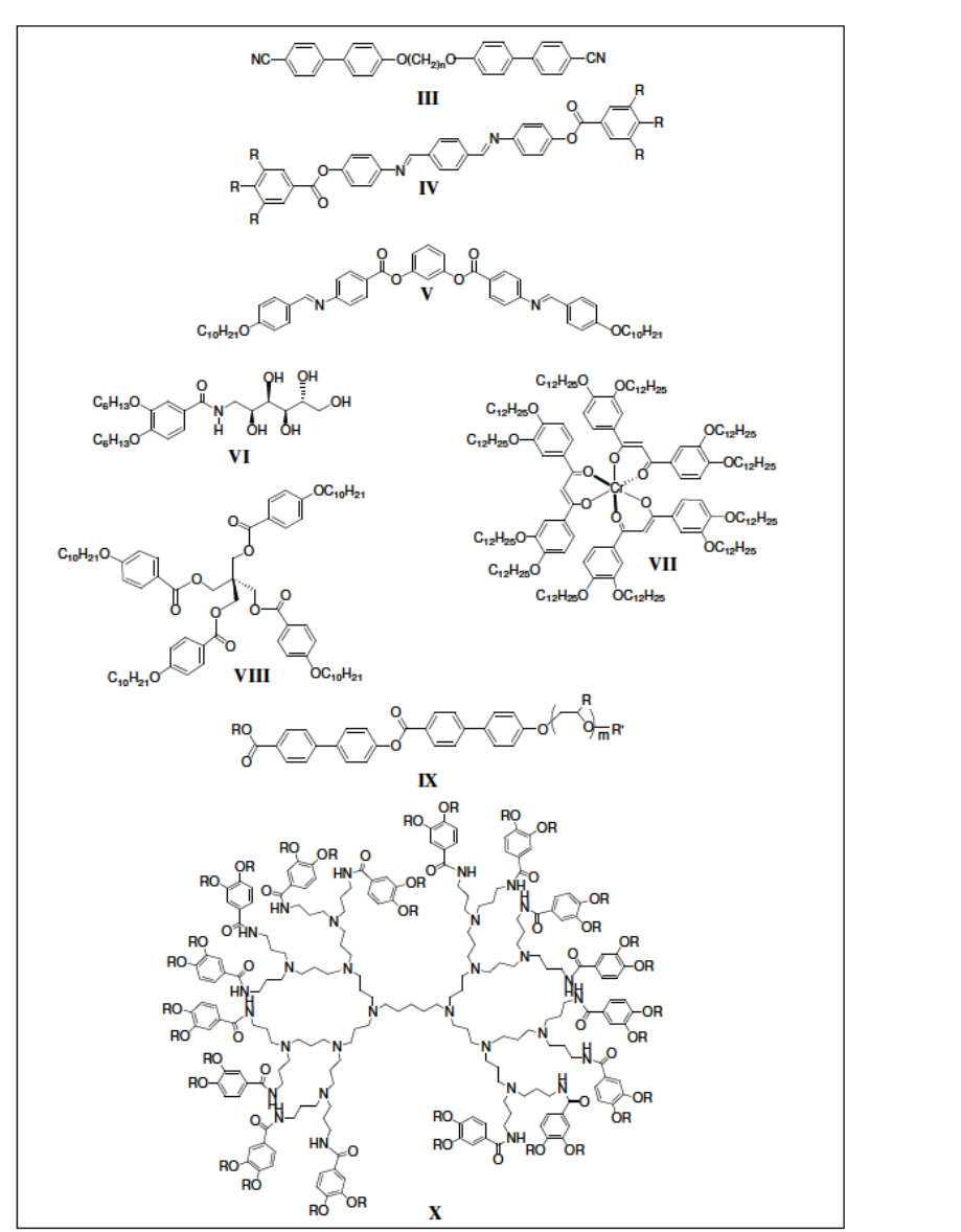
Figure 1. 4. Molecular structures of different types of non-conventional LCs. and
dendrimers (X) [17]. In this thesis the research work on non-conventional LCs is focused
on dimeric and bent core molecules.
1. 4. 3. Mesophase morphologies of thermotropic liquid crystals
Depending on the chemical structure and the shape of the constituent
molecules and external parameters such as temperature and pressure, a rich variety
of LC phases have been observed. In this section, mesomorphism exhibited by
conventional calamitic molecules is discussed. The mesomorphism of discotic
molecules and dimers is described briefly in section 1. 6. Some of the non-
conventional molecular structures mentioned in the previous section which show a
distinctive phase behavior are discussed in the recent review articles [10].
1. 4. 3. 1. Calamitic liquid crystals: phases and structures
In calamitic mesogens, there are three types of mesophases namely the
nematic, cholesteric and smectic originally classified by Friedel [7] based on the
degree of positional and orientational order. The discovery of new phases in liquid
crystals turns to be often associated with an increase of complexity. Examples
include the formation of chirality induced helical supermolecular structures like
TGB and Blue phases. In the following sections brief description about the
structures of the above mentioned phases are given.
(a)Nematic (N) phase:
The simplest LC phase is the nematic and it generally occurs just below
the isotropic phase with a viscosity comparable to those of isotropic liquids.
Depending on the surface conditions, N phase exhibits schlieren, marble and
pseudoisotropic textures. In this phase the constituent molecules have no
positional order but are on an average, oriented about a particular direction called
the director, n [18]. The molecular organization in the nematic phase is illustrated
in Fig. I. 5. Even though the preferred direction of molecules varies from point to

point in the medium, a uniformly aligned sample is optically uniaxial (N
u
) and
birefringent. However, the biaxial modification of this phase abbreviated as N
b
, is
also known [18 d-g]. The orientational order of the phase is quantified by the
order parameter S and the values increase from, about 0.3 near the clearing
temperature to 0.6-0.7 at temperatures below the clearing point. Because of the
parallel alignment of the molecules along their long axes they exhibit anisotropic
physical properties.
Figure 1. 5. Schematic representation of the molecular organization in the N phase of the
calamitic LCs
(b)Cholesteric (N*) mesophase
Cholesteric mesophase is the chiral variant of the nematic mesophase and
therefore it is also called chiral nematic phase. It occurs in systems where
constituent molecules are chiral [8]. It can also be obtained by doping the nematic
LC with optically active molecules. The name cholesteric has a historical origin
i.e., this particular type of liquid crystalline organization was observed in esters of
cholesterols [18c]. In these systems, there is a weak tendancy for neighboring

molecules to allign at a slight angle at one another. This leads a local director to
form a helix in space with a well-defined pitch that is much longer than the size of
a single molecule. Helical twist may be right handed or left handed depending on
the molecular conformation. The cholesteric state is illustrated in Fig. I. 6. This
helical arrangement is responsible for the unique optical properties of the phase,
such as selective reflection [1,10e, f]. When plane-polarised light interacts with
this chiral macroscopic structure, its plane of polarization is rotated along the
direction of the helix. When the pitch of the helix corresponds to a wavelength in
the visible region of the spectrum (~400-800 nm) the chiral mesophase is colored.
Importantly, the pitch of the helix is temperature-sensitive and therefore, the
reflected wavelength. Furthermore; helical structures can be unwound by the
application of an electric field, which drives the reorientation of the molecular
axis along the field direction. Depending on the surface conditions, N* phase
exhibits schlieren and oily streak textures.
Figure 1. 6 (a) Helical structure of the chiral nematic phase, (b) The director lies in the xy plane,
perpendicular to the direction of the helix (z), and rotates in the plane that defines the helical
structure.
(c)Smectic (Sm) mesophases:
In some phases the molecular center of gravity is on an average arranged
in equidistant planes, so that in addition to orientational order, positional order is
also present which leads to a layered structure: such phases have been called
smectics. Depending on the molecular arrangements within the layer and the
extent of inter-layer correlations smectic mesophases are classified into different
types [1, 19, 20] according to the chronological order of their detection the
smectic phases have been designated with code letters A,B,C…etc. Fluidity of
the layer is an essential characteristic of all smectic phases. A more rigorous way
to treat the layering arrangement is to consider an one-dimensional mass density
wave [21], the different smectic LC phases discovered hitherto are smecticA
(SmA), smectic B (SmB, also known as hexatic B), smectic C (SmC), smectic F
(SmF) and smectic I (SmI). Further, these smectic LC phases can be divided into
two categories depending upon whether the constituent molecules are tilted or not,
with respect to the layer normal. The SmA and SmB phases are orthogonal (non-
tilted) phases whereas SmC, SmF and SmI are tilted phases. The chiral smectic
mesophases are formed when the constituent molecules are chiral. These are chiral
SmA, chiral smectic C (SmC*), chiral smectic I (SmI*) and chiral smectic F
(SmF*) phases. SmA and SmC are the two most commonly observed and
extensively investigated among the various smectic phases. In the following
section the structural details of some of the important smectic phases have been
discussed briefly.
Smectic A (SmA) and chiral SmA phases:
In the smectic A phase the director lies along the layer normal. The molecular
packing within the layers is liquid-like and has no long-range positional
correlation. Likewise, there is no correlation between the lateral positions of the
molecules in successive layers. Because of the disorder within the layers, the
layers are not well defined and in formal terms the SmA phase can be described as
a one-dimensional mass density wave [21]. Thus the idealized picture of the SmA
phase shown in Fig. I. 1b is far from accurate. The sub-phases of SmA such as
SmA
2
(a bilayer phase), SmA
d
(a partially-bilayer. Thus the idealized picture of
the SmA phase shown in Fig. I. 1b is far from accurate. The sub-phases of SmA
such as SmA
2
(a bilayer phase), SmA
d
(a partially-bilayer phase) and Smà (a
modulated phase) are also known. Like biaxial nematic phase, SmA can also
possess biaxial symmetry that has been termed biaxial smectic A (SmA
b
) phase
wherein the molecules are along the layer normal, but have an additional director
in the plane of the layers. Though the chiral version of the smectic A phase
(observed with optically active molecules) is structurally the same as that of
achiral SmA, owing to molecular chirality the symmetry is reduced from D
h
to
D
.
As a consequence, in the SmA phase (Fig. I. 7a), when an electric field is
applied orthogonal to the layer normal direction there will be a coupling of the
electroclinic susceptibility to the field and the long molecular axes of the
molecules will tilt with respect to the layer planes (Fig. I. 7b) for relatively low
applied fields, the tilt angle varies linearly with the field. This linear electrooptic
phenomenon is called electroclinic effect [22]. Both SmA and chiral SmA phases

exhibit characteristic focal-conic texture in slides treated for planar orientation and
a dark field of view in slides treated for homeotropic orientation.
Figure 1. 7 Schematic representation of the SmA phase formed by chiral rod-like anisometric
molecules: (a) orthogonal layered geometry; (b) tilted layered structure (electroclinic effect)
obtained by the application of electric field along the layer planes of geometry (a)
Smectic C (SmC) and chiral smectic C (SmC*) phases:
The smectic C phase differs from the SmA phase in that the director of
each layer is inclined at an angle to the layer normal and this angle being identical
for all layers (Fig. I. 8a) [23]. While the SmA phase is generally optically uniaxial,
the SmC phase is optically biaxial. The tilt angle in this phase has been shown to
vary with temperature and it often increases monotonically with decreasing
temperature. X-ray studies indicate that the layer thickness in this phase is
considerably less than the molecular length. The symmetry elements of this phase
correspond to the point group C
2h
(Fig. I. 8a and I. 9a). In the chiral smectic C
(SmC*) phase, formed by optically active molecules a macroscopic molecules
exist. The helix occurs as a result of a gradual change in molecular tilt direction
(n) from layer to layer, about an axis perpendicular to the layer planes (Fig. I. 9b).
Due to the presence of chiral molecules, the SmC* phase has reduced C
2

symmetry (Fig. I. 8b) which creates in equivalence in the dipole moment along the
C
2
axis normal to the tilt
Centre of symmetry
Figure 1. 8. Symmetry in the (a) SmC and (b) SmC* mesophases
Figure 1. 9. (a) Structure of the SmC phase, (b) LHS: helical macroscopic structure of the SmC*
phase in which the consecutive layers precess around the layer normal (z); RHS: the representation
of the precession of a single chiral molecule in the consecutive layers; (c) a chiral molecule
represented in its layer plane (xy) with its polarisation (Ps) (due to the inherent form chirality in
the SmC* phase) (LHS: Left hand side; RHS: right hand side)
direction (Figure. I. 9c), resulting in spontaneous polarization (Ps) in each layer.
However the presence of helix averages out the Ps to zero [23]. Nevertheless, to
obtain a macroscopic Ps (ferroelectric behavior) the helix can be unwound by
surface interactions or by the application of an electric field [24].
(d)Chiral frustrated phases:
Chirality efficiently reduces the molecular symmetry which in turn can
significantly modify the mesomorphic behaviour. Chiral molecules prefer to pack
in a certain manner, but such a structure cannot be adopted everywhere due to
molecular constraints. Such a situation leads to the stabilization of what are called
as frustrated phases [25]. Examples include blue phases (BP) and twist grain
boundary (TGB) phases and the structures of which are briefly described below.
Blue phases (BP):
These are distinct thermodynamic phases that appear over a narrow
temperature range between chiral nematic and isotropic liquid phases in short
pitch (<5000 Å), BPII a simple cubic lattice and BPIII is probably achiral nematic
LCs [26-33] which are usually single component optically active rod-like
mesogens or mixtures composed of achiral and optically active mesogens [30b].
Recently, they have been also reported to occur in discotics [29] and LC dimers
[10i]. The first observation of the blue phase has been attributed to Reinitzer [28].
Three distinct blue phases have been identified i.e., BPI, BPII and BPIII that occur
in the same order with increasing temperature. The naming of these phases as blue
is due to their Bragg reflections in the blue wavelengths indicating a partially
periodic structure with lattice parameters of several hundred nanometers.
However, blue phases are now known to reflect other colors in the visible range.
Saupe was the first to suggest a chiral cubic structure from the optical activity of
the BPs and their lack of birefringence [24, 28]. Bragg reflection studies indicate

that BPI has a body centered cubic lattice amorphous one. The structure of the
BPs involves a radial twist of the director called a double cylinder. However, this
double twisted structure cannot extend perfectly into three-dimensional space.
Figure 1. 10 shows the schematic representation of the spaghetti model of BPIII,
having randomly oriented squirming double twist cylinders, while geometrical
models of cubic blue phases (BPI and BPII) consist of cubic net works of double
twist cylinders separated by disclination lines (Fig. I. 11) [30]. (see below for
details).
Figure 1. 10. Schematic representation of the theoretical spaghetti model of BPIII (a) having
randomly oriented squirming double twist tubes (b).
Figure 1. 11. (a) Schematic illustration of a double twist cylinder. At the core the director is
oriented parallel to the cylinder axis. Moving outwards, the local director twists along any radius
until the twist is approximately 45
o
at the edge of the double twist cylinder; (b) local arrangement
of three double twist cylinders forming a defect region; (c) spatial arrangement of double twist
cylinders that lead to the simple cubic structure of BPII and (d) spatial arrangement of double twist
cylinders that lead to body centred cubic structure of BPI.
Cubic blue phases BPI and BPII are built up of double-twist cylinders as
schematically shown in fig. I. 10a, which represent a local structure of minimum
energy within a double twist cylinder the local director rotates around any given
radius of the cylinder. The double twist cylinders spatially arrange perpendicular
to each other, the arrangement eventually leading to the three dimensional cubic
lattice of topological defects [32] observed in blue phases (Figure. I. 11c, d).
Combined interpretation of various experimental investigations on the structure of
these phases has revealed that the BPII phase has a simple cubic unit cell of lattice
defects, while the BPI phase is body centered cubic, both with lattice parameters
in the order of several hundred nanometers (the wavelength of visible light). The
blue phases are thus optically isotropic, i.e. linear birefringence is absent. The
optical texture of the cubic blue phases is quite characteristic, generally with a
platelet texture. Amorphous BPIII is characterized by its foggy appearance.
The twist grain boundary (TGB) phases:
These phases usually appear at the transition from SmA or SmC* phase
to N* or isotropic phase. For short pitch chiral materials there can be a
competition between the need for the molecules to form abhelical structure due to
their chiral packing requirements and the need for the phase to form a layered
structure. Molecules relieve this frustration by forming twist grain boundary phase
that consists of blocks of smectic layers, the successive layers being rotated by a
constant angle to give a helical structure with helix axis orthogonal to the layer
normal direction. Since the smectic layers cannot be continuously twisted, they
are separated from one another by screw dislocations to form grain boundaries
which themselves are periodic, leading to the presence of layering as well as
helical twist. Further, depending upon whether the smectic blocks are of smectic
A or smectic C or smectic C*, three different types of TGB phases such as TGBA,
TGBC and TGBC* are possible [43] and are observed experimentally [34-36]
(Fig. I. 12). The structure of the TGBC* phase is more complicated than the
TGBA and TGBC phases. Experimentally it has been observed that this phase
exhibits a regular (square or hexagonal) grid pattern superimposed on the planar
structure. To explain the structure of TGBC* phase, Galerne proposed an
improved model based on the original model by Renn [46d]. According to this
model, in addition to the tilt of the molecules with respect to the smectic layer
normal as in TGBC phase, the molecular tilt itself undergoes a twist around the
SmC* helix axis, which lies in a plane perpendicular to the TGB helix axis. Thus
each of the smectic blocks has a smectic C* structure with its helix axis
orthogonal to that of the TGB helix. The model retains the concept of helislabs,
which leads to an additional type of coarse grain boundary whose size could be
larger than the size of the smectic slabs. Like the smectic slabs, helislabs are also
separated by parallel sets of defect lines (with defects now being disclinations)
and the grids are consequence of this. According to another model proposed [36e],
the appearance of the square grid in this TGBC* phase is supposed to be due to
the undulation of the smectic slabs, which means that the grain boundaries are not
flat. Thus, in TGB phases, as in blue phases, the frustration is relieved by the
presence of defects. The model retains the concept of helislabs, which leads to an
additional type of coarse grain boundary whose size could be larger than the size
of the smectic slabs. Like the smectic slabs, helislabs are also separated by parallel
sets of defect lines (with defects now being disclinations) and the grids are

consequence of this. According to another model proposed [36e], the appearance
of the square grid in this TGBC* phase is supposed to be due to the undulation of
the smectic slabs, which means that the grain boundaries are not flat. This is
referred as undulated TGBC* (UTGBC*) phase. Recently, Clark et al. , have
proposed that the square grid pattern arises from a common structure: „giant‟
smectic blocks of planar layers terminated by grain boundaries [36g].
Figure 1. 12. (a) Structure of TGBA phase, where d = smectic layer spacing, lb = thickness of the
smectic slabs, ld = distance between neighboring screw dislocation and p = pitch of the director
field, (b) structure of TGBC phase where _L = tilt angle of the layers, n = director, N = layer
normal, PS = spontaneous polarization, lb = thickness of the smectic slabs, (c) structure of TGBC*
phase where Q = main helical wave vector, N = layer normal, lb = distance between the two
neighboring grain boundaries, lH = thickness of helislab
1. 5. Sequence rule and reentrant behaviour in calamitic liquid crystals
A thermotropic LC can exhibit one to several LC phases between the
crystal and isotropic liquid states. Materials which exhibit two or more LC phases
are said to be polymesomorphic and the process is known as polymesomorphism.
By systematic observation of different phases in polymorphic compounds a rule
for the phase sequences was derived [46]. According to this general rule smectic
phases are the low temperature phases while the nematic phase occurs at higher
temperatures. Considering all structures known in calamitic LCs a hypothetical
sequence was derived: Isotopic (I) - N - SmA - SmC - SmB - SmI - SmF - Crystal B
- J - G - E - K - H- Crystal for achiral materials and I - BP- N*- TGB - SmA -
SmC* - SmI* -SmF* for chiral LCs. Till date, there is no single material is
reported to exhibit all these phases. However, there are many real phase sequences
that can be considered as parts of the above given hypothetical full sequence.
Remarkable exceptions to this hypothetical sequence have been detected in
reentrant transitions [47]. A system is said to undergo a reentrant phase transition,
if a variation of any thermodynamic field such as temperature or pressure results
in two (or sometimes more) phase changes and finally attains a state which is
macroscopically similar to the initial state.
1. 6. Discotic liquid crystals: phase types and structures
It was believed for a long time that mesomorphism could be shown only
by molecules with rod-like structure. However, in 1977 Chandrasekhar et al.
showed that disc-like molecules such as hexa-n-alkanoyloxybenzenes (see II in
Fig. I. 3) exhibit mesomorphic behavior [6]. In general such compounds are called
"discotics" and here the rigidity at the centre of the molecules is an essential

structural requirement [34]. In general a discotic molecular structure can be shown
as in figure1. 2b. Achiral discotic LCs exhibit two different types of mesophases
namely nematic (N), lamellar and columnar (Col) phases. The nematic phase is
similar to the nematic phase of the rod-like molecules in possessing the
orientational order (Fig. I. 13a). Another variant of nematic phase is known in
which the nematic structure is formed by columns (Fig. I. 13b) and has been
called columnar nematic phase (Ncol).
Figure 1. 13. (a) The nematic phase, (b) columnar nematic phase, (c) columnar hexagonal phase,
(d) columnar rectangular phase, (e)-(i) plan views of the two-dimensional lattice: (e) hexagonal
symmetry,(f) rectangular symmetry, (g) oblique symmetry (h) rectangular symmetry, (i)
rectangular face-centered symmetry
The most common phase exhibited by disc-like molecules is the columnar phase,
in which the discs stack into columns (Fig. I. 13c, d). Columnar LCs shows a rich
polymorphism and is normally classified at three levels; according to the
symmetry of the two-dimensional array, the orientation of the core with respect to
the column axis and the degree of order within the column. The stacking of discs
within the columns can be ordered or disordered.
However, based on the symmetry of two dimensional (2D) array of the
columnar mesophases they may be classified into three classes namely, hexagonal,
rectangular and oblique [34b]. In columnar hexagonal phase the constituent
molecules can have either an aperiodic arrangement (liquid-like) or long-range
positional order within the column. Columnar rectangular (Colr) and columnar
oblique (Col
ob
) phases are characterized by a liquid-like molecular order along the
columns, in which the columns are arranged either in a rectangular or oblique
packing respectively. Fig1. 13-e-i show plan view of the two-dimensional lattice
of columns in different columnar mesophases [1a]. The workhorses of discotic
liquid crystal research have been derivatives of triphenylene and pthalocyanines
[37a]. Many derivatives of anthraquinone, ethynyl benzene, hexabenzocoronens,
tricycloquinazolines, macrocycles with a large cavity at the centre, metallo-
discogens containing copper, molybdenum, nickel and palladium etc are added to
the list of new discogens [37]. The guidelines framed for the formation of
mesophases in achiral discotics have been followed to realize chiraldiscotic
systems by introducing one or several chiral chains around the periphery of
discotic core which are known to exhibit either a chiral nematic (N*) or columnar
phases. The blue phase has been rarely observed in discotics [37d]. The discotic
chiral nematic phase has a structure analogous to that of the chiral nematic phase
exhibited by calamitics. Interestingly, a certain columnar phase formed by chiral
discotics exhibits ferroelectric switching properties, which appear to have some
advantages over its tilted smectic counterpart in electro-optical displays. The
discotic nematic is now considered to be a better medium for display applications
especially with respect to viewing angle problems [38]. Added to this the recent
commercialization of discotic nematic in the production of optical compensation
films by Fuji Film Company [39] has created an immense interest in this area.
The potential use of discotic materials, especially those exhibiting columnar
phases, as quasi-one dimensional conductors, photoconducting systems,
ferroelectrics, light emitting diodes, photovoltaic solar cells, optical storage
devices, hybrid computer chips for molecular electronics etc. , are attracting
considerable attention [37c].
1. 7. Identification of thermotropic mesophases
As discussed in previous sections, till date a number of liquid crystalline
phases have been discovered. The structural differences between these phases are
quite narrow and therefore the precise characterization of LC phases generally
requires the use of different techniques. The most commonly used device to
identify the LC phases is the polarizing optical microscope (POM) which reveals
the characteristic optical texture of a mesophase. The optical textures are usually
observed in thin layers of the sample between two glass plates, pretreated for
either homogeneous or homeotropic alignment of the molecules. Calorimetric
study using differential scanning calorimetry (DSC) is a complementary tool to
microscopic studies to know the precise phase transition temperature and the
enthalpy change associated with the transition. However there are limitations in
mesophase characterization by either of these methods as the optical textures of
different smectic or columnar phases are difficult to distinguish and the enthalpy
values can not be so characteristic for different phase transitions. Sometimes
miscibility studies, in which a well known liquid crystal phase are physically
mixed with an unknown phase to ascertain the nature of the phase is carried out
based on the criterion of complete miscibility of identical phases [40]. For
unambiguous identification of mesophases, structural information such as relative
molecular positions, the presence of long-range positional order, the quality of
preferred molecular orientation etc. , can be obtained from diffraction studies. X-
ray, electron and neutron radiations are suitable for diffraction studies. X-rays are
probably the most convenient and widely used whereas electrons and neutrons
have advantages in particular situations. Other experimental techniques such as
electro-optic measurements, nuclear magnetic resonance (NMR) spectroscopy etc.
, are also in use for the characterization of mesophase.
I. 8. Physical properties of liquid crystals
Since liquid crystals are anisotropic fluids, various physical properties
measured in different directions will not be the same. In other words, the parallel
alignment of anisotropic molecules gives rise to the anisotropy of various physical
properties that are the basis of a number of practical applications known for LCs.
Some of the important anisotropic properties directly relevant to various liquid
crystal applications [1c, 56] are discussed below.
(a)Optical anisotropy (Birefringence)
All crystal types other than cubic are optically anisotropic or birefringent. The
free rotation in liquids averages out any asymmetry of molecular shape and the
medium becomes optically isotropic. Mesogens due to their shape and
polarization anisotropy are birefringent, exhibiting different properties for light
traveling with the electric vector propagating parallel and perpendicular to the
director or optic axis. The electric vector of incident plane polarized light entering
a liquid crystalline phase is split into two components called ordinary (o) and
extraordinary (e) rays. The electric field of the o-ray is always perpendicular to the
optic axis, so its refractive index „n
o
‟is a constant independent of propagation
direction. The electric field of e- ray lies in a plane that contains the optic axis, so
its refractive index n
e
(θ) varies with the ray propagation angle with respect to the
optic axis. Thus the birefringence of the medium, Δn (θ), depends on the
propagation direction and is defined as Δn (θ) = n
e
(θ) - n
o
. Most nematic liquid
crystals have positive birefringence (Δn > 0), meaning that the e-ray is delayed
with respect to the o-ray on passage through the LC phase. Interference between
the e-ray and the o-ray that travel through the medium with different velocities
gives rise to the coloured appearance of these thin films.
(a) Dielectric anisotropy
The interaction between a liquid crystal and an electric field is
dependent on the magnitude of the dielectric permittivity (measured parallel
(||) and perpendicular ( to the director and to the difference between them (i.e.
, the dielectric anisotropy Δ|| - ). The dielectric permittivity of a material is
defined as the ratio of the capacitance of the material C
mat
to that in vacuum C
vac
(= C
mat
/C
vac
). The dielectric constants are dependent on the frequency of the
applied field up to transition to the isotropic liquid. Above the clearing point, the
dielectric constants measured along all the three axes are equal due to the isotropic
nature of a liquid and therefore, Δ decreases to zero. The sign and magnitude of
the Δ are attributable to the resultant permanent dipole moments.
(b) Elastic constants
The elastic behaviour of a liquid crystal phase under a distorting force such as
an electric field or at an interface with a solid surface is determined by the three
elastic constants k
1
, k
2
, k
3
that are associated with splay, twist and bend
deformations respectively. The elastic constants are molecular parameters and
describe the restoring forces on a molecule within a liquid crystalline phase in
response to an external force that distorts the medium from its lowest energy
configuration. The elastic constants co-determine the spatial and temporal
response of the director to the applied external electric and magnetic fields. The
equilibrium position is then restored upon removal of the field by elastic forces
that originate at the interface between the LC and the orientation layers that cover
the device substrates.
(c) Viscosity
The viscosity of any material is a collective property resulting from the
interaction of the molecules with one another. The flow velocity in the liquid
crystalline state is also an anisotropic property that depends on the direction of
flow of individual molecule with respect to the director at any one point within the
medium. Three parameters are required to characterize the nematic state as the
constituent molecules are anisotropic. These are η
1
, which is perpendicular to the
direction of flow, but parallel to the velocity gradient; η
2
, which is parallel to the
direction of flow, but perpendicular to the velocity gradient and η
3
which is
perpendicular to the direction of flow and to the velocity gradient. Individual
viscosity coefficients influence the optical response times in an electro-optic
display device.
I. 9. Applications and prospects of liquid crystals
(a) Display applications
By virtue of their fluid nature, LCs can be easily processed into thin
films, yet they retain the optical properties of crystalline materials such as the
ability to rotate plane polarized light. In addition, the orientation of the molecules
in liquid crystal films can be modulated on a relatively short time scale using a
low electric field. Because the birefringence in a liquid crystal phase is a function
of the angle formed by plane-polarized light and the director „n‟, it can effectively
function as an ON/OFF light shutter between crossed polarizers under the
influence of an electric field. Most LC applications are indeed based on this
simple concept of an ON/OFF light shutter [29d]. Majority of the liquid crystals
displays (LCDs) fabricated today use either the twisted nematic (TN) [1c] or super
twisted nematic (STN) [43] displays. The nematic phase formed by discotic
mesogens has recently been reported to be useful for wide viewing angle LCDs
because of their negative birefringence [42, 44].
(b)Temperature sensors
Chiral nematic (cholesteric) liquid crystals reflect light with a wavelength
proportional to the magnitude of pitch. Because the pitch is dependent upon
temperature, the colour reflected also is dependent upon temperature. Thus,
cholesteric LCs make it possible to accurately gauge temperature just by looking
at the colour. By mixing different cholesteric LCs, a device for practically any
temperature range can be built. This property has been exploited for practical
applications [45] in diverse areas including medicine, packing industry and
electronics. Cholesteric liquid crystals as „fever strips‟ are in use as disposable
thermometers. LC thermal sensors can be attached to skin to show a thermal map.
This is useful because often physical problems such as tumors have a different
temperature than the surrounding tissue. LC temperature sensors can also be used
to find bad connections on a circuit board by detecting the characteristic higher
temperature.
(d) Columnar fluid phases as a promising media for modern applications
As discussed earlier, the preferential self-organizing ability of discotic
mesogens to form columnar (Col) mesophases is driven by favourable π-π
interactions between the aromatic cores. Columnar mesophase offers a one-
dimensional pathway for the electronic charge migration, where the central
aromatic core is the conducting unit, with external peripheral chains as the
insulating mantle [46,1i]. This LC state is of great importance because it allows
the possibility to combine different physical properties (optical, conductive) with
orientational control of the molecular order, self healing of structural defects and
ease of processability. Most importantly all these properties can be tailored by
careful molecular engineering. Thus, Col LC phases can be used as promising
media for various device applications as shown in (fig. I. 15). Currently the solar
cells used for the direct conversion of light into electricity by the photovoltaic
effect are fabricated from inorganic semiconductors; in particular they are based
on the single or polycrystalline silicon cells. On the other hand, organic thin-film
solar cells having single crystalline material are also promising flat-plate
photovoltaic technology. However, the flat-plate technology based on either of
these two materials is rather difficult and expensive. Most importantly, the large
quantity of inorganic semiconductors used in such a technology is hazardous to

Figure1. 15. Schematic representations of molecular electronic devices from columnar
mesophases [adopted from ref. 49]: (a) field effect transistor; (b) Photovoltaic or solar cells; (c) gas
sensors and (d) organic light emitting diodes.
the environment. Thus, for the solar cell applications, new organic materials with
low cost and good processability, large absorption coefficient, efficient photo
generation of charge and good charge carrier mobility are needed. In this context,
the Col phases formed by the electron rich/poor discotic mesogens appear to be
promising given the fact that their structure resembles the aromatic stacking in
single crystalline conductors. In particular, segregated stacks of columnar
mesophases made up of donor and acceptor type discotics in their “face on”
orientation imitate the same morphology of solar cells (Fig. I. 15b). The“edge on”
orientation of the Col phases can be translated into field effect transistors (FET)
which are the vital components in molecular electronic devices (Fig. I. 15a). The
high mobility for photo induced charge carriers in the Col phases also make them
suitable for their use as the active charge transport layer in fast and high resolution
xerographic and laser printing applications [47]. The Col phase has a unique
conductive surface layer due to the fluctuations along the lengths of the column.
The carrier mobility along the surface is fluctuation assisted and the tunneling
rates are exponentially dependent on the molecular core spacings. The core
separation fluctuates with the surface and changes as soon as the surface is
disturbed. The electrical conductivity of this surface layer is, therefore, very
sensitive to the absorption of molecules. Thus columnar liquid crystals can be
used as sensitive gas sensors for both polar and nonpolar molecules (Fig. I. 15c)
[48]. Recently Col phases gaining importance in the construction of organic light
emitting diodes (OLEDs) as they can act as good emitting and conductive layers
with proper structural design. Columnar phases with a combination of hol/electron
transporting and luminescence properties are an ideal media for the fabrication of
OLEDs (Fig. 1. 15d) [46].
(e) Other applications
Liquid crystals have other applications also. Polymers form an
important subclass of liquid crystal materials and occur in nature as solutions of
some biopolymers and are important in the processing of advanced high-modulus
engineering materials like Kevlar [49]. Liquid crystals are employed as
anisotropic solvents for the study of various physiochemical properties [50]. The
nematic phase, in which the molecules can be homogeneously oriented by a
magnetic field such that the optic axis lies parallel to the field, is employed as
anisotropic solvent in NMR spectroscopy. This technique provides information
regarding the anisotropy of the chemical shifts and molecular geometry [51].
Liquid crystals are used as solvents to alter the rates of uni- or bi-molecular
thermal and photochemical reactions [52]. This technique is based on the ability
of the mesophase to control the orientation of solutes, impart constraints on their
mobility and remove the randomness of molecular motions and orientations. A
combination of the analytical strengths of gas chromatography and the unique
structure and shape selective properties of the LC phase has led to the wide spread
use of LCs as stationary phases in chromatography. Effective and selective
separation of positional and geometric isomers can be brought about by the
interaction of the solute with the orientational order provided by the anisotropy of
the LC stationary phase. Cholesteric LCs are also used for chiral recognition [53].
Lyotropic LCs are exploited for applications in commercial detergents and
cosmetics [54] and for the simulation of bio membranes [55]. Recently, another
important application of LCs as a medium for controlled drug release has been
envisaged [56].
References
1. For an introduction to the subject see: (a) S. Chandrasekhar, Liquid
Crystals. ,Cambridge University Press, 2
nd
Ed. 1994; (b) P. J. Collings; M.
Hird. , Introduction to Liquid Crystals Chemistry and Physics. ,Taylor
and Francis Ltd. London, 1997; (c) B. Bahadur,Liquid Crystals:
Application and Uses. , Vol. 1-3, World Scientific, Singapore, 1990; (d) G.
W. Gray, Molecular structure and the properties of liquid crystals. ,
Academic press, London and New York,1962: (e) D. Demus; L. Richter;
Textures of liquid crystals, 2
nd
Ed. 1978: (f) G. W. Gray in Handbook of
liquid crystal, Vol-1, Eds:D. Demus; J. Goodby; G. W. Gray; H. W.
Spiess; V. Vill. Weiley-VCH, Germany,1998; (g) G. W. gray; J. W.
Goodby, Smectic Liquid Crystalline Textures and Structures. , Leonard
Hill, Philadelphia, 1984: (h) P. G. de Gennes; J. Prost, The Physics of
Liquid Crystals, Oxford Science Publication, Oxford, 1993.
2. (a) J. M. Lehn, Supramolecular Chemistry: Concepts and Perspectives. ,
Wiley-V CH, New York, 1995; (b) T. Kato, Science. , 2002, 295, 2414.
3. C. Tschierske, Prog. Polym. Sci. 1996, 21, 775.
4. Handbook of liquid crystals, Vol-3, Eds. :D. Demus; J. W. Goodby; G. W.
Gray; H. W. Spiess; V. Vill; Wiley-VCH, New York, 1998, p. 303.
5. D. Vorlander, Kristallinisch-flussige Substanzen. , Enke-Verlag, Stuttgart,
1908.
6. L. J. Yu; A. Saupe, Phys. Rev. Lett. , 1980, 45, 1000.
7. S. Chandrasekhar; B. K. Sadashiva; K. A. Suresh, Pramana. 1977, 9, 471.
8. H. S. Kitzerow; C. Bahr, Chirality in Liquid Crystals, Springer-Verlag,
New York, 2001.
9. (a) D. Demus, Liq. Cryst. , 1989, 5, 75; (b) C. Tschierske, J. Mater. Chem.
, 1998,8, 1485; (c) C. Tschierske, J. Mater. Chem. , 2001, 11, 2647; (d) C.
Tschierske,Annu. Rep. Prog. Chem. , Sect. C, 2001, 97, 191; (e) C.
Tschierske, Curr. Opin. Colloid Interface Sci. , 2002, 7, 69, 80.
10. (a) C. T. Imrie; P. A. Henderson, Chem. Soc. Rev. 2007, 36, 2096. (b) C.
T. Imrie;G. R. Luckhurst, in Handbook of liquid crystals. , Vol-2B, Eds. :
D. Demus; J. W. Goodby; G. W. Gray; H. -W. Spiess; V. Vill; Wiley-
VCH, Germany, 1998, part – III, p. 799. (c) C. T. Imrie; P. A. Henderson,
Curr. Opin. Colloid Interface Sci. 2002, 7, 298. (d) C. T. Imrie, in
Structure and Bonding – Liquid crystals, II, Ed: D. Mingos, M. P.
Springer-Verlag, 1999, p. 149. (e) N. Tamaoki; M. Moriyama; H.
Matsuda, Angew. Chem. Int. Ed. 2000, 39, 509. (f) N. Tamaoki, Adv.
Mater. 2001, 13, 1135 and references cited in these articles. (g) R. A.
Reddy; C. Tschierske, J. Mater. Chem. 2006, 16, 907. (h) H. Takezoe; Y.
Takanishi, J. of App. Phys. 2006, 45, No. 2A, 597. (i) C. V. Yelamaggad;
I. S. Shashikala; G. Liao; D. S. S. Rao; S. K. Prasad; Q. Li; A. Jakli,
Chem. Mater. 2006, 18, 6100 and references cited therein. (j) V. A. Mallia;
N. Tamaoki, Chem. Soc. Rev. 2004, 33, 76. (k) C. V. Yelamaggad; A. S.
Achalkumar; D. S. Shankar Rao; S. Krishna Prasad, Org. Lett. 2007, 9,
2641.
11. (a) H. T. Nguyen; C. Destrade; J. Malthete, Adv. Mater. 1997, 9, 375. (b)
J. Malthete; H. T. Nguyen; C. Destrade, Liq. Cryst. 1993, 13, 171.
12. (a) T. Niori; T. Sekine; J. Watanabe; T. Furukawa; H. Takezoe, J. Mater.
Chem. 1996, 6, 1231. (b) G. Pelzl; S. Diele; W. Weissflog, Adv. Mater.
1999,11, 707. (c) K. Fodor-Csorba; A. Vajda; G. Galli; A. Jakli; D.
Demus; S. Holly; E. Gacs-Batiz, Macro. Chem. Phys. 2002, 203, 1556.
13. (a) K. Borisch; S. Diele; P. Goring; H. Muller; C. Tschierske, Liq. Cryst.
1997, 22, 427. (b) C. Tschierske, Chem. Soc. Rev. 2007, 36, 1903.
14. (a) H. Zeng; T. M. Swager, J. Am. Chem. Soc. 1994, 111, 761. (b) T. M.
Swager;H. Zeng, H. Mol. Cryst. Liq. Cryst. 1995, 260, 301.
15. A. Pegenau; P. Goring; C. Tschierske, Chem. Commun. 1996, 2563. 27
16. M. Lee; D. -W. Lee; B. -K. Cho,J. Am. Chem. Soc. 1998, 120, 13258.
17. (a) J. H. Cameron; A. Facher; G. Lattermann; S. Diele, Adv. Mater. 1997,
9, 398. (b) J. Malthete; A. M. Levulut; H. T. Nguyen, J. Phys. Lett. 1985,
46, 875. (c) K. Borisch; S. Diele; P. Goring; H. Kresse; C. J. Tschierske,
Mater. Chem. 1998, 8, 529. (d) A. Pegenau; T. Hegmann; C. Tschierske;
S. Diele, Chem. Eur. J. 1999, 5, 1643. (e) S. I. Stupp; M. Keser; G. N.
Tew, Polymer. 1998, 39,4505.
18. (a) G. Friedel,Ann. Physique. 1922, 18, 273. (b)J. W. Goodbye, in
Handbook of liquid crystals, Vol-2A, Eds. : D. Demus; J. W. Goodbye; G.
W. Gray; H. -W. Spiess;V. Vill; Wiley-VCH, Germany, 1998, part – I, p.
1. (c) C. J. Booth,in Handbook of liquid crystals. , Vol-2A, Eds. : D.
Demus; J. W. Goodbye; G. W. Gray; H. -W. Spiess; V. Vill; Wiley-VCH,
1998, part–I, p. 303. (d) S. Chandrasekhar; G. G. Nair; D. S. Rao; S. K.
Prasad; K. Praefcke; D. Blunk, Cur. Sci. 1998, 75, 1042. (e) C. V.
Yelamaggad; S. K. Prasad; G. G. Nair; I. S. Shashikala; D. S. Rao; C. V.
Lobo; S. Chandrasekhar, Angew. Chem. Int. Ed. 2004,43, 3429. (f)
Acharya, B. R. ; Primak, A. ; Kumar, S. Phys. Rev. Lett. 2004, 92,145506.
(g) Prasad, V. ; Kang, S. -W. ; Suresh, K. A. ; Joshi, L. ; Wang, Q. ;
Kumar,S. J. Am. Chem. Soc. 2005, 127,17224.
19. G. W. Gray; J. W. Goodbye, Smectic Liquid Crystals. Leonard Hill, 1984.
Glasgow.
20. P. S. Pershan, Structure of Liquid Crystal Phases. 1988, (Singapore:
World Scientific Lecture Series).
21. (a) K. K. Kobayashi, Phys. Lett. 1970, 31A, 125. (b) W. L. McMillan,
Phys. Rev. A. , 1971, 4, 1238. (c) P. G. de Gennes, Solid State Commun.
1972, 10, 1753. (d) R. Schaetzing; J. D. Lister, Advances in Liquid
Crystals. Vol-4, 1979, Ed. : G. H. Brown, Academic Press, p-147.
22. S. Garoff; R. B. Meyer, Phys. Rev. A. 1978, 18, 2739.
23. W. Helfrich; C. S. Oh, Mol. Cryst. Liq. Cryst. , 1971, 14, 289.
24. S. T. Lagerwall, Ferroelectric and Antiferroelectric Liquid Crystals. ,
1999. Wiley-VCH.
25. (a) P. P. Crooker, in Chirality in Liquid Crystals, Eds: H. S. Kitzerow and
C. Bahr (Springer-Verlag, New York), 2001; (b) P. P. Crooker, Liq. cryst. ,
1989, 5, 751;(c) D. C. Wright; N. D. Mermin, Review of Modern Physics. ,
1989, 61, 385.
26. H. S. Kitzerow, H. S. ; Bahr, C. Chirality in Liquid Crystals. Springer-
Verlag, New York, 2001.
27. (a) C. Loubser; P. L. Wessels; J. W. Goodby; P. Styring, Liq. Cryst. 1993,
15,233. (b) C. C. Dong; P. Styring; J. W. Goodby; L. K. M. Chan, J.
Mater. Chem. 1999, 9, 1669.
28. F. Reinitzer, Monatsh. Chem. 1888, 9, 421. For English translation see
Liq.
Cryst. 1989, 5, 7.
29. (a) J. Dijon, in Liquid Crystals: Applications and Uses, Vol-1,B.
Bahadur,(Ed);World Scientific: Singapore, 1990, Chapter 13. (b) D. M.
Walba, Science. 1995, 270, 250. (d) R. P. Lemieux, Acc. Chem. Res.
2001, 34, 845.
30. O. M. Neson; S. T. Lagerwall; K. Skarp, Liq. Cryst. 1987, 2, 757.
31. (a) G. W. Gray; M. Hird; D. Lacey; K. J. Toyne, J. Chem. Soc. , Faraday
TransII. 1989 2, 2041. (b) G. -X. Sun; B. Chen; T. Hong; S. -Y. Xu, J.
Mater. Chem. 2003, 13, 742.
32. (a) W. F. Brinkman; P. E. Cladis, Phys. Today. 1982, 35, 48. (b) Coles, H.
J. ;Pivnenko, M. N. Nature, 2005, 436, 997.
33. (a) S. R. Renn; T. C. Lubensky, Phys. Rev. A. 1988, 38, 2132.
34. (a) J. W. Goodby, M. A. Waugh, S. M. Stein, E. Chin, R. Pindak and J. S.
Patel,Nature, 1989, 337, 449; (b) G. Srajer, R. Pindak, M. A. Wagh, J. S.
Goodby and J. S. Patel, Phys. Rev. Lett. , 1990, 64, 1545; (c) J. W. Goodby
in “Structure and Bonding - Liquid crystasl II”, Ed: D. M. P. Mingos,
Springer-Verlag, 1999.
35. (a) H. T. Nguyen; A. Bouchta; L. Navailles; P. Barois; N. Isaert; R. J.
Twieg; A. Maaroufi; C. Destrade, J. Phys. II. , 1992, 2, 1889; (b) L.
Navailles; P. Barois;H. T. Nguyen, Phys. Lett. , 1993, 71, 545; (c) M.
Petit; P. Barois; H. T. Nguyen, Eur. Phys. Lett. , 1996, 36, 185.
36. (a) W. Kuczynski; H. Stegemeyer; Mol. Cryst. Liq. Cryst. , 1995, 260,
377; (b)W. Kuczynski; H. Stegemeyer; Proc. SPIE. , 1997, 3318, 90; (c)
For a summary on the TGBC* phase, see H. S. Kitzerow in Chirality in
liquid crystals, Eds: H. S. Kitzerow; C. Bahr (New York: Springer
Verlag), 2000; (d) Y. Galerne; Eur. Phys. J. , 2000, E3, 355; (e) P. A.
Pramod; R. Pratibha; N. V. Madhusudana, Curr. Sci. , 1997, 73, 761; (f) C.
V. Yelamaggad; S. Anitha Nagamani; U. S. Hiremath; D. S. Shankar
Rao;S. K. Prasad, Liq. Cryst. , 2001,28, 1581.
37. (a) A. N. Cammidge; R. J. Bushby, in Handbook of Liquid Crystals. , Vol-
2B,Eds: D. Demus; J. W. Goodby; G. W. Gray; H. -W. Spiess; V. Vill;
Wiley-VCH, Germany, 1998, part-II p. 693. (b) S. Chandrasekar; in
Handbook of liquid crystal. , Vol-2B, Eds. : D. Demus; J. W. Goodby; G.
W. Gray; H. -W. Spiess;V. Vill; Weiley-VCH, Germany, 1998, part - II p.
749. (c) N. Boden; B. Movaghar,in Handbook of liquid crystal. , Vol-2B,
Eds. : D. Demus; J. W. Goodby; G. W. Gray; H. -W. Spiess; V. Vill;
Weiley-VCH, Germany, 1998, part – II p. 781. (d) D. Kruerke; H. S.
Kitzerow; G. Heppke; Bunsenges. Ber. Phys. Chem. 1993, 97, 1371. (e) S.
Kumar, Liq. Cryst. 2005, 32, 189. (f) S. Kumar, Chem. Soc. Rev. 2006, 35,
83. (g) S. Sergeyev; W. Pisula; Y. H. Geerts, Chem. Soc. Rev. 2007, 36,
1902.
38. S. Chandrasekhar; S. Krishna Prasad;G. G. Nair; D. S. Shankar Rao;
Sandeep Kumar; M. Manickam, US Patent, 6, 558, 759, B2.
39. K. Kawata, The Chemical Record. , 2002, 2, 59.
40. H. Sackmann; D. Demus, Mol. Cryst. Liq. Cryst. , 1973, 21, 239.
41. (a) S. M. Kelly; M. O‟Neill, in Handbook of Advanced Electronic and
Photonic Materials and Devices. , Vol-7, Chapter-1, 2001, Eds: H. S.
Nalwa, AcademicPress.
42. (a) S. Chandrasekhar; S. K. Prasad; G. G. Nair; D. S. Rao; S. Kumar; M.
Maanickam, EuroDisplay `99, The 19th International Display Research
Conference Late-news papers. Berlin, Germany, 1999, p 9.
43. (a) T. J. Scheffer; J. Nehring, Appl. Phys. Lett. 1984, 45, 1021. (b) T. J.
Scheffer; J. Nehring; M. Kaufmann; H. Amstutz; D. Heimgartner; P.
Eglin, SID 1985 Digest of Technical Papers XVI. 1985, 120.
44. (a) G. Ungar; V. Percec; M. Zuber, Macromolecules. 1992, 25, 75. (b) H.
Watanabe; M. Hayashi, Macromolecules. 1989, 22, 4083. (c) H.
Watanabe;M. Hayashi,Macromolecules. 1988,21,278. (d) H. Watanabe; S.
J. Kinoshita,J. Phys II France. 1992, 2, 1237. (e) M. Tokita; K. Osada; J.
Watanabe, Liq. Cryst. 1998, 24, 477. (f) A. Blumstein; O. Thomas,
Macromolecules. 1982, 15,1264.
45. (a) R. Williams; J. Chem. Phys. , 1963, 39, 384. (b)J. L. Fergason, Sci.
Am. , 1964,211, 77; (c) G. H. Heilmeier, L. A. Barton and L. A. Zanoni,
Appl. Phys. Lett. ,1968, 13, 46.
46. (a) S. Chandrasekhar; V. S. K. Balagurusamy, Proc. Royal Society,
London, Ser. A. 2002,458,3. (b)D. Adam; P. Schuhamcher; J. Simmerer; L.
Hayssling; K. Siemensmeyer; K. H. Etzbach, K; H. Ringsdorf; D. Haarer,
Nature. 1994, 371,141. (c) E. J. Osburn; A. Schmidt; L. K. Chau; S. Y.
Chen; P. Smolenyak; N. R. Armstrong; D. F. O‟Brian, Adv. Mater. 1996,
8, 926. (d) T. Christ; B. Glusen; A. Greiner; A. Kettner; R. Sander; V.
Stumpflen; V. Tsukruk; J. H. Wendorff, Adv. Mater. , 1997, 9, 48. (e) L.
Schmidt-Mende; A. Fechtenkotter; K. Mullen; E. Moons; R. H. Friend; J.
D. MacKenzie, Science. 2001, 293, 1119.
47. C. D. Simpson; J. Wu; M. D. Watson; K. J. Mullen, Mater. Chem. 2004,
14,494.
48. N. Boden; R. Bissel; J. Clements; B. Movaghar, Current Science. 1996,
71, 599.
49. S. L. Kwolek, Du Pont. 1971, US Patent 3600350.
50. (a) W. A. Crossland; T. D. Wilkinson, in Handbook of liquid crystals, Vol
- I,Eds. : D. Demus; J. W. Goodbye; G. W. Gray; Spiess, H. -W; V. Vill;
Wiley-VCH, Germany; 1998, p. 763. (b) W. J. Leigh; M. S. Workentin, in
Handbook of liquid crystals, Vol - I, Eds. : D. Demus; J. W. Goodby; G.
W. Gray; Spiess, H. -W; V. Vill; Wiley - VCH, Germany, 1998, p. 839. (c)
C. Lavigueur; E. J. Foster; V. E. Williams, J. Am. Chem. Soc 2008, 130,
1179. (d) J. Miao; L. Zhu, Chem. Mater, 2010, 22, 197. (f) F. Vera; J. L.
Serrano; T. Sierra, Chem. Soc. Rev. 2009, 38, 781-796. (g) H. Y. Zhao; Y.
H. Xing; Y. Z. Cao; Z. P. Li; D. M. Wei; X. Q. Zeng; M. F. Ge, J. Mol.
Struct. 2009, 938, 54.
51. C. L. Khetrapal; R. G. Weiss; A. C. Kumar, in Liquid Crystals-
Applications and uses. Vol. 2, World Scientific, Singapore, 1991, p. 225.
52. R. G. Weiss, Tetrahedron. 1988, 44, 3413.
53. T. D. James; H. Kawabata; R. Ludwig; K. Murata; S. Shinkai,
Tetrahedron.
1995, 21, 555.
54. (a) D. R. Karsa, Industrial applications of surfactants IV. ,
Cambridge:RSC,1999. (b) M. R. Porter, Hand book of surfactants.
London: Blackie Academic and Professional, 1994. (c) D. Myers,
Surfactant science and technology. , New York: VCH, 1992.
55. (a) T. Kunitake; N. Higashi, J. Am. Chem. Soc. 1985, 107, 692. (b) S. J.
Singer; G. L. Nicolson, Science. 1972, 175, 720.
56. S. J. Watson; H. F. Gleeson; A. D'Emanuele; S. Serak; V. Grozhik, Mol.
Cryst. Liq. Cryst. Sci. Technol. Sect. A. 1999, 331, 2235.
