
Rider's manual
R 1250 GS
BMW Motorrad

Vehicle data/dealership details
Vehicle data
Model
Vehicle Identification Number
Colour code
Date of first registration
Registration number
Dealership details
Person to contact in Service department
Ms/Mr
Phone number
Dealership address/phone number (com-
pany stamp)
Welcome to BMW
We congratulate you on
your choice of a vehicle from
BMW Motorrad and welcome
you to the community of BMW
riders. Familiarise yourself with
your new vehicle so that you can
ride it safely and confidently in all
traffic situations.
About this Rider's Manual
Please read this Rider's Manual
carefully before starting to use
your new BMW. It contains im-
portant information on how to
operate the controls and how to
make the best possible use of all
your BMW's technical features.
In addition, it contains informa-
tion on maintenance and care to
help you maintain your vehicle's
reliability and safety, as well as its
value.
This record of the maintenance
work you have had performed on
your vehicle is a precondition for
generous treatment of goodwill
claims.
If the time comes to sell your
BMW, please remember to hand
over this Rider's Manual to the
new owner. It is an important
part of the vehicle.
Suggestions and criticism
If you have questions concern-
ing your vehicle, your authorised
BMW Motorrad dealer will gladly
provide advice and assistance.
We hope you will enjoy riding
your BMW and that all your jour-
neys will be pleasant and safe
BMW Motorrad.
01 40 9 899 651
*01409899651*
*01409899651*
*01409899651*
Table of Contents
1 General instructions . ... 5
Overview . . . . . . . . . . . . . . . . . . . . . 6
Abbreviations and
symbols . . . . . . . . . . . . . . . . . . . . . . 6
Equipment . . . . . . . . . . . . . . . . . . . 7
Technical data . . . . . . . . . . . . . . . 7
Currentness . . . . . . . . . . . . . . . . . . 8
Additional sources of informa-
tion . . . . . . . . . . . . . . . . . . . . . . . . . . . 8
Certificates and operating li-
cences . . . . . . . . . . . . . . . . . . . . . . . 8
Data memory. . . . . . . . . . . . . . . . . 8
Intelligent emergency call
system . . . . . . . . . . . . . . . . . . . . . . 12
2 General views ........ . . . 17
General view, left side . . . . . . . 19
General view, right side . . . . . 21
Underneath the seat . . . . . . . . 22
Multifunction switch, left . . . . 23
Multifunction switch,
right . . . . . . . . . . . . . . . . . . . . . . . . . 25
Instrument panel . . . . . . . . . . . . 26
3 Status indicators . . . . . . . 27
Indicator and warning
lights . . . . . . . . . . . . . . . . . . . . . . . . 28
TFT display in Pure Ride
view . . . . . . . . . . . . . . . . . . . . . . . . . 29
TFT display in view
menu . . . . . . . . . . . . . . . . . . . . . . . . 31
Warnings . . . . . . . . . . . . . . . . . . . . 32
4 Operation. . . . . . . . . . ... . . . 61
Ignition switch/steering
lock . . . . . . . . . . . . . . . . . . . . . . . . . 62
Ignition with Key-
less Ride . . . . . . . . . . . . . . . . . . . . 64
Emergency off switch (kill
switch) . . . . . . . . . . . . . . . . . . . . . . 68
Intelligent emergency
call . . . . . . . . . . . . . . . . . . . . . . . . . . 69
Lights . . . . . . . . . . . . . . . . . . . . . . . 71
Day run lights . . . . . . . . . . . . . . . 73
Hazard warning lights sys-
tem . . . . . . . . . . . . . . . . . . . . . . . . . 75
Turn indicators . . . . . . . . . . . . . . 75
Antilock Brake System
(ABS). . . . . . . . . . . . . . . . . . . . . . . . 76
Automatic Stability Control
(ASC) . . . . . . . . . . . . . . . . . . . . . . . 78
Dynamic Traction Control
(DTC) . . . . . . . . . . . . . . . . . . . . . . . 80
Electronic Suspension Ad-
justment (DESA) . . . . . . . . . . . 81
Riding mode . . . . . . . . . . . . . . . . 85
PRO riding mode . . . . . . . . . . . 87
Cruise-control system . . . . . . . 89
Hill Start Control . . . . . . . . . . . . 92
Anti-theft alarm (DWA) . . . . . . 94
Tyre pressure monitoring
(RDC) . . . . . . . . . . . . . . . . . . . . . . . 97
Heated handlebar grips . . . . . 97
On-board computer . . . . . . . . . 98
Front and rear seats. . . . . . . . . 99
5 TFT display . .. . . . . . . . . 103
General instructions . . . . . . . 104
Principle . . . . . . . . . . . . . . . . . . . 105
Pure Ride view . . . . . . . . . . . . 111
General settings . . . . . . . . . . . 113
Bluetooth. . . . . . . . . . . . . . . . . . 114
My vehicle . . . . . . . . . . . . . . . . 118
Navigation . . . . . . . . . . . . . . . . . 121
Media . . . . . . . . . . . . . . . . . . . . . 123
Phone . . . . . . . . . . . . . . . . . . . . . 123
Display software
version . . . . . . . . . . . . . . . . . . . . 124
Display licence informa-
tion . . . . . . . . . . . . . . . . . . . . . . . . 124
6 Adjustment . . . . . . . . . . . . 125
Mirrors . . . . . . . . . . . . . . . . . . . . 126
Headlight . . . . . . . . . . . . . . . . . . 127
Windscreen . . . . . . . . . . . . . . . 128
Clutch . . . . . . . . . . . . . . . . . . . . . 128
Gearshift lever . . . . . . . . . . . . . 129
Brakes . . . . . . . . . . . . . . . . . . . . 130
Footrests . . . . . . . . . . . . . . . . . . 132
Handlebars . . . . . . . . . . . . . . . . 133
Spring preload . . . . . . . . . . . . 133
Damping . . . . . . . . . . . . . . . . . . 134
7 Riding .. . . .. . . . . . . . . . . . . 137
Safety information . . . . . . . . . 138
Comply with checklist . . . . . 141
Always before riding off . . . 141
At every third refuelling
stop . . . . . . . . . . . . . . . . . . . . . . . 141
Starting. . . . . . . . . . . . . . . . . . . . 141
Running in . . . . . . . . . . . . . . . . 145
Off-road use . . . . . . . . . . . . . . 145
Shifting gear . . . . . . . . . . . . . . 147
Brakes . . . . . . . . . . . . . . . . . . . . 148
Parking your motor-
cycle . . . . . . . . . . . . . . . . . . . . . . 150
Refuelling . . . . . . . . . . . . . . . . . 151
Securing motorcycle for
transportation . . . . . . . . . . . . . 155
8 Engineering
details .. . ... . . . . . . . . . . . 157
General instructions . . . . . . . 158
Antilock Brake System
(ABS). . . . . . . . . . . . . . . . . . . . . . 158
Automatic Stability Control
(ASC) . . . . . . . . . . . . . . . . . . . . . 161
Dynamic Traction Control
(DTC) . . . . . . . . . . . . . . . . . . . . . 162
Dynamic ESA . . . . . . . . . . . . . 164
Riding mode . . . . . . . . . . . . . . 164
Dynamic Brake Control . . . . 167
Tyre pressure control
(RDC) . . . . . . . . . . . . . . . . . . . . . 168
Shift assistant . . . . . . . . . . . . . 169
Hill Start Control . . . . . . . . . . 171
9 Maintenance . . . . . . . . . . 173
General instructions . . . . . . . 174
Toolkit. . . . . . . . . . . . . . . . . . . . . 174
Service toolkit . . . . . . . . . . . . . 174
Front-wheel stand . . . . . . . . . 175
Engine oil . . . . . . . . . . . . . . . . . 176
Brake system . . . . . . . . . . . . . 177
Clutch . . . . . . . . . . . . . . . . . . . . . 182
Coolant. . . . . . . . . . . . . . . . . . . . 182
Tyres . . . . . . . . . . . . . . . . . . . . . . 184
Rims and tyres . . . . . . . . . . . . 184
Wheels . . . . . . . . . . . . . . . . . . . . 185
Air filter . . . . . . . . . . . . . . . . . . . . 191
Lighting . . . . . . . . . . . . . . . . . . . 193
Jump-starting . . . . . . . . . . . . . 195
Battery . . . . . . . . . . . . . . . . . . . . 196
Fuses . . . . . . . . . . . . . . . . . . . . . 200
Diagnostic connector . . . . . . 202
10 Accessories . . . ... . . . 205
General instructions . . . . . . . 206
Power sockets . . . . . . . . . . . . 206
Cases . . . . . . . . . . . . . . . . . . . . . 207
Topcase. . . . . . . . . . . . . . . . . . . 210
Navigation system . . . . . . . . . 216
11 Care . . . . . . . . . . . . ... . . . 223
Care products . . . . . . . . . . . . . 224
Washing the vehicle . . . . . . . 224
Cleaning easily damaged
components . . . . . . . . . . . . . . . 225
Care of paintwork . . . . . . . . . 226
Vehicle preservation . . . . . . . 226
Laying up the motor-
cycle . . . . . . . . . . . . . . . . . . . . . . 226
Restoring motorcycle to
use . . . . . . . . . . . . . . . . . . . . . . . . 227
12 Technical data . . . . . . 229
Troubleshooting chart . . . . . 230
Screw connections . . . . . . . . 232
Fuel . . . . . . . . . . . . . . . . . . . . . . . 235
Engine oil . . . . . . . . . . . . . . . . . 236
Engine . . . . . . . . . . . . . . . . . . . . 236
Clutch . . . . . . . . . . . . . . . . . . . . . 237
Transmission . . . . . . . . . . . . . . 238
Rear-wheel drive . . . . . . . . . . 238
Frame . . . . . . . . . . . . . . . . . . . . . 239
Chassis and
suspension . . . . . . . . . . . . . . . . 239
Brakes . . . . . . . . . . . . . . . . . . . . 241
Wheels and tyres . . . . . . . . . . 242
Electrical system . . . . . . . . . . 244
Anti-theft alarm. . . . . . . . . . . . 245
Dimensions . . . . . . . . . . . . . . . 246
Weights . . . . . . . . . . . . . . . . . . . 248
Riding specifications . . . . . . 249
13 Service .. . . . . . . . . . . ... 251
BMW Motorrad Service . . . 252
BMW Motorrad Service
history . . . . . . . . . . . . . . . . . . . . . 252
BMW Motorrad Mobility
services . . . . . . . . . . . . . . . . . . . 253
Maintenance work . . . . . . . . . 253
BMW Service . . . . . . . . . . . . . 253
Maintenance schedule . . . . 257
Maintenance confirma-
tions. . . . . . . . . . . . . . . . . . . . . . . 258
Service confirmations . . . . . 272
14 Appendix ... . . . . . . . . . . 275
Certificate for electronic
immobiliser . . . . . . . . . . . . . . . . 276
Certificate for Key-
less Ride . . . . . . . . . . . . . . . . . . 278
Certificate for tyre pressure
control (RDC) . . . . . . . . . . . . . 280
Certificate for TFT instru-
ment cluster . . . . . . . . . . . . . . . 281
15 Index . . . . . . . . . . . . ... . . 284

General instructions
Overview . . . . . . . . . . . . . . . . . . . . . . . . . . . . 6
Abbreviations and symbols . . . . . . . . . . 6
Equipment . . . . . . . . . . . . . . . . . . . . . . . . . . . 7
Technical data . . . . . . . . . . . . . . . . . . . . . . . 7
Currentness . . . . . . . . . . . . . . . . . . . . . . . . . 8
Additional sources of information . . . . 8
Certificates and operating
licences . . . . . . . . . . . . . . . . . . . . . . . . . . . . . . 8
Data memory . . . . . . . . . . . . . . . . . . . . . . . . 8
Intelligent emergency call
system . . . . . . . . . . . . . . . . . . . . . . . . . . . . . . 12
1
5
z
General instructions

Overview
An important aspect of this
Rider's Manual is that it can
be used for quick and easy
reference. Consulting the
extensive index at the end of this
Rider's Manual is the fastest way
to find information on a particular
topic or item. To first read an
overview of your motorcycle,
please go to Chapter 2. All
maintenance and repair work on
the motorcycle is documented
in Chapter 12. This record of
the maintenance work you have
had performed on your vehicle
is a precondition for generous
treatment of goodwill claims.
When the time comes to sell
your BMW, please remember
to hand over this Rider's Manual;
it is an important part of the mo-
torcycle.
Abbreviations and
symbols
CAUTION Low-risk hazard.
Non-avoidance can lead to
slight or moderate injury.
WARNING Medium-risk
hazard. Non-avoidance can
lead to fatal or severe injury.
DANGER High-risk haz-
ard. Non-avoidance leads
to fatal or severe injury.
ATTENTION Special
notes and precautionary
measures. Non-compliance can
lead to damage to the vehicle or
accessory and, consequently, to
voiding of the warranty.
NOTICE Specific instruc-
tions on how to operate,
control, adjust or look after items
of equipment on the vehicle.
Indicates the end of an
item of information.
Instruction.
Result of an activity.
Reference to a page with
more detailed informa-
tion.
Indicates the end of a
passage relating to spe-
cific accessories or items
of equipment.
Tightening torque.
Technical data.
NV National-market version.
1
6
z
General instructions

OE Optional extras.
The vehicles are as-
sembled complete with
all the BMW Motorrad
optional extras originally
ordered.
OA Optional accessories.
You can obtain
BMW Motorrad
optional accessories
through your authorised
BMW Motorrad dealer;
optional accessories
have to be retrofitted to
the vehicle.
ABS
Anti-lock brake system.
ASC Automatic Stability Con-
trol.
D-
ESA
Electronic chassis and
suspension adjustment.
DTC Dynamic Traction Con-
trol (optional extra only
in combination with Pro
riding modes).
DWA
Anti-theft alarm (Dieb-
stahlwarnanlage).
EWS
Electronic immobiliser.
RDC
Tyre pressure monitor-
ing.
Equipment
When purchasing your BMW mo-
torcycle, you chose a model with
individual equipment. This rider's
manual describes optional equip-
ment (OE) and selected optional
accessories (OA) provided by
BMW. Please make allowance
for the fact that some equip-
ment specifications may be de-
scribed that you have not selec-
ted. Equally, country-specific de-
viations to the motorcycle shown
are also possible.
If your motorcycle has equipment
that is not described, you will find
the relevant description in a sep-
arate manual.
Technical data
All dimensions, weights and
power outputs in the rider's
manual refer to the German
standard DIN (Deutsches Institut
für Normung e. V.) and comply
with its specified tolerances.
Technical data and specifications
in this rider's manual serve as
reference points. The vehicle-
specific data may deviate from
these, for example as a result of
selected optional equipment,
the national-market version or
country-specific measuring
procedures. Detailed values
can be taken from the vehicle
registration documents and
signs on the vehicle, or can be
1
7
z
General instructions

obtained from your authorised
BMW Motorrad Retailer or
another qualified service partner
or specialist workshop. The
specifications in the vehicle
documents always have priority
over the information provided in
this rider's manual.
Currentness
The high safety and quality level
of BMW motorcycles is ensured
by constant further development
in the areas of design, equipment
and accessories. This may res-
ult in deviations between these
operating instructions and your
motorcycle. Also, mistakes can-
not be completely excluded by
BMW Motorrad. Please therefore
understand that we do not ac-
cept any liability for claims arising
from incorrect information, draw-
ings and descriptions.
Additional sources of
information
BMW Motorrad Retailer
Your BMW Motorrad Retailer will
be happy to answer any ques-
tions you may have.
Internet
The rider's manual for your
vehicle, operating and installation
instructions for any accessories
and general information on
BMW Motorrad, for example
relating to technology, are
available at www.bmw-
motorrad.com/service.
Certificates and
operating licences
The certificates for the vehicle
and the official operating licences
for any accessories are available
at www.bmw-motorrad.com/
certification.
Data memory
General
Control units are installed in the
vehicle. Control units process
data that they receive, for ex-
ample, from vehicle sensors, or
that they generate themselves or
exchange between each other.
Some control units are required
for the vehicle to function safely
or provide assistance during rid-
ing, for example assistance sys-
tems. In addition, control units
enable comfort or infotainment
functions.
Information on data that has
been stored or exchanged can
be obtained from the manufac-
turer of the vehicle, for example
via a separate booklet.
Personal reference
Each vehicle is identified with a
clear vehicle identification num-
ber. Depending on the country,
the vehicle identification num-
1
8
z
General instructions

ber, the number plate and the
corresponding authorities can
be referenced to ascertain the
vehicle owner. There are also
other ways to use data obtained
from the vehicle to trace the rider
or vehicle owner, for example
using the ConnectedDrive user
account.
Data protection rights
In accordance with applicable
data protection laws, vehicle
users have certain rights in re-
lation to the manufacturer of the
vehicle or in relation to compan-
ies which collect or process per-
sonal data.
Vehicle users have the right to
obtain full information at no cost
from persons or entities storing
personal data of the vehicle user.
These entities may include:
Manufacturer of the vehicle
Qualified service partners
Specialist workshops
Service providers
Vehicle users have the right to
request information on what per-
sonal data has been stored, for
what purpose the data is used,
and where the data comes from.
To obtain this information, proof
of ownership or use is required.
The right to information also in-
cludes information about data
that has been shared with other
companies or entities.
The website of the vehicle man-
ufacturer contains the applicable
data protection information. This
data protection information in-
cludes information on the right to
have data deleted or corrected.
The manufacturer of the vehicle
also provides their contact details
and those of the data protection
officer on their website.
The vehicle owner can also re-
quest that a BMW Motorrad Re-
tailer or another qualified service
partner or specialist workshop
read out the data that is stored in
the vehicle for a charge.
The vehicle data is read out us-
ing the legally prescribed socket
for on-board diagnosis (OBD) in
the vehicle.
Legal requirements for the
disclosure of data
As part of its legal responsib-
ilities, the manufacturer of the
vehicle is obligated to make its
stored data available to the rel-
evant authorities. This data is
provided in the required scope in
individual cases, for example to
clarify a criminal offence.
In the context of applicable laws,
public agencies are entitled in
individual cases to read out data
from the vehicle themselves.
1
9
z
General instructions

Operating data in the vehicle
Control units process data to op-
erate the vehicle.
This includes, for example:
Status reports of the vehicle
and its individual components,
for example wheel revolutions,
wheel speed, deceleration
Environmental conditions, for
example temperature
The data is only processed in
the vehicle itself and is gener-
ally non-permanent. The data is
not stored beyond the operating
period.
Electronic components, for ex-
ample control units, contain com-
ponents for storing technical in-
formation. Information can be
temporarily or permanently stored
on the vehicle condition, com-
ponent loads, incidents or errors.
This information is generally used
to document the condition of a
component, a module, a system
or the surrounding area, for ex-
ample:
Operating conditions of system
components, for example filling
levels, tyre pressure
Malfunctions and faults in im-
portant system components,
for example light and brakes
Response of the vehicle in
special riding situations, for
example engagement of the
driving dynamics systems
Information on incidents result-
ing in damage to the vehicle
The data is necessary for the
provision of control unit functions.
Furthermore, the data is used to
detect and rectify malfunctions
and to enable the vehicle manu-
facturer to optimise vehicle func-
tions.
The vast majority of this data is
non-permanent and is only pro-
cessed in the vehicle itself. Only
a small amount of the data is
stored in incident or fault memor-
ies as required by events.
If services are accessed, for ex-
ample repairs, service processes,
warranty cases and quality assur-
ance measures, this technical in-
formation can be read out of the
vehicle together with the vehicle
identification number.
The information can be read out
by a BMW Motorrad Retailer or
another qualified service part-
ner or specialist workshop. The
legally stipulated socket for on-
board diagnosis (OBD) in the
vehicle is used to read out the
data.
The data is obtained, processed
and used by the relevant parts of
the retailer network. The data is
used to document the technical
conditions of the vehicle, to help
with error localization, to comply
with warranty obligations and to
improve quality.
1
10
z
General instructions

In addition, the manufacturer has
various product monitoring ob-
ligations arising from product li-
ability legislation. To meet these
obligations, the vehicle manu-
facturer requires technical data
from the vehicle. The data from
the vehicle can also be used to
check warranty claims from the
customer.
Error and incident memories in
the vehicle can be reset dur-
ing servicing or repair work by
a BMW Motorrad Retailer or an-
other qualified service partner or
specialist workshop.
Data input and data transfer
in the vehicle
General
Depending on the equipment,
comfort and customised settings
can be stored in the vehicle and
can be changed or reset at any
time.
This includes, for example:
Settings of the windscreen po-
sition
Chassis and suspension set-
tings
If required, data can be entered
in the entertainment and commu-
nication system of the vehicle, for
example using a smartphone.
Depending on the individual
equipment, this includes:
Multimedia data, such as music
for playback
Contacts data for use in con-
nection with a communication
system or an integrated naviga-
tion system
Entered destinations
Data on the use of internet
services. This data can be
stored locally in the vehicle
or is located on a device that
is connected to the vehicle,
for example smartphone, USB
stick, MP3 player. If this data is
stored in the vehicle, the data
can be deleted at any time.
This data is transferred to third
parties only if personally reques-
ted within the context of using
online services. This depends on
the selected settings when using
the services.
Incorporation of mobile end
devices
Depending on the equipment,
mobile end devices connected to
the vehicle, for example smart-
phones, can be controlled using
the operating elements of the
vehicle.
The image and sound of the mo-
bile end device can then be out-
put via the multimedia system.
At the same time, specific in-
formation is transferred to the
mobile end device. Depending
on the type of integration, this in-
cludes, for example, position data
and additional general vehicle in-
formation. This enables optimal
1
11
z
General instructions

use of the selected apps, for ex-
ample navigation or music play-
back.
The type of additional data pro-
cessing is determined by the
provider of the respective app.
The scope of the possible set-
tings depends on the corres-
ponding app and the operating
system of the mobile end device.
Services
General
If the vehicle has a wireless con-
nection, this enables the ex-
change of data between the
vehicle and other systems. The
wireless connection is enabled by
the vehicle's own transmitter and
receiver unit or using personally
integrated mobile end devices,
for example smartphones. On-
line functions can be used using
this wireless connection. These
include online services and apps
that are provided by the vehicle
manufacturer or by other pro-
viders.
Services of the vehicle manu-
facturer
For online services of the vehicle
manufacturer, the individual
functions are described at
suitable points, for example
rider's manual, website of the
manufacturer. At the same time,
information is also provided on
the relevant data protection law.
Personal data may be used to
provide online services. Data
is exchanged using a secure
connection, for example with
the IT systems provided by the
vehicle manufacturer.
Obtaining, processing and us-
ing personal data outside of the
normal provision of services re-
quires legal permission, contrac-
tual agreement or consent. It is
also possible to have the entire
data connection activated or de-
activated. Statutory functions are
excluded from this.
Services from other providers
When using online services from
other providers, these services
are subject to the responsibil-
ity and the data protection and
operating conditions of the indi-
vidual provider. The vehicle man-
ufacturer has no influence on the
content that is exchanged in this
instance. Information on the type,
scope and purpose of the data
capture and use of personal data
as part of the services of third
parties can be ascertained from
the individual provider.
Intelligent emergency
call system
with intelligent emergency
call
OE
1
12
z
General instructions

Principle
The intelligent emergency call
system enables manual or auto-
matic emergency calls, for ex-
ample in the event of an acci-
dent.
The emergency calls are re-
ceived by an emergency call
centre that is commissioned by
the vehicle manufacturer.
For information on operating the
intelligent emergency call system
and its functions, please refer to
"Intelligent emergency call".
Legal basis
Processing of personal data us-
ing the intelligent emergency call
system is in line with the follow-
ing regulations:
Protection of personal data:
Directive 95/46/EC of the
European Parliament and of the
Council.
Protection of personal data:
Directive 2002/58/EC of the
European Parliament and of the
Council.
The legal basis for the activa-
tion and function of the intelli-
gent emergency call system is
the completed ConnectedRide
contract for this function, as well
as the corresponding laws, or-
dinances and directives of the
European Parliament and of the
European Council.
The relevant ordinances and dir-
ectives regulate the protection of
natural persons during the pro-
cessing of personal data.
The processing of personal data
by the intelligent emergency call
system satisfies the European
directives for the protection of
personal data.
The intelligent emergency call
system processes personal data
only with the agreement of the
vehicle owner.
The intelligent emergency call
system and other services with
additional benefits may only pro-
cess personal data with the ex-
press permission of the person
affected by the data processing,
for example the vehicle owner.
SIM card
The intelligent emergency call
system is operated by mobile ra-
dio using the SIM card installed
in the vehicle. The SIM card is
permanently logged into the mo-
bile phone network to enable
rapid connection setup. Data is
sent to the vehicle manufacturer
in the event of an emergency.
Improving quality
The data that is transferred in
an emergency is also used by
the manufacturer of the vehicle
1
13
z
General instructions

to improve product and service
quality.
Location determination
The position of the vehicle can
be determined exclusively by
the mobile phone network pro-
vider based on the mobile phone
site locations. The provider can-
not link the vehicle identifica-
tion number and phone number
of the installed SIM card. Only
the manufacturer of the vehicle
can link the vehicle identification
number and phone number of
the installed SIM cards.
Log data of emergency calls
The log data of emergency calls
is stored in a memory of the
vehicle. The oldest log data is
regularly deleted. The log data
includes, for example, information
on when and where an emer-
gency call was made. In excep-
tional cases, the log data can be
read out of the vehicle memory.
As a rule, log data is only read
out following a court order, and
this is only possible if the corres-
ponding devices are connected
directly to the vehicle.
Automatic emergency call
The system is designed so that,
following a sufficiently serious
accident, which is detected by
sensors in the vehicle, an emer-
gency call is automatically activ-
ated.
Sent information
In the event of an emergency
call by the intelligent emergency
call system, the same informa-
tion is sent to the commissioned
emergency call centre as is sent
by the statutory emergency call
system eCall to the emergency
services.
In addition, the intelligent emer-
gency call system sends the fol-
lowing additional information to
an emergency call centre com-
missioned by the vehicle man-
ufacturer and, if required, to the
emergency services:
Accident data, for example the
direction of impact detected
by the vehicle sensors, to as-
sist the emergency services
response.
Contact details, for example the
phone number of the installed
SIM card and the phone num-
ber of the rider, if available, to
enable rapid contact with those
involved in the accident if re-
quired.
Data storage
The data for an activated
emergency call is stored in
the vehicle. The data contains
information on the emergency
call, for example the location and
time of the emergency call.
1
14
z
General instructions

The voice recordings of the
emergency call are stored at the
emergency call centre.
The voice recordings of the cus-
tomer are stored for 24 hours in
case details of the emergency
call need to be analysed. After
this, the voice recordings are
deleted. The voice recordings
of the employee of the emer-
gency call centre are stored for
24 hours for quality assurance
purposes.
Information on personal data
The data that is processed as
part of the intelligent emergency
call is processed exclusively to
carry out the emergency call. As
part of its statutory obligation,
the manufacturer of the vehicle
provides information about the
data that it has processed and
any data that it still has stored.
1
15
z
General instructions

1
16
z
General instructions

General views
General view, left side. . . . . . . . . . . . . . . 19
General view, right side . . . . . . . . . . . . . 21
Underneath the seat . . . . . . . . . . . . . . . . 22
Multifunction switch, left . . . . . . . . . . . . 23
Multifunction switch, right . . . . . . . . . . . 25
Instrument panel . . . . . . . . . . . . . . . . . . . . 26
2
17
z
General views

2
18
z
General views


2
20
z
General views

General view, right side
1 Adjuster for spring preload,
rear ( 134)
2 Air filter (under the centre
trim panel) ( 191)
3 Brake-fluid reservoir, front
( 180)
4 Height adjustment of the
windscreen ( 128)
5 Power socket ( 206)
6 Vehicle identification num-
ber (on the steering-head
bearing)
Type plate (on the
steering-head bearing)
7 Coolant-level indicator
( 182)
Coolant reservoir ( 183)
8 Oil filler opening ( 177)
9 Engine oil level indicator
( 176)
10 Behind the side trim panel:
Battery ( 196)
Remote positive terminal
( 195)
Diagnostic connector
( 202)
11 Brake-fluid reservoir, rear
( 181)
2
21
z
General views


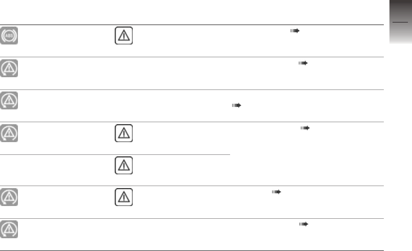
Multifunction switch,
left
1 High-beam headlight and
headlight flasher ( 71)
2 with cruise control
OE
Cruise-control system
( 89).
3 Hazard warning lights sys-
tem ( 75)
4 ABS ( 76)
ASC ( 78)
with riding modes Pro
OE
DTC ( 80)
5 with Dynamic ESA
OE
Dynamic ESA possible set-
tings ( 82)
6 with LED additional
headlight
OA
Auxiliary headlights
( 72).
7 Turn indicators ( 75)
8 Horn
9 MENU/ rocker switch
( 105)
2
23
z
General views


Instrument panel
1 Indicator and warning lights
( 28)
2 TFT display ( 29)
( 31)
3 Alarm system LED
with anti-theft alarm
(DWA)
OE
Alarm signal ( 95)
with Keyless Ride
OE
Indicator light for the radio-
operated key
Ignition with Keyless Ride
( 65).
4 Photosensor (for adapting
the brightness of the in-
strument lighting)
2
26
z
General views


Indicator and warning
lights
1 Turn indicators, left
Operating the turn indicat-
ors ( 75).
2 High-beam ( 71)
3 General warning light
( 32)
4 Turn indicators, right
5 - With export to EU mar-
kets
NV
Malfunction indicator lamp
6 ASC ( 55)
with riding modes Pro
OE
DTC ( 56)
7 ABS ( 76)
8 with daytime riding
light
OE
Manual daytime riding light
( 73).
9 with LED additional
headlight
OA
Auxiliary headlights
( 72).
3
28
z
Status indicators

TFT display in
Pure Ride view
1 Hill Start Control ( 58)
2 Changing the operating
focus ( 109)
3 Engine speed display
( 111)
4 Driver info. status line
( 110)
5 Speedometer
6 Coding plug ( 88)
7 Riding mode ( 85)
8 Recommendation to up-
shift ( 112)
9 Gear indicator; "N" indic-
ates neutral.
10 Speed Limit Info ( 111)
11 with cruise control
OE
Cruise-control system
( 89)
12 Clock ( 113)
13 Connection status
( 115)
14 Muting ( 113)
3
29
z
Status indicators


TFT display in view
menu
1 Hill Start Control ( 58)
2 Speedometer
3 with cruise control
OE
Cruise-control system
( 89).
4 Speed Limit Info ( 111)
5 Coding plug ( 88)
6 Riding mode ( 85)
7 Driver info. status line
( 110)
8 Recommendation to up-
shift ( 112)
9 Gear indicator; "N" indic-
ates neutral.
10 Clock
11 Connection status
12 Muting ( 113)
13 Operator help
14 Heating stages, handlebar
grips ( 98)
15 Automatic daytime riding
light ( 74)
3
31
z
Status indicators

16 Outside temperature warn-
ing ( 43)
17 Ambient temperature
18 Menu section
Warnings
Mode of presentation
Warnings are indicated by the
corresponding warning lights.
Warnings are shown by the gen-
eral warning light in connec-
tion with a dialogue in the TFT
display. The 'general' warning
light is yellow or red, depending
on the urgency of the warning.
The general warning light is
displayed according to the
most urgent warning .
The possible warnings are listed
on the next pages.
Check Control display
The messages shown in the
display vary. Different colours
and symbols are used depending
on priority:
Green CHECK OK 1: No mes-
sage, values optimum.
White circle with small "i" 2:
Information.
Yellow warning triangle 3:
Warning message, value not
optimum.
Red warning triangle 3: Warn-
ing message, value critical
3
32
z
Status indicators

Values display
The symbols 4 displayed vary.
Different colours are used de-
pending on assessment. In-
stead of numerical values 8 with
units 7, texts 6 are displayed:
Colour of the symbol
Green: (OK) current value is
optimum.
Blue: (Cold!) Current tempera-
ture is too low.
Yellow: (Low! / High!) Current
value is too low or too high.
Red: (Hot! / High!) Current
temperature or value is too
high.
White: (---) Valid value not
available. Instead of the value,
dashes 5 are displayed.
NOTICE
The assessment of some values
is only possible from a certain
journey duration or speed. If a
measured value is still not being
displayed because the conditions
for measurement have not been
met, dashes are displayed in-
stead as a placeholder. If there
are no valid measured values,
there will be no assessment in
the form of a coloured symbol.
Check Control dialogue
Messages are output as a Check
Control dialogue 1.
If several CC messages with
the same priority are present,
the messages alternate in the
order they occurred until these
are acknowledged.
If the symbol 2 is actively being
displayed, it can be acknow-
ledged by holding the Multi-
Controller to the left.
CC messages are dynamically
attached as additional tabs on
the pages in the menu vehicle
( 107). The message can be
3
33
z
Status indicators

called up again as long as the
faulty persists.
3
34
z
Status indicators

Warnings, overview
Indicator and warning
lights
Display text Meaning
Ice crystal symbol
is displayed.
Outside temperature warning ( 43)
General warning
light shows yellow.
Remote key not
in range.
Radio-operated key out of range ( 43)
General warning
light shows yellow.
Remote key bat-
tery at 50%.
Replacing battery of remote key ( 44)
Remote key bat-
tery weak.
General warning
light shows yellow.
is displayed in yel-
low.
Vehicle voltage too low ( 44)
Vehicle voltage
low.
General warning
light shows red.
is displayed in red. Vehicle voltage critical ( 44)
Vehicle voltage
critical!
3
35
z
Status indicators

Indicator and warning
lights
Display text Meaning
General warning
light shows yellow.
The faulty light
source is displayed.
Bulb faulty ( 45)
Alarm system
battery weak.
Anti-theft alarm battery weak ( 46)
General warning
light shows yellow.
Alarm system
battery empty.
Anti-theft alarm battery flat ( 46)
Oil level too
low! Check oil
level.
Engine-oil level too low ( 47)
General warning
light shows red.
Coolant temper-
ature too high!
Coolant temperature too high ( 47)
General warning
light shows yellow.
No communica-
tion with en-
gine control.
Engine control failed ( 48)
General warning
light shows yellow.
Fault in the en-
gine control.
Engine in emergency-operation mode
( 48)
General warning
light flashes yellow.
Serious fault
in the engine
control!
Severe fault in the engine control
( 49)
3
36
z
Status indicators

Indicator and warning
lights
Display text Meaning
General warning
light shows yellow.
is displayed in yel-
low.
Tyre pressure in limit range of the per-
mitted tolerance ( 50)
Tyre pressure
is not at set-
point.
General warning
light flashes red.
is displayed in red. Tyre pressure outside the permitted tol-
erance ( 51)
Tyre pressure
is not at set-
point.
Tyre press.
control. Loss
of pressure.
"---"
Transmission fault ( 52)
General warning
light shows yellow.
"---"
Sensor faulty or system fault ( 52)
General warning
light shows yellow.
RDC sensor bat-
tery weak..
Battery for tyre pressure sensor weak
( 53)
3
37
z
Status indicators

Indicator and warning
lights
Display text Meaning
Drop sensor
faulty.
Drop sensor defective ( 53)
Intell. emerg.
call failure.
Emergency call function restricted
( 53)
Side stand mon-
itoring faulty.
Side stand monitoring is faulty ( 53)
ABS telltale and
warning light
flashes.
ABS self-diagnosis not completed
( 54)
ABS telltale and
warning light
shows.
Off!
ABS deactivated ( 54)
ABS deactiv-
ated.
ABS telltale and
warning light
shows.
Limited ABS
availability!
ABS fault ( 54)
ABS telltale and
warning light
shows.
ABS failure!
ABS failed ( 54)
3
38
z
Status indicators
Indicator and warning
lights
Display text Meaning
ABS telltale and
warning light
shows.
ABS Pro fail-
ure!
ABS Pro failed ( 55)
ASC telltale and
warning light quick-
flashes.
ASC intervention ( 55)
ASC telltale and
warning light slow-
flashes.
ASC self-diagnosis not completed
( 55)
ASC telltale and
warning light
shows.
Off!
ASC switched off ( 56)
Traction con-
trol deactiv-
ated.
ASC telltale and
warning light
shows.
Traction con-
trol failure!
ASC fault ( 56)
DTC indicator
and warning light
flashes quickly.
DTC intervention ( 56)
3
39
z
Status indicators

Indicator and warning
lights
Display text Meaning
DTC indicator
and warning light
flashes slowly.
DTC self-diagnosis not completed
( 56)
DTC indicator
and warning light
comes on.
Off!
DTC switched off ( 57)
Traction con-
trol deactiv-
ated.
DTC indicator
and warning light
comes on.
Traction con-
trol failure!
DTC fault ( 57)
General warning
light shows yellow.
Spring strut
adjustment
faulty!
DESA fault ( 58)
Fuel reserve
reached. Go to a
filling station soon
Fuel down to reserve ( 58)
Green holding sym-
bol is displayed.
Hill Start Control active ( 58)
3
40
z
Status indicators

Indicator and warning
lights
Display text Meaning
General warning
light flashes yellow.
Yellow holding
symbol flashes.
Hill Start Control automatically deactiv-
ated ( 58)
Crossed-out hold-
ing symbol is dis-
played.
Hill Start Control cannot be activated
( 59)
The gear indicator
flashes.
Gear not trained ( 59)
Turn signal indic-
ator light flashes
green.
Hazard warning lights system is switched
on ( 59)
Turn signal indic-
ator light flashes
green.
is displayed in
white.
Service due ( 60)
Service due!
General warning
light shows yellow.
is displayed in yel-
low.
Service-due date has passed ( 60)
3
41
z
Status indicators


Ambient temperature
The ambient temperature is dis-
played status line of the TFT
display.
When the motorcycle is at a
standstill, the heat of the engine
can falsify the ambient-temper-
ature reading. If the heat of the
engine is affecting it too much,
dashes are temporarily shown in
place of the value.
If the ambient temperature
falls below the following
limit value, there is a risk of black
ice.
Limit value for the ambi-
ent temperature
approx. 3 °C
Once the temperature has fallen
below that value, the ambient
temperature display along with a
snowflake symbol flashes in the
status line on the TFT display.
Outside temperature
warning
Ice crystal symbol is dis-
played.
Possible cause:
The air temperature
measured at the vehicle
is lower than:
approx. 3 °C
WARNING
Risk of black ice also applic-
able at over 3 °C
Risk of accident
Always take extra care
when temperatures are
low; remember that there is
particular danger of black ice
forming on bridges and where
the road is in shade.
Ride carefully and think well
ahead.
Radio-operated key out of
range
with Keyless Ride
OE
General warning light shows
yellow.
Remote key not in
range. Do not stop
engine. Not possible to
restart the engine.
Possible cause:
Communication between R/C key
and engine electronics is disrup-
ted.
Check the battery in the radio-
operated key.
with Keyless Ride
OE
Replace the battery of the
radio-operated key ( 67).
Use the reserve key to con-
tinue your journey.
with Keyless Ride
OE
Battery of the radio-operated
key is flat or the key has been
lost ( 67).
3
43
z
Status indicators

If a check control dialogue box
appears during the journey,
remain calm. You can continue
your journey; the engine will
not switch off.
Have the defective radio-op-
erated key replaced by an au-
thorised BMW Motorrad dealer.
Replacing battery of
remote key
General warning light shows
yellow.
Remote key battery at
50%. No functional
impairment.
Remote key battery
weak. Limited central
locking function. Change
battery.
Possible cause:
The battery of the remote key
has lost a significant propor-
tion of its original capacity. The
function of the remote key is
only still ensured for a limited
time.
with Keyless Ride
OE
Replace the battery of the
radio-operated key ( 67).
Vehicle voltage too low
General warning light shows
yellow.
is displayed in yellow.
Vehicle voltage low.
Switch off unneces-
sary consumers.
WARNING
Failure of the vehicle sys-
tems
Risk of accident
Do not continue your journey.
The battery will not be charged.
By continuing to drive on, the
vehicle electronics discharge the
battery.
NOTICE
The fuse for the alternator reg-
ulator can blow if the 12 V bat-
tery is installed incorrectly or if
the terminals are swapped (e.g.
when using a starting aid).
Possible cause:
The alternator or alternator drive
is faulty, battery is faulty or the
fuse for the alternator regulator
has blown.
Have the fault rectified as
quickly as possible by a
specialist workshop, preferably
an authorised BMW Motorrad
dealer.
Vehicle voltage critical
General warning light shows
red.
is displayed in red.
3
44
z
Status indicators

Vehicle voltage crit-
ical! Consumers have
been switched off. Check
battery condition.
WARNING
Failure of the vehicle sys-
tems
Risk of accident
Do not continue your journey.
The battery will not be charged.
By continuing to drive on, the
vehicle electronics discharge the
battery.
NOTICE
The fuse for the alternator reg-
ulator can blow if the 12 V bat-
tery is installed incorrectly or if
the terminals are swapped (e.g.
when using a starting aid).
Possible cause:
The alternator or alternator drive
is faulty, battery is faulty or the
fuse for the alternator regulator
has blown.
Have the fault rectified as
quickly as possible by a
specialist workshop, preferably
an authorised BMW Motorrad
dealer.
Bulb faulty
General warning light shows
yellow.
The faulty light source is
displayed:
High beam faulty!
Front left turn in-
dicator faulty! or
Front right turn indicator
faulty!
Low-beam headlight
faulty!
Front side light
faulty!
with daytime riding light
OE
Daytime riding light
faulty!
with LED additional
headlight
OA
Left additional
headlight faulty!
or Right additional
headlight faulty!
Tail light faulty!
Brake light faulty!
Rear left turn in-
dicator faulty! or
Rear right turn indicator
faulty!
3
45
z
Status indicators

Number plate light
faulty!
Have it checked by a spe-
cialist workshop.
WARNING
Vehicle overlooked in traffic
due to failure of the lights on
the vehicle
Safety risk
Replace defective bulbs as
soon as possible; always carry
a complete set of spare bulbs if
possible.
Possible cause:
One or more light sources are
faulty.
Identify the faulty light source
through a visual inspection.
Having LED headlight replaced
( 194).
Replacing bulbs for front and
rear turn indicators ( 193).
Replace the LED rear light
( 194).
with LED flashing turn indic-
ator
OE
Replace LED flashing turn in-
dicators ( 194).
Anti-theft alarm battery
weak
with anti-theft alarm (DWA)
OE
Alarm system
battery weak. No
restrictions. Make
an appointment at a
specialist workshop.
NOTICE
This error message shows briefly
only after the Pre-Ride-Check
completes.
Possible cause:
The integral battery in the anti-
theft alarm has lost a significant
proportion of its original capacity.
There is no assurance of how
long the anti-theft alarm can re-
main operational if the vehicle's
battery is disconnected.
Seek the advice of a specialist
workshop, preferably an author-
ised BMW Motorrad dealer.
Anti-theft alarm battery
flat
with anti-theft alarm (DWA)
OE
General warning light shows
yellow.
Alarm system battery
empty. No independent
alarm. Make an appoint-
ment at a specialist work-
shop.
3
46
z
Status indicators

NOTICE
This error message shows briefly
only after the Pre-Ride-Check
completes.
Possible cause:
The integral battery in the anti-
theft alarm has lost its entire ori-
ginal capacity. There is no as-
surance that the anti-theft alarm
will be operational if the vehicle's
battery is disconnected.
Seek the advice of a specialist
workshop, preferably an author-
ised BMW Motorrad dealer.
Electronic oil-level check
The electronic oil-level
check assesses the oil level
in the engine with OK or Low!
The preconditions for the elec-
tronic oil-level check are as fol-
lows:
Engine at operating tempera-
ture.
Engine idling for at least ten
seconds.
Side stand folded in.
No brake applied.
Motorcycle standing upright on
a smooth, level surface.
If these conditions are not met, it
is not possible to measure the oil
level. Dashes will appear on the
display instead of a reading.
Engine-oil level too low
Oil level too low!
Check oil level.
Possible cause:
The electronic oil-level sensor
has registered an excessively low
oil level. The next time you stop
for fuel:
Checking engine oil level
( 176).
If the oil level is too low:
Topping up the engine oil
( 177).
If the oil level is correct:
Seek the advice of a specialist
workshop, preferably an author-
ised BMW Motorrad dealer.
Coolant temperature too
high
General warning light shows
red.
Coolant temperature
too high! Check
coolant level. Continue
under part. load to cool
down.
ATTENTION
Riding with overheated en-
gine
Engine damage
Compliance with the
information set out below is
essential.
3
47
z
Status indicators

Possible cause:
The coolant level is too low.
Check coolant level ( 182).
If the coolant level is too low:
Leave the engine to cool down.
Topping up coolant ( 183).
Have the cooling system
checked by a specialist
workshop, preferably by a
BMW Motorrad partner.
Possible cause:
The coolant temperature is too
high.
If possible, ride in the part-load
range to cool down the engine.
If the coolant temperature is fre-
quently too high:
Have the fault rectified as
quickly as possible by a
specialist workshop, preferably
an authorised BMW Motorrad
dealer.
Engine control failed
General warning light shows
yellow.
No communication with
engine control. Mul-
tiple sys. affected. Ride
carefully to the next spe-
cialist workshop.
Engine in emergency-
operation mode
General warning light shows
yellow.
Fault in the engine
control. Riding at
mod. speed pos. Ride care-
fully to next specialist
workshop.
WARNING
Unusual ride characterist-
ics when engine running in
emergency-operation mode
Risk of accident
Avoid accelerating sharply and
overtaking.
Possible cause:
The engine control unit has
diagnosed a fault which impairs
the engine performance or
throttle response. The engine is
in emergency-operation mode.
In exceptional cases, the engine
stops and refuses to start.
Have the fault rectified as
quickly as possible by a
specialist workshop, preferably
an authorised BMW Motorrad
dealer.
It is possible to continue riding,
however the engine perform-
ance and engine speed range
may be impaired and not func-
tion as normal.
3
48
z
Status indicators

Severe fault in the engine
control
General warning light
flashes yellow.
Serious fault in
the engine control!
Riding at mod. speed pos.
Engine damage possible.
Have checked by workshop.
WARNING
Engine damage when run-
ning in emergency-operation
mode
Risk of accident
Ride slowly, avoid accelerating
sharply and overtaking.
If possible, have the vehicle
picked up and have the fault
rectified by a specialist work-
shop, preferably an authorised
BMW Motorrad Retailer.
Possible cause:
The engine control unit has dia-
gnosed a fault which may cause
severe secondary faults. The en-
gine is in emergency-operation
mode.
It is possible to continue to ride
but not recommended.
Avoid high load and rpm
ranges if possible.
Have the fault rectified as
quickly as possible by a
specialist workshop, preferably
an authorised BMW Motorrad
dealer.
Tyre pressure
with tyre pressure control
(RDC)
OE
In addition to the menu screen
MY VEHICLE and the Check
Control messages, there is also
the screen TYRE PRESSURE for
the display of the tyre pressures:
The left values refer to the front
wheel, the right values to the rear
wheel.
The pressure difference is dis-
played via the actual and target
tyre pressure.
Only dashes are displayed im-
mediately after the ignition is
switched on. The transmission
of the tyre pressure values be-
gins only after the first time the
following minimum speed has
been exceeded:
3
49
z
Status indicators

RDC sensor is not active
min 30 km/h (The RDC sensor
does not transmit its signal
to the vehicle until a certain
minimum speed has been
reached.)
The tyre pressures
are shown in the TFT
display as temperature
compensated and always
refer to the following tyre air
temperature:
20 °C
If the tyre symbol is ad-
ditionally displayed in yel-
low or red, this is a warning. The
pressure difference is highlighted
with an exclamation point in the
same colour.
If the value in question is
close to the limit of the
permissible tolerance range, the
'General' warning light also lights
up in yellow.
If the tyre pressure re-
gistered by the sensor is
outside the permissible tolerance
range , the 'General' warning light
flashes red.
For further information about
the BMW Motorrad RDC, see
chapter "Engineering details"
from page ( 168).
Tyre pressure in limit
range of the permitted
tolerance
with tyre pressure control
(RDC)
OE
General warning light shows
yellow.
is displayed in yellow.
Tyre pressure is not
at setpoint. Check
tyre pressure.
Possible cause:
Measured tyre pressure is close
to the limit of permitted toler-
ance.
Correct tyre pressure.
Before adjusting the tyre pres-
sure, observe the information
on temperature compensation
and pressure adaptation in the
section entitled "Engineering
details":
Temperature compensation
( 168)
Pressure adaptation ( 169)
Find the correct tyre pressures
in the following places:
On the back cover of the
rider's manual
Instrument cluster in the TYRE
PRESSURE view
3
50
z
Status indicators

Sign under the seat
Tyre pressure outside the
permitted tolerance
with tyre pressure control
(RDC)
OE
General warning light
flashes red.
is displayed in red.
Tyre pressure is not
at setpoint. Stop
immediately! Check tyre
pressure.
Tyre press. control.
Loss of pressure.
Stop immediately! Check
tyre pressure.
WARNING
Tyre pressure outside the
permitted tolerance.
Risk of accident, degradation of
the vehicle's driving characterist-
ics.
Adapt your style of riding
accordingly.
Possible cause:
Measured tyre pressure is out-
side permitted tolerance.
Check the tyre for damage
and to ascertain whether the
vehicle can be ridden with the
tyre in its present condition.
If the vehicle can be ridden with
the tyre in its present condition:
Correct the tyre pressure at the
earliest possible opportunity.
Before adjusting the tyre pres-
sure, observe the information
on temperature compensation
and pressure adaptation in the
section entitled "Engineering
details":
Temperature compensation
( 168)
Pressure adaptation ( 169)
Find the correct tyre pressures
in the following places:
On the back cover of the
rider's manual
Instrument cluster in the TYRE
PRESSURE view
Sign under the seat
Have the tyre checked for
damage by a specialist
workshop, preferably an
authorised BMW Motorrad
Retailer.
NOTICE
You can deactivate RDC warn-
ings for riding in off-road mode.
If you are unsure whether the
vehicle can be ridden with the
tyre in its present condition:
Do not continue your journey.
Notify the breakdown service.
3
51
z
Status indicators

Transmission fault
with tyre pressure control
(RDC)
OE
"---"
Possible cause:
The vehicle has not reached the
minimum speed ( 168).
RDC sensor is not active
min 30 km/h (The RDC sensor
does not transmit its signal
to the vehicle until a certain
minimum speed has been
reached.)
Observe the RDC display at
higher speeds.
A permanent fault is
present only when the
general warning light also lights
up.
Under these circumstances:
Have the fault rectified by a
specialist workshop, preferably
an authorised BMW Motorrad
dealer.
Possible cause:
The radio link to the RDC
sensors is faulty. Radio systems
are located in the surrounding
area which are interfering with
the transmission between
the RDC control unit and the
sensors.
Observe the RDC displays in
other surrounding areas.
A permanent fault is
present only when the
general warning light also lights
up.
Under these circumstances:
Have the fault rectified by a
specialist workshop, preferably
an authorised BMW Motorrad
dealer.
Sensor faulty or system
fault
with tyre pressure control
(RDC)
OE
General warning light shows
yellow.
"---"
Possible cause:
Vehicle is fitted with wheels not
equipped with RDC sensors.
Fit wheels and tyres equipped
with RDC sensors.
Possible cause:
1 or 2 RDC sensors have failed
or a system error has occurred.
Have the fault rectified by a
specialist workshop, preferably
an authorised BMW Motorrad
dealer.
3
52
z
Status indicators

Battery for tyre pressure
sensor weak
with tyre pressure control
(RDC)
OE
General warning light shows
yellow.
RDC sensor battery
weak. Function lim-
ited. Have it checked by a
specialist workshop.
NOTICE
This error message shows briefly
only after the Pre-Ride-Check
completes.
Possible cause:
The integral battery in the tyre-
pressure sensor has lost a sig-
nificant proportion of its original
capacity. There is no assurance
of how long the tyre pressure
control system can remain opera-
tional.
Seek the advice of a specialist
workshop, preferably an author-
ised BMW Motorrad dealer.
Drop sensor defective
Drop sensor faulty.
Have it checked by a
specialist workshop.
Possible cause:
The drop sensor is not available.
Seek the advice of a specialist
workshop, preferably an author-
ised BMW Motorrad dealer.
Emergency call function
restricted
with intelligent emergency
call
OE
Intell. emerg. call
failure. Make an ap-
pointment at a specialist
workshop.
Possible cause:
The emergency call cannot be
cannot be made automatically or
via BMW.
Observe information on oper-
ating the intelligent emergency
call from page ( 69).
Seek the advice of a specialist
workshop, preferably an author-
ised BMW Motorrad dealer.
Side stand monitoring is
faulty
Side stand monitoring
faulty. To avoid
breakdown do not stop
engine. Have checked by
spec. workshp.
Possible cause:
The side-stand switch or its wir-
ing are damaged.
Seek the advice of a specialist
workshop, preferably an author-
ised BMW Motorrad dealer.
3
53
z
Status indicators

ABS self-diagnosis not
completed
ABS telltale and warning
light flashes.
Possible cause:
ABS self-diagnosis not
completed
The ABS function is not avail-
able, because self-diagnosis
did not complete. (The motor-
cycle has to reach a defined
minimum speed for the wheel
speed sensors to be checked:
5 km/h)
Pull away slowly. Bear in mind
that the ABS function is not
available until self-diagnosis has
completed.
ABS deactivated
ABS telltale and warning
light shows.
Off!
ABS deactivated.
Possible cause:
The rider has switched off the
ABS system.
Activating the ABS function
( 77).
ABS fault
ABS telltale and warning
light shows.
Limited ABS availab-
ility! Riding at mod.
speed pos. Ride carefully
to next specialist work-
shop.
Possible cause:
The ABS control unit has
detected a fault. The partially
integral function and the
Dynamic Brake Control function
have failed. The ABS function
has limited availability.
You can continue to ride. Pay
attention to the more detailed
information on certain situ-
ations that can lead to an ABS
fault message ( 159).
Have the fault rectified as
quickly as possible by a
specialist workshop, preferably
an authorised BMW Motorrad
Retailer.
ABS failed
ABS telltale and warning
light shows.
ABS failure! Riding
at mod. speed pos.
Ride carefully to next
specialist workshop.
Possible cause:
The ABS control unit has detec-
ted a fault. The ABS function is
not available.
3
54
z
Status indicators

You can continue to ride. Bear
in mind the more detailed in-
formation on situations that can
lead to an ABS fault message
( 159).
Have the fault rectified as
quickly as possible by a
specialist workshop, preferably
an authorised BMW Motorrad
dealer.
ABS Pro failed
with riding modes Pro
OE
ABS telltale and warning
light shows.
ABS Pro failure!
Riding at mod. speed
pos. Ride carefully to
next specialist workshop.
Possible cause:
The ABS Pro control unit has
detected a fault. The ABS Pro
function is not available. The
ABS function is still available.
ABS provides support only for
braking in straight-ahead driving.
You can continue to ride. Pay
attention to the further inform-
ation about certain situations
that can lead to an ABS Pro
fault message ( 159).
Have the fault rectified as
quickly as possible by a
specialist workshop, preferably
an authorised BMW Motorrad
dealer.
ASC intervention
without riding modes Pro
OE
ASC telltale and warning
light quick-flashes.
The ASC has detected a degree
of instability at the rear wheel
and has intervened to reduce
torque. The indicator and warn-
ing light flashes longer than the
ASC intervention lasts. This af-
fords the rider visual feedback on
control intervention even after the
critical situation has been dealt
with.
ASC self-diagnosis not
completed
without riding modes Pro
OE
ASC telltale and warning
light slow-flashes.
Possible cause:
ASC self-diagnosis not
completed
The ASC function is not avail-
able, because self-diagnosis
did not complete. (The motor-
cycle has to reach a defined
minimum speed for the wheel
sensors to be checked: min
5 km/h)
Pull away slowly. The ASC in-
dicator and warning light goes
out after a few minutes.
The ASC indicator and warning
light continues to flash:
3
55
z
Status indicators

Seek the advice of a specialist
workshop, preferably an author-
ised BMW Motorrad dealer.
ASC switched off
without riding modes Pro
OE
ASC telltale and warning
light shows.
Off!
Traction control de-
activated.
Possible cause:
The rider has switched off the
ASC system.
without riding modes Pro
OE
Activating the ASC function
( 79).
ASC fault
without riding modes Pro
OE
ASC telltale and warning
light shows.
Traction control
failure! Riding
at mod. speed pos.
Ride carefully to next
specialist workshop.
Possible cause:
The DSC control unit has detec-
ted a fault. The ASC function is
no longer available.
You can continue to ride. Bear
in mind that the ASC function
is not available. Bear in mind
the more detailed information
on situations can lead to an
ASC fault ( 162).
Have the fault rectified as
quickly as possible by a
specialist workshop, preferably
an authorised BMW Motorrad
dealer.
DTC intervention
with riding modes Pro
OE
DTC indicator and warning
light flashes quickly.
The DTC has detected a degree
of instability at the rear wheel
and has intervened to reduce
torque. The indicator and warn-
ing light flashes longer than the
DTC intervention lasts. This af-
fords the rider visual feedback on
control intervention even after the
critical situation has been dealt
with.
DTC self-diagnosis not
completed
with riding modes Pro
OE
DTC indicator and warning
light flashes slowly.
3
56
z
Status indicators

Possible cause:
DTC self-diagnosis not
completed
The DTC function is not avail-
able, because self-diagnosis
did not complete. (The motor-
cycle has to reach a defined
minimum speed with the en-
gine running for the wheel-
speed sensors to be checked:
min 5 km/h)
Pull away slowly. Bear in mind
that the DTC function is not
available until self-diagnosis has
completed.
DTC switched off
with riding modes Pro
OE
DTC indicator and warning
light comes on.
Off!
Traction control de-
activated.
Possible cause:
The rider has switched off the
DTC system.
DTC Switching on ( 81).
DTC fault
with riding modes Pro
OE
DTC indicator and warning
light comes on.
Traction control
failure! Riding
at mod. speed pos.
Ride carefully to next
specialist workshop.
Possible cause:
The DTC control unit has detec-
ted a fault.
ATTENTION
Damaged components
Damage to sensors, for example,
which causes malfunctions
Do not transport any objects
underneath the driver or pas-
senger seat.
Secure the toolkit.
Do not damage the angular
rate sensor.
Bear in mind that the DTC
function is not available or the
functionality is subject to cer-
tain restrictions.
You can continue to ride. Bear
in mind the more detailed in-
formation on situations that can
lead to a DTC fault ( 162).
Have the fault rectified as
quickly as possible by a
specialist workshop, preferably
an authorised BMW Motorrad
dealer.
3
57
z
Status indicators

DESA fault
General warning light shows
yellow.
Spring strut adjust-
ment faulty! Riding
at mod. speed pos. Ride
carefully to next special-
ist workshop.
Possible cause:
The DESA control unit has de-
tected a fault. The damping and/
or spring adjuster may be the
cause. In Auto the cause may
also be a fault in the riding posi-
tion equaliser. In this condition,
the motorcycle may have too
much damping and is uncom-
fortable to drive, especially on
roads in poor condition. Alternat-
ively, the spring preload may be
incorrectly adjusted.
Have the fault rectified as
quickly as possible by a
specialist workshop, preferably
an authorised BMW Motorrad
dealer.
Fuel down to reserve
Fuel reserve reached. Go
to a filling station soon.
WARNING
Irregular engine operation or
engine shutdown due to lack
of fuel
Risk of accident, damage to cata-
lytic converter
Do not run the fuel tank dry.
Possible cause:
The fuel tank contains no more
than the reserve quantity of fuel.
Reserve fuel
approx. 4 l
Refuelling ( 151).
Hill Start Control active
Green holding symbol is
displayed.
Possible cause:
The driver has activated Hill Start
Control ( 171).
Switch off Hill Start Control.
Operate Hill Start Control
( 92).
Hill Start Control
automatically deactivated
General warning light
flashes yellow.
Yellow holding symbol
flashes.
Possible cause:
Hill Start Control has been auto-
matically deactivated.
Side stand has been folded
out.
3
58
z
Status indicators

Hill Start Control is deactivated
when the side stand is folded
out.
Engine has been switched off.
Hill Start Control is deactivated
when the engine is switched
off.
Operate Hill Start Control
( 92).
Hill Start Control cannot
be activated
Crossed-out holding sym-
bol is displayed.
Possible cause:
Hill Start Control cannot be activ-
ated.
Retract the side stand.
Hill Start Control functions only
when the side stands are fol-
ded in.
Start the engine.
Hill Start Control functions only
when the engine is running.
Gear not trained
with shift assistant Pro
OE
The gear indicator flashes.
The Pro shift assistant is
not available.
Possible cause:
with shift assistant Pro
OE
The gearbox sensor is not fully
trained.
Engage neutral gear N and,
with the vehicle at a standstill,
let the engine run for at least
10 seconds to train the idle
gear.
Engage all gears with clutch
actuation and ride at least 10
seconds with the engaged
gear.
The gear indicator starts to
flash when the gearbox sensor
has been trained successfully.
When the gearbox sensor is
fully trained, the Pro shift as-
sistant functions as described
( 169).
If the training process was
not successful, have the fault
rectified by a specialist work-
shop, preferably an authorised
BMW Motorrad dealer.
Hazard warning lights
system is switched on
Turn signal indicator light
flashes green.
Turn signal indicator light
flashes green.
Possible cause:
The driver has switched on the
hazard warning lights system.
Operating hazard warning flash-
ers ( 75).
Service-due indicator
If service is overdue, the
due date or the odometer
reading at which service was due
is accompanied by the 'General'
warning light showing yellow.
3
59
z
Status indicators

If the service is overdue, a yel-
low CC message is displayed.
Exclamation marks also draw at-
tention to the displays for service,
service appointment and remain-
ing distance in the MY VEHICLE
and SERVICE REQUIREMENTS
menu screens.
NOTICE
If the service-due indicator ap-
pears more than a month before
the service date, the current date
has to be corrected. This situ-
ation can occur if the battery was
disconnected.
Service due
is displayed in white.
Service due! Have service
carried out by authorised
BMW Motorrad Retailer.
Possible cause:
Service is due because of the
driving performance or the date.
Have your motorcycle serviced
regularly by a specialist work-
shop, preferably by an author-
ised BMW Motorrad retailer.
The operational and road
safety of the motorcycle remain
intact.
The motorcycle's value is
maintained as best as possible.
Service-due date has
passed
General warning light shows
yellow.
is displayed in yellow.
Service overdue! Have
service carried out by
authorised BMW Motorrad
Retailer.
Possible cause:
Service is overdue because of
the driving performance or the
date.
Have your motorcycle serviced
regularly by a specialist work-
shop, preferably by an author-
ised BMW Motorrad retailer.
The operational and road
safety of the motorcycle remain
intact.
The motorcycle's value is
maintained as best as possible.
3
60
z
Status indicators

Operation
Ignition switch/steering lock . . . . . . . . . 62
Ignition with Keyless Ride . . . . . . . . . . . 64
Emergency off switch (kill
switch) . . . . . . . . . . . . . . . . . . . . . . . . . . . . . . 68
Intelligent emergency call . . . . . . . . . . . 69
Lights . . . . . . . . . . . . . . . . . . . . . . . . . . . . . . . 71
Day run lights . . . . . . . . . . . . . . . . . . . . . . . 73
Hazard warning lights system . . . . . . . 75
Turn indicators . . . . . . . . . . . . . . . . . . . . . . 75
Antilock Brake System (ABS) . . . . . . . 76
Automatic Stability Control
(ASC) . . . . . . . . . . . . . . . . . . . . . . . . . . . . . . . 78
Dynamic Traction Control (DTC) . . . . 80
Electronic Suspension Adjustment
(DESA) . . . . . . . . . . . . . . . . . . . . . . . . . . . . . 81
Riding mode . . . . . . . . . . . . . . . . . . . . . . . . 85
PRO riding mode . . . . . . . . . . . . . . . . . . . 87
Cruise-control system . . . . . . . . . . . . . . 89
Hill Start Control . . . . . . . . . . . . . . . . . . . . 92
Anti-theft alarm (DWA) . . . . . . . . . . . . . . 94
Tyre pressure monitoring (RDC) . . . . 97
Heated handlebar grips . . . . . . . . . . . . . 97
On-board computer. . . . . . . . . . . . . . . . . 98
Front and rear seats . . . . . . . . . . . . . . . . 99
4
61
z
Operation

Ignition switch/steering
lock
Keys
You receive 2 ignition keys.
Please consult the information on
the electronic immobiliser (EWS)
if a key is lost or mislaid ( 63).
Ignition switch/steering lock, fuel
filler cap lock and seat lock are all
operated with the same key.
If you wish you can arrange to
have the cases and the top-
case fitted with locks that can be
opened with the ignition key as
well. Consult a specialist work-
shop, preferably an authorised
BMW Motorrad dealer.
Lock the handlebars
Turn the handlebars all the way
to left.
Turn the key to position 1,
while moving the handlebars
slightly.
Ignition, lights and all function
circuits switched off.
Handlebars are locked.
Key can be removed.
Switching on ignition
Insert the key in the ignition
switch and turn to position 1.
Side lights and all function cir-
cuits are switched on.
Pre-Ride-Check is performed.
( 142)
ABS self-diagnosis is in pro-
gress. ( 142)
without riding modes Pro
OE
ASC self-diagnosis is per-
formed. ( 143)
with riding modes Pro
OE
DTC self-diagnosis is in pro-
gress. ( 144)
4
62
z
Operation

Welcome lights
Switch on the ignition.
The side lights briefly light up.
with daytime riding light
OE
The daytime riding lights briefly
light up.
with LED additional
headlight
OA
The LED auxiliary headlights
briefly light up.
Switching off ignition
Turn the ignition key to posi-
tion 1.
When the ignition is switched
off, the instrument cluster re-
mains switched on for a short
time and displays any existing
fault messages.
Handlebars not locked.
Electrically powered accessor-
ies remain operational for a lim-
ited period of time.
The battery can be recharged
via the socket.
Key can be removed.
with daytime riding light
OE
The daytime riding light goes
out soon after the ignition is
switched off.
with LED additional
headlight
OA
The LED auxiliary headlights
go out soon after the ignition is
switched off.
Electronic immobiliser
EWS
The electronic design of the
motorcycle allows it to access
data stored in the ignition key
by means of a ring antenna loc-
ated in the ignition switch/steer-
ing lock. The engine control unit
will not permit the engine to be
started unless the key is identi-
fied as “authorised”.
NOTICE
A spare key attached to the
same ring as the ignition key
used to start the engine could
"irritate" the electronics, in which
case the enabling signal for
starting is not issued.
Always keep the spare key sep-
arately from the ignition key.
4
63
z
Operation

If you lose your key, you can
have it barred by your author-
ised BMW Motorrad dealer.
If you wish to do this, you will
need to bring all other keys for
the motorcycle with you. The
engine cannot be started by a
barred key, but a key that has
been barred can subsequently be
reactivated.
You can obtain emergency/extra
keys only through an authorised
BMW Motorrad dealer. The keys
are part of an integrated security
system, so the dealer is under an
obligation to check the legitimacy
of all applications for replace-
ment/extra keys.
Ignition with
Keyless Ride
with Keyless Ride
OE
Keys
NOTICE
The telltale light for the radio-
operated key flashes while the
search for the radio-operated key
is in progress.
The telltale light goes out as
soon as the radio-operated key
or the emergency key is found.
The telltale light goes out briefly
if the search times out without
the radio-operated key or the
emergency key being found.
You receive one radio-operated
key and one emergency key.
Please consult the information on
the electronic immobiliser (EWS)
if a key is lost or mislaid ( 63).
Ignition, fuel filler cap and anti-
theft alarm system all work with
the radio-operated key. Seat
lock, topcase and cases can be
locked and unlocked manually.
NOTICE
The vehicle cannot be started if
the radio control key is not within
range (e.g. key inside one of the
cases or the topcase).
If the radio-operated key re-
mains out of range the ignition
is switched off after about 1.5
minutes to protect the battery.
It is advisable to keep the radio-
operated key on your person
(e.g. in a jacket pocket) and to
have the emergency key with
you as an alternative.
Range of the Keyless
Ride radio-operated key
with Keyless Ride
OE
approx. 1 m
4
64
z
Operation

Lock the handlebars
Requirement
The handlebars are turned to-
wards the left. Radio-operated
key is within range.
Press and hold down button 1.
The steering lock engages with
an audible click.
Ignition, lights and all function
circuits switched off.
Short-press button 1 to disen-
gage the steering lock.
Switching on ignition
Requirement
Radio-operated key is within
range.
There are two ways of activat-
ing the ignition.
Version 1:
Briefly press button 1.
Side lights and all function cir-
cuits are switched on.
with daytime riding light
OE
Daytime riding light is switched
on.
with LED additional
headlight
OA
LED auxiliary headlights are
switched on.
Pre-Ride-Check is performed.
( 142)
ABS self-diagnosis is in pro-
gress. ( 142)
without riding modes Pro
OE
ASC self-diagnosis is per-
formed. ( 143)
Version 2:
Steering lock is engaged; press
and hold down button 1.
The steering lock disengages.
Parking lights and all function
circuits switched on.
Pre-Ride-Check is performed.
( 142)
ABS self-diagnosis is in pro-
gress. ( 142)
without riding modes Pro
OE
ASC self-diagnosis is per-
formed. ( 143)
4
65
z
Operation

Switching off ignition
Requirement
Radio-operated key is within
range.
There are two ways of deactiv-
ating the ignition.
Version 1:
Short-press button 1.
Light is switched off.
Handlebars (steering lock) are
not locked.
Version 2:
Turn the handlebars all the way
to left.
Press and hold down button 1.
Light is switched off.
The steering lock engages.
Electronic immobiliser
EWS
The on-board electronics access
the data saved in the radio-op-
erated key via a ring aerial in the
wireless lock. The ignition is not
enabled for starting until the en-
gine control unit has recognised
the radio-operated key as "au-
thorised" for your motorcycle.
NOTICE
A spare key attached to the
same ring as the radio-operated
key used to start the engine
could 'irritate' the electronics, in
which case the enabling signal
for starting is not issued.
Always keep the spare key sep-
arate from the radio-operated
key.
If you mislay a radio-operated key
you can have the key in ques-
tion barred by your authorised
BMW Motorrad dealer. In order
to have a key barred you must
bring along all the other keys be-
longing to the motorcycle.
The engine cannot be started
by a barred radio-operated key,
but a radio-operated key that has
been barred can subsequently be
reactivated.
You can obtain emergency/ex-
tra keys only through an author-
ised BMW Motorrad dealer. The
radio-operated keys are part of
an integrated security system, so
the dealer is under an obligation
to check the legitimacy of all ap-
plications for replacement/extra
keys.
4
66
z
Operation

Battery of the radio-
operated key is flat or the
key has been lost
Please consult the information
on the electronic immobiliser
(EWS) if a key is lost or mis-
laid.
If you happen to lose or mislay
the radio-operated key while
on a journey, you can start the
vehicle with the emergency
key.
If the battery of the radio-op-
erated key is flat, the motor-
cycle can be started by touch-
ing the rear-wheel cover with
the radio-operated key.
Hold the emergency key 1 or
the flat radio-operated key 2
against the rear-wheel cover
at the same height as the an-
tenna 3.
NOTICE
The emergency key or the radio-
operated key with the empty bat-
tery must be in contact with
the rear-wheel cover.
Time during which the
engine has to be started.
The unlocking procedure has
to be repeated if this time is
allowed to expire.
30 s
Pre-Ride-Check is performed.
Key has been recognised.
Engine can be started.
Starting the engine ( 141).
Replace the battery of the
radio-operated key
If the radio-operated key does
not react when you short-press
or long-press a button:
The battery in the radio-oper-
ated key is not at full capacity.
Remote key battery
weak. Limited central
locking function. Change
battery.
Press button 1.
Key bit flips out.
Push up battery cover 2.
Remove the battery 3.
4
67
z
Operation

Dispose of the old battery in
accordance with all applicable
laws and regulations; do not
attempt to dispose of batteries
as domestic waste.
ATTENTION
Unsuitable or incorrectly in-
serted batteries
Component damage
Use a battery compliant with
the manufacturer's specifica-
tions.
When inserting the battery,
always make sure polarity is
correct.
Insert the new battery with the
positive terminal up.
Battery type
for Keyless Ride-radio-oper-
ated key
CR 2032
Remove the battery 2.
Red LED on the instrument
panel flashes.
The radio-operated key is
ready for use again.
Emergency off switch
(kill switch)
1 Emergency off switch (kill
switch)
WARNING
Operation of the kill switch
while riding
Risk of fall due to rear wheel
locking
Do not operate the kill switch
when riding.
The emergency off switch is a
kill switch for switching off the
engine quickly and easily.
A Engine switched off
B Normal operating position
(run)
4
68
z
Operation

Intelligent emergency
call
with intelligent emergency
call
OE
Emergency call via BMW
Press the SOS button in an
emergency only.
Even if an emergency call using
BMW is not possible, the system
may make an emergency call to
a public emergency call number.
This depends on the respective
mobile phone network and the
national regulations.
The emergency call is not able to
be ensured because of technical
reasons due to unfavourable con-
ditions, e.g. in areas where there
is no mobile phone reception.
Language for emergency
call
Each vehicle has a language as-
signed to it depending on the
market for which it is intended.
The BMW Call Center answers in
this language.
NOTICE
The language for the emergency
call can only be changed by the
BMW Motorrad partner. The lan-
guage assigned to the vehicle
differs from the display languages
that can be selected by the rider
in the TFT display.
Manual emergency call
Requirement
An emergency call has occurred.
The vehicle is at a standstill. The
ignition is switched on.
Open cover 1.
Briefly press SOS button 2.
The time until transmission of
an emergency call is displayed.
During that time, it is possible to
cancel the emergency call.
4
69
z
Operation

Operate the emergency-off
switch to stop the engine.
Remove helmet.
After expiry of the timer, a
voice contact to the BMW Call
Center is established.
The connection was established.
Provide information to the
emergency services using the
microphone 3 and speaker 4.
Automatic emergency call
The intelligent emergency call
is active after the ignition is
switched on and reacts if a fall or
crash occurs.
Emergency call in the
event of a light fall
A minor fall or a crash is detec-
ted.
An acoustic signal is sounded.
The time until transmission of
an emergency call is displayed.
During that time, it is possible to
cancel the emergency call.
If possible, remove helmet and
stop engine.
A voice contact connection to
the BMW Call Center is estab-
lished.
4
70
z
Operation

The connection was established.
Open cover 1.
Provide information to the
emergency services using the
microphone 3 and speaker 4.
Emergency call in the
event of a severe fall
A severe fall or a crash is de-
tected.
The emergency call is placed
automatically without delay.
Lights
Low-beam headlight and
sidelights
The side lights switch on auto-
matically when the ignition is
switched on.
NOTICE
The side lights place a strain on
the battery. Do not switch the
ignition on for longer than abso-
lutely necessary.
The low-beam headlight switches
on automatically when the engine
is started.
with daytime riding light
OE
In daytime the daytime riding
light can be switched on as an
alternative to the low-beam head-
light.
High-beam headlight and
headlight flasher
Switching on ignition ( 62).
Push switch 1 forward to
switch on the high-beam
headlight.
Pull switch 1 back to operate
the headlight flasher.
4
71
z
Operation

Headlight courtesy delay
feature
Switch off the ignition.
Immediately after switching off
the ignition, pull switch 1 back
and hold it in that position until
the headlight courtesy delay
feature comes on.
The vehicle lighting lights for
one minute and is automatically
switched back off.
This can be used after parking
the vehicle, for example, to light
the way to the house door.
Parking lights
Switching off ignition ( 63).
Immediately after switching off
the ignition, push button 1 to
the left and hold it in that po-
sition until the parking lights
come on.
Switch the ignition on and off
again to switch off the parking
lights.
Auxiliary headlights
with LED additional
headlight
OA
Requirement
The additional headlights are
active only when the low-beam
headlight is active.
NOTICE
The auxiliary headlights have ap-
proval as fog lights and their use
is permissible in bad weather
conditions only. Always comply
with the road traffic regulations in
force in the country in which the
vehicle is used.
Starting the engine ( 141).
4
72
z
Operation

Press button 1 to switch on
the additional headlights.
The indicator light for the
auxiliary headlight illumin-
ates.
Press button 1 again to switch
off the additional headlights.
Day run lights
with daytime riding light
OE
Manual daytime riding
light
Requirement
Automatic daytime riding light is
switched off.
WARNING
Switching on the daytime
riding light in the dark.
Risk of accident
Do not use the daytime riding
light in the dark.
NOTICE
By comparison with the low-
beam headlight, the daytime
running light makes the vehicle
more visible to oncoming traffic.
This improves daytime visibility.
Starting the engine ( 141).
In the Settings, Vehicle
settings, Lights menu,
switch off the Auto. dayt.
rid. light function.
Press button 1 to switch on
the daytime riding light.
The indicator light for the
daytime riding light lights
up.
The low-beam headlight
and the front side lights are
switched off.
In the dark or in tunnels: Press
button 1 again to switch off the
daytime riding light and switch
on the low-beam headlight and
front side light.
4
73
z
Operation

NOTICE
If the high-beam headlight is
switched on while the daytime
riding light is on, the daytime
riding light is switched off after
approx. 2 seconds and the
high-beam headlight, low-beam
headlight and front side light are
switched on.
If the high beam headlight is
switched off again, the daytime
running light is not automat-
ically reactivated, but must be
switched on again if required.
Automatic daytime riding
light
NOTICE
The changeover between
daytime riding light and low-
beam headlight including front
side lights can be effected
automatically.
WARNING
The automatic daytime rid-
ing light does not replace the
personal assessment of the
light conditions
Risk of accident
Switch off the automatic day-
time riding light in poor light
conditions.
In the Settings, Vehicle
settings, Lights menu,
switch on the Auto. dayt.
rid. light function.
The indicator light for the
automatic daytime riding
light lights up.
If the ambient brightness de-
creases below a certain value,
the low beam headlight is auto-
matically switched on (e. B. in a
tunnel). When sufficient ambi-
ent brightness is detected, the
daytime riding light is switched
back on.
The indicator light for the
daytime riding light shows if
the daytime riding light is active.
Manual operation of the
light when the automatic
system is switched on
If you press the button for the
daytime riding light the daytime
riding light is switched off and
the low-beam headlight and
front side lights are switched
on (e. g. when you ride into
a tunnel, and the response of
the automatic daytime riding
light to the change in ambient
brightness is delayed).
If you press the button again
the daytime riding light is re-
activated, in other words the
daytime riding light is switched
on again when ambient light is
bright enough.
4
74
z
Operation

Hazard warning lights
system
Operating hazard warning
flashers
Switching on ignition ( 62).
NOTICE
The hazard warning flashers
place a strain on the battery.
Do not use the hazard warning
flashers for longer than absolutely
necessary.
Press button 1 to switch on
the hazard warning lights sys-
tem.
Ignition can be switched off.
To switch off the hazard warn-
ing lights system, switch on the
ignition if necessary and press
button 1 again.
Turn indicators
Operating the turn
indicators
Switching on ignition ( 62).
Press button 1 to the left to
switch on the left turn indicator.
Press button 1 to the right to
switch on the right turn indic-
ator.
Operate button 1 in the centre
position to switch off the turn
indicator.
4
75
z
Operation
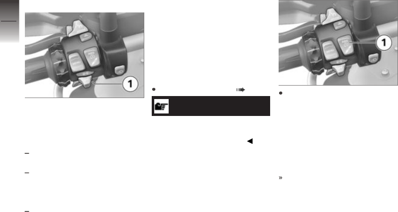
Comfort turn indicator
If button 1 has been pressed to
the right or left, the turn indic-
ators are automatically switched
off under the following circum-
stances:
Speed below 30 km/h: after 50
m distance covered.
Speed between 30 km/h and
100 km/h: after a speed-de-
pendent distance covered or in
case of acceleration.
Speed over 100 km/h: after
flashing five times.
If button 1 is pressed to the right
or left slightly longer, the turn in-
dicators only switch off automat-
ically once the speed-dependent
distance covered is reached.
Antilock Brake System
(ABS)
Deactivating the ABS
function
Switching on ignition ( 62).
NOTICE
You have the option of deactiv-
ating the ABS function while the
motorcycle is on the move.
Press and hold button 1 until
the ABS indicator and warning
light changes its display beha-
viour.
Immediately after the button 1 is
pressed, the system statuses for
ASC⁄DTC and ABS are displayed
as ON.
First the ASC indicator and
warning light changes its
display behaviour. Press and
hold down button 1 until the
ABS indicator and warning
light responds. Under these
circumstances, there is no
4
76
z
Operation

change in the ASC⁄DTC
setting.
ABS telltale and warning
light shows.
Possible ABS system status
OFF! is displayed.
Release button 1 after the ABS
system status changes over.
The ASC⁄DTC system status
remains unchanged and a new
ABS system status OFF! is
briefly displayed.
ABS telltale and warning
light remains on.
The ABS function is switched
off.
The integral function remains
active.
without riding modes Pro
OE
Hill Start Control is still
activated.
with riding modes Pro
OE
Hill Start Control Pro is still
activated.
with riding modes Pro
OE
The function of the Dynamic
Brake Control is also switched
off when the ABS function is
switched off.
See the section entitled "En-
gineering details" for more in-
formation on brake systems
with BMW Motorrad Integ-
ral ABS:
Partially integral brakes
( 158)
Hill Start Control function
( 171)
with riding modes Pro
OE
Dynamic Brake Control func-
tion ( 167)
Activating the ABS
function
Press and hold button 1 until
the ABS indicator and warning
light changes its status.
Immediately after the button 1 is
pressed, the system statuses for
ASC⁄DTC and ABS are displayed
as OFF!.
ABS telltale and warning
light goes out; if self-
diagnosis has not completed it
starts flashing.
Possible ABS system status ON
is displayed.
4
77
z
Operation

Release button 1 once the
ABS system status has
changed.
ABS telltale and warning
light remains off or contin-
ues to flash.
The ASC⁄DTC system status
remains unchanged and a new
ABS system status ON is briefly
displayed.
The ABS function is switched
on.
You also have the option of
switching the ignition off and
then on again.
An ABS fault has oc-
curred if the ABS telltale
and warning light shows when
the motorcycle accelerates to
a speed in excess of the min-
imum stated below after the
ignition was switched off and
then on again.
min 10 km/h
with riding modes Pro
OE
If the encoding plug is not in-
serted, you have the alternative
of switching the ignition off and
back on again.
Automatic Stability
Control (ASC)
Deactivating the ASC
function
without riding modes Pro
OE
Switching on ignition ( 62).
NOTICE
You have the option of deactiv-
ating the ASC function while the
motorcycle is on the move.
Press and hold button 1 until
the ASC indicator light changes
its status.
Immediately after button 1 is
pressed, ASC system status ON
and current ABS system status
are displayed.
4
78
z
Operation

ASC telltale and warning
light shows.
Possible ABS system status
OFF! is displayed.
Release button 1 once the
ASC system status has
changed.
The new ASC system
status OFF! is displayed briefly.
The ABS system status remains
unchanged.
ASC telltale and warning
light remains on.
The ASC function is switched
off.
Activating the ASC
function
without riding modes Pro
OE
Press and hold button 1 until
the ASC indicator light changes
its status.
Immediately after button 1
is pressed, ASC system
status OFF! and current ABS
system status are displayed.
ASC indicator and warn-
ing light no longer lights up
and starts flashing if the self-dia-
gnosis is incomplete.
Possible ABS system status ON
is displayed.
Release button 1 once the
status has changed.
ASC indicator and warning
light remains off or contin-
ues flashing.
The new ASC system status ON
is displayed briefly. The
ABS system status remains
unchanged.
The ASC function is switched
on.
If the encoding plug is not in-
serted, you have the alternative
of switching the ignition off and
then on again.
NOTICE
See the section entitled "Engin-
eering details" for more inform-
ation on BMW Motorrad Auto-
matic Stability Control (ASC).
4
79
z
Operation

An ASC fault has oc-
curred if the ASC indic-
ator and warning light shows
when the motorcycle accel-
erates to a speed in excess
of the minimum stated below
after the ignition was switched
off and then on again.
min 5 km/h
See the section entitled "En-
gineering details" for more in-
formation on Automatic Stabil-
ity Control.
How does ASC work? ( 161)
Dynamic Traction
Control (DTC)
with riding modes Pro
OE
DTC Switching off
Switch on the ignition.
NOTICE
Dynamic Traction Control (DTC)
can also be switched off when
the motorcycle is in motion .
Press and hold button 1
until the DTC indicator light
changes its status.
Immediately after button 1 is
pressed, DTC system status ON
and current ABS system status
are displayed.
DTC indicator and warning
light comes on.
Possible DTC system status
OFF! is displayed.
Release button 1 once the
status has changed.
The new DTC system
status OFF! is displayed briefly.
The ABS system status remains
unchanged.
DTC indicator and warning
light remains on.
The DTC function is switched
off.
4
80
z
Operation

DTC Switching on
Press and hold button 1
until the DTC indicator light
changes its status.
Immediately after button 1
is pressed, DTC system
status OFF! and current ABS
system status are displayed.
DTC indicator and warn-
ing light goes out; if self-
diagnosis has not completed, it
starts to flash.
Possible DTC system status ON
is displayed.
Release button 1 once the
status has changed.
DTC indicator and warning
light remains off or contin-
ues to flash.
The new DTC system status ON
is displayed briefly. The
ABS system status remains
unchanged.
The DTC function is switched
on.
If the encoding plug is not in-
serted, you have the alternative
of switching the ignition off and
then on again.
A DTC fault has oc-
curred if the DTC telltale
light shows when the motor-
cycle accelerates to a speed
in excess of the minimum
stated below after the igni-
tion was switched off and then
on again.
min 5 km/h
See the section entitled "En-
gineering details" for more in-
formation on Dynamic Traction
Control:
How does traction control
work? ( 162)
Electronic Suspension
Adjustment (DESA)
with Dynamic ESA
OE
4
81
z
Operation

Dynamic ESA possible
settings
The electronic chassis and
suspension setting Dynamic ESA
is able to adjust your motorcycle
automatically to the load. If the
spring preload is set to Auto, the
rider does not have to change
the load settings.
See the section "Engineering
details" for more information on
Dynamic ESA ( 164).
Available damping modes
For on-road mode: Road and
Dynamic
For off-road mode: Enduro
Available load settings
Fixed set minimum spring pre-
load: Min
Activated riding position equal-
iser with automatic adjustment
of the spring preload: Auto
Fixed set maximum spring pre-
load: Max
Viewing suspension
settings
Switching on ignition ( 62).
Press button 1 briefly to view
the current setting.
Immediately after pressing
the button 1, the chassis and
suspension adjustments for
damping action 2 and spring
preload 3 are displayed.
The setting shows briefly, then
disappears automatically.
Adjusting the chassis and
suspension
Switching on ignition ( 62).
4
82
z
Operation

Press button 1 briefly to view
the current setting.
To adjust damping:
Repeatedly press button 1
briefly until the setting you
want to use appears on the
display.
NOTICE
You can adjust the damping
characteristic while the motor-
cycle is on the move.
The selection arrow 4 is dis-
played.
The selection arrow 4
disappears after the status is
changed.
The following settings are avail-
able:
Road: damping for comfortable
on-road riding
Dynamic: damping action for
dynamic on-road riding
Enduro: damping for off-
road riding. Only available in
ENDURO or ENDURO PRO riding
modes and can also not be
adjusted further in these riding
modes.
The following message is
displayed in the selected riding
mode if no setting is possible:
In ENDURO riding mode
damp. not adjustable.
To adjust spring preload:
Starting the engine ( 141).
Repeatedly press and hold but-
ton 1 until the setting you want
to use appears on the display.
4
83
z
Operation

NOTICE
BMW Motorrad recommends the
Auto setting. Min can be used
for better ground accessibility
and Max, for example, for the off-
road mode.
NOTICE
The Min, Auto and Max settings
can be chosen only when the
vehicle is stationary.
The following message is
displayed if no setting is possible:
Load adjustment only
avail. stopped.
The selection arrow 4 is dis-
played.
The selection arrow 4
disappears after the status is
changed.
The following settings are avail-
able:
Min: minimum spring preload
Auto: automatic adjustment of
the spring preload
Max: maximum spring preload
The settings for damping and
spring preload shown on the
display are automatically ac-
cepted if you allow a certain
length of time to pass without
pressing button 1.
The new chassis and suspension
adjustments for damping action 2
and spring preload 3 are briefly
displayed.
If the temperature is very low,
take the weight off the motor-
cycle before increasing spring
preload; if applicable, have your
passenger dismount.
The chassis and suspension
settings disappear once adjust-
ment is complete.
In Auto loading mode, the
spring preload is adjusted only
4
84
z
Operation

once the motorcycle is driven
off.
Riding mode
Using the riding modes
BMW Motorrad has developed
operational scenarios for your
motorcycle from which you can
select the scenario suitable for
your situation:
Series
RAIN: Riding on a rain-wet
roadway.
ROAD: Riding on a dry road-
way.
with riding modes Pro
OE
with Pro riding modes
DYNAMIC: Dynamic riding on a
dry roadway.
ENDURO Riding off-road with
road tyres.
with Pro riding modes and
installed encoding plug
DYNAMIC PRO: For dynamic
riding on dry roadways while
taking into account the settings
made by the rider.
ENDURO PRO: For riding off
road with off-road tyres with
large tread blocks while taking
into account the settings made
by the rider.
When an encoding plug is in-
stalled, the DYNAMIC PRO and
ENDURO PRO riding modes re-
place DYNAMIC and ENDURO.
The interplay of throttle
response, ABS control and ASC/
DTC control is optimised for
each of the scenarios.
with Dynamic ESA
OE
The chassis and suspension ad-
justment can also be adjusted in
the scenario selected.
See the section "Engineering
details" for more information on
the riding modes ( 164).
Selecting riding mode
Switching on ignition ( 62).
Press button 1.
4
85
z
Operation

The riding mode currently act-
ive 2 is sent to the back and the
first selectable riding mode 3 is
displayed. The guide 4 displays
how many riding modes are avail-
able.
ATTENTION
Switching on the off-
road mode (ENDURO and
ENDURO PRO) in the on-
road mode
Crash hazard due to unstable
driving conditions during braking
and accelerating in the control
range of ABS and ASC / DTC
Switch on the off-road mode
(ENDURO and ENDURO PRO)
only for riding off road.
Repeatedly press button 1 until
the riding mode you want ap-
pears on the display.
NOTICE
With the factory setting, the ABS
control for the rear wheel is de-
activated when the ENDURO PRO
riding mode is active.
The following ride modes can be
selected:
RAIN: for riding on a rain-wet
road surface.
ROAD: for riding on a dry road
surface.
with riding modes Pro
OE
The following riding modes are
additionally available for selection:
DYNAMIC: for dynamic riding
on a dry road surface.
ENDURO: when riding off-road
with road tyres.
with riding modes Pro
OE
When an encoding plug is in-
stalled, the ENDURO PRO and
4
86
z
Operation

DYNAMIC PRO riding modes re-
place ENDURO and DYNAMIC.
DYNAMIC PRO: for dynamic
riding on dry roadways while
taking into account the settings
made by the rider.
ENDURO PRO: for riding off road
with off-road tyres with large
tread blocks while taking into
account the settings made by
the rider.
With the motorcycle at a stand-
still, the selected mode is ac-
tivated after approximately two
seconds.
The newly selected riding
mode is activated as you
ride only when the following
preconditions are satisfied:
Throttle grip is in the idle posi-
tion.
Brake is not applied.
Cruise control is not active.
The riding mode selected in
this way is retained with the
engine-characteristic, ABS,
ASC ⁄ DTC and Dynamic ESA
adaptation settings even after
the ignition has been switched
off.
PRO riding mode
with riding modes Pro
OE
Adjustment option
The PRO riding modes can be
set individually.
Setting up PRO riding
mode
Installing coding plug ( 88).
Switching on ignition ( 62).
Call up the Settings,
Vehicle settings menu.
The following PRO riding
modes can adapted:
ENDURO PRO riding mode
DYNAMIC PRO riding mode
Select and confirm riding
mode.
Enduro Pro adjusting
with riding modes Pro
OE
Setting up PRO riding mode
( 87).
The Engine system has been
selected. The current setting is
displayed as a diagram 1 with
explanatory texts relating to the
system 2.
Select system and confirm.
4
87
z
Operation

You can browse through the
available settings 3 and the cor-
responding explanations 4.
Set up system.
The Engine, DTC and ABS
systems can be set up in the
same way.
The settings can be reset to
the factory settings:
Resetting riding mode settings
( 88).
Adjusting Dynamic Pro
Setting up PRO riding mode
( 87).
Adjust systems in the same
way as ENDURO PRO riding
mode.
NOTICE
ABS is only adjustable in the
ENDURO PRO riding mode.
Resetting riding mode
settings
Setting up PRO riding mode
( 87).
Select Reset and confirm.
The following factory settings
apply for ENDURO PRO RIDING
MODE:
DTC: Enduro Pro
ABS: Enduro Pro
ENGINE: Road
The following factory settings
apply for DYNAMIC PRO RID-
ING MODE:
DTC: Dynamic
ENGINE: Dynamic
Installing coding plug
Switching off ignition ( 63).
Removing front seat ( 100).
ATTENTION
Dirt and damp penetrating
inside open connectors
Malfunctions
Reinstall the protective cap
after removing the coding
plug.
Remove cover cap from plug
connection 1.
4
88
z
Operation

To do this, press in lock 1 and
pull off cap.
Insert encoding plug.
Switch on the ignition.
The symbol for the encoding
plug 1 is displayed. The rid-
ing modes ENDURO PRO and
DYNAMIC PRO can be selected
and replace the ENDURO and
DYNAMIC riding modes.
Installing front seat ( 101).
Cruise-control system
with cruise control
OE
Display when adjusting
settings (Speed Limit Info
not active)
The symbol 1 for cruise control
is displayed in the Pure Ride view
and the top status line.
Display when adjusting
settings (Speed Limit Info
active)
The symbol 1 for cruise control
is displayed in the Pure Ride view
and the top status line.
Switching on cruise
control
Requirement
Cruise control is available only
after changing out of the riding
modes ENDURO or ENDURO
PRO.
4
89
z
Operation

Slide switch 1 to the right.
Button 2 is operational.
Saving road speed
Briefly push button 1 forward.
Adjustment range for
cruise control (depending
on gear)
20...210 km/h
Telltale light for cruise con-
trol shows.
The motorcycle maintains your
current cruising speed and the
setting is saved.
Accelerating
Briefly push button 1 forward.
Speed is increased by approx.
1 km/h each time you push the
button.
Push button 1 forward and
hold it in this position.
The motorcycle accelerates
steplessly.
The current speed is main-
tained and saved if button 1 is
not pushed again.
Decelerating
Briefly push button 1 back.
Speed is reduced by approx.
1 km/h each time you push the
button.
4
90
z
Operation

Push button 1 back and hold it
in this position.
The motorcycle decelerates
steplessly.
The current speed is main-
tained and saved if button 1 is
not pushed again.
Deactivate cruise control
Brake, pull the clutch lever
or turn the throttle twistgrip
(close the throttle by turning
the twistgrip back past the
idle position) to deactivate the
cruise-control system.
Telltale light for cruise control
goes out.
Resuming former cruising
speed
Briefly push button 1 back to
return to the speed saved be-
forehand.
NOTICE
Opening the throttle does not
deactivate the cruise-control sys-
tem. If you release the twistgrip
the motorcycle will decelerate
only to the cruising speed saved
in memory, even though you
might have intended slowing to
a lower speed.
Telltale light for cruise con-
trol shows.
Switching off cruise
control
Slide switch 1 to the left.
The system is deactivated.
Button 2 is disabled.
4
91
z
Operation

Hill Start Control
Reading
The 1 symbol for the drive-
off assistant is displayed in the
Pure Ride view and in the top
status line.
Operate Hill Start Control
Requirement
The vehicle is at a standstill.
ATTENTION
Failure of the drive-off as-
sistant
Risk of accident
Secure the vehicle by braking
manually.
NOTICE
Hill Start Control is purely a com-
fort system to facilitate holding
the machine and pulling way
on uphill gradients and should
not be confused with a parking
brake.
Operate the brake lever 1 or
footbrake lever forcefully and
release again quickly.
Green holding symbol is
displayed.
Hill Start Control has been ac-
tivated.
To switch off Hill Start Control,
operate the brake lever 1 or
footbrake lever again.
The holding symbol disap-
pears.
Alternatively, ride off in 1st or
2nd gear.
NOTICE
When riding off, Hill Start Control
is automatically deactivated.
Once the brake has been
fully released, the holding
symbol disappears.
Hill Start Control is deactivated.
See the "Engineering details"
section for more information on
Hill Start Control:
4
92
z
Operation

Hill Start Control function
( 171)
Switching Hill Start
Control on or off
Switching on ignition ( 62).
Call up the Settings,
Vehicle settings menu.
Switch Hill Start Control
on or off.
Operating
Hill Start Control Pro
with riding modes Pro
OE
ATTENTION
Failure of the drive-off as-
sistant
Risk of accident
Secure the vehicle by braking
manually.
NOTICE
The drive-off assistant Hill Start
Control Pro is only a comfort sys-
tem to enable easier riding off on
gradients and should not be con-
fused with an electromechanical
holding brake.
NOTICE
The Hill Start Control Pro drive-
off assistant should not be used
on inclines of over 40 %.
Operate the brake lever 1 or
footbrake lever strongly and
release again quickly.
Alternatively, apply the brake
for about one second beyond
the vehicle reaching a standstill
on an incline of at least 5 %.
Green holding symbol is
displayed.
Hill Start Control Pro is activ-
ated.
To switch off the
Hill Start Control Pro, operate
the brake lever 1 or footbrake
lever again.
4
93
z
Operation

NOTICE
If Hill Start Control Pro has been
deactivated using the brake lever,
automatic Hill Start Control is
deactivated for the next 4 m.
The holding symbol disap-
pears.
Alternatively, ride off in 1st or
2nd gear.
NOTICE
When riding off, Hill Start Control
Pro is automatically deactivated.
Once the brake has been
fully released, the holding
symbol disappears.
Hill Start Control Pro is deactiv-
ated.
See the "Engineering details"
section for more information on
Hill Start Control Pro:
Hill Start Control function
( 171)
Adjusting Hill Start
Control Pro
with riding modes Pro
OE
Switching on ignition ( 62).
Call up the Settings,
Vehicle settings menu.
Select Hill Start Control
Pro.
To switch off Hill Start Control
Pro, select Off.
Hill Start Control Pro is deactiv-
ated.
To switch on manual Hill Start
Control Pro, select Manual.
Hill Start Control Pro can be
activated by forcefully operat-
ing the handbrake or footbrake
lever.
To switch on automatic Hill
Start Control Pro, select Auto.
Hill Start Control Pro can be
activated by forcefully operat-
ing the handbrake or footbrake
lever.
If the brake is actuated for
approximately one second
after the vehicle has come to
a standstill and the motorcycle
is on a gradient of at least 5%,
Hill Start Control Pro is auto-
matically activated.
The selected setting remains
stored even after the ignition is
switched off.
Anti-theft alarm (DWA)
Activation
with anti-theft alarm (DWA)
OE
Switching on ignition ( 62).
Customising anti-theft alarm
settings ( 97).
Switch off the ignition.
If the alarm system is activated,
then the alarm system will be
automatically activated when
the ignition is switched off.
4
94
z
Operation

Activation takes approximately
30 seconds to complete.
Turn indicators flash twice.
Confirmation tone sounds
twice (if programmed).
Anti-theft alarm is active.
with Keyless Ride
OE
Switch off the ignition.
Press button 1 on the radio-
operated key twice.
Activation takes approximately
30 seconds to complete.
Turn indicators flash twice.
Confirmation tone sounds
twice (if programmed).
Anti-theft alarm is active.
Press button 1 again on the
radio-operated key during the
activation phase to deactiv-
ate the motion sensor (e.g. to
transport the motorcycle by
train when the severe move-
ments may activate the alarm).
Turn indicators flash three
times.
Confirmation tone sounds three
times (if programmed).
Motion sensor has been deac-
tivated.
Alarm signal
with anti-theft alarm (DWA)
OE
A DWA alarm can be triggered
by:
motion sensor
Switch-on attempt with an un-
authorised vehicle key
disconnection of the DWA anti-
theft alarm from the motor-
cycle's battery (DWA internal
battery in the anti-theft alarm
provides power - alarm tone
only, the turn indicators do not
flash)
All functions are sustained even
if the internal battery of the DWA
anti-theft alarm system is flat; the
only difference is that an alarm
cannot be triggered if the system
is disconnected from the motor-
cycle's battery.
4
95
z
Operation

An alarm lasts for approximately
26 seconds. While an alarm is in
progress an alarm tone sounds
and the turn indicators flash. The
type of alarm tone can be set by
an authorised BMW Motorrad
dealer.
with Keyless Ride
OE
The activated alarm can be abor-
ted at any time by pressing the 1
button on the radio-operated key,
without deactivating the anti-theft
alarm.
If an alarm was triggered while
the motorcycle was unattended,
the rider is notified accordingly
by an alarm tone sounding once
when the ignition is switched on.
The DWA LED then indicates
the reason for the alarm for one
minute.
Light signals issued by the
DWA LED:
Flashes 1x: Motion sensor 1
Flashes 2x: Motion sensor 2
Flashes 3x: Ignition switched
on with unauthorised vehicle
key
Flashes 4x: Disconnection of
the anti-theft alarm from the
motorcycle's battery
Flashes 5x: Motion sensor 3
Deactivation
with anti-theft alarm (DWA)
OE
Kill switch in operating position
(run).
Switch on the ignition.
Turn indicators flash once.
Confirmation tone sounds once
(if programmed).
DWA has been switched off.
with Keyless Ride
OE
Press button 1 on the radio-
operated key once.
NOTICE
The alarm function is reactivated
after 30 seconds if "activation
after ignition off" has been selec-
ted if the alarm function is deac-
tivated using the radio-operated
key and the ignition is not then
switched on.
4
96
z
Operation

Turn indicators flash once.
Confirmation tone sounds once
(if programmed).
DWA has been switched off.
Customising anti-theft
alarm settings
Switching on ignition ( 62).
Call up the Settings,
Vehicle settings, Alarm
system menu.
The following settings are avail-
able:
Adapt Warning signal
Switch Tilt alarm sensor
on or off
Switch Arming tone on or off
Switch Arm automatically
on or off
Possible settings ( 97)
Possible settings
Warning signal: Set the in-
creasing and decreasing or inter-
mittent alarm tone.
Tilt alarm sensor: Activate
tilt sensor to monitor the inclin-
ation of the vehicle. The DWA
responds, for example, to wheel
theft or being towed away.
NOTICE
Deactivate the tilt sensor when
transporting the vehicle in or-
der to prevent the DWA from
tripping.
Arming tone: Confirmation
alarm tone after having activated/
deactivated the DWA in addition
to flashing turn indicators.
Arm automatically:
Automatic activation of the alarm
function after the ignition is
switched off.
Tyre pressure
monitoring (RDC)
with riding modes Pro
OE
Switching the minimum
pressure warning on or off
The minimum pressure of the
tyres can be freely selected.
When the minimum pressure is
reached, a minimum pressure
warning can be displayed.
Call up the Settings,
Vehicle settings, RDC
menu.
Switch Nom. pressure
warning on or off.
Heated handlebar grips
with heated grips
OE
4
97
z
Operation

Operating the heated
handlebar grips
NOTICE
The heating in the heated
handlebar grips can be activated
only when the engine is
running.
NOTICE
The increase in power consump-
tion caused by having the heated
handlebar grips switched on can
drain the battery if you are rid-
ing at low engine speeds. If the
charge level is low, the heated
handlebar grips are switched off
to ensure the battery's starting
capability.
Starting the engine ( 141).
Repeatedly press button 1 un-
til the desired heating level 2
appears in front of the heated
grip symbol 3.
The handlebar grips have two-
stage heating.
50 % heating power
100 % heating power
Stage 2 is for heating the grips
quickly: it is advisable to switch
back to stage 1 as soon as the
grips are warm.
The selected heating stage will
be saved if you allow a certain
length of time to pass without
making further changes.
To switch off the heated grips,
repeatedly press button 1 until
the heated grip 3 is hidden.
On-board computer
Calling up the on-board
computer
Call up the My vehicle menu.
Scroll to the right until the
ON-BOARD COMPUTER menu
screen is displayed.
Resetting on-board
computer
Calling up the on-board com-
puter ( 98).
Press down the MENU rocker
button.
Select Reset all values
or Reset individual val.
and confirm.
4
98
z
Operation

The following values can be re-
set:
Break
Journey
Current (TRIP 1)
Av. spee.
Av. consump.
Calling up the trip
computer
Calling up the on-board com-
puter ( 98).
Scroll to the right until the
TRIP COMPUT. menu screen
is displayed.
Resetting trip computer
Calling up the trip computer
( 99).
Press down the MENU rocker
button.
Select Reset automatic-
ally or Reset all and con-
firm.
If Reset automatically is
selected, the journey computer
is automatically reset if a min-
imum of six hours have passed
and the date has changed
since the ignition was switched
off.
Front and rear seats
Removing rear seat
Place the motorcycle on its
stand on firm, even ground.
Turn the key clockwise in seat
lock 1 and hold it in this pos-
ition while pressing down the
rear part of rear seat 2.
Lift the rear seat at the front
and release the key.
Remove the rear seat and
place it, upholstered side down,
on a clean surface.
Install the rear seat
ATTENTION
Damaged components
Damage to sensors, for example,
which causes malfunctions
Do not transport any objects
underneath the driver or pas-
senger seat.
Secure the toolkit.
4
99
z
Operation

Bear in mind the position of
the rider`s seat with regard to
the direction for adjustment of
the passenger seat.
The passenger seat can be
adjusted in 2 different seat po-
sitions.
Set passenger seat with both
lugs 1 centrally in the mount-
ing.
Rear seat position: press pas-
senger seat to the rear A.
Front seat position: press pas-
senger seat to the front B.
Lugs 1 of the passenger seat
are correctly located.
Press down firmly on passen-
ger seat 1 at the front.
The passenger seat engages
with an audible click.
Removing front seat
Removing rear seat ( 99).
Turn and hold the seat lock 1
to the left with the ignition key
while pushing down the driver's
seat at the rear 2.
Lift the driver's seat at the rear
and release the key.
Remove the driver's seat and
place it on a clean surface with
the upholstery facing down.
Setting the driver's seat
height and inclination
Removing front seat ( 100).
4
100
z
Operation

To remove the front height ad-
justment 1, push the locking
mechanism forwards 2 and re-
move the height adjustment in
an upwards direction.
To set the low seat position,
install the height adjustment
and align it with 1 (identification
L).
To set the high seat position,
install the height adjustment
and align it with 2 (identification
H).
First push the front height ad-
justment under the mounts1
then push it into the locking
mechanism 2 until it engages.
To set the low seat position,
swing the rear height adjust-
ment 1 into position 3 (identi-
fication L).
To set the high seat position,
swing the rear height adjust-
ment 1 into position 2 (identi-
fication H).
If the seat angle needs to be ad-
justed:
Position the front and rear
height adjustment differently.
Installing front seat
Removing rear seat ( 99).
4
101
z
Operation
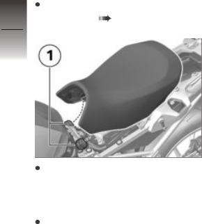
Set the driver's seat height and
inclination ( 100).
Insert the rider's seat into the
fixtures 1 on the left and right
and lean carefully on the mo-
torcycle.
Push the rider's seat forwards
slightly by applying pressure
at the rear and then push it
down with force until the lock-
ing mechanism engages.
4
102
z
Operation

TFT display
General instructions . . . . . . . . . . . . . . . . 104
Principle . . . . . . . . . . . . . . . . . . . . . . . . . . . 105
Pure Ride view . . . . . . . . . . . . . . . . . . . . . 111
General settings . . . . . . . . . . . . . . . . . . . 113
Bluetooth . . . . . . . . . . . . . . . . . . . . . . . . . . 114
My vehicle . . . . . . . . . . . . . . . . . . . . . . . . . 118
Navigation . . . . . . . . . . . . . . . . . . . . . . . . . 121
Media . . . . . . . . . . . . . . . . . . . . . . . . . . . . . . 123
Phone . . . . . . . . . . . . . . . . . . . . . . . . . . . . . 123
Display software version . . . . . . . . . . . 124
Display licence information . . . . . . . . . 124
5
103
z
TFT display

General instructions
Warnings
WARNING
Using a smartphone during
the journey or while the en-
gine is running
Risk of accident
Always observe the relevant
road traffic regulations.
Do not use the smartphone
during the journey (apart from
applications that do not require
operation, e.g. making tele-
phone calls with the hands-free
system).
WARNING
Distraction from the road and
loss of control
Operating the integrated inform-
ation system and communication
devices while driving results in a
risk of accident
Operate those systems or
devices only when the traffic
situation allows for it.
If necessary, stop and operate
the systems or devices when
stationary.
Connectivity functions
Connectivity functions include
media, telephony and navigation.
Connectivity functions can
be used if the TFT display is
connected to a mobile end
device and a helmet ( 115).
For more information on the
Connectivity functions go
to bmwmotorrad.com/
connectivity
NOTICE
If the fuel tank is between
the mobile device and the
TFT display, the Bluetooth
connection may be restricted.
BMW Motorrad recommends
storing the device above the fuel
tank (e.g. in your jacket pocket).
NOTICE
Depending on the mobile device,
the scope of the Connectivity
functions may be restricted.
BMW Motorrad
Connected App
The BMW Motorrad Connec-
ted App contains usage and
vehicle information. For some
functions, such as navigation, the
app must be installed on the mo-
bile end device and connected
to the TFT display. The app is
used to start route guidance and
adjust the navigation.
NOTICE
On some mobile devices, e.g.
those with iOS operating sys-
tems, the BMW Motorrad Con-
5
104
z
TFT display

nected App must be opened be-
fore use.
Actuality
The TFT display may be updated
after the publication date. Be-
cause of this, your motorcycle
may differ from the information
supplied in the Rider's Manual.
For up-to-date information go to
bmwmotorrad.com
Principle
Controls
All contents of the display are
operated using the multi-con-
troller 1 and the MENU 2 rocker
button.
Depending on the context, the
following functions are possible.
Multi-controller functions
Turn the multi-controller
upwards:
Move the cursor upwards in
lists.
Adjust settings.
Increase volume.
Turn the multi-controller
downwards:
Move the cursor downwards in
lists.
Adjust settings.
Decrease volume.
Tilt the multi-controller to
the left:
Activate the function in accord-
ance with the operation feed-
back.
Activate the function to the left
or back.
Go back to the View menu
after settings.
In the View menu, change up a
level.
In the My Vehicle menu: ad-
vance one menu screen.
Tilt the multi-controller to
the right:
Activate the function in accord-
ance with the operation feed-
back.
5
105
z
TFT display

Confirm selection.
Confirm settings.
Advance a menu step.
Scroll to the right in lists.
In the My Vehicle menu: ad-
vance one menu screen.
MENU rocker button
functions
NOTICE
Instructions given by the navig-
ation system are displayed in a
dialogue box if the Navigation
menu has not been called up.
Operation of the MENU rocker
button is temporarily restricted.
Briefly push MENU up:
In the View menu, change up a
level.
In the Pure Ride view: change
the display for rider info status
line.
Press and hold MENU up:
In the View menu: call up
Pure Ride view.
In Pure Ride view: change op-
erating focus to the Navigator.
Briefly push MENU down:
Change down a level.
No function if the lowest
hierarchical level has been
reached.
Hold MENU down:
Change back to the last menu
after a previous menu change
by holding up the MENU
rocker button.
Operating instructions in
the main menu
Operating instructions show
whether interactions are possible,
and which ones.
5
106
z
TFT display

What the operating
instructions mean:
Operating instruction 1: the left
end has been reached.
Operating instruction 2: it is
possible to scroll to the right.
Operating instruction 3: it is
possible to scroll down.
Operating instruction 4: it is
possible to scroll to the left.
Operating instruction 5: the
right end has been reached.
Operating instructions in
submenus
In addition to the operating in-
structions in the main menu,
there are additional operating in-
structions in the submenu.
Meaning of operating
instructions:
Operating instruction 1: The
current display is located in a
hierarchical menu. A submenu
level is shown with a symbol.
Two symbols indicate two or
more submenu levels. The col-
our of the symbol changes de-
pending on if it is possible to
move up a level.
Operating instruction 2: A fur-
ther submenu level can be
called up.
Operating instruction 3: There
are more entries than can be
displayed.
Display Pure Ride view
Press and hold MENU rocker
button up.
5
107
z
TFT display

Switching functions on
and off
Some menu items have a check
box in front of them. The check
box shows whether the function
is on or off. Action symbols after
the menu items show what will
be switched by tilting the multi-
controller briefly to the right.
Examples for switching on
and off:
Symbol 1 shows that the func-
tion is switched on.
Symbol 2 shows that the func-
tion is switched off.
Symbol 3 shows that the func-
tion can be switched off.
Symbol 4 shows that the func-
tion can be switched on.
Call up the menu
Display Pure Ride view
( 107).
Briefly push button 2 down.
The following menus can be
called up:
My vehicle
Navigation
Media
Telephone
Settings
Repeatedly press the multi-
controller 1 briefly to the right
until the desired menu item is
highlighted.
Briefly push button 2 down.
NOTICE
The Settings menu can only
be called up when the vehicle is
stationary.
Move the cursor in lists
Call up the menu ( 108).
To move the cursor down in
lists, turn the multi-controller 1
5
108
z
TFT display

down until the desired entry is
highlighted.
To move the cursor up in lists,
turn the multi-controller 1 up
until the desired entry is high-
lighted.
Confirm selection
Select the desired entry.
Briefly press the multi-control-
ler 1 to the right.
Call up the last menu used
In Pure Ride view: press and
hold the MENU rocker button.
The last menu used is called
up. The last entry highlighted
is selected.
Change of operating focus
with preparation for navigation
system
OE
If the Navigator is connected, it
is possible to switch between
operation of the Navigator and
the TFT display.
Changing the operating
focus
with preparation for navigation
system
OE
Securing navigation device
( 217).
Display Pure Ride view
( 107).
Press and hold rocker button
MENU up.
Operating focus switches
to the Navigator or the TFT
display. The active device is
marked on the left in the upper
status line. Operator actions
affect the currently active
device until the operating focus
is changed again.
Operating navigation system
( 218)
System status displays
The system status is displayed in
the lower area of the menu if a
function is switched on or off.
Examples of what the system
statuses mean:
System status 1: ASC/DTC
function is switched on.
5
109
z
TFT display

System status 2: ABS function
is switched off.
Switches the display for
driver info. status line
Requirement
The vehicle is at a standstill. The
Pure Ride view appears on the
display.
Switching on ignition ( 62).
All necessary information from
the on-board computer for op-
eration on public roads (e.g.
TRIP 1) and trip computer
(e.g. TRIP 2) are available in
the TFT display. The informa-
tion can be displayed in the top
status line.
with tyre pressure control
(RDC)
OE
Information from the tyre
pressure control can also be
displayed.
Select content of the rider info.
status line ( 111).
Press and hold the button 1 to
display the Pure Ride view.
Briefly press button 1 to se-
lect the value in the top status
line 2.
The following values can be dis-
played:
Odometer Total
Trip distance 1 TRIP 1
Trip distance 2 TRIP 2
Average consumption 1
Average consumption 2
Riding time 1
Riding time 2
Break 1
Break 2
Average speed 1
Average speed 2
Tyre pressure
Fuel gauge
Range
5
110
z
TFT display

Select content of the rider
info. status line
Call up the Settings,
Display, Status line
content menu.
Switch on the desired displays.
It is possible to switch between
the selected displays in the
rider info. status line. If no dis-
plays are selected, only the
range will be displayed.
Adjust settings
Select and confirm the desired
settings menu.
Turn the multi-controller 1
downwards until the desired
setting is highlighted.
If there are operating instruc-
tions, tilt the multi-controller 1
to the right.
If there are no operating in-
structions, tilt the multi-control-
ler 1 to the left.
The setting is saved.
Switching Speed Limit
Info on or off
Requirement
Vehicle is connected to the Nav-
igator or a compatible mobile
end device. The BMW Motorrad
Connected App is installed on
the mobile end device.
Speed Limit Info displays
the maximum speed currently
permitted.
Call up the Settings,
Display menu.
Switch Speed Limit Info on
or off.
Pure Ride view
Engine speed display
1 Scale
2 Lower engine speed range
3 Upper/red engine speed
range
4 Needle
5 Secondary indicator
6 Engine speed display unit:
1,000 revolutions per
minute
5
111
z
TFT display

NOTICE
The red engine speed range
changes depending on the oil
temperature:
The colder the engine, the lower
the speed at which the red en-
gine speed range starts.
The warmer the engine, the
higher the speed at which the
red engine speed range starts.
When the operating temperature
is reached, the display of the red
engine speed range no longer
changes.
The upshift recommendation is
dynamically adapted.
Range
The range readout 1 indicates
how far you can ride with the fuel
remaining in the tank. This dis-
tance is calculated on the basis
of average consumption and the
quantity of fuel on board.
When the motorcycle is
propped on its side stand
the slight angle of inclination
means that the sensor cannot
register the fuel level correctly.
This is the reason why the
range is recalculated only
when the side stand is in the
retracted position.
The range is shown together
with a warning once the fuel
reserve has been reached.
After a refuelling stop, range is
recalculated if the amount of
fuel in the tank is greater than
the reserve quantity.
The calculated range is only an
approximate figure.
Recommendation to
upshift
The upshift recommendation 1
signals the economically best
point in time for upshift.
5
112
z
TFT display

General settings
Adjust the volume
Connect rider's and passen-
ger's helmet ( 116).
Increase volume: turn the
multi-controller upwards.
Decrease volume: turn the
multi-controller downwards.
Mute: turn the multi-controller
all the way down.
Setting the date
Switching on ignition ( 62).
Call up the Settings, Sys-
tem settings, Date and
time, Set date menu.
Adjust Day, Month and Year.
Confirm setting.
Set date format
Call up the Settings, Sys-
tem settings, Date and
time, Date format menu.
Select the desired setting.
Confirm setting.
Setting the clock
Switching on ignition ( 62).
WARNING
Adjusting the clock while rid-
ing
Risk of accident
Set the clock only when the
motorcycle is stationary.
Call up the Settings, Sys-
tem settings, Date and
time, Set time menu.
Adjust Hour and Minute.
Setting time format
WARNING
Adjusting the clock while rid-
ing
Risk of accident
Set the clock only when the
motorcycle is stationary.
Call up the Settings, Sys-
tem settings, Date and
time, Time format menu.
Select the desired setting.
Confirm setting.
Switching GPS
synchronisation on or off
with preparation for navigation
system
OE
Call up the Settings, Sys-
tem settings, Date and
time menu.
Switch GPS synchronisa-
tion on or off.
When the respective option
is activated in the Navigator,
the time from the Navigator is
applied.
Special functions ( 221)
Setting units of
measurement
Call up the Settings, Sys-
tem settings, Units menu.
5
113
z
TFT display

The following units of measure-
ment can be set:
Distance covered
Pressure
Temperature
Speed
Consumption
Setting the language
Call up the Settings, Sys-
tem settings, Language
menu.
The following languages can be
adjusted:
Chinese
German
English
Spanish
French
Italian
Dutch
Portuguese
Russian
Ukrainian
Polish
Turkish
Adjusting brightness
Call up the Settings,
Display, Brightness menu.
Adjusting display brightness.
Resetting all settings
All the settings in the Set-
tings menu can be reset to
the factory settings.
Call up the Settings menu.
Select Reset all and confirm.
The settings in the following
menus are reset:
Vehicle settings
System settings
Connections
Display
Information
Existing Bluetooth connections
are not deleted.
Bluetooth
Short-range wireless
technology
The Bluetooth function might not
be available in certain countries.
Bluetooth is a short-range
wireless technology. Bluetooth
devices are short-range devices
transmitting on the license-free
ISM band (Industrial, Scientific,
Medical) between 2.402 GHz
and 2.480 GHz. They can be
operated anywhere in the world
without a licence being required.
Although Bluetooth is designed
to establish and sustain robust
connections over short distances,
as with every other wireless
technology disruptions are
possible. Interference can affect
connections or connections can
sometimes fail. Particularly when
multiple devices operate in a
Bluetooth network, with wireless
technology of this nature it is
5
114
z
TFT display

not possible to ensure fault-
free communications in every
situation.
Possible sources of
interference:
interference zones due to
transmission masts and similar.
devices with non-compliant
Bluetooth implementations
proximity of other Bluetooth-
compatible devices
Pairing
Two Bluetooth devices must de-
tect each other before they can
create a connection with each
other. This process of mutual
recognition is known as pairing.
When two devices have paired
they remember each other, so
the pairing process is conducted
only once, on initial contact.
NOTICE
On some mobile devices, e.g.
those with iOS operating sys-
tems, the BMW Motorrad Con-
nected App must be opened be-
fore use.
During the pairing process, the
TFT display searches for other
Bluetooth-compatible devices
within its reception range. The
conditions that have to be satis-
fied before the audio system can
recognise another device are as
follows:
The Bluetooth function of the
device must be activated
The device must be "visible" to
others
The device must support the
A2DP profile
Other Bluetooth-compatible
devices must be OFF (e.g.
mobile phones and navigation
systems).
Please consult the operating in-
structions for your communica-
tion system.
Pairing
Call up the Settings, Con-
nections menu.
Bluetooth connections can
be established, managed and
deleted in the CONNECTIONS
menu. The following Bluetooth
connections are displayed:
Mobile device
Rider's helmet
Passenger helm.
The connection status for mobile
end devices is displayed.
Connect mobile end
device
Pairing ( 115).
Activate the mobile end
device's Bluetooth function
5
115
z
TFT display

(see mobile end device's
operating instructions).
Select Mobile device and
confirm.
Select PAIRING NEW MOB.
DEVICES and confirm.
Mobile end devices are being
searched for.
The Bluetooth symbol
flashes in the bottom status
line during pairing.
Mobile end devices found are
displayed.
Select and confirm mobile end
device.
Follow the instructions on the
mobile end device.
Confirm that the code
matches.
The connection is established
and the connection status up-
dated.
If the connection is not
established, consult the
troubleshooting chart in the
section entitled "Technical
data". ( 230)
Depending on the mobile end
device, telephone data is trans-
ferred to the vehicle automatic-
ally.
Telephone data ( 124)
If the telephone book is
not displayed, consult the
troubleshooting chart in the
section entitled "Technical
data". ( 231)
If the Bluetooth connection is
not working as expected, con-
sult the troubleshooting chart
in the section entitled "Tech-
nical data". ( 231)
Connect rider's and
passenger's helmet
Pairing ( 115).
Select Rider's helmet or
Passenger helm. and con-
firm.
Make the helmet's communica-
tion system visible.
Select PAIRING NEW HEL-
METS or PAIRING NEW PASS.
HELM. and confirm.
Helmets are searched for.
The Bluetooth symbol
flashes in the bottom status
line during pairing.
Helmets found are displayed.
Select and confirm helmet.
The connection is established
and the connection status up-
dated.
If the connection is not
established, consult the
troubleshooting chart in the
section entitled "Technical
data". ( 230)
If the Bluetooth connection is
not working as expected, con-
sult the troubleshooting chart
in the section entitled "Tech-
nical data". ( 231)
5
116
z
TFT display

Deleting connections
Call up the Settings, Con-
nections menu.
Select Delete connections.
To delete an individual connec-
tion, select the connection and
confirm.
To delete all connections, se-
lect Delete all connec-
tions and confirm.
5
117
z
TFT display


Operating instructions
Operating instruction 1: tabs
which show how far to the left
or right can be scrolled.
Operating instruction 2: tab
which shows the position of
the current menu screen.
Scrolling through menu
screens
Call up the My vehicle menu.
To scroll to the right, briefly
press Multi-Controller 1 to the
right.
To scroll to the left, briefly
press Multi-Controller 1 to the
left.
The My Vehicle menu contains
the following screens:
MY VEHICLE
Check Control messages (if
any)
ON-BOARD COMPUTER
TRIP COMPUT.
with tyre pressure control
(RDC)
OE
TYRE PRESSURE
SERVICE REQUIREMENTS
For more information on tyre
pressure and Check Control
messages, see the "Displays"
section.
NOTICE
Check control messages are at-
tached dynamically to the My
Vehicle menu screen as addi-
tional tabs.
On-board computer and
trip computer
The ON-BOARD COMPUTER and
TRIP COMPUT. menu screens
display vehicle and trip data, such
as average values.
5
119
z
TFT display

Service requirements
If the time remaining to the next
service is less than a month or
if the next service is due within
1,000 km, a white CC message
is displayed.
5
120
z
TFT display

Navigation
Warnings
WARNING
Using a smartphone during
the journey or while the en-
gine is running
Risk of accident
Always observe the relevant
road traffic regulations.
Do not use the smartphone
during the journey (apart from
applications that do not require
operation, e.g. making tele-
phone calls with the hands-free
system).
WARNING
Distraction from the road and
loss of control
Operating the integrated inform-
ation system and communication
devices while driving results in a
risk of accident
Operate those systems or
devices only when the traffic
situation allows for it.
If necessary, stop and operate
the systems or devices when
stationary.
Precondition
The vehicle is connected to a
compatible mobile end device.
Precondition
The BMW Motorrad Connec-
ted App is installed on the con-
nected mobile end device.
NOTICE
On some mobile devices, e.g.
those with iOS operating sys-
tems, the BMW Motorrad Con-
nected App must be opened be-
fore use.
Entering destination
address
Connect mobile end device
( 115).
Call up the BMW Motorrad
Connected App and start the
route guidance.
Call up the Navigation menu
in the TFT display.
Active route guidance is dis-
played.
If the active route guidance
is not displayed, consult the
troubleshooting chart in the
section entitled "Technical
data". ( 231)
Selecting destination from
recent destinations
Call up the Navigation, Re-
cent destinations menu.
Select and confirm destination.
Select Start route guid-
ance.
5
121
z
TFT display

Selecting destination from
favourites
The FAVOURITES menu dis-
plays all destinations which
have been saved as favourites
in the BMW Motorrad Con-
nected app. No new favourites
can be added using the TFT
display.
Call up the Navigation, Fa-
vourites menu.
Select and confirm destination.
Select Start guidance.
Entering special
destinations
Special destinations, such as
points of interest, can be dis-
played on the map.
Call up the Navigation,
POIs menu.
The following locations can be
selected:
At current location
At destination
Along the route
Select where the special des-
tinations should be looked for.
e.g. the following special destina-
tion can be selected:
Filling station
Select and confirm the special
destination.
Select Start route guid-
ance and confirm.
Setting route criteria
Call up the Navigation,
Route criteria menu.
The following criteria can be se-
lected:
Route type
Avoid
Select desired Route type.
Switch desired Avoid on or
off.
The number of avoidances activ-
ated is displayed in brackets.
Ending route guidance
Call up the Navigation,
Active route guidance
menu.
Select End route guidance
and confirm.
Switching spoken
instructions on or off
Connect rider's and passen-
ger's helmet ( 116).
The navigation can be read out
by a computer voice. For this
purpose, Spoken instruc-
tions must be switched on.
Call up the Navigation,
Active route guidance
menu.
Switch Spoken instruc-
tions on or off.
Repeating last spoken
instruction
Call up the Navigation,
Active route guidance
menu.
5
122
z
TFT display

Select Current instruc-
tion and confirm.
Media
Precondition
The vehicle is connected to a
compatible mobile end device
and helmet.
Control music playback
Call up the Media menu.
NOTICE
BMW Motorrad recommends
setting the volume on the mobile
end device for media and calls to
maximum before setting off.
Adjust the volume ( 113).
Next track: briefly tilt Multi-
Controller 1 to the right.
Last track or start of the cur-
rent track: briefly tilt Multi-Con-
troller 1 to the left.
Fast forward: hold Multi-Con-
troller 1 to the right.
Rewind: hold Multi-Controller 1
to the left.
Call up the context menu:
press the bottom part of the
button 2.
NOTICE
Depending on the mobile device,
the scope of the Connectivity
functions may be restricted.
The following functions can be
used in the context menu:
Start playback or Pause
playback.
Select the Now playing, All
artists, All albums or All
tracks category for search
and playback.
Select Playlists.
You can adjust the following set-
tings in the Audio options
submenu:
Switch Shuffle on or off.
Select Repeat: Off, One (cur-
rent track) or All.
Phone
Precondition
The vehicle is connected to a
compatible mobile end device
and helmet.
5
123
z
TFT display

Telephone calls
Call up the Telephone menu.
Accept call: tilt Multi-Control-
ler 1 to the right.
Reject call: tilt Multi-Control-
ler 1 to the left.
End the call: tilt Multi-Control-
ler 1 to the left.
Muting
During active phone calls, the
microphone in the helmet can be
muted.
Phone calls with multiple
participants
A second call can be accepted
while you are on a call. The first
phone call is put on hold. The
number of active telephone calls
is shown in the Telephone
menu. It is possible to switch
between two phone calls.
Telephone data
Depending on the mobile end
device, telephone data may be
transmitted to the vehicle auto-
matically once pairing is com-
plete ( 115).
Phone book: list of contacts
saved on the mobile end device
Call list: list of calls with the
mobile end device
Favourites: list of favourites
saved on the mobile end device
Display software
version
Call up the Settings, In-
formation, Software ver-
sion menu.
Display licence
information
Call up the Settings, In-
formation, Licences menu.
5
124
z
TFT display

Adjustment
Mirrors . . . . . . . . . . . . . . . . . . . . . . . . . . . . . 126
Headlight . . . . . . . . . . . . . . . . . . . . . . . . . . 127
Windscreen . . . . . . . . . . . . . . . . . . . . . . . . 128
Clutch . . . . . . . . . . . . . . . . . . . . . . . . . . . . . 128
Gearshift lever . . . . . . . . . . . . . . . . . . . . . 129
Brakes . . . . . . . . . . . . . . . . . . . . . . . . . . . . . 130
Footrests . . . . . . . . . . . . . . . . . . . . . . . . . . 132
Handlebars . . . . . . . . . . . . . . . . . . . . . . . . 133
Spring preload . . . . . . . . . . . . . . . . . . . . . 133
Damping . . . . . . . . . . . . . . . . . . . . . . . . . . . 134
6
125
z
Adjustment

Mirrors
Adjusting mirrors
Turn the mirror to the correct
position.
Adjusting mirror arm
Push protective cap 1 up over
the threaded fastener on the
mirror arm.
Slacken nut 2.
Turn the mirror arm to the ap-
propriate position.
Tighten the nut to the spe-
cified tightening torque, while
holding the mirror arm in place.
Mirror (locknut) to ad-
apter
22 Nm (Left-hand thread)
Push protective cap 1 over the
threaded fastener.
Adjusting mirrors
with Option 719, Classic milled
part package
OE
or
with Option 719, Storm milled
part package
OE
or
with HP milled part package
OE
NOTICE
A small and a large angle screw-
driver is supplied with the vehicle
for adjusting the mirror arm.
Turn the mirror 1 to the correct
position.
6
126
z
Adjustment

Adjusting mirror arm
with Option 719, Classic milled
part package
OE
or
with Option 719, Storm milled
part package
OE
or
with HP milled part package
OE
NOTICE
A small and a large angle screw-
driver is supplied with the vehicle
for adjusting the mirror arm.
Remove bolt 1 and cover 2.
Loosen adjusting screw 3 and
turn the mirror arm 4 to the
desired position.
Tighten adjusting screw 3,
while holding the mirror arm.
Attach cover 2 and fit bolt 1.
Mirror on handlebars
25 Nm
with hand protector
OE
25 Nm
Headlight
Headlight beam throw and
spring preload
Headlight beam throw is gener-
ally kept constant when spring
preload is adjusted to suit load.
Spring preload adjustment might
not suffice only if the motorcycle
is very heavily loaded. Under
these circumstances, headlight
beam throw has to be adjusted
to suit the weight carried by the
motorcycle.
NOTICE
If there are doubts about the cor-
rect headlight beam throw, have
the setting checked by a special-
ist workshop, preferably an au-
thorised BMW Motorrad dealer.
Adjusting headlight beam
throw
Requirement
If, for a high load, the adjust-
ment of the spring pre-load is
no longer sufficient not to dazzle
oncoming traffic:
6
127
z
Adjustment

The headlight beam-throw is
adjusted via a bell crank.
A neutral position
B position if payload is high
Windscreen
Adjust windscreen
WARNING
Adjusting the windscreen
while riding
Risk of falling
Do not attempt to adjust the
windscreen unless the motor-
cycle is at a standstill.
Turn adjuster knob 1 clockwise
to lower the windscreen.
Turn adjuster knob 1 counter-
clockwise to raise the wind-
screen.
Clutch
Adjusting the clutch lever
WARNING
Adjusting the clutch lever
while riding
Risk of accident
Adjust the clutch lever only
when the motorcycle is at a
standstill.
Turn adjuster knob 1 to the
desired position.
6
128
z
Adjustment

NOTICE
The adjuster is easier to turn
if you push the clutch lever
forward.
Four settings are possible:
Position 1: smallest distance
between handlebar grip and
clutch lever
Position 4: largest distance
between handlebar grip and
clutch lever
with Option 719, Classic milled
part package
OE
or
with Option 719, Storm milled
part package
OE
or
with HP milled part package
OE
Turn the adjustment lever 1 in
the desired position.
Adjustment options:
from position A: narrowest dis-
tance between handlebar grip
and clutch lever.
In 5 steps in direction of po-
sition B for enlarging the dis-
tance between handlebar grip
and clutch lever.
Gearshift lever
with Option 719, Classic milled
part package
OE
or
with Option 719, Storm milled
part package
OE
or
with HP milled part package
OE
6
129
z
Adjustment

Adjusting gearshift lever
peg
Foot distance and height to
peg 2 can be adjusted by turn-
ing to different positions.
Remove the bolt 1.
Clean the threads.
Turn the peg 2 in the desired
position.
Fit new bolt 1.
Peg to gearshift lever
Thread-locking compound:
Micro-encapsulated
10 Nm
Brakes
Adjusting the front brake
lever
WARNING
Adjusting the brake lever
while riding
Risk of accident
Do not attempt to adjust the
brake lever unless the motor-
cycle is at a standstill.
Turn adjuster knob 1 to the
desired position.
6
130
z
Adjustment
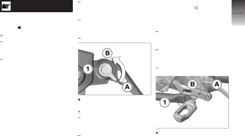
NOTICE
The adjuster is easier to turn
if you push the brake lever
forward.
Four settings are possible:
Position 1: smallest distance
between handlebar grip and
brake lever
Position 4: largest distance
between handlebar grip and
brake lever
with Option 719, Classic milled
part package
OE
or
with Option 719, Storm milled
part package
OE
or
with HP milled part package
OE
Turn the adjustment lever 1 in
the desired position.
Adjustment options:
from position A: narrowest dis-
tance between handlebar grip
and brake lever.
In 5 steps in direction of po-
sition B for enlarging the dis-
tance between handlebar grip
and brake lever.
Adjusting footbrake lever
peg
with Option 719, Classic milled
part package
OE
or
with Option 719, Storm milled
part package
OE
or
with HP milled part package
OE
Foot distance and height to
peg 1 can be adjusted by turn-
ing through 180° and installa-
tion in position A or B.
6
131
z
Adjustment

Remove the bolt 1.
Clean the threads.
Install peg 2 in desired posi-
tion A or B.
Turn the peg 2 in the desired
position.
Fit new bolt1.
Peg to footbrake lever
Thread-locking compound:
Micro-encapsulated
10 Nm
Footrests
with Option 719, Classic milled
part package
OE
or
with Option 719, Storm milled
part package
OE
or
with HP milled part package
OE
Adjusting footrests
The footrest is adjusted on the
right and left in the same way.
The position of the footrest
must be set identically on the
right and on the left.
Remove screws 1.
Remove footrest 3 from clamp-
ing block 2.
Remove bolt 2.
Remove clamping block 1.
6
132
z
Adjustment

Install clamping block 1 in re-
quired position A or B and
tighten bolt 2.
Clamping block on
footrest hinge
20 Nm
Position footrest 3 on clamping
block 2.
Install screws 1.
Footrest on clamping
block
10 Nm
Remove and refit the footrest
on the other side in the same
way.
Handlebars
Adjustable handlebars
The angle of the handlebars can
be adjusted within the marked
areas 1.
Allow a specialist workshop,
preferably an authorised
BMW Motorrad dealer to adjust
the handlebars.
Spring preload
without Dynamic ESA
OE
6
133
z
Adjustment

Adjustment
It is essential to set the spring
preload of the rear suspension
to suit the load carried by the
motorcycle. Increase the spring
preload when the vehicle is heav-
ily loaded and reduce the spring
preload accordingly when the
vehicle is lightly loaded.
Adjusting spring preload
for rear wheel
WARNING
Adjusting spring preload
while riding.
Risk of accident
Do not attempt to adjust spring
preload unless the motorcycle
is at a standstill.
Place the motorcycle on its
stand on firm, even ground.
WARNING
Spring preload setting and
spring-strut damping setting
not matched.
Impaired handling.
Adjust spring-strut damping to
suit spring preload.
To increase the spring preload,
turn the adjuster knob 1 in the
direction indicated by the HIGH
arrow.
To reduce the spring preload,
turn the adjuster knob 1 in the
direction indicated by the LOW
arrow.
Basic setting of spring
preload, rear
Turn the knob as far as it
will go in the LOW direction.
(One-up without luggage)
Turn the adjuster knob as far
as it will go in the LOW direc-
tion, then 15 turns in the HIGH
direction. (One-up with lug-
gage)
Turn the adjuster knob as far
as it will go in the LOW direc-
tion, then 30 turns in the HIGH
direction. (Two-up with lug-
gage)
Damping
without Dynamic ESA
OE
Setting
Damping must be adapted to suit
the surface on which the motor-
cycle is ridden and to suit spring
preload.
6
134
z
Adjustment

An uneven surface requires
softer damping than a smooth
surface.
An increase in spring preload
requires firmer damping, a re-
duction in spring preload re-
quires softer damping.
Adjusting the damping
characteristic for rear
wheel
Place the motorcycle on its
stand on firm, even ground.
Set the damping from the left-
hand vehicle side.
Turn the adjusting screw 1
clockwise to harden the damp-
ing action.
Turn the adjusting screw 1 an-
ticlockwise to soften the damp-
ing action.
Basic setting of rear-
suspension damping
characteristic
Turn the adjuster knob as far
as it will go in the clockwise
direction, then back it off 8
clicks in the counter-clockwise
direction. (One-up without lug-
gage)
Basic setting of rear-
suspension damping
characteristic
Turn the adjuster knob as far
as it will go in the clockwise
direction, then back it off 2
clicks in the counter-clockwise
direction. (One-up with lug-
gage)
Turn the adjuster knob as far
as it will go in the clockwise
direction, then back it off 2
clicks in the counter-clockwise
direction. (Two-up with lug-
gage)
6
135
z
Adjustment

6
136
z
Adjustment

Riding
Safety information . . . . . . . . . . . . . . . . . 138
Comply with checklist . . . . . . . . . . . . . . 141
Always before riding off . . . . . . . . . . . . 141
At every third refuelling stop . . . . . . . 141
Starting . . . . . . . . . . . . . . . . . . . . . . . . . . . . 141
Running in . . . . . . . . . . . . . . . . . . . . . . . . . 145
Off-road use . . . . . . . . . . . . . . . . . . . . . . . 145
Shifting gear . . . . . . . . . . . . . . . . . . . . . . . 147
Brakes . . . . . . . . . . . . . . . . . . . . . . . . . . . . . 148
Parking your motorcycle . . . . . . . . . . . 150
Refuelling . . . . . . . . . . . . . . . . . . . . . . . . . . 151
Securing motorcycle for transporta-
tion . . . . . . . . . . . . . . . . . . . . . . . . . . . . . . . . 155
7
137
z
Riding

Safety information
Rider's equipment
Do not ride without the correct
clothing! Always wear:
Helmet
Motorcycling jacket and
trousers
Gloves
Boots
This applies even to short
journeys, and to every season
of the year. Your authorised
BMW Motorrad dealer will be
glad to advise you on the correct
clothing for every purpose.
Restricted angle of heel
with low-slung
OE
A motorcycle with lowered
suspension has less ground
clearance and cannot corner
at angles of heel as extreme
as those achievable by a
counterpart motorcycle with
standard-height suspension.
WARNING
When a motorcycle with
lowered suspension is cor-
nering, certain components
can come into contact with
the surface at a bank angle
less than that to which the
rider is accustomed.
Risk of falling
Carefully try out the limits of
the motorcycle's bank angle
and adapt your style of riding
accordingly.
Test your motorcycle's angle
of heel in situations that do not
involve risk. When riding over
kerbs and similar obstacles, bear
in mind that your motorcycle's
ground clearance is limited.
Lowering the motorcycle's
suspension shortens suspension
travel (see the section entitled
"Technical Data"). Ride comfort
might be restricted as a result.
Be sure to adjust spring preload
accordingly, particularly for riding
two-up.
Loading
WARNING
Handling adversely affected
by overloading and imbal-
anced loads
Risk of falling
Do not exceed the permissible
gross weight and be sure to
comply with the instructions on
loading.
Adjusting spring preload set-
ting and damping to the total
weight.
7
138
z
Riding

with case
OA
Ensure that the case volumes
on the left and right are equal.
Make sure that the weight is
uniformly distributed between
right and left.
Pack heavy items at the bot-
tom and toward the inboard
side.
Note the maximum permissible
payload and the speed limit
for riding with cases fitted, as
stated on the label inside the
case (see also the section en-
titled "Accessories").
with topcase
OA
Note the maximum permissible
payload and the speed limit
for riding with topcase fitted,
as stated on the label inside
the case (see also the section
entitled "Accessories").
with tank bag
OA
Note the maximum permissible
payload of the tank rucksack.
Payload of tank rucksack
max 5 kg
Speed
If you ride at high speed, always
bear in mind that various bound-
ary conditions can adversely af-
fect the handling of your motor-
cycle:
Settings of the spring-strut and
shock-absorber system
Imbalanced load
Loose clothing
Insufficient tyre pressure
Poor tyre tread
Etc.
Maximum speed with
knobbly tyres or winter
tyres
DANGER
Maximum speed of the mo-
torcycle is higher than the
permissible maximum rated
speed of the tyres
Risk of accident due to tyre dam-
age at high speed
Comply with the tyre-specific
speed restrictions.
Always bear the maximum per-
missible speed of the tyres in
mind when riding a motorcycle
fitted with knobbly tyres or winter
tyres.
Affix a label stating the maximum
permissible speed to the instru-
ment panel in the rider's field of
vision.
7
139
z
Riding

Risk of poisoning
Exhaust fumes contain carbon
monoxide, which is colourless
and odourless but highly toxic.
WARNING
Exhaust gases adversely af-
fecting health
Risk of asphyxiation
Do not inhale exhaust fumes.
Do not run the engine in an
enclosed space.
Risk of burn injury
CAUTION
Engine and exhaust system
become very hot when the
vehicle is in use
Risk of burn injury
When you park the vehicle
make sure that no-one and no
objects can come into contact
with the hot engine and ex-
haust system.
Catalytic converter
If misfiring causes unburned fuel
to enter the catalytic converter,
there is a danger of overheating
and damage.
The following guidelines must be
observed:
Do not run the fuel tank dry.
Do not attempt to start or run
the engine with a spark-plug
cap disconnected.
Stop the engine immediately if
it misfires.
Use only unleaded fuel.
Comply with all specified main-
tenance intervals.
ATTENTION
Unburned fuel in catalytic
converter
Damage to catalytic converter
Note the points listed for
protection of the catalytic
converter.
Risk of overheating
ATTENTION
Engine running for prolonged
period with vehicle at stand-
still
Overheating due to insufficient
cooling; in extreme cases vehicle
fire
Do not allow the engine to idle
unnecessarily.
Ride away immediately after
starting the engine.
Tampering
ATTENTION
Tampering with the motor-
cycle (e.g. engine manage-
ment ECU, throttle valves,
clutch)
Damage to the affected parts,
failure of safety-relevant func-
tions, voiding of warranty
7
140
z
Riding

Do not tamper with the vehicle
in any way that could result in
tuned performance.
Comply with checklist
At regular intervals, use the
checklist below to check your
motorcycle.
Always before riding off
Check operation of the brake
system.
Check operation of the lights
and signalling equipment.
Checking clutch function
( 182).
Checking tyre tread depth
( 184).
Checking tyre pressure
( 184).
Check that cases and luggage
are securely held in place.
At every third refuelling
stop
without Dynamic ESA
OE
Adjuster for spring preload, rear
( 134).
Checking engine oil level
( 176).
Checking front brake pad thick-
ness ( 178).
Check rear brake pad thickness
( 179).
Checking brake-fluid level, front
brakes ( 180).
Checking the brake-fluid level,
rear brakes ( 181).
Check coolant level ( 182).
Starting
Starting the engine
Switch on the ignition.
Pre-Ride-Check is performed.
( 142)
ABS self-diagnosis is in pro-
gress. ( 142)
without riding modes Pro
OE
ASC self-diagnosis is per-
formed. ( 143)
with riding modes Pro
OE
DTC self-diagnosis is in pro-
gress. ( 144)
Select neutral or, if a gear is
engaged, pull the clutch lever.
NOTICE
You cannot start the motorcycle
with the side stand extended and
a gear engaged. The engine will
switch itself off if you start it with
the gearbox in neutral and then
engage a gear before retracting
the side stand.
For a cold engine start and low
temperatures: pull clutch.
with HP battery
OE
Low temperatures can impact
on the starting response.
7
141
z
Riding

Press the starter button 1.
The engine starts.
If the engine refuses to start,
consult the troubleshooting
chart in the section entitled
"Technical data". ( 230)
Recharge the battery before you
start the engine, or use jump
leads and a donor battery to
start:
Charge battery when connec-
ted ( 197).
Jump-starting ( 195).
NOTICE
The start attempt is automatically
interrupted if battery voltage is
too low.
Pre-Ride-Check
When the ignition is switched
on, the instrument cluster runs a
test of the indicator and warning
lights. This test is known as the
"Pre-Ride-Check". The test is
aborted if you start the engine
before it completes.
Phase 1
All indicator and warning lights
are switched on.
After a longer vehicle standstill
period, an animation is displayed
when the system starts up.
Phase 2
The 'General' warning light
changes from red to yellow.
Phase 3
All the indicator and warning
lights switched on in the initial
phase are switched off in reverse
sequence.
If one of the indicator and warn-
ing lights did not switch on:
Have the fault rectified as
quickly as possible by a
specialist workshop, preferably
an authorised BMW Motorrad
Retailer.
ABS self-diagnosis
BMW Motorrad Integral ABS per-
forms self-diagnosis to ensure its
operability. Self-diagnosis starts
automatically when you switch on
the ignition.
Phase 1
Test of the diagnosis-compat-
ible system components with
the vehicle at a standstill.
7
142
z
Riding

ABS telltale and warning
light flashes.
Phase 2
Test of the wheel-speed
sensors as the vehicle pulls
away from rest.
ABS telltale and warning
light flashes.
ABS self-diagnosis
completed
The ABS indicator and warning
light goes out.
ABS self-diagnosis not
completed
The ABS function is not avail-
able, because self-diagnosis
did not complete. (The motor-
cycle has to reach a defined
minimum speed for the wheel
speed sensors to be checked:
5 km/h)
If an indicator showing an ABS
fault appears when ABS self-dia-
gnosis completes:
You can continue to ride. Bear
in mind that neither the ABS
function nor the integral brak-
ing function is available.
Have the fault rectified as
quickly as possible by a
specialist workshop, preferably
an authorised BMW Motorrad
dealer.
ASC self-diagnosis
without riding modes Pro
OE
BMW Motorrad ASC performs
self-diagnosis to ensure its op-
erability. Self-diagnosis is per-
formed automatically when you
switch on the ignition.
Phase 1
Test of the diagnosable system
components with the vehicle at
a standstill.
ASC telltale and warning
light slow-flashes.
Phase 2
Test of the diagnosis-compat-
ible system components while
the motorcycle is on the move.
ASC telltale and warning
light slow-flashes.
ASC self-diagnosis
completed
The ASC telltale and warning
light goes out.
Check all the indicator and
warning lights.
7
143
z
Riding

ASC self-diagnosis not
completed
The ASC function is not avail-
able, because self-diagnosis
did not complete. (The motor-
cycle has to reach a defined
minimum speed for the wheel
sensors to be checked: min
5 km/h)
If an indicator showing an ASC
fault appears when ASC self-
diagnosis completes:
You can continue to ride. Bear
in mind that the ASC function
is not available.
Have the fault rectified as
quickly as possible by a
specialist workshop, preferably
an authorised BMW Motorrad
dealer.
DTC self-diagnosis
with riding modes Pro
OE
BMW Motorrad DTC performs
self-diagnosis to ensure its op-
erability. Self-diagnosis is per-
formed automatically when you
switch on the ignition.
Phase 1
Test of the diagnosis-compat-
ible system components with
the vehicle at a standstill.
DTC indicator and warning
light flashes slowly.
Phase 2
Pullaway test of the system
components with diagnostic
capability.
DTC indicator and warning
light flashes slowly.
DTC self-diagnosis
completed
The DTC symbol no longer
shows.
Check all the indicator and
warning lights.
DTC self-diagnosis not
completed
The DTC function is not avail-
able, because self-diagnosis
did not complete. (The motor-
cycle has to reach a defined
minimum speed with the en-
gine running for the wheel-
speed sensors to be checked:
min 5 km/h)
If an indicator showing an DTC
fault appears when DTC self-
diagnosis completes:
You can continue to ride. Bear
in mind that the DTC function
is not available or the function-
ality might be subject to certain
restrictions.
7
144
z
Riding

Have the fault rectified as
quickly as possible by a
specialist workshop, preferably
an authorised BMW Motorrad
dealer.
Running in
Engine
Until the first running-in check,
vary the throttle opening and
engine-speed range frequently;
avoid riding at constant engine
rpm for prolonged periods.
Try to do most of your rid-
ing during this initial period on
twisting, fairly hilly roads.
Comply with the rpm limits for
running in.
Running-in speeds
<5000 min
-1
(Odometer read-
ing 0...1000 km)
no full throttle (Odometer
reading 0...1000 km)
Note the mileage after which
the running-in check should be
carried out.
Mileage until the
running-in check
500...1200 km
Brake pads
New brake pads have to bed
down before they can achieve
their optimum friction levels. You
can compensate for this initial re-
duction in braking efficiency by
exerting greater pressure on the
levers.
WARNING
New brake pads
Longer stopping distance, risk of
accident
Apply the brakes in good
time.
Tyres
New tyres have a smooth sur-
face. This must be roughened by
riding in a restrained manner at
various heel angles until the tyres
are run in. This running in pro-
cedure is essential if the tyres are
to achieve maximum grip.
WARNING
New tyres losing grip on wet
roads and at extreme bank
angles
Risk of accident
Ride carefully and avoid ex-
tremely sharp inclines.
Off-road use
For off-roading
Rims
ATTENTION
Off-roading more severe than
riding on unsurfaced tracks
7
145
z
Riding

Damage to standard cast-alu-
minium rims
Use the cross-spoked wheels
available as optional extras for
severe off-roading.
After off-roading
BMW Motorrad recommends
checking the following after riding
the motorcycle off-road:
Tyre pressure
WARNING
Lower tyre pressure for off-
roading in operation on
smooth roads
Risk of accident due to impaired
driving characteristics.
Always check that the tyre
pressures are correct.
Brakes
WARNING
Driving on unpaved or dirt
roads
Delayed braking efficiency due
to soiled brake disks and brake
pads.
Brake early until the brakes are
clean.
ATTENTION
Riding on unsurfaced or dirty
roads
Increased brake pad wear
Check the thickness of the
brake pads more frequently
and replace the brake pads in
good time.
Spring preload and shock-
absorber settings
WARNING
Changed values for spring
preload and spring strut
damping for off-roading
Impaired driving characteristics
on paved roads
Before leaving the off-road ter-
rain, set the correct spring pre-
load and shock absorption.
Rims
BMW Motorrad recommends
checking the rims for damage
after off-roading.
Air filter element
ATTENTION
Dirty air filter element
Engine damage
If you ride in dusty terrain
check the air filter element for
7
146
z
Riding

clogging at shorter intervals;
clean or replace as necessary.
Operation in very dusty condi-
tions (desert, steppes, or the like)
necessitates the use of air filter
elements specially designed for
conditions of this nature.
Shifting gear
with shift assistant Pro
OE
Shift assistant Pro
NOTICE
Whenever the Pro shift assist-
ant shifts down, cruise control
is automatically disengaged for
safety reasons.
Select the gears in the usual
way by using the foot-operated
gearshift lever.
The shift assistant assists up-
shifts and downshifts without
the rider having to pull the
clutch or close the throttle.
This is not an automatic-shift
system.
The rider is the most important
part of the system and decides
when to shift gears.
The sensor 1 on the gearshift
shaft registers the gearshift
request and triggers shift as-
sistance.
When riding at a steady speed
in a low gear at high engine
rpm, an attempt to shift gear
without pulling the clutch can
cause a severe load-change
reaction.
BMW Motorrad recommends
disengaging the clutch for
shifts in these circumstances.
It is advisable to avoid using
the Pro shift assistant at engine
speeds close to the limits at
which the governor cuts in to
limit engine rpm.
Shift assistance is not available
in the following situations:
With clutch lever pulled.
shift lever not in its initial posi-
tion
Upshifts with the throttle valve
closed (coasting overrun) and
when decelerating.
When shifting down with the
throttle valve open or when
accelerating.
7
147
z
Riding

After a gearshift, you must fully
release the gearshift lever be-
fore the gear can be shifted
again with the Pro shift assist-
ant.
See the section "Engineering
details" for more information on
the Pro shift assistant:
with riding modes Pro
OE
Shift assistant Pro ( 169)
Brakes
How can stopping
distance be minimised?
Each time the brakes are applied,
a load distribution shift takes
place with the load shifting for-
ward from the rear to the front
wheel. The sharper the motor-
cycle decelerates, the more load
is shifted to the front wheel. The
higher the wheel load, the more
braking force can be transmitted
without the wheel locking.
To optimise stopping distance,
apply the front brakes rapidly and
keep on increasing the force you
apply to the brake lever. This
makes the best possible use of
the dynamic increase in load at
the front wheel. Remember to
pull the clutch at the same time.
In the "panic braking situations"
that are trained so frequently
braking force is applied as rap-
idly as possible and with the
rider's full force applied to the
brake levers; under these circum-
stances the dynamic shift in load
distribution cannot keep pace
with the increase in deceleration
and the tyres cannot transmit the
full braking force to the surface
of the road.
BMW Motorrad Integral ABS pre-
vents the front wheel from lock-
ing up.
Panic braking
If the vehicle decelerates sharply
above 50 km/h, the brake light
will flash rapidly to warn road
users behind the vehicle.
If the vehicle decelerates to be-
low 15 km/h, the hazard warning
lights come on. When the speed
increases to above 20 km/h,
the hazard warning lights are
switched off again automatically.
Descending mountain
passes
WARNING
Braking only with the rear
brake on mountain descents
Brake fade, destruction of the
brakes due to overheating
Use both front and rear brakes,
and make use of the engine's
braking effect as well.
7
148
z
Riding

Wet and dirty brakes
Wetness and dirt on the brake
discs and the brake pads dimin-
ish braking efficiency.
Delayed braking action or poor
braking efficiency must be
reckoned with in the following
situations:
Riding in the rain or through
puddles of water.
After the vehicle has been
washed.
Riding on salted or gritted
roads.
After work has been carried on
the brakes, due to traces of oil
or grease.
Riding on dirt-covered surfaces
or off-road.
WARNING
Wetness and dirt result in
diminished braking efficiency
Risk of accident
Apply the brakes lightly while
riding to remove wetness and
dirt, or dismount and clean the
brakes.
Think ahead and brake in good
time until full braking efficiency
is restored.
ABS Pro
with riding modes Pro
OE
Physical limits applicable to
motorcycling
WARNING
Braking when cornering
Risk of crash despite ABS Pro
Invariably, it remains the rider's
responsibility to adapt riding
style to riding conditions.
Do not take risks that would
negate the additional safety
offered by this system.
ABS Pro and the as-
sisting function of the
Dynamic Brake Control are
available in all riding modes
except Enduro PRO.
Possibility of a fall not
precluded
Although ABS Pro and
Dynamic Brake Control provide
the rider with valuable assistance
and constitutes a huge advance
in safety for braking with
the motorcycle banked for
cornering, it cannot under any
circumstances be considered as
redefining the physical limits that
apply to motorcycling. It is still
possible for these limits to be
overshot due to misjudgement or
rider error. In extreme cases this
can result in a crash.
Use on public roads
ABS Pro and
Dynamic Brake Control
help make the motorcycle even
safer for riding on public roads.
7
149
z
Riding

When the brakes are applied
because of an unforeseen hazard
when the motorcycle is banked
for cornering, within the physical
limits that apply to motorcycling
the ABS Pro system prevents the
wheels from locking and skidding
away. During emergency
braking, Dynamic Brake Control
increases the braking effect and
intervenes when the throttle grip
is accidentally actuated during
the braking process.
NOTICE
ABS Pro was not developed to
enhance individual braking per-
formance with the motorcycle
banked into corners.
Parking your
motorcycle
Side stand
Switch off the engine.
ATTENTION
Poor ground underneath the
stand
Risk of damage to parts if vehicle
topples
Always check that the ground
under the stand is level and
firm.
ATTENTION
Additional weight placing
strain on the side stand
Risk of damage to parts if vehicle
topples
Do not sit or lean on the
vehicle while it is propped on
the side stand.
Extend the side stand and prop
the motorcycle on the stand.
Turn the handlebars all the way
to left.
On a gradient, the motorcycle
should always face uphill; se-
lect 1st gear.
Centre stand
Switch off the engine.
ATTENTION
Poor ground underneath the
stand
Risk of damage to parts if vehicle
topples
Always check that the ground
under the stand is level and
firm.
ATTENTION
Centre stand folds in due to
sharp movements
Risk of damage to parts if vehicle
topples
7
150
z
Riding

Do not lean or sit on the
vehicle with the centre stand
extended.
Extend the centre stand and lift
the motorcycle onto the stand.
On a gradient, the motorcycle
should always face uphill; se-
lect 1st gear.
Refuelling
Fuel grade
Requirement
To ensure optimal fuel consump-
tion, fuel should be sulphur-free
or as low-sulphur as possible.
ATTENTION
Engine operation with leaded
fuel
Damage to catalytic converter
Do not attempt to run the
vehicle on leaded fuel or fuel
with metallic additives (e.g.
manganese or iron).
Fuels with a maximum ethanol
content of 15 %, that is E15,
can be used.
Recommended fuel
grade
Super unleaded (max
15 % ethanol, E10/E15)
95 ROZ/RON
90 AKI
Alternative fuel grade
Normal unleaded (power-
and consumption-related
restrictions.) (max 15 %
ethanol, E10/E15)
91 ROZ/RON
87 AKI
Pay attention to the following
symbols in the fuel filler cap
and on the fuel pump:
After refuelling with fuels of
poor-quality, sporadic knocking
noises may be perceptible.
Refuelling
WARNING
Fuel is highly flammable
Risk of fire and explosion
Do not smoke. Never bring
a naked flame near the fuel
tank.
ATTENTION
Component damage
Component damage caused by
overfilled fuel tank
Overfilling the fuel tank will
cause excess fuel to penetrate
7
151
z
Riding

the carbon canister and cause
component damage.
Fill the fuel tank up to the
lower edge of the filler neck
only.
ATTENTION
Wetting of plastic surfaces
by fuel
Damage to the surfaces (surfaces
become unsightly or dull)
Clean plastic surfaces immedi-
ately after contact with fuel.
Make sure the ground is level
and firm and place the motor-
cycle on its centre stand.
Open the protective cap 2.
Use ignition key 1 to unlock
fuel filler cap by turning it
clockwise, and flip the cap
open.
Refill with fuel up to the lower
edge of the fuel filler neck.
NOTICE
When refuelling after running on
reserve, make sure that you top
up the tank to a level above re-
serve, so that the new level is
detected and the fuel reserve in-
dicator light is switched off.
NOTICE
The "usable fuel capacity" spe-
cified in the technical data is the
quantity that the fuel tank could
hold if refilled after it had been
7
152
z
Riding
run dry and the engine had cut
out due to a lack of fuel.
Usable fuel capacity
approx. 20 l
Reserve fuel
approx. 4 l
Press the fuel tank cap down
firmly to close.
Remove the ignition key and
close the protective cap.
Refuelling
with Keyless Ride
OE
Requirement
The steering lock is disengaged.
WARNING
Fuel is highly flammable
Risk of fire and explosion
Do not smoke. Never bring
a naked flame near the fuel
tank.
WARNING
Escape of fuel due to heat-
induced expansion if fuel
tank is overfilled
Risk of falling
Do not overfill the fuel tank.
ATTENTION
Wetting of plastic surfaces
by fuel
Damage to the surfaces (surfaces
become unsightly or dull)
Clean plastic surfaces immedi-
ately after contact with fuel.
Make sure the ground is level
and firm and place the motor-
cycle on its centre stand.
with Keyless Ride
OE
Switching off ignition ( 66).
NOTICE
The fuel filler cap can be opened
within the defined waiting time
after the ignition has been
switched off, without the radio-
operated key being within
range.
Waiting time for opening
fuel filler cap
2 min
There are two variant ways
of opening the fuel filler cap:
Within the waiting time.
After the waiting time has ex-
pired.
Version 1
with Keyless Ride
OE
Requirement
Within the waiting time
7
153
z
Riding

Pull up tab 1 of the fuel filler
cap slowly.
Fuel filler cap unlocks.
Fully open the fuel filler cap.
Version 2
with Keyless Ride
OE
Requirement
After the waiting time has expired
Bring the radio-operated key
into range.
Slowly pull tab 1 up.
The telltale light for the radio-
operated key flashes while the
search for the radio-operated
key is in progress.
Again slowly pull up tab 1 of
the fuel filler cap.
Fuel filler cap unlocks.
Fully open the fuel filler cap.
Refuel with fuel of the grade
stated above; do not fill the
tank past the bottom edge of
the filler neck.
NOTICE
When refuelling after running on
reserve, make sure that you top
up the tank to a level above re-
serve, so that the new level is
detected and the fuel reserve in-
dicator light is switched off.
NOTICE
The "usable fuel capacity" spe-
cified in the technical data is the
quantity that the fuel tank could
hold if refilled after it had been
run dry and the engine had cut
out due to a lack of fuel.
Usable fuel capacity
approx. 20 l
Reserve fuel
approx. 4 l
Press down firmly on the filler
cap of the fuel tank.
The fuel filler cap engages with
an audible click.
7
154
z
Riding

The fuel filler cap locks auto-
matically when the waiting time
expires.
The engaged fuel filler cap
locks immediately when you
secure the steering lock or
switch on the ignition.
Securing motorcycle
for transportation
Make sure that all components
that might come into contact
with straps used to secure the
motorcycle are adequately pro-
tected against scratching. Use
adhesive tape or soft cloths, for
example, for this purpose.
ATTENTION
Vehicle topples to side when
being lifted on to stand
Risk of damage to parts if vehicle
topples
Secure the vehicle to prevent it
toppling, preferably with the as-
sistance of a second person.
Push the motorcycle onto the
transportation flat and hold it in
position: do not place it on the
side stand or centre stand.
ATTENTION
Trapping of components
Component damage
Do not trap components such
as brake lines or cable legs.
At the front, secure the straps
to the handlebars on both
sides.
Pass the straps through the
leading link and tighten the
straps.
7
155
z
Riding

Secure the tensioning straps
behind on both sides on the
bracket for the rear footrest
and tighten.
Tighten all the straps uniformly;
the vehicle's suspension should
be compressed as tightly as
possible front and rear.
7
156
z
Riding

Engineering details
General instructions . . . . . . . . . . . . . . . . 158
Antilock Brake System (ABS) . . . . . . 158
Automatic Stability Control
(ASC) . . . . . . . . . . . . . . . . . . . . . . . . . . . . . . 161
Dynamic Traction Control
(DTC) . . . . . . . . . . . . . . . . . . . . . . . . . . . . . . 162
Dynamic ESA . . . . . . . . . . . . . . . . . . . . . . 164
Riding mode . . . . . . . . . . . . . . . . . . . . . . . 164
Dynamic Brake Control . . . . . . . . . . . . 167
Tyre pressure control (RDC) . . . . . . . 168
Shift assistant . . . . . . . . . . . . . . . . . . . . . . 169
Hill Start Control . . . . . . . . . . . . . . . . . . . 171
8
157
z
Engineering details

General instructions
To find out more about engineer-
ing, go to:
bmw-motorrad.com/techno-
logy
Antilock Brake System
(ABS)
Partially integral brakes
Your motorcycle is equipped with
partially integral brakes. Both
front and rear brakes are applied
when you pull the handbrake
lever. The footbrake lever acts
only on the rear brake.
While the brakes are slowing the
motorcycle with ABS actively in-
tervening, the BMW Motorrad
Integral ABS adapts braking-force
distribution between front and
rear brakes to suit the load on
the motorcycle.
ATTENTION
Attempted burn-out despite
Integral braking function
Damage to rear brake and clutch
Do not burn out tyres.
How does ABS work?
The amount of braking force that
can be transferred to the road
depends on factors that include
the coefficient of friction of the
road surface. Loose stones, ice
and snow or a wet road all have
much lower coefficients of friction
than a clean and dry asphalt sur-
face. The lower the coefficient
of friction, the longer the braking
distance.
If the rider increases braking
pressure to the extent that brak-
ing force exceeds the maximum
transferable limit, the wheels start
to lock and the vehicle loses its
directional stability; a fall is im-
minent. Before this situation oc-
curs the ABS will be activated
and the brake pressure adap-
ted to the maximally transferable
braking force. The wheels con-
tinue to turn and the driving sta-
bility is retained irrespective of
the road condition.
What are the effects of
surface irregularities?
Humps and surface irregularit-
ies can cause the wheels to lose
contact temporarily with the road
surface; if this happens the brak-
ing force that can be transmit-
ted to the road can drop to zero.
If the rider brakes in this situ-
ation, the ABS has to reduce the
brake pressure in order to ensure
driving stability when resuming
contact with the road. Up to this
point, BMW Motorrad Integral
ABS assumes an extremely low
coefficient of friction (gravel, ice,
snow) so that the road wheels
turn in every conceivable situ-
8
158
z
Engineering details

ation and so ensure driving sta-
bility. As soon as is registers the
actual circumstances, the system
reacts instantly and adjusts brak-
ing force accordingly to achieve
optimum braking.
What feedback does the
rider receive from the
BMW Motorrad Integral
ABS?
If the ABS system has to reduce
braking force on account of the
circumstances described above,
vibration is perceptible through
the handbrake lever.
When the handbrake lever is
pulled, brake pressure is also
built up at the rear wheel by
the integral function. If the
brake pedal is depressed after
the handbrake lever is pulled,
the brake pressure built up
beforehand is perceptible as
counter-pressure sooner than is
the case when the brake pedal is
depressed either before or at the
same time as the brake lever is
pulled.
Rear wheel lift
Under very severe and sudden
deceleration, however, under cer-
tain circumstances it is possible
that the BMW Motorrad Integ-
ral ABS will be unable to prevent
the rear wheel from lifting clear
of the ground. If this happens
the outcome can be a highsiding
situation in which the motorcycle
can flip over.
WARNING
Rear wheel lift due to severe
braking
Risk of falling
When you brake sharply, bear
in mind that ABS control can-
not always be relied on to pre-
vent the rear wheel from lifting
clear of the ground.
What is the design
baseline for
BMW Motorrad Integral
ABS?
Within the limits imposed by
physics, the BMW Motorrad In-
tegral ABS ensures directional
stability on any surface. The sys-
tem is not optimised for special
requirements that apply under
extreme competitive situations
off-road or on the track. The
driving behaviour should be ad-
apted to actual driving skills and
the road conditions.
Special situations
The speeds of the front and rear
wheels are compared as one
means of detecting a wheel's
incipient tendency to lock. If
the system registers implaus-
ible values for a lengthy period
the ABS function is deactivated
for safety reasons and an ABS
fault message is issued. Self-dia-
8
159
z
Engineering details

gnosis has to complete before
fault messages can be issued.
In addition to problems with the
BMW Motorrad ABS, exceptional
riding conditions can also cause
a fault message to be issued:
Heating up with the motorcycle
on the centre stand or an auxil-
iary stand, engine idling or with
a gear engaged.
Rear wheel locked by the en-
gine brake for a lengthy period,
for example while descending
on a loose or slippery surface.
If a fault message is issued on
account of exceptional riding
conditions, you can reactivate
the ABS function by switching
the ignition off and on again.
What significance
devolves on regular
maintenance?
WARNING
Brake system not regularly
serviced.
Risk of accident
In order to ensure that the ABS
is always maintained in op-
timum condition, it is essen-
tial for you to comply strictly
with the specified inspection
intervals.
Reserves for safety
The potentially shorter braking
distances which BMW Motorrad
Integral ABS permits must not be
used as an excuse for careless
riding. ABS is primarily a means
of ensuring a safety margin in
genuine emergencies.
WARNING
Braking when cornering
Risk of accident despite ABS
Invariably, the rider bears re-
sponsibility for assessing road
and traffic conditions and ad-
opting his or her style of riding
accordingly.
Do not take risks that would
negate the additional margin of
safety offered by this system.
Evolution of ABS to
ABS Pro
with riding modes Pro
OE
Until now, the BMW Motorrad
ABS helped ensure a very high
degree of safety for braking
with the motorcycle upright
and travelling in a straight line.
Now ABS Pro offers enhanced
safety for braking in corners
as well. ABS Pro prevents the
wheels from locking even under
8
160
z
Engineering details

sharp braking. ABS Pro reduces
abrupt changes in steering
force, particularly in panic-
braking situations, counteracting
the vehicle's otherwise natural
but undesirable tendency to
straighten up.
ABS intervention
Technically speaking, depending
on the riding situation ABS Pro
adapts ABS intervention to the
motorcycle's bank angle. Signals
for rate of roll and rate of yaw
and lateral acceleration are used
to calculate bank angle.
As the motorcycle is heeled over
more and more as it banks into
a corner, an increasingly strict
limit is imposed on the brake-
pressure gradient for the start of
brake application. This slows the
build-up of brake pressure to a
corresponding degree. Addition-
ally, pressure modulation is more
uniform across the range of ABS
intervention.
Advantages for the rider
The advantages of ABS Pro for
the rider are sensitive response
and high braking and directional
stability combined with best-case
deceleration of the motorcycle,
even when cornering.
Automatic Stability
Control (ASC)
How does ASC work?
BMW Motorrad ASC compares
the speed of rotation of the front
wheel and the rear wheel. The
differential is used to compute
slip as a measure of the reserves
of stability available at the rear
wheel. If slip exceeds a certain
limit, the engine control inter-
venes and adapts the engine
torque accordingly.
What is the design
baseline for
BMW Motorrad ASC?
BMW Motorrad ASC is designed
as an assistant system for the
rider and for use on public roads.
The extent to which the rider af-
fects ASC control can be consid-
erable (weight shifts when cor-
nering, items of luggage loose on
the motorcycle), especially when
the style of riding takes rider and
machine close to the limits im-
posed by physics.
Activate the Enduro mode for
off-roading. This mode delays
ASC intervention slightly in order
to permit controlled drifting.
The system is not optimised for
special requirements that apply
under extreme competitive situ-
ations off-road or on the track.
The BMW Motorrad ASC can be
deactivated in these cases.
8
161
z
Engineering details

WARNING
Risky riding
Risk of accident despite ASC
Invariably, the rider bears re-
sponsibility for assessing road
and traffic conditions and ad-
opting his or her style of riding
accordingly.
Do not take risks that would
negate the additional safety
offered by this system.
Dynamic Traction
Control (DTC)
How does traction control
work?
Traction control is available in
two versions
without provision for the bank
angle: Automatic Stability Con-
trol ASC
ASC is a rudimentary function
intended to prevent falls.
with provision for bank angle:
Dynamic Traction Control DTC
DTC regulation is more del-
icate and more comfortable
thanks to the additional bank
angle and acceleration informa-
tion.
The traction control system com-
pares the speed of rotation at
the circumferences of the front
wheel and the rear wheel. The
differential is used to compute
slip as a measure of the reserves
of stability available at the rear
wheel. If slip exceeds a certain
limit, the engine management
system intervenes and adapts
engine torque accordingly.
WARNING
Risky riding
Risk of accident despite DTC
Invariably, the rider bears re-
sponsibility for assessing road
and traffic conditions and ad-
opting his or her style of riding
accordingly.
Do not take risks that would
negate the additional safety
offered by this system.
Special situations
In accordance with the laws of
physics, the ability to accelerate
is restricted more and more as
the angle of heel increases. Con-
sequently, there can be a per-
ceptible reduction in acceleration
out of very tight bends.
The speeds of the front and rear
wheels are compared and DTC,
unlike ASC, also takes the bank
angle into account in processing
data to detect the rear wheel's
incipient tendency to spin or slip
sideways.
8
162
z
Engineering details

with riding modes Pro
OE
If the electronic processor re-
ceives values for the bank angle
that it considers implausible over
a lengthy period, a dummy value
is used for the bank angle or the
DTC function is switched off.
Under these circumstances the
indicator for a DTC fault shows.
Self-diagnosis has to complete
before fault messages can be is-
sued.
The BMW Motorrad Traction
Control can shut down automat-
ically under the exceptional riding
conditions outlined below.
Exceptional riding
conditions:
Riding for a lengthy period with
the front wheel lifted off the
ground (wheelie).
Rear wheel rotating with the
vehicle held stationary by ap-
plying the front brake (burn-
out).
Heating up with the motorcycle
on an auxiliary stand, in neutral
or with a gear engaged.
If the encoding plug is not inser-
ted, the DTC is reactivated after
a fault has occurred by switching
the ignition off and on and then
by continuing to drive at min-
imum speed.
Minimum speed for ac-
tivation of DTC
min 5 km/h
If the front wheel lifts clear of the
ground under severe accelera-
tion, the ASC or DTC reduces
engine torque in the RAIN and
ROAD riding modes until the front
wheel regains contact with the
ground.
The ENDURO and ENDURO PRO
riding modes are designed for
the off-road mode and not suit-
able for the on-road mode.
In DYNAMIC, DYNAMIC PRO and
ENDURO riding modes, the front
wheel lift-off detection allows for
short wheelies.
In ENDURO PRO riding mode, the
front wheel lift-off detection is
switched off.
BMW Motorrad recommends
turning the throttle grip back
slightly when lifting the front
wheel in order to reach a stable
driving condition again as soon
as possible.
When riding on a slippery sur-
face, never snap the throttle grip
fully closed without pulling the
clutch at the same time. En-
gine braking torque can cause
the rear wheel to skid, with a cor-
responding loss of stability. The
BMW Motorrad DTC is unable to
control a situation of this nature.
8
163
z
Engineering details

Dynamic ESA
with Dynamic ESA
OE
Riding position equaliser
The electronic chassis and
suspension setting Dynamic ESA
is able to adjust your motorcycle
automatically to the load. If the
spring preload is set to Auto, the
rider does not have to change
the load settings.
When driving off and when rid-
ing, the system monitors the
suspension on the rear wheel
and corrects the spring preload
in order to set the riding posi-
tion correctly. The damping is
also adjusted automatically to the
load.
Via ride height sensors,
Dynamic ESA detects the
movements in the chassis and
suspension and responds by
adjusting the EDC valves. The
chassis and suspension will thus
be adapted to the characteristics
of the terrain.
Dynamic ESA calibrates itself at
regular intervals to ensure the
system functions correctly.
Possible settings
Damping modes
Road: Damping action for
comfortable on-road riding
Dynamic: Damping action for
dynamic on-road riding
Enduro: Damping action for
off-road mode
Load settings
Auto: Active riding position
equaliser with automatic ad-
justment of the spring preload
and damping action
Min: Minimum spring preload
Max: Maximum spring preload
(for off-road use)
The Min and Max spring pre-
loads can be selected by the
rider but not changed. The rid-
ing position equaliser function
is inactive when set to Min and
Max.
Riding mode
Selection
To adjust the motorcycle to the
road condition and the desired
driving experience, the following
riding modes can be selected:
RAIN
ROAD (standard mode)
with riding modes Pro
OE
DYNAMIC
ENDURO
When an encoding plug is in-
stalled, the DYNAMIC PRO and
ENDURO PRO riding modes re-
place DYNAMIC and ENDURO.
For each of these riding modes
there is a calibrated setting for
the ABS, ASC and DTC sys-
8
164
z
Engineering details

tems as well as for the throttle
response.
with Dynamic ESA
OE
The adjustment of the Dynamic
ESA also depends on the riding
mode selected.
In every riding mode, ABS and/
or ASC ⁄ DTC can be switched
off. The following explanations
always refer to the driving safety
systems that are switched on.
Throttle response
In RAIN and ENDURO riding
modes: restrained
In ROAD and ENDURO PRO
riding modes: direct
In DYNAMIC and DYNAMIC
PRO riding modes: dynamic
In the DYNAMIC PRO and
ENDURO PRO riding modes,
the throttle response can be
set differently via SETUP
( 85).
ABS
The rear wheel lift-off detection
is activated in all riding modes.
In RAIN, ROAD, DYNAMIC
and DYNAMIC PRO riding
modes, the ABS is set to on-
road mode.
In ENDURO riding mode, ABS
is set to off-road mode with
road tyres.
with riding modes Pro
OE
There is no ABS control at the
rear wheel when the footbrake
lever is operated in ENDURO
PRO riding mode. The ABS
has been adjusted to off-road
operation using studded tyres.
In ENDURO PRO riding mode,
ABS can be set differently via
SETUP ( 85).
In RAIN, ROAD, DYNAMIC and
DYNAMIC PRO riding modes,
ABS Pro is fully available. The
tendency of the motorcycle to
straighten up when the brakes
are applied with the machine
banked for cornering is re-
duced to a minimum.
In ENDURO riding mode, the
assistance of ABS Pro is less
than in the ROAD riding mode.
ABS Pro is not available in
ENDURO PRO riding mode.
ASC
The front wheel lift-off detec-
tion is activated in all riding
modes.
ASC is calibrated for on-road
operation.
ASC provides high driving sta-
bility in ROAD riding mode and
maximum driving stability in
RAIN riding mode.
8
165
z
Engineering details

with riding modes Pro
OE
DTC
Tyres
In RAIN, ROAD, DYNAMIC and
DYNAMIC PRO riding modes,
DTC is set to on-road mode
with road tyres.
In ENDURO riding mode, DTC
is calibrated to off-road opera-
tion with road tyres.
DTC is set to off-road opera-
tion with off-road tyres in the
ENDURO PRO riding mode.
Driving stability
DTC intervenes early enough
to achieve maximum driving
stability in the RAIN riding
mode.
DTC intervenes later than in
the RAIN riding mode in the
ROAD riding mode. This pre-
vents the rear wheel from spin-
ning whenever possible.
The front wheel is prevented
from lifting in the RAIN and
ROAD riding modes.
In DYNAMIC and DYNAMIC
PRO riding modes, DTC inter-
venes later than in ROAD riding
mode, meaning that the mo-
torcycle may drift slightly when
coming out of the corner or do
short wheelies.
In DYNAMIC PRO riding mode,
DTC can be set differently via
SETUP ( 85).
DTC intervenes even later in
the ENDURO riding mode and
is set to off-road operation so
that longer drifts and short
wheelies are possible when
exiting corners.
DTC control assumes that
studded tyres are used when
off road in ENDURO PRO rid-
ing mode. Longer wheelies
and wheelies in slight lean
angles are permitted. The
front wheel lift-off detection is
switched off which may cause
rollover to the rear in extreme
cases.
In ENDURO PRO riding mode,
DTC can be set differently via
SETUP ( 85).
Mode changes
The riding mode can be changed
while the vehicle is stationary
with the ignition on. It is possible
to change it while driving under
the following conditions:
No drive torque on the rear
wheel.
No brake pressure in the brake
system.
The following steps must be
taken to change the riding mode:
Close the throttle twistgrip.
Release the brake levers.
8
166
z
Engineering details

The desired riding mode is ini-
tially preselected. The mode
change does not take place until
the systems in question are all in
the appropriate state.
The selection menu does not
disappear from the display un-
til the mode change has taken
place.
Dynamic Brake Control
with riding modes Pro
OE
Dynamic Brake Control
function
NOTICE
The Dynamic Brake Control func-
tion is active in all riding modes
except Enduro PRO when the
ABS is switched on.
The Dynamic Brake Control
function assists the rider during
emergency braking.
Detection of emergency
braking
Emergency braking is detected
when the front brake is actu-
ated quickly and forcefully.
Behaviour during emergency
braking
If emergency braking is initiated
at a speed above 10 km/h, the
Dynamic Brake Control takes
effect in addition to the ABS
function.
If partial braking at high brake
pressure gradients is initiated,
the Dynamic Brake Control in-
creases the integral brake pres-
sure on the rear wheel. The
stopping distance shortens and
controlled braking is possible.
Behaviour during accidental
actuation of the throttle grip
If, during emergency
braking, the throttle grip is
accidentally actuated (grip
position > 5 %), the actual
braking effect caused by the
Dynamic Brake Control is
guaranteed by closing the
gas. The effect of emergency
braking is guaranteed.
If, during the intervention of
the Dynamic Brake Control,
the gas is closed (throttle grip
position < 5 %), the engine
torque requested by the ABS
brake system is restored.
If emergency braking
finishes and the throttle
grip is still actuated, the
Dynamic Brake Control will
reduce the engine torque
to the driver's choice in a
controlled manner.
8
167
z
Engineering details

NOTICE
The function of the Dynamic
Brake Control is switched off
at the same time as the ABS is
switched off.
Tyre pressure control
(RDC)
with tyre pressure control
(RDC)
OE
Function
A sensor integrated into each
tyre measures the air tempera-
ture and the air pressure inside
the tyre and transmits this in-
formation to the control unit.
The sensors are fitted with a
centrifugal-force tripswitch which
allows the measured values to be
transmitted after the minimum
speed is exceeded the first time.
Minimum speed for
transmission of the RDC
measured values:
min 30 km/h
The display shows -- for each
tyre until the tyre-pressure signal
is received for the first time. The
sensors continue to transmit the
measured-value signals for some
time after the vehicle comes to a
stop.
Transmission duration
of the measured values
after vehicle standstill:
min 15 min
An error message is issued if
wheels without sensors are fit-
ted to a vehicle equipped with an
RDC control unit.
Tyre pressure ranges
The RDC control unit
distinguishes between three tyre
pressure ranges matched to the
vehicle:
Filling pressure within the per-
missible tolerance
Filling pressure in the limit
range of the permissible tol-
erance
Filling pressure outside permit-
ted tolerance
Temperature
compensation
Tyre pressure is a temperature-
sensitive variable: pressure in-
creases as tyre-air temperature
rises and decreases as tyre-air
temperature drops. Tyre-air tem-
perature depends on ambient
temperature as well as on the
style of riding and the duration of
the ride.
8
168
z
Engineering details

The tyre pressures
are shown in the TFT
display as temperature
compensated and always
refer to the following tyre air
temperature:
20 °C
The air lines available to the pub-
lic in petrol stations and motor-
way service areas have gauges
that do not compensate for tem-
perature; the reading shown by
a gauge of this nature is the
temperature-dependent tyre-air
pressure. As a result, the val-
ues displayed there usually do
not correspond to the values dis-
played in the TFT display.
Pressure adaptation
Compare the RDC value on the
TFT display with the value in the
table on the back cover of the
Rider's Manual. Then use the
air-line gauge at a service station
to compensate for the difference
between the RDC reading and
the value in the table.
Example
According to the rider's
manual, the tyre pressure
should be the following value:
2.5 bar
The following display is shown
in the TFT display:
2.3 bar
Missing:
0.2 bar
The tester on the filling station
shows:
2.4 bar
The tyre pressure must be in-
creased to the following value
to reach the correct tyre pres-
sure:
Example
2.6 bar
Shift assistant
with riding modes Pro
OE
Shift assistant Pro
Your vehicle is equipped with
a Pro shift assistant, a system
originally developed for racing
and now adapted for touring. It
permits upshifts and downshifts
without declutching or closing
the throttle in virtually all load and
rpm ranges.
Advantages
70-80 % of all gearshifts on a
trip can be done without using
the clutch.
Less relative movement
between rider and passenger
8
169
z
Engineering details

because the shift pauses are
shorter.
It is not necessary to close the
throttle valve when shifting un-
der acceleration.
When braking and downshifting
(throttle valve closed), engine
speed is adjusted by blipping
the throttle.
Shift time is shorter than a
gearshift with clutch actuation.
In order for the system to identify
a gearshift request, the rider
has to move the gearshift lever
from its idle position in the de-
sired direction against the spring
force through a certain "over-
travel" at ordinary speed or rap-
idly and keep the gearshift lever
in this position until the gearshift
is completed. It is not necessary
to increase the force applied to
the shift lever while shifting is in
progress. Once the gearshift has
completed the shift lever has to
be fully released before another
gearshift with the Pro shift assist-
ant can take place. When shifting
gears with the Pro shift assistant,
the rider has to keep load state
(throttle grip position) constant
before and during the gearshift.
A change in the position of the
throttle grip during a gearshift
can cause the function to abort
and/or lead to a missed shift.
The Pro shift assistant provides
no assistance for the gearshift if
the rider declutches.
Downshifting
Downshifting is assisted until
maximum rpm for the target
gear to be selected is reached.
This prevents overreving.
Maximum engine speed
max 9000 min
-1
Upshifting
Upshifting is only possible
when the current speed is
higher than the respective
release threshold of the next
higher gear.
This prevents the engine from
dropping below idle speed.
Idle speed
1050 min
-1
(Engine at regular
operating temperature)
Release thresholds
1st gear
min 1350 min
-1
2nd gear
min 1400 min
-1
3rd gear
min 1450 min
-1
4th gear
8
170
z
Engineering details

Release thresholds
min 1500 min
-1
5th gear
min 1550 min
-1
6th gear
min 1600 min
-1
Hill Start Control
Hill Start Control function
Hill Start Control assistant pre-
vents the motorcycle from rolling
backwards uncontrolled on gradi-
ents by intervening specific-
ally with the ABS brake system
without the driver having to con-
stantly operate the brake lever.
Pressure in the rear brake sys-
tem is built up when Hill Start
Control is activated in order to
keep the motorcycle stationary
on an incline.
The brake pressure in the brake
system is dependent on the
gradient.
Effect of an incline on brake
pressure and drive-off
behaviour
If the motorcycle is stopped on
a gentle incline, only low brake
pressure is built up. In this
case, the brakes are quickly
released when driving off. The
motorcycle can be moved off
more gently. It is not necessary
to turn the throttle grip again.
If the motorcycle is stopped
on a steep incline, high brake
pressure is built up. In this
case, the brakes take longer to
release when driving off. More
torque is required for driving off
which also requires the rider to
turn the throttle grip again.
Behaviour when the
motorcycle rolls or slips
If the motorcycle rolls when Hill
Start Control is activated, the
brake pressure is increased.
If the rear wheel slips, the
brake is released again after
approx. 1 m. This prevents,
for example, slipping due to a
blocked rear wheel.
Releasing brake when
stopping the engine or
timeout
Hill Start Control is deactivated
when the engine is stopped us-
ing the emergency-off switch,
when the side stand is folded out
or after timeout (10 minutes).
In addition to the indicator and
warning lights, the rider should
be made aware that Hill Start
Control has been deactivated by
the following behaviour:
8
171
z
Engineering details

Brake warning jolt
The brake is released briefly
and reactivated immediately.
This creates a jolt which the
rider feels.
The ABS brake system with
partially integral function sets a
speed of approx. 1-2 km/h.
The rider must brake the mo-
torcycle manually.
After two minutes, or when
the brake is actuated, Hill Start
Control is completely deactiv-
ated.
NOTICE
The holding pressure is released
immediately without a brake
warning jolt as soon as the
ignition is switched off.
8
172
z
Engineering details

Maintenance
General instructions . . . . . . . . . . . . . . . . 174
Toolkit . . . . . . . . . . . . . . . . . . . . . . . . . . . . . 174
Service toolkit. . . . . . . . . . . . . . . . . . . . . . 174
Front-wheel stand . . . . . . . . . . . . . . . . . 175
Engine oil . . . . . . . . . . . . . . . . . . . . . . . . . . 176
Brake system . . . . . . . . . . . . . . . . . . . . . . 177
Clutch . . . . . . . . . . . . . . . . . . . . . . . . . . . . . 182
Coolant . . . . . . . . . . . . . . . . . . . . . . . . . . . . 182
Tyres . . . . . . . . . . . . . . . . . . . . . . . . . . . . . . 184
Rims and tyres . . . . . . . . . . . . . . . . . . . . . 184
Wheels . . . . . . . . . . . . . . . . . . . . . . . . . . . . 185
Air filter . . . . . . . . . . . . . . . . . . . . . . . . . . . . 191
Lighting . . . . . . . . . . . . . . . . . . . . . . . . . . . . 193
Jump-starting. . . . . . . . . . . . . . . . . . . . . . 195
Battery . . . . . . . . . . . . . . . . . . . . . . . . . . . . . 196
Fuses . . . . . . . . . . . . . . . . . . . . . . . . . . . . . . 200
Diagnostic connector . . . . . . . . . . . . . . 202
9
173
z
Maintenance

General instructions
The "Maintenance" chapter de-
scribes straightforward proced-
ures for checking and replacing
certain wear parts.
Special tightening torques are lis-
ted as applicable. The tightening
torques for the threaded fasten-
ers on your vehicle are listed in
the section entitled "Technical
data".
Further information on mainten-
ance and repair work is available
from your BMW Motorrad author-
ised dealer in the form of a DVD.
Some of the work requires spe-
cial tools and a thorough know-
ledge of the technology involved.
If you are in doubt, consult a
specialist workshop, preferably
your authorised BMW Motorrad
dealer.
Toolkit
1 Screwdriver handle
Use with screwdriver in-
sert.
Topping up the engine
oil ( 177).
2 Reversible screwdriver
blade
Phillips PH1 and Torx T25
Removing bulbs for front
and rear turn indicators
( 193).
Removing battery cover
( 198).
3 Open-ended spanner
Width across flats 8/10
3 Removing battery
( 198).
4 Open-ended spanner
Width across flats 14
Adjusting mirror arm
( 126).
Service toolkit
with service toolkit
OA
BMW Motorrad has assembled
a service toolkit that is ideal for
carrying out extended service
work (e.g. removing and installing
wheels) on this motorcycle. You
can obtain the tools set from
9
174
z
Maintenance

your authorised BMW Motorrad
dealer.
Front-wheel stand
Installing the front-wheel
stand
ATTENTION
Use of the BMW Motorrad
front wheel stand without ac-
companying use of centre
stand or auxiliary stand
Risk of damage to parts if vehicle
topples
Place the motorcycle on its
centre stand or another auxili-
ary stand before lifting the front
wheel with the BMW Motorrad
front-wheel stand.
Make sure the ground is level
and firm and place the motor-
cycle on its centre stand.
Use basic stand with front-
wheel adapter. The basic stand
and its accessory compon-
ents are available from your
BMW Motorrad authorised
dealer.
Undo bolts 1.
Push the two adapters 2 apart
until the front forks fit between
them.
Use retaining pins 3 to set the
front-wheel stand to the de-
sired height.
Centre the front-wheel stand
relative to the front wheel and
push it against the front axle.
Align the two adapters 2 so
that the front forks are securely
seated.
Tightening 1 bolts.
9
175
z
Maintenance

ATTENTION
Centre stand retracts if mo-
torcycle is lifted too high
Risk of damage to parts if vehicle
topples
When raising the vehicle, make
sure that the centre stand re-
mains on the ground.
Apply uniform pressure to push
the front-wheel stand down
and raise the motorcycle.
Engine oil
Checking engine oil level
NOTICE
Incorrect interpretation of the
oil capacity is possible because
the oil level is temperature-
dependent.
Make sure the ground is level
and firm and place the motor-
cycle (at operating tempera-
ture) on its centre stand.
with HP style
OE
Make sure the engine is at op-
erating temperature and hold
the motorcycle upright.
Let engine idle until the fan
turns on.
Switch off the engine when it is
at operating temperature.
Wait five minutes for the oil to
drain into the oil pan.
NOTICE
To protect the environment,
BMW Motorrad recommends
occasionally checking the
engine oil after a journey of at
least 50 km.
Check the oil level in the
display 1.
9
176
z
Maintenance

Engine oil, specified level
between MIN and MAX marks
If the oil level is below the MIN
mark:
Topping up the engine oil
( 177).
If the oil level is above the MAX
mark:
Have the oil level corrected
by a specialist workshop,
preferably an authorised
BMW Motorrad dealer.
Topping up the engine oil
Place the motorcycle on its
stand on firm, even ground.
Wipe the area around the oil
filler opening clean.
Insert Torx end of reversible
screwdriver insert 1 into screw-
driver handle 2 (toolkit) for ad-
ditional leverage.
Engage this tool in cap 3 of
the oil filler opening and turn
anti-clockwise to remove.
Checking engine oil level
( 176).
ATTENTION
Use of insufficient engine oil
or too much engine oil
Engine damage
Always make sure that the oil
level is correct.
Top up the engine oil to the
specified level.
Engine oil, quantity for
topping up
max 0.8 l (Difference between
MIN and MAX)
Checking engine oil level
( 176).
Install cap 3 of the oil filler
opening.
Brake system
Checking function of
brakes
Pull the front brake lever.
9
177
z
Maintenance

The pressure point must be
clearly perceptible.
Press the footbrake lever.
The pressure point must be
clearly perceptible.
If pressure points are not clearly
perceptible:
ATTENTION
Work on brake system not
in compliance with correct
procedure
Risk to operational reliability of
the brake system
Have all work on the brake sys-
tem undertaken by trained and
qualified specialists.
Have the brakes checked by a
specialist workshop, preferably
an authorised BMW Motorrad
dealer.
Checking front brake pad
thickness
Place the motorcycle on its
stand on firm, even ground.
Visually inspect the left and
right brake pads to ascertain
their thickness. Viewing dir-
ection: between wheel and
front suspension toward brake
pads 1.
Brake-pad wear limit,
front
1.0 mm (Friction pad only,
without backing plate. The
wear indicators (grooves) must
be clearly visible.)
If the wear indicating marks are
no longer clearly visible:
9
178
z
Maintenance

WARNING
Brake-pad thickness less
than permissible minimum
Diminished braking effect, dam-
age to the brakes
In order to ensure the depend-
ability of the brake system, do
not permit the brake pads to
wear past the minimum per-
missible thickness.
Have the brake pads replaced
by a specialist workshop,
preferably an authorised
BMW Motorrad dealer.
Check rear brake pad
thickness
Place the motorcycle on its
stand on firm, even ground.
Visually inspect the brake pads
to ascertain their thickness.
View: between the spray guard
and rear suspension through to
the brake pads 1.
Brake-pad wear limit,
rear
1.0 mm (Friction pad only,
without backing plate.)
If the wear limit has been
reached:
9
179
z
Maintenance

WARNING
Brake-pad thickness less
than permissible minimum
Diminished braking effect, dam-
age to the brakes
In order to ensure the depend-
ability of the brake system, do
not permit the brake pads to
wear past the minimum per-
missible thickness.
Have the brake pads replaced
by a specialist workshop,
preferably an authorised
BMW Motorrad dealer.
Checking brake-fluid
level, front brakes
WARNING
Not enough brake fluid in
brake fluid tank
Considerably reduced braking
power due to air in the brake
system
Adjust the riding mode imme-
diately until the fault is rectified.
Check the brake-fluid level at
regular intervals.
Make sure the ground is level
and firm and place the motor-
cycle on its centre stand.
Move the handlebars to the
straight-ahead position.
Check the brake fluid level in
front reservoir 1.
NOTICE
Wear of the brake pads causes
the brake fluid level in the reser-
voir to sink.
Brake fluid level, front
Brake fluid, DOT4
It is impermissible for the
brake fluid level to drop below
the MIN mark. (Brake-fluid
reservoir horizontal, motorcycle
upright)
9
180
z
Maintenance

If the brake fluid level drops be-
low the permitted level:
Have the defect rectified as
quickly as possible by a spe-
cialist workshop, preferably
an authorised BMW Motorrad
dealer.
Checking the brake-fluid
level, rear brakes
WARNING
Not enough brake fluid in
brake fluid tank
Considerably reduced braking
power due to air in the brake
system
Adjust the riding mode imme-
diately until the fault is rectified.
Check the brake-fluid level at
regular intervals.
Make sure the ground is level
and firm and place the motor-
cycle on its centre stand.
Check the brake fluid level in
rear reservoir 1.
NOTICE
Wear of the brake pads causes
the brake fluid level in the reser-
voir to sink.
Brake fluid level, rear
Brake fluid, DOT4
It is impermissible for the
brake fluid level to drop below
the MIN mark. (Brake-fluid
reservoir horizontal, motorcycle
upright)
If the brake fluid level drops be-
low the permitted level:
Have the defect rectified as
quickly as possible by a spe-
cialist workshop, preferably
an authorised BMW Motorrad
dealer.
9
181
z
Maintenance

Clutch
Checking clutch function
Pull the clutch lever.
The pressure point must be
clearly perceptible.
If the pressure point is not clearly
perceptible:
Have the clutch checked by a
specialist workshop, preferably
an authorised BMW Motorrad
dealer.
Coolant
Check coolant level
Place the motorcycle on its
stand on firm, even ground.
CAUTION
Hot engine
Risk of burn injury
Keep ell clear of all hot engine
components.
Do not touch hot engine
components.
Check the coolant level in ex-
pansion tank 1.
Coolant target level
between the MIN and MAX
marking on the expansion tank
(Engine cold)
If the coolant drops below the
permitted level:
Top up coolant ( 183).
9
182
z
Maintenance


Install screws 1.
Tyres
Checking tyre pressure
WARNING
Incorrect tyre pressure
Impaired handling characteristics
of the motorcycle, shorter useful
tyre life
Always check that the tyre
pressures are correct.
WARNING
Tendency of valve inserts
installed vertically to open
by themselves at high riding
speeds
Sudden loss of tyre pressure
Install valve caps fitted with
rubber sealing rings and tighten
firmly.
Place the motorcycle on its
stand on firm, even ground.
Check tyre pressures against
the data below.
Tyre pressure, front
2.5 bar (tyre cold)
Tyre pressure, rear
2.9 bar (tyre cold)
If tyre pressure is too low:
Correct tyre pressure.
Rims and tyres
Checking rims
Place the motorcycle on its
stand on firm, even ground.
Visually inspect the rims for
defects.
Have damaged rims inspected
by a specialist workshop
and replaced if necessary,
preferably by an authorised
BMW Motorrad dealer.
Checking tyre tread depth
WARNING
Riding with badly worn tyres
Risk of accident due to impaired
handling
If applicable, have the tyres
changed in good time before
they wear to the minimum
tread depth permitted by law.
9
184
z
Maintenance

Place the motorcycle on its
stand on firm, even ground.
Measure the tyre tread depth
in the main tread grooves with
wear marks.
NOTICE
Wear indicators are built into the
main profile grooves on each
tyre. The tyre is worn out when
the tyre tread has worn down
to the level of the marks. The
locations of the marks are indic-
ated on the edge of the tyre, e.g.
by the letters TI, TWI or by an
arrow.
If the tyre tread is worn to min-
imum:
Replace tyre or tyres, as applic-
able.
Checking spokes
with cross-spoked wheels
OE
Place the motorcycle on its
stand on firm, even ground.
Use a screwdriver handle or
similar object to brush over the
spokes and pay attention to
the sequence of sounds.
If the sequence of sounds is ir-
regular:
Have the spokes checked
by a specialist workshop,
preferably by an authorised
BMW Motorrad Retailer.
Wheels
Effect of wheel size on
chassis and suspension
control systems
Wheel size is very important
as a parameter for the chassis
and suspension control sys-
tems ABS and ASC. In particu-
lar, the diameter and the width
of a vehicle's wheels are pro-
grammed into the control unit
and are fundamental to all cal-
culations. Any change in these
influencing variables, caused for
example by a switch to wheels
other than those installed ex-
works, can have serious effects
on the performance of the con-
trol systems.
The sensor rings are essential
for correct road-speed calcula-
tion, and they too must match
the motorcycle's control sys-
tems and consequently cannot
be changed.
If you decide that you would like
to fit non-standard wheels to
your motorcycle, it is very im-
portant to consult a specialist
workshop beforehand, preferably
an authorised BMW Motorrad
dealer. In some cases, the data
programmed into the control
units can be changed to suit the
new wheel sizes.
9
185
z
Maintenance

RDC label
with tyre pressure control
(RDC)
OE
ATTENTION
Tyre removal not in compli-
ance with correct procedure
Damage to RDC sensors
Be sure to explain to the spe-
cialist workshop or authorised
BMW Motorrad dealer that the
wheel is fitted with an RDC
sensor.
If the motorcycle is equipped
with RDC, each wheel rim bears
an adhesive label indicating the
position of the RDC sensor.
When changing the tyre, take
care not to damage the RDC
sensor. Be sure to draw the
attention of the authorised
BMW Motorrad dealer or
specialist workshop to the fact
that the wheel is fitted with an
RDC sensor.
Removing front wheel
Make sure the ground is level
and firm and place the motor-
cycle on its centre stand.
Disengage the cable for the
wheel speed sensor from hold-
ing clips 1 and 2.
Remove bolt 3 and remove the
wheel speed sensor from its
bore.
Mask off the parts of the wheel
rim that could be scratched in
the process of removing the
brake calipers.
ATTENTION
Unwanted inward movement
of the brake pads
Component damage on attempt
to install the brake caliper or be-
9
186
z
Maintenance

cause brake pads have to be
forced apart
Do not operate the brakes with
a brake caliper not correctly
secured.
Remove mounting bolts 4 of
the left and right brake calipers.
Force the brake pads 1 slightly
apart by rotational movement
of the brake caliper 2 against
brake disc 3.
Carefully pull the brake calipers
back and out until clear of the
brake discs.
Lift the front of the motorcycle
until the front wheel is clear of
the ground, preferably using
a BMW Motorrad front-wheel
stand.
Installing the front-wheel stand
( 175).
Remove right-hand axle clamp-
ing screw 1.
Remove screw 1.
Remove left-hand axle clamp-
ing screw 2.
Press quick-release axle slightly
toward the inside, so as to be
better able to grip it on the
right-hand side.
9
187
z
Maintenance

Withdraw quick-release axle 1,
support the front wheel when
doing this.
Set down front wheel and
roll forwards out of the front
suspension.
Remove spacer bush 1 from
the wheel hub.
Installing front wheel
WARNING
Use of a non-standard wheel
Malfunction as part of ABS and
ASC control interventions
See the information on the ef-
fect of wheel size on the ABS
and ASC systems at the start
of this chapter.
ATTENTION
Tightening threaded fasten-
ers to incorrect tightening
torque
Damage, or threaded fasteners
work loose
Always have the security of
the fasteners checked by a
specialist workshop, preferably
an authorised BMW Motorrad
dealer.
Insert spacer bush 1 into the
wheel hub on the left-hand
side.
9
188
z
Maintenance

ATTENTION
Front wheel installed wrong
way round
Risk of accident
Note direction-of-rotation ar-
rows on tyre or rim.
Roll the front wheel into
position between the front
suspension.
Lift front wheel and install
quick-release axle 1.
Remove front-wheel stand and
firmly compress front forks
several times. Do not oper-
ate handbrake lever.
Installing the front-wheel stand
( 175).
Install bolt 1 and tighten to
specified torque. Counter-hold
quick-release axle on the right-
hand side.
Hexagon screw on quick-
release axle
30 Nm
Tighten left axle clamping
screw 2 to specified torque.
Clamping screw for
quick-release axle in
telescopic fork
19 Nm
Tighten right axle clamping
screw 1 to specified torque.
Clamping screw for
quick-release axle in
telescopic fork
19 Nm
Remove the front-wheel stand.
9
189
z
Maintenance

Position left and right brake
calipers on the brake discs.
Install mounting bolts 4 on left
and right and tighten to spe-
cified torque.
Radial brake caliper on
telescopic forks
38 Nm
Remove the adhesive tape
from the wheel rim.
WARNING
Brake pads not lying against
the brake disc
Risk of accident due to delayed
braking effect.
Before driving, check that the
brakes respond without delay.
Operate the brake several
times until the brake pads are
bedded.
Insert the cable for the wheel
speed sensor into holding
clips 1 and 2.
Insert the wheel speed sensor
into the bore hole and install
bolt 3.
Wheel-speed sensor to
fork leg
Joining compound: Micro-
encapsulated
8 Nm
Removing rear wheel
Make sure the ground is level
and firm and place the motor-
cycle on its centre stand.
Engage first gear.
CAUTION
Hot exhaust system
Risk of burn injury
Do not touch a hot exhaust
system.
Allow rear silencer to cool
down.
Remove studs 1 from the rear
wheel, while supporting the
wheel.
Roll the rear wheel out toward
the rear.
9
190
z
Maintenance

Install the rear wheel
WARNING
Use of a non-standard wheel
Malfunction as part of ABS and
ASC control interventions
See the information on the ef-
fect of wheel size on the ABS
and ASC systems at the start
of this chapter.
ATTENTION
Tightening threaded fasten-
ers to incorrect tightening
torque
Damage, or threaded fasteners
work loose
Always have the security of
the fasteners checked by a
specialist workshop, preferably
an authorised BMW Motorrad
dealer.
Seat the rear wheel on the
rear-wheel adapter.
Install wheel studs 1 and
tighten to specified torque.
Rear wheel to wheel
flange
Tightening sequence: tighten
in diagonally opposite se-
quence
60 Nm
Air filter
Replace air filter element
Removing front seat ( 100).
Remove screws 1 and 2.
Remove the centre trim panel.
Remove screws 1.
9
191
z
Maintenance

Undo cover 2 on both sides.
Remove screws 1.
Remove the air filter cover 2.
Remove the frame 3.
Removing the air filter ele-
ment 4.
Clean and (if necessary) renew
the air filter element 4.
Insert the air filter element 4
and frame 3.
Fit the air filter cover 2.
Install screws 1.
Position cover 2 on both sides.
Install screws 1.
When installing on the retaining
lugs 2, pay attention to ensure
that the holder 4 engages in
the retaining lugs 3.
9
192
z
Maintenance

Install tank cover 1.
Install bolts 1 and 2 .
Installing front seat ( 101).
Lighting
Replacing bulbs for front
and rear turn indicators
without LED flashing turn indic-
ator
OE
Place the motorcycle on its
stand on firm, even ground.
Switch off the ignition.
Remove the bolt 1.
Pull the glass out of the re-
flector housing at the threaded-
fastener side.
Remove bulb 1 by turning
anti-clockwise from the mir-
ror housing.
Replace the defective bulb.
Bulbs for flashing turn
indicators, front
RY10W / 12 V / 10 W
with LED flashing turn indic-
ator
OE
LED
9
193
z
Maintenance

Bulbs for flashing turn
indicators, rear
RY10W / 12 V / 10 W
with LED flashing turn indic-
ator
OE
LED
Use a clean, dry cloth to hold
the bulb in order to keep the
glass free of foreign matter.
Turn bulb 1 clockwise to install
it in the light housing.
Working from the inboard side,
insert the glass into the light
housing and close the housing.
Install screw 1.
Replacing LED rear light
The LED rear light can be re-
placed only as a complete unit.
Consult a specialist workshop,
preferably an authorised
BMW Motorrad dealer.
Replace LED flashing turn
indicators
with LED flashing turn indic-
ator
OE
LED flashing turn indicators
can only be replaced as a com-
plete unit. Consult a specialist
workshop, preferably an author-
ised BMW Motorrad dealer.
Replacing the LED
headlight
LED headlights can only be
replaced as a complete unit.
Consult a specialist workshop,
preferably an authorised
BMW Motorrad dealer.
9
194
z
Maintenance

Replacing LED auxiliary
headlights
with LED additional
headlight
OA
The LED auxiliary headlights can
only be replaced as a unit; it is
not possible to replace individual
LEDs.
Consult a specialist workshop,
preferably an authorised
BMW Motorrad dealer.
Jump-starting
CAUTION
Touching live parts of the ig-
nition system when the en-
gine is running
Electric shock
Do not touch parts of the igni-
tion system when the engine is
running.
ATTENTION
Excessive current flowing
when the motorcycle is
jump-started
Wiring smoulders/ignites or dam-
age to the on-board electronics
If the motorcycle has to be
jump-started connect the leads
to the battery terminals; never
attempt to jump-start the en-
gine by connecting leads to the
on-board socket.
ATTENTION
Contact between crocodile
clips of jump leads and
vehicle
Risk of short-circuit
Use jump leads fitted with fully
insulated crocodile clips at both
ends.
ATTENTION
Jump-starting with a voltage
greater than 12 V
Damage to the on-board elec-
tronics
Make sure that the battery of
the donor vehicle has a voltage
rating of 12 V.
Place the motorcycle on its
stand on firm, even ground.
Removing battery cover
( 198).
When jump-starting the engine,
do not disconnect the battery
from the on-board electrical
system.
9
195
z
Maintenance

Remove the protective cap 1.
Use the red jump lead to con-
nect the positive battery con-
nection point 2 of the drained
battery to the positive terminal
of the donor battery.
Then connect one end of the
black jump lead to the negative
terminal of the donor battery,
and the other end to the neg-
ative terminal 3 of the drained
battery.
Run the engine of the donor
vehicle during jump-starting.
Start the engine of the vehicle
with the discharged battery
in the usual way; if the en-
gine does not start, wait a few
minutes before repeating the
attempt in order to protect the
starter motor and the donor
battery.
Allow both engines to idle for a
few minutes before disconnect-
ing the jump leads.
Disconnect the jump lead from
the negative terminals first,
then disconnect the second
lead from the positive termin-
als.
NOTICE
Do not use proprietary start-as-
sist sprays or other products to
start the engine.
Install the protective cap.
Fitting battery cover ( 200).
Battery
Maintenance instructions
Correct upkeep, recharging and
storage will prolong the life of
the battery and are essential if
warranty claims are to be con-
sidered.
Compliance with the points be-
low is important in order to max-
imise battery life:
Keep the surface of the battery
clean and dry.
Do not open the battery.
Do not top up with water.
Be sure to read and comply
with the instructions for char-
ging the battery on the follow-
ing pages.
Do not turn the battery upside
down.
9
196
z
Maintenance

ATTENTION
On-board electronics (e.g.
clock) draining connected
battery
Battery is deep-discharged; this
voids the guarantee
Connect a float charger to the
battery if the motorcycle is to
remain out of use for more
than four weeks.
NOTICE
BMW Motorrad has developed a
float charger specially designed
for compatibility with the elec-
tronics of your motorcycle. Us-
ing this charger, you can keep
the battery charged during long
periods of disuse, without having
to disconnect the battery from
the motorcycle's on-board sys-
tems. You can obtain additional
information from your authorised
BMW Motorrad dealer.
Charge battery when
connected
ATTENTION
Charging the battery that is
connected to the vehicle via
the battery terminals
Damage to the on-board elec-
tronics
Disconnect the battery at
the battery terminals before
charging.
ATTENTION
Recharging a fully
discharged battery via the
power socket or extra socket
Damage to the vehicle electron-
ics
If a battery has discharged to
the extent that it is completely
flat (battery voltage less than
12 V, indicator lights and mul-
tifunction display remain off
when the ignition is switched
on) always charge the discon-
nected battery with the char-
ger connected directly to the
battery terminals.
ATTENTION
Unsuitable chargers connec-
ted to a socket
Damage to charger and vehicle
electronics
Use suitable BMW chargers.
The suitable charger is
available from your authorised
BMW Motorrad dealer.
Charge via the charging socket,
with the battery connected
to the motorcycle's on-board
electrical system.
NOTICE
The motorcycle's on-board elec-
tronics know when the battery
is fully charged. The on-board
socket is switched off when this
happens.
9
197
z
Maintenance

Comply with the operating in-
structions of the charger.
NOTICE
If you are unable to charge the
battery through the on-board
socket, you may be using a char-
ger that is not compatible with
your motorcycle's electronics. If
this happens, charge the battery
directly at the terminals of the
battery that is disconnected from
the vehicle.
Charging battery when
disconnected
Charge the battery using a
suitable charger.
Comply with the operating in-
structions of the charger.
Once the battery is fully
charged, disconnect the
charger's terminal clips from
the battery terminals.
NOTICE
The battery has to be recharged
at regular intervals in the course
of a lengthy period of disuse.
See the instructions for caring
for your battery. Always fully re-
charge the battery before restor-
ing it to use.
Removing battery
Switch off the ignition.
Remove screw 1.
Each battery cover slightly for-
ward at the top at positions 2.
In order not to damage the bat-
tery cover or the mount, work
the battery cover up at posi-
tion 3 to remove.
with anti-theft alarm (DWA)
OE
If applicable, switch off the anti-
theft alarm.
Disconnect battery earth lead 1
and disengage rubber strap 2.
9
198
z
Maintenance

Pull retaining panel in posi-
tion 1 outwards and remove
in an upward direction.
Slightly lift the battery and ease
it clear of the holder until the
battery positive terminal is ac-
cessible.
Disconnect battery negative
lead 1 and remove the battery.
Installing battery
NOTICE
The fuse for the alternator reg-
ulator can blow if the 12 V bat-
tery is installed incorrectly or if
the terminals are swapped (e.g.
when using a starting aid).
Secure battery positive lead 1.
Push battery into the mounting.
First insert retaining plate into
the mountings 1 and then push
under the battery in position 2.
9
199
z
Maintenance

Secure battery negative lead 1.
Secure the battery with rubber
strap 2.
Place battery cover into the
mounting 1 and press into the
mountings 2.
Install screw 1.
Setting the clock ( 113).
Setting the date ( 113).
Fuses
Replace fuses
Switch off the ignition.
Removing front seat ( 100).
Pull off connector 1.
ATTENTION
Jumpering of blown fuses
Risk of short-circuit and fire
Never attempt to jumper a
blown fuse.
Always replace a defective fuse
with a new fuse of the same
amperage.
9
200
z
Maintenance

Replace faulty fuse in accord-
ance with the fuse allocation
diagram.
NOTICE
If fuse defects recur frequently
have the electric circuits checked
by a specialist workshop,
preferably an authorised
BMW Motorrad dealer.
Install plug 1.
Installing front seat ( 101).
Fuse assignment
1 10 A
Instrument panel
Anti-theft alarm (DWA)
Ignition switch
Diagnostic socket
2 7.5 A
Multifunction switch, left
Tyre pressure monitoring
(RDC)
Fuse for the alternator
regulator
1 50 A
Alternator regulator
9
201
z
Maintenance

Diagnostic connector
Disengaging diagnostic
connector
CAUTION
Incorrect procedure
followed when loosening the
diagnostic connector for the
on-board diagnosis
Motorcycle experiences malfunc-
tions
Only have the diagnostic con-
nector loosened by a specialist
workshop or other authorised
persons during your next BMW
Service appointment.
Have the work performed by
appropriately trained staff.
Refer to the vehicle manufac-
turer specifications.
Removing battery cover
( 198).
Press the hook 1 and pull the
diagnostic connector 2 out up-
wards.
Press the latches 3 on both
sides.
Disengage diagnostic con-
nector 2 from holder 4.
The interface to the diagnosis
and information system can
be connected to diagnostic
connector 2.
Securing the diagnostic
connector
Disconnect the interface for
the diagnosis and information
system.
Seat diagnostic connector 2 in
bracket 4.
The locks 3 engage on both
sides.
9
202
z
Maintenance


9
204
z
Maintenance

Accessories
General instructions . . . . . . . . . . . . . . . . 206
Power sockets . . . . . . . . . . . . . . . . . . . . . 206
Cases . . . . . . . . . . . . . . . . . . . . . . . . . . . . . . 207
Topcase . . . . . . . . . . . . . . . . . . . . . . . . . . . 210
Navigation system . . . . . . . . . . . . . . . . . 216
10
205
z
Accessories

General instructions
CAUTION
Use of other-make products
Safety risk
BMW Motorrad cannot exam-
ine or test each product of out-
side origin to ensure that it can
be used on or in connection
with BMW vehicles without
constituting a safety hazard.
Country-specific official author-
isation does not suffice as as-
surance. Tests conducted by
these instances cannot make
provision for all operating con-
ditions experienced by BMW
vehicles and, consequently,
they are not sufficient in some
circumstances.
Use only parts and accessor-
ies approved by BMW for your
vehicle.
BMW has conducted extens-
ive testing of the parts and ac-
cessory products to establish
that they are safe, functional and
suitable. Consequently, BMW
accepts product liability. BMW
accepts no liability whatsoever for
parts and accessories that it has
not approved.
Whenever you are planning
modifications, comply with all
the legal requirements. Make
sure that the vehicle does not
infringe the national road-vehicle
construction and use regulations
applicable in your country.
Your BMW Motorrad dealer can
offer expert advice on the choice
of genuine BMW parts, accessor-
ies and other products.
To find out more about
accessories go to:
bmw-motorrad.com/
accessories
Power sockets
Connection of electrical
devices
You can start using electrical
devices connected to the mo-
torcycle's sockets only when
the ignition is switched on.
Cable routing
The cables from the power
sockets to the auxiliary devices
must be routed in such a way
that they do not impede the
rider.
The cable routing should not
restrict the steering angle or
obstruct handling.
The cables must not be
trapped.
Automatic shutdown
The sockets will be automat-
ically switched off during the
start procedure.
10
206
z
Accessories

The power supply to the sock-
ets is switched off no more
than 15 minutes after the igni-
tion is switched off, in order to
prevent overloading of the on-
board electrics. Low-wattage
electrical accessories might not
be recognised by the vehicle’s
electronics. In such cases,
power sockets are switched
off very shortly after the ignition
is turned off.
If the battery charge state is
too low to maintain the mo-
torcycle's start capability, the
power sockets are switched off.
The power sockets are also
switched off when the max-
imum load capability as stated
in the technical data is ex-
ceeded.
Cases
Opening cases
with case
OA
Turn key 1 clockwise.
Keep the yellow latch 2 held
and fold out the carry handle 3.
Push yellow button 1 down
and at the same time open the
lid of the case.
Adjusting case volume
with case
OA
Open the case and remove all
its contents.
10
207
z
Accessories

Engage pivot lever 1 at the top
limit position to set the case to
minimum volume.
Engage pivot lever 1 at the
bottom limit position to set the
case to maximum volume.
Close the case.
Closing cases
with case
OA
Turn the lock with the key until
it is at right angles to the for-
ward direction of travel.
Close the case lid.
The lid engages with an aud-
ible click.
ATTENTION
Closure of carrying handle
with case lock latched
Damage to locking tab
Make sure that the case lock
is at right angles to the forward
direction of travel when you
close the carry handle.
Close carry handle 1.
Turn key 2 counter-clockwise
and remove.
Removing cases
with case
OA
Turn key 1 clockwise.
Keep the yellow latch 2 held
and fold out the carry handle 3.
10
208
z
Accessories

Pull red release lever 1 up.
Latching flap 2 pops up.
Fully open the latching flap.
Take a firm grip of the handle
and lift the case out of the
holder.
Mounting cases
with case
OA
Pull red release lever 1 up.
Latching flap 2 pops up.
Fully open the latching flap.
Place box from the top into the
mountings 1 and 2.
Press latching flap 1 down until
resistance is felt.
Then simultaneously press
down latching flap and red re-
lease lever 2.
The latching flap engages.
10
209
z
Accessories
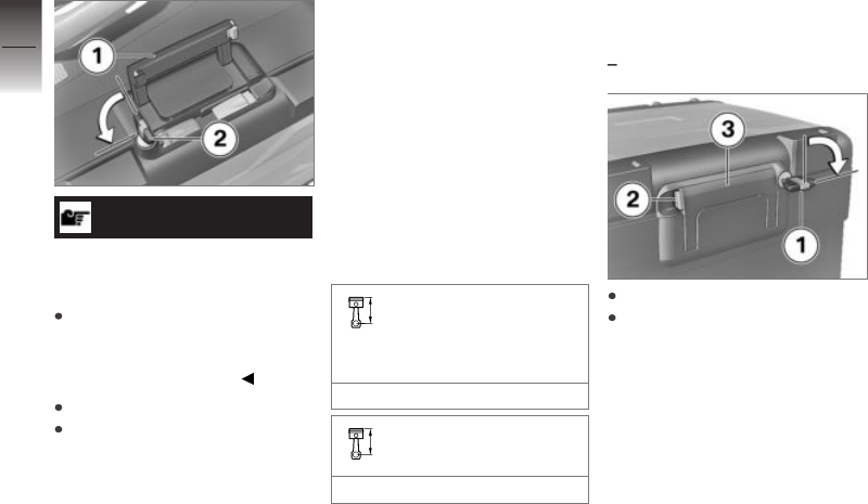
ATTENTION
Closure of carrying handle
with case lock latched
Damage to locking tab
Make sure that the case lock
is at right angles to the forward
direction of travel when you
close the carry handle.
Close carry handle 1.
Turn key 2 counter-clockwise
and remove.
Maximum payload and
maximum permissible
speed
Note the maximum permissible
payload and the speed limit for
riding with cases fitted, as stated
on the label inside the case.
Contact your authorised
BMW Motorrad dealer if you
cannot find your combination of
vehicle and cases on the label.
The values for the combination
described here are as follows:
Maximum permissible
speed for riding with
Vario cases fitted to the mo-
torcycle
max 180 km/h
Payload per Vario case
max 10 kg
Topcase
Opening topcase
with topcase
OA
Turn key 1 clockwise.
Keep the yellow latch 2 held
and fold out the carry handle 3.
10
210
z
Accessories

Push yellow button 1 forward
and at the same time open the
lid of the topcase.
Adjusting topcase volume
with topcase
OA
Open the topcase and remove
all its contents.
Engage pivot lever 1 at the
front limit position to set the
case to maximum volume.
Engage pivot lever 1 at the
rear limit position to set the
case to minimum volume.
Close the topcase.
Closing topcase
with topcase
OA
Press down firmly on the top-
case lid to close.
ATTENTION
Closure of carrying handle
with case lock latched
Damage to locking tab
Make sure that the topcase
lock is vertical when you close
the carry handle.
Close carry handle 1.
The handle engages with an
audible click.
Turn key 2 counter-clockwise
and remove.
10
211
z
Accessories

Removing the topcase
with topcase
OA
Turn key 1 clockwise.
Keep the yellow latch 2 held
and fold out the carry handle 3.
Pull red lever 1 back as far as it
will go.
Latching flap 2 pops up.
Fully open the latching flap.
Take a firm grip of the handle
and lift the topcase out of the
holder.
Mounting topcase
with topcase
OA
Pull red lever 1 back as far as it
will go.
Latching flap 2 pops up.
Fully open the latching flap.
10
212
z
Accessories

Engage the topcase in front
holders 1 of the topcase carrier
plate.
Press the topcase onto the
topcase carrier plate at the
rear.
Press latching flap 1 forward
until resistance is felt.
Next simultaneously press
down latching flap and red re-
lease lever 2.
The latching flap engages.
ATTENTION
Closure of carrying handle
with case lock latched
Damage to locking tab
Make sure that the topcase
lock is vertical when you close
the carry handle.
Close carry handle 1.
The handle engages with an
audible click.
Turn key 2 counter-clockwise
and remove.
10
213
z
Accessories

Maximum payload and
maximum permissible
speed
Note the maximum permissible
payload and the speed limit for
riding with topcase fitted, as
stated on the label inside the
topcase.
Contact your authorised
BMW Motorrad dealer if you
cannot find your combination of
vehicle and topcase on the label.
The values for the combination
described here are as follows:
Maximum speed for rid-
ing with a laden Vario
topcase
max 180 km/h
Payload of Vario topcase
max 5 kg
Installing topcase
with topcase 2, large, 50 l
OA
WARNING
Topcase not properly se-
cured
Driving safety is impaired
The topcase must not wobble
and must be secured free from
play.
Pull handle 1 up as far as it will
go.
Hook the topcase into the lug-
gage carrier 1. Make sure that
the hooks 2 fit securely into
the fixtures 3.
Push the handle down until it
engages.
10
214
z
Accessories

Turn the key in the topcase
lock to position 1 and remove
the key from the lock.
Maximum speed
for riding with
Topcase 2 large, 50 l
max 180 km/h
Payload of Top-
case 2 large, 50 l
max 5 kg
Do not exceed the values for
maximum speed and payload.
Opening topcase
with topcase 2, large, 50 l
OA
Turn the key in the topcase
lock to position 1.
Push lock barrel 1 forward.
Release lever 2 pops up.
Pull the release lever all the
way up.
The lid of the topcase opens.
Closing topcase
with topcase 2, large, 50 l
OA
Pull release lever 1 all the way
up.
Close the lid of the topcase
and hold it down. Check that
nothing is trapped between the
lid and the case.
10
215
z
Accessories

NOTICE
The topcase can also be locked
by turning the lock to the LOCK
position. In this case, make sure
that the key is not left inside the
topcase.
Push release lever 1 down until
it engages.
Turn key 2 in the topcase lock
to the LOCK position and re-
move the key from the lock.
Removing the topcase
with topcase 2, large, 50 l
OA
Turn the key in the topcase
lock to position 1.
The handle pops out.
Pull handle 1 up as far as it will
go.
Lift the topcase at the rear and
remove it from the luggage
carrier.
Navigation system
with preparation for navigation
system
OE
10
216
z
Accessories

Securing navigation
device
NOTICE
Navigation preparation is suit-
able from BMW Motorrad Navig-
ator IV.
NOTICE
The latching system of the
Mount Cradle is not designed to
protect against theft.
Always remove the navigation
system and stow it away safely
as soon as you finish your ride.
Turn ignition key 1 counter-
clockwise.
Pull retainer 2 to the left.
Press in lock 3.
The Mount Cradle is released
and cover 4 can be pivoted
forward and removed.
Insert the navigation system 1
in the lower area and swing it
towards the rear in one rota-
tional movement.
The navigation device is heard
to engage.
Push retainer 2 fully to the
right.
Lock 3 is engaged.
Turn ignition key 4 clockwise.
The navigation device is se-
cured and the ignition key can
be removed.
10
217
z
Accessories

Removing navigation
device and installing
cover
ATTENTION
Dust and dirt on the
Mount Cradle contacts
Damaged contacts
Always reinstall the cover as
soon as you finish your ride.
Turn vehicle key 1 counter-
clockwise.
Pull retainer 2 fully to the left.
Lock 3 is disengaged.
Push lock 3 fully to the left.
Navigation system 4 is un-
locked.
Tilt the navigation device 4 and
work it downward to remove.
Insert cover 1 at bottom and
pivot it up.
The cover engages with an
audible click.
Push retainer 2 to the right.
Turn vehicle key 3 clockwise.
Cover 1 is secured.
Operating navigation
system
NOTICE
The description below is based
on the BMW Motorrad Navig-
ator V and the BMW Motorrad
Navigator VI. The BMW Motorrad
Navigator IV does not support all
the options described here.
NOTICE
Only the latest version of the
BMW Motorrad communication
system is supported. A software
update of the BMW Motorrad
communication system may
be necessary. If this is the
case, consult your authorised
BMW Motorrad dealer.
If the BMW Motorrad Navigator
is installed and the operating fo-
cus is switched to the Navigator,
( 109), several of its functions
10
218
z
Accessories

can be operated directly from the
handlebars.
The navigation system is oper-
ated using the Multi-Controller 1
and the rocker button MENU 2.
Turn the Multi-Controller 1
up and down
In the compass and Mediaplayer
page: increase or decrease the
volume of a Bluetooth-connected
BMW Motorrad communication
system.
In the BMW special menu: select
menu item.
Tilt Multi-Controller 1 briefly
to the left and right
Switch between the main pages
of the Navigator:
Map view
Compass
Mediaplayer
BMW special menu
My Motorcycle page
Long tilt Multi-Controller 1 to
the left and right
Activate certain functions on the
Navigator display. An arrow to
the right or to the left above the
corresponding button area on the
display indicates a function that
can be activated in this way.
Long-push to the right to
activate this function.
Long-push to the left to
activate this function.
Press rocker button MENU 2
down
Switch operating focus to
Pure Ride view.
In detail, the following functions
can be controlled:
Map view
Turn up: Zoom in.
Turn down: Zoom out.
Compass page
Turning increases or
decreases the volume of a
BMW Motorrad communication
system connected via
Bluetooth.
BMW special menu
Speak: Repeat most recent
navigation announcement.
Waypoint: Save current loca-
tion as a favourite.
Home: Starts navigation to
home address (greyed if no
10
219
z
Accessories

home address has been
defined).
Mute: Switch automatic navig-
ation announcements off or on
(off: a crossed-out lips symbol
appears in the top line of the
display). "Speak" will still activ-
ate navigation announcements.
All other acoustic outputs re-
main switched on.
Switch off display: Deactivate
the display.
Dial home number: Dials the
home phone number saved in
the Navigator (not shown un-
less a communication system
and a telephone are connec-
ted).
Diversion: Activates the diver-
sion function (not shown unless
a route is active).
Skip: Skips the next waypoint
(not shown unless the route
has waypoints).
My Motorcycle
Turn: Changes the number of
data shown.
Touch a data field on the
display to open the menu for
selecting data.
The values available fr selection
depend on the optional extras
installed on the vehicle.
Mediaplayer
Push to the left and hold: Play
preceding track.
Push to the right and hold:
Play next track.
Turning increases or
decreases the volume of a
BMW Motorrad communication
system connected via
Bluetooth.
NOTICE
The Mediaplayer function is
only available when a Bluetooth
device complying with the A2DP
standard is used, for example a
BMW Motorrad communication
system.
Indicator and warning
messages
Indicator and warning messages
from the motorcycle are indicated
by a symbol 1 which appears at
the top left in the map view.
NOTICE
If a BMW Motorrad commu-
nication system is connected,
warnings are accompanied by an
acoustic signal.
10
220
z
Accessories

If there are two or more active
warnings the number appears
below the warning triangle.
Touching the warning triangle
when more than one warning
is active opens a list of all the
warnings.
Additional information appears as
soon as a message is selected.
NOTICE
Detailed information cannot be
displayed for all warnings.
Special functions
Integration of the BMW Motorrad
Navigator has produced a num-
ber of deviations from the de-
scriptions in the operating in-
structions for the Navigator.
Fuel reserve warning
The settings for the fuel gauge
are not available, because the
reserve fuel level warning is sent
by the vehicle to the Navigator.
Touch the message when it is
active to view the locations of the
nearest filling stations.
Time and date
The Navigator sends the time
and date to the motorcycle.
To accept the time in
the TFT display, the GPS
synchronisation function
must also be activated in the
menu Settings, System
settings, Date and time.
Security settings
The BMW Motorrad Navigator V
and the BMW Motorrad Navig-
ator VI can be secured against
unauthorised use with a four-digit
PIN (Garmin Lock). If this func-
tion is activated while the Navig-
ator is installed in the vehicle and
the ignition is switched on, you
will be asked whether you want
to add this vehicle to the list of
secured vehicles. If you answer
"Yes" at this prompt, the Navig-
ator saves the VIN of this vehicle
in its internal memory.
A maximum of five VINs can be
saved in this way.
Subsequently, the PIN does not
have to be entered when the
Navigator is switched on by ig-
nition ON while cradled in any of
these vehicles.
If the Navigator is removed from
the vehicle while switched on, a
security prompt asking for the
PIN to be entered is issued.
Screen brightness
In the installed condition, the
screen brightness is specified
by the motorcycle. No manual
input is necessary.
If you prefer, you can switch off
automatic adjustment n the Nav-
igator display settings.
10
221
z
Accessories

10
222
z
Accessories

Care
Care products . . . . . . . . . . . . . . . . . . . . . 224
Washing the vehicle . . . . . . . . . . . . . . . 224
Cleaning easily damaged compon-
ents. . . . . . . . . . . . . . . . . . . . . . . . . . . . . . . . 225
Care of paintwork . . . . . . . . . . . . . . . . . . 226
Vehicle preservation . . . . . . . . . . . . . . . 226
Laying up the motorcycle . . . . . . . . . . 226
Restoring motorcycle to use . . . . . . . 227
11
223
z
Care

Care products
BMW Motorrad recommends
that you use the cleaning
and care products you can
obtain from your authorised
BMW Motorrad dealer.
The substances in BMW
Care Products have been tested
in laboratories and in practice;
they provide optimised care and
protection for the materials used
in your vehicle.
ATTENTION
Use of unsuitable cleaning
and care products
Damage to vehicle parts
Do not use solvents such as
cellulose thinners, cold clean-
ers, fuel or the like, and do
not use cleaning products that
contain alcohol.
Washing the vehicle
BMW Motorrad recommends
that you use BMW insect re-
mover to soften and wash off
insects and stubborn dirt on
painted parts prior to washing
the vehicle.
To prevent stains, do not wash
the vehicle immediately after it
has been exposed to strong sun-
light and do not wash it in the
sun.
Make sure that the vehicle is
washed frequently, especially
during the winter months.
To remove road salt, clean the
motorcycle with cold water im-
mediately after every trip.
WARNING
Wet brake discs and brake
pads after vehicle wash, after
riding through water and in
rainy conditions
Diminished braking effect, risk of
accident
Apply the brakes in good time
to allow the friction and heat to
dry the brake discs and brake
pads.
ATTENTION
Effect of road salt intensified
by warm water
Corrosion
Use only cold water to wash off
road salt.
ATTENTION
Damage due to high water
pressure from high pressure
cleaners or steam cleaners
Corrosion or short circuit, dam-
age to labels, seals, hydraulic
brake system, electrical system
and the motorcycle seat
11
224
z
Care

Exercise restraint when using
a steam jet or high pressure
cleaning equipment.
Cleaning easily
damaged components
Plastics
ATTENTION
Use of unsuitable cleaning
agents
Damage to plastic surfaces
Do not use cleaning agents
that contain alcohol, solvents or
abrasives.
Do not use insect-remover
pads or cleaning pads with
hard, scouring surfaces.
Body panels
Clean trim panel components
with water and BMW Motorrad
solvent cleaner.
Plastic windscreens and
headlight lenses
Remove dirt and insects with
a soft sponge and generous
amounts of water.
NOTICE
Soften stubborn dirt and insects
by covering the affected areas
with a wet cloth.
Clean with water and
sponge only.
Do not use any chemical
cleaning agents.
Chrome
Carefully clean chrome sections
with a generous amount of water
and motorcycle cleaner from the
care series BMW Motorrad Care
Products. This applies especially
where road salt has been in use.
For an additional treatment, use
BMW Motorrad metal polish.
Radiator
Clean the radiator regularly to
prevent overheating of the en-
gine due to inadequate cooling.
For example, use a garden hose
with low water pressure.
ATTENTION
Bending of radiator fins
Damage to radiator fins
Take care not to bend the radi-
ator fins when cleaning.
Rubber components
Treat rubber components with
water or BMW rubber-care
products.
ATTENTION
Application of silicone sprays
to rubber seals
Damage to the rubber seals
11
225
z
Care

Do not use silicone sprays
or care products that contain
silicon.
Care of paintwork
The long-term effects of mater-
ials that are damaging to paint
can be prevented by regular
vehicle washes, particularly if
your vehicle is ridden in areas
susceptible to high levels of air
pollution or natural contamination,
for example tree resin or pollen.
Particularly aggressive materials,
however, should be removed
immediately, otherwise changes
to or discolouration of the paint
can result. These include, for
example, spilled fuel, oil, grease,
brake fluid or bird excrement.
For this, we recommend
BMW Motorrad solvent cleaner
followed by BMW Motorrad gloss
polish for preservation.
Contamination of the paint
surface can be seen particularly
clearly after a vehicle wash.
These areas should be cleaned
immediately using benzine or
spirit, applied with a clean cloth
or cotton pad. BMW Motorrad
recommends that tar spots
be removed using BMW tar
remover. The paint should then
be preserved in these areas.
Vehicle preservation
If water no longer rolls off the
paint, the paint must be pre-
served.
For paint preserva-
tion,BMW Motorrad recommends
the use of BMW Motorrad gloss
polish or agents containing
carnauba wax or synthetic wax.
Laying up the
motorcycle
Clean the motorcycle.
Fill the motorcycle's fuel tank.
Removing battery ( 198).
Spray the brake and clutch
lever pivots and the main and
side stand pivots with a suit-
able lubricant.
Preserve bright metal and
chrome-plated parts with an
acid-free grease (e.g. Vaseline).
Park the motorcycle in a dry
room so that no load applies
to either wheel (preferably us-
ing the front-wheel and rear-
wheel stand available from
BMW Motorrad).
11
226
z
Care


11
228
z
Care

Technical data
Troubleshooting chart . . . . . . . . . . . . . 230
Screw connections . . . . . . . . . . . . . . . . 232
Fuel. . . . . . . . . . . . . . . . . . . . . . . . . . . . . . . . 235
Engine oil . . . . . . . . . . . . . . . . . . . . . . . . . . 236
Engine . . . . . . . . . . . . . . . . . . . . . . . . . . . . . 236
Clutch . . . . . . . . . . . . . . . . . . . . . . . . . . . . . 237
Transmission . . . . . . . . . . . . . . . . . . . . . . 238
Rear-wheel drive . . . . . . . . . . . . . . . . . . . 238
Frame . . . . . . . . . . . . . . . . . . . . . . . . . . . . . 239
Chassis and suspension . . . . . . . . . . . 239
Brakes . . . . . . . . . . . . . . . . . . . . . . . . . . . . . 241
Wheels and tyres . . . . . . . . . . . . . . . . . . 242
Electrical system . . . . . . . . . . . . . . . . . . . 244
Anti-theft alarm . . . . . . . . . . . . . . . . . . . . 245
Dimensions . . . . . . . . . . . . . . . . . . . . . . . . 246
Weights. . . . . . . . . . . . . . . . . . . . . . . . . . . . 248
Riding specifications . . . . . . . . . . . . . . . 249
12
229
z
Technical data

Troubleshooting chart
The engine does not start.
Possible cause Rectification
Side stand extended and gear engaged Retract the side stand.
Gear engaged and clutch not disengaged Select neutral or pull the clutch lever.
No fuel in tank Refuelling ( 151).
Battery flat Charge battery when connected ( 197).
Overheating protection for starter motor has been
activated. Starter motor can only be operated for
a limited period of time.
Allow the starter motor to cool down for
approx. 1 minute before using it again.
The Bluetooth connection is not established.
Possible cause Rectification
The steps required for pairing were not carried
out.
Check the necessary steps for pairing in the oper-
ating instructions for the communication system.
The communication system was not connected
automatically despite successful pairing.
Switch off the helmet's communication system
and reconnect it after a minute or two.
Too many Bluetooth devices are saved on the
helmet.
All pairing entries on the helmet are deleted (see
the communication system operating instructions).
There are other vehicles with Bluetooth-capable
devices in the vicinity.
Avoid simultaneously pairing with more vehicles.
12
230
z
Technical data

Bluetooth connection is interrupted.
Possible cause Rectification
The Bluetooth connection to the mobile end
device is interrupted.
Switch off energy saving mode.
The Bluetooth connection to the helmet is inter-
rupted.
Switch off the helmet's communication system
and reconnect it after a minute or two.
The volume in the helmet cannot be adjusted. Switch off the helmet's communication system
and reconnect it after a minute or two.
The telephone book is not displayed in the TFT display.
Possible cause Rectification
The phone book was not transmitted to the
vehicle.
When pairing the mobile end device, confirm
transmission of the phone data ( 124).
Active route guidance is not displayed in the TFT display.
Possible cause Rectification
Navigation from the BMW Motorrad Connec-
ted App was not transmitted.
The BMW Motorrad Connected App is opened on
the connected mobile end device prior to depar-
ture.
The route guidance cannot be started. Secure the mobile device's data connection and
check the map data on the mobile end device.
12
231
z
Technical data

Screw connections
Front wheel Value Valid
Hexagon screw on quick-release
axle
M12 x 20 30 Nm
Clamping screw for quick-re-
lease axle in telescopic fork
M8 x 35 19 Nm
Radial brake caliper on tele-
scopic forks
M10 x 65 38 Nm
Wheel-speed sensor to fork leg
M6 x 16
Micro-encapsulated
8 Nm
Rear wheel Value Valid
Rear wheel to wheel flange
M10 x 1.25 x 40 Tightening sequence: tighten in diagon-
ally opposite sequence
60 Nm
12
232
z
Technical data

Mirrors Value Valid
Mirror (locknut) to adapter
M10 x 1.25 Left-hand thread, 22 Nm
Adapter to clamping block
M10 x 14 - 4.8 25 Nm
Mirror on handlebars
M10 x 30 25 Nm
M10 x 50 25 Nm with hand
protector
OE
Gearshift lever Value Valid
Peg to gearshift lever
M6 x 20
Micro-encapsulated
10 Nm
Footbrake lever Value Valid
Peg to footbrake lever
M6 x 20
Micro-encapsulated
10 Nm
12
233
z
Technical data

Footrests Value Valid
Clamping block on footrest
hinge
M8 x 25 20 Nm
Footrest on clamping block
M6 x 20 / M6 x 12 10 Nm
Handlebars Value Valid
Clamping block (handlebar
clamp) on fork bridge
M8 x 35 Tightening sequence: Tighten in riding
direction at the front of the block
19 Nm
12
234
z
Technical data

Fuel
Recommended fuel grade Super unleaded (max 15 % ethanol, E10/
E15)
95 ROZ/RON
90 AKI
Alternative fuel grade Normal unleaded (power- and consumption-
related restrictions.) (max 15 % ethanol,
E10/E15)
91 ROZ/RON
87 AKI
Usable fuel capacity approx. 20 l
Reserve fuel approx. 4 l
Exhaust emissions standard Euro4
12
235
z
Technical data

Engine oil
Engine oil, capacity max 4 l, with filter change
Specification SAE 5W-40, API SL / JASO MA2, Additives
(e.g. molybdenum-based) are not permissible
because they can attack coated components
of the engine, BMW Motorrad recommends
BMW Motorrad ADVANTEC Ultimate oil.
Engine oil, quantity for topping up max 0.8 l, Difference between MIN and MAX
BMW recommends
Engine
Location of engine number Crankcase, bottom right, below starter motor
Engine type A74B12M
Engine design Air/liquid-cooled, two-cylinder four-stroke
opposed-twin engine with two overlying, spur-
gear-driven camshafts, a counterbalance shaft and
BMW ShiftCam variable intake camshaft control
Displacement 1254 cm
3
Cylinder bore 102.5 mm
Piston stroke 76 mm
12
236
z
Technical data

Compression ratio 12.5:1
Nominal output 100 kW, at engine speed: 7750 min
-1
with power reduction
OE
79 kW, at engine speed: 7750 min
-1
Torque 143 Nm, at engine speed: 6250 min
-1
with power reduction
OE
140 Nm, at engine speed: 5000 min
-1
Maximum engine speed max 9000 min
-1
Idle speed 1050 min
-1
, Engine at regular operating tempera-
ture
Clutch
Clutch type Multiplate oil-bath clutch, anti-hopping
12
237
z
Technical data

Transmission
Gearbox type Claw-shift 6-speed gearbox with helical gearing
Gearbox transmission ratios 1.000 (60:60 teeth), Primary transmission ratio
1.650 (33:20 teeth), Transmission input ratio
2.438 (39:16 teeth), 1st gear
1.714 (36:21 teeth), 2nd gear
1.296 (35:27 teeth), 3rd gear
1.059 (36:34 teeth), 4th gear
0.943 (33:35 teeth), 5th gear
0.848 (28:33 teeth), 6th gear
1.061 (35:33 teeth), Transmission output ratio
Rear-wheel drive
Type of final drive Shaft drive with bevel gears
Type of rear suspension Cast aluminium single swinging arm featuring
BMW Motorrad Paralever
Gear ratio of final drive 2.91 (32/11 teeth)
Rear axle differential oil SAE 70W-80 / Hypoid Axle G3
12
238
z
Technical data

Frame
Frame type Tubular steel frame with supporting drive unit,
steel pipe rear frames
Type plate location Frame, front left at steering head
Position of the Vehicle Identification Number Frame, front right, on steering head
Chassis and suspension
Front wheel
Type of front suspension BMW Telelever, with anti-dive top fork bridge,
leading link pivot-mounted on engine and tele-
scopic forks, central spring strut supported by
leading link and frame
Design of front wheel suspension Central shock absorber with helical spring
with Dynamic ESA
OE
Central shock absorber complete with torsion
spring and header tank, electrically adjustable de-
compression and compression-stage damping
Spring travel, front 190 mm, at wheel
with HP style
OE
with sport suspension
OE
210 mm, at wheel
with low-slung
OE
158 mm, at wheel
12
239
z
Technical data

Rear wheel
Type of rear suspension Cast aluminium single swinging arm featuring
BMW Motorrad Paralever
Type of rear suspension Central spring strut with coil spring, adjustable
rebound stage damping and spring preload
with Dynamic ESA
OE
Central spring strut with coil spring and
reservoir, electrically adjustable rebound-.stage
and compression-stage damping, electrically
adjustable spring preload
Spring travel at rear wheel 200 mm
with HP style
OE
with sport suspension
OE
220 mm
with low-slung
OE
170 mm
12
240
z
Technical data

Brakes
Front wheel
Type of front brake Hydraulically actuated twin-disc brake with 4-pis-
ton radial monobloc calipers and floating brake
discs
Brake-pad material, front Sintered metal
Play of brake controls (Front brake) 1.6...2.1 mm, on the piston
Rear wheel
Type of rear brake Hydraulically actuated disc brake with 2-piston
floating caliper and fixed disc
Brake-pad material, rear Sintered metal
Blow-by clearance of the footbrake lever 1...1.5 mm, between the frame and the footbrake
lever
12
241
z
Technical data

Wheels and tyres
Recommended tyre sets An overview of currently approved tyres is avail-
able from your authorised BMW Motorrad Retailer
or on the Internet at bmw-motorrad.com.
Speed category, front/rear tyres V, required at least: 240 km/h
Front wheel
Front wheel type Aluminium cast wheel
with cross-spoked wheels
OE
cross-spoked wheel
Front wheel rim size 3.00'' x 19''
with cross-spoked wheels
OE
3.00'' x 19''
Tyre designation, front 120/70 R 19
Load index, front tyre min. 60
Permissible front-wheel imbalance max 5 g
12
242
z
Technical data

Rear wheel
Rear-wheel type Aluminium cast wheel
with cross-spoked wheels
OE
cross-spoked wheel
Rear wheel rim size 4.50'' x 17''
with cross-spoked wheels
OE
4.50'' x 17''
Tyre designation, rear 170/60 R 17
Load index, rear tyre min. 72
Permissible rear-wheel imbalance max 45 g
Tyre pressures
Tyre pressure, front 2.5 bar, tyre cold
Tyre pressure, rear 2.9 bar, tyre cold
12
243
z
Technical data

Electrical system
Electrical rating of on-board sockets max 5 A, total for all sockets
Fuse carrier 1 10 A, Slot 1: instrument cluster, alarm system
(DWA), ignition lock, diagnostic socket, coil main
relay
7.5 A, Slot 2: multifunction switch left, tyre pres-
sure control (RDC)
Fuse holder 50 A, Fuse 1: Voltage regulator
Battery
Battery type AGM battery (Absorbent Glass Mat)
with HP battery
OE
Lithium ion battery
Battery rated voltage 12 V
with HP battery
OE
12 V
Battery rated capacity 12 Ah
with HP battery
OE
10 Ah
Spark plugs
Spark plugs, manufacturer and designation NGK LMAR8AI-10
12
244
z
Technical data

Lighting
Bulb for high-beam headlight LED
Bulbs for the low-beam headlight LED
Bulb for parking light LED
Bulb for tail light/brake light LED
Bulbs for flashing turn indicators, front RY10W / 12 V / 10 W
with LED flashing turn indicator
OE
LED
Bulbs for flashing turn indicators, rear RY10W / 12 V / 10 W
with LED flashing turn indicator
OE
LED
Anti-theft alarm
Activation time on arming approx. 30 s
Alarm duration approx. 26 s
Battery type CR 123 A
12
245
z
Technical data

Dimensions
Length of motorcycle 2207 mm, via spray guard
Height of motorcycle 1430...1490 mm, over windscreen at DIN unladen
weight
with HP style
OE
1312...1372 mm, over windscreen at DIN unladen
weight
with HP style
OE
with sport suspension
OE
1332...1392 mm, over windscreen at DIN unladen
weight
with HP style
OE
with sport suspension
OE
with two-up riding package
OE
1450...1510 mm, over windscreen at DIN unladen
weight
with low-slung
OE
1405...1465 mm, over windscreen, bottom posi-
tion, at DIN unladen weight
Width of motorcycle 952 mm, with mirrors
895 mm, without mounted parts
Front-seat height 850...870 mm, without rider at unladen weight
with comfort seat
OE
825...845 mm, without rider at unladen weight
with comfort seat, high
OE
850...870 mm, without rider at unladen weight
with rider's seat, low
OE
820...840 mm, without rider at unladen weight
with HP style
OE
860 mm, without rider at unladen weight
12
246
z
Technical data

with HP style
OE
with seat, extra high
OE
880 mm, without rider at unladen weight
with HP style
OE
with two-up riding package
OE
850...870 mm, without rider at unladen weight
with HP style
OE
with sport suspension
OE
880 mm, without rider at unladen weight
with HP style
OE
with sport suspension
OE
with seat, extra high
OE
900 mm, without rider at unladen weight
with HP style
OE
with sport suspension
OE
with two-up riding package
OE
870...890 mm, without rider at unladen weight
with low-slung
OE
800...820 mm, without rider at unladen weight
Rider's inside-leg arc, heel to heel 1870...1910 mm, without rider at unladen weight
with comfort seat
OE
1880...1900 mm, without rider at unladen weight
with comfort seat, high
OE
1920...1940 mm, without rider at unladen weight
with rider's seat, low
OE
1820...1860 mm, without rider at unladen weight
with HP style
OE
1880 mm, without rider at unladen weight
with HP style
OE
with seat, extra high
OE
1920 mm, without rider at unladen weight
12
247
z
Technical data

with HP style
OE
with two-up riding package
OE
1870...1910 mm, without rider at unladen weight
with HP style
OE
with sport suspension
OE
1920 mm, without rider at unladen weight
with HP style
OE
with sport suspension
OE
with seat, extra high
OE
1960 mm, without rider at unladen weight
with HP style
OE
with sport suspension
OE
with two-up riding package
OE
1910...1950 mm, without rider at unladen weight
with low-slung
OE
1790...1830 mm, without rider at unladen weight
Weights
Vehicle kerb weight 249 kg, DIN unladen weight, ready for road 90 %
load of fuel, without OE
Permissible gross weight 465 kg
Maximum payload 216 kg
12
248
z
Technical data

Riding specifications
Top speed >200 km/h
12
249
z
Technical data

12
250
z
Technical data

Service
BMW Motorrad Service . . . . . . . . . . . . 252
BMW Motorrad Service history . . . . 252
BMW Motorrad Mobility
services . . . . . . . . . . . . . . . . . . . . . . . . . . . . 253
Maintenance work . . . . . . . . . . . . . . . . . 253
BMW Service . . . . . . . . . . . . . . . . . . . . . . 253
Maintenance schedule . . . . . . . . . . . . . 257
Maintenance confirmations . . . . . . . . 258
Service confirmations . . . . . . . . . . . . . . 272
13
251
z
Service
BMW Motorrad Service
BMW Motorrad has an extensive
network of dealerships in place
to look after you and your mo-
torcycle in more than 100 coun-
tries. Authorised BMW Motorrad
dealerships have the technical
information and the technical
know-how to carry out reliably
all maintenance and repair work
on your BMW.
You can locate your nearest au-
thorised BMW Motorrad dealer-
ship by visiting our website:
bmw-motorrad.com
WARNING
Maintenance and repair work
not in compliance with cor-
rect procedure
Risk of accident due to con-
sequential damage
BMW Motorrad recommends
having work of this nature car-
ried out on the vehicle by a
specialist workshop, preferably
an authorised BMW Motorrad
dealer.
In order to help ensure that your
BMW is always in optimum
condition, BMW Motorrad
recommends compliance with
the maintenance intervals
specified for your motorcycle.
Have all maintenance and re-
pair work that is carried out con-
firmed in the "Service" chapter in
this manual. For generous treat-
ment of claims submitted after
the warranty period has expired,
evidence of regular maintenance
is essential.
Your authorised BMW Motorrad
dealer can provide information on
BMW services and the work un-
dertaken as part of each service.
BMW Motorrad Service
history
Entries
Maintenance work that has been
carried out is entered in the proof
of maintenance. The entries
are like a Service Booklet and
provide proof of regular mainten-
ance.
If an entry is made in the
electronic service booklet of the
vehicle, service-relevant data is
saved in the central IT systems
of BMW AG, Munich.
If there is a change in vehicle
owner, the data saved in the
electronic service booklet can
also be viewed by the new
vehicle owner. A BMW Motorrad
Retailer or a specialist workshop
can also view data that is stored
in the electronic service booklet.
13
252
z
Service

Objection
The vehicle owner can object
to entries being made by the
BMW Motorrad Retailer or a spe-
cialist workshop in the electronic
service booklet along with the
corresponding storage of data in
the vehicle and transfer of data
to the vehicle manufacturer for
the period of time that they are
the vehicle owner. In this in-
stance, no entry is made in the
electronic service booklet of the
vehicle.
BMW Motorrad Mobility
services
As owner of a new BMW
motorcycle, in circumstances
in which assistance is required
you can benefit from the
protection afforded by the various
BMW Motorrad mobility services
(e.g. Mobile Service, breakdown
service, vehicle recovery service).
Your authorised BMW Motorrad
dealer will be happy provide in-
formation about the mobility ser-
vices available to you.
Maintenance work
BMW Pre-delivery Check
Your authorised BMW Motorrad
dealer conducts the BMW pre-
delivery check before handing
over the vehicle to you.
BMW Running-in Check
The BMW running-in check has
to be performed when the mo-
torcycle has covered between
500 km and 1200 km.
BMW Service
The BMW Service is carried out
once a year. The scope of the
service depends on the age of
the vehicle and the mileage rid-
den. Your BMW Motorrad Re-
tailer will confirm the service that
has been carried out for you and
will enter the deadline for the
next service.
For riders with a high mileage
it may be necessary to have
a service before the specified
deadline. In this case, a corres-
ponding maximum mileage is
entered in the service confirm-
ation. If this mileage is reached
before the next service deadline,
the service must be brought for-
ward.
The Service Interval Indicator in
the TFT display reminds you
about one month or 1000 km
in advance when the time for a
service is approaching, on the
basis of the programmed values.
To find out more about service,
go to:
bmw-motorrad.com/service
13
253
z
Service

The scope of maintenance work
required for your vehicle can be
found in the following mainten-
ance schedule:
13
254
z
Service

13
255
z
Service

13
256
z
Service

Maintenance schedule
1 BMW running-in check
(including oil change)
2 BMW Service standard
scope
3 Engine-oil change, with
filter
4 Oil change in bevel gears
rear
5 Check valve clearance
6 Replace all spark plugs
7 Replace air filter element
8 Check or replace air-filter
element
9 Change brake fluid, entire
system
a
annually or every
10000 km (whichever
comes first)
b
every 2 years or every
20000 km (whichever
comes first)
c
if vehicle is used off-
road, annually or every
10,000 km (whichever
comes first)
d
for the first time after one
year, then every two years
13
257
z
Service

Maintenance confirmations
BMW Service standard scope
The repair tasks in the BMW Service standard scope are listed below. The actual scope of maintenance
work applicable for your vehicle may vary.
Performing vehicle test with BMW Motorrad diagnostic system
Visual inspection of hydraulic clutch system
Visually inspecting brake pipes, brake hoses and connections
Checking front brake pads and brake discs for wear
Checking brake-fluid level, front brakes
Checking rear brake pads and brake disc for wear
Checking brake-fluid level, rear brakes
Checking coolant level
Checking ease of movement of side stand
Checking ease of movement of centre stand
Checking tyre tread depth and tyre pressure
Checking spoke tension, adjusting if necessary
Check the lights and signalling equipment
Function test, engine start suppression
Final inspection and check for road safety
Set the service-due date and service countdown distance
Check state of charge of the battery
Confirming the BMW service in the on-board literature
13
258
z
Service

BMW pre-delivery
check
carried out
at
Stamp, signature
BMW Running-in
Check
carried out
at
at km
Next service
at the latest
at
or, when reached earlier
at km
Stamp, signature
13
259
z
Service

BMW Service
carried out
at
at km
Next service
at the latest
at
or, when reached earlier
at km
Stamp, signature
Work performed
Yes No
BMW Service
Oil change, engine, with filter
Oil change in rear bevel gears
Checking valve clearance
Renewing all spark plugs
Renewing air cleaner insert
Checking or replacing air filter element
(for maintenance)
Change brake fluid in entire system
Notes
13
260
z
Service

BMW Service
carried out
at
at km
Next service
at the latest
at
or, when reached earlier
at km
Stamp, signature
Work performed
Yes No
BMW Service
Oil change, engine, with filter
Oil change in rear bevel gears
Checking valve clearance
Renewing all spark plugs
Renewing air cleaner insert
Checking or replacing air filter element
(for maintenance)
Change brake fluid in entire system
Notes
13
261
z
Service

BMW Service
carried out
at
at km
Next service
at the latest
at
or, when reached earlier
at km
Stamp, signature
Work performed
Yes No
BMW Service
Oil change, engine, with filter
Oil change in rear bevel gears
Checking valve clearance
Renewing all spark plugs
Renewing air cleaner insert
Checking or replacing air filter element
(for maintenance)
Change brake fluid in entire system
Notes
13
262
z
Service

BMW Service
carried out
at
at km
Next service
at the latest
at
or, when reached earlier
at km
Stamp, signature
Work performed
Yes No
BMW Service
Oil change, engine, with filter
Oil change in rear bevel gears
Checking valve clearance
Renewing all spark plugs
Renewing air cleaner insert
Checking or replacing air filter element
(for maintenance)
Change brake fluid in entire system
Notes
13
263
z
Service

BMW Service
carried out
at
at km
Next service
at the latest
at
or, when reached earlier
at km
Stamp, signature
Work performed
Yes No
BMW Service
Oil change, engine, with filter
Oil change in rear bevel gears
Checking valve clearance
Renewing all spark plugs
Renewing air cleaner insert
Checking or replacing air filter element
(for maintenance)
Change brake fluid in entire system
Notes
13
264
z
Service

BMW Service
carried out
at
at km
Next service
at the latest
at
or, when reached earlier
at km
Stamp, signature
Work performed
Yes No
BMW Service
Oil change, engine, with filter
Oil change in rear bevel gears
Checking valve clearance
Renewing all spark plugs
Renewing air cleaner insert
Checking or replacing air filter element
(for maintenance)
Change brake fluid in entire system
Notes
13
265
z
Service

BMW Service
carried out
at
at km
Next service
at the latest
at
or, when reached earlier
at km
Stamp, signature
Work performed
Yes No
BMW Service
Oil change, engine, with filter
Oil change in rear bevel gears
Checking valve clearance
Renewing all spark plugs
Renewing air cleaner insert
Checking or replacing air filter element
(for maintenance)
Change brake fluid in entire system
Notes
13
266
z
Service

BMW Service
carried out
at
at km
Next service
at the latest
at
or, when reached earlier
at km
Stamp, signature
Work performed
Yes No
BMW Service
Oil change, engine, with filter
Oil change in rear bevel gears
Checking valve clearance
Renewing all spark plugs
Renewing air cleaner insert
Checking or replacing air filter element
(for maintenance)
Change brake fluid in entire system
Notes
13
267
z
Service

BMW Service
carried out
at
at km
Next service
at the latest
at
or, when reached earlier
at km
Stamp, signature
Work performed
Yes No
BMW Service
Oil change, engine, with filter
Oil change in rear bevel gears
Checking valve clearance
Renewing all spark plugs
Renewing air cleaner insert
Checking or replacing air filter element
(for maintenance)
Change brake fluid in entire system
Notes
13
268
z
Service

BMW Service
carried out
at
at km
Next service
at the latest
at
or, when reached earlier
at km
Stamp, signature
Work performed
Yes No
BMW Service
Oil change, engine, with filter
Oil change in rear bevel gears
Checking valve clearance
Renewing all spark plugs
Renewing air cleaner insert
Checking or replacing air filter element
(for maintenance)
Change brake fluid in entire system
Notes
13
269
z
Service

BMW Service
carried out
at
at km
Next service
at the latest
at
or, when reached earlier
at km
Stamp, signature
Work performed
Yes No
BMW Service
Oil change, engine, with filter
Oil change in rear bevel gears
Checking valve clearance
Renewing all spark plugs
Renewing air cleaner insert
Checking or replacing air filter element
(for maintenance)
Change brake fluid in entire system
Notes
13
270
z
Service

BMW Service
carried out
at
at km
Next service
at the latest
at
or, when reached earlier
at km
Stamp, signature
Work performed
Yes No
BMW Service
Oil change, engine, with filter
Oil change in rear bevel gears
Checking valve clearance
Renewing all spark plugs
Renewing air cleaner insert
Checking or replacing air filter element
(for maintenance)
Change brake fluid in entire system
Notes
13
271
z
Service

Service confirmations
The table is used to verify maintenance and repair work as well as installed optional accessories and pur-
chased special promotions.
Work performed at km Date
13
272
z
Service

Work performed at km Date
13
273
z
Service

13
274
z
Service

Appendix
Certificate for electronic immobil-
iser . . . . . . . . . . . . . . . . . . . . . . . . . . . . . . . . 276
Certificate for Keyless Ride . . . . . . . . 278
Certificate for tyre pressure control
(RDC) . . . . . . . . . . . . . . . . . . . . . . . . . . . . . . 280
Certificate for TFT instrument
cluster . . . . . . . . . . . . . . . . . . . . . . . . . . . . . 281
14
275
z
Appendix

FCC Approval
Ring aerial in the
ignition switch
To verify the authorization
of the ignition key, the
electronic immobilizer
exchanges information with
the ignition key via the ring
aerial.
This device complies with
Part 15 of the FCC rules.
Operation is subject to the
following two conditions:
(1) This device may not
cause harmful inter-
ference, and
(2) this device must accept
any interference
received, including
interference that may
cause undesired
operation.
Any changes or modifi-
cations not expressly
approved by the party
responsible for compliance
could void the user’s
authority to operate the
equipment.

Approbation de
la FCC
Antenne annulaire
présente dans le
commutateur d'allumage
Pour vérifier l'autorisation
de la clé de contact, le
système d'immobilisation
électronique échange des
informations avec la clé de
contact via l'antenne
annulaire.
Le présent dispositif est
conforme à la partie 15
des règles de la FCC. Son
utilisation est soumise aux
deux conditions suivantes :
(1) Le dispositif ne
doit pas produire
d'interférences
nuisibles, et
(2) le dispositif doit
pouvoir accepter toutes
les interférences
extérieures, y compris
celles qui pourraient
provoquer une
activation inopportune.
Toute modification
qui n'aurait pas été
approuvée expressément
par l'organisme responsa-
ble de l'homologation peut
annuler l'autorisation
accordée à l'utilisateur pour
utiliser le dispositif.

Certifications
BMW Keyless Ride ID Device
USA, Canada
Product name: BMW Keyless Ride ID Device
FCC ID: YGOHUF5750
IC: 4008C-HUF5750
Canada:
Operation is subject to the following two
conditions:
(1) This device may not cause harmful interference,
and
(2) this device must accept any interference
received, including interference that may cause
undesired operation.
USA:
This device complies with Part 15 of the FCC rules.
Operation is subject to the following two
conditions:
(1) This device may not cause harmful interference,
and
(2) this device must accept any interference
received, including interference that may cause
undesired operation.
Any changes or modifications not expressly
approved by the party responsible for
compliance could void the user’s authority to
operate the equipment.

Declaration Of Conformity
We declare under our responsibility that the product
BMW Keyless Ride ID Device (Model: HUF5750)
camplies with the appropriate essential requirements of the article 3 of the R&TIE and the other relevant
provisions, when used for its intended purpose. Applied Standards:
1. Health and safety requirements contained in article 3 (1) a)
• EN 60950-1:2006+A11:2009+A1:2010+A12:2011; Information technology equipment- Safety
2. Protection requirements with respect to electromagnetic compatibility article 3 (1) b)
• EN 301 489-1 (V1 .9.2, 09/2011 ), Electromagnetic compatibility and radio spectrum matters (ERM);
Electromagnetic compatibility (EMC) standard for radio equipment and services;
Part 1: Common technical requirements
• EN 301 489-3 (V1.4.1, 08/2002) Electromagnetic compatibility and radio spectrum matters (ERM);
Electromagnetic compatibility (EMC) standard for radio equipment and services; Part 3: Specific conditions for short
range devices (SRD) operating on frequencies between 9 kHz and 40 GHz
3. Means of the efficient use of the radio frequency spectrum article 3 (2)
• EN 300 220-1 & -2 (V2.4.1, 05/2012), electromagnetic compatibility and radio spectrum matters (ERM); Short
range devices (SRD); Radio equipment tobe used in the 25 MHz to 1000 MHz frequency range with power Ieveis
ranging up to 500 mW;
Part 1: Technical characteristics and test methods.
Part 2: Harmonized EN covering essential requirements under article 3.2 ofthe R&TIE directive
The product is Iabeted wilh the CE marking:
Velbert, October 15
th
, 2013
Benjamin A. Müller
Product Development Systems
Car Access and Immobilization – Electronics
Huf Hülsbeck & Fürst GmbH & Co. KG
Steeger Straße 17, D-42551 Velbert

Certification Tire Pressure Control (TPC)
This device complies with Part 15 of the FCC
Rules and with Industry Canada license-exempt
RSS standard(s).
Operation is subject to the following two
conditions:
(1) This device may not cause harmful
interference, and
(2) This device must accept any interference
received, including interference that may
cause undesired operation.
Le présent appareil est conforme aux CNR
d'Industrie Canada applicables aux appareils
radio exempts de licence. L'exploitation est
autorisée aux deux conditions suivantes:
(1) l'appareil ne doit pas produire de brouillage,
et
(2) l'utilisateur de l'appareil doit accepter tout
brouillage radioélectrique subi, même si le
brouillage est susceptible d'en
compromettre le fonctionnement.
WARNING: Changes or modifications not expressively approved by the party responsible for
compliance could void the user's authority to operate the equipment. The term “IC:” before the radio
certification number only signifies that Industry Canada technical specifications were met.
FCC ID: MRXBC5A4
IC: 2546A-BC5A4
FCC ID: MRXBC54MA4
IC: 2546A-BC54MA4
Declaration of Conformity
Radio equipment TFT instrument cluster
For all Countries without EU
Technical information
BT operating frq. Range: 2402 – 2480 MHz
BT version: 4.2 (no BTLE)
BT output power: < 4 dBm
WLAN operating frq. Range: 2412 – 2462 MHz
WLAN standards: IEEE 802.11 b/g/n
WLAN output power: < 20 dBm
Manufacturer and Address
Manufacturer:
Robert Bosch Car Multimedia GmbH
Adress: Robert Bosch Str. 200,
31139 Hildesheim, GERMANY
Turkey
Robert Bosch Car Multimedia GmbH, ICC6.5in
tipi telsiz sisteminin 2014/53/EU
nolu yönetmeliğe uygun olduğunu beyan eder.
AB Uygunluk Beyanı'nın tam metni, aşağıdaki
internet adresinden görülebilir: http://cert.bosch-
carmultimedia.net
Brazil
Este equipamento opera em caráter secundário,
isto é, não tem direito a proteção contra
interferência prejudicial, mesmo de estações do
mesmo tipo, e não pode causar interferência a
sistemas operando em caráter primário.
Canada
This device complies with Industry Canada’s
licence-exempt RSSs and part 15 of the FCC
Rules. Operation is subject to the following two
conditions:
(1) this device may not cause interference, and
(2) this device must accept any interference,
including interference that may cause undesired
operation of the device.
Changes or modifications not expressly approved
by the party responsible for compliance could
void the user's authority to operate the
equipment.
Le présent appareil est conforme aux CNR
d'Industrie Canada applicables aux appareils radio
exempts de licence. L'exploitation est autorisée
aux deux conditions suivantes : (1) l'appareil ne
doit pas produire de brouillage, et (2) l'appareil
doit accepter tout brouillage radioélectrique subi,
même si le brouillage est susceptible d'en
compromettre le fonctionnement.
Mexico
La operación de este equipo está sujeta a las
siguientes dos condiciones:
(1) es posible que este equipo o dispositivo no
cause interferencia perjudicial y
(2) este equipo o dispositivo debe aceptar
cualquier interferencia, incluyendo la que pueda
causar su operación no deseada.
Taiwan, Republic of
根據 NCC 低功率電波輻射性電機管理辦法 規定:
第十二條
經型式認證合格之低功率射頻電機,非經許可,公
司、商號或使用者均不得擅自變更頻率、加大功率
或變更原設計之特性及功能。
第十四條
低功率射頻電機之使用不得影響飛航安全及干擾合
法通信;經發現有干擾現象時,應立即停用,並改
善至無干擾時方得繼續使用。
前項合法通信,
指依電信法規定作業之無線電通信。
低功率射頻電機須忍受合法通信或工業、科學及醫
療用電波輻射性電機設備之干擾。
Thailand
.
(This telecommunication equipments is in
compliance with NTC requirements)
United States (USA)
This device complies with Industry Canada’s
licence-exempt RSSs and part 15 of the FCC
Rules. Operation is subject to the following two
conditions:
(1) this device may not cause interference, and
(2) this device must accept any interference,
including interference that may cause undesired
operation of the device.
Changes or modifications not expressly approved
by the party responsible for compliance could
void the user's authority to operate the
equipment.
Le présent appareil est conforme aux CNR
d'Industrie Canada applicables aux appareils radio
exempts de licence. L'exploitation est autorisée
aux deux conditions suivantes : (1) l'appareil ne
doit pas produire de brouillage, et (2) l'appareil
doit accepter tout brouillage radioélectrique subi,
même si le brouillage est susceptible d'en
compromettre le fonctionnement.

A
Abbreviations and symbols, 6
ABS
Control, 23
Engineering details, 158
operate, 76
Self-diagnosis, 142
Status indicators, 54
Accessories
General instructions, 206
Actuality, 8
Air filter
Position on the motorcycle, 21
Replacing the air filter
element, 191
Ambient temperature
Outside temperature
warning, 43
Reading, 43
Anti-theft alarm
Indicator light, 26
operate, 94
Technical data, 245
Warning, 46
ASC
Control, 23
Engineering details, 162
operate, 78
Reading, 55
Self-diagnosis, 143
B
Battery
Charge battery when
connected, 197
Charging battery when
disconnected, 198
Indicator light for vehicle
voltage, 44
install, 199
Maintenance instructions, 196
Removal, 198
Technical data, 244
Bluetooth, 114
Pairing, 115
Brake fluid
Checking fluid level, front, 180
Checking fluid level, rear, 181
Reservoir, front, 21
Reservoir, rear, 21
Brake pads
Checking front, 178
checking rear, 179
Running in, 145
Brakes
ABS Pro in detail, 160
ABS Pro depending on riding
mode, 149
Adjusting footbrake lever, 131
Adjusting handlebar lever, 130
Checking function, 177
Dynamic Brake Control
depending on riding mode, 149
Safety information, 148
Technical data, 241
15
284
z
Index

C
Care
Chrome, 225
Paintwork preservation, 226
Cases, 207
Check control
Dialogue, 32
Reading, 32
Checklist, 141
Clock
Adjusting, 113
Clutch
Adjusting handlebar lever, 128
Checking function, 182
Technical data, 237
Coding plug
install, 88
Coolant
Checking fill level, 182
Indicator light for excess
temperature, 47
Topping up, 183
Cruise-control system
operate, 89
D
Damping
Adjuster, rear, 19
Daytime riding lights
Automatic daytime riding
light, 74
Manual daytime riding light, 73
Diagnostic connector
Loosen, 202
secure, 202
Dimensions
Technical data, 246
DTC
Engineering details, 162
Indicator and warning light , 56
operate, 80
Self-diagnosis, 144
switching off, 80
switching on, 81
Dynamic Brake Control, 167
Engineering details, 167
E
Electrics
Technical data, 244
Emergency call
Automatically in the event of a
light fall, 70
Automatically in the event of a
severe fall, 71
Information, 12
Language, 69
manual, 69
operate, 69
Emergency off switch (kill
switch), 25
Operation, 68
Engine
Indicator light for engine
control, 49
Indicator light for engine
electronics, 48
starting, 141
Technical data, 236
Engine oil
Checking fill level, 176
Electronic oil-level check, 47
Filler neck, 21
Fill-level indicator, 21
15
285
z
Index

Indicator light for engine oil
level, 47
Technical data, 236
Topping up, 177
Equipment, 7
ESA
Control, 23
operate, 81
F
Frame
Technical data, 239
Front-wheel stand
Installing, 175
Fuel
Filler neck, 19
Fuel grade, 151
refuelling, 151
refuelling with Keyless
Ride, 153
Technical data, 235
Fuel reserve
Range, 112
Warning, 58
Fuses
Replacing, 200
G
General views
Indicator and warning lights, 28
Instrument panel, 26
Left multifunction switch, 23
Left side of vehicle, 19
My vehicle, 118
Right multifunction switch, 25
Right side of vehicle, 21
TFT display, 29, 31
Underneath the seat, 22
H
Handlebars
Adjusting, 133
Hazard warning flashers
Control, 23, 25
operate, 75
Headlight
Beam throw, 127
Headlight beam-throw
adjustment, 19
Headlight courtesy delay
feature, 62, 72
Heated handlebar grips
Control, 25
operate, 97
Hill Start Control, 92, 171
cannot be activated, 59
Engineering details, 171
Indicator and warning lights, 58
operate, 92
switching on/off, 93
Hill Start Control Pro
Adjusting, 94
Engineering details, 171
operate, 93
Horn, 23
I
Ignition
switching off, 63
switching on, 62
Immobiliser
Emergency key, 66
Reserve key, 63
15
286
z
Index

Instrument panel
Ambient-light brightness
sensor, 26
Overview, 26
J
Jump-start, 195
K
Keyless Ride
Battery of the radio-operated
key is flat or the key has been
lost, 67
Electronic immobiliser EWS, 66
Fuel filler cap, unlocking, 153
Lock the handlebars, 65
Switching off ignition, 66
Switching on ignition, 65
Warning, 43, 44
Keys, 62, 64
L
Lighting
Replacing LED auxiliary
headlights, 195
Replacing LED rear light, 194
Replacing the LED
headlight, 194
Technical data, 245
Turn indicators, 193
Warning for faulty bulb, 45
Lights
Automatic daytime riding
light, 74
Control, 23
Headlight courtesy delay
feature, 72
Headlight flasher, operating, 71
High-beam headlight,
operating, 71
Low-beam headlight, 71
Manual daytime riding light, 73
Operating additional
headlights, 72
Parking lights, 72
Side light, 71
Lowered suspension
Restrictions, 138
Luggage
Instructions for loading, 138
M
Maintenance
General instructions, 174
Maintenance schedule, 257
Maintenance confirmations, 258
Maintenance intervals, 253
Media
operate, 123
Menu
Call up, 108
Mirrors
Adjusting, 126
Adjusting mirror arm, 127
Adjusting mirrors, 126
Mobility services, 253
Motorcycle
Care, 223
Cleaning, 223
Lashing, 155
Laying up, 226
Parking, 150
Multifunction switch
General view, left side, 23
General view, right side, 25
15
287
z
Index

N
Navigation
operate, 121
O
Off-roading, 145
On-board computer, 98
On-board voltage
Warning, 44
Operating focus
change, 109
P
Pairing, 115
Parking, 150
Parking light, 72
Phone
operate, 123
Power socket
Notes on use, 206
Position on the vehicle, 21
Pre-Ride-Check, 142
Pure Ride
Overview, 29
R
RDC
Adhesive label for rim, 186
Engineering details, 168
Warnings, 50
Rear-wheel drive
Technical data, 238
Refuelling, 151
Fuel grade, 151
with Keyless Ride, 153
Remote control
Replacing battery, 67
Rev. counter, 26
Engine speed display, 111
Rider info status line
Adjusting, 110, 111
Rider's Manual
Position on the vehicle, 22
Riding mode
Adjusting, 85
Control, 25
Engineering details, 164
Setting PRO riding mode, 87
Riding specifications
Technical data, 249
Running gear
Technical data, 239
Running in, 145
S
Safety instructions
for brakes, 148
For riding, 138
Seat
Position of the height
adjustment, 22
Seats
Adjust the seat height, 100
Lock, 19
Removing and installing, 99
Service, 252
Service history, 252
Service-due indicator, 59
Shift assistant
Engineering details, 169
Gear not trained, 59
Riding, 147
Shift lever
Adjusting the peg, 129
15
288
z
Index

Shifting gear
Recommendation to
upshift, 112
Spark plugs
Technical data, 244
Speed Limit Info
Switching on or off, 111
Speedometer, 26
Spring preload
Adjuster, rear, 21
Adjusting, 133
Starting, 141
Control, 25
Steering lock
Locking, 62
T
Technical data
Anti-theft alarm, 245
Battery, 244
Brakes, 241
Bulbs, 245
Chassis and suspension, 239
Clutch, 237
Dimensions, 246
Electrical system, 244
Engine, 236
Engine oil, 236
Frame, 239
Fuel, 235
General instructions, 7
Rear-wheel drive, 238
Riding specifications, 249
Spark plugs, 244
Standards, 7
Transmission, 238
Weights, 248
Wheels and tyres, 242
Telltale lights, 26
Overview, 28
TFT display, 26
Control, 23
operate, 108, 109, 110
Overview, 29, 31
Select display, 105
Threaded fasteners, 232
Toolkit
Position on the vehicle, 22
Topcase
operate, 210
Torques, 232
Traction control
ASC, 161, 162
DTC, 162
Transmission
Technical data, 238
Troubleshooting chart, 230
Turn indicators
Control, 23
Control, right, 25
operate, 75
Type plate
Position on the vehicle, 21
Tyre pressure monitoring RDC
Reading, 49
Tyres
Checking inflation
pressure, 184
Checking tread depth, 184
Pressures, 243
Running in, 145
Table of tyre pressures, 22
15
289
z
Index

Technical data, 242
Top speed, 139
V
Value
Reading, 32
Vehicle
Put into operation, 227
Vehicle Identification Number
Position on the vehicle, 21
W
Warning lights, 26
Overview, 28
Warnings
ABS, 54
Anti-theft alarm, 46
ASC, 55
Bulb faulty, 45
Coolant temperature, 47
DTC, 56
Engine control unit, 49
Engine electronics, 48
Engine oil level, 47
Fuel reserve, 58
Gear not trained, 59
Hill Start Control, 58, 59
Mode of presentation, 32
My vehicle, 118
On-board voltage, 44
Outside temperature
warning, 43
RDC, 50
Warnings, overview, 35
Weights
Payload table, 22
Technical data, 248
Wheels
Change of size, 185
Checking rims, 184
Checking spokes, 185
Install the rear wheel, 191
Installing front wheel, 188
Removing front wheel, 186
Technical data, 242
Windscreen
Adjusting, 128
Adjusting element, 21
15
290
z
Index

15
291
z
Index
Details described or illustrated
in this booklet may differ from
the vehicle's actual specification
as purchased, the accessories
fitted or the national-market spe-
cification. No claims will be en-
tertained as a result of such dis-
crepancies.
Dimensions, weights, fuel con-
sumption and performance data
are quoted to the customary tol-
erances.
The right to modify designs,
equipment and accessories is
reserved.
Errors and omissions excepted.
© 2018 Bayerische Motoren
Werke Aktiengesellschaft
80788 Munich, Germany
Not to be reproduced by any
means whatsoever, wholly or
in part, without the written per-
mission of BMW Motorrad, After
Sales.
Original rider’s manual, printed in
Germany.

Important data for refuelling:
Fuel
Recommended fuel grade Super unleaded (max 15 % ethanol, E10/E15)
95 ROZ/RON
90 AKI
Alternative fuel grade Normal unleaded (power- and consumption-related
restrictions.) (max 15 % ethanol, E10/E15)
91 ROZ/RON
87 AKI
Usable fuel capacity approx. 20 l
Reserve fuel approx. 4 l
Tyre pressures
Tyre pressure, front 2.5 bar, tyre cold
Tyre pressure, rear 2.9 bar, tyre cold
You can find further information on all aspects of your vehicle at:
bmwmotorrad.com
BMW recommends
Order No.: 01 40 9 899 651
05.2018, 1st edition, 01
*01409899651*
*01409899651*
*01409899651*
