
IAEA-TECDOC-1335
Configuration management in
nuclear power plants
January 2003
The originating Section of this publication in the IAEA was:
Nuclear Power Engineering Section
International Atomic Energy Agency
Wagramer Strasse 5
P.O. Box 100
A-1400 Vienna, Austria
CONFIGURATION MANAGEMENT IN NUCLEAR POWER PLANTS
IAEA, VIENNA, 2003
IAEA-TECDOC-1335
ISBN 92–0–100503–2
ISSN 1011–4289
© IAEA, 2003
Printed by the IAEA in Austria
January 2003
FOREWORD
Configuration management (CM) is the process of identifying and documenting the
characteristics of a facility’s structures, systems and components of a facility, and of ensuring
that changes to these characteristics are properly developed, assessed, approved, issued,
implemented, verified, recorded and incorporated into the facility documentation.
The need for a CM system is a result of the long term operation of any nuclear power
plant. The main challenges are caused particularly by ageing plant technology, plant
modifications, the application of new safety and operational requirements, and in general by
human factors arising from migration of plant personnel and possible human failures. The
IAEA Incident Reporting System (IRS) shows that on average 25% of recorded events could
be caused by configuration errors or deficiencies.
CM processes correctly applied ensure that the construction, operation, maintenance and
testing of a physical facility are in accordance with design requirements as expressed in the
design documentation. An important objective of a configuration management program is to
ensure that accurate information consistent with the physical and operational characteristics of
the power plant is available in a timely manner for making safe, knowledgeable, and cost
effective decisions with confidence.
Currently, the nuclear industry and governmental organizations are showing an
increasing interest in the implementation of this process as an effective way of limiting
configuration errors and related risks. In this report the necessary attributes of a good
operational CM are identified. It is recognized and emphasized that a CM is one aspect of the
overall management system. Nevertheless, this is an important part of managerial activity
focused on the compliance of knowledge of the plant personnel, plant documentation and
records with the state of the plant technology.
The concepts developed in this report present a basic approach to CM, taking into
consideration experience gained from organizations and utilities which have successfully
implemented partial or full CM programmes and from discussions at meetings organized on
the subject. This report will be used in IAEA sponsored workshops and seminars on
operational safety and will also serve as a basis for follow-up activities in CM.
Appreciation is expressed to all Member States and individuals for their valuable
contributions, especially to B. Grimes, J. Lockau and R. Petit. The IAEA officers responsible
for this publication were A. Kossilov of the Division of Nuclear Power and V. Kotyza of the
Division of Nuclear Installation Safety.
EDITORIAL NOTE
The use of particular designations of countries or territories does not imply any judgement by the
publisher, the IAEA, as to the legal status of such countries or territories, of their authorities and
institutions or of the delimitation of their boundaries.
The mention of names of specific companies or products (whether or not indicated as registered) does
not imply any intention to infringe proprietary rights, nor should it be construed as an endorsement
or recommendation on the part of the IAEA.
CONTENTS
1. INTRODUCTION .............................................................................................................. 1
1.1. Background................................................................................................................ 1
1.2. Present situation and the need for a plant configuration management system .......... 2
1.3. Scope and structure.................................................................................................... 2
2. PLANT CONFIGURATION MANAGEMENT PROGRAM ........................................... 3
2.1. General principles of a configuration management program................................... 3
2.1.1. Program management.................................................................................. 5
2.1.2. Design requirements.................................................................................... 5
2.1.3. Information control...................................................................................... 6
2.1.4. Change control............................................................................................. 6
2.1.5. Assessment .................................................................................................. 6
2.1.6. Training ....................................................................................................... 6
2.2. Advantages and challenges of an effective configuration management program .... 6
2.2.1. Advantages of an effective configuration management program................ 6
2.2.2. Challenges affecting configuration management ........................................ 7
2.3. The configuration management process................................................................... 8
2.3.1. Program planning ........................................................................................ 9
2.3.2. Physical configuration scope criteria........................................................... 9
2.3.3. Facility configuration information scope criteria ...................................... 10
2.3.4. Concepts and terminology......................................................................... 10
2.3.5. Interfaces.................................................................................................... 10
2.3.6. Configuration control information system................................................. 10
2.3.7. Procedures ................................................................................................. 11
2.3.8. Configuration audits and assessments....................................................... 11
2.3.9. CM training................................................................................................ 11
2.3.10. Symptoms of CM problems....................................................................... 12
2.4. Design requirements............................................................................................... 12
2.4.1. Establishment of design requirements ....................................................... 12
2.4.2. System and process boundaries.................................................................. 13
2.4.3. Specific SSC list ........................................................................................ 13
2.4.4. Assignment of SSC grades or classes........................................................ 13
2.4.5. Establishment of design bases.................................................................... 13
2.4.6. Information on design requirements .......................................................... 14
2.5. Documentation, maintenance, and reconstitution of design information............... 14
2.5.1. General....................................................................................................... 14
2.5.2. Document control elements ....................................................................... 14
2.5.3. Updating of design documentation ............................................................ 15
2.5.4. Maintenance of design documentation....................................................... 15
2.6. Operational configuration....................................................................................... 16
2.7. Change control process .......................................................................................... 17
2.7.1. General....................................................................................................... 17
2.7.2. Idea for modification — Design change initiation..................................... 20
2.7.3. Design phase .............................................................................................. 21
2.7.4. On site implementation.............................................................................. 22
2.7.5. Updating documentation............................................................................ 22
3. PROCESS FOR IMPROVING THE EXISTING CONFIGURATION
MANAGEMENT PRACTICE ......................................................................................... 23
3.1. Principles of improvement ..................................................................................... 23
3.1.1. Use both a “top-down” and a “bottom-up” approach ................................ 23
3.1.2. Use a graded approach ............................................................................... 24
3.1.3. Document, qualify, store and protect the information developed.............. 24
3.1.4. Develop a means to promptly disposition substantive
weaknesses discovered during the improvement process.......................... 24
3.1.5. Understand the relation of the improvement program to
on-going work processes............................................................................ 24
3.1.6. Introduce a high level information management system............................ 25
3.1.7. Assign data ownership at the source of expertise ...................................... 25
3.1.8. Usability of the information management system is very important ......... 25
3.1.9. Use electronic tools to facilitate streamlined work processes.................... 25
3.1.10 Use databases in ongoing work processes.................................................. 26
3.2. Description of the improvement process................................................................ 26
3.2.1. Understand what others have done ............................................................ 26
3.2.2. Identify where your plant stands now in terms of CM............................... 26
3.2.3. Establish where you want to be in the future ............................................. 26
3.2.4. Formulate a CM plan that describes how to develop and implement
the desired CM process.............................................................................. 26
3.3. Assessing the existing processes and documentation status .................................. 27
3.3.1. Identify structures, systems and components in CM scope........................ 27
3.3.2. Identify design requirements for the SSC in the CM scope....................... 27
3.3.3. Perform a technical review of design requirement and
design bases adequacy................................................................................ 28
3.3.4. Perform a review of recent modification packages in
various discipline areas.............................................................................. 28
3.3.5. Incorporate existing design requirements and a list of
associated documents and procedures into an information system............ 28
3.3.6. Examine the adequacy of operational system line-up and
surveillance procedures.............................................................................. 28
3.3.7. Validate the plant configuration (as-built facility and
supporting operational procedures) versus design documentation ............ 28
3.4. Implementation issues............................................................................................ 28
3.4.1. Analysis of existing methodes and tools.................................................... 28
3.4.2. Analysis of the existing organisation......................................................... 29
3.4.3. CM-related process for improvements....................................................... 29
3.4.4. Implementation of computer systems ........................................................ 29
3.4.5. Practical aspects ......................................................................................... 30
4. CONCLUSIONS AND RECOMMENDATIONS ........................................................... 30
4.1. Conclusions............................................................................................................ 30
4.2 Recommendations.................................................................................................. 31
REFERENCES......................................................................................................................... 33
Annex A: Terminology........................................................................................................... 35
Annex B: Assessments ........................................................................................................... 37
Annex C: Example of top management instruction for configuration
management policy and direction........................................................................... 41
Annex D: Development of methods and tools for CM
(computer and non-computer systems) .................................................................. 45
Annex E: Design basis consideratons..................................................................................... 49
Annex F: Design documentation reconstitution program ...................................................... 52
Annex G: Setting priorities and structuring of existing documentation ................................. 58
Annex H: Samples of “good practices” .................................................................................. 59
Annex I: Summary of findings from IAEA OSART missions and
follow-up visits related to configuration management........................................... 61
Annex J: Status of configuration management in Member States........................................ 62
ABBREVIATIONS.................................................................................................................. 71
CONTRIBUTORS TO DRAFTING AND REVIEW.............................................................. 73

1. INTRODUCTION
1.1. BACKGROUND
Configuration management (CM)
*
programs ensure that the construction, operation,
maintenance and testing of the physical facility are in accordance with the design
requirements* as expressed in the design documentation. An important objective of the
configuration management program is to ensure that accurate information, consistent with the
plant physical and operational characteristics, is available, in a timely manner, for making
safe, knowledgeable, and cost-effective decisions, with confidence. Because the nuclear
industry is one of the most regulated and complex industries in the world, the importance of
configuration management has been clearly understood, but there is yet no clear roadmap on
how to plan and implement configuration management.
The IAEA Safety Standard Safety of Nuclear power Plants: Operation [1] includes many
requirements related to plant configuration. These requirements deal with documentation of
all needed actions in updated procedures, as well as with the need for a thorough updating of
the documentation associated with modifications. They also emphasise the need to maintain
the configuration documentation in strict accordance with the actual physical configuration.*
An evaluation of past Incident Reporting System (IRS) data [2] indicates that a
significant number of reported events have resulted from errors in the control and
maintenance of the configuration of the physical facility, errors in the original design or
design modifications, inadequate corrective actions, inadequate testing, and documentation
discrepancies. A review of results of IAEA OSART missions and follow-up reports shows
also that many findings are related to configuration management deficiencies (see Annex I).
Therefore, the IAEA has developed this guidance on configuration management for nuclear
power stations.
The principal concern relating to inadequate configuration management is that a loss of
the ability to perform safety actions when needed may result. Other potential impacts on the
reliability of the plant with both economic and safety consequences are also of concern. Not
having the right information available at the right time and in the right format to engineering
and operations staff can lead to human errors having potential safety consequences. The effort
required to respond to and correct these errors is greater than the effort required to initially
maintain configuration control.*
Unnecessary expenditure of staff effort also has direct implications for the economic
operation of the facility. For example, in the area of maintenance, configuration errors can
cause business processes in the production of electric energy. Management ownership and
support of duplication of effort and result in rework. Moreover, configuration errors can affect
worker safety with potential impact on the environment and worker exposure to radiological
and other hazards, such as stored-energy sources. Establishment of an effective CM process
can optimize all the configuration management program is essential to assure that processes
are implemented properly and that a culture of configuration management exists at all levels
of the organization.
*
Terms indicated by an asterisk in the text (the first time that they are used) are defined in Annex A.
1
The purpose of this report is to describe the various aspects that need to be considered in
the development and implementation of a systematic plant configuration management system.
The aspects that should be considered include design, procurement, operations and
maintenance, methods/tools, human factors, cost/benefit, and implementation. A systematic
and practical approach for improving configuration management systems, that may be weak or
inadequate, is also described. In addition, examples are included from various countries that
have implemented or improved such a system and the lessons learned during this
implementation.
1.2. PRESENT SITUATION AND THE NEED FOR A PLANT CONFIGURATION
MANAGEMENT SYSTEM
Many nuclear power plants, particularly older facilities, have still not fully consolidated
design bases* and other relevant documentation. Originally, the documentation for these
plants had the same form that was used for design, manufacturing, civil construction, erection,
pre-operational testing, operation and maintenance.
The form of the actual design documentation depends on the design (engineering)
technology used for initial planning of the plant and also on the contractual model. For
example, plants that were designed as “turn-key” by the nuclear system supplier did not have
all relevant design documents transferred to the pant owner/operator. There is also a
difference in configuration documentation between plants, depending on whether the plant
was designed by a single architect/engineer (A/E) or by several designers/suppliers.
Older facilities may have some of the following characteristics:
– Documentation is dispersed, even that containing very important information,
– The main design principles are not readily available and sometimes have been lost,
although functionality of the plant was approved,
– The original ” know-why” is not readily available for use by plant personnel,
– Many plant changes have been made, but the cumulative effects of these changes have
not been considered,
– After several years of plant operation, modification, and maintenance, management of
the plant does not have a high degree of assurance that the facility documentation
reflects actual plant status.
1.3. SCOPE AND STRUCTURE
This report focuses primarily on setting up, implementing and improving a
configuration management program to support the overall engineering and operational change
process for existing nuclear power plants. Guidance is provided in developing and
implementing a configuration management program for control of engineering records and
operational documentation needed to maintain the authorization basis and design basis of
nuclear power facilities.
This guidance does not address details of the installation, post-installation and turnover
processes for implementation of plant changes but addresses the interface with configuration
management of these activities. It address all changes, including temporary ones, which are
not intended to be permanent and are implemented on an interim basis to support plant
operations, maintenance and start-up activity.
2
A special part of the configuration management program has to ensure that design
requirements are met for all operational situations, including transients or accidents.
The report is offered to IAEA Member States for their voluntary use as appropriate.
They are not intended to describe the only method of implementing a configuration
management system, but to provide consistent and informative guidance on the development
and implementation of a configuration management program. Members are encouraged to use
the guidelines as a reference point from which to review their existing or planned efforts. The
guidelines are structured primarily for use by the owners and operators of nuclear power
facilities, who are responsible for facility management processes, rather than for regulatory
authorities. Regulatory authorities may wish to use aspects of this guidance related to
determination of the effectiveness of existing or improved configuration management
processes.
Section 2 below is an overview of the desired characteristics of a nuclear power plant
configuration management program.
Section 3 then describes a process that can be used to improve existing configuration
management processes.
Annexes are provided which contain more detailed information on these subjects
including methods and tools (including computer tools) for maintaining configuration, design
bases considerations, design document reconstitution, setting priorities, and assessment of the
adequacy of configuration control.
2. PLANT CONFIGURATION MANAGEMENT PROGRAM
2.1. GENERAL PRINCIPLES OF A CONFIGURATION MANAGEMENT PROGRAM
Configuration management (CM) is a management discipline that applies technical and
administrative direction to the development, production and support life cycle of an item for
which configuration needs to be maintained. This discipline is applicable to hardware,
software, processed materials, services, and related technical documentation. CM is an
integral part of life-cycle management.
A statement by a utility applying CM may illustrate the importance of a CM approach:
“Contrary to popular belief, the costs of intervention resources is many times higher than that
required to achieve and maintain information integrity.”
Configuration management programs ensure that the construction, operation,
maintenance, and testing of the physical facility are in accordance with the design
requirements as expressed in the design documentation, and to maintain this consistency
throughout the operational life-cycle phase, particularly as changes are being made. These
basic relationships are depicted in Figure 1.
3
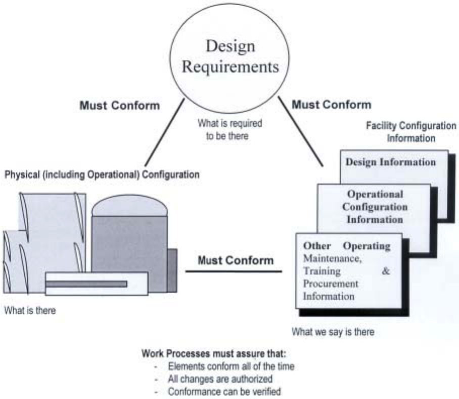
FIG. 1. Relationship among design requirements, documentation and physical configuration.
The physical configuration should conform to the facility configuration information,*
which is based on the design requirements. The facility configuration information, which
includes as-built drawings and operating (including maintenance) procedures, should
accurately reflect both the physical configuration and the design requirements.
Changes to design requirements should be reflected in both the physical configuration
and the facility configuration information. Changes to either the facility physical configuration
or facility configuration information should be supported by, and be consistent with, the
design requirements. These concepts are consistent with those in NIRMA TG 19-1996 and
ANSI/NIRMA 1.0 — 2000 [3].
Operations, including maintenance, must be conducted within a comprehensive set of
procedures, the aim of which is to guarantee the safety of persons and integrity of the
equipment. This procedural system must, in particular, guarantee that after completion of
maintenance work the circuits and equipment are returned strictly to their plant operating
configuration.
4
Achieving consistency among design requirements, physical configuration, plant
operations, and facility documentation offers many benefits in terms of the safety and
efficiency of the facility. Effective implementation of the elements and functions of an
operational CM program provides the tools and information necessary for integrating and co-
ordinating activities to ensure that work is done correctly and safely the first time.
Many programs other than design and modification activities need an effective CM
program to fulfil their objectives and requirements. By maintaining the basic relationships
shown in Figure 1, the CM program helps maintain the integrity and accuracy required of
licensing documents, maintenance procedures and operating procedures.
It is important that top management fully support the concepts of configuration
management in order to assure an appropriate appreciation of the significance of CM at all
organisational levels. A comprehensive description of organisational responsibilities in terms
of configuration management should be developed and put into policies and procedures. This
description of responsibilities should include the design bases, design processes, operation,
maintenance, and change processes. This description of responsibilities should define
precisely who is responsible for what, including the interfaces, transfer of responsibility and of
documents and other information. The organisations whose responsibilities should be defined
include the following:
– The original designer (if involved), at both corporate and unit level as appropriate,
– The suppliers (if involved),
– The design organisation in charge of modification design (if not the same as the original
designer),
– The operating organisation, corporate level (if involved), station, and unit level,
– The training organisation, (if not the same as operations),
– The maintenance organisation (if not the same as operations),
– Other organisations if need be (for example, corporate or local level administrative or
computer support organisations).
An evaluation of the necessary resources at each level should be performed, in order to
ensure that each of them will be able to carry out the corresponding tasks. For an example of
the above assignment of responsibilities, see Annex C.
The following six (6) elements are normally included in successful implementation of
configuration management for Operating Facilities. Each should be considered and factored
into a facility’s overall approach to implementing CM based on the unique circumstances
applicable to the facility.
2.1.1. Program management
The objective is to prioritise, direct, and monitor the development and implementation
of CM for the facility.
2.1.2. Design requirements
The objective is to establish, document, maintain and communicate the design
requirements associated with the facility structures, systems and components.
5
2.1.3. Information control
The objective is to identify and manage facility configuration information (including
document and electronic information* control) related to the physical configuration and the
design requirements.
2.1.4. Change control
The objective of change control is to maintain consistency among the design
requirements, the physical configuration, and the facility configuration information as changes
are made. It is the most important element of effective configuration management, and
warrants extra attention. A graded approach* to individual change control activities should be
considered. The degree of assurance required for a particular change should be proportional to
the safety significance, complexity and economic impact of potential configuration errors.
2.1.5. Assessment
The objective of assessments is to help define facility CM needs and to measure how
effectively the basic relationships between design requirements, physical configuration and
facility configuration information are being established and maintained. Assessments should
be conducted during all stages of the facility life cycle and generally should emphasize
examination of end products rather than program.
2.1.6. Training
The objective of CM training is to provide adequate assurance that all facility personnel
are aware of the owner organization configuration management vision and CM concepts,
terminology, definitions and procedures and are able to properly carry out their work in a way
that helps the organization achieve the CM objectives.
2.2. ADVANTAGES AND CHALLENGES OF AN EFFECTIVE CONFIGURATION
MANAGEMENT PROGRAM
2.2.1. Advantages of an effective configuration management program
A configuration management program is established in order to procure the following
advantages:
– Assure current facility configuration is accurately known,
– Reduce risk of safety significant events,
– Reduce risk of shutdowns and extended outages,
– Facilitate modification design and implementation by providing timely access to facility
configuration information,
– Avoid delays in maintenance activities,
– Facilitate regulatory review,
– Facilitate life management programs,
– Integral to promotion of a safety culture.
6
2.2.2. Challenges affecting configuration management
Several different challenges can affect and, in some cases, prevent effective
configuration management.
2.2.2.1. Transfer of document ownership
Any time ownership of documentation is transferred from one organisation to another
the potential exists for a loss of supporting information. For example, when initial
documentation is transferred from the original designer to the plant owner, some of the
necessary engineering files (justifications, calculations, consistency studies) may not have
been established or provided, or may not have been up-dated according to the actual state of
the installation at the commissioning stage. Likewise, when outsourcing engineering services,
supporting documentation turned over to the owner may not be complete and frequently does
not convey the intent or “know-why” for the design authority and the operator to fully
understand the design bases. (See Annex E.)
2.2.2.2. Failure to up-date to current safety standards
At the occasion of the periodic safety reviews or in response to event lessons learned,
very often some changes in safety standards have to be taken into account, at the regulator’s
request, or by decision of the company. Sometimes this leads to modification of some
procedures or equipment, but all the documents affected by this modification cannot be up-
dated at the same time, and so they may never be up-dated at all.
2.2.2.3. Failure to update documents after plant changes
It is difficult to identify all the documents impacted by a modification, especially when
the documents are not required to physically implement the modification. For example, a
modification can impair the consistency of some related transverse design area such as
internal flooding. A few examples of transverse effects* areas with which consistency must be
maintained is given in Section 2.7.1. A systematic survey of the potential consequences of
each modification on these transverse effects areas and the related documentation needs to be
performed as well as a systematic checking of all types of documents (and systems) which
may be directly affected.
2.2.2.4. Failure to update documents to reflect parts replacement
During maintenance it frequently happens that a part that is fully identical to the original
is no longer available. There is a substantial risk that all documents in which this part appears
may not be updated (e.g. parts list, maintenance procedures, drawings, loads lists). Unless the
non-identical part replacement is considered as a potential design change, there is a risk that
the part function could be inadvertently be modified.
2.2.2.5. Failure to update documents to reflect changed characteristics due to component or
structure degradation
The physical characteristics of materials and components may change during plant life
causing effects such as changes in the gaps between equipment and supports or between
internal parts of a component, or changes in snubber characteristics, even if remaining within
7
the design margins. When these conditions are not restored to the designed status, there is a
risk that all of the documents in which the modified characteristic appears, such as
maintenance instructions, training materials or training tools, may not be updated.
2.2.2.6. Failure to adequately account for human factors
Human factors can influence configuration management at different levels. It is
important that management is aware of these factors and incorporates these into the
configuration management program. Several examples are provided below.
Use of personal documentation including databases
Frequently people use personal documentation or databases which are not maintained or
controlled. This habit can only be fought efficiently by providing personnel with a
configuration management system giving them the same level of reliability as they suppose
their own documents give them
Personnel job migration or retirement
The impact associated with personnel migration is the problem of transferring the
undocumented knowledge that has been acquired by the migrating individual.
Understanding the origin of procedures and modifications
When a person performing an action does not understand the reasons for the action, and
especially if the documentation is not precise enough, there is a risk of inappropriate action.
For example, if an instruction says that the door of a cabinet should be left open and if
the reason is not given, it can be closed by mistake and if an event occurs with which the
instruction was intended to cope, there could be unexpected consequences.
Acceptance of change
The reaction of personnel when a new technology, new process or a new organization is
implemented can be an obstacle to effective configuration management.
Adoption of nuclear safety culture principles and habits
Safety culture principles are important to implementation of an effective configuration
management program. Personnel must recognize that unreliable data can have a negative
effect on plant safety. They must generate and communicate reliable information, and verify
they are using reliable data.
2.3. THE CONFIGURATION MANAGEMENT PROCESS
This section provides the general program criteria that define the functions of
operational configuration management. These criteria encompass the program objectives and
content and should guide the development and implementation of configuration management
programs.
8
2.3.1. Program planning
To effectively achieve configuration management objectives, a facility should develop a
“top-down” configuration management plan (see section 3.1.1), and use it both as a basis for
communication to all facility personnel and as the basis for more detailed implementation
planning. The processes and personnel of the organization should recognize and address the
linkage between design requirements, operations processes and maintenance requirements,
and related information sources. This plan should be reviewed periodically and revised as
necessary based on implementation experience.
Configuration management planning may include consideration of a graded approach in
which the level of analysis, documentation, and actions necessary to comply with
requirements are made commensurate with a number of factors. These factors include the
relative importance to facility safety, safeguards and security, the magnitude of any personnel
hazard involved, the life-cycle stage of the facility, and any other relevant factors.
Configuration management planning steps should include:
– Issuance of a policy/directive that proclaims top management support for the
configuration management objectives, defines key roles and responsibilities, provides
criteria for the scope and establishes key terminology and definitions.
– A mechanism for initiation of immediate review and appropriate disposition of
substantive weaknesses discovered during assessments.
– Issuance of a document that details how the organization(s) responsible for the
operation, maintenance, and modification of the facility will implement configuration
management in accordance with this guideline. This document should specifically
address details of the graded approach to the definition of program requirements and
monitoring of implementation. This document should address each of the following
topics: scope of the structures, systems, and components to be included in the
configuration management program; objectives of each program activity; description of
each program activity; basis for the technical content of each program activity;
organisational structure and staffing; interfaces; implementation priorities, milestone
deliverables, and implementation schedules; and cost estimates.
It is noted that there are alternative business process design practices and computer-
aided tools that could be used in the development of the configuration management program.
2.3.2. Physical configuration scope criteria
The facility structure, systems and components (SSC) to be included in the managed
configuration should be identified. The scope should be based on the function(s) provided by
the SSC. These may be categorised as:
– SSC supporting design-based safety functions (those functions necessary to protect
offsite personnel, on-site personnel, and facility workers from nuclear and other
hazards),
9
– SSC supporting environmental impact-oriented functions (those functions necessary to
protect the environment from significant damage or to satisfy environmental
requirements or permits),
– SSC supporting mission based functions (those functions necessary to avoid substantial
interruptions of the facility mission or severe cost impacts).
Such categorisation can facilitate the implementation of a graded approach to
configuration management. Additional categories, or a further decomposition of these
categories, may be developed if deemed appropriate.
The scope of the SSC included in the managed configuration should be issued to the
organisation, and the list maintained current.
2.3.3. Facility configuration information scope criteria
The facility configuration information to be included in the managed configuration
should be identified. The scope should be based on the category of the SSC associated with
the information and the use of the information to support the facility mission. These may be
categorised as:
– Design information*,
– Operational configuration information*,
– Other configuration information necessary for facility procurement, operations,
maintenance and training activities.
2.3.4. Concepts and terminology
Standard CM concepts, terminology and definitions, based on those provided in this
guideline and other applicable references, should be established and maintained for the
facility. These items should be developed and incorporated into facility administrative control
procedures, management systems and training initiatives. It should be recognized that changes
in work processes may result from these efforts.
2.3.5. Interfaces
Control should be established for identifying and maintaining effective organization,
process and program interfaces, including the control of vendor activities and information.
Interface controls should include clear definition and assignment of key roles and
responsibilities. Particular emphasis should be placed on interfaces required for
implementation of daily business processes that support operation, maintenance and
modification of the facility.
2.3.6. Configuration control information system
An information system consisting of one or more databases for use in the
identification, storage, control and retrieval of information important to CM should be
established. Policy criteria and appropriate procedures for its use should be defined and issued
to the organization. This system should serve the facility’s need for configuration status
tracking, and link the physical configuration with the facility configuration information at
10
minimum. (Note: as business conditions dictate, the use of linked multiple databases, a “list”,
or a combination of these may be appropriate.)
2.3.7. Procedures
An action plan and appropriate implementing procedures should be issued to support the
CM criteria and intended business practices. The action plan should include training on CM
concepts, terminology, definitions and procedures. This training should be provided to all
facility personnel.
2.3.8. Configuration audits* and assessments
A configuration audit should be performed before the acceptance of a configuration
program to assure that the status of the facility complies with its specified requirements and to
assure that the current physical status of the facility is accurately reflected by the configuration
documents.
Normally there are two types of configuration audits, as follows:
a) A functional configuration audit is a formal examination to verify that a configuration
item has achieved the performance and functional characteristics specified in its
configuration documents.
b) A physical configuration audit is a formal examination of the “as-built” configuration
of a configuration item to verify that it conforms to the facility design configuration
documents.
Assessments of CM program effectiveness in the various stages of planning, program
start-up, improvement of the existing program, and ongoing program implementation are
discussed in Annex B.
2.3.9. CM training
The following aspects of configuration management and training systems’ interrelation
should be considered and addressed in plant policies and practices:
– Training should be provided on changes to plant procedures and documentation,
regulatory developments, modifications of plant systems, structures and components,
and changes to the plant organisation structure.
– A mechanism for training programme configuration management should be established.
Training materials and tools (e.g. simulators, computer-based training systems) should
be subject to configuration management, and must reflect the actual status of plant
processes, equipment and procedures. The systematic approach to training (SAT)
provides a solid basis for training configuration management (see Refs. [4,5] for more
details).
– Training programmes for plant managers and relevant personnel should include the
modules on CM addressing configuration management vision and concepts,
terminology, procedures, practices, and job-specific competencies associated with CM
implementation.
11
Necessary links between CM and training systems should be established and
maintained. The CM system should generate and communicate necessary information to be
used in training development and revision.
2.3.10. Symptoms of CM problems
At the very beginning the question will be asked why and when a CM program should
be started. Some symptoms that may be an indication of configuration management problems
follow:
– The as-is situation deviates from the as-documented situation to a significant extent,
– During the outage a lot of extra work occurs due to unforeseen items,
– The time needed for document searches is increasing due to the erosion of
documentation control,
– The actual information is stored in ”personal data bases” as the information in the
central systems is obsolete.
The symptoms mentioned above or similar ones show at least a latent problem which
may turn into an acute CM problem when safety issues are involved. The symptoms
mentioned above also indicate that time and money is wasted.
2.4. DESIGN REQUIREMENTS
For many plants, establishing a complete and accurate set of design requirements can
involve more time and resources than any other configuration management program element.
However, to have the plant design requirements accurately documented is essential because
the design requirements are the foundation from which the configuration management
program basic relationships are maintained. The design requirements are reflected in design
output documents*. These output documents may be used for launching the call for bids,
constructing or manufacturing structures, equipment and instrumentation, and also for
supporting test programs and operational manuals. They include documents such as
calculations, equipment specifications, typical (guidance) drawings, process flow diagrams,
logic diagrams, detailed drawings, system manuals, and set-point documentation.
2.4.1. Establishment of design requirements
The design requirements for the configuration management of SSC should be formally
established, documented and maintained.
– For each SSC, the design requirements should be identified by the design authority as
supporting one or more of the categories established by the physical configuration scope
criteria.
– A technical review should be performed to determine the adequacy of the design
requirements. This includes specification of the requirements associated with all
functions performed by an SSC. If the design requirements are not fully documented,
not accurate, or not complete, the design requirements should be updated to the extent
required to support ongoing and planned operation, considering the expected remaining
life of the facility. Also, any related effects of this inadequacy should be identified and
resolved as appropriate (see section 2.5).
12
– Each SSC should be incorporated into an information system respecting its function
category, assigned grade/class, associated design requirements, associated technical
topics, and associated documentation.
– As the design requirements are developed, they should be categorized and documented
in a form to provide a clear platform for establishing the design basis documents* for
the SSC. This practice should be kept also during the design both of new facilities and
modifications to existing facilities.
– Where the characteristics of physical SSC exceed the design requirements, care should
be taken that the current characteristics are not substituted for (or considered as) the
design requirements of facility original configuration information.
2.4.2. System and process boundaries
The boundaries for each system and process should be established and be identifiable
via appropriate controlled documentation and/or information systems. Criteria used to define
such boundaries should be identified and should relate to design requirement considerations.
2.4.3. Specific SSC list
The specific SSC list included in the managed configuration scope should be identified
on the basis of the physical configuration scope criteria and incorporated into the
configuration Control information system.
2.4.4. Assignment of SSC grades or classes
For each SSC a grade or classification should be assigned based on the most important
type of design requirements applicable to it. The SSC grade or quality classification should be
used as the basis for the degree of control placed on all activities associated with the SSC.
2.4.5. Establishment of design bases
The bases for design requirements should be identified, documented, and maintained to
the extent and level appropriate to the facility’s mission, life-cycle stage and other relevant
factors.
– A technical review should be performed to determine the adequacy of the design basis.
If the basis is not fully documented, or not complete, it may be updated to the extent
required considering the facility life-cycle, the cost of reconstituting the information,
and the need for the information.
– The basis for new or modified design requirements should be established and
documented as these requirements are developed. This should include determination of
the design basis of the portion of the facility being modified to the extent necessary to
obtain confidence that the original design bases are not violated by the modification.
Annex F contains an additional discussion of design basis considerations.
13
2.4.6. Information on design requirements
New and/or revised design requirements should be identified by the design authority and
clearly communicated to facility engineering, operations, maintenance and procurement
personnel.
Design requirements should be identified separately from design basis information and
other facility configuration information. Facility information systems for maintenance
procedures and training should be used to distribute this information.
2.5. DOCUMENTATION, MAINTENANCE, AND RECONSTITUTION OF DESIGN
INFORMATION
2.5.1. General
Documentation, maintenance and reconstitution (when needed) should be performed
according to the principles described in Section 2.4. The present section gives, in a more
detailed way, guidelines to:
– Establish the documentation for physical configuration, design requirements and design
bases in order to be able to control it,
– Complete or reconstitute it when necessary and maintain it throughout the plant life,
– Improve it when needed.
See Annex G for additional detail.
2.5.2. Document control elements
The necessary document control elements have the objective of identifying and
maintaining the configuration documents throughout the plant life, consistent with the actual
configuration and design requirements.
Documentation required for configuration elements depends on the level of control
needed. However, all documentation needs to include all relevant information on traceability
and changes.
2.5.2.1. Identification conventions
The types of documents needed to define the configuration should be pre-established, as
well as numbering conventions for the documents, in accordance with the numbering
conventions used for the configuration items. These numbering conventions should allow
links to be created between items within the documents. The configuration management
system (manual or electronic) and other facility systems may be used to maintain these links.
The links should allow hierarchical or subordinate relationships among the various
configuration elements.
The “design authority” for the design documents and the “owner” of the operation and
maintenance documents should be responsible for the consistency of the identification system,
and for the technical content of the assigned documents.
14
2.5.2.2. Storage
Original or master copies of all documents describing the facility configuration,
including electronic information, should be stored and protected in safe conditions in
accordance with the rules defined in IAEA Safety Series No. 50-C/SG-Q [6].
2.5.2.3. Document management system
A Document management system has to be implemented. It should be set up at the very
beginning of the design, be available to define the original configuration, and should be
maintained current throughout the plant life. The currently approved revisions of each
document should be identifiable in this system. This will allow visibility and traceability of
documents for the efficient management of the evolving configuration.
The following types of data that are normally maintained are listed below:
– Identification (document number, issue / revision, serial number)
– Title
– Date
– Release status
– Implementation status (designed/built/produced standard).
This information is maintained not only for the base configuration documents but for
subsequent modifications caused by facility change processes and deviation and waiver
procedures.
The objective of the document control system for facility configuration should be to
provide authorized users of the system timely information as to current document status and
timely access to the documents relevant to the user.
2.5.3. Updating of design documentation
Design documentation can be affected not only by design changes, but also by the
evolutions of safety standards and by periodic safety re-evaluations or generic issue
evaluations (see Section 2.2.2) even if no physical modification is initiated.
Every time a new document affecting the configuration documentation is written or
modified it is necessary to check to assure that all documents which can be affected by the
new document or new information are modified as appropriate. It is to be noted that a
documentation management system that includes computerized links among documents can
be a valuable tool in accomplishing this checking.
2.5.4. Maintenance of design documentation
2.5.4.1. Priority for reconstitution
The design documents generally are prepared or reconstituted in accordance with a
priority that considers the safety significance and risk significance of the systems, structures
and components (SSC). (See Annex G.) The frequency of modifications to the system and
components, the complexity of the SSC, the importance of the SSC to sustained plant
15
operation, and the possible effect of the SSC on other risk-significant SSC should also be
considered. For additional detail on design document reconstitution see Annex G and
NUREG-1397 [7]. The relation between design bases and design documentation is discussed
in Annex E.
Some utilities have had informal methods for determining the necessity and timeframe
for document regeneration. These determinations were in large measure made on a case-by-
case basis, based on the judgement of the cognisant discipline lead engineer. Other utilities
may have identified the documents as missing, but delayed evaluations and decisions on
reconstitution until a later time. Most utilities are considering regenerating at least those
missing design documents that are required to validate critical system or component
functional attributes, especially if the absence of these attributes resulted in a reportable item.
Missing documents are usually identified during the preparation and field validation of the
design documents.
2.5.4.2. Verifying replacement documents
Most existing plants have been designed without using a fully computerized design
system. Most of the documents for these plants, especially drawings, have been developed by
hand, or by using software that is no longer in use, and which cannot translated to new
software, at least without a very thorough verification.
Even for plants designed with a ”computerized” design system, many of the sub-
contractor documents were not computerized, or used software not compatible with the main
software. Electronic support for the original computer system is sometimes not still provided
by the supplier.
After some modifications the so called ”archived” original document systems, even the
originals kept by the supplier, are ageing, and cannot be used any more because reproduction
has become nearly, if not totally impossible. If reconstitution by electronic means, (see the
next paragraph) is not possible for practical or economic reasons, reconstitution of the
document is sometimes necessary. In that case the verification that the reconstituted document
is identical with the original document has to be very thoroughly performed.
2.5.4.3. Electronic information
Converting the document to a digital format can be accomplished in different ways.
– Redrawing or writing the document using design software,
– Scanning the document,
– Photo-imaging the document.
In all cases, a very thorough verification is necessary to avoid discrepancies with the
original document, or to examine the consequences of the differences in resolution with the
previous document in the case of photo imaging.
2.6. OPERATIONAL CONFIGURATION*
Operational configuration must be maintained within design requirements at all times.
(These requirements vary in accordance with the different operating modes). Operating
16
documentation (for example, system manuals, general operation rules, alarm sheets,
maintenance manual, periodic tests, operating procedures, chemical specifications, etc.) must
guarantee that design requirements are met for all operational transients or accidents.
Configuration changes not covered by procedure should be treated as change requests
requiring approval according to the change request management system. Operational line-up
and surveillance procedures should contain requirements to periodically verify that such
parameter adjustments remain within approved ranges.
Operating procedures may be used to change the configuration of the plant without
additional approval only if the changes are within design requirements. Possible examples
include:
– Adjustment of programmable logic controller operating band within the range allowed
by the system design,
– Installation and removal of jumpers as a part of surveillance or performance testing,
– Adjustment of valve position or pump discharge pressure to maintain system
parameters,
– Procedural maintenance of condensate storage tank level at more than 90 percent when
the minimum design requirement is 76 percent,
– Procedural maintenance of shutdown boron concentration at 2,500 parts per million
when the technical specification limit is 2,200 parts per million,
– Short-term, temporary operation of an automatic system or component in the manual or
bypass mode,
– Installation and removal of piping flanges required to support changing operational
modes such as refueling.
Turnover to operations following maintenance or testing can challenge safe operation.
The execution of maintenance work on mechanical and electrical circuit equipment requires
rigorous isolation of the work area from the rest of the process. Isolation is also required for
some periodic tests and for some post-modification requalification tests. Failure to properly
reconfigure equipment can invalidate the response capability of equipment to postulated
events and thereby invalidate safety analyses. (See Annex H.)
The relationships among operational configuration, design requirements, and design
bases are shown in the following Figure 2. In this figure, the operational configuration is
confined within the design requirements and the design requirements are confined within the
design bases.
2.7. CHANGE CONTROL PROCESS
2.7.1. General
A rough outline of a change process including all consequences regarding the
documentation and the plant object structure is shown on Figure 3.
17

Design bases
Design requirements
Operational
configuration
FIG. 2. Relationship of design bases, design requirements and operational configuration
(INPO AP929 — 1998) [8].
Power Plan
Management
System
Change
request
Decision of the
steering
committee
Feasibility
(technical, time,
cost, etc.)
Idea for
modification
Design phase
Approval by the
authorities when
required
Time schedule
work order
manufacturing
Lockout of
the system
On site
implementation
Detailed planning
work preparation
Element for updating
documentation
Updating the
documentation
FIG. 3. Example of workflow for a modification in a nuclear power plant.
18
It is important that the plant management information system is appropriately updated to
assure that no mismatch between the physical plant status and the plant documentation occurs,
It is also important that all documentation possibly affected by any change of information is
identified and updated.
The design and configuration control process is applied to design and operational
configuration activities for safety-related equipment and/or systems to ensure that applicable
design requirements such as design bases, regulatory requirements, codes, and standards are
correctly translated into the associated design output documents. These output documents
include drawings, specifications, design analyses, calculations, installation procedures, test
procedures, and operational documentation (e.g. procedures for periodic tests, operating
procedures, maintenance procedures, and training documentation).
The actual process to be followed will depend on the rules of the regulatory body and
also on the practise of the utility organisation.
In implementing the basic principles above the following guidelines are suggested:
– Preservation of safety levels,
– Limitation of modifications,
– Avoid increasing outage time,
– Cost control.
If a change request comes up, a substantial effort should be spent to determine whether
the change is really necessary, using a formal ranking system. Particular attention is warranted
to the consequences of the modification with respect to CM. It is therefore a good practice to
minimise plant modifications as far as possible.
For preparing a sound decision the analysis of the planned change also should account
for the transverse effects on other systems or objects. This analysis should be documented and
is part of the basis for a cost-benefit-analysis and the final decision. Examples of such effects
follow:
– Earthquake as initial event,
– Deep freeze environmental conditions,
– Internal flooding,
– Whipping and open flow effect of piping,
– Behaviour of valves under rapid full flow shut down,
– Fire detection and prevention, and fire zoning,
– Classification of equipment, systems, and buildings,
– Post accident qualification of systems and components,
– Building penetrations.
When the decision is made to proceed with a change the detailed engineering is
performed including the specific time schedule for the change. The change is implemented. In
the next step, a re-qualification test is undertaken to prove that the change complies with the
specified values.
19
Finally the documentation is made consistent with the change that has been
implemented. The whole work process is controlled by a specified work flow which
standardises the work process.
2.7.2. Idea for modification — design change initiation
2.7.2.1. Sources of design changes
A design change is initiated by a modification request. Often, the request is linked to an
integrated schedule that provides for processing technical and engineering services while
prioritising the use of resources and providing budget accountability.
The initial screening process is a key factor in determining which proposed
modifications are selected for development and implementation. When the utility selectively
decides to implement a plant modification that has gone through a rigorous screening process
there are few, if any, surprises during implementation. This is because the screening process
has included the performance of walk-downs and because much of the needed inter-
organisational co-ordination already has been done in order to develop the information needed
to gain approval for funding. A rigorous screening process thereby results in better utility
control of the overall modification implementation program. Whenever the possibility of
avoiding the modification appears, a complete justification file should be maintained.
The main sources of modification requests are:
– Screening of events that occur both internal to the plant or the utility and at other
facilities, including international experience,
– Plant or utility change requests for safety or availability improvements,
– Regulatory body requests,
– Results of evolution of safety standards or of safety reviews (Safety issues),
– Maintenance requirements,
– Operational economy,
– Waste reduction, etc.
2.7.2.2. Feasibility
In order to give to the utility decision-making authority adequate information on which
to base a decision, a feasibility study is generally necessary, which includes:
– Development of potential conceptual solutions,
– Preliminary check with design requirements and regulatory constraints,
– Cost evaluation,
– Duration of design and procurement and of on-site implementation as well as the plant
state needed to perform the work,
– Determination whether the work should be done in-house or contracted to an external
organisation,
– If needed, thermohydraulic, integrity and probabilistic safety studies (PSA) studies
– “Transverse effects” listed in Section 2.7.1 considered for applicability.
20
2.7.2.3. Decision
Based on the information developed, the decision whether to initiate the modification,
when, and in what conditions, is taken.
2.7.2.4. Change request
After the positive decision is obtained the proposal is changed into a change request in
order to initiate the design phase.
2.7.3. Design phase
2.7.3.1. Involvement of the original designer
As expressed in Section 2.5.2, a “design authority” should be in charge of the design or,
at least, of its supervision, in order to ensure the overall consistency with the original design
bases, and of the whole installation. In order to benefit from the design background, the main
original designers should be used when feasible. In any case, the original design intent should
be established for the system. The design intent can be established by consulting design bases
documents in those cases where such documents have been comprehensively developed.
It is generally appropriate to perform a walk-down of the area affected by the
modification to validate existing facility drawings and to note any structural details,
environmental conditions or other configuration details that may need to be considered in
developing the implementation file.
2.7.3.2. Implementation file
An implementation file has to be established, providing all information and
documentation necessary for the implementation, justification, operation, and maintenance.
According to the Utility organisation, this file could be split into different parts depending on
the division of responsibilities.
Typical contents of an implementation file are:
– Background and description of the modification, including its justification. This can be
used as a basis for information for the regulator,
– Reference documents. Including safety standards used, upstream documents (to clarify),
justifications, transverse analyses (see Section 2.7.1) and calculation notes,
– Equipment qualification (EQ-File),
– Re-qualification (system) tests needed after implementation. These can include tests to
confirm the adequacy of the modification and overall inter-systems tests to be re-
performed, with corresponding procedures,
– Engineering documentation, including integration conditions (status of the unit,
electromagnetic protections, radioactive protection precautions), risk analysis related to
potential problems or errors during implementation, erection procedures, and schedule,
– Effect on NDE scope and requirements,
– Supplier contract management,
– Detailed design package, including updated documents, or elements to update all design,
simulator and training documentation of the plant,
21
– Updating of all operational documents (system manuals, alarm sheets, (general
operating rules), maintenance manuals, testing procedures, chemical specifications and
operating procedures),
– Spare parts list adaptation,
– When relevant, unit specific adaptations,
– QA programme for the process.
An example for a minor modification is given in Annex H.
2.7.3.3. Approval by the authorities
Both the design authority and the operation organisation and when required the safety
authorities should be involved in setting up this file.
During the design phase it is necessary to identify design bases and design inputs in the
development of a proposal package. From these design bases and design inputs, preliminary
design support documents are developed and a budget package put together that identifies
time and material costs for the proposed modification.
The design bases document incorporated in the modification package is prepared for
those projects involving design changes or installation methods that are anticipated to affect
safety related structures, systems, and components (SSC).
2.7.4. On site implementation
On site implementation needs to be thoroughly planned and scheduled before starting
the work itself. This planning includes a verification that the implementation file provided,
totally fits with the actual state of the unit.
It is advisable that a representative of the design authority be present during the
implementation phase, in order to update the file if necessary, in real time, after agreement of
the designer’s offices.
Before transfer to the operation staff, the tests can include, according to the
modification, overall tests, and not only tests of the modification itself, if these overall tests
have been impacted by it.
2.7.5. Updating documentation
All types of documentation potentially impacted by the modification should be
examined and updated if necessary. These categories can be summarised as follows:
– Design documentation — Documents that may be related to the design include design
bases documents, justification reports, calculation notes, drawings (lay out, guide and
detailed drawings), equipment lists, electrical, I&C and mechanical diagrams,
reconfiguration and re-qualification procedures, safety analysis report, and
environmental report.
22
– Operational documentation — system manuals, general operating rules, maintenance
manuals, maintenance procedures, operating procedures, testing procedures, chemical
specification, alarm and set-point documents.
– Other documentation — full scope, partial or engineering simulators, configuration and
training documentation, other training tools.
A graded priority system for updating the various documents should be established to
assure that there is a clear understanding of the schedule for updating documents in those
cases where the updating is not required prior to declaring a plant modification operational.
The priority system should be based on the use of the document and its importance to safety.
3. PROCESS FOR IMPROVING THE EXISTING CONFIGURATION
MANAGEMENT PRACTICE
This section discusses methods for improvement of existing configuration management
processes. The general principles that should underlie a CM program improvement effort are
first presented. These principles were contributed by several experts from member states with
extensive practical experience in improving and revising configuration management
programs.
A practical sequence of improvement efforts is next described. Some of the key steps of
the improvement process, such as assessing the existing CM processes and documentation
status, and cost/benefit analysis of improvements and setting priorities, are also elaborated in
this section. Finally, selected implementation issues and selected good practices are discussed.
3.1. PRINCIPLES OF IMPROVEMENT
Each facility will have a different existing configuration management situation and CM
improvement plans and implementation approaches will therefore differ in detail. However,
several general principles are useful to keep in mind as these plans and methods are
developed.
3.1.1. Use both a “top-down” and a “bottom-up” approach
A top-down improvement approach is characterised by describing an “ideal” system and
attempting to implement this system by a systematic plan. A “bottom-up” approach might
assess all of the existing documentation and control systems and attempt to improve each
system and its interfaces with other systems. Based on the experience of several Member
States with CM improvement, a combination of these two approaches is recommended.
Although an improvement plan is important to guide detailed implementation of
improvement initiatives, it is also essential to obtain a comprehensive understanding of the
existing work processes and documentation as well as the conformity of the as-built facility
with the existing documentation. This will allow an accurate assessment by station
management of the scope, time, and costs associated with various improvement approaches
and selection and prioritisation of realistic and useful improvement initiatives. These selected
23
initiatives can then be described in an improvement plan. Such a plan will provide both
guidance to the staff that implements the plan and a means of progress measurement.
The implementation plan is also an important means of communicating CM
improvement goals to the station staff, to the regulatory authority and to others.
3.1.2. Use a graded approach
There are always more opportunities for improvement than resources for
implementation. Choices must therefore be made as to the scope and priorities of the CM
improvement plan. A graded approach that takes into account both contributions to safety and
process efficiency benefits is recommended. Adequate assurance of safe operation is, of
course, the highest priority. If a judgement of adequate safety cannot be made, the plant
should be placed in a safe state until such adequacy can be established.
Improvements in configuration management should take into account the safety
significance of the systems for which documentation, for example, is to be improved.
Priorities should also be set by the work-process efficiency benefits that can be achieved. For
example, less engineering hours will be expended if efficient document-content search tools
are available to engineers. Priorities are further discussed in Annex G.
INPO document AP-929 [8] provides a suggested method for applying a graded
approach to classification of plant documents, based on their use. Refer to Annex A for a
definition of ”graded approach”
3.1.3. Document, qualify, store and protect the information developed
It is important that the improvement process includes means to control the information
developed. This includes documentation of the efforts completed, qualification of the data and
information developed (including QA as appropriate). Appropriate storage and integrity
protection of information also requires attention, particularly information in electronic
formats.
3.1.4. Develop a means to promptly disposition substantive weaknesses discovered
during the improvement process
Various findings relating to information weaknesses or incorrect documents will
undoubtedly be identified during the improvement process. It is important to decide in
advance how these findings can be most efficiently handled. For example, grouping of
findings for entry into a corrective action system may be more useful than listing each finding
separately when the same process change or reconstitution effort is expected to resolve the
findings. However, it is also important to make an early safety screening of discovered
deficiencies so that problems with direct impacts on safety or compliance with, for example,
technical specifications can be dealt with in a timely way.
3.1.5. Understand the relation of the improvement program to on-going work processes
Introduction of a configuration management improvement process into facility activities
has complex implications for ongoing processes that use the information and documents that
are being reviewed, changed or replaced. These ongoing processes include the plant
24
modification process, various operations procedures, and document control processes. Some
of the interactions that need advance consideration are as follows:
– How information that results from improvement activities relates to information use in
ongoing processes needs to be specified in advance,
– If initial reviews indicate that the design bases information for systems important to
safety is lacking, modification processes should be amended to assure that an adequate
engineering basis is developed for current modification activities,
– When deficiencies in existing work processes are identified, new processes should not
be added without eliminating ineffective processes,
– When a need to reconstitute documents is identified, priority should be given to
reconfiguring ongoing work processes to avoid accumulating more inadequate
documents that must be later reconstituted.
3.1.6. Introduce a high level information management system
An information management system that allows easy navigation of important documents
and databases can significantly enhance the usefulness of available information. Technology is
now available to implement computer architecture without a large hardware cost. To the
extent that the CM process is computerised, use linked access to text-searchable electronic
material as a key concept (as opposed to attempting to achieve consistency of database
formats).
3.1.7. Assign data ownership at the source of expertise
To the extent possible, one source should be specified as authoritative for each type of
data or information. Data should appear in only one authoritative database to the extent
feasible. Changes to database information should be originated or approved by the source of
expertise, which also usually should be the owner of the database.
3.1.8. Usability of the information management system is very important
Usability (lack of complexity) of the information management system is important and
must be balanced against the detail contained in the system. Information should be shown to
be essential, regularly used or be available at very low initial and update cost before being
included in system databases. One of the main sources of configuration management human-
error problems is misuse or non-use of complex information systems. Information systems
and databases should be attractive to the user (use of the system should be seen by the user as
an advantage as well as an obligation). Simplification of work process tools is often more
important than assuring comprehensiveness in a database or information management system.
3.1.9. Use electronic tools to facilitate streamlined work processes
Process streamlining enhanced by computerisation can result in substantial efficiencies
as well as safety benefits. However, the use of electronic tools should not be viewed as a
panacea for configuration management problems. More problem sources can be eliminated by
improving a process than by simply applying electronic tools to existing processes. Special
caution should be used to understand the existing process before attempting to introduce any
electronic tools.
25
3.1.10. Use databases in ongoing work processes
It is important that the use of certain information sources be mandatory during certain
work processes, such as engineering work on modifications. It is also important to make clear
the approximate amount of effort to be expended in ascertaining the associated past work
history or regulatory commitments. These expectations can be changed as information systems
and search tools become more useable and efficient.
3.2. DESCRIPTION OF THE IMPROVEMENT PROCESS
This section provides a possible sequence of activities that could be followed to develop
and implement a configuration management improvement process. These activities are based
on those found to be of practical use by facility organisations in Member Countries that have
undertaken to improve configuration management processes.
3.2.1. Understand what others have done
One of the most useful preparatory activities for configuration management
improvements is to understand what has worked and not worked at other facilities. This can
include visits to counterparts at other facilities, and inclusion of counterparts on internal
assessment teams. Cost and schedule experience of other facilities should also be understood.
3.2.2. Identify where your plant stands now in terms of CM
It is important for facility management to understand in general terms where their plant
stands in terms of configuration management effectiveness. This can be primarily based on
knowledge of the facility processes and comparison with the configuration management
Principles in section 2.1 above, examination of condition reports (e.g. related to design and
line-up errors) in the Corrective Action system, and by benchmarking with other facilities.
This understanding will allow facility management to make initial time and resource estimates
for various CM improvement efforts.
3.2.3. Establish where you want to be in the future
Facility management should articulate some general vision of the characteristics of the
configuration management process that is the ultimate goal of the facility. For example, this
could be expressed in terms of the principles of configuration management systems of
Section 2.1 above, the degree of computerisation of work processes and information systems,
and work process efficiency or facility competitiveness goals. Having the right information
available at the right time in the right format will contribute to both facility safety and
productivity.
3.2.4. Formulate a CM plan that describes how to develop and implement the desired
CM process
The configuration management improvement plan should provide facility management
expectations in terms of responsibility assignments, schedules, budgets and personnel
resources for the following plan elements:
26
– The responsibility for plan implementation should be assigned to a single senior
manager and an interdisciplinary steering group formed. The steering group is
recommended to assure that the viewpoints and information needs of all involved
departments are incorporated in process and information system improvements.
– The plan itself is a means of communicating the CM vision to facility staff and others.
The plan should also provide for staff training on configuration management concepts
and on the CM improvement plan as well as providing for periodic staff updates on
progress and a means for staff information feedback on implementation problems.
– Detailed assessments should be carried out of existing processes and documentation
status (see Section 3.3) and an inventory made of available sources of knowledge and
information.
– A determination should then be made as to which of the available knowledge and
information sources contain reliable information that can and should be used in ongoing
processes.
– Using the information developed from the assessments, formulate the desired CM
process.
– Make appropriate changes to ongoing modification and document control processes and
operational procedures so that current work activities are compatible with the desired
CM process. This may include implementation of a new top-level information
navigation tool.
– Prioritise CM improvement efforts, including reconstitution of missing information or
inadequate design bases and reclassification of structures, systems and components
subject to various degrees of CM control.
– Periodically evaluate the effectiveness of the new CM processes and improvement
efforts.
3.3. ASSESSING THE EXISTING PROCESSES AND DOCUMENTATION STATUS
The following elaboration is provided on the detailed assessments of existing processes
and documentation status that are essential in the improvement plan elements described in
Section 3.2.4 above. The overall assessment process is discussed in Annex B.
3.3.1. Identify structures, systems and components in CM scope
The structures, systems and components subject to various degrees of configuration
management control should be identified (configuration identification*).
3.3.2. Identify design requirements for the SSC in the CM scope
The design requirements and associated design bases for the structures, systems and
components for which some degree of configuration management is appropriate should be
identified. Caution should be exercised to assure that design requirements, not current system
characteristics, are compiled.
27
3.3.3. Perform a technical review of design requirement and design bases adequacy
A technical assessment of the adequacy of design requirements for various structures,
systems and components can be carried out by selected “vertical slice” reviews of system
functionality and by checking the applicability to other systems of adverse findings from these
reviews. Such a review requires a multi-discipline team of experienced design engineers. It
may also be useful to assess the completeness of design requirements by constructing a
“template” of usually expected items covered in the design requirements of a structure, system
or component.
3.3.4. Perform a review of recent modification packages in various discipline areas
One way of achieving an understanding of the effectiveness of configuration
management in the facility modification process is to perform a technical review of
representative recent modification packages in the mechanical, electrical, instrumentation and
control, and structural discipline areas. The review should include the testing of the
modification, the implementation of the modification in affected operational procedures, and
whether appropriate changes to plant drawings and information sources were made.
3.3.5. Incorporate existing design requirements and a list of associated documents and
procedures into an information system
Existing design requirements and a list of associated documents should be incorporated
into an information system. This can serve as an interim source of validated information and
can be useful in locating the design information to be used in the plant configuration
validation described in Section 3.3.6 below.
3.3.6. Examine the adequacy of operational system line-up and surveillance procedures
One of the significant sources of operational configuration problems is the inadvertent
mis-positioning of equipment controls. It is important to assess, on a sampling basis, whether
all remote and local controls and valve positions that could affect system operability are
included in operational surveillance and system line-up procedures. This should be done by
system walk-downs by a joint design and operations (including maintenance) team.
3.3.7. Validate the plant configuration (as-built facility and supporting operational
procedures) versus design documentation
The relationship among the design documentation, plant drawings, operational
procedures and the physical as-built facility needs to be established. This will involve
thorough walk-downs of selected systems and a systematic comparison of the physical facility
with documentation. Discrepancies identified in the walk-downs of the selected systems
should be examined for generic applicability to other systems and for common mode process
errors.
3.4. IMPLEMENTATION ISSUES
3.4.1. Analysis of existing methods and tools
The CM methodology should be based initially on the existing methods and tools. In the
following, the implementation procedure is clarified using the example of “information”.
28
Special attention should be paid to the fact that the information should contain not only the
know-how but also the “know-why”. The principles of chapter 3.1.1 should be followed. In
many cases, valuable information sources are found on the site or at the corporate level. As
these sources normally are separated from each other (islands of information) these sources
should be treated in the following manner:
– List all sources of information (e.g. data banks, papers, drawings, archives),
– Judge the content of the information and discard unreliable sources and the
redundancies,
– Make people responsible for the remaining information,
– Identify the missing information,
– Introduce a plan to recover the information that is missing,
– Combine the information using some type of a browser (electronic search tool) that is
capable of browsing over the information needed.
3.4.2. Analysis of the existing organisation
The existing organisation should “personalise” the CM approach so that the person who
co-ordinates the CM activities reports directly to high ranking management. Further, a
positive climate is needed for the implementation of CM. The installation of a co-ordinator is
only the first step. By workshops and training the background of CM should be transferred to
the facility staff so as to create a positive ”culture” with respect to CM. This can, for example,
include CM-related communication between groups and individuals. Further, sharing ”best
practices” among groups and individuals is a good approach to spread and homogenise the
common information.
The organisation should require that reliable information be used as entry data for every
action. This makes necessary actions to sensitise the staff as to the absolute need:
– To document every change, and every request,
– To get used to making sure that all impacted documentation, on paper or in software
form, is identified,
– To assure that all necessary means are adopted to update in a consistent way all affected
documents as appropriate.
Audits should be performed to verify that such principles are understood and are
implemented.
3.4.3. CM-related process for improvements
As the improvement process has been described in detail under 3.1 the implementation
of this process should be performed keeping in mind that the awareness of this process has to
be transferred to the people involved. This awareness should be audited afterwards. A good
way to maintain CM awareness is to implement CM steps into the working process so that it
is followed without any additional effort.
3.4.4. Implementation of computer systems
The software should be selected and customised following ISO 9003 [9]. For the
implementation itself, a good acceptance process should be instituted. The proper use of the
software is so crucial to the plant that all users should be informed at a very early stage of the
29
project. This will allow the staff to participate in the software development from a user
standpoint and will allow specific issues regarding customising of the system to be addressed.
The hardware requirements for the servers and clients including scanners for different
sizes should be settled at an early stage. Special attention should be paid to the size of the
mass storage and the response time especially for those cases where the system must provide
information for far distant locations.
3.4.5. Practical aspects
When deciding to convert totally or partially the plant documentation to electronic form
(see Annex D), it must be kept in mind that the software used as the new document support
will be replaced by other software quite soon. This new software will certainly be more
efficient, but will also almost certainly not be totally compatible with the previous software.
Experience with software upgrading is that there are nearly always some mistakes and/or
defects which appear when using the automatic conversion system, whether or not provided
by the supplier of the new version of the software or of new software.
It is therefore absolutely necessary to implement a thorough verification of the new data
format, and to keep a reference data set and document package archived in a paper or micro-
film form. There may be a few cases of conversion of software when it is not possible to
generate hard copies.
4. CONCLUSIONS AND RECOMMENDATIONS
4.1.CONCLUSIONS
Configuration management processes ensure that the construction, operation,
maintenance and testing of the physical facility are in accordance with the design
requirements as expressed in the design documentation. An important objective of the
configuration management program is to ensure that accurate information, consistent with the
plant physical and operational characteristics, is available, in a timely manner, for making
safe, knowledgeable, and cost-effective decisions, with confidence.
The principal concern relating to inadequate configuration management is that a loss of
the ability to perform safety actions when needed may result. Not having the right information
available at the right time and in the right format to engineering and operations staff can lead
to human errors having potential safety consequences.
Other potential impacts on the reliability of the plant with both economic and safety
consequences are also of concern. Establishment of an effective CM process can optimize all
business processes in the production of electric energy. Management ownership and support
of the configuration management program is essential to assure that processes are
implemented properly and that a culture of configuration management exists at all levels of
the organization.
This report describes the various aspects that need to be considered in the development
and implementation of a systematic plant configuration management system. A systematic and
30
practical approach for improving configuration management systems at existing plants, that
may be weak or inadequate, is also described. In addition, examples are included from various
countries that have implemented or improved such a system and the lessons learned during
this implementation.
4.2. RECOMMENDATIONS
1. For new plants, a configuration management process should be set up as early as
possible (at the design stage).
2. For existing plants, the configuration management process should be evaluated and
systematically improved, to achieve the desired characteristics described in this
guideline.
3. For all plants, the following aspects should be emphasized:
– The design requirements for the plant should be established, documented and
maintained. They should be actively used throughout the plant life.
– The scope of configuration information should be identified and the information
controlled throughout the plant life.
– An effective change control process is essential, and should be established to
maintain consistency among the physical configuration, the design requirements
and the documentation contained in various information systems.
– When feasible, participation of the original designer in both the establishment of
design requirements and the change process should be facilitated. Provisions
should be made to maintain a continuity of personnel knowledge and skills
(design, maintenance, and operation).
– The effectiveness and efficiency of configuration management processes should
be assessed at all stages of the plant life.
– Specific training on configuration management objectives and processes should be
provided to all personnel to assure that they can effectively carry out their work.
31
REFERENCES
[1] INTERNATIONAL ATOMIC ENERGY AGENCY, Safety of Nuclear Power Plants:
Operation Requirements, Safety Standards Series No. NS-R-2, IAEA, Vienna (2000).
[2] INTERNATIONAL ATOMIC ENERGY AGENCY, Incident Reporting System (IRS).
[3] NIRMA TG 19-1996, Configuration Management of Nuclear Facilities, ANSI/NIRMA
1.0 — 2000.
[4] INTERNATIONAL ATOMIC ENERGY AGENCY, Nuclear Power Plant Personnel
Training and its Evaluation, A Guidebook, Technical Reports Series No. 380, IAEA,
Vienna (1996).
[5] INTERNATIONAL ATOMIC ENERGY AGENCY, Experience in Use of Systematic
Approach to Training (SAT) for Nuclear Power Plant Personnel, IAEA TECDOC-1057,
Vienna, (1999).
[6] INTERNATIONAL ATOMIC ENERGY AGENCY, Quality Assurance for Safety in
Nuclear Power Plants and Other Nuclear Installations, Safety Series No. 50-C/SG-Q,
IAEA, Vienna (2001).
[7] UNITED STATES NUCLEAR REGULATORY COMMISSION, An Assessment of
Design Control Practices and Design Reconstitution Programs in the Nuclear Industry,
USNRC, NUREG-1397.
[8] INSTITUTE OF NUCLEAR POWER OPERATIONS, Configuration Control Process
Description, INPO AP-929 (May 1998).
[9] INTERNATIONAL ORGANIZATION FOR STANDARDIZATION, Quality systems
— Model for quality assurance in final inspection and test, ISO 9003 (1994).
[10] INTERNATIONAL ORGANIZATION FOR STANDARDIZATION, Quality
management — Guidelines for configuration management, ISO 10007 (1995).
[11] UNITED STATES NUCLEAR REGULATORY COMMISSION, Fundamental
Attributes of a Practical Configuration Management Program for Nuclear Plant Design
Control, USNRC, NUREG/CR-5147 (June 1988).
33
Annex A
TERMINOLOGY
Configuration audit: A formal examination to verity that all configuration items identified
have achieved the performance specified in the configuration documentation, and to verify
that as-built and processed configuration conforms to configuration
documents. (ISO 10007) [1].
Configuration control: Control of changes after initial establishment of configuration
documents (ISO 10007) [1].
Configuration identification: Determination of the hardware, software, processed material,
services included in the plant configuration definition, as well as of their physical, functional
interface, and changes documentation. (ISO 10007) [10].
Configuration management (CM): The process of identifying and documenting the
characteristics of a facility’s structures, systems and components (including computer systems
and software), and of ensuring that changes to these characteristics are properly developed,
assessed, approved, issued, implemented, verified, recorded and incorporated into the facility
documentation.
Configuration status accounting: Formalised recording and reporting of the configuration
documents, the status of proposed changes, and status of the implementation of approved
changes. (ISO 10007) [5].
Design authority: The organization responsible for establishing the design requirements and
ensuring that design output information (document and/or data) appropriately and accurately
reflect the design.
Design bases: Any combination of the specifications, criteria, codes, standards, analyses,
constraints, qualifications, and limitations which determine the functions, interfaces, and
expectations of a facility, structure, system or component. The design bases identify and
supports “WHY” design requirements are established. Calculations are typically considered
part of the design bases. Calculations generally translate design bases into design requirements
or confirm that a design requirement supports the design bases.
Design information: The subset of Facility Configuration information that includes the
documentation of design requirements information and the design basis information
Design output documents: The set of documents issued from the design studies which may
be used for launching the call for bids, constructing or manufacturing structures, equipment
and instrumentation, and also for supporting test programs and operational manuals. They
include documents such as calculations, equipment specifications, typical (guidance)
drawings, process flow diagrams, logic diagrams, detailed drawings, system manuals, and set-
point documentation.
Design requirements: An engineering requirement reflected in design output information
(document and/or data) that defines the form, fit and function, including capabilities,
capacities, physical sizes and dimensions, limits and set points, specified by the design
authority for a structure, system or component of the facility. Each design requirement has a
design basis, documented or not.
35
Electronic information: Information that may be conveyed using computer technology
without requiring physical (or “hard copy”) media. This includes data of all forms, such as
raster image files of documents, text files, CAD files of documents, text files, CAD files and
raw data files.
Facility configuration information (configuration information): Record information that
describes, specifies, reports, certifies, or provides data or results regarding the design
requirements or design basis, or pertains to other information attributes associated with the
facility and its structures, systems and components. This information may be contained in
original hard media (mylar, etc.), paper copies, electronic media and any other sources of
information used to make sound technical decisions regarding design procurement,
modification, operation and maintenance of the facility. It includes current information,
pending information and records. The scope of facility configuration information to be
controlled is defined and the level of control is determined using a graded approach.
Graded approach: An approach by which the level of analysis, documentation and actions
necessary to define a configuration management requirement are made commensurate with a
number of considerations. These include the relative importance to safety, safeguards and
security; the magnitude of any hazards involved; the life cycle stage of a facility; the mission
of the facility; the particular characteristics of a facility and any other relevant factors.
Licensing basis: Those aspects of the facility design basis relied upon by the agency which
authorises or licenses facility operation. This is sometimes called the authorisation basis.
These aspects are considered to be import to the safety of facility operation. The licensing
basis is described in licensing documents.
Operational configuration (configuration baseline): The ‘state’ (i.e. on/off, open/closed,
operating/not operating) of facility structures, systems or components at a particular point in
time. The actual operational configuration will vary depending on overall plant status and
condition.
.
Operational configuration information: Recorded information which describes the
acceptable configuration of facility structures, systems and components, when variable
configuration conditions may exist, based on operational needs. This information may be
recorded as a specific state, such as a valve or switch position, or as a step in an operating
procedure for performing a particular task or evolution.
Physical configuration: The term includes all the configuration of equipment (hardware)
with its functional software.
Transverse effects: Potential impacts of the proposed modification on the design capabilities
of other systems that are not functionally connected and which, generally, are safety related.
These “transverse“ impacts typically affect the ability of parts of a large number of
components or structures to perform a safety function. For example, the verification that the
safety related equipment in the reactor building will not be destroyed or damaged in case of
earthquake by the destruction, fall or damage of non safety related equipment or structure is
verified. When adding non-safety related equipment for a modification, it is necessary to
verify that safety systems are not impacted by the failure of non-safety systems.
36
Annex B
ASSESSMENTS
Assessment during various CM phases
The following guidance is provided with respect to the assessment areas that should be
emphasized during various phases of CM planning and implementation. These include
planning a program for a new or existing facility, startup and implementation of a CM
program, improvement of existing CM programs, and implementation of an ongoing program.
The focus of assessments in the early phases is generally programmatic, with the assessment
focus changing to emphasize the effectiveness of CM by examining end products during
ongoing implementation of the program.
CM planning phase
The CM planning phase should generally exhibit the management, implementation and
resource characteristics of the CM to be carried out, should describe overall schedule of the
CM, and should define the types of configuration items (e.g. design documents) to be
managed.
– The management characteristics of the CM planning should include purpose,
organization, and responsibilities. The plan should specify the person or team
responsible for the successful completion of each CM activity. It should define the
duties of the external team who decide whether or not they are cost-effective from a
strategic and organizational viewpoint rather than a technical viewpoint. The team may
include representatives from client and contractor staff. This board should be
independent of project responsible for the target system. The CM planning defines who
takes responsibility for the CM procedures and creation of baselines, and defines
policies for change control and revision management. The baseline is the assignment of
a documented identifier to each configuration item and associated entities.
– The implementation characteristics of the CM planning should include measurement or
some criteria to determine the success or failure of the CM activity, a description of the
CM strategy, and items to be controlled. The plan should deal with the following CM
activities:
– configuration identification,
– updating baseline document,
– change control,
– status accounting,
– review and audit, and
– release processing of the configuration items.
– The resource characteristics of the CM planning should include methods/tools that will
be used to carry out each CM activity, and some standards which is a list of the
international, domestic, industry and company standards and guidelines to be followed
by the CM organization.
37
– Interface control — The CM planning should identify the external items to which the
configuration item interfaces. For each interface the Plan should define the following:
– The nature of the interface;
– The affected organizations;
– How the interfaced documentation and data are to be controlled;
– How the interface control documents are approved and released into a specified
baseline.
For any team established to control interfaces, the plan should identify its
responsibilities and procedures.
– Supplier Control — Subcontractor/vendor control activities incorporate items developed
outside the plant environment into the plant configuration items. Special attention
should be directed to these CM activities due to the added organizational and legal
relationships. For both subcontracted and acquired configuration items, the plan should
define the activities to incorporate the externally developed items into the plant
configuration items and to coordinate changes to these items with their development
organizations.
– New Project — Some new projects involve ”turnkey” arrangements with suppliers. How
CM activities will be affected by contracted arrangements should be considered in the
planning process. For example, there should be assurance that adequate design basis
information will be transferred to, and understood by, the organizations that are to
control the design during plant operation.
– Schedule — This information establishes the sequence and coordination for the
identified CM activities and for all events affecting the plan’s implementation. The
planning should describe the sequence and dependencies among all CM activities and
the relationship of key CM activities to CM planning milestones or events. The schedule
should cover the duration of the plan and contain all major planning milestones of the
CM activities. CM planning milestones should include establishment of a configuration
baseline, implementation of change control procedures, and the start and completion
dates for a configuration audit. Schedule information should be expressed as absolute
dates, as dates relative to CM planning milestones, or as a simple sequence of events.
Graphic representation may be particularly appropriate for conveying this information.
Startup and initial implementation of CM
A step by step introduction is recommended the first step being to assess the facility
position. This is best done by participating in a benchmark and by best- and worst-practice
sharing. This should be performed in an absolutely open and unrestricted atmosphere to
uncover the real roots of the unwanted effects that challenge the control of facility
configuration.
As the benchmarking demonstrates some weaknesses in the facility CM position, the
most urgent and the most effective measures should be addressed first.
As a result a CM project should be launched with the planning of the CM which
includes clear personal responsibilities, time schedule, personnel resources and budget as
discussed above.
38
The focus of assessments in the startup and initial implementation of a CM program can
usefully include the following areas:
– Whether the facility staff is knowledgeable about the philosophy and the background of
the CM project,
– Whether there are mutually agreed goals and expectations,
– Whether the personnel involved are adequately trained regarding the methods and tools
used in the CM project,
– Whether an appropriate pilot project has been selected (the pilot system should
preferably be small, not given extensive attention previously, and important enough to
demonstrate the advantages of the CM approach),
– Whether attention has been directed to the use of personal databases with inconsistent
information. (This area covers a large field of activities from software engineering to the
change of culture.),
– Whether appropriate benchmarking with other facilities has been completed,
– Whether any significant deficiencies revealed in the benchmarking or from other
sources are being given adequate priority in ongoing facility change processes.
Improvement of existing CM program
Three main areas should be assessed to determine whether the basic building blocks on
which configuration management depends are currently adequate or require improvement.
These areas are the physical facility configuration, the definition of design requirements and
the status of change control processes and documentation. It is also important to assess the
consistency among these three areas (see Figure 1).
Physical facility configuration elements to be assessed:
– Piping layouts consistent with P&ID and isometrics,
– Wiring consistent with wiring schematics and logic diagrams,
– Equipment access for maintenance or emergency response not prevented by plant
physical conditions or high radiation areas,
– Buried piping locations are known,
– Equipment integrity and worker safety not challenged by corrosive environments.
Design requirement aspects to be assessed:
– Functional and physical design requirements for both safety-related and economically
significant structures systems and components are appropriately specified,
– Technical adequacy of design requirements,
– Safety and engineering design bases are known, technically correct, and accessible,
– Technical adequacy of calculations supporting equipment specifications.
39
Facility configuration information:
– Design information is available and up to date,
– Critical drawings are current and other drawings are being revised in a systematic
manner, with appropriate markups available between revisions,
– Operational configurations, including maintenance, surveillance and test configurations,
are systematically controlled,
– Maintenance, training, procurement and other supporting documents are appropriately
revised and reflect the current facility physical configuration.
Processes that maintain consistency among the facility, requirements and configuration
information.
– Work processes assure that:
– Consistency among the facility, requirements and information is continuously
maintained,
– All changes to the facility configuration are appropriately authorized.
Ongoing CM program
The assessment of ongoing CM processes should focus on the effectiveness of the CM
program. The elements assessed should include:
– Whether all changes to configuration are appropriately authorized,
– Whether design requirements, physical configuration and configuration information
conform on a continuing basis,
– Whether training programs have been effective as measured by the performance of
personnel,
– Whether self-assessments have been conducted with appropriate corrective actions
carried out,
– Verification that modification packages are correct in technical content,
– Verification (e.g. by plant walk-downs and examination of corrective action reports) that
operational programs, such as reconfiguration of system lineups after maintenance, are
effective in maintaining plant configuration,
– Whether updating of affected documents is completed in a timely manner during and
after plant modifications.
40

Annex C
EXAMPLE OF TOP MANAGEMENT INSTRUCTION FOR CONFIGURATION
MANAGEMENT POLICY AND DIRECTION
(This instruction applies only to operation division activities and engineering activities
depending on another Division)
Addressees: — All Corporate Department Managers,
— All Plant Managers
Subject: Reference set of products applicable to all NPPs, of corporate level responsibility.
Nature: Prescription
Please find attached Instruction YY-1 “Reference set of products applicable to all NPPs,
of corporate level responsibility” approved by the Corporate Operation Commission on
XX/XX/XX.
The instruction has a three-fold purpose:
1. To define and structure only those products which contain requirements of the
corporate level,
2. To clarify the procedures used to generate these products in order to guarantee their
consistency,
3. To stabilise the reference set of products applied on all NPPs and to control any
changes.
– These products, conventionally classified in four groups, are prepared by the
corporate departments, with contributions from individual NPPs, and validated by
the operation division management team.
– Each Plant Manager is responsible for their implementation and as such has to
ensure that there is a system of internal checks guaranteeing that this reference set
of products is complied with.
– Delegations remain possible with an explicit procedure that ensures their
traceability.
Consequently, I would ask each and everyone to contribute to ensuring that this
approach is successful from this year and to send me your observations, suggestions and
improvements by the end of the year, for discussion at the Corporate Operation Commission.
Moreover, I would ask the corporate departments during this year:
– To check the quality and to limit the number of provisional arrangements issued to those
strictly necessary. Moreover, these provisional arrangements have to be identified
clearly, and their duration of validity managed.
41

– To gradually input all the “products” identified as within this new framework, beginning
with a dozen or so typical products which appear essential for the NPP fleet objectives.
As a complement to the assessment by the Nuclear Inspectorate, the corporate NPP
management team will carry out random checks (on a limited number of modifications) in
order to ensure that the corporate requirements are effectively integrated by the facilities.
This putting in order should also help to relieve the volume of mail received by the sites
from the corporate departments. The results of the survey carried out at the end of last year on
one unit show that there is still room for improvement, even though there are undeniable signs
that the corporate departments-Facilities-corporate management triangle is working better.
Lastly, this Instruction is part of the commitment made by corporate NPP management
to the Safety Authority to clarify the reference set of requirements and better monitor its
implementation.
Head of NPP operation division
(signature)
Attachment — Instruction YY-1
Reference set of products applicable to all NPPs, of corporate level responsibility
Class 1. Management product
Summary
The reference set of products applicable to all NPPs, of corporate level responsibility is
a set of « products » that contain requirements approved by the NPP operation management
and which is applied to each NPP. This instruction describes the requirements applicable to
the Reference set of products applicable to all NPPs of corporate level responsibility. A
“product” is the result of an activity or an organised process. It may take the form of a
document, a service or an activity.
Purpose of the instruction
The purpose of this instruction is to structure and manage only those products
which
contain the requirements (stipulations and aims) applicable on all the NPPS of the Company
so that the development of the products can be closely monitored and their application by each
unit implemented.
A product is the result of an activity or an organised process. It may take the form of a document or a service.
The reference set of products applicable to all NPPs of corporate level responsibility essentially consists of
paper documents. Hence, the term “products” or “documents” will be used indifferently in this instruction.
42
In this respect it consists of:
– At corporate management level:
– Identifying the products backing up the requirements of corporate level,
– Controlling of their evolution by guaranteeing consistency and relevance of all of
these requirements,
– Checking the capacity of the units to take these requirements into account.
– At each unit management level:
– Identifying only those products which contain the requirements of the corporate
level,
– Identifying the purpose and the targets of each one of these products so as to
facilitate local implementation,
– Alert the NPP operation division management in the event of disagreement and/or
difficulties when taking into account the stipulated requirements,
– Ensuring the existence of an inspection system, inside the unit, which will
guarantee that this reference set of products is taken into account.
This instruction only concerns:
– The rules and stipulations imposed on the NPP operation division (e.g. National
regulations, company or division instructions),
– The exchange products which relate to the complementary nature of assignments or to
networking between the different entities. These products (recommendations, studies,
memos, reports, etc.) do not contain requirements or stipulations.
Subsequently, only the titles of the instruction are given
2. Composition of the reference set of products applicable to all NPPs, of corporate
responsibility
------
- Management products
------
- Policy products
------
- Activity products
------
- Operational products
------
3. Control of the reference set of products applicable to all NPPs, of corporate
responsibility
------
The sponsor
------
The National pilot engineer
------
The Development manager
------
43
4. Methods for evolving the reference set applicable to all NPPs
------
Product change
------
Provisional arrangement
------
5. Application of the reference set applicable to all NPPs
------
6. Monitoring and taking into account of the reference set applicable to all NPPs
------
Appendix
Reference set of typical products applicable to all NPPs and the contributors involved
44

Annex D
DEVELOPMENT OF METHODS AND TOOLS FOR CM
(COMPUTER AND NON-COMPUTER SYSTEMS)
Computer based systems
The method dealing with the control of change must be capable to handle the relational
structure of the plant objects as described in the figure below and the reconstituted database.
The relationship between design requirements, physical configuration and the facility
configuration information (see Figure 1 in Section 2.1) must be kept under control using
administrative measures together with some particular tools. The plant management system,
for example, can support most of the administrative aspects. Often a variety of tools is used
without an integral approach. This approach requires intensive control at the interfaces among
the different tools. Many staff-hours can be saved with the assistance of computer programs
with EDM (e
ngineering data management) capabilities. There are tools on the market that can
perform the following tasks:
1. Document management
A document in electronic form is described by additional data — so called “meta-data”
for storage and easy retrieval. The tool provides thorough revision and version management.
Thus, the tool can store all versions and revisions of a document when needed and the history
of a document can be traced back. The retrieval mechanism should also include full text
retrieval capabilities. If necessary, the whole document content can be searched for a specific
word or word string.
2. Communication
For the sake of communication the tool should provide good viewing and redlining
features. As ordinary paper is replaced by the electronic document the user should be
independent of the programs installed on the client. A good viewing tool can view up to 200
different formats. Special care should be taken to assure that the viewer can handle the
specific formats of the utility. With respect to the communication between departments or
individuals, the notes on the report or drawing, for example, are replaced by the redlining
feature on the electronic document. With this feature comments are transferred without
changing the original document. This is achieved by adding specific layers to the original
document where remarks, comments and clarifications are stored.
Concerning the distribution of the documents to participants within the EDM-system
only the pointer to the documents should be transferred. So the huge amount of data generated
by the E-Mail-system can be avoided. Further the system should select by itself the non-
participants of the system and automatically provide the information by e-mail.
The communication between the users not having an EDM installation is best supported
using some web-based technology which can access the EDM system. It helps to convince the
internal users to abandon the private information platforms as they see the advantage of a
common platform that is kept up-to-date.
45

The same is true for the communication with external partners as suppliers, AE etc. In
this case an extra-net approach is very helpful providing the central information to the partners
mentioned above. This can be done using a viewer on the information available which may be
restricted according to the access rights.
3. Representation of the plant structure
For the purpose of part control management, the documents, data and information
should be tied to the plant structure. The following structure may assist to visualise the
information mechanisms needed:
Document and Part objects are managed
by one system
All objects are related to each other to
represent the complex environment
Furthermore all objects belong to several
technical or functional structures, e.g.
- Plant Object Structure
- Classification
- Project Documentation Structure
Document
PartType
Classification
Project Documentation Structure
Leaf Families
Branch Families
Plant Object Structure
Part
FIG. 4. Object (part) seen from different viewpoints.
The figure above demonstrates some needs that should be kept under control.
Here three different views of the same object are represented. The “project document
structure” is the structure chosen in the project to have easy access to the document. This
structure may follow the change requests. The “plant object structure” represents the logical
structure of the plant as described in the P&IDs. The ”Classification” defines geometrical
structures often defined in catalogues.
The following example may clarify the different aspects. Taking a pipe line as an
example, the “project document structure” may be organised according to outage activities or
revision dates. The “plant object structure” gives the information about the logical context
meaning that a specific valve is positioned downstream of a reducer, for example. The “plant
documentation structure” will give information on design requirements and design bases. The
“classification” stores the information about the construction, i.e. the item list with the
information about a specific elbow with its geometry, material and fabrication mode. Also the
connection type is described, normally being either welded or flanged. In the case of the weld
the weld type is given, in the case of a flanged connection the thickness of the flange required
by pressure and seismic loads and the type of the gasket is given.
46
As the system allows different views on the plant objects and their documentation the
users may choose for their purposes the most appropriate views. The user in the plant certainly
will use the “plant object structure” for easy navigation.
The plant object structure and the project document structure must be reconciled
including all revisions. As the EDM method illustrated above links documents with plant
objects, any deviation occurring during installation or during the operation is noticed so that
countermeasures can be taken.
Giving an example, the EDM system should be capable of providing all information
concerning a specific valve, e.g. P&ID, wiring diagram, isometric of the pipe where the valve
is located, section through the valve, item list of the valve.
4. Workflow management
With the features mentioned above changes in the documentation can be followed
regarding the time of the change and the author of the change. So every change can be traced
back complying with the demands of Figure 1 in Section 2.1.
The path of a change request (see Figure 3 in Section 2.7.1) — can be followed using
the work flow feature of the EDM system. The workflow should be modelled following the
work process and can replace administrative measures. So the release of a drawing is
channelled automatically to the person who has the right to release this drawing.
In the case of the reconciliation of the documentation with the as-built situation after the
modification, the work flow (see Figure 3) automatically transfers the documents to the
“electronic desks” of the persons in charge of the different tasks. As this transfer is registered
by the system everybody having the specific rights can see the status and the position of the
documents.
5. Customising the EDM tool
In selecting an EDM system, special attention should be paid to the fact that the tool
must work and represent a power plant situation and documentation. Some tools are already
customised in advance for the representation of a power plant with its identification system
and corresponding document types. So less customisation has to be applied in this field. As
the EDM-system covers a lot of administrative and organisational aspects it must further be
customised to fit to the individual organization, i.e. the representation of the work flows.
Non-computer based systems
A non-computerised configuration management process was evaluated during an IAEA
design control assistance mission. The system was based on organisational, qualified staff and
some supporting electronic tools.
The procedures comprehensively describe the process of operational monitoring,
maintenance, design changes, documentation control system, testing and surveillance. An
adequate organisation and qualified engineers (some of whom participated in the original
design) serve as technical support for operations and maintenance. The design organisation
47
serves as the design authority for the station. With respect to configuration management
during modifications, the responsible system engineer plays a key role in co-ordinating the
whole process of modification from the identification of the need for the modification,
through the design, implementation, and final testing and commissioning.
The organisational structure responsible for the configuration management of
modifications is supported by such electronic tools as an electronic archive, a modification
status database, and a component qualification database. In addition, all safety related
modifications are reviewed and approved by a safety and licensing unit.
48
Annex E
DESIGN BASIS CONSIDERATONS
Introduction
The design bases for a structure, system, or component identifies the specific functions
to be performed and the controlling design parameters and specific values or ranges of values
for these parameters. From a licensing point of view, the bases of a facility used by the facility
staff and regulator in judging the acceptability of the original design and of modifications to
the facility with respect to the health and safety of the public.
The design bases stipulate the following:
– The function of the structures, systems and components (SSC),
– The fundamental process that satisfies the function,
– Essential SSC parameters of the stated functions and processes,
– The basic safety margins to be included in the design,
– Interfaces with other SSC, including mutual dependencies,
– Accident and fault scenario expectations,
– Environmental considerations and impacts,
– Applicability of industry codes and standards.
Design bases are typically established at the system or structure level; as such, they form
the foundation for selection and specification of subsystems, system components, and
substructures. In the ideal case, the complete set of design bases for a given system or
structure would be contained in a single document with comprehensive reference to the source
documents
Design bases should be defined during the initial design phase. It can happen that some
parts of this design basis are found after commissioning of the unit to be not complete. If this
is the case, these design bases should be completed to the extent feasible in order to ensure the
completeness of configuration documentation.
Integration of design bases documents with configuration management and design
control
Configuration management and design control are long-standing practices, independent
of design bases documentation (DBD) efforts, that support plant operations by preventing
unknown or unauthorized plant configuration changes. A design bases program supplements
and supports configuration management and design control by providing a foundation of
design bases and supporting design information. From this foundation, configuration
management and design control can ensure that design bases requirements are being met
through the following:
– Capturing the applicable design bases for which the utility is responsible in “living
documents” maintained by the utility engineering organisation for use in support of
various plant activities.
49
– Ensuring that detailed design is completed such that the design bases requirements are
met, and the detailed design is properly documented in design process documents and
design output documents.
– Ensuring that plant configuration documents are consistent with their supporting design
process and design output documents and are therefore consistent with the bases. Plan
configuration documents include those controlled documents used to support various
plant activities such as operations, maintenance, testing, procurement and training.
A successful design bases program is thus a key step in ensuring effective design control
and configuration management. The DBD provide a standard, well-defined, and controlled
interpretation of the design bases which, when fully integrated with design control and
configuration management, will enhanced the continued safe operation of the plant.
Changes to the design bases often affect many documents and analyses, including the
DBD. To assist in identifying affected documents and analyses, matrices that cross/reference
documents can be developed. These matrices are often computer based because of the number
and complexity of interactions involved. This can also be done by linkage mechanism’s
between documents and data bases.
Integration of licensing basis* with design bases, configuration management and design
control.
The licensing basis consists of the regulatory authority requirements that are applicable
to a specific plant or a series of plants and the written commitments from the licensee that
ensure compliance with and operations within both regulatory authority requirements and the
plant-specific design basis. The licensing basis includes regulatory authority regulations,
license conditions, exemptions, technical specifications, design basis information, such as that
within the safety analysis report, and the utility’s commitments in response to generic
communications, enforcement actions, regulatory authority safety evaluations and Licensee
event reports.
Maintaining the licensing bases ensures that the physical plant, the processes,
procedures, and methods by which it is operated; and the documentation associated with the
facility are all consistent with the NPP. The availability of a retrievable licensing basis that is
accurate including timely updates to maintain consistency with the configuration of the facility
is absolutely essential for renewal activities.
Intent of design bases programs
The intent of establishing a design bases program is to organise and collate a nuclear
plant’s engineering design bases information along with supporting design information that
provides the rationale or “whys” for the design bases, together with a set material references
that identify the detailed design that supports the engineering design bases information.
Experiences have demonstrate that, for a number of plant, there are additional economic
and operational benefits from broadening a design bases program to include the collation and
assessment of design bases, and its supporting information. Additionally, by providing a
standard, well-defined, and controlled interpretation of a plant’s design bases, DBDs can
enhance existing design control and configuration management practices.
50
In providing the reasons why particular design bases exist, the supporting design
information establishes and maintains an understanding of the design bases that enables
successful accomplishment of key program objectives. The level of detail provided in the
supporting design information should be directly related to the intended users needs in
supporting the program objectives. As a minimum, supporting design information should
provide the rationale, or “why”, that support the design bases of a nuclear power plant.
A number of utilities have found it beneficial to collate a list or references that link the
design bases to the detailed design (analyses, descriptions, drawings, etc.). Having a readily
available list of references that are linked to the design bases provides a process for increasing
personnel awareness of design bases information. Experiences have indicated that such action
reduces the likelihood of inadvertent plan operation or activities outside of the design bases
envelope.
DBD can be used to support a variety of plant activities. However, without a clear sense
of the objectives that the DBD are developed to achieve, the program could produce
documents of minimal value to the intended users. Thus, it is imperative that objectives be
identified as an initial step in the program. As DBD are developed, they should be evaluated
by the degree to which they fulfil the program objectives. The following objectives are
recommended for design bases programs.
– Provide a documented reference for engineering personnel to use in the design process
when considering future plant modifications,
– Server as a basis for technical reviews, safety reviews, and safety evaluations,
– Provide a documented reference to support operability evaluations and determinations
for continued operation,
– Provide a documented reference for licensing personnel in support of licensing analyses
and updates to safety analysis reports,
– Provide a documented reference to support the review of technical specifications
changes.
The above objectives are certainly not all inclusive. They target the engineering and
licensing areas as the primary beneficiaries of DBD.
51
Annex F
DESIGN DOCUMENTATION RECONSTITUTION PROGRAM
1. Introduction
The objective of the design reconstitution (DR) program is to establish, organise, and
document design information (i.e. both design requirements and design basis), where existing
design information is not adequate.
Complete, accurate, and retrievable design information is necessary to make facility
changes that preserve safety, environmental and mission requirements. Design information is
needed to support facility design changes and their evaluation and to enhance existing design
control and configuration management practices. In addition, design information is necessary
to support operability evaluations, justifications for continued operation, facility transient
evaluation, safety analysis report and technical safety requirement revisions, and various
facility activities. Complete design information is also necessary to evaluate unplanned facility
changes that might result from equipment degradation and ageing.
The DR program is a structured approach toward accomplishing design reconstitution
and producing design information summaries. The initial activities focus on identifying and
retrieving documents that might contain design information and reviewing them to identify
and extract design information. The program then evaluates this information to produce
technically valid design information. Discrepancies are identified and resolved. Missing
design requirements and design basis are identified and the most critical missing design
information is regenerated. The design information is formatted into DISs and field validated.
Design reconstitution is accomplished in a phased manner with defined milestones and
associated deliverables. A phased approach is used to effectively support design activities and
facility operations by providing for an early set of design information with steadily increasing
quantity and quality. If the design information were not available for use until completely
reconstituted, configuration control and facility operations would likely suffer in the interim.
The DR programs is structured with emphasis on reconstituting the design requirements rather
than the design basis.
The configuration management program interfaces with the design reconstitution
program primarily at the design requirements element. The design requirements element (see
section 2.4) determines whether reconstitution of design information is necessary. Throughout
design reconstitution, the design requirements element maintains the equipment database that
relates equipment to their design requirements and design basis. The design requirements
element ensures that design requirements are collected and catalogued in the CM equipment
database that related them to their SSCs, design basis, and associated documentation. Once
design information is reconstituted, maintenance and control of this information is integrated
into CM program work activities under the design requirements element.
2. Program plans and procedures
A program plan, an action plan, and implementing procedures should be developed for
the DR program. The DR program plan should be based on the initial assessments and the
graded approach. The DR program should be implemented in stages to provide a timely initial
52
set of design information and more information as it becomes available. It should include
prioritisation of the development and issuance of design information summaries. Design
information summaries for systems or technical topics necessary to support the facility
accident analysis and technical safety requirements should receive the highest priority. The
DR program plan should address the same topics identified for the CM program plan
(described in section 2.3.1).
3. Identification and retrieval of design information
The identification and retrieval of design information should be accomplished in stages,
with emphasis on the most important and most accessible information first.
(a) Identification and retrieval of source documents. The objective and scope of source
documents to be reviewed should be defined for each document identification and
retrieval stage. The recommended stages are the formal review, the smart search, and the
comprehensive search. The formal review should address those on-hand documents,
such as the facility safety analysis and technical safety requirements, that contain
summary-type design information: the smart search should identify and retrieve those
types of documents that can be identified as most likely to contain design requirements;
and the comprehensive search should identify and retrieve any remaining documents
that might contain design information, including regulatory authority correspondence
and vendor correspondence.
(b) Extraction of design information. Technical review and identification of design
information from each source document should include both design requirements and
design basis information. Extracted design information should be identified as to the
applicable facility structure systems and components (SSC), type of SSC, technical topic
area, and whether it is a design requirement or design basis. The technical review and
identification of design information from each source document should be complete,
such that the document does not have to be reconsidered during subsequent searches and
reviews.
4. Evaluation, verification, and validation of design information
Extracted design information should be verified by a second party to ensure the design
information was extracted completely and accurately from the source documents. Extracted
design information should be technically validated to ensure that it is reasonable, that it is
applicable to the current facility, mission and configuration, and that the analytical methods
and technical assumptions used in the design process are valid and appropriate. Design basis
information should be correlated with the design requirements. Extracted design information
should also be evaluated to identify any missing design requirements or design basis
information. Design information summaries should be field validated to ensure that design
requirements are property reflected in the physical configuration and in the associated facility
documentation.
5. Discrepancy resolution
Validated situations involving the following should be document as open items:
apparent contradictions in the information from different source documents; concerns;
unanswered technical questions; and cases of missing, undocumented, or inaccurate
53
information. The open items should be dispositioned by a formal resolution process and
should be tracked to completion and closeout, including documentation of their resolution.
Safety-significant open items (i.e. discrepancies) should be promptly addressed by existing
programs for determining operability and reportability and resolved by those programs.
6. Regeneration of missing critical design information
Missing design information should be evaluated to determine which part need to be
regenerated. Missing design information that is critical, including that necessary to support the
facility accident analysis and technical safety requirement, should be regenerated in order of
priority.
7. Preparation and issuance of design information summaries
Extracted design requirements should be entered into the CM equipment database
promptly after verification and technical validation. Design information summaries should
include a system description (including systems interface information), system operability
requirements, system-level design requirements, component-level design requirements, the
design basis, and related design topical information. They also should identify design
requirements by type; attributes of the design that were not mandatory for the designer should
be distinguished from other types of design requirements. The authorisation basis should be
clearly distinguished from other aspects of the design basis. The design information summary
should be written for easy use by individuals at all levels of experience.
A design information summary should be initially issued when the design requirements
are complete and technically validated, including the regeneration of missing critical design
requirements. This initial version should also contain available technically validated design
basis information and should identify open items to be resolved. The design information
summary should be revised and reissued when the design basis has been reconstituted
(including regeneration of missing critical design basis) and the field validation has been
completed.
8. Specific application of graded approach design reconstitution
The design reconstitution program is the portion of the configuration management
program most amenable to the graded approach. The primary consideration for adjusting
implementation is the SSC grade. The following design reconstitution program activities may
be adjusted in terms of structure system and component grades: design information searches
(i.e. formal review, smart search, and comprehensive search), regeneration of design
requirements, preparation of design information summaries, and regeneration of the design
basis.
– Assignment of structure, system and components (SSC) grades: The grading of SSCs
can be performed efficiently by separating system and component grading. The systems
are graded first the components to systems and graded next. This approach to grading
calls for increasing levels of design requirements knowledge as the grading proceeds to
the component level. For example, it might be obvious that a given system is related to
safety, but less obvious that a given component within that system has a safety function.
54

– Formal review (summary design documents): The formal review of on-hand, summary-
level design documents is the first stage of identification and retrieval of existing design
information. The scope for this review should be limited to readily available, top-level
design documents such as Safety Analysis Report, Technical Safety Requirements, and
System Design Descriptions, if available, ad other top-level synthesis and summary-type
design documents.
Through document identification and information extraction, the formal review
establishes the preliminary set of design requirement and the design basis. For facilities with
inadequate design requirements (as determined by the configuration management program
initial assessments or otherwise), the formal review may be needed to support initial
development of certain portion of the design reconstitution program (i.e. establishment of the
configuration management equipment database, initial system categorisation, and initial
system grading) and may be pursued as a priority action within configuration management
program implementation.
– Smart search (design output documents): The smart search identifies and retrieves those
types of documents most likely to contain design requirements. It culminates in the
identification of most of the retrievable design requirements as well as the design basis
information contained in the associated source documents. The smart search provides an
expedited input to the configuration management database for use by design and other
facility personnel. The documents include drawings, specifications, load lists, valve
lists, operational setpoints, maintenance ant test requirements, and construction and
installation instructions. Further examples of design output documents are provided in
Annex F.
– Comprehensive search (remaining design documents): The comprehensive search aims
at identifying and retrieving the remaining documents that might contain design
information, including design analyses and calculations, regulatory authority
correspondence, and vendor correspondence. This search identifies mostly design-basis
information, but it may serve to capture additional design requirements.
The following matrix shows adjustments to implementation based on the SSC grades.
Graded Approach to Design Reconstitution Activities
System
Grade
Formal
Review
Smart
Search
Comprehensive
Search
Regeneration
of Design
Requirements
Preparation of
DISs
Regeneration
of Design
Basis
1 Necessary Necessary Necessary Necessary Recommended Necessary
2 Necessary Necessary Recommended Recommended Recommended Recommende
d
3 Necessary Necessary Recommended Optional Optional Optional
4 Necessary Recommended Optional Optional Optional Optional
Application of this matrix is bases on system grade, not on the grade for individual
components. The entry ”Necessary” for the comprehensive search, for example, means that all
design information and design requirements for a system of grade 1, and for the components
of that system, would be retrieved during such a search. The numerical values shown in the
55
table for the system grades are illustrative; system grade 1, for example, could encompass
safety systems.
This matrix applies to the case in which the system grade is being applied directly to
configuration management program general criteria; no other graded-approach considerations
(e.g. facility technical type, remaining facility lifetime) have been applied. With the
application of other graded-approach considerations, the implementation level could be
adjusted further, and this matrix would then serve as an example of relative priorities.
However, the minimum design information regenerated should be that necessary to support
the facility accident analysis and technical safety report.
The design reconstitution program activities related to reconstitution of design
requirements (i.e. formal review, smart search, comprehensive search, and requirements
regeneration) should be such as to ensure that the desired/remaining facility lifetime equals or
exceeds the time involved in those activities. Thus, if the remaining facility lifetime is 5 years
or more, the full design requirements reconstitution should be implemented; if the remaining
facility lifetime is less than 5 years, the searches should be reduced. Retrieving and
regenerating safety requirements should have top priority. This guideline is warranted because
of the fundamental importance of design requirements to facility operations. Design
requirements reconstitution will contribute substantially to a better understanding of the
important aspects of facility SSCs, and thus will have a positive impact on operating
procedures, training programs, and maintenance programs.
Moreover, the activities involved in the development of design information summaries
enable them to remain in use for a period of facility operation equal to or greater than the
period estimated for their development. For example, if the desired/remaining facility lifetime
is 10 years, an adjusted design reconstitution program that can be accomplished in 5 years is
appropriate. In adjusted design reconstitution program activities, safety SSCs and safety
requirements should receive top priority.
Where facility importance or other considerations (particularly remaining facility
lifetime) call for an adjusted design reconstitution program, the following adjustment
strategies may be considered:
– Perform only the most important system and topical design information summaries. If
the DR program scope has to be limited, it might be best to complete design information
summaries for the most important systems only.
– Provide the design basis only for safety requirements. For a program of limited scope
emphasis should be placed on the most important design basis. This option can be used
in conjunction with the option above.
– Reduce the scope of searches in favour of regeneration. The program might be adjusted
to provide for skipping or limiting searches, particularly the comprehensive search, in
favour of an aggressive regeneration program. It may be more cost-effective to go ahead
with the regeneration without pursuing every possible source of existing design
information.
56
– Limit the technical management review. For a program of adjusted scope, a full
technical management review might not be worthwhile. An effort to identify primarily
missing design requirements might be appropriate.
– Do not regenerate missing design basis. The effort might be limited to collecting
retrieved design basis information-that is, forgoing the identification or regeneration of
missing basis.
– Adopt short-cuts regeneration. It might be appropriate to adjust the level and depth of
regeneration efforts.
– Use an index approach for design information summaries. The use of an index approach
rather that a mixed approach might mean savings in time and expense and still be
adequate for the remaining lifetime.
– Include essential DIS contents only. At a minimum, the design information summaries
should define the conditions necessary to determine the operability of the facility SSCs.
These strategies may be used alone or in combination depending on the scope of the
adjustment. Other strategies may be adopted in response to individual needs and
circumstances. The basis for the scope of the DR program should be established in the
program plan.
57

Annex G
SETTING PRIORITIES AND STRUCTURING OF EXISTING DOCUMENTATION
The evaluation of the existing documentation should follow the following criteria:
1. Safety impact
2. Amount of accesses
3. Amount of periodical changes
4. Quality of the existing documentation
5. Media applied for the existing documents
No.1: The highest priority must be given to the “licensing documentation”. The content of the
”licensing documentation” is governed by the specific guidelines of the country affected. The
basic design philosophy as specified and recorded should belong to this documentation. This
is necessary for the understanding of the cross-references between different objects and their
documentation. Further the decisions made in the design process should be retraceable.
The “design documentation” ranks second in the priority. Both types of documentation
must include the results of the final design calculations, analyses, tests, etc.
Regarding the documentation of the ”black boxes” it should individually be decided
what is the safety impact in direct or indirect way. Then the documents and information
accompanying it should be treated as above
Nos. 2 to 5: The existing documents should be sorted according to their specific number of
accesses and modifications.
So one can set up the following matrix as an example:
Number of Accesses Number of Modifications
Medium Quality of
Doc.
Per Day Per Month Per Year Per Month Per Year
Document
System Description
System Diagram/P+ID
Piping Calculation
Isometric
Piping Fabrication
Isometric
Civil Plans
Steel Structure Plans
Operational Handbook
I&C Diagrams
Component Specification
Weld Inspection
Specification
X-ray Diagrams
Ultrasonic Inspection
Results
From this matrix a priority for the conversion can be derived the documents with the
highest rate of modification should be addressed first. As the documents with the highest
access rate are worn out first they also are the first to be digitised anyway. The same is true for
objects with a bad original documentation.
58
Annex H
SAMPLES OF “GOOD PRACTICES”
The following are examples of configuration management considerations for an
operational control and for a minor modification.
Good practice sample for an operational control (equipment lockouts/removals from
service).
The need for periodic maintenance of the electrical and the mechanical equipment
makes important a reliable and easy to handle system for treating temporary lockouts. During
a typical outage, some 1000 temporary lockouts have to be handled. As the safety of personnel
and the integrity of the equipment is involved, a strict procedure has been adapted that may
only be implemented by authorised persons. The following actions are covered:
– Phasing-in (turnover) of equipment,
– Removal from operation (lockout) for maintenance,
– Transfer, according to the procedures, of the logged-out area to the team performing the
work,
– Management of equipment configurations needed for operation.
In the phasing-in procedure, the responsibility for equipment is transferred from the
supplier (those in charge of the modification including tests) to the operational division. The
transfer of the equipment is documented and the documents are archived so that the whole
procedure can be traced back if necessary. In the lockout-phase the responsible manager must
follow the following sequence:
– Define the exhaustive list of lockout operations for isolating the equipment,
– Check the validity of the boundary (guaranteed isolation)Check the compatibility of the
lockout with other procedures in progress,
– Produce lockout operation forms and lockout notice,
– Activate the execution of venting, bleeding and lockout operation,
– Develop the list of equipment made unavailable and check with the manager for the
consequences,
– Check that isolation operations are properly executed,
– Deliver a lockout certificate to the maintenance manager to allow the execution of the
work.
Three types of configuration management procedures are involved:
– Definition of equipment sub-assemblies with safety functions. This equipment must be
locked in the required position,
– Keeping the integrity of certain circuits,
– Placement of the circuits in an operational configuration again after they have been
disabled.
59
The lockout configuration management system assists the following work processes:
– Managing a large number of procedures concurrently,
– Ensuring the strict application of the procedures,
– Close monitoring of the procedure status,
– Making use of historical date,
– Defining isolation boundaries,
– Checking and validating boundaries,
– Checking the proper execution of operations,
– Optimising the number of operations,
– Evaluating procedure feasibility,
– Managing incompatibilities between procedures,
– Determining operational rules to apply if functions are unavailable,
– Communication among organisations.
A special feature of the system allows the simulation of the actions planned, so that
incompatibilities can be found ahead and countermeasures can be taken.
The contents of the procedure can be consulted by any operator. Changes to the
procedure are authorised according to a combination of criteria such as user authorisation and
procedure status.
Good practice sample of a minor modification (change to a sipping device).
In the case of a defect in a fuel element all fuel elements of the core have to be
examined. As this is rather time consuming, an alternative method was introduced, i.e. a
sipping device guided by a pole.
For this purpose the sipping device had to be modified. The following workflow was
followed:
– Developing the change request with the justification,
– Developing a description of the work in general,
– Determining and listing the documents involved
– Planning the resources needed,
– Estimating radiation exposure
– Generating the list of the spare parts needed,
– Describing the work to be performed in detail
– Obtaining the spare parts from the stock,
– Execution of the work,
– Documentation of the work performed,
– Updating the plant documentation.
This workflow was performed using a plant information management system that
provided all form sheets automatically and controlled the filling out and signing of these form
sheets. As all changes were reflected in the plant management system, the configuration
management was maintained without any additional effort.
60
Annex I
SUMMARY OF FINDINGS FROM IAEA OSART MISSIONS AND FOLLOW-UP
VISITS RELATED TO CONFIGURATION MANAGEMENT
A brief survey of around 50 Missions and follow-up visits recommendations including
findings related to physical or documentation modification (permanent or temporary), shows
that the more common deficiencies are related to the following problems (starting by the more
common):
– Lack of adequate procedure to monitor and document the temporary modifications,
– Inconsistency between facility configuration and associated documentation,
– Temporary modifications not correctly documented or hand marked, or not accessible to
operating teams,
– Inconsistency between actual activities and corresponding procedures,
– Updating of the documentation corresponding to modifications delayed or deficient,
– Updating of the training material, including the full scope simulator, delayed, sometimes
without time limit,
– Logs or alarms not correctly tracked or documented,
– Inconsistency between modification design and design basis,
– Difficulty to find the requested documents.
This shows that the configuration problems are still a very real problem, whatever the
size or the nationality of the utility, and that efforts are necessary to improve the situation.
61
Annex J
STATUS OF CONFIGURATION MANAGEMENT IN MEMBER STATES
The present section is based on the contributions provided by the members of the expert
group and the participants of the Regional Workshop on Configuration Management Through
Plant Service Life held in Ljubljana, Slovenia, 19–23 November 2001.
Armenia
Configuration management at NPP is a new approach for Armenia. In the past years,
some activities were performed within the scope of configuration management, but these
activities were not integrated and understood as in the CM direction.
Bulgaria
In the Units 5 and 6 in Kozloduy NPP, several plant guidelines were developed which
defined the basic requirements for performing work related to system management, document
control, records management, and design change control. Following these requirements, the
QA departments that are responsible for the units developed their precise and detailed
procedures, which corresponded to the guidelines. At the present moment, these elements are
implemented and maintained at the nuclear units of Kozloduy NPP.
The procedure for document control covers all requirements defined by the CM
standards. There is a database for controlled documents, which currently consist data for
1854 procedures and 1015 controlled drawings. The database generates the documents ID
numbers and stores information for the document owner, date of issue, number of changes,
periodical checks, distribution, relation to certain system, etc. It is updated when a new
document is issued, superseded or planned for development. It is the basic tool for document
control. It is obligatory for the archives in fulfilling their responsibilities related to document
control.
The procedure for record management covers all requirements defined by the CM
standards and national legislation. There is a database for records, which currently consist of
data for more that 30,000 design documents, protocols, specification, vendor documentation,
etc. The records management database generates the numbers of newly created documents and
stores information for location of a certain document in an archive, originator of the
document, relation to a certain system, relation to other documents, etc. Units 5&6 have
currently two central archives and several smaller archives in the departments. They all work
perfectly together since there are guiding procedures and good structured databases.
The procedure for design change control covers all activities defined in the CM
standards and national legislation. There is a database obligatory for usage for all personnel
that take part in design change process, including change proposal, development and approval
of change package, implementation of change in the plant, documenting the change, updating
the related documentation and notifying the personnel. The possibility of implementation of
unauthorized changes is fully eliminated. The multiple assessments contribute for needed,
effective and cost-reasonable design changes as well as for the interfaces with other CM
elements.
62
There are several documents that guide the different types of assessments related to
configuration management, like audits of planned activities, assessments of CM system
functioning and assessment of the current status of configuration, documentation and design
requirements. Quality audits are used for assessments of management activities related to
configuration management, plant assessments and CM. System functional inspections are used
for assessments of CM system and assessment of the current status of configuration,
documentation and design requirements. There are approved criteria, which are developed in a
checklist form for the purposes of the assessments.
Czech Republic
In the Czech Republic where 4 units of Dukovany NPP and 2 units of Temelin NPP
(under commissioning) are operated, the management of the Czech power utility CEZ is
aware of the necessity to implement an effective configuration management. Therefore, the
adequate engineering departments at both NPPs are established, to promote maintenance of
knowledge and to serve as engineering support for the plant operation. Because of the specific
situation when the capability of the original A/E was reduced, the utility has recently started
the programme focused on transformation of the original plant documentation into digital
form using 3D models and an effective Plant information system based on "Passport "
technology was implemented .
In 2001, the specific project “Design Basis Maintenance” in the framework of IAEA
regional RER/9/069 programme has started, to facilitate the process of the plant modifications
and the adequate regulatory procedures.
France
The requirements on NPP configuration management and configuration Control are
included in the design specifications as well for new plants as for maintenance and
modifications of existing plants, even if these terms are not used. They are also included in the
operating and maintenance procedures.
Especially a specific procedure gives the detailed content of the « modification
implementation file », which is compulsory for any modification. This content includes the list
of all documents which are impacted by the modification and which have to be updated. The
procedure precises also the responsibilities for these actions.
In order to have a good knowledge of the design documentation impacted, and to take
advantage of the experience of construction tests, and commissioning, the responsibility of the
design and implementation on site of any change is given to the original designing and
construction organisation.
The series principle used in France facilitates very much the configuration management.
Configuration control itself is included in all requalification procedures after any
maintenance or modification actions.
A very large program has been implemented in order to upgrade the documentation
established originally. This upgrading included as well computerization of some categories of
documents, as regeneration of lots of drawings. This operation was also facilitated by the
series effect. The data base management system has also been modernised.
63
Hungary
The most important item is that there was a high ranking review mission (OSSART) in
the nuclear power plant. They did not have any findings in the topic of configuration
management. All of the old Russian drawings are fully digitalized. A complete 3D drawings
of systems where made. They are used also for training of the staff. NPP procedures in the
framework of configuration management are completed. The regulatory requirements are also
ready. Currently, the NPP has many separated databases. The problem of the future is to
connect these databases. An administrative software called SAP is used for configuration
management and documentation handling.
Lithuania
The achievements in the framework of configuration management at Ignalina NPP are:
– Quality assurance program is developed and successfully implemented.
– Plant modification control system is developed and fully implemented.
– Operational control configuration procedure for safety related systems is developed and
fully implemented.
– Safety analysis report for Unit 1 (SAR-1) is done and approved by Regulatory Body
(VATESI). License for Unit 1 operation is received.
– Safety analysis report for Unit 2 (SAR-2) is in process.
– Computerized documentation system (ARKI) is developed and fully implemented.
– Computerized maintenance control system (RMMS) is in process of active
implementation. This includes database of plant systems, equipment and components.
– Ignalina NPP and its technical support organizations have developed:
– aging control program,
– non destructive evaluation program,
– equipment maintenance programs.
– Probabilistic safety analysis of level 1 (PSA-1) — Project BARSELINA is done.
– Probabilistic safety analysis of level 2 (PSA-2) is in process.
Configuration management system of Ignalina NPP is implemented in general.
Romania
In Romania, elements associated with the configuration management were implemented
at Cernavoda NPP Unit #1 during the early commissioning phases. Since then, a design
change control process was implemented and also other two processes key commissioning
objectives and commissioning completion assurance were in place to ensure and document
that the design bases were identified. The implementation was proved by testing that they are
satisfied by the as commissioned systems.
Since the plant is in commercial operation, further steps towards CM elements
improvement were made. These include the following:
– The AS Built program that was initiated during the last commissioning phase is
completed and currently all design drawings are in AUTOCAD.
– A Master Equipment List project was initiated two years ago and is still undergoing but
nearly completed for the first level.
64
– Technical review and organization of design documents which describe the Equipment
Component design requirements is being carried out for two years within a program
called TS/DS program, still ongoing. MEL database is currently correlated with TS/DS
database. (TS is the equipment and component technical specification and DS is the data
sheet).
– A new design change control process was developed including associated procedures
and is being implemented for a year. The new process incorporates the industry best
practices and was expertised by an IAEA mission at Cernavoda NPP site.
– All procedures associated with operational configuration control are in place and have
been updated to include the operating experience. Main procedures related to the subject
are jumper records, conditional release of materials, work plans, work request, operating
manuals and instructions, and the processes are all correlated with the design change
control process.
– Specific and detailed procedures are implemented for documentation, drawings
management and control.
– The FSAR was updated in 2000 to include all design modifications implemented by the
end of 1999.
– In the interest of providing appropriate technical expertise for design changes, CM
related activities and other key processes, a project was initiated within tech. division to
develop and implement two new functions: component and procurement engineering.
This project is coordinated under IAEA Technical Cooperation Program umbrella and
also covers the development of aging and life management program.
The following improvements were introduced by the new design change control
process:
– Clear management policy, split of responsibilities, and directions related to the process
are provided.
– Requirement for an effective preliminary technical evaluation of proposal for design
changes was introduced to ensure that is needed and to document the justifications.
– A screening process was designed to make distinction between a permanent design
change and an Equivalent Replacement process, which is governed by a specific
procedure to ensure that technical evaluation is performed in accordance with applicable
codes and standards, is documented properly and documentation affected is identified
and updated.
– Approval of the design modification is granted by a commitee when the conceptual
design is completed and after completion of technical evaluation of the modification
potential impact on nuclear safety, design and license bases and other key areas.
– Additional requirements were imposed for the design development phase like design
plan for multidisciplinary modifications, project coordinator, independent verification of
conceptual and detailed design, identification in early stages of all design and license
documentation affected.
65
– Additional and specific requirements were imposed for the process of modification
work package preparation which is used for field , installation and testing and becomes
at the end modification history file and includes all documents and records associated
with installation. Improved control of actual field work is ensured and compliance with
the design requirement is documented for the as installed modification.
– For modification close out phase a better control of documentation update process is
imposed by specifying for each document the required milestone for update completion
before implementation, when modified system is declared available for service, during
close out of the package and the outstanding ones no later than 3 months from
implementation.
– The process monitoring is currently accomplished using an ACCESS data base which
reflects the entire process.
Slovakia
The CM was evaluated in the NPP EBO several times in the framework of the
international missions. The shortcomings and the deviations from the international
recommendations were stepwise removed. In the last missions (as for example WENRA M.
OR IAEA M.) the CM levels have been evaluated and the conclusions were very positive. The
achievements are:
(1) QA program has been established and fully implemented in NPP.
(2) In the framework of QA program, the QA standard was elaborated for Document
management.
The standard established not only the principles of documentation management, but also
the following:
(1) Responsibility for creation, approval, distribution and innovation of documents were
established.
(2) QA standard for management of design documentation was elaborated.
(3) Established system of updating of drawings in the framework of modification
implementation.
(4) Archiving rooms are protected by fire detectors. The documentation is issued in two
copies that are stored in two physically separated buildings.
(5) The database of controlled documents is updated on-line for safety evaluations. Only
controlled documents are used for designing of modifications and for safety evaluation.
However, it is needed to improve the documentation unification (above all drawings
documentation) and the storage of documentation into the digital form (including the
archiving in the digital form). EBO NPP has elaborated a QA program for software document
management of the digital system, which has been planned to implement in the NPP including
the software change and modification documentation.
Slovenia
To support safe, reliable and economic operations, maintenance, engineering and
modifications, Nuklearna Elektrarna Krško (NEK) has undertaken a long-term strategic
66
program to provide the plant personnel and management with timely access, accurate and
transparent data to assist them in conducting their jobs and in making decisions.
Being a relatively small stand-alone unit, Nuclear Power Plant Krško is always striving
for optimal, proven, cost effective solutions.
Three major approaches to CM were observed in standards, guidelines and practices at
other utilities/power plants:
Centralized configuration management: process ownership, centralized controls and
authority, but very administrative intensive, slow, hard to change.
Configuration management aspects migrated in plant processes with distributed
responsibility: fast, flexible, but no process ownership, no centralized (process
independent) efficiency monitoring, no global/systematical upgrades and very often
there are grey zones with non-assigned responsibilities.
Combination of the two methods (positive aspects of both) with a varying level of
centralization.
The third approach was selected and with partially distributed ownership configuration
management became a policy and the way the business is carried out. The controls are
provided as a necessity to ensure that the physical and functional attributes of NEK plant
structures, systems and components are consistent with established design configuration. They
ensure that the plant is designed, constructed, maintained and operated consistent with the
design bases and licensing commitments, and that the information describing these attributes
is readily accessible. The CM objectives are fulfilled through a combination of a centralized
relational database — MECL (master equipment component list) with a configuration
management group as module owner, controlled updates & interfaces and activities migrated
in major processes (modifications, maintenance, documentation management etc.) correlating
with the centralized application. Too much administration and too many interfaces &
correlations were avoided attaining expeditiousness, flexibility in development and upgrading.
The CM group at the same time provides a foundation for all CM processes through
controlled data within relational database(s) and overall CM monitoring identifying weak
areas and grey zones of non-defined responsibilities.
The initial hardships caused by the cultural shock of new technology, the need to
drastically change the way of thinking and doing business, were overcome by intensive
training, continuous promotion and positive feedback/results. Final confirmation and full
credibility of the concept and the actual CM practices became evident during the Steam
Generator Replacement, Power Uprate and Full Scope Simulator Projects (year 2000) where
despite enormous changes (design bases, documentation, physical configuration) the CM
related problems were marginal.
Russian Federation
The requirements on NPP configuration management and configuration control are
established in the current operation licenses, nevertheless the term “configuration
management” is not defined and not used in practice.
67
Guidelines for configuration management exist in form of license procedures and
procedures on quality assurance in different areas like the documentation control, project
change control, etc.
There are different databases on equipment and documentation at Russian NPPs.
At Novovoronezh NPP within the framework of the pilot project on configuration
management, the integrated database is developed. The database consists of information on
equipment, documentation and project requirements. At the present time, the software testing
of the database is under way. It is planned that the database will be in normal operation in two
years.
Ukraine
All utilities of Ukrainian NPPs were designed in 1970
th
years according to the normative
requirements (documents) acting in that time. During operations, a lot of modifications were
carried out. Moreover, in the beginning of 1990
th
years, after break-up of the USSR, new
national normative documents on nuclear and radiation safety were entered into the force. All
those have resulted in the change of NPP designs and required both realization of comparison
of original design documentation with one using at NPPs and elimination of discrepancies
between the actual physical configuration and as-built design documentation.
In 1998, initial steps were taken to establish a CM program at Zaporizhzhya NPP.
However this project was halted in 1999 due to reduction of funds. Currently, Ukraine has the
new project titled «Design Documentation System Management for the Safety Analyses of
Ukrainian NPPs with WWER 1000 type reactor» (DDSM). Results of the CM Project at
Zaporizhzhya NPP will be used in the new project. The DDSM Project is providing
applications to all Ukrainian NPPs.
The main tasks of DDSM Project are:
(a) Design documentation inventory at NPPs and designers (KievEnergoproekt and
KharkivEnergoproekt).
(b) Development and Implementation of NPP administrative procedures for design
documentation management.
(c) Development of pilot design bases documents (DBD). Collation and reconstitution of
design bases.
(d) Development of NPPs management design Documentation System including:
– Design documentation database
– SSC database (electronic MECL)
In 2002, the pilot DBDs will be prepared. Currently, Ukrainian NPPs are developing
local databases of equipment and design documentation.
68
The achievements of these projects consist of the following:
(1) Ukraine will prepare the guidance (template) for development of DBDs.
(2) Ukraine will prepare the procedure for preparation and maintenance of DBDs.
(3) Both documents will be useful for other countries operating WWER 1000.
(4) Countries operating WWER 1000 should use the design bases of pilot systems.
United States of America
Guidance for configuration management (CM) within the USA was improved by the
issuance of the industry standard ANSI/NIRMA CM-1.0 2000, “Configuration Management
of Nuclear Facilities”. The standard provides a consistent understanding of the fundamental
CM elemental relationships described as the “3-ball” model. Briefly stated, the goal of CM is
to maintain synchronization of design requirements, the physical configuration, and
configuration information. The ANSI CM standard also identifies basic CM program
requirements, common terminology, and emphasizes the importance of performing program
assessments and CM awareness training.
Most US utilities have completed their design basis reconstitution efforts and are now in
a maintenance mode for the information gathered. Managing the configuration information is
being addressed by many utilities through the use of enterprise information management
programs such as, PassPort, SAP, and programs developed in-house by the utilities. These
enterprise systems provide overall workflow management, engineering change control, easy
access to the configuration information, integration of peripheral organizations such as
procurement, licensing, and document control, as well as providing archival records of
decisions made.
The Configuration Management Benchmarking Group (CMBG), which started as an
initiative of utility CM professionals in 1994, continues to serve as a communication forum
for the industry. The CMBG Steering Committee has taken on the role of speaking for the
CMBG as a “community of practice”. In this capacity, the Steering Committee recently
drafted proposed revisions to the Nuclear Energy Institute (NEI) Standard Nuclear
Performance Model and the Institute of Nuclear Power Operations (INPO) document AP-929,
“Configuration Control”. The proposed revisions would better align the NEI and INPO
documents with the ANSI CM standard.
Challenges ahead for the US CM practitioners are:
(1) Guarding against complacency in CM programs by maintaining a CM focus while
responding to the need to be competitive and cut costs;
(2) Continuing to maintain CM awareness training and self assessments;
(3) Taking advantage of advances in information technology;
(4) Using CM principles and tools to assure that knowledge is managed to minimize the
impacts of an aging work force;
(5) Developing realistic CM performance indicators that can be used by each utility.
69
ABBREVIATIONS
A/E Architect/engineer
ANSI American National Standards Institute
CAD Computer aided design
CM Configuration management
DBD Design bases documentation
EDM Engineering data management
EQ Equipment qualification
NIRMA Nuclear Information and Records Management Association
OSART Operational Safety Assessment Review Team
P&ID Piping and instrumentation diagram
PSA Probabilistic safety assessment
QA Quality assurance
SSC Systems, structures, and components
71
CONTRIBUTORS TO DRAFTING AND REVIEW
Annon, M. United States of America
Gambin, W. Millstone Nuclear Station
Garcia-Gutierrez, M.E. Empresarios Agrupados, Spain
Grimes, B. United States of America
Hancock, L. LRH Consulting, United States of America
Harris, R.A. McGuire Nuclear Station, United States of America
Heruc, Z. Krsko NPP, Slovenia
Imbro, E. USNRC, United States of America
Jambor, J. 3E Engineering, Czech Republic
Kazennov, A. International Atomic Energy Agency
Kossilov, A. International Atomic Energy Agency
Kotyza, V. International Atomic Energy Agency
Lockau, J. Siemens KWU, Germany
Petit, R. Electricité de France, France
Plavjanik, D. Dukovany NPP, Czech Republic
Quinn, E. MDM Services Corporation, United States of America
Ren, Y. SNERDI Shanghai, China
Se-Woo, C. Korea Atomic Research Institute, Republic of Korea
Stout, M. Susquehanna Nuclear Station, United States of America
Zdarek, J. NRI Rez, Czech Republic
Consultants Meetings
Vienna, Austria: 4–7 October 1999, 2–6 October 2000
Advisory Group Meeting
Vienna, Austria: 19–23 June 2000
73
