1
GROUNDWATER FLOW NETS
Graphical Solutions to the Flow Equations
One family of curves are flow lines
Another family of curves are equipotential lines
Boundary Conditions
AB and DE - constant head
BC - atmospheric P - phreatic surface
CD - atmospheric P - seepage face
AE - no-flow
A
B
C
D
E
Basic Assumptions for Drawing a Flow Net:
- material zones are homogeneous
- isotropic hydraulic conductivity
-fully saturated
- flow is steady, laminar, continuous, irrotational
- fluid is constant density
- Darcy's Law is valid
-Drawn parallel to flow
Flow into the zone between 2 flow lines = flow out of the zone

2
Rules for drawing flow nets
- equipotential lines parallel constant head boundaries
- flow lines parallel no-flow boundaries
- streamlines are perpendicular to equipotential lines
- equipotential lines are perpendicular to no-flow boundaries
- the aspect ratio of the shapes formed by intersecting stream
and equipotential lines must be constant
e.g. if squares are formed, the flow net must be squares
throughout
(areas near boundaries are exceptions)
Each flow tube will represent the same discharage: Q = KiA
Procrastination is common. It is best to "dive in" and begin drawing. Just
kee
p
an eraser hand
y
and do not hesitate to revise!
Draw a very simple flow net:
H
1
H
2
- equipotential lines parallel constant head boundaries
- flow lines parallel no-flow boundaries
- streamlines are perpendicular to equipotential lines
- equipotential lines are perpendicular to no-flow boundaries
- Interescting equipotential and flow lines form squares

3
Here is a simple net with:
4 stream lines
3 flow tubes n
f
6 equipotential lines
5 head drops n
d
Rate of flow through 1 square: q
A
= K i
A
a
A
headloss in A is H is total head loss
a
A
= w (1)
so for a unit width
since A is square w = l
Total Q per unit width =
dd
21
n
H
n
HH
=
−
d
A
nl
H
i =
d
A
nl
KHw
q =
d
A
n
KH
q =
d
f
fA
n
n
KHnqQ ==
Consider an
application:
- equipotential lines parallel constant head boundaries
- flow lines parallel no-flow boundaries
- streamlines are perpendicular to equipotential lines
- equipotential lines are perpendicular to no-flow boundaries
- form squares by intersecting stream and equipotential lines
A sand filter has its base at 0 meters and is 10 meters high. It is the same from top to
bottom. A plan view, to-scale diagram of it is shown below. There is an impermeable
pillar in the center of the filter. Reservoirs on the left and right are separated from the
sand by a screen that only crosses a portion of the reservoir wall. The head in the inlet
reservoir on the left is 20 m and the outlet reservoir on the right is 12m. Properties of
the sand are: K=1x10
-3
m/s S=1x10
-3
SY=0.2. Draw and label a flow net. Calculate the
discharge through the system using units of meters and seconds. What is the head at
the location of the * at the top of the tank? What is the pressure at that location?

4
- equipotential lines parallel constant head boundaries
-- flow lines parallel no-flow boundaries
-- streamlines are perpendicular to equipotential lines
- equipotential lines are perpendicular to no-flow boundaries
- form squares by intersecting stream and equipotential lines
Try this before next class
K = 0.53m/day
Draw the flow net
Calculate Q
What is the maximum gradient?
What are the head and pressure at the *?
25m
15m
*
We can use the flow net to identify areas where critical gradients may
occur and determine the magnitude of the gradient at those locations
Stress caused in soil by flow = j = iγ
w
If flow is upward, stress is resisted by weight of soil
If j exceeds submerged weight of soil, soil will be uplifted
For uplift to occur j > γ
submerged soil
= γ
t
- γ
w
where: γ
t
- unit saturated weight of soil
γ
w
- unit weight of water
then for uplift to occur:
i γ
w
> (γ
t
- γ
w
)
the critical gradient for uplift then is:
What is the critical gradient for a soil with 30% porosity and a particle
density of 2.65 g/cc (165 lb/ft
3
)?
γ
t
= 0.7 (165 lb/ft
3
) + 0.3 (62.4 lb/ft
3
) = (134 lb/ft
3
)
i
critical
= 134 lb/ft
3
- 62.4 lb/ft
3
= 1.15
62.4 lb/ft
3
We can use the flow net to identify areas where critical gradients may
occur and determine the magnitude of the gradient at those locations
w
wt
i
γ
γ
γ
−
=
critical

5
d
f
fA
n
n
KHnqQ ==
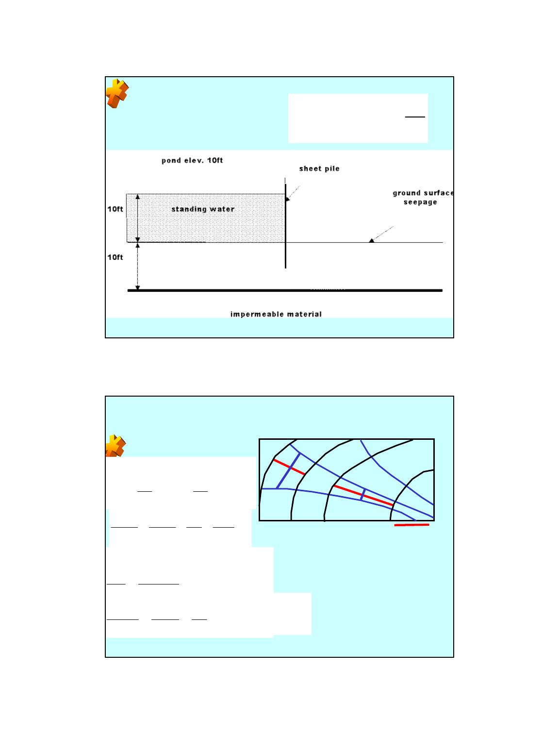
What is the flux under the sheet pile wall if K=2ft/day?
Will piping occur?
Is the higher transmissivity in this diagram at A or B?
2B1A
VAVAQ ==
A PLAN VIEW FLOW NET BY CONTOURING USING FIELD HEADS AND
DRAWING FLOW LINES PERPENDICULAR: can't assume constant K or b
A longer narrower shape indicates higher T, a shorter wider shape, low T
"Irregularities" in "Natural" flow nets
varying K
varying flow thickness
recharge/discharge
vertical components of flow
Nature's flow nets provide
clues to
geohydrologic conditions
assuming no inflow from above or below, we can evaluate relative T:
B
BB
A
AA
l
h
KA
l
h
KA
Δ
=
Δ
A
AB
B
ABB
A
AA
lA
lA
K
K
l
KA
l
KA
==
BB
)thicknessaquiferb(wbA ==
BAA
ABB
B
A
lbw
lbw
K
K
=
100’
100’
98’
96’
94’
l
b
l
a
w
b
w
a
B
A
BA
AB
BB
AA
T
T
lw
lw
bK
bK
==
w
B
l
A
=125*200=25000
w
A
l
B
= 33*100= 3300
T
A
~ 8 times T
B
B
A

6
ANISOTROPY: How do anisotropic materials influence
flownets?
Conductivity Ellipsoid:
z
K
x
K
s
K
Flow lines will not meet equipotential
lines @ right angles,
but they will if we transform the domain
into an equivalent isotropic section,
draw the flow net, and transform it back.
For the material above, we would either
expand z dimensions or compress x
dimensions
To do this we establish revised
coordinates
OR
In the case where
Kz is smaller:
stretch z
or shrink x
z'z
K
Kx
'x
x
z
==
K
Kz
'zx'x
z
x
==
Most noticeable is the lack of orthogonality when the net is
transformed back
Size of the transformed region depends on whether you
choose to shrink or expand but the geometry is the same.
To calculate Q or V, work with the transformed sections
But use "transformed" K
zx
KK'K =

7
z'z
K
Kx
'x
K
Kz
'zx'x
x
z
z
x
==
==
If the pond elevation is 8m, ground surface is 6m, the
drain is at 2m (with 1m diameter, so bottom is at 1.5m
and top is at 2.5m), bedrock is at 0m, K
x
is 16m/day
and K
z
1m/day, what is the flow at the drain?
Transform the flow field for this system and draw a
flow net.
pond
surface
bedrock
drain
If you want to know flow direction at a specific point
within an anisotropic medium, undertake the following
construction on an equipotential line:
1 - Draw an INVERSE K ellipse for semi-axes
2 - Draw the direction of the hydraulic gradient through the
center of the ellipse and note where it intercepts the ellipse
3 - Draw the tangent to the ellipse at this point
4 - Flow direction is perpendicular to this line
zx
K
1
and
K
1
day/ft4K andday/ft16Kfor aboveit try
zx
=
=
1
0
0
f
t
9
0
f
t

8
Toth developed a classic application of the Steady State flow
equations for a Vertical 2D section from a stream to a divide
His solutions describe flow nets … both are methods for
solving the flow equations
0
z
h
x
h
EquationLaplace the solved he
2
2
2
2
=
∂
∂
−
∂
∂
() ()
()
() ()
xtanzcxzz,xh tablewater upper
00,x
z
h
lower
0z,s
x
h
right 0z,0
x
h
left
boundaries
ooo
α+=+=
=
∂
∂
=
∂
∂
=
∂
∂
α
Toth's result:
() ()
() ()
⎥
⎦
⎤
⎢
⎣
⎡
π
++
⎥
⎦
⎤
⎢
⎣
⎡
π
+
⎥
⎦
⎤
⎢
⎣
⎡
π
+
=
π
−+=
∑
∞
=
s
z
1m2cosh1m2
s
z
1m2cosh
s
x
1m2cos
a
a
cs4
2
cs
z)z,x(h
o
2
0m
2
o

9
Toth's result for system of differing depth:
Recharge ZoneDischarge Zone
Head
decreases
with depth
downward
flow
Head
increases
with depth
upward
flow
Regional Flow (Classic Papers by Freeze and Witherspoon):
homogeneous & isoptropic with and without hummocks

10
Hierarchy of flow systems Dominance controlled by:
Local Basin Depth
Intermediate Slope of water table
Regional Frequency of Hummocks
Size of Hummocks
Regional Flow (Classic Papers by Freeze and Witherspoon):
Layered systems / High K at depth
K=1
K=1000
K=1
K=100
K=1
K=10
K=1
K=10

11
Regional Flow (Classic Papers by Freeze and Witherspoon):
Layered systems / Low K at depth
K=100
K=1
K=1
K=10
K=1
Regional Flow (Classic Papers by Freeze and Witherspoon):
Layered systems / High K at depth and hummocks
K=1
K=100
K=1
K=10
K=100

12
Regional Flow (Classic Papers by Freeze and Witherspoon):
Partial layers and lenses
K=1
K=10
K=1
K=1
K=10
K=1
K=1
K=10
K=1
K=10
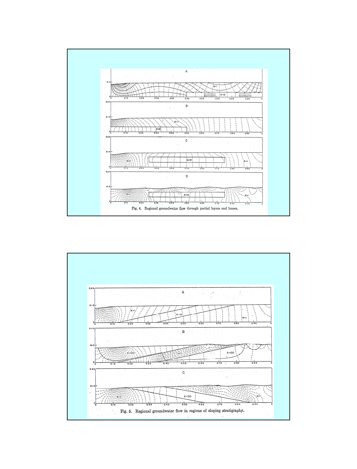
Regional Flow (Classic Papers by Freeze and Witherspoon):
Layered systems / sloping stratigraphy
K=1
K=10
K=1
K=100
K=1
K=100
K=1
K=100
K=1

13
Regional Flow (Classic Papers by Freeze and Witherspoon):
Anisotropic systems
Kh=10
Kv=1
Kh=1
Kv=10
Kh=1
Kv=10
Kh=10
Kv=1
Above
transformed
shallow
intermediate
deep
Constant
head in
shallow

14
Explore the Flow Net Software at
http://www.mines.edu/~epoeter/_GW/11FlowNets/topodrive
