
Bevin’s Skiff Building Manual
© 2012 Alexandria Seaport Foundation
1
Building Manual Introduction
Capacity
The recommended capacity of Bevin’s Skiff is 450 lbs (the capacity with 8" of freeboard)
equivalent to 3, 150lb people.
A Word on Safety-
You're brought into this world with two eyes, two ears, ten fingers and ten toes, make sure
you keep them.
When you are using a tool, keep your hands behind the cutting edge of the blade.
Use safety glasses, hearing protection and nitrile gloves.
Most importantly, use common sense.
It is your responsibility to know how to use your tools. If you don't know how to do
something, ask someone who does.
This boat is designed to be easy to build, but nails can fly through the air when you try to hammer
them. Hammering is noisy and polyurethane adhesive (e.g. Sikaflex or 3M 4200/5200) is not totally
benign. Epoxy can sensitize your skin and cause a rash. So be smart. Also be neat! Clean up squeezed
out adhesive before it dries! Life (and painting) will be easier.
A Word About This Manual
The tone of this manual reflects the importance we put on safety.
When we say, "Don't Be Stupid!", we mean it (and we're talking from personal
experience…)
Read the directions all the way through before you start.
Familiarize yourself with the pictures, drawings, parts list and tools/ supplies list.
Read the directions for each step all the way through- before you mark or cut the wood.
These instructions are written to be used as you build this boat. If something is unclear,
think about how the piece will fit in the boat.
Build the cardstock model first. It’s a good introduction to how the boat parts fit together.
It’s available at both www.alexandriaseaport.org and the Building To Teach training
website, where there is also access to hands on math training materials. To learn more

Bevin’s Skiff Building Manual
© 2012 Alexandria Seaport Foundation
2
about Building To Teach, go to www.buildingtoteach.com,
You might read these instructions all the way through at the beginning and say, "I have no idea
what he's talking about. I'll never be able to build this. This isn't simple." Believe us, it is simple. A
wonderful boat builder, Pete Culler, used to say, "Experience starts when you begin." So don't be
afraid to get started. Remember, it's only a boat. A journey of 1,000 miles starts with one step.
Videos
Videos showing how to build a Bevin’s skiff and teach math are available at www.maritimetv.com.
Look for “Building To Teach.” Even if you’re not teaching math, the videos take you through the
boat building process.
Building Technical Support
We are available to answer questions about these boats, but remember, we're a small outfit! The
best way is via E-Mail. Our address is asfoffice@alexandriaseaport.org. You can reach us by
phone, during US East Coast work hours, at 703 549 7078.
Kit Builders vs. Plan Builders
Kit builders receive everything they need to build the boat when they buy a kit from the Alexandria
Seaport Foundation. Plan builders need to obtain all the materials and make all the boat parts. There
are tools, materials list and material suppliers lists at the end of this Manual. Kit builders should
also familiarize themselves with all the pieces before they get started. There will be several places
in the building process where plan builders will need to fabricate pieces and kit builders won't.
Math Guide v. Building Instructions
Bevin’s Skiff was originally designed as a teaching tool. These instructions are also used for a Math
Instructors’ Guide. Each step is numbered with the Unit number first and the building step number
second, i.e. 2.3
The order of the building steps reflects the optimum method of teaching math while building the
boat. So, laying out and cutting the boat parts is the last unit. If you’re a plan builder, you’ll be
doing that work first.

Bevin’s Skiff Building Manual
© 2012 Alexandria Seaport Foundation
3
Epoxy and Polyurethane Adhesive
You will be using two types of glue. Epoxy (e.g. MAS) and a polyurethane adhesive (e.g.Sikaflex) .
Neither likes to come out of clothes. There are golden rules for both.
Epoxy
Use in a warm place, 40 degrees F, or over
Measure your resin and hardener accurately. The ratio must be correct.
Stir the resin/ hardener mix well for at least a minute before you add wood flour filler. Mix
in the filler well for at least a minute.
Don't mix until you need it and only mix a little more than you think you'll need.
Read the manufacturer's instructions.
You can clean up wet epoxy from your hands and tools with ordinary household “white”
vinegar or "GOJO" hand cleaner.
Polyurethane
Use in a warm place, 40 degrees F and over.
Make sure you remove the metal cap from the rear of the tube, if there is one, and cut the
nozzle and punch a hole in the nozzle seal with a 16d nail, or other long pointed object.
Release the pressure in the calking gun after each use. Otherwise more adhesive will end up
on the floor than in the boat.
Let's Get To It!

Bevin’s Skiff Building Manual
© 2012 Alexandria Seaport Foundation
4
Glossary
Tool Terms
Bevel Board A board on which needed angles, or bevels, are marked
Bevel Gauge A tool with a body and a movable blade that usually can be locked into
position. It’s used to transfer angles from one object to another, i.e. from the
boat to a piece of wood. Also known as a sliding tee bevel
Bucking Iron A small heavy mass, usually a big hammerhead, used to support a piece as it
is being nailed
Carpenter’s Scribers A simple compass. Used for “scribing” – marking a piece of wood to fit it
against another surface. Similar to a compass used for drafting and
mechanical drawing
Carpenter’s Square A flat 90 degree square with ruler scales on each edge of both sides. The
scales can include 1/8ths”, 1/16ths”, 1/12ths”, 1/10
th
” and 1/100ths”. The
long leg , 24” x 2” ,is the body. The shorter leg , 16 x 1 ½”, is the tongue.
The front surface is the “face.” The opposite surface is the “back.” Most
squares have tables printed on the face and back that can be used to calculate
rafter lengths, board footage, brace lengths and measurements necessary to
eight side a timber. Square features vary by manufacturer and model. Also
known as a framing square. Stanley 45-011 or Empire e1190 are typical
complete squares.
Clamping Pad Disposable piece of wood used to spread the clamping pressure and protect
the finished wood
Combination Square A square with a 12” sliding ruler, level and usually a scribe for scratching
marks. Can be used to create either 90 degree or 45 degree angles. Can also
be used as a depth, or marking, gauge.
Hand Saw You want to use a cross cut saw, rather than a rip saw. There are two styles,
Western and Japanese. Both styles work well- when sharp. Japanese saws are
thinner and cut on the “pull” stroke. They cut faster, but can be bent easier

Bevin’s Skiff Building Manual
© 2012 Alexandria Seaport Foundation
5
than a Western blade.
Hand Plane You’ll be using either block planes, or bench planes. The major difference
that affects this project is that block planes are smaller. Which style you pick
depends mainly upon your builders. Small hands like small tools… Make
sure the tools are sharp. Sharpening a plane is a great example of practical
geometry. The bevel and the back of the iron (blade) are planes that intersect
in a straight line, which is the cutting edge.
Finger/
Feeler Gauge A marking gauge with two parallel fingers that can reach around a protruding
piece of wood (or other material.)
Saw Horse A movable support with a cross piece and legs.
Scribers A simple compass. Used for “scribing” – marking a piece of wood to fit it
against another surface. Similar to a compass used for drafting and
mechanical drawing
Toe Nail To nail through the inside corner of one board in order to fasten it to another
Boat Terms
Aft Towards the back of the boat
Bow The front of the boat
Center Frame The boat component that is placed near the mid-point of the boat which helps
define the shape of the boat and allows the boat to be built without building
molds.
Chine 1) The corner between the side of a flat, or vee-bottomed, boat and its
bottom. 2) The piece of wood that allows the bottom to be nailed to the sides
and reinforces this joint.
Deck Beam A beam that runs across the boat and supports the deck
Fair Line A curved line without humps, or bumps. It doesn’t have to be constant, or
regular, just smooth and usually pleasing to the eye.
Faying Surface The common surface shared by two pieces of joining wood

Bevin’s Skiff Building Manual
© 2012 Alexandria Seaport Foundation
6
Feather edge A thin , fragile, edge of wood that (in this case) results from cutting the
scarph joint
Foredeck The small, triangular deck, that goes in the front of the boat
Gussets Plywood corner braces
Keel The timber that runs down the center of the boat, outside of the bottom
Layout Draw
Line Rope (on a boat)
Lofting Drawing the boat at a large scale, usually full scale, 1:1.
Painter The line that is fastened to the bow of the boat. It is used for towing the boat,
or tying it up to a dock.
Pilot Hole A hole drilled to allow a nail, or screw, to be driven without splitting the
wood.
Marine Grade
Plywood Traditionally made out of veneers with no voids and waterproof glue. British
Standard (BS)1088 is the good stuff
Quarter Knee Serves as a corner brace between the side and transom
Rabbet A groove cut into a piece of wood into which another piece of wood fits. The
joint between the outside of the planking and the backbone of the boat –stem,
keel, transom or sternpost
Sheer The top edge, or line, of the boat. The “sweep” of the upper edge of the
boat’s side.
Skeg The “fin” that protrudes from the keel at the aft end of the boat. Provides
directional stability
Station The location of a cross section in the boat’s drawing- also the location of a
building mold. Think of it as the location of a “slice” in a loaf of bread.
Stern The back of the boat
Stem The piece that forms the front of the boat
Thwart Seat
Transom The piece that forms the back of the boat
Bevin’s Skiff Building Manual
© 2012 Alexandria Seaport Foundation
7
Pick up bevels Measure angles. Usually using a bevel gauge
Scarph joint A long, angled joint between two pieces of wood. The length of the joint is described as a ratio in relationship to the
thicknesses of the joining pieces. In boat building, 12:1 is typical, 8:1 is used for plywood.
Flare The angle between the side and bottom of a “Vee”, or flat bottomed, boat
Stand Proud Stick out

Bevin’s Skiff Building Manual
© 2012 Alexandria Seaport Foundation
8
Tools and Supplies Needed
For use with Bevin’s Skiff plans and kits. Kits are available from the Alexandria Seaport
Foundation, P.O. Box 25036, Alexandria, VA 22313 703-549-7078 www.alexandriaseaport.org
1. Basic Tools Needed
Two Saw Horses 4’ wide
Claw Hammer
Bucking Iron: four pound sledge hammer (preferably without the handle) or anything
similarly massive (including rounded stones)
Hand Saw
Bevel Gauge
Combination Square
Pencils
Chalk Line
Screw driver that accepts a #2 square drive bit (the bit is included in the kit)
Phillips head screw driver
Hand Plane (and a way to keep it sharp)
At least two 4” “C” Clamps
Hand Drill with bits to drill pilot holes and countersinks for #8 and #10 screws, as well as
5/64”, or 3/32” bits to pilot for nails.
2. Optional but Recommended Tools if you are building from the ASF kit
Battery Powered Drill (to drive screws and drill holes)
Nail Set (to help remove bent nails)
Pliers (to help remove bent nails)
Router w/trim bit (to trim bottom panel)
Disk/orbital sander (to clean and prep outside of hull for painting)
3. Additional Tools Needed if you are building from the plans and didn’t buy the kit
Table Saw
Band Saw or Good Orbital Jig Saw (recommended but not absolutely necessary)

Bevin’s Skiff Building Manual
© 2012 Alexandria Seaport Foundation
9
Hand Held Circular Saw
14’x ½”x ½”square Batten straight grained spruce or pine
4. Basic Supplies Needed if you are building from the ASF kit
4d finish nails
One straight 2”x 4” x 8’
Hand Cleaner
White Vinegar
Paint Thinner (for clean up of polyurethane adhesive)
4mil Plastic (for gluing)
1 5/8” Drywall Screws two dozen
Nitrile gloves
Paper Towels
Spreading Sticks, spatulas, or plastic “Bondo Spreaders”
5. Additional Supplies Needed if you are building from the plans and didn’t buy the kit
3 - 2”x 4”x 8’ for making a work table with the saw horses
4’x8’ sheet of 1/4” plywood for work table top
10d common nails for work table assembly
6d Finish Nails for batten
Bevin’s Skiff Building Manual
© 2012 Alexandria Seaport Foundation
10
MATERIALS LIST
# DIMENSIONS MATERIAL PART
1 2”x 3” x 18” White Oak Stem
3 3/8” x 4’x 8’ Mahogany Marine Plywood Side Panels & Bottom, Foredeck, Gussets
26 Linear Feet 3/4” x 1 1/2” Spruce or Fir Frames, Deckbeam
1 1-1/2” x 5 1/2”x 8’ Spruce or Fir Transom
2 1-1/2” x 3/4” x 12’ Spruce or Fir Chines
1 1-1/2” x 5 1/2”x2’ Spruce or Fir Quarter Knees
2 1-1/2” x 3/4” x 14’ Spruce or Fir Rails
2 1-1/2” x 5/8” x 10’ Spruce or Fir Seat Riser
1 3/4” x 3-1/2”x 12’ Spruce, Fir or Eastern White Pine Keel
1 3/4” x 3-1/2” Spruce, Fir or Eastern White Pine Skeg
1 3/4” x 9-1/4”x 12’ Spruce, Fir or Eastern White Pine Seats
1 1-1/2” X 1-1/2”x 1’ Spruce or Fir Seat Support
2 1/2” Angle Plate Oarlock Sockets
2 1/2” Oarlocks
Nails
200 1” Bronze Ring Nails #12 Gauge
100 1.5” Bronze Ring Nails #12 Gauge
30 2” Bronze Ring Nails #10 Gauge
Bronze Wood Screws (We recommend square drive heads)
10 #8 x 1”
20 #8 x 1.5”
2 #10x2”
1 #2 Square Drive Screwdriver Bit
Glue and Adhesive
6 Tubes SIKAFLEX Polyurethane Adhesive
1 Qt. MAS Epoxy Kit
1 Small Bag Wood Flour

Bevin’s Skiff Building Manual
© 2012 Alexandria Seaport Foundation
11
Unit 1 Forming The Boat
Tools and Materials Needed For This Unit
Saw Horses
Tape Measure
Carpenters’ Square
Combination Square
Polyurethane Adhesive
Calking Gun
1-1/2” Ring Nails- Bronze or Stainless
Hammer
Drop cloth- maybe
Pilot Drill Bit
Drill/ Driver
Clamps
Disposable Gloves
Safety Glasses
Hearing Protection
Step 1.1) Setting Up Your Building Area
You’ve gotten your boat parts all together- either by purchasing a kit, or making them
yourself. (See Unit 6)
Now, you’re going to start assembling your boat.
Set up your building area...saw horses, tools and safety equipment- disposable gloves, safety
glasses, hearing protection…
Step 1.2) Marking the Center Frame Location.
Stack the sides exactly on top of one another and clamp them together.

Bevin’s Skiff Building Manual
© 2012 Alexandria Seaport Foundation
12
Match the pieces with the drawing, making sure you know which end is the bow and which is
the transom, or stern. (NOTE: On the plans, the bottom panel and side panel have their ends
reversed. The bow of the bottom panel is next to the stern of the side panel.)
Label the transom (stern), bow, top (sheer) and bottom of each panel.
Measure back 75" from the bow along the lower edge.
Make a mark on the edge of both pieces. Use either a carpenters or combination square.
Use a carpenter’s square and draw a line perpendicular (90 degrees) to the bottom on both
sides of both pieces. Use the square so that the short leg (tongue) is facing the bow.
Carry the lines around all sides and mark an "X" on the aft side of this line- on all four panel
sides.
Mark the frame thickness on the "X" side of all the lines. You can do this by tracing the
outline of a frame, or by measuring.
1.3) Nail the Sides to the Stem.
Apply adhesive into one side of the stem rabbet. You need adhesive on both “faying
surfaces.”
Set the side panel into the rabbet. Make sure that the lower forward corner of the side panel is
lined up with the lower corner of the rabbet.
Hold the pieces together and drill a 3/32" pilot hole through the panel, into the stem.
Nail it with 1-1/2" nails. Use a solid surface, such as the floor, or a saw horse, to back it up.
Drill six more 3/32" pilot holes through the panel into the stem in a zig zag pattern about 3/4"
from the edge of the panel.
The nails need to go down the center of the stem rabbet's "faying surface"- that's where the
adhesive goes....
BOW
TRANSOM
BOTTOM
TOP (SHEER)
75"
90°
CENTER FRAME

Bevin’s Skiff Building Manual
© 2012 Alexandria Seaport Foundation
13
Step 1.4) Nail the Other Side Panel to the Stem.
Lay the nailed panel on the floor.
Get the tallest person in the room to hold up the second side panel so it will fit into the stem
rabbet at the correct angle.
Apply adhesive to the stem rabbet.
Align the panel in the rabbet- make sure the bottoms of the panels line up with the lower
corner of the stem.
Drill pilot holes as you did on the first side, and nail the panel to the stem as you did before.
Clean up any squeezed out adhesive. You'll be happier if you work neatly.
1.5) Putting the Boat on Saw Horses
The boat is now very fragile. Don't bend the sides together- keep them spread apart! If you push
them together, you'll pop the nails out of the stem.
Rotate the boat so that the bottom of the boat is up.
Set the stem onto one horse
Set one side, at the transom, onto another horse.
Someone will need to hold up the other side, so the sides don't pinch and pull the stem loose.
(Instead of a person, you can use a third horse.)

Bevin’s Skiff Building Manual
© 2012 Alexandria Seaport Foundation
14
BUCKING IRON
(HOLD TIGHT AGAINST
WOOD)
How to Use a Bucking Iron
A bucking Iron is a heavy piece of metal (we often use a sledge hammer head) that is used to "back
up" two pieces of wood that are being nailed together. The purpose of a bucking Iron is to absorb the
energy of your hammer blows. This prevents the piece you are nailing into from bouncing around.
Make sure that the bucking iron is held tightly on the work, exactly opposite from where you are
hammering.

Bevin’s Skiff Building Manual
© 2012 Alexandria Seaport Foundation
15
Step 1.6) Attach the Center Frame to a Side.
Apply adhesive onto the side of the center frame, or onto the inside of the side panel aft of
the frame line. (where you put your "X")
Take the frame and hold it or clamp it to the side so that the bottom of the frame lines up
with the inside corner of the side panel. An easy way to make sure the pieces line up
correctly is to lay a straight edge along the edge of the frame.
Drill four 3/32" pilot holes through the panel and into the frame. Use the frame line on the
outside of the panel as your guide. Make sure your pilot holes land in the middle of the
frame- 3/8" away from the frame line you drew in Step 1.2
Nail it with 1-1/2" nails. Make sure you use your bucking iron.
1.7) Attach the Center Frame to the Other Side
Bring the aft ends of the side panels towards one another. This will bend in the other side so
it can be attached to the center frame.
Nail the center frame to the side panels, the same way you did in the previous step.
Clean up the adhesive squeeze out!
1.8) Attaching the Transom
On the inside face of each side panel, draw a line 11/2" from the aft edge.
Align the transom with one side panel. The inside face of the transom should be up against
the line you just drew. Note: the inside face of the transom is the larger face.
Drill pilot holes in the plywood for the nails that will attach the sides to the transom. Space
the holes about 2.5" apart. These holes need to be parallel to the transom face- not 90° to the
surface of the side panel.
Apply adhesive between the line you drew at the beginning of this step and the end of the
side panel.
Nail the side to transom using 2" nails.
Bend the sides together and attach the other side panel to the transom in the same manner. To
bend the panels together have one person on the end of each side panel.
Bevin’s Skiff Building Manual
© 2012 Alexandria Seaport Foundation
16

Bevin’s Skiff Building Manual
© 2012 Alexandria Seaport Foundation
17
Unit 2 Attaching the Bottom
Tools Needed for this Unit
Combination Square
Bevel Gauge
Pencils
Hammer
Bucking iron
Finger Gauge or feeler gauge
4’ Straightedge
Calking Gun
Hand saw
Hand plane(s)
2.1) Fit the Chines at the Stem
At this point, the chines are longer than their finished dimensions. In order to fit these pieces
into the boat, you need to do two things, uses a bevel gauge and subtract. Neither is hard to
do.
2.1A) Label the chine faces "inside," "outside," "up," and "down."
Using the bevel gauge, measure the horizontal angle between the surface of the side panel
and the inside face of the stem. Remember to keep the gauge square (90°) to the surface of
the panel.
Mark the angle at the end of the chine on the chine's top face.

Bevin’s Skiff Building Manual
© 2012 Alexandria Seaport Foundation
18
Note: The boat will be upside down. This drawing is right side up. Study the drawing.
2.1 B) Next, measure the angle between the edge of the panel and the face of the stem.
Mark it on the side of the chine with the base of its angle starting at the end of the previous
angle.
2.1 C) Cut the compound angle.

Bevin’s Skiff Building Manual
© 2012 Alexandria Seaport Foundation
19
2.1 D) Butt the chine against the stem and bend the chine into the boat. Check the fit against the
stem.
When the forward half of the chine is tight to the side and in the mid frame notch, make
a mark on the chine at the center frame and an opposite mark on the side panel.
Firmly and carefully remove the chine from the boat. The chine is still too long.
MARKS
MARK ON
SIDE PANEL
CENTER FRAME
MARK ON
CHINE

Bevin’s Skiff Building Manual
© 2012 Alexandria Seaport Foundation
20
2.2) Fitting the Chines at the Transom (Stern)
Now, you need to measure the angles (or pick up the bevels) on the chine for the transom.
2.2A) Using the bevel gauge, measure the angle between the surface of the side panel and the
transom. Remember to keep the gauge square (90°) to the surface of the panel- not parallel to
the ground.
Mark it near the end of the chine. Remember which edge is up! (Good thing you labeled it
when we started fitting the chines.)
2.2 B) Measure the angle between the edge of the panel and the face of the transom.
Mark it on the chine with the base of its angle starting at the starting point of the angle you
drew in the previous step.
2.2 C) Cut the compound angle and check the fit.
Bend the chine into the boat starting at the stern. Make sure the chine fits tightly against the
transom. Fit the chine into the notch at the center frame.
The excess length will extend past the bow. (Don't worry.) Make sure the chine also fits
tightly against the side panel.
2.2D) Find the mark on side panel that you made when you were fitting the forward half of the
chine and make a new mark on the chine opposite the panel mark.
Firmly and carefully remove the chine from the boat.

Bevin’s Skiff Building Manual
© 2012 Alexandria Seaport Foundation
21
2.2) Fitting the Chines at the Transom (cont.)
2.2 E) Find your two marks on the chine. The distance between them is the distance you need to cut
off of one end of the chine. You can measure the distance with a ruler, or just take a stick and
make tick marks opposite the marks on the chine. (Subtraction without numbers!)
Subtract the distance from one end of the chine and make a mark on the chine.
2.2 F) Using that mark, reconstruct the existing compound angle.
Make the cut.
2.3) Install the Chines
You will need a combination square, 1" Ring nails, polyurethane adhesive, a hammer, a
bucking iron and gloves.
Using the combination square as a marking gauge, draw a line 1" down from the bottom edge
of the panel on the outside face of the panel. This is your nailing line.
Draw another line 1-1/2" down from the bottom edge of the panel on the inside face of the
panel. Apply polyurethane adhesive in this area. Put plenty on. An alternative method is to
apply the polyurethane to the chine.
Take the aft (transom) end of the chine and run it down toward the floor, or ground, and back
toward the transom. This will allow you room to fit the front half.
Put a short stick between the chine and the side panel near the transom. (an offcut of the chine
works well.) This minimizes the spread of adhesive until the chine is in its final position.
2.3) Install the chines (cont.)
Fit the chine into the center frame notch. Bend it all the way in. While bending the chine use
clamps or hands to prevent it from springing out of the boat.
After the chine is in, slide it forward until it fits the stem. Then, raise the aft end up until it
2 MARK S
S UBTRACT DIS TA NCE
FROM ONE END

Bevin’s Skiff Building Manual
© 2012 Alexandria Seaport Foundation
22
fits the transom.
Align the inside edge of the chine with the inside edge of the transom. The chine will “stand
proud” and will be planed to fit the bottom later.
Starting at the center frame and working your way towards the ends, nail through the
plywood side panel into the chine. Remember to use the bucking iron on the inside of the
chine opposite the nail!
Space the nails about four inches apart. Forward of the center frame, give the nails a little zig
zag above and below the nailing line. Aft of the center frame, drive the nails just below the
nailing line. This will keep the nails below the finished outside edge. You're going to be
planing the chines flat to accept the bottom and you don't want to plane the nail heads.
CHINE
NOTCH
CENTER FRAME
STEM
TRANSOM
SIDE PANEL
CENTER FRAME
NAIL BELOW THIS LINE

Bevin’s Skiff Building Manual
© 2012 Alexandria Seaport Foundation
23
2.4) Planing the Chines and Transom Flat to Accept the Bottom
You're going to need a straight edge at least 4’ long (the seat riser works fine for this) and a
sharp plane.
Plane the chines and transom flat so the bottom will bear fully on them.
Using the straightedge, going across the boat, ensure that both chines are flat from the bow to
the stern and make sure the bottom will lie flat on the transom.
When planing the transom work in from the ends. If you run all the way across, you'll split
out the plywood on the far side.
Trim the end of the stem, if necessary. If you have to plane the bottom of the stem, chamfer
its forward and aft edges a little bit. That way you won't splinter out either face.
Remember, you want as much surface area (faying surface) between the bottom and the edge
of the chine. The better the fit, the fewer the leaks.
Checking to make sure the bottom will lie flat on the chines and transom.

Bevin’s Skiff Building Manual
© 2012 Alexandria Seaport Foundation
24
2.5) Nailing the Bottom On.
Test fit the bottom. Lay it so the trailing edge of the scarph is aft (looking from the outside.)
2.5 A) Make sure the bottom fits tightly on the chines, stem, center frame and transom.
When the bottom fits tight, take it off and apply adhesive to chines (including the edge of the
side panel), stem, transom and center frame.
Put the bottom back on, align it with the back edge of the transom, allowing an even overlap
on each side.
Then, nail the bottom into the chines at both ends of the center frame.
2.5 B) Using the finger gauge, space the nails every 4 inches and locate them at the middle of the
chine. You're going to need to pay attention because the flare on the boat changes and the
finger gauge is made for the average angle. The pattern for a finger gauge is on the plans.
You can make it out of any scrap plywood or stiff cardboard.
Clean adhesive off the finger gauge as it builds up.
AFT
FEELER
GAUGE
Bevin’s Skiff Building Manual
© 2012 Alexandria Seaport Foundation
25
2.5 C) Start nailing from the center.
If you have two teams of “nailers”, have them work on opposite sides of the boat.
Nail both sides towards an end then, go back to the middle and nail towards the other end.
This way you will avoid nailing any bubbles or humps into the bottom.
Be sure your nails are parallel to the side panel, not perpendicular to the surface of the bottom
panel.
Nail the bottom to the center frame, stem and transom.
2.5 D) Space the transom nails at 4".
Clean up any squeeze out with a scrap of wood, plastic scraper or piece of cardboard.
2.5 E) Trim the bottom so it is even with the sides.
To rough cut the bottom to size, we use either a router with a trim bit, or a jig saw with its
blade angled away from the side panel.
Use a plane to do the final trimming.
You can also finish the bottom/ side joint with a belt sander, or disk sander. Be careful not to
make waves in the wood, or sand through the outer veneer of the plywood sides.

Bevin’s Skiff Building Manual
© 2012 Alexandria Seaport Foundation 26
Unit 3 Building The Interior
Introduction
Even though the boat looks “done.” You’re only halfway to the launch. Your builders have been exposed
to most of the skills they will need to finish the boat. Now, they have the opportunity to practice those
skills and strengthen their weaknesses.
Tools and Materials Needed For This Unit
Carpenter’s Scribers
Carpenter’s Square
Combination Square
Pencil
Hammer
Bucking iron
Tape measure
Drill with a Pilot Bit
Jig Saw, or Band Saw
Calking Gun
1-1/2", 2” Ring nails,
Polyurethane adhesive
Deck Beam
Quarter Knees

Bevin’s Skiff Building Manual
© 2012 Alexandria Seaport Foundation 27
3.1) Putting in the Deck Beam
With at least one helper, turn the boat right side up.
Using the center point (apex or vertex) of the stem as the starting point, measure back
16" along the top edge of each side panel. Congratulations you just made another
Isosceles triangle! This is the back edge of the deck beam.
M EASURE FROM
CENTER OF STEM
1 6 "
1 6 "
SIDE
PANEL S
DECK BEAM
INSTAL LED

Bevin’s Skiff Building Manual
© 2012 Alexandria Seaport Foundation 28
3.1.A) Measuring and Cutting Deckbeam
Plan builders need to measure and cut the deck beam. The easiest way to "pick up"
the compound bevels is to use a hot melt glue gun and glue together a pattern out of
paint stir sticks (or the like.) This will give you the length of the piece and the angle
of the boat's flare. You can then use your bevel gauge to pick up the fore and aft
angle. We usually cut this compound angle with a hand saw- just like the chines.
Place the deck beam in its location, make sure it fits.
Apply adhesive to its ends.
Set it even with the top the side panels.
Drill pilot holes through the sides into the ends of the deck beam and then nail from
the outside into the ends of the beam with (2) 1-1/2" ring nails.
4 PIECE "PAINT STICK" PATTER N

Bevin’s Skiff Building Manual
© 2012 Alexandria Seaport Foundation 29
3.2) Cutting out the Quarter Knees (Plan Builders Only)
Transfer the shape of the quarter knees from the plans onto the stock.
Make sure the grain is running the right way, diagonally, as indicated on the plans.
Then, cut both straight cuts using a saw that tilts. Pick up the angles from the bevel
board on the plans.
A band saw or a good jig saw is best for this. You can also use a hand saw. Don’t use
a hand circular saw. It is difficult to clamp the piece and make a safe cut.
The inside, curved face of the quarter knee is cut with the saw set at 90 degrees.

Bevin’s Skiff Building Manual
© 2012 Alexandria Seaport Foundation 30
3.3) Installing the Quarter Knees
Depending upon how closely your boat matches the plans, you may need to fine tune
the fit of the quarter knees against the transom. We use a pair of carpenter’s scribers
(a simple compass) and mark the gap on the upper and lower surfaces of the quarter
knee. You can then plane, or belt sand, down to those lines.
Apply adhesive to the angled faces of the knees.
Set them so the top edge is even with the top edge of the side panel.
Nail the quarter knees from the outside in. Use 2" nails for the transom face and 1
1/2" nails from the sides.
Also “toe nail” in two1 1/2" nails from the inside corner of the knee into the transom.
Using a bucking iron helps when driving the nail
Installing a Quarter knee

Bevin’s Skiff Building Manual
© 2012 Alexandria Seaport Foundation 31
3.4 Locating the frames (Lots of isosceles triangles!)
You will be installing 4 sets of frames. Starting at the apex of the stem measure
straight back to each location along the top edge of each side.
Make a mark on the top inside of the side panels at each frame location.
28"
53"
102"
132"

Bevin’s Skiff Building Manual
© 2012 Alexandria Seaport Foundation 32
3.5) Marking the Frame Lines
Take a framing, or carpenter's, square and set the short leg (tongue) on the chine
pointing towards the middle of the boat.
Slide the square along the chine until the long blade hits the pencil mark and draw the
line.
Make an "X" on the side closer to the middle of the boat. Do this for both sides of the
boat.
Remember to keep the short leg of the square pointed to the center frame. (This
means you have to flip the square when you move from the front of the boat to the
back...) When you are done you should have four sets of frame lines.
The frames are placed so that they cover the "X"s.
Take the frame and line up its edge with the line. Make sure the frame covers the "X"
Draw a line on the other edge of the frame.
Remove the frame and, from the inside of the boat, drill four evenly spaced 3/32"
pilot holes down the center of the outlined frame.
These are the pilot holes for your frame nails.
CENTER
FRAME
SQUARE
FRAME MARK
DRAW LINE
MARK "X"
FRAME OUTLINE
PILOT HOLESCHINE
BOTTOM

Bevin’s Skiff Building Manual
© 2012 Alexandria Seaport Foundation 33
3.6) Installing Frames
Apply polyurethane adhesive to the edge of a frame. Put the frame over the "X"s so
that one edge lines up with your frame line. Clamp it and nail through the plywood
panels into the frame with 1-1/2" nails. Remember to use the bucking iron. Clamps
may be used to help secure the frames, as well. Clean up the adhesive squeeze out.
Using your bevel gauge, draw a line across the top of each frame angled inward. The
exact angle is not important- something about 45 degrees is fine. You just want to
make sure that you don’t leave a sharp corner on the top of the frame. They hurt if
you land on them when you’re using the finished boat…
Make sure to tighten your gauge so that you mark each frame with the same angle.
Cut off the top of each frame following the lines you just marked.
3.7) Installing Seat Risers
This step takes at least two people.
The seat risers are 5/8" x 1-1/2" pieces that support the seats. Measure and mark each
frame 6-1/2" below the top edge of the sides (sheer). This mark is the top edge of the
seat riser.
Put an "X" below this mark.
Put a dab of polyurethane adhesive on each "X".
Using your helper(s), position the seat riser in place.
Drill 5/64" pilot holes and nail the seat riser to each of the frames using two 1-1/2"
nails per frame.

Bevin’s Skiff Building Manual
© 2012 Alexandria Seaport Foundation 34
Start nailing at the center frame and work your way towards the ends. Use the
bucking iron to support the side panel from the outside.

Bevin’s Skiff Building Manual
© 2012 Alexandria Seaport Foundation 35
Unit 4 Finishing the Outside
Tools Needed for this Unit
Carpenters Square
Combination square
Hammer
Bucking iron
Tape measure
Pencil
Chalk Line
Calking Gun
Clamps
Hand Saw
Drill/ Driver

Bevin’s Skiff Building Manual
© 2012 Alexandria Seaport Foundation 36
4.1) Installing Rails
This takes at least two people!
The rail runs from the forward end of the stem to the aft end of the transom on the
outside of the side panel. The top edge of the rail is even to the top edge of the side
panel.
Using a combination square, draw a line on the inside of the side panel, 3/4" down
from the top edge. This is your nailing line.
Apply adhesive to the inside of the rail.
Drill a pilot hole and nail the side panel into the stem from the outside with a 1-1/2"
nail.
From the stem, nail the rail into the frames from the outside using 1-1/2" ring nails.
Use a bucking Iron to support the inside of the frames.
Drill pilot holes and set three 1-1/2" nails into the transom and quarter knee. Try to
avoid hitting the other nails already fastening the side to the quarter knee.
The rail will tend to slide down, so you will need to hold it into position with clamps
or hands.
Along the nailing line on the inside of the panel, drill three evenly spaced holes
between each set of frames. Using 1" nails, nail the rail on from the inside.
Remember to use the bucking iron. Make sure the polyurethane adhesive is squeezing
out of the joint!
Fasten the other rail in the same way. You can then cut the protruding rail ends flush
to the stem and transom. Or, you can cut all your “overhanging” pieces at the end.

Bevin’s Skiff Building Manual
© 2012 Alexandria Seaport Foundation 37
4.2) Installing the foredeck
Plane the stem, or cut it with a saw, so that the top is flush with the rails.
Plane the deckbeam and the rails so the foredeck lays evenly over the stem, rails,
sides and deckbeam.
Once it all is planed and the foredeck fits well, apply polyurethane adhesive, line up
the aft end of the foredeck with the deckbeam,
Drill pilot holes and nail the foredeck to the deck beam and rails with 1" nails. Space
the nails every 3". Use clamps to hold the deck down.
4.3) Installing Keel and Skeg- Caution! Fractions Ahead.
With helpers, turn the boat upside down.
Marking on the bottom, find the centers of the transom, mid frame and stem.
Strike the center line with a chalk line or straight edge.
Measure the width of the keel and divide it in half.
Using a framing square, make a couple of marks that "half width" distance away from
your newly made center line. These indicate the edge of your keel.
Take the keel and lay it on the boat. Line it up with your marks. The keel should
overhang 1/4" at the transom.
CENTERLINE
OF BOAT
MARKS FOR
EDGE OF KEEL

Bevin’s Skiff Building Manual
© 2012 Alexandria Seaport Foundation 38
Trace the outside edges of the keel and the slot for the skeg (Fig23) on the bottom of
the boat.
Remove the keel.
Within the outline of the keel, from the stem to the start of the skeg slot, mark and
drill pilot holes through the bottom about 4" apart in a zig zag pattern.
4.3) Installing Keel and Skeg (cont.)
Continue drilling holes spaced 4" apart down each finger of the keel alongside the
skeg. These “fingers” have been created by the slot in the keel.
Measure and drill 5 evenly spaced holes in the skeg slot.
Apply and spread polyurethane adhesive to the bottom between the lines. Spread
evenly.
Place the keel on the bottom.
Make sure that the trailing edge of your scarph is facing aft! You don't want the
feather edge to catch on anything when you drag the boat onto the beach.
Spread adhesive in the slot of the keel. Insert the skeg.
Align keel and skeg on the bottom panel. The keel and skeg should overhang the
transom by about 1/4". From outside the boat, set two 1-1/2" nails through the keel
into the transom.
SLO T FO R SKEG
KEEL - CUT TO SHAPE
BO W

Bevin’s Skiff Building Manual
© 2012 Alexandria Seaport Foundation 39
From outside the boat, set two 1-1/2" nails through the keel into the center frame and
one 1-1/2" nail through the keel into the stem.
At this point, you need to nail from the inside of the boat, through the bottom panel and into
the keel. You can use several different techniques to accomplish this task.
One is to set the boat, right side up on a hard floor- with a drop cloth between the boat and
the floor. In this way the floor serves as a bucking iron for all except the aftermost nails.
A second technique is to put the boat on its side; have two people hold the boat in position
and then have one person nail from the inside, while another person holds the bucking iron
on the outside.
The third way is to keep the boat upside down and send somebody underneath (with hearing
protection) to nail. Another person stays outside to use the bucking iron.
All these techniques work, although the second technique is usually fastest. Select the
technique that fits your situation.
Regardless of which technique you chose, make sure the skeg is aligned
perpendicular to the bottom and pushed forward in its slot in the keel.
From inside the boat, nail through the bottom panel into the skeg. Put three 1-1/2"
nails into the back (large end) of the skeg and two 1" nails through the bottom panel
into the front (skinny) end of the skeg.
Start at the transom (inside the boat) and nail through the bottom panel into the keel
with 1" nails using the pilot holes you drilled earlier.
Use a saw to trim the keel flush at the stem and in line with the transom. Or, you can
do all your trimming at the end.

Bevin’s Skiff Building Manual
© 2012 Alexandria Seaport Foundation 40
4.4) Install Seats
Kit builders- put them where they fit!
But seriously… the forward seat should fit behind the most forward frame. The
middle seat, or thwart, fits in front of the center frame. The stern seat fits forward of
the after most frame. Look at the plans for locations.
Plan builders need to mark the seats location on the seat risers. Then, take the
measurements for the front and rear edge of each seat. Divide each measurement in
half. These half widths are what you need. Next, go to the seat stock (1x10 )and lay
out your measurements. The key is to draw the centerline of the seat and lay out your
half widths from there. That way, your angles at the end of the seats will be correct.
4.5) Seat Posts
This is optional; but we recommend putting a 1-1/2"x 1-1/2" seat post under the middle of
the center seat.
Fit the seat so it lands in the middle of the boat- over the keel. Put a dab of adhesive
on the bottom of the post, then nail the seat to the top of the post. You can put
supports under the other seat, if you like.
4.6) Installing Oar Lock Sockets
The center of the oar lock sockets are located 13" behind the back edge of the center
seat. Mount the oarlock socket on the inside top edge of the side panel.
Drill pilot holes for your screws.
Insert the horizontal screws into the rail while holding the socket in place.
Drill pilot holes and install the vertical screws.
When you're using the boat, tie the oarlocks to the seat riser. That way they won't fall
into the drink.
4.7) Filling
Mix up a batch of epoxy filled with wood flour and fill all the holes in the boat.
Microballoons can be added to make a smoother mix. Be neat. You can also use

Bevin’s Skiff Building Manual
© 2012 Alexandria Seaport Foundation 41
"Famowood" wood filler for the holes above the waterline.
4.8) Sanding
Some people go crazy sanding and finishing boats. We don't. They're boats- not
pianos. If you use the boat, you're going to scratch it up. Paint to protect the boat. You
still need to be neat and clean but you don't have to go wild. It's very easy to spend as
much time painting a boat as building it. Be careful!
4.9) Paint
We don't supply paint with our kits. We recommend oil based enamels for the finish
coat. You can thin that enamel to make a primer. We recommend epoxy coating the
exposed end grain of the plywood bottom. (Straight Epoxy- no filler) You can also
epoxy coat the outside of the hull.
4.10) The Painter
To attach your painter line, we usually drill a 1/2" hole in the side panel on either side
of the stem just below the rail and pass a line in one hole, around the back of the stem
and out through the other hole. You can then splice an eye or tie a bowline.
4.11) Oars
Oars are easy and fun to build. WoodenBoat Magazine and Mystic Seaport sell oar
plans. WoodenBoat Magazine has run several articles on how to build oars. You can
also buy oars from several suppliers including Shaw and Tenney and American
Traders
Notes on Using the Boat
Lift the boat by the seat risers, not the seats.
This boat is designed for rowing and sailing- not power.
If you choose to put flotation under the seats, add a second seat riser above the seats. That

Bevin’s Skiff Building Manual
© 2012 Alexandria Seaport Foundation 42
will prevent the seat screws from pulling out if the flotation is ever put to use.
Unit 5 Making the Kit
Tools List for this Unit
Hand Plane
Jointer
Batten- ½” x ¾” x 14’
Bar Clamps
Tape Measure
Drill/ Driver
Pilot/ countersink Bit
Chalk Line
4’ Straightedge
Framing Square
Hammer
Table Saw
Push stick
Feather board
Bevel Gauge
Protractor

Bevin’s Skiff Building Manual
© 2012 Alexandria Seaport Foundation 43
5.1) Cutting the Stem (Plan Builders Only)
To start you need a 2" x 3" x 18" piece of appropriate material, “stock”. White Oak,
Locust, good Yellow Pine or Douglas Fir will do (in that order). The easiest way to
cut the rabbets in the stem is to use a table saw.
Table saws are dangerous. Use push sticks and finger boards to hold the work
safely. If you don't know what I'm talking about- find somebody who does.
Trace the stem section from the plans onto the end of the stem stock. To do this you
can use, tracing paper, mylar, or you can prick through the drawing with a nail- into
the wood below. When you are setting your cuts, you can set your saw blade heights
and angles using a straightedge to project from the saw blade to this tracing. Or, you
can make a pattern of the stem cross section out of pattern stock and use it to set the
saw.
Set the saw to 26 °.
Lay the 2" face of the stem on the table and make cut #1.
Make this cut stop 1/8" short of cutting all the way through the piece.
SAW TABLE
FENCE
SAW
BLADE
CUT 1/8" SHORT
OF ALL THE WAY THROUGH
CUTS 1 & 2

Bevin’s Skiff Building Manual
© 2012 Alexandria Seaport Foundation 44
5.1) Cutting the Stem (Cont.)
Put the other 3” face against the saw fence and repeat the process for cut #2
Reset saw depth and fence to make cuts #3 and #4.
Lay the 3" face of the stem on the table. Reset saw depth and fence to make cuts #5
and #6.
Now, use a hand saw to finish cuts 1 & 2
SAW TABLE
FENCE
SAW
BLADE
CUT S 3 & 4
SAW TABLE
FENCE
SAW
BLADE
CUT S 5 & 6

Bevin’s Skiff Building Manual
© 2012 Alexandria Seaport Foundation 45
5.2) Building the Transom
The transom is designed to be cut out of an 8' long 2x6. You can use framing lumber
that has good, tight knots.
5.2A) Cut a Pattern for the Transom
Find some stiff cardboard, or 1/4" plywood, to use as pattern stock.
Using the dimensions on the drawing, lay out the center line and measure off your
heights and half breadths so that you locate the four corners of the transom.
Connect the dots.
Then, measure 2" up from the sheer height at the center line.
Bend (or “spring”) a batten from the two corner sheer points through this higher
center point and draw the line. You've just drawn the crown of the transom.
Cut the pattern out.
This is the pattern of the inside (and larger) face of the transom.
5.2B) Lay Out Transom Pieces
Your transom is made out of three pieces of 2x6.
Lay your pattern on top of your 8' 2x6.
Line up the bottom edge of the pattern with the edge of the 2x6. Mark on the pattern
where the top edge of the 2x6 crosses the pattern.
Mark the edges of the pattern on the 2x6.
Rotate the pattern 180 degrees. Line up the "2x6 edge marks" you just made on the
pattern with the edge of the 2x6. The angles of the first and second piece will
complement one another (isn't geometry wonderful.) Make sure you leave 1/8"
between pieces for your saw cut.
Draw the edges of the second piece.
Repeat the process for the third piece.

Bevin’s Skiff Building Manual
© 2012 Alexandria Seaport Foundation 46
5.2D) Straighten the Edges of the Boards
Use a plane, jointer or table saw to straighten the edges of the 2x6s- if they need it.
If you’re going to use a power tool, it’s assumed you know how to perform this
operation.
Follow these steps to joint two pieces with a hand plane:
Clamp them in a vise side by side.
Plane until the surfaces are straight. Try to keep your plane at 90 degrees so the edges
are square. Don't sweat it if they're a little off.
When you have the edges straight, unclamp the boards and flip the top board up using
the middle seam between the two boards as a hinge.
Do this for both joints.
5.2E) Glue the Transom Pieces Together
For this, you'll need three bar or pipe clamps at least 18" long.
Mix up your epoxy of choice. Stir it well for at least one minute.
Add in your wood flour, or high-density filler of choice, until it is the consistency of
thick molasses. Stir it for at least a minute.
Spread the glue on both sides of each joint.
Clamp it up. It will be messy.
Scrape off the excess epoxy. You should be getting squeeze out all along both joints.
If not, undo it, add more epoxy, and re-clamp.
We also clamp a straight edge along the surface of the transom. This avoids a cupped
transom. Make sure you put wax paper or plastic in between the work and the straight
edge. Otherwise, it will stick together.

Bevin’s Skiff Building Manual
© 2012 Alexandria Seaport Foundation 47
5.2F) Cut the Bevels on the Transom
Lay the pattern on top of the transom.
Draw the outline.
Pick up the angles for the transom sides from the bevel board on the drawing using a
bevel gauge.
Using either a hand saw, band saw or hand circular saw (preferred), cut the bevels.
Remember, your pattern is the wide face of the transom. These are under bevels.
Also, make sure you clamp your work down when you cut.
Pick up the bevel for the bottom and make the cut.
Remember to cut the crown of the transom. (no bevel)
5.3) Rip Stock for Chines, Rails, Frames and Seat Risers (Plan Builders Only)
Using a table saw rip out enough stock for your chines, rails, frames and seat risers.
See the material list at the end of these instructions. All but the frames need to be
straight grained stock. It all can be gotten out of "2 by" lumber. Either you need to
pick over the local lumber yards supply of framing lumber or spend the money and
buy "C and Better" grade lumber. If your going to pick, think about buying 2x12s and
ripping the clear straight wood off the edges for rails etc… and using the middle,
knottier sections, for your transom.

Bevin’s Skiff Building Manual
© 2012 Alexandria Seaport Foundation 48
5.4) Scarphing Your Plywood Panels
You've spent the money and gotten the good, marine grade, BS1088, plywood.
(Right?!)
Now is the time to measure twice and cut once. You will be joining your plywood
pieces together using a scarph joint- which is two long angles glued together. The
keys to successful glue up are: proper layout, flat surfaces, plenty of glue, proper
alignment and good clamping pressure.
5.4A) Cut the Short Pieces
Take a piece of plywood and cross cut it at 53-5/8". This will give you two pieces:
one 48" x 53 5/8 "- the other 48 " x 42 3/8".
On both pieces, draw a line 3" in from the uncut, "factory edge" of the 48" face.
Draw the same 3” lines in from the edges on one end of both remaining full sheets.
5.4B) Set Up to Cut the Joints
Lay a full sheet of plywood on a well supported work surface. Saw horses with 2x4s
running underneath and a piece of 1/4" plywood on top will do.
Line up the end of the full sheet of marine plywood with the end of the supporting
plywood. Make sure your 3" line is facing up.
Nail the marine plywood down with 4d finish nails. Sink the nail heads.
Lay one of the short pieces of plywood cut in the previous step on top of the long
piece.
Line up the factory edge with the full sheet's 3" line. Nail the short piece down with
4d finish nails.
Don't put any nails inside your 3" lines!

Bevin’s Skiff Building Manual
© 2012 Alexandria Seaport Foundation 49
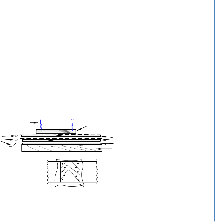
5.5) Glue the Panels Together
Use your saw horses, 2x4s, and ¼” plywood with a sheet of plastic over it as a gluing
table.
You are going to be stacking the two complete panels with wet epoxy in the scarphs
on top of one another- while the glue is still wet. In order to prevent the layers of
plywood from sticking together, you will need a strip of plastic to put in between the
layers, underneath the glue joint.
Make sure you have 4d finish nails, or drywall screws, to hold your pieces in place.
You will be applying clamping pressure with drywall screws run through a scrap of
3/8” or 1/2" plywood long enough to cover the entire scarph joint. Make sure that you
have 20 or so 1 5/8" drywall screws with a screwdriver (a power drill/ driver really
helps.)
Mix your epoxy then add wood flour so that the glue is the consistency of thin
molasses.
Coat both sides of each joint.
Tack them down on the table with 4d finish nails, so your center lines make one
straight line. Use a string to check. The side edges of the finished panel should also be
straight.
3" 3"
WOOD TO BE
REMOVED
STACKED
PLYWOOD
Bevin’s Skiff Building Manual
© 2012 Alexandria Seaport Foundation 50
5.5) Glue the Panels Together (cont)
Lay down a strip of plastic on top wide enough that no epoxy squeeze-out can join the
stacked panels.
Repeat the gluing process with your second set of panels. Make sure the joints for
each set of panels line up on top of one another.
Lay down another strip of plastic, over the joint, on top of the last panel.
Take your clamping pad of 3/8” plywood and lay it over the joint. on top of the
plastic.
Screw down through the clamping pad, the two layers of marine ply and the wooden
surface beneath it. Starting from one end, put one screw every 3 inches and zig zag
them. You should get lots of squeezed out epoxy. You want a saturated joint (excess
epoxy) rather than a "starved" joint.
Allow 24 hours for the epoxy to harden. Longer is better. If you can make a dent in
the epoxy with your fingernail, it's not hard enough to proceed. Let the epoxy set for
another day, or so.
PLYWOOD
PLASTIC
CLAMP PAD
PLASTIC PANELS
1/4" PLY
2 X 4 BASE
CLAMP PAD
DRYWALL
SCREWS
SHEETS

Bevin’s Skiff Building Manual
© 2012 Alexandria Seaport Foundation 51
5.6) Laying Out the Side Panel Shapes
This is nothing more than a big version of "connect the dots." On the plans are the
measurements for the expanded shapes of the sides and half the bottom. (You will be making
a whole bottom.) You're going to be making full size copies of these drawings on your
plywood panels.
5.6A) Laying Out the First Side Panel
You will need a tape measure, pencil, 6d finish nails, hammer and 4' straight edge or
chalk line and a 14' batten. The batten should be a straight grained piece of pine,
spruce or Douglas Fir 1/2" x 1/2".
First, you need to undo your glue up of the plywood panels.
The sides come out of the longer panel.
Take the longer panel and lay it either on the ground or on your saw horses and 2x4s.
Again, you'll cut your sides from this panel.
Take your chalk line (or string), pull it tight and see if the long edge of the panel is
straight. If it is, use it as your baseline.
If its not straight, chalk a straight-line about 1" up from the edge and that will be your
baseline.
You will also need a line parallel to the baseline on the other edge of the plywood.
You can use the edge of the plywood, if it is straight. If not, snap another chalk line,
or draw another line, one inch in from the edge.
The next thing you need to do is layout a grid of lines 1' apart.

Bevin’s Skiff Building Manual
© 2012 Alexandria Seaport Foundation 52
5.6A) Laying Out the First Side Panel (Cont.)
Hook your tape on the end of the panel and make marks on the baseline at 1 through
12 feet. Do the same along the other edge.
Connect the dots and you have your grid.
Label the edge of the plywood, on which you hooked your tape measure, "0" and the
next line "1" etc...
These are now your "stations."
On the plans, each station has two measurements. They both are taken from the
baseline. One measurement is for the bottom edge of the side panel and the other for
the sheer. (top edge of the side panel).
Mark all these points. Set a finish nail (6d works well) vertically in each point.
Spring the batten through all the points. Set a few finish nails on the other side of the
batten to hold it in place. Put these nails on the station lines- opposite the original set
of nails. There shouldn't be any lumps or bumps. If there are, shift the batten as little
as possible to "fair" the curve. It’s usually better to make a few adjustments, at several
stations, rather than one big adjustment.
Draw the bottom line.
Create the other needed points and draw the remaining lines until your plywood looks
like the plans.
The measurements for locating the ends of the panels, the stem and transom, are also
on the plans.
Cut the side out with either a jig saw or a hand held circular saw. Stay 1/16 to the
outside of the line.

Bevin’s Skiff Building Manual
© 2012 Alexandria Seaport Foundation 53
5.6B) Laying Out and Cutting the Second Side Panel
Use the cut out side piece as a pattern and mark your second side on the remaining
stock.
Cut it out. Then, clamp or nail both pieces together (grid lines visible) and plane both
down to your original lines. They should be identical. Remember to hold your plane
90 degrees to the surface of the panel.
5.7) Laying out and Cutting the Bottom Panel
This panel is drawn oversized. When you install it, you're going to lay the panel on the boat
and then trim it to its final size. Therefore, if you want to skip this step you can. We have
included it because the smaller "oversize bottom" is easier to handle than the larger uncut
panel.
Draw the same grid on this panel as you did with the side panels.
Then, draw a centerline down the length of the panel.
The measurements on the plan are taken from the centerline. Only half of the bottom
is drawn on the plans. The other half is a mirror image.
Lay out both sides.
Remember this is a flat bottomed boat. You cut the perimeter of the bottom panel.
DO NOT cut the centerline.
5.8) Gluing Rails, Chines, Keel and Seat Risers (Kit Builders Only)
Because of shipping rules we had to cut your long pieces. (Sob!) Now you have to glue them
together. Fortunately, we've cut the scarph joints for you. The key is to get them aligned- not
crooked. Here's one way to glue them together.
Get a piece of 2x4 that's flat and straight and at least 8' long.
Nail it to a couple of saw horses. This is your gluing table.
Lay a strip of plastic over the 2x4 where your glue joints will be.
We'll start with the rails.
Take your long section of rail, lay it so the bevel is up, the edge is flush with the edge
of the 2x4 and the joint will be at about the center of the 8' length of 2x4.
Nail it with two 4d finish nails.

Bevin’s Skiff Building Manual
© 2012 Alexandria Seaport Foundation 54
Get its partner and check the fit before you glue.
Mix epoxy, and thicken with wood flour, to a heavy molasses consistency.
Spread glue on both sides of the joint.
Put the mate into place.
Nail it with two 4d finish nails- so it won't wiggle.
Put a piece of plastic over the glued area.
Stack the second rail right on top and repeat the steps. Then clamp the joints together
( c- clamp, bar clamp, etc). Make sure you have squeeze-out.
Clamp and glue the chines the same way on the other edge of the 2x4.
Clamp and glue your seat risers and keel the same way as the chines.
5.9) Make a Pattern for your Center Frame
(Plan Builders Only)
Using the dimensions in the plans, lay out a full width pattern for the center frame.
You can make this out of cardboard, or thin plywood. You will use this as a layout
table to build your center frame.
This process is the same as for laying out the transom pattern.
Only the half breadth dimensions are given on the plan. So, make sure you mark off
this distance from the centerline of the pattern.

Bevin’s Skiff Building Manual
© 2012 Alexandria Seaport Foundation 55
5.10) Assembling the Center Frame. (Plan Builders Only)
Take the bottom and two sides of the frame. Run the frame sides past the bottom,
apply adhesive and nail the gusset on with 1" nails.
Use the gusset to give you the correct frame angle or better yet, use the center frame
pattern you just made.
Make sure you cut 3/4" by 1-1/2" notches on the bottom corners to accept the chine
log.
Nail, or screw, a spreader at the top of the frame to hold the top dimension
Don't glue the spreader to the frame; you will remove it later. And make sure there is
enough room for the sides to fit below the spreader.
GUSSETS
SPREADER
NAILS
NOTCH FOR CHINE LOGS
