
GE
Digital Energy
g
imagination at work
XA/21
™
EMS
Energy Management Systems
Energy Management Systems to meet the challenges of today’s
smart grid environment
Electric utilities are faced with many challenges imposed by today’s Smart Grid. High penetration of bulk
renewables, demand response options, aging assets and an aging workforce, coupled with increased
operating and maintenance costs, security, increased integration with external systems and increased
data processing requirements contribute to the needs of today’s advanced Energy Management System
(EMS).
The XA/21 EMS meets these demands with a secure core system built on an open-standard, distributed
architecture and augmented by powerful application suites for generation, transmission and distribution
power grids.
Key Benefits
• Monitors and controls generation, transmission and distribution assests in real-time
• Provides real-time situational awareness coupled with advanced visualization capabilities for faster
user recognition of the overall system status
• Analyzes near-term operating grid contingencies and provides alternative solutions to reduce
potential outages
• Economically provides increased grid capacity while maintaining overall grid reliability and regulatory
requirements
• Reduces overall system support costs through intuitive data and display maintenance support tools
• Meets today’s secure system needs with flexible environments including fully redundant primary and
backup production, quality assurance, training and development systems
Situational Awareness
• Robust generation and transmission grid power
system applications supporting real-time, study
and training environments provide current and
future operator situational awareness
• Built-in advanced visualization capabilities
driven by a secure, platform independent
Graphical User Interface
• World coordinate displays supporting
transmission grid overviews provide support
for graphical backgrounds, weather data,
crew locations, flexible gradients and dynamic
approaching limit symbols for flows and other
real-time data
• Operator configurable dashboards provide
support for displays, charts and graphs,
summaries and graphical contingencies
• Advanced alarm and event summaries with
operator customizable sorting and filtering
Advanced Functionality
• Enhanced grid reliability
• Increased grid capacity
• Advanced contingency awareness
• Decreased system support costs
• Secure system that meets worldwide regulatory
requirements

GEDigitalEnergy.com
2
XA/21 EMS Overview
The XA/21 EMS is designed to flexibly meet each utility’s needs based on
their asset fleet. The base system provides the XA/21 system platform
infrastructure and three core application suites: EnterNet Suite (ES) (platform
independent GUI), SCADA (DAC, Alarm Events, RT-Calcs, HIS, etc.) and Data
Engineering Tools.
Optional applications can be added depending on each utility’s needs.
Generation applications provide a solution for generation and enterprise
renewable management companies and industrials with onsite generation.
Typical transmission grid operators may only need the advanced
transmission applications. A vertically-integrated electrical utility can
choose the entire suite of applications, including Transmission, Generation,
Hydro and Distribution applications.
The distributed and extensible architecture of XA/21 scales from a single
server to a fully redundant system with many servers supporting hundreds
of operator consoles.
XA/21 systems are typically deployed in a multi-system environment, with
separate systems for the Primary and Emergency Backup Control Centers and
the Program Development, Quality Assurance and Operator Training Systems.
The secure architecture of XA/21 conforms to industry-standard security
practices and is implemented with a layered strategy to ensure cyber
security at the network, system and application levels.
Architecture
XA/21 is a network-based, distributed processing environment consisting of
interconnected processing nodes which can be tailored to specific functions.
XA/21 is a highly eXtensible Architecture based on industry-standards and
designed to meet the needs of the EMS market well into the 21st century.
The XA/21 system is a highly available security-hardened solution that has
the inherent capability to expand as user requirements dictate, both in
terms of applications and architecture. XA/21 can be scaled from a single
processing node to a fully redundant configuration with multiple servers
supporting hundreds of users.
A redundant Local Area Network (LAN) serves as the data highway
connecting the various elements in the XA/21 system. The XA/21 system
uses a broadcast interface for the exchange and propagation of dynamically
changing data required at multiple nodes in the network.
Each node with critical functionality in the XA/21 system connects to both
the primary and backup LANs. Either LAN can be designated as prime
with the other becoming the backup. The system continuously checks the
integrity of both LANs.
The platform independent ES GUI consists of autonomous multi-headed
high-performance graphics workstations connected to the LAN. The ES
architecture supports a three-tiered (client, server, agent) configuration,
allowing support for secure remote users with the server residing in the
Demilitarized Zone (DMZ).
Multi-system Environment
XA/21 control systems are generally deployed in a multiple system
environment to meet the security and redundancy needs of each utility.
Most deployment environments include separate systems for the Primary
and Emergency Backup Control Centers, as well as Development, Quality
Assurance and Training. Three Backup Control System (BCS) options are
natively supported within XA/21:
• Site Isolation BCS
• Standby or Snapshot BCS
• Integrated BCS
Optional Applications
Operating System
XA/21 System Base RDBMS
XA/21 Portable Application Interface
XA/21 EnterNet
Suite GUI
XA/21 SCADA
XA/21 Data
Engineering Tools
Platform and Core Applications
Transmission Applications
• State Estimator
• Scheduling
• Contingency Analysis
• Optimal Power Flow
• Security-constrained Dispatch
• Remedial Action
• Preventative Action
• Network Status Processor
• Fault Level Analysis
• Voltage and Transient Stability
• Operator Training Simulator
• Enterprise Gateway
Generation Applications
• Automatic Generation Control
• Generation Dispatch
• Real-time Production Costs
• Reserve Monitoring
• Energy Scheduling and
Accounting
• GDC Market Interface
Hydro Applications
• Automatic Voltage Control
• Water Monitoring and
Accounting
• Automatic Generation Control
• Power Scheduling
• Spillway Gate Control
Distribution Applications
• Connectivity Analysis
• Load Flow
• Fault Detection, Isolation and
System Restoration
• Contingency Load Transfer
• Integrated Volt-Var Control

GEDigitalEnergy.com
3
XA/21 System Architecture
EMS LAN
Switches
DAC LAN
DMZ
Operator Consoles
NAS/SAN
Array
EMS LAN
SCADA/TSM
Servers
DAC LAN
DMZ
Switches
FEP/ES
Servers
Web Server/
Proxy Server
Oracle Servers
Corporate
Historian
Primary Control Center
Backup Control Center
Operator Consoles
Switch
Switches
Firewall
Web Server/
Proxy Server
Corporate
Historian
Domain Servers
Firewall
Switches
Switch
NAS/SAN
Array
SCADA/TSM
Servers
FEP/ES
Servers
Oracle Servers
Domain Servers
External
Network
Printers
Printers
GPS
DAC Cabinet
Communications to RTUs
GPS
DAC Cabinet
Communications to RTUs

GEDigitalEnergy.com
4
Site Isolation Backup Control System
The Site Isolation (SISO) BCS provides an independent, isolated system that
is loosely coupled with the primary system. Only one site is “active” (primary)
at any given instance in time and the BCS must be manually prompted. Real-
time updates are buffered and distributed in real-time. This BCS supports
both Dual DAC and Isolated DAC scan options. The SISO BCS provides the
highest overall system availability, with a moderate level of bandwidth
required between the two systems.
Standby or Snapshot Backup Control System
The Standby or Snapshot BCS provides a separate system, with a critical
data snapshot, periodically from the primary to the backup system for
manual backup system initiation.
Integrated Backup Control System
The Integrated BCS extends the primary system across two geographic sites,
allowing for four levels of server redundancy.
Secure Architecture
XA/21 systems are implemented with a defense-in-depth strategy to ensure
the cyber security of the production environment, with processes at the
business level and technical security measures at the network, host and
application layers. The XA/21 system is designed to conform to industry-
standard security practices, including those within the NIST SP 800-53
guidelines and NERC
®
CIP standard.
Security controls at the network level include:
• An architecture with a strictly defined perimeter.
• A DMZ network designed to eliminate direct communication between the
critical trusted zone and the external networks.
Security controls at the host level include:
• A system built with only the software, accounts and services required for
operational use.
• Malicious software prevention tools to detect, prevent, deter and mitigate
the introduction, exposure and propagation of malware.
• Only the ports and services required for normal and emergency
operations to communicate.
• File integrity monitoring to determine if unauthorized modifications have
been made.
• Centralized user account management.
• Disaster recovery capabilities.
Security controls at the application level include:
• The use of secure coding standards to reduce the risk of software bugs
and flaws creating security vulnerabilities.
• A system that has been independently tested for security vulnerabilities.
• Access controls designed to enforce authentication and accountability, as
well as minimize the risk of unauthorized access.
Logging and auditing capabilities that allow for traceability of access and
actions.
Visualization – EnterNet Suite GUI
The XA/21 system provides a rich, platform-independent user interface.
Features of the ES GUI include basic SCADA visualization as well as many
advanced situational awareness capabilities that enable operators
to proactively monitor and control the power grid. The ES GUI is fully
internationalized for single- and multi-byte languages and will run on
Microsoft
®
and Linux
®
based consoles.
ES includes bookmarks displays, filtered and sorted summaries, charts and
graphs, time series forms and dashboards. It allows the operator to link
to URLs (e.g., maintenance records, photos, live camera for door alarm,
outage management, geo-spatial maps, etc.). Displays can be referenced
by external applications on the user console using a URL.
Displays
The ES GUI supports dynamic world-, page-, and list/grid-based displays.
World-based displays are primarily used for large, geographic or
schematic system maps. A single world coordinate display is composed
of one or more layers of information that are automatically decluttered
based on zoom level.
Page-based displays are designed to emulate the pages of a book. All pages
are the same size and only one page can be viewed at a time. Page-based
displays are primarily used for station one-line or schematics. The ES GUI
allows the use of same display definition for multiple data sources (SCADA,
Operator Training Simulator, advanced applications and historical playback)
in real-time and study modes.
SCADA summaries are presented as a list- or grid-based display. Grid-based
displays provide a highly flexible and feature-rich method for displaying tabular
data, in which the total number of entries (rows) in the set varies with current
system or filter conditions, and the tabular information is presented in columns
that can be optionally viewed, sorted, re-sized and re-positioned by the user.
Charts and Graphs
Charts and graphs can be dynamically built using drag and drop into a
wizard from a display. The ES GUI supports many chart and graph types
including real-time and historical trends, kiviat, bar, line, compass, wind rose
and power charts. Charts and graphs can be bookmarked and included in
dashboards.
One-line Diagram

GEDigitalEnergy.com
5
Advanced Visualization
The ES GUI has many built-in advanced visualization capabilities, including:
• Graphical backgrounds
• Gradients based on display filter criteria
• Support for dynamic network coloring based on prevailing conditions
• Approaching limit symbols and summary colorization to show
measurements approaching limit violations
• Geo-coordinate plotting of events on displays (e.g., lightning strikes, crew
locations)
• Playback of data and events from data historians
• Bitmap weather overlays
Dashboards
A Dashboard is a convenient way of creating an overview display containing
multiple display components that are joined together. A Dashboard
provides the user with many different layout arrangements and can include
displays, charts and graphs, and filtered and sorted summaries. Once built,
each component of the Dashboard is fully functional and the completed
dashboard can be bookmarked.
Access Control and Permissions
User interface features and functions are granted to a user based on each
individual user’s permissions, areas of responsibility (AORs) and other access
control restrictions. Users are authenticated by a centralized domain server
with support for multi-factor authentication.
SCADA Applications
Data Acquisition and Control
The Data Acquisition and Control (DAC) System is responsible for acquiring
and processing data from and issuing controls to the following SCADA
remote devices:
• Remote Terminal Units (RTUs)
• Time and Frequency Receivers
• Mapboards
• Digital Displays
• Strip Chart Recorders
Data acquisition tasks include remote device scanning, communication
failure detection, message encoding and decoding, communication
restoration, error checking and error rate monitoring. Data may be
scanned at multiple different frequencies and may be demanded by either
application programs or by operator request. The number of scan cycles,
the frequency of each and the remote devices scanned is configurable by
the programmer/engineer through the Database Editing System.
RTU Protocol Support
The XA/21 system supports a number of RTU protocols including DNP 3.0,
IEC
®
870-5-101, IEC 870-5-104 and Modbus
®
, as well as a large number of
legacy protocols.
The DAC software maintains error statistics on, and the current status
of, communications over the various channels via RTUs. This feature
provides the operators and communications technicians with updated
communications status information, including noisy channel conditions
which result in normally un-noticed communications retries.
Area of Responsibility Administration Display
Geographical Overview with Voltage Gradients
Kiviat Chart
GEDigitalEnergy.com
6
Sequence of Events (SOE) processing provides the operator with
chronological reports and display(s) showing the change-of-state events for
pre-defined RTU indication (status) points. SOE reports are maintained by
the historical information system for the current and previous day’s events.
Data Link Support
XA/21 Data Links provide the capability for communication with other
control centers via a common protocol. XA/21 supports the following data
link protocols:
• ELCOM™-90 (ELCOMB83 compatibility)
• ICCP for ISO
®
standard ISO/IEC 870-6
Association-based secure ICCP functionality is available.
OPC Data Access Server and Client Support
XA/21 extends the system architecture to loosely coupled PCs, by
supporting Object Linking and Embedding for Process Control (OPC) Data
Access (DA). The OPC Front-end Processor (FEP) communicates with OPC
DA servers provided by one or more vendors for acquiring data on behalf
of the XA/21 EMS.
Phasor Measurement Unit Device
XA/21 has the capability to acquire synchrophasor measurements directly
from Phasor Measurement Units (PMUs) and/or Primary Domain Controllers
(PDCs) in IEEE
®
C37.118 format and store them into its real-time database
for visualization and use by other applications such as the State Estimator.
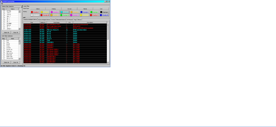
Alarm and Events
The alarm and events reporting mechanism is designed to support up to 16
classes (1-16). For a given class, the handling and attributes (priority, color,
audible) of each are database configurable.
Alarms and events are presented to the user in real-time within SCADA
summaries. In addition, applications are available that allow the user to
extract alarm and event data from the historical database.
Load Shedding/Restoration
Automatic Load Shedding/Restoration (LS/R) provides a rapid method of
opening and (optionally) closing groups of circuit breakers without the need
to individually select and then operate each breaker separately. Groups are
defined in the database and can be one of three types as follows.
Linear LS/R Group
Begins the shed at the breaker stated as the Start Point and proceeds to the
end of the list or until the desired load is shed.
Circular LS/R Group
Begins at the Start Point and processes until the desired load is shed. Upon
reaching the end the start point wraps back to the first breaker.
Rotational LS/R Group
Circular LS/R group that automatically restores the previously shed
breaker(s).
Sequential Control (Automatic Supervisory)
Sequential Control provides the capability to schedule automatic execution
of pre-defined control sequences. A sequence editor is provided to enable
the easy creation and maintenance of sequences and to categorize them
in a sequence library. The sequential control capability allows the user to
perform operations such as:
• Switching sequence related to maintenance , isolation or feeder
reconfiguration.
• De-energizing or energizing network elements such as parallel
transformers.
• Group commands (ganged switching, device isolation, load shed).
• Conditional control of one or more devices at different stations as a result
of detecting a specific system condition.
Transmission Switching Application
The Transmission Switching Applications (TSAs) are a suite of applications
that can be deployed either individually or in combination.
TSA Real-time Switching Validation involves real-time validation of all
requested switching device change of states. With this feature, every control
request, manual state change request or programmatic non-control state
change request associated with a switching device is validated against a
set of configurable validation rules. If the request is invalid, it is rejected and
not performed.
TSA Documents and Permits provides comprehensive management of the
electronic documentation and field permits associated with switching (in
PDF format).
TSA Switching Schedule Jobs provides comprehensive management of the
electronic switching schedules associated with planned switching schedule
jobs, fault switching schedules or unplanned switching schedules.
Given that each utility’s types of switching schedules and operational
procedures vary, TSAs are customizable through data configuration so they
can be easily tailored to meet a given utility’s needs.
Alarm/Event Summary

GEDigitalEnergy.com
7
Real-time Calculations
Real-time Calculations provides a standard and extensible calculation library
which, in addition to arithmetic and logical operations, contains standard
functions traditionally associated with a power system (e.g., MVA, PF).
Points are associated to the calculations using the database administration
facilities.
Historical Information Systems
XA/21 supports multiple Historical Information Systems including Oracle
®
’s
RDBMS, Instep’s eDNA, OSIsofts Inc.’s PI Historian and GE’s Proficy data
historian.
Data Engineering Tools
The XA/21 system provides a number of editors that allow users to manage
and administer the database, displays and forms or reports, including the
Database Suite, Commit User Interface, Display Editor, Display Update
Manager, Pseudo Display Editor and Time Series Builder.
For the database and display editing functions, centralized editing controls
changes to the on-line database by allowing editing at only one system (the
Master), and automatically making the data available for commit by job at each
of the other systems (the Slaves) to keep the data synchronized. All database
edits and commits are performed on-line without any system failovers. The
Commit User Interface and the Display Update Manager prepare and execute
the files needed to perform this synchronization, and all configured systems
have access to a centralized data storage repository of proven editing files.
Database Editor Suite
The Database Editor Suite application is a combination of the Database
Browser and the Database Editor functions. It allows for the display of
XA/21 views, attributes and other structures that make up the XA/21 Logical
Database, including allowing editing of these values.
Commit User Interface
The Commit User Interface provides the capability to choose one or more
database modifications to apply to the on-line system. This design allows
users to commit only the portions of data that are complete, while not
interfering with the editing capabilities of other users. A user may select
individual instances, jobs, multiple jobs or selections from several jobs for
application to the operational database.
Display Editor
The XA/21 Display Editor is a set of interactive software tools that can be
used to build and manage all elements of displays within an XA/21 system.
The Display Editor is based on AutoCAD
®
with linkages back to the real-time
database. In addition to the capabilities supplied by AutoCAD, the Display
Build Facility provides the facilities to meet the requirements for displays in
the XA/21 EMS environment. These facilities include:
• Definition of the static display information using AutoCAD’s graphic
drawing facilities for defining geographical or schematic diagrams.
• Incorporation of real-time or application data within a display.
• The ability to define graphical symbols to represent the current state
of telemetered or calculated devices. These graphical symbols can be
further organized into groups (called a device) and stored in libraries for
future reference.
• The ability to define the characteristics (referred to as attributes) of a
display such as display ID, pan/zoom characteristics, refresh rates, fonts,
application interfaces, etc. These attributes vary depending on the type of
display being constructed.
Display Update Manager
The Display Update Manager allows for the distribution of run-time displays
to all systems. Once distributed, the displays are available to the operator on
the next display call-up.
Pseudo Display Editor
The Pseudo Display Editor allows the engineer to build multiple displays
based on a common template. An example of representative use is a wind
farm. A typical wind farm is made up of many turbines/generators. Drawing
and maintaining individual displays for each turbine would be very time
consuming. As each turbine pseudo display is derived from a common
template, any changes to the template are automatically reflected in the
resultant turbine display.
Time Series Form Builder
The Time Series Form Builder is a development tool used for creating
applications for viewing XA/21 historical data from the Oracle relational
database. The Time Series Form Builder is designed for the non-technical
user, whereby simple point-and-click, drag-and-drop operations are used to
create fully functional applications.
Database Editor
AutoCAD based Display Editor (One-line)

GEDigitalEnergy.com
8
Transmission Applications
The XA/21 Transmission Security Management (TSM) subsystem delivers a
powerful set of tools for efficiently operating and protecting the integrity
of the power system. The TSM application module delivers rich information
about the real-time system with the added capability of being able to
examine near future states of the system.
With multi-user/multi-case support, the TSM subsystem provides a high
performance environment for network analysis, contingency analysis,
optional optimal power flow and optional fault level analysis functions.
Using the TSM subsystem, control center personnel can identify and analyze
potential operating problems and formulate various preventative strategies.
Base Applications
Real-time and Study State Estimator
The State Estimator (SE) engine estimates and analyzes the accuracy of the
telemetry within the transmission network provides this functionality using
robust algorithms. Estimated values are provided for all input measurement
types as well as for bus phase angles and branch series and shunt
impedances. SE has the ability to use PMU data such as time-aligned bus
voltage and phase angles to improve results.
Study Power Flow
Study Power Flow uses robust algorithm techniques, including Newton and
Fast-decoupled, for analyzing the transmission network within TSM. The
Power Flow engines provide a base case off-line study solution that can be
used for further study.
Network Status Processor
Network Status Processor (NSP) provides a precise determination of
electrical connectivity at the individual bus section level. Rather than relying
on user-defined calculations that must be maintained over time, NSP uses
a detailed connectivity model in conjunction with generalized Boolean logic
to accurately determine electrical connectivity and resulting energization
status for each individual power system component.
Schedules
Schedules provide typical day and absolute schedules for use in determining
the base network solution in Power Flow and in State Estimation where
telemetry is not available or requires further scaling.
Real-time and Study Contingency Analysis/Contingency Selection
Contingency Analysis tools provide capabilities for studying the impacts
of topological or MW generation changes to a base case solution. Each
contingency case can be processed as part of a group of other contingency
cases in a batch mode, providing the user with the ability to study impacts
of many contingencies against known system conditions.
Supplemental Applications
Real-time and Study Optimal Power Flow
To supplement the base transmission applications the following applications
can be optionally included.
• Security-constrained Dispatch Active Power Optimization
Optimization tools allow constraint limit violations to be relieved through
several selectable objective function methodologies using active power
controls. Users can choose to optimize all limits or only active power
limits.
• Voltage/VAR Scheduling Reactive Power Optimization
Constraint violations can be relieved through several selectable objective
function methodologies using reactive power controls. Users can choose
to optimize all limits or only reactive power limits.
• Post-contingency Remedial Action Optimization
The Remedial Action (RA) module provides the capability to obtain
independent optimized corrective rescheduling plans for each of a list
of harmful contingency cases that is identified by Contingency Analysis.
For each harmful case, a set of active and reactive power control moves
is obtained that minimizes the values of the user-specified objectives
while observing all operating limits designated for enforcement when
implemented in the post-contingency time frame.
• Pre-contingency Preventative Action Optimization
The Preventative Action (PA) module provides the capability to obtain
optimized preventative scheduling plans for a list of contingency cases.
PA minimizes the values of the user-specified objectives while observing
all operating limits designated for enforcement in the base case and
contingency cases. A set of active and reactive power control moves
is obtained that results in the system remaining secure due to the
occurrence of any one of the contingency cases when implemented in
the pre-contingency time frame.
Contingency Analysis Case Report
State Estimator Case Comparison

GEDigitalEnergy.com
9
Real-time and Study Fault Level Analysis
Fault level analysis tools provide real-time and off-line study capability to
simulate three-phase, phase-ground, phase-phase and phase-phase-
ground fault currents. User-defined or pre-defined faults can be used within
any active case.
Voltage and Transient Stability
XA/21 supports an interface to third-party security assessment tools,
including Voltage and Transient Stability.
Operator Training Simulator
Due to the ever-increasing growth and complexity of today’s EMS, the
need for training tools that supplement the traditional on the job training
of system dispatchers is recognized as an important requirement in the
control center environment. The Operator Training Simulator (OTS) provides
simulated conditions through which operators can be trained to control
the transmission grid on an XA/21 EMS, all based on the same engines and
model as the base transmission applications. The OTS creates a realistic
environment for the system operator to become familiarized with XA/21
system operation functions, test new operational approaches and learn to
manage emergencies through simulated conditions.
Enterprise Gateway – IEC 61970 Common Information Model
Exchange
The Enterprise Gateway (EG) allows the transmission model to be exchanged
in Common Information Model (CIM) format. EG supports full and incremental
model import and export into the XA/21. Imported models may be used as
the base network model definition, as incremental changes to the external
model or be imported into the study environment as an independent model.
Generation Applications
The XA/21 Generation Applications provide the functions required for
dispatch and closed loop control of generation in an economical fashion
while considering interchange schedules, generation limits and reserve
requirements. In addition, the Generation Dispatch and Control (GDC)
subsystem provides alarming as required in order to alert the operator to
impending conditions.
Automatic Generation Control
Automatic Generation Control (AGC) provides closed-loop control of
generating units within a control area of an interconnected power system.
AGC provides supplementary control of area generation to maintain area
frequency and/or area net interchange within defined limits. The primary
objective of AGC is to minimize the instantaneous and accumulated Area
Control Error (ACE) subject to specified NERC control performance criteria.
A secondary goal of AGC, in conjunction with the Generation Dispatch
function, is to minimize the area production cost within the bounds of
practical operating constraints.
Generation Dispatch
Generation Dispatch (GD) allocates the required amount of area generation
among available on-line generating units in an economical fashion so as to
minimize control area production cost with consideration of transmission
losses and high/low generator limits.
The GD function supports conventional fossil fuel (i.e., coal, oil and natural
gas) fired units and combustion turbines for which incremental heat rate
(IHR) curves are available.
Real-time Production Costs
Real-time Production Cost (RTPC) processes real-time data for power system
operating cost accounting. Historical Database Reports are prepared on a
periodic basis, which summarize the fuel, operating and maintenance (OM)
and startup/shutdown costs for each unit, plant and area in the power system.
Automatic Generation Control Summary
Fault Level Analysis Fault Detail Display
Operator Training Simulator - Conditional Event

GEDigitalEnergy.com
10
RTPC also provides real-time production cost performance monitoring. The
actual production cost is periodically compared with the optimal production
cost (based on the Target Pass economic dispatch). An alarm is issued to
the operator if the difference between actual and optimal production costs
exceeds a pre-defined tolerance.
Reserve Monitoring
Reserve Monitoring provides current information on available active (MW)
and reactive (MVAR) reserves in the system. The Reserve Monitor is a
standard software feature of the GDC. However, definitions of the various
Reserve parameters may vary with individual customer requirements.
Energy Scheduling and Accounting
Energy Scheduling and Accounting (ESA) provides the operator with the
capability to schedule future operating plans (for load, generation and
interchange) and review past accounting information through Java-based
energy related forms and reports.
ESA comprises the following functions:
• AGC Performance Monitoring (APM)
• Production Costs and Fuel Accounting (PC)
• Interchange Scheduling (I/S)
• Inadvertent Interchange Accounting (IA)
• Load Forecasting with:
- Similar Day Load Forecasting (SDF), or
- Demand Forecasting (DF)
• Unit Commitment/Transaction Evaluation (UC/TE) or Comprehensive
Operations Planning and Scheduling (COPS)
GDC Market Interface
XA/21 offers interfaces to many different regional market systems. A typical
market system interface consists of the primary data being supplied via
ICCP data links for Base points and Net Scheduled Interchange with XML
files provided as supplementary or as a backup. XA/21 has the option of
running in “Market mode” or independently as a backup for the Regional
Marketing System. As each market interface is different, the XA/21 system
can be customized to meet the needs of each utility.
Hydro Applications
For systems with reservoir-based, hydro-electric generators, XA/21 is
available with several optional hydro applications.
Automatic Voltage Control with MVAR Balancing
Generator Automatic Voltage Control (AVC) and MVAR Balancing provide
simultaneous operation of AGC with AVC to coordinate closed control of MW
and MVAR generation within operational and capability limits.
Water Monitoring and Accounting
Water Monitoring and Accounting provides the operator with a water release
summary and detailed information for current/previous hour conditions
for all reservoirs, plants, generators and gates (spillway, bypass, auxiliary
releases) along with projected releases for the current hour.
Historical forms are available for summarizing water release on a daily,
monthly and yearly basis.
Automatic Generation Control of Hydro Plants
AGC of hydro plants provides closed-loop MW control of hydro generators
to meet the plants hourly base-point schedules or real-time plant set-points,
while remaining within hourly plant operational water and generation limits.
Power Scheduling for Hydro Plants
The Power Scheduling functions support the processing of 24-hour (current/
next days) plant base-point schedules and bus KV or MVAR schedules
originating either locally or remotely (via data link).
Spillway Gate Control
Spillway Gate Control provides open and closed loop control of spillway
gates using either a total discharge or release level control objective.
Turbine Discharge Curve Monitor Display
Production Cost

GEDigitalEnergy.com
11
Distribution Applications
XA/21 Distribution Management System (DMS) applications provide facilities
for the effective management and operation of the distribution network
from the distribution station and into the feeder network. DMS applications
are based on models and graphics derived from a utility’s GIS.
Distribution Connectivity Analysis
The Distribution Connectivity Analysis (DCA) application automatically
monitors and analyzes the global connectivity network state based on static
or wired connectivity and current open/closed status of switching devices.
In addition, temporary changes to network topology applied by a user in
the real-time operating environment are taken into account. The electrical
status of each device in the network is always up-to-date.
Load Flow
Load Flow (LF) is an event-triggered application that uses network topology
information, as well as the current estimated load demands, to calculate
the three-phase voltage and current values for every device in the network.
LF provides estimated values for those electrical quantities at network
locations where SCADA measurements are not available.
Fault Detection, Isolation and System Restoration
The objective of Fault Detection, Isolation and System Restoration (FDIR) is
to improve customer service by minimizing the duration/extent of forced
outages due to faults in the medium voltage radial network. Whenever a
substation breaker or line recloser trips, and the associated auto-reclosing
relay locks out, FDIR will:
• Automatically attempt to determine the location of the fault based on
telemetered FRTU fault passage detection and breaker over-current relay
trip data.
• Then attempt to identify switching actions to isolate the faulted section
and restore power to un-faulted feeder sections up- and down-stream of
the faulted section.
• Then display the recommended switching actions to the operator for
approval and implementation.
Contingency Load Transfer
The interactive Contingency Load Transfer (CLT) study mode application
provides switching recommendations for a network reconfiguration
transferring load from one feeder to another to reduce overload on a
particular device or re-energize outaged portions of the network.
Integrated Volt-Var Control
The Integrated Volt-Var Control (IVVC) determines desirable capacitor
switching and transformer tap control actions resulting in better network
operations. IVVC has two primary modes of operation: Voltage Control,
concerned with temporarily reducing the total system load below defined
levels at peak load periods; and VAR Control, concerned with maintaining
the power factor at bulk supply points above minimum defined levels.
Distribution Device Select Switch
Distribution Load Flow Results
Distribution Allocated Load and Generator States
g
imagination at work
Digital Energy
2018 Powers Ferry Road
Atlanta, GA 30339
1-877-605-6777 (toll-free in North America)
678-844-3777 (direct number)
GEDigitalEnergy.com
GE, the GE monogram and XA/21 are trademarks of General Electric Company.
IEC is a registered trademark of Commission Electrotechnique Internationale. ISO is a registered
trademark of the International Organization for Standardization. NERC is a registered trademark
of North American Electric Reliability Corporation. Microsoft is a registered trademark of Microsoft
Corporation in the United States and/or other countries. LINUX is a registered trademark of Linus
Torvalds. Modbus is a registered trademark of Schneider Automation, Inc. ELCOM is a trademark
of ELCOM, Inc. IEEE is a registered trademark of the Institute of Electrical Electronics Engineers,
Inc. OSISoft is a registered trademark of OSI Soft, LLC. Oracle is a registered trademark of Oracle
Corporation and/or its affiliates. AutoCAD and Autodesk are either registered trademarks or
trademarks of Autodesk, Inc., in the USA and/or other countries.
GE reserves the right to make changes to specifications of products described at any time without
notice and without obligation to notify any person of such changes.
Copyright 2012, General Electric Company.
GEA-12686A(E)
English
120919
