
Cisco Preferred Architecture for
Webex Edge Connect for Webex
Meetings and Calling
Design Overview
January 2024
© 2024 Cisco Systems, Inc. All rights reserved.

Cisco Preferred Architecture for Enterprise Collaboration PAGE 2
Preface
Contents
Preface .......................................................................................................................................................... 4
Documentation for Cisco Preferred Architectures ...................................................................................................... 4
About This Guide ........................................................................................................................................................ 4
Introduction .................................................................................................................................................... 5
Technology Use Cases .............................................................................................................................................. 5
Benefits ....................................................................................................................................................................... 5
Available Services ...................................................................................................................................................... 5
Architecture ................................................................................................................................................... 6
Equinix Facilities and Webex DC Collocations ................................................................................................. 8
Webex Edge Connect Components and Roles .......................................................................................................... 9
Equinix Cloud Exchange (ECX) ...................................................................................................................... 10
Circuits, Fabric Ports and Connections ........................................................................................................... 10
Local and Remote Connections (BGP Peering Options) ................................................................................ 10
Core Requirements for Webex Edge Connect ................................................................................................ 12
Creating a Connection in the ECX Portal (Example) ...................................................................................... 12
Customer Requirements Before Edge Connect “Connection” (Peering) Request .......................................... 12
Requirements for The ECX Connection Request ........................................................................................... 14
Increasing Connection Bandwidth in the ECX Portal ...................................................................................... 15
Webex Meeting Traffic Flows over Edge Connect ................................................................................................... 17
Webex Meetings Traffic flows ......................................................................................................................... 18
Webex Edge Connect Design Considerations for Webex App, Devices (Board, Room, Desk) and Video Mesh .... 25
Webex App, Devices (Board, Room, Desk) Discovery ................................................................................... 26
Discovery ........................................................................................................................................................ 26
Design Considerations .................................................................................................................................... 26
DNS Considerations ................................................................................................................................................. 26
Webex Events Traffic Flows over Edge Connect ..................................................................................................... 27
Webex Calling Traffic Flows over Edge Connect ..................................................................................................... 29
High Availability and Redundancy ............................................................................................................................ 30
Local Redundancy .......................................................................................................................................... 30
BGP path redundancy ..................................................................................................................................... 31
BGP Communities........................................................................................................................................... 31
Active / Passive Local Redundancy ................................................................................................................ 34
Active / Active Local Redundancy ................................................................................................................... 37
Site Redundancy (Remote Redundancy - Geographically Dispersed) ........................................................... 37
Active / Active Geographically Dispersed Edge Connect Circuits................................................................... 37
Active / Passive Geographically Dispersed Edge Connect Circuits ................................................................ 40
Internet as Failover ......................................................................................................................................... 43
Bandwidth Provisioning and Capacity Planning ....................................................................................................... 44
Determining Active Participants (Active Calls) ................................................................................................ 44
Bandwidth Utilization ....................................................................................................................................... 46
QoS for Webex Signaling and Media ....................................................................................................................... 48
Ingress Marking, Egress Queueing ................................................................................................................. 49
Bandwidth Allocation ....................................................................................................................................... 50
Equinix ECX Physical Port Considerations ..................................................................................................... 51


Cisco Preferred Architecture for Enterprise Collaboration PAGE 4
Preface
Preface
Cisco Preferred Architectures provide recommended deployment models for specific market segments based on common
use cases. They incorporate a subset of products from the Cisco Collaboration portfolio that is best suited for the targeted
market segment and defined use cases. These deployment models are prescriptive, out-of-the-box, and built to scale with
an organization as its business needs change. This prescriptive approach simplifies the integration of multiple system-
level components and enables an organization to select the deployment model that best addresses its business needs.
Documentation for Cisco Preferred Architectures
•
Cisco Preferred Architecture (PA) design overview guides help customers and sales teams select the appropriate
architecture based on an organization’s business requirements; understand the products that are used within the
architecture; and obtain general design best practices. These guides support sales processes.
•
Cisco Validated Design (CVD) guides provide details for deploying components within the Cisco Preferred
Architectures. These guides support planning, deployment, and implementation (PDI).
•
Cisco Collaboration Solution Reference Network Design (SRND) guide provides detailed design options for Cisco
Collaboration. This guide should be referenced when design requirements are outside the scope of Cisco Preferred
Architectures.
About This Guide
The Cisco Preferred Architecture for Webex Edge Connect is for:
•
Sales teams that design and sell collaboration solutions
Customers and sales teams who want to understand the Webex Edge Connect architecture, its components, and general
design best practices.
Readers of this guide should have a general knowledge of Cisco Voice, Video, and Collaboration products and a basic
understanding of how to deploy these products.
This guide simplifies the design and sales process by:
•
Recommending products in the Cisco Collaboration portfolio that are built for the enterprise and that provide
appropriate feature sets for this market
•
Detailing a collaboration architecture and identifying general best practices for deploying in enterprise organizations
For detailed information about configuring, deploying, and implementing this architecture, consult the related CVD
documents on the Cisco Collaboration Preferred Architectures.

Cisco Preferred Architecture for Enterprise Collaboration PAGE 5
Introduction
Introduction
Webex Edge Connect is a dedicated, managed, QoS-supported IP link from your premises to Webex, achieved through
direct peering over Equinix Cloud Exchange (ECX). It insulates your meetings from the Internet, resulting in less
congestion, packet loss, jitters, and delay. Without exposure to the public Internet, you have better protection from
potential threats and attacks.
Technology Use Cases
Organizations want to streamline their business processes, optimize employee productivity, and enhance relationships
with partners and customers. The Cisco Preferred Architecture (PA) for Webex Edge Connect delivers direct connectivity
and dedicated high-speed bandwidth to Webex Cloud services. Additionally, the following technology use cases offer
organizations opportunities to develop new, advanced business processes that deliver even more value in these areas:
•
Dedicated Bandwidth – Dedicated bandwidth throughput and low latency access to Webex Meetings services
•
Meeting and Calling Quality - Conduct your day-to-day core business over Webex Edge Connect without worries
that it will interfere with meetings and calling. You can be assured of a highly consistent, reliable, cost-effective, and
secure experience for all.
•
Added Security - Webex Edge Connect direct peering insulates your meetings and calling from the variability of the
Internet. Edge Connect provides protection from the public Internet and potential threats and attacks.
Benefits
• Private circuit (not over Internet)
• Deterministic network path
• Predictable and stable latency and jitter
• Guaranteed bandwidth
• Speed options: 200M, 500M, 1G, 5G, 10G
Available Services
• Webex Meetings
• Webex Events
• Webex App, Webex Devices, Webex Video Mesh Media*
• Video Device-Enabled Webex Meetings
• Webex Edge Audio
• Webex Calling Services and Components**
*Webex App, Webex Devices (Board, Room and Desk) and Webex Video Mesh require Internet access for signaling over
HTTPS/SSL.
**Webex Calling also require internet access for various services.

Cisco Preferred Architecture for Enterprise Collaboration PAGE 6
Architecture
Architecture
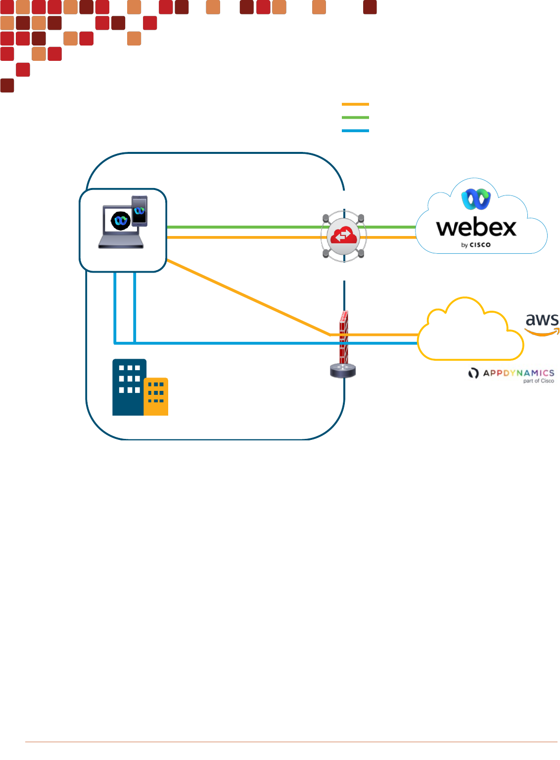
Webex Edge Connect is a dedicated, managed, Quality-of-Service (QoS) supported IP link from a customer’s premises to
the Webex cloud via the Equinix Cloud Exchange Fabric. This dedicated peering connection insulates your meetings from
the variability of the Internet – so less congestion, packet loss, jitter, and delay. Not being exposed to the public Internet
also means you are better protected from potential threats and attacks. This setup leads to better and faster Webex
Meetings and Calling powered by the Webex backbone. The direct connection provides enhanced meeting and Calling
quality with consistent network performance and added security.
Figure 1 illustrates a high-level overview of the solution. Equinix Cloud Exchange Fabric (ECX) inter-connects the end-
customer with a Webex Meetings Datacenter to route Webex destined traffic directly over a BGP (Border Gateway
Protocol) peering link. Equinix manages and is responsible for layer 2 inter-connectivity between customer and Webex.
Cisco manages one side of the layer 3 BGP peering while the customer manages their own side of the layer 3 BGP
peering.
Figure 1 Webex Edge Connect
Through route advertisements from Webex the customer routes Webex traffic over the peering link. Figure 2 illustrates
advertisement routing at a high level. Each numbered step is highlighted in the illustration by a number.
1. Layer 1 – Physical Connectivity
2. Layer 2 – Ethernet Connectivity
3. Layer 3 – IP connectivity
Equinix responsibility:
ü Physical link provisioning (cross connects)
ü Virtual circuit monitoring reports & support
Cisco responsibility
ü peering provisioning and support
IMPORTANT ROLES AND RESPONSIBILITIES
Layer 2
(802.1q)
Equinix Cloud Exchange
Layer 3
(BGP)
Layer 1
(1G/10G)
AS13445Cust ASN
Customer
Network

Cisco Preferred Architecture for Enterprise Collaboration PAGE 7
Architecture
Figure 2 Webex Traffic Routing
1) Webex advertises all Webex Meetings and Calling Datacenter prefixes (subnets) over the peering link
2) The customer router receives the Webex DC prefixes (subnets) and redistributes them into the internal routing
protocol, OSPF is used here as an example of a private routing protocol. The subnets are then available in the
customer routing tables directing traffic back towards the peering link.
3) Just like an enterprise’s Internet connection, the BGP peering connection requires a public IP address space. As
such the customer will have a pool of IP addresses that will be used to NAT from private IP to public IP. These
addresses will be advertised by the customer peering router to the Webex BGP network peer.
4) On the Webex router, the IP address space advertised by the customer is in turn redistributed into the Webex
network routing. This allows for the return traffic sourced from that NAT IP address pool.
Figure 3 illustrates a simplified example of call routing by the Webex Meetings Desktop Application and the traffic paths
taken to reach the Webex DC over Edge Connect. Each numbered step is highlighted in the illustration by a number.
Internet
Webex Routes
AMER
64.68.96.0/19
64.68.104.0/21
….
APAC
69.26.176.0/20
69.26.176.0/22
….
EMEA
62.109.192.0/18
….
Customer Routes
100.64.1.0 /29
BGP
BGP
Customer
Routed Network
Equinix
OSPF
Webex Ro utes
AMER
64.68.96 .0/ 19
64.68.10 4.0/ 21
….
APAC
69.26.17 6.0/ 20
69.26.17 6.0/ 22
….
EM EA
62.109.192.0/ 18
….
DNS Lookup
DNS Server
DNS Server
Webex Routes
AMER
64.68.96.0/ 19
64.68.104.0/ 21
….
APAC
69.26.176.0/ 20
69.26.176.0/ 22
….
EM EA
62.109.192.0/ 18
….
Webex Routes
AMER
64.68 .96.0 /19
64.68 .104 .0/ 21
….
APAC
69.26 .176 .0/ 20
69.26 .176 .0/ 22
….
EM EA
62.10 9.192.0/ 18
….
NAT POOL
Public IPs
Customer Routes
100.64.1.0 /29
Redistribute
Advertise
Webex Routes
AMER
64.68 .96.0 /19
64.68 .104 .0/ 21
….
APAC
69.26 .176 .0/ 20
69.26 .176 .0/ 22
….
EMEA
62.10 9.192.0/ 18
….
Advertise
Customer Routes
100.64.1.0 /29
Customer Routes
100.64.1.0 /29
Redistribute
Traffic to Webex
Traffic From Webex
1
2
3
4
2
3
Customer Routes
100.64.1.0 /29
4
1
Webex Routes
AMER
64.68.96.0/ 19
64.68.104.0/ 21
….
APAC
69.26.176.0/ 20
69.26.176.0/ 22
….
EM EA
62.109.192.0/ 18
….

Cisco Preferred Architecture for Enterprise Collaboration PAGE 8
Architecture
Figure 3 Webex Meetings Desktop Application routing over Edge Connect
1) The client does a DNS lookup to connect to the Webex service. This DNS request goes over the traditional path
of the Internet as an example. There are cases where DNS can be routed over Edge Connect. See DNS
Considerations for more information.
2) Once the client has resolved the IP address of the server to which it is connecting the client then connects to the
server which will be an IP address that resides in one of the Webex subnets that was advertised over Edge
Connect in Figure 2 step 1 and 2. As the customer’s network routing now has these prefixes (subnets) available
directing traffic to the Edge Connect peering, the traffic is then sent to the Webex DC over this path. It is at this
point that NAT is performed at the edge of the customer Edge Connect network to translate private to public IP
addressing before traversing the peering link.
3) The return traffic that is sourced by the NAT server is known by the Webex routing DC as these routes were
advertised by the customer router in Figure 2 step 3 and 4. As such the return traffic has a route back over the
peering link back to the NAT server and from the NAT server back to the client.
Note: It is important to keep in mind that this solution is a layer 3 routing solution and thus it is NOT possible to route
based on different types of Webex traffic components, endpoints, clients or even Webex meeting sites. All types of Webex
traffic flow through the Edge Connect and there is no specific filtering for components, clients or Webex meeting site
designations to alter this routing behavior.
Equinix Facilities and Webex DC Collocations
Webex Datacenters (DCs) are collocated in several Equinix Cloud Exchange locations. Figure 4 lists the US and
International locations while Figure 5 shows these same locations overlaid across the Equinix Cloud Exchange location
map.
Internet
Webex Routes
AMER
64.68.96.0/19
64.68.104.0/21
….
APAC
69.26.176.0/20
69.26.176.0/22
….
EMEA
62.109.192.0/18
….
BGP
BGP
Customer
Routed Network
Equinix
OSPF
Webex Ro utes
AMER
64.68.96 .0/ 19
64.68.10 4.0/ 21
….
APAC
69.26.17 6.0/ 20
69.26.17 6.0/ 22
….
EM EA
62.109.192.0/ 18
….
DNS Lookup
DNS Server
DNS Server
64.68.96.55
Webex Routes
AMER
64.68.96.0/ 19
64.68.104.0/ 21
….
APAC
69.26.176.0/ 20
69.26.176.0/ 22
….
EM EA
62.109.192.0/ 18
….
Webex Routes
AMER
64.68 .96.0 /19
64.68 .104 .0/ 21
….
APAC
69.26 .176 .0/ 20
69.26 .176 .0/ 22
….
EM EA
62.10 9.192.0/ 18
….
Connect to
webex.com
Customer Routes
100.64.1.0 /29
Webex Routes
AMER
64.68.96.0/ 19
64.68.104.0/ 21
….
APAC
69.26.176.0/ 20
69.26.176.0/ 22
….
EM EA
62.109.192.0/ 18
….
Traffic to Webex
Traffic From Webex
1
2
3
2
2
2
3
3
3
NAT POOL
Public IPs
Customer Routes
100.64.1.0 /29
Customer Routes
100.64.1.0 /29
Customer Routes
100.64.1.0 /29

Cisco Preferred Architecture for Enterprise Collaboration PAGE 9
Architecture
Figure 4 List of Webex DCs collocated in Equinix Facilities
North American Locations
International Locations
Ashburn, VA, US
Amsterdam, NL
Chicago, IL, US
London, GB
Dallas, TX, US
Frankfurt, DE
New York, NY, US
Singapore, SG
Silicon Valley, CA, US
Sydney, AU
Montreal, Canada
Tokyo, JP
Toronto, Canada
Figure 5 Equinix Facilities and Overlaid Webex DC Collocations
Webex Edge Connect Components and Roles
In this section the various solution components are discussed as well as the component roles in the solution. In this
discussion it’s important to separate the Webex Edge Connect components from the Webex Meetings solution
components. The following section discusses the components and roles of the Webex Edge Connect Solution.
Webex Edge Connect is fundamentally made up of the routing and switching components of a direct peering solution
allowing for Webex traffic normally destined to the Internet (Cloud) to be redirected through customer edge routing to the
Webex Backbone via the direct peering. As mentioned in the previous architecture illustration (Figure 1) Equinix manages
the Layer 2 portion while Webex manages the Layer 3 IP BGP peering.

Cisco Preferred Architecture for Enterprise Collaboration PAGE 10
Architecture
Equinix Cloud Exchange (ECX)
Equinix Cloud Exchange (ECX) is an interconnection solution that enables on-demand and direct access to Cloud
providers like Webex Meetings. The ECX solution has a few common components. Below are few of these components
and their roles.
The Equinix Cloud Exchange (ECX) Portal is a customer facing portal that allows the customer to order and configure
ports and connections to cloud service providers.
Circuits, Fabric Ports and Connections
Equinix has specific nomenclature on their ECX portal for ordering and connecting to cloud providers. It’s important to
understand these concepts to know where they fit in the design constructs.
Physical Circuit: This network circuit between the Customer building and the Equinix facility. This circuit is typically a
Metro-Ethernet but could be other types of physical circuits. This circuit runs all the traffic to Equinix and may have traffic
to multiple cloud providers running over it.
Equinix Fabric “Port”: A fabric port, or simply “port” is the physical port that was ordered in ECX that is connected from
ECX fabric to the customer equipment in the cage (router or switch). This fabric port connects the customer cage
equipment to the ECX fabric. A port can be used for a single provider or multiple providers up to the bandwidth allocated
to that port. For example, a 10G port could potentially have ten 1G connections to ten different cloud providers.
Equinix “Connection”: This is where a customer uses the ECX portal to submit a request to connect to a Cloud Provider.
This submission requires all of the BGP and routing information for the peering along with the Cisco Purchase Order (PO)
number for Webex Edge Connect. For more information on Webex Edge Licensing please visit the Webex Edge Data
Sheet.
Figure 6 illustrates where these ECX components reside in the overall design.
Figure 6 Equinix Cloud Exchange Components and Roles: Circuits, Fabric Ports and Connections
Local and Remote Connections (BGP Peering Options)
There are 2 main BGP peering options with Equinix, local “connection” and remote “connection”. Local connection is
where a customer has equipment in a cage in Equinix in a location where Webex is co-located as indicated in Figure 4
above and in Figure 5 denoted by the Webex Locations. Remote connection is where a customer has equipment in a
cage in an Equinix location where Webex is not co-located and thus requires a “Remote Connection” from Equinix Cloud
Exchange. Equinix locations are indicated in Figure 5 by a small red dot (there are more so check Equinix Cloud
Exchange for updated information). If a customer is in an ECX building where Webex is not located, then they will have to
purchase a remote connection to one of the ECX locations where Webex is co-located.
Local connection is illustrated in Figure 7. With local connection the customer can place their router for the BGP peering in
either their Equinix cage (Figure 7 – 1) or in their Enterprise and connect over Layer 2 to their Equinix cage (Figure 7 – 2).
Cisco Webex
Customer
Customer Cage
BGP Peering
Connection
PortCircuit
Equinix ECX Facility
ECX Fabric

Cisco Preferred Architecture for Enterprise Collaboration PAGE 11
Architecture
Figure 7 Edge Connect Local Connection (via Customer Cage)
Remote connection is illustrated in Figure 8. With remote connection the customer can place their router for the BGP
peering in either their Equinix cage (Figure 8 – 1) or in their Enterprise and connect over Layer 2 to their Equinix cage
(Figure 8 – 2).
Figure 8 Edge Connect Remote Connection (via Customer Cage)
Equinix ECX FacilityCustomer
Cisco Webex Cage
Customer to
Equinix
Physical Circuit
Customer Equipment to
Webex via Equinix Local
“Connection”
Customer Cage
`
BGP Peering
1
2
On-premise
Enterprise
Equinix Facility A
Customer
Equinix Facility B
Equinix Backbone
Customer Cage
BGP Peering
Customer to
Equinix
Physical Circuit
Customer Equipment to
Webex via Equinix
Remote “Connection”
1
2
Cisco Webex Cage
On-premise
Enterprise

Cisco Preferred Architecture for Enterprise Collaboration PAGE 12
Architecture
Core Requirements for Webex Edge Connect
• An IT team knowledgeable of BGP and peering principles – Probably one of the most overlooked areas of this
offering. Customers are responsible for their network architecture and engineering. It is critical to avoid
asymmetric routing and suboptimal network paths. Customers who do not have the networking expertise
internally should consider enlisting a partner or Cisco Advanced Services to ensure a successful deployment.
• A circuit established from customer premise to an Equinix ECX facility
• Equinix Cloud Exchange (ECX) Account and Rackspace in ECX
• BGP and Dot1Q Tagging Capable Router with L3 Connectivity to the Enterprise
• Physical port [1G/10G typical] available for connecting to the ECX Fabric
• An available Internet connection for various Webex device signaling services (see Traffic Flows below for more
details)
• IP addressing requirements:
o All customer owned IP addresses – This includes both sides of the BGP peering connection as well as
the customer advertised routes used for performing NAT from their private network to the public network
▪ BGP peering link address space - Public IP - /30 or /31 supported
▪ Advertised IP space – public and provider-independent - Edge Connect does not accept
private IP advertisements like RFC1918 – this address space is the customer edge NAT pool
space used to translate from private to public IP addressing that will be routed over Edge
Connect.
o Autonomous System Number (ASN) – Support for Public or Private 2-byte or 4-byte ASN
o Max length prefix that Webex advertises is /24
o The maximum length prefix that Webex accepts is /29
o The maximum number of routes Webex accepts is 100
o We recommend that customers allow 500 routes from Webex on the BGP peering as the number of
routes that Webex advertises may change over time
o Bidirectional-Forwarding Detection (BFD) is supported and enabled with a default value of 300 ms x 3
on the Webex Edge routers
Creating a Connection in the ECX Portal (Example)
Customer Requirements Before Edge Connect “Connection” (Peering) Request
1. Customer must have a circuit to Equinix Cloud Exchange (ECX)
2. They should also typically have equipment (router / switches) in a cage in ECX
3. They also have a port available to make the connection request. The port is the physical circuit created from their
cage to the ECX backbone. See Circuits, Fabric Ports and Connections above
4. Cisco Purchase Order Number (PO#) of Edge Connect purchase from Cisco Commerce Workspace

Cisco Preferred Architecture for Enterprise Collaboration PAGE 13
Architecture
Figure 9 ECX Portal Connection Request to Webex – Source and Destination Location Selection Page
Figure 9 illustrates the first page of the Webex Connection request in the ECX portal. This is where the source location
(Customer) and destination location (Webex) are selected. The following numbers correspond to the numbers in Figure 9
1. Origin location: where the customer equipment resides and where the ECX port that will be used is located.
2. This exact source location broken down by theater. In this example AMER is the theater selected and Silicon
Valley is the location of the cage where the router with the port configured resides.
3. This is the port that was configured in ECX and will be selected to be used for this connection.
4. Destination location: where the Webex DC location that will be selected to terminate this connection.
Note: There is no port to select on the destination side. Webex will associate the port accordingly. If there are multiple
connections to the same site for the same customer Cisco will configure those connections over two separate routers
(Premise Equipment) to ensure port and hardware redundancy.
5. This exact destination location broken down by theater. In this example AMER is also the theater selected as
well as Silicon Valley as we want this connection to be a local connection (see Figure 7).
6. These are other potential ECX facilities where Webex is located if we wanted to create a remote connection (see
Figure 8).
1
4
2
3
5
6

Cisco Preferred Architecture for Enterprise Collaboration PAGE 14
Architecture
Figure 10 ECX Portal Connection Request to Webex – Connection Details Page
Figure 10 illustrates the next page in the ECX portal configuration. This is where the connection details are entered,
highlighted in the “Requirements for The ECX Connection Request” section below. The following numbers correspond to
the numbers in Figure 10.
Requirements for The ECX Connection Request
1. Webex Connection Identifier: This is the name of the connection that both buyer (customer) and seller (Webex)
will see in the Equinix ECX portal. It is helpful that this name be indicative of the customer it is serving and the
purpose of the link. For example, if the customer was name Enterprise1 and this connection was their primary in
“Silicon Valley” location a helpful naming convention would be Enterprise1_SV_PRI and their secondary
connection in the same location could be Enterprise1_SV_SEC.
2. VLAN ID (customer side locally significant between customer and Equinix)
a. Recommended that customers provision their Equinix Cloud Exchange Ethernet port using standard
802.1q (Dot1q) framing with a standard EtherType of 0x8100 for simplicity. These are normal values
associated with a trunk and do not include complex Metro ethernet settings that carriers typically use
(qinq).
3. Purchase Order Number: This can be ignored. The one to use is the one at the bottom of the page (Step 7)
4. 1st Public IP Range: BGP Peering subnet ((/30 or /31) – Customer side and Webex side)

Cisco Preferred Architecture for Enterprise Collaboration PAGE 15
Architecture
5. 2nd Public IP Range(s): Subnets used for NAT and Advertised to Webex over BGP peering (max /29 – max 100
subnets)
6. Public or private ASN + password (32 bit supported)
7. Tech contact (i.e. admin group alias + phone number)
8. Cisco Purchase Order (PO) Number (for Edge Connect)
Figure 11 ECX Portal Connection Request to Webex – Connection Details Page: Connection Speed
Figure 11 illustrates the connection speed selection. Figure 11 – 8 shows an example of the speed options available for
the port selected in Figure 9 – 3. Figure 11 – 9 illustrates the connection charge, this contains the local connection charge
and if the Webex destination location is remote to the port location chosen in Figure 9 then a remote surcharge will be
shown. The following numbers correspond to the numbers in Figure 11.
9. Link speed to provision: 200mb, 500mb, 1gb, 5gb, 10gb
10. Pricing Overview: This will show the pricing and if there is a remote connection surcharge or if it’s a local
connection only.
Increasing Connection Bandwidth in the ECX Portal
If you are starting to see bandwidth usage get closer to your limit it is time for an upgrade. Fortunately, this is a pretty easy
fix and doesn’t cause any interruption in services, provided that you have a connection on a port that has available
bandwidth. So, for example if a 10GB port was connected to Equinix ECX fabric and a 1GB connection was made on that
port then upgrading the connection is as simple as making the request to add more bandwidth on the connection in the
ECX portal. If on the other hand a 1GB port was connected to Equinix fabric and a 1GB connection was made, then
another port will need to be connected or used. In which case this is a more complicated upgrade in bandwidth because a
new port will need to be established with enough bandwidth for the total requested bandwidth.
If a new port is required, it is recommended to get the new port installed and a new connection created. Once the new
connection and BGP peering is up and passing advertisements then the older connection can be deleted and removed.

Cisco Preferred Architecture for Enterprise Collaboration PAGE 16
Architecture
Figure 12 Increasing Connection Bandwidth in the ECX Portal
1
2

Cisco Preferred Architecture for Enterprise Collaboration PAGE 17
Architecture
Figure 12 – 1 illustrates the Connection and bandwidth details required to edit in order to upgrade the bandwidth of the
connection. Figure 12 – 2 shows the bandwidth details after selecting the “edit” and then selecting an upgrade to 1 Gbps
connection speed. Figure 12 – 3 shows the pricing details overview and confirmation of the order. Once confirmation is
selected Webex receives the request in their queue. Webex also require an updated Purchase Order Number (PO#). It’s
important to follow up this submission with an email to csg-[email protected] with the following information:
• Company Name: This is the name of the company to whom the connection is subscribed. This is important for
resellers and service providers to ensure that the customer company name is included.
• Name of the connection: This is the name of the connection as seen in Figure 12 – 1 in the “Primary
Connection Overview” section.
• Purchase Order Number: This is the PO# that should correspond to the updated bandwidth request.
• Autonomous System Number (ASN): This is the BGP ASN of configured in the “Additional Buyer Options” of
the connection page (see Figure 10 for where this is located on the connection details page).
Once Webex receives the ECX submission request and can validate the PO# associated with the connection they will
update the Webex side router (Seller side) of the connection to the requested speed. Once done they will approve the
request in the ECX portal, and this enables the auto-configuration for the speed change in the ECX fabric for both sides of
the connection in the ECX fabric. At that point it is appropriate to modify the bandwidth of the interface configuration on
the customer equipment hosting this connection.
Webex Meeting Traffic Flows over Edge Connect
This section discusses the traffic flows from the various Webex products and components that send traffic over Webex
Edge Connect. As mentioned earlier the following Webex services are supported over Webex Edge Connect:
• Webex Meetings
• Webex App Media (Webex App, Webex Devices (Board, Room and Desk) and Video Mesh require Internet
access for signaling)
• Video Device-Enabled Webex Meetings
• Webex Edge Audio
3

Cisco Preferred Architecture for Enterprise Collaboration PAGE 18
Architecture
Webex Meetings Traffic flows
Webex meetings can be joined by several different endpoints and clients. The following is a compilation of Webex solution
components and their associated traffic flows to illustrate the signaling and media flows with regards to their associated
points of egress, through either the Edge Connect path or the Internet path, when Webex Edge Connect is deployed.
Webex Meetings Desktop Application
Figure 13 Webex Meetings Desktop Application, Webex Productivity Tools and Webex Meetings Browser Integration
In the above illustration (Figure 13) the Webex Meetings Desktop Application as well as Webex Meetings Browser and
Productivity Tools send their signaling and media over the Edge Connect peering.
Webex Devices
Z
Customer
ECX
Edge Connect
Media Path
Signaling
Additional Webex-Related
Services (Including Third-Party)
Z
Webex Meetings
Browser Integration
and Productivity
Tools
Webex Meetings
Desktop/Mobile
Internet

Cisco Preferred Architecture for Enterprise Collaboration PAGE 19
Architecture
Figure 14 Webex Devices
In the above illustration (Figure 14) the Webex Board and Webex Devices only send their media over the Edge Connect
peering. Their signaling for call control and analytics all go over the Internet.
Webex App
Z
Customer
ECX
Edge Connect
Media Path
Signaling
Additional Webex-Related
Services (Including Third-Party)
Internet
Z
Webex Devices
Cisco Preferred Architecture for Enterprise Collaboration PAGE 20
Architecture
Figure 15 Webex App
In Figure 15 the Webex App sends both signaling and media over the Edge Connect peering, however, also sends
signaling for call control and analytics over the Internet.
Video Mesh with Webex App, Webex Boards and Webex Devices
Z
Customer
ECX
Edge Connect
Media Path
Signaling
Additional Webex-Related
Services (Including Third-Party)
Internet
Z
Webex App

Cisco Preferred Architecture for Enterprise Collaboration PAGE 21
Architecture
Figure 16 Video Mesh with Webex App, Webex Boards and Webex Devices
In the above illustration (Figure 16) Webex App (with Full Featured Meetings disabled), Webex Board and Webex Devices
send their media directly to a local Video Mesh Node when it is available. The Video Mesh Node in turn sends all cascade
media over the Edge Connect peering and all signaling for call control and analytics directly to the Internet, alongside the
signaling of the other Webex App, Webex Board and Webex Devices.
Video Mesh Integration with Unified CM Registered Video Devices
Z
Customer
ECX
Edge Connect
Media Path
Signaling
Additional Webex-Related
Services (Including Third-Party)
Z
Video Mesh
Internet
Z
Cisco Webex App
and Webex Devices

Cisco Preferred Architecture for Enterprise Collaboration PAGE 22
Architecture
Figure 17 Unified CM Registered Video Devices
The above illustration (Figure 17) shows Unified CM registered video devices connecting to Webex Meetings via Video
Mesh. Unified CM signals the Video Mesh via a SIP trunk while the video endpoints stream media directly to the Video
Mesh Node. The Video Mesh Node in turn sends all cascade media over the Edge Connect peering and all of the
signaling for call control and analytics directly to the Internet.
Webex Video Meetings Integration with Unified CM Registered Video Endpoints
Z
Customer
Z
Unified CM
Video Devices
Video Mesh
Cisco
Unified CM
SIP Trunk
ECX
Edge Connect
Media Path
Signaling
Additional Webex-Related
Services (Including Third-Party)
Internet

Cisco Preferred Architecture for Enterprise Collaboration PAGE 23
Architecture
Figure 18 Webex Video Meetings
The above illustration (Figure 18) shows Unified CM registered video devices connecting to Webex Meetings via an
Expressway Edge deployment. In an Expressway deployment all call control signaling and associated media go directly
over the Edge Connect peering link. Unified CM signals the Expressway-C server via a SIP trunk while the video
endpoints stream media directly to the Expressway-C. The Expressway-C in turn sends all signaling and media directly to
the Expressway-E and then on to the Webex DC via Edge Connect.
Webex Edge Audio with Unified CM
Z
Customer
Cisco
Unified CM
Z
Expressway C/E
SIP Trunk
Video Endpoints
ECX
Edge Connect
Unified CM
Video Devices
Media Path
Signaling
Additional Webex-Related
Services (Including Third-Party)
Internet

Cisco Preferred Architecture for Enterprise Collaboration PAGE 24
Architecture
Figure 19 Webex Edge Audio
The above illustration (Figure 19) shows Unified CM registered telephony devices connecting to Webex Meetings via an
Edge Audio solution. Edge Audio uses an Expressway Edge deployment to interface with Webex Meetings. In an
Expressway deployment for Edge Audio all call control signaling and associated media go directly over the Edge Connect
peering link. There are multiple types of call flows in Edge Audio both inbound and outbound but all signaling and media
run over the Edge Connect peering link.
Webex Hybrid Services
Z
Customer
Z
Expressway C/E
Cisco
Unified CM
Webex Edge
Audio
Dials +1.844.621.3956
US Webex Access Number
SIP Trunk
IP Phone
ECX
Edge Connect
Internet
Media Path
Signaling
Additional Webex-Related
Services (Including Third-Party)

Cisco Preferred Architecture for Enterprise Collaboration PAGE 25
Architecture
Figure 20 Hybrid Services
Figure 20 shows a Webex Hybrid Services solution where the Webex Hybrid Connectors (Management Connector,
Calendar Connector, Directory Connector and the Device Connector) are all installed and running. Most of these
connectors use the Internet to communicate with the Webex Cloud except for the Directory Connector. The Directory
Connector uses the Edge Connect path to communicate with the Webex Cloud. Hybrid call flows are signaled through an
Expressway connected over the Edge Connect peering link. This Expressway pair manages the signaling and media to
the Webex Cloud through Edge Connect and is only responsible for the call signaling and media flows for Webex while
the connectors having different roles and on different devices communicate to their corresponding services nodes
separately.
Webex Edge Connect Design Considerations for Webex App, Devices (Board, Room,
Desk) and Video Mesh
Amazon Web Services (AWS) host various micro-services for Webex App, Devices (Board, Room, Desk) and Video
Mesh. Webex App services for Webex App, Devices (Board, Room, Desk) and Video Mesh are hosted in globally
distributed data centers, that are either Cisco owned (e.g., Webex data centers for identity services, key management
services and media servers) or hosted in a Cisco Virtual Private Cloud (VPC) on the Amazon AWS platform (e.g., Webex
App micro-services, message and file storage services). All data is encrypted in transit and at rest.
During a recent Webex expansion new media services have been added to the Amazon Web Services (AWS) Cisco
Virtual Private Cloud (VPC) hosted services for Webex App, Devices (Board, Room, Desk) and Video Mesh.
As such it is important to understand the impact of this with regards to Webex Edge Connect. Webex Edge Connect does
not advertise the AWS VPC prefixes over the BGP peering. As explained in the Webex Meeting Traffic Flows over Edge
Connect Webex App, Webex Devices and Video Mesh use the internet to access signaling microservices in the AWS
VPC as part of their normal functioning. As media services now reside in the AWS VPC the discovery process will
determine the closest resources to use. The expectation is that media resources over Edge Connect will have a lower
round-trip time (RTT) than any available resources in AWS VPC, so this is most likely a non-issue for most deployments.
Z
Customer
Calendar Connector
Active Directory
Management Connector
Expressway- C
Connector Host
Microsoft
Ex change
Directory Connector
Expressway C/E
Cisco
Unified CM
Z
Video Endpoints
SIP Trunk
Edge Connect
ECX
W
e
b
e
x
D
e
v
i
c
e
C
o
n
n
e
c
t
o
r
Internet
Media Path
Signaling
REST/HTTPS

Cisco Preferred Architecture for Enterprise Collaboration PAGE 26
Architecture
That said it should be noted that these media resources are available in AWS and media flows could potentially be routed
over the internet to the AWS VPC if the RTT is lower over that path.
To better understand how this mechanism functions, it’s important to know the Webex App, Devices (Board, Room, Desk)
and Video Mesh discovery process.
Webex App, Devices (Board, Room, Desk) Discovery
When a Webex App or Device starts up, it registers to Webex call control. Webex then returns a list of addresses of cloud
media services as well as any Video Mesh Node (VMN) clusters provisioned for that Webex App/Devices organization.
Next the Webex App or Device performs several tests to determine where it should send media when joining a meeting.
Discovery
The first test that the Webex App and Devices perform is a cluster reachability test to see if they can connect to the cloud
media services as well as any Video Mesh Node clusters.
The second test that the client or device performs is a STUN test to determine the round-trip delay time (RTD) between
the endpoint and the media node (Video Mesh, Webex Cloud and Cisco VPC). In most cases, for an on-premises Webex
App endpoint, a Video Mesh cluster should have a shorter RTD than cloud media services. The Webex client or device
reports the results of the STUN test to Webex. Webex then assigns the Webex App endpoint to send media to a media
services node with the lowest round-trip delay time. The client prefers on net Video Mesh Nodes (VMNs) over cloud
media nodes except in the case where the closest VMN cluster is >250ms and the cloud node is 200 ms or less. This is
not configurable to the customer.
Webex App endpoints perform these tests in the background when one of the following events occurs:
• Webex App and Devices startup
• A network change event
• Media service cache expiry
The cache expiry time for media node discovery is 2 hours. When new Video Mesh Nodes are added to a deployment, it
may take Webex App endpoints up to 2 hours to recognize this event. Restarting a Webex App endpoint will force the
endpoint to perform connectivity and STUN tests again and to recognize the new Video Mesh Node.
Design Considerations
Typically, due to the decreased latency of media resources available over the Edge Connect peering, the Amazon Web
Services (AWS) Cisco Virtual Private Cloud (VPC) IP blocks for media services will likely not be used. These media
services located in AWS VPC would have a higher RTT (round-trip time) from the media services over Edge Connect.
That said and depending on where the Webex App or Webex Devices are located in the network and the delay between
the direct internet access (DIA) point and the Edge Connect point they could choose those resources over the Edge
Connect resources simply due to latency alone. It is not recommended to block these IP segments over the internet for a
couple of reasons. One is that the internet segment is typically used as a backup to Edge Connect. By blocking this they’ll
then block potentially lower latency services once failed to the Internet. Another reason is that not all Webex components
have the same discovery and reachability mechanisms for using the AWS VPC media services and as such, blocking the
IP segments could cause meeting failures. So, it is recommended to let the Webex component’s discovery and
reachability mechanisms determine the lowest latency resources available based on their location in the network.
DNS Considerations
There are scenarios where Webex resources do lookups on domain-names for customer’s mail services for example,
such as an MX record lookup to determine the mail servers to deliver Webex scheduled meeting requests. In these
situations, the Webex micro-services in the Webex DC may do a look-up and be pointed to the external DNS server for
the Enterprise organization. If the DNS server is also served by a network segment that contains the Webex Edge
Connect prefixes, this can cause asymmetric routing of DNS query-response and thus be blocked by the firewalls.

Cisco Preferred Architecture for Enterprise Collaboration PAGE 27
Architecture
Figure 21 Asymmetric DNS query / response example
Figure 21 illustrates a design where the Internet and Edge Connect are served from the same network segment (DMZ).
When a component server, in this case the Mail Delivery Agent for Webex does a lookup on the Mx record for
mail.enterprise.com it does a DNS query the enterprise DNS server. This query comes into the enterprise via the internet
because the DNS server is only advertised out the internet, not Edge Connect. However, in this case when the response
returns to the network segment that serves the internet, there is a path to the source IP address of the DNS query, as it
matches a path from the advertised routes over Edge Connect. As such the DNS response is routed over Edge Connect
and gets blocked by a firewall due to the asymmetric routing.
The recommendation for this type of design is to ensure that the DNS servers or any public facing network component
that are used in communication with the Webex Services are advertised over Edge Connect. This would allow for
symmetric routing over Edge Connect and over the Internet during failure scenarios.
Webex Events Traffic Flows over Edge Connect
Webex Events service allows hosts to organize virtual events and webinars. In Webex Events the host can choose
between webinar mode and webcast mode.
ECX
Edge
Connect
Blocked
FW
Internet
DNS Query
DNS Response
dns.enterprise.com
DMZ
Blocked
Lookup: mail.enterprise.com
Query: dns.enterprise.com

Cisco Preferred Architecture for Enterprise Collaboration PAGE 28
Architecture
Figure 22 Webex Events Webinar
In the Webex Events Webinar feature the host, cohost, panelists, and attendees send their media and signaling through
Edge Connect. Figure 22 illustrates this.
Z
ECX
Edge Connect
Internet
Media Path
Signaling
Webex Events Webinar
Customer
Z
Webex Events
Hosts, Panelists Attendees

Cisco Preferred Architecture for Enterprise Collaboration PAGE 29
Architecture
Figure 23 Webex Events Webcast
In the Webex Events Webcast feature the host, cohost and panelists send their media and signaling through Edge
Connect however the attendees send their signaling over Edge Connect while their media comes across the Internet.
Figure 23 illustrates this.
Webex Calling Traffic Flows over Edge Connect
Webex calling can be joined by several different endpoints and clients which can be grouped into 2 categories: Local
Gateways and Calling Endpoints and Clients. The following are the associated traffic flows to illustrate the signaling and
media flows with regards to their associated points of egress, through either the Edge Connect path or the Internet path,
when Webex Edge Connect is deployed.
The following Webex Calling services are supported over Webex Edge Connect:
1. Local Gateway:
a. Cisco Unified Border Element (CUBE)
2. Calling Endpoints and Clients:
a. Multiplatform Phones (MPP)
b. Video capable phones (8845, 8865)
c. The Webex App (both desktop and mobile) when configured with Webex Calling for the users
d. The Webex Calling application (both mobile and desktop)
Z
ECX
Edge Connect
Media Path
Signaling
Customer
Z
Webex Events
Hosts and Panelists
Z
Webex Events
Attendees
Webex Events
Hosts, Panelists
and Attendees
Webex Events Webcast
Z
Internet

Cisco Preferred Architecture for Enterprise Collaboration PAGE 30
Architecture
Figure 24 Webex Calling Endpoints and Local Gateway Signaling and Media flow
Figure 24 illustrates the Webex Calling Endpoints and Clients such as the Multiplatform Phone (MPP) and the Webex App
as well as the Local Gateway both sending call control signaling as well as media over the Edge Connect link. The Webex
App in this case is only referring to the signaling and media for Webex Calling. Webex signaling and media for Webex
Meetings is discussed in the Webex Meetings traffic flows. The Local Gateway may have other connections inside the
enterprise such as to a Unified CM cluster or to PSTN or PSTN provider over SIP. Lastly there are some connections
made from the Webex Calling Endpoints, Clients and Local Gateway that may require an internet connection for other
Webex services or infrastructure services, some examples are Webex Services, DNS or NTP.
High Availability and Redundancy
High availability and redundancy can be done in several ways. This section will discuss local redundancy, site redundancy
(remote redundancy) and Internet as failover. Please keep in mind that traffic engineering is managed and supported by
the enterprise. The following examples are simply samples of possible deployment models used to give an idea of the
function of BGP routing in an Edge Connect deployment.
Local Redundancy
Local redundancy consists of having local redundancy (at the same site) for the Edge Connect peering. This can be
achieved in several ways such as active/passive or active/active peering circuits. The benefits of one over the other are
covered in each sub-section.
Note: Webex Edge Connect does not support a single peering link over multiple layer 2 ports. As such it is not possible
to deploy a layer 2 redundancy model with a single BGP peering in this offering. Each peering (connection) requires its
own port.
Z
Customer
ECX
Edge Connect
Media Path
Signaling
PSTN Connectivity
Additional Webex-Related
Services (DNS/NTP/Other)
PSTN
Z
Local
Gateway
Webex Calling Endpoints
and Clients
Z
Local
Ga teway
Internet
Webex Calling
Multiplatform
Phone (MPP)
Webex app
Desktop/Mobile

Cisco Preferred Architecture for Enterprise Collaboration PAGE 31
Architecture
BGP path redundancy
In BGP path redundancy there are 2 separate BGP peerings at the same location in an active/active or active/passive
routing configuration. The recommendation is to have an active/passive routing configuration with equal bandwidth
amounts for the active and passive links. Each link should be provisioned to support the service at the busy hour. See the
section on bandwidth provisioning (Bandwidth Provisioning) for more information on that.
Figure 25 BGP path redundancy
There are multiple ways to configure BGP path redundancy. While this is ultimately up to the customer to configure and
manage the BGP traffic engineering Webex provides BGP Community strings and local preference tagging for the highest
level of control and routing influence. Webex provides several BGP Community strings that customers can use to
influence traffic engineering.
Note: AS-PATH prepending is a technique used to deprioritize a route by artificially increasing the length of the AS-
PATH attribute by repeating an autonomous system number (ASN). Route selection in BGP prefers the shorter AS path
length, assuming all other criteria are equal. This is another traffic engineering tool used to affect BGP routing and path
selection. AS-PATH prepending is supported in Edge Connect however only with Public ASNs. While Private ASN’s are
supported the ASN is stripped as it enters the Webex Network and as such cannot support AS-PATH prepending.
BGP Communities
The following BGP communities are honored by Webex inbound route policies and may be used by customers to
influence Edge Connect link priority.
Link Priority Communities
• None — Default (least desirable path and / or hot potato)
• 13445:200 — Local Preference 200
• 13445:300 — Local Preference 300
• 13445:400 — Local Preference 400
• 13445:500 — Local Preference 500
• 13445:600 — Local Preference 600
• 13445:700 — Local Preference 700
• 13445:800 — Local Preference 800
• 13445:900 — Local Preference 900 (Most desirable path)
Route Propagation Scoping Communities
NAT
Enterprise Network
192.0.2.1/30
192.0.2.5/30
192.0.2.2/30
192.0.2.6/30
198.51.100.0/28
RTR1
RTR2
AS 64496
Primary Path
Secondary Path
AS13445

Cisco Preferred Architecture for Enterprise Collaboration PAGE 32
Architecture
Customers that have a global peering arrangement with Webex may want to limit route advertisements within the Webex
cloud to the local geographic theater. The following communities may be used to limit customer route propagation across
the Webex network.
• None — Default permit global reachability
• 13445:677 — Permit local theater reachability
Webex Route Origin Communities
Webex applies BGP community tags to indicate where the Webex prefix originates. This can be helpful if you want to
perform route filtering based on location tag. The following BGP communities indicate the origin of the Webex prefix
grouped by geographic theater. It is recommended to only filter based on geographic theater.
Webex Meetings Communities (By Theater)
• 13445:10000 — AMER
• 13445:10010 — EMEA
• 13445:10020 — APAC
Webex Calling Communities (By Theater)
• 13445:20000 — AMER
• 13445:20010 — EMEA
• 13445:20020 — ANZ
• 13445:20060 — APAC
Webex Route Origin Community Examples
The following are a couple of examples of basic router configurations using BGP community strings to filter on the theater
group of prefixes or by Webex solution (i.e., Webex Meetings or Webex Calling).
Figure 26 illustrates a design where only Webex Calling prefixes are accepted into the routing table and thus Webex
Meetings prefixes are filtered out.

Cisco Preferred Architecture for Enterprise Collaboration PAGE 33
Architecture
Figure 26 Filtering on Webex Calling Prefixes through Community Strings
In Figure 26 there are 7 community strings created, one for each solution and theater. Community lists 1-3 cover the 3
theaters for Webex Meetings while the community lists 4-7 cover the 4 theaters for Webex Calling. In this configuration a
route-map named CALL-ONLY is created to permit community lists 4-7 which are all theaters for Webex Calling (Figure
26 – step 1). This route-map is then applied to the neighbor string thus only permitting communities 4-7 into the BGP
routing table (Figure 26 – step 2).
Figure 27 illustrates a design where only Webex Meetings prefixes are accepted into the routing table and thus Webex
Calling prefixes are filtered out.

Cisco Preferred Architecture for Enterprise Collaboration PAGE 34
Architecture
Figure 27 Filtering on Webex Meetings Prefixes through Community Strings
In Figure 27 there are the same 7 community strings created, one for each solution and theater. Community lists 1-3
cover the 3 theaters for Webex Meetings while the community lists 4-7 cover the 4 theaters for Webex Calling. In this
configuration a route-map named MTG-ONLY is created to permit community lists 1-3 which are all theaters for Webex
Meetings (Figure 27 – step 1). This route-map is then applied to the neighbor string thus only permitting communities 1-3
into the BGP routing table (Figure 27 – step 2).
Note: It is recommended that customers accept all Webex routes or use community strings to filter routes by solution
(Webex Calling or Webex Meetings) and/or by theater (AMER, EMEA, etc..) and avoid hard coding prefix-list or route-
polices. Filtering based on CIDR blocks is not recommended because traffic can be bi-furcated or lead to asymmetric
routing issues. Filtering based on community strings simplifies the design and configuration.
Active / Passive Local Redundancy
In active / passive local redundancy 2 connections each with a separate peering are installed advertising the same NAT
pool and receiving the same Webex route prefixes. In this example each BGP peering is on a separate router to further
allow for router redundancy. BGP communities and local preference are used in this example to ensure 1 peering link is
active while the 2
nd
peering link is only used for traffic when the 1
st
path fails. This example demonstrates an enterprise
network with two Edge Connect circuits to Webex in the same location using BGP Community local preference to ensure
path selection of Active/Passive is illustrated in Figure 28.

Cisco Preferred Architecture for Enterprise Collaboration PAGE 35
Architecture
Figure 28 Active / Passive Local Redundancy: BGP Community local preference
In Figure 28 RTR1 is the primary link that is active and RTR2 is the secondary link that is passive. In this case BGP local
preference is used to indicate the most desirable path via RTR1. This is required in both directions. Local preference is
set inbound on routes received on RTR1 and RTR2 from Webex router peers to influence outbound routing behavior
(routing behavior of traffic from the Enterprise to Webex). Subsequently BGP Link Priority Communities can be used to
indicate to Webex the local preference for the Enterprise routes back towards the customer network.
Note: When purchasing an Edge Connect license there is a redundancy option available. This redundancy option
allows for a cost savings on the secondary connection when purchasing an Edge Connect license. So, when purchasing a
1GB connection for example and selecting the redundancy option, this allows for two 1GB connections in an Active /
Passive local redundancy model. This redundancy licensing option is only available for the Active / Passive local
redundancy and is not available for the Active / Active local redundancy model, nor the site redundancy models such as
Active / Active Geographically Dispersed Edge Connect Circuits or Active / Passive Geographically Dispersed Edge
Connect Circuits.
Enterprise to Webex Network path selection:
RTR1 applies an inbound policy on the routes (prefixes) received from the Webex BGP peering to set local preference of
900 and RTR2 applies a local preference of 800 to the Webex prefixes. This is illustrated in Figure 28 - 1. As a result, the
best path to reach the Webex cloud prefixes from the Enterprise network is RTR1 because it has assigned the highest
local preference.
Webex to Enterprise network path selection:
RTR1 applies outbound policy setting the BGP community 13445:900 and RTR2 applies the community 13445:800 to the
enterprise prefix 198.51.100.0/28 advertised to Webex. This is illustrated in Figure 28 - 2. As a result, the Webex cloud
selects the RTR1 path because it is advertising the most desirable link priority community (900).
The following configuration on RTR1 and RTR2 is an example configuration of the above network path selection using
BGP community to set local preference. The route-maps highlighted in blue show the configuration used to set community
and local preference.
RTR1 Example BGP Configuration
Ent Routes: BGP community 13445:900
Local Preference
900
Local Preference
800
Ent Routes: BGP community 13445:800
Local Preference
900
Local Preference
800
NAT
Enterprise Network
192.0.2.1/30
192.0.2.5/30
192.0.2.2/30
192.0.2.6/30
198.51.100.0/28
RTR1
RTR2
AS13445
AS 64496
Active / Primary
Passive / Secondary
1
2
Webex Routes
1
Webex Routes
2
Routing Prefix
Advertisements

Cisco Preferred Architecture for Enterprise Collaboration PAGE 36
Architecture
router bgp 64496
neighbor 192.0.2.2 remote-as 13445
!
address-family ipv4
neighbor 192.0.2.2 activate
neighbor 192.0.2.2 send-community both
neighbor 192.0.2.2 route-map PRIMARY-OUT out
neighbor 192.0.2.2 route-map PRIMARY-IN in
exit-address-family
!
ip prefix-list ADVERTISE-TO-WEBEX seq 5 permit 198.51.100.0/28
!
route-map PRIMARY-OUT permit 10
match ip address prefix-list ADVERTISE-TO-WEBEX
set community 13445:900
!
route-map PRIMARY-IN permit 10
set local-preference 900
RTR2 Example BGP Configuration
router bgp 64496
neighbor 192.0.2.6 remote-as 13445
!
address-family ipv4
neighbor 192.0.2.6 activate
neighbor 192.0.2.6 send-community both
neighbor 192.0.2.6 route-map SECONDARY-OUT out
neighbor 192.0.2.6 route-map SECONDARY-IN in
exit-address-family
!
ip prefix-list ADVERTISE-TO-WEBEX seq 5 permit 198.51.100.0/28
!
route-map SECONDARY-OUT permit 10
match ip address prefix-list ADVERTISE-TO-WEBEX
set community 13445:800
!
route-map SECONDARY-IN permit 10
set local-preference 800

Cisco Preferred Architecture for Enterprise Collaboration PAGE 37
Architecture
Active / Active Local Redundancy
In an active / active local redundancy 2 links each with a separate peering on separate routers advertising the same NAT
pool and receiving the same Webex route prefixes. In this example each BGP peering is on a separate router for further
redundancy of the router platform itself. Nothing special is required in the BGP configuration to ensure both peering links
are active for traffic. This example demonstrates an enterprise network with two Edge Connect circuits on separate
routers to Webex in the same location with Active/Active links is illustrated in Figure 29.
Figure 29 Active / Active Local Redundancy
In Figure 29 RTR1 and RTR2 are both active in routing the traffic they receive from either direction. In this case nothing
special is required in the BGP configuration in this example. The routers receiving the traffic will forward all of the traffic
that they receive over their path. However, the enterprise routers need to be load balanced prior to RTR1 and RTR2.
Another router on the internal routing protocol side would be required to load-balance traffic to RTR1 and RTR2 and
would need to ensure an equal cost next hop path of RTR1 and RTR2 for the Webex subnets advertised into the local
routing protocol. This is illustrated in Figure 29 - 1. In Figure 29 - 2 the advertisements of the Enterprise route
198.51.100.0/28 used for NAT’ing from Private to Public IP is advertised to Webex Cloud without any specific link priority.
Note: If a single router was used for both peering links to Webex Cloud, then BGP multipath would be a required
configuration to load balance the 2 separate peering links. While it is technically feasible, this is not something that is
recommended because the router becomes a single point of failure for the 2 links and diminishes the value of the multiple
peering links at a single location.
Site Redundancy (Remote Redundancy - Geographically Dispersed)
Site redundancy refers to a primary and secondary path where each Edge Connect circuit is located at a geographically
separated site. This is where each Edge Connect site is remote to the other however each are backing one another up in
case of link or site failure. The following 2 examples will illustrate active/active and active/passive site redundancy.
Active / Active Geographically Dispersed Edge Connect Circuits
In this setup two sites East and West hosts Edge Connect circuits. For West networking domain users, the West Edge
Connect circuit is primary and the East Edge connect circuit is secondary. For East networking domain users East is
primary and West is secondary. This is illustrated in Figure 30 and Figure 31. As mentioned, due to the geographical
separation of the two circuits two separate NAT pools are required. Because the NAT pools are separate and unique the
Ent Routes
Ent Routes
NAT
Enterprise Network
192.0.2.1/30
192.0.2.5/30
192.0.2.2/30
192.0.2.6/30
198.51.100.0/28
RTR1
RTR2
AS13445
AS 64496
Active
Active
2
Webex Routes
1
Webex Routes
2
Routing Prefix
Advertisements

Cisco Preferred Architecture for Enterprise Collaboration PAGE 38
Architecture
return client traffic from the Cloud back towards the Enterprise will always be routed back to the specific unique NAT pool
and thus site. Figure 30 illustrates West users being routed over the West connection as Primary (Figure 30 - 1) and the
East connection as Secondary (Figure 30 - 2). Figure 31 illustrates this for East networking domain users being routed
over the East connection as Primary (Figure 31 - 1) and West connection as Secondary (Figure 31 - 2).
This routing scenario is named Active / Active because both circuits are actively routing traffic for their site’s users, thus
active, while both circuits are available as backup for the other’s site in case of failure. From a sizing perspective each
circuit needs to be able to handle the bandwidth requirements of both sites in case of a failure. As such each circuit needs
to be provisioned accordingly. If the sites are separated by an Enterprise WAN, the WAN will also need to be sized
accordingly if traffic is to be routed site to site over the WAN.
Figure 30 Site to Site Redundancy Active / Active circuits: West’s Primary/Secondary Paths
Figure 31 Site to Site Redundancy Active / Active circuits: East’s Primary/Secondary Paths
Enterprise WAN
Enterprise Network - West Enterprise Network - East
1
2
West’s Secondary Path
West’s Primary Path
East’s Secondary Path
East’s Primary Path
NAT1
NAT2
Enterprise Network - West Enterprise Network - East
Enterprise WAN
1
2
West’s Secondary Path
West’s Primary Path
East’s Secondary Path
East’s Primary Path
NAT1
NAT2

Cisco Preferred Architecture for Enterprise Collaboration PAGE 39
Architecture
Being geographically separated each site requires a unique NAT pool and thus return traffic over that NAT pool will
always come back from Webex Cloud to that site removing any concern for asymmetrically routed traffic.
Figure 32 illustrates the 2 sites using local preference to ensure active/active routing of traffic. In this case the West
connection (Figure 32 - 1) is primary and the East connection (Figure 32 - 2) is secondary. It’s important to note that
engineering the traffic between locations over the internal WAN (Figure 32 - 3) will be crucial in ensuring this routed
behavior.
Figure 32 Geographically separate sites Active/Active circuits
The following configuration is illustrated in Figure 32.
RTR1 as the primary active link for West and RTR2 as the primary active link for East.
Webex to Enterprise network path selection:
RTR1 and RTR2 are advertising unique prefixes. As such the return traffic from Webex network will always follow the
return path from those source network prefixes.
Enterprise to Webex Network path selection:
In Figure 26 RTR1 and RTR2 will each have the same cost for their respective sites (Figure 26 - 1) and (Figure 26 - 2). It
is up to the internal routing protocol to redistribute the subnets learned from the BGP peering over the WAN (Figure 26 -
3) with a cost that will ensure that the secondary path is only used when the primary local path for the same routes
(prefixes) is down.
The following configuration on RTR1 and RTR2 is an example configuration of the above network path selection. The
route-maps highlighted in blue show the configuration used to advertise the NAT pool.
RTR1 Example BGP Configuration
router bgp 64496
NAT1
Enterprise Network - West
192.0.2.1/30
192.0.2.2/30
192.0.2.6/30
198.51.100.0/28
RTR1
RTR2
AS 64496
Active / Primary for
West
Active / Primary
for East
NAT2
198.51.100.16/28
192.0.2.5/30
AS 64496
Enterprise Network - East
WAN
1
2
3
AS13445

Cisco Preferred Architecture for Enterprise Collaboration PAGE 40
Architecture
neighbor 192.0.2.2 remote-as 13445
!
address-family ipv4
neighbor 192.0.2.2 activate
neighbor 192.0.2.2 send-community both
neighbor 192.0.2.2 route-map PRIMARY-OUT out
exit-address-family
!
ip prefix-list ADVERTISE-NAT1-TO-WEBEX seq 5 permit 198.51.100.0/28
!
route-map PRIMARY-OUT permit 10
match ip address prefix-list ADVERTISE-NAT1-TO-WEBEX
RTR2 Example BGP Configuration
router bgp 64496
neighbor 192.0.2.6 remote-as 13445
!
address-family ipv4
neighbor 192.0.2.6 activate
neighbor 192.0.2.6 send-community both
neighbor 192.0.2.6 route-map SECONDARY-OUT out
exit-address-family
!
ip prefix-list ADVERTISE-NAT2-TO-WEBEX seq 5 permit 198.51.100.16/28
!
route-map SECONDARY-OUT permit 10
match ip address prefix-list ADVERTISE-NAT2-TO-WEBEX
Active / Passive Geographically Dispersed Edge Connect Circuits
In this setup one site (West) hosts an Edge Connect circuit that is primary for both sites (West and East) while the other
site (East) hosts a circuit that is secondary for both sites (West and East). This is illustrated in Figure 33 and Figure 34. In
this case “Enterprise Network – West” hosts the primary path to Edge Connect and in case that link fails then “Enterprise
Network – East” path should be used. This case is different from 2 circuits at the same site due to the geographical
separation where 2 separate NAT pools are required. Because of these 2 separate NAT pools return traffic from the
Enterprise will always be routed back to the specific site because of the unique NAT pool at each site. Figure 33 illustrates
West users being routed over the West connection as Primary (Figure 33 - 1) and the East connection as Secondary
(Figure 33 - 2). Figure 34 illustrates this for East users, being routed over the West connection as Primary (Figure 34 - 1)
and the East connection as Secondary (Figure 34 - 2).
This routing scenario is named Active / Passive because the West circuit is actively routing traffic for both site’s users.
From a sizing perspective each circuit also needs to be able to handle both sites bandwidth requirements in case of failure
scenarios. As such each circuit needs to be provisioned accordingly.

Cisco Preferred Architecture for Enterprise Collaboration PAGE 41
Architecture
Figure 33 Site to Site Redundancy Active / Passive circuits: West’s Primary/Secondary Paths
Figure 34 Site to Site Redundancy Active / Passive circuits: East’s Primary/Secondary Paths
Being geographically separated each site requires a unique NAT pool and thus return traffic over that NAT pool will
always come back from Webex Cloud to that site removing any concern for asymmetrically routed traffic.
Figure 35 illustrates the 2 sites using local preference to ensure active/standby routing of traffic. In this case West (Figure
35 - 1) is primary and East (Figure 35 - 2) is secondary. It’s important to note that engineering the traffic between locations
over the internal WAN (Figure 35 - 3) will be crucial in ensuring this routed behavior. Each network segment (East and
West) must have a lower cost route for all of the Webex prefixes.
Enterprise WAN
West’s Secondary Path
West’s Primary Path
East’s Secondary Path
East’s Primary Path
Enterprise Network - West Enterprise Network - East
1
2
NAT1
NAT2
Enterprise Network - West Enterprise Network - East
Enterprise WAN
2
1
West’s Secondary Path
West’s Primary Path
East’s Secondary Path
East’s Primary Path
NAT2
NAT1
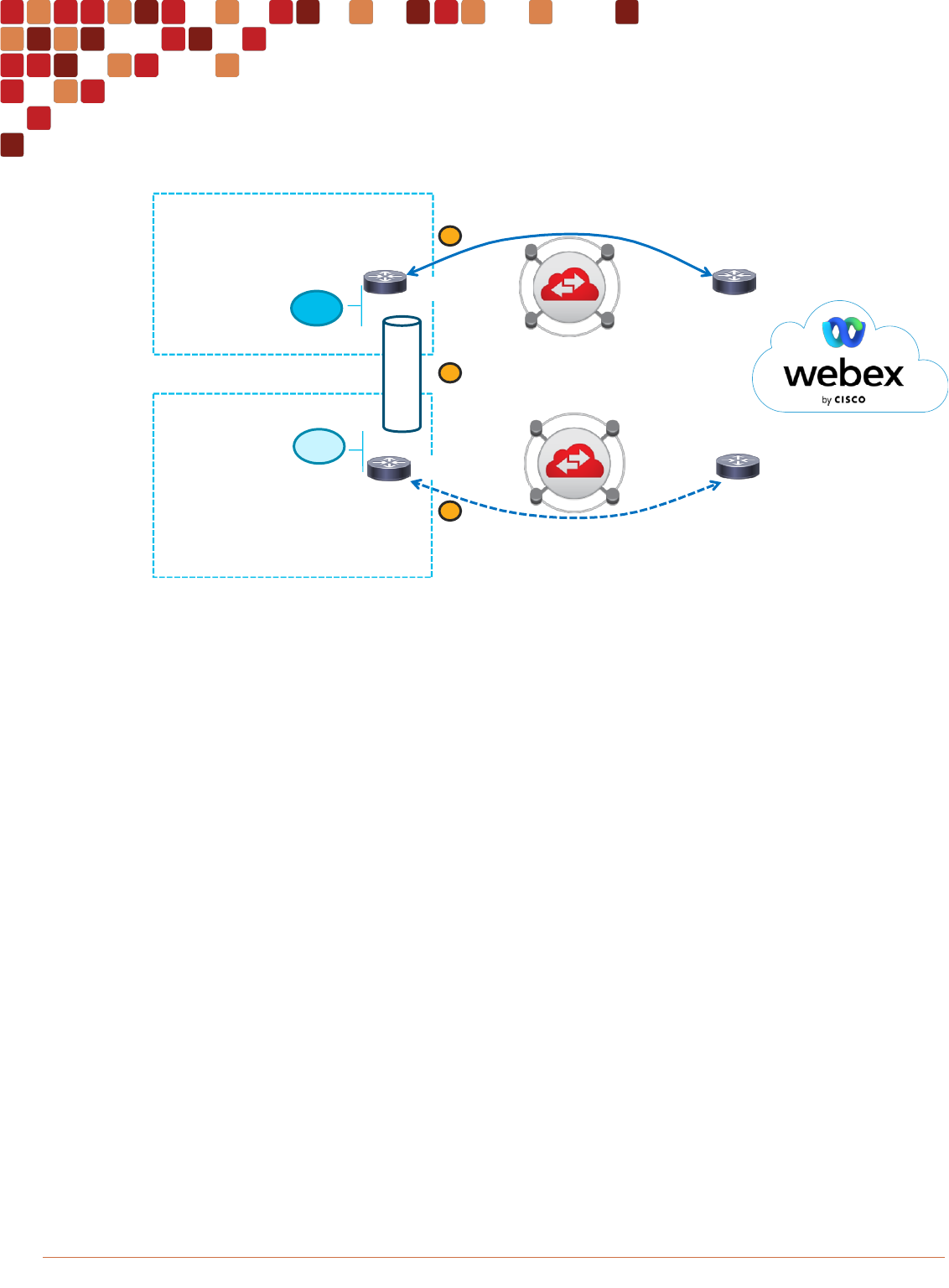
Cisco Preferred Architecture for Enterprise Collaboration PAGE 42
Architecture
Figure 35 Enterprise network with 2 Edge Connect circuits to Webex in geographically separate sites
The following configuration is illustrated in Figure 35.
RTR1 is the primary link and RTR2 is the secondary link. RTR1 is using a local preference of 200 while RTR2 is using a
local preference of 100.
Webex to Enterprise network path selection:
In Figure 35 RTR1 and RTR2 are advertising unique prefixes. The Webex network will respond to the router performing
the NAT.
Enterprise to Webex Network path selection:
RTR1 applies a local preference of 200 (Figure 35 - 1) to make it the most desirable path towards the Webex network
while RTR2 applies a local preference of 100 (Figure 35 - 2) making it less desirable compared to West. It is up to the
internal routing protocol to redistribute the subnets learned from the BGP peering over the WAN (Figure 35 - 3) with a cost
that will be reflective of this local preference priority in BGP ensuring that from the point of view of the network at West
and East that West path is preferred over East path for the Webex subnet prefixes.
The following configuration on RTR1 and RTR2 is an example configuration of the above network path selection using
BGP local preference. The route-maps highlighted in blue show the configuration used to set local preference.
RTR1 Example BGP Configuration
router bgp 64496
neighbor 192.0.2.2 remote-as 13445
!
address-family ipv4
Local Preference
200
Local Preference
100
NAT1
Enterprise Network - West
192.0.2.1/30
192.0.2.2/30
192.0.2.6/30
198.51.100.0/28
RTR1
RTR2
AS 64496
Primary
Secondary
NAT2
198.51.100.16/28
192.0.2.5/30
AS 64496
Enterprise Network - East
WAN
1
2
3
AS13445

Cisco Preferred Architecture for Enterprise Collaboration PAGE 43
Architecture
neighbor 192.0.2.2 activate
neighbor 192.0.2.2 send-community both
neighbor 192.0.2.2 route-map PRIMARY-OUT out
neighbor 192.0.2.2 route-map PRIMARY-IN in
exit-address-family
!
ip prefix-list ADVERTISE-NAT1-TO-WEBEX seq 5 permit 198.51.100.0/28
!
route-map PRIMARY-OUT permit 10
match ip address prefix-list ADVERTISE-NAT1-TO-WEBEX
!
route-map PRIMARY-IN permit 10
set local-preference 200
RTR2 Example BGP Configuration
router bgp 64496
neighbor 192.0.2.6 remote-as 13445
!
address-family ipv4
neighbor 192.0.2.6 activate
neighbor 192.0.2.6 send-community both
neighbor 192.0.2.6 route-map SECONDARY-OUT out
neighbor 192.0.2.6 route-map SECONDARY-IN in
exit-address-family
!
ip prefix-list ADVERTISE-NAT2-TO-WEBEX seq 5 permit 198.51.100.16/28
!
route-map SECONDARY-OUT permit 10
match ip address prefix-list ADVERTISE-NAT2-TO-WEBEX
!
route-map SECONDARY-IN permit 10
set local-preference 100
Internet as Failover
Webex customers who are already deployed using the Internet as their gateway towards the Webex Cloud can use the
Internet as a failover path when designing their Edge Connect implementation. An Internet connection is required for this
type of failover with adequate bandwidth to handle the load of traffic expected. If the Edge Connect path was to fail for
whatever reason the routes re-distributed into the local routing protocol would remove the routes for those prefixes to
Edge Connect and traffic would use the default gateway and thus the Internet to route the traffic as was consistent with
the routing of Webex traffic prior to the deployment of Edge Connect. Figure 36 illustrates Internet as failover.

Cisco Preferred Architecture for Enterprise Collaboration PAGE 44
Architecture
Figure 36 Internet as failover
In Figure 36 - 1 the Edge Connect link goes down. As a result of the link failure the routing protocol converges and route
prefixes from Webex are removed from the local routing protocol (Figure 36 - 2). As a result of this traffic is redirected out
the new path. In most cases the Internet path and the Edge Connect path will be separate routed locations and thus not
routing off the same NAT pool. With a change in NAT pool the connections that were already established over Edge
Connect will need to re-establish over the Internet. This may succeed or may fail depending on several factors. There is
no guarantee that the connections will re-establish automatically, and users may be forced to re-connect to the meeting.
Bandwidth Provisioning and Capacity Planning
Ensuring that enough bandwidth is available for all of the active participants during the busy hour as well as ensuring for
growth can be a daunting task. In order to simplify this task, it is recommended to calculate the number of active meeting
participants (equivalent to active calls – used interchangeably in this example) based on current usage values (monthly
meeting minutes). Take that number of active calls (participants) and multiply for 100% audio usage and a reasonable
percentage for video usage. Add a percentage for growth over time and the link should be sized appropriately.
Determining Active Participants (Active Calls)
A validated method to use to determine the value of concurrent or active calls is to use the monthly participant minutes
recorded in Webex Control Hub Analytics and divide that by a port efficiency value. A port in this case is equivalent to
an active call. This terminology is used in conference resource engineering. A port efficiency value is value that can help
determine the number of potentially active calls based on monthly participant minutes. This means we can garner an
understanding of the probability of the active connections required during the busy hour based on the number of
participant minutes used whereby so many participant minutes equals a port and thus a required active connection. Based
on data from existing customers with reasonable port efficiencies (i.e., utilization rates based on resources allocated) the
port efficiency value is estimated between 500 and 8500 minutes per port. This is dependent on a range of monthly
participant minutes because as systems become larger (more active calls), they become more efficient and thus the port
efficiency value grows as a result. See Figure 38 below for the port efficiency values used in the calculation.
BGP
BGP
Equinix
Webex Ro utes
AMER
64.68.96 .0/ 19
64.68.10 4.0/ 21
….
APAC
69.26.17 6.0/ 20
69.26.17 6.0/ 22
….
EM EA
62.109.1 92.0/ 18
….
Customer
Network
OSPF
DNS Lookup
DNS Server
DNS Server
Webex Routes
AMER
64.68.96.0/ 19
64.68.104.0/ 21
….
APAC
69.26.176.0/ 20
69.26.176.0/ 22
….
EM EA
62.109.192.0/ 18
….
Webex Routes
AMER
64.68 .96.0/ 19
64.68 .104.0/ 21
….
APAC
69.26 .176.0/ 20
69.26 .176.0/ 22
….
EM EA
62.10 9.192.0/ 18
….
Connect to
webex.com
Private Public
Media
Signaling
NAT
POOL
NAT
POOL
64.68.104.196
Signaling
Media
64.68.96.55
1
2
2
3
Internet

Cisco Preferred Architecture for Enterprise Collaboration PAGE 45
Architecture
Sizing summary:
1. Determine the “monthly participant minutes”
2. Locate where that fits in the monthly minutes range to get a “port efficiency value”
3. Divide “monthly participant minutes” by the “port efficiency value” to calculate active calls (“monthly participant
minutes” / “port efficiency value” = “active calls”)
4. Once the number of active calls is determined we can start calculating bandwidth utilization
The first step in this is to verify the maximum number of participant minutes per month in control hub analytics (Figure 37 -
1-5). In Webex Control Hub Analytics viewing the “Usage by Participant Minutes” (Figure 37 - 1) over a 12-month period
(Figure 37 - 2) is an easy method to determine the highest usage of participant minutes during any given month (Figure
37 - 3). Ensure that the location is appropriate, for example if sizing for a “United States” based Edge Connect circuit,
you’d only want to include the “United States” under “Usage by Location” (Figure 37 - 4) if that was appropriate for the
traffic envisioned over this peering.
Figure 37 Example of Monthly Participant Meeting Minutes in Webex Control Hub Analytics
The next step is to calculate the active calls by taking the value “monthly participant minutes” (Figure 37 - 3) and dividing it
by the “port efficiency value” equivalent to the range in which the monthly minutes occur. Figure 38 shows the
recommended values:
Figure 38 Monthly minutes range to port efficiency calculation value
Monthly Minutes
Port Efficiency Value
0k – 50k
Monthly Minutes / 500
50k – 500k
Monthly Minutes / 1000
Participant
Minutes
Highest Total
Monthly Min
Usage by
Location - US
Usage by
Activity – Video
1 2
3
4
5

Cisco Preferred Architecture for Enterprise Collaboration PAGE 46
Architecture
500k – 1m
Monthly Minutes / 2000
1m – 2m
Monthly Minutes / 3000
2m – 8m
Monthly Minutes / 4000
8m – 15m
Monthly Minutes / 5700
15m - 30m
Monthly Minutes / 6500
30m - 40m
Monthly Minutes / 7000
40m – 100m
Monthly Minutes / 7500
>100m
Monthly Minutes / 8500
So, for example if the maximum participant minutes for a given month are 25.5 million (Figure 38 - 3) they would fall into
the category of Monthly Minutes / 6500 calculation. So, 25,500,000 / 6500 = 3923 active connections. We can also round
this up to 3950 active connections to simplify and over-provision.
Bandwidth Utilization
Next, we would have to Figure an average bandwidth value that gives an approximation of the amount of bandwidth a
single user/device would consume on average for an active Webex meetings call. As there are different types of
endpoints, different capabilities of max resolutions and thus bandwidth it can be helpful to break these up into different
groupings.
While all Webex devices and applications use rate adaptation to dynamically change their bit rate depending on network
conditions and available bandwidth, it is important to know how much bandwidth is typically used by a call so that Edge
Connect can be provisioned to accommodate busy hour traffic without compromising the user experience.
Figure 39 lists audio and video bandwidth recommendations for various types of Webex components. There are a number
of variables that go into determining send and receive bandwidth values. These bandwidth values are simplified for easy
calculation as this value will be augmented for both growth and extra overhead to ensure a lower utilization rate of the
circuit so that it’s not running at or near capacity. It’s also worth noting that Webex Apps and Webex Devices have both
main video and shared content video. While there are differences in sending and receiving video bandwidth based on
devices sharing content vs sending video only, these differences are marginal and not relevant when doing larger scale
capacity planning. In general, the larger the number of users used in the bandwidth calculation the more the averages will
flatten out with regards to the variability of video bandwidth utilization.
Figure 39 Bandwidth Requirements for Webex Components (Including Layer-3 Overhead)
Webex Component
Audio
Bandwidth
Video Bandwidth
Average (Max)
High FPS
Content
Share
Grid 5x5
Webex Meetings Desktop App / Browser
100 kbps
2 mbps (3 mbps)
1mb - 2.5
mbps
5 mbps
Webex App
170 kbps
2 mbps (4 mbps)
1mb - 2.5
mbps
N/A
Video Mesh Deployments (Webex App,
Unified CM Integration)
600 kbps
12 mbps (20 Mbps)
NA
NA

Cisco Preferred Architecture for Enterprise Collaboration PAGE 47
Architecture
DX Series, SX10, MX Series, SX20,
SX80, Webex App Room Kit, Webex
Board *
100 kbps
2 mbps (4 mbps)
NA
NA
Expressway Edge Deployments (Webex
Edge Audio / Webex Video Meetings /
Webex Hybrid)
80 kbps
2 mbps (Customer
Configured**)
NA
NA
* For dual screened systems double the video bandwidth utilization
** Expressway video flows max bit is configured on the Endpoints registered to Unified CM
In our example we have 3950 active connections to accommodate for. If all those 3950 connections are Webex meetings
app and we expect 65% video enablement we could run the following calculation for bandwidth. The 65% video
enablement can be calculated from control hub as well (see Figure 37 - 5) Usage By Activity – Video. In this example
we can see that 65.2% of those meeting participants enabled video. As such, we can use 65% as the Percentage of
Video in our bandwidth calculation.
Webex Meetings App Users Bandwidth Calculation (example):
Active Calls = 3950
Active Audio = (Active Calls * Audio BW) = (3950 * 100k) = 395mb
Active Video = ((Active Calls * Percentage of Video) * Video Bandwidth) = ((3950 * 0.65) * 2mb) = 5135mb
Total Webex App Bandwidth = (Active Audio) + (Active Video) = (395mb) + (5135mb) = 5530mb or 5.53gb
Figure 40 Bandwidth Calculations
So, based on this analysis we can assume that an Edge Connect circuit in the US would require approximately 5.6gb. A
few notes about this calculation. In Webex Control Hub the data is for all participants connected to meetings. It does not
differentiate guests, or participants who would be coming into Webex Meetings over Direct Internet Access (DIA) or via
the Enterprise network. There are ways to gather data that can assist in discerning this information but that is out of the
scope of this document. Therefore, one can consider this difference in on-net vs off-net usage if it is ascertainable. If not,
then it is recommended to use the calculated value to ensure over-provisioning and underutilization.
The last step is to add for growth. A growth number could be based on known factors such as expected growth of usage
Webex usage across the company for example. This could be due to a roll-out process or various parts of the company
who used their own system and are migrating to Webex, the reasons could be many, but the point is that it is a known
variable and can be added as a percentage. So, for example, the current calculation is based on 80% of the company and
(3950 * 100k) + ((3950 * 0.65) * 2mb) = Total BW
(395mb) + ((2567.5) * 2mb) = Total BW
(395mb) + (5135mb) = 5530mb or 5.53gb
(Active Calls * Audio BW) + ((Active Calls * Percentage of Video) * Video Bandwidth) = Total BW
(Active Audio) + (Active Video) = Total BW

Cisco Preferred Architecture for Enterprise Collaboration PAGE 48
Architecture
it is expected that the rest of the company will soon roll out Webex then 20% can be added to the calculation provided that
the expectations of factors are the same, meaning there will be an increase of 20% of the same platform as used in the
calculation (Webex Desktop App).
Another example could be the rollout of Room systems. If for example 300 room systems were going to be deployed with
Webex Devices (Board, Room and Desk) that this usage could be added as a total number of connected endpoints. So,
say it is expected that 100% of those room systems were expected to be in use during the busy hour, in which case we
could calculate that 300 room systems of 100kbps audio and 2mbps video and add that to our Figure calculated above:
Room Systems bandwidth calculation (audio and video):
Room Systems = 300
Room System Audio = (Active Room Systems * Audio BW) = (300 * 100k) = 30mb
Room System Video = ((Active Room Systems * Percentage of Video) * Video Bandwidth) = ((300 * 2mb) = 600mb
Total Room System Bandwidth = (Active Audio) + (Active Video) = (30mb) + (600mb) = 630mb
Total Bandwidth Calculation (Total Room System Bandwidth + Total Webex App Bandwidth):
Total Bandwidth = Total Webex App Bandwidth + Total Room System Bandwidth = 5530mb + 630mb = 6160mb or
6.16gb
Considering the above calculations this Enterprise would be safe to go with a 10gb connection. They could also go with a
7gb connection (5gb+2gb) however after pricing the Equinix costs and the Cisco cost for 7gb vs 10gb the pricing might
prove better to go to with 10gb. 10gb will allow for unknowns in video usage uptake as well as allow for unknown future
growth.
QoS for Webex Signaling and Media
QoS for media is essential for ensuring a quality experience in the network. Edge Connect should primarily be an over-
provisioned and under-utilized service. The value of Edge Connect is dedicated bandwidth and low latency. Edge Connect
also by-passes the Internet for media and removes the latency and undue packet loss associated with the Internet links.
As such Edge Connect should be over-provisioned. Nonetheless it remains an Edge technology and it’s important to
ensure QoS marking into and out of the Enterprise network. This protects against unforeseen congestion events as well
as abnormally high usage periods that may occur during unforeseen events. It also ensures downstream packet marking
in the case that other WAN or congestion points are reached across the Enterprise, such as a remote site WAN delivering
traffic from the remote site to the central site where edge connect is deployed.
For an overview of QoS best practices and recommendations see the Bandwidth Management Chapter of the Preferred
Architecture for Webex Hybrid Services, CVD. While the Hybrid Service CVD does not cover all of the Webex
Collaboration components it covers the bulk of them and provides insight into the strategy for marking and queuing
Webex meetings traffic.
The Webex cloud marks traffic natively to EF for audio and AF41 for video. This is consistent with Cisco’s QoS for
Collaboration applications marking recommendations for media. Most of the time this QoS marking is lost as the Service
Providers remark all QoS to BE (dscp 0) over the Internet exchange. With Edge Connect however DSCP marking is left
untouched and can be utilized on ingress from Webex Cloud to the Enterprise to trust or remark as is appropriate with the
company QoS marking posture.
Figure 41 DSCP Values Used by traffic coming from Webex Cloud for Webex App Endpoints, Applications, and Video
Mesh Node
Traffic Type
DSCP
Notes

Cisco Preferred Architecture for Enterprise Collaboration PAGE 49
Architecture
Audio
EF; 46
Includes audio streams of voice-only calls, audio streams of video
calls, and related RTCP packets
Video
AF41; 34
Includes video streams (main video and presentations or content) and
related RTCP packets
Other traffic
Best Effort; 0
Includes messaging, file transfer, configuration, call and meeting
setup
Ingress Marking, Egress Queueing
As mentioned, Edge Connect is deployed at the Edge where the Enterprise network transitions to the Webex Cloud
Services network. Like other edge areas of the network this is the place where marking and queueing occur. Marking
occurs in the ingress of a router interface while queueing occurs on the egress of a router’s interface. Figure 42 illustrates
the areas of the Edge Connect network where marking and queueing might occur.
Figure 42 Marking and queuing Webex Traffic
Figure 42 illustrates the areas of the network where a QoS marking policy can be placed and where an outbound queuing
policy could be placed. Traffic flowing from Enterprise to Cloud on the top (router locations 1 and 2) and traffic from Cloud
to Enterprise on the bottom (router locations 3 and 4). When traffic enters the router that is the place where QoS marking
can take place. Regardless of how the traffic is marked elsewhere in the network it is critical to have a QoS marking policy
at the edge of the network to ensure that all the places where traffic was unable to be marked in the enterprise get
captured prior to going toward the outbound interface and subsequent queue.
At location 1 an inbound policy can capture all the Webex destined traffic coming from the Enterprise and mark it
appropriately. Then at location 1 on the outbound interface a queueing policy can be configured to ensure that in the
event of a burst of traffic or an unexpected event of high usage that if the traffic requires queueing it will be managed here
prior to being put onto the wire. If a queueing policy is not created, then if the transmit ring of the outbound interface were
to become congested it would place traffic on the wire in a default FIFO (First In, First Out) queue and drop excess traffic
as needed regardless of its priority. This could potentially drop audio over video and cause audio quality issues. In general
video is much more resilient to loss and can adapt better to changes in bandwidth. Audio has a much lower tolerance for
loss and is thus more effected by loss than video. As such it’s recommended to at a minimum have a Priority Queue (PQ)
Ingress Policy
ECX
Cage
Ingress Policy
Outbound Queue
Outbound Queue
Enterprise Edge
Ingress Policy
Outbound
Queue
Ingress Policy
Outbound
Queue
Metro link to Equinix
Cage
Enterprise LAN Equinix Facility
1
2
4
3

Cisco Preferred Architecture for Enterprise Collaboration PAGE 50
Architecture
for audio and a Class-Based Weighted Fair-Queue (CBWFQ) for video allowing for audio to always be prioritized over
video so that if drops do occur, video will be dropped first ensuring a quality audio connection while video can rate adapt
based on the loss it incurs.
Location 2 of Figure 42 is on the router in the cage and is another potential location for QoS marking and queueing. While
the marking is no longer necessary if it was done at location 1 the queueing should still be enforced to ensure any
congestion is regulated through a PQ/CBWFQ vs a FIFO queue.
For the reverse traffic at location 3 coming from the Cloud towards the Enterprise. This is a location to mark the traffic
coming from the Cloud to the values of the enterprise QoS policy. Webex Cloud marks EF for Audio, AF41 for video and
all other traffic is marked BE. As such and even where EF and AF41 are simply to be trusted this would be a good place
to remark signaling to CS3 and other traffic accordingly. The same queueing policy should also apply to location 3 and 4
outbound interface as it did for location 1 and 2.
Note: Networks are considered full-duplex and transmit and receive over different wires and traffic patterns can be
quite different even for symmetric call flows. As such congestion could occur inbound where it is not seen outbound. It is
therefore important to ensure a queuing policy on these interfaces to ensure the traffic gets prioritized correctly and
dropped efficiently, as may be the case, in the face of congestion.
Bandwidth Allocation
For allocating bandwidth to our queues our earlier capacity planning calculations of audio and video can be used to
determine an approximation of the percentage of the PQ and CBWFQ. The following is only an example of what is
possible based on the type of gross calculation that was made earlier. Bandwidth calculation and allocation can be
deduced with varying different process and varying degrees of accuracy. In this example our model is to ensure that audio
be placed in the PQ and is never dropped. As such it is important to ensure over-provisioning of the PQ as will be
illustrated in the example below. That said anything realistically above 33% starts to turn the PQ into a FIFO queue and
could starve the other queues. As such it is typically not recommended to allocate more that 33% of the PQ to the overall
bandwidth. The below example will not get close to that however some scenarios might. If Audio does get above 33% of
overall bandwidth, then it would be better to have audio in a separate CBWFQ from video and manage both audio and
video in separate CBWFQs.
In the calculation for sizing our connection we had audio from the Room Systems at 30mb and audio from the Webex
Meetings App at 395mb for a total of 425mb. For video we had 600mb + 5135mb respectively for video for a total of
5735mb. In this example of the total bandwidth of 6.16gb audio would use approximately 7% of the total amount of
bandwidth while video would use approximately 93%. This helps in approximating the percentage of bandwidth allowed
for the PQ and CBWFQ. For the purposes of sizing the PQ we can add more than the percentage for audio knowing that
what is NOT used by the PQ will be allocated to the CBWFQs in case of congestion. As such if we have a 10gb
connection and we allow for 15% of that for the PQ that will give 1.5gb for audio in the PQ (3x more than we require from
our calculations). We need a minimum of 5735 or approximately 6gb for video. So, by allocating 70% to the video CBWFQ
that will allow for 7gb. This leaves approximately 15% of the bandwidth for signaling, routing data and excess bandwidth.
By configuring in this way we’ve ensured that audio will never get dropped or delayed and that if video were to use more
that it’s share it would get tail dropped from the CBWFQ accordingly. Again, our calculations have been made for growth
and over-provisioned with ample bandwidth to spare for unknown utilization but protected such that if more audio were
needed, we could grow up to 3x the audio percentage without impacting our video. All the while video could use the
unused bandwidth from the PQ ensuring quality of experience in times of extreme utilization.
For more information on QoS and scheduling and queueing Webex media please see the Bandwidth Management
Chapter of the Preferred Architecture for Webex Hybrid Services, CVD.
Note: Please note that the Bandwidth Management Chapter of the Preferred Architecture for Webex Hybrid Services,
CVD does not include all Webex meetings traffic. For example, Webex Meetings Application traffic is not in the examples.
That said the concepts discussed in bandwidth management chapter can be applied to all Webex Meetings clients,
endpoints, and edge equipment. In most cases it is simply a question of gathering the information required to effectively

Cisco Preferred Architecture for Enterprise Collaboration PAGE 51
Architecture
mark and classify traffic such as audio, video and signaling protocols and ports used or other applicable classification
mechanisms such as NBAR.
Equinix ECX Physical Port Considerations
The ECX connection is a virtual circuit over a physical port for a specified bandwidth at or below the physical interface’s
bandwidth capacity. For example, if the port provisioned was a 1gb port and the connection was set to 500mb then a sub-
interface on the physical router interface would be configured and set to a bandwidth of 500mb.
The virtual connection is policed by Equinix at the bandwidth rate. As such a traffic shaper on the router's physical
interface will protect the traffic from sub-second bursting above the sub-interface virtual circuit capabilities. A traffic shaper
will ensure the traffic does not get dropped by any policers that are in place on the Equinix link for short bursts of traffic.
So, if the connection was configured for 500mb then a matching shaper of 500mb could be implemented to avoid sub-
second traffic bursting which exceeds the bandwidth provisioning with Equinix. It is recommended to place a traffic shaper
on the CBWFQ to reap the benefits of traffic shaping and CBWFQ. More information on this can be found in QoS:
Regulating Packet Flow Configuration Guide.
QoS Policy Examples
Figure 43 illustrates an IOS configuration of a hierarchical egress policy with traffic shaping to 200 mbps and using a QoS
policy (PQ/CBWFQ) with NBAR for matching on Webex related traffic.
Note: This is only an example and in order to match all types of Webex traffic a more complete matching policy with
ACLs using protocol and source/destinations UDP/TCP ports to identify other Webex destined traffic (i.e. SIP or Video
Mesh) is required.
Figure 43 Hierarchical QoS and Traffic Shaping Policy using NBAR
In Figure 43 there are 2 policy-maps, EGRESS-QUEUING and 200M-SHAPER. First the 200M-SHAPER policy is a
traffic-shaping policy ensuring that traffic is shaped to 200 mbps. This ensures that sub-second bursts of traffic are

Cisco Preferred Architecture for Enterprise Collaboration PAGE 52
Architecture
smoothed out so that drops related to bursts are not experienced. Next the EGRESS-QUEUING policy-map is nested into
the 200M-SHAPER policy and is an egress queuing policy with a PQ (Priority Queue) for Webex audio and a CBWFQ
(Class-Based Weighted Fair Queue) for Webex video and signaling traffic. This policy uses 92% of the link bandwidth
ensuring only 30% for audio in the PQ, 60% for video and 2% for Webex signaling traffic. There is 8% that is not utilized
and would normally require a default queue or another CBWFQ to ensure that other traffic such as BGP, BFD or other
signaling protocols are ensured access to the queues. The class-maps associated with the EGRESS-QUEUING are
configured for matching on NBAR protocols for Webex App and Webex Devices related traffic. This also includes Webex
App with Full-Featured Meetings enabled traffic. Webex App with Full-Featured Meetings traffic is the same as Webex
Meetings Desktop App traffic and thus the same NBAR protocols are used for matching on this traffic subset.

Cisco Preferred Architecture for Enterprise Collaboration PAGE 53
Early Access Program
Early Access Program
Cisco is offering an Early Access (also referred to as Early Adopter or EA) to customers for new a new set of features in
Edge Connect.
The Early Access program adds these new features:
1. Support for Megaport
2. Single peering for Webex Calling Dedicated Instance, Webex Meetings and Webex Calling Multi-tenant: This solution
would previously require 2 separate connections and peerings, one for Meetings/Calling and one for Dedicated Instance.
3. Webex Calling Dedicated Instance available with local connections at all Webex points of presence in Equinix Fabric
and Megaport: This solution would previously require remote connections for all customers who are not local to SJC and
DFW, reducing customer costs.
To find out more information or to purchase these services, work with your local Cisco account team.
