
Cisco Systems, Inc. www.cisco.com
Cisco Extended Enterprise SD-WAN
Design Guide
January 2020
ii
THE SPECIFICATIONS AND INFORMATION REGARDING THE PRODUCTS DESCRIBED IN THIS DOCUMENT ARE SUBJECT TO
CHANGE WITHOUT NOTICE. THIS DOCUMENT IS PROVIDED “AS IS.”
ALL STATEMENTS, INFORMATION, AND RECOMMENDATIONS IN THIS DOCUMENT ARE PRESENTED WITHOUT WARRANTY
OF ANY KIND, EXPRESS, IMPLIED, OR STATUTORY INCLUDING, WITHOUT LIMITATION, THOSE OF MERCHANTABILITY,
FITNESS FOR A PARTICULAR PURPOSE AND NONINFRINGEMENT OR ARISING FROM A COURSE OF DEALING, USAGE, OR
TRADE PRACTICE. IN NO EVENT SHALL CISCO BE LIABLE FOR ANY INDIRECT, SPECIAL, CONSEQUENTIAL, PUNITIVE,
EXEMPLARY, OR INCIDENTAL DAMAGES UNDER ANY THEORY OF LIABILITY, INCLUDING WITHOUT LIMITATION, LOST
PROFITS OR LOSS OR DAMAGE TO DATA ARISING OUT OF THE USE OF OR INABILITY TO USE THIS DOCUMENT, EVEN IF
CISCO HAS BEEN ADVISED OF THE POSSIBILITY OF SUCH DAMAGES.
All printed copies and duplicate soft copies of this document are considered uncontrolled. See the current online version for
the latest version.
Cisco has more than 200 offices worldwide. Addresses, phone numbers, and fax numbers are listed on the Cisco website at
www.cisco.com/go/offices.
©
2020 CISCO SYSTEMS, INC. ALL RIGHTS RESERVED

iii
Cisco Systems, Inc. www.cisco.com
Contents
Introduction . . . . . . . . . . . . . . . . . . . . . . . . . . . . . . . . . . . . . . . . . . . . . . . . . . . . . . . . . . . 1
Scope and Audience. . . . . . . . . . . . . . . . . . . . . . . . . . . . . . . . . . . . . . . . . . . . . . . . . . 1
Why Extend SD-WAN to IoT Edge. . . . . . . . . . . . . . . . . . . . . . . . . . . . . . . . . . . . . . . . 2
Use Cases . . . . . . . . . . . . . . . . . . . . . . . . . . . . . . . . . . . . . . . . . . . . . . . . . . . . . . . . . 3
Remote Point-of-Sale Systems . . . . . . . . . . . . . . . . . . . . . . . . . . . . . . . . . . . . . . . 3
Direct Internet Access and SD-WAN . . . . . . . . . . . . . . . . . . . . . . . . . . . . . . . . . . . 3
Warehouses and Distribution Centers . . . . . . . . . . . . . . . . . . . . . . . . . . . . . . . . . . 4
Unique Value Propositions of the CVD. . . . . . . . . . . . . . . . . . . . . . . . . . . . . . . . . . . . . 4
Extended Enterprise Solution Design . . . . . . . . . . . . . . . . . . . . . . . . . . . . . . . . . . . . . . . . 5
Design Considerations . . . . . . . . . . . . . . . . . . . . . . . . . . . . . . . . . . . . . . . . . . . . . . . . 5
Solution Design Overview . . . . . . . . . . . . . . . . . . . . . . . . . . . . . . . . . . . . . . . . . . . . . . 6
Solution Components . . . . . . . . . . . . . . . . . . . . . . . . . . . . . . . . . . . . . . . . . . . . . . . . . 7
Cisco Validated Hardware and Software Components . . . . . . . . . . . . . . . . . . . . . . 7
Cisco SD-WAN Controllers . . . . . . . . . . . . . . . . . . . . . . . . . . . . . . . . . . . . . . . . . . 8
Data Center . . . . . . . . . . . . . . . . . . . . . . . . . . . . . . . . . . . . . . . . . . . . . . . . . . . . . . 9
Non-carpeted Remote Sites . . . . . . . . . . . . . . . . . . . . . . . . . . . . . . . . . . . . . . . . . 9
IOS XE SD-WAN Router . . . . . . . . . . . . . . . . . . . . . . . . . . . . . . . . . . . . . . . . . . . . 9
WAN Connectivity . . . . . . . . . . . . . . . . . . . . . . . . . . . . . . . . . . . . . . . . . . . . . . . . 10
Service Switch. . . . . . . . . . . . . . . . . . . . . . . . . . . . . . . . . . . . . . . . . . . . . . . . . . . 11
SD-WAN Deployment Models . . . . . . . . . . . . . . . . . . . . . . . . . . . . . . . . . . . . . . . . . . 12
Cloud Deployment . . . . . . . . . . . . . . . . . . . . . . . . . . . . . . . . . . . . . . . . . . . . . . . . 12
On-Prem Deployment . . . . . . . . . . . . . . . . . . . . . . . . . . . . . . . . . . . . . . . . . . . . . 12
Multi-Tenancy . . . . . . . . . . . . . . . . . . . . . . . . . . . . . . . . . . . . . . . . . . . . . . . . . . . 14
Overlay Topologies . . . . . . . . . . . . . . . . . . . . . . . . . . . . . . . . . . . . . . . . . . . . . . . . . . 15
Hub-and-Spoke Topology. . . . . . . . . . . . . . . . . . . . . . . . . . . . . . . . . . . . . . . . . . 15
Mesh Topology . . . . . . . . . . . . . . . . . . . . . . . . . . . . . . . . . . . . . . . . . . . . . . . . . . 15
Non-Carpeted Remote Sites Design. . . . . . . . . . . . . . . . . . . . . . . . . . . . . . . . . . . . . . . . 16
Very Small Site . . . . . . . . . . . . . . . . . . . . . . . . . . . . . . . . . . . . . . . . . . . . . . . . . . . . . 17
Transport Side. . . . . . . . . . . . . . . . . . . . . . . . . . . . . . . . . . . . . . . . . . . . . . . . . . . 18
Service Side . . . . . . . . . . . . . . . . . . . . . . . . . . . . . . . . . . . . . . . . . . . . . . . . . . . . 18
Small Site . . . . . . . . . . . . . . . . . . . . . . . . . . . . . . . . . . . . . . . . . . . . . . . . . . . . . . . . . 18
Transport Side. . . . . . . . . . . . . . . . . . . . . . . . . . . . . . . . . . . . . . . . . . . . . . . . . . . 19
Service Side . . . . . . . . . . . . . . . . . . . . . . . . . . . . . . . . . . . . . . . . . . . . . . . . . . . . 19
Medium Site . . . . . . . . . . . . . . . . . . . . . . . . . . . . . . . . . . . . . . . . . . . . . . . . . . . . . . . 19
Transport Side. . . . . . . . . . . . . . . . . . . . . . . . . . . . . . . . . . . . . . . . . . . . . . . . . . . 20

iv
Service Side. . . . . . . . . . . . . . . . . . . . . . . . . . . . . . . . . . . . . . . . . . . . . . . . . . . . 20
Large Site . . . . . . . . . . . . . . . . . . . . . . . . . . . . . . . . . . . . . . . . . . . . . . . . . . . . . . . . 20
Transport Side . . . . . . . . . . . . . . . . . . . . . . . . . . . . . . . . . . . . . . . . . . . . . . . . . . 21
Service Side. . . . . . . . . . . . . . . . . . . . . . . . . . . . . . . . . . . . . . . . . . . . . . . . . . . . 21
Message Flow Diagrams . . . . . . . . . . . . . . . . . . . . . . . . . . . . . . . . . . . . . . . . . . . . . . . . 22
Onboarding Cisco IR1101 with Plug and Play . . . . . . . . . . . . . . . . . . . . . . . . . . . . . 23
Onboarding Cisco IR1101 with Bootstrap Configuration. . . . . . . . . . . . . . . . . . . . . . 24
Security Design . . . . . . . . . . . . . . . . . . . . . . . . . . . . . . . . . . . . . . . . . . . . . . . . . . . . . . . 24
Authenticity of Cisco IR1101 IOS XE SD-WAN Router . . . . . . . . . . . . . . . . . . . . . . . 24
Secure Control Channel between IOS XE SD-WAN Router and vManage . . . . . . . . 25
Secure Data Communication Channel between IOS XE SD-WAN Routers . . . . . . . . 25
Segmenting Data Traffic among Different Services . . . . . . . . . . . . . . . . . . . . . . . . . 26
Filtering Undesired Traffic and Directing Traffic to Firewalls with ACLs. . . . . . . . . . . 27
User and Device Profiles and Design Recommendations . . . . . . . . . . . . . . . . . . . . . 27
QoS Design. . . . . . . . . . . . . . . . . . . . . . . . . . . . . . . . . . . . . . . . . . . . . . . . . . . . . . . . . . 29
SD-WAN QoS Design Considerations . . . . . . . . . . . . . . . . . . . . . . . . . . . . . . . . . . . 29
Order of Applying Polices. . . . . . . . . . . . . . . . . . . . . . . . . . . . . . . . . . . . . . . . . . 29
SD-WAN QoS Design . . . . . . . . . . . . . . . . . . . . . . . . . . . . . . . . . . . . . . . . . . . . . . . 30
Comply SLA over WAN with Application Aware Routing . . . . . . . . . . . . . . . . . . . . . 32
Scale and Dimension. . . . . . . . . . . . . . . . . . . . . . . . . . . . . . . . . . . . . . . . . . . . . . . . . . . 33
SD-WAN Controller Scale . . . . . . . . . . . . . . . . . . . . . . . . . . . . . . . . . . . . . . . . . . . . 33
Remote Sites Scale . . . . . . . . . . . . . . . . . . . . . . . . . . . . . . . . . . . . . . . . . . . . . . . . . 34
Server Hardware Recommendations . . . . . . . . . . . . . . . . . . . . . . . . . . . . . . . . . . . . 34
Cisco vManage Single-Pane-of-Glass . . . . . . . . . . . . . . . . . . . . . . . . . . . . . . . . . . . . . 34
Dashboard. . . . . . . . . . . . . . . . . . . . . . . . . . . . . . . . . . . . . . . . . . . . . . . . . . . . . . . . 34
Events and Alarms . . . . . . . . . . . . . . . . . . . . . . . . . . . . . . . . . . . . . . . . . . . . . . . . . . 34
Network Monitoring and Assurance . . . . . . . . . . . . . . . . . . . . . . . . . . . . . . . . . . . . . 34
Sotware Image Management . . . . . . . . . . . . . . . . . . . . . . . . . . . . . . . . . . . . . . . . . . 34
vAnalytics . . . . . . . . . . . . . . . . . . . . . . . . . . . . . . . . . . . . . . . . . . . . . . . . . . . . . . . . 35
References . . . . . . . . . . . . . . . . . . . . . . . . . . . . . . . . . . . . . . . . . . . . . . . . . . . . . . . . . . 35

1
Cisco Systems, Inc. www.cisco.com
Cisco Extended Enterprise SD-WAN
Design Guide
Introduction
Extended enterprise is the extension of enterprise network to non-carpeted spaces in harsh environments that can span
across geographies. Typical examples include remote point-of-sale (POS), warehouses, distribution centers, remote
sites, kiosks, remote ATM sites, production centers, storage spaces, and outdoor spaces, all connected over private or
public Wide Area Networks (WAN) networks. This requires thousands of miles of remotely located assets to be managed
alongside information technology (IT) infrastructure with a central management platform as the single pane of glass.
The enterprise landscape is continuously evolving. Businesses are embracing digital transformation and rapidly adopting
technology to increase productivity, reduce costs, and transform the customer experience. Legacy WAN architectures
are facing major challenges under this evolving landscape. Legacy WAN architectures typically consist of multiple MPLS
transports, or an MPLS paired with an Internet or LTE used in an active/standby fashion, most often with Internet or
software-as-a-service (SaaS) traffic being backhauled to a central data center or regional hub for Internet access. Issues
with these architectures include inefficient bandwidth usage, high bandwidth costs, application downtime, poor SaaS
performance, complex operations, complex workflows for cloud connectivity, long deployment times and policy
changes, limited application visibility, and difficulty in securing the network.
Customers are using a fragmented WAN to support critical business functions. Multiple connections were being
controlled by several routers, all from different service providers. This created a complex IT environment where
applications were manually rerouted in case of link failure. The proposed extended enterprise Software-Defined Wide
Area Networking (SD-WAN) solution in this Cisco Validated Design (CVD) is based on the principles of Software Defined
Access (SDA).
SD-WAN is part of a broader technology of software-defined networking (SDN). SDN is a centralized approach to
network management which abstracts the underlying network infrastructure from its applications. This decoupling of data
plane forwarding and control plane allows customers to centralize the intelligence of the network and allows for more
network automation, operations simplification, and centralized provisioning, monitoring, and troubleshooting. Cisco
SD-WAN applies these principles of SDN to the WAN.
Customers can quickly establish Cisco SD-WAN overlay fabric to connect data centers, branches, campuses, and
colocation facilities to improve network speed, security, and efficiency. Cisco SD-WAN is an on-prem and
cloud-delivered, highly-automated, secure, scalable, and application-aware with rich analytics.
This CVD outlines the steps for both IT and operations teams to accomplish their business goals by realizing unified
SD-WAN-based management for enterprise and extended enterprise deployments with the Cisco IR1101 Integrated
Services Router Rugged (Cisco IR1101).
Scope and Audience
This design guide provides an overview of the requirements driving the evolution of extended enterprise network designs
followed by a discussion of the latest technologies and designs that are available for building an extended network to
address those requirements. It is a companion to the associated Implementation Guides (IGs) for Extended Enterprise
networks, which provide configurations explaining how to deploy the most common implementations of the designs
described in this guide. The intended audience includes technical decision makers, solution architects, and field

2
Cisco Extended Enterprise SD-WAN Design Guide
Introduction
personnel who want to understand the Cisco extended enterprise solution offerings, the available technology options,
reference design blueprints, and the leading practices for designing the best network for the needs of an extended
enterprise.
This guide provides:
A reference design for extending the enterprise network with the Cisco SD-WAN to remote non-carpeted locations.
Design of a centralized policy matrix using the Cisco SD-WAN.
Design details for segmentation of extended enterprise endpoint points such as cameras, phones, laptops, and
others.
The companion implementation guide provides step-by-step guidance on how to deploy and manage Cisco IR1101
IOS XE SD-WAN ruggedized router devices using the Cisco SD-WAN.
For associated deployment guides, design guides, and white papers, see the following URLs and References, page 35:
Cisco Enterprise Networking design guides:
https://www.cisco.com/go/designzone
Cisco Enterprise SD-WAN design guides:
https://www.cisco.com/c/dam/en/us/td/docs/solutions/CVD/SDWAN/CVD-SD-WAN-Design-2018OCT.pdf
Cisco IoT Solutions design guides:
https://www.cisco.com/go/iotcvd
Cisco extended enterprise solution overview, design guides, and implementation guides:
— https://www.cisco.com/c/en/us/solutions/enterprise/design-zone-industry-solutions/index.html#~stickynav=1
— https://www.cisco.com/go/extendedenterprise
Why Extend SD-WAN to IoT Edge
The traditional role of the WAN was to connect users at the branch or campus to applications hosted on servers in the
data center. Dedicated MPLS circuits were used to help ensure security and reliable connectivity. This no longer works
in a digital world where applications are moving out of the data center into the cloud, and the users consuming those
applications are increasingly mobile and using a diverse set of traditional IT and IoT endpoint devices.
The Cisco SD-WAN solution is an enterprise-grade WAN architecture overlay that enables digital and cloud
transformation for enterprises. It fully integrates routing, security, centralized policy, and orchestration into large-scale
networks. It is cloud-delivered, highly-automated, secure, scalable, and application-aware with rich analytics. The Cisco
SD-WAN technology addresses the problems and challenges of common WAN deployments. Some of the benefits
include:
Centralized management and policy management, as well as operational simplicity, resulting in reduced change
control and deployment times.
A mix of MPLS and low-cost broadband or any combination of transports in an active/active fashion, optimizing
capacity and reducing bandwidth costs.
A transport-independent overlay that extends to the data center, branch, or cloud.
Deployment flexibility. Due to the separation of the control plane and data plane, controllers can be deployed on
premises, in the cloud, or in a combination of both.
Robust and comprehensive security, which includes strong encryption of data, end-to-end network segmentation,
router and controller certificate identity with a zero-trust security model, control plane protection, application
firewall, and other network services.

3
Cisco Extended Enterprise SD-WAN Design Guide
Introduction
Seamless connectivity to the public cloud and movement of the WAN edge to the branch.
Application visibility and recognition and application-aware policies with real-time service-level agreement (SLA)
enforcement.
Rich analytics with visibility into applications and infrastructure, which enables rapid troubleshooting and assists in
forecasting and analysis for effective resource planning.
Enterprise IT prefers to have seamless WAN connectivity, management, and uniform security policies across all carpeted
and non-carpeted enterprise remote WAN locations, which requires extending the reach of SD-WAN.
Use Cases
Figure 1 illustrates various customer objectives and challenges in digitizing extended enterprise environments. A few
example use cases are discussed below.
Figure 1 Customer Objectives and Challenges in Digitizing Extended Enterprise Environments
Remote Point-of-Sale Systems
With the advent of cloud computing, cloud-based POS systems serve businesses across energy, utility, retail, wholesale,
healthcare, hospitality, sports industries, and so on. Many companies would like to set up remote POS systems in several
locations for their customers to make payments for products, services, and utilities. At the authorized payment locations,
customers can conveniently pay using several different forms of payment. Multiple endpoints such as payment machines,
cameras, and emergency alarm systems are deployed at the POS location. Due to complete dependency of site
operations on WAN connectivity, these remote POS systems require redundant WAN links (LTE/Internet) connecting
enterprise backhaul.
However, the remote POS systems require ruggedized networking products because often they are in areas that are
dusty, damp, or without air conditioning. Being located in harsh environments, ruggedized SD-WAN compatible WAN
routers such as Cisco IR1101 with redundant WAN connectivity are the preferred choice for these deployments.
Direct Internet Access and SD-WAN
Today, Direct Internet Access (DIA) is more economical than traditional MPLS and leased lines. With many applications
moving to cloud, it makes more sense to reach out to the cloud applications with a local Internet breakout (DIA) than a
traditional centralized data center approach for enterprise Internet connectivity. This model is being adopted by many

4
Cisco Extended Enterprise SD-WAN Design Guide
Introduction
enterprises. Another prominent use case is site-to-site mesh connectivity between remotes sites. All these bring in the
need for additional security at the branch office and a policy-based centralized WAN management model. Other needs
for these remote sites/branches are redundant LTE WAN links over secured private APN. Often these remote sites are
located in non-carpeted spaces. The Cisco IR1101 is a ruggedized SD-WAN compatible WAN router that becomes the
default choice for such extended enterprise deployments.
Warehouses and Distribution Centers
Many eCommerce companies have warehouses spread across the globe. Often located in remote locations, these
warehouses need redundant and secure WAN connectivity of different topologies between them. The harsh
environmental conditions, need for policy driven interconnect options, and need for redundant LTE WAN connectivity
prevailing in these extended enterprise deployments make the Cisco IR1101 a highly suitable choice.
Unique Value Propositions of the CVD
The extended enterprise SD-WAN solution, which is documented in this design guide, provides a design foundation for
incorporating a broad set of technologies, features, and applications to help customers extend enterprise IT services to
remote outdoor spaces. This CVD incorporates industry best practices to solve targeted common customer use cases.
Most important, the proposed design has been comprehensively validated by Cisco engineers to help ensure a faster,
reliable, and fully predictable deployment.
The unique value propositions of this CVD are:
The design and deployment details in the CVD are tailored explicitly for extended enterprise WAN management use
cases.
The CVD proposes cost effective and generic design blueprints for WAN connected extended enterprise use cases.
The CVD evaluates usage of LTE WAN as an alternative for expensive MPLS.
The solution in this CVD features the following:
— Unified template and policy driven management
— Multi-topology (star and hub-and-spoke) WAN interconnections
— WAN redundancy including LTE and Internet
— Multi-services (voice, video, and data) network
— End-to-end security (device integrity, device authentication, secured data channel, secured control channel,
segmentation, firewall, and intrusion detection)
— Scalable architecture for both control and data
— Supports multiple deployment options for management, data center, and remote site
— Ruggedized routers and switches for outdoor deployments
Additional value adds of the CVD due to the choice of solution components such as Cisco IR1101, Cisco SD-WAN
management, and Cisco IE switches include:
Cisco IR1101 is a ruggedized SD-WAN compatible WAN router suitable for extended enterprise deployments.
Due to their cost effectiveness and availability, LTE (backward compatible) connections are preferred over
MPLS/leased lines in most of the remote site locations of extended enterprise. Also, dual LTE (primary and backup)
WAN transport including private APN are important value adds. Availability of dual LTE and dual SIM in Cisco IR1101
makes it a default choice for extended enterprise.
Use of ruggedized IE switches on the service side in the remote sites caters to non-carpeted deployment needs.
Using OSPF/EiGRP as the service side routing protocol adds additional flexibility in management and scale.

5
Cisco Extended Enterprise SD-WAN Design Guide
Extended Enterprise Solution Design
Single-pane-of-glass management for enterprise and extended enterprise SD-WAN is an important customer
requirement. This CVD leverages a common SD-WAN controller for managing both enterprise WAN network with
vEdge WAN routers and extended enterprise networks with Cisco IR1101 WAN routers.
Both on-prem and cloud deployed Cisco vManage are part of the CVD.
Extended Enterprise Solution Design
The extended enterprise SD-WAN design is flexible enough to suit any harsh outdoor requirement. There is no “one size
fits all.” This document serves as a reference design for typical very small, small, medium, and large remote site
requirements.
This section discusses the design considerations and the solution architecture of extended enterprise.
Design Considerations
The following are design considerations for the extended enterprise SD-WAN solution:
Extended enterprise locations have harsh outdoor environments. Thus devices used in these deployments need to
be ruggedized.
This extended enterprise design guide serves as a reference design/blueprint for different extended enterprise
SD-WAN deployments.
As an extension to the enterprise network, extended enterprise is a brown field deployment with the following
considerations:
— Entire network is IT managed, with a single-pane-of-glass management for the enterprise and extended
enterprise network.
— Common infrastructure (backhaul network, DHCP, DNS, NMS, firewalls, and internet connection) is shared by
both the enterprise and extended enterprise.
— Security and QoS policies of the enterprise should be extendable to the extended enterprise.
— Scaling and dimensioning considerations of the enterprise infrastructure need to consider the extended
enterprise.
Being geographically dispersed across campuses and cities, the extended enterprise requires a distributed solution
architecture. Different deployment examples include campus and branch, kiosks, service desks, etc.
Support for different logical topologies for communication including peer-to-peer, hub-and-spoke, and mesh
networks.
Extended enterprise security considerations include policy-driven authentication of network devices, access control,
and isolation of networks and services.
Scaling considerations include a cost effective incremental/modular architecture that suits different network sizes.
WAN link optimization considerations:
— Optimal usage WAN links for reducing OPEX is essential.
— Appropriate choice of WAN links for different traffic types according to their traffic requirement and dynamic
WAN link condition.
— Differentiated QoS treatment for different extended enterprise traffic types matching their traffic characteristics.

6
Cisco Extended Enterprise SD-WAN Design Guide
Extended Enterprise Solution Design
Appropriate design for high-availability and resiliency at various levels in the network is needed.
Overall simplicity is important and ease of deployment (plug-and-play) for network devices and management should
be considered.
Solution Design Overview
Figure 2 shows the extended enterprise cloud-hosted SD-WAN solution architecture and Figure 6 shows on-prem
hosted extended enterprise SD-WAN solution architecture.

7
Cisco Extended Enterprise SD-WAN Design Guide
Extended Enterprise Solution Design
Figure 2 Extended Enterprise Cloud Hosted SD-WAN Solution Architecture
Solution Components
The overall Cisco SD-WAN solution is an overlay that integrates routing, security, policy driven management, and
orchestration of a large WAN network. Different components in the Cisco SD-WAN extended enterprise network include
the SD-WAN controllers, network data center, non-carpeted remote sites, the WAN routers (CE router), and the transport
side and service side networks of the CE router. In extended enterprise Cisco SD-WAN architecture, the Cisco IR1101
is positioned as the CE router or IOS XE SD-WAN router.
Cisco Validated Hardware and Software Components
The hardware and software components validated for extended enterprise SD-WAN solution are shown in Table 1.
Cisco DMZCisco DMZ
Cellular
Cellular
vBondvBond
vManagevManage
vSma
rt
vSma
rt
vBond
vManage
vSma
rt
SD-WAN CloudSD-WAN Cloud
vBond
vManage
vSma
rt
SD-WAN Cloud
Remote Site-1Remote Site-1
Remote Site-KRemote Site-K
DC Switch
Internet
GE WANGE WAN
FE LANFE LAN
FE LANFE LAN
InternetInternetInternet
LTELTELTE
Cellular
FEFE
Cloud hosted SD -WAN-WAN
Data CenterData Center
WAN ConnectivityWAN Connectivity
Transport Side Transport Side
Service Side
Service router / Switch
Data Center
Firewall
Data Center
Firewall
Internet Firewall
Cloud hosted
Applications
Cloud hosted Cloud hosted
Public/Private CloudPublic/Private Cloud
vEdgvEdge
Remote Site-NRemote Site-N
L2 SwitchL2 Switch
Internet
Cloud hosted applications
Cisco PNP
Connect
Cisco PNP Connect
(Day0 automation)
Cisco PNP Connect
(Day0 automation)
Carpeted Remote SitesCarpeted Remote Sites
Non-Carpeted Remote SitesNon-Carpeted Remote Sites
QFP
QFP
100
258517
IE2000/4000/5000
Cat IE 3x00 Series
IE2000/4000/5000
Cat IE 3x00 Series
Cisco Unified Communications
Manager / Cisco Video
Surveillance Manager
IOS XE SD-WAN router
IOS XE SD-WAN router
Cisco IR1101 IOS
XE SD-WAN router
Cisco IR1101 IOS
XE SD-WAN router

8
Cisco Extended Enterprise SD-WAN Design Guide
Extended Enterprise Solution Design
Cisco SD-WAN Controllers
The Cisco SD-WAN Controllers have three components:
Cisco vBond orchestrator assists in plug-and-play provisioning of the Cisco IR1101 IOS XE SD-WAN routers and
onboarding them into the SD-WAN overlay. The orchestrator is the first point of authentication following a white-list
model. The orchestration plane assists in automatic onboarding of the known SD-WAN routers into the SD-WAN
overlay. It also orchestrates the secure data plane connectivity between the IOS XE SD-WAN router by distributing
crypto key information, allowing for a very scalable, IKE-less architecture. The Cisco vBond orchestrator informs the
list of vSmart and vManage components to the Cisco IR1101 IOS XE SD-WAN routers. Being the first to be contacted
by IOS XE SD-WAN router, vBond requires a public IP. This is a critical component in the system and therefore
requires redundancy.
Cisco vManage NMS is the centralized manager responsible for all provisioning, configurations, dashboards for
monitoring, analytics, and maintenance of the entire SD-WAN network including the SD-WAN management
components and Cisco IR1101 IOS XE SD-WAN routers. Cisco vManage is a single-pane-of glass for Day 0, Day 1,
and Day 2 operations. It is highly scalable and has multi-tenant capability. It provides a user-friendly GUI interface
for policy and template configuration and deployment.
Cisco vSmart is the central control unit responsible for topology building, traffic flow decisions, and control
commands across the network. It facilitates fabric discovery, distributes policies to the IOS XE SD-WAN routers, and
implements centralized control plane policies. As the heart of the control network, Cisco vSmart needs to have built
in redundancy. The TCP-based Overlay Management Protocol (OMP) runs between the Cisco IR1101 IOS XE
SD-WAN router and the vSmart controller apart from running between vSmart controllers.
Table 1 Extended Enterprise SD-WAN Hardware and Software Components
Role Cisco Platform Version Description
Data center WAN
routers
Cisco ISR4321 IOS XE SD-WAN
16.12.1d
Cisco 4000 family ISRs support SDWAN feature
with diverse WAN transport. Refer to the
enterprise guide for other Cisco SD-WAN
compatible routers.
Extended enterprise
remote site WAN
routers
Cisco IR1101,
Expansion module
IOS XE SD-WAN
16.12.1
Rugged Integrated Services Router with Dual
LTE, Dual SIM, SDWAN managed, Edge
compute, and GPS
Extended enterprise
Service Side
Switch/Router
Cisco IE 2000, Cisco IE
4000, Cisco IE 5000
series
15.2(7)E0 Ruggedized Industrial Ethernet Switches with
PoE capability
Cisco Catalyst IE 3200,
Cisco Catalyst IE 3300,
Cisco Catalyst IE 3400
series
16.12.1
SD-WAN controller vBond, vSmart,
vManage
19.2 Software defined Wide Area Network.
(SD-WAN) is part of software-defined
networking (SDN) technology. SDN is a
centralized approach for network management
which abstracts the underlying network
infrastructure from its applications. SD-WAN
applies these principles to WAN.

9
Cisco Extended Enterprise SD-WAN Design Guide
Extended Enterprise Solution Design
Data Center
The data center hosts the common infrastructure components and application servers in the extended enterprise
network. Application servers are selectively accessible to end-points hosted at remote sites based on the segmentation
or access policy.
The data center can have multiple public and private WAN connectivity. The IOS XE SD-WAN routers on the remote sites
connect the data center over the WAN networks. Depending on the requirement, as illustrated later in this document,
different models of routers, such as the Cisco ASR 100x, Cisco ISR4xxx, and Cisco CSR1000V, can be selected as the
data center WAN router. Refer to the enterprise design guide for data center router selection:
https://www.cisco.com/c/en/us/td/docs/solutions/Verticals/EE/DG/ee-dg.html
Various health monitoring and maintenance functionality of the IOS XE SD-WAN router and functionality of the SD-WAN
overlay connections such as routing, security, and traffic policy are managed by the SD-WAN management system
(Cisco vManage). Both the transport and service side connectivity of the data center IOS XE SD-WAN router are also
manged by the SD-WAN management system.
Non-carpeted Remote Sites
The extended enterprise network consists of a large number of non-carpeted remote sites such as kiosks, service desks,
branch offices, warehouses, and so on. Each remote site can have multiple WAN connectivity, with the type and number
of connections depending on the specific requirement. Various remote site models are depicted in the next section.
Each remote site is connected to one or more WAN network using Cisco IR1101 IOS XE SD-WAN router(s). As depicted
in Figure 2, the WAN side of the IOS XE SD-WAN router is called the Transport side and branch side of the router is called
Service Side.
IOS XE SD-WAN Router
The Cisco IR1101 plays the role of IOS XE SD-WAN (Cisco customer edge) router for extended enterprise remote sites
It is centrally managed by SD-WAN controllers. Based on the control information from vSmart, the Cisco IR1101 IOS XE
SD-WAN routers handle the data plane traffic routing and policy implementation. The IOS XE SD-WAN router functions
include secure network connectivity between the sender and receiver WAN edge, secure control plane connectivity
(OMP) to vSmart controller, secure communication channel (NETCONF) with vManage network manager, policy
implementation, export of telemetry to Cisco vManage, and implementation of traditional routing and redundancy
protocols on the transport and service side, such as BGP, OSPF, EiGRP, and VRRP based on routes and policy information
distributed from central vSmart. It also supports plug-and-play onboarding. Once configured, all local configurations at
Cisco IR1101 are retained and tunnels are up until timeout, irrespective of vManage connectivity.
Cisco IR1101 (Figure 3) is the recommended WAN router for all extended enterprise remote sites that require ruggedized
equipment and LTE (backward compatible) with redundancy (dual LTE, dual SIM). Cisco IR1101 is part of Cisco IoT
networking gateway portfolio.
The salient features of the Cisco IR1101 IOS XE SD-WAN router relevant for extended enterprise use cases are listed
below.
Cisco IR1101 IOS XE SD-WAN Router Salient Features
Cisco SD-WAN compatible
Form factor: compact, DIN rail mounting
Fanless device
Low average power consumption of 10W
Interfaces support: dual LTE, dual SIM, 1GE SFP WAN, 4FE and 1GE SFP LAN
Automatic carrier selection (US and Europe LTE carrier support), fast LTE switchover in three minutes

10
Cisco Extended Enterprise SD-WAN Design Guide
Extended Enterprise Solution Design
Ruggedized: purpose built for harsh environments -40 to 75°C, IP30, salty-fog-tolerant
Zero-touch deployment with Cisco plug-and-play and operational visibility
Secure-boot, application-level firewall
Future-proofed for 5G
Figure 3 Cisco IR1101 with Expansion Module
Refer to the Cisco IR1101 Datasheet for technical specifications:
https://www.cisco.com/c/en/us/products/collateral/routers/1101-industrial-integrated-services-router/datasheet-c7
8-741709.html
WAN Connectivity
WAN connectivity is a critical component in the remote site design, as most of the application servers are hosted in the
data center. The remote sites need continuous access to these application servers for their operations. Thus redundant
WAN connectivity and easy to manage WAN control network are crucial. This ability to monitor WAN link status and select
best suited link for routing different kinds of traffic is vital. To cater to these requirements, it is recommended to deploy
the Cisco SD-WAN solution with the Cisco IR1101 as WAN router at the remote site.
WAN Router Transport Side
The WAN side of the Cisco IR1101 is called the transport side. Multiple simultaneous WAN connections can coexist. All
WAN interfaces and sub-interfaces are grouped under Transport VPN 0. Both static routes and dynamic routing protocol
configurations are possible for the transport VPN 0. DTLS/TLS connections to vBond/vSmart/vManage and IPSec/GRE
tunnels to remote sites are initiated from this VPN.
Each tunnel termination point on the IOS XE SD-WAN router that connects into a transport network is represented by a
transport location information (TLOC). TLOC route is the logical tunnel termination point on the IOS XE SD-WAN. Each
TLOC route is uniquely identified by a three-tuple, namely tunnel IP address, link color, and encapsulation (GRE/IPSec).
The TLOC-tuples are advertised to the vSmart controller. A number of other link-related parameters are associated with
the TLOC routes. An active BFD session must be associated with each IOS XE SD-WAN TLOC, then only the TLOC is
considered active. As mentioned earlier IPSec/GRE tunnels are established between TLOCs of remote sites.
LTE module
Mini-USB
console
RS-232
serial port
Four FE
LAN ports
Copper
GE WAN on
base module
SFP
GE WAN
VPN LED
LTE module
SFP GE LAN on
expansion module
Expansion
module
I/O ports
258518

11
Cisco Extended Enterprise SD-WAN Design Guide
Extended Enterprise Solution Design
The IOS XE SD-WAN routers securely connect to IOS XE SD-WAN routers with IPSec tunnels at other sites. The
Bidirectional Forwarding Detection (BFD) protocol is enabled by default and will run over each of these tunnels, detecting
loss, latency, jitter, and path failures. For scale and performance reasons, in case of Cisco IR1101 IOX XE SD-WAN router,
it is recommended to limit BFD sessions to 50.
Each Cisco IR1101 can have up to four TLOCs. Both IPSec and GRE encapsulation can be selected between two remote
sites over a single WAN link; in that case, two TLOCs will be created, one for each tunnel interface, with the same IP and
color but different encapsulation. Both IPSec and GRE encapsulate/tunnel the traffic. In addition, IPSec channels encrypt
the payloads. IPSec is preferred when sending sensitive data over public networks, while GRE can be used for private
networks.
WAN Router Service Side
The LAN/local side of the Cisco IR1101 IOS XE SD-WAN is called the service side. To isolate services (segmentation)
from each other, a service VPN can be created for each service type such as VOIP and IP camera. VPNs are isolated from
one another and each have their own forwarding table. User data traffic is carried in the service VPN. A service VPN can
be associated with one or more interfaces/SVI on the local side. Note that the Cisco IR1101 service side FE ports are
switched ports, so sub-interfaces cannot be created; however multiple SVIs can be created to associate with multiple
VPNs. An interface/SVI can be associated with only one VPN.
Note: Sub-interfaces cannot be created for the switched ports, however SVIs can be created.
Routing protocols can run on the service side for the local routes to get dynamically detected and advertised to other
remote sites via vSmart. Multiple features can be enabled on the service VPNs such as OSPF, EiGRP, VRRP, QoS, etc.
Service Switch
The Cisco IR1101 has four FE ports on the base module for the service side connectivity. For small sites that have a
maximum of four end nodes, the end nodes can be directly connected to Cisco IR1101 FE ports. For large sites a service
switch can be added to increase Ethernet port density. To cater to non-carpeted environments Cisco IE switches are
recommended. A brief comparison of the possible ruggedized Industrial Ethernet switch models is shown in Table 3. In
the current design service switches are manually configured and managed.
Table 2 VPNs on IOS XE SD-WAN Router
VPN Number Description Interfaces/sub-interfaces
VPN 0 (reserved) Transport VPN WAN interfaces
VPN 512 (reserved) Management VPN Local management interface
VPN (0-65530 except reserved) Service VPN Service side interfaces

12
Cisco Extended Enterprise SD-WAN Design Guide
Extended Enterprise Solution Design
SD-WAN Deployment Models
The SD-WAN controllers can be cloud-hosted or on-premise hosted. Figure 4 shows a cloud-hosted extended
enterprise deployment.
Cloud Deployment
Cloud hosted SD-WAN controllers are hosted by Cisco.
On-Prem Deployment
In the on-prem model, the SD-WAN components are installed on virtualized hardware. vManage NMS, vBond
orchestrator, and vSmart controller can all be deployed on VMs. In the on-prem model, the SD-WAN components are
protected by a data center firewall. Similarly, cloud-hosted SD-WAN is protected by a cloud firewall. Figure 6 shows an
on-prem hosted extended enterprise deployment.
Block diagrams of cloud and on-prem hosted SD-WAN are shown in Figure 4 and Figure 5 respectively.
Table 3 Service Side Ruggedized Industrial Switch Comparison
Product
Family
Cisco IE
2000 IP67
Cisco IE
3200
series
Cisco IE
3300
series
Cisco IE
3400
series
Cisco IE
4000
series
Cisco IE
4010
series
Cisco IE
5000
series
Form Factor Wall
mountable
Fixed DIN
Rail
Modular DIN
Rail
Advanced
Modular DIN
Rail
DIN Rail Rack mount Rack mount
Total
Ethernet
Ports
18 10 Expandable
to 26 ports
of GE
Expandable
to 26 ports
of GE
Up to 20
Gigabit
Ethernet
ports
Up to 28
Gigabit
Ethernet
ports
28
PoE/PoE+ Yes (8) Yes (8) Yes (up to
24), Power
budget -
360W
Yes (up to
24), Power
budget -
480W
Yes (8 (GE),
240W
Yes (24),
385W
Yes (12),
360W
Routing
protocols
OSPF/EiGR
P/BGP
No No Partly
(OSPF)
Partly
(OSPF)
Yes Yes Yes
Stacking
support
No No No No No No Yes
MTBF 374,052
hours
613,125
hours
633,420
hours
549,808
hours
591, 240
hours
429,620
hours
390,190
hours
Product ID:
Cisco
IE-3200-8P
2S-E
Product ID:
IE-3300-8T
2S-E
Product ID:
IE-3400-8T
2S-E
Product ID:
IE-4000-8G
T4G-E
Product ID:
IE-4010-4S
24P

13
Cisco Extended Enterprise SD-WAN Design Guide
Extended Enterprise Solution Design
Figure 4 Cloud Hosted SD-WAN Deployment
Figure 5 On-Prem Hosted SD WAN Deployment
258519
258520

14
Cisco Extended Enterprise SD-WAN Design Guide
Extended Enterprise Solution Design
Figure 6 Extended Enterprise On-Prem Hosted SD-WAN Solution Architecture
Multi-Tenancy
Cisco SD-WAN supports dedicated and multi-tenancy deployment modes. The network owner can chose one of the
models based on their requirements. With the multi-tenancy model one can manage multiple customers, called tenants,
from a single Cisco vManage NMS running in multi-tenant mode. All tenants share the vBond orchestrator and service
provider domain name. Each tenant can have its own subdomain. Each tenant has its own set of vSmart controllers and
manages its own set of Cisco SD-WAN routers. A vManage NMS needs to be configured into one of the modes
(dedicated/multi-tenant) during the initial configuration and the mode is not a convertible process after the initial
configuration. In multi-tenant mode, multiple isolated overlay networks can coexist managed by a single Cisco vManage
(or cluster), thus providing network isolation between the tenants. Multi-tenancy is not validated as part of this CVD.
Data Center
Cellular
Cellular
vManavMana
ge
vBonvBon
d
Internet
vSmvSm
art
Remote Site-1Remote Site-1
Remote Site-KRemote Site-K
SD-WAN SD-WAN
DC SwitchDC Switch
Internet
GE WAN
FE LANFE LAN
FE LANFE LAN
InternetInternetInternet
LTELTELTE
Cellular
FEFE
-WAN
On
Prem Hosted SD
-
-WAN
Data CenterData Center
WAN ConnectivityWAN Connectivity
Cloud hosted
Applications
Cloud hosted
Applications
Cloud hosted
Applications
Cloud Hosted ApplicationsCloud Hosted Applications
vEdg
100
vEdge
Remote Site-NRemote Site-N
L2 Switch
Internet
Cisco PNP
Connect
Cisco PNP Cisco PNP
Cisco PNP Connect
(Day0 automation)
Cisco PNP Connect
(Day0 automation)
Carpeted Remote SitesCarpeted Remote SitesNon-Carpeted Remote SitesNon-Carpeted Remote Sites
Data Center
Firewall
Data Center
Firewall
Internet FirewallInternet Firewall
Transport Side Transport Side
Service Side
Service router / Switch
IE2000/4000/5000
Cat IE 3x00 Series
IE2000/4000/5000
Cat IE 3x00 Series
Cisco Unified Communications
Manager / Cisco Video
Surveillance Manager
IOS XE SD-WAN router
IOS XE SD-WAN router
Cisco IR1101 IOS
XE SD-WAN router
Cisco IR1101 IOS
XE SD-WAN router
QFP
QFP
258521

15
Cisco Extended Enterprise SD-WAN Design Guide
Extended Enterprise Solution Design
Overlay Topologies
With SD-WAN arbitrary topologies can be configured for the connections between the sites. Various topologies can be
full mesh, partial mesh, hub-and-spoke, or point-to-point. Different topologies can be configured for different VPNs.
Thus multiple topologies can coexist between the same network sites. In general for the extended enterprise use cases,
hub-and-spoke and partial-mesh are suitable.
Hub-and-Spoke Topology
Hub-and-spoke is a controlled connectivity topology with minimal tunnels that is beneficial from a security perspective.
For the extended enterprise use cases where the application servers are installed at a central location in the data center,
hub-and-spoke topology is appropriate for the data path. In this case each remote site is a spoke that logically connects
with the data center hub as shown in Figure 7.
Figure 7 Hub-and-Spoke Topology with Cisco IR1101 and SD-WAN
Mesh Topology
Secure full and partial mesh topologies can easily be configured with SD-WAN. Multiple coexisting topologies can also
be configured. A mesh topology as shown in Figure 8 improves peer-to-peer performance by avoiding multi-hop path.
In peer-to-peer communication applications can benefit from the shortest-path, improving bandwidth efficiency and
latency. A few possible use cases suitable for mesh topology are sharing distributed resources such as file servers,
storage, database, and printers across multiple sites.
Remote Site 2Remote Site 2Remote Site 2
Remote Site 1Remote Site 1
Remote Site 3Remote Site 3
Remote Site 4Remote Site 4
Campus /
Data Center
Campus /
Data Center
Campus /
Data Center
vManage
Cisco IR1101
Cisco IR1101
Cisco IR1101
Cisco IR1101
258522

16
Cisco Extended Enterprise SD-WAN Design Guide
Non-Carpeted Remote Sites Design
Figure 8 Mesh Topology with Cisco IR1101 and SD-WAN
Non-Carpeted Remote Sites Design
Depending on the size and requirements of a remote site four different remote site designs are proposed as shown in
Table 4.
As all operations at the remote site are WAN link dependent, dual WAN link is recommended in all designs.
In this guide public IP address is considered for each tunnel endpoint (LTE and Internet) on both the remote site and data
center side. Thus no NAT is needed to reach any tunnel endpoint (VPN0).
Note: For details on NAT considerations and design refer to the Cisco SD-WAN Design Guide:
https://www.cisco.com/c/dam/en/us/td/docs/solutions/CVD/SDWAN/CVD-SD-WAN-Design-2018OCT.pdf
Dynamic IP address allocation is considered for LTE connections. Default gateway and DNS IP are obtained during the
IP allocation.
IP address allocation for the service side endpoints (camera, IP phone, computers, and so on) can be configured local
or centralized. In case of local IP allocation, DHCP server is configured at Cisco IR1101. In case of central IP allocation,
DHCP relay is configured at Cisco IR1101 pointing to DHCP server at the data center.
Similarly, internal DNS server for the service side endpoints is also located at the data center and DNS IP is configured
at the Cisco IR1101 gateway’s service VPN side to point to the enterprise DNS server.
Usually LTE networks are charged based on usage and monthly subscription, not based on the connection time. Thus in
case of dual LTE, Equal-Cost Multipath (ECMP) is configured. ECMP enables load sharing and fault tolerance. The ECMP
uses Layer 4 source and destination IP and port, protocol, and DSCP as the hash key for path selection and load sharing.
Note that ECMP takes effect only when both link are selected having equal priority.
Remote Site 2Remote Site 2Remote Site 2
Remote Site 1Remote Site 1
Remote Site 3Remote Site 3
Remote Site 4Remote Site 4
Campus /
Data Center
Campus /
Data Center
Campus /
Data Center
vManage
Cisco IR1101
Cisco IR1101
Cisco IR1101
Cisco IR1101
258523

17
Cisco Extended Enterprise SD-WAN Design Guide
Non-Carpeted Remote Sites Design
Very Small Site
Table 4 shows a remote site size classification chart. Very small sites have up to four endpoints, with high WAN
dependency and no Power over Ethernet (PoE) requirement. Figure 9 shows a recommended design of a very small site.
This design is suitable for remote sites such as ATM booths and unmanned payment centers or POS.
Table 4 Remote Site Network Sizing
Very Small Small Medium Large
Number of end points Up to 4 5 to 8 > 8 > 8
WAN dependency High High Very High Very High
LAN Switch
dependency
NA Small Medium High
POE needed No Yes Any Any
Table 5 Remote Site Network Design Recommendations
Very Small Small Medium Large
WAN Links Dual LTE Dual LTE or
LTE + Internet
Dual LTE or
LTE + Internet
Dual LTE or
LTE + Internet
WAN Router Single Single Redundant Redundant
Service switch Not required Single Single Redundant

18
Cisco Extended Enterprise SD-WAN Design Guide
Non-Carpeted Remote Sites Design
Figure 9 Very Small Remote Site Design
Transport Side
In this architecture WAN connectivity is provided by a single Cisco IR1101 WAN router. WAN connectivity has WAN
redundancy with dual active/active LTE connections. Cisco IR1101 has two LTE modules, one on the base module and
the other on the expansion module. Both LTE physical links are grouped under the VPN 0 (transport VPN). Refer to the
previous section for LTE link IP address allocation. Each cellular tunnel endpoint is represented by a TLOC. It is
recommended to enable IPSec encryption for each cellular TLOC.
Service Side
Cisco IR1101 has four FE ports on the service side; up to four endpoints can be directly connected. All FE ports are
switched ports, no sub-interfaces can be created for these interfaces. One or more interfaces can be configured under
one service VPN. In this case we recommend a separate service VPN for each service type that needs to be isolated.
Small Site
Per the classification shown in Table 4, small sites have five to eight endpoints. Similar to very small sites, they have high
WAN dependency. In addition, they can have PoE requirements. Figure 10 shows a recommended design for a small site.
Remote sites such as kiosks and manned payment centers can be of this category.
LTE
LTE
FE-1
SVI-1, VPN 1
FE-1
SVI-1, VPN 1
VPN 0VPN 0
FE-3, FE-4
SVI-3, VPN 3
FE-3, FE-4
SVI-3, VPN 3
FE-2
SVI-2, VPN 2
FE-2
-2, VPN 2
258524
Cisco IR1101 ISO
XE SD-WAN router
Table 6 Example Service VPN Configuration for a Remote Site
Service Type FE Number Service VPN Number
Voice 1 1
Video 2 2
Internet 3 and 4 3

19
Cisco Extended Enterprise SD-WAN Design Guide
Non-Carpeted Remote Sites Design
Figure 10 Small Remote Site Design
Transport Side
Small sites are configured with a single Cisco IR1101 WAN router and a service side switch. The transport side in
Figure 10 shows a combination of LTE and Internet WAN link. All WAN links are configured under VPN0. The Internet
connection quality and price can vary based on the type of the connection. Usually the LTE links are expensive compared
to Internet links. Also, Internet links provide higher bandwidth. In some other cases where dedicated Internet connections
are used, the price of LTE can be lower. Thus depending on the bandwidth requirement and price, one of the WAN links
can be chosen as the preferred path and the other as the backup path. Both load balance and preferred path can be
achieved with prefix-based route selection. Refer to an earlier section for LTE link IP address allocation. Each cellular
tunnel endpoint is represented by a TLOC. It is recommended to enable IPSec encryption for each cellular TLOC. Static
IP, default route, and DNS are considered for Internet WAN link. Depending on the inherent reliability of the Internet
connection, encryption for Internet TLOC is considered. All transport side interfaces are included in VPN0.
Service Side
As the number of endpoints is greater than the FE ports on the Cisco IR1101, a ruggedized service switch is positioned
at the service side. The other reason for a service switch could be need for PoE at the service side to connect end
devices. For creating service VPN, multiple SVI can be created on the downlink FE interface. Different SVI can be
associated with different service VPN. For each service type that needs isolation, separate service VPN should be
created.
Medium Site
The third category as per Table 4 is medium site. These are sites that have more than eight endpoints, very high WAN
dependency, medium LAN switch dependency, and need PoE. Enterprise branch offices with limited staff can be
classified into this category. Figure 11 depicts the recommended network diagram of a medium remote site.
258525
LTE or
Internet
LTE
SVI-1, VLAN 10, VPN 2
and SVI-2, VLAN 20, VPN 1
SVI-1, VLAN 10, VPN 2
and SVI-2, VLAN 20, VPN 1
GE Expansion (SFP/Copper)GE Expansion (SFP/Copper)
VPN 0VPN 0
S
S
a
a
G
G
IE 2000/4000/5000,
Cat IE 3x00 Series
Cisco IR1101 IOS
XE SD-WAN router
LT
E Base
DHCP IP, Gateway
LTE/GE Base
Static/DHCP IP,
Gateway

20
Cisco Extended Enterprise SD-WAN Design Guide
Non-Carpeted Remote Sites Design
Figure 11 Medium Remote Site Design
Transport Side
For medium sites, dual Cisco IR1101 WAN routers are recommended, with each WAN router having WAN connectivity
(either LTE or Internet). This model provides redundancy for the WAN link and WAN router. Refer to an earlier section for
LTE link IP address allocation. Each cellular tunnel endpoint is represented by a TLOC. It is recommended to enable IPSec
encryption for each cellular TLOC. Static IP, default route, and DNS are considered for Internet WAN link. Depending on
the inherent reliability of the Internet connection, encryption for Internet TLOC is considered. All transport side interfaces
are included in VPN0.
Service Side
As per classification in Table 4, these sites have medium level LAN dependency. A ruggedized Industrial Ethernet switch
is positioned on the service side to connect the endpoints. The service side switch remains a single point of failure in
this design. As shown in Figure 11, the OSPF area covering the service side network is created. Unequal-cost load
balancing with preference to WAN router having preferred WAN (based on cost and bandwidth) is considered.
Apart from this prefix path affinity and application aware routing can also be configured, which are discussed later in this
document. As discussed earlier in other deployment models, multiple service VPNs are created for traffic
isolation/segmentation.
In this deployment configuration, the uplink side of the service switch is a Layer 3 connectivity to Cisco IR1101.
Segmentation can be provided on the service switch uplink to the router interface by configuring VRF-lite and separating
route interfaces within the routing table. Thus the SD-WAN VPN segmentation is extended with VRF-lite on the service
switch. On the Layer 2 side of the service switch different service endpoints should be separated with different VLANs
mapping to corresponding VRFs, thus end-to-end segmentation is ensured.
Large Site
As per Table 4 sites with more than eight endpoints with very high WAN and LAN dependency and possible PoE
requirements are classified as large sites. Typical examples of a large site could be warehouses and large distribution
centers. The recommended network diagram of a large site is shown in Figure 12.
LTE or
Internet
LTE or
Internet
LTE
OSPF AreaOSPF Area
258526
Cisco IR1101 IOS
XE SD-WAN router
Cisco IR1101 IOS
XE SD-WAN router
IE4000 / Cat IE 3x00 Series
LTE Base
DHCP IP,
Gateway

21
Cisco Extended Enterprise SD-WAN Design Guide
Non-Carpeted Remote Sites Design
Figure 12 Large Remote Site Design
Transport Side
For the large site deployment scenarios, similar to medium sites, on the transport side redundancy is provided both for
WAN router and WAN link. Dual WAN router Cisco IR1101 and dual WAN link, one router with LTE and other router with
Internet, is proposed. However, additional WAN links can be added (up to a maximum of four LTE and two Internet) based
on the requirements. Refer to Transport Side, page 20 subsection in Medium Site, page 19 for additional details.
Service Side
In this design redundancy is proposed for the service side switch. Dual service switches are configured in a stack as
shown in Figure 12. A routing network with OSPF can be configured between Cisco IR1101 and the service switch stack
for redundancy and load-sharing across the WAN routers. Alternately, a Layer 2 network with Virtual Router Redundancy
Protocol (VRRP) can be configured on the service side. The WAN router having the preferred WAN link is configured with
higher VRRP priority. Also, VRRP configures the preferred WAN router as the master and others as backup. The master
WAN edge router automatically becomes the default gateway for hosts at the branch.
A prefix list containing the default route can be created for VRRP to track on it. On failure of WAN link or router, or on
failure of reachability to default route, the backup router becomes the master, thus enabling failover path for the hosts.
For load-sharing, two VRRP groups can be created based on prefixes. Each group can have different preferred VRRP
priority for selecting the WAN link and thus enabling load-sharing.
When a Layer 2 network is configured on the service side, service VPN segmentation is terminated at the Cisco IR1101
WAN edge router. The segmentation can be extended to the service side by configuring separate service VLANs for each
service type and mapping to the corresponding VPN/VRF.
The choice of OSPF or VRRP is a typical Layer 3 versus Layer 2 decision that depends on the service side network
requirement. If local router need to be distributed into WAN, then OSPF is preferable. OSPF provides load-sharing,
however it has a much longer switchover time with the default being 40 seconds. VRRP is primarily meant for redundancy
and has a much shorter failover time of 1 to 3 seconds.
Other redundancy options such as STP and Port-Channel are not considered for the service side as they are not
supported with Cisco SD-WAN.
Note: If case of Dual-IOS XE SD-WAN router sites: For the proper functioning of Deep Packet Inspection (DPI), it is
important for traffic to be symmetric; that is, DPI should be able to see both request and response traffic. In other words,
paths for both request and response need to be same.
LTE or
Internet
LTE or
Internet
LTE or
Internet
LTE
DHCP IP,
Gateway
VRRPVRRP
258527
LTE Base
Cisco IR1101 IOS
XE SD-WAN router
Cisco IR1101 IOS
XE SD-WAN router
IE5000 Series Stacked

22
Cisco Extended Enterprise SD-WAN Design Guide
Message Flow Diagrams
Note: With TLOC-extension the WAN link of one WAN router can be shared by another WAN router. Currently
TLOC-extension is not supported with the Cisco IR1101 router.
Message Flow Diagrams
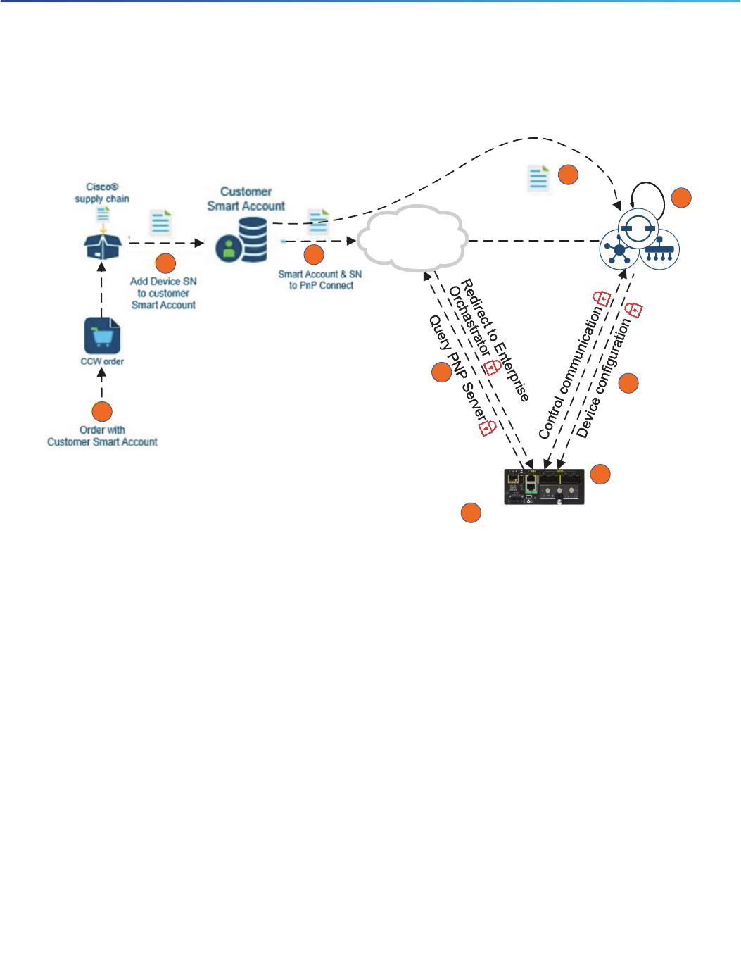
When a customer with a Customer Smart Account orders Cisco IOS XE-based IR1101 WAN Edge routers, the device
identity information, such as a serial number, is automatically added to the Customer Smart Account and can later be
imported to Cisco PNP connect.
To provide administrative control over the environment, the Cisco SD-WAN solution leverages a white-listing model that
allows administrators to revoke certificates from the environment, reject devices with valid certificates, and generate new
certificates as determined by their security policy. The vManage white-list is populated by synchronizing with a customer
smart account.
No pre-shared keys are used in SD-WAN network. Every element in the solution must have a unique device certificate
issued by a trusted Certificate Authority (CA).
Cisco IOS XE-based IR1101 WAN edge routers use Secure Unique Device Identifier (SUDI) and are trustworthy systems.
During manufacturing the SUDI certificate is installed on the Cisco IR1101 routers. The SUDI is an X.509v3 certificate
with an associated key-pair that is protected in hardware. SUDI certificates are used to authenticate Cisco IR1101 routers
during the PNP process.
Cisco IR1101 router installations with Internet access that are able to reach Cisco PNP connect can be securely
onboarded to vManage with no manual intervention, as shown in Figure 13. For deployments where a Cisco IR1101 WAN
edge router cannot reach Cisco PNP connect, a bootstrap configuration can be generated from vManage NMS, manually
loaded to the Cisco IR1101 router, and securely onboarded to vManage, as shown in Figure 14.
23
Cisco Extended Enterprise SD-WAN Design Guide
Message Flow Diagrams
Onboarding Cisco IR1101 with Plug and Play
Figure 13 Cisco IR1101 Onboarding Workflow with PNP
Cisco PNP
Connect
Cisco PNP
Connect
SD-WAN
Manager
SD-WAN
Manager
SD-WAN PNP agent
and SUDI certificate
Plugin Cisco IR1101 with
SD-WAN PNP agent
and SUDI certificate
Create and associ
device template
Create and associ
device template
Device OperationalDevice Operational
Note: Alternately for Step 3
and Step 4, device info can
be manually provided
Note: Alternately for Step 3
and Step 4, device info can
be manually provided
5
4
3
2
1
6
7
8
9
258528
Sync Smart Account

24
Cisco Extended Enterprise SD-WAN Design Guide
Security Design
Onboarding Cisco IR1101 with Bootstrap Configuration
Figure 14 Cisco IR1101 Onboarding Workflow with Bootstrap
For more information about onboarding the Cisco IR1101 SD-WAN router, see:
https://www.cisco.com/c/dam/en/us/td/docs/solutions/CVD/SDWAN/sd-wan-wan-edge-onboarding-deploy-guide-
2019dec.pdf
Security Design
In the Extended Enterprise 2.0 SD-WAN solution, security is ensured at multiple levels, including:
Authenticity of Cisco IR1101 IOS XE SD-WAN router
Secure control channel between IOS XE SD-WAN routers and vManage controller
Secure data communication channel between IOS XE SD-WAN routers
Segmenting data traffic among different services
Filtering undesired traffic and directing traffic to firewalls with ACLs
Authenticity of Cisco IR1101 IOS XE SD-WAN Router
Cisco IR1101 runs Cisco IOS XE-based SD-WAN image. Cisco IR1101 devices are factory loaded with Secure
Unique Device Identifier (SUDI) certificates. The SUDI is an X.509v3 certificate with an associated key-pair that is
protected in hardware.
Key trustworthy technologies of Cisco IOS XE-based SD-WAN edge devices include image signing, secure boot,
runtime defenses, and the Cisco Trust Anchor module (TAm). These protect against counterfeit hardware and
software modification, help enable secure, encrypted communications, and help enable Plug-and-Play (PnP).
Trustworthiness of Virtual Network Functions (VNF) for SD-WAN can be trusted as long as the appliance hardware
has the proper built-in security features, such as a TAm, to enforce hardware-anchored Secure Boot.
Cisco PNP
Connect
Cisco PNP
Connect
SD-WAN
Manager
SD-WAN
Manager
Sync Smart Account
Create and associate
device template
Create and associate
device template
Manually generate
bootstrap config
Manually generate
bootstrap config
SD-WAN PNP agent
and SUDI certificate
Plugin Cisco IR1101 with
-
Manually configure
bootstrap config
Manually configure
bootstrap config
e
e
e
e
Device OperationalDevice Operational
Note: Alternately for Step 3
and Step 4, device info can
be manually provided
Note: Alternately for Step 3
and Step 4, device info can
be manually provided
5
4
3
2
1
6
7
8
9
258529

25
Cisco Extended Enterprise SD-WAN Design Guide
Security Design
Secure Onboarding of Cisco IR1101 is depicted in Message Flow Diagrams, page 22.
Secure Control Channel between IOS XE SD-WAN Router and vManage
All Day 0, Day 1, and Day N control plane communications between the IOS XE SD-WAN router and SD-WAN controllers
(vBond, vSmart, vManage) are protected by a standards-based secure Datagram Transport Layer Security (DTLS) or
Transport Layer Security (TLS 1.2) channels. DTLS uses UDP and TLS uses TCP. Only DTLS is supported to connect
vBond and both DTLS/TLS can be used to connect vSmart/vManage servers. NETCONF management protocol is used
by vManage to communicate with both vSmart and IOS XE SD-WAN router. OMP management protocol is used by
vSmart to communicate with IOS XE SD-WAN router. Both NETCONF and OMP communications are protected by
DTLS/TLS.
Similarly, all communications between the SD-WAN controllers are secured by DTLS tunnels. The SD-WAN CVD design
guide lists the ports to be opened for DTLS/TLS communication
(https://www.cisco.com/c/dam/en/us/td/docs/solutions/CVD/SDWAN/CVD-SD-WAN-Design-2018OCT.pdf).
It may be noted that the IOS XE SD-WAN router establishes individual DTLS/TLS connections to the vSmart controllers
over each transport link.
Figure 15 Secure Data and Control Plane Communication Channels between SD-WAN Components
Secure Data Communication Channel between IOS XE SD-WAN Routers
1. Before a pair of IOS XE SD-WAN routers can exchange data traffic, they establish an IPsec connection between
them, which they use as a secure communications channel, and then the routers authenticate each other over this
connection. As with the control plane, the data plane also uses keys to perform device authentication.
258555

26
Cisco Extended Enterprise SD-WAN Design Guide
Security Design
2. In a traditional IPsec environment, key exchange is handled by the Internet Key Exchange (IKE) protocol. Cisco
SD-WAN implements a simple and scalable key exchange process that does not use per-pair keys for secured
authentication between each pair of IOS XE SD-WAN routers and it dispenses with IKE altogether. For details refer to:
https://sdwan-docs.cisco.com/Product_Documentation/Software_Features/Release_18.1/05Security
3. To further strengthen data plane authentication and encryption, vEdge routers regenerate their AES keys
aggressively (by default, every 24 hours). Also, the key regeneration mechanism ensures that no data traffic is
dropped when keys change.
Segmenting Data Traffic among Different Services
As with encryption, traffic isolation is another key element of any compliance strategy. Many regulatory agencies require
traffic isolation and firewalling in addition to encryption in order to be compliant. As an example, Payment Card Industry
(PCI) compliance mandates that, should a malicious user intercept traffic not intended for them, it should not be readable.
Likewise, if a malicious user were to gain access to an unauthorized segment of a PCI-compliant network, they should
be limited in the destinations they are allowed to access from that segment.
Figure 16 SD-WAN Secured and Segmented Data Plane Communication
1. Cisco SD-WAN solution with IOS XE SD-WAN router provides data plane segmentation.
2. In the SD-WAN solution, Virtual Private Networks (VPNs) provide segmentation. Segmentation is initiated in the
control plane, but it is enforced within the data plane. As traffic enters the IOS XE SD-WAN router, it is assigned to
a VPN. Each VPN is assigned a numerical value (0-65530, where 0 and 512 are reserved for system use). Each VPN
is isolated from one another and each have their own forwarding table. An interface or sub-interface is explicitly
configured under a single VPN and cannot be part of more than one VPN. The router advertises these VPN values to
the control plane via OMP. Hence, users in one VPN cannot (by default) transmit data to another VPN without explicit
configuration allowing the traffic. Different VPN types (transport, management, service) are listed in Table 2.
3. As shown in the Figure 16, the service VPNs are encapsulated with in the encrypted transport VPN0.
VP
N1
VP
N1
VP
N1
VP
N1
VPN
1
VPN 2
VPN 1
VPN 3
SD-WAN
IPSec/GRE
Tunnel (VPN0)
VP
N1
VPN 1
VP
N1
VPN 3
VP
N1
VPN 2
SD-WAN
IPSec/GRE
Tunnel (VPN0)
VP
N1
VPN 4
VPN
1
VPN 3
VPN 1
VPN 4
VPN 1
VPN 3
VPN 2
VPN 4
VP
N1
VPN 4
258530
Egress of IOS XE SD-WAN
router @Data Center
Ingress of Cisco IR1101
@Remote site 1
Egress of Cisco IR1101 @Remote site N

27
Cisco Extended Enterprise SD-WAN Design Guide
Security Design
4. As a user transmits data across the WAN, the WAN Edge router will append the user’s service VPN (in the form of a
label) to the traffic. The label, identifies which VPN the user's traffic belongs to when it reaches the remote
destination. As the remote router decapsulates the encrypted data, the label is used to determine the VPN to which
traffic should be delivered.
5. The SD-WAN service isolation/segmentation ends at the end of Layer 3 transport, VRFs are created for each service
VPN. Within the service network the isolation should be extended manually with VLANs. Each VRF is mapped to a
service VLAN.
Filtering Undesired Traffic and Directing Traffic to Firewalls with ACLs
One of the final pieces to security strategy on the data plane is protection through firewalls. A firewall ensures that user
traffic is restricted to authorized destinations as well as providing auditing in the event of a security incident. ACL rules
can be configured to filter unwanted traffic and always forward selective traffic to a firewall before it can be routed to the
destination.
User and Device Profiles and Design Recommendations
Table 7 lists highly possible user profiles that we have created as an example that illustrates the key design concepts and
also shows the power of the Cisco SD-WAN in orchestrating this policy.

28
Cisco Extended Enterprise SD-WAN Design Guide
Security Design
Table 7 User and Device Profile Samples and Design Recommendations
User/Device
Profile
Role Policy Requirements Design Recommendation
Security cameras This profile belongs to devices that
perform security function, for
example, cameras.
Must be able to only
communicate with VSM
server in the data center.
Must not be able to
communicate with
anything else in the
network.
Hub-and-Spoke
Allow access only to VSM
server.
Prefer Internet over LTE.
IP phones This profile belongs to IP phones. Can communicate with IP
phones across all locations
via the CUCM located at
the DC.
Hub-and-Spoke
Load balance across WAN,
delay and jitter sensitive
Application Aware Routing
(AAR), QoS Low Latency
Queue (LLQ)
Employee
computer
This is a user profile associated with
employee computers. Only
employees can login to computers
designated for them. All employee
computers are of same category.
The employees must be
able to access application
servers in the data center
and shared resources in
peer remote locations.
Partial Mesh
QoS Weighted Round
Robin Queue (WRR), only
predefined destination
ports allowed, access to
Internet blocked
Utility computer
(ATM, POS)
This is a user profile associated with
utility computers, such as ATM
machines and utility payment
gateways.
The utility computer must
be able talk to utility
servers located in the data
center/cloud. It cannot
access any other system.
Hub-and-Spoke access to
Internet/Cloud.
Only predefined
destinations allowed, WRR
with dedicated bandwidth
quote
CUCM Server This is again a device profile for a
VOIP Call Manager, a server that
manages the VOIP phone
communications.
This device profile is
allowed to communicate
with the IP phones
present in the remote
sites.
Hub-and-Spoke
Load sharing across
WAN, delay and jitter
sensitive (AAR), QoS
LLQ
Video
Security
Server
This is a device profile for a Video
Security Server which manages the
security cameras.
The security cameras
need to access the
video server for the
management purposes.
Also, a contractor needs
to access the video
server to access the
content, if needed.
Hub-and-Spoke
Guest This group is assigned to
computers accessible to guests for
Internet browsing.
The guests can access
Internet via DC, all guest
traffic must go through
physical firewall located
at DC.
Need to go through
firewall (localized ACL)
QoS best effort, No
access to internal
systems, restrict video
streaming such as You
tube.

29
Cisco Extended Enterprise SD-WAN Design Guide
QoS Design
QoS Design
This section covers the IOS-XE SD-WAN Cisco IR1101 QoS design details such as QoS considerations, QoS design
steps, and recommendation for traffic classification and marking.
SD-WAN QoS Design Considerations
This section describes the various considerations that the operator must take into account while designing a QoS policy
for the extended enterprise SD-WAN network:
Classification and Marking should be applied to all traffic types in the entire network hierarchy, irrespective of
available WAN bandwidth and expected traffic.
Police traffic by defining QoS exceed policy. Use tail drop for loss sensitive traffic, otherwise use RED. In case of
RED, linear drop probability, i.e., X% queue depth results in X% drop probability.
Limit total strict priority queuing traffic (LLQ) to 33% of link capacity to bound application response time of
non-priority applications. LLQ queue is not subjected to policer. Bandwidth allocated to Q0 is dedicated. The
remaining bandwidth is distributed between Q1 to Q7 with a WRR algorithm.
To limit processing overhead, limit classification only for desired applications and application sets from application
list. Remaining traffic will be considered as scavenger traffic and treatment will be provided accordingly.
Order of Applying Polices
Figure 17 shows the order of applying policies as the traffic traverses from ingress to egress. This is an extract from the
Cisco Enterprise SD-WAN Design Guide. The first three steps (policy applications) happen at the ingress before the
traffic reaches the routing engine. The last two steps, scheduling and shaping (5 and 6), happen on the egress side at
the exit of the traffic. It may be noted that the traffic classification, marking, and policer configurations applied by
localized policy at step 1 are overwritten by centralized policy applied on step 3. Based on monitored SLA, the application
aware routing (AAR) selects only those WAN interfaces that meet the (loss, latency, jitter) quality criteria. For more
information, see:
https://www.cisco.com/c/dam/en/us/td/docs/solutions/CVD/SDWAN/CVD-SD-WAN-Design-2018OCT.pdf

30
Cisco Extended Enterprise SD-WAN Design Guide
QoS Design
Figure 17 Policy Order of Operations on a IOS XE SD-WAN Router
SD-WAN QoS Design
In a SD-WAN, QoS can be configured by defining policies. As a general principle GUI-based menu driven QoS policy is
preferred to CLI-based policy.
The following are the design recommendations:
1. The first step in QoS is Application Recognition. The IOS-XE SD-WAN image has a Deep Packet Inspection (DPI)
Engine. It can recognize and classify traffic of a large set of applications such as Facebook, ms-office-365, twitter,
etc. In addition, six tuple ACLs can be configured to classify any traffic to the desired category. Thus incoming traffic
is classified into different QoS forwarding classes.
2. Several QoS policies such as classifications, marking, policing, and remarking can be defined in both centralized and
localized data policies. Considering the use cases for extended enterprise, most of the QoS requirements are
common across all remote sites, thus centralized data policy is recommended for classification, marking, policing,
and remarking. The other advantage with centralized data policy is classification/grouping can be done based on a
number of predefined standard applications and application family. Also, centralized data policy is applied after
localized policy as shown in Figure 17, overwriting the localized policy. Hence centralized data policy has a higher
preference. A single policer can only be defined with centralized data policy, however in the case of differing
bandwidth WAN links, different policers might be preferable. In such a scenario, a local policer can be defined for
each WAN link.
3. To avoid complexity of operations, it is recommended not to define classification, marking, and remarking using
localized policy.
4. Queueing and scheduling based on specific traffic characteristics such as bandwidth requirement, burst nature,
sensitivity to jitter, latency, and packet loss are configurable only with localized policy.
5. A total of eight output queues are supported by SD-WAN for scheduling, of which queue0 is a Low Latency Queue
(LLQ) and remaining seven are Weighted Round Robin Queue (WRR) queues. Network control and real time traffic
which is sensitive to latency such as real time voice can be mapped to this queue. Realtime control traffic such as
DTLS, TLS, BFD, Routing protocols are auto mapped to queue0 the LLQ. Remaining applications can be classified
into multiple groups and mapped to separate queues for desired scheduling treatment.
6. The QoS forwarding classes are mapped to appropriate output queue.
258556
2
5
8
55
6

31
Cisco Extended Enterprise SD-WAN Design Guide
QoS Design
7. Centralized policy is applied to a group of sites and VPN list, whereas localized policy apply to a group of interfaces.
Thus, centralized QoS policy (classification, marking, and policing) is applied to the configured service VPNs. And
localized QoS policy (queueing) is applied to configured WAN interfaces through device and interface templates.
8. vManage maps QoS-map configurations to Cisco IOS XE policy-map configurations.
9. QoS policy can be applied to the inbound traffic (from service side to transport side) or outbound traffic (from tunnel
to service side) or on all directions. Considering the much higher bandwidth on the service side compared to the
WAN side, QoS policy is essential in the LAN to WAN direction.
10. Configure shaping rate, the aggregate traffic transmission rate on the interface, to be less than line rate. According
to published survey results (https://www.tomsguide.com/us/best-mobile-network,review-2942.html), typical
carrier uplink speeds for major LTE Cellular networks vary from 10 to 15Mbps. Hence the suggested shaping rate
for LTE Cellular interface is 10Mbps. Similarly, configure shaping rate for other WAN networks, such as Internet,
based on the service provider agreement. This will ensure that maximum transmission speed does not go beyond
permitted limit and bandwidth allocation % across the queues which are computed based on aggregate traffic
transmission rate on the interface.
A sample QoS configuration is shown in Table 8, Table 9, and Table 10. SD camera traffic is limited to 1Mbps and HD
camera to 4Mbps. For low speed uplinks such as cellular, only SD cameras are permitted.

32
Cisco Extended Enterprise SD-WAN Design Guide
QoS Design
Comply SLA over WAN with Application Aware Routing
Application aware routing (AAR) is another data policy tool that can improve application performance. The operation
Table 8 Extended Enterprise Traffic Policer
Name Burst Exceed Rate
Policer-SD-Camera-1MB-drop 2000,0000 Drop 1000,000
Policer-HD-Camera-4MB-drop 8000,0000 Drop 4000,000
In case of WRR queues, the bandwidth % indicates the maximum bandwidth allocated to the class. The unused
bandwidth from any WRR queue is distributed to other classes.
Table 9 Extended Enterprise Traffic QoS Map for Internet WAN
Class DSCP Scheduling
Type
Bandwidth % Drop
Action
Queue Policer
Voice EF/46 Priority
Queuing (PQ)
10 Tail 0 NIL
Broadcast-Video CS5/40 Weighted
Round Robin
Queueing
(WRR)
20 Tail 1 Policer-HD-
Camera-4M
B-drop
Network-Control CS6/48 WRR 5 Tail 2 NIL
Signalling CS3/24 WRR 5 Tail 3 NIL
OAM CS2/16 WRR 10 Tail 4 NIL
Scavenger CS1/8 WRR 50 Random
Early Drop
(RED)
5NIL
Table 10 Extended Enterprise Traffic QoS Map for Celluar WAN
Class DSCP Scheduling
Type
Bandwidth % Drop
Action
Queue Policer
Voice EF/46 Priority
Queuing (PQ)
10 Tail 0 NIL
Broadcast-Video CS5/40 Weighted
Round Robin
Queueing
(WRR)
60 Tail 1 Policer-SD-
Camera-1M
B-drop
Network-Control CS6/48 WRR 5 Tail 2 NIL
Signalling CS3/24 WRR 5 Tail 3 Policer-Half
MB- remark
OAM CS2/16 WRR 10 Tail 4 OneMB-dro
p
Scavenger CS1/8 WRR 10 Random
Early Drop
(RED)
5OneMB-dro
p

33
Cisco Extended Enterprise SD-WAN Design Guide
Scale and Dimension
steps for AAR are shown below. Figure 17 shows the order of application for AAR.
The design and operation of AAR:
Application-aware routing policies are configured as part of a centralized policy. It affects traffic on a WAN edge
router that is flowing from the service (LAN) side to the transport tunnel (WAN) side.
Up to four SLA classes can be defined with certain loss, jitter, and delay values.
Multiple WAN link tunnels of a remote-site are monitored by BFD protocol and are calibrated for loss, latency, and
jitter. BFD is also used to detect link failures.
In real time, packets of uplink traffic are matched and classified into different classes of SLA (loss, latency, and jitter).
Traffic is load-balanced across all tunnels meeting the SLA class. If no tunnels meet the SLA, the traffic is sent
through any available tunnel.
If preferred colors are specified in the policy, then traffic will be sent through the preferred color tunnels as long as
the SLA is met. If no tunnels meet the SLA, the traffic is sent through any available tunnel.
If a backup-SLA preferred color is specified, then that tunnel is used when there are no paths that meet the SLA.
A strict keyword can be used in the policy, which means if no tunnel can meet the SLA, the traffic is dropped.
Based on the guidelines published in Implementing Quality of Service Over Cisco MPLS VPNs:
http://www.ciscopress.com/articles/article.asp?p=471096&seqNum=6
The recommended SLA guidelines for different services of the Extended Enterprise SD-WAN solution are shown in
Table 11.
Scale and Dimension
SD-WAN Controller Scale
The SD-WAN controller provides a scalable solution with a horizontal scale-out model. As published in the Cisco
SD-WAN 19.1 release notes, in a vManage NMS cluster each vManage server is validated for a scale of 2,000 devices
(WAN edge) and up to six vManage server instances can be spawned in a cluster. Similarly, a single vSmart instance
supports up to 2,700 connections and a single vBond instance supports up to 1,500 connections. Overall a vManage
NMS cluster can manage up to 10,000 devices (WAN edge routers). For more information:
https://www.cisco.com/c/en/us/td/docs/routers/sdwan/vManage-Help/vmanage-help-16-11/administration.html
Table 11 SLA Guidelines for Different Services
SLA-ClassList Name Traffic Type Loss (%) Latency (ms) Jitter (ms)
SLA-1 Voice 1 150 30
SLA-2 Streaming-Video 2 300 500
SLA-3 Network-Control
Signalling
Network-Management
3 500 500
SLA-4 Scavenger 5 500 500

34
Cisco Extended Enterprise SD-WAN Design Guide
Cisco vManage Single-Pane-of-Glass
Remote Sites Scale
As illustrated earlier, multiple architectures are proposed matching the need for very small, small, medium, and large size
remote sites. The number of endpoints supported at the remote site depends on the availability of Ethernet ports on the
service side for connecting end-devices. Considering a mixture of single and dual WAN routers at the remote sites, 5,000
to 10,000 remote sites or WAN edge routers can be managed by a vManage cluster deployment.
Server Hardware Recommendations
Server hardware specifications for different size of deployments can be found at:
https://www.cisco.com/c/en/us/td/docs/routers/sdwan/configuration/sdwan-xe-gs-book.pdf
The document provides the hardware recommendations for the vBond orchestrator server, vManage Network
Management System (NMS) server, and vSmart controller server. The specification varies based on the number of
devices in the overlay network. The specification covers the vCPU, RAM, OS Volume, number of NIC cards, and network
bandwidth requirement.
Cisco vManage Single-Pane-of-Glass
Cisco vManage provides a single-pane-of-glass management to manage all controller components and both enterprise
and extended enterprise WAN edge devices. The comprehensive vManage GUI has dashboard, monitor, configuration,
tools, maintenance, administration, and analytics as the top-level menus.
Dashboard
Dashboard screens provide an at-a-glance view of the overall health of the SD-WAN overlay network. Dashboard
screens showing Cisco IR1101 status include main dashboard and VPN dashboard. Multi-level zoom-in and navigation
is supported from various dashboard views.
The main dashboard shows a birds-eye-view of the health status of controllers, remote site WAN connectivity, WAN
transport interface health and bandwidth distribution, WAN edge router health, top applications, and tunnel endpoints
status monitored for application-aware routing.
The VPN dashboard shows the health of various VPN groups/VPN segments and top applications transiting.
Events and Alarms
The alarms pane shows the system-wide active and cleared alarms, severity wise alarm classification and distribution
over a date and time range, impacted sites, and severity. Hierarchical multi-level zoom-in is supported. The events pane
shows system-wide statistics and histograms for the received events.
Network Monitoring and Assurance
The status of Cisco IR1101 IOS XE SD-WAN router and links in the overlay network can be viewed in a GIS map with
geo-location. Multiple filters help to filter the view to the parts of the network of interest.
Sotware Image Management
Cisco vManage maintains a software image repository for WAN edge devices and controllers. Images of Cisco IR1101
IOS XE SD-WAN router can be uploaded to vManage server or a link to an image on a remote server can be provided.
An operator can trigger a software upgrade for controllers and WAN edge devices.

35
Cisco Extended Enterprise SD-WAN Design Guide
References
vAnalytics
Based on DPI and cflowd (traffic flow monitoring), assorted telemetry is collected from across the network and analytics
are generated. Some of the analytics and views include:
Availability—Site and network availability
Bandwidth usage—Identification of top network bandwidth using sites. The drill-down view shows top sources,
destinations, and applications using network bandwidth.
Application performance—Application to tunnel-binding and performance information
Anomaly detection—Baseline of application usage. Anomaly detection based on overall application usage/by
family/by site.
Carrier performance—Performance of carriers and tunnels by latency, loss, or jitter. Application performance by
carrier.
References
Cisco Enterprise Networking design guides:
https://www.cisco.com/go/designzone
Cisco IoT Solutions design guides:
https://www.cisco.com/go/iotcvd
Cisco extended enterprise solution overview and design and implementation guides:
— https://www.cisco.com/c/en/us/solutions/enterprise/design-zone-industry-solutions/index.html#~stickynav=1
— https://www.cisco.com/go/extendedenterprise
Cisco Enterprise SD-WAN design guides:
https://www.cisco.com/c/dam/en/us/td/docs/solutions/CVD/SDWAN/CVD-SD-WAN-Design-2018OCT.pdf
Cisco SD-WAN product documentation security section:
https://sdwan-docs.cisco.com/Product_Documentation/Software_Features/Release_18.1/05Security
Cisco SD-WAN vManage Help, Cisco IOS XE Gibraltar 16.11.x, Cisco SD-WAN Release 19.1:
https://www.cisco.com/c/en/us/td/docs/routers/sdwan/vManage-Help/vmanage-help-16-11/administration.html
Cisco SD-WAN Getting Started Guide:
https://www.cisco.com/c/en/us/td/docs/routers/sdwan/configuration/sdwan-xe-gs-book.pdf
Cisco IR1101 Datasheet:
https://www.cisco.com/c/en/us/products/collateral/routers/1101-industrial-integrated-services-router/datasheet
-c78-741709.html
Onboarding Cisco IR1101 with Plug and Play:
https://www.cisco.com/c/dam/en/us/td/docs/solutions/CVD/SDWAN/sd-wan-wan-edge-onboarding-deploy-gui
de-2019dec.pdf
Implementing Quality of Service Over Cisco MPLS VPNs:
http://www.ciscopress.com/articles/article.asp?p=471096&seqNum=6
Beyond the Network: SD-WAN and The Golden Gate Bridge:
https://www.cisco.com/c/dam/en/us/solutions/collateral/cisco-on-cisco/podcast-transcript-material-sdwan-brid
ge.pdf

