
ACR
�
Manual on
MR Safety
Copyright © American College of Radiology
ACR Committee on MR Safety
AMERICAN COLLEGE OF RADIOLOGY
1892 PRESTON WHITE DRIVE
RESTON, VA 20191
2024

ACR Manual on MR Safety
ACR Committee on MR Safety
This manual is copyright protected and the property of the ACR. Any reproduction or attempt to
sell this manual is strictly prohibited absent the express permission of the ACR.
Copyright ©2024 American College of Radiology. All rights reserved.

AMERICAN COLLEGE OF RADIOLOGY
Return to Table of Contents i
Table of Contents
Preface ................................................................................................................................................................................ iii
Revision History ............................................................................................................................................................... iv
Chapter 1: Introduction.................................................................................................................................................... 6
Introduction and overview of unique risks in MRI .................................................................................................................. 6
Introduction to MRI fields and potential safety concerns ............................................................................................... 7
Chapter 2: Management Of Mr Safety Policies And Standard Operating Procedures ............................ 13
Chapter 3: MR Safety Zones ....................................................................................................................................... 18
Chapter 4: MR Personnel ............................................................................................................................................ 27
MR Personnel And Non-MR Personnel ...................................................................................................................................... 27
MR Personnel And Training: Level 1 And Level 2 ................................................................................................................ 27
Supervision And Independent Access ....................................................................................................................................... 30
Staffing ............................................................................................................................................................................................................. 31
Chapter 5: MR Screening ............................................................................................................................................. 41
MR Safety Screening Forms ................................................................................................................................................................. 41
Patients/Research Participants And Accompanying Companions ................................................................................. 41
Screening With Ferromagnetic Detection Systems ............................................................................................................... 43
Staff/Personnel Screening ................................................................................................................................................................... 44
Risk Identification, Assessment, And Mitigation ...................................................................................................................... 46
Patient Preparation/Gowning .............................................................................................................................................................. 47
Chapter 6: Full Stop/Final Check ............................................................................................................................... 51
Chapter 7: Zone IV Examination Preparation And Completion ......................................................................... 53
Chapter 8: MRI Fields And Safety Concerns .......................................................................................................... 56
Static Magnetic Field ............................................................................................................................................................................... 56
Time-Varying Radiofrequency Magnetic Field .......................................................................................................................... 61
Time-Varying Gradient Magnetic Field ......................................................................................................................................... 69
Chapter 9: MR Contrast Agents ................................................................................................................................ 75
Chapter 10: Classification Of Objects And Medical Implants And Devices In The MR Environment ...... 76
MR Safety Labeling Classifications ................................................................................................................................................ 76
Chapter 11: Introducing Portable Metallic Objects And Equipment Into Zone III And Zone IV .................. 81
Labeling And Testing ................................................................................................................................................................................ 81
MR Unsafe Transport Equipment—Temporary Provisions ................................................................................................ 81
Portable Objects In Zone IV.................................................................................................................................................................. 82
AMERICAN COLLEGE OF RADIOLOGY
Return to Table of Contents ii
Chapter 12: Managing Patients And Research Subjects With Medical Implants And Devices In The MR
Environment .................................................................................................................................................................... 87
Active Implanted/On-Planted Devices .......................................................................................................................................... 87
Passive Implanted Devices ................................................................................................................................................................... 92
Implant, Device, Or Object Discovered During An MR Examination ............................................................................. 94
Chapter 13: Physiological Monitoring Of Patients ............................................................................................... 100
Chapter 14: Emergency Situations .......................................................................................................................... 101
Emergency Table Stop And Emergency Power Off ............................................................................................................. 101
Emergency Magnet Off (Quench) ................................................................................................................................................... 102
Fire .................................................................................................................................................................................................................... 103
Medical Code .............................................................................................................................................................................................. 104
Entrapment .................................................................................................................................................................................................. 105
Chapter 15: Special Patient And Personnel Considerations .............................................................................106
Pregnancy ..................................................................................................................................................................................................... 106
Pediatric MR Safety Concerns ......................................................................................................................................................... 107
Claustrophobia, Anxiety, And Sedation ...................................................................................................................................... 108
Large Body Habitus ................................................................................................................................................................................ 108
Prisoners/Detainees................................................................................................................................................................................ 108
Parolees ......................................................................................................................................................................................................... 109
Chapter 16: Alternative MR Environments ............................................................................................................ 114
PET/MR ............................................................................................................................................................................................................ 114
Intraoperative/Interventional MR .................................................................................................................................................... 115
MR Simulator And MR Linear Accelerator ................................................................................................................................. 116
7-T MR Environments ............................................................................................................................................................................. 116
Point-Of-Care MRI Systems ................................................................................................................................................................ 118
Mobile MR Scanners ............................................................................................................................................................................... 118
Appendix 1: MR Safety Policies And Standard Operating Procedures .......................................................... 121
Appendix 2: MR Facility Safety Design Guidelines ............................................................................................ 128
Appendix 3: MR Facility Maintenance And Emergency Preparedness Guidelines .................................... 137
Appendix 4: Implanted Device MR Risk/Safety Assessment ...........................................................................140
Appendix 5: Spatial Field Gradient Evaluation .................................................................................................... 144

AMERICAN COLLEGE OF RADIOLOGY
Return to Table of Contents iii
PREFACE
This 2024 edition of the ACR Manual on MR Safety replaces all earlier versions. This document
is published in a web-based format so that it can be revised and updated in a timelier manner as
needed.
In 2001, the American College of Radiology (ACR) formed a Blue-Ribbon Panel on Magnetic
Resonance (MR) Safety in response to various reports in the medical literature and print media
detailing MR imaging (MRI) adverse events and incidents involving patients, equipment, and
personnel. Initially published in 2002, the ACR MR Safe Practices Guidelines are often looked to
as authoritative guidance for establishing safe and responsible practices in clinical and
research MR environments. Subsequently, these guidelines have been reviewed and updated
throughout the years to address feedback from the MR community as well as changes in the
MRI industry since the original publication. The ACR Manual on MR Safety represents the
consensus of those representing the Committee on MR Safety of the ACR. It should be noted
that these recommendations are not only appropriate from a scientific point of view but also
generally reasonable for real-world application, with consideration given to patient care,
throughput, financial pressures, and other considerations.
This document is an educational tool designed to assist practitioners in providing appropriate
radiologic care for patients. The ACR Manual on MR Safety recommendations are not to be
considered inflexible rules or requirements of practice and are not intended, nor should they be
used, to establish a legal standard of care. For these reasons and those set forth herein, the
ACR cautions against the use of this document in litigation in which the clinical decisions of a
practitioner or imaging practice are called into question. The ultimate judgment regarding the
propriety of any specific procedure or course of action must be made by the
practitioner/practice considering all the circumstances presented. Thus, an approach that
differs from the guidance in this document, standing alone, does not necessarily imply that the
approach was below the standard of care.
The views expressed in this document are solely those of the authors and in no way imply a
policy or position of any of the organizations represented by the authors.
The ACR sincerely thanks all who have contributed their knowledge and valuable time to this
and all previous versions of this publication including the ACR MR Safe Practice Guidelines,
ACR Guidance Documents on MR Safe Practices, and the ACR Manual on MR Safety. The ACR
Safety Committee thanks those in the MR Safety community who provided valuable comments
on the draft version of the ACR Manual on MR Safety. Those comments were instrumental in
improving this 2024 version of the manual.
Members of the ACR Committee on MR Safety are:
Robert Watson, Jr, MD, PhD, FACR
Chair
Alexander McKinney, IV, MD
Jason Stafford, PhD
David Altman, MD
Ivan Pedrosa, MD, PhD
James Webb, Jr., RT(R)(QM)
Jonathan Dillman, MD, MSc, FACR
Scott Reeder, MD, PhD, FACR
Dina Hernandez, ACR Staff
Michael Hoff, PhD
Jeffrey Rogg, MD, FACR

AMERICAN COLLEGE OF RADIOLOGY
Return to Table of Contents iv
REVISION HISTORY
The ACR Manual on MR Safety was published in 2020 as a web-based product. Content
changes may take place as a result of changes in technology, clinical treatment, or other
evidence-based decisions from the MR Safety Committee.
Date
Section
Change
4/15/2020 All Creation of the ACR Manual on MR Safety based on the
reorganization and updates to previously published “ACR Guidance
Document on MR Safe Practices: 2013.”
Magnetic Resonance (MR)
Personnel
Expanded staffing guidance to align with the Veterans Health
Administration Directive on MR safety, 2018.
Explanation of formal safety roles.
MR Screening Deference to the Heart Rhythm Society on guidance regarding the
performance of MR examinations in patients with non–MR
Conditional cardiac devices.
Full Stop/Final Check
New
Special Patient Population
Considerations
Updated pregnancy, prisoner/detainee, and parolee sections.
MR Imaging (MRI) Contrast
Agents
Updated language.
MR Environment Atypical environments to include complex intraoperative and 7-T
environments.
Screening Form Formerly Appendix 2: This section has been removed and will be
available as a separate document available for download on the
acr.org MR Safety webpage.
5/15/2020
All
Grammatical corrections and general editorial changes.
Screening
Clarification for emergent patients.
1/1/2024
All
Created a chapter-based format.
Introduction Basic introduction of MR risks and safety concerns related to the
MR fields.
Management of MR Safety
Policies and Standard
Operating Procedures
Formerly, establishing, implementing, and maintaining MR safety
policies and procedures. Provides new points to consider when
developing MR policies and procedures.
MR Safety Zones Key definitions of MR safety zones including MR controlled access,
MR environment, and MR projectile area.
MR Environment
IEC update of fringe field to 9 gauss.
MR Personnel Updated language for MR safety training levels and
responsibilities.
New training checklist.
Updated staffing guidance.
New remote scanning guidance.
MR Screening Reorganization of information involving staff/personnel screening,
patient screening, screening for ferromagnetic material, risk
identification, MR Safe attire, and ferromagnetic detection.
Final Stop/Final Check Updated routine and augmented guidance and new language
about removal of hearing aids before Zone IV entry.

AMERICAN COLLEGE OF RADIOLOGY
Return to Table of Contents v
Zone IV Exam Preparation
and Completion
New
MRI Fields and Safety
Concerns
Reorganization of Time-Varying Radiofrequency (RF) Magnetic
Field to include whole-body heating, focal heating, and resonant
heating.
Reorganization of Time-Varying Magnetic Field Gradient (dB/dt) to
include auditory considerations, induced voltages, and peripheral
nerve stimulation.
Classification of Objects
and Medical Devices in the
MR Environment
Formerly implants, devices, and objects section. Includes MR
safety labeling classifications.
Introducing Portable
Metallic Objects and
Equipment in the MR
Environment
New (formerly included in implants, devices, and objects). Contains
labeling and testing, MR Unsafe transport equipment temporary
provisions, and portable objects in Zone IV.
Managing
Patients/Subjects with
Medical Devices in the MR
Environment
New (formerly included in implants, devices, and objects). Contains
active implanted/on-planted devices, passive implanted devices,
and implants, devices, or objects discovered during MR
examination.
Emergency Situations New (formerly included in MR Environment). Includes emergency
table stop, emergency power off, emergency magnet off, quench,
fire, code, and entrapment.
Special Patient and
Personnel Considerations
Formerly, special patient population considerations. Includes
reorganization of information involving pregnancy, pediatric MR
safety concerns, claustrophobia, anxiety, and sedation, /large body
habitus (new), prisoners/detainees, and parolees.
Alternative MR
Environments
New (formerly found in MR environment). Includes PET/MR,
intraoperative/interventional MR, MR simulator and MR-LINAC
(new), point-of-care MR system (new), and mobile MR scanner
(new) information.
Appendix 1 New appendix containing MR safety policies and standard
operating procedures guidance.
Appendix 4 New appendix containing implanted device MR risk/safety
assessment.
Appendix 5 New appendix containing spatial field gradient information.
Key Points New Key Points boxes for a quick visual of the important elements
in each chapter.
Key Abbreviations New Key Abbreviation boxes for a quick visual on important
abbreviations used in each chapter.
6-18-2024 Cover Updated the ACR Manual on MR Safety 2024 cover to align with the
updated ACR brand theme

AMERICAN COLLEGE OF RADIOLOGY
Return to Table of Contents 6
CHAPTER 1: Introduction
It remains the intent of the ACR that this ACR Manual on MR Safety will prove helpful as the field
of MRI continues to evolve and mature, providing MR services that are not only safe but also
valuable from a clinical or research point of view.
Introduction and Overview of Unique Risks in MRI
While considered a clinically impactful and versatile imaging modality, particularly because of
the lack of ionizing radiation, the unique fields encountered in the MR environment do
potentially pose serious safety risks
*
not only for patients, research participants, and health
care staff, but also others who may encounter the MR environment, including patient family
members, security officers, firefighters, police officers, housekeeping personnel, etc. MR safety
accidents have led to serious injuries and deaths. There have been at least 3 deaths, in 2001,
2018, and 2021, from oxygen cylinders that have become lethal projectiles. Additionally, deaths
and serious injuries have resulted from improper scanning of patients with implanted devices
[2,3]. A death occurred in 2023 when a firearm was brought into the MR environment, and the
magnetic field caused a weapon discharge [4]. “On-planted” external devices, those worn or
located largely external to the body such as insulin pumps, can be the source of MR safety
events if exposed to the MR environment in an unsafe manner.
Many other nonlethal projectile-
related injuries have also occurred. Every projectile event is preventable. MRI-associated burns
constitute the most frequently reported injury in MRI [5-7].
Root cause analyses of MR safety accidents reveal the accident resulted only very rarely from a
malfunction of the MR equipment. Instead, accidents are more typically the result of how the
equipment was being used, frequently involving a breakdown in adherence to policies and
procedures or being impacted by previously unrecognized significant gaps in those policies and
procedures. As there will always be potential for human error, it is essential that MR facilities
design thoughtful policies and procedures that reliably address predictable as well as unusual
situations. Concurrent with this notion is the recognition that contemporary MRI practices
encounter ongoing challenges associated with ever-evolving technology, patient throughput,
staffing challenges, and increasingly complex patients with increasing numbers of implanted
devices.
The following ACR Manual on MR Safety is intended to be used as a template for MR facilities
to follow in the development of a safety program. These guidelines were developed to help
guide MR practitioners and institutions regarding these issues and to provide a basis for them
to develop and implement their own MR policies and practices. These guidelines, along with the
policies and procedures that are developed, are intended to be reviewed and updated at
defined intervals specific to the policy/standard operating procedure (SOP). These are
guidelines and may not be prescriptive or appropriate for all facilities. This version of the
manual includes a new appendix (Appendix 1
) that could serve as a guide for the development
of MR safety policies and SOPs. However, it is impossible to cover all potential configurations of
*
Throughout this manual, the term “risk” is used literally to include the occurrence of injury or damage (harm), the potential source of
harm (hazard), and the probability of occurrence of harm and the severity of that harm. Definitions for the terms risk, harm, and
hazard can be found in ISO/IEC Guide 63:2019, 3.1, 3.2, and 3.10 [1].

AMERICAN COLLEGE OF RADIOLOGY
Return to Table of Contents 7
an MRI facility in this manual. Indeed, different configurations may be adequate to serve the
functional needs of the facility.
The principles found in this safety manual are intended to apply to clinical diagnostic imaging,
research, and complex MR settings (e.g., linear accelerator MR, interventional MR, etc.) and
encompass information for patients, research participants, and health care personnel. It is worth
noting that the use of remote MR imaging does not, in any way, diminish the obligations of the
site to provide safe MR patient care. It is also important to emphasize that MR Personnel must be
familiar with the specific MR safety guidelines provided by the manufacturer, which in some
cases may exceed the recommendations in this manual.
Introduction to MRI Fields and Potential Safety Concerns
The unique safety concerns in MR imaging are primarily caused by the generation and/or
presence of 3 independent magnetic fields used for imaging by the MR scanner (Figure 1), and
all contribute to specific MR safety challenges:
- static magnetic field (B
0
),
- time-varying radiofrequency magnetic field (B
1
), and
- time-varying gradient magnetic field (dB/dt).
These topics are elaborated upon in the MRI Fields and Safety Concerns section.

AMERICAN COLLEGE OF RADIOLOGY
Return to Table of Contents 8
Static magnetic field (B
0
). A very strong magnetic field to polarize the spin of protons in human
tissue allows for MR imaging. This is typically measured in units of tesla (T). This field, and its
sharp increase approaching the MR system (spatial field gradients, T/m), are the source for
potentially large magnetic forces on ferromagnetic objects entering the MR environment.
Depending on the scanner room configuration, shielding, and magnitude of the magnetic fields,
these fields may extend outside the scanner room confines and potentially affect devices and
personnel. For virtually all clinical MRI scanners in use today, this field is usually generated by
large currents circulating in cryogen-cooled superconducting coils and so should be assumed to
be always on, making the safety concerns caused by this field omnipresent and requiring
controlled access, supervisory control, and vigilance over personnel and items entering the MR
environment [8,9]. Current FDA-cleared MR scanners for human use rely on magnetic fields
between 0.064 and 7 T [10]. The main risks of the static magnetic field (B
0
) field include
translational (projectile effect) and rotational forces. The risks associated with B
0
are always
present, even when imaging is not taking place, and may extend several meters away from the
MRI scanner in all directions (depending on the properties of the specific MRI scanner).
Time-varying radiofrequency magnetic field (B1). A much smaller magnetic field (mT)
oscillating at or near the MR frequency (MHz) of protons is generated orthogonal to the static
field by another set of current-carrying coils (i.e., built-in body coil in the bore of the scanner or
dedicated anatomical transmit-receive RF coils placed directly around the anatomy of interest)
close to the patient during imaging to excite and/or manipulate the polarized spins for signal and
FIGURE 1. Schematic diagram of a typical superconducting magnet MRI system. Closest to the bore wall, adjacent to
the patient is the radiofrequency (RF) coil; unsafe physical proximity to this RF coil may cause patient heating and
burns. Peripheral to the RF coil are the gradient coils; rapid current changes in these coils produce the characteristic
loud noises during MRI. Gradient magnetic fields can also cause peripheral nerve stimulation. The outermost ring is
associated with the static magnetic field (B0) that creates the strong magnetic translational and torque on
ferromagnetic objects. All 3 electromagnetic fields can interact with implanted or on-planted medical devices or any
metallic object in the MR environment.

AMERICAN COLLEGE OF RADIOLOGY
Return to Table of Contents 9
contrast. This field, characterized by its amplitude, frequency, and duty cycle, is responsible for
risks caused by the heating of materials, including human tissues, in the bore of the scanner. This
field is only present during imaging [8,9]. The risks of the B1 field include general patient heating,
localized heating resulting in burns, unintended stimulation, and device malfunction.
Time-varying gradient magnetic field (dB/dt). Three orthogonal linear gradient magnetic fields
are generated by another set of coils in the bore and are pulsed during image acquisition for
image encoding. These switched gradients have magnitudes (mT/m) in space across the bore,
with rise times (ms) that indicate their ramp-up rate defined as the magnetic field slew rate
(T/m/s). Gradient fields’ continual ramp up and ramp down leads to their standard definition as
time-varying magnetic fields, dB/dt (T/s). The rapid switching of large currents through the
gradient coils is the source of both the loud acoustic noise generated during MR imaging and
peripheral nerve stimulation. The main risks of the gradient (dB/dt) field result from induced
voltages/currents and include acoustic injury, unintended arrhythmogenesis, peripheral nerve
stimulation, and implant device malfunction. This field is only present during imaging and
represents clinical risks of induced electrical currents in tissues or other materials that are within
the bore of the MRI during active imaging.
MRI output operating modes. To aid in managing the bioeffects of exposure to these
electromagnetic fields in patients, the International Electrotechnical Commission and FDA have
recommended output limits for each field, referred to as “Operating Modes.”
• Normal Operating Mode. Mode of operation of MR equipment in which the biophysical
effect induced by a specific electromagnetic field typically presents negligible risk [11].
This is the most commonly used operating mode in clinical practice.
• First Level Controlled Operating Mode. Mode of operation of MR equipment in which
medical supervision mitigates risks associated with biophysical effects induced by
exposure to electromagnetic fields [11].
This mode carries higher risk to the patient than
Normal Operating Mode. In some clinical scenarios, the use of first level controlled
operating mode may be of benefit to the patient (e.g., patients with limited breath-hold
capacity). Risk must be mitigated by employing appropriate medical supervision of the
patient for the specific scanning scenario as defined by the facility’s policies and
procedures.
• Second Level Controlled Operating Mode. Mode of operation of the MR equipment for
which the responsible organization defines risk acceptability as part of a human studies
protocol and in which medical supervision is implemented to mitigate such risks [11]. This
higher mode of operation typically is not used in routine clinical practice and is generally
reserved for human participant research with appropriate medical supervision.
It is important to note that the operating mode thresholds for each of the fields is independent of
the others, and in no way takes into account issues with medical devices or other equipment in the
bore of the scanner that may cause a patient injury. MR system operators should be aware and
knowledgeable of these operating mode limits and when to employ them. Similarly, newer scanners
provide the capability of employing an optimized operating mode with low specific absorption rate
(SAR) for specific applications (e.g., patients with MR Conditional devices that have more strict SAR
levels for MR imaging) that generally sacrifice image quality for reduced energy deposition.
Operating modes are also discussed in the Peripheral Neural Stimulation (PNS
) section.
Other unique MR environments and MR-related risks addressed in this ACR Manual on MR
Safety include:
• Implanted/on-planted medical devices and associated MR safety risks [12-14].

AMERICAN COLLEGE OF RADIOLOGY
Return to Table of Contents 10
• Cryogens used for maintaining magnet coil superconduction and risks associated with
cryogen exposure loss during magnet quenching.
• MRI safety considerations in unique patient populations, including pregnancy, pediatric,
those with claustrophobia and large body habitus, and those with law enforcement
considerations (prisoners, monitored parole, etc.).
• Alternative MR environments (PET/MR, radiation oncology, interventional/intraoperative,
high/low field, and mobile).
• Gadolinium-based contrast media in MR (with reference to the ACR Manual on Contrast
Media).
KEY POINTS
Deaths and serious injuries have occurred in MRI. MR safety events are typically related to unsafe
practices, failure to follow MR safety policies and procedures, or gaps in those policies and
procedures. Equipment failure or shortcomings rarely underlie serious MR safety events.
The 3 types of magnetic fields in MR are associated with unique risks.
1. Main magnetic field B
0
Ferromagnetic object translation/torque and projectile incidents
2. RF field B
1
Heating and burns
3. Time-varying gradient magnetic field
Acoustic injury, peripheral nerve stimulation
The risks associated with the RF field B
1
and gradient fields are managed in part using scanner
Operating Modes (Normal and First Level Controlled).
All 3 types of magnetic fields can interact with implanted and on-planted medical devices in
potentially deleterious ways.
Additional MR risks are addressed in other sections of this manual.

AMERICAN COLLEGE OF RADIOLOGY
Return to Table of Contents 11
References
1. ISO/IEC. Guide to the development and inclusion of aspects of safety in international standards for medical
devices. Published August 2019. Accessed April 22, 2024. https://www.iso.org/standard/67944.html
2. Henderson JM, Tkach J, Phillips M, Baker K, Shellock FG, Rezai AR. Permanent neurological deficit related to
magnetic resonance imaging in a patient with implanted deep brain stimulation electrodes for Parkinson’s
disease: case report. Neurosurgery. 2005;57(5):E1063. doi: 10.1227/01.neu.0000180810.16964.3e
3. US Food and Drug Administration. Safety concerns with implantable infusion pumps in the magnetic
resonance (MR) environment: FDA safety communication. Published January 11, 2017. Accessed April 22,
2024.
https://wayback.archive-it.org/7993/20201224130324/https://www.fda.gov/medical-devices/safety-
communications/safety-concerns-implantable-infusion-pumps-magnetic-resonance-mr-environment-fda-
safety
KEY ABBREVIATIONS
ACR: American College of Radiology
B
0
: static magnetic field
B
1
:
time-varying radiofrequency magnetic field
dB/dt: time-varying gradient magnetic field
FDA: Food and Drug Administration
GBCM: gadolinium-based contrast material
IEC: International Electrotechnical Commission
MRI: Magnetic Resonance Imaging
mHz: megahertz
mT/m: millitesla per meter
PET: positron emission tomography
RF: radiofrequency
SAR: specific absorption rate
SOP: standard operating procedure
T: tesla
T/m: tesla per meter
T/m/s: magnetic field slew rate, tesla per
meter per second
µs: rise time in microseconds
µT: microtesla

AMERICAN COLLEGE OF RADIOLOGY
Return to Table of Contents 12
4. Murphy H. Gun goes off during MRI, injuring patient’s son. Health Imaging. January 23, 2023. Accessed April
22, 2024.
https://healthimaging.com/topics/medical-imaging/magnetic-resonance-imaging-mri/man-shot-
his-own-gun-mri-suite
5. Tanaka R, Yumoto T, Shiba N, et al. Overheated and melted intracranial pressure transducer as cause of
thermal brain injury during magnetic resonance imaging: case report. J Neurosurg. 2012;117(6):1100-1109. doi:
10.3171/2012.9.JNS12738
6. Delfino JG, Krainak DM, Flesher SA, Miller DL. MRI-related FDA adverse event reports: a 10-yr review. Med
Phys. 2019;46(12):5562-5571. doi: 10.1002/mp.13768
7. Hudson D, Jones AP. A 3-year review of MRI safety incidents within a UK independent sector provider of
diagnostic services. BJR Open. 2019;1(1):20180006. doi: 10.1259/bjro.20180006
8. Stafford RJ. The physics of magnetic resonance imaging safety. Magn Reson Imaging Clin N Am.
2020;28(4):517-536. doi: 10.1016/j.mric.2020.08.002
9. Panych LP, Madore B. The physics of MRI safety. J Magn Reson Imaging. 2018;47(1):28-43. doi:
10.1002/jmri.25761
10. US Food and Drug Administration. 510(k) clearances. Accessed April 22, 2024.
https://www.fda.gov/medical-
devices/device-approvals-denials-and-clearances/510k-clearances
11. International Electrotechnical Commission. IEC 60601-2-33:2022: Medical electrical equipment - Part 2-33:
Particular requirements for the safety of magnetic resonance equipment for medical diagnosis. Published
August 4, 2022. Accessed April 22, 2024. https://webstore.iec.ch/publication/67211
12. Jabehdar Maralani P, Schieda N, Hecht EM, et al. MRI safety and devices: an update and expert consensus. J
Magn Reson Imaging. 2020;51(3):657-674. doi: 10.1002/jmri.26909
13. Rahman M, Shellock FG. Chapter 26: Neuromodulation systems: MRI safety issues. In: Shellock FG, Crues JV
III, eds. MRI Bioeffects, Safety, and Patient Management. 2nd ed. Biomedical Research Publishing Group;
2022:710-748.
14. Watson RE Jr, Edmonson HA. Chapter 19: Active implanted medical devices: An overview of MRI safety
considerations. In: Shellock FG, Crues JV III, eds. MRI Bioeffects, Safety, and Patient Management. 2nd ed.
Biomedical Research Publishing Group; 2022:498-513.

AMERICAN COLLEGE OF RADIOLOGY
Return to Table of Contents 13
CHAPTER 2:
Management of MR Safety Policies and Standard
Operating Procedures
All clinical and research MR facilities, irrespective of magnet format or field strength, including
installations for diagnostic, research, interventional, and/or intra- or perioperative applications,
should maintain MR safety policies.
Policies and standard operating procedures. These policies and procedures should be
reviewed at intervals deemed appropriate by the facility based on their specific content. Also,
concurrently with the introduction of any substantial changes in safety parameters of the MR
system or site (e.g., related to hardware and/or software upgrades resulting in faster or
stronger gradient capabilities or higher radiofrequency duty cycles), these policies and
procedures should be updated as needed. A related consideration is the addition of
Alternative
MR systems (e.g., PET/MR, hybrid procedural interventional suite, etc.) to a facility’s MR fleet;
due to the unique risks in these specialized environments, appropriate site-specific policies and
procedures must be developed to ensure safety. During the review process, national and
international standards and recommendations as well as the operator manuals for the MR
equipment should be taken into consideration. Points to consider when developing MR safety
policies and standard operating procedures can be found in
Appendix 1. The MR facility’s
administrative staff must ensure that the policies and procedures that result from these MR
safe-practice guidelines are implemented and adhered to at all times by all of the site’s
personnel.
MR safety roles. The ACR Committee on MR Safety supports the recommendations of the
consensus document calling for formal MR safety roles and responsibilities for facility
management of MR safety. These roles include MR Medical Director (MRMD), MR Safety
Officer (MRSO), and MR Safety Expert (MRSE) [1].
The following personnel organizational structure recommendations are aimed to ensure the
implementation and management of MR safety in and around MRI facilities.
Consistent with the consensus document, the development, implementation, and ongoing
management of MR facility responsibility will be shared between a designated physician
MRMD, an MRSO, and, in an advisory role, an MRSE. The specific job roles and responsibilities
are described below.
MR Medical Director. Each MR facility will name a physician MRMD whose responsibilities will
include ensuring that MR safe-practice guidelines are established and maintained as current
and appropriate for the facility (e.g., outpatient, inpatient, interventional/intraoperative, radiation
oncology, or any site with a human MR system). Specific supervision responsibilities in systems
with multiple sites should be designated by the institution policy. Many sites may have a
complex organizational structure; the MRMD may serve in one or more roles per institution
policy. If the MRMD serves in more than one setting, the institution should ensure it does not
compromise their function in this role.

AMERICAN COLLEGE OF RADIOLOGY
Return to Table of Contents 14
The MRMD responsibility will be assumed by a licensed physician/radiologist with appropriate
training in MR safety, which is defined later in this document. The MRMD is responsible for
overseeing overall MR facility operational safety. The MRMD responsibility is to ensure policies
and procedures are in place for the safe performance of MR procedures. These include:
1. The appointment of an MRSO and advisory MRSE.
2. The development, implementation, and maintenance of specific policies and procedures
pertaining to the safe operation of MR services.
3. The implementation and maintenance of appropriate MR safety and quality assurance
programs.
4. Appropriate ongoing assessment of risk for the facility.
5. Appropriate system for record keeping and analysis of adverse events (with the MRSO
and MRSE as needed).
6. Appropriate investigation and recording of all reported MR safety adverse events.
7. Site-specific MR Safety training requirements for MR Personnel and others accessing
the MR environment.
MR Safety Officer. This responsibility will be designated to a suitably trained individual, often
an MR Technologist. Multiple MRSOs can be appointed by the MRMD, but a single MRSO
should be identified as being responsible and should oversee safety practices within a defined
component of the MRI practice at all times. It might be appropriate to name an MRSO for each
facility location (i.e., 3 MR systems in the same location) for each shift. The MRSO
responsibilities include:
1. Ensuring accessibility at all times, if the MR facility is in use, to the operators of MR
scanners.
2. Ensuring that policies and procedures of the MRMD are implemented and enforced at
all times.
3. Development, documentation, and execution, in conjunction with and under the
authority of the MRMD, of safe working procedures for the MR environment.
4. Ensuring that adequate written safety procedures, emergency procedures, and
operating instructions are issued, in consultation with the MRMD and MRSE, as needed.
5. Ensuring the implementation and monitoring of appropriate measures for minimizing
risks to staff and patients in cooperation with the MRMD.
6. Managing hazards posed by the MR equipment and monitoring the measures taken to
protect against such hazards.
7. Ensuring, in cooperation with the MRMD, that medical, technical, nursing, emergency,
and all other relevant staff groups (including ancillary workers) who may be exposed to
the MR environment are educated appropriately and updated as necessary as to MR
safety requirements.
8. Providing and/or ensuring the provision of MR safety education and training in
cooperation with and as per the policies of the MRMD and maintaining records of
personnel education.
a. Ensure safety training to include understanding of the specific Instructions for
Use (operator manual) for every MR system.
9. Consulting the MRMD and/or MRSE when further advice is required regarding MR
safety.

AMERICAN COLLEGE OF RADIOLOGY
Return to Table of Contents 15
10. Reporting back to the MRMD in a timely fashion any and all MR safety–related issues.
11. Ensuring that there is a clear policy for purchasing, testing, and clearly marking of all
equipment that will be taken into Zones III and IV.
12. Providing safety advice on the modification of MR protocols (in cooperation with the
MRMD and/or MRSE) if/as needed.
13. Maintaining regular contact with other relevant groups or committees responsible for
the safety and welfare of personnel on-site.
14. Providing expertise in root cause analyses, solutions meetings, etc., related to MR
adverse events.
MR Safety Expert. This individual is expected to serve as a resource for the MRMD and MRSO
for technical- and physics-related MR safety issues (i.e., issues other than contrast agents,
anxiolytics, and other pharmaceuticals). It is assumed the MRMD and MRSO are part of the
organization performing the MR examination. However, the MRSE may be external to the
organization. It is expected that each organization will have an MRSE prospectively identified.
The MRSE is often an MR physicist, but others with suitable expertise could also fill this role. It
is expected that the MRSE will serve in an advisory role for one or several MR facilities and
thereby does not need to be physically present at the MR facility, although a prospectively and
clearly defined means to contact this individual is expected. The MRSE responsibilities include:
1. Providing advice on the engineering, scientific, and administrative aspects of the safe
use of MR equipment, which includes quantification assistance for energy, force, and
risk exposures.
2. Providing advice on the development and continuing evaluation of a safety framework
for the MR environment.
3. Providing advice for the development of local rules and procedures to ensure the safe
use of MR equipment.
4. Providing safety advice regarding nonroutine MR procedures, which includes advice
regarding safety related to implanted devices and other similar issues.
5. Providing advice on MR Safety and MR quality assurance programs, evaluations, and
audits.
6. Providing safety advice regarding equipment acceptance testing.
7. Establishing and maintaining links with appropriate regional and professional bodies
and reporting back to the MRMD and MRSO on safety-related issues.
8. Providing expertise in root cause analyses, solutions meetings, etc., related to MRI
adverse events.
MR research settings: MR Research Director. Further considerations and valuable information
about safety structure related to the scanning of human participants in a research setting,
including the role of an MRRD (MR Research Director), have been previously published [2]. The
MRRD is the individual who is responsible for the safe operation of research-only/nonclinical
facilities in which human scanning is performed. Many parallels exist with the role of the MRMD.
MR Safety Committee. An MR Safety Committee structure centered on MRMD, MRSO, and
MRSE organizational structure with the inclusion of pertinent stakeholders (to possibly include
other radiologists, physicists, technologists, advanced practice providers, nurses, anesthesia
personnel, clinical assistants, MR technical maintenance personnel, desk operations,
administrative personnel, facility management personnel, among others) is encouraged,

AMERICAN COLLEGE OF RADIOLOGY
Return to Table of Contents 16
allowing a timely discussion of MR safety issues and an infrastructure focused on continual
improvement.
Reporting of MR-related adverse events and incidents. It is recommended that policies and
procedures are in place to ensure that all MR-related adverse events, safety incidents, or “near
misses” that occur are reported to the MRMD in a timely manner (e.g., within 24 hours or 1
business day of their occurrence) and used in continuous quality improvement efforts. In
general, safety events related to the equipment (e.g., burn, device-related event) should be
reported to the manufacturer to ensure no malfunction of the equipment. The FDA has
guidelines addressing the reporting of adverse events and incidents via their MedWatch
program [3,4].
The ACR Committee on MR Safety supports this recommendation because it is in
the best interest of MR practitioners to contribute to the Manufacturer and User Facility Device
Experience database of such events to facilitate learning about them and how to better avoid
them in the future [5].
KEY POINTS
Management of MR safety should include the following roles.
o MRMD: licensed physician/radiologist with appropriate training in MR safety
who is responsible for overseeing overall MR facility operational safety
policies and procedures.
o MRSO: responsible for working with the MRMD and MRSE in implementation
of day-to-day practice of a comprehensive MR safety program.
o MRSE: a resource for the MRMD and MRSO for technical- and physics-
related issues. Issues related to contrast agents, anxiolytics, and other
pharmaceuticals are considered outside the purview of the MRSE.
ACR MR Safety Committee supports the FDA’s request for facilities to report
adverse events to MedWatch.
It is recommended that adverse events and “near misses” are reported to the site’s
MRMD (and manufacturer when appropriate) in a timely manner per the facility’s
standard operating procedure.
Facilities will create and maintain MR safety policies that are reviewed at least
annually (Appendix 1
).

AMERICAN COLLEGE OF RADIOLOGY
Return to Table of Contents 17
References
1. Calamante F, Ittermann B, Kanal E, Norris D; The Inter-Society Working Group on MR Safety. Recommended
responsibilities for management of MR safety. J Magn Reson Imaging. 2016;44(5):1067-1069. doi:
10.1002/jmri.25282
2. Calamante F, Faulkner WH Jr, Ittermann B, et al; ISMRM Safety Committee. MR system operator:
recommended minimum requirements for performing MRI in human subjects in a research setting. J Magn
Reson Imaging. 2015;41(4):899-902. doi: 10.1002/jmri.24717
3. US Food and Drug Administration. MedWatch: the FDA safety information and adverse event reporting
program. Accessed April 22, 2024.
https://www.fda.gov/safety/medwatch-fda-safety-information-and-
adverse-event-reporting-program
4. US Food and Drug Administration. Mandatory reporting requirements: manufacturers, importers and device
user facilities. Accessed April 22, 2024.
https://www.fda.gov/medical-devices/postmarket-requirements-
devices/mandatory-reporting-requirements-manufacturers-importers-and-device-user-facilities
5. US Food and Drug Administration. Device advice: comprehensive regulatory assistance. Accessed April 22,
2024. https://www.fda.gov/medical-devices/device-advice-comprehensive-regulatory-assistance
KEY ABBREVIATIONS
ACR: American College of Radiology
APP: advanced practice provider
FDA: Food and Drug Administration
MAUDE: Manufacturer and User Facility Device Experience
MRMD: Magnetic Resonance Medical Director
MRRD: Magnetic Resonance Research Director
MRSE: Magnetic Resonance Safety Expert
MRSO: Magnetic Resonance Safety Officer
SOP: standard operating procedure

AMERICAN COLLEGE OF RADIOLOGY
Return to Table of Contents 18
CHAPTER 3:
MR Safety Zones
Defining areas, zones, and environments located within the MR safety zones helps lend clarity
to the rationale for organizing the MR facility into 4 zones. Key definitions pertinent to this,
adapted from several sources [1-3], are below.
MR Controlled Access Area: The locally defined area around the MR system that contains the
MR Environment (including its associated static magnetic field) to which access is controlled.
Frequently, additional areas outside the MR Environment may also have access control.
MR Environment: The 3-D volume surrounding the MR system that contains both the Faraday
shielded volume and the 0.90-mT field contour (9 gauss (G) line) (see discussion of 9 gauss line).
This volume is the region in which a medical device might pose a hazard from exposure to the
electromagnetic fields produced by the MR equipment and accessories and for which access
control is part of the risk mitigation.
MR Projectile Area: The area around the MR system in which ferromagnetic objects are at risk
of becoming projectiles. As individual ferromagnetic objects could become projectiles at
different distances from the MR system, there is no intention to define a specific boundary
delimiting the margins of the MR Projectile Area. It is implicit that this is located in Zone IV, and
strict access control and screening is essential to maintain safety related to projectiles.
The MR facility may be conceptually divided into 4 zones for MR safety purposes (Figure 2
).

AMERICAN COLLEGE OF RADIOLOGY
Return to Table of Contents 19
FIGURE 2. Schematic representation of
the ACR 4-zone model. This diagram is
an example intended for educational
illustration purposes only; individual
sites should tailor their space to best
serve their individual setting and clinical
and/or research needs while maintaining
MR safety. This MR Functional Diagram
was obtained and modified with the
permission of the “Department of
Veterans Affairs Office of Construction
& Facilities Management, Strategic
Management Office.”

AMERICAN COLLEGE OF RADIOLOGY
Return to Table of Contents 20
The MR Projectile Area, MR Environment, and MR Controlled Access Area and their relationship
to the 4 ACR MR Safety Zones are illustrated in this adaptation of the pertinent figure in the
Medicines and Healthcare products Regulatory Agency document [1] (Figure 3)
.
Zone IV. Zone IV is synonymous with the MRI scanner room and is comprised of the physical
walled confines where the scanner is located. It includes the
MR Projectile Area where there is
definite, potentially lethal projectile risk. Zone IV, by definition, is generally located within a
surrounding
MR Controlled Access Area. Note that in some special environments, such as
FIGURE 3. Illustrated example layout of an MR facility. This is adapted from Figure 1 in the Medicine and Healthcare
products Regulatory Agency Safety Guidelines for Magnetic Resonance Imaging Equipment in Clinical Use [1]. Note
depictions of “MR Controlled Access Area,” “MR Environment,” and “Projectile Area” as they relate to the 4-zone
model.

AMERICAN COLLEGE OF RADIOLOGY
Return to Table of Contents 21
perioperative MR (see Alternative MR Environments), the precise boundaries of Zone IV and
Zone III can be in flux depending on the clinical situation and configuration [1].
Zone IV should be clearly labeled as being potentially hazardous because of the presence of
the very strong magnetic fields. The entrance to Zone IV with a superconducting magnet should
also be clearly marked with a prominently displayed red illuminated warning sign stating, “The
Magnet is Always On.” Illuminated signs should have a battery backup energy source in case of
power failure. In the case of resistive MR systems, the sign may be active only when the magnet
is energized.
The entry door to Zone IV (i.e., the MR scanner room) should be closed except when it must
remain open for patient care or room/MR system maintenance. During the times that the door to
the MR system room must remain open, a “caution” barrier is recommended at the entry to Zone
IV to inhibit unintended passage of personnel and/or materials from Zone III to IV. Examples of
caution barriers include easily adjusted straps, plastic chains, or other deployable barrier
devices secured across the doorway to Zone IV (Figure 4
). Strictly controlled entrance to Zone
IV is a critical safety consideration for the prevention of ferromagnetic objects entering the
room. As such, when the entry door to Zone IV is not being actively monitored by MR Personnel,
it is advised that it remains closed and preferably locked. There should be the ability to unlock
the Zone IV door from the inside. Periodic inspection and maintenance of the Zone IV door and
associated locks, handles, articulating arms, etc., is recommended to minimize the likelihood of
failures that may lead to entrapment or inability to reach the patient in a timely manner.
There should be a readily accessible communication system or emergency call button within
Zone IV that allows personnel to quickly contact security or request help.

AMERICAN COLLEGE OF RADIOLOGY
Return to Table of Contents 22
Zone III. Zone III primarily includes MR Controlled Access Areas where there is direct doorway
access to Zone IV. A common Zone III could serve multiple scanners (Zone IVs). In addition,
areas where the magnetic field (i.e., greater than 9 gauss) extends into spaces not connected
directly by doorway to Zone IV and considered a B
0
hazard risk area are also considered MR
Controlled Access Areas and, as such, are included in the Zone III designation.
Entrance to the primary Zone III area should be restricted by reliable key locks, locking systems
controlled by access control cards/badges with radiofrequency identification or similar
technology, or any method to ensure appropriate access by designated personnel. The use of
combination locks is specifically not recommended because combination codes often become
more widely distributed than intended, with the possibility of unauthorized access. Doors should
be self-closing and self-locking, particularly when in direct contiguity with a Zone IV doorway.
Entrances to Zone III should be identified with signage denoting the Zone III space. Statements
on these signs could include “Caution,” “Restricted Access,” “Screened MRI Patients and
Personnel Only,” and similar statements and should be pertinent to the particular space (i.e., in
contiguity with Zone IV or, alternatively, in a noncontiguous Zone IV space in which there is 9
gauss or greater field intrusion, such as in an adjacent equipment room).
Being 3-D, static magnetic fields may project beyond the confines of the Zone IV room on the
same floor as well as into adjacent upper and lower floors, necessitating their designation as a
space under the umbrella of an
MR Controlled Access Area. Magnetic fringe fields of sufficient
magnitude can present a hazard to individuals with certain active implants, such as cardiac
pacemakers and implantable cardioverter defibrillators.
Historically, the 5-gauss line (0.50 mT field contour) has been a standard threshold for risk. A
magnetic fringe field of 5 gauss (0.5 mT) has previously been synonymous with the “pacemaker
line” for MR safety. Cardiac implantable electronic device manufacturers are required to
demonstrate that these devices are immune to static magnetic fields up to 10 gauss (1.0 mT) (ISO
14117: 2019) [4], which has particular importance for devices that continue to use a reed switch or
other sensitive switch for patient therapy control. Thus, prior International Electrotechnical
Commission (IEC) standards for the basic safety of MR equipment specified 5 gauss to provide a
substantial safety margin (IEC 60601-2-33:2002) [5]. A recent update to the IEC standard has
revised the fringe field limit to 9 gauss (0.9 mT) (IEC 60601-2-33:2022) [6]. It is anticipated that MR
system manufacturers will include instructions to control access to 9 gauss in the future, which
allows for 1 gauss tolerance variability in the cardiac pacemaker test method. The FDA recognizes
the new IEC standard of the 9-gauss line defining the B
0
hazard area. The ACR MR Safety
Committee endorses the new IEC standard. Herein and throughout the rest of the MR Safety
Manual, the ACR MR Safety Committee refers to the B
0
hazard area as the space located within the
9-gauss line. Because the 9-gauss line is located within the 5-gauss line (i.e., it is closer to the
magnet), those facilities following previous recommendations to use the 5-gauss line as the B
0
hazard zone should not be expected to make additional adjustments.
FIGURE 4. Examples of door barriers to Zone IV.

AMERICAN COLLEGE OF RADIOLOGY
Return to Table of Contents 23
In a Zone III region exceeding 9 gauss, an item might pose a hazard from exposure to the
electromagnetic fields produced by the MR equipment and accessories [3].
For example, there
is the possibility of interaction with implanted electronic medical devices such as cardiac
pacemakers if they come within the 9-gauss line that extends beyond Zone IV confines into
areas on adjacent floors. For this reason, magnetic field–strength spatial plots for all MRI
systems should be analyzed in both horizontal and vertical orientations, identifying areas
around, above, and/or below the scanner that may pose potential hazards. These potentially
harmful access areas should be clearly identified, and their potential hazard should be clearly
marked, even in typically unoccupied areas such as rooftops or storage and equipment rooms.
Given its proximity to Zone IV, ferromagnetic objects, including those brought by patients,
visitors, contractors, and others, should be restricted from entering Zone III whenever practical.
(Note: see the Introducing Portable Metallic Objects and Equipment into Zone III and IV
section
for additional guidance in Zone III.)
Note that in Zone III regions in which there is direct doorway contiguity with Zone IV (e.g., in typical
clinical scanning technologist control rooms), MR Personnel are expected to closely monitor entry
of MR Personnel and non-MR Personnel. There is no expectation that MR Personnel closely monitor
entry into noncontiguous regions designated as Zone III (e.g., adjacent equipment rooms), although
key card access is to be restricted to properly vetted MR Personnel and others as dictated by the
site’s MR safety policies and standard operating procedures.
Zone II. This area is the interface between the publicly accessible, uncontrolled Zone I and the
strictly controlled areas of Zones III and IV. This area typically contains a patient waiting area,
patient prep areas, locker rooms, etc. Screening and ferromagnetic detection is often
performed in Zone II. Access control to Zone II with personal badges is commonly used so that
patients and companions must be allowed to enter into Zone II by MR Personnel.
Zone I. This region includes all areas that are freely accessible to the general public. This area
is outside the MR facility itself and is the area through which patients, health care personnel,
and other employees of the MR facility access the MR environment.
Cryogen Venting Zone. During the quench of a superconducting magnet in which there is a
loss of superconductivity, external cryogen vents are associated with potential hazards (e.g.,
frostbite and/or asphyxiation) given the typical explosive-like rapid venting of cryogen gases.
The cryogen vents (typically located on the roof or on an outside wall of the facility) should have
access restricted around them to personnel who have been educated about the risks
associated with cryogen gas and should be labeled with appropriate signage (
Figure 5). See
Appendix 2 for further information on cryogen venting.
Although previously designated as Zone III, the area of the facility with the cryogen vents is
conceptually different than Zone III in the MR suite (i.e., between Zone II and Zone IV). Some of
these differences may include the lack of exposure to the magnetic field, lack of direct access
to Zone IV, and the impracticality of having MR Personnel monitoring its access at all times, a
requirement for the traditional Zone III in the MR suite. For these reasons, this area is now
considered a separate zone, the Cryogen Venting Zone. However, facilities must use signage
and ensure controlled access by other means (e.g., restricted access to the facility roof,
physical barriers, etc.).

AMERICAN COLLEGE OF RADIOLOGY
Return to Table of Contents 24
Site planning. Many issues can impact MR safety that should be considered during site
planning. This document includes information in separate sections and appendices that address
such issues, including cryogen vent locations and pathways, tether anchor point placement,
patient access pathways, and other design considerations. It is advantageous during the facility
planning process, especially with higher field magnets (i.e., 3 T and 7 T), that efforts are made to
limit excessive static field extension outside the physical confines of the Zone IV magnetic
fringe field (see 9 gauss fringe field discussion
in Zone III paragraphs above). Plans should be
carefully reviewed with those experienced with MR site planning and familiar with the patient
safety and patient flow considerations prior to committing construction to a specific site design.
Enlisting assistance from an architectural firm experienced with MR site design early in the
planning process is anticipated to be beneficial. See
Appendix 2 for further information on MR
Facility Safety Design Guidelines.
FIGURE 5. Example of a cryogen vent with signage.

AMERICAN COLLEGE OF RADIOLOGY
Return to Table of Contents 25
KEY POINTS
MR facility is conceptually divided into 4 zones.
Zone IV
o Located within the
MR Controlled Access Area
and
MR Environment
. In most
cases, it uniquely includes the
MR Projectile Area.
o “Magnet is Always On” signage must be visible under all conditions for
superconducting systems.
o Zone IV MR system room door will be closed at all times except for patient
transport, etc.
A caution barrier is recommended to prevent unauthorized access to
Zone IV.
Zone III
o Located within the MR Controlled Access Area.
o The
MR Environment
and an associated 9-gauss line may be found to extend
outside the confines of Zone IV into Zone III control room areas, or possibly
adjacent noncontiguous areas such as equipment rooms.
o Entrances to Zone III should be identified with appropriate signage denoting
the Zone III space and appropriate access control utilized.
Zone II
o Interface between the publicly accessible, uncontrolled Zone I and the MR
Controlled Access Area.
o Typically includes patient waiting, changing, nursing preparation area,
patient screening including ferromagnetic detection.
o Although no part of the
Controlled Access Area
, access to this area is often
restricted to MR Personnel.
Zone I:
Freely accessible
to the general public.
Cryogen Venting Zone
o MR-related potentially hazardous environmental areas requiring access
control and signage.

AMERICAN COLLEGE OF RADIOLOGY
Return to Table of Contents 26
References
1. Medicines and Healthcare products Regulatory Agency. Safety guidelines for magnetic resonance imaging
equipment in clinical use. Published November 7, 2014. Accessed April 22, 2024.
https://www.gov.uk/government/publications/safety-guidelines-for-magnetic-resonance-imaging-
equipment-in-clinical-use#full-publication-update-history
2. US Food and Drug Administration. Testing and labeling medical devices for safety in the magnetic resonance
(MR) environment: guidance for industry and Food and Drug Administration staff. Published October 10,
2023. Accessed April 22, 2024. https://www.fda.gov/regulatory-information/search-fda-guidance-
documents/testing-and-labeling-medical-devices-safety-magnetic-resonance-mr-environment
3. American Society for Testing Materials International. Standard practice for marking medical devices and
other items for safety in the magnetic resonance environment. Published October 24, 2023. Accessed April
22, 2024. doi: 10.1520/F2503-23E01
4. International Organization for Standardization. Active implantable medical devices. Published September
2019. Accessed April 22, 2024. https://www.iso.org/standard/73915.html
5. International Electrotechnical Commission. Medical electrical equipment - Part 2-33: Particular requirements
for the safety of magnetic resonance equipment for medical diagnosis. 2nd ed. Published May 22, 2002.
Accessed April 22, 2024. https://webstore.iec.ch/publication/16871
6. International Electrotechnical Commission. Medical electrical equipment - Part 2-33: Particular requirements
for the safety of magnetic resonance equipment for medical diagnosis. 4th ed. Published August 4, 2022.
Accessed April 22, 2024. https://webstore.iec.ch/publication/67211
KEY ABBREVIATIONS
ACR: American College of Radiology
ASTM: American Society for Testing and Materials
B
0
: static magnetic field
CIED: cardiac implantable electronic device
FDA: Food and Drug Administration
G: gauss
IEC: International Electrotechnical Commission
MHRA: Medicines and Health Care products Regulatory Agency
mT: millitesla
RFID: radiofrequency identification
T: tesla

AMERICAN COLLEGE OF RADIOLOGY
Return to Table of Contents 27
CHAPTER 4:
MR Personnel
MR Personnel and Non-MR Personnel
MR Personnel. MR Personnel are directly responsible for safety in Zones III and IV and are to
be documented as having been successfully educated in MR safety topics (as defined by the
facility’s MR Medical Director (MRMD)) at least to a level sufficient to ensure that they do not
represent a danger to themselves or others in the MR environment. Although basic MRI safety
training is often offered at many institutions for personnel who may visit the MRI facility (e.g.,
physicians, nurses, etc., accompanying a patient), the level of training for MR Personnel is more
in depth and formal than that which might be provided to non-MR Personnel.
MR Personnel can either be Level 1 or Level 2, as defined below. Throughout this document, all
references to MR Personnel that do not specify Level 1 or Level 2 will apply to both Level 1 and
Level 2 MR Personnel.
Non-MR Personnel. Non-MR Personnel are those that within the previous 12 months have not
successfully completed the designated formal MR safety education defined by the MRMD of
that facility to qualify as MR Personnel. Patients, visitors, facility staff, and health care providers
including radiologists and technologists who do not meet the criteria for MR Personnel are non-
MR Personnel.
For maintenance, vendor, and engineer personnel considerations, refer to Appendix 3: MR
Facility Maintenance and Emergency Preparedness Guidelines for further guidance.
MR Personnel and Training: Level 1 and Level 2
It is essential that MR Personnel are sufficiently trained in MR safety issues that are central to
their job responsibilities and roles (Table 1
). Level 1 and Level 2 Personnel and associated
training provides a basic framework for job/role stratification, recognizing that increasingly
complex MR practices are leading to growing needs for specialized training and competencies
and stratification beyond those associated with only Level 1 and Level 2. (See
Appropriately
tailoring MR safety education below.)
It is the responsibility of the MRMD to determine site-specific training that is necessary and
appropriate for those individuals who will serve as Level 1 and Level 2 MR Personnel.
We
recommend that all Level 1 and Level 2 MR Personnel, including the MRMD, undergo annual MR
safety training that will include topics emphasized in this safety manual and are pertinent to the
safe care and imaging of MR patients. Such training could be a condition for permitting site
access.
Level 1 MR Personnel. Level 1 MR Personnel are those who have been educated and
successfully mastered MR safety topics as defined by the facility’s MRMD
to ensure that they
would not constitute a danger to themselves or others in the MR environment.
Level 1 MR Personnel must regularly and routinely work in the MR environment to maintain
Level 1 status per institutional policy and MRMD approval. Substantial ongoing engagement
and experience in the MR environment in this role is the expectation; undergoing a single

AMERICAN COLLEGE OF RADIOLOGY
Return to Table of Contents 28
annual lecture and rarely performing a role in the MR environment may be insufficient to
maintain Level 1 MR Personnel status. It is important to note that, in some instances, Level 1 MR
Personnel must be prepared to respond to emergencies in the MR environment.
Roles in the MR environment often designated as Level 1 MR Personnel include patient aides,
technologist assistants, some nursing roles, etc.
Level 2 MR Personnel. Level 2 MR Personnel are those who have been more extensively
trained and educated in MR safety topics beyond Level 1 MR training. Due to their higher level
of MR safety training and associated job responsibilities, Level 2 MR Personnel supervise Level
1 MR Personnel in MR safety–related aspects of a practice.
Included in the table below are training topics anticipated to be valuable for Level 1 and Level 2
MR Personnel. This is not considered to be exhaustive, and the facility’s MRMD and MR safety
team can identify additional topics that may best serve the facility’s needs, particularly as they
relate to its staffing model.
TABLE 1. Key Elements of MRI Safety Training
Topic Level 1 MR
Personnel
Level 2 MR
Personnel
Ferromagnetic projectile risks
X
X
General magnetic field safety: “Magnet is Always On”
X
X
Importance of maintaining Zone III and IV doorway
protection and vigilance
X X
Emergency procedures and responsibilities in the MRI
environment, including when and how to quench
X X
Importance of MR safety screening prior to entering
Zone III and Zone IV
X X
Understanding the roles of MRMD, MR Safety Officer,
MR Safety Expert, and how to contact these personnel
X X
Understanding the importance of safety events and
near-miss reporting and the site-specific mechanisms
of doing this
X X
Procedures to secure potentially unsafe equipment in
Zone III (tether, locked storage, etc.)
X X
Appropriate precautions/procedures for operation in
alternative MR environments (e.g., PET/MR,
intraoperative/interventional, 7T, etc.)
X X
Cryogen and quench safety
X
X
Proper use and function of all safety switches
X
X
Understanding of MR Safety labeling: MR Safe; MR
Conditional; MR Unsafe
X X
Elements of MR safety screening prior to entering
Zone III and Zone IV, including the proper use of
ferromagnetic detection systems, and understanding
X

AMERICAN COLLEGE OF RADIOLOGY
Return to Table of Contents 29
the factors that impact the safety of implants and
devices
Radiofrequency-related safety
X
Time-varying gradient magnetic field–related
acoustic noise and the peripheral neural stimulation
X
Implanted device safety
X
Contrast agent safety
X
Static magnetic field safety: spatial gradients and
Lenz forces
X
Thermal burn prevention
X
Procedures to ensure ability to communicate with the
patient/research participant when scanning
X
Factors related to scanning of unique patients
(pregnant, pediatric, claustrophobic, large body
habitus, prisoners/detainees, parolees, etc.)
X
MR Technologists and MR Radiologists are required to be Level 2 MR Personnel with
requirements designated by the MRMD in order to perform their specific roles.
Note: MR safety may also be enhanced by appropriate annual job-specific training for non-MR
Personnel. Examples include MR scheduling staff, patient transport personnel, nonradiology
house staff, and others.
Management of MR safety roles: MRMD, MR Safety Officer, MR Safety Expert. It is
understood that those serving in the MRMD, MR Safety Officer (MRSO), or MR Safety Expert
(MRSE) role will have the necessary education and experience in MR safety to qualify as Level 2
MR Personnel and should also undergo MR safety–specific education on an annual basis [1].
MR Technologists. MR Technologists are healthcare professionals who have received specific
training and satisfy the local requirements to operate MR systems for human scanning. MR
Technologists should comply with the technologist qualifications listed in the
ACR MRI
Accreditation Program Requirements [2]. With their advanced level of MR safety training, Level
2 MR Technologists play the central role in management of the local environment and are the
main patient advocate for MR Safety.
Appropriately tailoring MR safety education. MR environments are becoming increasingly
complicated (e.g., PET/MR facilities, interventional MRI/hybrid procedural suites, intraoperative
MRI facilities, MR-LINAC, etc.), and the personnel working in these environments are becoming
increasingly diverse in their backgrounds (e.g., nuclear medicine, ultrasound, anesthesiology,
etc.). As a result, it is important that the MRMD and the MR safety education team appropriately
tailor necessary and relevant education for these personnel relative to their roles in the MR
environment and that there are no unrecognized gaps. Firm expectations for subject matter
proficiency must be maintained.
As such, there may be instances when stratification and
specialization of Level 1 and Level 2 education and personnel designation may be beneficial to
safety and operational efficiency, particularly as it could relate to specific responsibilities in the

AMERICAN COLLEGE OF RADIOLOGY
Return to Table of Contents 30
MR environment. For example, there could be stratification such as Level 2a and Level 2b that
could be appropriate for specific job roles.
Supervision and Independent Access
Level 1 and Level 2 MR Personnel may be permitted unaccompanied access throughout Zones
III and IV following appropriate screening. The presence of untrained non-MR Personnel in the
MR environment poses definite safety risks. For this reason, MR facilities must have well-
designed policies and procedures to ensure safety when non-MR Personnel are in Zone III and
Zone IV.
Specific points related to the presence of non-MR Personnel in the MR environment include the
following:
• Level 1 MR Personnel are not permitted to directly admit or be responsible for non-MR
Personnel in Zones III or IV.
• Access by non-MR Personnel to Zone III and Zone IV is controlled by and entirely under
the supervision of Level 2 MR Personnel.
• Non-MR personnel must be accompanied, monitored, and under the direct supervision of
a Level 2 Personnel while in Zone III and Zone IV. Visual contact is to be maintained. An
exception to this is when the non-MR Personnel individual is in a changing room and/or
bathroom, when verbal communication is sufficient. For non-MR Personnel visitors in the
MR environment (nonpatient) who are to be under the direct supervision of a Level 2 MR
Personnel, an MR Safe visually distinct identifier, such as a site-specific uniquely
colored lanyard (Figure 6
), surgical cap/bouffant, or other appropriate means, can serve
as a valuable adjunct for MR Personnel monitoring these individuals.
• In the event of the need for handoff of Level 2 responsibility, there must be a formal
transfer of responsibility for safety related to the presence of the non-MR Personnel to
another Level 2 MR Personnel who fully accepts that responsibility.
• This function of the Level 2 MR Personnel is directly under the authority and
responsibility of the MRMD or the Level 2 trained MR Physician of the day for the MR
facility. MRSO(s) can lend valuable support to the proper implementation of policies and
procedures related to this.
Note: There are special considerations for noncontiguous (i.e., without direct access to Zone IV)
areas exceeding 9 gauss, which by definition are Zone III. An exception to the rule related to
accompanying MR Personnel requirements occurs for noncontiguous Zone III areas that are
defined by extension of the 0.9-mT field outside of Zone IV. These areas include crawl spaces
underneath Zone IV, equipment rooms, rooftops, etc.) Access to these areas is permitted by
non-MR Personnel that have been safety screened and cleared medically (i.e., see
Chapter 5:
MR screening).
FIGURE 6.
Example of an MR Safe lanyard, with no metal
components, that could be used to identify non-MR Personnel.

AMERICAN COLLEGE OF RADIOLOGY
Return to Table of Contents 31
Staffing
Overriding guiding principles
• Emergency assistance. MRI of patients or research participants necessitates that Level
2 MR Personnel who are conducting scans have immediate access to other dedicated
MR Personnel (Level 1 or Level 2) at all times to assist in case of an emergency. Level 2
MR Technologists performing human scanning should not be considered the primary
emergency responder for other Level 2 MR Technologists conducting MR examinations
simultaneously.
• Minimum staffing plan. A minimum staffing plan for each MR area in a facility must be
established with the aim of ensuring an appropriate number of appropriately trained
personnel are staffed to ensure safety.
• Additional MR Personnel. During routine hours, there must be a minimum of 1 Level 2
MR Technologist per scanner. There must be a minimum of 1 additional Level 1 or Level 2
MR Personnel in Zone III. Temporary exception is made when MR Personnel are
interviewing the patient/research participant or retrieving the patient/research participant
from the waiting/changing areas. The 2 MR Personnel must be able to directly and
immediately communicate and respond at all times. This is in accordance with the
Veterans Health Administration Responsibilities Directive 1105.05 for the Medical
Facility Director of 2018, which the ACR MR Safety Committee continues to endorse [3].
• MR Technologist. In typical clinical situations, it is presumed that the Level 2 MR
Personnel operating the MR scanner for human scanning is a trained and certified Level
2 MR Technologist.
• Research settings. In nonclinical, typically research settings, other Level 2 MR
Personnel who are not technologists may be permitted to operate the MR scanner under
the direction of the MR Research Director (MRRD). There must be a minimum of one
additional Level 1 or Level 2 MR Personnel in Zone III at these times. Ensuring MR safety
in these research settings is the responsibility of the MRRD.
• Expert consultation. Depending on the complexity of the examinations, direct or
remote consultation to MRMD/MRSO/MRSE or appropriate individuals should be
available to give guidance to the Level 2 MR Personnel.

AMERICAN COLLEGE OF RADIOLOGY
Return to Table of Contents 32
Routine hours
One MR magnet per
Zone III
For facilities with 1 MR magnet per Zone III performing human
scanning, there must be a minimum of 2 MR Personnel. In addition
to the Level 2 MR Technologist, there is to be at least 1 additional
MR Personnel (Level 1 or Level 2) within the immediate Zone III MR
environment whenever patients are in the MR environment.
Temporary exception is made when MR Personnel are interviewing
the patient/research participants or retrieving the patient/research
participant from the waiting/changing areas. During this time, the 2
MR Personnel must be able to directly and immediately
communicate with each other and respond at all times.
Two MR magnets
sharing Zone III
For 2 MR magnets sharing Zone III with both machines in use at
the same time, there must be 1 Level 2 MR Technologist per
machine and at least 1 additional MR Personnel (Level 1 or Level 2)
in the immediate Zone III MR environment (noting the temporary
exception when one may need to attend to a patient in Zone II as
above) whenever patients are present. During this time, the 2 Level
2 MR Personnel/MR Technologists and the additional MR
Personnel must be able to directly and immediately communicate
with each other and respond at all times.
Three or more MR
magnets sharing a
common Zone III
In facilities with multiple scanners in a common Zone III (i.e., 3 or
more scanners), in addition to the single Level 2 MR Technologist
per scanner, additional MR Personnel should be thoughtfully
staffed. This helps ensure appropriate emergency preparedness
and safety for patients, research participants, and staff. These
minimum staffing decisions should be based on the physical
layout of the facility, complexity of the environment, etc. The
MRMD and MR safety team should participate fully with the
facility’s management to establish the appropriate staffing model
and plan. Extrapolating the ratio of an additional MR Personnel per
magnet pair may be appropriate for a site with multiple magnets
sharing a large common Zone III, but final determination of the
precise number of necessary personnel at a given facility in such a
circumstance may remain locally determined, as above.
Emergent clinical situations
In emergent, nonroutine clinical situations, a staffing model is recommended to be identical to
that employed in routine hours in which an additional MR Personnel is physically located within
Zone III to help ensure patient and personnel safety, particularly as these cases can be
complex.
TABLE 1.
Example Staffing Scenarios

AMERICAN COLLEGE OF RADIOLOGY
Return to Table of Contents 33
Research environments. The ACR recognizes that, in research facilities where the operation of
MRI systems involves the use of phantoms, animals, and human participants, such facilities
should develop policies and procedures that ensure safe operation. Site-specific emergency
procedures appropriate for these unique environments should be developed.
Remote operation. Remote MR operating technology (a.k.a ‘remote scanning’) permits the MR
Technologist performing the scan to be off-site [4]. Such situations may be beneficial for
patients by providing access to an MR Technologist with expertise not available at the facility
as well as to increase patient throughput given widespread MR Technologist staffing
shortages. For such an approach to be considered, there must be sufficient on-site trained MR
Personnel to ensure the overall safety of the MR facility, including that of patients/research
participants and all personnel. Particular attention must be directed to patient complexity (e.g.,
routine outpatient versus inpatient requiring life support), anticipating potential safety
concerns.
The overriding principle in situations in which the MR Technologist is remotely scanning a
patient or human research participant is that the safety of those being scanned and the on-
site personnel must be maintained at all times to exactly the same level as for standard
scanning with the MR Technologist on-site. The MRMD of the facility is to be responsible for
the development and implementation of policy regarding staffing and training required for
the safety of those being scanned at their facility.
For all remote operation scenarios, policies and standard operating procedures (SOPs) must be
developed and enforced by adequately trained personnel to guarantee the safety of patients
and research participants at all times. Essential elements of this include the following:
1. A Level 2 MR Technologist must be in full control of the scanner in either the facility’s
MR Zone III or at the remote location.
2. The patient/subject must be directly monitored by onsite personnel when being scanned
remotely.
3. A dedicated on-site Level 2 MR Personnel with the sole responsibility for
monitoring/communicating with both the patient and the Remote MR Technologist must
be assigned to each patient in Zone IV.
Presence of an on-site Level 2 MR Technologist. Presently, the ACR MR Safety Committee
endorses a remote operation model in which at least 1 MR Technologist with Level 2 training in
MR safety is on-site at the location where scanning is being performed by a remotely located
MR Technologist. This is to provide on-site expertise related to nonscanning responsibilities
with profound MR safety implications, including the following:
• MR safety patient screening (by history and physically)
• Researching implanted devices
• Properly positioning patients in the magnet
• Insulating as necessary to prevent bore contact, internal circuit, or other burns
• Choosing the correct imaging coil and correctly positioning/connecting it
• Providing first response to patient/research participants in Zone III/IV with a change in
medical status/emergency

AMERICAN COLLEGE OF RADIOLOGY
Return to Table of Contents 34
• Providing guidance/instructions to personnel in the MR facility (e.g., nursing, anesthesia,
respiratory technologists, etc.)
Although alternative models including on-site “MR tech aides” and a “patient manager” have
been recently proposed [5,6], presently, national and state standards for these new job
classifications do not exist nor are there training, licensure, or accreditation standards yet for
such positions. The ACR MR Safety Committee will continue to evaluate these rapidly evolving
remote scanning practices. Guidance may change as future training standards evolve and will be
reflected in future editions of the online ACR Manual on MR Safety.
Remote scanning staffing considerations. A minimum of 3 MR Personnel is required when
remote scanning technology is employed. These include the Remote MR Technologist, an on-
site MR Technologist with Level 2 MR safety training, and at least 1 additional on-site Level 1 or
Level 2 MR Personnel to assist in maintaining the safety of the patient or research participant
and all personnel in the MR facility. The 2 on-site MR Personnel must be able to directly and
immediately communicate with each other and respond at all times.
When remote scanning is utilized, the on-site MR Technologist must be within Zones III and IV
(with temporary exemption to Zone II as noted above).
A dedicated on-site Level 2 MR Personnel with the sole responsibility for
monitoring/communicating with both the patient and the Remote MR Technologist must be
assigned to each patient in Zone IV. This monitoring may be done by the on-site MR
Technologist or a non-MR Technologist MR Personnel with Level 2–specialized MR safety
training. In all scenarios, at least 1 on-site Level 2–trained MR Technologist must be immediately
available.
Monitoring and/or communicating with more than 1 patient/research participant in
Zone IV simultaneously by a single on-site MR Technologist or Level 2 MR Personnel is not
recommended. Similarly, the Remote MR Technologist is expected to participate in the
scanning of a single patient/research participant at any given time (i.e., remote scanning more
than 1 patient simultaneously is not recommended. See
Simultaneous remote MR scanning of
multiple patients below).
If the Level 2 MR Personnel fulfilling the monitoring role is not a licensed/registered MR
Technologist, they must have specialized Level 2 MR safety training as defined by the MRMD
that is sufficient to ensure MR safety for patients/research participants in this scenario and to
ensure that they do not pose a risk to themselves or others. These non-MR Technologist MR
Personnel must be supported by the on-site MR Technologist(s) and be able to immediately
contact the on-site MR Technologist if requested by the Remote MR Technologist.
If the on-site MR Technologist is fulfilling the monitoring role, an additional Level 1 or Level 2
MR Personnel is to be present in the immediate Zone III MR environment to assist in maintaining
site safety (noting temporary exception when personnel may need to briefly attend a
patient/research participant in Zone II) whenever patients/research participants are in the MR
environment. (See Table 2
for common responsibilities/duties when remote technology is
employed.)
For situations in which multiple scanners share a common Zone III and 1 or more of them are
being controlled by a Remote MR Technologist(s), a dedicated on-site MR Technologist or non-
technologist Level 2 MR Personnel must be assigned to each patient-occupied MR scanner

AMERICAN COLLEGE OF RADIOLOGY
Return to Table of Contents 35
room. If 1 or more of such MR scanners are being monitored by Level 2 MR Personnel, the
number of on-site MR Technologist(s) assigned to Zones III and IV may be established at a ratio
locally determined in consideration of
a) the number of MR scanners served by a common Zone III
b) the suite size/layout
c) local/state/institutional regulations
d) case complexity and scanning personnel requirements
e) maintenance of uncompromised patient safety and care
FIGURE 7 illustrates examples of possible staffing scenarios in remote MR scanning.
TABLE 2. Common Responsibilities/Duties When Remote MR Scanning Technology Is
Employed
A
B
C
D
NOTE: The personnel for
column B may be the
same person as column
A.
On-site MR
Technologist with Level
2 training
On-site Monitoring Level
2 MR Personnel (MR
Technologist or
specially trained non-
MR Technologist)
Additional on-
site Level 1 or
Level 2
Personnel
Remote MR
Technologist
Complete the
patient/research
participant MR safety
screening process.
Position the patient/
research participant on
the MR scanner,
including appropriate
elements (as in Chapter
7) to include, but not
limited to, the following:
Set up of physiological
monitoring equipment
and other equipment
with proper safe
placement of
wires/cables.
Placement of insulating
padding, etc.
Provide proper hearing
protection and ensure
Be in Zone III during the
time the patient is in
Zone III and IV and be
able to communicate
with the patient/research
participant and the
Remote MR Technologist
at all times, before,
during and after the
exam.
Continuously monitor
each specifically
assigned
patient/research
participant while they
are in Zone IV to include,
but not limited to, the
following:
Respond immediately to
patient/research
participant emergency
notification (e.g., squeeze
Assist in
maintaining site
safety.
Assist in event
of emergencies
(e.g., calling
and providing
access to Zone
III for a code
team).
Perform MR scan
and effectively
coordinate with
patient site
personnel regarding
all aspects of
acquiring MR
imaging and
maintaining patient
safety.

AMERICAN COLLEGE OF RADIOLOGY
Return to Table of Contents 36
that it is used properly
by the patient/research
participant.
Provide emergency
squeeze alarm.
Be present in Zone III
and IV whenever a
patient/research
participant is in Zone IV
or supervise a non-
technologist with Level
2 MR safety training.
Assist the monitoring
Level 2 Personnel in the
event of a change in
medical status or
emergency of the
patient/research
participant in Zone III
and IV.
ball) and other verbal
communication in which
on-site response is
appropriate.
Respond to possible
contrast agent reactions,
contrast agent
extravasation, concern
for possible excessive
heating and/or burns and
other related issues.
Serve as the point of
contact for the remote
MR scanning
Technologist and assist
with conveying any
necessary
patient/research
participant instructions
(e.g., issues related to
patient motion etc.).
A Level 2 MR Personnel or Level 1 MR Personnel under the direct Level 2 MR Personnel
supervision must remove the patient/research participant from Zone IV.
Within the facility’s remote MR scanning SOPs, provisions must be in place to ensure
patient/research participant safety if the remote connection is interrupted or lost during the
scan. Dedicated facilities equipped with high standard internet connection are strongly
recommended for personnel scanning remotely (i.e., household internet connections are
discouraged).
In some clinical research environments, remote MR scanning of a human research participant
may be performed by a remote operator who is not a certified MR Technologist. These
situations fall under the purview of the site’s MRRD for developing SOPs to ensure research
participant and personnel safety.
Simultaneous remote MR scanning of multiple patients. Some remote operators and
platforms have the capacity to scan more than 1 patient simultaneously. Several challenges in
such scenarios that could compromise patient safety must be considered. For example, the
recognition of unanticipated implants or metallic objects requires careful evaluation of the MR
images for susceptibility artifact. This task may be compromised if a single operator is
concurrently scanning more than 1 patient. The site’s MRMD should ensure that there are
established policies and provide oversight for the safe scanning of all being scanned at their
facility. Therefore, they must be aware of such a possibility and anticipate other potential
emerging safety issues and prospectively develop SOPs using the guiding principles above
such that safety is not compromised.
NOTE: These may vary among facilities based on needs, policies, and procedures as established by the MRMD. On-
site MR Personnel must continuously monitor and communicate with the patient before, during and after the scan.

AMERICAN COLLEGE OF RADIOLOGY
Return to Table of Contents 37
MR facilities are discouraged from adopting the aforementioned approach until more
widespread information and peer-reviewed literature become available that better define best
practices, help ensure patient safety, and illuminate potential unanticipated harms (e.g., worse
clinical outcomes due to suboptimal image quality). Given the lack of experience with
simultaneous remote scanning of multiple patients, sites are recommended to adopt this
approach only if they are confident that they have developed sufficient staffing and SOPs that
will in no way compromise patient safety and diagnostic efficacy of the MR examinations. The
ACR MR Safety Committee will actively consider new safety information related to this
important topic as it emerges.

AMERICAN COLLEGE OF RADIOLOGY
Return to Table of Contents 38
FIGURE 7. Examples of possible
staffing scenarios in remote MR
scanning.
Illustrative examples of
different scenarios during remote
scanning are presented. Other
possible situations may exist and
should be addressed by the MRMD at
each specific site. (A)
A remote
console may be connected to a single
or multiple MR scanners. However,
simultaneous remote monitoring
and/or scanning (i.e., active
connection) with more than 1 scanner
at a given time by a single remote
technologist is not recommended. In
this example, the remote console is
connected to 4 different MR
scanners, although the Remote MR
Technologist has established an
active connection only with scanner
#3 (red dashed line). (B) Single
scanner per Zone III. An on-site Level
2 MR Technologist monitors the
patie
nt while interacting with the
remote scanning Level 2 MR
Technologist. An additional on-site
MR Personnel assists the on-site MR
Technologist. (C) Two scanners
sharing Zone III with specially MR
safety–trained on-
site Level 2
Personnel monitoring an individual
patient for whom they are responsible
while interacting with the remote
scanning Level 2 MR Technologist. An
MR facility Level 2 MR Technologist is
always on-
site and immediately
available to the monitoring personnel
in this situation. (D) Two scanners
sharing Zone III with a combination of
a specially MR safety–trained on-site
Level 2 Personnel and a Level 2 MR
Technologist monitoring an individual
patient for whom they are responsible
while interacting with the remote
scanning Level 2 MR Technologist. An
MR facility Level 2 MR Technologist is
always on-
site and immediately
available to the monitoring personnel
in this situation since the Level 2 MR
Technologist monitoring the patient in
the MR scanner #2 cannot assist the
MR Level 2 Personnel in the MR
scanner #1.

AMERICAN COLLEGE OF RADIOLOGY
Return to Table of Contents 39
KEY POINTS
o MR Personnel
o Level 1 MR Personnel: individuals who have passed the facility’s MR safety
educational requirements (as defined by the facility’s MRMD) with the aim that they
would not constitute a danger to themselves or others in the MR environment.
o Level 2 MR Personnel: those who have been more extensively trained and educated
in the broader aspects of MR safety issues, including but not limited to issues
related to the potential for radiofrequency-related thermal loading or burns and
direct neuromuscular excitation from rapidly changing gradients.
o Non-MR Personnel
o Patients, visitors, or facility staff who do not meet the criteria of Level 1 or Level 2
MR Personnel.
o Supervision and Independent Access
o Level 1 and Level 2 MR Personnel may be permitted unaccompanied access
throughout Zones III and IV following appropriate screening.
o Level 1 MR Personnel are not permitted to directly admit or be responsible for non-
MR Personnel in Zones III or IV.
o Access by non-MR Personnel to Zone III and Zone IV is controlled by and entirely
under the supervision of Level 2 MR Personnel.
o Non-MR personnel must be accompanied, monitored, and under the direct
supervision of a Level 2 Personnel while in Zone III and Zone IV.
o In the event of the need for handoff of Level 2 responsibility, there must be formal
transfer of responsibility for safety related to the presence of the non-MR
Personnel to another Level 2 MR Personnel who fully accepts that responsibility.
o Staffing
o Appropriate staffing in routine operating hours is essential to maintain patient
safety in the MR environment.
o Staffing in emergent situations is recommended at a minimum to be comparable to
that employed during routine operating hours. A lone technologist is specifically
not recommended in this scenario.
o Remote MR Scanning
o Safety should be in no way diminished with the use of a remote MR scanning
operator, and adequate staffing is essential.
o In all scenarios, at least 1 on-site level 2 trained MR Technologist must be
immediately available.

AMERICAN COLLEGE OF RADIOLOGY
Return to Table of Contents 40
References
1. Calamante F, Ittermann B, Kanal E, Norris D; The Inter-Society Working Group on MR Safety.
Recommended responsibilities for management of MR safety. J Magn Reson Imaging. 2016;44(5):1067-
1069. doi: 10.1002/jmri.25282
2. American College of Radiology. MRI and Breast MRI Accreditation. Technologist: MRI/Breast MRI.
Published December 12, 2019. Accessed April 22, 2024.
https://accreditationsupport.acr.org/support/solutions/articles/11000055859-technologist-mri-
breast-mri.
3. US Department of Veterans Affairs. VHA Directive 1105.05: Magnetic resonance (MR) safety. Published
May 29, 2018. Accessed April 22, 2024. https://www.va.gov/vhapublications/publications.cfm?Pub=1
4. Hudson D, Sahibbil JP. Remote scanning support in magnetic resonance imaging: friend or foe?
Radiography (Lond). 2022;28(3):739-745. doi: 10.1016/j.radi.2022.03.010
5. Kanal E. Divided liability remote MR scanning. J Magn Reson Imaging. 2024;59(1):337-339. doi:
10.1002/jmri.28715
6. Quinsten AS, Apel M, Oliveira S. Remote MR scanning – a solution for shortage of skilled radiographers. J
Med Imaging Radiat Sci. 2023;54(3):410-414. doi: 10.1016/j.jmir.2023.05.046
KEY ABBREVIATIONS
ACR: American College of Radiology
MRMD: Magnetic Resonance Medical Director
MRRD: Magnetic Resonance Research Director
MRSE: Magnetic Resonance Safety Expert
MRSO: Magnetic Resonance Safety Officer
mT: millitesla
PET: positron emission tomography
TJC: The Joint Commission

AMERICAN COLLEGE OF RADIOLOGY
Return to Table of Contents 41
CHAPTER 5:
MR Screening
Due to the inherent dangers in the MR environment, well-designed procedures and policies
centered on thorough and effective screening of all entering Zones III and IV are essential [1].
Thorough and accurate communication among all involved stakeholders is essential at all levels
of the MR screening process. When necessary and appropriate because of language barriers
that could negatively impact the accuracy of the screening process, the physical presence of
appropriate individuals serving as translators, or reliable communication through electronic
means with properly qualified translators, is recommended.
MR Safety Screening Forms
Well-designed written or electronic MR safety screening forms are essential in efforts to
prevent unsafe exposures to the Zone IV MR environment for patients, research participants,
and other individuals as well as for MR Personnel, non-MR Personnel, and any others. A sample
pre-MR screening form is provided on the ACR.org MR Safety webpage, found at
https://www.acr.org/Clinical-Resources/Radiology-Safety/MR-Safety
. Different MR screening
forms, including those with additional information, may be added at the discretion of the facility.
No empty responses are accepted, and each question must be answered with a yes or no, or
specific further information must be provided as requested. The patient, guardian, or research
participant and the screening MR staff member must each physically or electronically sign the
completed form to acknowledge the accuracy of the information provided. If the individual is
not a patient or a research participant (e.g., guardian), facilities should develop a process to file
and store these forms. This form should then become part of the individual’s medical record.
Additional written or verbal information for inclusion on a screening form must be provided by a
physician or an advanced practice provider (such as a licensed nurse practitioner or licensed
physician assistant) or other reliable source (e.g., those knowledgeable about specifics related
to an implanted device) and documented in writing.
Patients/Research Participants and Accompanying Companions
The MR safety screening form represents one facet of a comprehensive safety screening
program. MR safety screening can be enhanced by a multitiered approach that also includes
safety questions that are included with the referring physician order sets. Patient screening
efforts can be augmented by radiology prescreening scheduling questions and implant device
modules/alerts in electronic medical records (EMRs). In this way, scheduling considerations may
be enhanced. For example, a patient may be scheduled at the correct magnet in coordination
with the cardiology team if there is previsit knowledge of the presence of a cardiac implanted
electronic device (CIED).
Screening of conscious nonemergent patients, research participants, and volunteer
participants.
Conscious nonemergent patients, research participants, and volunteer
participants are to complete an MR safety screening questionnaire (written or electronic) prior
to their introduction to Zone III. A healthcare proxy may be indicated for a patient in a
nonemergent setting if there is concern for lack of response accuracy due to the patient’s
condition (for example, in the setting of mild or more advanced cognitive impairment).

AMERICAN COLLEGE OF RADIOLOGY
Return to Table of Contents 42
Conscious nonemergent patients and research or volunteer participants must be MR safety
screened at least twice prior to being granted access to Zone IV. At least 1 of these screens
must be performed by Level 2 MR Personnel verbally and/or interactively. For example,
following completion of the screening form, a Level 2 MR Personnel (typically the technologist)
verbally reviews the form’s responses and contents in its entirety together with the patient. If
safety concerns are identified, entrance into Zone III is not permitted until the concern is
rectified. If no disqualifying safety concerns are identified, escorted passage into Zone III can
proceed.
Pediatric/minor patients. Children may not be reliable historians. If possible, and allowed by
institutional policies, children, especially teenagers, should be screened twice by Level 2 MR
Personnel: once in the presence of parents or guardians and once separately to maximize the
possibility that all potential dangers are disclosed [2]. As with all patients, pediatric patients are
recommended to change into MR Safe pocketless garments to help ensure that no metallic
objects, toys, or other unsafe items enter Zone IV. Pillows, stuffed animals, and other comfort
items brought from home represent potential risks and should be discouraged from entering
Zone IV. These items should be permitted only on a case-by-case basis if thorough screening
has ensured their safety in the MR Zone IV. It is common for properly screened parents or
guardians to accompany pediatric/minor patients into Zone IV to help ensure the success of the
imaging exam. There is no known contraindication for a pregnant parent or guardian to
accompany the pediatric/minor patient in Zone IV (see
Chapter 15: Pregnancy).
Unconscious, unresponsive, altered-level-of-consciousness, mentally impaired, unable to
communicate patients.
As these patients cannot provide their own reliable histories regarding
possible prior surgery, trauma, or injury by a metallic foreign body, a multifaceted approach to
obtaining reliable information is recommended prior to proceeding with the MR examination.
1. Consultation of the EMR (including surgical records and any available implanted
devices module) as well as an evaluation of prior imaging can provide additional
important safety screening information.
2. Available family members or guardians with appropriate knowledge of such patients
should complete a written MR safety screening questionnaire and undergo a verbal
interview, if possible, prior to the patient’s introduction to Zone III. In certain
circumstances, the MR Technologist may enter the responses of the verbal interview
in the MR safety screening form (e.g., verbal interview with a translator).
3. If no reliable patient history can be obtained and if the requested MR examination
cannot reasonably wait until a reliable history might be obtained, it is recommended
that
a. a thorough visual inspection should be performed for scars, sites of trauma,
and/or obvious implants by MR Personnel designated by the MR Medical
Director (MRMD).
b. if recently obtained radiographs, CT studies, or MR studies of core anatomic
regions (with the exception of distal extremities) are not available, patients
should undergo plain radiography to exclude potentially harmful embedded
or implanted metallic foreign bodies, implants, or devices. Plain-film
radiography should include the head/neck, chest, abdomen/pelvis, and
contiguous upper arms and thighs. If there are obvious post-traumatic
changes to the distal extremities, those regions should also undergo imaging

AMERICAN COLLEGE OF RADIOLOGY
Return to Table of Contents 43
evaluation prior to MR exposure. (See Potential eye foreign body/orbital
trauma.)
Emergent patients. Emergent patients and their accompanying non-MR Personnel may be
screened only once, provided that the screening individual is Level 2 MR Personnel. Any
exceptions to this in extremely extenuating circumstances in which delayed diagnosis could
have devastating consequences (such as but not limited to cases in which a screening-induced
delay may result in imminent patient paralysis, blindness, and/or death) must be with the mutual
agreement of the ordering physician and covering Level 2 MR Physician or MRMD, who
specifically acknowledge the potential risks of a decision NOT to screen prior to granting that
patient MR access.
Companions in Zones III or IV. Any individual deemed appropriate to accompany or remain with
the patient should be screened before entering Zone IV. An abbreviated MR safety screening
form that informs of the risks of entering Zone IV and screens for ferromagnetic objects and
implanted/on-planted devices may be used, eliminating the need to screen for other medical
conditions and personal background (e.g., diabetes, hypertension, gender). It is recommended
that the accompanying individual change into facility-provided MR Safe scrubs/gowns, if
possible (see Patient Preparation/Gowning).
In general, it is prudent to limit accompanying companions to a single individual. Only a
qualified, responsible Level 2 MR Physician should make screening criteria exceptions.
If screening reveals a potential conductive or metallic foreign body or other safety issue and the
individual wishes to proceed to Zone IV, a Level 2 MR Personnel or Level 2 MR Physician must
discuss with them the requirement for further evaluation and to determine if it is safe for that
individual to enter Zone IV.
The use of hearing protection is recommended for accompanying companions within Zone IV.
MR Safe/MR Conditional seating should be made available for accompanying companions
within Zone IV.
Service and support animals. Introducing service and support animals in Zone IV is not
recommended given the difficulty of screening them to ensure their safety (including hearing
protection) and the safety of patients and MR Personnel. The facility must ensure alternative
arrangements to facilitate MR imaging of patients in the setting of service and support animals.
Screening with Ferromagnetic Detection Systems
Screening for ferromagnetic materials by direct inspection and use of a ferromagnetic
detection system (FMDS) is recommended prior to entering Zone III and Zone IV [3,4]. Implanted
and on-planted medical devices, both MR Conditional and MR Unsafe, may include
ferromagnetic material (including batteries) that can lead to FMDS activation.
The use of conventional metal detectors that do not specifically differentiate between
ferromagnetic and nonferromagnetic materials is not recommended. The use of an FMDS is
recommended as an adjunct and not replacement of thorough and conscientious screening of
persons and devices prior to being permitted into Zone III and/or IV [5]. FMDS screening may
help detect ferromagnetic objects and some medical implants missed during the standard
screening [6, 7].

AMERICAN COLLEGE OF RADIOLOGY
Return to Table of Contents 44
Nonambulatory patients can pose special challenges, as transport equipment can impact the
reliability of FMDSs. In such situations, facilities should have standard operating procedures
(SOPs), including augmented visual and physical inspection, to investigate for potential metallic
devices.
Staff/Personnel Screening
1. MR Personnel. All MR Personnel should undergo an initial onboarding MR screening
process to identify any potential devices or medical conditions that could impact
their or others’ safety in the MR environment as part of their employment
agreement. This screening record should be reviewed annually. Interval pertinent
medical/surgical changes in status (e.g., new implanted/on-planted device) and new
injuries/trauma involving ferromagnetic objects could pose safety issues in MRI.
These changes must be immediately reported to the MRMD or designated
personnel, with appropriate updating of the MR safety screening record, to
determine ongoing safety in Zones III and IV, and with appropriate changes in roles,
access, and other similar situations implemented as necessary. Similarly, subjective
health complaints potentially associated with the B
0
field (e.g., vertigo, dizziness,
nausea, metallic taste, and/or illusion of movement) have been reported among MR
Personnel, particularly those working in the 3 T environment compared to 1.5 T [8].
MR Personnel should be encouraged to report these known effects to the MRMD [9].
MR Personnel who work in Zone IV during image acquisition should immediately
report a pregnancy to the MRMD or designated personnel for appropriate
adjustment of job duties. For other pregnant MR Personnel, see Chapter 15:
Pregnancy section.
2. Non-MR Personnel. Entry into Zone III/IV by non-MR Personnel is granted only
following appropriate safety screening by Level 2 MR Personnel. In the special
circumstance of a non-MR Personnel with a legitimate need to be in the MR
environment with active implanted medical devices (e.g., cardiac pacemaker,
implantable cardioverter defibrillator, medication pump, cochlear implant) as well as
certain passive implants (including aneurysm clips), they should be prevented from
entering Zone III and IV and prevented from passing the 9-gauss line unless
specifically cleared in writing by a Level 2 MR Physician or the MRMD of the MR
facility.

AMERICAN COLLEGE OF RADIOLOGY
Return to Table of Contents 45
KEY POINTS
All non-MR Personnel needing to enter Zone III must first pass an MR safety
screening process that includes a written form and verbal interview.
Level 2 MR Personnel have the final authorization to admit non-MR Personnel into
Zone III.
A sample pre–MR screening form
is provided on the ACR.org MR Safety webpage.
Staff/Personnel screening
o All MR Personnel must undergo initial onboarding MR screening and a yearly
review of this screening.
o Significant changes in screening status must be reported to the MRMD or
designee immediately before returning to the MR environment.
Conscious nonemergent patients
o Conscious nonemergent patients and research and volunteer participants are
to complete written or electronic MR safety screening questionnaires prior to
their introduction to Zone III and must be screened twice, including at least
once by a Level 2 MR Personnel.
Pediatric/minor patients
o Should be screened twice by Level 2 Personnel, once separately from their
parents or guardians.
o It is recommended that they be changed into MR Safe pocketless garments
before entering Zone IV, like all patients and research participants.
Unconscious, unresponsive, altered-level-of-consciousness patients
o Family members or guardians of such patients should complete a written MR
safety screening questionnaire and undergo a verbal interview prior to the
patient’s introduction to Zone III.
o If no reliable patient history can be obtained and if the requested MR
examination cannot reasonably wait until a reliable history might be obtained,
it is recommended that such patients be physically examined and undergo
plain-film radiography as necessary to exclude potentially harmful
embedded or implanted metallic foreign bodies, implants, or devices.
Emergent patients and their accompanying non-MR Personnel may be screened only
once, provided that the individual is Level 2 MR Personnel.
o In cases of extenuating circumstances, there must be agreement between
the ordering physician and covering Level 2 MR Physician or MRMD
acknowledging the risks of a decision NOT to screen prior to proceeding.
Companions in Zones III or IV
o Those deemed appropriate to accompany or remain with the patient should
be screened prior to entering Zone IV.

AMERICAN COLLEGE OF RADIOLOGY
Return to Table of Contents 46
Risk Identification, Assessment, and Mitigation
Level 2 MR Physician/MRMD final determination. Final determination of whether or not to
scan a patient is to be made by the MRMD or the designated Level 2 MR Physician responsible
for the patient. Frequently, the
MRMD delegates this authority to MR Technologists through
existing policies and SOPs such that the designated on-duty physician is only consulted for
selected patients in whom the decision to proceed is not straightforward. Consideration of both
the benefit of the imaging (including diagnosis, care plan, etc.) against the risks of proceeding
with the MR examination as well as the risks that may occur if the study is not performed
should be made. Potential risks of proceeding with the requested MRI examination may include
mechanical, thermal, and functional risks associated with MRI of implants as well as reactions
to contrast agents. These complex decisions often involve patients with implanted devices and
may require input from multiple healthcare professionals (e.g., physicians, MRSO, MRSE, device
manufacturer representative, etc.). See
Appendix 4: Implanted Device MR Risk/Safety
Assessment.
Implanted devices. If an implanted device is indicated on a screening form, medical record,
referring physician order, etc., it is imperative to accurately identify and/or verify the type of
implant and its location. For some devices, it is essential to identify its exact make/model and
material due to potential injury or other consequences of improper scanning in the presence of
the device [10]. Such devices include active electronic implants (CIEDS, neurostimulators) and
some passive devices (e.g., aneurysm clips). In contrast, some sites may opt to designate
through their SOPs other classes of implants for which there are fewer MR safety concerns,
such as coronary stents and orthopedic hardware, as relatively low risk for scanning, obviating
the need for precise identification of the make/model of each specific implant.
Verification and positive identification should be in writing or electronically documented.
Sources of information may come from operative notes, device identification cards, and
electronic medical record implanted device modules. Other sources may include archived MR
safety screening forms. Clearance for MRI based on prior screening requires written
documentation by a Level 2 MR Personnel of the specific device and conditions for MR imaging.
Once positive identification is complete, the implant must be assessed as being MR Safe, MR
Conditional, or MR Unsafe. For MR Conditional devices, the most recently available conditions
for safe scanning based on the product information (i.e., the instructions for use) must be
assessed. Note that the MR conditions for the same device may be different in different
countries. Other sources could include written records of the results of formal testing of the
implant prior to implantation and peer-reviewed publications regarding the conditions of MR
safety of the specific make, model, and type of implant as long as the device/system is identical
to the device that was tested. A key role of MR Safety Officers (MRSOs) and MR Safety Experts
(MRSEs) includes helping ensure safe scanning of patients with implanted devices. For devices
in which the assurance of MR safety is not provided by the device manufacturer (e.g.,
unidentified device, device manufacturer does not provide MR safety labeling, MR Conditional
device in which at least 1 of the MR conditions is not met), the responsible MR Personnel must
perform a risk assessment and subsequently a risk/benefit decision on how to proceed. This 2-
step process often involves individuals with different expertise, such as MRMDs, MRSOs,
MRSEs, and radiologists.
Appendix 4 Implanted Device MR Risk/Safety Assessment may
provide some guidance.

AMERICAN COLLEGE OF RADIOLOGY
Return to Table of Contents 47
Foreign body. All patients and non-MR Personnel with a history of penetrating injury or
implantation associated with an unspecified metallic foreign body including bullets and
shrapnel must undergo further investigation prior to being permitted entry to Zone III [11].
Examples of acceptable methods of screening/risk assessment include patient history, plain
radiographs, prior CT (with adequate thin sections) or recent MR studies of the anatomic area in
question, the use of a FMDS, consideration of the anatomic location, procurement of the same
metallic object, or access to written documentation as to the type of implant or foreign object
that is present. For field strengths up to 3 T, if the metallic object is less than 2 cm in size and
more than 3 cm from other conductors, significant heating is not considered to be an issue if the
radiofrequency output is limited to Normal Operating Mode [12].
If the object is ferromagnetic or
potentially ferromagnetic, the object’s anatomic location relative to tissues and organs should
be considered. Also, anticipated fibrous scarring or encapsulation of the object relative to the
time since the injury should be considered. Fibrous scarring could effectively limit any
translation, even if ferromagnetic, limiting the possibility of potential injury. Proximity to
sensitive tissues, such as the spinal cord, clearly could be a contraindication versus the location
of the object in subcutaneous fat or skeletal muscle where a significant injury would not be
anticipated.
Potential eye foreign body/orbital trauma. All patients with a history of orbital trauma by a
potential ferromagnetic foreign body for which they sought medical attention or for which there
is otherwise high clinical suspicion for globe penetration by a ferromagnetic body are to have
their orbits evaluated either by a single orbit radiograph [13,14] with additional views as
necessary or by a radiologist’s review and assessment of prior thin-section CT (obtained since
the suspected traumatic event), if available. Evaluation of a prior MR examination’s
susceptibility artifact of the region of the orbits may provide an experienced physician with
important information on the ferromagnetic nature of the foreign body, but MR images alone
are insufficient to clear orbits.
Patient Preparation/Gowning
Any individual undergoing an MR procedure must remove all readily removable metallic
personal belongings and devices. This includes important on-planted devices such as external
insulin pumps, external hearing aids, continuous glucose monitoring devices, and other similar
items. Also, they should remove watches, jewelry, pagers, cell phones, body piercings,
contraceptive diaphragms, cosmetics containing metallic particles (such as eye makeup,
magnetic eyelashes, hair product), and clothing items that may contain metallic fasteners,
hooks, zippers, or loose metallic components/threads or may have been treated with
antimicrobial electrically conductive materials. Metallic drug-delivery patches should also be
removed when appropriate (see section on Drug-delivery patches and pads). Many antimicrobial
silver-impregnated wound dressings, bandages, and patches have been tested at 1.5 and 3 T
and shown to demonstrate no significant heating risk in 3 prior studies [15-17]. Nevertheless,
several vendors specify removal of their silver-containing products if located within the
radiofrequency (RF) field of view [18]; therefore, appropriate screening should be performed.
Patients with these silver-containing dressings should be instructed to alert the technologist if
they experience heating. Patients or research participants must remove all clothing and wear
site-supplied MR Safe pocketless garments in place of their own clothing (and undergarments
if possible) in the region undergoing direct electromagnetic RF irradiation
(see Chapter 8 for

AMERICAN COLLEGE OF RADIOLOGY
Return to Table of Contents 48
thermal considerations). Face masks should not include metal in the form of nose pieces or
fibers incorporated into the mask materials [19].
KEY POINTS
Risk identification
o Final determination to scan a patient is to be made the MRMD or by a
designated Level 2 MR Physician responsible for the patient.
o Accurate identification of the type, location, make/model of an implanted
device is essential.
o The most up-to-date conditions for safe scanning of a patient with an implant
or device should be identified and followed.
Gowning
o Patients or research participants should remove all clothing, accessories, and
jewelry and wear site-supplied MR Safe pocketless garments in place of
their own clothing and undergarments in the region undergoing direct RF
irradiation.
Screening with ferromagnetic detection systems
o Screening with an FMDS is recommended as an adjunct to other safety
screening methods.
o Use of more conventional nonspecific metal detectors is not recommended.

AMERICAN COLLEGE OF RADIOLOGY
Return to Table of Contents 49
References
1. Kimbrell V. Elements of effective patient screening to improve safety in MRI. Magn Reson Imaging Clin N Am.
2020;28(4):489-496. doi: 10.1016/j.mric.2020.07.005
2. Elmquist C, Shellock FG, Stoller D. Screening adolescents for metallic foreign bodies before MR procedures.
J Magn Reson Imaging. 1995;5(6):784-785. doi: 10.1002/jmri.1880050629
3. Orchard LJ. Implementation of a ferromagnetic detection system in a clinical MRI setting. Radiography.
2015;21(3):248-253. doi: 10.1016/j.radi.2014.12.007
4. Kanal E, Barkovich AJ, Bell C, et al; Expert Panel on MR Safety. ACR guidance document on MR safe
practices: 2013. J Magn Reson Imaging. 2013;37(3):501-530. doi: 10.1002/jmri.24011
5. Keene MN. Chapter 16: Using ferromagnetic detection systems in the MRI environment. In: Shellock FG,
Crues JV III, eds. MRI Bioeffects, Safety, and Patient Management. 2nd ed. Biomedical Research Publishing
Group; 2022:400-434.
6. Shellock FG, Karacozoff AM. Detection of implants and other objects using a ferromagnetic detection
system: implications for patient screening before MRI. AJR Am J Roentgenol. 2013;201(4):720-725. doi:
10.2214/AJR.12.10332
7. Watson RE, Walsh SM, Felmlee JP, Friedman PA, Keene MN. Augmenting MRI safety screening processes:
reliable identification of cardiac implantable electronic devices by a ferromagnetic detector system. J Magn
Reson Imaging. 2019;49(7):e297-e99. doi: 10.1002/jmri.26277
KEY ABBREVIATIONS
ACR: American College of Radiology
AIMD: active implanted medical device
B
0
: static magnetic field
CIED: cardiac implantable electronic device
CT: computed tomography
CGM: continuous glucose monitor
EMR: electronic medical record
FMDS: ferromagnetic detection systems
ICD: implantable cardioverter defibrillator
IFU: instructions for use
MRMD: Magnetic Resonance Medical Director
MRSE: Magnetic Resonance Safety Expert
MRSO: Magnetic Resonance Safety Officer
RF: radiofrequency
SOP: standard operating procedure
T: tesla

AMERICAN COLLEGE OF RADIOLOGY
Return to Table of Contents 50
8. Glans A, Wilen J, Lindgren L, Björkman-Burtscher IM, Hansson B. Health effects related to exposure of static
magnetic fields and acoustic noise-comparison between MR and CT radiographers. Eur Radiol.
2022;32(11):7896-7909. doi: 10.1007/s00330-022-08843-y
9. Modenese A, Gobba F. Occupational exposure to electromagnetic fields and health surveillance according to
the European Directive 2013/35/EU. Int J Environ Res Public Health. 2021;18(4):1730. doi:
10.3390/ijerph18041730
10. Shellock FG. Chapter 18: MRI issues for implants and devices. In: Shellock FG, Crues JV III, eds. MRI Bioeffects,
Safety, and Patient Management. 2nd ed. Biomedical Research Publishing Group; 2022;462-497.
11. Fountain AJ, Corey A, Malko JA, Strozier D, Allen JW. Imaging appearance of ballistic wounds predicts bullet
composition: implications for MRI safety. AJR Am J Roentgenol. 2021;216(2):542-551. doi:
10.2214/AJR.20.23648
12. US Food and Drug Administration. Testing and labeling medical devices for safety in the magnetic resonance
(MR) environment: guidance for industry and Food and Drug Administration staff. Published October 10,
2023. Accessed April 22, 2024.
https://www.fda.gov/regulatory-information/search-fda-guidance-
documents/testing-and-labeling-medical-devices-safety-magnetic-resonance-mr-environment
13. Seidenwurm DJ, McDonnell CH III, Raghavan N, Breslau J. Cost utility analysis of radiographic screening for
an orbital foreign body before MR imaging. AJNR Am J Neuroradiol. 2000;21(2):426-433.
14. Jarvik JG, Ramsey S. Radiographic screening for orbital foreign bodies prior to MR imaging: is it worth it?
AJNR Am J Neuroradiol. 2000;21(2):245-247.
15. Bailey JK, Sammet S, Overocker J, et al. MRI compatibility of silver based wound dressings. Burns.
2018;44(8):1940-1946. doi: 10.1016/j.burns.2018.05.017
16. Chaudhry Z, Sammet S, Coffey R, Crockett A, Yuh WT, Miller S. Assessing the safety and compatibility of
silver based wound dressings in a magnetic resonance environment. Burns. 2009;35(8):1080-1085. doi:
10.1016/j.burns.2009.02.014
17. Nyenhuis J, Duan L. An evaluation of MRI safety and compatibility of a silver-impregnated antimicrobial
wound dressing. J Am Coll Radiol. 2009;6(7):500-505. doi: 10.1016/j.jacr.2009.02.013
18. Questions and Answers in MRI. Thermal injuries: how do burns occur in MRI? Accessed April 22, 2024.
https://mriquestions.com/rf-burns.html
19. American College of Radiology. ACR guidance on COVID-19 and MR use. Accessed April 22, 2024.
https://www.acr.org/Clinical-Resources/Radiology-Safety/MR-Safety/COVID-19-and-MR-Use

AMERICAN COLLEGE OF RADIOLOGY
Return to Table of Contents 51
CHAPTER 6:
Full Stop/Final Check
“Full stop and final check” processes should be implemented. A tiered approach is suggested
that appropriately addresses the different levels of anticipated MR safety risks:
• Routine. Typically, ambulatory settings where there is no obvious increased risk due to
additional equipment and personnel.
• Augmented. Complex MR settings (e.g., hospitalized, emergent, anesthesia,
interventional, etc.) that require an
augmented process, including, in particular, when the
patient is transported with support equipment and/or personnel.
Routine. A full stop and final check performed by the MR Technologist is recommended to
review and confirm the satisfactory completion of MR safety screening for all patients before
entering Zone IV. Elements of this include verification of the following:
• Patient identification and visual inspection.
• The examination to be performed includes potential use of contrast and completion of
associated contrast risk assessment.
• Appropriately performed screening.
• Proper preparation, programming, or removal of implanted/on-planted devices.
• A lack of change in patient status while in Zone III.
If hearing aids have been left in place to ensure communication with the patient in Zone III, strict
attention must be paid to ensure that these are removed and properly stored before entering
Zone IV. Providing a graphic such as the one pictured in Figure 8
may be helpful to prompt a
patient’s memory of other items that have not been identified previously in the screening
process.
FIGURE 8. Examples of visual cards used during full stop/final check.

AMERICAN COLLEGE OF RADIOLOGY
Return to Table of Contents 52
Augmented. The augmented full stop and final check process includes a verbal review by the
supervising Level 2 MR Technologist and an acknowledgement by a second MR Personnel team
member, modeled on elements of the Universal Protocol Final operating room/pre-procedure
check. Elements of this verification include the following:
• Items included in the routine process above.
• Thorough screening for any support staff that will also enter Zone IV.
• Completion, as appropriate, of augmented screening of unconscious, unresponsive,
altered-level-of-consciousness patients (as described in
MR screening, unconscious,
unresponsive, altered-level-of consciousness, mentally impaired patients).
• Completion of careful visual inspection of the patient as well as the transport/support
equipment that will enter Zone IV for the presence of concealed or previously
unrecognized potentially dangerous items that could pose a projectile risk (e.g., steel
oxygen cylinders), burn risk (e.g.,
unconnected electrocardiogram electrodes and
lead), or other safety issues (i.e., radiofrequency identification (RFID) tags in hospital
linens).
• Identify the appropriate port/line to be accessed for potential gadolinium-based
contrast agent injection.
• Ensure that the equipment that needs to be tethered in Zone IV is properly secured prior
to allowing the patient to enter the MR system room.
• Ensure that there has been no change in patient and/or equipment status while in Zone
III.
KEY POINTS
Routine full stop and final check
o Typically, ambulatory setting.
o Performed by the MR Technologist to confirm the satisfactory completion of
MR safety screening for the patient, support equipment, and personnel
immediately prior to crossing from Zone III to Zone IV.
o Hearing aids, external insulin pumps, continuous glucose monitoring devices,
and other similar devices must be removed and properly stored prior to Zone
IV entry.
o Verbal review by Level 2 MR Technologist.
Augmented full stop and final check
o Typically, complex setting.
o Helps ensure appropriate screening of patients in more complex
environments (e.g., hospitalized, emergent, interventional, etc.).
o Performed by the MR Technologist to confirm the satisfactory completion of
MR safety screening for the patient, support equipment, and personnel
immediately prior to crossing from Zone III to Zone IV.
o Verbal review by Level 2 MR Technologist and second MR Personnel team
member.


AMERICAN COLLEGE OF RADIOLOGY
Return to Table of Contents 54
CHAPTER 7:
Zone IV Examination Preparation and Completion
After appropriate screening and patient preparation as discussed in previous chapters, final
steps that must be accomplished by MR Personnel prior to scanning include but are not limited
to these elements:
1. Discuss the scan expectations with the patient (e.g., breath holding requirements, need
to limit motion, etc.) to aid in obtaining a quality diagnostic examination. Discuss the
need for the patient to disclose uncomfortable heating, pain, noise, etc. Concerns
regarding claustrophobia or anxiety (see Claustrophobia, anxiety, and sedation section)
can be discussed.
2. Provide hearing protection and ensure proper fit and function.
3. Position the patient, choose and place the radiofrequency (RF) coil appropriately, and
plug the RF coil into the MR system securely.
4. Ensure proper RF burn prevention [1].
a. Properly pad/insulate the patient from the scanner bore and RF transmission
body coil, ensuring manufacturer’s recommended separation/distance.
b. Ensure no unsafe skin-skin contact points that would risk creating internal
induced current loops (see Conducted tissue loop-related burns).
Note, that skin-
skin contact points outside the bore can also pose a burn risk and must be
prevented.
c. Ensure safety related to electronic cables (e.g., proper insulation, distance from
edge of the magnet bore, central and straight coil positioning [1]).
d. Ensure equipment such as MR Conditional electrocardiogram electrode pads are
properly attached to the patient consistent with their use and product labeling.
5. Ensure that there is an effective means by which the patient/subject can communicate
with the operating MR Technologist during the scan.
a. Provide the patient/subject a technologist notification device such as a squeeze
ball and have the patient test it. Provide a brief discussion on when it is
appropriate to squeeze the ball (e.g., unanticipated heating, excessive noise, the
need to move, pain, etc.).
b. Other site-specific comfort methods (such as audio/video).
c. Establish a 2-way intercom.
6. Reaffirm protocol, scanning conditions, and scan duration.
7. After obtaining localizers
a. Check patient comfort, safety, and willingness to proceed.
b. Check for concerning susceptibility artifacts associated with unanticipated
objects.
c. Confirm adequate hearing protection.
MR Personnel under direct Level 2 MR Personnel supervision must remove the patient/research
participant from Zone IV.


AMERICAN COLLEGE OF RADIOLOGY
Return to Table of Contents 56
CHAPTER 8:
MRI Fields and Safety Concerns
The electromagnetic fields associated with MRI are generally the primary sources of safety
considerations associated with routine use of the equipment. Therefore, these fields should be
considered in terms of potential interactions and risks with respect to humans and objects
exposed to the fields. The strong static magnetic field can induce torque and translational
forces on ferromagnetic objects and devices that can lead to projectile events. The pulsed
gradient magnetic fields can cause peripheral nerve stimulation and damage to implanted and
on-planted devices as well as generate loud acoustic noise. Each of these phenomena will be
discussed in turn. Additionally, time-varying radiofrequency (RF) magnetic fields are
predominantly responsible for whole-body and localized heating of tissue and devices.
Static Magnetic Field
The static magnetic field, often denoted as B
0
, is the strong, unchanging field in MRI that, for
most superconducting systems, remains on at all times. Generally, the B
0
field is designed to be
constant within the magnet bore central to the imaging system and taper off quickly outside
this region. The MR environment is typically defined as the region with a magnetic field higher
than 9 gauss, within which some medical devices, such as pacemakers, have been observed to
malfunction and therefore present a threat for patients and personnel [1]. This spatial rate of
change in the magnetic field from the center of the magnet to the fringes of the MR
environment is referred to as the “spatial field gradient” (SFG).
As noted earlier, all projectile safety events are preventable. In terms of risk, torque on objects
is determined primarily by the strength of the static magnetic field and is greatest within the
bore where the field is at its maximum, while translational displacement forces tend to be
greatest near the bore openings where the SFG is largest. As ferromagnetic objects approach
the front or back of the bore of the scanner, the translational forces can easily turn them into
dangerous projectiles, with forces increasing with proximity to the bore edge and with B
0
static
magnetic field strength. This is a primary risk associated with MRI and a fundamental reason
why access of personnel and objects into Zone IV is highly restricted (Figure 9
).

AMERICAN COLLEGE OF RADIOLOGY
Return to Table of Contents 57
Spatial field gradient. Strong magnetic fields can magnetize metallic objects placed within
them, making the object itself interact with the magnetic field. The effect is strongest for
objects with ferromagnetic content. The translational force on a metallic object in a magnetic
field is proportional to the product of the induced magnetic field in the object and the SFG
experienced by the object. The SFG (sometimes called the static field gradient) describes the
rate of change in B
0
as a function of position around the MR system and is (typically cited in
tesla per meter (T/m) or gauss per centimeter (G/cm), in which 1T/m = 100 G/cm). The
translational forces experienced by ferromagnetic objects near the MR scanner are directly
influenced by the SFG. MR magnets are designed to confine the magnetic field to the area of
imaging as much as possible. For typical cylindrical, horizontal-field magnets, the maximal
translational forces exerted by the system on objects occurs at the front or back of the bore of
the MR system (Figure 10
).
FIGURE 9. 3-D depiction of the static magnetic field in a 1.5 T MR scanner. The right side of the scanner has been
rendered transparent so that the energies/fields can be depicted as they are distributed 3-dimensionally throughout
the MR scanner bore and room. The strength and spatial distribution of the static magnetic field B
0
are depicted.
(Courtesy of Dr. Emanuel Kanal, created using MagnetVision, Advanced Magnetic Analytics, LLC)

AMERICAN COLLEGE OF RADIOLOGY
Return to Table of Contents 58
To aid in evaluating forces on specific objects in the MR environment, in particular medical
implants, MR system manufacturers are required to provide a map of both B
0
and the SFG for
their scanner(s) to demonstrate to the MR system operator the strength of these fields at
specific locations. Some MR system manufacturers also provide the product of the SFG and B
0
at these locations.
These charts are designed to be used by the MR system operator to evaluate whether an object
or implant will be exposed to fields exceeding the MR conditions described on the device
labeling [2,3].
Typically, implant and device manufacturers will cite the MR system B
0
and
magnet configuration (i.e., cylindrical bore) along with the SFG known to facilitate safe scanning
of an implant as determined by nonclinical testing. The MR system operator must then
determine the maximal SFG a device will be exposed to when entering/exiting the MR system
to ensure that it is within the stated conditions for the implant or device. In a cylindrical bore
magnet, the SFG that a device may be exposed to while traveling into or out of the magnet
increases with proximity to the magnet bore as shown in Figure 11
.
FIGURE 10. 3-D depiction of the SFG in a 1.5-T MR scanner. The right side of the scanner has been rendered
transparent so that the energies/fields can be depicted as they are distributed 3-dimensionally throughout the MR
scanner bore and room. The strength and spatial distribution of the SFG is depicted. Notice that, in the homogeneous
static magnetic field at the center of the MR scanner, the strength of the SFG and, therefore, potential translational
forces on ferromagnetic materials and objects are minimal. The greatest translational forces scale with the SFG of
this magnet, which maximizes near the radial extremes/borders at the entrance (and exits) to the MR scanner bore.
(Courtesy of Dr. Emanuel Kanal, created using MagnetVision, Advanced Magnetic Analytics, LLC)
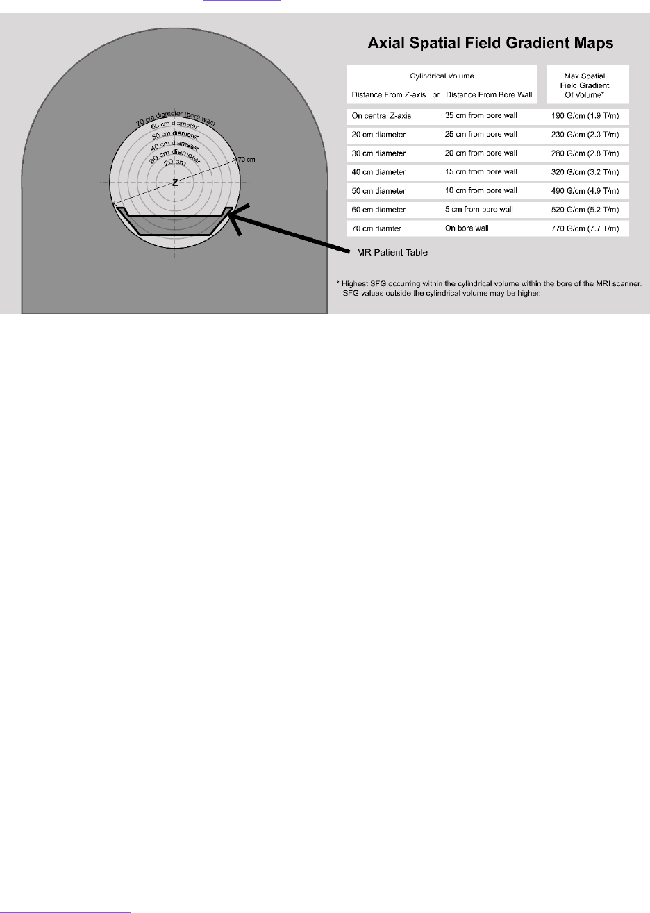
AMERICAN COLLEGE OF RADIOLOGY
Return to Table of Contents 59
Further information on how to evaluate SFG information provided by MR system manufacturers
for this purpose is provided in Appendix 5
.
Lenz effect. A conducting object experiencing a change in magnetic field will have a current
induced within the object that generates a magnetic field resisting that change. This resistive
effect can result in mechanical forces on the object. This has important consequences for MRI:
if an electrical conductor (i.e., an aluminum tray) is moved through the SFG of the static
magnetic field, voltages and currents will be generated within the conductor with a magnitude
directly proportional to the rate of motion as well as the regional SFG value. The current will
induce a secondary magnetic field oriented in opposition to the motion of the conductor, which
will exert an opposing force on its motion. Note that this will occur even if the conductor is
metallic but nonferromagnetic.
There are many scenarios in which these forces may pose concerns. For example, if a
nonferromagnetic metallic device such as an MR Conditional oxygen tank is moved toward the
bore of an MR scanner, as the scanner bore is approached, the force that arises from these Lenz
effects can be sufficiently strong to virtually stop forward progress of the device. Further, the
faster one moves the device into the bore, the greater the opposing force that is created to stop
this motion. There are also potential consequences for large implanted metallic devices. Even if
these devices do not pose projectile hazards, rapid motion of the patient/implant in a direction
perpendicular to the static magnetic field orientation can result in forces on the implant
opposing this motion that may be detected by the patient. If the patient were to complain of
experiencing forces tugging or pulling on the implant, this might lead to the patient or health
care personnel to erroneously conclude that the device has ferromagnetic components and
possibly canceling the examination. Slowly moving a patient with a relatively large metallic
FIGURE 11. Front view of an example SFG map of an MR system indicating maximum SFG values that may be
encountered within each of the cylindrical volumes within the diameter of the bore as a patient with an implant or
device enters/exits this particular magnet (black arrow, table top of the MR system).
(Image courtesy of Tobias Gilk of Gilk Radiology Consultants.)

AMERICAN COLLEGE OF RADIOLOGY
Return to Table of Contents 60
device into and out of the bore is a key factor in decreasing any Lenz effects that might be
induced, decreasing the likelihood of a misunderstanding or unnecessary study cancelation.
As Lenz effects are proportional to the rate of the object’s motion through an SFG, and as these
effects may be substantially higher at 7 T than 1.5 T or 3 T, these might bear special
reconsideration for metal objects or devices used in or around 7-T MR scanners such as
metallic aortic or mitral valve replacements [4].
Electrocardiograms (ECGs) are significantly
distorted within the bore of an MRI as a result of the magnetohydrodynamic (MHD) effect,
rendering those ECGs nondiagnostic and potentially inappropriate for cardiac gating. Magnetic
field–induced voltage in flowing blood in the descending aorta underlies the MHD
effect. Maximum blood flow in the descending aorta coincides temporally with the T wave on
the ECG. Due to this, ST segment elevation or depression in an ECG acquired while in the
magnet bore could mimic or obscure cardiac ischemia. The MHD can be associated with trace
resistance to cardiac output, not considered to be clinically significant [5-7].
KEY POINTS
Static magnetic field
o The strong static magnetic field associated with MRI can interact with
metallic objects, potentially turning ferromagnetic metals into dangerous
projectiles. Access to these fields (Zone IV) must be strictly
controlled. Personnel and devices entering this environment must be
thoroughly screened by Level 2 MR Personnel.
o The fringes of the static magnetic field above 9 gauss can interfere with
implanted medical devices, such as pacemakers or implantable cardioverter
defibrillators, resulting in potential injury or death. Access to these fields
(Zone III and IV) must be strictly controlled. Personnel entering this
environment must be screened by Level 2 MR Personnel.
o Metal devices and medical implants have defined limits for exposure to
maximal field strength and/or the SFG to prevent damage to the person
and/or device. MR operators should have access to, and understanding of,
vendor documents that describe these fields to safely manage both patients
and devices in the MR environment.
o The SFG changes markedly about the magnet bore edges (also see
Appendix
5 for further discussion).
Translational forces are greatest near the edge of the magnet where
the SFG is largest.
B
0
torque is greatest at the center of the magnet.

AMERICAN COLLEGE OF RADIOLOGY
Return to Table of Contents 61
Time-Varying Radiofrequency Magnetic Field
Electric fields induced by RF transmission and the subsequent B
1
magnetic field in MR are the
main sources of tissue heating and burns [8] (Figure 12
).
Focal heating during the MR examination can result in tissue burns. Most thermal injuries occur
on the skin of the upper extremities or torso, although they can occur virtually anywhere in the
body. Direct communication between the patient and the MR Technologist during the
examination is crucial because the patient may only experience minimal discomfort during the
MR exam. Direct inspection of the area of discomfort may reveal only minimal skin redness, but
thermal injury with blisters or even ulcers may yet develop within 24 hours after completion of
the MR examination. Unconscious patients and those with limited capacity to communicate are
at higher risk and require careful preparation prior to the MR exam.
A.

AMERICAN COLLEGE OF RADIOLOGY
Return to Table of Contents 62
B.
Whole-body heating: Quantitative considerations
Specific absorption rate, B
1
+
rms
, specific energy dose, and specific absorption. The dosimetric
term used to estimate the rate of absorption of RF energy by human tissue in MR is the specific
absorption rate (SAR), which is the mass-normalized rate at which RF power is coupled to
biological tissue. It is expressed in units of watts per kilogram (W/kg) on the MR system [9]. The
most commonly used SAR metric presented by the scanner is the whole body–averaged value
[10-12]. SAR is an estimation of the rate of energy absorption by the patient, not a total dose of
energy. The normal operating mode limits the whole-body SAR to less than 2 W/kg. The first
level control mode whole-body SAR is limited to be less than 4 W/kg. The SAR is a conservative
metric that is meant to estimate the dose received by the patient, which is extrapolated from
the B
1
+
rms
, the root-mean-square value of the transmitted B
1
RF energy averaged over 10
seconds. Total energy absorbed by the patient over the course of an exam is referred to as the
FIGURE 12. 3-D depiction of the transmitted RF (B
1
) oscillating magnetic fields in a 1.5-T MR scanner. The right side
of the scanner has been rendered transparent so that the energies/fields can be depicted as they are distributed 3-
dimensionally throughout the MR scanner bore. (A) The spatial distribution of the transmitted RF (B
1
) oscillating
magnetic fields with the body RF coil of this scanner being used as the RF transmitter hardware is depicted. (B) The
spatial distribution of the transmitted RF (B
1
) oscillating magnetic fields with a transmit-receive head RF coil being
used as the RF transmitter hardware is depicted. Note how the transmitted RF fields cover a smaller volume when a
transmit-receive head RF coil is used for RF transmission in this same scanner.
(Courtesy of Dr. Emanuel Kanal, created using MagnetVision, Advanced Magnetic Analytics, LLC)

AMERICAN COLLEGE OF RADIOLOGY
Return to Table of Contents 63
specific energy dose (SED). The SED is commonly reported in units of joules per kilogram or
kilojoules per kilogram. It is worth noting that recently the International Electrotechnical
Commission (IEC) renamed SED to specific absorption (SA), and this term may begin to appear
in MR safety literature and guidance documents [1].
The thermal load associated with an MR examination is a separate phenomenon from focal RF-
related thermal injury [9]. Although discomfort related to a high thermal load during MR may be
experienced by the patient, an actual burn does not occur if that load is sufficiently dissipated
over time and/or space. Various health conditions may impair an individual’s ability to manage a
thermal challenge during MRI, including cardiovascular disease, diabetes, fever, and large body
habitus. Medications, including diuretics, beta-blockers, calcium blockers, amphetamines, and
sedatives, can alter the patient’s thermoregulatory responses to a heat load [8,11]. Importantly,
certain medications may have a synergistic effect with RF radiation with respect to tissue
heating [8,11].
SAR limits are designed to avoid excessive RF-related tissue heating and burns, whereas SED
limits are intended to protect a patient from experiencing an excessive elevation in core
temperature or physiologic stress or discomfort related to inordinately high thermal loads from
long-duration and/or high-SAR pulse sequences (e.g., total spine or body exams).
The SED of an exam may be reduced with shorter pulse sequences and/or reduced RF pulse
strength, but sufficient rest and cooling-off periods between pulse sequences can ensure that
it is possible to safely scan the patient even with high total SED values. It should be noted that
although manufacturers have implemented SED limits on their MR scanners, limiting the SED of
an MR examination does not necessarily reduce the risks of a thermal injury (burns have
occurred in patients even when MR systems were operating within guidelines for RF power
deposition) [13-16].
The IEC permits each MR system manufacturer to conduct its own risk assessment and
structure criteria for MR system operator alerts, warnings, and/or “lockouts” as it deems
appropriate [1].
Therefore, depending on the software operating on the MR system, the scanner
may not present SED information (e.g., for older software versions); it may provide SED
warnings at predetermined intervals with or without a lockout, or it may provide warnings and
prevent additional scanning on a given patient for up to 24 hours if the MR system
manufacturer–defined maximum SED threshold is reached. MR health care professionals
should be aware of the SED procedure that a given MR system uses and understand the
context of alerts and possible scanning restrictions. If restrictions exist, it may be necessary to
modify the scanning protocol to successfully and safely complete the examination.
Specific thermal safety risks
Electrically conductive material–related burns. Electrical voltages and currents can be
induced within electrically conductive materials that are within the bore of the MR scanner
during the MRI exam. This might result in the heating of this conductive material by resistive
losses. This heat might be of a magnitude sufficient to cause injury to human tissue. Among the
variables that determine the amount of induced voltage or current is the consideration that the
larger the implant and/or the diameter of conductive loops, typically the greater the potential
for induced current that could result in a thermal injury to the patient.

AMERICAN COLLEGE OF RADIOLOGY
Return to Table of Contents 64
Transmitting RF coil-related proximity burns. To help safeguard against thermal injuries or
burns, pads meeting the MR system manufacturer’s specifications ensuring adequate distance
should be placed between the patient’s skin and any transmit RF coil [8,11,17]. These pads
ensure spacing between the transmit RF coil and the patient’s tissue, protecting against
proximity burns. Attention to the physical condition of insulating padding is recommended, as
with time, pads can degrade and become overly compressible such that their insulating
capacity is compromised, and a sufficient distance from the bore wall is not maintained. It is
important to emphasize that insulating pads are necessary; a single-layer bedsheet is
insufficient insulation or spacing to prevent burns (Figure 13
).
Conducted tissue loop–related burns. RF deposition can be exacerbated by electrically
conducting tissue loops within the patient’s body. If there is significant current induction, burns
can result when there are small areas of high resistance contact points where the energy is
dissipated as heat. Therefore, it is important to prevent electrically conductive current loops
that involve small areas of high resistance contact points such as between the patient’s finger
and a thigh, between small thigh-to-thigh contact areas, etc. The usage of supplied insulation
pads to help prevent induced tissue current loops is recommended [18].
Electrically conductive wires/leads. The concern for induced current loops is even greater
when electrically conductive wires or leads are involved. When electrically conductive material
(wires, leads, implants, etc.) are required to be entirely or partially within the volume undergoing
direct RF irradiation during MRI, care should be taken to ensure that no potentially dangerous
electrically conducting loops (including the patient’s tissue) are formed within the MR scanner
during imaging. There are several reports of serious injury, including coma and permanent
neurological impairment, in patients with implanted neurological stimulators who underwent
MR examinations. The injuries in these instances resulted from excessive heating of the
electrodes [19-23].
FIGURE 13. Example of a full thickness third degree burn that resulted from the MR bore proximity associated with
use of a worn-out insulating pad that was overly compressed (central circled area).

AMERICAN COLLEGE OF RADIOLOGY
Return to Table of Contents 65
To avoid potential thermal issues and injuries associated with RF fields, all unnecessary or
unused electrically conductive materials external to the patient should be removed from the
MR system before the onset of imaging [8]. It is insufficient to merely disconnect and leave
unused, unnecessary electrically conductive devices, such as surface RF coils or ECG leads and
electrodes, in the MR scanner with the patient during imaging. All electrical connections, such
as those used for surface RF coils or patient interfaces used for physiological monitoring
systems, must be visually checked by the scanning MR Technologist prior to each use to ensure
the integrity of the thermal and/or electrical insulation.
Resonant wavelength-related heating of conductors. The length, orientation, shape, position,
and inductance of any electrical conductor may be heated by the transmitted RF energy during
an MRI exam. Even if only part of a conductor is within range of the transmitted RF radiation,
substantial unsafe heating can result. While heating concerns generally increase with stronger
magnetic fields and longer conductors, specific conductor lengths, orientations, and other
settings can lead to resonant spikes in induced current.
Virtually any conductor lengths of more than a few centimeters can produce substantial
heating under certain conditions [24].
Internal. Very rapid and clinically significant internal lead heating can occur due to RF
deposition. Especially at the uninsulated lead tips, this can occur in a matter of seconds with a
magnitude sufficient to result in serious thermal injury [8]. Residual or abandoned implanted
leads or wires that are not connected to any other device are also prone to substantial heating
under certain conditions [25].
For example, while it has been demonstrated in vitro that the
heating of certain implants or wires may be clinically insignificant at 1.5 T but quite significant
at 3 T, the converse can also be true in some circumstances in which specific implants might
demonstrate no significant heating at 3 T/128 MHz but may heat to clinically significant levels
in seconds at 1.5 T/64 MHz [25]. Thus, it is important to follow established product MR
Conditional labeling and safety guidelines carefully and precisely, applying them to the static
magnetic field strengths and frequencies at which they have been tested. MR scanning at
either stronger and/or weaker magnetic field strengths than those tested may result in
significant heating in which no or insignificant heating had been observed at the tested field
strength(s).
For example, if MR Conditional labeling specifies 3 T, it cannot be assumed that
similar scanning parameters at 1.5 T are safe for the patient.
It is possible to substantially reduce RF exposure to implanted leads with the use of transmit-
receive RF coils located at distant anatomic sites relative to implanted devices. For example, a
patient with an abandoned spinal cord stimulator lead located a sufficient distance from the
head is likely able to safely undergo a head MRI using a transmit-receive head RF coil without
risk of RF heating of the stimulator. Other transmit-receive RF coils, including wrist, knee, ankle,
etc., may be used in similar situations to limit RF deposition to implanted devices and leads [26].
There are devices available that can be used to shape the RF-field, such as RF-shielding
blankets or RF shim pads. These can be potentially unsafe since electric fields are shifted to
their edges where there could be interaction with adjacent tissue (heating). These devices
should be used with caution and in accordance with their FDA approved instructions for use.
External. When any portion of electrically conductive materials external to the patient are
required to be within the volume of the transmitting RF coil during imaging, thermal insulation

AMERICAN COLLEGE OF RADIOLOGY
Return to Table of Contents 66
(including air, pads, etc.) should be placed between the patient and the electrically conductive
material to minimize any contact with the patient. It is also appropriate to position the leads or
wires as far as possible from the inner bore walls along the midline central long axis of the MR
scanner if the body RF coil is being used for RF transmission [27]. When it is necessary that
electrically conductive leads directly contact the patient during imaging, consideration should
be given to prophylactic application of cold compresses or sealed ice packs to such contact
areas. If using detachable transmit-receive coils (e.g., head, wrist, knee, etc.), the risk of the
heating of external leads can be substantially diminished [26,28].
Examples of RF field–associated burns are provided in Figure 14.
Special considerations for RF field–related thermal issues
Electrically conductive clothing
.
Some materials used in clothing have been increasingly
associated with thermal injury and/or burns in patients undergoing MRI. Recent trends in the
manufacturing of clothing and other related products have incorporated metallic and
conductive materials (e.g., antimicrobial silver and copper) that are not reliably disclosed in
labeling [29]. Such clothing products include, but are not limited to, sportswear (including
A
B
C
D
FIGURE 14. Examples of serious tissue burns resulting from RF-related heating during MRI exams. (A) Healing third
degree burn at patient’s knee. (B) Reenactment of path of an arterial pressure transducer extension cable within the
RF field that crossed an anesthetized patient’s knee during an interventional MR procedure. Subsequent testing
with the cable in that configuration demonstrated that the turbo spin-echo pulse sequences with whole body–
averaged SARs of approximately 2 W/kg produced localized heating approaching 30° Celsius. (C) Skin burns caused
by ECG electrode lead heating during MRI. The reader is referred to [25] for details. Figure used with permission. (D)
Third degree burn resulting from RF-related heating of a material (i.e., cell phone)
courtesy of Frank G. Shellock, PhD.

AMERICAN COLLEGE OF RADIOLOGY
Return to Table of Contents 67
underwear), brassieres, orthotic-related items (e.g., stump covers or stump shrinkers), and
blankets [8,30].
Reliance on clothing labeling is not sufficient, as the Federal Trade Commission
guidelines allow clothing to contain impurities at levels as high as 5%, which could be
significant for a patient undergoing an MR examination [31].
For anatomic regions within or near
the volume undergoing direct RF (B
1
) field irradiation, to avoid such thermal concerns, we
recommend gowning patients to skin, wearing only MR Safe pocketless garments supplied by
the imaging facility.
Skin staples, multiple dermal implants, or piercings in proximity to each other. In general,
although the thermal risks associated with individual small dermal implants (i.e., skin staples,
superficial metallic sutures, piercings that cannot be removed) are quite small, dermal implants
that are in close proximity or directly contact one another may increase the risk of thermal
injury. If the items are inside the MR bore and the built-in body coil is being used for
transmission, several precautions are recommended.
a. The patient should be instructed to report immediately if they experience warmth or
burning sensations during the study by verbally alerting the technologist or using
the technologist notification device (i.e., squeeze ball) and not wait until the end of
the MR sequence.
b. The application of cold compresses or sealed ice packs may be helpful.
Alternatively, the use of a transmit-receive RF coil may be used to avoid RF irradiation of the
dermal implants in a different part of the body inside the bore of the scanner (e.g., transmit-
receive RF head coil for a brain MRI exam in a patient with unremovable umbilical piercings).
Patients with tattoos within range of RF transmission. Extensive, dark, or loop-shaped tattoos
or tattooed eyeliner may increase the potential for RF heating. Patients should be instructed to
immediately report any discomfort during scanning. If appropriate, the placement of cold
compresses or sealed ice packs should be considered. Parenthetically, although not an RF
thermal concern, patients with tattoos that had been placed within 48 hours prior to the
pending MR examination should be advised of the potential for a smearing or smudging of the
edges of the freshly placed tattoo [32-36].
Drug-delivery patches and pads
.
Some drug-delivery patches contain metallic components.
Scanning patients with such medication patches may result in thermal injury or alteration in
drug-delivery rate by heating if the patch is within the volume of RF irradiation [37]. Options are
to remove the patch, use a transmit-receive RF coil to scan a different anatomic region, or
perform the MRI exam using low whole-body average SAR pulse sequences. Clinical
implications of patch removal need to be assessed and reviewed by a Level 2 MR Physician.
In the case of clinically important drug-delivery patches, removal or repositioning may be
considered following a consultation with the patient’s prescribing physician. If the patch for a
prescription medication is removed, an appropriate process must be in place to replace the
medication (particularly for drugs that may cause undesired clinical symptoms or complications
if not replaced in a timely manner).
An option to consider could include placing a cold compress or sealed ice pack directly on the
medication patch, recognizing this could substantially alter the rate of delivery or absorption of
the medication and possibly be less comfortable for the patient.

AMERICAN COLLEGE OF RADIOLOGY
Return to Table of Contents 68
KEY POINTS
Time-varying RF magnetic field
o RF burns are the most commonly reported adverse events in MR.
o Remove all removable electrically conductive materials from the patient prior
to imaging.
o Insulation and appropriate distance should be placed between the patient
and any external conductive material, including the bore wall.
o Avoid large diameter electrically conducting loops, including patient tissue.
o Avoid skin-to-skin contact, especially small contact areas, completing large
caliber body loops.
o Currents can be induced within conductive materials.
Any conductor of more than a few centimeters may produce
substantial heating, which may increase rapidly depending on its
specific length, orientation, and position due to resonant heating.
• Follow established product MR Conditional labeling and
safety guidelines carefully and precisely.
• Position any leads or wires as far as possible from the inner
bore walls along the midline central long axis of the MR
scanner if the body coil is being used for RF transmission.
Metallic clothing can cause injury.
• Reliance on clothing labeling is not sufficient.
• MR Safe pocketless garments supplied by the facility are
recommended.
Dermal implants that are in close proximity or directly contacting one
another may increase the risk of thermal injury.
• Tattoos can heat.
• Consider cold compresses.
Drug-delivery patches can contain metallic components, which may
result in thermal injury and/or alterations in drug-delivery rate.
MR Conditional labeling at a specified field strength does not imply
MR conditions at other field strengths.
Detachable transmit-receive coils can reduce the risk of heating in
specific clinical scenarios.
o SAR estimates the rate of absorption of RF energy.
SAR limits are designed to manage RF heating of tissue.
Normal Operating Mode can reduce the risk of whole-body heating
but does not necessarily eliminate the risk of burns.
First Level Controlled Operating Mode may increase risk and requires
medical supervision (see discussion of Operating Modes in PNS
)
o SED refers to total energy absorbed.
SED limits are a means to protect a patient from adverse events
related to core temperature elevation over time.
Shorter sequence length and cooling-off periods between sequences
can reduce risk.
SA is a newer synonymous term that may replace SED.

AMERICAN COLLEGE OF RADIOLOGY
Return to Table of Contents 69
Time-Varying Gradient Magnetic Field
Spatial localization of MR signal employs time-varying gradient magnetic fields that are rapidly
alternated and varied over time and are often described by their temporal rate of change, dB/dt.
A sample time-varying gradient magnetic field is shown in Figure 15
; these fields can vary with
pulse sequences employed, and so associated safety considerations should be recognized on
an exam-specific (and implant-specific) basis.
Auditory considerations. Acoustic noise is generated by the switching of the time-varying
gradient magnetic fields. It is recommended that all patients and research volunteers use
hearing protection when appropriate [38]. MRI sequences that are not FDA cleared should not
be performed on patients or research volunteers without hearing protection in place. The FDA
considers MRI systems capable of producing sound pressures that exceed 99 A-weighted
decibels (dB(A)) with hearing protection in place as a significant risk [12]. The IEC standard on
this issue (IEC 60601-2-33:2022) [1]
also states that, for all equipment capable of producing
more than an A-weighted root-mean-square sound pressure level of 99 dB(A), hearing
protection should reduce the sound pressure level below that threshold for the safety of the
FIGURE 15. 3-D depiction of the time-varying gradient magnetic fields dB/dt in a 1.5-T MR scanner. The near side of
the scanner has been rendered transparent so that the energies/fields can be depicted as they are distributed 3-
dimensionally throughout the MR scanner bore and room. The strength and spatial distribution of the time-varying
gradient magnetic fields dB/dt is depicted. Note that when the patient’s brain is positioned at the MR isocenter, the
greatest dB/dt values are over the chest of this patient, right where a cardiac pacemaker might be positioned.
(Courtesy of Emanuel Kanal, MD, created using MagnetVision, Advanced Magnetic Analytics, LLC)

AMERICAN COLLEGE OF RADIOLOGY
Return to Table of Contents 70
patient. Hearing protection frequently needs to be in excess of 28 to 30 dB(A) given the
loudness of some contemporary magnets and sequences. Manufacturer instructions for use
should provide at least the minimum appropriate level of hearing protection.
It is important that staff are thoroughly trained on the proper placement of ear plugs and use of
other types of hearing protection. Staff should work with all persons receiving the hearing
protection to ensure proper placement and to verify fit and function of the hearing protection
prior to the MR examination. Hearing must be adequately protected concurrent with being able
to adequately hear patient instructions, etc. In the event a patient refuses hearing protection,
sites should have a process and procedure in place to discuss the risks of proceeding without
the protection and may consider canceling the examination.
All patients or research volunteers in whom research sequences are to be performed (i.e., MR
scan sequences that have not yet been cleared by the FDA) should also have hearing protective
devices in place prior to initiating any MR sequences.
Peripheral neural stimulation. Nerve and muscle cells can be stimulated by currents induced
by the time-varying gradient magnetic field. The resulting sensation ranges from tingling to
muscle contractions and generally presents minimal discomfort or danger to the patient. The
magnitude of the stimulation is a function of the pulse characteristics and repetition rate.
Concerns related to this are addressed in the IEC standard 60601-2-33 [1], which defines
different scanning modes. Clinical scanners are usually restricted to the Normal Operating
Mode and the First Level Controlled Operating Mode.
The IEC standard 60601-2-33 [1] defines 3 modes for scanning:
1. Normal Operating Mode: mode of operation of the MR equipment in which none
of the outputs has a value that may cause physiologic stress to patients.
(Outputs refer to the magnitude of the magnetic fields.)
2. First Level Controlled Operating Mode: mode of operations of the MR equipment
in which 1 or more outputs reach a value that may cause physiologic stress to
patients that needs to be controlled by medical supervision.
a. Software allowing access to this mode must require specific
acknowledgement by the operator that the First Level Controlled
Operating Mode has been entered.
3. Second Level Controlled Operating Mode: mode of operation of the MR
equipment in which 1 or more outputs reach a value that may produce significant
risk for patients in which explicit ethical approval is required (i.e., a human
subject research protocol approved to local requirements).
In Normal Operating Mode, the gradient system shall operate at a level that does not exceed
80% of the mean threshold for peripheral neural stimulation (PNS), in which the threshold for
PNS is defined as the onset of sensation.
In First Level Controlled Operating Mode, the gradient system shall operate at a level that does
not exceed 100% of the directly determined mean threshold for PNS.
Induced voltages. Patients with implanted or retained wires and leads in anatomically or
functionally sensitive areas (e.g., myocardium, implanted electrodes in the brain, adjacent to the
spinal cord, etc.) should be considered higher risk, especially from faster MRI pulse sequences

AMERICAN COLLEGE OF RADIOLOGY
Return to Table of Contents 71
such as echo-planar imaging (i.e., often used with diffusion-weighted imaging), functional
imaging, perfusion-weighted imaging, MR angiographic imaging, etc. that require a rapid
variation of the gradient magnetic fields. These risks include whether the lead/wire is directly
exposed to the time-varying gradient magnetic fields or may be part of an anticipated induced
current pathway. The decision to alter the rate of magnetic field change (dB/dt) and the
maximum strength of the magnetic field of the gradient subsystems during the imaging of such
patients should be reviewed by the Level 2 MR Physician supervising the patient with attention
to the MR conditions of scanning.
Additionally, time-varying gradient magnetic field–induced voltages can potentially be induced
in implanted devices, possibly causing implant vibration, active device
damage/malfunction/incorrect sensing, or even device and tissue heating [39-41].
KEY POINTS
Time-varying gradient magnetic field (dB/dt)
o The rapidly switched magnetic field gradients used during imaging may result
in uncomfortable or painful PNS. MRI operators can reduce the probability of
PNS by employing Normal Operating Mode for dB/dt versus First Level
Controlled Operating Mode.
o The rapid switching of this field can also result in peak acoustic noise in the
MR suite, requiring appropriately positioned hearing protection to minimize
discomfort and the potential for auditory damage.
o Additionally, devices and implants in this field may experience induced
voltages, vibration, damage, and (in some cases) additional heating. MR
operators should be able to understand and apply recommended dB/dt limits
for devices using information provided by the MR vendor.

AMERICAN COLLEGE OF RADIOLOGY
Return to Table of Contents 72
References
1. International Electrotechnical Commission. Medical electrical equipment — Part 2-33: Particular
requirements for the safety of magnetic resonance equipment for medical diagnosis. 4th ed. Published
August 4, 2022. Accessed April 22, 2024. https://webstore.iec.ch/publication/67211
2. Shellock FG, Woods TO, Crues JV III. MR labeling information for implants and devices: explanation of
terminology. Radiology. 2009;253(1):26-30. doi: 10.1148/radiol.2531091030.
3. Shellock FG, Kanal E, Gilk TB. Regarding the value reported for the term “spatial gradient magnetic field” and
how this information is applied to labeling of medical implants and devices. AJR Am J Roentgenol.
2011;196(1):142-145. doi: 10.2214/AJR.10.5004
4. Hoff MN, McKinney At, Shellock FG, et al. Safety Considerations of 7-T MRI in Clinical Practice. Radiology.
2019;292(3):509-518. doi: 10.1148/radiol.2019182742
5. Edwards MB, McLean J, Solomonidis S, Condon B, Gourlay T. In vitro assessment of the Lenz effect on heart
valve prostheses at 1.5 T. J Magn Reson Imaging. 2015;41(1):74-82. doi: 10.1002/jmri.24547
6. Krug JW, Rose G. Magnetohydrodynamic distortions of the ECG in different MR scanner configurations.
Paper presented at: 2011 Computing in Cardiology; September 18-21, 2011; Hangzhou, China.
KEY ABBREVIATIONS
B
0
: static magnetic field
B
1
: time-varying radiofrequency magnetic field
B
1
+
rms
: radiofrequency magnetic field + root mean
square
dB(A): A-weighted decibels
dB/dt: time-varying gradient magnetic field
ECG: electrocardiogram
FDA: Food and Drug Administration
G/cm: gauss per centimeter
IEC: International Electrotechnical Commission
MHz: megahertz
MHD: magnetohydrodynamic
PNS: peripheral nerve stimulation
RF: radiofrequency
SA: specific absorption
SAR: specific absorption rate
SED: specific energy dose
SFG: spatial field gradient
T/m: tesla per meter

AMERICAN COLLEGE OF RADIOLOGY
Return to Table of Contents 73
7. Jekic M, Ding Y, Dzwonczyk R, Burns P, Raman SV, Simonetti OP. Magnetic field threshold for accurate
electrocardiography in the MRI environment. Magn Reson Med. 2010;64(6):1586-1591. doi: 10.1002/mrm.22419
8. Shellock FG. Chapter 8: Radiofrequency-energy induced heating during MRI: laboratory and clinical
experiences. In: Shellock FG, Crues JV III, eds. MRI Bioeffects, Safety, and Patient Management. 2nd ed.
Biomedical Research Publishing Group; 2022:233-253.
9. Bottomley PA, Edelstein WA. Power deposition in whole-body NMR imaging. Med Phys. 1981;8(4):510-512. doi:
10.1118/1.595000
10. Shellock FG, Crues JV. Temperature, heart rate, and blood pressure changes associated with clinical MR
imaging at 1.5 T. Radiology. 1987;163(1):259-262. doi: 10.1148/radiology.163.1.3823445
11. Shellock FG. Radiofrequency energy-induced heating during MR procedures: a review. J Magn Reson Imaging.
2000;12(1):30-36. doi: 10.1002/1522-2586(200007)12:1<30::aid-jmri4>3.0.co;2-s.
12. US Food and Drug Administration. Criteria for significant risk investigation of magnetic resonance diagnostic
devices - guidance for industry and Food and Drug Administration staff. Published June 20, 2014. Accessed
April 22, 2024.
https://www.fda.gov/regulatory-information/search-fda-guidance-documents/criteria-
significant-risk-investigations-magnetic-resonance-diagnostic-devices-guidance-industry-and
13. Shellock FG. Reference Manual for Magnetic Resonance Safety, Implants, and Devices. 2020 ed. Biomedical
Research Publishing Group; 2020.
14. Shellock FG, Schaefer DJ, Crues JV. Alterations in body and skin temperatures caused by magnetic
resonance imaging: is the recommended exposure for radiofrequency radiation too conservative? Br J Radiol.
1989;62(742):904-909. doi: 10.1259/0007-1285-62-742-904.
15. Shellock FG, Schaefer DJ, Kanal E. Physiologic responses to an MR imaging procedure performed at a
specific absorption rate of 6.0 W/kg. Radiology. 1994;192(3):865-8. doi: 10.1148/radiology.192.3.8058962
16. Boss A, Graf H, Berger A, et al. Tissue warming and regulatory responses induced by radio frequency energy
deposition on a whole-body 3-Tesla magnetic resonance imager. J Magn Reson Imaging. 2007;26(5):1334-
1339. doi: 10.1002/jmri.21156
17. Tsai LL, Grant AK, Mortele KJ, Kung JW, Smith MP. A practical guide to MR imaging safety: what radiologists
need to know. Radiographics. 2015;35(6):1722-1737. doi: 10.1148/rg.2015150108
18. Knopp MV, Essig M, Debus J, Zabel HJ, van Kaick G. Unusual burns of the lower extremities caused by a
closed conducting loop in a patient at MR imaging. Radiology. 1996;200(2):572-575. doi:
10.1148/radiology.200.2.8685360
19. Gandhi OP, Chen XB. Specific absorption rates and induced current densities for an anatomy-based model of
the human for exposure to time-varying magnetic fields of MRI. Magn Reson Med. 1999;41(4):816-823. doi:
10.1002/(sici)1522-2594(199904)41:4<816::aid-mrm22>3.0.co;2-5
20. Konings MK, Bartels LW, Smits HF, Bakker CJ. Heating around intravascular guidewires by resonating RF
waves. J Magn Reson Imaging. 2000;12(1):79-85. doi: 10.1002/1522-2586(200007)12:1<79::aid-jmri9>3.0.co;2-t
21. Rezai AR, Phillips M, Baker K, et al. Neurostimulation system used for deep brain stimulation (DBS): MR
safety issues and implications of failing to follow guidelines. Invest Radiol. 2004;39(5):300-303. doi:
10.1097/01.rli.0000124940.02340.ab
22. Henderson JM, Tkach J, Phillips M, Baker K, Shellock FG, Rezai AR. Permanent neurological deficit related to
magnetic resonance imaging in a patient with implanted deep brain stimulation electrodes for Parkinson’s
disease: case report. Neurosurgery. 2005;57(5):E1063. doi: 10.1227/01.neu.0000180810.16964.3e
23. Rezai AR, Baker K, Tkach J, et al. Is magnetic resonance imaging safe for patients with neurostimulation
systems used for deep brain stimulation? Neurosurgery. 2005;57(5):1056-1062. doi:
10.1227/01.neu.0000186935.87971.2a
24. US Food and Drug Administration. Testing and labeling medical devices for safety in the magnetic resonance
(MR) environment: guidance for industry and Food and Drug Administration staff. Published October 10,
2023. Accessed April 22, 2024.
https://www.fda.gov/regulatory-information/search-fda-guidance-
documents/testing-and-labeling-medical-devices-safety-magnetic-resonance-mr-environment
25. Langman DA, Goldberg IB, Finn JP, Ennis DB. Pacemaker lead tip heating in abandoned and pacemaker-
attached leads at 1.5 Tesla MRI. J Magn Reson Imaging. 2011;33(2):426-431. doi: 10.1002/jmri.22463

AMERICAN COLLEGE OF RADIOLOGY
Return to Table of Contents 74
26. Nagy Z, Oliver-Taylor A, Kuehne A, Goluch S, Weiskopf N. Tx/Rx head coil induces less RF transmit-related
heating than body coil in conductive metallic objects outside the active area of the head coil. Front Neurosci.
2017;11:15. doi: 10.3389/fnins.2017.00015
27. Brix L, Isaksen C, Bh K, Tufa D. Third degree skin burns caused by a MRI conditional electrocardiographic
monitoring system. J Radiol Imaging. 2016;1(4):29-32. doi: 10.14312/2399-8172.2016-7
28. Kanal E. Standardized Approaches to MR Safety Assessment of Patients with Implanted Devices. Magn
Reson Imaging Clin N Am. 2020;28(4):537-548. doi: 10.1016/j.mric.2020.07.003
29. Pietryga JA, Fonder MA, Rogg JM, North DL, Bercovitch LG. Invisible metallic microfiber in clothing presents
unrecognized MRI risk for cutaneous burn. AJNR Am J Neuroradiol. 2013;34(5):E47-50. doi: 10.3174/ajnr.A2827
30. Bertrand A, Brunel S, Habert MO, et al. A New Fire Hazard for MR Imaging Systems: Blankets-Case Report.
Radiology. 2018;286(2):568-570. doi: 10.1148/radiol.2017162921
31. Federal Trade Commission. Threading your way through the labeling requirements under the textile and wool
acts. Published July 2014. Accessed April 22, 2024.
https://www.ftc.gov/tips-advice/business-
center/guidance/threading-your-way-through-labeling-requirements-under-textile
32. Wagle WA, Smith M. Tattoo-induced skin burn during MR imaging. AJR Am J Roentgenol. 2000;174(6):1795.
doi: 10.2214/ajr.174.6.1741795
33. Franiel T, Schmidt S, Klingebiel R. First-degree burns on MRI due to nonferrous tattoos. AJR Am J Roentgenol.
2006;187(5):W556. doi: 10.2214/AJR.06.5082
34. Ratnapalan S, Greenberg M, Armstrong D. Tattoos and MRI. AJR Am J Roentgenol. 2004;183(2):541. doi:
10.2214/ajr.183.2.1830541
35. Ross JR, Matava MJ. Tattoo-induced skin “burn” during magnetic resonance imaging in a professional football
player: a case report. Sports Health. 2011;3(5):431-434. doi: 10.1177/1941738111411698
36. Callaghan MF, Negus C, Leff AP, et al. Safety of tattoos in persons undergoing MRI. N Engl J Med.
2019;380(5):495-496. doi: 10.1056/NEJMc1811197
37. US Food and Drug Administration. Risk of burns during MRI scans from the transdermal drug patches with
metallic backings. Published March 5, 2009. Accessed April 22, 2024.
https://wayback.archive-
it.org/7993/20170111190504/http://www.fda.gov/Drugs/DrugSafety/PostmarketDrugSafetyInformationfor
PatientsandProviders/ucm111313.htm
38. McJury M. Chapter 6: Acoustic noise and MRI procedures. In: Shellock FG, Crues JV III, eds. MRI Bioeffects,
Safety, and Patient Management. 2nd ed. Biomedical Research Publishing Group; 2022:157-207.
39. Fuhrer E, Jouda M, Klein CO, Wilhelm M, Korvink JG. Gradient-induced mechanical vibration of neural
interfaces during MRI. IEEE Trans Biomed Eng. 2020;67(3):915-923. doi: 10.1109/TBME.2019.2923693
40. Wooldridge J, Arduino A, Zilberti L, et al. Gradient coil and radiofrequency induced heating of orthopaedic
implants in MRI: influencing factors. Phys Med Biol. 2021;66(24). doi: 10.1088/1361-6560/ac3eab
41. Zanovello U, Fuss C, Arduino A, Bottauscio O. Efficient prediction of MRI gradient-induced heating for guiding
safety testing of conductive implants. Magn Reson Med. 2023;90(5):2011-2018. doi: 10.1002/mrm.29787

AMERICAN COLLEGE OF RADIOLOGY
Return to Table of Contents 75
CHAPTER 9:
MR Contrast Agents
No patient is to be administered prescription MR contrast agents, typically gadolinium-based
contrast media (GBCM), without orders from a licensed physician or advanced practice provider
practicing under a supervising physician [1]. Research study participants may receive MR
contrast agents as directed by the study protocol after they agree to enroll in the study that
has undergone ethics committee (i.e., institutional review board) approval and sign the
appropriate informed consent (and assent, as appropriate). Qualified MR Personnel may
establish and attend peripheral intravenous (IV) access lines if they have undergone the
requisite site-specified training in peripheral IV access and have demonstrated and
documented appropriate proficiency in this area. IV injection–qualified MR Personnel may
administer MR GBCMs via peripheral IV routes as a bolus or slow or continuous injection as
directed by the orders of a licensed site physician or advanced practice provider.
Practices relating to the administration of these agents and recommendations regarding GBCM
usage, adverse reactions, nephrogenic systemic fibrosis, and retained or residual gadolinium in
the body should follow the ACR Committee on Drugs and Contrast Media [2]. The most recent
version of the ACR Manual on Contrast Media
may be downloaded from the ACR website at
Contrast Manual | American College of Radiology (acr.org).
References
1. American College of Radiology; Society for Pediatric Radiology. ACR-SPR practice parameter for the use of
intravascular contrast media. Published 2022. Accessed April 22, 2024.
https://www.acr.org/-
/media/ACR/Files/Practice-Parameters/IVCM.pdf
2. ACR Committee on Drugs and Contrast Media. ACR Manual on Contrast Media. American College of
Radiology; 2023. https://www.acr.org/-/media/ACR/Files/Clinical-Resources/Contrast_Media.pdf
KEY POINTS
No patient is to be administered prescription MR contrast agents without orders
from a licensed physician or advanced practice provider.
Practices relating to the administration of these agents and recommendations
regarding GBCM usage, adverse reactions, nephrogenic systemic fibrosis, and
retained or residual gadolinium in the body should follow the
Contrast Manual |
American College of Radiology (acr.org).
KEY ABBREVIATIONS
ACR: American College of Radiology
APP: advanced practice provider
GBCM: gadolinium-based contrast media
IV: intravenous

AMERICAN COLLEGE OF RADIOLOGY
Return to Table of Contents 76
CHAPTER 10:
Classification of Objects and Medical Implants and
Devices in The MR Environment
This chapter will focus on the classification of materials/objects in the MR environment and
ensuring safety. These fall into 2 major categories:
1. Patient support equipment and portable items such as ventilators, physiological
monitors, anesthesia machines, infusion pumps, intravenous poles, wheelchairs, step
stools, and others. Chapter 11
provides additional information on these objects and
equipment.
2. Medical devices directly related to the patient, including implanted devices (e.g., cardiac
pacemakers, aneurysm clips, etc.) as well as on-planted devices (external insulin pumps,
continuous glucose monitoring devices, etc.). Several implanted devices are discussed in
detail in Chapter 12
.
Items that are not required for the care of a patient during the acquisition of their MRI
examination should not enter Zone IV until the patient has been removed fully from the scanner
room.
Recognizing the manufacturer’s MR safety labeling, as part of the Zone III site restriction and
equipment testing and clearing responsibilities, all sites should have ready access to a strong
handheld magnet (>1000 G) and/or a ferromagnetic detection system. This will enable the site
to test external, and even some superficial internal, devices or implants for the presence of
grossly detectable ferromagnetic attractive forces. The use of conventional metal detectors
that do not differentiate between ferromagnetic and nonferromagnetic materials is not
recommended.
MR Safety Labeling Classifications
Throughout this manual, the standard MR labeling terms (MR Safe, MR Conditional, and MR
Unsafe) designated by American Society for Testing Materials (ASTM) International, ASTM
F2503-23 Standard Practice for Marking Medical Devices and Other Items for Safety in the MR
Environment, [1] and adopted by the FDA (Figure 16
) are used. These designations can apply to
objects peripheral to the patient as well as implanted/on-planted devices.
Particularly with regard to nonclinical and incidental equipment, current products marketed
with ill-defined terminology such as nonmagnetic or outdated classifications such as MR
compatible should not be presumed to conform to a particular current ASTM International and
FDA classification. Similarly, any product with metallic construction or components cannot by
definition be MR Safe and must be considered as MR Unsafe or possibly MR Conditional.
Objects intended for use in Zone IV, including nonclinical incidental products such as step
stools or ladders, which are not accompanied by manufacturer or third-party MR safety test
results under the ASTM International Standard F2503 criteria, should be site tested as
described in MR Conditional.

AMERICAN COLLEGE OF RADIOLOGY
Return to Table of Contents 77
MR Safe .
A designation indicating that the object or device is safe in all MR environments,
without conditions. The term “MR Safe” is reserved for items that are composed of materials
that are nonmetallic, nonconducting, and nonmagnetic; such objects pose no known hazards
during or resulting from exposure to any MR environment.
MR Conditional . A designation indicating that the object or device has been demonstrated
to be safely used within the MR environment, provided the specified conditions for safe use (as
provided by the manufacturer) are met. When making decisions based on published MR
Conditional or safety claims, one should recognize that all such claims only apply to the tested
precise model, make, and identification of the object/item as tested to be safe under the
specified conditions within the MR environment; these include the defined conditions for the
tested static magnetic field strength (B
0
) and spatial field gradient strengths, the
radiofrequency fields (B
1
), and the time-varying gradient magnetic fields (dB/dt). An example is
provided in the statement, “MR Conditional having been tested to be safe at 3 T for a maximum
spatial field gradient of 30 T/m (3000 G/cm) or less and the Normal Operating Mode (regarding
RF output).”
Implant or device MR safety information must be documented in writing or in the medical
record. Decisions based on published MR safety information should recognize that all safety
claims regarding MR Conditional devices apply only to specifically tested conditions, such as
the static magnetic field strength (B
0
), the exposure of the device to the spatial field gradient,
the strength and duration of the transmitted radiofrequency field (B
1
), and the rate of change of
the time-varying gradient magnetic fields (dB/dt).
FIGURE 16. FDA labeling criteria developed by ASTM International for objects and devices taken into Zone IV [1,2].
The square green MR Safe label is for nonmetallic, nonconducting objects; the triangular yellow label is for objects
with MR Conditional labeling; and the round red label is for MR Unsafe objects. Alternatively, these symbols may be
printed as black and white icons [1,2].

AMERICAN COLLEGE OF RADIOLOGY
Return to Table of Contents 78
TABLE 4. A summary of common MR safety conditions specified in the device vendor
instructions for use
Example specified
conditions
Example values for generic active implanted medical device
(whole-body transmit)
Device
Allowed devices
Implantable pulse generator (IPG) and lead model(s)
Allowed configurations
Allowed IPG and lead model combination(s) for all conditions
that follow
Implant configuration
IPG in upper buttock, low back, flank, abdomen, or midline Lead
tip in the epidural space between the T7 and T12 vertebrae
Device status
Make sure IPG and patient controller fully charged
No broken leads and lead impedance within specified
parameters
Device mode
Set device to the MRI Mode
MR system
Configuration
Field strength(s)
Cylindrical bore with horizontal field
1.5 T or 3.0 T
Maximum spatial field
gradient
25 mT/m (2500 gauss/cm)
Maximum gradient slew
rate
200 T/m/s (per axis)
Radiofrequency (RF)
transmit equipment
Frequency
Hydrogen (
1
H) nuclei only
RF coil(s)
Integrated whole-body transmit
RF transmit mode
Circularly polarized or Multichannel-2 (MC-2)
Scan regions
Any landmark acceptable
RF exposure
(For specific IPG and lead model combinations)
Anatomic scan region A
Isocenter superior to C7
RF output limits
For 1.5-T MR scanner: Normal Operating Mode (whole-body
specific absorption rate (SAR) <2 W/kg)
For 3.0-T MR scanner: Normal Operating Mode (whole-body
SAR <2 W/kg)
Anatomic scan region B
Isocenter inferior to C7

AMERICAN COLLEGE OF RADIOLOGY
Return to Table of Contents 79
RF output limits
For 1.5-T MR scanner: Normal Operating Mode (whole-body SAR
<2 W/kg)
For 3.0-T MR scanner: B
1
+
rms
<1.7 mT or whole-body SAR <1.2
W/kg
Scan duration
Active scan time <30 minutes per session with 30 minutes
between sessions
Receive RF coil
Any
Image artifacts
Signal loss expected up to 5 cm from IPG using a spin-echo
acquisition
Some manipulation of scan parameters may be needed to
compensate
Patient
Positioning/orientation
Thermoregulatory status
Supine or prone
Patient should not have a fever. Do not cover patient with a
blanket
Cognitive status
Patient can notify MR Personnel immediately if any discomfort,
pain, heating, stimulation, or vibration is experienced
Monitoring
Visually and audibly monitor the patient, including verbal
communication
NOTE: The table is populated with example values for safely scanning a patient with a generic active implanted
medical device that has leads (e.g., neuromodulation system, pacemaker, defibrillator, etc.) that has conditions for
full-body imaging. This example is intended to highlight key conditions and not represent any specific device [2].
MR Unsafe . An item which poses unacceptable risks to the patient, medical staff, or other
persons within the MR environment.
Object/device alteration. Alterations performed by the facility on MR Safe, MR Unsafe, and
MR Conditional equipment or devices may change the MR safety properties of the device. For
example, tying a ferromagnetic metallic twisting wire/binder onto a sign labeling the device as
MR Conditional or MR Safe might result in safety issues or image artifacts if introduced into the
MR scanning environment. It is critical to always establish that immediately following repairs or
modifications or maintenance of MR Conditional object/items/devices, these items are again
confirmed to be safe within the MR environment as defined under the originally specified
testing conditions. Hence, maintenance and repair of MR Conditional devices must include
reconfirmation of the MR Conditional labeling information.

AMERICAN COLLEGE OF RADIOLOGY
Return to Table of Contents 80
References
1. American Society for Testing Materials International. Standard practice for marking medical devices and
other items for safety in the magnetic resonance environment. Published October 24, 2023. Accessed April
22, 2024. doi: 10.1520/F2503-23E01
2. US Food and Drug Administration. Testing and labeling medical devices for safety in the magnetic resonance
(MR) environment: guidance for industry and Food and Drug Administration staff. Published October 10,
2023. Accessed April 22, 2024.
https://www.fda.gov/regulatory-information/search-fda-guidance-
documents/testing-and-labeling-medical-devices-safety-magnetic-resonance-mr-environment
KEY POINTS
Classifications
o MR Safe: the object or
device is safe in all MR
environments (must be
nonmetallic, nonconducting,
and nonmagnetic).
o MR Conditional: the object
or device may be safe in the
MR environment if
conditions for safe use are
met.
o MR Unsafe: the object or
device presents safety risks
in the MR environment.
KEY ABBREVIATIONS
ASTM: American Society for Testing
Materials
B
0
: static magnetic field
B
1
: time-varying radiofrequency
magnetic field
B
1
+
rms
: radiofrequency magnetic field +
root mean square
dB/dt: time-varying gradient magnetic
field
FMDS: ferromagnetic detection
systems
FDA: Food and Drug Administration
G: gauss
G/cm: gauss per centimeter
IFU: instructions for use
IPG: implantable pulse generator
MC: multichannel
mT: millitesla

AMERICAN COLLEGE OF RADIOLOGY
Return to Table of Contents 81
CHAPTER 11:
Introducing Portable Metallic Objects and Equipment
Into Zone III and Zone IV
Labeling and Testing
All sites should have ready access to a strong handheld magnet (>1000 G) and/or a
ferromagnetic detection device for testing purposes.
All
portable
metallic or partially metallic objects intended to be stored/located in Zone III/IV are
to be properly labeled as MR Unsafe or MR Conditional prior to permitting them into
Zone III when practical based on size/mass (e.g., pens, paperclips).
Never assume an MR Conditional or MR Safe status of an object unless it has been tested. The
results of such testing, as well as the date, time, name of the tester, and methodology used for
that particular object, should be documented in writing. If an object has not been tested or if its
MR safety status is unknown, it should not be permitted unrestricted access into Zone III.
Zone III areas typically house electrically active stationary computers, printers, etc., that are not
intended to enter Zone IV. MR safety testing and labeling are not required for such stationary
items.
The testing of objects that are not electrically activated (e.g., fire extinguishers, intravenous
poles, oxygen tanks, step stools) is to be accomplished by MR Personnel exposing the object to
a handheld magnet (>1000 G) or ferromagnetic detector. If grossly detectable ferromagnetic
properties are observed, it is to be labeled with a circular red MR Unsafe label . If none are
observed, the object may be a candidate for a triangular yellow MR Conditional label ,
which can be used in specific locations and scenarios in the room that do not adversely impact
the function of the device nor introduce other safety hazards (i.e., conducting materials). It is
only when the composition of an object and its components are known to be nonmetallic,
nonconducting, and nonmagnetic that the green MR Safe label
is to be affixed to a device
or object.
MR Unsafe Transport Equipment—Temporary Provisions
MR Unsafe transport equipment (e.g., wheelchairs, gurneys) may be brought into Zone III under
specific
temporary circumstances if they are deemed by MR Personnel to be necessary and
appropriate for patient care (e.g., minimize patient transfers in medically compromised patients,
etc.) and conscientiously secured to ensure that they do not pose a projectile risk. This
equipment should only be brought into Zone III if it is under the direct supervision of specifically
designated MR Personnel who are thoroughly familiar with the equipment, its function, and the
reason supporting its introduction into Zone III. These devices must be appropriately physically
secured, tethered, or restricted at all times within Zone III to ensure that they never pose a
projectile risk (as in
Figure 17 and Figure 18).

AMERICAN COLLEGE OF RADIOLOGY
Return to Table of Contents 82
FIGURE 17. Tethering of an MR Unsafe gurney to a fixed anchor point in Zone III.
Portable Objects in Zone IV
In general, objects that are not required for the immediate care of a patient should not enter
Zone IV if a patient is occupying the room. For example, introducing an MR Conditional
ventilator into Zone IV should be done prior to a patient occupying the room. To the extent
possible, it may be beneficial for the patient to be last in and first out of Zone IV with respect to
external objects.
FIGURE 18. An example of a stop sign reminder that the tethered equipment cannot be taken into the magnet room.

AMERICAN COLLEGE OF RADIOLOGY
Return to Table of Contents 83
All portable metallic objects that are to be brought into Zone IV must be properly labeled as MR
Conditional or MR Unsafe . MR Conditional objects should be obtained instead of MR
Unsafe objects when necessary for use within Zone IV. Items that are clearly made of ferrous
materials or otherwise deemed unsafe should be identified as MR Unsafe and labeled
appropriately with the corresponding round label . Proper precautions including tethering
must be taken to prevent an MR Unsafe object from becoming a dangerous projectile (
see MR
Conditional External Nonimplanted Devices (Zone IV) in Appendix 2). It is advisable to position
these objects in Zone IV when patients and staff are not occupying the room. If the patient is
already in the MR scanner, if feasible, remove the patient from the bore of the magnet prior to
object transport. Objects with an MR Conditional status should be affixed with a triangular MR
Conditional label
prior to being brought into the scan room/Zone IV (
Figure 19 and Figure
20) and the conditions clearly documented and communicated.
FIGURE 19. Tethering and placement of
anesthesia equipment in Zone IV. Note the
tether (black arrow) and the 200-gauss
line (yellow arrow).
FIGURE 20. Tethering of an appropriately
labeled MR Unsafe ultrasound equipment
in a hybrid procedural suite, preventing it
from crossing the black and yellow striped
line. The ultrasound system is positioned
beyond the 100-gauss (blue line) and 300-
gauss (red line) areas. The intention of the
tether is to prevent the ultrasound system
from entering a fringe field
that would
cause it to become a projectile. Extensive
physics testing was performed on the
ultrasound equipment, verifying its safe
location as pictured, prior to its
deployment in Zone IV. (Figure used with
permission of the Mayo Clinic Foundation
for Medical Education and Research, all
rights reserved.)

AMERICAN COLLEGE OF RADIOLOGY
Return to Table of Contents 84
FIGURE 21 illustrates a typical configuration of an MR system and associated equipment in an
inpatient facility.
MR scanning of hospitalized, higher-risk, or nonambulatory patients presents additional
challenges. In many instances, these patients are too sick to enter Zone IV by themselves and
must be transported into the MR scanner using an MR Conditional wheelchair or stretcher.
Similarly, metallic objects used for patient care (e.g., needles, small oxygen tanks, sandbags
with metal shot, etc.) may be inadvertently transported after being used at other locations in the
facility and hidden around the patient (e.g., underneath sheets or within pillow covers). The full
stop/final check is intended to mitigate these potential projectile risks. (Refer to
Chapter 6: Full
Stop/Final Check). Whenever possible, the transfer of these patients to the MR table should be
done in Zone III (e.g., via a detachable MR table).
FIGURE 21. Typical configuration of an MR system in an inpatient facility. The design of Zone IV should consider the
optimal workflow during more complex MR examinations, such as those requiring anesthesia. It is recommended
that dedicated space is devoted to the anesthesia ventilator and physiologic patient monitoring equipment, typically
away from the door. Similarly, anesthesiologists, nurses, respiratory technicians, and other personnel supporting the
patient must have dedicated space to perform their functions. A clear path between the scanner door and the
patient ensures easy access to the patient by the MR Technologist and nursing and a route for fast transportation of
the patient out of Zone IV in the event of a medical emergency. In addition to the 9-gauss line marking on the floor, a
200-gauss line is recommended since this limit is often stipulated in labeling for MR Conditional equipment
frequently used in Zone IV. Reliable tethering prevents this equipment from crossing the 200-gauss line. This is an
example configuration, and appropriate physics testing may be required for specific devices at any given facility.

AMERICAN COLLEGE OF RADIOLOGY
Return to Table of Contents 85
Cellphones. Cellphones in Zone III represent a particular challenge because they can become
projectiles if brought into Zone IV and are ubiquitous and commonly used for routine work in
Zone III. Facilities should develop policies and procedures to ensure that cellphones do not
enter Zone IV (including potential use of pocketless scrubs, dedicated secured locations for
their storage in Zone III, etc.).
Pocketless attire. Items commonly found in the pockets of personnel (cellphones, scissors,
stethoscopes, and other small metallic objects without MR safety labeling, etc.) present
additional projectile risks. MR Safe pocketless garments should be strongly considered for use
by all individuals entering Zone IV to mitigate projectile risks (Figure 22
). Pocketless attire is
recommended for those MR Personnel that regularly work in Zone IV on a daily basis. Existing
attire can be made functionally pocketless by oversewing the pockets. Due to potential issues
at institutional laundries in accurately separating pocketless from pocketed attire, having them
uniquely colored or conspicuously labeled/emblazoned will ensure the ability to readily identify
these garments. Unique MR Personnel attire would also be anticipated to aid rapid identification
of MR Personnel from non-MR Personnel.
FIGURE 22. Example of pocketless scrub attire.

AMERICAN COLLEGE OF RADIOLOGY
Return to Table of Contents 86
KEY POINTS
Processes/procedures to decrease projectile risk from portable equipment/devices:
o Employ a ferromagnetic detection system.
o Employ Zone IV doorway protection closed/strap/other barrier.
o Incorporate full stop/final check standard operating procedure.
o Deploy MR Safe or MR Conditional equipment/devices in Zone IV when
possible. The use of MR Conditional equipment must follow the specified
conditions.
o Tether MR Unsafe items in Zone III and Zone IV.
o Provide MR Safe pocketless attire to patients/research participants, MR
Personnel, and any other personnel required to work in Zone IV.
o Employ proper American Society for Testing Materials MR safety labeling of
equipment in Zone III and Zone IV.
o Employ proper and effective screening of all staff, research subjects, and
patients, including MR Personnel, before crossing into Zone IV.
o Ensure that all non-MR Personnel granted access to Zone III are closely
monitored by and remain the consistent responsibility of Level 2 MR
Personnel.
o Ensure that entry into Zone IV is appropriately secured when the area is
unsupervised.
o Position external objects prior to patient entry to Zone IV.
o Remove the patient from Zone IV prior to removing or manipulating objects
whenever possible.
KEY ABBREVIATIONS
ASTM: American Society for Testing Materials
G: gauss

AMERICAN COLLEGE OF RADIOLOGY
Return to Table of Contents 87
Chapter 12:
Managing Patients and Research Subjects With
Medical Implants and Devices In The MR Environment
Some devices, both active and passive, may require adjustments before and after the MRI to
ensure a safe completion of the MR examination and adequate functioning of the device. The
number of such devices continues to increase and requires MRI facilities to develop specific
standard operating procedures (SOPs), frequently in conjunction with the referring physicians.
Adequate management during and after the MR scan should include an assessment of the
device, programming for MR scanning, and a post-scan reprogramming or check. Facilities must
ensure access to properly trained personnel both inside and outside radiology (i.e., cardiology,
electrophysiology, pain medicine, vendor representative, etc.) to meet the MR safety conditions
as specified by the instructions for use (IFU).
Active Implanted/On-planted Devices
Active implanted medical devices (AIMDs) contain an energy source such as a battery or have
the ability to be inductively coupled [1,2].
In contrast to implanted devices, on-planted or
external devices (e.g., external insulin pump, continuous glucose monitoring device, etc.) are
located, at least partially, external to a patient’s body.
An exhaustive discussion of the large number of AIMDs currently available is beyond the scope
of this Manual. However, this Manual will summarize information for several AIMDs due to their
frequency in the clinical environment and the important MR safety considerations related to
these items.
All elements of an MR Conditional system must be present for the system to be MR Conditional.
For example, an MR Conditional neurostimulation system is comprised of a MR Conditional
pulse generator and MR Conditional leads. If any element of the system is not MR Conditional,
the entire system is not MR Conditional.
Cardiac implantable electronic devices. Cardiac implantable electronic devices (CIEDs) have
expanded in number and complexity since their introduction in 1958 and now include cardiac
pacemakers, implantable cardioverter defibrillators (ICDs), cardiac resynchronization therapy
(CRT) devices, cardiac contractility modulation therapy devices, implantable cardiovascular
monitors (ICMs), and implantable loop recorders (ILRs). Cardiac pacemakers, which include
implantable pulse generators (IPGs) and leads that are approved by the FDA and are labeled
MR Conditional, became available in the United States in 2011. Since then, other commercially
available CIEDs have been labeled MR Conditional, including ICDs, CRT devices, ILRs, and ICMs.
IFU product inserts, identification cards for patients, manufacturer-maintained databases, lead
and IPG identifiers visualized on plain radiographs, and operative notes may assist in the proper
identification of MR Conditional CIEDs.
In patients who have implanted cardiac devices that have not been labeled MR Conditional,
guidance regarding the performance of MR examinations is deferred to recommendations from
the Heart Rhythm Society [3].
Key elements included in the document related to the scanning of

AMERICAN COLLEGE OF RADIOLOGY
Return to Table of Contents 88
patients with CIEDs that have not been labeled MR Conditional include, but are not limited to
the following:
• Institutional workflow/SOP with responsible MR Medical Director (MRMD) and CIED MD
and a radiology/cardiology team approach.
• Medical necessity of the MR exam.
• Evaluation for fractured or abandoned leads. At times, the documentation in the
electronic medical record for a patient with a history of a removed implanted CIED may
not be entirely clear. A chest radiograph may be useful to determine the presence of
abandoned leads.
• Electrocardiogram and pulse oximetry monitored during the MR examination.
• Defibrillator/monitor with external pacing available (outside Zone IV).
• Advanced cardiac life support personnel in attendance during the MR exam until the
CIED is reprogrammed following the examination.
• CIED evaluation/programming immediately pre- and post-MRI.
Further information related to MRI scanning of patients with CIEDs has been provided by the
ISMRM. [4]
Epicardial pacing wires. A distinction of the type, MR safety labeling, and location/alteration
associated with epicardial leads is important for MR safety decision-making considerations. In
the majority of cases, epicardial leads are associated with 2 major scenarios:
1. Temporary epicardial pacing leads and remnants. After cardiac surgery, these
typically short, small caliber leads (wires) are placed and are tunneled through the
mediastinum to traverse the chest wall to permit attachment to an external pulse
generator in the event that it is necessary to support the patient with temporary pacing.
While frequently these are completely extracted prior to patient discharge, not
infrequently, some remnant remains, often cut/snipped and often extending to just
below the skin surface (
Figure 23). Previous publications have addressed performing
MRI exams in this patient group [5,6]. In the typical clinical setting of a patient with a
retained temporary epicardial lead fragment, the relatively short length together with
lack of large conducting loops has not been shown to pose a barrier to scanning, with no
adverse outcomes associated with this scenario reported to date. Postsurgical
temporary epicardial leads that have been partially removed are not considered to be
abandoned pacing leads according to the Heart Rhythm Society [3].

AMERICAN COLLEGE OF RADIOLOGY
Return to Table of Contents 89
FIGURE 23.
Lateral chest
radiograph demonstrating a
relatively short, temporary
epicardial pacing lead (wire)
remnant (white arrows). These
have not been shown to be a
barrier to scanning, without
reported adverse events
associated with these.
FIGURE 24. Typical
appearance of permanent
epicardial leads (white
arrows). Note that these are
typically larger caliber than
the finer temporary epicardial
leads that are used commonly
in cardiac bypass and related
surgeries as shown in Figure
23.
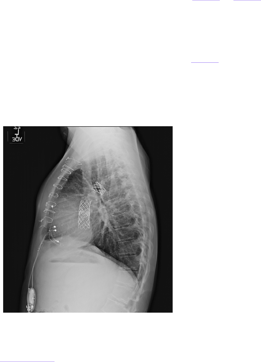
AMERICAN COLLEGE OF RADIOLOGY
Return to Table of Contents 90
2. Permanently implanted epicardial leads/CIEDs. These permanent epicardial
leads/CIEDs are often implanted in children or infants with congenital heart defects in
whom endovascular access would be difficult or impossible (
Figure 24 and Figure 25).
Other applications are in those with infected endovascular CIEDs or endocarditis.
Permanently implanted epicardial leads are typically of a larger caliber than temporary
epicardial pacing leads, and these are combined with IPGs. As noted in the Heart
Rhythm Society document, there are presently insufficient data to comment on the
safety of MRI performance in the presence of permanent epicardial leads [3], although
some recent studies have addressed this question [7,8].
Retained or abandoned endovascular and intracardiac leads. A typical appearance of
abandoned endovascular and intracardiac leads is demonstrated in Figure 26
. Also as noted in
the Heart Rhythm Society document, there is insufficient data to comment on MR safety
considerations in the presence of retained or abandoned endovascular and intracardiac leads
[3]. A prior study demonstrated the possibility of substantial length-dependent lead tip heating.
In addition, the attachment of leads to the pulse generator substantially affects heating at the
lead tip [9]. Recent studies have investigated safety in patients with abandoned leads
undergoing MRI with careful monitoring and other precautions [10,11]. As other studies emerge
on abandoned leads, the recommendations in this manual may be modified.
FIGURE 25. Lateral chest radiograph
demonstrating relatively long
permanently implanted epicardial
leads (white arrows) and attached to a
pulse generator.

AMERICAN COLLEGE OF RADIOLOGY
Return to Table of Contents 91
FIGURE 26. Radiograph demonstrating
abandoned transvenous intracardiac
leads (white arrows).
For patients with a history of revision or
removal of implanted electronic devices,
cardiac or otherwise, radiographic
screening prior to MR examination
should be considered to evaluate for
abandoned leads.
Neuromodulation systems. An increasing number of AIMDs used for neuromodulation are now
available, designed to stimulate the central nervous system and peripheral nervous system
targets for clinical benefit. These include deep brain stimulators, responsive neurostimulation
systems, cochlear implants, spinal cord stimulator systems, vagus nerve stimulator systems,
hypoglossal nerve stimulator systems, sacral nerve stimulator systems, and peripheral nerve
stimulator systems [12].
Careful attention to the accurate identification of the precise make, model, and manufacturer
as well as location of implantation of the leads and IPG for the AIMD is mandatory to ensure
patient safety. Subtle differences in model numbers within a particular class of
neurostimulation systems or a modification in how or where it is or was implanted can markedly
change the scanning conditions, including a device changing from being MR Conditional to
being MR Unsafe and posing a serious risk to the patient. Different model numbers within a
particular type of neurostimulator class can be associated with the ability to use the transmit
body RF coil as opposed to being restricted to transmit/receive RF coils such as those used for
the head or knee.
It is frequently necessary to have current imaging to accurately confirm the location of IPG and
lead systems as well as to evaluate for possible broken or abandoned leads. Increasingly,
patients can present with more than 1 active implanted device, requiring thoughtful
considerations of the conditions for safe scanning and frequently benefiting from a coordinated
evaluation by the MR Safety Officer (MRSO), MR Safety Expert, and MRMD safety team. For MR
Conditional neurostimulation systems, it is useful to contact the patient prior to their arrival to
ensure that they bring the device programmer to allow the device to be programmed
appropriately for scanning as needed. Facilities should incorporate SOPs, often including

AMERICAN COLLEGE OF RADIOLOGY
Return to Table of Contents 92
Patient Eligibility forms or Patient Checklists, to ensure that all the necessary conditions for
safe scanning are being met. Coordination with nonradiology subspecialty clinical teams can
also be beneficial for post-MRI reprogramming of certain devices (e.g., vagus nerve stimulators).
Implantable infusion pumps. Implantable infusion pumps provide controlled delivery of
medications primarily into the spinal subarachnoid space, with morphine and baclofen and their
derivatives the most commonly infused agents for control of pain and spasticity, respectively. If
MR conditions for safe scanning are not followed carefully, there is potential for patient injury or
death that can be related to drug overdosage or potentially from interrupted drug infusion. Safety
issues related to implantable infusion pumps in MRI were the subject of a 2017 FDA alert [13].
A number of deaths have occurred in association with MRI related to drug overdosing that are
apparently attributable primarily to not adhering to MR conditions for safe scanning [14]. The
drug reservoirs for some implantable infusion pumps must be entirely emptied of their contents
prior to scanning, as the drug can be subject to uncontrolled release while in MRI, with
potentially catastrophic results. For other devices, the motors are expected to stall in MRI,
temporarily interrupting drug infusion, but occasionally the pump motors may not restart as
expected following removal of the patient from the MR environment. This can pose significant
clinical problems associated with unanticipated opioid withdrawal or clinically more dangerous
baclofen withdrawal syndrome, which is associated with approximately 20% mortality [15].
For
this reason, these infusion pumps must be evaluated to ensure they are operating properly
following scanning. Other infusion pumps exist, including hepatic artery infusion pumps, that
are MR Conditional primarily for the administration of chemotherapeutic agents.
Implantable and external insulin pumps. Due to increasingly widespread use, practices
should be particularly vigilant for the presence of insulin pumps that can be implanted or worn
externally (on planted). Presently, these devices are considered MR Unsafe due to the presence
of ferrous materials and/or electronics that can be adversely impacted by the electromagnetic
field used for MR. Importantly, if exposed to the MR environment, sensing and insulin delivery
circuits may be temporarily or permanently damaged such that there may be dangerous
physiologically unsafe insulin delivery that could lead to life-threatening hypo- or
hyperglycemia [16]. For this reason, it is critical to positively identify diabetic patients in the
screening process in an effort to further ensure reliable detection of these devices.
If the
patient has an implantable insulin pump, MRI is contraindicated. If the patient has an
external insulin pump, the device must be removed from the patient prior to allowing
the patient into the MR system room. Additionally, MR Personnel should be aware that
internal and external insulin pumps are often used in association with continuous
glucose monitoring devices, some of which are MR Unsafe and therefore require
removal from the patient prior to entry into Zone IV.
Passive Implanted Devices
Passive implants and devices, unlike active devices, do not contain an intrinsic electrical power
source. All passive implants that contain metal are by definition either MR Conditional or MR
Unsafe. Common passive implants and devices include aneurysm clips, intravascular stents
(vascular, ureteral, tracheal, esophageal, etc.), heart valve prostheses, orthopedic implants
(plates, screws, pins, total hip prostheses, mesh, etc.), intraocular lens implants and glaucoma
shunts, programmable and nonprogrammable ventricular shunts, and prostheses. The major

AMERICAN COLLEGE OF RADIOLOGY
Return to Table of Contents 93
risks in MRI of these devices relate to the potential for electrical current induction, RF-
associated heating, gradient-associated vibration or heating, magnetic field–associated
translation and torque, and possible Lenz-related forces. Some devices, such as certain
programmable ventricular shunts, may require confirmation of setting with possible setting
reprogramming after exposure to the MR environment. A nonmetallic, nonconducting,
nonmagnetic passive implant, such as hernia mesh, can be considered MR Safe [17].
Intracranial aneurysm clips. If it is unclear whether a patient has an implanted intracranial
aneurysm clip, if available, recent cranial radiographs or CT or MR examinations should be
reviewed to identify a possible intracranial aneurysm clip. If unavailable, radiographs or CT
should be obtained.
In the event that a patient has an intracranial aneurysm clip, the MR examination should not be
performed until the specific manufacturer, model, and type of aneurysm clip within that patient
is identified. Next, it should be determined if the aneurysm clip is MR Unsafe or MR Conditional
[18]. All documentation of types of implanted clips, dates, etc., must be in writing and signed
by/attributable to a licensed physician. Electronic copies of operative reports, physician
statements, etc., are acceptable as long as a legible physician signature or other electronic
attestation accompanies the requisite documentation. Blanket letters indicating the safety of
all clips implanted by a practice are not acceptable. A written history of the clip describing
appropriate ferromagnetic testing methods (as specified for appropriate labeling in American
Society for Testing Materials (ASTM) International F2503) [17] used to characterize the clip
prior to implantation by the operating surgeon is also considered acceptable.
A patient with a previously unrecognized MR Unsafe aneurysm clip (or another implant) may
have undergone a prior MR examination without a known adverse event. This fact is insufficient
evidence of the safety of the implant and should not be relied on solely to determine the MR
safety status of that aneurysm clip (or other implant) for future MR examinations.
For these previously scanned patients with unknown or unsafe aneurysm clips, it is important to
note that variations in static magnetic field strength, static gradient magnetic field, orientation
of the aneurysm clip (or other implant) relative to the direction of the static magnetic field or its
static magnetic field gradient, and rate of motion through that static magnetic field gradient, as
well as other factors, are presumably unknown variables that are impossible to control or
reproduce. These variables may not have resulted in an adverse event in one circumstance but
could potentially result in significant injury or death on a subsequent MR exposure. By
assessing the size of the artifact associated with the clip relative to the static field strength on
which it was studied, the MRI pulse sequence type, and the MRI parameters selected, an
opinion may be issued by one of the facility’s Level 2 MR Physicians as to whether or not the
aneurysm clip demonstrates substantial ferromagnetic properties. Access to the MR scanner
could be based on that opinion.
Barring the availability of either pretesting or prior MRI-related data for the aneurysm clip in
question, the supervising physician in each case must perform a risk versus benefit assessment
and review. Furthermore, for patients with intracranial aneurysm clips with no available
ferromagnetic or imaging data, should the risk-benefit ratio favor the performance of the MR
examination, the patient or guardian should provide written informed consent that includes
death as a potential risk of the MR procedure prior to permitting that patient to undergo an MR

AMERICAN COLLEGE OF RADIOLOGY
Return to Table of Contents 94
examination. Because research scans in general do not offer benefit for the research
participant, scanning patients without written information about the specific device is strongly
discouraged.
Figure 27 depicts CT and 1.5-T MRI appearance of MR Conditional aneurysm clips and
aneurysm embolization coils.
Implant, Device, or Object Discovered During an MR Examination
During an MR examination, it is possible that an unanticipated ferromagnetic implant or foreign
body is discovered within a patient or research participant. This is typically suspected or
detected on localizer images by observing a sizable image distortion and/or signal-loss artifact
that grows with increasing echo time and is more prominent on gradient-echo relative to spin-
echo imaging sequences. In such cases, it is imperative that further image acquisition is put on
hold and that the Level 2 MR Physician (and/or MRMD or MRSO when appropriate) responsible
for the patient be immediately notified of the suspected ferromagnetic object. This Level 2 MR
Physician should then assess the situation, review the imaging, and decide the best course of
action.
FIGURE 27. CT and 1.5-T MRI appearance of MR Conditional aneurysm clips and aneurysm embolization coils. (A) CT
topogram appearance of MR Conditional aneurysm clip (arrow) and aneurysm embolization coil mass (dashed
arrow). (B and C) CT appearance of aneurysm clip and embolization coil mass. (D and E) 1.5-T T2* gradient-echo axial
and coronal localizer images. Note the limited susceptibility artifact associated with the nonferromagnetic
aneurysm clip and embolization coil mass and compare this with the pronounced artifact associated with the MR
Unsafe ferromagnetic clip seen in Figure 28. (F and G) Relatively limited susceptibility artifact on T2 fast spin-echo
images associated with the MR Conditional nonferromagnetic aneurysm clip and embolization coil mass.

AMERICAN COLLEGE OF RADIOLOGY
Return to Table of Contents 95
A
B
C
D
It should be noted that there are numerous potentially acceptable courses of action that might
be recommended that are dependent on many factors, including the status of the patient, the
location of the suspected ferromagnetic implant/foreign body relative to local anatomic
structures, the mass of the implant, the length of the object, the strength of the static magnetic
field, and other factors. Appropriate courses of action might include proceeding with the scan
underway, immobilizing and slowly removing the patient from the scanner, or other
intermediate steps. Regardless of the course of action selected, it is important to note that the
forces on the implant will change, and may actually increase, during the attempt to remove the
patient from the scanner bore. Further, the greater the rate of motion of the patient/device
through the magnetic field near the scanner bore (spatial field gradient), the greater the forces
acting on that device will likely be. In general, slow table speed and slow patient movement
should be beneficial. Efforts to immobilize an unrecognized on-planted device can be helpful.
FIGURE 28. Examples of pronounced susceptibility artifact on 1.5-T localizer images associated with ferromagnetic
intracranial aneurysm clip (A, B, C). The ferromagnetic clip is seen on the CT images (D). In this case, the patient was
removed safely from the scanner using slow table speed, and the table was detached and wheeled out of the room
slowly without the patient sitting up.

AMERICAN COLLEGE OF RADIOLOGY
Return to Table of Contents 96
Figure 28 illustrates discovery and subsequent safe removal of a patient after identification of
susceptibility artifact associated with an aneurysm clip on the anatomical localizer. Reinforcing
this critical need to carefully review patient localizer images to assess for the presence of
ferromagnetic objects, a case reported in 1986 in the literature documented a patient that went
blind from interactions between an undetected metallic foreign body in his retina and the static
magnetic field of the MR system after both entering the scanner and undergoing the entire MR
examination without reported incident. Notably, this patient only went blind on exiting the MR
system at the completion of the examination [19].
The detection of an unexpected focus of susceptibility artifact in MR examinations of the torso
can be particularly challenging because of the multitude of devices that are implanted during
surgical and interventional procedures (e.g., staples, stents, inferior vena cava filters,
hemostatic clips, embolization coils, etc.). The Level 2 MR Personnel should be aware that some
commonly used devices, such as certain clips used in endoscopic procedures, are indeed MR
Unsafe [20]. Furthermore, ingested iron supplements within the bowel can cause substantial
susceptibility artifacts mimicking metallic clips on MRI [21].
Also, due to their ferromagnetic
content, some hemostatic clips deployed during endoscopy impart susceptibility artifacts that
could adversely affect the diagnostic quality of the images.
When an unexpected artifact is encountered in a patient undergoing MRI, the Level 2
supervising physician should be contacted before proceeding with the rest of the MR
examination. The magnetic fields associated with the MR scanner are 3-D. Thus, especially for
superconducting systems, one should avoid the temptation to have the patient sit up as soon as
they are physically out of the bore. Doing so may expose the ferromagnetic object to significant
torque- and translation-related forces despite its being physically outside the scanner bore.
Therefore, it is advisable to continue to extract the patient along a straight-line course
parallel to the center of the MR system while the patient remains immobilized until they are
as far as physically possible from the MR scanner in Zone IV and continuing directly into
Zone III, if possible, before having the patient sit up.
If the table is dockable, detach the table and move the patient into Zone III before allowing the
patient to sit up. If the table is fixed, it is recommended to slowly horizontally transfer the
patient to an MR Conditional stretcher in Zone IV and then move the patient into Zone III. If there
is determined to be a strong likelihood of producing or worsening patient injury by attempting
to remove the patient from the MR system, quenching could be a consideration. Additionally,
having emergency medical assistance readily available (with proper safety precautions) is also
a consideration.
Should an implanted device that may be altered by the magnetic field (e.g., programmable
shunt, implantable infusion pump, tissue expander, continuous glucose monitor, etc.)
inadvertently be discovered while the patient is in Zone IV, the physician responsible for the
maintenance of the device(s) should be contacted prior to the patient’s discharge from the MRI
facility. Significant injuries have resulted from such partial exposures to powerful static
magnetic fields, and thus, the functionality of the device should be verified and never assumed
for critical devices such as internal or external insulin pumps or AIMDs.

AMERICAN COLLEGE OF RADIOLOGY
Return to Table of Contents 97
KEY POINTS
External (nonimplanted) devices, objects, and equipment
o Portable metallic devices should be properly labeled prior to entry
to Zone III.
o MR Unsafe equipment necessary for patient care in Zone III must be
responsibly managed by physically securing/tethering or other
means.
o Pocketless scrubs attire should be strongly considered for
personnel entering Zone IV to decrease projectile risks.
Active implanted/on-planted devices
o Active medical devices contain an energy source or can be
inductively coupled.
o Careful attention to MR conditions for safe scanning of specific
devices is essential.
CIED systems without MR Conditional labeling can be
scanned provided a program is employed in accordance with
the recommendations of the Heart Rhythm Society.
o Identify patients with CIED, neurostimulators, insulin pumps, and
infusion devices early in the screening process to confirm whether
and how the patient can be safely scanned.
Passive implanted devices
o Passive implanted devices do not contain an intrinsic electrical
power source.
o Metal-containing passive devices cannot be MR Safe, only MR
Conditional or MR Unsafe.
o Lack of a known adverse event in a patient scanned with an
implanted device of unknown safety labeling does not ensure its
safety in any way with future MR exams.
Implant, device, or object discovered during MR examination
o Extensive susceptibility artifacts can be an indicator of potentially
unsafe ferromagnetic content in an implant.
o Sites should have SOPs in place on processes/procedures to
remove a patient from the magnet if potentially unsafe metal is
identified.
Slow table speed and keeping the patient recumbent until
well away from the bore are important elements.

AMERICAN COLLEGE OF RADIOLOGY
Return to Table of Contents 98
References
1. Watson RE Jr, Edmonson HA. MR safety: active implanted electronic devices. Magn Reson Imaging Clin N Am.
2020;28(4):549-558. doi: 10.1016/j.mric.2020.08.001
2. International Organization of Standardization. Assessment of the safety of magnetic resonance imaging for
patients with an active implantable medical device. Published April 2018. Accessed April 22, 2024.
https://www.iso.org/standard/65055.html
3. Indik JH, Gimbel JR, Abe H, et al. 2017 HRS expert consensus statement on magnetic resonance imaging and
radiation exposure in patients with cardiovascular implantable electronic devices. Heart Rhythm.
2017;14(7):e97-e153. doi: 10.1016/j.hrthm.2017.04.025
4. Vigen KK, Reeder SB, Hood MN, et al. Recommendations for Imaging Patients With Cardiac Implantable
Electronic Devices (CIEDs). J Magn Reson Imaging. 2021;53(5):1311-1317. doi:10.1002/jmri.27320
KEY ABBREVIATIONS
ACLS: advanced cardiac life support
AIMD: active implanted medical device
ASTM: American Society for Testing Materials
CCM: cardiac contractility modulation
CIED: cardiac implantable electronic device
CRT: cardiac resynchronization therapy
CT: computed tomography
FDA: Food and Drug Administration
ICD: implantable cardioverter defibrillator
ICM: implantable cardiovascular monitor
IFU: instructions for use
ILR: implantable loop recorder
IPG: implantable pulse generators
MRMD: Magnetic Resonance Medical Director
MRSE: Magnetic Resonance Safety Expert
MRSO: Magnetic Resonance Safety Officer
RF: radiofrequency
SOP: standard operating procedure
B
0
: Static magnetic field

AMERICAN COLLEGE OF RADIOLOGY
Return to Table of Contents 99
5. Hartnell GG, Spence L, Hughes LA, Cohen MC, Saouaf R, Buff B. Safety of MR imaging in patients who have
retained metallic materials after cardiac surgery. AJR Am J Roentgenol. 1997;168(5):1157-1159. doi:
10.2214/ajr.168.5.9129404
6. Murphy KJ, Cohan RH, Ellis JH. MR imaging in patients with epicardial pacemaker wires. AJR Am J Roentgenol.
1999;172(3):727-728. doi: 10.2214/ajr.172.3.10063869
7. Vuorinen AM, Paakkanen R, Karvonen J, et al. Magnetic resonance imaging safety in patients with abandoned
or functioning epicardial pacing leads. Eur Radiol. 2022;32(6):3830-3838. doi: 10.1007/s00330-021-08469-6
8. Ma YD, Watson RE Jr, Olson NE, et al. Safety of magnetic resonance imaging in patients with surgically
implanted permanent epicardial leads. Heart Rhythm. 2023;20(8):1111-18. doi: 10.1016/j.hrthm.2023.04.003
9. Langman DA, Goldberg IB, Finn JP, Ennis DB. Pacemaker lead tip heating in abandoned and pacemaker-
attached leads at 1.5 Tesla MRI. J Magn Reson Imaging. 2011;33(2):426-431. doi: 10.1002/jmri.22463
10. Higgins JV, Gard JJ, Sheldon SH, et al. Safety and outcomes of magnetic resonance imaging in patients with
abandoned pacemaker and defibrillator leads. Pacing Clin Electrophysiol. 2014;37(10):1284-1290. doi:
10.1111/pace.12419
11. Schaller RD, Brunker T, Riley MP, Marchlinski FE, Nazarian S, Litt H. Magnetic resonance imaging in patients
with cardiac implantable electronic devices with abandoned leads. JAMA Cardiol. 2021;6(5):549-556. doi:
10.1001/jamacardio.2020.7572
12. Rahman M, Shellock FG. Chapter 18: MRI issues for implants and devices. In: Shellock FG, Crues JV III, eds.
MRI Bioeffects, Safety, and Patient Management. Biomedical Research Publishing Group; 2022:710-748.
13. US Food and Drug Administration. Safety concerns with implantable infusion pumps in the magnetic
resonance (MR) environment. Published January 11, 2017. Accessed April 22, 2024.
https://wayback.archive-
it.org/7993/20201224130324/https:/www.fda.gov/medical-devices/safety-communications/safety-
concerns-implantable-infusion-pumps-magnetic-resonance-mr-environment-fda-safety
14. McRobbie DW. Essentials of MRI Safety. Wiley Blackwell; 2020.
15. Mohammed I, Hussain A. Intrathecal baclofen withdrawal syndrome- a life-threatening complication of
baclofen pump: a case report. BMC Clin Pharmacol. 2004;4:6. doi: 10.1186/1472-6904-4-6
16. Yeh T, Yeung M, Mendelsohn Curanaj FA. Managing patients with insulin pumps and continuous glucose
monitors in the hospital: to wear or not to wear. Curr Diab Rep. 2021;21(2):7. doi: 10.1007/s11892-021-01375-7
17. American Society for Testing Materials International. Standard practice for marking medical devices and
other items for safety in the magnetic resonance environment. Published October 24, 2023. Accessed April
22, 2024. doi: 10.1520/F2503-23E01
18. Shellock FG. Chapter 18: MRI issues for implants and devices. In: Shellock FG, Crues JV III, eds. MRI Bioeffects,
Safety, and Patient Management. 2nd ed. Biomedical Research Publishing Group; 2022;462-497.
19. Kelly WM, Paglen PG, Pearson JA, San Diego AG, Soloman MA. Ferromagnetism of intraocular foreign body
causes unilateral blindness after MR study. AJNR Am J Neuroradiol. 1986;7(2):243-245.
20. Accorsi F, Coutu G, Simms EL, Lalonde A, Leswick DA. Endoscopic clip MRI screening: a Canada-wide policy
survey. AJR Am J Roentgenol. 2017;209(1):130-135. doi: 10.2214/AJR.16.17521
21. Bowser BA, Campeau NG, Carr CM, et al. Incidental ferumoxytol artifacts in clinical brain MR imaging.
Neuroradiology. 2016;58(11):1087-1091. doi: 10.1007/s00234-016-1747-1

AMERICAN COLLEGE OF RADIOLOGY
Return to Table of Contents 100
CHAPTER 13:
Physiological Monitoring of Patients
Visual and audio monitoring are basic required monitoring processes used for patients and
research subjects. Additional physiological monitoring for patients during MR examinations is
often necessary. Physiological monitoring techniques should be carefully selected, primarily
because of the risk of thermal injury associated with monitoring equipment in the MR
environment. While not all radiofrequency-induced thermal injuries can be detected as they are
developing, sedated, anesthetized, or unconscious patients are especially vulnerable to such
injuries, as they are unable to provide the operator with adequate warning of developing
thermal injuries. The potential for heating scales with the magnetic field exists, at least
theoretically, at all MRI field strengths. When needed, MR Conditional electrocardiogram (ECG)
and electroencephalogram electrodes should be used, and leads should be positioned per the
manufacturers’ direction during the scan [1].
Distortion of the ECG within the magnetic field, particularly during sequence acquisition, can
make interpretation of the ECG unreliable, even with filtering used by contemporary monitoring
systems. For example, T-wave elevation is frequently noted [2]. ECG recordings in MRI are
unreliable and may demonstrate ST segment elevation or depression due to the
magnetohydrodynamic effect. This may simulate or mask cardiac infarction (discussed in
Lenz
effects).
Routine monitoring of the patient’s heart rate and rhythm may also be accomplished with an MR
Conditional pulse oximeter, with careful attention to the instructions for use.
Additional physiological monitoring devices exist, including indwelling temperature probes and
intracranial pressure monitors, and their conditions for safe scanning should be followed
carefully in accordance with MRI labeling.
References
1. Abdel-Rehim S, Bagirathan S, Al-Benna S, O’Boyle C. Burns from ECG leads in an MRI scanner: Case series
and discussion of mechanisms. Ann Burns Fire Disasters. 2014;27(4):215-218.
2. Gupta A, Weeks AR, Richie SM. Simulation of elevated T-waves of an ECG inside a static magnetic field (MRI).
IEEE Trans Biomed Eng. 2008;55(7):1890-1896. doi: 10.1109/TBME.2008.919868
KEY POINTS
Monitoring techniques
should be selected and
carefully implemented
following manufacturer’s
MR Conditional instructions
because of the risk of
thermal injury.
KEY ABBREVIATIONS
ECG: electrocardiogram
EEG: electroencephalogram
IFU: instructions for use
MHD: magnetohydrodynamic
T: tesla

AMERICAN COLLEGE OF RADIOLOGY
Return to Table of Contents 101
CHAPTER 14:
Emergency Situations
This section discusses several MR safety switches that can be used in the case of an
emergency as well as emergency response–related issues such as fires, codes, and entrapment
by ferromagnetic objects
. Facilities should have policies and procedures to ensure appropriate
communication and chain of authority during after-hours emergencies [1]. For the safety of
firefighters, code or rapid-response teams, and other emergent services responding to an
emergent call at the MR facility, it is recommended that all fire alarms, cardiac arrests, or other
emergent service response calls originating from or located in the MR facility should be
forwarded simultaneously to a specifically designated individual from among the facility’s MR
Personnel. This individual should, if possible, be on-site prior to the arrival of the firefighters or
emergency responders to ensure that they do not have free access to Zones III or IV. The facility
might also consider assigning appropriately trained security personnel, who have been trained
and designated as MR Personnel, to respond to such calls. For firefighter or police responses,
clear lines of authority for screening, access restrictions, and Emergency Magnet Off
procedures are essential.
Given differences in the design of MR facilities and between MR system manufacturers, it is
strongly advised that all MR facilities perform regular training and drills to reinforce knowledge
of where key safety switches reside and their use as well as to rehearse and refine emergency
response protocols to protect patients, MR staff, and first responders.
Emergency Table Stop and Emergency Power Off
Two safety switches that do not ramp down the magnetic field are the Emergency Table Stop
and the Emergency Power Off buttons. MR system manufacturers may give different names to
these switches, but the MR operator/Level 2 MR Personnel needs to be aware of where they
are, when to use them, and how to recover the system after using these switches.
The Emergency Table Stop button is generally designed to immediately stop MR scanning and
table motion. Emergency Table Stop buttons (Figure 29
) are usually found on or near the MRI
console and on the MR bore front cover or the patient table. The Emergency Table Stop button
should generally be used when something is caught on the table and further table motion may
result in damage or injury to the patient.
The Emergency Power Off button is generally used to stop electrical power to the entire suite
and computer room, including an uninterrupted power supply if present. Use of the Emergency
Power Off may require an electrician and access to the main breaker to reset and so should be
used with caution and only in emergent situations only. The Emergency Power Off button is
generally present in the MR control room or on the wall inside Zone IV. In some cases, it may be
covered with a plastic guard to avoid accidental activation (i.e., if situated next to the
electronically active door seal switch). The Emergency Power Off may be used in cases of fire,
flooding, or voltage accidents. Example scenarios for deploying an Emergency Power Off could
include detecting smoke or having an uncontrolled water pipe burst in the MR environment.
In the case of Emergency Table Stop or Power Off, if a patient needs to be quickly removed
from the scanner, the operator must be familiar with the manual process for moving the table

AMERICAN COLLEGE OF RADIOLOGY
Return to Table of Contents 102
and/or undocking the table. Fast and safe patient removal from the room is often a key
component in any emergency response scenario.
(a
)
(b)
(c)
(d)
FIGURE 29. (a) Universal symbol used for emergency stop safety switch. (b) Example of an Emergency Power Off
safety switch. (c and d) Examples of Emergency Magnet Off units for quenching superconducting units (Source: GE
and Siemens Operator Manuals)
Emergency Magnet Off (Quench)
Another primary safety switch in the MRI suite is the Emergency Magnet Off unit for rapidly
shutting down the magnetic field. Emergency Magnet Off is usually activated by a button or
lever in the MR operator room and/or Zone IV. Buttons are usually protected by a plastic cover
to avoid inadvertently deactivating the magnet. MR Personnel should be aware that MR fields
may change unexpectedly during a quench. Different magnet designs will have different rates
for the field to be shut down. Electromagnets will usually take much longer than
superconducting magnets. The MR operator should be familiar with the vendor safety manual
concerning their Emergency Magnet Off procedure and safety considerations.
Traditional superconducting magnets used for MRI use large volumes of liquid cryogens to
remain in superconducting mode. The Emergency Magnet Off, often referred to as the “Quench
button” for superconducting magnets, involves “quenching” the magnet, whereby a tremendous
amount of energy is dissipated as the cryogen undergoes rapid expansion and is released as
gas through the cryogen vent. This procedure carries its own safety considerations. Because of
the risks involved with quenching these magnets, the decision to quench a magnet should be
deliberate. Alternatively, some newer generation human MR systems now on the market use
lower volumes of cryogen liquid and do not require an externalized venting pipe during
installation. The Emergency Magnet Off switch in such systems also quenches the magnet, with
the release of a relatively small volume of cryogen material into the room.
If a situation arises in which emergency responders must enter a Zone IV containing an MR
system with a superconducting magnet without undergoing screening or elimination of
ferromagnetic items, deliberate quenching must seriously be considered. For superconducting
systems, it is imperative that all personnel and patients be evacuated from Zone IV as quickly

AMERICAN COLLEGE OF RADIOLOGY
Return to Table of Contents 103
and safely as feasible and that the site access be immediately restricted for all individuals until
the arrival of MR equipment services or other qualified personnel.
A Level 2 MR Personnel should monitor the quench to determine when it is safe for nonmedical
emergency responders to enter Zone IV. It may take more than a minute for the magnetic field to
dissipate sufficiently for responders to safely enter Zone IV with ferromagnetic equipment [2].
Quenching a magnet can introduce new hazards. This is especially true in the event of a venting
failure in which cryogenic gases are vented partially or completely into the scan room, as
evidenced in part by the sudden appearance of white “clouds” or “fog” around or above the MR
scanner. Such circumstances could introduce the risk of cold-related injuries (i.e., frostbite or
hypothermia) and asphyxiation due to oxygen displacement from helium, which is less dense
than air.
In the case of a quench venting failure, it is important for Level 2 Personnel to remain calm and
follow the established standard operating procedures for their area, including the following:
•
If a patient is currently in the scanner and is ambulatory, advise the patient to leave
Zone IV as soon as possible, walking as low to the floor as possible to maintain their
head below the potential accumulation of cryogen gas to minimize the risk of asphyxia.
•
Immediately turn on the exhaust fan in the MRI suite to help eliminate the cryogen gas
from the room.
•
Open the scan room door to ventilate Zone IV.
•
Consider opening the door to other zones to help ventilate Zone III.
•
If entering Zone IV to rescue the patient or personnel, stay as low to the ground as
possible. If a gurney or wheelchair is needed, assume the magnet is still on and at field
and use MR Conditional equipment if possible.
•
When the rescue is complete, close the door to Zone IV to stop helium flow into Zone III.
Evacuate the area to allow helium gas to dissipate. MR vendor personnel would be
anticipated to assist in indicating when it is safe to re-enter the site.
There are newer MR systems in which an externally vented quench pipe is unnecessary due to
low cryogen volume. While quenching does not lead to a release of high volumes of cryogen in
the room with such scanners, the magnetic field in the room remains a risk until it can be
verified it is sufficiently dissipated.
For resistive systems (without cryogenic gases), the magnetic field of the MR scanner should be
shut down as completely as possible and verified prior to permitting the emergency response
personnel access to Zone IV. For permanent, resistive, or hybrid systems whose magnetic fields
cannot be completely shut down, MR Personnel should ideally be available to warn the
emergency response personnel that a very powerful magnetic field is still present in Zone IV
and secure dangerous ferromagnetic objects, if possible.
Fire
All MR facilities should prospectively educate their local firefighters, fire marshals, and police
and security personnel about the potential hazards of responding to emergencies in the MR
suite.

AMERICAN COLLEGE OF RADIOLOGY
Return to Table of Contents 104
It should be assumed that in the event of a fire (or other emergency) in Zone IV, the magnetic
field is present, fully operational, and potentially dangerous. Therefore, free access to Zone III
or IV by firefighters or other non-MR Personnel with air tanks, axes, crowbars, and other
firefighting equipment might prove catastrophic or even lethal to those responding or to others
in the vicinity.
As part of the Zone III and IV restrictions, all MR facilities must have clearly marked, readily
accessible MR Conditional or MR Safe fire extinguishing equipment physically stored within
Zones III or IV. All conventional fire extinguishers and other firefighting equipment not tested
and verified as safe in the MR environment should be restricted from Zone III and IV.
RACE can be a useful mnemonic for MR staff response to fire:
• Rescue persons in danger IF SAFE TO DO SO.
• Activate the nearest Alarm, and call, when possible, to provide specific information.
• Contain the fire by closing ALL doors of the room/area, including fire doors. An MR
Conditional fire extinguisher may be used to control the fire IF SAFE TO DO SO.
• Evacuate if instructed to do so by the fire department.
When a fire is in the magnet room (Zone IV) and cannot be contained by the in-room sprinkler
system or by the safe use of an MR Conditional fire extinguisher and the fire department will
require access to the room, the Emergency Magnet Off (quench) should be engaged to avoid
potential serious injury to the fire department staff or damage to MRI equipment. Note that for
superconducting magnets, this will initiate a “quench,” a process that has its own safety
considerations (see Emergency Magnet Off
).
When a fire is in Zone II or III, restricting access to Zone IV by closing and locking the access
doors is recommended to prevent entry of fire personnel or hazardous material.
Medical Code
In case of cardiac or respiratory arrest or other medical emergencies within Zone IV for which
emergent medical intervention or resuscitation is required, the patient or research participant
must be removed immediately from Zone IV to a predetermined, magnetically safe location, and
appropriately trained and certified MR Personnel should immediately initiate basic life support
or cardiopulmonary resuscitation as required by the situation. Facilities must have immediate
access to an MR Conditional gurney on which to transfer the patient when the MR table cannot
be undocked. If transferring the unstable patient outside Zone IV is delayed for more than a few
seconds, the MR Personnel should prioritize patient safety and initiate cardiorespiratory
resuscitation maneuvers (i.e., chest compressions, rescue breaths), as needed, while still in Zone
IV. However, MR Unsafe items such as automated external defibrillators should not be brought
into Zone IV. The Emergency Magnet Off (quench) procedure is not routinely recommended for
these scenarios. All priorities should be focused on initiating necessary basic life support with
cardiac compressions and manual ventilation and evacuating the patient as rapidly and safely
as possible. Once the resuscitation is moved to Zone III, it is recommended that the Zone IV door
be closed and secured to avoid inadvertent potentially dangerous entry by those responding to
the code.

AMERICAN COLLEGE OF RADIOLOGY
Return to Table of Contents 105
It is recommended that sites implement mock code training exercises and practice
opportunities with specific issues that may arise in the MR environment. Engagement of MR
Personnel and the related staff that would be involved in a code situation is essential. Mock
code team leaders can be helpful to access performance and maintenance of important MR
safety measures in what are usually high-stress situations. Debriefing sessions and
performance feedback following the mock code can help identify areas for improvement and
potential additional needed resources. Facilities should consider the need to perform multiple
mock code training sessions when there are substantial intra-practice differences in the MRI
suite design and/or MR Personnel (e.g., inpatient, outpatient, intraoperative, etc.).
Entrapment
In the event of patient or personnel entrapment against the bore by a sizable ferromagnetic
object, causing injury or potential death without possibility of timely extraction, initiating the
Emergency Magnet Off (quench) procedure for the magnet is recommended.
References
1. Posh J. Chapter 27: MRI policies and procedures for a hospital or medical center setting. In: Shellock FG,
Crues JV III, eds. MRI Bioeffects, Safety, and Patient Management. 2nd ed. Biomedical Research Publishing
Group; 2022:749-764.
2. International Electrotechnical Commission. Medical electrical equipment — Part 2-33: Particular
requirements for the safety of magnetic resonance equipment for medical diagnosis. 4th ed. Published
August 4, 2022. Accessed April 22, 2024. https://webstore.iec.ch/publication/67211
KEY ABBREVIATIONS
AED: automated external defibrillator
RF: radiofrequency
UPS: uninterrupted power supply

AMERICAN COLLEGE OF RADIOLOGY
Return to Table of Contents 106
CHAPTER 15:
Special Patient and Personnel Considerations
Pregnancy
Health care practitioner pregnancies. Pregnant health care practitioners are permitted to work in
and around the MR environment, including Zone III and IV throughout all stages of their pregnancy
[1]. There are no restrictions of activities in Zone III. Physical presence in Zone IV is permissible for all
activities when there is no active scanning occurring. Although there is no current evidence that
exposure to the MR environment during scanning causes harm to the fetus, it seems prudent that
pregnant staff, both MR Personnel and non-MR Personnel, should not be in Zone IV during scanning
due to the currently unknown side effects of prolonged interactions with the radiofrequency (RF)
field and acoustic noise [2]. For example, the effects of acoustic noise to the fetus in the
occupational setting is unknown [3]. There is no data available to date regarding human pregnancy
exposures to 7-T and higher static magnetic fields.
Patient pregnancies. The vast majority of data today has failed to show that exposure to MR
has deleterious effects on the developing fetus [4-6].
Nevertheless, there are indications that
the embryo is potentially more sensitive to thermal events in the first trimester. To this end, if
pregnancy is established, the decision to proceed with a noncontrast MR study in the Normal
Operating Mode for a whole body–averaged specific absorption rate (SAR; ≤2 W/kg) should be
based on the medical benefits weighed against unknown potential risk.
The preponderance of research studies has failed to demonstrate any reproducible harmful
effects of exposure of the mother or developing fetus to the 3-T or weaker magnetic fields
used in the routine clinical MR practice [7,8]. Theoretical concerns include time-varying gradient
and RF magnetic fields, potential acoustic noise–related issues, and heat deposition in tissue,
respectively. There is little peer-reviewed literature regarding the acoustic safety of fetal
scanning, but the majority of published material on this topic has failed to find deleterious
effects on newborn hearing when exposed to MRI in utero [9-14]. The thermal-related
theoretical concerns are addressed by results from experiments in pregnant pigs exposed to
standard MR sequences commonly used in clinical practice that are associated with relatively
high SAR levels (i.e., half-Fourier single-shot spin-echo). Such studies failed to demonstrate
substantial heating in fetal tissues or amniotic fluid when imaging at 3 T with the MR system
operating in the Normal Operating Mode (whole body–averaged SAR, 2 W/kg) and a maximum
scan time of 30 minutes [15,16]. Thus, the ACR Manual on MR Safety supports the clinical use
of MR imaging for patients known or suspected to be pregnant under the following conditions:
1) MR system up to 3T in Normal Operating Mode (Whole body-averaged-SAR, 2-W/kg); 2) there
is expected benefit to the patient and/or fetus from performing the exam; 3) There is no other
practical way to obtain the same information for patient care [7]. The American College of
Obstetricians and Gynecologists clinical guidelines acknowledge MR and ultrasound (US) as
the ‘imaging techniques of choice for the pregnant patient, but they should be used prudently
and only when use is expected to answer a relevant clinical question or otherwise provide
medical benefit to the patient’ [17]. The risks of exposure to MR fields >3T are currently
unknown. The ACR Committee on MR Safety also supports the enrollment of pregnant research
participants for research studies using MR systems up to 3T to investigate conditions related to

AMERICAN COLLEGE OF RADIOLOGY
Return to Table of Contents 107
pregnancy if they are willing to consent to participate in the research study. However, the
enrollment of pregnant patients for other research studies to investigate conditions not related
to pregnancy with MRI is discouraged.
Use of gadolinium-based contrast media. The committee supports the recommendations of
the ACR Manual on Contrast Media
in relation to the administration of gadolinium-based
contrast media to pregnant or potentially pregnant patients: MR contrast agents should not be
routinely administered to pregnant patients [18,19].
Also, there is widespread consensus that avoiding gadolinium-based contrast media (GBCM) in
pregnancy is prudent [18].
The decision to administer GBCM is typically made according to the
institutional contrast policy, on a case-by-case basis, by the responsible Level 2 MR Physician
who can assess the risk versus benefit ratio for that particular patient. While additional research
is needed, one paper suggested that exposure to GBCM at any time during pregnancy has been
associated with an increased risk of a broad set of rheumatological, inflammatory, or infiltrative
skin conditions and risk of stillbirth or neonatal death [20]. Thus, the decision should be
accompanied by thoughtful risk-benefit analysis and well-documented with written informed
consent. This analysis should be able to defend a decision to administer the contrast agent
based on the potential benefit to the patient or fetus outweighing the potential risks of
exposure of the developing fetus to a GBCM.
A 2019 paper highlighted an increased exposure level of first trimester pregnancies to GBCM,
suggesting that increased screening and vigilance may be warranted when administering these
contrast agents to potentially pregnant patient populations [21].
Pediatric MR Safety Concerns
Pediatric patients may present with additional MR safety concerns, including potentially
increasing projectile risks in Zone IV, as well as body temperature considerations, and obtaining
nondiagnostic MR examinations due to the inability to cooperate [22].
Projectile risks and the need for enhanced screening have been discussed in
Chapter 5: MR
Screening.
For the neonatal and the young pediatric population, special attention is needed in monitoring
body temperature for both hypo- and hyperthermia as well as other vital signs [22]. MR
Conditional temperature-monitoring equipment that is approved for use in the MR suite is
readily available. Commercially available neonatal isolation transport units and other warming
devices intended to be used in the MR environment are also available. In addition, as an option
for performing MRI exams in neonatal patients at the “point of care,” there is now a head-only
scanner specially designed for this patient population [23].
Particular attention should be paid to the body temperature of neonates and infants while in the
MRI environment [22]. In a study by Don Paul et al [24], only 43% of infants were normothermic
upon return to the neonatal intensive care unit (NICU) following MRI, suggesting that MRI-
related unintentional hypothermia is common unless proactively managed. Predictors of a post-
MRI decrease in body temperature in neonates and infants include younger age, lower weight,
lower pre-MRI temperature, use of propofol as the primary anesthetic, use of an advanced
airway device, and being outside the NICU [25]. In the event that the pediatric patient requires

AMERICAN COLLEGE OF RADIOLOGY
Return to Table of Contents 108
sedation/anesthesia, the ACR MR Safety Committee defers to the American Society of
Anesthesiologists on pediatric sedation guidelines [26-29]. Alternative methods to facilitate
compliance without sedation/anesthesia should be considered (e.g., fast/accelerated MR
sequences, engagement of child life specialists, MR Conditional video entertainment headsets).
Claustrophobia, Anxiety, and Sedation
Adult and pediatric patient anxiolysis, sedation, analgesia, and anesthesia for any reason should
follow established ACR practice parameters [30],
American Society of Anesthesiologists [26-
29], and The Joint Commission standards [31].
Implementation of SOPs and policies for the
management of claustrophobic/anxious patients is recommended. Similarly, sites should develop
policies for the release of patients who receive sedation. For example, the requirement of a
responsible person, 18 years of age or older, to accompany and drive the patient after an MR
procedure.
Large Body Habitus
Very large patient/research participant body habitus is an MR safety concern primarily due to
inherent risk of RF burns. As noted in earlier sections of this manual (see Chapter 8: RF section
),
contact or excessive proximity to the bore of the magnet can result in near field RF burns, and
appropriate insulating pad thickness and positioning about the patient/subject is essential to
prevent burns. Ensuring adequate appropriately placed padding can be difficult with very large
patients/subjects, and particularly while under general anesthesia or while sedated, padding
must be scrupulously assessed to prevent burns. Another consideration in very large
patients/subjects is the possibility of forming closed-loop tissued proximities and contacts,
such that skin-to-skin contacts become more likely (e.g., between thighs, between abdominal
panniculus and thigh, etc.). Thus, properly applied padding that serves as insulation is vital in
this patient population. Strategies to reduce patient heating include using a detachable
transmit-receive RF coil as well as choosing lower SAR and reducing scan time to minimize
overall energy deposition in the patient.
Prisoners/Detainees
MR scanning presents unique MR safety challenges for patients who are incarcerated. These
patients may present wearing metallic or ferromagnetic handcuffs, ankle cuffs, or shackles.
Accompanying correctional officers may be carrying ferromagnetic objects including guns or
other weapons. Prior to the patient arriving at the MR department, notification to the
corrections department for an alternative nonferromagnetic restraining option should be
requested. MR screening of the patient and the accompanying correctional officer(s) should
take place prior to entering Zone III. The accompanying officer(s) should be educated as to the
static magnetic field–related safety issues and, if they agree following screening, should
accompany the technologist into Zone IV for patient positioning and removal.
Ferromagnetic weapons should not be permitted into Zone III unless essential for maintenance
of security. Firearms with ferromagnetic components pose a potential serious threat in Zone IV
and can become dangerous projectiles and may discharge, resulting in a death, as described
recently in 2023 [32,33].
Firearms represent potential projectiles and are a hazard to all if brought into Zone IV [32,33].

AMERICAN COLLEGE OF RADIOLOGY
Return to Table of Contents 109
Parolees
Patients on parole wearing metallic prisoner-monitoring devices such as radiofrequency
identification (RFID) tags or tracking bracelets could theoretically lead to adverse events,
including the following:
1. Ferromagnetic attractive effects leading to patient injury
2. Ferromagnetic attractive effects leading to device/battery pack damage
3. RF interference with the MRI study and secondary image artifact
4. RF interference with the functionality of the device
5. RF power deposition leading to heating of the bracelet, tagging device, or its
circuitry, and secondary patient injury (if the bracelet is in the volume of the RF
transmitter coil being used for imaging)
Therefore, in cases in which a patient wearing an RFID tag or tracking bracelet needs an MR
examination, a request should be made to the appropriate authorities that the monitoring device
be removed prior to the MR examination. At that time, it can also be determined if the
appropriate authorities should be in attendance at the time of the scan. Plans for monitoring
device replacement following the scan should also be made.

AMERICAN COLLEGE OF RADIOLOGY
Return to Table of Contents 110
KEY POINTS
Pregnancy
o Pregnant health care practitioners are permitted to work in and around the
MR environment, including Zone III and IV, except in Zone IV during active
scanning.
o Research studies have failed to demonstrate any reproducible harmful
effects of exposure of the mother or developing fetus to 3-T or weaker static
magnetic fields used in the routine clinical MRI practice. Nevertheless, the
decision to proceed with an MR examination should be based on the medical
benefits weighed against unknown potential risks.
o If an MR examination of a pregnant patient is indicated, the Level 2 MR
Technologist should confirm that the Normal Operating Mode is selected.
o The committee supports the recommendations of the ACR Manual on
Contrast Media in relation to GBCM administration to pregnant or potentially
pregnant patients.
Pediatric
o Need enhanced screening for projectile risks.
o Need special attention to body temperature (particularly neonates and
infants).
o ACR MR Safety Committee defers to the American Society of
Anesthesiologists on pediatric sedation guidelines.
Claustrophobia, anxiety, sedation
o Adult and pediatric patient anxiolysis, sedation, analgesia, and anesthesia for
any reason should follow established ACR,
American Society of
Anesthesiologists, and The Joint Commission standards.
Large body habitus
o Inherent increased risk of RF burns.
o Requires special attention to padding.
Prisoners/detainees
o Notification to the corrections department for an alternative
nonferromagnetic restraining option should be requested.
o MR screening of the patient and the accompanying correctional officer(s)
should take place prior to entering Zone III.
Parolees
o Arrangements should be made with proper authorities to remove and replace
RFID tags or tracking bracelets as needed.

AMERICAN COLLEGE OF RADIOLOGY
Return to Table of Contents 111
References
1. Kanal E, Gillen J, Evans JA, Savitz DA, Shellock FG. Survey of reproductive health among female MR workers.
Radiology. 1993;187(2):395-9. doi: 10.1148/radiology.187.2.8475280
2. Hartwig V, Virgili G, Mattei F, et al. Occupational exposure to electromagnetic fields in magnetic resonance
environment: an update on regulation, exposure assessment techniques, health risk evaluation, and
surveillance. Med Biol Eng Comput. 2022;60(2):297-320. doi: 10.1007/s11517-021-02435-6
3. McRobbie DW. Occupational exposure in MRI. Br J Radiol. 2012;85(1012):293-312. doi: 10.1259/bjr/30146162
4. Chartier AL, Bouvier MJ, McPherson DR, Stepenosky JE, Taysom DA, Marks RM. The Safety of Maternal and
Fetal MRI at 3 T. AJR Am J Roentgenol. 2019;213(5):1170-1173. doi: 10.2214/AJR.19.21400
5. Copel J, El-Sayed Y, Phillips Heine R, Wharton KR; American College of Obstetricians and Gynecologists’
Committee on Obstetric Practice. Committee opinion no. 723: guidelines for diagnostic imaging during
pregnancy and lactation. Obstet Gynecol. 2017;130(4):e210-e216. doi: 10.1097/AOG.0000000000002355
6. Little JT, Bookwalter CA. Magnetic resonance safety: pregnancy and lactation. Magn Reson Imaging Clin N
Am. 2020;28(4):509-516. doi: 10.1016/j.mric.2020.06.002
7. American College of Radiology; Society for Pediatric Radiology. ACR-SPR practice parameter for the safe
and optimal performance of fetal magnetic resonance imaging (MRI). Published 2015. Accessed April 22,
2024. https://www.acr.org/-/media/ACR/Files/Practice-Parameters/mr-fetal.pdf
8. Colletti PM. Chapter 11: MRI procedures and pregnancy. In: Shellock FG, Crues JV III, eds. MRI Bioeffects,
Safety, and Patient Management. 2nd ed. Biomedical Research Publishing Group; 2022:306-332.
9. Jaimes C, Delgado J, Cunnane MB, et al. Does 3-T fetal MRI induce adverse acoustic effects in the neonate? A
preliminary study comparing postnatal auditory test performance of fetuses scanned at 1.5 and 3 T. Pediatr
Radiol. 2019;49(1):37-45. doi: 10.1007/s00247-018-4261-2
10. Baker PN, Johnson IR, Harvey PR, Gowland PA, Mansfield P. A three-year follow-up of children imaged in
utero with echo-planar magnetic resonance. Am J Obstet Gynecol. 1994;170(1 Pt 1):32-33. doi: 10.1016/s0002-
9378(94)70379-5
11. Glover P, Hykin J, Gowland P, Wright J, Johnson I, Mansfield P. An assessment of the intrauterine sound
intensity level during obstetric echo-planar magnetic resonance imaging. Br J Radiol. 1995;68(814):1090-1094.
doi: 10.1259/0007-1285-68-814-1090
KEY ABBREVIATIONS
ACR: American College of Radiology
GBCM: gadolinium-based contrast material
NICU: neonatal intensive care unit
RF: radiofrequency
RFID: radiofrequency identification
SAR: specific absorption rate
SOP: standard operating procedure
T: tesla
TJC: The Joint Commission

AMERICAN COLLEGE OF RADIOLOGY
Return to Table of Contents 112
12. Bulas D, Egloff A. Benefits and risks of MRI in pregnancy. Semin Perinatol. 2013;37(5):301-304. doi:
10.1053/j.semperi.2013.06.005
13. Strizek B, Jani JC, Mucyo E, et al. Safety of MR imaging at 1.5 T in fetuses: a retrospective case-control study
of birth weights and the effects of acoustic noise. Radiology. 2015;275(2):530-537. doi:
10.1148/radiol.14141382
14. Machado-Rivas F, Cortes-Albornoz MC, Afacan O, et al. Fetal MRI at 3 T: principles to optimize success.
Radiographics. 2023;43(4):e220141. doi: 10.1148/rg.220141
15. Cannie MM, De Keyzer F, Van Laere S, et al. Potential heating effect in the gravid uterus by using 3-T MR
imaging protocols: experimental study in miniature pigs. Radiology. 2016;279(3):754-761. doi:
10.1148/radiol.2015151258
16. Levine D, Zuo C, Faro CB, Chen Q. Potential heating effect in the gravid uterus during MR HASTE imaging. J
Magn Reson Imaging. 2001;13(6):856-861. doi: 10.1002/jmri.1122
17. Committee Opinion No. 723: Guidelines for Diagnostic Imaging During Pregnancy and Lactation [published
correction appears in Obstet Gynecol. 2018 Sep;132(3):786]. Obstet Gynecol. 2017;130(4):e210-e216.
doi:10.1097/AOG.0000000000002355
18. Kallmes DF, Watson RE Jr. Gadolinium administration in undetected pregnancy: cause for alarm? Radiology.
2019;293(1):201-202. doi: 10.1148/radiol.2019191634
19. ACR Committee on Drugs and Contrast Media. ACR Manual on Contrast Media. American College of
Radiology; 2023. https://www.acr.org/-/media/ACR/Files/Clinical-Resources/Contrast_Media.pdf
20. Ray JG, Vermeulen MJ, Bharatha A, Montanera WJ, Park AL. Association between MRI exposure during
pregnancy and fetal and childhood outcomes. JAMA. 2016;316(9):952-961. doi: 10.1001/jama.2016.12126
21. Bird ST, Gelperin K, Sahin L, et al. First-trimester exposure to gadolinium-based contrast agents: a utilization
study of 4.6 million U.S. pregnancies. Radiology. 2019;293(1):193-200. doi: 10.1148/radiol.2019190563
22. Harris C. Chapter 29: MRI safety policies and procedures for a children’s hospital. In: Shellock FG, Crues JV III,
eds. MRI Bioeffects, Safety, and Patient Management. 2nd ed. Biomedical Research Publishing Group;
2022:781-796.
23. Berson ER, Mozayan A, Peterec S, et al. A 1-Tesla MRI system for dedicated brain imaging in the neonatal
intensive care unit. Front Neurosci. 2023;17:1132173. doi: 10.3389/fnins.2023.1132173
24. Don Paul JM, Perkins EJ, Pereira-Fantini PM, et al. Surgery and magnetic resonance imaging increase the risk
of hypothermia in infants. J Paediatr Child Health. 2018;54(4):426-431. doi: 10.1111/jpc.13824
25. Dalal PG, Porath J, Parekh U, et al. A quality improvement project to reduce hypothermia in infants
undergoing MRI scanning. Pediatr Radiol. 2016;46(8):1187-1198. doi: 10.1007/s00247-016-3592-0
26. Committee on Standards and Practice Parameters; American Society of Anesthesiologists. Standards for
basic anesthetic monitoring. Published December 13, 2020. Accessed April 22, 2024.
https://www.asahq.org/standards-and-practice-parameters/standards-for-basic-anesthetic-monitoring
27. Committee on Standards and Practice Parameters; American Society of Anesthesiologists. Standards for
postanesthesia care. Published October 23, 2019. Accessed April 22, 2024.
https://www.asahq.org/standards-and-practice-parameters/standards-for-postanesthesia-care
28. Committee on Standards and Practice Parameters; American Society of Anesthesiologists. Statement on
non-operating room anesthetizing locations. Published October 17, 2018. Accessed April 22, 2024.
https://www.asahq.org/standards-and-practice-parameters/statement-on-nonoperating-room-anesthesia-
services
29. Coté CJ, Wilson S; American Academy of Pediatrics; American Academy of Pediatric Dentistry. Guidelines for
monitoring and management of pediatric patients before, during, and after sedation for diagnostic and
therapeutic procedures. Pediatrics. 2019;143(6):e20191000. doi: 10.1542/peds.2019-1000
30. American College of Radiology; Society of Interventional Radiology. ACR–SIR practice parameter for minimal
and/or moderate sedation/analgesia. Published 2020. Accessed April 22, 2024.
https://www.acr.org/-
/media/ACR/Files/Practice-Parameters/Sed-Analgesia.pdf?la=en
31. The Joint Commission. Report no. TX 2-2: standards and intents of sedations and anesthesia care.
Comprehensive Accreditation Manual for Hospitals. Joint Commission on Accreditation of Healthcare
Organizations; 2002.

AMERICAN COLLEGE OF RADIOLOGY
Return to Table of Contents 113
32. Kanal E, Shaibani A. Firearm safety in the MR imaging environment. Radiology. 1994;193(3):875-876. doi:
10.1148/radiology.193.3.7972840
33. Beitia AO, Meyers SP, Kanal E, Bartell W. Spontaneous discharge of a firearm in an MR imaging environment.
AJR Am J Roentgenol. 2002;178(5):1092-1094. doi: 10.2214/ajr.178.5.1781092

AMERICAN COLLEGE OF RADIOLOGY
Return to Table of Contents 114
CHAPTER 16:
Alternative MR Environments
MR systems are increasingly being operated in alternative environments outside of
conventional diagnostic MR facilities. Examples of such facilities include hybrid PET/MR,
intraoperative/interventional MR, MR-guided radiation therapy, and point-of-care scanners [1-4].
Each of these facilities presents unique challenges to implementing MR safety policies and
standard operating procedures (SOPs), particularly with regard to unique devices, procedures,
personnel, site access restrictions, screening, site contamination and infection control, and
adverse event management.
As the type and number of personnel who work in these complex MR settings are often more
varied and numerous than in conventional diagnostic MR facilities, the MR Medical Director
(MRMD) should ensure specific SOPs are in place that define the roles and responsibilities of
these MR Personnel [5].
This should include identification of the responsible person to ensure the safety of the
patient, MR Personnel, and other personnel who may care for the patient while in these
alternative environments.
Specialized personnel with MR safety training as well as specific training to the workflows and
procedures in these more complex, alternative environments are recommended. Personnel
working in the MR environment should have a minimum of Level 1 MR training or be supervised
by Level 2 MR Personnel. It is crucial to develop a process to educate all other personnel who
have the need to access Zone IV in these complex environments (e.g., interventional
radiologists, nurses, surgeons, anesthesiologists, respiratory therapists).
As in all MR settings, SOPs should include the process for evaluation and screening of patients
and health care personnel, implants or devices, and equipment (e.g., patient support equipment
and surgical, radiation, and anesthesia devices) that enter the MR environment. Also, SOPs
should be in place for contrast reaction/code situations, transport during emergent events, and
cryogen safety in these alternative MR environments.
PET/MR
Hybrid PET/MR systems are currently available for clinical and research imaging. These hybrid
systems pose unique safety challenges because each modality requires a different group of
personnel with varied training and access [6-8]. Governance can be complicated by the inherent
multifaceted challenges of each imaging technique, requiring careful communication and
delineation of responsibilities. Often the best option is to form a codirectorship between the
MRMD (i.e., responsible for MR safety) and another director such as a physician with specialized
training in nuclear medicine and the handling/use of radioactive materials (i.e., authorized user).
These codirectors must work together to develop policies and SOPs and ensure that the facility
follows current MR and PET safety procedures. All MR safety procedures must be overseen by
Level 2 MR Personnel. Similarly, all radiation protection and handling of radioactive material
must follow state and federal policies (refer to US Nuclear Regulatory Commission 10 CFR part
20 and part 35) [9]. PET imaging personnel who work in Zone III and IV should additionally be
trained as MR Personnel following local standard policies and procedures.

AMERICAN COLLEGE OF RADIOLOGY
Return to Table of Contents 115
Supplementary to standard MR safety considerations, PET imaging poses several additional
challenges in the MR environment. Facilities must be appropriately shielded to avoid radioactive
doses to personnel and the public, and facility cleaning must be executed to ensure infection
control and to avoid potential radioactivity contamination. Because of the regulations around
the use of radioactive materials, uptake rooms and Zone III serving a PET/MR scanner must be
adequately isolated following the institution’s radiation safety policies and procedures.
Additionally, the handling, dissemination, and disposal of radioactive material requires
specialized training and knowledge. Specialized equipment used in PET, such as shielded
syringes or phantoms, need to be assessed for ferromagnetic properties before entering into
Zone IV. Emergency procedures should be developed that incorporate quenches, radioactive
spills, and other emergencies. In the event of spillage of radioactive material in Zone IV, a wipe
test bringing the sample into Zone III may be required to assess radiation levels if the facility
does not have access to an MR Conditional survey meter that allows interrogation of the
contaminated site.
Intraoperative/Interventional MR
The physical environment for intraoperative/interventional MR presents substantial challenges
[5]. Each entrance to Zone IV (e.g., operative room patient entry, angiography suite, control room
entry) requires appropriate controlled access and effective screening practices to prevent the
introduction of potentially dangerous objects or equipment. Transient changes in MR Zone
labeling can occur in dynamic MR environments. A space that may be Zone IV in one instance
may convert to Zone III at another time or configuration. Thus, multiple points of entry and
variable room configurations can considerably increase the complexity required to achieve
effective MR safety planning and design of these facilities [5].
Attempts to “retrofit” safe practices into intraoperative/interventional MR environments that
have already been constructed can be challenging and lead to unintended consequences.
Careful planning of the facility prior to construction is highly recommended.
These environments present unique circumstances that require site-specific coordination to
manage time-sensitive emergent responses. Policies and procedures for emergency and
adverse event management must be developed, reviewed by personnel expected to execute
the defined procedures, and approved by the MRMD. In the development of such procedures,
each person’s role must be clearly identified and documented. Particularly, specific MR
Personnel responsible for overseeing MR safety should be clearly identified.
Although the challenges to each intraoperative MR environment vary from site to site, the
guiding principles of MR safety remain. MR Personnel must be appropriately educated, be
vigilant in their awareness of a dynamic environment, and apply that knowledge to successfully
ensure patient and staff safety in the MR environment. Additionally, many devices that are not
used in a routine diagnostic suite nor in and around a patient undergoing a diagnostic MR are
frequently present in these environments. Rigorous adherence to testing, labeling, appropriate
storage, securing, and usage guidelines are paramount to avoiding accidents. Ultimately, the
MRMD must facilitate a culture of safety in which adverse events as well as “near misses” (e.g.,
accidental introduction of MR Unsafe equipment or devices into Zone IV without unintended
consequences) are reviewed regularly so that policies and procedures can be updated and
personnel education enhanced, as needed, to prevent similar events in the future.

AMERICAN COLLEGE OF RADIOLOGY
Return to Table of Contents 116
MR Simulator and MR Linear Accelerator
Due to its unique and excellent soft-tissue contrast, MR is a popular tool for planning and
delivering radiation therapy through the use of MR simulators to image the patient in treatment
position in a manner similar to CT. Additionally, hybrid systems in which a linear accelerator
(LINAC) is coupled with an MR are now commercially available [10]. As with prior hybrid PET/MR
scanners, unique challenges arise for guaranteeing patient and personnel safety in these
environments [11].
From an MR safety standpoint, the MR simulator is a standard MR scanner housed in a
nondiagnostic imaging environment such as a radiation oncology department. Since MR safety
is generally not a routine part of radiation oncology training and workflow, careful consideration
needs to go into personnel access, training, and proficiency in MR safety tasks such as patient
and personnel screening, patient positioning, and emergent procedures. Development of
training programs and proficiency tests that include MR safety are likely beneficial in orienting
staff to the new environment. It is worth noting that patients often receive multiple radiation
doses (i.e., fractions) and may visit the MR simulator several times during the course of their
therapy. Furthermore, such patients often undergo multidisciplinary care with other procedures
being performed concurrently during the radiation therapy. Therefore, as in diagnostic imaging,
it is important to screen the patient each time prior to the patient receiving the MR examination
and make certain there has been no change in status. Many devices used during treatment
simulation, such as immobilization devices, need to be evaluated for patient safety and artifacts.
Conducting materials such as metal (both ferromagnetic and nonferromagnetic) and some
carbon fiber objects can potentially be a source of heating and can also generate severe
artifacts. Alternative materials should be procured in these situations.
The hybrid MR-LINAC system requires additional consideration, since the overall design of the
facility must accommodate both radiation and the MR environment. Devices used during the
delivery of radiation to immobilize the patient as well as those used to measure radiation should
be MR Conditional for the MR environment employed. Since motors and measurements used for
the calibration of these systems can be affected by the magnetic field, modified equipment
may be needed. All considerations given for the MR simulator also apply to the MR-LINAC, in
which the unique environmental concerns of the hybrid system necessitate careful screening,
access restriction, and training.
7-T MR Environments
Ultra-high field-strength MRI scanners (i.e., >3 tesla) exist both for clinical and research
imaging. Presently, the FDA limits on static magnetic field exposure vary depending on the age
of the patient or research participant.
Static Magnetic Field [12]
TABLE 5.
Population
Maximum static magnetic field (tesla)
Adults, children, and infant aged >1 month
8
Neonates (i.e., infants aged ≤1 month)
4

AMERICAN COLLEGE OF RADIOLOGY
Return to Table of Contents 117
The FDA clearance for clinical use of 7-T MR necessitated the development of specific
guidelines for these scanners [13,14].
Transient bioeffects associated with the static magnetic field tend to increase with field
strength and/or its associated spatial field gradient and are felt more strongly by some
individuals and not at all by others [15]. At 7 T, the sensation of vertigo is the most often
reported biologic effect. Other effects observed include dizziness, nausea, nystagmus
(involuntary eye movements), magnetophosphenes (perceived visual flashes of light), and
electrogustatory effects (metallic taste in the mouth). All effects are considered transient with
no permanent cognitive or other health effects observed [16]. These transient effects are not
known to have a negative health effect for staff or patients; however, the potential for patient
and staff discomfort must be recognized and managed accordingly. Because some of these
effects are influenced by the Lenz effect, limiting patient motion during their positioning into
the MR scanner (i.e., during MR table motion) has been shown to decrease vertigo. Moving the
patient with slow table velocity in and out of the MR scanner may also decrease this effect.
Similarly, patient head motion during the MR examination should be minimized [16]. Given these
potential side effects, MR Personnel should check with the patient or research participant prior
to complete removal from the table. Sitting on the MR table for some time may be helpful.
Similarly, access to an MR Conditional wheelchair may be helpful for some patients.
There are several particular considerations that should be taken into account for metallic
implants, devices, and foreign bodies in the 7-T environment. Compared with lower field-
strength MR environments, 7-T strength is associated with greater transmitted radiofrequency
(RF) energy. Devices that can be safely imaged at 3 T may represent a risk at 7 T because of
length-dependent RF heating. Thus, RF field–induced heating leading to dangerous
temperature elevations of shorter electrically conductive objects is theoretically more likely at
7 T than at 1.5 T or even 3 T.
The MR Conditional status at 7 T cannot be assumed from existing MR Conditional status at 3 T
or other field strengths. A major concern for implants and devices in the 7-T environment or in
patients undergoing MR is that relatively few objects have undergone standardized testing to
determine their level of safety. Because 7-T MR exposes implants and devices to higher static
magnetic field strength and RF energy, each item must be evaluated at 7 T, even if the object
had been previously deemed safe for a patient undergoing an MR examination at 1.5 T or 3 T.
For example, a patient with an aneurysm clip that can be imaged safely at 3 T (i.e., labeled MR
Conditional) may not be allowed to undergo an MR exam at 7 T [17,18].
Translational forces on unsaturated ferromagnetic objects are broadly similar in the fringe field
region of actively shielded 7-T systems compared to modern lower field-strength MR systems,
albeit subject to slightly more extended fringe fields, while rotational forces may scale
approximately with the static magnetic field. Also, note that substantially higher Lenz forces
associated with conducting material moving through the field may be associated with 7-T
environments [19]. Additionally, certain implants such as programmable cerebral spinal fluid
shunt valves and active implanted medical devices (AIMDs; e.g., neuromodulation devices,
cochlear implants, etc.) that retain functionality at lower field strengths may potentially
malfunction or suffer interference, altered settings, or permanent damage at 7 T [20].

AMERICAN COLLEGE OF RADIOLOGY
Return to Table of Contents 118
As with other complex MR environments, guiding MR safety principles must drive practice
decisions in the 7-T setting. A risk versus benefit assessment with the most current information
available to determine whether a certain patient diagnostic question, possibly with particular
implant or device considerations, warrants undergoing MR at 7 T.
Point-of-Care MRI Systems
A point-of-care portable ultra-low field-strength (<0.1 T) system with FDA clearance exists,
permitting bedside head scanning and rapid diagnostic results (e.g., recent infarcts,
hemorrhages) and obviating the need to transport patients to fixed-location MR units. For the
systems with ultra-low B
0
field strength, projectile incidents are presently considered to be
relatively low risk, particularly compared to conventional superconducting 1.5-T and 3-T
magnets or low-field MR scanners (e.g., <1 T). No cryogens are used to maintain a
superconducting environment, eliminating that safety concern. Although the relatively lower
energies utilized in low-field point-of-care MR make these systems lower risk than traditional
MR systems, care should still be taken that staff, particularly non-MR Personnel, still follow
appropriate safety procedures that specify screening and other safety protocols around point-
of-care systems. In particular, noting the portable nature of these systems, they should be
safely stored in a dedicated secure storage area and transported to the patient area while
preventing unintentional access by unscreened persons when not in use, according to
manufacturer’s instructions.
This is an evolving field, and evaluation and assessment of safety concerns related to this class
of MRs will continue to be of interest to the ACR MR Safety Committee going forward as new
information emerges. In situations in which there is not a registered trained MR Technologist,
there should be sufficient training for all individuals operating the unit to ensure safety. At
present, there is insufficient data to assess safety related to scanning in the presence of AIMDs
and other devices such as programmable ventricular shunts, although preliminary reports are
emerging [21-22]. The 4-zone model (Chapter 3)
is not applicable to ultra-low field-strength
magnet systems.
Mobile MR Scanners
Mobile MR scanners are often constructed or sited near facilities with insufficient room but a
radiological need for additional MR capabilities. While these scanners may offer imaging
services at typical clinical field strengths, their environments generate unique MR safety
considerations. Mobile units are often parked near moving vehicles, which can potentially
expose external persons to magnetic fringe fields. If the fringe fields extend outside of the
mobile unit, there must be appropriate access restriction relative to the 9-gauss line. Stray
magnetic field interference and vibrations from outside the mobile unit can also directly affect
image quality, and thus, appropriate siting restrictions (e.g., restricted parking around mobile
MR unit) should also be in place. While some mobile facilities include a Zone II area outside the
Zone III console room, many mobile structures only have an enclosed Zone III console room and
a Zone IV scan room. In these situations, Zone II could be a parking lot or other open area
outside radiology that can be difficult to manage. Not infrequently, Zone III is relatively small,
necessitating strict Zone IV access restrictions.

AMERICAN COLLEGE OF RADIOLOGY
Return to Table of Contents 119
KEY ABBREVIATIONS
ACR: American College of Radiology
AIMD: active implanted medical device
B
0
: static magnetic field
CT: computed tomography
FDA: Food and Drug Administration
MRMD: Magnetic Resonance Medical Director
PET: positron emission tomography
RF: radiofrequency
RFID: radiofrequency identification
SOP: standard operating procedure
T: tesla
KEY POINTS
Alternative MR environments
o Personnel working in the MR environment should have a minimum of Level 1
MR training or be screened and directly supervised by Level 2 MR Personnel.
PET/MR
o MR safety and radiation regulatory requirements often need shared
responsibilities between 2 medical directors (MRMD and nuclear medicine
authorized user).
Intraoperative/interventional MR
o Policies and procedures must clearly indicate which specific Level 2 MR
Personnel is responsible for overseeing MR safety.
7 T
o The risk of accidents due to projectiles or complications related to implanted
devices is substantially increased.
o MR Conditional status at 7 T cannot be assumed from existing MR
Conditional status at 3 T or other field strengths.
Point-of-care MRI systems
o Low risk of missile-effect projectile incidents.
o Insufficient data to assess safety related to scanning in the presence of
AIMDs and other devices.
o All involved staff, including non-MR Personnel, should follow appropriate
safety procedures.
Mobile MR scanners
o Siting may be associated with additional challenges around MR Zone
restrictions.

AMERICAN COLLEGE OF RADIOLOGY
Return to Table of Contents 120
References
1. Do RKG, Dick DW. PET/MRI: safety considerations. In: Iagaru A, Hope T, Veit-Haibach P, eds. PET/MRI in Oncology.
Springer; 2018:115-130.
2. Johnston T, Moser R, Moeller K, Moriarty TM. Intraoperative MRI: safety. Neurosurg Clin N Am. 2009;20(2):147-153.
doi: 10.1016/j.nec.2009.04.007
3. Rai R, Kumar S, Batumalai V, et al. The integration of MRI in radiation therapy: collaboration of radiographers
and radiation therapists. J Med Radiat Sci. 2017;64(1):61-68. doi: 10.1002/jmrs.225
4. Parasuram NR, Crawford AL, Mazurek MH, et al. Future of neurology & technology: neuroimaging made
accessible using low-field, portable MRI. Neurology. 2023;100(22):1067-1071. doi:
10.1212/WNL.0000000000207074
5. Kacher DF, Fairhurst J, Vacanti JC, Tempany-Afdhal CM, Mukundan S Jr. Chapter 31: Safety issues for
interventional MR systems. In: Shellock FG, Crues JV III, eds. MRI Bioeffects, Safety, and Management.
Biomedical Research Publishing Group; 2014:833-868.
6. Kamvosoulis P, Currie GM. PET/MRI, part 1: establishing a PET/MRI facility. J Nucl Med Technol. 2021;49(2):120-125.
doi: 10.2967/jnmt.120.261339
7. Parikh N, Friedman KP, Shah SN, Chandarana H. Practical guide for implementing hybrid PET/MR clinical service:
lessons learned from our experience. Abdom Imaging. 2015;40(6):1366-1373. doi: 10.1007/s00261-015-0444-6
8. van Osch MJP, Webb AG. Safety of ultra-high field MRI: what are the risks? Curr Radiol Rep. 2014;2:61. doi:
10.1007/s40134-014-0061-0
9. United States Nuclear Regulatory Commission. Medical uses of nuclear materials. Published June 23, 2021.
Accessed April 22, 2024. https://www.nrc.gov/materials/miau/med-use.html
10. Mittauer K, Paliwal B, Hill P, et al. A new era of image guidance with magnetic resonance-guided radiation therapy
for abdominal and thoracic malignancies. Cureus. 2018;10(4):e2422. doi: 10.7759/cureus.2422
11. Glide-Hurst CK, Paulson ES, McGee K, et al. Task group 284 report: magnetic resonance imaging simulation in
radiotherapy: considerations for clinical implementation, optimization, and quality assurance. Med Phys.
2021;48(70):e636-e70. doi: 10.1002/mp.14695
12. US Food and Drug Administration. Criteria for significant risk investigations of magnetic resonance diagnostic
devices. Published June 20, 2014. Accessed April 22, 2024. https://www.fda.gov/media/71385/download
13. US Food and Drug Administration. FDA clears first 7T magnetic resonance imaging device. Published October 12,
2017. Accessed April 22, 2024.
https://www.fda.gov/news-events/press-announcements/fda-clears-first-7t-
magnetic-resonance-imaging-device
14. Hoff MN, McKinney At, Shellock FG, et al. Safety considerations of 7-T MRI in clinical practice. Radiology.
2019;292(3):509-518. doi: 10.1148/radiol.2019182742
15. International Commission on Non-Ionizing Radiation Protection. Guidelines on limits of exposure to static magnetic
fields. Health Phys. 2009;96(4):504-514. doi: 10.1097/01.HP.0000343164.27920.4a
16. Kraff O, Quick HH. Chapter 3: MRI physics and safety at 7 tesla. In: Shellock FG, Crues JV III, eds. MRI Bioeffects,
Safety, and Patient Management. 2nd ed. Biomedical Research Publishing Group; 2022:71-95.
17. Dula AN, Virostko J, Shellock FG. Assessment of MRI issues at 7 T for 28 implants and other objects. AJR Am J
Roentgenol. 2014;202(2):401-405. doi: 10.2214/AJR.13.10777
18. Shaffer A, Weisbaum D, Naik A, et al. Neurosurgical implant safety in 7 T MRI: a scoping review. J Magn Reson
Imaging. 2023;57(3):661-669. doi: 10.1002/jmri.28449
19. Fagan AJ, Bitz AK, Björkman-Burtscher IM, et al. 7T MR Safety. J Magn Reson Imaging. 2021;53(2):333-346. doi:
10.1002/jmri.27319
20. Mirzayan MJ, Klinge PM, Samii M, Goetz F, Krauss JK. MRI safety of a programmable shunt assistant at 3 and 7
Tesla. Br J Neurosurg. 2012;26(3):397-400. doi: 10.3109/02688697.2011.625060
21. Cho SM, Wilcox C, Keller S, et al. Assessing the SAfety and FEasibility of bedside portable low-field brain Magnetic
Resonance Imaging in patients on ECMO (SAFE-MRI ECMO study): study protocol and first case series experience.
Crit Care. 2022;26(1):119. doi: 10.1186/s13054-022-03990-6
22. Shellock FG, Rosen MS, Webb A, et al. Managing Patients With Unlabeled Passive Implants on MR Systems
Operating Below 1.5 T. J Magn Reson Imaging. Published online September 28, 2023. doi:10.1002/jmri.29002

AMERICAN COLLEGE OF RADIOLOGY
Return to Table of Contents 121
APPENDIX 1:
MR Safety Policies and Standard Operating
Procedures
Facilities should develop written MR safety policies and standard operating procedures (SOPs)
to minimize risks to patients, patient families, research participants, visitors, and personnel.
Whereas the general approach to MR safety should be documented in institutional MR safety
policies, items that require frequent updates and/or include detailed instructions (e.g., MR
imaging with implanted devices) may be better documented in SOPs. A checklist such as the
one provided below can be of assistance in the development of such policies and SOPs. Note
that policies related to the use of contrast in MR should follow the recommendations from the
ACR Committee on Drugs and Contrast Media and thus are not included in this checklist.
Designated MR Safety Committee with MR Medical Director (MRMD), MR Safety Officer
(MRSO), Designated MR Safety Expert (MRSE)
Designation of formal safety roles for the MRMD, MRSO, and MRSE should include specific
duties, training, and competencies for each role. The policy should also refer to a document
with the current names and contact information for the designated individuals.
Specific members of a MR Safety Committee
□
Specific duties for MRMD
□
Specific duties for MRSO
□
Specific duties for MRSE
□
Specific training and competencies
□
Document with the current names and
contact information (i.e., phone tree,
expertise contact list)
□
Supervision
These policies should include supervision responsibility and independent access within Zone
III and Zone IV and include the process/procedure for the formal transfer of Level 2
responsibility.
Level 2 MR Personnel access and
responsibility
□
Level 1 MR Personnel access and
responsibility
□
Non-MR Personnel access
□
Level 2 responsibility transfer process
□
Reporting of MR-related adverse events and near misses
The reporting of MR-
related adverse events and near misses should specify reporting
procedures and corresponding time intervals.
Reporting procedures
□

AMERICAN COLLEGE OF RADIOLOGY
Return to Table of Contents 122
Time interval
□
Documented MR safety education/training/availability of resources for all MR Personnel
The policy should define MR Personnel, required training for each level designation, specific
training content and/or competency measures for each level, and the time interval of education
training.
Definition of MR Personnel training levels
□
Specific training content and/or competency
measures for each level
□
Training time interval
□
MR Equipment Operator
Manual(s)/instructions for use availability as
necessary for specific job role
□
Site access privileges (MR zones) and methods of controlled access
Areas to be controlled and the methods used to restrict unauthorized access to Zone III and IV
should be defined. The policy should clearly associate the MR safety personnel levels and their
site access privileges.
Areas to be controlled
□
Methods to grant access to Zone III and IV
□
MR safety personnel levels and site access
privileges
□
Staffing
A minimum staffing plan for each MR area in a facility must be established with the aim of
ensuring an appropriate number of
appropriately trained personnel are staffed to ensure
safety.
Staffing plan
□
MR safety warning signage
Signage should include illuminated or reflective sign stating “Magnet is Always On” with a
battery backup (if illuminated) at Zone IV entrance(s). Additional signage that describes
hazards and access restrictions (at a minimum at entrances to Zone III and IV).
MR safety warning signage
□

AMERICAN COLLEGE OF RADIOLOGY
Return to Table of Contents 123
MR safety screening
Policies should include the following:
Staff/personnel screening: process for documented screening for all MR Personnel that
includes initial onboarding MR screening, periodic annual screening, and provisions to update
screening upon change in medical status.
Patient screening: Process for documented screening of all patients that includes screening
practices for conscious, unconscious, unresponsive, altered-level-of-consciousness,
communication-restricted, and emergent patients, in addition to companions/family
members. The screening policy should also include the appropriate use of physical screening
adjuncts (i.e., ferromagnetic detection).
Pediatric patients: process for both screening with parents/guardian and private clinical
screening.
Staff/MR Personnel screening
□
Conscious, nonemergent patient screening
□
Unconscious, unresponsive, altered-level-of-
consciousness patient screening
□
Emergent patient screening
□
Companion/family member screening
□
Communication-
restricted screening (i.e.,
medical translator, interpreter services)
□
Physical screening adjuncts (i.e.,
ferromagnetic detectors)
□
Pediatric patient screening
□
Risk identification, assessment, and mitigation
Risk management should include processes for identification and safety assessment for any
metallic object in or about the patient, including implanted/on-planted devices and other
foreign bodies with particular attention to objects that may involve orbital, intracranial,
intraspinal, or other critical areas.
Processes for identification of implanted
devices, foreign body,
and orbital trauma
during the screening process
□
Assessment of risk
Mitigation of risk
□
Patient preparation
The policy should include MR Safe attire (pocketless garments) and means to reliably remove
metallic personal belongings and devices and gowning provisions for all patients/research
participants to ensure removable metal does not enter Zone IV. Provisions to ensure patient
cell phones do not enter Zone III (e.g., dedicated storage locations in Zone II, etc.).
MR Safe attire
□

AMERICAN COLLEGE OF RADIOLOGY
Return to Table of Contents 124
Removal of readily removable metallic
personal belongings and devices
□
Ensure that any patient assist/transport
devices are MR Conditional
□
Prevention of patient
cell phones entering
Zone III
□
Full stop/final check process—routine
□
Full stop/final check process—augmented
□
Acoustic noise protection
Hearing protection provisions for all patients/persons in Zone IV during scanning should
include instructions on proper “fit and function” of hearing protection and the process and
procedure for patients who refuse hearing protection.
Hearing protection
□
Fit and function of hearing protection
□
Process and procedures for patients who
refuse hearing protection
□
MR scanning safety
Guidance for patient positioning, coil choice and placement, and padding should be
documented. A policy should also include patient communication management to include the
use of a technologist notification device (i.e., squeeze ball) and continuous acoustic monitoring
(i.e., open 2-way intercom channel) during MR examinations of conscious patients.
Positioning
□
Coil choice and placement
□
Determination of appropriate operating mode
□
Padding, burn prevention
□
Patient communication management
□
Implant/device/object management
The process/methodology for examination approval/denial for patients with
implants/devices/objects.
Process/methodology for examination
approval for implants/devices/objects that
have manufacturer MR safety labeling
□
Process/methodology for examination
approval for implants/devices/objects that
have no or incomplete MR safety labeling
□
Process/methodology for examination
approval for MR Conditional labeled
implants/devices/objects when the
□

AMERICAN COLLEGE OF RADIOLOGY
Return to Table of Contents 125
manufacturer’s stated conditions cannot be
met
Portable objects in Zone IV
Policies and SOPs to decrease projectile risk from portable equipment/devices.
Zone IV doorway protection
Deployment of MR Safe or MR Conditional
equipment/devices in Zone IV when possible
□
Use of tethers for MR Conditional and MR
Unsafe items as necessary
□
MR Safe attire for MR Personnel who
routinely work in Zone IV to mitigate
projectile risks
□
MR Personnel cell phone management
□
Emergency
The processes for appropriate use of emergency table stop and emergency power off switch
should also include guidance on when to initiate emergency magnet off (versus an emergency
power off) by designated authorized personnel. Processes of emergency response for various
emergent situations including fire, medical (e.g., code),
and other emergencies (e.g.,
entrapment) should also be included.
Emergency table stop and emergency power
off switches
□
Emergency Magnet Off (quench)
□
Fire
□
Code
□
Entrapment/other emergencies
□
Education for first responders such as
firefighters who may respond to emergencies
in the MR environment
□
Cryogen safety (as applicable)
The frequency and process for documentation of inspection of the MR quench pipe assembly
and the education/training required for any person working or managing others working near
the quench pipe discharge point (e.g., roofing or air conditioning repair personnel) should be
included in a cryogen policy.
Frequency and documentation of inspection
of MR quench pipe assembly
□
Education/training for any person working
near the quench pipe discharge point
□

AMERICAN COLLEGE OF RADIOLOGY
Return to Table of Contents 126
Pregnant patients and staff
The policy
should include the screening process for pregnancy and the management of
pregnant patient care within the MR environment. The policy for pregnant health care
practitioners should define permitted workplace activities and restrictions.
Screening process for pregnancy
□
Management of pregnant patient care within
the MR environment
□
Permitted workplace activities and
restrictions for pregnant health care
practitioners
□
Claustrophobia
The policy should include the management of
patients with claustrophobia, anxiety, or
emotional distress in the MR environment.
Management of patients with claustrophobia,
anxiety, or emotional distress in the MR
environment
□
Sedation/anesthesia
The policy should include the
management of patients who have undergone sedation or
anesthesia within the MR environment and actions related to the release of such patients.
Management of patients who have undergone
sedation/anesthesia within the MR
environment
□
Actions for release of patients who have
undergone sedation or anesthesia
□
Infection control and medical waste
The policy should include requirements for MR area cleaning, including access for
environmental services, normal and terminal (following patient discharge) cleaning, and the
use of staff personal protective equipment (PPE) based on potential infection/contamination
risk.
Requirements of MR area cleaning
□
Access for environmental services, normal
and terminal cleaning
□
Use of staff PPE based on potential
infection/contamination risk
□
Alternative MR environments
Policies and SOPs that are site specific for these complex environments must be created
adhering to basic MR safety principles used in more routine settings.

AMERICAN COLLEGE OF RADIOLOGY
Return to Table of Contents 127
Responsible individuals for each unique
alternative MR environment
□
Policy access and review
The policy should detail the process for review and update/re-endorsement of MR safety
policies and SOPs by the MR Medical Director (MRMD) and relevant institutional responsible
person concurrently with the introduction of any substantial changes in safety parameters of
the MR system or suite. Policies and SOPs should include citations/references to contemporary
standards or best practice documentation and include appendices when applicable. Policies
should be present and readily available to facility staff (either physically or electronically).
Reviewed/updated/re-endorsed at defined
interval specific to the policy/SOP
□
Endorsed by current MRMD and relevant
institutional responsible person
□
Policies include citations/references to
contemporary standards or best practice
documentation and appendices when
applicable
□
Present and readily available to facility staff
(either physically or electronically)
□

AMERICAN COLLEGE OF RADIOLOGY
Return to Table of Contents 128
APPENDIX 2:
MR Facility Safety Design Guidelines
According to safety and human factors engineering principles, employing multiple and varied
safety strategies can enhance a program’s effectiveness. This multifaceted approach is
sometimes termed defense in depth. The safety strategies outlined in the preceding main body
of this MR Safety Manual can be enhanced by thoughtful safety-oriented architectural and
interior design strategies. For example, a facility’s physical design can strategically encourage
safety and compliance with best practices by facilitating MR Personnel safety-related
workflows while enhancing patient flow through the facility. Different design elements may be
incorporated depending on the setting (e.g., inpatient versus outpatient, diagnostic versus
interventional) within the same institution that aim to optimize the main function of that
particular site.
Some examples of designing prospectively in an effort to improve safety follow. For example,
having a private area for patient screening interviews will make it more likely that patients will
disclose sensitive types of implants. Similarly, dedicated permanent and temporary storage
space in Zone III, including lockable space and equipment tether points for MR Unsafe
equipment (e.g., ferromagnetic intravenous poles, oximetry monitors, wheelchairs, transport
stretchers) is desirable.
For MR suites planning to use MR Conditional equipment in Zone IV (e.g., anesthesia machines),
it is recommended that the installation of tethers in their appropriate locations is planned
during the design phase. Similarly, marking relevant gauss lines (e.g., 200 gauss) on the floor of
Zone IV is recommended to help define the necessary length of such tethers. There may be
special circumstances (e.g., hybrid procedural suites) in which the storage of MR Unsafe
equipment in Zone IV may be accomplished with wall anchor and tether strap/cable systems
that prevent such equipment from becoming a projectile. In certain circumstances, maintaining
such equipment in Zone IV is crucial for standard operations (
see Chapter 16: Alternative MR
Environments). However, the storage of unsafe equipment in Zone IV in routine MR settings is
strongly discouraged.
Effective and safe MR suites must balance the technical demands of the MR equipment with
local and state building codes, standards of accrediting bodies, clinical and patient population
needs, payor requirements, and a collage of civil requirements from the HIPAA to the
Americans with Disabilities Act.
Although it could be desirable to provide a universal MR safety design, the variables are too
numerous to adequately address in a single template. The following MR Facility Safety Design
Guidelines [1] are provided to support the planning, design, and construction of MR facilities,
including updates to existing MR facilities, which enhance the safety of patients, visitors, and
staff. Sites may be faced with bringing existing facilities into compliance with modern MR
safety standards. Until more complete renovation can occur, the primary goal should be safety
in the MR suite, including appropriately labeled and secured access to Zone III and IV as well as
attention to what devices and types of procedures may be appropriate for the site.

AMERICAN COLLEGE OF RADIOLOGY
Return to Table of Contents 129
This information is intended to supplement and expand on patient safety guidance provided
throughout the ACR Manual on MR Safety.
General principles
• Facility location, access, etc.
o An important consideration is the physical weight of the MR unit and having
adequate foundation to support it. The weight of the magnet and associated
structural pressures may influence what floors it can be sited on. Magnets sited on
the ground floor or lower may need to be protected from flooding.
o There should be a careful assessment of facility location to avoid potential areas of
unintended interaction (e.g., magnetic field, vibrations, etc.) with MRI scanners (e.g.,
elevator shaft, train rail tracks, etc.).
o Consider ease of access to Zone IV for deployment of the MR scanner and future
upgrades/replacements. A location with a removable panel for Zone IV in the
exterior wall of the building is desirable to allow direct access from the outside into
Zone IV. Alternatively, a path for delivery of the MR scanner (or extraction and
delivery of future replacements) should be available, including doors and hallways
that are wide enough (i.e., 8 feet or larger).
• MR equipment vendor templates
o Design templates provided by MR equipment manufacturers are invaluable in
developing suites that meet the minimum technical siting requirements for the
specific equipment.
o Vendor design templates, however, typically depict only the control and equipment
rooms in addition to the magnet room, Zone IV.
o Patient/family waiting, interview areas, physical screening/changing areas, access
controls, storage, crash carts, induction, medical gas services, post-screened patient
holding areas, infection control provisions, and interventional applications, among
many other issues, are not addressed in typical vendor-provided drawings. These
issues are left to facility owners, operators, and their design professionals to resolve.
Zone II
• Patient interview/screening
o Reviewing the patient Safety Screening Form and MR Hazard Checklist requires
discussing confidential personal information.
To facilitate full and complete patient disclosure of their medical history,
this clinical screening should be conducted in an area that provides
auditory and visual privacy for the patient.
Facilities should prospectively plan for electronic patient medical
records, which are useful in clinical screening, and should provide access
to records in the MR suite in support of clinical patient screening.
Clinical screening of inpatients may be completed in the patient room for
hospital-based MR facilities.
• Changing areas/gowning

AMERICAN COLLEGE OF RADIOLOGY
Return to Table of Contents 130
o A location should be provided for patients where they may change out of their street
clothes and into facility-provided MR Safe pocketless garments.
o All facilities must provide means of identifying, removing, and temporarily storing
items that the patient may have brought with them that might pose threats in the MR
environment. It is recommended that keyless lockable storage or nonferromagnetic
keys are available for valuable personal belongings.
• Transfer area/ferromagnetic quarantine storage
o An area should be provided to transfer the patient from MR Unsafe transport
equipment (e.g., ferromagnetic wheelchair) to equipment appropriate for the MR
environment.
o Unsafe equipment accompanying the patient should be secured in a “ferromagnetic
quarantine” storage area outside of Zone III, distinct from storage areas for MR Safe
and MR Conditional equipment.
Zone II or III
• Emergency resuscitation space and equipment
o It is recommended that emergency code and emergency resuscitation equipment be
stored in a readily accessible area within either Zone II or Zone III, in close proximity
to Zone IV. If the equipment is MR Conditional and to be stored in Zone III, providing
securing tethers is recommended.
o A dedicated area to hold a patient in acute distress is recommended in Zone II or III,
in close proximity to Zone IV, sufficiently large to allow the conducting of a patient
resuscitation (i.e., cardiopulmonary resuscitation maneuvers).
• MR Conditional fire extinguisher storage
• MR Conditional housekeeping equipment storage
• MR Conditional patient transport equipment storage (e.g., wheelchairs, stretchers,
walkers, lifts)
• Patient recovery area
o Facilities performing MR examinations in patients undergoing moderate sedation
or anesthesia, such as those imaging inpatient and performing MRI-guided
procedures, should consider a patient recovery area in Zone II or III that is
adequately equipped (e.g., medical gases, crash cart). It is recommended that the
recovery area is in close proximity to Zone IV to minimize distance during the
transport of intubated patients.
o Involvement of personnel with expertise in anesthesia procedures is helpful
during the design phase of the facility.
• Ferromagnetic detection devices (FMDS)
o Permanently installed FMDS have been demonstrated to be effective as
adjuncts to the MR safety screening process. It is recommended that new facility
construction anticipates the use of an FMDS for screening and provide for
installation of the device in a location that facilitates use and throughput.
o Several types of FMDS and roles for them exist.

AMERICAN COLLEGE OF RADIOLOGY
Return to Table of Contents 131
Patient screening FMDS, at a distance from entrance to Zone IV (typically
Zone II to III).
• Considered useful for screening of ambulatory patients/subjects
who have changed into MR Safe pocketless garments in an effort
to identify any concealed/forgotten ferromagnetic object. Peer-
reviewed publications report evidence that some implanted and
on-planted devices may be detected. Can be useful to verify
ferrous-free status of patients prior to passing into Zone III.
Entryway FMDS
• Intent is to provide a final ferromagnetic check immediately
before entering Zone IV.
Handheld FMDS
• Can be useful to specifically assess specific body parts,
particularly to more precisely determine the location/identity of a
potential ferromagnetic object indicated by patient screening
FMDS.
• Can be useful to screen nonambulatory patients if on MR
Conditional transport equipment.
Permanent magnet (at least 1000 gauss)
o Depending on the workflow of the facility, FMDS should be optimally sited in Zone II
and/or Zone III.
o Handheld FMDS and permanent magnets, while needing to be accessible, must have
provisions/standard operating procedures to prevent their introduction into Zone IV.
Zone III
• Access control
o Means of physically securing and restricting access to Zone III from all adjacent
areas must be provided.
o Access to Zone III should be limited by usage of a personalized electronic badge to
those who have been granted access by the MR Medical Director based on local
policy.
o Access to Zone III must be guaranteed in the event of a power outage, either with
emergency power or a mechanical release from inside Zone III.
• Post-screened patient holding/transit
o Depending on facility functionality, capacity, and patient volume, it may be advisable
to provide a post-screened patient holding area.
o Zone III holding areas should be equipped and staffed to prevent patient exit and
subsequent reentry to avoid the introduction of unscreened objects and personnel.
o Multimodal radiology facilities combine patient holding and/or induction areas for
patients of different modalities.
• This presents safety challenges because patients for a different modality would not
typically be screened for MR contraindications or ferromagnetic materials. This poses a
risk for a patient or other individual with a contraindicated implant. Those in MR Zone IV

AMERICAN COLLEGE OF RADIOLOGY
Return to Table of Contents 132
would be subjected to a serious safety threat if an erroneously unscreened or
suboptimally screened individual entered Zone IV with a ferromagnetic object.
• A patient holding area in Zone III should be used exclusively for post-screened MR
patients.
• A small Zone III may be sufficient in outpatient facilities performing diagnostic MR
scans. In this scenario, Zone III serves as a transit zone for the patient being transported
from Zone II into Zone IV, with no patient holding occurring in Zone III.
• Lines of sight/situational awareness
• Level 2 MR Personnel should have a direct line of sight to the entrance to Zone IV.
• The MR Technologist seated at the MR operator’s console should be able to view the
patient in the MR scanner.
• Remote video and audio capabilities can be helpful to enhance the communication
between personnel in Zone III and Zone II.
• Video recording equipment monitoring the Zone IV door may be helpful in quality
improvement efforts to evaluate best practices, near misses, and safety events.
Prospective planning for such equipment could be helpful.
• Appropriate signage
• Battery backup “Magnet is Always on” sign.
• Potential harmful unique aspects of the MR environment
• For many MR system installations, the magnetic field may project beyond the confines
of the magnet room (Zone IV) and can superimpose potential hazards on spaces that
may be outside the MR suite, even on floors above or below the MR facility and perhaps
even outside the building.
• Facilities must identify all areas, including those outside the MR suite (including
rooftops, storage areas, mechanical closets, crawling spaces, etc.) that are exposed to
potentially hazardous fields related to the MR environment and that may be occupied.
• Areas of potential hazard must be clearly identified, and access to these areas must be
restricted and clearly indicated with appropriate signage just as they would be within
the MR suite.
Zone IV
• The design of Zone IV (and MR equipment room) is complex and typically requires
following the MR vendor recommendations.
• Being the location of the MR magnet itself, many critical issues and items must be
considered thoughtfully during the Zone IV design stage. Adjoining building space must
be large enough, accessible enough, and with sufficient foundational support to
accommodate delivery of the large and heavy MR unit.
• Adequate space must be devoted to adjacent equipment rooms, and access to these
rooms must be planned in advance.
• Planning is essential for runs/chases for electrical lines; data management lines;
heating, ventilation, and air conditioning (with considerations for unique temperature,
humidity control, and airflow requirements); and plumbing lines.
• Quench pipe routing pathways must be considered (see Cryogen vent pathway
).

AMERICAN COLLEGE OF RADIOLOGY
Return to Table of Contents 133
• Various shielding elements must be built into Zone IV walls to contain and/or limit the
fringe field, radiofrequency (RF) field, and acoustic noise.
• Depending on whether the RF door opens inwardly or outwardly, discuss with the vendor
the need for a pressure release mechanism during a quench venting failure. If the RF
door opens outward, the line of site and ferromagnetic detector placement should be
considered.
• Planning for the contents of Zone IV is essential, and the overall room size must be
sufficient to accommodate all the planned elements. These elements must be
thoughtfully sited to maintain practice efficiency as well as safety. Please refer to
Figure 21
for a depiction of a typical contemporary Zone IV room and its contents of a
facility performing both inpatient and outpatient MR examinations, understanding that
this is not intended to be absolutely all inclusive of room contents and that individual
practices need to tailor their facilities to best serve their unique needs. Common
elements are included in the following table:
TABLE 6. Common Elements for Zone IV
Visual in/on floor 9 and 200
gauss and other device-
specific gauss line markers
Emergency call/assistance
button (either Zone IV or
close proximity in Zone III)
Power injector Safety strap/access control
barrier at Zone IV door
Data ports Waveguide and other cable
management
Anesthesia machine Temperature/humidity
control
Emergency backup power Ambient and procedural
lighting and controls
Wall anchor and fixed length
tethers
In-room storage, cabinets,
shelves, or others permitting
access to coils/phantoms, RF
insulating pad, contrast
media, linen, and
entertainment/fMRI systems
Medical gases
Sink
Suction Sharps container
Physiologic monitoring
equipment
Glove dispenser
Patient monitoring camera
and intercom system and
patient squeeze ball
Hand antiseptic dispenser
Emergency Magnet Off
button
Waste receptacle

AMERICAN COLLEGE OF RADIOLOGY
Return to Table of Contents 134
• Cryogen safety
o For most MR systems, if the magnet quenches (i.e., loss of
superconductivity/magnetic field), the escaping cryogenic gases are ducted
outside the building to an unoccupied discharge area. Accommodation for
such an area and plans for appropriate access restriction and signage must
be included in the design phase.
o Superconductive MR scanners with very small volumes of cryogen do not
require a quench pipe in the room. Permanent magnet MR scanners do not
use cryogens.
o The following recommended MRI suite design and construction elements
reduce patient and staff risks in the unlikely event of a quench in which the
cryogen vent pathway (quench pipe) ruptures or leaks into Zone IV:
All magnet rooms/Zone IV regions for superconducting magnets
should be provided with an emergency exhaust pathway (unless the
vendor specifically indicates that the magnet does not require one).
The emergency exhaust grille is to be located in the ceiling opposite
the entrance to the magnet room (Zone IV) door. At this location,
when activated in the unlikely event of a quench breach (inadvertent
venting of cryogenic gases into Zone IV), the exhaust fan is positioned
to draw the cryogenic cloud away from the magnet room exit.
Many MR manufacturers now require that magnet rooms for
superconducting magnets also be provided with an additional form of
passive pressure relief/pressure equalization to minimize the risks of
positive-pressure entrapment. Designs for passive pressure relief
mechanisms should follow design criteria similar to that of the
cryogen vent pathway and active exhaust, including discharge to a
protected area.
o Even with an exhaust fan, designing the door to Zone IV to swing outward is
not, by itself, an appropriate means of pressure relief.
o Once provided with appropriate pressure equalization and emergency
exhaust, magnet room door-swing direction and design should be left to the
discretion of a facility and their design professionals.
• Cryogen vent pathway
o Obstructions, inappropriate pipe materials, insufficient pipe caliber and/or
length, or faulty connections in the length of the cryogen vent pathway can
cause failure between the magnet and point of discharge.
o Because minimum design requirements for some cryogen vent systems have
been revised by magnet system vendors, facilities should obtain current
standards from the original equipment manufacturers to use in evaluating
their cryogen vent assembly and not rely on original siting requirements.
o Because obstructions/occlusions of the cryogen vent can increase the
likelihood of rupture in a quench event, facilities should ensure the following:
The discharge point has an appropriate weather head that prevents
horizontal, wind-driven precipitation from entering, collecting, or
freezing in the quench exhaust pipe.
The discharge point is positioned so that snow or debris cannot enter
or occlude the pipe.

AMERICAN COLLEGE OF RADIOLOGY
Return to Table of Contents 135
The discharge is covered by a material of sufficiently small openings
to prevent birds, other animals, or other material from entering the
quench pipe, while not occluding cryogenic gaseous egress in a
quench situation.
o To protect persons from cryogen exposure at the point of discharge during a
quench, facilities should ensure the following:
At the point of cryogen discharge, a quench safety exclusion zone
should be established and clearly marked with surface warnings and
signage. Note that the quench pathway discharge point must be
surrounded by physical restrictions for non-MR Personnel.
The quench safety exclusion zone should be devoid of serviceable
equipment, air intakes, operable windows, or unsecured doors that
either require servicing or offer a pathway for cryogenic gases to re-
enter the building.
• MR Conditional, external, non-implanted equipment and devices
o Examples of such equipment/devices include anesthesia machines and
power injectors for use in Zone IV. The specific MR conditions for use should
be carefully assessed, and permissible distances/proximity to the magnet
should be identified. It is recommended that these allowable proximity lines
be delineated on the floor and walls of the magnet to aid in safe positioning
and effective use of the equipment.
o The use of tethering hooks in the wall of the MR suite (Zone IV) and tethers
with specific lengths to prevent the MR Conditional device from moving
closer to the MR scanner beyond the conditions specified by the vendor are
strongly recommended in those facilities using such devices routinely.
o Tether anchor points should be prospectively planned in the design and
construction of the Zone IV enclosure, as penetrations into existing RF-
shielded walls or floors could damage the function of an RF-shielded
enclosure.
• Infection control
o The magnet system room finishes, and construction details should be
designed to facilitate cleaning by appropriately trained staff with
nonmotorized equipment.
o For interventional and MR-guided procedures, basic infection control
protocols such as seamless floorings, scrubbable surfaces, and hand-
washing stations should be considered.
Disclaimers and recommendations. The facility design issues identified in this appendix
only address general safety design issues for MRI suites. There are a multitude of site-
specific and magnet-specific operational and technical design considerations relevant to
MR facility design and construction that are not addressed in this appendix. These issues
include, but are not limited to, patient acuity, staff access, modality conflicts, vibration
sensitivity, throughput/efficiency, HIPAA considerations, magnetic contamination, sound
transmission, magnet shim tolerances, shielding design, moving metal interferences, MR
equipment upgrades, and electromagnetic interference.

AMERICAN COLLEGE OF RADIOLOGY
Return to Table of Contents 136
In addition to incorporating the guidance from this appendix, a facility would be well advised
to seek expert assistance in the planning and design of MRI and multimodal radiology
suites.
Reference
1. The Facility Guidelines Institute. Guidelines for Design and Construction of Hospitals. 2018 ed.

AMERICAN COLLEGE OF RADIOLOGY
Return to Table of Contents 137
APPENDIX 3:
MR Facility Maintenance and Emergency
Preparedness Guidelines
Health care facilities have a unique obligation to minimize the disruption from maintenance
issues as well as disasters and hasten their ability to restore critical patient care services when
interrupted.
Those charged with the operation of MR facilities have the added complexities of protecting not
only the staff and structure but also the equipment, which may be extraordinarily sensitive to
changes in its environment, including vibration, interrupted power supply, and water damage.
Depending on location, facilities may have to contend with earthquakes, tornadoes, fires, ice
storms, snowstorms, or blackouts. Prospective disaster planning may prove beneficial to such
sites.
1. Maintenance
Maintenance in Zone IV brings many unique challenges. Maintenance efforts should be
well planned and monitored, and an MR Safety Officer should be available to supervise
contractors and maintenance personnel. Appropriate role-specific MR safety training for
these individuals is recommended. Every effort should be made to have nonferrous
tools, and if ferromagnetic material must be brought into Zone IV, there must be a well-
designed plan of action to ensure safety (i.e., tethering, potentially ramping the magnet
down prior to the maintenance work). Maintenance should be performed in accordance
with manufacturer’s recommendations and schedules.
2. Water damage
Whether from roof failure, burst pipes, storm surges, or rising water levels, every facility
has the potential for water damage to equipment and facilities. It takes only a small
quantity of water in contact with an MRI scanner to incapacitate or destroy the
equipment.
In the event of impending water damage, facilities may decide to prepare by covering
gantries and equipment with sturdy plastic taped in place. Where possible, electronic
components should be raised from the ground. Radiofrequency (RF) shields, particularly
the floor assembly, may be significantly damaged and may need to be replaced
following a flood if not designed to be protected against water damage.
Temporary electrical power may be provided either through on-site or portable
emergency generators. Facilities should evaluate risks from water damage and assess
their preparations for failure of the building enclosure and be especially sensitive to
emergency generators that may be located in basements or other low-lying areas.
3. Structural damage
MRI presents a particular challenge with structural failure. Although unlikely with
current MR systems, vibrations from seismic events have the potential to initiate a

AMERICAN COLLEGE OF RADIOLOGY
Return to Table of Contents 138
quench of the MR system. Structural damage or motion may also damage the RF shield
enclosure, potentially degrading image quality.
4. Power outage
Without electrical power to the vacuum pump/cold head to reliquefy the cryogen within
a superconducting MR system, the cryogens will begin to boil off at an accelerated rate.
Depending on cryogen vent design and boil-off rate, the additional cryogenic gas
discharge may freeze any accumulated water or water vapor in the cryogen vent,
occluding the pipe and increasing the possibility for a cryogen vent breach in the event
of a quench.
At some point, if power to the vacuum pump is not restored, likely a couple days to
perhaps a week after power is lost, the magnet will spontaneously quench, discharging
most or all of its remaining cryogenic gases. This poses a safety risk to anyone near the
discharge and runs a risk of potentially permanently damaging the magnet’s coils.
However, if power to the vacuum pump/cold head and cryogen levels is restored prior to
a quench, there should be no long-term consequences to the magnet’s operation from a
power interruption.
5. Quench
Because of the risks to personnel, equipment, and physical facilities, manual magnet
quenches are to be initiated only after careful consideration and preparation. In addition
to following those specific recommendations provided by the MRI manufacturer, a
facility should initiate a preemptive quench in nonemergent situations only after
verifying the function of emergency exhaust systems and verifying or providing means
of pressure relief. The facility should check for water leaking from fittings or
condensation forming on vent pipe sections as possible signs for water or ice inside the
pipe. If/when feasible, a discussion with the device manufacturer regarding an
intentional, controlled static magnetic field ramp down may be advisable.
6. Prevention
Although it is the nature of emergencies to be surprises, we can anticipate the types of
incidents that have higher likelihoods given our facilities, practices, and locations. Every
facility should anticipate the potential for flooding and fire.
State and federal offices of emergency preparedness are dedicated to anticipating and
preparing for the specific threats of a given region. These can serve as an excellent
resource regarding risks and strategies for preparation.
Once a disaster has struck, it is important to assess what the immediate needs of a
community are and to restore those critical patient care services first.
Damage to MRI equipment and facilities may not be repaired as quickly. For seriously
incapacitated facilities, the use of mobile MR system units may be the only means of
quickly restoring radiology capacity.

AMERICAN COLLEGE OF RADIOLOGY
Return to Table of Contents 139
All health care facilities should have emergency preparedness plans. The health care plans for
MRI facilities should specifically address the unique aspects of MRI equipment. These plans
should define who has the authority to authorize nonemergent quenches, procedures for
emergency or backup power for the vacuum pump/cold head, and instructions on how to
protect gantries and sensitive electronics. Facilities should have the necessary supplies
prepositioned and checklists for preparatory and responsive actions. Emergency preparedness
plans should also include information necessary for restoring clinical services, including
contacts for the MR system vendor, RF shield vendor, cryogen contractor, MR suite architect
and construction contractor, local and state officials, and affiliated hospital and professional
organizations.
Below are a few questions that may facilitate the development of an emergency preparedness
plan specific to the needs of a facility.
• What are the likely/possible natural disasters to affect the area?
• What are the likely/possible manmade disasters to affect the area?
• Is electrical power likely to be interrupted?
• Would other utilities (natural gas, telecommunications, etc.) likely be
interrupted?
• What equipment would be inoperative during the emergency?
• What equipment could be damaged by the emergency?
• What equipment should be provided with critical or backup power?
• If the utility service is not quickly restored, what other risks may arise?
• Would patients and staff be able to get to the facility?
• Would patients or staff be trapped at the facility?
• How critical is each patient care service provided at the facility?
• How does the facility protect the equipment needed to support each service?
• How does the facility protect the patient data (including such options as off-site
storage) from each service?
• If the facility does not have the resources for the above on-site, who can provide
them?

AMERICAN COLLEGE OF RADIOLOGY
Return to Table of Contents 140
APPENDIX 4:
Implanted Device MR Risk/Safety Assessment
In clinical practice, medically necessary MR examinations in the presence of implanted devices
with potential safety concerns have become increasingly common [1]. MR Conditional implanted
devices may require specific conditions for safe scanning that may be difficult to meet or limit
the ability to acquire MR images of sufficient quality to address the specific clinical question.
Similarly, implanted devices may lack documentation in the medical record (e.g., implanted at a
different medical center or several years prior) and thus challenge the ability to determine the
risk level. Moreover, a patient with the need for MR imaging may have an implanted device
labeled as MR Unsafe, potentially precluding MR imaging.
Here, we provide a general approach to evaluating the potential risks of performing an MR
examination when patients have implanted devices that, for example, may not meet all MR
conditions for safe scanning. A similar discussion is included in the Medicines and Healthcare
products Regulatory Agency document for reference [2]. It should be noted that itemizing the
complex, multifactorial decision tree in all clinical scenarios is not only beyond the scope of this
manual but also virtually impossible. Nevertheless, the guiding principle in this decision process
should be to adequately address the risk versus benefit ratio of undergoing an MR examination
for the patient. This often requires a discussion between the treating physician(s) and MR
Personnel with expertise in MR safety (i.e., Level 2 MR Physician, MR Medical Director (MRMD),
MR Safety Officer (MRSO), and/or MR Safety Expert (MRSE)). Alternative imaging modalities
(e.g., computed tomography, ultrasound) and the medical risk of not receiving an MR
examination should be considered. Lastly, research participants generally do not benefit from a
research MR examination, and therefore, the threshold for accepting an unknown or higher-risk
scenario should be much higher than that of a clinically indicated MR examination.
The following considerations, among potential others, should be addressed during the initial
assessment, preparation, scanning, and post-examination follow-up phases of the MRI exam.
Initial assessment
1. Implanted device(s)
a. Type of device(s).
b. Manufacturer(s) and model(s).
c. Anatomic location(s).
d. Available information on MR conditions.
i. Device eligibility for MR.
ii. Vendor MR Conditional instructions for use (IFU).
1. Exposure of object/device to
a. static magnetic field
b. time-varying gradient magnetic field
c. radiofrequency (RF) magnetic field
iii. Published recommendations from appropriate professional bodies.
iv. Published evidence of scanning device under similar conditions.

AMERICAN COLLEGE OF RADIOLOGY
Return to Table of Contents 141
e. Current device status (operational, abandoned, damaged, implanted outside of
vendor MR conditions, etc.).
Note: addressing the above may require consulting the device manufacturer or local
representative, a device specialist, relevant documentation, prior imaging, and/or
operative reports and could lead to the need to acquire x-rays or CT prior to making a
decision.
2. MR scanner
a. Availability of a scanner to meet MR conditions.
i. Field strength and orientation, spatial field gradient, gradient
performance, RF coil (e.g., detachable transmit-receive coils).
ii. Sequences and options for obtaining needed information within specific
absorption rate (SAR)/B
1
+
rms
and/or dB/dt exposure limits with
appropriate image quality.
iii. MR Equipment Output Conditioning (MROC) options to manage RF and
gradient outputs [3].
iv. Availability of appropriate ancillary equipment, expert personnel, and
emergent response team for monitoring and managing patient and
device in the MR environment.
3. Patient
a. Clinical question and/or requested examination.
i. Patient positioning permitting compliance with MR conditions as well as
consideration of location of implant(s) within the scanner to assess
impact of static, RF, and gradient field conditions.
b. Patient eligibility for MRI with device(s) via vendor IFU.
c. Patient status (routine, emergency, under anesthesia, compromised
thermoregulatory system, etc.).
d. Potential impact of device artifacts and/or MR protocol and parameter
limitations on examination image quality/diagnostic capacity.
e. Further risk/benefit considerations.
i. Potential injury to the patient.
ii. Potential damage to the device and associated impact on the patient.
iii. Clinical impact of performing a procedure to remove a device prior to
examination.
iv. Clinical impact of not performing or delaying the MR examination.
v. Identification of alternative imaging approaches.
f. Document risk versus benefit decision, and plan for managing risk during MR
examination.
Preparation and scanning
1. Implanted device(s) (as appropriate).
a. Appropriate device expert, including MRSE and/or clinician present if needed.
b. Device battery level.
c. Patient/clinician implanted device programmer electrically charged and
available

AMERICAN COLLEGE OF RADIOLOGY
Return to Table of Contents 142
i. Interrogate device to establish/verify eligibility (i.e., impedance
check/lead damage).
ii. Record/save settings (i.e., cardiac implantable devices, deep brain
stimulator, vagal nerve stimulator, programmable shunt).
iii. Program device for MR environment (e.g., MR Conditional mode).
d. Secure and immobilize on patient (i.e., cochlear magnet, tissue expander with
magnetic port).
e. Plan for device damage or inability to recover normal function.
2. MR scanner and environment.
a. Patient scheduled to appropriate MR resource at an appropriate time.
b. MR safety screening and training of team members possibly to include non-MR
Personnel that may need to be present during examination.
c. Consultation or direct supervision (MRMD, MRSO, or MRSE) as needed/required
d. Modified MR protocol available to meet planned conditions.
e. Scanner in appropriate operating mode or MROC setting for SAR/B
1
+
rms
and
dB/dt.
i. Active monitoring of scanner output and timing during examination by
appropriately trained personnel to meet MR conditions.
3. Patient
a. Verification of patient eligibility for MR.
b. Informed consent when appropriate.
c. Educated on device preparation for examination.
d. Proper positioning of patient and device within bore and RF coil.
i. Management of external leads or cables.
ii. Distancing device from bore wall.
iii. Placement of sealed ice packs for external object cooling.
e. Communication plan (with the team and with the patient).
i. Audible, visual, and squeeze ball.
ii. Clear instructions to patient (and team) on what sensations to expect and
when/how to stop examination or communicate with the team.
f. Patient monitoring and management plan.
i. Appropriate physiological monitoring.
ii. Sedation or anesthesia.
iii. Planned periods of nonscanning for cooling off if necessary.
Post-examination follow-up
1. Patient: assess for pain or injury.
2. Device: assess and/or reprogram device to normal function.
Sites are encouraged to objectively assess their capability of safely performing an MR examination
under challenging/unusual conditions. Thoughtful consideration of referring the patient to an
alternate imaging facility with the necessary expertise is encouraged when appropriate.

AMERICAN COLLEGE OF RADIOLOGY
Return to Table of Contents 143
References
1. Shellock FG. Chapter 18: MRI issues for implants and devices. In: Shellock FG, Crues JV III, eds. MRI Biological
Effects, Safety, and Patient Management. Biomedical Research Publishing Group; 2022:462-497.
2. Medicines and Healthcare products Regulatory Agency. Safety guidelines for magnetic resonance imaging
equipment in clinical use. Published November 7, 2014. Accessed April 22, 2024.
https://www.gov.uk/government/publications/safety-guidelines-for-magnetic-resonance-imaging-
equipment-in-clinical-use#full-publication-update-history
3. International Electrotechnical Commission. Medical electrical equipment - Part 2-33: Particular requirements
for the safety of magnetic resonance equipment for medical diagnosis. 4th ed. Published August 4, 2022.
Accessed April 22, 2024. https://webstore.iec.ch/publication/67211

AMERICAN COLLEGE OF RADIOLOGY
Return to Table of Contents 144
APPENDIX 5:
Spatial Field Gradient Evaluation
The translational force on an object in the MR environment is proportional to the product of the
induced field in the object by the magnetic field and the spatial field gradient (SFG). Therefore,
the SFG plays an important role in the forces experienced by an object in addition to the
magnitude of the magnetic field itself. The SFG characterizes the static spatial gradient of the
magnetic field surrounding an MR system. It is the spatial rate of change (∆) in the magnetic
field at any given position in space around the MR scanner. The SFG increases substantially as
one approaches either end, or “face,” of an MR scanner.
A map of the SFG is necessary to characterize or predict forces on ferromagnetic objects in the
vicinity of the MR system and so is required to be disclosed for each specific magnet
configuration in the MR vendor operating manual [1]. Note that this information is most often
applied to assess the MR safety conditions on implanted medical devices.
MR Conditional labeling of implants and devices typically provide 2 numbers relevant to
translational and rotational forces, the maximum static field (B
0
) and the maximum SFG (DB/Dz),
to which the device/implant has been tested and shown to be safe when exposed [2,3]. The SFG
varies as a function of the proximity to the bore wall, increasing with increased bore wall
proximity. Based on the physical location of the implant in the patient’s body, the use of specific
SFG plots provided by manufacturers for the specific MRI unit permits predicting the maximum
SFG to which an implant would be subjected based on its physical location in the body and its
location relative to the bore wall. Implanted device vendors provide the maximum SFG value
that should not be exceeded with the device’s MR Conditional labeling in its instructions for use.
Note the maximum allowable SFG may be quoted as a function of maximal static B
0
value or
may be stated to be independent of this value [1,3].
The relevant question to be answered is the following: What is the maximum SFG a device in
the patient will be exposed to for a specific anatomic scan during movement into and out of
the MR scanner bore?
Currently, MR system vendors provide SFG maps specific to their magnets. The suggested
visual layout, advocated by the current International Electrotechnical Commission standard, is
via manufacturer-provided SFG maps that depict a transaxial view of the bore of the magnet
and include the patient couch, with equidistant concentric circles around the scanner isocenter
(Figure 30
) [4]. Each concentric circle represents the cross-section of a cylindrical volume
within the scanner bore and the maximum estimated or measured SFG value within this volume,
which is listed in a legend for reference. Limitations of such axial SFG maps include ambiguity
of the exact location of the maximum SFG value along the cylindrical volume associated with
each circle. Another common representation of SFG values are maps that depict either sagittal
(
Figure 31) or coronal planes passing through the center of the magnet bore, with contours
tracing out the regions of constant SFG values (isogradient contours). If provided in only 1/4
view, the operator should understand that these representations of SFG are typically both
horizontally (about both the central y and central x axes) and radially (about the central z axis)
symmetric. Quarter SFG maps may be mirrored to yield a map that covers the entire MR bore.

AMERICAN COLLEGE OF RADIOLOGY
Return to Table of Contents 145
F
FIGURE 30. Transaxial view SFG map of an MR system indicating maximum SFG values that may be encountered
within each of the cylindrical volumes within the diameter of the bore (image courtesy of Tobias Gilk of Gilk
Radiology Consultants).

AMERICAN COLLEGE OF RADIOLOGY
Return to Table of Contents 146
It is essential that the physician responsible for MR safety, or the physician’s designee(s) (i.e.,
often the MR Safety Expert), be able to apply the manufacturer-provided SFG values and maps
to each scanning event as a means of safe scanning in the presence of a medical device, taking
into consideration the anatomy scanned and the route the device will take during its course in
Zone IV [1].
References
1. Shellock FG, Kanal E, Gilk TB. Regarding the value reported for the term “spatial gradient magnetic field” and
how this information is applied to labeling of medical implants and devices. AJR Am J Roentgenol.
2011;196(1):142-145. doi: 10.2214/AJR.10.5004
2. Shellock FG. Reference Manual for Magnetic Resonance Safety, Implants, and Devices. 2020 ed. Biomedical
Research Publishing Group; 2020.
3. Shellock FG, Woods TO, Crues JV III. MR labeling information for implants and devices: explanation of
terminology. Radiology. 2009;253(1):26-30. doi: 10.1148/radiol.2531091030
4. International Electrotechnical Commission. IEC 60601-2-33:2022: Medical electrical equipment - Part 2-33:
Particular requirements for the safety of magnetic resonance equipment for medical diagnosis. Published
August 4, 2022. Accessed April 22, 2024. https://webstore.iec.ch/publication/67211
FIGURE 31. Sagittal view spatial field gradient map of an MR system. The solid gray line just above the horizontal x-
axis is the tabletop. Each dotted line represents spatial increments of 10 cm (image courtesy of Tobias Gilk of
Radiology Consultants).
