
Recommended Practice for Use of Faraday Probes
in Electric Propulsion Testing
Daniel L. Brown
∗
U.S. Air Force Research Laboratory, Edwards Air Force Base, California 93524
Mitchell L. R. Walker
†
Georgia Institute of Technology, Atlanta, Georgia 30332
James Szabo
‡
Busek Co., Inc., Natick, Massachusetts 01760
Wensheng Huang
§
NASA John H. Glenn Research Center, Cleveland, Ohio 44135
and
John E. Foster
¶
University of Michigan, Ann Arbor, Michigan 48109
DOI: 10.2514/1.B35696
Faraday probes are a common plasma diagnostic used to determine the local ion charge flux of electric propulsion
plumes. Standard practices, guidelines, and recommendations are provided for experimental methods and analysis
techniques that aim to standardize community practices, to mitigate test environment effects, and to reduce systematic
measurement error in order to improve plume predictions in the space environment. The approaches are applicable
to time-averaged plasma properties in the near-field and far-field of electric propulsion plumes, with emphasis on Hall
effect thrusters and gridded ion thrusters. Considerations for other electric propulsion technologies are provided,
including electrosprays, arcjets, and electromagnetic thruster concepts. These test strategies are expected to increase
the quality of comparisons between different thrusters and vacuum environments, thereby broadening the
applicability of ground-based measurements and enhancing the fidelity for on-orbit predictions and modeling
validation.
Nomenclature
A
C
= cross-sectional geometric area, m
2
A
G
= Richardson constant, A · cm
−2
· K
−2
C
1;2
= curve-fit parameters
D
T
= thruster diameter, m
E
δ
= error metric of divergence angle
E
θ
= error metric of travel angle
e = elementary charge; 1.6022 × 10
−19
C
F
t
= thrust loss parameter
h
C
= height of collector, m
h
GR
= height of guard ring, m
I
Axial
= axial component of ion beam current parallel to thrust
axis, A
I
Beam
= integrated ion beam current, A
I
d
= thruster discharge current, A
I
FP
= measured ion current on the Faraday probe collector, A
j = ion current density, A ⋅ m
−2
J
Bohm
= Bohm ion current density, A ⋅ m
−2
j
t
= thermionic emission ion current density, A ⋅ m
−2
k = propellant charge state index; 0, 1, 2, 3, etc., for Xe
0
,
Xe
1
, Xe
2
, Xe
3
k
B
= Boltzmann constant; 1.3806 × 10
−23
J · K
−1
M
i
= ion mass, kg
m = iteration index, 0, 1, 2, :::
_
m
T
= total propellant flow rate, kg · s
−1
N = number axial positions
n = plasma density, m
−3
n
n
= neutral density, m
−3
Q = average ion charge
r = radial coordinate
R = radial measurement distance, m
R
C
= radius of collector, m
R
C-GR
= collector to guard ring resistance, Ω
R
FP
= probe shunt resistance, Ω
R
GR
= inner radius of guard ring, m
R
N
,
R
F
= near and far probe distances in two-point source
model, m
R
P
= probe radius, m
r
0
= shift in jet radial point of origin, m
S
f
= linear regression slope
T = thrust, N
T
e
= electron temperature, eV
T
S
= surface temperature, K
V
Beam
= thruster beam voltage, V
V
bias
= probe bias voltage, V
V
FP
= measured shunt voltage, V
w = plasma discharge width, m
Z = downstream measurement distance, m
Z
k
= ion charge state of the kth species
z = axial coordinate
z
0
= shift in jet axial point of origin, m
α = thrust reduction due to multiple charged ions
α
A
= ion divergence angle in two-point source model, rad
α
N
, α
F
= angle of the probe in two-point source model, rad
β = near-field gridded ion thruster divergence half-angle,
rad
β
1;2
= tuning parameters
Γ
k
= particle flux of the kth species, m
−2
· s
−1
Received 15 December 2014; revision received 1 July 2016; accepted for
publication 5 July 2016; published online 14 September 2016. This material is
declared a work of the U.S. Government and is not subject to copyright
protection in the United States. Copies of this paper may be made for personal
and internal use, on condition that the copier pay the per-copy fee to the
Copyright Clearance Center (CCC). All requests for copying and permission
to reprint should be submitted to CCC at www.copyright.com; employ the
ISSN 0748-4658 (print) or 1533-3876 (online) to initiate your request.
*Chief, Liquid Rocket Engines Branch, Aerospace Systems Directorate.
Associate Fellow AIAA.
†
Associate Professor, High-Power Electric Propulsion Laboratory.
Associate Fellow AIAA.
‡
Chief Scientist for Hall Thrusters. Associate Fellow AIAA.
§
Research Engineer, Propulsion and Propellants. Member AIAA.
¶
Associate Professor, Nuclear Engineering and Radiological Sciences.
Associate Fellow AIAA.
582
JOURNAL OF PROPULSION AND POWER
Vol. 33, No. 3, May–June 2017
Downloaded by GEORGIA INST OF TECHNOLOGY on January 19, 2018 | http://arc.aiaa.org | DOI: 10.2514/1.B35696

γ
k
= secondary electron emission yield of the kth species,
electrons/ion
δ = near-field Hall effect thruster divergence half-angle,
rad
δ
j
= jet divergence angle, rad
ε = surface emissivity
ε
o
= permittivity of free space; 8.8542 × 10
−12
F · m
−1
η
Beam
= beam divergence utilization
η
Current
= current utilization
η
Mass
= mass utilization
θ = angular coordinate
θ
j
= jet travel angle, rad
κ
A
= correction for ion angle of incidence
κ
D
= correction for probe distance to thruster
κ
G
= correction for probe ion collection area
κ
SEE
= correction for collector secondary electron emission
λ = far-field divergence half-angle, rad
λ
D
= Debye length, m
λ
MFP
= mean free path, m
σ = collision cross section, m
2
σ
SB
=Stefan–Boltzmann con stant; 5.6704× 10
−8
W·m
−2
·K
−4
Φ = azimuthal angle, rad
φ = work function, eV
Ψ = probe angle, rad
Ω
k
= ion current fraction of the kth species
hi
J
= charge flux-weighted average quantity
I. Introduction
F
ARADAY probe measurements of ion charge flux in the plume of
spacecraft electric propulsion (EP) technologies are used for sev eral
purposes, including 1) ground predictions and flight measurements of
local plume properties to determine plasma–sp acecraft interactions,
2) characterization of global plume properties to assess the thruster
plasma discharge and loss mechanisms, 3) v alidat ion data for modeling
and simulation, and 4) data for thruster acceptance tests. In addition to
EP, these diagnostics have been used for many applications, such as
space plasma experiments, dense plasma focus experiments, and laser-
produced plasma [1–4]. In its simplest form, the Faraday probe consists
of a collector electrode that measures local ion charge flux. Other
configurations use collimators, guard rings, or biased grids to filter
charged particles, such as the Faraday cup. Although Faraday probe
design and implementation is straightforward, the test methodology and
data analysis required for EP technologies are complicated by systematic
measurement errors.
This paper provides recommendations for time-averaged
Faraday probe measurements in the near-field and far-field plumes
of Hall effect thrusters (HETs) and gridded ion thrusters (GITs)
to provide common test methodologies, diagnostic design, and
analysis techniques. Although this paper is applicable to other EP
technologies, there is insufficient data in the literature to establish
standard methods for electrosprays, arcjets, and electromagnetic
thruster concepts. Section II discusses the applicability to EP
technologies and consideration s of the plasma envir onment. Sections III
and IV describe experimental apparatus and test methodologies,
respecti v ely. Section V presents data reduction and analys is techniques.
Section VI provi des information on m easurement error and uncertainty .
Section VII discusses probe design considerations. Section VIII
contains considerations for other EP technologies. A tabulated
summary of all guidelines and recommendations is provided in
Appendix A, and an analysis method to remove the cathode plume
is included in Appendix B.
The guidance in this paper uses precise definitions for the words
should and may. The word should denotes the statement is advisory;
there may be circumstances when the statement is ignored, but the
associated implications must be understood and accounted for. The
word may denotes the statement is a recommendation, and it is
considered discretionary.
II. Applicability
A. Electric Propulsion Technologies
In EP systems, electrical energy is added to the propellant from an
external power source to ionize and accelerate propellant to high
exhaust velocities; this is in contrast to chemical rockets where the
propellant exhaust velocity is limited to less than 5km∕s by the
energy released during propellant combustion processes. Thus, EP
technologies decouple the available energy from the propellant
chemical reactions, and they impart energy through electric heating,
electrostatic fields, and/or electromagnetic fields. Additional details
on EP thruster concepts and plasma processes are found in the
literature [5,6].
This paper focuses on HETs and GITs due to the flight heritage
and extensive Faraday probe measurements in ground testing,
which enables development of guidelines and recommendations.
Examples of Faraday probe measurements and analysis of HET and
GIT plumes are provided, with particular consideration for HET
plumes due to the more recent investigations that have further
improved test methodologies and analyses to reduce systematic
measurement uncertainty. In addition, HETs may have additional
complexities associated with annular geometry, oscillatory behavior,
and facility effects on the plasma ionization and acceleration
processes. The guidance for HETs and GITs may also serve as a
starting point for Faraday probe measurements of other EP
technologies, as discussed in Sec. VIII.
In HETs, propellant ionization and acceleration are achieved with
orthogonal electric and magnetic fields in the annular discharge
channel, as shown in Fig. 1 for a typical stationary plasma thruster
configuration. The guidelines and recommendations in this paper are
based primarily on numerous past experiments with stationary
plasma thrusters; however, the paper is applicable to alternative HET
configurations, including nested channel HETs and the thruster with
anode layer variants [7–9]. In HETs, a constant potential difference is
applied between the anode and cathode, where the cathode may be
located external to the thruster body (as in Fig. 1) or centrally
mounted on the thruster centerline axis. The cathode provides
electrons to the plasma discharge and to neutralize the ion beam. The
anode often serves as the propellant gas distributor. The HET electric
and magnetic fields are designed such that electrons are confined in
the plasma discharge and have a net azimuthal motion known as the
Hall effect, which is the origin of the device name. Said electrons
ionize propellant through a cascade of electron impact collisions. The
generated ions are weakly magnetized and are accelerated by the
axial electric field to generate thrust. Plasma in the HET channel is
North
North
South
Thruster Centerline
Magnets
Cathode with
Gas Feed
Insulator
Anode with
Propellant
Gas Feed
e
-
Neutralizing e
-
Propellant Xe
0
Ionization and
Acceleration
Xe
0
E
B
y
z
Fig. 1 Schematic of design features and plasma properties for HETs.
BROWN ET AL. 583
Downloaded by GEORGIA INST OF TECHNOLOGY on January 19, 2018 | http://arc.aiaa.org | DOI: 10.2514/1.B35696

quasi neutral, and thus the extracted current density is not space-
charge limited.
The GIT plasma is generated within an enclosed discharge
chamber via a direct current (dc) discharge, a radio-frequency (RF)
discharge, or a microwave discharge [6]. Neutral propellant gas is
injected into the discharge chamber and ionized by electrons from the
discharge cathode, as shown in Fig. 2, or by alternating electric and
magnetic field in the case of RF or microwave discharge chambers.
Magnetic fields are typically used near the anode wall to confine
energetic electrons, and thereby improve ionization processes.
Propellant ions are extracted, focused, and accelerated to generate
thrust by the ion optics, which are typically a series of closely spaced,
multiaperture grids terminating at the thruster exit plane. The ion
optics geometry determines ion trajectories, particle grid interactions,
and beam divergence. Maximum ion current density extracted though
the ion optics is limited by space-charge considerations; thus, the
maximum GIT ion beam current density is lower than a HET beam.
The exhaust ion plume is neutralized by an externally mounted
hollow cathode.
A Faraday probe is typically employed to assess time-averaged ion
current density in the plume. Time-resolved Faraday probe
measurements at tens of kilohertz are feasible (up to low megahertz
are possible) with existing capabilities, as demonstrated by local
plasma measurements with ion saturation reference probes at fixed
bias voltages that were used in experiments with high-speed dual
Langmuir probes in the near-field of HETs [10,11]. However, time-
resolved Faraday probes have not been used to map an EP plume or to
evaluate facility effects. Although certain guidelines related to time-
averaged Faraday probe measurements may be applicable to time-
resolved measurements, there may be significant differences in the
probe configuration, data acquisition, data analysis, measurement
error, and quantification of ion beam parameters. These differences
are beyond the scope of this paper.
The guidelines in this paper were generated for inert, nonreactive
propellants such as the noble gases. Faraday probes may also be used
with low vapor pressure (“condensable”) and reactive propellants,
such as bismuth, iodine, mercury, and ionic liquids [12,13]. Although
this paper is applicable to HETs and GITs with these propellants,
additional issues may arise that should be accounted for. For
example, a possible concern with condensable propellants is the
potential for contamination of dielectric surfaces leading to electrical
leakage from the collector. Laboratory HET measurements with
iodine propellant showed negligible accumulation on test coupons in
the plume [14]. Mercury GITs on the Space Electric Rocket Test 2
(SERT II) spacecraft were successfully fired on orbit for 4000 h,
where most critical spacecraft surfaces, such as solar arrays, were too
warm to permit mercury condensation and no evidence of condensate
accumulation was expected [15]. However, the issues unique to
condensable and reactive propellant should be carefully considered for
each application, such as deposition of propellant upon probe
electrodes, deposition on ceramic surfaces leading to reduced electrical
isolation, leakage current, and material degradation due to corrosion.
B. Plasma Plume Characterization
The plume of EP thrusters is associated with dynamic and complex
processes that must be considered for Faraday probe measurements.
Examples include downstream regions of ion acceleration, spatial and
temporal gradients in plasma properties, and interactions with neutrals.
In addition, there are thruster specific processes such as beamlet
interactions downstream of GIT ion optics or HET ion beam merging
from opposing sides of the annular channel. These challenges will be
addressed with regard to experimental configuration, test methods, and
analysis in Secs. III, IV, and V, respecti vely.
Facility effects influence thruster operation and the plasma plume,
and they are well characterized in the EP literature [16–21]. These
interactions are present in both the near-field and far-field regions,
including the influence of facility background neutrals, backsputtering
of facility surfaces, pressure gradients due to facility configuration and
pumping, and the thruster discharge circuit in a grounded vacuum test
facility. The interactions are inherent in ground-based EP plume
investigations, and thus cannot be completely eliminated to fully
replicate the space environment. The two primary facility interactions
on the thruster plume are related to facility background neutrals, and
they are illustrated in Figs. 3 and 4 for HETs and GITs, respectively.
The first interaction is collisional processes between facility neutrals
and the thruster beam, where ion-neutral charge exchange (CEX)
collisions are the dominant interaction. The second interaction is
ingestion, ionization, and acceleration of facility neutrals.
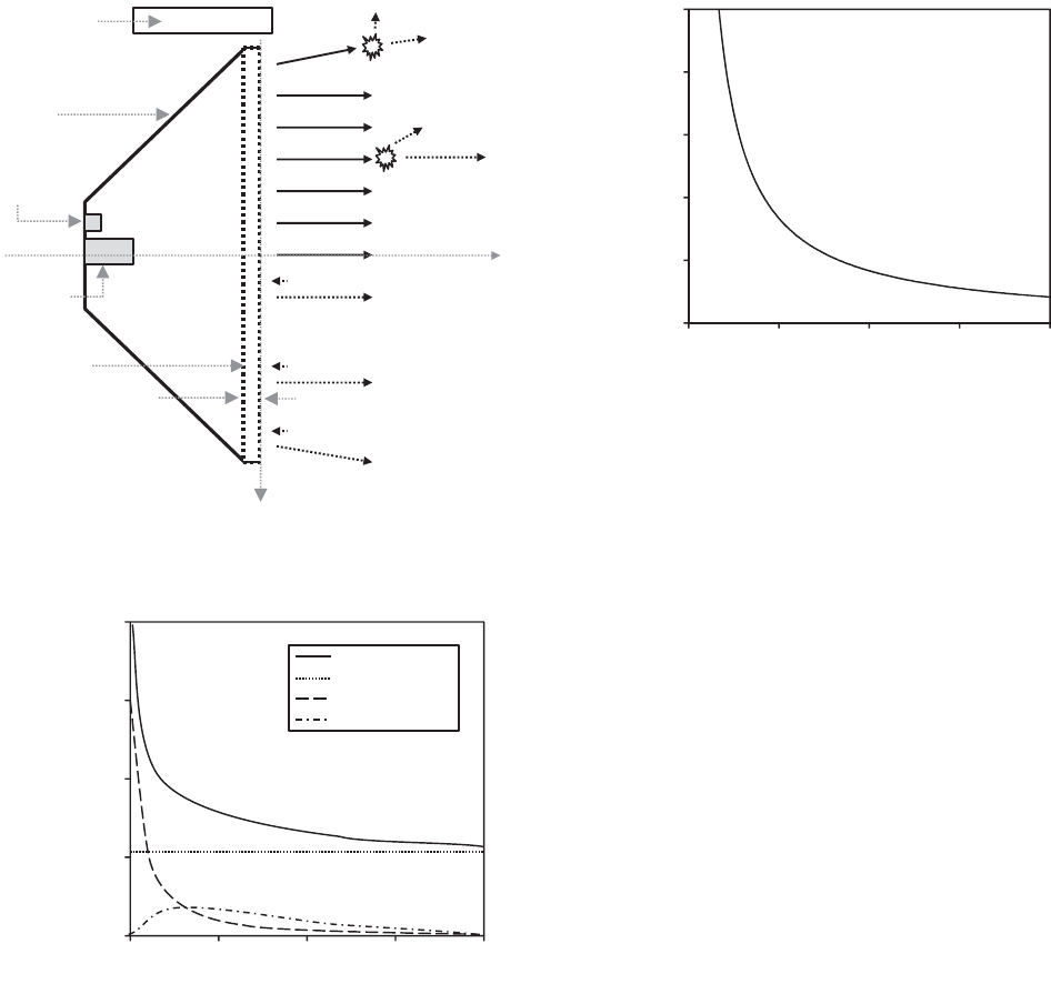
The influence of collisional processes between facility neutrals
and the thruster beam may be evaluated with respect to the neutral
particle populations in EP plumes, as shown in Fig. 5 for simulations
of the BPT-4000 HET [22]. In Fig. 5, the ambient facility neutral
density exceeds the thruster neutral density beyond approximately
0.02 m, which is comparable to GIT plumes for a similar propellant
flow rate [23]. The mean free path (MFP) in Eq. (1) represents the
mean distance a fast particle will travel in a background of stationary
neutrals before a collision:
Thruster
Centerline
Neutralizer
Cathode with
Gas Feed
Ion Optics
e
-
Neutralizing e
-
Xe
0
Anode
Plasma
Generator
Propellant
Gas Feed
Xe
+, +2,…
Beam Ions
Discharge
Cathode
with Gas
Feed
Electrostatic Ion
Acceleration
y
z
Fig. 2 Schematic of design features and plasma properties for GITs.
Xe
+, +2,…
Beam Ions
North
North
Thruster Centerline
Magnets
Cathode with
Gas Feed
Insulator
Anode with
Propellant
Gas Feed
Xe
0
Background Xe
0
Ionization and
Acceleration
Xe
+, +2,…
Accelerated
Background
Ions
Xe
0
↔Xe
+
CEX Collision
Fast Xe
0
Slow Xe
+
Slow Xe
+
Fast Xe
0
Fast Xe
0
Slow Xe
+
Ingested
Background
Xe
0
y
z
South
Fig. 3 Diagram of HET plasma interactions of facility background
neutrals.
584
BROWN ET AL.
Downloaded by GEORGIA INST OF TECHNOLOGY on January 19, 2018 | http://arc.aiaa.org | DOI: 10.2514/1.B35696
λ
MFP
n
n
σ
−1
(1)
In Eq. (1), n
n
is the neutral density and σ is the particle collision
cross section. The MFP may be used to determine the dominant beam
collisional processes in the plume region; an overview of particle
collisions and relevant cross sections was described elsewhere
[6,24,25]. The cross section for CEX collisions between ambient
xenon neutrals and xenon ions has been experimentally measured as
5 × 10
−19
to 8 × 10
−19
m
2
[25], which was much larger than the cross
section for xenon-neutral elastic scattering (10
−20
m
2
), as well as
xenon ionization and excitation cross sections (10
−20
m
2
) [6,26]. The
CEX collisions between background neutral particles and beam ions
generated high-velocity neutrals and low-energy scattered ions. The
CEX collisional processes scattered beam ions and increased ion
current density on the periphery of the plume, thereby increasing
thruster plume divergence [18,27,28]. Based on Eq. (1), the xenon
ion-neutral MFP of CEX collisions is shown in Fig. 6. For a HET or
GIT operating at a 300 V discharge condition, the relative velocity
between the xenon ions and neutral atoms was approximately
17;000 m∕s and the CEX cross section was 6 × 10
−19
m
2
[25]. For a
background neutral pressure of 1.3 × 10
−5
torr of xenon gas
(torr-Xe), the neutral number density was 4.2 × 10
17
m
−3
[29] and
the ion-neutral CEX collision MFP was 3.97 m. The MFP values in
Fig. 6 are on the order of the far-field spatial measurement region, and
they are consistent with far-field experimental results showing
increased plume divergence at elevated facility pressure in Sec. V.
Although the ion-neutral CEX MFP is larger than the near-field
spatial region of interest for most HETs and GITs, the difference is
not significant; thus, CEX collisions are expected to have a
nonnegligible effect in the near-field plume. These observations will
be discussed with experimental results in Sec. V.
The second dominant facility interaction is associated with
ingestion of facility background neutrals near the thruster discharge
exit, which increases the amount of propellant used by the thruster.
These ingested neutrals undergo ionization and subsequent
acceleration, which increases the amount of propellant available to
the thruster. The ingested facility neutrals may be ionized and
accelerated downstream of the peak electric field, and thus manifest
as a low-velocity divergent ion population in the beam. In GITs, the
accelerator grid current may become prohibitively high at an elevated
background pressure due to a CEX ion current, and therefore
operation at these elevated pressures is often impractical well before
ingestion effects become a significant factor. This is further discussed
in Sec. IV.E.
Multiple studies have evaluated Faraday probe design modifications
to minimize facility effects associated with probe collection of low-
energy CEX ions and ions generated from ingested propellant,
including probe filtering mechanisms and collimators [1,30–32].
Although these techniques successfully mitigate the collection of low-
energy ions generated through facility interactions, they introduce
additional error that is not representative of thruster plumes in the space
environment. The impact of these facility interactions on Faraday
probe measurements will be discussed, and guidelines to mitigate and
account for the effects will be recommended.
In theory, computational simulations of the EP plume allow
isolation and elimination of facility pressure effects to predict the
on-orbit ion beam. However, this predictive capability relies on
accurate plasma input source models, understanding of facility
interactions, and validation with flight measurements and ground
testing. To date, comparisons of plume profiles between ground
testing, flight data, and/or simulations demonstrate inconsistent
agreement [33–37].
III. Experimental Apparatus
The test hardware and configuration requirements for plume
measurements of ion current density include the Faraday probe,
motion control system, power electronics, and data acquisition
(DAQ) system to monitor collected current. The power electronics,
experimental configuration, and probe calibration considerations are
described in the following sections.
0 0.1 0.2 0.3 0.4
Distance Downstream of Thruster Exit Plane (m)
Neutral Particle Density (m
-3
)
4.0x10
18
2.0x10
18
0
Total
Facility
Hall Thruster
Hollow Cathode
Fig. 5 Neutral particle density on thruster centerline, recreated from [22].
0.0
1.0
2.0
3.0
4.0
5.0
Neutral Particle Density (m
-3
)
Ion-Neutral Mean Free Path (m)
4.0x10
18
3.0x10
18
2.0x10
18
1.0x10
18
0.0
Fig. 6 Xenon ion-neutral CEX mean free path for expected neutral
particle density in the near-field plume, for σ 6 × 10
−19
m
2
.
Thruster
Centerline
Xe
+, +2,…
Accelerated
Background Ions
CEX Collision
Slow Xe
+
Slow Xe
+
Fast Xe
0
Fast Xe
0
Ingested
Background
Xe
0
Neutralizer
Cathode with
Gas Feed
Xe
0
y
z
Ion Optics
Anode
Plasma
Generator
Propellant
Gas Feed
Discharge
Cathode
with Gas
Feed
Electrostatic Ion
Acceleration
Xe
0
↔Xe
+
Fig. 4 Diagram of GIT plasma interactions of facility background
neutrals.
BROWN ET AL. 585
Downloaded by GEORGIA INST OF TECHNOLOGY on January 19, 2018 | http://arc.aiaa.org | DOI: 10.2514/1.B35696

A. Hemispherical Coordinate System and Test Configuration
Faraday probe measurements in a hemispherical coordinate system
are shown in Fig. 7 with respect to Cartesian coordinates, where θ is the
angular position from thruster centerline, Φ is the azimuthal angle, R is
the measurement distance, and D
T
is the thruster diameter. In this
paper, D
T
is defined as the outer grid diameter for GITs or outer
channel diameter for HETs. Different definitions, such as the
midchannel diameter of HETs, may necessitate minor modification to
equations and will be identified in the text. The plume is assumed
axisymmetric about the z axis,and the probe axis of rotation is typically
the y axis at the intersection of the thruster exit plane and the thruster
centerline axis in Fig. 7. The Faraday probe is swept in an arc at
constant R, and the collector face is pointed toward the rotation axis at
all angular locations of the measurement.
Note that, in a true hemispherical coordinate system, the angular
coordinate θ cannot be negative with respect to the thruster centerline
axis. However, for EP thruster testing, probes are generally swept
from one side of the thruster to the other. Plasma measurements are
collected during the entire sweep, thereby providing data from two
opposing azimuthal angles (i.e., Φ 0 and 180 deg). Common
convention within the EP test community is to refer to these two
datasets as the positive θ and negative θ datasets, where −θ refers to
data collected at Φ 180 deg since cos180 deg is −1. Collecting
data in this fashion has the advantage of allowing researchers to
determine the symmetry of the plasma plume in the swept plane. For
the purpose of this paper, −θ positions represent the left side of the
plume where Φ 180 deg and is understood to represent angular
positions opposite of the azimuthal plane at Φ 0 deg.
The hemispherical coordinate geometry should be used for
measurements of the far-field HET and GIT plume, which is defined
as the region where R is greater than four thruster diameters
downstream (TDD) of the exit plane, such that R∕D
T
is greater
than 4. Measurements where R∕D
T
is less than 4 have been shown
to introduce systematic error, since the hemispherical coordinate
system assumes a point ion source [18]. This issue is further
discussed in Sec. V.B. In addition, multiple HET investigations have
shown a nonnegligible population of beam ions on the periphery of
the plume beyond θ 50 deg for different thruster designs and over
a wide range of operating conditions [38,39]; the hemispherical
coordinate system is well-suited to evaluate these divergent plume
structures.
If an external cathode is used for beam neutralization and the
Faraday probe measurement sweep is conducted in the Φ 0 deg
plane, the cathode should be positioned in the Φ 90 deg or
270 deg plane (i.e., y-axis). Faraday probe sweeps in the cathode
plane may measure localized plume asymmetry near the cathode.
B. Cylindrical Coordinate System and Test Configuration
The cylindrical coordinate system is defined in Fig. 8 with respect
to Cartesian coordinates, where r is the radial coordinate, z is the axial
coordinate, and Φ is the azimuthal angle [40]. The plume is assumed
to be axisymmetric about the z-axis and the axial measurement
distance Z is defined with respect to the thruster exit plane, where
z 0. Beam ions are assumed to be aligned in the axial direction, and
therefore the probe face is oriented normal to the z-axis. The probe is
typically swept in the radial direction at a fixed axial distance Z, with
Φ 0 deg and/or 180 deg.
In a true cylindrical coordinate system, r cannot be negative with
respect to the thruster centerline axis. Similar to discussions of −θ in
the hemispherical coordinate system, near-field Faraday probe
measurements are typically swept across the plume. Thus, a single
Fig. 7 Diagram of a) hemispherical coordinate system for far-field
Faraday probe measurements and b) measurement geometry in x-z plane
where Φ 0 and 180 deg.
Fig. 8 Diagram of a) cylindrical coordinate system for Faraday probe
measurements and b) measurement geometry in x-z plane where
Φ 0 deg.
586
BROWN ET AL.
Downloaded by GEORGIA INST OF TECHNOLOGY on January 19, 2018 | http://arc.aiaa.org | DOI: 10.2514/1.B35696

dataset includes opposing azimuthal angles (i.e., Φ 0 and
180 deg). Common convention within the EP test community is to
refer to these two datasets as the positive r and negative r datasets,
where −r refers to data collected at Φ 180 deg because
cos180 deg is −1. Collecting data in this fashion has the advantage
of allowing researchers to assess plume symmetry. For the purpose of
this paper, −r positions represent the right side of the plume where
Φ 180 deg and are understood to represent angular positions
opposite of the azimuthal plane at Φ 0 deg.
A cylindrical coordinate system should be used in the near-field
plume extending from the thruster exit plane to Z∕D
T
less than four,
which is equivalent to R∕D
T
less than four on the thruster centerline
in the hemispherical coordinate system. If an external cathode is used
for beam neutralization and the Faraday probe measurement sweep is
conducted in the Φ 0 deg and/or 180 deg plane, the cathode
should be positioned in the Φ 90 or 270 deg plane (i.e., y axis).
Faraday probe sweeps in the cathode plane may measure localized
plume asymmetry and plasma gradients near the cathode, which
complicate data analysis [41].
A limitation of the cylindrical coordinate system is the inability to
measure high-energy beam ion flux at high angles from the thruster
centerline approaching Ψ 90 deg (in Fig. 8) because the probe is
oriented perpendicular to the thrust axis. HETs in particular exhibit a
nonnegligible fraction of beam ions on the plume periphery [38,42];
thus, the cylindrical coordinate system may not be practical for
quantitative evaluation of the near-field HET plume for 1 < Z∕D
T
< 4.
C. Probe Positioning Techniques
Faraday probe measurement positioning may be performed with
two methods, either 1) maintain continuous motion and data
acquisition, or 2) stop at a specific measurement position, record data,
and then move to the next position. Probe acceleration and translation
speed impacts spatial accuracy, resolution, and scan duration. Large
acceleration and deceleration magnitude may induce probe vibration,
and thus it is critical to characterize the effect on resolution if the probe
is stopped at each measurement location. For continuous motion, the
probe translation speed will limit spatial measurement resolution.
Limiting factors for slow translation speeds include long duration of
the measurement sweep, probe heating, and survivability. High-speed
motion stages should be employed if excessive probe heating and
survivability are an issue, which imposes additional demands on the
mechanical setup. For example, the supporting structure for Faraday
probe armature and the high-speed motion stage must be secure, and
they should be attached to the test facility in a way that also braces
against possible torsional modes. Additional information on high-
speed probe positioning may be found in [43,44].
There is currently no simple formula for determining a minimum
motion stage speed necessary to pass through the thruster plasma.
The probe area and the residence time in the plasma are proportional
to the total energy transferred to the probe as heat. Past near-field
studies of a 20 kW HET plasma demonstrated a probe residence time
in the plasma of ∼1swas acceptable for a probe with frontal area of
∼10 mm
2
at 0.05 TDD from the exit plane [45]. During these studies,
the probe translation speed ranged from 150 to 500 mm∕s.
D. Power Electronics and Data Acquisition
Power electronics serve two functions: to source electrode bias
voltage, and to measure ion current collected by the electrode. The
probe bias repels electrons such that the probe is in ion saturation.
Probe electrode biasing is accomplished through the use of one or
more dc power supplies, typically −15 to −30 V with respect to
facility ground in far-field measurements and approaching −100 V
with respect to facility ground in near-field measurements. A single
power supply can bias the collector and guard ring electrodes to the
same bias potential V
bias
, assuming equivalent electrical wiring
lengths are used to both electrodes. Additional power supplies may be
necessary if a filtering or collimating technique is used that requires
different voltages than that applied to the collector. The electrical
diagram of a recommended probe circuit is shown in Fig. 9, where the
ion current to the collector I
FP
may be read as a voltage V
FP
across the
resistor R
FP
. The resistance of R
FP
is typically between 10 and
1000 Ω. Larger R
FP
resistance values may influence measurements
in several ways, including generation of a low-pass filter, creating a
voltage divider effect with measurement equipment, or Johnson–
Nyquist noise [46]. Avoltmeter may be used to measure V
FP
. Often, a
DAQ system or digital multimeter with high impedance (greater than
gigaohms) is required to further reduce leakage current. (Leakage
current is equivalent to probe voltage divided by input impedance.
For megaohm input impedance, the leakage current may exceed a
nonnegligible fraction of the probe signal strength in the far-field
plume (∼10–100 μA∕cm
2
), thereby limiting resolution and increas-
ing measurement uncertainty. For example, a probe bias of −20 V
and 1MΩ input impedance generates leakage current of ∼20 μA,
whereas 1GΩ input impedance corresponds to ∼20 nA.)
Resistance between the collector and guard ring, identified as
R
C-GR
in Fig. 9, and between the collector to ground should be large,
such that stray current does not exceed the ion current measurement
resolution. For ion current measurement resolution of 1 nA and
typical electrode bias voltage ranging from −10 to −100 V, the
resistance R
C-GR
from the collector to the guard ring should exceed
100 MΩ 10 V∕1nA). An isolation amplifier may be imple-
mented to prevent arc events from damaging the DAQ system.
The measurement DAQ rate is typically determined by the desired
spatial resolution and probe speed. High-speed probe positioning may
require an encoder. If an encoder is not used, the repeatability of probe
positioning should be characterized to evaluate precision and estimate
positioning error. During measurements with low data acquisition
rates, the probe location may be monitored through encoders, through
the motion controller, or through the controlling program.
E. Probe Calibration, Alignment, and Periodic Maintenance
The methods described in this section are suitable to minimize
systematic error in key aspects of the measurement system and
experimental configuration in a ground test environment. The F araday
probe, probe positioning, and D AQ system may be characterized and/or
calibrated according to manufacturer recommendations before Faraday
probe measurements. Ideally , before testing the probe, an experimental
measurement system would be ev aluated with an ion source that could
provide a uniform, monoenergetic ion beam with the ion energy per
charge ranging from 0 V to greater than the maximum thruster
acceleration voltage. Although this approach may be ideal in an
inv estigation with unlimited resources, there are significant limitations in
applying the characterization of an ideal ion beam to measurements of EP
thruster plumes and mitigating systematic error associated with facility
pressure effects. First, the thruster ion beam will vary spatially (and
temporally in the case of HETs) throughout the plume, including ion
energy distribution and ion charge states. Second, the thruster ion beam
will be influenced by facility effects and vary with thruster operating
condition. Thus, the complexities of EP plumes and resources required to
characterize the experiment with an ion source make it impractical for
most investigations. In practice, the errors may be characterized and/or
mitigated with careful probe design, using correction factors, and
implementing the test and analysis methods described in Secs. IVand V.
The manufacturer uncertainty in DAQ system components should
account for many drift errors or offsets. It is important to account for
R
FP
Guard Ring
V
FP
V
bias
R
C-GR
Collector
Fig. 9 Electrical schematic of a typical Faraday probe showing the
collector and guard ring.
BROWN ET AL. 587
Downloaded by GEORGIA INST OF TECHNOLOGY on January 19, 2018 | http://arc.aiaa.org | DOI: 10.2514/1.B35696

DAQ system error for the measurement range and DAQ thermal
environment specified by the manufacturer. In addition, a null
measurement of the DAQ system without plasma may be used to
assess DAQ system uncertainties.
Resistance of the collector to ground and R
C-GR
should be
measured before testing; both should exceed 100 MΩ. If the
resistance is below this threshold, the exposed surfaces within the gap
between the collector and guard ring should be evaluated for surface
deposition. Faraday probe contaminants may include materials used
in the thruster, cathode, spacecraft or facility, Faraday probe
materials, and experimental mounting hardware. Common sputtering
contaminants may include iron, tungsten, molybdenum, stainless
steel, ceramics (i.e., boron nitride, alumina, etc.), graphite, and
Kapton. Sputtering of dielectric or conductive materials may impact
probe ion collection in different ways, such as leakage current from
the collector, collector thermionic emission, or collector secondary
electron emission (SEE) [47–50]. Contamination effects will likely
manifest in multiple ways and may affect the data in a competing
manner. In this case, the probe should undergo a cleaning process to
reduce contamination and remove buildup of sputtered material
through exposure to high-energy ions in the beam [51,52], or it may
be cleaned periodically, such as with 40% isopropyl alcohol.
Although it is possible to remove surface material buildup, and even
achieve a polished finish by sanding the probe surfaces, this should be
done with caution to avoid altering probe dimensions and tolerances;
reassessment of probe dimensions and evaluation of the collection
area are recommended if sanding is implemented.
Probe alignment and orientation with respect to the thruster should
be conducted before evacuating the facility. For evaluation of the
axisymmetric plume, the collector face should be aligned parallel to
the thruster exit plane to within 1 deg when the probe is located on the
thruster centerline. The downstream distance R (or Z)shouldbe
measured along the thruster centerline from the centerpoint of the
probe collector surface to the intersection with the thruster exitplane, as
shown in Figs. 7 and 8. The definition of the thruster exit plane is
thruster design dependent, and it is left to the user. The probe axial and
radial position accuracy should be within 1 mm or 0.5% of R (or Z)at
the furthest measurement distance (i.e., 5 mm at R 1m): whichever
is greater. Alignment may be repeated at multiple distances and angles
from the thruster centerline. These alignment tolerances are less than
the measurement resolution, and they are intended to minimize spatial
error in measurements to provide sufficient resolution for plume
regions with steep gradients in plasma properties and for validation of
high-fidelity modeling and simulation[53,54]. Due to the possibility of
damage to the probe or thruster with misalignment, a device for
alignment while under vacuum may be used, such as a contact probe
and a reference with a fixed, known position relative to the thruster.
During plasma plume mapping, there should be no obstructions in
the line of sight of the Faraday probe to any point of the thruster
plasma discharge. Diagnostic wiring should be a coaxial cable or
twisted shielded pair, and electrical connections should not be
exposed to the plasma. Cable shielding should be grounded to the
facility walls in ground testing. All probe mounting structure and
cables near the probe should be downstream of the probe collection
surface. Any mounting structure that experiences direct beam ion
impingement should be shielded with low-sputter materials, such as
Kapton or graphite [48,55].
The user should consider Faraday probe distance from the facility
walls or other grounded surfaces. One possibility is maintaining a
probe distance greater than one mean free path from the facility walls.
In this case, using Eq. (1) for a thruster operating at 1.3 ×
10
−5
torr-Xe and a local electron temperature of 2 eV (electron-
neutral elastic collision cross section of 1.6 × 10
−19
m
2
) results in an
electron-neutral MFP of 12.3 m [56]. Thus, this approach is likely not
practical. An alternative approach is based on the Debye length λ
D
in
Eq. (2), which is the length scale that the bulk plasma shields the
effect of the perturbing electrode:
λ
D
ε
0
k
B
T
e
e
2
n
r
(2)
Electron number densities typically vary over more orders of
magnitude than electron temperature in the EP plume; therefore, the
electron Debye length is primarily dictated by the plasma density. For
a typical thruster plasma with an electron temperature of 2 eV and an
electron number density of 10
13
m
−3
, the electron Debye length
is 3.3 mm.
IV. Test Methodology
A. Test Conditions and Plasma Regimes
Spatial variations of plasma properties in EP plumes span orders of
magnitude, and they necessitate consideration of the facility
interactions with the thruster plasma and probe ion collection. The
time-averaged ion current density in the plume of HETs and GITs
typically ranges from 1 to 100 mA∕cm
2
in the near-field to less than
0.001 mA∕cm
2
in they periphery of the far-field plume [21,45]. Over
this region, the time-averaged electron temperature and ion density
range from approximately 10 eV and greater than 10
18
m
−3
in the
near-field (Z > 0.2D
T
) to less than 1 eVand 10
13
m
−3
in the far-field
plume periphery.
Analyses of collisional processes in the plasma plume indicate
CEX collisions between beam ions and facility neutrals dominate
over ion-neutral momentum collisions or Coulomb interactions [39].
There is an important distinction in CEX collisions between beam
ions with facility neutrals or beam ions with non-ionized propellant
from the thruster and cathode. The former are a leading source of
facility effects that should be evaluated and corrected for. The latter
CEX collisional processes exist on orbit and should not be filtered
from Faraday probe measurements. Differentiating these CEX
processes and characterizing the facility influence on ion beam
properties requires the lowest facility pressure achievable and
execution of the methodologies described in this paper.
Facility pressure during Faraday probe measurements should be as
low as possible to better replicate the space environment. Modern
vacuum facilities may achieve background pressure less than
10
−5
torr-Xe. Lower pressure will give more accurate results, and
therefore it is highly recommended for model validation data and
predictions of the in-space plume properties. The pressure should be
monitored near the thruster and adhere to recommendations in [57].
The thruster discharge should reach operational steady state before
conducting Faraday probe measurements. Thruster input parameters
are typically fixed, such as applied magnetic fields and voltage applied
to electrodes. In addition, the thruster should be monitored for possible
perturbation during a sweep, which may be associated with plasma
interaction with the probe mounting structure or the influence of probe
bias and local sheath effects. The definition of steady state and
perturbation should be identified by the user. It is recommended that
the thruster discharge telemetry be monitored throughout plume
characterization. Monitoring may include time-resolved and time-
averaged thruster telemetry such as discharge voltage(s) and current(s),
mass flow rate, cathode to ground potential, and thrust.
Facility background pressure may influence the ratio of thruster
discharge current to the anode propellant flow rate. If Faraday probes
are used to measure the ion current density of the HET plume at
multiple background pressures, either the thruster discharge current
or anode mass flow rate should be held constant; this may require
adjustment of the unfixed parameter and should be reported.
B. Probe Operating Characteristics
The bias potential to the collector and guard ring should be equal,
and it must be sufficient for collector ion current saturation
throughout the plume measurement region. The probe ion saturation
should be characterized at multiple locations in the plume to span the
maximum and minimum plasma densities and electron temperature.
In far-field measurements, this typically corresponds to the minimum
R at θ 0 deg and the maximum R at θ 90 deg. In cylindrical
coordinates, this typically corresponds to the minimum Z down-
stream of the plasma discharge (e.g., channel centerline for HET) and
at maximum distance on the plume periphery (i.e., maximum Z and/
or r). At each location, the collector ion current should be assessed,
starting from 0 V to a negative bias voltage where the collected
588 BROWN ET AL.
Downloaded by GEORGIA INST OF TECHNOLOGY on January 19, 2018 | http://arc.aiaa.org | DOI: 10.2514/1.B35696

current asymptotes. This negative bias voltage indicates ion
saturation. Characterization of ion saturation is demonstrated in
Fig. 10 at R 50 cm for the nested Faraday probe described in [18],
where the measured collector current is peak normalized at each
angular location. There is not a quantified value for the degree of ion
saturation necessary for Faraday probes in an EP plasma. Thus, it is
suggested that ion saturation is achieved when the change in
measured collector current is less than approximately 1% per volt of
collector bias. Applying this criterion to data in Fig. 10, ion saturation
is achieved for an approximately −20 V bias on the collector and
guard ring with respect to test facility ground. This value is consistent
with bias voltage typically used in far-field measurements, which
range from −10 to −30 V. Typically, the least negative bias voltage
necessary to achieve ion saturation throughout the far-field plume
should be used. In near-field measurements, there can be a large
variation in bias voltage required for ion saturation, and interactions
between the plasma and thruster surfaces can introduce large
variations in floating potential. A Faraday probe bias voltage as low
as −100 V may be necessary to enter the ion saturation regime at the
closest approach to the thruster [45]. Since the bias voltage can vary
greatly depending on distance from the thruster and thruster
operating condition, a variable bias voltage may be used. If a fixed
Faraday probe bias voltage is used at all locations, local Langmuir
probe plasma measurements may inform whether collector sheath
expansion is impacting Faraday probe measured current.
The wide range of plasma conditions in the EP plume necessitate
careful e v aluation of collected ion current due to ambient plasma and the
collector plasma sheath. The Bohm sheath criterion is used to calculate
the probe ion current (also called the Bohm current [6]) in Eq. (3), where
the thin-sheath assessment is applicable (R
P
> 10λ
D
)[58]:
j
Bohm
e
−1
2
en
eT
e
M
i
s
(3)
The Bohm current density j
Bohm
is evaluated for n and T
e
at the edge
of the presheath. It is expected to increase for elev ated background
pressure; thus, the Faraday probe would measure an artificially high ion
current density. If the ratio of R
P
∕λ
D
is less than 50, the collector sheath
will expand as an oblate ellipsoid and increase the effective ion
collection area [59,60]. Note that the ou ter diameter of the biased
surface is suitable for e v aluation of sheath expansion; thus, probe radius
R
P
is equal to the guard ring outer radius or else R
P
is equivalent to R
C
if
no guard ring is used. Probe sheath expansion is most likely to arise for a
small probe radius on the plume periphery at low background pressure,
where the plasma density is lowest. T rends in j
Bohm
and R
P
∕λ
D
are
ev aluated in Fig. 11 over a range of typical plasma properties, where
R
P
20 mm.InFig.11,j
Bohm
shows significant va riation over the
range of plasma density from 10
13
to 10
16
m
−3
but minor sensitivity to
electron temperature from 0.5 to 3 eV. For a typical Faraday probe radius
of 20 mm in 3 eV plasma conditions, the thin-sheath assessment is not
applicable (i.e., R
P
∕λ
D
< 50) at pressure less than approximately
10
15
m
−3
(in Fig. 11); thus, collector sheath expansion may be an issue
at these local plasma conditions. In cases where R
P
∕λ
D
is less than 50,
the trends in ion Bohm current may deviate from Eq. (3), as identified
with the black circles on lines of j
Bohm
in Fig. 11 for R
P
20 mm .The
other issue identified in Fig. 11 is ele v ated ion Bohm current density at
high plasma density, which may be a nonnegligible fraction of the ion
beam current. Ideally, j
Bohm
should be less than 1% of the measured ion
current density. Issues associated with probe sheath expansion and
Bohm current collection may have impacted data in Secs. V.B and V.E,
and they will be identified. To evaluate these issues and reduce
measurement error, Langmuir probe measurements of local plasma
density and electron temperature near the Faraday probe may be used to
quantify the effects.
In general, the high-energy flux of EP plasma plumes generates a
harsh environment for plasma diagnostics, the thruster, and other
exposed surfaces in the test or operational space environment. Probe
surfaces with long-duration exposure to beam ions may undergo
degradation through sputtering and subsequent deposition of nearby
materials. This could impact the probe collection area, collector
surface properties, or electrical characteristics of the probe. Thus, it is
recommended to conduct visual inspection and electrical verification
of the Faraday probe at the beginning and end of a test campaign, or if
there is a change in measurement repeatability over time.
In addition to surface degradation, ions transfer a significant
fraction of their energy upon probe impact, leading to elevated
temperatures of the probe, associated support structure, and wiring.
For modern HET and GIT designs of moderate power (less than
5 kW), the maximum ion current density in the near-field is typically
less than 250 mA∕cm
2
for HETs and less than 10 mA∕cm
2
for GITs
[21,44,54,61]. For a beam where each ion deposits 400 eV, the
corresponding maximum energy flux is typically less than
100 W∕cm
2
for HETs and less than 4W∕cm
2
for GITs. Since
plasma diagnostics for EP plumes rarely have active cooling, the
principal means of heat rejection is radiation and passive thermal
conduction through the probe support structure. In the worst-case
estimate of heating with no thermal conduction, the collector radiated
power per unit area is calculated with the Stefan–Boltzmann relation
as εσ
SB
T
4
S
, where T
S
is surface temperature [62]. For a molybdenum
collector at 1000 K, the radiated power is approximately 0.6 to
1.8 W∕cm
2
for a polished surface (ε 0.10) or roughened surface
(ε 0.31), respectively [62]. This is significantly lower than the
high-energy flux conditions of HETs (less than 100 W∕cm
2
) and
GITs (less than 40 W∕cm
2
) described previously; therefore, probe
heating is expected unless there is sufficient thermal conduction in
the probe apparatus. This will be further considered for higher-energy
density devices discussed in Sec. IX, including electromagnetic
propulsion concepts.
In plume regions with high-energy flux, probe heating may
introduce additional measurement error. Thermionic emission
current density may be estimated with the Richardson–Dushman
0.0
0.2
0.4
0.6
0.8
1.0
-25-20-15-10-50
Normalized Colllected Current (-)
Bias Voltage to Chamber Ground (V)
90 deg
60 deg
30 deg
0 deg
Fig. 10 Normalized Faraday probe collector current in the plume of a
200 W HET at R 50 cm.
0
20
40
60
80
100
Plasma Density (m
-3
)
Ion Bohm Current Density (mA/cm
2
)
10
-1
10
16
10
14
Probe Radius / Debye Length (-)
Thin
Sheath
10
-2
10
-3
10
-4
10
-5
10
13
j
Bohm
0.5 eV
1 eV
3 eV
R
P
/ λ
D
0.5 eV
1 eV
3 eV
10
15
Fig. 11 Trends in ion Bohm current density and ratio of probe radius
(R
P
20 mm) to Debye length.
BROWN ET AL. 589
Downloaded by GEORGIA INST OF TECHNOLOGY on January 19, 2018 | http://arc.aiaa.org | DOI: 10.2514/1.B35696

equation in Eq. (4), where φ is the material work function and the
parameter A
G
is specific to material and surface properties (based on
the theoretical Richardson constant) [63]:
j
t
A
G
T
2
S
e
−φ
k
B
T
S
(4)
The Richardson–Dushman equation is valid for surfaces in zero or
weak electric fields. Past measurements of the region surrounding a
nude Faraday probe in the far-field HET plume revealed local electric
fields were less than approximately 100 V∕m [19], and Eq. (4) is
suitable in these plasma conditions. Measurements in regions of high
electric field strength may be susceptible to field enhanced thermionic
emission, also known as the Schottky effect, and may require a
modified version of the Richardson–Dushman equation [64]. A
thermionic emission current less than 1% of the Faraday probe
collected current is recommended, and the maximum collector
temperature may be estimated accordingly for each experiment. For
example, a far-field measurement with an ion current density of
0.01 mA∕cm
2
on the plume periphery would correspond to a
maximum collector temperature of ∼1500 K for thermionic emission
less than 10
−4
mA∕cm
2
, based on Eq. (4) for a pure tungsten surface
where A
G
60 A∕cm
2
· K
2
and φ 4.52 eV [65,66]. Note that
Eq. (4) is sensitive to φ, which may have a significant error due surface
characteristics, such as adsorption of contaminants on the surface [67].
Since the collector surface material properties are typically not well
defined, the collector temperature may be monitored with a
thermocouple to enable qualitative analysis of thermionic emission.
This may also set allowable limits for collector temperature and inform
probe positioning speed through the plume. For example, a collector
temperature less than 700 K would maintain thermionic emission
below 10
−4
mA∕cm
2
, even if surface contamination was suspected of
lowering the work function to φ 2eV.
In the absence of collector temperature measurements, the effects
of probe heating and measurement drift are often considered by
consecutive measurements in opposite sweep directions. The user
may determine whether discrepancies between scans are acceptable.
For example, a past study showed Faraday probe measurements
unaffected by probe heating yielded repeatable profiles of collected
current density to within 2% [18]. In the event ion current density
profiles are not repeatable, experience measurement drift, or the
measurement exhibits sensitivity to sweep direction, further
assessment of the cause is necessary, as this could be associated
with effects not related to the Faraday probe, such as thruster
construction, experimental misalignment, and plasma dynamics or
perturbations.
C. Far-Field Spatial Range and Resolution
When using the hemispherical coordinate system for far-field
plume measurements, the angular sweep should be performed in a
single plane from θ 0 to 90 deg at constant R and fixed Φ (i.e.,
Φ 0 deg), according to Fig. 7a. Faraday probe sweeps should also
be conducted from θ 0 to 90 deg at fixed Φ for the opposite side of
the plume (i.e., Φ 180 deg), such that a continuous measurement
is taken from θ 90 deg at fixed R, as shown in Fig. 7b, to assess
plume symmetry. Asymmetry in the plume may arise due to thruster
misalignment with respect to the coordinate geometry, probe
positioning misalignment, or an asymmetric feature of the thruster,
such as external cathode placement or a mechanical misalignment in
thruster assembly. If significant asymmetry in the plume is observed,
the cause and the impact on measurement uncertainty should be
evaluated.
The plume periphery beyond θ 90 deg may be evaluated to
characterize particle scattering, although data are more susceptible to
facility effects and may influence calculations of total ion beam
current and divergence. Angular measurement resolution should be
less than or equal to 2 deg, and less than 1 deg is recommended. In
addition, the Faraday probe should be sized such that the ratio of
probe collector diameter to measurement radius is less than the
angular resolution (i.e., 2R
C
∕R ≤ dθ ≤ 2 deg). Thus, for a
measurement resolution of 1 deg at a measurement distance of
100 cm, the probe collector diameter should be less than 1.7 cm.
A distance greater than four TDD should be used for far-field
Faraday probe measurements employing the hemispherical coor-
dinate system. This is necessary based on the assumption of an
axisymmetric hemispherical coordinate system with a point source
origin, where approximating the plasma discharge as a point source is
a poor assumption for measurement distances closer than four TDD
[18]. Further discussion on the systematic spatial measurement error
and analytical corrections are provided in Sec. V.B.
D. Near-Field Spatial Range and Resolution
When using the cylindrical coordinate system for near-field
measurements, the Faraday probe radial sweep should be performed
at constant axial distance Z and fixed Φ (e.g., Φ 0 deg), as shown
in Fig. 8. The radial measurement range should extend to the location
where measured ion current density is less than 0.2% of the maximum
current density along the radial profile at fixed Z. This range enables a
0.2% threshold-based integration limit, and it is recommended based
on past experiments [45]. Faraday probe sweeps should also be
conducted at fixed Φ for the opposite side of the plume (i.e.,
Φ 180 deg), such that a continuous radial sweep is taken to less
than 0.2% of the maximum current density value for the left side
(r>0) and right side (r < 0), as shown in Fig. 8b, in order to assess
plume symmetry. Multiple axial measurement distances may be
evaluated for near-field plume asymmetry. Measurement resolution
in the radial coordinate should be less than 0.01D
T
between
measurement locations, where the best resolution is limited by the
probe collector diameter 2R
C
. In the event this criterion is not
practical for small thruster designs or for suitable probe signal
strength, the probe collector diameter may be minimized to approach
the 0.01D
T
criteria and the radial distance between measurements
may be less than 1 mm (i.e., 2R
C
≤ dr ≤ 0.01D
T
or ≤ 1mm,
whichever is greater).
The near-field HET plume should be analyzed at axial distances
upstream of the plume merging region, termed the “transitional
region” in [54], where ion beams from opposing sides of the channel
merge. Past near-field studies of multiple HET designs found this
transitional region was approximately 0.5 to 1.0 TDD [44,45,54].
Axial distances less than 0.2 TDD are not recommended due to
ionization and acceleration processes that may occur downstream of
the HET exit plane, and they have been shown to be influenced by
background pressure [68]. In addition, distances within 0.2 TDD of
the HET body may perturb discharge plasma behavior or encounter
plasma floating potentials on the order of the Faraday probe bias
potential, such that the probe is not electron repelling and may be
susceptible to sheath effects [54]. It should be noted that regions of
plume merging, probe perturbation, and issues due to collector sheaths
or ion Bohm current may vary with thruster design, operating condi-
tions, and background environment. Thus, the spatial measurement
and analysis range should be evaluated for each experiment, and this
will be further discussed in Secs. V.C and V.E. In many cases, these
issues are mitigated by avoiding plume regions where the issues are
present (i.e., plume merging, probe perturbation) or addressed by
monitoring thruster discharge telemetry, described in Sec. IV.A.
Near-field measurements of GIT plumes can be made at distances
as close as a few millimeters downstream of the ion optics. Such
measurements can be used to study individual beamlets. Near-field
measurements of the NASA Evolutionary Xenon Thruster (NEXT)
plume revealed beamlets merged within 0.1D
T
downstream of the
exit [21]. In NEXT investigations, the very near-field Faraday probe
measurements revealed beamlet merging was a viable indicator of
far-field plume divergence. However, the actual location of beamlet
merging is in large part a function of the ion optics geometry. For
example, investigations of the High Power Electric Propulsion
(HiPEP) ion thruster, which has flat rectangular ion optics apertures
(40 by 90 cm), measured individual beamlets as far as 13 cm
downstream of the grids, which was approximately 36% of the grid
width (analogous to 0.36 D
T
) [69]. To accurately interrogate the
region upstream of beamlet merging in GITs, a small Faraday probe
590 BROWN ET AL.
Downloaded by GEORGIA INST OF TECHNOLOGY on January 19, 2018 | http://arc.aiaa.org | DOI: 10.2514/1.B35696

collector diameter less than the grid aperture spacing is required and a
high radial measurement resolution is necessary to resolve beamlet
ion current density profiles. Systematic evaluation of different
thrusters and examination of facility interactions in the very near-field
of GITs is recommended to establish a minimum measurement
distance. The maximum near-field distance for GITs is likely limited
by the radial measurement range required to capture a significant
fraction of beam ions, where proximity to facility walls may be a
factor. Thus, the spatial measurement range should be evaluated for
each GIT experiment.
E. Characterization of Facility Effects
Facility pressure effects associated with background neutral
particles are inherent in ground-based EP plumes, and they are
unavoidable in both near-field and far-field plume measurements.
The following guidelines are based on experiments with multiple
thrusters at multiple facilities. Although understanding of facility
effects on the near-field plume region is limited, many of the same
plasma interactions known to impact far-field measurements are
expected, as described in Sec. II.B. Thus, recommendations for near-
field measurements are primarily derived from the current state of
knowledge for far-field Faraday probe measurements.
Faraday probe measurements of the far-field and near-field plumes
should be conducted at a minimum of four distances. Further, plume
measurements at each distance should be conducted at a minimum of
four background pressures to enable the extrapolation to spacelike
conditions from ground testing, and they should adhere to
recommendations in [57]. One of the four background pressures
should be the lowest achievable facility pressure during thruster
operation. Background pressure variation is often achieved by
injecting additional propellant gas into the ground test facility or
varying the facility pumping. The maximum background pressure is
typically less than 5.0 × 10
−5
torr-Xe; however, this value may vary
with thruster technology, operating condition, and facility pumping
capability. In HETs, the facility background pressure may influence
thruster operating mode and stability, which is caused by the
additional neutral density near the thruster plasma that is not present
on orbit [70,71]. This behavior has been observed in HETs and may
be identified by a large change in discharge oscillation behavior or
time-averaged discharge current, voltage, or mass flow rate [72,73].
Significant changes in HET operation may invalidate the pressure
characterization for Faraday probe measurements; therefore, the
thruster should be monitored for large changes in operation, as
described in Sec. IV.A.
In GITs, the influence of background pressure is evident from the
accelerator grid current. In the space environment, the accelerator
grid current is primarily associated with collection of low-energy ions
generated from CEX collisions between beam ions and the non-
ionized thruster neutrals that escape through the ion optic grids [23].
The elevated pressure in ground testing introduces additional CEX
collisions, and thereby increases GIT accelerator grid current that is
not present in flight conditions; the increased GIT accelerator grid
current indicates increased CEX ions impinging the grid, which
cause significant erosion and eventually form holes through the
accelerator grid webbing. At high propellant utilization of ∼90%, the
space equivalent accelerator grid current ranges between 0.25 to
0.5% of the total beam current over a range of operating conditions, as
shown in Fig. 12 for the NASA Solar Technology Application
Readiness (NSTAR) ion thruster on the Deep Space One (DS1)
Mission and in ground test facilities [74,75]. In general, the ratio of
accelerator grid current relative to thruster beam current decreases
with decreasing chamber pressure, as shown in Fig. 13 for a 30 cm
GIT at 3.2 A beam current in ground tests at NASA Glenn Research
Center (GRC) and Jet Propulsion Laboratory (JPL) [76]. This
variation can be used as guidance to determine the maximum facility
background pressure used in pressure characterization of GIT
plumes. Although a maximum allowable ratio of accelerator grid
current to total beam current has not been determined, it is expected to
be less than a few percent and may be determined by the user.
Without predictive capability of facility pressure effects on the
thruster and on the Faraday probe, the systematic error cannot be
determined a priori. Different facility interactions may dominate in
different regions of the plume; thus, plume characterization with
distance and pressure is considered the best approach to quantify
spatial variation in plume properties and probe behavior; systematic
errors are not easily quantified through data postprocessing or
generalized analysis. Plume characterizations over a range of
measurement distances and background pressures are recommended
to resolve nonlinear trends, as will be shown for experiments with a
200 W HET in Sec. V.E. Additional measurement distances, lower
facility background pressure, and characterizations at additional
pressures will improve corrections for facility interactions and
predictions of the space environment.
Qualitative assessment of the plasma profile may be conducted at a
single measurement distance or pressure, which limits the application
to thruster-to-thruster comparisons of the same model (i.e., acceptance
testing) or over the course of an extended firing (i.e., life test). A single
Faraday probe measurement should not be used to quantify ion beam
current or plume divergence losses in performance. Further, using a
single Faraday probe measurement should be avoided for plume
predictions of the space environment, comparisons between facilities,
or validation data for computational simulations.
V. Data Analysis
A. Ion Current Density
For a Faraday probe collector in ion saturation, the ion charge flux
or ion current density j is calculated as
j
X
k
Γ
k
Z
k
e
I
FP
A
c
κ
G
κ
SEE
(5)
where Γ is the local ion flux of the k th species, Z
k
is the ion charge
state, A
C
is the cross-sectional geometric area of the collector face
0.0
1.0
2.0
3.0
4.0
5.0
0.4 0.6 0.8 1.0 1.2 1.4 1.6
Beam Current (A)
Accelerator Grid Current (mA)
Ground Test, VF 5 at NASA GRC
Ground Test, 10 ft Chamber at JPL
DS1 Flight, 0-432 h
DS1 Flight, 432-14200 h
Markers = Data
Lines = Best Fit
Fig. 12 Accelerator grid current of the NSTAR GIT, recreated from [74].
0.0
0.5
1.0
1.5
2.0
0
10
20
30
40
50
60
70
Background Pressure (torr-Xe)
Accelerator Grid Current (mA)
10
-4
10
-5
10
-6
Accelerator Grid Current / Beam Current (%)
GRC 890 h
life test
Curve-Fit to
GRC Data
JPL Data
Fig. 13 Accelerator grid current of a 30 cm GIT, recreated from [76].
BROWN ET AL. 591
Downloaded by GEORGIA INST OF TECHNOLOGY on January 19, 2018 | http://arc.aiaa.org | DOI: 10.2514/1.B35696

(A
C
πR
2
C
), κ
G
is a correction for ions collected in the gap between
collector and guard ring, and κ
SEE
is a correction for SEE at the
collector surface. The collected ion current I
FP
is a point
measurement by the Faraday probe at (θ, R) for hemispherical
coordinates as shown in Fig. 7 or at (r, Z) for cylindrical coordinates
in Fig. 8. The correction factors are calculated as
κ
G
πR
2
GR
-R
2
C
2πR
C
h
C
2πR
C
h
C
2πR
GR
h
GR
(6)
κ
SEE
1
1
P
k
Ω
k
γ
k
Z
k
(7)
where γ
k
is the SEE yield from the kth ion species; Ω
k
is the ion
current fraction of the kth species; and the parameters R
C
, R
GR
, h
C
,
and h
GR
are collector and guard ring dimensions for a typical nude
Faraday probe configuration, as shown in Fig. 14.
Past experiments demonstrated ions entering the gap between the
Faraday probe collector and guard ring are a nonnegligible fraction of
the measured collector current [77]. The effect is illustrated in Fig. 14,
where the effective cross-sectional ion collection area is the sum of A
C
and κ
G
. The correction κ
G
in Eq. (6) is formulated based on the
assumption that ions entering the gap volume will be collected by
exposed, conductive walls and distributed between the collector and
guard ring based on relative wall surface areas. Laboratory studies have
shown the assumption is suitable for probes with a nonconducting
material at the base of the gap, such as ceramic. Ions entering the gap in
probes with a conductiv e base are preferentially collected by this line-
of-sight surface, and the current collected on the sidewalls becomes
sensitive to changes in background pressure [77]. The conductive gap
base raises issues for facility characterizations, and it is discussed with
respect to probe design considerations in Sec. VII.
Although the Faraday probe collector is typically made of low SEE
yield material, such as molybdenum or tungsten, SEE has a
nonnegligible effect on measured ion current. Secondary electrons
born on the negatively biased collector surface will accelerate away
from the probe, which artificially increases measured current. The
correction κ
SEE
formulated in Eq. (7) accounts for the effect, and it
may be calculated using the SEE yield values in Table 1 [78–80].
Tungsten and molybdenum SEE yields in Table 1 were averaged for
xenon ion bombardment over the energy range of 100–1000 V, where
measured yields varied by less than 20% for Xe
bombardment and
less than 10% for Xe
2
and Xe
3
bombardment. Note the
molybdenum SEE yield for Xe
3
ion bombardment is unavailable in
the literature, and it is estimated in Table 1 based on trends observed
for tungsten. Calculation of κ
SEE
in Eq. (7) requires knowledge of the
ion species composition, which may be measured using analysis
techniques for ExB probes (also known as Wien filters) developed in
[81]. The effect of κ
SEE
is small but nonnegligible for the ion species
compositions of typical HET and GIT plumes; the value of κ
SEE
is
greater than 0.95 for typical EP plumes and greater than 0.90 if the
Xe
ion current fraction is reduced to 60%. Thus, not correcting
measurements with κ
SEE
may lead to overprediction of local ion
current density by 5 to 10%, and it should be accounted for in the data
analysis and/or error assessment. However, the spatial variation of
ion species composition in the central plume is not expected to have
a significant effect on the value of κ
SEE
; therefore, a single
measurement of ion species current fraction in the central core is
sufficient to calculate κ
SEE
[82] for evaluation of ion beam current and
divergence. The population of multiply charged ions may increase
beyond the central core; thus, it is advised to incorporate local values
of ion species current composition in evaluations of local spacecraft
plume interactions on the plume periphery.
B. Far-Field Plume
Far-field test methodologies described in Sec. IV.C provide the
necessary characterization to isolate pressure effects and predict
time-averaged ion current density properties in the space vacuum
environment. This is achieved by simple linear regression [83] of ion
current density as a function of pressure at each location in the plume,
as exemplified by far-field measurements of the H6 HET plume in
Fig. 15. The linear extrapolations of ion current density to vacuum
conditions in Fig. 15 reveal regions where the linear regression slope
is positive, negative, and near zero. In this paper, a positive slope
refers to an increase of ion current density with increasing pressure,
such as θ 0, 30, 40, and 90 deg in Fig. 15. A negative slope refers to
a decrease of ion current density with increasing pressure, such as
θ 3 and 15 deg. A linear regression slope near zero, such as θ 1
and 24 deg, occurs in regions when the extrapolation to zero pressure
transitions between positive and negative linear regression slope. The
coefficient of determination, termed R-squared (no relation to radial
measurement distance R), for each linear extrapolation is calculated
as the square of the Pearson product moment correlation coefficient,
and it can be interpreted as a metric for how well the linear regression
fits the data [83]. The R-squared term ranges from zero to one, where
a value of unity indicates a perfect fit. Although the linear regression
slope is near zero in the transition region and is associated with low
coefficient of determination, there is minimal change in ion current
density as a function of background pressure, and thus the correction
is small. The method of extrapolating ion current density to zero
pressure conditions has been conducted with multiple HETs at
different facilities [18,70,84–86]. Based on the far-field plume
processes involved, GIT plumes are expected to follow similar trends.
R
P
Collector
R
C
R
GR
h
GR
h
C
Ceramic
Guard
ring
Ions to collector face
A
C
= Cross-Sectional area
Ions to guard ring face
Ions to guard ring Sidewall
Ions to collector Sidewall
κ
G
= effective Cross-Sectional collection area
+
+
+
+
+
+
Fig. 14 Illustration of ions collected by the sidewalls of the Faraday
probe and the effective increase in cross-sectional ion collection area.
Table 1 Summary of SEE yield for xenon ion
bombardment of Faraday probe collector materials [78–80]
Bombarding particle ion
charge state Z
k
SEE yield of
molybdenum γ
k
SEE yield of
tungsten γ
k
1 0.022 0.016
2 0.20 0.20
3 0.70
a
0.71
a
SEE yield unavailable in literature; value estimated based on measured
yield for tungsten.
592 BROWN ET AL.
Downloaded by GEORGIA INST OF TECHNOLOGY on January 19, 2018 | http://arc.aiaa.org | DOI: 10.2514/1.B35696

In Fig. 16, angular profiles of far-field ion current density in the H6
HET plume reveal background pressure effects and show the ion
current density linear regression to vacuum conditions at each
angular location, based on the method shown in Fig. 15. At the plume
periphery in Fig. 16, a difference in ion current density greater than
one order of magnitude between low-pressure measurements and
extrapolated vacuum conditions is consistent with comparison of
flight and ground data for the SPT-100 on the Express Satellite
[33,34,42]. It should be noted that the linear regression to zero
pressure does not arbitrarily force the extrapolated ion current density
to zero at θ 90 deg. The primary sources of error, unrelated to
facility effects, in H6 HET results in Figs. 15 and 16 were accounted
for, including the effective probe collection area and collector SEE.
The effective collection area was determined using Eq. (6), where κ
G
increased the collection area by 13%. The thruster plume was
approximately 90% Xe
and κ
SEE
0.97 as calculated from Eq. (7).
Thus, facility effects were the principal source of error, which is the
motivation for facility pressure characterization. Remaining errors
were expected to be minimal with respect to the trends in Figs. 15
and 16.
Figure 17 displays the angular distribution of the linear regression
slope and coefficient of determination of the H6 thruster operating at
120, 150, and 300 V with 10 mg/s anode flow and 7% cathode flow.
The linear regression slope at thruster centerline decreased from
15 A∕torr · cm
2
at 150 V H6 HET operation to less than
3A∕torr · cm
2
at 120 and 300 Voperation. All H6 HET operating
conditions showed reduction in ion current density with increasing
facility pressure within the central plume core at θ 25 deg,
where the linear regression slope approached −30 A∕torr · cm
2
for
a)
b)
c)
y = 7197.4x + 3.39
R² = 0.8723
y = -222.9x + 3.72
R² = 0.0033
y = -34082x + 4.38
R² = 0.9857
θ = 0°
θ = 1°
θ = 3°
Ion Current Density (mA/cm
2
)
4.5
4.2
3.9
3.6
3.3
3.0
Pressure (torr-xenon)
01x10
-5
2x10
-5
3x10
-5
4x10
-5
5x10
-5
y = 7197.4x + 3.39
R-Squared = 0.8723
y = -34,082x + 4.38
R-Squared = 0.9857
y = -222.9x + 3.72
R-Squared = 0.0033
y = 93.7x + 0.30
R² = 0.0582
y = 1925.1x + 0.12
R² = 0.9933
Ion Current Density (mA/cm
2
)
1.0
0.8
0.6
0.4
0.2
0
Pressure (torr-xenon)
01x10
-5
2x10
-5
3x10
-5
4x10
-5
5x10
-5
θ = 15°
θ = 24°
θ = 30°
y = -5535.6x + 0.89
R-Squared = 0.9560
y = 93.7x + 0.30
R-Squared = 0.0582
y = 1925.1x + 0.12
R-Squared = 0.9933
y = 1525.9x 0.0002
R² = 0.9981
y = 2949.8x + 0.04
R² = 0.9989
θ = 40°
θ = 90°
Ion Current Density (mA/cm
2
)
0.20
0.16
0.12
0.08
0.04
0
Pressure (torr-xenon)
01x10
-5
2x10
-5
3x10
-5
4x10
-5
5x10
-5
y = 2949.8x + 0.04
R-Squared = 0.9989
y = 1525.9x - 0.0002
R-Squared = 0.9981
Fig. 15 Ion current density at six TDD as a function of pressure for the
H6 HET at 300 V, 10 mg∕s anode flow, and 7% cathode flow.
0.0001
0.001
0.01
0.1
1
10
Ion Current Density, mA/cm
2
-90 -60 -30 0 30 60 90
Angular Position, deg
Extrapolation to Vacuum
9.1x10 torr
1.5x10 torr
1.9x10 torr
2.5x10 torr
3.0x10 torr
-6
-5
-5
-5
-5
Ion Current Density (mA/cm
2
)
Angular Position (deg)
Fig. 16 Ion current density at six TDD as a function of angular position
for the H6 HET at 300 V, 10 mg∕s anode flow, and 7% cathode flow.
-50
-40
-30
-20
-10
0
10
20
30
Slope, A/torr-cm
2
-90 -60 -30 0 30 60 90
Angular Position, deg
0.0001
0.001
0.01
0.1
1
Residuals
Line Style Line Color
300V Slope
150V Residuals
120V
Slope (A/torr-cm
2
)
Angular Position (deg)
R-Squared (-)
R-Squared
Slope
Fig. 17 Linear regression slope and coefficient of determination of the
H6 HET ion current density at six TDD.
BROWN ET AL. 593
Downloaded by GEORGIA INST OF TECHNOLOGY on January 19, 2018 | http://arc.aiaa.org | DOI: 10.2514/1.B35696

the 300 V condition. The ion current density ranged from
approximately 1 to 3A∕torr · cm
2
beyond θ 25 deg, which is
attributed to the net migration of scattered beam ions from the
primary ion beam. Although the angular features of the linear
regression slope in Fig. 17 are consistent across operating conditions
(i.e., positive on thruster centerline, negative in the central core, and
positive on the wings), the magnitude and shape are significantly
different, thereby revealing the importance of characterizing
background pressure interactions.
The linear regression of ion current density and extrapolation to zero
pressure are further demonstrated in Figs. 18 and 19 for a 200 W HET
[18]. In Fig. 18, ion current density profiles at 8 and 20 TDD show the
influence of background pressure varies with downstream distance and
pressure, where ion current density is normalized to the centerlinevalue
at eight TDD and 3.1 × 10
−6
torr-Xe. The effects are also evident in
Fig. 19, where a positive linear regression slope on the thruster
centerline is attributed to ingestion, ionization, and acceleration of
facility neutral particles within 10 deg. The region from 10 to
40 deg in Fig. 19 shows a negative linear regression slope. This
feature may be attributed to ion scattering when a slow ion, resulting
from a CEX collision event, is accelerated by radial electric fields in the
plume. The process leads to increased ion scattering to the plume
periphery beyond 40 deg from centerline and increased overall
divergence of the plasma plume.
The angular profiles of linear regression slope were decomposed
into contributions from facility neutral ingestion and ion scattering in
[18], and they enabled examination of the magnitude and angular
range of each effect to enhance evaluations of EP plume structure
with variation in pressure, downstream distance, or operating
condition. The consistent angular features in the linear regression
slope between different thrusters in Figs. 17 and 19 at multiple
operating conditions and at multiple downstream measurement
distances is evidence that the dominant facility effects are common
between the two thruster plumes. Note that ion scattering may be the
dominant effect on thruster centerline rather than facility neutral
ingestion effects, resulting in a net negative linear regression slope.
These results increase confidence that facility effects on the HET ion
beam can be effectively characterized and extrapolation of ion current
density to vacuum is suitable, given the thruster operation and
oscillations are not significantly altered with variation in facility
background pressure.
The far-field GIT beam also shows complex plume structure on the
periphery, as shown for the T5 GIT in Fig. 20 [87] at 11.8 m
downstream (
~
11.8 TDD) and 2 × 10
−6
torr-Xe. Similar structures
were observed on the NEXT thruster [21]. As discussed in Sec. V.D,
the integrated ion beam current from GIT Faraday probe
measurements is often greater than beam current measured by the
ion optics. This may be associated with not using corrections
described in Sec. V.A, such as κ
G
for the effective probe collection
area. To remedy this discrepancy and improve evaluation of GIT
beam divergence, a systematic investigation of the GIT far-field
plume and characterization with background pressure is warranted,
similar to investigations of the 200 W HET plume in Figs. 18 and 19.
The ion beam current of GITs and HETs is calculated from far-field
plume measurements of ion current density in Eq. (5) integrated over
the axisymmetric, hemispherical surface for the fixed sweep radius R:
I
Beam
2πR
2
Z
π∕2
0
jθ
κ
D
κ
A
sinθ dθ (8)
0.001
0.01
0.1
1
10
Normalized Current Density
Extrapolation to Vacuum
3.1x10 torr
1.0x10 torr
3.4x10 torr
-6
-5
-5
8 TDD
20 TDD
-90 -60 -30 0 30 60 90
Normalized Ion Current Density (-)
Angular Position (deg)
Fig. 18 Normalized ion current density of a 200 W HET.
20
15
10
5
0
-5
-10 0.0001
0.001
0.01
0.1
1
Line Style Line Color
8 TDD Slope
12 TDD
16 TDD
20 TDD
-90 -60 -30 0 30 60 90
Slope (A/torr)
Angular Position (deg)
R-Squared (-)
R-Squared
Slope
Fig. 19 Linear regression slope and coefficient of determination of ion
current for a 200W HET.
-40-30-20-100 102030405060
10
0
10
-1
10
-2
10
-3
10
-4
10
-5
10
-6
10
-7
Angular Position (deg)
Ion Current Density (mA/cm
2
)
Fig. 20 Ion current density of the T5 GIT at 1.18 m downstream,
recreated from [87].
594
BROWN ET AL.
Downloaded by GEORGIA INST OF TECHNOLOGY on January 19, 2018 | http://arc.aiaa.org | DOI: 10.2514/1.B35696

Since Faraday probe plume measurements using hemispherical
coordinates are often conducted from θ 0 to 90 deg on both the left
and right sides of the plume in Fig. 7, the ion beam current in Eq. (8)
may be calculated for each side of the plume and averaged. Two
spatial correction factors, κ
D
and κ
A
, are introduced to account for
systematic error associated with the hemispherical coordinate
system, where measurements are with respect to a point source as
opposed to the thruster discharge geometry. The angular correction
factor κ
A
and the distance correction factor κ
D
are formulated by
approximating the thruster ions as originating from two point
sources, as shown in Fig. 21. These point sources are located on the
channel centerline at the exit plane of an annular HET in Fig. 21a. For
GIT geometry, the point sources may be located at the midpoint
between the GIT centerline and the outer diameter of the acceleration
grid, as shown in Fig. 21b. Although the spatial correction factors κ
D
and κ
A
will not eliminate the systematic error introduced with the
hemispherical coordinate system, the approximations serve to
quantify the effect and reduce measurement error.
The correction factor κ
A
accounts for variations in probe angle with
respect to the point sources, which affects the ion angle of incidence
to the probe face and changes with angular position and distance. In
addition, the ion angle of incidence is different for each point source.
An average cosine loss in probe collection area is defined in Eq. (9),
where the ion angles of incidence from the near- and far-point sources
are calculated in Eq. (10) as α
N
and α
F
, respectively. As shown in
Fig. 21, the angle α
N
refers to the ion angle of incidence from the near
source and will alternate from the left to right sides of the diagram in
Fig. 21 as the probe crosses thruster centerline. The width of the
plasma discharge is denoted w, which is the width of the channel in an
annular HET or w D
T
∕2 in a GIT:
κ
A
cos
α
N
α
F
2
(9)
α
N;F
θ;R;D
T
θ − tan
−1
sinθ∓
D
T
−w
2R
cosθ
(10)
The correction κ
D
accounts for differences in path length from the
near- and far-point sources to the probe, which would introduce a
systematic error in the R
2
term in Eq. (8). Probe collector distances
from the near- and far-point sources are characterized as R
N
and R
F
,
respectively. Similar to the analysis of ion angle of incidence, the path
length will vary with probe angular position, and R
N
and R
F
will
alternate from the left to right sides of the diagram in Fig. 21 as the
probe crosses thruster centerline. The exception is on the thruster
centerline, where the distance from the probe to each point source is
equal and greater than R . Using the geometry in Fig. 21, κ
D
is defined
in Eq. (11) based on the lengths R
N
and R
F
, shown in Eq. (12):
κ
D
1
2
R
N
R
R
F
R
2
(11)
R
N;F
θ;R;D
T
R
cosθ
2
sinθ∓
D
T
− w
2R
2
s
(12)
The ratio of spatial correction factors (κ
D
∕κ
A
) is displayed for GITs
(w 0.5D
T
) and HETs (w 0.15D
T
) as a function of probe
angular position in Fig. 22 in terms TDD, calculated as R∕D
T
. The
value of w 0.15D
T
is a representative value for the HET channel
width; however, a smaller channel will further increase the ratio
(κ
D
∕κ
A
). The overall effect of κ
D
∕κ
A
is to increase current density in
the plume central core, where ion current density is greatest, and thus
the spatial corrections increase the calculated ion beam current in
Eq. (8). The variation in κ
D
∕κ
A
decreases rapidly with downstream
distance in the far-field, where the approximation of a point source
measurement improves for hemispherical coordinate system. In
Fig. 23, the correction on the thruster centerline shows the ratio of
κ
D
∕κ
A
rapidly approaches unity with the downstream measurement
distance, and it is less than 1.02 for distances greater than four TDD.
The spatial corrections are valid for beam ions originating near the
exit plane. In addition, the correction only increases the ion source
model from one to two, and it does not directly account for the
accelerated ions across the full grid diameter or the channel width.
This is expected to have a small effect on far-field measurements
taken beyond four TDD, as evidenced by the comparison of w
0.15D
T
and 0.50D
T
in Fig. 23. Although the corrections are
formulated assuming equal contribution of beam ions from each side
of the channel or grid, this should also not be a significant source of
error in the far-field plume.
The axial component of ion beam current is necessary for
calculations of beam divergence, as discussed in Sec. V.E, and is
formulated as
I
Axial
2πR
2
Z
π∕2
0
jθ
κ
D
κ
A
cosα
A
sinθ dθ (13)
where the angle α
A
is introduced to calculate plume divergence with
respect to the channel centerline in HETs or the grid radius midpoint
in GITs as opposed to thruster centerline, as shown in Fig. 24 for HET
geometry. Although this approach has not been applied to GIT
plumes, the geometry will be equivalent to the grid radius midpoint of
w 0.5D
T
. If the GIT outer grid diameter or the HET outer channel
a)
b)
R
Probe
Channel Centerline
D
T
θ
α
N
α
F
R cos(θ)
R sin(θ)
θ
θ=90°
Φ=180°
θ=90°
Φ=0°
Thruster Centerline, θ = 0°
R
F
R
N
w
R
Probe
Outer Grid Diameter
D
T
θ
α
N
α
F
R cos(θ)
R sin(θ)
θ
θ=90°
Φ=180°
θ=90°
Φ=0°
Thruster Centerline, θ = 0°
R
F
R
N
w
Fig. 21 Measurement coordinate geometry showing probe distance
and angular location in a two-point source model for a) annular HET
geometry or b) GIT geometry.
BROWN ET AL. 595
Downloaded by GEORGIA INST OF TECHNOLOGY on January 19, 2018 | http://arc.aiaa.org | DOI: 10.2514/1.B35696

diameter is the preferred, then w 0. The parameter α
A
is calculated
as a piecewise function in Eq. (14):
α
A
θ;R;D
T
8
<
:
θ −α
N
tan
−1
sinθ∓
D
T
−w
2R
cosθ
for sin
−1
D
T
−w
2R
≤ θ ≤ 90 deg
0 for 0 ≤ θ ≤ sin
−1
D
T
−w
2R
(14)
With the axial and total ion beam current, the charge flux weighted
average cosine hcosθi
j
is calculated to determine an effective far-
field divergence angle λ [88].
λ cos
−1
hcos θi
j
cos
−1
I
Axial
I
Beam
(15)
For Faraday probe plume measurements of the H6 HET in Figs. 16
and 17, the variation in thruster discharge current I
d
, I
Beam
, and I
Axial
are shown in Fig. 25. The pressure characterizations indicate these
plume properties increased by 10–20% compared to extrapolated
vacuum conditions and, if unaccounted for, would represent a
significant error in analysis of thruster divergence and utilization
efficiencies. The linear increase in I
d
and I
Axial
with increasing
background pressure is comparable in magnitude for all conditions,
and it is consistent with increasing facility neutral ingestion,
ionization, and acceleration. However, I
Beam
increased at a higher
rate than thruster discharge current with increasing pressure,
indicating I
Beam
was influenced by a facility interaction not related to
the thruster discharge. The I
Beam
trend in Fig. 25 may be influenced
by ionization of facility neutrals far downstream of the thruster
discharge, which would not increase I
d
. However, this is unlikely
because the electron-neutral ionization MFP is greater than 10
2
m
(for n>10
18
m
−3
, σ ∼ 10
−20
m
2
).
A more probable cause of the increased I
Beam
is associated with
Faraday probe collection of the Bohm current on the plume periphery,
described in Sec. IV.B. The Bohm current would have the greatest
influence in regions of low beam ion current density, which is
expected on the plume periphery. Although local plasma densities
and electron temperatures in the H6 HET plume are not known for
these Faraday probe measurements, plasma properties and variation
with pressure may be estimated based on models of a 4.5-kW-class
HET at 300 V discharge [89]. The model indicates local plasma
conditions at R 1m(approximately six TDD in the H6 HET) are
b)a)
1.00
1.02
1.04
1.06
1.08
1.10
0 153045607590
2 TDD
4 TDD
6 TDD
10 TDD
20 TDD
Ratio of Correction Factors,
κ
D
/
κ
A
(-)
Angular Position (deg)
1.00
1.02
1.04
1.06
1.08
1.10
0 153045607590
2 TDD
4 TDD
6 TDD
10 TDD
20 TDD
Ratio of Correction Factors,
κ
D
/
κ
A
(-)
Angular Position (deg)
Fig. 22 Combined correction factors (κ
D
∕κ
A
) for a) GIT with w 0.5D
T
and b) HET with w 0.15D
T
.
a) b)
1.00
1.05
1.10
1.15
0 3 6 9 12 15 18
Axial Position (TDD)
Ratio of Correction Factors,
κ
D
/
κ
A
(-)
1.00
1.05
1.10
1.15
0369121518
Axial Position (TDD)
Ratio of Correction Factors,
κ
D
/
κ
A
(-)
Fig. 23 Combined correction factors (κ
D
∕κ
A
) on thruster centerline for a) GIT with w 0.5D
T
and b) HET with w 0.15D
T
.
R
Probe
θ
α
N
α
A
R cos(
θ
)
R sin(
θ
)
θ
θ
=90°
Φ
=0°
θ
=90°
Φ=180°
Thruster Centerline,
θ
= 0°
Channel Centerline (HET) or
Grid Radius Midpoint (GIT),
θ
= sin
-1
((D
T
- w)/2R)
D
T
w
Fig. 24 Diagram of plume divergence with respect to channel centerline
for a two-point source model.
596
BROWN ET AL.
Downloaded by GEORGIA INST OF TECHNOLOGY on January 19, 2018 | http://arc.aiaa.org | DOI: 10.2514/1.B35696

approximately 1.2 to 1.6 eV and 10
14
to 10
16
m
−3
on the plume
periphery over a range of high background pressure conditions
comparable to the H6 HET measurements in Figs. 16 and 17. Based
on Eq. (3), j
Bohm
would be 0.001 − 0.1 mA∕cm
2
, which may be a
significant fraction of the measured ion current density on the plume
periphery beyond approximately 30 deg from centerline in
Fig. 16. Confirming this cause for increased I
Beam
with increasing
background pressure requires experimental data, such as local
Langmuir probe measurements of plasma density and electron
temperature to subtract j
Bohm
from Faraday probe measurements.
These trends are further examined in Sec. V.E with respect to the
beam divergence and thruster utilization efficiencies.
C. Near-Field Hall Thruster Plume
A systematic investigation of facility interactions on the near-field
HET ion current density has not been conducted, though there are
several Faraday probe studies on the spatial variation of ion current
density in this region for multiple HET technologies [7,41,44,45,90].
Characterization of the near-field HET plume at multiple background
pressures is recommended to enable extrapolation of ion current
density to zero pressure, similar to the linear regression of far-field
ion current density in Sec. V.B.
The near-field ion current density measurements from four HET
designs are shown in Fig. 26, with thruster operation ranging from 2
to 50 kW. This includes the NASA-457Mv2 at 500 V∕50 kW [54] in
Fig. 26a, the NASA-300M at 500 V∕20 kW [54] in Fig. 26b, the H6
at 300 V∕6kW [44] in Fig. 26c, and the NASA-173Mv2 at
500 V∕2.2 kW [41] in Fig. 26d. These near-field measurements
illustrate features common to the annular HET designs, and they
range from less than 0.1 TDD to beyond two TDD. For all four
thruster designs, the plume merges at approximately 0.5–1.0 TDD.
Downstream of the transitional region of plume merging, the plume
interactions are complex and complicate data analysis. Negative
collected current near the thruster was observed in Fig. 26d near
100 mm radial distance and 25 mm downstream of the exit. The
negative current was attributed to a region of reduced plasma
potential where the electrons were 5–10 eV; thus, the probe bias
potential was insufficient to achieve ion saturation [41]. Although a
more negative bias may mitigate the effect, it may also affect probe
sheath expansion and induce thruster perturbations. These issues
were minimal at greater than 0.2 TDD in Figs. 26b and 26d. In these
studies, the recommended near-field measurement range would
extend from 0.2 to 0.5 TDD downstream of the thruster exit. Near-
field HET plume measurements outside of this range may be
desirable for model validation and investigation of ion acceleration
processes or the transition region; however, the probe perturbations,
sheath effects, and plume merging effects should be addressed.
A common HET feature is the region of high ion current density on
thruster centerline, which is often visually observed and described as
the “center spike” or “dovetail” [72]. This is evident in Fig. 26 for all
thrusters upstream of the region of beam merging, including those
with a centrally mounted cathode or external cathode configuration.
The center spike contains beam ions, whereas the cathode plume does
not. As stated in Sec. III.B, in the case of an externally mounted
cathode, the recommended approach is to sweep the Faraday probe in
a plane orthogonal to the plane containing the cathode. In the case of a
centrally mounted cathode, the recommended approach is to remove
the contributions of the cathode plume from the Faraday probe
results, as shown in Appendix B.
The total ion beam current from near-field plume measurements of
ion current density is calculated with Eq. (5) for a fixed downstream
distance Z, written as
I
Beam
2π
Z
∞
0
jrr dr (16)
Note the measured ion current density jr in near-field
measurements is simply the axial component of current density;
therefore, I
Beam
I
Axial
as the radial integration limit approaches
infinity. In contrast to Eq. (8) used for the hemispherical coordinate
system, no correction factors associated with coordinate system
geometry are necessary in Eq. (16). Since near-field Faraday
probe measurements are t ypically conducted across the entire
thruster, the ion beam current in Eq. (16) may be calculated for each
side of the plume and averaged. The radial integra tion in Eq. (16) is
limited in practice by low signal strength and probe proximity to the
facility walls. A 0.2% t hreshold-based integration limit may be
used, as described in Sec. IV.D. The integrated ion beam current is
sensitive to integration limit; therefore, it is recommended to
characterize I
Beam
as a function of the integration limit [45] and
correlate the results to far-fiel d Faraday probe results or assess with
a thruster efficiency analysis [45,88], if resources allow. The
recommended radial span of 1.5D
T
from thruster centerline was
sufficient for the 0.2% threshold- based limit from 0.2 to 0.5 TDD in
Fig. 26b.
Evaluation of HET beam divergence from near-field Faraday
probe data is complicated by the proximity to the thruster exit plane,
since the ion current point of origin cannot be assumed at the channel
midpoint or outer channel diameter, nor emanating from the exit
plane. Although the bulk HET plasma is directed along the firing axis,
the local plasma jet from the annular channel may be traveling toward
or away from the thruster centerline. The iterative path-finding
method may be used to determine the effective origin of the plasma
plume within the channel, and thereby used as a reference for ion
beam divergence. The points of origin from each side of the HET
channel are illustrated as a two-dimensional channel cross section in
Fig. 27, where the variables θ
j
and δ
j
are the travel angle and
divergence angle of the jet, and r
0
and z
0
are the radial and axial
coordinates of the jet point of origin, respectively.
The iterative path-finding method starts with the assumption that
the near-field annular HET plasma plume can be treated as a free-
expanding jet, such that the travel and divergence angles do not
change as a function of axial distance downstream. Based on past
experiments, this assumption was only valid downstream of the
evolving jet structure (greater than 0.2 TDD) and the region upstream
of merging beams from opposite sides of the annular channel (less
than 0.5 TDD) [45].
The iterative path-finding method iterates between two calculation
steps. In the first step, an initial estimate of the point of origin is
applied to expressions of the travel angle in Eq. (17) and the
divergence angle in Eq. (18):
tanθ
j
2π
R
∞
0
jr; z
r−r
0
z−z
0
r dr
2π
R
∞
0
jr; zr dr
(17)
5
6
7
8
9
10
11
12
Current (A)
Pressure (torr-xenon)
0 1 2 3x10
-5
I
d
I
Beam
I
Axial
300 V 300 V 300 V
150 V 150 V 150 V
120 V 120 V 120 V
Fig. 25 Plume properties of the H6 HET at six TDD.
BROWN ET AL. 597
Downloaded by GEORGIA INST OF TECHNOLOGY on January 19, 2018 | http://arc.aiaa.org | DOI: 10.2514/1.B35696

cosδ
j
2π
R
∞
0
jr; z cos
tan
−1
r−r
0
z−z
0
− θ
j
r dr
2π
R
∞
0
jr; zr dr
(18)
In contrast to the expression for ion beam current in Eq. (16), the
iterative path-finding method in Eqs. (17) and (18) is generally
insensitive to changes in the choice of integration limit.
In the second step, variations in the travel and divergence angles
with axial distance are used to compute the error metrics and update
the point of origin location on each side of the plume. Equations (19)
and (20) are feedback equations that are used to update the point of
origin and may be reinserted into Eqs. (17) and (18). Equations (21)
and (22) are the error metrics for radial and axial coordinates,
respectively:
r
0;m1
r
0;m
− β
1
sin
r
0;m−1
− r
0;m
E
θ;m−1
− E
θ;m
E
θ;m
(19)
z
0;m1
z
0;m
− β
2
sin
z
0;m−1
− z
0;m
E
δ;m−1
− E
δ;m
E
δ;m
(20)
E
θ
1
N
X
θ
j
−
θ
j
4
1∕4
(21)
E
δ
1
N
X
δ
j
−
δ
j
4
1∕4
(22)
z
0
r
0
δ
j
θ
j
δ
j
Point of Origin
z
Thruster Centerline, r=0
r
Fig. 27 Illustration of free-expanding jet emanating from the
axisymmetric annular HET channel.
b)a)
d)c)
-1.0
-0.5
0.0
0.5
1.0
00.511.52
Radial Distance from Centerline (r/D
T
)
Axial Distance from Exit Plane (z/D
T
)
Ion Current Density, mA/cm
2
150
100
50
0
-1.0
-0.5
0.0
0.5
1.0
00.511.52
Radial Distance from Centerline (r/D
T
)
Axial Distance from Exit Plane (z/D
T
)
Ion Current Density, mA/cm
2
150
100
50
0
0.0
0.5
1.0
1.5
2.0
012345
Ion Current Density, mA/cm
2
200
50
2052
Radial Distance from Centerline (
r/D
T
)
Axial Distance from Exit Plane (
z/D
T
)
20 mg/s
Fig. 26 Ion current density measurements of the a) NASA-457Mv2 [54], b) NASA-300M [54], c) H6 [44], and d) NASA-173Mv2 [41] HETs.
598
BROWN ET AL.
Downloaded by GEORGIA INST OF TECHNOLOGY on January 19, 2018 | http://arc.aiaa.org | DOI: 10.2514/1.B35696

where the subscript m indicates the mth iteration, β
1
and β
2
are tuning
parameters to control the speed of convergence, E
θ;m
is the error
metric of the travel angle, E
δ;m
is the error metric of the divergence
angle,
θ
j
is the mean travel angle,
δ
pj
is the mean divergence angle,
and N is the number of axial positions over which the angles were
calculated. This process is typically repeated on both sides of the
measurement sweep, for r greater than zero and r less than zero.
Convergence of the iterative path-finding method for the point of
origin within the channel is shown for the NASA-300M operating at
500 V, 20 kW in Fig. 28 [45], where the black lines represent the
origin for the jet in the channel for r greater than zero and the red lines
represent the opposite channel where r is less than zero [45]. The
corresponding integrated total ion beam current, travel angles, and
divergence angles are shown in Fig. 29, where dashed vertical lines
indicate the boundaries of the jet analysis zone for near-field plume
[45]. Although this dataset extends beyond the defined near-field
plume, the expansive range shows the variation in parameters outside
of the 0.2–0.5 TDD region. The trends were consistent for near-
field Faraday probe measurements over a wide range of operating
conditions for the both NASA-300M and NASA-457Mv2
HETs [45].
To calculate the overall beam divergence angle as a global plume
parameter of annular HETs, the jet momentum is assumed to be
decomposed into the momenta of two collimated beams from the
channel. The beams each carry half of the momentum of the
associated jet and radiate outward from the jet travel angle at plus/
minus the jet divergence angle, as shown in Fig. 27. This approach is
represented mathematically in Eq. (23):
δ
jθ
j
δ
j
jjθ
j
− δ
j
j
2
(23)
For Faraday probe sweeps across the channel, the divergence angle
should be averaged from each side of the thruster, where r is greater
than zero and r is less than zero. The near-field HET divergence half-
angle δ is suitable for evaluation of thrust loss, and ideally is
equivalent to the effective far-field divergence angle λ. The HET
beam divergence using the iterative path-finding method was
compared to evaluations of the outer beam threshold limit and to
far-field Faraday probe measurements [45,54]. The iterative
path-finding method generally provided good agreement with far-
field measurements and expected divergence based on thruster
performance, whereas the outer beam threshold limits consistently
underpredicted divergence.
D. Near-Field Gridded Ion Thruster Plume
As with the near-field HET plume, a systematic investigation of
facility interactions on the near-field GIT ion current density has not
been conducted. Facility effects associated with background
pressure, such as CEX collisions and propellant ingestion, on the GIT
plume may be characterized similar to far-field characterizations.
However, there are unique considerations for GITs. Near-field test
recommendations described in Secs. IV.D and IV.E are expected to
provide the necessary data to predict time-averaged ion current
density properties in the space vacuum environment.
In the near-field GIT plume, a Faraday probe can be used to
evaluate ion plume properties, infer plasma uniformity, and resolve
features of the ion beamlet structure in the very near-field. Ion plume
profiles may be integrated according to Eq. (16) to estimate the actual
extracted beam current and compare to the beam current measured
by the ion optics. In many cases, the integrated ion beam current
measured by Faraday probes is greater than 10% larger than
measured by ion optics [61,91–93], which may be associated with not
using corrections described in Sec. V.A, such as κ
G
for the effective
probe collection area. However, the integration is also complicated by
asymmetry in the near-field ion current density beam profile,
specifically near the thruster centerline axis [94]. The location of peak
ion current density is often specific to a particular engine. The
physical origin of this effect is not well understood, although it has
been speculated to be associated with peculiarities in cathode
operation and coupling to the anode. Figure 30 illustrates typical ion
current measurements of a nude Faraday probe ranging from
approximately 0.16 to 1.7 TDD (∼5 to 50 cm) downstream of the ion
optics of an NSTAR thruster at 1.76 A beam current and 2.3 kW input
power [92,95]. In these measurements, the peak ion current density
profile is left of the thrust axis, and the left and right plume profiles
show slight asymmetry about the peak. Similar behaviors were
observed in the NEXT near-field ion current density profiles [21,93].
In cases of plume asymmetry, past studies have calculated differences
in integrated ion beam current exceeding 20% on the left or right side
of the plume [92]. To mitigate the asymmetry, the ion current density
Fig. 28 Convergence of the iterative path-finding method of the NASA-
300M plume [45].
Fig. 29 Calculated parameters for the NASA-300M plume using the
iterative path-finding method [45].
BROWN ET AL. 599
Downloaded by GEORGIA INST OF TECHNOLOGY on January 19, 2018 | http://arc.aiaa.org | DOI: 10.2514/1.B35696

profile was shifted radially to align the peak to thruster centerline. The
plume divergence and ion beam current were then averaged from
each side of the redefined profile [61,92]. This approach can lead to
large error, and it should be included in error analysis if it is
implemented.
Similar to Faraday probe measurements of the near-field HET
plume in Sec. V.C, the radial extent of integration limits for GIT
plumes using Eq. (16) is uncertain. Additional studies are necessary
to determine the suitable limits of integration. However, since the GIT
beam current is known based on ion optics, the integrated ion beam
current from near-field plume measurements is often scaled and, in
many cases, the radial measurement range is limited to the central
beam. Traditionally, the primary use of Faraday probe measurements
of GIT plumes has been to determine the plume divergence for
calculations of thrust. To this end, near-field Faraday probe measure-
ments at fixed axial location are used to calculate the fraction of total
ion beam current enclosed within a given radius, shown in Eq. (24)
for the 95% fraction:
0.95I
Beam
2π
Z
r
95
0
jrr dr (24)
Note that the value of I
Beam
in Eq. (24) is typically the beam current
measured by ion optics, but it could also be the integrated ion beam
current from Faraday probe measurements. If the integrated ion beam
current is used, the radial integration limits will impact the radius
enclosing a given fraction of the beam.
In Fig. 31, the enclosed current fractions from 20 to 99% are shown
for the ion current density profiles in Fig. 30, where I
Beam
is
determined by GIT ion optics. This GIT dataset reveals the spatial
distribution of calculated enclosed current fractions yields a linear
relationship in the near-field plume, where the arctangent of the
best-fit linear regression slope S
f
of each enclosed current fraction
may be used to determine an effective divergence half-angle β of the
GIT near-field plume as defined in Eq. (25):
β tan
−1
1
S
f
(25)
For this method to be meaningful, the Faraday probe radial
measurement sweeps must extend beyond the beam central core and
multiple axial distances are required. Figure 32 shows is the enclosed
current fractions from Fig. 31 relative to thruster beam current and
corresponding β. The relevant enclosed current fractions used for
evaluation of thrust loss parameter are often 90, 95, or 99%. Ideally,
the near-field GIT divergence β should be equal to the effective far-
field divergence half-angle λ if facility pressure interactions are
suitably isolated and mitigated in data analysis.
This approach was used for the 30 cm GITs on the Dawn ion
propulsion system and demonstrated good agreement between flight
thrust levels and predictions using the 90% beam divergence half-
angles from ground measurements [75]. Nevertheless, the method
requires further analysis and the assumptions should be evaluated for
future systems. For example, it is not clear that the 90% enclosed
current fraction is the most suitable nor whether the integrated total
ion beam current should be used instead of the beam current from ion
optics for this calculation. In addition, the results may benefit from
plume characterization at multiple background pressures to improve
consistency between the total ion beam current calculated with
Faraday probe plume measurements and the values determined from
the ion optics. Unlike far-field Faraday probe measurements, Faraday
probe measurements of the near-field GIT plume are not significantly
affected by CEX collisions due to the large mean free path relative
to the plume region of interest. Instead, background pressure
characterizations of the near-field GIT plume may enable evaluation
of processes associated with facility neutral ingestion and features
associated with the beamlets. For example, Faraday probe studies of
the very near-field plume region of the NEXT indicated beamlet
focusing was a better indicator of far-field GIT beam divergence than
the near-field region downstream of beamlet merging. Alternative
approaches should also be considered, such as the iterative path-
finding method described for near-field HET plumes in Sec. V.D. Thus,
a systematic evaluation of background pressure effects on the GIT
near-field plume and the advantages, or limitations, of the different
analysis techniques should be conducted to establish standard test
practices for Faraday probe measurements of near-field GIT plumes.
E. Global Plume Properties
Thruster plume properties calculated with Faraday probe
measurements may be used to quantify thruster performance loss
mechanisms and determine utilization efficiencies. The development
and derivation of these parameters may be found elsewhere in the
literature [6,88].
0.0
1.0
2.0
3.0
4.0
5.0
6.0
7.0
-400 -300 -200 -100 0 100 200 300 400
Radial Position (mm)
Ion Current Density (mA/cm
2
)
49 mm
199 mm
274 mm
349 mm
499 mm
Fig. 30 Ion current density profiles of the 30 cm NSTAR thruster,
recreated from [92].
0
100
200
300
400
500
600
0 100 200 300 400 500 600
Radial Position (mm)
Axial Location (mm)
0.20
0.40
0.60
0.80
0.90
0.95
0.98
0.99
Fig. 31 Fractions of total integrated beam current of the 30 cm NSTAR
thruster, recreated from [92].
0
20
40
60
80
100
0 5 10 15 20 25 30 35 40
Diver
g
ence Half An
g
le (de
g
)
Fraction of Enclosed Beam Current (%)
Fig. 32 Fraction of enclosed ion beam current and corresponding
divergence half-angle of the 30 cm NSTAR thruster, recreated from [92].
600
BROWN ET AL.
Downloaded by GEORGIA INST OF TECHNOLOGY on January 19, 2018 | http://arc.aiaa.org | DOI: 10.2514/1.B35696

Current utilization is defined by the ratio of ion beam current to
input discharge current as
η
Current
I
Beam
I
d
(26)
The thruster mass utilization may be calculated with Eq. (27) as the
ratio of the ion mass flow rate to the total thruster mass flow rate,
which includes both anode and cathode propellant flows. The ion
mass flow rate is calculated using ion beam current and the average
ion charge Q from measurements of ion species charge fractions in
the plume in Eq. (28):
η
Mass
I
Beam
_
m
T
Q
M
i
e
(27)
where
Q
X
k1
Ω
k
Z
k
−1
(28)
The beam utilization, also known as divergence utilization, is a
measure of momentum losses in axial thrust due to plume divergence.
Losses in directed thrust may be estimated using divergence of ion
beam current. A past analysis indicated the differences in divergence
in momentum and divergence of ion current are primarily affected by
spatial variation in ion charge species fractions within the central core
of the plume [88]. Variation in the ion charge state within the ion
beam is small and, typically, Q may vary less than 5% [96]; thus, the
assumption that divergence in ion current is representative of
divergence in momentum is suitable. The beam utilization may be
expressed in Eq. (29) with λ for far-field plume measurements.
Replacing divergence half-angle λ with δ or β enables calculation of
beam utilization for near-field HET measurements or near-field GIT
measurements, respectively:
η
Beam
cos
2
λ
F
t
p
(29)
The thrust loss parameter F
t
in Eq. (29) is often used to calculate
thrust in Eq. (30), where α represents thrust reduction due to multiply
charged ions, M
i
is the ion mass, and V
Beam
is the average ion
acceleration voltage [6]. In practice, the uncertainty in measured
global plume parameters has higher uncertainty than direct
measurements of thrust. This approach is used more often for GITs,
since I
Beam
and V
Beam
are known from the ion optics:
T αF
t
I
Beam
2M
i
V
Beam
e
r
(30)
Calculated values of η
Current
, η
Mass
, and η
Beam
are shown in Fig. 33
for H6 HET operation at 10 mg∕s anode flow and 7% cathode flow,
based on plume properties in Fig. 25. The mass utilization was
calculated with Eq. (27), using measurements of ion species current
fractions measured at 1 m on the H6 HET channel centerline [88].
The trends in Fig. 33 over the range of 1 × 10
−5
to 3 × 10
−5
torr-Xe
were primarily associated with increased I
Beam
in Fig. 25, and they
revealed η
Current
increased by 0.1, η
Mass
increased by 0.16–0.21, and
η
Beam
decreased by 0.09–0.16. The extrapolations of η
Current
, η
Mass
,
and η
Beam
to zero pressure provided R-squared greater than 0.99 for
all operating conditions. In addition, these values at zero pressure
were consistent with analysis of H6 HET utilization efficiencies in
[88], which were calculated with a combination of ion energy
diagnostics in the plume and performance measurements. Thus, the
extrapolation of Faraday probe ion current density to zero pressure
may be partially mitigating the effect of the Bohm current, and this
increases confidence in the approach to estimate global properties in
the space environment.
The global far-field plume properties of a 200 W HETwith variation
in facility pressure and downstream distance are shown in Figs. 34–36,
based on plume measurements in Figs. 18 and 19. This unique dataset
included all corrections in Secs. V.A and V.B, and it was conducted
with a nested Faraday probe that enabled simultaneous measurements
of the HET plume with four probe collector and guard ring geometries
[18]. The precision in measured ion current density profiles, calculated
0.5
0.6
0.7
0.8
0.9
1.0
1.1
1.2
1.3
Utilization Efficiency (-)
Pressure (torr-xenon)
0 1 2 3x10
-5
η
Current
η
Beam
η
Mass
300 V 300 V 300 V
150 V 150 V 150 V
120 V 120 V 120 V
Fig. 33 Current utilization, beam utilization, and mass utilization of the
H6 HET at six TDD.
a)
b)
40
35
30
25
20
Divergence, deg
4x10
-5
3210
Chamber Pressure, torr
8 TDD
12 TDD
16 TDD
20 TDD
Pressure (torr-xenon)
Divergence (deg)
40
35
30
25
20
Divergence, deg
20181614121086420
Measurement Distance, TDDs
Vacuum Extrapolation
3.1x10 torr
1.0x10 torr
3.4x10 torr
-6
-5
-5
Axial Distance (TDD)
Divergence (deg)
Fig. 34 Beam divergence of a 200 W HET as a function of a) facility
pressure and b) measurement distance.
BROWN ET AL. 601
Downloaded by GEORGIA INST OF TECHNOLOGY on January 19, 2018 | http://arc.aiaa.org | DOI: 10.2514/1.B35696

global plume properties, and extrapolations to zero pressure between
four probe geometries and over a wide range of background pressure
and regions of the far-field plume in [18] increased confidence in the
results and test methodologies. No such dataset is known for GITs or
near-field HET plumes.
The data in Figs. 34–36 reveal several key considerations for
Faraday probe measurements of a far-field HET plume. First, the
variations in global plume properties with pressure show the impact of
facility background particles are nonnegligible at all far-field distances
and angular locations. Second, the extrapolations to zero pressure in
Figs. 34a, 35a, and 36a yielded different results at fixed R. These trends
suggest a natural evolution of the plume unrelated to facility effects,
which may be associated with HET plume merging or CEX collisional
processes between beam ions and neutral propellant from the thruster
and cathode. This outcome is in agreement with results in Figs. 34b,
35b, and 36b, where the global plume properties (at fixed pressure)
extrapolated to the thruster exit plane at zero TDD yielded consistent
values of λ, η
Current
,andη
Beam
; this was true for the three background
pressures characterized and the values extrapolated to zero pressure.
The reduction in η
Beam
with increasing pressure for the 200 W HET
in Fig. 35a was associated with ion scattering, and it was consistent
with the reduction shown for the H6 HET in Fig. 33, and it was
associated with ion scattering. However, the extrapolation of 200 W
HET η
Beam
to zero TDD in Fig. 35b reveals the beam utilization
increases near the thruster exit plane, ranging from 0.81 at eight TDD to
0.89 at zero TDD for the lowest pressure condition 3.1 × 10
−6
torr-Xe.
The value η
Beam
extrapolated to zero TDD ranged from 0.88 to 0.89 for
all facility pressure conditions in Fig. 35a, and the corresponding
divergence half-angle λ at zero TDD ranged from 20 to 21 deg for
all facility pressure conditions in Fig. 34a. The consistent estimates of
η
Beam
and λ at zero TDD from Faraday probe measurements
demonstrate the value of characterizing the HET plume across a wide
range of facility pressures and measurement distances. Based on this
result, the values of η
Beam
for H6 HET in Fig. 33 at a single distance are
likely underestimating the true plume divergence as a thruster
performance loss mechanism [88].
The reduction in 200 W HET η
Current
with increasing pressure in
Fig. 36a is opposite to the H6 trends in Fig. 33. However, the 200 W
HET trend has been observed in other thrusters [97], and different
HET behaviors have been observed with increasing facility pressure
in multiple past studies [73,98,99]. These inconsistent trends indicate
complex physics between the facility neutrals with thruster plasma or
the Faraday probe that are not fully understood. Although the effect
may be related to additional electron current fraction in the HET
discharge, another possibility is related to probe sheath expansion
when R
p
∕λ
D
is less than 50, as discussed in Sec. IV.B and in [59,60].
The ratio of R
p
∕λ
D
(where R
p
is the biased guard ring outer diameter)
in Faraday probe measurements of the 200 W HET plume were
estimated based on past studies [100]. The estimated ratio R
p
∕λ
D
varied from 21 at eight TDD to 15 at 20 TDD at 3 × 10
−6
torr-Xe,
and it increased to 64 at eight TDD and to 49 at 20 TDD at
3 × 10
−5
torr-Xe. Although this is still in the thin-sheath regime, it is
possible that sheath expansion artificially increased Faraday probe
measured ion current density at low pressure by several percent on the
plume periphery; thus, the value of η
Current
extrapolated to zero
pressure in Fig. 36a is overestimating the true current utilization as a
thruster performance loss mechanism. It is noteworthy that the
extrapolation of η
Current
to zero TDD in Fig. 36b resulted in consistent
a)
b)
0.9
0.8
0.7
0.6
Beam Utilization Efficiency
4x10
-5
3210
Chamber Pressure, torr
8 TDD
12 TDD
16 TDD
20 TDD
Pressure (torr-xenon)
Beam Utilization Efficiency (-)
0.9
0.8
0.7
0.6
Beam Utilization Efficiency
20181614121086420
Measurement Distance, TDDs
Vacuum Extrapolation
3.1x10 torr
1.0x10 torr
3.4x10 torr
-6
-5
-5
Axial Distance (TDD)
Beam Utilization Efficiency (-)
Fig. 35 Beam utilization efficiency of a 200 W HET as a function of
a) facility pressure and b) measurement distance.
a)
b)
0.88
0.86
0.84
0.82
0.80
Current Utilization Efficiency
4x10
-5
3210
Chamber Pressure, torr
8 TDD
12 TDD
16 TDD
20 TDD
Pressure (torr-xenon)
Current Utilization Efficiency (-)
0.88
0.86
0.84
0.82
0.80
Current Utilization Efficiency
20181614121086420
Measurement Distance, TDDs
Vacuum Extrapolation
3.1x10 torr
1.0x10 torr
3.4x10 torr
-6
-5
-5
Axial Distance (TDD)
Current Utilization Efficiency (-)
Fig. 36 Current utilization efficiency of a 200 W HET as a function of
a) facility pressure and b) measurement distance.
602
BROWN ET AL.
Downloaded by GEORGIA INST OF TECHNOLOGY on January 19, 2018 | http://arc.aiaa.org | DOI: 10.2514/1.B35696

values for all background pressures, and it is further indication that
the Faraday probe plume characterization with distance is necessary
to determine global plume properties.
Based on the nature of facility effects on the plasma plume (i.e., ion
scattering, ingestion) and Faraday probe (i.e., Bohm current, sheath
expansion) measurements of far-field HET plume properties, the issues
are expected to apply generally to the near-field and far-field of the
HET and GIT plumes. Hence, the guidelines and recommendations in
Secs. IV and V were aimed to characterize and correct for the overall
facility pressure effects, including Faraday probe collection of Bohm
current, ingested and ionized facility neutrals, ion scattering, and probe
collector sheath expansion. If Faraday probe plume characterization
with distance and facility pressure is a valid approach to correct and/or
mitigate the overall facility effects, then a complete understanding of
the individual processes may not be necessary. This result warrants
further investigation, including different thruster technologies and
thruster models, different facilities, and measurement region.
VI. Measurement Error and Uncertainty
The total measurement error is the difference between a measured
value and the true value, and it may be separated into a random error
and a systematic error . Random error is stochastic or unpredictable in
nature and may be associated with equipment sensitivity or signal
noise; it may be reduced through repeated measurement, but not
eliminated. The systematic error, or statistical bias, may be predictable
and is typically constant or proportional to the true value. The
systematic error may be known or unknown, and it may be associated
with imperfect calibration, imperfect observation, or interference of the
measurement process by the environment (i.e., facility effects). If the
known systematic error is significant relative to the required mea-
surement accuracy, a correction factor is appropriate to minimize the
impact. Ideally, the systematic error is zero after correction factors are
implemented; however, errors arising from imperfect corrections
cannot be exactly quantified. Thus, there will be inherent errors in the
correction factors, such as κ
G
, κ
SEE
, κ
D
,andκ
A
.Theerrorinthese
corrections contributes to overall measurement uncertainty. A detailed
description of measurement error, uncertainty, and definition of terms
and concepts may be found in [101,102].
In Faraday probe measurements of ion current density in EP
plumes, the random error is typically minimal compared to sys-
tematic error. The exception is on the plume periphery where the ion
current density is orders of magnitude less than the central core and
random error may be nonnegligible. The correction factors, test
methodologies, and recommended analytical techniques in this guide
have been established to allow characterizations and corrections that
minimize systematic error and improve estimates of local charge flux
and global EP plume properties in the space environment. A list of the
primary systematic errors is provided in Table 2, along with the
location of discussion. The magnitude of systematic measurement
errors may vary for different experiments due to thruster technology,
operating condition, experimental setup, and/or facility test condi-
tions. In addition, there are limited flight comparisons with ground
data and insufficient Faraday probe plume measurement in the space
environment to rigorously determine the fidelity of linear regression
to vacuum conditions or to zero TDD.
Based on this knowledge, experiments that follow the guidelines in
Secs. III–V, as well as Appendix A, are expected to have less than
approximately 5% uncertainty in far-field measurements and
10% uncertainty in near-field measurements. Local Langmuir
probe measurements at the Faraday probe location enable direct
calculation of the Bohm current and evaluation of the probe sheath,
and they may be used to reduce measurement uncertainty. Comparing
calculated global plume properties from Faraday probe measure-
ments with other plasma diagnostics and evaluation with a thruster
performance analysis may further increase confidence in results. For
example, the GIT ion beam current measured by ion optics may be
used to evaluate the Faraday probe integrated ion current density
results. For a HET, the total ion beam current measured by a Faraday
probe may be bounded by the thruster discharge current (maximum)
and the lower limit based on evaluation of total thruster efficiency
and utilization efficiencies [88]; this approach necessitates thrust
measurements and other plasma diagnostics, such as electrostatic
analyzers [103] or ExB probes [81].
VII. Probe Design Considerations
A. Design Guidelines
Numerous investigations have evaluated Faraday probe designs
and modifications aimed to form a uniform collector sheath and to
prevent collection of low-energy ions generated through facility
effects, such as CEX ions and ingested neutral particles [1,30,32].
These ion filtering mechanisms include collimators, electrically
biased grids, or magnetic fields. Although these filtering approaches
will successfully attenuate low-energy ions, they do not selectively
isolate facility effects from the ionization of thruster and cathode
neutrals downstream of the primary acceleration zone. For example, a
collimated Faraday probe collects the low-energy thruster beam ion
population, CEX ions, and ingested facility neutrals that are ionized
and accelerated near the thruster exit. In contrast, the magnetically
filtered Faraday probe or gridded Faraday probe eliminates all low-energy
ion populations. T hus, the filtering mechanisms may no t accurately
determine the on-orbit plume characteristics. The recommended design is
a nude Faraday probe with a guard ring, based on design simplicity and
past systematic experiments that increase confidence in the ability to
characterize systematic measurement errors.
A typical nude Faraday probe consists of a collector, guard ring,
ceramic isolator, probe housing, and necessary fasteners and
electrical wiring. The collector and guard ring are often made of metal
with low sputter yield and low SEE, such as molybdenum, tungsten, or
graphite [49,78,79,104,105]. Although materialsspray coated with 2%
thoriated tungsten have been used, it is not recommended due to a
lower work function that leads to increased thermionic emission at a
given temperature [65]. High-purity (≥99%) collector and guard ring
materials should be used due to availability of literature on material
properties. The collector and guard ring should be the same material to
minimize differences associated with material properties, such as SEE
and thermionic emission. The collector and/or guard ring electrical
connections internal to the probe housing may be a suitable location to
monitor a representative probe temperature for evaluation of effects
associated with heating, such as thermionic emission.
The collector diameter is determined based on the expected range
of ion current density, which may span microamperes per square
centimeter in the far-field plume to milliamperes per square
centimeter in the near-field plume of HETs and GITs; ion current
density may exceed amperes per square centimeter in the far-field
plume of pulsed electromagnetic thruster concepts, as discussed in
Sec. VIII.C. Thus, the collector diameter should be scaled to achieve
the necessary signal strength over the measured ion current density
range in the near-field and far-field plumes for the experiment DAQ
system capabilities, or voltage should be measured across a shunt
resistor as described in Sec. III.D. In addition, the lowest achievable
Table 2 Systematic errors in Faraday probe measurements
Parameter Section
Probe positioning and alignment III.C
Probe leakage current III.D
DAQ system and electrical configuration III.D, III.E
Collector surface contamination III.E
Thermionic emission IV.B
Bias voltage and ion saturation IV.B
Sheath expansion IV.B, V.E
Bohm current collection IV.B, V.B
Ion collection in collector–guard ring gap V.A
Collector secondary electron emission V.A
Hemispherical coordinate system V.B
CEX collisions with facility neutrals V.B
Facility neutral ingestion V.B
Divergence angle reference V.B,V.C,V.D
Linear regression (to zero pressure, zero TDD) V.B, V.E
Cathode plume Appendix B
BROWN ET AL. 603
Downloaded by GEORGIA INST OF TECHNOLOGY on January 19, 2018 | http://arc.aiaa.org | DOI: 10.2514/1.B35696

measurement resolution is set by the collector diameter 2R
C
; thus, the
collector diameter should be scaled to satisfy the experimental
guidelines in Secs. IV.C and IV.D.
The gap width between the collector and guard ring may be less than
5to10λ
D
to create a flat, uniform sheath over the collector surf ace. Past
experiments demonstrated that ions entering the gap between the nude
Farada y probe collector and guard ring were collected by the walls, and
they were a nonnegligible fraction of the measured collector current
[77]. Although the ef fectiv e ion collection area of nude Faraday probes
is larger than cross-sectional geometric area of the collector , the area
correction factor κ
A
, as defined in Sec. V.B, has demonstrated consistent
results for different nude probe configu ratio ns ov er a range of
measurement distances and background pressures, where the isolator
base of the gap between collector and guard ring was ceramic [18].
The ratio R
P
∕λ
D
is an important consideration in determining the
range of plasma conditions where the thin-sheath assessment is valid.
In a nude Faraday probe, the probe radius R
P
is equal to the guard ring
outer diameter. The ratio R
P
∕λ
D
50 in Fig. 37 for R
P
from 0 to
100 mm over a wide range of plasma densities and electron
temperatures is based on Eq. (2), showing the conditions where
sheath expansion is negligible. Large R
P
enables Faraday probe
measurements at larger λ
D
while satisfying R
P
∕λ
D
greater than 50,
thereby enabling studies of lower plasma density at a given T
e
.For
example, R
P
of 40 mm enables Faraday probe measurements of 1 eV
plasma at density 10
14
m
−3
, and R
P
of 100 mm is insufficient to
measure a 1 eV plasma at density of 10
13
m
−3
.
There are two circumstances when a guard ring may not be viable. In
regions of high plasma density , such as near-field measurements close to
the plasma discharge, the gap between the collector and guard ring may
be less than 5 to 10λ
D
andthegapdesigncriteriaisnotsatisfied.For
instance, plasma density in the very near-field of HETs and GITs is 10
17
to 10
18
m
−3
, and the corresponding λ
D
is 17–50 μm in a 5 eV plasma
based on Eq. (2). Thus, the gap between the collector and guard ring
must be less than 0.1 to 0.5 mm to satisfy the 5 to 10λ
D
gap criteria.
Under these conditions, there may be practical limits to the minimum
gap width and significant challenges associated with probe fabrication,
construction, assembly, alignment, and/or tolerance. A second situation
where a guard ring may not be pra ctical is one in which the physical
probe diameter is large with respect to the region of interest, such as the
near-field of a very small thruster, within or very near a HET discharge
channel, or directly downst ream of GIT grids before beamlet merging.
Evaluation of gap widths larger than 5 to 10λ
D
was conducted in [77].
These experimental results indicated the 5 to 10λ
D
design criterion may
be relaxed if the gap correction factor κ
G
was applied. It is
recommended to evaluate these challenges and errors, as well as to
compare to errors associated with collector sheath expansion if no guard
ring is implemented. In the absence of plasma properties to estimate the
range of λ
D
, it is recommende d to use a guard ring. Both approaches
necessitate careful analysis and should be accounted for in the error
analysis.
The isolator is intended to electrically isolate the collector and
guard ring, and it is typically a dielectric, such as boron nitride (BN),
Macor®, or aluminum oxide (Al
2
O
3
). A comparison of dielectric
materials used in probe construction for use in an EP plasma was
provided elsewhere in the literature [106,107]. Boron nitride is
available in multiple grades with high thermal conductivity, a
temperature limit exceeding 3000 K (for XP grade BN), and excellent
thermal shock resistance [108,109]. Aluminum oxide, also known as
alumina, has sufficient thermal conductivity and maximum temper-
ature for most EP plasma plume environments, and it has a higher
elastic modulus that is advantageous for applications with high
mechanical and vibrational loads [110]. Macor is an easily machin-
able glass ceramic with the low thermal conductivity, no porosity, and
no outgassing [111]. In general, the ceramic isolator SEE and sputter
yields should be minimized; these properties may be found in the
literature [48,50,107,112]. However, other test considerations may
drive material selection. For example, BN may have advantages
associated with thermal properties and alumina may have beneficial
mechanical properties for rapid probe positioning.
The probe housing should be capable of withstanding the plasma
environment, and thus it is made from a material with a low sputter
yield, such as graphite [55,105]. Alternative materials such as alumi-
num may have advantages for probe construction; however, the
aluminum sputter yield due to xenon bombardment is approximately
five times higher than graphite [105]. Kapton [48] may be used to
cover the housing material, but it will undergo degradation in the
plasma environment. As stated in Sec. III.E, Faraday probe electrical
wiring and fasteners should not be exposed to the plasma in order to
minimize sputtering, deposition, and degradation. A shield may be
implemented to limit direct ion beam impingement.
B. Recommended Probe Design
Based on the design guidelines in Sec. VII.A, a recommended
nude Faraday probe design is shown in Fig. 38. The diagram shows
major components of the probe design and includes key features
based on past test campaigns. It should be noted that this design is
notional, and it has not been fabricated or evaluated with thruster
plasma in a ground test environment. The collector, guard ring,
isolator, and probe housing are shown in Fig. 38a. Probe materials
discussed in Sec. VII.A would suffice for the design. However, for
consistency in results associated with material properties (i.e., SEE,
sputter yield, work function), it is advised to use tungsten due to an
extensive knowledge of material properties and plasma interactions.
The recommended isolator material in Fig. 38 is BN due to thermal
characteristics and knowledge of material properties based on past
studies [48,50,108,109]. Alternative isolator ceramics may be used
for specific advantages, such as mechanical properties.
Probe manufacturability has been considered, including separating
the isolator into two components for alignment and the notched isolator
base as shown in Fig. 38b. The notched isolator base is to reduce the
buildup of deposited material, and thereby reduce the possibility of
electrical leakage current caused by a conductive path between the
collector and guard ring. In addition, there are through holes in the
isolator and tapped holes in the collector and guard ring, which enable
options for probe assembly and electrical connections at fasteners
internal to the probe housing. This configuration is also expected to
allow adjustments in component alignment, including concentricity
between the collector and guard ring. The diagram does not specify an
attachment between the isolator and probe housing. Vent holes are
included at the base of the ceramic isolator in Fig. 38a to reduce the
buildup of neutral particles in the gap; however, this may not be
necessary for low particle flux in the far-field plume.
Critical design dimensions for the probe in Fig. 38 are shown in
Fig. 39a with respect to recommendations for near-field and far-field
measurements in Sec. IV, including the collector diameter, the gap
width between the collector and guard ring, and the guard ring outer
diameter. These critical dimensions should be evaluated and satisfied
throughout the plume measurement range. For a given investigation,
10
17
10
15
10
14
10
16
0 102030405060708090100
Plasma Density (m
-3
)
10
-15
10
-14
10
-13
10
-12
Probe Radius (mm)
10 eV
3 eV
1 eV
0.3 eV
0.1 eV
0.03 eV
0.01 eV
Fig. 37 Minimum plasma density measureable for a probe radius
satisfying R
P
∕λ
D
greater than 50, with manifolds of fixed electron
temperature.
604
BROWN ET AL.
Downloaded by GEORGIA INST OF TECHNOLOGY on January 19, 2018 | http://arc.aiaa.org | DOI: 10.2514/1.B35696

λ
D
is typically lowest at the highest thruster discharge current
condition and at the nearest downstream measurement location; this
value should be used for scaling the gap width. The ratio R
P
∕λ
D
is
typically smallest at the lowest thruster discharge current condition
and lowest pressure on the plume periphery; this value should be used
for scaling the guard ring outer diameter.
Dimensions for two recommended probe designs are provided in
Fig. 39b . For 2R
C
of 17 mm, the far-field measurement resolution is
1degat1mand2degat0.5m.Thegapwidthissetto0.5mm,whichis
suitable for λ
D
greater than 0.05 mm. Two outer diameter guard rings are
shown in Fig. 39b for different values of R
P
. A guard ring outer diameter
of 106 mm (R
P
53 mm) corresponds to R
P
∕λ
D
greater than 50 at
greater than 5 × 10
13
m
−3
in a 1 eV plasma. The guard ring outer
diameter of 34 mm (R
P
17 mm) corresponds to R
P
∕λ
D
greater than
50 at greater than 5 × 10
14
m
−3
in a 1 eV plasma, where the smaller
probe cross section may reduce probe heating and thruster perturbations.
The Faraday probe is connected with fasteners that attach the
collector and guard ring to the isolator assembly. In addition, the
fasteners may be used as attachment points for electrical connections
and thermocouples within the probe housing. A thermocouple is
recommended at the guard ring electrical connection to monitor
probe temperature. The probe housing may extend greater than
50 mm from a mounting post or diagnostic array. The isolator extends
upstream of the probe housing in order to reduce deposition and the
possibility of a current path forming across the isolator surface
between the guard ring and conductive probe housing. In general,
these probe dimensions may be modified to improve manufactur-
ability, or as needed, for experimental requirements.
In situations where the probe diameter is minimized or a guard ring
is not used, several design options have been implemented
[7,21,44,54,113]. For simplicity, the planar Faraday probe design
used in [113] is the recommended approach, where the collector is
flush mounted with an isolator jacket. This is due to a known exposed
collection area with no possibility of ion collection on the sidewalls,
as occurs in the probe configuration in Figs. 38 and 39. The sheath
effects should be evaluated as stated in Sec. VII.A with local
Langmuir probe measurements, and probe heating may be monitored
with a thermocouple. Techniques for construction and assembly of
small plasma probes were found elsewhere [45,106,114].
Evaluations of the plume periphery for high-fidelity predictions of
ion flux in the space environment may necessitate a larger collector to
improve the signal-to-noise ratio and a larger guard ring to satisfy
R
P
∕λ
D
greater than 50. The scaling shown in Fig. 39a should be used
to scale this probe design. In addition, local Faraday probe mea-
surements are recommended to evaluate sheath expansion and Bohm
current, as discussed in Sec. IV.B.
Fig. 38 Recommended nude Faraday probe design showing a) key components and b) internal features.
b)a)
<5-10
λ
D
R
P
>50
λ
D
2R
C
≤ R
θ
(far-field)
2R
C
≤ 0.01 D
T
(near-field)
17
0.5
12
8
5
3
>50
13
34 (>5x10
14
m
-3
at 1 eV)
106 (>5x10
13
m
-3
at 1 eV)
Fig. 39 Recommended nude Faraday probe design showing a) key design parameters and b) a design dimensions in mm.
BROWN ET AL. 605
Downloaded by GEORGIA INST OF TECHNOLOGY on January 19, 2018 | http://arc.aiaa.org | DOI: 10.2514/1.B35696

VIII. Considerations for Other EP Technologies
The Faraday probe experimental apparatus, test methodologies, and
analysis techniques presented in Secs. III, IV, and V, respectively, are
applicable to many EP technologies. Multiple criteria in Table A1 of
Appendix A are common to all EP devices. These are primarily related
to probe considerations and experimental apparatus. However, there is
limited information in the literature on Faraday probe measurements
for the EP devices in this section, and it is undetermined if additional
measurement considerations or analysis techniques are warranted. This
is especially true for issues related to thruster interactions and plume
characterizations with distance and pressure. Limitations of the
guidelines in Table A1 and modifications for select EP technologies are
described in the following.
A. Electrospray Thrusters
Electrospray propulsion technologies, which includes fieldemission
electric propulsion and colloid thrusters, typically use a small number
(less than 10) of emission sites and small emission area for low-power
sub-millinewton thrust applications [115,116]. There is limited
information in the literature of Faraday probe measurements for single
emitter experiments or electrospray arrays with a small number of
emitters; thus, it is unclear if additional Faraday probe considerations
will arise in measurements of large electrospray arrays for greater than
microampere-level devices [117].
Plume measurements of the colloid micronewton thruster (CMNT)
system, a nine-emitter array , were conducted for the NASA Space
Technology 7-Disturbance Reduction System (ST7-DRS) flown on the
Laser Interferometer Space Antenna Pathfinder mission. The CMNT
beam was not evaluated with a traditional Faraday probe; however , a
segmented plume target in the far-field plume provided details of the ion
current density profiles approximately 34 cm downstream of the
thruster [115,117]. The plume target consisted of 64 electrometers in a
cross configuration along the x axis and y axis, as shown in Fig. 8 for the
cylindrical coordinate system. There were minimal details on the
experimental apparatus or facility configuration, and the plume
measurements were not consistent with the test methods in this paper.
Howe v er , the reported ion flux and divergence half-angles in Fig. 40
indicate the electrospray ion beam is similar to GIT and HET plumes.
Figure 40b demonstrate the 99.9% diver gen ce half-angles were with in
50 deg from the thruster centerline, and the 95.5% half-angle was no
greater than 24 deg in any operational condition [115]. The integrated
ion beam current was not compared to electrospray emitted current.
Based on the ST7-DRM dataset, Faraday probe guidelines in this
paper should be used as a starting point for measurements of
electrospray plumes. The influence of facility background pressure or
facility electrical environment has not been established for electrospray
thruster technologies. However, the plume characterization with
multiple background pressures and measurement distances are
advised, as listed in Table A1, to isolate facility effects associated with
CEX collisions, Bohm current collection, and probe sheath expansion.
Electrosprays may be operated in several configurations to achieve
beam neutralization, including with a neutralizer cathode, with both
positive and negative emitters, or operated in a bipolar fashion with
alternating positive and negative particles. The latter two approaches
may require additional considerations that are beyond the scope of this
paper. In addition, Faraday probe design should be evaluated for
measurements of the electrospray plasma with charged droplets,
including guidelines for the guard ring and gap spacing. As stated in
Sec. II.A, the effect of propellant on the Faraday probe surfaces should
be considered if an ionic liquid or condensable propellant is used.
B. Arcjet Thrusters
Electrothermal thrusters, such as arcjets and resistojets, use electric
heating to impart energy to the propellant and accelerate through a nozzle
to produce thrust [118,119]. In the arcjet, an arc originating from the
cathode attaches to the anode nozzle to heat the propellant, which can
then be accelerated through the nozzle to produce thrust. The arcjet flow
conditions e volve from nearly fully ionized plasma near the cathode to a
relatively cold plasma near the anode surface, and a weakly ionized
plasma in the exhaust plume. Arc current density near the arcjet cathode
has been estimated at 10
4
A∕cm
2
, and peak current density along the
anode surface was measured to be greater than 10 A∕cm
2
[118,120].
There have been multiple studies of the arcjet exit plane, near -field
plasma, and far-field plasma [121–124]; however , there is a dearth of
information on ion current density in the arcjet plume due to the very low
ionization fraction of less than 10
−3
. Plasma properties in the arcjet plume
are an electron temperature less than 1 eV and electron density ranging
from less than 10
13
cm
−3
in the near-field plume to less than 10
9
cm
−3
in
the far-field plume [118,121]. Thus, the signal-to-noise ratio may be a
challenge and the orbital-motion-limited sheath assessment may be
necessary , as opposed to the thin-sheath assessment, due to the large λ
D
at
low plasma density. Neutral propellant temperatures may approach 3000
to 5000 K near the arcjet exit plane, and the exhaust velocity ranges from
hundreds of kilometers per second up to approximately 1000 km∕s on
the thruster centerline, depending on propellant, where the ratio of ion
velocity to neutral exhaust velocity is ∼1.5 [122,125].
The Faraday probe guidelines and recommendations in this paper
may be used as a starting point; however, an examination of the arcjet
near-field and far-field plumes is necessary to determine whether the
guidelines and recommendations are suitable. It is not known to what
extent facility effects influence the arcjet plume; they may be minimal
because most of the acceleration is within the nozzle area and the
ionization fraction is very low in the plume. To establish guidelines for
Faraday probe measurements of arcjet thrusters, examination of ion
current density with characterization of background pressure and
downstream distance is advised. These data should be correlated to
measurements of plasma properties near the exit plane and far-field
plume, and they should be considered with respect to Faraday probe
design requirements and design applicability throughout the plume.
For example, the Debye length may range from 3 × 10
4
cm [122] near
the arcjet exit planeto the order of 10
−2
cm in the far-field plume [126].
To accommodate these conditions, the gap width of a nude Faraday
probe collector must be less than 0.03 mm and is not practical. Based
on past plasma measurements of the arcjet plume, probe heating must
b)
0.0
10.0
20.0
30.0
40.0
50.0
23456789
Beam Voltage (kV)
Enclosing Half-Angle of Exhaust Beam (°)
Electrodes
Beam Current (µA)
95.5% 99.9%
2.25 2.25
3.0 3.0
4.0 4.0
5.0 5.0
5.4 5.4
ST7 Thruster, 9 Emitters
95.5%
99.9%
a)
Fig. 40 Far-field plume measurements of the ST7-DRS electrospray
thruster a) normalized ion flux recreated from [117] and b) divergence
half-angle recreated from [115].
606
BROWN ET AL.
Downloaded by GEORGIA INST OF TECHNOLOGY on January 19, 2018 | http://arc.aiaa.org | DOI: 10.2514/1.B35696

also be considered and recommendations for probe operating
characteristics in Sec. IV.B should be implemented.
C. Electromagnetic Thrusters
Faraday probe measurements in the near-field and far-field plumes
of electromagnetic propulsion are challenging due to the severe
plasma plume environment, the wide range of plasma properties, and
the complex transient nature of electromagnetic thrusters. Common
electromagnetic thruster devices include magnetoplasmadynamic
thrusters (MPDTs) and pulsed plasma thrusters (PPTs). Electromag-
netic thruster concepts can range in average power from less than 1 W
up to megawatt levels, and total enthalpies in the plume can reach
5 × 10
8
J∕kg. Peak pulsed ion current density in these devices may
exceed 10
6
mA∕cm
2
near the plasma discharge and be greater than
10
3
mA∕cm
2
in the far-field plume [127–130]. At these extreme
conditions, the probe is likely to experience elevated temperatures
and the recommendations for probe operating characteristics in
Sec. IV.B should be implemented. There have been few compre-
hensive studies of ion current density in the plume of MPDTs or
PPTs. In cases where ion current density is reported, it is typically
measured with Langmuir probes or Hall probes [127–129].
Ion current density measurements using a planar Langmuir probe are
shown i n Fig. 41 from investigations of the Lincoln Experimental
Satellite (LES) 8∕9 PPT plume [128]. These ion current density
measurements were conducted in a hemispherical coordinate system at a
radius of 24 cm with a planar probe rake, which corresponds to
R 9.4 TDD for the 2.54 × 2.54 cm
2
exit cross section. The planar
probes had copper collectors and a guard ring, both biased to −40 V
with respect to facility ground. In Fig. 41, the relati v ely flat ion beam
profile on the thruster centerline sho ws a peak ion current density of
approximately 2000 mA∕cm
2
, which is two to three orders of
magnitude lar ger than HETs or GITs at a similar location in the far-field
plume (∼8–10 TDD). Based on the results with a planar Langmuir
probe, a F araday probe designed for the high-energy flux in Fig. 41 may
be viable for examinations of the PPT plume. Howe ver, the proper test
approach, data analysis, and characterization of facility effects on
Faraday probe measurements in the PPT plume has not been established.
For example, several PPT studies with Langmuir probes hav e confirmed
asymmetry in plasma plume properties dow nstream of the exit plane,
which were attributed to the plane parallel or perpendicular to the
rectangular PPT discharge cross section [131]. Thus, the Faraday probe
guidelines and recommendations in this paper should be ev aluated
before adoption and/or modification for the PPT plume.
A representativ e measurement of ion beam current in the very near-
field of an MPDT operating at 60 kW and 1500 A is shown in Fig. 42
[129]. This measurement was conducted with a Hall probe, where the
self-induced magnetic field distribution is related to the enclosed
current. The Hall probe was swept through the plume within ∼50 ms at
fixed 2.7 cm downstream of the exit plane, where the anode outer radius
was ∼2.54 cm, as shown in the diagram within Fig. 42. In this
configuration, the cathode was recessed within the discharge region and
oriented along the thruster centerline (r 0cm). The peak current
within the Hall probe loop was near the anode radius, indicating the
current was attached to the anode face. Multiple studies have reported
that the applied-field MPDT was highly susceptible to facility effects,
such as propellant ingestion and ion scattering in the plume, since
the acceleration region can extend far downstream of the thruster exit
[132–134]. Although facility effects have been evaluated exper-
imentally and computationally, there is not a standard approach to
mitigate the facility effects on MPDT performance or plume ev alua-
tions, and such an analysis is beyond the scope of this paper. A
systematic and comprehensive evaluation of the MPDT near -field and
far-f ield plumes is necessary to determine whether the guidelines and
recommendations in this paper are suitable for the MPDT plume. This
will necessitate Faraday probe measurements of ion current density ,
characterization of background pressure and downstream di stance, and
plume examination of plasma properties throughout the plume (i.e.,
electron density, electron temperature, ion species) to inform Faraday
probe design requirements and design applicability throughout
the plume.
IX. Conclusions
This paper described guidelines and recommended practices for
the use of Faraday probes to measure ion flux in the near-field and
far-field plumes of EP devices: specifically, HETs and GITs. These
measuremen ts were used to quantify thruster performance loss
mechanisms and global beam properties, as well as to evaluate
plasma plume interactions with the host spacecraft. No viable
approach has been demonstrated to quantitatively predict the
influence of facility pressure effects throughout the EP plume a
priori. Rigoro us Faraday pr obe studie s of far-field Hall thrust er
plumes have advanced understanding of the facility effects on
thruster plasma and probe ion collection behavior, and they have
led to t est methods, analysis tec hniques , and c orrection factors to
reduce systematic measurement errors. A measurement un-
certainty l ess than approximately 5% in far-field measu re ments
and 10% in near-field measureme nts was possible, and it may be
improved w ith local Langmuir probe mea surem ents or evalua-
tion with thruster telemetry and efficiency analysis. Further
investigation is warranted to better u nderstand facility effects on
the near- field plume region and dat a analysis a pproach es to
improve plume predictio ns of the spac e environment. The state of
knowledge of Faraday probe measurements for other EP c once pts
is limited, including electrosprays, arcjets, and electromagnetic
thrusters. Thus, the guidelines and recommenda tions describ ed in
this paper should serve as a starting point.
The establishment of recommended test practices for Faraday
probe measurements will enable quantitative evaluation of EP plume
properties and enhance the quality of comparisons between different
EP devices and facilities. This will broaden the acceptance of Faraday
probe results and improve measurement fidelity for on-orbit
predictions and model validation. Standardization and improved
10
100
1,000
10,000
-100 -75 -50 -25 0 25 50 75 100
Angle from Thrust Axis (deg)
Ion Current Density (A/cm
2
)
Fig. 41 Far-field ion current density measurements of the LES 8∕9 PPT
with a rake of planar Langmuir probes, recreated from [128].
0
100
200
300
400
500
600
700
0.0 0.5 1.0 1.5 2.0 2.5 3.0 3.5 4.0 4.5
Radial Distance (cm)
Enclosed Current (A)
Anode Radius
Anode
Hall Probe
Measurement
Centerline
Cathode
Anode Radius
Fig. 42 Enclosed current distribution of the MPDT plume at 2.7 cm
downstream of the exit, recreated from [129].
BROWN ET AL. 607
Downloaded by GEORGIA INST OF TECHNOLOGY on January 19, 2018 | http://arc.aiaa.org | DOI: 10.2514/1.B35696

predictive capabilities have broad application to laboratory
researchers, satellite designers, and operators, and they ultimately
advance the utilization of EP for flight.
Appendix A: Summary of Recommended Practices
The numerous guidelines and recommendations for Faraday probe
test practices are summarized in Table A1 for HETs and GITs,
including the relevant section where additional information is
provided.
Appendix B: Method o f Cathode Plume Removal
In the case of a centrally mounted cathode, the recommended
approach is to remove the contributions of the cathode plume from the
Faraday probe results. One approach is to evaluate the cathode plume
as an expanding jet into vacuum that does not interact with itself or the
thruster ion beam. The approach will be demonstrated based on
analysis of the NASA-300M at 500 V, 20 kW in Figs. B1–B3 [45]. The
first step is to identify a region near the cathode where the measured ion
current is dominated by the cathode plume. In past studies, the cathode
plume region was defined as Z less than 0.2 TDD in the radial vicinity
Table A1 Summary of Faraday probe guidelines and recommendations for HETs and GITs
Experimental parameter/section Guideline
Coordinate geometry/III.A, III.B 1) Channel or grid outer diameter D
T
should be used for HETs and GITs, respectively.
a
2) External cathode should be located at Φ 90 deg (or 270 deg) for measurement in Φ 0 deg, 180 deg plane.
3) Hemispherical coordinate system should be used in far-field.
4) Cylindrical coordinate system should be used in near-field.
Background pressure characterization/
IV.E
1) Measurements should be conducted at a minimum four background pressures.
2) Pressure characterization should include plume measurements at the lowest achievable facility pressure during thruster
operation.
3) Pressure should follow recommendations in [57].
b
Measurement distance/IV.C, IV.D 1) Far-field measurements should be greater than four TDD.
2) Near-field measurements should be less than four TDD.
3) Near-field HET analysis should be upstream of the transitional region and may be greater than 0.2 TDD.
Spatial characterization/IV.E Measurements should be conducted at a minimum four distances at all background pressures.
c
Measurement span/IV.C, IV.D 1) Far-field measurements at fixed R should span θ 0 to 90 deg, for fixed Φ and at Φ 180 deg for the opposite side of
the plume (e.g., θ 0 to 90 deg at Φ 0 and 180 deg).
d
2) Near-field measurements at fixed Z should extend to the location where measured ion current density is less than 0.2%
of the maximum value along the radial profile, for fixed Φ and at Φ 180 deg for the opposite side of the plume (e.g.,
Φ 0 and 180 deg).
Measurement resolution/IV.C, IV.D 1) Far-field angular resolution should be 2R
C
∕R ≤ dθ ≤ 2 deg.
e
2) Near-field radial resolution should be 2R
C
≤ dr ≤ 0.01D
T
or ≤ 1mm, whichever is greater.
Probe materials/VII.A 1) Probe collector, guard ring, and side surfaces should be ≥99% purity molybdenum, graphite, or tungsten.
2) Isolator materials may be boron nitride, aluminum oxide, or Macor.
f
Collector bias voltage/IV.B 1) Probe collector and guard ring should be biased voltage relative to ground to achieve ion saturation throughout the
measurement region.
2) Bias voltage to achieve ion saturation should be characterized at multiple locations in the plume to span the maximum
and minimum n and T
e
(e.g., minimum R at θ 0 deg and the maximum R at θ 90 deg in the far-field).
3) Collector and guard ring bias voltage should be equal.
Probe electrical resistance/III.D, III.E 1) Collector resistance to ground and R
C-GR
should be measured before testing, and they should exceed 100 MΩ.
2) Collector shunt resistor may range from 10 to 1000Ω.
Diagnostic alignment/III.E 1) Probe alignment should be conducted before pumping the facility to vacuum conditions.
2) Collector face should be oriented parallel to the thruster exit plane within 1 deg, when positioned on thruster centerline.
3) Probe position accuracy should be within 1 mm or within 0.5% R (or Z) at the maximum measurement distance (e.g.,
5mmatR 1m), whichever is greater.
Bohm current/IV.B Bohm current density to the collector should be less than 1% of the measured ion current density.
Thermionic emission current/IV.B Collector thermionic emission current should be less than 1% of the measured ion current density.
Probe checkout/III.E, IV.B 1) No obstructions should be in the line of sight of the Faraday probe to any point of the thruster plasma discharge.
2) All probe mounting structures and cables near the probe should be downstream of the probe collection surface.
3) Probe mounting structure that experiences direct beam ion impingement should be shielded with low-sputter materials,
such as Kapton or graphite.
4) May conduct visual inspection and electrical verification of the probe at the beginning and end of a test campaign, or if
there is a change in measurement repeatability over time.
Probe cabling/III.E 1) Probe cabling should be coaxial cable or twisted shielded pair, with no electrical leads or connections exposed to
plasma.
2) Cable shielding should be grounded to the facility walls in ground testing.
Thruster operation/IV.A 1) Thruster discharge should reach operational steady state before conducting measurements (user defined).
2) Thruster telemetry should be monitored for perturbation during measurements.
Probe design dimensions/VII 1) Collector to guard ring gap should be less than 5λ
D
to 10λ
D
.
2) Ratio R
P
∕λ
D
should be greater than 50.
3) 2R
C
should be less than or equal to Rθ in the far-field.
4) 2R
C
should be less than or equal to 0.01D
T
in the near-field.
Correction for collector SEE/V.A Measurements should be corrected for collector SEE with κ
SEE
.
Corrections for hemispherical
coordinate system/V.B
Far-field measurements in a hemispherical coordinate system should be corrected with κ
A
and κ
D
.
Correction for probe collection
area/V.A
Probe ion collection area should be corrected for ions entering gap between the collector and guard ring with κ
G
.
a
Note that alternative definitions of D
T
may be used, such as midchannel diameter for HETs.
b
Note that pressure recommendations are the same for all working gases. For increased accuracy, recommend lower background pressure and additional pressure characterizations.
Qualitative assessment of plume profile may be conducted at a single background pressure.
c
Note that, for increased accuracy, recommend additional distances and additional background pressures. Qualitative assessment of plume may be conducted at a single distance.
d
Note that, for increased accuracy, recommend 100 deg for far-field measurements.
e
Note that, for increased accuracy, recommend ≤1 deg resolution for far-field measurements.
f
Note that recommended probe design lists specific materials for consistency in Sec. VII.B. Alternative materials may be selected for specific applications.
608 BROWN ET AL.
Downloaded by GEORGIA INST OF TECHNOLOGY on January 19, 2018 | http://arc.aiaa.org | DOI: 10.2514/1.B35696

of the cathode plume [45,54], which is within approximately 0.1D
T
in
Fig. B1a, although the range can be modified. The dashed lines in
Fig. B1a are overlaid to show the approximate boundaries of the
cathode plume region in the analysis of [45].
Analyses of the NASA-457Mv2 in Fig. 26a and NASA-300M in
Fig. B1a demonstrated that an exponential decay function of the form
in Eq. (B1) yielded an excellent fit to the radial cathode plume profile
at fixed Z [45]:
frC
1
e
−jrj∕C
2
(B1)
The cathode plume expands as it travels downstream, where the
parameters C
1
and C
2
are constant for a given radial plume profile at a
fixed Z but may vary with axial location in the cathode plume region.
The recommended approach is to fit Eq. (B1) at multiple axial
positions within the measured cathode plume region. Past studies
used a method of least squares to determine C
1
and C
2
at each axial
measurement location, indicated by markers in Figs. B2a and B2b.
Based on the values of C
1
and C
2
for the exponential decay function
in Eq. (B1), the radial cathode current density profiles may be
integrated to calculate the total cathode plume current at each
downstream distance, as indicated by markers in Fig. B2c. This
calculation allows determination of a mean plume current in the
expanding cathode jet, which is assumed constant with downstream
distance in the cathode plume region. The mean cathode plume
current is approximately 0.684 A, as shown in Fig. B2c. To determine
the cathode plume ion current density throughout the Faraday probe
measurement region, it is necessary to develop an expression for
parameters C
1
and C
2
as a function of axial location in the cathode
plume. To this end, a second-order polynomial is used to evaluate
variation of C
2
as a function of Z in Fig. B2b. Using this second-order
polynomial expression for C
2
and the mean cathode plume current in
Fig. B2c, an expression for C
1
can be determined as a function of Z
with Eq. (B1), shown as a dashed line in Fig. B2a. The calculated
values of C
1
for an expanding cathode jet (dashed line) in Fig. B2a are
consistent with the values determined with least-squares analyses
(markers), thereby indicating the approach is suitable to evaluate the
cathode plume ion current density throughout the measurement
domain.
The cathode plume profile developed using Eq. (B1) and Fig. B2
may then be subtracted from the Faraday probe ion current density
measurements. Based on the total cathode plume current in Fig. B2c,
the cathode plume contributed ∼0.68 A current to the integrated
thruster ion beam current, which was ∼2% of the thruster discharge
current. However, removal of the cathode plume has a larger impact
on evaluation of beam divergence, including the iterative path-
finding method described in Sec. V.C. This is due to the elevated
current density outside of the channel, which would alter values of r
0
and z
0
in the free-expanding jet in Fig. 27.
The cathode plume model is shown for the NASA-300M HET at
various axial positions in Fig. B3, where solid black lines indicate the
raw trace, and dashed red lines indicate the curve-fit results [45]. The
flooded ion current density plots after cathode plume removal are
shown in Fig. B1b, where dashed lines indicate the limits of integration.
Spurious spikes may be present in the postsubtraction datadue to minor
a
)
b
)
-1.0
-0.5
0.0
0.5
1.0
0 0.5 1 1.5 2
Radial Distance from Centerline (
r/D
T
)
Axial Distance from Exit Plane (z/D
T
)
Ion Current Density, mA/cm
2
150
100
50
0
BEFORE
Cathode
Plume
Region
-1.0
-0.5
0.0
0.5
1.0
0 0.5 1 1.5 2
Radial Distance from Centerline (r/D
T
)
Axial Distance from Exit Plane (z/D
T
)
Ion Current Density, mA/cm
2
150
100
50
0
AFTER
Fig. B1 Ion current density from a) plume measurements and b) with cathode plume removal, recreated from [45].
a)
b)
c)
0
500
1,000
1,500
2,000
0.05 0.10 0.15 0.20 0.25
Fit Constant C
1
Exponential Decay Fit
Expanding Jet (calculated)
Axial Distance (z/D
T
)
0
500
1,000
1,500
0.05 0.10 0.15 0.20 0.25
8
6
4
2
Fit Constant C
2
Exponential Decay Fit
Expanding Jet (Second-Order Poly)
Axial Distance (z/D
T
)
0
500
1,000
1,500
0.05 0.10 0.15 0.20 0.25
0.70
0.68
0.64
0.66
Total Cathode Plume Current (A)
Axial Distance (z/D
T
)
Fit Constants
Expanding Jet (mean, fixed)
Fig. B2 Curve-fit parameters a) C
1
,b)C
2
, and c) the integrated cathode
plume current, recreated from [45].
BROWN ET AL. 609
Downloaded by GEORGIA INST OF TECHNOLOGY on January 19, 2018 | http://arc.aiaa.org | DOI: 10.2514/1.B35696

misalignment between the measured ion current density and the
cathode plume, as shown in Fig. B1b on the thruster centerline at less
than 0.2 TDD. Removal of the cathode plume is advised, even if the
method generates spurious spikes or does not completely remove the
cathode plume structure, possibly due to a low signal-to-noise ratio.
The cathode plume remnants typically contribute less than a few
percent to the integrated ion beam current due to the small integration
element area. The effects may be included in error analysis. Overall, the
cathode plume removal process is expected to improve analyses of
beam divergence despite limitations of the correction. Additional
details and recommendations are found in [45].
References
[1] Whited, J. B., “Summary of Electrical Propulsion Diagnostic
Instrumentation,” Arnold Engineering Development Center Rept.
AEDC-TDR-63-242, Arnold AFB, TN, Jan. 1964.
[2] Hilton, H. H., and Stevens, J. R., “Faraday Cup Detectors,” The
Aerospace Corporation Rept. TR-0172(2260-20)-3, El Segundo, CA,
June 1971.
[3] Pearlman, J. S., “Faraday Cups for Laser Plasmas,” Review of Scientific
Instruments, Vol. 48, No. 8, 1977, pp. 1064–1067.
doi:10.1063/1.1135184
[4] Gerdin, G., Stygar, W., and Venneri, F., “Faraday Cup Analysis of Ion
Beams Produced by a Dense Plasma Focus,” Journal of Applied
Physics, Vol. 52, No. 5, 1981, pp. 3269–3275.
doi:10.1063/1.329145
[5] Jahn, R. G., Physics of Electric Propulsion, 1st ed., McGraw–Hill,
New York, 1968, pp. 2–25.
[6] Goebel, D., and Katz, I., Fundamentals of Electric Propulsion: Ion and
Hall Thrusters, Wiley, Hoboken, NJ, 2008, pp. 1–89.
[7] Domonkos, M. T ., Gallimore, A. D., Marrese, C. M., and Haas, J. M., “Ver y -
Near-Field Plume Investigation of the Anode Layer Thruster,” Journal of
Propulsion and Power , Vol. 16, No. 1, Jan.-Feb. 2000, pp. 91–98.
doi:10.2514/2.5536
[8] Hofer, R. R., “Development and Characterization of High-Efficiency,
High-Specific Impulse Xenon Hall Thrusters,” Ph.D. Dissertation,
Univ. of Michigan, Ann Arbor, MI, 2004.
[9] Liang, R., “The Combination of Two Concentric Discharge Channels
into a Nested Hall-Effect Thruster,” Ph.D. Dissertation, Univ. of
Michigan, Ann Arbor, MI, 2013.
[10] Sekerak, M. J., Longmier, B. W., Gallimore, A. D., Brown, D. L.,
Hofer, R. R., and Polk, J. E., “Azimuthal Spoke Propagation in Hall
Effect Thrusters,” IEEE Transactions on Plasma Science, Vol. 43,
No. 1, 2015, pp. 72–85.
doi:10.1109/TPS.2014.2355223
[11] Lobbia, R. B., “A Time-Resolved Investigation of the Hall Thruster
Breathing Mode,” Ph.D. Dissertation, Univ. of Michigan, Ann Arbor,
MI, 2010.
[12] Szabo, J., and Robin, M., “Plasma Species Measurements in the Plume
of an Iodine Fueled Hall Thruster,” Journal of Propulsion and Power,
Vol. 30, No. 5, 2014, pp. 1357–
1367.
doi:10.2514/1.B35075
[13] Szabo, J., Robin, M., Paintal, S., Pote, B., and Hruby, V., “High Density
Hall Thruster Propellant Investigations,” AIAA Paper 2012-3853,
July 2012.
[14] Szabo, J., Robin, M., Paintal, S., Pote, B., Hruby, V., and Freeman, C.,
“Iodine Plasma Propulsion Test Result sat 1-10 kW,” IEEE
Transactions on Plasma Science, Vol. 43, No. 1, 2015, pp. 141–148.
doi:10.1109/TPS.2014.2367417
[15] Kerslake, W., and Ignaczak, L., “Development and Flight History of
SERT II Spacecraft,” AIAA Paper 1992-3516, July 1992.
[16] Brophy, J. R., Pless, L. C., and Garner, C. E., “Ion Engine Endurance
Testing at High Background Pressures,” AIAA Paper 1992-3205,
July 1992.
[17] Randolph, T., Kim, V., Kaufman, H., Kozubsky, K., Zhurin, V., and Day,
M., “Facility Effects on Stationary Plasma Thruster Testing,” International
Electric Propulsion Conference, Electric Rocket Propulsion Soc. Paper
1993-093, Sept. 1993, http://erps.spacegrant.org/.
[18] Brown, D. L., and Gallimore, A. D., “Evaluation of Facility Effects on
Ion Migration in a Hall Thruster Plume,” Journal of Propulsion and
Power, Vol. 27, No. 3, 2011, pp. 573–585.
doi:10.2514/1.B34068
[19] Walker, M. L. R., Victor, A. L., Hofer, R. R., and Gallimore, A. D.,
“Effect of Backpressure on Ion Current Density Measurements in Hall
Thruster Plumes,” Journal of Propulsion and Power, Vol. 21, No. 3,
2005, pp. 408–415.
doi:10.2514/1.7713
[20] Walker, J., Frieman, J., Walker, M. L. R., and Khayms, V., “Hall Effect
Thruster Electrical Interaction with a Conductive Vacuum Chamber,”
AIAA Paper 2014-3711, July 2014.
[21] Pollard, J. E., Diamant, K. D., Crofton, M. W., Patterson, M. J., and
Soulas, G. C., “Spatially-Resolved Beam Current and Charge-State
Distributions for the NEXT Ion Engine,” AIAA Paper 2010-6779,
July 2010.
[22] Mikellides, I. G., Katz, I., Kuharski, R. A., and Mandell, M. J., “Elastic
Scattering of Ions in Electrostatic Thruster Plumes,” Journal of
Propulsion and Power, Vol. 21, No. 1, 2005, pp. 111–118.
doi:10.2514/1.5046
[23] Soulas, G. C., “Modeling Neutral Densities Downstream of a Gridded
Ion Thruster,” AIAA Paper 2010-6699, July 2010.
[24] Boyd, I. D., and Yim, J. T., “Modeling of the Near-Field Plume of a Hall
Thruster,” Journal of Applied Physics, Vol. 95, No. 9, 2004, pp. 4575
–4584.
doi:10.1063/1. 1688444
[25] Miller, J. S., Pullins, S. H., Levandier, D. J., Chiu, Y. H., and Dressler,
R. A., “Xenon Charge Exchange Cross Sections for Electrostatic
Thruster Models,” Journal of Applied Physics, Vol. 91, No. 3, 2002,
pp. 984–991.
doi:10.1063/1.1426246
[26] Oh, D. O., “Computational Modeling of Expanding Plasma Plumes in
SpaceUsingaPIC-DSMCAlgorithm,” Ph.D. Disse rtation , Massachus etts
Inst. of Technology , Cambridge, MA, 1997.
[27] Wang, J., Brinza, D. E., Young, D. T., Nordholt, J. E., Polk, J. E., Henry,
M. D., Goldstein, R., Hanley, J. J., Lawrence, D. J., and Shappirio, M.,
“Deep Space One Investigations of Ion Propulsion Plasma Environ-
ment,” Journal of Spacecraft and Rockets, Vol. 37, No. 5, 2000,
pp. 545–555.
doi:10.2514/2.3608
[28] Davis, V. A., Mandell, M. J., Brinza, D. E., Henry, M. D., Wang, J. J.,
and Young, D. T., “Ion Engine Generated Charge Exchange Environ-
ment: Comparison Between NSTAR Flight Data and Numerical
Simulations,” AIAA Paper 2001-0970, Jan. 2001.
Fig. B3 Comparison of experimental data to curve-fitting results of the
cathode plume, recreated from [45].
610
BROWN ET AL.
Downloaded by GEORGIA INST OF TECHNOLOGY on January 19, 2018 | http://arc.aiaa.org | DOI: 10.2514/1.B35696
[29] Oh, D. O., “Computational Modeling of Expanding Plasma Plumes
in Space Using a PIC-DSMC Algorithm,” Ph.D. Dissertation,
Massachusetts Inst. of Technology, Cambridge, MA, 1997.
[30] Byers, D. C., “Angular Distribution of Kaufman Ion Thruster Beams,”
NASA TN D-5844, June 1970.
[31] Rovey, J. L., Walker, M. L. R., Gallimore, A. D., and Peterson, P. Y.,
“Magnetically Filtered Faraday Probe for Measuring the Ion Current
Density Profile of a Hall Thruster,” Review of Scientific Instruments,
Vol. 77, No. 1, 2006, Paper 013503.
doi:10.1063/1.2149006
[32] Hofer, R. R., Walker, M. L. R., and Gallimore, A. D., “AComparisonof
Nude and Collimated Faraday Probes for Use with Hall Thrusters,”
International Electric Propulsion Conference, Electric Rocket
Propulsion Soc. P aper 2001-020, Oct. 2001, http://erps.spacegrant.org/.
[33] Boyd, I. D., and Dressler, R. A., “Far-Field Modeling of the Plasma
Plume of a Hall Thruster,” Journal of Applied Physics, Vol. 92, No. 4,
2002, pp. 1764–1774.
doi:10.1063/1.1492014
[34] Mikellides, I. G., Jongeward, G. A., Katz, I., and Manzella, D. H.,
“Plume Modeling of Stationary Plasma Thrusters and Interactions with
the Express—A Spacecraft,” Journal of Spacecraft and Rockets,
Vol. 39, No. 6, 2002, pp. 894–903.
doi:10.2514/2.3896
[35] Passaro, A., Vicini, A., Nania, F., and Biagioni, L., “Numerical
Rebuilding of SMART-1 Hall Effect Thruster Plasma Plume,” Journal
of Propulsion and Power, Vol. 26, No. 1, 2010, pp. 149–158.
doi:10.2514/1.36821
[36] Mikellides, I. G., Kuharski, R. A., Mandell, M. J., and Gardner, B. M.,
“Assessment of Spacecraft Systems Integration Using the Electric
Propulsion Interactions Code (EPIC),” AIAA Paper 2002-3667,
July 2002.
[37] Wang, J., Brinza, D., Goldstein, R., Polk, J., Henry, M., Young, D. T.,
Hanley, J. J., Nordholt, J., Lawrence, D., and Shappirio, M., “Deep
Space One Investigations of Ion Propulsion Plasma Interactions:
Overview and Initial Results,” AIAA Paper 1999-2971, June 1999.
[38] Pollard, J. E., Diamant, K. D., Khayms, V., Werthman, L., King, D. Q.,
and de Grys, K. H., “Ion Flux, Energy, and Charge-State Measurements
for the BPT-4000 Hall Thruster,” AIAA Paper 2001-3351, July 2001.
[39] Azziz, Y., Martinez-Sanchez, M., and Szabo, J. J., “Determination of
In-Orbit Plume Characteristics from Laboratory Measurements,”
AIAA Paper 2006-4484, July 2006.
[40] Beyer, W. H., CRC Standard Mathematical Tables, 28th ed., CRC
Press, Boca Raton, FL, 1987, pp. 242–245.
[41] Hofer, R. R., and Gallimore, A. D., “Recent Results from Internal and
Very-Near-Field Plasma Diagnostics of a High Specific Impulse Hall
Thruster,
” International Electric Propulsion Conference, Electric
Rocket Propulsion Soc. Paper 2003-037, March 2003, http://erps.
spacegrant.org/.
[42] Manzella, D., Jankovsky, R., Elliot, F., Mikellides, I., Jongeward, G.,
and Allen, D., “Hall Thruster Plume Measurements On-Board the
Russian Express Satellites,” International Electric Propulsion
Conference, Electric Rocket Propulsion Soc. Paper 2001-044,
Oct. 2001, http://erps.spacegrant.org/.
[43] Haas, J. M., Gallimore, A. D., McFall, K., and Spanjers, G.,
“Development of a High-Speed, Reciprocating Electrostatic Probe
System for Hall Thruster Interrogation,” Review of Scientific Instru-
ments, Vol. 71, No. 11, 2000, pp. 4131–4138.
doi:10.1063/1.1318921
[44] Reid, B. M., and Gallimore, A. D., “Near-Field Ion Current Density
Measurements of a 6-kW Hall Thruster,” International Electric
Propulsion Conference, Electric Rocket Propulsion Soc. Paper 2009-
124, Sept. 2009, http://erps.spacegrant.org/.
[45] Huang, W., Shastry, R., Herman, D. A., Soulas, G. C., and Kamhawi,
H., “A New Method for Analyzing Near-Field Faraday Probe Data in
Hall Thrusters,” AIAA Paper 2013-4118, July 2013.
[46] Horowitz, P., and Hill, W., The Art of Electronics, 3rd ed., Cambridge
Univ. Press, New York, 2015, p. 474.
[47] Yalin, A. P., Williams, J. D., Surla, V., and Zoerb, K. A., “Differ-
ential Sputter Yield Profiles of Molybdenum Due to Bombardment
by Low Energy Xenon Ions at Normal and Oblique Incidence,”
Journal of Physics D: Applied Physics, Vol. 40, No. 10, 2007,
pp. 3194–3202.
doi:10.1088/0022-3727/40/10/025
[48] Yalin, A. P., Rubin, B., Domingue, S. R., Glueckert, Z., and Williams, J.
D., “Differential Sputter Yields of Boron Nitride, Quartz, and Kapton
Due to Low Energy Xe+ Bombardment,” AIAA Paper 2007-5314,
July 2007.
[49] Zoerb, K. A., Williams, J. D., Williams, D. D., and Yalin, A. P.,
“Differential Sputter Yields of Refractory Metals by Xenon, Krypton,
and Argon Ion Bombardment at Normal and Oblique Incidences,”
International Electric Propulsion Conference, Electric Rocket
Propulsion Soc. Paper 2005-293, Oct. 2005, http://erps.spacegrant.
org/.
[50] Tondu, T., Chardon, J., and Zurbach, S., “Sputtering Yield of Potential
Ceramics for Hall Effect Thruster Discharge Channel,” International
Electric Propulsion Conference, Electric Rocket Propulsion Soc.
Paper 2011-106, Sept. 2011, http://erps.spacegrant.org/.
[51] Thomas, T. L., and Battle, E. L., “Effects of Contamination on
Langmuir Probe Measurements in Glow Discharge Plasmas,” Journal
of Applied Physics, Vol. 41, No. 8, 1970, pp. 3428–3432.
doi:10.1063/1.1659435
[52] Szuszczewicz, E. P., and Holmes, J. C., “Surface Contamination of
Active Electrodes in Plasmas: Distortion of Conventional Langmuir
Probe Measurements,” Journal of Applied Physics, Vol. 46, No. 12,
1975, pp. 5134
–5139.
doi:10.1063/1.321572
[53] Mikellides, I. G., Katz, I., Hofer, R. R., and Goebel, D. M., “Magnetic
Shielding of Walls from the Unmagnetized Ion Beam in a Hall Thruster,”
Applied Physics Letters, Vol. 102, No. 2, 2013, Paper 023509.
doi:10.1063/1.4776192
[54] Huang, W., Shastry, R., Herman, D. A., Soulas, G. C., and Kamhawi,
H., “Ion Current Density Study of the NASA-300M and NASA-
457Mv2 Hall Thrusters,” AIAA Paper 2012-3870, July 2012.
[55] Williams, J. D., Johnson, M. L., and Williams, D. D., “Differential
Sputtering Behavior of Pyrolytic Graphite and Carbon-Carbon
Composite Under Xenon Bombardment,” AIAA Paper 2004-3788,
July 2004.
[56] Chapman, B., Glow Discharge Processes: Sputtering and Plasma
Etching, Wiley, New York, 1980, p. 45.
[57] Dankanich, J. W., Walker, M. L. R., Swiatek, M. W., and Yim, J. T.,
“Recommended Practice for Pressure Measurement and Calculation of
Effective Pumping Speed in Electric Propulsion Testing,” Journal of
Propulsion and Power (accepted for publication).
[58] Chen, F. F., “Electric Probes,” Plasma Diagnostic Techniques, edited
by Huddlestone, R. H., and Leonard, S. L., Academic Press, New York,
1965, pp. 113–200.
[59] Malik, S. M., Fetherston, R. P., Sridharan, K., and Conrad, J. R.,
“Sheath Dynamics and Dose Analysis for Planar Targets in Plasma
Source Ion Implantation,” Plasma Sources Science and Technology,
Vol. 2, No. 2, 1993, 1993, pp. 81–85.
doi:10.1088/0963-0252/2/2/002
[60] Lobbia, R. B., and Beal, B. E., “Recommended Practice for Use of
Langmuir Probes in Electric Propulsion Testing,” Journal of
Propulsion and Power (accepted for publication).
[61] Foster, J. E., Soulas, G. C., and Patterson, M. J., “Plume and Discharge
Plasma Measurements of an NSTAR-type Ion Thruster,” AIAA Paper
2000-3812, July 2000.
[62] Incropera, F. P., and DeWitt, D. P., Fundamentals of Heat and Mass
Transfer, 5th ed., Wiley, Hoboken, NJ, 2002, p. 691.
[63] Dushman, S., “Electron Emission from Metals as a Function of
Temperature,” Physical Review, Vol. 21, No. 6, 1923, pp. 623–636.
doi:10.1103/PhysRev.21.623
[64] Swanson, L. W., and Schwind, G. A., “Review of ZrO/W Schottky
Cathode,” Handbook of Charged Particle Optics, 2nd ed., CRC Press,
Boca Raton, FL, 2009, pp. 5–6.
[65] Lassner, E., and Schubert, W. D., Tungsten: Properties, Chemistry,
Technology of the Element, Alloys, and Chemical Compounds, Kluwer
Academic/Plenum, New York, 1999, pp. 40–42.
[66] Nottingham, W. B., “Thermionic Emission from T ungsten and Thoriated
T ungsten Filaments, ” Physical Review, Vol. 49, No. 1, 1936, pp. 78–97.
doi:10.1103/PhysRev.49.78
[67] Murphy, E. L., and Good, R. H., Jr., “Thermionic Emission, Field
Emission, and the Transition Region,” Physical Review, Vol. 102,
No. 6, 1956, pp. 1464–1473.
doi:10.1103/PhysRev.102.1464
[68] Nakles, M. R., and Hargus, W. A., Jr., “Background Pressure Effects on
Ion Velocity Distribution Within a Medium-Power Hall Thruster,”
Journal of Propulsion and Power, Vol. 27, No. 4, 2011, pp. 737–743.
doi:10.2514/1.48027
[69] Foster, J. E., Williams, G. J., and Patterson, M. J., “Characterization of
an Ion Thruster Neutralizer,” Journal of Propulsion and Power,
Vol. 23, No. 4, 2007, pp. 828–835.
doi:10.2514/1.22591
[70] Brown, D. L., “Investigation of Low Discharge Voltage Hall Thruster
Characteristics and Evaluation of Loss Mechanisms,” Ph.D.
Dissertation, Univ. of Michigan, Ann Arbor, MI, 2009.
[71] Brown, D. L., and Gallimore, A. D., “Investigation of Low Discharge
Voltage Hall Thruster Operating Modes and Ionization Processes, ”
BROWN ET AL. 611
Downloaded by GEORGIA INST OF TECHNOLOGY on January 19, 2018 | http://arc.aiaa.org | DOI: 10.2514/1.B35696
International Electric Propulsion Conference, Electric Rocket Propulsion
Soc. Paper 2009-074, Sept. 2009, http://erps.spacegrant.or g/.
[72] Sekerak, M. J., “Plasma Oscillations and Operational Modes in Hall
Effect Thrusters,” Ph.D. Dissertation, Univ. of Michigan, Ann Arbor,
MI, 2014.
[73] Brown, D. L., Lobbia, R. B., and Blakely, J. M., “Low-Voltage Hall
Thruster Mode Transitions,” AIAA Paper 2014-3510, July 2014.
[74] Polk, J. E., Kakuda, R. Y., Anderson, J. R., and Brophy, J. R.,
“Demonstration of the NSTAR Ion Propulsion System on the Deep
Space One Mission,” International Electric Propulsion Conference,
Electric Rocket Propulsion Soc. Paper 2001-075, Jan. 2001, http://erps
.spacegrant.org/.
[75] Brophy, J. R., Garner, C. E., and Mikes, S., “Dawn Ion Propulsion
System: Initial Checkout After Launch,” Journal of Propulsion and
Power, Vol. 25, No. 6, 2009, pp. 1189–1202.
doi:10.2514/1.40480
[76] Brophy, J. R., Pless, L. C., and Garner, C. E., “Ion Engine Endurance
Testing at High Background Pressures,” AIAA Paper 1992-3205,
July 1992.
[77] Brown, D. L., and Gallimore, A. D., “Evaluation of Ion Collection Area
in Faraday Probes,” Review of Scientific Instruments, Vol. 81, No. 6,
2010, Paper 063504.
doi:10.1063/1.3449541
[78] Hagstrum, H. D., “Auger Ejection of Electrons from Tungsten by
Noble Gas Ions,” Physical Review, Vol. 96, No. 2, 1954, pp. 325–335.
doi:10.1103/PhysRev.96.325
[79] Hagstrum, H. D., “Auger Ejection of Electrons from Molybdenum
by Noble Gas Ions,” Physical Review, Vol. 104, No. 3, 1956,
pp. 672–683.
doi:10.1103/PhysRev.104.672
[80] Hagstrum, H. D., “Auger Ejection of Electrons from Tungsten by
Noble Gas Ions,” Physical Review, Vol. 104, No. 2, 1956, pp. 317–318.
doi:10.1103/PhysRev.104.317
[81] Shastry, R., Hofer, R. R., Reid, B. M., and Gallimore, A. D., “Method
for Analyzing ExB Probe Spectra from Hall Thruster Plumes,” Review
of Scientific Instruments, Vol. 80, No. 6, 2009, Paper 063502.
doi:10.1063/1.3152218
[82] Reid, B. M., Shastry, R., Gallimore, A. D., and Hofer, R. R., “Angularly
Resolved ExB Probe Spectra in the Plume of a 6-kW Hall Thruster,”
AIAA Paper 2008-5287, July 2008.
[83] Draper, N. D., and Smith, H., “Chapter 1 Fitting a Straight Line by
Least Squares,”
Applied Regression Analysis, 3rd ed., Wiley, New
York, 1998, pp. 15–46.
[84] de Grys, K. H., Tilley, D. L., and Aadland, R. S., “BPT Hall Thruster
Plume Characteristics,” AIAA Paper 1999-2283, June 1999.
[85] Reid, B. M., “The Influence of Neutral Flow Rate in the Operation of Hall
Thrusters,” Ph.D. Dissertation, Univ. of Michigan, Ann Arbor, MI, 2009.
[86] Azziz, Y., “Experimental and Theoretical Characterization of a Hall
Thruster Plume,” Ph.D. Dissertation, Massachusetts Inst. of Technology,
Cambridge, MA, 2007.
[87] Mundy, D. H., “Factors Affecting the Beam Divergence of a T5 Ion
Engine,” International Electric Propulsion Conference, Electric
Rocket Propulsion Soc. Paper 1997-095, Oct. 1997, http://erps.
spacegrant.org/.
[88] Brown, D. L., Larson, C. W., Beal, B. E., and Gallimore, A. D.,
“Methodology and Historical Perspective of a Hall Thruster Efficiency
Architecture,” Journal of Propulsion and Power, Vol. 25, No. 6, 2009,
pp. 1163–1177.
doi:10.2514/1.38092
[89] Boyd, I. D., and Crofton, M. W., “Numerical Momentum Tracking for a
Hall Thruster Plume,” AIAA Paper 2014-3428, July 2014.
[90] Kim, S., Foster, J. E., and Gallimore, A. D., “Very-Near-Field Plume
Study of a 1.35 kW SPT-100,” AIAA Paper 1996-2972, July 1996.
[91] Myers, R. M., Pencil, E. J., Rawlin, V. K., Kussmaul, M., and Oden, K.,
“NSTAR Ion Thruster Plume Impacts Assessments,” AIAA Paper
1995-2825, July 1995.
[92] Soulas, G. C., Foster, J. E., and Patterson, M. J., “Performance of
Titanium Optics on a NASA 30 cm Ion Thruster,” AIAA Paper 2000-
3814, July 2000.
[93] Soulas, G. C., Haag, T. W., and Patterson, M. J., “Performance
Evaluation of 40 cm Ion Optics for the NEXT Ion Engine,” AIAA
Paper 2002-3834, July 2002.
[94] Polk, J. E., Kakuda, R. Y., Anderson, J. R., Brophy, J. R., Rawlin, V. K.,
Patterson, M. J., Sovey, J., and Hamley, J., “Validation of the NSTAR
Ion Propulsion System on Deep Space One Mission: Overview and
Initial Results,” AIAA Paper 1999-2274, June 1999.
[95] Foster, J. E., Soulas, G. C., and Patterson, M. J., “Plume and Discharge
Plasma Measurements of an NSTAR-Type Ion Thruster,” AIAA Paper
2000-3812, July 2000.
[96] Reid, B. M., Shastry, R., Gallimore, A. D., and Hofer, R. R.,
“Angularly-Resolved ExB Probe Spectra in the Plume of a 6-kW Hall
Thruster,” AIAA Paper 2008-5287, July 2008.
[97] Huang, W., Kamhawi, H., and Haag, T., “Effect of Background
Pressure on the Performance and Plume of the HiVHAc Hall Thruster,”
International Electric Propulsion Conference, Electric Rocket
Propulsion Soc. Paper 2013-058, Oct. 2013, http://erps.spacegrant.
org/.
[98] Byers, D., and Dankanich, J. W., “A Review of Facility Effects on Hall
Effect Thrusters,” International Electric Propulsion Conference,
Electric Rocket Propulsion Soc. Paper 2009-076, Sept. 2009, http://
erps.spacegrant.org/.
[99] Hofer, R. R., Peterson, P. Y., and Gallimore, A. D., “Characterizing
Vacuum Facility Backpressure Effects on the Performance of a Hall
Thruster,” International Electric Propulsion Conference, Electric
Rocket Propulsion Soc. Paper 2001-045, Oct. 2001, http://erps.
spacegrant.org/.
[100] Nakles, M. R., Brieda, L., Reed, G. D., Hargus, W. A., Jr., and
Spicer, R. L., “Experimental and Numerical Examination of
the BHT-200 Hall Thruster Plume,” AIAA Paper 2007-5305,
July 2007.
[101] “Evaluation of Measurement Data—Guide to the Expression of
Uncertainty in Measurement,” 1st ed., Joint Committee for Guides in
Metrology Rept. JCGM 100:2008, 2008, pp. 1–51, http://www.bipm.
org/en/publications/guides/ [retrieved Oct. 2015].
[102] “International Vocabulary of Metrology—Basic and General Concepts
and Associated Terms,” 3rd ed., Joint Committee for Guides in
Metrology Rept. JCGM 200:2008, 2008, pp. 1–34, http://www.bipm.
org/en/publications/guides/ [retrieved Oct. 2015].
[103] Farnell, Casey C., Farnell, Cody C., Farnell, S. C., and Williams, J. D.,
“Recommended Practice for Use of Electrostatic Analyzers in Electric
Propulsion Testing,” Journal of Propulsion and Power (accepted for
publication).
[104] Yamamura, Y., “Theory of Sputtering and Comparison to Experimental
Data,” Nuclear Instruments and Methods in Physics Research,
Vol. 194, Nos. 1–3, 1982, pp. 515–522.
doi:10.1016/0029-554X(82)90575-4
[105] Boyd, I. D., and Falk, M. L., “A Review of Spacecraft Material
Sputtering By Hall Thruster Plumes,” AIAA Paper 2001-3353,
July 2001.
[106] Reid, B. M., and Gallimore, A. D., “Plasma Potential Measurements in
the Discharge Channel of a 6-kW Hall Thruster,” AIAA Paper 2008-
5185, July 2008.
[107] Dunaevsky, A., Raitses, Y., and Fisch, N. J., “Secondary Electron
Emission from Dielectric Materials of a Hall Thruster with Segmented
Electrodes,” Physics of Plasmas, Vol. 10, No. 6, 2003, pp. 2574–2577.
doi:10.1063/1.1568344
[108] “
COMBAT® Boron Nitride Solids,” Saint-Gobain Ceramic Materials,
Product Datasheet, SGBN-Combat Solids-DS1-0214-R03, Amherst,
NY, 2011, http://www.bn.saint-gobain.com/uploadedFiles/SGbn/
Documents/Solids/Combat-Solids-DS1.pdf, [retrieved Oct. 2015].
[109] “Boron Nitride XP Grade Material Properties,” Accuratus Ceramic
Corp., Produce Datasheet, Phillipsburg, NJ, http://accuratus.com/pdf/
BNXPprops.pdf [retrieved Oct. 2015].
[110] Hussey, R. J., and Wilson, J., Advanced Technical Ceramics
Directory and Databook, 1st ed., Chapman and Hall, New York, 1998,
pp. 106–109.
doi:10.1007/978-1-4419-8662-7
[111] “MACOR® Machinable Glass Ceramic for Industrial Applications ,”
Corning, Inc., Avon, France, http://www .corning.com/media/worldwide/
csm/documents/71759a443535431395eb34ebead091cb.pdf [retrieved
Oct. 2015].
[112] Tartz, M., Heyn, T., Bundesmann, C., and Neumann, H., “Measuring
Sputter Yields of Ceramic Materials,” International Electric
Propulsion Conference, Electric Rocket Propulsion Soc. Paper
2009-240, Sept. 2009, http://erps.spacegrant.org/.
[113] Hofer, R. R., and Gallimore, A. D., “Recent Results from Internal and
Very-Near-Field Plasma Diagnostics of a High Specific Impulse Hall
Thruster,” International Electric Propulsion Conference, Electric
Rocket Propulsion Soc. Paper 2003-037, March 2003, http://erps.
spacegrant.org/.
[114] Haas, J. M., Gallimore, A. D., McFall, K., and Spanjers, G.,
“Development of a High-Speed, Reciprocating Electrostatic Probe
System for Hall Thruster Interrogation,” Review of Scientific Instru-
ments, Vol. 71, No. 11, 2000, pp. 4131–4138.
doi:10.1063/1.1318921
[115] Ziemer, J. K., “Performance of Electrospray Thrusters,” International
Electric Propulsion Conference, Electric Rocket Propulsion Soc.
Paper 2009-242, Sept. 2009, http://erps.spacegrant.org/.
612
BROWN ET AL.
Downloaded by GEORGIA INST OF TECHNOLOGY on January 19, 2018 | http://arc.aiaa.org | DOI: 10.2514/1.B35696
[116] Martinez-Sanchez, M., Fernandez de la Mora, J., Hruby, V., Gamero-
Castaño, M., and Khayms, V., “Research on Colloid Thrusters,”
International Electric Propulsion Conference, Electric Rocket Propulsion
Soc. Paper 1999-014, Oct. 1999, http://erps.spacegrant. org/.
[117] Demmons, N., Hruby, V., Spence, D., Roy, T., Ehrbar, E., Zwahlen, J.,
and Martin, R., “ST7-DRS Mission Colloid Thruster Development,”
AIAA Paper 2008-4823, July 2008.
[118] Wilbur, P. J., Jahn, R. G., and Curran, F. C., “Space Electric Propulsion
Plasmas,” IEEE Transactions on Plasma Science, Vol. 19, No. 6, 1991,
pp. 1167–1179.
doi:10.1109/27.125039
[119] Pugmire, T. K., Shaw, R., and Enos, G. R., “Applied Resistojet
Technology,” Journal of Spacecraft and Rockets, Vol. 8, No. 1, 1971,
pp. 63–68.
doi:10.2514/3.30218
[120] Tiliakos, N. T., Burton, R. L., and Krier, H., “Arcjet Anode Plasma
Measurements Using Electrostatic Probes,” Journal of Propulsion and
Power, Vol. 14, No. 4, 1998, pp. 560–567.
doi:10.2514/2.5315
[121] Gallimore, A. D., Kim, S., Foster, J. E., King, L. B., and Gulczinski, F.
S., “Near- and Far-Field Plume Studies of a One-Kilowatt Arcjet,”
Journal of Propulsion and Power, Vol. 12, No. 1, 1996, pp. 105–111.
doi:10.2514/3.23997
[122] Bufton, S. A., and Burton, R. L., “Velocity and Temperature
Measurements in a Low-Power Hydrazine Arcjet,” Journal of Propul-
sion and Power, Vol. 13, No. 6, 1997, pp. 768–774.
doi:10.2514/2.5231
[123] Crofton, M. W., Moore, T. A., Boyd, I. D., Masuda, I., and Gotoh, Y.,
“Near-Field Measurement and Modeling Results for Flight-Type
Arcjet: NH Molecule,” Journal of Spacecraft and Rockets, Vol. 38,
No. 1, 2001, pp. 79–86.
doi:10.2514/2.3657
[124] Crofton, M. W., Moore, T. A., Boyd, I. D., Masuda, I., and Gotoh, Y.,
“Near-Field Measurement and Modeling Results for Flight-Type
Arcjet: Hydrogen Atom,” Journal of Spacecraft and Rockets, Vol. 38,
No. 3, 2001, pp. 417–425.
doi:10.2514/2.3700
[125] Butler, G. W., and Cassady, R. J., “Directions for Arcjet Technology
Development,” Journal of Propulsion and Power, Vol. 12, No. 6, 1996,
pp. 1026–1034.
doi:10.2514/3.24140
[126] Carney, L. M., and Sankovic, J. M., “The Effects of Arcjet Thruster
Operating Conditions and Constrictor Geometry on the Plasma
Plume,” AIAA Paper 1989-2723, July 1989.
[127] Lau, M., Manna, S., Herdrich, G., Schonherr, T., and Komurasaki, K.,
“Experimental Investigation of the Current Density in the
Discharge Plasma of ADD SIMP-LEX,” AIAA Paper 2012-4275,
July 2012.
[128] Myers, R. M., Arrington, L. A., Pencil, E. J., Carter, J., Heminger, J.,
and Gatsonis, N., “Pulsed Plasma Thruster Contamination,” AIAA
Paper 1996-2729, July 1996.
[129] Myers, R. M., “Plume Characteristics of MPD Thrusters: A
Preliminary Investigation,” AIAA Paper 1989-2832, July 1989.
[130] Sankaran, K., Choueiri, E. Y., and Jardin, S. C., “Comparison of
Simulated Magnetoplasmadynamic Thruster Flowfields to Exper-
imental Measurements,” Journal of Propulsion and Power, Vol. 21,
No. 1, 2005, pp. 129–138.
doi:10.2514/1.5340
[131] Eckman, R., Byrne, L., Gatsonis, N. A., and Pencil, E. J., “Triple
Langmuir Probe Measurements in the Plume of a Pulsed Plasma
Thruster,” Journal of Propulsion and Power, Vol. 17, No. 4, 2001,
pp. 762–771.
doi:10.2514/2.5831
[132] Kodys, A. D., and Choueiri, E. Y., “A Critical Review of the State-of-
the-Art in the Performance of Applied-Field Magnetoplasmadynamic
Thrusters,” AIAA Paper 2005-4247, July 2005.
[133] Krulle, G., Auweter-Kurtz, M., and Sasoh, A., “Technology and
Application Aspects of Applied Field Magnetoplasmadynamic
Propulsion,” Journal of Propulsion and Power, Vol. 14, No. 5, 2005,
pp. 754–763.
doi:10.2514/2.5338
[134] Sovie, R. J., and Connolly, D. J., “Effects of Backgrounds Pressure on
Magnetoplasmadynamic Thruster Operation,” Journal of Spacecraft
and Rockets, Vol. 7, No. 3, 1970, pp. 255–258.
doi:10.2514/3.29916
J. Blandino
Associate Editor
BROWN ET AL. 613
Downloaded by GEORGIA INST OF TECHNOLOGY on January 19, 2018 | http://arc.aiaa.org | DOI: 10.2514/1.B35696
