
Montgomery County Residential Deck Details Page | 1 04/15/2021
MONTGOMERY COUNTY RESIDENTIAL TYPICAL DECK DETAILS
Based on the 2018 International Residential Code
1. General Requirements and Limitations……. 2
2. Framing Plans and Sections …….…………. 4
3. Footings ……………..………….………….... 6
4. Posts ………………..................................... 6
5. Beam ……………….…………………………. 7
6. Post to Beam Connection…………………… 7
7. Joist ………….………….……………………. 9
8. Floor Joist to Beam Connection…………..... 9
9. Ledger Attachment …………………... 10
10. Ledger Board Fasteners………………12
11. Deck Lateral Loads ………………….. 13
12. Framing at Chimney or Bay Window...14
13. Decking ……………….……………..... 14
14. Guardrail ………………………………. 15
15. Stairway …………..…………………… 17
16. Deck Worksheet ……………………….20
CONTENTS
MONTGOMERY COUNTY DEPARTMENT OF
PERMITTING SERVICES
2425 Reedie Dr. 7th Floor
Wheaton, MD 20902
https://www.montgomerycountymd.gov/DPS/index.html

Montgomery County Residential Deck Details Page | 2 04/15/2021
1.
GENERAL REQUIREMENTS
1. This document can be used in lieu of construction plans and it applies to single level – single span
rectangular decks only. The overall deck length shall be equal to or less than the overall deck width.
(Figures 1 or 2, page 4)
2. Band joists supporting attached decks shall be capable of supporting the new deck. If the condition
can’t be verified a free-standing deck or full plan submission will be required.
3. A copy of this document is required to be on the jobsite and available for inspection.
4. Deck joists shall be parallel to the house joists. When house joists are perpendicular to the deck joists a
free-standing deck or full plan submission will be required.
5. Decks constructed according to these guidelines are not approved for future hot tub installations.
6. Decks shall not be attached to house overhangs, bay windows, or chimneys.
7. Deck shall not be loaded with more than 50 psf (pounds per square foot) total load. Soil bearing
capacity shall be minimum 2000 psf and the minimum compressive strength of concrete shall be 3000
psi (pounds per square inch).
8. All deck lumber shall be #2 Southern Pine or better. All lumber shall be pressure-treated – with an
approved process and preservative in accordance with the American Wood Protection Association
standard. All lumber in contact with the ground shall be approved preservative treated wood suitable for
ground contact.
9. Deck post size and maximum post height shall be in accordance with Table 1, page 5.
10. All screws, bolts, washers, nuts and nails shall be hot-dipped zinc-coated galvanized steel, stainless
steel, silicon bronze or copper. Hot-dipped galvanized fasteners shall meet the requirements of ASTM
A 153. Class D for fasteners 3/8” diameter and smaller or Class C for fasteners with diameters over
3/8”. Stainless steel driven fasteners shall be in accordance with the material requirements of ASTM F
1667. Fasteners other than nails and timber rivets shall be permitted to be of mechanically deposited
zinc-coated steel with coatings and weights in accordance with ASTM B695, Class 55, minimum.
11. All connectors (joist hangers, cast-in-place post anchors, etc.) shall be galvanized or shall be stainless
steel. Hardware to be hot-dipped galvanized prior to fabrication shall meet ASTM A653, G-185 coating.
Hardware to be hot-dipped galvanized after fabrication shall meet ASTM A123.
12. Screws, spirally grooved and ring shanked nails shall be used for the deck surface and only
manufacturer-specified fasteners shall be used to attach the connectors. Do not mix galvanized and
stainless-steel connectors.
13. Decks 30 inches or less above grade are not required to have a guardrail. Grade measurement is at
any point within 36” horizontally.
14. All decks that are accessible from the inside of the dwelling shall have at least one receptacle outlet
accessible from the deck. (NEC 210.52(e)3).
15. Before you dig call MISS UTILITY 1-800-257-7777 (2-day notice is required). Please note that the
Maryland High Voltage Line Act prohibits any person or object from getting closer than 10 feet to high
voltage power lines.

Montgomery County Residential Deck Details Page | 3 04/15/2021
Carriage Bolts are not Permitted
Countersunk bolts are not Permitted
DECK TYPES
Attached Deck: a deck structure that is physically attached to and
supported by the house with a ledger board.
Note: Not all decks are permitted to be attached to the house. Ledger Board
attachment to brick veneer, stone or cultured stone, house cantilever, bay
windows or chimneys, and web floor trusses are not permitted. Band joists
supporting attached decks shall be capable of supporting the new deck.
Deck joists shall be parallel to the house joists. If the condition can’t be
verified a free-standing deck or full plan submission will be required
Free-Standing Deck: a self-supporting deck structure built independently
from the house, requires two support beams.

Montgomery County Residential Deck Details Page | 4 04/15/2021
2. DECK FRAMING PLANS AND SECTIONS
ATTACHED DECK
Figure 1
FREE STADING DECK
Figure 2

Montgomery County Residential Deck Details Page | 5 04/15/2021
Note: Diagonal and lateral bracing not shown for clarity
ATTACHED DECK
Figure 3
Note: Diagonal and lateral bracing not shown for clarity
FREE STANDING DECK
Figure 4
Montgomery County Residential Deck Details Page | 6 04/15/2021
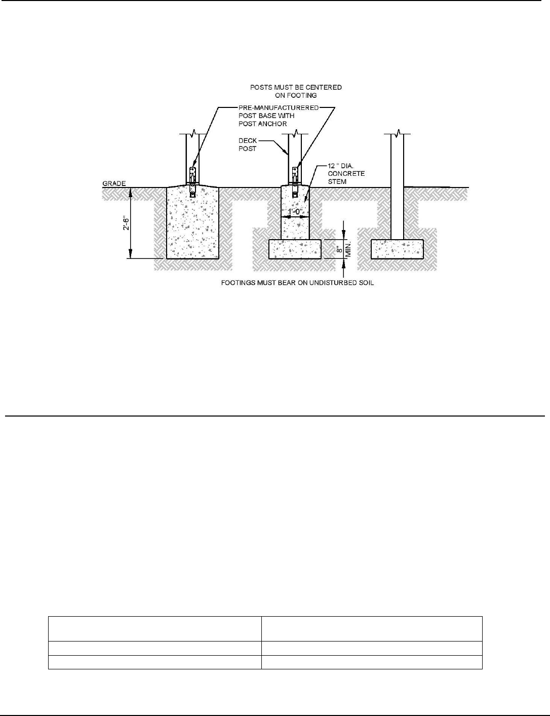
3. DECK FOOTINGS
Footings shall be minimum 20 inches square or 22 inches diameter. Bottom of footings shall be a minimum of
30 inches below grade and shall bear on undisturbed soil. Deck footings closer than 5’-0” to an exterior
house foundation wall must bear at the same elevation as the existing house foundation. Distances to
the edges of the footing and connector’s embedment must be in accordance with the manufacturer’s
recommendations.
DECK FOOTINGS
Figure 5
a. Posts shall be restrained to prevent lateral displacement at the bottom support by
manufacturer connectors or by a minimum of 12” in surrounding soils or concrete piers.
Where expansible, compressible, shifting or other questionable soils are present, soils
shall not be relied on for lateral support.
b. Cut ends of posts shall be field treated with an approved preservative.
4. DECK POSTS
Deck post size shall be in accordance with Table 1. The height of the post is measured from grade or top of
foundation (whichever is higher) to the underside of the beam. Post shall be centered on the footing. Cut ends
and notches of post shall be field treated with an approved preservative. The post shall be attached to the beam
by notching as shown in Figure 7 or by providing an approved post cap to connect the post to the beam as shown
in Figure 7. Where post bear on concrete footings lateral restrain shall be provided by manufactured connectors
or a minimum post embedment of 12 inches in surrounding soils of concrete piers.
Provide diagonal bracing at each post greater than 2 feet in height (grade to bottom of beam) as shown in
Figure 6. Diagonal bracing is prohibited on center posts. Bracing shall be fastened to the post at one end with
½” dia. Lag screws. One set of diagonal bracing shall be located between posts and beams or parallel to the
house. Another set of diagonal bracing shall be located perpendicular to beams and house in the end spans.
This bracing shall be bolted to the post and joist above the post location. If the joist spacing is such that a joist
does not align over a post location an extra joist shall be added to facilitate connection of the diagonal bracing.
For free standing decks (see Figure 4) diagonal bracing may be omitted at the beam and posts adjacent to the
house.
DECK POST SIZE
MAXIMUM HEIGHT
a,b
(feet and inches)
4x4
6’-9”
6x6
14’-0”
a. Measured to the underside of the beam
b. Based on 40 psf live load
Table 1

Montgomery County Residential Deck Details Page | 7 04/15/2021
Figure 6
5. DECK BEAM
Maximum allowable spans for deck beams to be as per Table 2. Beam plies shall be fastened with two rows of
10d (3 in x 0.128 in) nails minimum at 16” o.c. along each edge. Beams shall be permitted to cantilever up to 2
feet or up to one-fourth of the beam span, whichever is less. The ends of beams shall have a minimum of 1 ½”
inches of bearing.
DECK BEAM SPANS
a,b,
Southern
Pine No. 2
Size
DECK JOIST SPAN LESS THAN OR EQUAL TO:
(feet)
6
8
10
12
14
16
18
(2) 2x6
6’-11”
5’-11”
5’-4”
4’-10”
4’-6”
4’-3”
4’-0”
(2) 2x8
8’-9”
7’-7”
6’-9”
6’-2”
5’-9”
5’-4”
5’-0”
(2) 2x10
10’-4”
9’-0”
8’-0”
7’-4”
6’-9”
6’-4”
6’-0”
(2) 2x12
12’-2”
10’-7”
9’-5”
8’-7”
8’-0”
7’-6”
7’-0”
(3) 2x6
8’-2”
7’-5”
6’-8”
6’-1”
5’-8”
5’-3”
5’-0”
(3) 2x8
10’-10”
9’-6”
8’-6”
7’-9”
7’-2”
6’-8”
6’-4”
(3) 2x10
13’-0”
11’-3”
10-0”
9’-2”
8’-6”
7’-11”
7’-6”
(3) 2x12
15’-3”
13’-3”
11’-10”
10’-9”
10’-0”
9’-4”
8’-10”
a. Beam depth shall be greater than or equal to the depth of the floor joist with a flush beam condition.
b. Beams shall be permitted to cantilever at each end 2 feet or up to one-fourth of the actual beam span, whichever is less.
Table 2
6. POST TO BEAM CONNECTION
Deck beams shall be attached to deck post in a manner capable of transferring vertical loads and resisting
horizontal displacement. Where multiple span beams bear on intermediate posts each ply must have full
bearing on the post as shown on Figures 7, 8 and 9 Connections shall be as per Figures 7,8 and 9.
Manufactured post to beam connectors shall be sized for the post and beam sizes. Bolts shall have washers
under the head and nut.
Beam to post connection with fasteners only is prohibited, see Figure 10. Built-up beams shall be assembled in
accordance with Figure 11. For triple member beams, provide the nailing pattern shown to the outside member
on each side; however staggered rows shall be offset so as not to occur in the same location.

Montgomery County Residential Deck Details Page | 8 04/15/2021
POST-BEAM CONNECTION
Figure 7
POST-BEAM CONNECTION AT SPLICE
Figure 8
POST TO BEAM PROHIBITED
CONNECTION
Figure 10
NOTCHED POST TO BEAM CONNECTION Note:
Figure 9 a.Beams must span continuously between posts and
shall be spliced at interior post locations only.
b.Spans are measured between the centerline of
bearings or supports.

Montgomery County Residential Deck Details Page | 9 04/15/2021
BUILT-UP BEAM CONNECTION
Figure 11
7. DECK JOIST
Maximum allowable span for deck joists to be as per Table 3. The maximum cantilever shall be limited to one-
fourth of the actual adjacent joist span or the maximum cantilevered length shown on table 3. Whichever is
less. The ends of joists shall have not less than 1 ½” bearing on wood or metal. Joist framing into the side of a
beam or ledger shall be supported by approved joists hangers. Joist ends and bearings shall be provided with
lateral resistance to prevent rotation by joists hangers or blocking and their depth shall not be less than 60% of
the joist depth. Rim joists shall be secure to the end of each joist with no less than three 10d (3-in x 0.128in)
nails or three No. 10 x 3-in long wood screws.
SPECIES
SIZE
ALLOWABLE JOIST SPAN
MAXIMUM CANTILEVER
SPACING OF DECK JOISTS
SPACING OF DECK JOISTS WITH
CANTILEVER
(inches)
(inches)
Southern
Pine No. 2
12
16
24
12
16
24
2x6
9’-11”
9’-0”
7’-7”
1’-3”
1’-4”
1’-6”
2x8
13’-1”
11’-10”
9’-8”
2’-1”
2’-3”
2’-5”
2x10
16’-2”
14’-0”
11’-5”
3’-4”
3’-6”
2’-10”
2x12
18’-0”
16’-6”
13’-6”
4’-6”
4’-2”
3’-4”
Table 3
8. JOIST TO BEAM CONNECTION
Each joist shall be attached to the beam as shown on Figure 12. Joist may bear on an overhang past the beam
face when Option 1 or Option 2 is used, and blocking is provided between joists at beam bearing. Option 2
mechanical fasteners of hurricane clips must have a minimum uplift and lateral load capacity of 100 lbs in both
uplift and lateral load directions. Joists may also be attached to the side of the beam with joist hangers per
Option 3. Joists shall not frame in from opposite sides of the beam. Joist hangers shall be at least 60% of the
ledger of beam depth. See Table 4 for minimum joist hanger capacity. Inside flange hangers can be used at
edge conditions. Clip angles or brackets to support deck joists are prohibited.

Montgomery County Residential Deck Details Page | 10 04/15/2021
F
JOIST HANGER VERTICAL CAPACITY
Table 4
JOIST TO BEAM CONNECTION
Figure 12
9. LEDGER DECK ATTACHMENT
The ledger board shall be equal to or greater than the deck joist depth but equal or less than the house band or
rim joist. Ledger board attachments to the exterior wall shall be constructed as indicated in Figure 13. The
ledger shall be a minimum nominal 2x8. When attachments are made to the house band joist the connection
shall be to a 2” nominal lumber band joist or LVL rim joist bearing on a sill plate or wall plate and it shall be
constructed with ½” bolts with washers. The band joist shall be capable of supporting the new deck. If this
cannot be verified or conditions at the house differ from the details herein, a free-standing deck or full plan
submission will be required. Prohibited ledger board attachments are attachment to or through exterior veneers
(Brick, Masonry, Stone) Figure 16, cantilever floor overhangs Figure 16, open web trusses Figure 16, as they
are not intended or designed to support a new deck.
Note: Flashing is not shown for clarity
LEDGER BOARD TO RIM JOIST ATTACHMENT
Figure 13
JOIST SIZE
MIN. CAPACITY
2x6
400 lbs
2x8
500 lbs
2x10
600 lbs
2x12
700 lbs

Montgomery County Residential Deck Details Page | 11 04/15/2021
ATTACHED DECK FLASHING DETAIL
Figure 15
Attachment to Open Web Trusses Attachment to Brick, Masonry Attachment to House Overhang
or Stone Veneers or Chimney
PROHIBITED LEDGER ATTACHMENTS
Figure16

Montgomery County Residential Deck Details Page | 12 04/15/2021
10. LEDGER BOARD FASTENERS
LEDGER FASTENER SPACING AND CLEARANCES
Figure 17
Connection
On-Center Spacing of Fasteners
Max. Joists Span
6’-0”
8’-0”
10’-0”
12’-0”
14’-0”
16’-0”
18’-0”
½” dia. bolt
24”
18”
14”
12”
10”
9”
8”
FASTENER SPACING
Table 5
Through-Bolts
Through-Bolts shall have a diameter of ½”. Pilot holes for through-bolts shall be 17/32” to 9/16” in diameter.
Through-Bolts require washers at the bolt head and nut.
11. DECK LATERAL LOAD CONNECTION
Decks shall be positively anchored to the primary structure. The lateral connection shall be permitted in
accordance with Figures 19 and 20. For conditions where the house joists are parallel to the deck joists hold-
down devices shall be provided not less than two locations within two feet of the edge of the deck and shall
have an allowable design capacity of not less than 1,500lbs (Figure 19); or hold down devices shall be
connected to the base of the deck to house structure at not less than 4 locations, evenly distributed along deck
and within 2 ft of each end and shall have an allowable design capacity of not less than 750 lbs each (figure
20).

Montgomery County Residential Deck Details Page | 13 04/15/2021
LATERAL LOAD CONNECTION
DECK JOISTS PARALLEL TO HOUSE JOISTS
Figure 19
LATERAL LOAD CONNECTION
DECK JOISTS PARALLEL TO HOUSE JOISTS
Figure 20

Montgomery County Residential Deck Details Page | 14 04/15/2021
12. DECK FRAMING AT CHIMNEY OR BAY WINDOW
All members at chimneys or bay windows shall be framed in accordance with Figure 22. Header may span a
maximum of 6’-0”. When a chimney or bay window is wider than 6’-0”, one or more 6x6 post may be added to
reduce header spans to less than 6’-0”. In such cases, the post footing must meet the requirements in the
footings section. Headers shall be located no more than 3’-0” from the end of the trimmer joist. Triple trimmer
joists are required on each side of the header. Joist hangers shall each have a minimum vertical capacity in
accordance with Table 4. Bolts, screws, or lag screws used to attach the hanger to the ledger shall fully
extend through the ledger into the 2-inch nominal lumber band joist (1-1/2” actual) or LVL rim joist. Otherwise
a free-standing deck is required.
SECTION
FRAMING AROUND CHIMNEY OR BAY WINDOW
Figure 22
13. DECKING
Decking laid perpendicular to joists may consist of 2x6 structural lumber supported by joists spaced at
24” o.c. maximum or 1 ¼ inch thick wood decking supported by joists spaced 16” o.c. maximum. Attach
decking to each joist with 2-8d threated nails of 2-#10 screws. Space decking boards approximately 1/8” apart.
See figure 23 for decking connection requirements to rim joist. Decking placement may range from an angle
perpendicular to the joist to an angle of 45 degrees to the joist. Each segment of decking must bear on a
minimum of 3 joist.
Plastic composite deck boards and stair treads will be accepted if they are labeled to indicate
compliance with ASTM D7032. A complete current code evaluation report for the manufactured decking
system that includes the maximum allowable load and span must be provided to the building inspector at the
time of framing inspection. Manufactured decking systems must be installed in accordance with the code
evaluation report and manufacturer’s specifications.

Montgomery County Residential Deck Details Page | 15 04/15/2021
RIM JOIST CONNECTION DETAIL
Figure 23
14. DECK GUARDRAIL
All decks greater than 30” above grade are required to have a guard constructed as shown in Figure
24. Deck guard posts shall be a minimum 4x4 (nominal). Joists and rim joists to which guards post are
attached shall be a minimum of 2x8 (nominal). Guard post which run parallel to the deck joist shall be attached
to the outside joist as per figure 25. Guard post that run perpendicular to the deck joists shall be attached to
the rim joist in accordance with Figure 26. Hold down anchors shall have a minimum allowable tension load of
1,800 lbs for a 36” maximum guard height and shall be installed in accordance with manufacturer’s
instructions.
Manufactured railing systems will be accepted only if they are labeled to indicate compliance with
ASTM D7032 and listed by an approved code agency in a current code evaluation report. A complete current
code evaluation report for the manufactured railing system to be installed must be provided to the building
inspector at the time of framing inspection. Manufactured railing systems must be installed in accordance with
the report and manufacturer’s specifications. Wood post spacing and connections, if used for supporting
manufactured rails, balusters or pickets, must follow the conditions specified by the code evaluation report.
DECK GUARD DETAIL
Figure 24

Montgomery County Residential Deck Details Page | 16 04/15/2021
GUARD POST TO OUTSIDE JOIST
Figure 25
GUARD POST TO RIM JOIST
Figure 26

Montgomery County Residential Deck Details Page | 17 04/15/2021
15. STAIR REQUIREMENTS
Stair, stair stringers, and guards shall meet the requirements shown in Figure 27 through Figure 34. All
stringers shall be a minimum of 2x12. Stair stringers shall not span more than the dimensions shown on Figure
28. An intermediate landing may also be provided to shorten the stringer span. If the total vertical height for a
stairway exceeds 12’-0” and intermediate landing will be required.
All intermediate stair landings must be constructed as a non-ledger deck using the details in this document.
Stair shall be a minimum of 36” in width. If only cut stringers are used, a minimum of 3 stringers are required.
For stairs greater than 36” in width, a combination of cut and solid stringers can be used but shall be placed at
a maximum spacing of 18” on center (see Figure 29). Stair stringers must be fully supported or connected to
the deck structure (see Figures 30 and 33) The width of each landing shall not be less than the width of the
stairway served. Every rectangular landing shall have a minimum dimension of 36” measured in the direction of
travel and not less than the width of the stair served.
TREAD AND RISER DETAIL
Figure 27
BETWEEN SUPPORTS
STAIR STRINGER REQUIREMENTS
Figure 28

Montgomery County Residential Deck Details Page | 18 04/15/2021
TREAD CONNECTION REQUIREMENTS
Figure 29
STAIR STRINGER ATTACHMENT
Figure 30
HANDRAIL GRIP SIZE
Figure 32
HANDRAIL MOUNTING EXAMPLES
Figure 31

Montgomery County Residential Deck Details Page | 19 04/15/2021
STAIR AND GUARDRAIL REQUIREMENTS
Figure 33
STAIR FOOTING REQUIREMENTS
Where the stair meets the grade, attach the stringers
to the stair guard post as shown of Figure 33. Post
shall bear on footings. All footing shall bear on solid
ground at least 30” below grade. Stringers shall bear
on 2x4 bearing block attached to the post as shown.
STAIR LIGHTING REQUIREMENTS
Stairways shall have a light source located at the
top landing such that all stairs and landings are
illuminated. The light switch shall be operated
from the inside of the house. Motion detected or
timed switches are acceptable
STAIR FOOTING DETAIL
Figure 34

Montgomery County Residential Deck Details Page | 20 04/15/2021
16. DECK WORKSHEET
This worksheet is provided to help you determine compliance with the requirements of the
Montgomery County Residential Typical Deck Details
1. Attached Deck or Free-Standing Deck
2. Deck Dimensions (L): ____________ x (W)___________ x Height __________
3. Footing Size: __________ Total #:_________ (including stairs)
4. Post Spacing: _________
5. Beam Size ( ) ______ x ______
6. Post Base/Cap Connectors: YES NO
7. Ledger Size: ______ x ______ w/ ½” dia. Bolts
8. Joists _______ x _______ @ ________ o.c.
9. Deck Boards: Wood Composite*
(*Provide current Code Evaluation Report @ Framing Inspection)
10. Guardrails: Wood or Composite*
(*Provide current Code Evaluation Report @ Framing Inspection)
