
Redbooks
Front cover
IBM z/OS V2R2 Communications Server
TCP/IP Implementation Volume 1
Base Functions, Connectivity, and Routing
Bill White
Octavio Ferreira
Teresa Missawa
Teddy Sudewo

International Technical Support Organization
IBM z/OS V2R2 Communications Server TCP/IP
Implementation Volume 1
November 2016
SG24-8360-00

© Copyright International Business Machines Corporation 2016. All rights reserved.
Note to U.S. Government Users Restricted Rights -- Use, duplication or disclosure restricted by GSA ADP Schedule
Contract with IBM Corp.
First Edition (November 2016)
This edition applies to Version 2, Release 2 of z/OS Communications Server.
Note: Before using this information and the product it supports, read the information in “Notices” on
page xi.
© Copyright IBM Corp. 2016. All rights reserved. iii
Contents
Notices . . . . . . . . . . . . . . . . . . . . . . . . . . . . . . . . . . . . . . . . . . . . . . . . . . . . . . . . . . . . . . . . . xi
Trademarks . . . . . . . . . . . . . . . . . . . . . . . . . . . . . . . . . . . . . . . . . . . . . . . . . . . . . . . . . . . . . . xii
Preface . . . . . . . . . . . . . . . . . . . . . . . . . . . . . . . . . . . . . . . . . . . . . . . . . . . . . . . . . . . . . . . . xiii
Authors. . . . . . . . . . . . . . . . . . . . . . . . . . . . . . . . . . . . . . . . . . . . . . . . . . . . . . . . . . . . . . . . . xiv
Now you can become a published author, too! . . . . . . . . . . . . . . . . . . . . . . . . . . . . . . . . . . .xv
Comments welcome. . . . . . . . . . . . . . . . . . . . . . . . . . . . . . . . . . . . . . . . . . . . . . . . . . . . . . . .xv
Stay connected to IBM Redbooks . . . . . . . . . . . . . . . . . . . . . . . . . . . . . . . . . . . . . . . . . . . . .xv
Chapter 1. Introduction to IBM Communications Server for z/OS IP . . . . . . . . . . . . . . . 1
1.1 Overview and basic concepts . . . . . . . . . . . . . . . . . . . . . . . . . . . . . . . . . . . . . . . . . . . . . 2
1.2 Featured functions . . . . . . . . . . . . . . . . . . . . . . . . . . . . . . . . . . . . . . . . . . . . . . . . . . . . . 3
1.3 Communications Server for z/OS IP implementation . . . . . . . . . . . . . . . . . . . . . . . . . . . 4
1.3.1 Functional overview . . . . . . . . . . . . . . . . . . . . . . . . . . . . . . . . . . . . . . . . . . . . . . . . 5
1.3.2 Operating environment . . . . . . . . . . . . . . . . . . . . . . . . . . . . . . . . . . . . . . . . . . . . . . 6
1.3.3 Reusable address space ID . . . . . . . . . . . . . . . . . . . . . . . . . . . . . . . . . . . . . . . . . . 6
1.3.4 64-bit enablement of the TCP/IP stack . . . . . . . . . . . . . . . . . . . . . . . . . . . . . . . . . . 7
1.3.5 Protocols and devices. . . . . . . . . . . . . . . . . . . . . . . . . . . . . . . . . . . . . . . . . . . . . . . 7
1.3.6 Supported routing applications . . . . . . . . . . . . . . . . . . . . . . . . . . . . . . . . . . . . . . . . 9
1.3.7 Application programming interfaces . . . . . . . . . . . . . . . . . . . . . . . . . . . . . . . . . . . . 9
1.3.8 z/OS Communications Server applications. . . . . . . . . . . . . . . . . . . . . . . . . . . . . . 10
1.3.9 UNIX System Services . . . . . . . . . . . . . . . . . . . . . . . . . . . . . . . . . . . . . . . . . . . . . 11
1.4 Additional information . . . . . . . . . . . . . . . . . . . . . . . . . . . . . . . . . . . . . . . . . . . . . . . . . . 19
Chapter 2. The resolver . . . . . . . . . . . . . . . . . . . . . . . . . . . . . . . . . . . . . . . . . . . . . . . . . . 21
2.1 Basic concepts of the resolver . . . . . . . . . . . . . . . . . . . . . . . . . . . . . . . . . . . . . . . . . . . 22
2.2 The resolver address space . . . . . . . . . . . . . . . . . . . . . . . . . . . . . . . . . . . . . . . . . . . . . 24
2.2.1 The resolver SETUP data set . . . . . . . . . . . . . . . . . . . . . . . . . . . . . . . . . . . . . . . . 25
2.2.2 The resolver configuration file. . . . . . . . . . . . . . . . . . . . . . . . . . . . . . . . . . . . . . . . 25
2.2.3 Local hosts file . . . . . . . . . . . . . . . . . . . . . . . . . . . . . . . . . . . . . . . . . . . . . . . . . . . 29
2.2.4 Resolver DNS cache. . . . . . . . . . . . . . . . . . . . . . . . . . . . . . . . . . . . . . . . . . . . . . . 31
2.2.5 Unresponsive DNS name servers. . . . . . . . . . . . . . . . . . . . . . . . . . . . . . . . . . . . . 39
2.2.6 Affinity servers and generic servers . . . . . . . . . . . . . . . . . . . . . . . . . . . . . . . . . . . 43
2.2.7 Resolving an IPv6 address . . . . . . . . . . . . . . . . . . . . . . . . . . . . . . . . . . . . . . . . . . 45
2.2.8 Resolver support for EDNS0. . . . . . . . . . . . . . . . . . . . . . . . . . . . . . . . . . . . . . . . . 47
2.2.9 Considerations . . . . . . . . . . . . . . . . . . . . . . . . . . . . . . . . . . . . . . . . . . . . . . . . . . . 48
2.3 Implementing the resolver. . . . . . . . . . . . . . . . . . . . . . . . . . . . . . . . . . . . . . . . . . . . . . . 50
2.3.1 Implementation tasks . . . . . . . . . . . . . . . . . . . . . . . . . . . . . . . . . . . . . . . . . . . . . . 50
2.3.2 Activation and verification . . . . . . . . . . . . . . . . . . . . . . . . . . . . . . . . . . . . . . . . . . . 57
2.4 Problem determination . . . . . . . . . . . . . . . . . . . . . . . . . . . . . . . . . . . . . . . . . . . . . . . . . 61
2.4.1 Deciding which tool to use to diagnose a resolver problem . . . . . . . . . . . . . . . . . 62
2.4.2 Trace Resolver . . . . . . . . . . . . . . . . . . . . . . . . . . . . . . . . . . . . . . . . . . . . . . . . . . . 62
2.4.3 CTRACE: RESOLVER (SYSTCPRE). . . . . . . . . . . . . . . . . . . . . . . . . . . . . . . . . . 66
2.5 Additional information . . . . . . . . . . . . . . . . . . . . . . . . . . . . . . . . . . . . . . . . . . . . . . . . . . 71
Chapter 3. Base functions . . . . . . . . . . . . . . . . . . . . . . . . . . . . . . . . . . . . . . . . . . . . . . . . 73
3.1 The base functions . . . . . . . . . . . . . . . . . . . . . . . . . . . . . . . . . . . . . . . . . . . . . . . . . . . . 74
3.2 Common design scenarios for base functions . . . . . . . . . . . . . . . . . . . . . . . . . . . . . . . 74
3.2.1 Single-stack environment . . . . . . . . . . . . . . . . . . . . . . . . . . . . . . . . . . . . . . . . . . . 75
iv IBM z/OS V2R2 Communications Server TCP/IP Implementation Volume 1
3.2.2 Multiple-stack environment . . . . . . . . . . . . . . . . . . . . . . . . . . . . . . . . . . . . . . . . . . 76
3.2.3 One TCP/IP stack per LPAR. . . . . . . . . . . . . . . . . . . . . . . . . . . . . . . . . . . . . . . . . 78
3.2.4 Suggestions for MTU . . . . . . . . . . . . . . . . . . . . . . . . . . . . . . . . . . . . . . . . . . . . . . 78
3.3 z/OS UNIX System Services setup for TCP/IP . . . . . . . . . . . . . . . . . . . . . . . . . . . . . . . 79
3.3.1 RACF actions for UNIX . . . . . . . . . . . . . . . . . . . . . . . . . . . . . . . . . . . . . . . . . . . . . 79
3.3.2 APF authorization . . . . . . . . . . . . . . . . . . . . . . . . . . . . . . . . . . . . . . . . . . . . . . . . . 81
3.3.3 Changes to SYS1.PARMLIB members. . . . . . . . . . . . . . . . . . . . . . . . . . . . . . . . . 82
3.3.4 Changes to SYS1.PROCLIB members. . . . . . . . . . . . . . . . . . . . . . . . . . . . . . . . . 88
3.3.5 Additional z/OS customization for z/OS UNIX. . . . . . . . . . . . . . . . . . . . . . . . . . . . 88
3.3.6 TCP/IP server functions . . . . . . . . . . . . . . . . . . . . . . . . . . . . . . . . . . . . . . . . . . . . 88
3.3.7 TCP/IP client functions . . . . . . . . . . . . . . . . . . . . . . . . . . . . . . . . . . . . . . . . . . . . . 89
3.3.8 UNIX client functions. . . . . . . . . . . . . . . . . . . . . . . . . . . . . . . . . . . . . . . . . . . . . . . 89
3.3.9 Verification checklist . . . . . . . . . . . . . . . . . . . . . . . . . . . . . . . . . . . . . . . . . . . . . . . 91
3.4 Configuring z/OS TCP/IP . . . . . . . . . . . . . . . . . . . . . . . . . . . . . . . . . . . . . . . . . . . . . . . 93
3.4.1 TCP/IP configuration data set names . . . . . . . . . . . . . . . . . . . . . . . . . . . . . . . . . . 94
3.4.2 PROFILE.TCPIP . . . . . . . . . . . . . . . . . . . . . . . . . . . . . . . . . . . . . . . . . . . . . . . . . . 95
3.4.3 PROFILE.TCPIP SYNTAXCHECK command . . . . . . . . . . . . . . . . . . . . . . . . . . 104
3.4.4 The VTAM resource . . . . . . . . . . . . . . . . . . . . . . . . . . . . . . . . . . . . . . . . . . . . . . 105
3.4.5 TCPIP.DATA. . . . . . . . . . . . . . . . . . . . . . . . . . . . . . . . . . . . . . . . . . . . . . . . . . . . 106
3.4.6 Configuring the local hosts file . . . . . . . . . . . . . . . . . . . . . . . . . . . . . . . . . . . . . . 106
3.5 Implementing the TCP/IP stack. . . . . . . . . . . . . . . . . . . . . . . . . . . . . . . . . . . . . . . . . . 107
3.5.1 Creating a TCPIP.DATA file . . . . . . . . . . . . . . . . . . . . . . . . . . . . . . . . . . . . . . . . 108
3.5.2 Creating the PROFILE.TCPIP file. . . . . . . . . . . . . . . . . . . . . . . . . . . . . . . . . . . . 109
3.5.3 Checking BPXPRMxx . . . . . . . . . . . . . . . . . . . . . . . . . . . . . . . . . . . . . . . . . . . . . 112
3.5.4 Creating a TCP/IP cataloged procedure . . . . . . . . . . . . . . . . . . . . . . . . . . . . . . . 112
3.5.5 Adding RACF definitions. . . . . . . . . . . . . . . . . . . . . . . . . . . . . . . . . . . . . . . . . . . 112
3.5.6 Creating a VTAM TRL major node for MPCIPA OSA . . . . . . . . . . . . . . . . . . . . . 112
3.6 Activating the TCP/IP stack. . . . . . . . . . . . . . . . . . . . . . . . . . . . . . . . . . . . . . . . . . . . . 114
3.6.1 UNIX System Services verification . . . . . . . . . . . . . . . . . . . . . . . . . . . . . . . . . . . 115
3.6.2 Verifying the TCP/IP configuration . . . . . . . . . . . . . . . . . . . . . . . . . . . . . . . . . . . 126
3.7 Reconfiguring the system with z/OS commands. . . . . . . . . . . . . . . . . . . . . . . . . . . . . 132
3.7.1 Deleting a device and adding or changing a device . . . . . . . . . . . . . . . . . . . . . . 132
3.7.2 Modifying a device . . . . . . . . . . . . . . . . . . . . . . . . . . . . . . . . . . . . . . . . . . . . . . . 133
3.8 Job log versus syslog as a diagnosis tool . . . . . . . . . . . . . . . . . . . . . . . . . . . . . . . . . . 136
3.9 Message types: Where to find them . . . . . . . . . . . . . . . . . . . . . . . . . . . . . . . . . . . . . . 136
3.10 Additional information . . . . . . . . . . . . . . . . . . . . . . . . . . . . . . . . . . . . . . . . . . . . . . . . 137
Chapter 4. Connectivity . . . . . . . . . . . . . . . . . . . . . . . . . . . . . . . . . . . . . . . . . . . . . . . . . 139
4.1 What is connectivity . . . . . . . . . . . . . . . . . . . . . . . . . . . . . . . . . . . . . . . . . . . . . . . . . . 140
4.2 Preferred interfaces. . . . . . . . . . . . . . . . . . . . . . . . . . . . . . . . . . . . . . . . . . . . . . . . . . . 141
4.2.1 High-bandwidth and high-speed networking technologies . . . . . . . . . . . . . . . . . 142
4.2.2 OSA-Express (MPCIPA) . . . . . . . . . . . . . . . . . . . . . . . . . . . . . . . . . . . . . . . . . . . 142
4.2.3 OSA-Express for zEnterprise (z196 and z114). . . . . . . . . . . . . . . . . . . . . . . . . . 151
4.2.4 HiperSockets (MPCIPA) . . . . . . . . . . . . . . . . . . . . . . . . . . . . . . . . . . . . . . . . . . . 152
4.2.5 Dynamic XCF . . . . . . . . . . . . . . . . . . . . . . . . . . . . . . . . . . . . . . . . . . . . . . . . . . . 155
4.3 Connectivity for the z/OS environment . . . . . . . . . . . . . . . . . . . . . . . . . . . . . . . . . . . . 157
4.3.1 IOCP definitions . . . . . . . . . . . . . . . . . . . . . . . . . . . . . . . . . . . . . . . . . . . . . . . . . 158
4.3.2 VTAM definitions. . . . . . . . . . . . . . . . . . . . . . . . . . . . . . . . . . . . . . . . . . . . . . . . . 160
4.4 OSA-Express QDIO connectivity . . . . . . . . . . . . . . . . . . . . . . . . . . . . . . . . . . . . . . . . 161
4.4.1 Dependencies: CHPID, IOCDS, port numbers, port names, and port sharing . . 162
4.4.2 Considerations for isolating traffic across a shared OSA port. . . . . . . . . . . . . . . 168
4.4.3 Configuring OSA-Express with a VLAN ID . . . . . . . . . . . . . . . . . . . . . . . . . . . . . 169
4.4.4 Verifying the connectivity status . . . . . . . . . . . . . . . . . . . . . . . . . . . . . . . . . . . . . 172
Contents v
4.5 OSA-Express QDIO connectivity with connection isolation. . . . . . . . . . . . . . . . . . . . . 177
4.5.1 Description of connection isolation . . . . . . . . . . . . . . . . . . . . . . . . . . . . . . . . . . . 178
4.5.2 Dependencies for connection isolation . . . . . . . . . . . . . . . . . . . . . . . . . . . . . . . . 179
4.5.3 Considerations for connection isolation . . . . . . . . . . . . . . . . . . . . . . . . . . . . . . . 179
4.5.4 Configuring OSA-Express with connection isolation. . . . . . . . . . . . . . . . . . . . . . 183
4.5.5 Verifying connection isolation on OSA2080X . . . . . . . . . . . . . . . . . . . . . . . . . . . 184
4.5.6 Conclusions and suggestions: Preferred practices for isolating traffic . . . . . . . . 201
4.6 HiperSockets connectivity . . . . . . . . . . . . . . . . . . . . . . . . . . . . . . . . . . . . . . . . . . . . . . 201
4.6.1 Dependencies . . . . . . . . . . . . . . . . . . . . . . . . . . . . . . . . . . . . . . . . . . . . . . . . . . . 202
4.6.2 Considerations . . . . . . . . . . . . . . . . . . . . . . . . . . . . . . . . . . . . . . . . . . . . . . . . . . 202
4.6.3 Configuring HiperSockets . . . . . . . . . . . . . . . . . . . . . . . . . . . . . . . . . . . . . . . . . . 202
4.6.4 Verifying the connectivity status . . . . . . . . . . . . . . . . . . . . . . . . . . . . . . . . . . . . . 204
4.7 Dynamic XCF connectivity . . . . . . . . . . . . . . . . . . . . . . . . . . . . . . . . . . . . . . . . . . . . . 206
4.7.1 Dependencies . . . . . . . . . . . . . . . . . . . . . . . . . . . . . . . . . . . . . . . . . . . . . . . . . . . 207
4.7.2 Considerations . . . . . . . . . . . . . . . . . . . . . . . . . . . . . . . . . . . . . . . . . . . . . . . . . . 207
4.7.3 Configuring DYNAMICXCF. . . . . . . . . . . . . . . . . . . . . . . . . . . . . . . . . . . . . . . . . 208
4.7.4 Verifying connectivity status . . . . . . . . . . . . . . . . . . . . . . . . . . . . . . . . . . . . . . . . 208
4.8 Controlling and activating devices. . . . . . . . . . . . . . . . . . . . . . . . . . . . . . . . . . . . . . . . 214
4.8.1 Starting a device . . . . . . . . . . . . . . . . . . . . . . . . . . . . . . . . . . . . . . . . . . . . . . . . . 214
4.8.2 Stopping a device . . . . . . . . . . . . . . . . . . . . . . . . . . . . . . . . . . . . . . . . . . . . . . . . 214
4.8.3 Activating modified device definitions . . . . . . . . . . . . . . . . . . . . . . . . . . . . . . . . . 215
4.9 Problem determination . . . . . . . . . . . . . . . . . . . . . . . . . . . . . . . . . . . . . . . . . . . . . . . . 215
4.10 Additional information . . . . . . . . . . . . . . . . . . . . . . . . . . . . . . . . . . . . . . . . . . . . . . . . 221
Chapter 5. Routing . . . . . . . . . . . . . . . . . . . . . . . . . . . . . . . . . . . . . . . . . . . . . . . . . . . . . 223
5.1 Basic concepts . . . . . . . . . . . . . . . . . . . . . . . . . . . . . . . . . . . . . . . . . . . . . . . . . . . . . . 224
5.1.1 Terminology . . . . . . . . . . . . . . . . . . . . . . . . . . . . . . . . . . . . . . . . . . . . . . . . . . . . 224
5.1.2 Direct routes, indirect routes, and the default route . . . . . . . . . . . . . . . . . . . . . . 225
5.1.3 Route selection . . . . . . . . . . . . . . . . . . . . . . . . . . . . . . . . . . . . . . . . . . . . . . . . . . 226
5.1.4 Static routing and dynamic routing . . . . . . . . . . . . . . . . . . . . . . . . . . . . . . . . . . . 227
5.1.5 Choosing the routing method . . . . . . . . . . . . . . . . . . . . . . . . . . . . . . . . . . . . . . . 229
5.2 Routing in the z/OS environment . . . . . . . . . . . . . . . . . . . . . . . . . . . . . . . . . . . . . . . . 230
5.2.1 Static routing . . . . . . . . . . . . . . . . . . . . . . . . . . . . . . . . . . . . . . . . . . . . . . . . . . . . 230
5.2.2 Dynamic routing by using OMPROUTE . . . . . . . . . . . . . . . . . . . . . . . . . . . . . . . 231
5.2.3 Policy-based routing . . . . . . . . . . . . . . . . . . . . . . . . . . . . . . . . . . . . . . . . . . . . . . 235
5.3 Dynamic routing protocols. . . . . . . . . . . . . . . . . . . . . . . . . . . . . . . . . . . . . . . . . . . . . . 235
5.3.1 Open Shortest Path First . . . . . . . . . . . . . . . . . . . . . . . . . . . . . . . . . . . . . . . . . . 235
5.3.2 Routing Information Protocol . . . . . . . . . . . . . . . . . . . . . . . . . . . . . . . . . . . . . . . 240
5.3.3 IPv6 dynamic routing . . . . . . . . . . . . . . . . . . . . . . . . . . . . . . . . . . . . . . . . . . . . . 243
5.4 Implementing static routing in z/OS . . . . . . . . . . . . . . . . . . . . . . . . . . . . . . . . . . . . . . 245
5.4.1 Dependencies . . . . . . . . . . . . . . . . . . . . . . . . . . . . . . . . . . . . . . . . . . . . . . . . . . . 245
5.4.2 Considerations . . . . . . . . . . . . . . . . . . . . . . . . . . . . . . . . . . . . . . . . . . . . . . . . . . 246
5.4.3 Implementation tasks . . . . . . . . . . . . . . . . . . . . . . . . . . . . . . . . . . . . . . . . . . . . . 246
5.4.4 Activation and verification . . . . . . . . . . . . . . . . . . . . . . . . . . . . . . . . . . . . . . . . . . 248
5.5 Implementing OSPF routing in z/OS with OMPROUTE . . . . . . . . . . . . . . . . . . . . . . . 252
5.5.1 Dependencies . . . . . . . . . . . . . . . . . . . . . . . . . . . . . . . . . . . . . . . . . . . . . . . . . . . 253
5.5.2 Considerations . . . . . . . . . . . . . . . . . . . . . . . . . . . . . . . . . . . . . . . . . . . . . . . . . . 253
5.5.3 Suggestions . . . . . . . . . . . . . . . . . . . . . . . . . . . . . . . . . . . . . . . . . . . . . . . . . . . . 253
5.5.4 Implementation tasks . . . . . . . . . . . . . . . . . . . . . . . . . . . . . . . . . . . . . . . . . . . . . 253
5.5.5 Configuring routers . . . . . . . . . . . . . . . . . . . . . . . . . . . . . . . . . . . . . . . . . . . . . . . 262
5.5.6 Activation and verification . . . . . . . . . . . . . . . . . . . . . . . . . . . . . . . . . . . . . . . . . . 262
5.5.7 Managing OMPROUTE. . . . . . . . . . . . . . . . . . . . . . . . . . . . . . . . . . . . . . . . . . . . 270
5.6 Problem determination . . . . . . . . . . . . . . . . . . . . . . . . . . . . . . . . . . . . . . . . . . . . . . . . 273
vi IBM z/OS V2R2 Communications Server TCP/IP Implementation Volume 1
5.6.1 Commands to diagnose networking connectivity problems . . . . . . . . . . . . . . . . 274
5.6.2 Diagnosing an OMPROUTE problem . . . . . . . . . . . . . . . . . . . . . . . . . . . . . . . . . 276
5.7 Additional information . . . . . . . . . . . . . . . . . . . . . . . . . . . . . . . . . . . . . . . . . . . . . . . . . 283
Chapter 6. Virtual LAN and virtual MAC support . . . . . . . . . . . . . . . . . . . . . . . . . . . . . 285
6.1 Virtual MAC overview . . . . . . . . . . . . . . . . . . . . . . . . . . . . . . . . . . . . . . . . . . . . . . . . . 286
6.1.1 Why use virtual MACs. . . . . . . . . . . . . . . . . . . . . . . . . . . . . . . . . . . . . . . . . . . . . 286
6.1.2 Virtual MAC concept . . . . . . . . . . . . . . . . . . . . . . . . . . . . . . . . . . . . . . . . . . . . . . 288
6.1.3 Virtual MAC address assignment . . . . . . . . . . . . . . . . . . . . . . . . . . . . . . . . . . . . 289
6.2 Virtual MAC implementation . . . . . . . . . . . . . . . . . . . . . . . . . . . . . . . . . . . . . . . . . . . . 289
6.2.1 IP routing when using VMAC . . . . . . . . . . . . . . . . . . . . . . . . . . . . . . . . . . . . . . . 290
6.2.2 Verification . . . . . . . . . . . . . . . . . . . . . . . . . . . . . . . . . . . . . . . . . . . . . . . . . . . . . 291
6.3 Virtual LAN overview. . . . . . . . . . . . . . . . . . . . . . . . . . . . . . . . . . . . . . . . . . . . . . . . . . 294
6.3.1 Types of ports . . . . . . . . . . . . . . . . . . . . . . . . . . . . . . . . . . . . . . . . . . . . . . . . . . . 294
6.3.2 Types of connections . . . . . . . . . . . . . . . . . . . . . . . . . . . . . . . . . . . . . . . . . . . . . 294
6.4 VLAN implementation on z/OS . . . . . . . . . . . . . . . . . . . . . . . . . . . . . . . . . . . . . . . . . . 295
6.4.1 Single VLAN per OSA. . . . . . . . . . . . . . . . . . . . . . . . . . . . . . . . . . . . . . . . . . . . . 295
6.4.2 Multiple VLAN support . . . . . . . . . . . . . . . . . . . . . . . . . . . . . . . . . . . . . . . . . . . . 296
6.4.3 Multiple VLANs configuration guidelines. . . . . . . . . . . . . . . . . . . . . . . . . . . . . . . 297
6.4.4 Verification . . . . . . . . . . . . . . . . . . . . . . . . . . . . . . . . . . . . . . . . . . . . . . . . . . . . . 299
6.5 Additional information . . . . . . . . . . . . . . . . . . . . . . . . . . . . . . . . . . . . . . . . . . . . . . . . . 301
Chapter 7. Shared Memory Communications. . . . . . . . . . . . . . . . . . . . . . . . . . . . . . . . 303
7.1 What is Shared Memory Communications . . . . . . . . . . . . . . . . . . . . . . . . . . . . . . . . . 304
7.1.1 Shared Memory Communication that uses RDMA . . . . . . . . . . . . . . . . . . . . . . . 304
7.1.2 Shared Memory Communications that uses DMA . . . . . . . . . . . . . . . . . . . . . . . 307
7.1.3 How the SMC connections are defined on the platform . . . . . . . . . . . . . . . . . . . 309
7.2 Enabling SMC support . . . . . . . . . . . . . . . . . . . . . . . . . . . . . . . . . . . . . . . . . . . . . . . . 313
7.2.1 10GbE RoCE Express support for SMC-R . . . . . . . . . . . . . . . . . . . . . . . . . . . . . 313
7.2.2 OSA-Express support for SMC-R and SMC-D . . . . . . . . . . . . . . . . . . . . . . . . . . 315
7.2.3 HiperSockets support for SMC-D . . . . . . . . . . . . . . . . . . . . . . . . . . . . . . . . . . . . 315
7.2.4 ISM support for SMC-D. . . . . . . . . . . . . . . . . . . . . . . . . . . . . . . . . . . . . . . . . . . . 315
7.2.5 SMCR and SMCD parameters on the GLOBALCONFIG statement. . . . . . . . . . 315
7.2.6 Planning considerations for SMC-R and SMC-D . . . . . . . . . . . . . . . . . . . . . . . . 316
7.3 Setting up the SMC-R environment . . . . . . . . . . . . . . . . . . . . . . . . . . . . . . . . . . . . . . 317
7.3.1 Verifying and testing the SMC-R implementation . . . . . . . . . . . . . . . . . . . . . . . . 319
7.3.2 Diagnosing an SMC-R environment . . . . . . . . . . . . . . . . . . . . . . . . . . . . . . . . . . 324
7.4 Setting up our SMC-D environment . . . . . . . . . . . . . . . . . . . . . . . . . . . . . . . . . . . . . . 324
7.4.1 Verifying and testing the SMC-D implementation . . . . . . . . . . . . . . . . . . . . . . . . 326
7.4.2 Diagnosing the SMC-D environment. . . . . . . . . . . . . . . . . . . . . . . . . . . . . . . . . . 330
7.5 Additional information . . . . . . . . . . . . . . . . . . . . . . . . . . . . . . . . . . . . . . . . . . . . . . . . . 331
Chapter 8. Sysplex subplexing . . . . . . . . . . . . . . . . . . . . . . . . . . . . . . . . . . . . . . . . . . . 333
8.1 Introduction . . . . . . . . . . . . . . . . . . . . . . . . . . . . . . . . . . . . . . . . . . . . . . . . . . . . . . . . . 334
8.2 Subplex environment . . . . . . . . . . . . . . . . . . . . . . . . . . . . . . . . . . . . . . . . . . . . . . . . . 336
8.3 Load Balancing Advisor and subplexing . . . . . . . . . . . . . . . . . . . . . . . . . . . . . . . . . . . 337
8.4 Subplex implementation . . . . . . . . . . . . . . . . . . . . . . . . . . . . . . . . . . . . . . . . . . . . . . . 339
8.4.1 XCF group names. . . . . . . . . . . . . . . . . . . . . . . . . . . . . . . . . . . . . . . . . . . . . . . . 340
8.4.2 TCP/IP structures . . . . . . . . . . . . . . . . . . . . . . . . . . . . . . . . . . . . . . . . . . . . . . . . 340
8.4.3 Subplex 11: Internal subplex. . . . . . . . . . . . . . . . . . . . . . . . . . . . . . . . . . . . . . . . 342
8.4.4 Subplex 22: External subplex . . . . . . . . . . . . . . . . . . . . . . . . . . . . . . . . . . . . . . . 345
8.4.5 Access verifications . . . . . . . . . . . . . . . . . . . . . . . . . . . . . . . . . . . . . . . . . . . . . . 346
8.4.6 LBA connected to a subplex . . . . . . . . . . . . . . . . . . . . . . . . . . . . . . . . . . . . . . . . 346
8.5 Additional information . . . . . . . . . . . . . . . . . . . . . . . . . . . . . . . . . . . . . . . . . . . . . . . . . 347
Contents vii
Chapter 9. Diagnosis. . . . . . . . . . . . . . . . . . . . . . . . . . . . . . . . . . . . . . . . . . . . . . . . . . . . 349
9.1 Debugging a problem in a z/OS TCP/IP environment. . . . . . . . . . . . . . . . . . . . . . . . . 350
9.1.1 Categorizing the problem . . . . . . . . . . . . . . . . . . . . . . . . . . . . . . . . . . . . . . . . . . 350
9.1.2 An approach to problem analysis . . . . . . . . . . . . . . . . . . . . . . . . . . . . . . . . . . . . 351
9.2 Logs to diagnose Communications Server for z/OS IP problems . . . . . . . . . . . . . . . . 353
9.3 Sysplex Autonomics function . . . . . . . . . . . . . . . . . . . . . . . . . . . . . . . . . . . . . . . . . . . 353
9.4 Useful commands to diagnose Communications Server for z/OS IP problems . . . . . 355
9.4.1 The ping command (TSO or z/OS UNIX) . . . . . . . . . . . . . . . . . . . . . . . . . . . . . . 355
9.4.2 The traceroute command . . . . . . . . . . . . . . . . . . . . . . . . . . . . . . . . . . . . . . . . . . 358
9.4.3 The netstat command (console, TSO, or z/OS UNIX) . . . . . . . . . . . . . . . . . . . . 359
9.4.4 NETSTAT catalog validation. . . . . . . . . . . . . . . . . . . . . . . . . . . . . . . . . . . . . . . . 365
9.4.5 Timestamp validation for NETSTAT catalogs . . . . . . . . . . . . . . . . . . . . . . . . . . . 365
9.5 Gathering traces in Communications Server for z/OS IP . . . . . . . . . . . . . . . . . . . . . . 365
9.5.1 Taking a component trace . . . . . . . . . . . . . . . . . . . . . . . . . . . . . . . . . . . . . . . . . 367
9.5.2 Event trace for TCP/IP stacks (SYSTCPIP) . . . . . . . . . . . . . . . . . . . . . . . . . . . . 368
9.5.3 Packet trace (SYSTCPDA) . . . . . . . . . . . . . . . . . . . . . . . . . . . . . . . . . . . . . . . . . 371
9.5.4 OMPROUTE trace (SYSTCPRT) . . . . . . . . . . . . . . . . . . . . . . . . . . . . . . . . . . . . 376
9.5.5 Resolver trace (SYSTCPRE) . . . . . . . . . . . . . . . . . . . . . . . . . . . . . . . . . . . . . . . 378
9.5.6 IKE daemon trace (SYSTCPIK) . . . . . . . . . . . . . . . . . . . . . . . . . . . . . . . . . . . . . 379
9.5.7 Intrusion Detection Services trace (SYSTCPIS) . . . . . . . . . . . . . . . . . . . . . . . . . 379
9.5.8 OSAENTA trace (SYSTCPOT) . . . . . . . . . . . . . . . . . . . . . . . . . . . . . . . . . . . . . . 380
9.5.9 Queued Direct I/O Diagnostic Synchronization. . . . . . . . . . . . . . . . . . . . . . . . . . 380
9.5.10 Network Security Services server trace (SYSTCPNS) . . . . . . . . . . . . . . . . . . . 381
9.5.11 Obtaining component trace data with a dump. . . . . . . . . . . . . . . . . . . . . . . . . . 381
9.5.12 Analyzing a trace . . . . . . . . . . . . . . . . . . . . . . . . . . . . . . . . . . . . . . . . . . . . . . . 382
9.5.13 Configuration profile trace. . . . . . . . . . . . . . . . . . . . . . . . . . . . . . . . . . . . . . . . . 382
9.6 OSA-Express Network Traffic Analyzer . . . . . . . . . . . . . . . . . . . . . . . . . . . . . . . . . . . 382
9.6.1 Determining the microcode level for OSA-Express3. . . . . . . . . . . . . . . . . . . . . . 383
9.6.2 Defining TRLE definitions . . . . . . . . . . . . . . . . . . . . . . . . . . . . . . . . . . . . . . . . . . 384
9.6.3 Checking TCPIP definitions . . . . . . . . . . . . . . . . . . . . . . . . . . . . . . . . . . . . . . . . 384
9.6.4 Customizing OSA-Express Network Traffic Analyzer . . . . . . . . . . . . . . . . . . . . . 385
9.6.5 Defining a resource profile in RACF . . . . . . . . . . . . . . . . . . . . . . . . . . . . . . . . . . 392
9.6.6 Allocating a VSAM linear data set. . . . . . . . . . . . . . . . . . . . . . . . . . . . . . . . . . . . 392
9.6.7 Starting the OSA-Express Network Traffic Analyzer trace . . . . . . . . . . . . . . . . . 392
9.6.8 Operator command to query and display OSA information. . . . . . . . . . . . . . . . . 401
9.6.9 OSM and OSX information . . . . . . . . . . . . . . . . . . . . . . . . . . . . . . . . . . . . . . . . . 403
9.7 Additional tools for diagnosing Communications Server for z/OS IP problems. . . . . . 405
9.7.1 Network Management Interface API . . . . . . . . . . . . . . . . . . . . . . . . . . . . . . . . . . 405
9.7.2 Systems Management Facilities accounting records . . . . . . . . . . . . . . . . . . . . . 406
9.8 MVS console support for selected TCP/IP commands . . . . . . . . . . . . . . . . . . . . . . . . 410
9.8.1 Concept. . . . . . . . . . . . . . . . . . . . . . . . . . . . . . . . . . . . . . . . . . . . . . . . . . . . . . . . 410
9.8.2 Commands and environments that are supported by EZACMD. . . . . . . . . . . . . 411
9.8.3 When to use EZACMD . . . . . . . . . . . . . . . . . . . . . . . . . . . . . . . . . . . . . . . . . . . . 411
9.8.4 How to use the EZACMD command . . . . . . . . . . . . . . . . . . . . . . . . . . . . . . . . . . 411
9.8.5 Configuring z/OS for using the EZACMD . . . . . . . . . . . . . . . . . . . . . . . . . . . . . . 412
9.8.6 Using the EZACMD command in the z/OS console . . . . . . . . . . . . . . . . . . . . . . 413
9.8.7 Preparing the EZACMD command in z/OS TSO and z/OS NetView . . . . . . . . . 414
9.8.8 Using the EZACMD command from z/OS TSO . . . . . . . . . . . . . . . . . . . . . . . . . 414
9.8.9 Integrating EZACMD into REXX programs in TSO and NetView . . . . . . . . . . . . 415
9.8.10 Protecting the EZACMD command. . . . . . . . . . . . . . . . . . . . . . . . . . . . . . . . . . 416
9.8.11 Diagnosing the EZACMD command . . . . . . . . . . . . . . . . . . . . . . . . . . . . . . . . . 418
9.9 Additional information . . . . . . . . . . . . . . . . . . . . . . . . . . . . . . . . . . . . . . . . . . . . . . . . . 418
viii IBM z/OS V2R2 Communications Server TCP/IP Implementation Volume 1
Chapter 10. IBM z/OS in an ensemble . . . . . . . . . . . . . . . . . . . . . . . . . . . . . . . . . . . . . . 419
10.1 Basic concepts . . . . . . . . . . . . . . . . . . . . . . . . . . . . . . . . . . . . . . . . . . . . . . . . . . . . . 420
10.2 zEnterprise Unified Resource Manager . . . . . . . . . . . . . . . . . . . . . . . . . . . . . . . . . . 420
10.3 Connectivity. . . . . . . . . . . . . . . . . . . . . . . . . . . . . . . . . . . . . . . . . . . . . . . . . . . . . . . . 422
10.3.1 Intranode management network . . . . . . . . . . . . . . . . . . . . . . . . . . . . . . . . . . . . 422
10.3.2 Intraensemble data network . . . . . . . . . . . . . . . . . . . . . . . . . . . . . . . . . . . . . . . 422
10.4 Enabling z/OS as a member of the ensemble. . . . . . . . . . . . . . . . . . . . . . . . . . . . . . 423
10.4.1 Enabling z/OS for IPv6 . . . . . . . . . . . . . . . . . . . . . . . . . . . . . . . . . . . . . . . . . . . 423
10.4.2 Enabling VTAM for the ensemble . . . . . . . . . . . . . . . . . . . . . . . . . . . . . . . . . . . 425
10.4.3 Validating the INMN interfaces in z/OS. . . . . . . . . . . . . . . . . . . . . . . . . . . . . . . 426
10.4.4 Displaying information about the OSM interfaces. . . . . . . . . . . . . . . . . . . . . . . 428
10.5 Adding z/OS Communications Server into the ensemble . . . . . . . . . . . . . . . . . . . . . 430
10.5.1 Configuring the OSA CHPID to OSX in HCD . . . . . . . . . . . . . . . . . . . . . . . . . . 430
10.5.2 Creating a VLAN definition on Unified Resource Manager in the HMC . . . . . . 431
10.5.3 Adding hosts to the virtual network . . . . . . . . . . . . . . . . . . . . . . . . . . . . . . . . . . 432
10.5.4 Configuring OSX interfaces in the TCP/IP stack. . . . . . . . . . . . . . . . . . . . . . . . 434
10.5.5 Displaying information about the OSX interfaces . . . . . . . . . . . . . . . . . . . . . . . 436
10.5.6 HiperSockets connectivity to the intraensemble data network . . . . . . . . . . . . . 438
10.5.7 Enabling HiperSockets access to the intraensemble data network . . . . . . . . . 438
10.5.8 Verifying the HiperSockets IQDX implementation. . . . . . . . . . . . . . . . . . . . . . . 440
10.6 Additional information . . . . . . . . . . . . . . . . . . . . . . . . . . . . . . . . . . . . . . . . . . . . . . . . 441
Appendix A. IPv6 support . . . . . . . . . . . . . . . . . . . . . . . . . . . . . . . . . . . . . . . . . . . . . . . 443
A.1 Overview of IPv6. . . . . . . . . . . . . . . . . . . . . . . . . . . . . . . . . . . . . . . . . . . . . . . . . . . . . 444
A.2 Importance of IPv6 . . . . . . . . . . . . . . . . . . . . . . . . . . . . . . . . . . . . . . . . . . . . . . . . . . . 444
A.3 Common design scenarios for IPv6 . . . . . . . . . . . . . . . . . . . . . . . . . . . . . . . . . . . . . . 445
A.3.1 Tunneling . . . . . . . . . . . . . . . . . . . . . . . . . . . . . . . . . . . . . . . . . . . . . . . . . . . . . . 445
A.3.2 Dedicated data links . . . . . . . . . . . . . . . . . . . . . . . . . . . . . . . . . . . . . . . . . . . . . . 445
A.3.3 Multi-Protocol Label Switching backbones . . . . . . . . . . . . . . . . . . . . . . . . . . . . . 446
A.3.4 Dual-stack backbones . . . . . . . . . . . . . . . . . . . . . . . . . . . . . . . . . . . . . . . . . . . . 446
A.3.5 Dual-mode stack. . . . . . . . . . . . . . . . . . . . . . . . . . . . . . . . . . . . . . . . . . . . . . . . . 447
A.3.6 Suggestion . . . . . . . . . . . . . . . . . . . . . . . . . . . . . . . . . . . . . . . . . . . . . . . . . . . . . 447
A.4 How IPv6 is implemented in z/OS Communications Server . . . . . . . . . . . . . . . . . . . . 447
A.4.1 IPv6 addressing . . . . . . . . . . . . . . . . . . . . . . . . . . . . . . . . . . . . . . . . . . . . . . . . . 447
A.4.2 Stateless address autoconfiguration . . . . . . . . . . . . . . . . . . . . . . . . . . . . . . . . . 448
A.4.3 IPv6 TCP/IP network part (prefix). . . . . . . . . . . . . . . . . . . . . . . . . . . . . . . . . . . . 450
A.4.4 IPv6 implementation in z/OS . . . . . . . . . . . . . . . . . . . . . . . . . . . . . . . . . . . . . . . 453
A.4.5 Verification . . . . . . . . . . . . . . . . . . . . . . . . . . . . . . . . . . . . . . . . . . . . . . . . . . . . . 463
Appendix B. Additional parameters and functions . . . . . . . . . . . . . . . . . . . . . . . . . . . 471
B.1 MVS system symbols . . . . . . . . . . . . . . . . . . . . . . . . . . . . . . . . . . . . . . . . . . . . . . . . . 472
B.1.1 MVS system symbols processing. . . . . . . . . . . . . . . . . . . . . . . . . . . . . . . . . . . . 472
B.1.2 Symbols definitions. . . . . . . . . . . . . . . . . . . . . . . . . . . . . . . . . . . . . . . . . . . . . . . 473
B.1.3 Include files. . . . . . . . . . . . . . . . . . . . . . . . . . . . . . . . . . . . . . . . . . . . . . . . . . . . . 473
B.1.4 Sample PROFILE.TCPIP definition that uses MVS system symbols . . . . . . . . . 474
B.2 Reusable address space ID function examples . . . . . . . . . . . . . . . . . . . . . . . . . . . . . 475
B.3 PROFILE.TCPIP statements . . . . . . . . . . . . . . . . . . . . . . . . . . . . . . . . . . . . . . . . . . . 478
B.3.1 IPCONFIG statements . . . . . . . . . . . . . . . . . . . . . . . . . . . . . . . . . . . . . . . . . . . . 478
B.3.2 GLOBALCONFIG statements. . . . . . . . . . . . . . . . . . . . . . . . . . . . . . . . . . . . . . . 481
B.3.3 PORT statement. . . . . . . . . . . . . . . . . . . . . . . . . . . . . . . . . . . . . . . . . . . . . . . . . 484
B.3.4 IDYNAMICXCF. . . . . . . . . . . . . . . . . . . . . . . . . . . . . . . . . . . . . . . . . . . . . . . . . . 491
B.3.5 SACONFIG (SNMP subagent) . . . . . . . . . . . . . . . . . . . . . . . . . . . . . . . . . . . . . . 491
B.3.6 SMFCONFIG . . . . . . . . . . . . . . . . . . . . . . . . . . . . . . . . . . . . . . . . . . . . . . . . . . . 492
B.3.7 NETMONITOR . . . . . . . . . . . . . . . . . . . . . . . . . . . . . . . . . . . . . . . . . . . . . . . . . . 493
Contents ix
B.3.8 INTERFACE statement. . . . . . . . . . . . . . . . . . . . . . . . . . . . . . . . . . . . . . . . . . . . 493
B.3.9 DEVICE and LINK statements . . . . . . . . . . . . . . . . . . . . . . . . . . . . . . . . . . . . . . 500
B.3.10 Source IP address . . . . . . . . . . . . . . . . . . . . . . . . . . . . . . . . . . . . . . . . . . . . . . 501
B.4 TCP/IP built-in security functions . . . . . . . . . . . . . . . . . . . . . . . . . . . . . . . . . . . . . . . . 503
Appendix C. Examples that are used in our environment. . . . . . . . . . . . . . . . . . . . . . 505
C.1 Resolver . . . . . . . . . . . . . . . . . . . . . . . . . . . . . . . . . . . . . . . . . . . . . . . . . . . . . . . . . . . 506
C.2 TCP/IP stack. . . . . . . . . . . . . . . . . . . . . . . . . . . . . . . . . . . . . . . . . . . . . . . . . . . . . . . . 507
C.3 OMPROUTE dynamic routing . . . . . . . . . . . . . . . . . . . . . . . . . . . . . . . . . . . . . . . . . . 514
Appendix D. Our implementation environment . . . . . . . . . . . . . . . . . . . . . . . . . . . . . . 519
D.1 The environment that is used for all four books . . . . . . . . . . . . . . . . . . . . . . . . . . . . . 520
D.2 Our focus for this book . . . . . . . . . . . . . . . . . . . . . . . . . . . . . . . . . . . . . . . . . . . . . . . . 522
D.3 IBM z/OSMF Configuration Assistant . . . . . . . . . . . . . . . . . . . . . . . . . . . . . . . . . . . . . 523
D.3.1 Using Configuration Assistant to create a TCP/IP profile. . . . . . . . . . . . . . . . . . 523
D.3.2 Starting a TCP/IP stack by using the TCP/IP profile from z/OSMF . . . . . . . . . . 531
D.3.3 Verifying the TCP/IP configuration . . . . . . . . . . . . . . . . . . . . . . . . . . . . . . . . . . . 532
Related publications . . . . . . . . . . . . . . . . . . . . . . . . . . . . . . . . . . . . . . . . . . . . . . . . . . . . 535
IBM Redbooks publications . . . . . . . . . . . . . . . . . . . . . . . . . . . . . . . . . . . . . . . . . . . . . . . . 535
Other publications . . . . . . . . . . . . . . . . . . . . . . . . . . . . . . . . . . . . . . . . . . . . . . . . . . . . . . . 535
Online resources . . . . . . . . . . . . . . . . . . . . . . . . . . . . . . . . . . . . . . . . . . . . . . . . . . . . . . . . 536
Help from IBM . . . . . . . . . . . . . . . . . . . . . . . . . . . . . . . . . . . . . . . . . . . . . . . . . . . . . . . . . . 537
x IBM z/OS V2R2 Communications Server TCP/IP Implementation Volume 1
© Copyright IBM Corp. 2016. All rights reserved. xi
Notices
This information was developed for products and services offered in the US. This material might be available
from IBM in other languages. However, you may be required to own a copy of the product or product version in
that language in order to access it.
IBM may not offer the products, services, or features discussed in this document in other countries. Consult
your local IBM representative for information on the products and services currently available in your area. Any
reference to an IBM product, program, or service is not intended to state or imply that only that IBM product,
program, or service may be used. Any functionally equivalent product, program, or service that does not
infringe any IBM intellectual property right may be used instead. However, it is the user’s responsibility to
evaluate and verify the operation of any non-IBM product, program, or service.
IBM may have patents or pending patent applications covering subject matter described in this document. The
furnishing of this document does not grant you any license to these patents. You can send license inquiries, in
writing, to:
IBM Director of Licensing, IBM Corporation, North Castle Drive, MD-NC119, Armonk, NY 10504-1785, US
INTERNATIONAL BUSINESS MACHINES CORPORATION PROVIDES THIS PUBLICATION “AS IS”
WITHOUT WARRANTY OF ANY KIND, EITHER EXPRESS OR IMPLIED, INCLUDING, BUT NOT LIMITED
TO, THE IMPLIED WARRANTIES OF NON-INFRINGEMENT, MERCHANTABILITY OR FITNESS FOR A
PARTICULAR PURPOSE. Some jurisdictions do not allow disclaimer of express or implied warranties in
certain transactions, therefore, this statement may not apply to you.
This information could include technical inaccuracies or typographical errors. Changes are periodically made
to the information herein; these changes will be incorporated in new editions of the publication. IBM may make
improvements and/or changes in the product(s) and/or the program(s) described in this publication at any time
without notice.
Any references in this information to non-IBM websites are provided for convenience only and do not in any
manner serve as an endorsement of those websites. The materials at those websites are not part of the
materials for this IBM product and use of those websites is at your own risk.
IBM may use or distribute any of the information you provide in any way it believes appropriate without
incurring any obligation to you.
The performance data and client examples cited are presented for illustrative purposes only. Actual
performance results may vary depending on specific configurations and operating conditions.
Information concerning non-IBM products was obtained from the suppliers of those products, their published
announcements or other publicly available sources. IBM has not tested those products and cannot confirm the
accuracy of performance, compatibility or any other claims related to non-IBM products. Questions on the
capabilities of non-IBM products should be addressed to the suppliers of those products.
Statements regarding IBM’s future direction or intent are subject to change or withdrawal without notice, and
represent goals and objectives only.
This information contains examples of data and reports used in daily business operations. To illustrate them
as completely as possible, the examples include the names of individuals, companies, brands, and products.
All of these names are fictitious and any similarity to actual people or business enterprises is entirely
coincidental.
COPYRIGHT LICENSE:
This information contains sample application programs in source language, which illustrate programming
techniques on various operating platforms. You may copy, modify, and distribute these sample programs in
any form without payment to IBM, for the purposes of developing, using, marketing or distributing application
programs conforming to the application programming interface for the operating platform for which the sample
programs are written. These examples have not been thoroughly tested under all conditions. IBM, therefore,
cannot guarantee or imply reliability, serviceability, or function of these programs. The sample programs are
provided “AS IS”, without warranty of any kind. IBM shall not be liable for any damages arising out of your use
of the sample programs.

xii IBM z/OS V2R2 Communications Server TCP/IP Implementation Volume 1
Trademarks
IBM, the IBM logo, and ibm.com are trademarks or registered trademarks of International Business Machines
Corporation, registered in many jurisdictions worldwide. Other product and service names might be
trademarks of IBM or other companies. A current list of IBM trademarks is available on the web at “Copyright
and trademark information” at http://www.ibm.com/legal/copytrade.shtml
The following terms are trademarks or registered trademarks of International Business Machines Corporation,
and might also be trademarks or registered trademarks in other countries.
AIX®
CICS®
CICS Explorer®
FICON®
Global Business Services®
HiperSockets™
IBM®
IBM z Systems®
IBM z13®
IBM z13s™
IMS™
Language Environment®
Lotus®
MVS™
NetView®
OMEGAMON®
Parallel Sysplex®
PR/SM™
RACF®
Redbooks®
Redpapers™
Redbooks (logo) ®
RMF™
System z10®
System z9®
Tivoli®
VTAM®
WebSphere®
z Systems®
z/OS®
z/VM®
z/VSE®
z10™
z13™
z13s™
z9®
zEnterprise®
The following terms are trademarks of other companies:
Linux is a trademark of Linus Torvalds in the United States, other countries, or both.
Windows, and the Windows logo are trademarks of Microsoft Corporation in the United States, other
countries, or both.
UNIX is a registered trademark of The Open Group in the United States and other countries.
Other company, product, or service names may be trademarks or service marks of others.
© Copyright IBM Corp. 2016. All rights reserved. xiii
Preface
For more than 50 years, IBM® mainframes have supported an extraordinary portion of the
world’s computing work, providing centralized corporate databases and mission-critical
enterprise-wide applications. IBM z Systems™, the latest generation of the IBM distinguished
family of mainframe systems, has come a long way from its IBM System/360 heritage.
Likewise, its IBM z/OS® operating system is far superior to its predecessors in providing,
among many other capabilities, world-class and state-of-the-art support for the TCP/IP
internet protocol suite.
TCP/IP is a large and evolving collection of communication protocols that is managed by the
Internet Engineering Task Force (IETF), an open, volunteer organization. Because of its
openness, the TCP/IP protocol suite has become the foundation for the set of technologies
that form the basis of the internet. The convergence of IBM mainframe capabilities with
internet technology, connectivity, and standards (particularly TCP/IP) is dramatically changing
the face of information technology and driving requirements for even more secure, scalable,
and highly available mainframe TCP/IP implementations.
The IBM z/OS Communications Server TCP/IP Implementation series provides
understandable, step-by-step guidance for enabling the most commonly used and important
functions of z/OS Communications Server TCP/IP.
This IBM Redbooks® publication is for people who install and support z/OS Communications
Server. It introduces z/OS Communications Server TCP/IP, describes the system resolver,
and shows the implementation of global and local settings for single and multi-stack
environments. It presents implementation scenarios for TCP/IP base functions, connectivity,
routing, and subplexing.
For more specific information about z/OS Communications Server standard applications, high
availability, and security, see the other volumes in the series:
IBM z/OS V2R2 Communications Server TCP/IP Implementation Volume 2: Standard
Applications, SG24-8361
IBM z/OS V2R2 Communications Server TCP/IP Implementation Volume 3: High
Availability, Scalability, and Performance, SG24-8362
IBM z/OS V2R2 Communications Server TCP/IP Implementation Volume 4: Security and
Policy-Based Networking, SG24-8363
For comprehensive descriptions of the individual parameters for setting up and using the
functions that are described in this book, along with step-by-step checklists and supporting
examples, see the following publications:
z/OS Communications Server: IP Configuration Guide, SC27-3650
z/OS Communications Server: IP Configuration Reference, SC27-3651
z/OS Communications Server: IP System Administrator’s Commands, SC27-3661
z/OS Communications Server: IP User’s Guide and Commands, SC27-3662
This book does not duplicate the information in those publications. Instead, it complements
them with practical implementation scenarios that can be useful in your environment. To
determine at what level a specific function was introduced, see z/OS Communications Server:
New Function Summary, GC31-8771. For complete details, review the documents that are
listed in the additional information section at the end of each chapter.
xiv IBM z/OS V2R2 Communications Server TCP/IP Implementation Volume 1
Authors
This book was produced by a team of specialists from around the world working at the
International Technical Support Organization (ITSO), Poughkeepsie Center.
Bill White is a Project Leader and Senior IBM z Systems® Networking and Connectivity
Specialist at IBM Redbooks, Poughkeepsie, NY.
Octavio Ferreira is a Consulting IT Specialist with IBM Brazil. He has 34 years of experience
in IBM software support. His areas of expertise include z/OS Communications Server, SNA
and TCP/IP, and Communications Server on all platforms. For the last 15 years, Octavio has
worked in the Area Program Support Group, providing guidance and support to clients and
designing networking solutions such as SNA-TCP/IP Integration, z/OS Connectivity,
Enterprise Extender design and implementation, and SNA-to-APPN migration. He has also
co-authored other IBM Redbooks publications.
Teresa Missawa is a Network Project IT Specialist at Banco Bradesco in Brazil, and is
responsible for the mainframe network design and architecture. She has 27 years of
experience with IBM mainframes and has a bachelor degree in Computer Science and an
MBA in Business Management with an emphasis in business technology. Teresa’s area of
expertise includes z/OS Communications Server (VTAM/APPN and TCP/IP), IP routers, and
dynamic routing protocols (such as Open Shortest Path First (OSPF) and BGP). She was
responsible for coordinating and implementing APPN, Enterprise Extender, and TCP/IP high
availability solutions at Banco Bradesco. Before that, she had worked as an IBM CICS®
support analyst.
Teddy Sudewo is an IT Specialist at IBM Indonesia, working with large bank customers. He
has over 3 years of experience with IBM z Systems and IBM Systems Storage hardware. He
holds a bachelor degree in Electrical Engineering from Institut Teknologi of Sepuluh
Nopember, Surabaya, Indonesia. His areas of expertise include z Systems hardware, z/OS,
TCP/IP, encryption, STP, and storage products that are related to the IBM mainframe
infrastructure. He has written extensively about basic TCP/IP configurations, FTP TLS, FTP
AT-TLS, and zOSMF.
Thanks to the following people for their contributions to this project:
David Bennin, Don Brennan, Richard Conway, Robert Haimowitz
IBM Global Business Services®, Development Support Team
Doris Bunn, Mike Fox, Michael Gierlach, Randall Kunkel, Sam Reynolds, Jerry Stevens
IBM z/OS Communications Server Development, IBM Raleigh
Finally, we want to thank the authors of the previous z/OS Communications Server TCP/IP
Implementation series for creating the groundwork for this series:
Rufus P. Credle, Mike Ebbers, Rama Ayyar, Octavio L Ferreira, Yohko Ojima, Mike Riches,
Maulide Xavier, Valirio Braga, WenHong Chen, Demerson Cilloti, Sandra Elisa Freitag, Gwen
Dente, Marco Giudici, Adi Horowitz, Michael Jensen, Gazi Karakus, Shizuka Katoh, Uma
Maheswari Kumaraguru, Sherwin Lake, Bob Louden, Garth Madella, Yukihiko Miyamoto,
Hajime Nagao, Shuo Ni, Carlos Bento Nonato, Gilson Cesar de Oliveira, Roland Peschke,
Joel Porterie, Marc Price, Frederick James Rathweg, Micky Reichenberg, Georg Senfleben,
Rutsakon Techo, Larry Templeton, Rudi van Niekerk, Thomas Wienert, and Andi Wijaya.
Preface xv
Now you can become a published author, too!
Here’s an opportunity to spotlight your skills, grow your career, and become a published
author—all at the same time! Join an ITSO residency project and help write a book in your
area of expertise, while honing your experience using leading-edge technologies. Your efforts
will help to increase product acceptance and customer satisfaction, as you expand your
network of technical contacts and relationships. Residencies run from two to six weeks in
length, and you can participate either in person or as a remote resident working from your
home base.
Find out more about the residency program, browse the residency index, and apply online at:
ibm.com/redbooks/residencies.html
Comments welcome
Your comments are important to us!
We want our books to be as helpful as possible. Send us your comments about this book or
other IBM Redbooks publications in one of the following ways:
Use the online Contact us review Redbooks form found at:
ibm.com/redbooks
Send your comments in an email to:
Mail your comments to:
IBM Corporation, International Technical Support Organization
Dept. HYTD Mail Station P099
2455 South Road
Poughkeepsie, NY 12601-5400
Stay connected to IBM Redbooks
Find us on Facebook:
http://www.facebook.com/IBMRedbooks
Follow us on Twitter:
http://twitter.com/ibmredbooks
Look for us on LinkedIn:
http://www.linkedin.com/groups?home=&gid=2130806
Explore new Redbooks publications, residencies, and workshops with the IBM Redbooks
weekly newsletter:
https://www.redbooks.ibm.com/Redbooks.nsf/subscribe?OpenForm
Stay current on recent Redbooks publications with RSS Feeds:
http://www.redbooks.ibm.com/rss.html
xvi IBM z/OS V2R2 Communications Server TCP/IP Implementation Volume 1

© Copyright IBM Corp. 2016. All rights reserved. 1
Chapter 1. Introduction to IBM
Communications Server for z/OS
IP
The IBM z/OS Communications Server is the IBM implementation of the standard TCP/IP
protocol suite on the z/OS platform. TCP/IP is a component product of the z/OS
Communications Server, and it provides a multitude of technologies. Collectively, those
technologies provide an open systems environment for the development, establishment, and
maintenance of applications and systems.
The z/OS Communications Server product includes ACF / IBM VTAM®, in addition to TCP/IP.
This chapter presents a basic overview of z/OS Communications Server IP as it is
implemented in the z/OS environment. You can find a complete and comprehensive
explanation of z/OS Communications Server IP from the publications that are listed in 1.4,
“Additional information” on page 19.
This chapter covers the topics that are shown in Table 1-1.
Table 1-1 Chapter 1 topics
1
Section Topic
1.1, “Overview and basic concepts” on
page 2
Basic concepts of Communications Server for z/OS IP
1.2, “Featured functions” on page 3 Key characteristics of Communications Server for z/OS
IP
1.3, “Communications Server for z/OS IP
implementation” on page 4
Functional overview of how Communications Server for
z/OS IP is implemented
1.4, “Additional information” on page 19 Lists IBM publications that provide further details for
implementing Communications Server for z/OS IP
2 IBM z/OS V2R2 Communications Server TCP/IP Implementation Volume 1
1.1 Overview and basic concepts
z/OS Communications Server provides the industry-standard TCP/IP protocol suite, allowing
z/OS environments to share data and computing resources with other TCP/IP computing
environments, when authorized. Communications Server for z/OS IP enables anyone in a non
z/OS TCP/IP environment to access resources in the z/OS environment and perform tasks
and functions that are provided by the TCP/IP protocol suite.
z/OS Communications Server provides the computer platform with the freedom that is wanted
by organizations to distribute workload to environments suited to their needs.
Communications Server for z/OS IP, therefore, adds the z/OS environment to the list of
environments in which an organization can share data and computer processing resources in
a TCP/IP network.
Communications Server for z/OS IP supports two environments:
It provides a native IBM MVS™ (z/OS) environment on which users can use the TCP/IP
protocols in the z/OS applications environment, including batch jobs, started tasks, Time
Sharing Option (TSO), IBM CICS applications, and IBM IMS™ applications.
It also provides native TCP/IP support in the UNIX Systems Services environment on
which users can create and use applications that conform to the POSIX or XPG4 standard
(a UNIX specification). The UNIX environment and services can also be used from the
z/OS environment, and vice versa.
The TCP/IP address space is where the TCP/IP protocol suite is implemented for
Communications Server for z/OS IP. The TCP/IP address space is commonly referred to as a
stack.
Communications Server for z/OS IP has highly efficient direct communication between the
UNIX System Services address space (OMVS) and a TCP/IP stack that was integrated in
UNIX System Services. This communication path includes the UNIX System Services
Physical File System (PFS) component for AF_INET and AF_INET6 (Addressing
Family-Internet) sockets communication.
The z/OS Communications Server has the following features:
A process model that provides a full multiprocessing capability. It includes full duplex data
paths of reduced lengths.
An I/O process model that allows VTAM to provide the I/O device drivers. Multipath
channel (MPC) data link control (DLC) is shared between VTAM and TCP/IP. It runs
multiple dispatchable units of work and is tightly integrated with the Common Storage
Manager (CSM) support.
A storage management model handles the expansion and contraction of storage
resources, and also requests varying sizes and types of buffers. CSM manages
communication between the Sockets PFS through the transport provider and network
protocols to the network interface layer of Communications Server for z/OS IP stack. The
data that is placed in the buffers can be accessed by any function all the way down to the
protocol stack.
The TCP/IP stack and the DLCs for OSA-Express in queued direct I/O (QDIO) mode,
IBM HiperSockets™, Shared Memory Communications - Remote Direct Memory Access
(SMC-R), and the Shared Memory Communications - Direct Memory Access (SMC-D) are
enabled to run in AMODE64 to fully use 64-bit virtual memory.
Chapter 1. Introduction to IBM Communications Server for z/OS IP 3
Communications Server for z/OS IP runs as a single stack that serves both the traditional
MVS (z/OS) environment and the z/OS UNIX (UNIX System Services) environment, and IP
offers two variants of the UNIX shell environment:
The OMVS shell, which is much like a native UNIX environment
The ISHELL, which is an ISPF interface with access to menu-driven command interfaces
The TCP/IP protocol suite is implemented by an MVS started task within the TCP/IP address
space along with z/OS UNIX (UNIX System Services).
A Communications Server for z/OS IP environment requires a Data Facility Storage
Management Subsystem (DFSMS), a z/OS UNIX file system, and a security product such as
IBM Resource Access Control Facility (IBM RACF®). These resources must be defined and
functional before the z/OS Communications Server can be started successfully and establish
the TCP/IP environment. This book later mentions the manner in which these products impact
this environment.
1.2 Featured functions
z/OS Communications Server provides a high-performance, highly secure, scalable, and
reliable platform on which to build and deploy networking applications.
Communications Server for z/OS IP offers an environment that is accessible to the enterprise
IP network and the internet. It defines the z/OS environment as a viable platform by making
z/OS applications and systems available to the non-z/OS environment, which are typically
UNIX or Windows centric. So, it eliminates the issues and challenges of many large
corporations to migrate or integrate with a more accessible platform and newer technologies.
The following list includes many of the technologies that are implemented in the z/OS
environment to complement TCP/IP:
High-speed connectivity, such as the following items:
– OSA-Express up to 10-Gigabit Ethernet in QDIO mode.
– IBM HiperSockets in internal queued direct I/O (iQDIO) mode.
–SMC-R.
–SMC-D.
High availability for applications that use IBM Parallel Sysplex® technology with the
following items:
– Dynamic Virtual IP Address (VIPA), which provides TCP/IP application availability
across z/OS systems in a sysplex and allows participating TCP/IP stacks to provide
backup and recovery for each other, for planned and unplanned TCP/IP outages.
– Sysplex Distributor, which provides intelligent load balancing for TCP/IP application
servers in a sysplex, and along with Dynamic VIPA provides a single system image for
client applications connecting to those servers.
– The Load Balancing Advisor (LBA), which provides z/OS Sysplex server application
availability and performance data to outboard load balancers through the Server
Application State Protocol (SASP).
4 IBM z/OS V2R2 Communications Server TCP/IP Implementation Volume 1
Enterprise connectivity support is offered through many features:
– TN3270 Server, which provides workstation connectivity over TCP/IP networks to
access z/OS and enterprise SNA applications.
– Enterprise Extender, which allows SNA Enterprise applications to communicate
reliably over an IP network by using SNA HPR over the UDP transport layer protocol.
– IPv4 and IPv6 (Internet Protocol versions 4 and 6) networking functions are provided
by the TCP/IP stack operating in a standard dual-mode setup where IPv4 and IPv6
connectivity and applications are supported concurrently by a single TCP/IP stack
instance.
– Sockets programming interface support for traditional z/OS workloads provides IP
connectivity to applications written in REXX, COBOL, and PL/I. Sockets programming
interfaces are supported in various environments, such as TSO, batch, CICS, and IMS.
Network Security protects sensitive data and the operation of the TCP/IP stack on z/OS by
using the following items:
– IPSec/VPN functions that enable the secure transfer of data over a network by using
standards for encryption, authentication, and data integrity at the IP layer.
– Intrusion Detection Services (IDS), which evaluates the stack for attacks that can
undermine the integrity of its operation. Events to examine and actions to take (such as
logging) at event occurrence are defined by the IDS policy.
– Transport Layer Security (TLS) enablement ensures that TCP application data is
protected as it flows across the network.
– Kerberos and GSSAPI support is provided for selected applications.
– Defensive filtering provides an infrastructure to add, delete, and modify short-term
TCP/IP filters in real time to counter-specific attacks.
– Network Security Services (NSS) provides a centralized security infrastructure to
extend z Systems security to NSS clients, such as IKE daemons and XML appliances.
Network Management support collects network topology, status, and performance
information and makes it available to network management tools, including the following
items:
– Local management applications that can access management data by using a
specialized high-performing network management programming interface that is
known as NMI.
– Support of remote management applications through the SNMP protocol.
Communications Server z/OS supports the latest SNMP standard, SNMPv3.
Communications Server z/OS also supports standard TCP/IP-based Management
Information Base (MIB) data.
– Additional MIB support is also provided by Enterprise-specific MIB, which supports
management data for Communications Server TCP/IP stack-specific functions.
1.3 Communications Server for z/OS IP implementation
Communications Server for z/OS IP provides TCP/IP support for the native MVS and UNIX
System Services environment. It is implemented within a z/OS address space and runs within
the native MVS environment, and consequently it has RACF, DFSMS, and z/OS UNIX file
system dependencies.

Chapter 1. Introduction to IBM Communications Server for z/OS IP 5
1.3.1 Functional overview
Communications Server for z/OS IP takes advantage of Communications Storage Manager
(CSM) and of VTAM MPC and QDIO capabilities in its TCP/IP protocol implementation. This
tight coupling with VTAM provides enhanced performance and serviceability.
As shown in Figure 1-1, many DLC protocols are provided with the z/OS Communications
Server by the VTAM component.
Figure 1-1 Functional overview
With Communications Server for z/OS IP, two worlds converge, providing access to the z/OS
UNIX environment and the traditional MVS environment.
Statement of direction: z/OS Communications Server V2R2 is planned to be the last
release to include the TCP/IP device drivers for FDDI and Token Ring (LCS with LINK
types FDDI and IBMTR), Token Ring (MPCIPA with a LINK type IPAQTR), and ENet and
FDDI (MPCOSA with LINK types OSAENET and OSAFDDI). If you are using any of these
devices, consider migrating to devices such as OSA Express (QDIO) and HiperSockets
(iQDIO). This withdrawal applies only to TCP/IP device types, and not SNA device drivers.
TN3270 server, FTP server, FTP client, Telnet server,
X-Windows client, SNMP Agent, OMPROUTE,
DPI library and SNMP Command, Netstat, Ping, Tracerte,
R-commands, RPC, REXEC, RSH, Sendmail, CSSMTP
NDB, NICS, RPC, Kerberos,
MISC server, Portmapper, NPF,
SNMP query, X-Windows client,
DPI library
LPD client,
LPD server,
SMTP server,
Telnet client
IMS CICS
Pascal
API
Sockets Extended
Callable ASM, COBOL, PL/1
Assembler
C-Sockets
REXX
Sockets
C
S
M
C-Sockets
BPX
ASM
Callable
API
z/OS UNIX Sockets
Logical File System
IP and ICMP (Network Protocols and Interface Layer)
TCP, UDP, and Raw Sockets (Transport Protocol Layer)
Physical File System
z/OS Communications Server DLCs
CTC SAMEHOST LCS MPCIPA MPCIPA MPCPTP

6 IBM z/OS V2R2 Communications Server TCP/IP Implementation Volume 1
1.3.2 Operating environment
Because the z/OS UNIX environment is supported in the MVS environment, there is no need
to describe the creation of an MVS environment here. However, there are customization
requirements on the UNIX System Services side of the environment that are needed to start
Communications Server for z/OS IP successfully. This dependence on UNIX implies that
z/OS UNIX administrators must also be familiar with both traditional MVS commands and
interfaces.
I/O flow process
Another feature of the operating environment is the storage and I/O designs. The operating
environment design features a tightly integrated storage and I/O model, which is known as
CSM. The CSM facility is used by authorized programs to manage subsystem storage pools.
It provides a flat storage model that is accessible by multiple layers of the process model, as
Figure 1-1 on page 5 illustrates. It is also accessible across z/OS address space boundaries,
which reduces the data moves between processes and tasks that exchange data as they
perform work. VTAM and TCP/IP tasks are typical examples. The CSM facility also manages
storage because it automates the addition and subtraction of the different types and sizes of
storage requests.
1.3.3 Reusable address space ID
The z/OS system assigns an address space identifier (ASID) to an address space when the
address space is created. A limited number of ASIDs are available for the system to assign.
When all ASIDs are assigned to existing address spaces, the system cannot start a new
address space. This condition can cause lost ASIDs in the system, which are address spaces
that have terminated but which the system does not reuse because of the address space’s
residual cross memory connections.
ASIDs that are used for the TCP/IP stack, the resolver, VTAM, and TN3270 are non-reusable
because they provide PC-entered services that must be accessible to other address spaces.
If these address spaces are terminated enough times, all available ASIDs can be exhausted,
preventing the creation of an address space on the system. That situation might require an
initial program load (IPL).
To avoid this situation, these ASIDs should be started as reusable. To enable the reuse ASID
function, you must specify the following information:
REUSASID(YES) in member DIAGxx of your PARMLIB
REUSASID=YES on the start command when starting the address space
The REUSASID parameter cannot be coded in the JCL of the started task because the Master
Scheduler needs to know this information
before the JCL is read and the ASID is assigned.
The resolver started task always uses a reusable ASID when started during z/OS UNIX
initialization through the BPXRMMxx statement RESOLVER_PROC, but uses a non-reusable
ASID if stopped and started. You should restart resolver with the REUSASID=YES parameter that
is specified on the start command.
Consideration: Do not specify REUSASID=YES when you are starting the VMCF and TNF
subsystems or any applications that use these subsystems.

Chapter 1. Introduction to IBM Communications Server for z/OS IP 7
The REUSASID parameter is used only by address spaces such as TCP/IP, resolver, and
TN3270 that are non-reusable when terminated because unnecessary use of REUSASID=YES
can reduce the number of ASIDs that are available for satisfying ordinary address space
requests.
This book includes examples of REUSASID coding and its results in Appendix B, “Additional
parameters and functions” on page 471.
1.3.4 64-bit enablement of the TCP/IP stack
The TCP/IP stack and the DLCs for OSA-Express in QDIO mode, HiperSockets, SMC-R, and
SMC-D are enabled to use 64-bit virtual memory. These components run in AMODE64 and
use virtual memory above the 2 GB bar, which reduces the usage of data space, ECSA, and
private virtual storage below the 2 GB bar.
With the increasing demand for processing and memory capacity, the storage in 31-bit
addressing mode (below the bar) is of special concern. Over the past several releases, code
changes moved storage that used to be obtained below the bar to 64-bit addressing mode
(above the bar), and by doing so, helped reduce the overall costs of its delivered services.
These changes allow for improved networking scalability because TCP/IP’s usage of data
space, ECSA, and private virtual storage is not significantly affected by the scale of
networking activity.
Other types of TCP/IP network connectivity, for example XCF, MPCPTP, LCS, or CTC, are still
31-bit types and are 64-bit stack compatible. These drivers do not provide 64-bit exploitation.
When you use the 31-bit types of network connectivity, your network performance and CPU
cost might not be as efficient as it was in previous releases because extra data copies might
be required. One example of a data traffic where this situation might occur is sysplex
distributor forwarding.
For more information about 64-bit exploitation and how it might affect your z/OS environment,
see z/OS Communications Server: New Function Summary, GC27-3664.
1.3.5 Protocols and devices
As illustrated in Figure 1-1 on page 5, the DLC is a protocol layer that manages and provides
communication between the file I/O subsystem and the I/O device driver of a particular
device.
The VTAM component of z/OS Communications Server provides the I/O support for each of
these communication interfaces, and requires the creation (dynamically or through definition)
of Transport Resource List Entries (TRLEs) to represent each interface. TRLEs must be
defined for the following communication interfaces:
MPCOSA
MPCIPA
MPCPTP
Tip: Use VIPAROUTE over OSA-Express QDIO or HiperSockets for sysplex distributor
forwarding to avoid using 31-bit network connectivity. Also, consider migrating your
connectivity environment to use only those drivers that support 64-bit mode.
8 IBM z/OS V2R2 Communications Server TCP/IP Implementation Volume 1
For information about how to define these TRLEs, see z/OS Communications Server: SNA
Resource Definition, SC31-8778.
For all other communication interfaces, VTAM dynamically creates TRLEs.
The DLCs that are implemented by z/OS Communications Server are described here:
CTC provides connectivity through a channel-to-channel (CTC) connection that is
established over an IBM z Systems FICON® environment.
LCS provides connectivity through special devices like the OSA-Express feature
1000BASE-T Ethernet, in LAN emulation mode (defined as channel-path identifier
(CHPID) type OSE in the I/O configuration).
MPCPTP allows a Communications Server for z/OS IP environment to connect to a peer
IP stack in a point-to-point configuration. With MPCPTP, a Communications Server for
z/OS IP stack can be connected to the following items:
– Another Communications Server for z/OS IP stack.
– An IP router with corresponding support.
– A non-z/OS server.
MPCPTP Samehost, also referred as IUTSAMEH, is used to connect two or more
Communications Server for z/OS IP stacks running on the same z/OS LPAR. In addition, it
can be used to connect these Communications Server for z/OS IP stacks to z/OS VTAM
for the use of Enterprise Extender.
MPCIPA allows an Open Systems Adapter-Express (OSA-Express) port to act as an
extension of the z/OS Communications Server TCP/IP stack and not as a peer TCP/IP
stack, as with MPCPTP:
– OSA-Express provides a mechanism for communication called QDIO. Although it uses
the MPC protocol for its control signals, the QDIO interface is different from channel
protocols. It uses Direct Memory Access (DMA) to avoid the impact that is associated
with channel programs. A partnership between Communications Server for z/OS IP
and the OSA-Express adapter provides compute-intensive functions from the
z Systems server to the adapter.
– OSA-Express collaborates with z/OS Communications Server TCP/IP to support
10-Gigabit Ethernet, 1000BASE-T, Fast Ethernet, and High-Speed Token Ring
network. TCP/IP hosts support all models of OSA-Express features.
– HiperSockets (iQDIO) provides high-speed, low-latency IP message passing between
logical partitions (LPARs) within a single z Systems server. The communication is
through processor system memory through DMA. The virtual servers that are
connected through HiperSockets form a virtual LAN (VLAN). HiperSockets uses
internal QDIO at memory speeds to pass traffic between virtual servers.
The IBM 10 GbE RoCE Express feature enables the use of Remote Direct Memory
Access (RDMA) processing by using SMC-R protocols for TCP connections to remote
peers on external networks that also support this function.
SMC-D allows TCP/IP stacks on different LPARs within the same central processor
complex (CPC) to share the Internal Shared Memory (ISM) device.
Cross-system coupling facility
Cross-system coupling facility (XCF) allows communication between multiple
Communications Server for z/OS IP stacks within a Parallel Sysplex. The XCF DLC can be
defined as with traditional DLCs, but it also supports XCF Dynamics, in which the XCF links
are established automatically.
Chapter 1. Introduction to IBM Communications Server for z/OS IP 9
If DYNAMICXCF is coded and a HiperSockets interface is available, z/OS images within the
same server use the HiperSockets DYNAMICXCF connectivity instead of the standard XCF
connectivity for data transfer.
For more information about devices and connectivity options, see Chapter 4, “Connectivity”
on page 139.
1.3.6 Supported routing applications
z/OS Communications Server ships only one routing application, which is called
OMPROUTE. OMPROUTE implements the Open Shortest Path First protocols (OSPF and
OSPFv4) and Routing Information Protocols (RIPv1, RIPv2, and RIPng). It enables the
Communications Server for z/OS IP to function as an OSPF/RIP-capable router in a TCP/IP
network. Either (or both) of these two routing protocols can be used to dynamically maintain
the host routing table.
Additionally, Communications Server for z/OS IP provides an OMPROUTE subagent that
implements the OSPF MIB variable containing OSPF protocol and state information for
SNMP. This MIB variable is defined in RFC 1850. For a detailed description about
OMPROUTE and its function, see Chapter 5, “Routing” on page 223.
1.3.7 Application programming interfaces
As Figure 1-1 on page 5 illustrates, all of the application programming interfaces (APIs) that
are provided by Communications Server for z/OS IP, with the exception of the Pascal API,
interface with the Logical File System (LFS) layer. The APIs are divided into the following
categories:
Pascal
TCP/IP socket APIs
z/OS UNIX APIs
REXX sockets
This book describes these items in more detail in the following sections.
Pascal API
You can use the Pascal API to develop TCP/IP applications in the Pascal language.
Supported environments are normal MVS address spaces. Unlike the other APIs, the Pascal
API does not interface directly with the LFS. It uses an internal interface to communicate with
the TCP/IP protocol stack. The Pascal API supports only AF_INET.
TCP/IP socket APIs
The z/OS Communications Server provides several APIs to access TCP/IP sockets. These
APIs can be used in either or both integrated and common INET (CINET) PFS configurations.
However, in a CINET PFS configuration, they function differently from z/OS UNIX APIs. In this
type of configuration, the z/OS Communications Server APIs always bind to a single PFS
transport provider, and the transport provider must be the TCP/IP stack that is provided by the
z/OS Communications Server.
10 IBM z/OS V2R2 Communications Server TCP/IP Implementation Volume 1
The following TCP/IP socket APIs are included in the z/OS Communications Server:
You can use the CICS socket interface to write CICS applications that act as clients or
servers in a TCP/IP-based network. CICS sockets support only AF_INET.
The C sockets interface supports socket function calls that can be started from C
programs. However, for C application development, use the UNIX C sockets interface.
These programs can be ported between MVS and most UNIX environments relatively
easily if the program does not use any other MVS specific services. C sockets support
only AF_INET.
The Information Management System (IMS) IPv4 socket interface supports client/server
applications in which one part of the application runs on a TCP/IP-connected host and the
other part runs as an IMS application program. The IMS sockets API supports AF_INET.
The Sockets Extended macro API is a generalized assembler macro-based interface to
sockets programming. The Sockets Extended macro API supports AF_INET and
AF_INET6.
The Sockets Extended Call Instruction API is a generalized call-based, high-level
language interface to sockets programming. The Sockets Extended Call Instruction API
supports AF_INET and AF_INET6.
z/OS UNIX APIs
The following APIs are provided by the z/OS UNIX element of z/OS and are supported by the
TCP/IP stack in the z/OS Communications Server:
z/OS UNIX C sockets are used in the z/OS UNIX environment. It is the z/OS UNIX version
of the native MVS C sockets programming interface. Programmers use this API to create
applications that conform to the POSIX or XPG4 standard (a UNIX specification). The
z/OS UNIX C sockets support AF_INET and AF_INET6.
z/OS UNIX assembler callable services is a generalized call-based, high-level language
interface to z/OS UNIX sockets programming. The z/OS UNIX assembler callable services
support AF_INET and AF_INET6.
For complete documentation of the z/OS UNIX C sockets APIs, see z/OS XL C/C++ Compiler
and Run-Time Migration Guide for the Application Programmer, GC09-4913. You can also
find further guidance in z/OS UNIX System Services Programming Tools, SA22-7805.
REXX sockets
The REXX sockets programming interface implements facilities for socket communication
directly from REXX programs by using an address rxsocket function. REXX socket programs
can run in TSO, online, or batch. The REXX sockets programming interface supports
AF_INET and AF_INET6.
For complete documentation of the TCP/IP Services APIs, see z/OS Communications Server:
IP Sockets Application Programming Interface Guide and Reference, SC31-8788.
1.3.8 z/OS Communications Server applications
z/OS Communications Server provides several standard client and server applications:
SNA 3270 Logon Services (TN3270)
z/OS UNIX logging services (syslogd)
File transfer services (FTP)
Network management services (SNMP agents, subagents, and trap forwarding)
IP printing (LPR, LPD, and Infoprint Server)
Internet daemon listener (INETD)
Chapter 1. Introduction to IBM Communications Server for z/OS IP 11
Mail services (CSSMTP, SMTP, and sendmail)
z/OS UNIX logon services (otelnetd)
Remote execution (REXECD, RSHD, REXEC, RSH, orexecd, orshd, orexec, and orsh)
These applications are described in more detail in IBM z/OS V2R2 Communications Server
TCP/IP Implementation Volume 2: Standard Applications, SG24-8361 and z/OS
Communications Server: IP Configuration Guide, SC27-3650.
z/OS Communications Server also provides several specialized services, including:
Policy Agent for implementing networking and security policies in a z/OS environment
Centralized or Distributed Policy Services
NSS
Defense Manager
Integrated Services policies that use Resource ReSrVation Protocol (RSVP)
Differentiated Services that use quality of service (QoS) policies.
These applications are described in the following publications:
IBM z/OS V2R2 Communications Server TCP/IP Implementation Volume 4: Security and
Policy-Based Networking, SG24-8363
z/OS Communications Server: IP Configuration Guide, SC27-3650
1.3.9 UNIX System Services
UNIX System Services is the z/OS Communications Server implementation of UNIX as
defined by X/Open in XPG 4.2. UNIX System Services coexists with traditional MVS functions
and traditional MVS file types (partitioned data sets, sequential files, and so on). It
concurrently allows access to z/OS UNIX file system files and to UNIX utilities and commands
by means of APIs and the interactive shell environment.
Communications Server for z/OS IP offers two variants of the UNIX shell environment:
The z/OS shell, which is the default shell
The tcsh shell (Ishell), which is an enhanced version of the Berkeley UNIX C shell
The Communications Server for z/OS IP requires that UNIX System Services be customized
in full-function mode before the TCP/IP stack successfully initializes. For this reason, this
book presents an overview of UNIX System Services to provide an overview of the coding
and security considerations that are involved with UNIX System Services.
Customization levels of UNIX System Services
There are two levels of z/OS UNIX services:
Minimum mode, indicating that although OMVS initializes, it provides few z/OS UNIX
services, and there is no support for TCP/IP and the z/OS shell. In this mode, there is no
need for DFSMS or for a security product such as RACF.
Full-function mode, indicating that the complete array of z/OS UNIX services is available.
In this mode, DFSMS, RACF, and the z/OS UNIX file system are required. TCP/IP and
z/OS UNIX file system interaction with UNIX System Services is defined within the
BPXPRMxx member of SYS1.PARMLIB.
For a useful description of the UNIX System Services customization process and TCP/IP, see
z/OS UNIX System Services Planning, GA22-7800.
12 IBM z/OS V2R2 Communications Server TCP/IP Implementation Volume 1
UNIX System Services concepts
z/OS UNIX enables two open systems interfaces on the z/OS operating system:
An API
An interactive shell interface
With the APIs, programs can run in any environment (including batch jobs, in jobs submitted
by Time Sharing Option Extensions (TSO/E) interactive users, and in most other started
tasks) or in any other MVS application task environment. The programs can request:
Only MVS services
Only z/OS UNIX services
Both MVS and z/OS UNIX services
The shell interface is an execution environment similar to TSO/E, with a programming
language of shell commands like those in the Restructured Extended Executor (REXX)
language.
The shell work consists of these items:
Programs that are run interactively by shell users
Shell commands and scripts that are run interactively by shell users
Shell commands and scripts that are run as batch jobs
In z/OS UNIX Systems Services, address spaces are provided by the fork() or spawn()
functions of the Open Edition callable services:
For a fork() function, the system copies one process, called the
parent process, into a
new process, called the
child process, and places the child process in a new address
space, the forked address space.
A spawn() functions also starts a new process in a new address space. Unlike a fork(), in
a spawn() call, the parent process specifies a name of a program to be run in the child
process.
The types of processes can be as follows:
User processes, which are associated with a user.
Daemon processes, which perform continuous or periodic system-wide functions, such as
a web server.
Daemons (a UNIX concept) are programs that are typically started when the operating
system is initialized and remain active to perform standard services. Some programs are
considered daemons that initialize processes for users even though these daemons are
not long-running processes. Examples of daemons that are provided by z/OS UNIX are
cron, which starts applications at specific times, and inetd, which provides service
management for a network.
A process can have one or more threads. A
thread is a single flow of control within a process.
Application programmers create multiple threads to structure an application in independent
sections that can run in parallel for more efficient use of system resources.
UNIX Hierarchical File System
Data sets and files are comparable terms. If you are familiar with MVS, you probably use the
term
data set to describe a unit of data storage. If you are familiar with IBM AIX® or UNIX, you
probably use the term
file to describe a named set of records that are stored or processed as
a unit. In the UNIX System Services environment, the files are arranged in a z/OS UNIX file
system.
Chapter 1. Introduction to IBM Communications Server for z/OS IP 13
The Hierarchical File System (HFS) allows you to set up a file hierarchy that consists of
directories, files, and systems:
Directories, which contain files, other directories, or both. Directories are arranged
hierarchically, in a structure that resembles an upside-down tree, with the root directory at
the top and branches at the bottom.
z/OS UNIX file system files, which contain data or programs. A file containing a load
module, shell script, or REXX program is called an
executable file. Files are kept in
directories.
Additional local or remote file systems, which are mounted on directories of the root file
system or of additional file systems.
To the z/OS system, the UNIX file hierarchy appears as a collection of z Systems File System
data sets. Each z/OS UNIX file system data set is a mountable file system. The root file
system is the
first file system mounted. Subsequent file systems can be mounted logically on
a directory within the root file system or on a directory within any mounted file system.
Each mountable file system is in a z/OS UNIX file system data set on direct-access storage.
DFSMS/MVS manages the z/OS UNIX file system data sets and the physical files.
For more information about the z/OS UNIX file system, see z/OS CS: IP Migration,
GC31-8773, and z/OS UNIX System Services Planning, GA22-7800.
z/OS UNIX file system definitions in BPXPRMxx
To get UNIX System Services active in full-function mode, you must define the root file system
in the BPXPRMxx member of SYS1.PARMLIB. The root file system is loaded or copied at
z/OS installation time. The BPXPRMxx definition is detailed in z/OS UNIX System Services
Planning, GA22-7800.
An important part of your z/OS UNIX file system is in the /etc directory. The /etc directory
contains some basic configuration files of UNIX System Services, and most applications keep
their configuration files in there. To avoid losing all of your configuration when you upgrade
your operating system, put the /etc directory in a separate z/OS UNIX file system data set
and mount it at the /etc mountpoint. For more information about the /etc directory, see z/OS
UNIX System Services Planning, GA22-7800.
z/OS UNIX user identification
All users of an MVS system, including users of z/OS UNIX functions, must have a valid MVS
user ID and password. To use standard MVS functions, the user must have the standard MVS
identity based on the RACF user ID and group name.
If a unit of work in MVS uses z/OS UNIX functions, this unit of work must have, in addition to
a valid MVS identity, a z/OS UNIX identity. A z/OS UNIX identity is based on a UNIX user ID
(UID) and a UNIX group ID (GID). Both UID and GID are numeric values 0 - 2147483647
(2
31
-1).
In a z/OS UNIX system, the UID is defined in the OMVS segment in the user’s RACF user
profile, and the GID is defined in an OMVS segment in the group’s RACF group profile. What
in an MVS environment is called the user ID is in a UNIX environment normally termed the
user name or the login name. It is the name that users use to present themselves to the
operating system. In both a z/OS UNIX system and other UNIX systems, this user name is
correlated to a numeric user identification, the UID, which is used to represent this user
wherever such information has to be stored in the z/OS UNIX environment. One example of
this is in the Hierarchical File System, where the UID of the owning user is stored in the file
security portion of each individual file.
14 IBM z/OS V2R2 Communications Server TCP/IP Implementation Volume 1
Access to resources in the traditional MVS environment is based on the MVS user ID, group
ID, and individual resource profiles that are stored in the RACF database.
Access to z/OS UNIX resources is granted
only if the MVS user ID has a valid OMVS
segment with an OMVS UID, or if a default user is configured. Access to resources in the
Hierarchical File System is based on the UID, the GID, and file access permission bits that are
stored with each file. The permission bits are three groups of three bits each. The groups
describe the following information:
The owner of the file itself
The users with the same GID as the owner
The rest of the world
The three bits are as follows:
Read access
Write access
Search access if it is a directory or if it is a file that is executable
The superuser UID has a special meaning in all UNIX environments, including the z/OS UNIX
environment. This user has a UID of zero and can access every resource.
In lieu of or in addition to RACF definitions for individual users, you can define a
default user.
The default user is used to allow users without an OMVS segment defined to access UNIX
System Services. The default user concept should be used with caution because it might
become a security exposure.
For more information about the RACF security aspects of implementing the Communications
Server for z/OS IP, see IBM z/OS V2R2 Communications Server TCP/IP Implementation
Volume 4: Security and Policy-Based Networking, SG24-8363.
Accessing the z/OS UNIX shells
You can access z/OS UNIX shells in the following ways:
The TSO/E OMVS command provides a 3270 interface in the z/OS UNIX shell.
The TSO/E ISHELL or ISH command provides a 3270 interface that uses ISPF dialogs.
The rlogin command provides an ASCII interface.
The telnet command provides an ASCII interface. This telnet is into the UNIX Telnet
daemon and not the TN3270 server in the z/OS system space.
From a TCP/IP network, the TN3270 command can be used, which provides a full-screen
3270 interface for running the OMVS or ISHELL commands.
There are two shells: the z/OS shell and the Ishell. The login shell is determined by the
PROGRAM parameter in the RACF OMVS segment for each user. The default is the z/OS shell.
For more information about the z/OS UNIX shells, see z/OS UNIX System Services User’s
Guide, SA22-7801.
Operating mode
When a user first logs on to the z/OS UNIX shell, the user is operating in line mode.
Depending on the method of accessing the shell, the user can then use utilities that require
raw mode (such as vi) or run an X Window System application.

Chapter 1. Introduction to IBM Communications Server for z/OS IP 15
The workstation operating modes are as follows:
Line mode
Input is processed after you press Enter. This is also called
canonical mode.
Raw mode
Each character is processed as it is typed. This is also called
non-canonical mode.
Graphical mode
This is a graphical user interface for X Window System applications.
UNIX System Services communication
A socket is the endpoint of a communication path; it identifies the address of a specific
process at a specific computer that uses a specific transport protocol. The exact syntax of a
socket address depends on the protocol being used, that is, on its
addressing family.
When you obtain a socket by using the socket() system call, you pass a parameter that tells
the socket library to which addressing family the socket should belong. All socket addresses
within one addressing family use the same syntax to identify sockets.
Socket addressing families in UNIX System Services
In a z/OS UNIX environment, the most widely used addressing families are AF_INET and
AF_UNIX. There is IPv6 support (AF_INET6 addressing family) in Communications Server
for z/OS IP in a single transport driver environment that is configured in Dual-mode. Socket
applications that are written to the IPv6 APIs can use the z/OS TCP/IP stack for IPv6 network
connectivity.
The z/OS UNIX Systems Services implement support for a given addressing family through
different physical file systems. There is one physical file system for the AF_INET addressing
family, and there is another for the AF_UNIX addressing family. A PFS is the part of the z/OS
UNIX operating system that handles the storage of data and its manipulation on a storage
medium.
Note: Throughout this book, information regarding AF_INET (IPv4) also applies to
AF_INET6 (IPv6).

16 IBM z/OS V2R2 Communications Server TCP/IP Implementation Volume 1
AF_UNIX addressing family
The UNIX addressing family is also referred to as the UNIX domain. If two socket applications
on the same MVS image want to communicate with each other, they can open a socket as an
AF_UNIX family socket. In that case, the z/OS UNIX address space handles the full
communication between the two applications (see Figure 1-2). That is, the AF_UNIX physical
file system is self-contained within z/OS UNIX and does not rely on other products to
implement the required functions.
Figure 1-2 AF_UNIX sockets
AF_INET addressing family
This is the internet addressing family, also referred to as the internet domain. Socket
programs communicate with socket programs on other hosts in the IP network by using
AF_INET family sockets, which, in turn, use the AF_INET physical file system.
You can configure either AF_INET or both AF_INET and AF_INET6. You
cannot define the
stack as IPv6 only. Although coding AF_INET6 alone is not prohibited, TCP/IP does not start
because the master socket is AF_INET and the call to open it fails.
For more information, see Chapter 3, “Base functions” on page 73 or z/OS UNIX System
Services Planning, GA22-7800.
The AF_INET physical file system relies on other products to provide the AF_INET transport
services to interact with UNIX System Services and its sockets programs.
UNIX Application UNIX Application
LFS
PFS = AF_UNIX = UDS

Chapter 1. Introduction to IBM Communications Server for z/OS IP 17
For AF_INET/AF_INET6 sockets, the z/OS UNIX address space routes the socket request to
the TCP/IP address space directly. As shown in Figure 1-3, the sockets/PFS layer is a
transform layer between z/OS UNIX and the TCP/IP stack.
Figure 1-3 AF_INET sockets
The sockets/PFS effectively transforms the sockets calls from the z/OS UNIX interface to the
TCP/IP stack regardless of the version of MVS or TCP/IP. The sockets/PFS handles the
communication between the TCP/IP address space and the z/OS UNIX address space in
much the same manner as High Performance Native Socket (HPNS) handles the
communication between the TCP/IP address space and the TCP/IP client and server address
spaces.
Physical File System transport providers
TCP/IP requires the use of the PFS (AF_INET) configured in two ways:
The Integrated Sockets File System type (INET)
The CINET PFS type
INET is used in a single-stack environment and CINET is used in a multiple-stack
environment.
A single Physical File System transport provider
If your background is in a UNIX environment, it might seem strange to have a choice of using
INET or CINET because you are familiar with the TCP/IP protocol stack being a part of the
UNIX operating system. However, this is not the case in a z/OS environment; it is versatile. In
this environment, you can start multiple instances of a TCP/IP protocol stack, each stack
running on the same operating system, but each stack having a unique TCP/IP identity in
terms of network interfaces, IP addresses, host name, and sockets applications.
A simple example of a situation where you have more TCP/IP stacks running in your z/OS
system is if you have two separate IP networks, one production and one test (or one secure
and one not). You do not want routing between them, but you do want to give hosts on both IP
networks access to your z/OS environment. In this situation, you can implement two TCP/IP
stacks, one connected to the production IP network and another connected to the test
network.
UNIX Application
CS for z/OS IP
LFS
PFS = AF_INET=Type(INET)

18 IBM z/OS V2R2 Communications Server TCP/IP Implementation Volume 1
This multi-stack implementation in which you share the UNIX System Services across
multiple TCP/IP stacks provides challenges. Sockets applications that must have an affinity to
a particular stack need special considerations, in some cases including the coordination of
port number assignments to avoid conflicts. For more information, see Chapter 3, “Base
functions” on page 73.
If a single AF_INET(6) transport provider is sufficient, then use INET. If you need more than
one AF_INET(6) transport provider (multiple TCP/IP stacks), then you must use CINET.
You can customize z/OS to use the Common INET physical file system with just a single
transport provider (AF_INET(6)), but it is not preferred because of a slight performance
decrease as compared to the INET. However, you might consider doing this if you expect to
run multiple stacks in the future.
The PFS is also known under the name INET, and this appears in UNIX System Services
definitions when a FILESYSTYPE and NETWORK TYPE must be defined in the BPXPRMxx
member of SYS1.PARMLIB.
Common INET Physical File System
If you have two or more AF_INET transport providers on an MVS image, such as a production
TCP/IP stack together with a test TCP/IP stack, you must use the CINET. Figure 1-4 shows a
multiple-stack environment with CINET.
Figure 1-4 Multiple INET transport providers: CINET PFS
OE Application
OE LFS
C-INET PFS
Stack TCPIPA Stack TCPIPB
CS for z/OS
TCP and UDP
IP and ICMP
Network Interfaces
CS for z/OS
TCP and UDP
IP and ICMP
Network Interfaces
IP Network

Chapter 1. Introduction to IBM Communications Server for z/OS IP 19
1.4 Additional information
The following IBM publications provide further details for implementing a z/OS environment
that supports the TCP/IP protocol suite:
z/OS Communications Server: IP Configuration Guide, SC27-3650
This document explains the major concepts of, and provides implementation guidance for,
z/OS Communications Server functions.
z/OS Communications Server: IP Configuration Reference, SC27-3651
This document details the parameters or statements that can be used to implement z/OS
Communications Server functions.
z/OS Communications Server: IP Programmer’s Guide and Reference, SC31-8787
This document provides the guidelines for programming the IP applications on the z/OS.
z/OS Communications Server: IP Sockets Application Programming Interface Guide and
Reference, SC31-8788
This document provides detailed information about the socket API for programming the IP
applications on the z/OS.
For migration, the following publications are also helpful:
z/OS Communications Server: New Function Summary, GC27-3664
This document includes function summary topics to describe all the functional
enhancements for the IP and SNA components of Communications Server, including task
tables that identify the actions that are necessary to use new functions. Use this document
as a reference for using all the enhancements of z/OS Communications Server.
z/OS Planning for Installation, GA22-7504
This document helps you prepare to install z/OS by providing the information that you
need to write an installation plan.
Preferred practice: Although in some situations multiple stacks per LPAR can provide
value, as a preferred practice, implement only one TCP/IP stack per LPAR for the following
reasons:
A TCP/IP stack can use all available resources that are defined to the LPAR in which it
is running. Therefore, starting multiple stacks does not yield any increase in throughput.
When running multiple TCP/IP stacks, additional system resources, such as memory,
CPU cycles, and storage, are required.
Multiple TCP/IP stacks add a significant level of complexity to TCP/IP system
administration tasks.
It is not necessary to start multiple stacks to support multiple instances of an application
on a given port number, such as a test HTTP server on port 80 and a production HTTP
server also on port 80. This type of support can instead be implemented by using
BIND-specific support where the two HTTP server instances are each associated to
port 80 with their own IP address, using the BIND option on the PORT reservation
statement.
20 IBM z/OS V2R2 Communications Server TCP/IP Implementation Volume 1
z/OS Migration, GA22-7499
This document describes how to migrate (convert) from release to release. Use this
document as a reference for keeping all z/OS applications working as they did in previous
releases.
z/OS Introduction and Release Guide, GA22-7502
This document provides an overview of z/OS and lists the enhancements in each release.
Use this document to determine whether to obtain a new release, and to decide which
new functions to implement.
z/OS Summary of Message and Interface Changes, SA22-7505
This document describes the changes to interfaces for individual elements and features of
z/OS. Use this document as a reference to the new and changed commands, macros,
panels, exit routines, data areas, messages, and other interfaces of individual elements
and features of z/OS.

© Copyright IBM Corp. 2016. All rights reserved. 21
Chapter 2. The resolver
TCP/IP protocols rely upon IP addressing to reach other hosts in a network to communicate.
For ease of use, instead of using the IP addresses that are represented by numbers, they are
sometimes mapped to easy-to-remember names. Typically, the names are assigned to the IP
address of the servers that many users can access, such as web servers, FTP servers, and
TN3270 servers.
The
resolver function allows applications to use names instead of IP addresses to connect to
other partners. The mapping of IP addresses and names is managed by name servers or
local definitions. The resolver queries those name servers, or searches local definitions, to
convert the name to an IP address or the IP address to a name. Using the resolver relieves
users of having to remember the decimal or hexadecimal IP addresses.
The resolver is important for enabling TCP/IP stacks or TCP/IP applications to establish
connections to other hosts.
This chapter covers the topics that are shown in Table 2-1.
Table 2-1 Chapter 2 topics
2
Section Topic
2.1, “Basic concepts of the resolver” on
page 22
Basic concepts of the resolver
2.2, “The resolver address space” on
page 24
Key characteristics of the resolver address space
2.3, “Implementing the resolver” on
page 50
The configuration and verification tasks of resolver
implementation
2.4, “Problem determination” on page 61 Problem determination techniques

22 IBM z/OS V2R2 Communications Server TCP/IP Implementation Volume 1
2.1 Basic concepts of the resolver
A resolver is a set of routines that acts as a client on behalf of an application. It reads a local
host file or accesses one or more Domain Name System (DNS) servers for name-to-IP
address or IP address-to-name resolution.
In most systems, in order for an application to reach a remote partner, it uses two commands
to ask the resolver what the IP address is for a host name, or vice versa. The commands are
gethostbyname(nnnnn) and gethostbyaddress(aaa.aaa.aaa.aaa). The IPv6-enabled
equivalent calls are getaddrinfo(nnnn) and getnameinfo(IPaddress).
Figure 2-1 illustrates the information request and response flows. The resolver gets a request
and based on its own configuration file, either looks at a local hosts file or sends a request to
a DNS server. After the relationship between the host name and IP address is established,
the resolver returns the response to the application.
Figure 2-1 How the resolver works
As mentioned, the resolver function allows applications to use names instead of IP addresses
to connect to other partners. Although using an IP address might seem to be an easy way to
establish such a connection, for applications that need to connect to numerous partners, or
for applications that are accessed by thousands of clients, using names is a much easier and
more reliable form of establishing access.
Another important reason to use names instead of IP addressing is that a user or an
application is not affected by the IP address changes to the underlying network.
--
--
gethostbyname(hostx)
--
connect(192.168.1.1)
--
--
DomainOrigin abc.com
NSInterAddr 10.1.1.1
--
Get resolver info
send UDP query
receive UDP reply
return IP address
DNS server 10.1.1.1
IP address
is 192.168.1.1
Client Application
Resolver Routines
resolv.conf
Give me IP address
for hostx.abc.com
Find an IP address that
corresponds to the name

Chapter 2. The resolver 23
Table 2-2 compares the benefits and drawbacks of the use of hardcoded IP addresses and
the following two name resolution methods:
The local hosts file
The name server (DNS)
Table 2-2 Compare the use of direct addressing with name resolution
Item Hardcoded IP
addresses
Local hosts file Domain Name System
Technology None. Use the entered
IP address directly on the
connect() or sendto()
socket call.
Use gethostbyname() and
let the resolver find an
IP address in the locally
configured hosts file.
Use gethostbyname() and
let the resolver contact the
configured name server
for an IP address.
Benefits Fast (no name resolution).
Good in some debugging
situations (you know
exactly which IP address
is being used).
Fast (local name
resolution).
IP address changes can
be done without any local
changes. All host names
(in the entire network) can
be resolved.
A hierarchical name
space.
Drawbacks Difficult to remember
IP addresses.
Inconvenient if an
IP address change
occurs. Think about IPv6.
If an IP addressing
change is needed, all the
local hosts files must be
updated. Only locally
configured host names
can be resolved.
Additional packets
(requests) flow to resolve
a host name before a
destination can be
reached.
a
a. Resolver caching (described in 2.2.4, “Resolver DNS cache” on page 31) alleviates some of
the need for these flows by locally saving previously obtained information.

24 IBM z/OS V2R2 Communications Server TCP/IP Implementation Volume 1
2.2 The resolver address space
In z/OS systems, the resolver works as a procedure. The resolver address space is a z/OS
UNIX process. The resolver uses z/OS UNIX services within the resolver address space.
The resolver must be started before TCP/IP stacks or any TCP/IP applications issue the
resolver calls. It can be started in one of the following ways:
Default z/OS UNIX resolver
If no customized resolver address space is configured, the z/OS UNIX System Services
starts the default resolver. The default resolver is named RESOLVER. To use the default
RESOLVER address space, specify the RESOLVER_PROC(DEFAULT) statement or do not
specify any RESOLVER_PROC statements in BPXPRMxx.
Customized resolver address space
The customized resolver address space can specify additional options to control the use
of the resolver configuration file. To create the customized resolver address space, create
a resolver started procedure and a SETUP data set to specify the additional options. The
customized resolver address space can be started automatically with the
RESOLVER_PROC(procname) statement in BPXPRMxx.
Although the resolver address space can be started manually, as a preferred practice, start
the resolver address space automatically during initialization of the UNIX System Services by
defining the RESOLVER_PROC() statement within BPXPRMxx.
After the resolver address space is activated, the global TCPIP.DATA statements cannot be
overridden unless the MODIFY command is issued.
Note: Use of the z/OS UNIX services requires the resolver to have an OMVS segment that
is associated with its user ID. If you do not have a user ID defined for the resolver that has
an associated OMVS segment, you must act before starting the resolver. Otherwise, the
resolver address space initialization fails and the initialization of all TCP/IP stacks is
delayed. Complete one of the following steps:
If you already have a resolver user ID but it does not have an OMVS segment, then you
must define an OMVS segment for the resolver user ID.
If you do not have a resolver user ID, then you must create one that includes an OMVS
segment.
For more information, see “Creating a user ID for the resolver and assigning an OMVS
segment” on page 50.
For more information about defining and assigning a user ID for started procedures, see
“Using Started Procedures” in z/OS Security Server RACF Security Administrator’s Guide:
http://publibz.boulder.ibm.com/cgi-bin/bookmgr_OS390/BOOKS/ichza7c0/5.9?SHELF=E
Z2ZO213&DT=20110620175910
For more information about defining an OMVS segment, see “RACF and z/OS UNIX” in
z/OS Security Server RACF Security Administrator’s Guide:
http://publibz.boulder.ibm.com/cgi-bin/bookmgr_OS390/BOOKS/ichza7c0/17.0?SHELF=
EZ2ZO213&DT=20110620175910#HDRRUSS

Chapter 2. The resolver 25
2.2.1 The resolver SETUP data set
The resolver SETUP data set is used by the customized resolver address space. The default
z/OS UNIX resolver does not read this file. The SETUP data set can include the following
statements:
GLOBALTCPIPDATA
DEFAULTTCPIPDATA
GLOBALIPNODES
DEFAULTIPNODES
COMMONSEARCH or NOCOMMONSEARCH
CACHE or NOCACHE
CACHESIZE
CACHEREORDER or NOCACHEREORDER
MAXTTL
UNRESPONSIVETHRESHOLD
The use of each statement is described in later sections.
2.2.2 The resolver configuration file
The resolver configuration file is often called TCPIP.DATA. In this file, you can define how the
resolver should query the name-to-address or address-to-name resolution to the name
servers or search the local hosts file.
The configuration file can be an MVS data set or a z/OS UNIX Hierarchical File System (HFS)
file.
TCPIP.DATA configuration statements
The following basic statements should be defined in the TCPIP.DATA file:
TCPIPJOBNAME (equivalent to TCPIPUSERID)
The name of the procedure that is used to start the TCP/IP address space. The default is
TCPIP.
DOMAIN (equivalent to DOMAINORIGIN)
The domain origin that is appended to the host name to form the fully qualified domain
name of a host.
HOSTNAME
The TCP host name of the z/OS Communications Server server.
LOOKUP
The order in which the DNS or local host files are to be searched for name resolution. By
default, DNS is looked up first. If caching is in effect, the resolver cache is considered to be
part of the “DNS” lookup step, and resolver examines its cache data before contacting any
name server. Then, if the resolution is unsuccessful, the local host files are searched.
NSINTERADDR (equivalent to NAMESERVER)
The IP address of a name server the resolver should query to.
Note: z/OS Communications Server: IP Configuration Guide, SC27-3650 contains useful
information about the characteristics that are required for the z/OS data sets or file system
files that contain resolver SETUP and configuration statements. The guide also points out
the security characteristics and file system permission settings that are needed.

26 IBM z/OS V2R2 Communications Server TCP/IP Implementation Volume 1
DATASETPREFIX
The high-level qualifier for the dynamic allocation of data sets. DATASETPREFIX is referred to
as the
hlq of the TCP/IP stacks.
NOCACHE
You must specify NOCACHE in the TCPIP.DATA data set if you want to prevent applications
using this data set from either querying the cache or adding records to the cache.
NOCACHEREORDER
If CACHEREORDER is defined in the Resolver Setup data set, you must specify
NOCACHEREORDER in the TCPIP.DATA data set if you want to prevent applications using this
data set from reordering cached results on host name to IP address resolution requests.
TCPIP.DATA search order
On z/OS, the configuration file is located based on the search order. You must be mindful of
this search order to ensure that the resolver works in the way you expect.
The TCP/IP applications run a set of commands in the Sockets API Library to initiate a
request to the resolver in z/OS. The Sockets API Library uses one of the following socket
environments:
Native MVS environment
z/OS UNIX environment
Table 2-3 lists some of the APIs, z/OS applications, and user commands that use the active
MVS environment and the z/OS UNIX environment.
Table 2-3 Socket APIs, applications, and commands in Native MVS or z/OS UNIX environment
Items Native MVS environment z/OS UNIX environment
Socket APIs TCP/IP C Sockets
TCP/IP Pascal Sockets
TCP/IP REXX Sockets
TCP/IP Sockets Extended
IMS Sockets
CICS Sockets
IBM Language Environment® C
Sockets
UNIX System Services
z/OS Applications TN3270 Telnet server
SMTP
CICS Listener
LPD
Miscellaneous server
PORTMAP
RSHD
FTP
OMPROUTE
CSSMTP
SNMP Agent
z/OS UNIX OPORTMAP
z/OS UNIX OREXECD
z/OS UNIX ORSHD

Chapter 2. The resolver 27
Each socket environment uses a different search order of the resolver configuration file, as
shown in Figure 2-2.
Figure 2-2 The resolver configuration file search order for each socket environment
This provides the flexibility to control the resolver lookup differently, depending on which
socket API the application uses. However, because of the difference in search orders, it
sometimes causes an unexpected result in the address resolution.
For example, if you set up /etc/resolv.conf as your resolver configuration file, the FTP
server application that uses the z/OS UNIX search order can resolve the name-to-address or
address-to-name successfully. However, the TN3270 server, which uses the native MVS
search order, fails because /etc/resolv.conf is not included in its search list.
Using GLOBALTCPIPDATA
To deal with the complexity of the different search orders in the environments, the
GLOBALTCPIPDATA statement was introduced. Using the GLOBALTCPIPDATA statement, you can
use the same resolver configuration file throughout the z/OS system because it is the first
choice in all socket search orders. This consolidation allows for consistent name resolution
processing across all TCP/IP applications.
User commands TSO FTP (batch)
TSO NETSTAT
TSO NSLOOKUP
TSO PING
TSO TRACERTE
TSO DIG
TSO LPR
TSO REXEC
TSO RPCINFO
TSO RSH
TSO FTP (command)
netstat
nslookup
ping
traceroute
ftp
host
hostname
dnsdomainname
dig
rexec
rpcinfo
sendmail
snmp
Note: UNIX System Services Callable sockets use the z/OS UNIX environment search
order, but the z/OS UNIX API does not have access to the IBM XL C/C++ environment
variables (for example, RESOLVER_CONFIG and RESOLVER_TRACE).
Items Native MVS environment z/OS UNIX environment
Native MVS environment
1. GLOBALTCPIPDATA
2. //SYSTCPD DD statement
3. userid/jobname.TCPIP.DATA
4. SYS1.TCPPARMS(TCPDATA)
5. DEFAULTTCPIPDATA
6. TCPIP.TCPIP.DATA
z/OS UNIX environment
1. GLOBALTCPIPDATA
2. RESOLVER_CONFIG
environment variable
3. /etc/resolv.conf
4. //SYSTCPD DD statement
5. userid/jobname.TCPIP.DATA
6. SYS1.TCPPARMS(TCPDATA)
7. DEFAULTTCPIPDATA
8. TCPIP.TCPIP.DATA

28 IBM z/OS V2R2 Communications Server TCP/IP Implementation Volume 1
To specify the GLOBALTCPIPDATA statement, you must create a resolver started procedure and
its SETUP data set, instead of using the z/OS UNIX System Services default RESOLVER
address space. The use of the resolver address space and GLOBALTCPIPDATA statement
simplifies the resolver configuration on z/OS.
The TCPIP.DATA file that is specified by the GLOBALTCPIPDATA statement is often called the
global TCPIP.DATA file. If you define GLOBALTCPIPDATA, the following statements can be
included only in the global TCPIP.DATA file:
DomainOrigin/Domain or Search
NSInterAddr/NameServer
NSPortAddr
ResolveVia
ResolverTimeOut
ResolverUDPRetries
SortList
Other TCPIP.DATA statements can be optionally included in the global TCPIP.DATA file, and the
definition in the global TCPIP.DATA always has precedence. If TCPIPJobname is specified in
both the global TCPIP.DATA file and the local (non-global) TCPIP.DATA file, then the one in the
global TCPIP.DATA file is used.
If other TCPIP.DATA statements, such as HostName and TCPIPJobname, cannot be found in the
global TCPIP.DATA file, then the resolver continues its search according to the search order of
each socket environment. The search stops when the file is found.
If statements such as HostName and TCPIPJobname cannot be found in that file either, the
defaults are applied. It does not continue searching in the list. A maximum of two files can be
used (global TCPIP.DATA file and one TCPIP.DATA file in the search order list).
Using GLOBALTCPIPDATA, the administrators can specify which statements should be applied
throughout the z/OS image, and decide which statements can be customized by each socket
environment by omitting those statements in the global TCPIP.DATA file.
Figure 2-3 on page 29 depicts the relationship between global TCPIP.DATA and local
TCPIP.DATA.
Note: In the CINET multi-stack environment, omit the TCPIPJobname statement from the
global TCPIP.DATA file so that each TCP/IP stack, or the applications that have affinity to a
stack, can specify a local TCP.DATA with its own TCPIPJobname statement.
When using GLOBALTCPIPDATA in the CINET environment, the name server that is specified
by NSInterAddr or NameServer in the global TCPIP.DATA file must be accessible from all
TCP/IP stacks that issue resolver calls.
Chapter 2. The resolver 29
Figure 2-3 Use global TCPIP.DATA and local TCPIP.DATA
Using DEFAULTTCPIPDATA
DEFAULTTCPIPDATA can be specified in the resolver SETUP data set to define the last choice of
the TCPIP.DATA in the search order. The file that is specified by DEFAULTTCPIPDATA is used
when the application does not specify the local (non-global) TCPIP.DATA.
2.2.3 Local hosts file
The local hosts file lists the mapping of the IP addresses and the names just like the name
servers, but held locally on the server. The LOOKUP statement in the TCPIP.DATA configuration
file defines whether the resolver address space performs the name resolution only in the local
files, or by using the defined name server (including resolver cache, if active), or both, in any
specified order.
Using COMMONSEARCH
When the local hosts file is searched, the search order for the native MVS environment and
the z/OS UNIX environment are different. The difference in the search orders adds complexity
to configuration tasks and can lead unexpected results of the name resolution.
Global TCPIP.DATA
DOMAINORIGIN ITSO.IBM.COM
NSINTERADDR 10.1.2.10
NSPORTADDR 53
RESOLVEVIA UDP
RESOLVERTIMEOUT 5
RESOLVERUDPRETRIES
LOOKUP LOCAL DNS
TCPIPA
Local TCPIP.DATA
TCPIPJOBNAME TCPIPA
HOSTNAME WTSC30A
DATASETPREFIX TCPIPA
MESSAGECASE MIXED
SC30
TN3270
server
TCPIPZ
FTPDZ
server
Local TCPIP.DATA
TCPIPJOBNAME TCPIPZ
HOSTNAME WTSC30Z
DATASETPREFIX TCPIPZ
MESSAGECASE MIXED

30 IBM z/OS V2R2 Communications Server TCP/IP Implementation Volume 1
The simpler approach is to use the COMMONSEARCH statement in the resolver SETUP data set.
By specifying COMMONSEARCH, native MVS and z/OS UNIX environments use the same search
order as shown in Figure 2-4 (except the RESOLVER_IPNODES environment variable, which is
only supported by the z/OS UNIX environment). In both environments, the first choice is the
file that is specified by the GLOBALIPNODES statement, which is defined in the resolver SETUP
data set.
The local hosts files looked up in this search order are typically called ETC.IPNODES files.
When COMMONSEARCH is specified in the resolver SETUP data set, it uses the same search
order for both IPv4 and IPv6 queries. You can list both IPv4 and IPv6 addresses in the
ETC.IPNODES file.
Figure 2-4 Local hosts file search order with COMMONSEARCH specified
To determine which environment is used for a particular socket’s APIs, applications, or
commands, see Table 2-3 on page 26.
If COMMONSEARCH is not specified in the resolver SETUP data set, then the default is
NOCOMMONSEARCH and the default search order that is shown in Figure 2-5 on page 31 is used.
Using GLOBALIPNODES
The GLOBALIPNODES statement specifies the global local host file that is used in the entire z/OS
image, regardless of which environment (native MVS or z/OS UNIX) that the applications or
sockets API use. To put the GLOBALIPNODES statement into effect for the name resolution of
IPv4 addresses, also specify COMMONSEARCH in the resolver SETUP data set.
Using DEFAULTIPNODES
The DEFAULTIPNODES statement specifies the last candidate of the local host file search. To put
the DEFAULTIPNODES statement into effect for the name resolution of IPv4 addresses, also
specify COMMONSEARCH in the resolver SETUP data set.
Default local hosts file search order
If NOCOMMONSEARCH (the default) is specified in the resolver SETUP data set or the default z/OS
UNIX resolver is used, the default local hosts file search order that is shown in Figure 2-5 on
page 31 is used. The default local hosts file search order applies only to the query of IPv4
addresses. The query for IPv6 addresses always uses the search order that is listed in
Figure 2-4.
Native MVS environment
(COMMONSEARCH specified)
IPv4 or IPv6 host name or address
search:
1. GLOBALIPNODES
2. userid/jobname.ETC.IPNODES
3. hlq.ETC.IPNODES
4. DEFAULTIPNODES
5. /etc/ipnodes
z/OS UNIX environment
(COMMONSEARCH specified)
IPv4 or IPv6 host name or address
search:
1. GLOBALIPNODES
2. RESOLVER_IPNODES
environment variable
3. userid/jobname.ETC.IPNODES
4. hlq.ETC.IPNODES
5. DEFAULTIPNODES
6. /etc/ipnodes

Chapter 2. The resolver 31
Figure 2-5 Local hosts file search order with NOCOMMONSEARCH specified (default)
2.2.4 Resolver DNS cache
To provide better system performance, consider eliminating redundant network flows to DNS
servers. You can accomplish this goal by using the resolver DNS cache, which uses the
resolver for system-wide caching of DNS responses.
Using CACHE or NOCACHE
The resolver cache is enabled by default and is shared across the entire z/OS system image.
If you are running a caching-only DNS name server, you might be able to use the resolver
DNS cache instead; the resolver DNS cache provides the same function with better system
performance.
Two of the new resolver setup file statements are CACHE and NOCACHE. The CACHE statement,
which is the default, explicitly indicates that resolver caching is active across the entire
system. The NOCACHE statement explicitly indicates that resolver caching is
not active across
the entire system. You must code NOCACHE if you want to maintain the current level of resolver
processing. The setting of CACHE or NOCACHE can be changed dynamically by running the
MODIFY RESOLVER,REFRESH,SETUP command. If you change from a setting of CACHE to a setting
of NOCACHE dynamically, any existing cache records are immediately deleted.
z/OS UNIX environment
(NOCOMMONSEARCH specified)
IPv4 host name or address search:
1. X_SITE or X_ADDR environment
variable
2. /etc/hosts
3. userid.HOSTS.SITEINFO or
userid.HOSTS.ADDRINFO
4. hlq.HOSTS.SITEINFO or
hlq.HOSTS.ADDRINFO
Native MVS environment
(NOCOMMONSEARCH specified)
IPv4 host name or address search:
1. userid.HOSTS.SITEINFO or
userid.HOSTS.ADDRINFO
2. hlq.HOSTS.SITEINFO or
hlq.HOSTS.ADDRINFO

32 IBM z/OS V2R2 Communications Server TCP/IP Implementation Volume 1
Figure 2-6 shows how the resolver DNS cache works.
Figure 2-6 How the cache works
In step 1, an application delivers a request to translate the host name host.raleigh.ibm.com
into an IP address. The resolver, in step 2, forwards the request to the first DNS name server
that is specified in the list of name servers in the TCPIP.DATA data set. The response from the
name server in step 3 is returned to the application in step 4. If the first DNS name server
(10.1.1.1) does not respond in time, the resolver forwards the request to the second name
server (10.1.1.2) in the list. Now, the resolver saves the information into the local resolver
cache. At step 5, when the second request for the host name translation is received, the
resolver first queries the local cache for data about the host name. In this example, the
information is there, and is still valid, so the resolver returns the response data immediately to
the application (step 6).
Using CACHESIZE(size)
CACHESIZE indicates how much storage the cache function can use to hold resolver cache
information. The valid range for size is 1 - 999 MB. The default is 200 MB. For planning
purposes, assume a megabyte of data holds slightly more than 400 entries and consider
coding a CACHESIZE at least 50% greater than your expected needs.
Using MAXTTL(time)
MAXTTL indicates the longest amount of time that the resolver cache can use saved
information. The valid range for time is 1 - 2147483647 (seconds). The default is
2,147,483,647, which is the largest TTL a name server can return.
Tip: When CACHESIZE is specified with NOCACHE, the value is ignored.
Important: You can modify the CACHESIZE by using the MODIFY REFRESH,SETUP command,
but you can increment only the storage amount or keep it the same. To decrease the value
of CACHESIZE M, you must stop and restart the resolver.
RESOLVER
NSINTERADDR 10.1.1.1
NSINTERADDR 10.1.1.2
query for
host.pok.ibm.com
CACHE
TCPIP.DATA
z/OS LPAR
3
2
1,5
4,6
2
Name Server
10.1.1.1
Name Server
10.1.1.2

Chapter 2. The resolver 33
You can dynamically change MAXTTL by using the MODIFY REFRESH,SETUP command. Changing
the value of MAXTTL has no impact on any records currently in the cache. The value can be
increased or decreased, but the new value affects only records that are created after the
MODIFY RESOLVER command completes.
Using the cached information
The resolver caching function does not impact the data that is presented to the application
across the resolver APIs. The same control block structures are used for returning the
information. Applications invoking the resolver should not detect any difference between data
that is supplied from the cache and data that had to be retrieved from a name server.
Furthermore, the cache function is designed to allow resource information to be reused by
compatible API calls. For example, if Getaddrinfo is used to obtain IPv4 addresses for a host
name, that same cached information can be retrieved later by using Gethostbyname. The
same capability exists for Getnameinfo and Gethostbyaddr calls in terms of host names that
are obtained from an IPv4 address. IPv6 processing is only available by using Getaddrinfo
and Getnameinfo, so IPv6 information cannot be shared in this manner. In addition, the
resolver caching function handles translating the cache information from EBCDIC to ASCII, or
vice versa, so cached information is available by using either protocol.
Reordering of cached resolver results
When a request is made to DNS to resolve a given host name, it is possible for the DNS to
return, instead of a single IP address, a list of IP addresses that can be used by the
application or client to reach the required destination. When this situation occurs, these
addresses are kept in the Resolver Cache to be used by the next requests to the same host
name.
When a list of IP addresses is cached for a host name, the Getaddrinfo process reorders the
list. If you need more control over the preferable IP address in the list, the statement SORTLIST
in the Resolver setup data set member can be used to define which IP address or network is
the one the cache returns to the requester. However, this statement is used only the first time
a list is returned from the DNS, and only the chosen IP address is returned from that moment
onward.
You can configure the resolver to enable reordering of the cached list of IP addresses that
was returned in response to a host name resolution request. Using this function, the list of IP
addresses are reordered in a round-robin fashion after each time the list in the cache is
queried, allowing the connection requests to be distributed among the addresses that are
provided.
This function can be enabled for a single application, or for the entire system, depending
where the statement is coded.
Tip: When MAXTTL is specified with NOCACHE, the value is ignored.

34 IBM z/OS V2R2 Communications Server TCP/IP Implementation Volume 1
Implementing the cache reordering function
To enable the reordering of the list of IP addresses that are associated with a cached host
name, use the statement CACHEREORDER in the Resolver setup data set member, as shown in
Example 2-1.
Example 2-1 Resolver setup data set member
; *****************************************
; TCPIPA.TCPPARMS(RESOLV30)
; *****************************************
GLOBALTCPIPDATA('TCPIPA.TCPPARMS(GLOBAL)')
DEFAULTTCPIPDATA('TCPIPA.TCPPARMS(DEFAULT)')
GLOBALIPNODES('TCPIPA.TCPPARMS(IPNODES)')
COMMONSEARCH
CACHE
CACHEREORDER
CACHESIZE(20M)
MAXTTL(600)
UNRESPONSIVETHRESHOLD(25) RESOLVERUDPRETRIES 1
After changing the resolver setup data set member to include the statement, run the modify
resolver,refresh,setup=<file name> command to apply the change. The messages
resulting from the refresh command show that the parameter is in place, as shown in
Example 2-2.
Example 2-2 Modify the resolver,refresh,setup(resolv30) command
F RESOLV30,REFRESH,SETUP=TCPIPA.TCPPARMS(RESOLV30)
EZZ9298I DEFAULTTCPIPDATA - TCPIPA.TCPPARMS(DEFAULT)
EZZ9298I GLOBALTCPIPDATA - TCPIPA.TCPPARMS(GLOBAL)
EZZ9298I DEFAULTIPNODES - None
EZZ9298I GLOBALIPNODES - TCPIPA.TCPPARMS(IPNODES)
EZZ9304I COMMONSEARCH
EZZ9304I CACHE
EZZ9298I CACHESIZE - 20M
EZZ9298I MAXTTL - 600
EZZ9304I CACHEREORDER
1
EZZ9298I UNRESPONSIVETHRESHOLD - 25
EZZ9293I REFRESH COMMAND PROCESSED
After CACHEREORDER is defined in the resolver setup data set member, it applies to all z/OS
LPARs. However, it is possible to disable it for a single application by including the statement
NOCACHEREORDER in the application’s resolver setup data set member.
To verify that the cache reorder function is working, follow the steps that are described in
“Testing the resolver DNS cache with CACHEREORDER in place” on page 35.
Attention: Avoid using the statements CACHEREORDER and SORTLIST together. With both
applied, the results might not be as expected.
1
Determines whether system-wide cache reordering is in effect when EZZ9304I CACHEREORDER is displayed.

Chapter 2. The resolver 35
Testing the resolver DNS cache with CACHEREORDER in place
To verify that the resolver can cache the expected name-to-address resolution, complete the
following steps:
1. Delete all information from the resolver cache by running the modify resolver,flush,all
command, as shown in Example 2-3.
Example 2-3 MODIFY RESOLVER,FLUSH,ALL command display
F RESOLV30,FLUSH,ALL
EZZ9305I 1 CACHE ENTRIES DELETED
EZZ9293I FLUSH COMMAND PROCESSED
2. Run the netstat RESCache command in the console or Time Sharing Option (TSO)
command line to display information regarding the resolver cache. In the UNIX System
Services (now called z/OS UNIX) environment, the same command is netstat -q. Two
main types of information can be displayed: statistical information and actual resource
information.
You can specify additional modifiers or filters to influence the amount of cache data that is
displayed. For statistical information, you can add the DNS modifier to have the overall
statistics broken into statistical information on a name server IP address basis. You have
even more options for detailed entry information reports. You can filter the information by
the IP address of the name server that provided the information. You can filter the
information so that only entries that are related to a specific host name or IP address value
are displayed. You can display only negative cache information from the cache, either all
entries or subsets of entries based on name server IP address, host name value, or IP
address value.
3. Create a cache entry by running a ping command to resolve the host name
zoscs.lab.itso.ibm.com. To verify it, run the netstat -q command, as shown in
Example 2-4 and Example 2-5.
Example 2-4 UNIX ping command display
CS01 @ SC30:/u/cs01>ping zoscs
CS V2R2: Pinging host ZOSCS.LAB.ITSO.IBM.COM (10.1.1.40)
Ping #1 response took 0.000 seconds.
Example 2-5 The netstat -q DETAIL command display
CS01 @ SC30:/u/cs01>netstat -q DETAIL -H zoscs.lab.itso.ibm.com
MVS TCP/IP NETSTAT CS V2R2 TCPIP Name: TCPIP 16:34:07
HostName to IPAddress translation
---------------------------------
HostName: ZOSCS.LAB.ITSO.IBM.COM 1
DNS IPAddress: 10.1.2.10 2
DNS Record Type: T_A
Canonical Name: ZOSCS.LAB.ITSO.IBM.COM
Cache Time: 05/19/2016 20:26:26
Expired Time: 05/19/2016 20:36:26 3
Hits: 1 4
IPAddress: 10.1.1.40 5
10.1.1.30 5
10.1.1.20 5

36 IBM z/OS V2R2 Communications Server TCP/IP Implementation Volume 1
In Example 2-5 on page 35, the numbers correspond to the following information:
1. The entry-name is in the cache.
2. The DNS Server IP address where the resolver found the entry-name
zoscs.lab.itso.ibm.com.
3. The expiration time, which is 600 seconds. This is the time in the MAXTTL statement or in
the TTL value for this entry, as supplied by the name server at 10.1.2.10.
4. How many times this entry-name (zoscs.lab.itso.ibm.com) was used by the resolver
while remaining in the cache.
5. The IP addresses that are returned for the entry-name zoscs.lab.itso.ibm.com.
In Example 2-4 on page 35, the resolver had not yet cached itso.ibm.com. However,
after a ping command, zoscs.lab.itso.ibm.com was cached, as shown in
Example 2-5 on page 35.
6. Verify the cache reordering function by running a new ping, confirming that the reorder
function returned a new address for every attempt, as shown in Example 2-6.
Example 2-6 First ping command for host zoscs.lab.itso.ibm.com
Querying resolver cache for ZOSCS.LAB.ITSO.IBM.COM
...
GetAddrInfo Succeeded: IP Address(es) found:
IP Address(1) is 10.1.1.30
IP Address(2) is 10.1.1.20
IP Address(3) is 10.1.1.40
GetAddrInfo Ended: 2016/05/19 17:37:01.286304
Pinging host ZOSCS.LAB.ITSO.IBM.COM (10.1.1.30)
Ping #1 response took 0.000 seconds.
The next ping command to the same host shows that the cache provided the next address
in the list, as shown in Example 2-7.
Example 2-7 Next ping command for host zoscs.lab.itso.ibm.com
Querying resolver cache for ZOSCS.LAB.ITSO.IBM.COM
...
GetAddrInfo Succeeded: IP Address(es) found:
IP Address(1) is 10.1.1.20
IP Address(2) is 10.1.1.30
IP Address(3) is 10.1.1.40
GetAddrInfo Ended: 2016/05/19 17:44:28.746422
Pinging host zoscs.LAB.ITSO.IBM.COM (10.1.1.20)
Ping #1 response took 0.001 seconds.
This test confirms that the cache reordering function is working.
7. Display the cache statistics by using the netstat -q SUMMARY DNS command, as shown in
Example 2-8.
Example 2-8 The netstat -q SUMMARY DNS command display
CS01 @ SC30:/u/cs01>netstat -q SUMMARY DNS
MVS TCP/IP NETSTAT TCPIP Name: TCPIP 17:51:17
Storage Usage:
Maximum: 20M 1
Current: 19K MaxUsed: 21K 2
Cache Usage:

Chapter 2. The resolver 37
Total number of entries: 1
Non-NX entries: 1
A: 1 AAAA: 0 PTR: 0
NX entries: 0
A: 0 AAAA: 0 PTR: 0
Queries: 65 Hits: 53
SuccessRatio: 82% 3
DNS address: 10.1.2.10 4
Total number of entries: 1 5
Non-NX entries: 1
A: 1 AAAA: 0 PTR: 0
NX entries: 0
A: 0 AAAA: 0 PTR: 0
References: 65 Hits: 53
In this example, the numbers correspond to the following information:
1. The maximum amount of storage that is permitted, or CACHESIZE.
2. The current amount of storage in use and maximum amount the resolver has ever used for
caching since the resolver was started.
3. Percentage of queries that are satisfied by information in the cache.
4. IP address of the name server providing the cache data.
5. Number of entries in cache, which are grouped by negative (NX) entries and other
(Non-NX) entries.
Cache usage statistics include the total number of entries in the cache and the volume of
activity involving the cache. The number of entries is differentiated between negative
cache entries and non-negative cache entries. Within each of these main categories, the
number of DNS A, AAAA, and PTR records are indicated. These same subsets of entries
are displayed for individual name servers.
The number of resolver cache requests and how often usable data was returned by the
cache gives you a sense of the efficiency of your cache operations. A single resolver API
call can generate multiple cache queries. For example, a Getaddrinfo request for both
IPv6 and IPv4 addresses generates two cache queries. On an individual name server
level, the “References” value indicates the number of times the set of cache information
that is provided by this name server was examined. Typically, the sum of the name server
“References” values is greater than the number of cache queries because multiple name
server information sets can be examined as part of one cache query.

38 IBM z/OS V2R2 Communications Server TCP/IP Implementation Volume 1
6. Display the cache statistics by using the netstat -q DETAIL command to display
information about a specific cache entry, as shown in Example 2-9.
Example 2-9 The netstat -q DETAIL command display
CS01 @ SC30:/u/cs01>netstat -p tcpipa -q DETAIL -H zoscs.lab.itso.ibm.com
MVS TCP/IP NETSTAT ... TCPIP Name: TCPIPA 13:57:21
HostName to IPAddress translation
---------------------------------
HostName: ZOSCS.LAB.ITSO.IBM.COM
DNS IPAddress: 10.1.2.10 1
DNS Record Type: T_A
Canonical Name: ZOSCS.LAB.ITSO.IBM.COM
Cache Time: 05/20/2016 17:55:55 2
Expired Time: 05/20/2016 18:05:55 3
Hits: 1 4
IPAddress: 10.1.1.20 5
10.1.1.40 5
10.1.1.30 5
In this example, the numbers correspond to the following information:
1. The DNS that provided the entry.
2. The time and the date of cache entry creation.
3. The time and date when the entry expires.
4. The number of times this entry has been reused.
5. IP addresses provided by the specified name server.
This is a partial example of a netstat report showing a detailed cache entry. The reports are
formatted so that DNS A and AAAA records are displayed as one group, and DNS PTR
records are displayed as a second group. Negative cache entries can appear in either group,
in any order, and are identified by using the following notation:
***NA***
For each record, the cache entry key, or the target resource that was searched for to acquire
this cache information, is the first line of the entry. After that, the two types of entries are
similar. The IP address of the DNS name server that supplied this particular information is
displayed, allowing you to see what values were provided by what name servers. In the case
of DNS A and AAAA record entries, the host name that is used to create the record might
really be an alias or nickname for the official name of the resource. For that reason, the
display includes the official, or canonical, name, regardless of whether the names match.
There is no canonical name concept for DNS PTR records.
Two time values are displayed: one is the time and the date of cache entry creation. The other
is the time and date when the entry expires, based on the name server TTL or MAXTTL setting.
The netstat RESCACHE report does not include any resources that are in the cache that
represent expired information. The number of times this entry is reused is displayed as the
“Hits” value. Finally, for DNS A and AAAA entries, up to 35 IP addresses that are provided by
the specified name server for the host name value are included. For DNS PTR entries, the
one host name that is associated with the input IP address (either IPv4 or IPv6) is included.

Chapter 2. The resolver 39
2.2.5 Unresponsive DNS name servers
Communications Server for z/OS IP can notify the operator console when a defined DNS
name server does not respond to resolver queries during the most recent sliding 5-minute
interval.
The resolver also provides statistics for each currently unresponsive name server regarding
the number of queries that are attempted and the number of queries that received no
response during a sliding 5-minute interval.
Communications Server for z/OS IP considers a DNS name server to be unresponsive when
the number of unsuccessful queries exceeds a percentage threshold of the total queries that
are sent during a 5-minute interval. By default, the percentage threshold is 25% of the total
queries. This percentage can be customized by using the UNRESPONSIVETHRESHOLD
configuration statement in the resolver setup file.
The percentage threshold value can also be changed while the resolver is active by changing
the UNRESPONSIVETHRESHOLD configuration statement in the resolver setup file and running the
MODIFY resolver,REFRESH,SETUP=setup_file_name command.
Criteria for indicating an unresponsive DNS name server
A DNS name server is considered unresponsive for a specific query when any of the following
statements are true:
The resolver sends a UDP or TCP query to a name server and never receives a response.
The resolver sends a UDP query to a name server and receives a response after the
RESOLVERTIMEOUT value has expired.
The resolver attempts to send data to a name server by using UDP, but the data cannot be
sent to the target IP address (for example, because of an error in the route configuration).
The resolver attempts to connect to a name server by using TCP, but the connection
attempt times out.
The unresponsive DNS notification function is enabled by default. It can be turned off by
specifying the UNRESPONSIVETHRESHOLD configuration statement with a value of 0.
Resolver notifications for DNS name server responsiveness
When the resolver detects that a name server is not being responsive, based on the provided
failure threshold, network operator messages are issued to report the problem, as shown in
Example 2-10.
Example 2-10 Notification about DNS responsiveness
*EZZ9308E UNRESPONSIVE NAME SERVER DETECTED AT IP ADDRESS 10.1.2.10
EZZ9310I NAME SERVER 10.1.2.10
TOTAL NUMBER OF QUERIES SENT 132
TOTAL NUMBER OF FAILURES 132
PERCENTAGE 100%
Note: The autonomic function uses shorter time intervals than the sliding 5-minute
intervals that are described here. For more information, see “Polling for unresponsiveness”
on page 41.

40 IBM z/OS V2R2 Communications Server TCP/IP Implementation Volume 1
The error message EZZ9308E is issued only once. It remains on the operator console for as
long as the resolver considers the name server to be unresponsive. During that time of
unresponsiveness, the informational message EZZ9310I is reissued every 5 minutes, giving
updated statistics for the unresponsive name server for that sliding 5-minute interval.
If by the end of a subsequent monitor interval the resolver determines that the name server’s
failure rate dropped below the threshold value, the resolver considers this name server to be
responsive again, clears message EZZ9308E from the operator console, and issues a
message indicating the DNS is responsive again, as shown in Example 2-11.
Example 2-11 Notification that DNS is now responsive
EZZ9309I NAME SERVER IS NOW RESPONSIVE AT IP ADDRESS 10.1.2.10
EZZ9310I NAME SERVER 10.1.2.10
TOTAL NUMBER OF QUERIES SENT 190
TOTAL NUMBER OF FAILURES 19
PERCENTAGE 10%
Considerations for UNRESPONSIVETHRESHOLD usage
When you specify the UNRESPONSIVETHRESHOLD value, consider the following factors that have
an impact in the network environment:
Specifying a small value might generate many console messages.
Specifying a value that is too large might result in intermittent problems with the DNS
name server or the IP network not being detected.
Consider using a higher value for UNRESPONSIVETHRESHOLD if you use a small value for
RESOLVERTIMEOUT. If you set a short timeout value, even temporary problems in the network
might generate unnecessary unresponsive name server messages to the operator.
The values that are specified on the RESOLVERUDPRETRIES, SEARCH, and NAMESERVER
statements in the TCPIP.DATA file can affect the number of messages that are generated
by the system resolver.
Autonomic quiescing of unresponsive name servers
With the autonomic quiescing function, the resolver does not forward application resolver
queries to any unresponsive name servers. Instead, the resolver sends the request to other
responsive name servers. Meanwhile, the resolver periodically sends a poll DNS query to the
unresponsive name servers. When the name servers respond to the resolver polls at an
acceptable rate, the resolver resumes sending application queries to the name servers.
Implementation
You must explicitly enable this function. By default, the resolver performs only the network
operator notification level of monitoring.
Enable the autonomic quiescing function by completing the following steps:
1. Define a global TCPIP.DATA file.
2. Code the AUTOQUIESCE operand on the UNRESPONSIVETHRESHOLD resolver setup statement.
3. Specify a percentage value on the UNRESPONSIVETHRESHOLD statement.

Chapter 2. The resolver 41
The autonomic quiescing function sends queries to each name server and notes the number
of queries that receive no response. It then calculates the failure rate for each name server
and compares the failure rate to your configured threshold value. The three failure rate levels
to consider are as follows:
Level1 is when the name server experiences a failure rate that is less than 1% of the total
queries. The resolver considers this name server to be healthy, and permits application
queries to be sent to the name server.
Level2 involves a failure rate greater than 1% but less than the configured threshold. The
resolver still permits application queries to be sent to this name server, but the resolver
also polls the name server periodically.
Level3 is when the failure rate exceeds or equals the threshold. The resolver stops
forwarding application queries to a name server operating in this level (unless all name
servers are unresponsive, in which case all name servers receive the requests). The
resolver polls the name server to detect when the name server becomes healthy again.
The resolver polls only name servers that are defined in the global TCPIP.DATA file. The
resolver generates a new poll every six seconds regardless of the timeout value being used.
After the resolver starts polling a name server, it continues polling until the name server
becomes healthy.
Polling for unresponsiveness
The autonomic function checks at 30-second intervals, and the decision regarding
unresponsive versus responsive DNS is made on the basis of 30 or 60 seconds worth of data.
There is no default for the autonomic threshold value.
When the resolver finds an unresponsive name server, it does the following tasks:
1. Stops forwarding queries to the name server.
2. Alerts the network operator with an action message, EZZ9311E, that remains on the screen
until cleared by the operator, or until the resolver determines the name server is
responsive again.
3. Issues a second message, EZZ9313I, that provides the statistics that is used by the
resolver to determine that the name server was unresponsive.
Note: The resolver uses a separate socket for each name server being polled. You might
need to increase your MAXSOCKETS value by the number of name servers in your global
TCPIP.DATA file to assure that the resolver can always get a socket for polling.

42 IBM z/OS V2R2 Communications Server TCP/IP Implementation Volume 1
The resolver issues the EZZ9312I message when a previously unresponsive name server
becomes responsive again. Figure 2-7 shows the messages that are issued when there are
unresponsive servers.
Figure 2-7 Messages: Unresponsive name servers
Health Checker support
The resolver defines three checks by using IBM Health Checker for z/OS to help you ensure
the appropriateness of your configuration settings for use with the autonomic quiescing
function:
CSRES_AUTOQ_GLOBALTCPIPDATA: Checks that you coded the GLOBALTCPIPDATA setup
statement if AUTOQUIESCE is coded on the UNRESPONSIVETHRESHOLD setup statement.
CSRES_AUTOQ_TIMEOUT: Checks, by default, whether you specified a value greater than five
(seconds) for RESOLVERTIMEOUT when autonomic quiescing is enabled.
CSRES_AUTOQ_RESOLVEVIA: Checks whether you specified RESOLVEVIA TCP when autonomic
quiescing is enabled.
F RESOLV33,DISPLAY
EZZ9298I DEFAULTTCPIPDATA - None
EZZ9298I GLOBALTCPIPDATA - SYS1.TCPPARMS(GLBLDATA)
EZZ9298I DEFAULTIPNODES - None
EZZ9298I GLOBALIPNODES - SYS1.TCPPARMS(IPNODES)
EZZ9304I COMMONSEARCH
EZZ9304I CACHE
EZZ9298I CACHESIZE - 10M
EZZ9298I MAXTTL - 600
EZZ9298I UNRESPONSIVETHRESHOLD - 5
EZZ9304I AUTOQUIESCE
EZD2035I NAME SERVER 9.12.6.7 184
STATUS: ACTIVE FAILURE RATE: *NA*
EZZ9293I DISPLAY COMMAND PROCESSED
...
...
*EZZ9311E STOPPED USING NAME SERVER AT IP ADDRESS 9.12.6.7
EZZ9313I NAME SERVER 9.12.6.7 188
TOTAL NUMBER OF QUERIES SENT 12
TOTAL NUMBER OF FAILURES 2
TOTAL NUMBER OF POLLS SENT 10
TOTAL NUMBER OF POLL FAILURES 0
PERCENTAGE 16%
...
...
EZZ9312I RESUMED USING NAME SERVER AT IP ADDRESS 9.12.6.7

Chapter 2. The resolver 43
2.2.6 Affinity servers and generic servers
In the multiple-stack environment, a TCP/IP application might have an affinity to a specific
TCP/IP stack. When designing a multiple-stack system, it is important to check each
application that is used and how it is implemented in the environment.
Affinity server
An affinity server is an application that has affinity to a specific TCP/IP stack; it provides
service to the clients that are connected through the TCP/IP stack to the applications.
In this case, you must code a TCP/IPJobname statement that represents the application to
direct traffic to a specific stack. So, when designing the global definitions in the resolver
address space, do not code a TCPIPJobname statement in GLOBALTCPIPDATA. Instead, allow it
to be coded in the local TCPIP.DATA.
A native TCP/IP sockets program always uses one stack only, and by default, it is the stack
that is identified in the TCPIPJOBNAME option in the chosen resolver configuration file. However,
the stack can also be chosen through the program configuration and API calls to associate
the program with a chosen stack, as shown in Figure 2-8.
Figure 2-8 Native TCP/IP applications in a multiple-stack environment
TCPA
X
TCPC
VZY
TCPB
C-INET
Pre-routing Table
BPX Callable Sockets
Inbound Outbound
Native MVS
Socket
Program
TCPIP Jobname
TCPB
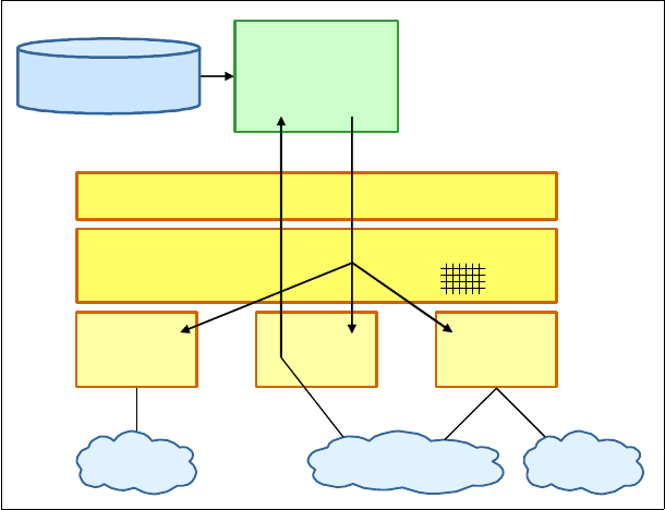
44 IBM z/OS V2R2 Communications Server TCP/IP Implementation Volume 1
Applications that use UNIX System Services callable APIs or Language Environment C/C++
sockets APIs can also use a specific bind to open a socket. A bind-specific server socket
receives connections only from the stack that owns the IP address to which the socket is
bound. Outbound connections or UDP datagrams are handled by the stack that offers the
best route to the destination IP address, as shown in Figure 2-9.
Figure 2-9 APIs: bind-specific
Generic server
A generic server is a server without an affinity to a specific stack, and it provides service to
any clients that are connected to any TCP/IP stacks on the system.
When using the generic bind, it does not matter whether the chosen resolver configuration file
has a TCPIPJobname; it is not used when the server is a pure generic server.
TCPA
X
TCPC
VZY
TCPB
C-INET
Pre-routing Table
BPX Callable Sockets
Inbound Outbound
socket( )
bind(8001, Y)
listen( )
Application-specific
Configuration Data

Chapter 2. The resolver 45
Applications that use UNIX System Services callable APIs or Language Environment C/C++
sockets APIs can be implemented by using a generic bind to open the same port in all TCP/IP
stacks. By doing so, the application accepts incoming connections or UDP data grams over
any interface of all connected stacks, as shown in Figure 2-10.
Figure 2-10 APIs: generic bind
Outbound connections or UDP datagrams are processed by the CINET pre-router, and the
stack with the best route to the destination is chosen.
When using a generic bind, the server port number must be reserved in all stacks. If one
stack has it reserved to another address space, the bind() call fails.
2.2.7 Resolving an IPv6 address
IPv6 support introduces several changes to how host name and IP address resolution is
performed. These changes affect several areas of resolver processing:
Resolver APIs were introduced for IPv6-enabled applications.
An algorithm is defined to describe how a resolver needs to sort a list of IP addresses that
is returned for a multihomed host.
DNS resource records are defined to represent hosts with IPv6 addresses and network
flows between resolvers and name servers (instead of DNS IPv4 A records).
Resolver support for IPv6 connections to DNS name servers
Communications Server for z/OS IP allows the system resolver to send requests to the DNS
name servers by using IPv6 communication. To implement IPv6 communication with a DNS
name server, specify the IPv6 address of the server on the existing NSINTERADDR and
NAMESERVER resolver configuration statements in the TCPIP.DATA data set.
TCPA
X
TCPC
VZY
TCPB
C-INET
Pre-routing Table
BPX Callable Sockets
Inbound Outbound
socket( )
bind(8001, Y)
listen( )
Application-specific
Configuration Data
Consideration: The res_state structure (nsaddr_list) contains only the IPv4 addresses
coded on the NSINTERADDR or NAMESERVER statements. Applications that examine or update
the nsaddr_list cannot manipulate the IPv6 addresses.
46 IBM z/OS V2R2 Communications Server TCP/IP Implementation Volume 1
IPv6 resolver statements
ETC.IPNODES is a local host file (in the style of /etc/hosts), which can contain both IPv4 and
IPv6 addresses. IPv6 addresses can be defined only in ETC.IPNODES. This file allows the
administration of local host files to more closely resemble that of other TCP/IP platforms, and
eliminates the requirement of post-processing the files (specifically, MAKESITE).
The IPv6 search order is the same as the COMMONSEARCH search order, as shown in Figure 2-4
on page 30. If you do not want to use the COMMONSEARCH search order for existing IPv4 local
hosts files, you might need to maintain two separate local host files (for example, IPv4
addresses in HOSTS.LOCAL, and IPv6 and IPv4 addresses in ETC.IPNODES).
Name and address resolution functions
The APIs, such as getaddrinfo, getnameinfo, and freeaddrinfo, allow applications to resolve
host names to IP addresses and vice versa for IPv6. The APIs are designed to work with both
IPv4 and IPv6 addressing. Consider the use of these APIs if an application is being designed
for eventual use in an IPv6 environment.
The manner in which host name (getaddrinfo) or IP address (getnameinfo) resolution is
performed depends on resolver specifications that are contained in the resolver SETUP data
sets and TCPIP.DATA configuration data sets, just like IPv4 address resolution. These
specifications determine whether the APIs query a name server first and then search the
local host files, or whether the order is reversed, or even if one of the steps is eliminated. The
specifications also control whether local host files must be searched, and which local host file
is accessed.
Default destination address selection
Resolver APIs can return multiple IP addresses as a result of a host name query. However,
many applications use only the first address that is returned to attempt a connection or to
send a UDP datagram. Therefore, the sorting of these IP addresses is performed by the
default destination address selection algorithm.
Establishing connectivity might depend on whether an IPv6 address or an IPv4 address is
selected, thus making this sorting function even more important. Default destination address
selection occurs only when the system is enabled for IPv6 and the application is using the
getaddrinfo() API to retrieve IPv6 or IPv4 addresses.
The default destination address selection algorithm takes a list of destination addresses and
sorts them to generate a new list. The algorithm sorts together both IPv6 and IPv4 addresses
by a set of rules.

Chapter 2. The resolver 47
The following rules are applied, in order, to the first and second address, choosing a best
address. Rules are then applied to this best address and the third address. This process
continues until rules are applied to the entire list of addresses.
Rule 1 Avoid unusable destinations. If one address is reachable (the stack has a route
to the particular address) and the other is unreachable, then place the
reachable destination address
before the unreachable address.
Rule 2 Prefer matching scope. If the scope of one address matches the scope of its
source address and the other address does not meet this criteria, then the
address with the matching scope is placed
before the other destination
address.
Rule 3 Avoid deprecated addresses. If one address is deprecated and the other is
non-deprecated, then the non-deprecated address is placed
before the other
address.
Rule 4 Prefer matching address formats. If one address format matches its associated
source address format and the other destination does not meet this criteria,
then place the destination with the matching format
before the other address.
Rule 5 Prefer higher precedence. If the precedence of one address is higher than the
precedence of the other address, then the address with the higher precedence
is placed
before the other destination address.
Rule 6 Use the longest matching prefix. If one destination address has a longer
CommonPrefixLength with its associated source address than the other
destination address has with its source address, then the address with the
longer CommonPrefixLength is placed
before the other address.
Rule 7 Leave the order unchanged. No rule selected a better address of these two;
they are equally good. Choose the first address as the better address of these
two and the order is not changed.
2.2.8 Resolver support for EDNS0
An early implementation of DNS, which is described in RFC 1035, allows only a maximum of
512 bytes for any DNS packet sent through UDP. This limitation inhibits DNS performance
because when a DNS server or client must communicate with a large amount of data, it must
use the bulky TCP protocol (higher performance cost) instead of the simple UDP protocol
(lower performance cost).
Extension Mechanism for DNS (EDNS0) was introduced in RFC 2671 to address the
performance improvement limitation that was imposed by the traditional DNS implementation.
The IBM implementation of the EDNS0 standard allows DNS communication of up to
3072 bytes by using UDP. This implementation improves DNS’s ability to communicate a large
amount of data, such as IP version 6 (IPv6).
Terminology: Deprecated, in this context, means that the state of an IPv6
address changed from
preferred state (the address was leased to an
interface for a fixed, possibly infinite, length of time) to
deprecated state.
(When a lifetime expires, the binding and address can become invalid, and
the address can be reassigned to another interface elsewhere on the
internet.) While in a deprecated state, the use of an address is discouraged
but not strictly forbidden.

48 IBM z/OS V2R2 Communications Server TCP/IP Implementation Volume 1
The z/OS Communications Server resolver supports the EDNS0 standard by default. No
additional steps are needed to enable this feature. However, the following dependencies are
required for the resolver to support EDNS0:
The DNS name server must also support EDNS0 protocols to use UDP packets larger
than 512 bytes.
Firewalls that exist between the DNS name server and the z/OS resolver must be
configured to accept DNS messages that are sent as UDP packets of greater than 512
bytes to use EDNS0 protocols.
In rare situations where the DNS server was recently upgraded to support EDNS0, a refresh
of the z/OS resolver is required so that it can relearn the DNS server EDNS0 capabilities. Run
MODIFY RESOLVER,REFRESH to the resolver address space to refresh.
2.2.9 Considerations
To implement the resolver address space, it is important to first determine whether your
environment requires a single TCP/IP stack or multiple TCP/IP stacks. In both cases, the
resolver is an independent address space and must be running before the TCP/IP stack is
started.
The statements that are defined in the global TCPIP.DATA file cannot be overridden by the
local TCPIP.DATA file of each TCP/IP stack. The local TCPIP.DATA file can specify only the
statement if it is not already defined in the global TCPIP.DATA file.
The resolver in a single-stack environment
As preferred practice, create a global TCPIP.DATA file for a single-stack environment. The
TCPIPJobname statement can be coded in a global TCPIP.DATA file or in the local (non-global)
TCPIP.DATA file because there is only one stack on the system. If some applications have
requirements to specify their own TCPIP.DATA statements, then omit them from the global
TCPIP.DATA file so that the applications can point to the local TCPIP.DATA file to be used.
The resolver in a multiple-stack environment
When implementing for a multiple-stack environment, each TCP/IP stack should use a local
TCPIP.DATA file specifying stack-specific statements, such as TCPIPJobname and HostName.
Optionally, you can merge some statements that can be applied to all TCP/IP stacks and all
TCP/IP applications to a global TCPIP.DATA file. You must determine which statements should
be defined in the global TCPIP.DATA file and used in the entire z/OS image. This determination
depends on how much you want to allow each stack or application to define its own
definitions.
In the multiple-stack environment, as a preferred practice, create a global TCPIP.DATA file if all
the statements that are needed in the global TCPIP.DATA file (see “Using
GLOBALTCPIPDATA” on page 27) can be applied to all the stacks, as shown in Figure 2-3 on
page 29. If not, do not use the global TCPIP.DATA file and use only the local TCPIP.DATA file for
each stack.
Important: In certain resolver environments, the use of the trace functions (such as
SockDebug or TraceResolver) might affect performance. Therefore, as a preferred
practice, use the method that is described in 2.4.3, “CTRACE: RESOLVER (SYSTCPRE)”
on page 66.

Chapter 2. The resolver 49
Figure 2-11 shows the multiple-stack environment without the use of a global TCPIP.DATA file.
Figure 2-11 The multiple-stack environment without a global TCPIP.DATA file
Preferred practice: Although there are specialized cases where multiple stacks per LPAR
can provide value, as a preferred practice, implement only one TCP/IP stack per LPAR.
The reasons for this preferred practice are as follows:
A TCP/IP stack can use all available resources that are defined to the LPAR in which it
is running. Therefore, starting multiple stacks does not yield any increase in throughput.
When running multiple TCP/IP stacks, additional system resources, such as memory,
CPU cycles, and storage, are required.
Multiple TCP/IP stacks add a significant level of complexity to TCP/IP system
administration tasks.
It is not necessary to start multiple stacks to support multiple instances of an application
on a given port number, such as a test HTTP server on port 80 and a production HTTP
server also on port 80. This type of support can instead be implemented by using
BIND-specific support where the two HTTP server instances are each associated with
port 80 with their own IP address, by using the BIND option on the PORT reservation
statement.
One example where multiple stacks can have value is when an LPAR must be connected
to multiple isolated security zones in such a way that there is no network level connectivity
between the security zones. In this case, a TCP/IP stack per security zone can be used to
provide that level of isolation, without any network connectivity between the stacks.
Local TCPIP.DATA
TCPIPJOBNAME TCPIPA
HOSTNAME WTSC30A
DATASETPREFIX TCPIPA
MESSAGECASE MIXED
DOMAINORIGIN ITSO.IBM.COM
NSINTERADDR 10.12.6.7
NSPORTADDR 53
RESOLVEVIA UDP
RESOLVERTIMEOUT 5
RESOLVERUDPRETRIES
LOOKUP LOCAL DNS
SC30
Local TCPIP.DATA
TCPIPJOBNAME TCPIPZ
HOSTNAME WTSC30Z
DATASETPREFIX TCPIPZ
MESSAGECASE MIXED
DOMAINORIGIN ITSO.IBM.COM
NSINTERADDR 10.1.100.222
NSPORTADDR 53
RESOLVEVIA UDP
RESOLVERTIMEOUT 5
RESOLVERUDPRETRIES
LOOKUP DNS LOCAL
TCPIPA
TN3270
server
TCPIPZ
FTPDZ
server

50 IBM z/OS V2R2 Communications Server TCP/IP Implementation Volume 1
2.3 Implementing the resolver
This scenario uses the customized resolver address space and specifies GLOBALTCPIPDATA,
DEFAULTTCPIPDATA, and GLOBALIPNODES in the resolver SETUP data set. You define a global
TCPIP.DATA file and define a common set of parameters for the entire z/OS image. Omit some
statements in the global TCPIP.DATA file so that the applications or TCP/IP stack can use their
own local TCPIP.DATA file for the statements undefined in the global TCPIP.DATA file.
Figure 2-12 depicts the environment that we use for this implementation.
Figure 2-12 The resolver environment on SC30
2.3.1 Implementation tasks
To implement the resolver address space in our test environment, perform these steps:
1. Creating a user ID for the resolver and assigning an OMVS segment
2. Setting up the resolver started procedure
3. Customizing BPXPRMxx
4. Configuring the resolver SETUP data set
5. Creating the global TCPIP.DATA file
6. Creating the default TCPIP.DATA file
7. Creating the global IPNODES data set.
8. Creating a TCPIP.DATA file for the TCPIPA stack
9. Creating the TCPIPA stack started procedure
The following sections describe these steps.
Creating a user ID for the resolver and assigning an OMVS segment
Use of the z/OS UNIX services requires the resolver to have an OMVS segment that is
associated with its user ID. If you do not have a user ID defined for the resolver that has an
associated OMVS segment, you must act before starting that resolver, or the resolver
address space initialization fails and the initialization of all TCP/IP stacks is delayed.
RESOLV30
Global TCPIP.DATA
DOMAINORIGIN ITSO.IBM.COM
NSINTERADDR 10.1.2.10
NSPOR TAD DR 53
RESOLVEVIA UDP
RESOLVERTI MEOU T 5
RESOLVERUDPRETRIES
LOOKUP LOCAL DNS
TCPIP stack
Local TCPIP.DATA
TCPIPJOBNAME TCPIPA
HOSTNAME WTSC30A
DATASETPREFIX TCPIPA
MESSAGECA SE MIXED
SC30
Global ETC.IPNODES
10 .1.1 .10 W TSC30A
10.1 .1. 20 W TSC31 B
10.1 .1. 30 W TSC32 C
10.1 .2. 240 route r 1
10.1 .2. 220 route r 2 .. .

Chapter 2. The resolver 51
Complete one of the following tasks:
If you already have a resolver user ID but it does not have an OMVS segment, then you
must define an OMVS segment for the resolver user ID.
If you do not have a resolver user ID, then you must create one that includes an OMVS
segment.
For information about defining and assigning a user ID for started procedures, go to the
following website:
http://publibz.boulder.ibm.com/cgi-bin/bookmgr_OS390/BOOKS/ichza7c0/5.9?SHELF=EZ2Z
O213&DT=20110620175910
For information about defining an OMVS segment, go to the following website:
http://publibz.boulder.ibm.com/cgi-bin/bookmgr_OS390/BOOKS/ichza7c0/17.0?SHELF=EZ2
ZO213&DT=20110620175910#HDRRUSS
Setting up the resolver started procedure
In this scenario, we create the resolver procedure so that it starts during the UNIX System
Services initialization.
To create the procedure, copy the sample procedure hlq.SEZAINST(EZBREPRC) and customize
it to the environment, as shown in Example 2-12. The procedure has only one DD card that
must be configured, the SETUP DD card 1, which describes where the SETUP data set is.
Example 2-12 The resolver started procedure
/*****************************************
/* SYS1.PROCLIB(RESOLV30)
/*****************************************
//RESOLV30 PROC PARMS='CTRACE(CTIRES00)' 1
//EZBREINI EXEC PGM=EZBREINI,REGION=0M,TIME=1440,PARM=&PARMS
//* SETUP contains resolver setup parameters.
//* See the section on "Understanding Resolvers" in the
//* IP Configuration Guide for more information. A sample of
//* resolver setup parameters is included in member RESSETUP
//* of the SEZAINST data set.
//*
//SETUP DD DSN=TCPIPA.TCPPARMS(RESOLV&SYSCLONE),DISP=SHR,FREE=CLOSE 2
In this example, the numbers correspond to the following information:
1. The name of the resolver procedure is RESOLV30.
2. Specifies the resolver SETUP data set. The &SYSCLONE MVS system symbol value on
this system is 30.

52 IBM z/OS V2R2 Communications Server TCP/IP Implementation Volume 1
Customizing BPXPRMxx
We customize the RESOLVER_PROC statement in BPXPRMxx to specify the procedure name
that we used, which causes the resolver to start automatically the next time z/OS UNIX
System Services initializes. Example 2-13 shows the partial contents of BPXPRMxx.
Example 2-13 Specifying the resolver procedure to be started
/*****************************************
/* SYS1.PARMLIB(BPXPRM00)
/*****************************************
/* RESOLVER_PROC is used to specify how the resolver address space */
/* is processed during Unix System Services initialization. */
/* The resolver address space is used by Tcp/Ip applications */
/* for name-to-address or address-to-name resolution. */
/* In order to create a resolver address space, a system must be */
/* configured with an AF_INET or AF_INET6 domain. */
/* RESOLVER_PROC(procname|DEFAULT|NONE) */
/* procname - The name of the address space for the resolver. */
/* In this case, this is the name of the address */
/* space as well as the procedure member name */
/* in SYS1.PROCLIB. procname is 1 to 8 characters */
/* long. */
/* DEFAULT - An address space with the name RESOLVER will */
/* be started. This is the same result that will */
/* occur if the RESOLVER_PROC statement is not */
/* specified in the BPXPRMxx profile. */
/* */
/* NONE - Specifies that a RESOLVER address space is */
/* not to be started. */
/* @DAA*/
/********************************************************************/
RESOLVER_PROC(RESOLV&SYSCLONE.) 1
In this example, the number corresponds to the following information:
1. Specifies the name of the resolver procedure that we created in “Setting up the resolver
started procedure” on page 51. The &SYSCLONE MVS system symbol value on this
system is 30.
Configuring the resolver SETUP data set
We configure the resolver SETUP data set, which is specified with the SETUP DD definition
in the resolver started procedure. This data set defines the location of the global and default
TCPIP.DATA files containing the parameters that we want to be defined in the z/OS
environment.
Important: When the resolver is started by UNIX System Services, you must pay attention
to the following information:
The resolver address space is started by SUB=MSTR. This means that JES services are
not available to the resolver address space. Therefore, no DD cards with SYSOUT can
be used.
The resolver start procedure must be in a data set that is specified by the MSTJCLxx
PARMLIB member’s IEFPDSI DD card specification. Otherwise, the procedure is not
found and the resolver does not start. SYS1.PROCLIB is usually one of the libraries
that are specified there.

Chapter 2. The resolver 53
In our test environment, we copy the SETUP sample data set and change its contents to meet
our requirements, as shown in Example 2-14.
Example 2-14 Resolver address space SETUP data set
; ****************************************
; TCPIPA.TCPPARMS(RESOLV30)
; ****************************************
GLOBALTCPIPDATA('TCPIPA.TCPPARMS(GLOBAL)') 1
DEFAULTTCPIPDATA('TCPIPA.TCPPARMS(DEFAULT)') 2
GLOBALIPNODES('TCPIPA.TCPPARMS(IPNODES)') 3
COMMONSEARCH 4
CACHE 5
CACHESIZE(20M) 6
CACHEREORDER 7
MAXTTL(600) 8
UNRESPONSIVETHRESHOLD(25) 9
In this example, the numbers correspond to the following information:
1. Specifies the first choice of the TCPIP.DATA file.
2. Specifies the last choice of the TCPIP.DATA file.
3. Specifies the first choice of the local hosts file.
4. The COMMONSEARCH search order is used. This statement is needed so that
GLOBALIPNODES is applied.
5. Indicates that system-wide caching is enabled for the resolver.
6. Specifies the maximum amount of storage that can be allocated by the resolver to manage
cached records. A value of at least 50 MB should be considered in a production
environment.
7. Indicates that system-wide cache reordering is enabled for the resolver.
8. Specifies the maximum amount of time the resolver can use resource information that is
obtained from a DNS server as part of resource resolution.
9. Defines the percentage threshold value to be used to calculate when a name server
should be declared to be unresponsive to resolver queries.
Important: Be careful when creating these global parameters. The definitions in the
resolver SETUP data set are applied to all TCP/IP stacks or applications.

54 IBM z/OS V2R2 Communications Server TCP/IP Implementation Volume 1
Creating the global TCPIP.DATA file
In this step, we provide the global statements that all TCP/IP stacks and applications use in
our z/OS environment. To define these statements, we copy the sample TCPIP.DATA file that is
provided in hlq.SEZAINST(TCPDATA) and customized the statements, as shown in
Example 2-15.
Example 2-15 Global TCPIP.DATA file
; *****************************************
; TCPIPA.TCPPARMS(GLOBAL)
; *****************************************
DOMAINORIGIN ITSO.IBM.COM 1
NSINTERADDR 10.1.2.10 2
NSPORTADDR 53
RESOLVEVIA UDP
RESOLVERTIMEOUT 5
RESOLVERUDPRETRIES 1
LOOKUP DNS LOCAL 3
In this example, the numbers correspond to the following information:
1. Specifies the list of domain names that is appended to the host name when the search is
performed.
2. Specifies the IP address of the DNS server.
3. To take advantage of the caching that we enabled in the Global Resolver SETUP file
(Example 2-14 on page 53), we change our previously used LOOKUP sequence to favor
the DNS over the LOCAL file. If neither a cache entry or a DNS entry is found for a lookup,
the resolver searches the local file.
Important: If GLOBALTCPIPDATA is specified:
Any statements that are contained in the global TCPIP.DATA file take precedence over
any statements in the local TCPIP.DATA file that is found by the appropriate
environment’s (Native z/OS or z/OS UNIX) search order.
The TCPIP.DATA statements in Example 2-15 (with the exception of LOOKUP) can be
specified only in GLOBALTCPIPDATA. If the resolver statements are found in any of the
other search locations for TCPIP.DATA, they are ignored. If the resolver statements are
not found in GLOBALTCPIPDATA, their default value is used.

Chapter 2. The resolver 55
Creating the default TCPIP.DATA file
We create a default TCPIP.DATA file, as shown in Example 2-16, to be the last choice of the
local TCPIP.DATA search order. It is used when the application does not specify the local
TCPIP.DATA file explicitly.
Example 2-16 Default TCPIP.DATA file
; *****************************************
; TCPIPA.TCPPARMS(DEFAULT)
; *****************************************
TCPIPJOBNAME TCPIP 1
HOSTNAME WTSC30 2
In this example, the numbers correspond to the following information:
1. Specifies the default TCP/IP procedure name.
2. Specifies the default host name.
Creating the global IPNODES data set
We create the global IPNODES data set, which is referred as GLOBALIPNODES in the
resolver SETUP data set. It contains name-to-address mappings. This data set is used for the
local search to resolve a name into an IP address or vice versa.
We choose to use COMMONSEARCH because it allows us to have a common local search
environment with IPv4 or IPv6 hosts. Example 2-17 shows the contents of the
GLOBALIPNODES data set. When using COMMONSEARCH, only the IPNODES data set is
used.
Example 2-17 GLOBALIPNODES data set
; *****************************************
; TCPIPA.TCPPARMS(IPNODES)
; *****************************************
10.1.2.10 OURDNS 1
10.1.1.10 WTSC30A 1
10.1.1.20 WTSC31B 1
10.1.1.30 WTSC32C 1
10.1.2.240 router1 1
10.1.3.240 router2 1
1::2 TESTIPV6ADDRESS1 2
1:2:3:4:5:6:7:8 TESTIPV6ADDRESS2 2
In this example, the numbers correspond to the following information:
1. The mapping of a name and a IPv4 address is listed.
2. The mapping of a name and a IPv6 address is listed.
Important: Applications that use Language Environment services without a TCPIPJOBNAME
statement cause applications that issue __iptcpn() to receive a job name of NULL, and
some of these applications use INET instead of TCP/IP. Although this presents no problem
when running in a single-stack environment, it can potentially cause errors in a multi-stack
environment.

56 IBM z/OS V2R2 Communications Server TCP/IP Implementation Volume 1
Creating a TCPIP.DATA file for the TCPIPA stack
We create a local TCPIP.DATA file for the TCPIPA stack with the file name DATAA30, as shown
in Example 2-18.
Example 2-18 TCPIP.DATA file DATAA30
; *****************************************
; TCPIPA.TCPPARMS(DATAA30)
; *****************************************
TCPIPJOBNAME TCPIPA 1
HOSTNAME WTSC30A 2
DATASETPREFIX TCPIPA
MESSAGECASE MIXED
In this example, the numbers correspond to the following information:
1. Specifies the procedure name of the TCPIPA stack.
2. Specifies the host name of the TCPIPA stack.
Creating the TCPIPA stack started procedure
We create the TCPIPA stack procedure (with RESOLVER_CONFIG) and pointed to
TCPIPA.TCPPARMS(DATAA30) by using the &sysclone variable to simplify our implementation to
allow for a single procedure to be used by any z/OS image in our sysplex environment, as
shown in Example 2-19.
Example 2-19 TCPIPA procedure
/*****************************************
/* SYS1.PROCLIB(TCPIPA)
/*****************************************
//TCPIPA PROC PARMS='CTRACE(CTIEZB00),IDS=00', 1
// PROFILE=PROFA&SYSCLONE.,TCPDATA=DATAA&SYSCLONE
//TCPIPA EXEC PGM=EZBTCPIP,REGION=0M,TIME=1440,
// PARM=('&PARMS',
// 'ENVAR("RESOLVER_CONFIG=//''TCPIPA.TCPPARMS(&TCPDATA)''")') 2
//SYSPRINT DD SYSOUT=*,DCB=(RECFM=VB,LRECL=132,BLKSIZE=136)
//SYSTCPT DD SYSOUT=*,DCB=(RECFM=VB,LRECL=132,BLKSIZE=136)
//ALGPRINT DD SYSOUT=*,DCB=(RECFM=VB,LRECL=132,BLKSIZE=136)
//CFGPRINT DD SYSOUT=*,DCB=(RECFM=VB,LRECL=132,BLKSIZE=136)
//SYSOUT DD SYSOUT=*,DCB=(RECFM=VB,LRECL=132,BLKSIZE=136)
//CEEDUMP DD SYSOUT=*,DCB=(RECFM=VB,LRECL=132,BLKSIZE=136)
//SYSERROR DD SYSOUT=*
//PROFILE DD DISP=SHR,DSN=TCPIPA.TCPPARMS(&PROFILE.) 3
In this example, the numbers correspond to the following information:
1. The TCP/IP procedure name is TCPIPA.
2. The local TCPIP.DATA file is specified.
3. The TCP/IP profile is specified (the TCP/IP configuration file example is not shown in this
chapter).

Chapter 2. The resolver 57
2.3.2 Activation and verification
To verify that the resolver address space is working as expected, we perform these steps:
1. Stopping the default z/OS UNIX resolver
2. Starting the resolver address space
3. Displaying the resolver address space configuration
4. Using the ping command to verify the name resolution
To implement our resolver address space, we halt the running resolver by using the STOP
command, as shown in Example 2-20.
Stopping the default z/OS UNIX resolver
In our current environment, the default z/OS UNIX resolver is running. We stop this default
resolver, as shown in Example 2-20, to run the customized resolver.
Example 2-20 Stop the resolver address space
P RESOLV30
EZZ9292I RESOLVER ENDING
IEF352I ADDRESS SPACE UNAVAILABLE
$HASP395 RESOLV30 ENDED
Starting the resolver address space
We start the customized resolver address space (see Example 2-21) by using the procedure
that we create in Example 2-12 on page 51.
Example 2-21 Start a configured resolver address space
S RESOLV30
IRR812I PROFILE ** (G) IN THE STARTED CLASS WAS USED 681
TO START RESOLV30 WITH JOBNAME RESOLV30.
$HASP100 RESOLV30 ON STCINRDR
IEF695I START RESOLV30 WITH JOBNAME RESOLV30 IS ASSIGNED TO USER
IBMUSER , GROUP SYS1
$HASP373 RESOLV30 STARTED
IEE252I MEMBER CTIRES00 FOUND IN SYS1.PARMLIB
EZZ9298I DEFAULTTCPIPDATA - TCPIPA.TCPPARMS(DEFAULT) 1
EZZ9298I GLOBALTCPIPDATA - TCPIPA.TCPPARMS(GLOBAL) 2
EZZ9298I DEFAULTIPNODES - None
EZZ9298I GLOBALIPNODES - TCPIPA.TCPPARMS(IPNODES) 3
EZZ9304I COMMONSEARCH
EZZ9304I CACHE 4
EZZ9298I CACHESIZE - 20M 5
EZZ9298I MAXTTL - 600 6
EZZ9304I CACHEREORDER 7
EZZ9298I UNRESPONSIVETHRESHOLD - 25 8
EZZ9291I RESOLVER INITIALIZATION COMPLETE
Important: Stop and restart the resolver only if you install a new level of the resolver code.

58 IBM z/OS V2R2 Communications Server TCP/IP Implementation Volume 1
In Example 2-21 on page 57, the numbers correspond to the following information:
1. The correct DEFAULTTCPIPDATA file is applied.
2. The correct GLOBALTCPIPDATA file is applied.
3. The correct GLOBALIPNODES file is applied.
4. Indicates that system-wide caching is enabled for the resolver.
5. Indicates the maximum amount of storage that can be allocated by the resolver.
6. Indicates the maximum amount of time that the resolver can use resource information that
is obtained from a DNS server as part of resource resolution.
7. Indicates that the resolver is using the cache reorder option.
8. Indicates the percentage threshold value to calculate when a name server should be
declared to be unresponsive to resolver queries. If the user had used the following coding,
another instance of EZZ9304I with the words AUTOQUIESCE would have been displayed, and
also a display of the status of the name servers in the global TCPIP.DATA file:
UNRESPONSIVETHRESHOLD (25,AUTOQUIESCE)
See Figure 2-7 on page 42.
If you want to reload the SETUP data set content changes, run the MODIFY command to
refresh the resolver. To show how this is done, we create a SETUP data set named NEWSETUP,
with the same configuration as the RESOLV30 setup file, change the UNRESPONSIVETHRESHOLD
statement to 35%, and refresh the resolver to reflect the changes, as shown in Example 2-22.
Example 2-22 Modify the resolver address space
F RESOLV30,REFRESH,SETUP=TCPIPA.TCPPARMS(NEWSETUP)
EZZ9298I DEFAULTTCPIPDATA - TCPIPA.TCPPARMS(DEFAULT)
EZZ9298I GLOBALTCPIPDATA - TCPIPA.TCPPARMS(GLOBAL)
EZZ9298I DEFAULTIPNODES - None
EZZ9298I GLOBALIPNODES - TCPIPA.TCPPARMS(IPNODES)
EZZ9304I COMMONSEARCH
EZZ9304I CACHE
EZZ9298I CACHESIZE - 30M
EZZ9298I MAXTTL - 600
EZZ9304I CACHEREORDER
EZZ9298I UNRESPONSIVETHRESHOLD - 35
EZZ9293I REFRESH COMMAND PROCESSED
Notes:
If you want to start the default z/OS UNIX resolver, run the following command instead:
START IEESYSAS.RESOLVER,PROG=EZBREINI,SUB=MSTR
The resolver uses non-reusable address spaces. To start the resolver by using a
reusable address space ID (REUSASID), see 1.3.3, “Reusable address space ID” on
page 6.

Chapter 2. The resolver 59
Resolver initialization resilience
z/OS Communications Server V2R1 introduces the resolver initialization resilience. The
resolver parses the setup file for errors during initialization. Because the resolver parses the
entire file, it continues to issue messages identifying specific errors in the files.
A possibility is that the resolver encounters correct and incorrect parameter values for the
same setup statement. If that occurs, the resolver uses the last correct specification, ignoring
any subsequent or previous specification. If no correct specification is found, the default value
is used.
During initialization, even if errors are encountered in the file, the resolver continues to parse
the file and issue messages identifying specific errors. You can use one single setup file for all
systems regardless of release level.
The resolver stops parsing the setup file if errors are encountered during MODIFY
RESOLVER,REFRESH,SETUP= command processing (see Example 2-22 on page 58).
The main reason for continuing with this behavior is that the resolver assumes that the MODIFY
command is a full replacement of the resolver configuration, which means that if a setup
statement is not coded in the setup file, the resolver assumes that the default value for the
statement should be used. This is true even if a non-default setting was specified for the
statement previously. If the resolver were to ignore errors in the setup file during MODIFY
processing, the behavior of the resolver might possibly change drastically, and unintentionally,
after the MODIFY command.
Two new messages were introduced with the resolver resiliency function:
A message is issued after resolver unitization completes when one or more errors are
detected.
The message EZD2039I is issued when the MODIFY RESOLVER,DISPLAY is issued and lists
the errors that the resolver encountered during initialization.
We intentionally introduce an error in the SYS1.TCPPARMS(RESOLV30) setup file. Example 2-23
shows the output of the RESOLV30 job log.
Example 2-23 Resolver initialization with errors
EZZ9295I INCORRECT STATEMENT SYNTAX ON LINE 6
EZZ9298I DEFAULTTCPIPDATA - TCPIPA.TCPPARMS(DEFAULT)
EZZ9298I GLOBALTCPIPDATA - TCPIPA.TCPPARMS(GLOBAL)
EZZ9298I DEFAULTIPNODES - None
EZZ9298I GLOBALIPNODES - None
EZZ9304I COMMONSEARCH
EZZ9304I CACHE
EZZ9298I CACHESIZE - 20M
EZZ9298I MAXTTL - 600
EZZ9304I CACHEREORDER
EZZ9298I UNRESPONSIVETHRESHOLD - 25
EZD2038I RESOLVER INITIALIZATION COMPLETED WITH WARNINGS

60 IBM z/OS V2R2 Communications Server TCP/IP Implementation Volume 1
Example 2-24 shows the output of F RESOLV30,DISPLAY. The error has not been fixed and
message EZD2039I is displayed.
Example 2-24 RESOLV30,DISPLAY output after a detected error during initialization
EZZ9298I DEFAULTTCPIPDATA - TCPIPA.TCPPARMS(DEFAULT)
EZZ9298I GLOBALTCPIPDATA - TCPIPA.TCPPARMS(GLOBAL)
EZZ9298I DEFAULTIPNODES - None
EZZ9298I GLOBALIPNODES - None
EZZ9304I COMMONSEARCH
EZZ9304I CACHE
EZZ9298I CACHESIZE - 20M
EZZ9298I MAXTTL - 600
EZZ9304I CACHEREORDER
EZZ9298I UNRESPONSIVETHRESHOLD - 25
EZD2039I WARNINGS ISSUED DURING RESOLVER INITIALIZATION
EZZ9293I DISPLAY COMMAND PROCESSED
We fix the error and run F RESOLV30,REFRESH,SETUP=SYS1.TCPPARMS(RESOLV30). Message
EZD2038I is not displayed. See Example 2-25.
Example 2-25 Fix an error by running F RESOLV30,REFRESH,SETUP=
EZZ9298I DEFAULTTCPIPDATA - None
EZZ9298I GLOBALTCPIPDATA - SYS1.TCPPARMS(GLBLDATA)
EZZ9298I DEFAULTIPNODES - None
EZZ9298I GLOBALIPNODES - SYS1.TCPPARMS(IPNODES)
EZZ9304I COMMONSEARCH
EZZ9304I CACHE
EZZ9298I CACHESIZE - 10M
EZZ9298I MAXTTL - 600
EZZ9304I CACHEREORDER
EZZ9298I UNRESPONSIVETHRESHOLD - 25
EZZ9293I REFRESH COMMAND PROCESSED
The new message EZD2039I is included only if resolver setup file errors were detected and no
MODIFY RESOLVER,REFRESH command was successfully processed since resolver initialization
completed. Because MODIFY REFRESH processing succeeds only if there are no resolver setup
file errors, the assumption is that MODIFY REFRESH processing fixes any previous setup file
errors. Therefore, the message is no longer displayed when a successful MODIFY REFRESH is
performed.
Automation
The new resolver messages are designed to assist with automation that detects errors during
system startup and to highlight previous errors that might not have been detected.
Displaying the resolver address space configuration
To verify that the correct configuration file is applied to the resolver address space, run the
MODIFY command with the display option, as shown in Example 2-26.
Example 2-26 Modify the resolver with the display option
EZZ9298I DEFAULTTCPIPDATA - None
EZZ9298I GLOBALTCPIPDATA - SYS1.TCPPARMS(GLBLDATA)
EZZ9298I DEFAULTIPNODES - None
EZZ9298I GLOBALIPNODES - SYS1.TCPPARMS(IPNODES)

Chapter 2. The resolver 61
EZZ9304I COMMONSEARCH
EZZ9304I CACHE
EZZ9298I CACHESIZE - 10M
EZZ9298I MAXTTL - 600
EZZ9304I CACHEREORDER
EZZ9298I UNRESPONSIVETHRESHOLD - 25
EZZ9293I DISPLAY COMMAND PROCESSED
Using the ping command to verify the name resolution
Verify that the resolver can perform the expected name-to-address resolution by running the
ping command, as shown in Example 2-27. The example shows the name router1 was
resolved to address 10.1.2.240. For more information about running the ping command, see
9.4.1, “The ping command (TSO or z/OS UNIX)” on page 355.
Example 2-27 UNIX ping command display
CS02 @ SC30:/u/cs02>ping router1
Pinging host router1 (10.1.2.240)
Ping #1 response took 0.001 seconds.
The TSO PING command was also successful, as shown in Example 2-28.
Example 2-28 TSO PING command display
TSO PING ROUTER1
Pinging host router1 (10.1.2.240)
Ping #1 response took 0.001 seconds.
***
Another possibility to verify where the resolver is looking is by using the TRACE RESOLVER
parameter in the stack’s or application’s TCPIP.DATA file. For an explanation of how this is
done and what the contents of this trace will be, see 2.4, “Problem determination” on page 61.
2.4 Problem determination
To diagnose resolver problems, you can use two kinds of trace tools:
Trace Resolver
This tool provides information that can be helpful in debugging problems that an
application program might have with using resolver facilities (for example,
GetHostByName or GetHostByAddr).
Component Trace RESOLVER (SYSTCPRE)
This is useful for diagnosing resolver problems that cannot be isolated to one particular
application, and it also allows you to activate the resolver trace without recycling the
application that you might want to diagnose, by using the option TRACERES.
This section offers a brief explanation of when to debug, which trace must be used, and how
to use these trace facilities. For more information about resolver diagnosis, see z/OS
Communications Server: IP Diagnosis Guide, GC31-8782.
Note: CTRACE Resolver (SYSTCPRE) is the preferred method for gathering
documentation for Resolver problems.

62 IBM z/OS V2R2 Communications Server TCP/IP Implementation Volume 1
2.4.1 Deciding which tool to use to diagnose a resolver problem
The first step when diagnosing a possible resolver problem is to check the symptoms to verify
whether the issue is definitely a resolver problem (see Table 2-4).
Table 2-4 What to do if the host name cannot be reached
2.4.2 Trace Resolver
The Trace Resolver informs you what the resolver looks for (the questions) and where it looks
(name server’s cache and IP addresses or local host file names).
The following situations can be checked in the trace output:
Check whether the correct resolver data sets are in use. If an unexpected TCPIP.DATA file
is used, check the search orders of the data set.
Check whether the data sets that are defined to be used are authorized by RACF and can
be read by the application, TCP/IP stack, or user.
Check the TCPIP.DATA parameter values, especially Search, NameServer,
NSINTERADDR, and NsPortAddr.
Check the questions that are posed by the resolver to DNS or in searching the local host
files. Are these the queries that you expect?
Look for errors or failures in the trace.
Was the information obtained from the resolver cache? If so, run netstat Rescache/-Q
commands to determine whether the cache information is correct.
Did DNS respond (if you expected it to)? If not, see whether DNS is active at the IP
address you specified for NameServer and NSINTERADDR and what port it is listening
on. Also, DNS logs can be helpful, so ask the DNS administrator for help.
Did the resolver choose to not send the request to the DNS because the resolver “thought”
the DNS was unresponsive?
Symptom of ping
command when you
ping a host name
Possible problem Solution
Succeeds, but another
application fails when
resolving the same host
name.
The problem is with the resolver
configuration for the application in
the user’s environment.
Use the Trace Resolver
statement on the local
TCPIP.DATA file that is used by
the application that has the
problem.
Fails, but the host name is
converted to an IP address.
The resolution is successful but
the host is not reachable or active.
This problem is related to
connectivity, not a resolver
problem.
Fails to convert the name to
an IP address.
The problem might be with the
resolver configuration, searching
local host files, or using DNS.
Use Trace Resolver to solve the
problem.
Tip: If the problem seems to be related to the DNS, use the LOOKUP LOCAL DNS statement
to check the local files first.

Chapter 2. The resolver 63
Trace Resolver can be activated in the following ways, in its precedence order:
1. The RESOLVER_TRACE environment variable (z/OS UNIX environment only)
2. SYSTCPT DD allocation
3. TRACE RESOLVER or OPTIONS DEBUG statements (You must allocate STDOUT or SYSPRINT
to generate trace data.
4. The resDebug bit set to on in the _res structure option field (You must allocate STDOUT
or SYSPRINT to generate trace data.)
Using Trace Resolver in a z/OS UNIX environment
Example 2-29 shows how to enable and disable the Trace Resolver in z/OS UNIX
environment.
Example 2-29 Use Trace Resolver in a z/OS UNIX environment
CS02 @ SC30:/u/cs02>export RESOLVER_TRACE=/u/cs02/trace1.txt 1
CS02 @ SC30:/u/cs02>ping admin 2
Pinging host admin.ITSO.IBM.COM (10.1.4.11)
Ping #1 response took 0.000 seconds.
CS02 @ SC30:/u/cs02>set -A RESOLVER_TRACE 3
CS01 @ SC30:/u/cs01>obrowse /u/cs02/trace1.txt
In this example, the numbers correspond to the following information:
1. To enable the Trace Resolver, set the RESOLVER_TRACE environment variable. This
command directs the output to the /u/cs06/trace1.txt HFS file. You can also direct the
output to STDOUT by specifying RESOLVER_TRACE=STDOUT. If you want to direct it to a new
MVS data set, specify the following command:
RESOLVER_TRACE="//’SOME.MVS.DATASET’"
2. After enabling a Trace Resolver, perform a z/OS UNIX shell command that invokes a
resolver call.
3. This command disables the Trace Resolver.
Using Trace Resolver in a TSO environment with SYSTCPT DD
Example 2-30 shows how to enable and disable the Trace Resolver in a TSO environment.
Example 2-30 Use Trace Resolver in a TSO environment
alloc dd(systcpt) da(*) 1
ping router1 2
free dd(systcpt) 3
In this example, the numbers correspond to the following information:
1. To enable the Trace Resolver, allocate a SYSTCPT data set. If you specify da(*), the
Trace Resolver outputs to a TSO terminal. If you want to direct the output to a specific data
set, specify da(‘SOME.DATASET.NAME’).
2. After enabling the Trace Resolver, perform a TSO command that invokes a resolver call.
3. To disable the Trace Resolver, free a SYSTCPT data set.
Tip: When directing Trace Resolver output to a TSO terminal, define the screen size to be
only 80 columns wide. Otherwise, the trace output is difficult to read.

64 IBM z/OS V2R2 Communications Server TCP/IP Implementation Volume 1
Using Trace Resolver for applications with TCPIP.DATA statements
Allocate STDOUT or SYSPRINT (as a DD statement in the procedure) as an output data set,
and define the statement TRACE RESOLVER or OPTIONS DEBUG in the first line of the TCPIP.DATA
file that is being used by the application, as shown in Example 2-31. Start the application that
invokes a resolver call.
Example 2-31 Using the OPTIONS DEBUG to get a trace of the resolver
OPTIONS DEBUG 1
TCPIPJOBNAME TCPIPA
HOSTNAME WTSC30A
DOMAINORIGIN ITSO.IBM.COM
DATASETPREFIX TCPIPA
MESSAGECASE MIXED
NSINTERADDR 10.1.2.10
NSPORTADDR 53
In this example, specify OPTIONS DEBUG (1) or TRACE RESOLVER to enable Trace Resolver.
Displaying the output of the Trace Resolver
Example 2-32 shows the output of the Trace Resolver in the z/OS UNIX environment (which
was taken from Example 2-29 on page 63). The Trace Resolver that is taken in the TSO
environment (Example 2-30 on page 63) is almost identical.
Example 2-32 Trace Resolver partial output: z/OS UNIX shell environment
Resolver Trace Initialization Complete -> 2010/09/27 15:04:49.709930
res_init Resolver values:
Global Tcp/Ip Dataset = TCPIPA.TCPPARMS(GLOBAL) 1
Default Tcp/Ip Dataset = TCPIPA.TCPPARMS(DEFAULT)
Local Tcp/Ip Dataset = /etc/resolv.conf 2
...
...
(G) LookUp = LOCAL DNS 3
(*) Cache
res_init Succeeded
res_init Started: 2010/09/27 15:04:49.741620
res_init Ended: 2010/09/27 15:04:49.741624
***************************************************************************
GetAddrInfo Started: 2010/09/27 15:04:49.741646
GetAddrinfo Invoked with following inputs:
Host Name: admin 4
...
...
GetAddrInfo Only IPv4 Interfaces Exist
GetAddrInfo Searching Local Tables for IPv4 Address
Global IpNodes Dataset = TCPIPA.TCPPARMS(IPNODES) 5
Default IpNodes Dataset = None
Search order = CommonSearch
...
...
- Lookup for admin.ITSO.IBM.COM
- Lookup for admin
res_search(admin, C_IN, T_A)
res_search Host Alias Search found no alias 6
res_querydomain(admin, ITSO.IBM.COM, C_IN, T_A)
res_querydomain resolving name: admin.ITSO.IBM.COM
res_query(admin.ITSO.IBM.COM, C_IN, T_A)

Chapter 2. The resolver 65
Querying resolver cache for admin.ITSO.IBM.COM
...
No cache information was available 7
res_mkquery(QUERY, admin.ITSO.IBM.COM, C_IN, T_A)
res_mkquery created message:
...
res_send Name Server Capabilities
Name server 10.1.2.10
...
res_send Sending query to Name Server 10.1.2.10 8
DNS Communication Started: 2010/09/27 15:04:49.752519
No OPT RR record sent on request to 10.1.2.10
...
BPX1AIO RECVMSG : From 10.1.2.10
UDP Data Length: 86
res_send received data via UDP. Message received:
* * * * * Beginning of Message * * * * *
Query Id: 62855
...
Response Code: NOERROR
Number of Question RRs: 1
Question 1:
admin.ITSO.IBM.COM
...
Answer 1:
admin.ITSO.IBM.COM
Type (0X0001) T_A Class (0X0001) C_IN
TTL: 86400 (1 days, 0 hours, 0 minutes, 0 seconds)
10.1.4.11
* * * * * End of Message * * * * *
DNS Communication Ended: 2010/09/27 15:04:49.753095 time used 00:00:00.000576
Name Server Capability Updates
Name server 10.1.2.10
Queries sent = 1
Failures = 0
res_send Succeeded
Attempting to cache results for admin.ITSO.IBM.COM
EZBRECAR: RetVal = 0, RC = 0, Reason = 0x00000000
Cache information was saved 9
...
GetAddrInfo Succeeded: IP Address(es) found:
IP Address(1) is 10.1.4.11 10
GetAddrInfo Ended: 2010/09/27 15:04:49.753194
***************************************************************************
FreeAddrInfo Started: 2010/09/27 15:04:49.753222
FreeAddrInfo Called to free addrinfo structures
FreeAddrInfo Succeeded, Freed 1 Addrinfos
FreeAddrInfo Ended: 2010/09/27 15:04:49.753229
***************************************************************************
In this example, the numbers correspond to the following information:
1. Informs you that the global TCPIP.DATA file in use.
2. Informs you that the local TCPIP.DATA file in use.
3. The local hosts file is looked up first, followed by the DNS server if it fails.
4. The admin host name is looked up.
5. Informs you that the global ETC.IPNODE file in use.

66 IBM z/OS V2R2 Communications Server TCP/IP Implementation Volume 1
6. No information was available in the ETC.IPNODE file.
7. The admin host entry could not be found in the cache.
8. The resolver sends a query to the name server.
9. The response of name server is cached.
10.The IP address was found in the name server.
2.4.3 CTRACE: RESOLVER (SYSTCPRE)
Component Trace (CTRACE) is used for the RESOLVER component (SYSTCPRE) to collect
debug information. The TRACE RESOLVER traces information about a per-application basis
and directs the output to a unique file for each application. The CTRACE shows resolver
actions for all applications (although it might be filtered).
The CTRACE support allows for JOBNAME, ASID filtering, or both. The trace buffer is in the
resolver private storage. The trace buffer minimum size is 128 KB. The maximum size is
128 MB. The default size is 16 MB. Trace records can optionally be written to an external
writer.
The resolver CTRACE can be started any time needed by using the TRACE CT command, or it
can be activated during resolver procedure initialization.
Using CTRACE for RESOLVER
The resolver CTRACE initialization PARMLIB member can be specified at resolver start time.
To activate the resolver CTRACE during resolver initialization, complete the following steps:
1. Create a CTWTR procedure in SYS1.PROCLIB, as shown in Example 2-33.
Example 2-33 CTWTR procedure
//CTWTR PROC
//IEFPROC EXEC PGM=ITTTRCWR
//TRCOUT01 DD DSNAME=CS02.CTRACE1,VOL=SER=COMST2,UNIT=3390,
// SPACE=(CYL,10),DISP=(NEW,KEEP),DSORG=PS
//TRCOUT02 DD DSNAME=CS02.CTRACE2,VOL=SER=COMST2,UNIT=3390,
// SPACE=(CYL,10),DISP=(NEW,KEEP),DSORG=PS
//*
2. Using the sample resolver procedure that is included with the product, run the following
console command:
S RESOLV30,PARMS='CTRACE(CTIRESxx)'
The xx is the suffix of the CTIRESxx PARMLIB member to be used. To customize the
parameters that are used to initialize the trace, you can update CTIRES00 (the
SYS1.PARMLIB member), as shown in Example 2-34.
Example 2-34 Trace options
/*********************************************************************/
TRACEOPTS
/* ---------------------------------------------------------------- */
/* Optionally start external writer in this file (use both */
/* WTRSTART and WTR with same wtr_procedure) */
Note: If you suspect an error exists in the operation of the resolver cache, you must collect
CTRACE records because there are no Trace Resolver trace entries for cache processing.

Chapter 2. The resolver 67
WTRSTART(CTWTR)
/* ---------------------------------------------------------------- */
/* ON OR OFF: PICK 1 */
/* ---------------------------------------------------------------- */
ON
/* OFF */
/* BUFSIZE: A VALUE IN RANGE 128K TO 128M */
BUFSIZE(16M)
/* JOBNAME(jobname1,...) */
/* ASID(Asid1,...) */
WTR(CTWTR)
/* ---------------------------------------------------------------- */
/* OPTIONS: NAMES OF FUNCTIONS TO BE TRACED, OR "ALL" */
/* ---------------------------------------------------------------- */
/* OPTIONS( */
/* 'ALL ' */
/* ,'MINIMUM ' */
/* ) */
3. Run the TRACE CT command to define the options, as shown in Example 2-35.
Example 2-35 TRACE CT command flow
TRACE CT,ON,COMP=SYSTCPRE,SUB=(RESOLV30)
*189 ITT006A SPECIFY OPERAND(S) FOR TRACE CT COMMAND.
R 189,OPTIONS=(ALL),END
IEE600I REPLY TO 189 IS;OPTIONS=(ALL),END
ITT038I ALL OF THE TRANSACTIONS REQUESTED VIA THE TRACE CT COMMAND
WERE SUCCESSFULLY EXECUTED.
IEE839I ST=(ON,0256K,00512K) AS=ON BR=OFF EX=ON MT=(ON,024K) 497
ISSUE DISPLAY TRACE CMD FOR SYSTEM AND COMPONENT TRACE STATUS
ISSUE DISPLAY TRACE,TT CMD FOR TRANSACTION TRACE STATUS
4. Reproduce the problem.
5. Save the trace contents into the trace file that is created by the CTWTR procedure by
running the commands that are shown in Example 2-36.
Example 2-36 Save the trace contents
TRACE CT,ON,COMP=SYSTCPRE,SUB=(RESOLV30)
*190 ITT006A SPECIFY OPERAND(S) FOR TRACE CT COMMAND.
R 190,WTR=DISCONNECT,END
IEE600I REPLY TO 190 IS;WTR=DISCONNECT,END
ITT038I ALL OF THE TRANSACTIONS REQUESTED VIA THE TRACE CT COMMAND
WERE SUCCESSFULLY EXECUTED.
IEE839I ST=(ON,0256K,00512K) AS=ON BR=OFF EX=ON MT=(ON,024K) 503
ISSUE DISPLAY TRACE CMD FOR SYSTEM AND COMPONENT TRACE STATUS
ISSUE DISPLAY TRACE,TT CMD FOR TRANSACTION TRACE STATUS
6. Stop CTRACE by running the command that is shown in Example 2-37.
Example 2-37 Stop CTRACE
TRACE CT,OFF,COMP=SYSTCPRE,SUB=(RESOLV30)
ITT038I ALL OF THE TRANSACTIONS REQUESTED VIA THE TRACE CT COMMAND
WERE SUCCESSFULLY EXECUTED.
IEE839I ST=(ON,0256K,00512K) AS=ON BR=OFF EX=ON MT=(ON,024K) 506
ISSUE DISPLAY TRACE CMD FOR SYSTEM AND COMPONENT TRACE STATUS
ISSUE DISPLAY TRACE,TT CMD FOR TRANSACTION TRACE STATUS

68 IBM z/OS V2R2 Communications Server TCP/IP Implementation Volume 1
After completing these steps, you have a trace file to be formatted by running the IPCS
command:
CTRACE COMP(SYSTCPRE) TALLY
Displaying the CTRACE result
The resulting display lists the resolver process entries, as shown in Example 2-38.
Example 2-38 Resolver formatted trace entries
COMPONENT TRACE TALLY REPORT
SYSNAME(SC30)
COMP(SYSTCPRE)
TRACE ENTRY COUNTS AND AVERAGE INTERVALS (IN MICROSECONDS)
FMTID COUNT Interval MNEMONIC DESCRIBE
-------- ----------- ------------ -------- --------------------------------
00000001 0 CTRACE CTrace Initialized
00000002 0 CTRACE Status changed or displayed
00000003 0 CTRACE CTrace Terminated
00000004 0 CTRACE !CTrace has abended
00000005 0 CTRACE CTrace Stopped - Buffers Retain
00010001 0 API GetHostByAddr Entry Parameters
00010002 0 API GetHostByAddr Stack Affinity
00010003 0 API GetHostByAddr Failure
00010004 0 API GetHostByAddr Success
00010005 0 API GetHostByAddr GetLocalHostName
00010006 0 API GetHostByName Entry Parameters
00010007 0 API GetHostByName Stack Affinity
00010008 0 API GetHostByName Failure
00010009 0 API GetHostByName Success
Activating the Resolver trace without restarting applications by using
CTRACE
When you are debugging a problem with the resolver, sometimes it is important to look at how
a specific application is working with the resolver while the application is encountering the
problem. Any attempt to reactivate the application might change the symptoms, or even clean
up the problem until it occurs again, slow down the problem determination process, or make it
difficult to find the root cause the problem.
To help in situations like these, z/OS Communications Server has the Resolver CTRACE
TRACERES option to dynamically enable or disable the Resolver trace process for one or more
applications without the need to recycle the application (stop and start). The TRACERES option
collects the trace resolver entries and saves them as Resolver CTRACE records.
To activate the Resolver trace by using the TRACERES option when the Resolver procedure is
started, complete the following steps:
1. Specify the CTRACE TRACERES option in the CTRACE PARMLIB member CTIRESxx, as
shown in Example 2-39.
Example 2-39 CTIRES00 with TRACERES option defined
/*********************************************************************/
TRACEOPTS
WTRSTART(CTWTR)

Chapter 2. The resolver 69
ON
/* OFF */
BUFSIZE(16M)
WTR(CTWTR)
/* JOBNAME(jobname1,...) */
/* ASID(Asid1,...) */
OPTIONS(
'TRACERES'
/* 'ALL ' */
/* ,'MINIMUM ' */
)
2. Start the Resolver with the PARMS keyword. This command activates the Resolver
CTRACE component (SYSTCPRE), and also starts the external writer to receive the
collected data:
S RESOLV30,PARMS='CTRACE(CTIRES00)'
3. After the CTRACE is active, the TRACERES option can be activated or inactivated at any
point for any specific application by using the CTRACE command, without changing the
application status (see Example 2-40).
Example 2-40 Use the CTRACE command to activate TRACERES for a specific application
TRACE CT,ON,COMP=SYSTCPRE,SUB=(RESOLV30)
*007 ITT006A SPECIFY OPERAND(S) FOR TRACE CT COMMAND.
R 07,OPTIONS=(TRACERES),JOBNAME=(CS01),END
IEE600I REPLY TO 007 IS;OPTIONS=(TRACERES),JOBNAME=(CS01),END
ITT038I ALL OF THE TRANSACTIONS REQUESTED VIA THE TRACE CT COMMAND
WERE SUCCESSFULLY EXECUTED.
4. To verify whether the TRACERES option is active, display the current settings for the
Resolver CTRACE component (SYSTCPRE) by running the Display Trace command that
is shown in Example 2-41.
Example 2-41 D TRACE,COMP=SYSTCPRE,SUB=(RESOLV30)
IEE843I 17.43.03 TRACE DISPLAY 578
SYSTEM STATUS INFORMATION
ST=(ON,0001M,00002M) AS=ON BR=OFF EX=ON MO=OFF MT=(ON,024K)
TRACENAME
=========
SYSTCPRE
MODE BUFFER HEAD SUBS
=====================
OFF HEAD 1
NO HEAD OPTIONS
SUBTRACE MODE BUFFER HEAD SUBS
--------------------------------------------------------------
RESOLV30 ON 0016M
ASIDS *NONE*
JOBNAMES CS01
Tip: If the CTRACE command is run to activate a trace for a specific jobname, it might
override any previous active filter. Before you activate the TRACERES option for a specific
application, run D TRACE,COMP=SYSTCPRE,SUB=(resolver_proc) to verify whether any
previous definition is already active.

70 IBM z/OS V2R2 Communications Server TCP/IP Implementation Volume 1
OPTIONS TRACERES
WRITER CTWTR
5. Reproduce the problem.
6. Stop the Trace Resolver data collection by running the following command:
TRACE,CT,ON,COMP=SYSTCPRE,SUB=(RESOLV30)
To restore the default CTRACE options, and disable TRACERES, reply with the following
command:
R xx,OPTIONS=(),END
7. Stop the CTRACE process and the external writer CTWTR to save the data that is
collected, as shown in Example 2-42.
Example 2-42 Stop the CTRACE process
TRACE CT,ON,COMP=SYSTCPRE,SUB=(RESOLV30)
004 ITT006A SPECIFY OPERAND(S) FOR TRACE CT COMMAND.
R 04,WTR=DISCONNECT,END
IEE600I REPLY TO 004 IS;WTR=DISCONNECT,END
ITT038I ALL OF THE TRANSACTIONS REQUESTED VIA THE TRACE CT COMMAND
WERE SUCCESSFULLY EXECUTED.
TRACE CT,WTRSTOP=CTWTR
...
AHL904I THE FOLLOWING TRACE DATASETS CONTAIN TRACE DATA : 436
SYS1.SC30.TCPIPA.CTRACE
ITT111I CTRACE WRITER CTWTR TERMINATED BECAUSE OF A WTRSTOP REQUEST.
TRACE CT,OFF,COMP=SYSTCPRE,SUB=(RESOLV30)
ITT038I ALL OF THE TRANSACTIONS REQUESTED VIA THE TRACE CT COMMAND
WERE SUCCESSFULLY EXECUTED.
8. Use IPCS to format and view the formatted Trace Resolver output in the Resolver
CTRACE component (SYSTCPRE), and run the IPCS CTRACE,FULL command to format
the information in a similar manner, as shown in Example 2-43.
Example 2-43 Sample of a TRACERES formatted trace entry in IPCS
=================================================================00000009
SC30 TRACERES 000A0002 19:57:02.479075 Formatted Trace Resolver
ASID.... 0065 TCB.... 007B64E8 JOBN.... CS01 CID.... 000000B6
Resolver Trace Initialization Complete -> 2016/05/17 15:57:02.479055
res_init Resolver values:
Setup file warning messages = No
CTRACE TRACERES option = Yes
Global Tcp/Ip Dataset = None
Default Tcp/Ip Dataset = TCPIPA.TCPPARMS(DEFAULT)
Local Tcp/Ip Dataset = //DD:SYSTCPD
==> TCPIPA.TCPPARMS(DATAA30)
Translation Table = TCPIPA.STANDARD.TCPXLBIN
UserId/JobName = CS01
Caller API = TCP/IP Sockets Extended
Caller Mode = EBCDIC
System Name = SC30 (from VMCF)
UnresponsiveThreshold = 25
(L) DataSetPrefix = TCPIPA
(L) HostName = WTSC30A

Chapter 2. The resolver 71
(L) TcpIpJobName = TCPIPA
(L) DomainOrigin = LAB.ITSO.IBM.COM
(L) NameServer = 10.1.100.220
2.5 Additional information
For more information, see the following publications:
For more specific information about the resolver address space:
– z/OS Communications Server: IP Configuration Guide, SC27-3650
– z/OS Communications Server: IP Configuration Reference, SC27-3651
For more information about resolver diagnosis, see z/OS Communications Server: IP
Diagnosis Guide, GC31-8782.
72 IBM z/OS V2R2 Communications Server TCP/IP Implementation Volume 1

© Copyright IBM Corp. 2016. All rights reserved. 73
Chapter 3. Base functions
The term base functions in this case implies the minimum configuration that is required for the
operation of a z/OS TCP/IP environment. The base functions that are described in this
chapter are considered necessary for any useful deployment of the TCP/IP stack and
commonly used applications.
This chapter covers the topics that are shown in Table 3-1.
Table 3-1 Chapter 3 topics
3
Section Topic
3.1, “The base functions” on page 74 Basic concepts of base functions
3.2, “Common design scenarios for base
functions” on page 74
Key characteristics of base functions and why they might
be important in your environment
3.3, “z/OS UNIX System Services setup
for TCP/IP” on page 79
Selected implementation scenarios, tasks, configuration
examples, and problem determination suggestions
3.4, “Configuring z/OS TCP/IP” on
page 93
Configuration details for the z/OS TCP/IP environment
3.5, “Implementing the TCP/IP stack” on
page 107
Implementation tasks for the TCP/IP stack
3.6, “Activating the TCP/IP stack” on
page 114
Messages that are used to verify the accuracy of the
current environment customization data sets that are
used in z/OS UNIX and TCP/IP initialization
3.7, “Reconfiguring the system with z/OS
commands” on page 132
z/OS commands that are used to reconfigure the system
3.8, “Job log versus syslog as a
diagnosis tool” on page 136
Information about using job log versus syslog when
diagnosing issues
3.9, “Message types: Where to find
them” on page 136
Listing of message types

74 IBM z/OS V2R2 Communications Server TCP/IP Implementation Volume 1
3.1 The base functions
Base functions are those functions that are considered to be standard in TCP/IP
environments regardless of the implementation. Base functions establish a functional working
environment that can be used by other features, or upon which many other functions can be
implemented or validated. When the base functions are implemented, they exercise the most
commonly used features of a TCP/IP environment, providing an effective way to perform
integrity tests and validate the TCP/IP environment before embarking on the more complex
features, configurations, and implementations of the stack.
Most of these functions are implemented at the lower layers. Certain base functions are
implemented at the application layer (such as Telnet and FTP). The details of the standard
applications can be found in IBM z/OS V2R2 Communications Server TCP/IP Implementation
Volume 2: Standard Applications, SG24-8361. Here, this chapter describes the configuration
that provides the infrastructure of the TCP/IP protocol suite in the z/OS Communications
Server environment.
The z/OS TCP/IP stack (a TCP/IP instance) is a fully functional implementation of the
standard RFC protocols that are fully integrated and tightly coupled between z/OS and UNIX
System Services. It provides the environment that supports the base functions, and also the
many traditional TCP/IP applications. Here are the two environments that must be created
and customized to support the z/OS Communications Server for TCP/IP:
A native z/OS environment on which users can use the TCP/IP protocols in a standard
z/OS application environment, such as batch jobs (with JES interface), started tasks, Time
Sharing Option (TSO), CICS, and IMS applications.
A z/OS UNIX System Services environment that lets you develop and use applications
and services that conform to the POSIX or XPG4 standards (UNIX specifications). The
z/OS UNIX environment also provides some of the base functions to support the z/OS
environment and vice versa.
Because the z/OS Communications Server uses z/OS UNIX services even for traditional
z/OS environments and applications, a full-function mode z/OS UNIX environment, including
a Data Facility Storage Management Subsystem (DFSMS), a z/OS UNIX file system, and a
security product (such as Resource Access Control Facility (RACF)), are required before the
z/OS Communications Server can be started successfully and the TCP/IP environment
initialized.
3.2 Common design scenarios for base functions
Because base functions are primarily setting up the primitives in the TCP/IP environment,
this book deals with basic scenarios, which can be built upon later. For the base functions,
consider two scenarios:
Single-stack environment
Multiple-stack environment
Important: Although there are specialized cases where multiple stacks per LPAR can
provide value, it is a preferred practice to implement only one TCP/IP stack per LPAR.
Chapter 3. Base functions 75
3.2.1 Single-stack environment
A single-stack environment refers to the existence of one TCP/IP system address space in a
single z/OS image (LPAR) supporting the functions and features of the TCP/IP protocol suite.
Dependencies
To achieve a successful implementation of the z/OS Communications Server - TCP/IP
component, there are certain dependencies, as explained here:
Implement a
full-function UNIX System Services system on z/OS. Detailed information
about this topic is available in z/OS UNIX System Services Planning, GA22-7800, and in
z/OS MVS Initialization and Tuning Reference, SA22-7592. Also, see z/OS Program
Directory, GI10-0670, which is available at the following address:
http://publibz.boulder.ibm.com/epubs/pdf/iea2p1c0.pdf
Define a RACF environment for the z/OS Communications Server - TCP/IP component.
This includes defining RACF groups to z/OS UNIX groups to manage resources, profiles,
user groups, and user IDs.
An OMVS UID must be defined with UID (0) and assigned to the started task name of the
Communications Server for z/OS IP system address space. Detailed information is
available in IBM z/OS V2R2 Communications Server TCP/IP Implementation Volume 4:
Security and Policy-Based Networking, SG24-8363, z/OS Security Server RACF Security
Administrator's Guide, SA22-7683, z/OS Security Server RACF System Programmer's
Guide, SA22-7681, and z/OS Security Server RACF Command Language Reference,
SA22-7687.
Customize SYS1.PARMLIB members with special reference to BPXPRMxx to use the
integrated sockets INET with the AF_INET and AF_INET6 physical file system. Detailed
information is available in z/OS MVS Initialization and Tuning Reference, SA22-7592,
z/OS UNIX System Services Planning, GA22-7800, and z/OS V1R7.0 Program Directory
GI10-0670.
Customize the TCP/IP configuration data sets:
– PROFILE.TCPIP
– TCPIP.DATA
– Other configuration data sets
Use fully functional VTAM, which is required to support the interfaces that are used by
TCP/IP.
Advantages
A single-stack environment has the following advantages:
Fewer CPU cycles are spent processing TCP/IP traffic because there is only one logical
instance of each physical interface in a single-stack environment versus a multiple-stack
environment.
Servers use fewer CPU cycles when certain periodic updates arrive (OMPROUTE
processing routing updates). Multiple stacks mean multiple copies of OMPROUTE.
Each stack requires a certain amount of storage, the most significant being virtual storage.
Multiple TCP/IP stacks add a level of complexity to TCP/IP system administration tasks.
76 IBM z/OS V2R2 Communications Server TCP/IP Implementation Volume 1
Considerations for a single-stack environment
When creating a TCP/IP stack, you must consider the other requirements upon which the
successful initialization of the stack depends. Often, the initial problems that are encountered
are related to the omission of tasks that were not performed by other disciplines, such as
RACF administration.
Communications Server for z/OS IP uses the tightly coupled design of the z/OS
Communications Server, the integration of z/OS and UNIX System Services, and the
provision of RACF services. Coordination is the key to a successful implementation of the
TCP/IP stack.
3.2.2 Multiple-stack environment
A multiple-stack environment consists of more than one stack running concurrently in a single
LPAR. These stacks exist independent of each other, with the ability to be uniquely
configured. Each stack can support different features and provide different functions. Each
stack is configured in its own address space, and can communicate with the other stacks in
the LPAR if needed.
Dependencies
The dependencies for the multiple-stack environment are the same as for the single-stack
environment, with the following additional dependencies:
Additional storage, especially virtual storage
Additional CPU cycles for processing subsequent interfaces and services performing
periodic functions, such as OMPROUTE routing updates
Advantages
There are advantages to running a multiple-stack environment because it provides you with
the flexibility to partition your networking environment. Here are advantages to consider:
You might want to establish separate stacks to separate workloads based on availability
and security. For example, you might have different requirements for a production stack, a
system test stack, and a secure stack.
This approach can, for example, be used to establish a test TCP/IP stack, where new
socket applications are tested before they are moved into the production system. You
might also want to apply maintenance to a non-production stack so it can be tested before
you apply it to the production stack.
Your strategy might be to separate your workload onto multiple stacks based on the
functional characteristics of applications, as with UNIX (OpenEdition) applications and non
UNIX (z/OS) applications.
You might be running z/OS servers and UNIX (OpenEdition) servers on the same
well-known port (TN3270 and telnet on port 23). An alternative to this is approach is the
BIND for INADDR_ANY function.
Whatever the reason, the ability to configure multiple stacks and have them fully functional,
independently and concurrently, can be used in many different ways.
Considerations for a multiple-stack environment
The considerations for a multiple-stack environment are primarily the same as they are for a
single-stack environment. This section describes only the
differences and the additional
considerations
regarding the multiple-stack environment.
Chapter 3. Base functions 77
Sharing the resolver between multiple stacks
As a preferred practice, use separate DATASETPREFIX values per stack and create separate
copies of configuration data sets or at the least resolver data sets. For more information, see
“The resolver in a multiple-stack environment” on page 48.
Selecting the correct configuration data sets
The resolver needs access to all resolver data sets if there are multiple stacks in multiple
z/OS LPARs. For more information, see Chapter 2, “The resolver” on page 21.
TSO clients
TSO client functions can be directed against any number of TCP/IP stacks. The client must
be able to find the TCPIP.DATA data set appropriate for the stack of interest. You can modify
your TSO logon procedure with a SYSTCPD DD statement, or use a common TSO logon
procedure without the SYSTCPD DD statement and allocate the TCPIP.DATA data set to the
appropriate stack of interest.
Stack affinity
Any server or client must reference the appropriate stack if the needed stack is not the default
stack that is defined in the BPXPRMxx member of SYS1.PARMLIB. Servers can use the
BPXK_SETIBMOPT_TRANSPORT environment variable to override the choice of the default
stack. There might also be applications that have affinity to the wrong stack and do not have
the option of establishing stack affinity. In those instances, you can run BPXTCAFF before the
application execution step. For example:
//AFFINITY EXEC PGM=BPXTCAFF,PARM='TCPIPA'
This assumes that TCPIPA is not the default stack.
Port management
When there is a single stack and the relationship of the server to stack is 1:1, port
management is relatively simple. Using the PORT statement, the port number can be reserved
for the server in the PROFILE.TCPIP for that given stack.
Port management becomes more complex in an environment where there are multiple stacks
and a potential for multiple combinations of the same server (for example, UNIX System
Services TELNET and TN3270 TELNET). With use of VIPA, it is possible to use the same
“well-known” port number, in this case 23, for both services. The distinction is made by
different names mapping to different IP addresses (VIPAs). Therefore, in a multiple-stack
environment, you must answer several questions based on the following concepts:
Generic server
A generic server is a server without affinity for a specific stack, and it provides service to
any client in the network. FTP is an example because the stack is merely a connection
linking client and server. The service File Transfer is not related to the internal functioning
of the stack, and the server can communicate concurrently over any number of stacks.
Servers with an affinity for a specific stack
There must be an
explicit binding of the server application to the chosen stack when the
service (for example, z/OS UNIX DNS, SNMP, and NETSTAT) is related to the internal
functioning of the stack.
This bind is made by using the setibmopt() socket call (to specify the chosen stack) or by
using the C function _iptcpn(), which allows applications to search in the TCPIP.DATA file
to find the name of a specific stack.
78 IBM z/OS V2R2 Communications Server TCP/IP Implementation Volume 1
Ephemeral ports
In addition to synchronizing PORT reservations for specific applications across all stacks,
you must synchronize reservations for port numbers that are dynamically assigned across
all stacks when running with multiple stacks.
Those ports are called
ephemeral ports, which are all above 1024, and are assigned by
the stack when none is specified on the application bind(). Use the PORTRANGE statement
in the PROFILE.TCPIP to reserve a group of ports, and specify the
same port range for every
stack. You also must let CINET know which ports are ensured to be available on every
stack by using the BPXPRMxx parmlib member through the INADDRANYPORT and
INADDRANYCOUNT statements.
CPU resources
Provisions must be made for additional CPU cycles and storage (especially virtual storage).
These increases in resources are for the existence of the additional stacks running
concurrently.
3.2.3 One TCP/IP stack per LPAR
As a preferred practice, implement only one TCP/IP stack per LPAR for the following reasons:
A TCP/IP stack can use all available resources that are defined to the LPAR in which it is
running. Therefore, starting multiple stacks does not yield any increase in throughput.
When running multiple TCP/IP stacks, additional system resources, such as memory,
CPU cycles, and storage, are required.
Multiple TCP/IP stacks add a level of complexity to TCP/IP system administration tasks.
It is not necessary to start multiple stacks to support multiple instances of an application
on a given port number, such as a test HTTP server on port 80 and a production HTTP
server also on port 80. This type of support can instead be implemented by using
BIND-specific support where the two HTTP server instances are each associated to port
80 with their own IP address by using the BIND option on the PORT reservation statement.
3.2.4 Suggestions for MTU
The maximum transmission unit (MTU) is the largest packet size that can be sent by using
this route. If the packet is larger than this size, the packet must be fragmented if fragmentation
is permitted. If fragmentation is not permitted, the packet is dropped and an ICMP error is
returned to the originator of the packet. If a route is inactive, the configured MTU value that
was defined by using the MTU parameter in the ROUTE statement (or the default MTU value for
the specified interface type) is displayed. If a route is active, then the actual MTU value is
displayed.
For more information about MTU sizes for OSA-Express and HiperSockets, see IBM z/OS
V2R2 Communications Server TCP/IP Implementation Volume 3: High Availability, Scalability,
and Performance, SG24-8362.
Chapter 3. Base functions 79
3.3 z/OS UNIX System Services setup for TCP/IP
There are several areas that require your attention and action to implement a TCP/IP stack
successfully. Chapter 1, “Introduction to IBM Communications Server for z/OS IP” on page 1
reviews the UNIX concepts in the z/OS environment. It made specific references to the
BPXPRMxx member in SYS1.PARMLIB. However, it is important to understand the security
considerations for the UNIX environment.
3.3.1 RACF actions for UNIX
Security is an important consideration for most z/OS installations, and there are a few
features that you should be aware of for the base functions of any TCP/IP environment.
TCP/IP has some built-in internal security mechanisms, and it relies on the services of a
security manager, such as the RACF.
A security manager is a requirement in the Communications Server for z/OS IP environment.
As an online application, it is important that TCP/IP undergo security checks to eliminate
possible security exposures. Some basic security concepts are included in the following
sections, but for a more detailed explanation, see IBM z/OS V2R2 Communications Server
TCP/IP Implementation Volume 4: Security and Policy-Based Networking, SG24-8363.
The RACF environment
RACF is flexible and can be set up and tailored to meet almost all security requirements of
large enterprises. All RACF implementations are based on the following key elements:
User IDs
Groups
RACF resources
RACF profiles
RACF facility classes
The hierarchical owner principle, which is applicable for all RACF definitions of user IDs,
groups, and RACF resources
RACF implementation
Each unit of work in the z/OS system that requires UNIX System Services must be
associated with a valid UNIX System Services identity. A valid identity refers to the presence
of a valid UNIX user ID (UID) and a valid UNIX group ID (GID) for each such user. The UID
and the GID are defined through the OMVS segment in the user’s RACF user profile and in
the group’s RACF group profile.
Each functional RACF access group must be authorized to access a specific TCP/IP RACF
resource with a specific access attribute. The details of this process are described in IBM
z/OS V2R2 Communications Server TCP/IP Implementation Volume 4: Security and
Policy-Based Networking, SG24-8363.
80 IBM z/OS V2R2 Communications Server TCP/IP Implementation Volume 1
Assigning user IDs to started tasks
In some cases, the user ID and started task must be associated with the UNIX superuser. In
other cases, you can associate the user ID and started task with the default user.
RACF offers you two techniques to assign user IDs and group IDs to started tasks:
The started procedure name table (ICHRIN03)
The RACF STARTED resource profiles
By using the STARTED resources, you can add new started tasks to RACF, and
immediately make those new definitions active, for example:
IEF695I START T03DNS WITH JOBNAME T03DNS IS ASSIGNED TO USER TCPIP3, GROUP
OMVSGRP
The user ID and default group must be defined in RACF, which then treats the user ID as any
other RACF user ID for its resource access checking. RACF allows multiple started procedure
names to be assigned to the same RACF user ID. In this example, this method is used to
assign RACF user IDs to
all TCP/IP started tasks.
Started task user IDs
The UNIX System Services tasks OMVS and BPXOINIT need to run in an z/OS system
space and have the special user ID OMVSKERN assigned to them. OMVSKERN must be
defined as superuser with UID 0, program /bin/sh, and the home directory.
TCP/IP tasks need RACF user IDs with the OMVS segment defined. The user ID that is
associated with the main TCP/IP address space must be defined as a superuser; the
requirements for the individual servers vary, but most need to be a superuser also.
z/OS VARY TCPIP commands
Access to VARY TCPIP commands can be controlled by RACF. This places restrictions on this
command, which can be used to alter and disrupt the TCP/IP environment.
NETSTAT command
Access to the TSO NETSTAT command, the UNIX shell command onetstat, and command
options can be controlled by RACF, by defining NETSTAT resources to the RACF generic class
SERVAUTH. This command might also need to be restricted because it can be used to alter
or drop connections or to stop the TN3270 server.
Establishing the RACF security environment
The notes that follow are merely an overview of the steps in the process. Consult the
instructions in z/OS Security Server RACF Callable Services, SA22-7691 to accomplish
these tasks.
1. Defining commands for Communications Server for z/OS IP in the RACF OPERCMDS
class.
2. Establishing a group ID for a default OMVS group segment:
ADDGROUP OEDFLTG OMVS(GID(9999))
3. Defining a user ID for a default OMVS group segment:
RDEFINE FACILITY BPX.DEFAULT.USER APPLDATA('OEDFLTU/OEDFLTG')
ADDUSER OEDFLTU DFLTGRP(OEDFLTG) NAME('OE DEFAULT USER') PASSWORD(xg18ej)
OMVS(UID(999999) HOME('/') PROGRAM('/bin/sh'))
Chapter 3. Base functions 81
4. Activating or refreshing the appropriate facility classes:
SETROPTS CLASSACT(FACILITY)
SETROPTS RACLIST(FACILITY)
SETROPTS RACLIST(FACILITY) REFRESH
5. Defining one or more superuser IDs to be associated with certain UNIX System Services
users and TCP/IP started tasks:
ADDGROUP OMVSGRP OMVS(GID(1))
ADDUSER TCPIP3 DFLTGRP(OMVSGRP) OMVS(UID(0) HOME('/') PROGRAM('/bin/sh'))
6. Defining other UNIX System Services users.
You might already have defined RACF groups and users. If this is the case, you can set up
a z/OS UNIX file system home directory for each user and add an OMVS identity by
altering the group to include a GID (ALTGROUP). Then, by using the ISHELL utility, add
OE segments for UNIX System Services users (associating them with the altered group
and giving each user a distinct UID).
Otherwise, you must perform these tasks in a more painstaking manner, for example:
ADDGROUP usergrp OMVS(GID(10))
ADDUSER user01 DFLTGRP(usrgrp) OMVS(UID(20) HOME('/u/user01')
PROGRAM('/bin/sh/'))
More information about RACF with z/OS Communications Server TCP/IP
RACF can be used to protect many TCP/IP resources, such as the TCP/IP stack itself and
ports. Further information about securing your TCP/IP implementation can be found in IBM
z/OS V2R2 Communications Server TCP/IP Implementation Volume 4: Security and
Policy-Based Networking, SG24-8363.
3.3.2 APF authorization
The TCP/IP system program libraries must be APF-authorized. Authorized Program Facility
(APF) means that z/OS built-in security can be bypassed by programs that are run from such
libraries. Communications Server for z/OS IP data sets must be protected with RACF. Special
attention must be given to the APF-authorized libraries that are defined in PROGxx.
This example uses the LNKAUTH=LNKLST specification in SYSx.PARMLIB member IEASYSxx,
which means that all libraries in the LNKLST concatenation are APF-authorized. If these
libraries are accessed through STEPLIB or JOBLIB, they are not APF-authorized unless they
are defined in the IEAAPFxx or PROGxx member.
SEZALOAD is one library that
must be made part of your LNKLST concatenation. Because of
the LNKAUTH=LNKLST specification, it is APF-authorized when it is accessed through the
LNKLST concatenation. The SEZALOAD library holds the TCP/IP system code that is used
by both servers and clients.
In addition to the LNKLST libraries, there are libraries that are not accessed through the
LNKLST concatenation, but have to be APF-authorized. The SEZATCP library holds the
TCP/IP system code that is used by servers. This library is normally placed in the STEPLIB or
JOBLIB concatenation, which is part of the server JCL.

82 IBM z/OS V2R2 Communications Server TCP/IP Implementation Volume 1
The following libraries might have to be APF-authorized, depending on the choices that you
make during the installation of z/OS:
SEZALPA This library holds the TCP/IP modules that must be made part of your
system’s LPA. If you choose to add the library name to your LPALSTxx
member in SYSx.PARMLIB, you also must make sure that the library
is APF-authorized. If you copy the load modules in the library to an
existing LPALSTxx data set, you do not need to authorize the
SEZALPA data set.
SEZADSIL This library holds the load modules that are used by the SNMP
command processor running in the IBM NetView® address space. If
you choose to concatenate this library to STEPLIB in the NetView
address space, you might have to APF authorize it if other libraries in
the concatenation are already APF-authorized.
Every APF-authorized online application might have to be reviewed to ensure that it matches
the security standards of the installation. A program is a “well-behaved program” if it meets
the following requirements:
Logged-on users cannot access or modify system resources for which they are not
authorized.
The program does not require any special credentials to be able to run.
Or, in the case of RACF, the program does not need the RACF authorization attribute
OPERATIONS for execution.
3.3.3 Changes to SYS1.PARMLIB members
The z/OS environment consists of the traditional MVS and UNIX System Services
environment. Because the UNIX System Services environment is implemented within a z/OS
system space, there are definitions in the z/OS environment upon which the UNIX System
Services environment depends.
SYS1.PARMLIB is the single most important data set in the z/OS environment. It contains
most of the parameters that define z/OS and also many other subsystems. The
SYS1.PARMLIB data set definition parameters are critical to the proper initialization and
functioning of UNIX System Services and to the TCP/IP implementation. Several members of
interest are as follows:
IEASYS00
BPXPRMxx
Integrated Sockets PFS definitions
IEASYS00
Because the z/OS Communications Server uses z/OS UNIX services even for traditional MVS
environments and applications, a full-function mode z/OS UNIX environment, including a
DFSMS and z/OS File Systems (including z/OS UNIX file system), is required before the
z/OS Communications Server can be started and the TCP/IP environment successfully
established.
Note: User IDs with the RACF attribute OPERATIONS have ALTER access to all data
sets in the system. The access authority to single data sets can be lowered or
excluded.

Chapter 3. Base functions 83
This example uses the following IEASYS00 parmlib definitions that are relevant to TCP/IP:
OMVS=3A
This definition specifies that BPXPRM3A is used to configure the z/OS UNIX environment
at system initialization time.
SMS=00
This definition specifies that IGDSMS00 is used for definitions of the DFSMS at z/OS
UNIX initialization time.
BPXPRMxx
All the parameters that are defined in BPXPRMxx should be reviewed and tailored to
individual installation specification and resource utilization. The following resources explain
the details and significance of each parameter in the BPXPRMxx member:
z/OS UNIX System Services Planning, GA22-7800
z/OS MVS Initialization and Tuning Guide, SA22-7591
The following resources detail the structure, design, installation, and implementation of the
z/OS UNIX environment:
z/OS UNIX System Services Planning, GA22-7800
z/OS UNIX System Services User's Guide, SA22-7802
z/OS V1R7.0 Program Directory GI10-0670
z/OS V1R7.0 Program Directory GI10-0670 is available at the following address:
http://publibz.boulder.ibm.com/epubs/pdf/iea2p1c0.pdf
Concepts such as Logical and Physical File Systems (PFS) are design components of z/OS
UNIX and are not described here.
Integrated Sockets PFS definitions
You must define the file systems that are needed to support the communication that is
provided by the stack. Example 3-1 illustrates how support for IPv4 and IPv6 (dual mode) is
defined for a single-stack environment.
Specifying NETWORK definitions for both AF_NET and AF_INET6 provides dual support. If IPv6
support is not what you want, you may omit the NETWORK DOMAINNAME(AF_INET6) statement
and subsequent parameters.
Example 3-1 BPXPRMxx definitions for a single stack supporting dual mode
FILESYSTYPE TYPE(UDS)
ENTRYPOINT(BPXTUINT)
NETWORK DOMAINNAME(AF_UNIX)
DOMAINNUMBER(1)
MAXSOCKETS(10000)
TYPE(UDS)
/* IPv4 support
NETWORK DOMAINNAME(AF_INET) 1
DOMAINNUMBER(2)
MAXSOCKETS(25000)
TYPE(INET) 2
INADDRANYPORT(10000)
INADDRANYCOUNT(2000)

84 IBM z/OS V2R2 Communications Server TCP/IP Implementation Volume 1
FILESYSTYPE TYPE(INET) 2
ENTRYPOINT(EZBPFINI) 3
/* IPv6 support
NETWORK DOMAINNAME(AF_INET6) 4
DOMAINNUMBER(19)
TYPE(INET)
INET specifies a single stack with TCP/IP (by default) as the stack name. In Example 3-1 on
page 83, the numbers correspond to the following information:
1. AF_INET specifies the IPv4 support for the physical file type for the socket address that is
used by this stack (TCP/IP).
2. Specify TYPE(INET) for a single-stack environment. If you specify INET, you cannot start
multiple TCP/IP stacks.
3. EZBPFINI identifies a TCP/IP stack (this is the only valid value).
4. AF_INET6 specifies IPv6 support for the physical file type for the socket address that is
used by this stack (TCP/IP).
Example 3-2 shows BPXPRMxx definitions for a multiple-stack environment.
Example 3-2 BPXPRMxx definitions for a multiple stack supporting dual mode
FILESYSTYPE TYPE(UDS) ENTRYPOINT(BPXTUINT)
NETWORK DOMAINNAME(AF_UNIX)
DOMAINNUMBER(1)
MAXSOCKETS(10000)
TYPE(UDS)
FILESYSTYPE TYPE(CINET)
ENTRYPOINT(BPXTCINT)
NETWORK DOMAINNAME(AF_INET) 1
DOMAINNUMBER(2)
MAXSOCKETS(10000)
TYPE(CINET) 2
INADDRANYPORT(10000)
INADDRANYCOUNT(2000)
NETWORK DOMAINNAME(AF_INET6) 3
DOMAINNUMBER(19)
MAXSOCKETS(10000)
TYPE(CINET)
SUBFILESYSTYPE NAME(TCPIPA) 4
TYPE(CINET) 2
ENTRYPOINT(EZBPFINI) 5
DEFAULT
SUBFILESYSTYPE NAME(TCPIPB) 4
TYPE(CINET) 2
ENTRYPOINT(EZBPFINI) 5
.....

Chapter 3. Base functions 85
In Example 3-2 on page 84, the numbers correspond to the following information:
1. AF_INET specifies IPv4 support for the physical file type for the socket address that is
used by this stack (TCP/IP).
2. Specify TYPE(CINET) for a single-stack environment. If you specify INET, you cannot start
multiple TCP/IP stacks.
3. AF_INET6 specifies IPv6 support for the physical file type for the socket address that is
used by this stack (TCP/IP).
4. Specify the name of TCP/IP stack that you want to configure.
5. EZBPFINI identifies a TCP/IP stack (this is the only valid value).
Additional SYS1.PARMLIB updates
Here are the additional updates:
1. LNKLSTxx
Add the following Communications Server for z/OS IP link libraries to the z/OS system link
list:
– hlq.SEZALOAD
– hlq.SEZALNK2
2. LPALSTxx
Add the Communications Server for z/OS IP LPA module hlq.SEZALPA to the LPA during
the IPL of z/OS.
3. PROGnn or IEAAPFxx
Add the following TCP/IP libraries for APF authorization:
– hlq.SEZATCP
– hlq.SEZADSIL
– hlq.SEZALOAD
– hlq.SEZALNK2
– hlq.SEZALPA
– SYS1.MIGLIB
Note: The hlq.SEZALPA module must be cataloged into the MVS master catalog. The
hlq.SEZALOAD and hlq.SEZALNK2 link libraries can be cataloged into the MVS master
catalog. You can omit them from the MVS master catalog if you identify them to include
a volume specification:
TCPIP.SEZALOAD(WTLTCP),
TCPIP.SEZALNK2(WTLTCP)
If the three data sets that are mentioned are renamed during the installation process,
then use these names instead.
86 IBM z/OS V2R2 Communications Server TCP/IP Implementation Volume 1
4. IEFSSNxx
TNF and VMCF might be required for some of the Communications Server for z/OS IP
facilities and components that you are using. If you need to configure TNF and VMCF, add
the subsystem definitions for the MVS address spaces of TNF and VMCF as follows:
– If you choose to use restartable VMCF and TNF, use these definitions:
• TNF
• VMCF
– If you will not be using restartable VMCF and TNF, use these definitions:
• TNF,MVPTSSI
• VMCF,MVPXSSI,nodename
Set the nodename to the MVS NJE node name of this MVS system. It is defined in the
JES2 parameter member of SYSx.PARMLIB:
NJEDEF ....
OWNNODE=03,
....
N03 NAME=SC30,SNA,NETAUTH
Before you make this update, make sure that the hlq.SEZALOAD definition is added to
LNKLSTxx and the library itself is APF-authorized. z/OS initializes the address spaces
of the TNF and VMCF subsystems during IPL as part of the master scheduler
initialization.
5. SCHEDxx
You must specify certain Communications Server for z/OS IP modules as privileged
modules in MVS. The following entries are present in the IBM-supplied program properties
table (PPT); however, if your installation has a customized version of the PPT, ensure that
these entries are present:
– For Communications Server for z/OS IP:
PPT PGMNAME(EZBTCPIP) KEY(6) NOCANCEL PRIV NOSWAP SYST LPREF SPREF
– If you use restartable VMCF and TNF:
PPT PGMNAME(MVPTNF) KEY(0) NOCANCEL NOSWAP PRIV SYST
PPT PGMNAME(MVPXVMCF) KEY(0) NOCANCEL NOSWAP PRIV SYST
–For NPF:
PPT PGMNAME(EZAPPFS) KEY(1) NOSWAP
PPT PGMNAME(EZAPPAAA) NOSWAP
– For SNALINK:
PPT PGMNAME(SNALINK) KEY(6) NOSWAP SYST
6. COMMNDxx
VMCF and TNF might be required for some of the Communications Server for z/OS IP
facilities and components you are using. If you use restartable VMCF and TNF, procedure
EZAZSSI must be run during your IPL sequence (EZAZSSI starts VMCF and TNF).
Either use your operation’s automation software to start EZAZSSI, or add a command to
your COMMNDxx member in SYSx.PARMLIB:
COM='S EZAZSSI,P=your_node_name'

Chapter 3. Base functions 87
The value of variable P defaults to the value of the MVS symbolic &SYSNAME. If your
node name is the same as the value of &SYSNAME, then you can use the following
command instead:
COM='S EZAZSSI'
When the EZAZSSI address space starts, a series of messages is written to the MVS log
indicating the status of VMCF and TNF. Then, the EZAZSSI address space terminates.
After VMCF and TNF initialize successfully, you can start your TCP/IP system address
spaces.
7. IKJTSOxx
You also must specify Communications Server for z/OS IP modules as authorized for TSO
commands. Update the IKJTSOxx member by adding the following to the AUTHCMD
section: MVPXDISP, PING, MODDVIPA, TRACERTE, RSH, LPQ, LPR, and LPRM.
8. IEASYSxx
Review your CSA and SQA specifications and verify that the numbers that are allocated
are sufficiently large enough to prevent getmain errors:
IEASYSxx: CSA(3000,250M)
IEASYSxx: SQA(8,448)
9. IVTPRMxx
Review the computed CSM requirements to reflect ACF/VTAM and Communications
Server for z/OS IP usage:
– IVTPRMxx: FIXED MAX(120M)
– IVTPRMxx: ECSA MAX(120M)
10.CTIEZBxx
Copy CTIEZB00 to SYSx.PARMLIB from hlq.SEZAINST for use with CTRACE.
This member can be customized to include a different size buffer. The default buffer size is
8 MB. This should be increased to 32 MB to allow the capture of debugging information.
This example has a new member, CTIEZB01, with the buffer size change.
For more information about the use of component tracing (CTRACE), see z/OS CS: IP
Diagnosis, GC31-8782 and z/OS CS: IP Migration, GC31-8773. Also, see Chapter 9,
“Diagnosis” on page 349.
11.BPXPRMxx
In addition to defining the UNIX PFSs, you must ensure that the ports that are enabled on
the system are consistent with what is defined in the PROFILE.TCPIP data set, as shown in
Example 3-3.
Example 3-3 BPXPRMxx member with port range that is provided by a single-stack environment
/* IPv4 support
NETWORK DOMAINNAME(AF_INET)
DOMAINNUMBER(2)
MAXSOCKETS(25000)
TYPE(INET)
INADDRANYPORT(10000) 8
INADDRANYCOUNT(2000) 8
* IPv6 support
NETWORK DOMAINNAME(AF_INET6)
DOMAINNUMBER(19)
TYPE(INET)

88 IBM z/OS V2R2 Communications Server TCP/IP Implementation Volume 1
Ensure that the INADDRANYPORT 8 assignment does not conflict with PORT
assignments in the TCPIP.PROFILE data set.
Review the values that are specified in BPXPRMxx for MAXPROCSYS, MAXPROCUSER,
MAXUIDS, MAXFILEPROC, MAXPTYS, MAXTHREADTASKS, and MAXTHREADS.
12.IFAPRDxx or PROGxx
Use these to add product and feature information in a z/OS environment.
3.3.4 Changes to SYS1.PROCLIB members
This section explains changes that you can make to incorporate the new TCP/IP functions.
TCP/IP JCL procedures
If you choose to use restartable VMCF and TNF, add procedure EZAZSSI:
//EZAZSSI PROC P=''
//STARTVT EXEC PGM=EZAZSSI,PARM=&P
//STEPLIB DD DSN=hlq.SEZATCP,DISP=SHR
Update your TCP/IP startup JCL procedure. The sample for the Communications Server for
z/OS IP procedure is in hlq.SEZAINST(TCPIPROC).
TSO logon procedures
Update your TSO logon procedures by adding the TCP/IP help data set SYS1.HELP to the
//SYSHELP DD concatenation. Optionally, add the //SYSTCPD DD statement to your logon
procedures.
Add hlq.SEZAMENU to the //ISPMLIB DD concatenation and hlq.SEZAPENU to the //ISPPLIB DD
and the //ISPTLIB DD concatenations.
3.3.5 Additional z/OS customization for z/OS UNIX
Updating the MVS system libraries must be done with great care. Follow the instructions in
z/OS Program Directory, Program Number 5694-A01, GI10-0670, and check the PSP bucket
to ensure that all required PTFs and modifications are done as required. You might need to
make changes to some or all of the following members, depending on the features you are
installing.
3.3.6 TCP/IP server functions
Each Communications Server for z/OS IP server relies on the use of a security manager,
such as RACF. Several servers provide some built-in security functions for additional security.
These servers are described in IBM z/OS V2R2 Communications Server TCP/IP
Implementation Volume 2: Standard Applications, SG24-8361.
Note: The OpenEdition ENTRYPOINT for Communications Server for z/OS IP is
EZBPFINI. If you have the incorrect value in BPXPRMxx member, you might see
messages such as EZZ4203I or abend codes such as S806.
Chapter 3. Base functions 89
3.3.7 TCP/IP client functions
The client functions of Communications Server for z/OS IP are run in a TSO environment or a
UNIX shell environment. Some functions are also available in other environments, such as
batch or started task address spaces.
Any TSO user can run any TCP/IP command and use a TCP/IP client function to access any
other TCP/IP server host through the attached TCP/IP network. If these TCP/IP servers have
not implemented adequate password protection, then any TSO client user can log on to these
servers and access all data.
3.3.8 UNIX client functions
Certain client functions that are run from the UNIX shell environment require superuser
authority. The user ID accessing the shell must have an OMVS segment that is associated
with it. RACF considerations for UNIX Client functions in Communications Server for z/OS IP
are covered in detail in IBM z/OS V2R2 Communications Server TCP/IP Implementation
Volume 2: Standard Applications, SG24-8361 and IBM z/OS V2R2 Communications Server
TCP/IP Implementation Volume 4: Security and Policy-Based Networking, SG24-8363.
Common errors implementing UNIX System Services
Implementation problems that are frequently encountered are described in this section.
Superuser mode
Certain commands and operations from OMVS or from the ISHELL are authorized only for
superusers. There are two alternatives for running as a superuser:
The user ID can have permanent superuser status.
The ID was created with a UID value of zero. TCP/IP started tasks and some of its servers
are also defined with a UID of zero.
The user ID can have temporary authority for the superuser tasks.
The defined UID is set up as a non-zero value in RACF, but the user is granted READ
access to the RACF facility class of BPX.SUPERUSER. Also, RACF provides superuser
granularity enhancements to assign functions to users that need them.
If you need only temporary authority to enter superuser mode, then granting simple READ
permission to the BPX.SUPERUSER facility class allows the user to switch back and forth
between superuser mode and standard mode. You can enter su from the OMVS shell, or you
can select SETUP OPTIONS from the ISHELL and specify Option #7 to obtain superuser
mode.
The user is then authorized to enter commands that are authorized for the superuser function
from the ISHELL, or switch to an OMVS shell the user has already signed onto. The basic
prompt level, indicated by the dollar sign ($) prompt, is changed when in superuser mode to a
pound sign (#). The exit command takes the user out of superuser mode and also the OMVS
(UNIX) shell. Running the whoami command shows the change of user IDs.

90 IBM z/OS V2R2 Communications Server TCP/IP Implementation Volume 1
Home directory
In Example 3-4, the TSO user attempted unsuccessfully to enter the OMVS shell interface
from ISPF. The user has an OMVS segment that is defined but another problem occurs. The
user entered the TSO OMVS command to enter the UNIX environment and received the
response that is shown in Example 3-4.
Example 3-4 Error while running the TSO OMVS command
FSUM2078I No session was started. The home directory for this TSO/E
user does not exist or cannot be accessed, +
FSUM2079I Function = sigprocmask, return value = FFFFFFFF, return code
code = 9C reason code = 0507014D
This error occurred because the home directory that is associated with the user is not defined
or authorized in to the OMVS segment. You can determine the home directory with the RACF
listuser command (if you have the RACF authorization to use the command). However, you
still have access to the z/OS file, even though the message was displayed.
A similar problem occurs when trying to access the ISHELL environment, as shown in
Example 3-5.
Example 3-5 Error running in the ISHELL
Errno=9Cx Process Initialization error; Reason=0507014D The dub failed
due to an error with the initial home directory. Press Enter to continue.
In both cases, the user had an OMVS segment defined in RACF. However, the home directory
that was associated with the user in the user’s OMVS segment was not defined or authorized.
(You can determine the home directory with the RACF listuser command.) Authorization is
provided with the permission bits.
The same symptom shows up for users without an OMVS segment that is defined if the
BPX.DEFAULTUSER facility was activated with an inaccessible home directory.
UNIX permission bits
You have already read something about setting up appropriate UNIX permission bits.
Example 3-6 shows an example of
incorrect permission bits set for a user.
Example 3-6 Incorrect permission bits set for a user
ICH408I USER(CS01 ) GROUP(WTCRES ) NAME(CS RESIDENT ) 703
/u/CS01 CL(DIRSRCH) FID(01E2D7D3C5E7F34E2B0F000000000003)
INSUFFICIENT AUTHORITY TO LOOKUP
ACCESSINTENT(--X) ACCESS ALLOWED(OTHER ---)
ICH408I USER(CS01 ) GROUP(WTCRES ) NAME(CS RESIDENT ) 704
In this case, although the user has the UNIX permission bit settings of 755 on the /u/cs01/
directory, the permission bits are set at 600 for the /u/ directory. Thus, you must ensure that
all directories in the entire path are authorized with suitable permission bits. After the settings
are changed to 755 for the /u/ directory, access to the subdirectory is allowed.
You can display UNIX permission bits from the ISHELL environment or by running the ls
-alF command from the shell.

Chapter 3. Base functions 91
The ls -alF options indicate that all files should be listed (including hidden files), that the long
format should be displayed, and that the flags about the type of file (link, directory, and so on)
should be given.
Default search path and symbolic links
The directory search path is specified in the environment variable $PATH. Normally this
environment variable is set system-wide in /etc/profile and can be further customized for
individual users in $home/.profile. The sample for /etc/profile sets $PATH to the following
entry:
/bin:.
It should be expanded to the following entry:
/bin:/usr/sbin:.
Otherwise, it should be expanded to the following entry, depending on whether you want the
current directory searched first or last:
.:/bin:/usr/sbin
The instructions for setting up this user profile are in z/OS UNIX System Services User’s
Guide, SA22-7801, and z/OS UNIX System Services Planning, GA22-7800.
A user might attempt to run a simple TCP/IP command, such as oping, and receive an error
that the command is not found, as shown in Example 3-7.
Example 3-7 Command not found error
BROWSE -- /tmp/cs01
Command ===>
********************************* Top of Data ***
oping: FSUM7351 not found
In this case, you must preface the command with the directory path to find it:
/usr/lpp/tcpip/bin/oping
If you experience such a problem, check that the symbolic links are correct. Part of the
installation is to run the UNIX MKDIR program to set up the symbolic links for the various
commands and programs from their real path to /bin or /usr/sbin, where they can be found
by using the default search path.
3.3.9 Verification checklist
The following checklist can help ensure that all z/OS and UNIX System Services related
setup tasks are complete for the base functions:
1. If you are using TNF and VMCF, have TNF and VMCF initialized successfully?
Check the console log for a successful start of EZAZSSI, TNF, and VMCF.
2. Has the TCP/IP feature of z/OS been enabled or registered in IFAPRDxx?
Note: To view the search path that is established for you, run echo $PATH from the shell
environment.
92 IBM z/OS V2R2 Communications Server TCP/IP Implementation Volume 1
3. Has a full-function OMVS (DFSMS, RACF, zFS) started successfully?
– Is OMVS active when you issue D OMVS?
– Is SMS active when you issue D SMS?
– Have z/OS UNIX file systems been mounted? Verify with D OMVS,F.
– Is RACF enabled on the system?
4. Have the definitions in BPXPRMxx of SYS1.PARMLIB been made to reflect the following
items?
– Is the stack (or stacks) that you are running the correct stack?
– Is the support for dual-mode defined to support IPv4 and IPv6 (AF_INET and
AF_INET6)?
– Do you have the correct Communications Server for z/OS IP proc names?
– Do you have the correct use of INET versus CINET?
– Do you have the correct ENTRYPOINT name for Communications Server for z/OS IP
versus earlier versions of OE function in TCP/IP (z/OS IP ENTRYPOINT = EZBPFINI)?
– Do you have the mounting of file systems for users? (You can verify with D OMVS,F.)
– Do you have the appropriate values for MAXPROCSYS, MAXPROCUSER, MAXUIDS,
MAXFILEPROC, MAXPTYS, MAXTHREADTASKS, and MAXTHREADS?
5. Have z/OS UNIX file systems and directories been created and mounted for the users of
the system?
6. Have RACF definitions been put in place? For example:
– OMVS user IDs and group IDs for your Communications Server for z/OS IP
procedures.
– OMVS user IDs and group IDs for your other users, for superusers, for a default user,
with definitions for appropriate Facility classes, such as BPX.SUPERUSER.
–TCP/IP VARY commands.
– NETSTAT commands.
7. Have you placed the correct definitions in the z/OS data sets? For example:
– SYSx.LNKLSTxx
– SYSx.LPALSTxx
– SYSx.SCHEDxx
– SYSx.PROGxx
– SYSx.IEASYSxx
– SYSx.IEFSSNxx
– SYSx.IKJTSOxx
– SYSx.IVTPRMxx
8. Raw sockets require authorization; they run from SEZALOAD and are usually already
authorized. If you moved applications and functions to another library (which is
not a
preferred practice), ensure that this library is authorized.
9. The loopback address is now 127.0.0.1 for IPv4 and ::1 for IPv6. However, If you require
14.0.0.0, have you added this to the HOME list?
Chapter 3. Base functions 93
10.Have you computed CSA requirements to include not only ACF/VTAM, but also
Communications Server for z/OS IP?
– IEASYSxx: CSA(3000,250M) (need to review)
– IEASYSxx: SQA(8,448) (need to review)
11.Have you computed CSM requirements to include ACF/VTAM and Communications
Server for z/OS IP?
– IVTPRMxx: FIXED MAX(120M)
– IVTPRMxx: ECSA MAX(120M)
12.Have you modified the CTRACE initialization member (CTIEZB00) to reflect 32 MB of
buffer storage?
13.Have you created CTRACE Writer procedures for taking traces?
14.Have you updated your TCP/IP procedure?
15.Have you updated your other procedures, for example, the FTP server procedure?
16.Have you revamped your TCP/IP Profile to use the new statements and to comment out
the old?
– Have you made provisions to address device connections that are no longer
supported?
– Have you investigated all your connections to ensure to what extent they are still
supported? (In some cases, definitions have changed.)
17.Have your applications that relied on VMCF and IUCV sockets been converted now that
those APIs are no longer supported?
18.If you are migrating from a previous release, have you reviewed the Planning and
Migration checklist in z/OS CS: IP Migration, GC31-8773, and made appropriate plans to
use the sample data sets?
19.Have you reviewed the list and location of configuration data set samples in z/OS
Communications Server: IP Configuration Reference, SC27-3651?
3.4 Configuring z/OS TCP/IP
A z/OS TCP/IP environment can be complex. It is controlled by using a many various settings,
including PARMLIB members, and /etc files for UNIX System Services. Each of these
settings has a different interface and requires special knowledge to configure.
z/OS Communications Server IP continues to have new features, enhancements, and
defaults added. So, if you are migrating from a previous release, consult with the migration
guide for your particular release from which you are migrating. For more information, see
z/OS Communications Server: New Function Summary, GC27-3664.
94 IBM z/OS V2R2 Communications Server TCP/IP Implementation Volume 1
3.4.1 TCP/IP configuration data set names
This topic is described in z/OS CS: IP Configuration Guide, SC31-8775. Read the information
about data set names in this book before you decide on your data set naming conventions.
The purpose here is to give an introduction to the data set naming and allocation techniques
that z/OS Communications Server uses. If you choose, you can allocate some of the
configuration data sets either implicitly or explicitly. In addition, you must ensure that both the
MVS and the z/OS UNIX functions can find the data sets.
Allocation can be accomplished in two ways:
Implicit allocation
The name of the configuration data set is resolved at run time based on a set of rules (the
search order) that is implemented in the various components of TCP/IP. When a data set
name is resolved, the TCP/IP component uses the dynamic allocation services of MVS or
of UNIX System Services to allocate that configuration data set. For more information, see
z/OS CS: IP Configuration Guide, SC31-8775.
Some of the data sets (or files) that can be only
implicitly allocated in an z/OS
Communications Server IP are as follows:
– hlq.ETC.PROTO
– hlq.ETC.RPC
– hlq.HOSTS.ADDRINFO
– hlq.HOSTS.SITEINFO
– hlq.SRVRFTP.TCPCHBIN
– hlq.SRVRFTP.TCPHGBIN
– hlq.SRVRFTP.TCPKJBIN
– hlq.SRVRFTP.TCPSCBIN
– hlq.SRVRFTP.TCPXLBIN
– hlq.STANDARD.TCPCHBIN
– hlq.STANDARD.TCPHGBIN
– hlq.STANDARD.TCPKJBIN
– hlq.STANDARD.TCPSCBIN
– hlq.STANDARD.TCPXLBIN
In these data set names, hlq is determined by using the following search sequence:
– User ID or job name
– DATASETPREFIX value (or its default of TCP/IP), which is defined in TCPIP.DATA
Dynamically allocated data sets can include a mid-level qualifier (MLQ), for example, a
node name, or a function name:
– For data sets containing a PROFILE configuration file, use:
xxxx.nodename.zzzz
– For data sets containing a translate table that is used by a particular TCP/IP server,
use:
xxxx.function_name.zzzz (for the FTP server the function_name is SRVRFTP)
Data set SYS1.TCPPARMS(TCPDATA) can be dynamically allocated if it contains the
TCPIP.DATA configuration file.

Chapter 3. Base functions 95
Explicit allocation
For some of the configuration files, you can tell TCP/IP which files to use by coding DD
statements in JCL procedures, or by setting UNIX environment variables. The various data
sets that are used by TCP/IP functions and their resolution method are described in z/OS
CS: IP Configuration Guide, SC31-8775.
3.4.2 PROFILE.TCPIP
Before you start your TCP/IP stack, you must configure the operational and address space
characteristics. These definitions are defined in the configuration data set, which is often
called PROFILE.TCPIP. The PROFILE.TCPIP data set is read by the TCP/IP address space
during initialization.
The PROFILE data set contains the following major groups of TCP/IP configuration
parameters:
Operating characteristics
Port number definitions
Network interface definitions
Network routing definitions
A sample PROFILE.TCPIP configuration file is provided in hlq.SEZAINST(SAMPPROF).
You can find detailed information about TCP/IP connectivity and routing definitions in
Chapter 4, “Connectivity” on page 139, and Chapter 5, “Routing” on page 223.
PROFILE.TCPIP statements
This section shows several essential statements for configuring TCP/IP stack.
The syntax for the parameters in PROFILE can be found in z/OS Communications Server: IP
Configuration Reference, SC27-3651. Additional profile statements and descriptions are
available in “PROFILE.TCPIP statements” on page 95.
Most PROFILE parameters that are required in a basic configuration have default values that
allow the stack to be initialized and ready for operation. However, there are a few parameters
that must be modified or must be unique to the stack.
Appendix D, “Our implementation environment” on page 519 describes the environment that
was used to create this book.
DEVICE and LINK
Use DEVICE and LINK statements to define the physical or virtual interfaces, such as OSA,
HiperSockets, and VIPA. z/OS Communications Server can define multiple interfaces. You
must define a pair of DEVICE and LINK statements for each interface you want to configure for
a TCP/IP stack.
Each device type has a different set of parameters that you can define. For details about each
device type and its definition, see Chapter 4, “Connectivity” on page 139.
Note: You can instead define IPv4 OSA-Express devices (IPQAENET), HiperSockets, and
Static VIPA with the INTERFACE statement. This is a preferred practice, and is described in
“INTERFACE” on page 96.

96 IBM z/OS V2R2 Communications Server TCP/IP Implementation Volume 1
The following DEVICE and LINK statements are examples for defining one OSA in QDIO mode:
DEVICE OSA20A0 MPCIPA
LINK OSA20A0I IPAQENET OSA20A0
The following DEVICE and LINK statements are example for defining one VIPA:
DEVICE VIPA1 VIRTUAL 0
LINK VIPA1L VIRTUAL 0 VIPA1
INTERFACE
The INTERFACE statement defines all IPv6 interfaces and is enhanced to define IPv4
IPAQENET and HiperSockets devices, and Static VIPA. This statement combines the
definitions of DEVICE, LINK, and HOME into a single statement for IPv4 and IPv6. It allows
multiple VLAN support for HiperSockets and IPAQENET devices in both IPv4 and IPv6.
The INTERFACE statement is set to reference the PORTNAME that is defined in the QDIO TRLE
definition statement as per DEVICE and LINK definitions and assigns an IP address to it by
using the IPADDR operand, according to the HOME definition. Optional operands include
subnetmask settings that use the /subnetmask bit number value in the IPADDR statement and
MTU size with the BEGINROUTES or BSDROUTINGPARMS, and SOURCEVIPAINT statements, which
associate a specific VIPA with this INTERFACE only.
You can define the VLANID and VMAC with the LINK statement, with the additional benefit
that you can use the INTERFACE statement to set multiple VLANs on the same OSA port.
However, you cannot define multiple VLANs on the same OSA port with the LINK statement.
The devices that are defined through the INTERFACE statement return displays that differ from
devices that are defined through the DEVICE or LINK statements. See examples in B.3.8,
“INTERFACE statement” on page 493.
Example 3-8 shows a sample definition of the INTERFACE statement.
Example 3-8 INTERFACE statement in profile TCP/IP for IPv4 IPAQENET devices
INTERFACE OSA20A0I
DEFINE IPAQENET
PORTNAME OSA20A0
IPADDR 10.1.2.12/24
MTU 1492
VLANID 20
VMAC
SOURCEVIPAINT VIPA2L
You can delete a previously defined interface from the stack, after you stop it, with the
INTERFACE DELETE command (Example 3-9) by running the VARY TCPIP,,OBEYFILE command.
Example 3-9 INTERFACE delete statement
INTERFACE OSA20A0I
DELETE
Note: If SOURCEVIPAINT is coded, you define the entire INTERFACE definition block in
PROFILE
after the VIPA is defined.

Chapter 3. Base functions 97
The INTERFACE statement for HiperSockets is similar to the existing IPv6 statement that
includes the channel-path identifier (CHPID) parameter that specifies the HiperSockets
CHPID, single IPv4 address with an optional subnet mask, and has an optional
SOURCEVIPAINTERFACE parameter for specifying source VIPA and MTU, as shown in
Example 3-10.
To use the multiple VLAN option in HiperSockets, configure an INTERFACE statement for each
VLAN connecting to the HiperSockets CHPID. The DEVICE and LINK definitions and IPv6
interface definitions share only a single DATAPATH for the same CHPID. However, each
HiperSockets INTERFACE statement requires a separate DATAPATH device from the Transport
Resource List Entry (TRLE) to the CHPID. VTAM automatically creates the TRLE for
HiperSockets.
Example 3-10 INTERFACE statement in profile TCP/IP for IPv4 IPAQIDIO devices
INTERFACE IUTIQDF4L
DEFINE IPAQIDIO
CHPID F4
IPADDR 10.1.4.31/24
SOURCEVIPAINTerface VIPA1L
READSTORAGE GLOBAL
SECCLASS 255
NOMONSYSPLEX
The INTERFACE statement for static VIPA is also similar to the IPv6 statement that has the
IPADDR parameter, which specifies a single home IP address (Example 3-11).
Example 3-11 INTERFACE statement in profile TCP/IP for IPv4 static VIPA
INTERFACE VIPA1L DEFINE VIRTUAL IPADDR 10.1.1.10
INTERFACE VIPA2L DEFINE VIRTUAL IPADDR 10.1.2.10
Note: DATAPATH requires a certain amount of fixed storage, which can be defined by
using the IQDIOSTG VTAM start option and READSTORAGE parameter on the INTERFACE
statement.
Notes:
OMPROUTE checks for any mismatch in the MTU or subnet mask parameter that is
defined in the INTERFACE statement in the stack profile and OMPROUTE configuration.
If it detects a mismatch, it issues messages and uses the value that is configured in the
OMPROUTE.
When you convert a HiperSockets definition from DEVICE, LINK, or HOME statements to
INTERFACE statements, you must restart VTAM to delete the existing TRLE node of the
HiperSockets interface, which was created dynamically when the HiperSockets were
first configured.
TIP: You can use the CONVERT parameter on the TCPIPCS PROFILE subcommand to help you
migrate all IPv4 DEVICE and LINK definitions to INTERFACE statements. From a dump, this
function displays all the DEVICE, LINK, and HOME definitions in the form of INTERFACE
statements for all OSA, HiperSockets, and static VIPA. Review the output of this command
before making any profile changes.

98 IBM z/OS V2R2 Communications Server TCP/IP Implementation Volume 1
The IP addresses can be verified by using the the NETSTAT DEV command, as shown in
Example 3-12.
Example 3-12 NETSTAT Dev display
INTFNAME: VIPA1L INTFTYPE: VIPA INTFSTATUS: READY
IPADDR: 10.1.1.10
MULTICAST SPECIFIC:
MULTICAST CAPABILITY: NO
INTFNAME: VIPA2L INTFTYPE: VIPA INTFSTATUS: READY
IPADDR: 10.1.2.10
MULTICAST SPECIFIC:
INTFNAME: OSA2080I INTFTYPE: IPAQENET INTFSTATUS: READY
PORTNAME: OSA2080 DATAPATH: 2082 DATAPATHSTATUS: READY
CHPIDTYPE: OSD SMCR: DISABLED (GLOBALCONFIG NOSMCR)
PNETID: *NONE*
SPEED: 0000001000
IPBROADCASTCAPABILITY: NO
VMACADDR: 0200594FE98E VMACORIGIN: OSA VMACROUTER: LOCAL
SRCVIPAINTF: VIPA1L
ARPOFFLOAD: YES ARPOFFLOADINFO: YES
CFGMTU: 1492 ACTMTU: 1492
IPADDR: 10.1.2.11/24
VLANID: 10 VLANPRIORITY: DISABLED
DYNVLANREGCFG: NO DYNVLANREGCAP: YES
READSTORAGE: GLOBAL (4096K)
INBPERF: BALANCED
CHECKSUMOFFLOAD: YES SEGMENTATIONOFFLOAD: YES
SECCLASS: 255 MONSYSPLEX: NO
ISOLATE: NO OPTLATENCYMODE: NO
MULTICAST SPECIFIC:
MULTICAST CAPABILITY: YES
GROUP REFCNT SRCFLTMD
----- ------ --------
224.0.0.1 0000000001 EXCLUDE
SRCADDR: NONE
INTERFACE STATISTICS:
BYTESIN = 84
INBOUND PACKETS = 1
INBOUND PACKETS IN ERROR = 0
INBOUND PACKETS DISCARDED = 0
INBOUND PACKETS WITH NO PROTOCOL = 0
BYTESOUT = 0
OUTBOUND PACKETS = 0
OUTBOUND PACKETS IN ERROR = 0
OUTBOUND PACKETS DISCARDED = 0
INTFNAME: IUTIQDF4L INTFTYPE: IPAQIDIO INTFSTATUS: READY
TRLE: IUTIQ4F4 DATAPATH: 7A02 DATAPATHSTATUS: READY
CHPID: F4
IPBROADCASTCAPABILITY: NO
SRCVIPAINTF: VIPA1L
ARPOFFLOAD: YES ARPOFFLOADINFO: YES
CFGMTU: NONE ACTMTU: 8192
IPADDR: 10.1.4.11/24
VLANID: NONE
READSTORAGE: GLOBAL (2048K)

Chapter 3. Base functions 99
SECCLASS: 255 MONSYSPLEX: NO
IQDMULTIWRITE: ENABLED (ZIIP)
MULTICAST SPECIFIC:
MULTICAST CAPABILITY: YES
GROUP REFCNT SRCFLTMD
----- ------ --------
224.0.0.5 0000000001 EXCLUDE
SRCADDR: NONE
224.0.0.1 0000000001 EXCLUDE
SRCADDR: NONE
INTERFACE STATISTICS:
BYTESIN = 1515404
INBOUND PACKETS = 13501
INBOUND PACKETS IN ERROR = 0
INBOUND PACKETS DISCARDED = 0
INBOUND PACKETS WITH NO PROTOCOL = 0
BYTESOUT = 435916
OUTBOUND PACKETS = 3895
OUTBOUND PACKETS IN ERROR = 21
OUTBOUND PACKETS DISCARDED = 0
More examples and displays are available in Appendix B, “Additional parameters and
functions” on page 471.
For more information, see z/OS Communications Server: IP Configuration Guide,
SC27-3650, and z/OS Communications Server: IP Configuration Reference, SC27-3651.
HOME
The HOME statement is used for assigning an IP address for each interface you defined with
DEVICE and LINK statements. The following HOME statement is an example:
HOME
10.1.1.10 VIPA1L
10.1.2.12 OSA20A0I
The TCP/IP stack uses an IP address of 127.0.0.1 for IPv4 and ::1 for IPv6 as the loopback
interfaces. If there is a requirement to represent the loopback IP address of 14.0.0.0 for
compatibility with earlier TCP/IP versions, you must code an entry in the HOME statement. The
link label that is specified is LOOPBACK and you can define multiple IP addresses with the
LOOPBACK interface, as in the following example:
HOME
14.0.0.0 LOOPBACK
Note: The HOME statement (with DEVICE and LINK) is mutually exclusive from the INTERFACE
statement. You must use one or the other. Use INTERFACE, as described in “INTERFACE”
on page 96.

100 IBM z/OS V2R2 Communications Server TCP/IP Implementation Volume 1
You can display the HOME IP address that is defined in a particular TCP/IP stack with a
D TCPIP,procname,Netstat HOME command, as shown in Example 3-13. You can also use the
z/OS UNIX shell command onetstat -h. An additional field, called the Flag field, indicates
which interface is the primary interface. The primary interface is the first entry in the HOME
list in the PROFILE.TCPIP definitions unless the PRIMARYINTERFACE parameter is specified.
The PRIMARYINTERFACE statement can be used to specify which link is to be designated as the
default local host address for the GETHOSTID() function.
Example 3-13 The netstat home display command
D TCPIP,TCPIPA,N,HOME
HOME ADDRESS LIST:
LINKNAME: VIPA1L
ADDRESS: 10.1.1.10
FLAGS: PRIMARY
LINKNAME: VIPA2L
ADDRESS: 10.1.2.10
FLAGS:
LINKNAME: IUTIQDF4L
ADDRESS: 10.1.4.11
FLAGS:
LINKNAME: IUTIQDF5L
ADDRESS: 10.1.5.11
FLAGS:
LINKNAME: IUTIQDF6L
ADDRESS: 10.1.6.11
FLAGS:
LINKNAME: EZASAMEMVS
ADDRESS: 10.1.7.11
FLAGS:
LINKNAME: IQDIOLNK0A01070B
ADDRESS: 10.1.7.11
FLAGS:
LINKNAME: VIPL0A01080A
ADDRESS: 10.1.8.10
FLAGS:
LINKNAME: VIPL0A01081C
ADDRESS: 10.1.8.28
FLAGS: INTERNAL
LINKNAME: VIPL0A01090B
ADDRESS: 10.1.9.11
FLAGS:
LINKNAME: LOOPBACK
ADDRESS: 127.0.0.1
FLAGS:
INTFNAME: OSA2080I
ADDRESS: 10.1.2.11
FLAGS:
INTFNAME: OSA2081I
ADDRESS: 10.1.2.14
FLAGS:
INTFNAME: OSA20A0I
ADDRESS: 10.1.2.12
FLAGS:

Chapter 3. Base functions 101
INTFNAME: OSA20C0I
ADDRESS: 10.1.3.11
FLAGS:
INTFNAME: OSA20E0I
ADDRESS: 10.1.3.12
FLAGS:
INTFNAME: OSA230AI
ADDRESS: 10.1.111.11
FLAGS:
INTFNAME: OSA232AI
ADDRESS: 10.1.111.12
FLAGS:
INTFNAME: OSA230BI
ADDRESS: 10.1.112.10
FLAGS:
INTFNAME: OSA232BI
ADDRESS: 10.1.112.11
FLAGS:
INTFNAME: LOOPBACK6
ADDRESS: ::1
TYPE: LOOPBACK
FLAGS:
INTFNAME: EZ6OSM01
ADDRESS: FE80::FEFF:FEB7:200E
TYPE: LINK_LOCAL
FLAGS: AUTOCONFIGURED
INTFNAME: EZ6OSM02
ADDRESS: FE80::FEFF:FEEA:10
TYPE: LINK_LOCAL
FLAGS: AUTOCONFIGURED
23 OF 23 RECORDS DISPLAYED
END OF THE REPORT
BEGINROUTES
Use this statement to define static routes for the TCP/IP routing table. This statement is
optional when you use the OMPROUTE dynamic routing daemon. However, if you do not
configure the OMPROUTE dynamic routing daemon, BEGINROUTES is necessary for a TCP/IP
stack to communicate with other hosts. For details about static and dynamic routing, see
Chapter 5, “Routing” on page 223.
VIPADYNAMIC
Use this statement to define dynamic VIPA or the functions that are related to dynamic VIPA,
such as sysplex distributor and dynamic VIPA takeover. For details about high availability and
load balancing functions that use dynamic VIPA, See IBM z/OS V2R2 Communications
Server TCP/IP Implementation Volume 3: High Availability, Scalability, and Performance,
SG24-8362.
AUTOLOG
The procedures that are specified in the AUTOLOG statement are initialized at TCP/IP startup,
so you do not have to start the TCP/IP applications manually after the TCP/IP startup.
AUTOLOG also monitors procedures that are started under its auspices, and restarts a
procedure that terminates for any reason unless NOAUTOLOG is specified on the PORT
statement.

102 IBM z/OS V2R2 Communications Server TCP/IP Implementation Volume 1
For UNIX servers, special rules apply:
If the procedure name on the AUTOLOG statement is 8 characters long, no job name must
be specified.
If the procedure name on the AUTOLOG statement is fewer than eight characters long
and the job spawns listener threads with different names, you might have to specify the
JOBNAME parameter and ensure that the job name matches that coded on the PORT
statement. In the following example, job name FTPDA1 on the PORT statement matches
JOBNAME on the AUTOLOG statement:
PORT
20 TCP * NOAUTOLOG ;OMVS
21 TCP FTPDA1 ;Contol Port
AUTOLOG 1
FTPDA JOBNAME FTPDA1 ; FTP Server
ENDAUTOLOG
START
Specify a device name or an interface name on a START statement to initialize the interface at
the TCP/IP stack start. The following example is of a START statement for an OSA and a
HiperSockets device. VIPA does not need to be started because it is virtual and always active.
START OSA20A0
START IUTIQDF4L
If you do not specify a
device name or an interface name on a START statement, you can
initialize the device with the TCPIP,procname,START,devicename command after the TCP/IP
stack start.
IPCONFIG
IPv4 features are defined within IPCONFIG. There is a separate configuration section for IPv6
parameters. For commonly used IPCONFIG statements, see B.3, “PROFILE.TCPIP
statements” on page 478.
TCPCONFIG
TCP features are defined within TCPCONFIG. TCP/IP on z/OS is enhanced to allow the
configuration of many TCP parameters externally in the TCP/IP profile. The default values for
several TCP parameters are changed, as listed in Table 3-2.
Table 3-2 TCP parameters for which the default values are changed.
New TCP parameters that can be configured in the TCPCONFIG statement are as follows:
TIMEWAITINTERVAL
FINWAIT2TIME
MAXIMUMRETRANSMITTIME
TCP parameter Old default values New default values
TCPRCVBUFRSIZE 16K 64K
TCPSENDBUFRSIZE 16K 64K
SOMAXCONN 10 1024
Note: Because default values for these parameters are changed, if your environment
requires the old default values, code them explicitly in the TCP/IP configuration.

Chapter 3. Base functions 103
RETRANSMITATTEMPTS
CONNECTTIMEOUT
CONNECTINTERVAL
NONAGLE
NAGLE
KEEPALIVEPROBES
KEEPALIVEPROBEINTERVAL
QUEUEDRTT
FRRTHRESHOLD
TCPMAXSENDBUFRSIZE
EPHEMERALPORTS
SELECTIVEACK
For commonly used TCPCONFIG statements, see B.3, “PROFILE.TCPIP statements” on
page 478. However, in general see Appendix B, “Additional parameters and functions” on
page 471 for more information about these parameters and their usage.
For a detailed description of TCPCONFIG statements, see z/OS Communications Server: IP
Configuration Reference, SC27-3651.
UDPCONFIG
UDP features are defined within UDPCONFIG. For commonly used UDPCONFIG statements, see
B.3, “PROFILE.TCPIP statements” on page 478.
GLOBALCONFIG
The GLOBALCONFIG statement defines the parameters that affect the entire TCP/IP stack. For
commonly used GLOBALCONFIG statements, see B.3, “PROFILE.TCPIP statements” on
page 478.
IPCONFIG6
All IPv6 features are defined within IPCONFIG6.
Locating PROFILE.TCPIP
The following search order is used to locate the PROFILE.TCPIP configuration file:
1. //PROFILE DD
//PROFILE DD DSN=TCPIPA.TCPPARMS(PROFA30)
2. jobname.nodename.TCPIP
3. TCPIP.nodename.TCPIP
4. jobname.PROFILE.TCPIP
5. TCPIP.PROFILE.TCPIP
PROFILE must exist, or the TCP/IP address space terminates abnormally with the following
message:
EZZ0332I DD:PROFILE NOT FOUND. CONTINUING PROFILE SEARCH
EZZ0325I INITIAL PROFILE COULD NOT BE FOUND
Use the //PROFILE DD statement in the TCP/IP address space JCL procedure to explicitly
allocate the PROFILE data set.
Note: The lowest configurable value for the FINWAIT2TIME parameter is 1 second.

104 IBM z/OS V2R2 Communications Server TCP/IP Implementation Volume 1
3.4.3 PROFILE.TCPIP SYNTAXCHECK command
Before starting a TCPIP or running the VARY TCPIP,,OBEYFILE,profile command, you can
use the VARY TCPIP,,SYNTAXCHECK command to check the syntax of the profile. Checking for
syntax errors does not affect the operation of the stack. This requires an active TCP/IP stack
at the same level as the intended target system to process the command. The command
checks a profile without dependencies on the target stack configuration; it cannot detect
logical configuration errors.
Example 3-14 shows the command syntax for checking the TCPIPA profile statements in the
HOMEOBY member of the TCPIPA.TCPIPPARMS dataset on LPAR SC31.
Example 3-14 VARY SYNTAXCHECK command
RO SC31,V TCPIP,TCPIPA,SYNTAXCHECK,TCPIPA.TCPIPPARMS(HOMEOBY)
The command processes all INCLUDE files specified (even nested ones), in the same way as
the VARY TCPIP,,OBEYFILE command.
In Example 3-15, the VARY TCPIP,,SYNTAXCHECK command found an error on line 50. The
value for TCPSENDBFRSIZE is incorrect.
Example 3-15 Output of SYNTAXCHECK command with errors
V TCPIP,TCPIPA,SYNTAXCHECK,TCPIPA.TCPPARMS(PROFAGS)
EZZ0060I PROCESSING COMMAND: VARY TCPIP,TCPIPA,SYNTAXCHECK,TCPIPA.TCPP
ARMS(PROFAGS)
EZZ0061I VARY SYNTAXCHECK COMMAND BEGINNING
EZZ0300I OPENED SYNTAXCHECK FILE 'TCPIPA.TCPPARMS(PROFAGS)'
EZZ0309I PROFILE PROCESSING BEGINNING FOR 'TCPIPA.TCPPARMS(PROFAGS)'
EZZ0312I THE TCPCONFIG TCPSENDBFRSIZE ON LINE 50 CONTAINS AN
INCORRECT VALUE XXXX
EZZ0316I PROFILE PROCESSING COMPLETE FOR FILE 'TCPIPA.TCPPARMS(PROFAGS)'
EZZ0064I VARY SYNTAXCHECK FOUND ERRORS: SEE PREVIOUS MESSAGES
EZZ0065I VARY SYNTAXCHECK COMMAND COMPLETE
Changing the incorrect value XXXX, for example, to 128K, results in no errors being found by
the VARY TCPIP,,SYNTAXCHECK command. For a successful output of this command, see
Example 3-16.
Example 3-16 Output of the SYNTAXCHECK command without errors
V TCPIP,TCPIPA,SYNTAXCHECK,TCPIPA.TCPPARMS(PROFAGS)
EZZ0060I PROCESSING COMMAND: VARY TCPIP,TCPIPA,SYNTAXCHECK,TCPIPA.TCPP
ARMS(PROFAGS)
EZZ0061I VARY SYNTAXCHECK COMMAND BEGINNING
EZZ0300I OPENED SYNTAXCHECK FILE 'TCPIPA.TCPPARMS(PROFAGS)'
EZZ0309I PROFILE PROCESSING BEGINNING FOR 'TCPIPA.TCPPARMS(PROFAGS)'
EZZ0316I PROFILE PROCESSING COMPLETE FOR FILE 'TCPIPA.TCPPARMS(PROFAGS)'
EZZ0062I VARY SYNTAXCHECK FOUND NO ERRORS
EZZ0065I VARY SYNTAXCHECK COMMAND COMPLETE
Note: If system symbols are being used, they are resolved based on the system symbols
configuration of the system where the command is run. If your profile statements use MVS
system symbols, run the command on the MVS system where you plan to use the profile
for consistent resolution of the MVS system symbols.

Chapter 3. Base functions 105
For more details about the VARY TCPIP,,SYNTAXCHECK command, see z/OS CS: IP System
Administrator’s Commands, SC27-3661-00.
3.4.4 The VTAM resource
VTAM provides the data link control (DLC) layer (Layer 2 of the OSI model) for TCP/IP,
including support of the Multi-Path Channel (MPC) interfaces. MPC protocols are used to
define the DLC layer for OSA-Express devices in QDIO.
OSA-Express QDIO connections are configured through a TRLE definition. All TRLEs are
defined as VTAM major nodes. For more information about MPC-related devices/interfaces,
see Chapter 4, “Connectivity” on page 139.
A TRLE definition that is used for the example OSA-Express in QDIO mode is shown in
Example 3-17.
Example 3-17 TRLE VTAM major node definition for device OSA2080
OSA2080 VBUILD TYPE=TRL
OSA2080T TRLE LNCTL=MPC, *
READ=2080, *
WRITE=2081, *
DATAPATH=(2082-2087), *
PORTNAME=OSA2080, 1 *
MPCLEVEL=QDIO
Because VTAM provides the DLC layer for TCP/IP, VTAM must be started before TCP/IP. The
major node (in this example, OSA2080) should be activated when VTAM is initializing. This
ensures that the TRLE is active when the TCP/IP stack is started. This is accomplished by
placing an entry for OSA2080 in the VTAM startup list ATCCONxx. The port name 1 (in
Example 3-17) must also be the same as the device name that is defined in the
PROFILE.TCPIP data set on the DEVICE and LINK statements.
This definition can be used for OSA-Express by using only port 0.
With multi-port OSA-Express features, you can use both ports on the same TRL statement,
as shown in Example 3-18.
Example 3-18 TRL VTAM majnode definition for two ports for device OSA2080
OSA2080 VBUILD TYPE=TRL
OSA200T TRLE LNCTL=MPC, *
READ=2080, *
WRITE=2081, *
DATAPATH=(2082-2087), *
PORTNAME=OSA2080, *
PORTNUM=0, *
MPCLEVEL=QDIO
OSA201T TRLE LNCTL=MPC, *
READ=2088, *
WRITE=2089, *
DATAPATH=(208A-208D), *
PORTNAME=OSA2081, *
PORTNUM=1, *
MPCLEVEL=QDIO
106 IBM z/OS V2R2 Communications Server TCP/IP Implementation Volume 1
3.4.5 TCPIP.DATA
The resolver configuration file is often called TCPIP.DATA. The TCPIP.DATA configuration data
set is the anchor configuration data set for the TCP/IP stack and all TCP/IP servers and
clients running on that stack.
The TCPIP.DATA configuration data set is read during initialization of
all TCP/IP server and
client functions. TCPIP.DATA contains the configuration for the resolver address space. You
define the way name-to-address or address-to-name resolution is performed by the resolver.
TCPIP.DATA is also used by the TCP/IP applications to specify the TCP/IP stack that it
establishes an affinity with. The associated TCP/IP stack name is specified with the
TCPIPJOBNAME statement. Other stack-specific statements are HOSTNAME, which is the host
name of the TCP/IP stack, and DATASETPREFIX, which is the data set prefix (hlq) to be used for
searching a configuration data set.
The syntax for the parameters in the TCPIP.DATA file is in z/OS Communications Server: IP
Configuration Guide, SC27-3650. A sample TCPIP.DATA configuration file is provided in
hlq.SEZAINST(TCPDATA). You can define the TCPIP.DATA parameters in an MVS data set or
z/OS UNIX file system file.
For more information about the TCPIP.DATA file and the resolver address space, see
Chapter 2, “The resolver” on page 21.
3.4.6 Configuring the local hosts file
You can set up the local hosts file to support local host name resolution. If you use only the
local hosts file for this purpose, your sockets applications can resolve only names and IP
addresses that are in your local hosts file.
If you must resolve host names outside your local area, you can configure the resolver to use
a domain name server (see the NSINTERADDR or NAMESERVER statement in the TCPIP.DATA
configuration file). A domain name server can be used with the local hosts file. If you
configured your resolver to use a name server, it always tries to do so, unless your
applications are written with a RESOLVE_VIA_LOOKUP symbol in the source code.
For further explanation and details, see Chapter 2, “The resolver” on page 21.

Chapter 3. Base functions 107
3.5 Implementing the TCP/IP stack
This scenario creates a TCP/IP stack by the name of TCPIPA on the SC30 system (LPAR
A12). The scenario defines four OSAs and three HiperSockets interfaces and static routing.
Figure 3-1 illustrates the OSA2080 and OSA20A0 pair connecting to the same VLAN by
using two different OSA-Express features. The same applies to the OSA20C0 and OSA20E0
pair. This scenario also defines a dynamic XCF connection, which in the example
environment can use either a coupling facility link or HiperSockets (CHPID F7).
Figure 3-1 Network diagram
To implement the TCP/IP stack to support base functions, complete the following steps:
Creating a TCPIP.DATA file
Creating the PROFILE.TCPIP file
Checking BPXPRMxx
Creating a TCP/IP cataloged procedure
Adding RACF definitions
Creating a VTAM TRL major node for MPCIPA OSA
Allocate the TCPPARMS library to be used for explicitly allocated configuration data sets
for the stack, or create a member in your existing TCPPARMS library. For this example,
we allocated TCPIPA.TCPPARMS(DATAA30).
HiperSockets CHPID F4 Devices E800-E81F IPADDR 10.1.4.x1
HiperSockets CHPID F5 Devices E900-E91F IPADDR 10.1.5.x1
HiperSockets CHPID F6 Devices EA00-EA1F IPADDR 10.1.6.x1
HiperSockets CHPID F7 Devices EB00-EB1F (DYNAMICXCF) IPADDR 10.1.7.x1
TRUNK MODE
TRUNK MODE
A12 (SC30)
TCPIPA
PROFA30 (dynamic routes)
PROFAS30 (static routes)
VIPA3L 10.1.30.10/24
VIPA1L 10.1.1.10/24
VIPA2L 10.1.2.10/24
OSA2080I 10.1.2.11/24
OSA20A0I 10.1.2.12/24
OSA20C0I 10.1.3.11/24
OSA20E0I 10.1.3.12/24
IUTIQDF4L 10.1.4.11/24
IUTIQDF5L 10.1.5.11/24
IUTIQDF6L 10.1.6.11/24
XCF 10.1.7.11/24
VIPADEFINE 10.1.8.10/24
VIPARANGE 10.1.9.0/24
(10.1.9.10-19)
TCPIPB
PROFB31 (dynamic routes)
PROFBS31 (static routes)
VIPA3L 10.31.0.10/24
VIPA1L 10.1.1.20/24
VIPA2L 10.1.2.20/24
OSA2080I 10.1.2.21/24
OSA20A0I 10.1.2.22/24
OSA20C0I 10.1.3.21/24
OSA20E0I 10.1.3.22/24
IUTIQDF4L 10.1.4.21/24
IUTIQDF5L 10.1.5.21/24
IUTIQDF6L 10.1.6.21/24
XCF 10.1.7.21/24
VIPADEFINE 10.1.8.20/24
VIPARANGE 10.1.9.0/24
(10.1.9.20-29)
A13 (SC31)
A14 (SC32)
TCPIPC
PROFC32 (dynamic routes)
PROFCS32 (static routes)
VIPA1L 10.1.1.30/24
VIPA2L 10.1.2.30/24
OSA2080I 10.1.2.31/24
OSA20A0I 10.1.2.32/24
OSA20C0I 10.1.3.31/24
OSA20E0I 10.1.3.32/24
IUTIQDF4L 10.1.4.31/24
IUTIQDF5L 10.1.5.31/24
IUTIQDF6L 10.1.6.31/24
XCF 10.1.7.31/24
VIPADEFINE 10.1.8.30/24
VIPARANGE 10.1.9.0/24
(10.1.9.20-29)
A15 (SC33)
TCPIPD
PROFD33 (dynamic routes)
PROFDS33 (static routes)
VIPA1L 10.1.1.40/24
VIPA2L 10.1.2.40/24
OSA2080I 10.1.2.41/24
OSA20A0I 10.1.2.42/24
OSA20C0I 10.1.3.41/24
OSA20E0I 10.1.3.42/24
IUTIQDF4L 10.1.4.41/24
IUTIQDF5L 10.1.5.41/24
IUTIQDF6L 10.1.6.41/24
XCF 10.1.7.41/24
VIPADEFINE 10.1.8.40/24
VIPARANGE 10.1.9.0/24
(10.1.9.40-49)
VLAN 10
10.1.2.240
VLAN 11
10.1.3.240
OSA-Express 1000BASE-T
TRUNK MODE
TRUNK MODE
SWITCH
CHPID 02
OSA2080
10.1.2.x1
2080-208F
CHPID 03
OSA20A0
10.1.2.x2
20A0-20AF
CHPID 04
OSA20C0
10.1.3.x1
20C0-20CF
CHPID 05
OSA20E0
10.1.3.x2
20E0-2E0F
XCF
10.1.7.x1

108 IBM z/OS V2R2 Communications Server TCP/IP Implementation Volume 1
3.5.1 Creating a TCPIP.DATA file
Define a global TCPIP.DATA file and a local TCPIP.DATA file for TCPIPA, as shown in
Example 3-19 and Example 3-20.
Example 3-19 Global TCPIP.DATA file
; *****************************************
; TCPIPA.TCPPARMS(GLOBAL)
; *****************************************\
DOMAINORIGIN ITSO.IBM.COM
SEARCH ITSO.IBM.COM IBM.COM
DATASETPREFIX TCPIP
MESSAGECASE MIXED
NSINTERADDR 10.12.6.7
NSPORTADDR 53
RESOLVEVIA UDP
RESOLVERTIMEOUT 5
RESOLVERUDPRETRIES 1
LOOKUP LOCAL
Example 3-20 shows a local TCPIP.DATA file for the TCPIPA stack.
Example 3-20 Local TCPIP.DATA file
; *****************************************
; TCPIPA.TCPPARMS(DATAA30)
; *****************************************
TCPIPJOBNAME TCPIPA 1
HOSTNAME WTSC30A 2
DATASETPREFIX TCPIPA
MESSAGECASE MIXED
In this example, the numbers correspond to the following information:
1. Specifies the procedure name of TCPIPA stack.
2. Specifies the host name of the TCPIPA stack.
Updating the domain name server
If you are using a domain name server, ensure that it is updated with your new host name and
address.
Updating the local hosts file
If you are not using a domain name server, edit your global ETC.IPNODES file or the local
ETC.IPNODES file and add your host name and address.

Chapter 3. Base functions 109
3.5.2 Creating the PROFILE.TCPIP file
For this scenario, we create a TCP/IP profile and include the statements that are described in
this section. You can also use z/OSMF Configuration Assistant to create a TCP/IP profile, as
described in D.3, “IBM z/OSMF Configuration Assistant” on page 523.
INTERFACE statement
We configure two OSA-Express features, each having four ports. We configure only two ports
on each card with the INTERFACE statement. For redundancy, we define two VLANs, with each
pair using one port per feature and each pair attached to the same VLAN. This facilitates ARP
Takeover.
DEVICE and LINK statement
We define HiperSockets and VIPA devices with the DEVICE and LINK statements, and the
others with the INTERFACE statement.
HOME statement
We assign an IP address for each interface that was configured with a DEVICE and LINK
statement pair.
BEGINROUTES statement
We define static routes with the BEGINROUTES statement to route traffic to other hosts on a
network by using the OSA-Express or HiperSockets interfaces.
PORT statement
We reserve TCP ports for some applications with the PORT statement.
PORTRANGE statement
We reserve TCP ports for some wild card job name applications with the PORTRANGE
statement.
START statement
We define a START statement to initialize the interfaces at the TCP/IP stack startup.
DYNAMICXCF statement
We use a DYNAMICXCF statement to dynamically define the device to join the sysplex.
Example of PROFILE.TCPIP file
Example 3-21 shows a sample PROFILE.TCPIP file.
Example 3-21 PROFILE.TCPIP file
; *****************************************
; TCPIPA.TCPPARMS(PROFA30S)
; *****************************************
ARPAGE 20
;
GLOBALCONFIG NOTCPIPSTATISTICS
;
IPCONFIG DATAGRAMFWD SYSPLEXROUTING
;
DYNAMICXCF 10.1.7.11 255.255.255.0 1
;
110 IBM z/OS V2R2 Communications Server TCP/IP Implementation Volume 1
SOMAXCONN 10
;
TCPCONFIG TCPSENDBFRSIZE 64K TCPRCVBUFRSIZE 64K SENDGARBAGE FALSE
TCPCONFIG TCPMAXRCVBUFRSIZE 256K
TCPCONFIG UNRESTRICTLOWPORTS
;
UDPCONFIG UNRESTRICTLOWPORTS
;
;INTERFACE OSA20x0I DEFINE IPAQENET (OSA-E) PORTNAME OSA20x0
;TRL MAJ NODE: OSA2080,OSA20A0,OSA20C0,AND OSA20E0
;
INTERFACE OSA2080I
DEFINE IPAQENET
PORTNAME OSA2080
IPADDR 10.1.2.11/24
VLANID 10
VMAC
;
INTERFACE OSA20A0I
DEFINE IPAQENET
PORTNAME OSA20A0
IPADDR 10.1.2.12/24
VLANID 10
VMAC
;
INTERFACE OSA20C0I
DEFINE IPAQENET
PORTNAME OSA20C0
IPADDR 10.1.3.11/24
VLANID 11
VMAC
;
INTERFACE OSA20E0I
DEFINE IPAQENET
PORTNAME OSA20E0
IPADDR 10.1.3.12/24
VLANID 11
VMAC
;
;HIPERSOCKETS DEFINITIONS
DEVICE IUTIQDF4 MPCIPA
LINK IUTIQDF4L IPAQIDIO IUTIQDF4
DEVICE IUTIQDF5 MPCIPA
LINK IUTIQDF5L IPAQIDIO IUTIQDF5
DEVICE IUTIQDF6 MPCIPA
LINK IUTIQDF6L IPAQIDIO IUTIQDF6
;
;STATIC VIPA DEFINITIONS
DEVICE VIPA1 VIRTUAL 0
LINK VIPA1L VIRTUAL 0 VIPA1
DEVICE VIPA2 VIRTUAL 0
LINK VIPA2L VIRTUAL 0 VIPA2
;
HOME
10.1.1.10 VIPA1L
10.1.2.10 VIPA2L
10.1.4.11 IUTIQDF4L
10.1.5.11 IUTIQDF5L
10.1.6.11 IUTIQDF6L

Chapter 3. Base functions 111
;
BEGINRoutes
; Direct Routes - Routes that are directly connected to my interfaces
; Destination Subnet Mask First Hop Link Name Packet Size ;
ROUTE 10.1.2.0/24 = OSA2080I MTU 1492
ROUTE 10.1.2.0/24 = OSA20A0I MTU 1492
ROUTE 10.1.3.0/24 = OSA20C0I MTU 1492
ROUTE 10.1.3.0/24 = OSA20E0I MTU 1492
ROUTE 10.1.4.0/24 = IUTIQDF4L MTU 8192
ROUTE 10.1.5.0/24 = IUTIQDF5L MTU 8192
ROUTE 10.1.6.0/24 = IUTIQDF6L MTU 8192
ROUTE 10.1.1.20/32 10.1.4.21 IUTIQDF4L MTU 8192
ROUTE 10.1.2.20/32 10.1.4.21 IUTIQDF4L MTU 8192
ROUTE 10.1.31.10/32 10.1.4.21 IUTIQDF4L MTU 8192
ROUTE 10.1.100.0/24 10.1.2.240 OSA2080I MTU 1492
ROUTE 10.1.100.0/24 10.1.2.240 OSA20A0I MTU 1492
ROUTE 10.1.100.0/24 10.1.3.240 OSA20C0I MTU 1492
ROUTE 10.1.100.0/24 10.1.3.240 OSA20E0I MTU 1492
; Default Route - All packets to an unknown destination are routed
;through this route.
; Destination First Hop Link Name Packet Size
ROUTE DEFAULT 10.1.2.240 OSA2080I MTU 1492
ROUTE DEFAULT 10.1.2.220 OSA2080I MTU 1492
ROUTE DEFAULT 10.1.2.240 OSA20A0I MTU 1492
ROUTE DEFAULT 10.1.2.220 OSA20A0I MTU 1492
ROUTE DEFAULT 10.1.3.240 OSA20C0I MTU 1492
ROUTE DEFAULT 10.1.3.220 OSA20C0I MTU 1492
ROUTE DEFAULT 10.1.3.240 OSA20E0I MTU 1492
ROUTE DEFAULT 10.1.3.220 OSA20E0I MTU 1492
ENDRoutes
;
PORT
20 TCP OMVS NOAUTOLOG ; FTP Server
23 TCP TN3270A ; Telnet Server
514 UDP OMVS ; UNIX SyslogD Server
21 TCP FTPDA1 BIND 10.1.1.10 ; control port
25 TCP SMTP ; SMTP Server
500 UDP IKED ; @ADI
520 UDP OMPA NOAUTOLOG ; OMPROUTE RIPV2 port
521 UDP OMPA NOAUTOLOG ; OMPROUTE RIPV2 port
4500 UDP IKED ; @ADI
;
PORTRANGE 10000 2000 TCP OMVS ; TCP 10000 - 11999
PORTRANGE 10000 2000 UDP OMVS ; UDP 10000 - 11999
PORTRANGE 5000 3 TCP USER1* ; Wildcard JOBNAME on PORTRANGE
;
PORT UNRSV UDP * DENY
;
START OSA2080I
START OSA20C0I
START OSA20E0I
START OSA20A0I
START IUTIQDF4
START IUTIQDF5
START IUTIQDF6

112 IBM z/OS V2R2 Communications Server TCP/IP Implementation Volume 1
3.5.3 Checking BPXPRMxx
View SYS1.PARMLIB(BPXPRMxx) and make sure that you have your TCP/IP stack name defined
in it. If you do not have the stack name in BPXPRMxx, see 3.3.3, “Changes to
SYS1.PARMLIB members” on page 82.
3.5.4 Creating a TCP/IP cataloged procedure
Create a cataloged procedure for the TCPIPA stack, as shown in Example 3-22.
Example 3-22 Address space JCL procedure (SC30)
//TCPIPA PROC PARMS='CTRACE(CTIEZB00),IDS=00',
// PROFILE=PROFA&SYSCLONE.S,TCPDATA=DATAA&SYSCLONE 1
//TCPIPA EXEC PGM=EZBTCPIP,REGION=0M,TIME=1440,
// PARM=('&PARMS',
// 'ENVAR("RESOLVER_CONFIG=//''TCPIPA.TCPPARMS(&TCPDATA)''")')
//SYSPRINT DD SYSOUT=*,DCB=(RECFM=VB,LRECL=132,BLKSIZE=136)
//ALGPRINT DD SYSOUT=*,DCB=(RECFM=VB,LRECL=132,BLKSIZE=136)
//CFGPRINT DD SYSOUT=*,DCB=(RECFM=VB,LRECL=132,BLKSIZE=136)
//SYSOUT DD SYSOUT=*,DCB=(RECFM=VB,LRECL=132,BLKSIZE=136)
//CEEDUMP DD SYSOUT=*,DCB=(RECFM=VB,LRECL=132,BLKSIZE=136)
//SYSERROR DD SYSOUT=*
//PROFILE DD DISP=SHR,DSN=TCPIPA.TCPPARMS(&PROFILE.)
//SYSTCPD DD DSN=TCPIPA.TCPPARMS(&TCPDATA.),DISP=SHR 2
In this example, the numbers correspond to the following information:
1. Illustrates the use of SYSTEM SYMBOLS.
2. A SYSTCPD DD statement points to TCPIPA.TCPPARMS(DATAA30).
3.5.5 Adding RACF definitions
The RACF administrator must add RACF definitions to assign started task user IDs to new
address spaces, as shown in Example 3-23.
Example 3-23 Define a TCPIP*.* procedure to started task
ADDGROUP TCPGRP OMVS(UID(100))
ADDUSER TCPIP DFLTGRP(TCPGRP) OMVS(UID(0) HOME(/) PROGRAM(/bin/sh)) NOPASSWORD
SETROPTS GENERIC(STARTED)
SETROPTS CLASSACT(STARTED) RACLIST(STARTED)
DEFINE STARTED TCPIP*.* STDATA(USER(TCPIP) GROUP(TCPGRP))
SETROPTS RACLIST(STARTED) REFRESH
3.5.6 Creating a VTAM TRL major node for MPCIPA OSA
Define the TRLEs in VTAM. Include TRLE in the VTAM startup list in ATCCONxx.
Example 3-24 on page 113 and Example 3-25 on page 113 are sample TRL major nodes for
one OSA device. Create TRLEs for all OSA devices.

Chapter 3. Base functions 113
Example 3-24 displays the TRLE VTAM major node definition for device OSA2080.
Example 3-24 TRLE VTAM major node definition for device OSA2080
OSA2080 VBUILD TYPE=TRL
OSA2080T TRLE LNCTL=MPC, *
READ=2080, *
WRITE=2081, *
DATAPATH=(2082-2087), *
PORTNAME=OSA2080, *
PORTNUM=0, *
MPCLEVEL=QDIO
OSA2081T TRLE LNCTL=MPC, *
READ=2088, *
WRITE=2089, *
DATAPATH=(208A-208D), *
PORTNAME=OSA2081, *
PORTNUM=1, *
MPCLEVEL=QDIO
Example 3-25 displays the TRLE VTAM major node definitions for devices OSA20A0 and
OSA20A1.
Example 3-25 TRLE VTAM major node definition for device OSA20A0
OSA20A0 VBUILD TYPE=TRL
OSA20A0T TRLE LNCTL=MPC, *
READ=20A0, *
WRITE=20A1, *
DATAPATH=(20A2-20A7), *
PORTNAME=OSA20A0, *
PORTNUM=0, *
MPCLEVEL=QDIO
*
OSA20A1 VBUILD TYPE=TRL
OSA20A1T TRLE LNCTL=MPC, *
READ=20A8, *
WRITE=20A9, *
DATAPATH=(20AA-20AE), *
PORTNAME=OSA20A1, *
PORTNUM=1, *
MPCLEVEL=QDIO
Note: If server-specific configuration data sets can be explicitly allocated by using DD
statements, create the configuration data set as a member in the stack-specific
TCPPARMS library. If the data set must be implicitly allocated, create it with the
stack-specific data set prefix.

114 IBM z/OS V2R2 Communications Server TCP/IP Implementation Volume 1
3.6 Activating the TCP/IP stack
If you start (perform an IPL) your z/OS system with PARMLIB definitions similar to our
example environment, you see messages similar to those shown in Example 3-26. These are
some of the messages that can be used to verify the accuracy of the current environment
customization data sets that are used in z/OS UNIX and TCP/IP initialization.
Messages that are issued by z/OS UNIX begin with the prefix BPX.
Example 3-26 IPL and start TCPIPA
/* IPL and start of TCPIPA
IEE252I MEMBER BPXPRM3A FOUND IN SYS1.PARMLIB 1
CEE3739I LANGUAGE ENVIRONMENT INITIALIZATION COMPLETE 2
IEE252I MEMBER CTIEZB00 FOUND IN SYS1.IBM.PARMLIB
IEE252I MEMBER CTIIDS00 FOUND IN SYS1.IBM.PARMLIB
IEE252I MEMBER CTINTA00 FOUND IN SYS1.PARMLIB
/*
EZZ4202I Z/OS UNIX - TCP/IP CONNECTION ESTABLISHED FOR TCPIPA 3
/*
EZZ4313I INITIALIZATION COMPLETE FOR DEVICE OSA2080
EZZ4313I INITIALIZATION COMPLETE FOR DEVICE OSA2081
EZZ4313I INITIALIZATION COMPLETE FOR DEVICE OSA20C0
EZZ4313I INITIALIZATION COMPLETE FOR DEVICE OSA20E0
EZZ4340I INITIALIZATION COMPLETE FOR INTERFACE OSA20A0I
EZZ4340I INITIALIZATION COMPLETE FOR INTERFACE OSA20A0X
EZB6473I TCP/IP STACK FUNCTIONS INITIALIZATION COMPLETE.
EZZ4313I INITIALIZATION COMPLETE FOR DEVICE IUTIQDF5
EZZ4313I INITIALIZATION COMPLETE FOR DEVICE IUTIQDF6
EZZ4313I INITIALIZATION COMPLETE FOR DEVICE IUTIQDF4
EZB6473I TCP/IP STACK FUNCTIONS INITIALIZATION COMPLETE. 5
EZAIN11I ALL TCPIP SERVICES FOR PROC TCPIPA ARE AVAILABLE.
/*
EZBH006E GLOBALCONFIG SYSPLEXMONITOR RECOVERY was not specified when
IPCONFIG DYNAMICXCF or IPCONFIG6 DYNAMICXCF was configured.
/*
EZD1176I TCPIPA HAS SUCCESSFULLY JOINED THE TCP/IP SYSPLEX GROUP 4
EZBTCPCS
EZD1214I INITIAL DYNAMIC VIPA PROCESSING HAS COMPLETED FOR TCPIPA
EZZ4313I INITIALIZATION COMPLETE FOR DEVICE IUTIQDIO
/*
In this example, the first number corresponds to the following information:
1. The first important message indicates whether the correct UNIX customization data set is
used. In our environment, it is BPXPRM3A. This contains the
root system upon which all
other file systems are mounted, and it is critical for the current establishment of the correct
UNIX System Services environment.
The next set of messages shows the initialization of SMS. SMS is a critical component
because the zFSs are SMS-managed. Subsequently, the file systems are mounted starting
with the root.
2. This message indicates that the Language Environment is available to be exploited by IBM
TCP/IP Lotus®, WebSphere®, and parts of the z/OS base, and also by languages such as
C/C++, COBOL, and others.

Chapter 3. Base functions 115
The next set of messages indicates the successful establishment of the PFS and availability
for socket services for both IPv4 and IPv6. The resolver messages indicate that the resolver
process is available to support network resolution, which can be critical to some applications.
The initialization of the resolver is completed before TCP/IP.
3. This message indicates the successful establishment of a connection to the UNIX System
Services environment.
4. Our example environment is defined within a sysplex; therefore, message EZD1176I
indicates the connectivity to the TCP/IP sysplex group EZBTCPCS.
Initialization of devices must be completed before they achieve READY status (displayed by
using NETSTAT DEVLNKS) and connected to the network.
5. The EZB6473I and EZAIN11I messages are the final initialization messages to complete
the successful initialization of the TCP/IP stack.
3.6.1 UNIX System Services verification
A few commands can be used to perform a simple verification of the z/OS UNIX environment
after a maintenance IPL; for example, D SMS verifies that the system is running a functional
SMS environment, as shown in Example 3-27.
Example 3-27 Output of the “D SMS” command
RESPONSE=SC30
IGD002I 14:22:21 DISPLAY SMS 218
SCDS = SYS1.SMS.SCDS
ACDS = SYS1.SMS.ACDS
COMMDS = SYS1.SMS.COMMDS
ACDS LEVEL = z/OS V1.13
DINTERVAL = 150
REVERIFY = NO
ACSDEFAULTS = NO
SYSTEM CONFIGURATION LEVEL INTERVAL SECONDS
SC30 2011/07/13 14:22:14 10
SC31 2011/07/13 14:22:13 10
SC32 2011/07/13 14:22:08 10
SC33 2011/07/13 14:22:10 10
WTSCPLX5 ---------- -------- N/A
Example 3-28 is the output from the OMVS display that shows the address space identifiers
for all z/OS UNIX processes on this LPAR.
Example 3-28 Display the OMVS system that is running
D OMVS,ASID=ALL
BPXO070I 14.33.21 DISPLAY OMVS 331
OMVS 000F ACTIVE OMVS=(3A) 1
USER JOBNAME ASID PID PPID STATE START CT_SECS
OMVSKERN BPXOINIT 003F 1 0 MRI----- 15.25.14 1.5 2
LATCHWAITPID= 0 CMD=BPXPINPR
SERVER=Init Process AF= 0 MF=00000 TYPE=FILE
IBMUSER RESOLV30 0019 65538 1 1R---B-- 15.25.14 .1
LATCHWAITPID= 0 CMD=EZBREINI
IBMUSER RESOLV30 0019 65539 1 1R---B-- 15.25.14 .1
LATCHWAITPID= 0 CMD=EZBREUPS
IBMUSER HZSPROC 002D 65540 1 1R---B-- 15.25.14 9.0
116 IBM z/OS V2R2 Communications Server TCP/IP Implementation Volume 1
LATCHWAITPID= 0 CMD=HZSTKSCH
OMVSKERN 0000 65542 1 1L------ 15.25.15 .0
CEA CEA 0018 16842759 1 1R---P-- 15.25.21 .0
LATCHWAITPID= 0 CMD=CEAPSRVR
OMVSKERN SYSLOGD 0042 33619977 1 HF------ 15.25.16 .9
LATCHWAITPID= 0 CMD=/usr/sbin/syslogd -c -i -u -f /etc/syslo
NET NET 001F 65547 1 1F---P-- 15.25.16 40.8
LATCHWAITPID= 0 CMD=ISTMGCEH
TCPIP TN3270 0046 65550 1 1R---B-- 15.25.18 15.1
LATCHWAITPID= 0 CMD=EZBTNINI
RMF RMFGAT 0047 65551 1 1R---P-- 15.25.18 886.1
LATCHWAITPID= 0 CMD=ERB3GMFC
TCPIP TN3270 0046 65552 1 1R---B-- 15.25.18 15.1
LATCHWAITPID= 0 CMD=EZBTTSSL
TCPIP TN3270 0046 65554 1 1R---B-- 15.25.19 15.1
LATCHWAITPID= 0 CMD=EZBTXLUR
TCPIP TN3270 0046 65555 1 1R---B-- 15.25.19 15.1
LATCHWAITPID= 0 CMD=EZBTXLUS
TCPIP TN3270 0046 65556 1 1R---B-- 15.25.19 15.1
LATCHWAITPID= 0 CMD=EZBTMCTL
TCPIP TN3270 0046 65557 1 1R---B-- 15.25.19 15.1
LATCHWAITPID= 0 CMD=EZBTTMST
TCPIP TN3270 0046 65558 1 1R---B-- 15.25.19 15.1
LATCHWAITPID= 0 CMD=EZBTTMST
TCPIP TN3270 0046 65559 1 1R---B-- 15.25.19 15.1
LATCHWAITPID= 0 CMD=EZBTTMST
TCPIP TCPIP 0045 65560 1 MF---B-- 15.25.19 33.4
LATCHWAITPID= 0 CMD=EZBTCPIP
TCPIP TCPIP 0045 16842778 1 1F---B-- 15.25.21 33.4
LATCHWAITPID= 0 CMD=EZACFALG
IBMUSER JES2S001 0023 16842779 1 1R------ 15.25.21 1.0
LATCHWAITPID= 0 CMD=IAZNJTCP
TCPIP TCPIP 0045 65564 1 1F---B-- 15.25.21 33.4
LATCHWAITPID= 0 CMD=EZASASUB
OMVSKERN INETD1 0040 16842781 1 1FI----- 15.25.29 .0
LATCHWAITPID= 0 CMD=/usr/sbin/inetd /etc/inetd.conf
TCPIP NFSCLNT 003E 50397214 1 HR---B-- 15.25.31 1.1
LATCHWAITPID= 0 CMD=GFSCINIT
SERVER=MVSNFSC AF= 0 MF=00000 TYPE=FILE
TCPIP REXECD 004A 65570 1 1FI----- 15.25.32 .0
LATCHWAITPID= 0 CMD=RSHD
TCPIP FTPMVS1 0043 16842787 1 1FI----- 15.25.32 .0
LATCHWAITPID= 0 CMD=FTPD
PFA PFA 0048 33620004 1 MRI----- 15.25.38 7.6
LATCHWAITPID= 0 CMD=AIRA1INI
TCPIP PORTMAP 0049 33620005 1 1FI----- 15.25.32 .0
LATCHWAITPID= 0 CMD=PORTMAP
TCPIP FTPOE1 0041 65574 1 1FI----- 15.25.32 .0
LATCHWAITPID= 0 CMD=FTPD
IBMUSER JES2S001 0023 65575 1 1R------ 15.25.38 1.0
LATCHWAITPID= 0 CMD=IAZNJSTK
IBMUSER IOASRV 004B 16842792 1 1FI----- 15.25.38 .0
LATCHWAITPID= 0 CMD=IOAXTSRV
TCPIP TCPIPF 0044 65577 1 MR---B-- 15.25.39 27.4
LATCHWAITPID= 0 CMD=EZBTCPIP

Chapter 3. Base functions 117
TCPIP TCPIPF 0044 65578 1 1R---B-- 15.25.41 27.4
LATCHWAITPID= 0 CMD=EZACFALG
TCPIP TCPIPF 0044 65579 1 1F---B-- 15.25.41 27.4
LATCHWAITPID= 0 CMD=EZASASUB
IBMUSER WS8 0051 16842796 1 HF------ 15.25.49 9.9
LATCHWAITPID= 0 CMD=/var/iwl/bin/iwldaemon --port 7780 --log
IBMUSER D9K1ADMT 0054 83951661 1 HF------ 15.25.57 3.9
LATCHWAITPID= 0 CMD=DSNADMT0
IBMUSER D9K1DIST 0053 67174446 1 MF---B-- 15.25.56 .1
LATCHWAITPID= 0 CMD=DSNVEUS3
IBMUSER 0000 50397232 1 1L------ 15.25.48 .0
TCPIP FTPDF1 004F 65586 1 1FI----- 15.26.03 .0
LATCHWAITPID= 0 CMD=FTPD
TCPIP TCPIPA 005B 83951717 1 MF---B-- 14.32.40 .0 3
LATCHWAITPID= 0 CMD=EZBTCPIP
TCPIP TCPIPA 005B 65641 1 1F---B-- 14.32.42 .0
LATCHWAITPID= 0 CMD=EZACFALG
TCPIP TCPIPA 005B 65642 1 1F---B-- 14.32.42 .0
LATCHWAITPID= 0 CMD=EZASASUB
TRMD TRMDA1 005A 16842859 1 1FI----- 14.32.52 .0
LATCHWAITPID= 0 CMD=EZATRMD
TCPIP FTPDA1 005C 16842861 1 1FI----- 14.32.52 .0
LATCHWAITPID= 0 CMD=FTPD
TRMD 0000 33620078 1 1L------ 14.32.52 .0
RMF RMFGAT 0047 50397295 1 1F---P-- 14.33.20 886.1
LATCHWAITPID= 0 CMD=ERB3GZFD
The numbers in the example correspond to the following information:
The OMVS member that is running is related to BPXPRM3A (1).
The initialization process is running as superuser OMVSKERN (2), and the PID is 1 (the
first process to start).
The stack that is started is TCPIPA (3).
What is also significant here is that OMVS=DEFAULT is not displayed in the output. In the
previous review of the z/OS UNIX environment, we mentioned that the z/OS UNIX System
Services must be customized in
full-function mode. The display tells you that, at the least,
your system is not running in default mode (
minimal mode).
Notice the various TPC/IP stacks and that tasks that are associated with them. Both TCPIPA
and TCPIP (the default stacks) are running EZBTCPIP. There are also multiple tasks that are
associated with the same RACF user ID, TCPIP. This offers the advantage of easier
maintenance and system definitions. However, this also presents the disadvantage of having
no distinguishing features among messages for individual tasks. Many users of TCP/IP and
UNIX System Services assign individual RACF user IDs to each OMVS user for easier
problem determination.
For a thorough description about the use and implementation of RACF, see IBM z/OS V2R2
Communications Server TCP/IP Implementation Volume 4: Security and Policy-Based
Networking, SG24-8363.

118 IBM z/OS V2R2 Communications Server TCP/IP Implementation Volume 1
Example 3-29 shows the display of available file systems after the initialization of the z/OS
UNIX System Services environment. The display should list all of the files that are defined in
the mount statement in the BPXPRMxx member, which in our scenario is BPXPRM3A.
Example 3-29 Output of D OMVS,F
D OMVS,F
BPXO045I 14.45.48 DISPLAY OMVS 373
OMVS 000F ACTIVE OMVS=(3A)
TYPENAME DEVICE ----------STATUS----------- MODE MOUNTED LATCHES
ZFS 246 ACTIVE RDWR 07/11/2011 L=74
NAME=CS00.HFS 15.28.28 Q=0
PATH=/u/cs00
OWNER=SC30 AUTOMOVE=Y CLIENT=N
ZFS 238 ACTIVE RDWR 07/11/2011 L=72
NAME=OMVS.SC30.WEB.BW301 15.25.25 Q=0
PATH=/SC30/web/bw301
OWNER=SC30 AUTOMOVE=U CLIENT=N
ZFS 215 ACTIVE RDWR 07/11/2011 L=68
NAME=OMVS.SC30.IWL.COMMON.ZFS 15.25.21 Q=0
PATH=/SC30/etc/iwl/common
OWNER=SC30 AUTOMOVE=U CLIENT=N
ZFS 211 ACTIVE RDWR 07/11/2011 L=67
NAME=OMVS.SC30.IWL.LOG.ZFS 15.25.20 Q=0
PATH=/SC30/var/iwl/log
OWNER=SC30 AUTOMOVE=U CLIENT=N
ZFS 208 ACTIVE RDWR 07/11/2011 L=66
NAME=OMVS.SC30.IWL.ZFS 15.25.19 Q=0
PATH=/SC30/var/iwl
OWNER=SC30 AUTOMOVE=U CLIENT=N
ZFS 171 ACTIVE RDWR 07/11/2011 L=57
NAME=OMVS.SC31.WEB.BW311 15.25.13 Q=0
PATH=/SC31/web/bw311
OWNER=SC31 AUTOMOVE=U CLIENT=Y
ZFS 73 ACTIVE RDWR 07/11/2011 L=44
NAME=PFA.HFS 15.25.12 Q=0
PATH=/u/pfa
OWNER=SC33 AUTOMOVE=Y CLIENT=Y
ZFS 71 ACTIVE RDWR 07/11/2011 L=43
NAME=ZOSMF.V7R0.CONFIG1.ZFS 15.25.12 Q=0
PATH=/zWebSphereOEM/V7R0/config1
OWNER=SC33 AUTOMOVE=U CLIENT=Y
ZFS 69 ACTIVE RDWR 07/11/2011 L=42
NAME=ZOSMF.SIZUDATA 15.25.12 Q=0
PATH=/SC33/var/zosmf/data
OWNER=SC33 AUTOMOVE=U CLIENT=Y
ZFS 66 ACTIVE RDWR 07/11/2011 L=39
NAME=ZOSMF.SC33.VARWBEM.ZFS 15.25.12 Q=0
PATH=/SC33/var/wbem
OWNER=SC33 AUTOMOVE=U CLIENT=Y
ZFS 65 ACTIVE RDWR 07/11/2011 L=38
NAME=OMVS.SC33.WEB.HOD 15.25.12 Q=0
PATH=/SC33/web/hod
OWNER=SC33 AUTOMOVE=U CLIENT=Y
ZFS 64 ACTIVE READ 07/11/2011 L=37
NAME=OMVS.ZOSR1D.Z1DRC1.SIZUROOT 15.25.12 Q=0
PATH=/Z1DRC1/usr/lpp/zosmf/V1R13
OWNER=SC33 AUTOMOVE=Y CLIENT=N
ZFS 63 ACTIVE READ 07/11/2011 L=36
NAME=OMVS.ZOSR1D.Z1DRC1.SBBN7HFS 15.25.12 Q=0
PATH=/Z1DRC1/usr/lpp/zWebSphereOEM/V7R0
Chapter 3. Base functions 119
OWNER=SC33 AUTOMOVE=Y CLIENT=N
ZFS 62 ACTIVE READ 07/11/2011 L=35
NAME=OMVS.ZOSR1D.Z1DRC1.XML 15.25.12 Q=0
PATH=/Z1DRC1/usr/lpp/ixm
OWNER=SC33 AUTOMOVE=Y CLIENT=N
ZFS 61 ACTIVE READ 07/11/2011 L=34
NAME=OMVS.ZOSR1D.Z1DRC1.JAVA64V6 15.25.12 Q=0
PATH=/Z1DRC1/usr/lpp/java/J6.0_64
OWNER=SC33 AUTOMOVE=Y CLIENT=N
ZFS 60 ACTIVE READ 07/11/2011 L=33
NAME=OMVS.ZOSR1D.Z1DRC1.JAVA31M1 15.25.12 Q=0
PATH=/Z1DRC1/usr/lpp/java/J6.0.1
OWNER=SC33 AUTOMOVE=Y CLIENT=N
ZFS 59 ACTIVE READ 07/11/2011 L=32
NAME=OMVS.ZOSR1D.Z1DRC1.JAVA31V6 15.25.12 Q=0
PATH=/Z1DRC1/usr/lpp/java/J6.0
OWNER=SC33 AUTOMOVE=Y CLIENT=N
ZFS 58 ACTIVE READ 07/11/2011 L=31
NAME=OMVS.ZOSR1D.Z1DRC1.JAVA64V5 15.25.12 Q=0
PATH=/Z1DRC1/usr/lpp/java/J5.0_64
OWNER=SC33 AUTOMOVE=Y CLIENT=N
ZFS 57 ACTIVE READ 07/11/2011 L=30
NAME=OMVS.ZOSR1D.Z1DRC1.JAVA31V5 15.25.12 Q=0
PATH=/Z1DRC1/usr/lpp/java/J5.0
OWNER=SC33 AUTOMOVE=Y CLIENT=N
ZFS 55 ACTIVE RDWR 07/11/2011 L=28
NAME=OMVS.SC33.VAR 15.25.12 Q=0
PATH=/SC33/var
OWNER=SC33 AUTOMOVE=U CLIENT=Y
ZFS 54 ACTIVE RDWR 07/11/2011 L=27
NAME=OMVS.SC33.ETC 15.25.12 Q=0
PATH=/SC33/etc
OWNER=SC33 AUTOMOVE=U CLIENT=Y
ZFS 53 ACTIVE READ 07/11/2011 L=26
NAME=OMVS.ZOSR1D.Z1DRC1.ROOT 15.25.12 Q=0
PATH=/Z1DRC1
OWNER=SC33 AUTOMOVE=Y CLIENT=N
ZFS 52 ACTIVE RDWR 07/11/2011 L=25
NAME=WTSCPLX5.SC33.SYSTEM.ROOT 15.25.12 Q=0
PATH=/SC33
OWNER=SC33 AUTOMOVE=U CLIENT=Y
ZFS 17 ACTIVE READ 07/11/2011 L=24
NAME=DB9K9.SDSN5HFS.D101029 15.25.12 Q=0
PATH=/pp/db2v9/D101029/osc
OWNER=SC32 AUTOMOVE=Y CLIENT=N
ZFS 16 ACTIVE READ 07/11/2011 L=23
NAME=DB9K9.SDDAHFS.D101029 15.25.12 Q=0
PATH=/pp/db2v9/D101029/jcct4v3
OWNER=SC32 AUTOMOVE=Y CLIENT=N
ZFS 15 ACTIVE READ 07/11/2011 L=22
NAME=DB9K9.SDSNWORF.D101029 15.25.12 Q=0
PATH=/pp/db2v9/D101029/db2910_worf
OWNER=SC32 AUTOMOVE=Y CLIENT=N
ZFS 14 ACTIVE READ 07/11/2011 L=21
NAME=DB9K9.SDAHHFS1.D101029 15.25.12 Q=0
PATH=/pp/db2v9/D101029/db2910_das
OWNER=SC32 AUTOMOVE=Y CLIENT=N
ZFS 13 ACTIVE READ 07/11/2011 L=20
NAME=DB9K9.SDSNMQLS.D101029 15.25.12 Q=0
PATH=/pp/db2v9/D101029/db2910_mql
120 IBM z/OS V2R2 Communications Server TCP/IP Implementation Volume 1
OWNER=SC32 AUTOMOVE=Y CLIENT=N
ZFS 12 ACTIVE READ 07/11/2011 L=19
NAME=DB9K9.SDSNJCC.D101029 15.25.12 Q=0
PATH=/pp/db2v9/D101029/db2910_jdbc
OWNER=SC32 AUTOMOVE=Y CLIENT=N
ZFS 11 ACTIVE READ 07/11/2011 L=18
NAME=DB9K9.SDSNAHFS.D101029 15.25.12 Q=0
PATH=/pp/db2v9/D101029/db2910_base
OWNER=SC32 AUTOMOVE=Y CLIENT=N
ZFS 10 ACTIVE RDWR 07/11/2011 L=17
NAME=OMVS.HOM.PRIVATE.HFS 15.25.12 Q=0
PATH=/pp/HOD/hostondemand/private
OWNER=SC32 AUTOMOVE=Y CLIENT=Y
ZFS 9 ACTIVE RDWR 07/11/2011 L=16
NAME=OMVS.HOM.HFS 15.25.12 Q=0
PATH=/pp/HOD
OWNER=SC32 AUTOMOVE=Y CLIENT=Y
AUTOMNT 67 ACTIVE RDWR 07/11/2011 L=40
NAME=*AMD/u 15.25.12 Q=0
PATH=/u
OWNER=SC33 AUTOMOVE=Y CLIENT=N
TFS 181 ACTIVE RDWR 07/11/2011 L=61
NAME=/SC30/TMP 15.25.13 Q=0
PATH=/SC30/tmp
MOUNT PARM=-s 500
OWNER=SC30 AUTOMOVE=U CLIENT=N
TFS 131 ACTIVE RDWR 07/11/2011 L=54
NAME=/DEV 15.25.13 Q=0
PATH=/SC31/dev
MOUNT PARM=-s 10
OWNER=SC31 AUTOMOVE=U CLIENT=Y
TFS 130 ACTIVE RDWR 07/11/2011 L=53
NAME=/SC31/TMP 15.25.13 Q=0
PATH=/SC31/tmp
MOUNT PARM=-s 500
OWNER=SC31 AUTOMOVE=U CLIENT=Y
TFS 95 ACTIVE RDWR 07/11/2011 L=48
NAME=/SC32/TMP 15.25.12 Q=0
PATH=/SC32/tmp
MOUNT PARM=-s 500
OWNER=SC32 AUTOMOVE=U CLIENT=Y
TFS 56 ACTIVE RDWR 07/11/2011 L=29
NAME=/SC33/TMP 15.25.12 Q=0
PATH=/SC33/tmp
MOUNT PARM=-s 500
OWNER=SC33 AUTOMOVE=U CLIENT=Y
HFS 6822 ACTIVE RDWR 07/13/2011 L=76
NAME=CS03.HFS 13.08.12 Q=0
PATH=/u/cs03
OWNER=SC30 AUTOMOVE=Y CLIENT=N
HFS 277 ACTIVE RDWR 07/11/2011 L=75
NAME=CS02.HFS 15.40.55 Q=0
PATH=/u/cs02
OWNER=SC30 AUTOMOVE=Y CLIENT=N
HFS 243 ACTIVE RDWR 07/11/2011 L=71
NAME=CS01.HFS 15.28.03 Q=0
PATH=/u/cs01
OWNER=SC30 AUTOMOVE=Y CLIENT=N
HFS 233 ACTIVE RDWR 07/11/2011 L=70
NAME=OMVS.WAS6.BWCELL.BWNODEA.CONFIG.HFS 15.25.24 Q=0
Chapter 3. Base functions 121
PATH=/SC30/wasbwconfig/bwcell/bwnodea
OWNER=SC30 AUTOMOVE=U CLIENT=N
HFS 226 ACTIVE RDWR 07/11/2011 L=69
NAME=OMVS.WAS6.BWCELL.BWDMNODE.CONFIG.HFS 15.25.23 Q=0
PATH=/SC30/wasbwconfig/bwcell/bwdmnode
OWNER=SC30 AUTOMOVE=U CLIENT=N
HFS 219 ACTIVE RDWR 07/11/2011 L=65
NAME=BBW6030.SBBOHFS 15.25.22 Q=0
PATH=/SC30/zWebSphereBW
OWNER=SC30 AUTOMOVE=U CLIENT=N
HFS 180 ACTIVE RDWR 07/11/2011 L=60
NAME=OMVS.SC30.VAR 15.25.13 Q=0
PATH=/SC30/var
OWNER=SC30 AUTOMOVE=U CLIENT=N
HFS 179 ACTIVE RDWR 07/11/2011 L=59
NAME=OMVS.SC30.ETC 15.25.13 Q=0
PATH=/SC30/etc
OWNER=SC30 AUTOMOVE=U CLIENT=N
HFS 178 ACTIVE RDWR 07/11/2011 L=58
NAME=WTSCPLX5.SC30.SYSTEM.ROOT 15.25.13 Q=0
PATH=/SC30
OWNER=SC30 AUTOMOVE=U CLIENT=N
HFS 166 ACTIVE RDWR 07/11/2011 L=56
NAME=OMVS.WAS6.BWCELL.BWNODEB.CONFIG.HFS 15.25.13 Q=0
PATH=/SC31/wasbwconfig/bwcell/bwnodeb
OWNER=SC31 AUTOMOVE=U CLIENT=Y
HFS 159 ACTIVE RDWR 07/11/2011 L=55
NAME=BBW6031.SBBOHFS 15.25.13 Q=0
PATH=/SC31/zWebSphereBW
OWNER=SC31 AUTOMOVE=U CLIENT=Y
HFS 129 ACTIVE RDWR 07/11/2011 L=52
NAME=OMVS.SC31.VAR 15.25.12 Q=0
PATH=/SC31/var
OWNER=SC31 AUTOMOVE=U CLIENT=Y
HFS 128 ACTIVE RDWR 07/11/2011 L=51
NAME=OMVS.SC31.ETC 15.25.12 Q=0
PATH=/SC31/etc
OWNER=SC31 AUTOMOVE=U CLIENT=Y
HFS 127 ACTIVE RDWR 07/11/2011 L=50
NAME=WTSCPLX5.SC31.SYSTEM.ROOT 15.25.12 Q=0
PATH=/SC31
OWNER=SC31 AUTOMOVE=U CLIENT=Y
HFS 123 ACTIVE RDWR 07/11/2011 L=49
NAME=HAIMO.HFS 15.25.12 Q=0
PATH=/u/haimo
OWNER=SC33 AUTOMOVE=Y CLIENT=Y
HFS 94 ACTIVE RDWR 07/11/2011 L=47
NAME=OMVS.SC32.VAR 15.25.12 Q=0
PATH=/SC32/var
OWNER=SC32 AUTOMOVE=U CLIENT=Y
HFS 93 ACTIVE RDWR 07/11/2011 L=46
NAME=OMVS.SC32.ETC 15.25.12 Q=0
PATH=/SC32/etc
OWNER=SC32 AUTOMOVE=U CLIENT=Y
HFS 92 ACTIVE RDWR 07/11/2011 L=45
NAME=WTSCPLX5.SC32.SYSTEM.ROOT 15.25.12 Q=0
PATH=/SC32
OWNER=SC32 AUTOMOVE=U CLIENT=Y
HFS 8 ACTIVE RDWR 07/11/2011 L=15
NAME=OMVS.PP.HFS 15.25.12 Q=0

122 IBM z/OS V2R2 Communications Server TCP/IP Implementation Volume 1
PATH=/pp
OWNER=SC32 AUTOMOVE=Y CLIENT=Y
HFS 1 ACTIVE RDWR 07/11/2011 L=14
NAME=WTSCPLX5.SYSPLEX.ROOT 15.25.12 Q=0
PATH=/
OWNER=SC32 AUTOMOVE=Y CLIENT=Y
Example 3-30 shows several files that are defined in the active BPXPRM3A member for
comparative purposes only. You can compare the names that are defined in the active
BPXPRM3A member with the names that are actually active by using the D OMVS,F command.
Example 3-30 BPXPRM3A member
ROOT FILESYSTEM('WTSCPLX5.SYSPLEX.ROOT')
TYPE(HFS)
AUTOMOVE
MODE(RDWR)
MOUNT FILESYSTEM('WTSCPLX5.&SYSNAME..SYSTEM.ROOT')
MOUNTPOINT('/&SYSNAME.')
UNMOUNT
TYPE(HFS) MODE(RDWR)
MOUNT FILESYSTEM('OMVS.&SYSLEVEL..&SYSR1..ROOT')
MOUNTPOINT('/$VERSION')
AUTOMOVE
TYPE(HFS) MODE(READ)
MOUNT FILESYSTEM('OMVS.&SYSNAME..ETC')
MOUNTPOINT('/&SYSNAME./etc')
UNMOUNT
TYPE(HFS) MODE(RDWR)
MOUNT FILESYSTEM('OMVS.&SYSNAME..VAR')
MOUNTPOINT('/&SYSNAME./var')
UNMOUNT
TYPE(HFS) MODE(RDWR)
MOUNT FILESYSTEM('/&SYSNAME./TMP')
TYPE(TFS) MODE(RDWR)
MOUNTPOINT('/&SYSNAME./tmp')
PARM('-s 500')
UNMOUNT
MOUNT FILESYSTEM('/DEV')
MOUNTPOINT('/dev')
TYPE(TFS)
PARM('-s 10')
UNMOUNT
MOUNT FILESYSTEM('OMVS.&SYSLEVEL..&SYSR1..JAVA31V5')
MOUNTPOINT('/usr/lpp/java/J5.0')
TYPE(HFS) MODE(READ)
MOUNT FILESYSTEM('OMVS.&SYSLEVEL..&SYSR1..JAVA64V5')
MOUNTPOINT('/usr/lpp/java/J5.0_64')
TYPE(HFS) MODE(READ)
MOUNT FILESYSTEM('OMVS.&SYSLEVEL..&SYSR1..JAVA31V6')
MOUNTPOINT('/usr/lpp/java/J6.0')
TYPE(HFS) MODE(READ)
MOUNT FILESYSTEM('OMVS.&SYSLEVEL..&SYSR1..JAVA31M1')

Chapter 3. Base functions 123
MOUNTPOINT('/usr/lpp/java/J6.0.1')
TYPE(HFS) MODE(READ)
MOUNT FILESYSTEM('OMVS.&SYSLEVEL..&SYSR1..JAVA64V6')
MOUNTPOINT('/usr/lpp/java/J6.0_64')
TYPE(HFS) MODE(READ)
MOUNT FILESYSTEM('OMVS.&SYSLEVEL..&SYSR1..XML')
MOUNTPOINT('/usr/lpp/ixm')
TYPE(HFS) MODE(READ)
MOUNT FILESYSTEM('OMVS.&SYSLEVEL..&SYSR1..SBBN7HFS')
MOUNTPOINT('/usr/lpp/zWebSphereOEM/V7R0')
TYPE(HFS) MODE(READ)
MOUNT FILESYSTEM('OMVS.&SYSLEVEL..&SYSR1..SIZUROOT')
MOUNTPOINT('/usr/lpp/zosmf/V1R13')
TYPE(HFS) MODE(READ)
The OMVS processes can also be displayed within the z/OS UNIX environment, and similar
comparisons can be made. Use the shell environment to look at UNIX processes and to run
the UNIX command ps -ef. This displays all processes and their environments in forest or
family tree format.
For detailed information about UNIX commands in the z/OS UNIX environment, see z/OS
UNIX System Services Planning, GA22-7800 and z/OS UNIX System Services User's Guide,
SA22-7802.
Example 3-31 shows that the UNIX System Services, after this initialization, is running with
user ID SYSPROG. The reason is because RACF cannot map a UNIX System Services UID
to an MVS user ID correctly if there are multiple MVS user IDs defined with the same UID. So,
RACF uses the last referenced MVS user ID.
Example 3-31 UNIX System Services processes display from the shell
CS03 @ SC30:/u/cs03>ps -ef
UID PID PPID C STIME TTY TIME CMD
SYSPROG 1 0 - Jul 11 ? 0:01 BPXPINPR
SYSPROG 65538 1 - Jul 11 ? 0:00 EZBREINI
SYSPROG 65539 1 - Jul 11 ? 0:00 EZBREUPS
SYSPROG 65540 1 - Jul 11 ? 0:09 HZSTKSCH
SYSPROG 65542 1 - Jul 11 ? 0:00
CEA 16842759 1 - Jul 11 ? 0:00 CEAPSRVR
SYSPROG 33619977 1 - Jul 11 ? 0:00 /usr/sbin/syslogd -c -
i -u -f /etc/syslog.conf
NET 65547 1 - Jul 11 ? 0:41 ISTMGCEH
SYSPROG 65550 1 - Jul 11 ? 0:15 EZBTNINI
SYSPROG 65551 1 - Jul 11 ? 14:53 ERB3GMFC
SYSPROG 65552 1 - Jul 11 ? 0:15 EZBTTSSL
SYSPROG 65554 1 - Jul 11 ? 0:15 EZBTXLUR
SYSPROG 65555 1 - Jul 11 ? 0:15 EZBTXLUS
SYSPROG 65556 1 - Jul 11 ? 0:15 EZBTMCTL
SYSPROG 65557 1 - Jul 11 ? 0:15 EZBTTMST
SYSPROG 65558 1 - Jul 11 ? 0:15 EZBTTMST
SYSPROG 65559 1 - Jul 11 ? 0:15 EZBTTMST
SYSPROG 65560 1 - Jul 11 ? 0:33 EZBTCPIP
SYSPROG 16842778 1 - Jul 11 ? 0:33 EZACFALG
SYSPROG 16842779 1 - Jul 11 ? 0:01 IAZNJTCP
SYSPROG 65564 1 - Jul 11 ? 0:33 EZASASUB
SYSPROG 16842781 1 - Jul 11 ? 0:00 /usr/sbin/inetd /etc/i
netd.conf
SYSPROG 50397214 1 - Jul 11 ? 0:01 GFSCINIT
SYSPROG 65570 1 - Jul 11 ? 0:00 RSHD

124 IBM z/OS V2R2 Communications Server TCP/IP Implementation Volume 1
SYSPROG 16842787 1 - Jul 11 ? 0:00 FTPD
PFA 33620004 1 - Jul 11 ? 0:07 AIRA1INI
SYSPROG 33620005 1 - Jul 11 ? 0:00 PORTMAP
SYSPROG 65574 1 - Jul 11 ? 0:00 FTPD
SYSPROG 65575 1 - Jul 11 ? 0:01 IAZNJSTK
SYSPROG 16842792 1 - Jul 11 ? 0:00 IOAXTSRV
SYSPROG 65577 1 - Jul 11 ? 0:27 EZBTCPIP
SYSPROG 65578 1 - Jul 11 ? 0:27 EZACFALG
SYSPROG 65579 1 - Jul 11 ? 0:27 EZASASUB
SYSPROG 16842796 1 - Jul 11 ? 0:10 /var/iwl/bin/iwldaemon
--port 7780 --log /tmp/iwl/iwldaemon.SYSPROG.log
SYSPROG 83951661 1 - Jul 11 ? 0:04 DSNADMT0
SYSPROG 67174446 1 - Jul 11 ? 0:00 DSNVEUS3
SYSPROG 50397232 1 - Jul 11 ? 0:00
SYSPROG 65586 1 - Jul 11 ? 0:00 FTPD
SYSPROG 83951717 1 - 14:32:40 ? 0:00 EZBTCPIP
SYSPROG 65641 1 - 14:32:43 ? 0:00 EZACFALG
SYSPROG 65642 1 - 14:32:43 ? 0:00 EZASASUB
SYSPROG 16842859 1 - 14:32:53 ? 0:00 EZATRMD
SYSPROG 16842861 1 - 14:32:53 ? 0:00 FTPD
SYSPROG 33620078 1 - 14:32:53 ? 0:00
CS03 16842865 1 - 14:53:39 ? 0:01 OMVS
CS03 65650 16842865 - 14:53:39 ttyp0000 0:01 sh -L
SYSPROG 67174515 65650 - 14:53:48 ttyp0000 0:00 sh
SYSPROG 65652 67174515 - 14:53:51 ttyp0000 0:00 ps -ef
Several typical UNIX commands are as follows:
The mkdir/u/cso1 command creates the directory for the user mount point. The
permission bits are set as specified in etc/profile or $home/.profile.
The ls -all command lists the files with their permission bits. Occasionally, you might
need to change the permission bits in the file.
The chmod command is used to change the permission bits that are associated with the
files.
The TSO/E interface can be used to work with z/OS UNIX files. You can browse files by
using the ISHELL PDSE interface or you can run the obrowse command from the OMVS
shell environment. You can also edit files by using the ISHELL tools, or you can use the
oedit command from the OMVS shell.
ISHELL provides an ISPF look and feel. The OMVS shell provides a more UNIX or DOS look
and feel, and of course for UNIX users there is the vi editor.
The final act of the verification is starting z/OS Communications Server TCP/IP. Example 3-32
shows the start of the TCP/IP stack.
Example 3-32 z/OS Communications Server TCP/IP start
S TCPIPA
$HASP373 TCPIPA STARTED
IEE252I MEMBER CTIEZB00 FOUND IN SYS1.IBM.PARMLIB 1
IEE252I MEMBER CTIIDS00 FOUND IN SYS1.IBM.PARMLIB
IEE252I MEMBER CTINTA00 FOUND IN SYS1.PARMLIB
EZZ0162I HOST NAME FOR TCPIPA IS WTSC30A
Note: Both obrowse and oedit are TSO commands. If you used telnet or rlogin to get to
the UNIX System Services shell, you have to use the cat command and the vi editor.

Chapter 3. Base functions 125
EZZ0300I OPENED PROFILE FILE DD:PROFILE
EZZ0309I PROFILE PROCESSING BEGINNING FOR DD:PROFILE
EZZ0316I PROFILE PROCESSING COMPLETE FOR FILE DD:PROFILE 2
EZZ0641I IP FORWARDING NOFWDMULTIPATH SUPPORT IS ENABLED
EZZ0350I SYSPLEX ROUTING SUPPORT IS ENABLED 3
EZZ0624I DYNAMIC XCF DEFINITIONS ARE ENABLED 4
EZZ0338I TCP PORTS 1 THRU 1023 ARE NOT RESERVED
EZZ0338I UDP PORTS 1 THRU 1023 ARE NOT RESERVED
EZZ0613I TCPIPSTATISTICS IS DISABLED 5
EZZ4202I Z/OS UNIX - TCP/IP CONNECTION ESTABLISHED FOR TCPIPA 6
EZZ4313I INITIALIZATION COMPLETE FOR DEVICE IUTIQDF6
EZZ4313I INITIALIZATION COMPLETE FOR DEVICE IUTIQDF4
EZZ4313I INITIALIZATION COMPLETE FOR DEVICE OSA20C0
EZZ4313I INITIALIZATION COMPLETE FOR DEVICE OSA20E0
EZZ4313I INITIALIZATION COMPLETE FOR DEVICE IUTIQDF5
EZZ4313I INITIALIZATION COMPLETE FOR DEVICE OSA2080
EZZ4313I INITIALIZATION COMPLETE FOR DEVICE OSA20A0
EZB6473I TCP/IP STACK FUNCTIONS INITIALIZATION COMPLETE. 7
EZAIN11I ALL TCPIP SERVICES FOR PROC TCPIPA ARE AVAILABLE.
EZZ4340I INITIALIZATION COMPLETE FOR INTERFACE EZ6OSM01
EZZ4340I INITIALIZATION COMPLETE FOR INTERFACE EZ6OSM02
EZD1176I TCPIPA HAS SUCCESSFULLY JOINED THE TCP/IP SYSPLEX GROUP EZBTCPCS
EZD1214I INITIAL DYNAMIC VIPA PROCESSING HAS COMPLETED FOR TCPIPA
EZZ4313I INITIALIZATION COMPLETE FOR DEVICE IUTIQDIO
In this example, the numbers correspond to the following information:
1. Shows how the member that defines CTRACE processing was found (CTIEZB00). This is
described in 9.5.1, “Taking a component trace” on page 367.
2. Shows how PROFILE.TCPIP for the stack was found and processed.
3. Sysplex routing is enabled, so communication between z/OS TCP/IP is possible.
4. Dynamic XCFs are enabled (DYNAMICXCF parameter).
5. TCPIPSTATICTICS is not generated.
6. Shows how the stack is bound to UNIX System Services.
7. The stack (TCP/IP) is successfully initialized and ready for work.
Important: Because TCP/IP shares its DLCs with VTAM, you must restart TCP/IP if you
restart VTAM.
Note: If you want to run TCPIP in a reusable address space ID, see 1.3.3, “Reusable
address space ID” on page 6.

126 IBM z/OS V2R2 Communications Server TCP/IP Implementation Volume 1
3.6.2 Verifying the TCP/IP configuration
After the configuration files are updated, verify the configuration and restart the TCP/IP
address space. You should see the following message:
EZB6473I TCP/IP STACK FUNCTIONS INITIALIZATION COMPLETE
If the message is not displayed, the messages that are issued by the TCP/IP address space
describe why TCP/IP did not start.
Displaying the TCP/IP configuration
To display the enabled features and operating characteristics of a TCP/IP stack, enter any of
the following commands:
TSO/E command NETSTAT, CONFIG
MVS command D TCPIP,procname,NETSTAT,CONFIG
UNIX shell command onetstat -f
Example 3-33 shows the output from the NETSTAT, CONFIG display.
Example 3-33 NETSTAT CONFIG display
D TCPIP,TCPIPA,NETSTAT,CONFIG
TCP CONFIGURATION TABLE: 1
DEFAULTRCVBUFSIZE: 00065536 DEFAULTSNDBUFSIZE: 00065536
DEFLTMAXRCVBUFSIZE: 00262144 SOMAXCONN: 0000000010
MAXRETRANSMITTIME: 120.000 MINRETRANSMITTIME: 0.500
ROUNDTRIPGAIN: 0.125 VARIANCEGAIN: 0.250
VARIANCEMULTIPLIER: 2.000 MAXSEGLIFETIME: 30.000
DEFAULTKEEPALIVE: 00000120 DELAYACK: YES
RESTRICTLOWPORT: NO SENDGARBAGE: NO
TCPTIMESTAMP: YES FINWAIT2TIME: 600
TTLS: NO
UDP CONFIGURATION TABLE: 2
DEFAULTRCVBUFSIZE: 00065535 DEFAULTSNDBUFSIZE: 00065535
CHECKSUM: YES
RESTRICTLOWPORT: NO UDPQUEUELIMIT: YES
IP CONFIGURATION TABLE: 3
FORWARDING: YES TIMETOLIVE: 00064 RSMTIMEOUT: 00060
IPSECURITY: NO
ARPTIMEOUT: 01200 MAXRSMSIZE: 65535 FORMAT: LONG
IGREDIRECT: NO SYSPLXROUT: YES DOUBLENOP: NO
STOPCLAWER: NO SOURCEVIPA: NO
MULTIPATH: NO PATHMTUDSC: NO DEVRTRYDUR: 0000000090
DYNAMICXCF: YES
IPADDR: 10.1.7.11 SUBNET: 255.255.255.0 METRIC: 01
SECCLASS: 255
QDIOACCEL: NO
IQDIOROUTE: NO
TCPSTACKSRCVIPA: NO
CHECKSUMOFFLOAD: YES SEGOFFLOAD: NO
IPV6 CONFIGURATION TABLE:
FORWARDING: YES HOPLIMIT: 00255 IGREDIRECT: NO
SOURCEVIPA: NO MULTIPATH: NO ICMPERRLIM: 00003
IGRTRHOPLIMIT: NO
IPSECURITY: NO

Chapter 3. Base functions 127
DYNAMICXCF: NO
TCPSTACKSRCVIPA: NO
TEMPADDRESSES: NO
CHECKSUMOFFLOAD: YES SEGOFFLOAD: YES
SMF PARAMETERS: 4
TYPE 118:
TCPINIT: 00 TCPTERM: 00 FTPCLIENT: 00
TN3270CLIENT: 00 TCPIPSTATS: 00
TYPE 119:
TCPINIT: NO TCPTERM: NO FTPCLIENT: NO
TCPIPSTATS: NO IFSTATS: NO PORTSTATS: NO
STACK: NO UDPTERM: NO TN3270CLIENT: NO
IPSECURITY: NO PROFILE: NO DVIPA: NO
GLOBAL CONFIGURATION INFORMATION: 5
TCPIPSTATS: NO ECSALIMIT: 0000000K POOLLIMIT: 0000000K
MLSCHKTERM: NO XCFGRPID: IQDVLANID: 0 SYSPLEXWLMPOLL: 060 MAXRECS:
100
EXPLICITBINDPORTRANGE: 00000-00000 IQDMULTIWRITE: NO
AUTOIQDX: ALLTRAFFIC
WLMPRIORITYQ: NO
SYSPLEX MONITOR:
TIMERSECS: 0060 RECOVERY: NO DELAYJOIN: NO AUTOREJOIN: NO
MONINTF: NO DYNROUTE: NO JOIN: YES
ZIIP:
IPSECURITY: NO IQDIOMULTIWRITE: NO
NETWORK MONITOR CONFIGURATION INFORMATION: 6
PKTTRCSRV: NO TCPCNNSRV: NO NTASRV: NO
SMFSRV: YES
IPSECURITY: YES PROFILE: YES CSSMTP: YES CSMAIL: NO DVIPA: YES
AUTOLOG CONFIGURATION INFORMATION: WAIT TIME: 0300
PROCNAME: FTPDA JOBNAME: FTPDA1
PARMSTRING:
DELAYSTART: NO
END OF THE REPORT
Parameters such as SOURCEVIPA can be either enabled or disabled. A value of NO in the
NETSTAT CONFIG display means it is DISABLED. In this example, the numbers correspond to the
following information:
1. The settings in effect for the TCPCONFIG parameters
2. The settings for the UDPCONFIG parameters
3. The settings in effect for the IPCONFIG parameters
4. The settings in effect for SMFCONFIG
5. The settings in effect for GLOBALCONFIG
6. The settings in effect for Network Monitoring Information

128 IBM z/OS V2R2 Communications Server TCP/IP Implementation Volume 1
Displaying the status of devices
You can display the status of devices by using the MVS display command, as shown in
Example 3-34, TSO NETSTAT DEVLINKS, or UNIX onetstat -d.
Example 3-34 Results of device display
D TCPIP,TCPIPA,N,DE
.................................................................... Lines deleted
INTFNAME: OSA2080I INTFTYPE: IPAQENET INTFSTATUS: READY 1
PORTNAME: OSA2080 DATAPATH: 2082 DATAPATHSTATUS: READY
CHPIDTYPE: OSD
SPEED: 0000001000
IPBROADCASTCAPABILITY: NO
VMACADDR: 020002776873 VMACORIGIN: OSA VMACROUTER: ALL
ARPOFFLOAD: YES ARPOFFLOADINFO: YES
CFGMTU: NONE ACTMTU: 8992
IPADDR: 10.1.2.11/24
VLANID: 10 2 VLANPRIORITY: DISABLED
DYNVLANREGCFG: NO DYNVLANREGCAP: YES
READSTORAGE: GLOBAL (4096K)
INBPERF: BALANCED
CHECKSUMOFFLOAD: YES SEGMENTATIONOFFLOAD: YES 3
SECCLASS: 255 MONSYSPLEX: NO
ISOLATE: NO OPTLATENCYMODE: NO
MULTICAST SPECIFIC:
MULTICAST CAPABILITY: YES
GROUP REFCNT SRCFLTMD
----- ------ --------
224.0.0.1 0000000001 EXCLUDE
SRCADDR: NONE
.................................................................... Lines deleted
In this example, the numbers correspond to the following information:
1. Indicates the overall status of the OSA interface OSA2080I: READY. If this status is not
READY, verify that the VTAM Major node is active. You can do this by using the VTAM
command D NET,TRL.
2. The VLAN ID defined on the INTERFACE statement in the PROFILE data set.
3. Both the Checksum and Segmentation Offload features are enabled.
Example 3-35 shows results of the display.
Example 3-35 Results of the TRLE display
D NET,TRL,TRLE=OSA2080T
IST075I NAME = OSA2080T, TYPE = TRLE 337
IST1954I TRL MAJOR NODE = OSA2080
IST486I STATUS= ACTIV, DESIRED STATE= ACTIV 1
IST087I TYPE = LEASED , CONTROL = MPC , HPDT = YES
IST1715I MPCLEVEL = QDIO MPCUSAGE = SHARE
IST2263I PORTNAME = OSA2080 PORTNUM = 0 OSA CODE LEVEL = 0010
IST2337I CHPID TYPE = OSD CHPID = 02
IST1577I HEADER SIZE = 4096 DATA SIZE = 0 STORAGE = ***NA***
IST1221I WRITE DEV = 2081 STATUS = ACTIVE STATE = ONLINE 2
IST1577I HEADER SIZE = 4092 DATA SIZE = 0 STORAGE = ***NA***
IST1221I READ DEV = 2080 STATUS = ACTIVE STATE = ONLINE 2

Chapter 3. Base functions 129
IST924I -------------------------------------------------------------
IST1221I DATA DEV = 2082 STATUS = ACTIVE STATE = N/A 3
IST1724I I/O TRACE = OFF TRACE LENGTH = *NA*
IST1717I ULPID = TCPIPA ULP INTERFACE = OSA2080I
IST2310I ACCELERATED ROUTING DISABLED
IST2331I QUEUE QUEUE READ QUEUE
IST2332I ID TYPE STORAGE STATUS
IST2205I ------ -------- --------------- ----------------------
IST2333I RD/1 PRIMARY 4.0M(64 SBALS) ACTIVE
IST2305I NUMBER OF DISCARDED INBOUND READ BUFFERS = 0
IST1757I PRIORITY1: UNCONGESTED PRIORITY2: UNCONGESTED
IST1757I PRIORITY3: UNCONGESTED PRIORITY4: UNCONGESTED
IST2190I DEVICEID PARAMETER FOR OSAENTA TRACE COMMAND = 01-01-00-02
IST1801I UNITS OF WORK FOR NCB AT ADDRESS X'25206010'
IST1802I P1 CURRENT = 0 AVERAGE = 0 MAXIMUM = 0
IST1802I P2 CURRENT = 0 AVERAGE = 0 MAXIMUM = 0
IST1802I P3 CURRENT = 0 AVERAGE = 0 MAXIMUM = 0
IST1802I P4 CURRENT = 0 AVERAGE = 1 MAXIMUM = 1
IST924I -----------------------------------------------------------
IST1221I DATA DEV = 2083 STATUS = RESET STATE = N/A
IST1724I I/O TRACE = OFF TRACE LENGTH = *NA*
IST924I -------------------------------------------------------------
IST1221I DATA DEV = 2084 STATUS = RESET STATE = N/A
IST1724I I/O TRACE = OFF TRACE LENGTH = *NA*
IST924I -------------------------------------------------------------
IST1221I DATA DEV = 2085 STATUS = RESET STATE = N/A
IST1724I I/O TRACE = OFF TRACE LENGTH = *NA*
IST924I -------------------------------------------------------------
IST1221I DATA DEV = 2086 STATUS = RESET STATE = N/A
IST1724I I/O TRACE = OFF TRACE LENGTH = *NA*
IST924I -------------------------------------------------------------
IST1221I DATA DEV = 2087 STATUS = RESET STATE = N/A
IST1724I I/O TRACE = OFF TRACE LENGTH = *NA*
IST924I -------------------------------------------------------------
IST314I END
In this example, the numbers correspond to the following information:
1. The Major node is ACTIVE.
2. The READ and WRITE channels are ACTIVE and ONLINE.
3. The data channel is also ACTIVE.
Displaying storage usage
The z/OS Communications Server uses the Common Storage Manager (CSM) to manage
storage pools. As a preferred practice, increase storage allocations by a minimum of 20 MB
for TCP/IP in the CSA definition in IEASYSxx and the FIXED and ECSA definitions in
IVTPRMxx.
Check your storage utilization to ensure that you made the correct allocations. Storage usage
can also be controlled by using the GLOBALCONFIG ECSALIMIT and GLOBALCONFIG POOLLIMIT
parameters. ECSALIMIT allows you to specify the maximum amount of extended common
service area (ECSA) that TCP/IP can use. POOLLIMIT allows you to specify the maximum
amount of authorized private storage that TCP/IP can use within the TCP/IP address space.

130 IBM z/OS V2R2 Communications Server TCP/IP Implementation Volume 1
The DISPLAY TCPIP,tcpproc,STOR command display and the NMI storage statistics report are
enhanced to distinguish the common storage that is used by dynamic LPA for load modules
from the ECSA storage that is used for control blocks. The display shows the storage usage
above the 2 GB “bar” for control blocks and for CTRACE capture.
You can also use the MVS command D TCPIP,tcpproc,STOR to display TCP/IP storage
usage, as illustrated in Example 3-36.
Example 3-36 Results of storage display
D TCPIP,TCPIPA,STOR
EZZ8453I TCPIP STORAGE
EZZ8454I TCPIPA STORAGE CURRENT MAXIMUM LIMIT
EZD2018I 31-BIT
EZZ8455I ECSA 3344K 3799K NOLIMIT
EZZ8455I PRIVATE 9453K 9458K NOLIMIT
EZZ8455I ECSA MODULES 8565K 8565K NOLIMIT
EZD2018I 64-BIT
EZZ8455I HVCOMMON 1M 1M NOLIMIT
EZZ8455I HVPRIVATE 0M 0M NOLIMIT
EZZ8455I TRACE HVCOMMON 2579M 2579M 2579M
EZZ8459I DISPLAY TCPIP STOR COMPLETED SUCCESSFULLY
Verifying the TCPIP.DATA statement values in z/OS
To display which TCPIP.DATA statement values are being used and where they are being
obtained from, use the trace resolver output. You can obtain the trace resolver output from
your TSO panel by running the following TSO commands:
alloc f(systcpt) dsn(*)
READY
netstat up
READY
free f(systcpt)
READY
Verifying the TCPIP.DATA statement values in z/OS UNIX
To display which TCPIP.DATA statement values are being used and where they are being
obtained from, use the trace resolver output. You can obtain the trace resolver output by
running the following z/OS UNIX shell commands:
#
export RESOLVER_TRACE=stdout
#
onetstat –u
#
set -A RESOLVER_TRACE
Tip: When directing trace resolver output to a TSO terminal, define the screen size to be
only 80 columns wide. Otherwise, the trace output is difficult to read.

Chapter 3. Base functions 131
Verifying PROFILE.TCPIP
Many configuration values that are specified within the PROFILE.TCPIP file can be verified with
the TSO NETSTAT or z/OS UNIX onetstat commands. To verify the physical network and
hardware definitions, run the D TCPIP,,N,DEV, NETSTAT DEVLINKS or onetstat -d commands.
To see operating characteristics, display the configuration by running NETSTAT CONFIG or
onetstat -f.
Verifying interfaces with PING and TRACERTE
PING and TRACERTE can be used in the TSO environment to verify adapters or interfaces that
are attached to the z/OS host. In the z/OS UNIX environment, oping and otracert can be
used with identical results. For more information about the syntax and output of the
commands, see z/OS Communications Server: IP System Administrator’s Commands,
SC27-3661. Given that your PROFILE.TCPIP file contains the interfaces of your installation and
that the TCPIP.DATA file contains the correct TCPIPJOBNAME, the TCP/IP address space is
configured and you can go on to configuring routes, servers, and so on.
Verifying interfaces with NETSTAT ALL
NETSTAT commands can be used to verify the status of each socket connection. The output
from D TCPIP,,N,ALL,NETSTAT ALL commands can show the start date and time for TCP
connections and UDP endpoints. See Example 3-37.
Example 3-37 Result from the NETSTAT ALL command
D TCPIP,TCPIPA,N,ALL
CLIENT NAME: D9K1DIST CLIENT ID: 0000029B
LOCAL SOCKET: ::..37973
FOREIGN SOCKET: ::..0
BYTESIN: 00000000000000000000
BYTESOUT: 00000000000000000000
SEGMENTSIN: 00000000000000000000
SEGMENTSOUT: 00000000000000000000
STARTDATE: 07/19/2013 STARTTIME: 16:01:45
LAST TOUCHED: 16:01:45 STATE: LISTEN
Socket establishment time is useful for performance and problem analysis. For more
information about the syntax and output of the commands, see z/OS Communications Server:
IP System Administrator’s Commands, SC27-3661.
Note: For TCP connections, the start date and time indicate the occurrence of the following
socket functions for the TCP socket:
Bind
Listen
Connection establishment
For UDP endpoints, the start date and time indicate the occurrence of the bind socket
function for the UDP socket.
132 IBM z/OS V2R2 Communications Server TCP/IP Implementation Volume 1
3.7 Reconfiguring the system with z/OS commands
The z/OS Communications Server provides the VARY OBEYFILE command to change the
running TCP/IP configuration dynamically. This command replaces the OBEYFILE TSO
command.
The VARY command is an z/OS Console command. It allows you to add, delete, or redefine all
devices dynamically, and also change TN3270 parameters, routing, and almost any TCP/IP
parameter in the profile. These changes are in effect until the TCP/IP started task is started
again, or another VARY OBEYFILE command overrides them.
Authorization is through the user’s RACF profile containing the MVS.VARY.TCPIP.OBEYFILE
definition. There is no OBEY statement in PROFILE.TCPIP, which in earlier MVS TCP/IP
implementations provided authorization.
For further details about the VARY OBEYFILE command, see z/OS CS: IP System
Administrator’s Commands, SC31-8781. For more information about RACF definitions, see
IBM z/OS V2R2 Communications Server TCP/IP Implementation Volume 2: Standard
Applications, SG24-8361.
3.7.1 Deleting a device and adding or changing a device
You can use the OBEYFILE command to reconfigure the devices that are being used by the
stack. Reconfiguration might be the deletion of existing devices, the addition of new devices,
or the redefinition of existing devices. The syntax of the statements for OBEYFILE processing is
the same as that is used in PROFILE.TCPIP.
Device reconfiguration is a three-step process:
1. Stop the device with an z/OS console command (VARY STOP) or with a VARY OBEYFILE that
names a data set in which the STOP command is defined.
2. Activate an OBEYFILE that deletes the links and the devices.
3. Activate an OBEYFILE that adds the new or changed links and devices and then starts
them.
Deleting and adding back a device
If you want to delete a device, the order of the steps that you perform is important. The DELETE
statement in PROFILE.TCPIP allows you to remove LINK, DEVICE, and PORT or PORTRANGE
definitions. You must delete a resource that is defined by using the INTERFACE statement by
using the DELETE parameter.
The sequence for deleting and adding back a resource that was defined by using the
INTERFACE statement is as follows:
1. Stop the device.
2. Delete the interface.
3. Add the new or changed interface.
4. Start the device.
To delete and add back a resource that was defined by using the DEVICE, LINK, or HOME
statements, complete the following steps:
1. Stop the device.
2. Remove the HOME address by excluding it from the full stack’s HOME list.
3. Delete the link.
4. Delete the device.

Chapter 3. Base functions 133
5. Add the new or changed device.
6. Add the new or changed link.
7. Add the HOME statements for the full stack.
8. Add the full routing statements for the stack if you are using static routing.
9. Start the device.
3.7.2 Modifying a device
In this example, you want to change the IP address of the OSA-Express interface/device
OSA2080I from 10.1.2.11 to 10.1.2.14. This process involves stopping and deleting the
current interface or device, and then redefining and restarting it.
Example 3-38 and Example 3-39 show the interface OSA2080I, or link OSA2080L, that is
active with associated IP address of 10.1.2.11.
Example 3-38 Displays a netstat device before deletion (for INTERFACE defined)
D TCPIP,TCPIPA,N,DE
.................................................................... Lines deleted
INTFNAME: OSA2080I INTFTYPE: IPAQENET INTFSTATUS: READY
PORTNAME: OSA2080 DATAPATH: 2082 DATAPATHSTATUS: READY
CHPIDTYPE: OSD
SPEED: 0000001000
IPBROADCASTCAPABILITY: NO
VMACADDR: 020002776873 VMACORIGIN: OSA VMACROUTER: ALL
ARPOFFLOAD: YES ARPOFFLOADINFO: YES
CFGMTU: NONE ACTMTU: 8992
IPADDR: 10.1.2.11/24
VLANID: 10 VLANPRIORITY: DISABLED
DYNVLANREGCFG: NO DYNVLANREGCAP: YES
READSTORAGE: GLOBAL (4096K)
INBPERF: BALANCED
CHECKSUMOFFLOAD: YES SEGMENTATIONOFFLOAD: YES
SECCLASS: 255 MONSYSPLEX: NO
ISOLATE: NO OPTLATENCYMODE: NO
MULTICAST SPECIFIC:
MULTICAST CAPABILITY: YES
GROUP REFCNT SRCFLTMD
----- ------ --------
224.0.0.1 0000000001 EXCLUDE
SRCADDR: NONE ....................................................................
Lines deleted
Example 3-39 Display netstat home before deletion (for DEVICE/LINK/HOME defined)
D TCPIP,TCPIPA,N,HO
.................................................................... Lines deleted
INTFNAME: OSA2080I
ADDRESS: 10.1.2.11
FLAGS:
.................................................................... Lines deleted
Note: You can delete and redefine OSA-Express resources that are defined with either the
INTERFACE statement or the DEVICE, LINK, or HOME statements by following the same
procedure but by creating different OBEYFILE commands. Because the INTERFACE
statement is now the preferred way of defining OSA devices, we use that procedure first in
the following examples.

134 IBM z/OS V2R2 Communications Server TCP/IP Implementation Volume 1
Notice the address of OSA2080I (10.1.2.11). We needed to change this in the running
system by stopping, deleting, redefining, and adding back the OSA-Express device and link
and home address.
Because the STOP command is run as the last statement within an OBEYFILE regardless of its
position within the file, you cannot run STOP and DELETE in one step. Trying to do so results in
error messages. You should stop the interface or device with the console command, as
shown in Example 3-40.
Example 3-40 Command to stop the interface or device
V TCPIP,TCPIPA,STOP,OSA2080I
EZZ0060I PROCESSING COMMAND: VARY TCPIP,TCPIPA,STOP,OSA2080I
EZZ0053I COMMAND VARY STOP COMPLETED SUCCESSFULLY
EZZ4341I DEACTIVATION COMPLETE FOR INTERFACE OSA2080I
Then, delete it from the stack, as shown in Example 3-41.
Example 3-41 Command to delete the interface or device
V TCPIP,TCPIPA,O,TCPIPA.TCPPARMS(OBDELINT)
EZZ0060I PROCESSING COMMAND: VARY TCPIP,TCPIPA,O,TCPIPA.TCPPARMS(OBDELINT)
EZZ0300I OPENED OBEYFILE FILE 'TCPIPA.TCPPARMS(OBDELINT)'
EZZ0309I PROFILE PROCESSING BEGINNING FOR 'TCPIPA.TCPPARMS(OBDELINT)'
EZZ0316I PROFILE PROCESSING COMPLETE FOR FILE 'TCPIPA.TCPPARMS(OBDELINT)'
EZZ0053I COMMAND VARY OBEY COMPLETED SUCCESSFULLY
Enter either the NETSTAT DEV or NETSTAT HOME command to check that the device you wanted
to delete is missing from the list.
Example 3-42 and Example 3-43 show the statements that are necessary to delete the
device.
Example 3-42 OBEYFILE member to delete the device OSA2080I (INTERFACE defined)
INTERFACE OSA2080I
DELETE
Example 3-43 OBEYFILE member to delete the device OSA2080 (DEVICE/LINK/HOME defined)
HOME
10.1.1.10 VIPA1L
10.1.2.10 VIPA2L
;;;10.1.2.11 OSA2080I
10.1.3.11 OSA20C0I
10.1.3.12 OSA20E0I
10.1.2.12 OSA20A0I
10.1.4.11 IUTIQDF4L
10.1.5.11 IUTIQDF5L
10.1.6.11 IUTIQDF6L
;
DELETE LINK OSA2080I
DELETE DEVICE OSA2080
Note: With DEVICE/LINK/HOME defined devices, you must provide the complete HOME
definition that excludes the device that you want to delete because the new HOME statement
replaces the existing one. This step is not necessary with devices that are defined by using
the INTERFACE statement.

Chapter 3. Base functions 135
Next, add either the interface or the device and link back with the changed address
definition 3, as shown in Example 3-44 and Example 3-45.
Example 3-44 OBEYFILE member to add the interface
INTERFACE OSA2080I
DEFINE IPAQENET
PORTNAME OSA2080
IPADDR 10.1.2.14/24 3
VLANID 10
VMAC
;
START OSA2080I
Example 3-45 OBEYFILE member to add the device (ADDA30)
DEVICE OSA2080 MPCIPA
LINK OSA2080I IPAQENET OSA2080 VLANID 10
;
HOME
10.1.1.10 VIPA1L
10.1.2.10 VIPA2L
10.1.2.14 OSA2080I 3
10.1.3.11 OSA20C0I
10.1.3.12 OSA20E0I
10.1.2.12 OSA20A0I
10.1.4.11 IUTIQDF4L
10.1.5.11 IUTIQDF5L
10.1.6.11 IUTIQDF6L
Run the command that is shown in Example 3-46 to add the device and link that are
associated with its own IP address.
Example 3-46 Add the device and link
V TCPIP,TCPIPA,O,TCPIPA.TCPPARMS(OBADDINT)
EZZ0060I PROCESSING COMMAND: VARY TCPIP,TCPIPA,O,TCPIPA.TCPPARMS(OBADDINT)
EZZ0300I OPENED OBEYFILE FILE 'TCPIPA.TCPPARMS(OBADDINT)'
EZZ0309I PROFILE PROCESSING BEGINNING FOR 'TCPIPA.TCPPARMS(OBADDINT)'
EZZ0316I PROFILE PROCESSING COMPLETE FOR FILE 'TCPIPA.TCPPARMS(OBADDINT)'
EZZ0053I COMMAND VARY OBEY COMPLETED SUCCESSFULLY
EZZ4340I INITIALIZATION COMPLETE FOR INTERFACE OSA2080I
Then, follow with a display to verify the addition to the stack, as shown in Example 3-47.
Example 3-47 Display with OSA2080 using a new address
D TCPIP,TCPIPA,N,HOME
.................................................................... Lines deleted
LINKNAME: OSA2080I
ADDRESS: 10.1.2.14
FLAGS:
.................................................................... Lines deleted

136 IBM z/OS V2R2 Communications Server TCP/IP Implementation Volume 1
3.8 Job log versus syslog as a diagnosis tool
In the past, the TCP/IP job log was used to detect problems. Most procedures now send
messages to the syslogd daemon or the MVS console log. For more information about the
syslog daemon, see IBM z/OS V2R2 Communications Server TCP/IP Implementation
Volume 2: Standard Applications, SG24-8361. Individual server documentation also provides
information about diagnosis.
3.9 Message types: Where to find them
For an explanation of z/OS UNIX and TCP/IP messages or SNA sense codes, see the
publications that are listed in Table 3-3.
Table 3-3 Messages and return code publications
Message type Publication
Messages with prefix BPX z/OS MVS System Messages, Vol 3 (ASB-BPX), SA22-7633
Messages with prefix EZA For Communications Server for z/OS IP, see z/OS Communications Server: IP
Messages Volume 1 (EZA), SC31-8783
Messages with prefix EZB For Communications Server for z/OS IP, see z/OS Communications Server: IP
Messages Volume 2 (EZB, EZD), SC31-8784
Messages with prefix EZY For Communications Server for z/OS IP, see z/OS Communications Server: IP
Messages Volume 3 (EZY), SC31-8785
Messages with prefix EZZ and SNM For Communications Server for z/OS IP, see z/OS Communications Server: IP
Messages Volume 4 (EZZ, SNM), SC31-8786
Messages with prefix FOMC,
FOMM, FOMO, FSUC, and FSUM
z/OS UNIX System Services Messages and Codes, SA22-7807
Eight-digit SNA sense codes and
DLC codes
z/OS Communications Server: IP and SNA Codes, SC31-8791
UNIX System Services return
codes and reason codes
z/OS UNIX System Services Messages and Codes, SA22-7807
Chapter 3. Base functions 137
3.10 Additional information
When you install and customize the Communications Server for z/OS IP, having the following
documentation and product publications available can be helpful:
Implementation and migration plans, fallback plans, and test plans that you created and
customized for your environment
Printouts of procedures and data sets that you use for the implementation
z/OS Program Directory, Program Number 5694-A01, GI10-0670
z/OS XL C/C++ Run-Time Library Reference, SA22-7821
z/OS Migration, GA22-7499
z/OS Communications Server: IP Configuration Guide, SC27-3650
z/OS Communications Server: IP Configuration Reference, SC27-3651
z/OS Communications Server: IP Messages Volume 1 (EZA), SC31-8783
z/OS Communications Server: IP Messages Volume 2 (EZB, EZD), SC31-8784
z/OS Communications Server: IP Messages Volume 3 (EZY), SC31-8785
z/OS Communications Server: IP Messages Volume 4 (EZZ, SNM), SC31-8786
z/OS Communications Server: IP and SNA Codes, SC31-8791
OSA-Express Customer’s Guide and Reference, SA22-7935
z/OS UNIX System Services Planning, GA22-7800
z/OS UNIX System Services User’s Guide, SA22-7801
z/OS UNIX System Services Messages and Codes, SA22-7807
z/OS MVS System Messages, Vol 1 (ABA-AOM), SA22-7631
z/OS MVS System Messages, Vol 2 (ARC-ASA), SA22-7632
z/OS MVS System Messages, Vol 3 (ASB-BPX), SA22-7633
z/OS MVS System Messages, Vol 4 (CBD-DMO), SA22-7634
z/OS MVS System Messages, Vol 5 (EDG-GFS), SA22-7635
z/OS MVS System Messages, Vol 6 (GOS-IEA), SA22-7636
z/OS MVS System Messages, Vol 7 (IEB-IEE), SA22-7637
z/OS MVS System Messages, Vol 8 (IEF-IGD), SA22-7638
z/OS MVS System Messages, Vol 9 (IGF-IWM), SA22-7639
z/OS MVS System Messages, Vol 10 (IXC-IZP), SA22-7640
138 IBM z/OS V2R2 Communications Server TCP/IP Implementation Volume 1

© Copyright IBM Corp. 2016. All rights reserved. 139
Chapter 4. Connectivity
In today’s networked world, the usability of a computer system is defined by its connectivity.
Although there are many ways for TCP/IP traffic to reach IBM mainframes, this chapter
describes the most commonly used and the most dynamic types of mainframe connectivity.
Detailed topics about these interfaces are provided, including implementation information,
design scenarios, and setup examples.
This chapter covers the topics that are shown in Table 4-1.
Table 4-1 Chapter 4 topics
4
Section Topic
4.1, “What is connectivity” on
page 140
Network connectivity options that are supported by z/OS and
Communications Server TCP/IP, IBM System z servers, and
key characteristics of VLAN implementation
4.2, “Preferred interfaces” on
page 141
Recommended interfaces that are supported by z Systems
hardware and z/OS Communications Server
4.3, “Connectivity for the z/OS
environment” on page 157
Basic implementation information for z/OS and
Communications Server when connecting to the immediate
LAN environment
4.4, “OSA-Express QDIO
connectivity” on page 161
Configuration examples, with dependencies, considerations,
and preferred practices for an OSA-Express interface
4.5, “OSA-Express QDIO
connectivity with connection
isolation” on page 177
Configuration examples, with dependencies, considerations,
and preferred practices for isolating traffic across a shared OSA
port
4.6, “HiperSockets connectivity” on
page 201
Configuration examples, with dependencies, considerations,
and preferred practices for a HiperSockets interface
4.7, “Dynamic XCF connectivity” on
page 206
Configuration examples, with dependencies, considerations,
and preferred practices for a dynamic XCF interface
4.8, “Controlling and activating
devices” on page 214
Commands to start and stop devices, and also activate
modified device definitions
4.9, “Problem determination” on
page 215
How to determine why certain connectivity options are not
working

140 IBM z/OS V2R2 Communications Server TCP/IP Implementation Volume 1
4.1 What is connectivity
Connectivity is the pipeline through which data is exchanged between clients and servers
through physical and logical communication interfaces and the network. IBM z Systems
servers provide a wide range of interface options for connecting your z/OS system to an IP
network or to another IP host. Some interfaces offer point-to-point or point-to-multipoint
connectivity. Others support local area network (LAN) connectivity.
Figure 4-1 shows the physical interfaces (and device types) that are provided by z Systems
servers. The physical network interface is enabled through z/OS Communications Server
(TCP/IP) definitions.
Figure 4-1 z Systems: physical interfaces
z Systems network connectivity is handled by the physical and logical interfaces to enable the
transport of IP datagrams. Using the OSI model as an example, it spans Layer 1 (physical
layer) and Layer 2 (data link control (DLC) layer). The z/OS Communications Server supports
several types of interfaces connecting to separate networking environments. These
environments vary from point-to-point connections (such as MPCPTP, CTC, and CLAW), to
LAN connections (such as LCS and MPCIPA).
CTC
(FICON/Escon)
IBM System p
or OEM
Servers
MPCPTP
MPCPTP (XCF)
CF
Sysplex
Environment
z Systems
Servers
Token Ring
Ethernet
LCS/MPCIPA
MPCIPA (GbE)
LCS/MPCIPA
(1000BASE-T)
MPCIPA (10GbE )
ATM
Network
ATM (LANE)
LCS/MPCIPA
MPCPTP
(samehost)
MPCIPA
(HiperSockets)
MPCOSA (OSA2)

Chapter 4. Connectivity 141
The supported IPv4 interfaces are listed in Table 4-2.
Table 4-2 z Systems network interfaces
For more information about these protocols, see z/OS Communications Server: IP
Configuration Reference, SC27-3651.
4.2 Preferred interfaces
This section describes the preferred interfaces that are supported by z Systems hardware
and z/OS Communications Server. They deliver the best throughput and performance, and
also offer the most flexibility and highest levels of availability. These interfaces include:
OSA-Express
HiperSockets
Dynamic cross-system coupling facility (dynamic XCF)
Interface type Attachment type Protocol type Description
Channel-to-
channel (CTC)
FICON/ESCON channel Point-to-point Provides access to TCP/IP hosts
through a CTC connection that is
established over an IBM FICON or
ESCON channel.
LAN Channel
Station (LCS)
OSA-Express:
1000BASE-T
Fast Ethernet
Token Ring
ATM Native and LAN
Emulation
LAN:
IEEE802.3
IEEE802.3
IEEE802.5
ATM network
Various channel adapters support a
protocol that is called the LCS. The
most common are OSA-Express
features that are configured as
channel-path identifier (CHPID) type
OSE. LCS supports native IP flows on
z/OS. CHPID type OSE also supports
the Link Station Architecture (LSA)
protocol, which supports native SNA
flows for VTAM on z/OS.
MultiPath Channel
IP Assist (MPCIPA)
HiperSockets
a
OSA-Express:
10-Gigabit Ethernet
Gigabit Ethernet
1000BASE-T
Fast Ethernet
Token Ring
ATM LAN Emulation
a. Can also be used with DYNAMICXCF
Internal LAN
LAN:
IEEE802.3
IEEE802.3
IEEE802.3
IEEE802.3
IEEE802.5
ATM network
Provides access to TCP/IP hosts by
using OSA-Express in queued direct I/O
(QDIO) mode and HiperSockets using
the internal queued direct I/O (iQDIO).
MultiPath Channel
Point-to-Point
(MPCPTP) for
IUTSAMEH
IUTSAMEH links Point-to-point Provides access to directly connect
z/OS LPARs. Also used to connect
VTAM for Enterprise Extender
connectivity.
MultiPath Channel
Point-to-Point
(MPCPTP)
for XCF
XCF links Point-to-point Provides access to directly connect
z/OS hosts or z/OS LPARs, or by
configuring it to use coupling facility
links (if it is part of a sysplex).

142 IBM z/OS V2R2 Communications Server TCP/IP Implementation Volume 1
4.2.1 High-bandwidth and high-speed networking technologies
z/OS Communications Server supports high-bandwidth and high-speed networking
technologies that are provided by OSA-Express and HiperSockets:
The OSA-Express features comply with the most commonly used IEEE standards, which
are used in LAN environments.
HiperSockets is used for transporting IP traffic between TCP/IP stacks running in logical
partitions (LPARs) within a z Systems server at memory speed.
Both interfaces use the System z I/O architecture that is called queued direct input/output
(QDIO).
QDIO is a highly efficient data transfer mechanism that satisfies the increasing volume of
applications and bandwidth demands. It dramatically reduces system processing impact, and
improves throughput by using system memory queues and a signaling protocol to directly
exchange data between the OSA-Express microprocessor and network software by using
data queues in main memory and by using Direct Memory Access (DMA).
The components that comprise QDIO are DMA, Priority Queuing, dynamic OSA Address
Table (OAT) building, LPAR-to-LPAR communication, and Internet Protocol (IP) Assist
functions.
A HiperSockets implementation is based on the OSA-Express QDIO protocol, hence the
name iQDIO. The z Systems microcode for HiperSockets emulates the link control layer of an
OSA-Express QDIO interface. The communication is through system memory of the server
by using I/O queues. IP traffic is transferred at memory speeds between LPARs, eliminating
the I/O subsystem processing impact and external network delays.
z/OS Communications Server can transport only IP traffic over OSA-Express in QDIO mode
and HiperSockets. However, SNA can be transported over IP connections by using
encapsulation technologies, such as Enterprise Extender (EE) and TN3270.
For more information about EE, see Enterprise Extender Implementation Guide, SG24-7359.
For TN3270 details, see IBM z/OS V2R2 Communications Server TCP/IP Implementation
Volume 2: Standard Applications, SG24-8361.
4.2.2 OSA-Express (MPCIPA)
OSA-Express can use the I/O architecture that is called QDIO when OSA-Express is defined
as channel type (CHPID) OSD. QDIO provides a highly optimized data transfer interface that
eliminates the need for channel command words (CCWs) and interrupts during data
transmission, resulting in accelerated TCP/IP packet transmission. This is done by providing
a data queue between TCP/IP and the OSA-Express. OSA-Express uses a DMA protocol to
transfer the data to and from the TCP/IP stack.
Consideration: Some OSA-Express features also support LCS (known as non-QDIO
mode). However, as a preferred practice, use QDIO mode with the OSA-Express Ethernet
features where possible.
With QDIO, I/O interrupts and I/O path-lengths are minimized, resulting in significantly
improved performance versus non-QDIO mode, reduction of system assist processor
(SAP) utilization, improved response time, and server cycle reduction.

Chapter 4. Connectivity 143
The OSA-Express also provides offloading of IP processing from the host, which is called
IP
assist (IPA)
. With IPA, the OSA-Express offloads the following processing from the host:
All MAC handling is done in the card. The TCP/IP stack no longer has to fully format the
data grams for LAN-specific media.
ARP processing for identifying the physical address.
Packet filtering, screening, and discarding of LAN packets.
Table 4-3 lists the OSA-Express Ethernet features that are available on the z Systems
platforms. The mode of operation in which they can run and the necessary TCP/IP and VTAM
definition types are included.
Table 4-3 OSA-Express features to support native TCP/IP data flows
OSA-Express QDIO IPv4 address registration
The Dynamic OAT contains certain active IP addresses that are displayed in the HOME list of
the TCP/IP stack; the addresses are downloaded into the OSA-Express when the interface is
started.
z/OS Communications Server registers IPv4 addresses in the OSA OAT for two distinct
purposes:
Inbound routing
ARP offload
Several factors contribute to the types of IPv4 addresses in a TCP/IP stack that are registered
in the OAT. These factors are summarized in the following questions:
Does the adapter interface definition include a virtual MAC (VMAC) keyword?
Is VMAC ROUTEALL coded or defaulted for the adapter interface?
Is VMAC ROUTLCL coded for the adapter interface?
Depending on these factors, separate addresses are registered in the OSA as described here
for the purposes of inbound routing and ARP offload:
Inbound routing:
– For an INTERFACE statement with VMAC ROUTEALL or for DEVICE/LINK, do not register any
IP addresses for inbound routing. Register only an IP address for supporting ARP
offload.
–For INTERFACE without VMAC ROUTEALL or for DEVICE/LINK, register the entire home list
for inbound routing.
OSA-Express feature Operation
mode
TCP/IP
device type
TCP/IP link type VTAM
definitions
10 GbE LR QDIO MPCIPA IPAQENET TRLE
1 GbE QDIO MPCIPA IPAQENET TRLE
1000BASE-T
a
a. OSA-Express4S does not have a 1000Base-T feature.
QDIO MPCIPA IPAQENET TRLE
Non-QDIO LCS ETHERNet, 802.3, or
ETHEROR802.3
N/A
Note: The 1000Base-T feature can also support native SNA data flows to VTAM when
configured in Non-QDIO mode. The VTAM device type protocol is called Link Station
Architecture (LSA).

144 IBM z/OS V2R2 Communications Server TCP/IP Implementation Volume 1
ARP offload:
– Always register the home IP address for ARP offload.
– If you have multiple OSAs on the same VLAN, LAN, or physical network (PNET), and
ARP takeover is in effect, register the IP address of the interface for which you are
taking over connection responsibility.
– Also, register VIPAs for ARP offload purposes as follows:
• For the INTERFACE statement with a subnet mask that is configured on the
statement, register only the VIPAs that are in the same subnet as the OSA.
• For the INTERFACE statement without a subnet mask that is coded on it. For
DEVICE/LINK, register all the active VIPAs in the Home list.
For both of these, if multiple OSAs are on the same VLAN, LAN, or PNET, register
these VIPAs on only one of the OSAs.
OSA-Express VLAN support
The OSA-Express Ethernet features also support IEEE standards 802.1p/q (priority tagging
and VLAN identifier tagging). Deploying VLAN IDs enables a physical LAN to be partitioned
or subdivided into discrete virtual LANs (VLANs). This support is provided by the z/OS
TCP/IP stack and OSA-Express in QDIO mode. It allows a TCP/IP stack to register specific
single or multiple VLAN IDs for both IPv4 and IPv6 for the same OSA-Express port. The
VLAN IDs for IPv4 can differ from the VLAN ID for IPv6.
When a VLAN ID is configured for an OSA-Express interface in the TCP/IP stack, the
following operations occur:
The TCP/IP stack becomes VLAN-enabled, and the OSA-Express port is considered to be
part of a VLAN.
During activation, the TCP/IP stack registers the VLAN ID value to the OSA-Express port.
A VLAN tag is added to all outbound packets.
The OSA-Express port filters all inbound packets based on the configured VLAN ID.
If the TCP/IP stack is also configured with PRIRouter or SECRouter for an OSA-Express port
that has a VLAN ID defined, then the stack serves as an IP router for the configured VLAN ID.
If OSA-Express ports are shared across multiple TCP/IP routing stacks, consider using virtual
MAC support for your environment instead of the PRIRouter and SECRouter options. For
details, see Chapter 6, “Virtual LAN and virtual MAC support” on page 285.
Displaying registered addresses: OSA/SF has a Get OAT function that retrieves the
registered IP addresses in the OAT. However, the displayed table is incomplete, containing
only a limited number of the addresses that the stack registered with the OSA device.
When performing problem determination for the OSA, do not assume that OSA/SF is
showing you everything that you need to know. You might have to solicit the help of Level 2
defect support to see everything that is registered in the OSA.
Alternatively, use the D TCPIP,tcpipproc,OSAinfo,INTFName=intf_name display for
OSA-Express3 and later interfaces.
Note: The INTERFACE statement is required if one stack is attaching to multiple VLANs
though a single OSA port.

Chapter 4. Connectivity 145
VLAN support of Generic Attribute Registration Protocol
Generic Attribute Registration Protocol (GVRP) is defined in the IEEE 802.1p standard for the
control of IEEE 802.1q VLANs. It can be used to help simplify networking administration and
management of VLANs. With GVRP support, an OSA-Express4S, OSA-Express3, or
OSA-Express2 port can register or unregister its VLAN IDs with a GVRP-capable switch and
dynamically update its table as the VLANs change. Support of GVRP is exclusive to IBM
System z9® or later and is applicable to all of the OSA-Express4S, OSA-Express3, and
OSA-Express2 features when in QDIO mode. Defining DYNVLANREG in the LINK statement or
INTERFACE statement defining your OSA-Express4S, OSA-Express3, or OSA-Express2 port
enables GVRP.
OSA-Express router support
OSA-Express also provides primary router (PRIRouter) and secondary router (SECRouter)
support. This function allows a single TCP/IP stack, on a per-protocol (IPv4 and IPv6) basis,
to register and act as a router stack based on a given OSA-Express port. Secondary routers
can also be configured to provide for conditions in which the primary router becomes
unavailable and the secondary router takes over for the primary router.
Figure 4-2 shows how the PRIRouter function works in a shared OSA environment.
Figure 4-2 How PRIRouter works with a shared OSA
In Figure 4-2, the terminal user connects to 10.1.4.41. Each stack sharing OSA1 registered
the IP addresses for VIPAs, OSAs, and the HiperSockets in the OAT. However, the address
10.1.4.41 is not represented in OSA1’s OAT. Therefore, the packet from the terminal that
arrives at OSA1 is sent to the primary routing TCP/IP stack in LPAR A. The TCP/IP stack in
LPAR A uses its routing table to forward the packet to LPAR D, where IP address 10.1.4.41
is.
LPAR A LPAR B LPAR C
PRIRouter SECRouter
HS4 10.1.4.11
VIPA 10.1.1.10
OSA 10.1.2.11
HiperSockets Network 10.1.4.0/24
Connect to 10.1.4.41
LPAR D
OSA 1
HS4 10.1.4.21
VIPA 10.1.1.20
OSA 10.1.2.21
HS4 10.1.4.31
VIPA 10.1.1.30
OSA 10.1.2.31
HS4 10.1.4.41
VIPA 10.1.1.40
OSA 10.1.3.41
OSA 2
VIPA 10.1.1.10
OSA 10.1.2.11
HS4 10.1.4.11
VIPA 10.1.1.20
OSA 10.1.2.21
HS4 10.1.4.21
VIPA 10.1.1.30
OSA 10.1.2.31
HS4 10.1.4.31
VIPA 10.1.1.40
OSA 10.1.3.41
HS4 10.1.4.41
Connect to 10.1.4.31
146 IBM z/OS V2R2 Communications Server TCP/IP Implementation Volume 1
The connection to IP address 10.1.4.31 is simpler. Because the address is represented in
the OAT of OSA1, the OSA can immediately forward the request to the correct TCP/IP stack
in LPAR C.
If LPAR A becomes unavailable, the TCP/IP stack in LPAR B or C takes over the routing
responsibility for OSA1.
VLAN and primary and secondary router support: VMAC support
The OSA-Express primary router support considers VLAN ID support (VLAN ID registration
and tagging) and interacts with it. OSA-Express supports a primary and secondary router on
a per-VLAN basis (per registered VLAN ID).
Therefore, if an OSA interface is configured with a specific VLAN ID and also configured as a
primary or secondary router, that stack serves as a router for just that specific VLAN. This
allows each OSA-Express (CHPID) to have a primary router per VLAN. Configuring primary
routers (one per VLAN) has many advantages and preserves traffic isolation for each VLAN.
If OSA-Express ports are shared across multiple TCP/IP routing stacks, consider using virtual
MAC support for your environment instead of the PRIRouter and SECRouter options. For
more information, see Chapter 6, “Virtual LAN and virtual MAC support” on page 285.
High latency network
Streaming a workload over large bandwidth and high latency networks (such as satellite links)
is, in general, constrained by the TCP window size. The problem is that it takes time to send
data over such a network. At any point, data filling the full window size is in transit and cannot
be acknowledged until it starts arriving at the receiver side. The sender can send up to the
window size and then must wait for an ACK to advance the window size before the next chunk
can be sent.
The left side of Figure 4-3 on page 147 depicts a high-latency network where the TCP
window size is too small. The round-trip time (RTT) is relatively long and the window size is
relatively small. Therefore, the sender fills the window before it receives an ACK for the data
at the start of the window. This forces the sender to delay sending additional data until it
receives an ACK or a window update. Over a long-distance connection, this can cause
transmission stalls and suboptimal performance.
The right side demonstrates a situation where the window size is large enough for the
high-latency network. The sender has not yet sent the last bit of the window size before it
receives an ACK for the first bit of the current window. The z/OS TCP maximum windows size
is 512K (defined in TCPMAXRCVBUFRSIZE in the TCPCONFIG section). However, a window size
of 512K might not always be enough to achieve this behavior.
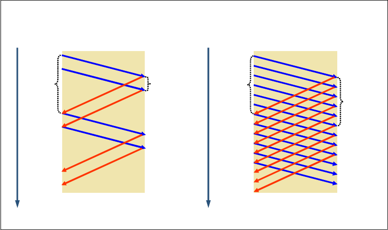
Chapter 4. Connectivity 147
Figure 4-3 High latency network and window size
The solution for high latency networks
z/OS Communications Server implements Dynamic Right-Sizing (DRS) to address the
problem that is related to high latency networks. DRS is described in a paper that is published
by the Los Alamos National Laboratory (LANL):
http://public.lanl.gov/radiant/software/drs.html
The goal of the DRS function is to keep the pipe full for inbound streaming TCP connections
over networks with large capacity and high latency and prevent the sender from being
constrained by the receiver’s advertised window size.
If a TCP connection uses a receive buffer size larger than 64 KB, the stack detects a high
latency inbound streaming TCP connection and dynamically increases the receive buffer size
for the connection (in an attempt to not constrain the sender). This in turn adjusts the
advertised receive window and allows window size to grow as high as 2 MB. The TCP receive
buffer size can grow as high as 2 MB for certain TCP connections regardless of the
TCPMAXRCVBUFRSIZE value. The stack disables the function for a connection if the application is
not keeping up with the pace.
DRS does not take effect for applications that set a value less than 64 KB on the SO_RCVBUF
socket option on SETSOCKOPT().
If TCPRCVBUFRSIZE is less than 64 KB, then DRS does not take effect for applications that do
not use the SO_RCVBUF socket option.
Implementation
To configure an OSA-Express4S or OSA-Express3 feature to operate in optimized latency
mode, use the INTERFACE statement with the OLM parameter. Because optimized latency
mode affects both inbound and outbound interrupts, it supersedes other inbound
performance settings set by the INBPERF parameter.
Optimized latency mode is limited to the OSA-Express4S and OSA-Express3 Ethernet
feature in QDIO mode running with an IBM System z10® or later.
Time Time
Sender Receiver
Round
trip
time
(RTT)
Window
size
Sender Receiver
Round
trip
time
(RTT)
Window
size
Inefficient window size Efficient window size
A
C
K
D
a
t
a
D
a
t
a
D
a
t
a
A
C
K
A
C
K
A
C
K
D
a
t
a
D
a
t
a
148 IBM z/OS V2R2 Communications Server TCP/IP Implementation Volume 1
Restrictions
You must observe the following restrictions:
Traffic that is either inbound over (or being forwarded to) an OSA-Express feature
configured to operate in optimized latency mode is not eligible for the accelerated routing
that is provided by HiperSockets Accelerator and QDIO Accelerator.
For an OSA-Express configured to operate in optimized latency mode, the stack ignores
the value that is coded on the INBPERF parameter. The value that is assigned to the
INBPERF is DYNAMIC.
Guidelines
Because of the operating characteristics of optimized latency mode, other configuration
changes might be required:
For outbound traffic to gain the benefit of optimized latency mode, traffic must be directed
to priority queues 1, 2, or 3 by using the WLMPRIORITYQ parameter in the GLOBALCONFIG
statement or by using Policy Agent and configuring a policy with the
SetSubnetPrioTosMask statement.
Although an OSA-Express feature supports multiple outbound write priority queues,
outbound optimized latency mode is performed only for traffic on priority queue 1 (priority
level 1). The TCP/IP stack combines all the traffic that is directed to priority queues 1, 2,
and 3 into priority queue 1 for any OSA-Express4S or OSA-Express3 feature operating in
optimized latency mode.
Configure the WLMPRIORITYQ parameter with no subparameters, which assigns a default
mapping of service class importance levels to OSA-Express outbound priority queues.
This default mapping directs traffic that is assigned to the higher priority service class
importance levels 1 - 4 to queues that operate in optimized latency mode, and enables the
appropriate types of traffic to benefit from optimized latency mode.
Ensure that there are no more than four concurrent users of an OSA-Express4S or
OSA-Express3 feature that are configured with optimized latency mode.
When enabling multipath routing by using the PERPACKET option, do not configure a
multipath group that contains an OSA-Express feature that is configured with optimized
latency mode and any other type of device.
For more information about OSA-Express features and capabilities, see OSA-Express
Implementation Guide, SG24-5948.
OSA multiple inbound queue support
Outbound traffic separation (assignment to a specific priority queue) on the multiple write
queues can be accomplished by using Policy Agent and configuring a policy with the
SetSubnetPrioTosMask statement, and by using the WLMPRIORITYQ parameter on the
GLOBALCONFIG statement. Each priority queue is processed independently of the others.
The left side of Figure 4-4 on page 149 depicts OSA single inbound queue support. All
inbound QDIO traffic is received on a single read queue regardless of the data type. This
includes both batch and interactive traffic and both traffic that is destined for this TCP/IP stack
and traffic to be forwarded by this TCP/IP stack. The maximum amount of storage available
for inbound traffic is limited to the read buffer size (64 KB read SBALs) times the maximum
number of read buffers (126).

Chapter 4. Connectivity 149
Figure 4-4 QDIO inbound queuing
Multiple processes run for inbound traffic only when data is accumulating on the read queue
(typically during burst periods when z/OS Communications Server is not keeping up with the
OSA). This can cause bulk data packets for a single TCP connection to arrive at the TCP
layer out of order. Each time the TCP layer on the receiving side sees out of order data, it
transmits a duplicate ACK. A single process is used to package the data, queue it, and
schedule the TCP/IP stack to process it. This same process also performs acceleration
functions, such as Sysplex Distributor connection routing accelerator. The TCP/IP stack
separates the traffic types to be forwarded to the appropriate stack component that processes
them.
For these reasons, z/OS Communications Server is becoming the bottleneck as
OSA-Express 10 GbE nears line speed. z/OS Communications Server is injecting latency
and increasing processor utilization.
The solution for the bottleneck on a single read queue
z/OS Communications Server supports inbound traffic separation by using multiple read
queues. The right side of Figure 4-4 depicts OSA multiple inbound queue support. TCP/IP
registers with OSA which traffic is to be received on each read queue. The OSA-Express
Data Router function routes traffic to the correct queue. Each read queue can be serviced by
a separate process. The primary input queue is used for general traffic. One or more ancillary
input queues (AIQs) are used for specific traffic types.
The supported traffic types are streaming bulk data, sysplex distributor, and Enterprise
Extender. Examples of bulk data traffic are FTP, TSM, NFS, and IBM TDMF. Both IP versions
are supported for all types of traffic.
A single inbound queue
Multiple inbound queue
z/OS
z/OS
Ap pl ic at io n A pp li ca t io n
TCP/IP TCP/IP
zz
OSA
OSA
1234
12 34
CP
CP
CP CP CP CP
CP
C P CP CP C P
VTAM
other
SD
bu lk
EE
150 IBM z/OS V2R2 Communications Server TCP/IP Implementation Volume 1
With bulk data traffic separated onto its own read queue, TCP/IP services the bulk data queue
from a single processor. This solves the out of order delivery issue. With sysplex distributor
traffic separated onto its own read queue, it can be efficiently accelerated or presented to the
target application. With Enterprise Extender traffic separated onto its own read queue, it can
be efficiently accelerated or presented to VTAM. All other traffic is processed simultaneously
with the bulk data, sysplex distributor, and Enterprise Extender traffic.
The dynamic LAN idle timer is updated independently for each read queue. This ensures the
most efficient processing of inbound traffic based on the traffic type.
Implementation
The QDIO inbound workload queuing function is enabled with the INBPERF DYNAMIC
WORKLOADQ setting on the IPAQENET and IPAQENET6 INTERFACE statements. WORKLOADQ is not
supported for INBPERF DYNAMIC on IPAQENET LINK statements. The VMAC parameter can be
specified with or without macaddr.
For more information, see the information about the IPAQENET INTERFACE and IPAQENET6
INTERFACE statements in z/OS Communications Server: IP Configuration Reference,
SC27-3651.
Verification
See a WorkloadQueuing field in the netstat DEVLINKS/-D report to determine whether the
QDIO inbound workload queuing function is enabled. This information can also be returned
by the GetIfs callable NMI.
Moreover, you can use other commands to obtain more information about the QDIO inbound
workload queuing function for the QDIO interface. The output for the Display ID=trlename
and Display TRL,TRLE=trlename commands shows whether this function is in use for the
QDIO interface as follows:
For each input queue, it includes the queue ID and queue type in addition to the read
storage. The queue type is PRIMARY for the primary input queue, BULKDATA for the bulk
data AIQ, and SYSDIST for the sysplex distributor connection routing AIQ.
The queue type value N/A indicates that the queue is initialized but is not in use by the
TCP/IP stack.
In addition, the queue ID and queue type can be used to correlate with VTAM tuning statistics,
packet trace, and OSA-Express Network Traffic Analyzer (OSAENTA) trace output for the
QDIO interface. The netstat ALL/-A report includes the interface name for bulk data TCP
connections that are using this function. This information can also be returned by the
GetConnectionDetail callable NMI. The netstat STATS/-S report includes the total number of
segments that is received for all connections from the bulk data AIQ of this function. This
information can also be returned by the GetGlobalStats callable NMI.
For more information, see z/OS Communications Server: IP System Administrator’s
Commands, SC27-3661, and the DISPLAY ID and DISPLAY TRL commands in z/OS
Communications Server: SNA Operation, SC31-8779.

Chapter 4. Connectivity 151
4.2.3 OSA-Express for zEnterprise (z196 and z114)
The IBM zEnterprise® 196 (z196) and IBM zEnterprise 114 (z114) systems offer
communications access to two new internal networks through OSA-Express4S and
OSA-Express3 adapters that are configured with an appropriate channel path ID (CHPID)
type. The following list describes the two new internal networks:
The
intranode management network (INMN) provides connectivity between network
management applications within the z196 node and it can be accessed through
1000BASE-T Ethernet OSA-Express3 adapters that are configured with a CHPID type of
OSM.
The
intraensemble data network (IEDN) provides access to other images that are
connected to the IEDN and to applications and appliances that are running in an IBM
zEnterprise BladeCenter Extension (zBX). This internal network can be accessed through
10 GbE OSA-Express4S and OSA-Express3 adapters that are configured with a CHPID
type of OSX.
Figure 4-5 shows the zEnterprise design.
Figure 4-5 zEnterprise node
Considerations:
Access to the INMN is restricted to authorized management applications, and is only
available through Port 0 of any OSA-Express CHPID that is configured with type OSM.
Port 1 is not available for these communications.
Connectivity to the INMN is restricted to stacks that are enabled for IPv6.
Connectivity to the INMN and to the IEDN is allowed only when the central processor
complex (CPC) is a member of an ensemble.
zEnterprise Node
z196
OSD
OSX
OSM
zBX
TOR
TOR
TOR
TOR
zBX
TOR
TOR
TOR
TOR
HMC
BladeCenter
Chassis
Intranode
Management
Network
(INMN)
Customer
Managed
Data
Networks
Customer
Managed
Management
Network
Intraensemble
Data Network
(IEDN)

152 IBM z/OS V2R2 Communications Server TCP/IP Implementation Volume 1
4.2.4 HiperSockets (MPCIPA)
HiperSockets, also known as iQDIO, is a hardware feature that provides high-speed
LPAR-to-LPAR communications within the same server (through memory). It also provides
secure data flows between LPARs and high availability if there is no network attachment
dependency or exposure to adapter failures.
HiperSockets can be used to communicate among consolidated servers within a single
z Systems server. All the hardware boxes running these separate servers can be eliminated,
along with the cost, complexity, and maintenance of the networking components that
interconnect them.
Consolidated servers that have to access corporate data on the z Systems server can do so
at memory speeds, bypassing all the network processing impact and delays.
HiperSockets can be customized to accommodate varying traffic sizes. With HiperSockets, a
maximum frame size can be defined according to the traffic characteristics that are
transported for each HiperSockets.
Because there is no server-to-server traffic outside the z Systems server, a much higher level
of network availability, security, simplicity, performance, and cost effectiveness is achieved as
compared with servers communicating across a LAN, such as:
HiperSockets has no external components. It provides a secure connection. For security
purposes, servers can be connected to separate HiperSockets or VLANs within the same
HiperSockets. All security features, such as IPSec or IP filtering, are available for
HiperSockets interfaces as they are with other TCP/IP network interfaces.
HiperSockets looks like any other TCP/IP interface; it is transparent to applications and
supported operating systems.
HiperSockets can also improve TCP/IP communications within a sysplex environment
when the DYNAMICXCF is used (for example, in cases where Sysplex Distributor uses
HiperSockets within the same z Systems server to transfer IP packets to the target
systems).
The HiperSockets device is represented by the IQD channel ID (CHPID) and its associated
subchannel devices. All LPARs that are configured in HCD/IOCP to use the same IQD CHPID
have internal connectivity and can communicate by using HiperSockets.
VTAM builds a single HiperSockets MPC group by using the subchannel devices that are
associated with a single IQD CHPID. VTAM uses two subchannel devices for the read and
write control devices, and 1 - 8 devices for data devices. Each TCP/IP stack is assigned a
single data device.
Therefore, to build the MPC group, there must be a minimum of three subchannel devices
defined (within HCD) and associated with the same IQD CHPID. The maximum number of
subchannel devices that VTAM uses is 10 (supporting eight data devices or eight TCP/IP
stacks) per LPAR or MVS image.
Tip: OSA/SF cannot manage these CHPIDs. You can see the related information about
these CHPIDs by using the DISPLAY TCPIP,,OSAINFO command.
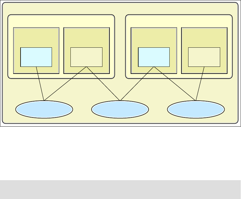
Chapter 4. Connectivity 153
When the server that supports HiperSockets and the CHPIDs is configured in HCD (IOCP),
TCP/IP connectivity is provided in the following circumstances:
If DYNAMICXCF is configured on the IPCONFIG (IPv4) or the IPCONFIG6 (IPv6) statements
If a user-defined HiperSockets (MPCIPA) DEVICE and LINK or (IPAQIDIO) INTERFACE for
IPv4 or IPv6 is configured and started
IQD CHPID can be viewed as a
logical LAN within the server. z Systems servers allow up to
16 separate IQD CHPIDs, creating the capability of having up to 16 separate logical LANs
within the same server.
Each IQD CHPID can be assigned to a set of LPARs (configured in HCD) so isolating these
LPARs in separate logical LANs becomes possible, as Figure 4-6 shows.
Figure 4-6 HiperSockets: multiple logical LANs
HiperSockets multiple write
The HiperSockets multiple write facility moves multiple buffers of data with a single write
operation. This facility was added to reduce CPU utilization and to improve performance for
large outbound messages over HiperSockets.
To enable the HiperSockets multiple write facility on all HiperSockets interfaces, including
interfaces that are created for dynamic XCF, add the IQDMULTIWRITE parameter to the
GLOBALCONFIG statement.
For more information, see Appendix B, “Additional parameters and functions” on page 471.
For a review of the scenarios that we used to test HiperSockets multiple write, see
Appendix A, “HiperSockets Multiple Write,” in IBM z/OS V2R2 Communications Server
TCP/IP Implementation Volume 3: High Availability, Scalability, and Performance,
SG24-8362.
Restriction: HiperSockets multiple write is effective only on IBM System z10 or later and
when z/OS is not running as a guest in an IBM z/VM® environment.
LPAR 1 LPAR 2
Production
LPAR 3 LPAR 4
Test
HiperSockets
(CHPID FD)
HiperSockets
(CHPID FE)
HiperSockets
(CHPID FF)
TCP/IP
Stack A
TCP/IP
Stack B
TCP/IP
Stack C
TCP/IP
Stack D
z Systems Server

154 IBM z/OS V2R2 Communications Server TCP/IP Implementation Volume 1
HiperSockets multiple write assist with IBM zIIP
On an IBM System z10, an additional assist for HiperSockets data that is using the multiple
write facility is available through the IBM System z10 Integrated Information Processor (zIIP).
To enable HiperSockets traffic that is using the multiple write facility to be processed on
available zIIPs, specify the ZIIP IQDIOMULTIWRITE parameter on the GLOBALCONFIG statement.
HiperSockets VLAN support
HiperSockets connections that are defined through DYNAMICXCF coding or through individual
DEVICE and LINK statement coding also support VLAN tagging. You can split the internal LAN
that is represented by a single HiperSockets CHPID into multiple VLANs, providing isolation
for security or administrative purposes. Only stacks that are attached to the same
HiperSockets VLAN can communicate with each other. Stacks that are attached to a separate
HiperSockets VLAN on the same CHPID cannot use the HiperSockets path to communicate
with the stacks on a separate VLAN.
HiperSockets Accelerator
z/OS Communications Server IP takes advantage of the technological advances and
high-performing nature of the I/O processing that are offered by HiperSockets with the
z Systems servers and OSA-Express by using the QDIO architecture. This is achieved by
optimizing IP packet forwarding processing that occurs across these two types of
technologies. This function is referred to as
HiperSockets Accelerator. It is a configurable
option, and is activated by defining the IQDIORouting option on the IPCONFIG statement.
When the TCP/IP stack is configured with HiperSockets Accelerator, it allows IP packets that
are received from HiperSockets to be forwarded to an OSA-Express port (or vice versa)
without the need for those IP packets to be processed by the TCP/IP stack.
When using this function, one or more LPARs contain the
routing stack, which manages
connectivity through OSA-Express ports to the LAN; the other LPARs connect to the routing
stack by using the HiperSockets, as shown in Figure 4-7 on page 155.
Note: The VLAN ID that is assigned to a HiperSockets device applies to both IPv4 and
IPv6 connections over that CHPID.

Chapter 4. Connectivity 155
Figure 4-7 HiperSockets Accelerator
Detailed information about the subject of HiperSockets is available in IBM HiperSockets
Implementation Guide, SG24-6816.
4.2.5 Dynamic XCF
You can either define the XCF connectivity to other TCP/IP stacks individually or by using the
dynamic XCF definition facility. Dynamic XCF reduces the number of definitions that you need
to create when a system joins the sysplex or when you need to start a TCP/IP stack. These
changes become more numerous as the number of stacks and systems in the sysplex grows.
This can lead to configuration errors. With dynamic XCF, you do not need to change the
definitions of the existing stacks to accommodate a new stack.
From an IP topology perspective, DYNAMICXCF establishes fully meshed IP connectivity to all
other z/OS TCP/IP stacks in the sysplex. You need only one end-point specification in each
stack for fully meshed connectivity to all other stacks in the sysplex. When a new stack starts,
Dynamic XCF connectivity is automatically established.
Dynamic XCF is required to support Sysplex Distributor and nondisruptive dynamic VIPA
movement, as described in IBM z/OS V2R2 Communications Server TCP/IP Implementation
Volume 3: High Availability, Scalability, and Performance, SG24-8362.
Note: This example is intended purely to demonstrate IP traffic flow. Do not implement
HiperSockets Accelerator by using a single LPAR.
LPAR A LPAR B LPAR C LPAR D
z Systems Server
TCP/IP
Stack A
TCP/IP
Stack B
TCP/IP
Stack C
TCP/IP
Stack D
HiperSockets
(CHPID FE)
HiperSockets
(CHPID FD)
LPAR E
OSA
Gigabit Ethernet Network
OSA
Note: Only one dynamic XCF network is supported per sysplex.

156 IBM z/OS V2R2 Communications Server TCP/IP Implementation Volume 1
Dynamic XCF uses Sysplex Sockets support, allowing the stacks to communicate with each
other and exchange information such as VTAM CPNAMEs, MVS SYSCLONE values, and IP
addresses. The dynamic XCF definition is activated by coding the IPCONFIG DYNAMICXCF
parameter in the TCP/IP profile.
Dynamic XCF creates definitions for DEVICE, LINK, HOME, and BSDROUTINGPARMS statements
and the START statement dynamically. When activated, the dynamic XCF devices and links
appear to the stack as though they are defined in the TCP/IP profile. They can be displayed
by using standard commands, and they can be stopped and started.
During TCP/IP initialization, the stack joins the XCF group, ISTXCF, through VTAM. When
other stacks in the group discover the new stack, the definitions are created automatically, the
links are activated, and the remote IP address for each link is added to the routing table. After
the remote IP address is added, IP traffic can flow across one of the following interfaces:
IUTSAMEH (within the same LPAR)
HiperSockets (within the same server)
XCF signaling (different server, either by using the coupling facility link or a CTC
connection)
Dynamic XCF support is illustrated in Figure 4-8.
Figure 4-8 Dynamic XCF support
HiperSockets DYNAMICXCF connectivity
z/OS images within the same server with DYNAMICXCF coded use HiperSockets DYNAMICXCF
connectivity instead of standard XCF connectivity, under these conditions:
The TCP/IP stacks must be on the same server.
For the DYNAMICXCF HiperSockets device (IUTIQDIO), the stacks must be using the same
IQD CHPID, even with separate channel subsystems (spanning).
The stacks must be configured through HCD or the IOCDS to use HiperSockets.
LPAR 1
z Systems Server 1
TCP/IP
Stack A
TCP/IP
Stack B
HiperSockets
IUTSAMEH
LPAR 2
TCP/IP
Stack C
Coupling Facility Link
LPAR 3
TCP/IP
Stack D
z Systems Server 2
CF
Channel-to-Channel
(CTC)
(
X
C
F
S
i
g
n
a
l
i
n
g
)
Chapter 4. Connectivity 157
For IPv6 HiperSockets connectivity, both stacks must be at z/OS V1R7 or higher.
The initial HiperSockets activation must complete successfully.
When an IPv4 DYNAMICXCF HiperSockets device and link are created and successfully
activated, a subnetwork route is created across the HiperSockets link. The subnetwork is
created by using the DYNAMICXCF IP address and mask. This allows any LPAR within the same
server to be reached, even ones that are not within the sysplex. To do that, the LPAR that is
outside of the sysplex environment must define at least one IP address for the HiperSockets
endpoint that is within the subnetwork that is defined by the DYNAMICXCF IP address and mask.
When multiple stacks are within the same LPAR that supports HiperSockets, both IUTSAMEH
and HiperSockets links or interfaces coexist. In this case, it is possible to transfer data across
either link. Because IUTSAMEH links have better performance, it is always better to use them
for intra-stack communication. A host route is created by DYNAMICXCF processing across the
IUTSAMEH link, but not across the HiperSockets link.
For more information about dynamic XCF, Sysplex Distributor, and nondisruptive dynamic
VIPA movement, see IBM z/OS V2R2 Communications Server TCP/IP Implementation
Volume 3: High Availability, Scalability, and Performance, SG24-8362.
4.3 Connectivity for the z/OS environment
The section focuses on the interface implementation only, which means establishing Layer 2
and a subset of Layer 3 (IP addressing) connectivity. For details beyond the basic
implementation of the immediate LAN environment, see:
Chapter 5, “Routing” on page 223 for IP routing details
Chapter 6, “Virtual LAN and virtual MAC support” on page 285 for use of virtual MAC
addresses
Chapter 8, “Sysplex subplexing” on page 333 for isolating TCP/IP stack in a sysplex
To design connectivity in a z/OS environment, you must account for the following
considerations:
As a server environment, network connectivity to the external corporate network must be
carefully designed to provide a high-availability environment, avoiding single points of
failures.
If a z/OS LPAR is seen as a stand-alone server environment on the corporate network, it
should be designed as an endpoint.
If a z/OS LPAR is used as a front-end concentrator (for example, using HiperSockets
Accelerator), it should be designed as an intermediate network or node.

158 IBM z/OS V2R2 Communications Server TCP/IP Implementation Volume 1
Based on these considerations, the following sections present preferred practice scenarios for
building a z/OS Communications Server TCP/IP configuration by using OSA-Express (QDIO),
HiperSockets (iQDIO), and dynamic XCF.
We built our connectivity scenarios with two OSA-Express3 1000BASE-T features (four ports
each) that are connected to the LAN environment (one Layer3 switch). We also implemented
a HiperSockets internal LAN to interconnect all LPARs within the same System z10. Finally,
we used dynamic XCF connectivity for the Sysplex environment.
The following scenarios are described:
4.4.3, “Configuring OSA-Express with a VLAN ID” on page 169
4.6.3, “Configuring HiperSockets” on page 202
4.7.3, “Configuring DYNAMICXCF” on page 208
For a complete picture of the implementation environment, see Appendix D, “Our
implementation environment” on page 519.
4.3.1 IOCP definitions
Example 4-1 on page 159 is an excerpt of the IOCP statements that we used in our z
Systems environment (showing only OSA-Express CHPID 02 and HiperSockets CHPID F4).
These statements are required by the input/output subsystem and the operating system.
Because all of our OSA-Express and HiperSockets connectivity is used across all four LPARs,
we defined the CHPIDs as shared.
Preferred practice: Although there are specialized cases where multiple stacks per LPAR
can provide value, implement only one TCP/IP stack per LPAR for the following reasons:
A TCP/IP stack can use all available resources that are defined to the LPAR in which it
is running. Therefore, starting multiple stacks does not yield any increase in throughput.
When running multiple TCP/IP stacks, additional system resources, such as memory,
CPU cycles, and storage, are required.
Multiple TCP/IP stacks add a significant level of complexity to TCP/IP system
administration tasks.
It is not necessary to start multiple stacks to support multiple instances of an application
on a given port number, such as a test HTTP server on port 80 and a production HTTP
server also on port 80. This type of support can instead be implemented by using
BIND-specific support where the two HTTP server instances are each associated to
port 80 with their own IP address, by using the BIND option on the PORT reservation
statement.
One example where multiple stacks can have value is when an LPAR must be connected
to multiple isolated security zones in such a way that there is no network level connectivity
between the security zones. In this case, a TCP/IP stack per security zone can be used to
provide that level of isolation without any network connectivity between the stacks.
Note: Although in our environment we connected all the OSA ports to one switch, in a
production implementation, the preferred approach is to connect your OSAs to at least two
switches.
Note: This chapter defines only the LPARs as end points.

Chapter 4. Connectivity 159
Example 4-1 IOCP statements
ID MSG2='SYS6.IODF64 - 2010-09-23 11:18',SYSTEM=(2817,1), *
LSYSTEM=SCZP301, *
TOK=('SCZP301',00800006991E2094111808480110266F00000000,*
00000000,'10-09-23','11:18:08','SYS6','IODF64')
RESOURCE PARTITION=((CSS(0),(A0A,A),(A0B,B),(A0C,C),(A0D,D),(A*
0E,E),(A0F,F),(A01,1),(A02,2),(A03,3),(A04,4),(A05,5),(A*
06,6),(A07,7),(A08,8),(A09,9)),(CSS(1),(A1B,B),(A1E,E),(*
A1F,F),(A11,1),(A12,2),(A13,3),(A14,4),(A15,5),(A16,6),(*
A17,7),(A18,8),(*,9),(*,A),(*,C),(*,D)),(CSS(2),(A2F,F),*
(A21,1),(A22,2),(*,3),(*,4),(*,5),(*,6),(*,7),(*,8),(*,9*
),(*,A),(*,B),(*,C),(*,D),(*,E)),(CSS(3),(A31,1),(*,2),(*
*,3),(*,4),(*,5),(*,6),(*,7),(*,8),(*,9),(*,A),(*,B),(*,*
C),(*,D),(*,E),(*,F)))
CHPID PATH=(CSS(1),0A),SHARED,
PARTITION=((A11,A13,A16,A18),(=)),CHPARM=02,PCHID=531,
TYPE=OSM 1
CHPID PATH=(CSS(1),0B),SHARED,
PARTITION=((A11,A13,A16,A18),(=)),CHPARM=02,PCHID=101,
TYPE=OSM
CNTLUNIT CUNUMBR=2340,PATH=((CSS(1),0A)),UNIT=OSM
IODEVICE ADDRESS=(2340,015),MODEL=M,UNITADD=00,CUNUMBR=(2340),
UNIT=OSA,MODEL=M,DYNAMIC=YES,LOCANY=YES
CNTLUNIT CUNUMBR=2360,PATH=((CSS(1),0B)),UNIT=OSM
IODEVICE ADDRESS=(2360,015),MODEL=M,UNITADD=00,CUNUMBR=(2360),
UNIT=OSA,MODEL=M,DYNAMIC=YES,LOCANY=YES
CHPID PATH=(CSS(1),18),SHARED,
PARTITION=((A11,A13,A16,A18),(=)),PCHID=590,TYPE=OSX 1
CHPID PATH=(CSS(1),19),SHARED,
PARTITION=((A11,A13,A16,A18),(=)),CHPARM=02,PCHID=510,
TYPE=OSX
CNTLUNIT CUNUMBR=2300,PATH=((CSS(1),18)),UNIT=OSX
IODEVICE ADDRESS=(2300,015),MODEL=X,CUNUMBR=(2300),UNIT=OSA,
MODEL=X,DYNAMIC=YES,LOCANY=YES
CNTLUNIT CUNUMBR=2320,PATH=((CSS(1),19)),UNIT=OSX
IODEVICE ADDRESS=(2320,015),MODEL=X,UNITADD=00,CUNUMBR=(2320),
UNIT=OSA,MODEL=X,DYNAMIC=YES,LOCANY=YES
CHPID PATH=(CSS(1),02),SHARED,
PARTITION=((A11,A13,A16,A18),(=)),PCHID=530,TYPE=OSD
CHPID PATH=(CSS(1),03),SHARED,
PARTITION=((A11,A13,A16,A18),(=)),PCHID=100,TYPE=OSD
CHPID PATH=(CSS(1),04),SHARED,
PARTITION=((A11,A13,A16,A18),(=)),PCHID=181,TYPE=OSD
CHPID PATH=(CSS(1),05),SHARED,
PARTITION=((A11,A13,A16,A18),(=)),PCHID=291,TYPE=OSD
CNTLUNIT CUNUMBR=2080,PATH=((CSS(1),02)),UNIT=OSA
IODEVICE ADDRESS=(2080,015),UNITADD=00,CUNUMBR=(2080),UNIT=OSA
IODEVICE ADDRESS=208F,UNITADD=FE,CUNUMBR=(2080),UNIT=OSAD
CNTLUNIT CUNUMBR=20A0,PATH=((CSS(1),03)),UNIT=OSA
IODEVICE ADDRESS=(20A0,015),UNITADD=00,CUNUMBR=(20A0),UNIT=OSA
IODEVICE ADDRESS=20AF,UNITADD=FE,CUNUMBR=(20A0),UNIT=OSAD
CNTLUNIT CUNUMBR=20C0,PATH=((CSS(1),04)),UNIT=OSA
IODEVICE ADDRESS=(20C0,015),UNITADD=00,CUNUMBR=(20C0),UNIT=OSA
IODEVICE ADDRESS=20CF,UNITADD=FE,CUNUMBR=(20C0),UNIT=OSAD

160 IBM z/OS V2R2 Communications Server TCP/IP Implementation Volume 1
CNTLUNIT CUNUMBR=20E0,PATH=((CSS(1),05)),UNIT=OSA
IODEVICE ADDRESS=(20E0,015),UNITADD=00,CUNUMBR=(20E0),UNIT=OSA
IODEVICE ADDRESS=20EF,UNITADD=FE,CUNUMBR=(20E0),UNIT=OSAD
CHPID PATH=(CSS(1),F4),SHARED,
PARTITION=((A11,A13,A16,A18),(=)),TYPE=IQD
CHPID PATH=(CSS(1),F5),SHARED,
PARTITION=((A11,A13,A16,A18),(=)),TYPE=IQD
CHPID PATH=(CSS(1),F6),SHARED,
PARTITION=((A11,A13,A16,A18),(=)),TYPE=IQD
CHPID PATH=(CSS(1),F7),SHARED,
PARTITION=((A11,A13,A16,A18),(=)),TYPE=IQD
CNTLUNIT CUNUMBR=E800,PATH=((CSS(1),F4)),UNIT=IQD
IODEVICE ADDRESS=(E800,032),CUNUMBR=(E800),UNIT=IQD
CNTLUNIT CUNUMBR=E900,PATH=((CSS(1),F5)),UNIT=IQD
IODEVICE ADDRESS=(E900,032),CUNUMBR=(E900),UNIT=IQD
CNTLUNIT CUNUMBR=EA00,PATH=((CSS(1),F6)),UNIT=IQD
IODEVICE ADDRESS=(EA00,032),CUNUMBR=(EA00),UNIT=IQD
CNTLUNIT CUNUMBR=EB00,PATH=((CSS(1),F7)),UNIT=IQD
IODEVICE ADDRESS=(EB00,032),CUNUMBR=(EB00),UNIT=IQD
In addition to Example 4-1 on page 159, there are other ways to build the IOCDS for an
OSA-Express adapter. This applies particularly to a OSA-Express4S and OSA-Express3
GbE, which can contain more than a single port on the same CHPID. However, in our labs, we
used the method that is shown in Example 4-1 on page 159. To see other alternatives to
define the IOCDS and to review our suggestions, see 4.4.1, “Dependencies: CHPID, IOCDS,
port numbers, port names, and port sharing” on page 162.
4.3.2 VTAM definitions
Before getting started with configuring the scenarios in the following sections, be sure that
you understand the role of VTAM in the TCP/IP configuration.
z/OS Communications Server provides a set of High Performance Data Transfer (HPDT)
services that includes multipath channel (MPC), which is a high-speed channel interface that
is designed for network protocol use (for example, APPN or TCP/IP).
Multiple protocols can either share or have exclusive use of a set of channel paths to an
attached platform. With MPC, you can have multiple device paths that are defined as a single
logical connection.
The term
MPC group is used to define a single MPC connection that can contain multiple
read and write paths. The number of read and write paths does not have to be equal, but
there must be at least one read and write path that are defined within each MPC group.
MPC groups are defined by using the Transport Resource List (TRL), where each defined
MPC group becomes a TRL entry (TRLE) in the TRL table. The configuration and control of
the MPC interfaces are provided by VTAM. They are enabled in VTAM as TRLE minor nodes.
You must define the channel paths that are a part of the group in the TRLE. Each TRLE is
identified by a resource name. For OSA-Express, the TRLE also has a port name to identify
the association between VTAM and TCP/IP, allowing connectivity to the OSA-Express port.
Important: The CHPIDs, type OSM and OSX (1), are used only if z/OS is part of an
ensemble.

Chapter 4. Connectivity 161
OSA-Express4S, OSA-Express3 Gigabit Ethernet, and OSA-Express3 1000Base-T also
define port_num to identify to which port the TRLE definition applies.
For HiperSockets, the TRLE is generated dynamically by VTAM.
For details about defining a TRLE, see z/OS Communications Server: SNA Resource
Definition, SC31-8778.
4.4 OSA-Express QDIO connectivity
Configuring an OSA-Express (QDIO mode) in a single-stack scenario is the simplest way to
integrate your z/OS TCP/IP stack into a LAN environment. However, this scenario still must
be planned to avoid any single points of failure. Therefore, you must have at least two
OSA-Express features connecting to two separate switches in the network.
Because you are dealing with multiple LPARs in the example server, for redundancy purposes
share the OSA-Express ports (CHPID type OSD) across all LPARs.
In this scenario, there are two OSA-Express3 1000BASE-T features, each with four ports, two
ports per channel. One port of each channel was used unless the second port was needed
for the testing of new functions. This allows you to have four CHPIDs (02, 03, 04, and 05),
shared by four LPARs (SC30, SC31, SC32, and SC33), as shown in Figure 4-9.
Figure 4-9 OSA-Express (QDIO) implementation
To make better use of the OSA-Express ports and to control data traffic patterns, define one
port on each OSA-Express feature with a separate VLAN ID, creating two subnetworks to be
used by all LPARs. In a high availability configuration, these OSA-Express ports are the path
to all of the IP addresses for the LAN environment.
SC30
TCPIPA
VIPA1L 10.1.1.10/24
OSA2080I 10.1.2.11/24
OSA20A0I 10.1.2.12/24
OSA20C0I 10.1.3.11/24
OSA20E0I 10.1.3.12/24
TCPIPB
VIPA1L 10.1.1.20/24
OSA2080I 10.1.2.21/24
OSA20A0I 10.1.2.22/24
OSA20C0I 10.1.3.21/24
OSA20E0I 10.1.3.22/24
SC31
SC32
TCPIPC
VIPA1L 10.1.1.30/24
OSA2080I 10.1.2.31/24
OSA20A0I 10.1.2.32/24
OSA20C0I 10.1.3.31/24
OSA20E0I 10.1.3.32/24
SC33
TCPIPD
VIPA1L 10.1.1.40/24
OSA2080I 10.1.2.41/24
OSA20A0I 10.1.2.42/24
OSA20C0I 10.1.3.41/24
OSA20E0I 10.1.3.42/24
TRUNK MODE
TRUNK MODE
VLAN 10
10.1.2.240
VLAN 11
10.1.3.240
OSA-Express 1000BASE-T
TRUNK MODE
TRUNK MODE
SWITCH
CHPID 02
OSA2080
10.1.2.x1
2080-208F
CHPID 03
OSA20A0
10.1.2.x2
20A0-20AF
CHPID 04
OSA20C0
10.1.3.x1
20C0-20CF
CHPID 05
OSA20E0
10.1.3.x2
20E0-2E0F

162 IBM z/OS V2R2 Communications Server TCP/IP Implementation Volume 1
4.4.1 Dependencies: CHPID, IOCDS, port numbers, port names, and
port sharing
To implement this scenario, there are the following dependencies:
The OSA-Express port must be defined as CHPID type OSD to the server by using HCD
or IOCP to enable QDIO. This CHPID must be defined as shared to all LPARs that use the
OSA-Express port (see Example 4-1 on page 159).
To define an OSA-Express port in QDIO mode, use the MPCIPA DEVICE statement,
specifying the PORTNAME value from the TRLE definition as the device_name. The TRLE
must be defined as MPCLEVEL=QDIO.
The VLAN identifiers (VLAN IDs) that are defined to each OSA-Express port must be
recognized by the switch.
The switch ports where the OSA-Express ports are connected must be configured in
trunk mode.
OSA-Express2 and OSA-Express3 Adapter and port layouts
Although an OSA-Express2 adapter (with the exception of the 10 Gbe adapter) contains two
ports, the OSA-Express3 (with the exception of the 10 Gbe adapter) houses four ports.
Compare and contrast the layouts of an OSA-Express2 and an OSA-Express3 in Figure 4-10.
Figure 4-10 Comparison: OSA-E2 2-port adapter and OSA-E3 4-port adapter
Each port of the OSA-Express2 adapter that is shown in Figure 4-10 is on a separate CHPID:
CHPID x and CHPID y. Each port on each CHPID is defined with a separate port name and is
at port number 0.
The OSA-Express3 is engineered with two ports on each CHPID: CHPID x and CHPID y. The
two ports on each CHPID are numbered port 0 and port 1. Note how the top half of the
OSA-E3 is the mirror image of the bottom half with regard to the port number assignments;
reading from top to bottom, you see Port 0, Port 1, Port 1, Port 0. As with any OSA port, the
port names on the multi-port OSA-E3 must be unique to a CHPID. An explanation of this port
name assignment is in “Considerations for assigning the OSA port name” on page 168.
CHPID x
CHPID y
CHPID x
CHPID y
OSA-E2: 2-Port Adapter
OSA-E3: 4-Port Adapter
Port 0
Port 1
Port 1
Port 0
Port 0
Port 0

Chapter 4. Connectivity 163
Considerations for the IOCP or IOCDS definitions for an OSA-Express3
Example 4-1 on page 159 shows an IOCDS that was originally built for an OSA-Express2
configuration. When you migrate to an OSA-Express3, you can choose to use a similar
IOCDS and spread the assigned addresses from a single address range across two ports of
the same CHPID that originally connected to only one port. You can also choose to change
your IOCDS to reflect separate address ranges or even separate
logical control units, despite
the presence of only a single
physical control unit on the CHPID. We now show several of
ways to implement an IOCDS for an OSA-Express3 implementation.
Alternative 1: Single IODEVICE range for two E3 ports on single CHPID
In the scenarios where we use an OSA-Express3, we use the same IOCDS definitions as
those deployed for an OSA-Express2. You see this IOCDS in Example 4-1 on page 159. We
use as an example the IOCDS definitions for the devices on OSA port OSA2080. In
Example 4-2, you see (1) that we allocate 15 addresses (2080 - 208E) to QDIO connections
starting with device address 2080.
Example 4-2 Sample CNTLUNIT and IODEVICE for an OSA on CHPID Type OSD (QDIO)
CNTLUNIT CUNUMBR=2080,PATH=((CSS(2),02)),UNIT=OSA
IODEVICE ADDRESS=(2080,015),CUNUMBR=(2080),UNIT=OSA 1
Example 4-2 corresponds to what you must code in a VTAM TRLE definition to support a
QDIO connection of a TCP/IP stack. Look at Example 4-3, where you see that the VTAM
TRLE that defines port number 0 (which is at A, the only port number on an OSA-Express2)
uses only the first nine addresses (2080 - 2088) of the allocated 15 addresses (2080 - 208E)
on this CNTLUNIT.
Example 4-3 TRLE definition for PORTNUM=0 (port name of OSA2080)
OSA2080 VBUILD TYPE=TRL
OSA2080P TRLE LNCTL=MPC, *
READ=2080, *
WRITE=2081, *
DATAPATH=(2082-2088), *
PORTNAME=OSA2080, *
PORTNUM=0, A *
MPCLEVEL=QDIO
To add the OSA-Express3 port that is at port number 1 of the same CHPID, use the same
IOCDS as before, but add a TRLE definition for PORTNUM=1 (B). See the TRLE in Example 4-4.
In the example, we have simply started the addresses for PORTNUM=1 at 2089 of the IOCDS C.
Example 4-4 TRLE definition for PORTNUM=1 (port name of OSA2081)
OSA2081 VBUILD TYPE=TRL
OSA201P TRLE LNCTL=MPC,
READ=2089, C
WRITE=208A,
DATAPATH=(208B-208D),
PORTNAME=OSA2081,
PORTNUM=1, B
MPCLEVEL=QDIO

164 IBM z/OS V2R2 Communications Server TCP/IP Implementation Volume 1
Figure 4-11 shows the allocation of all the device addresses across the two ports of an
OSA-Express 3 card.
Figure 4-11 Allocation of device addresses across two ports of an OSA-Express3
As Example 4-2 on page 163 shows, the IOCP definitions have no awareness of the OSA
adapter’s two ports and simply assign device addresses; the VTAM definition for z/OS does
care about the port numbers and maps the number to the addresses (Example 4-3 on
page 163 and Example 4-4 on page 163). This address allocation scheme worked well for us
because we did not have to reconfigure the IOCP for our test. Other schemes might work
better for you, particularly if you are consolidating OSA ports from separate CHPIDs onto the
same CHPID of a new OSA-Express3.
A migration to OSA-Express 3 can affect more than just the IOCDS. You also have other
types of definitions in the operating system and potentially in access methods (like VTAM) to
migrate. The more you can keep the definitions the same across migrations, the easier and
more efficient the migration to a new platform or release becomes. This is where the next two
alternatives can make a difference for you.
Alternative 2: Two IODEVICE ranges for two E3 ports on a single CHPID
An alternative to the coding scheme (in Example 4-2 on page 163, Example 4-3 on page 163,
and Example 4-4 on page 163) is to use a separate address for each of the two ports. Such a
scheme might make problem determination and operator procedures easier for you because
message displays clearly show the distinction between the two ports, although they are on
the same CHPID.
Note: Our examples show how to point to the two separate ports with the PORTNUM
parameter in a z/OS example. Other z Systems operating systems, such as z/VM, Linux on
z, IBM z/VSE®, or TPF, have similar coding parameters to allocate addresses to port
number 0 versus port number 1. See the appropriate operating system documentation for
those definitions.
CHPID x
CHPID y
CHPID x
CHPID y
OSA-E2: 2-Port Adapter
OSA-E3: 4-Port Adapter
Port 0
Port 1
Port 1
Port 0
Port 0
Port 0
IODEVICE 2080 - 2088
IODEVICE 2080 - 2088
IODEVICE 2089 - 208D

Chapter 4. Connectivity 165
Example 4-5 shows a range of addresses starting with 1000 (A) and another range starting
with 2000 (B). The VTAM definitions in Example 4-6 show that these addresses are used for
OSA-E3 port numbers 0 and 1. (Compare with 1 and 2 in Example 4-6.)
Example 4-5 Separate device ranges for separate OSA-Express3 ports
CNTLUNIT CUNUMBR=1000,PATH=((CSS(0),10)),UNIT=OSA
IODEVICE ADDRESS=(1000,032),CUNUMBR=(1000),UNIT=OSA (A)
IODEVICE ADDRESS=(10FE,001),CUNUMBR=(1000),UNIT=OSAD
IODEVICE ADDRESS=(2000,032),UNITADD=20,CUNUMBR=(1000),UNIT=OSA (B)
Example 4-6 VTAM definitions for OSA-E3 port numbers 0 and 1 (two device ranges)
OSA1000 VBUILD TYPE=TRL
OSA1000P TRLE LNCTL=MPC, *
READ=1000, *
WRITE=1001, *
DATAPATH=(1002), *
PORTNAME=OSA1000, *
PORTNUM=0, 1 *
MPCLEVEL=QDIO
OSA2000 VBUILD TYPE=TRL
OSA2000P TRLE LNCTL=MPC, *
READ=2000, *
WRITE=2001, *
DATAPATH=(2002), *
PORTNAME=OSA2000, *
PORTNUM=1, 2 *
MPCLEVEL=QDIO
Figure 4-12 shows how the device addresses are allocated for this example.
Figure 4-12 Consolidate two OSA ports from OSA-E2 onto a single CHPID of OSA-E3
CHPID x
CHPID y
CHPID x
CHPID y
OSA-E2: 2-Port Adapter
OSA-E3: 4-Port Adapter
Port 0
Port 1
Port 1
Port 0
Port 0
Port 0
IODEVICE 1000 - 101F
IODEVICE 2000 - 201F
IODEVICE 1000 - 101F
IODEVICE 2000 - 201F

166 IBM z/OS V2R2 Communications Server TCP/IP Implementation Volume 1
With this alternative, you can preserve the device addresses in your VTAM definitions and
basically handle a few changes in the IOCDS. This might represent a simple migration
scenario for you if you have many VTAM definitions to change.
Alternative 3: Two logical control units on a physical CU for two E3 ports
The following examples show how to make a logical distinction within the IOCP between ports
0 and 1 of an OSA-E3 CHPID. You can specify separate logical control units with the CUADD
parameter. Although in the past defining multiple control units had value only if you were
defining many devices, customers that migrate from OSA-Express2 channels to multi-port
OSA-Express3s are finding that combining two OSA-Express CHPIDs into the two ports of an
OSA-Express3 CHPID is easier.
Example 4-7 shows the device range for port number 0 under CUADD=0 (A) and the device
range for port number 1 under CUADD=1 (B).
Example 4-7 Separate logical control unit for each OSA-E3 port
CNTLUNIT CUNUMBR=3000,CUADD=0 A,PATH=((CSS(0),02),(CSS(1),02)),UNIT=OSA
IODEVICE ADDRESS=(3000,032),UNITADD=00,CUNUMBR=(3000),UNIT=OSA
IODEVICE ADDRESS=3020,UNITADD=FE,CUNUMBR=(3000),UNIT=OSAD
CNTLUNIT CUNUMBR=3500,CUADD=1 B,PATH=((CSS(0),02),(CSS(1),02)),UNIT=OSA
IODEVICE ADDRESS=(3500,032),UNITADD=00,CUNUMBR=(3500),UNIT=OSA
The VTAM definitions look similar to what you have seen before. Examine the coding in
Example 4-8.
Example 4-8 VTAM TRLEs for two logical control units and port numbers of an OSA-E3
OSA3000 VBUILD TYPE=TRL
OSA3000P TRLE LNCTL=MPC, *
READ=3000, *
WRITE=3001, *
DATAPATH=(3002), *
PORTNAME=OSA3000, *
PORTNUM=0, 1 *
MPCLEVEL=QDIO
OSA3500 VBUILD TYPE=TRL
OSA3500P TRLE LNCTL=MPC, *
READ=3500, *
WRITE=3501, *
DATAPATH=(3502), *
PORTNAME=OSA3500, *
PORTNUM=1, 2 *
MPCLEVEL=QDIO

Chapter 4. Connectivity 167
The device range beginning with 3000 is assigned to port number 0 (1); the device range
starting with 3500 is assigned to port number 1 (2). See Figure 4-13.
Figure 4-13 Distinguish OSA-E3 port numbers in the IOCDS with a CUADD parameter
As with the second alternative, you might find it easier to merge what were OSA connections
on two separate CHPIDs into a single CHPID and distinguish them with separate address
ranges and separate logical control unit numbers.
Notes:
In all the IOCDS definitions that are illustrated so far, we coded the Open Systems
Adapter/Support Facility (OSA/SF) device on CUADD=0, either by default or through
explicit coding. The OSA/SF device must be on CUADD=0.
OSA supports outbound priority queuing (multiple outbound queues) when no more
than 480 valid subchannels are defined for all LPARs sharing a CHPID. Each LPAR
sharing a CHPID gets a subchannel for every device that is defined on that CHPID.
Therefore, if you define a CHPID that is shared by 15 LPARs and define 32 devices
(either on one port or across two ports), you have used 480 valid subchannels (15 * 32
= 480). If your definition requires more than 480 valid subchannels (with a maximum of
1920), then the user must explicitly turn off Outbound Priority Queuing on the CHPID
definition by specifying CHPARM=02 in the IOCP or by specifying it in HCD.
HCD prevents a device definition that causes the 480 subchannel limit to be broken.
IOCP issues an error message and does not create an IOCDS if the limit is broken.
If you must define more than 254 devices for an unshared OSD channel path, multiple
control units must be defined. Specify a unique logical address for each control unit by
using the CUADD keyword.
CHPID x
CHPID y
CHPID x
CHPID y
OSA-E2: 2-Port Adapter
OSA-E3: 4-Port Adapter
Port 0
Port 1
Port 1
Port 0
Port 0
Port 0
IODEVICE 3000 - 301F
CUADD=0 (default)
IODEVICE 3500 - 351F
CUADD=0 (default)
IODEVICE 3000 - 301F
CUADD=0 *
IODEVICE 3500 - 351F
CUADD=1
* If you define multiple Control Units on a CHPID, you must
specify a CUADD keyword on all CNTLUNIT statements for
the CHPID. There is no default in this case.

168 IBM z/OS V2R2 Communications Server TCP/IP Implementation Volume 1
Considerations for assigning the OSA port name
OSA port name assignment for a QDIO implementation (CHPID Type of OSD) is important in
the z/OS operating system. The rule for assigning a port name is the same regardless of the
type of OSA adapter being implemented:
The port name of an OSA port must be unique on a
CHPID
.
This rule seems obvious, but you might find yourself confused when you contemplate a
migration from certain configurations of the OSA-Express2 to an implementation of a new
OSA-Express3. Consider Figure 4-14.
Figure 4-14 Provide unique port names for OSA-Express ports
Figure 4-14 shows that if you attempt to move both ports that are named GIG0 to CHPIDy of
the OSA-E3, one port does not activate because the names are no longer unique to the
CHPID. The presence of duplicate names on the same CHPID generates an SNA sense code
of 8010311B.
4.4.2 Considerations for isolating traffic across a shared OSA port
VLANs can isolate traffic over a shared network and shared OSA port. The isolation is
complete if all TCP/IP stacks that share an OSA port implement VLAN ID tagging and assign
separate VLANIDs. For more information about this subject, see Chapter 6, “Virtual LAN and
virtual MAC support” on page 285.
CHPID x
CHPID y
CHPID x
CHPID y
OSA-E2: 2-Port Adapter
OSA-E3: 4-Port Adapter
Port 0
Port 1
Port 1
Port 0
Port 0
Port 0
Port name GIGx
Port name GIGy
On an OSA CHPID, the port name value must
be unique to the CHPID.
This example depicts a single port per CHPID,
as in the design of an OSA-E2.
The port names are unique to the CHPID and
also different from each other.
However, certain configurations permit the port
names to be the same as in "GIG0." For
example, if different VTAMs control the OSA
TRLE definitions, the port names can be the
same (for example, GIG0) across the two
CHPIDs.
[Port name GIG0]
[Port name GIG0]
On an OSA CHPID, the port name value must
be unique to the CHPID.
This example depicts multiple ports per CHPID,
as in the design of an OSA-E3.
The port names at the top of the graphic are
not only unique to the CHPID but also different
from each other: "GIG0x" and "GIG1x."
No configuration can allow two OSA ports on
the same CHPID to be assigned the same port
name. For example, the port names in the
bottom half of the graphic must bear unique
port names or one port fails to activate.
Port name GIG0x
Port name GIG1x
[Port name GIG0]
[Port name GIG0]

Chapter 4. Connectivity 169
Another method that is available to isolate traffic across a shared OSA port is
OSA connection
isolation
. This method can be deployed with or without out assigning a VLAN ID or a VMAC
to the OSA port. You can read more about this method in 4.5, “OSA-Express QDIO
connectivity with connection isolation” on page 177.
When planning connectivity for a LAN environment, there might not be a requirement to
isolate data traffic or services for certain servers or clients as we show in this scenario. In
such cases, VLAN IDs can be omitted.
If there is a requirement for VLANs, add the VLAN IDs to your IP addressing scheme to aid in
the mapping of IP addresses to VLANs based on data traffic patterns or access to resources.
Also, to simplify administration and management of VLANs, consider using Generic Attribute
VLAN Registration Protocol (GVRP) where possible. For details, see “VLAN support of
Generic Attribute Registration Protocol” on page 145.
4.4.3 Configuring OSA-Express with a VLAN ID
To implement OSA-Express (QDIO) in our environment, we performed these tasks:
1. Verifying the switch port configuration.
2. Defining a TRLE in VTAM to represent each OSA-Express port.
We also performed these tasks in the TCP/IP profile:
1. Creating DEVICE and LINK or INTERFACE statements for each OSA-Express port.
2. Creating a HOME address to each defined LINK.
3. Defining the characteristics of each LINK statement by using BSDROUTINGPARMS. You
can code the BSDROUTINGPARMS statement even if you define the LINK characteristics in
OMPROUTE.
These tasks are described in more detail in the following sections.
Verifying the switch port configuration
It is important to be aware of the switch configuration and definitions to which the
OSA-Express ports are connected. You must confirm the following information:
The switch ports to which the OSA-Express ports are connected.
Table 4-4 shows the OSA-Express and switch port assignment with VLAN IDs and mode
type in our configuration.
Table 4-4 OSA-Express and switch port assignment with VLAN IDs
OSA-Express port Connects to switch Switch port VLAN ID (mode)
CHPID 02 (2080) Switch 1 Interface GIGA 1/8 10 (Trunk mode)
CHPID 03 (20A0) Switch 1 Interface GIGA 1/41 10 (Trunk mode)
CHPID 04 (20C0) Switch 1 Interface GIGA 1/43 11 (Trunk mode)
CHPID 05 (20E0) Switch 1 Interface GIGA 1/19 11 (Trunk mode)

170 IBM z/OS V2R2 Communications Server TCP/IP Implementation Volume 1
The IP subnetwork and mask. We used the following subnetwork and mask:
– Subnetwork 10.1.2.0, mask 255.255.255.0 for VLAN 10
– Subnetwork 10.1.3.0, mask 255.255.255.0 for VLAN 11
The appropriate switch ports should be defined in trunk mode, as shown in Example 4-9.
Example 4-9 Switch port definition from Switch 1 port 1/41
interface GigabitEthernet1/41
switchport
switchport trunk encapsulation dot1q
switchport mode trunk
no ip address
Defining a TRLE in VTAM to represent each OSA-Express port
Each OSA-Express port must have a TRLE definition that is defined, as shown in
Example 4-10. The PORTNAME 1 must match the device name of the DEVICE definition or
the port name in the INTERFACE definition in the TCP/IP profile. The PORTNUM 2 operand
is optional (default 0), but required when defining the second port of an OSA-Express3. The
statement MPCLEVEL 3 must be specified as QDIO.
Example 4-10 TRLE definition
OSA2080 VBUILD TYPE=TRL
OSA2080P TRLE LNCTL=MPC, *
READ=2080, *
WRITE=2081, *
DATAPATH=(2082-2088), *
1 PORTNAME=OSA2080, *
2 PORTNUM=0, *
3 MPCLEVEL=QDIO
For all OSA-Express ports in our scenarios, we used the following port names:
OSA2080
OSA20A0
OSA20C0
OSA20E0
Creating DEVICE and LINK or INTERFACE statements for each
OSA-Express port
Create the DEVICE and LINK or INTERFACE statements for each OSA-Express port, as shown in
Example 4-11.
Example 4-11 OSA-Express device and link definitions
;OSA DEFINITIONS
;TRL MAJ NODE: OSA2080,OSA20A0,OSA20C0,AND OSA20E0
DEVICE OSA2080 MPCIPA 1
LINK OSA2080L IPAQENET 2 OSA2080 VLANID 10 3
DEVICE OSA20C0 MPCIPA
LINK OSA20C0L IPAQENET OSA20C0 VLANID 11
DEVICE OSA20E0 MPCIPA
LINK OSA20E0L IPAQENET OSA20E0
DEVICE OSA20A0 MPCIPA
LINK OSA20A0L IPAQENET OSA20A0

Chapter 4. Connectivity 171
The device definition of an OSA-Express port must be set as an MPCIPA device type 1. The
link definition describes the type of transport used (in our case, QDIO Ethernet, which is
defined as IPAQENET 2). VLAN ID 3 defines the VLAN number the packets are tagged with
as they are being sent out to the switch.
In Example 4-12, the alternative interface statement of OSA-Express ports combines the
definitions that are otherwise coded in the DEVICE, LINK, HOME, BEGINROUTES, and
BSDROUTINGPARMS statements, and as such requires a label 1, the type of transport used
(QDIO Ethernet, as defined as IPAQENET 2, which is the only type allowed for IPv4 devices),
a port name 3 matching the TRLE port name, an IP address and optional subnetmask 4,
optional MTU size 5, VLANID 6, VMAC 7 (required when setting multiple VLANs on the same
physical OSA port), and SOURCEVIPAINT 8, which associates a specific VIPA with
this
interface.
Example 4-12 OSA-Express interface definition
INTERFACE OSA20A0I 1
DEFINE IPAQENET 2
PORTNAME OSA20A0 3
IPADDR 10.1.2.12/24 4
MTU 1492 5
VLANID 20 6
VMAC 7
SOURCEVIPAINT VIPA2L 8
Creating a HOME address to each defined LINK
If you are not implementing the connection with the INTERFACE statement, you must assign an
IP address to the LINK of each DEVICE/LINK pair. Each link that is configured must have its
own IP address that is configured on the HOME statement of the TCP/IP profile. Our
OSA-Express ports are defined with the IP addresses shown in Example 4-13.
Example 4-13 OSA-Express HOME addresses
HOME
10.1.2.11 OSA2080L
10.1.3.11 OSA20C0L
10.1.3.12 OSA20E0L
10.1.2.12 OSA20A0L
Note: As a preferred practice, use the INTERFACE statement because it groups all the
definitions that are required in one location; DEVICE and LINK require that the IP address be
assigned in the HOME list.
Note: You can define only a single VLAN for each OSA port with DEVICE and LINK
statements. If you want to define multiple VLANs on a single OSA port, you must define it
with the INTERFACE statement.
Note: If SOURCEVIPAINT is coded, the whole INTERFACE definition block must be
defined in PROFILE
after the VIPA DEVICE and LINK statements are defined.
Note: This step is not required when you define OSA ports through the INTERFACE
statement.

172 IBM z/OS V2R2 Communications Server TCP/IP Implementation Volume 1
Defining the characteristics of each LINK statement by using
BSDROUTINGPARMS
To define the link characteristics, such as MTU size 1 and subnet mask 2, use the
BSDROUTINGPARMS statements (see Example 4-14).
If not supplied, defaults are used from static routing definitions in BEGINROUTES or the
OMPROUTE configuration (dynamic routing definitions), if implemented.
If the link characteristics, BEGINROUTES statements, or the OMPROUTE configuration are not
defined, then the stack’s interface layer (based on hardware capabilities) and the
characteristics of devices and links are used. However, this might not provide the
performance or function that you want.
Example 4-14 BSDRoutingparms statements
BSDROUTINGPARMS TRUE
; Link name MTU Cost metric Subnet Mask Dest address
VIPA1L 1492 1 0 255.255.255.252 0
OSA2080L 1492 0 255.255.255.0 2 0
OSA20A0L 1492 0 255.255.255.0 0
OSA20C0L 1492 0 255.255.255.0 0
OSA20E0L 1492 0 255.255.255.0 0
ENDBSDROUTINGPARMS
4.4.4 Verifying the connectivity status
Next, verify the status of the OSA devices that are defined to the TCP/IP stack and VTAM.
Verifying the device status in TCP/IP stack
To verify the status of all devices being activated in the TCP/IP stack, use the NETSTAT
command with the DEVLIST option, as shown in Example 4-15.
Example 4-15 Use command D TCPIP,TCPIPA,N,DEV to verify the device status
D TCPIP,TCPIPA,N,DEV
........................................................................ Lines deleted
INTFNAME: OSA2080I INTFTYPE: IPAQENET INTFSTATUS: READY
PORTNAME: OSA2080 DATAPATH: 2082 DATAPATHSTATUS: READY
CHPIDTYPE: OSD
SPEED: 0000001000
IPBROADCASTCAPABILITY: NO
VMACADDR: 02000C776873 VMACORIGIN: OSA VMACROUTER: LOCAL
ARPOFFLOAD: YES ARPOFFLOADINFO: YES
CFGMTU: 1492 ACTMTU: 1492
IPADDR: 10.1.2.11/24
VLANID: 10 VLANPRIORITY: DISABLED
DYNVLANREGCFG: NO DYNVLANREGCAP: YES
READSTORAGE: GLOBAL (4096K)
Note: This step is not required when defining OSA ports through the INTERFACE
statement.
Note: Static and dynamic routing definitions override or replace the link characteristics that
are defined through the BSDROUTINGPARMS statements. For more information about static
and dynamic routing, see Chapter 5, “Routing” on page 223.

Chapter 4. Connectivity 173
INBPERF: BALANCED
CHECKSUMOFFLOAD: YES SEGMENTATIONOFFLOAD: YES
SECCLASS: 255 MONSYSPLEX: NO
ISOLATE: NO OPTLATENCYMODE: NO
MULTICAST SPECIFIC:
MULTICAST CAPABILITY: YES
GROUP REFCNT SRCFLTMD
----- ------ --------
224.0.0.1 0000000001 EXCLUDE
INTERFACE STATISTICS:
BYTESIN = 0
INBOUND PACKETS = 0
INBOUND PACKETS IN ERROR = 0
INBOUND PACKETS DISCARDED = 0
INBOUND PACKETS WITH NO PROTOCOL = 0
BYTESOUT = 168
OUTBOUND PACKETS = 2
OUTBOUND PACKETS IN ERROR = 0
OUTBOUND PACKETS DISCARDED = 0
#(................................................................. Lines deleted)
Displaying TCP/IP device resources in VTAM
The device drivers for TCP/IP are provided by VTAM. When Communications Server for z/OS
IP devices are activated, there must be an equivalent TRLE defined to VTAM. The devices
that are exclusively used by z/OS Communications Server IP have TRLEs that are
automatically generated for them.
Because the device driver resources are provided by VTAM, you can display the resources by
using VTAM display commands. To display a list of all TRLEs active in VTAM, use the D
NET,TRL command, as shown in Example 4-16.
Example 4-16 D NET,TRL command output
D NET,TRL
IST350I DISPLAY TYPE = TRL 135
IST924I ----------------------------------------------------
IST1954I TRL MAJOR NODE = ISTTRL
IST1314I TRLE = IUTIQDF6 STATUS = ACTIV CONTROL = MPC
IST1314I TRLE = IUTIQDF5 STATUS = ACTIV CONTROL = MPC
IST1314I TRLE = IUTIQDF4 STATUS = ACTIV CONTROL = MPC
IST1314I TRLE = ISTT3033 STATUS = ACTIV CONTROL = XCF
IST1314I TRLE = ISTT3032 STATUS = ACTIV CONTROL = XCF
IST1314I TRLE = ISTT3031 STATUS = ACTIV CONTROL = XCF
IST1314I TRLE = IUTIQDIO STATUS = ACTIV CONTROL = MPC
IST1314I TRLE = IUTSAMEH STATUS = ACTIV CONTROL = MPC
IST1454I 8 TRLE(S) DISPLAYED
IST924I ----------------------------------------------------
IST1954I TRL MAJOR NODE = TRLTONET
IST1314I TRLE = MPCNET STATUS = ACTIV CONTROL = MPC
IST1454I 1 TRLE(S) DISPLAYED
IST924I ----------------------------------------------------
IST1954I TRL MAJOR NODE = OSA2000
IST1314I TRLE = OSA2000P STATUS = NEVAC CONTROL = MPC
IST1454I 1 TRLE(S) DISPLAYED
IST924I ----------------------------------------------------
IST1954I TRL MAJOR NODE = OSA2020
IST1314I TRLE = OSA2020P STATUS = NEVAC CONTROL = MPC
IST1454I 1 TRLE(S) DISPLAYED
IST924I ----------------------------------------------------

174 IBM z/OS V2R2 Communications Server TCP/IP Implementation Volume 1
IST1954I TRL MAJOR NODE = OSA2080
IST1314I TRLE = OSA2080T STATUS = ACTIV CONTROL = MPC
IST1454I 1 TRLE(S) DISPLAYED
IST924I ----------------------------------------------------
IST1954I TRL MAJOR NODE = OSA20A0
IST1314I TRLE = OSA20A0P STATUS = ACTIV CONTROL = MPC
IST1454I 1 TRLE(S) DISPLAYED
IST924I ----------------------------------------------------
IST1954I TRL MAJOR NODE = OSA20A1
IST1314I TRLE = OSA20A1P STATUS = NEVAC CONTROL = MPC
IST1454I 1 TRLE(S) DISPLAYED
IST924I ----------------------------------------------------
IST1954I TRL MAJOR NODE = OSA20C0
IST1314I TRLE = OSA20C0P STATUS = ACTIV CONTROL = MPC
IST1454I 1 TRLE(S) DISPLAYED
IST924I ----------------------------------------------------
IST1954I TRL MAJOR NODE = OSA20E0
IST1314I TRLE = OSA20E0P STATUS = ACTIV CONTROL = MPC
IST1454I 1 TRLE(S) DISPLAYED
IST924I ----------------------------------------------------
IST1954I TRL MAJOR NODE = OSA2100
IST1314I TRLE = OSA2100T STATUS = ACTIV CONTROL = MPC
IST1454I 1 TRLE(S) DISPLAYED
IST924I ----------------------------------------------------
IST1954I TRL MAJOR NODE = OSA2120
IST1314I TRLE = OSA2120T STATUS = ACTIV CONTROL = MPC
IST1454I 1 TRLE(S) DISPLAYED
IST314I END
You can also display information about TRLEs that are grouped by control type, such as MPC
or XCF devices, as shown in Example 4-17.
Example 4-17 D NET,TRL,CONTROL=MPC
D NET,TRL,CONTROL=MPC
IST350I DISPLAY TYPE = TRL 276
IST924I ----------------------------------------------------
IST1954I TRL MAJOR NODE = ISTTRL
IST1314I TRLE = IUTIQDF6 STATUS = ACTIV CONTROL = MPC
IST1314I TRLE = IUTIQDF5 STATUS = ACTIV CONTROL = MPC
IST1314I TRLE = IUTIQDF4 STATUS = ACTIV CONTROL = MPC
IST1314I TRLE = IUTIQDIO STATUS = ACTIV CONTROL = MPC
IST1314I TRLE = IUTSAMEH STATUS = ACTIV CONTROL = MPC
IST1454I 5 TRLE(S) DISPLAYED
IST924I ----------------------------------------------------
IST1954I TRL MAJOR NODE = TRLTONET
IST1314I TRLE = MPCNET STATUS = ACTIV CONTROL = MPC
IST1454I 1 TRLE(S) DISPLAYED
IST924I ----------------------------------------------------
IST1954I TRL MAJOR NODE = OSA2000
IST1314I TRLE = OSA2000P STATUS = NEVAC CONTROL = MPC
IST1454I 1 TRLE(S) DISPLAYED
IST924I ----------------------------------------------------
IST1954I TRL MAJOR NODE = OSA2020
IST1314I TRLE = OSA2020P STATUS = NEVAC CONTROL = MPC
IST1454I 1 TRLE(S) DISPLAYED
IST924I ----------------------------------------------------
IST1954I TRL MAJOR NODE = OSA2080
IST1314I TRLE = OSA2080T STATUS = ACTIV CONTROL = MPC
IST1454I 1 TRLE(S) DISPLAYED

Chapter 4. Connectivity 175
IST924I ----------------------------------------------------
IST1954I TRL MAJOR NODE = OSA20A0
IST1314I TRLE = OSA20A0P STATUS = ACTIV CONTROL = MPC
IST1454I 1 TRLE(S) DISPLAYED
IST924I ----------------------------------------------------
IST1954I TRL MAJOR NODE = OSA20A1
IST1314I TRLE = OSA20A1P STATUS = NEVAC CONTROL = MPC
IST1454I 1 TRLE(S) DISPLAYED
IST924I ----------------------------------------------------
IST1954I TRL MAJOR NODE = OSA20C0
IST1314I TRLE = OSA20C0P STATUS = ACTIV CONTROL = MPC
IST1454I 1 TRLE(S) DISPLAYED
IST924I ----------------------------------------------------
IST1954I TRL MAJOR NODE = OSA20E0
IST1314I TRLE = OSA20E0P STATUS = ACTIV CONTROL = MPC
IST1454I 1 TRLE(S) DISPLAYED
IST924I ----------------------------------------------------
IST1954I TRL MAJOR NODE = OSA2100
IST1314I TRLE = OSA2100T STATUS = ACTIV CONTROL = MPC
IST1454I 1 TRLE(S) DISPLAYED
IST924I ----------------------------------------------------
IST1954I TRL MAJOR NODE = OSA2120
IST1314I TRLE = OSA2120T STATUS = ACTIV CONTROL = MPC
IST1454I 1 TRLE(S) DISPLAYED
IST314I END
You can also get specific information about a single TRLE by using the TRLE name, as shown
in Example 4-18, for an OSA-Express device.
Example 4-18 D NET,TRL,TRLE=OSA2080T
D NET,TRL,TRLE=OSA2080T
IST075I NAME = OSA2080T, TYPE = TRLE 336
IST1954I TRL MAJOR NODE = OSA2080
IST486I STATUS= ACTIV, DESIRED STATE= ACTIV
IST087I TYPE = LEASED , CONTROL = MPC , HPDT = YES
IST1715I MPCLEVEL = QDIO MPCUSAGE = SHARE
IST2263I PORTNAME = OSA2080 PORTNUM = 0 OSA CODE LEVEL = 000C
IST2337I CHPID TYPE = OSD CHPID = 02
IST1577I HEADER SIZE = 4096 DATA SIZE = 0 STORAGE = ***NA***
IST1221I WRITE DEV = 2081 STATUS = ACTIVE STATE = ONLINE
IST1577I HEADER SIZE = 4092 DATA SIZE = 0 STORAGE = ***NA***
IST1221I READ DEV = 2080 STATUS = ACTIVE STATE = ONLINE
IST924I ------------------------------------------------------------
IST1221I DATA DEV = 2082 STATUS = ACTIVE STATE = N/A
IST1724I I/O TRACE = OFF TRACE LENGTH = *NA*
IST1717I ULPID = TCPIPA
IST2309I ACCELERATED ROUTING ENABLED
IST2331I QUEUE QUEUE READ
IST2332I ID TYPE STORAGE
IST2205I ------ -------- ---------------
IST2333I RD/1 PRIMARY 4.0M(64 SBALS)
IST2305I NUMBER OF DISCARDED INBOUND READ BUFFERS = 0
IST1757I PRIORITY1: UNCONGESTED PRIORITY2: UNCONGESTED
IST1757I PRIORITY3: UNCONGESTED PRIORITY4: UNCONGESTED
IST2190I DEVICEID PARAMETER FOR OSAENTA TRACE COMMAND = 01-01-00-02
IST1801I UNITS OF WORK FOR NCB AT ADDRESS X'0F512010'
IST1802I P1 CURRENT = 0 AVERAGE = 0 MAXIMUM = 0
IST1802I P2 CURRENT = 0 AVERAGE = 0 MAXIMUM = 0
IST1802I P3 CURRENT = 0 AVERAGE = 0 MAXIMUM = 0

176 IBM z/OS V2R2 Communications Server TCP/IP Implementation Volume 1
IST1802I P4 CURRENT = 0 AVERAGE = 2 MAXIMUM = 2
IST924I -----------------------------------------------------------
IST1221I DATA DEV = 2083 STATUS = ACTIVE STATE = N/A
IST1724I I/O TRACE = OFF TRACE LENGTH = *NA*
IST1717I ULPID = TCPIPC
IST2309I ACCELERATED ROUTING ENABLED
IST2331I QUEUE QUEUE READ
IST2332I ID TYPE STORAGE
IST2205I ------ -------- ---------------
IST2333I RD/1 PRIMARY 4.0M(64 SBALS)
IST2305I NUMBER OF DISCARDED INBOUND READ BUFFERS = 0
IST1757I PRIORITY1: UNCONGESTED PRIORITY2: UNCONGESTED
IST1757I PRIORITY3: UNCONGESTED PRIORITY4: UNCONGESTED
IST2190I DEVICEID PARAMETER FOR OSAENTA TRACE COMMAND = 01-01-00-03
IST1801I UNITS OF WORK FOR NCB AT ADDRESS X'0FCF0010'
IST1802I P1 CURRENT = 0 AVERAGE = 1 MAXIMUM = 2
IST1802I P2 CURRENT = 0 AVERAGE = 0 MAXIMUM = 0
IST1802I P3 CURRENT = 0 AVERAGE = 0 MAXIMUM = 0
IST1802I P4 CURRENT = 0 AVERAGE = 1 MAXIMUM = 1
IST924I -----------------------------------------------------------
IST1221I DATA DEV = 2084 STATUS = ACTIVE STATE = N/A
IST1724I I/O TRACE = OFF TRACE LENGTH = *NA*
IST1717I ULPID = TCPIPB
IST2310I ACCELERATED ROUTING DISABLED
IST2331I QUEUE QUEUE READ
IST2332I ID TYPE STORAGE
IST2205I ------ -------- ---------------
IST2333I RD/1 PRIMARY 4.0M(64 SBALS)
IST2305I NUMBER OF DISCARDED INBOUND READ BUFFERS = 0
IST1757I PRIORITY1: UNCONGESTED PRIORITY2: UNCONGESTED
IST1757I PRIORITY3: UNCONGESTED PRIORITY4: UNCONGESTED
IST2190I DEVICEID PARAMETER FOR OSAENTA TRACE COMMAND = 01-01-00-04
IST1801I UNITS OF WORK FOR NCB AT ADDRESS X'0F03F010'
IST1802I P1 CURRENT = 0 AVERAGE = 0 MAXIMUM = 0
IST1802I P2 CURRENT = 0 AVERAGE = 0 MAXIMUM = 0
IST1802I P3 CURRENT = 0 AVERAGE = 0 MAXIMUM = 0
IST1802I P4 CURRENT = 0 AVERAGE = 0 MAXIMUM = 0
IST924I -----------------------------------------------------------
IST1221I DATA DEV = 2085 STATUS = RESET STATE = N/A
IST1724I I/O TRACE = OFF TRACE LENGTH = *NA*
IST924I -----------------------------------------------------------
IST1221I DATA DEV = 2086 STATUS = RESET STATE = N/A
IST1724I I/O TRACE = OFF TRACE LENGTH = *NA*
IST924I -----------------------------------------------------------
IST1221I DATA DEV = 2087 STATUS = RESET STATE = N/A
IST1724I I/O TRACE = OFF TRACE LENGTH = *NA*
IST924I -----------------------------------------------------------
IST314I END

Chapter 4. Connectivity 177
4.5 OSA-Express QDIO connectivity with connection isolation
Many customers share OSA-Express ports across LPARs, especially if capacity is not an
issue. Each stack sharing the OSA port registers certain IP addresses and multicast groups
with the OSA.
For performance reasons, the OSA-Express bypasses the LAN and routes packets directly
between the stacks when possible. Figure 4-15 shows two TCP/IP stacks, TCPIPA and
TCPIPB, which share the OSA port that is connected to subnet 10.1.2.0/24.
Figure 4-15 Routing paths over an OSA port
For performance reasons, the OSA-Express bypasses the LAN and routes packets directly
between the stacks when possible. For unicast packets, OSA internally routes the packet
when the next-hop IP address is registered on the same LAN or VLAN by another stack
sharing the OSA port. Figure 4-15 illustrates examples of this action.
Note: You might want to revisit the description of IPv4 address registration in
“OSA-Express QDIO IPv4 address registration” on page 143.
SC30
TCPIPA
PROFA30X
VIPA1L 10.1.1.10/24
OSA2080X 10.1.2.11/24
TCPIPB
PROFB31X
VIPA1L
10.1.1.20/24
OSA2080X 10.1.2.21/24
SC31
10.1.2.11
224.000.000.001
224.000.000.005
QDIO OSA
10.1.2.0/24
10.1.2.21
224.000.000.001
224.000.000.005
Switch
Router
A
B
CC
IP Network
178 IBM z/OS V2R2 Communications Server TCP/IP Implementation Volume 1
The letters (A, B, and C) have the following meanings:
A: You see how TCPIPA routes a packet to 10.1.2.21 in TCPIPB over the OSA port
without exiting out onto the LAN because the next hop to reach the destination is
registered in the OAT; the TCPIPA routing table indicates that the destination can be
reached by hopping through the direct connection to the 10.1.2.0/24 network.
B: For multicast (for example, Open Shortest Path First (OSPF) protocol packets), OSA
internally routes the packet to all sharing stacks on the same LAN or VLAN that register
the multicast group. TCPIPA and TCPIPB each register multicast addresses for OSP
(224.000.000.00n) in the OSA port.
C: OSA also sends the multicast/broadcast packet to the LAN. For broadcast (not
depicted), OSA internally routes the packet to all sharing stacks on the same LAN or
VLAN.
Thus, you see that stacks sharing an OSA-Express port can communicate over the OSA.
Some customers might express concerns about this efficient communication path and want to
disable it because traffic flowing internally through the OSA adapter bypasses any security
features that are implemented on the external LAN. For example, the customer might have
used the virtualization features of the z Systems and of 10-Gigabit OSA adapters to build a
perimeter network (DMZ) on several LPARs of a z Systems and also several production
LPARs on the same z Systems footprint. Although they can implement firewall and intrusion
detection technologies within the LPARs to isolate the two zones (DMZ and production) from
each other, they might have already invested in external security mechanisms on the LAN. If
traffic through a shared OSA bypasses the security on the LAN, they must find a way to
prevent the internal routing across the shared OSA path.
Several network designs are available to provide isolation and force the traffic to bypass the
shared OSA path or to be prevented from using it:
Implement IP filtering on the stacks in the adjacent zones by using z/OS Policy Agent with
IP filtering and Intrusion Detection Services (IDS).
Implement routing filters that block the advertisement of certain routing zones to parts of
the network from which they should remain concealed. Examples of such features are
OSPF range checking, RIP, or EIGRP routing filters.
Implement policy-based routing (PBR) to eliminate the internal OSA path where it is not
wanted.
Define static routes so that paths to a stack sharing the OSA are forced to hop through a
router on the LAN.
Configure the TCP/IP stacks in separate zones (IP subnets) with separate VLANs that
extend into the stacks themselves.
Implement
OSA connection isolation.
4.5.1 Description of connection isolation
Some environments require strict controls for routing data traffic between servers or nodes. In
certain cases, the LPAR-to-LPAR capability of a shared OSA port can prevent such controls
from being enforced. For example, you might need to ensure that traffic flowing through the
OSA adapter does not bypass firewalls or IDSs implemented on the external LAN. There are
several ways to isolate traffic from separate LPARs on a shared OSA port; one of these
methods is
OSA connection isolation.

Chapter 4. Connectivity 179
The feature in z/OS is called
OSA connection isolation, but it is also available in z/VM, where
it is called
QDIO data connection isolation or VSWITCH port isolation. It allows you to
disable the internal routing on a QDIO connection basis, providing a means for creating
security zones and preventing network traffic between the zones. It also provides extra
insurance against a misconfiguration that might otherwise allow such traffic to flow, as in the
case of an incorrectly defined IP filter. With interface isolation, internal routing can be
controlled on an LPAR basis. When interface isolation is enabled, the OSA discards any
packets that are destined for a z/OS LPAR that is registered in the OAT as isolated.
4.5.2 Dependencies for connection isolation
QDIO interface isolation is supported by Communications Server for z/OS and all
OSA-Express4S, OSA-Express3, and OSA-Express2 features on System z10 or higher, and
by all OSA-Express2 features on System z9, with an MCL update. See the appropriate
Preventive Service Planning bucket for details regarding your z Systems server.
Coding ISOLATE on your INTERFACE statement enables the function. It tells the OSA-Express
not to allow communications to this stack other than over the LAN. OSA-Express requires that
both stacks sharing the port are non-isolated for direct routing to occur.
Because this function is specific to security, an OSA-Express interface that does not support
the connection isolation function cannot be activated. Examine the messages at 1 and 2 in
Example 4-19 which show an unsuccessful activation attempt for a QDIO interface whose
OSA does not support the ISOLATE function that was coded on it.
Example 4-19 Failure to activate an OSA interface that does not support the ISOLATE feature
V TCPIP,TCPIPF,START,OSA2080X
EZZ0060I PROCESSING COMMAND: VARY TCPIP,,START,OSA2080X
EZZ0053I COMMAND VARY START COMPLETED SUCCESSFULLY
EZD0022I INTERFACE OSA2080X DOES NOT SUPPORT THE ISOLATE FUNCTION 1
EZZ4341I DEACTIVATION COMPLETE FOR INTERFACE OSA2080X 2
To eliminate the ISOLATE specification on the device so that you can successfully activate it,
you must first STOP the interface before using the V TCPIP,,OBEYFILE command to modify
the ISOLATE parameter.
4.5.3 Considerations for connection isolation
When connection isolation is in effect on either or both endpoints of a connection on a shared
OSA port, OSA-Express discards any packets when the next-hop address is registered in the
OSA by a sharing stack, that is, OSA discards unicast packets that previously qualified for
internal routing. It also ceases to route internal multicast or broadcast packets. However, it
does continue to send the multicast or broadcast packets to the LAN. OSA-Express requires
that both stacks sharing the port are non-isolated for direct routing to occur.
If you implement static routing where connection isolation is in effect, it is simple to code the
appropriate routing statements to bypass the direct path through the OSA. If you are running
a dynamic routing protocol, you might see routing errors when the routing protocol attempts to
send packets over the ISOLATED OSA port. Such errors are “working as designed” when
ISOLATION is introduced into the configuration.

180 IBM z/OS V2R2 Communications Server TCP/IP Implementation Volume 1
Dynamic routing protocol implementations with RIP or OSPF require careful planning on
LANs where OSA-Express connection isolation is in effect; the dynamic routing protocol
learns of the existence of the direct path but is unaware of the isolated configuration, which
renders the direct path across the OSA port to the registered target unusable. If the direct
path that is operating as ISOLATEd is selected, you experience routing failures.
If the visibility of such errors is unwanted, you can take other measures to avoid the failure
messages. If you are simply attempting to bypass the direct route in favor of another, indirect
route, you can accomplish this also with some thoughtful design.
For example, you might purposely bypass the direct path by using PBR or by coding static
routes that supersede the routes that are learned by the dynamic routing protocol. You might
adjust the weights of connections to favor alternate interfaces over the interfaces that are with
ISOLATE.
Static routes to override the direct OSA path
Examine the sample network diagram in Figure 4-16. It shows two TCP/IP stacks: TCPIPA
and TCPIPB. They share an OSA port on network 10.1.2.0/24.
Figure 4-16 Route TCPIPA and TCPIPB: block direct OSA path and multi-hop static route
Both stacks are running a dynamic routing protocol that informs them that there is a direct
path (1) through the OSA port between each other. The routing protocol knows nothing of the
ISOLATE function that was introduced to prevent packets from using the direct route.
(ISOLATE must be coded on only one of the two TCP/IP stacks, although you can code it on
both in this diagram.)
SC30
TCPIPA
PROFA30X
VIPA1L 10.1.1.10/24
OSA2080X 10.1.2.11/24
TCPIPB
PROFB31X
VIPA1L
10.1.1.20/24
OSA2080X 10.1.2.21/24
SC31
10.1.2.11
224.000.000.001
224.000.000.005
QDIO OSA
10.1.2.0/24
10.1.2.21
224.000.000.001
224.000.000.005
Switch
Router
1 = Direct route between TCPIPA and TCPIPB
2 = Indirect route between TCPIPA and TCPIPB
ISOLATE
[ISOLATE]
1
2
X

Chapter 4. Connectivity 181
Another path between the two TCP/IP stacks is available through an external, next-hop router
(2). However, the dynamic routing protocol does not apprise the TCP/IP stack of this route’s
existence because it is not the shortest path. Therefore, when a packet is sent from TCPIPA
to TCPIPB, the stack’s routing table always tries to send that packet through the shortest
path; the send operation is not successful because the stacks are isolated from each other
over the OSA port.
If TCPIPA and TCPIPB do not communicate with each other at all, then there is no need to
alter the appearance of the existing routing table. A route failure in this instance might be
wanted. To produce a message that explains that the two endpoints are ineligible for routing
to each other at all, you can introduce an IP filter.
However, if TCPIPA and TCPIPB do need to exchange information, you must deploy an
effective route that bypasses the direct route between them. Therefore, at TCPIPA, you might
add a non-replaceable static route to an IP address in TCPIPB; the static route in the
BEGINROUTES block points to the next-hop router on the path indicated with 2 in Figure 4-16
on page 180.
The effect of ICMP redirect packets
To avoid the override of the ICMP redirect packets that most likely can occur from the router to
the originating host, disable the receipt of ICMP redirects in the IP stacks or disable ICMP
redirects at the router. If you are using OMPROUTE, ICMP redirects are automatically
disabled, as evidenced by the message that is issued during OMPROUTE initialization:
EZZ7475I ICMP WILL IGNORE REDIRECTS DUE TO ROUTING APPLICATION BEING ACTIVE
Note: The routing failure itself has no failure message that indicates that ISOLATE is at
fault.

182 IBM z/OS V2R2 Communications Server TCP/IP Implementation Volume 1
An alternative path that is more wanted than the direct path
If you choose two TCP/IP stacks that are sharing an OSA port communicate with each other,
and if you do not want to introduce the static routes that are just described, another
alternative is to provide another path that has, for example, a lower weighted path. See
Figure 4-17.
Figure 4-17 Route TCPIPA and TCPIPB: block direct path provides a lower-cost alternate path
Figure 4-17 shows a lower-cost route at 2. The dynamic routing protocol continues to run, but
now the favored route is the one over HiperSockets, XCF, CTC, or over an alternative LAN
connection. Although the dynamic routing protocol continues its awareness of the direct OSA
path, it prefers the path at 2.
Altering the routing table with policy-based routing
You might also want to deploy PBR to bypass direct routes. For more information about how
to accomplish this task, see Chapter 4, “Policy Agent”, in IBM z/OS V2R2 Communications
Server TCP/IP Implementation Volume 4: Security and Policy-Based Networking,
SG24-8363.
SC30
TCPIPA
PROFA30X
VIPA1L 10.1.1.10/24
OSA2080X 10.1.2.11/24
TCPIPB
PROFB31X
VIPA1L 10.1.1.20/24
OSA2080X 10.1.2.21/24
SC31
10.1.2.11
224.000.000.001
224.000.000.005
QDIO OSA
10.1.2.0/24
10.1.2.21
224.000.000.001
224.000.000.005
1
X
1 = Direct route between TCPIPA and TCPIPB
2 = Lower cost route between TCPIPA and TCPIPB
ISOLATE
[ISOLATE]
Cost = 90 Cost = 90
Cost = 100 Cost = 100
2

Chapter 4. Connectivity 183
4.5.4 Configuring OSA-Express with connection isolation
Figure 4-18 shows the test network that is the basis of our testing for OSA Express
connection isolation. This diagram shows how we depicted the shared OSA environment in
other volumes in this series.
Figure 4-18 Stacks that are started with test profiles PROFA30X, B31X, C32X, and D33X
All of the z Systems TCP/IP stacks are members of an OSPF Totally Stubby Network. The
TCP/IP profiles at each stack are named PROFA30X, PROFB31X, PROFC32X, and
PROFD33X. Each stack shares each of the four OSA ports that are depicted. In VLAN 10 and
on subnet 10.1.2.0/24, you see two OSA ports on each stack: OSA2080 and OSA20A0. In
VLAN 11 and on subnet 10.1.3.0/24, you see two OSA ports on each stack: OSA20C0 and
OSA20E0. Each stack also has a static VIPA in subnet 10.1.1.0/24. The OSA and VIPA
interfaces are all advertised with OSPF protocols. However, the connections that are
implemented with the DYNAMICXCF keyword use only static routing.
SC30
TCPIPA
PROFA30X
VIPA1L 10.1.1.10/24
OSA2080X 10.1.2.11/24
OSA20A0X 10.1.2.12/24
OSA20C0X 10.1.3.11/24
OSA20E0X 10.1.3.12/24
TCPIPB
PROFB31X
VIPA1L 10.1.1.20/24
OSA2080X 10.1.2.21/24
OSA20A0X 10.1.2.22/24
OSA20C0X 10.1.3.21/24
OSA20E0X 10.1.3.22/24
SC31 SC32
TCPIPC
PROFC32X
VIPA1L 10.1.1.30/24
OSA2080X 10.1.2.31/24
OSA20A0X 10.1.2.32/24
OSA20C0X 10.1.3.31/24
OSA20E0X 10.1.3.32/24
SC33
TCPIPD
PROFD33X
VIPA1L 10.1.1.40/24
OSA2080X 10.1.2.41/24
OSA20A0X 10.1.2.42/24
OSA20C0X 10.1.3.41/24
OSA20E0X 10.1.3.42/24
TRUNK MODE
TRUNK MODE
VLAN 10
10.1.2.240
VLAN 11
10.1.3.240
OSA-Express 1000BASE-T
TRUNK MODE
TRUNK MODE
SWITCH
CHPID 02
OSA2080
10.1.2.x1
2080-208F
CHPID 03
OSA20A0
10.1.2.x2
20A0-20AF
CHPID 04
OSA20C0
10.1.3.x1
20C0-20CF
CHPID 05
OSA20E0
10.1.3.x2
20E0-2E0F
DYNAMICXCF 10.1.7.x1: HiperSockets, XCF, EZASAMEMVS
Static Routes
OSPF Routes
Totally Stubby Area

184 IBM z/OS V2R2 Communications Server TCP/IP Implementation Volume 1
Examine the revised figure in Figure 4-19. It attempts to more clearly depict (compared to
Figure 4-18 on page 183) how the OSA ports are shared across the four LPARs. Each
TCP/IP stack has two connections into subnet 10.1.2.0/24 and two into subnet 10.1.3.0/24.
Figure 4-19 OAT entries for the stacks sharing the four OSA ports
The revised diagram shows you how stacks communicate with each other over the shared
OSA ports when the next-hop router IP address is registered in the OSA. For performance
reasons, the OSA-Express bypasses the LAN and routes packets directly between the stacks
when possible.
4.5.5 Verifying connection isolation on OSA2080X
This section describes how to verify connection isolation on OSA2080X.
Scenario for testing
To simplify the testing of the connection isolation scenario, we start only the connections to
the OSA on CHPID 2. We then modify the existing configuration to implement OSA
connection isolation only on TCPIPA and TCPIPB on CHPID 2. Connection isolation was not
used on CHPID 2 for TCPIPC and TCPIPD.
SC30
TCPIPA
PROFA30X
VIPA1L 10.1.1.10/24
OSA2080X 10.1.2.11/24
OSA20A0X 10.1.2.12/24
OSA20C0X 10.1.3.11/24
OSA20E0X 10.1.3.12/24
TCPIPB
PROFB31X
VIPA1L 10.1.1.20/24
OSA2080X 10.1.2.21/24
OSA20A0X 10.1.2.22/24
OSA20C0X 10.1.3.21/24
OSA20E0X 10.1.3.22/24
SC31 SC32
TCPIPC
PROFC32X
VIPA1L 10.1.1.30/24
OSA2080X 10.1.2.31/24
OSA20A0X 10.1.2.32/24
OSA20C0X 10.1.3.31/24
OSA20E0X 10.1.3.32/24
SC33
TCPIPD
PROFD33X
VIPA1L
10.1.1.40/24
OSA2080X
10.1.2.41/24
OSA20A0X
10.1.2.42/24
OSA20C0X
10.1.3.41/24
OSA20E0X
10.1.3.42/24
CHPID 02
OSA2080
10.1.2.x1
2080-208F
VMACs/VLANID 10
CHPID 04
OSA20C0
10.1.3.x1
20C0-20CF
VMACs/VLANID 11
CHPID 05
OSA20E0
10.1.3.x2
20E0-2E0F
VMACs/VLANID 11
10.1.2.11 10.1.2.21 10.1.2.31 10.1.2.41
10.1.2.12 10.1.2.22 10.1.2.32 10.1.2.42
10.1.3.11 10.1.3.21 10.1.3.31 10.1.3.41
10.1.3.12 10.1.3.22 10.1.3.32 10.1.3.42
Registered:
Next-hop
CHPID 03
OSA20A0
10.1.2.x2
20A0-20AF
VMACs/VLANID 10
Registered:
Next-hop
Registered:
Next-hop
Registered:
Next-hop
communication path
through OSA port
communication path
through OSA port
communication path
through OSA port
communication path
through OSA port

Chapter 4. Connectivity 185
The new configuration is depicted in Figure 4-20. Our communication paths are indicated with
the letter
X.
Figure 4-20 OSA2080 shared across four TCP/IP images
In our testing, we do not permit TCPIPA or TCPIPB to be reached directly over the shared
OSA port. Using the ISOLATE function, we prevent direct communication between TCPIPA
and TCPIPB by way of this port; we also prevent direct communication between either
TCPIPA or TCPIPB and either of the two remaining stacks in our configuration: TCPIPC and
TCPIPD.
We continue to permit TCPIPC and TCPIPD to share the OSA path between each other.
Note: You might choose to design your OSA ISOLATE function so that the non-sharing
TCP/IP stack might use the direct path through the OSA. However, if you have abundant
bandwidth on the OSA port, you might choose to implement ISOLATE on only selected
sharing TCP/IP stacks, as we have done in our test.
SC30
TCPIPA
PROFA30A
VIPA1L 10.1.1.10/24
OSA2080 10.1.2.11/24
IUTIQDF4L 10.1.4.11/24
TCPIPB
PROFB31A
VIPA1L 10.1.1.20/24
OSA2080 10.1.2.21/24
IUTIQDF4L 10.1.4.21/24
SC31
SC32
TCPIPC
PROFC32A
VIPA1L 10.1.1.30/24
OSA2080 10.1.2.31/24
IUTIQDF4L 10.1.4.31/24
SC33
TCPIPD
PROFD33A
VIPA1L 10.1.1.40/24
OSA2080 10.1.2.41/24
IUTIQDF4L 10.1.4.41/24
TRUNK MODE
VLAN 10
10.1.2.240
SWITCH
CHPID 02
OSA2080
10.1.2.x1
2080-208F
X
X
X

186 IBM z/OS V2R2 Communications Server TCP/IP Implementation Volume 1
Coding ISOLATE on the INTERFACE statements
The ISOLATE keyword can be coded only on an INTERFACE statement. The coding for TCPIPA
and for TCPIPB is displayed at 1 and 2 in Example 4-20.
Example 4-20 ISOLATE coding on CHPID2 (OSA2080X) for PROFA30X and PROFB31X
INTERFACE OSA2080X
DEFINE IPAQENET
PORTNAME OSA2080
IPADDR 10.1.2.11/24
MTU 1492
VLANID 10
VMAC ROUTEALL
ISOLATE 1
INTERFACE OSA2080X
DEFINE IPAQENET
PORTNAME OSA2080
IPADDR 10.1.2.21/24
MTU 1492
VLANID 10
VMAC ROUTEALL
ISOLATE 2
The definitions for the interface in stacks TCPIPC and TCPIPD contain NOISOLATE, which is
also the default. See 3 and 4 in Example 4-21.
Example 4-21 NOISOLATE coding on CHPID2 (OSA2080X) for PROFC32X and PROFD33X
INTERFACE OSA2080X
DEFINE IPAQENET
PORTNAME OSA2080
IPADDR 10.1.2.31/24
MTU 1492
VLANID 10
VMAC ROUTEALL
NOISOLATE 3
INTERFACE OSA2080X
DEFINE IPAQENET
PORTNAME OSA2080
IPADDR 10.1.2.41/24
MTU 1492
VLANID 10
VMAC ROUTEALL
NOISOLATE 4

Chapter 4. Connectivity 187
Displaying the DEVICE to verify that ISOLATE is enabled
A display of all the INTERFACEs on which we coded ISOLATE shows that ISOLATE is in force
(A), as shown in Example 4-22.
Example 4-22 ISOLATE coding on the Interface definition
INTFNAME: OSA2080X INTFTYPE: IPAQENET INTFSTATUS: READY
PORTNAME: OSA2080 DATAPATH: 2082 DATAPATHSTATUS: READY
SPEED: 0000001000
IPBROADCASTCAPABILITY: NO
VMACADDR: 020004749925 VMACORIGIN: OSA VMACROUTER: ALL
ARPOFFLOAD: YES ARPOFFLOADINFO: YES
CFGMTU: 1492 ACTMTU: 1492
IPADDR: 10.1.2.21/24
VLANID: 10 VLANPRIORITY: DISABLED
DYNVLANREGCFG: NO DYNVLANREGCAP: YES
READSTORAGE: GLOBAL (4096K) INBPERF: BALANCED
CHECKSUMOFFLOAD: YES
SECCLASS: 255 MONSYSPLEX: NO
ISOLATE: YES A OPTLATENCYMODE: NO
Viewing OSA/SF for ISOLATE enablement
The OSA/SF display shows where ISOLATE is enabled (X), as Example 4-23 shows.
Example 4-23 OSA/SF and ISOLATE
************************************************************************
*** OSA/SF Get OAT output created 18:28:38 on 11/02/2009 ***
*** IOACMD APAR level - OA26486 ***
*** Host APAR level - OA27643 ***
************************************************************************
*** Start of OSA address table for CHPID 02 ***
************************************************************************
* UA(Dev) Mode Port Entry specific information Entry Valid
************************************************************************
Image 2.3 (A11 ) CULA 0
80(2080)* MPC N/A OSA2080 (QDIO control) SIU ALL
82(2082) MPC 00 No4 No6 OSA2080 (QDIO data) Isolated X SIU ALL
VLAN 10 (IPv4)
Group Address Multicast Address
01005E000001 224.000.000.001
01005E000005 224.000.000.005
VMAC IP address
HOME 020005749925 010.001.002.011
...
************************************************************************
Image 2.4 (A24 ) CULA 0
80(2080)* MPC N/A OSA2080 (QDIO control) SIU ALL
82(2082) MPC 00 No4 No6 OSA2080 (QDIO data) Isolated X SIU ALL
VLAN 10 (IPv4)
Group Address Multicast Address
01005E000001 224.000.000.001
01005E000005 224.000.000.005
VMAC IP address
HOME 020004749925 010.001.002.021
...
************************************************************************

188 IBM z/OS V2R2 Communications Server TCP/IP Implementation Volume 1
Viewing routes with ISOLATE in effect
We recycle all four stacks that were sharing the OSA port named OSA2080. We test
connectivity between 10.1.2.11 at TCPIPA and 10.1.2.21, 31, and 33 at the other three
stacks. We also want to test connectivity between 10.1.2.11 and the VIPAs in 10.1.1.0 at the
other three stacks.
First, we examine the routing table at TCPIPA to determine whether we have routes that take
us to those destinations, as shown in Example 4-24.
Example 4-24 View of routing at TCPIPA before adding static routes
D TCPIP,TCPIPA,N,ROUTE
IPV4 DESTINATIONS
DESTINATION GATEWAY FLAGS REFCNT INTERFACE
DEFAULT 10.1.2.240 UGO 0000000000 OSA2080I
DEFAULT 10.1.2.240 UGO 0000000000 OSA20A0I
10.1.1.10/32 0.0.0.0 UH 0000000000 VIPA1L
10.1.1.12/32 10.1.4.12 UGHO 0000000000 IUTIQDF4L
10.1.1.12/32 10.1.5.12 UGHO 0000000000 IUTIQDF5L
10.1.1.20/32 10.1.4.21 UGHO 0000000001 IUTIQDF4L
10.1.1.20/32 10.1.5.21 UGHO 0000000000 IUTIQDF5L
10.1.1.25/32 10.1.4.25 UGHO 0000000000 IUTIQDF4L
10.1.1.25/32 10.1.5.25 UGHO 0000000000 IUTIQDF5L
10.1.1.30/32 10.1.4.31 UGHO 0000000000 IUTIQDF4L
10.1.1.30/32 10.1.5.31 UGHO 0000000000 IUTIQDF5L
10.1.1.40/32 10.1.4.41 UGHO 0000000000 IUTIQDF4L
10.1.1.40/32 10.1.5.41 UGHO 0000000000 IUTIQDF5L
10.1.1.50/32 10.1.2.52 UGHO 0000000000 OSA2080I
10.1.1.50/32 10.1.2.51 UGHO 0000000000 OSA2080I
10.1.1.50/32 10.1.2.52 UGHO 0000000000 OSA20A0I
10.1.1.50/32 10.1.2.51 UGHO 0000000000 OSA20A0I
10.1.2.0/24 0.0.0.0 UO 0000000000 OSA20A0I
10.1.2.0/24 0.0.0.0 UO 0000000000 OSA2080I
10.1.2.10/32 0.0.0.0 UH 0000000000 VIPA2L
10.1.2.11/32 0.0.0.0 UH 0000000000 OSA2080I
10.1.2.12/32 0.0.0.0 UH 0000000000 OSA20A0I
10.1.2.14/32 0.0.0.0 H 0000000000 OSA2081I
10.1.2.17/32 10.1.4.12 UGHO 0000000000 IUTIQDF4L
10.1.2.17/32 10.1.5.12 UGHO 0000000000 IUTIQDF5L
10.1.2.20/32 10.1.4.21 UGHO 0000000000 IUTIQDF4L
10.1.2.20/32 10.1.5.21 UGHO 0000000000 IUTIQDF5L
10.1.2.25/32 10.1.4.25 UGHO 0000000000 IUTIQDF4L
10.1.2.25/32 10.1.5.25 UGHO 0000000000 IUTIQDF5L
10.1.2.30/32 10.1.4.31 UGHO 0000000000 IUTIQDF4L
10.1.2.30/32 10.1.5.31 UGHO 0000000000 IUTIQDF5L
10.1.3.0/24 0.0.0.0 UO 0000000000 OSA20E0I
10.1.3.11/32 0.0.0.0 UH 0000000000 OSA20C0I
10.1.3.12/32 0.0.0.0 UH 0000000000 OSA20E0I
10.1.4.0/24 0.0.0.0 UO 0000000000 IUTIQDF4L
10.1.4.11/32 0.0.0.0 UH 0000000000 IUTIQDF4L
10.1.5.0/24 0.0.0.0 UO 0000000000 IUTIQDF5L
10.1.5.11/32 0.0.0.0 UH 0000000000 IUTIQDF5L
10.1.6.0/24 10.1.4.41 UGO 0000000000 IUTIQDF4L
10.1.6.0/24 10.1.5.41 UGO 0000000000 IUTIQDF5L
10.1.6.11/32 0.0.0.0 UH 0000000000 IUTIQDF6L
10.1.7.0/24 0.0.0.0 US 0000000000 IQDIOLNK0A01070

Chapter 4. Connectivity 189
B
10.1.7.11/32 0.0.0.0 UH 0000000000 EZASAMEMVS
10.1.7.11/32 0.0.0.0 UH 0000000000 IQDIOLNK0A01070
B
10.1.7.21/32 0.0.0.0 UHS 0000000000 IQDIOLNK0A01070
B
10.1.7.25/32 0.0.0.0 UHS 0000000000 EZASAMEMVS
10.1.8.10/32 10.1.4.41 UGHO 0000000000 IUTIQDF4L
10.1.8.10/32 10.1.5.41 UGHO 0000000000 IUTIQDF5L
10.1.8.20/32 10.1.4.41 UGHO 0000000000 IUTIQDF4L
10.1.8.20/32 10.1.5.41 UGHO 0000000000 IUTIQDF5L
10.1.8.21/32 10.1.4.21 UGHO 0000000000 IUTIQDF4L
10.1.8.21/32 10.1.5.21 UGHO 0000000000 IUTIQDF5L
10.1.8.23/32 0.0.0.0 UH 0000000000 VIPL0A010817
10.1.8.28/32 10.1.4.12 UGHO 0000000000 IUTIQDF4L
10.1.8.28/32 10.1.5.12 UGHO 0000000000 IUTIQDF5L
10.1.8.30/32 10.1.4.31 UGHO 0000000000 IUTIQDF4L
10.1.8.30/32 10.1.4.41 UGHO 0000000000 IUTIQDF4L
10.1.8.30/32 10.1.5.31 UGHO 0000000000 IUTIQDF5L
10.1.8.30/32 10.1.5.41 UGHO 0000000000 IUTIQDF5L
10.1.8.40/32 10.1.4.41 UGHO 0000000000 IUTIQDF4L
10.1.8.40/32 10.1.5.41 UGHO 0000000000 IUTIQDF5L
10.1.8.41/32 10.1.4.41 UGHO 0000000000 IUTIQDF4L
10.1.8.41/32 10.1.5.41 UGHO 0000000000 IUTIQDF5L
10.1.8.42/32 10.1.4.41 UGHO 0000000000 IUTIQDF4L
10.1.8.42/32 10.1.5.41 UGHO 0000000000 IUTIQDF5L
10.1.8.43/32 10.1.4.41 UGHO 0000000000 IUTIQDF4L
10.1.8.43/32 10.1.5.41 UGHO 0000000000 IUTIQDF5L
10.1.8.44/32 10.1.4.41 UGHO 0000000000 IUTIQDF4L
10.1.8.44/32 10.1.5.41 UGHO 0000000000 IUTIQDF5L
10.1.8.50/32 10.1.2.52 UGHO 0000000000 OSA2080I
10.1.8.50/32 10.1.2.51 UGHO 0000000000 OSA2080I
10.1.8.50/32 10.1.2.52 UGHO 0000000000 OSA20A0I
10.1.8.50/32 10.1.2.51 UGHO 0000000000 OSA20A0I
10.1.30.10/32 0.0.0.0 UH 0000000000 VIPA3L
10.1.100.0/24 10.1.2.240 UGO 0000000002 OSA2080I
10.1.100.0/24 10.1.2.240 UGO 0000000001 OSA20A0I
127.0.0.1/32 0.0.0.0 UH 0000000005 LOOPBACK
192.168.1.0/24 10.1.2.240 UGO 0000000000 OSA2080I
192.168.1.0/24 10.1.2.240 UGO 0000000000 OSA20A0I
192.168.1.40/32 10.1.2.45 UGHO 0000000000 OSA2080I
192.168.1.40/32 10.1.2.45 UGHO 0000000000 OSA20A0I
192.168.2.0/24 10.1.2.240 UGO 0000000000 OSA2080I
192.168.2.0/24 10.1.2.240 UGO 0000000000 OSA20A0I
192.168.3.0/24 10.1.2.240 UGO 0000000000 OSA2080I
192.168.3.0/24 10.1.2.240 UGO 0000000000 OSA20A0I
IPV6 DESTINATIONS
DESTIP: ::1/128
GW: ::
INTF: LOOPBACK6 REFCNT: 0000000000
FLGS: UH MTU: 65535
86 OF 86 RECORDS DISPLAYED
END OF THE REPORT

190 IBM z/OS V2R2 Communications Server TCP/IP Implementation Volume 1
Test 1: Effect of ISOLATE with a basic dynamic routing table
The first test uses a limited routing table, where only one path is available among the four
TCP/IP stacks, and that path is blocked with the ISOLATE keyword at TCPIPA and TCPIPB.
We run all the commands in the following examples at TCPIPA, where ISOLATE is coded.
We run traceroute against the three target addresses in network 10.1.2.0/24, as shown in
Example 4-25.
Example 4-25 Test traceroute from TCPIPA to native OSA Home address of TCPIPB
===> tracerte 10.1.2.21 (tcp tcpipa V srcip 10.1.2.11 Intf OSA2080X
CS V1R12: Traceroute to 10.1.2.21 (10.1.2.21):
1 * * *
The results are the same when trying to reach TCPIPC and TCPIPD from either TCPIPA or
TCPIPB: Because the route table indicates a direct path through the OSA, the stack attempts
to send the packet over the direct route and experiences a failure. This is what we expect
because we coded ISOLATE on OSA2080X in TCPIPA (and TCPIPB).
Can we reach the VIPAs over the OSA port that is indicated as a route in Example 4-24 on
page 188? We run a traceroute to the VIPAs and discover that the available routes cannot be
reached, as shown in Example 4-26.
Example 4-26 Test traceroute from TCPIPA to VIPA address of TCPIPB
===> tracerte 10.1.1.20 (tcp tcpipa V srcip 10.1.1.10
CS V1R12: Traceroute to 10.1.1.20 (10.1.1.20):
1 * * *
The results are the same when trying to reach the VIPAs at TCPIPC and TCPIPD from either
TCPIPA or TCPIPB: Because the route table indicates a direct path through the OSA, the
stack attempts to send the packet over the direct route and experiences a failure. This is what
we expect because we coded ISOLATE on OSA2080X in TCPIPA (and TCPIPB).
ARP takeover with ISOLATE
As part of this test, we also activate a second interface on the same subnet to test the ARP
takeover function. The second interface was also coded with ISOLATE on TCPIPA and
TCPIPB. TCPIPC and TCPIPD were not defined with ISOLATE. When we deactivate the
second interface, the address from the adapter port we were taking over moved to the
remaining interface on that subnet, as you see at Y in Example 4-27.
Example 4-27 Effect of ARP takeover with ISOLATE
/**********************************************************************/
/* OSA/SF Query created 14:31:35 on 10/12/2010 */
/* IOACMD APAR level - OA26486 */
/* Host APAR level - OA31645 */
/**********************************************************************/
************************************************************************
*** Start of OSA address table for CHPID 02 ***
************************************************************************
* UA(Dev) Mode Port Entry specific information Entry Valid
************************************************************************
Image 1.1 (A11 ) CULA 0
00(2080)* MPC N/A OSA2080 (QDIO control) SIU ALL

Chapter 4. Connectivity 191
02(2082) MPC 00 No4 No6 OSA2080 (QDIO data) Isolated SIU ALL
VLAN 10 (IPv4)
Group Address Multicast Address
01005E000001 224.000.000.001
VMAC IP address
HOME 02004F776872 010.001.002.010
HOME 02004F776872 010.001.002.011 Y
Test 2: Effect of ISOLATE and NOISOLATE for multiple stacks
The next test is to see whether the shared OSA on CHPID2 allows TCPIPC and TCPIPD to
communicate directly with each other and with TCPIPA and TCPIPB. The test also confirms
that the stack routes still allow you to reach TCP/IP stacks in the external network across the
OSA ports, even if they are coded with ISOLATE. Examine Figure 4-21.
Figure 4-21 Available paths when ISOLATE is defined and dynamic routing is enabled
Those tests show that the existing basic routing table at each of the stacks allows you to
communicate with TCP/IP networks that are reached through the external router (5).
The routing tables also permit TCPIPC and TCPIPD to communicate with each other (4).
Note: The ARP takeover function still works as expected if you start a second device on
the same subnet in the same stack. ISOLATE does not alter this function.
SC30
TCPIPA
PROFA30X
VIPA1L 10.1.1.10/24
OSA2080X 10.1.2.11/24
TCPIPB
PROFB31X
VIPA1L 10.1.1.20/24
OSA2080X 10.1.2.21/24
SC31
SC32
TCPIPC
PROFC32X
VIPA1L 10.1.1.30/24
OSA2080X 10.1.2.41/24
TCPIPD
PROFD33X
VIPA1L 10.1.1.40/24
OSA2080X 10.1.2.41/24
SC33
3
QDIO OSA
10.1.2.0/24
ISOLATE
X
1
ISOLATE
X
X
2
5 5
1, 2, 3 = Direct routes from TCPIPA or TCPIPB to any other stack are unsuccessful.
4 = Direct route between TCPIPC and TCPIPD is successful.
5 = Routes from any stack to terminals reached through the router are successful.
OMPROUTEOMPROUTE OMPROUTEOMPROUTE
10.1.100.0/24
10.1.100.221
10.1.100.224
Switch
Router
10.1.2.31
224.000.000.001
224.000.000.005
10.1.2.41
224.000.000.001
224.000.000.005
4
10.1.2.11
224.000.000.001
224.000.000.005
10.1.2.21
224.000.000.001
224.000.000.005

192 IBM z/OS V2R2 Communications Server TCP/IP Implementation Volume 1
NOISOLATE is either coded or defaulted on the INTERFACE in the two stacks. However, TCPIPC
and TCPIPD cannot communicate with either TCPIPA or TCPIPB, and TCPIPA and TCPIPB
cannot communicate with each other over the internal OSA path (1, 2, 3). Example 4-28
shows the typical responses when a target cannot be reached.
Example 4-28 Unsuccessful attempts to reach TCPIPB from TCPIPC
===> tracerte 10.1.2.21 (tcp tcpipc V srcip 10.1.2.31
Traceroute to 10.1.2.21 (10.1.2.21):
1 * * *
2 * * *
Unfortunately, the only path that TCPIPC and TCPIPD have for reaching TCPIPA and
TCPIPB is the direct route through the OSA port, but this port prevents internal routing
because the parameter ISOLATE is coded at TCPIPA and TCPIPB. The routing table in
Example 4-24 on page 188 shows that the table points to a network route for 10.1.2.0/24,
which is reached by way of a directly attached next-hop router (0.0.0.0):
10.1.2.0/24 0.0.0.0 UO 0000000000 OSA2080X
There is no route for any of the stacks to reach each other over the external router.
Again, the issue is that the dynamic routing table knows nothing about the ISOLATE feature
because ISOLATE is not a Layer 3 function. The dynamic routing protocol is working according
to the protocol standards. So, how do we rectify this situation if we really want the stacks to
communicate with each other, but just not directly over the OSAs? It is a matter of adjusting
the routing table by adding some non-replaceable static routes.
Recall that you have options for handling this situation:
Bypass the direct path by using PBR.
Bypass the direct path by coding static routes that supersede the routes that are learned
by the dynamic routing protocol (see Figure 4-16 on page 180).
Adjust the costs or weights of connections to favor alternate interfaces over the interfaces
that are coded with ISOLATE (see Figure 4-17 on page 182).
We tested only one of these options: coding static routes to supersede the dynamically
learned routes.
Note: ISOLATE prevents only direct communication across the OSA port to any stack that
coded the ISOLATE keyword. However, it does
not prevent communication between the
stack that is defined with ISOLATE and any destinations beyond the OSA port. Therefore,
you can continue to use the stack’s routing table to TELNET or FTP from your workstations
into any of the TCP/IP stacks, regardless of the coding of ISOLATE or NOISOLATE.

Chapter 4. Connectivity 193
Test 3: Effect of ISOLATE if an alternate path is present in the routing
table
In this test, we want to establish connectivity between TCPIPA and the other stacks on
z Systems, but not over the direct OSA path. We also want to establish connectivity between
TCPIPB and the other stacks, but not over the direct OSA path. In summary, we want to leave
our dynamic routing with OSPF in place, but we must ensure that the learned routes over the
direct OSA path are not always used. However, in doing so, we must ensure that the direct
paths between TCPIPC and TCPIPD stay in place. To accomplish all of this, we add
non-replaceable static routes to the TCP/IP stacks, as shown in Figure 4-22.
Figure 4-22 Making paths available through an external next-hop router
The routes to the remote TCP/IP nodes (5) through the OSA ports continue to be successful
in our scenario; no changes are necessary here. The routing table between TCPIPC and
TCPIPD continues to function as expected to permit direct routing between the two stacks (4);
changes to the routing table are also unnecessary here.
The routing paths that are indicated with 1, 2, and 3 in Figure 4-22 continue to be
unsuccessful in this test because we want to enforce ISOLATE. However, we can make the
two-hop paths through the external router (6) available if we code non-replaceable static
routes. These routes supersede the dynamically learned routes in the stack’s routing table.
SC30
TCPIPA
PROFA30X
VIPA1L 10.1.1.10/24
OSA2080X 10.1.2.11/24
TCPIPB
PROFB31X
VIPA1L 10.1.1.20/24
OSA2080X 10.1.2.21/24
SC31
SC32
TCPIPC
PROFC32X
VIPA1L 10.1.1.30/24
OSA2080X 10.1.2.41/24
TCPIPD
PROFD33X
VIPA1L 10.1.1.40/24
OSA2080X 10.1.2.41/24
SC33
3
QDIO OSA
10.1.2.0/24
ISOLATE
X
1
ISOLATE
X
X
2
6
1, 2, 3 = Direct routes from TCPIPA or TCPIPB to any other stack are unsuccessful.
4 = Direct route between TCPIPC and TCPIPD is successful.
5 = Routes from any stack to terminals reached through the router are successful.
6 = Indirect routes among the stacks through external router are successful if present in routing table.
OMPROUTEOMPROUTE OMPROUTEOMPROUTE
5 5
10.1.100.0/24
10.1.100.221
10.1.100.224
Switch
Router
10.1.2.31
224.000.000.001
224.000.000.005
10.1.2.41
224.000.000.001
224.000.000.005
4
10.1.2.11
224.000.000.001
224.000.000.005
10.1.2.21
224.000.000.001
224.000.000.005

194 IBM z/OS V2R2 Communications Server TCP/IP Implementation Volume 1
Coding non-replaceable static routes with the BEGINROUTES statement block
We add the static routing statements that are shown in Example 4-29 to TCPIPA. The
TCPIPA’s VIPA should not be present in the table.
Example 4-29 Static non-replaceable routes at TCPIPA to override the direct route through the OSA
port
;TCPIPA.TCPPARMS(ROUTA30X)
BEGINRoutes
; Direct Routes - Routes that are directly connected to my interfaces
; Destination Subnet Mask First Hop Link Name Packet Size
;;;;;;;;;;;;;;;;;;;;;;;;;BELOW IS FOR TESTING ISOLATION;;;;;;;;;;;;;;;;
ROUTE 10.1.2.0/24 10.1.2.240 OSA2080X mtu 1492 1
ROUTE 10.1.1.0/24 10.1.2.240 OSA2080X mtu 1492 2
ROUTE 10.1.1.20/32 10.1.2.240 OSA2080X mtu 1492 3
ROUTE 10.1.1.30/32 10.1.2.240 OSA2080X mtu 1492 3
ROUTE 10.1.1.40/32 10.1.2.240 OSA2080X mtu 1492 3
;;;;;;;;;;;;;;;;;;;;;;;;ABOVE IS FOR TESTING ISOLATION;;;;;;;;;;;;;;;;;
ENDRoutes
The example shows, at 1 and 2, the indirect route to both the native OSA port IP subnet and
the VIPA IP subnet. In our scenario, these two statements do not suffice because our OSPF
configuration indicates that we are advertising HOST routes for the VIPAs. As a result, we
also need the statements you see at 3, that is, the statements that point to a route over the
external router to reach the specific host VIPA addresses. If we do not code these statements,
OSPF advertises HOST routes and our stack always tries unsuccessfully to reach the target
VIPAs over the OSA port.
We add the static routing statements that are shown in Example 4-30 to TCPIPB. The only
difference to the statements at TCPIPA is the absence of TCPIPB’s VIPA and the presence of
TCPIPA’s VIPA address.
Example 4-30 Static non-replaceable routes at TCPIPB to override the direct route through the OSA
port
;TCPIPB.TCPPARMS(ROUTB31X)
BEGINRoutes
; Direct Routes - Routes that are directly connected to my interfaces
; Destination Subnet Mask First Hop Link Name Packet Size
;
;;;;;;;;;;;;;;;;;;;;;;;;;BELOW IS FOR TESTING ISOLATION;;;;;;;;;;;;;;;;
ROUTE 10.1.2.0/24 10.1.2.240 OSA2080X mtu 1492
ROUTE 10.1.1.0/24 10.1.2.240 OSA2080X mtu 1492
ROUTE 10.1.1.10/32 10.1.2.240 OSA2080X mtu 1492
ROUTE 10.1.1.30/32 10.1.2.240 OSA2080X mtu 1492
ROUTE 10.1.1.40/32 10.1.2.240 OSA2080X mtu 1492
;;;;;;;;;;;;;;;;;;;;;;;;ABOVE IS FOR TESTING ISOLATION;;;;;;;;;;;;;;;;;
ENDRoutes
We test only a subset of all addresses that are available at the four stacks, that is, the
connectivity with the VIPAs and the native OSA port addresses. Therefore, we limit our
BEGINROUTES coding only to these two address types.
Note: If you also need connectivity to other addresses, such as CTC or HiperSockets, you
might have to add more routes to your list of non-replaceable routes.

Chapter 4. Connectivity 195
To simplify the test, we stop all interfaces but OSA2080X and take a snapshot of the current
routing table (shown in Example 4-31).
Example 4-31 Routing table that is built by OMPROUTE (OSPF) at TCPIPA
D TCPIP,TCPIPA,N,ROUTE
IPV4 DESTINATIONS
DESTINATION GATEWAY FLAGS REFCNT INTERFACE
DEFAULT 10.1.2.240 UGO 0000000000 OSA2080X
10.1.1.10/32 0.0.0.0 UH 0000000000 VIPA1L
10.1.1.20/32 10.1.2.21 UGHO 0000000000 OSA2080X A
10.1.1.30/32 10.1.2.31 UGHO 0000000000 OSA2080X A
10.1.1.40/32 10.1.2.41 UGHO 0000000000 OSA2080X A
10.1.2.0/24 0.0.0.0 UO 0000000000 OSA2080X B
10.1.2.11/32 0.0.0.0 UH 0000000000 OSA2080X
10.1.2.12/32 0.0.0.0 H 0000000000 OSA20A0X
10.1.3.0/24 10.1.2.21 UGO 0000000000 OSA2080X
10.1.3.0/24 10.1.2.31 UGO 0000000000 OSA2080X
10.1.3.11/32 0.0.0.0 H 0000000000 OSA20C0X
10.1.3.12/32 0.0.0.0 H 0000000000 OSA20E0X
10.1.7.0/24 0.0.0.0 US 0000000000 IQDIOLNK0A01070B
10.1.7.11/32 0.0.0.0 H 0000000000 EZASAMEMVS
10.1.7.11/32 0.0.0.0 UH 0000000000 IQDIOLNK0A01070B
10.1.7.31/32 0.0.0.0 UHS 0000000000 IQDIOLNK0A01070B
10.1.7.41/32 0.0.0.0 UHS 0000000000 IQDIOLNK0A01070B
10.1.100.0/24 10.1.2.240 UGO 0000000000 OSA2080X
127.0.0.1/32 0.0.0.0 UH 0000000002 LOOPBACK
192.168.1.0/24 10.1.2.240 UGO 0000000000 OSA2080X
192.168.2.0/24 10.1.2.240 UGO 0000000000 OSA2080X
192.168.3.0/24 10.1.2.240 UGO 0000000000 OSA2080X
IPV6 DESTINATIONS
DESTIP: ::1/128
GW: ::
INTF: LOOPBACK6 REFCNT: 0000000000
FLGS: UH MTU: 65535
23 OF 23 RECORDS DISPLAYED
END OF THE REPORT
In Example 4-31, A shows that OSPF reaches the VIPAs in subnet 10.1.1.0/24 over the OSA
port; B shows that OSPF informed the stack that the network 10.1.2.0/24 is directly attached.

196 IBM z/OS V2R2 Communications Server TCP/IP Implementation Volume 1
We place OBEYFILE in the BEGINROUTES block. The new routing table is depicted in
Example 4-32. TCPIPB’s routing table looks similar after the changes are made. Both tables
now have HOST routes that point directly to the VIPAs and to the native OSA port addresses;
however, the route statement now sends any packets that are destined for those addresses
through the router with an IP address of 10.1.2.240. See the lines that are marked with A and
B.
Example 4-32 Routing table at TCPIPA with static routes inserted
D TCPIP,TCPIPA,N,ROUTE
IPV4 DESTINATIONS
DESTINATION GATEWAY FLAGS REFCNT INTERFACE
DEFAULT 10.1.2.240 UGO 0000000000 OSA2080X
10.1.1.0/24 10.1.2.240 UGS 0000000000 OSA2080X
10.1.1.10/32 0.0.0.0 UH 0000000000 VIPA1L
10.1.1.20/32 10.1.2.240 UGHS 0000000000 OSA2080X C
10.1.1.30/32 10.1.2.240 UGHS 0000000000 OSA2080X C
10.1.1.40/32 10.1.2.240 UGHS 0000000000 OSA2080X C
10.1.2.0/24 10.1.2.240 UGS 0000000000 OSA2080X D
10.1.2.11/32 0.0.0.0 UH 0000000000 OSA2080X
10.1.2.12/32 0.0.0.0 H 0000000000 OSA20A0X
10.1.3.0/24 10.1.2.21 UGO 0000000000 OSA2080X
10.1.3.0/24 10.1.2.31 UGO 0000000000 OSA2080X
10.1.3.11/32 0.0.0.0 H 0000000000 OSA20C0X
10.1.3.12/32 0.0.0.0 H 0000000000 OSA20E0X
10.1.7.0/24 0.0.0.0 US 0000000000 IQDIOLNK0A01070B
10.1.7.11/32 0.0.0.0 H 0000000000 EZASAMEMVS
10.1.7.11/32 0.0.0.0 UH 0000000000 IQDIOLNK0A01070B
10.1.7.31/32 0.0.0.0 UHS 0000000000 IQDIOLNK0A01070B
10.1.7.41/32 0.0.0.0 UHS 0000000000 IQDIOLNK0A01070B
10.1.100.0/24 10.1.2.240 UGO 0000000000 OSA2080X
127.0.0.1/32 0.0.0.0 UH 0000000003 LOOPBACK
192.168.1.0/24 10.1.2.240 UGO 0000000000 OSA2080X
192.168.2.0/24 10.1.2.240 UGO 0000000000 OSA2080X
192.168.3.0/24 10.1.2.240 UGO 0000000000 OSA2080X
IPV6 DESTINATIONS
DESTIP: ::1/128
GW: ::
INTF: LOOPBACK6 REFCNT: 0000000000
FLGS: UH MTU: 65535
24 OF 24 RECORDS DISPLAYED
END OF THE REPORT

Chapter 4. Connectivity 197
We also need to make routing changes at TCPIPC. See the statements that we added to this
stack in Example 4-33.
Example 4-33 TCPIPC: non-replaceable static routes to other TCP/IP nodes on z Systems
;TCPIPC.TCPPARMS(ROUTC32X)
BEGINRoutes
; Direct Routes - Routes that are directly connected to my interfaces
; Destination Subnet Mask First Hop Link Name Packet Size
;;;;;;;;;;;;;;;;;;;;;;;;;BELOW IS FOR TESTING ISOLATION;;;;;;;;;;;;;;;;
ROUTE 10.1.2.11/32 10.1.2.240 OSA2080X mtu 1492 1
ROUTE 10.1.2.21/32 10.1.2.240 OSA2080X mtu 1492 1
ROUTE 10.1.1.10/32 10.1.2.240 OSA2080X mtu 1492 2
ROUTE 10.1.1.20/32 10.1.2.240 OSA2080X mtu 1492 2
;;;;;;;;;;;;;;;;;;;;;;;;ABOVE IS FOR TESTING ISOLATION;;;;;;;;;;;;;;;;;
ENDRoutes
At TCPIPC and TCPIPD, we need to override the routes that are learned from OSPF that
point to the addresses at TCPIPA and TCPIPB. In Example 4-33 at 1, we define host routes to
the native OSA port IP addresses at TCPIPA and TCPIPB that point to the external router. We
did not explicitly code any static routes for the TCPIPD stack. At 2, we add routes to the host
VIPAs that are in TCPIPA and TCPIPB, but not in TCPIPD.
We must make the same types of routing changes at TCPIPD. See the statements that we
add to this stack in Example 4-34.
Example 4-34 TCPIPD: non-replaceable static routes to other TCP/IP nodes on z Systems
;TCPIPD.TCPPARMS(ROUTD33X)
BEGINRoutes
; Direct Routes - Routes that are directly connected to my interfaces
; Destination Subnet Mask First Hop Link Name Packet Size
;;;;;;;;;;;;;;;;;;;;;;;;;BELOW IS FOR TESTING ISOLATION;;;;;;;;;;;;;;;;
ROUTE 10.1.2.11/32 10.1.2.240 OSA2080X mtu 1492 1
ROUTE 10.1.2.21/32 10.1.2.240 OSA2080X mtu 1492 1
ROUTE 10.1.1.10/32 10.1.2.240 OSA2080X mtu 1492 2
ROUTE 10.1.1.20/32 10.1.2.240 OSA2080X mtu 1492 2
;;;;;;;;;;;;;;;;;;;;;;;;ABOVE IS FOR TESTING ISOLATION;;;;;;;;;;;;;;;;;
ENDRoutes
At 1, we define host routes to the native OSA port IP addresses that point to the external
router. We do not explicitly code any static routes for the TCPIPC stack. At 2, we add routes to
the host VIPAs that are in TCPIPA and TCPIPB, but not in TCPIPC.

198 IBM z/OS V2R2 Communications Server TCP/IP Implementation Volume 1
Example 4-35 shows you the new routing table structure at TCPIPC. (The routing table at
TCPIPD resembles the one at TCPIPC, and so we do not illustrate it here.)
Example 4-35 Routing table at TCPIPC with entries that are provided by OSPF and by static routes
D TCPIP,TCPIPC,N,ROUTE
IPV4 DESTINATIONS
DESTINATION GATEWAY FLAGS REFCNT INTERFACE
DEFAULT 10.1.2.240 UGO 0000000000 OSA2080X
10.1.1.10/32 10.1.2.240 UGHS 0000000000 OSA2080X A
10.1.1.20/32 10.1.2.240 UGHS 0000000000 OSA2080X A
10.1.1.30/32 0.0.0.0 UH 0000000000 VIPA1L
10.1.1.40/32 10.1.2.41 UGHO 0000000000 OSA2080X B
10.1.2.0/24 0.0.0.0 UO 0000000000 OSA2080X C
10.1.2.11/32 10.1.2.240 UGHS 0000000000 OSA2080X D
10.1.2.21/32 10.1.2.240 UGHS 0000000000 OSA2080X D
10.1.2.31/32 0.0.0.0 UH 0000000000 OSA2080X
10.1.2.32/32 0.0.0.0 H 0000000000 OSA20A0X
10.1.3.0/24 10.1.2.41 UGO 0000000000 OSA2080X
10.1.3.0/24 10.1.2.240 UGO 0000000000 OSA2080X
10.1.3.31/32 0.0.0.0 H 0000000000 OSA20C0X
10.1.3.32/32 0.0.0.0 H 0000000000 OSA20E0X
10.1.7.0/24 0.0.0.0 US 0000000000 IQDIOLNK0A01071F
10.1.7.11/32 0.0.0.0 UHS 0000000000 IQDIOLNK0A01071F
10.1.7.31/32 0.0.0.0 H 0000000000 EZASAMEMVS
10.1.7.31/32 0.0.0.0 UH 0000000000 IQDIOLNK0A01071F
10.1.7.41/32 0.0.0.0 UHS 0000000000 IQDIOLNK0A01071F
10.1.100.0/24 10.1.2.240 UGO 0000000000 OSA2080X
127.0.0.1/32 0.0.0.0 UH 0000000002 LOOPBACK
192.168.1.0/24 10.1.2.240 UGO 0000000000 OSA2080X
192.168.2.0/24 10.1.2.240 UGO 0000000000 OSA2080X
192.168.3.0/24 10.1.2.240 UGO 0000000000 OSA2080X
IPV6 DESTINATIONS
DESTIP: ::1/128
GW: ::
INTF: LOOPBACK6 REFCNT: 0000000000
FLGS: UH MTU: 65535
25 OF 25 RECORDS DISPLAYED
END OF THE REPORT
Look more closely at Example 4-35. The entries that are marked with A are statically added to
override learned routes from OSPF. The entries at B and C remain as OSPF originally
advertised them. These are for addresses in TCPIPD or for other 10.1.2.0/24 addresses that
are not to be found in TCPIPA or TCPIPB. The entries that are marked with D are statically
added to override learned routes from OSPF.

Chapter 4. Connectivity 199
Testing with the non-replaceable static routes and OSPF
We use traceroute to determine whether we are now taking a one-hop or two-hop route
through the router. See the output in Example 4-36.
Example 4-36 The traceroute tests from TCPIPA to TCPIPB
TO NATIVE OSA PORT ADDRESS AT TCPIPB:
===> tracerte 10.1.2.21 (tcp tcpipa V srcip 10.1.2.11
Traceroute to 10.1.2.21 (10.1.2.21):
1 router1 (10.1.2.240) 36 bytes to 10.1.2.11 1 ms 0 ms 0 ms A
2 10.1.2.21 (10.1.2.21) 36 bytes to 10.1.2.11 0 ms 0 ms 0 ms
***
TO VIPA AT TCPIPB from NATIVE OSA PORT on TCPIPA:
===> tracerte 10.1.1.20 (tcp tcpipa V srcip 10.1.2.11
Traceroute to 10.1.1.20 (10.1.1.20):
1 router1 (10.1.2.240) 36 bytes to 10.1.2.11 0 ms 0 ms 0 ms A
2 WTSC31B (10.1.1.20) 36 bytes to 10.1.2.11 2 ms 0 ms 0 ms
***
TO VIPA AT TCPIPB from VIPA on TCPIPA:
===> tracerte 10.1.1.20 (tcp tcpipa V srcip 10.1.1.10
Traceroute to 10.1.1.20 (10.1.1.20):
1 router1 (10.1.2.240) 36 bytes to 10.1.1.10 0 ms 0 ms 0 ms A
2 WTSC31B (10.1.1.20) 36 bytes to 10.1.1.10 0 ms 0 ms 0 ms
***
As Example 4-36 shows, our command executions are successful and point to a two-hop
route across the router (A) between the two isolated TCPIP stacks (TCPIPA and TCPIPB).
Our tests to the external terminals from TCPIPA are also successful. (See Figure 4-22 on
page 193 for a diagram of where the terminals are.) Our test in Example 4-37 shows a
verbose ping to the terminal at address 10.1.100.221.
Example 4-37 Connectivity through the ISOLATED OSA to the remote network
===> ping 10.1.100.221 (tcp tcpipa V srcip 10.1.1.10
Pinging host 10.1.100.221
with 256 bytes of ICMP data
Ping #1 from 10.1.100.221: bytes=264 seq=1 ttl=127 time=1.28 ms
***
Ping #2 from 10.1.100.221: bytes=264 seq=2 ttl=127 time=0.37 ms
Ping #3 from 10.1.100.221: bytes=264 seq=3 ttl=127 time=0.91 ms
Ping statistics for 10.1.100.221
Packets: Sent=3, Received=3, Lost=0 (0% loss)
Approximate round-trip times in milliseconds:
Minimum=0.37 ms, Maximum=1.28 ms, Average=0.85 ms, StdDev=0.46 ms
***

200 IBM z/OS V2R2 Communications Server TCP/IP Implementation Volume 1
Again, notice how our test is successful. The ISOLATE parameter did not inhibit us from
reaching our external network over the OSA port.
We must test our connectivity from TCPIPA to TCPIPC and TCPIPD to see whether the
two-hop route is successful now that we updated the routing tables at all four stacks. See the
indications of a two-hop route (2) in Example 4-38.
Example 4-38 The traceroute tests from TCPIPA to TCPIPC
TO NATIVE OSA PORT ADDRESS AT TCPIPC from NATIVE OSA PORT at TCPIPA:
===> tracerte 10.1.2.31 (tcp tcpipa V srcip 10.1.2.11
Traceroute to 10.1.2.31 (10.1.2.31):
1 router1 (10.1.2.240) 36 bytes to 10.1.2.11 0 ms 0 ms 0 ms
2 10.1.2.31 (10.1.2.31) 36 bytes to 10.1.2.11 0 ms 0 ms 0 ms 2
***
TO NATIVE OSA PORT ADDRESS AT TCPIPC from VIPA at TCPIPA:
===> tracerte 10.1.2.31 (tcp tcpipa V srcip 10.1.1.10
Traceroute to 10.1.2.31 (10.1.2.31):
1 router1 (10.1.2.240) 36 bytes to 10.1.1.10 0 ms 0 ms 0 ms
2 10.1.2.31 (10.1.2.31) 36 bytes to 10.1.1.10 0 ms 0 ms 0 ms 2
***
TO VIPA AT TCPIPC from VIPA on TCPIPA:
===> tracerte 10.1.1.30 (tcp tcpipa V srcip 10.1.1.10
Traceroute to 10.1.1.30 (10.1.1.30):
1 router1 (10.1.2.240) 36 bytes to 10.1.1.10 0 ms 0 ms 0 ms
2 WTSC32C (10.1.1.30) 36 bytes to 10.1.1.10 0 ms 0 ms 0 ms 2
***
Finally, we test the connectivity between TCPIPC and TCPIPD to ensure that we are still
taking the direct path through the OSA port despite the addition of our static routes.
Example 4-39 shows that we are indeed taking the one-hop route (A).
Example 4-39 Static and dynamic routes at TCPIPC and TCPIPD
TO NATIVE OSA PORT ADDRESS AT TCPIPD from NATIVE OSA PORT at TCPIPC:
===> tracerte 10.1.2.41 (tcp tcpipc srcip 10.1.2.31
Traceroute to 10.1.2.41 (10.1.2.41):
1 10.1.2.41 (10.1.2.41) 0 ms 0 ms 0 ms A
***
TO VIPA AT TCPIPD from VIPA on TCPIPC:
===> tracerte 10.1.1.40 (tcp tcpipc srcip 10.1.1.30
Traceroute to 10.1.1.40 (10.1.1.40):
1 10.1.1.40 (10.1.1.40) 0 ms 0 ms 0 ms A
***

Chapter 4. Connectivity 201
4.5.6 Conclusions and suggestions: Preferred practices for isolating traffic
Our experience shows that the ISOLATE function is not necessary to segregate traffic that is
flowing across a shared OSA port. We also see that the ISOLATE function requires careful
consideration, especially when you implement dynamic routing protocols to simplify the
maintenance of valid routes in your network.
If you are using static routing protocols at z/OS and must isolate traffic over shared OSA
ports, then either deploy a VLAN implementation with separate VLAN IDs assigned to
separate IP subnets or use the ISOLATE feature and remember to disable ICMP redirects.
If you are using a dynamic routing protocol at z/OS and must isolate traffic over shared OSA
ports, use a VLAN implementation with separate VLAN IDs that are assigned to separate IP
subnets for each of the sharing TCP/IP stacks.
If you are using a dynamic routing protocol at z/OS and must isolate traffic over shared
OSA ports but are reluctant to deploy VLANs in the z Systems TCP/IP stacks, use the
OSA connection isolation feature. When doing so, plan a strategy to include some
non-replaceable static routes in the TCP/IP stack’s routing table that forces a hop over
an external router. Create a robust testing plan to ensure that you are permitting only the type
of routing that you want.
4.6 HiperSockets connectivity
HiperSockets provides fast TCP/IP communications between separate logical partitions
(LPARs) through the system memory of the z Systems server. The LPARs that are connected
this way form an
internal LAN, passing data between the LPARs at memory speeds, and
therefore totally eliminating the I/O subsystem processing impact and external network
delays.
To create this scenario, we define the HiperSockets, which is represented by the IQD CHPID
and its associated devices. All LPARs that are configured to use the shared IQD CHPID have
internal connectivity, and therefore can communicate by using HiperSockets.
Our environment uses three IQD CHPIDs (F4, F5, and F6). Each creates a separate logical
LAN with its own subnetwork. Figure 4-23 depicts these interfaces of our scenario.
Figure 4-23 HiperSockets implementation scenario
A11 (SC30)
TCPIPA
IUTIQDF4L 10.1.4.11/24
IUTIQDF5L 10.1.5.11/24
IUTIQDF6L 10.1.6.11/24
A18 (SC33)
TCPIPD
IUTIQDF4L 10.1.4.41/24
IUTIQDF5L 10.1.5.41/24
IUTIQDF6L 10.1.6.41/24
HiperSockets CHPID F4 Devices E800-E81F IPADDR 10.1.4.x1
HiperSockets CHPID F5 Devices E900-E91F IPADDR 10.1.5.x1
HiperSockets CHPID F6 Devices EA00-EA1F IPADDR 10.1.6.x1
TCPIPB
IUTIQDF4L 10.1.4.21/24
IUTIQDF5L 10.1.5.21/24
IUTIQDF6L 10.1.6.21/24
A13 (SC31)
A16 (SC32)
TCPIPC
IUTIQDF4L 10.1.4.31/24
IUTIQDF5L 10.1.5.31/24
IUTIQDF6L 10.1.6.31/24

202 IBM z/OS V2R2 Communications Server TCP/IP Implementation Volume 1
4.6.1 Dependencies
The dependencies are as follows:
HiperSockets must be defined as CHPID type IQD to the server by using HCD or IOCP.
This CHPID must be defined as shared to all LPARs that are part of the HiperSockets
internal LAN (see Example 4-1 on page 159).
When explicitly defined, a correspondent TRLE must be created in VTAM by using a port
name IUTIQDxx, where xx is the CHPID number.
When more than one IQD CHPID is configured to a specific LPAR, the VTAM start option
IQDCHPID must be used to specify which specific IQD CHPID this LPAR should use.
4.6.2 Considerations
For isolation of IP traffic between LPARs through HiperSockets, consider using VLANs so you
can logically subdivide the internal LAN for a HiperSockets CHPID into multiple VLANs.
Therefore, stacks that configure the same VLAN ID for the same CHPID can communicate
over HiperSockets; stacks that have no VLAN ID or a different VLAN ID configured cannot.
For HiperSockets, the VLAN ID applies to IPv4 and IPv6 connections. HiperSockets
VLAN IDs can be defined by using the VLANID parameter on a LINK or INTERFACE statement.
Valid VLAN IDs are 1 - 4094.
4.6.3 Configuring HiperSockets
The steps to implement HiperSockets are basically the same as with an OSA-Express
interface. What changes is that there is no external configuration to be done, and the TRLE is
created dynamically by VTAM.
The steps in the TCP/IP profile are as follows:
1. Creating DEVICE and LINK statements for each HiperSockets CHPID
2. Creating a HOME address to each defined link
3. Defining the characteristics of each LINK statement by using BSDROUTINGPARMS
Creating DEVICE and LINK statements for each HiperSockets CHPID
When defining an MPCIPA HiperSockets, use the DEVICE statement to specify the IQD CHPID
hexadecimal value. The reserved device name prefix IUTIQDxx must be specified. The suffix
xx indicates the hexadecimal value of the corresponding IQD CHPID that was configured with
HCD or IOCP.
Define the DEVICE and LINK statements for each HiperSockets CHPID being implemented, as
shown in Example 4-40 on page 203. A HiperSockets CHPID must be defined as an MPCIPA
type of device 1. The link definition describes the type of transport being used. A
HiperSockets link is defined as IPAQIDIO 2.
Note: In both cases, the TRLE is dynamically built by VTAM. The IQDCHPID VTAM start
option controls the VTAM selection of which IQD CHPID (and related devices) to
include in the HiperSockets MPC group (IUTIQDIO) when it is dynamically built for
DYNAMICXCF connectivity.
For additional details regarding how to configure a user-defined HiperSockets device or
interface, see z/OS Communications Server: IP Configuration Reference, SC27-3651.

Chapter 4. Connectivity 203
Example 4-40 HiperSockets device and link definitions
;HiperSockets definition. The TRLE is dynamically created on VTAMs
DEVICE IUTIQDF4 MPCIPA 1
LINK IUTIQDF4L IPAQIDIO 2 IUTIQDF4
DEVICE IUTIQDF5 MPCIPA 1
LINK IUTIQDF5L IPAQIDIO 2 IUTIQDF5
DEVICE IUTIQDF6 MPCIPA 1
LINK IUTIQDF6L IPAQIDIO 2 IUTIQDF6
Creating a HOME address to each defined link
Each link that is configured must have its own IP address. Our HiperSockets links are defined
with the IP addresses, as shown in Example 4-41.
Example 4-41 HiperSockets HOME addresses
HOME
10.1.4.11 IUTIQDF4L
10.1.5.11 IUTIQDF5L
10.1.6.11 IUTIQDF6L
Defining the characteristics of each LINK statement by using
BSDROUTINGPARMS
To define the link characteristics, such as MTU size (1) and subnet mask (2), we use the
BSDROUTINGPARMS statements (see Example 4-42). If they are not supplied, the defaults from
the static routing definitions in BEGINROUTES or the OMPROUTE configuration (dynamic
routing definitions) are used, if they are implemented.
If the link characteristics, BEGINROUTES statements, or the OMPROUTE configuration are not
defined, the stack’s interface layer (based on hardware capabilities) and the characteristics of
devices and links are used. However, this might not provide the performance or function you
want.
Example 4-42 BSDRoutingparms statements
BSDROUTINGPARMS TRUE
; Link name MTU Cost metric Subnet Mask Dest address
VIPA1L 1492 0 255.255.255.252 0
OSA2080L 1492 0 255.255.255.0 0
OSA20A0L 1492 0 255.255.255.0 0
OSA20C0L 1492 0 255.255.255.0 0
OSA20E0L 1492 0 255.255.255.0 0
IUTIQDF4L 8192 1 0 255.255.255.0 2 0
IUTIQDF5L 8192 0 255.255.255.0 0
IUTIQDF6L 8192 0 255.255.255.0 0
ENDBSDROUTINGPARMS
Important: The hexadecimal value that is specified here represents the CHPID, and it
cannot be the same value as that used for the dynamic XCF HiperSockets interface.

204 IBM z/OS V2R2 Communications Server TCP/IP Implementation Volume 1
4.6.4 Verifying the connectivity status
Verify the status of all devices that are defined to the TCP/IP stack or VTAM.
Verifying the device status in the TCP/IP stack
To verify the status of all devices being activated in the TCP/IP stack, we use the NETSTAT
command with the DEVLIST option, as shown in Example 4-43.
Example 4-43 Using the command D TCPIP,TCPIPA,N,DEV to verify the HiperSockets connection
DEVNAME: IUTIQDF4 DEVTYPE: MPCIPA
DEVSTATUS: READY
LNKNAME: IUTIQDF4L LNKTYPE: IPAQIDIO LNKSTATUS: READY
IPBROADCASTCAPABILITY: NO
CFGROUTER: NON ACTROUTER: NON
ARPOFFLOAD: YES ARPOFFLOADINFO: YES
ACTMTU: 8192
VLANID: NONE
READSTORAGE: GLOBAL (2048K)
SECCLASS: 255 MONSYSPLEX: NO
IQDMULTIWRITE: ENABLED (ZIIP)
ROUTING PARAMETERS:
MTU SIZE: 8192 METRIC: 80
DESTADDR: 0.0.0.0 SUBNETMASK: 255.255.255.0
MULTICAST SPECIFIC:
MULTICAST CAPABILITY: YES
GROUP REFCNT SRCFLTMD
----- ------ --------
224.0.0.5 0000000001 EXCLUDE
SRCADDR: NONE
224.0.0.1 0000000001 EXCLUDE
SRCADDR: NONE
LINK STATISTICS:
BYTESIN = 196650
INBOUND PACKETS = 1647
INBOUND PACKETS IN ERROR = 0
INBOUND PACKETS DISCARDED = 0
INBOUND PACKETS WITH NO PROTOCOL = 0
BYTESOUT = 82841
OUTBOUND PACKETS = 670
OUTBOUND PACKETS IN ERROR = 0
OUTBOUND PACKETS DISCARDED = 0
Notes:
Static and dynamic routing definitions override or replace the link characteristics that
are defined through the BSDROUTINGPARMS statements. For more information about static
and dynamic routing, see Chapter 5, “Routing” on page 223.
Instead of DEVICE and LINK statements, HiperSockets can also be configured by using
INTERFACE statements.

Chapter 4. Connectivity 205
Displaying TCP/IP device resources in VTAM
The device drivers for TCP/IP are provided by VTAM. When Communications Server for z/OS
IP devices are activated, there must be an equivalent TRLE that is defined to VTAM. The
devices that are exclusively used by z/OS Communications Server IP have TRLEs that are
automatically generated for them.
Because the device driver resources are provided by VTAM, you can display the resources by
using VTAM display commands.
For TRLEs that are generated dynamically, the device type and address can be decoded from
the generated TRLE name. The format of the TRLE name is IUTtaaaa:
IUT Fixed for all TRLEs that are generated dynamically.
t Shows the device type, which indicates the following information:
C CDLC device
H HYPERCHANNEL device
I QDIO device
L LCS device
S SAMEHOST device
W CLAW device
X CTC device
aaaa The read device number. For SAMEHOST connections, this is a sequence
number.
To display a list of all TRLEs active in VTAM, run the D NET,TRL command, as shown in
Example 4-44.
Example 4-44 D NET,TRL command output
D NET,TRL
IST350I DISPLAY TYPE = TRL 468
IST924I ----------------------------------------------------
IST1954I TRL MAJOR NODE = ISTTRL
IST1314I TRLE = IUTIQDF6 STATUS = ACTIV CONTROL = MPC
IST1314I TRLE = IUTIQDF5 STATUS = ACTIV CONTROL = MPC
IST1314I TRLE = IUTIQDF4 STATUS = ACTIV CONTROL = MPC
IST1314I TRLE = ISTT3033 STATUS = ACTIV CONTROL = XCF
IST1314I TRLE = ISTT3032 STATUS = ACTIV CONTROL = XCF
IST1314I TRLE = ISTT3031 STATUS = ACTIV CONTROL = XCF
IST1314I TRLE = IUTIQDIO STATUS = ACTIV CONTROL = MPC
IST1314I TRLE = IUTSAMEH STATUS = ACTIV CONTROL = MPC
IST1454I 8 TRLE(S) DISPLAYED
The D NET,TRL,TRLE command that is used to obtain information about a HiperSockets device
is shown in Example 4-45.
Example 4-45 D NET,TRL,TRLE=IUTIQDF6
D NET,TRL,TRLE=IUTIQDF6
IST075I NAME = IUTIQDF6, TYPE = TRLE
IST1954I TRL MAJOR NODE = ISTTRL
IST486I STATUS= ACTIV, DESIRED STATE= ACTIV
IST087I TYPE = LEASED , CONTROL = MPC , HPDT = YES
IST1715I MPCLEVEL = QDIO MPCUSAGE = SHARE
IST2263I PORTNAME = PORTNUM = 0 OSA CODE LEVEL = *NA*
IST2337I CHPID TYPE = IQD CHPID = F6
IST2319I IQD NETWORK ID = 071A

206 IBM z/OS V2R2 Communications Server TCP/IP Implementation Volume 1
IST1577I HEADER SIZE = 4096 DATA SIZE = 16384 STORAGE = ***NA***
IST1221I WRITE DEV = EA01 STATUS = ACTIVE STATE = ONLINE
IST1577I HEADER SIZE = 4092 DATA SIZE = 0 STORAGE = ***NA***
IST1221I READ DEV = EA00 STATUS = ACTIVE STATE = ONLINE
IST924I -------------------------------------------------------------
IST1221I DATA DEV = EA02 STATUS = ACTIVE STATE = N/A
IST1724I I/O TRACE = OFF TRACE LENGTH = *NA*
IST1717I ULPID = TCPIPA ULP INTERFACE = IUTIQDF6
IST2309I ACCELERATED ROUTING ENABLED
IST2331I QUEUE QUEUE READ QUEUE
IST2332I ID TYPE STORAGE STATUS
IST2205I ------ -------- --------------- ----------------------
IST2333I RD/1 PRIMARY 2.0M(126 SBALS) ACTIVE
IST2305I NUMBER OF DISCARDED INBOUND READ BUFFERS = 0
IST1757I PRIORITY1: UNCONGESTED PRIORITY2: UNCONGESTED
IST1757I PRIORITY3: UNCONGESTED PRIORITY4: UNCONGESTED
IST1801I UNITS OF WORK FOR NCB AT ADDRESS X'2B240010'
IST1802I P1 CURRENT = 0 AVERAGE = 0 MAXIMUM = 0
IST1802I P2 CURRENT = 0 AVERAGE = 0 MAXIMUM = 0
IST1802I P3 CURRENT = 0 AVERAGE = 0 MAXIMUM = 0
IST1802I P4 CURRENT = 0 AVERAGE = 0 MAXIMUM = 0
IST924I -------------------------------------------------------------
IST1221I DATA DEV = EA03 STATUS = RESET STATE = N/A
IST1724I I/O TRACE = OFF TRACE LENGTH = *NA*
IST924I -------------------------------------------------------------
IST1221I DATA DEV = EA04 STATUS = RESET STATE = N/A
IST1724I I/O TRACE = OFF TRACE LENGTH = *NA*
IST924I -------------------------------------------------------------
IST1221I DATA DEV = EA05 STATUS = RESET STATE = N/A
IST1724I I/O TRACE = OFF TRACE LENGTH = *NA*
IST924I -------------------------------------------------------------
IST1221I DATA DEV = EA06 STATUS = RESET STATE = N/A
IST1724I I/O TRACE = OFF TRACE LENGTH = *NA*
IST924I -------------------------------------------------------------
IST1221I DATA DEV = EA07 STATUS = RESET STATE = N/A
IST1724I I/O TRACE = OFF TRACE LENGTH = *NA*
IST924I -------------------------------------------------------------
IST1221I DATA DEV = EA08 STATUS = RESET STATE = N/A
IST1724I I/O TRACE = OFF TRACE LENGTH = *NA*
IST924I -------------------------------------------------------------
IST1221I DATA DEV = EA09 STATUS = RESET STATE = N/A
IST1724I I/O TRACE = OFF TRACE LENGTH = *NA*
IST924I -------------------------------------------------------------
IST314I END
4.7 Dynamic XCF connectivity
The last connectivity scenario that we add to our environment connects all images within
the same sysplex environment through a dynamic XCF connection that is created by the
DYNAMICXCF definition in the TCP/IP profile.
After DYNAMICXCF is defined, it provides connectivity between stacks under the same LPAR by
using the IUTSAMEH device (SAMEHOST) and between LPARs through HiperSockets that
use a IUTiQDIO device. To connect other z/OS images or other servers, an XCF coupling
facility link is created.

Chapter 4. Connectivity 207
Our scenario uses DYNAMICXCF through HiperSockets with IQD CHPID F7. By defining the
DYNAMICXCF statement, we create the XCF subnetwork through HiperSockets, as shown in
Figure 4-24.
Figure 4-24 Dynamic XCF environment
4.7.1 Dependencies
The dependencies are as follows:
All z/OS hosts must belong to the same sysplex.
VTAM must have XCF communications that are enabled by specifying XCFINIT=YES or
XCFINIT=DEFINE as a startup parameter or by activating the VTAM XCF local SNA major
node, ISTLSXCF. For details about configuration, see z/OS Communications Server: SNA
Network Implementation, SC31-8777.
DYNAMICXCF must be specified in the TCP/IP profile of each stack.
The IQD CHPID that is used for the DYNAMICXCF device cannot be the user-defined
HiperSockets device (IQD CHPID). To avoid this, a VTAM start option, IQDCHPID, can be
used to identify which IQD CHPID is used by DYNAMICXCF.
4.7.2 Considerations
z/OS Communications Server improved and optimized Sysplex IP routing. In a sysplex
environment, you might prefer to use a connection other than a coupling facility link for
cross-server connectivity because XCF is heavily used by other workloads (in particular, for
distributed application data sharing).
This option can be configured with the VIPAROUTE statement in the VIPADYNAMIC statement. It
allows for the use of OSA-Express features, such as 1000BASE-T Ethernet, Gigabit Ethernet,
and 10-Gigabit Ethernet. For details, see IBM z/OS V2R2 Communications Server TCP/IP
Implementation Volume 3: High Availability, Scalability, and Performance, SG24-8362.
z/OS Communications Server supports sysplex subplexing with HiperSockets and
DYNAMICXCF. For details about restricting data traffic flow among certain TCP/IP stacks in a
sysplex environment, see Chapter 8, “Sysplex subplexing” on page 333.
HiperSockets CHPID F7 Devices EB00-EB1F (DYNAMICXCF) IPADDR 10.1.7.x1
A11 (SC30)
TCPIPA
XCF 10.1.7.11/24
TCPIPB
XCF 10.1.7.21/24
A13 (SC31)
A16 (SC32)
TCPIPC
XCF 10.1.7.31/24
A26 (SC33)
TCPIPD
XCF 10.1.7.41/24
XCF
10.1.7.x1

208 IBM z/OS V2R2 Communications Server TCP/IP Implementation Volume 1
4.7.3 Configuring DYNAMICXCF
To implement XCF connections, you can use three types of devices:
A DynamicXCF HiperSockets device (IUTIQDIO) for connections between z/OS LPARs
within the same server
A DynamicXCF SAMEHOST device (IUTSAMEH) for stacks within the same LPAR
VTAM dynamically created ISTLSXCF to connect z/OS LPARs in other servers within the
same sysplex
Figure 4-24 on page 207 shows the DynamicXCF implementation in our environment by
using HiperSockets CHPID F7.
When you use dynamic XCF for sysplex configuration, make sure that XCFINIT=YES or
XCFINIT=DEFINE is coded in the VTAM start options.
If XCFINIT=NO was specified, run the VARY ACTIVATE command for the ISTLSXCF major node.
This ensures that XCF connections between TCP stacks on separate VTAM nodes in the
sysplex can be established.
The VTAM ISTLSXCF major node must be active for DYNAMICXCF work, except for the following
scenarios:
Multiple TCP/IP stacks on the same LPAR. A dynamic SAMEHOST definition is generated
whether or not ISTLSXCF is active.
HiperSockets is configured and enabled across multiple z/OS LPARs that are in the same
sysplex and the same server. If this is the case, a dynamic IUTIQDIO link is created
whether or not ISTLSXCF is active.
To implement DYNAMICXCF in our environment, we coded the IPCONFIG definitions in the
TCP/IP profile, as shown in Example 4-46. To control the IP subnetwork that is used to
connect all z/OS images, we define the XCF IP address, the IP mask, and the link cost in the
DYNAMICXCF statement
1.
Example 4-46 IPCONFIG DYNAMICXCF configuration
IPCONFIG DATAGRAMFWD SYSPLEXROUTING IPSECURITY
DYNAMICXCF 10.1.7.11 255.255.255.0 1 1
4.7.4 Verifying connectivity status
Verify the status of all devices that are defined to the TCP/IP stack or VTAM.
Verifying the device status in the TCP/IP stack
To verify the status of all devices being activated in the TCP/IP stack, use the NETSTAT
command with the DEVLIST option, as shown in Example 4-47.
Example 4-47 Using command D TCPIP,TCPIPA,N,DEV to verify the device status
D TCPIP,TCPIPA,N,DEV
........................................................................ Lines
deleted
DEVNAME: IUTSAMEH DEVTYPE: MPCPTP
DEVSTATUS: READY
LNKNAME: EZASAMEMVS LNKTYPE: MPCPTP LNKSTATUS: READY
ACTMTU: 65535

Chapter 4. Connectivity 209
SECCLASS: 255
ROUTING PARAMETERS:
MTU SIZE: 65535 METRIC: 00
DESTADDR: 0.0.0.0 SUBNETMASK: 255.255.255.0
MULTICAST SPECIFIC:
MULTICAST CAPABILITY: YES
GROUP REFCNT SRCFLTMD
----- ------ --------
224.0.0.1 0000000001 EXCLUDE
SRCADDR: NONE
LINK STATISTICS:
BYTESIN = 0
INBOUND PACKETS = 0
INBOUND PACKETS IN ERROR = 0
INBOUND PACKETS DISCARDED = 0
INBOUND PACKETS WITH NO PROTOCOL = 0
BYTESOUT = 96
OUTBOUND PACKETS = 4
OUTBOUND PACKETS IN ERROR = 0
OUTBOUND PACKETS DISCARDED = 0
DEVNAME: IUTIQDIO DEVTYPE: MPCIPA
DEVSTATUS: READY
LNKNAME: IQDIOLNK0A01070B LNKTYPE: IPAQIDIO LNKSTATUS: READY
IPBROADCASTCAPABILITY: NO
CFGROUTER: NON ACTROUTER: NON
ARPOFFLOAD: YES ARPOFFLOADINFO: YES
ACTMTU: 8192
VLANID: 21
READSTORAGE: GLOBAL (2048K)
SECCLASS: 255
IQDMULTIWRITE: ENABLED (ZIIP)
ROUTING PARAMETERS:
MTU SIZE: 65535 METRIC: 00
DESTADDR: 0.0.0.0 SUBNETMASK: 255.255.255.0
MULTICAST SPECIFIC:
MULTICAST CAPABILITY: YES
GROUP REFCNT SRCFLTMD
----- ------ --------
224.0.0.1 0000000001 EXCLUDE
SRCADDR: NONE
LINK STATISTICS:
BYTESIN = 0
INBOUND PACKETS = 0
INBOUND PACKETS IN ERROR = 0
INBOUND PACKETS DISCARDED = 0
INBOUND PACKETS WITH NO PROTOCOL = 0
BYTESOUT = 0
OUTBOUND PACKETS = 0
OUTBOUND PACKETS IN ERROR = 0
OUTBOUND PACKETS DISCARDED = 0
Note: The link name for device IUTIQDIO is defined dynamically as IQDIOLNK0A01070B.
In the link name, 0A01070B is the hexadecimal value of the assigned IP address
(10.1.7.11).

210 IBM z/OS V2R2 Communications Server TCP/IP Implementation Volume 1
Displaying TCP/IP device resources in VTAM
The device drivers for TCP/IP are provided by VTAM. When Communications Server for z/OS
IP devices are activated, there must be an equivalent TRLE that is defined to VTAM. The
devices that are exclusively used by z/OS Communications Server IP have TRLEs that are
automatically generated for them.
Because the device driver resources are provided by VTAM, you can display the resources by
using VTAM display commands.
For TRLEs that are generated dynamically, the device type and address can be decoded from
the generated TRLE name. The format of the TRLE name is IUTtaaaa:
IUT Fixed for all TRLEs that are generated dynamically.
t Shows the device type, which indicates the following information:
C Indicates this is a CDLC device.
H Indicates this is a HYPERCHANNEL device.
I Indicates this a QDIO device.
L Indicates this is an LCS device.
S Indicates this is a SAMEHOST device.
W Indicates this is a CLAW device.
X Indicates this is a CTC device.
aaaa The read device number. For SAMEHOST connections, this is a sequence
number.
For XCF links, the format of the TRLE name is ISTTxxyy. ISTT is fixed, xx is the SYSCLONE
value of the originating VTAM, and yy is the SYSCLONE value of the destination VTAM.
To display a list of all TRLEs active in VTAM, run the D NET,TRL command, as shown in
Example 4-48.
Example 4-48 D NET,TRL command output
D NET,TRL
IST097I DISPLAY ACCEPTED
IST350I DISPLAY TYPE = TRL 605
IST924I -------------------------------------------------------------
IST1954I TRL MAJOR NODE = ISTTRL
IST1314I TRLE = ISTT3032 STATUS = ACTIV CONTROL = XCF
IST1314I TRLE = ISTT3031 STATUS = ACTIV CONTROL = XCF
IST1314I TRLE = ISTT3033 STATUS = ACTIV CONTROL = XCF
IST1314I TRLE = IUTIQDF6 STATUS = ACTIV CONTROL = MPC
IST1314I TRLE = IUTIQDF5 STATUS = ACTIV CONTROL = MPC
IST1314I TRLE = IUTIQDF4 STATUS = ACTIV CONTROL = MPC
IST1314I TRLE = IUTIQDIO STATUS = ACTIV CONTROL = MPC
IST1314I TRLE = IUTSAMEH STATUS = ACTIV CONTROL = MPC
IST1454I 8 TRLE(S) DISPLAYED
IST924I -------------------------------------------------------------
IST314I END

Chapter 4. Connectivity 211
You can display information of TRLEs that are grouped by control type, such as MPC or XCF
devices, as shown in Example 4-49.
Example 4-49 D NET,TRL,CONTROL=XCF
D NET,TRL,CONTROL=XCF
IST350I DISPLAY TYPE = TRL 911
IST924I ----------------------------------------------------
IST1954I TRL MAJOR NODE = ISTTRL
IST1314I TRLE = ISTT3033 STATUS = ACTIV CONTROL = XCF
IST1314I TRLE = ISTT3032 STATUS = ACTIV CONTROL = XCF
IST1314I TRLE = ISTT3031 STATUS = ACTIV CONTROL = XCF
IST1454I 3 TRLE(S) DISPLAYED
You can also display XCF TRLE-specific information, as shown in Example 4-50.
Example 4-50 D NET,TRL,TRLE=ISTT3031
D NET,TRL,TRLE=ISTT3031
IST097I DISPLAY ACCEPTED
IST075I NAME = ISTT3031, TYPE = TRLE 977
IST1954I TRL MAJOR NODE = ISTTRL
IST486I STATUS= ACTIV, DESIRED STATE= ACTIV
IST087I TYPE = LEASED , CONTROL = XCF , HPDT = *NA*
IST1715I MPCLEVEL = HPDT MPCUSAGE = SHARE
IST1717I ULPID = ISTP3031 ULP INTERFACE = *NA*
IST1503I XCF TOKEN = 02000047001F0004 STATUS = ACTIVE
IST1502I ADJACENT CP = USIBMSC.SC31M
IST314I END
The DYNAMICXCF configuration created a HiperSockets TRLE named IUTIQDIO. The related
TRLE status can also be displayed, as shown in Example 4-51.
Example 4-51 D NET,TRL,TRLE=IUTIQDIO
D NET,TRL,TRLE=IUTIQDIO
IST075I NAME = IUTIQDIO, TYPE = TRLE 997
IST1954I TRL MAJOR NODE = ISTTRL
IST486I STATUS= ACTIV, DESIRED STATE= ACTIV
IST087I TYPE = LEASED , CONTROL = MPC , HPDT = YES
IST1715I MPCLEVEL = QDIO MPCUSAGE = SHARE
IST2263I PORTNAME = IUTIQDF3 PORTNUM = 0 OSA CODE LEVEL = *NA*
IST2337I CHPID TYPE = IQD CHPID = F3
IST2319I IQD NETWORK ID = 0710
IST1577I HEADER SIZE = 4096 DATA SIZE = 16384 STORAGE = ***NA***
IST1221I WRITE DEV = 7301 STATUS = ACTIVE STATE = ONLINE
IST1577I HEADER SIZE = 4092 DATA SIZE = 0 STORAGE = ***NA***
IST1221I READ DEV = 7300 STATUS = ACTIVE STATE = ONLINE
IST924I ------------------------------------------------------------
IST1221I DATA DEV = 7302 STATUS = ACTIVE STATE = N/A
IST1724I I/O TRACE = OFF TRACE LENGTH = *NA*
IST1717I ULPID = TCPIPA ULP INTERFACE = IUTIQDIO
IST2309I ACCELERATED ROUTING ENABLED
IST2331I QUEUE QUEUE READ QUEUE
IST2332I ID TYPE STORAGE STATUS
IST2205I ------ -------- --------------- ----------------------
IST2333I RD/1 PRIMARY 2.0M(126 SBALS) ACTIVE
IST2305I NUMBER OF DISCARDED INBOUND READ BUFFERS = 0
IST1757I PRIORITY1: UNCONGESTED PRIORITY2: UNCONGESTED

212 IBM z/OS V2R2 Communications Server TCP/IP Implementation Volume 1
IST1757I PRIORITY3: UNCONGESTED PRIORITY4: UNCONGESTED
IST1801I UNITS OF WORK FOR NCB AT ADDRESS X'25A9F010'
IST1802I P1 CURRENT = 0 AVERAGE = 1 MAXIMUM = 1
IST1802I P2 CURRENT = 0 AVERAGE = 0 MAXIMUM = 0
IST1802I P3 CURRENT = 0 AVERAGE = 0 MAXIMUM = 0
IST1802I P4 CURRENT = 0 AVERAGE = 1 MAXIMUM = 3
IST924I -------------------------------------------------------------
IST1221I DATA DEV = 7303 STATUS = ACTIVE STATE = N/A
IST1724I I/O TRACE = OFF TRACE LENGTH = *NA*
IST1717I ULPID = TCPIPD ULP INTERFACE = IUTIQDIO
IST2310I ACCELERATED ROUTING DISABLED
IST2331I QUEUE QUEUE READ QUEUE
IST2332I ID TYPE STORAGE STATUS
IST2205I ------ -------- --------------- ----------------------
IST2333I RD/1 PRIMARY 2.0M(126 SBALS) ACTIVE
IST2305I NUMBER OF DISCARDED INBOUND READ BUFFERS = 0
IST1757I PRIORITY1: UNCONGESTED PRIORITY2: UNCONGESTED
IST1757I PRIORITY3: UNCONGESTED PRIORITY4: UNCONGESTED
IST1801I UNITS OF WORK FOR NCB AT ADDRESS X'25D76010'
IST1802I P1 CURRENT = 0 AVERAGE = 0 MAXIMUM = 0
IST1802I P2 CURRENT = 0 AVERAGE = 0 MAXIMUM = 0
IST1802I P3 CURRENT = 0 AVERAGE = 0 MAXIMUM = 0
IST1802I P4 CURRENT = 0 AVERAGE = 0 MAXIMUM = 0
IST924I -------------------------------------------------------------
IST1221I DATA DEV = 7304 STATUS = RESET STATE = N/A
IST1724I I/O TRACE = OFF TRACE LENGTH = *NA*
IST924I -------------------------------------------------------------
IST1221I DATA DEV = 7305 STATUS = RESET STATE = N/A
IST1724I I/O TRACE = OFF TRACE LENGTH = *NA*
IST924I -------------------------------------------------------------
IST1221I DATA DEV = 7306 STATUS = RESET STATE = N/A
IST1724I I/O TRACE = OFF TRACE LENGTH = *NA*
IST924I -------------------------------------------------------------
IST1221I DATA DEV = 7307 STATUS = RESET STATE = N/A
IST1724I I/O TRACE = OFF TRACE LENGTH = *NA*
IST924I -------------------------------------------------------------
IST1221I DATA DEV = 7308 STATUS = RESET STATE = N/A
IST1724I I/O TRACE = OFF TRACE LENGTH = *NA*
IST924I -------------------------------------------------------------
IST1221I DATA DEV = 7309 STATUS = RESET STATE = N/A
IST1724I I/O TRACE = OFF TRACE LENGTH = *NA*
IST924I -------------------------------------------------------------
IST314I END
The DYNAMICXCF configuration created a SAMEHOST TRLE named IUTSAMEH. The related
TRLE status can be displayed, as shown in Example 4-52 on page 213.

Chapter 4. Connectivity 213
Example 4-52 D NET,TRL,TRLE=IUTSAMEH
D NET,TRL,TRLE=IUTSAMEH
IST075I NAME = IUTSAMEH, TYPE = TRLE 970
IST1954I TRL MAJOR NODE = ISTTRL
IST486I STATUS= ACTIV, DESIRED STATE= ACTIV
IST087I TYPE = LEASED , CONTROL = MPC , HPDT = YES
IST1715I MPCLEVEL = HPDT MPCUSAGE = SHARE
IST1717I ULPID = TCPIPB
IST1717I ULPID = TCPIPA
IST1717I ULPID = TCPIPD
IST1717I ULPID = TCPIPC
IST314I END
The DYNAMICXCF statement dynamically generates the DEVICE, LINK, and HOME statements. It
also starts the device when the TCP/IP stack is activated, as the messages in Example 4-53
show.
Example 4-53 DYNAMICXCF messages
$HASP373 TCPIPA STARTED
EZZ0350I SYSPLEX ROUTING SUPPORT IS ENABLED
EZZ0624I DYNAMIC XCF DEFINITIONS ARE ENABLED
EZD1176I TCPIPA HAS SUCCESSFULLY JOINED THE TCP/IP SYSPLEX GROUP EZBTCPCS
EZZ4324I CONNECTION TO 10.1.7.51 ACTIVE FOR DEVICE IUTSAMEH 1
EZZ4313I INITIALIZATION COMPLETE FOR DEVICE IUTSAMEH
EZZ4324I CONNECTION TO 10.1.7.31 ACTIVE FOR DEVICE IUTSAMEH 1
EZZ4313I INITIALIZATION COMPLETE FOR DEVICE IUTIQDIO 2
In this example, the numbers correspond to the following information:
1. Indicates that the TCPIPA stack is connected to the other stacks through XCF by using a
SAMEHOST device.
2. Indicates that XCF also uses HiperSockets to connect other TCP/IP stacks within the
same server by using a IUTIQDIO device.

214 IBM z/OS V2R2 Communications Server TCP/IP Implementation Volume 1
4.8 Controlling and activating devices
After all required connectivity definitions are defined in the TCP/IP profile and the stack is
started, you may start and stop devices, and also activate modified device definitions. This
section shows the commands that are used to perform these tasks.
4.8.1 Starting a device
A device can be started by any of the following methods:
Defining the START statement in the TCP/IP profile, as shown in Example 4-54.
Example 4-54 START statements in TCP/IP profile
START OSA2080
START OSA20C0
START OSA20E0
START OSA20A0
START IUTIQDF4
START IUTIQDF5
START IUTIQDF6
Using the z/OS console command VARY TCPIP,tcpipproc,start,devicename.
Creating a file with a START statement and using the z/OS console command
Vary TCPIP,tcpipproc,OBEYFILE,datasetname. The file that is defined by the file name
has the START statement to activate the device or devices.
Using any of the starting methods results in a series of messages, as shown in Example 4-55.
Example 4-55 Start a TCP/IP device
V TCPIP,TCPIPA,START,OSA2080
EZZ0060I PROCESSING COMMAND: VARY TCPIP,TCPIPA,START,OSA2080
EZZ0053I COMMAND VARY START COMPLETED SUCCESSFULLY
EZZ4313I INITIALIZATION COMPLETE FOR DEVICE OSA2080
4.8.2 Stopping a device
You can stop a device by using any of the following methods:
Running the z/OS console command Vary TCPIP,tcpipproc,STOP,devicename.
Creating a file with the STOP statement for the device or devices and using the z/OS
console command Vary TCPIP,tcpipproc,OBEYFILE,datasetname.
When you stop a device, messages are displayed, as shown in Example 4-56.
Example 4-56 Stop command resulting messages
V TCPIP,TCPIPA,STOP,OSA2080
EZZ0060I PROCESSING COMMAND: VARY TCPIP,TCPIPA,STOP,OSA2080
EZZ0053I COMMAND VARY STOP COMPLETED SUCCESSFULLY
EZZ4329I LINK OSA20A0L HAS TAKEN OVER ARP RESPONSIBILITY FOR INACTIVE LINK
OSA2080L
EZZ4315I DEACTIVATION COMPLETE FOR DEVICE OSA2080

Chapter 4. Connectivity 215
4.8.3 Activating modified device definitions
You can activate modified device definitions by running the OBEY command:
Vary TCPIP,tcpipproc,OBEYFILE,datasetname
Authorization to use this command is through the user’s RACF profile. The datasetname
variable cannot be a z/OS UNIX file system file. The data set contains the modified TCP/IP
configuration statements. See Example 4-57.
Example 4-57 OBEYFILE example
;Original BSDROUTINGPARMS statement for link OSA2080
;BSDROUTINGPARMS TRUE
; Link name MTU Cost metric Subnet Mask Dest address
;OSA2080L 1492 0 255.255.255.0 0
;ENDBSDROUTINGPARMS
;Modified BSDROUTINGPARMS statement for link OSA20C0
BSDROUTINGPARMS TRUE
; Link name MTU Cost metric Subnet Mask Dest address
OSA2080L 1024 0 255.255.255.0 0
ENDBSDROUTINGPARMS
4.9 Problem determination
Isolating network problems is an essential step to verifying a connectivity problem in your
environment. This section introduces commands and techniques that you can use to
diagnose network connectivity problems that are related to a specific interface. The
diagnostic commands that are described in this section are available for either the z/OS UNIX
environment or the Time Sharing Option (TSO) environment.
The ping command
The ping command can be useful for determining whether a destination address can be
reached in the network. Based on the results, a possibility is to define whether the problem is
related to the interface being tested or whether the problem is related to the network.
Note: When an OSA-Express device is stopped or loses its connection to the switch,
another OSA-Express device that is defined to the TCP/IP stack takes over the IP address.
A gratuitous ARP is broadcast on the LAN to advertise the new MAC address that is
related to the IP address being taken over. Message EZZ4329I in Example 4-56 indicates
this action.
Important: Dynamic XCF cannot be changed by using the OBEYFILE command. If you want
to change the IPCONFIG DYNAMICXCF parameters, stop TCP/IP, code a new IPCONFIG
DYNAMICXCF statement in the initial profile, and restart TCP/IP.

216 IBM z/OS V2R2 Communications Server TCP/IP Implementation Volume 1
With ping, you can verify the following information:
The directly attached network is defined correctly.
The device is correctly connected to the network.
The device can send and receive packets in the network.
The remote host can receive and send packets.
When you run a ping command, you might receive any of the responses that are listed in
Table 4-5. For more details about running the ping command, see 9.4.1, “The ping command
(TSO or z/OS UNIX)” on page 355.
Table 4-5 Using the ping command as a debugging tool
The netstat command
You can run the netstat command to verify the TCP/IP configuration. You must check the
information that is provided in the output from the netstat command against the values in the
configuration data sets for the TCP/IP stack. To verify connectivity status from an interface
perspective, use the following netstat options:
netstat HOME/-h
Displays all defined interfaces and their IP addresses, even those interfaces that are
created dynamically, as shown in Example 4-58.
Example 4-58 NETSTAT HOME command results
D TCPIP,TCPIPA,N,HOME
HOME ADDRESS LIST:
LINKNAME: VIPA3L
ADDRESS: 10.1.30.10
FLAGS:
LINKNAME: VIPA1L
ADDRESS: 10.1.1.10
FLAGS: PRIMARY
LINKNAME: VIPA2L
ADDRESS: 10.1.2.10
FLAGS:
LINKNAME: IUTIQDF4L
ADDRESS: 10.1.4.11
FLAGS:
LINKNAME: IUTIQDF5L
ADDRESS: 10.1.5.11
FLAGS:
LINKNAME: IUTIQDF6L
ADDRESS: 10.1.6.11
Command
(direct network)
Response Possible cause and actions
ping 10.1.2.11
(intf osa2080l)
Pinging host 10.1.2.11 sendMessage():
EDC8130I Host cannot be reached.
The interface being tested has a problem. Run the
netstat command to verify the interface status.
ping 10.1.2.11
(intf osa2080l)
Pinging host 10.1.2.11
Ping #1 timed out.
The ICMP packet was sent to the network, but the
destination address is either invalid or it cannot
answer. Correct the destination address or verify
the destination host status. This problem should
be verified in the network.
ping 10.1.2.11
(intf osa2080l)
Pinging host 10.1.2.11
Ping #1 response took 0.000 seconds.
This is the expected response. The interface is
working.

Chapter 4. Connectivity 217
FLAGS:
LINKNAME: EZASAMEMVS
ADDRESS: 10.1.7.11
FLAGS:
LINKNAME: IQDIOLNK0A01070B
ADDRESS: 10.1.7.11
FLAGS:
LINKNAME: VIPL0A010817
ADDRESS: 10.1.8.23
FLAGS:
LINKNAME: VIPL0A010815
ADDRESS: 10.1.8.21
FLAGS: INTERNAL
LINKNAME: LOOPBACK
ADDRESS: 127.0.0.1
FLAGS:
INTFNAME: OSA2080I
ADDRESS: 10.1.2.11
FLAGS:
INTFNAME: OSA2081I
ADDRESS: 10.1.2.14
FLAGS:
INTFNAME: OSA20A0I
ADDRESS: 10.1.2.12
FLAGS:
INTFNAME: OSA20C0I
ADDRESS: 10.1.3.11
FLAGS:
INTFNAME: OSA20E0I
ADDRESS: 10.1.3.12
FLAGS:
INTFNAME: LOOPBACK6
ADDRESS: ::1
TYPE: LOOPBACK
FLAGS:
17 OF 17 RECORDS
DISPLAYED
netstat DEVLINKS/-d
Displays the status of each interface, physical and logical, that is defined in the TCP/IP
stack, as illustrated in Example 4-59 (only one interface is shown as a sample).
Example 4-59 NETSTAT DEVLINKS command results
D TCPIP,TCPIPA,N,DEV,INTFN=OSA2080I
INTFNAME: OSA2080I INTFTYPE: IPAQENET INTFSTATUS: READY
PORTNAME: OSA2080 DATAPATH: 2082 DATAPATHSTATUS: READY
CHPIDTYPE: OSD
SPEED: 0000001000
IPBROADCASTCAPABILITY: NO
VMACADDR: 020010776873 VMACORIGIN: OSA VMACROUTER: LOCAL
ARPOFFLOAD: YES ARPOFFLOADINFO: YES
CFGMTU: 1492 ACTMTU: 1492
IPADDR: 10.1.2.11/24

218 IBM z/OS V2R2 Communications Server TCP/IP Implementation Volume 1
VLANID: 10 VLANPRIORITY: DISABLED
DYNVLANREGCFG: NO DYNVLANREGCAP: YES
READSTORAGE: GLOBAL (4096K)
INBPERF: BALANCED
CHECKSUMOFFLOAD: YES SEGMENTATIONOFFLOAD: YES
SECCLASS: 255 MONSYSPLEX: NO
ISOLATE: NO OPTLATENCYMODE: NO
MULTICAST SPECIFIC:
MULTICAST CAPABILITY: YES
GROUP REFCNT SRCFLTMD
----- ------ --------
224.0.0.1 0000000001 EXCLUDE
SRCADDR: NONE
INTERFACE STATISTICS:
BYTESIN = 2672
INBOUND PACKETS = 25
INBOUND PACKETS IN ERROR = 0
INBOUND PACKETS DISCARDED = 0
INBOUND PACKETS WITH NO PROTOCOL = 0
BYTESOUT = 3576
OUTBOUND PACKETS = 39
OUTBOUND PACKETS IN ERROR = 0
OUTBOUND PACKETS DISCARDED = 0
IPV4 LAN GROUP SUMMARY
LANGROUP: 00001
NAME STATUS ARPOWNER VIPAOWNER
---- ------ -------- ---------
OSA20E0I ACTIVE OSA20E0I YES
OSA2080I ACTIVE OSA2080I NO
OSA20A0I ACTIVE OSA20A0I NO
OSA20C0I ACTIVE OSA20C0I NO
1 OF 1 RECORDS DISPLAYED
END OF THE REPORT
netstat ARP/-R (for OSA-Express devices)
Used to query the ARP cache for a given address. Run this command when the remote
host does not answer as expected to check whether an ARP entry is created for the
remote host. It also allows you to check whether the relationship between the IP and MAC
address is the expected one. The resulting display is shown in Example 4-60.
Example 4-60 D TCPIP,TCPIPA,N,ARP command results
DISPLAY TCPIP,TCPIPA,N,ARP
QUERYING ARP CACHE FOR ADDRESS 10.1.2.23
INTERFACE: OSA2080I ETHERNET: 020011776873
QUERYING ARP CACHE FOR ADDRESS 10.1.2.61
INTERFACE: OSA2080I ETHERNET: 020007776873
QUERYING ARP CACHE FOR ADDRESS 10.1.2.41
INTERFACE: OSA2080I ETHERNET: 00145E776872
QUERYING ARP CACHE FOR ADDRESS 10.1.2.11
INTERFACE: OSA2080I ETHERNET: 020010776873
QUERYING ARP CACHE FOR ADDRESS 10.1.2.13
INTERFACE: OSA2080I ETHERNET: 020002776873
QUERYING ARP CACHE FOR ADDRESS 10.1.2.51
INTERFACE: OSA2080I ETHERNET: 020003776873
Chapter 4. Connectivity 219
QUERYING ARP CACHE FOR ADDRESS 10.1.2.21
INTERFACE: OSA2080I ETHERNET: 020014776873
QUERYING ARP CACHE FOR ADDRESS 10.1.2.240
INTERFACE: OSA2080I ETHERNET: 0014F1464600
QUERYING ARP CACHE FOR ADDRESS 10.1.2.24
INTERFACE: OSA20A0I ETHERNET: 02001277688D
QUERYING ARP CACHE FOR ADDRESS 10.1.2.62
INTERFACE: OSA20A0I ETHERNET: 02000677688D
QUERYING ARP CACHE FOR ADDRESS 10.1.2.60
INTERFACE: OSA20A0I ETHERNET: 02000677688D
QUERYING ARP CACHE FOR ADDRESS 10.1.2.42
INTERFACE: OSA20A0I ETHERNET: 00145E77688C
QUERYING ARP CACHE FOR ADDRESS 10.1.2.45
INTERFACE: OSA20A0I ETHERNET: 00145E77688C
QUERYING ARP CACHE FOR ADDRESS 10.1.2.52
INTERFACE: OSA20A0I ETHERNET: 02000277688D
QUERYING ARP CACHE FOR ADDRESS 10.1.2.12
INTERFACE: OSA20A0I ETHERNET: 02001177688D
QUERYING ARP CACHE FOR ADDRESS 10.1.2.32
INTERFACE: OSA20A0I ETHERNET: 02000B77688D
QUERYING ARP CACHE FOR ADDRESS 10.1.2.22
INTERFACE: OSA20A0I ETHERNET: 02001577688D
QUERYING ARP CACHE FOR ADDRESS 10.1.2.240
INTERFACE: OSA20A0I ETHERNET: 0014F1464600
QUERYING ARP CACHE FOR ADDRESS 10.1.3.11
INTERFACE: OSA20C0I ETHERNET: 02000E776C05
QUERYING ARP CACHE FOR ADDRESS 10.1.3.14
INTERFACE: OSA20E0I ETHERNET: 02000177855F
QUERYING ARP CACHE FOR ADDRESS 10.1.3.42
INTERFACE: OSA20E0I ETHERNET: 00145E77855F
QUERYING ARP CACHE FOR ADDRESS 10.1.3.52
INTERFACE: OSA20E0I ETHERNET: 02000277855F
QUERYING ARP CACHE FOR ADDRESS 10.1.3.12
INTERFACE: OSA20E0I ETHERNET: 00145E77855F
QUERYING ARP CACHE FOR ADDRESS 10.1.3.62
INTERFACE: OSA20E0I ETHERNET: 02000577855F
QUERYING ARP CACHE FOR ADDRESS 10.1.3.22
INTERFACE: OSA20E0I ETHERNET: 02000C77855E
QUERYING ARP CACHE FOR ADDRESS 10.1.3.240
INTERFACE: OSA20E0I ETHERNET: 0014F1464600
QUERYING ARP CACHE FOR ADDRESS 10.1.4.61
INTERFACE: IUTIQDF4L
QUERYING ARP CACHE FOR ADDRESS 10.1.4.41
INTERFACE: IUTIQDF4L
QUERYING ARP CACHE FOR ADDRESS 10.1.4.31
INTERFACE: IUTIQDF4L
QUERYING ARP CACHE FOR ADDRESS 10.1.4.25
INTERFACE: IUTIQDF4L
QUERYING ARP CACHE FOR ADDRESS 10.1.4.21
INTERFACE: IUTIQDF4L
QUERYING ARP CACHE FOR ADDRESS 10.1.4.12
INTERFACE: IUTIQDF4L
QUERYING ARP CACHE FOR ADDRESS 10.1.4.11
INTERFACE: IUTIQDF4L
QUERYING ARP CACHE FOR ADDRESS 10.1.5.61

220 IBM z/OS V2R2 Communications Server TCP/IP Implementation Volume 1
INTERFACE: IUTIQDF5L
QUERYING ARP CACHE FOR ADDRESS 10.1.5.41
INTERFACE: IUTIQDF5L
QUERYING ARP CACHE FOR ADDRESS 10.1.5.31
INTERFACE: IUTIQDF5L
QUERYING ARP CACHE FOR ADDRESS 10.1.5.25
INTERFACE: IUTIQDF5L
QUERYING ARP CACHE FOR ADDRESS 10.1.5.21
INTERFACE: IUTIQDF5L
QUERYING ARP CACHE FOR ADDRESS 10.1.5.12
INTERFACE: IUTIQDF5L
QUERYING ARP CACHE FOR ADDRESS 10.1.5.11
INTERFACE: IUTIQDF5L
QUERYING ARP CACHE FOR ADDRESS 10.1.6.11
INTERFACE: IUTIQDF6L
QUERYING ARP CACHE FOR ADDRESS 10.1.7.61
INTERFACE: IQDIOLNK0A01070B
QUERYING ARP CACHE FOR ADDRESS 10.1.7.51
INTERFACE: IQDIOLNK0A01070B
QUERYING ARP CACHE FOR ADDRESS 10.1.7.41
INTERFACE: IQDIOLNK0A01070B
QUERYING ARP CACHE FOR ADDRESS 10.1.7.31
INTERFACE: IQDIOLNK0A01070B
QUERYING ARP CACHE FOR ADDRESS 10.1.7.21
INTERFACE: IQDIOLNK0A01070B
QUERYING ARP CACHE FOR ADDRESS 10.1.7.12
INTERFACE: IQDIOLNK0A01070B
QUERYING ARP CACHE FOR ADDRESS 10.1.7.11
INTERFACE: IQDIOLNK0A01070B
48 OF 48 RECORDS DISPLAYED
END OF THE REPORT
These commands can help you discover connectivity problems. If they do not, the next step in
debugging a direct-attached network problem is to gather documentation that shows more
detailed information about traffic problems that are related to the interface and network.
To get this detailed information, the z/OS Communications Server typically uses the
component trace to capture event data and save it to an internal buffer, or writes the internal
buffer to an external writer, if requested. You can later format these trace records by using the
Interactive Problem Control System (IPCS) subcommand CTRACE.
To debug a network connectivity problem, you can use the Component trace with either of the
two specific components, as follows:
SYSTCPIP component trace with the following options:
– VTAM, which shows all of the non-data-path signaling occurring between the devices
and VTAM
– VTAMDATA, which shows data-path signaling between the devices and VTAM,
including a snapshot of media headers and some data
Important: This option slows performance considerably; use it with caution.
Chapter 4. Connectivity 221
SYSTCPDA component trace, which is used with the VARY TCPIP,PKTTRACE command.
You can use the PKTTRACE statement to copy IP packets as they enter or leave TCP/IP, and
then examine the contents of the copied packets.
For more information about how to set up and activate a CTRACE, see Chapter 9,
“Diagnosis” on page 349.
OSAENTA trace
This trace provides a way to trace inbound and outbound frames for an OSA-Express4S,
OSA-Express3, and OSA-Express2 feature in QDIO mode:
– The function allows the z/OS Communications Server to control and format the tracing
of frames that is collected in the OSA-Express4S, OSA-Express3, and OSA-Express2
features at the network port.
– It also provides the capability to trace frames that are discarded by the
OSA-Express4S, OSA-Express3, and OSA-Express2 features.
SYSTCPOT is a CTRACE component for collecting NTA trace data. The trace records can be
formatted by using the IPCS CTRACE command, specifying a component name of SYSTCPOT.
For more information about how to set up and enable the OSAENTA, see Chapter 9,
“Diagnosis” on page 349.
4.10 Additional information
For more information, see the following resources:
IBM HiperSockets Implementation Guide, SG24-6816
OSA-Express Implementation Guide, SG24-5948
z/OS Communications Server: IP Configuration Reference, SC27-3651
z/OS Communications Server: SNA Resource Definition, SC31-8778
222 IBM z/OS V2R2 Communications Server TCP/IP Implementation Volume 1

© Copyright IBM Corp. 2016. All rights reserved. 223
Chapter 5. Routing
One of the major functions of a network protocol such as TCP/IP is to efficiently interconnect
several disparate networks. These networks can include LANs and WANs, fast and slow,
reliable and unreliable, and inexpensive and expensive connections.
To interconnect these networks, some level of intelligence is needed at the boundaries to look
at the data packets as they pass, and make rational decisions as to where and how they
should be forwarded. This is known as
IP routing. This chapter looks at the various types of
IP routing that is supported in a z/OS Communications Server environment.
This chapter covers the topics that are shown in Table 5-1.
Table 5-1 Chapter 5 topics
5
Section Topic
5.1, “Basic concepts” on page 224 The basic concepts of IP routing
5.2, “Routing in the z/OS environment” on
page 230
Key characteristics of IP routing in z/OS
Communications Server and performance
considerations
5.3, “Dynamic routing protocols” on
page 235
Detailed characteristics of dynamic routing protocols
5.4, “Implementing static routing in z/OS”
on page 245
The implementation tasks and configuration examples
for static routing
5.5, “Implementing OSPF routing in z/OS
with OMPROUTE” on page 252
The implementation tasks and configuration examples
for Open Shortest Path First (OSPF) dynamic routing
5.6, “Problem determination” on
page 273
Techniques for problem determination

224 IBM z/OS V2R2 Communications Server TCP/IP Implementation Volume 1
5.1 Basic concepts
A key issue regarding networks is how to transport data across the network. Based on the
OSI reference model, the act of moving data traffic across a network from a source to a
destination can be accomplished by either bridging or routing this data between endpoints.
Bridging is often compared with routing, which might seem to accomplish precisely the same
goal. However, consider the primary differences between these functions:
Bridging occurs at Layer 2 (the data link control (DLC) layer) of the OSI reference model.
Routing occurs at Layer 3 (the network layer).
This distinction provides bridging and routing with different information to use while moving
information from source to destination, so the two functions accomplish their tasks in different
ways.
5.1.1 Terminology
To help you understand concepts, Table 5-2 lists several common IP routing terms. Most
functions or protocols that are listed are supported by z/OS Communications Server.
Table 5-2 IP routing terms
To route packets in the network, each network interface must have a unique IP address
assigned. Whenever a packet is sent, the destination and source IP addresses are included in
the packet’s header information. The network layer (Layer 3) of the TCP/IP stack examines
the destination IP address to determine how the packet should be forwarded. The packet is
either sent to its destination on the same network (direct routing) or, based on a routing table
entry, to another network by using a router (indirect routing).
Term Definition
Routing The process that is used in an IP network to deliver a datagram to the correct
destination.
Routing daemon A server process that manages the IP routing table. OMPROUTE is the z/OS
Communications Server component that acts as the routing daemon.
Replaceable
static routes Static routes that can be replaced by OMPROUTE.
Dynamic routing Routing that is dynamically managed by a routing daemon and automatically
changes in response to network topology changes.
Static routing Routing that is manually configured and does not change automatically in response
to network topology changes.
Autonomous system (AS) A group of routers exchanging routing information through a common routing
protocol. A single AS can represent many IP networks.
Router A device or host that interprets protocols at the Internet Protocol (IP) layer and
forwards datagrams on a path toward their correct destination.
Gateway A router that is placed between networks or subnetworks. The term is used to
represent routers between ASs.
Interior gateway protocols (IGP) Dynamic route update protocols that are used between dynamic routers running on
TCP/IP hosts within a single AS.
Exterior gateway protocols (EGP) Dynamic route update protocols that are used between routers that are placed
between two or more ASs.

Chapter 5. Routing 225
5.1.2 Direct routes, indirect routes, and the default route
Every IP host can route IP datagrams and maintaining an IP routing table. There are three
types of entries in an IP routing table:
Direct routes
The networks to which the host is directly attached are called direct routes. If the
destination host is attached to the same IP network as the source host, IP datagrams can
be exchanged directly.
Indirect routes
When the destination host is not connected to the same IP network as the source host, the
only way to reach the destination host is through one or more IP routers. The routing entry
with the destination IP address and the IP address of the first router (the next hop) is
called an indirect route in the IP routing algorithm.
The IP address of the first router is the only information that is required by the source host
to send a packet to the destination host. If the source and destination hosts are on the
same physical network, but belong to separate subnetworks, indirect routing is used to
communicate between the endpoints. A router is needed to forward packets between
subnetworks.
The default route
The default route entry contains the IP address of the first router (the next hop) to be used
when the destination IP address or network is not found in any of the direct or indirect
routes.
Figure 5-1 illustrates the concept of IP routing.
Figure 5-1 Sample network with multiple subnetworks
This example has hosts and routers in multiple networks, and to achieve connectivity between
these hosts, the routers are connected to multiple networks, creating a path between them.
Host B
Host A
10.1.1.0 / 24
192.168.1.0 / 24
172.16.1.0 / 24
Host DHost C
Router A Router B
192.168.1.1192.168.1.103
10.1.1.101 10.1.1.102
172.16.1.104
10.1.1.210.1.1.1
172.16.1.2
192.168.2.0 / 24
Host E
192.168.2.105
192.168.2.1

226 IBM z/OS V2R2 Communications Server TCP/IP Implementation Volume 1
In this scenario, if host A wants to connect to host D, both resources must create and maintain
a routing table to define which path must be used to reach its destination. Host A in this
example might contain the (symbolic) entries that are listed in Table 5-3.
Table 5-3 IP routing table for Host A
The routing table contains routes to various routers in this network. When host A has an IP
datagram to forward, it determines which IP address to forward it to by using the IP routing
algorithm and the routing table.
Because Host A is directly attached to network 10.1.1.0/24, it maintains a direct route to this
network. To reach other networks such as 192.168.1.0/24 and 172.16.1.0/24, it must have
an indirect route through router A and router B respectively because these networks are not
directly attached to it. Another option is to define a default route. If the indirect route to the
network is not defined explicitly, the default route is used.
In this example, Host A reaches Host B by using the direct route. To reach Host C
(192.168.1.103), it uses the indirect route to 192.168.1.0/24 and forwards the packet to
Router A (10.1.1.1).
Likewise, to reach Host D, it uses the indirect route to 172.16.1.0/24 and forwards the packet
to Router B (10.1.1.2). The indirect route to Host E (192.168.2.105) is not explicitly defined
in the Host A. So, the default route is used and the Host A forwards the packet to Router A
(10.1.1.1).
To reach any given IP network address, each host or router in the network needs to know only
the next hop’s IP address and not the full network topology.
5.1.3 Route selection
IP uses a unique algorithm to route an IP datagram. In a network without subnetworks, each
host in the path from source host to destination host does the following tasks:
1. Inspects the destination address of the packet.
2. Divides the destination address into network and host addresses.
3. Determines whether the network is directly attached:
– If it is, send the IP datagram directly to the destination.
– If it is not, send the IP datagram to the next router, as defined by the routing tables.
Destination IP address of next hop router
10.1.1.0/24 Directly connected
192.168.1.0/24 10.1.1.1 (Router A)
172.16.1.0/24 10.1.1.2 (Router B)
Default 10.1.1.1 (Router A)
127.0.0.1 Loopback
Note: The suffix of /24 represents the length of subnet mask (a 24-bit mask, in this case).
Chapter 5. Routing 227
In a subnetted network, each host in the path from source host to destination host does the
following tasks:
1. Inspects the destination address of the packet.
2. Divides the destination address into subnetwork and host addresses.
3. Determines whether the subnetwork is directly attached:
– If it is, forward the packet directly to the destination.
– If it is not, forward the packet to the next router as defined in the routing tables.
If two or more indirect routes are defined for the same destination, the route selection
depends on the implementation of the routers or hosts. Some implementation always uses
the top entry in the list, and some implementation uses all routes to distribute the packets. In
some cases, it is configurable with the provided parameters.
If two or more indirect routes are defined for the same destination but with different subnet
mask length, the route with longest mask length is selected. This method is called
the longest
match
.
5.1.4 Static routing and dynamic routing
The two ways to set up the necessary routing table in a system are by using static routing or
dynamic routing.
Static routing
Static routing requires you to manually configure the routing tables. This task is part of the
configuration steps you follow when customizing TCP/IP. It implies that you know the address
of every network you want to communicate with and how to get there. You must know the
address of the first router on the way.
The task of statically defining all necessary routes can be simple for a small network. It offers
the advantage of avoiding the network traffic processing impact of a dynamic route update
protocol. It also allows you to enforce rigid control of the allocation of addresses and resource
access. However, it requires manual reconfiguration if you move or add a resource.
Another disadvantage of static routing is that, even if the network failure occurs in the
intermediate path to the destination, the routing table remains unchanged and keeps sending
the packet according to the statically defined next hop routers. Sometimes it might cause the
network to be unreachable. Also, if you fail to define the correct next hop router in the route
entry, the routers continue forwarding the packet by using that entry. Even if there is a better
route, the router does not change its next hop router until the changes are made to the static
route entry.
If your network environment is small and manageable, with few to no network changes
anticipated, then using static routes is an option (keeping in mind that your z/OS system is
basically an application server environment). A preferred practice is to define only the default
gateways to the exterior networks, and let the routers do the exterior routing. You can
implement the static routing between the z/OS system and external router, and still let the
external routers use the dynamic routing protocol to exchange route information.
228 IBM z/OS V2R2 Communications Server TCP/IP Implementation Volume 1
Dynamic routing
Dynamic routing removes the need for static definition of the routing table. The network
routing table is built dynamically, automatically exchanging route information among the
routers in the network. This sharing of the routing information enables the routers to always
calculate the best path through the network to any destination. When a network outage
occurs in the intermediate route to the destination, the routers exchange the information
about the outage and the best path is recalculated.
If your routing tables are complex because of network growth, or if the system must act as a
gateway, it is far easier to let the system do the work for you by using dynamic routing.
The drawback of dynamic routing is the burden of route information exchange. There are
some configuration techniques that you can use to reduce this burden, as explained in 5.2,
“Routing in the z/OS environment” on page 230.
Dynamic routing protocols can be divided into two types:
Interior gateway protocols (IGPs) are dynamic route update protocols that are used
between dynamic routers running on TCP/IP hosts within a single AS. These protocols are
used by the routers to exchange information about which IP routes the IP hosts know. By
exchanging IP routing information with each other, the routers can maintain a complete
picture of all available routes inside an AS.
Exterior gateway protocols (EGPs) are dynamic route update protocols that are used
between routers that are placed between two or more ASs.
Open Shortest Path First and Routing Information Protocol
The IGPs OSPF, Routing Information Protocol (RIP) version 1, and RIP V2 are supported by
z/OS Communications Server:
Open Shortest Path First (OSPF)
OSPF uses a link state or shortest path first algorithm. OSPF’s most significant advantage
compared to RIP is the reduced time that is needed to converge after a network change.
In general, OSPF is more complicated to configure than RIP and might not be suitable for
small networks.
Routing Information Protocol (RIP)
RIP uses a distance vector algorithm to calculate the best path to a destination based on
the number of hops in the path. RIP has several limitations. Several limitations that existed
in RIP V1 are resolved by RIP V2.
RIP V2 expands RIP V1. Among the improvements are support for multicasting and
variable subnetting. Variable subnetting allows the division of networks into variable size
subnets.
IPv6 OSPF
IPv6 OSPF (OSPFv3) uses a link state or shortest path first algorithm to calculate the best
path to a destination. IPv6 OSPF has the same advantages and a more complicated
configuration compared to IPv6 RIP (as with OSPF compared to RIP).
IPv6 RIP
IPv6 RIP uses the same distance vector algorithm that is used by RIP to calculate the best
path to a destination. It is intended to allow routers to exchange information for computing
routes through an IPv6-based network.

Chapter 5. Routing 229
Table 5-4 lists the main characteristics of the routing protocols that are supported by the z/OS
Communications Server.
Table 5-4 Interior gateway protocol characteristics
5.1.5 Choosing the routing method
The choice of a routing protocol is a major decision for the network administrator, and has a
major impact on overall network performance. The selection depends on the network
complexity, size, and administrative policies. The protocol that is chosen for one type of
network might be inappropriate for other types of networks. Each unique environment must
be evaluated against several fundamental design requirements, as follows:
Scalability to large environments
The potential growth of the network dictates the importance of this requirement. If support
is needed for large, highly redundant networks, then link state or hybrid algorithms should
be considered. Distance vector algorithms do not scale into these environments. Static
routing also does not usually scale into large environments.
Stability during outages
Distance vector algorithms can introduce network instability during outage periods. The
counting to infinity problems might cause routing loops or other non-optimal routing paths.
Link state or hybrid algorithms reduce the potential for these problems. Static routing can
provide stability if the platform implements protocols such as Virtual Router Redundancy
Protocol (VRRP), Hot Standby Router Protocol (HSRP), or if redirected routes are
accepted.
On a z Systems platform, OSAs can provide stability in a static routing environment
through a feature called ARP Takeover. For more detailed information about ARP
Takeover, see IBM z/OS V2R2 Communications Server TCP/IP Implementation Volume 3:
High Availability, Scalability, and Performance, SG24-8362.
Characteristic RIP V1 RIP V2 IPv6 RIP OSPF IPv6 OSPF
Algorithm Distance
vector
Distance
vector
Distance
vector
Shortest
path first
Shortest
path first
Network load
a
a. Depends on network size and stability.
High High High Low Low
CPU processing
requirements
a
LowLowLowHighHigh
IP network design
restrictions
Many Some Some Virtually
none
Virtually
none
Convergence time Up to 180
seconds
Up to 180
seconds
Up to 180
seconds
Low Low
Multicast support
b
b. Multicast saves CPU cycles on hosts that do not require certain periodic updates, such as
OSPF link state advertisements (LSAs) or RIP V2 routing table updates. Multicast frames are
filtered out, either in the device driver or directly on the interface card, if this host has not joined
the specific multicast group.
No YesYesYesYes
Multiple equal-cost
routes
No
c
c. RIP in OMPROUTE allows multiple equal-cost routes only for directly connected destination
over redundant interfaces.
No
c
No
c
Ye s Ye s
230 IBM z/OS V2R2 Communications Server TCP/IP Implementation Volume 1
Speed of convergence
Triggered updates can immediately initiate convergence when a failure is detected. All
three types of protocols support this feature.
One contributing factor to convergence is the time that is required to detect a failure. In
OSPF networks, a series of “hello” packets must be missed before convergence begins.
In RIP environments, subsequent route advertisements must be missed before
convergence in initiated.
These detection times increase the time that is required to restore communication. In
static routing environments, convergence is a factor that is limited by the time it takes to
update static routing tables manually.
Metrics
Metrics can groom appropriate routing paths through the network. Link state algorithms
consider bandwidth when calculating routes.
Vendor interoperability
The types of devices that are deployed in a network indicate the importance of this
requirement. If the network contains equipment from several vendors, then standard
routing protocols should be used. The IETF has dictated the operating policies for the
distance vector and link state algorithms that are described in this book. Implementing
these algorithms avoids any interoperability problems that are encountered with
nonstandard protocols.
The administrator must assess the importance of each of these requirements when
determining the appropriate routing protocol for an environment.
5.2 Routing in the z/OS environment
This section describes the two IP routing methods that are provided by z/OS Communications
Server. It also describes OMPROUTE and what to consider when implementing dynamic and
static routes.
5.2.1 Static routing
In z/OS Communications Server, the static routes are defined with the BEGINROUTES statement
block in the TCP/IP profile. The defined static routes are installed into the routing table of the
TCP/IP stack.
Static routing can be combined with dynamic routing by using the OMPROUTE routing
daemon. If the ROUTE statement in the BEGINROUTES statement block is coded with
NOREPLACEABLE, then the static route is always preferred over the dynamically learned route for
the same destination with the same subnet mask length.
If two or more routes to the same destination with same subnet mask length are defined in the
z/OS Communications Server routing table, then the TCP/IP stack always uses the first
active
entry, by default. If you specify an IPCONFIG MULTIPATH statement in the TCP/IP profile, all
routes for the same destination are used per connection or per packet, depending on which
option you specify for MULTIPATH.

Chapter 5. Routing 231
5.2.2 Dynamic routing by using OMPROUTE
z/OS Communications Server IP has a multiprotocol routing daemon for dynamic routing
called OMPROUTE. (The term
daemon is used in UNIX to refer to a background server
process.) It provides an alternative to the static TCP/IP routing definitions. The z/OS host
running with OMPROUTE becomes an active OSPF or RIP router in a TCP/IP network. Either
or both of these routing protocols can be used to dynamically maintain the routing table.
Supported dynamic routing protocols
OMPROUTE supports the OSPF, RIP V1, and RIP V2 routing protocols.
For IPv4, OMPROUTE implements the OSPF protocol that is described in RFC 1583 (OSPF
version 2), the OSPF subagent protocol that is described in RFC 1850 (OSPF version 2
Management Information Base), and the RIP protocols that are described in RFC 1058
(Routing Information Protocol) and in RFC 1723 (RIP V2 - Carrying Additional Information).
For IPv6, OMPROUTE implements the IPv6 RIP protocol that is described in RFC 2080
(RIPng for IPv6) and the IPv6 OSPF protocol that is described in RFC 2740 (OSPF for IPv6).
How OMPROUTE works
OMPROUTE manages an OMPROUTE routing table. OMPROUTE installs the routes that are
learned dynamically through other routers with a routing protocol (OSPF or RIP) to the
TCP/IP stack’s routing table. When routing a packet to its destination, the TCP/IP stack
makes decisions for route selection based on TCP/IP stack’s routing table, not the
OMPROUTE routing table.
A one-to-one relationship exists between an OMPROUTE and a TCP/IP stack. OSPF/RIP
support for multiple TCP/IP stacks requires multiple instances of OMPROUTE. The affinity to
the TCP/IP stack is made by specifying the TCPIPJobname statement with the TCP/IP stack
name in the TCPIP.DATA file that OMPROUTE uses.
OMPROUTE supports Virtual IP Addressing (VIPA) to handle network interface failures by
switching to alternative paths. VIPA routes are included in the OSPF and RIP advertisements
to adjacent routers. Adjacent routers learn about VIPA routes from advertisements and can
use them to reach destinations at the z/OS.
OMPROUTE does not use the BSDROUTINGPARMS statement. Instead, its parameters are
defined in the OMPROUTE configuration file. The OMPROUTE configuration file is used to
define both OSPF and RIP environments.
For IPv4, the OSPF and RIP protocols are communicated over interfaces that are defined
with the OSPF_INTERFACE and RIP_INTERFACE configuration statements. Interfaces that are not
involved in the communication of the RIP or OSPF protocol are configured with the INTERFACE
configuration statement (unless it is a non-point-to-point interface and all default values that
are specified on the INTERFACE statement are acceptable).
If both OSPF and RIP protocols are used in an OMPROUTE environment, then OSPF takes
precedence over RIP. OSPF routes are preferred over RIP routes to the same destination.
Note: If the INTERFACE statement is used in the TCP/IP stack to define an interface, the
subnet mask and MTU that is coded in OMPROUTE must agree, or OMPROUTE issues
an error message and use the values that you configure to OMPROUTE.

232 IBM z/OS V2R2 Communications Server TCP/IP Implementation Volume 1
OMPROUTE allows the generation of multiple, equal-cost routes to a destination (with OSPF,
not RIP). If there are multiple routes for the same destination with the same subnet mask
length, the stack uses the first active route for all traffic. If you specify an IPCONFIG MULTIPATH
statement in the TCP/IP profile, the stack uses all routes for the same destination per
connection or per packet, depending on which option you specify for MULTIPATH.
Considerations for combining OMPROUTE with BEGINROUTES
When you code static routes in BEGINROUTES statements with the OMPROUTE configuration,
you have the following options for static routes:
NOREPLACEABLE (the default)
REPLACEABLE
OMPROUTE does
not replace a NOREPLACEABLE static route, even if it detected a dynamic
route to the same destination, and the TCP/IP stack uses a NOREPLACEABLE static route to
forward the packet. OMPROUTE replaces a REPLACEABLE static route if it detects a dynamic
route to the same destination. The REPLACEABLE option enables the last resort to the
destination if OMPROUTE has not detected a dynamic route to the destination.
Also, take care to ensure that the z/OS Communications Server host is not overly burdened
with routing work. Unlike routers or other network boxes whose sole purpose is routing, an
application host z/OS Communications Server is doing many things other than routing, and it
is not preferable for a large percentage of machine resources (memory and CPU) to be used
for routing tasks, as can happen in complex or unstable networks.
The most common and preferred way to use dynamic routing in the z/OS environment is to
define the stack as an OSPF Stub Area or, even better, as a Totally Stubby Area. Stub and
Totally Stubby Areas minimize the amount of routing work that z/OS must perform.
Effect of storage shortages on OMPROUTE
Dynamic routing protocols depend on the timely exchange of routing updates with neighbor
routers in the network. Responsiveness of the dynamic routing nodes and the network is
essential to maintaining valid routing tables. If OMPROUTE fails to receive routing updates
from neighbors, the dynamic routes that are learned from these neighbors are deleted from
the stack route table. If OMPROUTE fails to send updates to neighbors, the dynamic routes
that are affected by the missing updates are deleted from the stack route table at these
neighbors. If OMPROUTE exits for any reason, the dynamic routes in the stack route table are
not deleted, but they become stale because they no longer reflect an accurate network status.
Given the need for a responsive OMPROUTE node, a storage shortage in the node can lead
to lost connectivity in the network. For example, OMPROUTE might exit if the stack cannot
allocate storage for OMPROUTE dispatchable unit control blocks or for sending routing
updates to neighbor routers. Messages that advise you about storage shortages are shown in
Example 5-1.
Example 5-1 Messages that indicate storage shortages
EZZ4360I jobname ECSA CONSTRAINED
EZZ4361I jobname ECSA CRITICAL
EZZ4364I jobname POOL CONSTRAINED
EZZ4365I jobname POOL CRITICAL
IVT5591I CSM ECSA STORAGE AT CONSTRAINED LEVEL
IVT5562I CSM ECSA STORAGE AT CRITICAL LEVEL
IVT5592I CSM FIXED STORAGE AT CONSTRAINED LEVEL
IVT5563I CSM FIXED STORAGE AT CRITICAL LEVEL

Chapter 5. Routing 233
When storage shortages are relieved, other console messages advise you of this fact, as
shown in Example 5-2.
Example 5-2 Messages that indicate storage shortage relief
EZZ4363I jobname ECSA SHORTAGE RELIEVED
EZZ4367I jobname POOL SHORTAGE RELIEVED
IVT5564I CSM ECSA STORAGE SHORTAGE RELIEVED
IVT5565I CSM FIXED STORAGE SHORTAGE RELIEVED
Proper design of the dynamic routing environment can eliminate or reduce the likelihood of
storage shortages that affect OMPROUTE. For example, the most common and preferred
way to use dynamic routing in the z/OS environment is to define the stack as an OSPF Stub
Area or, even better, as a Totally Stubby Area.
Stub Areas minimize storage and CPU processing at the nodes that are part of the Stub Area
because they maintain less knowledge about the topology of the AS than do other types of
non-backbone routers. They maintain knowledge only of intra-area destinations and
summaries of inter-area destinations and default routes within the AS to reach external
destinations.
A Totally Stubby Area receives even less routing information than a Stub Area. It knows of
only intra-area destinations and default routes within the Stub Area to reach external
destinations. Thus, its storage and CPU processing requirements are even less than what is
required for a Stub Area.
Providing tolerance for storage shortage conditions affecting OMPROUTE
OMPROUTE and the TCP/IP stack work together to provide tolerance for storage shortage
conditions. Notifications are sent to OMPROUTE by the TCP/IP stack to inform OMPROUTE
when the stack enters or exits a storage shortage condition. During a storage shortage,
OMPROUTE uses these notifications to temporarily suspend the requirement that it receives
periodic routing updates from neighbor routers.
The TCP/IP stack ensures that there are always control blocks available for dispatchable units
doing work for OMPROUTE. In addition, the stack satisfies requests for stack storage that is
made on behalf of OMPROUTE while storage remains available. Requests made on behalf of
other applications are not satisfied during a storage shortage.
These actions temporarily keep OMPROUTE from deleting routes during a storage shortage
when OMPROUTE fails to receive the usual periodic routing updates from neighboring
routers. In addition, they decrease the likelihood that OMPROUTE exits, times out routes, or
fails to send routing updates to neighbor routers during a storage shortage. This temporary
reprieve lasts for 5 minutes, at which time OMPROUTE automatically resumes the
requirement for periodic routing table updates.

234 IBM z/OS V2R2 Communications Server TCP/IP Implementation Volume 1
Learning of OMPROUTE’s tolerance to a storage shortage
OMPROUTE displays can reveal that OMPROUTE is responding to a storage shortage
condition. For example, the detailed information about an OSPF neighbor could show that the
time interval since receipt of the last HELLO packet is longer than the configured Dead
Router Interval. Example 5-3 shows an example of this display, where the Dead Router
Interval is 40 seconds, but the HELLO packet was last received 60 seconds ago 1.
Example 5-3 OSPF neighbor display
D TCPIP,TCPIPA,OMPROUTE,OSPF,NEIGHBOR,IPADDR=10.1.2.240
EZZ7852I NEIGHBOR DETAILS 968
NEIGHBOR IP ADDRESS: 10.1.2.240
OSPF ROUTER ID: 10.1.3.240
NEIGHBOR STATE: 128
PHYSICAL INTERFACE: OSA2080I
DR CHOICE: 10.1.2.240
BACKUP CHOICE: 0.0.0.0
DR PRIORITY: 100
NBR OPTIONS: (0X50)
DB SUMM QLEN: 0 LS RXMT QLEN: 0 LS REQ QLEN: 0
LAST HELLO: 1 60 NO HELLO: OFF
# LS RXMITS: 1 # DIRECT ACKS: 0 # DUP LS RCVD: 11
# OLD LS RCVD: 1 # DUP ACKS RCVD: 0 # NBR LOSSES: 0
# ADJ. RESETS: 0
With RIP routes, you might discover that OMPROUTE is responding to the shortage event
when several route displays reveal that the age of RIP routes ceases to increase. See an
example of such a display at 2 in Example 5-4. Several iterations of the OMPROUTE command
showed that the age of the route never increased beyond 10.
Example 5-4 Display of OMPROUTE RTTABLE
D TCPIP,,OMPROUTE,RTTABLE
EZZ7847I ROUTING TABLE 796
TYPE DEST NET MASK COST AGE NEXT HOP(S)
RIP 30.1.1.0 FFFFFF00 2 10 2 9.67.103.6
A trace of OMPROUTE activity by using a trace level of -t2 and a debug level of -d1 also
provides information about OMPROUTE’s automatic tolerance of a storage shortage
condition. Messages that are shown in Example 5-5 advise you that OMPROUTE is reacting
as designed to a storage shortage. In the example, the value of the type field can be
begin or
end and the ip_version field can be IPv4 or IPv6.
Example 5-5 OMPROUTE trace messages for toleration of storage shortage
EZZ8166I Received type storage shortage notification for ip_version
EZZ8167I OSPF dead router checking is resumed for ip_version
EZZ8168I OSPF dead router checking is suspended for ip_version
EZZ8169I RIP route aging is resumed for ip_version
EZZ8170I RIP route aging is suspended for ip_version
IPv4 route aging bypassed - in stack storage shortage
IPv6 route aging bypassed - in stack storage shortage
IPv4 dead router checks bypassed - in stack storage shortage
IPv6 dead router checks bypassed - in stack storage shortage
Chapter 5. Routing 235
Despite OMPROUTE’s built-in tolerance to storage shortages, problems can still occur. First,
the already mentioned relief from storage shortage conditions lasts only 5 minutes. If the
storage shortage lasts longer, the local routes begin to be deleted from the stack route table if
updates from neighbors are still not reaching the stack. Second, OMPROUTE still exits if
stack storage becomes exhausted so that OMPROUTE can no longer send data. In such a
case, messages other than those that are shown in Example 5-5 on page 234 or in addition to
these messages might appear on the console or in a trace to advise you of these further
problems.
5.2.3 Policy-based routing
In a TCP/IP environment, the route is selected based on the destination IP address of the
packet. The TCP/IP routing table is looked up for the matching entry for the destination IP
address. This means that all types of packets that are destined to the same destination IP
address, including interactive traffic (TSO, for example) and bulk traffic (FTP, for example), are
forwarded to the same next hop router. In some cases, the bulk traffic might cause traffic
congestion and can lead to a performance problem for interactive traffic.
Policy-based routing (PBR) determines the destination based on the defined policy. Traffic
descriptors such as TCP/UDP port numbers, application name, and source IP addresses can
be used to define the policy to enable the optimized route selection.
PBR can use both static routes and dynamic routes, which are obtained with the OMPROUTE
routing daemon.
For more information about PBR, see IBM z/OS V2R2 Communications Server TCP/IP
Implementation Volume 4: Security and Policy-Based Networking, SG24-8363.
5.3 Dynamic routing protocols
z/OS Communications Server supports two types of dynamic routing:
Open Shortest Path First
Routing Information Protocol
5.3.1 Open Shortest Path First
This section provides a brief overview of the OSPF routing protocol.
The OSPF protocol is based on link-state or shortest path first technology. OSPF routing
tables contain details of the connections between routers, their status (active or inactive),
their cost (desirability for routing), and so on.
Updates are broadcast when a link changes status, and consist merely of a description of the
changed status. OSPF can divide its network into topology subsections, which are known as
areas, within which broadcasts are confined. OSPF is designed for the TCP/IP internet
environment. In Communications Server for z/OS IP, OSPF is configured by using the UNIX
daemon OMPROUTE.
236 IBM z/OS V2R2 Communications Server TCP/IP Implementation Volume 1
Features of OSPF are as follows:
OSPF supports variable length subnetting.
OSPF can be configured so that all its protocol exchanges are authenticated.
Only trusted routers can participate in an AS that has been configured with authentication.
Least-cost routing allows you to configure path costs based on any combination of
network parameters. Bandwidth, delay, and metric cost are several examples.
There are no limitations to the routing metric. Although RIP restricts the routing metric to
16 hops, OSPF has virtually no restrictions.
Multipath routing is allowed. OSPF supports multiple paths of equal cost that connect the
same points. These paths are then used for network load distribution, resulting in more
use of the network bandwidth.
OSPF’s area routing capability provides an additional level of routing protection and a
reduction in routing protocol traffic.
OSPF terminology
Several of the common IP routing-related terms and concepts that are used in OSPF are as
follows:
Router ID
This is a 32-bit number that is allocated to each router in the OSPF network protocol. This
number is unique in the AS. It represents the IP address of an interface that is defined on
the OSPF node.
For the z/OS implementation of the Router ID in OSPF, use a static VIPA address. Do not
use a Dynamic VIPA as the Router ID because the movement of the Router ID causes
confusion in the OSPF routing protocol exchanges.
Areas
OSPF networks can be divided into areas. An area consists of networks and routers that
are logically grouped. All routers within an area maintain the same topology database.
All OSPF networks consist of at least one area, typically the backbone area. If you define
more than one area, one of the areas must be the backbone area and the other area or
areas are defined as non-backbone areas.
Backbone area
All OSPF networks should have a backbone area. The area identifier of the backbone area
is always 0.0.0.0. The backbone area is special in that it distributes routing information to
all areas connected to it.
Area border routers
These routers connect two or more areas. The area border router maintains a topology
database of each area to which it is attached. All area border routers must have at least
one interface in the backbone area. A virtual link can be used to satisfy this requirement.
AS boundary routers
These routers connect the OSPF internetwork and exchange reachability information with
other routers in other ASs. They can use the EGPs. The AS boundary routers are used to
import static routes and RIP routes into the OSPF network (and vice versa).
Virtual link
This logical link connects an area that does not have a physical link to a backbone area.
The link is treated as a point-to-point link.
Chapter 5. Routing 237
Neighboring routers
Routers that have interfaces to the same connection are called
neighboring routers. To
become neighbors, routers must belong to the same OSPF area, use the same security
scheme, and have the same Hello and Dead intervals.
Adjacency
Neighboring routers are considered adjacent after they have exchanged link state
information and synchronized their topology database.
Link State Advertisement (LSA)
LSA is the unit of data describing the topology of the network and its adjacent routers.
LSAs are flooded to other routers after the Hello protocol has an established connection.
Link state database
Also called the topology database, the link state database contains the LSAs that describe
the OSPF area. Each router within the OSPF area maintains an identical copy of the link
state database.
Flooding
Flooding is the OSPF function that distributes LSAs and synchronizes the link state
database between routers after the network topology changes.
OSPF Hello protocol
This protocol is used to detect and establish contact with neighboring routers. It
dynamically maintains the relationship by periodically sending a Hello packet to all
adjacent routers.
Non-backbone area
There are several types of non-backbone areas. A non-backbone area is identified by a
four-octet area number that is not 0.0.0.0. There is a standard non-backbone area. There
are also two special types of non-backbone areas: the Stub area and the Totally Stubby
Area.
Stub Area
A Stub Area is a non-backbone area that is connected to the backbone area through an
Area Border Router. The Stub Area does not receive advertisements about destinations
that are in other ASs. Such advertisements are called “external LSAs” because they refer
to ASs external to this AS.
The Stub Area knows only about intra-area destinations within the Stub Area. It knows
about the Totally Stubby Area destinations that exist outside the Stub Area. It reaches
external destinations through default routes that are sent to it by the ABR. With smaller
link-state databases and smaller routing tables, Stub Areas consume less CPU storage
and fewer CPU cycles.
Totally Stubby Area
Nodes in a Totally Stubby Area consume even less CPU storage and fewer CPU cycles for
OSPF processing because they maintain knowledge only of the intra-area destinations
and the default routes to reach inter-area and external destinations.

238 IBM z/OS V2R2 Communications Server TCP/IP Implementation Volume 1
Designated router
A designated router (DR) is a router on a shared multi-access medium such as a LAN or
ATM network. A DR performs most of the OSPF protocol activities for that network, such
as synchronizing database information and informing members of the broadcast network
of changes to the network. The DR must be adjacent to all other routers on the broadcast
medium. Every network or subnetwork on a broadcast network must have a DR and
preferably a backup designated router (BDR).
Backup designated router (BDR)
As with the DR, the BDR is also adjacent to all other routers on the medium. It listens to
DR conversations, and takes over if the DR fails. After the DR fails, the BDR becomes the
DR and a new BDR is elected according to the router priority value. The router priority
value is 0 - 127. If you do not want a router to be elected a DR, configure it with a router
priority of zero.
Transit Area
A Transit Area is an area through which the virtual link ends. Virtual links behave like
point-to-point links.
Note: If possible, define z/OS OSPF nodes as members of a Totally Stubby Area to
reduce the size of the link state database and reduce the CPU cycles that are required
to produce a routing table. If Totally Stubby is not an option, find other ways to minimize
storage and CPU.
For example, you might integrate a mainframe network running OSPF with a router
network running Enhanced Interior Gateway Routing Protocol (EIGRP) to take
advantage of the filtering capabilities of EIGRP, thus reducing the amount of protocol
traffic between the OSPF network and the EIGRP network.
Note: Define non-z/OS routers that are attached to z/OS OSPF LAN broadcast
networks as the DRs. z/OS CPU utilization is reduced if a non-z/OS router performs the
work of the DR.
There is one exception to this rule when dealing with a HiperSockets network. A
HiperSockets network is also a broadcast network; however, only z/OS, z/VM, or Linux
on z Systems nodes participate in a HiperSockets network. Therefore, at least some
nodes inside the mainframe must be a DR on a HiperSockets LAN.
Complications can occur if the z/OS node is the DR on a LAN network when parallel
interfaces into the LAN over a shared OSA exist. Shared OSAs can route over the
shared OSA port without entering the network.
If the packet arrives over the backup interface instead of the primary parallel interface,
the recipient discards the packet. The databases at the nodes become corrupted
because of missing information, and lost adjacencies can result.
Therefore, do not allow z/OS nodes with parallel interfaces and shared LANs to be the
DR. If a z/OS node must be the DR, it should be connected to the broadcast medium
through a non-shared OSA port.
Chapter 5. Routing 239
Link-state routing
Link-state routing is a concept that is used in the routing of packet-switched networks. The
routers tell every router in the network about its closest neighbors. The entire routing table is
not distributed from any router, only the part of the table containing its neighbors. Basically,
implementing link-state routing by OSPF uses the following process:
Routers identify other routing devices on directly connected networks, and exchange
identification information with them.
Routers advertise the details of directly connected network links and the cost of those
links by exchanging LSAs with other routers in the network.
Each router creates a link state database based on the LSAs, and the database describes
the network topology for the OSPF area.
All routers in an area maintain an identical link state database.
A routing table is constructed from the link state database.
LSAs are normally sent under the following circumstances:
When a router discovers that a new neighbor is added to the area network
When a connection to a neighbor is unavailable
When the cost of a link changes
When basic LSA refreshes are transmitted every 30 minutes
Each area has its own topology and has a gateway that connects it to the rest of the network.
It dynamically detects and establishes contacts with its neighboring routers by periodically
sending Hello packets.
Link state advertisements
OSPF routers exchange one or more LSAs with adjacent routers. LSAs describe the state
and cost of an individual router’s interfaces that are within a specific area, and the status of an
individual network component.
There are five types of LSAs:
Router LSAs (Type-1) describe the state and cost of the routers’ interfaces within the area.
They are generated by
every OSPF router and are flooded throughout the area.
Network LSAs (Type-2) describe all routers that are attached to the network. They are
generated by the
DR and are flooded through the area.
Summary LSAs (Type-3) describe routes to destinations in other areas in the OSPF
network. They are generated by an
area border router.
Summary LSAs (Type-4) are also generated by an
area border router and describe routes
to an AS boundary router.
AS External LSAs (Type-5) describe routes to destinations outside the OSPF network.
They are generated by an
AS boundary router.
Link-state database
The link-state database is a collection of OSPF LSAs. OSPF, being a dynamic IP routing
protocol, does not need to have routes that are defined to it. It dynamically discovers all the
routes and the attached routers through its OSPF Hello part of the protocol. The OSPF Hello
part of the protocol transmits Hello packets to all its router neighbors to establish connection.
After the neighbors are discovered, the connection is made.
240 IBM z/OS V2R2 Communications Server TCP/IP Implementation Volume 1
However, before the link state databases are exchanged, the OSPF routers transmit only their
LSA headers. After receiving the LSA headers, they are examined for any corruptions. If
everything is fine, the request for the most recent LSAs is made. This process is bidirectional
between routers.
After the Hello protocol concludes that all the connections are established, the link state
databases are synchronized. This exchange is performed starting with the most recently
updated LSAs. The link state databases are synchronized until all router LSAs in the network
(within an area) have the same information. The link state protocol maintains a loop-free
routing because of the synchronization of the link state databases.
Physical network types
OSPF supports a combination of physical networks. The following list briefly describes each
physical network and how OSPF supports them.
Point-to-point
This type of network connects two routers together. A PPP serial line that connects two
routers is an example of a point-to-point network.
Point-to-multipoint
This type supports more than two attached routers with no broadcast capabilities.
Networks of this type are treated as a collection of point-to-point links. OSPF does not use
DRs on point-to-multipoint networks. The Hello protocol is used to detect the status of the
neighbors.
Broadcast multiaccess
This type supports more than two attached routers and can address a single message to
all the attached routers. OSPF’s Hello Protocol discovers the adjacent routers by
periodically sending and receiving Hello packets. This is a typical example of how OSPF
exploits a broadcast network. OSPF uses multicast in a broadcast network if implemented.
Non-broadcast multiaccess (NBMA)
This type supports more than two attached routers, but has no broadcast capabilities.
Because NBMA does not support multicasting, the OSPF Hello packets must be
specifically addressed to each router. Because OSPF cannot discover its neighbors
through broadcasting, more configuration is required: All routers that are attached to the
NBMA network must be configured. These routers must be configured whether they are
eligible to become DRs.
5.3.2 Routing Information Protocol
The RIP is designed to manage relatively small networks.
RIP uses a hop count (distance vector) to determine the best possible route to a network or
host. The hop count is also known as the
routing metric, or the cost of the route. A router is
defined as being zero hops away from its directly connected networks, one hop away from
networks that can be reached through one gateway, and so on. The fewer hops, the better.
The route that has the fewest hops is the preferred path to a destination. A hop count of 16
means infinity, or that the destination cannot be reached. Thus, large networks with more than
15 hops between potential partners cannot use RIP.
Chapter 5. Routing 241
The information is kept in a distance vector table, which is periodically advertised to each
neighboring router. The router also receives updates from neighboring gateways and uses
them to update its routing tables. If an update is not received for 3 minutes, a gateway is
assumed to be down, and all routes through that gateway are set to a metric of 16 (infinity).
Basic distance vector algorithm
The following procedure is carried out by every entity that participates in the RIP. This must
include all of the gateways in the system. Hosts that are not gateways can participate also.
Keep a table with an entry for every possible destination in the system. The entry contains
the distance D' to the destination, and the first gateway G' on the route to the network.
Periodically, send a routing update to every neighbor. The update is a set of messages
that contains all the information from the routing table. It contains an entry for each
destination, with the distance shown to that destination.
When a routing update arrives from the neighbor G', add the metric that is associated with
the network that is shared with G'. Call the resulting distance D'. Compare the resulting
distance with the current routing table entries.
If the new distance D' for N is smaller than the existing value D, then adopt the new route.
That is, change the table entry for N to have metric D' and gateway G'. If G' is the gateway
from which the existing route came, G' = G, then use the new metric, even if it is larger
than the old one.
RIP V1
RIP is a protocol that manages IP routing table entries dynamically. The gateways that use
RIP exchange their routing information to allow the neighbors to learn of topology changes.
The RIP server updates the local routing tables dynamically, resulting in current and accurate
routing tables. The protocol is based on the exchange of protocol data units (PDUs) between
RIP servers (such as OMPROUTE). Although various types of PDUs exist, the following two
are most important:
REQUEST PDU
This PDU is sent from a RIP server as a request to other RIP servers to transmit their
routing tables immediately.
RESPONSE PDU
This PDU is sent from a RIP server to other RIP servers either as a response to a
REQUEST PDU or as a result of expiration of the broadcast timer (every 30 seconds).
RIP V1 limitations
Because RIP is designed for a specific network environment, it has several limitations, as
described here. Consider the following limitations before implementing RIP in your network:
RIP V1 declares a route invalid if it passes through 16 or more gateways. Therefore,
RIP V1 places a limitation of 15 hops on the size of a large network.
RIP V1 uses fixed metrics to compare alternative routes versus actual parameters, such
as measured delay, reliability, and load. This means that the number of hops is the only
parameter that differentiates a preferred route from non-preferred routes.
The routing tables can take a relatively long time to converge or stabilize.
RIP V1 does not support variable subnet masks or variable subnetting because it does not
pass the subnet mask in its routing advertisements.
Variable subnet masking refers to the
capability of assigning different subnet masks to interfaces that belong to the same Class
A, B, or C network.
242 IBM z/OS V2R2 Communications Server TCP/IP Implementation Volume 1
RIP V1 does not support discontiguous subnets. Discontiguous subnets are built when
interfaces belong to the same Class A, B, or C network, but to different subnets that are
not adjacent to each other. Rather, they are separated from each other by interfaces that
belong to a separate network.
With RIP V1, discontiguous subnets represent unreachable networks. If you find it
necessary to build discontiguous subnets, you must use one of the following techniques:
– An OSPF implementation
– RIP V2 protocol
– Static routing
RIP V2
Rather than being another protocol, RIP V2 is an extension to the functions that are provided
by RIP V1. To use these new functions, RIP V2 routers exchange the same RIP V1
messages. The version field in the message specifies version number 2 for RIP messages
that use authentication or carry information in any of the newly defined fields.
RIP V2 protocol extensions provide features such as the following items:
Route tags to provide EGP-RIP and BGP-RIP implementation
Route tags are used to separate
internal RIP routes (routes for networks within the RIP
routing domain) from
external RIP routes, which might be imported from an EGP or
another IGP. OMPROUTE does not generate route tags, but preserves them in received
routes and readvertises them when necessary.
Variable subnetting support
Variable length subnet masks are included in routing information so that dynamically
added routes to destinations outside subnetworks or networks can be reached.
Immediate next hop for shorter paths
Next hop IP addresses, when applicable, are included in the routing information. Their
purpose is to eliminate packets being routed through extra hops in the network.
OMPROUTE does not generate immediate next hops, but preserves them if they are
included in RIP packets.
Multicasting to reduce load on hosts
An IP multicast address 224.0.0.9, which is reserved for RIP V2 packets, is used to
reduce unnecessary load on hosts that are not listening to RIP V2 messages. RIP V2
multicasting depends on interfaces that are multicast-capable.
Authentication for routing update security
Authentication keys can be included in outgoing RIP V2 packets for authentication by
adjacent routers as a routing update security protection. Likewise, incoming RIP V2
packets are checked against local authentication keys. The authentication keys are
configurable on a router-wide or per-interface basis.
Configuration switches for RIP V1 and RIP V2 packets
Configuration switches are provided to selectively control which versions of RIP packets
are sent and received over network interfaces. You can configure them router-wide or
per-interface.
Supernetting support
The supernetting feature is part of the Classless InterDomain Routing (CIDR) function.
Supernetting provides a way to combine multiple network routes into fewer supernet
routes. Therefore, the number of network routes in the routing tables becomes smaller for
advertisements. Supernet routes are received and sent in RIP V2 messages.
Chapter 5. Routing 243
RIP V2 packets are compatible with RIP V1 implementations. A RIP V1 system can process
RIP V2 packets but without the RIP V2 extensions, and broadcast them as RIP V1 packets
to other routers. Routing problems might occur when variable subnet masks are used in
mixed RIP V1 and RIP V2 systems. RIP V2 is based on a distance vector algorithm, just as
RIP V1 is.
5.3.3 IPv6 dynamic routing
Dynamic routing in a IPv6 network can be implemented in a z/OS Communications Server in
two ways:
IPv6 dynamic routing by using router discovery
IPv6 dynamic routing by using OMPROUTE
IPv6 dynamic routing by using router discovery
Enabling IPv6 router discovery in the z/OS Communications Server requires no additional
z/OS Communications Server configuration. All that is needed is at least one IPv6 interface
that is defined and started, and at least one adjacent router through that interface that is
configured for IPv6 router discovery. If these things exist, then the z/OS Communications
Server begins receiving router advertisements from the adjacent routers.
Depending on the configuration in the adjacent routers, the following types of routes can be
learned from the received router advertisements:
Default route, for which the originator of the router advertisement is the next hop
Direct routes (no next hop) to prefixes that are on the link that is shared by the z/OS
Communications Server and the originator of the router advertisement
IPv6 dynamic routing by using OMPROUTE
For IPv6, OMPROUTE implements the IPv6 RIP protocol that is described in RFC 2080
(RIPng for IPv6) and the IPv6 OSPF protocol that is described in RFC 2740 (OSPF for IPv6).
It provides an alternative to the static TCP/IP gateway definitions.
The z/OS host running with OMPROUTE becomes an active OSPF or RIP router in a TCP/IP
network. Either or both of these routing protocols can be used to dynamically maintain the
host IPv6 routing table. For example, OMPROUTE can detect when a route is created, is
temporarily unavailable, or if a more efficient route exists. If both IPv6 OSPF and IPv6 RIP
protocols are used simultaneously, then IPv6 OSPF routes are preferred over IPv6 RIP routes
to the same destination.
RIPng or RIP V2
RIP Next Generation (RIPng) is a distance vector routing protocol for IPv6 that is defined in
RFC 2080. RIPng for IPv6 is an adaptation of the RIP V2 protocol to advertise IPv6 network
prefixes. RIPng for IPv6 uses UDP port 521 to periodically advertise its routes, respond to
requests for routes, and advertise route changes.
RIPng for IPv6, like other distance vector protocols, has a maximum distance of 15, in which
15 is the accumulated cost (hop count). Locations that are a distance of 16 or further are
considered unreachable. RIPng for IPv6 is a simple routing protocol with a periodic
route-advertising mechanism that is designed for use in small to medium-sized IPv6
networks. RIPng for IPv6 does not scale well to a large or very large IPv6 network.
244 IBM z/OS V2R2 Communications Server TCP/IP Implementation Volume 1
Differences between RIPng and RIP V2
There are two important distinctions between RIP V2 and RIPng:
Support for authentication
The RIP V2 standard includes support for authenticating a node transmitting routing
information. RIPng does not include any native authentication support. Rather, RIPng
uses the security features that are inherent in IPv6.
In addition to authentication, these security features can encrypt each RIPng packet. This
can control the set of devices that receive the routing information.
One consequence of using IPv6 security features is that the AFI field within the RIPng
packet is eliminated. There is no longer a need to distinguish between authentication
entries and routing entries within an advertisement.
Support for IPv6 addressing formats
The fields that are contained in RIPng packets were updated to support the longer IPv6
address format.
OSPF for IPv6
OSPF for IPv6 is a link state routing protocol that is defined in RFC 2740 and designed for
routing table maintenance within a single AS. OSPF for IPv6 is an adaptation of the OSPF
routing protocol Version 2 for IPv4 that is defined in RFC 2328.
IPv6 OSPF is classified as an IGP. This means that it distributes routing information between
routers belonging to a single AS, which is a group of routers all using a common routing
protocol. The IPv6 OSPF protocol is based on link-state or shortest path first (SPF)
technology.
At a glance, the OSPF implementation is basically the same as it is for IPv4, except for some
primary differences.
Primary differences between IPv6 OSPF and IPv4 OSPFv2
IP addressing and topology semantics are separated where possible (many LSAs do not
carry IP addresses at all (only abstract topology information)). Removing IP addressing from
the topology description makes OSPFv3 more protocol-independent.
New LSA types are added (to carry addressing and link-local information). Because IP
addressing is removed from certain basic LSA types, new LSA types are provided to
communicate IP addresses, which routers then correlate to topology information in other LSA
types.
The Concept of Flooding Scope is added (scopes are link, area, and AS). It indicates how far
an advertisement can be flooded. For example, link scope means that an LSA can be flooded
only on the originating link.
Support for Unknown LSA types is added (this makes the protocol more extensible).
Unknown LSA types can be ignored, or they can be stored and forwarded by the router,
depending on the settings of bits in the LSA type field. This vastly improves interoperability
between routers running separate versions of the protocol. For example, a DR can
conceivably have a lower level of support than another router on the same link; because the
DR floods on behalf of the other routers on the link, it can store and forward unknown LSA
types that are received from its peers.
Multiple OSPF instances are supported on a link. An instance ID field is added to OSPF
headers, and OSPF processes only process packets whose instance ID matches their own.
This opens the possibility of one link belonging to completely different ASs.

Chapter 5. Routing 245
Subnet loses its importance, replaced by link (because multiple IPv6 prefixes per link are
allowed and expected, routing by subnet/prefix makes less sense). In OSPFv2, most routing
is done by subnet. In OSPFv3, it is done by link. This is because in IPv6 a subnet (prefix)
does not always uniquely identify a link, and a link can have more than one prefix assigned.
5.4 Implementing static routing in z/OS
In this section, we implement a static routing scenario, as illustrated in Figure 5-2. We provide
definition examples only for the TCPIPA stack on SC30 because the examples for the
TCPIPB stack on SC31 are similar. On TCPIPA, we define direct routes for interfaces, such as
OSA and HiperSockets, and indirect routes for TCPIPB VIPAs. We also define default routes
through our switches (Layer 3 switch).
Figure 5-2 Static routing scenario
5.4.1 Dependencies
All subnetworks that are defined in the TCP/IP stack that are used by the application servers,
including static and dynamic VIPAs, must also have static routing definitions in the routers. In
our case, the layer 3 switches (routers) do not need static route definitions for direct routes.
We define indirect routes for TCPIPA and TCPIPB VIPAs in the routers.
TRUNK
VLAN10
TRUNK
VLAN11
TRUNK
VLAN10
TRUNK
VLAN11
HiperSockets CHPID F4 Devices E800-E81F IPADDR 10.1.4.x1
HiperSockets CHPID F5 Devices E900-E91F IPADDR 10.1.5.x1
HiperSockets CHPID F6 Devices EA00-EA1F IPADDR 10.1.6.x1
SC30
TCPIPA
PROFAS30 (Static routes)
VIPA1L 10.1.1.10/24
VIPA2L 10.1.2.10/24
VIPA3L 10.1.30.10/24
OSA2080L 10.1.2.11/24
OSA20A0L 10.1.2.12/24
OSA20C0L 10.1.3.11/24
OSA20E0L 10.1.3.12/24
IUTIQDF4L 0.1.4.11/24
IUTIQDF5L 10.1.5.11/24
IUTIQDF6L 10.1.6.11/24
TCPIPB
PROFBS31 (Static routes)
VIPA1L 10.1.1.20/24
VIPA2L 10.1.2.20/24
VIPA3L 10.1.31.10/24
OSA2080L 10.1.2.21/24
OSA20A0L 10.1.2.22/24
OSA20C0L 10.1.3.21/24
OSA20E0L 10.1.3.22/24
IUTIQDF4L 10.1.4.21/24
IUTIQDF5L 10.1.5.21/24
IUTIQDF6L 10.1.6.21/24
SC31
CHPID 02
OSA2080
10.1.2.x1
2080-208F
CHPID 03
OSA20A0
10.1.2.x2
20A0-20AF
CHPID 04
OSA20C0
10.1.3.x1
20C0-20CF
CHPID 05
OSA20E0
10.1.3.x2
20E0-2E0F
10.1.2.240
10.1.3.240
SWITCH 1
OSA-Express 1000BASE-T

246 IBM z/OS V2R2 Communications Server TCP/IP Implementation Volume 1
5.4.2 Considerations
When planning to design a static routing environment on a z/OS Communications Server, you
must address several issues. Static routes are configured manually for each router by the
system administrator. Available network interfaces and routes through the network must be
determined before the routes are configured. Except for potential ICMP router redirections,
routers do not communicate with each other about the topology of the network.
The routing table’s management is manual, thus increasing the possibility of outages caused
by definition errors. If a destination (sub)network becomes unreachable, then the static routes
for that (sub)network remain in the routing table, and packets are still forwarded to the
destination. The only way to remove static routes from the routing table is for the network
administrator to update the routing table.
Define as few static routing definitions as possible when implementing a static routing
environment, keeping in mind that the z/OS system is basically an application server
environment. It is a preferred practice to define only the default gateways to the exterior
networks, and let the routers do the exterior routing. You can implement the static routing
between the z/OS system and external router and still let the external router use the dynamic
routing protocol.
In the router, define only the route definitions to the VIPA subnetworks. The interior
subnetworks, such as XCF and HiperSockets, do not usually need to be reached by the
corporate network, so they do not need to be defined.
5.4.3 Implementation tasks
Implementing the static routing scenario requires two tasks:
1. Updating the TCP/IP profile
2. Configuring the router
Updating the TCP/IP profile
In the TCP/IP profile, use the BEGINROUTES block and ROUTE statement to define the following
routes:
A direct route to all local interfaces (except static VIPAs, dynamic VIPAs, or XCF)
To define a direct route, specify equal sign (=) for its first hop.
An indirect route to the subnetwork
To define a direct route, specify the IP address of the next hop router for its first hop.
Default gateway statements to route all packets being sent to unknown destinations
Important: If you choose to implement the OSA connection isolation feature together with
dynamic routing and yet still must communicate between two or more nodes sharing the
OSA adapter port, you must override the dynamically generated subnet or host route
between the two TCP/IP stacks with a non-replaceable static route that indicates a
next-hop address of an external router. See the information about OSA connection
isolation in “Considerations for assigning the OSA port name” on page 168.

Chapter 5. Routing 247
Example 5-6 shows our definition example. When multiple default routes are defined, the
traffic is sent to the first default route that is defined. If the MULTIPATH parameter is specified
on the IPCONFIG statement, all default routes are used.
Example 5-6 Direct routes configuration
; *****************************************
; TCPIPA.TCPPARMS(PROFA30S)
; *****************************************
.....
BEGINRoutes
; Direct Routes - Routes that are directly connected to my interfaces
; Destination Subnet Mask First Hop Link Name Packet Size
ROUTE 10.1.2.0 255.255.255.0 = 1 OSA2080L MTU 1492
ROUTE 10.1.2.0/24 = 1 OSA20A0L MTU 1492
ROUTE 10.1.3.0/24 = 1 OSA20C0L MTU 1492
ROUTE 10.1.3.0/24 = 1 OSA20E0L MTU 1492
ROUTE 10.1.4.0/24 = 2 IUTIQDF4L MTU 8192
ROUTE 10.1.5.0/24 = 2 IUTIQDF5L MTU 8192
ROUTE 10.1.6.0/24 = 2 IUTIQDF6L MTU 8192
;
; Indirect Routes - Routes that are not directly connected to my interfaces
; Destination Subnet Mask First Hop Link Name Packet Size ;
ROUTE 10.1.1.20/32 10.1.4.21 IUTIQDF4L MTU 8192
ROUTE 10.1.2.20/32 10.1.4.21 IUTIQDF4L MTU 8192
ROUTE 10.1.31.10/32 10.1.4.21 IUTIQDF4L MTU 8192
ROUTE 10.1.100.0/24 10.1.2.240 3 OSA2080L MTU 1492
ROUTE 10.1.100.0/24 10.1.2.240 3 OSA20A0L MTU 1492
ROUTE 10.1.100.0/24 10.1.3.240 3 OSA20C0L MTU 1492
ROUTE 10.1.100.0/24 10.1.3.240 3 OSA20E0L MTU 1492
;
; Default Routes - Routes directly connected to my interfaces
; Destination Subnet Mask First Hop Link Name Packet Size ;
ROUTE DEFAULT 10.1.2.240 4 OSA2080L MTU 1492
ROUTE DEFAULT 10.1.2.240 4 OSA20A0L MTU 1492
ROUTE DEFAULT 10.1.3.240 4 OSA20C0L MTU 1492
ROUTE DEFAULT 10.1.3.240 4 OSA20E0L MTU 1492
;
ENDROUTES
In this example, the numbers correspond to the following information:
1. Define the direct routes for OSA interfaces. Specify the subnet mask with decimal format
(such as 255.255.255.0) or the
prefix length.
2. Define the direct routes for HiperSockets interfaces.
The first hop parameter is defined as an equal sign (=) 1
to identify this as a direct route.
3. Define the indirect routes to reach the external network. The next hop is router 1
(10.1.2.240 and 10.1.3.240).
4. Define the default routes to reach the external network, which are not explicitly defined as
indirect routes. The next hop is router 1 (10.1.2.240 and 10.1.3.240).
Configuring the router
Define the static routes to the VIPA or the physical interfaces that are not on the subnet that
the routers are directly connected to (HiperSockets, for example). In our example,

248 IBM z/OS V2R2 Communications Server TCP/IP Implementation Volume 1
10.1.2.0/24 and 10.1.3.0/24 are direct routes of the router, and we do not need to define the
static routes for those subnets.
Example 5-7 shows the example of router (Layer 3 switch) configuration.
Example 5-7 Static route definition in router
.....
ip route 10.1.1.10 255.255.255.255 10.1.2.11 1
ip route 10.1.2.10 255.255.255.255 10.1.2.11 1
ip route 10.1.30.10 255.255.255.255 10.1.2.11 1
.....
In this example, the number corresponds to the following information:
1. Define the static route to the static VIPA in TCPIPA. The next hop address is the IP
address of the OSA physical interface. In our example, we define this static route with
32-bit mask (255.255.255.255), but you can use a mask length shorter than 32 bits.
5.4.4 Activation and verification
Activating and verifying the static routing scenario requires the following tasks:
1. Applying changes to the TCP/IP profile.
2. Verifying the connectivity.
Applying changes to the TCP/IP profile
To apply the changes to static routes, do one of the following steps:
Restart the TCP/IP stack.
Modify the TCP/IP definition with the VARY TCPIP,procname,OBEYFILE command.
All static routes are then listed in the TCP/IP routing table.
Example 5-8 illustrates applying changes by using the OBEYFILE command.
Example 5-8 Apply changes with the OBEYFILE command
V TCPIP,TCPIPA,O,DSN=TCPIPA.TCPPARMS(PROFA30S)
EZZ0060I PROCESSING COMMAND: VARY TCPIP,TCPIPA,O,DSN=TCPIPA.TCPPARMS(P
ROFA30S)
EZZ0300I OPENED OBEYFILE FILE 'TCPIPA.TCPPARMS(PROFA30S)'
EZZ0309I PROFILE PROCESSING BEGINNING FOR 'TCPIPA.TCPPARMS(PROFA30S)'
....
EZZ0316I PROFILE PROCESSING COMPLETE FOR FILE 'TCPIPA.TCPPARMS(PROFA30S)'
.....
Verifying the connectivity
To verify that the static routing table is built as expected, the commands that are listed in this
section are useful.
Important: When using the OBEYFILE command, include all static routes that you want to
define. The OBEYFILE command replaces the entire BEGINROUTES block.

Chapter 5. Routing 249
Displaying the device status
Use the D TCPIP,TCPIPA,Netstat,DEVlink command to review the status of all devices that
are defined in the TCP/IP environment. If a device is not ready, there is no routing through this
device. Example 5-9 shows the resulting display of this command.
Example 5-9 The netstat DEVlink command display
D TCPIP,TCPIPA,N,DEV
DEVNAME: OSA2080 DEVTYPE: MPCIPA
DEVSTATUS: READY 1
LNKNAME: OSA2080L LNKTYPE: IPAQENET LNKSTATUS: READY 1
NETNUM: N/A QUESIZE: N/A SPEED: 0000001000
IPBROADCASTCAPABILITY: NO
CFGROUTER: NON ACTROUTER: NON
ARPOFFLOAD: YES ARPOFFLOADINFO: YES
ACTMTU: 8992
VLANID: 10 VLANPRIORITY: DISABLED
DYNVLANREGCFG: NO DYNVLANREGCAP: YES
READSTORAGE: GLOBAL (4096K) INBPERF: BALANCED
CHECKSUMOFFLOAD: YES
SECCLASS: 255 MONSYSPLEX: NO
BSD ROUTING PARAMETERS:
MTU SIZE: 1492 METRIC: 100
DESTADDR: 0.0.0.0 SUBNETMASK: 255.255.255.0
MULTICAST SPECIFIC:
MULTICAST CAPABILITY: YES
GROUP REFCNT SRCFLTMD
----- ------ --------
224.0.0.1 0000000001 EXCLUDE
SRCADDR: NONE
LINK STATISTICS:
BYTESIN = 2492
INBOUND PACKETS = 14
INBOUND PACKETS IN ERROR = 0
INBOUND PACKETS DISCARDED = 0
INBOUND PACKETS WITH NO PROTOCOL = 0
BYTESOUT = 536
OUTBOUND PACKETS = 6
OUTBOUND PACKETS IN ERROR = 0
OUTBOUND PACKETS DISCARDED = 0
.....
In this example, the number corresponds to the following information:
1. Make sure the DEVSTATUS and LNKSTATUS are both READY.
Note: The netstat commands can be run as TSO commands, z/OS UNIX shell
commands, or Display commands on the system console. Our examples are the result of
Display commands on the system console, but their output is identical to the TSO and
z/OS UNIX shell output.

250 IBM z/OS V2R2 Communications Server TCP/IP Implementation Volume 1
Displaying the routing table
Use the netstat ROUTe command to display the routing table in a TCP/IP stack. A sample of
the command is shown in Example 5-10.
Example 5-10 The netstat ROUTe resulting display
D TCPIP,TCPIPA,N,ROUTE
IPV4 DESTINATIONS
DESTINATION GATEWAY FLAGS REFCNT INTERFACE
DEFAULT 10.1.2.240 UGS
4 000000 OSA2080L 1
DEFAULT 10.1.2.240 UGS 000001 OSA20A0L
DEFAULT 10.1.3.240 UGS 000000 OSA20C0L
DEFAULT 10.1.3.240 UGS 000000 OSA20E0L
10.1.1.10/32 0.0.0.0 UH 000000 VIPA1L
10.1.1.20/32 10.1.4.21 UGHS 000000 IUTIQDF4L
2
10.1.2.0/24 0.0.0.0 US 000000 OSA2080L 3
10.1.2.0/24 0.0.0.0 US 000000 OSA20A0L
10.1.2.10/32 0.0.0.0 UH 000000 VIPA2L
10.1.2.11/32 0.0.0.0 UH 000000 OSA2080L
10.1.2.12/32 0.0.0.0 UH 000000 OSA20A0L
10.1.3.0/24 0.0.0.0 US 000000 OSA20C0L
10.1.3.0/24 0.0.0.0 US 000000 OSA20E0L
10.1.3.11/32 0.0.0.0 UH 000000 OSA20C0L
10.1.3.12/32 0.0.0.0 UH 000000 OSA20E0L
10.1.100.0/24 10.1.2.240 UGS 000000 OSA2080L
10.1.100.0/24 10.1.2.240 UGS 000000 OSA20A0L
10.1.100.0/24 10.1.3.240 UGS 000000 OSA20C0L
10.1.100.0/24 10.1.3.240 UGS 000000 OSA20E0L
127.0.0.1/32 0.0.0.0 UH 000001 LOOPBACK
IPV6 DESTINATIONS
DESTIP: ::1/128
GW: ::
INTF: LOOPBACK6 REFCNT: 000000
FLGS: UH MTU: 65535
41 OF 41 RECORDS DISPLAYED
END OF THE REPORT
In this example, the numbers correspond to the following information:
1. The default route is defined. If there are multiple default route entries as shown in the
example, only the first active entry (interface OSA2080L) is used.
2. The indirect route to VIPA in TCPIPB is defined.
3. The direct route for OSA physical interface is defined.
4. The letter “S” in the FLAG field stands for non-replaceable static route entry. For
replaceable static route entries, the letter “Z” is displayed.
Checking the connectivity by using the PING command
The PING command can be run by using the TSO PING command or the z/OS UNIX ping
command. Example 5-11 on page 251 shows the display of a successful TSO PING command.
In a CINET environment where multiple TCP/IP stacks are configured, use the TCP option for
the TSO PING command and the -p option for the z/OS UNIX ping command to specify the
TCP/IP stack name from which you want to issue the ping command.

Chapter 5. Routing 251
You do not need to specify these options if the user issuing this command is already
associated to the TCP/IP stack (with SYSTCPD DD, for example).
You do not need to specify these options if your environment is an INET environment where
only one TCP/IP stack is configured.
Example 5-11 TSO PING command display
TSO PING 10.1.1.20 (TCP TCPIPA
Pinging host 10.1.1.20
Ping #1 response took 0.000 seconds.
***
Example 5-12 shows the display of a z/OS UNIX ping command.
Example 5-12 z/OS UNIX ping command display
CS02 @ SC30:/u/cs02>ping -p tcpipa 10.1.1.20
Pinging host 10.1.1.20
Ping #1 response took 0.000 seconds.
Verifying the selected route with the TRACEROUTE command
TRACEROUTE can be invoked by either the TSO TRACERTE command or the z/OS UNIX shell
traceroute/otracert command. Example 5-13 shows the example of the display. Router 1
(10.1.2.240) is the next hop router to reach the destination IP address 10.1.100.221.
In a CINET environment where multiple TCP/IP stacks are configured, use the TCP option for
the TSO TRACERTE command and the -a option for the z/OS UNIX traceroute command to
specify the TCP/IP stack name you want to issue the TRACEROUTE command from.
You do not need to specify these options if the user issuing this command is already
associated to the TCP/IP stack (with SYSTCPD DD, for example).
You do not need to specify these options if your environment is an INET environment where
only one TCP/IP stack is configured.
Example 5-13 The traceroute command results
CS02 @ SC30:/u/cs02>otracert 10.1.100.221
Traceroute to 10.1.100.221 (10.1.100.221)
1 router1 (10.1.2.240) 0 ms 0 ms 0 ms
2 10.1.100.221 (10.1.100.221) 0 ms 0 ms 0 ms
***

252 IBM z/OS V2R2 Communications Server TCP/IP Implementation Volume 1
5.5 Implementing OSPF routing in z/OS with OMPROUTE
This scenario shows a dynamic routing implementation. In the example, we configure OSPF
for lesser network load, more IP network design flexibility, and lower convergence time
compared to RIP V1 and RIP V2 (see Table 5-4 on page 229). Although OSPF requires
higher CPU processing, you can reduce that requirement by making the z/OS
Communications Server a part of the OSPF Stub Area or Totally Stubby Area.
Figure 5-3 depicts the environment that we use for the OSPF scenario. The TCPIPA stack is
running on SC30. We create the OMPROUTE procedure OMPA to establish affinity to
TCPIPA. We also create OMPB for TCPIPB on SC31.
Figure 5-3 Dynamic routing scenario by using OSPF
We define a z/OS TCP/IP to be a member of OSPF Totally Stubby Area. The external routers
(Layer 3 switches) represent the ABRs between the Totally Stubby Area and the backbone
area. We made the external routers DR or BDR to reduce the routing workloads that are
required in z/OS.
Because the configuration examples for TCPIPB and OMPB on SC31 are similar to those
examples for TCPIPA and OMPA on SC30, we show configuration examples only on SC30.
HiperSockets CHPID F4 Devices E800-E81F IPADDR 10.1.4.x1
HiperSockets CHPID F5 Devices E900-E91F IPADDR 10.1.5.x1
HiperSockets CHPID F6 Devices EA00-EA1F IPADDR 10.1.6.x1
SC30
TCPIPA
PROFA30 (Dynamic routes)
VIPA1L 10.1.1.10/24
VIPA2L 10.1.2.10/24
VIPA3L 10.1.30.10/24
OSA2080I 10.1.2.11/24
OSA20A0I 10.1.2.12/24
OSA20C0I 10.1.3.11/24
OSA20E0I 10.1.3.12/24
IUTIQDF4L 10.1.4.11/24
IUTIQDF5L 10.1.5.11/24
IUTIQDF6L 10.1.6.11/24
TCPIPB
PROFB31 (Dynamic routes)
VIPA1L 10.1.1.20/24
VIPA2L 10.1.1.20/24
VIPA3L 10.1.31.10/24
OSA2080I 10.1.2.21/24
OSA20A0I 10.1.2.22/24
OSA20C0I 10.1.3.21/24
OSA20E0I 10.1.3.22/24
IUTIQDF4L 10.1.4.21/24
IUTIQDF5L 10.1.5.21/24
IUTIQDF6L 10.1.6.21/24
SC31
CHPID 02
OSA2080
10.1.2.x1
2080-208F
CHPID 03
OSA20A0
10.1.2.x2
20A0-20AF
CHPID 04
OSA20C0
10.1.3.x1
20C0-20CF
CHPID 05
OSA20E0
10.1.3.x2
20E0-2E0F
OSA-Express 1000BASE-T
TRUNK
VLAN10
SWITCH 1
TRUNK
VLAN10
10.1.2.240
VLAN10
10.1.3.240
VLAN11
Area 0.0.0.2
Totally Stub Area
Area 0.0.0.0
TRUNK
VLAN11
TRUNK
VLAN11

Chapter 5. Routing 253
5.5.1 Dependencies
The IP routers that are involved in establishing access to the external network must support
OSPF, and the configuration parameters that are set in OMPROUTE must be consistent with
those defined to the IP routers.
5.5.2 Considerations
A z/OS Communications Server host is usually used as an application server and the routing
daemon is running primarily to provide access to network resources and vice versa. Ensure
that the z/OS Communications Server host is not overly burdened with routing work.
The z/OS Communications Server must
not be configured as a backbone router, either
intentionally or inadvertently. Careful network design can minimize the routing burdens on the
z/OS Communications Server (application host) without compromising accessibility.
5.5.3 Suggestions
Define the z/OS Communications Server environment as an OSPF Stub Area to reduce the
CPU process that is needed for managing the routing table. A Stub Area can be configured so
that route summaries from other areas are not flooded into the Stub Area by the area border
routers. When this is done, only routes to destinations within the Stub Area are shared among
the hosts. Default routes are used to represent all destinations outside the Stub Area. The
Stub Area’s resources are still advertised to the network at large by the area-border routers.
You can use this optimization, sometimes referred to as a Totally Stubby Area.
Also, make the external routers DR or BDR, and do not allow z/OS systems to be DR or BDR,
to reduce the routing burden for z/OS systems. DR or BDR is selected in each LAN segment
or VLAN. However, on HiperSockets links, z/OS systems are the only participants. One of the
z/OS systems on the HiperSockets network must take the role of DR (optionally, another one
can take the role of BDR).
5.5.4 Implementation tasks
Implementing and configuring OMPROUTE in the z/OS Communications Server requires the
following tasks:
1. Creating the OMPROUTE cataloged procedure
2. Defining the OMPROUTE environment variables
3. Updating the TCPIP.DATA file
4. RACF authorizing user IDs for starting OMPROUTE
5. Starting syslogd
6. Changing port 520 and 521 definitions to NOAUTOLOG
7. Creating the OMPROUTE configuration file
8. Configuring routers
Note: Recall the earlier warning in this chapter about the use of OSA connection isolation:
It is generally incompatible with a dynamic routing protocol such as OSPF. If implemented,
you might need to introduce non-replaceable static routes pointing to external next-hop
routers. For more information, see “Considerations for assigning the OSA port name” on
page 168.

254 IBM z/OS V2R2 Communications Server TCP/IP Implementation Volume 1
In the sections that follow, we show only the configuration examples for the TCPIPA stack and
omit the examples for the TCPIPB stack. We do not define any static routes in TCP/IP profile
with the dynamic routing.
Creating the OMPROUTE cataloged procedure
Create the OMPROUTE cataloged procedure by copying the sample in
hlq.SEZAINST(OMPROUTE) to the PROCLIB. Specify the STDENV file name and OMPCFG file name,
as shown in Example 5-14.
Example 5-14 OMPROUTE cataloged procedure
//OMPA30 PROC STDENV=OMPENA&SYSCLONE 1
//OMPA30 EXEC PGM=OMPROUTE,REGION=0M,TIME=NOLIMIT,
// PARM=('POSIX(ON) ALL31(ON)',
// 'ENVAR("_BPXK_SETIBMOPT_TRANSPORT=TCPIPA"',
// '"_CEE_ENVFILE=DD:STDENV")/') 2
//STDENV DD DISP=SHR,DSN=TCPIP.SC&SYSCLONE..STDENV(&STDENV)
//SYSOUT DD SYSOUT=*
//OMPCFG DD DSN=TCPIPA.TCPPARMS(OMPA&SYSCLONE.),DISP=SHR 3
//CEEDUMP DD SYSOUT=*,DCB=(RECFM=FB,LRECL=132,BLKSIZE=132)
In this example, the numbers correspond to the following information:
1. Specifies the STDENV variable. You can use a common procedure for all images within
the same server environment by specifying the &SYSCLONE variable. The &SYSCLONE value
for this LPAR is 30.
2. Each OMPROUTE procedure in the same server has its own environment variables based
on this DD.
3. The OMPCFG DD card permits you to specify the OMPROUTE configuration file within
the JCL. The DD card enables the use of an MVS system symbol that can make the
procedure shareable across TCP/IP stacks. If you specify the configuration file here, you
can omit the statement OMPROUTE_FILE from the STDENV file.
Defining the OMPROUTE environment variables
To define the OMPROUTE environment variables, use an STDENV file, pointed to by the
STDENV DD statement in the OMPROUTE procedure. Example 5-15 shows the STDENV file
that we used in our example.
Example 5-15 OMPROUTE environment variables
; *****************************************
; TCPIP.SC30.STDENV(OMPENA30)
; *****************************************
RESOLVER_CONFIG=//'TCPIPA.TCPPARMS(DATAA&SYSCLONE.)' 1
;OMPROUTE_FILE=//'TCPIPA.TCPPARMS(OMPA30)' 2
OMPROUTE_DEBUG_FILE=/etc/omproute/debuga30
OMPROUTE_DEBUG_FILE_CONTROL=100000,5
Tip: OMPROUTE can be started as a z/OS procedure, or from the z/OS shell, or from
AUTOLOG.

Chapter 5. Routing 255
In this example, the numbers correspond to the following information:
1. Specify the TCPIP.DATA file. The &SYSCLONE value for this LPAR is 30. If you do not want to
use MVS system symbols, you can define the hardcoded member name as shown:
RESOLVER_CONFIG=//'TCPIPA.TCPPARMS(DATAA30)'
2. You can omit the OMPROUTE_FILE statement if you coded the OMPCFG DD statement in the
OMPROUTE started procedure.
With the appropriate naming conventions, you can make both the OMPROUTE
environment variable file and the OMPROUTE started procedure shareable across
multiple TCP/IP stacks.
Although you can include a UNIX time zone variable (TZ=...) in either the JCL or the
environment variable file, the preferred procedure is to insert the appropriate time zone for all
applications into the z/OS SYS1.PARMLIB(CEEPRMxx) member, as shown in
Example 5-16. You should define the TZ environment variable for all three LE option sets
(CEEDOPT, CEECOPT, and CELQDOPT).
Example 5-16 Set the time zone variable for all applications
CEECOPT(ALL31(ON), ENVAR('TZ=EST5EDT') )
CEEDOPT(ALL31(ON), ENVAR('TZ=EST5EDT') )
CELQDOPT(ALL31(ON), ENVAR('TZ=EST5EDT') )
Updating the TCPIP.DATA file
Our test environment is running under CINET. With CINET, there is often a global TCPIP.DATA
file and a stack-specific local TCPIP.DATA file. The keywords that are specified in the global
TCPIP.DATA file cannot be overridden with parameters in any local TCPIP.DATA files.
In the CINET environment, the Global Resolver configuration file contains keywords that are
shared with all TCP/IP stacks on the z/OS image, and should omit the stack-specific
keywords such as TCPIPJobname and Hostname. Those parameters should be specified in the
local TCPIP.DATA file. If a specific parameter is not found in the global TCPIP.DATA, the local
TCPIP.DATA file is searched according to the search order. You can read more about the
resolver in Chapter 2, “The resolver” on page 21.
Example 5-17 shows the global TCPIP.DATA file that is used in our example.
Example 5-17 Global TCPIP.DATA file
; *****************************************
; TCPIPA.TCPPARMS(GLOBAL)
; *****************************************
DOMAINORIGIN ITSO.IBM.COM
NSINTERADDR 10.12.6.7
NSPORTADDR 53
RESOLVEVIA UDP
RESOLVERTIMEOUT 10
RESOLVERUDPRETRIES 1
LOOKUP LOCAL DNS
Important: When you define the STDENV (_CEE_ENVFILE) file with a z/OS data set, the data
set must be allocated with RECFM=V. Using RECFM=F or FB is not preferable because the fixed
setting enables padding with blanks for the environment variables.

256 IBM z/OS V2R2 Communications Server TCP/IP Implementation Volume 1
Then, each stack has a stack-specific local TCPIP.DATA file identifying stack-specific
parameters, such as TCPIPJobname and Hostname. Example 5-18 shows the local TCPIP.DATA
file that is used in our example.
Example 5-18 Local TCPIP.DATA file
; *****************************************
; TCPIPA.TCPPARMS(DATAA30)
; *****************************************
TCPIPJOBNAME TCPIPA 1
HOSTNAME WTSC30A
DATASETPREFIX TCPIPA 2
MESSAGECASE MIXED
In this example, the numbers correspond to the following information:
1. Specify the TCP/IP stack name that OMPROUTE should establish affinity to by using the
TCPIPJobname statement.
2. Specify the data set prefix (hlq) that OMPROUTE should use.
In an INET environment, usually only a global TCPIP.DATA file is used. It should contain the
keywords (TCPIPJobname and DATASETPREFIX) that are used by OMPROUTE. The
TCPIPJobname parameter specifies the name of TCP/IP stack with which OMPROUTE
establishes an affinity.
RACF authorizing user IDs for starting OMPROUTE
To reduce the risk of an unauthorized user starting OMPROUTE and affecting the contents of
the routing table, users who start OMPROUTE must be RACF authorized to the entity
MVS.ROUTEMGR.OMPROUTE and require a UID of zero. In our test environment, we ran
the command that is shown in Example 5-19.
Example 5-19 RACF commands to authorize starting OMPROUTE
RDEFINE OPERCMDS (MVS.ROUTEMGR.OMPROUTE) UACC(NONE)
PERMIT MVS.ROUTEMGR.OMPROUTE ACCESS(CONTROL) CLASS(OPERCMDS) ID(OMPA) 1
SETROPTS RACLIST(OPERCMDS) REFRESH
In this example, the number corresponds to the following information:
1. Specify the OMPROUTE cataloged procedure name for the ID parameter.
Important: OMPROUTE must be started by a RACF authorized user ID.

Chapter 5. Routing 257
Starting syslogd
The syslogd file should be used to receive the specified messages from OMPROUTE. It can
be configured to receive all OMPROUTE non-critical messages. Update the syslogd.conf file
to isolate all OMPROUTE messages to a specific output destination file. Example 5-20 shows
how we configured the syslogd to receive error, warning, information, and notice messages.
Example 5-20 Syslogd configuration file
##**********************************************************************
#* *
#* syslog.conf - Defines the actions to be taken for the specified *
#* facilities/priorities by the syslogd daemon. *
#* *
*.OMP*.*.* /var/syslog/%Y/%m/%d/omp.log -F 640 -D 770 1
*.OMP*.*.err /var/syslog/%Y/%m/%d/omp.err -F 640 -D 770 2
*.OMP*.*.debug /var/syslog/%Y/%m/%d/omp.debug -F 640 -D 770 3
In this example, the numbers correspond to the following information:
1. Specify the syslog output destination file name for OMPROUTE information, warning, and
notice messages.
2. Specify the syslog output destination file name for OMPROUTE error messages.
3. Specify the syslog output destination file name for OMPROUTE debug messages.
Changing port 520 and 521 definitions to NOAUTOLOG
If OMPROUTE is started with AUTOLOG and only the OSPF protocol is used, doing one of the
following tasks is important:
Ensure that the RIP UDP port (520) and the IPv6 RIP UDP port (521) are
not reserved by
the PORT statement in PROFILE.TCPIP.
Add the NOAUTOLOG parameter to the PORT statement, as shown in Example 5-21.
Example 5-21 Ports 520 and 521 defined as NOAUTOLOG
; *****************************************
; TCPIPA.TCPPARMS(PROFA30)
; *****************************************
.....
520 UDP OMPA NOAUTOLOG ; OMPROUTE IPv4 RIPV2
521 UDP OMPA NOAUTOLOG ; OMPROUTE IPv6 RIPV2
.....
Important: If you fail to take one of these actions, OMPROUTE is periodically canceled
and restarted by TCP/IP.

258 IBM z/OS V2R2 Communications Server TCP/IP Implementation Volume 1
Creating the OMPROUTE configuration file
Define the parameters for the OSPF implementation in the OMPROUTE configuration file.
Example 5-22 shows the configuration that we used in our example. We defined a z/OS
TCP/IP to be a Totally Stubby Area, the interfaces as part of the Stub Area, and other
parameters. The search order for the OMPROUTE configuration file is as follows:
1. OMPCFG DD statement in the OMPROUTE started procedure
2. OMPROUTE_FILE environment variable
3. /etc/omproute.conf
4. hlq.ETC.OMPROUTE.CONF
Example 5-22 OMPROUTE configuration file
Area Area_Number=0.0.0.2 1
Stub_Area=YES
2
Authentication_type=None
Import_Summaries=Yes; 3
OSPF
RouterID=10.1.1.10
4
Comparison=Type2
DR_Max_Adj_Attempt = 10 5
Demand_Circuit=YES;
Global_Options
Ignore_Undefined_Interfaces=YES 6
;
Routesa_Config Enabled=No;
; Static vipa
OSPF_interface ip_address=10.1.1.10
name=VIPA1L
subnet_mask=255.255.255.0
Advertise_VIPA_Routes=HOST_ONLY
attaches_to_area=0.0.0.2
cost0=10
mtu=65535
OSPF_interface ip_address=10.1.2.10
name=VIPA2L
subnet_mask=255.255.255.0
Advertise_VIPA_Routes=HOST_ONLY
attaches_to_area=0.0.0.2
cost0=10
mtu=65535
; OSA Qdio VLAN10
OSPF_Interface IP_address=10.1.2.*
12
Subnet_mask=255.255.255.0
Router_Priority=0 13
Attaches_To_Area=0.0.0.2
Cost0=100
MTU=1492;
; OSA Qdio VLAN11
OSPF_Interface IP_address=10.1.3.*
Subnet_mask=255.255.255.0
Router_Priority=0
Attaches_To_Area=0.0.0.2
Cost0=90
MTU=1492;
; HiperSockets 10.1.4.x

Chapter 5. Routing 259
OSPF_Interface IP_address=10.1.4.*
Subnet_mask=255.255.255.0
Router_Priority=1
Attaches_To_Area=0.0.0.2
Cost0=80
MTU=8192;
; HiperSockets 10.1.5.x
OSPF_Interface IP_address=10.1.5.*
Subnet_mask=255.255.255.0
Router_Priority=1
Attaches_To_Area=0.0.0.2
Cost0=80
MTU=8192;
;
; Dynamic XCF - HiperSockets
ospf_interface ip_address=10.1.7.11
subnet_mask=255.255.255.0
name=IQDIOLNK0A01070B
ROUTER_PRIORITY=1
attaches_to_area=0.0.0.2
cost0=110
mtu=8192;
;
; Dynamic vipa VIPADEFINE
ospf_interface ip_address=10.1.8.*
subnet_mask=255.255.255.0
Advertise_VIPA_Routes=HOST_ONLY
- attaches_to_area=0.0.0.2
cost0=10
mtu=65535
;
; Dynamic vipa VIPADEFINE
ospf_interface ip_address=10.1.9.*
subnet_mask=255.255.255.0
Advertise_VIPA_Routes=HOST_ONLY
attaches_to_area=0.0.0.2
cost0=10
mtu=65535
;
;AS_Boundary_routing 14
; Import_Direct_Routes=yes;
In this example, the numbers correspond to the following information:
1. Define the OSPF Area (Area 2).
2. Indicates Area 2 is a Stub Area.
3. Import_Summaries has meaning only if coded in an ABR. It makes the area that is
connected to the ABR a Totally Stubby Area. If you coded the parameter in OMPROUTE
on a Stub Area, it is ignored but it functions as a reminder that the ABR (the Layer 3
switch) is defining our Stub Area as a Totally Stubby Area.
260 IBM z/OS V2R2 Communications Server TCP/IP Implementation Volume 1
4. Defines the router internal IP address to be represented as the router ID.
The RouterID
must be unique on each OMPROUTE configuration. Otherwise, routing
problems, timeouts, or poor performance occur; the constant flooding of LSAs that
contradict previous LSAs congests the network and consumes CPU as OSPF attempts to
update its routing tables with the frequent changes in the topology database. Code the
RouterID statement (4) either with the static VIPA address or with an interface IP address
because the dynamic VIPAs (DVIPAs) can move between z/OS hosts within a sysplex.
OMPROUTE issues message EZZ8165I when OSPF packets are received from an
adjacent router with the same router ID that OMPROUTE is using. EZZ8165I is issued to
the console once every 10 minutes per OSPF version. So, if a router is using the same
router ID for both IPv4 and IPv6 OSPF, message EZZ8165I is issued twice. Automation can
be put in place to monitor for the EZZ8165I message:
EZZ8165I DUPLICATE ip_version OSPF ROUTER ID router_number DETECTED
OMPROUTE cycles through all the OSPF interfaces until it finds a non-DVIPA interface if
no RouterID is coded. A message (EZZ8134I) is issued if a DVIPA is explicitly coded or
chosen as a RouterID because this is not recommended.
The interface with an IP address that represents RouterID (
6) must be explicitly coded, as
shown in Example 5-22 on page 258, and not by using the wild card (*). Therefore, if the
RouterID is hardcoded, as it is in this example, only portions of the configuration file can
be shared across systems.
5. Defines the DR_MAX_ADJ_ATTEMPT parameter on the OSPF to enable this function.
OMPROUTE then reports and controls futile neighbor state loops during the adjacency
formation process. Futile neighbor state loops are automatically detected and reported by
using message EZZ8157I. If a parallel OSPF interface is not available, adjacency formation
attempts continue to be retried over the same interface. If a parallel OSPF is available, an
interface change is reported by using message EZZ8158I.
6. Tells OSPF not to build an INTERFACE statement automatically for interfaces that are not
defined in the OMPROUTE configuration file.
7. Defines a specific interface as an OSPF interface. When the specific IP address is coded
(not the wildcard as in 12), the NAME statement must also be configured (see
7).
8. The NAME statement identifies the link as an OSPF interface. The NAME statement must
match the name that is specified in the LINK statement in the TCP/IP profile.
9. Defines that the interface should belong to Area 2.
10.If the OSPF_Interface is a VIPA link, you can use this parameter to tell OMPROUTE how
you want the VIPA address to be advertised. By default, both the host and the subnet
routes are advertised. Only the VIPA host route is advertised when this option is set to
HOST_ONLY. Use HOST_ONLY for VIPAs unless you have a compelling reason to advertise the
subnet route.
11.Define the interface cost of VIPA to be 10, HiperSockets to be 80, and OSA to be 100 and
90. We made the cost of HiperSockets smaller than OSA so that the HiperSockets route is
preferred for the mainframe-to-mainframe communication.
12.When defining OSPF_Interface IP_address with a wild card (*), all interfaces within the
defined range are seen as OSPF interfaces. Individual definitions with wild cards can be
used for seeding other OMPROUTE configuration files. The unique RouterID of each file
makes the entire file unshareable unless MVS system symbolics are employed.

Chapter 5. Routing 261
13.The z/OS Communications Server should be prevented from becoming the DR in the LAN
environment when routers that are present can perform this function. To do this, define
statement Router_Priority with value 0.
14.Stub Areas do not permit importation of OSPF external, direct, or static routes; although
the z/OS Communications Server on this node can learn about them, they are not
advertised. Therefore, the AS_Boundary_Routing statement is useless in this configuration
and it is commented out. If it is not commented out, it is ignored when the node belongs to
a Stub Area or Totally Stubby Area.
The next example of an OMPROUTE configuration file can be shared across multiple stacks
by using MVS system symbols, and you can use the statement INCLUDE. The statement can
group OMPROUTE configuration statements that are common to several OMPROUTE
instances into a single file. You do not need to repeat the configuration information in multiple
places; you need only use INCLUDE.
The use of MVS system symbols and the statement INCLUDE in the OMPROUTE configuration
file are introduced in z/OS Communications Server, as shown in Example 5-23.
Example 5-23 Shareable OMPROUTE configuration file by using MVS system symbols and INCLUDE
OSPF
RouterID=10.1.&SYSCLONE..10
1
Comparison=Type2
Demand_Circuit=YES;
Global_Options
Ignore_Undefined_Interfaces=YES
Routesa_Config Enabled=No;
; Static vipa
OSPF_Interface IP_address=10.1.&SYSCLONE..10
2
Subnet_mask=255.255.255.0
Name=VIPA3L
Attaches_To_Area=0.0.0.2
Advertise_VIPA_Routes=HOST_ONLY
Cost0=10
MTU=65535;
INCLUDE //'TCPIPA.TCPPARMS(OMPA30IN)'
3
This OMPROUTE configuration file is now shareable. We fully used wildcards, the MVS
system symbolics, and the INCLUDE statement.
In this example, the numbers correspond to the following information:
1. We used an MVS system symbol &SYSCLONE value to express the OSPF_Interface that is
also used to represent our RouterID of 10.1.0.10 (the &SYSCLONE value resolves to 30 on
this LPAR; we used only one digit starting with the second digit of the &SYSCLONE value).
2. We used the same SYSCLONE value to define the OSPF_Interface.
3. We used INCLUDE TCPIPA.TCPPARMS(OMPA30IN), and put in this file the statements of
common interfaces Dynamic XCF. Example 5-24 shows this data set.
Example 5-24 Data set OMPA30IN with include configuration
;Dynamic XCF
interface ip_address=10.1.7.*
subnet_mask=255.255.255.0
mtu=65535;

262 IBM z/OS V2R2 Communications Server TCP/IP Implementation Volume 1
5.5.5 Configuring routers
In our router, we created a router service 100, which is analogous to an OMPROUTE
procedure (or OSPF process). We defined the OSPF configuration for a Totally Stubby Area
under this process.
To configure router 1, we used the configuration statements that are shown in Example 5-25.
Example 5-25 Router A configuration statements
interface Loopback1
ip address 10.1.200.1 255.255.255.0
!
interface Vlan10
ip address 10.1.2.240 255.255.255.0
ip ospf cost 100
ip ospf priority 100
!
interface Vlan11
ip address 10.1.3.240 255.255.255.0
ip ospf cost 100
ip ospf priority 100
!
router ospf 100 1
router-id 10.1.3.240 2
log-adjacency-changes
area 2 stub no-summary 3
network 10.1.2.0 0.0.0.255 area 2 4
network 10.1.3.0 0.0.0.255 area 2 4
network 10.1.100.0 0.0.0.255 area 2 4
network 10.200.1.0 0.0.0.255 area 0 5
default-information originate always metric-type 1
In this example, the numbers correspond to the following information:
1. Designates the process 100 to be an OSPF routing service.
2. Defines the router ID of this process (100).
3. Creates an OSPF area to this process (Area 2) and defines it to be a Stub Area.
4. Defines the network range that is designated to Area 2. All interfaces within this IP
address range (10.10.0.0) belong to Area 2.
5. Defines the network range that is designated to the backbone Area 0. All interfaces within
this IP address range (10.200.0.0) belong to Area 0.
5.5.6 Activation and verification
Activating and verifying the OMPROUTE configuration requires the following steps:
1. Starting OMPROUTE
2. Verifying the configuration
Starting OMPROUTE
OMPROUTE can be started from an z/OS procedure, from the z/OS shell, or by AUTOLOG.

Chapter 5. Routing 263
In our test environment, we started OMPROUTE from the z/OS procedure, as shown in
Example 5-26.
Example 5-26 OMPROUTE initialization
S OMPA
$HASP100 OMPA ON STCINRDR
IEF695I START OMPA WITH JOBNAME OMPA IS ASSIGNED TO USER
TCPIP , GROUP TCPGRP
$HASP373 OMPA STARTED
IEE252I MEMBER CTIORA00 FOUND IN SYS1.PARMLIB
EZZ7800I OMPA STARTING 1
EZZ7975I OMPA IGNORING UNDEFINED INTERFACE EZASAMEMVS 2
EZZ7475I ICMP WILL IGNORE REDIRECTS DUE TO ROUTING APPLICATION BEING
ACTIVE
EZZ8100I OMPA SUBAGENT STARTING
EZZ7898I OMPA INITIALIZATION COMPLETE
In this example, the numbers correspond to the following information:
1. The procedure name OMPA appears in several of the informational messages: EZZ7871I,
EZZ975I, and EZZ8100I. This facilitates problem determination in a SYSPLEX or CINET
environment with messages flowing to a single console.
2. Message EZZ975I shows the effect of Ignore_Undefined_Interfaces=YES coding in the
OMPROUTE configuration file that is shown in Example 5-22 on page 258.
You can use the AUTOLOG statement to start OMPROUTE automatically during TCP/IP
initialization. Insert the name of the OMPROUTE start procedure in the AUTOLOG statement of
the PROFILE.TCPIP data set (see Example 5-27).
Example 5-27 AUTOLOG statements
; *****************************************
; TCPIPA.TCPPARMS(PROFA30)
; *****************************************
.....
AUTOLOG 5
OMPA ; OMPROUTE procedure
ENDAUTOLOG
.....
Verifying the configuration
To verify that OMPROUTE is configured correctly as defined, you can use either the DISPLAY
or the MODIFY command.
Several of the most useful DISPLAY commands and outputs are described in this section. For
other display command options and to find more detailed information about specific
commands, see z/OS Communications Server: IP System Administrator’s Commands,
SC31-8781.

264 IBM z/OS V2R2 Communications Server TCP/IP Implementation Volume 1
To display OSPF configuration information, run the Display OMPROUTE,OSPF,LIST,ALL
command. The sample display is shown in Example 5-28.
Example 5-28 D TCPIP,TCPIPA,OMP,OSPF,LIST,ALL command display
D TCPIP,TCPIPA,OMPR,OSPF,LIST,ALL
EZZ7831I GLOBAL CONFIGURATION 134
TRACE: 0, DEBUG: 0, SADEBUG LEVEL: 0
STACK AFFINITY: TCPIPA
OSPF PROTOCOL: ENABLED
EXTERNAL COMPARISON: TYPE 2
AS BOUNDARY CAPABILITY: DISABLED
DEMAND CIRCUITS: ENABLED
DR MAX ADJ. ATTEMPT: 10
EZZ7832I AREA CONFIGURATION
AREA ID AUTYPE STUB? DEFAULT-COST IMPORT-SUMMARIES?
0.0.0.2 0=NONE YES 1 YES 1
0.0.0.0 0=NONE NO N/A N/A
EZZ7833I INTERFACE CONFIGURATION
IP ADDRESS AREA COST RTRNS TRDLY PRI HELLO DEAD
DB_E*
10.1.9.11 0.0.0.2 10 N/A N/A N/A N/A N/A
N/A
10.1.8.10 0.0.0.2 10 N/A N/A N/A N/A N/A
N/A
10.1.5.11 0.0.0.2 80 5 1 1 10 40
40
10.1.4.11 0.0.0.2 80 5 1 1 10 40
40
10.1.3.12 0.0.0.2 90 5 1 0 10 40
40
10.1.3.11 0.0.0.2 90 5 1 0 10 40
40
10.1.2.12 0.0.0.2 100 5 1 0 10 40
40
10.1.2.14 0.0.0.2 100 5 1 0 10 40
40
10.1.2.11 0.0.0.2 100 5 1 0 10 40 2
40
10.1.7.11 0.0.0.2 110 5 1 1 10 40
40
10.1.2.10 0.0.0.2 10 N/A N/A N/A N/A N/A
N/A
10.1.1.10 0.0.0.2 10 N/A N/A N/A N/A N/A 3
N/A
ADVERTISED VIPA ROUTES
10.1.9.11 /255.255.255.255 10.1.8.10 /255.255.255.255
10.1.2.10 /255.255.255.255 10.1.1.10 /255.255.255.255

Chapter 5. Routing 265
In this example, the numbers correspond to the following information:
1. The Area 2 is defined as a Totally Stubby Area.
2. The OSA interface has Router_Priority=1, Hello_Interal=10, and Dead_Interval=40
specified to establish neighbors with other routers.
3. The VIPA interface does not have Router_Priority, Hello_Interval, or Dead_Interval
specified because they do not establish neighbors.
Displaying OSPF interfaces
Run the Display OMPROUTE,OSPF,INTERFACE command to display the defined OSPF interfaces
and their status. Our display example is shown in Example 5-29.
Example 5-29 D TCPIP,TCPIPA,OMP,OSPF,INTERFACE command display
D TCPIP,TCPIPA,OMPR,OSPF,INTERFACE
EZZ7849I INTERFACES 136
IFC ADDRESS PHYS ASSOC. AREA TYPE STATE #NBRS
#ADJS
10.1.9.11 VIPL0A01090B 0.0.0.2 VIPA N/A N/A N/A
10.1.8.10 VIPL0A01080A 0.0.0.2 VIPA N/A N/A N/A
10.1.5.11 IUTIQDF5L 0.0.0.2 BRDCST 32 3 2
10.1.4.11 IUTIQDF4L 0.0.0.2 BRDCST 32 3 2
10.1.3.12 OSA20E0I 0.0.0.2 BRDCST 32 2 1 1
10.1.3.11 OSA20C0I 0.0.0.2 BRDCST 2 0 0
10.1.2.12 OSA20A0I 0.0.0.2 BRDCST 32 4 1
10.1.2.14 OSA2081I 0.0.0.2 MULTI 1 0 0
10.1.2.11 OSA2080I 0.0.0.2 BRDCST 2 0 0
10.1.7.11 IQDIOLNK0A0* 0.0.0.2 BRDCST 64 3 3
10.1.2.10 VIPA2L 0.0.0.2 VIPA N/A N/A N/A
10.1.1.10 VIPA1L 0.0.0.2 VIPA N/A N/A N/A 2
* -- LINK NAME TRUNCATED
In this example, the numbers correspond to the following information:
1. The OSA interface is attached to Area 2 and has four neighbors that are established.
2. The VIPA interface is attached to Area 2 but does not establish neighbors.
Displaying OSPF neighbors
Run the Display OMPROUTE,OSPF,NBRS command to display the OSPF neighbors and their
status. Our display example is shown in Example 5-30.
Example 5-30 D TCPIP,TCPIPA,OMP,OSPF,NBRS command display
D TCPIP,TCPIPA,OMPR,OSPF,NBRS
EZZ7851I NEIGHBOR SUMMARY 138
NEIGHBOR ADDR NEIGHBOR ID STATE LSRXL DBSUM LSREQ HSUP IFC
10.1.5.41 10.1.1.40 128 0 0 0 OFF 3
IUTIQDF5L
10.1.5.21 10.1.1.20 8 0 0 0 OFF 3
IUTIQDF5L
10.1.5.31 10.1.1.30 128 0 0 0 OFF 3
IUTIQDF5L
10.1.4.41 10.1.1.40 128 0 0 0 OFF 3
IUTIQDF4L
10.1.4.21 10.1.1.20 8 0 0 0 OFF 3
IUTIQDF4L

266 IBM z/OS V2R2 Communications Server TCP/IP Implementation Volume 1
10.1.4.31 10.1.1.30 128 0 0 0 OFF 3
IUTIQDF4L
10.1.3.42 10.1.1.40 8 0 0 0 OFF OSA20E0I 2
10.1.3.240 10.1.3.240 128 0 0 0 OFF OSA20E0I 1
10.1.2.41 10.1.1.40 8 0 0 0 OFF OSA20A0I 2
10.1.2.22 10.1.1.20 8 0 0 0 OFF OSA20A0I 2
10.1.2.32 10.1.1.30 8 0 0 0 OFF OSA20A0I 2
10.1.2.240 10.1.3.240 128 0 0 0 OFF OSA20A0I 1
10.1.7.31 10.1.1.30 128 0 0 0 OFF
IQDIOLNK*
10.1.7.41 10.1.1.40 128 0 0 0 OFF
IQDIOLNK*
10.1.7.21 10.1.1.20 128 0 0 0 OFF
IQDIOLNK*
* -- LINK NAME TRUNCATED
D TCPIP,TCPIPA,OMPR,OSPF,NBRS
EZZ7851I NEIGHBOR SUMMARY 392
NEIGHBOR ADDR NEIGHBOR ID STATE LSRXL DBSUM LSREQ HSUP IFC
10.1.3.240 10.1.3.240 128 0 0 0 OFF OSA20E0I 1
10.1.3.41 10.1.3.10 8 0 0 0 OFF OSA20E0I 2
10.1.2.22 10.1.1.20 8 0 0 0 OFF OSA20A0I 2
10.1.2.240 10.1.3.240 128 0 0 0 OFF OSA20A0I 1
10.1.2.22 10.1.31.10 8 0 0 0 OFF OSA20A0I 2
10.1.4.21 10.1.31.10 128 0 0 0 OFF IUTIQDF4L 3
10.1.5.21 10.1.31.10 128 0 0 0 OFF IUTIQDF5L 3
10.1.6.21 10.1.31.10 128 0 0 0 OFF IUTIQDF6L 3
* -- LINK NAME TRUNCATED
In this example, the numbers correspond to the following information:
1. The neighbor with router 1 is established in each VLAN that OSA belongs to. The state is
128 (Full).
2. The neighbor with TCPIPB stack is established on the OSA interface. The state is
8 (2-way) because router 1 and router 2 are DR/BDR, so TCPIPA and TCPIPB are both
DR to each other.
3. The neighbor with TCPIPB stack is established on the HiperSockets interface.
Displaying OSPF routers
Run the Display OMPROUTE,OSPF,ROUTERS command to display the OSPF routes to ABRs and
ASBRs. Our display example is shown in Example 5-31.
Example 5-31 D TCPIP,TCPIPA,OMP,OSPF,ROUTERS command display
D TCPIP,TCPIPA,OMPR,OSPF,ROUTERS
EZZ7855I OSPF ROUTERS 140
DTYPE RTYPE DESTINATION AREA COST NEXT HOP(S)
BR SPF 10.1.3.240 0.0.0.2 90 10.1.3.240 1
*
In this example, the number corresponds to the following information:
1. Router 1 is the ABRs.

Chapter 5. Routing 267
Displaying the OMPROUTE routing table
Run the Display OMPROUTE,RTTABLE command to display the OMPROUTE routing table. Our
display example is shown in Example 5-32.
Example 5-32 D TCPIP,TCPIPA,OMP,RTTABLE command display
D TCPIP,TCPIPA,OMPR,RTTABLE
EZZ7847I ROUTING TABLE 142
TYPE DEST NET MASK COST AGE NEXT HOP(S)
SPIA 0.0.0.0 0 91 487 10.1.3.240 (2) 1
DIR* 10.1.1.0 FFFFFF00 1 493 10.1.1.10 2
DIR* 10.1.1.10 FFFFFFFF 1 493 VIPA1L 2
SPF 10.1.1.20 FFFFFFFF 90 363 10.1.4.21 (2) 3
SPF 10.1.1.30 FFFFFFFF 90 359 10.1.4.31 (2)
SPF 10.1.1.40 FFFFFFFF 90 487 10.1.4.41 (2)
SPF* 10.1.2.0 FFFFFF00 100 487 OSA2080I (2)
DIR* 10.1.2.10 FFFFFFFF 1 493 VIPA2L 2
SPF 10.1.2.30 FFFFFFFF 90 359 10.1.4.31 (2)
SPF 10.1.2.40 FFFFFFFF 90 487 10.1.4.41 (2)
SPF* 10.1.3.0 FFFFFF00 90 487 OSA20C0I (2)
SPF* 10.1.4.0 FFFFFF00 80 488 IUTIQDF4L
SPF* 10.1.5.0 FFFFFF00 80 488 IUTIQDF5L
STAT* 10.1.7.0 FFFFFF00 0 494 10.1.7.11
STAT* 10.1.7.21 FFFFFFFF 0 494 10.1.7.11
STAT* 10.1.7.31 FFFFFFFF 0 494 10.1.7.11
STAT* 10.1.7.41 FFFFFFFF 0 494 10.1.7.11
DIR* 10.1.8.0 FFFFFF00 1 493 10.1.8.10
DIR* 10.1.8.10 FFFFFFFF 1 493 VIPL0A01080A
SPF 10.1.8.40 FFFFFFFF 90 487 10.1.4.41 (2)
SPF 10.1.8.41 FFFFFFFF 90 487 10.1.4.41 (2)
SPF 10.1.8.42 FFFFFFFF 90 487 10.1.4.41 (2)
SPF 10.1.8.43 FFFFFFFF 90 487 10.1.4.41 (2)
SPF 10.1.8.44 FFFFFFFF 90 487 10.1.4.41 (2)
DIR* 10.1.9.0 FFFFFF00 1 493 10.1.9.11
DIR* 10.1.9.11 FFFFFFFF 1 493 VIPL0A01090B
SPF 10.1.100.0 FFFFFF00 91 487 10.1.3.240 (2)
SPF 192.168.2.0 FFFFFF00 91 487 10.1.3.240 (2)
DEFAULT GATEWAY IN USE.
TYPE COST AGE NEXT HOP
SPIA 91 487 10.1.3.240 (2)
0 NETS DELETED, 3 NETS INACTIVE
In this example, the numbers correspond to the following information:
1. Only the default route is advertised from ABR.
2. Direct routes to the subnet to which local interfaces belong are listed.
3. Indirect routes to the VIPA in TCPIPB are listed.

268 IBM z/OS V2R2 Communications Server TCP/IP Implementation Volume 1
Displaying the TCP/IP routing table
Run the netstat command to display the OSPF routes to ABRs and ASBRs. Our display
example is shown in Example 5-33.
Example 5-33 D TCPIP,TCPIPA,Netstat,ROUTE command display
D TCPIP,TCPIPA,N,ROUTE,MAX=*
IPV4 DESTINATIONS
DESTINATION GATEWAY FLAGS REFCNT INTERFACE
DEFAULT 10.1.3.240 UGO 0000000000 OSA20C0I 1
DEFAULT 10.1.3.240 UGO 0000000002 OSA20E0I
10.1.1.10/32 0.0.0.0 UH 0000000000 VIPA1L
10.1.1.20/32 10.1.5.21 UGHO 0000000001 IUTIQDF5L 2
10.1.1.20/32 10.1.4.21 UGHO 0000000000 IUTIQDF4L
10.1.1.30/32 10.1.5.31 UGHO 0000000001 IUTIQDF5L
10.1.1.30/32 10.1.4.31 UGHO 0000000000 IUTIQDF4L
10.1.1.40/32 10.1.4.41 UGHO 0000000000 IUTIQDF4L
10.1.1.40/32 10.1.5.41 UGHO 0000000000 IUTIQDF5L
10.1.2.0/24 0.0.0.0 UO 0000000000 OSA20A0I
10.1.2.0/24 0.0.0.0 UO 0000000000 OSA2080I
10.1.2.10/32 0.0.0.0 UH 0000000000 VIPA2L
10.1.2.11/32 0.0.0.0 UH 0000000000 OSA2080I
10.1.2.12/32 0.0.0.0 UH 0000000000 OSA20A0I
10.1.2.14/32 0.0.0.0 H 0000000000 OSA2081I
10.1.2.30/32 10.1.5.31 UGHO 0000000000 IUTIQDF5L
10.1.2.30/32 10.1.4.31 UGHO 0000000000 IUTIQDF4L
10.1.2.40/32 10.1.4.41 UGHO 0000000000 IUTIQDF4L
10.1.2.40/32 10.1.5.41 UGHO 0000000000 IUTIQDF5L
10.1.3.0/24 0.0.0.0 UO 0000000000 OSA20E0I
10.1.3.0/24 0.0.0.0 UO 0000000000 OSA20C0I
10.1.3.11/32 0.0.0.0 UH 0000000000 OSA20C0I
10.1.3.12/32 0.0.0.0 UH 0000000000 OSA20E0I
10.1.4.0/24 0.0.0.0 UO 0000000000 IUTIQDF4L
10.1.4.11/32 0.0.0.0 UH 0000000000 IUTIQDF4L
10.1.5.0/24 0.0.0.0 UO 0000000000 IUTIQDF5L
10.1.5.11/32 0.0.0.0 UH 0000000000 IUTIQDF5L
10.1.6.11/32 0.0.0.0 UH 0000000000 IUTIQDF6L
10.1.7.0/24 0.0.0.0 US 0000000000 IQDIOLNK0A01070
B
10.1.7.11/32 0.0.0.0 H 0000000000 EZASAMEMVS
10.1.7.11/32 0.0.0.0 UH 0000000000 IQDIOLNK0A01070
B
10.1.7.21/32 0.0.0.0 UHS 0000000000 IQDIOLNK0A01070
B
10.1.7.31/32 0.0.0.0 UHS 0000000000 IQDIOLNK0A01070
B
10.1.7.41/32 0.0.0.0 UHS 0000000000 IQDIOLNK0A01070
B
10.1.8.10/32 0.0.0.0 UH 0000000000 VIPL0A01080A
10.1.8.40/32 10.1.4.41 UGHO 0000000000 IUTIQDF4L
10.1.8.40/32 10.1.5.41 UGHO 0000000000 IUTIQDF5L
10.1.8.41/32 10.1.4.41 UGHO 0000000000 IUTIQDF4L
10.1.8.41/32 10.1.5.41 UGHO 0000000000 IUTIQDF5L
10.1.8.42/32 10.1.4.41 UGHO 0000000000 IUTIQDF4L
10.1.8.42/32 10.1.5.41 UGHO 0000000000 IUTIQDF5L

Chapter 5. Routing 269
10.1.8.43/32 10.1.4.41 UGHO 0000000000 IUTIQDF4L
10.1.8.43/32 10.1.5.41 UGHO 0000000000 IUTIQDF5L
10.1.8.44/32 10.1.4.41 UGHO 0000000000 IUTIQDF4L
10.1.8.44/32 10.1.5.41 UGHO 0000000000 IUTIQDF5L
10.1.9.11/32 0.0.0.0 UH 0000000000 VIPL0A01090B
10.1.100.0/24 10.1.3.240 UGO 0000000000 OSA20C0I
10.1.100.0/24 10.1.3.240 UGO 0000000000 OSA20E0I
127.0.0.1/32 0.0.0.0 UH 0000000003 LOOPBACK
192.168.2.0/24 10.1.3.240 UGO 0000000000 OSA20C0I
192.168.2.0/24 10.1.3.240 UGO 0000000000 OSA20E0I
In this example, the numbers correspond to the following information:
1. The default routes to the router 1 are listed. IPCONFIG MULTIPATH is not specified, so the
first active default route entry is always used for a destination that does not have an
explicit route entry.
2. Indirect routes to the VIPA in TCPIPB stack are listed. IPCONFIG MULTIPATH is not
specified, so the first active route entry (HiperSockets interface) is always used for the
VIPA destination.
Checking the connectivity by running the PING command
The PING command can be run with the TSO PING command or the z/OS UNIX ping
command. Example 5-34 shows the display of the TSO PING command. The ping is
successful.
Example 5-34 TSO PING command display
TSO PING 10.1.1.20 (TCP TCPIPA
Pinging host 10.1.1.20
Ping #1 response took 0.000 seconds.
***
In a CINET environment where multiple TCP/IP stacks are configured, use the TCP option for
the TSO PING command and the -p option for the z/OS UNIX ping command to specify the
TCP/IP stack name from which you want to run the ping command.
You do not need to specify those options if the user running this command is already
associated to the TCP/IP stack (with SYSTCPD DD, for example). There is no need to specify
these options if your environment is an INET environment where only one TCP/IP stack is
configured.
Example 5-35 shows the display of z/OS UNIX ping command.
Example 5-35 z/OS UNIX ping command display
CS02 @ SC30:/u/cs02>ping -p TCPIPA 10.1.1.20
Pinging host 10.1.1.20
Ping #1 response took 0.000 seconds.

270 IBM z/OS V2R2 Communications Server TCP/IP Implementation Volume 1
Verifying the selected route with the TRACEROUTE command
TRACEROUTE can be invoked by either the TSO TRACERTE command or the z/OS UNIX shell
traceroute/otracert command. Example 5-36 shows an example of the display. You can
see the router 1 (10.1.2.240) is the next hop router to reach destination IP address
10.1.100.221.
Example 5-36 TRACERTE command results
TSO TRACERTE 10.1.100.221 (TCP TCPIPA
Traceroute to 10.1.100.221 (10.1.100.221):
1 router1 (10.1.2.240) 0 ms 0 ms 0 ms
2 10.1.100.221 (10.1.100.221) 0 ms 0 ms 0 ms
***
In a CINET environment where multiple TCP/IP stacks are configured, use the TCP option for
the TSO TRACERTE command and the -a option for the z/OS UNIX traceroute command to
specify the TCP/IP stack name from which you want to issue the TRACEROUTE command.
You do not need to specify those options if the user running this command is already
associated to the TCP/IP stack (with SYSTCPD DD, for example). There is no need to specify
those options if your environment is an INET environment where only one TCP/IP stack is
configured.
5.5.7 Managing OMPROUTE
You can manage OMPROUTE from a z/OS operator console. Commands are available to do
the following operations:
Stop OMPROUTE.
Modify OMPROUTE.
Display OMPROUTE.
Stopping OMPROUTE from the z/OS console
OMPROUTE can be stopped from the z/OS console by running STOP <procname> or MODIFY
<procname>,KILL.
Example 5-37 shows the display.
Example 5-37 Stop OMPROUTE from the z/OS console
P OMPA
EZZ7804I OMPA EXITING
ITT120I SOME CTRACE DATA LOST, LAST 5 BUFFER(S) NOT WRITTEN
$HASP395 OMPA ENDED

Chapter 5. Routing 271
Stopping OMPROUTE from the z/OS UNIX shell
You can also stop OMPROUTE from a z/OS UNIX shell superuser ID by issuing the kill
command to the process ID (PID) that is associated with OMPROUTE. To determine the PID,
use one of the following methods:
From the z/OS console, run D OMVS,U=userid (where userid is the user ID that started
OMPROUTE from the shell). From the resulting display, look at the PID number that is
related to OMPROUTE, as shown in Example 5-38 (1).
Example 5-38 Stop OMPROUTE from z/OS UNIX
D OMVS,U=TCPIP
BPXO040I 14.56.39 DISPLAY OMVS 617
OMVS 000E ACTIVE OMVS=(7A)
USER JOBNAME ASID PID PPID STATE START CT_SECS
TCPIP OMPA 00EF 50397483 1 1 HS---- 14.43.13 243.843
LATCHWAITPID= 0 CMD=OMPROUTE
From the z/OS UNIX shell, run the ps -ef command, as shown in Example 5-39 (1).
Using the PID number, stop OMPROUTE with the kill pidnumber command, as shown in
Example 5-39 (2).
Example 5-39 The kill command in z/OS UNIX shell
CS03 @ SC30:/u/cs03>ps -ef
UID PID PPID C STIME TTY TIME CMD
BPXROOT 1 0 - Oct 11 ? 0:14 BPXPINPR
BPXROOT 16842754 1 - Oct 11 ? 1:07 BPXVCMT
BPXROOT 50397483 1 1 - 14:43:14 ? 4:10 OMPROUTE 1
CS03 @ SC30:/u/cs03>kill 50397483 2
Modifying the OMPROUTE configuration
You can use the MODIFY (F) command to change some configuration statements and to start,
stop, or change the level of OMPROUTE tracing and debugging, as follows:
The F procname,RECONFIG command: Used to reread the OMPROUTE configuration file
and add OSPF_interface definitions.
The F procname,ROUTESA=ENABLE/DISABLE command: Used to enable or disable the
OMPROUTE subagent.
The F procname,OSPF,WEIGHT,NAME=<if_name>,COST=<cost> command: Changes
dynamically the cost of an OSPF interface.
In OSPF environments in which there might be a problem with some remote hardware (for
example, a router, switch, or network cable) that is beyond detection by the z/OS hardware or
software, OMPROUTE can get into an infinite neighbor state loop over one of its interfaces
with a neighbor. This loop might contribute to increased workload. In LAN configurations in
which there are parallel OSPF interfaces that can reach the same neighbor for adjacency
formation, unless you are using OMPROUTE futile neighbor state loop detection or unless
you manually fix the problem, the backup interfaces are not used until after an outage occurs
for the OSPF interface that was initially involved in an adjacency formation attempt with a DR.
You can use the MODIFY (F) command to suspend and, after fixing the problem, activate an
OSPF interface by using the F procname,OSPF,INTERFACES,NAME=interfname,SUSPEND or
ACTIVATE command, which suspends or activates the OMPROUTE interface.

272 IBM z/OS V2R2 Communications Server TCP/IP Implementation Volume 1
In Example 5-40, we show these commands and the status of the interface. First, we suspend
the interface OSA20A01 (
1), and then we issue the display and see the state 1* (suspend) 2.
Finally, we reactivate the interface to the normal status 3.
Example 5-40 MODIFY SUSPEND and ACTIVATE commands
F OMPA,OSPF,INTERFACES,NAME=OSA20A0I,SUSPEND 1
EZZ7866I OMPA MODIFY COMMAND ACCEPTED
EZZ8159I OMPA MODIFY SUSPEND COMMAND FOR OSPF IPV4 INTERFACE OSA20A0I
IS SUCCESSFUL
D TCPIP,TCPIPA,OMP,OSPF,INTERFACES
EZZ7849I INTERFACES 803
IFC ADDRESS PHYS ASSOC. AREA TYPE STATE #NBRS
#ADJS
10.1.6.11 IUTIQDF6L 0.0.0.2 BRDCST 64 1 1
10.1.5.11 IUTIQDF5L 0.0.0.2 BRDCST 32 2 2
10.1.4.11 IUTIQDF4L 0.0.0.2 BRDCST 32 2 2
10.1.3.12 OSA20E0I 0.0.0.2 BRDCST 32 4 1
10.1.3.11 OSA20C0I 0.0.0.2 BRDCST 2 0 0
10.1.2.12 OSA20A0I 0.0.0.2 BRDCST 1* 0 0 2
10.1.2.14 OSA2081I 0.0.0.2 BRDCST 1 0 0
F OMPA,OSPF,INTERFACES,NAME=OSA20A0I,ACTIVATE 3
EZZ7866I OMPA MODIFY COMMAND ACCEPTED
EZZ8160I OMPA MODIFY ACTIVATE COMMAND FOR OSPF IPV4 INTERFACE
OSA20A0I IS SUCCESSFUL
Displaying the OMPROUTE information
You can run the MODIFY (F) command instead of the DISPLAY TCPIP command to display
information for OMPROUTE. Both commands provide the same information and use the
same statements, as shown in the following samples:
The F procname,RTTABLE command: The resulting display provides the same contents as
though you are using D TCPIP,procnamename,OMP,RTTABLE.
The F procname,OSPF,LIST ALL command: The resulting display provides the same
contents as though you are using D TCPIP,procnamename,OMP,OSPF,LIST ALL.
Starting, stopping, or changing the level of OMPROUTE tracing and
debugging
You can use the MODIFY (F) command to start, stop, or change the level of tracing and
debugging:
F procname,TRACE=n: For OMPROUTE tracing for initialization and IPv4 routing protocols.
n can be 0 - 2.
F procname,DEBUG=n: For OMPROUTE debugging for initialization and IPv4 routing
protocols. n can be 0 - 4.
F procname,SADEBUG=n: For OMPROUTE subagent debugging. n can be 0 or 1.
Note: Run the MODIFY SUSPEND command to stop OSPF traffic on an OSPF interface,
rather than running the VARY TCPIP command to deactivate the corresponding physical
interface in TCPIP. This allows existing sessions that use static routes on the affected
interface to not be disrupted.

Chapter 5. Routing 273
For more information about these commands and options, see z/OS Communications Server:
IP System Administrator’s Commands, SC27-3661.
5.6 Problem determination
When implementing a network environment with indirect access to external hosts or networks
that use routing definitions, it is important to understand how to isolate networking problems.
This means that using the correct diagnostic tools and techniques is essential. This section
describes the tools and techniques that are needed to debug routing problems in a static
routing environment and in a dynamic OSPF routing environment. To debug a network
problem in a z/OS environment, use the flow that is shown in Figure 5-4.
Figure 5-4 Routing problem determination flow
The descriptions for the tags, which are shown in Figure 5-4, are as follows:
1. Use the ping command to determine whether there is connectivity to the destination IP
address. More information about the ping command can be found in “PING command
(TSO or z/OS UNIX)” on page 274.
2. If the ping command fails immediately, there might not be a route to the destination host or
subnet. Run the netstat ROUTE/ -r command to display routes to the network, as shown
in Example 5-10 on page 250. Verify that TCP/IP has a route to the destination address.
Verify IP routing to a
destination host
Route
verified OK
Yes
No
External
network
problem
Verify and
correct the
dynamic
route
definition
Verify and
correct the
interface
config
problem
Ping to the
destination
address
OK?
Using
dynamic
routing?
Ping first
hop OK?
Verify and
correct the
device
problem
Verify and
correct the
static route
definition
Route to
the
destination
OK?
The
device is
ready?
1
Yes
Yes
Yes
No No
No
No
3a2 3
5b
4 5
4a 5a
Yes
274 IBM z/OS V2R2 Communications Server TCP/IP Implementation Volume 1
Choose one of the following steps:
– If no route exists, proceed to step 3.
– If a route does exist, proceed to step 4.
3. If there is no route to the destination, problem resolution depends on whether static or
dynamic routing is being used. In either case, choose
one of the following steps:
– If TCP/IP is configured by using Static Routing, review and correct the configuration.
– If OMPROUTE is being used to generate dynamic routes, verify and correct the
configuration. If it seems correct, then diagnose the problem by using the debugging
tools that are described in 5.6.2, “Diagnosing an OMPROUTE problem” on page 276.
4. If a route exists, verify that the route is correct for the destination. Determine whether the
gateway that is identified for the route to the destination is reachable. To verify this, use the
PING command to confirm connectivity to the gateway.
Choose
one of the following steps:
– If the gateway responds to a ping, it means that there is a network problem at the
gateway or beyond. To get further debug information, run the traceroute command
with the final destination address to determine which hop in the route is failing.
– If the gateway does not respond to a ping, proceed to step 5.
5. Determine which network interface is associated with the route to the destination. Verify
that it is operational by running the netstat Devlink command, as shown in Example 5-9
on page 249.
Based on the resulting display, choose
one of the following steps:
– If the device is ready, the problem might be in the interface configuration. Check the
network configuration (VLAN ID, IP address, subnet mask, and so on). Correct this and
resume testing.
Otherwise, a packet trace should be taken to verify that the packets are being sent to
the network. A LAN Analyzer could also be used to verify the network traffic in the
switch port where the OSA-Express port is connected.
– If the device is not ready, the problem might be that the device is not varied online to
z/OS, or that there is an error in the device configuration. Also, verify the VTAM TRLE
definitions, HCD/IOCP configuration, and also the physical connection, cable, and
switch port.
5.6.1 Commands to diagnose networking connectivity problems
This section briefly describes the commands that can be used to diagnose connectivity
problems. For more help and information about diagnosing problems, see z/OS
Communications Server: IP System Administrator’s Commands, SC27-3661.
PING command (TSO or z/OS UNIX)
Use the ping command to verify the following information:
The route to the remote network is defined correctly.
The router can forward packets to the remote network.
The remote host can send and receive packets in the network.
The remote host has a route back to the local host.
The ping command can be run with the TSO PING command or the z/OS UNIX ping
command. Example 5-41 on page 275 shows the display of TSO PING command. You see that
the ping is successful.

Chapter 5. Routing 275
Example 5-41 TSO PING command display
TSO PING 10.1.1.20 (TCP TCPIPA
Pinging host 10.1.1.20
Ping #1 response took 0.000 seconds.
***
In a CINET environment where multiple TCP/IP stacks are configured, use the TCP option for
the TSO PING command and the -p option for the /OS UNIX ping command to specify the
TCP/IP stack name from which you want to issue the ping command. You do not need to
specify those options if you are issuing this command in the associated TCP/IP stack (with
SYSTCPD DD, for example). There is no need to specify this option if your environment is an
INET environment where only one TCP/IP stack is configured.
Example 5-42 shows the display of the z/OS UNIX ping command.
Example 5-42 z/OS UNIX ping command display
CS02 @ SC31:/u/cs02>ping -p TCPIPA 10.1.1.20
Pinging host 10.1.1.20
Ping #1 response took 0.000 seconds.
TRACEROUTE command
TRACEROUTE can be invoked by either the TSO TRACERTE command or the z/OS UNIX shell
traceroute or tracert command.
TRACEROUTE displays the route that a packet takes to reach the requested target. TRACEROUTE
starts at the first router and uses a series of UDP probe packets with increasing IP time-to-live
(TTL) or hop count values to determine the sequence of routers that must be traversed to
reach the target host. The output that is generated by this command is shown in
Example 5-43.
Example 5-43 TSO TRACERTE command results
TSO TRACERTE 10.1.100.221 (TCP TCPIPA
Traceroute to 10.1.100.221 (10.1.100.221):
1 10.1.2.240 (10.1.2.240) 0 ms 0 ms 0 ms
2 10.1.100.221 (10.1.100.221) 0 ms 0 ms 0 ms
***
In a CINET environment where multiple TCP/IP stacks are configured, use the TCP option for
the TSO TRACERTE command and the -a option for the z/OS UNIX traceroute command to
specify the TCP/IP stack name from which you want to issue the TRACEROUTE command.
You do not need to specify those options if the user running this command is already
associated to the TCP/IP stack (with SYSTCPD DD, for example). There is no need to specify
those options if your environment is an INET environment where only one TCP/IP stack is
configured.

276 IBM z/OS V2R2 Communications Server TCP/IP Implementation Volume 1
Example 5-44 shows the display of the z/OS UNIX traceroute command.
Example 5-44 z/OS UNIX traceroute command result
CS02 @ SC31:/u/cs02>traceroute -a TCPIPA 10.1.100.221
Traceroute to 10.1.100.221 (10.1.100.221)
Enter ESC character plus C or c to interrupt
1 10.1.2.240 (10.1.2.240) 0 ms 0 ms 0 ms
2 10.1.100.221 (10.1.100.221) 0 ms 0 ms 0 ms
NETSTAT,DEVLINK command (console or z/OS UNIX)
Use the D TCPIP,procname,NETSTAT, DEVLINK command to display the status and associated
configuration values for a device and its defined interfaces. From the z/OS UNIX shell, use the
netstat -d -p procname command. The results are identical in the console or the z/OS UNIX
shell. Example 5-9 on page 249 shows a sample display.
NETSTAT,ROUTE command (console or z/OS UNIX)
Use the D TCPIP,procname,NETSTAT,ROUTE command to display the current routing tables for
TCP/IP. From z/OS UNIX shell, use the netstat -r -p procname command. Example 5-33 on
page 268 shows a display.
5.6.2 Diagnosing an OMPROUTE problem
This section describes methods that you can use to diagnose an OMPROUTE problem.
Useful commands
In addition to the commands in 5.6.1, “Commands to diagnose networking connectivity
problems” on page 274, you can use other commands to diagnose OMPROUTE problems, as
described here.
D TCPIP,TCPIPA,OMP,OSPF,NBRS command
This command displays all the OSPF neighbors. Make sure that you established the neighbor
with other routers. Example 5-30 on page 265 shows a display.
D TCPIP,TCPIPA,OMP,RTTABLE command
This command displays the OMPROUTE routing table. Make sure that you have the expected
route that is listed in the table. If you have multiple routes for the destination, with different
costs, only the best route (least cost route) is added to the OMPROUTE and TCP/IP routing
tables. Example 5-32 on page 267 shows a display.
D TCPIP,TCPIPA,OMP,RTTABLE,DELETED command
This command displays all of the route destinations that were deleted from the OMPROUTE
routing table since the initialization of OMPROUTE at this node. The routes that have
changed the next hop are
not considered deleted, and are therefore not displayed with this
command. Example 5-45 on page 277 shows the results of this display after OMPROUTE is
terminated at SC31 (OMPB), another member of the SYSPLEX.
Tip: Using a name instead of IP address needs the resolver or DNS to do the translation.
This adds more variables to the problem determination, and should be avoided when you
are diagnosing network problems. Use the host IP address instead.

Chapter 5. Routing 277
Example 5-45 Deleted OMPROUTE destinations
D TCPIP,TCPIPA,OMPR,RTTABLE,DELETED
EZZ8137I IPV4 DELETED ROUTES 182
TYPE DEST NET MASK COST AGE NEXT HOP(S)
DEL 10.1.1.20 FFFFFFFF 16 66 NONE
DEL 10.1.2.20 FFFFFFFF 16 66 NONE
DEL 10.1.8.20 FFFFFFFF 16 66 NONE
3 NETS DELETED, 2 NETS INACTIVE
Observing initialization messages and taking traces
If these additional commands do not help, use traces for further diagnosis and verify whether
you have any error messages that are related to OMPROUTE during the start process. To do
so, examine SYSLOGD, the JES MSG output, and the console log for errors.
If there is no apparent error message that can help you to solve the problem, then prepare
OMPROUTE to generate more detailed information by using the debug tools that are
available in OMPROUTE. This can be activated by coding the Debug and Trace options in the
start procedure, or by using the MODIFY command to implement these options.
Using OMPROUTE trace and debug for initialization
A trace from startup is ideal because some information is shown in the trace only at startup,
and because the time for problem determination and resolution is faster when the trace
captures the entire flow of events rather than just a small subset of events.
An OMPROUTE trace from startup can be enabled by coding the trace options after the
forward slash (/) in the PARM field of the OMPROUTE cataloged procedure, as shown in
Example 5-46.
Example 5-46 Trace options that are defined in the OMPROUTE startup procedure
//OMP30A PROC STDENV=STDENV&SYSCLONE
//OMP30A EXEC PGM=OMPROUTE,REGION=4096K,TIME=NOLIMIT,
// PARM=('POSIX(ON) ALL31(ON)',
// 'ENVAR("_BPXK_SETIBMOPT_TRANSPORT=TCPIPA"',
// '"_CEE_ENVFILE=DD:STDENV")/-t2 -d1')
//*
//STDENV DD DISP=SHR,DSN=TCPIPA.OMPROUTE.&STDENV
If a trace cannot be enabled from startup, the following commands can dynamically enable
and disable tracing:
Enable tracing:
– MODIFY omproute,TRACE=2 (TRACE6=2 for IPv6)
– MODIFY omproute,DEBUG=1 (DEBUG6=1 for IPv6)
Disable tracing:
– MODIFY omproute,TRACE=0 (TRACE6=0 for IPv6)
– MODIFY omproute,DEBUG=0 (DEBUG6=0 for IPv6)
The trace output is sent to one of the following locations:
A destination that is referenced by the OMPROUTE_DEBUG_FILE environment variable (which
is coded in the STDENV DD data set).
STDOUT DD, but the trace output is output to this location only if OMPROUTE_DEBUG_FILE is
not
defined, and the trace is started at initialization.
/{TMPDIR}/omproute_debug (TMPDIR is usually /tmp.).

278 IBM z/OS V2R2 Communications Server TCP/IP Implementation Volume 1
By default, OMPROUTE creates five debug files, each 200 KB, for a total of 1 MB of trace
data. The size and number of trace files can be controlled with the OMPROUTE_DEBUG_CONTROL
environment variable. For more information about the TRACE and DEBUG options, see z/OS
Communications Server: IP Diagnosis Guide, GC31-8782.
Using OMPROUTE CTRACE to get debugging information
As mentioned, the processing impact problems that can occur when using z/OS UNIX file
system files to save the trace and debug output data can be resolved by using the CTRACE
facility. To use this facility, use the OMPROUTE option (DEBUGTRC) in the startup procedure,
which changes the output destination of the OMPROUTE trace. This section briefly describes
how to define and use CTRACE to debug OMPROUTE problems.
You can start the OMPROUTE CTRACE anytime by using the command TRACE CT, or it can
be activated during OMPROUTE initialization. If not defined, the OMPROUTE component
trace is started with a buffer size of 1 MB and the MINIMUM tracing option.
A parmlib member can be used to customize the parameters and to initialize the trace.
The default OMPROUTE Component Trace parmlib member is the SYS1.PARMLIB
member CTIORA00. The parmlib member name can be changed by using the
OMPROUTE_CTRACE_MEMBER environment variable.
In addition to specifying the trace options, you can also change the OMPROUTE trace buffer
size. (The buffer size can be changed
only at OMPROUTE initialization.) The maximum
OMPROUTE trace buffer size is 100 MB. The OMPROUTE REGION size in the OMPROUTE
catalog procedure must be large enough to accommodate a large buffer size.
When OMPROUTE is initialized by using the DEBUGTRC option, use a larger internal CTRACE
buffer or an external writer. When using the internal CTRACE buffer, you must get a DUMP of
OMPROUTE to see the trace output.
The following steps illustrate how to start the CTRACE for OMPROUTE and direct the trace
output to an external writer:
1. Create a CTWTR procedure in your SYS1.PROCLIB, as shown in Example 5-47.
Example 5-47 CTWTR procedure
//CTWTR PROC
//IEFPROC EXEC PGM=ITTTRCWR
//TRCOUT01 DD DSNAME=SYS1.&SYSNAME..OMPA.CTRACE,
// VOL=SER=COMST2,UNIT=3390,
// SPACE=(CYL,10),DISP=(NEW,CATLG),DSORG=PS
//*
2. Prepare the SYS1.PARMLIB member CTIORA00 to get the output data. Example 5-48
shows a sample of CTIORA00 contents.
Example 5-48 CTIORA00 sample
/*********************************************************************/
/* */
/* DESCRIPTION = This parmlib member causes component trace for */
Important: Using the OMPROUTE TRACE and DEBUG options and directing the output to
z/OS UNIX file system files generates additional processing impact that might cause OSPF
adjacency failures or other routing problems. To prevent that, change the output destination
to the CTRACE Facility.

Chapter 5. Routing 279
/* the TCP/IP OMPROUTE application to be initialized */
/* with a trace buffer size of 1M */
/* */
/* This parmlib member only lists those TRACEOPTS */
/* values specific to OMPROUTE. For a complete list */
/* of TRACEOPTS keywords and their values see */
/* z/OS MVS INITIALIZATION AND TUNING REFERENCE. */
/* */
/* */
/* $MAC(CTIORA00),COMP(OSPF ),PROD(TCPIP ): Component Trace */
/* SYS1.PARMLIB member */
/* */
/*********************************************************************/
TRACEOPTS
/* ---------------------------------------------------------------- */
/* Optionally start external writer in this file (use both */
/* WTRSTART and WTR with same wtr_procedure) */
/* ---------------------------------------------------------------- */
/* WTRSTART(CTWTR) a */
/* ---------------------------------------------------------------- */
/* ON OR OFF: PICK 1 */
/* ---------------------------------------------------------------- */
ON
/* OFF */
/* ---------------------------------------------------------------- */
/* BUFSIZE: A VALUE IN RANGE 128K TO 100M */
/* CTRACE buffers reside in OMPROUTE Private storage */
/* which is in the regions address space. */
/* ---------------------------------------------------------------- */
BUFSIZE(50M) b
WTR(CTWTR) a
/* ---------------------------------------------------------------- */
/* OPTIONS: NAMES OF FUNCTIONS TO BE TRACED, OR "ALL" */
/* ---------------------------------------------------------------- */
/* OPTIONS( c */
/* 'ALL ' */
/* ,'MINIMUM ' */
/* ,'ROUTE ' */
/* ,'PACKET ' */
/* ,'OPACKET ' */
/* ,'RPACKET ' */
/* ,'IPACKET ' */
/* ,'SPACKET ' */
,'DEBUGTRC' d
/* ) */
In this example, the letters correspond to the following information:
– a Define whether you are going to use an external writer to save the output trace data.
– b Define the CTRACE buffer size that is allocated in the OMPROUTE private storage.
– c Define the trace options to be used to get specific debug information. MINIMUM is the
default option.
– d This option indicates that you send to CTRACE the trace and debug level options that
are defined in the OMPROUTE startup procedure.

280 IBM z/OS V2R2 Communications Server TCP/IP Implementation Volume 1
3. Start the OMPROUTE procedure by using the DEBUG and TRACE options, as shown in
Example 5-49.
Example 5-49 OMPROUTE procedure
//OMPA PROC STDENV=OMPENA&SYSCLONE
//OMPA EXEC PGM=OMPROUTE,REGION=0M,TIME=NOLIMIT,
// PARM=('POSIX(ON) ALL31(ON)',
// 'ENVAR("_BPXK_SETIBMOPT_TRANSPORT=TCPIPA"',
// '"_CEE_ENVFILE=DD:STDENV")/-t2 -d1') a
//STDENV DD DISP=SHR,DSN=TCPIP.SC&SYSCLONE..STDENV(&STDENV)
In this example, the letter corresponds to the following information:
a The parameters -t (trace) and -d (debug) define how detailed you want the output data
to be. Use -t2 and -d1.
To verify whether CTRACE is started as expected, display the CTRACE status by running
the console command that is shown in Example 5-50.
Example 5-50 Display the OMPROUTE CTRACE status
D TRACE,COMP=SYSTCPRT,SUB=(OMPA)
IEE843I 16.23.40 TRACE DISPLAY 677
SYSTEM STATUS INFORMATION
ST=(ON,0001M,00004M) AS=ON BR=OFF EX=ON MO=OFF MT=(ON,024K)
TRACENAME
=========
SYSTCPRT MODE BUFFER HEAD SUBS
=====================
OFF HEAD 2
NO HEAD OPTIONS
SUBTRACE MODE BUFFER HEAD SUBS
--------------------------------------------------------------
OMPA ON 0010M
ASIDS *NONE*
JOBNAMES *NONE*
OPTIONS MINIMUM ,DEBUGTRC
WRITER CTWTR
You can also use the TRACE CT command to define the options that you want after
OMPROUTE is initialized, and send the trace to an external writer, by following these steps:
1. Start the CTRACE external writer, as shown in Example 5-51.
Example 5-51 Start the CTRACE external writer, CTWTR, partial console output
TRACE CT,WTRSTART=CTWTR
ITT038I ALL OF THE TRANSACTIONS REQUESTED VIA THE TRACE CT COMMAND
WERE SUCCESSFULLY EXECUTED.
...
IRR812I PROFILE ** (G) IN THE STARTED CLASS WAS USED
TO START CTWTR WITH JOBNAME CTWTR.
...
IEF196I DSNAME=SYS1.SC30.OMPA.CTRACE,VOL=SER=COMST2,UNIT=3390,
IEF196I SPACE=(CYL,10),DISP=(NEW,
IEF196I CATLG),DSORG=PS
...
ITT110I INITIALIZATION OF CTRACE WRITER CTWTR COMPLETE.

Chapter 5. Routing 281
2. Activate CTRACE with the OMPROUTE options, as shown in Example 5-52.
Example 5-52 TRACE CT command flow
TRACE CT,ON,COMP=SYSTCPRT,SUB=(OMPA)
*011 ITT006A SPECIFY OPERAND(S) FOR TRACE CT COMMAND.
R 11,OPTIONS=(ALL),END
IEE600I REPLY TO 011 IS;OPTIONS=(ALL),END
ITT038I ALL OF THE TRANSACTIONS REQUESTED VIA THE TRACE CT COMMAND
WERE SUCCESSFULLY EXECUTED.
IEE839I ST=(ON,0001M,00004M) AS=ON BR=OFF EX=ON MO=OFF MT=(ON,024K)
ISSUE DISPLAY TRACE CMD FOR SYSTEM AND COMPONENT TRACE STATUS
ISSUE DISPLAY TRACE,TT CMD FOR TRANSACTION TRACE STATUS
3. Modify the trace or debug trace levels as needed, running one or both of the following
modify commands, as shown in Example 5-53:
– modify omp_proc,trace=x
– modify omp_proc,debug=x
Example 5-53 Modify the omproute to use the trace and debug levels
F OMPA,TRACE=1
EZZ7866I OMPA MODIFY COMMAND ACCEPTED
F OMPA,DEBUG=2
EZZ7866I OMPA MODIFY COMMAND ACCEPTE
4. Reproduce the problem.
5. Stop CTRACE by running the command that is shown in Example 5-54.
Example 5-54 Stop CTRACE
TRACE CT,OFF,COMP=SYSTCPRT,SUB=(OMPA)
ITT038I ALL OF THE TRANSACTIONS REQUESTED VIA THE TRACE CT COMMAND
WERE SUCCESSFULLY EXECUTED.
IEE839I ST=(ON,0001M,00004M) AS=ON BR=OFF EX=ON MO=OFF MT=(ON,024K)
ISSUE DISPLAY TRACE CMD FOR SYSTEM AND COMPONENT TRACE STATUS
ISSUE DISPLAY TRACE,TT CMD FOR TRANSACTION TRACE STATUS
6. Save the trace contents in the trace file that is created by the CTWTR procedure by
running the command that is shown in Example 5-55.
Example 5-55 Save the trace contents
TRACE CT,ON,COMP=SYSTCPRT,SUB=(OMPA)
R 12,WTR=DISCONNECT,END
IEE600I REPLY TO 012 IS;WTR=DISCONNECT,END
ITT038I ALL OF THE TRANSACTIONS REQUESTED VIA THE TRACE CT COMMAND
WERE SUCCESSFULLY EXECUTED.
IEE839I ST=(ON,0001M,00004M) AS=ON BR=OFF EX=ON MO=OFF MT=(ON,024K)
ISSUE DISPLAY TRACE CMD FOR SYSTEM AND COMPONENT TRACE STATUS
ISSUE DISPLAY TRACE,TT CMD FOR TRANSACTION TRACE STATUS

282 IBM z/OS V2R2 Communications Server TCP/IP Implementation Volume 1
7. Stop the external writer procedure CTWTR by running the command that is shown in
Example 5-56.
Example 5-56 Stop CTWTR
TRACE CT,WTRSTOP=CTWTR
ITT038I ALL OF THE TRANSACTIONS REQUESTED VIA THE TRACE CT COMMAND
WERE SUCCESSFULLY EXECUTED.
IEF196I AHL904I THE FOLLOWING TRACE DATASETS CONTAIN TRACE DATA :
IEF196I SYS1.SC30.OMPA.CTRACE
AHL904I THE FOLLOWING TRACE DATASETS CONTAIN TRACE DATA : 404
SYS1.SC30.OMPA.CTRACE
IEE839I ST=(ON,0001M,00004M) AS=ON BR=OFF EX=ON MO=OFF MT=(ON,024K)
ISSUE DISPLAY TRACE CMD FOR SYSTEM AND COMPONENT TRACE STATUS
ISSUE DISPLAY TRACE,TT CMD FOR TRANSACTION TRACE STATUS
ITT111I CTRACE WRITER CTWTR TERMINATED BECAUSE OF A WTRSTOP REQUEST.
IEF196I IEF142I CTWTR CTWTR - STEP WAS EXECUTED - COND CODE 0000
8. Change the OMPROUTE debug and trace level, as shown in Example 5-57, to avoid
performance problems. Run the MODIFY command.
Example 5-57 Modify the debug and trace level
F OMPA,TRACE=0
EZZ7866I OMPROUTE MODIFY COMMAND ACCEPTED
F OMPA,DEBUG=0
EZZ7866I OMPROUTE MODIFY COMMAND ACCEPTED
After these steps, the trace file must be formatted by using the following IPCS command in
the IPCS Subcommand screen (option 6), as shown in Example 5-58.
Example 5-58 Format the OMPROUTE CTRACE
CTRACE COMP(SYSTCPRT) FULL
The next display shows the OMPROUTE debug entries, as shown in Example 5-59.
Example 5-59 Sample of formatted OMPROUTE CTRACE
COMPONENT TRACE FULL FORMAT
SYSNAME(SC30)
COMP(SYSTCPRT)
**** 09/28/2010
SYSNAME MNEMONIC ENTRY ID TIME STAMP DESCRIPTION
------- -------- -------- --------------- -------------
SC30 DEBUGTRC 00060001 21:02:16.210715 Trace Message
09/28 17:02:16 EZZ7878I OSPF Version: 2 Packet Length: 56
========================================================================00089D17
SC30 DEBUGTRC 00060001 21:02:16.210775 Trace Message
09/28 17:02:16 EZZ7908I Received packet type 1 from 10.1.5.12
========================================================================00089D21
SC30
OPACKET 00020001 21:02:16.212164 OSPF RECVFROM PEEK
ASID...0053 TCB...007E60D0 JOBN...OMPA
MODID...EZAORORT CID...00000009 REG14..13F74178
ADDR...14BF1E18 LEN...00000014 OSPF PEEK Packet Buffer

Chapter 5. Routing 283
000000 4500004C 54D50000 01597672 0A01040C E0000005
|...<.N..........\... |
ADDR...14BF1E30 LEN...00000010 OSPF PEEK RECVFROM from address
000000 00020000 0A01040C 0A01040B 00000006
|................ |
ADDR...14BF1E08 LEN...00000004 OSPF PEEK RECVFROM size
000000 00000014
|.... |
=================================================================00089D22
For more information about OMPROUTE diagnosis, see z/OS Communications Server: IP
Diagnosis Guide, GC31-8782.
5.7 Additional information
For more information about these topics, see the following resources:
z/OS Communications Server: IP Configuration Guide, SC27-3650
z/OS Communications Server: IP Configuration Reference, SC27-3651
z/OS Communications Server: IP Diagnosis Guide, GC31-8782
284 IBM z/OS V2R2 Communications Server TCP/IP Implementation Volume 1

© Copyright IBM Corp. 2016. All rights reserved. 285
Chapter 6. Virtual LAN and virtual MAC
support
Virtual LAN (VLAN) technology is becoming more important in network planning for many
customers. A VLAN is a configured logical grouping of nodes that uses switches. Nodes on a
VLAN can communicate as though they were on the same LAN.
You need a switch to communicate across VLANs, but typically separate VLANs are in
separate IP subnets; therefore, you often need a router to communicate across VLANs.
Virtual Medium Access Control (VMAC) support for z/OS Communications Server is a
function that affects the operation of an OSA interface at the OSI layer 2 level. This is the data
link control (DLC) layer with its sublayer Medium Access Control (MAC) layer.
This chapter covers the topics that are shown in Table 6-1.
Table 6-1 Chapter 6 topics
6
Section Topic
6.1, “Virtual MAC overview” on page 286 The VMAC concept, and the environment on
which it can be used
6.2, “Virtual MAC implementation” on page 289 An implementation example of VMACs
6.3, “Virtual LAN overview” on page 294 VLAN basics
6.4, “VLAN implementation on z/OS” on page 295 Single VLAN and multiple VLAN
implementation scenarios on z/OS
286 IBM z/OS V2R2 Communications Server TCP/IP Implementation Volume 1
6.1 Virtual MAC overview
Before the introduction of the VMAC function, an OSA interface had only one MAC address.
This restriction caused problems when using load balancing technologies with TCP/IP stacks
that share OSA interfaces. The single MAC address of the OSA also causes a problem when
using TCP/IP stacks as a forwarding router for packets that are destined for unregistered IP
addresses.
VMAC support enables an OSA interface to have a physical MAC address and many distinct
virtual MAC addresses for each device or interface in a stack. Each stack can define up to
eight VMACs per protocol (IPv4 or IPv6) for each OSA interface.
Using VMACs, forwarding decisions in the OSA can be made without having to involve the
OSI Layer 3 level (network layer / IP layer). From a LAN perspective, the OSA interface with a
VMAC appears as a dedicated device or interface to a TCP/IP stack. Packets that are
destined for a TCP/IP stack are identified by an assigned VMAC address and packets that are
sent to the LAN from the stack use the VMAC address as the source MAC address. This
means that all IP addresses that are associated with a TCP/IP stack are accessible by using
their own VMAC address instead of sharing a single physical MAC address of an OSA
interface.
6.1.1 Why use virtual MACs
A shared OSA environment can be a challenge in certain network designs, and it requires
careful planning when selecting the correct TCP/IP stacks to act as routers.
“OSA-Express router support” on page 145 explains that the PRIRouter and SECRouter
functions enable routing through a TCP/IP stack to IP addresses that are not registered in the
OSA. The stack that has the OSA interface that is defined with PRIRouter receives packets
that are destined for IP addresses that are not in the given stack. The stack then forwards the
packets to the next hop.
Only one PRIRouter can be defined per OSA interface, although multiple SECRouters can be
defined to an OSA interface for other TCP/IP routing stacks. However, only one SECRouter
function can take over services if the PRIRouter is not available. If the first SECRouter
function is not available, then the next defined SECRouter forwards IP packets to the
associated stack. This means that the OSA interface cannot serve multiple TCP/IP routing
stacks concurrently even with the use of the PRIRouter and SECRouter functions.
Another challenge with shared OSA interfaces is one that requires load balancing of traffic
across multiple TCP/IP stacks and IP addresses. For example, certain load balancing
technologies use a concept of distributing packets to the appropriate adjacent systems based
on knowledge of the MAC address.
In our example, we use load balancing (LB) with Sysplex Distributor to illustrate this
challenge. If there is a shared OSA environment, the MAC address is attached to the Sysplex
Distributor and to the selected target system. However, the target IP address can be on a
system other than the Sysplex Distributor.
As a result, the LB forwarding agent sends the packets to be distributed to the OSA’s physical
MAC address, but the OSA knows to send only the information to the system that registered
the target address; it does not know to forward the information to the actual target stack.
Mechanisms that are in place to overcome this challenge are Generic Resource
Encapsulation (GRE) and network address translation (NAT).
Chapter 6. Virtual LAN and virtual MAC support 287
VMAC is a solution for both these problems. As a preferred practice, define VMAC whenever
multiple TCP/IP stacks share an OSA interface. VMAC support can provide the following
features:
Allow for multiple concurrent TCP/IP routing stacks sharing an OSA interface.
Simplify the LAN infrastructure.
Eliminate the need for PRIRouter/SECRouter.
Improve outbound routing.
Improve IP workload balancing.
Remove the dependency on GRE and NAT.
Two modes can be used with load-balancing technologies:
Directed mode is where the load balancer converts the destination IP address (cluster IP
address) to an IP address that is owned by the target system by using NAT. When IP
packets from the target system are sent back to the clients, the load balancer converts the
source IP address back to the cluster IP address. Therefore, the packets must return
through the same load balancer that recognizes the changes and do the reverse mapping
to ensure that packets can flow from the original destination to the original source.
Dispatch mode does not convert IP addresses, which eliminates the need for performing
NAT. This mode requires VMAC support whether the target stacks share the OSAs. In
addition, all target applications must bind to the IP address that is specified by INADDR_ANY
(or in6addr_any for IPv6), and the cluster IP address must be defined to the stack. The
cluster IP address must not be advertised through a dynamic routing protocol. Otherwise,
some systems might not have work that is routed to them. This can be done by defining
the cluster IP address in the HOME list as a loopback address.
For more information about load balancing modes (directed and dispatch), see z/OS
Communications Server: IP Configuration Guide, SC27-3650.

288 IBM z/OS V2R2 Communications Server TCP/IP Implementation Volume 1
6.1.2 Virtual MAC concept
Figure 6-1 depicts how the definition of VMACs in the TCP/IP stacks gives the appearance of
having a dedicated OSA interface on each stack. When packets arrive at the shared OSA
interface, the individual VMAC assignments allow the packets to be forwarded directly to the
correct stack. In the example that is shown, no individual stack must be defined as a primary
or secondary router, thus offloading this function from a TCP/IP stack.
Figure 6-1 Forward packets to VMAC targets
This simplifies a shared OSA configuration significantly. Defining VMACs has little
administrative impact. It is also an alternative to GRE or NAT when load balancing
technologies are used. In Figure 6-1, the Dynamic VIPA targets are found without the use
of GRE and without routing through the Sysplex Distributor. One of the options for defining
VMACs permits the OSA to bypass IP address lookup. As a result, when the packet arrives
at the correct VMAC, it is routed to the stack even though the DDVIPA is not registered in
the OAT.
For IPV6, TCP/IP uses the VMAC address for all neighbor discovery address resolution flows
for that stack’s IP addresses, and likewise uses the VMAC as the source MAC address for all
IPv6 packets sent from that stack. Again, from a LAN perspective, the OSA interface with a
VMAC appears as a dedicated device to that stack.
Note: VMAC definitions on a device in a TCP/IP stack override any NONRouter, PRIRouter,
or SECRouter parameters on devices in a TCP/IP stack. If necessary, selected stacks on a
shared OSA can define the device with VMAC and others can define the device with
PRIRouter and SECRouter capability.
LPAR A
Sysplex Distributor
Service Manager
LPAR B
Target Stack
LPAR C
Target Stack
Device OSA
VMAC [ <mac1> ]
XCF 10.1.7.11
VIPA 10.1.1.10
OSA 10.1.2.11
DDVIPA 10.1.8.10
Connect to 10.1.2.31
LPAR D
Target Stack
OSA 1
MAC aaaa.bbbb.cccc
XCF 10.1.7.21
VIPA 10.1.1.20
OSA 10.1.2.21
[ DDVIPA 10.1.8.10 ]
XCF
10.1.7.31
VIPA
10.1.1.30
OSA
10.1.2.31
[ DDVIPA 10.1.8.10 ]
XCF
10.1.7.41
VIPA
10.1.1.40
OSA
10.1.2.41
[ DDVIPA 10.1.8.10 ]
XCF 10.1.7.11
VIPA 10.1.1.10
OSA 10.1.2.11
DDVIPA 10.1.8.10
XCF 10.1.7.21
VIPA 10.1.1.20
OSA 10.1.2.21
XCF 10.1.7.31
VIPA 10.1.1.30
OSA 10.1.2.31
XCF 10.1.7.41
VIPA 10.1.1.40
OSA 10.1.2.41
Connect to 10.1.2.41
Device OSA
VMAC [ <mac2> ]
Device OSA
VMAC [ <mac3> ]
Device OSA
VMAC [ <mac4> ]
VMAC [ <mac1> ] VMAC [ <mac2> ] VMAC [ <mac3> ] VMAC [ <mac4> ]
ARP
Cache
Router
Forwarding Agent
ARP
Cache
10.1.7.0/24
10.1.2.0/24
XCF
10.1.2.11
10.1.2.21
10.1.2.31
10.1.2.41
vmac1
vmac2
vmac3
vmac4

Chapter 6. Virtual LAN and virtual MAC support 289
6.1.3 Virtual MAC address assignment
The VMAC address can be defined in the stack, or generated by the OSA. If generated by the
OSA, it is ensured to be unique from all other physical MAC addresses and from all other
VMAC addresses that are generated by any OSA-Express feature.
The same VMAC can be defined for both IPv4 and IPv6 usage, or a stack can use one VMAC
for IPv4 and one for IPv6. Also, a VLAN ID can be associated with an OSA-Express device or
interface that is defined with a VMAC.
6.2 Virtual MAC implementation
This section shows a scenario that uses VMAC as a replacement for PRIRouter and
SECRouter. However, the same implementation applies to an environment that uses load
balancing technologies. For more information load balancing technologies, see IBM z/OS
V2R2 Communications Server TCP/IP Implementation Volume 3: High Availability, Scalability,
and Performance, SG24-8362.
When implementing VMAC support, consider the following points:
The VMAC function is available only for OSA interfaces that are configured in QDIO mode.
Each stack can define one VMAC per protocol (IPv4 or IPv6) for each OSA interface.
If a VMAC is defined, the stacks do not receive any packets that are destined to the
physical MAC.
VLAN IDs also apply to VMACs such as physical MACs.
Allow the OSA to generate VMAC addresses.
When configuring VMACs to solve load balancing issues:
– Remove GRE tunnels as appropriate.
– Change external load balancer configurations (such as directed mode to dispatch
mode).
Note: Allow the OSA to generate the VMACs instead of assigning an address in the
TCP/IP profile. If VMACs are defined in the LINK statement, they must be defined as locally
administered MAC addresses, and should be unique to the LAN on which they are located.
Note: To enable virtual MAC support, you must be running at least an IBM System z9
Enterprise Class (z9 EC) or z9 Business Class (z9 BC), and an OSA-Express feature with
OSA Layer 3 Virtual MAC support.

290 IBM z/OS V2R2 Communications Server TCP/IP Implementation Volume 1
6.2.1 IP routing when using VMAC
This scenario, illustrated in Figure 6-2, defines VMACs to cause two TCP/IP stacks to act as
forwarding stacks to route unregistered IP addresses by using OMPRoute. TCPIPA and
TCPIPC share an OSA interface. We configured TCPIPA to forward packets to TCPIPB, and
we configured TCPIPC to forward packets to TCPIPD.
Figure 6-2 IP routing that uses VMAC
We omitted the DEVICE, LINK, and HOME statements for OSA20C0 on TCPIPB and TCPIPD,
and modified the IP routing definitions on all stacks.
Figure 6-2 is used only for demonstration purposes. We do
not recommend implementing any
configuration with single-points-of-failure.
Configuring the VMAC
The VMAC is defined on the LINK statement in the TCP/IP profile. Example 6-1 and
Example 6-2 on page 291 show the VMAC definitions for TCPIPA and TCPIPC. In our
example, we define VMAC for OSA with VLAN ID. However, VLAN ID is not a prerequisite.
Example 6-1 Device and link statements: VMAC definition for TCPIPA
DEVICE OSA20C0 MPCIPA
LINK OSA20C0L IPAQENET OSA20C0 VLANID 11 VMAC 020012345678 1
DEVICE IUTIQDF4 MPCIPA
LINK IUTIQDF4L IPAQIDIO IUTIQDF4
DEVICE VIPA1 VIRTUAL 0
LINK VIPA1L VIRTUAL 0 VIPA1
If VMAC is defined without a MAC address
2, then OSA generates a VMAC by using a part of
the “burned-in” MAC address of the OSA. You can also specify the MAC address for VMAC
1.
If you decide to specify a MAC address, it must be a locally administered address, which
means bit 6 of the first byte is 1 and bit 7 of the first byte is 0.
SC31
TCPIPB
SC30
TCPIPA
SC32
TCPIPC
SC33
TCPIPD
OSA20C0
VMAC
0200.1234.5678
VMAC
VIPA 10.1.1.20 VIPA 10.1.1.40VIPA 10.1.1.10
OSA20C0 10.1.3.11
VIPA 10.1.1.30
OSA20C0 10.1.3.31
SC30 10.1.3.11 VMAC 0200.1234.5678
SC32 10.1.3.31 VMAC 0200.021A.7454
HiperSockets 10.1.4.0/24 HiperSockets 10.1.5.0/24
Router 1

Chapter 6. Virtual LAN and virtual MAC support 291
Example 6-2 DEVICE and LINK statements: VMAC definition for TCPIPC
DEVICE OSA20C0 MPCIPA
LINK OSA20C0L IPAQENET OSA20C0 VLANID 11 VMAC 2
DEVICE IUTIQDF5 MPCIPA
LINK IUTIQDF5L IPAQIDIO IUTIQDF5
DEVICE VIPA1 VIRTUAL 0
LINK VIPA1L VIRTUAL 0 VIPA1
There is no need to define PRIRouter or SECRouter on the DEVICE statement. When VMAC is
specified on the LINK statement, PRIRouter or SECRouter is ignored.
6.2.2 Verification
We verify that VMAC is correctly defined in TCPIPA (see Example 6-3). We specify a MAC
address
1 for the OSA in TCPIPA, so VMACORIGIN is CFG 2.
Example 6-3 Display VMAC on TCPIPA
D TCPIP,TCPIPA,N,DEV
INTFNAME: OSA20C0I INTFTYPE: IPAQENET INTFSTATUS: READY
PORTNAME: OSA20C0 DATAPATH: 20C2 DATAPATHSTATUS: READY
CHPIDTYPE: OSD
SPEED: 0000001000
IPBROADCASTCAPABILITY: NO
VMACADDR: 020012345678 1 VMACORIGIN: CFG 2 VMACROUTER: ALL
ARPOFFLOAD: YES ARPOFFLOADINFO: YES
CFGMTU: 1492 ACTMTU: 1492
IPADDR: 10.1.3.11/24
VLANID: 11 VLANPRIORITY: DISABLED
DYNVLANREGCFG: NO DYNVLANREGCAP: YES
READSTORAGE: GLOBAL (4096K)
INBPERF: BALANCED
CHECKSUMOFFLOAD: YES SEGMENTATIONOFFLOAD: YES
SECCLASS: 255 MONSYSPLEX: NO
ISOLATE: NO OPTLATENCYMODE: NO
MULTICAST SPECIFIC:
MULTICAST CAPABILITY: YES
GROUP REFCNT SRCFLTMD
----- ------ --------
224.0.0.1 0000000001 EXCLUDE
SRCADDR: NONE
INTERFACE STATISTICS:
BYTESIN = 0
INBOUND PACKETS = 0
INBOUND PACKETS IN ERROR = 0
INBOUND PACKETS DISCARDED = 0
INBOUND PACKETS WITH NO PROTOCOL = 0
OUTBOUND PACKETS = 1
OUTBOUND PACKETS IN ERROR = 0
Note: z/OS Communications Server is enhanced and IPV4 interfaces VLANs can be
defined by running the INTERFACE statement. More details are available in “INTERFACE
statement” on page 109.

292 IBM z/OS V2R2 Communications Server TCP/IP Implementation Volume 1
We verify that VMAC is correctly defined in TCPIPC (see Example 6-4). Because we did not
specify a MAC address for the OSA in TCPIPC, the OSA generates the MAC address
3.
Because this is an OSA-generated MAC address, VMACORIGIN is OSA
4.
Example 6-4 Display VMAC on TCPIPC
D TCPIP,TCPIPC,N,DEV
INTFNAME: OSA20C0I INTFTYPE: IPAQENET INTFSTATUS: READY
PORTNAME: OSA20C0 DATAPATH: 20C2 DATAPATHSTATUS: READY
CHPIDTYPE: OSD
SPEED: 0000001000
IPBROADCASTCAPABILITY: NO
VMACADDR: 02000E776C05 1 VMACORIGIN: OSA 2 VMACROUTER: ALL
ARPOFFLOAD: YES ARPOFFLOADINFO: YES
CFGMTU: 1492 ACTMTU: 1492
IPADDR: 10.1.3.11/24
VLANID: 11 VLANPRIORITY: DISABLED
DYNVLANREGCFG: NO DYNVLANREGCAP: YES
DEVNAME: OSA20C0 DEVTYPE: MPCIPA
DEVSTATUS: READY
LNKNAME: OSA20C0L LNKTYPE: IPAQENET LNKSTATUS: READY
NETNUM: N/A QUESIZE: N/A SPEED: 0000000100
IPBROADCASTCAPABILITY: NO
VMACADDR: 0200021A7454 3 VMACORIGIN: OSA 4 VMACROUTER: ALL
We also see the VMAC in the OSA Address Table (OAT) is queried by OSA/SF
(Example 6-5). OSA registers all IP addresses (including VIPA) in the TCP/IP stack, and
maps them to the VMAC address.
Example 6-5 Display OAT queried with OSA/SF
Local MAC address --------------> 00145E776C05 5
Universal MAC address ----------> 00145E776C05
************************************************************************
Image 1.1 (A11 ) CULA 0
00(20C0)* MPC N/A OSA20C0 (QDIO control) SIU ALL
02(20C2) MPC 00 No4 No6 OSA20C0 (QDIO data) SIU ALL
VLAN 11 (IPv4)
Group Address Multicast Address
01005E000001 224.000.000.001
VMAC IP address
HOME 02000E776C05 010.001.003.011 7
03(20C3) MPC 00 No4 No6 OSA20C0 (QDIO data) SIU ALL
VLAN 11 (IPv4)
Group Address Multicast Address
01005E000001 224.000.000.001
01005E000005 224.000.000.005
VMAC IP address
HOME 02000F776C05 010.001.003.023 7

Chapter 6. Virtual LAN and virtual MAC support 293
************************************************************************
Image 1.6 (A16 ) CULA 0
00(20C0)* MPC N/A OSA20C0 (QDIO control) SIU ALL
02(20C2) MPC 00 No4 No6 OSA20C0 (QDIO data) SIU ALL
VLAN 10 (IPv4)
Group Address Multicast Address
01005E000001 224.000.000.001
01005E000005 224.000.000.005
VMAC IP address
HOME 020007776C05 7 010.001.002.030
HOME 020007776C05 010.001.002.033
The last 3 bytes of the OSA-generated VMAC
7 are identical to that of the universal MAC
address (“burned-in” address) of the OSA
5. The first byte of the OSA-generated VMAC is
always 02 to make the VMAC a locally administered address. To make the VMAC unique
among all TCP/IP stacks, the second and third bytes are used as a counter that is
incremented each time OSA generates a MAC address.
Example 6-6 shows the ARP cache of the router. IP address 10.1.3.11 in TCPIPA is mapped
to the VMAC that is defined in TCPIPA
8, and IP address 10.1.3.31 in TCPIPC is mapped to
the VMAC that is defined in TCPIPC
9.
Example 6-6 Display ARP cache in Router 1
Router1#sh arp
Internet 10.1.3.11 10 0200.1234.5678 8 ARPA Vlan11
Internet 10.1.3.31 20 0200.021a.7454 9 ARPA Vlan11
Each IP address is mapped to a different MAC address even if these stacks share an OSA
interface. OSA responds to ARP requests for all registered IP addresses by using a VMAC
instead of a “burned-in” MAC address.
According to the routing table, the router chooses 10.1.3.11 as the next hop for destination
address 10.1.1.20, and chooses 10.1.3.31 as the next hop for destination address
10.1.1.40. The router forwards the packet with the destination IP address 10.1.1.20 to the
destination MAC address 0200.1234.5678. When the packet reaches the OSA interface, OSA
forwards the packet to TCPIPA because OSA knows the VMAC 200.1234.5678 is mapped to
TCPIPA. The same can be said for the TCPIPC VMAC.
Example 6-7 shows that the two stacks (TCPIPA and TCPIPC) sharing one OSA interface are
able to route packets correctly.
Example 6-7 Display traceroute from Router 1
Router1#traceroute 10.1.1.20
1 10.1.3.11 0 msec 0 msec 0 msec
2 10.1.1.20 0 msec 0 msec 0 msec
Router1#traceroute 10.1.1.40
1 10.1.3.31 4 msec 0 msec 0 msec
2 10.1.1.40 0 msec 0 msec 0 msec
294 IBM z/OS V2R2 Communications Server TCP/IP Implementation Volume 1
6.3 Virtual LAN overview
A VLAN is the grouping of workstations, independent of physical location, that have a
common set of requirements. VLANs have the same attributes as physical LANs, although
they might not be physically on the same LAN segment.
A VLAN configuration provides several benefits:
VLANs can improve network performance by reducing traffic on a physical LAN. VLANs
can enhance security by isolating traffic.
VLANs provide more flexibility in configuring networks.
VLANs can be used to increase link optimization by allowing networks to be organized for
optimum traffic flow through implementation of network segregation and a quality of
service (QoS) policy.
VLANs can be used to increase bandwidth and reduce processing impact.
6.3.1 Types of ports
VLANs operate by defining switch ports as members of VLANs. Devices on a VLAN can use
three types of connections, based on whether the connected devices are VLAN-aware or
VLAN-unaware. VLAN-aware devices understand VLAN memberships (which users belong to
a particular VLAN) and VLAN formats.
Ports that are used to attach VLAN-unaware equipment are called
access ports; ports that are
used to connect to other switches or VLAN-aware servers are known as
trunk ports. Network
frames that are generated by VLAN-aware equipment are marked with a
tag, which identifies
the frame to the VLAN.
6.3.2 Types of connections
The connections are of the following types:
Trunk mode
Trunk mode indicates that the switch should allow all VLAN ID tagged packets to pass
through the switch port without altering the VLAN ID. This mode is intended for servers
that are VLAN capable. It filters and processes all VLAN ID tagged packets. In trunk mode,
the switch expects to see VLAN ID tagged packets inbound to the switch port.
Access mode
Access mode indicates that the switch should filter on specific VLAN IDs and allow only
packets that match the configured VLAN IDs to pass through the switch port. The VLAN ID
is then removed from the packet before it is sent to the server. VLAN ID filtering is
controlled by the switch. In access mode, the switch expects to see packets without VLAN
ID tags inbound to the switch port.
Hybrid mode
Hybrid mode is a combination of the previous two modes. This mode defines a port where
both VLAN-aware and VLAN-unaware devices are attached. A hybrid port can have both
tagged and untagged frames.

Chapter 6. Virtual LAN and virtual MAC support 295
6.4 VLAN implementation on z/OS
This section describes single and multiple VLANs and their configuration.
6.4.1 Single VLAN per OSA
Figure 6-3 shows one physical LAN that is subdivided into two VLANs, VLAN A and VLAN B.
To configure VLAN for an OSA-Express in QDIO mode, you specify a VLAN ID in the TCP/IP
profile. In earlier releases, the only way to access multiple VLANs from a given z/OS stack
was to use multiple OSAs.
Figure 6-3 Single VLAN per OSA
The z/OS stack registers the VLAN ID to OSA, which means that the OSA does the following
tasks:
Appends a Layer 2 VLAN tag with this VLAN ID on all outbound packets. (For IPv6 unicast
packets, the stack, not the OSA, appends the VLAN tags.)
Filters out any inbound packets that have a VLAN tag containing a different VLAN ID.
VLANs on a single footprint, as shown in Figure 6-3, typically map to separate IP subnets.
This one-to-one mapping is not a requirement because the same IP subnet (a Layer 3
construct) can be subdivided into separate VLANs. Likewise, separate IP subnets on the
same footprint can be mapped to the same VLAN. Nevertheless, it is more common to assign
a separate IP subnet to separate VLAN IDs, as shown in Figure 6-3. The latter type of
network design simplifies network topology and the planning of a Layer 3 routing
infrastructure.
(MAC B)
OSA a
VLAN ID 'A'
IP Subnet 10.1.2.0
(MAC A)
Single VLAN ID per OSA
Single VLAN ID per OSA
OSA b
VLAN ID 'B'
IP Subnet 10.1.3.0
z/OS
App BApp A
TCP/IP
Physical LAN
VLAN B
VLAN A

296 IBM z/OS V2R2 Communications Server TCP/IP Implementation Volume 1
6.4.2 Multiple VLAN support
Figure 6-4 shows the multiple VLAN functions that are supported. Multiple VLANs can be
configured for the same OSA-Express feature (up to 32 for IPv4 and 32 for IPv6) from the
same z/OS stack. This is done by defining multiple interfaces to the same OSA-Express (one
for each VLAN ID).
Figure 6-4 Multiple VLANs in z/OS
Multiple VLAN support provides the following consolidation or routing:
OSA port consolidation: The multiple VLAN function allows a customer to consolidate
multiple OSAs (for example, three 1 Gb OSA ports) into a single OSA (for example, one
10 Gb OSA port) serving multiple VLANs.
Server consolidation: The multiple VLAN function allows a customer to consolidate
multiple application servers across multiple stacks into a single z/OS image where the
traffic that is related to these servers is on unique VLANs.
Improved QoS with policy-based routing (PBR): The PBR function allows a z/OS stack to
make routing decisions for IPv4 traffic that accounts for additional criteria, such as job
name, source port, destination port, protocol type (TCP or UDP), source IP address,
NetAccess security zone, and a multilevel secure environment security label. It enables
routing of traffic that meets certain criteria to one VLAN and traffic that meets different
criteria to another VLAN.
Defining multiple VLANs
The INTERFACE statement in the TCPIP profile that was used to define IPV6 OSA interfaces,
is extended to use the IPV4 QDIO OSA devices and HiperSockets, as shown in Example 6-8.
Example 6-8 INTERFACE statement
INTERFACE OSA2080I
DEFINE IPAQENET
PORTNAME OSA2080
z/OS
OSA a
Physical LAN
App BApp A
TCP/IP
Multiple VLAN IDs per OSA
Multiple VLAN IDs per OSA
VLAN ID 'B'
(subnet / VMAC B)
VLAN ID 'A'
(subnet / VMAC A)
Policy Based Routing
could be used for outbound
traffic to select VLANs
VLAN B
VLAN A

Chapter 6. Virtual LAN and virtual MAC support 297
SOURCEVIPAINT VIPA1L 1
IPADDR 10.1.2.11/24
MTU 1492
VLANID 10 2
VMAC ROUTEALL 3
For a detailed description of the INTERFACE statement, see “INTERFACE statement” on
page 109. In this example, the numbers correspond to the following information:
1. For IPV4 source VIPA, specify the VIPA LINKNAME. For IPV6 source VIPA, specify the
interface name that is specified on the VIRTUAL6 interface statement.
2. This is the VLAN ID of the VLAN.
3. Specifies that all IP traffic that is destined to the virtual MAC is forwarded by the
OSA-Express device to the TCP/IP stack.
6.4.3 Multiple VLANs configuration guidelines
To define multiple interfaces to the same OSA express or define multiple VLANs on the same
OSA express port or more than one OSA express port, use the following rules:
Configure each IPv4 interface for the OSA-Express feature in the TCP/IP profile by using
the INTERFACE statement for IPAQENET rather than DEVICE/LINK/HOME. Configure each
IPv6 interface by using the INTERFACE statement for IPAQENET6.
Configure a VLANID value on each IPv4 and each IPv6 INTERFACE statement for this OSA.
Within each IP version, VLANID values must be unique.
Configure the VMAC parameter on each of these INTERFACE statements with the default
ROUTEALL attribute. The VMAC address can either be specified or OSA-generated. If you
specify a VMAC address, it must be unique for each INTERFACE statement.
Configure a unique subnet for each IPv4 interface for this OSA-Express feature by using
the subnet mask specification on the IPADDR parameter on the INTERFACE statement.
To use multiple VLANs for an OSA port, you must configure a separate interface to the
OSA port for each VLAN. Each of these interfaces requires a separate DATAPATH device
in the TRLE definition. Furthermore, each DATAPATH device requires a certain amount of
fixed storage. For more information, see “VTAM considerations” on page 299.
VLAN IDs must be unique on a single OSA port within a single stack. If you code multiple
INTERFACE statements from one stack to the same OSA and do not configure a VLAN ID
for one INTERFACE, the INTERFACE definition is rejected.
If one INTERFACE within a stack that is connecting to an OSA port is implemented with
VLAN/VMAC, then
all INTERFACE statements connecting to the same OSA port within that
stack must specify VLAN/VMAC.
If more than one INTERFACE is defined for a particular IP version for a single OSA port
within a stack, then the VLANID, VMAC, and IP subnet values must be unique on each of the
INTERFACE statements. If parallel interfaces are needed with the same IP subnet and same
VLANID, then the parallel INTERFACE statements must be coded on different OSA ports.
Note: By using the ROUTEALL attribute, you allow the interface to forward IP packets. You
can use the ROUTELOCAL attribute if you do not want the interface to forward IP packets.

298 IBM z/OS V2R2 Communications Server TCP/IP Implementation Volume 1
When a z/OS TCP/IP stack has access to multiple OSAs that are on the same physical
LAN, and when a VLAN ID is configured on any of the OSAs, it is a preferred practice that
this stack configures a VLAN ID for all OSAs on the same physical LAN. Do not mix
interfaces that are configured with and without VLAN on the same physical network when
a stack has access to the same LAN through multiple OSAs. Doing so can cause
problems with various ARP takeover scenarios.
The multi-VLAN configuration rules apply only within a stack. Each stack on a shared OSA
port is independent of any other stacks sharing the OSA port. Therefore, if you have one
TCP/IP stack (at an earlier release) sharing an OSA port with a second TCP/IP stack (at a
current release), the first stack can be configured to use the DEVICE/LINK statement for a
single connection to a shared OSA port and the second stack can be configured to use the
INTERFACE statement for any connections to the shared OSA port.
A network switch can establish VLANIDs on some connections of a trunk port to a single
OSA port. The switch can also configure other connections with what is called a
Native
VLANID
or a Default VLANID on the same trunk port to the shared OSA port. If a single
TCP/IP stack configures multiple VLAN connections to the switch and one of those
connections is to the Native VLAN, then the z/OS TCP/IP stack must set a VLANID for the
Native VLAN on that connection. Do not mix Native VLAN and other VLANIDs on the
same OSA port to the same TCP/IP stack.
Source VIPA
Use the following guidelines when selecting a source VIPA:
In earlier CS releases, for IPv4, when source VIPA is in effect, the stack selects a source
VIPA based on the order of the home list (from the ordering of IP addresses in the HOME
statement in the profile). So, for IPv4, the user controls source VIPA selection by using the
HOME statement.
For IPv6, there is no HOME statement. The user controls source VIPA selection by using the
SOURCEVIPAINTERFACE parameter on the INTERFACE statement.
The source VIPA selection for interfaces that are defined with the IPv4 INTERFACE
statement works the same way as IPv6 (by using the SOURCEVIPAINTERFACE parameter,
which must point to the link name of an IPv4 static VIPA).
For IPv4 interfaces that are defined by using DEVICE/LINK, source VIPA selection continues
to work based on the ordering of the home list.
You can specify SOURCEVIPAINTERFACE for every VLAN you define. The VIPA IP address
can be in the same or different subnet from the IP address of the OSA interface.
ARP processing
In QDIO mode, the OSA performs all Address Resolution Protocol (ARP) processing for IPv4.
The z/OS stack informs the OSA of the IP addresses for which it should perform ARP
processing. Because the z/OS stack also supports configurations where ARPs flow for VIPAs
(which one might see on some flat network configurations by using static routing), the stack
also informs the OSA of the VIPAs for which it should perform ARP processing. OSA sends
gratuitous ARPs for these IP addresses during interface takeover scenarios to provide fault
tolerance.
Note: Some switch vendors use VLAN ID 1 as the default value when a VLAN ID value is
not explicitly configured. You should avoid the value of 1 when configuring a VLAN ID
value. By convention, the “Native VLANID” is often coded as the number 1 (one).

Chapter 6. Virtual LAN and virtual MAC support 299
If the OSA is defined by using DEVICE/LINK statements, then the stack informs OSA to perform
ARP processing for all VIPAs in the home list, which can result in numerous unnecessary
gratuitous ARPs for VIPAs in an interface takeover scenario. However, if you use the IPv4
INTERFACE statement for IPAQENET, and a subnet mask is configured (non-0 num_mask_bits)
on the IPADDR parameter of the INTERFACE statement, the stack informs OSA to perform ARP
processing for a VIPA only if the VIPA is configured in the same subnet as the OSA.
VTAM considerations
The QDIOSTG VTAM start parameter specifies how much storage VTAM keeps available for all
OSA QDIO devices. Each OSA express QDIO DATAPATH device consumes a large amount
of fixed storage. The QDIOSTG value can be overridden by using the READSTORAGE parameter on
the IPAQENET LINK or the INTERFACE statement in the TCPIP profile. As every VLAN adds
another OSA device (DATAPATH) and environment, as a preferred practice, use VTAM tuning
statistics in a multi-VLAN and evaluate the needs and storage.
6.4.4 Verification
In our example, we perform TCPIP device displays and retrieve the OAT to present how
multiple VLANs are recognized by the system. Example 6-9 shows the output of the TCPIP
device display. We define two VLANs and a source VIPA on the INTERFACE statement.
Example 6-9 Multiple VLAN device display
D TCPIP,TCPIPA,N,DEV,INTFN=OSA2080I VLAN 10
INTFNAME: OSA2080I INTFTYPE: IPAQENET INTFSTATUS: READY
PORTNAME: OSA2080 DATAPATH: 2082 DATAPATHSTATUS: READY
CHPIDTYPE: OSD
SPEED: 0000001000
IPBROADCASTCAPABILITY: NO
VMACADDR: 020010776873 VMACORIGIN: OSA VMACROUTER: LOCAL
ARPOFFLOAD: YES ARPOFFLOADINFO: YES
CFGMTU: 1492 ACTMTU: 1492
IPADDR: 10.1.2.11/24 1
VLANID: 10 VLANPRIORITY: DISABLED 2
DYNVLANREGCFG: NO DYNVLANREGCAP: YES
READSTORAGE: GLOBAL (4096K)
INBPERF: BALANCED
CHECKSUMOFFLOAD: YES SEGMENTATIONOFFLOAD: YES
SECCLASS: 255 MONSYSPLEX: NO
ISOLATE: NO OPTLATENCYMODE: NO
MULTICAST SPECIFIC:
MULTICAST CAPABILITY: YES
D TCPIP,TCPIPA,N,DEV,INTFN=OSA20C0I VLAN 11
INTFNAME: OSA20C0I INTFTYPE: IPAQENET INTFSTATUS: READY
PORTNAME: OSA20C0 DATAPATH: 20C2 DATAPATHSTATUS: READY
CHPIDTYPE: OSD
SPEED: 0000001000
IPBROADCASTCAPABILITY: NO
VMACADDR: 02000E776C05 VMACORIGIN: OSA VMACROUTER: ALL
ARPOFFLOAD: YES ARPOFFLOADINFO: YES
CFGMTU: 1492 ACTMTU: 1492
IPADDR: 10.1.3.11/24 1
VLANID: 11 VLANPRIORITY: DISABLED 2
DYNVLANREGCFG: NO DYNVLANREGCAP: YES

300 IBM z/OS V2R2 Communications Server TCP/IP Implementation Volume 1
READSTORAGE: GLOBAL (4096K)
INBPERF: BALANCED
CHECKSUMOFFLOAD: YES SEGMENTATIONOFFLOAD: YES
SECCLASS: 255 MONSYSPLEX: NO
ISOLATE: NO OPTLATENCYMODE: NO
MULTICAST SPECIFIC:
MULTICAST CAPABILITY: YES
The numbers correspond to the following information:
1. The IP address and the subnet mask that are assigned to this VLAN
2. The VLAN ID
Example 6-10 shows the OAT of a channel-path identifier (CHPID) that is defined as multiple
VLANs and source VIPA.
Example 6-10 OAT of a CHPID that is defined as multiple VLANs and source VIPA
Image 1.1 (A11 ) CULA 0
00(20C0)* MPC N/A OSA20C0 (QDIO control) SIU ALL
02(20C2) MPC 00 No4 No6 OSA20C0 (QDIO data) SIU ALL
VLAN 11 (IPv4)
Group Address Multicast Address
01005E000001 224.000.000.001
VMAC IP address
HOME 02000E776C05 010.001.003.011 3
Image 1.1 (A11 ) CULA 0
04(2084) MPC 00 No4 No6 OSA2080 (QDIO data) SIU ALL
VLAN 10 (IPv4)
Group Address Multicast Address
01005E000001 224.000.000.001
VMAC IP address
HOME 020011776873 010.001.002.023 1
HOME 020011776873 010.001.002.025 2
In this example, the numbers correspond to the following information:
1. The source VIPA address as defined on the INTERFACE statement
2. The VLAN 10 IP address and the assigned VMAC
3. The VLAN 11 IP address and the assigned VMAC
Note: The same VMAC is assigned for the VLAN IP address and the source VIPA IP
address. Because VLAN 11 belongs to a different IP subnet mask from the source VIPA,
the source VIPA is not displayed on this VLAN.
Chapter 6. Virtual LAN and virtual MAC support 301
6.5 Additional information
For more information about the VMAC function, see the following documentation:
z/OS Communications Server: IP Configuration Guide, SC27-3650
z/OS Communications Server: IP Configuration Reference, SC27-3651
IBM z/OS V2R2 Communications Server TCP/IP Implementation Volume 3: High
Availability, Scalability, and Performance, SG24-8362
302 IBM z/OS V2R2 Communications Server TCP/IP Implementation Volume 1

© Copyright IBM Corp. 2016. All rights reserved. 303
Chapter 7. Shared Memory
Communications
The volume of data being generated and transmitted by cloud, mobile, analytics, and social
media environments is expanding rapidly, which increases the pressure on IT organizations to
provide faster access to data across applications and database tiers. Shared Memory
Communications (SMC) on IBM z Systems platforms is a technology that can improve
throughput by accessing data faster with less latency, while reducing CPU resource
consumption compared to traditional TCP/IP communications. Furthermore, applications do
not need to be modified to gain the performance benefits of SMC.
This chapter describes the SMC capabilities that are implemented on the z Systems platform
and contains the topics that are shown in Table 7-1.
Table 7-1 Chapter 7 topics
7
SectioncSectionSection Topic
7.1, “What is Shared Memory
Communications” on page 304
Introduction of the SMC protocols on the z Systems
platform.
7.2, “Enabling SMC support” on
page 313
What is needed to support SMC on z System platforms
with dependencies and considerations.
7.3, “Setting up the SMC-R environment”
on page 317
Configuration examples and implementation steps for
building an SMC-Remote Direct Memory Access
(SMC-R) environment.
7.4, “Setting up our SMC-D
environment” on page 324
Configuration examples and implementation steps for
building an SMC-Direct Memory Access (SMC-D)
environment.
304 IBM z/OS V2R2 Communications Server TCP/IP Implementation Volume 1
7.1 What is Shared Memory Communications
SMC is a technology that allows two peers to send and receive data by using system memory
buffers that each peer allocates for its partner's use. There are two types of SMC protocols
that are available on the z Systems platform:
SMC-Remote Direct Memory Access (SMC-R)
SMC-R is a protocol for Remote Direct Memory Access (RDMA) communication between
TCP socket endpoints in logical partitions (LPARs) in different systems. SMC-R runs over
networks that support RDMA over Converged Ethernet (RoCE). It permits existing TCP
applications to benefit from RDMA without requiring modifications. SMC-R provides
dynamic discovery of the RDMA capabilities of TCP peers and automatic setup of RDMA
connections that those peers can use.
SMC-Direct Memory Access (SMC-D)
SMC-D implements the same SMC protocol that is used with SMC-R to provide highly
optimized intra-system communications. Where SMC-R uses RoCE for communicating
between TCP socket endpoints in separate systems, SMC-D uses Internal Shared
Memory (ISM) technology for communicating between TCP socket endpoints in same
system. ISM provides adapter virtualization (virtual functions (VFs)) to facilitate the
intra-system communications. Hence, SMC-D does not require any additional physical
hardware (no adapters, switches, fabric management, or PCIe infrastructure). Therefore,
significant cost savings can be achieved when using the ISM for LPAR-to-LPAR
communication within the same z Systems platform.
Both SMC protocols use shared memory architectural concepts, eliminating TCP/IP
processing in the data path, yet preserving TCP/IP quality of service (QoS) for connection
management purposes.
7.1.1 Shared Memory Communication that uses RDMA
SMC-R uses existing z Systems and industry standard communications technology:
RDMA, which is based on Queue Pair (QP) technology that also uses an InfiniBand
transport service type that is called Reliable Connected-QPs (RC-QPs). RC-QPs can:
– Represent SMC Links in a logical point-to-point connection.
– Transport data over unique RDMA network interface cards (RNICs) that are logically
bound together to form Link Groups. Link Groups are used for high availability and load
balancing needs.
Ports in the z Systems 10GbE RoCE Express feature (also referred to as RNICs) are used
as the physical transport layer for RDMA.
Single root I/O virtualization (SR-IOV) is a peripheral component interconnect express
(PCIe) standard that define extensions to PCIe specifications. SR-IOV enables sharing of
10GbE RoCE Express ports between LPARs in the IBM z13® and IBM z13s™.
RDMA technology
One of the key InfiniBand transport mechanisms is RDMA, which allows the transfer of data to
or from memory on a remote system with low latency, high throughput, and low CPU
utilization. RDMA over RoCE is part of the InfiniBand Architecture Specification that provides
transport over Ethernet fabrics. It encapsulates InfiniBand transport headers into Ethernet
frames by using an IEEE-assigned Ethertype.

Chapter 7. Shared Memory Communications 305
Traditional Ethernet transports, such as TCP/IP, typically use software-based mechanisms for
error detection and recovery, and are based on the underlying Ethernet fabric that uses a
“best-effort” policy. With the traditional policy, the switches typically discard packets in
congestion and rely on the upper-level transport for packet retransmission. However, roCE
uses hardware-based error detection and recovery mechanisms that are defined by the
InfiniBand specification.
A RoCE transport performs best when the underlying Ethernet fabric provides a lossless
capability, where packets are not routinely dropped. This goal can be accomplished by using
Ethernet flow control where
Global Pause frames are enabled for both transmission and
reception on each of the Ethernet switches in the path between the 10GbE RoCE Express
features. This capability is enabled by default in the 10GbE RoCE Express feature.
RDMA has two key requirements (see Figure 7-1):
A reliable “lossless” Ethernet fabric
An RNIC
Figure 7-1 RDMA technology overview
RoCE uses a Layer 2 Ethernet fabric (switches with Global Pause enabled) and requires
advanced Ethernet hardware (RDMA-capable NICs).
Single root I/O virtualization
The SR-IOV function consists of a physical function (PF) driver and virtual function (VF)
drivers.
PF driver
The PF driver communicates with the PF in a PCIe adapter. The PF Driver has the following
functions:
Discover, configure, and manage resources.
Perform hardware error handling.
Perform code updates.
Run diagnostic tests.
VF driver
The VF driver is a function that shared a PCIe adapter across multiple LPARs.
SR-IOV in the z Systems platform provided isolation of VFs within the 10GbE RoCE Express
feature. For example, the 10GbE RoCE Express feature can be shared between 31 LPARs in
the z13 and z13s, and one LPAR cannot cause errors visible to other VFs or other LPARs.
Each operating system LPAR has its own VF driver and application queue in its memory
space.

306 IBM z/OS V2R2 Communications Server TCP/IP Implementation Volume 1
The device-specific z Systems Licensed Internal Code (LIC) connects the PF driver and VF
drivers to the Processor Resource/System Manager (IBM PR/SM™), as shown in Figure 7-2.
Figure 7-2 PF driver and VF drivers in PR/SM
SMC-R model
SMC-R is a hybrid solution, as shown in Figure 7-3. It uses an existing TCP connection to
establish the SMC-R connection. A TCP option (SMCR) controls switching from TCP to “out
of band” SMC-R. The SMC-R information is exchanged within the TCP data stream. Socket
application data is exchanged through RDMA (write operations). The TCP connection
remains established to control the SMC-R connection.
Figure 7-3 Dynamic transition from TCP to SMC-R
ETH
RNIC
TCP
IP
Interface
Sockets
Middleware/Application
SMC-R enabled platform
SMC-R
ETHRNIC
TCP
IP
Interface
Sockets
Middleware/Application
SMC-R enabled platform
SMC-R
TCP connection establishment over IP
IP Network (Ethernet)
RDMA Network RoCE (CEE)
TCP connection transitions to SMC-R allowing application data to be exchanged using RDMA
Dynamic (in-line) negotiation for SMC-R is initiated by presence of TCP Option (SMCR)
TCP syn flows (TCP Option SMCR)
data exchanged
using RDMA
data exchanged
using RDMA

Chapter 7. Shared Memory Communications 307
The SMC-R model uses these key attributes:
Follows the standard TCP/IP connection setup process.
Switches to RDMA (SMC-R) dynamically.
The TCP connection remains active and is used to control the SMC-R connection.
Application software is not required to change, so all application workloads can benefit
immediately.
Preserves the following operational and network management TCP/IP features:
– Minimal (or zero) IP topology changes.
– Supports TCP connection-level load balancers.
– Can use the existing IP security (IPSec) model, such as IP filters, policies, virtual LANs
(VLANs), and Secure Sockets Layer (SSL).
– Minimal network administration and management changes.
7.1.2 Shared Memory Communications that uses DMA
From an operational standpoint, SMC-D is similar to SMC-R. However, SMC-D uses Direct
Memory Access (DMA) instead of an RDMA, and uses a virtual PCI adapter that is called ISM
rather than an RNIC. The ISM interfaces are associated with IP interfaces (for example,
HiperSockets or OSA-Express) and are dynamically created, automatically started and
stopped, and are auto-discovered.
SMC-D over ISM does not use QP technology like SMC-R. Therefore, links and Link Groups
based on QPs (or other hardware constructs) are not applicable to ISM. SMC-D protocol has
a design concept of a “logical point-to-point connection” called an SMC-D link.
Internal Shared Memory technology
ISM is a virtual PCI network adapter that enables direct access to shared virtual memory,
providing highly optimized network communications for operating systems within the same
z Systems platform.
Virtual memory is managed by each z/OS (similar to SMC-R logically shared memory)
following the existing z Systems PCIe I/O translation architecture.
Note: The SMC-D information in the netstat command displays is related to ISM link
information (not Link Groups).

308 IBM z/OS V2R2 Communications Server TCP/IP Implementation Volume 1
ISM is based on the z Systems PCIe architecture and uses a virtual channel identifier
(VCHID) (similar to HiperSockets) for addressing purposes. Figure 7-4 depicts the SMC-D
LPAR-to-LPAR communications concept.
Figure 7-4 Connect two z/OS LPARs in the same z Systems platform by using SMC-D
SMC-D model
SMC-D is a protocol that allows TCP socket applications to transparently use ISM. ISM is a
virtual channel similar to IQD for HiperSockets. A virtual adapter is created in each z/OS
LPAR and by using the SMC protocol, the memory is logically shared. The virtual network is
provided by firmware.
SMC is based on a TCP/IP connection and preserves the entire network infrastructure.
SMC-D is also a “hybrid” solution, as shown in Figure 7-5. It uses a TCP connection to
establish the SMC-D connection. The TCP path can be either through an OSA-Express port
or HiperSockets connection. A TCP option (called SMCD) controls switching from TCP to “out
of band” SMC-D. The SMC-D information is exchanged within the TCP data stream. Socket
application data is exchanged through ISM (write operations). The TCP connection remains
established to control the SMC-D connection.
Figure 7-5 Dynamic transition from TCP to SMC-D by using two OSA-Express features
SMC-D enabled z Systems platform
z/OS LPAR 1
SMC
Client
Shared Memory
Sockets
z/OS LPAR 2
Shared Memory
Server
Sockets
SMC
ISM
ISM
VCHID
ISM
TCP
IP
Interface
Sockets
Middleware/Application
z/OS LPAR B
SMC-D
TCP
IP
Interface
Sockets
Middleware/Application
z/OS LPAR A
SMC-D
TCP connection establishment over IP
IP Network (Ethernet)
ISM VCHID (within z Systems platform)
TCP connection transitions to SMC-D allowing application data to be exchanged using Direct
Memory Access (LPAR-to-LPAR)
Dynamic (in-line) negotiation for SMC-R&SMC-D is initiated by presence of TCP Options
TCP syn flows (with TCP Options
CLC indicating SMC-R+SMC-D capability)
data exchanged using
native PCI operations
(PCI STB)
Data exchanged using
native PCI operations
(PCI STB)
OSA and ISM
have the same
PNet ID
OSA
ISM
OSA
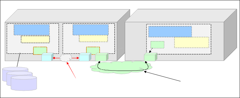
Chapter 7. Shared Memory Communications 309
This example shows OSA-Express features for the TCP/IP communications, but a
HiperSockets connection can be used instead.
The SMC-D model uses these key attributes:
Follows the standard TCP/IP connection setup process.
Switches to ISM (SMC-D) dynamically.
The TCP connection remains active and is used to control the SMC-D connection.
Application software is not required to change, so all host application workloads can
benefit immediately.
Preserves the following critical operational and network management TCP/IP features:
– Minimal (or zero) IP topology changes
– Supports TCP connection-level load balancers
– Can use the existing IPSec model, such as IP filters, policies, VLANs, and SSL
– Minimal network administration and management changes
Both SMC protocols can coexist in the same z Systems platform. Figure 7-6 shows a
three-tier solution using both SMC-D and SMC-R across two z Systems platforms.
Figure 7-6 Clustered systems: Multitier application solution by using RDMA and DMA
7.1.3 How the SMC connections are defined on the platform
To support SMC connections, the 10GbE RoCE Express features and the ISM adapters must
be defined to the z Systems platform. The following IOCP FUNCTION statements are important
for establishing the SMC connections.
Function ID
The 10GbE RoCE features and the ISM adapters are identified by a hexadecimal Function
Identifier (FID) with a range of 00 - FF. A FID can be used only by one LPAR at a time, but is
reconfigurable. Only one FID can be defined for z Systems platforms before the z13 or z13s.
Up to 31 FIDs can be defined for shared mode (on a z13 and a z13s) for each physical card.
SMC-R and SMC-D enabled platform
z/OS LPAR 1 (DB2)
z/OS LPAR 3 (WebSphere)
Shared Memory Communications
via DMA (SMC-D using ISM)
Client
Shared Memory Communications
via RDMA (SMC-R)
SMC
RDMA enabled (RoCE)
SMC-R enabled platform
Virtual server instance
Shared Memory
Sockets
SMC
Client & Server
Shared Memory
Sockets
z/OS LPAR 2 (CICS)
Shared Memory
Server
Sockets
SMC
RoCE RoCE
ISM
ISM
VCHID

310 IBM z/OS V2R2 Communications Server TCP/IP Implementation Volume 1
Virtual Function ID
Virtual Function ID is defined when PCIe hardware or the ISM is shared between LPARs.
Virtual Function ID has a decimal Virtual Function Identifier (VF=) in the range 1 – n, where n
is the maximum number of LPARs the PCIe feature supports. For example, the ISM supports
up to 255 VFs, and a 10GbE RoCE Express feature supports up to 31.
Physical channel identifier
The 10GbE RoCE feature, as installed in a specific PCIe I/O drawer and slot, is to be used for
the defined function. The physical installation (I/O drawer and slot) determines the physical
channel identifier (PCHID). The PCHID can be a 1- to 3- digit hexadecimal value in the
range 0 - n, where n depends on the maximum supported PCIe adapters in the given
z Systems platform. A PCHID is required for FUNCTION TYPE=RoCE.
A PCHID on a FUNCTION statement must be unique and cannot match a PCHID value on the
CHPID statement.
Virtual channel identifier
ISM does not use physical cards or card slots (no PCHID), but instead uses logical instances
in the firmware that are defined as VCHIDs in FUNCTION statements.
VCHID specifies the virtual channel identification number (7E0 - 7FF) that is associated with
the VF. VCHID is required for FUNCTION TYPE=ISM. A VCHID on a FUNCTION statement must be
unique and cannot match a VCHID value on the CHPID statement.
Physical network ID
The physical network ID (PNETID) is used to logically group interfaces and adapters based
on connectivity. Operating systems (for example, z/OS) dynamically learn the PNETID (from
the I/O configuration) and then group OSA-Express ports and 10GbE RoCE Express ports
based on matching PNETIDs for SMC-R. For SMC-D, OSA-Express ports or HiperSockets
and ISM are grouped based on matching PNETIDs.
TYPE
Specifies the type of function adapters that are supported for SMC-R and SMC-D. The
following TYPE keyword values are allowed:
ISM specifies that the Function ID is associated with an SMC-D (internal virtual network
connection).
ROCE or ROC specifies that the Function ID is associated with a 10GbE RoCE Express
feature.
PART
The PART keyword specifies the availability of the FID to LPARs. All LPAR names that are
specified must match those that are specified in the RESOURCE statement.
Important: If you do not configure a PNETID for the RoCE adapter, activation fails. If you
do not configure a PNETID for the OSA-Express port, activation is successful, but the
interface is not eligible for SMC-R use.

Chapter 7. Shared Memory Communications 311
Sample FUNCTION statements for SMC-R
Figure 7-7 shows the FUNCTION statements that define the RoCE adapters between LPARs on
the different z Systems platforms.
Figure 7-7 RoCE adaptors on two z Systems platforms
Example 7-1 shows a sample FUNCTION configuration to define 10GbE RoCE Express ports
that are shared between LPARs.
Example 7-1 Sample FUNCTION statements for RoCE
System A
FUNCTION FID=05,PCHID=100,PART=((LP08),(LP09)),VF=1,TYPE=ROCE,PNETID=(PNETA)
System B
FUNCTION FID=08,PCHID=12C,PART=((LP12),(LP06)),VF=2,TYPE=ROCE,PNETID=(PNETA)
This example has these characteristics:
PNETID identifies the network that the ports are associated with. Thus, FIDs on a RoCE
adapter that are associated with the same PCHID must have the same PNETID for each
port.
10GbE RoCE Express functions for LP08 are reconfigurable to LP09 with access to the
network (PNETA).
10GbE RoCE Express functions for LP12 are reconfigurable to LP06 with access to the
network (PNETA).
Physical 10GbE RoCE Express features on PCHID 100 and PCHID 12C can be shared
between other LPARs in the z Systems platform by adding FUNCTION statements with different
FIDs and VFs.
RDMA enabled (RoCE)
SMC-R enabled Platform
LP08
SMC
Shared Memory
Sockets
LP09
Shared Memory
Sockets
SMC
RoCE
PCHID=100 PNETID=PNETA
FID=05
VF=1
SMC-R enabled Platform
LP12
SMC
Shared Memory
Sockets
LP06
Shared Memory
Sockets
SMC
RoCE
PCHID=12C PNETID=PNETA
FID=08
VF=2
System A System B

312 IBM z/OS V2R2 Communications Server TCP/IP Implementation Volume 1
Sample FUNCTION statements for SMC-D
Example 7-2 shows FUNCTION statements that define ISM adapters that are shared between
LPARs on the same z Systems platform, as shown in Figure 7-8.
Figure 7-8 ISM adapters that are shared between LPARs in a single z Systems platform
Example 7-2 Sample IOCP FUNCTION statements for ISM
FUNCTION FID=17,VCHID=7E1,VF=1,PART=((LP1),(LP1,LP2)),PNETID=(PNET1),TYPE=ISM
FUNCTION FID=18,VCHID=7E1,VF=2,PART=((LP2),(LP1,LP2)),PNETID=(PNET1),TYPE=ISM
Workloads can be logically isolated on separate ISM VCHIDs or RoCE PCHIDs. Alternatively,
workloads can be isolated by using VLANs. The VLAN definitions are inherited from the
associated IP network definitions of the OSA-Express ports or HiperSockets with the same
PNETID. The VLANs are registered or inherited up front when the RNIC is first activated. The
VLANs are already registered to the RoCE feature before the TCP connection is set up.
Configuration considerations
The IOCDS (HCD) definitions for ISM PCI VFs are not directly related to the software
(SMC-D) usage of ISM (the z/OS TCP/IP and SMC-D implementation and usage are not
directly related to the I/O definition).
The user defines a list of ISM FIDs (VFs) in IOCDS (HCD), and z/OS dynamically selects an
eligible FID based on the required PNet ID. FIDs or VFs are
not defined in Communications
Server for z/OS TCP/IP. Instead, z/OS selects an available FID for a specific PNET. Access to
additional VLANs does not require configuration of additional VFs.
For native PCI devices, FIDs must be defined. Each FID in turn also defines a corresponding
VF. In terms of operating system administration tasks, the administrator typically references
FIDs. Usually VFs (and VF numbers) are transparent.
Note: In Figure 7-8, the ISM network “PNET1” is referenced by the PNETID statement. ISM
(like HiperSockets) does not use physical cards or card slots (PCHID), but instead uses a
logical instance that is defined as a VCHID.
Note: For future use, consider over-provisioning the number of FIDs and VFs for each ISM
VCHID.
LP 2
ISM
VCHID=7E1
PNETID=PNET1
Shared Memory
Sockets
SMC
FID=17
VF=1
LP 1
Shared Memory
Sockets
SMC
FID=18
VF=2
SMC-D enabled Platform

Chapter 7. Shared Memory Communications 313
7.2 Enabling SMC support
SMC needs both hardware and software support to work. The minimum z/OS level that is
supported for SMC-R is z/OS V2R1 for dedicated RoCE ports per LPAR, and PTFs are
required for shared RoCE ports across LPARs. SMC-D requires z/OS V2R2 with PTFs.
Check the appropriate PSP buckets for the most current list of required PTFs for SMC-R and
SMC-D.
SMC-R needs the following items in each IBM z13, IBM z13s™, IBM zEC12, or IBM zBC12:
10 Gigabit Ethernet (10GbE) RoCE Express features. Up to sixteen 10GbE RoCE
Express features are supported per platform. The ports
must be dedicated to an LPAR on
a zEC12 or zBC12. On a z13 or z13s, the ports
can be shared across LPARs.
OSA-Express ports in Queued direct input/output (QDIO) mode (channel-path identifier
(CHPID) type OSD). The supported OSA-Express features include the 10 GbE, the 1
GbE, and the 1000BASE-T.
A standard 10 GbE switch is optional and does not have to be RDMA over RoCE-enabled.
Input/output configuration data set (IOCDS) with PCHID, FID, VF (for sharing), and
PNETID defined to the FUNCTION statement for the 10GbE RoCE Express ports, and a
matching PNETID that is defined to the CHPID statement for the OSA-Express ports.
SMC-D requires the following items in each IBM z13 or IBM z13s:
HiperSockets connections or OSA-Express ports in queued direct input/output (QDIO)
mode (CHPID type OSD). The supported OSA-Express features include the 10 GbE, the
1 GbE, and the 1000BASE-T.
Input/output configuration data set (IOCDS) with VCHID, FID, VF, and PNETID defined to
the FUNCTION statement for the ISM with a matching PNETID in the CHPID statement for
HiperSockets connections or the OSA-Express ports.
7.2.1 10GbE RoCE Express support for SMC-R
SCM-R supports both a point-to-point connection (direct connection with another 10GbE
RoCE Express port) and a switched connection (through a 10 GbE switch).
An SMC-R point-to-point connection is a viable option for test scenarios, but is not a preferred
practice for production deployment because the connection does not allow for connectivity
with other LPARs (multiple SMC-R peers).
If the 10GbE RoCE Express ports are connected to 10 GbE switches, the switch ports must
be set to the following settings:
Global Pause: IEEE 802.3x port-based Flow Control should be enabled.
Priority Flow Control (PFC): IEEE 802.1Qbb, priority-based Flow Control should be
disabled.
The maximum supported unrepeated point-to-point distance is 300 meters (984.25 feet)
between the 10GbE RoCE Express port and the 10 GbE switch port.
Important: SMC-R and SMC-D cannot be used in these circumstances:
Peer LPARs are not within the same IP subnet and VLAN.
TCP traffic requires IPSec support.
Peer LPARs use the Fast Response Cache Accelerator (FRCA) feature.

314 IBM z/OS V2R2 Communications Server TCP/IP Implementation Volume 1
In addition, SMC-R traffic cannot traverse firewalls, IP routers, or an intra-ensemble data
network (IEDN).
Table 7-2 shows the port characteristics of the 10GbE RoCE Express feature and supported
z Systems platforms.
Table 7-2 Characteristics of the 10GbE RoCE Express feature per z Systems platform
Other considerations when using RoCE for SMC-R include:
Rules for the z Systems platform:
– Sixteen physical cards per z Systems platform.
– Thirty-one VFs per PCHID.
– One hundred twenty-eight unique VLANs per PCHID (physical port).
z/OS Communications Server consumption of RoCE virtual resources:
– One VF per TCP stack (per PCIe function ID (PFID) / port).
– One virtual MAC (VMAC) per VF (z/OS uses PF generated VMAC).
– One VLAN ID per OSA-Express VLAN with a maximum of 16 (registered to the RNIC
before the TCP connections setup).
z/OS Communications Server migration considerations:
– RoCE configuration changes are required (in HCD or IOCDS).
– Existing z/OS RoCE environments might be required to make a TCP/IP configuration
change (existing TCP/IP profile (PFID parameters) can be compatible with shared
RoCE).
Changes are required for existing RoCE environments in the following situations:
– Use of multiple TCP/IP stacks and where stacks currently use the same RoCE feature
(a single z/OS LPAR sharing a physical card among multiple stacks).
– Both physical RoCE ports can be used for the same z/OS LPAR, but this is not a
preferred practice. It is important to remember that having PFIDs that are configured
from unique physical RoCE ports (per stack) preserves high availability. The NETSTAT
DEVlinks/-d command can be used to show the redundancy of SMC-R link groups.
z Systems platform Supported ports Shared ports
a
a. Requires z/OS V2R1 with PTFs or later.
Dedicated ports
z13 2 Yes N/A
z13s 2 Yes N/A
zEC12 1 N/A Yes
zBC12 1 N/A Yes
Chapter 7. Shared Memory Communications 315
7.2.2 OSA-Express support for SMC-R and SMC-D
SMC-R requires IP network connectivity with access to an OSA-Express port, which is
defined as CHPID type OSD. This is optional for SMC-D if HiperSockets connections are not
being used. The OSA-Express port must be connected to another OSA-Express port on the z
Systems platforms with which the RoCE port or ISM interface is communicating. Both the
RoCE port and ISM interfaces are dynamically and transparently added and configured.
However, through the designated OSA-Express ports (through matching PNETID), TCP sync
flows are used to establish SMC-R or SMC-D communications between z/OS LPARs.
7.2.3 HiperSockets support for SMC-D
SMC-D requires IP network connectivity with access through a HiperSockets connection if
OSA-Express ports are not used. The HiperSockets interface must have a matching PNETID
to the one that is defined in the FUNCTION statement of the IOCDS for the ISM interfaces. The
ISM interfaces are dynamically and transparently added and configured, but TCP sync flows
are used to establish SMC-D communications between z/OS LPARs through HiperSockets
connections.
7.2.4 ISM support for SMC-D
ISM is a virtual PCI network adapter that enables direct access to shared virtual memory
providing a highly optimized network interconnect for z Systems intra-system
communications. ISM has a static VCHID type. The ISM VCHID concepts are similar to the
IQD (HiperSockets) type of virtual adapters. ISM is based on existing z Systems PCIe
architecture (that is virtual PCI function and adapter).
The configuration and operations tasks follow the same process (HCD or IOCDS) as existing
PCI functions, such as RoCE Express and zEDC Express. ISM supports dynamic I/O and
provides adapter virtualization (VFs), such as:
Up to 32 ISM VCHIDs per z13 or z13s. A VCHID represents a unique ISM network, each
with a unique PNETID.
Each VCHID supports up to 255 VFs (the maximum is 8,000 VFs per z13 or z13s).
VCHIDs support VLANs.
A Global Identifier (GID) that is internally generated to correspond with each ISM FID.
Virtual MACs (VMACs), MTU, physical ports, and frame size are not applicable.
z/VM is supported in pass-through mode (PTF is required).
7.2.5 SMCR and SMCD parameters on the GLOBALCONFIG statement
SMCR and SMCD parameters are required on the GLOBALCONFIG statement in the TCP/IP
profile. The key difference for the SMC-D parameter compared to the SMCR parameter is that
PFIDs are not defined in TCP/IP for ISM. Rather, ISM FIDs are discovered automatically
based on the matching PNETID that is associated with the OSA-Express port or
HiperSockets interface. For more information about the GLOBALCONFIG statement for SMC, see
IBM Knowledge Center:
https://www.ibm.com/support/knowledgecenter/en/SSLTBW_2.2.0/com.ibm.zos.v2r2.halz0
01/globalconfigstatement.htm
316 IBM z/OS V2R2 Communications Server TCP/IP Implementation Volume 1
7.2.6 Planning considerations for SMC-R and SMC-D
Before implementing SMC-R or SMC-D, check your environment for the following items:
Run the Shared Memory Communications Applicability Tool (SMC-AT) to evaluate
applicability and potential value. It is available at the following website:
ftp://public.dhe.ibm.com/software/os/systemz/pdf/SMC_Applicability_Tool_Overvie
w_03-10-16.pdf
Review and adjust as needed the available real memory and fixed memory usage limits
(z/OS and CS). SMC requires fixed memory. You might need to review the limits and
provision additional real memory for z/OS.
Review IP topology, VLAN usage considerations, and IPSec.
Review changes to messages, monitoring information, and diagnostic tools. There are
numerous updates to these items:
– Messages (VTAM and TCP stack)
– Netstat (status, monitoring, and display information)
– CS diagnostic tools (VIT, Packet trace, CTRACE, and IPCS formatted dumps)
For more information about SMC-R planning and security considerations, go to:
http://www.ibm.com/software/network/commserver/SMC-R/
For more information about SMC-D planning and security considerations, go to:
http://www.ibm.com/software/network/commserver/SMC-D/

Chapter 7. Shared Memory Communications 317
7.3 Setting up the SMC-R environment
This section provides examples showing how we set up, verify, and test our SMC-R
environment. We implement and test the configuration that is shown in Figure 7-9.
Figure 7-9 SMCR test scenario
We use two RoCE and two OSA-Express interfaces that are shared across four z/OS LPARs.
The I/O configuration that is shown in this section is defined in HCD, with the resulting IOCDS
definitions shown in Example 7-3.
Example 7-3 IOCDS FUNCTION statements for ROCE
FUNCTION FID=0004,VF=4,PCHID=140,PNETID=(COMMSRVA,COMMSRVB,,),*
PART=((A12),(=)),TYPE=ROCE
FUNCTION FID=0005,VF=5,PCHID=140,PNETID=(COMMSRVA,COMMSRVB,,),*
PART=((A13),(=)),TYPE=ROCE
FUNCTION FID=0006,VF=6,PCHID=140,PNETID=(COMMSRVA,COMMSRVB,,),*
PART=((A14),(=)),TYPE=ROCE
FUNCTION FID=0007,VF=7,PCHID=140,PNETID=(COMMSRVA,COMMSRVB,,),*
PART=((A15),(=)),TYPE=ROCE
FUNCTION FID=0014,VF=4,PCHID=208,PNETID=(COMMSRVA,COMMSRVB,,),*
PART=((A12),(=)),TYPE=ROCE
FUNCTION FID=0015,VF=5,PCHID=208,PNETID=(COMMSRVA,COMMSRVB,,),*
PART=((A13),(=)),TYPE=ROCE
FUNCTION FID=0016,VF=6,PCHID=208,PNETID=(COMMSRVA,COMMSRVB,,),*
PART=((A14),(=)),TYPE=ROCE
FUNCTION FID=0017,VF=7,PCHID=208,PNETID=(COMMSRVA,COMMSRVB,,),*
PART=((A15),(=)),TYPE=ROCE
OSA2380
10.1.10.x1
PNETID COMMSRVA
Ethernet
Switch
SC30
TCPIPA
PROFA30F (Flat network)
VIPA1I 10.1.10.10
VIPA2I 10.1.20.10
OSA2380I 10.1.10.11/24
OSA23A0I 10.1.20.11/24
SC31
TCPIPB
PROFB31F (Flat network)
VIPA1I 10.1.10.20
VIPA2I 10.1.20.20
OSA2380I 10.1.10.21/24
OSA23A0I 10.1.20.21/24
SC32
TCPIPC
PROFC32F (Flat network)
VIPA1I 10.1.10.30
VIPA2I 10.1.20.30
OSA2380I 10.1.10.31/24
OSA23A0I 10.1.20.31/24
SC33
TCPIPD
PROFD33F (Flat network)
VIPA1I 10.1.10.40
VIPA2I 10.1.20.40
OSA2380I 10.1.10.41/24
OSA23A0I 10.1.20.41/24
z Systems (z13)
OSA23A0
10.1.20.x1
PNETID COMMSRVA
ROCE PCHID 140
PNETID COMMSRVA
FID(04,05,06,07 )
VF(4,5,6,7 )
PNETID COMMSRVA
FID(14,15,16,17 )
VF(4,5,6,7 )
ROCE PCHID 208
FID(05)
VF(5) FID(06) VF(6)
FID(07) VF(7)FID(04)
VF(4)
PART: A12 PART: A13
PART: A14 PART: A15

318 IBM z/OS V2R2 Communications Server TCP/IP Implementation Volume 1
The following checklist provides a task summary for enabling SMC-R support:
Configuring the RoCE interfaces
Configuring the OSA interfaces
Altering the TCP/IP profile to include SMC-R support
Defining the OSA interfaces that are not for SMC-R use
Repeat the TCP/IP configuration steps for each stack that is part of the environment.
Verifying and testing the SMC-R implementation
These tasks are described in more detail in the following sections.
Configuring the RoCE interfaces
In this step, we configure the RoCE adapter that is used in our scenario as part of the same
environment, which is represented by the parameter PNETID, which, in our environment, we
name COMMSRVA for Port 1 of the RoCE adapter, and COMMSRVB for Port 2 of the RoCE
adapter.
To use the RoCE adapter in shared mode, create one FUNCTION statement for each LPAR in
our scenario, defining a specific FID for each LPAR and a Virtual Function ID for each TCP/IP
stack.
The resulting IOCDS for our scenario is shown in Example 7-3 on page 317.
Configuring the OSA interfaces
Next, we add the PNETID to the OSD definitions of the OSAs we are going to use in our
scenario, as shown in Example 7-4.
Example 7-4 OSA CHPID configuration in the IOCDS
CHPID PATH=(CSS(1),0A),SHARED, *
PARTITION=((A12,A13,A14,A15),(=)),PCHID=274, *
PNETID=(COMMSRVA,COMMSRVB,,),TYPE=OSD
CHPID PATH=(CSS(1),0B),SHARED, *
PARTITION=((A12,A13,A14,A15),(=)),PCHID=190, *
PNETID=(COMMSRVA,COMMSRVB,,),TYPE=OSD
Both OSAs are shared by the same partitions as the RoCE adapters.
Altering the TCP/IP profile to include SMC-R support
We specify the GLOBALCONFIG SMCR parameter in the TCP/IP profile we are using in our test
environment.
The profiles for each LPAR and TCP/IP stack that are going to be part of the same
environment must have at least one PFID that is associated to a specific RoCE adapter.
PORTNUM defaults to port 1 of the RoCE feature. If you want to use port 2 of the RoCE
feature, then PFID xxxx PORTNUM 2 must be defined on the GLOBALCONFIG statement.
In our environment, each TCP/IP stack uses both RoCE adapters, as shown in Example 7-5.
Example 7-5 TCP/IP profile SMCR definition
GLOBALCONFIG
SMCR PFID 04 PFID 14

Chapter 7. Shared Memory Communications 319
Defining the OSA interfaces that are not for SMC-R use
After the global statement SMCR is configured in the TCP/IP profile, all IPAQENET interfaces
with CHPID TYPE OSD use the SMC-R function by default.
In our test environment, we use two OSA interfaces. To compare the throughput with and
without SMC-R, we define one of the interfaces with the NOSMCR parameter, as shown in
Example 7-6.
Example 7-6 OSA interface definition without a connection to SMC-R
INTERFACE OSA2380I
DEFINE IPAQENET
PORTNAME OSA2380
SOURCEVIPAINT VIPA1I
IPADDR 10.1.10.11/24
MTU 8192
VMAC
NOSMCR
7.3.1 Verifying and testing the SMC-R implementation
Start the reconfigured TCP/IP stack, which is called TCPIPA to verify that SMC-R initializes
correctly and is ready to be used. This is done by checking the messages in the system log
that indicate the RNIC interfaces are up (see Example 7-7).
Example 7-7 TCPIPA SMC-R initialization messages
EZZ4340I INITIALIZATION COMPLETE FOR INTERFACE EZARIUT10004
EZZ4340I INITIALIZATION COMPLETE FOR INTERFACE EZARIUT10014
During the TCP/IP startup process, RNIC interfaces are dynamically created and associated
with the OSA interfaces where SMCR is defined. This can be verified by using a display
command, as shown in Example 7-8.
Example 7-8 Verify SMC-R through an OSA interface display (partial results)
D TCPIP,TCPIPA,N,DEV,INTFN=OSA23A0I
INTFNAME: OSA23A0I INTFTYPE: IPAQENET INTFSTATUS: READY
PORTNAME: OSA23A0 DATAPATH: 23A2 DATAPATHSTATUS: READY
CHPIDTYPE: OSD SMCR: YES 1
PNETID: COMMSRVA 2 SMCD: NO
...
INTERFACE STATISTICS:
BYTESIN = 0
INBOUND PACKETS = 0
INBOUND PACKETS IN ERROR = 0
INBOUND PACKETS DISCARDED = 0
INBOUND PACKETS WITH NO PROTOCOL = 0
BYTESOUT = 84
OUTBOUND PACKETS = 1
OUTBOUND PACKETS IN ERROR = 0
Important: Up to eight TCP/IP stacks can share a RoCE PCHID (RoCE feature) in a
specific LPAR (each stack must define a unique FID value).

320 IBM z/OS V2R2 Communications Server TCP/IP Implementation Volume 1
OUTBOUND PACKETS DISCARDED = 0
ASSOCIATED RNIC INTERFACE: EZARIUT10004 3
ASSOCIATED RNIC INTERFACE: EZARIUT10014 3
IPV4 LAN GROUP SUMMARY
...
1 OF 1 RECORDS DISPLAYED
END OF THE REPORT
In the results from the display, you can see the following information:
1. The OSA interface OSA23A0I has SMC-R enabled.
2. OSA23A0I is using PNETID COMMSRVRA.
3. OSA23A0I is associated with the RNIC interfaces that are created during TCP/IP stack
startup.
You also can verify the status of the RNIC interfaces by using a display command, as shown
in Example 7-9.
Example 7-9 Verify SMC-R on an RNIC interface display (partial results)
D TCPIP,TCPIPA,N,DEV,SMC
INTFNAME: EZARIUT10004 INTFTYPE: RNIC INTFSTATUS: READY
PFID: 0004 1 PORTNUM: 1 TRLE: IUT10004 2 PFIDSTATUS: READY
PNETID: COMMSRVA 3
VMACADDR: 8204C9E803D0
GIDADDR: FE80::8004:C9FF:FEE8:3D0
INTERFACE STATISTICS:
BYTESIN = 0
INBOUND OPERATIONS = 0
BYTESOUT = 0
OUTBOUND OPERATIONS = 0
SMC LINKS = 0
TCP CONNECTIONS = 0
INTF RECEIVE BUFFER INUSE = 0K
In the results from the display, you can verify the following relevant information:
1. The PFID that is associated with the LPAR this stack is running.
2. The dynamic TRLE that is created in VTAM to connect the RNIC physical interface.
3. The PNETID that represents the physical network where this interface is connected to. It
must be the same for all OSAs and TCP/IP stacks that are using this network.
Transferring data between LPARs with and without SMC-R
Next, with our environment active and ready to be tested, we use concurrent batch jobs to
transfer a high amount of data between all stacks, first through an OSA network without
SMC-R, and then we run the same set of batch jobs through the SMC-R environment to
compare the results.
Each batch job transfers data between different stacks and LPARs to verify that the RNIC
interface is being shared as expected. The results are similar in each stack, so we show the
results from one stack only.
The first test was made by transferring data through the OSA network without SMC-R,
subnetwork 10.1.10.xx. The results are shown in Example 7-10 on page 321.

Chapter 7. Shared Memory Communications 321
Example 7-10 Job log (partial) for the FTP data transfer by using OSA without SMC-R
EZA1736I FTP
EZY2640I Using dd:SYSFTPD=TCPIPA.TCPPARMS(FTPDA30) for local site configuration
parameters.
...
EZA1466I FTP: using TCPIPA
EZA1456I Connect to ?
EZA1736I 10.1.10.30
EZA1554I Connecting to: 10.1.10.30 port : 21.
...
...
EZA1460I Command:
EZA1736I PUT 'cs03.seq1' seq10
EZA1701I >>> SITE VARrecfm LRECL=27998 RECFM=U BLKSIZE=27998
200 SITE command was accepted
EZA1701I >>> PORT 10,1,10,10,4,4
2 0 0 P o r t r e q u e s t O K .
EZA1701I >>> STOR seq10
125 Storing data set CS03.SEQ10
EZA1485I 594740252 bytes transferred - 10 second interval rate 59474.02 KB/sec -
Overall transfer rate 59474.02 KB/sec
EZA1485I 893046069 bytes transferred - 10 second interval rate 29652.67 KB/sec -
Overall transfer rate 44518.75 KB/sec
EZA1485I 1036918614 bytes transferred - 10 second interval rate 14258.93 KB/sec -
Overall transfer rate 34392.00 KB/sec
250 Transfer completed successfully.
EZA1617I 1135494539 bytes transferred in 31.850 seconds. Transfer rate 35651.33
Kbytes/sec.
During the data transfer process, each concurrent job being activated causes the overall
performance to drop. You can observe the CPU utilization of the FTP batch jobs and the
TCP/IP stacks, as shown in Example 7-11.
Example 7-11 FTP services CPU utilization
Jobname CX Class Total AAP IIP CP AAP IIP
TCPIPA SO SYSSTC 3.830 0.000 0.000 3.830 0.000
TCPIPB SO SYSSTC 3.580 0.000 0.000 3.580 0.000
FTPBAT1 BO BATCHHI 1.280 0.000 0.000 1.280 0.000
FTPBAT2 BO BATCHHI 0.930 0.000 0.000 0.930 0.000
FTPBAT3 BO BATCHHI 1.260 0.000 0.000 1.260 0.000
FTPBAT4 BO BATCHHI 0.810 0.000 0.000 0.810 0.000
The OSA interfaces are getting most of the workload and are the bottleneck in this test.
Next, move to the SMC-R test. Before you initiate the data transfer by using SMC-R, check
the RNIC interfaces to verify their status, as shown in Example 7-12.
Example 7-12 Netstat DevLink,SMC command
RO SC30,d tcpip,tcpipa,n,dev,smc
...
INTFNAME: EZARIUT10004 INTFTYPE: RNIC INTFSTATUS: READY
PFID: 0004 PORTNUM: 1 TRLE: IUT10004 PFIDSTATUS: READY
PNETID: COMMSRVA

322 IBM z/OS V2R2 Communications Server TCP/IP Implementation Volume 1
VMACADDR: 8204C9E803D0
GIDADDR: FE80::8004:C9FF:FEE8:3D0
INTERFACE STATISTICS:
BYTESIN = 0
INBOUND OPERATIONS = 0
BYTESOUT = 0
OUTBOUND OPERATIONS = 0
SMC LINKS = 0
TCP CONNECTIONS = 0
INTF RECEIVE BUFFER INUSE = 0K
INTFNAME: EZARIUT10014 INTFTYPE: RNIC INTFSTATUS: READY
PFID: 0014 PORTNUM: 1 TRLE: IUT10014 PFIDSTATUS: READY
PNETID: COMMSRVA
VMACADDR: 820414078210
GIDADDR: FE80::8004:14FF:FE07:8210
INTERFACE STATISTICS:
BYTESIN = 0
INBOUND OPERATIONS = 0
BYTESOUT = 0
OUTBOUND OPERATIONS = 0
SMC LINKS = 0
TCP CONNECTIONS = 0
INTF RECEIVE BUFFER INUSE = 0K
2 OF 2 RECORDS DISPLAYED
END OF THE REPORT
The display command shows that both RNIC interfaces are ready and no connections are
established through them.
Then, start the same concurrent jobs, now using subnetwork 10.1.20.x, which is defined to
use SMC-R, with the results that are shown in Example 7-13.
Example 7-13 Job log (partial) for the FTP data transfer by using SMC-R
EZA1736I FTP
EZY2640I Using dd:SYSFTPD=TCPIPA.TCPPARMS(FTPDA30) for local site configuration parameters.
...
EZA1466I FTP: using TCPIPA
EZA1456I Connect to ?
EZA1736I 10.1.20.30
EZA1554I Connecting to: 10.1.20.30 port: 21.
...
EZA1460I Command:
EZA1736I PUT 'cs03.seq1' seq12
EZA1701I >>> SITE VARrecfm LRECL=27998 RECFM=U BLKSIZE=27998
200 SITE command was accepted
EZA1701I >>> PORT 10,1,20,10,4,6
200 Port request OK.
EZA1701I >>> STOR seq12
125 Storing data set CS03.SEQ12
EZA1485I 937781382 bytes transferred - 10 second interval rate 93778.06 KB/sec - Overall
transfer rate 93778.06 KB/sec
250 Transfer completed successfully.
EZA1617I 1135494539 bytes transferred in 12.080 seconds. Transfer rate 93997.88
Kbytes/sec.

Chapter 7. Shared Memory Communications 323
During the data transfer process, you see that the concurrent jobs do not affect the overall
performance. You can observe the CPU utilization of the FTP batch jobs and the TCP/IP
stacks, as shown in Example 7-14.
Example 7-14 FTP data transfer CPU utilization
Service --- Time on CP % --- ----- EAppl % -----
Jobname CX Class Total AAP IIP CP AAP IIP
TCPIPA SO SYSSTC 0.760 0.000 0.000 0.760 0.000
TCPIPB SO SYSSTC 0.700 0.000 0.000 0.700 0.000
FTPBAT2 BO BATCHHI 2.940 0.000 0.000 2.940 0.000
FTPBAT1 BO BATCHHI 2.940 0.000 0.000 2.940 0.000
FTPBAT4 BO BATCHHI 3.110 0.000 0.000 3.110 0.000
FTPBAT3 BO BATCHHI 3.030 0.000 0.000 3.030 0.000
With SMC-R in use, you can see that the bottleneck is moved to the application, which is
wanted because the data is delivered faster, which causes the application to use more CPU
during less time. The TCP/IP stack uses less CPU while improving the overall performance.
Looking at the RNIO interface display, you can observe that a connection between the LPARs
is created to transfer the data, as shown in Example 7-15.
Example 7-15 Netstat DevLink,SMC command during data transfer
-D TCPIP,TCPIPA,NETSTAT,DEVLINKS,SMC
INTFNAME: EZARIUT10004 INTFTYPE: RNIC INTFSTATUS: READY
PFID: 0004 PORTNUM: 1 TRLE: IUT10004 PFIDSTATUS: READY
PNETID: COMMSRVA
VMACADDR: 8204C9E803D0
GIDADDR: FE80::8004:C9FF:FEE8:3D0
INTERFACE STATISTICS:
BYTESIN = 13315
INBOUND OPERATIONS = 165431
BYTESOUT = 28839906320
OUTBOUND OPERATIONS = 197037
SMC LINKS = 4
TCP CONNECTIONS = 3
INTF RECEIVE BUFFER INUSE = 1152K
SMCR LINK INFORMATION:
LOCALSMCLINKID: 80120A01 REMOTESMCLINKID: A9910A01
SMCLINKGROUPID: 80120A00 VLANID: NONE MTU: 1024
LOCALGID: FE80::8004:C9FF:FEE8:3D0
LOCALMACADDR: 8204C9E803D0 LOCALQP: 001849
REMOTEGID: FE80::8006:C9FF:FEE8:3D0
REMOTEMACADDR: 8206C9E803D0 REMOTEQP: 001049
SMCLINKBYTESIN: 352
SMCLINKINOPERATIONS: 9261
SMCLINKBYTESOUT: 1585359711
SMCLINKOUTOPERATIONS: 10849
TCP CONNECTIONS: 1
LINK RECEIVE BUFFER INUSE: 1024K
1 OF 1 RECORDS DISPLAYED
END OF THE REPORT
The display command shows that SMC links are dynamically created between the stacks
connecting them and allow data to be transferred through them.
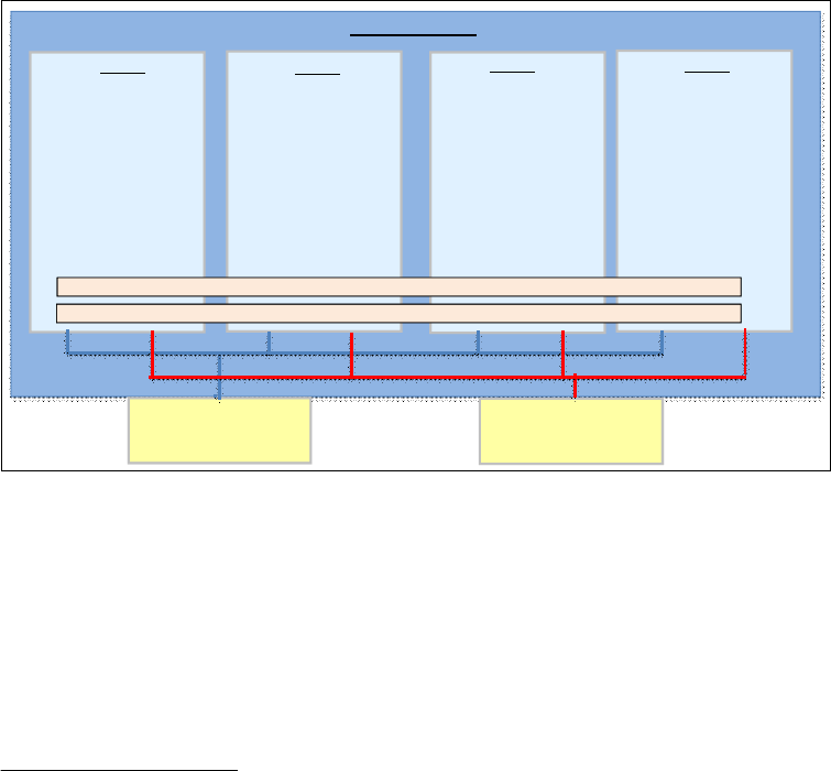
324 IBM z/OS V2R2 Communications Server TCP/IP Implementation Volume 1
7.3.2 Diagnosing an SMC-R environment
To monitor and diagnose SMC-R data, use the same methods that are used to monitor TCP
data because TCP does not create any specific trace packets for SMC-R data.
This data is formatted as packet trace data, and we enable the trace process the same way it
is done for TCP/IP connections (for example, protocol, port, and IP address).
The application flow is sent as TCP data as usual. You also can use Connection Layer Control
(CLC) and Link Layer Control (LLC) flows, with full support for TCP/IP component trace
(CTRACE), data trace, and VTAM Internal Trace (VIT).
No additional configuration tasks are necessary, and we format this data through the IPCS
component.
For more information about diagnosing SMC-R, see z/OS Communications Server: IP
Diagnosis Guide, GC31-8782.
7.4 Setting up our SMC-D environment
This section provides examples showing how we set up, verified, and tested our SMC-D
environment in our scenario. We implement the configuration that is shown in Figure 7-10.
Figure 7-10 SMC-D test scenario
We use two ISM interfaces, which are shared by four LPARs and two HiperSockets CHPIDs.
The I/O configuration that is shown in this section is defined in HCD. We show only the
resulting IOCDS definitions in Example 7-16 on page 325.
The following checklist provides a task summary for enabling SMC-D support:
Configuring the ISM interfaces
Configuring the HiperSockets connections
1
Altering the TCP/IP profile to include SMC-D support
1
An OSA interface can be used as described in “Configuring the OSA interfaces” on page 318 instead of a
HiperSockets connection.
SC30
TCPIPA
PROFB30F (Flat network)
VIPA3I 10.1.30.10
HIPERFEI 10.1.30.11/24
HIPERFFI 10.1.40.11/24
VIPA4I 10.1.40.10
SC31
TCPIPB
PROFB31F (Flat network)
VIPA3I 10.1.30.20
HIPERFEI 10.1.30.11/24
HIPERFFI 10.1.40.11/24
VIPA4I 10.1.40.20
SC32
TCPIPC
PROFB32F (Flat network)
VIPA3I 10.1.30.30
HIPERFEI 10.1.30.11/24
HIPERFFI 10.1.40.11/24
VIPA4I 10.1.40.30
SC33
TCPIPD
PROFB33F (Flat network)
VIPA3I 10.1.30.40
HIPERFEI 10.1.30.11/24
HIPERFFI 10.1.40.11/24
VIPA4I 10.1.40.40
HiperSockets CHPID FE IPADDR 10.1.30.x1 VCHID 7C0 COMMSRVC
HiperSockets CHPID FF IPADDR 10.1.40.x1 VCHID 7C1 COMMSRVD
ISM VCHID 7C0
PNETID COMMSRVC
FID(1004,1005,1006,1007 )
VF(4,5,6,7 )
PNETID COMMSRVD
FID(1004,1005,1006,1007 )
VF(4,5,6,7 )
ISM VCHID 7C1
z Systems (z13)

Chapter 7. Shared Memory Communications 325
Defining the HiperSockets connection that is not for SMC-D use
2
Repeat the TCP/IP configuration steps for each stack that is part of the environment.
Verifying and testing the SMC-D implementation
These tasks are described in more detail in the following sections.
Configuring the ISM interfaces
In this step, we configure the ISM adapters interfaces that are used in our scenario as part of
the same environment, which are represented by the parameter PNETID, which we named
COMMSRVC for the ISM VCHID 7C0 and COMMSRVD for the ISM VCHID 7C1.
To use the ISM adapter in shared mode, we create one FUNCTION statement for each LPAR in
our scenario, defining a specific Function ID (FID) for each LPAR and a Virtual Function ID for
each TCP/IP stack.
The resulting IOCDS configuration for ISM in our scenario is shown in Example 7-16.
Example 7-16 IOCDS FUNCTION statements for ISM
FUNCTION FID=1004,VF=4,VCHID=7C0,PNETID=COMMSRVC, *
PART=((A12),(=)),TYPE=ISM
FUNCTION FID=1005,VF=5,VCHID=7C0,PNETID=COMMSRVC, *
PART=((A13),(=)),TYPE=ISM
FUNCTION FID=1006,VF=6,VCHID=7C0,PNETID=COMMSRVC, *
PART=((A14),(=)),TYPE=ISM
FUNCTION FID=1007,VF=7,VCHID=7C0,PNETID=COMMSRVC, *
PART=((A15),(=)),TYPE=ISM
FUNCTION FID=1014,VF=4,VCHID=7C1,PNETID=COMMSRVD, *
PART=((A12),(=)),TYPE=ISM
FUNCTION FID=1015,VF=5,VCHID=7C1,PNETID=COMMSRVD, *
PART=((A13),(=)),TYPE=ISM
FUNCTION FID=1016,VF=6,VCHID=7C1,PNETID=COMMSRVD, *
PART=((A14),(=)),TYPE=ISM
FUNCTION FID=1017,VF=7,VCHID=7C1,PNETID=COMMSRVD, *
PART=((A15),(=)),TYPE=ISM
Configuring the HiperSockets connections
Next, we add the PNETID in the IOCDS definitions for the HiperSockets connections in our
scenario, as shown in Example 7-17.
Example 7-17 HiperSockets VCHID configuration in IOCDS
CHPID PATH=(CSS(1),FE),SHARED, *
PARTITION=((A12,A13,A14,A15),(=)),VCHID=7EE, *
PNETID=COMMSRVC,TYPE=IQD
CHPID PATH=(CSS(1),FF),SHARED, *
PARTITION=((A12,A13,A14,A15),(=)),VCHID=7EF, *
PNETID=COMMSRVD,TYPE=IQD
Both HiperSockets are shared by the same partitions as the ISM adapters.
2
The OSA interfaces must have NOSMCD added to the INTERFACE statement in the TCP/IP profile if they are not use for
SCM-D.

326 IBM z/OS V2R2 Communications Server TCP/IP Implementation Volume 1
Each HiperSockets CHPID is considered an independent LAN, so it must be connected to a
different PNETID and ISM interface.
Altering the TCP/IP profile to include SMC-D support
You must specify the GLOBALCONFIG SMCD parameter in the TCP/IP profile. The profile for each
LPAR and TCP/IP stack that are part of the same environment have the SMCD definition, as
shown in Example 7-18.
Example 7-18 TCP/IP profile SMCD definition
GLOBALCONFIG
SMCD
Defining the HiperSockets connection that is not for SMC-D use
After the global statement SMCD is active in the TCP/IP stack, all IPAQENET interfaces and
IPAQIDIO can use the SMC-D function by default, so it is important to define the parameter
NOSMCD in all interfaces that are not part of the SMC-D environment.
In our test environment, we use two IPAQIDIO interfaces to compare the throughput with and
without SMC-D. We define the first interface, HIPERFEI, with the NOSMCD parameter, as shown
in Example 7-19.
Example 7-19 Interface HiperSockets without SMC-D
Interface HIPERFEI
Define IPAQIDIO
IPADDR 10.1.30.11/24
SOURCEVIPAINTERFACE VIPA3I
NOSMCD
CHPID FE
;
Interface HIPERFFI
Define IPAQIDIO
IPADDR 10.1.40.11/24
SOURCEVIPAINTERFACE VIPA4I
SMCD
CHPID FF
The other HiperSockets interface HIPERFFI is defined to use SMC-D and it is connected to
PNETID COMMSRVD, as shown in Example 7-17 on page 325.
7.4.1 Verifying and testing the SMC-D implementation
Next, start the reconfigured TCP/IP stack, which is called TCPIPA to verify that SMC-D
initializes correctly and is ready to be used. This is done by checking the messages in the
system log that indicate the interfaces are up (see Example 7-20).
Example 7-20 TCPIPA stack SMCD initialization messages
EZZ4340I INITIALIZATION COMPLETE FOR INTERFACE HIPERFFI
EZZ4340I INITIALIZATION COMPLETE FOR INTERFACE EZAISM01
Important: Up to eight TCP/IP stacks can share an ISM VCHID (ISM feature) in a specific
LPAR (each TCP/IP stack must define a unique FID value).

Chapter 7. Shared Memory Communications 327
During the TCP/IP startup processing, an ISM interface is created that is associated with
each HiperSockets interface with the SMCD parameter, as shown in the display results in
Example 7-21.
Example 7-21 Verify the SMC-D HiperSockets connection through an interface display (partial results)
D TCPIP,TCPIPA,N,DEV,INTFN=HIPERFFI
INTFNAME: HIPERFFI INTFTYPE: IPAQIDIO INTFSTATUS: READY
TRLE: IUTIQ4FF DATAPATH: 7F02 DATAPATHSTATUS: READY
CHPID: FF
PNETID: COMMSRVD 2 SMCD: YES 1
...
INTERFACE STATISTICS:
BYTESIN = 0
INBOUND PACKETS = 0
INBOUND PACKETS IN ERROR = 0
INBOUND PACKETS DISCARDED = 0
INBOUND PACKETS WITH NO PROTOCOL = 0
BYTESOUT = 0
OUTBOUND PACKETS = 0
OUTBOUND PACKETS IN ERROR = 0
OUTBOUND PACKETS DISCARDED = 0
ASSOCIATED ISM INTERFACE: EZAISM01 3
1 OF 1 RECORDS DISPLAYED
END OF THE REPORT
In the resulting display, you can see this information:
1. This HiperSockets interface (HIPERFFI) is using SMC-D.
2. HIPERFFI is connected to PNETID COMMSRVRD.
3. HIPERFFI is associated with the ISM interfaces that are created during TCP/IP stack
startup.
You also can verify the status of the ISM interface by using the display command, as shown in
Example 7-22.
Example 7-22 D TCPIP,TCPIPA,N,DEV,SMC partial display results
D TCPIP,TCPIPA,N,DEV,SMC
RESPONSE=SC30
INTFNAME: EZAISM01 INTFTYPE: ISM INTFSTATUS: READY
PFID: 1014 1 TRLE: IUT01014 2 PFIDSTATUS: READY
PNETID: COMMSRVD 3
GIDADDR: 12008584DA872964
INTERFACE STATISTICS:
BYTESIN = 0
INBOUND OPERATIONS = 0
BYTESOUT = 0
OUTBOUND OPERATIONS = 0
SMC LINKS = 0
TCP CONNECTIONS = 0
INTF RECEIVE BUFFER INUSE = 0K
DEVICE INTERRUPTS = 0
1 OF 1 RECORDS DISPLAYED
END OF THE REPORT

328 IBM z/OS V2R2 Communications Server TCP/IP Implementation Volume 1
In the resulting display, you can verify the following information:
1. The PFID associated with the LPAR this stack is running.
2. The dynamic TRLE that is created in VTAM to connect the ISM logical interface.
3. The PNETID that represents the logical network where this interface is connected to. It
must be the same for all HiperSockets interfaces and TCP/IP stacks that are using this
network.
Transferring data between LPARs with and without SMC-D
Next, with our environment active and ready to be tested, we use concurrent batch jobs to
transfer a high amount of data between all stacks, first through a HiperSockets network
without SMC-D. Then, we run the same set of batch jobs through the SMC-D environment to
compare the results.
Each batch job transfers data between different TCP/IP stacks and LPARs to verify that the
ISM interface is being shared as expected. The results are similar in each stack, so we show
only the results from one TCP/IP stack.
The first test was made transferring data through the HiperSockets network without SMC-D,
subnetwork 10.1.30.xx, and the results are shown in Example 7-23.
Example 7-23 Job log (partial) for the FTP data transfer by using HiperSockets without SMC-D
EZA1554I Connecting to: 10.1.30.30 port: 21.
...
230 CS03 is logged on. Working directory is "CS03.".
EZA1460I Command:
EZA1736I ebcdic
EZA1701I >>> TYPE E
200 Representation type is Ebcdic NonPrint
EZA1460I Command:
EZA1736I mode b
EZA1701I >>> MODE B
200 Data transfer mode is Block
EZA1460I Command:
EZA1736I site recfm=u blksize=27998 cylinders volume=COMDA2 unit=3390
EZA1701I >>> SITE recfm=u blksize=27998 cylinders volume=COMDA2 unit=3390
EZA1701I >>> PORT 10,1,30,10,4,34
2 0 0 P o r t r e q u e s t O K .
EZA1701I >>> STOR seq13
125 Storing data set CS03.SEQ13
EZA1485I 779980521 bytes transferred - 10 second interval rate 77998.00 KB/sec -
Overall transfer rate 77998.00 KB/sec
250 Transfer completed successfully.
EZA1617I 1135494539 bytes transferred in 14.620 seconds. Transfer rate 77667.19
Kbytes/sec.

Chapter 7. Shared Memory Communications 329
During the data transfer process, each concurrent job being activated causes the overall
performance to drop. You can observe the CPU utilization of the FTP batch jobs and the
TCPIP stacks, as shown in Example 7-24.
Example 7-24 FTP data transfer CPU utilization
Service --- Time on CP % --- ----- EAppl % -----
Jobname CX Class Total AAP IIP CP AAP IIP
TCPIPA SO SYSSTC 16.39 0.000 0.000 16.39 0.000
TCPIPB SO SYSSTC 19.04 0.000 0.000 19.04 0.000
FTPBAT1 BO BATCHHI 3.310 0.000 0.000 3.310 0.000
FTPBAT2 BO BATCHHI 3.300 0.000 0.000 3.300 0.000
FTPBAT3 BO BATCHHI 3.407 0.000 0.000 3.407 0.000
FTPBAT4 BO BATCHHI 3.385 0.000 0.000 3.385 0.000
By using a HiperSockets interface to transfer data, you have better throughput and higher
CPU utilization compared to the tests made by using the OSA interface.
Before you initiate the data transfer by using SMC-D, check the ISM interface to verify its
status, as shown in Example 7-25.
Example 7-25 Netstat DevLink,SMC command
D TCPIP,TCPIPA,N,DEV,SMC
INTFNAME: EZAISM01 INTFTYPE: ISM INTFSTATUS: READY
PFID: 1014 TRLE: IUT01014 PFIDSTATUS: READY
PNETID: COMMSRVD
GIDADDR: 12008584DA872964
INTERFACE STATISTICS:
BYTESIN = 0
INBOUND OPERATIONS = 0
BYTESOUT = 0
OUTBOUND OPERATIONS = 0
SMC LINKS = 0
TCP CONNECTIONS = 0
INTF RECEIVE BUFFER INUSE = 0K
DEVICE INTERRUPTS = 0
1 OF 1 RECORDS DISPLAYED
END OF THE REPORT
The display command shows that the ISM interface is ready, but no traffic is using this path.
Next, start the same concurrent jobs by using subnetwork 10.1.40.x, which is defined to use
SMC-D. The results are shown in Example 7-26.
Example 7-26 Job log (partial) for the FTP data transfer by using HiperSockets with SMC-D
EZA1736I FTP
EZY2640I Using dd:SYSFTPD=TCPIPA.TCPPARMS(FTPDA30) for local site configuration
parameters.
...
EZA1459I NAME (10.1.40.30:CS01):
EZA1701I >>> USER cs03
...
EZA1701I >>> STOR seq14
125 Storing data set CS03.SEQ14

330 IBM z/OS V2R2 Communications Server TCP/IP Implementation Volume 1
EZA1485I 979225104 bytes transferred - 10 second interval rate 97922.50 KB/sec -
Overall transfer rate 97922.50 KB/sec
250 Transfer completed successfully.
EZA1617I 1135494539 bytes transferred in 11.570 seconds. Transfer rate 98141.25
Kbytes/sec.
Using SMC-D, we saw better throughput compared to the test using HiperSockets interface
without SMC-D, as shown in Example 7-23 on page 328.
To confirm, we use the SMC-D interface to transfer our data and run the command Netstat
DevLink,SMC again, as shown in Example 7-27.
Example 7-27 Netstat DevLink,SMC command result
D TCPIP,TCPIPA,N,DEV,SMC
...
INTFNAME: EZAISM01 INTFTYPE: ISM INTFSTATUS: READY
PFID: 1014 TRLE: IUT01014 PFIDSTATUS: READY
PNETID: COMMSRVD
GIDADDR: 12008584DA872964
INTERFACE STATISTICS:
BYTESIN = 5658
INBOUND OPERATIONS = 229924
BYTESOUT = 40877806818
OUTBOUND OPERATIONS = 277831
SMC LINKS = 0
TCP CONNECTIONS = 0
INTF RECEIVE BUFFER INUSE = 0K
DEVICE INTERRUPTS = 228941
1 OF 1 RECORDS DISPLAYED
END OF THE REPORT
Next, we look at the CPU utilization during the data transfer, and we see that the overall
utilization is reduced significantly, as shown in Example 7-28.
Example 7-28 CPU utilization during tests with SMC-D active
Service --- Time on CP % --- ----- EAppl % -----
Jobname CX Class Total AAP IIP CP AAP IIP
TCPIPA SO SYSSTC 2.030 0.000 0.000 2.030 0.000
TCPIPB SO SYSSTC 3.966 0.000 0.000 3.966 0.000
FTPBAT1 BO BATCHHI 2.710 0.000 0.000 2.710 0.000
FTPBAT2 BO BATCHHI 2.700 0.000 0.000 2.700 0.000
FTPBAT3 BO BATCHHI 2.835 0.000 0.000 2.835 0.000
FTPBAT4 BO BATCHHI 2.902 0.000 0.000 2.902 0.000
7.4.2 Diagnosing the SMC-D environment
To monitor and diagnose SMC-D data, use the same methods to monitor TCP data because
TCP does not create any specific trace packets for SMC-R data.
This data is formatted as packet trace data, and we enable the trace process the same way
as is done for TCP/IP connections (protocol, port, and IP address).
Chapter 7. Shared Memory Communications 331
The application flow is seen as TCP data, and we also can use CLC and LLC flows with full
support for TCP/IP component trace (CTRACE), data trace, and VIT.
No additional configuration processing is necessary, so we format this data through the IPCS
component.
For more information about diagnosing SMC-R, see z/OS Communications Server: IP
Diagnosis Guide, GC31-8782.
7.5 Additional information
For more information about the SMC-R and SMC-D implementation, see the following
resources:
z/OS Communications Server: IP Configuration Guide, SC27-3650
z/OS Communications Server: IP Configuration Reference, SC27-3651
z/OS Communications Server: IP Diagnosis Guide, GC31-8782
z/OS Communications Server: SNA Network Implementation, SC31-8777
z/OS Communications Server: SNA Resource Definition, SC31-8778
332 IBM z/OS V2R2 Communications Server TCP/IP Implementation Volume 1

© Copyright IBM Corp. 2016. All rights reserved. 333
Chapter 8. Sysplex subplexing
In large sysplex environments, there can be strict security requirements to isolate access to
certain VTAM nodes or TCP/IP stacks within the sysplex. A z/OS Communications Server
function, which is called
subplexing, provides this type of support. It enables the user to
implement automatically controlled access to subplex groups.
As mentioned, the subplexing support is also for VTAM nodes. However, this chapter
describes subplexing only for TCP/IP stacks. For information about VTAM subplexing, see
SNA Network Implementation Guide, SC31-8777.
This chapter covers the topics that are shown in Table 8-1.
Table 8-1 Chapter 8 topics
8
Section Topic
8.1, “Introduction” on page 334 The subplexing concept, and the environment on which
it can be used.
8.2, “Subplex environment” on page 336 Our TCP/IP subplexing environment.
8.3, “Load Balancing Advisor and
subplexing” on page 337
The Load Balancing Advisor (LBA) allows any external
load balancing solution to become sysplex aware.
8.4, “Subplex implementation” on
page 339
Implementation examples of TCP/IP subplexing.

334 IBM z/OS V2R2 Communications Server TCP/IP Implementation Volume 1
8.1 Introduction
Before subplexing, VTAM and TCP/IP sysplex functions were deployed sysplex-wide and
users had to implement complex resource controls and disable many of the dynamic XCF and
routing functions to support multiple security zones. For example, as shown in Figure 8-1,
TCP/IP stacks access different networks with diverse security requirements within the same
sysplex:
In the upper configuration, two TCP/IP stacks in the left LPARs access an internal
network. The TCP/IP stacks in the two LPARs on the right access the external network.
Presumably, the security requirements include isolating external traffic from the internal
network. However, all TCP/IP stacks in the sysplex can dynamically establish connectivity
with all the other TCP/IP stacks in the sysplex.
In the lower configuration, TCP/IP stacks in the same LPAR have different security
requirements. The first stack in each LPAR connects to the internal network, and the
second stack connects to the external network. Through the IUTSAMEH connection, the
two stacks in each LPAR can establish connectivity with each other dynamically and
possibly violate security policies.
Figure 8-1 Sysplex connectivity: Examples
Dedicated LPARs with
Multi-purpose LPARs
Internal Network
External Network
(e.g., Internet)
Appl1 Appl2 Appl3 Appl4
VTAM
z/OS LPAR
Appl1 Appl2 Appl3 Appl4
VTAM
z/OS LPAR
XCF
HiperSockets
Communications with all TCP/IP
stacks, including via IUTSAMEH
with dual TCP/IP stacks
XCFHiperSockets
z/OS LPAR
Appl1
Appl2
TCPIP
VTAM
z/OS LPAR
Appl1
Appl2
TCPIP
VTAM
z/OS LPAR
Appl1
Appl2
TCPIP
VTAM
z/OS LPAR
Appl1
Appl2
TCPIP
VTAM
Internal Network
Communications with all TCP/IP stacks
single TCP/IP stacks
TCPIPA TCPIPB TCPIPA TCPIPB
IUTSAMEH IUTSAMEH
External Network
(e.g., Internet)

Chapter 8. Sysplex subplexing 335
With subplexing, you can build
security zones. Only members within the same security zone
can communicate with each other. Subplex members are VTAM nodes and TCP/IP stacks
that are grouped in security zones to isolate communication.
Concept of subplexing
A subplex is a subset of a sysplex that consists of selected members. Those members are
connected and they communicate through the dynamic cross-system coupling facility (XCF)
groups to each other, using the following methods:
XCF links (for cross-system IP and VTAM connections)
IUTSAMEH (for IP connections within an LPAR)
HiperSockets (IP connections cross-LPAR in the same server)
Subplexes do not communicate with members outside the subset of the sysplex. For
example, in Figure 8-2, TCP/IP stacks with connectivity to the internal network can be
isolated from TCP/IP stacks that are connected to the external network by using subplexing.
Figure 8-2 Subplexing multiple security zones
TCP/IP stacks are defined as members of a subplex group with a defined group ID. For
example, in Figure 8-2, TCP/IP stacks within subplex 1 can communicate only with stacks
within the same subplex group. They cannot communicate with stacks in subplex 2.
Dedicated LPARs with
single TCP/IP stacks
z/OS LPAR
Appl1
Appl2
TCPIP
VTAM
z/OS LPAR
Appl1
Appl2
TCPIP
VTAM
z/OS LPAR
Appl1
Appl2
TCPIP
VTAM
z/OS LPAR
Appl1
Appl2
TCPIP
VTAM
Internal Network
External Network
(e.g., Internet)
VTAM VTAM
z/OS LPAR
Appl3 Appl4
TCPIPB
Subplex 2
Appl3 Appl4
Subplex 2
Appl1 Appl2
TCPIPA
Appl1 Appl2
Subplex 1
Subplex 1
IUTSAMEH
Communications
within same Subplex
VLAN IDs may be
associated with
Subplex
VLAN IDs may be
associated with Subplex
No communications to
dissimilar Subplexes
Internal Network
IUTSAMEH
No communications to
dissimilar Subplexes
HiperSockets
XCF
Subplex 2
Subplex 1
HiperSockets
Multi-purpose LPARs
with dual TCP/IP stacks
z/OS LPAR
XCF
External Network
(e.g., Internet)
TCPIPA
TCPIPB

336 IBM z/OS V2R2 Communications Server TCP/IP Implementation Volume 1
In an environment where a single LPAR has access to internal and external networks through
two TCP/IP stacks, those stacks are assigned to two different subplex group IDs. Even though
IUTSAMEH is the communication method, it is controlled automatically through the
association of subplex group IDs, thus creating two separate security zones within the LPAR.
8.2 Subplex environment
This section describes the environment that is used to demonstrate subplexing in multiple
security zones, based on Figure 8-2 on page 335. All LPARs in our scenarios were configured
in a single server with multiple stacks for demonstration purposes only.
Figure 8-3 illustrates our TCP/IP subplexing environment with the following attributes:
The first subplex is a VTAM subplex, which is not within the scope of this book. However,
when defining only a TCP/IP subplex, a default VTAM subplex is defined automatically.
The second subplex is configured with TCP/IP C stacks running in LPARs A11and A13,
representing the internal subplex.
The third subplex is configured with TCP/IP D stacks running in LPARs A13 and A16,
representing the external subplex.
Figure 8-3 Our TCP/IP subplexing environment
Suggestion: Network connectivity that is provided through an OSA port in a multiple
security zones environment should
not be shared across subplex groups. The OSA ports
and HiperSockets connections should be physically isolated or logically separated by using
firewall and VLAN technologies.
Note: Although there are specialized cases where multiple stacks per LPAR can provide
value, as a preferred practice, implement only one TCP/IP stack per LPAR when possible.
Note: A TCP/IP subplex uses VTAM XCF support for DYNAMICXCF connectivity.
Therefore, a TCP/IP stack cannot span different VTAM subplexes.
z/OS LPAR: A16
VTAM
SC32 (NN)
z/OS LPAR: A11
VTAM
SC30 (NN)
z/OS LPAR: A13
VTAM
SC31 (NN)
TCP/IP C
TCP/IP C
VTAM Subplex
IP Subplex 11
TCP/IP D TCP/IP D
IP Subplex 22

Chapter 8. Sysplex subplexing 337
We do not describe OSA connectivity in this chapter. For more information about OSA
functions and configuration information, see Chapter 4, “Connectivity” on page 139.
8.3 Load Balancing Advisor and subplexing
The LBA is a z/OS Communications Server component that allows any external load
balancing solution to become sysplex aware. Subplex support for LBA enhances the LBA and
the Load Balancing Agent function so that they can participate in a sysplex subplexing.
Before this support, only one LBA was implemented in an LPAR. In a multiple TCP/IP stacks
environment, one Load Balancing Agent reported on all servers on all stacks, not just those
stacks in a subplex.
With subplex support for LBA, more than one advisor can be active in the sysplex at any given
time. In fact, there should be one advisor active for each subplex in the sysplex that
participates in load balancing through the LBA. Each advisor reads configuration data from a
file, which can exist as a z/OS UNIX file, a PDS or PDSE member, or a sequential data set.
In the configuration file for each advisor, the sysplex_group_name statement specifies the
TCP/IP sysplex group name in the form of EZBTvvtt, where vv is the VTAM subplex group ID
that is specified on the VTAM XCFGRPID start option and tt is the TCP/IP subplex group ID that
is specified by the XCFGRPID parameter on the GLOBALCONFIG statement in the TCP/IP profile. If
no VTAM subplex ID is specified when VTAM is started, then vv is CP. If no TCP/IP subplex ID
is specified in the TCP/IP profile, then tt is CS. If you have a default subplex in your sysplex
(that is, a subplex in which both the VTAM and TCP/IP subplex IDs are not specified),
configure the LBA for that subplex with a sysplex group name of EZBTCPCS.
Figure 8-4 shows that a LBA application is configured to allow an external LBA to connect to
the internet subplex and the intranet production subplex.
Figure 8-4 Load Balancing Advisor in a subplexed sysplex
Note: XCFGRPID is explained in 8.4.1, “XCF group names” on page 340.
LPAR3 LPAR4 LPAR5LPAR2LPAR1
InternetLB1 IntranetLB2
Internet IP Subplex
TCP/IP XCFGRPID:Default (01)
TCPIP1 TCPIP2
Internet SNA Subplex
VTAM XCFGRPID:Default (01)
VTAM1 VTAM2
LBAG0101
LBAD0101
LBAG0101
LBAD2102
LBAG2102 LBAG2102 LBAG2102
Intranet Production IP Subplex
TCP/IP XCFGRPID: 02
TCPIP3 TCPIP4 TCPIP5
TCPIP8
Intranet SNA Subplex
VTAM XCFGRPID: 21
VTAM3 VTAM4 VTAM5
Intranet Dev. IP Subplex
TCP/IP XCFGRPID: 04
TCPIP6 TCPIP7

338 IBM z/OS V2R2 Communications Server TCP/IP Implementation Volume 1
LB1 is balancing connections to applications running on TCP/IP stacks in the internet IP
subplex on LPAR1 and LPAR2. The TCP/IP sysplex group name is EZBTCPCS (VTAM
XCFGRPID 01 and TCP/IP XCFGRPID 01). This is the default TCP/IP sysplex group name
when the TCP/IP subplex ID is 0101 (the default VTAM and TCP/IP XCFGRPID). LB1
connects to the LBA in this subplex. The Advisor job, LBAD0101, is configured to use stacks
that are members of TCP/IP subplex ID of 0101. A single instance of this Advisor can run in
LPAR1 or LPAR2. It is running in LPAR1. Two Agents are configured to use the stacks that are
members of TCP/IP subplex ID of 0101. The Agent job names are LBAG0101 on LPAR1 and
LBAG0101 on LPAR2.
LB2 is balancing connections to applications running TCP/IP stacks in the intranet production
IP subplex on LPAR3, LPAR4, and LPAR5. The TCP/IP sysplex group name is EZBT2102
(VTAM XCFGRPID 21 and TCP/IP XCFGRPID 02). The TCP/IP subplex ID is 2102. LB2
connects to an LBA in this subplex. The Advisor, LBAD2102, is configured to use stacks that
are members of the TCP/IP subplex ID of 2102. A single instance of this Advisor can run in
LPAR3, LPAR4, or LPAR5. It is running in LPAR3. Three agents are configured to use stacks
that are members of TCP/IP subplex ID of 2102. The three agent job names are as follows:
LBAG02102 on LPAR3
LBAG2102 on LPAR4
LBAG2102 on LPAR5
There is no load balancing for applications that are running in the intranet development IP
subplex. Therefore, no advisor and no agents need to run in this subplex. If you want to load
balance in the intranet development IP subplex, configure an Advisor instance to run on either
LPAR4 or LPAR5. Also, configure an Agent instance to run on both LPAR4 and LPAR5, and
configure the Advisor and Agent applications to use stacks that are members of TCP/IP
subplex ID 2104 (TCPIP6 and TCPIP7).
There are two subplexes in the three LPARs on the right side of the figure. The production IP
subplex has TCP/IP subplex ID 2102 because the VTAM XCF group ID is 21 and the TCP/IP
XCF group ID is 02. Subplex 2102 spans LPAR3, LPAR4, and LPAR5. The TCP/IP sysplex
group name is EZBT2102. This subplex includes the following stacks:
Stack TCPIP3 on LPAR3
Stack TCPIP4 on LPAR4
Stacks TCPIP5 and TCPIP8 on LPAR5
The Development IP subplex spans only LPAR4 and LPAR5. This subplex has a TCP/IP
subplex ID of 2104, which is VTAM XCF group ID 21 and TCP/IP XCF group ID 04. The
TCP/IP sysplex group name EZBT2104. This subplex includes the following stacks:
Stack TCPIP6 on LPAR4
Stack TCPIP7 on LPAR5
Note: Although there are two TCP/IP stacks in LPAR5 in subplex 2102, there is only
one Load Balancing Agent for that subplex on that LPAR. The one Agent reports on all
servers in that LPAR in that subplex.
Note: A TCP/IP subplex cannot span multiple VTAM subplexes because all TCP/IP stacks
on an LPAR use the same VTAM for their dynamic XCF communication.

Chapter 8. Sysplex subplexing 339
8.4 Subplex implementation
TCP/IP stacks in the sysplex must be at a current release under the following conditions:
Complete isolation between TCP/IP stacks in different subplexes is required.
HiperSockets are used in support of dynamic XCF connectivity for TCP/IP stacks in a
subplex.
TCP/IP stacks in different subplexes access HiperSockets with the same channel-path
identifier (CHPID).
An IP subplex is built through association of selected TCP/IP stack members to an XCF
group. This is done by defining the XCFGRPID parameter in the GLOBALCONFIG statement of the
TCP/IP profile. The subplex is created automatically at the start of the first stack member by
using this XCFGRPID definition plus the dynamic XCF IP address that is taken from the
IPCONFIG statement DYNAMICXCF.
If the IP traffic for a defined subplex uses HiperSockets, which is the preferred method for
cross-LPAR connectivity within the same server, then an additional parameter (IQDVLANID) in
the GLOBALCONFIG is needed for the HiperSockets VLAN ID of the HiperSockets connection
that is built with the DYNAMICXCF definition. Values 2 - 31 are valid for XCFGRPID, and IQDVLANID
allows values 1 - 4094. If you define HiperSockets with DEVICE and LINK statements, the
parameter VLANID on the LINK statement is required for assigning the VLAN for the subplex.
Figure 8-5 depicts our subplexing environment: three LPARs with a VTAM subplex, and two IP
subplexes (11 and 22). Because we did not define the VTAM subplex, the XCFGRPID value for
the VTAM subplex automatically defaults to CP.
Figure 8-5 Subplex configuration
Requirement: A minimum of a z890 or z990 at GA2 hardware level, or a z9 EC or z9 BC,
is required to support VLAN IDs on HiperSockets.
z/OS LPAR: A16
VTAM
SC32 (NN)
z/OS LPAR: A11
VTAM
SC30 (NN)
z/OS LPAR: A13
VTAM
SC31 (NN)
VTAM IQDCHPID: F7
TCP/IP C
VIPA:10.30.1. 230
TCP/IP C
VIPA:10.30.1. 241
IP Subplex 11
(internal subplex)
IP Subplex 22
(External subplex)
OSPF_Area=0.0.0.2
Stub_Area=YES
VTAM Subplex
XCFGRPID:11 IQDVLANID:11
XCF
10.30.20.0/24
.100 .101
HiperSockets
XCFGRPID:(default to CP)
TCP/IP D
VIPA:10.40.1. 241
TCP/IP D
VIPA:10.40.1. 221
XCFGRPID:22 IQDVLANID:22
XCF
10.20.40.0/24
.101
.102
HiperSockets

340 IBM z/OS V2R2 Communications Server TCP/IP Implementation Volume 1
8.4.1 XCF group names
Basically, XCF group names for subplexes are created through the XCFGRPID parameter for
the VTAM and TCP/IP environment, for example:
For defining a VTAM subplex, use the XCFGRPID parameter in the VTAM start option. For
more information about group and structure names, see SNA Network Implementation
Guide, SC31-8777.
For defining a TCP/IP subplex, use the XCFGRPID parameter on the GLOBALCONFIG
statement in the TCP/IP profile.
For TCP/IP, both the VTAM group ID suffix and the TCP group ID suffix are used to build the
TCP/IP group name. This group name is also used to join the sysplex. Remember, when
starting TCP/IP under Sysplex Autonomics control in previous z/OS releases, the stack joined
the sysplex group with the name EZBTCPCS. You can verify this by using the D XCF,GROUP
command.
EZBTCPCS is the default TCP/IP group name. The format of this group name is EZBTvvtt,
where vv is a 2-digit VTAM group ID suffix that is specified on the VTAM XCFGRPID start option
(the default is CP if not specified) and tt is a 2-digit TCP group ID suffix that is specified on the
XCFGRPID parameter of the GLOBALCONFIG statement (the default is CS if not specified).
In our scenario (see 3 in Example 8-3 on page 342), we define XCFGRPID 11 for TCP/IP; we
do not define XCFGRPID for VTAM. The result is an XCF group name of EZBTCP11 (6 in
Example 8-4 on page 343).
You might recognize that both XCFGRPIDs are important in creating the subplex group name.
Changing the VTAM XCFGRPID changes the XCF group name for the TCP/IP stack. Thus, the
stack is no longer a member of the previous TCP/IP subplex group.
For example, in our environment, no VTAM XCFGRPID is defined and XCFGRPID 11 is
specified for TCP/IP. Therefore, the XCF group name is dynamically built as EZBTCP11. If we
add XCFGRPID=02 to the VTAM start option, then the new XCF group name is EZBT0211.
Although nothing was changed in the TCP/IP profile definitions in this example, the TCP/IP
stack with the new subplex group name is no longer a member of the previous subplex
(EZBTCP11). Thus, the TCP/IP stack loses the connectivity to the subplex.
8.4.2 TCP/IP structures
This section is intended for TCP/IP implementations that use functions for Sysplex-wide
Security Associations (SWSAs) or for SYSPLEXPORTS, which is needed for sysplex-wide source
VIPA to use one source VIPA for all outbound TCP connections within the sysplex.
Important: If VTAM is brought down and restarted with a different XCFGRPID, the TCP/IP
stacks must be stopped and restarted to pick up the new VTAM subplex group ID.
Otherwise, the TCP/IP stacks continue to act as though there were in the original sysplex
group, resulting in unpredictable connectivity.

Chapter 8. Sysplex subplexing 341
The structures are as follows:
SWSA list structure (EZBDVIPA)
This structure stores information about IPSec tunnels that are addressed to distributed
DVIPAs within the sysplex or subplex. This information is used to renegotiate IPSec
tunnels in case of distributed DVIPA takeover. SWSA is enabled through definitions in the
IPSEC statement.
SYSPLEXPORTS list structure (EZBEPORT)
This structure contains all the ephemeral ports that are allocated in support of the
sysplex-wide source VIPA function. Ephemeral ports that establish connections with
external servers and use the sysplex-wide source VIPA function are allocated as
participating clients from TCP/IP stacks within the sysplex or subplex.
This function is defined by using TCPSTACKSOURCEVIPA on the IPCONFIG statement and
SYSPLEXPORTS on the VIPADISTRIBUTE statement.
If TCP and VTAM Coupling Facility structures are used, names must also be unique for each
subplex to preserve separation between the subplexes. This means that the TCP structures
EZBDVIPA and EZBEPORT must be appended with the VTAM and TCP XCF group ID
suffixes to the end of the structure names (for example, EZBDVIPAvvtt and EZBEPORTvvtt,
where vv is the 2-digit VTAM group ID suffix that is specified on the XCFGRPID start option and
tt is the 2-digit TCP group ID specified in the TCP/IP profile).
The default suffixes are as follows:
If no VTAM XCFGRPID is specified, then the structure names are EZBDVIPA01tt and
EZBEPORT01tt.
If no TCP/IP XCFGRPID is specified, then a null value is used for tt when the structure
names are built.
If no VTAM XCFGRPID and no TCP/IP XCFGRPID are specified, then vv and tt are both null.
The TCP structure names, including the suffixes, must be defined in the sysplex CFRM policy
(see Example 8-1).
Example 8-1 TCP/IP structure example for SYSPLEXPORTS: subplex 11
STRUCTURE NAME(EZBEPORT0111)
INITSIZE(4096)
SIZE(8192)
PREFLIST(FACIL02,FACIL01)
For more information about TCP and VTAM structures, see z/OS MVS Setting Up a Sysplex,
SA22-7625.
The following sections describe the implementation for each subplex in detail.
Note: Example 8-1 is only a sample. The size depends on the number of source DVIPAs
and concurrently established TCP outbound connections from all TCPSTACKSOURCEVIPA of
the participating stacks within the sysplex. The ephemeral port number for each
connection is stored to avoid duplicate source port numbers.

342 IBM z/OS V2R2 Communications Server TCP/IP Implementation Volume 1
8.4.3 Subplex 11: Internal subplex
Figure 8-6 depicts the configuration for IP Subplex 11 (the internal subplex).
Figure 8-6 Subplex 11: Internal subplex
TCP/IP profile definitions for subplex 11 in LPAR A13 stack C
Because we use automatically defined HiperSockets for the IP traffic within the subplex in our
example, we had to add only the VTAM start option IQDCHPID = F7
1 (see Example 8-2). This
CHPID is used when HiperSockets are implemented under z/OS.
The VTAM start option is needed by VTAM to automatically create the Transmission Resource
List Element (TRLE) for the HiperSockets interface of the stack. The TRLE points to its
IUTQDIO name, which is defined to the TCP/IP profile DEVICE name. The PORTNAME that
is created by VTAM is IUTQDxx, where xx is the used Channel Path ID (CHPID).
The DYNAMICXCF function also requires the VTAM start option XCFINIT=YES (see
2 in
Example 8-2), which creates the XCF major node dynamically.
Example 8-2 ATCSTRxx definitions that are needed for DYNAMICXCF and the HiperSockets interface
SYS1.VTAMLST(ATCSTR31)
IQDCHPID=F7, 1
XCFINIT=YES 2
Example 8-3 shows the TCP/IP profile definitions that are needed for assigning stack C in
LPAR A13 to subplex 11. Based on the parameters XCFGRPID 3 and IQDVLANID 4, stack C
belongs to subplex 11. The group interface is defined by using the IPCONFIG parameter
DYNAMICXCF with its IP address 10.30.20.101 5.
Example 8-3 TCP/IP profile: subplex definitions for stack C in LPAR A13
GLOBALCONFIG
XCFGRPID 11 3
IQDVLANID 11 4
;
IPCONFIG
DYNAMICXCF 10.30.20.101 255.255.255.0 8 5
Tip: You can check your VTAM start options by using the D NET,VTAMOPTS command.
z/OS LPAR: A11 z/OS LPAR: A13
VTAM IQDCHPID: F7
TCP/IP C
VIPA:10.30.1. 230
TCP/IP C
VIPA:10.30.1. 241
XCFGRPID:11 IQDVLANID:11
XCF
10.30.20.0/24
.100
.101
HiperSockets
IP Subplex 11
OSPF_Area = 0.0.0.2
Stub_Area = YES

Chapter 8. Sysplex subplexing 343
The definitions for LPAR A11 are not shown because the XCFGRPID is the same. Only the
DNAMICXCF IP address 5 is different (10.30.20.100).
Verification of the subplex 11
The group name that is used is in the form EZBTvvtt, where vv is the 2-digit VTAM group ID
suffix that is specified on the XCFGRPID start option or default (CP) and tt is the TCP group.
In our scenarios, we did not define the VTAM start option XCFGRPID. A display from LPAR A13
TCP/IP stack C (see Example 8-4) shows that the stack is a member of the VTAM subplex
group ID CP and TCP/IP subplex group 11, with the name EZBTCP11 6.
In the same LPAR, there is another stack member of subplex group 22 with the name
EZBTCP22 7 (see 8.4.4, “Subplex 22: External subplex” on page 345).
Example 8-4 Displays of XCF groups
D XCF,GROUP
IXC331I 12.13.08 DISPLAY XCF 229
GROUPS(SIZE): ATRRRS(3) COFVLFNO(3) DBCDU(3)
EZBTCPCS(5) EZBTCP11(2) 6
EZBTCP22(2) 7 IDAVQUI0(3) IGWXSGIS(6)
IOEZFS(3) IRRXCF00(3) ISTCFS01(3)
ISTXCF(3) IXCLO00A(3) IXCLO00B(3)
IXCLO006(3) SYSBPX(3) SYSCNZMG(3)
The number in parentheses is related to the number of stacks that are active in the XCF
group.
Example 8-5 displays that the stack in LPAR A13 is in subplex 11 with its name EZBTCP11 9.
The definitions for the subplex 22 (EZBTCP22) are described in 8.4.4, “Subplex 22: External
subplex” on page 345.
Example 8-5 Display of specific stacks that belong to an XCF group
D TCPIP,TCPIPC,SYSPLEX,GROUP
EZZ8270I SYSPLEX GROUP FOR TCPIPC AT SC31 IS EZBTCP11 9
D TCPIP,TCPIPD,SYSPLEX,GROUP
EZZ8270I SYSPLEX GROUP FOR TCPIPD AT SC31 IS EZBTCP22
Note: We use the same value for XCFGRPID and IQDVILANID. These values do not have to
match. XCFGRPID allows values range of 2 - 31; IQDVLANID allows values 1 - 4094.

344 IBM z/OS V2R2 Communications Server TCP/IP Implementation Volume 1
The NETSTAT CONFIG display (in Example 8-6) shows XCFGRPID 10 and IQDVLANID 11.
Example 8-6 NETSTAT CONFIG with XCFGRPID and IQDVLANID for stack C
D TCPIP,TCPIPC,NETSTAT,CONFIG
GLOBAL CONFIGURATION INFORMATION:
TCPIPSTATS: NO ECSALIMIT: 0000000K POOLLIMIT: 0000000K
MLSCHKTERM: NO XCFGRPID: 11 10 IQDVLANID: 11 11
SEGOFFLOAD: NO SYSPLEXWLMPOLL: 060 MAXRECS: 100
EXPLICITBINDPORTRANGE: 00000-00000 IQDMULTIWRITE: NO
WLMPRIORITYQ: NO
SYSPLEX MONITOR:
TIMERSECS: 0060 RECOVERY: NO DELAYJOIN: NO AUTOREJOIN: NO
MONINTF: NO DYNROUTE: NO JOIN: YES
The command NETSTAT DEV also shows the HiperSockets connection with VLANID
12, which
is the same value as IQDVLANID, as shown in Example 8-7.
Example 8-7 NETSTAT device showing the HiperSockets VLAN ID
D TCPIP,TCPIPC,NETSTAT,DEV
DEVNAME: IUTIQDIO DEVTYPE: MPCIPA
DEVSTATUS: READY
LNKNAME: IQDIOLNK0A1E1465 LNKTYPE: IPAQIDIO LNKSTATUS: READY
IPBROADCASTCAPABILITY: NO
CFGROUTER: NON ACTROUTER: NON
ARPOFFLOAD: YES ARPOFFLOADINFO: YES
ACTMTU: 8192
VLANID: 11 12
READSTORAGE: GLOBAL (2048K)
SECCLASS: 255
IQDMULTIWRITE: DISABLED
ROUTING PARAMETERS:
MTU SIZE: 8192 METRIC: 00
DESTADDR: 0.0.0.0 SUBNETMASK: 255.255.255.0
MULTICAST SPECIFIC:
MULTICAST CAPABILITY: YES
GROUP REFCNT SRCFLTMD
----- ------ --------
224.0.0.1 0000000001 EXCLUDE
SRCADDR: NONE
LINK STATISTICS:
BYTESIN = 57156
INBOUND PACKETS = 548
INBOUND PACKETS IN ERROR = 0
INBOUND PACKETS DISCARDED = 0
INBOUND PACKETS WITH NO PROTOCOL = 0
BYTESOUT = 18296
OUTBOUND PACKETS = 168
OUTBOUND PACKETS IN ERROR = 0
OUTBOUND PACKETS DISCARDED = 0

Chapter 8. Sysplex subplexing 345
8.4.4 Subplex 22: External subplex
Figure 8-7 depicts the configuration for IP Subplex 22 (the external subplex). Both subplexes
are using the same HiperSockets (CHPID F7).
Figure 8-7 Subplex 22: external subplex
TCP/IP profile definitions for subplex 22 in LPAR A13 stack D
If you compare the definitions for stack D (shown in Example 8-8) with stack C (shown in
Example 8-3 on page 342), you discover that only the XCFGRPID 1, IQDVLANID 2, and
DYNAMICXCF IP address 3 values are different.
Example 8-8 TCP/IP profile: subplex definitions for stack D in LPAR A13
GLOBALCONFIG
XCFGRPID 22 1
IQDVLANID 22 2
;
IPCONFIG
DYNAMICXCF 10.20.40.101 255.255.255.0 8 3
TCP/IP profile definitions for subplex 22 in LPAR A16 stack D
If you compare the definitions for stack D in LPAR A16 with stack D in LPAR A13 (see
Example 8-8), you discover that XCFGRPID 4 (Example 8-9) and IQDVLANID 5 have the same
values. Only the DYNAMICXCF IP address value 6 is different.
Example 8-9 TCP/IP profile: subplex definitions for stack D in LPAR A16
GLOBALCONFIG
XCFGRPID 22 4
IQDVLANID 22 5
;
IPCONFIG
DYNAMICXCF 10.20.40.102 255.255.255.0 8 6
z/OS LPAR: A16
z/OS LPAR: A13
TCP/IP D
VIPA:10.40.1. 241
TCP/IP D
VIPA:10.40.1. 221
XCFGRPID:22 IQDVLANID:22
XCF
10.20.40.0/24
VTAM IQDCHPID: F7
.101 .102
HiperSockets
IP Subplex 22
OSPF_Area = 0.0.0.2
Stub_Area = YES

346 IBM z/OS V2R2 Communications Server TCP/IP Implementation Volume 1
Verification of the subplex 22
The NETSTAT, CONFIG command (Example 8-10) shows the definitions that are used by the
stack.
Example 8-10 NETSTAT CONFIG from LPAR A13 stack D
D TCPIP,TCPIPD,NETSTAT,CONFIG
GLOBAL CONFIGURATION INFORMATION:
TCPIPSTATS: NO ECSALIMIT: 0000000K POOLLIMIT: 0000000K
MLSCHKTERM: NO XCFGRPID: 22 IQDVLANID: 22
SEGOFFLOAD: NO SYSPLEXWLMPOLL: 060 MAXRECS: 100
EXPLICITBINDPORTRANGE: 00000-00000 IQDMULTIWRITE: NO
WLMPRIORITYQ: NO
SYSPLEX MONITOR:
TIMERSECS: 0060 RECOVERY: NO DELAYJOIN: NO AUTOREJOIN: NO
MONINTF: NO DYNROUTE: NO JOIN: YES
8.4.5 Access verifications
We issue ping commands from all TCP/IP stacks in all LPARs. Example 8-11 shows a ping to
IP address 10.30.20.101 (XCF and HiperSockets interface) from outside Subplex 11, which
fails. All ping requests within each subplex are successful. Requests from other subplex
groups or non-subplex groups are rejected.
Example 8-11 The ping test
===> ping 10.30.20.101
Pinging host 10.30.20.101
Ping #1 timed out
8.4.6 LBA connected to a subplex
Ensure that the Advisor and Agent are configured for a subplexed environment:
There should be one Agent on each LPAR in the subplex.
The Agents report to the Advisor only about applications within their subplex.
If the Agent is configured with sysplex_group_name EZBTvvtt, the Agent reports only
applications that are on the VTAM subplex vv and TCP/IP stacks with subplex tt.
When configured for subplexing, the Agents do not report on other applications in the
same LPAR.
There can be more than one Agent in an LPAR if they are in different subplexes.
IP addresses that are used as the source IP address for outbound Agent connections to
the Advisor should be configured/owned by the proper stacks.
The DVIPA for the Advisor must be defined in all the stacks that are associated with the
subplex (and where a restart of the Advisor can occur).
Chapter 8. Sysplex subplexing 347
8.5 Additional information
For more information about subplexing, see the following publications:
z/OS Communications Server: IP Configuration Reference, SC27-3651
z/OS Communications Server: IP Configuration Guide, SC27-3650
IBM HiperSockets Implementation Guide, SG24-6816
348 IBM z/OS V2R2 Communications Server TCP/IP Implementation Volume 1

© Copyright IBM Corp. 2016. All rights reserved. 349
Chapter 9. Diagnosis
A key topic in any TCP/IP network infrastructure is documenting and analyzing problems.
This chapter describes tools that are available in z/OS Communications Server and
techniques to gather and diagnose problems that are related to the TCP/IP environment.
This chapter covers the topics that are shown in Table 9-1.
Table 9-1 Chapter 9 topics
9
Section Topic
9.1, “Debugging a problem in a z/OS
TCP/IP environment” on page 350
Problem determination techniques and the tools that are
available to debug a problem in z/OS Communications
Server - TCP/IP component.
9.2, “Logs to diagnose Communications
Server for z/OS IP problems” on
page 353
Why logs are important in problem analysis.
9.3, “Sysplex Autonomics function” on
page 353
Using System Autonomics monitoring functions to detect
and act on TCP/IP Sysplex operations.
9.4, “Useful commands to diagnose
Communications Server for z/OS IP
problems” on page 355
Commands that are used to debug network problems.
9.5, “Gathering traces in
Communications Server for z/OS IP” on
page 365
Using z/OS Component Trace Service to capture trace
data for the main z/OS Communications Server - TCP/IP
component.
9.6, “OSA-Express Network Traffic
Analyzer” on page 382
Using OSAENTA to diagnose OSA problems.
9.7, “Additional tools for diagnosing
Communications Server for z/OS IP
problems” on page 405
Other tools that can be used to diagnose network
problems.

350 IBM z/OS V2R2 Communications Server TCP/IP Implementation Volume 1
9.1 Debugging a problem in a z/OS TCP/IP environment
In a TCP/IP network, several types of problems can arise. Therefore, the support staff must
develop debugging techniques that can help them better understand, define, and debug such
problems. This section describes a problem-determination approach that uses logs, standard
commands, tools, and utilities.
When problems arise in a TCP/IP environment, they can sometimes be challenging to isolate.
Without the proper tools, techniques, and knowledge of the environment, debugging any
problem can be difficult. The culprit might be any one of the many components between the
affected endpoints.
9.1.1 Categorizing the problem
As a preferred practice, you should categorize the problem. Problems in TCP/IP networks can
usually be classified into three major categories:
Network connectivity problems
These occur when a z/OS server cannot establish a connection with another server or
client because the node is unreachable (for example, it does not respond to the ping
command).
Application-related problems
These occur when a host is reachable, but communication with the application fails.
Stack-related problems
These occur when the z/OS TCP/IP stack does not work as implemented, or ends with a
dump.
Most problems can easily be placed into one of these categories, and the information that is
needed to debug them can be retrieved from logs, commands, or utilities.
Logs are the first and most important tool to help you understand the nature of the problem. In
logs, you find messages that might explain what happened or even lead you to the actions
that are needed to solve the problem.
However, sometimes problems such as connectivity or routing do not provide messages that
clearly show what went wrong. Therefore, you need further information, which can be
obtained by using commands such as netstat, ping, or traceroute. If the commands do not
provide enough information to solve or isolate the problem, then you can start the z/OS
Communications Server trace utilities that gather data as it passes through the devices and
the stack.
Many problems that are related to the TCP/IP stack are because of configuration errors. Here,
you can use logs to find useful messages that indicate where the error is.
9.8, “MVS console support for selected
TCP/IP commands” on page 410
Using EZACMD to run z/OS CS UNIX commands from
the MVS console, in NetView and in TSO.
9.9, “Additional information” on page 418 More information about the usage of logs, standard
commands, tools, and utilities.
Section Topic
Chapter 9. Diagnosis 351
If the TCP/IP stack happens to abend, a dump is generated. In such a situation, the dump
and related information can be sent to IBM Support for further analysis.
9.1.2 An approach to problem analysis
When performing problem analysis, an essential component is that you have readily available,
current, and accurate documentation describing the physical and logical network
environment. This documentation should include network diagrams, naming conventions,
addressing schemes, and system configuration information.
When a problem occurs, the first step is to verify that the operating environment is behaving
as expected. After this is confirmed, you can then focus on other areas. To help isolate the
problem, a useful approach is to answer various basic questions:
Is the TCP/IP stack running correctly?
This generic question can help determine whether the problem is stack-related. It can be
answered by verifying the behavior of the entire Communications Server for z/OS IP
environment.
Usually, the tools that are used to answer this question are the logs where messages that
are related to the problem can be found (see 9.2, “Logs to diagnose Communications
Server for z/OS IP problems” on page 353) and tools that receive information by using the
Network Management Interface (NMI) (see 9.7, “Additional tools for diagnosing
Communications Server for z/OS IP problems” on page 405).
If the problem is an abend, save the generated dump for analysis. The configuration
should also be checked for inconsistencies. If you conclude it is not a stack-related
problem, then the next step is based on your findings to determine whether it is a network-
or application-related problem.
Has this ever worked before? If so, what changed?
These two basic questions might seem obvious, but they are in fact the most common
reasons for problems that are encountered in a Communications Server for z/OS IP
environment.
If the problem is with a production and stable environment, you must first check whether
any changes were made. In some cases, changes do not take effect until a system or
stack recycle is done. The only useful approach in this case is to track any changes and
always use change management processes.
If you are dealing with a new implementation, was a step-by-step approach being used? If
so, you probably know in which step the problem occurred and can adapt your problem
determination procedure based on the step being implemented.
Are the physical connections and interfaces active and working properly?
This question is related to a connectivity problem, and it leads to checking interface
definitions and status. You also need to look at the log files, and use commands to
determine whether the interfaces are operational. The netstat command can be used to
verify this, as described in 9.4, “Useful commands to diagnose Communications Server for
z/OS IP problems” on page 355.
If it is an intermittent problem, or if you cannot find the cause of the problem,
Communications Server for z/OS IP provides a set of trace tools that you can use to
gather more information. See 9.5, “Gathering traces in Communications Server for z/OS
IP” on page 365.
352 IBM z/OS V2R2 Communications Server TCP/IP Implementation Volume 1
Can the destination host be reached?
In cases where the physical connections are running, but a specific host cannot be
reached, the problem is probably related to routing. In this case, you must look at the logs
files for related error messages. You can also use commands such as ping, traceroute,
and netstat to discover why you cannot reach this host.
If these steps do not provide you with enough information to isolate the problem, you must
use the packet trace utility, as described in 9.5, “Gathering traces in Communications
Server for z/OS IP” on page 365. You use a packet trace to check whether there is any
data going to or coming from the host you are trying to reach.
Is the problem affecting multiple connections?
There might be a problem with the proper configuration of a firewall policy, an incorrect
interface configuration, or an application problem.
The approach in this case is to review the configuration files, looking for inconsistencies.
Also, examine the log files, which might contain error messages about this problem. If
necessary, you can also debug this problem by using the component trace for event and
packet tracing. See 9.5, “Gathering traces in Communications Server for z/OS IP” on
page 365.
Is this problem related to a single application?
To analyze application problems, you need general knowledge of the application protocol.
You should know what transport protocol is used, which port numbers are used, how the
connection is established, and the application protocol semantics.
Mainly, the following tools are used to diagnose application problems:
– Debugging commands
– Specific application traces
– Packet trace
– Component trace
If the application is a CICS TCP/IP IBM socket listener in CICS V4R2 or higher, it is
possible to track all the transactions that are run by a certain point of origin, such as its IP
address, because TCP/IP makes this information available to CICS. Through IBM CICS
Explorer®, the CICS support team can search for all the tasks that are initiated from that
origin and how they are related to each other to help diagnose the problem.
You can check whether an application is running by using display commands. With TELNET,
for example, the D TCPIP,,TELNET and V TCPIP,,TELNET commands can be used to verify
and control Telnet connections.
Specific application traces are useful to follow the execution of an application (either client
or server), and checking whether there are error messages. The application trace might
not be sufficient to diagnose some problems because it shows the commands (rather than
the data) that is exchanged during a connection.
For an in-depth investigation, you must use a packet trace, which can be interpreted
relatively easily for standard applications (see 9.5, “Gathering traces in Communications
Server for z/OS IP” on page 365), or a CTRACE (when requested by IBM).
Chapter 9. Diagnosis 353
9.2 Logs to diagnose Communications Server for z/OS IP
problems
To start the problem determination process, the most important step is to pull together reliable
information to verify, classify, and define possible lines of action to resolve a problem.
Examining logs is an excellent starting point in the problem determination process. Logs
contain different types of messages (informational, error-based, and warning-based) that
provide useful information. Logs are important in the problem determination process because
they can be the only source of information about a problem.
For example, in a production environment, problems are often business- or service-related,
and users are the first to notice that there is a problem (usually because they cannot access
applications or run services). The operational response that is taken when a problem is
discovered is often based on business or service recovery; it is usually only after these
actions are taken that support personal are called upon to evaluate and determine why the
outage occurred in the first place. In some cases, there is no information given other than a
problem description based on the business or service point of view, with no technical
perspective.
In many situations, the information that is obtained during the problem determination process
comes from separate logs (system, application, and stack logs). To build a clear picture of the
problem or outage, all significant information must be correlated.
As a preferred practice, implement syslogd to control where all messages are sent. Doing it
this way, you have a single place to refer to when debugging a problem. The syslogd process
is a UNIX process that logs UNIX application messages to one or more files.
TCP/IP services that run as UNIX processes log application messages by using syslogd can
consolidate logging information from several systems to one system through UDP
communications.
For more information about setting up syslogd, see IBM z/OS V2R2 Communications Server
TCP/IP Implementation Volume 2: Standard Applications, SG24-8361.
9.3 Sysplex Autonomics function
The Sysplex Autonomics function was created to detect problems and act if needed by
monitoring critical functions in the sysplex. Each sysplex member monitors itself and can
automatically leave the sysplex if it determines that it cannot function correctly inside the
sysplex group. To act, it monitors the following resources:
Internal resources such as available CSM, private storage, and common storage
External resources, such as availability of VTAM, or OMPROUTE if it is being used
To control how the actions that are performed by Sysplex Autonomics take place, configure
the SYSPLEXMONITOR parameter of the GLOBALCONFIG statement in PROFILE.TCPIP by using the
following values:
TIMERSECS defines the interval at which the sysplex monitor checks the monitored
functions in the stack.
RECOVERY / NORECOVERY defines whether the sysplex monitor acts when a problem is
detected, or just issues messages regarding the problem but take no further actions.
354 IBM z/OS V2R2 Communications Server TCP/IP Implementation Volume 1
MONINTERFACE / NOMONINTERFACE defines whether the stack should monitor the status of
specified network links or interfaces. Only those using the MONSYSPLEX keyword are entitled
to be monitored.
REJOIN / NOAUTOREJOIN specifies whether the stack should automatically rejoin the TCP/IP
sysplex group after a detected problem is relieved.
NOJOIN specifies that the TCP/IP stack should not join the TCP/IP sysplex group during
stack initialization.
DELAYJOIN / NODELAYJOIN specifies whether TCP/IP should delay joining or rejoining the
TCP/IP sysplex group during stack initialization or when using the OBEYFILE command.
To detect a problem and act upon it, a TCP/IP stack cannot be the only member of the TCP/IP
sysplex group and it must be advertising DVIPAs. The RECOVERY value must be defined to
allow the autonomics to act when a problem is detected, or only a message is displayed
regarding the detected problem.
Sysplex Autonomics can perform the following resource checks:
VTAM address space availability: If the VTAM address space is not active and the elapsed
time since VTAM was last detected as active exceeds the TIMERSECS value, message
EZZ9671E is issued.
Route availability: If there are no routes that are available to all partners, and the elapsed
time since an active route was detected exceeds the TIMERSECS value, message
EZZ9673E or EZD1172E is issued.
OMPROUTE status: If OMPROUTE is active and the elapsed time since a heartbeat was
received exceeds half of the TIMERSECS value, message EZZ9672E is issued. If the
elapsed time since a heartbeat was received exceeds the TIMERSECS value, message
EZZ9678E is issued.
If the network monitoring function is enabled, and at least one monitored interface is
configured, the following network connectivity checks are made by the monitor:
– Critical interfaces are active: If all monitored interfaces become inactive, and the
elapsed time since at least one active monitored interface was detected exceeds the
TIMERSECS value, message EZD1209E is issued.
– Presence of dynamic routes available over critical interfaces: If there are no available
dynamic routes that are found over any of the monitored interfaces, and the elapsed
time since at least one dynamic route over the monitored interfaces was detected
exceeds the TIMERSECS value, message EZD1210E is issued.
If this stack is advertising DVIPAs or is a sysplex distributor target, the following checks are
made:
– Availability of CSM storage: If CSM storage is continuously critical for more than the
TIMERSECS value, message EZZ9679E is issued.
– CSM storage constrained: If CSM storage is continuously constrained for more than
three times the TIMERSECS value, message EZD1974E is issued.
– TCP/IP ECSA storage limits (ECSALIMITS is defined in GLOBALCONFIG.): If TCP/IP
ECSA storage is continuously critical for a time greater than the TIMERSECS value,
message EZD1187E is issued.
– TCP/IP private storage limits (POOLLIMIT parameter of GLOBALCONFIG): If TCP/IP private
storage is continuously critical for a time greater than the TIMERSECS value, message
EZD1187E is issued.

Chapter 9. Diagnosis 355
Nonrecoverable sysplex error: If TCP/IP encounters a nonrecoverable sysplex error, it
issues the eventual action message EZZ9670E.
TCP/IP Abends: If five TCP/IP abends occur in less than 1 minute, eventual action
message EZD1973E is issued.
For more information about Sysplex Autonomics, see z/OS Communications Server: IP
Configuration Guide, SC27-3650.
9.4 Useful commands to diagnose Communications Server for
z/OS IP problems
To solve problems, it is important to know what tools are available and how to make the best
use of them. Some commands or utilities can be used to review configuration options or
settings; others can be used to test connectivity.
This section briefly describes the main commands that you can use to diagnose problems in a
Communications Server for z/OS IP environment. For additional help and detailed information
about the commands that are described and other commands that can be used for problem
determination, see z/OS Communications Server: IP System Administrator’s Commands,
SC27-3661 and z/OS Communications Server: IP Diagnosis Guide, GC31-8782.
This section describes the following commands:
The ping command (TSO or z/OS UNIX)
The traceroute command
The netstat command (console, TSO, or z/OS UNIX)
9.4.1 The ping command (TSO or z/OS UNIX)
The ping command is relatively simple, but it is one of the best tools you can use to check
basic connectivity. It sends an ICMP echo request message to the target system and waits for
an ICMP echo reply message. Because this command uses only two ICMP messages (echo
request and echo response), it cannot be used to test transport or application protocols. In
order for PING to work, the sending system and all intermediate systems must be correctly
set up for both the outbound and inbound journeys.
Typically, ping is used to verify the following items:
The route to a network is defined correctly.
The router can forward packets to the network.
The remote host can send and receive packets in the network.
The remote host has a route back to the local host.
In most cases, the default options of ping are used. However, in a z/OS Communications
Server environment, using the default options might lead to a false conclusion, given the
number of interfaces that can be used to transport the ICMP request.
Tip: Using names instead of IP address needs the resolver or DNS to do the translation,
thus adding more variables to the problem determination task. This should be avoided
when diagnosing network problems. Use the host IP address instead.

356 IBM z/OS V2R2 Communications Server TCP/IP Implementation Volume 1
This command provides several options that can be used to analyze a problem in more detail.
For example, the intf option of the TSO ping command (or the -i option if you use the z/OS
UNIX ping command) specifies the local interface over which the packets are sent. This can
be useful in determining whether a remote host is reachable through the wanted path.
Table 9-2 shows the available options that can be used with the ping command in TSO and
z/OS UNIX environments.
Table 9-2 Options that are available with ping
Figure 9-1 illustrates the use of the ping command for problem determination.
Figure 9-1 Using the ping command with the interface option
Options TSO z/OS UNIX
Address type (IPv4 /IPv6). Addrtype -A
Number of ping iterations. Count -c
Interface to be used as the path. Intf -i
Amount of data being sent. Length -l
Do not resolve IP addresses to host names (used with pmtu). NOName -n
Determine the path MTU size of a host in the network. PMTU -P
Source IP address. Srcip -s
TCP/IP stack to be used. TCP -p
How long it waits for a response. Timeout -t
Display details of the echo reply packets. Verbose -v
Help information. HELP or ?-h or -?
SC32
TCPIPC
Router 1
Router 2
OSA20A0
OSA20C0
10.1.2.31
10.1.2.240 10.1.3.220
10.1.3.31
10.1.1.31

Chapter 9. Diagnosis 357
This is a situation where a ping might work even when the expected route to the endpoint is
down. In this case, the endpoint was accessed by using an alternate route. However, using
the ping command
without the correct option hides the problem, as shown in Example 9-1.
Example 9-1 The ping command without the intf option
ping 10.1.3.220 (tcp tcpipc
Pinging host 10.1.3.220
Ping #1 response took 0.001 seconds.
***
To avoid such confusion, indicate which path to verify by using the interface (intf) option, as
shown in Example 9-2.
Example 9-2 The ping command with the intf option
ping 10.1.3.220 (tcp tcpipc intf osa20c0l
Pinging host 10.1.3.220
sendMessage(): EDC8130I Host cannot be reached. (errno2=0x74420291)
***
After using the correct command, you can see that there is a problem using interface
OSA20C0L, which is the direct connection to the 10.1.3.0 subnetwork.
Using the pmtu option
Use the pmtu option on the ping command to determine where fragmentation is necessary in
the network. The pmtu yes option differs from the pmtu ignore option in the way ping
completes its echo function. For a detailed description about the pmtu option, see z/OS
Communications Server: IP System Administrator’s Commands, SC27-3661.
Example 9-3 shows a ping with a very large packet size, with no pmtu option specified. We
use the noname option to avoid a reverse DNS lookup on the IP address.
Example 9-3 Use ping without the pmtu option
ping 10.1.1.10 (noname tcp tcpipb l 25000 c 1 t 1
Pinging host 10.1.1.10
Ping #1 response took 0.000 seconds.
***
Example 9-4 shows that by adding the pmtu yes option 1 to the ping command, you can
determine at which hop 2 the fragmentation is necessary, and the MTU size 3.
Example 9-4 Use ping with the pmtu option
ping 10.1.1.10 (noname tcp tcpipb l 25000 c 1 t 1 pmtu yes 1
Pinging host 10.1.1.10
Ping #1 needs fragmentation at: 10.1.7.21 2
Next-hop MTU size is 8192 3
***

358 IBM z/OS V2R2 Communications Server TCP/IP Implementation Volume 1
By varying the size of the ping packet, you can work your way through the path to the hop
requiring fragmentation, as shown in Example 9-5.
Example 9-5 Vary the ping packet size
ping 10.1.1.10 (noname tcp tcpipb l 6000 c 1 t 1 pmtu yes
Pinging host 10.1.1.10
Ping #1 response took 0.000 seconds.
***
ping 10.1.1.10 (noname tcp tcpipb l 8164 c 1 t 1 pmtu yes
Pinging host 10.1.1.10
Ping #1 response took 0.000 seconds.
***
ping 10.1.1.10 (noname tcp tcpipb l 8165 c 1 t 1 pmtu yes
Pinging host 10.1.1.10
Ping #1 needs fragmentation at: 10.1.5.21 (10.1.5.21)
Next-hop MTU size is 8192
***
Example 9-6 illustrates the use of the pmtu ignore option.
Example 9-6 The ping command with the pmtu ignore option
ping 10.1.1.10 (noname tcp tcpipb l 25000 c 1 t 1 pmtu ignore
Pinging host 10.1.1.10
Ping #1 needs fragmentation at: 10.1.7.21
Next-hop MTU size is 8192
***
9.4.2 The traceroute command
The traceroute (z/OS UNIX) or tracerte (TSO) command is used to determine the route that
IP datagrams follow through the network. The traceroute command is based on ICMP and
UDP. It sends an IP datagram with a time-to-live (TTL) of 1 to the destination host. The first
router decrements the TTL to 0, discards the datagram, and returns an ICMP Time Exceeded
message to the source. In this way, the first router in the path is identified. This process is
repeated with successively larger TTL values to identify the exact series of routers in the path
to the destination host.
On most platforms, the traceroute command sends UDP datagrams to the destination host.
These datagrams reference a port number outside the standard range. The source knows
when it reaches the destination host when it receives an ICMP “Port Unreachable” message.
The traceroute command displays the route that a packet takes to reach the requested
target. The output that is generated by this command is shown in Example 9-7.
Example 9-7 The tracerte command results
Traceroute to 10.1.100.222 (10.1.100.222)
1 10.1.2.240 (10.1.2.240) 0 ms 0 ms 0 ms
2 10.1.100.222 (10.1.100.222) 0 ms 0 ms 0 ms
***

Chapter 9. Diagnosis 359
9.4.3 The netstat command (console, TSO, or z/OS UNIX)
The netstat command provides information about the status of the local host, including
information about TCP/IP configuration, connections, network clients, gateways, and devices.
It also has options to drop connections for users who have the MVS.VARY.TCPIP.DROP
statement defined in their RACF profile.
Figure 9-2 shows various netstat options, and these can be further qualified by filter criteria,
depending on the option you choose. The output can be displayed to the terminal (default), to
a data set (report), or to the REXX data stack. The Output Format (short or long) supports
IPv6 addresses.
Figure 9-2 The netstat command options: Target output (filter select)
The remainder of this section shows examples of netstat commands that are used for
diagnostic purposes, and their outputs.
Example 9-8 displays the results of the D TCPIP,TCPIPA,NETSTAT,CONN command. This
command displays information about active TCP listener sockets, active TCP connections,
and active UDP sockets.
Example 9-8 D TCPIP,TCPIPA,NESTAT,CONN command
USER ID CONN STATE
FTPDA1 00000021 LISTEN
LOCAL SOCKET: ::FFFF:10.1.1.10..21
FOREIGN SOCKET: ::FFFF:0.0.0.0..0
JES2S001 00000013 LISTEN
LOCAL SOCKET: ::..175
FOREIGN SOCKET: ::..0
OMPA 0000007A ESTBLSH
LOCAL SOCKET: 127.0.0.1..1027
FOREIGN SOCKET: 127.0.0.1..1028
TCPIPA 00000078 ESTBLSH
LOCAL SOCKET: 127.0.0.1..1028
FOREIGN SOCKET: 127.0.0.1..1027
APPLD/-G
APPLname/-N
CLIent/-E
CONNType/-X
DNSAddr/-Q filter
HOSTName/-H
INTFName/-K
IPAddr/-I
IPPort/-B
LUName/-L
NOTN3270/-T
POLicyn/-Y
POrt/-P .
(applicable to
selected options
)
BYTEinfo*
CLients
CONFIG
COnn
DEvlinks
DRop
Gate
HElp
HOme
PORTList
RESCache
ROUTe*
SOCKets
STATs*
TELnet*
Up
ALL
ALLConn
ARp*
CACHinfo
IDS*
ND
SLAP
SRCIP
TTLS
VCRT*
VDPT*
VIPADCFG
VIPADyn
Options
Filter
Output options
FORMat (IPV6)
REPort (TSO only)
Stack (TSO only)
Target
TCP/IP stack
Select

360 IBM z/OS V2R2 Communications Server TCP/IP Implementation Volume 1
TN3270A 00001278 LISTEN
LOCAL SOCKET: ::..4992
FOREIGN SOCKET: ::..0
TN3270A 00001279 LISTEN
LOCAL SOCKET: ::..992
FOREIGN SOCKET: ::..0
TCPIPA 0000142E UDP
LOCAL SOCKET: ::..3271
FOREIGN SOCKET: *..*
7 OF 7 RECORDS DISPLAYED
END OF THE REPORT
Use the D TCPIP,tcpipproc,NETSTAT, DEVLINK command to display the status and
associated configuration values for a device and its defined interfaces. This command can be
filtered to display only the interface that you want, as shown in Example 9-9.
Example 9-9 D TCPIP,TCPIPA,N,DEV,INTFN=OSA2080I
D TCPIP,TCPIPA,N,DEV,INTFN=OSA2080I
INTFNAME: OSA2080I INTFTYPE: IPAQENET INTFSTATUS: READY
PORTNAME: OSA2080 DATAPATH: 2082 DATAPATHSTATUS: READY
CHPIDTYPE: OSD
SPEED: 0000001000
IPBROADCASTCAPABILITY: NO
VMACADDR: 02000A776873 VMACORIGIN: OSA VMACROUTER: LOCAL
ARPOFFLOAD: YES ARPOFFLOADINFO: YES
CFGMTU: 1492 ACTMTU: 1492
IPADDR: 10.1.2.11/24
VLANID: 10 VLANPRIORITY: DISABLED
DYNVLANREGCFG: NO DYNVLANREGCAP: YES
READSTORAGE: GLOBAL (4096K)
INBPERF: BALANCED
CHECKSUMOFFLOAD: YES SEGMENTATIONOFFLOAD: YES
SECCLASS: 255 MONSYSPLEX: NO
ISOLATE: NO OPTLATENCYMODE: NO
MULTICAST SPECIFIC:
MULTICAST CAPABILITY: YES
GROUP REFCNT SRCFLTMD
----- ------ --------
224.0.0.1 0000000001 EXCLUDE
SRCADDR: NONE
INTERFACE STATISTICS:
BYTESIN = 9548
INBOUND PACKETS = 128
INBOUND PACKETS IN ERROR = 0
INBOUND PACKETS DISCARDED = 0
INBOUND PACKETS WITH NO PROTOCOL = 0
BYTESOUT = 4891
OUTBOUND PACKETS = 66
OUTBOUND PACKETS IN ERROR = 0
OUTBOUND PACKETS DISCARDED = 0
IPV4 LAN GROUP SUMMARY
LANGROUP: 00001
NAME STATUS ARPOWNER VIPAOWNER
---- ------ -------- ---------
OSA2080I ACTIVE OSA2080I NO
OSA20A0I ACTIVE OSA20A0I YES
1 OF 1 RECORDS DISPLAYED Outbound Packets Discarded = 0

Chapter 9. Diagnosis 361
The D TCPIP,tcpipproc,NETSTAT,ROUTE command displays the current routing tables for
TCP/IP, and it can be filtered to show specific routes, as shown in Example 9-10.
Example 9-10 D TCPIP,TCPIPA,N,ROUTE,IPADDR=10.1.100.0/24
D TCPIP,TCPIPA,N,ROUTE,IPADDR=10.1.100.0/24
IPV4 DESTINATIONS
DESTINATION GATEWAY FLAGS REFCNT INTERFACE
10.1.100.0/24 10.1.2.240 UGO 000000 OSA2080L
10.1.100.0/24 10.1.2.240 UGO 000000 OSA20A0L
10.1.100.0/24 10.1.3.240 UGO 000000 OSA20C0L
10.1.100.0/24 10.1.3.240 UGO 000000 OSA20E0L
4 OF 4 RECORDS DISPLAYED
END OF THE REPORT
You can optionally display additional application connection data by using the APPLDATA
parameter on the NETSTAT CONN and NETSTAT ALLCONN commands. Example 9-11 contrasts
the output of two NETSTAT CONN commands: one without the APPLDATA parameter 1, the other
with the APPLDATA parameter 2. The TN3270 server populates the APPLDATA field with
connection data, as documented in z/OS Communications Server: IP Configuration
Reference, SC27-3651. The TN3270 APPLDATA fields that are shown for the connection are
the component ID, LU name, the SNA application name, connection mode, client type,
security method, security level, and security cipher 3.
Example 9-11 NETSTAT CONN without and with the APPLDATA option
D TCPIP,TCPIPB,N,conn 1
USER ID CONN STATE
JES2S001 00000013 LISTEN
LOCAL SOCKET: ::..175
FOREIGN SOCKET: ::..0
SNMPQEB 00000023 LISTEN
LOCAL SOCKET: 0.0.0.0..1025
FOREIGN SOCKET: 0.0.0.0..0
SNMPQEB 00000021 UDP
LOCAL SOCKET: 0.0.0.0..1026
FOREIGN SOCKET: *..*
SNMPQEB 00000022 UDP
LOCAL SOCKET: 0.0.0.0..162
FOREIGN SOCKET: *..*
TCPIPB 00000026 UDP
LOCAL SOCKET: ::..1027
FOREIGN SOCKET: *..*
5 OF 5 RECORDS DISPLAYED
D TCPIP,TCPIPB,N,conn,appldata 2
USER ID CONN STATE
FTPDA1 00000021 LISTEN
LOCAL SOCKET: ::FFFF:10.1.1.10..21
FOREIGN SOCKET: ::FFFF:0.0.0.0..0
APPLICATION DATA: EZAFTP0D 3
JES2S001 0000145F LISTEN
LOCAL SOCKET: ::..175
FOREIGN SOCKET: ::..0
OMPA 0000007A ESTBLSH
LOCAL SOCKET: 127.0.0.1..1027
FOREIGN SOCKET: 127.0.0.1..1028
SNMPDB 000014CF LISTEN

362 IBM z/OS V2R2 Communications Server TCP/IP Implementation Volume 1
LOCAL SOCKET: ::..1035
FOREIGN SOCKET: ::..0
TCPIPA 00000078 ESTBLSH
LOCAL SOCKET: 127.0.0.1..1028
FOREIGN SOCKET: 127.0.0.1..1027
TN3270A 000014CA LISTEN
LOCAL SOCKET: ::..992
FOREIGN SOCKET: ::..0
APPLICATION DATA: EZBTNSRV LISTENER 3
TN3270A 000014CB LISTEN
LOCAL SOCKET: ::..23
FOREIGN SOCKET: ::..0
APPLICATION DATA: EZBTNSRV LISTENER 3
You can optionally display the report that is provided by netstat ALL/-A, which is now
available when you run the DISPLAY TCPIP,,NETSTAT command, in addition to being available
by using the TSO or z/OS UNIX shell environment. You can filter this command to display only
the client IPADRR that you want, and receive complete details of this session, such as the
maximum segment size in use, as shown in Example 9-12.
Example 9-12 D TCPIP,TCPIPB,N,ALL,IPADDR=10.1.100.222
D TCPIP,TCPIPB,N,ALL,IPADDR=10.1.100.222
CLIENT NAME: TN3270B CLIENT ID: 00000DA3
LOCAL SOCKET: ::FFFF:10.1.1.20..23
FOREIGN SOCKET: ::FFFF:10.1.100.222..1401
BYTESIN: 00000000000000000035
BYTESOUT: 00000000000000000321
SEGMENTSIN: 00000000000000000008
SEGMENTSOUT: 00000000000000000012
LAST TOUCHED: 18:45:49 STATE: ESTABLSH
RCVNXT: 2832645553 SNDNXT:
2175448364
CLIENTRCVNXT: 2832645553 CLIENTSNDNXT:
2175448364
INITRCVSEQNUM: 2832645517 INITSNDSEQNUM:
2175448042
CONGESTIONWINDOW: 0000014520 SLOWSTARTTHRESHOLD:
0000065535
INCOMINGWINDOWNUM: 2833169838 OUTGOINGWINDOWNUM:
2175513578
SNDWL1: 2832645550 SNDWL2:
2175448364
SNDWND: 0000065214 MAXSNDWND:
0000065535
SNDUNA: 2175448364 RTT_SEQ:
2175448361
MAXIMUMSEGMENTSIZE: 0000001452 DSFIELD: 00
ROUND-TRIP INFORMATION:
SMOOTH TRIP TIME: 15.000 SMOOTHTRIPVARIANCE: 229.00
REXMT: 0000000000 REXMTCOUNT:
0000000000
DUPACKS: 0000000000 RCVWND:
0000524285
SOCKOPT: C000 TCPTIMER: 00
TCPSIG: 01 TCPSEL: 00

Chapter 9. Diagnosis 363
TCPDET: E0 TCPPOL: 00
TCPPRF: 00
QOSPOLICY: NO
ROUTINGPOLICY: NO
RECEIVEBUFFERSIZE: 0000262144 SENDBUFFERSIZE:
0000262144
RECEIVEDATAQUEUED: 0000000000
SENDDATAQUEUED: 0000000000
ANCILLARY INPUT QUEUE: N/A
APPLICATION DATA: EZBTNSRV SHLU02 ET B
----
1 OF 1 RECORDS DISPLAYED
You can filter the output of the NETSTAT CONN,APPLDATA command by adding the APPLD filter
option and specifying the filter criteria. The APPLDATA field is a total of 40 bytes. By using an
asterisk (*) in the filter criteria, you can filter on any part of the 40 bytes. Example 9-13 shows
several filter criteria strings being used.
Example 9-13 NETSTAT CONN APPLDATA with APPLD filter
D TCPIP,TCPIPB,N,CONN,APPLDATA,APPLD=*TNSRV*
USER ID CONN STATE
TN3270B 00000DA3 ESTBLSH
LOCAL SOCKET: ::FFFF:10.1.1.20..23
FOREIGN SOCKET: ::FFFF:10.1.100.222..1401
APPLICATION DATA: EZBTNSRV SHLU02 ET B
TN3270B 00000D7B LISTEN
LOCAL SOCKET: ::..23
FOREIGN SOCKET: ::..0
APPLICATION DATA: EZBTNSRV LISTENER
TN3270B 00000DC0 ESTBLSH
LOCAL SOCKET: ::FFFF:10.1.1.20..23
FOREIGN SOCKET: ::FFFF:10.1.100.221..4908
APPLICATION DATA: EZBTNSRV SH99LU02 ET B
TN3270B 00000D7A LISTEN
LOCAL SOCKET: ::..992
FOREIGN SOCKET: ::..0
APPLICATION DATA: EZBTNSRV LISTENER
4 OF 4 RECORDS DISPLAYED
END OF THE REPORT
D TCPIP,TCPIPB,N,CONN,APPLDATA,APPLD=*SC31*
USER ID CONN STATE
TN3270B 00000111 ESTBLSH
LOCAL SOCKET: ::FFFF:10.1.1.20..23
FOREIGN SOCKET: ::FFFF:10.1.100.222..1028
APPLICATION DATA: EZBTNSRV SC31BB05 SC31TS03 3T B
1 OF 1 RECORDS DISPLAYED
END OF THE REPORT
Note: The MAXRECS parameter is available on the GLOBALCONFIG TCP/IP profile statement
for configuring a default value for the DISPLAY TCPIP,,NETSTAT command’s MAX parameter.
The default value is 100.

364 IBM z/OS V2R2 Communications Server TCP/IP Implementation Volume 1
You can drop (reset) each connection by using the Netstat DROP/-D command with a
connection ID that is obtained by issuing the Netstat CONN/-c command. If you want to move
workload from one server application to another, you can quiesce the creation of connections
to the old server, but all persistent connections must be ended by running the Netstat
DROP/-D command. Also, you might want to drop dozens of connections with an unexpected
state, such as CLOSWT, for the purpose of solving any problems by running the Netstat
DROP/-D command.
The VARY TCPIP,,DROP command allows all TCP connections that are associated with a
server matching the specified filter to be reset. If more than one server application is found to
match the input filter values, the command fails. Existing TCP connections are reset by this
command, but new connection requests are not quiesced. If necessary, you might quiesce
new connection requests to the server application before issuing this command.
Example 9-14 shows the output for two VARY TCPIP,,DROP commands: One with the PORT
parameter and the optional JOBNAME parameter 1, the other with the JOBNAME parameter 2. You
can optionally specify the address space ID (ASID). You can see EZD2013I message 3,
which includes the number of connections that were reset. The following messages depend
on the server application on which the command was issued.
Example 9-14 V TCPIP,,DROP with PORT filter and JOBNAME filter
V TCPIP,TCPIPB,DROP,PORT=23,JOBNAME=TN3270B 1
EZZ0060I PROCESSING COMMAND: VARY TCPIP,TCPIPB,DROP,PORT=23,JOBNAME=TN
3270B
EZD2013I 3 CONNECTIONS WERE SUCCESSFULLY DROPPED 3
IKT100I USERID CANCELED DUE TO UNCONDITIONAL LOGOFF
IKT122I IPADDR..PORT 10.1.100.221..4214
IKT100I USERID CANCELED DUE TO UNCONDITIONAL LOGOFF
IKT100I USERID CANCELED DUE TO UNCONDITIONAL LOGOFF
IKT122I IPADDR..PORT 10.1.100.221..4213
IKT122I IPADDR..PORT 10.1.100.221..4212
EZZ6034I TN3270B CONN 000000AE LU SC31BB26 CONN DROP ERR 1010 141
IP..PORT: ::FFFF:10.1.100.221..4212 EZBTTRCV
EZZ6034I TN3270B CONN 000000B0 LU MULTIPLE CONN DROP ERR 1010 143
IP..PORT: ::FFFF:10.1.100.221..4213 EZBTTRCV
V TCPIP,TCPIPB,DROP,JOBNAME=TN3270B 2
EZZ0060I PROCESSING COMMAND: VARY TCPIP,TCPIPB,DROP,JOBNAME=TN3270B
IKT100I USERID CANCELED DUE TO UNCONDITIONAL LOGOFF
IKT100I USERID CANCELED DUE TO UNCONDITIONAL LOGOFF
EZD2013I 3 CONNECTIONS WERE SUCCESSFULLY DROPPED 3
IKT122I IPADDR..PORT 10.1.100.221..4217
IKT100I USERID CANCELED DUE TO UNCONDITIONAL LOGOFF
IKT122I IPADDR..PORT 10.1.100.221..4218
IKT122I IPADDR..PORT 10.1.100.221..4216
EZZ6034I TN3270B CONN 000000BE LU SC31BB29 CONN DROP ERR 1010 158
IP..PORT: ::FFFF:10.1.100.221..4216 EZBTTRCV
EZZ6034I TN3270B CONN 000000C0 LU MULTIPLE CONN DROP ERR 1010 159
IP..PORT: ::FFFF:10.1.100.221..4217 EZBTTRCV
Note: The VARY TCPIP,,DROP command drops all connections for a server. The Netstat
DROP/-D command supports dropping only one connection per command invocation.
Chapter 9. Diagnosis 365
9.4.4 NETSTAT catalog validation
You can start NETSTAT in three ways:
TSO
MVS console
z/OS UNIX command
NETSTAT uses two message catalogs: netmsg.cat (for IPv4 messages) and netmsg6.cat (for
IPv6 messages). When NETSTAT is run, it tries to open both message catalogs. If a message
catalog cannot be opened, default messages are used. The default message text is included
in the NETSTAT command.
If the catalogs and command processor are not in sync, an ABEND0C4 can occur in the
ONETSTAT module. The following message might be issued:
EZZ0157I CONFIGURATION: THE CONFIGURATION COMPONENT HAS TERMINATED
This error can occur during z/OS migration when the new z/OS version is pointing to the old
load library (TCPIP.SEZALOAD).
9.4.5 Timestamp validation for NETSTAT catalogs
NETSTAT checks the message catalog time stamp against the time stamp that is expected by
the command.
If there is a mismatch, the following message is displayed:
EZZ2394I Netstat was expecting netmsg.cat to be at service level HIP61D0 and 2011
041 21:05 UTC - Netstat is using default messages.
When you use a previous z/OS catalog version, you get the message 2008 100 19:39
UTC.ØIBM-1047 instead of 2011 041 21:05 UTC.yIBM-1047.
The maintenance level for the catalog must be at least EZASERVICE Service Level HIP61D0.
9.5 Gathering traces in Communications Server for z/OS IP
Using trace tools is helpful when you have a concern about what is happening in the flow of
data. Communications Server for z/OS IP provides general trace and application-specific
trace facilities. Included in the general traces are packet trace and event trace. Both use the
Component Trace (CTRACE) facilities of z/OS.
A
packet trace captures data packets that flow in or out of the IP stack.
An
event trace can capture data flows within the stack through the application socket
interfaces and other network flows, such as the ARP process.
This section covers the trace facilities that are available to analyze TCP/IP problems on z/OS
servers and clients. It also describes how to process those traces.
The MVS component trace can be used to diagnose most TCP/IP problems. Some
components of TCP/IP continue to maintain their own tracing mechanisms, for example, the
FTP server. For more information about the various trace options, see z/OS Communications
Server: IP Diagnosis Guide, GC31-8782, and z/OS MVS Diagnosis: Tools and Service Aids,
GA22-7589.

366 IBM z/OS V2R2 Communications Server TCP/IP Implementation Volume 1
The following TCP/IP traces are available by using the component trace:
Event trace for TCP/IP stacks (SYSTCPIP)
Packet trace (SYSTCPDA)
Socket data trace
OMPROUTE trace (SYSTCPRT)
Resolver trace (SYSTCPRE)
Intrusion Detection Services trace (SYSTCPIS)
IKE daemon trace (SYSTCPIK)
OSAENTA trace (SYSTCPOT)
Network Security Services server trace (SYSTCPNS)
Figure 9-3 shows the traces that can be used for debugging. Some applications have their
own internal trace functions. The output from those traces can be to the window, a file, or to
the syslogd logging function. The data from many of the traces that are captured by using the
z/OS Component Trace is written to either an external writer or 64-bit common storage
(HVCOMMON). The TN3270E Telnet server trace is written to either an external writer or
64-bit private storage. OMPROUTE, Resolver, and IKE traces are written to either an external
writer or private storage. The trace data can be dumped with the address space when
common and private storage is also dumped.
Figure 9-3 Trace points
Information APAR II12014 is a useful source of information about the TCP/IP component and
packet trace. For general information about the MVS component trace, see z/OS MVS
Diagnosis: Tools and Service Aids, GA22-7589.
Trace
files
Syslog
CTWTR
file
Console
z/OS Component Trace Points
Data Link layer
...
OSA
HiperSockets
MPC
64-bit
common
Trace output
Network/Transport layer
Event trace
Packet trace
OSPF UDP TCP ICMP
SYSTCPIP
SYSTCPDA
SYSTCPOT
OMPROUTE
Resolver
IDS
Application traces
:
TN3270E, FTPD, etc...
NSSIKED
SYSTCPIP
SYSTCPNSSYSTCPISSYSTCPRT SYSTCPRE
SYSTCPDA
SYSTCPIK

Chapter 9. Diagnosis 367
9.5.1 Taking a component trace
Component trace data is written to either an external writer or to 64-bit common storage, or to
private storage (the default is to write trace data to 64-bit common storage or private storage,
depending on the component being traced). This section shows the necessary steps to start
a component trace that uses the external writer; you can store trace data in data sets, which
can later be used as input to IPCS.
Before starting the traces, create the external write procedure in the SYS1.PROCLIB library,
which allocates the trace data set. This procedure is activated by running the trace
command. A sample procedure that is named CTWTR is shown in Figure 9-4.
Figure 9-4 Sample External Write procedure
Next, complete the following steps by running the trace command to activate, capture data,
and stop the trace process:
1. Start the external writer (CTRACE writer):
TRACE CT,WTRSTART=ctwtr
Where ctwtr is the name of the procedure that is created to allocate the trace data set.
2. Start the CTRACE and connect to the external writer:
TRACE CT,ON,COMP=component,SUB=(proc_name)
R xx,OPTION=(valid_options),WTR=ctwtr,END
Where:
– component is the component name of the trace being started and can be any of these:
• SYSTCPIP (Event trace)
• SYSTCPDA (Packet trace)
• SYSTCPDA (Data trace)
• SYSTCPIS (Intrusion Detection Services trace)
• SYSTCPIK (IKE daemon trace)
• SYSTCPOT (OSAENTA trace)
• SYSTCPNS (Network Security Services (NSS) server trace)
• SYSTCPRT (OMPROUTE trace)
• SYSTCPRE (RESOLVER trace)
– proc_name is the procedure that is related to the component trace being started, and
can be any of these:
• tcpip_proc
• iked_proc
• nss_proc
• omp_proc
//CTWTR PROC
//IEFPROC EXEC PGM=ITTTRCWR
//TRCOUT01 DD DSNAME=SYS1.&SYSNAME..CTRACE,
// VOL=SER=COMST2,UNIT=3390,
// SPACE=(CYL,10),DISP=(NEW,CATLG),DSORG=PS
//*

368 IBM z/OS V2R2 Communications Server TCP/IP Implementation Volume 1
– ctwtr is the started procedure name of the external writer.
3. To verify that the trace is started, run the display trace command:
DISPLAY TRACE,COMP=component,SUB=(proc_name)
4. Perform the operation that you want to trace.
5. Disconnect the external writer:
TRACE CT,ON,COMP=component,SUB=(proc_name)
R xx,WTR=DISCONNECT,END
6. Stop the component trace:
TRACE CT,OFF,COMP=component,SUB=(proc_name)
7. Stop the external writer:
TRACE CT,WTRSTOP=ctwtr
The next sections describe each component trace that is used by the z/OS Communications
Server - TCP/IP component for documenting problems. For a detailed explanation of each
component trace, see z/OS Communications Server: IP Diagnosis Guide, GC31-8782.
9.5.2 Event trace for TCP/IP stacks (SYSTCPIP)
The TCP/IP event trace, SYSTCPIP, traces TCP/IP stack components such as IP, ARP, TCP,
UDP, TELNET, VTAM, and Socket API (SOCKAPI). It is automatically started at TCP/IP
initialization by using the CTRACE parm option in the parms statement of the TCP/IP sack
startup procedure.
z/OS Communications Server provides a default trace options set in the SYS1.PARMLIB
member (CTIEZB00 for SYSTCPIP, and CTIEZBTN for the TN3270 Telnet server). The options
that are provided can be changed by using an alternate member with the options (for
example, CTIEZBXX), and then changing the value in the parm CTRACE keyword in your TCP/IP
procedure, as shown in Figure 9-5.
Figure 9-5 Override CTIEZB00 with CTIEZBXX
If you want to specify different trace options after TCP/IP initialization, you can run the TRACE
CT command and either specify the new component trace options file or respond to prompts
from the command.
Note: The buffer size option is defined during TCP/IP startup only, so any change must be
done by using the CTIEZBxx parmlib member and cannot be reset without restarting the
TCP/IP address space. The default is 8 MB.
//TCPIPC PROC PARMS='CTRACE(CTIEZBXX)'
//*
//TCPIP EXEC PGM=EZBTCPIP,REGION=0M,TIME=1440,
// PARM='&PARMS'

Chapter 9. Diagnosis 369
Figure 9-6 shows the status of the component trace for TCP/IP procedure TCPIPA as it is
initialized by using SYS1.PARMLIB member CTIEZB01. We use the default value for BUFSIZE of
8 MB.
Figure 9-6 DISPLAY TRACE,COMP=SYSTCPIP,SUB=(TCPIPC) output
The MINIMUM trace option is always active. During minimum tracing, certain exceptional
conditions are being traced so the trace records for these events are available for easier
debugging in case the TCP/IP address space should encounter an abend condition.
Socket API trace
The SOCKAPI option for the TCP/IP CTRACE component SYSTCPIP is intended to be used for
application programmers to debug problems in their applications. The SOCKAPI option
captures trace information that is related to the socket API calls that an application might
issue.
When you must trace application-related problems by using the SOCKAPI option, consider the
following guidelines:
Trace only one application. Use the job name or ASID option when capturing the trace to
limit the trace data to one application.
Trace only the SOCKAPI option. To get the maximum number of SOCKAPI trace records,
specify only the SOCKAPI option.
Use an external writer. Use the external writer to save more trace data.
Trace only one TCP/IP stack.
Activate the data trace only if more data is required. The SOCKAPI trace contains the first
96 bytes of data that is sent or received, which is usually sufficient.
However, the SOCKET option is primarily intended for use by TCP/IP Service and provides
information that is meant to be used to debug problems in the TCP/IP socket layer, UNIX
System Services, or the TCP/IP stack. For more information about the SOCKAPI option, see
z/OS CS: IP Diagnosis, GC31-8782.
RESPONSE=SC30
IEE843I 17.09.02 TRACE DISPLAY 466
SYSTEM STATUS INFORMATION
ST=(ON,0001M,00004M) AS=ON BR=OFF EX=ON MO=OFF MT=(ON,024K)
TRACENAME
=========
SYSTCPIP
MODE BUFFER HEAD SUBS
=====================
OFF HEAD 4
NO HEAD OPTIONS
SUBTRACE MODE BUFFER HEAD SUBS
--------------------------------------------------------------
TCPIPA ON 0008M
ASIDS *NONE*
JOBNAMES *NONE*
OPTIONS MINIMUM
WRITER *NONE*

370 IBM z/OS V2R2 Communications Server TCP/IP Implementation Volume 1
Sample SYSTCPIP trace
This section outlines the steps that are described in 9.5.1, “Taking a component trace” on
page 367 to start, get data, and stop a CTRACE for component SYSTCPIP. The TN3270 server
address space also uses the SYSTCPIP event trace. Therefore, all descriptions that follow here,
where TCP/IP is used, also pertain to the Telnet server, with the following exceptions:
The Telnet server does not use 64-bit common storage for trace data collection; it uses its
own 64-bit private storage.
A subset of the trace commands is used by Telnet so a new default member, CTIEZBTN,
is created, which provides an indication of the trace options available. This member can
also be overwritten in the same manner as the TCP/IP parmlib member can be
overwritten.
A subset of IPCS commands is used by Telnet.
The resulting messages are shown after each command, as follows:
1. Start the external writer (CTRACE writer):
TRACE CT,WTRSTART=CTWTR
ITT038I ALL OF THE TRANSACTIONS REQUESTED VIA THE TRACE CT COMMAND
WERE SUCCESSFULLY EXECUTED.
IEF196I IGD100I 8623 ALLOCATED TO DDNAME TRCOUT01 DATACLAS ( )
ITT110I INITIALIZATION OF CTRACE WRITER CTWTR COMPLETE.
2. Connect to the CTRACE external writer and specify the trace options:
TRACE CT,ON,COMP=SYSTCPIP,SUB=(TCPIPC)
*060 ITT006A SPECIFY OPERAND(S) FOR TRACE CT COMMAND.
R 60,JOBNAME=(FTPDC),OPTIONS=(SOCKAPI),WTR=CTWTR,END
IEE600I REPLY TO 060 IS;JOBNAME=(FTPDC),OPTIONS=(SOCKAPI),WTR=CTWTR
ITT038I ALL OF THE TRANSACTIONS REQUESTED VIA THE TRACE CT COMMAND
WERE SUCCESSFULLY EXECUTED.
3. Display the active component trace options to verify that they are correct:
DISPLAY TRACE,COMP=SYSTCPIP,SUB=(TCPIPC)
IEE843I 12.12.22 TRACE DISPLAY 206
SYSTEM STATUS INFORMATION
ST=(ON,0001M,00004M) AS=ON BR=OFF EX=ON MO=OFF MT=(ON,024K)
TRACENAME
=========
SYSTCPIP
MODE BUFFER HEAD SUBS
=====================
OFF HEAD 3
NO HEAD OPTIONS
SUBTRACE MODE BUFFER HEAD SUBS
--------------------------------------------------------------
TCPIPC ON 0008M
ASIDS *NONE*
Note: If you use the Telnet option, do not specify the JOBNAME parameter when starting
CTRACE.
Note: You can use the parmlib member CTIEZBxx to provide the same options:
TRACE CT,ON,COMP=SYSTCPIP,SUB=(TCPIPC),PARM=(CTIEZBXX)
Chapter 9. Diagnosis 371
JOBNAMES FTPDC
OPTIONS SOCKAPI
WRITER CTWTR
4. Reproduce the failure that you want to trace.
5. Disconnect the external writer:
TRACE CT,ON,COMP=SYSTCPIP,SUB=(TCPIPC)
*061 ITT006A SPECIFY OPERAND(S) FOR TRACE CT COMMAND.
R 61,WTR=DISCONNECT,END
IEE600I REPLY TO 061 IS;WTR=DISCONNECT,END
ITT038I ALL OF THE TRANSACTIONS REQUESTED VIA THE TRACE CT COMMAND
WERE SUCCESSFULLY EXECUTED.
6. Stop the component trace:
TRACE CT,OFF,COMP=SYSTCPIP,SUB=(TCPIPC)
ITT038I ALL OF THE TRANSACTIONS REQUESTED VIA THE TRACE CT COMMAND
WERE SUCCESSFULLY EXECUTED.
7. Stop the external writer:
TRACE CT,WTRSTOP=CTWTR
ITT038I ALL OF THE TRANSACTIONS REQUESTED VIA THE TRACE CT COMMAND
WERE SUCCESSFULLY EXECUTED.
ITT111I CTRACE WRITER CTWTR TERMINATED BECAUSE OF A WTRSTOP REQUEST.
IEF196I IEF142I CTWTR CTWTR - STEP WAS EXECUTED - COND CODE 0000
IEF196I IEF285I SYS1.SC32.CTRACE CATALOGED
After your events trace data is captured, the trace data set that is created by the external
writer procedure is saved and IPCS is used to format and analyze its contents. For further
details about SYSTCPIP events trace, see z/OS CS: IP Diagnosis, GC31-8782.
9.5.3 Packet trace (SYSTCPDA)
Packet tracing captures IP packets as they enter or leave TCP/IP. You select what you want to
trace by using the PKTTRACE statement within the PROFILE.TCPIP, or by using the VARY
PKTTRACE command that is entered from the MVS console. RACF authorization is required to
run this command.
You can also use the packet trace to capture data traffic going through
improved fast local
socket (local traffic). However, if packet trace is enabled, the connection flows by using fast
local sockets (pre-V1R12 function), even when the packet trace is turned off. Component
trace (CTRACE) and data trace (DATTRACE) can be used to gather diagnostic information for
improved fast local socket connections.
With the VARY PKTTRACE command or PKTTRACE statement in PROFILE.TCPIP, you can specify
options such as IP address, port number, discard, and protocol type. If you are planning to
gather a trace for relatively long hours, or if your system experiences heavy traffic, specify
these filtering options so that TCP/IP does not have to gather unnecessary packets.
372 IBM z/OS V2R2 Communications Server TCP/IP Implementation Volume 1
To run a packet trace, follow the steps that are described in 9.5.1, “Taking a component trace”
on page 367 to activate the component trace for component SYSTCPDA. Then, activate the
packet trace with the wanted options and filters. All data in this sample is written to an
external writer:
1. Start the CTRACE external writer:
TRACE CT,WTRSTART=CTWTR
ITT038I ALL OF THE TRANSACTIONS REQUESTED VIA THE TRACE CT COMMAND
WERE SUCCESSFULLY EXECUTED.
IEF196I IGD100I 8623 ALLOCATED TO DDNAME TRCOUT01 DATACLAS ( )
ITT110I INITIALIZATION OF CTRACE WRITER CTWTR COMPLETE.
Start the CTRACE and connect the external writer to the TCP/IP address space:
TRACE CT,ON,COMP=SYSTCPDA,SUB=(TCPIPA)
063 ITT006A SPECIFY OPERAND(S) FOR TRACE CT COMMAND.
R 63,WTR=CTWTR,END
IEE600I REPLY TO 063 IS;WTR=CTWTR,END
ITT038I ALL OF THE TRANSACTIONS REQUESTED VIA THE TRACE CT COMMAND
WERE SUCCESSFULLY EXECUTED.
2. Check that the trace started successfully:
D TRACE,COMP=SYSTCPDA,SUB=(TCPIPA)
IEE843I 14.00.29 TRACE DISPLAY 388
SYSTEM STATUS INFORMATION
TRACENAME
=========
SYSTCPDA
MODE BUFFER HEAD SUBS
=====================
OFF HEAD 2
NO HEAD OPTIONS
SUBTRACE MODE BUFFER HEAD SUBS
NO HEAD OPTIONS
SUBTRACE MODE BUFFER HEAD SUBS
--------------------------------------------------------------
TCPIPA MIN 0016M
ASIDS *NONE*
JOBNAMES *NONE*
OPTIONS MINIMUM
WRITER CTWTR
3. Start the trace through the PROFILE.TCPIP statement and the VARY OBEYFILE command, or
through the V TCPIP,,PKT command:
VARY TCPIP,TCPIPA,PKT,ON
EZZ0060I PROCESSING COMMAND: VARY TCPIP,TCPIPA,PKT,ON
EZZ0053I COMMAND VARY PKTTRACE COMPLETED SUCCESSFULLY
4. Optional: Modify the trace options to filter the data that is captured by using the VARY
command. If both options IPaddr and PORTNUM are specified in the same command, an
AND condition is created so data is captured only if
both conditions are met.

Chapter 9. Diagnosis 373
For example, issuing the following VARY command records only the packets with both
IPaddr=10.1.8.21
and PORTNUM=23. Example 9-15 shows the output that is generated by
this command.
Example 9-15 Command to modify the trace options
V TCPIP,TCPIPA,PKTTRACE,IP=10.1.8.21,PORTNUM=23
EZZ0053I COMMAND VARY PKTTRACE COMPLETED SUCCESSFULLY
It can also create an OR condition issuing multiple VARY commands to apply filters
together. For example, if you want to record all packets with destination ports xx OR
source ports yy, use the following commands:
VARY TCPIP,tcpprocname,PKT,DEST=xx
VARY TCPIP,tcpprocname,PKT,SRCP=yy
When VIPAROUTE statements are defined to a sysplex distributor to select routes, the
sysplex distributor encapsulates the packet with a new header before sending it to the
target stack. The IPaddr option can allow filtering to be performed on not only the outer
packet but the
inner packet.
Additionally, z/OS Communications Server provides the DISCARD option, which allows you
to filter inbound packets that are discarded by the stack. You can also filter packet trace
collection and formatting by using discard reason codes. For example, if you want to
record
all packets that are discarded or filter the packets with reason code such as 4136,
use these commands:
VARY TCPIP,TCPIPA,PKT,DISCARD=*
EZZ0060I PROCESSING COMMAND: VARY TCPIP,TCPIPA,PKT,DISCARD=*
EZZ0053I COMMAND VARY PKTTRACE COMPLETED SUCCESSFULLY
VARY TCPIP,TCPIPA,PKT,DISCARD=4136
EZZ0060I PROCESSING COMMAND: VARY TCPIP,TCPIPA,PKT,DISCARD=4136
EZZ0053I COMMAND VARY PKTTRACE COMPLETED SUCCESSFULLY
5. Check whether the packet trace options that are set are correct by using the netstat dev
(-d) command. Example 9-16 shows a sample packet trace setting. It shows the PORTNUM
= 23 option (1), the IPADDR = 10.1.8.21 option (2), and the Discard Code = 4136 option
(3).
Example 9-16 Packet trace options setting
D TCPIP,TCPIPA,N,DEV
...
DEVNAME: LOOPBACK DEVTYPE: LOOPBACK
DEVSTATUS: READY
LNKNAME: LOOPBACK LNKTYPE: LOOPBACK LNKSTATUS: READY
ACTMTU: 65535
BSD ROUTING PARAMETERS:
MTU SIZE: N/A METRIC: 00
DESTADDR: 0.0.0.0 SUBNETMASK: 0.0.0.0
PACKET TRACE SETTING:
PROTOCOL: * TRRECCNT: 00000000 PCKLENGTH: FULL
DISCARD: NONE
SRCPORT: * DESTPORT: * PORTNUM: 23 1
IPADDR: 10.1.8.21 SUBNET: * 2
PROTOCOL: * TRRECCNT: 00000000 PCKLENGTH: FULL
DISCARD: 4136 3
SRCPORT: * DESTPORT: * PORTNUM: *
IPADDR: * SUBNET: *

374 IBM z/OS V2R2 Communications Server TCP/IP Implementation Volume 1
MULTICAST SPECIFIC:
MULTICAST CAPABILITY: NO
...
6. Perform the operation that you want to trace.
7. Stop the trace:
VARY TCPIP,TCPIPA,PKT,OFF
EZZ0060I PROCESSING COMMAND: VARY TCPIP,TCPIPA,PKT,OFF
EZZ0053I COMMAND VARY PKTTRACE COMPLETED SUCCESSFULLY
8. Disconnect the external writer from TCP/IP:
TRACE CT,ON,COMP=SYSTCPDA,SUB=(TCPIPA)
064 ITT006A SPECIFY OPERAND(S) FOR TRACE CT COMMAND.
R 64,WTR=DISCONNECT,END
IEE600I REPLY TO 064 IS;WTR=DISCONNECT,END
ITT120I SOME CTRACE DATA LOST, LAST 9 BUFFER(S) NOT WRITTEN
ITT038I ALL OF THE TRANSACTIONS REQUESTED VIA THE TRACE CT COMMAND
WERE SUCCESSFULLY EXECUTED.
9. Stop the CTRACE:
TRACE CT,OFF,COMP=SYSTCPDA,SUB=(TCPIPA)
ITT038I ALL OF THE TRANSACTIONS REQUESTED VIA THE TRACE CT COMMAND
WERE SUCCESSFULLY EXECUTED
10.Stop the external writer:
TRACE CT,WTRSTOP=CTWTR
ITT038I ALL OF THE TRANSACTIONS REQUESTED VIA THE TRACE CT COMMAND
WERE SUCCESSFULLY EXECUTED.
ITT111I CTRACE WRITER CTWTR TERMINATED BECAUSE OF A WTRSTOP REQUEST.
IEF196I IEF142I CTWTR CTWTR - STEP WAS EXECUTED - COND CODE 0000
IEF196I IEF285I SYS1.SC30.CTRACE CATALOGED
After the packet trace or the socket data is captured, the trace data set that is created by the
external writer procedure is saved. Use IPCS to format and analyze the saved contents. For
further details about these traces, see z/OS CS: IP Diagnosis, GC31-8782.
Socket data trace
Using the SYSTCPDA component Communications Server for z/OS IP provides a way to
capture socket data into and out of the Physical File System (PFS). It helps to diagnose
application data-related problems. To activate this trace, follow the same steps that are used
to activate a packet trace and change only the command to start and stop the socket data
trace:
V TCPIP,tcpproc,DATTRACE,ON
V TCPIP,tcpproc,DATTRACE,OFF
A PORTNUM parameter is supported on the VARY TCPIP,,DATTRACE command that you can use
to trace only packets that have a source or destination port that matches a specific port
number.
Note: The next hop IP address is provided for all outbound packets. This information is
only viewable if the packet trace is formatted with the FULL option, and also is available
externally by way of the real-time packet trace NMI. Additionally, CTRACE with
OPTIONS((LAST IPADDR(ipaddress) )) can select packets for the inner IP address.

Chapter 9. Diagnosis 375
The Socket data trace options can modify the data being captured by using the VARY
command. For example, running the VARY command records only the data packets with both
IPaddr (10.1.9.11) and Portnum= 21, as shown in Example 9-17.
Example 9-17 V TCPIP,TCPIPB,DAT options
V TCPIP,TCPIPB,DAT,JOBNAME=*,IP=10.1.9.11/32,PORTNUM=21
EZZ0060I PROCESSING COMMAND: VARY TCPIP,TCPIPB,DAT,JOBNAME=*,
IP=10.1.9.11/32,PORTNUM=21
EZZ0053I COMMAND VARY DATTRACE COMPLETED SUCCESSFULLY
To verify whether the data trace options setting are correct, use the NETSTAT CONFIG
command. See Example 9-18.
Example 9-18 NETSTAT CONFIG command shows the options
D TCPIP,TCPIPB,N,CONFIG
TCP CONFIGURATION TABLE:
DEFAULTRCVBUFSIZE: 00262144 DEFAULTSNDBUFSIZE: 00262144
DEFLTMAXRCVBUFSIZE: 00524288 SOMAXCONN: 0000000010
MAXRETRANSMITTIME: 120.000 MINRETRANSMITTIME: 0.500
ROUNDTRIPGAIN: 0.125 VARIANCEGAIN: 0.250
VARIANCEMULTIPLIER: 2.000 MAXSEGLIFETIME: 30.000
DEFAULTKEEPALIVE: 00000015 DELAYACK: NO
RESTRICTLOWPORT: NO SENDGARBAGE: NO
TCPTIMESTAMP: YES FINWAIT2TIME: 600
TTLS: NO
...
DATA TRACE SETTING:
JOBNAME: * TRRECCNT: 00000000 LENGTH: FULL
IPADDR/PREFIXLEN: 10.1.9.11/32
PORTNUM: 21
Starting and ending records in the data flow
z/OS Communications Server provides socket data trace, which indicates data flow start and
end. The state field is used for writing these start and end records. A start record shows first
socket read/write, and an end record shows that the socket closed. Example 9-19 shows data
flow start and end records in a formatted data trace.
Example 9-19 Sample formatted trace for start and end records
COMPONENT TRACE SHORT FORMAT
SYSNAME(SC30)
COMP(SYSTCPDA)SUBNAME((TCPIPA))
z/OS TCP/IP Packet Trace Formatter, Copyright IBM Corp. 2000, 2010; 2010.067
DSNAME('SYS1.SC30.TCPIPA.CTRACE')
**** 2010/09/28
RcdNr Sysname Mnemonic Entry Id Time Stamp Description
----- -------- -------- -------- --------------- -----------------------------
------------------------------------------------------------------------------
129 SC30 DATA 00000005 13:19:18.657635 Data Trace
To Jobname : FTPDA Full=0
Tod Clock : 2010/09/28 13:19:18.657635 Cid: 00000205
Domain : AF_Inet6 Type: Stream Protocol: TCP
State : API Data Flow Starts

376 IBM z/OS V2R2 Communications Server TCP/IP Implementation Volume 1
Segment # : 0 Flags: Out
Source : ::ffff:10.1.1.10
Destination : ::ffff:10.1.100.223
Source Port : 20 Dest Port: 1141 Asid: 005B TCB: 007FF1D
------------------------------------------------------------------------------
131 SC30 DATA 00000005 13:19:18.661580 Data Trace
From Jobname : FTPDA Full=0
Tod Clock : 2010/09/28 13:19:18.661580 Cid: 00000205
Domain : AF_Inet6 Type: Stream Protocol: TCP
State : API Data Flow Ends
Segment # : 0 Flags: None
Source : ::ffff:10.1.100.223
Destination : ::ffff:10.1.1.10
Source Port : 1141 Dest Port: 20 Asid: 005B TCB: 007FF1D
Data trace records for the socket data flow start and end are supported only on
TCP and
UDP sockets; they are not supported on RAW sockets.
9.5.4 OMPROUTE trace (SYSTCPRT)
To diagnose OMPROUTE problems, z/OS Communications Server provides the debug and
trace parameter that can be defined during OMPROUTE initialization. The resulting output is
written to the OMPROUTE log and can cause increased processing impact. This
performance issue can be solved by using the CTRACE facility. To do so, use the
OMPROUTE option DEBUGTRC in the startup procedure, which changes the output destination
of the OMPROUTE trace. This section briefly describes how to define and use CTRACE to
debug OMPROUTE problems.
The OMPROUTE CTRACE can be started anytime by using the command TRACE CT, or it can
be activated during OMPROUTE initialization. If not defined, the OMPROUTE component
trace is started with a buffer size of 1 MB and the MINIMUM tracing option.
A parmlib member can be used to customize the parameters and to initialize the trace. The
default OMPROUTE Component Trace parmlib member is the SYS1.PARMLIB member
CTIORA00. The parmlib member name can be changed by using the
OMPROUTE_CTRACE_MEMBER environment variable.
In addition to specifying the trace options, you can also change the OMPROUTE trace buffer
size. The buffer size can be changed only at OMPROUTE initialization. The maximum
OMPROUTE trace buffer size is 100 MB. The OMPROUTE REGION size in the OMPROUTE
catalog procedure must be large enough to accommodate a large buffer size.
Here are the necessary steps to start the CTRACE for OMPROUTE during OMPROUTE
initialization by using the parmlib member CTIORA00 and directing the trace output to an
external writer:
1. Prepare the SYS1.PARMLIB member CTIORA00 to get the wanted output data.
Example 9-20 shows a sample of CTIORA00 contents.
Example 9-20 CTIORA00 sample
TRACEOPTS
/* ---------------------------------------------------------------- */
/* Optionally start external writer in this file (use both */
/* WTRSTART and WTR with same wtr_procedure) */
/* ---------------------------------------------------------------- */
WTRSTART(CTWTR)

Chapter 9. Diagnosis 377
/* ---------------------------------------------------------------- */
/* ON OR OFF: PICK 1 */
/* ---------------------------------------------------------------- */
ON
/* OFF */
/* ---------------------------------------------------------------- */
/* BUFSIZE: A VALUE IN RANGE 128K TO 100M */
/* CTRACE buffers reside in OMPROUTE Private storage */
/* which is in the regions address space. */
/* ---------------------------------------------------------------- */
BUFSIZE(50M)
WTR(CTWTR)
/* ---------------------------------------------------------------- */
/* OPTIONS: NAMES OF FUNCTIONS TO BE TRACED, OR "ALL" */
/* ---------------------------------------------------------------- */
/* OPTIONS( */
/* 'ALL ' */
/* ,'MINIMUM ' */
/* ,'ROUTE ' */
/* ,'PACKET ' */
/* ,'OPACKET ' */
/* ,'RPACKET ' */
/* ,'IPACKET ' */
/* ,'SPACKET ' */
,'DEBUGTRC'
/* ) */
2. Start the OMPROUTE procedure by using the wanted DEBUG and TRACE options, as shown
in Example 9-21.
Example 9-21 OMPROUTE procedure
///OMPC32 PROC STDENV=OMPENC&SYSCLONE
//OMPC32 EXEC PGM=OMPROUTE,REGION=0M,TIME=NOLIMIT,
// PARM=('POSIX(ON) ALL31(ON)',
// 'ENVAR("_BPXK_SETIBMOPT_TRANSPORT=TCPIPC"',
// '"_CEE_ENVFILE=DD:STDENV")/-d1 -t2')1
//STDENV DD DISP=SHR,DSN=TCPIPC.TCPPARMS(&STDENV)
//SYSPRINT DD SYSOUT=*
//SYSOUT DD SYSOUT=*
//CEEDUMP DD SYSOUT=*,DCB=(RECFM=FB,LRECL=132,BLKSIZE=132)
In Example 9-21, see item 1. Parameters -t (trace) and -d (debug) define how detailed
you want the output data to be. A preferred practice is to use -t2 and -d1.
3. Verify that CTRACE is started by running the following console command:
D TRACE,COMP=SYSTCPRT,SUB=(OMPC)
IEE843I 16.31.37 TRACE DISPLAY 058
SYSTEM STATUS INFORMATION
ST=(ON,0256K,00512K) AS=ON BR=OFF EX=ON MO=OFF MT=(ON,024K)
TRACENAME
=========
SYSTCPRT
MODE BUFFER HEAD SUBS
=====================
OFF HEAD 1
NO HEAD OPTIONS
SUBTRACE MODE BUFFER HEAD SUBS
-------------------------------------------------------------
378 IBM z/OS V2R2 Communications Server TCP/IP Implementation Volume 1
OMPC ON 0010M
ASIDS *NONE*
JOBNAMES *NONE*
OPTIONS MINIMUM ,DEBUGTRC
WRITER CTWTR
4. You can also use the TRACE CT command to define the options that you want after
OMPROUTE is initialized:
TRACE CT,ON,COMP=SYSTCPRT,SUB=(OMPC)
R 66,OPTIONS=(ALL),END
IEE600I REPLY TO 066 IS;OPTIONS=(ALL),END
ITT038I ALL OF THE TRANSACTIONS REQUESTED VIA THE TRACE CT COMMAND
WERE SUCCESSFULLY EXECUTED.
5. Reproduce the problem.
6. Disconnect the external writer:
TRACE CT,ON,COMP=SYSTCPRT,SUB=(OMPC)
067 ITT006A SPECIFY OPERAND(S) FOR TRACE CT COMMAND.
R 67,WTR=DISCONNECT,END
IEE600I REPLY TO 067 IS;WTR=DISCONNECT,END
ITT038I ALL OF THE TRANSACTIONS REQUESTED VIA THE TRACE CT COMMAND
WERE SUCCESSFULLY EXECUTED.
7. Stop the component trace:
TRACE CT,OFF,COMP=SYSTCPRT,SUB=(OMPC)
ITT038I ALL OF THE TRANSACTIONS REQUESTED VIA THE TRACE CT COMMAND
WERE SUCCESSFULLY EXECUTED.
8. Stop the external writer:
TRACE CT,WTRSTOP=CTWTR
ITT038I ALL OF THE TRANSACTIONS REQUESTED VIA THE TRACE CT COMMAND
WERE SUCCESSFULLY EXECUTED.
ITT111I CTRACE WRITER CTWTR TERMINATED BECAUSE OF A WTRSTOP REQUEST.
IEF196I IEF142I CTWTR CTWTR - STEP WAS EXECUTED - COND CODE 0000
IEF196I IEF285I SYS1.SC32.CTRACE CATALOGED
9. Change the OMPROUTE Debug and Trace level to avoid performance problems by using
the MODIFY command:
F OMPC,TRACE=0
EZZ7866I OMPROUTE MODIFY COMMAND ACCEPTED
F OMPC,DEBUG=0
EZZ7866I OMPROUTE MODIFY COMMAND ACCEPTED
After these steps, the generated trace file must be formatted by using the IPCS. For more
information about OMPROUTE diagnosis, see z/OS Communications Server: IP Diagnosis
Guide, GC31-8782.
9.5.5 Resolver trace (SYSTCPRE)
z/OS Communications Server provides component trace support for the resolver. A default
minimum component trace is always started during resolver initialization. To customize the
parameters that are used to initialize the trace, update SYS1.PARMLIB member CTIRES00. In
addition to specifying the trace options, you can change the resolver trace buffer size. The
buffer size can be changed
only at resolver initialization.

Chapter 9. Diagnosis 379
After resolver initialization, you must use the TRACE CT command to change component trace
options.
To gather the component trace for the resolver, use the commands that are listed in 9.5.1,
“Taking a component trace” on page 367 and, in step 2 on page 367, specify the comp=
parameter with the resolver component name SYSTCPRE and the sub= parameter with the
resolver proc_name.
The generated trace file that is created after the problem is reproduced must be formatted by
using the IPCS. For more information about resolver diagnosis, see z/OS Communications
Server: IP Diagnosis Guide, GC31-8782.
9.5.6 IKE daemon trace (SYSTCPIK)
z/OS Communications Server provides component trace support for the IKE daemon and, for
other components, a default minimum component trace is always started during IKE daemon
initialization. Use a parmlib member to customize the parameters that are used to initialize the
trace. The default IKE daemon component trace parmlib member is the SYS1.PARMLIB
member CTIIKE00. The parmlib member name can be changed by using the
IKED_CTRACE_MEMBER environment variable.
After the IKE daemon is initialized, you can start CTRACE to modify trace options or send
data to an external writer by using the commands that are listed in 9.5.1, “Taking a component
trace” on page 367 and, in step 2 on page 367, specify the comp= parameter with the IKE
daemon component name SYSTCPIK and the sub= parameter with the IKE proc_name.
The generated trace file that is created after the problem is reproduced must be formatted by
using the IPCS. For more information about IKE daemon diagnosis, see z/OS
Communications Server: IP Diagnosis Guide, GC31-8782.
9.5.7 Intrusion Detection Services trace (SYSTCPIS)
When the TCP/IP stack starts, it reads SYS1.PARMLIB member CTIIDS00, which contains
trace options for the SYSTCPIS trace. Packets are traced based on the IDS policy that is
defined in LDAP. For information about defining policy, see “Intrusion Detection Services” in
z/OS Communications Server: IP Configuration Guide, SC27-3650.
If the EZZ4210I message indicates the parmlib member name CTIIDS00, then the IDS
CTRACE space is set up by using the default BUFSIZE of 32 M.
The CTIIDS00 member is used to specify the IDS CTRACE parameters. To eliminate this
message, ensure that a CTIIDS00 member exists within parmlib and that the options are
correctly specified. A sample CTIIDS00 member is included with z/OS Communications
Server.
For details about the Intrusion Detection Services (IDS) trace, see z/OS Communications
Server: IP Diagnosis Guide, GC31-8782. For information about defining policy, see z/OS
Communications Server: IP Configuration Guide, SC27-3650.
Tip: The IKE daemon reads the IKED_CTRACE_MEMBER environment variable only during
initialization. Changes to IKED_CTRACE_MEMBER after daemon initialization have no effect.
After IKE daemon initialization, you must use the TRACE CT command to change
component trace options.

380 IBM z/OS V2R2 Communications Server TCP/IP Implementation Volume 1
9.5.8 OSAENTA trace (SYSTCPOT)
TCP/IP Services component trace is also available for use with the OSA-Express Network
Traffic Analyzer (OSAENTA) trace facility. The OSAENTA trace is a diagnostic method for
obtaining frames flowing to and from an OSA adapter. You can use the OSAENTA statement to
copy frames as they enter or leave an OSA adapter for an attached host. The host can be an
LPAR with z/OS, VM, or Linux. For more information about OSAENTA, see 9.6,
“OSA-Express Network Traffic Analyzer” on page 382.
9.5.9 Queued Direct I/O Diagnostic Synchronization
Communications Server supports a new Queued Direct I/O Diagnostic Synchronization
(QDIOSYNC) facility. It can synchronize OSA-Express2, OSA-Express3, and
OSA-Express4S diagnostic data with host diagnostic data. The QDIOSYNC facility also
provides for optional filtering of the OSA-Express diagnostic data. If a filter is specified, the
OSA-Express adapter honors the filter by limiting the types of diagnostic data that are
collected. Although the QDIOSYNC trace differs from a traditional VTAM TRACE command,
you use the VTAM MODIFY TRACE and NOTRACE commands to control it. The DISPLAY TRACES
command is modified to show the state of the QDIOSYNC trace.
The QDIOSYNC trace is not a traditional trace in which output is generated based on specific
events. Instead, the QDIOSYNC trace freezes and captures (logs) OSA-Express diagnostic
data in a timely manner. In addition to (or instead of) using the Hardware Management
Console (HMC) to manually capture the diagnostic data, you can arm the OSA-Express
adapter to automatically capture diagnostic data when one of the following situations occurs:
The OSA-Express adapter detects an unexpected loss of host connectivity.
Unexpected loss of host connectivity occurs when the OSA-Express adapter receives an
unexpected halt signal from the host or when the host is unresponsive to OSA requests.
The OSA-Express adapter receives a CAPTURE signal from the host.
A CAPTURE signal is sent by the host when one of the following situations occur:
– The VTAM-supplied message processing facility (MPF) exit (IUTLLCMP) is driven.
– Either the VTAM or TCP/IP functional recovery routine (FRR) is driven with ABEND06F.
(ABEND06F is the result of a SLIP PER trap that specifies ACTION=RECOVERY).
When arming an OSA-Express adapter for QDIOSYNC, you can specify an optional filter that
alters what type of diagnostic data is collected by the OSA-Express adapter. This filtering
reduces the overall amount of diagnostic data that is collected, and decreases the likelihood
that pertinent data is lost.
If you have several OSAs to arm, but you do not want to arm all of them, consider first arming
all OSAs and then individually disarm those you do not want armed.
Note: Do not use QDIOSYNC to unconditionally arm an OSA-Express adapter when it is
shared by other operating systems and those operating systems might use this function. In
this case, the function should be coordinated between all sharing operating systems.

Chapter 9. Diagnosis 381
For more information about how to set up the trace, see the following resources:
z/OS Communications Server: SNA Diagnosis Vol. 1, Techniques and Procedures,
GC31-6850
z/OS Communications Server: SNA Operation, SC31-8779
MVS Installation Exits, SA22-7593
9.5.10 Network Security Services server trace (SYSTCPNS)
z/OS Communications Server provides component trace support for the NSS and, as with
other components, a default minimum component trace is always started during NSS server
initialization. Use a parmlib member to customize the parameters that are used to initialize the
trace. The default NSS server component trace parmlib member is the SYS1.PARMLIB member
CTINSS00. In addition to specifying the trace options, you can also change the NSS trace
buffer size. The buffer size can be changed only at NSS initialization and has a maximum of
256 MB.
You can change the parmlib member name by using the NSSD_CTRACE_MEMBER environment
variable.
After the NSS server is initialized, you can start CTRACE to modify trace options or send data
to an external writer by using the commands that are listed in 9.5.1, “Taking a component
trace” on page 367 and, in step 2 on page 367, specify the comp= parameter with the NSS
server component name SYSTCPNS and the sub= parameter with the nss_proc_name.
The generated trace file that is created after the problem is reproduced must be formatted by
using the IPCS. For more information about NSS server diagnosis, see z/OS
Communications Server: IP Diagnosis Guide, GC31-8782.
9.5.11 Obtaining component trace data with a dump
If the TCP/IP or user’s address space abends, TCP/IP recovery dumps the home ASID, the
primary ASID, and the secondary ASID, which includes common storage, to the data sets that
are defined within your MVS environment. The trace data for SYSTCPIP, SYSTCPDA,
SYSTCPIS, SYSTCPOT, SYSTCPCN, and SYSTCPSM components are captured within the
64-bit common (HVCOMMON) storage area.
To obtain a dump of the TCP/IP stack when no abend occurred, use the DUMP command.
Specify the CSA option for SDATA because it contains the trace data that is contained in 64-bit
common (HVCOMMON) storage. Be sure to include “region” (RGN) in the SDATA dump
options, as shown here:
DUMP COMM=(enter_dump_title_here)
Rxx,JOBNAME=tcpproc,CONT
Rxx,SDATA=(CSA,LSQA,NUC,PSA,RGN,SQA,SUM,SQA,TRT),END
To obtain a dump of the OMPROUTE, RESOLVER, IKED or TELNET address space (which
contains the trace table), use the DUMP command as shown here:
DUMP COMM=(enter_dump _title_here)
Rxx,JOBNAME=proc_started_task_name,SDATA=(RGN,CSA,ALLPSA,SQA,SUM,TRT,ALLNUC),END
Tip: The NSS server reads the NSSD_CTRACE_MEMBER environment variable only during
initialization. Changes to NSSD_CTRACE_MEMBER after server initialization have no effect.

382 IBM z/OS V2R2 Communications Server TCP/IP Implementation Volume 1
For more information about how to get dump information, see z/OS Communications Server:
IP Diagnosis Guide, GC31-8782.
9.5.12 Analyzing a trace
You can format component trace records by using IPCS panels or a combination of IPCS
panels and the CTRACE command, either from a dump or from external writer files. You can
also use IPCS in batch to print a component trace.
The primary purpose of the component trace is to capture data that the IBM Support Center
can use in diagnosing problems. There is little information in the documentation on
interpreting trace data. If you want to analyze the packet trace or data trace, you can do so by
formatting the trace data by using a z/OS tool in TSO called IPCS. For more information about
trace and dump analysis by using IPCS, see z/OS Communications Server: IP Diagnosis
Guide, GC31-8782.
9.5.13 Configuration profile trace
You can use the ITRACE statement in the PROFILE.TCPIP data set to activate TCP/IP runtime
tracing for configuration, the TCP/IP SNMP subagent, commands, and the autolog subtask.
ITRACE should be set only if an IBM Service representative directs you to. For more
information, see z/OS Communications Server: IP Diagnosis Guide, GC31-8782.
9.6 OSA-Express Network Traffic Analyzer
When data problems occur in a LAN environment, multiple traces are usually required. A
sniffer trace might be required to see the data as it was received from or sent to the network.
An OSA hardware trace might be required if the problem is suspected in the OSA, and z/OS
Communications Server traces are required to diagnose VTAM or TCP/IP problems.
To assist in problem diagnosis, the OSAENTA function provides a way to trace inbound and
outbound frames for the OSA-Express2, OSA-Express3, and OSA-Express4S features. The
OSAENTA trace function is controlled and formatted by z/OS Communications Server, but is
collected in the OSA at the network port.
Setting up and using OSAENTA requires the following steps:
Determining the microcode level for OSA-Express3
Defining TRLE definitions
Checking TCPIP definitions
Customizing OSA-Express Network Traffic Analyzer
Defining a resource profile in RACF
Allocating a VSAM linear data set
Starting the OSA-Express Network Traffic Analyzer trace
Note: To enable OSAENTA, you must be running a minimum of an IBM System z9 EC or
z9 BC; OSA-Express2 with Licensed Internal Code (LIC) level May 2007, OSA-Express3
or OSA-Express4S feature in QDIO mode (channel-path identifier (CHPID) type OSD). For
more information about these topics, see the 2094DEVICE Preventive Service Planning
(PSP) and the 2096DEVICE Preventive Service Planning (PSP) buckets.

Chapter 9. Diagnosis 383
9.6.1 Determining the microcode level for OSA-Express3
The two ways to determine the OSA-Express microcode level are from the HMC, or by issuing
the D NET,TRL,TRLE=OSA2080P command.
If you determine the microcode level from the HMC, complete the following tasks:
1. Select your system.
2. Double-click OSA Advanced Facilities.
3. Select the appropriate physical channel identifier (PCHID).
4. Select View code level.
Figure 9-7 shows the microcode level that is installed in one of the OSA-Express3 features.
Figure 9-7 View code level
Alternatively, you can issue the D NET,TRL,TRLE=OSA2080T command. Example 9-22 shows
the output.
Example 9-22 Output Display TRL
NAME = OSA2080T, TYPE = TRLE 068
TRL MAJOR NODE = OSA2080
STATUS= ACTIV, DESIRED STATE= ACTIV
TYPE = LEASED , CONTROL = MPC , HPDT = YES
MPCLEVEL = QDIO MPCUSAGE = SHARE
PORTNAME = OSA2080 PORTNUM = 0 OSA CODE LEVEL = 000C
CHPID TYPE = OSD CHPID = 02
HEADER SIZE = 4096 DATA SIZE = 0 STORAGE = ***NA***
WRITE DEV = 2081 STATUS = ACTIVE STATE = ONLINE
HEADER SIZE = 4092 DATA SIZE = 0 STORAGE = ***NA***
READ DEV = 2080 STATUS = ACTIVE STATE = ONLINE
------------------------------------------------------------
DATA DEV = 2082 STATUS = ACTIVE STATE = N/A
I/O TRACE = OFF TRACE LENGTH = *NA*

384 IBM z/OS V2R2 Communications Server TCP/IP Implementation Volume 1
9.6.2 Defining TRLE definitions
Use the D U,,,2080,16 command to ensure that you defined enough devices, as shown in
Example 9-23.
Example 9-23 Verify the number of OSA devices
D U,,,2080,16
IEE457I 16.50.55 UNIT STATUS 833
UNIT TYPE STATUS VOLSER VOLSTATE
2080 OSA A-BSY
2081 OSA A
2082 OSA A-BSY
2083 OSA O
2084 OSA O
2085 OSA O
2086 OSA O
2087 OSA O
2088 OSA O
2089 OSA O
208A OSA O
208B OSA O
208C OSA O
208D OSA O
208E OSA O
208F OSAD O-RAL
The OSA-Express needs an additional DATAPATH statement on the TRL for OSAENTA tracing
(see Example 9-24).
Example 9-24 TRL definition
OSA2080 VBUILD TYPE=TRL
OSA2080T TRLE LNCTL=MPC,
READ=2080,
WRITE=2081,
DATAPATH=(2082-208E),
PORTNAME=OSA2080,
MPCLEVEL=QDIO
9.6.3 Checking TCPIP definitions
An excerpt of the TCP/IP profile, which is displayed in Example 9-25, shows the information
that you need when starting the OSAENTA trace in 9.6.7, “Starting the OSA-Express Network
Traffic Analyzer trace” on page 392. Keep this information available.
Example 9-25 TCP/IP definitions
;OSA DEFINITION
DEVICE OSA2080 MPCIPA
LINK OSA2080L IPAQENET OSA2080 VLANID 10
HOME
10.1.2.11 OSA2080L
START OSA2080

Chapter 9. Diagnosis 385
After TCP/IP is started, you can see the OAT entries by using OSA/SF (see Example 9-26).
Example 9-26 OAT entries
Image 2.3 (A16) CULA 0
00(2080)* MPC N/A OSA2080P (QDIO control) SIU ALL
02(2082) MPC 00 No4 No6 OSA2080P (QDIO data) SIU ALL
VLAN 10 (IPv4)
Group Address Multicast Address
01005E000001 224.000.000.001
VMAC IP address
HOME 00096B1A7490 010.001.000.010
HOME 00096B1A7490 010.001.001.010
HOME 00096B1A7490 010.001.002.010
HOME 00096B1A7490 010.001.002.011
REG 00096B1A7490 010.001.002.012
REG 00096B1A7490 010.001.003.011
REG 00096B1A7490 010.001.003.012
REG 00096B1A7490 010.001.004.011
REG 00096B1A7490 010.001.005.011
REG 00096B1A7490 010.001.006.011
REG 00096B1A7490 010.001.007.011
REG 00096B1A7490 010.001.008.010
REG 00096B1A7490 010.001.008.020
03(2083) N/A N/A CSS
9.6.4 Customizing OSA-Express Network Traffic Analyzer
Use this task to select an OSAENTA Support Element (SE) control to customize the
OSA-Express NTA settings in Advanced Facilities, or to check the current OSA-Express NTA
authorization.
Customizing OSA-Express NTA allows the following activities for the SE:
Set up the OSA LAN Analyzer traces and capture data to the SE hard disk drive.
Change authorization to allow host operating systems to enable the NTA traces outside
their own partition.
Important: If you use a zEnterprise (z196) at driver 86 and later, the HMC icon for Network
Traffic Analyzer (NTA) does not exist anymore. In this case, go to 9.6.5, “Defining a
resource profile in RACF” on page 392.
Note: The OSA-Express NTA is mutually exclusive with the OSA LAN Analyzer for tracing
on a specified CHPID. Only one or the other can be enabled for a specified CHPID at any
one time.
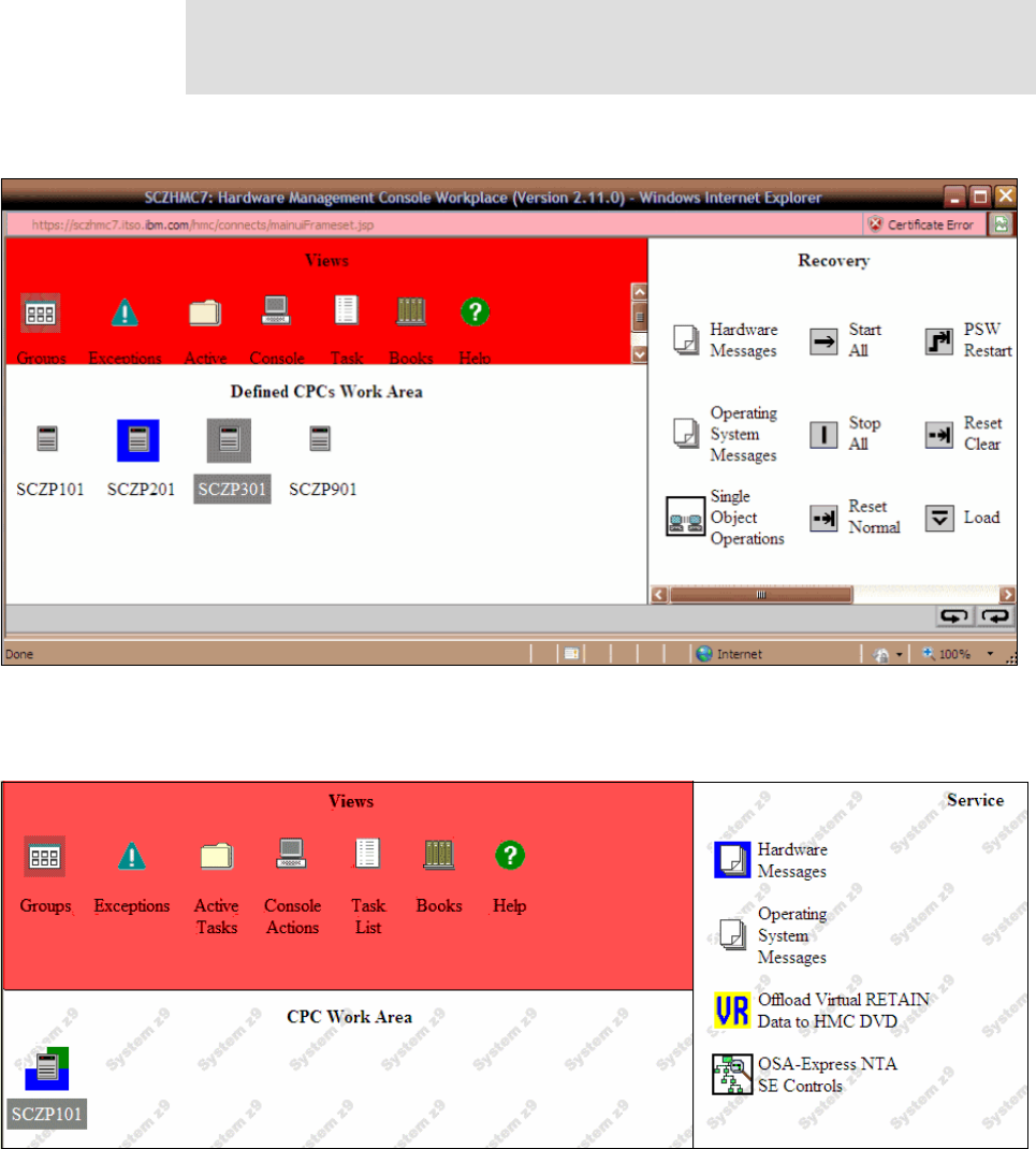
386 IBM z/OS V2R2 Communications Server TCP/IP Implementation Volume 1
To accomplish this customization, change the current OSA-Express NTA control by using the
HMC as follows:
1. Log on to the SE on the HMC through Single Object Operations (SOO).
2. Select the CPC that you want to work with, as shown in Figure 9-8.
Figure 9-8 From the HMC log on to SE
3. Select and open the Service task list, as shown in Figure 9-9.
Figure 9-9 OSA-Express NTA
Important: Enabling OSA-Express NTA support can allow tracing of sensitive
information. Therefore, the user ID that is used to do the following steps must have the
“Access Administrator Tasks” role assigned.

Chapter 9. Diagnosis 387
4. Double-click the OSA-Express NTA SE Controls task, as shown in Figure 9-10.
Figure 9-10 OSA NTA Controls
5. Select the control to work with:
– Customize OSA-Express Network Traffic Analyzer Settings: Provides the capability
to allow or disallow the SE to change authorization to allow host operating systems to
enable the NTA to trace outside their own partition.
– Check current OSA-Express Network Traffic Analyzer authorization: Allows the
SE to scan all the OSAs and reports back which OSAs are authorized for NTA to trace
outside its own partition.
6. Click OK to change the current OSA-Express NTA control, as shown in Figure 9-11.
Figure 9-11 Change the current OSA-Express NTA control
7. Click Allow the Support Element to allow Host Operating System to enable NTA.

388 IBM z/OS V2R2 Communications Server TCP/IP Implementation Volume 1
8. Click OK, as shown in Figure 9-12.
Figure 9-12 Command completed
9. Log off from the SE and from the HMC.
10.Log on to the SE on the HMC through SOO by using the SYSPROG user ID.
11.Select Channels work area (on the left side of the window) and then select Channel
Operation (on the right side of the window).

Chapter 9. Diagnosis 389
12.Select the channel that you want to manage; see Figure 9-13.
Figure 9-13 Channel Operations menu
13.In our case, we select PCHID 0390 (CHPID 02), and then double-click Advanced
Facilities. See Figure 9-14.
Figure 9-14 Advanced Facilities options

390 IBM z/OS V2R2 Communications Server TCP/IP Implementation Volume 1
14.Select Card trace/log/dump facilities, and then click OK. See Figure 9-15.
Figure 9-15 Card Trace/Log/Dump Facilities
15.Select OSA-Express Host Network Traffic Analyzer Authorization, and then click OK.
See Figure 9-16.
Figure 9-16 NTA Authorization

Chapter 9. Diagnosis 391
16.If your CHPID is shared between several LPARs, take the second option that is shown in
Figure 9-16 on page 390, and then click OK. Figure 9-17 shows the results.
Figure 9-17 Command completed
17.Verify whether the command is set as required:
a. Log off the SYSPROG user ID.
b. Log on to the SE on the HMC through SOO. See Figure 9-8 on page 386.
c. Select Check current OSA-Express Network Traffic Analyzer Authorization, as
shown in Figure 9-10 on page 387.
d. Click OK. See Figure 9-18.
Figure 9-18 OSA-Express NTA controls
Figure 9-19 shows that PCHID 0390 is allowed to be traced.
Figure 9-19 Physical channel identifier NTA Authorization
Important: For checking the authorization of OSA-Express NTA support, the user
ID must have the Access Administrator Tasks role assigned.

392 IBM z/OS V2R2 Communications Server TCP/IP Implementation Volume 1
9.6.5 Defining a resource profile in RACF
Example 9-27 shows the RACF commands that are needed to allow users to issue the VARY
TCPIP command.
Example 9-27 RACF commands
RDEFINE OPERCMDS MVS.VARY.TCPIP.OSAENTA UACC(NONE) PERMIT MVS.VARY.TCPIP.OSAENTA
ACCESS(CONTROL) CLASS(OPERCMDS) ID(CS03) SETR GENERIC(OPERCMDS) REFRESH SETR
RACLIST(OPERCMDS) REFRESH
9.6.6 Allocating a VSAM linear data set
Example 9-28 shows how to create the VSAM linear data set. This VSAM linear data set is
optional; however, its use is a preferred practice.
Example 9-28 Allocate VSAM linear data set
//DEFINE EXEC PGM=IDCAMS
//SYSPRINT DD SYSOUT=*
//SYSIN DD *
DELETE +
(CS03.CTRACE.LINEAR) +
CLUSTER
DEFINE CLUSTER( +
NAME(CS03.CTRACE.LINEAR) +
LINEAR +
MEGABYTES(10) +
VOLUME(CPDLB0) +
CONTROLINTERVALSIZE(32768) +
) +
DATA( +
NAME(CS03.CTRACE.DATA) +
)
LISTCAT ENT(USER41.CTRACE.LINEAR)
ALL
9.6.7 Starting the OSA-Express Network Traffic Analyzer trace
The OSAENTA statement dynamically defines a QDIO interface to the OSA-Express being
traced; it is called an OSAENTA interface. That interface is used exclusively for capturing
OSAENTA traces.
The OSAENTA statement enables an installation to trace data from other hosts that are
connected to OSA-Express.
To see the complete syntax of the OSAENTA command, see z/OS Communications Server: IP
Configuration Reference, SC27-3651.
Important: The trace data that is collected should be considered confidential and TCP/IP
system dumps and external trace files containing this trace data should be protected.

Chapter 9. Diagnosis 393
Components that are involved with z/OS CTRACE
The CTRACE component for collecting NTA trace data is called SYSTCPOT. The member in
SYS1.PARMLIB is named CTINTA00. This member is used to define the size of the buffer
space in 64-bit common storage that is reserved for OSAENTA CTRACE. The size can be
16 - 624 MB, with a default of 32 MB.
Using the OSAENTA command
An internal interface is created when PORTNAME is defined on the OSAENTA statement. The
dynamically defined interface name is EZANTA concatenated with the port name. These
EZANTA interfaces are displayed at the end of the NETSTAT DEV output.
When the ON keyword of the OSAENTA parameter is used, VTAM allocates the next available
TRLE data path that is associated with the port. This data path is used only for inbound trace
data.
When the OFF keyword of the OSAENTA parameter is used (or the trace limits of the TIME, DATA,
or FRAMES keywords are reached), the data path is released.
Setting the OSAENTA traces
You can set the OSAENTA trace in two ways: by coding the OSAENTA statement in the profile
TCP/IP or by issuing a command in z/OS. These methods are explained in this section.
To code the OSAENTA statement in the profile TCP/IP, see Example 9-29.
Example 9-29 TCP/IP profile
; set up the filters to trace for TCP packets on PORT 2323 with a source
;or destination
; IP address of 10.1.2.11 over MAC address 00096B1A7490
OSAENTA PORTNAME=OSA2080 PROT=TCP IP=10.1.2.11 PORTNUM=2323
OSAENTA PORTNAME=OSA2080 MAC=00096B1A7490
; activate the tracing (the trace will self-deactivate after 20,000 frames)
OSAENTA PORTNAME=OSA2080 ON FRAMES=20000
; deactivate the tracing
OSAENTA OFF PORTNAME=OSA2080
In this case, OSAENTA traces the port name OSA2080 only for traffic matching the
following filters:
– Protocol = UDP
– IP address = 10.1.2.11
– Port number = 2323
The following filters are available to define the packets to be captured:
– MAC address
–VLAN ID
– Ethernet frame type
– IP address (or range)
– IP protocol
Note: Update CTINTA00 to set the CTRACE buffer size. This setting uses up auxiliary
page space storage.

394 IBM z/OS V2R2 Communications Server TCP/IP Implementation Volume 1
–Device ID
– TCP/UDP
Issue the following command in z/OS:
V TCPIP,TCPIPA,OSAENTA,ON,PORTNAME=OSA2080,IP=10.1.2.11,PORTNUM=2323
The messages that you receive in response to this command are shown in Figure 9-20.
Figure 9-20 OSAENTA results
The NETSTAT DEVLINKS command is enhanced to show the OSAENTA definition
(Example 9-30).
Example 9-30 NETSTAT DEVLINKS command output
OSA-EXPRESS NETWORK TRAFFIC ANALYZER INFORMATION:
OSA PORTNAME: OSA2080 OSA DEVSTATUS: READY
OSA INTFNAME: EZANTAOSA2080 OSA INTFSTATUS: READY
OSA SPEED: 1000 OSA AUTHORIZATION: CHPID
OSAENTA CUMULATIVE TRACE STATISTICS:
DATAMEGS: 0 FRAMES: 0
DATABYTES: 0 FRAMESDISCARDED: 0
FRAMESLOST: 0
OSAENTA ACTIVE TRACE STATISTICS:
DATAMEGS: 0 FRAMES: 0
DATABYTES: 0 FRAMESDISCARDED: 0
FRAMESLOST: 0 TIMEACTIVE: 0
OSAENTA TRACE SETTINGS: STATUS: ON
DATAMEGSLIMIT: 1024 FRAMESLIMIT: 2147483647
ABBREV: 224 TIMELIMIT: 10080
DISCARD: EXCEPTION
OSAENTA TRACE FILTERS: NOFILTER: NONE
DEVICEID: *
MAC: *
VLANID: *
ETHTYPE: *
Note: Use filters to limit the trace records to prevent overconsumption of the OSA CPU
resources, the LPAR CPU resources, 64-bit common storage, memory, auxiliary page
space, and the IO subsystem writing trace data to disk.
Important: If you receive ERROR CODE 0003, it means that an attempt was made to
enable OSAENTA tracing for a specified OSA, but the current authorization level does
not permit it.
For directions about how to change the authorization to allow OSAENTA to be used on
this specified OSA, see 9.6.4, “Customizing OSA-Express Network Traffic Analyzer” on
page 385. For more information about this topic, see Support Element Operations
Guide, SC28-6860.
RESPONSE=SC30 EZZ0060I PROCESSING COMMAND: VARY TCPIP,TCPIPA,OSAENTA,ON,
RESPONSE=PORTNAME=OSA2080,IP=10.1.2.11,PORTNUM=2323
RESPONSE=SC30 EZZ0053I COMMAND VARY OSAENTA COMPLETED SUCCESSFULLY

Chapter 9. Diagnosis 395
IPADDR: 10.1.2.11/32
PROTOCOL: * TCP
PORTNUM: * 2323
The NETSTAT display for devices shows the NTA interfaces. The interface name prefixed
the OSA port name with EZANTA.
To display a specific NTA interface, use the INTFName=EZANTAosaportname keyword.
Traces are placed in an internal buffer, which can then be written out by using a CTRACE
external writer. The MVS TRACE command must also be issued for component SYSTCPOT
to activate the OSAENTA trace.
When the trace is started from OSA/SF, you can see that another device is allocated for
trace (Example 9-31).
Example 9-31 OAT with OSAENTA started
Image 2.3 (A16 ) CULA 0
00(2080)* MPC N/A OSA2080P (QDIO control) SIU ALL
02(2082) MPC 00 No4 No6 OSA2080P (QDIO data) SIU ALL
VLAN 10 (IPv4)
Group Address Multicast Address
01005E000001 224.000.000.001
VMAC IP address
HOME 00096B1A7490 010.001.000.010
HOME 00096B1A7490 010.001.001.010
HOME 00096B1A7490 010.001.002.010
HOME 00096B1A7490 010.001.002.011
REG 00096B1A7490 010.001.002.012
REG 00096B1A7490 010.001.003.011
REG 00096B1A7490 010.001.003.012
REG 00096B1A7490 010.001.004.011
REG 00096B1A7490 010.001.005.011
REG 00096B1A7490 010.001.006.011
REG 00096B1A7490 010.001.007.011
REG 00096B1A7490 010.001.008.010
REG 00096B1A7490 010.001.008.020
03(2083) MPC 00 No4 No6 OSA2080P (QDIO data) SIU ALL
Important: If you receive ERROR CODE 0005, it means that an attempt was made to
enable OSAENTA tracing for a specified OSA that already has either OSAENTA or OSA
LAN Analyzer tracing enabled elsewhere on the system for this OSA.
Only one instance of active tracing (either OSAENTA or LAN Analyzer) for a specified
OSA is permitted on the system at any one time.

396 IBM z/OS V2R2 Communications Server TCP/IP Implementation Volume 1
You can also use the D NET,TRL,TRLE=OSA2080 command, as shown in Example 9-32.
Example 9-32 Output Display TRLE
TRL MAJOR NODE = OSA2080
STATUS= ACTIV, DESIRED STATE= ACTIV
TYPE = LEASED , CONTROL = MPC , HPDT = YES
MPCLEVEL = QDIO MPCUSAGE = SHARE
PORTNAME = OSA2080 LINKNUM = 0 OSA CODE LEVEL = 087A
HEADER SIZE = 4096 DATA SIZE = 0 STORAGE = ***NA***
WRITE DEV = 2081 STATUS = ACTIVE STATE = ONLINE
HEADER SIZE = 4092 DATA SIZE = 0 STORAGE = ***NA***
READ DEV = 2080 STATUS = ACTIVE STATE = ONLINE
DATA DEV = 2082 STATUS = ACTIVE STATE = N/A
I/O TRACE = OFF TRACE LENGTH = *NA*
ULPID = TCPIPA
IQDIO ROUTING DISABLED
READ STORAGE = 4.0M(64 SBALS)
PRIORITY1: UNCONGESTED PRIORITY2: UNCONGESTED
PRIORITY3: UNCONGESTED PRIORITY4: UNCONGESTED
DEVICEID PARAMETER FOR OSAENTA TRACE COMMAND = 02-03-00-02
UNITS OF WORK FOR NCB AT ADDRESS X'0F4E7010'
P1 CURRENT = 0 AVERAGE = 0 MAXIMUM = 0
P2 CURRENT = 0 AVERAGE = 0 MAXIMUM = 0
P3 CURRENT = 0 AVERAGE = 0 MAXIMUM = 0
P4 CURRENT = 0 AVERAGE = 2 MAXIMUM = 3
TRACE DEV = 2083 STATUS = ACTIVE STATE = N/A
Starting the CTRACE
To print the internal trace data, start CTRACE by using the following steps:
1. Start the external writer (CTRACE writer):
TRACE CT,WTRSTART=CTWTR
2. Start the CTRACE and connect to the external writer:
TRACE CT,ON,COMP=SYSTCPOT,SUB=(TCPIPA)
R xx,WTR=CTWTR,END
3. Display the active component trace options by using the following command:
DISPLAY TRACE,COMP=SYSTCPOT,SUB=(TCPIPA)
Example 9-33 shows the output of this command.
Example 9-33 Display Trace output
RESPONSE=SC30
IEE843I 16.45.15 TRACE DISPLAY 165
SYSTEM STATUS INFORMATION
ST=(ON,0001M,00004M) AS=ON BR=OFF EX=ON MO=OFF MT=(ON,024K)
TRACENAME
=========
SYSTCPOT
MODE BUFFER HEAD SUBS
=====================
OFF HEAD 2
NO HEAD OPTIONS
SUBTRACE MODE BUFFER HEAD SUBS

Chapter 9. Diagnosis 397
--------------------------------------------------------------
TCPIPA ON 0128M
ASIDS *NONE*
JOBNAMES *NONE*
OPTIONS MINIMUM
WRITER CTWTR
To display information about the status of the component trace for all active stack
procedures in a CINET environment, issue the following command:
DISPLAY TRACE,COMP=SYSTCPOT,SUBLEVEL,N=8
Example 9-34 displays the output.
Example 9-34 Status of Component Trace
IEE843I 10.35.04 TRACE DISPLAY 821
SYSTEM STATUS INFORMATION
ST=(ON,0001M,00004M) AS=ON BR=OFF EX=ON MO=OFF MT=(ON,024K)
TRACENAME
=========
SYSTCPOT
MODE BUFFER HEAD SUBS
=====================
OFF HEAD 2
NO HEAD OPTIONS
SUBTRACE MODE BUFFER HEAD SUBS
--------------------------------------------------------------
TCPIPA ON 0128M
ASIDS *NONE*
JOBNAMES *NONE*
OPTIONS MINIMUM
WRITER CTWTR
--------------------------------------------------------------
TCPIP MIN 0016M
ASIDS *NONE*
JOBNAMES *NONE*
OPTIONS MINIMUM
WRITER *NONE*
4. Reproduce the problem.
5. Disconnect the external writer:
TRACE CT,ON,COMP=SYSTCPOT,SUB=(TCPIPA)
R xx,WTR=DISCONNECT,END
6. Stop the component trace:
TRACE CT,OFF,COMP=SYSTCPOT,SUB=(TCPIPA)
7. Stop the external writer:
TRACE CT,WTRSTOP=CTWTR
Analyzing the trace
You can format the CTRACE by using two methods:
Using IPCS to format CTRACE
Using a batch job to format CTRACE

398 IBM z/OS V2R2 Communications Server TCP/IP Implementation Volume 1
Using IPCS to format CTRACE
You can format component trace records by using IPCS panels or a combination of IPCS
panels and the CTRACE command, either from a dump or from external writer files.
From the IPCS PRIMARY OPTION MENU, select 0 DEFAULTS - Specify default dump and
options. See Example 9-35.
Example 9-35 IPCS default value
------------------------- IPCS Default Values ---------------------------------
Command ===>
You may change any of the defaults listed below. The defaults shown before
any changes are LOCAL. Change scope to GLOBAL to display global defaults.
Scope ==> LOCAL (LOCAL, GLOBAL, or BOTH)
If you change the Source default, IPCS will display the current default
Address Space for the new source and will ignore any data entered in
the Address Space field.
Source ==> DSNAME('SYS1.SC30.CTRACE')
Address Space ==>
Message Routing ==> NOPRINT TERMINAL
Message Control ==> CONFIRM VERIFY FLAG(WARNING)
Display Content ==> NOMACHINE REMARK REQUEST NOSTORAGE SYMBOL
Modify the DSNAME and OPTIONS to match your environment, and then select the following
options:
2 ANALYSIS - Analyze dump contents
7 TRACES - Trace formatting
1 CTRACE - Component trace
D DISPLAY - Specify parameters to display CTRACE entries
Fill in the parameters that are necessary to format the OSAENTA trace. See Example 9-36.
Example 9-36 CTRACE parameters
-------------------- CTRACE DISPLAY PARAMETERS ------------------------
COMMAND ===>
System ===> (System name or blank)
Component ===> SYSTCPOT (Component name (required))
Subnames ===> TCPIPA
GMT/LOCAL ===> G (G or L, GMT is default)
Start time ===> (mm/dd/yy,hh:mm:ss.dddddd or
Stop time ===> mm/dd/yy,hh.mm.ss.dddddd)
Limit ===> 0 Exception ===>
Report type ===> SHORT (SHort, SUmmary, Full, Tally)
User exit ===> (Exit program name)
Override source ===>
Options ===>
To enter/verify required values, type any character
Entry IDs ===> Jobnames ===> ASIDs ===> OPTIONS ===> SUBS ===>

Chapter 9. Diagnosis 399
CTRACE COMP(SYSTCPOT) SUB((TCPIPA)) SHORT
ENTER = update CTRACE definition. END/PF3 = return to previous panel.
S = start CTRACE. R = reset all fields.
On the command line, enter the S command. Example 9-37 shows the trace that is formatted
by IPCS.
Example 9-37 TRACE format
COMPONENT TRACE SHORT FORMAT
SYSNAME(SC30)
COMP(SYSTCPOT)SUBNAME((TCPIPA))
z/OS TCP/IP Packet Trace Formatter, (C) IBM 2000-2006, 2007.052
DSNAME('SYS1.SC30.CTRACE')
**** 2007/09/11
RcdNr Sysname Mnemonic Entry Id Time Stamp Description
----- -------- -------- -------- --------------- -----------------------------
------------------------------------------------------------------------------
365 SC30 OSAENTA 00000007 15:01:23.356987 OSA-Express NTA
To Interface : EZANTAOSA2080 Full=86
Tod Clock : 2010/09/24 14:20:25.931533
Sequence # : 0 Flags: Pkt Out Nta Vlan Lpar L3
Source : 10.1.2.11
Destination : 224.0.0.5
Source Port : 0 Dest Port: 0 Asid: 0000 TCB: 0000000
Frame: Device ID : 02030002 Sequence Nr: 372 Discard: 0 (OK)
EtherNet II : 8100 IEEE 802.1 Vlan Len: 0x0044 (68
Destination Mac : 01005E-000005 ()
Source Mac : 00096B-1A7490 (IBM)
Vlan_id : 10 Priority: 0 Type: 0800 (Int
IpHeader: Version : 4 Header Length: 20
Tos : 00 QOS: Routine Normal Service
Packet Length : 68 ID Number: 0AFD
Fragment : Offset: 0
TTL : 1 Protocol: OSPFIGP CheckSum: C253
Source : 10.1.2.11
Destination : 224.0.0.5
------------------------------------------------------------------------------
366 SC30 OSAENTA 00000007 15:01:33.360143 OSA-Express NTA
To Interface : EZANTAOSA2080 Full=86
Tod Clock : 2010/09/24 14:20:35.933003
Sequence # : 0 Flags: Pkt Out Nta Vlan Lpar L3
Source : 10.1.2.11
Destination : 224.0.0.5
Source Port : 0 Dest Port: 0 Asid: 0000 TCB: 0000000
Frame: Device ID : 02030002 Sequence Nr: 373 Discard: 0 (OK)
EtherNet II : 8100 IEEE 802.1 Vlan Len: 0x0044 (68
Destination Mac : 01005E-000005 ()
Source Mac : 00096B-1A7490 (IBM)
Vlan_id : 10 Priority: 0 Type: 0800 (Int
IpHeader: Version : 4 Header Length: 20
Tos : 00 QOS: Routine Normal Service

400 IBM z/OS V2R2 Communications Server TCP/IP Implementation Volume 1
Packet Length : 68 ID Number: 0B07
Fragment : Offset: 0
TTL : 1 Protocol: OSPFIGP CheckSum: C249
Source : 10.1.2.11
Destination : 224.0.0.5
------------------------------------------------------------------------------
Using a batch job to format CTRACE
In our example, we use a batch job to generate the TRACE file, as shown in Example 9-38.
Example 9-38 CTRACE batch job format
//PKT2SNIF JOB (999,POK),'CS03',NOTIFY=&SYSUID,
// CLASS=A,MSGCLASS=T,TIME=1439,
// REGION=0M,MSGLEVEL=(1,1)
// SET INDUMP='SYS1.SC30.CTRACE'
//IPCSBTCH EXEC PGM=IKJEFT01,DYNAMNBR=30
//IPCSDDIR DD DISP=SHR,DSN=SYS1.DDIR
//IPCSDUMP DD *
//SYSTSPRT DD SYSOUT=*
//SYSPRINT DD SYSOUT=*
//INDMP DD DISP=SHR,DSN=&INDUMP.
//IPCSPRNT DD DSN=ENTA.CTRACE.SHORT,UNIT=SYSDA,
// DISP=(NEW,CATLG),LRECL=133,SPACE=(CYL,(10,1)),RECFM=VBS,DSORG=PS
//IPCSTOC DD SYSOUT=*
//SYSUDUMP DD SYSOUT=*
//SYSTSIN DD *
PROFILE MSGID
IPCS NOPARM
SETD PRINT NOTERM LENGTH(160000) NOCONFIRM FILE(INDMP)
DROPD
CTRACE COMP(SYSTCPOT) SUB((TCPIPA)) SHORT
END
The output from the batch job is shown in Example 9-39.
Example 9-39 Output from the batch job
COMPONENT TRACE SHORT FORMAT
SYSNAME(SC30)
COMP(SYSTCPOT)SUBNAME((TCPIPA))
z/OS TCP/IP Packet Trace Formatter, (C) IBM 2000-2006, 2007.052
FILE(INDMP)
**** 2007/09/11
RcdNr Sysname Mnemonic Entry Id Time Stamp Description
----- -------- -------- -------- --------------- -------------------------------
-------------------------------------------------------------------------------
365 SC30 OSAENTA 00000007 15:01:23.356987 OSA-Express NTA
To Interface : EZANTAOSA2080 Full=86
Tod Clock : 2010/09/24 14:20:25.931533
Sequence # : 0 Flags: Pkt Out Nta Vlan Lpar L3
Source : 10.1.2.11
Destination : 224.0.0.5
Source Port : 0 Dest Port: 0 Asid: 0000 TCB: 00000000
Frame: Device ID : 02030002 Sequence Nr: 372 Discard: 0 (OK)
EtherNet II : 8100 IEEE 802.1 Vlan Len: 0x0044 (68)

Chapter 9. Diagnosis 401
Destination Mac : 01005E-000005 ()
Source Mac : 00096B-1A7490 (IBM)
Vlan_id : 10 Priority: 0 Type: 0800 (Inter
IpHeader: Version : 4 Header Length: 20
Tos : 00 QOS: Routine Normal Service
Packet Length : 68 ID Number: 0AFD
Fragment : Offset: 0
TTL : 1 Protocol: OSPFIGP CheckSum: C253 FF
Source : 10.1.2.11
Destination : 224.0.0.5
-------------------------------------------------------------------------------
366 SC30 OSAENTA 00000007 15:01:33.360143 OSA-Express NTA
To Interface : EZANTAOSA2080 Full=86
Tod Clock : 2010/09/24 14:20:35.933003
Sequence # : 0 Flags: Pkt Out Nta Vlan Lpar L3
Source : 10.1.2.11
Destination : 224.0.0.5
Source Port : 0 Dest Port: 0 Asid: 0000 TCB: 00000000
Frame: Device ID : 02030002 Sequence Nr: 373 Discard: 0 (OK)
EtherNet II : 8100 IEEE 802.1 Vlan Len: 0x0044 (68)
Destination Mac : 01005E-000005 ()
Source Mac : 00096B-1A7490 (IBM)
Vlan_id : 10 Priority: 0 Type: 0800 (Inter
IpHeader: Version : 4 Header Length: 20
Tos : 00 QOS: Routine Normal Service
Packet Length : 68 ID Number: 0B07
Fragment : Offset: 0
TTL : 1 Protocol: OSPFIGP CheckSum: C249 FF
Source : 10.1.2.11
Destination : 224.0.0.5
-------------------------------------------------------------------------------
9.6.8 Operator command to query and display OSA information
Communications Server provides the DISPLAY TCPIP,,OSAINFO command, which you can use
to retrieve information about an interface from an OSA-Express feature that is in QDIO mode.
This command is an alternative to using OSA/SF, which lacks information about many of the
latest enhancements to the OSA-Express feature and to z/OS Communications Server.

402 IBM z/OS V2R2 Communications Server TCP/IP Implementation Volume 1
Figure 9-21, shows the scope of the Display OSAINFO,INTFN command. In our example, it is
Interface3.
Figure 9-21 Scope of OSAINFO command
Example 9-40 shows the output of the following command:
D TCPIP,TCPIPA,OSAINFO,INTFNAME=OSA2080I,MAX=200
Example 9-40 Output of the OSAINFO command
Display OSAINFO results for IntfName: OSA2080I
PortName: OSA2080 PortNum: 00 Datapath: 2082 RealAddr: 0002
PCHID: 0530 CHPID: 02 CHPID Type: OSD OSA code level: 0010
Gen: OSA-E3 Active speed/mode: 1000 mb/sec full duplex
Media: Copper Jumbo frames: Yes Isolate: No
PhysicalMACAddr: 00145E776872 LocallyCfgMACAddr: 000000000000
Queues defined Out: 4 In: 1 Ancillary queues in use: 0
Connection Mode: Layer 3 IPv4: Yes IPv6: No
SAPSup: 000FF603 SAPEna: 00082603
IPv4 attributes:
VLAN ID: 10 VMAC Active: Yes
VMAC Addr: 020060776873 VMAC Origin: OSA VMAC Router: Local
AsstParmsEna: 00310C57 OutCkSumEna: 0000001A InCkSumEna: 0000001A
Registered Addresses:
IPv4 Unicast Addresses:
ARP: No Addr: 10.1.1.10
ARP: Yes Addr: 10.1.2.10
ARP: Yes Addr: 10.1.2.11
ARP: No Addr: 10.1.2.12
ARP: No Addr: 10.1.2.14
zSeries CEC-1
LPAR-2
TCP/IP
Stack-3
LPAR-1
TCP/IP
Stack-2
TCP/IP
Stack-1
Interface4
PCI-X
OSA
Interface3
VLAN-3
Interface2
VLAN-2
Interface1

Chapter 9. Diagnosis 403
ARP: No Addr: 10.1.3.11
ARP: No Addr: 10.1.3.12
ARP: No Addr: 10.1.4.11
ARP: No Addr: 10.1.5.11
ARP: No Addr: 10.1.6.11
ARP: No Addr: 10.1.7.11
ARP: No Addr: 10.1.8.10
ARP: No Addr: 10.1.8.20
ARP: No Addr: 10.1.9.11
Total number of IPv4 addresses: 14
IPv4 Multicast Addresses:
MAC: 01005E000001 Addr: 224.0.0.1
Total number of IPv4 addresses: 1
36 of 36 lines displayed
End of report
If you have multiple interfaces in the same stack, you must issue this command for each
interface.
9.6.9 OSM and OSX information
OSA/SF cannot manage OSM and OSX CHPIDs. The D TCPIP,,OSAINFO command can be
used to get information about those CHPID types.
Displaying the CHPID type
In our example, we use the z/OS command D M=CHP to see how the system shows these
CHPIDs. Example 9-41 shows the output.
In the IOCDS, CHPIDs 0A and 0B are OSM; 18 and 19 are OSX.
Example 9-41 Output of z/OS command “D M=CHP”
CHANNEL PATH STATUS
0 1 2 3 4 5 6 7 8 9 A B C D E F
0 + + + + + + + + + + + + + + + +
1 + + + + . . . . + + - - . . . .
CHANNEL PATH TYPE STATUS
0 1 2 3 4 5 6 7 8 9 A B C D E F
0 11 14 11 11 11 11 11 11 11 11 31 31 11 14 11 11
1 11 11 11 11 00 00 00 00 30 30 11 11 00 00 00 00
30 OSA ZBX DATA OSX
31 OSA ZBX MANAGEMENT OSM
In our case, the CHPIDs are online and operating.
Example 9-42 shows the output of D U,,,2340,15 (OSM CHPID).
Example 9-42 Output of Display Unit command for OSM CHPID
D U,,,2340,15
IEE457I 16.22.42
UNIT TYPE STATUS
2340 OSAM O-RAL

404 IBM z/OS V2R2 Communications Server TCP/IP Implementation Volume 1
2341 OSAM O-RAL
2342 OSAM O-RAL
2343 OSAM O-RAL
2344 OSAM O-RAL
2345 OSAM O-RAL
2346 OSAM O-RAL
2347 OSAM O-RAL
2348 OSAM O-RAL
2349 OSAM O-RAL
234A OSAM O-RAL
234B OSAM O-RAL
234C OSAM O-RAL
234D OSAM O-RAL
234E OSAM O-RAL
Example 9-43 shows the output of D U,,,2300,15 (OSX CHPID).
Example 9-43 Output of Display Unit command for OSX CHPID
D U,,,2300,15
IEE457I 16.23.10
UNIT TYPE STATUS
2300 OSAX O
2301 OSAX O
2302 OSAX O
2303 OSAX O
2304 OSAX O
2305 OSAX O
2306 OSAX O
2307 OSAX O
2308 OSAX O
2309 OSAX O
230A OSAX O
230B OSAX O
230C OSAX O
230D OSAX O
230E OSAX O
The devices are online and allocated.
Note: You can use the OSAENTA trace facility to debug any problem with OSX and OSM
CHPID types.
When you use NTA, you must have a data path that is available for each NTA that you start.
An OSM CHPID type supports nine data paths; an OSX CHPID type supports 17 data
paths. For more information, see Chapter 10, “IBM z/OS in an ensemble” on page 419.

Chapter 9. Diagnosis 405
9.7 Additional tools for diagnosing Communications Server for
z/OS IP problems
IBM and other vendors developed tools to assist in diagnosing problems in the network
from the perspective of z/OS. The tools often run as GUIs on a workstation, but retrieve
their problem diagnosis information by using data from SNMP, SMF, and from MVS control
blocks. Some of these tools also interface with the NMI API, which is provided by IBM.
9.7.1 Network Management Interface API
Figure 9-22 depicts a high-level view of the NMI and its interfaces to network management
products.
Figure 9-22 Network Management Interface Architecture
The NMI API can interface with IBM Tivoli® OMEGAMON® XE for Mainframe Networks (or
other products) to provide the following types of functions:
Trace assistance: Real-time tracing and formatting for packet and data traces (including
OSA trace)
Information gathering:
– TCP connection initiation and termination notifications
– API for real-time access to TN3270 server and FTP event data and to IPSec
– APIs to poll information about currently active connections
– TCP listeners (server processes)
– TCP connections (detailed information about individual connections and UDP
endpoints)
– Communications Server storage usage
– API to receive and poll for Enterprise Extender management data
CS z/OS and
components
Remote monitor
Local monitor
Private
protocol
APIs
Commands/Utilities
Exit points
SNMP
SMF and Syslogd
Exit
point
I
n
s
t
r
u
m
e
n
t
a
t
i
o
n
Presentation
IBM Tivoli Software
or other Network
Management vendor
SNMP
z/OS
406 IBM z/OS V2R2 Communications Server TCP/IP Implementation Volume 1
– Information and statistics for IP filtering and IPSec security associations on the local
TCP/IP stacks
– Information and statistics for IP filtering and IPSec security associations on remote
NSS clients when using the NSS server
Control activities
Control the activation and inactivation of IPSec tunnels
Loading policies for IP filtering and IPSec security associations on local TCP/IP stacks:
– Loading policies for IP filtering and IPSec security associations on remote NSS clients
when using the NSS server
– Drop one or multiple TCP connections or UDP endpoints
TCP/IP callable NMI (EZBNMIFR)
z/OS Communications Server provides a high-speed, low-impact callable NMI interface for
the following TCP/IP stack information:
Network interface information
Monitoring TCP or UDP endpoints
Monitoring TCP/IP storage
Dropping one or more TCP connections
Dropping one or more UDP endpoints
Monitoring TCP/IP sysplex networking data
Monitoring TCP/IP stack profile statement settings
Monitoring network interface and TCP/IP stack global statistics
Network Management Interface for retrieving system resolver
configuration information
A resolver callable NMI (EZBREIFR) is available to provide a fast interface for network
applications to access resolver configuration data. A single request that is called
GetResolverConfig is supported.
The resolver callable NMI is modeled after the TCP/IP callable NMI. You can use the same
triplet and quadruplet structures to identify the offset, length, and number of various types of
information about requests and responses. The calling application, which must be authorized,
provides an output buffer area to hold the NMI response data.
The resolver NMI provides the current resolver setup statement and global TCPIP.DATA
statement values. The resolver indicates in the NMI output whether the configuration
statements were explicitly defined or were defaulted. The resolver also includes the source
file names of the z/OS of file system files from which the configuration data was retrieved.
z/OS Communications Server provides both assembler (EZBRENMA) and C (EZBRENMC)
data mappings for the resolver NMI data. z/OS Communications Server: IP Programmer’s
Guide and Reference, SC31-8787 includes descriptions of the data fields that are returned by
the GetResolverConfig request and the possible return and reason codes that are returned
when the request fails.
9.7.2 Systems Management Facilities accounting records
Another technique that is often used to verify the state of the z/OS Communications Server -
TCP/IP component in a stack or even in a sysplex environment is to list and analyze the
Systems Management Facilities (SMF) records.

Chapter 9. Diagnosis 407
In general, SMF records are created for deferred processing and analysis. SMF recording is
generally not used for real-time monitoring purposes. In a TCP/IP environment, real-time
monitoring is implemented by using the NMI API and SNMP protocol, but on z/OS much of
the information that is written in SMF records is useful from a real-time monitoring
perspective.
The objective of the TCP/IP product is to define and generate the lowest level of detail that
is needed by all disciplines. A customer must use other products such as IBM RMF™,
Performance Reporter for z/OS (PR), MVS Information Control System (MICS), or
SAS-based tools. In many cases, there are customer-written programs to generate the
reports to collect and analyze the SMF Records that are created by TCP/IP.
The contents of SMF records can be used to generate reports in customized formats that help
customers to perform tasks such as the following ones:
Performance management
Customized reports can be generated to verify whether the defined service levels are met
and, if not, to identify possible causes. These reports are usually a set of time intervals
ranging from weeks through days matching the SMF interval. Examples of potential
reports that are related to performance management are as follows:
– TCP connection elapsed time per server port number per time of day (potentially
broken down by source IP address or netmask)
– Number of TCP connections per server port number per time of day (potentially broken
down by source IP address or netmask)
– Number of inbound/outbound bytes transferred in TCP connections per time of day
(potentially broken down in various ways: by destination or source port, by destination
IP address, netmask, or in total)
– Events that are related to dynamic VIPA environment, such as the following events:
• Status changes
• DVIPA removed or added
• Changes on the target server (stop/start)
Capacity planning
Capacity planning can be done by using the SMF records to generate reports showing
trends for resource utilization of central processing power, memory, channel-based I/O
subsystem, network attachments, and network bandwidth, over a period. These trends
can help with planned launches of new applications or use of existing applications to
predict capacity needs in the future. Some examples of potential reports that are related to
capacity planning are:
– Total number of TCP connections per reserved server port number per day including
analysis of average and variations around average during daily peak periods
– Total number of UDP inbound/outbound UDP datagrams per reserved server port
number per day including average and variations around average during daily peak
periods
– Number of bytes or packets transferred inbound and outbound per interface (LINK) per
time of day (potentially broken down into unicasts, broadcasts, and multicasts)
Note: SMF records that are produced by TCP/IP should not be viewed in isolation. Other
components in MVS produce SMF records for the same purposes as those produced by
TCP/IP. An installation is likely to combine information from a series of subsystems when
performing detailed performance or capacity planning.
408 IBM z/OS V2R2 Communications Server TCP/IP Implementation Volume 1
Auditing
Auditing involves tasks that are related to identifying and proving that individual events
have taken place. Some examples of potential reports that are related to auditing are:
– Detailed information about specific TCP connections or UDP sockets, IP addresses,
server/client identification, duration, number of bytes, and so on
– Details about activity that involves a specific client or server
– Details about a given application session based on server-specific SMF recording,
such as individual Telnet sessions or FTP sessions
– An SMF 119 record for recording TCP/IP configuration updates
– Changes on the dynamic VIPA environment
Accounting
Accounting involves tasks that are related to calculating how much each individual user or
organizational unit should be charged for use of the shared central IS resources. Input for
these reports can be based on CPU cycle use, data quantities, bandwidth usage, and
memory use. For TCP/IP, additional metrics can be defined, such as type of service (FTP,
web server, TN3270, and so on), and TCP connection-related information (number of
connections, duration, byte transfer counts, and so on).
Some examples of potential reports that are related to accounting are:
– Aggregated number of connections to a given server from a given source in terms of a
specific client IP address, or netmask
– Accumulated connect time to a given server from a given source in terms of a specific
client IP address, or netmask
– Number of bytes transferred to or from a given source in terms of a specific client IP
address, or netmask
– Amount of data that is protected by specific manual or dynamic tunnels
– For IKED: Information about IKE tunnels
– For TN3270: Number of sessions and session type (TN3270/TN3270E/LINEMODE)
Depending on the configuration for the z/OS Communications Server - TCP/IP component,
SMF records can be cut at multiple levels in the TCP/IP protocol stack, and the type of
information that can be included depends on where the SMF record is created:
At the IP and interface layer
Information about ICMP activity, IP packet fragmentation and reassembly activity, IP
checksum errors, IGMP activity, and ARP activity. This information is important to
generate reports that are related either to performance or capacity management.
At the transport protocol layer
Information about IP addresses, port numbers, and host names. It has also information
about TCP connections, such as byte counts, connection times, reliability metrics, and
performance metrics. For UDP-related workload, each UDP datagram is a separate entity;
the only way to aggregate information for UDP is on a UDP socket level, where SMF
records can be created every time a UDP socket is closed.
At the application layer
Currently, application-layer SMF recording is done for the TN3270 Telnet server (Telnet),
the FTP server, and the IKE daemon, but not for any other servers.

Chapter 9. Diagnosis 409
SMF record types that are used by Communications Server for z/OS IP
Communications Server for z/OS IP generates SMF records by using two types of records:
SMF record type 118 and SMF record type 119. TCP/IP SMF records that are written by
using record type 118 are created to reflect information that is related to the events that are
shown in Table 9-3.
Table 9-3 Events that are logged by using SMF record type 118
SMF record type 118 provides basic information and does not have information that is related
to the TCP/IP stack. In a multiple-stack environment, it is not easy to determine which SMF
records relate to which TCP/IP stack.
SMF record type 119 contains additional values that identify the TCP/IP stack, which solves
the record 118 problem. It also provides other advantages such as uniformity of date and time
(UTC), common record format (self-defining section and TCP/IP identification section), and
support for IPv6 addresses and expanded field sizes (64-bit versus 32-bit) for some counters.
The SMF record type 119 subtype records that are available are shown in Table 9-4.
Table 9-4 Events that are logged by using SMF record type 119
Events Subtype records
TCP API connection initiation 1
TCP API connection termination 2
FTP client requests 3
Telnet client connection initiation and termination 4
TCP/IP statistics 5
TN3270 server session initiation and termination 20 - 21
FTP Server-related information 70 - 75
Events Subtype records
TCP connection initiation 1
TCP connection termination 2
FTP client transfer completion 3
TCPIP PROFILE information 4
TCP/IP, interface, and server port statistics 5-7
TCP/IP stack start/stop 8
UDP socket close 10
TN3270 server session initiation and termination 20 - 21
TSO Telnet client session initiation and termination 22 - 23
DVIPA status changes 32
DVIPA removed 33
DVIPA target added 34
DVIPA target removed 35
DVIPA target server started 36

410 IBM z/OS V2R2 Communications Server TCP/IP Implementation Volume 1
Customizing the SMF records data collection
Depending on the type of information that must be gathered, you can control the collection of
these records by using the SMFCONFIG statements in PROFILE.TCPIP, the SMF statements in
the FTP.DATA for the FTP server configuration, and the SMF119 statement in the IKE daemon
configuration file. For more information about configuring those statements, see B.3.6,
“SMFCONFIG” on page 492.
Also, see the following resources:
IBM z/OS V2R2 Communications Server TCP/IP Implementation Volume 2: Standard
Applications, SG24-8361
IBM z/OS V2R2 Communications Server TCP/IP Implementation Volume 4: Security and
Policy-Based Networking, SG24-8363
9.8 MVS console support for selected TCP/IP commands
This section describes MVS console support for selected TCI/IP commands.
9.8.1 Concept
You may use the EZACMD command to run selected z/OS Communications Server UNIX
commands from other command environments, such MVS console, IBM Tivoli NetView for
z/OS, and TSO.
The command is used as a common interface for the running of specific z/OS
Communications Server TCP/IP infrastructure policy-related commands (pasearch, trmdstat,
nssctl, ipsec, and ping) from other environments beyond z/OS CS UNIX.
However, if you want to use this feature, you must enable EZACMD. The following sections
describe how to enable the EZACMD functions.
DVIPA target server ended 37
FTP server transfer completion 70
FTP server logon failure 72
IKE tunnel activation, refresh, deactivation, and expire 73 - 74
Dynamic tunnel activation, refresh, installation, and removal 75 - 78
Manual tunnel activation and deactivation 79 - 80
Events Subtype records
Note: You must configure and enable the System REXX component to use EZACMD.

Chapter 9. Diagnosis 411
9.8.2 Commands and environments that are supported by EZACMD
The commands, which are listed with their environments in Table 9-5, are the only commands
that are supported by EZACMD.
Table 9-5 Policy-related z/OS UNIX infrastructure commands and environments
9.8.3 When to use EZACMD
When you need information about the infrastructure’s policy and cannot log in to z/OS CS
UNIX, use the commands that are shown in Table 9-6.
Table 9-6 The commands and their functions
9.8.4 How to use the EZACMD command
EZACMD is in the System REXX as a group of REXX libraries:
SYS1.SAXREXEC
Contains the REXX system’s library. It is used by MVS console. This is a VB,LRECL=255
library.
tcpip.SEZAEXEC
Contains the z/OS Communications Server REXX’s library. It is used by TSO and
NetView. This is an FB,LRECL=80 library.
Environment Commands
z/OS TSO pasearch, trmdsat, nssctl, and ipsec
z/OS console pasearch, trmdsat, nssctl, ipsec, and ping
z/OS NetView pasearch, trmdsat, nssctl, ipsec, and ping
Command What it does
pasearch Queries information from the z/OS Communications Server policy agent.
nssctl Displays information about NSS clients that are currently connected to the local NSS
server.
trmdstat Displays a consolidated view of log messages that are written out by the Traffic
Regulation Management daemon (TRMD).
ipsec Displays and modifies IP security (IPSec) information for a local TCP/IP stack and the
IKE daemon. It is also used for the NSS IPSec client that uses the IPSec network
management service of the local NSS server.
ping Tests the connectivity between devices and the z/OS system.

412 IBM z/OS V2R2 Communications Server TCP/IP Implementation Volume 1
Table 9-7 shows the syntax for the EZACMD command.
Table 9-7 Syntax of EZACMD
9.8.5 Configuring z/OS for using the EZACMD
To configure z/OS to use EZACMD, complete the following steps:
1. Configure SYS1.PARMLIB member AXRnn with a System REXX command recognition
string, as shown in Figure 9-23. In this example, we use ‘REXX&SYSCLONE’ and the AXRnn
definition CPF('REXX&SYSCLONE.',SYSPLEX).
Figure 9-23 SYS1.PARMLIB(AXR00)
In the figure, item 1 shows that REXX is the constant, and &SYSCLONE is the system symbol
defining a one- to two-character shorthand notation for the system name. This command
prefix is available sysplex-wide to route commands between images within a sysplex.
2. Follow the System REXX documentation for defining JCL procedures and RACF
definitions.
Command name Command options MAX= *
EZACMD is one of the
supported z/OS UNIX
commands (and
pasearch, trmdstat,
nssctl, ipsec, and ping).
The command name is
not case-sensitive.
See the options for z/OS UNIX commands
in z/OS Communications Server: IP
System Administrator’s Commands,
SC31-8781, z/OS Communications
Server: Quick Reference, SX75-0124, and
z/OS Communications Server: IP
Configuration Guide, SC31-8775. Options
are case-sensitive and must be entered in
the required case.
This is the optional
maximum number
of output lines.
The default is 100,
and the maximum
is 64000.
Note: Each environment has specific requirements and characteristics for using EZACMD,
which are described in 9.8.5, “Configuring z/OS for using the EZACMD” on page 412.
CPF('REXX&SYSCLONE.',SYSPLEX) /* Defines REXXnn as a sysplex */ 1
/* wide cpf value */
AXRUSER(AXRUSER) /* ?AXREXX security=axruser results in the
exec running in a security environment
defined by the userid AXRUSER */
REXXLIB ADD DSN(SYS1.SAXREXEC) VOL(&SYSR1.)

Chapter 9. Diagnosis 413
Table 9-8 lists the required configurations steps.
Table 9-8 Steps to configure the MVS support for selected TCP/IP commands
9.8.6 Using the EZACMD command in the z/OS console
To use the EZACMD command in the z/OS console, complete the following steps:
1. Click ISPF → SDSF → LOG (System log), or directly to DA (display active users), and
input the variable for the environment (in this case, we use REXX30) followed by the
EZACMD command.
2. Next, enter the specific TCP/IP policy command and its options within quotes to avoid
having the input translated to uppercase, as shown in Example 9-44.
Example 9-44 Response of Ipsec command through EZACMD through the MVS console
REXX32EZACMD 'ipsec -f display -r short -p tcpipc MAX=10'
System REXX EZACMD: ipsec command - start - userID=CS03
System REXX EZACMD: ipsec -f display -r short -p tcpipc
Primary: Filter Function: Display Format: Short
Source: Stack Policy Scope: Current TotAvail: 42
Logging: On Predecap: Off DVIPSec: No
NatKeepAlive: 20 FIPS140: No
Defensive Mode: Inactive
FilterName |FilterNameExtension
|GroupName
System REXX EZACMD: Maximum number of output lines (10) has been
reached.
System REXX EZACMD: ipsec command - end - RC=4
Task How to do it Reference
Enable the use of
EZACMD from the MVS
console.
Configure and enable
the System REXX
component on z/OS.
Chapter 8, “AXR00 (default System REXX
data set concatenation)”, in MVS
Programming: Authorized Assembler
Services Guide, SA22-7608, and Chapter
31, “System REXX”, in MVS Initialization
and Tuning Reference, SA22-7592
Call z/OS
Communications Server
UNIX policy-related
commands from the
MVS console, TSO, or
NetView environments.
Use the new EZACMD
command, followed by a
specific policy-related
command, such as
pasearch, trmdstat,
nssctl, ipsec, or ping,
as input.
z/OS Communications Server: IP System
Administrator’s Commands, SC31-8781
Note: If you need help while in the console, type the following line, where (pref) is your
current sysplex/partition:
(pref)EZACMD ? /-? /help

414 IBM z/OS V2R2 Communications Server TCP/IP Implementation Volume 1
9.8.7 Preparing the EZACMD command in z/OS TSO and z/OS NetView
To prepare the EZACMD command in z/OS TSO and z/OS NetView, complete the steps that are
shown in Table 9-9.
Table 9-9 Steps to configure the use of EZACMD by TSO and NetView
9.8.8 Using the EZACMD command from z/OS TSO
Go to ISPF menu 6 (TSO command) or to native line-mode TSO and type EZACMD, as shown
in Figure 9-24.
Figure 9-24 EZACMD syntax for TSO
Example 9-45 shows the response to the EZACMD command in Figure 9-24.
Example 9-45 Response to ipsec command through EZACMD in TSO
TSO REXX EZACMD: ipsec command - start - userID=CS02
TSO REXX EZACMD: ipsec -p tcpipa -f display
Primary: Filter Function: Display Format: Detail
Source: Stack Profile Scope: Current TotAvail: 4
Logging: On Predecap: Off DVIPSec: No
NatKeepAlive: 0
Defensive Mode: Inactive
***
Task How to do it Reference
Enable the use of
EZACMD from the
z/OS TSO.
1. Copy EZACMD to a REXX library that is
used by TSO.
2. Concatenate tcpip.SEZAEXEC to the
SYSEXEC or SYSPROC DD name.
z/OS Communications Server: IP
System Administrator’s
Commands, SC31-8781
Enable the use of
EZACMD from the
z/OS NetView.
Ensure that you:
1. Copy EZACMD to a REXX library that is
used by NetView.
2. Concatenate tcpip.SEZAEXEC to the
DSICLD DD name.
z/OS Communications Server: IP
System Administrator’s
Commands, SC31-8781
Note: To preserve the case of the entered arguments, prefix the EZACMD command with the
NetView NETVASIS command:
netvasis ezacmd ping -v w3.ibm.com max=20

Chapter 9. Diagnosis 415
FilterName: SYSDEFAULTRULE.1
FilterNameExtension: 1
GroupName: n/a
LocalStartActionName: n/a
VpnActionName: n/a
TunnelID: 0x00
Type: Generic
DefensiveType: n/a
State: Active
Action: Permit
Scope: Local
Direction: Outbound
TSO REXX EZACMD: Maximum number of output lines (20) has been reached.
TSO REXX EZACMD: ipsec command - end - RC=4
***
9.8.9 Integrating EZACMD into REXX programs in TSO and NetView
The EZACMD command can easily be integrated with other automation-based REXX logic in
NetView by using the PIPE command. To preserve the case when used in REXX, use the
address NETVASIS prefix for the PIPE command, as shown in Example 9-46.
Example 9-46 EZACMD integrated in REXX through the NetView PIPE command
/* NetView REXX */
cmd = 'EZACMD ping -v 127.0.0.1'
address NETVASIS 'PIPE NETV 'cmd' | Corrwait 10 | Stem cmdout.'
if cmdout.0 > 0 then do nvix=1 to cmdout.0
say '**'||cmdout.nvix
end
exit(0)
There are no specific requirements for using EZACMD in a TSO REXX program. It can be
invoked like any other TSO command by using an address command, as shown in
Example 9-47.
Example 9-47 EZACMD integrated in REXX through a TSO address command
/* TSO REXX */
x = outtrap('cmdout.')
address TSO 'ezacmd ipsec -f display max=10'
x = outtrap('OFF')
if cmdout.0 > 0 then do xi=1 to cmdout.0
say '**'||cmdout.xi
end

416 IBM z/OS V2R2 Communications Server TCP/IP Implementation Volume 1
9.8.10 Protecting the EZACMD command
You can protect the EZACMD command from being issued by unauthorized users.
Console command security
You can protect the EZACMD command in the z/OS console by using a normal RACF
OPERCMDS class, as shown in Example 9-48.
Example 9-48 EZACMD protected by RACF
CLASS NAME
----- ----
OPERCMDS MVS.SYSREXX.EXECUTE.EZACMD
LEVEL OWNER UNIVERSAL ACCESS YOUR ACCESS WARNING
----- -------- ---------------- ----------- -------
00 USER1 NONE READ NO
USER ACCESS ACCESS COUNT
---- ------ ------ -----
USER1 READ 000000
Create an OPERCMDS resource profile with the following name to protect the EZACMD
command:
MVS.SYSREXX.EXECUTE.EZACMD
Only logged in console users who are authorized with READ access to that profile can use
the EZACMD command from the z/OS console. This level of security applies to the z/OS
console environment only.
The z/OS UNIX command security that is described in Table 9-10 applies to all environments
in which the EZACMD command is used.
Table 9-10 SERVAUTH profile that is applicable to EZACMD
The SERVAUTH profiles Function
EZB.IPSECCMD.sysname.stackname.command_type Can control ipsec command usage in general.
EZB.IPSECCMD.sysname.DMD_GLOBAL.command_type Controls whether a user can display
(command_type=DISPLAY) or update
(command_type=CONTROL) the defensive filters on a
system.
EZB.NETMGMT.sysname.clientname.IPSEC.CONTROL Controls whether a user can issue the ipsec command
with the -z option to perform a management action on
an NSS IPSec client (for example, to activate and
deactivate options).
EZB.NETMGMT.sysname.clientname.IPSEC.DISPLAY Controls whether a user can issue the ipsec command
with the -z option to display options for an NSS IPSec
client.
EZB.NETMGMT.sysname.sysname.NSS.DISPLAY Controls whether a user can issue the ipsec command
with the -x option to display NSS IPSec client
connections to the NSS server. It also controls whether
a user can issue the nssctl command to display NSS
client connections to the NSS server.

Chapter 9. Diagnosis 417
SERVAUTH profiles are especially useful with the ipsec command, so consider using them
for that command.
For more information about this topic, see Appendix E, “Steps for preparing to run IP
security”, in z/OS Communications Server: IP Configuration Guide, SC27-3650.
Security when using EZACMD through NetView
Review your NetView security setup and learn which z/OS UNIX security credentials under
which of the UNIX commands will run. The z/OS NetView supports five types of operator
security, as listed in Table 9-11.
Table 9-11 The five types of operator security that are supported by z/OS NetView
EZB.NETMGMT.sysname.sysname.IKED.DISPLAY Controls whether a user can issue the ipsec command
with the -w option to display IKE daemon NSS IPSec
client information.
EZB.PAGENT.sysname.image.ptype Can restrict pasearch command, IKE daemon, policy
clients, and nslapm2 usage by policy type.
The SERVAUTH profiles Function
NetView
SECOPTS.OPERSEC
setting
_BPX_USERI
D passed to
z/OS UNIX by
EZACMD
z/OS UNIX command What it does
SAFDEF NetView
operator SAF
user ID
NetView operator SAF
user ID, UID, and GID
SAF checking for both logon passwords and
attributes (NETVIEW segment).
SAFCHECK NetView
operator SAF
user ID
NetView operator SAF
user ID, UID, and GID
Logon passwords are checked by SAF.
Attributes that are specified in the
DSIOPF/DSIPRF. DATASET, and
OPERCMDS classes are checked at the
task level.
SAFPW NetView
operator SAF
user ID
NetView operator SAF
user ID, UID, and GID
Logon passwords are checked by SAF.
Attributes that are specified in the
DSIOPF/DSIPRF. DATASET, and
OPERCMDS classes are checked at the
NetView level.
NETVPW NetView
started task
user ID
NetView started task SAF
user ID, UID, and GID
Logon passwords are defined in DSIOPF or
DSIEX12. Attributes are specified in
DSIOPF/DSIPRF.
MINIMAL NetView
started task
user ID
NetView started task SAF
user ID, UID, and GID
Ignore logon passwords and attributes.

418 IBM z/OS V2R2 Communications Server TCP/IP Implementation Volume 1
9.8.11 Diagnosing the EZACMD command
If EZACMD encounters problems, it issues various error messages. Commands that do not
complete within a defined period (for example, 30 seconds) might time out.
In Example 9-49, the IP address cannot be reached from the location where the ping
command is issued, and System REXX times out the command after 30 seconds.
Example 9-49 EZACMD timeout by REXX
REXX30EZACMD 'ping -v 1.12.6.51 MAX=100'
System REXX EZACMD: ping command - start - userID=CS02
System REXX EZACMD: ping -v 1.12.6.51
System REXX EZACMD: Halt trap entered (likely timeout)
System REXX EZACMD: ping command - end - RC=8
AXR0203I AXREXX INVOCATION OF EZACMD FAILED.
RETCODE=0000000C RSNCODE=042A0C0A
REQTOKEN=0000400000000000C4BAC3DFB9B67580
DIAG1=00000000 DIAG2=00000000 DIAG3=00000000 DIAG4=00000000
9.9 Additional information
For more information about the use of logs, standard commands, tools, and utilities, see the
following resources:
z/OS Communications Server: IP System Administrator’s Commands, SC27-3661
z/OS Communications Server: IP Diagnosis Guide, GC31-8782
z/OS Communications Server: IP Configuration Reference, SC27-3651
z/OS MVS Diagnosis: Tools and Service Aids, GA22-7589
z/OS Communications Server: SNA Diagnosis Vol. 1, Techniques and Procedures,
GC31-6850
z/OS Communications Server: SNA Operation, SC31-8779
MVS Installation Exits, SA22-7593
Support Element Operations Guide, SC28-6860
Information about z/OS Communications Server product support is at the following address:
http://www.ibm.com/software/network/commserver/zos/support/
Information about IBM Tivoli OMEGAMON XE for Mainframe Networks is at the following
address:
http://publib.boulder.ibm.com/tividd/td/IBMTivoliOMEGAMONXEforMainframeNetworks1.0
.html

© Copyright IBM Corp. 2016. All rights reserved. 419
Chapter 10. IBM z/OS in an ensemble
The zEnterprise System (zEnterprise) brings about a revolution in the end-to-end
management of diverse systems while offering expanded and evolved traditional z Systems
capabilities.
With zEnterprise, virtualized resources of both the z Systems platform and selected IBM
blades, which are housed in the zEnterprise BladeCenter Extension (zBX), are pooled and
jointly managed through the zEnterprise Unified Resource Manager.
End-to-end solutions based on multi-platform workloads can be deployed across zEnterprise
infrastructure and benefit from the z Systems traditional quality of service (QoS), including
high availability, and simplified and improved management of the virtualized resources.
This chapter covers the topics that are shown in Table 10-1.
Table 10-1 Chapter 10 topics
10
SectioncSectionSection Topic
10.1, “Basic concepts” on page 420 Basic concepts of zEnterprise.
10.2, “zEnterprise Unified Resource
Manager” on page 420
Basic description of zEnterprise Unified Resource
Manager functions.
10.3, “Connectivity” on page 422 The connections between z Systems and zBX.
10.4, “Enabling z/OS as a member of the
ensemble” on page 423
Requirements for z/OS to become a member of the
ensemble.
9.4, 10.5, “Adding z/OS
Communications Server into the
ensemble” on page 430
How to define and verify the z/OS ensemble interfaces.
420 IBM z/OS V2R2 Communications Server TCP/IP Implementation Volume 1
10.1 Basic concepts
Each z Systems platform, with its optional zBX, makes up a node of a zEnterprise ensemble.
A zEnterprise ensemble is composed of up to eight members, with up to eight z Systems
servers and up to eight zBXs, dedicated integrated networks for management and data, and
the Unified Resource Manager function. With the Unified Resource Manager, z Systems
provides advanced end-to-end management capabilities for the diverse systems that are
housed in the zBX.
The zBX components are configured, managed, and serviced the same way as the other
components of z Systems. Although the zBX processors are not z Systems PUs and run
specific software, including hypervisors, the software that is intrinsic to the zBX components
does not require any additional administration effort or tuning by the user. In fact, it is handled
as z Systems Licensed Internal Code (LIC). The zBX hardware features are part of the
mainframe, not add-ons.
10.2 zEnterprise Unified Resource Manager
The zEnterprise ensemble is a group of highly virtualized diverse servers that can be
managed as a single logical entity where diverse workloads can be deployed. The Unified
Resource Manager is responsible for providing advanced end-to-end management functions
to the diverse systems in the ensemble.
A node of a zEnterprise ensemble is composed of a zEnterprise CPC and an optional zBX. A
zEnterprise ensemble can have a collection of 1 -8 nodes, each of them with one z196 server
and one zBX with up to 896 blades.

Chapter 10. IBM z/OS in an ensemble 421
The Unified Resource Manager manages and provisions the ensemble and runs in the
Hardware Management Console (HMC). See Figure 10-1.
For more information, see Building an Ensemble Using IBM zEnterprise Unified Resource
Manager, SG24-7921.
Figure 10-1 HMC ensemble main window

422 IBM z/OS V2R2 Communications Server TCP/IP Implementation Volume 1
10.3 Connectivity
Figure 10-2 shows a zEnterprise node, consisting of a z196 and a zBX. The first rack (Rack
B) in the zBX has four top-of-rack (TOR) switches for network connectivity: two TOR switches
for the intranode management network (INMN) and two TOR switches for the intraensemble
data network (IEDN).
Figure 10-2 zEnterprise Node
10.3.1 Intranode management network
The INMN is one of the ensemble’s two private and secure internal networks. INMN is used
by the Unified Resource Manager functions in the HMC. z Systems introduces the
OSA-Express for Unified Resource Manager (OSM) channel-path identifier (CHPID) type.
The OSM connections are from OSA-Express3 ports to the Bulk Power Hubs (BPHs) in
z Systems. The BPHs are connected to the INMN TOR switches in zBX. The INMN requires
two OSA-Express3 1000BASE-T ports from separate features.
10.3.2 Intraensemble data network
The IEDN is the ensemble’s other private and secure internal network. IEDN is used for
communications across the virtualized images (logical partitions (LPARs) and virtual
machines (VMs) on z/VM and the IBM blades). z Systems introduces the OSA-Express for
zBX (OSX) CHPID type. The OSX connection is from z Systems to the IEDN TOR switches in
zBX. The IEDN requires two OSA-Express4S, or OSA-Express3, 10 GbE ports from separate
features.
The communication among LPARs in the same CPC can take advantage of using the internal
queued direct I/O extensions (IQDX) function.
Top of rack switch
Top of rack switch
Top of rack switch
zBX Infrastructure
Intranode
Management
Network
Intraensemble
Data
Network
Top of rack switch
Support
Ethernet
Support
Ethernet
Support
Ethernet
Bulk Power
Hub (BPH)
Support
Ethernet
OSA-E3
1000 Base T
"CSM"
Support
Ethernet
OSA-E3
10 Gigabit
"OSX"
zEnterprise z196
1 Gigabit (OSM)
HMC
HMC
HMC
HMC
Note: Access to INMN is restricted to authorized management applications only, and is
available through Port 0 of the OSA-Express3 1000BASE-T feature. To use the INMN, the
stacks must be IPv6-enabled.

Chapter 10. IBM z/OS in an ensemble 423
10.4 Enabling z/OS as a member of the ensemble
To enable a particular z/OS system to become a member of the ensemble, you must enable
z/OS by completing the following tasks:
1. If you want to use the INMN, then enable the z/OS TCP/IP stack for IPv6 so that it can
participate in the INMN. However, you can use the IEDN (with only IPv4 OSX/IQDX
connectivity) without using the INMN.
2. Specify in VTAM that this z/OS image is to participate in the ensemble. To allow z/OS
Communications Server to have connectivity to the IEDN and the INMN, the parameter
(ENSEMBLE=YES) must be added to the VTAM start options (ATCSTRxx). This parameter
can also be defined dynamically by using the VTAM MODIFY command. After the ensemble
is enabled in VTAM, the INMN connections (through CHPID type OSM) are dynamically
created.
3. Define the necessary interfaces in the TCP/IP stack for connecting into the ensemble. For
each IEDN connection (CHPID type OSX), configure an INTERFACE statement with the
appropriate VLAN ID. The related VTAM TRLEs must be created in one of two ways:
– Dynamically by VTAM by using a prefix and the CHPID
– Manually in VTAM as a TRLE major node
The INMN connections (using CHPID type OSM) are dynamically created and activated
when an ensemble is defined and the stack is IPv6-enabled. The OSM TRLEs are
dynamically created by VTAM.
10.4.1 Enabling z/OS for IPv6
To enable the z/OS image for IPv6, add the IPv6 addressing family to the BPXPRMnn
member in hlq.PARMLIB (see Example 10-1).
Example 10-1 BPXPRMnn changes to add the IPv6 address family to the z/OS image
NETWORK DOMAINNAME(AF_INET) A
DOMAINNUMBER(2)
MAXSOCKETS(10000)
TYPE(CINET)
INADDRANYPORT(10000)
INADDRANYCOUNT(2000)
NETWORK DOMAINNAME(AF_INET6) B
DOMAINNUMBER(19)
MAXSOCKETS(10000)
TYPE(CINET)
With these definitions in BPXPRMnn,
dual-mode TCP/IP stacks are supported (IPv4 with
AF_INET (A) and IPv6 with AF_INET6 (B)). If your z/OS image contains only one TCP/IP
stack, your definition is simpler, indicating a TYPE(INET) and omitting the INADDRANYPORT and
INADDRANYCOUNT parameters.
Note: MAXSOCKETS is enforced independently for AF_INET and AF_INET6 sockets.
The INADDRANYPORT and INADDRANYCOUNT values for NETWORK AF_INET6 are taken from
the NETWORK AF_INET statement. These values are ignored if they are specified on the
NETWORK statement for AF_INET6.

424 IBM z/OS V2R2 Communications Server TCP/IP Implementation Volume 1
You may add the AF_INET6 NETWORK statement dynamically with a SETOMVS RESET command
against the BPXPRMnn member to which the new statement is added, or you can perform an
IPL to restart z/OS to pick up the new statement. After the statement is installed, you must
recycle TCP/IP to pick up the AF_INET6 Physical File System (PFS). To verify that you have
a dual-mode z/OS, run the D OMVS,PFS command and examine the output (Example 10-2).
Example 10-2
Verify that IPv6 is available in the z/OS image
D OMVS,PFS
BPXO068I 14.54.21 DISPLAY OMVS 341
OMVS 000F ACTIVE OMVS=(3A)
PFS CONFIGURATION INFORMATION
PFS TYPE ENTRY ASNAME DESC ST START/EXIT TIME
NFS GFSCINIT NFSCLNT REMOTE A 2011/09/07 01.39.12
CINET BPXTCINT SOCKETS A 2011/09/07 01.39.12
UDS BPXTUINT SOCKETS A 2011/09/07 01.39.12
ZFS IOEFSCM ZFS LOCAL A 2011/09/07 01.39.06
AUTOMNT BPXTAMD LOCAL A 2011/09/07 01.39.06
TFS BPXTFS LOCAL A 2011/09/07 01.39.06
HFS GFUAINIT LOCAL A 2011/09/07 01.39.06
PFS TYPE DOMAIN MAXSOCK OPNSOCK HIGHUSED
CINET AF_INET6 1 10000 17 46
AF_INET 10000 33 39
UDS AF_UNIX 10000 11 12
SUBTYPES OF COMMON INET
PFS NAME ENTRY START/EXIT TIME STATUS FLAGS
TCPIP EZBPFINI 2011/11/01 12.13.02 ACT SC
TCPIPA EZBPFINI 2011/11/01 17.13.55 ACT
TCPIPB EZBPFINI INACT
TCPIPC EZBPFINI INACT
TCPIPD EZBPFINI INACT
TCPIPE EZBPFINI INACT
TCPIPF EZBPFINI 2011/09/07 01.39.41 ACT
PFS TYPE FILESYSTYPE PARAMETER INFORMATION
ZFS PRM=(30,00)
HFS
CURRENT VALUES: FIXED(0) VIRTUAL(2009)
Location 1 shows that common INET (CINET) is running with the IPv6 PFS and the address
family for IPv6 (AF_INET6).
Next, display the TCP/IP stack’s home list to verify that a LOOPBACK6 device appears there,
indicating that the stack itself is enabled for IPv6 (Example 10-3).
Example 10-3 A z/OS display of the dual-mode TCP/IP stack and its home list with IPv6 enabled
D TCPIP,TCPIPA,N,HOME
HOME ADDRESS LIST:
LINKNAME: VIPA1L
ADDRESS: 10.1.1.10
FLAGS: PRIMARY
...

Chapter 10. IBM z/OS in an ensemble 425
LINKNAME: LOOPBACK
ADDRESS: 127.0.0.1
FLAGS:
...
INTFNAME: LOOPBACK6 A
ADDRESS: ::1
TYPE: LOOPBACK
FLAGS:
...
END OF THE REPORT
An interface at A, LOOPBACK6 is generated because of the IPv6 enablement in the
BPXPRMnn member. The format of the IPv6 loopback address includes colons (:) to indicate
that the address is 128 bits long, with leading zeroes followed by 1.
10.4.2 Enabling VTAM for the ensemble
Although a z/OS LPAR can be automatically detected by the zEnterprise Unified Resource
Manager firmware, resulting in the creation of a Virtual Server container for the z/OS
operating system, z/OS itself cannot participate in an ensemble until it is enabled. You must a
change VTAM to allow this z/OS image to participate in the ensemble.
The ENSEMBLE start option must be changed to indicate ENSEMBLE=YES. You can enable the
option in either of two ways:
Change the VTAM Start Options to include the option setting.
Issue a MODIFY command.
Before you enable the ENSEMBLE option, examine the VTAM Transport Resource List Entries
(TRLEs) to determine whether any are built for the INMN network. Example 10-4 shows the
VTAM member ISTTRL.
Example 10-4 The TRLEs before ensemble enablement
D NET,E,ID=ISTTRL
IST097I DISPLAY ACCEPTED
IST075I NAME = ISTTRL, TYPE = TRL MAJOR NODE 811
IST1314I TRLE = IUTIQDF6 STATUS = ACTIV CONTROL = MPC
IST1314I TRLE = IUTIQDF5 STATUS = ACTIV CONTROL = MPC
IST1314I TRLE = IUTIQDF4 STATUS = ACTIV CONTROL = MPC
IST1314I TRLE = ISTT3033 STATUS = ACTIV CONTROL = XCF
IST1314I TRLE = ISTT3032 STATUS = ACTIV CONTROL = XCF
IST1314I TRLE = ISTT3031 STATUS = ACTIV CONTROL = XCF
IST1314I TRLE = IUTIQDIO STATUS = ACTIV CONTROL = MPC
IST1314I TRLE = IUTSAMEH STATUS = ACTIV CONTROL = MPC
IST314I END

426 IBM z/OS V2R2 Communications Server TCP/IP Implementation Volume 1
The INMN TRLEs that are built for VTAM should have a prefix of IUTM. None of them are
displayed in the list in Example 10-5. Therefore, you must enable the VTAM ENSEMBLE start
option as a first step towards obtaining the INMN TRLEs.
In the example LPAR, the VTAM Start Options are SYS1.VTAMLST(ATCSTR30). We add a
parameter to this Start Option list so that the next recycle of VTAM can make z/OS ready for
the ensemble.
Example 10-5
Ensemble Start Option in ATCSTR30
SSCPID=30,NOPROMPT,NETID=USIBMSC,SSCPNAME=SC30M, X
CONFIG=30,SUPP=NOSUP, X
HOSTPU=SC30PU, X
NETID=USIBMSC, X
IQDCHPID=F3, X
.....
ENSEMBLE=YES, A X
......
Fortunately, the start option ENSEMBLE (A) is dynamically modifiable; therefore, before you
perform a new IPL of VTAM, you can change the default of ENSEMBLE=NO to ENSEMBLE=YES. Use
the following command from the z/OS console to change the setting of the parameter:
F NET,VTAMOPTS,ENSEMBLE=YES
After the change in VTAM Start options, the next step to implement the ensemble is to recycle
the TCP/IP stack. This step dynamically creates the INMN interfaces and the corresponding
TRLEs in VTAM, as shown in 10.4.3, “Validating the INMN interfaces in z/OS” on page 426.
10.4.3 Validating the INMN interfaces in z/OS
The next display of the TRLEs shows that the INMN TRLEs are created (Example 10-6).
Example 10-6 Display the TRLEs for the INMN Connections in VTAM
D NET,E,ID=ISTTRL
IST097I DISPLAY ACCEPTED
IST075I NAME = ISTTRL, TYPE = TRL MAJOR NODE 248
...
IST1314I TRLE = IUTMT00B STATUS = ACTIV CONTROL = MPC A
IST1314I TRLE = IUTMT00A STATUS = ACTIV CONTROL = MPC B
IST1314I TRLE = IUTIQDIO STATUS = INACT CONTROL = MPC
IST1314I TRLE = IUTSAMEH STATUS = INACT CONTROL = MPC
IST314I END
Important: If the host is not added to ensemble in VTAM, the following message is
displayed when you start the TCP/IP stack:
EZZ4336I ERROR DURING ACTIVATION OF INTERFACE OSA230AI - CODE 10103037
DIAGNOSTIC CODE 01

Chapter 10. IBM z/OS in an ensemble 427
Example 10-6 on page 426 (at lines A and B) shows that you now have two active INMN
TRLEs by the names of IUTMT00B and IUTMT00A. The 0A and 0B are suffixes of the TRLE
names and are also the CHPIDs for the two OSM OSA ports.
A simple display of one of the ensemble TRLEs in VTAM shows which device addresses from
the IOCDS are used to build the TRLE. As an example, we display the TRLE for an OSM
CHPID (see Example 10-7).
Example 10-7 TRLE display of the devices to be used for an OSM interface
D NET,E,ID=IUTMT00A
IST097I DISPLAY ACCEPTED
IST075I NAME = IUTMT00A, TYPE = TRLE 281
IST486I STATUS= ACTIV, DESIRED STATE= ACTIV
IST087I TYPE = LEASED , CONTROL = MPC , HPDT = YES
IST1954I TRL MAJOR NODE = ISTTRL
IST1715I MPCLEVEL = QDIO MPCUSAGE = SHARE
IST2263I PORTNAME = IUTMP00A PORTNUM = 0 OSA CODE LEVEL = 0932
IST2337I CHPID TYPE = OSM CHPID = 0A
IST1577I HEADER SIZE = 4096 DATA SIZE = 0 STORAGE = ***NA***
IST1221I WRITE DEV = 2341 STATUS = ACTIVE STATE = ONLINE
IST1577I HEADER SIZE = 4092 DATA SIZE = 0 STORAGE = ***NA***
IST1221I READ DEV = 2340 STATUS = ACTIVE STATE = ONLINE
IST924I -------------------------------------------------------------
IST1221I DATA DEV = 2342 STATUS = ACTIVE STATE = N/A
IST1724I I/O TRACE = OFF TRACE LENGTH = *NA*
IST1717I ULPID = TCPIP ULP INTERFACE = EZ6OSM01
IST2310I ACCELERATED ROUTING DISABLED
IST2331I QUEUE QUEUE READ
IST2332I ID TYPE STORAGE
IST2205I ------ -------- ---------------
IST2333I RD/1 PRIMARY 4.0M(64 SBALS)
IST2305I NUMBER OF DISCARDED INBOUND READ BUFFERS = 0
IST1757I PRIORITY1: UNCONGESTED PRIORITY2: ****NA****
IST1757I PRIORITY3: ****NA**** PRIORITY4: ****NA****
IST2190I DEVICEID PARAMETER FOR OSAENTA TRACE COMMAND = 01-01-00-03
IST1801I UNITS OF WORK FOR NCB AT ADDRESS X'2807E010'
IST1802I P1 CURRENT = 1 AVERAGE = 2 MAXIMUM = 4
IST924I -------------------------------------------------------------
IST1221I DATA DEV = 2343 STATUS = RESET STATE = N/A
IST1724I I/O TRACE = OFF TRACE LENGTH = *NA*
IST924I -------------------------------------------------------------
................
IST1500I STATE TRACE = OFF
IST314I END

428 IBM z/OS V2R2 Communications Server TCP/IP Implementation Volume 1
The next display shows the TCP/IP home list in the netstat output. Look for the INMN
interfaces at points A and B in Example 10-8.
Example 10-8 Display the INMN and IEDN addresses and interface names in TCP/IP
D TCPIP,,N,HOME
HOME ADDRESS LIST:
LINKNAME: OSA2100LNK
ADDRESS: 9.12.4.211
FLAGS: PRIMARY
LINKNAME: OSA2120LNK
ADDRESS: 9.12.4.212
FLAGS:
LINKNAME: TOSAME1
ADDRESS: 192.1.1.1
FLAGS:
LINKNAME: LOOPBACK
ADDRESS: 127.0.0.1
FLAGS:
INTFNAME: LOOPBACK6
ADDRESS: ::1
TYPE: LOOPBACK
FLAGS:
INTFNAME: EZ6OSM01
ADDRESS: FE80::76FF:FE9E:C008 A
TYPE: LINK_LOCAL
FLAGS: AUTOCONFIGURED
INTFNAME: EZ6OSM02
ADDRESS: FE80::76FF:FE87:8009 B
TYPE: LINK_LOCAL
FLAGS: AUTOCONFIGURED
11 OF 11 RECORDS DISPLAYED
END OF THE
REPORT
Note how the addresses for the INMN interfaces (A and B) are IPv6 LINK_LOCAL addresses
that begin with the prefix FE80. The dynamically assigned names for the
autoconfigured
interfaces are EZ6OSM01 and EZ6OSM02.
10.4.4 Displaying information about the OSM interfaces
One of the two OSM interfaces, EZ6OSM01, is displayed (Example 10-9).
Example 10-9 Display the OSA Information for an OSM OSA interface
D TCPIP,TCPIPA,OSAINFO,INTFNAME=EZ6OSM01 1
EZZ0053I COMMAND DISPLAY TCPIP,,OSAINFO COMPLETED SUCCESSFULLY
Display OSAINFO results for IntfName: EZ6OSM01
PortName: IUTMP00A 2 PortNum: 00 3 Datapath: 2344 4 RealAddr: 0004
PCHID: 0531 5 CHPID: 0A 6 CHPID Type: OSM 7 OSA code level: 0932 8
Gen: OSA-E3 Active speed/mode: 1000 mb/sec full duplex
Media: Copper 9 Jumbo frames: Yes 10 Isolate: Yes 11
PhysicalMACAddr: 00145E7769EC 12 LocallyCfgMACAddr: 000000000000
Queues defined 13 Out: 1 In: 1 Ancillary queues in use: 0
Connection Mode: Layer 2 14
SAPSup: 0009F603 SAPEna: 00082603

Chapter 10. IBM z/OS in an ensemble 429
Layer 2 attributes:
VLAN ID: N/A 15 VMAC Active: Yes 16
VMAC Addr: 02007769E023 17 VMAC Origin: OSA 18
15 of 15 lines displayed
End of report
Example 10-9 on page 428 provides valuable information with the OSAINFO display:
1 Syntax of command to display a single OSM, dynamically generated
interface.
2 Dynamically assigned port name for an OSM TRLE and interface.
3 The OSM must be on Port number 0 of the OSM adapter.
4 The data path assignment correlates with the IOCDS for the generated
TRLE.
5, 6, 7 The physical channel identifier (PCHID), CHPID number, and CHPID type
correlate with the IOCDS.
8 The MCL level of the OSA port.
9, 10, 11 This is a Copper OSA, capable of jumbo frames, operating in ISOLATE mode.
12 The physical MAC address of the OSA port.
13 The management OSA does not perform priority queuing in either direction.
14 The management OSA operates only in Layer 2 mode with no Layer 3
routing.
15 The management OSA port is operating in ACCESS mode, the TOR switch
assigns the VLAN ID, and the stack is unaware of any VLAN ID.
16, 17 A Virtual MAC is active and its address is displayed with the Ensemble prefix.
18 The Virtual MAC was fully generated by the OSA itself by using the Ensemble
prefix.
The next display is a typical NETSTAT output display. Use it for more information about the
OSM OSA port (Example 10-10).
Example 10-10 Device display for an OSM interface
D TCPIP,TCPIPA,N,DEV,INTFNAME=EZ6OSM01
INTFNAME: EZ6OSM01 INTFTYPE: IPAQENET6 INTFSTATUS: READY
PORTNAME: IUTMP00A DATAPATH: 2344 DATAPATHSTATUS: READY
CHPIDTYPE: OSM
QUESIZE: 0 SPEED: 0000001000
VMACADDR: 02007769E023 VMACORIGIN: OSA VMACROUTER: ALL
DUPADDRDET: 1
CFGMTU: NONE ACTMTU: 1500
VLANID: NONE VLANPRIORITY: DISABLED
READSTORAGE: GLOBAL (4096K)
INBPERF: BALANCED
SECCLASS: 255 MONSYSPLEX: NO
ISOLATE: YES OPTLATENCYMODE: NO
TEMPPREFIX: NONE
MULTICAST SPECIFIC:
MULTICAST CAPABILITY: YES
GROUP: FF02::1:FF69:E023
REFCNT: 0000000001 SRCFLTMD: EXCLUDE
SRCADDR: NONE

430 IBM z/OS V2R2 Communications Server TCP/IP Implementation Volume 1
GROUP: FF01::1
REFCNT: 0000000001 SRCFLTMD: EXCLUDE
SRCADDR: NONE
GROUP: FF02::1
REFCNT: 0000000001 SRCFLTMD: EXCLUDE
SRCADDR: NONE
INTERFACE STATISTICS:
BYTESIN = 1497186636
INBOUND PACKETS = 59183
INBOUND PACKETS IN ERROR = 39
INBOUND PACKETS DISCARDED = 0
INBOUND PACKETS WITH NO PROTOCOL = 0
BYTESOUT = 42964196
OUTBOUND PACKETS = 59294
OUTBOUND PACKETS IN ERROR = 0
OUTBOUND PACKETS DISCARDED = 0
IPV6 LAN GROUP SUMMARY
LANGROUP: 00005
NAME STATUS NDOWNER VIPAOWNER
---- ------ ------- ---------
EZ6OSM01 ACTIVE EZ6OSM01 YES
EZ6OSM02 ACTIVE EZ6OSM02 NO
1 OF 1 RECORDS DISPLAYED
END OF THE REPORT
10.5 Adding z/OS Communications Server into the ensemble
The following steps add a z/OS Communications Server into the ensemble:
1. Configuring the OSA CHPID to OSX in HCD
2. Creating a VLAN definition on Unified Resource Manager in the HMC
3. Adding hosts to the virtual network
4. Configuring OSX interfaces in the TCP/IP stack
5. Enabling HiperSockets access to the intraensemble data network
10.5.1 Configuring the OSA CHPID to OSX in HCD
Configure the OSA CHPID, as shown in Example 10-11.
Example 10-11 HCD definition
Device number . . . . . . . : 2300,32
Device type . . . . . . . . : OSA-X
Serial number . . . . . . . :
Description . . . . . . . . :
Volume serial number . . . . : (for DASD)
PPRC usage . . . . . . . . . : (for DASD)
Connected to CUs : 2300
Note: Only the OSA Express 3 10 GB or OSA Express 4S can be defined as an OSX
interface.

Chapter 10. IBM z/OS in an ensemble 431
10.5.2 Creating a VLAN definition on Unified Resource Manager in the HMC
Complete the following steps:
1. In the HMC, select Manage Virtual Networks from the Configuration list (Figure 10-3).
Figure 10-3 HMC Virtual Network configuration
2. On the Manage Virtual Networks window, select New Virtual Network (Figure 10-4).
Figure 10-4 Option to add a VLAN
3. As shown in Figure 10-5, configure a VLAN and then click OK.
Figure 10-5 VLAN settings on this window

432 IBM z/OS V2R2 Communications Server TCP/IP Implementation Volume 1
10.5.3 Adding hosts to the virtual network
Complete the following steps:
1. As shown in Figure 10-6, select Add Hosts to Virtual Network.
Figure 10-6 Add a host to a VLAN
2. Select the hosts for the VLAN and click Next to add them. See Figure 10-7.
Figure 10-7 Add hosts to VLAN

Chapter 10. IBM z/OS in an ensemble 433
Figure 10-8 shows that the hosts are added.
Figure 10-8 Hosts added to VLAN 111
Figure 10-9 shows the number of members that is added for a specific VLAN. The example
has two OSX interfaces for each host.
Figure 10-9 Members of a VLAN
In the example, we create two VLANs (cs113res111 and cs113res112) for high availability
purposes.
Important: If the host was not added to the VLAN that is created in zEnterprise Unified
Resource Manager, the following messages are displayed at the activation of the interface:
EZD0004I ERROR SETTING VLAN ID FOR INTERFACE OSA232AI
EZZ4341I DEACTIVATION COMPLETE FOR INTERFACE OSA232AI

434 IBM z/OS V2R2 Communications Server TCP/IP Implementation Volume 1
10.5.4 Configuring OSX interfaces in the TCP/IP stack
This step defines the OSX interfaces in the TCP/IP stack profile for each host.
Example 10-12 shows how to define the INTERFACE statements by using the CHPID number in
SC30 LPAR for TCPIPA. We insert the statements for the interfaces on IEDN VLANs 111 and
112 into the TCP/IP profile.
Example 10-12 IEDN interface statements added to TCPIPA.TCPPARMS(PROFA30)
;
; OSX 2300 CHPID 18
;
INTERFACE OSA230AI
DEFINE IPAQENET CHPIDTYPE OSX
CHPID 18 VLANID 111
IPADDR 10.1.111.11/24
MTU 8992
;
; OSX 2320 CHPID 19
;
INTERFACE OSA232AI
DEFINE IPAQENET CHPIDTYPE OSX
CHPID 19 VLANID 111
IPADDR 10.1.111.12/24
MTU 8992
;
; OSX 2300 CHPID 18
;
INTERFACE OSA230BI
DEFINE IPAQENET CHPIDTYPE OSX
CHPID 18 VLANID 112
IPADDR 10.1.112.10/24
MTU 8992
;
; OSX 2320 CHPID 19
;
INTERFACE OSA232BI
DEFINE IPAQENET CHPIDTYPE OSX
CHPID 19 VLANID 112
IPADDR 10.1.112.11/24
MTU 8992
; -------END: IEDN INTERFACES FOR ENSEMBLE ATTACHMENTS ---------
Note: The IEDN interfaces can also be dynamically added with an OBEYFILE, but the INMN
connections require a stack initiation for the initial dynamic creation.

Chapter 10. IBM z/OS in an ensemble 435
Example 10-13 shows the TCP/IP home list in the netstat command.
Example 10-13 Display the INMN and IEDN addresses and interface names in TCP/IP
D TCPIP,TCPIPA,N,HOME
HOME ADDRESS LIST:
LINKNAME: VIPA1L
ADDRESS: 10.1.1.10
FLAGS: PRIMARY
...
INTFNAME: OSA2080I
ADDRESS: 10.1.2.11
FLAGS:
...
INTFNAME: OSA230AI 1
ADDRESS: 10.1.111.11
FLAGS:
INTFNAME: OSA232AI 2
ADDRESS: 10.1.111.12
FLAGS:
INTFNAME: OSA230BI 3
ADDRESS: 10.1.112.10
FLAGS:
INTFNAME: OSA232BI 4
ADDRESS: 10.1.112.11
FLAGS:
INTFNAME: LOOPBACK6
ADDRESS: ::1
TYPE: LOOPBACK
FLAGS:
INTFNAME: EZ6OSM01
ADDRESS: FE80::77FF:FE69:E025
TYPE: LINK_LOCAL
FLAGS: AUTOCONFIGURED
INTFNAME: EZ6OSM02
ADDRESS: FE80::77FF:FE68:702C
TYPE: LINK_LOCAL
FLAGS: AUTOCONFIGURED
23 OF 23 RECORDS DISPLAYED
END OF THE REPORT
Observe the names of the OSX interfaces at 1 - 4. These are the names that we preassigned
in our INTERFACE definitions in the TCP/IP profile. The interfaces are assigned the IPv4
addresses that we planned for.
Also, you may choose one of the following ways to define OSX interfaces for VTAM:
You can allow VTAM to build the TRLEs for the IP interfaces dynamically by referring to the
CHPID number.
You can predefine the VTAM TRLEs with a PORTNAME, and then code the IP interface
definitions by using the PORTNAME.

436 IBM z/OS V2R2 Communications Server TCP/IP Implementation Volume 1
10.5.5 Displaying information about the OSX interfaces
You can use the D TCPIP,,OSAINFO,INTFNAME and the D TCPIP,,N,DEV,INTFNAME commands
to provide information about the OSA interface (see Example 10-14 and Example 10-15 on
page 437).
Example 10-14 Display the OSA information for an OSX OSA interface
D TCPIP,TCPIPA,OSAINFO,INTFN=OSA230AI
EZZ0053I COMMAND DISPLAY TCPIP,,OSAINFO COMPLETED SUCCESSFULLY
Display OSAINFO results for IntfName: OSA230AI
PortName: IUTXP018 PortNum: 00 Datapath: 2304 RealAddr: 0004
PCHID: 0590 CHPID: 18 CHPID Type: OSX OSA code level: 0D2F
Gen: OSA-E3 Active speed/mode: 10 gigabit full duplex
Media: Multimode Fiber Jumbo frames: Yes Isolate: No
PhysicalMACAddr: 001A643B2135 LocallyCfgMACAddr: 000000000000
Queues defined Out: 4 In: 1 Ancillary queues in use: 0
Connection Mode: Layer 3 IPv4: Yes IPv6: No
SAPSup: 000FF603 SAPEna: 0008A603
IPv4 attributes:
VLAN ID: 111 VMAC Active: Yes
VMAC Addr: 0207E300002D VMAC Origin: OSA VMAC Router: All
AsstParmsEna: 00300C57 OutCkSumEna: 0000001A InCkSumEna: 0000001A
Registered Addresses:
IPv4 Unicast Addresses:
ARP: Yes Addr: 10.1.111.11
Total number of IPv4 addresses: 1
IPv4 Multicast Addresses:
MAC: 01005E000001 Addr: 224.0.0.1
Total number of IPv4 addresses: 1
23 of 23 lines displayed
End of report
Important: Port names that are assigned to IEDN CHPIDs must be consistent across all
shared LPARs for z/OS. Therefore, standardize the TRL definition type for each OSA
CHPID. If you have four z/OS LPARs sharing an OSA port, all four must define the TRLEs
in the same way, either through dynamic definition of the PORTNAME (choice 1 in the
previous list), or through a predefinition (choice 2). Do not attempt to mix definition types
on a single OSA port; this results in a failure of the IEDN interfaces definition and
activation.

Chapter 10. IBM z/OS in an ensemble 437
Example 10-15 Device display for an OSX interface
D TCPIP,TCPIPA,N,DEV,INTFNAME=OSA230AI
INTFNAME: OSA230AI INTFTYPE: IPAQENET INTFSTATUS: READY
PORTNAME: IUTXP018 DATAPATH: 2304 DATAPATHSTATUS: READY
CHPIDTYPE: OSX CHPID: 18
SPEED: 0000010000
IPBROADCASTCAPABILITY: NO
VMACADDR: 0207E300003D VMACORIGIN: OSA VMACROUTER: ALL
ARPOFFLOAD: YES ARPOFFLOADINFO: YES
CFGMTU: 8992 ACTMTU: 8992
IPADDR: 10.1.111.11/24
VLANID: 111 VLANPRIORITY: DISABLED
DYNVLANREGCFG: NO DYNVLANREGCAP: YES
READSTORAGE: GLOBAL (4096K)
INBPERF: DYNAMIC
WORKLOADQUEUEING: NO
CHECKSUMOFFLOAD: YES SEGMENTATIONOFFLOAD: YES
SECCLASS: 255 MONSYSPLEX: NO
ISOLATE: NO OPTLATENCYMODE: NO
MULTICAST SPECIFIC:
MULTICAST CAPABILITY: YES
GROUP REFCNT SRCFLTMD
----- ------ --------
224.0.0.1 0000000001 EXCLUDE
SRCADDR: NONE
INTERFACE STATISTICS:
BYTESIN = 0
INBOUND PACKETS = 0
INBOUND PACKETS IN ERROR = 0
INBOUND PACKETS DISCARDED = 0
INBOUND PACKETS WITH NO PROTOCOL = 0
BYTESOUT = 84
OUTBOUND PACKETS = 1
OUTBOUND PACKETS IN ERROR = 0
OUTBOUND PACKETS DISCARDED = 0
ASSOCIATED IQDX INTERFACE: EZAIQX18 IQDX STATUS: NOT ACTIVE
BYTESIN = 0
INBOUND PACKETS = 0
BYTESOUT = 0
OUTBOUND PACKETS = 0
IPV4 LAN GROUP SUMMARY
LANGROUP: 00004
NAME STATUS ARPOWNER VIPAOWNER
---- ------ -------- ---------
OSA232AI ACTIVE OSA232AI YES
OSA230AI ACTIVE OSA230AI NO
1 OF 1 RECORDS DISPLAYED
END OF THE REPORT
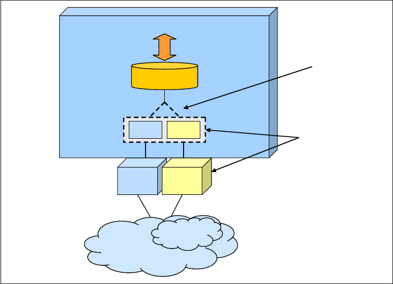
438 IBM z/OS V2R2 Communications Server TCP/IP Implementation Volume 1
10.5.6 HiperSockets connectivity to the intraensemble data network
zEnterprise can integrate HiperSockets connectivity to the IEDN. HiperSockets connectivity
to the IEDN is referred to as the z/OS Communications Server IEDN-enabled HiperSockets
function. Within each central processor complex (CPC) that is a member of an ensemble, you
can elect a single HiperSockets CHPID to provide connectivity to the IEDN.
To provide this capability, configure the elected IQD CHPID by using a channel parameter (in
this case, it is the IQDX function in HCD), which enables the IQDX function of HiperSockets.
See Figure 10-10.
When the IQDX function is configured, the single IQD CHPID is integrated with the OSX to
the IEDN, inheriting the OSX configuration and eliminating the HiperSockets configuration
tasks within z/OS Communications Server and Unified Resource Manager.
Figure 10-10 Converged IQDX OSX interface
For more information about IQDX function and its benefits, see z/OS Communications Server
IP Configuration Guide, SC31-8775.
10.5.7 Enabling HiperSockets access to the intraensemble data network
Before you implement the IQDX function, you must configure the zEnterprise CPC and the
LPARs as members of an ensemble, as shown in 10.4, “Enabling z/OS as a member of the
ensemble” on page 423.
Only OSX connectivity
must be configured!
IQDX connectivity is transparent!
With AUTOIQDX
the IQDX interface is
dynamically configured
and transparently managed
("tucked" under OSX).
z/OS Communications Server
transparently splits and
converges network traffic
to this interface
All IP traffic to/from
this IP subnet
Single IP Address
(single network interface)
z/OS
IEDN
Internal IEDN
OSX IQDX
OSX
IQD
(IQDX)
Converged
Interface

Chapter 10. IBM z/OS in an ensemble 439
To implement the IQDX function, complete the following steps:
1. Configure all OSX interfaces to the IEDN. OSX connectivity to the IEDN is required to
enable HiperSockets connectivity to the IEDN.
To configure OSX, see 10.5.1, “Configuring the OSA CHPID to OSX in HCD” on page 430.
2. Define the IQDX function in HCD: In the HiperSockets CHPID configuration, set the IQDX
function by using a channel parameter in the hardware configuration definition (HCD), as
shown in Figure 10-11.
Figure 10-11 Define the IQDX function in the IQD Channel Parameters window
3. Authorize the LPAR to use a VLANID, replicating this authorization to all Interfaces for this
LPAR on the IEDN. This setting is the default, so there is no need to do any further
changes in z/Enterprise Unified Resource Manager.
4. Enable HiperSockets access to the IEDN. Configure the appropriate value for the
AUTOIQDX parameter on the GLOBALCONFIG statement in the TCP/IP profile. You can code
the following values:
– NOAUTOIQDX: Do not use the IQDX interfaces.
– AUTOIQDX ALLTRAFFIC: This value is the default. Use IQDX interfaces for all eligible
outbound traffic on the IEDN.
– AUTOIQDX NOLARGEDATA: The large outbound TCP data is transported through IEDN
over OSX interfaces.
We used the default in our environment.
For more information about IQDX function implementation, see z/OS Communications Server
IP Configuration Guide, SC31-8775.
Important: To define the IQDX function, add sufficient subchannel addresses to enable
the creation of one dynamic IQDX TRLE for each OSX CHPID for each IP version
(Version 4 and Version 6). Define at least ten IQDX subchannel addresses for each
OSX CHPID for IPv4, and ten subchannel addresses for each OSX CHPID for IPv6,
regardless of the number of VLANs.
---------------------- View IQD Channel Parameters ----------------------
| |
| |
| Maximum frame size in KB . . . . . : 64 |
| |
| IQD function ID . . . . . . . . . : 2 1. Basic HiperSockets |
| 2. IEDN Access (IQDX) |
| 3. External Bridge |
| |
| ENTER to continue. |
| |
| |
| |
| F1=Help F2=Split F3=Exit F9=Swap F12=Cancel |
|-----------------------------------------------------------------------|

440 IBM z/OS V2R2 Communications Server TCP/IP Implementation Volume 1
10.5.8 Verifying the HiperSockets IQDX implementation
To verify that the IQDX function is being used, use the following commands:
NETSTAT CONFIG /-f
Use this command to verify the parameter AUTOIQDX, as shown in Example 10-16.
Example 10-16 Netstat Config partial results
TCP Configuration Table:
...
Global Configuration Information:
TcpIpStats: No ECSALimit: 0000000K PoolLimit: 0000000K
MlsChkTerm: No XCFGRPID: IQDVLANID: 0
SysplexWLMPoll: 060 MaxRecs: 100
ExplicitBindPortRange: 00000-00000 IQDMultiWrite: Yes
AutoIQDX: AllTraffic
WLMPriorityQ: No
Netstat DEVlinks /-d :
Use this command to show an OSX interface with its associated IQDX interface. The
ASSOCIATED IQDX INTERFACE section shows the associated IQDX interface name. The
statistics in this section show how much data that is destined for the OSX interface was
sent and received over the associated IQDX interface, as shown in Example 10-17.
Example 10-17 D TCPIP,TCPIPA,N,DEV,INTFN=OSA230AI command results
D TCPIP,TCPIPA,N,DEV,INTFN=OSA230AI
INTFNAME: OSA230AI INTFTYPE: IPAQENET INTFSTATUS: READY
PORTNAME: IUTXP018 DATAPATH: 2304 DATAPATHSTATUS: READY
CHPIDTYPE: OSX CHPID: 18
SPEED: 0000010000
IPBROADCASTCAPABILITY: NO
VMACADDR: 0207E300003D VMACORIGIN: OSA VMACROUTER: ALL
ARPOFFLOAD: YES ARPOFFLOADINFO: NO
CFGMTU: 8992 ACTMTU: 8992
IPADDR: 10.1.111.11/24
VLANID: 111 VLANPRIORITY: DISABLED
DYNVLANREGCFG: NO DYNVLANREGCAP: YES
READSTORAGE: GLOBAL (4096K)
INBPERF: DYNAMIC
WORKLOADQUEUEING: NO
CHECKSUMOFFLOAD: YES SEGMENTATIONOFFLOAD: YES
SECCLASS: 255 MONSYSPLEX: NO
ISOLATE: NO OPTLATENCYMODE: NO
MULTICAST SPECIFIC:
MULTICAST CAPABILITY: YES
GROUP REFCNT SRCFLTMD
GROUP REFCNT SRCFLTMD
----- ------ --------
224.0.0.1 0000000001 EXCLUDE
SRCADDR: NONE
INTERFACE STATISTICS:
BYTESIN = 0
INBOUND PACKETS = 0

Chapter 10. IBM z/OS in an ensemble 441
INBOUND PACKETS IN ERROR = 0
INBOUND PACKETS DISCARDED = 0
INBOUND PACKETS WITH NO PROTOCOL = 0
BYTESOUT = 84
OUTBOUND PACKETS = 1
OUTBOUND PACKETS IN ERROR = 0
OUTBOUND PACKETS DISCARDED = 0
ASSOCIATED IQDX INTERFACE: EZAIQX18 IQDX STATUS: NOT ACTIVE
BYTESIN = 0
INBOUND PACKETS = 0
BYTESOUT = 0
OUTBOUND PACKETS = 0
1 OF 1 RECORDS DISPLAYED
END OF THE REPORT
10.6 Additional information
For more information about the zEnterprise and z/OS Communications Server ensemble
setup, see the following resources:
z/OS Communications Server ensemble implementation:
– z/OS Communications Server: SNA Network Implementation, SC31-8777
– z/OS Communications Server: SNA Resource Definition, SC31-8778
– z/OS Communications Server: IP Configuration Guide, SC27-3650
IPv6 information:
– z/OS Communications Server: IPv6 Network and Application Design Guide,
SC31-8885
– Appendix A, “IPv6 support” on page 443
IBM Redbooks publications:
– IBM zEnterprise System Technical Introduction, SG24-7832
– IBM zEnterprise 196 Technical Guide, SG24-7833
– IBM zEnterprise 196 Configuration Setup, SG24-7834
– IBM System p Advanced POWER Virtualization (PowerVM) Best Practices,
REDP-4194
– IBM BladeCenter JS12 and JS22 Implementation Guide, SG24-7655
442 IBM z/OS V2R2 Communications Server TCP/IP Implementation Volume 1

© Copyright IBM Corp. 2016. All rights reserved. 443
Appendix A. IPv6 support
IPv6 has gained greater acceptance in the industry in recent years. IPv6 is attractive because
it resolves some deficiencies of IPv4 in the following areas:
IP address space
Auto-configuration
Security
Quality of service (QoS)
Anycast and multicast
A
444 IBM z/OS V2R2 Communications Server TCP/IP Implementation Volume 1
A.1 Overview of IPv6
Internet Protocol version 6 (IPv6) is the next generation of the internet protocol that replaces
the current Internet Protocol version 4 (IPv4).
IPv6 was developed to resolve impending problems that are related to the limitations of IPv4
and the rapidly growing demand for IP resources and functions; the most significant issue is
the diminishing supply and expected shortages of IPv4 addresses.
Using IPv4 32-bit addressing allows for over 4 million nodes, each with a globally unique
address. This current IPv4 space cannot satisfy the huge expected increase in the number of
users on the internet. The expected shortage is exacerbated by the requirements of emerging
technologies such as PDAs, home area networks, and internet-connected commodities, such
as automotive and integrated telephone services. IPv6 uses 128-bit addressing and
generates a space large enough to last for the foreseeable future.
A.2 Importance of IPv6
IPv6 is important because it addresses the limitations of IPv4:
128-bit addressing
Quadruples the network address bits from 32 to 128, increasing the number of possible
unique IP addresses. This huge address space obviates the need for private addresses
and network address translation (NAT).
Simplified header formats
Allows for more efficient packet handling and reduced bandwidth cost.
Hierarchical addressing and routing
Keeps routing tables small and backbone routing efficient by using address prefixes rather
than address classes.
Improved support for options
Changes the way IP header options are encoded, allowing more efficient forwarding and
greater flexibility.
Address auto-configuration
Allows stateless IP address configuration without a configuration server.
Security
IPv6 brings greater authentication and privacy capabilities through the definition of
extensions.
QoS
QoS is provided through a traffic class byte in the header.
Appendix A. IPv6 support 445
A.3 Common design scenarios for IPv6
Although there are predictable improvements over IPv4, the success of any IPv6
implementation depends on IPv6
coexisting with IPv4. Because of the pervasiveness of IPv4,
this coexistence will be around for some time. Therefore, the development of technologies
and mechanisms to facilitate coexistence is as important as the deployment strategy for IPv6.
The following sections describe some of the
coexistence technologies that are available.
A.3.1 Tunneling
Tunneling is the transmission of IPv6 traffic that is encapsulated within IPv4 packets over an
IPv4 connection. Tunnels are used primarily to connect remote IPv6 networks, or to simply
connect an IPv6 network over an IPv4 network infrastructure.
Dependencies
All tunnel mechanisms require that the endpoints of the tunnel run in dual-stack mode. A
dual-stack router is a router running
both versions of IP. There are other dependencies based
on the tunneling mechanism that is used.
For example, an IPv6
manually configured tunnel requires an ISP-registered IP address. The
automatic tunnel mechanism requires IPv6 prefixes. Intra-Site Automatic Tunnel Addressing
Protocol (ISATAP) tunnels require only a dual-stack router, but they are not yet commercially
available and
6over4 tunnels are not supported by vendor router software.
Advantages
Tunneling allows the implementation of IPv6 without any significant upgrades to the existing
infrastructure, and therefore does not risk interrupting the existing services that are provided
by the IPv4 network.
Considerations
Various tunneling mechanisms are designed for different primary tasks, so you must carefully
consider the mechanism that you choose. Some are primarily used for stable and secure links
for regular communications. Others are primarily used for single hosts or small sites, with low
data traffic volumes.
A.3.2 Dedicated data links
Network architects can choose a separate ATM, frame relay permanent virtual circuits
(PVCs), or separate optical media, to run IPv6 traffic across. The only requirement is the
reconfiguration of the routers (with IPv6 support). These links can be used
only for IPv6
traffic.
Dependencies
Dual-stack routers with IPv6 and IPv4 addresses are required to provide access to the WAN.
Access to a Domain Name System (DNS) is needed to resolve IPv6 names and addresses.
Advantages
Use of the existing Layer 2 infrastructure makes this implementation less complex and
immediate. This implementation is not disruptive, apart from a schedule change for router
configuration, and there is little impact to the status quo.
446 IBM z/OS V2R2 Communications Server TCP/IP Implementation Volume 1
Considerations
All routers on the WAN must support IPv6 over dedicated data links. Additional costs for those
links are incurred until the environment is migrated over to IPv6.
A.3.3 Multi-Protocol Label Switching backbones
A Multi-Protocol Label Switching (MPLS) IPv4 core network can enable IPv6 domains to
communicate over MPLS backbones. It is primarily used by enterprises and service
providers. There are various implementations of this strategy, ranging from no changes and
no impact to changes and risks, which means that the closer the IPv6 implementation is to
the client edge, the less expensive it becomes. In contrast, the closer the IPv6 implementation
is to the service provider edge, the more expensive it becomes.
Dependencies
Dependencies vary from router configuration to specific hardware requirements to software
upgrades, depending on the service provider solution.
Advantages
Using this strategy requires minor modifications to the infrastructure and minor
reconfigurations of the core routers. It is a strategy that might have little or no impact to your
environment, involving low costs and low risks.
Considerations
Considerations also vary, depending on the strategy that is chosen. For example, using the
Circuit Transport over MPLS strategy does not support a mix of IPv4 and IPv6 traffic. IPv6 on
service provider edge routers do not support virtual private networks (VPNs) or virtual routing
and forwarding (VRF) currently.
A.3.4 Dual-stack backbones
A dual-stack backbone is a core network with all routers that are configured to support dual
stacks. It consists of two network types existing side by side. The IPv4 stack routes the IPv4
traffic through the IPv4 network. The IPv6 stack routes the IPv6 traffic through the IPv6
network. This is a basic approach to routing both IPv4 and IPv6 traffic through a network.
Dependencies
Each site has the appropriate entries in a DNS to resolve both IPv4 and IPv6 names and
IP addresses.
Advantages
This is a basic and simple strategy for routing IPv4 and IPv6 traffic in a network.
Considerations
All routers in the network require a software upgrade to support dual stacks. Having dual
stacks require additional router management of a dual addressing scheme and additional
router memory.
Appendix A. IPv6 support 447
A.3.5 Dual-mode stack
A dual-mode stack is a stack that is configured to support both IPv4 and IPv6 protocols. It is a
single stack (not two stacks) that is configured to support IPv4 and IPv6 simultaneously. Both
IPv4 and IPv6 interfaces can receive and send IPv4 and IPv6 packets over the corresponding
interfaces.
Dependencies
A z/OS Communications Server that is configured to support IPv6 requires OSA-Express
ports to be running in QDIO mode.
Advantages
There are no additional software or hardware requirements for users in a z/OS environment
that is configured with OSA-Express features. Dual-mode allows IPv4 and IPv6 applications
to coexist indefinitely. However, any application can be migrated one at a time or at the user’s
convenience from IPv4 to IPv6. This is an inexpensive, low-risk, and low-impact deployment
strategy.
Considerations
The only link layer protocol that supports IPv6 is MPC+. The devices that use the MPC+
protocol are XCF, MPCPTP, and MPCIPA (for example, OSA-Express3 in QDIO mode and
HiperSockets on the System z196).
A.3.6 Suggestion
Using dual-mode stacks is the preferred strategy for application migration from IPv4 to IPv6.
A.4 How IPv6 is implemented in z/OS Communications Server
IPv6 is implemented in the z/OS Communications Server through a series of configuration
tasks. You configure the stack to support IPv6 in a similar fashion to the steps that are
performed for IPv4 configuration. However, before you start to configure the stack to support
IPv6 traffic, you must understand a few things about IPv6.
A.4.1 IPv6 addressing
An IPv6 address is a 128-bit number that is written in colon hexadecimal notation. This
scheme is hexadecimal and consists of eight 16-bit pieces of the address.
Alternative notations that are described in RFC 4291 are acceptable, as in the following
example:
fedc:ba98:7654:3210:fedc:ba98:7654:3210

448 IBM z/OS V2R2 Communications Server TCP/IP Implementation Volume 1
The following conventional forms represent IPv6 addresses as text strings:
The preferred form is x:x:x:x:x:x:x:x, which indicates the hexadecimal value of the eight
16-bit pieces of the address, for example:
fedc:ba98:7654:3210:fedc:ba98:7654:3210
1080:0:0:0:8:800:200c:417a
Because of some methods of allocating certain styles of IPv6 addresses, it is common for
addresses to contain long strings of zero bits. To simplify the writing of addresses that
contain zero bits, a special syntax is available to compress the zeros. The use of the
double colon (::) indicates one or more groups of 16 bits of zeros. The :: can appear only
once in an address; it can also be used to compress the leading or trailing zeros in an
address.
Consider the following addresses:
– 1080:0:0:0:8:800:200c:417a (unicast address)
– ff01:0:0:0:0:0:0:101 (multicast address)
– 0:0:0:0:0:0:0:1 (loopback address)
– 0:0:0:0:0:0:0:0 (unspecified addresses)
They can be represented as follows:
– 1080::8:800:200c:417a (unicast address)
– ff01::101 (multicast address)
– ::1 (loopback address)
– :: (unspecified addresses)
An alternative form that is sometimes more convenient to use when dealing with a mixed
environment of IPv4 and IPv6 nodes is to use x:x:x:x:x:x:d.d.d.d. Here, the x’s are the
hexadecimal values of the six high-order 16-bit pieces of the address. The d’s are the
decimal values of the four low-order 8-bit pieces of the address (standard IPv4
representation).
Consider this example:
0:0:0:0:0:0:13.1.68.3
0:0:0:0:0:ffff:129.144.52.38
In compressed form, it is written as follows:
::13.1.68.3
::ffff:129.144.52.38
A.4.2 Stateless address autoconfiguration
IPv6 addresses can be manually defined or autoconfigured.
With minimal router configuration and no manual configuration of local addresses, a host can
generate its own IPv6 addresses. An IPv6 public autoconfigured address is the combination
of a router advertised prefix and the interface ID that is provided by the OSA-Express QDIO
adapter or manually configured by using the INTFID parameter on the INTERFACE statement.
Note: Although writing the leading zeros in an individual field is unnecessary, at least
one numeral must be in every field,
except for the case that is described in the next list
item.

Appendix A. IPv6 support 449
Routers advertise prefixes that identify the subnets that are associated with a LAN. In the
absence of routers or manual configuration, a host can generate only link local addresses.
However, link local addresses are sufficient for allowing communication among nodes that are
attached to the same LAN.
Defining or adding an address on the INTERFACE statement indicates that stateless
autoconfiguration is not wanted. Only a link local address is generated. Examine the layout of
a link local address in Figure A-1.
Figure A-1 Unicast IPv6 addressing formats
Guidelines for IP filter rules and security associations with IPv6
If you use autoconfiguration, your IPv6 addresses might not be predictable. To configure IP
filter rules for dynamic security associations with autoconfigured IPv6 addresses, you must
specify the IP addresses by using wild cards.
Manual security associations typically use specific IP addresses for the endpoints. You can
use wild cards for the security endpoint addresses so that the data endpoints and security
endpoints are considered identical. Alternatively, you can use predictable IPv6 addresses for
the security endpoints. You can obtain predictable IPv6 addresses by configuring full 128-bit
IPv6 addresses on your INTERFACE statements by specifying the INTFID keyword on your
INTERFACE statements or by using VIPAs.
Security with IPv6 autoconfiguration
RFC 4941- Privacy Extensions for Stateless Address Autoconfiguration in IPv6, addresses a
potential security concern that can arise with the use of stateless address autoconfiguration.
The static interface ID in an autoconfigured address makes it possible to correlate
independent transactions to and from the system by using the adapter even if the overall IPv6
address changes.
0
127
10 bits
54 bits
64 bits
Interface ID
1111 1110 10
FE80
0...0
MAC, Other Interface ID
9
63
Link-local
Scope
0
127
54 bits
64 bits
Interface ID
1111 1110 11
FEC0
0...0
MAC, Other Interface ID
9
63
Site-local
Scope
(deprecated)
10 bits
0
127
3 bits
61 bits
64 bits
Interface ID
001
(anything
else)
variable
"subnet"
MAC, Other Interface ID
4
63
Global Scope
RFC 2373
and
RFC 4291
Unicast
"Prefix" or "Full Routing Prefix"
Format Prefix
Scope Prefix
450 IBM z/OS V2R2 Communications Server TCP/IP Implementation Volume 1
RFC 4941 defines a mechanism to generate a random interface ID that changes over time,
thus eliminating the potential security exposure that is caused by the usual predictability of
the interface ID. This random interface ID can be used in place of the static interface ID in
generating temporary autoconfigured addresses. Based on new configuration parameters,
the random interface ID and temporary addresses are regenerated periodically.
Temporary autoconfigured addresses have the same characteristics as public autoconfigured
addresses. The address is generated as the result of a received router advertisement. The
address is deprecated at the end of its preferred lifetime. The address is deleted at the end
of its valid lifetime.
Temporary autoconfigured addresses are designed to be used by short-lived client
applications to make it more difficult to correlate activity. Temporary addresses should not be
used for a server because the server must have a known IP address (or DNS name) so that
clients can reach it. Temporary addresses should not be used with a long-lived client
connection because the connection can become unusable if its source IP address is deleted
while the connection is active.
To enable temporary address support for a TCP/IP stack, specify TEMPADDRS on the IPCONFIG6
statement in the TCP/IP profile. TEMPPREFIX on an interface definition specifies the set of
prefixes for which temporary IPv6 addresses can be generated.
A.4.3 IPv6 TCP/IP network part (prefix)
Designers define some address types, which are known as address scopes, and saved room
for future definitions because unknown requirements might arise. RFC 4291 - IP version 6
Addressing Architecture (February 2006), defines the current addressing scheme. Figure A-1
on page 449 shows the layout of three types or “scopes” of addresses:
The link-local scope
The site-local scope (now deprecated)
The global scope
Each address begins with a format or scope prefix of 10 bits, followed by a second field and
then an interface identifier field. Each of these addresses serves a unique purpose:
Link-local scope
These are special addresses that are only valid on a
link of an interface. Using this
address as the destination, the packet never passes through a router. A packet with a
link-local source or destination address does not leave its originating LAN. A router
receiving the packet does not forward it onto another physical LAN. An address of this type
bears the prefix of fe80.
A link-local address is assigned to each IPv6-enabled interface after stateless
auto-configuration, commonly used in IPv6 implementations. The link-local address is
used for link communications, such as the following examples:
– Neighbor discovery, that is, discovering whether anyone else is on this link
– Communication with a neighbor when a router is unnecessary
Figure A-2 on page 451 shows a LAN environment that is separated into two LAN
segments, which are represented by link scope zone A with three nodes and link scope
zone B with four nodes. The link local addresses in each zone begin with the prefix fe80.

Appendix A. IPv6 support 451
Consider the example in Figure A-2.
Figure A-2 Link-local addresses and link-local scope zones
Within a zone, nodes communicate with each other by using link-local addresses. Across
zones, nodes must communicate with each other by using global scope addresses.
Node X has link-local addresses in two zones: in zone A and in zone B. Because link-local
addresses use the same prefix value, it is necessary to understand which zone a packet
should be sent to, particularly when a default route is used. So, if a route exists on Node X
for any destination address with a prefix of fe80, then the routing table must distinguish
between fe80 in zone A and fe80 in zone B.
Therefore, both the address and the zone index value must be specified in the routing
table. The
zone index is a value that is assigned by the stack to represent the correct entry
(or interface) in the routing table. If the zone index is not present, then the stack uses the
“default route” for this configuration.
If the default route uses the interface that matches the IPv6 link-local address that was
specified, everything works fine. However, if the default route does
not use the correct
interface for the specified IPv6 link-local address, then a routing error is encountered and
the application request fails or times out. So, the zone index helps the stack to distinguish
whether the routing path should flow into zone A or into zone B.
z/OS Communications Server supports scope zone information about Getaddrinfo and
Getnameinfo invocations, and also on the z/OS socket APIs that support IPv6, thus
satisfying requirements for IPv6 compliance. One of those supported socket APIs is, for
example, the source address selection that enables specifying whether your application
prefers temporary or public addresses (if a JOBNAME procname PUBLICADDRS or TEMPADDRS
statement is specified in the SRCIP block, the API statement is ignored). In addition,
scope zone information can be included on command-line operations and in configuration
files for ftp, ping, traceroute, rexec, orexec, rsh, and orsh.
Link scope
zone A
fe80...
Link scope
zone B
fe80...
fe80...
fe80...
fe80... fe80... fe80...
Node X

452 IBM z/OS V2R2 Communications Server TCP/IP Implementation Volume 1
Site-local address type
These addresses are now deprecated, that is, no longer recommended by the IETF. Use
and deployment difficulties that are caused by the use of such addresses led the IETF to
discourage their use.
Originally, site-local addresses were used to communicate across routers or zones within
the same intranet. They were similar to the RFC 1918 - Address Allocation for Private
Internets in IPv4 today, such as the address ranges that are represented by 10.0.0.0/8,
172.16.0.0/16 - 172.31.0.0/16, and 192.168.0.0/24. Since their deprecation, they are
treated as global unicast addresses.
This deprecated address scope begins with the following prefixes:
– fec0: (most commonly used)
– fed0:
– fee0:
6bone test addresses
These addresses were the first global addresses that are defined and used for testing
purposes. They all begin with the following prefix:
3ffe:
6to4 addresses
These addresses were designed for a special tunneling mechanism (RFC 3056 -
Connection of IPv6 Domains using IPv4 Clouds and RFC 2893 - Transition Mechanisms
for IPv6 Hosts and Routers). They encode a given IPv4 address and a possible subnet.
They begin with the following prefix:
2002:
Consider this example, representing 192.168.1.1/5:
2002:c0a8:0101:5::1
Assigned by a provider for hierarchical routing
These addresses are delegated to internet service providers (ISPs) and begin with the
following prefix:
2001:
Multicast addresses
Multicast addresses are used for related services and always begin with the prefix ffxx:.
Here, xx is the scope value.
Anycast addresses
Anycast addresses are special addresses that are used to cover such items as the
nearest DNS server, nearest Dynamic Host Configuration Protocol (DHCP) server, or
similar dynamic groups. Addresses are taken out of the unicast address space and can be
aggregated globally or site-local at the moment. The anycast mechanism (client view) is
handled by dynamic routing protocols.
A simple example of an anycast address is the
subnet-router anycast address. Assuming
that a node has the following global assigned IPv6 address:
3ffe:ffff:100:f101:210:a4ff:fee3:9566/64
Note: Anycast addresses cannot be used as source addresses. They are used only as
destination addresses.

Appendix A. IPv6 support 453
The subnet-router anycast address is created by blanking the suffix (least significant
64 bits):
3ffe:ffff:100:f101::/64
A.4.4 IPv6 implementation in z/OS
The z/OS Communications Server supports both IPv4 and IPv6 protocols to coexist. This
book describes how this strategy can be implemented in a z/OS networking environment.
Further details about configuration options that are not referenced here are available in z/OS
Communications Server: IP Configuration Reference, SC27-3651 and z/OS Communications
Server: IPv6 Network and Application Design Guide, SC31-8885.
Table A-1 summarizes the z/OS TCP/IP stack-related functions and the level of support,
which are based on the current release of the z/OS Communications Server. You can use this
table to determine whether a given function is applicable and supported.
Table A-1 z/OS TCP/IP stack function support
z/OS TCP/IP stack
function
IPv4
support
IPv6
support
Comments
Link-layer device support
OSA-Express in QDIO
mode
Y Y Related configuration statements:
DEVICE MPCIPA and LINK IPAQENET
INTERFACE IPAQENET
INTERFACE IPAQENET6
CTC Y N
LCS Y N
CLAW Y N
CDLC (3745/3746) Y N
SNALINK LU0 and LU6.2 Y N
X.25 NPSI Y N
NSC HyperChannel Y N
MPC Point-Point Y Y Related configuration statement: INTERFACE MPCPTP6
ATM Y N
HiperSockets Y Y Related configuration statements:
INTERFACE IPAQIDIO6
IPCONFIG6 DYNAMICXCF
XCF Y Y Related configuration statements:
INTERFACE MPCPTP6
IPCONFIG6 DYNAMICXCF
Virtual IP addressing (VIPA) support
Virtual Device/Interface
Configuration for static VIPA
Y Y Related configuration statements:
DEVICE and LINK VIRTUAL
INTERFACE VIRTUAL6

454 IBM z/OS V2R2 Communications Server TCP/IP Implementation Volume 1
Sysplex support
Sysplex distributor
integration with Cisco
MNLB
YN
Sysplex Wide Security
Associations (SWSA)
YN
IP routing functions
Dynamic routing - OSPF
and RIP
YY
OMPROUTE supports OSPFv3 and RIPng.
Multipath Routing Groups Y Y Related configuration statements:
IPCONFIG
IPCONFIG6
Policy-based routing (PBR) Y N
Static Route Configuration
by way of the BEGINROUTES
statement
Y Y Related configuration statement: BEGINROUTES
Socket API support for
source address selection
Y Y Related configuration statement: SRCIP
Miscellaneous IP/IF-layer functions
Path MTU discovery Y Y Path MTU discovery is mandatory in IPv6.
Related configuration statements:
IPCONFIG
IPCONFIG6
Configurable Device or
Interface Recovery Interval
YY
Link-Layer Address
Resolution
Y Y In IPv4, this is performed by using Address Resolution Protocol
(ARP).
In IPv6, this is performed by using the neighbor discovery
protocol.
Related configuration statements:
DEVICE and LINK (LAN Channel Station and OSA devices)
INTERFACE (IPAQENET6 interfaces)
ARP/Neighbor Cache
PURGE Capability
Y Y Use the V TCPIP,PURGECACHE command. For more information,
see z/OS Communications Server: IP System Administrator’s
Commands, SC27-3661.
Datagram Forwarding
Enable/Disable
Y Y Related configuration statements:
IPCONFIG
IPCONFIG6
HiperSockets Accelerator Y N Related configuration statements: IPCONFIG QDIOROUTING
QDIO Accelerator Y N Related configuration statements: IPCONFIG QDIOACCELERATOR
Checksum offload Y Y Related configuration statements:
IPCONFIG
IPCONFIG6
z/OS TCP/IP stack
function
IPv4
support
IPv6
support
Comments

Appendix A. IPv6 support 455
Segmentation offload Y Y Related configuration statements:
IPCONFIG
IPCONFIG6
QDIO inbound workload
queuing
YN
Transport-layer functions
Fast Response Cache
Accelerator (FRCA)
YY
Enterprise Extender Y Y IPv6 Enterprise Extender support requires a VIPA and
IUTSAMEH.
Related configuration statements:
INTERFACE VIRTUAL6 and MPCPTP6
IPCONFIG6 DYNAMICXCF
Server-BIND control Y Y Related configuration statement: PORT
UDP Checksum
Disablement Option
Y N UDP checksum is required when operating over IPv6.
Related configuration statement: UDPCONFIG
Network management and accounting functions
SNMP Y Y
SNMP applications can communicate over an IPv6 connection.
IPv6 management data includes added support for the
version-neutral (both IPv4 and IPv6) MIB data in the following
IETF internet drafts:
IP-MIB: draft-ietf-ipv6-rfc2011-update-01.txt
IP-FORWARD-MIB:
draft-ietf-ipv6-rfc2096-update-02.txt
TCP-MIB: draft-ietf-ipv6-rfc2012-update-01.txt
SNMP agent Y Y
TCP/IP subagent Y Y No IPv6 UDP support
Network SLAPM2 subagent Y Y
Distributed Protocol
Interface
YY
OMPROUTE subagent Y N
Trap forwarder daemon Y Y
Policy-Based Networking Y Y IPv6 support in Policy Agent:
IPv6 source and destination IP addresses are allowed to be
specified in policy rules (LDAP and configuration files).
Interfaces in policy rules and subnet priority TOS masks are
allowed to be specified by name:
– Allowed for both IPv4 and IPv6 interfaces.
– IPv6 interfaces
must be specified by name.
TOS in policy definitions means IPv4 Type of Service or IPv6
Traffic Class.
SMF Y Y Related configuration statement: SMFCONFIG
TN3270 subagent Y Y
z/OS TCP/IP stack
function
IPv4
support
IPv6
support
Comments

456 IBM z/OS V2R2 Communications Server TCP/IP Implementation Volume 1
Based on the description in “Common design scenarios for IPv6” on page 445, here we
concentrate on a single-stack environment running in dual-mode. A single-stack environment
is one TCP/IP stack running in an LPAR.
Dual-mode stack
A TCP/IP stack that supports both IPv4 and IPv6 interfaces that can receive and send IPv4
and IPv6 packets over the corresponding interfaces is referred to as a
dual-mode stack. A
dual-mode stack is a single stack supporting IPv4 and IPv6 protocols, which is different from
a dual-stack mode that uses two TCP/IP stacks running side by side, each supporting only
one of the protocols (either IPv4 or IPv6).
The z/OS Communications Server IP can be configured to support an IPv4-only stack or a
dual-mode stack (IPv4 and IPv6). There is no support for an IPv6-only stack. By default,
IPv6-enabled applications can communicate with both IPv4 and IPv6 peers in a dual-mode
environment.
A z/OS dual-mode stack is enabled when both AF_INET and AF_INET6 are coded in
SYS1.PARMLIB(BPXPRMxx). You cannot code AF_INET6 without specifying AF_INET,
and doing so causes the TCP/IP stack initialization to fail.
Security function
IPSec Y Y Related configuration statements:
IPCONFIG
IPCONFIG6
IP filtering Y Y
IKE daemon Y Y
NAT traversal Y N
Network Access Control Y Y Related configuration statement: NETACCESS
Stack and Port Access
Control
Y Y Related configuration statements:
PORT
DELETE
Application Transparent
TLS (AT-TLS)
YY
Intrusion Detection
Services (IDS)
YY
Server applications
Rpcbind server Y Y IPv6-enabled RPC applications require a Rpcbind server. The
following RPC facilities are not IPv6 enabled, and they do not
support RPC binding protocols Version 3 and Version 4:
rpcgen and orpcgen
rpcinfo and orpcinfo
RPC library for the z/OS Communications Server
environment
RPC library for the z/OS UNIX System Services environment
For more information see z/OS Communications Server: IP
Configuration Guide, SC27-3650
z/OS TCP/IP stack
function
IPv4
support
IPv6
support
Comments

Appendix A. IPv6 support 457
AF_INET6 support can be dynamically enabled by configuring AF_INET6 in BPXPRMxx and
then issuing the SETOMVS RESE= command to activate the new configuration.
IPv6 application on a dual-mode stack
An IPv6 application on a dual-mode stack can communicate with IPv4 and IPv6 partners if it
does
not bind to a native IPv6 address. If it binds to a native IPv6 address, then the native
IPv6 address cannot be converted to an IPv4 address.
If a partner is IPv6, all communication uses IPv6 packets.
If a partner is IPv4, the following events occur:
Both source and destination are IPv4-mapped IPv6 addresses.
On inbound, the transport protocol layer maps the IPv4 address to its corresponding
IPv4-mapped IPv6 address before returning to the application with AF_INET6 addresses.
On outbound, the transport protocol layer converts the IPv4-mapped address to the native
IPv4 addresses and send IPv4 packets.
IPv4 application on a dual-mode stack
An IPv4 application running on a dual-mode stack can communicate with an IPv4 partner.
The source and destination addresses are native IPv4 addresses and the packet is an IPv4
packet.
If a partner is IPv6 enabled and running on an IPv6-only stack, then communication fails. The
partner has only a native IPv6 address (not an IPv4-mapped IPv6 address). The native IPv6
address for the partner cannot be converted into a form that the AF_INET application
understands.
Older AF_INET applications can communicate only by using IPv4 addresses. IPv6-enabled
applications that use AF_INET6 sockets can communicate by using both IPv4 and IPv6
addresses (on a dual-mode stack). AF_INET and AF_INET6 applications can communicate
with one another, but only by using IPv4 addresses.
If the socket libraries on the IPv6-enabled host are updated to support IPv6 sockets
(AF_INET6), applications can be IPv6-enabled. When an application on a dual-mode stack
is IPv6-enabled, the application can communicate with both IPv4 and IPv6 partners. This is
true for both clients and server on a dual-mode stack.
IPv6-enabling both sockets libraries and applications on dual-mode stack becomes a
migration concern. When IPv6-only hosts are deployed in a network, applications on those
IPv6-only partners cannot communicate with the IPv4-only applications on the dual-mode
hosts, unless one of the multiple migration technologies is implemented either on
intermediate nodes in the network or directly on the dual-mode hosts.
Table A-2 summarizes the application communication rules when running in dual-mode.
Table A-2 Dual-mode communication
Partner Application communication on a dual-mode TCP/IP stack
IPv4 only IPv6-enabled
IPv4-only Yes Yes
IPv6-only No Yes

458 IBM z/OS V2R2 Communications Server TCP/IP Implementation Volume 1
Figure A-3 depicts a dual-mode stack, which is the IPv6 configuration we implemented in our
networking environment. The following sections walk you through the setup.
Figure A-3 Dual-mode TCP/IP stack
Implementation tasks for a dual-mode stack
To implement a dual-mode stack in our networking environment, we modify the following
definitions:
BPXPRMxx definitions
VTAM definitions
TCP/IP definitions
BPXPRMxx definitions
IPv6 is not enabled by default. You must specify a NETWORK statement with AF_INET6 in your
BPXPRMxx member.
To support our dual-mode stack (IPv4 and IPv6), we add the NETWORK statement, as shown in
Example A-1, to our BPXPRMxx member.
Example A-1 BPXPRMxx NETWORK statement
NETWORK DOMAINNAME (AF_INET6)
DOMAINNUMBER(19)
MAXSOCKETS(2000)
TYPE(INET)
The TYPE option in our case is INET because we use a single stack.
Dual-mode Stack
IPv4-only
Application
IPv6-enabled
Application
TCP, UDP, and Raw
IPv4 and IPv6
Network Interfaces
IPv6
Network
IPv6
Network

Appendix A. IPv6 support 459
For more information about the definitions that are required in BPXPRMxx to provide a dual-
stack, see z/OS Communications Server: IP Configuration Guide, SC27-3650.
VTAM definitions
One of the protocols that z/OS Communications Server TCP/IP supports is MPC+, and the
MPC+ protocols are used to define the DLCs for OSA-Express devices in QDIO.
OSA-Express QDIO connections are configured through a TRLE definition. Because VTAM
provides the DLCs for TCP/IP, all TRLEs are defined as VTAM major nodes (see
Example A-2).
Example A-2 TRLE definition
OSA2080 VBUILD TYPE=TRL
OSA2080T TRLE LNCTL=MPC,
READ=2080,
WRITE=2081,
DATAPATH=(2082-2087),
PORTNAME=OSA2080, 1
MPCLEVEL=QDIO
The PORTNAME 1 is identical to the device name that is defined in the TCP/IP PROFILE data set
on the INTERFACE statement.
TCP/IP definitions
We add one INTERFACE statement for the OSA-Express3 1000BASE-T port to support IPv6.
This statement merges the DEVICE, LINK, and HOME definitions into a single statement. Several
different parameters are associated with the INTERFACE statement. To determine which of
them best fits your requirements, see z/OS Communications Server: IP Configuration
Reference, SC27-3651.
We use the following syntax:
INTERFace interfname DEFINE linktype PORTNAME portname IPADDR ipaddr
The syntax has the following meanings:
interfname specifies a name for the interface with no more than 16 characters in length.
linktype must be IPAQENET6, which is the only DLC that currently supports IPv6.
portname is specified in the VTAM TRLE definition for the QDIO interface.
ipaddr is optional for link type IPAQENET6. If not specified, TCP/IP enables
auto-configuration for the interface. If used, one or more prefixes or full IPv6 addresses
can be specified.
Note: The BPXPRMxx member can be updated dynamically by using the z/OS command
SETOMVS RESET=(xx). After the reset, we receive the message BPXF203I DOMAIN AF_INET6
WAS SUCCESSFULLY ACTIVATED. We then
recycle the TCP/IP stack to pick up the change.
Note: To configure a single physical device for both IPv4 and IPv6 traffic, you must use
DEVICE/LINK/HOME for the IPv4 definition and INTERFACE for the IPv6 definition so that the
PORTNAME value on the INTERFACE statement matches the device name on the DEVICE
statement.

460 IBM z/OS V2R2 Communications Server TCP/IP Implementation Volume 1
The TCP/IP IPv6 PRFOFILE for a single stack is illustrated in Example A-3. The INTERFACE
statement defines the configuration of the OSA-Express device (OSA2080) that we used for
network connectivity. The PORTNAME must be identical to the PORTNAME that is defined in the
TRLE. The TRLE is defined as a VTAM major node in the VTAM definition data set.
Example A-3 shows the TCP/IP profile for our environment by using SYSTEM SYMBOLS and
INCLUDE statements. The &SYSCLONE that you see throughout the example results in a two-digit
value (30 in our example, for system SC30) being inserted. By doing this, we can use the
same profile for each of several systems, each time translating to the appropriate system
value (systems 30, 31, and 32). The &SYSCLONE value is defined in SYS1.PARMLIB.
Example A-3 Profile definition with the use of SYSTEM SYMBOLS and INCLUDE
ARPAGE 20
;
GLOBALCONFIG NOTCPIPSTATISTICS
;
IPCONFIG NODATAGRAMFWD SOURCEVIPA 1
IPCONFIG6 NODATAGRAMFWD SOURCEVIPA 2
;
SOMAXCONN 240
;
TCPCONFIG TCPSENDBFRSIZE 64K TCPRCVBUFRSIZE 64K SENDGARBAGE FALSE
TCPCONFIG TCPMAXRCVBUFRSIZE 256K
TCPCONFIG RESTRICTLOWPORTS
;
UDPCONFIG RESTRICTLOWPORTS
;
INCLUDE TCPIPE.TCPPARMS(HOME&SYSCLONE.V6)
INCLUDE TCPIPE.TCPPARMS(STAT&SYSCLONE.V6)
;
AUTOLOG 5
FTPDE&SYSCLONE JOBNAME FTPDE&SYSCLONE.1
ENDAUTOLOG
;
PORT
20 TCP * NOAUTOLOG ; FTP Server
21 TCP FTPDE&SYSCLONE.1 ; control port
23 TCP TN3270XE NOAUTOLOG ; MVS Telnet Server
23 TCP OMVS ; Telnet Server
25 TCP SMTP ; SMTP Server
514 UDP OMVS ; UNIX Syslogd daemon
;
SACONFIG ENABLED COMMUNITY public AGENT 161
;
SMFCONFIG
FTPCLIENT TN3270CLIENT
TYPE119 FTPCLIENT TN3270CLIENT
;
In this example, the numbers correspond to the following information:
1 Defines the IPv4 environment.
2 Defines the IPv6 environment.

Appendix A. IPv6 support 461
Example A-4 shows the DEVICE, LINK, HOME, INTERFACE, and IPADDR definitions that we used to
support IPv4 and IPv6 and their addressing schemes.
Example A-4 Interface and address definitions
DEVICE OSA2080 MPCIPA 1
LINK OSA2080LNK IPAQENET OSA2080 VLANID 12
INTERFACE LNK62080 DEFINE IPAQENET6 PORTNAME OSA2080 1
IPADDR FEC0:0:0:1::3302
FEC0:0:0:1001::3302
;
DEVICE STAVIPA1 VIRTUAL 0
LINK STAVIPA1LNK VIRTUAL 0 STAVIPA1
;
HOME
192.168.1.10 STAVIPA1LNK
192.168.2.10 OSA2080LNK
;
START OSA2080
START LNK62080
In this example, the number corresponds to the following information:
1 Defines the same device (OSA2080) to support IPv4 and IPv6 addresses.
Example A-5 show static routes in a flat network (no dynamic routing protocol).
Example A-5 Static route definitions
BEGINRoutes
; Direct Routes - Routes that are directly connected to my interfaces
; Destination Subnet Mask First Hop Link Name Packet Size
ROUTE FEC0::0/10 = LNK62080 MTU 1492
ROUTE 192.168.2.0 255.255.255.0 = OSA2080LNK MTU 1492
; Default Route - All packets to an unknown destination are routed
;through this route.
; Destination First Hop Link Name Packet Size
ROUTE DEFAULT 192.168.2.240 OSA2080LNK MTU 1492
ENDRoutes
The messages that are shown in Example A-6 are written to the z/OS console when the
TCP/IP stack of TCPIPE is initializing on SC30. We also manually start our external TN3270E
server (TN3270XE).
Example A-6 TCP/IP stack and TN3270E server initializations
S TCPIPE
$HASP100 TCPIPE ON STCINRDR
IEF695I START TCPIPE WITH JOBNAME TCPIPE IS ASSIGNED TO USER
TCPIP , GROUP TCPGRP
$HASP373 TCPIPE STARTED
IEE252I MEMBER CTIEZB00 FOUND IN SYS1.IBM.PARMLIB
IEE252I MEMBER CTIIDS00 FOUND IN SYS1.IBM.PARMLIB
IEE252I MEMBER CTINTA00 FOUND IN SYS1.PARMLIB
EZZ7450I FFST SUBSYSTEM IS NOT INSTALLED
EZZ0162I HOST NAME FOR TCPIPE IS WTSC30E
EZZ0300I OPENED INCLUDE FILE 'TCPIPE.TCPPARMS(HOME30V6)'
EZZ0300I OPENED INCLUDE FILE 'TCPIPE.TCPPARMS(STAT30V6)'

462 IBM z/OS V2R2 Communications Server TCP/IP Implementation Volume 1
EZZ0300I OPENED PROFILE FILE DD:PROFILE
EZZ0309I PROFILE PROCESSING BEGINNING FOR DD:PROFILE
EZZ0309I PROFILE PROCESSING BEGINNING FOR TCPIPE.TCPPARMS(HOME30V6)
EZZ0316I PROFILE PROCESSING COMPLETE FOR FILE 'TCPIPE.TCPPARMS(HOME30V
6)'
EZZ0304I RESUMING PROCESSING OF FILE DD:PROFILE
EZZ0309I PROFILE PROCESSING BEGINNING FOR TCPIPE.TCPPARMS(STAT30V6)
EZZ0316I PROFILE PROCESSING COMPLETE FOR FILE 'TCPIPE.TCPPARMS(STAT30V
6)'
EZZ0304I RESUMING PROCESSING OF FILE DD:PROFILE
EZZ0316I PROFILE PROCESSING COMPLETE FOR FILE DD:PROFILE
IEF196I IEF237I 2084 ALLOCATED TO TP2084
EZZ0334I IP FORWARDING IS DISABLED
EZZ0351I SOURCEVIPA SUPPORT IS ENABLED
EZZ0699I IPV6 FORWARDING IS DISABLED 1
EZZ0702I IPV6 SOURCEVIPA SUPPORT IS ENABLED 1
EZZ4313I INITIALIZATION COMPLETE FOR DEVICE OSA2080
EZZ0338I TCP PORTS 1 THRU 1023 ARE RESERVED
EZZ0338I UDP PORTS 1 THRU 1023 ARE RESERVED
EZZ0613I TCPIPSTATISTICS IS DISABLED
EZZ4248E TCPIPE WAITING FOR PAGENT TTLS POLICY
EZZ4202I Z/OS UNIX - TCP/IP CONNECTION ESTABLISHED FOR TCPIPE
BPXF206I ROUTING INFORMATION FOR TRANSPORT DRIVER TCPIPE HAS BEEN
INITIALIZED OR UPDATED.
EZB6473I TCP/IP STACK FUNCTIONS INITIALIZATION COMPLETE.
EZAIN11I ALL TCPIP SERVICES FOR PROC TCPIPE ARE AVAILABLE.
EZZ4340I INITIALIZATION COMPLETE FOR INTERFACE EZ6OSM02
EZZ4340I INITIALIZATION COMPLETE FOR INTERFACE LNK62080 2
EZD1176I TCPIPE HAS SUCCESSFULLY JOINED THE TCP/IP SYSPLEX GROUP
EZBTCPCS
S FTPDE30
$HASP100 FTPDE30 ON STCINRDR
IEF695I START FTPDE30 WITH JOBNAME FTPDE30 IS ASSIGNED TO USER
TCPIP , GROUP TCPGRP
$HASP373 FTPDE30 STARTED
$HASP395 FTPDE30 ENDED
------------------------------------------------
We manually started our external TN3270E server.
------------------------------------------------
S TN3270XE
$HASP100 TN3270XE ON STCINRDR
IEF695I START TN3270XE WITH JOBNAME TN3270XE IS ASSIGNED TO USER
TCPIP , GROUP TCPGRP
$HASP373 TN3270XE STARTED
IEE252I MEMBER CTIEZBTN FOUND IN SYS1.IBM.PARMLIB
EZZ6001I TN3270XE SERVER STARTED
EZZ6044I TN3270XE PROFILE PROCESSING BEGINNING FOR FILE 897
TCPIPE.TCPPARMS(TN3270XE)
EZZ6045I TN3270XE PROFILE PROCESSING COMPLETE FOR FILE
TCPIPE.TCPPARMS(TN3270XE)
EZZ6003I TN3270XE LISTENING ON PORT 23
In this example, 1 and 2 indicate that IPv6 support is enabled and that the interface is
initialized with IPv6 addresses.

Appendix A. IPv6 support 463
A.4.5 Verification
Next, we verify our environment. Because the TRLE must be active before the interface is
started, we ensure that the TRLE is in an active state. The results are shown in Example A-7.
You can also verify the OSA-Express code level with this command.
Example A-7 OSA-Express status and code level
D NET,TRL,TRLE=OSA2080T
IST097I DISPLAY ACCEPTED
IST075I NAME = OSA2080T, TYPE = TRLE 111
IST1954I TRL MAJOR NODE = OSA2080
IST486I STATUS= ACTIV, DESIRED STATE= ACTIV 1
IST087I TYPE = LEASED , CONTROL = MPC , HPDT = YES
IST1715I MPCLEVEL = QDIO MPCUSAGE = SHARE
IST2263I PORTNAME = OSA2080 PORTNUM = 0 OSA CODE LEVEL = 0010 4
IST2337I CHPID TYPE = OSD CHPID = 02
IST1577I HEADER SIZE = 4096 DATA SIZE = 0 STORAGE = ***NA***
IST1221I WRITE DEV = 2081 STATUS = ACTIVE STATE = ONLINE 2
IST1577I HEADER SIZE = 4092 DATA SIZE = 0 STORAGE = ***NA***
IST1221I READ DEV = 2080 STATUS = ACTIVE STATE = ONLINE 2
...
IST924I -------------------------------------------------------------
IST1221I DATA DEV = 2083 STATUS = ACTIVE STATE = N/A 3
IST1724I I/O TRACE = OFF TRACE LENGTH = *NA*
IST1717I ULPID = TCPIPE ULP INTERFACE = OSA2080
IST2310I ACCELERATED ROUTING DISABLED
IST2331I QUEUE QUEUE READ QUEUE
IST2332I ID TYPE STORAGE STATUS
IST2205I ------ -------- --------------- ----------------------
IST2333I RD/1 PRIMARY 4.0M(64 SBALS) ACTIVE
IST2305I NUMBER OF DISCARDED INBOUND READ BUFFERS = 0
IST1757I PRIORITY1: UNCONGESTED PRIORITY2: UNCONGESTED
IST1757I PRIORITY3: UNCONGESTED PRIORITY4: UNCONGESTED
IST2190I DEVICEID PARAMETER FOR OSAENTA TRACE COMMAND = 01-01-00-03
IST1801I UNITS OF WORK FOR NCB AT ADDRESS X'25678010'
IST1802I P1 CURRENT = 0 AVERAGE = 0 MAXIMUM = 0
IST1802I P2 CURRENT = 0 AVERAGE = 0 MAXIMUM = 0
IST1802I P3 CURRENT = 0 AVERAGE = 0 MAXIMUM = 0
IST1802I P4 CURRENT = 0 AVERAGE = 1 MAXIMUM = 2
...
IST314I END
In this example, the numbers correspond to the following information:
1 indicates the state of the TRLE major node.
2 and 3 are the wanted and required states.
4 indicates the OSA code level, which is a four-digit number that relates to a specific
microcode engineering change (EC) and patch level (MCL).
Example A-8 displays the HOME addresses after initialization.
Example A-8 HOME addresses displayed
D TCPIP,TCPIPE,N,HOME
HOME ADDRESS LIST:
LINKNAME: STAVIPA1LNK
ADDRESS: 192.168.1.10 1

464 IBM z/OS V2R2 Communications Server TCP/IP Implementation Volume 1
FLAGS: PRIMARY
LINKNAME: OSA2080LNK
ADDRESS: 192.168.2.10
FLAGS:
LINKNAME: LOOPBACK
ADDRESS: 127.0.0.1
FLAGS:
INTFNAME: LNK62080
ADDRESS: FEC0:0:0:1::3302 2
TYPE: GLOBAL
FLAGS:
ADDRESS: FEC0:0:0:1001::3302 2
TYPE: GLOBAL
FLAGS:
ADDRESS: FE80::14:5E00:177:6872 3
TYPE: LINK_LOCAL
FLAGS: AUTOCONFIGURED
INTFNAME: LOOPBACK6
ADDRESS: ::1 4
TYPE: LOOPBACK
FLAGS:
INTFNAME: EZ6OSM01
ADDRESS: FE80::77FF:FE69:E025 5
TYPE: LINK_LOCAL
FLAGS: AUTOCONFIGURED
INTFNAME: EZ6OSM02
ADDRESS: FE80::77FF:FE68:702A 5
TYPE: LINK_LOCAL
FLAGS: AUTOCONFIGURED
9 OF 9 RECORDS DISPLAYED
END OF THE REPORT
In this example, the numbers correspond to the following information:
1 This is the IPv4 address that is assigned to the OSA Express device (OSA2080).
2 These are the site-local IPv6 unicast addresses that are assigned to the same OSA
Express device (OSA2080) that are defined with the INTERFACE statement. However,
site-local addresses are not preferable and are deprecated.
3 This is an auto-configured LINK_LOCAL address for the same OSA Express device.
4 This is the IPv6 Loopback address.
5 These are the auto-configured LINK_LOCAL addresses for the OSM channel-path
identifiers (CHPIDs), which are part of the intranode management network (INMN).
Note: The NETSTAT display classifies them as GLOBAL. This classification adheres to
RFC 4291 - Site-Local IPv6 Unicast Addresses, which states the following information:
“New implementations must treat this prefix as Global Unicast.”

Appendix A. IPv6 support 465
Example A-9 shows the output of NETSTAT DEV, with the IPv6 Loopback and device interfaces
shown as READY.
Example A-9 Device display using NETSTAT
D TCPIP,TCPIPE,N,DEV
DEVNAME: LOOPBACK DEVTYPE: LOOPBACK
DEVSTATUS: READY
LNKNAME: LOOPBACK LNKTYPE: LOOPBACK LNKSTATUS: READY
ACTMTU: 65535
ROUTING PARAMETERS:
MTU SIZE: N/A METRIC: 00
DESTADDR: 0.0.0.0 SUBNETMASK: 0.0.0.0
MULTICAST SPECIFIC:
MULTICAST CAPABILITY: NO
LINK STATISTICS:
BYTESIN = 6477
INBOUND PACKETS = 102
INBOUND PACKETS IN ERROR = 0
INBOUND PACKETS DISCARDED = 0
INBOUND PACKETS WITH NO PROTOCOL = 0
BYTESOUT = 6477
OUTBOUND PACKETS = 102
OUTBOUND PACKETS IN ERROR = 0
OUTBOUND PACKETS DISCARDED = 0
INTFNAME: LOOPBACK6 INTFTYPE: LOOPBACK6 INTFSTATUS: READY 1
ACTMTU: 65535
MULTICAST SPECIFIC:
MULTICAST CAPABILITY: NO
INTERFACE STATISTICS:
BYTESIN = 0
INBOUND PACKETS = 0
INBOUND PACKETS IN ERROR = 0
INBOUND PACKETS DISCARDED = 0
INBOUND PACKETS WITH NO PROTOCOL = 0
BYTESOUT = 0
OUTBOUND PACKETS = 0
OUTBOUND PACKETS IN ERROR = 0
OUTBOUND PACKETS DISCARDED = 0
INTFNAME: EZ6OSM01 INTFTYPE: IPAQENET6 INTFSTATUS: READY
PORTNAME: IUTMP00A DATAPATH: 2346 DATAPATHSTATUS: READY
CHPIDTYPE: OSM
QUESIZE: 0 SPEED: 0000001000
VMACADDR: 02007769E025 VMACORIGIN: OSA VMACROUTER: ALL
DUPADDRDET: 1
CFGMTU: NONE ACTMTU: 1500
VLANID: NONE VLANPRIORITY: DISABLED
READSTORAGE: GLOBAL (4096K)
INBPERF: DYNAMIC
WORKLOADQUEUEING: NO
CHECKSUMOFFLOAD: NO SEGMENTATIONOFFLOAD: NO
SECCLASS: 255 MONSYSPLEX: NO
ISOLATE: YES OPTLATENCYMODE: NO
TEMPPREFIX: NONE
MULTICAST SPECIFIC:
MULTICAST CAPABILITY: YES
GROUP: FF02::1:FF69:E025
REFCNT: 0000000001 SRCFLTMD: EXCLUDE
SRCADDR: NONE
GROUP: FF01::1
466 IBM z/OS V2R2 Communications Server TCP/IP Implementation Volume 1
REFCNT: 0000000001 SRCFLTMD: EXCLUDE
SRCADDR: NONE
GROUP: FF02::1
REFCNT: 0000000001 SRCFLTMD: EXCLUDE
SRCADDR: NONE
INTERFACE STATISTICS:
BYTESIN = 0
INBOUND PACKETS = 0
INBOUND PACKETS IN ERROR = 0
INBOUND PACKETS DISCARDED = 0
INBOUND PACKETS WITH NO PROTOCOL = 0
BYTESOUT = 534
OUTBOUND PACKETS = 5
OUTBOUND PACKETS IN ERROR = 0
OUTBOUND PACKETS DISCARDED = 0
INTFNAME: EZ6OSM02 INTFTYPE: IPAQENET6 INTFSTATUS: READY
PORTNAME: IUTMP00B DATAPATH: 2366 DATAPATHSTATUS: READY
CHPIDTYPE: OSM
QUESIZE: 0 SPEED: 0000001000
VMACADDR: 02007768702A VMACORIGIN: OSA VMACROUTER: ALL
DUPADDRDET: 1
CFGMTU: NONE ACTMTU: 1500
VLANID: NONE VLANPRIORITY: DISABLED
READSTORAGE: GLOBAL (4096K)
INBPERF: DYNAMIC
WORKLOADQUEUEING: NO
CHECKSUMOFFLOAD: NO SEGMENTATIONOFFLOAD: NO
SECCLASS: 255 MONSYSPLEX: NO
ISOLATE: YES OPTLATENCYMODE: NO
TEMPPREFIX: NONE
MULTICAST SPECIFIC:
MULTICAST CAPABILITY: YES
GROUP: FF02::1:FF68:702A
REFCNT: 0000000001 SRCFLTMD: EXCLUDE
SRCADDR: NONE
GROUP: FF01::1
REFCNT: 0000000001 SRCFLTMD: EXCLUDE
SRCADDR: NONE
GROUP: FF02::1
REFCNT: 0000000001 SRCFLTMD: EXCLUDE
SRCADDR: NONE
INTERFACE STATISTICS:
BYTESIN = 0
INBOUND PACKETS = 0
INBOUND PACKETS IN ERROR = 0
INBOUND PACKETS DISCARDED = 0
INBOUND PACKETS WITH NO PROTOCOL = 0
BYTESOUT = 534
OUTBOUND PACKETS = 5
OUTBOUND PACKETS IN ERROR = 0
OUTBOUND PACKETS DISCARDED = 0
DEVNAME: OSA2080 DEVTYPE: MPCIPA
DEVSTATUS: READY
LNKNAME: OSA2080LNK LNKTYPE: IPAQENET LNKSTATUS: READY 2
SPEED: 0000001000
IPBROADCASTCAPABILITY: NO
CFGROUTER: NON ACTROUTER: NON
ARPOFFLOAD: YES ARPOFFLOADINFO: YES
ACTMTU: 8992
VLANID: 12 VLANPRIORITY: DISABLED
Appendix A. IPv6 support 467
DYNVLANREGCFG: NO DYNVLANREGCAP: YES
READSTORAGE: GLOBAL (4096K)
INBPERF: BALANCED
CHECKSUMOFFLOAD: YES SEGMENTATIONOFFLOAD: NO
SECCLASS: 255 MONSYSPLEX: NO
ROUTING PARAMETERS:
MTU SIZE: N/A METRIC: 00
DESTADDR: 0.0.0.0 SUBNETMASK: 255.255.255.0
MULTICAST SPECIFIC:
MULTICAST CAPABILITY: YES
GROUP REFCNT SRCFLTMD
----- ------ --------
224.0.0.1 0000000001 EXCLUDE
SRCADDR: NONE
LINK STATISTICS:
BYTESIN = 0
INBOUND PACKETS = 0
INBOUND PACKETS IN ERROR = 0
INBOUND PACKETS DISCARDED = 0
INBOUND PACKETS WITH NO PROTOCOL = 0
BYTESOUT = 366
OUTBOUND PACKETS = 4
OUTBOUND PACKETS IN ERROR = 0
OUTBOUND PACKETS DISCARDED = 0
INTFNAME: LNK62080 INTFTYPE: IPAQENET6 INTFSTATUS: READY 3
PORTNAME: OSA2080 DATAPATH: 2083 DATAPATHSTATUS: READY
CHPIDTYPE: OSD
QUESIZE: 0 SPEED: 0000001000
MACADDRESS: 00145E776872
DUPADDRDET: 1
CFGROUTER: NON ACTROUTER: NON
CFGMTU: NONE ACTMTU: 9000
VLANID: NONE VLANPRIORITY: DISABLED
READSTORAGE: GLOBAL (4096K)
INBPERF: BALANCED
CHECKSUMOFFLOAD: UNSUPPORTED SEGMENTATIONOFFLOAD: NO
SECCLASS: 255 MONSYSPLEX: NO
ISOLATE: NO OPTLATENCYMODE: NO
TEMPPREFIX: ALL
MULTICAST SPECIFIC:
MULTICAST CAPABILITY: YES
GROUP: FF02::1:FF00:3302
REFCNT: 0000000002 SRCFLTMD: EXCLUDE
SRCADDR: NONE
GROUP: FF02::1:FF77:6872
REFCNT: 0000000001 SRCFLTMD: EXCLUDE
SRCADDR: NONE
GROUP: FF01::1
REFCNT: 0000000001 SRCFLTMD: EXCLUDE
SRCADDR: NONE
GROUP: FF02::1
REFCNT: 0000000001 SRCFLTMD: EXCLUDE
SRCADDR: NONE
INTERFACE STATISTICS:
BYTESIN = 0
INBOUND PACKETS = 0
INBOUND PACKETS IN ERROR = 0
INBOUND PACKETS DISCARDED = 0
INBOUND PACKETS WITH NO PROTOCOL = 0
BYTESOUT = 888

468 IBM z/OS V2R2 Communications Server TCP/IP Implementation Volume 1
OUTBOUND PACKETS = 9
OUTBOUND PACKETS IN ERROR = 0
OUTBOUND PACKETS DISCARDED = 0
DEVNAME: STAVIPA1 DEVTYPE: VIPA
DEVSTATUS: READY
LNKNAME: STAVIPA1LNK LNKTYPE: VIPA LNKSTATUS: READY
ROUTING PARAMETERS:
MTU SIZE: N/A METRIC: 00
DESTADDR: 0.0.0.0 SUBNETMASK: 255.255.255.0
MULTICAST SPECIFIC:
MULTICAST CAPABILITY: NO
IPV4 LAN GROUP SUMMARY
LANGROUP: 00003
NAME STATUS ARPOWNER VIPAOWNER
---- ------ -------- ---------
OSA2080LNK ACTIVE OSA2080LNK YES
IPV6 LAN GROUP SUMMARY
LANGROUP: 00001
NAME STATUS NDOWNER VIPAOWNER
---- ------ ------- ---------
EZ6OSM02 ACTIVE EZ6OSM02 YES
EZ6OSM01 ACTIVE EZ6OSM01 NO
LANGROUP: 00002
NAME STATUS NDOWNER VIPAOWNER
---- ------ ------- ---------
LNK62080 ACTIVE LNK62080 YES
OSA-EXPRESS NETWORK TRAFFIC ANALYZER INFORMATION:
NO OSA-EXPRESS NETWORK TRAFFIC ANALYZER INTERFACES ARE DEFINED
7 OF 7 RECORDS DISPLAYED
END OF THE REPORT
If the device does not have an LNKSTATUS or INTFSTATUS of READY (as with 1, 2, and 3),
you must resolve this before you continue. There are several factors that might cause the
LNKSTATUS or INTFSTATUS to not be READY. For example, the device cannot be varied
online or defined to z/OS correctly or the device cannot be defined in the TCP/IP profile
correctly.

Appendix A. IPv6 support 469
Example A-10 shows the FTP server 1 and the TN3270E server 2 bound to the IPv6
unspecified address (in6addr_any). They can now be accessed by another IPv6-enabled
client across an IPv4 network.
Example A-10 Sockets in the stack
D TCPIP,TCPIPE,N,CONN
USER ID CONN STATE
D9K1DIST 0000001F LISTEN
LOCAL SOCKET: ::..37973
FOREIGN SOCKET: ::..0
D9K1DIST 00000022 LISTEN
LOCAL SOCKET: ::..37974
FOREIGN SOCKET: ::..0
FTPDE301 00000023 LISTEN
LOCAL SOCKET: ::..21 1
FOREIGN SOCKET: ::..0
JES2S001 00000013 LISTEN
LOCAL SOCKET: ::..175
FOREIGN SOCKET: ::..0
TN3270XE 00000031 LISTEN
LOCAL SOCKET: ::..23 2
FOREIGN SOCKET: ::..0
TCPIPE 0000006B UDP
LOCAL SOCKET: ::..1047
FOREIGN SOCKET: *..*
6 OF 6 RECORDS DISPLAYED
END OF THE REPORT
We use the TSO ping command to verify locally IPv4 and IPv6 interfaces (see
Example A-11).
Example A-11 Results of the TSO ping command
ping fe80::14:5e00:177:6872
Pinging host FE80::14:5E00:177:6872
Ping #1 response took 0.000 seconds.
ping feC0:0:0:1001::3302
Pinging host FEC0:0:0:1001::3302
Ping #1 response took 0.000 seconds.
ping 192.168.2.10
Pinging host 192.168.2.10
Ping #1 response took 0.000 seconds.
470 IBM z/OS V2R2 Communications Server TCP/IP Implementation Volume 1

© Copyright IBM Corp. 2016. All rights reserved. 471
Appendix B. Additional parameters and
functions
This appendix contains examples and a description of the following topics:
MVS system symbols
Reusable Address Space ID (REUSASID) function
PROFILE.TCPIP parameters
TCP/IP built-in security functions
B

472 IBM z/OS V2R2 Communications Server TCP/IP Implementation Volume 1
B.1 MVS system symbols
One of the many strengths of the z/OS technology is that it allows multiple TCP/IP stacks
(instances) to be configured in the same MVS system or across multiple MVS systems. If you
must use many stacks, you must ensure that each profile configuration data set is unique. For
example, if you are running your TCP/IP stacks in a sysplex, you must maintain one
configuration for each stack on each of the systems. As more systems are added to the
sysplex, more TCP/IP configuration files must be maintained and synchronized.
In our case, we use MVS system symbols to enable us to share the definitions for our TCP/IP
stacks across LPAR SC30, SC31, SC32, and SC33. MVS system symbols are used in
creating shared definitions for systems that are in a sysplex. With this facility, you use the
symbols that are defined during system startup as variables in configuring your TCP/IP stack.
This means that you must create and maintain only a template file for all the systems in the
sysplex.
B.1.1 MVS system symbols processing
Use of MVS system symbols in the following files or environment variables is automatically
supported:
PROFILE.TCPIP file
Resolver SETUP file
TCPIP.DATA file
OMPROUTE configuration file
CSSMTP configuration file
Resolver environment variables, such as RESOLVER_CONFIG and RESOLVER_TRACE
For the use of MVS system symbols in other configuration files, use the symbol translator
utility, EZACFSM1. EZACFSM1 reads an input file that includes the system symbols, and
creates an output file with the symbols converted to the system-specific values. This process
is done before the files are read by TCP/IP.
The sample JCL for EZACFSM1 utility is included in hlq.SEZAINST(CONVSYM), as shown in
Example B-1.
Example B-1 JCL for EZACFSM1
//CONVSYM JOB (accounting,information),programmer.name,
// MSGLEVEL=(1,1),MSGCLASS=A,CLASS=A
//*
//STEP1 EXEC PGM=EZACFSM1,REGION=0K
//SYSIN DD DSN=TCP.DATA.INPUT,DISP=SHR
//*SYSIN DD PATH='/tmp/tcp.data.input'
//* The input file can be either an MVS data set or an z/OS
//* UNIX file.
//*
//*
//*
//SYSOUT DD DSN=TCP.DATA.OUTPUT,DISP=SHR
//*SYSOUT DD PATH='/tmp/tcp.data.output',PATHOPTS=(OWRONLY,OCREAT),
//* PATHMODE=(SIRUSR,SIWUSR,SIRGRP,SIWGRP)

Appendix B. Additional parameters and functions 473
The input to EZACFSM1 is your template data set that contains the system symbols and the
definitions that you need. The output data set consists of the parameter files, such as
TCPIP.DATA, which the TCP/IP stack or Communications Server for z/OS IP application uses
during its startup and operation. You must run the utility on each of the systems where you
must have the symbols converted.
B.1.2 Symbols definitions
The variable &SYSCLONE is defined in the IEASYMxx member of SYS1.PARMLIB. As shown in
Example B-2, the value for &SYSCLONE is derived from &SYSNAME. The variable
&SYSNAME can be defined either in the IEASYMxx or IEASYSxx PARMLIB member or in the
LOADxx member that is used during IPL. In our case, &SYSNAME was defined in
IEASYMxx. You can find more information about system symbols in z/OS V1R1.0-V1R2.0
MVS Initialization and Tuning Guide, SA22-7591.
Example B-2 &SYSCLONE definition in SYS1.PARMLIB
SYSDEF SYSCLONE(&SYSNAME(3:2)) 1
SYSDEF HWNAME(SCZP301)
LPARNAME(A11)
SYSNAME(SC30)
SYSPARM(00)
SYMDEF(&SYSID1='0')
SYMDEF(&BROTHER='SC31M')
In this example, at location 1, the value of SYSCLONE is defined as two characters starting from
the third character of SYSNAME. Our SYSNAME is SC30, so SYSCLONE resolves to 30.
You can also define and use your own variable in configuring Communications Server for
z/OS IP aside from &SYSNAME or &SYSCLONE. For information about creating symbols
output data set, see z/OS Communications Server: IP Configuration Guide, SC27-3650.
B.1.3 Include files
Together with the MVS system symbols support, we also used a facility (INCLUDE) to help us
organize and share our stack configuration. By using the include configuration statement, we
were able to structure our configuration better by putting different sections of PROFILE.TCPIP
in separate files. During the stack’s initialization, the contents of the file pointed to by the
INCLUDE statement are read and processed. These INCLUDE statements are treated as though
they were coded in PROFILE.

474 IBM z/OS V2R2 Communications Server TCP/IP Implementation Volume 1
B.1.4 Sample PROFILE.TCPIP definition that uses MVS system symbols
Example B-3 shows the use of MVS system symbols in TCP/IP profile. Because
&SYSCLONE is unique in each system, it ensures that the files and IDs that are generated
when the stacks initialize are also unique.
In our environment, all stacks across LPARs share OSAs and use the same HiperSockets
interfaces. We can share the device-related definitions: DEVICE, LINK, BEGINROUTES, and START.
We cannot share the definitions for HOME and VIPADynamic statements because they are
unique in each TCP/IP stack, so we make them separate members and use the INCLUDE
statement. We use the SYSCLONE value to point to those members (the members name must
include SYSCLONE).
Example B-3 Use of system symbols in our TCP/IP profile
.....
;***************************************************************
; Include the stack-specific Dynamic VIPA definitions
;***************************************************************
INCLUDE TCPIPA.TCPPARMS(DVIPA&SYSCLONE) 1
;
;***************************************************************
; Include the stack-specific HOME definitions
;***************************************************************
INCLUDE TCPIPA.TCPPARMS(HOME&SYSCLONE) 1
;
......................................................................... Lines
deleted
;***************************************************************
; start the ftp daemon in each of the A stack
;***************************************************************
AUTOLOG 5
FTPD&SYSCLONE JOBNAME FTPD&SYSCLONE.1 2
; OMP&SYSCLONE ; OSPF daemon
; SMTP ; SMTP Server
ENDAUTOLOG
;***************************************************************
; Include the stack-specific PORT definitions
;***************************************************************
INCLUDE TCPIPA.TCPPARMS(PORT&SYSCLONE) 1
....
START OSA2080I
START OSA20C0I
START OSA20E0I
START OSA20A0I
START IUTIQDF4
START IUTIQDF5
START IUTIQDF6
Important: The system symbols are stored in uppercase by MVS. Because you can code
the TCP/IP configuration statements in either uppercase or lowercase, you must ensure
that you code the system symbol name in uppercase.

Appendix B. Additional parameters and functions 475
In this example, the numbers correspond to the following information:
1 Include file for system-specific device definitions.
2 Defines the AUTOLOG with unique FTP server daemon job name.
Example B-4 shows the sample definition of a separate member for a stack-specific
statement. It contains only the HOME statement for system SC30, called HOME30. This
member is included in the PROFILE.TCPIP file in SC30 system. Likewise, define separate
members for other LPARs.
Example B-4 Included device file HOME30 for SC30
;**************************************************************
; TCPIPA.TCPPARMS(HOME30)
; HOME definitions for stack on SC30 image
;**************************************************************
HOME
10.1.1.10 VIPA1L
10.1.2.11 OSA2080I
10.1.3.11 OSA20C0I
10.1.3.12 OSA20E0I
10.1.2.12 OSA20A0I
10.1.4.11 IUTIQDF4L
10.1.5.11 IUTIQDF5L
10.1.6.11 IUTIQDF6L
10.1.2.10 VIPA2L
10.1.&SYSCLONE..10 VIPA3L
B.2 Reusable address space ID function examples
This section has sample definitions of the REUSASID function and the results of its usage.
Example B-5 shows how to enable this function in PARMLIB.
Example B-5 Sample DIAGXX member in PARMLIB
002800 VSM TRACK CSA(ON) SQA(ON)
002900 VSM TRACE GETFREE(OFF)
003000 REUSASID(YES) 1
In Example B-5, the number corresponds to the following information:
1 Parameter to code in member DIAGxx of PARMLIB to enable REUSASID.
Example B-6 shows how to enable this function by using the MVS SET (T) command.
Example B-6 Enable the new DIAGXX definition
T DIAG=88
IEE252I MEMBER DIAG88 FOUND IN SYS1.IBM.PARMLIB
IEE536I DIAG VALUE 88 NOW IN EFFECT
Note: A dot (.) is needed at the end of &SYSCLONE because the next character is not a
space or a closing parenthesis.

476 IBM z/OS V2R2 Communications Server TCP/IP Implementation Volume 1
Without REUSASID, the old ASID is unavailable and a new ASID is assigned, as shown in
Example B-7.
Example B-7 Without REUSASID TCPIP the old ASID is unavailable and a new ASID is assigned
D A,TCPIPA
IEE115I 14.42.09 2010.298 ACTIVITY 318
JOBS M/S TS USERS SYSAS INITS ACTIVE/MAX VTAM OAS
00004 00024 00003 00034 00019 00003/00030 00022
TCPIPA TCPIPA TCPIPA NSW SO A=0082 PER=NO SMC=000 1
PGN=N/A DMN=N/A AFF=NONE
CT=000.223S ET=333.691S
WUID=STC09685 USERID=TCPIP
WKL=SYSTEM SCL=SYSSTC P=1
RGP=N/A SRVR=NO QSC=NO
ADDR SPACE ASTE=062B7080
DSPNAME=00000EDC ASTE=093D7500
DSPNAME=TCPIPDS1 ASTE=7EE44C00
P TCPIPA
EZZ4201I TCP/IP TERMINATION COMPLETE FOR TCPIPA
IEF352I ADDRESS SPACE UNAVAILABLE 2
$HASP395 TCPIPA ENDED
S TCPIPA 3
$HASP100 TCPIPA ON STCINRDR
IEF695I START TCPIPA WITH JOBNAME TCPIPA IS ASSIGNED TO USER
TCPIP , GROUP TCPGRP
$HASP373 TCPIPA STARTED
D A,TCPIPA
IEE115I 14.43.10 2010.298 ACTIVITY 446
JOBS M/S TS USERS SYSAS INITS ACTIVE/MAX VTAM OAS
00004 00023 00002 00034 00019 00002/00030 00021
TCPIPA TCPIPA TCPIPA NSW SO A=0085 PER=NO SMC=000 4
PGN=N/A DMN=N/A AFF=NONE
CT=000.107S ET=030.909S
WUID=STC09689 USERID=TCPIP
WKL=SYSTEM SCL=SYSSTC P=1
RGP=N/A SRVR=NO QSC=NO
ADDR SPACE ASTE=062B7140
DSPNAME=00000EDC ASTE=093D7500
DSPNAME=TCPIPDS1 ASTE=7EE44C00
In Example B-7, the numbers correspond to the following information:
1 TCPIPA ASID=0082.
2 Without REUSASID, the address space is unavailable.
3 TCPIPA restarted without the REUSASID parameter.
4 TCPIPA new ASID=0085.

Appendix B. Additional parameters and functions 477
When REUSASID is enabled, the old ASID is available and reused, as shown in Example B-8.
Example B-8 With REUSASID enabled the old ASID is available and reused
S TCPIPA,REUSASID=YES 1
$HASP100 TCPIPA ON STCINRDR
IEF695I START TCPIPA WITH JOBNAME TCPIPA IS ASSIGNED TO USER
TCPIP , GROUP TCPGRP
$HASP373 TCPIPA STARTED
D A,TCPIPA
IEE115I 14.49.38 2010.298 ACTIVITY 711
JOBS M/S TS USERS SYSAS INITS ACTIVE/MAX VTAM OAS
00004 00023 00002 00034 00019 00002/00030 00021
TCPIPA TCPIPA TCPIPA NSW SO A=0085 PER=NO SMC=000 2
PGN=N/A DMN=N/A AFF=NONE
CT=000.121S ET=069.808S
WUID=STC09694 USERID=TCPIP
WKL=SYSTEM SCL=SYSSTC P=1
RGP=N/A SRVR=NO QSC=NO
ADDR SPACE ASTE=062B7140
DSPNAME=00000EDC ASTE=093D7500
DSPNAME=TCPIPDS1 ASTE=7EE44C00
P TCPIPA
EZZ4201I TCP/IP TERMINATION COMPLETE FOR TCPIPA 3
$HASP395 TCPIPA ENDED
S TCPIPA,REUSASID=YES 4
$HASP100 TCPIPA ON STCINRDR
IEF695I START TCPIPA WITH JOBNAME TCPIPA IS ASSIGNED TO USER
TCPIP , GROUP TCPGRP
$HASP373 TCPIPA STARTED
D A,TCPIPA
IEE115I 14.56.01 2010.298 ACTIVITY 868
JOBS M/S TS USERS SYSAS INITS ACTIVE/MAX VTAM OAS
00004 00023 00001 00034 00019 00001/00030 00021
TCPIPA TCPIPA TCPIPA NSW SO A=0085 PER=NO SMC=000 5
PGN=N/A DMN=N/A AFF=NONE
CT=000.111S ET=028.495S
WUID=STC09698 USERID=TCPIP
WKL=SYSTEM SCL=SYSSTC P=1
RGP=N/A SRVR=NO QSC=NO
ADDR SPACE ASTE=062B7140
DSPNAME=00000EDC ASTE=093D7500
DSPNAME=TCPIPDS1 ASTE=7EE44C00
In Example B-8, the numbers correspond to the following information:
1 TCPIPA started with the REUSASID parameter.
2 TCPIPA is using ASID=0085.
3 When TCPIPA is terminated, the message ADDRESS SPACE UNAVAILABLE is no longer
issued.
4 TCPIPA restarted with the REUSASID parameter.
5 The old ASID=0085 is being reused.

478 IBM z/OS V2R2 Communications Server TCP/IP Implementation Volume 1
B.3 PROFILE.TCPIP statements
This section shows PROFILE.TCPIP statements that are not always necessary but are
important. For detailed descriptions of the statements, see z/OS Communications Server: IP
Configuration Guide, SC27-3650. The syntax for the statement in the PROFILE can be found
in z/OS Communications Server: IP Configuration Reference, SC27-3651.
B.3.1 IPCONFIG statements
This section provides information about IPCONFIG statements.
SOURCEVIPA
When the packet is sent to the destination host, the source IP address is included in the
packet. In most cases, the source IP address of the packet is used as the destination IP
address of the returning packet from the other host. For the inbound traffic, z/OS
Communications Server sets the destination IP address of the incoming packet to the source
IP address of the return packet. However, for outbound traffic, the source IP address is
determined by several parameters.
By default (IPCONFIG NOSOURCEVIPA), z/OS Communications Server sets the IP address of the
interface that is used to send out a packet to a specific destination as the source IP address.
The sending interface is selected depending on the routing table of the TCP/IP stack.
When IPCONFIG SOURCEVIPA is set, outbound data grams use the Virtual IP Addressing (VIPA)
for the source IP address of the packet instead of the physical interface IP address. By using
VIPA as the source IP address and the destination IP address of the return packets from other
hosts, SOURCEVIPA provides the tolerance of device and adapter failures.
The order of the HOME list is important if SOURCEVIPA is specified. The source IP address is the
first static VIPA listed above the interface that is chosen for sending the packet. In
Example B-9, if OSA20C0
2 is chosen as the actual physical interface for sending the
outbound packet, then the IP address of the first VIPA above the HOME list, 10.1.2.10, is the
source IP address.
Example B-9 Source IP address selection with IPCONFIG SOURCEVIPA
....
IPCONFIG SOURCEVIPA
HOME
10.1.1.10 VIPA1L
10.1.2.10 VIPA2L 1
10.1.2.11 OSA2080I
10.1.3.11 OSA20C0I 2
....
Note: The source IP address selection can be overridden with the SRCIP statement, as
described in “Source IP address” on page 501.
SOURCEVIPA has no effect on OSPF or RIP route information exchange packets that are
generated by the OMPROUTE routing daemon, which means that it is only applicable for
data diagrams.

Appendix B. Additional parameters and functions 479
MULTIPATH
With the IPCONFIG MULTIPATH statement, packets can be load balanced on routes that are
defined to be of equal cost. These routes can either be learned dynamically or defined
statically in your routing program (OMPROUTE). With multipath enabled, TCP/IP selects a
route to that destination network or host on a round-robin basis. TCP/IP can select a route on
a per-connection or per-packet basis, but as preferred practice, do not use the per-packet
basis because it requires high CPU processing for reassembly of out-of-order packets at the
receiver. For details about this topic, see Chapter 5, “Routing” on page 223.
By default (IPCONFIG NOMULTIPATH), there is no multipath support and all connections use the
first active route to the destination network or host even if there are other, equal-cost routes
available.
PATHMTUDISCOVERY
Coding IPCONFIG PATHMTUDISCOVERY prevents the fragmentation of data grams. It tells TCP/IP
to discover dynamically the Path Maximum Transfer Unit (PMTU), which is the smallest of the
MTU sizes of each hop in the path between two hosts.
When a connection is established, TCP/IP uses the minimum MTU of the sending host as the
starting segment size and sets the Don’t Fragment (DF) bit in the IP header. Any router along
the route that cannot process the MTU returns an ICMP message requesting fragmentation
and informs the sending host that the destination is unreachable. The sending host can then
reduce the size of its assumed PMTU. You can find more information about PMTU discovery
in RFC 1191 - Path MTU Discovery.
The default is IPCONFIG NOPATHMTUDISCOVERY. Aside from enabling PMTU during stack
initialization, you can also enable or disable PMTU discovery by using VARY OBEYFILE.
CHECKSUMOFFLOAD
When sending or receiving packets over OSA-Express in QDIO mode with checksum offload
support, TCP/IP offloads most IPv4 (outbound and inbound) checksum processing (IP
header, TCP, and UDP checksums) to the OSA. The TCP/IP stack still performs checksum
processing in the cases where checksum cannot be offloaded. With the OSA-Express4S
features, LPAR-LPAR and LAN checksum offload are supported for both IPv4 and IPv6 and
do not have to be performed by the stack.
SEGMENTATIONOFFLOAD
When sending packets over OSA-Express in QDIO mode with TCP segmentation offload
support, TCP/IP offloads most IPv4 outbound TCP segmentation processing to the OSA. The
TCP/IP stack still performs TCP segmentation processing in the cases where segmentation
cannot be offloaded. Segmentation offload is supported only for packets that go onto the
LAN. It is not supported, for example, for LPAR-LPAR traffic through a shared OSA.
Tip: Applications that use large TCP send buffers obtain the most benefit from TCP
segmentation offload. The size of the TCP receive buffer on the other side of the TCP
connection also affects the negotiated buffer size.
You can control the size of these buffers by using the TCPSENDBFRSIZE and TCPRCVBUFRSIZE
parameters on the TCPCONFIG statement to set the default TCP send/receive buffer size for
all applications. However, an application can use the SO_SNDBUF socket option to
override the default TCP send buffer sizes (for example, FTP).

480 IBM z/OS V2R2 Communications Server TCP/IP Implementation Volume 1
The segmentation offload feature decreases host CPU utilization and increases data transfer
efficiency for IPv4 packets. The z/OS Communications Server provides the offloads feature
for IPv4 segmentation processing to OSA-Express in QDIO mode. This enhances the
data transfer efficiency of IPv4 packets while decreasing host CPU utilization. With the
OSA-Express4S features, segmentation offload is supported for IPv6.
The OFFLOAD feature is supported by OSA-Express in QDIO mode.
Example B-10 displays the NETSTAT DEVLINKS of an OSA-Express that has
SegmentationOffload enabled.
Example B-10 SegmentationOffload enabled
D TCPIP,TCPIPA,N,DE
................................................................ Lines deleted
INTFNAME: OSA2080I INTFTYPE: IPAQENET INTFSTATUS: READY
PORTNAME: OSA2080 DATAPATH: 2082 DATAPATHSTATUS: READY
CHPIDTYPE: OSD
SPEED: 0000001000
IPBROADCASTCAPABILITY: NO
VMACADDR: 020010776873 VMACORIGIN: OSA VMACROUTER: LOCAL
ARPOFFLOAD: YES 1 ARPOFFLOADINFO: YES 1
CFGMTU: 1492 ACTMTU: 1492
IPADDR: 10.1.2.11/24
VLANID: 10 VLANPRIORITY: DISABLED
DYNVLANREGCFG: NO DYNVLANREGCAP: YES
READSTORAGE: GLOBAL (4096K)
INBPERF: BALANCED
CHECKSUMOFFLOAD: YES 1 SEGMENTATIONOFFLOAD: YES 1
SECCLASS: 255 MONSYSPLEX: NO
ISOLATE: NO OPTLATENCYMODE: NO
MULTICAST SPECIFIC:
MULTICAST CAPABILITY: YES
................................................................ Lines deleted
In this example, the number corresponds to the following information:
1 Indicates the enabled features of ARP, Segmentation, and Checksum Offload.
IQDIOROUTING
When IPCONFIG IQDIOROUTING is configured, the inbound packets that are to be forwarded by
this TCP/IP stack use HiperSockets (also known as internal queued direct I/O (iQDIO)) and
queued direct I/O (QDIO) directly and bypass the TCP/IP stack. This type of routing is called
HiperSockets Accelerator because it allows you to concentrate external network traffic over a
single OSA-Express QDIO connection and then accelerates the routing over a HiperSockets
link, bypassing the TCP/IP stack. The default is NOIQDIOROUTING. For more information about
HiperSockets, see Chapter 4, “Connectivity” on page 139.
Note: These offloads apply to QDIO mode for the OSD and OSX channel-path identifier
(CHPID) types. No offloads are supported for OSM (which is Layer 2).

Appendix B. Additional parameters and functions 481
ARPTO
IPCONFIG ARPTO and ARPAGE statements have the same function: they specify the time interval
between the creation or revalidation and deletion of an entry in the ARP table. The value of
IPCONFIG ARPTO is specified in seconds, and the value of ARPAGE is specified in minutes. ARP
cache entries for MPCIPA and MPCOSA are not affected by ARPTO or ARPAGE because they
use the ARP offload function. The ARP cache timer for ARP offload is set to 20 minutes. It is
hardcoded and not configurable. For more information about devices that are affected by
ARPTO, see z/OS Communications Server: IP Configuration Guide, SC27-3650.
The UNIX shell command onetstat -R displays the current ARP cache entries. The
uppercase R in the option is required for this display. A third parameter can be coded that
specifies the IP address of the entry that you want to display, as the NETSTAT ARP ip_addr
command does from TSO. If you want to display the entire ARP cache, you can specify the
third parameter with the reserved word ALL (again, all in uppercase letters). If you do not
specify in uppercase letters, the reserved word is not recognized (see Example B-11).
Example B-11 ARP display
D TCPIP,TCPIPA,N,ARP
QUERYING ARP CACHE FOR ADDRESS 10.1.2.11
INTERFACE: OSA2080I ETHERNET: 020002749925
QUERYING ARP CACHE FOR ADDRESS 10.1.2.32
INTERFACE: OSA2080I ETHERNET: 00145E749924
QUERYING ARP CACHE FOR ADDRESS 10.1.2.31
INTERFACE: OSA2080I ETHERNET: 00145E749924
QUERYING ARP CACHE FOR ADDRESS 10.1.2.41
INTERFACE: OSA2080I ETHERNET: 00145E749924
QUERYING ARP CACHE FOR ADDRESS 10.1.2.42
INTERFACE: OSA2080I ETHERNET: 00145E749924
.......................................................... Lines deleted
QUERYING ARP CACHE FOR ADDRESS 10.1.3.13
INTERFACE: OSA20E0I ETHERNET: 020003749A7F
QUERYING ARP CACHE FOR ADDRESS 10.1.4.12
INTERFACE: IUTIQDF4L
QUERYING ARP CACHE FOR ADDRESS 10.1.4.11
INTERFACE: IUTIQDF4L
31 OF 31 RECORDS DISPLAYED
END OF THE REPORT
B.3.2 GLOBALCONFIG statements
This section provides information about GLOBALCONFIG statements.
TCPIPSTATISTICS
This statement prints the values of several TCP/IP counters to the output data set that is
designated by the CFGPRINT JCL statement. These counters include the number of
TCP retransmissions and the total number of TCP segments that is sent from the MVS
TCP/IP system. These TCP/IP statistics are written to the designated output data only during
termination of the TCP/IP address space.
The TCPIPSTATISTICS parameter is confirmed by the following message:
EZZ0613I TCPIPSTATISTICS IS ENABLED

482 IBM z/OS V2R2 Communications Server TCP/IP Implementation Volume 1
This parameter should be specified in the GLOBALCONFIG section. The SMFCONFIG
TCPIPSTATISTICS parameter serves a different purpose; it requests that SMF records of
subtype 5 containing TCP/IP statistics be created.
IQDMULTIWRITE | NOIQDMULTIWRITE
This statement allows the HiperSockets to move multiple buffers of data with a single write
operation. HiperSockets multiple write can reduce CPU use and increase throughput for
outbound streaming-type workloads, such as FTP transfers.
This parameter applies to all HiperSockets interfaces, including IUTIQDIO and IQDIOINTF6
interfaces that are created for Dynamic XCF.
NOIQDIOMULTIWRITE | IQDIOMULTIWRITE
This statement tells TCP/IP to displace the CPU cycles for HiperSockets multiple write
workload to a z Systems Integrated Information Processor (zIIP). Example B-12 shows the
output of the following z/OS command:
D TCPIP,TCPIPA,NETSTAT,CONFIG
Example B-12 Output of DISPLAY TCPIP,TCPIPA,N,CONFIG
TCP Configuration Table:
DefaultRcvBufSize: 00262144 DefaultSndBufSize: 00262144
DefltMaxRcvBufSize: 00524288 SoMaxConn: 0000001000
MaxReTransmitTime: 120.000 MinReTransmitTime: 0.500
RoundTripGain: 0.125 VarianceGain: 0.250
VarianceMultiplier: 2.000 MaxSegLifeTime: 30.000
DefaultKeepAlive: 00000120 DelayAck: Yes
RestrictLowPort: Yes SendGarbage: No
TcpTimeStamp: Yes FinWait2Time: 0600
TTLS: No EphemeralPorts: 01024-65535
SelectiveACK: No TimeWaitInterval: 060
DefltMaxSndBufSize: 00262144 RetransmitAttempt: 015
ConnectTimeOut: 0075 ConnectInitIntval: 3000
KeepAliveProbes: 10 KAProbeInterval: 075
Nagle: Yes QueuedRTT: 020
FRRThreshold: 0003
UDP Configuration Table:
DefaultRcvBufSize: 00065535 DefaultSndBufSize: 00065535
CheckSum: Yes EphemeralPorts: 01024-65535
RestrictLowPort: Yes UdpQueueLimit: Yes
IP Configuration Table:
Forwarding: Yes TimeToLive: 00064 RsmTimeOut: 00060
IpSecurity: No
ArpTimeout: 01200 MaxRsmSize: 65535 Format: Long
IgRedirect: No SysplxRout: Yes DoubleNop: No
StopClawEr: No SourceVipa: Yes
MultiPath: No PathMtuDsc: No DevRtryDur: 0000000090
DynamicXCF: No
QDIOAccel: No
IQDIORoute: No
TcpStackSrcVipa: No
ChecksumOffload: Yes SegOffload: No
IPv6 Configuration Table:

Appendix B. Additional parameters and functions 483
Forwarding: Yes HopLimit: 00255 IgRedirect: No
SourceVipa: No MultiPath: No IcmperrLim: 00003
IgRtrHopLimit: No
IpSecurity: No
DynamicXCF: No
TcpStackSrcVipa: No
TempAddresses: No
ChecksumOffload: Yes SegOffload: No
SMF Parameters:
Type 118:
TcpInit: 00 TcpTerm: 00 FTPClient: 00
TN3270Client: 00 TcpIpStats: 00
Type 119:
TcpInit: No TcpTerm: No FTPClient: No
TcpIpStats: No IfStats: No PortStats: No
Stack: No UdpTerm: No TN3270Client: No
IPSecurity: No Profile: No DVIPA: No
SmcrGrpStats: No SmcrLnkEvent: No
Global Configuration Information:
TcpIpStats: No ECSALimit: 0000000K PoolLimit: 0000000K
MlsChkTerm: No XCFGRPID: IQDVLANID: 0
SysplexWLMPoll: 060 MaxRecs: 100
ExplicitBindPortRange: 00000-00000 IQDMultiWrite: No 1
AutoIQDX: AllTraffic
WLMPriorityQ: No
Sysplex Monitor:
TimerSecs: 0060 Recovery: No DelayJoin: No AutoRejoin: No
MonIntf: No DynRoute: No Join: Yes
zIIP:
IPSecurity: No IQDIOMultiWrite: No 2
SMCR: No
Network Monitor Configuration Information:
PktTrcSrv: No TcpCnnSrv: No NtaSrv: No
SmfSrv: Yes
IPSecurity: Yes Profile: Yes CSSMTP: Yes CSMail: No DVIPA: Yes
Autolog Configuration Information: Wait Time: 0300
ProcName: FTPMVS JobName: FTPMVS1
ParmString:
DelayStart: No
ProcName: FTPOE JobName: FTPOE1
ParmString:
DelayStart: No
ProcName: PORTMAP JobName: PORTMAP
ParmString:
DelayStart: No
ProcName: REXECD JobName: REXECD
ParmString:
DelayStart: No
END OF THE REPORT
484 IBM z/OS V2R2 Communications Server TCP/IP Implementation Volume 1
In this example, the numbers correspond to the following information:
1 Indicates the enabled features of HiperSocket Multi-Write is “on.”
2 Indicates the enabled features of zIIP Assisted HiperSocket Multiple Write is “on.”
B.3.3 PORT statement
The PORT statement has various uses.
Port sharing (TCP only)
If you want to run multiple instances of a listener for performance reasons, you can share a
port between them. TCP/IP selects the listener with the fewest connections (both active and
in the backlog) at the time when a client request comes in. A typical application that uses this
feature is the Internet Connection Secure Server. If the load becomes high, additional servers
are started by the Workload Manager.
The following example shows a shared port:
PORT
80 TCP WEBSRV1 SHAREPORT
80 TCP WEBSRV2
80 TCP WEBSRV3
BIND control for INADDR_ANY
The BIND option associates the server job name with a specific IP address when the server
binds to INADDR_ANY. This function can be used to change the BIND for INADDR_ANY to a
BIND for a specific IP address.
Telnet, for example, is a server that binds to INADDR_ANY. Previously, a client that wanted to
access both Telnet servers, TN3270 and UNIX Telnet, connected to different ports or different
TCP/IP stacks, depending on which Telnet server it wanted to connect to. This led to cases
where either one server used a different, nonstandard port, or multiple TCP/IP stacks had to
be used. With this function, you do not need to have two separate ports or TCP/IP stacks. You
use the same port 23 for both TN3270 and UNIX Telnet. All that is needed is to code the BIND
keyword in the PORT statement for each server:
PORT
23 TCP TN3270A BIND 10.1.1.10
23 TCP OMVS BIND 10.1.1.20
In this case, the TN3270A is a job name for a TN3270 server. When it binds to port 23 and
INADDR_ANY, it is associated with IP address 10.1.1.10. The OMVS job name identifies any
UNIX server, including the UNIX Telnet server. When UNIX Telnet Server binds to port 23 and
INADDR_ANY, it is associated with IP address 10.1.1.20.
Both IP addresses can be dynamic VIPA addresses, static VIPA addresses, or real interface
addresses. You also can code a wildcard for the job name. This function works only for
servers that bind to INADDR_ANY, and it is not valid with the PORTRANGE statement.
TCPCONFIG or UDPCONFIG parameter
This section describes restricting low ports for these parameters.

Appendix B. Additional parameters and functions 485
Restricting low ports
Port numbers that are not specified on a PORT profile statement are considered unreserved
ports. You can restrict the use of unreserved ports below 1024 to programs that are
APF-authorized or have OMVS superuser authority. You might decide not to explicitly reserve
all well-known ports by defining the UNRESTRICTLOWPORTS option on the TCPCONFIG and
UDPCONFIG statements, which allows any socket application to acquire a well-known port. See
Example B-13.
Example B-13 PROFILE.TCPIP UNRESTRICTLOWPORTS statement
TCPCONFIG UNRESTRICTLOWPORTS
UDPCONFIG UNRESTRICTLOWPORTS
If you want the well-known ports to be used only by predefined application processes or
superuser-authorized application processes, then you can define the RESTRICTLOWPORTS
option on the TCPCONFIG and UDPCONFIG statements. This action prevents any non-authorized
socket application from acquiring a well-known port.
EPHEMERALPORTS
Typically, ephemeral ports are ports that TCP/IP assigns to a client when the client issues a
connect( ) socket call and the port number is not already known. In some cases, ephemeral
ports can also be used by servers. For example, FTP servers in passive mode use ephemeral
ports. Ephemeral ports are port numbers 1024 - 65,535. Security requirements necessitate
configuring firewalls to limit the range of acceptable ports. A parameter on the TCPCONFIG and
UDPCONFIG statements, EPHEMERALPORTS, allows the assignment of the range of the low and
high ephemeral ports to be given out by the stack.
If EPHEMERALPORTS is not specified, the low value defaults to 1024 and the high value defaults
to 65,535. Separate definitions for TCPCONFIG and UDPCONFIG statements allow different ranges
per protocol. Example B-14 shows the assignment of a non-default range of the ephemeral
ports.
Example B-14 PROFILE.TCPIP EPHEMERALPORTS statement
TCPCONFIG EPHEMERALPORTS 1200 60000
UDPCONFIG EPHEMERALPORTS 1200 60000
Other methods of assigning ports, such as EXPLICITBINDPORTRANGE, PORT, or PORTRANGE limit
the number of ephemeral ports and generally take precedence over EPHEMERALPORTS. The
EPHEMERALPORTS range can be changed by issuing a vary obey command with either of or
both of the TCPCONFIG and UDPCONFIG statements. Changing the port range does not affect
existing sockets. To display the new ephemeral ports range, use the NETSTAT CONFIG TSO/E
command, the D TCPIP,procname,N,CONFIG MVS command, or the onetstat -p procname -f
UNIX shell command. Example B-15 shows the output of the MVS command for stack
TCPIPA.
Example B-15 Output of DISPLAY TCPIP,TCPIPA,NETSTAT,CONFIG
D TCPIP,TCPIPA,NETSTAT,CONFIG
TCP CONFIGURATION TABLE:
DEFAULTRCVBUFSIZE: 00131072 DEFAULTSNDBUFSIZE: 00131072
DEFLTMAXRCVBUFSIZE: 00262144 SOMAXCONN: 0000000010
MAXRETRANSMITTIME: 120.000 MINRETRANSMITTIME: 0.500

486 IBM z/OS V2R2 Communications Server TCP/IP Implementation Volume 1
ROUNDTRIPGAIN: 0.125 VARIANCEGAIN: 0.250
VARIANCEMULTIPLIER: 2.000 MAXSEGLIFETIME: 30.000
DEFAULTKEEPALIVE: 00000120 DELAYACK: YES
RESTRICTLOWPORT: NO SENDGARBAGE: NO
TCPTIMESTAMP: YES FINWAIT2TIME: 0600
TTLS: YES EPHEMERALPORTS: 01200-60000
SELECTIVEACK: NO TIMEWAITINTERVAL: 060
DEFLTMAXSNDBUFSIZE: 00262144 RETRANSMITATTEMPT: 015
CONNECTTIMEOUT: 0075 CONNECTINITINTVAL: 3000
KEEPALIVEPROBES: 10 KAPROBEINTERVAL: 075
NAGLE: YES QUEUEDRTT: 020
FRRTHRESHOLD: 0003
UDP CONFIGURATION TABLE:
DEFAULTRCVBUFSIZE: 00065535 DEFAULTSNDBUFSIZE: 00065535
CHECKSUM: YES EPHEMERALPORTS: 01200-60000
RESTRICTLOWPORT: NO UDPQUEUELIMIT: NO
With the NETSTATS STATS/-S command in Example B-16, you can display four new TCP and
UDP statistics.
Example B-16 Output of DISPLAY TCPIP,TCPIPA,NETSTAT,STATS
D TCPIP,TCPIPA,NETSTAT,STATS
.......................................................... Lines deleted
TCP STATISTICS
.......................................................... Lines deleted
CONFIGURED EPHEMERAL PORTS = 56796 1
EPHEMERAL PORTS IN USE = 1 2
EPHEMERAL PORTS MAX USAGE = 2 3
EPHEMERAL PORTS EXHAUSTED = 0 4
UDP STATISTICS
DATAGRAMS RECEIVED = 0
NO PORT ERRORS = 11055
RECEIVE ERRORS = 0
DATAGRAMS SENT = 11055
CONFIGURED EPHEMERAL PORTS = 56799 1
EPHEMERAL PORTS IN USE = 0 2
EPHEMERAL PORTS MAX USAGE = 2 3
EPHEMERAL PORTS EXHAUSTED = 0 4
END OF THE REPORT
In this example, the number corresponds to the following information:
1 Configured ephemeral ports indicates the number of ports that are available for the stack
to return to applications binding to port zero. Any ports that are reserved by PORT,
PORTRANGE, or EXPLICITBINDPORTRANGE statements are excluded from the count.
2 Ephemeral ports in use indicates the number of ports in use that were within the defined
ephemeral port range at the time the port was bound. This value goes down only when a
socket is closed. If the ephemeral port range changes due to a vary obey and existing
assigned ports are no longer within the port range, the in use count does not change.
3 Ephemeral port max usage indicates the highest number of ephemeral ports in use at any
time.
4 Ephemeral Ports Exhausted shows the number of times a bind() request failed because
all available ephemeral ports were in use.
Appendix B. Additional parameters and functions 487
Other methods of assigning or reserving ports can have interactions with EPHEMERALPORTS and
generally take precedence over EPHEMERALPORTS.
The following methods of assigning or reserving ports can have interactions and take
precedence over EPHEMERALPORTS:
PORT or PORTRANGE statement:
– Ports that are reserved by PORT and PORTRANGE statements are not available for use as
ephemeral ports.
– Ports that are reserved by PORT or PORTRANGE for a protocol that are also within the
defined EPHEMERALPORT range for that protocol are skipped when assigning an
ephemeral port.
– PORT UNRSV does not affect ephemeral port assignment and applications can bind to
ports that are within the defined EPHEMERALPORT range.
GLOBALCONFIG EXPLICITBINDPORTRANGE statement:
– The range that is defined by EXPLICITBINDPORTRANGE is not required to be within the
EPHEMERALPORTS range.
– If there is overlap between EXPLICITBINDPORTRANGE and EPHEMERALPORTS, ports within
that overlap are not available for general ephemeral port assignment.
SYSPLEXPORTS statement:
– If a bind() is made to a distributed DVIPA with SYSPLEXPORTS specified, a port is chosen
by the coupling facility from the EPHEMERALPORTS range.
– TCP/IP communicates its EPHEMERALPORTS range to the coupling facility to ensure that it
uses the correct range.
FTP passive data specification:
– If an FTP command uses PASSIVEDATAPORTS, the port is assigned from within the
PASSIVEDATAPORTS range, as defined in the FTP server’s configuration file.
–The PASSIVEDATAPORTS range must also be reserved on a PORTRANGE statement with the
AUTHPORT parameter:
• They are available for assignment only to the FTP server.
• This range of ports is not required to be within the defined EPHEMERALPORTS range.
• If these ranges do overlap, the AUTHPORTS are not available for general
ephemeral port assignment.
BPXPARMS INADDRANYPORT and INADDRANYCOUNT statements:
– Ports that are defined by BPXPARMS INADDRANYPORT and INADDRANYCOUNT must be
restricted by the PORT
or PORTRANGE statement to the job name OMVS:
• These ports are not assigned by the stack unless the user has a job name of
OMVS.
• This range is not required to be within the defined EPHEMERALPORT range.
• If there is overlap with the defined EPHEMERALPORT range, the ports that are reserved
for job name OMVS are not available for ephemeral port assignment.
All these methods reduce the number of ephemeral ports that are available for general
assignment by the stack. The “Configured ephemeral ports” values shown on NETSTAT STATS
reflect the actual number of ports available for assignment by the stack. Ensure that you have
sufficient EPHEMERALPORTS range available after accounting for the interactions that are
described. Use Ephemeral Ports Max Usage and Ephemeral Ports Exhausted statistics to
monitor whether the chosen port range is sufficient.

488 IBM z/OS V2R2 Communications Server TCP/IP Implementation Volume 1
Network Management
The TCPCONFIG and UDPCONFIG EPHEMERALPORTS low and high values can be retrieved by the
Network Management Interface (NMI), System Management Facility (SMF) records, and
Simple Network Management Protocol.
The GetProfile NMI supports the low and high values for both TCP and UDP.
System Management Facility record 119, subtype 4 supports the low and high values for both
TCP and UDP.
System Management Facility record 119, subtype 5 supports the configured ephemeral ports,
in use, maximum usage, and exhausted values for both TCP and UDP.
Simple Network Management Protocol supports four new MIB objects:
ibmMvsTcpEphemeralPortLow
ibmMvsTcpEphemeralPortHigh
ibmMvsUdpEphemeralPortLow
ibmMvsUdpEphemeralPortHigh
PORT
The PORT reservations that are defined in the PROFILE data set are the ports that are used by
specific applications. You control access to particular ports by port number by reserving the
port by using the PORT or PORTRANGE profile statements. You can also use the optional SAF
parameter to provide additional access control.
You then must explicitly define PORT statements to reserve each port or define the process
with superuser authority in RACF. The reserved ports indicate that the port is not available for
use by any user. However, the unreserved port numbers 1024 - 65535 are available for use by
any application that issues an explicit bind to a specific unreserved port. These port numbers
are also used by the stack to provide stack-selected ephemeral ports.
Controlling access to unreserved ports
You can also use the PORT statement to control application access to unreserved ports by
configuring one or more PORT statements in which the port number is replaced by the keyword
UNRSV. The UNRSV keyword refers to any unreserved port (any port number that is not reserved
by a PORT or PORTRANGE statement). If you configure the RESTRICTLOWPORTS parameter on the
TCPCONFIG or UDPCONFIG profile statement, PORT UNRSV statements for the corresponding
protocol control access only to unreserved ports above port 1023. If you do not configure the
RESTRICTLOWPORTS parameter, PORT UNRSV statements control access to all unreserved ports
1 - 65535.
Note: Specifying the EXPLICITBINDPORTRANGE parameter on the GLOBALCONFIG statement
might not have the expected outcome when the TCP/IP stack is configured to be in a
common INET (CINET) environment.
Application requests to bind to INADDR_ANY and the unspecified IPv6 address
(in6addr_any) and port 0 might not result in successful connection setup unless one of the
following criteria are met:
CINET is configured, but only a single TCP/IP stack is active at any time.
Multiple TCP/IP stacks are active, but all applications that perform bind requests to
INADDR_ANY and in6addr_any and port 0 have an affinity to a specific TCP/IP stack.

Appendix B. Additional parameters and functions 489
This new type of entry is identified by the UNRSV keyword and it too is used to specify the job
name or user IDs that are allowed to run applications that use an application-specified
unreserved port.
You reserve the ports by using PORT and PORTRANGE statements with a job name of OMVS, the
forked process job name, or a wildcard job name, such as asterisk (*) for UNIX applications.
The job can use fork() to another address space with a different name (for example, InetD or
an FTP server). Example B-17 shows the access control to the ports.
Example B-17 PROFILE.TCPIP: PORT, PORTRANGE, and UNRSV
TCPCONFIG
RESTRICTLOWPORTS
UDPCONFIG
RESTRICTLOWPORTS
PORT
20 TCP OMVS NOAUTOLOG ; FTP Server 1
21 TCP FTPDA1 BIND 10.1.1.10 ; FTP Server 2
23 TCP TN3270A ; Telnet Server
25 TCP SMTP ; SMTP Server
514 UDP OMVS ; UNIX SyslogD Server 3
520 UDP OMPA NOAUTOLOG ; OMPROUTE RIP IPv4
521 UDP OMPA NOAUTOLOG ; OMPROUTE RIP IPv6
PORTRANGE 10000 2000 TCP OMVS ; TCP 10000 - 11999 4
PORTRANGE 10000 2000 UDP OMVS ; UDP 10000 - 11999 4
PORTRANGE 5000 3 TCP USER1* ; Wildcard JOBNAME on PORTRANGE 5
PORT UNRSV UDP * DENY 6
Normally, you can specify either OMVS or the job name in the PORT statement. However,
certain daemons have special considerations in this matter.
When the FTP server starts, it forks the listener process to run in the background, requiring
that the name of the forked address space (FTPDA1, in this example), not the original
procedure name, be used on the PORT statement of the control connection (2). You must
specify OMVS as the name on the PORT for FTP’s PORT 20 (
1), which is used for the data
connection that is managed by the child process. If you specify the forked name on the data
connection (Port 20), the data connections fail.
You can also reserve UDP port 514 (3) to OMVS. This port is used by the SyslogD server in
OMVS to receive log messages from other SyslogD servers in the TCP/IP network. The
PORTRANGE statements (4) reserve a range of ephemeral TCP and UDP ports for UNIX System
Services. The PORTRANGE statement (5) reserves TCP ports 5000 - 5002 for any job name
starting USER1 that uses the wildcard feature. The PORT UNRSV statement (6) denies UDP
explicit bind access to application-specified unreserved ports by any job.
Note: This control (UNRSV) does not affect the use of ports that are selected by the stack
either as a local ephemeral port or as a sysplex-wide port for a distributed DVIPA.

490 IBM z/OS V2R2 Communications Server TCP/IP Implementation Volume 1
In Example B-14 on page 485, ports 10000 - 11999 are reserved. The range must match the
INADDRANYPORT and INADDRANYCOUNT in your BPXPRMxx member (6). See Example B-18.
Example B-18 INADDRANYPORT and INADDRANYCOUNT in BPXPRMxx member
NETWORK DOMAINNAME(AF_INET)
DOMAINNUMBER(2)
MAXSOCKETS(10000)
TYPE(INET)
INADDRANYPORT(10000) 6
INADDRANYCOUNT(2000) 6
NETWORK DOMAINNAME(AF_INET6)
DOMAINNUMBER(19)
MAXSOCKETS(10000)
TYPE(INET)
To display the PORT reservation list, use the NETSTAT PORTL TSO/E command, the
D TCPIP,procname,NETSTAT PORTL MVS command, or the onetstat -p procname -o UNIX
shell command. Example B-19 shows the MVS command.
Example B-19 Viewing port reservation list
D TCPIP,TCPIPA,N,PORTL
PORT# PROT USER FLAGS RANGE SAF NAME
20 TCP OMVS D
21 TCP FTPDA1 DABU
BINDSPECIFIC: 10.1.1.10
23 TCP TN3270A DA
25 TCP SMTP DA
5000 TCP USER1* DAR 05000-05002
10000 TCP OMVS DAR 10000-11999
UNRSV UDP * XI
500 UDP IKED DA
514 UDP OMVS DA
520 UDP OMPA D
521 UDP OMPA D
4500 UDP IKED DA
10000 UDP OMVS DAR 10000-11999
13 OF 13 RECORDS DISPLAYED
END OF THE REPORT
TCPCONFIG TCPSENDBFRSIZE
TCPCONFIG TCPSENDBFRSIZE specifies the TCP send buffer size. This value is used as the
default send buffer size for those applications that do not explicitly set the buffer size by using
SETSOCKOPT(). The default is 64K.
TCPCONFIG TCPRCVBUFRSIZE
TCPCONFIG TCPRCVBUFRSIZE specifies the TCP receive buffer size. This value is used as the
default receive buffer size for those applications that do not explicitly set the buffer size by
using SETSOCKOPT(). You can specify a value 256 - TCPMAXRCVBUFRSIZE. The default is 64K.

Appendix B. Additional parameters and functions 491
TCPCONFIG TCPMAXRCVBUFRSIZE
TCPCONFIG TCPMAXRCVBUFRSIZE specifies the TCP maximum receive buffer size an application
can set as its receive buffer size by using SETSOCKOPT(). You can use this parameter to limit
the receive buffer size that an application can set. The minimum value that you can specify is
TCPRCVBUFRSIZE, and the maximum is 512 KB. The default is 256 KB.
TCPCONFIG FINWAIT2TIME
The TCPCONFIG FINWAIT2TIME parameter allows you to specify the number of seconds a TCP
connection should remain in the FINWAIT2 state. When this time limit is reached, the system
waits a further 75 seconds before dropping the connection. The default is 600 seconds, but
you can specify a value as low as 60 seconds, which reduces the time that a connection
remains in the FINWAIT2 status and free up resources for future connections.
TCPCONFIG TCPTIMESTAMP
The TCP time stamp option is exchanged during connection setup. This option is enabled (by
default) by using the TCPCONFIG TCPTIMESTAMP parameter. Enabling the TCP time stamp
allows TCP/IP to better estimate the round-trip time (RTT), which helps avoid unnecessary
retransmissions and helps protect against the wrapping of sequence numbers.
B.3.4 IDYNAMICXCF
You have the option of either defining the DEVICE, LINK, HOME, and START statements for MPC
XCF connections to another z/OS, or letting TCP/IP dynamically define them for you.
Dynamic XCF devices and links, when activated, appear to the stack as though they are
defined in the TCP/IP profile. They can be displayed by using standard commands, and they
can be stopped and started. For multiple-stack environments, IUTSAMEH links are
dynamically created for same-LPAR links. For more information, see IBM z/OS V2R2
Communications Server TCP/IP Implementation Volume 3: High Availability, Scalability, and
Performance, SG24-8362.
B.3.5 SACONFIG (SNMP subagent)
The SACONFIG statement provides subagent support for SNMP. Through the subagent
support, you can manage an ATM OSA network interface. For more information, see Chapter
4, “Simple Network Management Protocol”, in IBM z/OS V2R2 Communications Server
TCP/IP Implementation Volume 2: Standard Applications, SG24-8361. Example B-20 shows
this statement.
Example B-20 The SACONFIG statement
SACONFig
COMMUNity public ; Community string
OSASF 760 ;OSASF port number
; AGENT 161 ;Agent port number
ENABLed
SETSENAbled
ATMENabled
Note: The FTP server and client applications override the default settings and use 64 KB
as the TCP window size and 180 KB for send/recv buffers. No changes are required in the
TCPCONFIG statement for the FTP server and client.

492 IBM z/OS V2R2 Communications Server TCP/IP Implementation Volume 1
B.3.6 SMFCONFIG
The SMFCONFIG statement is used to turn on SMF logging. It defines the type 118 and type 119
records to be collected (the default format is type 118). The following example shows the
SMFCONFIG statement to provide SMF logging for TCP stack activity, TCP connection
initialization, TCP connection termination TCP/IP statistics, when an IPSEC dynamic tunnel is
added and removed, and when an IPSEC manual tunnel is activated or deactivated:
SMFCONFIG TYPE119 DVIPA TCPSTACK TCPINIT TCPTERM TCPIPSTATISTICS IPSECURITY
The SMFPARMS statement can also be used to turn on SMF logging. However, you are
encouraged to migrate to SMFCONFIG, which has the following advantages over the SMFPARMS
statement:
Using SMFCONFIG means that SMF records are written by using standard subtypes. With
SMFPARMS, you must specify the subtypes to be used.
You can use SMFCONFIG to record both type 118 and type 119 records. With SMFPARMS, only
type 118 records can be collected.
You can use SMFCONFIG to record a wider variety of information.
By using SMFCONFIG, you gain support for dynamic reconfiguration for all environments
under which Communications Server for z/OS IP is running (SRB mode, reentrant, XMEM
mode, and so on), and you can avoid duplicate SMF exit processes.
In the following example, type 118 FTP client records, type 119 TN3270 client records, and
type 119 IPSEC records are collected:
SMFCONFIG TYPE118 FTPCLIENT
TYPE119 TN3270CLIENT IPSECURITY
The preceding example can also be coded as follows because type 118 records are collected
by default:
SMFCONFIG FTPCLIENT
TYPE119 TN3270CLIENT IPSECURITY
SMFCONFIG is coded in the PROFILE.TCPIP, but it has related entries in both Telnet and in FTP.
(See IBM z/OS V2R2 Communications Server TCP/IP Implementation Volume 2: Standard
Applications, SG24-8361.)
In our example, we use the NETSTAT,CONFIG command to check whether the SMFCONFIG setup
is correct. Example B-21 shows the output.
Example B-21 Output of NETSTAT CONFIG
D TCPIP,TCPIPA,N,CONFIG
TYPE 118:
TCPINIT: 00 TCPTERM: 00 FTPCLIENT: 00
TN3270CLIENT: 00 TCPIPSTATS: 00
TYPE 119:
TCPINIT: YES TCPTERM: YES FTPCLIENT: YES
TCPIPSTATS: YES IFSTATS: NO PORTSTATS: NO
STACK: NO UDPTERM: NO TN3270CLIENT: YES
IPSECURITY: NO PROFILE: NO DVIPA: YES
SMCRGRPSTATS: NO SMCRLNKEVENT: NO

Appendix B. Additional parameters and functions 493
The only SMF exit that is supported in Communications Server for z/OS IP is the FTP server
SMF exit, FTPSMFEX. This exit is called only for type 118 records. If you must access type
119 FTP SMF records, use the standard SMF exit facilities, IEFU83, IEFU84, and IEFU85.
For more information about TCP/IP SMF record layouts and standardized subtype numbers,
see z/OS Communications Server: IP Configuration Reference, SC27-3651.
B.3.7 NETMONITOR
Use the NETMONITOR statement to activate or deactivate selected real-time TCP/IP NMI.
The NETMONITOR parameters, TCPCONNSERVICE and SMFSERVICE, provide two functions:
Control the availability of the real-time SMF services that are associated with each
parameter.
Control the creation of the SMF 119 records that are supported by each service.
If you want your application to process only SMF 119 records by using these real-time SMF
services, you must configure only the NETMONITOR profile statement. You do not need to
request support for these SMF 119 records on the SMFCONFIG profile statement.
The SMFSERVICE parameter can be used to configure the real-time Internet Protocol network
monitoring NMI to support the new SMF 119 event records, subtypes 32 - 37, which provide
sysplex event information, specifying the subparameter DVIPA, as shown in Example B-22.
Example B-22 TCPIPA profile contents: NETMONITOR option
;
NETMONITOR SMFSERVICE DVIPA
;
To verify that the configuration is implemented as expected, use the NETSTAT,CONFIG
command, as shown in Example B-23.
Example B-23 Use the NETSTAT, CONFIG command to verify the network monitor statements
D TCPIP,TCPIPA,N,CONFIG
NETWORK MONITOR CONFIGURATION INFORMATION:
PKTTRCSRV: NO TCPCNNSRV: NO NTASRV: NO
SMFSRV: YES
IPSECURITY: YES PROFILE: YES CSSMTP: YES CSMAIL: NO DVIPA: YES
For more information about NETMONITOR usage, see z/OS Communications Server: IP
Programmer’s Guide and Reference, SC31-8787.
B.3.8 INTERFACE statement
You can use the INTERFACE statement to define either IPv4 or IPv6. If used for IPv4, the
statement combines the definitions of the DEVICE/LINK/HOME statements. See Example B-24.
Example B-24 INTERFACE statement to define IPv4 interfaces
INTERFACE VIPA1L DEFINE VIRTUAL IPADDR 10.1.1.10
;
INTERFACE OSA20A0I 1
DEFINE IPAQENET 2

494 IBM z/OS V2R2 Communications Server TCP/IP Implementation Volume 1
PORTNAME OSA20A0 3
IPADDR 10.1.2.12/24 4
MTU 1492 5
VLANID 20 6
VMAC 7
SOURCEVIPAINT VIPA2L 8
;
INTERFACE OSA20A0X 1
DEFINE IPAQENET
PORTNAME OSA20A0 3
IPADDR 10.1.10.16/24 4
MTU 1492
VLANID 21 6
VMAC 7
INTERFACE IUTIQDF4L 9
DEFINE IPAQIDIO
CHPID F4 10
IPADDR 10.1.4.31/24
SOURCEVIPAINTerface VIPA1L
READSTORAGE GLOBAL 11
SECCLASS 255 12
NOMONSYSPLEX 13
;
In Example B-24 on page 493, the numbers correspond to the following information:
1 The INTERFACE statement replaces the DEVICE and LINK statements. The INTERFACE
statement label must be unique.
2 The INTERFACE statement can be used for all IPv4 and IPv6 devices.
3 The PORTNAME operand as defined in TRL node. For multiple VLAN configurations, the
same PORTNAME can be defined several times.
4 The IPADDR operand replaces the HOME statement. The optional subnetmask definition
replaces a similar definition that is coded in BEGINROUTES.
5 The optional MTU operand replaces a similar definition that is coded in BSDROUTINGPARMS.
6 The optional VLANID operand is required when defining multiple VLANs.
7 The optional VMAC operand, with or without set values, is required when defining VLANs.
8 SOURCEVIPAINT defines the VIPA that is associated with this INTERFACE.
9 The INTERFACE statement for HiperSockets.
10 IQD CHPID for HiperSockets interface.
11 GLOBAL is the default value for READSTORAGE, which specifies a fixed amount of storage that
should be kept available for read processing.
12 The parameter that is used to associate a security class for IP filtering with this interface.
13 NOMONSYSPLEX is the default value that specifies the sysplex autonomics to not monitor the
link status.
Note: If SOURCEVIPAINT is coded, the whole INTERFACE definition block must be defined in
PROFILE
after the VIPA DEVICE and LINK statements are defined.

Appendix B. Additional parameters and functions 495
Example B-25 shows the output of the netstat dev (-d) command.
Example B-25 Display netstat dev (-d)
D TCPIP,TCPIPA,N,DE
.................................................................. Lines deleted
DEVNAME: OSA2080 1 DEVTYPE: MPCIPA
DEVSTATUS: READY
LNKNAME: OSA2080I 2 LNKTYPE: IPAQENET LNKSTATUS: READY
SPEED: 0000001000
IPBROADCASTCAPABILITY: NO
CFGROUTER: NON ACTROUTER: NON
ARPOFFLOAD: YES ARPOFFLOADINFO: YES
ACTMTU: 8992
VLANID: 10 VLANPRIORITY: DISABLED
DYNVLANREGCFG: NO DYNVLANREGCAP: YES
READSTORAGE: GLOBAL (4096K) INBPERF: BALANCED
CHECKSUMOFFLOAD: YES
SECCLASS: 255 MONSYSPLEX: NO
BSD ROUTING PARAMETERS:
MTU SIZE: 1492 METRIC: 90
DESTADDR: 0.0.0.0 SUBNETMASK: 255.255.255.0
MULTICAST SPECIFIC:
MULTICAST CAPABILITY: YES
.................................................................. Lines deleted
INTFNAME: OSA20A0I 3 INTFTYPE: IPAQENET INTFSTATUS: READY
PORTNAME: OSA20A0 4 DATAPATH: 20A2 5 DATAPATHSTATUS: READY
SPEED: 0000001000
IPBROADCASTCAPABILITY: NO
VMACADDR: 020012749661 VMACORIGIN: OSA 6 VMACROUTER: ALL
ARPOFFLOAD: YES ARPOFFLOADINFO: YES
CFGMTU: 1492 ACTMTU: 1492
IPADDR: 10.1.2.12/24 7
VLANID: 20 VLANPRIORITY: DISABLED
DYNVLANREGCFG: NO DYNVLANREGCAP: YES
READSTORAGE: GLOBAL (4096K) INBPERF: BALANCED
CHECKSUMOFFLOAD: YES
SECCLASS: 255 MONSYSPLEX: NO
MULTICAST SPECIFIC:
MULTICAST CAPABILITY: YES
.................................................................. Lines deleted
INTFNAME: OSA20A0X 3 INTFTYPE: IPAQENET INTFSTATUS: READY
PORTNAME: OSA20A0 4 DATAPATH: 20A3 5 DATAPATHSTATUS: READY
SPEED: 0000001000
IPBROADCASTCAPABILITY: NO
VMACADDR: 020013749661 VMACORIGIN: OSA 6 VMACROUTER: ALL
ARPOFFLOAD: YES ARPOFFLOADINFO: YES
CFGMTU: 1492 ACTMTU: 1492
IPADDR: 10.1.10.16/24 7
VLANID: 21 VLANPRIORITY: DISABLED
DYNVLANREGCFG: NO DYNVLANREGCAP: YES
READSTORAGE: GLOBAL (4096K) INBPERF: BALANCED
CHECKSUMOFFLOAD: YES
SECCLASS: 255 MONSYSPLEX: NO
MULTICAST SPECIFIC:
MULTICAST CAPABILITY: YES

496 IBM z/OS V2R2 Communications Server TCP/IP Implementation Volume 1
Compare the resulting displays of resources that are defined with the DEVICE, LINK, or HOME
statement to resources that are defined with the INTERFACE statement. In Example B-25 on
page 495, the numbers correspond to the following information:
1 Device and link names.
2 Device and link names.
3 Interface name.
4 The PORTNAME that is in use that matches the TRLE PORTNAME definition. The same
PORTNAME is defined several times for multiple VLANs (which is not possible with
DEVICE/LINK).
5 The DATAPATH device address that is in use. One DATAPATH device is needed per each
INTERFACE that is defined on the same physical OSA port.
6 VMAC dynamically assigned by OSA.
7 IP address and subnet mask.
Example B-26 shows the OBEYFILE definition to delete an INTERFACE.
Example B-26 OBEYFILE definition to delete an INTERFACE
INTERFACE OSA20A0I
DELETE 1
In Example B-26, the number 1 is the parameter to code to delete an INTERFACE. Note the
syntax differences from DEVICE/LINK deletion coding.
Example B-27 shows the process to delete an INTERFACE.
Example B-27 Process to delete an INTERFACE
V TCPIP,TCPIPA,STOP,OSA20A0I 1
EZZ0060I PROCESSING COMMAND: VARY TCPIP,TCPIPA,STOP,OSA20A0I
EZZ0053I COMMAND VARY STOP COMPLETED SUCCESSFULLY
D TCPIP,TCPIPA,N,DE,INTFN=OSA20A0I 2
INTFNAME: OSA20A0I INTFTYPE: IPAQENET INTFSTATUS: NOT ACTIVE 2
PORTNAME: OSA20A0 DATAPATH: UNKNOWN DATAPATHSTATUS: NOT ACTIVE 2
.................................................................. Lines deleted
IPV4 LAN GROUP SUMMARY
LANGROUP: 00002
NAME STATUS ARPOWNER VIPAOWNER
---- ------ -------- ---------
OSA2081L ACTIVE OSA2081L YES
OSA20A0I 2 NOT ACTIVE OSA2081L NO
1 OF 1 RECORDS DISPLAYED
END OF THE REPORT
V TCPIP,TCPIPA,O,TCPIPA.TCPPARMS(OBDELINT) 3
EZZ0060I PROCESSING COMMAND: VARY TCPIP,TCPIPA,O,TCPIPA.TCPPARMS(OBDELINT)
EZZ0300I OPENED OBEYFILE FILE 'TCPIPA.TCPPARMS(OBDELINT)'
EZZ0309I PROFILE PROCESSING BEGINNING FOR 'TCPIPA.TCPPARMS(OBDELINT)'
Note: The netstat dev (-d) command always return the resources that are defined with
the DEVICE/LINK statements first and the resources that are defined with the INTERFACE
statement later.

Appendix B. Additional parameters and functions 497
EZZ0316I PROFILE PROCESSING COMPLETE FOR FILE 'TCPIPA.TCPPARMS(OBDELINT)'
EZZ0053I COMMAND VARY OBEY COMPLETED SUCCESSFULLY
D TCPIP,TCPIPA,N,DE,INTFN=OSA20A0I 4
0 OF 0 RECORDS DISPLAYED 4
END OF THE REPORT
In Example B-27 on page 496, the numbers correspond to the following information:
1 Stop the interface.
2 Check that the interface is not active.
3 Enter the OBEYFILE command.
4 Check that the interface is deleted.
Example B-28 shows the TRL nodes definition in VTAMLST for OSA-Express 3.
Example B-28 TRL nodes definition in VTAMLST for OSA-Express 3
OSA20A0 VBUILD TYPE=TRL
OSA20A0P TRLE LNCTL=MPC, *
READ=20A0, 1 *
WRITE=20A1, 1 *
DATAPATH=(20A2-20A7), 1 2 *
PORTNAME=OSA20A0, 3 *
PORTNUM=0, 4 *
MPCLEVEL=QDIO
OSA20A1 VBUILD TYPE=TRL
OSA20A1P TRLE LNCTL=MPC, *
READ=20A8, 1 *
WRITE=20A9, 1 *
DATAPATH=(20AA-20AE), 12 *
PORTNAME=OSA20A1, 3 *
PORTNUM=1, 4 *
MPCLEVEL=QDIO
In Example B-28, the numbers correspond to the following information:
1 OSA-Express 3 devices that are defined on the same CHPID (see Example B-31 on
page 499).
2 Multiple DATAPATH device addresses to allow for multiple INTERFACE statements.
3 The PORTNAME to be referenced in VTAM TRL node.
4 The port to be used on OSA-Express 3.
Note: The two TRLE resources that are associated with the two ports that are defined on
the same CHPID can be defined on either the same or different TRL major nodes.

498 IBM z/OS V2R2 Communications Server TCP/IP Implementation Volume 1
Example B-29 shows the TRL nodes.
Example B-29 Display TRL nodes
D NET,TRL,TRLE=OSA20A0P
IST097I DISPLAY ACCEPTED
IST075I NAME = OSA20A0P, TYPE = TRLE 003
IST1954I TRL MAJOR NODE = OSA20A0
IST486I STATUS= ACTIV, DESIRED STATE= ACTIV
IST087I TYPE = LEASED , CONTROL = MPC , HPDT = YES
IST1715I MPCLEVEL = QDIO MPCUSAGE = SHARE
IST2263I PORTNAME = OSA20A0 PORTNUM = 0 1 OSA CODE LEVEL = 000C
IST2337I CHPID TYPE = OSD CHPID = 03
IST1577I HEADER SIZE = 4096 DATA SIZE = 0 STORAGE = ***NA***
IST1221I WRITE DEV = 20A1 STATUS = ACTIVE 2 STATE = ONLINE
IST1577I HEADER SIZE = 4092 DATA SIZE = 0 STORAGE = ***NA***
IST1221I READ DEV = 20A0 STATUS = ACTIVE 2 STATE = ONLINE
IST924I ------------------------------------------------------------
IST1221I DATA DEV = 20A2 STATUS = ACTIVE 2 STATE = N/A
IST1724I I/O TRACE = OFF TRACE LENGTH = *NA*
IST1717I ULPID = TCPIPA
IST2309I ACCELERATED ROUTING ENABLED
IST2331I QUEUE QUEUE READ
IST2332I ID TYPE STORAGE
IST2205I ------ -------- ---------------
IST2333I RD/1 PRIMARY 4.0M(64 SBALS)
IST2305I NUMBER OF DISCARDED INBOUND READ BUFFERS = 0
IST1757I PRIORITY1: UNCONGESTED PRIORITY2: UNCONGESTED
IST1757I PRIORITY3: UNCONGESTED PRIORITY4: UNCONGESTED
IST2190I DEVICEID PARAMETER FOR OSAENTA TRACE COMMAND = 01-01-00-02
IST1801I UNITS OF WORK FOR NCB AT ADDRESS X'0F3A4010'
.................................................................. Lines deleted
IST1221I DATA DEV = 20A3 STATUS = ACTIVE 2 STATE = N/A
.................................................................. Lines deleted
IST1221I DATA DEV = 20A4 STATUS = RESET 3 STATE = N/A
.................................................................. Lines deleted
IST314I END
D NET,TRL,TRLE=OSA20A1P
IST097I DISPLAY ACCEPTED
IST075I NAME = OSA20A1P, TYPE = TRLE
IST1954I TRL MAJOR NODE = OSA20A1
IST486I STATUS= ACTIV, DESIRED STATE= ACTIV
IST087I TYPE = LEASED , CONTROL = MPC , HPDT = YES
IST1715I MPCLEVEL = QDIO MPCUSAGE = SHARE
IST2263I PORTNAME = OSA20A1 PORTNUM = 1 1 OSA CODE LEVEL = 000C
IST1577I HEADER SIZE = 4096 DATA SIZE = 0 STORAGE = ***NA***
IST1221I WRITE DEV = 20A9 STATUS = ACTIVE 2 STATE = ONLINE
IST1577I HEADER SIZE = 4092 DATA SIZE = 0 STORAGE = ***NA***
IST1221I READ DEV = 20A8 STATUS = ACTIVE 2 STATE = ONLINE
IST1221I DATA DEV = 20AA STATUS = ACTIVE 2 STATE = N/A
IST1724I I/O TRACE = OFF TRACE LENGTH = *NA*
IST1724I I/O TRACE = OFF TRACE LENGTH = *NA*
IST1717I ULPID = TCPIPA
.................................................................. Lines removed
IST1221I DATA DEV = 20AB STATUS = ACTIVE 2 STATE = N/A
.................................................................. Lines removed
IST1221I DATA DEV = 20AC STATUS = ACTIVE 2 STATE = N/A
.................................................................. Lines removed
IST1221I DATA DEV = 20AD STATUS = RESET 3 STATE = N/A
.................................................................. Lines removed
IST314I END

Appendix B. Additional parameters and functions 499
In Example B-29 on page 498, the numbers correspond to the following information:
1 The OSA-Express 3 Port number.
2 The Read, Write, and Datapath device addresses that are in use. Multiple DATAPATH
devices are needed if multiple INTERFACE statements and multiple VLANs are defined on
the same OSA port.
3 The data path device is not in use.
Example B-30 shows the OSA-Express 3 devices online and allocated by NET.
Example B-30 Display OSA-Express 3 devices online and allocated by NET
D U,,,20A0,16
IEE457I 09.34.57 UNIT STATUS 249
UNIT TYPE STATUS VOLSER VOLSTATE
20A0 OSA A-BSY
20A1 OSA A
20A2 OSA A-BSY
20A3 OSA A-BSY
20A4 OSA O
20A5 OSA O
20A6 OSA O
20A7 OSA O
20A8 OSA A-BSY
20A9 OSA A
20AA OSA A-BSY
20AB OSA A-BSY
20AC OSA A-BSY
20AD OSA O
20AE OSA O
20AF OSAD O-RAL
Example B-31 shows the OSA-Express 3 CHPID.
Example B-31 Display OSA-Express 3 CHPID
D M=CHP(03)
IEE174I 14.59.34 DISPLAY M 586
CHPID 03: TYPE=11, DESC=OSA DIRECT EXPRESS, ONLINE
DEVICE STATUS FOR CHANNEL PATH 03
0 1 2 3 4 5 6 7 8 9 A B C D E F
020A + + + + + + + + + + + + + + + +
SWITCH DEVICE NUMBER = NONE
PHYSICAL CHANNEL ID = 0581
Note: All OSA-Express 3 devices of either port 0 and port 1 are defined under the same
CHPID. Additional device addresses can be defined through HCD if required (see
OSA-Express Customer’s Guide and Reference, SA22-7935).

500 IBM z/OS V2R2 Communications Server TCP/IP Implementation Volume 1
B.3.9 DEVICE and LINK statements
DEVICE and LINK statements now have features to support VLAN IDs and OFFLOAD
processing to the OSA-Express adapter.
VLAN ID
Support is provided for virtual local area network standard IEEE 802.1q (VLAN).
Implementing VLAN allows a physical LAN to be logically subdivided into separate logical
LANs. With VLANID specified, the TCP/IP stacks that share an OSA can have an IP address
that is assigned from separate IP subnets.
The VLAN ID is configured and implemented in the z/OS environment through the LINK
definitions in the PROFILE.TCPIP for OSA-Express in QDIO mode. VLANs support ARP
takeover in a
flat network (no routing protocol) when connected appropriately. For more
information about this implementation, see Chapter 4, “Connectivity” on page 139.
Example B-32 shows a link definition example of OSA2080I that is attached to virtual LAN
(VLAN) 10.
Example B-32 Link definition example
INTERFACE OSA2080I
DEFINE IPAQENET
PORTNAME OSA2080
IPADDR 10.1.2.11/24
MTU 1492
VLANID 10
VMAC
Example B-33 shows the NETSTAT DEVLINKS display of an OSA-Express that has VLAN ID
enabled.
Example B-33 VLAN ID enabled
D TCPIP,TCPIPA,N,DE
................................................................ Lines deleted
INTFNAME: OSA2080I INTFTYPE: IPAQENET INTFSTATUS: READY
PORTNAME: OSA2080 DATAPATH: 2082 DATAPATHSTATUS: READY
SPEED: 0000001000
IPBROADCASTCAPABILITY: NO
VMACADDR: 020005749925 VMACORIGIN: OSA VMACROUTER: ALL
ARPOFFLOAD: YES ARPOFFLOADINFO: NO
CFGMTU: 1492 ACTMTU: 1492
IPADDR: 10.1.2.11/24
VLANID: 10 1 VLANPRIORITY: DISABLED
DYNVLANREGCFG: NO DYNVLANREGCAP: YES
READSTORAGE: GLOBAL (4096K) INBPERF: BALANCED
CHECKSUMOFFLOAD: YES SEGMENTATIONOFFLOAD: YES
SECCLASS: 255 MONSYSPLEX: NO
................................................................. Lines deleted
In this example, the VLAN tagging (1) is enabled on this device (VLAN 10).

Appendix B. Additional parameters and functions 501
B.3.10 Source IP address
For inbound packets, the source IP address (SRCIP) of a returning packet is always the
destination IP address of a receiving packet. For outbound packets, the default source IP
address is the HOME IP address of the interface that is chosen for sending the packet
according to the routing table. If you specify IPCONFIG SOURCEVIPA, the source IP address is
the first static VIPA that is listed above the interface that is chosen for sending the packet.
Alternatively, you can designate the source IP addresses to be used for outbound TCP
connections that are initiated by specified jobs or destined for specified IP addresses,
networks, or subnets, by using the SRCIP statement, as described here:
You can set
job-specific source IP addressing by using the JOBNAME option in the SRCIP
statement.
You can set
destination-specific source IP addressing by using the DESTINATION option in
the SRCIP statement.
These source IP address definitions override any other source IP address specification in the
TCP/IP profile. However, the use of SRCIP can also be overridden directly by an application
through the use of specific socket API options.
A distributed DVIPA cannot be specified as the source IP address on the DESTINATION
statement. The TCP/IP client application issues a connect() socket call to start a TCP/IP
connection, and optionally issues a bind() socket call before connect(). A problem occurs
when a client application issues an explicit bind() socket call with INADDR_ANY and port 0
to have a port that is assigned before connect(). Until a connect() socket call that includes
the destination IP address is issued, z/OS Communications Server cannot determine the
source IP address and fails to choose which sysplex port pool the port should be assigned
from.
You can relieve this restriction by adding the option EXPLICITBINDPORTRANGE. Unlike the
sysplexport pools, where each pool is associated with a specific distributed DVIPA, the port
range that is specified by EXPLICITBINDPORTRANGE is not associated with any specific
distributed DVIPA, and can be used for any distributed DVIPA.
The EZBEPORTvvtt structure in the coupling facility, where vv is the two-character VTAM group
ID suffix that is specified on the XCFGRPID start option and tt is the TCP group ID suffix that is
specified on the GLOBALCONFIG statement in the TCP/IP profile, coordinates this port range
among all members of the sysplex. The port range should be identical in all members of the
sysplex.
Note: The use of EXPLICTBINDPORTRANGE has a restriction in a CINET environment. It is
only available when the application has an affinity to a specific TCPIP stack, or when only
one stack is managed by CINET.

502 IBM z/OS V2R2 Communications Server TCP/IP Implementation Volume 1
Example B-34 shows a definition of the SRCIP statement.
Example B-34 SRCIP definition
GLOBALCONFIG EXPLICITBINDPORTRANGE 7000 1024 3
SRCIP
JOBNAME * 10.1.1.10 CLIENT 1
JOBNAME CUST* 10.1.2.10 SERVER 1
DESTINATION 10.1.2.240 10.1.1.10 2
DESTINATION 10.1.2.0/24 10.1.2.10 2
DESTINATION 10.1.100.0/24 10.1.8.10 3
ENDSRCIP
In this example, the numbers correspond to the following information:
1 This is a sample definition of a job-specific source IP address. The SERVER option listens to
server applications; the CLIENT option indicates support for client applications, and is the
default.
2 This is a sample definition of a destination-specific source IP address feature. The most
specific match is applied.
3 This example uses a distributed DVIPA for the source IP address on the DESTINATION
option. Define GLOBALCONFIG EXPLICITBINDPORTRANGE to reserve 1024 ports starting from
7000 for any distributed DVIPAs that are to be the source IP addresses. Ensure that the
ports that are specified for EXPLICITBINDPORTRANGE are same among all sysplex members
and do not overlap with any other port reservations: PORT, PORTRANGE, SYSPLEXPORTS, or
BPXPRMxx INADDRANYPORT.
We use the NETSTAT,SRCIP command to verify our configuration, as shown in Example B-35.
Example B-35 NETSTAT SRCIP display
D TCPIP,TCPIPA,N,SRCIP
SOURCE IP ADDRESS BASED ON JOB NAME:
JOB NAME TYPE FLG SOURCE
-------- ---- --- ------
* IPV4 C 10.1.1.10
CUST* IPV4 S 10.1.2.10
SOURCE IP ADDRESS BASED ON DESTINATION
DESTINATION: 10.1.100.0/24
SOURCE: 10.1.8.10
DESTINATION: 10.1.2.240
SOURCE: 10.1.1.10
DESTINATION: 10.1.2.0/24
SOURCE: 10.1.2.10
5 OF 5 RECORDS DISPLAYED
END OF THE REPORT
To verify the destination-specific source IP address feature functions correctly, we issue the
TSO telnet command with an IP address that is configured in an L3 Switch. Example B-36
shows the results of the show tcp brief command that is issued for the L3 Switch.
Example B-36 Show tcp brief commands
telnet 10.1.2.240
Router1#sh tcp bri
TCB Local Address Foreign Address (state)
46303D58 10.1.2.240.23 10.1.1.10.1036 ESTAB

Appendix B. Additional parameters and functions 503
telnet 10.1.2.220
Router2#sh tcp bri
TCB Local Address Foreign Address (state)
423B1414 10.1.2.220.23 10.1.2.10.1037 ESTAB
The example shows a separate source IP address that is used for each specific destination IP
address.
B.4 TCP/IP built-in security functions
z/OS Communications Server has built-in security functions that can be activated and used to
control specific areas:
Simple Mail Transfer Protocol (SMTP) provides a secure mail gateway option that allows
an installation to create a database of registered network job entry (NJE) users who are
allowed to send mail through SMTP to a Internet Protocol network recipient.
The FTP server gives you the opportunity to code security exits, in which you can extend
control over the functions that are performed by the FTP server. Using these exits, you can
control:
– The use of the FTP server based on IP addresses and port numbers.
– The use of the FTP server based on user IDs.
– The use of individual FTP subcommands.
– The submission of batch jobs through the FTP server.
FTP server logins act in the following ways:
– You can configure the FTP server to restrict the users that can log in to the FTP server
to only those users who are granted READ access to a resource profile in the
SERVAUTH class.
– When logging in to the FTP server by using the protected port (the port that is defined
by the TLSPORT configuration statement), the FTP server and client initiate a TLS
handshake without using the AUTH command. In previous releases, the FTP server had
interoperability issues with non-z/OS FTP clients that connect to the protected port.
With this enhancement, you can configure the FTP server to support non-z/OS FTP
clients that connect to the protected port.
z/OS Communications Server provides an SNMP agent that supports community-based
security, such as SNMPv1 and SNMPv2C, and user-based security, such as SNMPv3. If
you are concerned about sending SNMP data in a less secure environment, consider
implementing SNMPv3, whose messages have data integrity and data origin
authentication.
Both the IMS sockets and CICS sockets support provide a user exit that you can use to
validate each IMS or CICS transaction that is received by the listener function. How you code
this exit, and what data you require to be present in the transaction initiation request, is your
decision.
504 IBM z/OS V2R2 Communications Server TCP/IP Implementation Volume 1


506 IBM z/OS V2R2 Communications Server TCP/IP Implementation Volume 1
C.1 Resolver
This section shows how to set up the resolver. Example C-1 through Example C-5 on
page 507 show the required procedures.
Example C-1 The resolver cataloged procedure
/*****************************************
/* SYS1.PROCLIB(RESOLV30)
/*****************************************
//RESOLV30 PROC PARMS='CTRACE(CTIRES00)'
//EZBREINI EXEC PGM=EZBREINI,REGION=0M,TIME=1440,PARM=&PARMS
//* SETUP contains resolver setup parameters.
//* See the section on "Understanding Resolvers" in the
//* IP Configuration Guide for more information. A sample of
//* resolver setup parameters is included in member RESSETUP
//* of the SEZAINST data set.
//*
//SETUP DD DSN=SYS1.TCPPARMS(RESOLV&SYSCLONE),DISP=SHR,FREE=CLOSE
Example C-2 Specify the resolver procedure to be started
/*****************************************
/* SYS1.PARMLIB(BPXPRM00)
/*****************************************
/* RESOLVER_PROC is used to specify how the resolver address space */
/* is processed during UNIX System Services initialization. */
/* The resolver address space is used by Tcp/Ip applications */
/* for name-to-address or address-to-name resolution. */
/* In order to create a resolver address space, a system must be */
/* configured with an AF_INET or AF_INET6 domain. */
/* RESOLVER_PROC(procname|DEFAULT|NONE) */
/* procname - The name of the address space for the resolver. */
/* In this case, this is the name of the address */
/* space as well as the procedure member name */
/* in SYS1.PROCLIB. procname is 1 - 8 characters */
/* long. */
/* DEFAULT - An address space with the name RESOLVER will */
/* be started. This is the same result that will */
/* occur if the RESOLVER_PROC statement is not */
/* specified in the BPXPRMxx profile. */
/* */
/* NONE - Specifies that a RESOLVER address space is */
/* not to be started. */
/* @DAA*/
/********************************************************************/
RESOLVER_PROC(RESOLV30)
Example C-3 Resolver address space SETUP data set
; *****************************************
; SYS1.TCPPARMS(RESOLV30)
; *****************************************
GLOBALTCPIPDATA('SYS1.TCPPARMS(GLBLDATA)')
GLOBALIPNODES('SYS1.TCPPARMS(IPNODES)')
CACHE

Appendix C. Examples that are used in our environment 507
CACHESIZE(10M)
COMMONSEARCH
MAXTTL(600)
Example C-4 Global TCPIP.DATA file
; *****************************************
; SYS1.TCPPARMS(GLBLDATA)
; *****************************************
DOMAINORIGIN ITSO.IBM.COM
NSINTERADDR 9.12.6.7
NSPORTADDR 53
RESOLVERTIMEOUT 10
RESOLVERUDPRETRIES 1
RESOLVEVIA UDP
COMMONSEARCH
LOOKUP DNS LOCAL
CACHE
Example C-5 GLOBALIPNODES data set
; *****************************************
; SYS1.TCPPARMS(IPNODES)
; *****************************************
10.1.1.10 wtsc30.itso.ibm.com wtsc30
10.1.1.10 wtsc30a.itso.ibm.com wtsc30a
10.1.1.20 wtsc31.itso.ibm.com wtsc31
10.1.1.20 wtsc31b.itso.ibm.com wtsc31b
10.1.1.30 wtsc32.itso.ibm.com wtsc32
10.1.1.30 wtsc32c.itso.ibm.com wtsc32c
10.1.1.40 wtsc33.itso.ibm.com wtsc33
10.1.1.40 wtsc33d.itso.ibm.com wtsc33d
10.1.2.240 router1
C.2 TCP/IP stack
This section lists some examples that define the TCP/IP stack. Example C-6 through
Example C-9 on page 511 show the required procedures.
Example C-6 TCPIPA procedure
/*****************************************
/* SYS1.PROCLIB(TCPIPA)
/*****************************************
//TCPIPA PROC PARMS='CTRACE(CTIEZB00),IDS=00',
// PROFILE=PROFA&SYSCLONE.,TCPDATA=DATAA&SYSCLONE
//TCPIPA EXEC PGM=EZBTCPIP,REGION=0M,TIME=1440,
// PARM=('&PARMS',
// 'ENVAR("RESOLVER_CONFIG=//''TCPIPA.TCPPARMS(&TCPDATA)''")')
//SYSPRINT DD SYSOUT=*,DCB=(RECFM=VB,LRECL=132,BLKSIZE=136)
//ALGPRINT DD SYSOUT=*,DCB=(RECFM=VB,LRECL=132,BLKSIZE=136)
//CFGPRINT DD SYSOUT=*,DCB=(RECFM=VB,LRECL=132,BLKSIZE=136)
//SYSOUT DD SYSOUT=*,DCB=(RECFM=VB,LRECL=132,BLKSIZE=136)
//CEEDUMP DD SYSOUT=*,DCB=(RECFM=VB,LRECL=132,BLKSIZE=136)

508 IBM z/OS V2R2 Communications Server TCP/IP Implementation Volume 1
//SYSERROR DD SYSOUT=*
//PROFILE DD DISP=SHR,DSN=TCPIPA.TCPPARMS(&PROFILE.)
Example C-7 TCPIP.DATA file DATAA30
; *****************************************
; TCPIPA.TCPPARMS(DATAA30)
; *****************************************
TCPIPJOBNAME TCPIPA
HOSTNAME WTSC30A
DATASETPREFIX TCPIPA
MESSAGECASE MIXED
Example C-8 PROFILE.TCPIP (for static routing)
; This profile is for CS Redbook -- Static Routing
ARPAGE 20
;
GLOBALCONFIG NOTCPIPSTATISTICS
;
; Added IPSECURITY to IPCONFIG statement
;
IPCONFIG NODATAGRAMFWD SYSPLEXROUTING SEGMENTATIONOFFLOAD
;IPCONFIG IPSECURITY
DYNAMICXCF 10.1.7.11 255.255.255.0 1
;
NETMONITOR SMFSERVICE
;
;
SOMAXCONN 10
;
TCPCONFIG TCPSENDBFRSIZE 256K TCPRCVBUFRSIZE 256K SENDGARBAGE FALSE
TCPCONFIG TCPMAXRCVBUFRSIZE 256K
TCPCONFIG UNRESTRICTLOWPORTS
;TCPCONFIG TTLS
;
UDPCONFIG UNRESTRICTLOWPORTS
;
;OSA DEFINITIONS
;TRL MAJ NODE: OSA2080,OSA20a0,OSA20c0,and OSA20e0
;
INTERFACE OSA2080I
DEFINE IPAQENET
PORTNAME OSA2080
IPADDR 10.1.2.11/24
VLANID 10
VMAC
SOURCEVIPAINT VIPA1L
MTU 1492
;
INTERFACE OSA20A0I
DEFINE IPAQENET
PORTNAME OSA20A0
IPADDR 10.1.2.12/24
VLANID 10
VMAC
Appendix C. Examples that are used in our environment 509
SOURCEVIPAINT VIPA1L
MTU 1492
;
INTERFACE OSA20C0I
DEFINE IPAQENET
PORTNAME OSA20C0
IPADDR 10.1.3.11/24
VLANID 11
VMAC
SOURCEVIPAINT VIPA1L
MTU 1492
;
INTERFACE OSA20E0I
DEFINE IPAQENET
PORTNAME OSA20E0
IPADDR 10.1.3.12/24
VLANID 11
VMAC
SOURCEVIPAINT VIPA1L
MTU 1492
;
;HIPERSOCKETS DEFINITIONS
DEVICE IUTIQDF4 MPCIPA
LINK IUTIQDF4L IPAQIDIO IUTIQDF4
DEVICE IUTIQDF5 MPCIPA
LINK IUTIQDF5L IPAQIDIO IUTIQDF5
DEVICE IUTIQDF6 MPCIPA
LINK IUTIQDF6L IPAQIDIO IUTIQDF6
;
;STATIC VIPA DEFINITIONS
DEVICE VIPA1 VIRTUAL 0
LINK VIPA1L VIRTUAL 0 VIPA1
DEVICE VIPA2 VIRTUAL 0
LINK VIPA2L VIRTUAL 0 VIPA2
;
;DYNAMIC VIPA DEFINITIONS
VIPADYNAMIC
VIPADEFINE MOVEABLE IMMEDIATE 255.255.255.0 10.1.2.99
VIPADEFINE MOVEABLE IMMEDIATE 255.255.255.0 10.1.8.10
VIPABACKUP 3 MOVEABLE IMMEDIATE 255.255.255.0 10.1.8.20
VIPABACKUP 3 MOVEABLE IMMEDIATE 255.255.255.0 10.1.8.30
VIPABACKUP 3 MOVEABLE IMMEDIATE 255.255.255.0 10.1.8.40
VIPARANGE DEFINE 255.255.255.0 10.1.2.0
ENDVIPADYNAMIC
;
HOME
10.1.1.10 VIPA1L
10.1.2.10 VIPA2L
10.1.4.11 IUTIQDF4L
10.1.5.11 IUTIQDF5L
10.1.6.11 IUTIQDF6L
;
PRIMARYINTERFACE VIPA1L
;
BEGINRoutes
510 IBM z/OS V2R2 Communications Server TCP/IP Implementation Volume 1
; Direct Routes - Routes that are directly connected to my interfaces
; Destination Subnet Mask First Hop Link Name Packet Size ;
ROUTE 10.1.2.0/24 = OSA2080I MTU 1492
ROUTE 10.1.2.0/24 = OSA20A0I MTU 1492
ROUTE 10.1.3.0/24 = OSA20C0I MTU 1492
ROUTE 10.1.3.0/24 = OSA20E0I MTU 1492
ROUTE 10.1.4.0/24 = IUTIQDF4L MTU 8192
ROUTE 10.1.5.0/24 = IUTIQDF5L MTU 8192
ROUTE 10.1.6.0/24 = IUTIQDF6L MTU 8192
ROUTE 10.1.1.20/32 10.1.4.21 IUTIQDF4L MTU 8192
ROUTE 10.1.2.20/32 10.1.4.21 IUTIQDF4L MTU 8192
ROUTE 10.1.31.10/32 10.1.4.21 IUTIQDF4L MTU 8192
ROUTE 10.1.100.0/24 10.1.2.240 OSA2080I MTU 1492
ROUTE 10.1.100.0/24 10.1.2.240 OSA20A0I MTU 1492
ROUTE 10.1.100.0/24 10.1.3.240 OSA20C0I MTU 1492
ROUTE 10.1.100.0/24 10.1.3.240 OSA20E0I MTU 1492
; Default Route - All packets to an unknown destination are routed
;through this route.
; Destination First Hop Link Name Packet Size
ROUTE DEFAULT 10.1.2.240 OSA2080I MTU 1492
ROUTE DEFAULT 10.1.2.220 OSA2080I MTU 1492
ROUTE DEFAULT 10.1.2.240 OSA20A0I MTU 1492
ROUTE DEFAULT 10.1.2.220 OSA20A0I MTU 1492
ROUTE DEFAULT 10.1.3.240 OSA20C0I MTU 1492
ROUTE DEFAULT 10.1.3.220 OSA20C0I MTU 1492
ROUTE DEFAULT 10.1.3.240 OSA20E0I MTU 1492
ROUTE DEFAULT 10.1.3.220 OSA20E0I MTU 1492
ENDRoutes
;
AUTOLOG 5
FTPDA JOBNAME FTPDA1
ENDAUTOLOG
;
PORT
20 TCP OMVS NOAUTOLOG ; FTP Server 1
23 TCP TN3270A ; Telnet Server
514 UDP OMVS ; UNIX SyslogD Server
21 TCP FTPDA1 ; control port
25 TCP SMTP ; SMTP Server
500 UDP IKED ; @ADI
520 UDP OMPA NOAUTOLOG ; OMPROUTE RIPV2 port
521 UDP OMPA NOAUTOLOG ; OMPROUTE RIPV2 port
;
PORTRANGE 10000 2000 TCP OMVS ; TCP 10000 - 11999
PORTRANGE 10000 2000 UDP OMVS ; UDP 10000 - 11999
PORTRANGE 5000 3 TCP USER1* ; Wildcard JOBNAME on PORTRANGE
;
PORT UNRSV UDP * DENY
;
SACONFIG ENABLED COMMUNITY j0s9m2ap AGENT 161
;
START OSA2080I
START OSA20C0I
START OSA20E0I
START OSA20A0I

Appendix C. Examples that are used in our environment 511
START IUTIQDF4
START IUTIQDF5
START IUTIQDF6
Example C-9 PROFILE.TCPIP (for OMPROUTE dynamic routing)
;-------------------------------------------------------------------
; This profile is for CS Redbook -- Dynamic Routing -
; TCPIPA running on SC30 -
;-------------------------------------------------------------------
NETMONITOR SMFSERVICE DVIPA
ARPAGE 20
;
;-------------------------------------------------------------------
; GLOBALCONFIG
;-------------------------------------------------------------------
GLOBALCONFIG
NOTCPIPSTATISTICS
IQDMULTIWRITE
ZIIP
IQDIOMULTIWRITE
SYSPLEXMONitor RECOVERY NODYNROUTE MONINTERFACE DELAYJOIN AUTOREJOIN
;-------------------------------------------------------------------
; IPCONFIG
;-------------------------------------------------------------------
IPCONFIG
ARPTO 1200
QDIOACCELERATOR
SOURCEVIPA
IGNOREREDIRECT
NODATAGRAMFWD
SEGMENTATIONOFFLOAD
SYSPLEXROUTING
MULTIPATH PERCONNECTION
PATHMTUDISCOVERY
DYNAMICXCF 10.1.7.11 255.255.255.0 8
;
SOMAXCONN 10
;
;-------------------------------------------------------------------
; TCPCONFIG
;-------------------------------------------------------------------
TCPCONFIG
TCPSENDBFRSIZE 128K
TCPRCVBUFRSIZE 128K
SENDGARBAGE FALSE
TCPMAXRCVBUFRSIZE 256K
UNRESTRICTLOWPORTS
TTLS
;
;-------------------------------------------------------------------
; UDPCONFIG
;-------------------------------------------------------------------
UDPCONFIG
UNRESTRICTLOWPORTS
UDPSENDBFRSIZE 65535
UDPRCVBUFRSIZE 65535
NOUDPQUEUELIMIT
;
;-------------------------------------------------------------------
512 IBM z/OS V2R2 Communications Server TCP/IP Implementation Volume 1
; STATIC VIPA DEFINITIONS
;-------------------------------------------------------------------
DEVICE VIPA1 VIRTUAL 0
LINK VIPA1L VIRTUAL 0 VIPA1
DEVICE VIPA2 VIRTUAL 0
LINK VIPA2L VIRTUAL 0 VIPA2
;
;-------------------------------------------------------------------
; OSA INTERFACE STATEMENT
; INTERFACE OSA20x0I DEFINE IPAQENET (OSA-E) PORTNAME OSA20x0
; TRL MAJ NODE: OSA2080,OSA20A0,OSA20C0,AND OSA20E0
;-------------------------------------------------------------------
INTERFACE OSA2080I
DEFINE IPAQENET
PORTNAME OSA2080
SOURCEVIPAINT VIPA1L
IPADDR 10.1.2.11/24
MTU 1492
VLANID 10
VMAC
;
INTERFACE OSA2081I
DEFINE IPAQENET
PORTNAME OSA2081
SOURCEVIPAINT VIPA1L
IPADDR 10.1.2.14/24
MTU 1492
VLANID 10
VMAC
;
INTERFACE OSA20A0I
DEFINE IPAQENET
PORTNAME OSA20A0
SOURCEVIPAINT VIPA1L
IPADDR 10.1.2.12/24
MTU 1492
VLANID 10
VMAC
;
INTERFACE OSA20C0I
DEFINE IPAQENET
PORTNAME OSA20C0
SOURCEVIPAINT VIPA1L
IPADDR 10.1.3.11/24
MTU 1492
VLANID 11
VMAC
;
INTERFACE OSA20E0I
DEFINE IPAQENET
PORTNAME OSA20E0
SOURCEVIPAINT VIPA1L
IPADDR 10.1.3.12/24
MTU 1492
VLANID 11
VMAC
;-------------------------------------------------------------------
; HIPERSOCKETS
;-------------------------------------------------------------------
DEVICE IUTIQDF4 MPCIPA
Appendix C. Examples that are used in our environment 513
LINK IUTIQDF4L IPAQIDIO IUTIQDF4
DEVICE IUTIQDF5 MPCIPA
LINK IUTIQDF5L IPAQIDIO IUTIQDF5
DEVICE IUTIQDF6 MPCIPA
LINK IUTIQDF6L IPAQIDIO IUTIQDF6
;-------------------------------------------------------------------
; DYNAMIC VIPA
;-------------------------------------------------------------------
VIPADYNAMIC
;-------------------------------------------------------------------
; vipadefine/vipabackup -
; -
;-------------------------------------------------------------------
VIPADEFINE MOVE IMMED 255.255.255.0 10.1.8.10
;VIPABACKUP 100 MOVE IMMED 255.255.255.0 10.1.8.20
;-------------------------------------------------------------------
; viparange -
;-------------------------------------------------------------------
VIPARANGE DEFINE MOVEable NONDISRUPTive 255.255.255.0 10.1.9.0
ENDVIPADYNAMIC
;-------------------------------------------------------------------
; HOME IP ADDRESSES
;-------------------------------------------------------------------
HOME
10.1.1.10 VIPA1L
10.1.2.10 VIPA2L
10.1.4.11 IUTIQDF4L
10.1.5.11 IUTIQDF5L
10.1.6.11 IUTIQDF6L
;
PRIMARYINTERFACE VIPA1L
;
;-------------------------------------------------------------------
; AUTOLOG
;-------------------------------------------------------------------
AUTOLOG 5
FTPDA JOBNAME FTPDA1 DELAYSTART
OMPA
TRMDA JOBNAME TRMDA1
ENDAUTOLOG
;
;-------------------------------------------------------------------
; PORT
;-------------------------------------------------------------------
PORT
20 TCP OMVS NOAUTOLOG ; FTP Server
21 TCP FTPDA1 BIND 10.1.9.11 ;Control port
23 TCP TN3270A1 SHAREPORTWLM
23 TCP TN3270A2
23 TCP TN3270A3
25 TCP SMTP ; SMTP Server
53 TCP NAMED* ; Domain Name Server
53 UDP NAMED* ; Domain Name Server
500 UDP IKED ; @ADI
514 UDP OMVS ; Remote Execution Server
520 UDP OMPROUTE NOAUTOLOG ; OMPROUTE RIPV2 port
521 UDP OMPROUTE NOAUTOLOG ; OMPROUTE RIPV2 port
2000 TCP IOASRV
4500 UDP IKED ; @ADI
;

514 IBM z/OS V2R2 Communications Server TCP/IP Implementation Volume 1
PORTRANGE 10000 2000 TCP OMVS ; TCP 10000 - 11999
PORTRANGE 10000 2000 UDP OMVS ; UDP 10000 - 11999
PORTRANGE 5000 3 TCP USER1* ; Wildcard JOBNAME on PORTRANGE
;
SACONFIG ENABLED COMMUNITY j0s9m2ap AGENT 161
;
SMFCONFIG TYPE119 DVIPA TCPINIT TCPTERM TCPIPSTATISTICS TN3270CLIENT
FTPCLIENT
;
;-------------------------------------------------------------------
; START DEVICES
;-------------------------------------------------------------------
START OSA2080I
START OSA20A0I
START OSA20C0I
START OSA20E0I
START IUTIQDF4
START IUTIQDF5
START IUTIQDF6
C.3 OMPROUTE dynamic routing
This section lists the complete examples (Example C-10 through Example C-14 on page 516)
that we use in our environment, which is described in Chapter 5, “Routing” on page 223.
Example C-10 OMPROUTE cataloged procedure
//OMPA PROC STDENV=OMPENA&SYSCLONE
//OMPA EXEC PGM=OMPROUTE,REGION=0M,TIME=NOLIMIT,
// PARM=('POSIX(ON) ALL31(ON)',
// 'ENVAR("_BPXK_SETIBMOPT_TRANSPORT=TCPIPA"',
// '"_CEE_ENVFILE=DD:STDENV")/')
//STDENV DD DISP=SHR,DSN=TCPIP.SC&SYSCLONE..STDENV(&STDENV)
//SYSTCPT DD SYSOUT=*
//SYSPRINT DD SYSOUT=*
//SYSOUT DD SYSOUT=*
//OMPCFG DD DSN=TCPIPA.TCPPARMS(OMPA&SYSCLONE.),DISP=SHR
//CEEDUMP DD SYSOUT=*,DCB=(RECFM=FB,LRECL=132,BLKSIZE=132)
Example C-11 OMPROUTE environment variables
; *****************************************
; TCPIP.SC30.STDENV(OMPENA30)
; *****************************************
RESOLVER_CONFIG=//'TCPIPA.TCPPARMS(DATAA&SYSCLONE.)'
OMPROUTE_DEBUG_FILE=/tmp/syslog/debuga30
OMPROUTE_DEBUG_FILE_CONTROL=10000,5
Example C-12 Syslogd configuration file
##**********************************************************************
#* *
#* syslog.conf - Defines the actions to be taken for the specified *
#* facilities/priorities by the syslogd daemon. *
#* * **.TRMD*.*.*
/var/syslog/%Y/%m/%d/trmd.log -F 640 -D 770
*.OMP*.*.* /var/syslog/%Y/%m/%d/omp.log -F 640 -D 770
*.OMP*.*.err /var/syslog/%Y/%m/%d/omp.err -F 640 -D 770

Appendix C. Examples that are used in our environment 515
*.OMP*.*.debug /var/syslog/%Y/%m/%d/omp.debug -F 640 -D 770
*.INETD*.*.* /var/syslog/%Y/%m/%d/inetd.log -F 640 -D 770
*.OSNMP*.*.* /var/syslog/%Y/%m/%d/inetd.log -F 640 -D 770
*.PAGENT*.*.* /var/syslog/%Y/%m/%d/pagent.log -F 640 -D 770
*.FTPD*.*.* /var/syslog/%Y/%m/%d/ftpdb.log -F 640 -D 770
*.IKED*.*.* /var/syslog/%Y/%m/%d/iked.log -F 640 -D 770
*.NSSD*.*.* /var/syslog/%Y/%m/%d/nssd.log -F 640 -D 770
*.TN3270*.*.* /var/syslog/%Y/%m/%d/tn3270b.log -F 640 -D 770
*.SYSLOGD*.*.* /var/syslog/%Y/%m/%d/syslogd.log -F 640 -D 770
*.SENDMAIL.*.* /var/syslog/%Y/%m/%d/sendmail.log -F 640 -D 770
*.NAMED*.*.* /var/syslog/%Y/%m/%d/named.log -F 640 -D 770
*.DMD*.*.* /var/syslog/%Y/%m/%d/dmd.log -F 640 -D 770
local4.* /var/syslog/%Y/%m/%d/local4.log -F 640 -D 770
*.*.*.* /var/syslog/%Y/%m/%d/all.log -F 640 -D 770
Example C-13 OMPROUTE configuration file
;Redbooks OMPROUTE for TCPIPA on SC30
;
Area Area_Number=0.0.0.2
Stub_Area=YES
Authentication_type=None
Import_Summaries=Yes;
;
;New Parameter OSPF
OSPF
RouterID=10.1.1.10
Comparison=Type2
DR_Max_Adj_Attempt = 10
Demand_Circuit=YES;
Global_Options
Ignore_Undefined_Interfaces=YES ;
;
Routesa_Config Enabled=No;
;
; Static vipa (router-id)
ospf_interface ip_address=10.1.1.10
name=VIPA1L
subnet_mask=255.255.255.0
Advertise_VIPA_Routes=HOST_ONLY
attaches_to_area=0.0.0.2
cost0=10
mtu=65535;
;
ospf_interface ip_address=10.1.2.10
name=VIPA2L
subnet_mask=255.255.255.0
Advertise_VIPA_Routes=HOST_ONLY
attaches_to_area=0.0.0.2
cost0=10
mtu=65535;
;
; OSA Qdio VLAN10
ospf_interface ip_address=10.1.2.*
subnet_mask=255.255.255.0
ROUTER_PRIORITY=0
attaches_to_area=0.0.0.2
cost0=100
mtu=1492;
;
; OSA Qdio VLAN11

516 IBM z/OS V2R2 Communications Server TCP/IP Implementation Volume 1
ospf_interface ip_address=10.1.3.*
subnet_mask=255.255.255.0
ROUTER_PRIORITY=0
attaches_to_area=0.0.0.2
cost0=90
mtu=1492;
;
; HiperSockets 10.1.4.x
ospf_interface ip_address=10.1.4.*
subnet_mask=255.255.255.0
ROUTER_PRIORITY=1
attaches_to_area=0.0.0.2
cost0=80
mtu=8192;
;
; HiperSockets 10.1.5.x
ospf_interface ip_address=10.1.5.*
subnet_mask=255.255.255.0
ROUTER_PRIORITY=1
attaches_to_area=0.0.0.2
cost0=80
mtu=8192;
;
; Dynamic XCF - HiperSockets
ospf_interface ip_address=10.1.7.11
subnet_mask=255.255.255.0
name=IQDIOLNK0A01070B
ROUTER_PRIORITY=1
attaches_to_area=0.0.0.2
cost0=110
mtu=8192;
;
; Dynamic vipa VIPADEFINE
ospf_interface ip_address=10.1.8.*
subnet_mask=255.255.255.0
Advertise_VIPA_Routes=HOST_ONLY
attaches_to_area=0.0.0.2
cost0=10
mtu=65535;
;
; Dynamic vipa VIPARANGE
ospf_interface ip_address=10.1.9.*
subnet_mask=255.255.255.0
attaches_to_area=0.0.0.2
Advertise_VIPA_Routes=HOST_ONLY
cost0=10
mtu=65535;
Example C-14 Router configuration
interface Loopback1
ip address 10.1.200.1 255.255.255.0
!
interface Vlan10
ip address 10.1.2.240 255.255.255.0
ip ospf cost 100
ip ospf priority 100
!
interface Vlan11
ip address 10.1.3.240 255.255.255.0
ip ospf cost 100

Appendix C. Examples that are used in our environment 517
ip ospf priority 100
!
router ospf 100
router-id 10.1.3.240
log-adjacency-changes
area 2 stub no-summary
network 10.1.2.0 0.0.0.255 area 2
network 10.1.3.0 0.0.0.255 area 2
network 10.1.100.0 0.0.0.255 area 2
network 10.200.1.0 0.0.0.255 area 0
default-information originate always metric-type 1
518 IBM z/OS V2R2 Communications Server TCP/IP Implementation Volume 1

© Copyright IBM Corp. 2016. All rights reserved. 519
Appendix D. Our implementation environment
We wrote the four IBM z/OS Communications Server TCP/IP Implementation books
concurrently. Given the complexity of this project, we needed to be creative in organizing the
test environment so that each team could work with minimal coordination and interference
from the other teams. In this appendix, we show the complete environment that we used for
the four books and the environment that we used for this book. We also have an example of
using IBM z/OSMF Configuration Assistant to create a basic TCP/IP profile.
This appendix contains a description of the following topics:
The environment that is used for all four books
Our focus for this book
IBM z/OSMF Configuration Assistant
D

520 IBM z/OS V2R2 Communications Server TCP/IP Implementation Volume 1
D.1 The environment that is used for all four books
To enable concurrent work on each of the four books, we set up and shared the test
environment that is illustrated in Figure D-1.
Figure D-1 Our implementation environment
We wrote our books (and ran our implementation scenarios) by using four logical partitions
(LPARs) on an IBM z13 (referred to as LPARs A12, A13, A14, and A15). We implemented and
started one TCP/IP stack on each LPAR. Each LPAR shared the following resources:
HiperSockets inter-server connectivity
Coupling Facility connectivity (CF38 and CF39) for Parallel Sysplex scenarios
Eight OSA-Express 1000BASE-T Ethernet ports that are connected to a switch
Finally, we shared four Windows workstations, representing corporate network access to the
z/OS networking environment. The workstations are connected to the switch. For verifying our
scenarios, we used applications such as TN3270 and FTP.
The IP addressing scheme that we used allowed us to build multiple subnetworks so that we
did not impede ongoing activities from other team members.
z/OS LPAR: A12 z/OS LPAR: A13 z/OS LPAR: A14 z/OS LPAR: A15
VTAM
SC30 (NN)
TSO
SC30TS
VTAM
SC31 (NN)
TSO
SC31TS
VTAM
SC32 (NN)
TSO
SC32TS
VTAM
SC33 (NN)
TSO
SC33TS
TCPIPA
10.1.x.x
Ethernet Switch 2
10.1.x.220
10.1.x.x
10.1.100.22410.1.100.22310.1.100.22210.1.100.221
TCPIPB
10.1.x.x
TCPIPC
10.1.x.x
TCPIPD
10.1.x.x
HiperSockets
CHPID F4 Devices E800-E81F IPADDR 10.1.4.x
CHPID F5 Devices E900-E91F IPADDR 10.1.5.x
CHPID F6 Devices EA00-EA1F IPADDR 10.1.6.x
CHPID F7 Devices EB00-EB1F (DYNAMICXCF) IPADDR 10.1.7.x
CF38
CF LPAR: A2E
CHPID 05
OSA20E0
10.1.3.x
Devices 20E0-F
OSA-Express
1000BASE-T
CF39
CF LPAR: A2F
CHPID 02
OSA2080
10.1.2.x
Devices 2080-F
CHPID 03
OSA20A0
10.1.2.x
Devices 20A0-F
CHPID 04
OSA20C0
10.1.3.x
Devices 20C0-F
TCPIPE
192168.x.x
OSA2080
192.168.x.x
Devices 2080-F
Ethernet Switch 1
10.1.x.240
Windows XP
with PCOM
192.168.x.x

Appendix D. Our implementation environment 521
VLANs were also defined to isolate the TCP/IP stacks and portions of the LAN environment
(Figure D-2).
Figure D-2 LAN configuration: VLAN and IP addressing
OSA2080
TCPIPA
TCPIPB
Router
OSA20E0
TCPIPC
TCPIPD
OSA20A0
OSA20C0
TCPIPE
OSA2080
VLAN 30
10.1.2.240
10.1.3.240
10.1.100.240
TRUNK
CS01TEST
CS02TEST
CS04TEST
10.1.100.221
10.1.100.222
CS03TEST
10.1.100.223
10.1.100.224
VLAN 12
192.168.2.240
R
R
TRUNK
TRUNK
TRUNK
TRUNK
VLAN 11
VLAN 10

522 IBM z/OS V2R2 Communications Server TCP/IP Implementation Volume 1
D.2 Our focus for this book
Figure D-3 depicts the environment that we worked with, as required for our basic function
implementation scenarios.
Figure D-3 Our environment for this book
HiperSockets CHPID F4 Devices E800-E81F IPADDR 10.1.4.x1
HiperSockets CHPID F5 Devices E900-E91F IPADDR 10.1.5.x1
HiperSockets CHPID F6 Devices EA00-EA1F IPADDR 10.1.6.x1
HiperSockets CHPID F7 Devices EB00-EB1F (DYNAMICXCF) IPADDR 10.1.7.x1
TRUNK MODE
TRUNK MODE
A12 (SC30)
TCPIPA
PROFA30 (dynamic routes)
PROFA30S (static routes)
VIPA3L 10.1.30.10/24
VIPA1L 10.1.1.10/24
VIPA2L 10.1.2.10/24
OSA2080I 10.1.2.11/24
OSA20A0I 10.1.2.12/24
OSA20C0I 10.1.3.11/24
OSA20E0I 10.1.3.12/24
IUTIQDF4L 10.1.4.11/24
IUTIQDF5L 10.1.5.11/24
IUTIQDF6L 10.1.6.11/24
XCF 10.1.7.11/24
VIPADEFINE 10.1.8.10/24
VIPARANGE 10.1.9.0/24
(10.1.9.10-19)
TCPIPB
PROFB31 (dynamic routes)
PROFB31S (static routes)
VIPA3L 10.31.0.10/24
VIPA1L 10.1.1.20/24
VIPA2L 10.1.2.20/24
OSA2080I 10.1.2.21/24
OSA20A0I 10.1.2.22/24
OSA20C0I 10.1.3.21/24
OSA20E0I 10.1.3.22/24
IUTIQDF4L 10.1.4.21/24
IUTIQDF5L 10.1.5.21/24
IUTIQDF6L 10.1.6.21/24
XCF 10.1.7.21/24
VIPADEFINE 10.1.8.20/24
VIPARANGE 10.1.9.0/24
(10.1.9.20-29)
A13 (SC31)
A14 (SC32)
TCPIPC
PROFC32 (dynamic routes)
PROFC32S (static routes)
VIPA1L 10.1.1.30/24
VIPA2L 10.1.2.30/24
OSA2080I 10.1.2.31/24
OSA20A0I 10.1.2.32/24
OSA20C0I 10.1.3.31/24
OSA20E0I 10.1.3.32/24
IUTIQDF4L 10.1.4.31/24
IUTIQDF5L 10.1.5.31/24
IUTIQDF6L 10.1.6.31/24
XCF 10.1.7.31/24
VIPADEFINE 10.1.8.30/24
VIPARANGE 10.1.9.0/24
(10.1.9.30-39)
A15 (SC33)
TCPIPD
PROFD33 (dynamic routes)
PROFD33S (static routes)
VIPA1L 10.1.1.40/24
VIPA2L 10.1.2.40/24
OSA2080I 10.1.2.41/24
OSA20A0I 10.1.2.42/24
OSA20C0I 10.1.3.41/24
OSA20E0I 10.1.3.42/24
IUTIQDF4L 10.1.4.41/24
IUTIQDF5L 10.1.5.41/24
IUTIQDF6L 10.1.6.41/24
XCF 10.1.7.41/24
VIPADEFINE 10.1.8.40/24
VIPARANGE 10.1.9.0/24
(10.1.9.40-49)
VLAN 10
10.1.2.240
VLAN 11
10.1.3.240
OSA-Express 1000BASE-T
TRUNK MODE
TRUNK MODE
SWITCH 1
CHPID 02
OSA2080
10.1.2.x1
2080-208F
CHPID 03
OSA20A0
10.1.2.x2
20A0-20AF
CHPID 04
OSA20C0
10.1.3.x1
20C0-20CF
CHPID 05
OSA20E0
10.1.3.x2
20E0-2E0F
XCF
10.1.7.x1

Appendix D. Our implementation environment 523
D.3 IBM z/OSMF Configuration Assistant
IBM z/OSMF Configuration Assistant is a GUI-based tool that can be used to build
configuration files for Communication Server for z/OS. The z/OSMF Configuration Assistant
can replace manual configuration tasks when creating a TCP/IP profile and policy disciplines
that are managed by the policy agent. It was previously provided as a downloadable tool, but
is now integrated into z/OSMF.
You can use the z/OSMF Configuration Assistant to generate configuration files and policies
for the following technologies:
Application Transparent TLS (AT-TLS)
Defense Manager Daemon (DMD)
IP Security (IPSec)
Network Security Services (NSS)
Policy-based routing (PBR)
Quality of service (QoS)
Intrusion detection system (IDS)
TCP/IP profile
Configuration files can be created for any number of z/OS images, with any number of TCP/IP
stacks per image.
Configuration options are preselected or pre-filled to conform to preferred practice values.
Reusable configuration elements are available and consist of a set of profile definitions that
can be included in one or more stacks.
D.3.1 Using Configuration Assistant to create a TCP/IP profile
Before you start your TCP/IP profile configuration in z/OSMF Configuration Assistant, the
following configuration information should be available:
Operating characteristics
Port number definitions
Network interface definitions
Network routing definitions
This section shows how to configure a simple TCP/IP stack by using the information that is
shown in Table D-1 (which is based on the A12 LPAR (SC30) configuration in Figure D-3 on
page 522).
Table D-1 SC30 configuration information
Network interface Channel-path
identifier (CHPID)
VLAN ID IP addressing
OSA2080I 02 10 10.1.2.11/24
OSA20A0I 03 10 10.1.2.12/24
OSA20C0I 04 11 10.1.3.11/24
OSA20E0I 05 11 10.1.3.12/24
HIPERF4I F4 N/A 10.1.4.11/24
HIPERF5I F5 N/A 10.1.5.11/24
HIPERF6I F6 N/A 10.1.6.11/24

524 IBM z/OS V2R2 Communications Server TCP/IP Implementation Volume 1
Creating a backing store file
A backing store file is where your customized settings are saved. The default backing store
file is called saveData and is always available. You can create as many backing store files as
you need.
This following procedure describes how to create a backing store file:
1. Log in to z/OSMF and, under Configuration in the left pane, click Configuration
Assistant.
2. Create a backing store by clicking Open → Tools → Manage Backing Stores.
3. In Manage Backing Stores, click Actions → New. Now you are creating the configuration
from scratch (see Figure D-4). We name the new backing store PROFA30T and clicked OK.
Figure D-4 Create a backing store file
Adding a z/OS image
After the backing store file is created, a z/OS image for the TCP/IP stack must be added by
completing the following steps:
1. In the Configuration Assistant Home window, select the Current Backing Store, in our
case, PROFA30T. Click Open. Select the TCP/IP technology to be configured (TCP/IP
Profile).
2. From the System Group or Sysplex / System Image / Stack list, select Default. Then,
select Add z/OS System Image from the Actions drop-down menu. The window that is
shown in Figure D-5 opens.
Figure D-5 Add a z/OS image
3. Add your information and click OK.
You are prompted to proceed to the next step of adding a TCP/IP stack to the z/OS system
image (see Figure D-6 on page 525).
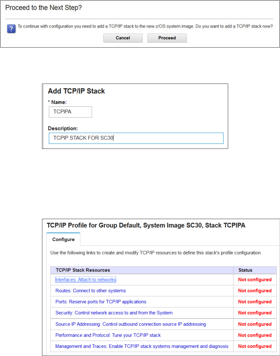
Appendix D. Our implementation environment 525
Figure D-6 Proceed to the next step
4. Click Proceed. In the New TCP/IP Stack Information window, type the TCP/IP stack name
and then click OK. We use the TCPIPA for our stack on SC30, as shown in Figure D-7.
Figure D-7 Add TCP/IP Stack
Configuring TCP/IP stack resources
We use TCP/IP Stack Resource to modify and define the TCP/IP stack. To use this menu,
complete the following steps:
1. In TCP/IP Stack Resources, click Interfaces: Attach to Network, as shown in Figure D-8.
The Define Network Interface window shows the default LPAR image. Click Action →
New.
Figure D-8 TCP/IP Stack Resources

526 IBM z/OS V2R2 Communications Server TCP/IP Implementation Volume 1
2. Create a connection for each VIPA. There are two VIPAs that are defined, as shown in
Table D-1 on page 523. Enter a name and select the network interface and IP address
types and then click OK, as shown in Figure D-9.
Figure D-9 Name and Type of VIPA
3. Enter the IP address of the VIPA in the connectivity column, as shown in Figure D-10.
Figure D-10 IP address of VIPA
4. The z/OSMF Configuration Assistant can define multiple interfaces. We define OSA2080I
with CPHPID 02, VLAN ID 10, and IP address 10.1.2.11/24, as shown in Figure D-11 on
page 527.

Appendix D. Our implementation environment 527
Figure D-11 Connectivity of OSA-Express interface
5. To define HiperSockets interfaces in this configuration, you must enter a name, type, and
IP address of this device:
a. Each type has a different set of parameters that you can define. HiperSockets
interfaces are defined as shown in Figure D-12.
Figure D-12 Name and type of HiperSockets interface

528 IBM z/OS V2R2 Communications Server TCP/IP Implementation Volume 1
b. Enter the IP address of the HiperSockets interface (HIPERF6I) in the connectivity
column, as shown in Figure D-13.
Figure D-13 IP address of HIPERF6I
6. In the Current Backing Store window (see Figure D-14), the Systems tab shows that the
Status of the TCP/IP Configuration file is now Complete. Click Action and select Install
Configuration File.
Figure D-14 Current Backing Store status complete
7. Select the current list configuration file and Select Action → Show Configuration File to
see the configuration TCP/IP profile details that are created by the z/OSMF Configuration
Assistant, as shown in Example D-1.
Example D-1 TCP/IP profile details
;; TCP/IP Profile Configuration file for:
;; Image: SC32
;; Stack: PROFA30
;;
;; Created by the IBM Configuration Assistant for z/OS Communications Server
;; Version 2 Release 2
;; Backing Store = PROFA30T
;; Install History:
;; End of Configuration Assistant information
INTERFACE VIPA2I
DEFINE VIRTUAL
IPADDR 10.1.2.10
;; END OF INTERFACE STATEMENT
INTERFACE VIPA1I
DEFINE VIRTUAL
IPADDR 10.1.1.10
;; END OF INTERFACE STATEMENT
Appendix D. Our implementation environment 529
INTERFACE HIPERF4I
DEFINE IPAQIDIO
CHPID F4
IPADDR 10.1.4.11/24
SMCD
READSTORAGE GLOBAL
SOURCEVIPAINTERFACE VIPA1I
NOMONSYSPLEX
;; END OF INTERFACE STATEMENT
START HIPERF4I
INTERFACE OSA20E0I
DEFINE IPAQENET
CHPIDTYPE OSD
PORTNAME OSA20E0
IPADDR 10.1.3.12/24
VLANID 11
INBPERF DYNAMIC NOWORKLOADQ
VMAC ROUTEALL
SMCR
SMCD
SOURCEVIPAINTERFACE VIPA1I
READSTORAGE GLOBAL
NOMONSYSPLEX
NODYNVLANREG
NOOLM
NOISOLATE
;; END OF INTERFACE STATEMENT
START OSA20E0I
INTERFACE OSA20A0I
DEFINE IPAQENET
CHPIDTYPE OSD
PORTNAME OSA20A0
IPADDR 10.1.2.12/24
VLANID 10
INBPERF DYNAMIC NOWORKLOADQ
VMAC ROUTEALL
SMCR
SMCD
SOURCEVIPAINTERFACE VIPA1I
READSTORAGE GLOBAL
NOMONSYSPLEX
NODYNVLANREG
NOOLM
NOISOLATE
;; END OF INTERFACE STATEMENT
START OSA20A0I
INTERFACE HIPERF6I
DEFINE IPAQIDIO
CHPID F6
IPADDR 10.1.6.11/24
SMCD
READSTORAGE GLOBAL
SOURCEVIPAINTERFACE VIPA1I
NOMONSYSPLEX
;; END OF INTERFACE STATEMENT

530 IBM z/OS V2R2 Communications Server TCP/IP Implementation Volume 1
START HIPERF6I
INTERFACE OSA2080I
DEFINE IPAQENET
CHPIDTYPE OSD
PORTNAME OSA2080
IPADDR 10.1.2.11/24
VLANID 10
INBPERF DYNAMIC NOWORKLOADQ
VMAC ROUTEALL
SMCR
SMCD
SOURCEVIPAINTERFACE VIPA1I
READSTORAGE GLOBAL
NOMONSYSPLEX
NODYNVLANREG
NOOLM
NOISOLATE
;; END OF INTERFACE STATEMENT
START OSA2080I
INTERFACE OSA20C0I
DEFINE IPAQENET
CHPIDTYPE OSD
PORTNAME OSA20C0
IPADDR 10.1.3.11/24
VLANID 11
INBPERF DYNAMIC NOWORKLOADQ
VMAC ROUTEALL
SMCR
SMCD
SOURCEVIPAINTERFACE VIPA1I
READSTORAGE GLOBAL
NOMONSYSPLEX
NODYNVLANREG
NOOLM
NOISOLATE
;; END OF INTERFACE STATEMENT
START OSA20C0I
INTERFACE HIPERF5I
DEFINE IPAQIDIO
CHPID F5
IPADDR 10.1.5.11/24
SMCD
READSTORAGE GLOBAL
SOURCEVIPAINTERFACE VIPA1I
NOMONSYSPLEX
;; END OF INTERFACE STATEMENT
START HIPERF5I
IPCONFIG
ARPTO 1200
;; END OF IPCONFIG STATEMENT
PRIMARYINTERFACE VIPA1I

Appendix D. Our implementation environment 531
8. Click Close, and then Select Action → Install. Because z/OSMF Configuration Assistant
runs on image SC33 (a different LPAR), select Save to disk (Figure D-15). In your
environment, you might need to use FTP to send the TCP/IP Profile to the correct image.
We add a meaningful suffix data set (‘TCPIPA.TCPPARMS(PROFA30F)’) to the default Install
file name field, and then clicked GO.
Figure D-15 Install the TCP/IP profile
9. When the save is complete, click Close. You can optionally enter a comment for the
configuration file’s history log. Click OK → Close.
D.3.2 Starting a TCP/IP stack by using the TCP/IP profile from z/OSMF
In our example, we start TCPIPA in LPAR A12 and receive the messages that are shown in
Example D-2.
Example D-2 Start TCPIPA
S TCPIPA
EZZ4202I Z/OS UNIX - TCP/IP CONNECTION ESTABLISHED FOR TCPIPA
IEF196I IEF237I 23A2 ALLOCATED TO TP23A2
BPXF206I ROUTING INFORMATION FOR TRANSPORT DRIVER TCPIPA HAS BEEN
INITIALIZED OR UPDATED.
IEE252I MEMBER CTIEZB00 FOUND IN SYS1.IBM.PARMLIB
IEE252I MEMBER CTIIDS00 FOUND IN SYS1.IBM.PARMLIB
IEE252I MEMBER CTINTA00 FOUND IN SYS1.PARMLIB
/*
Z/OS UNIX - TCP/IP CONNECTION ESTABLISHED FOR TCPIPA 1
*
EZZ4340I INITIALIZATION COMPLETE FOR INTERFACE HIPERFEI

532 IBM z/OS V2R2 Communications Server TCP/IP Implementation Volume 1
EZZ4340I INITIALIZATION COMPLETE FOR INTERFACE HIPERFFI
EZZ4340I INITIALIZATION COMPLETE FOR INTERFACE EZAISM01
EZZ4340I INITIALIZATION COMPLETE FOR INTERFACE OSA2380I 1
EZZ4340I INITIALIZATION COMPLETE FOR INTERFACE OSA23A0I
EZB6473I TCP/IP STACK FUNCTIONS INITIALIZATION COMPLETE.2
EZAIN11I ALL TCPIP SERVICES FOR PROC TCPIPA ARE AVAILABLE.
/*
EZD1176I TCPIPA HAS SUCCESSFULLY JOINED THE TCP/IP SYSPLEX GROUP 3
/*
This message indicates the successful establishment of a connection to the UNIX System
Services Environment. The numbers have the following meaning:
1. Show how the stack is bound to UNIX System Services.
2. The EZB6473I and EZAIN11I messages show that the TCP/IP stack initialization is
complete and the services are available.
3. Our environment is defined within a sysplex, so message EZD1176I indicates the
connectivity to the TCP/IP sysplex group EZBTCPCS.
D.3.3 Verifying the TCP/IP configuration
We finish the TCP/IP profile in z/OSMF Configuration Assistant. Now, we verify the
configuration. We restart the TCP/IP address space and ensure that we get the following
message:
EZB6473I TCP/IP STACK FUNCTIONS INITIALIZATION COMPLETE
If messages are displayed by the TCP/IP address space, they should describe errors or why
the TCP/IP stack did not start.
Displaying the TCP/IP configuration
To display the enabled features and operating characteristic of a TCP/IP stack, enter either of
the following commands:
D TCPIP,procname,NETSTAT,HOME
D TCPIP,procmane,NETSTAT,DEVLINKS
Example D-3 shows the output from the NETSTAT HOME command.
Example D-3 NETSTAT HOME display
D TCPIP,TCPIPA,NETSTAT,HOME
HOME ADDRESS LIST:
LINKNAME: LOOPBACK
ADDRESS: 127.0.0.1
FLAGS:
INTFNAME: VIPA2I
ADDRESS: 10.1.2.10
FLAGS:
INTFNAME: VIPA1I
ADDRESS: 10.1.1.10
FLAGS: PRIMARY
INTFNAME: HIPERF4I
ADDRESS: 10.1.4.11

Appendix D. Our implementation environment 533
FLAGS:
INTFNAME: OSA20E0I
ADDRESS: 10.1.3.12
FLAGS:
INTFNAME: OSA20A0I
ADDRESS: 10.1.2.12
FLAGS:
INTFNAME: HIPERF6I
ADDRESS: 10.1.6.11
FLAGS:
INTFNAME: OSA2080I
ADDRESS: 10.1.2.11
FLAGS:
INTFNAME: OSA20C0I
ADDRESS: 10.1.3.11
FLAGS:
INTFNAME: HIPERF5I
ADDRESS: 10.1.5.11
FLAGS:
INTFNAME: LOOPBACK6
ADDRESS: ::1
TYPE: LOOPBACK
FLAGS:
11 OF 11 RECORDS DISPLAYED
END OF THE REPORT
Example D-4 shows the output from the NETSTAT DEVLINKS command.
Example D-4 NETSTAT DEVLINKS display
D TCPIP, TCPIPA,NETSTAT,DEVLINKS
RESPONSE=SC32
------------------------------------------------------------------- Line deleted
INTFNAME: OSA20E0I INTFTYPE: IPAQENET INTFSTATUS: READY
PORTNAME: OSA20E0 DATAPATH: 20E2 DATAPATHSTATUS: READY
CHPIDTYPE: OSD SMCR: DISABLED (GLOBALCONFIG NOSMCR)
PNETID: *NONE* SMCD: DISABLED (GLOBALCONFIG NOSMCD)
SPEED: 0000001000
IPBROADCASTCAPABILITY: NO
VMACADDR: 0200024830E8 VMACORIGIN: OSA VMACROUTER: ALL
SRCVIPAINTF: VIPA1I
ARPOFFLOAD: YES ARPOFFLOADINFO: YES
CFGMTU: NONE ACTMTU: 8992
IPADDR: 10.1.3.12/24
VLANID: 11 VLANPRIORITY: DISABLED
DYNVLANREGCFG: NO DYNVLANREGCAP: YES
READSTORAGE: GLOBAL (4096K)
INBPERF: DYNAMIC
WORKLOADQUEUEING: NO
CHECKSUMOFFLOAD: YES SEGMENTATIONOFFLOAD: NO
SECCLASS: 255 MONSYSPLEX: NO
ISOLATE: NO OPTLATENCYMODE: NO
MULTICAST SPECIFIC:
MULTICAST CAPABILITY: YES
GROUP REFCNT SRCFLTMD
----- ------ --------

534 IBM z/OS V2R2 Communications Server TCP/IP Implementation Volume 1
224.0.0.1 0000000001 EXCLUDE
SRCADDR: NONE
INTERFACE STATISTICS:
BYTESIN = 84
INBOUND PACKETS = 1
INBOUND PACKETS IN ERROR = 0
INBOUND PACKETS DISCARDED = 0
INBOUND PACKETS WITH NO PROTOCOL = 0
BYTESOUT = 0
OUTBOUND PACKETS = 0
OUTBOUND PACKETS IN ERROR = 0
OUTBOUND PACKETS DISCARDED = 0
INTFNAME: OSA20A0I INTFTYPE: IPAQENET INTFSTATUS: READY
PORTNAME: OSA20A0 DATAPATH: 20A2 DATAPATHSTATUS: READY
CHPIDTYPE: OSD SMCR: DISABLED (GLOBALCONFIG NOSMCR)
PNETID: *NONE* SMCD: DISABLED (GLOBALCONFIG NOSMCD)
SPEED: 0000001000
IPBROADCASTCAPABILITY: NO
VMACADDR: 020002484C96 VMACORIGIN: OSA VMACROUTER: ALL
SRCVIPAINTF: VIPA1I
ARPOFFLOAD: YES ARPOFFLOADINFO: YES
CFGMTU: NONE ACTMTU: 8992
IPADDR: 10.1.2.12/24
VLANID: 10 VLANPRIORITY: DISABLED
DYNVLANREGCFG: NO DYNVLANREGCAP: YES
READSTORAGE: GLOBAL (4096K)
INBPERF: DYNAMIC
WORKLOADQUEUEING: NO
CHECKSUMOFFLOAD: YES SEGMENTATIONOFFLOAD: NO
SECCLASS: 255 MONSYSPLEX: NO
ISOLATE: NO OPTLATENCYMODE: NO
MULTICAST SPECIFIC:
MULTICAST CAPABILITY: YES
GROUP REFCNT SRCFLTMD
----- ------ --------
224.0.0.1 0000000001 EXCLUDE
SRCADDR: NONE
INTERFACE STATISTICS:
BYTESIN = 0
INBOUND PACKETS = 0
INBOUND PACKETS IN ERROR = 0
INBOUND PACKETS DISCARDED = 0
INBOUND PACKETS DISCARDED = 0
INBOUND PACKETS WITH NO PROTOCOL = 0
BYTESOUT = 84
OUTBOUND PACKETS = 1
OUTBOUND PACKETS IN ERROR = 0
OUTBOUND PACKETS DISCARDED = 0
------------------------------------------------------------------- Line deleted
If the status for the interface is not READY, verify that the VTAM Major node is active. You can
do this by using the VTAM command D NET, TRL.
Also, make sure that the VLAN ID that is defined to the interface matches the one for the port
in the Ethernet switch.
© Copyright IBM Corp. 2016. All rights reserved. 535
Related publications
The publications that are listed in this section are considered suitable for a more detailed
discussion of the topics that are covered in this book.
IBM Redbooks publications
The following IBM Redbooks publications provide additional information about the topic in this
document. Some publications that are referenced in this list might be available in softcopy
only.
IBM HiperSockets Implementation Guide, SG24-6816
IBM z/OS V2R2 Communications Server TCP/IP Implementation Volume 2: Standard
Applications, SG24-8361
IBM z/OS V2R2 Communications Server TCP/IP Implementation Volume 3: High
Availability, Scalability, and Performance, SG24-8362
IBM z/OS V2R2 Communications Server TCP/IP Implementation Volume 4: Security and
Policy-Based Networking, SG24-8363
IP Network Design Guide, SG24-2580
Migrating Subarea Networks to an IP Infrastructure Using Enterprise Extender,
SG24-5957
OSA-Express Implementation Guide, SG24-5948
SNA in a Parallel Sysplex Environment, SG24-2113
TCP/IP Tutorial and Technical Overview, GG24-3376
z/OS 1.6 Security Services Update, SG24-6448
z/OS Infoprint Server Implementation, SG24-6234
You can search for, view, or download Redbooks, IBM Redpapers™, Technotes, draft
publications and Additional materials, and order hardcopy Redbooks publications, at this
website:
ibm.com/redbooks
Other publications
The following publications are also relevant as further information sources:
IBM Health Checker for z/OS: User’s Guide, SA22-7994
OSA-Express Customer’s Guide and Reference, SA22-7935
z/OS Communications Server: CSM Guide, SC31-8808
z/OS Communications Server: IP Configuration Guide, SC27-3650
z/OS Communications Server: IP Configuration Reference, SC27-3651
z/OS Communications Server: IP Diagnosis Guide, GC31-8782
z/OS Communications Server: IP Messages Volume 1 (EZA), SC31-8783
536 IBM z/OS V2R2 Communications Server TCP/IP Implementation Volume 1
z/OS Communications Server: IP Messages Volume 2 (EZB, EZD), SC31-8784
z/OS Communications Server: IP Messages Volume 3 (EZY), SC31-8785
z/OS Communications Server: IP Messages Volume 4 (EZZ, SNM), SC31-8786
z/OS Communications Server: IP Programmer’s Guide and Reference, SC31-8787
z/OS Communications Server: IP and SNA Codes, SC31-8791
z/OS Communications Server: IP Sockets Application Programming Interface Guide and
Reference, SC31-8788
z/OS Communications Server: IP System Administrator’s Commands, SC27-3661
z/OS Communications Server: IP User’s Guide and Commands, SC31-8780
z/OS Communications Server: IPv6 Network and Application Design Guide, SC31-8885
z/OS Communications Server: New Function Summary, GC31-8771
z/OS Communications Server: Quick Reference, SX75-0124
z/OS Communications Server: SNA Network Implementation, SC31-8777
z/OS Communications Server: SNA Operation, SC31-8779
z/OS Communications Server: SNA Resource Definition, SC31-8778
z/OS Migration, GA22-7499
z/OS MVS IPCS Commands, SA22-7594
z/OS MVS System Commands, SA22-7627
z/OS TSO/E Command Reference, SA22-7782
z/OS UNIX System Services Command Reference, SA22-7802
z/OS UNIX System Services Programming: Assembler Callable Services Reference,
SA22-7803
z/OS UNIX System Services Command Reference, SA22-7802
z/OS UNIX System Services File System Interface Reference, SA22-7808
z/OS UNIX System Services Messages and Codes, SA22-7807
z/OS UNIX System Services Parallel Environment: Operation and Use, SA22-7810
z/OS UNIX System Services Planning, GA22-7800
z/OS UNIX System Services Programming Tools, SA22-7805
z/OS UNIX System Services User’s Guide, SA22-7801
z/OS XL C/C++ Run-Time Library Reference, SA22-7821
Online resources
The following websites are also relevant as further information sources:
Mainframe networking
http://www.ibm.com/servers/eserver/zseries/networking/
z/OS Communications Server product overview
http://www.ibm.com/software/network/commserver/zos/
z/OS Communications Server product support
http://www.ibm.com/software/network/commserver/zos/support/
538 IBM z/OS V2R2 Communications Server TCP/IP Implementation Volume 1

ISBN 0738442097
SG24-8360-00
(1.0” spine)
0.875”<->1.498”
460 <-> 788 pages
IBM z/OS V2R2 Communications Server TCP/IP
Implementation Volume 1

