
Version 2.7, May 2024
SolarEdge Inverters - SunSpec Logging - Technical Note
1
SolarEdge Inverters - SunSpec Logging - Technical Note
Revision History
Version 2.7, May 2024: Updated Appendix A and Appendix B. Removed Appendix C.
Version 2.6, December 2023: Updated L-L voltage for SE meter via MODBUS.
Version 2.5, November 2022: Synergy inverter updates; multiple MPPT Inverter Extension Model table:
value at address 40127 changed to 0.
Contents
Revision History .................................................................................................................................................................................................................................................... 1
Overview .................................................................................................................................................................................................................................................................. 2
Communication Technologies ........................................................................................................................................................................................................................ 2
SunSpec Supported Inverters .......................................................................................................................................................................................................................... 3
Use Cases for MODBUS over RS485 ............................................................................................................................................................................................................. 3
Use Cases for MODBUS over TCP.................................................................................................................................................................................................................. 6
SolarEdge Device Configuration – Using SetApp ................................................................................................................................................................................... 9
SolarEdge Device Configuration – Using the Inverter/Commercial Gateway Display (LCD) .............................................................................................. 11
Register Mapping – Monitoring Data ........................................................................................................................................................................................................ 13
Multiple MPPT Inverter Extension Model ................................................................................................................................................................................................. 17
Meter Models ...................................................................................................................................................................................................................................................... 19
Appendix A – Encoding and Decoding Examples ................................................................................................................................................................................ 31
Appendix B – Response Time Information............................................................................................................................................................................................... 37
Support Contact Information ........................................................................................................................................................................................................................ 39

Version 2.7, May 2024
SolarEdge Inverters - SunSpec Logging - Technical Note
2
Overview
SolarEdge inverters support transmission of inverter-level monitoring data directly from the
inverter to a local non-SolarEdge device using the SunSpec open protocol for interoperability
between devices in renewable energy systems. This option can be used alongside the
connection to the SolarEdge monitoring server. This document describes the connection
method and the protocol and configurations needed to implement this feature.
Direct connection to a monitoring device is useful when a network connection is unavailable,
when extensive custom data processing is required, or when authorities require direct access to
monitoring data.
In many cases, it is possible – and recommended – to employ the direct connection alongside a
SolarEdge monitoring platform connection. Connection to the monitoring platform enables all
the monitoring benefits, primarily:
Proactive installer maintenance and real time troubleshooting by SolarEdge support, using
with the physical mapping available only in the monitoring platform
Module-level monitoring
Communication Technologies
SolarEdge uses an open, industry-standard communications stack to provide efficient messaging
between SolarEdge and third-party devices and applications.
The communications stack components are briefly described below.
SunSpec
SunSpec is an application-layer communications protocol designed to achieve interoperability
between Distributed Energy Resource (DER) components and smart grid applications.
Modbus
Modbus is a serial communications protocol typically used to connect data collection terminals
to a centralized processing unit. SolarEdge products use Modbus to perform SunSpec
messaging over two types of physical/link-layer channels:
Modbus RTU: Remote Terminal Unit (RTU) Modbus over a serial RS485 connection
Modbus TCP: Modbus over an Ethernet connection
SolarEdge systems support a single Modbus Leader only – either single Modbus RTU or
single Modbus TCP.

Version 2.7, May 2024
SolarEdge Inverters - SunSpec Logging - Technical Note
3
SunSpec Supported Inverters
Depending on their type, SolarEdge devices may be configured in either of the two ways:
Using SetApp
Using the LCD
All SolarEdge inverters with SetApp configuration are SunSpec-supported.
SolarEdge inverters with the LCD that have Firmware version 3.xxxx and above only are SunSpec-
supported.
To check the inverter firmware versions (for inverters with the LCD):
1.
Short press the LCD light button until the following screen is displayed:
2.
If required, upgrade to the latest available firmware, as described in
https://www.solaredge.com/sites/default/files/upgrading_an_inverter_using_micro_sd_card.pdf.
Use Cases for MODBUS over RS485
This section describes RS485 options to connect the inverter to a non-SolarEdge monitoring
device.
Physical Connection
The connection is performed using an RS485 connector with a twisted pair cable. The
transmission mode in SolarEdge inverters is set to RTU (binary).
The COM port default properties are: 115200 bps, 8 data bits, no parity, 1 stop bit, no flow
control. Baud rate can be changed between 9600bps to 115200bps (supported from CPU
version 2.0549).
The RS485 bus can be configured to support connection either to a non-SolarEdge monitoring
device or Leader-Follower connection between SolarEdge inverters. Therefore, a Follower
inverter cannot communicate simultaneously with a Leader inverter and with a non-SolarEdge
monitoring device on the same RS485 bus.
All SolarEdge inverters with SetApp configuration have two built-in RS485 ports. An inverter can
act as Leader on both ports simultaneously. Each port on a leader inverter can connect to up to
31 follower inverters. The two ports therefore support connectivity with 62 follower inverters.
A Commercial Gateway with LCD can act as Leader on one of the built-in RS485 ports and on
the RS485 Plug-in.
For more information on the RS485 Plug-in, see:
https://www.solaredge.com/sites/default/files/RS485_expansion_kit_installation_guide.pdf
I D : # # # # # # # # # #
D S P 1 / 2 : x . x x x x / x . x x x x
C P U : 0 0 0 2 . 0 4 9 6
C o u n t r y : X X X X X

Version 2.7, May 2024
SolarEdge Inverters - SunSpec Logging - Technical Note
4
NOTE
For connectivity purposes, the Synergy Manager is considered a single inverter.
Single Inverter Connection
Use the RS485 bus for connecting to a non-SolarEdge monitoring device.
Use the Ethernet connection or any of the optional wireless connection options to connect to
the SolarEdge monitoring platform.
Multiple Inverter Connection
If a second RS485 port is required to establish connection, use:
RS485-2 for inverters with SetApp configuration
RS485-E (requires a RS485 Plug-in) for inverters with an LCD
Connection to a non-SolarEdge monitoring device only (without connection to the monitoring platform)
Option 1 (direct connection) – Use RS485-1 to connect Followers to the Leader and the Leader
to a non-SolarEdge monitoring device. Every inverter in the RS485 bus should be configured to
a different device ID (MODBUS ID).
Option 2 – Use RS485-1 to connect Follower inverters to the Leader; use either RS485-2 or
RS485-E to connect the Leader to a non-SolarEdge monitoring device. Every inverter in the

Version 2.7, May 2024
SolarEdge Inverters - SunSpec Logging - Technical Note
5
RS485 bus should be configured to a different device ID (MODBUS ID).
Connection to a non-SolarEdge monitoring device (with connection to the monitoring platform)
Use the RS485 bus for connection to a non-SolarEdge monitoring device. Every inverter in the
RS485 bus should be configured to a different device ID (MODBUS ID).
Option 1 (direct connection) – Connect each inverter to the router via Ethernet cables.
Option 2 – Connect the router to one inverter only.

Version 2.7, May 2024
SolarEdge Inverters - SunSpec Logging - Technical Note
6
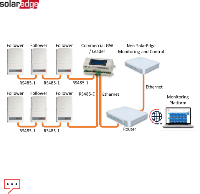
Connection to the monitoring platform and to a non-SolarEdge monitoring device using a Commercial
Gateway
Use the RS485-2 bus for connection to a non-SolarEdge monitoring device. Every inverter
connected to the RS485 bus should be configured to a different device ID (MODBUS ID).
If required, use the RS485-E bus for connecting a second chain of inverters.
Use Cases for MODBUS over TCP
This section describes MODBUS over TCP options to connect the inverter to a non-SolarEdge
monitoring device.
Single Inverter Connection
Use Ethernet for connecting to a non-SolarEdge monitoring device.

Version 2.7, May 2024
SolarEdge Inverters - SunSpec Logging - Technical Note
7
Multiple Inverter Connection
Connection to a non-SolarEdge monitoring device only (without connection to the SolarEdge monitoring
platform)
Use Ethernet for connection to a non-SolarEdge monitoring device.
Connection to a non-SolarEdge monitoring device (with connection to the SolarEdge monitoring platform)
Use Ethernet for connection to a non-SolarEdge monitoring device.
Option 1 (direct connection) – Connect each inverter to the Ethernet router via Ethernet cables.

Version 2.7, May 2024
SolarEdge Inverters - SunSpec Logging - Technical Note
8
Option 2 – Connect the Leader only to the Ethernet router via Ethernet cables.
Connect a second chain of the inverters to the Leader inverter using RS485-2/RS485-E.
Connection to the SolarEdge monitoring platform and to a non-SolarEdge
monitoring device using a Commercial Gateway
Use Ethernet for connection to a non-SolarEdge monitoring device. Every inverter connected to
the RS485 bus should be configured to a different device ID (MODBUS ID).
Version 2.7, May 2024
SolarEdge Inverters - SunSpec Logging - Technical Note
9
If required, use the RS485-E bus for connecting a second chain of inverters.
SolarEdge Device Configuration – Using SetApp
This section describes how to configure a SolarEdge device (inverter or Commercial Gateway) to
be monitored by a non-SolarEdge monitoring device using SetApp.
NOTE
The actual SetApp configuration procedures may differ from the ones shown in this
document.
To reach the main setup menu, access SetApp and tap Commissioning Site Communication:
Modbus over RS485 Configuration
To configure the inverters (when used without the Commercial Gateway):
1.
Under the Site Communication menu, set the following:
RS485-1 Protocol SunSpec (Non-SE Logger)
RS485-1 Device ID, and enter the MODBUS address (a unique value 1…247). This will set the register
C_DeviceAddress.
2.
If needed, set the baud rate to a preferred value: RS485-1 Baud rate and enter the rate.
To configure the inverters and gateway (when used with the Commercial
Gateway):
1.
Inverter configuration: For all inverters, verify the following RS485 bus settings under the Site
Communication menu:
RS485-1 Protocol SolarEdge SolarEdge Follower
RS485-1 Device ID [a unique value 1…247]
2.
Commercial Gateway configuration
using the device display
: Use RS485-1 to connect to the
inverters. RS485-1 bus configuration is as follows:
Communication RS485-1 Conf Device Type SolarEdge
Communication RS485-1 Conf Protocol Leader
Communication RS485-1 Conf Follower Detect

Version 2.7, May 2024
SolarEdge Inverters - SunSpec Logging - Technical Note
10
The Commercial Gateway should report the correct number of Follower inverters. If it does not,
verify the connections and terminations.
3.
Use RS485-2 to connect the Commercial Gateway to the non-SolarEdge monitoring device.
Configure the RS485-2 bus settings as follows,
using the device display
:
Communication RS485-2 Conf Protocol SunSpec (Non-SE Logger)
The Commercial Gateway device ID is irrelevant for communications, but needs to be set to a
different ID than the one set for the inverters.
Communication RS485-2 Conf Device ID [use one of the higher IDs (e.g. 247) to make sure it
is out of scope]
The default baud rate is 115200 bps. If a different baud rate is required, select: Communication
RS485-2 Conf Baud Rate
4.
Make sure the device ID of the non-SolarEdge monitoring device is different from all other
device IDs configured in the inverters and gateways.
5.
Connect the Commercial Gateway to router via the Ethernet interface and configure the
following settings
using the device display
:
Communication Server LAN
Communication LAN Conf Set DHCP [Select Enable for DHCP or Disable for static IP
configuration]
For Static DHCP setting, configure as follows:
Communication LAN Conf Set IP [Set inverters’ IP]
Communication LAN Conf Set Mask [Set inverters’ subnet mask]
Communication LAN Conf Set Gateway [Set inverters’ gateway]
Communication LAN Conf Set DNS [Set inverters’ DNS]
6.
If the router is connected to the server, select Commissioning Status and verify that
“S_OK” is displayed on the Status page.
MODBUS over TCP Support
MODBUS/TCP uses the Ethernet media in physical layers to carry the MODBUS message
handling structure and can support a large number of devices in one network; it is easier to
integrate into the Local Area Network (LAN) of a company, so it is the choice of more and more
customers.
Here, it is used for remote 3rd party monitoring and control. MODBUS TCP is agnostic of the
server connection. It works only over LAN. When configured, MODBUS TCP does not initiate a
connection - the server waits for a client to connect. Only one connection is supported.
NOTE
The MODBUS TCP function is disabled by default. When enabled, it supports TCP port 1502 by
default. Port number can be reconfigured.

Version 2.7, May 2024
SolarEdge Inverters - SunSpec Logging - Technical Note
11
MODBUS over TCP Configuration
To setup MODBUS TCP:
1.
Select Site Communication Modbus TCP Enable. A new Port menu is added to the
screen (the default port is 1502).
2.
To modify the TCP port, select Port, set the port number and tap Done.
NOTE
The default device ID of the inverter connected to the Ethernet is 1.
NOTE
The TCP server idle time is 2 minutes. In order to leave the connection open, the request
should be made within 2 minutes. The connection can remain open without any
MODBUS requests.
SolarEdge Device Configuration – Using the Inverter/Commercial
Gateway Display (LCD)
This section describes how to configure a SolarEdge device (inverter or Commercial Gateway) to
be monitored by a non-SolarEdge monitoring device using the LCD. To reach the main setup
menu, follow the instructions in the Installation Guide of the specific SolarEdge device.
Modbus over RS485 Configuration
To configure the inverters (when used without the Commercial Gateway):
1.
In the Communication menu, set the following:
Communication Server Select any server connection, except for RS485 (if the inverter is not
connected to the SolarEdge monitoring platform, select None.
Communication RS485-1 Conf
RS485-1 Conf Device Type Non-SE Logger
RS485-1 Conf Protocol SunSpec
RS485-1 Conf Device ID and enter the MODBUS address (a unique value 1…247). This will set the
register C_DeviceAddress.
2.
If necessary, set the baud rate to a preferred value: RS485-1 Conf Baud rate and enter the
rate.
To configure the inverter (when used with the Commercial Gateway):
1.
Inverters configuration: For all inverters, set the following RS485 bus settings:
Communication RS485-1 Conf Device Type SolarEdge
Communication RS485-1 Conf Protocol Follower
Communication RS485-1 Conf Device ID [a unique value 1…247]

Version 2.7, May 2024
SolarEdge Inverters - SunSpec Logging - Technical Note
12
2.
Commercial Gateway configuration: Use RS485-1 to connect to the inverters. RS485-1 bus
configuration is as follows:
Communication RS485-1 Conf Device Type SolarEdge
Communication RS485-1 Conf Protocol Master
Communication RS485-1 Conf Follower Detect
The Commercial Gateway should report the correct number of followers. If it does not, verify the
connections and terminations.
3.
Use RS485-2 to connect to the non-SolarEdge monitoring device. RS485-2 bus configuration
is as follows:
Communication RS485-2 Conf Device Type Non-SE Logger
Communication RS485-2 Conf Protocol SunSpec
The Commercial Gateway Device ID is irrelevant for communications, but needs to be set to a
different ID than the one set for the inverters.
Communication RS485-2 Conf Device ID [use one of the higher ID’s (e.g. 247) to make sure it
is out of scope]
The default baud rate is 115200 bps. If a different baud rate is required, select: Communication
RS485-2 Conf Baud Rate
4.
Make sure the device ID of the non-SolarEdge monitoring device is different from all other
device IDs configured in the inverters and gateways.
5.
Connect the Commercial Gateway to router via the Ethernet interface and configure the
following settings:
Communication Server LAN
Communication LAN Conf Set DHCP [Select Enable for DHCP or Disable for static IP
configuration]
For Static DHCP setting, configure as follows:
Communication LAN Conf Set IP [Set inverters’ IP]
Communication LAN Conf Set Mask [Set inverters’ subnet mask]
Communication LAN Conf Set Gateway [Set inverters’ gateway]
Communication LAN Conf Set DNS [Set inverters’ DNS]
6.
If the router is connected to the server, verify that the LCD panel displays <S_OK>.
7.
Verify that the LCD panel of all inverters is <S_OK>.
MODBUS over TCP Support
MODBUS/TCP uses the Ethernet media in physical layers to carry the MODBUS message
handling structure and can support a large number of devices in one network; it is easier to
integrate into the Local Area Network (LAN) of a company, so it is the choice of more and more
customers.

Version 2.7, May 2024
SolarEdge Inverters - SunSpec Logging - Technical Note
13
Here, it is used for remote 3rd party monitoring and control. MODBUS TCP is agnostic of
the server connection. It works only over LAN. When configured, MODBUS TCP does not
initiate a connection. The server waits for a client to connect. Only one connection is
supported.
MODBUS over TCP Configuration
To setup MODBUS TCP:
1.
Select Communication LAN Conf Modbus TCP (the default port is 502).
2.
To modify the TCP port, select Modbus TCP TCP Port, set the port number and long-
press Enter.
When the MODBUS TCP feature is enabled, the following information is
displayed: Status:
Init – Initializing server – This state only occurs after the first configuration until it reaches the ready
status. This activity lasts about 10sec.
Ready – The server is up and waiting for a client to connect.
Connected – The client is connected.
Failed – The server is unable to accept clients (see error message).
Error messages:
Disconnected – The Ethernet cable is not connected
Gateway Ping Failed – A ping to the 1st router failed
No IP – Either no DHCP configuration or static IP configuration (no DHCP server that
assigned an IP address) or need to define a static IP.
NOTE
The TCP server idle time is two minutes. In order to leave the connection open, the request
should be made within 2 minutes. The connection can remain open without any MODBUS
requests.
Register Mapping – Monitoring Data
This section describes the registers mapping for the inverter monitoring data (read-only
MODBUS protocol data). The SolarEdge inverter mapping for monitoring data is based on
the open protocol managed by SunSpec: SunSpec Alliance Interoperability Specification –
Inverter Models v1.0. Refer to the SunSpec Alliance Interoperability Specification –
Common Models (Elements) document for a detailed description of the protocol.
The register mapping can be downloaded from the SunSpec Alliance web page:
http://www.sunspec.org/
NOTE
The MODBUS
TCP function is disabled by default. When enabled, it supports TCP port 502 by
default. The port number can be reconfigured.
NOTE
The default device ID of the inverter connected to the Ethernet is 1.

Version 2.7, May 2024
SolarEdge Inverters - SunSpec Logging - Technical Note
14
SolarEdge inverters support the following mappings:
SunSpec module ID 101, 102
1
and 103 register mappings.
SolarEdge three phase inverters with Synergy technology also support SunSpec module ID
160 register mappings.
Common Model MODBUS Register Mappings
The base Register Common Block is set to 40001 (MODBUS PLC address [base 1]) or 40000
(MODBUS Protocol Address [base 0]).
All parameters are defined as in the SunSpec Common block definition, except for the
C_Options register, which is set to NOT_IMPLEMENTED.
C_Manufacturer is set to SolarEdge.
C_Model is set to the appropriate inverter model, e.g. SE5000.
C_Version contains the CPU software version with leading zeroes, e.g. 0002.0611.
C_SerialNumber contains the inverter serial number.
C_DeviceAddress is the device MODBUS ID.
Address
Size Name Type Description
(base 0)
(base 1)
40000 40001 2 C_SunSpec_ID uint32
Value = "SunS" (0x53756e53). Uniquely identifies this
as a SunSpec MODBUS Map
40002 40003 1 C_SunSpec_DID uint16
Value = 0x0001. Uniquely identifies this as a SunSpec
Common Model Block
40003 40004 1
C_SunSpec_Lengt
h
uint16 65 = Length of block in 16-bit registers
40004
40005
16
C_Manufacturer
String(32)
Value Registered with SunSpec = "SolarEdge "
40020
40021
16
C_Model
String(32)
SolarEdge Specific Value
40044
40045
8
C_Version
String(16)
SolarEdge Specific Value
40052
40053
16
C_SerialNumber
String(32)
SolarEdge Unique Value
40068
40069
1
C_DeviceAddress
uint16
MODBUS Unit ID
Inverter Device Status Values
The following I_Status_* values are supported:
Parameter
Value
Description
I_STATUS_OFF
1
Off
I_STATUS_SLEEPING
2
Sleeping (auto-shutdown) – Night mode
I_STATUS_STARTING
3
Grid Monitoring/wake-up
I_STATUS_MPPT
4
Inverter is ON and producing power
I_STATUS_THROTTLED
5
Production (curtailed)
I_STATUS_SHUTTING_DOWN
6
Shutting down
I_STATUS_FAULT
7
Fault
I_STATUS_STANDBY
8
Maintenance/setup
1
Supported only in split-phase configurations (Japanese grid and 240V grid in North America)

Version 2.7, May 2024
SolarEdge Inverters - SunSpec Logging - Technical Note
15
Inverter Model MODBUS Register Mappings
The following table lists the supported MODBUS register values. Unsupported values are
indicated by the NOT_IMPLEMENTED value. The base register of the Device Specific block is set
to 40070 (MODBUS PLC address [base 1]), or 40069 (MODBUS Protocol Address [base 0]).
acc32 is a uint32 accumulator that should always increase. Its value is in the range of
0...4294967295.
Scale Factors. As an alternative to floating point format, values are represented by Integer
values with a signed scale factor applied. The scale factor explicitly shifts the decimal point
to left (negative value) or to the right (positive value).
For example, a value “Value” may have an associated value “Value_SF”
Value = “Value” * 10^ Value_SF for example:
For “Value” = 2071 and “Value_SF” = -2 Value = 2071*10^-2 = 20.71
For “Value” = 2071 and “Value_SF” = 2 Value = 2071*10^2 = 207100
Address
Size Name Type Units Description
(base 0)
(base 1)
40069
40070
1
C_SunSpec_DID
uint16
101 = single phase
102 = split phase
103 = three phase
40070
40071
1
C_SunSpec_Length
uint16
Registers
50 = Length of model block
40071
40072
1
I_AC_Current
uint16
Amps
AC Total Current value
40072
40073
1
I_AC_CurrentA
uint16
Amps
AC Phase A Current value
40073
40074
1
I_AC_CurrentB
uint16
Amps
AC Phase B Current value
40074
40075
1
I_AC_CurrentC
uint16
Amps
AC Phase C Current value
40075
40076
1
I_AC_Current_SF
int16
AC Current scale factor
40076
40077
1
I_AC_VoltageAB
uint16
Volts
AC Voltage Phase AB value
40077
40078
1
I_AC_VoltageBC
uint16
Volts
AC Voltage Phase BC value
40078
40079
1
I_AC_VoltageCA
uint16
Volts
AC Voltage Phase CA value
40079
40080
1
I_AC_VoltageAN
1
uint16
Volts
AC Voltage Phase A to N value
40080
40081
1
I_AC_VoltageBN
1
uint16
Volts
AC Voltage Phase B to N value
40081
40082
1
I_AC_VoltageCN
1
uint16
Volts
AC Voltage Phase C to N value
40082
40083
1
I_AC_Voltage_SF
int16
AC Voltage scale factor
40083
40084
1
I_AC_Power
int16
Watts
AC Power value
40084
40085
1
I_AC_Power_SF
int16
AC Power scale factor
40085
40086
1
I_AC_Frequency
uint16
Hertz
AC Frequency value
40086
40087
1
I_AC_Frequency_SF
int16
Scale factor
40087
40088
1
I_AC_VA
int16
VA
Apparent Power
40088
40089
1
I_AC_VA_SF
int16
Scale factor
40089
40090
1
I_AC_VAR
2
int16
VAR
Reactive Power
40090
40091
1
I_AC_VAR_SF
2
int16
Scale factor
1
Supported only in split-phase configurations (Japanese grid and 240V grid in North America).
2
For details, see the Power Configurations and Correlated Outcomes under Reactive Power Configuration
in SolarEdge Inverters, Power Control Options.

Version 2.7, May 2024
SolarEdge Inverters - SunSpec Logging - Technical Note
16
Address
Size Name Type Units Description
(base 0)
(base 1)
40091
40092
1
I_AC_PF
1
int16
%
Power Factor
40092
40093
1
I_AC_PF_SF
1
int16
Scale factor
40093
40094
2
I_AC_Energy_WH
acc32
WattHours
AC Lifetime Energy production
40095
40096
1
I_AC_Energy_WH_SF
uint16
Scale factor
40096
40097
1
I_DC_Current
uint16
Amps
DC Current value
40097
40098
1
I_DC_Current_SF
int16
Scale factor
40098
40099
1
I_DC_Voltage
uint16
Volts
DC Voltage value
40099
40100
1
I_DC_Voltage_SF
int16
Scale factor
40100
40101
1
I_DC_Power
int16
Watts
DC Power value
40101
40102
1
I_DC_Power_SF
int16
Scale factor
40103
40104
1
I_Temp_Sink
int16
Degrees C
Heat Sink Temperature
40106
40107
1
I_Temp_SF
int16
Scale factor
40107
40108
1
I_Status
uint16
Operating State
40108
40109
1
I_Status_Vendor
uint16
Vendor-defined operating state and
error codes. For error description,
meaning and troubleshooting, refer
to the SolarEdge Installation Guide.
1
For details, see the Power Configurations and Correlated Outcomes under Reactive Power Configuration
in SolarEdge Inverters, Power Control Options
.

Version 2.7, May 2024
SolarEdge Inverters - SunSpec Logging - Technical Note
17
Multiple MPPT Inverter Extension Model
The Multiple MPPT (Maximum Power Point Tracker) Inverter Extension Model (160) is supported
for SolarEdge Synergy Inverters with firmware version 4.13.xx or later. The fixed block data
below refers to an entire Synergy Manager system (and not to individual blocks within the
system).
Address
Name
Size
Type
Units
Description
(base 0)
(base 1)
Header (Size: 2 words)
40121
40122
ID
1
uint16
N/A
Value = 160
Multiple
MPPT Inverter Extension
Model
40122
40123
L
1
uint16
N/A
Model length
Fixed Block (Size: 8 words)
40123
40124
DCA_SF
1
sunssf
N/A
Current Scale Factor
40124
40125
DCV_SF
1
sunssf
Voltage Scale Factor
40125
40126
DCW_SF
1
sunssf
Power Scale Factor
40126
40127
DCWH_SF
1
sunssf
0 (not supported)
40127
40128
Evt
2
bitfield32
0 (not supported)
40129
40130
N
1
count
Number of Synergy units (2 or 3)
40130
40131
TmsPer
1
uint16
0 (not supported)
Synergy Unit 0 Block (Size: 20 words)
40131
40132
ID
1
uint16
Synergy Unit #0
40132
40133
IDStr
8
string
Input ID String
40140
40141
DCA
1
uint16
DC Current (A)
40141
40142
DCV
1
uint16
DC Voltage (V)
40142
40143
DCW
1
uint16
DC Power (W)
40143
40144
DCWH
2
acc32
0 (not supported)
40145
40146
Tms
2
uint32
0 (not supported)
40147
40148
Tmp
1
int16
Temperature (
o
C)
40148
40149
DCSt
1
enum16
0 (not supported)
40149
40150
DCEvt
2
bitfield32
0 (not supported)
Synergy Unit 1 Block (Size: 20 words)
40151
40152
ID
1
uint16
Synergy Unit #1
40152
40153
IDStr
8
string
Input ID String
40160
40161
DCA
1
uint16
DC Current (A)
40161
40162
DCV
1
uint16
DC Voltage (V)
40162
40163
DCW
1
uint16
DC Power (W)
40163
40164
DCWH
2
acc32
0 (not supported)
40165
40166
Tms
2
uint32
0 (not supported)
40167
40168
Tmp
1
int16
Temperature (
o
C)
40168
40169
DCSt
1
enum16
0 (not supported)
40169
40170
DCEvt
2
bitfield32
0 (not supported)

Version 2.7, May 2024
SolarEdge Inverters - SunSpec Logging - Technical Note
18
Address
Name
Size
Type
Units
Description
(base 0)
(base 1)
Synergy Unit 2 Block (Size: 20 words)
40171
40172
ID
1
uint16
Synergy Unit #2
40172
40173
IDStr
8
string
Input ID String
40180
40181
DCA
1
uint16
DC Current (A)
40181
40182
DCV
1
uint16
DC Voltage (V)
40182
40183
DCW
1
uint16
DC Power (W)
40183
40184
DCWH
2
acc32
0 (not supported)
40185
40186
Tms
2
uint32
0 (not supported)
40187
40188
Tmp
1
int16
Temperature (
o
C)
40188
40189
DCSt
1
enum16
0 (not supported)
40189
40190
DCEvt
2
bitfield32
0 (not supported)

Version 2.7, May 2024
SolarEdge Inverters - SunSpec Logging - Technical Note
19
Meter Models
The SunSpec Alliance Interoperability Specification describes the data models and MODBUS
register mappings for meter devices used in Renewable Energy systems. This section defines the
models for:
Single Phase Meter
Split Phase Meter
WYE (4-wire) Meter
Delta (3-wire)Meter
Meter Device Block
The following data elements are provided to describe meters.
C_SunSpec_DID – A well-known value that uniquely identifies this block as a meter
block. (4) for single phase meters and (5) for three phase meter types.
C_SunSpec_Length – The length of the meter block in registers.
M_AC_xxxx – Meter AC values.
M_Exported_xxxx – Meter Exported Energy values
M_Imported_xxxx – Meter Imported Energy values
Energy Value
The energy value is represented by a 32-bit unsigned integer accumulator with a scale factor.
Values for import and export are provided. Unsupported or invalid accumulators may return
0x00000000. Power signs and Energy quadrants are per IEEE 1459-2000.
Meter Event Flag Values
The SunSpec Common Elements defines a C_Event value. The meter specific flags are defined
here.
C_Event Value
Flag
Description
M_EVENT_Power_Failure
0x00000004
Loss of power or phase
M_EVENT_Under_Voltage
0x00000008
Voltage below threshold (Phase Loss)
M_EVENT_Low_PF
0x00000010
Power Factor below threshold (can indicate miss-associated
voltage and current inputs in three phase systems)
M_EVENT_Over_Current
0x00000020
Current Input over threshold (out of measurement range)
M_EVENT_Over_Voltage
0x00000040
Voltage Input over threshold (out of measurement range)
M_EVENT_Missing_Sensor
0x00000080
Sensor not connected
M_EVENT_Reserved1
0x00000100
Reserved for future use
M_EVENT_Reserved2
0x00000200
Reserved for future use
M_EVENT_Reserved3
0x00000400
Reserved for future use
M_EVENT_Reserved4
0x00000800
Reserved for future use
M_EVENT_Reserved5
0x00001000
Reserved for future use
M_EVENT_Reserved6
0x00002000
Reserved for future use
M_EVENT_Reserved7
0x00004000
Reserved for future use
M_EVENT_Reserved8
0x00008000
Reserved for future use
M_EVENT_OEM1-15
0x7FFF000
Reserved for OEMs

Version 2.7, May 2024
SolarEdge Inverters - SunSpec Logging - Technical Note
20
MODBUS Register Mappings
Meter Model – MODBUS Mapping
This map supports single, split, wye, and delta meter connections in a single map as proper
subsets. The connection type is distinguished by the C_SunSpec_DID. Registers that are not
applicable to a meter class return the unsupported value (for example, Single Phase meters will
support only summary and phase A values).
The meters’ base address is calculated as shown in the table below:
For 2-unit three phase inverters with Synergy technology, add 50 to the default addresses.
For 3-unit three phase inverters with Synergy technology, add 70 to the default addresses.
Address
(Default)
Address
(using 2-unit Synergy)
Address
(using 3-unit Synergy)
Meter #
(base 0)
(base 1)
(base 0)
(base 1)
(base 0)
(base 1)
1st meter
40000 + 121
40000 + 122
40000 + 171
40000 + 172
40000 + 191
40000 + 192
2nd meter
40000 + 295
40000 + 296
40000 + 345
40000 + 346
40000 + 365
40000 + 366
3rd meter
40000 + 469
40000 + 470
40000 + 519
40000 + 520
40000 + 539
40000 + 540
Meter 1
Address
Size
Name
Type
Units
Description
(base 0)
(base 1)
Common Block
40121
40122
1
C_SunSpec_DID
uint16
N/A
Value = 0x0001. Uniquely
identifies this as a SunSpec
Common Model Block
40122
40123
1
C_SunSpec_Length
uint16
N/A
65 = Length of block in 16-bit
registers
40123
40124
16
C_Manufacturer
String(32)
N/A
Meter manufacturer
40139
40140
16
C_Model
String(32)
N/A
Meter model
40155
40156
8
C_Option
String(16)
N/A
Export + Import, Production,
consumption,
40163
40164
8
C_Version
String(16)
N/A
Meter version
40171
40172
16
C_SerialNumber
String(32)
N/A
Meter SN
40187
40188
1
C_DeviceAddress
uint16
N/A
Inverter Modbus ID
NOTE
Modbus registers store data in Big
-Endian format. Most-significant values are stored first, at the lowest
storage address.
NOTE
Only
enabled meters are readable, i.e. if meter 1 and 3 are enabled, they are readable as 1st
meter
and 2nd meter (and the 3rd meter isn't readable). The meter type can be read from the Common
block Options field (the same strings that we use in the menus).

Version 2.7, May 2024
SolarEdge Inverters - SunSpec Logging - Technical Note
21
Address
Size
Name
Type
Units
Description
(base 0)
(base 1)
Identification
40188
40189
1
C_SunSpec_DID
uint16
N/A
Well-known value. Uniquely
identifies this as a SunSpec
MODBUS Map:
Single
Phase (AN or AB) Meter
(201)
Split
Single Phase (ABN) Meter
(202)
Wye
-Connect Three Phase (ABCN)
Meter (203)
Delta
-Connect Three Phase (ABC)
Meter(204)
40189
40190
1
C_SunSpec_Length
uint16
Registers
Length of meter model block
Current
40190
40191
1
M_AC_Current
int16
Amps
AC Current (sum of active phases)
40191
40192
1
M_AC_Current_A
int16
Amps
Phase A AC Current
40192
40193
1
M_AC_Current_B
int16
Amps
Phase B AC Current
40193
40194
1
M_AC_Current_C
int16
Amps
Phase C AC Current
40194
40195
1
M_AC_Current_S F
int16
SF
AC Current Scale Factor
Voltage
Line to Neutral Voltage
40195
40196
1
M_AC_Voltage_L N
int16
Volts
Line to Neutral AC Voltage
(average of active phases)
40196
40197
1
M_AC_Voltage_A N
int16
Volts
Phase A to Neutral AC Voltage
40197
40198
1
M_AC_Voltage_B N
int16
Volts
Phase B to Neutral AC Voltage
40198
40199
1
M_AC_Voltage_C N
int16
Volts
Phase C to Neutral AC Voltage
Line to Line Voltage
1
40199
40200
1
M_AC_Voltage_L L
int16
Volts
Line to Line AC Voltage (average
of active phases)
40200
40201
1
M_AC_Voltage_A B
int16
Volts
Phase A to Phase B AC Voltage
40201
40202
1
M_AC_Voltage_B C
int16
Volts
Phase B to Phase C AC Voltage
40202
40203
1
M_AC_Voltage_C A
int16
Volts
Phase C to Phase A AC Voltage
40203
40204
1
M_AC_Voltage_S F
int16
SF
AC Voltage Scale Factor
Frequency
40204
40205
1
M_AC_Freq
int16
Herts
AC Frequency
40205
40206
1
M_AC_Freq_SF
int16
SF
AC Frequency Scale Factor
Power
Real Power
40206
40207
1
M_AC_Power
int16
Watts
Total Real Power (sum of active
phases)
1
The SolarEdge (SE) Meter does not support reading Line-to-Line (L-L) voltages via MODBUS Sunspec.
Version 2.7, May 2024
SolarEdge Inverters - SunSpec Logging - Technical Note
22
Address
Size
Name
Type
Units
Description
(base 0)
(base 1)
40207
40208
1
M_AC_Power_A
int16
Watts
Phase A AC Real Power
40208
40209
1
M_AC_Power_B
int16
Watts
Phase B AC Real Power
40209
40210
1
M_AC_Power_C
int16
Watts
Phase C AC Real Power
40210
40211
1
M_AC_Power_SF
int16
SF
AC Real Power Scale Factor
Apparent Power
40211
40212
1
M_AC_VA
int16
Volt- Amps
Total AC Apparent Power (sum of
active phases)
40212
40213
1
M_AC_VA_A
int16
Volt- Amps
Phase A AC Apparent Power
40213
40214
1
M_AC_VA_B
int16
Volt- Amps
Phase B AC Apparent Power
40214
40215
1
M_AC_VA_C
int16
Volt- Amps
Phase C AC Apparent Power
40215
40216
1
M_AC_VA_SF
int16
SF
AC Apparent Power Scale Factor
Reactive Power
40216
40217
1
M_AC_VAR
int16
VAR
Total AC Reactive Power (sum of
active phases)
40217
40218
1
M_AC_VAR_A
int16
VAR
Phase A AC Reactive Power
40218
40219
1
M_AC_VAR_B
int16
VAR
Phase B AC Reactive Power
40219
40220
1
M_AC_VAR_C
int16
VAR
Phase C AC Reactive Power
40220
40221
1
M_AC_VAR_SF
int16
SF
AC Reactive Power Scale Factor
Power Factor
40221
40222
1
M_AC_PF
int16
%
Average Power Factor (average of
active phases)
40222
40223
1
M_AC_PF_A
int16
%
Phase A Power Factor
40223
40224
1
M_AC_PF_B
int16
%
Phase B Power Factor
40224
40225
1
M_AC_PF_C
int16
%
Phase C Power Factor
40225
40226
1
M_AC_PF_SF
int16
SF
AC Power Factor Scale Factor
Accumulated Energy
Real Energy
40226
40227
2
M_Exported
uint32
Watt- hours
Total Exported Real Energy
40228
40229
2
M_Exported_A
uint32
Watt- hours
Phase A Exported Real Energy
40230
40231
2
M_Exported_B
uint32
Watt- hours
Phase B Exported Real Energy
40232
40233
2
M_Exported_C
uint32
Watt- hours
Phase C Exported Real Energy
40234
40235
2
M_Imported
uint32
Watt- hours
Total Imported Real Energy
40236
40237
2
M_Imported_A
uint32
Watt- hours
Phase A Imported Real Energy
40238
40239
2
M_Imported_B
uint32
Watt- hours
Phase B Imported Real Energy
40240
40241
2
M_Imported_C
uint32
Watt- hours
Phase C Imported Real Energy
40242
40243
1
M_Energy_W_SF
int16
SF
Real Energy Scale Factor
Apparent Energy
40243
40244
2
M_Exported_VA
uint32
VA-hours
Total Exported Apparent Energy
40245
40246
2
M_Exported_VA_ A
uint32
VA-hours
Phase A Exported Apparent
Energy
40247
40248
2
M_Exported_VA_ B
uint32
VA-hours
Phase B Exported Apparent
Energy
40249
40250
2
M_Exported_VA_ C
uint32
VA-hours
Phase C Exported Apparent
Energy

Version 2.7, May 2024
SolarEdge Inverters - SunSpec Logging - Technical Note
23
Address
Size
Name
Type
Units
Description
(base 0)
(base 1)
40251
40252
2
M_Imported_VA
uint32
VA-hours
Total Imported Apparent Energy
40253
40254
2
M_Imported_VA_ A
uint32
VA-hours
Phase A Imported Apparent
Energy
40255
40256
2
M_Imported_VA_ B
uint32
VA-hours
Phase B Imported Apparent
Energy
40257
40258
2
M_Imported_VA_ C
uint32
VA-hours
Phase C Imported Apparent
Energy
40259
40260
1
M_Energy_VA_S F
int16
SF
Apparent Energy Scale Factor
Reactive Energy
40260
40261
2
M_Import_VARh_ Q1
uint32
VAR-hours
Quadrant 1: Total Imported
Reactive Energy
40262
40263
2
M_Import_VARh_ Q1A
uint32
VAR-hours
Phase A - Quadrant 1: Imported
Reactive Energy
40264
40265
2
M_Import_VARh_ Q1B
uint32
VAR-hours
Phase B- Quadrant 1: Imported
Reactive Energy
40266
40267
2
M_Import_VARh_ Q1C
uint32
VAR-hours
Phase C- Quadrant 1: Imported
Reactive Energy
40268
40269
2
M_Import_VARh_ Q2
uint32
VAR-hours
Quadrant 2: Total Imported
Reactive Energy
40270
40271
2
M_Import_VARh_ Q2A
uint32
VAR-hours
Phase A - Quadrant 2: Imported
Reactive Energy
40272
40273
2
M_Import_VARh_ Q2B
uint32
VAR-hours
Phase B- Quadrant 2: Imported
Reactive Energy
40274
40275
2
M_Import_VARh_ Q2C
uint32
VAR-hours
Phase C- Quadrant 2: Imported
Reactive Energy
40276
40277
2
M_Export_VARh_ Q3
uint32
VAR-hours
Quadrant 3: Total Exported
Reactive Energy
40278
40279
2
M_Export_VARh_ Q3A
uint32
VAR-hours
Phase A - Quadrant 3: Exported
Reactive Energy
40280
40281
2
M_Export_VARh_ Q3B
uint32
VAR-hours
Phase B- Quadrant 3: Exported
Reactive Energy
40282
40283
2
M_Export_VARh_ Q3C
uint32
VAR-hours
Phase C- Quadrant 3: Exported
Reactive Energy
40284
40285
2
M_Export_VARh_ Q4
uint32
VAR-hours
Quadrant 4: Total Exported
Reactive Energy
40286
40287
2
M_Export_VARh_ Q4A
uint32
VAR-hours
Phase A - Quadrant 4: Exported
Reactive Energy
40288
40289
2
M_Export_VARh_ Q4B
uint32
VAR-hours
Phase B- Quadrant 4: Exported
Reactive Energy
40290
40291
2
M_Export_VARh_ Q4C
uint32
VAR-hours
Phase C- Quadrant 4: Exported
Reactive Energy
40292
40293
1
M_Energy_VAR_ SF
int16
SF
Reactive Energy Scale Factor
Events
40293
40294
2
M_Events
uint32
Flags
See M_EVENT_ flags. 0 = nts.

Version 2.7, May 2024
SolarEdge Inverters - SunSpec Logging - Technical Note
24
Meter 2
Address
Size
Name
Type
Units
Description
(base 0)
(base 1)
Common Block
40295
40296
1
C_SunSpec_DID
uint16
N/A
Value = 0x0001. Uniquely identifies this as a
SunSpec Common Model Block
40296
40297
1
C_SunSpec_Length
uint16
N/A
65 = Length of block in 16-bit registers
40297
40298
16
C_Manufacturer
String(32
)
N/A
Meter manufacturer
40313
40314
16
C_Model
String(32
)
N/A
Meter model
40329
40330
8
C_Option
String(16
)
N/A
Export+Import, Production, Consumption,
40337
40338
8
C_Version
String(16
)
N/A
Meter version
40345
40346
16
C_SerialNumber
String(32
)
N/A
Meter SN
40361
40362
1
C_DeviceAddress
uint16
N/A
Inverter Modbus ID
Identification
40362
40363
1
C_SunSpec_DID
uint16
N/A
Well-known value. Uniquely identifies this as a
SunSpec MODBUS Map:
Single
Phase (AN or AB) Meter (201)
Split
Single Phase (ABN) Meter (202)
Wye
-Connect Three Phase (ABCN) Meter
(203)
Delta-Connect Three Phase (ABC) Meter(204)
40363
40364
1
C_SunSpec_Length
uint16
Registers
Length of meter model block
Current
40364
40365
1
M_AC_Current
int16
Amps
AC Current (sum of active phases)
40365
40366
1
M_AC_Current_A
int16
Amps
Phase A AC Current
40366
40367
1
M_AC_Current_B
int16
Amps
Phase B AC Current
40367
40368
1
M_AC_Current_C
int16
Amps
Phase C AC Current
40368
40369
1
M_AC_Current_S F
int16
SF
AC Current Scale Factor
Voltage
Line to Neutral Voltage
40369
40370
1
M_AC_Voltage_L
N
int16
Volts
Line to Neutral AC Voltage (average of
active phases)
40370
40371
1
M_AC_Voltage_A
N
int16
Volts
Phase A to Neutral AC Voltage
40371
40372
1
M_AC_Voltage_B
N
int16
Volts
Phase B to Neutral AC Voltage
40372
40373
1
M_AC_Voltage_C
N
int16
Volts
Phase C to Neutral AC Voltage

Version 2.7, May 2024
SolarEdge Inverters - SunSpec Logging - Technical Note
25
Address
Size
Name
Type
Units
Description
(base 0)
(base 1)
Line to Line Voltage
1
40373
40374
1
M_AC_Voltage_L L
int16
Volts
Line to Line AC Voltage (average of active
phases)
40374
40375
1
M_AC_Voltage_A B
int16
Volts
Phase A to Phase B AC Voltage
40375
40376
1
M_AC_Voltage_B C
int16
Volts
Phase B to Phase C AC Voltage
40376
40377
1
M_AC_Voltage_C A
int16
Volts
Phase C to Phase A AC Voltage
40377
40378
1
M_AC_Voltage_S F
int16
SF
AC Voltage Scale Factor
Frequency
40378
40379
1
M_AC_Freq
int16
Herts
AC Frequency
40379
40380
1
M_AC_Freq_SF
int16
SF
AC Frequency Scale Factor
Power
Real Power
40380
40381
1
M_AC_Power
int16
Watts
Total Real Power (sum of active phases)
40381
40382
1
M_AC_Power_A
int16
Watts
Phase A AC Real Power
40382
40383
1
M_AC_Power_B
int16
Watts
Phase B AC Real Power
40383
40384
1
M_AC_Power_C
int16
Watts
Phase C AC Real Power
40384
40385
1
M_AC_Power_SF
int16
SF
AC Real Power Scale Factor
Apparent Power
40385
40386
1
M_AC_VA
int16
Volt- Amps
Total AC Apparent Power (sum of active
phases)
40386
40387
1
M_AC_VA_A
int16
Volt- Amps
Phase A AC Apparent Power
40387
40388
1
M_AC_VA_B
int16
Volt- Amps
Phase B AC Apparent Power
40388
40389
1
M_AC_VA_C
int16
Volt- Amps
Phase C AC Apparent Power
40389
40390
1
M_AC_VA_SF
int16
SF
AC Apparent Power Scale Factor
Reactive Power
40390
40391
1
M_AC_VAR
int16
VAR
Total AC Reactive Power(sum of active phases)
40391
40392
1
M_AC_VAR_A
int16
VAR
Phase A AC Reactive Power
40392
40393
1
M_AC_VAR_B
int16
VAR
Phase B AC Reactive Power
40393
40394
1
M_AC_VAR_C
int16
VAR
Phase C AC Reactive Power
40394
40395
1
M_AC_VAR_SF
int16
SF
AC Reactive Power Scale Factor
Power Factor
40395
40396
1
M_AC_PF
int16
%
Average Power Factor (average of active
phases)
40396
40397
1
M_AC_PF_A
int16
%
Phase A Power Factor
40397
40398
1
M_AC_PF_B
int16
%
Phase B Power Factor
40398
40399
1
M_AC_PF_C
int16
%
Phase C Power Factor
40399
40400
1
M_AC_PF_SF
int16
SF
AC Power Factor Scale Factor
Accumulated Energy
Real Energy
1
The SolarEdge (SE) Meter does not support reading Line-to-Line (L-L) voltages via MODBUS Sunspec.

Version 2.7, May 2024
SolarEdge Inverters - SunSpec Logging - Technical Note
26
Address
Size
Name
Type
Units
Description
(base 0)
(base 1)
40400
40401
2
M_Exported
uint32
Watt- hours
Total Exported Real Energy
40402
40403
2
M_Exported_A
uint32
Watt- hours
Phase A Exported Real Energy
40404
40405
2
M_Exported_B
uint32
Watt- hours
Phase B Exported Real Energy
40406
40407
2
M_Exported_C
uint32
Watt- hours
Phase C Exported Real Energy
40408
40409
2
M_Imported
uint32
Watt- hours
Total Imported Real Energy
40410
40411
2
M_Imported_A
uint32
Watt- hours
Phase A Imported Real Energy
40412
40413
2
M_Imported_B
uint32
Watt- hours
Phase B Imported Real Energy
40414
40415
2
M_Imported_C
uint32
Watt- hours
Phase C Imported Real Energy
40416
40417
1
M_Energy_W_SF
int16
SF
Real Energy Scale Factor
Apparent Energy
40417
40418
2
M_Exported_VA
uint32
VA-hours
Total Exported Apparent Energy
40419
40420
2
M_Exported_VA_ A
uint32
VA-hours
Phase A Exported Apparent Energy
40421
40422
2
M_Exported_VA_ B
uint32
VA-hours
Phase B Exported Apparent Energy
40423
40424
2
M_Exported_VA_ C
uint32
VA-hours
Phase C Exported Apparent Energy
40425
40426
2
M_Imported_VA
uint32
VA-hours
Total Imported Apparent Energy
40427
40428
2
M_Imported_VA_ A
uint32
VA-hours
Phase A Imported Apparent Energy
40429
40430
2
M_Imported_VA_ B
uint32
VA-hours
Phase B Imported Apparent Energy
40431
40432
2
M_Imported_VA_ C
uint32
VA-hours
Phase C Imported Apparent Energy
40433
40434
1
M_Energy_VA_S F
int16
SF
Apparent Energy Scale Factor
Reactive Energy
40434
40435
2
M_Import_VARh_
Q1
uint32
VAR-hours
Quadrant 1: Total Imported Reactive Energy
40436
40437
2
M_Import_VARh_
Q1A
uint32
VAR-hours
Phase A - Quadrant 1: Imported Reactive
Energy
40438
40439
2
M_Import_VARh_
Q1B
uint32
VAR-hours
Phase B- Quadrant 1: Imported Reactive
Energy
40440
40441
2
M_Import_VARh_
Q1C
uint32
VAR-hours
Phase C- Quadrant 1: Imported Reactive
Energy
40442
40443
2
M_Import_VARh_
Q2
uint32
VAR-hours
Quadrant 2: Total Imported Reactive Energy
40444
40445
2
M_Import_VARh_
Q2A
uint32
VAR-hours
Phase A - Quadrant 2: Imported Reactive
Energy
40446
40447
2
M_Import_VARh_
Q2B
uint32
VAR-hours
Phase B- Quadrant 2: Imported Reactive
Energy
40448
40449
2
M_Import_VARh_
Q2C
uint32
VAR-hours
Phase C- Quadrant 2: Imported Reactive
Energy
40450
40451
2
M_Export_VARh_
Q3
uint32
VAR-hours
Quadrant 3: Total Exported Reactive Energy
40452
40453
2
M_Export_VARh_
Q3A
uint32
VAR-hours
Phase A - Quadrant 3: Exported Reactive
Energy
40454
40455
2
M_Export_VARh_
Q3B
uint32
VAR-hours
Phase B- Quadrant 3: Exported Reactive
Energy
40456
40457
2
M_Export_VARh_
uint32
VAR-hours
Phase C- Quadrant 3: Exported Reactive

Version 2.7, May 2024
SolarEdge Inverters - SunSpec Logging - Technical Note
27
Address
Size
Name
Type
Units
Description
(base 0)
(base 1)
Q3C
Energy
40458
40459
2
M_Export_VARh_
Q4
uint32
VAR-hours
Quadrant 4: Total Exported Reactive Energy
40460
40461
2
M_Export_VARh_
Q4A
uint32
VAR-hours
Phase A - Quadrant 4: Exported Reactive
Energy
40462
40463
2
M_Export_VARh_
Q4B
uint32
VAR-hours
Phase B- Quadrant 4: Exported Reactive
Energy
40464
40465
2
M_Export_VARh_
Q4C
uint32
VAR-hours
Phase C- Quadrant 4: Exported Reactive
Energy
40466
40467
1
M_Energy_VAR_ SF
int16
SF
Reactive Energy Scale Factor
Events
40467
40468
2
M_Events
uint32
Flags
See M_EVENT_ flags. 0 = nts.
Meter 3
Address
Size
Name
Type
Units
Description
(base 0)
(base 1)
Common Block
40469
40470
1
C_SunSpec_DID
uint16
N/A
Value = 0x0001. Uniquely identifies this as a
SunSpec Common Model Block
40470
40471
1
C_SunSpec_Length
uint16
N/A
65 = Length of block in 16-bit registers
40472
40473
16
C_Manufacturer
String(32
)
N/A
Meter manufacturer
40488
40489
16
C_Model
String(32
)
N/A
Meter model
40504
40505
8
C_Option
String(16
)
N/A
Export+Import, Production, Consumption,
40512
40513
8
C_Version
String(16
)
N/A
Meter version
40520
40521
16
C_SerialNumber
String(32
)
N/A
Meter SN
40536
40537
1
C_DeviceAddress
uint16
N/A
Inverter Modbus ID
Identification
40537
40538
1
C_SunSpec_DID
uint16
N/A
Well-known value. Uniquely identifies this as a
SunSpec
MODBUS Map:
Single
Phase (AN or AB) Meter (201)
Split
Single Phase (ABN) Meter (202)
Wye
-Connect Three Phase (ABCN) Meter (203)
Delta-Connect Three Phase (ABC) Meter(204)
40538
40539
1
C_SunSpec_Length
uint16
Registers
Length of meter model block
Current
40539
40540
1
M_AC_Current
int16
Amps
AC Current (sum of active phases)
40540
40541
1
M_AC_Current_A
int16
Amps
Phase A AC Current
40541
40542
1
M_AC_Current_B
int16
Amps
Phase B AC Current
40542
40543
1
M_AC_Current_C
int16
Amps
Phase C AC Current

Version 2.7, May 2024
SolarEdge Inverters - SunSpec Logging - Technical Note
28
Address
Size
Name
Type
Units
Description
(base 0)
(base 1)
40543
40544
1
M_AC_Current_S F
int16
SF
AC Current Scale Factor
Voltage
Line to Neutral Voltage
40544
40545
1
M_AC_Voltage_L N
int16
Volts
Line to Neutral AC Voltage (average of active
phases)
40545
40546
1
M_AC_Voltage_A N
int16
Volts
Phase A to Neutral AC Voltage
40546
40547
1
M_AC_Voltage_B N
int16
Volts
Phase B to Neutral AC Voltage
40547
40548
1
M_AC_Voltage_C N
int16
Volts
Phase C to Neutral AC Voltage
Line to Line Voltage
1
40548
40549
1
M_AC_Voltage_L L
int16
Volts
Line to Line AC Voltage (average of active
phases)
40549
40550
1
M_AC_Voltage_A B
int16
Volts
Phase A to Phase B AC Voltage
40550
40551
1
M_AC_Voltage_B C
int16
Volts
Phase B to Phase C AC Voltage
40551
40552
1
M_AC_Voltage_C A
int16
Volts
Phase C to Phase A AC Voltage
40552
40553
1
M_AC_Voltage_S F
int16
SF
AC Voltage Scale Factor
Frequency
40553
40554
1
M_AC_Freq
int16
Herts
AC Frequency
40554
40555
1
M_AC_Freq_SF
int16
SF
AC Frequency Scale Factor
Power
Real Power
40555
40556
1
M_AC_Power
int16
Watts
Total Real Power (sum of active phases)
40556
40557
1
M_AC_Power_A
int16
Watts
Phase A AC Real Power
40557
40558
1
M_AC_Power_B
int16
Watts
Phase B AC Real Power
40558
40559
1
M_AC_Power_C
int16
Watts
Phase C AC Real Power
40559
40560
1
M_AC_Power_SF
int16
SF
AC Real Power Scale Factor
Apparent Power
40560
40561
1
M_AC_VA
int16
Volt-
Amps
Total AC Apparent Power (sum of active phases)
40561
40562
1
M_AC_VA_A
int16
Volt-
Amps
Phase A AC Apparent Power
40562
40563
1
M_AC_VA_B
int16
Volt-
Amps
Phase B AC Apparent Power
40563
40564
1
M_AC_VA_C
int16
Volt-
Amps
Phase C AC Apparent Power
40564
40565
1
M_AC_VA_SF
int16
SF
AC Apparent Power Scale Factor
Reactive Power
40565
40566
1
M_AC_VAR
int16
VAR
Total AC Reactive Power (sum of active phases)
40566
40567
1
M_AC_VAR_A
int16
VAR
Phase A AC Reactive Power
40567
40568
1
M_AC_VAR_B
int16
VAR
Phase B AC Reactive Power
40568
40569
1
M_AC_VAR_C
int16
VAR
Phase C AC Reactive Power
1
The SolarEdge (SE) Meter does not support reading Line-to-Line (L-L) voltages via MODBUS Sunspec.

Version 2.7, May 2024
SolarEdge Inverters - SunSpec Logging - Technical Note
29
Address
Size
Name
Type
Units
Description
(base 0)
(base 1)
40569
40570
1
M_AC_VAR_SF
int16
SF
AC Reactive Power Scale Factor
Power Factor
40570
40571
1
M_AC_PF
int16
%
Average Power Factor (average of active
phases)
40571
40572
1
M_AC_PF_A
int16
%
Phase A Power Factor
40572
40573
1
M_AC_PF_B
int16
%
Phase B Power Factor
40573
40574
1
M_AC_PF_C
int16
%
Phase C Power Factor
40574
40575
1
M_AC_PF_SF
int16
SF
AC Power Factor Scale Factor
Accumulated Energy
Real Energy
40575
40576
2
M_Exported
uint32
Watt-
hours
Total Exported Real Energy
40577
40578
2
M_Exported_A
uint32
Watt-
hours
Phase A Exported Real Energy
40579
40580
2
M_Exported_B
uint32
Watt-
hours
Phase B Exported Real Energy
40581
40582
2
M_Exported_C
uint32
Watt-
hours
Phase C Exported Real Energy
40583
40584
2
M_Imported
uint32
Watt-
hours
Total Imported Real Energy
40585
40586
2
M_Imported_A
uint32
Watt-
hours
Phase A Imported Real Energy
40587
40588
2
M_Imported_B
uint32
Watt-
hours
Phase B Imported Real Energy
40589
40590
2
M_Imported_C
uint32
Watt-
hours
Phase C Imported Real Energy
40591
40592
1
M_Energy_W_SF
int16
SF
Real Energy Scale Factor
Apparent Energy
40592
40593
2
M_Exported_VA
uint32
VA-hours
Total Exported Apparent Energy
40594
40595
2
M_Exported_VA_ A
uint32
VA-hours
Phase A Exported Apparent Energy
40596
40597
2
M_Exported_VA_ B
uint32
VA-hours
Phase B Exported Apparent Energy
40598
40599
2
M_Exported_VA_ C
uint32
VA-hours
Phase C Exported Apparent Energy
40600
40601
2
M_Imported_VA
uint32
VA-hours
Total Imported Apparent Energy
40602
40603
2
M_Imported_VA_ A
uint32
VA-hours
Phase A Imported Apparent Energy
40604
40605
2
M_Imported_VA_ B
uint32
VA-hours
Phase B Imported Apparent Energy
40606
40607
2
M_Imported_VA_ C
uint32
VA-hours
Phase C Imported Apparent Energy
40608
40609
1
M_Energy_VA_S F
int16
SF
Apparent Energy Scale Factor
Reactive Energy
40610
40611
2
M_Import_VARh_ Q1
uint32
VAR-hours
Quadrant 1: Total Imported Reactive Energy
40612
40613
2
M_Import_VARh_ Q1A
uint32
VAR-hours
Phase A - Quadrant 1: Imported Reactive
Energy
40614
40615
2
M_Import_VARh_ Q1B
uint32
VAR-hours
Phase B- Quadrant 1: Imported Reactive Energy
40616
40617
2
M_Import_VARh_ Q1C
uint32
VAR-hours
Phase C- Quadrant 1: Imported Reactive Energy

Version 2.7, May 2024
SolarEdge Inverters - SunSpec Logging - Technical Note
30
Address
Size
Name
Type
Units
Description
(base 0)
(base 1)
40618
40619
2
M_Import_VARh_ Q2
uint32
VAR-hours
Quadrant 2: Total Imported Reactive Energy
40620
40621
2
M_Import_VARh_ Q2A
uint32
VAR-hours
Phase A - Quadrant 2: Imported Reactive
Energy
40622
40623
2
M_Import_VARh_ Q2B
uint32
VAR-hours
Phase B- Quadrant 2: Imported Reactive Energy
40624
40625
2
M_Import_VARh_ Q2C
uint32
VAR-hours
Phase C- Quadrant 2: Imported Reactive Energy
40626
40627
2
M_Export_VARh_ Q3
uint32
VAR-hours
Quadrant 3: Total Exported Reactive Energy
40628
40629
2
M_Export_VARh_ Q3A
uint32
VAR-hours
Phase A - Quadrant 3: Exported Reactive Energy
40630
40631
2
M_Export_VARh_ Q3B
uint32
VAR-hours
Phase B- Quadrant 3: Exported Reactive Energy
40632
40633
2
M_Export_VARh_ Q3C
uint32
VAR-hours
Phase C- Quadrant 3: Exported Reactive Energy
40634
40635
2
M_Export_VARh_ Q4
uint32
VAR-hours
Quadrant 4: Total Exported Reactive Energy
40636
40637
2
M_Export_VARh_ Q4A
uint32
VAR-hours
Phase A - Quadrant 4: Exported Reactive Energy
40638
40639
2
M_Export_VARh_ Q4B
uint32
VAR-hours
Phase B- Quadrant 4: Exported Reactive Energy
40640
40641
2
M_Export_VARh_ Q4C
uint32
VAR-hours
Phase C- Quadrant 4: Exported Reactive Energy
40642
40643
1
M_Energy_VAR_ SF
int16
SF
Reactive Energy Scale Factor
Events
40643
40644
2
M_Events
uint32
Flags
See M_EVENT_ flags. 0 = nts.

Version 2.7, May 2024
SolarEdge Inverters - SunSpec Logging - Technical Note
31
Appendix A – Encoding and Decoding Examples
This appendix explains how to create Modbus commands to communicate with SolarEdge
devices and parse their responses.
Client Request/Server Response Register Structure
Use the table’s mandatory fields to structure and parse your Modbus command according to the
following order.
Field
Description
Range
(Hexadecimal)
Transaction processing
identifiers
Client identifier. This parameter cannot be changed by
the client.
XXXX
Length of the following
fields
sizeof (modbusID) + SizeOf(functionCode) +
SizeOf(Data)
0x0000
Modbus ID
Identifies a device in a network
0x00
Function code
Executes commands from the leader device to follower
devices
Main functions:
0x03 – Read holding register
0x06 – Preset single register
0x10 – Preset multiple registers
0x00
Data
Numerical value
0x000000
NOTE
When Modbus connection is over UDP, the Server Response Register has two extra
bytes for CRC.
When encoding the registers, note the following:
Some commands require two registers. You must write the two registers together
using Modbus function 16.
Each register contains two bytes in Big-Endian order from the most significant
byte to the least significant byte (MSB-LSB).
Each 32-bit value spans over two registers in the Little-Endian word order from
the least significant byte to the most significant byte (MSB-LSB).
If the controller does not support the Little-Endian word order, there is another
linked map using the Big-Endian word order at an offset of 0x800.

Version 2.7, May 2024
SolarEdge Inverters - SunSpec Logging - Technical Note
32
Modbus Broadcast
Modbus Broadcast write command sends the data to all devices on the bus; the client does not
receive a response.
Example of
Modbus Broadcast
command:
Broadcast write 1 to address 0xF300 in all slaves.
Client Request Register
Field
Description
Range
(Hexadecimal)
Transaction processing
identifiers
Client identifier. This parameter cannot be changed by
the installer.
XXXX
Length of the following
fields
(sizeof(modbusID) = 1 + SizeOf(functionCode) = 1 +
SizeOf(Data) = 4) = 06
0x06
Modbus ID
Identifies a device in a network.
0x00
Function code
Preset single register
0x06
Data
Numerical values
F3 00 00 01 (F300
address of starting
point, with
additional 1)

Version 2.7, May 2024
SolarEdge Inverters - SunSpec Logging - Technical Note
33
Read Single or Multiple Register Data
Create a Read Single or Multiple Register Data command to read data from the inverter using
Modbus.
Example of
Read Single or Multiple Register Data
command:
From Inverter with Modbus ID 1 requested to read
Dynamic Reactive Power Limit
Float) two
registers: 0xF324, 0xF325.
Client Request Register
Use the following fields to structure your command:
Field
Description
Range
(Hexadecimal)
Transaction processing
identifiers
Client identifier. This parameter cannot be changed by
the installer.
XXXX
Length of the following
fields
(sizeof (modbusID) = 1 + SizeOf(functionCode) = 1 +
SizeOf(Data) = 4) = 06
0x06
Modbus ID
Identifies a device in a network
0x01
Function code
Read holding register
0x03
Data
Numerical values
F3 24 00 01 (F324
address of starting
point, with
additional 1)
Server Response Register
Use the following fields to parse your command:
Field
Description
Range
(Hexadecimal)
Transaction processing
identifiers
Client identifier. This parameter cannot be changed by
the installer.
XXXX
Length of the following
fields
(sizeof(modbusID) = 1 + SizeOf(functionCode) = 1 +
SizeOf(Data) = 5) = 07
0x07
Modbus ID
Identifies a device in a network
0x01
Function code
Read holding register
0x03
Data
Numerical values
04 00 00 00 32
(04 is the data
length – 00 32
response for
F324, 00 00
response for
F325)

Version 2.7, May 2024
SolarEdge Inverters - SunSpec Logging - Technical Note
34
Write Single Register Data
Modbus write command sends to a single register. The server sends a response after it finishes
processing the command.
Enable the Dynamic Power Control Mode
This procedure explains how to execute multiple write to single register commands
consecutively.
1. Set the following:
AdvancedPwrControlEn on address 0xF142 to 1 (enable). It is 0 (disabled) by default.
ReactivePwrConfig on address 0xF104 to 4 for either Q or CosPhi control. The default
value is 0 (Fixed CosPhi mode).
NOTE
If the registers are already set to the correct value, do not re-write them.
2. Issue a Commit Power Control Settings command on address 0xF100 (set to 1) to put the
settings into effect. This command stops production and restarts the inverter.
3. Update the enhanced power control settings to addresses 0xF308–0xF320.
4. Enable Dynamic Power Control (set to 1). It is 0 (disabled) by default. See the example below.
Example of Write to Single Register command:
Inverter with Modbus ID 1, Enable Dynamic Power Control. Write 1 to F300.
Client Request Register
Use the following fields to structure your command:
Field
Description
Range
(Hexadecimal)
Transaction processing
identifiers
Client identifier. This parameter cannot be
changed by the installer.
XXXX
Length of the following
fields
(sizeof(modbusID) = 1 + SizeOf(functionCode) = 1
+ SizeOf(Data) = 4) = 06
0x06
Modbus ID
Identifies a device in a network
0x01
Function code
Preset single rigester
0x06
Data
Numerical values
0xF3 00 00 01. (write 1
to F300)
NOTE
Dynamic Power Control should be enabled only after the initialization of the enhanced power control
operation in the previous step.

Version 2.7, May 2024
SolarEdge Inverters - SunSpec Logging - Technical Note
35
Write Multiple Register Data
Modbus write command sends to a range of registers. The server sends a response after it
finishes processing the command.
Example of
Write Multiple Register Data
command:
Inverter with Modbus ID 1, Set
Dynamic Reactive Power Limit
to 100. Write 0x64 to F324.
Client Request Register
Use the following fields to structure your command:
Field
Description
Range (Hexadecimal)
Transaction processing
identifiers
Client identifier. This parameter cannot be
changed by the installer.
XXXX
Length of the following
fields
(sizeof(modbusID) = 1 + SizeOf(functionCode) =
1 + SizeOf(Data) = 4) = 08
0x08
Modbus ID
Identifies a device in a network
0x01
Function code
Preset multiple registers = 0x10
0X10
Data
Numerical values
F3 24 00 00 00 64
Example of Write Multiple Register to Modify Q Filter command:
Inverter with Modbus ID 1, Write 600ms to Q filter time in register D21E.
Use the following fields to structure your command:
Field
Description
Range
(Hexadecimal)
Transaction processing
identifiers
Client identifier. This parameter cannot be
changed by the installer.
XXXX
Length of the following
fields
(sizeof(modbusID) = 1 + SizeOf(functionCode) = 1
+ SizeOf(Data) = 4) = 06
0x06
Modbus ID
Identifies a device in a network
0x01
Function code
Preset multiple rigester
0x10
Data
Numerical values
0xD2 1E 00 02 04 00
00 02 58. (write 600 to
0xD21E)
Write Multiple Register Data – Big-Endian
To use Big-Endian notation, add an offset of 0x800 to the register address.
Example of
Write Multiple Register Data — Big Endian
command:
Inverter with Modbus ID 1, Set
Dynamic Reactive Power Limit
to 100. Write 0x64 FB24.
Client Request Register
Use the following fields to structure your command:

Version 2.7, May 2024
SolarEdge Inverters - SunSpec Logging - Technical Note
36
Field
Description
Range (Hexadecimal)
Transaction processing
identifiers
Client identifier. This parameter cannot be
changed by the installer.
XXXX
Length of the following
fields
(sizeof(modbusID) = 1 + SizeOf(functionCode) =
1 + SizeOf(Data) = 4) = 08
0x08
Modbus ID
Identifies a device in a network
0x01
Function code
Preset multiple registers = 0x10
0X10
Data
Numerical values
FB 24 64 00 00 00
Abnormal Response Data
If you input abnormal data in the Modbus, the leader/follower device returns the following
errors and messages:
Error
Message
Wrong address in Read/Write command
Illegal data address
Incorrect value
Follower/leader device failure
NOTE
The adjustable parameters in Modbus registers are intended for long
-
term storage. Periodic changes in
this parameter can possibly damage the flash memory.

Version 2.7, May 2024
SolarEdge Inverters - SunSpec Logging - Technical Note
37
Appendix B – Response Time Information
This appendix displays typical and max data processing and reaction time of the
Modbus interface.
This table list the products which follow the response time measurements:
Product
Part Number
Firmware Versions
Three Phase Commercial
Inverter
SExxK-xxxxIxxxx
Inverters with SetApp configuration –4.13.5xx
and above
Timing Definitions
Type of Time
Definition
Processing time of
setpoint
This is the time required by SolarEdge products to process the
incoming setpoint Modbus command.
Reaction time of
setpoint
This is the time between the changing of the setpoint until it’s come
into effect.
Response time
The is the time between the query and its acknowledgement.
Data transfer interval
For system stability, this is the time separation period between data
transfers.
Modbus Client
SE Modbus
Device
Write request
Write response
Read request
Read
response
Data transfer
interval
Processing time
Processing time
Response time

Version 2.7, May 2024
SolarEdge Inverters - SunSpec Logging - Technical Note
38
Modbus External Interface
Indirect (Daisy-Chain)
You can connect the follower devices to leader using RS485 interface. You can connect the leader to the
controller using RS485 or ethernet.
Direct/Single Inverter Connection
You can connect all inverters to the controller through individual Modbus TCP connection.
This provides better timing performance.
SolarEdge timing performance
Type of Command
Timing Definitions
Time [s]
Read
Response time (includes Processing time)
< 0.5 s
Write
Response time (includes Processing time)
< 0.5 s
Reaction time of
setpoint (dynamic)
Active Power (P)
< 1 s
Reactive Power (P)
< 5 s
1
Commit
< 1.5 s
2
Read/Write
Data transfer interval
< 0.1 s
1
To optimize the reaction time, set the Example of Write Single Register to Modify Q Filter command:. You must follow this command with a commit.
2
You need to follow static write commands with a commit. This can cause a longer response time.
NOTE
The effect on the response time is minor, according to the following:
Number of follower devices
Single or multiple read/write commands
When you add CCG as an interface, it results in a longer response time
Version 2.7, May 2024
SolarEdge Inverters - SunSpec Logging - Technical Note
39
Support Contact Information
If you have technical problems concerning SolarEdge products, please contact us:
https://www.solaredge.com/service/support
Before contacting us, make sure to have the following information at hand:
Model and serial number of the product in question.
The error indicated on the product SetApp mobile application LCD screen or on the monitoring
platform or by the LEDs, if there is such an indication.
System configuration information, including the type and number of modules connected
and the number and length of strings.
The communication method to the SolarEdge server, if the site is connected.
The product's software version as it appears in the
ID status screen.
