
N
the
NDT Technician
The American Society for Nondestructive Testing
www.asnt.org
Near vision acuity is a subject that
has been addressed in NDT
certification standards for years, yet
the process and purpose of
measuring near vision acuity is still
widely misunderstood. The most
common means to measure near
vision acuity for NDT personnel in
the U.S. is to have them read text
from a standardized reading card
using either the Jaeger or the
Snellen numbering system. Another
system, the Point system, uses text
in the Times Roman font on a near
point chart where each point is
0.35 mm (1/72 in.).
Standardized Reading Cards
Jaeger Chart. The Jaeger eye chart
is named for Edward Jaeger, who
in the nineteenth century
introduced a near point chart with
text divided into sections. The
letter sizes from one section to the
next are incremented from 0.5 mm
to 19.5 mm; sections are designated
J1 to J20. The smallest Jaeger text,
J1, subtends the visual angle of five
minutes, or 1/12 of a degree, at a
distance of 0.45 m (17.7 in.).
Snellen Chart. The Snellen chart,
developed by Herman Snellen, also
in the nineteenth century, uses
lower case letters which also
subtend the visual angle of
5 minutes of arc at 0.45 m
(17.7 in.). With the Snellen
technique, vision acuity is described
using a fraction d/D, where d is the
test distance and D is the distance
at which the letter subtends
5 minutes of arc. For example, if at
6 m (20 ft) a person can only read
a letter that subtends 5 minutes of
arc at 9 m (30 ft), then the Snellen
fraction would be 6/9 (20/30). A
simplistic way to explain this level
of vision is that the person can
only see letters that are at least
1.5 times larger [9/6 (30/20)] than
the smallest letter read by someone
with 6/6 (20/20) vision.
FOCUS
Understanding Near Vision Eye Tests
James W. Houf
FOCUS continued on page 2.
TNT · October 2009 ·
11
Vol. 8, No. 4
James W. Houf, Senior Manager, Technical Services
Department, American Society for Nondestructive
Testing, Columbus, OH 43228. (800) 222-2768,
jhouf@asnt.org.
Table 1. Equivalent letter sizes for common near vision acuity tests. The Snellen
fractions here are exact. Most Snellen charts using feet are in increments of 5
(20/20, 20/25, 20/30, etc.), so the Snellen number is usually rounded to the
nearest 5 (20/20, 20/25, etc.).
Eye chart Letter size
Jaeger J1 J2 J3
Jaeger viewing distance, cm (in.) 38 (15) 50 (20) 63 (25)
Snellen equivalent, m (ft) 6/7 (20/22 ) 6/8 (20/27)* 6/12 (20/40)*
Times Roman (points) 3.5 (N3.5) 4.5 (N4.5) 6.0 (N6.0)
* Snellen numbers here are equivalent only when viewed at 38 cm (15 in.).

Point Chart. The Point chart uses Times Roman
text as noted above. In the United Kingdom, the
point sizes are preceded by an "N", N5, N6, and so
forth. Table 1 shows the relationship between the
Jaeger, Snellen and Point charts for the smallest
three Jaeger numbers.
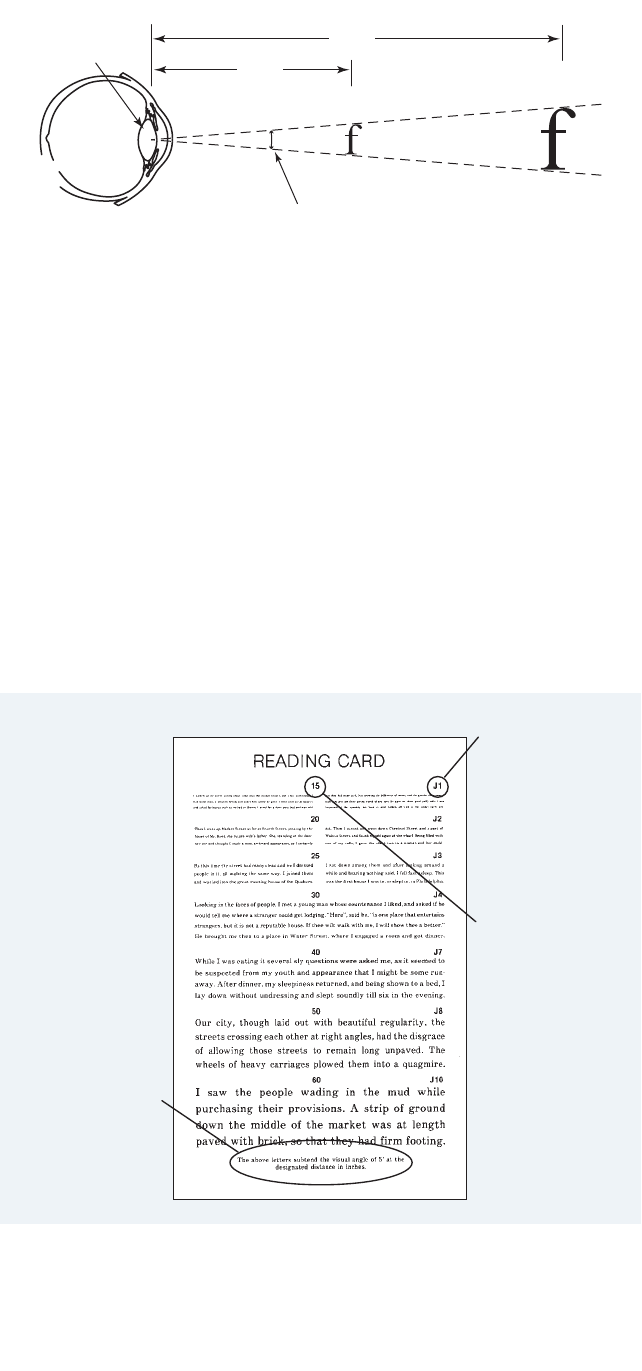
Visual Angle
The visual angle is the angle formed by two lines
drawn from the center of the eye lens to the
top and the bottom of one of the vision acuity
letters as shown in Fig. 1. As can be seen, both
letters “f ” subtend the same visual angle, but
because one letter is twice as far away from the
eye, its height is actually taller. This
demonstrates the fact that if the distance from
the eye to the object is greater, the letter must
be taller in order to maintain the same visual
angle.
As a result, one reading card may use a small
letter at a closer distance while another may
have a larger letter that must be read at a greater
distance yet each will be a valid test for the
same vision acuity. Viewing the larger letter at
the closer distance will increase the visual angle,
and conversely, viewing the smaller letter at a
greater distance will decrease the visual angle,
and neither would be a valid acuity test since
both charts would have been read at an
incorrect distance.
The Jaeger Reading Card
Character size (height) on a Jaeger reading card
(Fig. 2) will vary with the reading distance
specified on each individual card for a given
acuity.
Most cards will have a statement at the bottom
that says something like “the above letters subtend
the visual angle of 5 minutes at the designated
distance in inches.” This statement is printed on
the bottom of the Western Optical
®
reading cards
now published by Western Ophthalmics and sold
by ASNT. The height of letters on reading cards
will vary depending on the reading distance
specified on the individual card. There is usually a
set of numbers down the center of a card, one for
each Jaeger size, and that is the distance at which
A
ASNT’s Technical Services Department receives many calls throughout
t
he year concerning the proper use of eye charts as a means of
measuring near vision acuity. “Near Vision Eye Tests” provides an
in-depth explanation of some basic concepts of vision testing and
discusses three standardized reading cards as well.
The relationship between an NDT inspector and
welders is sometimes laden with more than average
potential for misunderstandings. In our “Practitioner
Profile,” structural steel inspector Timothy Crick
explains that both a working knowledge of welding
processes and finding and fairly evaluating
discontinuities can go a long way in building and
maintaining a good reputation among welders.
In 2005, researchers for the Antikythera
Mechanism Research Project used enhanced visual testing techniques and
microfocus computed tomography to unravel an ancient puzzle. The
nondestructive tests were used to examine the remnants of an ancient
device recovered from a Roman ship that sank more than two thousand
years ago near the tiny Aegean island of Antikythera
Hollis Humphries,
TTNNTT
Editor
PO Box 28518, Columbus, Ohio 43228; (800) 222-2768 X206;
fax (614) 274-6899; e-mail <[email protected]>
22
· Vol. 8, No. 4
F
OCUS continued from page 1.
FROM THE EDITOR
TTeecchh TToooonn
that size text is to be read to meet the
requirement for that Jaeger number. At
that distance, the letters will subtend the
visual angle of five minutes. Five minutes
is the standard visual angle used for
most reading cards.
Distance for Reading Test
As noted above, using a Jaeger reading
card at other than the distance
specified for the given text size will
cause the results to be inaccurate.
Similarly, Snellen 20/22 and 20/25 are
just that; one cannot be said to be
equivalent to another because they are
not. Again, a specific distance should
be used for the chart that is used, and
that distance should be specified on
the card or chart.
If you check two different reading
cards, you may find that the specified
distances vary. The taller letters should
specify a greater reading distance; the
distance at which the card is to be
r
ead changes with the font size. Using
the card at other distances will lead to
a false eye test.
Because many specifications state
that near distance vision acuity shall
be J1 (or J2) "at a distance of not less
than 12 inches," many people believe
that they can move the reading card in
to 300 mm (12 in.) and they will get a
J1 or J2 eye examination. This is not
so; the text selection must be read at
the appropriate distance as specified
on the card.
Most NDT certification documents
don't specify a near vision acuity test
at 300 mm (12 in.); they usually state
that the test is “not to be given at less
than 12 inches.” This statement was
intended to prevent the use of smaller
reading cards that might specify a
reading distance less than 300 mm
(12 in.) This prohibits the use of
miniature reading cards (some the size
of business cards) that have specified
reading distances less than 300 mm
(12 in.). To clarify this in the 2006
edition of Recommended Practice
No. SNT-TC-1A, the text in
paragraph 8.2.1 was changed to read,
“... the applicant is capable of reading
a minimum of Jaeger Number 2 or
equivalent type and size letter at the
distance designated on the chart but
not less than 12 inches (30.5 cm) on a
standard Jaeger test chart.” The bold
text is added for emphasis here to
ensure that the intended use of the
card is understood.
1
Jaeger Equivalents
In 2004, when ASNT first began to
draft ANSI/ASNT CP-106,
Non-destructive Testing — Qualification
and Certification of Personnel
2
(the U.S.
adoption of ISO 9712
3
), the phrase
TNT · October 2009 ·
33
FOCUS continued on page 5.
Figure 1. The concept of visual angle. From different distances, letters of different
sizes may subtend the same visual angle. In terms of vision acuity, they are
effectively the same size if read at the appropriate distances.
V
isual angle
Eye lens
x
2
x
J1 designation for
smallest text size
Corresponding reading
distance for J1 text
Chart must be held at
distance that corresponds
with text group
being read
Figure 2. The Jaeger eye card is widely used for performance examinations of
near vision acuity. Text groups gradually increase in size and are designated as J1,
J2 and so on. The vision acuity equivalent of each Jaeger designation depends on
the distance at which the chart is held. This image has been scaled and
processed for publication and must not be used for vision examination.


“or equivalent” was used in the near
v
ision acuity section. Because
"equivalent" values were not given, the
ASNT Technical Services Department
received numerous calls asking for
clarification of what was considered
equivalent to the various Jaeger
numbers, so the Standards
Development Committee (SDC),
ASNT’s consensus committee for
developing American National
Standards, was asked to include a note
regarding equivalents to clarify what
would be accepted. The committee
agreed. To determine “equivalency,”
the following organizations were
contacted:
1. for Snellen values and Times
Roman points, the American
Optometric Association, the
National Optometric Association,
The Ohio State University College
of Optometry and several local
optometrists;
2. for OrthoRater
®
values, the
Ophthalmic Division that passed
from Reichert, Inc., to Bausch &
Lomb and Leica-Microsystems;
3. for Titmus
®
values, the
Bacou-Dalloz Company (now
Sperian).
On Items 2 and 3, both companies
gave the values listed in CP-106. On
item 1, many of the responses to our
inquiries referred us the handbook for
optometry, Clinical Refraction, by Irvin
M. Borish.
4
Dr. Timothy Wingert,
then Acting Director of the Clinical
Care Group of the American
Optometric Association, provided
specific page and chapter references
from the 1975 edition of Clinical
Refraction, pointing out that while this
edition is out of print,
5
the data are
s
till valid, and he provided the
comparative information shown in
Table 1. Because most optometrists
record values in even numbers, 6/6
(20/20) is usually accepted for J1 and
6
/7.5 (20/25) for J2, but a company
should consider describing whatever
convention they choose to use in their
written practice, remembering that
acceptance of a certification program
is a matter of agreement between the
NDT supplier and purchaser.
Disclaimer
The information in this article is
provided for instructional purposes
and is not a statement of ASNT
policy or practice.
References
1. Recommended Practice
No. SNT-TC-1A, Personnel
Qualification and Certification in
Nondestructive Testing. Columbus,
OH: American Society for
Nondestructive Testing (2006).
2.ASNT CP-106 (national adoption
with modifications of ISO 9712),
Nondestructive Testing —
Qualification and Certification of
Personnel, third edition. Columbus,
OH: American Society for
Nondestructive Testing (2008).
3. ISO 9712, Non-Destructive Testing
— Qualification and Certification of
Personnel. Geneva, Switzerland:
International Organization for
Standardization (2006).
4. Borish, Irvin M. Clinical Refraction,
third edition. Volume 1. Chicago,
IL: Professional Press (1970, 1975):
pages 391 and 418.
5. Borish’s Clinical Refraction, second
edition. St Louis, MO: Butterworth
Heinemann (2006).
TNT · October 2009 ·
55
FOCUS continued from page 3.
Near Vision Acuity
equivalent 20/20 near vision
acuity: Vision acuity with
remote viewing or other indirect
viewing that approximates
20/20 direct viewing closely
enough to be considered the
same for visual testing purposes.
far vision: Vision of objects at a
distance, generally beyond arm’s
length.
jaeger eye chart: Eye chart used
for near vision acuity
examinations.
near vision: Vision of objects
nearby, generally within arm’s
length.
vision acuity: Ability to distinguish
fine details visually.
Quantitatively, it is the
reciprocal of the minimum
angular separation in minutes of
two lines of width subtending
one minute of arc when the
lines are just resolvable as
separate.
1,2
vision: Perception by eyesight.
visual angle: Angle subtended by
an object or detail at the point
of observation. It usually is
measured in minutes of arc.
1,2
References
1.Nondestructive Testing Handbook,
second edition: Vol. 8, Visual
and Optical Testing. Columbus,
OH: American Society for
Nondestructive Testing (1993).
2.IES Lighting Handbook:
Reference Volume. New York,
NY: Illuminating Engineering
Society of North America
(1984).
NDT GLOSSARY

I
In 1901, Greek sponge divers, blown
off course in a storm, sought refuge
by anchoring their ship in the lee of
the tiny Aegean island called
Antikythera. When the storm abated,
one of the crew donned a diving suit
and went over the side. It is unclear
whether the diver was looking for
sponges or foraging for food but he
was amazed when he found the
remains of a shipwreck directly below.
Strewn before him was a priceless
tangle of booty. It would eventually be
determined that the wrecked
ship was a Roman trader,
probably on its way to Rome. It
had been filled with treasures
from Greece. Dates on coins
from Pergamum found among
its wreckage showed the ship
sank around 80 BC.
The find was reported to
authorities and a major
underwater recovery expedition
was mounted by the National
Archeological Museum in
Athens. The recovered artifacts
were taken to the museum
where they reside today. The
items recovered included
classical Greek bronze and
marble statuary and even fine
glassware. In addition, a lump
of calcified bronze, shoebox-size, was
lifted from the seabed. Eventually, it
would come to be known as the
Antikythera Mechanism and would
attract international attention but, at
the time, it seemed relatively
insignificant and when it reached the
museum in Athens, it was set aside on
a shelf. After some time however, the
structure split apart to reveal intricate
gearing inside (Fig. 1). Modern
research was unaware that mechanical
sophistication of this degree existed in
ancient Greece. More than a thousand
years would have to pass before
structures approaching this complexity
would begin to appear again.
What was the Antikythera
Mechanism?
Much research has determined that
the Antikythera Mechanism was a
device to model astronomical
phenomena; its purpose was to link
the cycles of Greek culture with the
celestial cycles incorporated into its
gearworks. Its highly complex dials
and spirals, gears, and pointing devices
had the ability to track progressions of
the sun and moon (and possibly the
five planets known then). It was a
calendar and could predict eclipses. It
was a calculator with the ability to
multiply, divide and subtract. Recent
interpretations of its inscriptions lead
researchers to believe that its origin
was in the Corinthian colonies of
northwestern Greece, or possibly
Syracuse in Sicily. Although the device
had puzzled academics and scientists
for more than a hundred years, study
of the apparatus did not gain impetus
until the 1950s and 60s. In the early
1970s various kinds of imaging,
including X-ray, were done.
The mechanism housing had a
front door plate with
inscriptions. The front of the
mechanism itself also included
many inscriptions and a device
for showing the positions of the
sun and moon. Internal gearing
for the apparatus was formed
from bronze sheet
(approximately 2 mm thick).
The back of the structure had
an upper and lower dial as well
as additional inscriptions.
Significantly, the Antikythera
Mechanism is dated by its
inscriptions. Greek script varied
considerably during the period
when the mechanism was
manufactured. The structure of
the letters in the inscriptions
and the way they are put
together in sentences make it possible
to date it quite accurately. It is
relatively certain that it was made at
end of the second century BC —
140 to 100 BC.
Formation of the AMRP
Lead by astronomer Mike Edmunds,
Professor in the School of Physics
and Astronomy at Cardiff University
Visual Testing and X-Ray Used to Examine Antikythera
Mechanism
Insight
66
· Vol. 8, No. 4
Figure 1. Largest fragment of Antikythera Mechanism
shown in natural light. © Antikythera Research
Mechanism Project.

in Wales and mathematician Tony
F
reeth, a freelance producer and
director working in television and
independent production of scientific
documentaries, the Antikythera
Mechanism Research Project (AMRP)
w
as formed to collect new primary
data on the device. In late 2005,
permission to carry out proposed
investigations was granted and
state-of-the-art technology was
recruited to probe the interiors of the
Antikythera Mechanism using
enhanced digital imaging techniques
developed by Hewlett Packard Labs in
Palo Alto, California and microfocus
computed tomography (CT)
developed by X-Tek Industries (now
Metris) in Hertfordshire in the U.K.
Reflectance Imaging Techniques
The Antikythera Research Project
invited Hewlett Packard Labs research
scientists to Athens to apply
reflectance imaging to the front and
rear surfaces of the more than
70 fragments that comprise the
mechanism. The noninvasive
technique involves taking photos of
an artifact from a fixed point while
using 50 different light sources arrayed
i
n a hemisphere or dome placed over
the object (Fig. 2). The light sources
fire in succession and the camera
registers them individually. Software
can then be used to tie the images
t
ogether. In effect, this enables the
archaeologist to change the angle of
light or texture of the surface of the
object to make faint markings appear
more vivid. It’s as though the object
being investigated can be held and
moved around. Originally developed
for looking at indentations on
papyrus, the technique is a very good
way of discerning very subtle surface
detail. In addition, reflectance imaging
can be used to digitally manipulate the
surface quality of an object to
enhance its detail. Dull surfaces can be
made to look shiny, for example
(Fig. 3).
Microfocus Computed
Tomography
A major expedition brought the
400 kV microfocus computed
tomography machine – weighing more
than 7.5 metric tons – to examine the
artifact in Greece. Originally designed
by X-Tek Industries to search for
imperfections in turbine blades,
printed circuits and other industrial
devices, the machine creates detailed
t
hree-dimensional X-ray images. It was
originally thought that
three-dimensional CT results would
prove most useful by producing good
images of the gear train. This would
a
llow researchers to obtain accurate
teeth counts for the mechanism’s
gears, thereby resolving arguments
regarding relationships between the
gears. However, it came as surprise
when investigators realized how well
the machine was able to image
inscriptions inside the fragments of
the apparatus (Figs. 4, 5). It was
expected that some faint inscriptions
would be revealed but
three-dimensional CT not only
TNT · October 2009 ·
77
Figure 2. Researchers demonstrate
domed structure used to photograph
objects under varying light conditions.
© Hewlett Packard Laboratories.
Figure 3. Photos of Antikythera
Mechanism fragment show how the
device appears under conventional
lighting and how surface features are
enhanced by use of reflectance
imaging. © Antikythera Mechanism
Research Project.
Figure 4. Three-dimensional
computed tomography scans resulted
in high-resolution digital radiographs
that revealed textual and other details.
© Antikythera Research Mechanism
Project.
INSIGHT continued on page 8.
Figure 5. Digital radiographs obtained
with three-dimensional computed
tomography allowed researchers to
follow impression of inscriptions down
into fragment surface. © Antikythera
Mechanism Research Project.

allowed researchers to see the
inscriptions, it made them much
clearer by allowing researchers to
follow the impressions of the
c
haracters down into surfaces and
thus beneath corrosion. The CT
images, from various angles, enabled
the research project to read 932
characters, far more than any previous
attempt.
Conclusion
The mechanical complexity of the
Antikythera Mechanism implies a
technological tradition; one in which
its builders were accustomed to
working with gears and figuring out
how mechanisms were made. When it
was built, bronze was both extremely
valuable and difficult to produce. It’s
possible that devices such as these
would have been melted down when
they stopped working, lost their
novelty or people forgot how to use
them. Still, we are left to wonder what
happened to the rest of the
technology and how it all was lost.
Bibliography
1. Antikythera Mechanism Research
Project. <http://www.antikythera-
mechanism.gr/>.
2. X-Tek Group (now Metris).
Hertfordshire, United Kingdom.
<http://www.xtekxray.com/
applications/antikythera.html>.
3. Hewlett-Packard Laboratories.
<http://www.hpl.hp.com/research
/ptm/antikythera_mechanism/
index.html>.
4. Freeth, T., Y. Bitsakis, X. Moussas,
J. Seiradakis, A. Tselikas, E.
Maglou, M. Zafeiropoulou, R.
Hadland, D. Bate, A. Ramsey, M.
Allen, A. Crawley, P. Hockley, T.
Malzbender, D. Gelb, W. Ambrisco
and M. Edmunds. “Decoding the
Ancient Greek Astronomical
Calculator Known as the
Antikythera Mechanism.” Nature.
Vol. 444, No. 30. London, United
Kingdom: Nature Publishing
Group (November 2006):
p
587-591.
5. Seabrook, J. “Fragmentary
Knowledge.” The New Yorker.
New York, New York: Conde Nast
Publications (May 2007) p 94-102.
6
. Freeth, T., A. Jones, J. Steele and Y.
Bitsakis.. “Calendars with
Olympiad Display and Eclipse
Prediction on the Antikythera
Mechanism.” Nature. Vol. 454,
No. 30. London, United Kingdom:
Nature Publishing Group (July
2008) p 614-617.
88
· Vol. 8, No. 4
I
NSIGHT continued from p 7
Got a topic for “Working Smarter”? If
published, you can earn $50 in cash or
a $75 credit for ASNT merchandise.
Contributors to TNT also earn recert
points in the following programs:
• ACCP Level II,
• ACCP Professional Level III and
• ASNT NDT Level III.
A full article of 1000+ words earns
three points; short articles or items for
“Working Smarter” earn one point.
Contact the TNT Editor:
PO Box 28518, Columbus, OH 43228
(800) 222-2768 X206;
(614) 274-6899 fax
<hhumphries@asnt.org>

TNT · October 2009 ·
99
4. Liquid that enters cracks.
6. Instrument measuring UV light intensity.
8. Light used at fluorescent penetrant wash station.
10. Specification compliance document.
11. Aerospace known defect test piece.
12. Passive penetrant process activity.
16. Instrument measuring aqueous developer concentration.
17.Method D processing
step that precedes
emulsifier.
18.Approved penetrant
materials are listed on
the ___.
19.Penetrant flow rate.
21.Developer in spray can.
22.Tool for measuring
viscosity.
23.Sound wave cleaning.
27.Processing step following
penetrant dwell.
28.Method B and D
penetrant and emulsifier
are approved as a ______.
31.Black light output.
Across
3. Emulsifier diluted with water.
5. Early user of oil and whiting.
7. Highest sensitivity level for fluorescent penetrants.
9. Materials lot identification number.
12. Parts for penetrant inspection must be clean and ___.
13. Unit for measuring ultraviolet intensity per square centimeter.
14. Instrument measuring
Method D emulsifier
concentration.
15. Abbreviation for
solvent suspended
developer.
17. Instrument measuring
white light intensity.
20. Method B emulsifier.
24. A penetrant test kit is
used for _____
testing.
25. The Karl Fischer
analysis tests for
_____ content.
26. Document describing
any hazards.
28. Device used to
measure fluorescent
brightness.
29. Method C remover.
30. Penetrant requiring darkened area for inspection.
32. Static charge spray application method.
33. First thing you must do with an aerosol can of developer.
34. Forms A, B and C developers are supplied as ______.
35. Step preceding application of penetrant.
Down
1. Form B and C developers are applied before ______.
2. Method A remover.
Across
3. hydrophilic
5. railroad
7. four
9. batch
12. dry
13. microwatt
14. refractometer
15. NAD
17. photometer
20. lipophilic
24. field
25. water
26. MSDS
28. fluorometer
29. solvent
30. fluorescent
32. electrostatic
33.shake
34. powder
35. preclean
Down
1. drying
2. water
4. penetrant
6. radiometer
8. ultraviolet
10. certification
11. TAM
12. dwell
16. hydrometer
17. prerinse
18. QPL
19. viscosity
21. nonaqueous
22. viscometer
23. ultrasonic
27. removal
28. family
31. UVA
Crossword Challenge
LLiiqquuiidd PPeenneettrraanntt TTeessttiinngg
LLiiqquuiidd PPeenneettrraanntt TTeessttiinngg
TThhee PPeenneettrraanntt PPrrooffeessssoorr**
Crossword Challenge
*
Michael White and William Mooz, Met-L-Chek Company, 1639 Euclid Street, Santa Monica,
California 90404; phone (310) 452-4046; fax (310) 452-4046; e-mail info@me-l-chek.com.
Answers
1
5
2
7
8
1
5
2
0
2
4
2
5
2
8
3
0
3
1
3
3
1
8
1
6
2
3
2
1
1
9
9
1
4
1
0
1
1
1
2
6
1
3
1
7
2
2
2
6
2
9
2
7
32
34
35
3
4

PRACTITIONER PROFILE
1100
· Vol. 8, No. 4
W
While the working relationship between an NDT inspector and a
welder can sometimes be problematic, Timothy Crick demonstrates
that a good inspector with a proven record of finding and fairly
evaluating discontinuities can build and maintain a good
reputation among the welders whose work he inspects.
Q: How did you get started in NDT?
A: In the early 90s, I worked as a welder for a pipeline
manufacturer up in northern California doing flux core
arc welding and dual wire submerged arc welding. I’ve
always wanted to learn everything I could and when they
asked if I wanted to become an inspector I said yes.
Inspectors, if laid off, will get a job somewhere else, so
employers are reluctant to lay them off. So, number one,
there was definitely better job security and, number two, I
wanted to lean more than welding. The firm I was
working for did UT and RT inspections and I became a
level II in both. Our company Level III, Mr. Charles
Hanson, performed all of our training and certification.
Q: Tell us about your NDT experience to date.
A: I left northern California and moved to San Diego where
I worked for a one-man company. We did everything from
NDT in Navy and commercial shipyards to welder and
procedure qualifications. From there, I actually took two
jobs. One was eight hours a day and the other was as
many hours as I could fit into the rest of the day. I was
inspecting aircraft parts in the aerospace industry but that
only needed my X-ray Level II working experience. I really
enjoy doing UT and I couldn’t pass it up when somebody
needed me to do what I’m doing now —ultrasonic testing
on commercial buildings. So I kept both of my
certifications going by doing both. Each form of
inspection is totally different. I get dirty and climb all over
buildings in one and I sit in a clean room interpreting film
in the other. My next job was with an independent lab in
Texas where I did NDT in aerospace, oilfields, power
plants, and even in the amusement park industry. I got to
do different types of ultrasound there that I had only read
or heard about, such as through-transmission inspecting
747 parts that were as big as a car. In
through-transmission, there are two transducers facing
each other at a set distance apart. One transducer sends
and the other receives. A stream of water aimed at each of
them is used as the couplant. If there are any indications
within the part, you have a loss of sound. I also leaned to
do mag particle and became certified in that method.
Q: What are your current certifications?
A: I am currently certified as a Level II in UT, RT, MT, and
PT. I’ve also done ET, but not for many years.
Q: What was your educational background before you began
training in NDT?
A: My education was high school. I did learn mechanics in
the air force. I’ve always had a technical background and
hands-on is where I excel. I love the hands-on experience
and that’s definitely what NDT has been. I’ve inspected
parts that went five miles underground and parts that are
floating right now on the international space station. That
gives me a rewarding feeling.
Q: What kind of structures do you inspect now?
A: I’m inspecting welds in structural steel on the biggest
hospital project ever in the state of California — moment
connections — mainly beam splices and column splices
using UT and MT.
Timothy Crick
“It’s not my job to
advise the welders
but at the same time,
our common goal is
to complete an
acceptable product.”

TNT · October 2009 ·
1111
Q: Is phased array any part of that?
A: I’ve only had limited observation of phased array but not
its actual use. I understand its benefits and it’s something I
will be getting in the future.
Q
: How does your experience as a welder help you when
conducting inspections?
A
: It helps me understand the indications or the
discontinuities that I find. It also makes it easier for me to
help the welder understand problem areas so that we can
reduce the number of discontinuities and rejects. It’s not
my job to advise the welders but at the same time, our
common goal is to complete an acceptable product. My
experience has taught me that it’s much better to have a
weld done right the first time than to have to go back and
have it fixed.
Q: As an NDT inspector, how do you maintain a productive
relationship with the people that do the work you inspect?
A: Some inspectors out there have a bit of a power issue and
some couldn’t care less if the welder continues to get
rejects. My approach is to let them know that I’m there to
help. I also let them know that I have previous welding
experience so that they might be able to relate to me
better.
Q
: Do you see that your efforts reduce the number of rejects?
A: Definitely.
Q
: What’s the best part of your job?
A: The best part of my work is the people — people that
I’ve had the opportunity to learn from and work with.
Q: What’s the worst part?
A: I think the hardest part has been when I had to work
away from home, away from my family.
Q: How would you advise someone considering an NDT career?
A: Try to work for good people. I’ve found that the best
people to work for are those that raise the bar. Earlier I
threw out Charlie Hanson’s name. Charlie worked in the
pipeline industry with codes and specs that didn’t require
high quality but he took his prior work experience and
used it to raise the standards in the pipeline industry.
You can contact Timothy “TC” Crick by e-mail,
<tcrick41[email protected]>.

the
NDT Technician
Volume 8, Number 4 October 2009
Publisher: Wayne Holliday
Publications Manager : Tim Jones
Editor: Hollis Humphries
Technical Editor: Ricky L. Morgan
Review Board: W illiam W. Briody, Bruce G. Crouse,
Anthony J. Gatti Sr., Edward E. Hall, James W. Houf, Jocelyn
Langlois, Raymond G. Morasse, Ronald T. Nisbet, Angela
Swedlund
T
he NDT Technician: A Quarterly Publication for the NDT Practitioner
(ISSN 1537-5919) is published quarterly by the American Society for
N
ondestructive Testing, Inc. The TNT mission is to provide information
valuable to NDT practitioners and a platform for discussion of issues
r
elevant to their profession.
A
SNT exists to create a safer world by promoting the profession and
technologies of nondestructive testing
.
Copyright
©
2009 by the American Society for Nondestructive Testing, Inc. ASNT is
n
ot responsible for the authenticity or accuracy of information herein. Published
opinions and statements do not necessarily reflect the opinion of ASNT. Products or
services that are advertised or mentioned do not carry the endorsement or
r
ecommendation of ASNT.
I
RRSP, Materials Evaluation, NDT Handbook, Nondestructive Testing Handbook,
The NDT Technician and www.asnt.org are trademarks of The American Society for
Nondestructive Testing, Inc. ACCP, ASNT, Level III Study Guide, Research in
N
ondestructive Evaluation and RNDE are registered trademarks of the American
Society for Nondestructive Testing, Inc.
the
NDT Technician
PO Box 28518
C
olumbus, Ohio 43228-0518
NONPROFIT
US POSTAGE
PAID
ST JOSEPH, MI
PERMIT NO. 84
The American Society for Nondestructive Testing
www.asnt.org
Q:Where can I get an ASNT certification application?
A: All ASNT certification applications can be found on ASNT’s Web site at
http://www.asnt.org/certification/certification.htm.
Q:Where can I find ASNT’s exam schedules?
A: ASNT exam schedules can be found at
http://www.asnt.org/certification/schedules/index.htm.
Q:How long does it take to get exam results?
A: Examination results are mailed within four to six weeks for those residing in the
US or Canada. Results for candidates living outside the US may take one to two
weeks longer. Exam results cannot be given over the phone or via e-mail.
Q:How long does ASNT certification remain valid?
A: ASNT certification remains valid for five years.
E-mail, fax or phone your questions for “Inbox” to the Editor:
hhumphries@asnt.org, fax (614) 274-6899, phone (800) 222-2768 X206.
INBOX
