LEGO NXT LabVIEW
© Copyright Paul Oh
Hands-on Lab:
LabVIEW – PID
In previous labs, the step response and the PID simulation of the LEGO DCP were performed.
The former provides a Labview framework to use the gains discovered from latter to achieved
PID closed-loop control.
Concept 1: Experimental PID control
Step 1: Create Front Panel and Initial Block Diagram
From your System Identification lab open the file nxtLabviewLegoDcpSystemId1_0.vi.
Save this program as nxtLabviewLegoDcpPid1_0.vi. This program provided the framework
to acquire, graphically display, and save to file the DCP’s angle. This program also allowed one
to command the motor-prop. Since Step Input is no longer needed, eliminate the toggle switch.
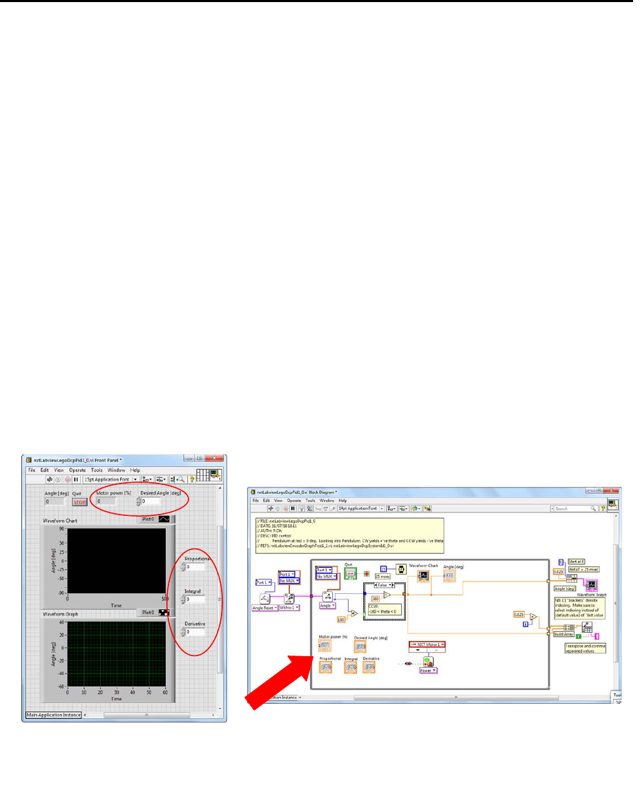
Add numeric controls to the Front Panel. These controls will allow one to set PID gains, the
desired angle. Also, add a numeric indicator to display the power going into the motor-prop
(Figure 1-1A left).
For the Block Diagram, delete the Case Structure that was associated with the toggle switch
(but keep the NXT motor Block). Blocks will be added, so re-arrange the Block Diagram to
provide suitable space (Figure 1-1A right).
Step 2: Create the error signal and proportional control
PID control works on the error signal. The error is the difference between the desired and actual
angle (in degrees). The proportional component of PID control scales this error. As such, add
Subtraction and Multiplication blocks (Figure 1-2A).
Figure 1-1A: Red ellipses show the numeric controls and indicators added to the Front Panel (left). Red arrow gathers
these blocks, to be used in next steps. NB: wires and blocks were slightly re-arranged, and the loop box was widened in
anticipation of the need to accommodate more blocks.

LEGO NXT LabVIEW
© Copyright Paul Oh
Step 3: Differentiate the error and derivative control
The derivative component of PID control scales the rate change of error. Mathematically, this is
∆
for discrete-time systems where is the sample time is,
is the current error
and
1
is the previous error. In Labview, shift registers were used to store the previous
value in a loop. As such, add a shift register (Figure 1-3A) for the error signal.
Figure 1-2A: The Subtraction block (left Red Arrow) forms the error. The Multiplication block (right Red Arrow)
proportionally scales this error.
Figure 1-3A: Red circle shows the resulting shift register that was added

LEGO NXT LabVIEW
© Copyright Paul Oh
In the Block Diagram, the loop uses a 25 millisecond Wait block. Thus, for this program
0.025seconds. Add a Division block to perform the differentiation (Figure 1-3B). Lastly,
add a Multiplication block; it multiplies the error derivative with a derivative gain value.
Step 4: Integrate the error and Integration control
The integration component of PID control, integrates the error. Mathematically, this is
∑
1
for discrete-time systems. Thus, add a Multiplication block to take the
product of the current error and sample time 0.025 seconds (Figure 1-4A).
Figure 1-3B: Red arrow indicates Division and Multiplication blocks used to respectively differentiate and scale it.
Figure 1-4A: Red arrow points to the Multiplication block which multiplies the current error with sampling time

LEGO NXT LabVIEW
© Copyright Paul Oh
Drag an Addition block into the loop. Feed one input of the Addition block with the
.
Next, wire the output of the Addition block as shift register (Figure 1-4B).
Lastly, drag a Multiplication block to form the product of the error sum and the integration
gain (Figure 1-4C).
Figure 1-4B: Red circle shows the Addition block used to sum the error signal. Red arrow shows the added shift
re
g
ister. NB: Text boxes at the shift re
g
ister ca
p
tion their value e.
g
.
and
1
.
Figure 1-4C: Red circle shows the Multiplication block for the Integration gain. Red arrow shows the shift register
going into the Additional block

LEGO NXT LabVIEW
© Copyright Paul Oh
Step 5: Form the control signal and dead-zoning
Drag 2 Addition Blocks and wire the summation of the proportional, integral, and derivative
commands (Figure 1-5A).
Motor power is limited from 0% (stop) to 100% (full power). Dead-zoning is used to limit signals
to within this range. Add the In Range and Coerce block (Programming – Comparison –
In Range and Coerce)
1
. Right-click this block and make sure both Include upper limit
and Include lower limit are checked (Figure 1-5B). Add and wire constants 0 and 100
to the lower and upper limits respectively, wire the PID command signal to the input of the In
Range and Coerce Block (Figure 1-5C). The numeric indicator (Motor Power [%]) has
been moved to this region of the loop as well.
Wire the PID command signal to Motor Power numeric indicator. This will allow one to
monitor this value when tuning gains. From the In Range and Coerce block, wire the
coerced(x) output in the input of the Motor Power block. Save your program (e.g.
nxtLabviewLegoDcpPid1_0.vi)
1
TheInRangeandCoerceblockisintheLabviewProgrammablePalette(nottheMindstormsRobotics
palette).Ifneeded,enabletheLabviewProgramPalette(Function–Customize–ChangeVisiblePalettes
andchecktheProgrammingbox).
Figure 1-5A: Red arrow shows location of the 2 Addition blocks that add up the P, I, and D components

LEGO NXT LabVIEW
© Copyright Paul Oh
Figure 1-5B: Right-clicking the In Range and Coerce block allows on to include both upper and lower limits
Figure 1-5C: Red ellipse shows the In Range and Coerce block configured with lower (0) and upper (100) constants. Right
red arrow shows output of this block feeding into the Motor Power block. Left red arrow shows PID output feeding into a numeric
indicator (Motor Power [%]).

LEGO NXT LabVIEW
© Copyright Paul Oh
Step 6: Execution
From the Simulink PID lab, one simulated that
, ,
0.3, 3.0, 0.5
. Before executing the
program, set these values in the appropriate numeric controls and set the desired angle to
35 degrees (Figure 1-6A). One can make these values default as well (Front Panel – Edit
– Make Current Values Default). One can now run the program.
From simulation, one expects that with such gains, the DCP should slowly rise to the desired
angle. Thus, the LEGO DCP should also slowly rise to 35 degrees if the Labview program is
correct (Figure 1-6B left). Data was saved to a file (e.g. labviewPidOutput-111518-
12H34M.csv) and plotted in Excel (Figure 1-6B right). One observes from the data plot, that
slow increase in the pendulum’s angle which converges to 35 degrees.
Figure 1-6A: Before executing the program, front panel shows desired angle set to 35 (red arrow) and P, I, D gains
set (red ellipse)
Figure 1-6B: On execution, Front panel shows DCP converging to 35 degrees (left). Excel data plot of acquired angles
reveals that for PID gains, steady-state is 35 degrees, with a rise time of about 3.1 seconds (right).

LEGO NXT LabVIEW
© Copyright Paul Oh
Congratulations: LEGO DCP PID Control Completed
Exercise 1:
2.1. Complete the following table
Your Damping Ratio Your Natural Frequency
e.g. 0.033 e.g. 7.320
2.2. Referring to the free body diagram, complete the following table
2.3. Using
compute the Moment of Inertia (e.g. 0.00033
)
2.4. Using 2
compute the coefficient of friction (e.g. 0.00016 /)
F
mg
d
r
d
dt
c
motor-propeller
T = Fr
Pendulum
Length[m]
e.g.0.265
[m]
Your
value
PivottoCG
distance[m]
e.g.0.1325
[m]
Massof
Pendulum[kg]
e.g.0.0137
[kg]
