
ZELTIQ Aesthetics, Inc.
4410 Rosewood Drive
Pleasanton, CA 94588 USA
(925) 474-2500
www.coolsculpting.com
ZELTIQ Customer Service
Worldwide: (+1) 925-474-8160
USA: (+1) 888-935-8471
(1-888-ZELTIQ1)
User Manual
BRZ-101-TUM-EN3-J
CoolSculpting System
(ZELTIQ Breeze System)

2 BRZ-101-TUM-EN3-J
Preface
Contents
• Intellectual Property ......................................................................... 2
• Intended Use .................................................................................... 2
• Contraindications .............................................................................. 2
• Warnings ........................................................................................... 3
• Treatment Sites ................................................................................ 4
• Cautions ............................................................................................ 5
• Side Effects ....................................................................................... 5
• Potential for Tissue Damage ............................................................. 6
• ZELTIQ Customer Service .................................................................. 6
• About the System ............................................................................. 6
• System Symbols ................................................................................ 7
• User Documentation......................................................................... 8
Intellectual Property
Copyright
©
2018 ZELTIQ Aesthetics, Inc. All rights reserved. Unauthorized duplication or use is prohibited.
COOLSCULPTING
®
, ZELTIQ
®
, and FREEZE DETECT
®
are registered trademarks of ZELTIQ Aesthetics, Inc. The
procedures described in this document are covered by U.S. Patent 7,367,341. Additional issued patents and
patent applications pending worldwide relate to the products and procedures described in this document.
WARNING: Unauthorized modification or repair of the control unit, its
components, or supplies may result in unsafe conditions and/or impaired
performance. No modification of this equipment is allowed without express
authorization from ZELTIQ. Any unauthorized modification or repair will void the
warranty.
Intended Use
The CoolSculpting
®
System, also labeled as the ZELTIQ
®
System or the ZELTIQ
®
Breeze System (system), is a
non-invasive thermoelectric cooling and heating device that applies controlled cooling or heating to a
treatment site on the patient’s skin.
Uses of the system in cooling mode include:
• Fat layer reduction through cold-assisted lipolysis.
• Minimizing pain and thermal injury during laser and dermatological treatments.
• Acting as a local anesthetic for procedures that induce minor local discomfort.
The system can also provide localized thermal therapy (hot or cold) to minimize pain for post-traumatic and/or
post-surgical pain and to temporarily relieve minor aches and pains and muscle spasms. The optional massage
function can also be used for:
• Temporary relief of minor muscle aches, pain, and spasm.
• Temporary improvement in local circulation.
Contraindications
Localized skin cooling is contraindicated in patients who have:
• Cryoglobulinemia

System Overview Warnings
User Manual 3
• Cold agglutinin disease
• Paroxysmal cold hemoglobinuria
• Areas of impaired peripheral circulation
• Pregnancy and lactation
Use of the ZELTIQ System for lipolysis should not include areas of the body with a subcutaneous fat layer
thickness of less than 1 cm.
Warnings
Use of the CoolSculpting System has not been studied in children, or in patients with:
• Known sensitivity to cold such as cold urticaria or Raynaud’s disease, or Chilblains (pernio)
• Known sensitivity or allergy to fructose, glycerin, isopropyl alcohol, or propylene glycol
• Impaired peripheral circulation in the area to be treated
• Neuropathic disorders such as post-herpetic neuralgia or diabetic neuropathy
• Scar tissue or extensive skin conditions such as eczema, or dermatitis at the area of intended treatment
• Impaired skin sensation
• Open or infected wounds
• Bleeding disorders or concomitant use of blood thinners
• Recent surgery or scar tissue in the area to be treated
• Hernia in or adjacent to the treatment site
• Skin conditions such as eczema, dermatitis, or rashes in the area to be treated
• Areas of recent bleeding or hemorrhage (heating)
The effect of performing a CoolSculpting treatment (treatment) with a vacuum applicator on a patient who has
a hernia in or adjacent to the treatment site has not been studied. The applicator uses vacuum pressure to
draw tissue into the applicator cup during the treatment. The vacuum pressure may therefore apply pressure
on a pre-existing hernia or pre-existing structurally weak area such as a surgical scar, causing further
complications. Physicians should examine the patient for evidence of pre-existing abdominal or femoral hernia
prior to use of the device.
The system operates at temperatures below 0°C, which can freeze tissue; clinical events that are common to
freezing tissue should be considered.
The use of this device on areas with superficially located nerve branches, arteries, or veins has not been
demonstrated to be safe and effective. Such use may result in injury to the patient.
The effect of performing treatments directly over active implanted devices in patients, such as pacemakers and
defibrillators, is not known.
Use of the system may result in temporary numbness or a tingling sensation in the treated area that may last
for up to several weeks after treatment.
Patients with chronic pain, sensitivity to cold, or an anxiety disorder may be more prone to pain or discomfort
during the treatment.
The use of other electronic medical devices on a patient who is undergoing a treatment might interfere with
the correct functioning of the system, possibly resulting in injury to the patient. Do not use other electronic
medical devices on a patient who is undergoing a treatment.
WARNING: Before using the system, read and understand the User
Documentation set. See User Documentation on page 8.

Treatment Sites System Overview
4 BRZ-101-TUM-EN3-J
Treatment Sites
Observe the following warnings when treating the submental and submandibular areas:
Treatment Site
Warning
WARNING: Cold exposure to the
hypoglossal nerve may cause tongue
deviation following treatment of the
submental and submandibular areas.
Hypoglossal Nerve
WARNING: Cold exposure to the
marginal mandibular nerve may cause
lower lip weakness following
treatment of the submental and
submandibular areas.
Marginal Mandibular Nerve
WARNING: Cold exposure to the
submandibular gland may cause
xerostomia, or decrease in saliva
production, following treatment of the
submental area.
Submandibular Gland
Table 1: Submental and Submandibular Areas Treatment Warnings

System Overview Cautions
User Manual 5
Observe the following warning when treating the upper arm:
Treatment Site
Warning
WARNING: Avoid compression of the
ulnar nerve during treatment of the
upper arm.
Ulnar Nerve
Table 2: Upper Arm Treatment Warning
Cautions
The system is intended for use by a trained physician or a physician-designated medical professional.
Fat layer reduction has been demonstrated for at least 6 months after the treatment. Longer-term studies have
not been completed to demonstrate sustained fat layer reduction beyond this time period.
If the operator observes a potential safety issue or operational abnormality during use, the treatment should
be terminated and ZELTIQ Customer Service should be contacted promptly.
The use of other equipment and supplies with the system has not been tested and may cause unexpected
results.
Side Effects
The following effects can occur in the treatment area during and after a treatment. These effects are
temporary and generally resolve within days or weeks.
During a treatment:
• Sensations of pulling, tugging, and mild pinching.
• Intense cold, tingling, stinging, aching, cramping. These sensations subside as the area becomes numb.
Immediately after a treatment:
• Redness and firmness.
• Transient blanching and/or mild bruising around the edges of the treatment area.
• Tingling and stinging.
One to two weeks after a treatment:
• Redness, bruising, and swelling.
• Tenderness, cramping, and aching.
• Itching, skin sensitivity, tingling, and numbness. Numbness can persist up to several weeks after a
treatment.
• Sensation of fullness in the back of the throat after submental area treatment.
Rare Side Effects
• Paradoxical hyperplasia: Visibly enlarged tissue volume within the treatment area, which may develop two
Potential for Tissue Damage System Overview
6 BRZ-101-TUM-EN3-J
to five months after treatment. Surgical intervention may be required.
• Late-onset pain with a typical onset several days after a treatment and resolution within several weeks.
• Freeze burn: First and second degree freeze burn may occur during treatment. It typically resolves without
sequelae with proper care.
• Vasovagal symptoms: Dizziness, lightheadedness, nausea, flushing, sweating, or fainting during or
immediately after the treatment.
• Subcutaneous induration: Generalized hardness and/or discrete nodules within the treatment area, which
may develop after the treatment, and may present with pain and/or discomfort.
• Hyperpigmentation: Hyperpigmentation may occur after treatment. Typically, it resolves spontaneously.
• Hernia: Treatment may cause new hernia formation or exacerbate pre-existing hernia, which may require
surgical repair.
• Treatment Area Demarcation (TAD): An aesthetic outcome of treatment in which the patient experiences
excessive fat removal in the treatment area, resulting in a visible disruption to the continuous contour of
fat, or unwanted indentation in the treated area.
• Cold panniculitis: Cold panniculitis results from injury to adipose tissue exposed to cold and may result in a
mild to severe inflammatory response. In mild cases, the symptoms are self-resolving and may include
redness, swelling, skin nodules, warmth, tenderness, and possible low-grade fever. These cases typically
resolve without long-term sequelae. In more severe cases, an intense inflammatory response may result in
more extensive tissue damage, including fat necrosis, which may require medical or surgical intervention.
Freeze burn, vasovagal symptoms, and hyperpigmentation were observed during clinical trials, while the others
were reported in post market use.
Potential for Tissue Damage
The system operates at temperatures below 0°C, which can freeze tissue. Therefore, the system monitors
tissue during cooling and employs multiple safety features including the Freeze Detect
®
system, to minimize the
risk of damage to tissue. In spite of these measures, on rare occasions, the Freeze Detect system can detect a
possible freeze condition.
The Freeze Detect system is comprised of several features, including thermal sensors and proprietary
algorithmic software. Freeze Detect is an integral part of the CoolSculpting System and is automatically
employed when a treatment is initiated. When the Freeze Detect system detects a possible freeze condition, it
stops the treatment and displays a Z409 message. If you receive this message, remove the applicator and
gelpad or gel, and assess the tissue before taking further action. If you receive a second Z409 message for one
treatment site, discontinue the treatment. Failure to follow instructions could result in injury to the patient,
including first- or second-degree burns. Second-degree burns or complications of second-degree burns may
result in hypopigmentation.
ZELTIQ Customer Service
• Worldwide: (+1) 925-474-8160
• U.S.A.: 1-888-935-8471 (1-888-ZELTIQ1)
About the System
The system is comprised of a control unit, a surface or vacuum applicator, and supplies. The applicators, foam
borders, gelpads, gel, liners, pretreatment skin wipes, and securement systems are patient -applied parts.
During a treatment, the operator applies a gelpad or gel and applicator to the patient’s skin. The vacuum
applicator draws tissue into the applicator cup and holds the tissue against the cooling surfaces of the
applicator; the surface applicator does not use vacuum pressure. The operator starts the treatment. Sensors in
the cooling surfaces of the applicator monitor the skin surface, providing feedback that controls the rate of

System Overview System Symbols
User Manual 7
heat flux. The gelpad or gel protects the skin by providing thermal coupling at the interface between the
cooling surfaces of the applicator and the skin. The card provides cycles and profiles for use with the system.
System Symbols
The following symbols are used on the components of the system and on its supplies and packaging.
Manufacturer
Authorized Representative in the European
Community
Follow instructions in the user manual and
directions for use
Consult instructions for use (user manual,
directions for use)
CE Marking
Caution
Do not reuse
Do not use if package is damaged
Type BF -- Floating patient applied parts. Not
for use in conjunction with defibrillators.
Potential for Electromagnetic Interference
Catalog number
Serial number
Quantity
Lot number
Protective earth ground
WARNING: High voltage
Equipotential contact
Alternating current
Use by
Special disposal methods are required for this
electrical device. Refer to local and national
regulations.
Locked position
Unlocked position
On (Power)
Off (Power)
Peel here
Single patient use
Regulatory Compliance Mark (Australia)
cTUVus: Meets minimum electrical safety
standards of Canada and the USA.
CAUTION: Federal Law (USA) restricts this
device to sale by or on the order of a
physician
Machine wash, cold

User Documentation System Overview
8 BRZ-101-TUM-EN3-J
Do not bleach
Tumble dry gentle, low heat
Do not iron
Do not dry clean
Table 3: System Symbols
For information on symbols and indicators that are displayed on the screen, see System Overview on page 11.
User Documentation
Note: All images in ZELTIQ user documentation are sample images. Your hardware
and information on the system screen may differ from those depicted in the
documentation.
User Manual
The User Manual provides detailed information on the components of the system, contraindications and side
effects, performing treatments, troubleshooting, and cleaning, and maintenance.
Directions for Use
A directions for use document is included with each applicator and with supplies. The document provides
up-to-date information on safety and usage. Refer to the most recent directions for use for each item.
ZELTIQ reserves the right to modify the content of the user documentation at any time. Retain the most
current user documentation and always review it prior to using any component of the system.
Conventions in User Documentation
Name
Description
Note
Additional information that is not associated with risk.
Caution
Use or misuse of the device is associated with risk of minor temporary injury and
damage to equipment.
Warning
Use or misuse of the device is associated with risk of serious and/or permanent
injury and death.
Table 4: Conventions in User Documentation
User Manual 9
Table of Contents
Preface ................................................................................................................................ 2
Intellectual Property ···································································································· 2
Intended Use················································································································ 2
Contraindications ········································································································· 2
Warnings ······················································································································ 3
Treatment Sites············································································································ 4
Cautions 5
Side Effects··················································································································· 5
Potential for Tissue Damage ························································································ 6
ZELTIQ Customer Service ····························································································· 6
About the System ········································································································ 6
System Symbols ··········································································································· 7
User Documentation ···································································································· 8
Chapter 1 System Overview .......................................................................................... 11
Control Unit ··············································································································· 11
Applicators ················································································································· 21
Supplies 21
Chapter 2 Treatment ..................................................................................................... 23
Overview ···················································································································· 23
Perform a Treatment ································································································· 23
Perform Another Treatment ······················································································ 31
Cancel a Treatment ···································································································· 33
About Restarting a Treatment ··················································································· 34
Complete a Treatment ······························································································· 35
Chapter 3 Cleaning and Maintenance ........................................................................... 39
Cleaning 39
Maintenance ·············································································································· 40
Disassembling the Control Unit ················································································· 43
Assembling the Control Unit ······················································································ 46
Connecting Latches, Hoses, and Cables ····································································· 47
Customer Service ······································································································· 48
Appendix A System Messages ....................................................................................... 49
ZELTIQ Customer Service ··························································································· 49
Recoverable Exceptions ····························································································· 49
Error Messages ·········································································································· 51
General Messages ······································································································ 51
Software Updates and Messages ··············································································· 52
Appendix B System Tools ............................................................................................... 55
Controls for System Tools ·························································································· 55
System Log Screen ····································································································· 55
Card Log Screen ········································································································· 56
Table of Contents
10 BRZ-101-TUM-EN3-J
Service Screen ············································································································ 58
Settings Screen ·········································································································· 60
Appendix C System Specifications ................................................................................. 65
Essential Performance ······························································································· 65
Disposal of Hazardous Materials ··············································································· 65
Environmental Requirements ···················································································· 65
Electrical Specifications ····························································································· 66
Medical Safety Standards ·························································································· 66
Electromagnetic Compatibility ·················································································· 66
Data Modem Specifications ······················································································· 70

User Manual 11
Contents
• Control Unit .................................................................................... 11
• Applicators ...................................................................................... 21
• Supplies ........................................................................................... 21
This chapter describes the system.
Control Unit
The control unit is a portable device that is used to start, stop, and monitor treatments.
• Control Unit - Front View on page 11
• Control Unit - Rear View on page 18
Control Unit - Front View
Components - Front View
1. Rail: When the applicator is resting on top of the control unit, the rail helps keep the applicator in
place. In addition, the rail is used as a handle to move the system.
2. Vents: Vents provide airflow that reduces heat build-up inside the control unit. Ensure all vents are
free from obstructions when the control unit is in operation.
3. Drawer: The drawer provides storage space for supplies and user documentation.
4. Casters and Locks: The control unit has four casters that swivel. Each caster has a lock. Always engage
the locks on all four casters before you use the control unit.
5. Screen: The screen displays system controls, information about the status of the system, information
about the treatment, and messages for the operator.
► To engage and release the locks:
1. Press down on the locking lever with the toe of your shoe.
2. Pull up on the locking lever with the toe of your shoe.
C H A P T E R 1
SYSTEM OVERVIEW

Control Unit System Overview
12 BRZ-101-TUM-EN3-J
General Controls and Cues on the Screen
The screen on the control unit displays cues and control buttons.
Button
Description
Name
Pay attention to safety concerns.
Caution
Connect the applicator to the control unit.
Applicator? Cue
Insert the card into the slot on the applicator.
Card? Cue
Display the list of profiles.
Display Profiles
Go to the next screen.
Next
Go to the previous screen.
Previous
Increase (Date and Time settings)
Increase
Decrease (Date and Time settings)
Decrease
Start
Start
Cancel
Cancel
Interrupt
Interrupt
Press Yes to confirm the selection
YES Button
Press No to cancel the selection
NO Button
Indicates that the system is cooling in preparation for treatment.
If this cue persists, contact Customer Service.
Cooling Cue
Indicates that the system is warming in preparation for
treatment. If this cue persists beyond 2 minutes, contact
Customer Service.
Warming Cue
Displays the time remaining in which to restart an interrupted
treatment.
Restart Timer
Table 5: General Controls and Cues

System Overview Control Unit
User Manual 13
Controls and Cues for Standard Vacuum Applicators
Note: See also the directions for use for CoolAdvantage and CoolMini applicators.
The screen on the control unit displays the following controls and cues when a standard vacuum applicator is
connected to the control unit.
Button
Description
Name
Install the liner onto the vacuum applicator.
Liner?
Do not use a gelpad that has wrinkles or tears (left).
Ensure that the gelpad is smooth and without tears
(right).
Gelpad Placement Cue
Press to indicate that a new gelpad is on the treatment
site.
GELPAD?
Indicates that the gelpad was confirmed.
Gelpad Confirmed
Place the applicator over the center of the gelpad.
Vacuum Applicator Placement
Cue
Place the applicator on the treatment site and wait
until the Start button is displayed.
Tissue Draw
Prompts you to activate or deactivate vacuum
pressure.
Activate / Deactivate Vacuum
Vacuum
Vacuum
Massage
Massage
Off - Press to turn on.
Off
On - Press to turn off.
On
View and modify vacuum settings for the treatment.
Vacuum Settings
Display massage settings
Display
Hide massage settings
Hide
Modify vacuum settings for massage.
Max and Min Massage
Settings

Control Unit System Overview
14 BRZ-101-TUM-EN3-J
Button
Description
Name
Increase
Increase
Decrease
Decrease
Indicates that the system is preparing for the next
action.
Progress Indicator
Table 6: Controls and Cues - Standard Vacuum Applicator
Controls and Cues for CoolAdvantage Applicators
Note: See also the CoolAdvantage Directions for Use.
The screen on the control unit displays the following controls and cues when a CoolAdvantage applicator is
connected to the control unit.
Button
Description
Name
Do not use a gelpad that has wrinkles or tears (left).
Ensure that the gelpad is smooth and without tears
(right).
Gelpad Placement Cue
Press to indicate that a new gelpad is on the treatment
site.
GELPAD?
Indicates that the gelpad was confirmed.
Gelpad Confirmed
Prepare the applicator with gel trap, gasket, and
contour.
Applicator Preparation Cue
Press to indicate that the required preparation is
complete.
CONFIRM?
Indicates that the preparation was confirmed.
CONFIRMED
Place the applicator over the center of the treatment
site.
Applicator Placement Cue
Place the applicator on the treatment site and wait
until the Start button is displayed.
Tissue Draw
Prompts you to activate or deactivate vacuum
pressure.
Activate / Deactivate Vacuum
Vacuum
Vacuum
Off - Press to turn on.
Off

System Overview Control Unit
User Manual 15
Button
Description
Name
On - Press to turn off.
On
Table 7: Controls and Cues - CoolAdvantage Applicators
Controls and Cues for the CoolMini Applicator
Note: See also the CoolMini Directions for Use.
The screen on the control unit displays the following controls and cues when a CoolMini applicator is
connected to the control unit.
Button
Description
Name
Apply gel to the treatment site.
Gel Cue
Press to indicate that new gel is on the treatment site.
GEL?
Indicates that the gel was confirmed.
Gel Confirmed
Press to indicate that a gel trap is in the slot in the
applicator cup.
Gel Trap Cue
Insert a gel trap into the slot in the applicator cup.
GEL TRAP?
Place the applicator over the center of the treatment
site.
Applicator Placement Cue
Place the applicator on the treatment site and wait
until the Start button is displayed.
Tissue Draw
Prompts you to activate or deactivate vacuum
pressure.
Activate / Deactivate Vacuum
Vacuum
Vacuum
Off - Press to turn on.
Off
On - Press to turn off.
On
View and modify vacuum settings for the treatment.
Vacuum Settings
Increase
Increase

Control Unit System Overview
16 BRZ-101-TUM-EN3-J
Button
Description
Name
Decrease
Decrease
Table 8: Controls and Cues - CoolMini Applicator
Controls and Cues for the Surface Applicator
The screen on the control unit displays the following cues and controls when a surface applicator is connected
to the control unit.
Button
Description
Name
Apply foam borders, gelpad, and liner.
Surface Applicator Site
Preparation Cue
Press to indicate that the required site preparation is
complete.
CONFIRM? Site Preparation
Indicates that site preparation was confirmed.
Site Preparation Confirmed
Place the applicator between the borders and attach
the securement system.
Surface Applicator Placement
Cue
Table 9: Controls and Cues - Surface Applicator
Patient Data Controls
Button
Description
Name
The patient is new to the practice.
New to Practice
The patient is returning to the practice.
Returning to Practice
The patient is female.
Female Patient
The patient is male.
Male Patient
Perform another treatment on the same patient.
Same Patient
Perform a treatment on the next patient.
Next Patient
Table 10: Patient Data Controls
Note: If the Patient Data controls are not displayed, contact Customer Service.
Body Profile Screen

System Overview Control Unit
User Manual 17
The Body Profile screen shows outlines of a male or female patient. In this example, a female patient is
displayed.
► To select a treatment site:
1. Press the desired body part.
If the selected part is not available, the system emits a tone.
In this example, the flanks are selected for a female patient.
Progress Bar
The Progress Bar displays information about the current treatment.
In the examples below, a vacuum profile is presented.
Sample
Description
60:00
Duration of the treatment in MM:SS or H:MM:SS. (H = hours, MM = minutes and SS =
seconds). This treatment will last 60:00 minutes.
The treatment progress indicator shows the current stage of the treatment.
(Vacuum applicator only) Massage: The tilde appears above a segment that includes
massage.
Table 11: Progress Bar
Audible Tones
The control unit beeps:
• When the operator presses a button on the screen

Control Unit System Overview
18 BRZ-101-TUM-EN3-J
• When the operator presses a button on the applicator touch pad
• When a treatment begins
• When the system detects an error
• When a treatment ends
Control Unit - Rear View
Components: Control Unit, Rear View
1. Rail: When the applicator is resting on top of the control unit, the rail helps keep the applicator in
place. In addition, the rail is used as a handle to move the system.
2. Vents: Vents provide airflow that reduces heat build-up inside the control unit. Ensure that all vents
are free from obstructions when the control unit is in operation.
3. Latches: The latches lock the upper and lower modules of the control unit together.
4. Antenna: The antenna and data modem send data to ZELTIQ. (Availability and use of the data modem
are subject to regional limitations.)
5. Casters and locks: The control unit has four casters that swivel. Each caster has a lock. Always engage
the locks on all four casters before you use the control unit.
6. Cleats: When the power cord is not in use, wrap it loosely around the cleats.
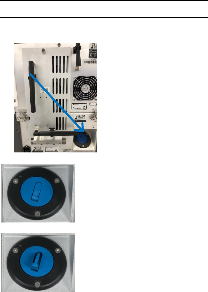
7. Chiller tank cap: The chiller tank cap provides access to the chiller tank for checking the coolant level
and adding coolant.
8. Support Arm: Drape the applicator cable over the support arm to minimize drag on the connections
and to keep the cable out of your way. Use the Velcro
®
straps to secure the cable to the support arm.

System Overview Control Unit
User Manual 19
Power Cord Clamp
The power cord clamp attaches the power cord to the rear of the control unit. Install the power cord clamp
before using the system. If the power cord is dislodged during a treatment, the treatment will be ended
abruptly.
► To install the power cord clamp:
1. Insert the thumbscrew into the hole on the rear of the control unit.
2. Using your fingers, turn the thumbscrew until it is snug.
Power Switch and Power Receptacle
The power switch controls power to the control unit and system components. The power receptacle houses
the plug for the power cord.
Components
1. Power Switch
2. Power Receptacle
► To power on the control unit:
1. Insert one end of the power cord into the power receptacle.
2. Insert the other end of the power cord into a grounded wall outlet.
3. Press the power switch on the back of the control unit to the On position.
4. The control unit powers on and displays the first screen.
Potential Equalization Test Connector
The test connector is for use by trained personnel only.
Access Panel
► To open the access panel cover:
1. Turn the thumb screw on the cover counterclockwise until it is loose.

Control Unit System Overview
20 BRZ-101-TUM-EN3-J
2. Open the cover downward.
The block holds the cover in a perpendicular position.
Components: Access Panel
1. Upper Port: The upper USB port (rectangular) is intended for use with approved software and
hardware provided by ZELTIQ.
2. Lower Port: The lower USB port (square) is for use by ZELTIQ Customer Service personnel. Do not use
the service port.
3. Vents: Vents provide airflow that reduces heat build-up inside the control unit. Ensure that all vents
are free from obstructions when the control unit is in operation.
4. Cables: The cables connect the upper module to the base module and carry electrical information
between the two modules.
5. Hoses: The hoses connect the upper module to the base module and carry coolant between the two
modules.
6. Data Modem: The antenna and data modem send data to ZELTIQ. (Availability and use of the data
modem are subject to regional limitations.)
Moving the Control Unit
► To move the control unit:
1. Power off the control unit.
2. Unplug the power cord from the wall outlet.
3. Wrap the power cord around the cleats on the back of the control unit.
Ensure that the cord does not exert force on the power cord clamp.
4. Release the locks on the casters.
5. Push or pull the rail to move the control unit to the new location.
6. Engage the locks on all four casters.

System Overview Applicators
User Manual 21
Applicators
CAUTION: Always use foam borders, gelpads, gel, liners, and securement
systems with the applicator as instructed in the directions for use.
The applicator delivers controlled cooling and warming to the treatment site; the vacuum applicator can
deliver optional massage to the treatment site.
The applicator consists of the applicator connector, the applicator cable, and the applicator head. The
applicator is used with supplies provided by ZELTIQ.
For information about using the applicator in a treatment, see:
• Attach the Applicator to the Control Unit on page 24
• Surface Applicator Treatment on page 29
• Vacuum Applicator Treatment on page 28
• CoolAdvantage Directions for Use
• CoolMini Directions for Use
Supplies
Card
The card provides cycles and profiles for use with the system. Each cycle provides a single treatment. The
profiles define the number of timed segments of cooling and warming. The profiles for a vacuum applicator
may include massage segments.
• Elements of a Profile on page 23
• Insert a Card on page 26
• Select a Profile on page 27
Coolant
The control unit requires an adequate supply of ZELTIQ coolant. When the coolant level is low, a
Recoverable Exception message is displayed.
Foam Borders
Foam borders minimize movement of the surface applicator during treatment. Refer to the directions for use
for foam borders.
Gasket
(CoolAdvantage Applicators)
The gasket provides a tight seal between the CoolAdvantage applicator cup and the contour.
Gel
CoolSculpting gel provides thermal contact between the applicator and the patient’s skin. The gel is intended
for a single use only. Refer to the gel or applicator directions for use for safety information on using gel.
Gelpad
The gelpad provides thermal contact between the applicator and the patient’s skin. The gelpad is intended for
a single use only. Refer to the gelpad directions for use for safety information on selecting and using gelpads.
Gel Trap
(CoolAdvantage and CoolMini Applicators)
Supplies System Overview
22 BRZ-101-TUM-EN3-J
The gel trap fits into the slot in the bottom of the applicator cup. The gel trap prevents the ingress of gel into
the vacuum system. Use a new gel trap for each treatment.
Liner
The liner provides a clean surface between the patient and the applicator and minimizes the spread of gel from
the gelpad. Refer to the liner directions for use for information on selecting and using liners.
Pretreatment Skin Wipe
Use the Pretreatment Skin Wipe (skin wipe) to prepare the treatment site before applying a gelpad. See
Surface Applicator Treatment on page 29.
Securement System
The securement system comprises a center panel and four straps. The securement system minimizes
movement of the surface applicator during treatment. Refer to the securement system directions for use.

User Manual 23
Contents
• Overview ......................................................................................... 23
• Perform a Treatment ...................................................................... 23
• Perform Another Treatment ........................................................... 31
• Cancel a Treatment ......................................................................... 33
• About Restarting a Treatment ........................................................ 34
• Complete a Treatment .................................................................... 35
Overview
A treatment is comprised of timed segments of cooling and heating; a vacuum treatment may include optional
massage. Each treatment is based on a profile, which is contained on the card. Each card contains a set number
of cycles and a list of profiles. When all the cycles have been used, the card is expired.
About Profiles
The profile defines the temperature and duration of a treatment. The surface applicator cools tissue from one
side and the vacuum applicator cools tissue from two sides; therefore, the rate of heat extraction and the
intensity of cooling achieved during a given period of time are greater with a vacuum applicator than with a
surface applicator. However, the total heat extraction for a given treatment is a function of temperature and
time, regardless of the applicator type.
Elements of a Profile
A profile contains the following elements:
Element
Description
°C
The treatment temperature.
Time
The duration of the treatment.
Massage
(Vacuum applicator only) Massage segment: Yes or No.
Table 12: Elements of a Profile
Perform a Treatment
• Set up the Control Unit on page 24
• Attach the Applicator to the Control Unit on page 24
• Insert a Card on page 26
• Enter Patient Data on page 26
• Select a Profile on page 27
• Vacuum Applicator Treatment on page 28
• Surface Applicator Treatment on page 29
C H A P T E R 2
TREATMENT

Perform a Treatment Treatment
24 BRZ-101-TUM-EN3-J
Set up the Control Unit
► To set up the control unit:
1. Position the control unit next to the bed or chair to be used for the treatment.
2. Ensure that the vents on all four sides of the system have adequate ventilation.
3. Ensure that the operator can access the power switch easily.
4. Insert the power plug into a grounded outlet.
WARNING: To minimize the risk of electric shock, connect this equipment to a
grounded electrical outlet.
5. Engage the locks on all four casters.
6. Power on the control unit.
The Applicator? and Card? cues are displayed on the Startup screen.
Attach the Applicator to the Control Unit
These examples show a vacuum applicator.
► To attach the applicator to the control unit:
1. Ensure that the support arm is installed on the side of the control unit that will be next to the
treatment bed or chair.
To install the support arm, insert the straight end into the jack.
2. Place the applicator on top of the control unit.
3. Position the connector above the connector plate.

Treatment Perform a Treatment
User Manual 25
4. With the locking lever in the Unlocked position, press the applicator connector down onto the
connector plate gently but firmly.
5. When the connector meets resistance, stop pressing down.
6. Turn the locking handle 180° clockwise to the Locked position.
The connector is pulled into the connector plate and locked in place.
7. Slip the applicator cable into the loop at the top of the support arm.
8. Apply Velcro
®
straps to connect the applicator cable to the support arm.
The applicator is authenticated.
When the process is complete, the authentication confirmation and the Card? cue are displayed in the
middle of the screen.
The name of the applicator is displayed in the lower left corner.
In this example, the applicator name is CoolCore.
Note: For information about status lights and touch pad controls, refer to the
directions for use for your applicator.

Perform a Treatment Treatment
26 BRZ-101-TUM-EN3-J
Insert a Card
► To insert a card:
1. Align the card to the slot on the applicator.
Note: For CoolAdvantage and CoolMini applicators, insert the card into the slot on
the applicator adapter.
2. Insert the card into the slot.
The card is authenticated.
The authentication confirmation and the number of cycles remaining on the card are displayed in the
middle of the screen.
The name of the card and the number of cycles remaining are displayed in the lower right corner.
The Next button is displayed.
In this example, the name of the card is CoolCard.
3. Press the Next button.
The New to Practice and Returning to Practice buttons are displayed.
Note: If the patient data controls are not displayed, contact Customer Service.
Enter Patient Data
Note: If the Usage Metrics function has been disabled, the Profile panel is displayed.
See Select a Profile on page 27.
► To enter patient data:
1. Press the New to Practice or Returning to Practice button.
2. Press the Female Patient or Male Patient button.

Treatment Perform a Treatment
User Manual 27
3. On the Body Profile screen, select a treatment site.
In this example, the flanks are selected for a female patient.
Refer to the Preface for warnings and cleared intended use.
4. Press the Next button.
5. Press the appropriate button for the current patient and treatment site.
6. The Profile panel is displayed.
In this example, a vacuum applicator profile is displayed.
Select a Profile
► To select a profile:
1. On the profile panel, press the Display Profiles button.
The drop-down list of available profiles is displayed.
The default profile is selected.
This example shows vacuum applicator profiles.
2. Press the desired profile.
The drop-down list is hidden and the selected profile is displayed.
3. Press the Next button.

Perform a Treatment Treatment
28 BRZ-101-TUM-EN3-J
Vacuum Applicator Treatment
• For a CoolAdvantage treatment, see the CoolAdvantage Directions for Use.
• For a CoolMini treatment, see the CoolMini Directions for Use.
If a liner is detected, the GELPAD? button is displayed.
If no liner is detected, the Liner? cue is displayed.
1. Install a liner.
CAUTION: Use a new liner on each patient.
CAUTION: Refer to the directions for use for your liner.
When the system detects the liner, it displays the GELPAD? button.
Note: If the liner is not detected, disconnect the tabs from the hooks. Grasp the
frames of the liner and remove the liner from the applicator cup. Repeat the
installation process.
► To apply a gelpad:
WARNING: Inspect the treatment site to ensure that the skin is intact. Treat
over intact skin only.
1. Remove jewelry that is in or directly adjacent to the application site.
2. Wipe the treatment site with an alcohol wipe and/or pretreatment skin wipe.
WARNING: Refer to the directions for use for your gelpad.
3. Press the GELPAD? button.
4. On the Gelpad Ready screen, press the Next button.
The Vacuum panel is displayed.
The Vacuum cue on the lower right spins.
The Vacuum Status light on the applicator touch pad flashes blue.

Treatment Perform a Treatment
User Manual 29
► To apply a vacuum applicator:
WARNING: The use of this device on areas with superficially located nerve
branches, arteries, or veins has not been demonstrated to be safe and effective.
Such use may result in injury to the patient.
WARNING: If the gelpad slips and the cooling surfaces of the applicator come
into direct contact with the patient’s skin, tissue injury may result. Inspect the
gelpad and applicator to ensure that the gelpad extends beyond the edges of the
applicator cup.
Note: Use the default vacuum settings or the lowest settings that result in
acceptable tissue draw into the applicator cup.
1. Press the Vacuum On/Off button on the applicator touch pad.
The vacuum is activated.
The Vacuum On button and the Tissue Draw indicator are displayed.
The Vacuum Status light on the applicator touch pad shines blue.
2. Place the applicator over the center of the gelpad on the treatment site.
3. Ensure that the gelpad extends beyond the edges of the applicator cup.
4. For best results, ensure that tissue is drawn into the applicator cup.
5. (Optional: Test Vacuum Pressure for Massage)
6. When the system detects that the applicator is connected to the treatment site, the Start button is
displayed.
The Treatment Status light on the applicator touch pad flashes blue.
Press the Start button.
The Treatment Status light on the applicator touch pad shines blue.
Surface Applicator Treatment
The CONFIRM? Site Preparation button is displayed.
WARNING: Inspect the treatment site to ensure that the skin is intact. Treat
over intact skin only.

Perform a Treatment Treatment
30 BRZ-101-TUM-EN3-J
1. Remove jewelry that is in or directly adjacent to the treatment site.
CAUTION: Prepare the treatment site with an alcohol wipe.
2. Apply one pair of foam borders around the treatment site.
CAUTION: Refer to the directions for use for your foam borders.
3. Wipe the treatment site with a pretreatment skin wipe.
4. Apply a gelpad to the treatment site.
WARNING: Refer to the directions for use for your gelpad.
5. Apply a liner over the gelpad.
CAUTION: Refer to the directions for use for your liner.
6. Press the CONFIRM? Site Preparation button.
7. Press the Next button.
The Surface Applicator Placement Cue is displayed.
► To apply a surface applicator:
WARNING: The use of this device on areas with superficially located nerve
branches, arteries, or veins has not been demonstrated to be safe and effective.
Such use may result in injury to the patient.
WARNING: If the gelpad slips and the cooling surfaces of the applicator come
into direct contact with the patient’s skin, tissue injury may result. Inspect the
gelpad and liner to ensure that they extend beyond the outside edges of the
foam borders.
1. Place the applicator between the foam borders on the treatment site.
2. Ensure that the gelpad and liner extend beyond the outside edges of the foam borders.
3. Wrap the securement system straps around the patient to secure the applicator in place.
Note: Refer to the securement system directions for use for information on securing
the applicator in place.
4. Press the Start button.
The Treatment Status light on the applicator shines blue.

Treatment Perform Another Treatment
User Manual 31
Perform Another Treatment
► To perform another treatment on the same patient:
CAUTION: When the vacuum is turned off or the securement system straps are
released, the applicator may disengage from the patient. The applicator could
fall and be damaged or cause injury. Grasp the head of the applicator firmly
before turning off the vacuum or releasing the securement system straps.
Remove a vacuum applicator:
Remove a surface applicator:
Grasp the applicator and turn off the vacuum.
Grasp the applicator and release the securement system
straps.
Remove the applicator from the patient.
Remove the applicator from the patient.
Place the applicator head on top of the control unit with
the cooling surfaces facing downward.
Place the applicator head on top of the control unit with
the cooling surfaces facing upward.
Allow gel to drain onto a towel or other absorbent
material.
n/a
Remove the gelpad or gel from the treatment site.
Remove the liner, gelpad, and foam borders from the
treatment site.
Discard the used gelpad or gel according to your site’s
medical waste protocols.
Discard the used liner, gelpad, and foam borders according
to your site’s medical waste protocols.
The Same Patient and Next Patient buttons are displayed.
(If the card is expired, see Expired Card on page 32.)
1. Press the Same Patient button.
2. On the Body Profile screen, select a treatment site.
In this example, the lower abdomen is selected for a female patient.
Refer to the Preface for warnings and cleared intended use.

Perform Another Treatment Treatment
32 BRZ-101-TUM-EN3-J
3. Press the Next button.
4. Press the appropriate button for the current patient and treatment site.
The Profile panel is displayed.
• See Select a Profile on page 27.
► To perform a treatment on the next patient:
CAUTION: When the vacuum is turned off or the securement system straps are
released, the applicator may disengage from the patient. The applicator could
fall and be damaged or cause injury. Grasp the head of the applicator firmly
before turning off the vacuum or releasing the securement system straps.
Remove a vacuum applicator:
Remove a surface applicator:
Grasp the applicator and turn off the vacuum.
Grasp the applicator and release the securement system
straps.
Remove the applicator from the patient.
Remove the applicator from the patient.
Place the applicator head on top of the control unit with
the cooling surfaces facing downward.
Place the applicator head on top of the control unit with
the cooling surfaces facing upward.
Allow gel to drain onto a towel or other absorbent
material.
n/a
Remove the gelpad or gel from the treatment site.
Remove the liner, gelpad, and foam borders from the
treatment site.
Remove the liner from the applicator cup.
n/a
Discard the used gelpad or gel, and liner according to your
site’s medical waste protocols.
Discard the used liner, gelpad, foam borders, and
securement system according to your site’s medical waste
protocols.
1. If the Same Patient and Next Patient buttons are displayed, press the Next Patient button.
If the Profile panel is displayed, select a profile.
• See Enter Patient Data on page 26.
Expired Card
If the card is expired, a recoverable exception is displayed.
1. Remove the card from the applicator.
2. Press the Next button to clear the message.
3. Insert a new card into the slot on the applicator.
The system authenticates the card.
4. When authentication is complete, press the Next button.

Treatment Cancel a Treatment
User Manual 33
The Profile screen is displayed.
Cancel a Treatment
A treatment can be canceled by the system or by the operator.
► To cancel a treatment in the first 10 minutes:
1. Press the Interrupt button.
2. Press the Cancel button.
3. Press the YES button.
The treatment is canceled and a message is displayed:
“The treatment was canceled by the operator.”
4. Press the Next button.
► To cancel a treatment after the first 10 minutes:
1. Press the Cancel button.
The treatment is canceled and a message is displayed.
“The treatment was canceled by the operator.”
2. Press the Next button.

About Restarting a Treatment Treatment
34 BRZ-101-TUM-EN3-J
Note: The Warming cue may be displayed for up to 2 minutes. When the applicator
cup is ready for the next treatment, the Next button is displayed.
About Restarting a Treatment
A treatment can be interrupted by either the operator or the system. When you restart a treatment, the
treatment count on the card is not reduced further.
Each treatment can be restarted only once.
A treatment can be restarted if:
• The operator interrupted the treatment during the first 10 minutes
• The system interrupted the treatment during the first 10 minutes with one of the following Recoverable
Exceptions:
The coolant level is low. Z403-YYY
Applicator control error. Z408-YYY
Treatment quality error. Z412-YYY
Potential loss of patient contact. Z415-YYY
Interference detected. Z426-YYY
• And, the Restart timer interval of 60 minutes has not expired
Interrupt a Treatment
► To interrupt a treatment:
1. Press the Interrupt button.
The Treatment Interrupted screen is displayed.
The Restart Timer runs for up to 60 minutes, after which the treatment can no longer be restarted.
2. Press the Next button to continue.
Note: The Warming cue may be displayed for up to 2 minutes. When the applicator
cup is ready for the next treatment, the Next button is displayed.

Treatment Complete a Treatment
User Manual 35
Restart a Treatment
CAUTION: When the vacuum is turned off or the securement system straps are
released, the applicator may disengage from the patient. The applicator could
fall and be damaged or cause injury. Grasp the head of the applicator firmly
before turning off the vacuum or releasing the securement system straps.
Note: The patient data that was used to start the treatment will be used to
complete the treatment.
► To restart a treatment:
Remove a vacuum applicator:
Remove a surface applicator:
Grasp the applicator and turn off the vacuum.
Grasp the applicator and release the securement system
straps.
Remove the applicator from the patient.
Remove the applicator from the patient.
Place the applicator head on top of the control unit with
the cooling surfaces facing downward.
Place the applicator head on top of the control unit with
the cooling surfaces facing upward.
Allow gel to drain onto a towel or other absorbent
material.
n/a
Remove the gelpad or gel from the treatment site.
Remove the liner and gelpad from the treatment site.
Discard the used gelpad or gel according to your site’s
medical waste protocols.
Discard the used liner and gelpad according to your site’s
medical waste protocols.
• See Vacuum Applicator Treatment on page 28
• See Surface Applicator Treatment on page 29
Complete a Treatment
► To complete a treatment:
When the treatment is complete, a message is displayed.
“The treatment is complete.”
CAUTION: When the vacuum is turned off or the securement system straps are
released, the applicator may disengage from the patient. The applicator could
fall and be damaged or cause injury. Grasp the head of the applicator firmly
before turning off the vacuum or releasing the securement system straps.
Remove a vacuum applicator:
Remove a surface applicator:
Grasp the applicator and turn off the vacuum.
Grasp the applicator and release the securement system
straps.
Remove the applicator from the patient.
Remove the applicator from the patient.
Place the applicator head on top of the control unit with
the cooling surfaces facing downward.
Place the applicator head on top of the control unit with
the cooling surfaces facing upward.
Allow gel to drain onto a towel or other absorbent
material.
n/a

Complete a Treatment Treatment
36 BRZ-101-TUM-EN3-J
Remove a vacuum applicator:
Remove a surface applicator:
Remove the gelpad or gel from the treatment site.
Remove the liner, gelpad, and foam borders from the
treatment site.
Remove the liner from the applicator cup.
n/a
Discard the used gelpad or gel, and liner according to your
site’s medical waste protocols.
Discard the used liner, gelpad, foam borders, and
securement system according to your site’s medical waste
protocols.
1. Wipe gel from the patient’s skin.
2. Wipe the cooling surfaces of the applicator with a soft, dry cloth.
3. To power off the control unit, press the power switch.
CAUTION: The electronic sensors on the cooling surfaces of the applicator are
delicate. Use care when cleaning and storing the applicator. (See Cleaning on
page 39.)
Test Vacuum Pressure for Massage
(Standard vacuum applicators only) Before you start a treatment, you can test and modify the vacuum pressure
for massage to ensure that the vacuum pressure is high enough to keep the applicator in place during the
treatment.
► To test the vacuum pressure for massage:
1. When the applicator is on the treatment site and the tissue is drawn into the applicator cup, press the
Display Massage Settings button.
The Massage Settings Panel is displayed.
2. Press the Massage Status (Off) button on the Massage Settings panel.
3. Press the Max and Min Increase and Decrease buttons on the Massage Settings panel if needed to
modify vacuum pressure for massage.
4. Press the Massage Status (On) button to turn off massage.
5. Press the Hide Massage Settings button.
Treatment Complete a Treatment
User Manual 37
6. If necessary, adjust the position of the vacuum applicator and modify the vacuum pressure for
massage.
7. If you turn off the vacuum and then remove the vacuum applicator from the site:
a) Discard the used gelpad or gel according to your site’s medical waste protocols.
b) Clean the treatment site.
c) Apply a new gelpad or new gel. (Refer to the Directions for Use for your gelpad. See page 27.)
Complete a Treatment Treatment
38 BRZ-101-TUM-EN3-J

User Manual 39
Contents
• Cleaning .......................................................................................... 39
• Maintenance ................................................................................... 40
• Disassembling the Control Unit ...................................................... 43
• Assembling the Control Unit ........................................................... 46
• Connecting Latches, Hoses, and Cables .......................................... 47
• Customer Service ............................................................................ 48
Perform routine cleaning and maintenance according to your site’s protocols.
Cleaning
CAUTION: The use of an unapproved cleaning solution or method on the control
unit or applicator may result in damage. Always use approved products and
follow the guidelines below.
Approved Products
The following products are approved for cleaning the control unit and applicators:
• Isopropyl alcohol
• Mild detergent and warm water
• PDI Sani Cloth Plus wipes
Cleaning Guidelines
• Unplug the control unit before cleaning.
• Use sterilization wipes or spray the cleaning agent on a soft wipe, paper towel, or equivalent material.
CAUTION: Do not spray or spill any fluid directly on any part of the control unit,
applicators, or supplies.
CAUTION: Do not submerge the applicator or any other part of the system in
any liquid.
• Do not use excessive amounts of fluid.
• Do not apply cleaning solution to the electrical connections.
• After cleaning the system components, dry them with a soft cloth to remove any cleaning residues.
• Do not sterilize the control unit, applicator, or any other system components.
Cleaning the Touch Screen
For best performance, clean the touch screen regularly.
Approved cleaning products include:
• Isopropyl alcohol
• Window cleaning fluid
C H A P T E R 3
CLEANING AND MAINTENANCE

Maintenance Cleaning and Maintenance
40 BRZ-101-TUM-EN3-J
► To clean the touch screen:
1. Dampen a soft lint-free cloth with isopropyl alcohol or a window cleaning fluid.
2. Wipe the touch screen gently.
Maintenance
External Chiller Filter
The CoolSculpting control unit has an external filter installed that is located on the front bottom of the
system (Picture A) and is easily replaceable. The purpose of this filter is to extend the service life of your
control unit.
► Location of filter (Picture A):
► When to replace:
Every 6 months or
Blue Thermometer icon appears for extended period of time:
3. (Picture B)
4.

Cleaning and Maintenance Maintenance
User Manual 41
The Z802-322 Chiller Pump alert message appears:
5. (Picture C)
► How to replace the external chiller filter:
Turn the control unit off prior to replacing the filter
► How to order:
The replacement part number is FRU-CTU-BAM-103 and can be ordered by contacting your local Allergan
office.
Maintenance Cleaning and Maintenance
42 BRZ-101-TUM-EN3-J
Coolant
Coolant circulates between the control unit and the applicator to remove heat from the applicator. When you
connect a new applicator, it takes up a significant amount of coolant. Also, when you disconnect an applicator,
or disconnect the hoses on the access panel to prepare for shipping a module, a small amount of coolant may
be lost.
When the level of coolant is low, the control unit displays a message. It is safe to add coolant while the control
unit is powered on.
CAUTION: The use of unauthorized coolant has not been tested. Always use
coolant authorized by ZELTIQ.
► To add coolant:
1. Locate the chiller tank cap.
2. Press down on the recessed end of the blue lever on the chiller tank cap.
The handle flips up.
3. Turn the blue handle counter-clockwise until the cap disengages.
4. Remove the cap.
5. Pour coolant into the tank.

Cleaning and Maintenance Disassembling the Control Unit
User Manual 43
The amount of additional coolant that is required can vary. To avoid spillage, watch the coolant as you
pour. Listen for changes in the sound.
6. Replace the cap and tighten it just until snug.
When the vacuum is activated, it pulls the cap in tighter. If you overtighten the cap, it could become
too tight to loosen.
Disassembling the Control Unit
The control unit consists of an upper module and a base module. Disassemble the control unit to prepare to
ship either module to the factory for repair or replacement.
CAUTION: The upper and base modules of the control unit are heavy. Do not
attempt to lift either module by yourself. This procedure requires two people.
Latches
► To disassemble the control unit:
1. Power off the control unit.
2. Engage the locks on all four casters.
3. Disconnect the power cord from the control unit.
4. Wrap the power cord around the cleats and secure it with the Velcro
®
strap.
5. Open the storage drawer and disconnect the latches on the front of the control unit.
6. Disconnect the latches on the back of the control unit.
► To disconnect a latch:

Disassembling the Control Unit Cleaning and Maintenance
44 BRZ-101-TUM-EN3-J
1. Flip the handle of the latch upward and turn it counterclockwise until the top of the clasp disengages.
2. Pull the handle back and let it hang downward.
Cables and Hoses
► To disconnect cables and hoses:
1. Turn the thumbscrew on the cover of the access panel.

Cleaning and Maintenance Disassembling the Control Unit
User Manual 45
2. Let the cover hang down, exposing the cables and hoses.
3. Working from left to right, disconnect the cables and then the hoses.
► To disconnect the data modem cable:
If the data modem cable is disconnected, skip this step.
1. Grasp the head of the data modem cable.
2. Pull the head straight out of the USB port.
► To disconnect a cable:
1. Locate the ring that is closest to the back of the access panel.
2. Turn the ring counterclockwise until it moves freely.
3. Pull the ring off the connector.
► To disconnect a hose:
1. Squeeze the metal clasp at the top of the hose connector.
2. Pull back until the hose connector disengages from the jack.
Note: A small amount of coolant may drip from the hoses. Wipe up coolant with a
soft cloth.

Assembling the Control Unit Cleaning and Maintenance
46 BRZ-101-TUM-EN3-J
Remove Upper Module
► To remove the upper module:
1. Engage the locks on all four casters.
2. Prepare a place to put the upper module.
3. Position each person on one side of the control unit.
4. Have each person grasp the rail with two hands.
5. Lift the upper module.
6. Walk past the base module and put the upper module down.
Assembling the Control Unit
CAUTION: The upper and base modules of the control unit are heavy. Do not
attempt to lift either module by yourself. This procedure requires two people.
► To install the upper module:
1. Engage the locks on all four casters.
2. Ensure that the power cord is disconnected from the control unit.
3. Ensure that the cables and hoses that are attached to the base module are out of the way.
4. Place the base module in front of the upper module.
5. Grasp the bar on the upper module and lift the upper module into position on top of the base module.

Cleaning and Maintenance Connecting Latches, Hoses, and Cables
User Manual 47
6. Ensure that the cables and hoses are clear.
7. Connect the latches, cables, and hoses.
8. Ensure that the upper module is aligned to the base module.
Connecting Latches, Hoses, and Cables
► To connect a latch:
1. Place the top clasp over the top hook.
2. Flip the handle of the latch outward.
3. Turn the handle clockwise until the top clasp is snug against the hook.
4. Press the handle down.
► To connect the hoses and cables:
1. Start with the hose on the right.
2. Press the hose into the jack.
3. Repeat for the hose on the left.
4. Press the cable connector on the right over the post.
5. Turn the ring clockwise until it is snug. Do not overtighten.
6. Repeat for the remaining cables, working from right to left.
7. Close the cover of the access panel.
8. Align the thumbscrew on the cover of the access panel to the hole on the upper module.
Customer Service Cleaning and Maintenance
48 BRZ-101-TUM-EN3-J
9. Turn the thumbscrew to the right just until it is snug. Do not overtighten.
► To connect the data modem cable:
1. Grasp the head of the data modem cable.
2. Ensure that the USB symbol is facing upward.
3. Insert the head of the cable into the upper USB port.
Customer Service
To report issues with the performance or use of your System, contact ZELTIQ Customer Service.
• Worldwide: (+1) 925-474-8160
• United States: 1-888-935-8471 (1-888-ZELTIQ1)
Routine Issues
For questions regarding device performance or to report issues that do not interfere with current patient
treatments:
• Call during regular business hours, 6 am to 6 pm, Pacific Time, Monday through Friday. Calls are answered
in the order received.
Urgent Issues
To report safety concerns or issues that interfere with current patient treatments:
• Call at any time. Outside regular business hours (above), leave a voicemail. A technician will be paged and
will return your call promptly.

User Manual 49
Contents
• ZELTIQ Customer Service ................................................................ 49
• Recoverable Exceptions .................................................................. 49
• Error Messages ............................................................................... 51
• General Messages ........................................................................... 51
• Software Updates and Messages ................................................... 52
This appendix lists system messages with the suggested user action, if any. Each message includes a message
code that is preceded by the letter Z and a Customer Service code.
Carry out the recommended action, if any. If the problem persists, record both codes and call Customer
Service. Customer Service will use the codes in order to help resolve the issue. For assistance with any message
not listed here, call Customer Service.
ZELTIQ Customer Service
• Worldwide: (+1) 925-474-8160
• United States: 1-888-935-8471 (1-888-ZELTIQ1)
Recoverable Exceptions
Message
Action
Applicator error. Z401-YYY
Disconnect and reconnect the applicator.
Disconnect and reconnect the applicator.
The card expired. Z402-YYY
Connect a new card.
Remove the card from the applicator and insert a new card.
The coolant level is low. Z403-YYY
Add coolant.
Add coolant.
The card and applicator are incompatible. Z404-YYY
Remove the card from the applicator. Insert a card that is
appropriate for the applicator type.
Applicator software error. Z405-YYY
Replace the applicator.
Use another applicator.
Card error. Z406-YYY
Disconnect and reconnect the card.
Remove and reinsert the card.
Card error. Z407-YYY
Disconnect and reconnect the card.
Remove and reinsert the card.
Applicator control error. Z408-YYY
Start a treatment. If the problem persists, call Customer
Service.
Start a treatment. If the problem persists, replace the
applicator.
A P P E N D I X A
SYSTEM MESSAGES

Recoverable Exceptions System Messages
50 BRZ-101-TUM-EN3-J
Message
Action
CAUTION
Thermal event detected. Z409-YYY
Remove the applicator and gelpad. Refer to the user
manual.
CoolAdvantage and CoolMini applicators:
• Do not retreat for at least 24 hours.
All other applicators:
• If you receive a second Z409 for a single treatment
site, discontinue treatment for the site, do not
retreat for at least 24 hours.
Applicator control error. Z410-YYY
Start a treatment. If the problem persists, call Customer
Service.
Start a treatment. If the problem persists, call Customer
Service.
Applicator error. Z411-YYY
Power the control unit off and on.
Power the control unit off and on.
Treatment quality error. Z412-YYY
Start a treatment. If the problem persists, call Customer
Service.
Restart the treatment or start a new treatment.
Applicator error. Z414-YYY
Disconnect and reconnect the applicator.
Disconnect and reconnect the applicator.
Potential loss of patient contact. Z415-YYY
Reapply the applicator and start a treatment. If the
problem persists, call Customer Service.
Turn off the vacuum, remove the applicator cup from the
patient, discard the used gelpad or gel, clean the treatment
site, and apply a new gelpad or new gel. Restart an
interrupted treatment or start a new treatment.
Card compatibility error. Z417-YYY
Replace the card.
Insert a card that is compatible with the control unit.
Card compatibility error. Z418-YYY
Call Customer Service.
Call Customer Service.
Card compatibility error. Z420-YYY
Call Customer Service.
Call Customer Service.
Card error. Z421-YYY
Disconnect and reconnect the card.
Disconnect and reconnect the card.
Disconnect and reconnect the applicator. Z422-YYY
Disconnect and reconnect the applicator.
The restart timer has expired. Z425-YYY
Start a new treatment.
Start a new treatment.
Interference detected. Z426-YYY
Start a treatment. If the problem persists, refer to the User
Manual.
Identify and resolve possible causes:
• Patient movement
• Another medical device in close proximity
If the problem persists, contact Customer Service.
This system must be serviced by ZELTIQ no later than
YYYY-MM-DD to ensure continued use. Z428-YYY
Contact Customer Service.
The applicator adapter and applicator are incompatible.
Z429-YYY. Contact Customer Service.
Contact Customer Service.
Table 13: Recoverable Exceptions

System Messages Error Messages
User Manual 51
Error Messages
For all system errors, power the control unit off and on. If the problem persists, call Customer Service. (ZELTIQ
Customer Service on page 49)
Code
Message
Z801
Chiller error. Z801-YYY
Z802
Chiller error. Z802-YYY
Z803
Control unit error. Z803-YYY
Z804
Control unit error. Z804-YYY
Z805
Control unit error. Z805-YYY
Z806
Invalid configuration values. Z806-YYY
Z808
Software error. Z808-YYY
Z809
Control unit error. Z809-YYY
Z810
This system must be serviced by ZELTIQ. Contact Customer Service.
Z811
Control unit error. Z811-YYY
Z812
The device connected to the control unit is not recognized. Z812-YYY
Table 14: Error Messages
General Messages
Message
Recommended Action
The applicator is disconnected.
Connect the applicator to the control unit.
The card is disconnected.
Insert the card into the slot on the applicator. Ensure that
the card is inserted correctly.
The treatment was canceled by the operator.
Restart the treatment or start a new treatment.
The treatment is complete.
Turn off vacuum, remove the applicator and gelpad or gel,
and clean the treatment site.
The treatment was interrupted by the operator.
Restart the treatment or start a new treatment.
Turn off the vacuum.
Remove the applicator and gelpad or gel.
Turn off vacuum power either on the applicator touch pad
or on the system touch screen. Remove the applicator and
gelpad or gel.
Are you sure you want to cancel the treatment?
Press the YES button to cancel the current treatment. Press
the NO button to continue and restart the current
treatment.
Table 15: General Messages
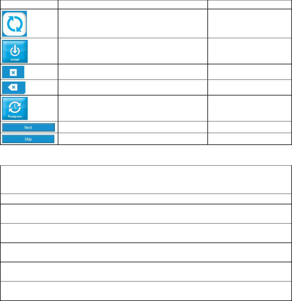
Software Updates and Messages System Messages
52 BRZ-101-TUM-EN3-J
Software Updates and Messages
From time to time, ZELTIQ may provide software updates.
Button
Description
Name
A software update is available.
Software Update
Install the software update.
Install
Clear the software update code.
Clear
Delete the last character of the patient number.
Backspace
Postpone the software update.
Postpone
Start the update.
Next Update
Skip the update.
Skip Update
Table 16: Controls and Cues for Software Updates
The following text and messages may be displayed.
Software Update
Approximate installation time: xx minutes
Installation must be performed no later than YYYY/MM/DD to ensure continued use.
Enter the Software Update Key.
Installation complete.
Press the Next button.
Installation error. Z930
Power the control unit off and on. If the problem persists, contact Customer Service.
Installation error. Z961-YYY
Remove the USB stick. Power the control unit off and on. Contact Customer Service.
Installation error. Z962-YYY
Press the Next button. Contact Customer Service.
Installation error. Z963
Power the control unit off and on. If the problem persists, contact Customer Service.
Table 17: Software Update Installation Messages

System Messages Software Updates and Messages
User Manual 53
CoolAdvantage Software Updates and Messages
In addition to the general software update messages, the following information may be displayed during a
CoolAdvantage software update.
Software Update: Attach the applicator adapter to the control unit. Approximate installation time: xx minutes
Installation must be performed no later than YYYY/MM/DD to ensure continued use.
Software updating ........
Installation complete. Press the Next button.
The applicator adapter was not detected. If you have an adapter, connect it to the control unit. To proceed with the
update, press the Next button. To skip the update, press the Skip button.
Table 18: CoolAdvantage Software Update Installation Messages
Software Updates and Messages System Messages
54 BRZ-101-TUM-EN3-J

User Manual 55
Contents
• Controls for System Tools ............................................................... 55
• System Log Screen .......................................................................... 55
• Card Log Screen .............................................................................. 56
• Service Screen ................................................................................. 58
• Settings Screen ............................................................................... 60
This chapter describes the System Tools.
The System Tools button is available on the Startup screen, Profile screen, Recoverable Exception screen, and
System Error screen.
Controls for System Tools
Button
Description
Name
Display the System Tools screen.
System Tools
Display the System Log screen to view information about system events.
System Log
Display the Card Log screen to view usage history for the current card.
Card Log
Display the Service screen to access the Vacuum Diagnostic and Chiller
Diagnostic screens. (For use during a Customer Service call.)
Service
Display the Settings screen to access the Calibration, Time Zone, and Date
and Time screens.
Settings
Table 19: Controls for System Tools
System Log Screen
The System Log screen displays information about system events and errors.
Heading
Description
Date
The date of the event as Month, DD, YYYY.
Time
The time of the event as HH:MM where H = hour and M = minute.
Code
The ZELTIQ error code.
Condition
A description of the condition: Recoverable, System Error, Treatment Error.
Text
The text of the control unit message.
Table 20: System Log Headings
A P P E N D I X B
SYSTEM TOOLS

Card Log Screen System Tools
56 BRZ-101-TUM-EN3-J
► To view the System Log screen:
1. On the System Tools screen, press the System Log button.
The System Log screen is displayed.
2. To scroll through the screen, drag the slider at the bottom or right side of the screen.
3. To return to the System Tools screen, press the Previous button.
Note: Availability and use of the data modem are subject to regional limitations. The
Upload Data button is displayed only if the modem is activated.
Note: The data upload function is for use during a call with customer service.
► To upload data to ZELTIQ:
1. On the System Log screen, press the Upload Data button.
The Upload Status screen is displayed.
When the process is complete, a message is displayed:
Upload Status: Uploading, Upload complete, Upload failed
Card Log Screen

System Tools Card Log Screen
User Manual 57
The Card Log screen displays information about card usage. View the Card Log screen when you have questions
about the number of cycles remaining and when treatments were performed.
Heading
Description
Date
The date of the usage: Month, DD, YYYY.
Time
The time of the usage as HH:MM, where H = hour and M = minute, in AM/PM.
Status
The status of the usage: (Canceled, Error, Unknown, Successful)
Table 21: Card Log Headings
► To view the Card Log screen:
1. Attach the applicator to the control unit.
2. Insert the card into the slot on the applicator.
The control unit authenticates the card.
3. When the process is complete, press the Next button.
4. On the System Tools screen, press the Card Log button.
The Card Log screen is displayed.
5. To return to the System Tools screen, press the Previous button.

Service Screen System Tools
58 BRZ-101-TUM-EN3-J
Service Screen
Controls for Service Tools
The tools on the Service screen are for use during a call with Customer Service. Follow the instructions provided
by Customer Service.
Button
Description
Name
Display the Vacuum Diagnostic screen to view information about the
performance of the vacuum system.
Vacuum Diagnostic
Display the Chiller Diagnostic screen to view information about the
performance of the chiller.
Chiller Diagnostic
The data modem can upload data to ZELTIQ. Availability and use of the
data modem are subject to regional limitations.
Data Modem
Table 22: Controls for Service Tools
► To view the Service screen:
1. On the System Tools screen, press the Service button.
The Service screen is displayed.
Vacuum Diagnostic Screen
The Vacuum Diagnostic screen provides information about the performance of the vacuum system.
Any changes to settings on this screen are temporary and do not influence the functionality of the system
during a treatment.
► To view the Vacuum Diagnostic screen:
1. On the Service screen, press the Vacuum Diagnostic button.

System Tools Service Screen
User Manual 59
The Vacuum Diagnostic screen is displayed.
Standard Vacuum Applicator
Vacuum Applicator with Adapter
On the sample screens, the applicator is disconnected and vacuum power is off.
2. Follow the instructions provided by Customer Service.
3. To return to the System Tools screen, press the Previous button.
Chiller Diagnostic Screen
The Chiller Diagnostic screen provides information about the performance of the chiller.
Any changes to settings on this screen are temporary and do not influence the functionality of the system
during a treatment.
► To view the Chiller Diagnostic screen:
1. On the Service screen, press the Chiller Diagnostic button.
The Chiller Diagnostic screen is displayed.
On the sample screen, the applicator is connected, the chiller is off, chiller power is off, and cooling is
off.
2. Follow the instructions provided by Customer Service.
3. To return to the System Tools screen, press the Previous button.

Settings Screen System Tools
60 BRZ-101-TUM-EN3-J
Data Modem Screen
Availability and use of the data modem are subject to regional limitations. Contact customer service for further
information.
► To view the Data Modem screen:
1. On the Service screen, press the Data Modem button.
The Data Modem screen is displayed.
On the sample screen, the Network Type is HSDPA_3G and the Connection Quality is Unknown.
2. Follow the instructions provided by Customer Service.
To return to the Service screen, press the Previous button.
Settings Screen
The Settings button is available on the System Tools screen.
Note: Ensure that the Time Zone setting is correct before you update the Date and
Time settings.
Controls for Settings Tools
► To view the Settings screen:
1. On the System Tools screen, press the Settings button.

System Tools Settings Screen
User Manual 61
The Settings screen is displayed.
2. To return to the System Tools screen, press the Previous button.
Calibration Screen
The system screen might require recalibration from time to time. If the screen does not respond accurately to
your touch, calibrate the screen.
► To calibrate the screen:
1. On the System Tools screen, press the Settings button.
2. Press the Calibration button.
The Calibration screen is displayed.
3. Use a cotton swab to press the cross-hatch.
The system records your touch and moves the cross-hatch to the next position.
4. Press the cross-hatch in each position.
After you press the last setting, the system displays a message.
5. To save your new settings, touch the screen within the time displayed in the message.

Settings Screen System Tools
62 BRZ-101-TUM-EN3-J
The new settings are saved and the Settings screen is displayed.
6. To discard your new settings and retain the previous settings, wait until the time runs out,
approximately 30 seconds.
The Settings screen is displayed.
Time Zone Screen
The setting on the Time Zone screen determines the time zone for entries on the Card Log screen and System
Log screen.
Note: Always check the Date and Time settings after you modify the time zone.
► To modify the time zone:
1. On the Settings screen, press the Time Zone button.
The Time Zone screen displays a list of regions.
2. To select a region, press the name of the region and then press the Next button.
The Time Zone screen displays a list of zones within the region you selected.
3. To scroll through the list, press and drag the scroll panel on the right.
4. To select a time zone, press a row.
5. To save changes, press the Next button.

System Tools Settings Screen
User Manual 63
6. To discard changes, press the Cancel button.
7. On the Settings screen, press the Date & Time button.
Date and Time Screen
Note: Ensure that the Time Zone setting is correct before you modify Date and Time
settings.
► To modify date and time settings:
1. On the Settings screen, press the Date & Time button.
The Date and Time screen is displayed.
2. To modify settings, press the Decrease and Increase buttons.
3. To save changes, press the Next button.
4. To discard changes, press the Cancel button.
The Settings screen is displayed.
Note: The 24 Hour setting controls the hour of the day and is in a 24-hour format.

Settings Screen System Tools
64 BRZ-101-TUM-EN3-J
Data Screen
The Data screen displays the Usage Metrics button. The Usage Metrics button controls the display of patient
data controls. The tools on the Data screen are for use during a call with Customer Service.
► To view the Data screen:
1. On the Settings screen, press the Data button.
2. The Data screen is displayed.
3. Follow the instructions provided by Customer Service.

User Manual 65
Contents
• Essential Performance .................................................................... 65
• Disposal of Hazardous Materials .................................................... 65
• Environmental Requirements ......................................................... 65
• Electrical Specifications .................................................................. 66
• Medical Safety Standards ............................................................... 66
• Electromagnetic Compatibility ....................................................... 66
• Data Modem Specifications ............................................................ 70
This product may contain remanufactured parts or parts that have had incidental use, all of which are
equivalent in performance to new parts.
Essential Performance
When cooling to a target temperature that is below 5°C, the device allows cooling to no more than 1°C below
the target temperature. When warming to a target temperature that is above 30°C, the device allows warming
to no more than 1°C above the target temperature. Under steady state conditions, the device controls vacuum
pressure to within ± 1 inches of Hg.
Disposal of Hazardous Materials
Various components of the system may contain materials whose disposal is subject to regulation. The upper
module of the system contains a lithium battery, which is not serviceable by the customer. Dispose of all
components of the system in accordance with applicable regulations. Contact your local environmental control
agency for additional information on recycling or disposing of the system in your area.
Environmental Requirements
The system and its components are designed to operate normally when stored, shipped, and operated under
the following conditions.
WARNING: Use of the system in an oxygen-rich environment may cause fire. Do
not use the system in an oxygen-rich environment.
CAUTION: The system may not operate as expected if it is stored or operated in
conditions of excessive heat, humidity, or atmospheric pressure. Operate and
store the system in a room that meets the stated requirements.
Shipping / Storage
Operating
Temperature
32°F to 140°F (0°C - 60°C)
59°F to 82°F (15°C - 28°C)
Humidity
10% to 95% (non-condensing)
10% to 70% (non-condensing)
Atmospheric Pressure
Sea level to 10,000 feet at standard pressure
Table 23: Shipping, Storage, and Operating Requirements
A P P E N D I X C
SYSTEM SPECIFICATIONS

Electrical Specifications System Specifications
66 BRZ-101-TUM-EN3-J
Dimensions of the Control Unit and Modules
Height
Depth
Width
Weight
Control unit alone
47.5 in
120.7 cm
35 in
88.9 cm
24 in
61 cm
215 lbs
97.5 kg
Control unit with support arm
62 in
157.5 cm
n/a
n/a
216 lbs
98.0 kg
Upper module
17 in
43.2 cm
27.25 in
69.2 cm
21.25 in
54 cm
65 lbs
29.5 kg
Base module
30.5 in
77.5 cm
28.5 in
72.4 cm
24 in
61 cm
150 lbs
68.0 kg
Table 24: Control Unit - Dimensions
Electrical Specifications
Electrical Safety
Class I Equipment, single phase AC, Continuous Operation
Contains Type BF Patient-applied Parts
Water Ingress Protection: Ordinary Equipment, IPX0
REF
Voltage
Frequency
Current
BRZ-CG1-BAM-100
100VAC
50-60 Hz
12A
BRZ-CG1-BAM-110
110-120VAC
50-60 Hz
12A
BRZ-CG1-BAM-220
220-240VAC
50-60 Hz
7A
Table 25: Electrical Specifications
Fuses
The system contains two internal fuses: Type 3AB (ceramic cartridge), Rating: 250VAC, 6.25A, Slo-Blo. The fuses
are not serviceable by the customer.
Medical Safety Standards
The system complies with the following medical safety standards:
• IEC 60601-1: 1998 + A1, A2
• IEC 60601-1: 2005 + CORR. 1 (2006) + CORR. 2 (2007)
• EN 60601-1: 2006
• CAN/CSA C22.2 No 60601.1: 08
• ANSI/AAMI ES 60601-1: 2005 / AS: 2010
• AS 3200.1.0: 1998 + A1/NZS 6150: 1990 + A1
• Electromagnetic Compatibility (EMC) EN 60601-1-2: 2007
Electromagnetic Compatibility
The system has been tested and found to comply with Medical Standard Electromagnetic Compatibility (EMC)
EN 60601-1-2: 2007. The system complies with the standards outlined below.

System Specifications Electromagnetic Compatibility
User Manual 67
This system requires special precautions to ensure electromagnetic compatibility with other electrical medical
devices. To ensure EMC, the system must be installed and operated according to the information provided in
this manual.
CAUTION: When the system is interconnected with other electrical devices,
leakage currents may be additive, resulting in electromagnetic emissions that
can interfere with the normal function of electronic medical equipment. To
properly control electromagnetic emissions and avoid potential harm to the
patient or user, ensure all electrical devices are installed and interconnected
according to the requirements of IEC 60601-1-1.
CAUTION: Install the system in a room that complies with all applicable IEC, CEC,
and NEC requirements for safety of electrical devices.
CAUTION: Portable and mobile RF communications equipment may affect the
normal function of the system.
CAUTION: Use of the system adjacent to or stacked with other equipment may
result in unexpected electromagnetic circumstances. Prior to such use, test the
operation of the system in the proposed configuration and ensure it meets all
requirements as defined in the tables below. Consult the tables below for
guidance in placing the system.
CAUTION: Use ports on the system exactly as instructed in this manual. Any
other use of these ports may cause unexpected results. See System Overview on
page 11.
CAUTION: Do not use cables or accessories other than those provided by ZELTIQ.
The use of other cables or accessories may result in increased electromagnetic
emissions or decreased immunity to such emissions.
Guidance and Manufacturer’s Declaration -- Electromagnetic Emissions
The system is intended for use in the electromagnetic environment specified below. The customer or user of the system
should ensure that it is used in such an environment.
Emissions Test
Compliance
Electromagnetic Environment - Guidance
RF Emissions CISPR 11
Group 1
The system uses RF energy only for its internal function; therefore, its RF
emissions are very low and are not likely to cause any interference in
nearby electronic equipment.
RF Emissions CISPR 11
Class A
(A) The system is suitable for use in all establishments other than
domestic, and may be used in domestic establishments and those directly
connected to the public low-voltage power supply network that supplies
buildings used for domestic purposes, provided the following warning
statement is heeded:
CAUTION: The system is intended for use by healthcare professionals only.
The system may cause radio interference or may disrupt the operation of
nearby equipment. It may be necessary to take mitigation measures, such
as reorienting or relocating the system or shielding the location.
Harmonic emissions
IEC 61000-3-2
Class A
Voltage fluctuations/
Flicker emissions
IEC 61000-3-3
Class A

Electromagnetic Compatibility System Specifications
68 BRZ-101-TUM-EN3-J
Guidance and Manufacturer’s Declaration -- Electromagnetic Immunity
The system is intended for use in the electromagnetic environment specified below. The customer or user of the system
should ensure that it is used in such an environment.
Immunity Test
IEC 60601
Test Level
Compliance Level
Electromagnetic Environment - Guidance
Electrostatic
discharge (ESD)
IEC 61000-4-2
±6kV contact
±8kV air
±2,4,6kV contact
±2,4,8kV air
Floors should be wood, concrete, or ceramic tile. If
floors are covered with synthetic material, the
relative humidity should be at least 30%.
Electrical fast
transient/burst
IEC 61000-4-4
±2kV for power supply
lines
±1kV for input/output
lines
±2kV for line to ground
±1kV for line to line
Mains power quality should be that of a typical
commercial or hospital environment.
Surge
IEC 61000-4-5
±1kV differential
mode
±2kV common mode
± 0.5, 1kV differential
mode
±0.5, 1, 2kV common
mode
Mains power quality should be that of a typical
commercial or hospital environment.
Voltage dips,
short
interruptions, and
voltage variations
on power supply
input lines
IEC 61000-4-11
<5% U
T
(>95% dip in
U
T
) for 0.5 cycle
40% U
T
(60% dip in U
T
)
for 5 cycles
70% U
T
(30% dip in U
T
)
for 25 cycles
<5% U
T
(>95% dip in
U
T
) for 5 sec
<5% U
T
(>95% dip in U
T
)
for 0.5 cycle
40% U
T
(60% dip in U
T
)
for 5 cycles
70% U
T
(30% dip in U
T
)
for 25 cycles
<5% U
T
(>95% dip in U
T
)
for 5 sec
Mains power quality should be that of a typical
commercial or hospital environment. If the user of
the system requires continued operation during
power mains interruptions, it is recommended that
the system be powered from an uninterruptible
power supply or a battery.
Power frequency
(50/60Hz)
magnetic field
IEC 61000-4-8
3A/m
3A/m
Power frequency magnetic fields should be at levels
characteristic of a typical location in a typical
commercial or hospital environment.
NOTE: U
T
is the AC mains voltage prior to application of the test level.

System Specifications Electromagnetic Compatibility
User Manual 69
Guidance and Manufacturer’s Declaration -- Electromagnetic Immunity
The system is intended for use in the electromagnetic environment specified below. The customer or user of the system
should ensure that it is used in such an environment.
Immunity Test
IEC 60601
Test Level
Compliance
Level
Electromagnetic Environment - Guidance
Portable and mobile RF communications equipment should be
used no closer to any part of the system, including its cables,
than the recommended separation distance calculated from the
equation applicable to the frequency of the transmitter.
Recommended Separation Distance
Conducted RF
IEC 61000-4-6
3 Vrms
150 kHz to 80 MHz
3 Vrms
d = 1.17
¯
P
Radiated RF
IEC 61000-4-3
3V/m
80 MHz to 2.5 GHz
3 V/m
d = 1.2
¯
P 80 MHz to 800 MHz
d = 2.3
¯
P 800 MHz to 2.5 GHz
where P is the maximum output power rating of the transmitter
in watts (W) according to the transmitter manufacturer and d is
the recommended separation distance in meters (m).
Field strengths from fixed RF transmitters, as determined by the
electromagnetic site survey,
a
should be less than the compliance
level in each frequency range.
b
Interference may occur in the vicinity of equipment marked with
the following symbol:
NOTE 1: At 80 MHz and 800 MHz, the higher frequency range applies.
NOTE 2: These guidelines may not apply in all situations. Electromagnetic propagation is affected by absorption and
reflection from structures, objects, and people.
(a) Field strengths from fixed transmitters, such as base stations for radio (cellular/cordless) telephones and land mobile
radios, amateur radio, AM and FM radio broadcast, and TV broadcast, cannot be predicted theoretically with accuracy. To
assess the electromagnetic environment due to fixed RF transmitters, an electromagnetic site survey should be
considered. If the measured field strength in the location in which the system is used exceeds the applicable RF
compliance level above, the system should be observed to verify normal operation. If abnormal performance is observed,
additional measures may be necessary, such as reorienting or relocating the system.
(b) Over the frequency range 150 kHz to 80 MHz, field strengths should be less than 3 V/m.
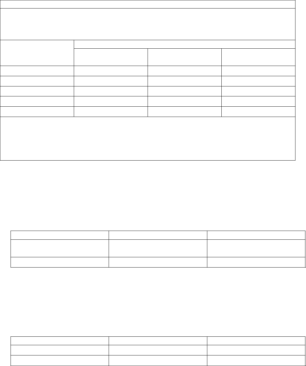
Data Modem Specifications System Specifications
70 BRZ-101-TUM-EN3-J
Recommended Separation Distances Between Portable and Mobile RF Communications Equipment and the System
The system is intended for use in an electromagnetic environment in which radiated RF disturbances are controlled. The
user of the system can help prevent electromagnetic interference by maintaining a minimum distance between portable
and mobile RF communications equipment (transmitters) and the system as recommended below, according to the
maximum output power of the communications equipment.
Rated maximum output
power (W) of transmitter
Separation distance (m) according to frequency of transmitter
150 kHz to 80 MHz
d = 1.2P
80 MHz to 800 MHz
d = 1.2P
800 MHz to 2.5 GHz
d = 2.3P
0.01
0.12
0.12
0.23
0.1
0.38
0.38
0.73
1
1.2
1.2
2.3
10
3.8
3.8
7.3
100
12
12
23
For transmitters rated at a maximum output power not listed above, the recommended separation distance (d) in meters
(m) can be estimated using the equation applicable to the frequency of the transmitter, where P is the maximum output
power rating of the transmitter in watts (W) according to the transmitter manufacturer.
NOTE 1 At 80 MHz and 800 MHz, the separation distance for the higher frequency range applies.
NOTE 2 These guidelines may not apply in all situations. Electromagnetic propagation is affected by absorption and
reflection from structures, objects, and people.
Data Modem Specifications
Below are the data modem specifications for the following modem models: MTSMC-LAT3 and MTSMC-H5.
The data modem is a 4G LTE with HSPA+ fallback embedded cellular modem:
Manufacturer: Multitech
Model: MTSMC-LAT3
IC 5131A-LE910NAV2
FCC ID RI7LE910NAV2
Use the modem only with the antenna provided by ZELTIQ.
Frequencies
Network Type
Effective Radiated Power
700MHz (B12/B13) / 850MHz (B5)
/AWS 1700MHz (B4)/ 1900MHz (B2)
4G
0.2W
850MHz (B5) /1900MHz (B2)
HSPA+ (3G)
0.25W
Table 26: Data Modem Transmission Specifications
Data Modem Specifications
The data modem is a GPRS wireless modem:
Manufacturer: Multitech
Model: MTSMC-H5
IC 5131A-HE910
FCC ID RI7HE910
Use the modem only with the antenna provided by ZELTIQ.
Frequencies
Network Type
Effective Radiated Power
850/900/1700/1900/2100 MHz
HSPA+ (3G)
0.226 to 1.995 watts
850/900/1800/1900 MHz
GSM/GPRS/EDGE (2G)
0.226 to 1.995 watts
Table 27: Data Modem Transmission Specifications
System Specifications Data Modem Specifications
User Manual 71
Electromagnetic Compatibility Compliance - Data Modem
The CoolSculpting System with the data modem complies with the following medical safety standards:
• EN 60601-1-2: 2007 (provides the presumption of compliance to the Medical Device Directive 93 / 42 / EEC
as amended by 2007 / 47 / EC).
The limits are designed to provide reasonable protection against harmful interference in a typical medical
installation. This equipment generates, uses, and can radiate radio frequency energy and, if not installed and
used in accordance with the instruction manual, may cause harmful interference to radio communications.
There is no guarantee that interference will be prevented by following the manufacturer’s instructions in a
particular installation.
If this equipment causes interference with other devices, which may be determined by turning the equipment
off and on, the user is encouraged to try to correct the interference by carrying out one or more of the
following measures:
• Reorient or relocate the device receiving the interference.
• Increase the separation between the equipment and the device receiving the interference.
• Connect the equipment into an outlet on a circuit different from that to which the other device(s) are
connected.
• Consult the manufacturer or field service technician for help.
Data Modem - Canada
The CoolSculpting System with the data modem complies with RSS-210 of Industry Canada. Operation is
subject to the following two conditions:
1. This device may not cause interference;
2. This device must accept any interference, including interference that may cause undesired operation
of the device.
Data Modem - European Union
CE Notice (European Notice): The Conformité Européenne symbol found on this product indicates compliance
to the Medical Device (93 / 42 / EEC) and Radio and Telecommunications Terminal Equipment (1999 / 5 / EC)
Directives of the European Union.
The CoolSculpting System with the data modem meets the following technical standards for EMC and radio
compliance:
• EN 60601-1-2: 2007
• EN 301-489-17
• EN 301-489-1
• EN 300328 V1.7.1
United States of America
The CoolSculpting System with the data modem has been tested and found to comply with the limits for a Class
A digital device, pursuant to part 15 of the FCC Rules. These limits are designed to provide reasonable
protection against harmful interference when the equipment is operated in a commercial environment. This
equipment generates, uses, and can radiate radio frequency energy and, if not installed and used in accordance
with the instruction manual, may cause harmful interference to radio communications. Operation of this
equipment in a residential area is likely to cause harmful interference in which case the user will be required to
correct the interference at his own expense.
ZELTIQ Aesthetics, Inc.
4410 Rosewood Drive
Pleasanton, CA 94588 USA
(925) 474-2500
www.coolsculpting.com
12/2018
