
This paper is included in the Proceedings of the
16th USENIX Conference on File and Storage Technologies.
February 12–15, 2018 • Oakland, CA, USA
ISBN 978-1-931971-42-3
Open access to the Proceedings of
the 16th USENIX Conference on
File and Storage Technologies
is sponsored by USENIX.
Clay Codes: Moulding MDS Codes
to Yield an MSR Code
Myna Vajha, Vinayak Ramkumar, Bhagyashree Puranik, Ganesh Kini, Elita Lobo,
Birenjith Sasidharan, and P. Vijay Kumar, Indian Institute of Science, Bangalore; Alexandar
Barg and Min Ye, University of Maryland; Srinivasan Narayanamurthy, Syed Hussain,
and Siddhartha Nandi, NetApp ATG, Bangalore
https://www.usenix.org/conference/fast18/presentation/vajha

Clay Codes: Moulding MDS Codes to Yield an MSR Code
Myna Vajha, Vinayak Ramkumar, Bhagyashree Puranik, Ganesh Kini,
Elita Lobo, Birenjith Sasidharan, P. Vijay Kumar
Indian Institute of Science, Bangalore
Alexander Barg, Min Ye
University of Maryland
Srinivasan Narayanamurthy, Syed Hussain, Siddhartha Nandi
NetApp ATG, Bangalore
Abstract
With increase in scale, the number of node failures
in a data center increases sharply. To ensure avail-
ability of data, failure-tolerance schemes such as Reed-
Solomon (RS) or more generally, Maximum Distance
Separable (MDS) erasure codes are used. However,
while MDS codes offer minimum storage overhead for
a given amount of failure tolerance, they do not meet
other practical needs of today’s data centers. Although
modern codes such as Minimum Storage Regenerating
(MSR) codes are designed to meet these practical needs,
they are available only in highly-constrained theoretical
constructions, that are not sufficiently mature enough for
practical implementation. We present Clay codes that ex-
tract the best from both worlds. Clay (short for Coupled-
Layer) codes are MSR codes that offer a simplified con-
struction for decoding/repair by using pairwise coupling
across multiple stacked layers of any single MDS code.
In addition, Clay codes provide the first practical im-
plementation of an MSR code that offers (a) low storage
overhead, (b) simultaneous optimality in terms of three
key parameters: repair bandwidth, sub-packetization
level and disk I/O, (c) uniform repair performance of
data and parity nodes and (d) support for both single and
multiple-node repairs, while permitting faster and more
efficient repair.
While all MSR codes are vector codes, none of the dis-
tributed storage systems support vector codes. We have
modified Ceph to support any vector code, and our con-
tribution is now a part of Ceph’s master codebase. We
have implemented Clay codes, and integrated it as a plu-
gin to Ceph. Six example Clay codes were evaluated on
a cluster of Amazon EC2 instances and code parameters
were carefully chosen to match known erasure-code de-
ployments in practice. A particular example code, with
storage overhead 1.25x, is shown to reduce repair net-
work traffic by a factor of 2.9 in comparison with RS
codes and similar reductions are obtained for both repair
time and disk read.
1 Introduction
The number of failures in storage subsystems increase
as data centers scale [11] [17] [29]. In order to ensure
data availability and durability, failure-tolerant solutions
such as replication and erasure codes are used. It is im-
portant for these solutions to be highly efficient so that
they incur low cost in terms of their utilization of stor-
age, computing and network resources. This additional
cost is considered an overhead, as the redundancy intro-
duced for failure tolerance does not aid the performance
of the application utilizing the data.
In order to be failure tolerant, data centers have in-
creasingly started to adopt erasure codes in place of repli-
cation. A class of erasure codes known as maximum dis-
tance separable (MDS) codes offer the same level of fail-
ure tolerance as replication codes with minimal storage
overhead. For example, Facebook [19] reported reduced
storage overhead of 1.4x by using Reed-Solomon (RS)
codes, a popular class of MDS codes, as opposed to the
storage overhead of 3x incurred in triple replication [13].
The disadvantage of the traditional MDS codes is their
high repair cost. In case of replication, when a node or
storage subsystem fails, an exact copy of the lost data
can be copied from surviving nodes. However, in case of
erasure codes, dependent data that is more voluminous in
comparison with the lost data, is copied from surviving
nodes and the lost data is then computed by a repair node,
which results in a higher repair cost when compared to
replication. This leads to increased repair bandwidth and
repair time.
A class of erasure codes, termed as minimum storage
regenerating (MSR) codes, offer all the advantages of
MDS codes but require lesser repair bandwidth. Until
recently, MSR codes lacked several key desirable prop-
erties that are important for practical systems. For exam-
ple, they were computationally more complex [14], or
demonstrated non-uniform repair characteristics for dif-
ferent types of node failures [18], or were able to recover
USENIX Association 16th USENIX Conference on File and Storage Technologies 139

from only a limited (one or two) number of failures [20],
or they lacked constructions of common erasure code
configurations [24], [20]. The first theoretical construc-
tion that offered all the desirable properties of an MSR
code was presented by Ye and Barg [35].
This paper presents Clay codes that extend the theo-
retical construction presented in [35], with practical con-
siderations. Clay codes are constructed by placing any
MDS code in multiple layers and performing pair-wise
coupling across layers. Such a construction offers effi-
cient repair with optimal repair bandwidth, causing Clay
codes to fall in the MSR arena.
We implement Clay codes and make it available as
open-source under LGPL. We also integrate Clay codes
as a plugin with Ceph, a distributed object storage sys-
tem. Ceph supports scalar erasure codes such as RS
codes. However, it does not support vector codes. We
modified Ceph to support any vector code, and our con-
tribution is now included in Ceph’s master codebase [4].
In erasure coding terminology, scalar codes require
block-granular repair data, while vector codes can work
at the sub-block granularity for repair. In Ceph, the
equivalent of an erasure-coded block is one chunk of
object. By this, we mean that Ceph supports chunk-
granular repair data, while our contribution extended it
to sub-chunk granularity. To the best of our knowledge,
after our contribution, Ceph has become the first dis-
tributed storage system to support vector codes. Also, if
Clay codes become part of Ceph’s codebase, this will be
the first-ever implementation of an MSR code that pro-
vides all desirable practical properties, and which is in-
tegrated to a distributed storage system.
Our contributions include (a) the construction of Clay
codes as explained in Section 3, (b) the modification
made to Ceph in order to support any vector code, ex-
plained in Section 4, and (c) the integration of Clay codes
as a plugin to Ceph, explained in Section 4. We con-
ducted experiments to compare the performance of Clay
codes with RS codes available in Ceph and the results
are presented in Section 5. One of the example Clay
codes that we evaluated, which has a storage overhead
of 1.25x, was able to bring down the repair network traf-
fic by a factor of 2.9 when compared with the RS code of
same parameters. Similar reductions were also obtained
for disk read and repair time.
2 Background and Preliminaries
Erasure Code Erasure codes are an alternative to
replication for ensuring failure tolerance in data storage.
In an [n,k] erasure-coded system, data pertaining to an
object is first divided into k data chunks and then en-
coded to obtain m = n − k parity chunks. When we do
not wish to distinguish between a data or parity chunk,
we will simply refer to the chunk as a coded chunk. The
collection of n coded chunks obtained after encoding are
stored in n distinct nodes. Here, by node, we mean an in-
dependent failure domain such as a disk or a storage node
of a distributed storage system (DSS). The storage effi-
ciency of an erasure code is measured by storage over-
head defined as the ratio of the number of coded chunks
n to the number of data chunks k. Every erasure code has
an underlying finite field over which computations are
performed. For the sake of simplicity, we assume here
that the field is of size 2
8
and hence each element of the
finite field can be represented by a byte
1
. It is convenient
to differentiate at this point, between scalar and vector
codes.
Scalar Codes Let each data chunk be comprised of L
bytes. In the case of a scalar code, one byte from each
of the k data chunks is picked and the k bytes are lin-
early combined in m different ways, to obtain m parity
bytes. The resultant set of n = k + m bytes so obtained is
called a codeword. This operation is repeated in parallel
for all the L bytes in a data chunk to obtain L codewords.
This operation will also result in the creation of m parity
chunks, each composed of L bytes (see Fig. 1). As men-
tioned above, every coded chunk is stored on a different
node.
Data chunks Parity chunks
Codeword
Byte
Figure 1: A pictorial representation of a scalar code. The L = 6 horizontal layers
are the codewords and the n = 6 vertical columns, the chunks, with the first k = 4
chunks corresponding to data chunks and the last (n − k) = 2 chunks, the parity
chunks. Each unit (tiny rectangle) in the figure corresponds to a single byte.
Vector Codes The difference in the case of vector
codes is that here, one works with ordered collections
of α ≥ 1 bytes at a time. For convenience, we will refer
to such an ordered collection of α bytes as a superbyte.
In the encoding process, a superbyte from each of the k
data chunks is picked and the k superbytes are then lin-
early combined in m different ways, to obtain m parity
superbytes. The resultant set of n = k + m superbytes is
called a (vector) codeword. This operation is repeated in
parallel for all the N =
L
α
superbytes in a data chunk to
obtain N codewords. Figure 2 shows a simple example
where each superbyte consists of just two bytes.
The number α of bytes within a superbyte is termed
the sub-packetization level of the code. Scalar codes
1
The codes described in this paper can however, be constructed
over a finite field whose size is significantly smaller, and approximately
equal to the parameter n. Apart from simplicity, we use the word byte
here since the finite field of size 2
8
is a popular choice in practice.
140 16th USENIX Conference on File and Storage Technologies USENIX Association

Data chunks Parity chunks
Codeword
Superbyte
1
2
1
2
1
2
Figure 2: A pictorial representation of a vector code where each superbyte con-
sists of 2 bytes. The picture shows N = 3 codewords. A single chunk, either data
or parity, stores 3 superbytes, each corresponding to a different codeword.
such as RS codes can be regarded as having sub-
packetization level α = 1. Seen differently, one could
view a vector code as replacing α scalar codewords with
a single vector codeword. The advantage of vector codes
is that repair of a coded chunk in a failed node can poten-
tially be accomplished by accessing only a subset of the
α bytes within the superbyte, present in each of the re-
maining coded chunks, corresponding to the same code-
word. This reduces network traffic arising from node re-
pair.
Sub-chunking through Interleaving In Fig. 2, we
have shown the α bytes associated to a superbyte as
being stored contiguously. When the sub-packetization
level α is large, given that operations involving multi-
ple codewords are carried out in parallel, it is advanta-
geous, from an ease-of-memory-access viewpoint, to in-
terleave the bytes so that the corresponding bytes across
different codewords are stored contiguously as shown in
Fig. 3. This is particularly true, when the number N of
superbytes within a chunk is large, for example, when
L = 8KB and α = 2, contiguous access to N = 4K bytes
is possible. With interleaving, each data chunk is par-
titioned into α subsets, which we shall refer to as sub-
chunks. Thus each sub-chunk within a node, holds one
byte from each of the N codewords stored in the node.
1
2
1
2
1
2
⇒
Interleave
1
1
1
2
2
2
subchunk
Figure 3: This figure shows the interleaving of the corresponding bytes within a
superbyte across codewords, for the particularly simple case of two bytes within
a superbyte. This results in a partitioning of the data chunk into sub-chunks and
can lead to improved-memory-access performance.
MDS Codes The sub-class of (n,k) erasure codes, ei-
ther scalar or vector, having the property that they can
recover from the failure of any (n − k) nodes are called
MDS codes. For a fixed k, these codes have the small-
est storage overhead
n
k
among any of the erasure codes
that can recover from a failure of a fixed number of n− k
nodes. Examples include RS, Row-Diagonal Parity [9]
and EVENODD [7] codes, see [5] for additional ex-
amples. Facebook data centers [28] have employed an
(14,10) RS code in their data warehouse cluster.
Node Repair The need for node repair in a distributed
storage system can arise either because a particular hard-
ware component has failed, is undergoing maintenance,
is being rebooted or else, is simply busy serving other si-
multaneous requests for data. A substantial amount of
network traffic is generated on account of node-repair
operations. An example cited in [28], is one of a
Facebook data-warehouse, that stores multiple petabytes
of data, where the median amount of data transferred
through top-of-rack switches for the purposes of node
repair, is in excess of 0.2 petabytes per day. The traf-
fic arising from node-repair requests, eats into the band-
width available to serve user requests for data. The time
taken for node repair also directly affects system avail-
ability. Thus there is strong interest in coding schemes
that minimize the amount of data transfer across the net-
work, and the time taken to repair a failed node. Under
the conventional approach to repairing an RS code for in-
stance, one would have to download k times the amount
of data as is stored in a failed node to restore the failed
node, which quite clearly, is inefficient.
MSR Codes MSR codes [10] are a sub-class of vector
MDS codes that have the smallest possible repair band-
width. To restore a failed node containing α bytes in an
(n,k) MSR code, the code first contacts an arbitrarily-
chosen subset of d helper nodes, where d is a design pa-
rameter that can take on values ranging from k to (n −1).
It then downloads β =
α
d−k+1
bytes from each helper
node, and restores the failed node using the helper data.
The total amount dβ of bytes downloaded is typically
much smaller than the total amount kα bytes of data
stored in the k nodes. Here α is the sub-packetization
level of an MSR code. The total number dβ of bytes
downloaded for node repair, is called the repair band-
width. Let us define the normalized repair bandwidth
to be the quantity
dβ
kα
=
d
k(d−k+1)
. The normalization by
kα can be motivated by viewing a single MSR codeword
having sub-packetization level α as a replacement for α
scalar RS codewords. The download bandwidth under
the conventional repair of α scalar RS codes equals kα
bytes, corresponding to a normalized repair bandwidth
of 1. For the particular case d = (n − 1), the normalized
value equals
n−1
k(n−k)
. It follows that the larger the number
(n − k) of parity chunks, the greater the reduction in re-
pair traffic. We will also use the parameter M = kα to de-
note the total number of databytes contained in an MSR
codeword. Thus an MSR code has associated parameter
set given by {(n,k),d,(α,β ),M} with β =
α
d−k+1
and
M = kα.
Additional Desired Attributes: Over and above the low
repair-bandwidth and low storage-overhead attributes of
MSR codes, there are some additional properties that one
would like a code to have. These include (a) uniform-
USENIX Association 16th USENIX Conference on File and Storage Technologies 141

Code
Storage
O/h
Failure
Tolerance
All-
Node
Optimal
Repair
Disk
Read
Opti-
mal
Repair-
bandwidth
Optimal
α
Order
of GF
Implemented
Distributed
System
RS Low n − k No No No 1 Low
HDFS, Ceph,
Swift, etc.
PM-RBT [24] High n − k Yes Yes Yes Linear Low Own system
Butterfly [20] Low 2 Yes No Yes Exponential Low HDFS, Ceph
HashTag [18] Low n − k No No Yes Polynomial High HDFS
Clay Code Low n − k Yes Yes Yes Polynomial Low Ceph
Table 1: Detailed comparison of Clay codes with RS and other practical MSR codes. Here, the scaling of α is with respect to n for a fixed storage overhead (n/k).
repair capability, i.e., the ability to repair data and parity
nodes with the same low repair bandwidth, (b) minimal
disk read, meaning that the amount of data read from disk
for node repair in a helper node is the same as the amount
of data transferred over the network from the helper node
and (c) low value of sub-packetization parameter α, and
(d) a small size of underlying finite field over which the
code is constructed. In MSR codes that possess the disk
read optimal property, both network traffic and number
of disk reads during node repair are simultaneously min-
imized and are the same.
2.1 Related Work
The problem of efficient node repair has been studied for
some time and several solutions have been proposed. Lo-
cally repairable codes such as the Windows Azure Code
[15] and Xorbas [28] trade the MDS property to allow
efficient node-repair by accessing a smaller number of
helper nodes. The piggy-backed RS codes introduced in
[26] achieve reductions in network traffic while retaining
the MDS property but they do not achieve the savings
that are possible with an MSR code.
Though there are multiple implementations of MSR
codes, these are lacking in one or the other of the de-
sired attributes (see Table 1). In [8], the authors present
2- parity FMSR codes, that allow efficient repair, but re-
construct a function of the data that is not necessarily
same as the failed node data. This demands an additional
decoding operation to be performed to retrieve original
data. In [24], the authors implement a modified product-
matrix MSR construction [27]. Although the code dis-
plays optimal disk I/O performance, the storage overhead
is on the higher side and of the form (2 −
1
k
). In [20],
the authors implement an MSR code known as the But-
terfly code and experimentally validate the theoretically-
proven benefits of reduced data download for node re-
pair. However, the Butterfly code is limited to (n − k) =
m = 2 and has large value of sub-packetization 2
k−1
. The
restriction to small values of parameter m limits the ef-
ficiency of repair, as the normalized repair bandwidth
can be no smaller than
1
2
. In [18], the authors propose a
class of MDS array codes named as HashTag codes with
α ≤ (n − k)
k/n−k
that permit flexibility in choice of α at
the expense of repair bandwidth. However, the code sup-
ports efficient repair only for systematic nodes, requires
computations at helper nodes, and involves operations in
a large finite-field. The authors have presented an evalu-
ation of HashTag codes in Hadoop.
In a parallel line of work, many theoretical construc-
tions of MSR codes are proposed in literature. The
product-matrix MSR codes proposed in [27] operate with
very low sub-packetization and small finite-field size,
however require a large storage overhead. In a sec-
ond notable construction known as zig-zag codes [30],
the authors present the first theoretical construction of
low-storage-overhead MSR codes for every n,k, when
d = (n − 1). The construction of zig-zag code is non-
explicit in the sense that the finite-field coefficients de-
termining the parities have to be found by computer
search. Thus, despite the many theoretical constructions
and a smaller number of practical implementations, the
search for an MSR code having all of the desirable prop-
erties described above and its practical evaluation con-
tinued to remain elusive. The recent theoretical results
of Ye and Barg [35] have resulted in an altered situa-
tion. In this work, the authors provide a construction
that permits storage overhead as close to 1 as desired,
sub-packetization level close to the minimum possible,
finite field size no larger than n, optimal disk I/O, and
all-node optimal repair.Clay codes offer a practical per-
spective and an implementation of the Ye-Barg theoreti-
cal construction, along with several additional attributes.
In other words, Clay codes possess all of the desirable
properties mentioned above, and also offer several addi-
tional advantages compared to the Ye-Barg code.
2.2 Refinements over Ye-Barg Code
The presentation of the Clay code here is from a coupled-
layer perspective that leads directly to implementation,
whereas the description in [35] is primarily in terms of
parity-check matrices. For example, using the coupled-
layer viewpoint, both data decoding (by which we mean
recovery from a maximum of (n − k) erasures) as well
as node-repair algorithms can be described in terms of
142 16th USENIX Conference on File and Storage Technologies USENIX Association

two simple operations: (a) decoding of the scalar MDS
code, and (b) an elementary linear transformation be-
tween pairs of bytes (see Section 3). While this coupled-
layer view-point was implicit in the Ye-Barg paper [35],
we make it explicit here.
In addition, Clay codes can be constructed using any
scalar MDS code as building blocks, while Ye-Barg code
is based only on Vandermonde-RS codes. Therefore,
scalar MDS codes that have been time-tested, and best
suited for a given application or workload need not be
modified in order to make the switch to MSR codes. By
using Clay codes, these applications can use the same
MDS code in a coupled-layer architecture and get the
added benefits of MSR codes. The third important dis-
tinction is that, in [35], only the single node-failure case
is discussed. In the case of Clay codes, we have come up
with a generic algorithm to repair multiple failures, that
has allowed us to repair many instances of multiple node
repair with reduced repair bandwidth. Our refinements
over Ye-Barg code primarily aiming at its practical real-
ization precede certain theoretical developments that are
to come later. In a recent work [6], it is proved that the
sub-packetization of Clay codes is the minimum possible
for any disk-read-optimal MSR code. In [31], authors
propose a permuatation-based transformation that con-
verts a non-binary (n,k) MDS code to another MDS code
permitting efficient repair of a set of (n − k) nodes, at the
cost of increasing the sub-packetization (n−k) times. An
MSR code obtained by repeated application of the trans-
formation results in the same sub-packetization as that of
the Ye-Barg code.
3 Construction of the Clay Code
Single Codeword Description In Section 2, we noted
that each node stores a data chunk and that a data chunk
is comprised of L bytes from N codewords. In the present
section we will restrict our attention to the case of a sin-
gle codeword, i.e., to the case when N = 1, L = α.
Parameters of Clay Codes Evaluated Table 2 lists the
parameters of the Clay codes evaluated here. As can
be seen, the normalized repair bandwidth can be made
much smaller by increasing the value of (d − k + 1). For
example, the normalized repair bandwidth for a (20,16)
code equals 0.297, meaning that the repair bandwidth of
a Clay code, is less than 30% of the corresponding value
for α = 1024 layers of a (20, 16) RS code.
Explaining Through Example We will describe the
Clay code via an example code having parameters:
{
(n = 4,k = 2), d = 3,(α = 4,β = 2), M = 8
}
. The
codeword is stored across n = 4 nodes of which k = 2
are data nodes and n −k = 2 are parity nodes. Each node
stores a superbyte made up of α = 4 bytes. The code
has storage overhead
nα
kα
=
n
k
= 2 which is the ratio of
(n,k) d (α, β) (dβ )/(kα)
(6,4) 5 (8,4) 0.625
(12,9) 11 (81,27) 0.407
(14,10) 13 (256,64) 0.325
(14,10) 12 (243,81) 0.4
(14,10) 11 (128,64) 0.55
(20,16) 19 (1024,256) 0.297
Table 2: Parameters of the Clay codes evaluated here.
the total number nα = 16 of bytes stored to the num-
ber M = kα = 8 of data bytes. During repair of a failed
node, β = 2 bytes of data are downloaded from each of
the d = 3 helper nodes, resulting in a normalized repair
bandwidth of
dβ
kα
=
d
k(d−k+1)
= 0.75.
Starting Point: A (4,2) Scalar RS Code We be-
gin our description of the Clay code with a simple,
distributed data storage setup composed of 4 nodes,
where the nodes are indexed by (x,y) coordinates:
{(x,y) | (x,y) ∈ J}, J = {(0,0),(1,0),(0, 1),(1,1)}}.
(0,0)
(0,1)
(1,0)
(1,1)
Figure 4: The (4, 2)
MDS code M .
Let us assume that a (4, 2) RS code
M is used to encode and store data
on these 4 nodes. We assume that
nodes (0,0),(1,0) store data, nodes
(0,1),(1, 1) store parity. Two nodes
are said to be in same y-section, if
they have the same y-coordinate.
The Uncoupled Code Next, consider storing on the
same 4 nodes, 4 codewords drawn from the same RS
code M . Thus each node now stores 4 bytes, each
associated to a different codeword. We will use the
parameter z ∈ {0,1,2,3} to index the 4 codewords.
z=0
x
y
z=1
z=2
z=3
Figure 5: The uncou-
pled code U .
Together these 4 codewords form
the uncoupled code U , whose bytes
are denoted by {U(x, y, z) | (x,y) ∈
J, z ∈ {0,1,2,3}}. These 16 bytes
can be viewed as being stored in a
data cube composed of 4 horizontal
layers (or planes), with 4 bytes to
a layer (Fig. 5). The data cube can
also be viewed as being composed
of 4 (vertical) columns, each col-
umn composed of 4 cylinders. Each
column stores a superbyte while each of the 4 cylinders
within a column stores a single byte.
It can be verified that the uncoupled code inherits the
property that data stored in the 4 nodes can be recov-
ered by connecting to any 2 nodes. As one might expect,
this code offers no savings in repair bandwidth over that
of the constituent RS codes, since we have simply repli-
cated the same RS code 4 times. We show below how
the uncoupled code can be used to create a new coupled-
layer (Clay) code that is an MSR code having the desired
optimal, repair bandwidth.
USENIX Association 16th USENIX Conference on File and Storage Technologies 143

z= (0,0)
z= (1,1)
z= (1,0)
z= (0,1)
Figure 6: The uncou-
pled code U .
Using a Pair of Coordinates to
Represent a Layer The coupling
of the layers is easier explained
in terms of a binary representation
(z
0
,z
1
) of the layer-index z, defined
by z = 2z
0
+ z
1
i.e., 0 ⇒ (0, 0), 1 ⇒
(0,1), 2 ⇒ (1,0) and 3 ⇒ (1,1).
We color in red, vertices within a
layer for which x = z
y
as a means of identifying the layer.
For example in Fig. 6, in layer (z
0
,z
1
) = (1, 1), the ver-
tices (1,0), (1,1) are colored red.
Pairing of Vertices and Bytes We will abbreviate and
write p = (x,y,z) in place of (x,y,z) and introduce a pair-
ing (p, p
∗
) of vertices within the data cube. The vertices
that are colored red are unpaired. The remaining vertices
are paired such that a vertex p and its companion p
∗
both
belong to the same y-section. In the data cube of our
example code, there are a total of 4 ∗ 4 = 16 vertices of
which 8 are unpaired. The remaining 8 vertices form 4
pairs. Each pair is shown in the data cube appearing on
the left in Fig. 7 using a pair of yellow rectangles linked
by a dotted line. Mathematically, p
∗
is obtained from
p = (x,y, z) simply by interchanging the values of x and
z
y
. Examples are presented in Table 3. As mentioned
Vertex p = (x,y, z
0
,z
1
) Companion p
∗
(interchange x,z
y
)
(0, 0, 1, 0) (1, 0, 0, 0)
(1, 1, 1, 0) (0, 1, 1, 1)
(0, 1, 1, 0) (0, 1, 1, 0) a red vertex, (p = p
∗
)
Table 3: Example vertex pairings.
earlier, each vertex p of the data cube is associated to a
byte U(p) = U(x, y, z) of data in the uncoupled code U .
We will use U
∗
(p) to denote the companion U (p
∗
), of
the byte U(p).
Transforming from Uncoupled to Coupled-Layer
Code We now show how one can transform in a sim-
ply way, a codeword belonging to the uncoupled code
U to a codeword belonging to the Coupled-layer (Clay)
code C . As with the uncoupled code, there are a total
of 16 bytes making up each codeword in the Clay code.
These 16 bytes are stored in a second, identical data cube
that is again, composed of 4 horizontal layers, 4 vertical
columns with 4 vertices in a layer and 4 vertices per col-
umn. Each node corresponds to a column of the data
cube and stores a superbyte, made up of 4 bytes. The
Clay code C associates a byte C(p) with each vertex
p of the data cube just as does the uncoupled code U .
The bytes U(p) and C(p) are related in a simple man-
ner. If p corresponds to an unpaired (and hence colored
in red) vertex, we simply set C(p) = U (p). If (p, p
∗
)
are a pair of companion vertices, p 6= p
∗
, U(p),U
∗
(p)
and C(p),C
∗
(p) are related by the the following pairwise
forward transform (PFT):
C(p)
C
∗
(p)
=
1 γ
γ 1
−1
U(p)
U
∗
(p)
. (1)
C
C*
U*
U
PFT
PRT
Figure 7: Bytes C(x,y, z) of the Clay code can be obtained from bytes U (x,y,z)
of the uncoupled code through a pairwise forward transform and in the reverse
direction, by the corresponding pairwise reverse transform. Vertex pairs within a
data cube are identified by a pair of yellow rectangles linked by a dotted line.
In the reverse direction, we have U(p) = C(p) respec-
tively if p is unpaired. Else, U(p),C(p) are related by
the pairwise reverse transform (PRT):
U(p)
U
∗
(p)
=
1 γ
γ 1
C(p)
C
∗
(p)
. (2)
We assume γ to be chosen such that γ 6= 0, γ
2
6= 1, and
under this condition, it can be verified that any two bytes
in the set {U(p),U
∗
(p),C(p),C
∗
(p)} can be recovered
from the remaining two bytes.
Use pairwise forward
transformation to obtain the data
to be stored in the parity nodes
of coupled code
Use the MDS code in layer-by-layer
fashion to determine data stored in
the parity nodes of uncoupled code
Use pairwise reverse
transformation to obtain data
stored in the 2 data nodes of
uncoupled code
Load data into the 2 data nodes of
coupled code
MDS
Encode
PRT
PFT
Figure 8: Encoding flowchart for the Clay code. A top view of the nodes is shown
on the right. The nodes in pink and blue correspond respectively, to the coupled
and uncoupled codes.
Encoding the Clay code The flow chart in Fig.8 pro-
vides a self-explanatory description of the encoding pro-
cess.
Reduced Repair Bandwidth of the Clay Code The
savings in repair bandwidth of the Clay code arises
from the fact that parity-check constraints are ju-
diciously spread across layers of the C data cube.
144 16th USENIX Conference on File and Storage Technologies USENIX Association

z= (1,1)
z= (1,0)
Figure 9: Identifying the
failed node and helper
data transferred.
In Fig. 9, which shows a portion
of the bytes in C , the dotted
column corresponds to the failed
node having coordinates (x, y) =
(1,0). To repair the node, only the
two layers z = (1,0) and z = (1,1)
corresponding to the presence of
red dots within the dotted column
are called upon for node repair.
Thus each helper node contributes
only 2 bytes, as opposed to 4 in an
RS code, towards node repair and
this explains the savings in repair bandwidth. To under-
stand how repair is accomplished, we turn to Fig. 11. As
shown in the figure, the PRT allows us to determine from
the the bytes in layers z = (1,0) and z = (1,1) belong-
ing to y-section y = 1 in data cube C, the corresponding
bytes in data cube U. RS decoding allows us to then re-
cover the bytes U (p) belonging to y-section y = 0 in the
same two planes. At this point, we have access to the
bytes C(p),U(p) for p corresponding to vertices lying
in planes z = (1,0) and z = (1,1) and lying in y-section
y = 0. This set includes 2 of the bytes C(p) in the col-
umn corresponding to the failed node. The remaining
two bytes C(p) in the failed column can be determined
using properties of the PFT.
Intersection Score To explain decoding, we introduce
the notion of an Intersection Score (IS). The IS of a layer
is given by the number of hole-dot pairs, i.e., the vertices
that correspond to erased bytes and which are at the same
time colored red. For example in Fig. 10, when nodes
(0,0), (0,1) are erased, layers (0,0),(0, 1),(1,1) have
respective IS=2,1,0.
(0,0) (0,1)
(1,0) (1,1)
(a) IS=2
(0,0) (0,1)
(1,0) (1,1)
(b) IS=1
(0,0) (0,1)
(1,0) (1,1)
(c) IS=0
Figure 10: Illustration of the intersection score (IS) for erasures at (0,1),(0,2).
Decoding The “Decode” algorithm of the Clay code is
able to correct the erasure of any n − k = 2 nodes. De-
coding is carried out sequentially, layer-by-layer, in order
of increasing IS. This is explained in Fig.12 for the case
when nodes (0, 0), (0,1) are erased and for layers hav-
ing IS= 0, IS= 1. In a layer with IS= 0, U bytes can
be computed for all non-erased vertices from the known
symbols. The erased U bytes are then calculated using
RS code decoding. For a layer with IS= 1, to compute U
bytes for all non-erased vertices, we make use of U bytes
recovered in layers with IS= 0. Thus the processing of a
layer with IS = 0 has to take place prior to processing a
layer with IS = 1 and so on. Once all the U bytes are re-
covered, the C bytes can be computed using the PFT. As a
result of the simple, pairwise nature of the PFT and PRT,
encoding and decoding times are not unduly affected by
the coupled-layer structure.
PRT
MDS Dec
C
U,C
C*
C* is
computed
from C and U
y=0 y=1
y=0 y=1
Figure 11: The dotted cylinder identifies the erased node. The bytes shown on
the top left represent helper data (6 bytes in all) transferred for repair. The PRT
is performed on helper data in C to obtain the bytes (4 bytes) U(p) belonging to
the same layers and lying y-section y = 1. RS code decoding within each of the
two layers is used to obtain the 4 missing U(p) bytes. The bytes corresponding
to the erased node in C can then be computed using properties of the PFT.
MDS Dec
Compute U
C*
C
C
C*
U
U
U
U
U
U
IS = 0
MDS Dec
C*
C,U*
C
C*
U
U
U
U
U
U
IS = 1
Compute U
Figure 12: Illustrating how the Clay code recovers from 2 erasures. We begin
with a layer having IS = 0 (top) before moving to a layer with IS = 1 (bottom).
Symbols alongside each vertex, indicate which of the 4 bytes {C,C
∗
,U,U
∗
} are
known. (Left) Pink circles indicate non-erased vertices in C. (Middle) Blue ver-
tices indicate vertices in U whose contents can be determined from the available
C,U bytes. (Right) Invoking the parity-check equations in U allows all bytes in U
to be recovered. Once all the U bytes are recovered, one recovers the remaining
unknown bytes C using the PFT.
Clay code parameters Clay codes can be constructed
for any parameter set of the form:
(n = qt, k, d) (α = q
t
,β = q
t−1
), with q = (d − k + 1),
for any integer t ≥ 1 over any finite field of size Q > n.
The encoding, decoding and repair algorithms can all be
generalized for the parameters above. However, in the
case d < n − 1, during single node repair, while pick-
ing the d helper nodes, one must include among the d
helper nodes, all the nodes belonging to the failed node’s
y-section.
USENIX Association 16th USENIX Conference on File and Storage Technologies 145

Clay codes for any (n,k,d) The parameters indicated
above have the restriction that q = (d − k + 1) divide n.
But the construction can be extended in a simple way to
the case when q is not a factor of n. For example, for pa-
rameters (n = 14, k = 10,d = 13), q = d − k +1 = 4. We
construct the Clay code taking n
0
= 16, the nearest mul-
tiple of q larger than n, and k
0
= k + (n
0
−n) = 12. While
encoding, we set data bytes in s = (n
0
−n) = 2 systematic
nodes as zero, and thus the resultant code has parameters
(n = 14,k = 10,d = 13). The technique used is called
shortening in the coding theory literature. We use s tem-
porary buffers each of size equal to chunk size during
the encoding, decoding and repair operations. Our im-
plementation of Clay code includes this generalization.
4 Ceph and Vector MDS Codes
4.1 Introduction to Ceph
Ceph [32] is a popular, open-source distributed storage
system [33], that permits the storage of data as objects.
Object Storage Daemon (OSD) is the daemon process of
Ceph, associated with a storage unit such as a solid-state
or hard-disk drive, on which user data is stored.
Ceph supports multiple erasure-codes, and a code
can be chosen by setting attributes of the erasure-code-
profile. Objects will then be stored in logical partitions
referred to as pools associated with an erasure-code-
profile. Each pool can have a single or multiple place-
ment groups (PG) associated with it. A PG is a collec-
tion of n OSDs, where n is the block length of the erasure
code associated to the pool.
The allocation of OSDs to a PG is dynamic, and is
carried out by the CRUSH algorithm [34]. When an ob-
ject is streamed to Ceph, the CRUSH algorithm allocates
a PG to it. It also performs load balancing dynamically
whenever new objects are added, or when active OSDs
fail. Each PG contains a single, distinct OSD designated
as the primary OSD (p-OSD). When it is required to store
an object in a Ceph cluster, the object is passed on to the
p-OSD of the allocated PG. The p-OSD is also responsi-
ble for initiating the encoding and recovery operations.
In Ceph, the passage from data object to data chunks
by the p-OSD is carried out in two steps as opposed to the
single-step description in Section 2. For a large object,
the amount of buffer memory required to perform encod-
ing and decoding operations will be high. Hence, as an
intermediate step, an object is first divided into smaller
units called stripes, whose size is denoted by S (in bytes).
If an object’s size is not divisible by S, zeros are padded.
The object is then encoded by the p-OSD one stripe at a
time. The stripe-size is to be specified within the clus-
ter’s configuration file. Both zero padding and system
performance are important factors to be considered while
fixing a stripe-size.
4.2 Sub-Chunking through Interleaving
To encode, the p-OSD first zero pads each stripe as nec-
essary in order to ensure that the strip size S is divisible
by kα. The reason for the divisibility by a factor of k is
because as described earlier, the first step in encoding is
to break up each stripe into k data chunks of equal size.
The reason for the additional divisibility requirement by
a further factor α arises because we are dealing with a
vector code and as explained in Section 2, operations in
a vector code involve superbytes, where each superbyte
contains α bytes. In what follows, we will assume that S
is divisible by kα.
The encoding of a stripe is thus equivalent to encod-
ing N =
S
kα
codewords at a time. The next step as ex-
plained in Section 2, is interleaving at the end of which
one obtains α sub-chunks per OSD, each of size N bytes.
We note that the parameter L introduced in Section 2, is
the number of bytes per data chunk and is thus given by
L =
S
k
. This notion of sub-chunk is not native to Ceph,
but rather is a modification to the Ceph architecture pro-
posed here, to enable the support of vector codes.
The advantage of a vector code is that it potentially en-
ables the repair of an erased coded chunk by passing on
a subset of the α sub-chunks. For example, in the Clay
code implemented in Ceph is an MSR code, it suffices
for each node to pass on β sub-chunks. However, when
these β sub-chunks are not sequentially located within
the storage unit, it can result in fragmented reads. We
analyze such disk read performance degradation in Sec-
tion 5.
4.3 Implementation in Ceph
Our implementation makes use of the Jerasure [22] and
GF-Complete [21] libraries which provide implementa-
tions of various MDS codes and Galois-field arithmetic.
We chose in our implementation to employ the finite field
of size 2
8
to exploit the computational efficiency for this
field size provided by the GF-complete library in Ceph.
In our implementation, we employ an additional
buffer, termed as U-buffer, that stores the sub-chunks
associated with the uncoupled symbols U introduced in
Section 3. This buffer is of size nL = S
n
k
bytes. The U-
buffer is allocated once for a PG, and is used repetitively
during encode, decode and repair operations of any ob-
ject belonging to that PG.
Pairwise Transforms We introduced functions that
compute any two sub-chunks in the set {U,U
∗
,C,C
∗
}
given the remaining two sub-chunks. We im-
plemented these functions using the function jera-
sure matrix dotprod(), which is built on top of function
galois w08 region multiply().
Encoding Encoding of an object is carried out by p-
OSD by pretending that m parity chunks have been
146 16th USENIX Conference on File and Storage Technologies USENIX Association
erased, and then recovering the m chunks using the k
data chunks by initiating the decoding algorithm for the
code. Pairwise forward and reverse transforms are the
only additional computations required for Clay encoding
in comparison with MDS encoding.
Enabling Selection Between Repair & Decoding
When one or more OSDs go down, multiple PGs are af-
fected. Within an affected PG, recovery operations are
triggered for all associated objects. We introduced a
boolean function is repair() in order to choose between
a bandwidth, disk I/O efficient repair algorithm and the
default decode algorithm. For the case of single OSD
failure, is repair() always returns true. There are multi-
ple failure cases as well for which is repair() returns true
i.e., efficient repair is possible. We discuss these cases in
detail in Appendix A.
Helper-Chunk Identification In the current
Ceph architecture, when a failure happens, mini-
mum to decode() is called in order to determine the
k helper chunk indices. We introduced a function
minimum to repair() to determine the d helper chunk
indices when repair can be performed efficiently i.e.,
when is repair() returns true. OSDs corresponding to
these indices are contacted to get information needed
for repair/decode. When there is a single failure,
minimum to repair() returns d chunk indices such that
all the chunks that fall in the y-cross-section of the failed
chunk are included. We describe the case of multiple
erasure cases in detail in Appendix A
Fractional Read For the case of efficient repair, we
only read a fraction of chunk, this functionality is imple-
mented by feeding repair parameters to an existing struc-
ture ECSubRead that is used in inter-OSD communica-
tion. We have also introduced a new read function with
Filestore of Ceph that supports sub-chunk reads.
Decode and Repair Either the decode or repair func-
tion is called depending on whether if is repair() returns
true or false respectively. The decoding algorithm is de-
scribed in Section 3. Our repair algorithm supports in ad-
dition to single-node failure (Section.3), some multiple-
erasure failure patterns as well (Section 6).
4.4 Contributions to Ceph
Enabling vector codes in Ceph: We introduced the
notion of sub-chunking in order to enable new vector era-
sure code plugins. This contribution is currently avail-
able in Ceph’s master codebase [4].
Clay codes in Ceph: We implemented Clay codes as a
technique (cl
msr) within the jerasure plugin. The cur-
rent implementation gives flexibility for a client to pick
any n, k,d parameters for the code. It also gives an op-
tion to choose the MDS code used within to be either
a Vandermonde-based-RS or Cauchy-original code. The
Clay code [2] is yet to be part of Ceph’s master codebase.
5 Experiments and Results
The experiments conducted to evaluate the performance
of Clay codes in Ceph while recovering from a single
node failure are discussed in the present section. Experi-
mental results relating multiple node-failure case can be
found in Section 6.1.
5.1 Overview and Setup
Codes Evaluated While Clay codes can be con-
structed for any parameter set (n,k, d), we have carried
out experimental evaluation for selected parameter sets
close to those of codes employed in practice, see Ta-
ble 4. Code C1 has (n,k) parameters comparable to that
of the RDP code [9], Code C2 with the locally repairable
code used in Windows Azure [16], and Code C3 with the
(20,17)-RS code used in Backblaze [1]. There are three
other codes C4, C5 and C6 that match with the (14,10)-
RS code used in Facebook data-analytic clusters [25].
Results relating to Codes C4-C6 can be found in Sec-
tion 6.1, which focuses on repair in the multiple-erasure
case.
(n,k,d) α Storage overhead
β
α
C1 (6,4,5) 8 1.5 0.5
C2 (12,9,11) 81 1.33 0.33
C3 (20,16,19) 1024 1.25 0.25
C4 (14,10,11) 128 1.4 0.5
C5 (14,10,12) 243 1.4 0.33
C6 (14,10,13) 256 1.4 0.25
Table 4: Codes C1-C3 are evaluated in Ceph for single-node repair. The evalua-
tion of Codes C4-C6 is carried out for both single and multiple-node failures.
The experimental results for Clay codes are compared
against those for RS codes possessing the same (n,k) pa-
rameters. By an RS code, we mean an MDS-code imple-
mentation based on the cauchy orig technique of Ceph’s
jerasure plugin. The same MDS code is also employed
as the MDS code appearing in the Clay-code construc-
tion evaluated here.
Experimental Setup All evaluations are carried out on
Amazon EC2 instances of the m4.xlarge (16GB RAM, 4
CPU cores) configuration. Each instance is attached to
an SSD-type volume of size 500GB. We integrated the
Clay code in Ceph Jewel 10.2.2 to perform evaluations.
The Ceph storage cluster deployed consists of 26 nodes.
One server is dedicated for the MON daemon, while the
remaining 25 nodes each run one OSD. Apart from the
installed operating system, the entire 500GB disk is ded-
icated to the OSD. Thus the total storage capacity of the
cluster is approximately 12.2TB.
USENIX Association 16th USENIX Conference on File and Storage Technologies 147

Object Distribution
Model Object # Objects Total, T Stripe
size (MB) (GB) size, S
Fixed (W
1
) 64 8192 512 64MB
64 6758
Variable 32 820 448 1MB
(W
2
) 1 614
Table 5: Workload models used in experiments.
Overview Experiments are carried out on both fixed
and variable object-size workloads, respectively referred
to as W
1
and W
2
. Workload W
1
has all objects of fixed
size 64MB, while in the W
2
workload we choose objects
of sizes 64MB, 32MB and 1MB distributed in respec-
tive proportions of 82.5%, 10% and 7.5%. Our choices
of object sizes cover a good range of medium (1MB),
medium/large(32MB) and large (64MB) objects[3], and
the distribution is chosen in accordance with that in the
Facebook data analytic cluster reported in [23]. The
workloads used for evaluation are summarized in Ta-
ble 5. The stripe-size S is set as 64MB and 1MB for
workloads W
1
and W
2
respectively, so as to avoid zero-
padding.
The failure domain is chosen to be a node. Since we
have one OSD per node, this is equivalent to having a
single OSD as the failure domain. We inject node fail-
ures into the system by removing OSDs from the cluster.
Measurements are taken using nmon and NMONVisual-
izer tools. We run experiments with a single PG, and
validate the results against the theoretical prediction. We
also run the same experiments with 512 PGs, which we
will refer to as the multiple-PG case. Measurements are
made of (a) repair network traffic, (b) repair disk read, (c)
repair time, (d) encoding time and (e) I/O performance
for degraded, normal operations.
5.2 Evaluations
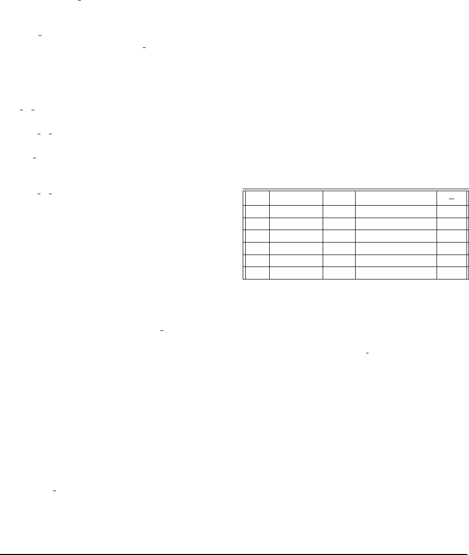
Network Traffic: Single Node Failure Network traf-
fic refers to the data transferred across the network dur-
ing single-node repair. Repair is carried out by the p-
OSD, which also acts as a helper node. The network
traffic during repair includes both the transfer of helper
data to the primary OSD and the transfer of recovered
chunk from primary OSD to the replacement OSD. The
theoretical estimate for the amount of network traffic is
T
k
((d −1)
β
α
+1) bytes for a Clay code, versus T bytes for
an RS code. Our evaluations confirm the expected sav-
ings, and we observed reductions of 25%, 52% and 66%,
(a factor of 2.9×) in network traffic for codes C1, C2
and C3 respectively in comparison with the correspond-
ing RS codes under fixed and variable workloads (see
Fig. 13(a), 13(d).) As can be seen, the code C3 with the
largest value of q = (d − k + 1) offer the largest savings
in network traffic.
In Ceph, the assignment of OSDs and objects to PGs
are done in a dynamic fashion. Hence, the number of
objects affected by failure of an OSD can vary across
different runs of multiple-PG experiment. We present an
network bandwidth performance with 512 PGs under the
W
1
workload averaged across 3 runs in Fig. 14. It was ob-
served that in certain situations, an OSD that is already
part of the PG can get reassigned as a replacement for
the failed OSD. In such cases, the number of failures are
treated as two resulting in inferior network-traffic perfor-
mance in multiple-PG setting.
Disk Read: Single Node Failure The amount of data
read from the disks of the helper nodes during the repair
of a failed node is referred to as disk read and is an im-
portant parameter to minimize.
Depending on the index of the failed node, the sub-
chunks to be fetched from helper nodes in a Clay code
can be contiguous or non-contiguous. Non-contiguous
reads in HDD volumes lead to a slow-down in perfor-
mance [20]. Even for SSD volumes that permit reads at
a granularity of 4kB, the amount of disk read needed de-
pends on the sub-chunk-size. Let us look at, for instance,
disk read from a helper node in the case of single node
failure for code C3 in workload W2. The stripe-size S =
1MB, and the chunk size is given by L = S/k = 64kB.
During repair of a node, L/(d − k + 1) = 16kB of data is
to be read from each helper node. In the best-case sce-
nario (for example, a systematic node failure), the 16kB
data is contiguous, whereas for the worst-case scenario
(as in the case of parity node failure) the reads are frag-
mented. In the latter case, β = 256 fragments with each
of size L/α = 64 bytes are read. As a consequence, when
4kB of data is read from the disk, only 1kB ends up be-
ing useful for the repair operation. Therefore, the disk
read is 4 times the amount of data needed for repair. This
is evident in disk read measurements from a helper node
in the worst-case as shown in Fig. 13(f). A similar anal-
ysis shows that for workload W2, the code C2 leads to
additional disk read while C1 does not. This is observed
experimentally as well.
On the other hand, for workload W1 with stripe-size
S = 64MB, all the three codes C1, C2, and C3 do not
cause any additional disk read as shown in Fig. 13(b).
For instance, with code C3, fragments of size S/kα =
4kB are to be read in the worst-case scenario. As the
size is aligned to the granularity of SSD reads, disk read
for the worst-case is equal to 256 ∗ 4kB=1MB. This is
exactly the amount read during best-case as well. (see
Fig. 13(f)). In summary, all the three codes result in disk
I/O savings for the W1 workload whereas for workload
W2 only C1 results in an advantage.
The expected disk read from all helper nodes during
repair is
T dβ
kα
bytes for a Clay code in contrast to T bytes
148 16th USENIX Conference on File and Storage Technologies USENIX Association
(a) Network Traffic (Workload W
1
) (b) Disk-read (Workload W
1
) (c) Average Repair time (Workload W
1
)
(d) Network Traffic (Workload W
2
) (e) Disk-read (Workload W
2
) (f) Fragmented Read: (20,16,19) Clay code
Figure 13: Experimental evaluation of C1, C2 and C3 in comparison with RS codes in a single-PG setting is presented in plots (a)-(e). The plot (f) gives a relative
comparison of disk read in a helper node for stripe-sizes 1MB and 64MB for code C3.
for an RS code. In experiments with fixed object-size
(see Fig. 13(b)), we obtain savings of 37.5%, 59.3% and
70.2% (a factor of 3.4×) for codes C1, C2 and C3 re-
spectively, when compared against the corresponding RS
code. Fig. 14 shows the disk read in the multiple-PG set-
ting.
Figure 14: Network traffic and disk read during repair of single node in a setting
with 512 PGs, for W
1
workload.
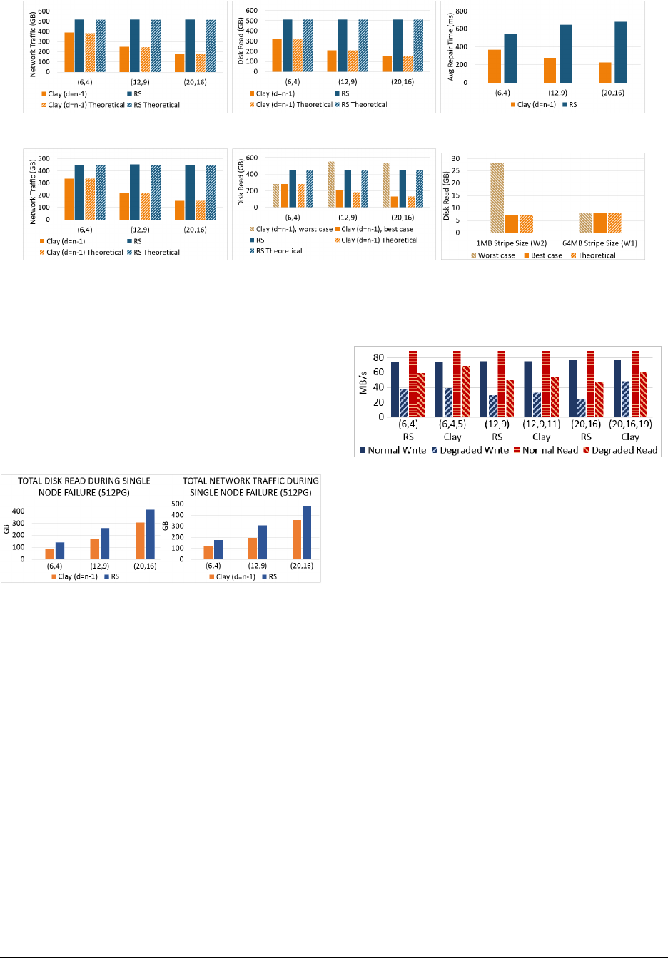
I/O Performance We measured the normal and de-
graded (i.e., with a repair executing in the background)
I/O performance of Clay codes C1-C3, and RS codes
with same parameters. This was done using the standard
Ceph benchmarking tests for read and write operations.
The results are shown in Fig. 15. Under the normal oper-
ation, the write, sequential-read and random-read perfor-
mances are same for both Clay and RS codes. However
in the degraded situation, the I/O performance of Clay
codes is observed to be better in comparison with RS
codes. In particular, the degraded write, read throughput
of (20,16, 19) Clay code is observed to be more than the
(20,16) RS code by 106% and 27% respectively. This
can possibly be attributed to the reduced amount of re-
pair data that is read, transmitted and computed on to
build the lost data in the erased node.
Figure 15: Normal and degraded I/O performance of codes C1, C2, C3 in com-
parison with RS. The observed values for sequential and random reads are almost
the same, and hence plotted as a single value.
Repair Time and Encoding Time We measure the
time taken for repair by capturing the starting and stop-
ping times of network activity within the cluster. We
observed a significant reduction in repair time for Clay
codes in comparison with an RS code. For the code C3
in a single-PG setting, we observe a reduction by a fac-
tor of 3× in comparison with an RS code. This is mainly
due to reduction in network traffic and disk I/O required
during repair. Every affected object requires recovery of
(1/k)-th fraction of the object size, and the average re-
pair time per object is plotted in Fig. 13(c).
We define the time required by the RADOS utility to
place an object into Ceph object-store as the encoding
time. The encoding time includes times taken for com-
putation, disk-I/O operations, and data transfer across
the network. We define the time taken for computing
the code chunks based on the encoding algorithm as the
encode computation time. During encoding, the net-
work traffic and I/O operations are the same for both
the classes of codes. Although the encode computation
time of Clay code is higher than that of the RS code (See
Fig. 16.) the encoding time of a Clay code remains close
to that of the corresponding RS code. The increase in the
USENIX Association 16th USENIX Conference on File and Storage Technologies 149

computation time for the Clay code is due to the multipli-
cations involved in PFT and PRT operations. In storage
systems, while data-write is primarily a one-time oper-
ation, failure is a norm and thus recovery from failures
is a routine activity [12],[24]. The significant savings in
network traffic and disk reads during node repair are a
sufficient incentive for putting up with overheads in the
encode computation time. The decoding time will be al-
most same as encoding time, since we perform encoding
using the decoding function as described in Section 4.3.
Figure 16: Comparison of average encoding times for C1, C2 and C3 in compar-
ison with RS codes, for the W
1
workload.
6 Handling Failure of Multiple Nodes
The Clay code is capable of recovering from multiple
node-failures with savings in repair bandwidth. In the
case of multiple erasures, the bandwidth needed for re-
pair varies with the erasure pattern. In Fig. 17, we show
the average network traffic of Clay codes with parame-
ters (n = 14,k = 10, d) for d = 11, 12,13 while repairing
f = 1,2,3, and 4 node failures. The average network
traffic for repairing f nodes is computed under the as-
sumption that all the f -node-failure patterns are equally
likely. Detailed analysis of savings in network traffic for
multiple erasures is relegated to Appendix A.
Figure 17: Average theoretical network traffic during repair of 64MB object.
6.1 Evaluation of Multiple Erasures
Network Traffic and Disk Read While the primary
benefit of the Clay code is optimal network traffic and
disk read during repair of a single node failure, it also
yields savings over RS counterpart code in the case of a
large number of multiple-node failure patterns. We eval-
uate the performance of codes C4-C6 (see Table 4) under
W
1
workload injecting multiple node-failures in a setting
of 512PGs. The plots for network traffic and disk read
are shown in Fig. 18, 19.
Figure 18: Network traffic evaluation of C4-C6 against RS codes (W
1
workload,
multiple-PG).
Figure 19: Disk-read evaluation of C4-C6 against RS codes (W
1
workload,
multiple-PG).
7 Conclusions
Clay codes extend the theoretical construction presented
by Ye & Barg with practical considerations from a
coupled-layer perspective that leads directly to imple-
mentation. Within the class of MDS codes, Clay codes
have minimum possible repair bandwidth and disk I/O.
Within the class of MSR codes, Clay codes possess the
least possible level of sub-packetization. A natural ques-
tion to ask is if these impressive theoretical credentials of
the Clay code result in matching practical performance.
We answer this in the affirmative here by studying the
real-world performance of the Clay code in a Ceph set-
ting, with respect to network traffic for repair, disk I/O
during repair, repair time and degraded I/O performance.
Along the way, we also modified Ceph to support any
vector code, and our contribution is now a part of Ceph’s
master code-base. A particular Clay code, with storage
overhead 1.25x, is shown to reduce repair network traf-
fic, disk read and repair times by factors of 2.9, 3.4 and
3 respectively. Much of this is made possible because
Clay codes can be constructed via a simple two-step pro-
cess where one first stacks in layers, α codewords drawn
from an MDS code; in the next step, elements from dif-
ferent layers are paired and transformed to yield the Clay
code. The same construction with minor modifications is
shown to offer support for handling multiple erasures as
well. It is our belief that Clay codes are well-poised to
make the leap from theory to practice.
8 Acknowledgments
We thank our shepherd Cheng Huang and the anony-
mous reviewers for their valuable comments. P. V. Ku-
mar would like to acknowledge support from NSF Grant
No.1421848 as well as the UGC-ISF research program.
The research of Alexander Barg and Min Ye was sup-
ported by NSF grants CCF1422955 and CCF1618603.
150 16th USENIX Conference on File and Storage Technologies USENIX Association

References
[1] Backblaze data service provider. https://www.
backblaze.com/blog/reed-solomon/. Accessed:
2017-Sep-28.
[2] Coupled-layer source code. https://github.com/ceph/
ceph/pull/14300/.
[3] Red hat ceph storage: Scalable object storage on qct servers - a
performance and sizing guide. Reference Architecture.
[4] Sub-chunks: Enabling vector codes in ceph. https://
github.com/ceph/ceph/pull/15193/.
[5] Tutorial: Erasure coding for storage applications.
http://web.eecs.utk.edu/
˜
plank/plank/
papers/FAST-2013-Tutorial.html. Accessed:
2017-Sep-28.
[6] BALAJI, S. B., AND KUMAR, P. V. A tight lower bound on the
sub-packetization level of optimal-access MSR and MDS codes.
CoRR abs/1710.05876 (2017).
[7] BLAUM, M., BRADY, J., BRUCK, J., AND MENON, J. EVEN-
ODD: an efficient scheme for tolerating double disk failures in
RAID architectures. IEEE Trans. Computers 44, 2 (1995), 192–
202.
[8] CHEN, H. C., HU, Y., LEE, P. P., AND TANG, Y. Nccloud: A
network-coding-based storage system in a cloud-of-clouds. IEEE
Transactions on Computers 63, 1 (2013), 31–44.
[9] CORBETT, P., ENGLISH, B., GOEL, A., GRCANAC, T.,
KLEIMAN, S., LEONG, J., AND SANKAR, S. Row-diagonal par-
ity for double disk failure correction. In Proceedings of the 3rd
USENIX Conference on File and Storage Technologies (2004),
pp. 1–14.
[10] DIMAKIS, A., GODFREY, P., WU, Y., WAINWRIGHT, M., AND
RAMCHANDRAN, K. Network coding for distributed storage
systems. IEEE Transactions on Information Theory 56, 9 (Sep.
2010), 4539–4551.
[11] FORD, D., LABELLE, F., POPOVICI, F. I., STOKELY, M.,
TRUONG, V.-A., BARROSO, L., GRIMES, C., AND QUIN-
LAN, S. Availability in globally distributed storage systems.
In Presented as part of the 9th USENIX Symposium on Operat-
ing Systems Design and Implementation (Vancouver, BC, 2010),
USENIX.
[12] GHEMAWAT, S., GOBIOFF, H., AND LEUNG, S. The google file
system. In Proceedings of the 19th ACM Symposium on Oper-
ating Systems Principles 2003, SOSP 2003, Bolton Landing, NY,
USA, October 19-22, 2003 (2003), pp. 29–43.
[13] GHEMAWAT, S., GOBIOFF, H., AND LEUNG, S.-T. The google
file system. In Proceedings of the Nineteenth ACM Symposium
on Operating Systems Principles (New York, NY, USA, 2003),
SOSP ’03, ACM, pp. 29–43.
[14] HU, Y., CHEN, H., LEE, P., AND TANG, Y. NCCloud: apply-
ing network coding for the storage repair in a cloud-of-clouds. In
Proceedings of the 10thth USENIX Conference on File and Stor-
age Technologies(FAST) (2012).
[15] HUANG, C., SIMITCI, H., XU, Y., OGUS, A., CALDER, B.,
GOPALAN, P., LI, J., AND YEKHANIN, S. Erasure coding in
windows azure storage. In Presented as part of the 2012 USENIX
Annual Technical Conference (USENIX ATC 12) (Boston, MA,
2012), USENIX, pp. 15–26.
[16] HUANG, C., SIMITCI, H., XU, Y., OGUS, A., CALDER, B.,
GOPALAN, P., LI, J., AND YEKHANIN, S. Erasure cod-
ing in Windows Azure storage. In Proceedings of the 2012
USENIX conference on Annual Technical Conference (Berkeley,
CA, USA, 2012), USENIX ATC.
[17] JIANG, W., HU, C., ZHOU, Y., AND KANEVSKY, A. Are disks
the dominant contributor for storage failures?: A comprehensive
study of storage subsystem failure characteristics. Trans. Storage
4, 3 (Nov. 2008), 7:1–7:25.
[18] KRALEVSKA, K., GLIGOROSKI, D., JENSEN, R. E., AND
VERBY, H. Hashtag erasure codes: From theory to practice. IEEE
Transactions on Big Data PP, 99 (2017), 1–1.
[19] MURALIDHAR, S., LLOYD, W., ROY, S., HILL, C., LIN, E.,
LIU, W., PAN, S., SHANKAR, S., SIVAKUMAR, V., TANG, L.,
AND KUMAR, S. f4: Facebook’s warm BLOB storage system. In
11th USENIX Symposium on Operating Systems Design and Im-
plementation (OSDI 14) (Broomfield, CO, 2014), USENIX As-
sociation, pp. 383–398.
[20] PAMIES-JUAREZ, L., BLAGOJEVIC, F., MATEESCU, R.,
GUYOT, C., GAD, E. E., AND BANDIC, Z. Opening the
chrysalis: On the real repair performance of MSR codes. In
Proceedings of the 4th USENIX Conference on File and Storage
Technologies (2016), pp. 81–94.
[21] PLANK, J., GREENAN, K., MILLER, E., AND HOUSTON, W.
Gf-complete: A comprehensive open source library for galois
field arithmetic. University of Tennessee, Tech. Rep. UT-CS-13-
703 (2013).
[22] PLANK, J. S., AND GREENAN, K. M. Jerasure: A library
in c facilitating erasure coding for storage applications–version
2.0. Tech. rep., Technical Report UT-EECS-14-721, University
of Tennessee, 2014.
[23] RASHMI, K. V., CHOWDHURY, M., KOSAIAN, J., STOICA,
I., AND RAMCHANDRAN, K. Ec-cache: Load-balanced, low-
latency cluster caching with online erasure coding. In 12th
USENIX Symposium on Operating Systems Design and Imple-
mentation, OSDI 2016, Savannah, GA, USA, November 2-4,
2016. (2016), pp. 401–417.
[24] RASHMI, K. V., NAKKIRAN, P., WANG, J., SHAH, N. B., AND
RAMCHANDRAN, K. Having your cake and eating it too: Jointly
optimal erasure codes for i/o, storage, and network-bandwidth. In
Proceedings of the 13th USENIX Conference on File and Storage
Technologies, FAST, (2015), pp. 81–94.
[25] RASHMI, K. V., SHAH, N. B., GU, D., KUANG, H.,
BORTHAKUR, D., AND RAMCHANDRAN, K. A solution to the
network challenges of data recovery in erasure-coded distributed
storage systems: A study on the facebook warehouse cluster. In
5th USENIX Workshop on Hot Topics in Storage and File Sys-
tems, HotStorage’13, 2013 (2013), USENIX Association.
[26] RASHMI, K. V., SHAH, N. B., GU, D., KUANG, H.,
BORTHAKUR, D., AND RAMCHANDRAN, K. A ”hitchhiker’s”
guide to fast and efficient data reconstruction in erasure-coded
data centers. In ACM SIGCOMM 2014 Conference, (2014),
pp. 331–342.
[27] RASHMI, K. V., SHAH, N. B., AND KUMAR, P. V. Optimal
Exact-Regenerating Codes for Distributed Storage at the MSR
and MBR Points via a Product-Matrix Construction. IEEE Trans-
actions on Information Theory 57, 8 (Aug 2011), 5227–5239.
[28] SATHIAMOORTHY, M., ASTERIS, M., PAPAILIOPOULOS,
D. S., DIMAKIS, A. G., VADALI, R., CHEN, S., AND
BORTHAKUR, D. Xoring elephants: Novel erasure codes for
big data. PVLDB 6, 5 (2013), 325–336.
[29] SCHROEDER, B., AND GIBSON, G. A. Disk failures in the real
world: What does an mttf of 1,000,000 hours mean to you? In
Proceedings of the 5th USENIX Conference on File and Storage
Technologies (Berkeley, CA, USA, 2007), FAST ’07, USENIX
Association.
[30] TAMO, I., WANG, Z., AND BRUCK, J. Zigzag codes: MDS array
codes with optimal rebuilding. IEEE Transactions on Information
Theory 59, 3 (2013), 1597–1616.
USENIX Association 16th USENIX Conference on File and Storage Technologies 151

[31] TIAN, C., LI, J., AND TANG, X. A generic transformation for
optimal repair bandwidth and rebuilding access in MDS codes. In
2017 IEEE International Symposium on Information Theory, ISIT
2017, Aachen, Germany, June 25-30, 2017 (2017), pp. 1623–
1627.
[32] WEIL, S. A., BRANDT, S. A., MILLER, E. L., LONG, D. D. E.,
AND MALTZAHN, C. Ceph: A scalable, high-performance dis-
tributed file system. In 7th Symposium on Operating Systems
Design and Implementation (OSDI ’06), November 6-8, Seattle,
WA, USA (2006), pp. 307–320.
[33] WEIL, S. A., BRANDT, S. A., MILLER, E. L., AND
MALTZAHN, C. Grid resource management - CRUSH: con-
trolled, scalable, decentralized placement of replicated data. In
Proceedings of the ACM/IEEE SC2006 Conference on High Per-
formance Networking and Computing, November 11-17, 2006,
Tampa, FL, USA (2006), p. 122.
[34] WEIL, S. A., LEUNG, A. W., BRANDT, S. A., AND
MALTZAHN, C. RADOS: a scalable, reliable storage service for
petabyte-scale storage clusters. In Proceedings of the 2nd Inter-
national Petascale Data Storage Workshop (PDSW ’07), Novem-
ber 11, 2007, Reno, Nevada, USA (2007), pp. 35–44.
[35] YE, M., AND BARG, A. Explicit constructions of optimal-access
MDS codes with nearly optimal sub-packetization. IEEE Trans.
Information Theory 63, 10 (2017), 6307–6317.
152 16th USENIX Conference on File and Storage Technologies USENIX Association

Appendices
A Handling Failure of Multiple Nodes
The failure patterns that can be recovered with
bandwidth-savings are referred to as repairable failure
patterns. Non repairable failure patterns are recovered
by using the decode algorithm.
Repairable Failure Patterns (i) d < n −1: Clay codes
designed with d < n − 1 can recover from e failures with
savings in repair bandwidth when e ≤ n − d, with a mi-
nor exception described in Remark 1. The helper nodes
are to be chosen in such a way that if a y-section con-
tains a failed node, then all the surviving nodes in that
y-section must act as helper nodes. If no such choice of
helper nodes is available then it is not a repairable failure
pattern. For example, consider the code with parame-
ters (n = 14,k = 10,d = 11). The nodes can be put in a
(2×7) grid, as q = d −k +1 = 2 and t =
n
q
= 7. In Fig.20,
we assume that nodes (0, 0) and (0, 1) have failed, and
therefore nodes (1,0) and (1,1) along with any 9 other
nodes can be picked as helper nodes.
(0,0) (0,1) (0,6)
(1,6)
(0,2) (0,3) (0,4) (0,5)
(1,0) (1,1) (1,2) (1,3) (1,4) (1,5)
Figure 20: The (2 × 7) grid of 14 nodes in (14,10,11) Clay code. The nodes
(0,0) and (0,1) have failed.
(ii) d = n − 1: When the code is designed for d =
(n − 1), up to (q − 1) failures that occur within a single
y-section can be recovered with savings in repair band-
width. As the number of surviving nodes is smaller than
d in such a case, all the surviving nodes are picked as
helper nodes. See Fig. 21 for an example of a repairable
failure-pattern in the case of a (14,10, 13) Clay code.
(0,0)
(0,3)
(1,0)
(2,0)
(3,0)
(1,3)
(2,3)
(3,3)
(0,2)
(1,2)
(2,2)
(3,2)
(1,1)
(2,1)
(3,1)
(0,1)
Figure 21: The (4 × 4) grid containing 14 nodes in (14, 10, 13) Clay code. Note
that the cells (2,2) and (3,2) in the grid do not represent nodes. The nodes (0,0)
and (2,0) coming from 0-section have failed.
Repair Layers For the case of a single failure, we
have already observed that all the layers with IS > 0 are
picked. This remains the same for the case of multiple
failures as well.
Repair Bandwidth Savings We describe here how to
compute network traffic during the repair of a multiple-
failure pattern. Let e
i
be the number of erased nodes
within (y = i)-section and e = (e
0
,·· · , e
t−1
). The total
number of failures is given by f =
t−1
∑
i=0
e
i
. The number
of helper nodes d
e
= d if the code is designed for d <
(n − 1), and d
e
= n − f if it is designed for d = (n − 1).
Total number of sub-chunks β
e
needed from each helper
node is same as the number of layers with IS > 0. This
can be obtained by subtracting the count of layers with
IS= 0 from α. The number of helper sub-chunks per
node is β
e
= α −
t−1
∏
i=0
(q − e
i
), and network traffic for re-
pair is d
e
β
e
. It can be observed that for a single node
failure, f = 1 and β
e
= q
t−1
.
Remark 1 Whenever d
e
β
e
> kα, decode algorithm is a
better option and the is
repair() function takes care of
these cases by returning false. For example, when there
are q failures within the same y-section, every layer will
have IS > 0 giving β
e
= α and hence repair is not effi-
cient for this case.
Repair Algorithm We present a repair algorithm in 1,
that is generic for single and multiple erasures. This is
invoked whenever savings in bandwidth are possible, i.e,
when is repair() returns true. In the algorithm, we refer
to those non-erased nodes that are not helper nodes as
aloof nodes.
Algorithm 1 repair
1: Input: E (erasures), I (aloof nodes).
2: repair layers = get repair layers(E ).
3: set s = 1.
4: set maxIS = max of IS(E ∪ I ,z) over all z from
repair layers
5: while ( 1 ≤ s ≤ maxIS )
6: for (z ∈ repair layers and IS(E ∪ I ,z) = s)
7: if (IS(E ,z) > 1) G = φ
8: else {
9: a = the erased node with hole-dot in layer z
10: G is set of all nodes in a’s y-section.}
11: E
0
= E ∪ G ∪ I
12: Compute U sub-chunks in layer z corre-
sponding to all the nodes other than E
0
13: Invoke scalar MDS decode to recover U sub-
chunks for all nodes in E
0
14: end for
15: s = s + 1
16: end while
17: Compute C chunks corresponding to all the erased
nodes, from U sub-chunks in repair layers and the
helper C sub-chunks in repair layers.
USENIX Association 16th USENIX Conference on File and Storage Technologies 153
