
Water Heaters
Electric Residential
The purpose of this manual is twofold:
one, to provide the installer with the basic
directions and recommendations for the proper
installation and adjustment of the water heater;
and two, for the owner–operator, to explain
the features, operation, safety precautions,
maintenance and troubleshooting of the water
heater. This manual also includes a parts list.
It is imperative that all persons who are
expected to install, operate or adjust this
water heater read the instructions carefully
so they may understand how to perform
these operations. If you do not understand
these instructions or any terms within it, seek
professional advice.
Any questions regarding the operation,
maintenance, service or warranty of this
water heater should be directed to the seller
from whom it was purchased. If additional
information is required, refer to the section on
“If you need service.”
Do not destroy this manual. Please read
carefully and keep in a safe place for future
reference.
!
Recognize this symbol as an
indication of Important Safety
Information!
with Electronic Control (Demand Response Ready)
®
LISTED
786H
AP21980 Rev 02
Use & Care Manual
With Installation Instructions for the Installer

2
FOR YOUR RECORDS
Write the model and serial numbers here:
#
#
You can find them on a label on the appliance.
Staple sales slip or cancelled check here.
Proof of the original purchase date is needed to obtain service
under the warranty.
Inside you will find many helpful hints on how to use and
maintain your water heater properly. Just a little preventive care
on your part can save you a great deal of time and money over
the life of your water heater.
You’ll find many answers to common problems in the Before
You Call For Service section. If you review our chart of
Troubleshooting Tips first, you may not need to call for service at
all.
READ THIS MANUAL
Your safety and the safety of others are very important. There
are many important safety messages in this manual and on your
appliance. Always read and obey all safety messages.
!
This is the safety alert symbol. Recognize this symbol
as an indication of Important Safety Information!
This symbol alerts you to potential hazards that can
kill or hurt you and others.
All safety messages will follow the safety alert symbol and
either the word “DANGER”, “WARNING”, “CAUTION” or
“NOTICE”.
These words mean:
!
DANGER
An imminently hazardous situation
that will result in death or serious
injury.
!
WARNING
A potentially hazardous situation that
could result in death or serious injury
and/or damage to property.
!
CAUTION
A potentially hazardous situation that
may result in minor or moderate
injury.
NOTICE:
Attention is called to observe a
specified procedure or maintain
a specific condition.
READ THE SAFETY INFORMATION
Care and Cleaning
Draining ................ 22
Maintenance ............. 22
Extended Shut-Down ..... 23
Safety Information
Safety Precautions ....... 3, 4
Installation Instructions
Location ................. 5
Water Connections ........ 6
Electrical Connections. . . . . . 8
Operating Instructions
Safety Controls .......... 12
Water Temperature ........13
Electronic Control
Operation . . . . . . . . . . 14 - 17
Setup Wi-Fi ..............18
Error Codes for
Electronic Control .........19
EcoPort (CTA-2045) ... 20, 21
Troubleshooting Tips
Before You Call
For Service .............. 24
Local Mode ............. 25
Customer Service
Parts List ................ 26
Cavity Insert Instructions ...27
Wiring Diagram ......... 28
If You Need
Service ................. 32

3
The chart shown above may be used as a guide
in determining the proper water temperature for your
home.
!
DANGER: Households with small children, disabled,
or elderly persons may require a 120°F (49°C) or lower
thermostat setting to prevent contact with “HOT” water.
The temperature of the water in the heater is
regulated by the electronic control and surface
mounted temperature sensors.
DO NOT attempt to set the temperature by
removing the electronic control or lower access
panel. See the electronic control operation section
of this manual.
!
DANGER: Hotter water increases the potential for
Hot Water SCALDS.
NOTICE: When used in Advanced Loadup demand
response applications a thermostatic mixing valve
conforming to ASSE 1017 shall be installed on the
hot water supply line following all manufacturer
installation instructions. See page 20 for additional
installation information.
IMPORTANT SAFETY INFORMATION.
READ ALL INSTRUCTIONS BEFORE USING.
DANGER!
WATER TEMPERATURE SETTING
Safety and energy conservation are factors to be considered when selecting the
water temperature setting of water heater’s thermostat. Water temperatures
above 125°F (52°C) can cause severe burns or death from scalding. Be sure to read
and follow the warnings outlined on the label pictured below. This label is also
located on the water heater near the thermostat access panel.
NOTICE: Mixing valves are recommended for reducing
point of use water temperature by mixing hot and
cold water in branch water lines. It is recommended
that a mixing valve complying with the Standard for
Temperature Actuated Mixing Valves for Hot Water
Distribution Systems, ASSE 1017 be installed. See page
13 for more details and contact a licensed plumber or the
local plumbing authority for further information.
DANGER
!
HOT
Water temperature over 125° F (52°C)
can cause severe burns instantly or
death from scalds.
Children, disabled and elderly are
at highest risk of being scalded.
See instruction manual before
setting temperature at water
heater.
Feel water before bathing or
showering.
Temperature limiting valves are
available, see manual.
BURN
Time/Temperature Relationship in Scalds
Water Temperature Time To Produce a Serious Burn
120°F (49°C) More than 5 minutes
125°F (52°C) 1
1
/2 to 2 minutes
130°F (54°C) About 30 seconds
135°F (57°C) About 10 seconds
140°F (60°C) Less than 5 seconds
145°F (63°C) Less than 3 seconds
150°F (66°C) About 1
1
/2 seconds
155°F (68°C) About 1 second
Table courtesy of Shriners Burn Institute

4
IMPORTANT SAFETY INFORMATION.
READ ALL INSTRUCTIONS BEFORE USING.
WARNING!
For your safety, the information in this manual must be followed to minimize the risk of fire or
explosion, electric shock, or to prevent property damage, personal injury, or loss of life.
Be sure to read and understand the entire Use and Care Manual before attempting to install
or operate this water heater. It may save you time and cost. Pay particular attention to the
Safety Instructions. Failure to follow these warnings could result in serious bodily injury or
death. Should you have problems understanding the instructions in this manual, or have any
questions, STOP, and get help from a qualified service technician, or the local electric utility.
READ AND FOLLOW THIS SAFETY INFORMATION
CAREFULLY.
SAVE THESE INSTRUCTIONS
Have the installer show you the location of the circuit breaker and how to shut it off if
necessary. Turn off the circuit breaker if the water heater has been subjected to overheating,
fire, flood, physical damage or if the ECO fails to shut off.
● Read this manual entirely before installing
or operating the water heater.
● Use this appliance only for its intended
purpose as described in this Use and Care
Manual.
● Be sure your appliance is properly installed
in accordance with local codes and the
provided installation instructions.
● DO NOT attempt to repair or replace
any part of your water heater unless it is
specifically recommended in this manual.
All other servicing should be referred to a
qualified technician.
SAFETY PRECAUTIONS
FOR INSTALLATIONS IN THE STATE OF CALIFORNIA
California Law requires that all new and replacement water heaters, and all existing
residential water heaters, must be braced, anchored, or strapped to resist falling or horizontal
displacement due to earthquake motion. At a minimum, any water heater shall be secured
in accordance with the California Plumbing Code, or modifications made thereto by a city,
county, or city and county pursuant to Section 17958.5. Generic instructions for California
titled “Guidelines for Earthquake Bracing Residential Water Heaters” can be obtained by:
• Writing the California, Department of General Services, Division of State Architect, 1102 Q
Street, Suite 5100, Sacramento, CA 95814
• Calling (916) 445-8100
• Following web address:
https://www.dgs.ca.gov/-/media/Divisions/DSA/Publications/gas_shutoff/waterheaterbracing

5
Installing the water heater.
The location chosen for the water heater must take into consideration the following:
Local Installation Regulations
This water heater must be installed in
accordance with these instructions, local
codes, utility codes, utility company
requirements or, in the absence of local
codes, the latest edition of the National
Electrical Code. It is available from some
local libraries or can be purchased from
the National Fire Protection Association,
Batterymarch Park, Quincy, MA 02269 as
booklet ANSI/NFPA 70.
Location
Locate the water heater in a clean dry area
as near as practical to the area of greatest
heated water demand. Long uninsulated hot
water lines can waste energy and water.
Place the water heater in such a manner
that the upper electronic control and the
lower access panels can be removed to
permit inspection and servicing such as
removal of elements or checking controls.
The water heater and water lines should be
protected from freezing temperatures.
DO NOT install the water heater in
outdoor, unprotected areas.
Make certain the floor underneath
the water heater is strong enough to
sufficiently support the weight of the
water heater once it is filled with water.
CAUTION: The water heater should
not be located in an area where leakage
of the tank or connections will result
in damage to the area adjacent to it or
to lower floors of the structure. Where
such areas cannot be avoided, it is
recommended that a suitable catch pan,
adequately drained, be installed under
the water heater.
A— Diameter of water
heater plus 2″ min.
B— Maximum 2″
NOTICE: Auxiliary catch pan MUST conform to local codes.
Catch Pan Kits are available from the store where the water heater was purchased, or
any water heater distributor.
B
A
To open drain, line
should be at least 3/4″ ID
and pitched for proper
drainage.
Inspect Shipment
Inspect the water heater for possible
damage. Check the markings on the rating
plate of the water heater to be certain the
power supply corresponds to the water
heater requirements.
!
NOTICE: DO NOT
install the water heater in
attics where the tempera-
ture may exceed 150°F
(66°C).

6
Installing the water heater
Typical Installation
Thermal Expansion
Determine if a check valve exists in the
inlet water line. Check with your local
water utility. It may have been installed in
the cold water line as a separate back flow
preventer, or it may be part of a pressure
reducing valve, water meter or water
softener. A check valve located in the cold
water inlet line can cause what is referred
to as a “closed water system”. A cold
water inlet line with no check valve or back
flow prevention device is referred to as an
“open” water system.
As water is heated, it expands in volume
and creates an increase in the pressure
within the water system. This action is
referred to as “thermal expansion”. In
an “open” water system, expanding water
which exceeds the capacity of the water
heater flows back into the city main where
the pressure is easily dissipated.
A “closed water system”, however,
prevents the expanding water from flowing
back into the main supply line, and the
result of “thermal expansion” can create
a rapid and dangerous pressure increase
in the water heater and system piping.
This rapid pressure increase can quickly
reach the safety setting of the relief
valve, causing it to operate during each
heating cycle. Thermal expansion, and the
resulting rapid and repeated expansion
and contraction of components in the
water heater and piping system can cause
premature failure of the relief valve, and
possibly the heater itself. Replacing the
relief valve will not correct the problem!
The suggested method of controlling
thermal expansion is to install an expansion
tank in the cold water line between the
water heater and the check valve (refer
to the illustration below). The expansion
tank is designed with an air cushion built
in that compresses as the system pressure
increases, thereby relieving the over
pressure condition and eliminating the
repeated operation of the relief valve. Other
methods of controlling thermal expansion
are also available. Contact your installing
contractor, water supplier or plumbing
inspector for additional information
regarding this subject.
NOTICE: DO NOT apply
heat to the HOT or COLD
water connections. If sweat
connections are used, sweat
tubing to adapter before
fitting adapter to the water
connections on heater.
Any heat applied to the
water supply fittings will
permanently damage the
dip tube and/or heat traps.
NOTICE: This electric
water heater is not intended
to be used with Eemax or
similar water temperature
boosting products.
Water Supply Connections
Refer to the illustration below for
suggested typical installation. The
installation of unions or flexible copper
connectors is recommended on the hot
and cold water connections so that the
water heater may be easily disconnected
for servicing if necessary. The HOT and
COLD water connections are clearly
marked and are 3/4″ NPT on all models.
Install a shut-off valve in the cold water
line near the water heater.
Vacuum Relief Valve
(Not Supplied)
If required, install per local codes
and valve manufacturer’s
instructions.
Heat trap
6" minimum
Auxiliary catch
pan 2" maximum
Drain Valve
6" air gap
Relief valve discharge line to
suitable open drain
Thermal
expansion tan
(if required)
Heat trap
6" minimum
To cold water
supply
Hot water outlet
to xture
User Interface Control
Lower Access Panel
Electrical junction box
(use only copper conductors)
EcoPort (CTA-2045)
Shuto
valve
Anode
Union
Union
Temperature
&
Pressure relief
valve
To electric
distribution panel
Shuto valve
(Optional)

7
!
WARNING: The pressure
rating of the relief valve must
not exceed 150 PSI, the
maximum working pressure
of the water heater as
marked on the rating plate.
A new combination temperature and pressure relief valve, complying with the Standard for Relief
Valves for Hot Water Supply Systems, ANSI Z21.22/CSA 4.4, is factory installed and must remain in
the opening provided and marked for the purpose on the water heater. No valve of any type should be
installed between the relief valve and the tank.
Relief Valve
The BTUH rating of the relief valve must
not be less than the input rating of the
water heater as indicated on the rating
label located on the front of the heater
(1 watt=3.412 BTUH).
Connect the outlet of the relief valve
to a suitable open drain so that the
discharge water cannot contact live
electrical parts or persons and to eliminate
potential water damage.
Piping used should be of a type approved
for hot water distribution. The discharge
line must be no smaller than the outlet of
the valve and must pitch downward from
the valve to allow complete drainage (by
gravity) of the relief valve and discharge
line. The end of the discharge line should
not be threaded or concealed and should
be protected from freezing. No valve of
any type, restriction or reducer coupling
should be installed in the discharge line.
To Fill the Water Heater
Make certain the drain valve is completely
closed.
Open the shut-off valve in the cold water
supply line.
Open each hot water faucet slowly to
allow the air to vent from the water
heater and piping.
A steady flow of water from the hot water
faucet(s) indicates a full water heater.
!
WARNING: The tank
must be full of water before
heater is turned on. The
water heater warranty does
not cover damage or failure
resulting from operation
with an empty or partially
empty tank.
Condensation
Condensation can form on the tank when
it is first filled with water. Condensation
might also occur with a heavy water draw
and very cold inlet water temperature.
This condition is not unusual, and will
disappear after the water becomes heated.
If, however, the condensation continues,
examine the piping and fittings for
possible leaks.

8
Installing the water heater
NOTICE: This guide recommends minimum branch circuit sizing and wire size based on National Electric Code.
Refer to wiring diagrams in this manual for field wiring connections.
Branch Circuit Sizing and Wire Size Guide
CAUTION: The presence of water
in the piping and water heater does
not provide sufficient conduction
for a ground. Non-metallic piping,
dielectric unions, flexible connectors
etc. can cause the water heater to be
electrically isolated.
Electrical Connections
A separate branch circuit with
copper conductors, overcurrent
protective device and suitable
disconnecting means must be
provided by a qualified electrician.
All wiring must conform to local
codes or latest edition of National
Electrical Code ANSI/NFPA 70.
The water heater is completely
wired to the junction box inside
jacket at the top front of the water
heater. An opening for 1/2″ or 3/4″
electrical fitting is provided for
field wiring connections.
The voltage requirements and
wattage load for the water heater
are specified
on the rating plate on the front of
the water heater.
The branch circuit wiring should
include either:
Metallic conduit or metallic
sheathed cable approved for
use as a grounding conductor
and installed with fittings
approved for the purpose.
Non-metallic sheathed cable,
metallic conduit or metallic
sheathed cable not approved
for use as a ground conductor
shall include a separate
conductor for grounding. It
should be attached to the
ground terminals of the water
heater and the electrical
distribution box.
Water heater junction box.
Single Phase
Wiring
Total Water
Heater Wattage
Recommended Over Current Protection
(fuse or circuit breaker amperage rating)
Copper Wire Size AWG Based
on N.E.C Table 310-16 (75
o
C)
240V 240V
4,500 25 10
5,500 30 10
!
NOTE: Should this heater not be involved in a Demand Response
Program, the EcoPort (CTA-2045) connections shown above will not
affect the functionality or performance of the water heater.
9
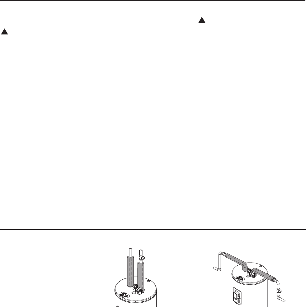
For increased energy efficiency, some
water heaters have been supplied with
two 24” sections of pipe insulation.
Please install the insulation, according
to the illustrations above, that best meets
your requirements.
Hot and Cold Pipe Insulation Installation
Insulation Blankets
Insulation blankets, available to the
general public, for external use on electric
water heaters are not necessary. The
purpose of an insulation blanket is to
reduce the standby heat loss encountered
with storage tank heaters. This water
heater meets or exceeds the National
Appliance Energy Conservation Act
standards with respect to insulation and
standby loss requirements making an
insulation blanket unnecessary.
The manufacturer’s warranty does not
cover any damage or defect caused by
installation, attachment or use of
any type of energy saving or other
unapproved devices (other than those
authorized by the manufacturer) into, onto
or in conjunction with the water heater.
The use of unauthorized energy saving
devices may shorten the life of the water
heater and may endanger life and property.
The manufacturer disclaims any
responsibility for such loss or injury
resulting from the use of such
unauthorized devices.
!
CAUTION: If local codes require the
application of an external insulation
blanket to this water heater, pay careful
attention to the following so as not to
restrict the proper function and
operation of the water heater:
DO NOT cover the operating or
warning labels attached to the water
heater or attempt to relocate them on
the exterior of insulation blanket.
DO NOT apply insulation to the top of
the water heater. This could interfere
with the safe operation of the electrical
junction box.
DO NOT cover the jacket access
panel(s) to the thermostat(s) and heating
element(s), or pressure and temperature
relief valve.
Inspect the insulation blanket frequently.
!
WARNING: If local
codes require external
application of insulation
blanket kits the
manufacturer’s instructions
included with the kit must
be carefully followed.
Typical vertical piping arrangement
(Shutoff Valve Optional)
Typical horizontal piping arrangement
(Shutoff Valve Optional)

10
Installing the water heater
For increased energy efficiency, some
water heaters have been supplied with
a 2-3/8” section of pipe insulation.
Please install the insulation, according
to the illustrations above, that best
meets your requirements.
Slip the insulation cover over the
T&P Valve through the center hole
and align the hole in the side with the
opening of the T&P Valve.
Typical top connection arrangement
(Optional Shutoff Valve Not Shown)
Relief Valve Insulation Installation
!
CAUTION: Ensure the
T&P Valve opening is not
obstructed by the
insulation.
Heat Trap
For increased energy efficiency, some
water heaters have been supplied with
factory installed internal or external
heat traps in the hot outlet and cold
water inlet openings.
NOTICE: DO NOT apply heat to the
HOT or COLD water connections.
If sweat connections are used, sweat
tubing to adapter before fitting adapter
to the water connections on heater. Any
heat applied to the water supply fittings
will permanently damage the dip tube
and/or heat traps.
LeakSense
TM
Should this water heater be equipped with built-in leak detection the following
information is applicable.
The leak detection device (LeakSense
TM
) detects the presence of water and
immediately alerts the electronic control as well as the EcoNet® app on the
cellular phone.
LeakGuard
TM
Should this water heater be
equipped with built-in leak detection
(LeakSense
TM
) and automatic shutoff
valve the following information is
applicable. When water is detected,
the electronic control will shut down
the heating elements in addition to
following the LeakSense
TM
protocols
detailed above. Please see more details
on servicing on page 17.
LeakGuard
TM
Self Check
The automatic water shut off valve
has a self check feature which runs
every 30 days once the water heater
is powered on. This feature works by
closing and reopening the automatic
water shut off valve. In case the valve
fails to reopen, the water heater will be
DISABLED. The water heater gives
alert when the automatic water shut off
valve fails to close.
!
WARNING: Failure
to follow the instructions
provided in this manual
may permanently
damage the unit and
void the manufacturer’s
warranty.
!
WARNING: Removing
automatic water shut off
valve will Disable it from
conducting the self check.
The automatic water shut
off valve will also not
CLOSE in the event a leak
is detected by LeakSense
TM
.
Troubleshooting Automatic Water Shut O Valve
1. Disconnect Automatic Water Shut o
Valve harness.
2. Conrm valve is open, if not, rotate
valve knob to open.
3. Press the clear alarm button for 10
seconds. After which time, the control
will then generate an audible tone.
4. Water heater will be ENABLED and
will resume heating water.
NOTICE: Once a new automatic shut off
valve is installed and connected properly,
the water heater will detect the automatic
shut off valve and then be included in the
leak detection system.

11
Installation Checklist
A. Water Heater Location
B. Water Supply
C. Relief Valve
D. Wiring
❑ Close to area of heated water demand.
❑ Indoors and protected from freezing
temperatures.
❑ Area free of flammable vapors.
❑ Provisions made to protect area from water
damage.
❑ Sufficient room to service heater.
❑ Water heater completely filled with water.
❑ Air purged from water heater and piping.
❑ Water connections tight and free of leaks.
❑ Temperature and Pressure Relief Valve
properly installed and discharge line run to
open drain.
❑ Discharge line protected from freezing.
❑ Power Supply voltage agrees with water
heater rating plate.
❑ Branch circuit wire and fusing or circuit
breaker of proper size.
❑ Electrical connections tight and unit properly
grounded.

12
Safety Precautions
Do turn off power to water heater
if it has been subjected to over
heating, fire, flood, physical
damage.
DO NOT turn on water heater
unless it is filled with water.
DO NOT turn on water heater if
cold water supply shut-off valve
is closed.
If there is any difficulty in
understanding or following the
Operating Instructions or the
Care and Cleaning section, it is
recommended that a qualified
person or serviceman perform the
work.
Operating the water heater
CAUTION: Hydrogen gas can be produced in a hot water system served by this water heater that has not been
used for a long period of time (generally two weeks or more). HYDROGEN GAS IS EXTREMELY
FLAMMABLE!! To dissipate such gas and to reduce risk of injury, it is recommended that the hot water faucet be
opened for several minutes at the kitchen sink before using any electrical appliance connected to the hot water
system. If hydrogen is present, there will be an unusual sound such as air escaping through the pipe as the water
begins to flow. DO NOT smoke or use an open flame near the faucet at the time it is open.
Safety Controls
The water heater is equipped with a
temperature sensor and temperature
limiting control (ECO) that is located
above the upper heating element in
contact with the tank surface. If for any
reason the water temperature becomes
excessively high, the temperature
limiting control (ECO) breaks the
power circuit to the heating element.
Once the control opens, it must be
reset manually.
CAUTION: The cause of the high
temperature condition must be
investigated by qualified service
technician and corrective action must
be taken before placing the water
heater in service again.
To reset the temperature limiting control:
Turn off the power to the water
heater.
Remove the user interface control
and insulation.
Press the red RESET button
located on power board and upper
sensor assembly.
Replace the insulation and user
interface control before turning on
the power to the water heater.
WARNING: If the water
heater has been subjected
to flood, fire, or physical
damage, turn off power and
water to the water heater.
DO NOT operate the water
heater again until it has
been thoroughly checked by
qualified service personnel.
Upper
Element
protective
cover
Reset Button

13
Water Temperature
Time/Temperature Relationship in Scalds
Temperature Time To Produce a Serious Burn
120°F (49°C) More than 5 minutes
125°F (52°C) 1
1
/2 to 2 minutes
130°F (54°C) About 30 seconds
135°F (57°C) About 10 seconds
140°F (60°C) Less than 5 seconds
145°F (63°C) Less than 3 seconds
150°F (66°C) About 1
1
/2 seconds
155°F (68°C) About 1 second
Table courtesy of Shriners Burn Institute
!
DANGER: There is a
hot water scald potential if
the thermostat is set too
high. Households with small
children, disabled, or
elderly persons may require
a 120°F (49°C) or lower
thermostat setting to
prevent contact with HOT
water.
Water Temperature Set Point
Safety and energy conservation are factors
to be considered when selecting the water
temperature setting of the water heater’s
thermostat(s). The lower the temperature
setting, the greater the savings in energy
and operating costs.
Water temperatures above 125°F (52°C)
can cause severe burns or death from
scalding. Be sure to read and follow the
warnings outlined in this manual and on
the label on the water heater. This label
is located on the water heater above the
lower access panel.
Mixing valves are recommended for
reducing point of use water temperature
by mixing hot and cold water in branch
water lines. It is recommended that a
mixing valve complying with the Standard
for Temperature Actuated Mixing Valves
for Hot Water Distribution Systems, ASSE
1017 be installed. See page 3 for more
details and contact a licensed plumber or
the local plumbing authority for further
information.
The electronic control allows the water
temperature to be set from 110°F (43°C)
to 150°F (66°C).
The Performance Platinum residential
electric water heater incorporates a
VACATION mode. This sets the
temperature setting to a predetermined
lower thermostat setting.
The chart below may be used as a guide in
determining the proper water temperature
for your home.
Refer to "Programming the Electronic
Control Instructions" on page 14.

14
Programming the Electronic Control
Setting the Water Temperature
Changing The Water Temperature
or
115°F
(46°C)
125°F
(52°C)
CLEAR
ALARM
VACATION 110
UNLOCK/LOCK
120
(3 SEC)
130 140 150
WiFi
SETUP
SERVICE NEEDED
SET POINT (°F)
CLEAR
ALARM
VACATION 110
UNLOCK/LOCK
120
(3 SEC)
130 140 150
WiFi
SETUP
SERVICE NEEDED
SET POINT (°F)
CLEAR
ALARM
VACATION 110
UNLOCK/LOCK
120
(3 SEC)
130 140 150
WiFi
SETUP
SERVICE NEEDED
SET POINT (°F)
CLEAR
ALARM
VACATION 110
UNLOCK/LOCK
120
(3 SEC)
130 140 150
WiFi
SETUP
SERVICE NEEDED
SET POINT (°F)
CLEAR
ALARM
VACATION 110
UNLOCK/LOCK
120
(3 SEC)
130 140 150
WiFi
SETUP
SERVICE NEEDED
SET POINT (°F)
When power is applied, the
water heater will be in a
Disabled mode. This means that
the water heater is not heating
the water and only the power
LED is illuminated. Press the
RIGHT arrow until the desired
temperature is shown.
Reduce Water Temperature:
Press LEFT arrow until the
desired temperature is shown.
Increase Water Temperature:
Press RIGHT arrow until the
desired temperature is shown.
NOTE: A change in
temperature is in increments
of 5°F unless the EcoNet® app
is used.
DANGER: Hotter water
increases the potential for Hot
Water SCALDS.

15
Locking The Keypad
Unlocking The Keypad
Vacation Setting On
CLEAR
ALARM
VACATION 110
UNLOCK/LOCK
120
(3 SEC)
130 140 150
WiFi
SETUP
SERVICE NEEDED
SET POINT (°F)
CLEAR
ALARM
VACATION 110
UNLOCK/LOCK
120
(3 SEC)
130 140 150
WiFi
SETUP
SERVICE NEEDED
SET POINT (°F)
CLEAR
ALARM
VACATION 110
UNLOCK/LOCK
120
(3 SEC)
130 140 150
WiFi
SETUP
SERVICE NEEDED
SET POINT (°F)
CLEAR
ALARM
VACATION 110
UNLOCK/LOCK
120
(3 SEC)
130 140 150
WiFi
SETUP
SERVICE NEEDED
SET POINT (°F)
CLEAR
ALARM
VACATION 110
UNLOCK/LOCK
120
(3 SEC)
130 140 150
WiFi
SETUP
SERVICE NEEDED
SET POINT (°F)
CLEAR
ALARM
VACATION 110
UNLOCK/LOCK
120
(3 SEC)
130 140 150
WiFi
SETUP
SERVICE NEEDED
SET POINT (°F)
Press and hold both arrow
buttons for 3 seconds to LOCK
the control. Locking will reduce
chance of unintentional changes
in water temperature.
Press and hold both arrow
buttons for 3 seconds to
UNLOCK the control.
Unlocking allows changes to
water temperature as needed.
Press LEFT arrow until the
VACATION indicator is lit.
This mode will reduce the water
temperature to save energy
during times when hot water is
not needed.

16
Vacation Setting Off
Heating Status
CLEAR
ALARM
VACATION 110
UNLOCK/LOCK
120
(3 SEC)
130 140 150
WiFi
SETUP
SERVICE NEEDED
SET POINT (°F)
CLEAR
ALARM
VACATION 110
UNLOCK/LOCK
120
(3 SEC)
130 140 150
WiFi
SETUP
SERVICE NEEDED
SET POINT (°F)
CLEAR
ALARM
VACATION 110
UNLOCK/LOCK
120
(3 SEC)
130 140 150
WiFi
SETUP
SERVICE NEEDED
SET POINT (°F)
Press RIGHT arrow until the desired
water temperature is shown on the
display.
When the water temperature indicator
is blinking, this means that a heating
element is on.
Blinking Indicator
Programming the Electronic Control
Setting The Water Heater Above 140°F (60°C)
(Not Available on the EcoNet app)
CLEAR
ALARM
VACATION 110
UNLOCK/LOCK
120
(3 SEC)
130 140 150
WiFi
SETUP
SERVICE NEEDED
SET POINT (°F)
CLEAR
ALARM
VACATION 110
UNLOCK/LOCK
120
(3 SEC)
130 140 150
WiFi
SETUP
SERVICE NEEDED
SET POINT (°F)
Press and hold both arrow buttons
for 3 seconds to unlock the keypad
and allow water temperatures above
140°F (60°C).
A press of the right arrow will
increase the water temperature
setting up to 150°F (66°C).
The keypad will not lock when
decreasing water temperatures
below 140°F (60°C).
DANGER: Hotter water
increases the potential for Hot
Water SCALDS.

17
24-Hour Leak Detection Override
Mute Alarm Beep
CLEAR
ALARM
VACATION 110
UNLOCK/LOCK
120
(3 SEC)
130 140 150
WiFi
SETUP
SERVICE NEEDED
SET POINT (°F)
CLEAR
ALARM
VACATION 110
UNLOCK/LOCK
120
(3 SEC)
130 140 150
WiFi
SETUP
SERVICE NEEDED
SET POINT (°F)
Press the CLEAR ALARM button for 1 second. The
controller will beep after the button is released. This
will silence the alarm beep and allow the heater to
run normally for 24-hours.
If water is detected while the override is active, the
SERVICE NEED indicator will be solid and the
EcoNet app will display an alert.
Prior to using the 24 hour override feature, check to determine the source of the leak. If
the leak is not coming from the water heater, stop the leak if possible and clean any excess
water around the water heater. Contact the Rheem call center or your local plumber if leak
detection alert persists after the 24 hour override. The use of a fan can shorten the time
to dry any residual moisture around the water heater. If a leak is coming from the water
heater, call for service.
Press the CLEAR ALARM button. This will silence
the alarm beep.
The alarm condition will remain and must be
corrected in order to remove the LED and silence the
beep permanently.
NOTE: The nature
of a water heater
install often result in
spilled water which
can trigger the leak
detection alarm and
closing of shutoff
valve, disabling the
water heater.
WARNING: The
use of heat to dry
the residual moisture
from a spill or leak is
NOT PERMITTED.
This section is only applicable if leak sensor/shut off valve system is installed.

18
Setting Up Wi-Fi
Wi-Fi
Wi-Fi Setup Procedure
Failure to Connect to User’s Router or Network
Your heater has integrated Wi-Fi capability. By connecting your heater
to the internet, you can access the full benefits of the water heater,
including remote control, leak detection alerts, and diagnostic alerts on
your mobile device.
1. Upon initial power up, the Wi-Fi
module is DISABLED.
a. Press the Wi-Fi SETUP button for 2
seconds. The keypad will beep and
Wi-Fi indicator will blink blue after
the press of the W-Fi Setup button.
b. SETUP mode will remain active for 30
minutes. The Wi-Fi SETUP button can
be pressed again to restart the setup
process.
2. Connect mobile device to the
local Wi-Fi network that the
water heater will connect to.
3. Download the EcoNet® app
via the App Store or Google
Play to your mobile device.
Create an EcoNet® account
and sign in.
4. The water heater is now able
to communicate with the app.
5. Follow the instructions in the
EcoNet® app to complete the
setup.
6. Blinking Wi-Fi indicator will
now be solid blue.
1. In the event that the Wi-Fi does not connect to the router
or network, the Wi-Fi Status LED will blink red 3 times
followed by a pause.
2. A reset of the Wi-Fi module will be required if changes
like a new router; router SSID or password change; new
user or homeowner occur.
3. Press the Wi-Fi Setup button for 5 seconds. The keypad
will beep 3 times.
4. Follow the above Wi-Fi setup procedure. If this does not
correct this issue, contact customer care support.
CLEAR
ALARM
VACATION 110
UNLOCK/LOCK
120
(3 SEC)
130 140 150
WiFi
SETUP
SERVICE NEEDED
SET POINT (°F)
CLEAR
ALARM
VACATION 110
UNLOCK/LOCK
120
(3 SEC)
130 140 150
WiFi
SETUP
SERVICE NEEDED
SET POINT (°F)
CLEAR
ALARM
VACATION 110
UNLOCK/LOCK
120
(3 SEC)
130 140 150
WiFi
SETUP
SERVICE NEEDED
SET POINT (°F)
CLEAR
ALARM
VACATION 110
UNLOCK/LOCK
120
(3 SEC)
130 140 150
WiFi
SETUP
SERVICE NEEDED
SET POINT (°F)
Blinking Indicator
Scheduling
Heating
Status
Set Point
Slider
Available
Hot Water
Indicator
Energy Usage
Network Settings
Schedule Status
2
NOTE: Should you have a problem getting the Wi-Fi setup,
contact CSS at 1-800-255-2388.

19
Error Codes for Electronic Control
CAUTION: For your safety DO NOT attempt repair of electrical wiring, temperature sensor, electronic control,
heating elements or other safety devices. Refer repairs to qualified service personnel.
!
CLEAR
ALARM
VACATION 110
UNLOCK/LOCK
120
(3 SEC)
130 140 150
WiFi
SETUP
SERVICE NEEDED
SET POINT (°F)
NOTE: The EcoNet®
app will display all
Alerts and Alarms in
the EcoNet® app with
specifics about the cause.
In the event of an error, the SERVICE NEEDED LED will blink red or remain solid red. This will depend on the type
of error that has occurred. The water heat will remain operational when an ALERT occurs. There are five (5) ALARM
codes that represent a family of ALARMS where the water heater will shut down. Note that several of the error codes
detailed below are only applicable should a leak sensor/shut off valve system be installed on the heater.
Blinking
Indicator
NUMBER OF BLINKS
ERROR CODES
TYPE SERVICE NEEDED LED DESCRIPTION/ACTION
ALERT Solid red
1. Leak sensor disconnected. Open the lower element cavity. If it is connected, call customer
service. If is not connected, reconnect the leak sensor to reset the error.
2. Conguration data restore failure. Call for service.
3. Shut o valve cannot close (self-check). Call for service and refer to the LeakGuard
TM
section of the manual.
4. Wi-Fi or Control Communication Error. Also, the Wi-Fi LED will turn red. See the Failure
to Connect to User’s Router or Network section of this manual.
5. Leak detected (24-hour leak alarm override active). Verify there is no longer a leak. Refer
to the 24-HOUR LEAK DETECTION OVERRIDE section of the manual.
ALARM
One (1) red blink followed by a
pause
1. Disconnection of lower thermistor. Please call for service.
2. Failure of lower thermistor. Please call for service.
Two (2) red blinks followed by a
pause
(Only applicable should
leaksense/leakguard system be
installed on heater)
1. Water in contact with wick or rope sensor. Check the pan for water. If there is no water
present, disconnect the sensor, dry and reinstall it to reset the error. Use of the LEAK
OVERRIDE FUNCTION maybe be required. Refer to the 24-HOUR LEAK DETEC-
TION OVERRIDE section of the manual. If there is water in the pan, call for service.
2. Shuto valve is not connected. Check harness connection. If alarm persists, call for service
and refer to the Leak-GuardTM section of the manual.
3. Shuto valve input error. Call for service and refer to the LeakGuard
TM
section of the
manual.
4. Shuto valve failed to close. Call for service and refer to the LeakGuard
TM
section of the
manual.
5. Shuto valve failed to re-open. Call for service and refer to the LeakGuard
TM
section of the
manual.
6. Shut o valve cannot open (self-check). Call for service and refer to the LeakGuard
TM
section of the manual.
Three (3) red blinks followed by
a pause
1. Tank not lled with water. Please ll the tank with water and recycle power.
Four (4) red blinks followed by
a pause
1. Disconnection of wire(s) to upper or lower element or ECO. Call for service.
2. Upper element wire(s) and lower element wire(s) switched. Call for service.
3. ECO tripped and needs reset. Reset ECO or call for service.
4. Failure of one or both elements. Call for service.
Five (5) red blinks followed by a
pause
1. Upper or lower element relay stuck on. Please call customer service.
2. Upper or lower temperature conversion error. Please call customer service.
3. Conversions stuck error. Call for service.
4. Conversion drift error. Call for service.
5. On-board temperature protection error. Call for service.
6. Failure or disconnection of upper thermistor. Please call for service.
x1 = Lower Thermistor Failure
x2 = Leak Detected or Shuto Valve Error
x3 = Dry Fire (Heating without water)
x4 = Element Wiring or Emergency Cut Out
x5 = Control or Power Board Error

20
Hot Water Outlet
Nominal 3/4" size mixing or tempering valve (refer to warning
above). Follow mixing or tempering valve manufacturer's instructions
for installation of the valve
Cold Water Inlet
3/4" Tempered
domestic hot water
supply to house
Shuto Valve
(optional)
NOTICE: If this water
heater is currently
enrolled in Advanced
Loadup, a thermostatic
mixing valve
conforming to ASSE
1017 shall be installed
on the hot water
supply line following
all manufacturer
installation.
EcoPort (CTA-2045)
EcoPort (CTA-2045) CTA Module Communication with the Water Heater
1. To ENABLE communication of the EcoPort (CTA-
2045) module with the water heater, press the LEFT
arrow for 10 seconds. After which time, the control will
then generate an audible ASCENDING tone.
2. To DISABLE communication of the EcoPort (CTA-
2045) module with the water heater, press the LEFT
arrow for 10 seconds. After which time, the control will
then generate an audible DESCENDING tone.
CLEAR
ALARM
VACATION 110
UNLOCK/LOCK
120
(3 SEC)
130 140 150
WiFi
SETUP
SERVICE NEEDED
SET POINT (°F)

21
NOTE: To re-enroll see page 20.
NOTE: To re-enroll see page 20.
EcoPort (CTA-2045)
EcoPort (CTA-2045) CTA Module Communication with the Water Heater
Cancel EcoPort Override
1. To EXIT the Demand Response Program after water heater
enrollment, press either the LEFT or RIGHT arrows once.
The water heater shall display current temperature set point.
2. The water heater will now remain un-enrolled in the Demand
Response Program for the following 24 hours.
3. After the 24-hour period transpires, the water heater will
automatically return to the enrolled Demand Response
Program. This process will be confirmed by the water heater’s
3 blinking temperature set point LEDs.
1. To Cancel the Override press and hold the LEFT arrow for
5 seconds. The water heater shall emit and audible tone up
chime.
2. The unit will confirm it has canceled the Override by the
water heater’s 3 blinking temperature set point LEDs to signal
that it is ready to accept any upcoming Demand Response
commands.
CLEAR
ALARM
VACATION 110
UNLOCK/LOCK
120
(3 SEC)
130 140 150
WiFi
SETUP
SERVICE NEEDED
SET POINT (°F)
CLEAR
ALARM
VACATION 110
UNLOCK/LOCK
120
(3 SEC)
130 140 150
WiFi
SETUP
SERVICE NEEDED
SET POINT (°F)
5

22
Care and cleaning of the water heater.
Draining the Water Heater
CAUTION: Shut off power to the
water heater before draining water.
DANGER: Before manually
operating the relief valve, make certain
no one will be exposed to the hot water
released by the valve. The water drained
from the tank may be hot enough to
present a scald hazard and should be
directed to a suitable drain to prevent
injury or damage.
In order to drain the water heater, turn off
the cold water supply. Open a hot water
faucet or lift the handle on the relief valve
to admit air to the tank.
Attach a garden hose to the drain valve on
the water heater and direct the stream of
water to a drain. Open the valve.
Routine Preventative Maintenance
Properly maintained, your water heater
will provide years of dependable trouble-
free service.
It is suggested that a routine preventive
maintenance program be established and
followed by the user.
It is further recommended that a periodic
inspection of the operating controls,
heating element and wiring should be
made by service personnel qualified in
electric appliance repair.
Most electrical appliances, even when
new, make some sound when in operation.
If the hissing or singing sound level
increases excessively, the electric heating
element may require cleaning. Contact a
qualified installer or plumbing contract to
inspect.
At least once a year, lift and release the
lever handle on the temperature pressure
relief valve, located near the top of the
water heater, to make certain the valve
operates freely. Allow several gallons to
flush through the discharge line to an open
drain.
A water heater’s tank can act as a setting
basin for solids suspended in the water. It
is therefore not uncommon for hard water
deposits to accumulate in the bottom of the
tank. It is suggested that a few quarts of
water be drained from the water heater’s
tank every month to clean the tank of these
deposits.
Rapid closing of faucets or solenoid
valves in automatic water using appliances
can cause a banging noise heard in a
water pipe. Strategically located risers in
the water pipe system or water hammer
arresting devices can be used to minimize
the problem.
The anode rod should be removed from the
water heater’s tank annually for inspection
and replaced when more than 6″ of core
wire is exposed at either end of the rod.
Make sure the cold water supply is turned
off before removing anode rod.
DANGER: Before
manually operating the
relief valve, make certain
no one will be exposed to
the danger of coming in
contact with the hot water
released by the valve. The
water may be hot enough to
create a scald hazard. The
water should be released
into a suitable drain to
prevent injury or property
damage.
NOTICE: If the
temperature and pressure
relief valve on the hot
water heater discharges
periodically, this may be due
to thermal expansion in a
closed water system.
Contact the water
supplier or your plumbing
contractor on how to
correct this. DO NOT plug
the relief valve outlet.

23
Extended Shut-Down
If the water heater is to remain idle for an
extended period of time, the power and
water to the appliance should be turned off
to conserve energy and prevent a build-up
of dangerous hydrogen gas.
The water heater and piping should be
drained if they might be subjected to
freezing temperatures.
After a long shut-down period, the
water heater’s operation and controls
should be checked by qualified service
personnel. Make certain the water heater
is completely filled again before placing
it in operation.
NOTICE: Refer to the
Hydrogen Gas Caution in
the Operating Instructions.
Anode Rod
This water heater is equipped with an
anode rod designed to prolong the life
of the glass lined tank. The anode rod is
slowly consumed, thereby eliminating or
minimizing corrosion of the glass lined
tank.
Water sometimes contains a high sulfate
and/or mineral content and together with
cathodic protection process can produce
a hydrogen sulfide, or rotten egg odor in
the heated water. Chlorination of the water
supply should minimize the problem.
NOTICE: DO NOT remove
the anode rod from the
water heater’s tank,
except for inspection
and/or replacement, as
operation with the anode
rod removed will greatly
shorten the life of the glass
lined tank and will exclude
warranty coverage.
Care and cleaning of the water heater.
24
Before You Call For Service…
Troubleshooting Tips
Save time and money! Review the chart on this page
first and you may not need to call for service.
CAUTION: For your safety DO NOT attempt repair of electrical wiring, temperature sensor, electronic control,
heating elements or other safety devices. Refer repairs to qualified service personnel.
!
Problem Possible Causes What To Do
Rumbling noise
Water conditions in your home
caused a build up of scale or
mineral deposits on the heating
elements.
● Remove and clean the heating elements.
Relief valve
producing popping
noise or draining
Pressure build up caused by ther-
mal expansion in a closed system.
● This is an unacceptable condition and must be corrected.
Contact the water supplier or plumbing contractor on how to
correct this. DO NOT plug the relief valve outlet.
Rattling noise
during periods
of water usage
Internal heat trap ttings in opera-
tion.
● This is normal for heat trap ttings when in operation and does
not indicate a need for service.
Not enough or
no hot water
Water usage may have exceeded the
capacity of the water heater.
● Wait for the water heater to recover after an abnormal demand.
A fuse is blown or a circuit breaker
tripped.
● Replace fuse or reset circuit breaker.
Electric supply may be o.
● Make sure electric supply to water heater and disconnect
switch, if used, are in the ON position.
The thermostat may be set set too
low.
● See the Temperature regulation of the water heater section of
this manual.
Leaking or open hot water faucets.
● Make sure all faucets are closed.
Electric service to your home may
be interrupted.
● Contact the local electric utility.
Improper wiring.
● See the Installing the water heater section of this manual.
Manual reset limit (ECO).
● See the Temperature regulation of the water heater section of
this manual.
Cold water inlet temperature may
be colder during the winter months.
● This is normal. The colder inlet water takes longer to heat.
Auto shuto valve is closed
(ONLY APPLICABLE SHOULD
THE LEAKSENSE/LEAKGUARD
SYSTEM BE INSTALLED)
Auto shuto valve is not connected.
● Turn power o to the water heater. Press and rotate the shuto
valve knob counterclockwise until it stops. The arrow of the
valve position indicator will be pointed to OPEN.
● Ensure the Auto shuto valve is connected. See the Leak-
Guard
TM
section of this manual.
Water is too hot
The thermostat is set too high.
● See the Temperature regulation of the water heater section of
this manual.
Cannot set
above 140°F (60°C)
The keypad is locked
● See conguration menu section on programming the electronic
control.

25
Diagnostic Mode
For additional unit information, you can
connect directly to the water heater via
local mode and use the EcoNet® app for
more details alarm and alert information.
To connect to the water heater via local
mode follow these steps.
1. Press the Wi-Fi step up button until the
unit beeps and the Wi-Fi LED blinks
blue.
2. From the EcoNet® app click on
Diagnostic Mode.
3. Press the connect button in the app.
4. Follow the on screen instructions.
5. Once connected you can view detailed
alarm history and network configuration
settings.
6. Once complete Close the app.
7. If your water heater was connected to
your home network previously, it will
return to that network.

26
Replacement Parts.
Instructions For Placing a Parts Order
Address parts orders to the distributor or
store where the heater was purchased.
All parts orders should include:
The model and serial number of the
water heater from the rating plate.
Specify voltage and wattage as
marked on the rating plate.
Part description (as noted below) and
number of parts desired.
!
CAUTION: For your safety DO NOT
attempt repair of electrical wiring,
thermostat(s), heating elements or other
operating controls. Refer repairs to qualified
service personnel.
User Interface
Control
Jacket Access
Cover
Cavity Insulation
Upper Element
Protective Cover
Lower Protective
Element Cover
Lower
Thermostat
Bracket
Water Sensor
(Optional)
Drain Valve
Junction Box Cover
Anode Rod
Dip Tube Gasket
Dip Tube
Outlet Water Nipple
Housing
EcoPort (CTA-2045) Harness
Outlet Water Nipple
T&P Insulation
T&P Valve
Upper
Thermostat
Bracket
Lower
Sensor
Power Board and
Upper Sensor
Upper
Heating
Element
Lower
Heating
Element
Heating Element Gasket
Heating Element Gasket
Auto Shuto Valve (Optional)

27
Cavity Insert Instructions
The following instructions are intended for
qualified service personnel ONLY, and should only
be done when necessary.
Upper
Lower
In order to replace the thermostat or heating element,
remove the cavity insert crossbar by following the
instructions below:
Turn off the power to the water heater.
Remove the jacket access panel or electronic control
and insulation.
Only for the lower temperature sensor and lower
element, rotate the crossbar up and down until it
breaks away from the remainder of the cavity insert.
(See illustration to the left)
Discard the crossbar. It cannot and need not be
replaced.
Replace the temperature sensor and/or element as
necessary.
Replace the insulation and jacket access panel/
electronic control before turning on the power to the
water heater.
NOTICE: The cavity insert crossbar is necessary for
the manufacturing process only. The removal of the
crossbar will not interfere with the operation of the
water heater.

28
Wiring Diagram
This water heater is wired as indicated in the schematic below. Use only a 2 wire power feed with
ground connection for this water heater.
Upper
Element
Lower
Element
J15J3
L1
L2
J1
Power board
Control
board
GND1
J4
J5
J12
J14
J11
Thermistor
Thermistor
R
BK
12 AWG Solid wire
Low voltage wire – 22 AWG
Multi pin connector
Junction
box
Y
Blue
Blue
BK
1 2
3 4
Multi conductor low voltage wire(s)
J10
CTA-2045
Connector
Housing
18 AWG Stranded wire
Leak
Sensor
J19
Shutoff
Valve

29
Notes

30
Notes

31
Notes
32
IF YOU NEED SERVICE
1. Should you have any questions about your new water heater, or if it
requires adjustment, repair, or routine maintenance, it is suggested that you
first contact your installer, plumbing contractor or previously agreed upon
service agency. In the event the firm has moved, or is unavailable, refer
to the telephone directory, commercial listings or local utility for qualified
service assistance.
2. Should your problem not be solved to your complete satisfaction, you
should then contact the Manufacturer’s National Service Department at
the following address:
800 Interstate Park Drive
Montgomery, Alabama 36109
Phone: 1-800-432-8373.
When contacting the manufacturer, the following information will be requested:
a. Model and serial number of the water heater as shown on the rating plate
attached to the jacket of the heater.
b. Address where the water heater is located and physical location.
c. Name and address of installer and any service agency who performed
service on the water heater.
d. Date of original installation and dates any service work was performed.
e. Details of the problems as you can best describe them.
f. List of people, with dates, who have been contacted regarding your
problem.
