SOLO 1/8
The SOLO thermostat is designed to control the temperature of a
floor heating system for both 120-volt and 240-volt applications. The
thermostat can be used to control either the floor temperature or the
ambient temperature. It has a maximum load capacity of 15 A
(1800 W @ 120 VAC or 3600 W @ 240 VAC).
SUPPLIED PARTS
• One (1) thermostat
• One (1) floor temperature sensor
• Four (4) solderless connectors
• Two (2) 6-32 mounting screws
• One (1) flat-tip screwdriver
TURN OFF POWER TO THE HEATING SYSTEM AT THE MAIN
POWER PANEL TO AVOID ELECTRICAL SHOCK. THE
INSTALLATION MUST BE PERFORMED BY A QUALIFIED
ELECTRICIAN.
The thermostat’s housing is not watertight. Do NOT install the
thermostat in an area where it can be exposed to water or rain.
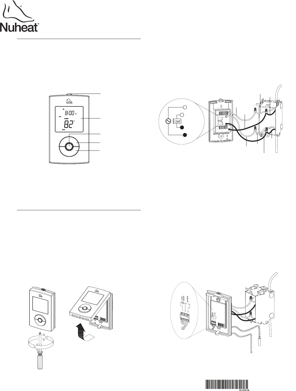
1 To remove the thermostat faceplate, loosen the screw at the bottom
of the thermostat and lift the bottom of the faceplate outwards
towards you. (The screw cannot be completely removed.)
2 Connect the thermostat wires to the power supply and to the load
using solderless connectors for copper wires as shown in the
following illustration.
NOTE: The SOLO thermostat does not have a ground wire. The
grounding of the system is done via the ground wire from the heating
apparatus (load side).
NOTE: All wires and connections must conform to the local electrical
code. This thermostat has tinned copper wires for line and load
connections. Special CO/ALR solderless connectors must be used if
these wires are to be connected to aluminium conductors.
3 Pull the temperature sensor wires through one of the openings
on the thermostat base and connect the wires to terminals 1 and
2 (no polarity).
• The sensor cable must not come in contact with the
electrical wires and must be routed outside the electrical
box and follow the wall down to the floor.
• Position the sensor cable such that it does not come in
contact with the floor heating wires. The sensor must be
centered between two floor heating wires for best
temperature control.
• Do NOT staple the sensor head (the plastic end) to the floor.
Doing so might damage the sensor. The damage might not
be noticeable during testing but can become apparent
several days later.
4 Push the excess length of the line voltage wires back inside the
electrical box. Install the thermostat base onto the electrical box
using the provided screws.
5 Set the DIP switches (refer to section 2.1).
Description
1.
Installation
2.
GFCI test button
Screen
Up/Previous button
Select button
Down/Next button
L2(N)
L1(L)
L2(N)
L1(L)
Load
Power supply
Red
Black
Red
(White)
Red
Black
Black
Black
240 V (120 V)
Red
(White)
Floor sensor
Network connection
(refer to section 9)
SOLO
User Guide
Programmable Dual Voltage Thermostat

SOLO 2/8
6 Reinstall the thermostat faceplate on its base and secure it with
the screw. If there is a sticker on the screen, peel it off.
7 Apply power to the heating system. Verify the installation by
making sure that the heating system can be turned on or off by
increasing or decreasing the setpoint respectively.
8 Test the GFCI (refer to section 6).
NOTE: Keep the air vents of thermostat clean and unobstructed at all
times.
2.1 DIP Switch Settings
Set the DIP switches on the back of the thermostat faceplate for your
specific application. Refer to Table 1:
Table 1
DIP switch 1
Leave in “Slave” if you are not connecting the thermostat to a
network (refer to section 9).
DIP switch 2
Set according to your floor type. For laminate or engineered wood
floor, you must set the DIP switch to 'Wood' to limit the maximum
floor temperature to 82°F (28°C).
3.1 Setting the Time and Date
1 Press and hold the
Select
button for 2 seconds to enter the
Programming Menu.
2 Using the
Up
or
Down
button, go to
Date+Time
and briefly press
the
Select
button.
3 Using the Up or Down button, choose the time format and briefly
press the Select button.
4 Set the hour and briefly press the Select button.
5 Set the minutes and briefly press the Select button.
6 Set the year and briefly press the Select button.
7 Set the month and briefly press the Select button.
8 Set the day and briefly press the Select button. You will
automatically be returned to the Programming Menu.
3.2 Setting the Week Schedule
Set the week schedule by assigning a Day Type (workday / home
day / away day) for each day of the week. The default Day Type for
each day is shown in Table 2:
Table 2
To change the Day Type:
1 Press and hold the
Select
button for 2 seconds to enter the
Programming Menu.
2 Using the
Up
or
Down
button, go to
Week Schedule
and briefly
press the
Select
button.
3 Using the Up or Down button, go to the day that you wish to
modify and briefly press the Select button.
4 Choose the Day Type (Workday / Home day / Away) and briefly
press the Select button.
5 Repeat steps 3 and 4 if you wish to modify another day.
6 When done, press the Up or Down button until Exit is flashing
and briefly press the Select button to return to the Programming
Menu.
DIP Switch Function Up Down
1 Master/Slave selection
Slave Master
2 Floor type selection
Tile Wood
NOTE: The default settings are shown inside the grey cells.
1
2
Programming
3.
Day Type MO TU WE TH FR SA SU
Workday
Home day
Away
Programming Menu
• To enter the programming menu, press
and hold the Select button for 2 seconds.
• To navigate inside the menu, press the
Next or Previous button.
• To select an item inside the menu, briefly
press the Select button (do not hold
down).
• To return to the previous menu, press
and hold the Select button for 2 seconds.
Select button
Previous button
Next button

SOLO 3/8
3.3 Setting the Workday Schedule
The default workday schedule (Table 3) represents a typical workday.
Table 3
To modify the Workday schedule:
1 Press and hold the
Select
button for 2 seconds to enter the
Programming Menu.
2 Using the
Up
or
Down
button, go to
Workday
and briefly press
the
Select
button.
3 Using the Up or Down button, choose the Period (Wake / Leave
/ Return / Sleep) that you wish to modify and briefly press the
Select button.
4 Set the hour and briefly press the Select button.
5 Set the minutes and briefly press the Select button.
6 Set the temperature and briefly press the Select button to return
to the Workday submenu.
7 Repeat steps 3 to 6 if you wish to modify another Period.
8 When done, press the Up or Down button until Exit is flashing.
Briefly press the Select button to return to the Programming
Menu.
3.4 Setting the Home day Schedule
The default home day schedule (Table 4) represents a typical day
when you stay at home (example: Saturdays and Sundays).
Table 4
To modify the Home day schedule:
1 Press and hold the
Select
button for 2 seconds to enter the
Programming Menu.
2 Using the
Up
or
Down
button, go to
Home day
and briefly press
the
Select
button.
3 Using the Up or Down button, choose the Period (Wake / Sleep)
that you wish to modify and briefly press the Select button.
4 Set the hour and briefly press the Select button.
5 Set the minutes and briefly press the Select button.
6 Set the temperature and briefly press the Select button to return
to the Home day submenu.
7 Repeat steps 3 to 6 if you wish to modify another Period.
8 When done, press the Up or Down button until Exit is flashing.
Briefly press the Select button to return to the Programming
Menu.
3.5 Setting the Away Temperature
The Away temperature setting is useful when you want the
thermostat to maintain a lower temperature for an extended period of
time. The default Away temperature setting is 50 °F (10 °C). This
setting can be used when you go on vacation or during warmer
months (refer to section 4.4).
To modify the Away temperature:
1 Press and hold the
Select
button for 2 seconds to enter the
Programming Menu.
2 Using the
Up
or
Down
button, go to
Away
and briefly press the
Select
button.
3 Using the Up or Down button, set the desired temperature and
briefly press the Select button. You will automatically be
returned to the Programming Menu.
4.1 Main Display
4.2 Heat Intensity Indicator ( )
The heat intensity indicator is a graphic representation of how long
the floor heating system is turned on compared to how long it is
turned off in order to reach and maintain the set temperature. The
more bars means the longer the floor heating system is turned on.
4.3 Temperature Display
The thermostat can display either of the following temperatures:
• Floor temperature (default display mode)
• Ambient temperature
To switch the temperature display mode:
1 Press and hold the
Select
button for 2 seconds to enter the
Programming Menu.
2 Using the
Up
or
Down
button, go to
Temp Display
and briefly
press the
Select
button.
3 Using the Up or Down button, choose the Temperature Display
(Ambient/ Floor) and briefly press the Select button. You will
automatically be returned to the Programming Menu.
4.4 Operating Modes
The thermostat has the following operating modes:
• Manual mode
• Automatic mode (default operating mode)
• Workday mode
• Home-day mode
•Away mode
• Off mode
Mode selection button
If the thermostat is in Automatic (Auto), Manual (Man) or Off mode,
you can switch between these three operating modes by pressing the
Select button.
Period Start Time
Floor Temperature
Tile Wood
Wake 6:00 am 88 °F (31 °C) 82 °F (28 °C)
Leave 9:00 am 74 °F (23 °C) 74 °F (23 °C)
Return 5:00 pm 88 °F (31 °C) 82 °F (28 °C)
Sleep 11:00 pm 74 °F (23 °C) 74 °F (23 °C)
Period Start Time
Floor Temperature
Tile Wood
Wake 8:00 am 88 °F (31 °C) 82 °F (28 °C)
Sleep 11:00 pm 74 °F (23 °C) 62 °F (16.5 °C)
Basic Operation
4.
Time
Day
Period (refer to sections
3.3 and 3.4)
Heat Intensity Indicator
(refer to section 4.2)
Operating Mode
(refer to section 4.4)
Temperature Display
(refer to section 4.3)
Auto Man Off

SOLO 4/8
NOTE: Mode selection via the Select button is disabled when the
thermostat is in Workday, Home-day or Away mode.
Mode selection menu
To switch between the six operating modes:
1 Press and hold the
Select
button for 2 seconds to enter the
Programming Menu.
2 Using the
Up
or
Down
button, go to
Mode
and briefly press the
Select
button.
3 Using the Up or Down button, choose the Operating Mode (Man
/ Auto / Workday / Home day / Away / Off) and briefly press the
Select button. You will automatically be returned to the
Programming Menu.
Manual mode
In Manual mode, the programmed schedule is not followed. Use this
mode if you always want to set the temperature manually. The
thermostat will maintain the set temperature until it is manually
changed or until you switch to another operating mode.
Automatic mode (default setting)
Use Automatic mode if you want the thermostat to follow the
programmed week schedule (refer to section 3.2).
Workday mode
Use Workday mode if you want the thermostat to follow the Workday
schedule for all 7 days of the week (refer to section 3.3).
Home-day mode
Use Home Day mode if you want the thermostat to follow the Home
Day schedule for all 7 days of the week (refer to section 3.4).
Away mode
Use Away mode when you want the thermostat to use the Away
temperature setting (refer to section 3.5). This mode is useful when
you want the thermostat to maintain a lower temperature for an
extended period of time. It can be used when you go on vacation or
during warmer months. In Away Mode, the thermostat will still display
the clock and the temperature readings.
Off mode
Use Off mode to turn off the floor heating system. This mode can be
used when you are away for an extended period of time such as a
vacation. The Off Mode does not erase any programmed settings.
The thermostat will display the clock but will not display any
temperature reading.
4.5 Temporarily Bypassing the Programmed Temperature
The thermostat uses a programmed temperature when it is in
Automatic mode, Workday mode, Home day mode or Away mode. To
temporarily bypass the programmed temperature, press the Up or
Down button until the desired temperature is displayed. The mode
indicator will flash indicating that you are temporarily bypassing the
programmed temperature. The thermostat will maintain this
temperature until the start of the next period (or for 2 hours for Away
mode).
5.1 Temperature Control Setting
The thermostat can be configured to control the floor temperature,
ambient air temperature, or a combination of ambient air and floor
temperature (as shown in Table 5):
Table 5
To change the Temperature Control setting:
1 Press and hold the
Select
button for 2 seconds to enter the
Programming Menu.
2 Using the
Up
or
Down
button, go to
Temp Control
and briefly
press the
Select
button.
3 Using the Up or Down button, choose the Temperature Control
setting (Ambient / Floor / Ambient+Floor) and briefly press the
Select button. You will automatically be returned to the
Programming Menu.
5.2 Ambient Temperature Settings
If the thermostat has been configured to control ambient temperature
(refer to section 5.1), the default temperatures for workday and home
day are shown in Table 6:
Table 6
To modify the temperature settings, refer to sections 3.3 and 3.4.
5.3 Early Start
Early Start calculates the optimal time to start heating in order to
obtain the desired temperature by the set time. It applies only if your
thermostat is following a programmed schedule (i.e. not in Manual
Mode or Away Mode). By default, this feature is enabled (On).
To turn Early Start on/off:
1 Press and hold the
Select
button for 2 seconds to enter the
Programming Menu.
2 Using the
Up
or
Down
button, go to
Early Start
and briefly press
the
Select
button.
3 Using the Up or Down button, choose the Early Start setting
(On / Off) and briefly press the Select button. You will
automatically be returned to the Programming Menu.
Configurations
5.
Temperature
Control Setting
Description
Floor (default) The thermostat controls the floor temperature.
Ambient The thermostat controls the ambient air
temperature. This setting is useful if the floor
temperature sensor is damaged or not
installed.
Ambient+Floor For advanced users only (refer to section 5.7).
Period
Ambient Temperature
Workday Home day
Wake 70 °F (21 °C) 70 °F (21 °C)
Leave 62 °F (16.5 °C)
Return 70 °F (21 °C)
Sleep 62 °F (16.5 °C) 62 °F (16.5 °C)

SOLO 5/8
5.4 Temperature Unit Setting
The thermostat can be configured to display the temperature in
Fahrenheit or Celsius.
To change the temperature unit:
1 Press and hold the
Select
button for 2 seconds to enter the
Programming Menu.
2 Using the
Up
or
Down
button, go to
°F/°C
and briefly press the
Select
button.
3Using the Up or Down button, choose the temperature unit
(°F / °C) and briefly press the Select button. You will
automatically be returned to the Programming Menu.
5.5 Daylight Saving
This feature automatically switches the thermostat to daylight saving
time on the second Sunday of March and reverts it back to normal
time on the first Sunday of November. By default, this feature is
enabled (On).
To change the Daylight Saving setting:
1 Press and hold the
Select
button for 2 seconds to enter the
Programming Menu.
2 Using the
Up
or
Down
button, go to
Daylight Saving
and briefly
press the
Select
button.
3Using the Up or Down button, choose the Daylight Saving
setting (On / Off) and briefly press the Select button. You will
automatically be returned to the Programming Menu.
5.6 Backlight
The thermostat has three backlight settings:
Table 7
To change the Backlight setting:
1 Press and hold the
Select
button for 2 seconds to enter the
Programming Menu.
2 Using the
Up
or
Down
button, go to
Backlight
and briefly press
the
Select
button.
3 Using the Up or Down button, choose the Backlight setting (Off /
Low / High) and briefly press the Select button. You will
automatically be returned to the Programming Menu.
5.7 Floor Limit Settings (advanced users only)
You can set the minimum and maximum temperature that your floor
can reach. These settings are available only if the Temperature
Control setting is at Ambient+Floor (refer to section 5.1).
NOTE: The desired ambient air temperature might not be attainable if
the maximum floor temperature is set too low.
To change the Floor Limit settings:
1 Press and hold the
Select
button for 2 seconds to enter the
Programming Menu.
2Using the
Up
or
Down
button, go to
Floor Limit
and briefly press
the
Select
button.
3Using the Up or Down button, choose the Floor Limit (Min /
Max) that you wish to modify and briefly press the Select button.
4 Set the temperature and briefly press the Select button to return
to the Floor Limit submenu.
5 Repeat steps 3 and 4 if you wish to modify the other Floor Limit
temperature.
6 When done, press the Up or Down button until Exit is flashing.
Briefly press the Select button to return to the Programming
Menu.
5.8 Resetting to default Values
To return the thermostat to its default settings, simultaneously press
both the Select and Down buttons and hold. rSt (reset) will flash on
the screen. After 5 seconds, the thermostat returns to its normal
display. Release the buttons. The thermostat is now reset.
This thermostat has a built-in GFCI (Ground Fault Circuit Interrupter).
The GFCI protects against risks of electrocution caused by a current
leakage. If the leakage current exceeds 5 mA, the GFCI will
automatically be triggered, thus cutting power to the
floor heating system. To indicate the fault, the TEST
button at the top of the thermostat will illuminate (red)
and the display as shown on the right will appear on
the screen.
If the GFCI is triggered during normal operation, check if the fault has
been caused by an external interference such as a halogen light or
an electric motor. If this is the case, reset and test the GFCI.
However, if the GFCI is triggered again for unknown reasons, cut
power to the floor heating system from the main electrical panel and
have the installation verified by an electrician.
WARNING: The GFCI does not protect against electrical shocks
resulting from contact with both conductor wires.
6.1 GFCI Reset
To reset the GFCI, press the Select button. The TEST button light
will go off and the thermostat will return to its normal display.
6.2 GFCI Test
To ensure the GFCI is always in working order, test it once the ther-
mostat is installed and test it every month thereafter.
1 Increase the temperature sufficiently to start heating.
2 Wait for about 5 seconds until the heat intensity indicator ( )
appears on the screen.
3 Press the TEST button at the top of the thermostat.
• If the TEST button does NOT illuminate, the test has failed.
Cut power to the heating system at the main electrical panel,
have an electrician verify the installation and, if necessary,
replace the thermostat.
• If the TEST button illuminates, continue to step 4.
4 Switch the thermostat to Off then back to On.
• If the TEST button light goes off, the test has passed. Set the
thermostat back to the desired temperature and ignore the
remaining steps. The test is now completed.
• If the TEST button light remains on, the test has failed. Con-
tinue to step 5.
5 Switch the circuit breaker (at the main electrical panel) of the
heating system to off then back to on.
6 Repeat the test. If the test fails again, cut power to the heating
system at the main electrical panel, have an electrician verify the
installation and, if necessary, replace the thermostat.
Setting Backlight Effect
Off (default)
The screen is backlit for 12 seconds when any
button is pressed.
Low The screen is permanently backlit at low intensity.
High The screen is permanently backlit at high intensity.
GFCI
6.

SOLO 6/8
NOTE: The Select button flashes during the error display when there
is corrective action to be taken. Also, the appropriate wording flashes
on the screen to pinpoint the source of the problem.
All programmed settings (time and temperature) are not erased
during a power outage. However, if a power outage exceeds 4 hours,
only the thermostat’s clock must be set (refer to section 3.1). When
power returns, the thermostat returns to the operating mode
preceding the power outage.
If you have multiple SOLO thermostats, you can connect them to
form a network. This allows you to use the “Send to Network” feature.
This feature allows you to program only one thermostat in the
network and be able to send its settings to the other thermostats.
This reduces programming time during installation and is useful when
you are leaving for vacation or returning home from a vacation.
To connect thermostats in a network:
1 Insert a pair of 18-gauge wires (not supplied) through one of the
two openings on the thermostat base and connect them to
terminals 2 and 3.
NOTE: Pay close attention to the polarity of the connections.
Link all terminals “2” together and all terminals “3” together.
2 Configure any one of the thermostats in the network as “Master”
using DIP Switch 2 and leave the rest as “Slave”. Refer to step 5
in section 2.
The following will appear on the “master” thermostat and “slave”
thermostat(s) when the thermostats are powered up:
Send to Network
The Send to Network function is available on the “master” thermostat
only. It is used to send the settings of the “Master” thermostat to all
“slave” thermostats in the network.
NOTE: Send to Network is not available if the “Master” thermostat is
not connected to other SOLO thermostats in a network.
To send the settings from the “master” thermostat to the “slave”
thermostat(s):
1 Press and hold the
Select
button for 2 seconds to enter the
Programming Menu.
2 Using the
Up
or
Down
button, go to
Send to Network
and briefly
press the
Select
button.
3 Using the Up or Down button, choose Yes and briefly press the
Select button. All settings are now transmitted to the “slave”
thermostat(s). You will automatically be returned to the
Programming Menu.
Error Displays
7.
The GFCI has tripped. Reset the thermostat (refer to
section 6). If the GFCI trips again, cut power to the
heating system from the main electrical panel and have
the installation verified by an electrician.
It is normal that this briefly appears at power-up. Wait
for the thermostat to obtain its reading. No corrective
action is necessary.
The temperature reading is higher than 158 °F (70 °C).
Although the thermostat does not display temperatures
above that value, it continues to operate and control the
temperature. No corrective action is necessary.
The ambient or floor temperature reading is lower than
32 °F (0 °C). Although the thermostat does not display
temperatures below that value, it continues to operate
and control the temperature. No corrective action is
necessary.
Two or more thermostats have been configured as
“master” in the same network (refer to section 9). Only
one thermostat per network must be configured as
“master”. This error code will appear only on all
thermostats configured as “master” thermostats.
There is a short in the network wires. This can indicate
the terminal polarity was not observed during the
network cable connections (refer to section 9). Although
the error code appears only on the master thermostat,
the short or bad connection can be anywhere in the
network.
The floor sensor circuit is open. This can be caused by
a cut in the sensor wires. Replace the floor sensor. The
thermostat is automatically set to use the “Ambient”
setpoint temperatures (refer to section 5.2). The
maximum heating power is 100% if the thermostat has
been configured for a tile floor and 70% for a wood
floor.
The floor sensor is shorted. This can happen, for
example, if a nail or screw has been driven through the
wires. Replace the floor sensor. The thermostat is
automatically set to use the “Ambient” setpoint
temperatures (refer to section 5.2). The maximum
heating power is 100% if the thermostat has been
configured for a tile floor and 70% for a wood floor.
The ambient temperature sensor circuit is open.
Replace the thermostat.
The ambient temperature sensor is shorted. Replace
the thermostat.
Power Outage
8.
Network Connection
9.
Appears on
a “master”
thermostat
Appears on
a “slave”
thermostat

SOLO 7/8
Display range: 32 °F to 158 °F (0 °C to 70 °C)
Display resolution: 1 °F (0.5 °C)
Setpoint interval: 1 °F (0.5 °C)
Setpoint range: see table below
Operating temperature: 32 °F to 122 °F (0 °C to 50 °C)
Storage temperature: -4 °F to 122 °F (-20 °C to 50 °C)
Control cycle: 15 minutes
GFCI rating: 5 mA
Certification: c CSA us
NUHEAT INDUSTRIES THREE (3) YEAR LIMITED WARRANTY
This product is guaranteed against workmanship defects for a three-
year period following the initial date of purchase. During this period,
NUHEAT will repair or replace, at our option and without charge, any
defective product which has been used under normal conditions.
The warranty does not cover delivery costs and does not apply to
products poorly installed or randomly damaged before, during or after
installation. This warranty cancels and replaces any other
manufacturer's express or implied warranty as well as any other
company commitment.
NUHEAT cannot be held liable for related or random damages
before, during or after the installation of this product. The defective
product as well as the purchase invoice must be returned to the place
of purchase or mailed, prepaid and insured, to the following address:
Specifications
10.
Supply 120 VAC, 60 Hz 240 VAC, 60 Hz
Maximum load 15 A (1800 W) 15 A (3600 W)
Temperature Control Floor Type Minimum Setpoint Maximum Setpoint
Ambient or
Ambient+Floor
Tile or wood 41 °F (5 °C) 86 °F (30 °C)
Floor
Tile 41 °F (5 °C) 104 °F (40 °C)
Wood 41 °F (5 °C) 82 °F (28 °C)
Warranty
11.
NUHEAT INDUSTRIES LTD.
USA
6920 Salashan Parkway
Building D-200
Ferndale, WA 98248
CANADA
3105 - 6900 Graybar Road
Richmond, BC
V6W 0A5
1 (800) 778-9276
www.nuheat.com
NUHEAT
®
is a registered trademark of Nuheat Industries LTD.
SOLO 8/8
Printed in China 03-2013
