
Application Technique
Original Instructions
EtherNet/IP Socket Interface

2 Rockwell Automation Publication ENET-AT002E-EN-P - January 2023
EtherNet/IP Socket Interface Application Technique
Summary of Changes
This publication contains the following new or updated information. This list includes substantive updates only and is not intended to reflect
all changes.
Topic Page
Added Secure Socket Object section 13
Revised instructions for communicating with a socket object via an MSG instruction 15, 16
Added error codes 38, 39
Added Exposing TLS Errors section 40

Rockwell Automation Publication ENET-AT002E-EN-P - January 2023 3
Table of Contents
Summary of Changes. . . . . . . . . . . . . . . . . . . . . . . . . . . . . . . . . . . . . . . . . . . . . . . . . . . . 2
Preface . . . . . . . . . . . . . . . . . . . . . . . . . . . . . . . . . . . . . . . . . . . . . . . . . . .5
About This Publication. . . . . . . . . . . . . . . . . . . . . . . . . . . . . . . . . . . . . . . . . . . . . . . . . . . 5
Download Firmware, AOP, EDS, and Other Files . . . . . . . . . . . . . . . . . . . . . . . . . . . . . . . 5
Chapter 1
Socket Interface Architecture
Socket Interface Architecture. . . . . . . . . . . . . . . . . . . . . . . . . . . . . . . . . . . . . . . . . . . . . 7
Number and Type of Sockets. . . . . . . . . . . . . . . . . . . . . . . . . . . . . . . . . . . . . . . . . . 7
Typical Sequence of Transactions for a TCP Client . . . . . . . . . . . . . . . . . . . . . . . . 9
Typical Sequence of Transactions for a TCP Server. . . . . . . . . . . . . . . . . . . . . . . . 10
Typical Sequence of Transactions for UDP without OpenConnection . . . . . . . . . . 11
Typical Sequence of Transactions for UDP with OpenConnection. . . . . . . . . . . . . 12
Secure Socket Object. . . . . . . . . . . . . . . . . . . . . . . . . . . . . . . . . . . . . . . . . . . . . . . . . . . . 13
Communicate with the Socket Object via an MSG Instruction. . . . . . . . . . . . . . . . . . . . 15
Service Timeouts . . . . . . . . . . . . . . . . . . . . . . . . . . . . . . . . . . . . . . . . . . . . . . . . . . . . . . . 17
MSG Instruction Timeouts . . . . . . . . . . . . . . . . . . . . . . . . . . . . . . . . . . . . . . . . . . . . . . . . 17
Socket Instance Timeouts. . . . . . . . . . . . . . . . . . . . . . . . . . . . . . . . . . . . . . . . . . . . . . . . 17
Disable the Socket Object with an MSG Instruction . . . . . . . . . . . . . . . . . . . . . . . . . . . . 17
Programming Considerations . . . . . . . . . . . . . . . . . . . . . . . . . . . . . . . . . . . . . . . . . . . . . 19
TCP Connection Loss . . . . . . . . . . . . . . . . . . . . . . . . . . . . . . . . . . . . . . . . . . . . . . . . 19
ControlLogix Redundancy. . . . . . . . . . . . . . . . . . . . . . . . . . . . . . . . . . . . . . . . . . . . 20
EtherNet/IP Module Reset. . . . . . . . . . . . . . . . . . . . . . . . . . . . . . . . . . . . . . . . . . . . 20
Change Controller Mode between Run and Program. . . . . . . . . . . . . . . . . . . . . . . 20
Application Messages and TCP. . . . . . . . . . . . . . . . . . . . . . . . . . . . . . . . . . . . . . . . 20
Application Messages and Inhibited Modules . . . . . . . . . . . . . . . . . . . . . . . . . . . . . 21
Partial Reads. . . . . . . . . . . . . . . . . . . . . . . . . . . . . . . . . . . . . . . . . . . . . . . . . . . . . . . 21
Partial Writes . . . . . . . . . . . . . . . . . . . . . . . . . . . . . . . . . . . . . . . . . . . . . . . . . . . . . . 21
Performance Considerations. . . . . . . . . . . . . . . . . . . . . . . . . . . . . . . . . . . . . . . . . . . . . 22
Chapter 2
Socket Object Services
Socket Create. . . . . . . . . . . . . . . . . . . . . . . . . . . . . . . . . . . . . . . . . . . . . . . . . . . . . . . . . 23
MSG Source Element. . . . . . . . . . . . . . . . . . . . . . . . . . . . . . . . . . . . . . . . . . . . . . . . 23
MSG Source Length. . . . . . . . . . . . . . . . . . . . . . . . . . . . . . . . . . . . . . . . . . . . . . . . . 24
MSG Destination Element . . . . . . . . . . . . . . . . . . . . . . . . . . . . . . . . . . . . . . . . . . . . 24
Considerations . . . . . . . . . . . . . . . . . . . . . . . . . . . . . . . . . . . . . . . . . . . . . . . . . . . . 24
OpenConnection. . . . . . . . . . . . . . . . . . . . . . . . . . . . . . . . . . . . . . . . . . . . . . . . . . . . . . . 25
MSG Source Element. . . . . . . . . . . . . . . . . . . . . . . . . . . . . . . . . . . . . . . . . . . . . . . . 25
MSG Source Length. . . . . . . . . . . . . . . . . . . . . . . . . . . . . . . . . . . . . . . . . . . . . . . . . 25
MSG Destination Element . . . . . . . . . . . . . . . . . . . . . . . . . . . . . . . . . . . . . . . . . . . . 25
Considerations . . . . . . . . . . . . . . . . . . . . . . . . . . . . . . . . . . . . . . . . . . . . . . . . . . . . 26
AcceptConnection . . . . . . . . . . . . . . . . . . . . . . . . . . . . . . . . . . . . . . . . . . . . . . . . . . . . . 26
MSG Source Element. . . . . . . . . . . . . . . . . . . . . . . . . . . . . . . . . . . . . . . . . . . . . . . . 26
MSG Source Length. . . . . . . . . . . . . . . . . . . . . . . . . . . . . . . . . . . . . . . . . . . . . . . . . 26
MSG Destination Element . . . . . . . . . . . . . . . . . . . . . . . . . . . . . . . . . . . . . . . . . . . . 27
Considerations . . . . . . . . . . . . . . . . . . . . . . . . . . . . . . . . . . . . . . . . . . . . . . . . . . . . 27

4 Rockwell Automation Publication ENET-AT002E-EN-P - January 2023
Table of Contents
ReadSocket. . . . . . . . . . . . . . . . . . . . . . . . . . . . . . . . . . . . . . . . . . . . . . . . . . . . . . . . . . . 27
MSG Source Element. . . . . . . . . . . . . . . . . . . . . . . . . . . . . . . . . . . . . . . . . . . . . . . . 28
MSG Source Length. . . . . . . . . . . . . . . . . . . . . . . . . . . . . . . . . . . . . . . . . . . . . . . . . 28
MSG Destination Element . . . . . . . . . . . . . . . . . . . . . . . . . . . . . . . . . . . . . . . . . . . . 28
WriteSocket . . . . . . . . . . . . . . . . . . . . . . . . . . . . . . . . . . . . . . . . . . . . . . . . . . . . . . . . . . 29
MSG Source Element. . . . . . . . . . . . . . . . . . . . . . . . . . . . . . . . . . . . . . . . . . . . . . . . 29
MSG Source Length. . . . . . . . . . . . . . . . . . . . . . . . . . . . . . . . . . . . . . . . . . . . . . . . . 30
MSG Destination Element . . . . . . . . . . . . . . . . . . . . . . . . . . . . . . . . . . . . . . . . . . . . 30
DeleteSocket . . . . . . . . . . . . . . . . . . . . . . . . . . . . . . . . . . . . . . . . . . . . . . . . . . . . . . . . . 30
MSG Source Element. . . . . . . . . . . . . . . . . . . . . . . . . . . . . . . . . . . . . . . . . . . . . . . . 30
MSG Source Length. . . . . . . . . . . . . . . . . . . . . . . . . . . . . . . . . . . . . . . . . . . . . . . . . 30
MSG Destination Element . . . . . . . . . . . . . . . . . . . . . . . . . . . . . . . . . . . . . . . . . . . . 30
Considerations . . . . . . . . . . . . . . . . . . . . . . . . . . . . . . . . . . . . . . . . . . . . . . . . . . . . . 31
DeleteAllSockets. . . . . . . . . . . . . . . . . . . . . . . . . . . . . . . . . . . . . . . . . . . . . . . . . . . . . . . . 31
MSG Source Element. . . . . . . . . . . . . . . . . . . . . . . . . . . . . . . . . . . . . . . . . . . . . . . . . 31
MSG Source Length. . . . . . . . . . . . . . . . . . . . . . . . . . . . . . . . . . . . . . . . . . . . . . . . . . 31
MSG Destination Element . . . . . . . . . . . . . . . . . . . . . . . . . . . . . . . . . . . . . . . . . . . . . 31
Considerations . . . . . . . . . . . . . . . . . . . . . . . . . . . . . . . . . . . . . . . . . . . . . . . . . . . . . 31
ClearLog . . . . . . . . . . . . . . . . . . . . . . . . . . . . . . . . . . . . . . . . . . . . . . . . . . . . . . . . . . . . . 32
MSG Source Element. . . . . . . . . . . . . . . . . . . . . . . . . . . . . . . . . . . . . . . . . . . . . . . . 32
MSG Source Length. . . . . . . . . . . . . . . . . . . . . . . . . . . . . . . . . . . . . . . . . . . . . . . . . 32
MSG Destination Element . . . . . . . . . . . . . . . . . . . . . . . . . . . . . . . . . . . . . . . . . . . . 32
JoinMulticastAddress. . . . . . . . . . . . . . . . . . . . . . . . . . . . . . . . . . . . . . . . . . . . . . . . . . . 32
MSG Source Element. . . . . . . . . . . . . . . . . . . . . . . . . . . . . . . . . . . . . . . . . . . . . . . . 33
MSG Source Length. . . . . . . . . . . . . . . . . . . . . . . . . . . . . . . . . . . . . . . . . . . . . . . . . 33
MSG Destination Element . . . . . . . . . . . . . . . . . . . . . . . . . . . . . . . . . . . . . . . . . . . . 33
DropMulticastAddress . . . . . . . . . . . . . . . . . . . . . . . . . . . . . . . . . . . . . . . . . . . . . . . . . . 33
MSG Source Element. . . . . . . . . . . . . . . . . . . . . . . . . . . . . . . . . . . . . . . . . . . . . . . . 34
MSG Source Length. . . . . . . . . . . . . . . . . . . . . . . . . . . . . . . . . . . . . . . . . . . . . . . . . 34
MSG Destination Element . . . . . . . . . . . . . . . . . . . . . . . . . . . . . . . . . . . . . . . . . . . . 34
Chapter 3
Socket Attributes
Socket Class Attributes . . . . . . . . . . . . . . . . . . . . . . . . . . . . . . . . . . . . . . . . . . . . . . . . . 35
Socket Instance Attributes . . . . . . . . . . . . . . . . . . . . . . . . . . . . . . . . . . . . . . . . . . . . . . 36
Chapter 4
Troubleshoot Socket
Applications
Diagnostic Webpages. . . . . . . . . . . . . . . . . . . . . . . . . . . . . . . . . . . . . . . . . . . . . . . . . . . 37
Debugging Tips. . . . . . . . . . . . . . . . . . . . . . . . . . . . . . . . . . . . . . . . . . . . . . . . . . . . . . . . 38
Error Codes for Socket Services . . . . . . . . . . . . . . . . . . . . . . . . . . . . . . . . . . . . . . . . . . 38
Exposing TLS Errors . . . . . . . . . . . . . . . . . . . . . . . . . . . . . . . . . . . . . . . . . . . . . . . . 40
Knowledgebase Articles. . . . . . . . . . . . . . . . . . . . . . . . . . . . . . . . . . . . . . . . . . . . . . . . . 40
Index . . . . . . . . . . . . . . . . . . . . . . . . . . . . . . . . . . . . . . . . . . . . . . . . . . . . 41
Additional Resources

Rockwell Automation Publication ENET-AT002E-EN-P - January 2023 5
Preface
About This Publication
This publication describes the socket interface that you can use to program MSG instructions to communicate between a Logix 5000™
controller via an EtherNet/IP™ module and Ethernet devices that do not support the EtherNet/IP application protocol, such as barcode
scanners, RFID readers, or other standard Ethernet devices.
Download Firmware, AOP, EDS, and Other Files
Download firmware, associated files (such as AOP, EDS, and DTM), and access product release notes from the Product Compatibility and
Download Center at rok.auto/pcdc.

6 Rockwell Automation Publication ENET-AT002E-EN-P - January 2023

Rockwell Automation Publication ENET-AT002E-EN-P - January 2023 7
Chapter 1
Socket Interface Architecture
The socket interface lets a Logix 5000® controller communicate with Ethernet devices that do not support the EtherNet/IP™ protocol. Such
devices include barcode scanners, RFID readers, or other standard Ethernet devices.
Socket services are available with these modules:
• ControlLogix® 5580 and GuardLogix® 5580 controllers
• CompactLogix™ 5380 and Compact GuardLogix 5380 controllers
• CompactLogix 5370 and Compact GuardLogix 5370 controllers
• CompactLogix 5480 controllers
• 1756-EN2x, 1756-EN3TR, and 1756-EN4TR EtherNet/IP communication modules
• 1756-EWEB and 1768-EWEB EtherNet/IP web server modules
Before you use the socket interface, make sure that you are familiar with these concepts:
• Basic TCP/IP, UDP, and socket programming concepts
• How to write socket programs in a programming language, such as C or Visual Basic
• How to use diagnostic tools, such as a network sniffer
• The application protocols of the devices and applications with which the Logix 5000 controller communicates
• How to write ladder logic or Structured Text for a Logix 5000 controller
Socket Interface Architecture
The socket interface is implemented via the socket object in the EtherNet/IP module or directly in the controller via the front port.
Logix 5000 controller programs communicate with the socket object via MSG instructions. MSG requests to the socket object are similar to
socket API calls in most computer operating systems. The socket object services let you open connections, accept incoming connections,
send data, and receive data.
To communicate with another device, you must understand the application protocol of the device. The EtherNet/IP module has no
application protocol knowledge. The module makes only the socket services available to programs in Logix 5000 controllers.
Number and Type of Sockets
The following table shows the number of supported socket instances.
IMPORTANT MicroLogix™ 1400 controllers also support socket capability, but the information in this document does not apply to
those products. For details on those products, see the MicroLogix 1400 Programmable Controllers Reference Manual,
publication 1766-RM001D
.
32 Socket Instances 20 Socket Instances
• ControlLogix 5580 controllers
• GuardLogix 5580 controllers
• CompactLogix 5480 controllers
• CompactLogix 5380 controllers
• Compact GuardLogix 5380 controllers
• CompactLogix 5370 controllers
• Compact GuardLogix 5370 controllers
• 1756-EN2x EtherNet/IP communication modules
• 1756-EN3TR EtherNet/IP communication module
• 1756-EN4TR EtherNet/IP communication module
• 1756-EWEB EtherNet/IP web server module
• 1768-EWEB EtherNet/IP web server module

8 Rockwell Automation Publication ENET-AT002E-EN-P - January 2023
Chapter 1 Socket Interface Architecture
Each instance can be one of these types:
• UDP socket—Sends and receives UDP datagrams.
• TCP client socket—The Logix 5000 program initiates the connection.
• TCP server socket—Another device initiates the connection to the Logix 5000 program.
• TCP listen socket—Listens on a specified port number for incoming connections.
These options are available for UDP and TCP send and receive services.
You must have a listen socket for each TCP port number that accepts connections. Multiple TCP server sockets can share a listen socket if
the connections are made to the same port number.
You can partition the available socket instances between UDP and TCP sockets in these ways:
• Use all instances for client TCP connections.
• Use one instance to listen for incoming TCP connections and then accept the remaining connections from other devices.
• Perform both TCP client and server operations.
• Perform both TCP and UDP operations.
The following table lists the available socket services.
Once you open a connection on a client socket instance, you cannot use the same socket instance to accept incoming connections. Similarly,
if you accept connections on a socket instance, you cannot then use the instance to open outgoing connections. This behavior is consistent
with standard socket API behavior.
Type Communication Send (Write) Receive (Read)
UDP
Unicast Yes Yes
Multicast Yes Yes
Broadcast Yes Yes
TCP
Unicast Yes Yes
Multicast — —
Broadcast — —
Socket Service Socket Instance Page
Socket Create Server or client 23
OpenConnection Client 25
AcceptConnection
If you issue an AcceptConnection service, the instance is a listen type.
If the AcceptConnection service returns an instance as a result of an incoming connection
request, the socket instance is a server type.
26
ReadSocket Server or client 27
WriteSocket Server or client 29
DeleteSocket Server or client 30
DeleteAllSockets Server or client 31
ClearLog Server or client 32
JoinMulticastAddress Server or client 32
DropMulticastAddress Server or client 33
Rockwell Automation Publication ENET-AT002E-EN-P - January 2023 9
Chapter 1 Socket Interface Architecture
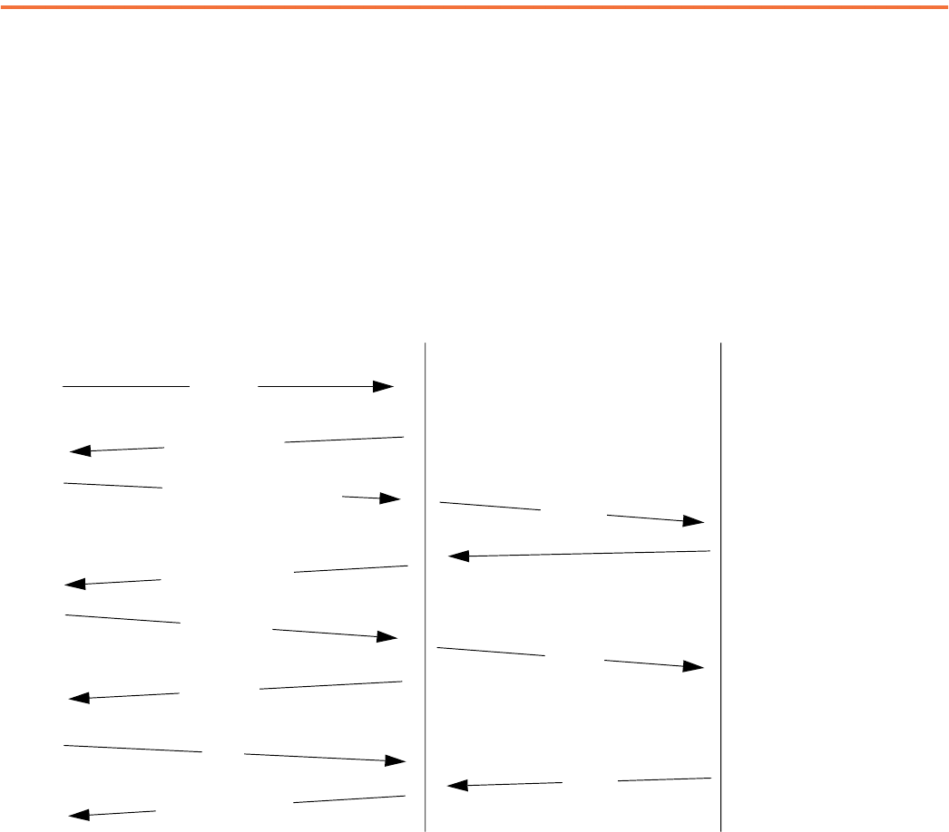
Typical Sequence of Transactions for a TCP Client
The following diagram shows a typical sequence of socket interface transactions with the Logix 5000 controller that acts as a TCP client.
Each transaction between the Logix 5000 controller and the EtherNet/IP module is a message (MSG) instruction.
In the following example, the Logix 5000 controller sends data to a device, and then the device sends a response. This sequence of
transactions is typical. Depending on the application protocol, the device can instead send data to the Logix 5000 controller once the
connection is open.
Also, each write transaction does not require an application response or acknowledgment. The application protocol determines the exact
sequence of application transactions.
Controller
EtherNet/IP Module
192.168.1.10
Device
192.168.1.11
Accept Connection
Receive Data
Send Data
Open TCP
Connection
Data = abc
Data = xyz
The response is returned to the controller as
soon as the data is sent.
Create
Socket
Create Socket Response
Instance = 102
OpenConnection
"192.168.1.11?Port=49200"
OpenConnection Response
Write Data = abc
Write Response
Read
Read Response Data = xyz
10 Rockwell Automation Publication ENET-AT002E-EN-P - January 2023
Chapter 1 Socket Interface Architecture
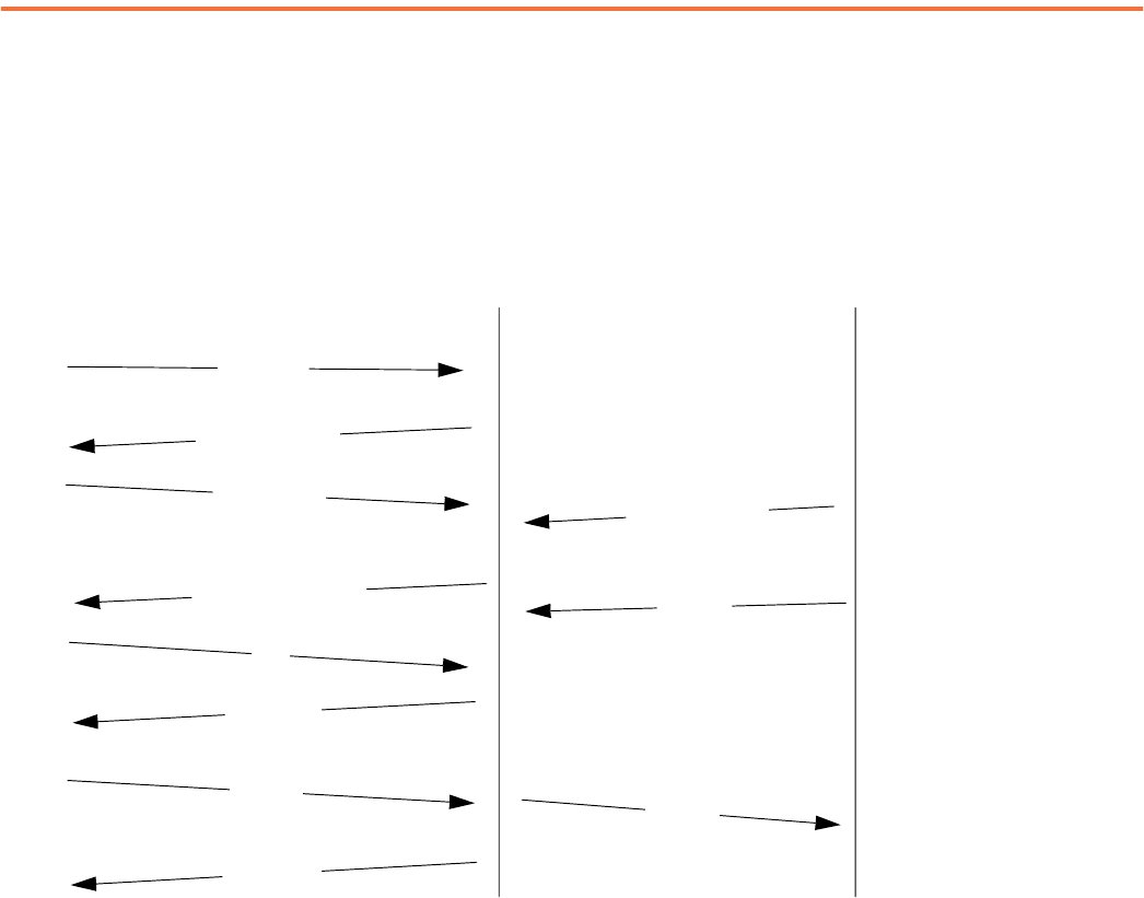
Typical Sequence of Transactions for a TCP Server
The following diagram shows a typical sequence of socket interface transactions with the Logix 5000 controller as a TCP server. Each
transaction between the Logix 5000 controller and EtherNet/IP module is an MSG instruction.
The following is a typical sequence of transactions. The exact sequence to send and receive data depends on the application protocol.
Controller
EtherNet/IP Module
192.168.1.10
Device
192.168.1.11
Open Connection
Send Data
Receive Data
Open TCP Connection
Port = 49100
Data = abc
Data = xyz
The response is returned to the
controller as soon as the data is sent.
Create Socket
Port = 49100
Create Socket Response
Instance = 102
AcceptConnection
Write
Data = xyz
Write Response
Read
Read Response
Data = abc
AcceptConnection Response

Rockwell Automation Publication ENET-AT002E-EN-P - January 2023 11
Chapter 1 Socket Interface Architecture
Typical Sequence of Transactions for UDP without OpenConnection
The following diagram shows a typical sequence of socket interface transactions for UDP communication without using the OpenConnection
service to specify the destination address. In this case, the Logix 5000 controller specifies the destination for each datagram and receives
the address from the sender along with each datagram it receives. Each transaction between the Logix 5000 controller and the EtherNet/IP
module is an MSG instruction.
This example shows the Logix 5000 controller sending data to a device, and then the device sending a response. This sequence of
transactions is atypical. Depending on the application protocol, the device could instead initiate sending data to the Logix 5000 controller.
Also, each Write transaction does not require an application response or acknowledgment. The application protocol determines the exact
sequence of application transactions.
Controller
EtherNet/IP Module
192.168.1.10
Device
192.168.1.11
Create Socket
Port=49100
Create Socket
Response Instance =
102
Write
192.168.1.11?Port=49200
Data = abc
Write Response
Read
Read Response
192.168.1.11?Port=49200
Data = xyz
Send Data to
192.168.1.10, Port 49100
Receive Data from Port 49200
Data = abc
Data = xyz
The response is returned to the controller as
soon as the data is sent.

12 Rockwell Automation Publication ENET-AT002E-EN-P - January 2023
Chapter 1 Socket Interface Architecture
Typical Sequence of Transactions for UDP with OpenConnection
The following diagram shows a typical sequence of socket interface transactions for UDP communication when using the OpenConnection
service to specify the destination address. Each transaction between the Logix 5000 controller and the EtherNet/IP module is an MSG
instruction.
The following is a typical sequence of transactions. The exact sequence of sending and receiving data depends on the application protocol.
Controller
EtherNet/IP Module
192.168.1.10
Device
192.168.1.11
Create
Socket
Port=49100
Create Socket Response
Instance = 102
Open Connection
192.168.1.11?Port=49200
Open Connection Response
Read
Read Response
192.168.1.11?Port=49200
Data = xyz
Write
Data = abc
Write Response
Data = abc
Data = xyz
The response is returned to the controller as
soon as the data is sent.
Send Data To
192.168.1.10, Port 49100
Receive Data from Port 49200

Rockwell Automation Publication ENET-AT002E-EN-P - January 2023 13
Chapter 1 Socket Interface Architecture
Secure Socket Object
The following devices support Transport Layer Security (TLS) for a secure socket object.
The TLS support has these considerations:
• TCP/TLS version 1.2 only; UDP/DTLS not supported
• Client only; server not supported
• Server authentication supported; client authentication not supported
• Secure socket object and CIP Security™ cannot be used at the same time
• Connections with multiple servers are not supported
• No Certificate Revocation List support
• No Subject Alternative Name support
• On multi-port devices (ControlLogix 5380 in dual IP mode), the same security is applied to both ports
TLS support is enabled by putting server certificates on the SD card. Certificates are loaded at startup only. The server certificates are
expected to be stored in the following files in PEM format:
• certs/ca.pem—A CA certificate signed by some trusted certificate authority
• certs/trustedcert.pem—A trusted peer certificate to be compared against the certificate sent during the TLS handshake
The following rules apply to the TLS protocol:
• If at least one certificate is present in the prescribed location and prescribed filename, TLS is applied to the socket object.
• If the SD card is not present, disabled, or neither of the certificates are present, then the socket object behaves as in previous
releases and no security is applied.
Once the encryption is enabled, it cannot be disabled without restarting the device.
Supported cipher suites include the following:
• TLS_ECDHE_RSA_WITH_AES_128_CBC_SHA256 (0xc027)
• TLS_ECDHE_RSA_WITH_AES_128_GCM_SHA256 (0xc02f)
• TLS_ECDHE_RSA_WITH_AES_256_GCM_SHA384 (0xc030)
• TLS_ECDHE_RSA_WITH_AES_256_CBC_SHA384 (0xc028)
• TLS_ECDHE_ECDSA_WITH_AES_128_CBC_SHA256 (0xc023)
• TLS_ECDHE_ECDSA_WITH_AES_128_GCM_SHA256 (0xc02b)
• TLS_ECDHE_ECDSA_WITH_AES_256_GCM_SHA384 (0xc02c)
• TLS_ECDHE_ECDSA_WITH_AES_256_CBC_SHA384 (0xc024)
IMPORTANT TLS for a secure socket object is not supported in ControlLogix redundancy or 1756-EN4TR redundant adapter mode.
Controllers and Communication Modules First Available in Firmware Revision
CompactLogix 5380 35.011 and later
Compact GuardLogix 5380 SIL 2 35.011 and later
Compact GuardLogix 5380 SIL 3 35.011 and later
CompactLogix 5380 Process 35.011 and later
ControlLogix 5580 35.011 and later
GuardLogix 5580 35.011 and later
ControlLogix 5580 Process 35.011 and later
1756-EN4TR, 1756-EN4TRK, 1756-EN4TRXT 5.001 and later

14 Rockwell Automation Publication ENET-AT002E-EN-P - January 2023
Chapter 1 Socket Interface Architecture
When encryption is enabled, the overall socket object performance is reduced. The impact depends on many factors, such as payload size,
number of sockets involved, and the cipher suite used.
Table 1
shows the maximum transfer rate when a socket object instance is running as a client connected to the HTTPS REST API server.
Simultaneously, the module handles multiple class 3 connections and data exchange with the server. The HTTP values apply to non-TLS
communications, while the HTTPS values apply with cipher suite TLS_ECDHE_RSA_WITH_AES_128_CBC_SHA256 applied.
For information on how to develop your application to access the HTTP REST API and implement HTTPS via the socket interface with TLS, see
documentation for these objects in the Common Application Libraries available in the Product Compatibility and Download Center at
rok.auto/pcdc
:
• raC_Impl_HTTPClient
• raC_Impl_HTTPCmdGET
• raC_Impl_HTTPCmdPOST
• raC_Impl_HTTPCmdPUT
Table 1 - Secure Socket Object Transfer Rates, Max
1756-EN4TR
ControlLogix 5580
CompactLogix 5380
Payload: 60 kB
Request: GET
HTTPS 140 kB/sec 270 kB/sec
HTTP 280 kB/sec 660 kB/sec
Payload: 60 kB
Request: PUT/POST
HTTPS 180 kB/sec 380 kB/sec
HTTP 290 kB/sec 800 kB/sec
Payload: 1 kB
Request: GET
HTTPS 12 kB/sec 20 kB/sec
HTTP 14 kB/sec 30 kB/sec
Payload: 1 kB
Request: PUT/POST
HTTPS 19 kB/sec 30 kB/sec
HTTP 21 kB/sec 50 kB/sec

Rockwell Automation Publication ENET-AT002E-EN-P - January 2023 15
Chapter 1 Socket Interface Architecture
Communicate with the Socket Object via an MSG Instruction
In the Logix Designer application, use a CIP™ Generic MSG instruction to request socket services.
On the Configuration tab for the MSG instruction, configure the parameters as described in Table 2
.
Table 2 - Configuration Tab
Field Description
Message Type Choose CIP Generic.
Service Type
Choose a socket service type. The software automatically completes the Service Code and Class fields.
Choose Get Attributes Single or Set Attributes Single when getting or setting a socket object attribute. For more information, see Socket
Attributes on page 35.
Service Code Enter the unique service code that corresponds to the socket service you chose in the Service Type field.
Class Enter 342 (hexadecimal) for the socket object.
Instance
Enter one of these values:
• 0 for Socket Create, Delete All Sockets, or ClearLog services
• Instance number that is returned by Socket Create for other services
Use a relay ladder instruction or Structured Text statement to move the returned instance number from a Socket Create service into the
Instance member of an MSG instruction.
Attribute Enter an attribute value only when getting or setting an attribute, but not when using other services.
Source Element
Choose the tag that contains the request parameters for the socket service. To define the request parameters, create a user-defined
data type for the tag.
Source Length Enter the length of the source element.
Destination Element
Choose the tag that contains the response data that the socket service returns. To define the response data, create a user-defined data
type for the tag.

16 Rockwell Automation Publication ENET-AT002E-EN-P - January 2023
Chapter 1 Socket Interface Architecture
On the Communication tab for the MSG instruction, configure the parameters that are described in Table 3.
The maximum amount of data you can send or receive depends on how you configure the MSG instruction, as shown in Table 4
. The size of
the data excludes the parameters in the ReadSocket and WriteSocket services.
If an MSG requests more than the maximum packet size (standard or large), the module can return a failure status and the MSG instruction
can set the .ER bit:
• For TCP sockets, if the application data is larger than the maximum size, you can issue multiple ReadSocket or WriteSocket services
to receive or send the entire application message.
• For UDP sockets, the size of application data cannot exceed the maximum sizes for the ReadSocket and WriteSocket services.
IMPORTANT If you use the front Ethernet port on a controller, you must use unconnected MSG instructions. For unconnected MSG
instructions, you must clear the Connected checkbox on the Communication tab.
Table 3 - Communication Tab
Field Description
Path
Enter the communication path to the EtherNet/IP module.
• For all communication modules, the path is 1, x. where x is the slot number of the communication module.
• For ControlLogix 5580 controllers, if the front Ethernet port is used, the path is 1, x where x is the slot number of the ControlLogix controller.
• For all supported CompactLogix controllers, the path is 1, 0.
When using the front Ethernet port on a controller with firmware revision 28.011 or later, you can also use a path of ‘THIS’.
Large Connection
To send large messages via an EtherNet/IP module on the backplane when using a ControlLogix 5560, 5570, or 5580 controller, you can check the
Large Connection checkbox. Large connections are only available with connected MSG instructions. For information about how to use the Connected
or Cache Connections options, refer to the Logix 5000 Controllers Messages Programming Manual, publication 1756-PM012
.
IMPORTANT: To use controller memory efficiently, use large connections only for ReadSocket or WriteSocket services that require more than the
standard connection size, as shown in Table 4
.
To avoid errors, be sure that you use unconnected MSG instructions by clearing the Connected checkbox in these scenarios:
• You are using the front Ethernet port on a ControlLogix 5580, CompactLogix 5380, or CompactLogix 5480 controller. Large connections are enabled
by default on these controllers.
• You are using a CompactLogix 5370 controller. Large connections are not supported on these controllers.
Table 4 - Maximum Packet Sizes
Service Unconnected Size Standard Connection Size Large Connection Size
ReadSocket 484 bytes 484 bytes 3984 bytes
WriteSocket 462 bytes 472 bytes 3972 bytes

Rockwell Automation Publication ENET-AT002E-EN-P - January 2023 17
Chapter 1 Socket Interface Architecture
Service Timeouts
You must specify a timeout parameter in milliseconds for any service that does not always complete immediately, such as OpenConnection,
AcceptConnection, ReadSocket, and WriteSocket services. The timeout tells the socket object the maximum amount of time to wait when
attempting to complete the service. While waiting for the service to complete, the MSG instruction is enabled.
If the requested service does not complete before the timeout period expires, the socket object returns a response to the service request.
See the service descriptions in Chapter 2
for the content of the response.
MSG Instruction Timeouts
The default MSG instruction timeout is 30 seconds. The maximum MSG timeout is approximately 35 minutes. Specify the MSG instruction
timeout by setting the appropriate member of the MSG tag:
• If the MSG is unconnected, set the UnconnectedTimeout member.
• If the MSG is connected, set the ConnectionRate and TimeoutMultiplier member.
The MSG timeout is determined by multiplying the ConnectionRate by the TimeoutMultiplier. A TimeoutMultiplier of 0 corresponds to
multiplier of 4, 1 corresponds to multiplier of 8, and so on.
Socket Instance Timeouts
Each socket instance has an inactivity timeout with a default of 5 minutes. If a socket instance receives no service requests for the amount
of time that is specified by the inactivity timeout, the socket instance is deleted. If you then try to use the socket instance, the MSG
instruction receives the error class or instance not supported.
You can change the timeout by setting the inactivity timeout attribute via the Set Attribute service. See Socket Instance Attributes on
page 47.
If you put the controller in Program mode and then back into Run mode before existing socket instances time out, you can receive errors
when the program tries to create socket instances. Eventually the socket instances time out and you can create more instances.
Disable the Socket Object with an MSG Instruction
The socket object is enabled by default. You can use a CIP Generic MSG instruction to disable the socket object.
After you disable the socket object:
• All object-specific services and all instance attributes are unavailable for writing and reading. The Object Enable attribute is read-
only.
• The TCP/IP socket object is disabled, and a factory reset can enable it again.
IMPORTANT Make the value of the service timeout parameter is shorter than the MSG instruction timeout. Otherwise, application
data could be lost.
IMPORTANT Make sure that the inactivity timeout is longer than the longest interval between socket operations. If the inactivity
timeout is too short, socket instances can time out and result in MSG instruction errors.
IMPORTANT The MSG instruction must be sent to the EtherNet/IP module via backplane.

18 Rockwell Automation Publication ENET-AT002E-EN-P - January 2023
Chapter 1 Socket Interface Architecture
On the Configuration tab, configure the parameters as described in Table 2.
On the Communication tab, configure the parameters that are described in Table 3
.
Table 5 - Configuration Tab
Field Description
Message Type Choose CIP Generic.
Service Type Choose Set Attributes Single.
Service Code 10 (hex)
Class 342 (hex)
Instance 0
Attribute 9 (hex)
Source Element Choose the SINT tag that contains the value of zero.
Source Length 1
Destination Element Not required.
IMPORTANT If you are using the front Ethernet port on a controller, you must use unconnected MSG instructions.

Rockwell Automation Publication ENET-AT002E-EN-P - January 2023 19
Chapter 1 Socket Interface Architecture
Programming Considerations
Observe these programming considerations.
TCP Connection Loss
Your application program can encounter conditions that result in TCP connection loss. For example, a network cable can be unplugged, or a
target device can be turned off.
Your application program detects the loss of TCP connections and handles those events appropriately. You can detect connection loss when
one of the following occurs:
• The ReadSocket service returns with an error.
• The WriteSocket service returns an extended error code other than 16#0000_0046. See Error Codes for Socket Services on page 51
.
Depending on the application, try these actions:
• Try to re-establish the connection if there is a client connection.
• Wait for another incoming connection to be established if there is a server connection.
If you want to re-establish communication with the other device, complete these actions:
• Delete the socket instance for the lost connection.
• If the connection is a client connection, create a socket instance and issue an OpenConnection service to the target device.
• If the connection is a server connection, issue an AcceptConnection service to wait for another connection from the remote device.
Table 6 - Communication Tab
Field Description
Path
Enter the communication path to the EtherNet/IP module. The module must be accessed via the backplane; you cannot access the module via the
Ethernet port.
• For all controllers and communication modules, the path is 1, x. Where x is the slot number of the communication module, or the slot number of a
ControlLogix 5580 controller if the front Ethernet port is used.
• For all supported CompactLogix controllers, the slot is 0.
• For all CompactLogix 5370, CompactLogix 5380, Compact GuardLogix 5380, CompactLogix 5480, ControlLogix 5580, and GuardLogix 5580
controllers with version 28.11 or later, you can also use a path of ‘THIS’.
IMPORTANT User code must manage messages so that only one message to a socket instance is active at a time. For example, the
read and write socket instructions for a given socket should be interlocked so that only one executes at a time. This is
on a per socket basis.

20 Rockwell Automation Publication ENET-AT002E-EN-P - January 2023
Chapter 1 Socket Interface Architecture
ControlLogix Redundancy
If your application uses sockets in an enhanced redundancy system, your application program must manage switchovers in these ways:
• After a switchover, socket instances in the EtherNet/IP module in the old primary chassis must be recreated in the EtherNet/IP
module in the new primary chassis via controller logic.
• Sockets that are connected outside of the enhanced redundancy system must recognize that communication is lost with socket
instances in the EtherNet/IP module in the old primary chassis after a switchover. A change in IP address of the EtherNet/IP module
after a switchover causes loss of communication. See TCP Connection Loss on page 19
.
• Although socket instances in the EtherNet/IP module in the old primary chassis are automatically deleted once their inactivity timeout
expires, it is possible that a second switchover can occur before the timeout expires. To be sure that these non-functioning socket
instances are deleted before a second switchover, your application program can issue a message to delete all sockets if there is a
switchover before creating functioning socket instances.
To learn more about redundancy systems, refer to the ControlLogix 5570 Redundancy User Manual, publication 1756-UM535
.
EtherNet/IP Module Reset
If the EtherNet/IP module is reset, for example by cycling power or with removal and insertion under power (RIUP), all socket instances are
lost.
If you create socket instances while MSG instructions are still using the old instance numbers, the new instance numbers can match the old
instance numbers. In this situation, your old MSG instructions can succeed but could not be communicating with the correct remote device.
Handle this situation by monitoring the status of the EtherNet/IP module via a GSV instruction. If you lose communication with the EtherNet/
IP module, the Logix 5000 program reinitializes its socket communication.
Change Controller Mode between Run and Program
If the Logix 5000 controller transitions from Run mode to Program mode while socket requests are active, the transition does not complete
until all outstanding MSG requests complete or time out. If you have long timeout values, you can experience an unexpectedly long time for
the Run-to-Program transition to complete.
Alleviate long transition times by appropriately setting the timeout parameter for the socket services. In the Logix 5000 program, you can
also set the .TO bit for any outstanding socket-related MSG instruction. This causes the MSG instruction to time out and set the .ER bit.
If the controller transitions from Run mode to Program mode, then back to Run mode again, previous socket instances can still exist on the
EtherNet/IP module. The previous socket instances time out eventually. Depending on the number of sockets you need, your program can
encounter errors during Run-Program-Run transitions because all available socket instances are in use.
To alleviate this situation, follow this procedure:
1. Wait for all socket instances to time out before putting the controller in Run mode.
2. When the Logix 5000 program starts, use the DeleteAllSockets service to delete any previous instances.
The DeleteAllSockets service deletes all socket instances, not just those instances that the controller that calls the service creates.
Application Messages and TCP
A TCP connection is a byte stream between two application entities. The application protocol determines the message formats. Messages
can be fixed size or variable size.
If an application sends variable size messages, a common strategy is to first send a fixed-size header that contains the size of the message
followed by the message. The receiving device can first issue a ReadSocket service of the fixed size header to determine the remaining size,
and then issue a subsequent ReadSocket service to receive the remaining data.
IMPORTANT Socket instances that are created in EtherNet/IP modules are not crossloaded in a redundancy system.

Rockwell Automation Publication ENET-AT002E-EN-P - January 2023 21
Chapter 1 Socket Interface Architecture
Application Messages and Inhibited Modules
Unlike I/O connected via an EtherNet/IP module, communication via messaging to socket instances can continue when a module is inhibited.
If you want to stop socket communication when a module is inhibited, your application code must detect the status of the module and take
the appropriate action.
Partial Reads
It is possible for a read service to return a BufLen that is less than the requested amount of data. For example, your program can request 100
bytes of data. Because TCP is a byte stream and not a datagram protocol, you can receive less than 100 bytes when the read service returns.
Depending on the application protocol, issue additional read requests to receive all data. If the application protocol dictates that all
messages are 100 bytes, then you must issue additional read requests until you receive 100 bytes. If the application protocol uses variable
size messages, your program needs additional logic to handle variable message sizes as defined by the application protocol.
When issuing multiple read requests, be careful to adjust the destination tag that receives the data so that data is not overwritten.
If the read request times out before any data is received, a BufLen of 0 is returned with success (0) status.
This fragment of Structured Text logic shows an example of handling a partial read request.
Partial Writes
Although uncommon, sometimes a write service is unable to send all specified bytes if the write service is called multiple times before the
target application can receive the data.
If the write service is not able to send the requested data, your program issues subsequent writes to send the remaining data. Your program
also adjusts the source tag, so that old data is not sent.
If the number of bytes written is less than requested, an extended error is returned, and the actual length of the data sent.
This fragment of Structured Text logic shows an example of handling a partial write service.
/* copy the message we just read */
COP (ReadResponse.Buf[0], ReadBuf[CurrentLen],
ReadResponse.BufLen);
CurrentLen := CurrentLen + ReadResponse.BufLen;
/* do we need to read more data get a complete message? */
if (CurrentLen < ApplicationMsgLen) then
/* issue another read */
ReadParams.BufLen := ApplicationMsgLen - CurrentLen;
MSG (ReadMSG0);
end_if;

22 Rockwell Automation Publication ENET-AT002E-EN-P - January 2023
Chapter 1 Socket Interface Architecture
Performance Considerations
The socket interface enables a Logix 5000 controller to communicate via an EtherNet/IP module with Ethernet devices that do not support
the EtherNet/IP application protocol, such as barcode scanners, RFID readers, or other standard Ethernet devices. The socket interface, via
messaging, is not well suited for real-time control as communication with this method is not scheduled or deterministic.
There are various factors that can affect the performance of the socket interface. For examples of some of the factors to consider, see the
Knowledgebase Article 1756-EWEB Performance
.
if (WriteMSG0.ER) then
/* write failed. if the extended error code was 16#0000_0046,
then it means less than the requested byte were sent. */
if (WriteMSG0.EXERR = 70) then
/* need to issue another write, with the data that was not
sent */
SentLen := WriteResponse; /* here's what was sent */
/* adjust the size */
WriteParams.BufLen := WriteParams.BufLen - SentLen;
/* copy remaining data to send to MSG buffer */
COP (WriteBuf[SentLen], WriteParams.Buf[0],
WriteParams.BufLen);
/* BufLen = Timeout + Sockaddr + data length */
WriteMSG0.REQ_LEN := 4 + 12 + WriteParams.BufLen;
MSG (WriteMSG0);
end_if;
end_if;

Rockwell Automation Publication ENET-AT002E-EN-P - January 2023 23
Chapter 2
Socket Object Services
For a socket object, application data has no inherent byte order. The service receives data in the same byte order as it is sent. However,
Logix 5000® controllers store data in CIP™ byte order (little-endian). For example, if you issue a write service with one DINT, that DINT is sent
over a TCP connection or in a UDP datagram in CIP byte order. If you issue a read service and your destination tag for the response contains
a DINT, the Logix 5000 controller assumes that the incoming data is in CIP byte order. Depending on the byte order of the application that you
are communicating with, you may need to convert the byte order in your Logix 5000 program or in the application.
To check your MSG configuration in the Studio 5000 Logix Designer® application, choose a service type from the Service Type pull-down
menu on the Configuration tab of the Message Configuration dialog box. The software completes the Service Code and Class fields.
With RSLogix 5000® software, version 15 and earlier, choose Custom from the Service Type pull-down menu and manually complete the
Service Code and Class fields.
Socket Create
The Socket Create service creates an instance of the socket object. The service returns an instance number that you use in the subsequent
socket operations. Call the Socket Create service with instance 0 (Socket object class).
MSG Source Element
Choose a tag with a user-defined data type. Use the information in Table 7 to define the data type.
Parameter Value
Service Type Socket Create
Service Code 4b
Class 342
Instance 0
Attribute 0

24 Rockwell Automation Publication ENET-AT002E-EN-P - January 2023
Chapter 2 Socket Object Services
MSG Source Length
Specify the size of the user-defined structure for the source element. In this example, CreateParams is 12 bytes.
MSG Destination Element
The MSG instruction returns the instance number of the socket that it created to the destination element. Specify a DINT tag.
Considerations
Use the instance that the Socket Create service returns on subsequent service requests.
Use a MOV instruction to move the instance to another MSG tag (the .Instance field).
If you use a local port number that is already in use by the EtherNet/IP™ module, you receive extended error code 16#0000_0030. Avoid using
commonly used ports.
When a CompactLogix 5380, Compact GuardLogix 5380, and CompactLogix 5480 controller operate in Dual-IP mode, the default IP address
for use with a Socket_Create service type is 0.0.0.0.
• If you use 0.0.0.0, IP communication that the Socket Object instance initiates follows the same routing rules as DNS request routing
rules described in these publications:
- CompactLogix 5380 and Compact GuardLogix 5380 Controllers User Manual, publication 5069-UM001
.
- CompactLogix 5480 Controllers User Manual, publication 5069-UM002
.
• If you use the IP address of port A1 instead of 0.0.0.0, IP packets can only go to the port A1 subnet or via its default gateway.
• If you use the IP address of port A2 instead of 0.0.0.0, IP packets can go only to port A2 subnet or via its default gateway.
• If you use the IP address of port B1 instead of 0.0.0.0, IP packets can only go to the port B1subnet or via its default gateway.
• If you use an IP address other than the port A1 or A2 IP addresses or 0.0.0.0, the Create_Socket_Service request is rejected.
Table 7 - Data Type for Socket Create Source Element
Member Name Data Type Description
Type DINT
Specify one of these values:
• 1 for TCP
• 2 for UDP
Addr structure A user-defined structure that specifies the address for the socket.
Family INT Specify the address family. Must be 2.
Port INT
Specify the local port number on which an application listens and receives. If you want a port that is randomly assigned,
use port 0.
Addr DINT
Specify an IP address. Typically, set to 0 (any address) for a CompactLogix™ 5370, CompactLogix 5380, Compact
GuardLogix® 5380, CompactLogix 5480, ControlLogix® 5580, GuardLogix 5580 controller in Linear/DLR mode.
For CompactLogix 5380, Compact GuardLogix 5380, and CompactLogix 5480 controllers in Dual-IP mode, the IP address
must be set in HEX format with 1 byte per octet. See Knowledgebase Article 5380 Ethernet Socket Errors and Path
Information.

Rockwell Automation Publication ENET-AT002E-EN-P - January 2023 25
Chapter 2 Socket Object Services
OpenConnection
The OpenConnection service does one of the following:
• Opens a TCP connection with the specified destination address
• For UDP, associates a destination IP address and port number with the specified socket
MSG Source Element
Choose a tag with a user-defined data type. Use the information in Table 8 to define the data type.
.
.
The MSG instruction that issues the OpenConnection service has a source length of 8 (Timeout + AddrLen) plus the number of characters in
the destination address.
MSG Source Length
Specify 8 bytes (Timeout + AddrLen) + number of characters in the destination address.
MSG Destination Element
Not used. The MSG instruction does not return any data.
Table 8 - Data Type for OpenConnection Source Element
Member Name Data Type Description
Timeout DINT Specify the timeout in milliseconds.
DestAddr STRING
Specify an array of characters (maximum of 64) to define the destination of the connection. You can specify either
Hostname or IP address.
• Hostname?port=xxxzaz
• IPAddr?port=xxx
For example, to specify an IP address, enter 10.88.81.10?port=2813
.LEN DINT The length of the destination address.
.DATA SINT array The array that contains the destination address.
Parameter Value
Service Type OpenConnection
Service Code 4c
Class 342
Instance from Socket Create
Attribute 0

26 Rockwell Automation Publication ENET-AT002E-EN-P - January 2023
Chapter 2 Socket Object Services
Considerations
In some cases, the OpenConnection service can return before the timeout period without creating a TCP connection. For example, if the
destination device is running, but is not listening for connections on the specified port number, the OpenConnection service returns with an
error before the timeout period.
For UDP, the information you must specify depends on whether you use the OpenConnection service:
• If you use the OpenConnection service, you do not have to specify the IP address and port number each time you send data. If you do
not specify an IP address and port number, you can receive data only from the previously specified IP address and port number until
you call the OpenConnection service to specify another IP address and port number.
• If you do not use the OpenConnection service, you must specify the destination address each time you call the WriteSocket service to
send data. When you call the ReadSocket service, you receive the data and the address of the sender. You can then use the address of
the sender to send a response via the WriteSocket service.
If you call the OpenConnection service on a UDP socket with an AddrLen of 0, this removes the association with the destination address.
AcceptConnection
The AcceptConnection service accepts a TCP connection request from a remote destination. Before calling the AcceptConnection service,
call the Socket Create service and specify the local port number that accepts the connection. When the AcceptConnection service
completes, it returns a socket instance that you use to send and receive data on the newly created connection.
The AcceptConnection service is not valid for UDP sockets.
MSG Source Element
Choose a DINT tag to contain the timeout in milliseconds.
MSG Source Length
Specify 4 bytes (Timeout).
Parameter Value
Service Type AcceptConnection
Service Code 50
Class 342
Instance from Socket Create
Attribute 0

Rockwell Automation Publication ENET-AT002E-EN-P - January 2023 27
Chapter 2 Socket Object Services
MSG Destination Element
Choose a tag with a user-defined data type. Use the information in Table 9 to define the data type.
Considerations
Create a separate socket instance with the Socket Create service for each port number that accepts connections. After you create socket
instances, call the AcceptConnection service to wait for an incoming connection request. You can accept connections on the same port
number. Each call to the AcceptConnection service returns another instance number to use to read and write data.
ReadSocket
The ReadSocket service reads data on a socket. You specify the number of bytes to receive. The service returns the number of bytes
received.
For TCP, the ReadSocket service returns when any data is received, up to the requested number of bytes. If no data is received before the
timeout period, the service returns a status of success by setting a message instruction Done Bit (.DN) and a BufLen of 0. The service can
return fewer bytes than were requested. Your application can require multiple read requests to receive an entire application message.
For UDP, the ReadSocket service completes when a datagram is available.
Table 9 - Data Type for AcceptConnection Destination Element
Member Name Data Type Description
Instance DINT
Contains the instance for this service. Use this Instance on subsequent Read and Write services for this
connection.
IMPORTANT: Copy this Instance number to Read and Write Messages
Addr structure A user-defined structure that contains the address for the socket.
Family INT Contains the address family. Must be 2.
Port INT Contains a remote port number.
Addr DINT Contains a remote IP address.
Parameter Value
Service Type ReadSocket
Service Code 4d
Class 342
Instance See Instance
Attribute 0

28 Rockwell Automation Publication ENET-AT002E-EN-P - January 2023
Chapter 2 Socket Object Services
Instance
This service uses the instance that is returned from the CreateConnection service. However, when accepting a connection via the
AcceptConnection service, use the instance that is returned from this AcceptConnection service as the ReadSocket instance.
MSG Source Element
Choose a tag with a user-defined data type. Use the information in Table 10 to define the data type.
MSG Source Length
Specify 8 bytes (Timeout + BufLen).
MSG Destination Element
Choose a tag with a user-defined data type. Use the information in Table 11 to define the data type.
Table 10 - Data Type for ReadSocket Source Element
Member Name Data Type Description
Timeout DINT Specify the timeout in milliseconds.
BufLen DINT Specify the number of bytes of data to receive.
Table 11 - Data Type for ReadSocket Destination Element
Member Name Data Type Description
FromAddr structure
A user-defined structure that can contain the address of the device that sends UDP data. This structure is populated
from the end device.
For TCP or UDP with OpenConnection, this structure is not used and contains all zeros. The TCP connection conveys all
remote address information.
Family INT Contains the address family for UDP. Must be 2.
Port INT
Contains the remote port number for UDP. The remote device uses this port for sending.
0 is an invalid port number for UDP.

Rockwell Automation Publication ENET-AT002E-EN-P - January 2023 29
Chapter 2 Socket Object Services
WriteSocket
The WriteSocket service sends data on a socket. You specify the number of bytes to send. The service attempts to send the requested
number of bytes and returns the number of bytes sent.
Instance
This service uses the instance that is returned from the CreateConnection service. However, when accepting a connection via the
AcceptConnection service, use the instance that is returned from this AcceptConnection service as the WriteSocket instance.
MSG Source Element
Choose a tag with a user-defined data type. Use the information in Table 12 on page 30 to define the data type.
Addr DINT Contains the remote IP address for UDP
BufLen DINT Contains the number of bytes of data received.
Buf SINT array
Contains the data.
This number must be large enough to contain the maximum amount of data expected. For a standard connection, the
maximum is SINT[484]. For a large connection, the maximum is SINT [3984].
Table 11 - Data Type for ReadSocket Destination Element
Member Name Data Type Description
Parameter Value
Service Type WriteSocket
Service Code 4e
Class 342
Instance See Instance
Attribute 0

30 Rockwell Automation Publication ENET-AT002E-EN-P - January 2023
Chapter 2 Socket Object Services
MSG Source Length
Specify 16 bytes (Timeout + Addr + BufLen) + number of bytes to write.
MSG Destination Element
The MSG instruction returns the number of bytes that were written. Choose a DINT tag.
DeleteSocket
The DeleteSocket service deletes a socket instance. For a TCP connection, the DeleteSocket service also closes the connection before it
deletes the instance.
MSG Source Element
Not used.
MSG Source Length
Specify 0 bytes.
MSG Destination Element
Not used.
Table 12 - Data Type for WriteSocket Source Element
Member Name Data Type Description
Timeout DINT Specify the timeout in milliseconds.
ToAddr structure
A user-defined structure that contains the address to which to write UDP data.
For TCP or UDP with OpenConnection, this structure is not used and contains all zeros. The TCP connection conveys all
required remote address information.
Family INT Specify the address family. Must be 2 for UDP.
Port INT
Specify the remote port number for UDP. This is the port that the remote device uses for receiving.
0 is an invalid port number for UDP.
Addr DINT
Specify the remote IP address for UDP.
0.0.0.0 is an invalid IP address for UDP.
BufLen DINT Specify the number of bytes of data to write.
Buf SINT array
Contains the data.
This number must be large enough to contain the maximum amount of data expected. For a standard connection, the
maximum is SINT[472]. For a large connection, the maximum is SINT [3972].
Parameter Value
Service Type DeleteSocket
Service Code 4f
Class 342
Instance from Socket Create
Attribute 0

Rockwell Automation Publication ENET-AT002E-EN-P - January 2023 31
Chapter 2 Socket Object Services
Considerations
Delete a socket instance if it is no longer needed. If unused instances are not deleted and you continue to create additional instances, you
can exceed the maximum number of instances.
DeleteAllSockets
The DeleteAllSockets service deletes all currently created socket instances. For TCP, the DeleteAllSockets service also closes all connections
before it deletes the instances.
Choose Custom for the service type. DeleteAllSockets is not an available option from the Service Type pull-down menu.
MSG Source Element
Not used.
MSG Source Length
Specify 0 bytes.
MSG Destination Element
Not used.
Considerations
Call the DeleteAllSockets service with instance 0.
Use the DeleteAllSockets service as the first operation when the program first begins to operate.
IMPORTANT Be careful with the DeleteAllSockets service when there are multiple controllers that use the socket interface of the
EtherNet/IP module. The service deletes all socket instances that are created by all controllers, not just the controller
that calls the service.
Parameter Value
Service Type Custom
Service Code 51
Class 342
Instance 0
Attribute 0

32 Rockwell Automation Publication ENET-AT002E-EN-P - January 2023
Chapter 2 Socket Object Services
ClearLog
The ClearLog service clears the debug log on the TCP/IP Socket Object webpage. This service does not change the logging options.
Choose Custom for the service type. ClearLog is not an available option from the Service Type pull-down menu.
MSG Source Element
Not used.
MSG Source Length
Specify 0 bytes.
MSG Destination Element
Not used.
JoinMulticastAddress
Joining a multicast group lets a socket receive multicast data. When a join is executed, it sends an IGMP membership packet and enables the
hardware filters to receive the multicast data. A specific address can be joined only once. Subsequent joins receive an error message until
the multicast address is dropped. Multicast joins are system wide. Two sockets cannot join the same multicast address simultaneously.
When the socket that the join was executed on is deleted, the multicast address is dropped. Each socket can join one or more multicast
groups.
Choose Custom for the service type. JoinMulticastAddress is not an available option from the Service Type pull-down menu.
IMPORTANT The TCP/IP Socket Object webpage is not visible on ControlLogix 5580, GuardLogix 5580, CompactLogix 5380,
Compact GuardLogix 5380, and CompactLogix 5480 controllers.
Parameter Value
Service Type Custom
Service Code 52
Class 342
Instance 0
Attribute 0
Parameter Value
Service Type Custom
Service Code 53
Class 342
Instance from Socket Create
Attribute 0

Rockwell Automation Publication ENET-AT002E-EN-P - January 2023 33
Chapter 2 Socket Object Services
MSG Source Element
Choose a tag with a user-defined data type. Use the information in Table 13 to define the data type.
Populate the Join_Source_Data.Addr field with a multicast IP address in hexadecimal format. The value must be a hexadecimal
representation of the IP address. For example, for address 239.1.2.100, enter 16#EF010264.
MSG Source Length
Specify 8 bytes.
MSG Destination Element
Not used.
DropMulticastAddress
Dropping a multicast address disables a socket from receiving multicast data. When a drop is executed, it sends an IGMP leave group packet
and disables the hardware filters from receiving the multicast data.
Choose Custom for the service type. DropMulticastAddress is not an available option from the Service Type pull-down menu.
Table 13 - Data Type for JoinMulticastAddress Source Element
Member Name Data Type Description
SocketsAddr structure A user-defined structure that specifies the multicast address to join.
Family INT Specify the address family. Must be 2.
Port INT Not used. The port is determined when the socket is created.
Addr DINT Specify the multicast IP address to receive from.
Parameter Value
Service Type Custom
Service Code 54
Class 342
Instance from Socket Create
Attribute 0

34 Rockwell Automation Publication ENET-AT002E-EN-P - January 2023
Chapter 2 Socket Object Services
MSG Source Element
Choose a tag with a user-defined data type. Use the information in Table 14 on page 34 to define the data type.
MSG Source Length
Specify 8 bytes.
MSG Destination Element
Not used.
Table 14 - Data Type for DropMulticast Address Source Element
Member Name Data Type Description
SocketsAddr structure A user-defined structure that specifies the multicast address to drop.
Family INT Specify the address family. Must be 2.
Port INT Not used. The port is determined when the socket is created.
Addr DINT Specify the multicast IP address to drop.

Rockwell Automation Publication ENET-AT002E-EN-P - January 2023 35
Chapter 3
Socket Attributes
You access socket attributes by configuring a CIP™ Generic MSG instruction to get or set the specific attribute:
• To change an attribute value for a socket, choose Set Attribute Single from the Service Type pull-down menu.
• To get a socket value, choose Get Attribute Single from the Service Type pull-down menu.
Some socket attributes apply to all sockets, and some apply to specific socket instances:
• For information about all sockets, type 0 in the Instance field. See Socket Class Attributes
.
• For information about a specific socket instance, type the specific socket instance number in the Instance field. A Socket Create or
AcceptConnection service returns the instance number. See Socket Instance Attributes on page 36
.
Socket Class Attributes
Class attributes apply to the socket object, not to specific socket instances. When you get or set a Class attribute, set the instance to 0.
Table 15 - Socket Class Attributes
Class Attribute Name Data Type Access Description
1 Revision INT Get Object revision.
2 Max Instance INT Get Largest socket instance number currently created.
3 Number of Instances INT Get Number of socket instances currently created.
8
Log Enable
(1)
(1) The Socket Object webpage is not visible on ControlLogix® 5580, GuardLogix® 5580, CompactLogix™ 5380, Compact GuardLogix 5380, and CompactLogix 5480 controllers.
DINT
Get
Set
Enable (1) or disable (0) logging to the Socket Object Log webpage.
Each socket service has a corresponding bit:
• If enabled, requests for that service request are logged.
• If disabled, then requests for that service are not logged.
Bit 0: Socket Create requests
Bit 1: OpenConnection requests
Bit 2: AcceptConnection requests
Bit 3: Read requests
Bit 4: Write requests
Bit 5: DeleteSocket and DeleteAllSockets requests
Bit 6: Get / Set Attribute requests
Bit 7: Log all service errors
9 Object Enable SINT
Get
Set
Enable (1) or disable (0) the Socket Object. Default is enabled.

36 Rockwell Automation Publication ENET-AT002E-EN-P - January 2023
Chapter 3 Socket Attributes
If you use the Get Attributes All service to get class attributes, the response contains all class attributes in Table 15 in the order shown with a
total size of 10 bytes.
If you use the Set Attributes All service to set class attributes, the request contains only the Log Enable class attribute.
Socket Instance Attributes
The socket object provides a number of instance attributes that apply to specific socket instances. To get or set an instance attribute,
specify a valid instance number.
If you use the Get Attributes All service to get instance attributes, the response contains all attributes in Table 16
in the order that is shown
with a total size of 36 bytes.
If you use the Set Attributes All service, the request must include attributes 3, 4, 5, 6 and 7 in that order with a total size of 20 bytes.
Table 16 - Socket Instance Attributes
Instance
Attribute
Name Data Type Access Description
1 (16#01) LocalAddr Struct SockAddr Get Local address for the socket.
2 (16#02) RemoteAddr Struct SockAddr Get Remote address for the socket.
3 (16#03) SendBufSize DINT
Get
Set
Size of the socket send buffer (bytes).
4 (16#04) RecvBufSize DINT
Get
Set
Size of the socket receive buffer (bytes).
5 (16#05) TCPKeepAlive DINT
Get
Set
Enable (1) or disable (0) TCP Keep Alive for the socket.
Enabled by default.
6 (16#06) TCPNoDelay DINT
Get
Set
Enable (1) or disable (0) the TCP No Delay behavior.
Enabled by default.
7 (16#07) InactivityTimeout DINT
Get
Set
Time for the inactivity timeout (default of 5 minutes). If a socket instance
receives no service requests for the amount of time that is specified by the
inactivity timeout, the socket instance is deleted. If you then try to use the
socket instance, the MSG instruction receives the error Class or instance not
supported.
8 (16#08) MulticastTTL DINT
Get
Set
Set the TTL value for UDP multicast, transmitted packets.
9 (16#09) UDPBroadcast DINT
Get
Set
Enable (1) or disable (0) the ability to transmit broadcast packets on UDP.
Disabled by default.
10 (16#0A) LingerOnOff DINT
Get
Set
Specifies whether the socket performs an orderly close (1) or an immediate
close (0).
Defaults to no linger (immediate close). For TCP sockets, setting linger to 0
results in a TCP RST packet to close the connection. If you set linger to
nonzero, then it results in the standard TCP connection close sequence (3-way
FIN, FIN-ACK, ACK handshake followed by TIME_WAIT).

Rockwell Automation Publication ENET-AT002E-EN-P - January 2023 37
Chapter 4
Troubleshoot Socket Applications
To help you troubleshoot socket applications, this chapter describes the following resources:
• Diagnostic webpages
• Debugging tips
• Error codes
• Knowledgebase articles
Diagnostic Webpages
To help debug and troubleshoot applications, the socket interface provides a set of webpages:
• For communication modules and controllers, go to Diagnostics > Advanced Diagnostics > Miscellaneous > System Data > Socket
Object.
• For web server modules, go to Diagnostics > Advanced Diagnostics.
IMPORTANT The Socket Object webpage is not visible on ControlLogix® 5580, GuardLogix® 5580, CompactLogix™ 5380, Compact
GuardLogix 5380, and CompactLogix 5480 controllers.
Webpage Description
Socket Object Diagnostics
Displays information about each instance:
• Instance number
• Socket type—client, server, or listen
• Local and remote ports and IP addresses
• Send and receive buffer sizes
• Socket up time and inactivity time
• Socket state and last error state
Socket Object Attributes Displays attribute settings for each instance
Socket Object Logs
Displays a log of service requests with a maximum of 100 log entries:
• Service requests made to the socket object
• Parameters that are passed for each service request
• Whether the service request was a success or failure
You can enable or disable logging for some services by using the Log Enable class attribute. See Socket Class Attributes on
page 35.

38 Rockwell Automation Publication ENET-AT002E-EN-P - January 2023
Chapter 4 Troubleshoot Socket Applications
Debugging Tips
This table describes tips for debugging problems by category.
Error Codes for Socket Services
If a socket object encounters an error with a service request, the following occurs:
• Socket object returns an error code.
• MSG instruction sets the .ER bit.
• MSG instruction sets error codes in the Error (.ERR) and Extended Error (.EXTERR) fields.
This table describes common error codes. For more a comprehensive list of error codes, see the Knowledgebase article Logic Sockets
Services Error Codes.
Category Consideration
EtherNet/IP™ module
Make sure the EtherNet/IP module has a valid IP address. Also, if you communicate with devices on different subnets,
configure the EtherNet/IP module with a valid subnet mask and gateway address.
Socket Create service
Make sure that the Destination tag is a DINT tag.
After creating the socket with the Socket Create service, make sure that you use the instance number that the service returns
in the subsequent socket services you call.
MSG instruction
Make sure that the Source Element is of a type that matches the request parameters for the requested service. Also make sure
that the Source Length is the correct length for the service parameters.
There is a limit to the number of active MSG instructions in a Logix 5000® controller. If an MSG instruction is enabled and
exceeds the maximum number of active MSG instructions, the MSG instruction receives an error (.ER bit set).
OpenConnection service
Make sure that the Source Length includes the size of the Timeout parameter + Address Length parameter + the Length of the
address itself.
Service Timeout parameter
Make sure that the Timeout parameter is sufficient for the service. Also make sure that the Timeout parameter is less than the
MSG instruction timeout.
If the timeout is set to 0, the service returns immediately.
TCP protocol
A TCP connection is a byte stream with no inherent message boundaries. The application defines how to interpret message
boundaries. For example, the application can use a fixed length for all messages. For a variable-length message, the
application can use a fixed-length header that contains the length of the remainder of the message.
Both ends of the TCP connection must agree on the application protocol that is used.
"our program should handle the loss of TCP connections in case they get dropped due to network issues or other reasons.
Ethernet sniffer
An Ethernet sniffer is useful to monitor the messages between the EtherNet/IP module and other devices. You can capture
network traffic and create filters to isolate messages between particular devices and particular messages between those
devices.
Table 17 - Common Error Codes
Error Code Extended Error Code Description
16#0001 16#0000_0117
An invalid path was programmatically entered in the MSG.Path string via COP or another string manipulation command.
For more information, see the Knowledgebase article, Sockets Error code 16#0001 Extended Code 16#0000_0117
.
16#0001
16#0000_0318
or
16#0000_0103
When configuring a CIP Generic MSG instruction for Open Socket communication, all CompactLogix 5370 controllers must use
unconnected MSG instructions.
If you configure an MSG instruction for a CompactLogix 5370 controller, make sure that the Connected checkbox is cleared on
the Communication tab of the Message Configuration dialog box (page 16
).
16#0001
16#0000_0900
through
16#0000_0915
See the I/O fault code descriptions in Logix 5000 Controller and I/O Fault Codes, publication 1756-RD001
.
16#0002 Simultaneous execution of Read, Write, or Delete messages.
16#0004
An attempt to access the socket object via the Ethernet port is blocked because of resiliency concerns.
For more information, see the Knowledgebase article, Logix Sockets message error 16#0004
.
16#0005
16#0000_0000
or
16#0000_0001
1. Ethernet module does not have firmware that supports Logix Sockets.
2. The socket instance does not exist. This error can occur in these scenarios:
– The socket instance number that the Socket Create service returned does not match the instance number in the socket
read or write message.
– The socket instance closed due to inactivity.
– The DeleteSocket service deleted the socket.
16#0006
Failed attempt to write more than 460 bytes with a CompactLogix 5370 controller. SocketWrite messages are limited to
460 bytes with CompactLogix 5370 controllers. This value is specified in the MessageSourceBuffLen tag.

Rockwell Automation Publication ENET-AT002E-EN-P - January 2023 39
Chapter 4 Troubleshoot Socket Applications
16#0008
A 1756-ENxT or 1756-ENxTR module that is used for socket messages is in a remote chassis that is connected to the controller
over the ControlNet® network or is using an older EtherNet/IP module that supports only 478-byte messages.
For more information, see the Knowledgebase Article Open Sockets: Message Read/Write error 16#0008 if "Large Connection"
option is enabled.
16#0009
Invalid socket descriptor. To resolve this error, do the following:
• Make sure that a valid socket instance exists.
• Make sure that the message source data format and source values are correct.
• For Create messages, make sure that Type and Family is set correctly.
• For UDP Read/Write messages, make sure that Source tag member Family is set to 2.
16#000b
or
16#000c
The Open (Connect) message instruction and Accept message were executed on the same socket.
For more information, see the Knowledgebase Article Open Sockets Error codes 16#000b, 16#000c
.
16#000d Invalid data in Source UDT.
16#0011
Failed attempt to read more than 484 bytes with a CompactLogix 5370 controller. SocketRead messages are limited to
484 bytes with CompactLogix 5370 controllers. This value is specified in the MessageSourceBuffLen tag.
16#0013
or
16#0015
The ‘Write’ message instruction Source length must be exactly equal to the buffer length+16.
For more information, see the Knowledgebase Article Open Sockets Error code 16#0013 and 16#0015
.
16#0020
The ‘Write’ message instruction Source length is less than 17 bytes. Length must be exactly equal to the buffer length+16.
For Connect messages, make sure that the Destination String address includes ‘?port=xxxx’ similar to 192.168.1.34?port=9100.
For more information, see the Knowledgebase Article 1756-EN2T, 1756-EWEB sockets error 16#0020
.
16#00ff
16#0000_0016
or
16#0000_0033
Open Sockets (TCP Client) is unable to connect to a third-party device (Slave). The device reports WIN=0 and the 1756-EN2T
module immediately closes the connection. For more information, see the Knowledgebase Article Open Sockets: Open
connection fails with error 16#0000_0046,16#0000_0016 or 16#0000_0033.
16#00ff 16#0000_0030 The address is already in use. This error can occur when multiple Socket Create requests are issued to the same port address.
16#00ff 16#0000_0036
A connection was forced closed by a peer. This error can occur when a remote device closes a connection with a Logix
module without notifying the module.
To resolve this error, delete the socket and then reconnect to the remote device.
16#00ff 16#0000_0039 In Server mode, instance number from Accept Message was not copied to Read/Write messages.
16#00ff 16#0000_003d
A connection refused by a peer. Possibly peer is out of connections if Logix module closes them without Linger Attribute set.
For more information, see the Knowledgebase Article Logix Open Sockets Linger Control
.
16#00ff 16#0000_0041
A socket operation could not find a route to the remote host. This error typically occurs in these scenarios:
• A remote IP address that is specified in the MSG instruction is not on the same subnet as the Logix module.
and
The IP address of the gateway or router is not specified in the Logix module properties.
• UDP multicasts messages to an unpingable IP address require you to specify a gateway address in the Logix module
properties even if a gateway address does not exist or is not required.
For more information, see the Knowledgebase Article 1756-EWEB socket errors 16#0041 and 16#0043
.
16#00ff 16#0000_0043
The remote device or gateway is not responding.
This error can occur if a UDP multicast message is sent to a gateway address that is not specified in the Logix module
properties.
For more information, see the Knowledgebase Article 1756-EWEB socket errors 16#0041 and 16#0043
.
16#00ff 16#0000_0046
The socket operation timed out. Known reasons include the following:
• Connect Service message:
– Server IP exists, but port does not.
– Server IP and port exist, but does not accept connections on this port.
– Service timeout value in UDT set to 0 or low value.
The peer device reports WIN=0 and the 1756-EN2T module immediately closes the connection. For more information, see the
Knowledgebase Article Open Sockets: Open connection fails with error 16#0000_0046,16#0000_0016 or 16#0000_0033.
• Read/Write Service message:
– Read and write executed simultaneously.
For more information, see the Knowledgebase Article Open Sockets message Error 16#00FF extended 16#0000_0046
.
• UDP Read message only:
– UDP Receive buffer is empty with no new incoming data.
16#00ff 16#0009_0315 Invalid path string manually or programmatically entered to the MSG.Path string.
16#00d0 16#0000_0001 CA certificate file has a loading error.
16#00d0 16#0000_0002 Trusted peer certificate file has a loading error.
16#00d0 16#0000_0003 Both certificate files have a loading error.
16#00d0 16#0000_0004 No resources for the TLS session.
16#00d0 16#0000_0005 Unknown error during TLS handshake.
Table 17 - Common Error Codes (Continued)
Error Code Extended Error Code Description

40 Rockwell Automation Publication ENET-AT002E-EN-P - January 2023
Chapter 4 Troubleshoot Socket Applications
Exposing TLS Errors
During the TLS handshake process, errors can occur that are not covered by the CIP specification but are defined in various RFCs. These
errors are exposed through extended status codes 16#0000_0900…16#0000_0915, as defined in Logix 5000 Controller and I/O Fault Codes,
publication 1756-RD001
.
Knowledgebase Articles
For additional help, see these Knowledgebase articles:
Knowledgebase Article Description
Sample Application for Ethernet module Sockets Feature
Sample applications for the 1756-EWEB module and CompactLogix 5380 controllers.
Logic Sockets Services Error Codes
Descriptions of possible socket error codes.
EWEB socket services hints
Helpful hints for EWEB socket services.
Summary of Logix Socket Information
Summary of major sockets topics and functionality descriptions.
RSLogix 5000®: AOI example for using sockets to read time from NTP or SNTP
server
Add-On Instruction example for using sockets to read time from NTP or SNTP server
Example Add On Instructions for Sockets
Using sockets in AOIs (Add-on Instructions).
Email with Basic Login Authentication Using Sockets and AOI
Using Sockets for Email with Basic Login Authentication

Rockwell Automation Publication ENET-AT002E-EN-P - January 2023 41
Index
A
AcceptConnection service 26 - 27
access
Knowledgebase
40
MSG configuration 23
socket attributes
35
application messages
TCP considerations
20
uninhibited module considerations
21
architecture, socket interface
number and type of sockets
8
overview
7
TCP client transactions
9
TCP server transactions
10
UDP communication
11 - 12
attributes
access via MSG instruction
35
socket class attributes
35
socket instance attributes
36
socket object
37
B
broadcast 8
C
change
controller mode
20
socket attribute value
35
class attributes
35
ClearLog service
32
client socket, TCP
8
codes, error
38
communication
socket object
15 - 16, 17
UDP
11 - 12
connection loss
19
considerations, programming
19 - 21
controller mode
20
ControlLogix enhanced redundancy
20
crossload
20
D
datagram 11, 21, 23, 27
debugging
37 - 40
DeleteAllSockets service
31
DeleteSocket service
30
diagnostic web pages
37
DropMulticastAddress service
33 - 34
dropped connection
19
E
enhanced redundancy 20
error codes
38
Ethernet sniffer
38
EtherNet/IP module
debug
38
reset
20
I
instance attributes 36
instance, socket
8
instruction, MSG
socket attributes
35
socket communication
15 - 16, 17
timeouts
17
interface architecture
7
J
JoinMulticastAddress service 32 - 33
K
Knowledgebase articles 40
L
listen socket, TCP 8
Logix5000 controller
as TCP client
9
as TCP server
10
logs, socket object
37
M
maximum packet size 16
messages
TCP considerations
20
uninhibited module considerations
21
mode, controller
20
module reset
20
MSG configuration 23
MSG instruction
debugging
38
socket attributes
35
socket communication 15 - 16
timeouts
17
multicast
8
O
OpenConnection service
about
25 - 26
debugging
38
P
packet size 16
partial reads
21
partial writes
21
Program mode
20

42 Rockwell Automation Publication ENET-AT002E-EN-P - January 2023
Index
programming considerations 19 - 21
protocol, TCP
38
R
reads, partial 21
ReadSocket service
27 - 29
redundancy, enhanced
20
request socket services
15
reset
Ethernet/IP module
20
Run mode
20
S
secure socket object 13
sequence of transactions
TCP client
9
TCP server
10
UDP communication
11 - 12
server socket, TCP
8
Service Timeout parameter
38
service timeouts
17
services
AcceptConnection
26 - 27
ClearLog
32
DeleteAllSockets
31
DeleteSocket
30
DropMulticastAddress
33 - 34
JoinMulticastAddress
32 - 33
OpenConnection
25 - 26
ReadSocket
27 - 29
Socket Create
23
WriteSocket
29 - 30
size, packet
16
sniffer, Ethernet
38
socket class attributes
35
Socket Create service
about
23
debugging 38
socket instances
attributes
36
crossload
20
timeouts 17
types of
8
socket interface
architecture
7
MSG instructions
15
number and type of sockets
8
programming considerations
19 - 21
service timeouts
17
TCP client 9
TCP client transactions
9
TCP server
10
TCP server transactions
10
UDP communication
11 - 12
socket object attributes
37
socket object diagnostics
37
socket object logs
37
socket object services
AcceptConnection
26 - 27
ClearLog
32
DeleteAllSockets
31
DeleteSocket 30
DropMulticastAddress
33 - 34
error codes
38
instances
8
JoinMulticastAddress
32 - 33
OpenConnection
25 - 26
overview
8, 23
ReadSocket
27 - 29
Socket Create
23
timeouts
17
WriteSocket
29 - 30
switchover
20
T
TCP application messages 20
TCP client socket
8
TCP client transactions
9
TCP communication
8, 9 - 10
TCP connection loss
19
TCP listen socket
8
TCP protocol
38
TCP server socket
8
TCP server transactions
10
timeout parameter
38
timeouts
17
tips for debugging
38
TLS
13
transaction sequence
TCP client
9
TCP server
10
UDP communication 11 - 12
troubleshooting
debugging tips
38
diagnostic web pages
37
error codes
38
Knowledgebase articles
40
U
UDP communication 8, 11 - 12
UDP socket 8
unicast
8
uninhibited modules
application message considerations
21
W
web pages, diagnostic 37
writes, partial
21
WriteSocket service
29 - 30

Rockwell Automation Publication ENET-AT002E-EN-P - January 2023 43
EtherNet/IP Socket Interface Application Technique
Additional Resources
These documents contain additional information concerning related products from Rockwell Automation. You can view or download
publications at rok.auto/literature
.
Resource Description
EtherNet/IP Network Devices User Manual, ENET-UM006
Describes how to configure and use EtherNet/IP devices to communicate on the EtherNet/IP
network.
Ethernet Reference Manual, ENET-RM002
Describes basic Ethernet concepts, infrastructure components, and infrastructure features.
System Security Design Guidelines Reference Manual, SECURE-RM001
Provides guidance on how to conduct security assessments, implement Rockwell
Automation products in a secure system, harden the control system, manage user access,
and dispose of equipment.
UL Standards Listing for Industrial Control Products,
publication CMPNTS-SR002
Assists original equipment manufacturers (OEMs) with construction of panels, to help ensure
that they conform to the requirements of Underwriters Laboratories.
American Standards, Configurations, and Ratings: Introduction to
Motor Circuit Design, publication IC-AT001
Provides an overview of American motor circuit design based on methods that are outlined
in the NEC.
Industrial Components Preventive Maintenance, Enclosures, and Contact
Ratings Specifications, publication IC-TD002
Provides a quick reference tool for Allen-Bradley industrial automation controls and
assemblies.
Safety Guidelines for the Application, Installation, and Maintenance of
Solid-state Control, publication SGI-1.1
Designed to harmonize with NEMA Standards Publication No. ICS 1.1-1987 and provides
general guidelines for the application, installation, and maintenance of solid-state control in
the form of individual devices or packaged assemblies incorporating solid-state
components.
Industrial Automation Wiring and Grounding Guidelines, publication 1770-4.1
Provides general guidelines for installing a Rockwell Automation industrial system.
Product Certifications website, rok.auto/certifications
. Provides declarations of conformity, certificates, and other certification details.

Publication ENET-AT002E-EN-P - January 2023
Supersedes Publication ENET-AT002D-EN-P - October 2020 Copyright © 2023 Rockwell Automation, Inc. All rights reserved. Printed in the U.S.A.
Rockwell Automation Support
Use these resources to access support information.
Documentation Feedback
Your comments help us serve your documentation needs better. If you have any suggestions on how to improve our content, complete the
form at rok.auto/docfeedback.
Technical Support Center
Find help with how-to videos, FAQs, chat, user forums, Knowledgebase, and product
notification updates.
rok.auto/support
Local Technical Support Phone Numbers Locate the telephone number for your country. rok.auto/phonesupport
Technical Documentation Center
Quickly access and download technical specifications, installation instructions, and user
manuals.
rok.auto/techdocs
Literature Library Find installation instructions, manuals, brochures, and technical data publications. rok.auto/literature
Product Compatibility and Download Center
(PCDC)
Download firmware, associated files (such as AOP, EDS, and DTM), and access product
release notes.
rok.auto/pcdc
Rockwell Automation maintains current product environmental compliance information on its website at rok.auto/pec.
Allen-Bradley, CompactLogix, ControlLogix, expanding human possibility, GuardLogix, Logix 5000, MicroLogix, Rockwell Automation, RSLogix 5000, and Studio 5000 Logix Designer, are
trademarks of Rockwell Automation, Inc.
CIP, CIP Security, ControlNet, and EtherNet/IP is a trademark of ODVA, Inc.
Trademarks not belonging to Rockwell Automation are property of their respective companies.
Rockwell Otomasyon Ticaret A.Ş. Kar Plaza İş Merkezi E Blok Kat:6 34752, İçerenköy, İstanbul, Tel: +90 (216) 5698400 EEE Yönetmeliğine Uygundur
