
History of Sound Motion Pictures
by Edward W Kellogg
Second Installment
History of Sound Motion Pictures
by Edward W Kellogg
Our thanks to Tom Fine for finding and scanning the Kellogg paper, which we present here as a
“searchable image”.
John G. (Jay) McKnight, Chair
AES Historical Committee
2003 Dec 04
Copyright © 1955 SMPTE. Reprinted from the Journal of the SMPTE, 1955
June, pp 291...302; July, pp 356...374; and August, pp 422...437.
This material is posted here with permission of the SMPTE. Internal or
personal use of this material is permitted. However, permission to
reprint/republish this material for advertising or promotional purposes or for
creating new collective works for resale or redistribution must be obtained
from the SMPTE.
By choosing to view this document, you agree to all provisions of the
copyright laws protecting it.

SECOND INSTALLMENT
History
of
Sound
Motion Pictures
For
the abstract
of
this paper which was presented on May
5,1954,
at the Society’s
Convention at Washington, D.C., see the first installment published in last month’s
Journal.
The Motion Picture Industry
Adopts
Sound
Many Commercially Unsuccessful Eforts.
The historical outline with which our
story began contains a very incomplete
account of the many efforts to combine
sound and picture, some of which at-
tained a fair degree of technical success,
elicited praise and held public interest
for short periods. We mentioned the
work
of
Edison, Lauste, Rumer, and
de Forest, and might add Path6 Frtres
and Lkon Gaumont* in Fran~e.~ Many
of these were ahead of their time, for
without amplifiers, the production of
adequate and natural sound was prac-
tically impossible. Even after amplifiers
became available the experimenters had
little better success in getting picture
producers seriously interested. The ar-
ticle by Lovette and Watkin~~~ states
that by the end of 1924 practically every
major producer in Hollywood had
re-
jected Western Electric’s sound-picture
system.
Economic Hurdles.
The same authors
give such a convincing statement of the
financial obstacles from the producer’s
standpoint that
I
cannot do better than
quote them:
“The motion picture producers had
large inventories of silent films, which
had cost millions to produce. They
had great numbers of actors and ac-
tresses under long term contracts, most of
whom knew no dramatic technique
except that of pantomime. The industry
was universally equipped with stages and
studios suited only to the silent film
technique.
“Moreover, world-wide foreign mar-
kets had been established for silent
films. To serve these markets, it was
merely necessary to translate the words
printed upon the film from English to
any language desired. Finding stars and
supporting casts who spoke the various
languages of the world, or finding ways
to give the illusion of their speaking
them, appeared to be an insuperable task.
*
Gaumont, in addition to many inventions
and other activities, was a pioneer and successful
leader in the motion-picture business, and prob-
ably came nearer to success with phonograph
sound than others.
See account, and references
given in the Theisen history5 from which ref.
77
is
taken.
“The art of the silent film had at-
tained superb quality and the public
was satisfied. Why then, producers
asked, should Hollywood scrap the
bulk of its assets, undertake staggering
conversion costs, and force upon the
public a new and doubtful experimental
art?
“Nor
were the exhibitors equipped
for sound. Many, it was argued, would
not be able to meet the cost of sound
picture equipment.”
These obstacles would not have pre-
vented the producers from introducing
synchronized sound, had they been con-
vinced that it would give their pictures
greater appeal. A factor which many
developers of sound equipment probably
did not fully recognize, was that to
contribute to the illusion, the sound must
have a degree of naturalness far
sur-
passing that which had sufficed for simply
transmitting information, or making
words understood.
How
It
Looked
in
7926-7.
To many,
the silent motion picture, with its freedom
of action, its settings for much of its
action in natural backgrounds, was
better entertainment than stage drama,
and when one tried to imagine what a
talking motion picture would be like,
one’s thoughts immediately turned to
examples of theater drama.
I
have
already quoted some of Dr. de Forest’s
reflections. The prevailing thought at
the General Electric Co. as our system
began to take shape is probably typical.
Many, even of the most enthusiastic
advocates of the sound-picture develop-
ment were not convinced that the chief
function of the synchronized sound would
be to give speech to the actors in plays.
The art of telling stories with pantomime
only (with the help of occasional titles)
had been
so
highly developed, that
giving the actors voices seemed hardly
necessary, although readily possible.
Such a view was actually a very high
tribute to the movie makers of the silent
era. However, a very large business in
synchronized sound seemed assured (even
without any use of the system for dia-
logue) in furnishing sound effects, back-
ground music, and providing voice for
lectures, speeches and travelogue com-
mentary.
By
EDWARD
W.
KELLOGG
As
one who shared in this misjudg-
ment,
I
would like to suggest to readers
that it is difficult today to divest oneself
of the benefit of hindsight. At that time,
the principal examples of sound pictures
we had seen were demonstration films,
very interesting to
us
sound engineers
working on the project, but scarcely
having entertainment value. None of
us
had seen a talking motion picture with a
good story, and picture and script well
designed for the purpose. When in 1927
such a picture was shown
(The Jazz
Singer)
the story, the music and the
dialogue were splendidly adapted to
produce a fascinating picture with
great emotional appeal, in which no
element could have been spared without
serious loss.
In short, the excellence of
showmanship played no small part in
making it clear to everyone
who saw
it that the day of “Talkies” was here.
The Jazz Singer
and its predecessor
Don
Juan,
it might be noted, had the
benefit of a newly designed lo~dspeaker,~‘
very much superior to those used in the
Western Electric 1924 demonstrations.
Warners
and
Fox
Take the Step.
Warner
Brothers committed themselves to the
adoption of sound pictures in 1926,
license contract being concluded in April,
followed by large investments in sound
stages and equipment. In July of the
same year the Fox Film Corp. became
committed, forming the Fox Case Corp.
which took license for the Case Labora-
tory developments in April, and in
December from Western Electric Co.
for rights to use amplifiers. Both Warners
and Fox operated theater chains. With
two major picture producing and ex-
hibiting organizations definitely launched
on a program of making and showing
pictures, could the other great picture
companies remain on the sidelines?
Large Producers Agree
to
Choose
Same
System.6
Early in 1927 the first Fox
Movietone Newsreel subjects were shown.
The other picture companies must by
this time have become convinced that
ssund pictures were inevitable, for a
part, if not the whole of motion-picture
entertainment. In February 1927, the
“big five”
-
M-G-M, First National,
Paramount, Universal and Producers’
Distributing Corp.
(or
PDC), jointly
asked the Hays organization to study
and make recommendation as to what
system should be adopted. The Movie-
tone and Vitaphone (disk) had already
356
July
1955
Journal
of
the
SMPTE
Volume
64
become commercial systems, Western
Electric was offering a sound-on-film
(light-valve) system, and General Electric
had made a number of demonstrations
of a variable-area system (later offered
to the industry with some modifications
through RCA Photophone). There had
as yet been no formal standardization,
and those participating in the conference
probably felt some uncertainty about
interchangeability of recordings. It is
not strange that the picture companies
thought it would be advantageous for
all to adopt the same system.
By far the most ambitious demonstra-
tion of sound motion pictures that had
as yet (February 1927) been witnessed
was the Warner Vitaphone
Don
Juan
(shown August 1926),l,
4s
with perform-
ances by noted artists and score and back-
ground music for the play by the New
York Philharmonic Orchestra. And the
sound quality was good. But it was
a demonstration of synchronized sound,
and not of sound motion-picture drama.
The producers, still “on the fence,”
continued their “watchful waiting.”
The presentation of
The Jazz Singer
in October 1927 dispelled all doubts.
But whether the future lay with the disk
or the film system was a question not
completely settled for several years.
“Big Fice”
Sign
Contracts with
ERPI.‘j
With such large producers as Warners
making pictures with sound on disk and
Fox
with Movietone releases on film, it
appeared that exhibitors might be
saddled with a dual system. Perhaps it
was the hope that one or the other would
very soon forge ahead in the race that
caused further hesitancy, but in April
and May of 1928 (about six months
after the showing of
The
Jazz
Singer)
Paramount, United Artists, M-G-M,
First National, Universal and several
others signed agreements with Electrical
Research Products Inc. (the commercial
outlet for the Western Electric systems)
for licenses and recording equipment.
Getting Started.’
There followed a period
of feverish activity in erection of sound
stages, and procurement and installation
of recording channels and equipment.
Deliveries of apparatus were far behind
the desires of the customers, and there
was great shortage of engineers and
technicians with sound-picture back-
ground. The manufacturers and asso-
ciated organizations lent or lost many
of their personnel. Intensive training
courses and much instructive literature
alleviated the situation. The Transac-
tions of the SMPE for the fall of
1928 are little short of an encyclopedia
of sound recording and reproduction by
both disk and film. To this body of litera-
ture, the engineers and processing lab-
oratory experts from the producing com-
panies soon began making their contribu-
tions.
Scarcely
a
step behind the building
and equipping of recording studios was
the installation of sound reproducing
systems in theaters. Theater chains con-
trolled by the picture-producing com-
panies which had already signed con-
tracts, used sound systems of the corre-
sponding make, but the business of
furnishing sound equipment to the great
number of independent theaters was com-
petitive between ERPI, RCA Photo-
phone and many other suppliers. An
idea of the rate of growth of the sound
pictures, may be had from the following
figures given in Sponable’s paper.6 At
the end of 1927 there were some 157
theaters in the
U.S.
equipped for sound,
of which 55 were for both disk and
film and 102 for disk only. At the end
of 1928, of the 1046 ERPI theater in-
stallations, 1032 were for disk
and
film.
By the end of 1929 ERPI had equipped
about 4000 theaters in the
U.S.
and 1200
abroad, and RCA Photophone had
equipped some 1200 in the
U.S.
and
600 abroad, most of these being for both
disk and film. The SMPE Progress
Report of February 1930 states that at
the time, Hollywood studios were pro-
ducing only 5% silent pictures. Instal-
lations by other manufacturers brought
the total number
of
theaters equipped
for sound in the
U.S.
to over 8700. There
were at the time 234
diyerent types
of
theater sound equipment including the
large number which were designed for
disk only. At the end of 1930 there were
about 13,500 theaters equipped for sound,
and about 8200 not equipped, according
to the SMPE Progress Report of August
1931.
Contracts
for
Photophone Vuriable-Area
Recording.
In 1928 RCA bought the
theater chain interests of B. F. Keith
and of Orpheum, and the film producing
company Film Booking Office
or
F.B.O.,
and organized Radio Keith Orpheum
or RKO. The new company (RKO),
with Photophone equipment, and draw-
ing heavily on the RCA group for much
of its initial sound personnel, made
many feature and shorter pictures, using
the name Radio Pictures for its product.
RCA Photophone made arrangements
for license and equipment with Path6
Exchange Inc., Mack Sennett, Tiffany
Stahland with Educational Pictures Corp.
One of the first feature pictures made
by Path6 was
King
of
Kings
directed by
Cecil de Mille. The Path6 Newsreels
were an important item, using a number
of RCA mobile recording equipments
or “sound trucks.”
Disney switched to the RCA Photo-
phone system in January 1933. Republic
Pictures Inc. used the RCA system be-
ginning October 1935 and Warner
Brothers in June 1936. Columbia Pic-
tures Inc. began May 1936 to use the
RCA variable-area system for part of
its operations, but continued for several
years to release on variable-density.
Kellogg:
History
of
Sound Motion Pictures
Cinekhone.
The Powers Cinephone
system was developed by R. R. Halpenny
and William Garity for Patrick
A.
Pow-
ers, who financed the project.
It
was
basically similar to the system of de
Forest, with whom Powers had permis-
sive contracts. Cinephone was put on
the market in September 1929 and used
for several years by Walt Disney and
others.
Tyke
of
Contract.
Most of the initial
contracts between the equipment-manu-
facturing companies and the picture
producers were on a lease (rather than
outright sale) basis, for
a
stipulated
term of years, with equipment servicing
and engineering assistance as part of the
suppliers’ obligation, and royalties de-
pending on the film footage recorded.
Evolution
of
a New Art,* Under
Dificul-
ties.
The idea that the silent motion
picture would continue to have its place
in theater entertainment died hard.
What
The Jazz Singer
had proved was
that with
a
suitable story and presenta-
tion, a sound picture could have an ap-
peal far beyond what was possible
without sound. It had not proved that
sound would help in
all
types of presen-
tation. In March 1929, Fox discontinued
making silent pictures. In speaking of
this in his historical paper5 of 1941,
W. E. Theisen calls it a daring decision,
“since a large number of the leaders of
the industry still felt that sound films
were only a passing fad.” In “The
Entertainment Value of the Sound
Movie”
(Trans.
SMPE,
No. 35, 1928),
H. B. Franklin, President of West Coast
Theatres, says: “The silent motion
picture is too well established.
.
.to
vanish because of this new development.”
It
took time, much work and some
mistakes for the industry to learn to use
sound to full advantage, and the great
pressure under which writers and pro-
ducers worked during the years of trans-
ition was not conducive to best results.
Two quotations from 1928 papers are
illuminating. In “The Public and Sound
Pictures”
(Trans.
SMPE,
No.
35) Wm. A.
Johnson, Editor of
Motion Picture News,
speaks of the great demand for sound
pictures, and says: “The present hastily
turned out crop of talkies are for the
most part crude and disappointing.”
In “Reaction of the Public to Motion
Pictures with Sound”
(Trans.
SMPE,
No.
35), Mordaunt Hall, motion-picture
editor of the
New
York
Times,
describes
the shortcomings of many efforts as due
to stories not adapted to talkies, actors
who didn’t articulate,
or
had poor
voices, and misjudgments in production.
*
Many
excellent discussions of the requirements
for the new form
of
entertainment have been
published. One
such
is
Chapter
IX
“Comments
on Production,”
of
H.
B.
Franklin’s
Sound
Motion
Pictures.2
357
viscous
Brake
1
n
Shaf
’t
Opt lGaL
Axis
-Independently-
Journaled Driver
A.
Filtered Sound Sprocket
vi
s
cous
free on Shaft)
C.
Rotary Stabilizer
and Kinetic Scanner
Viscous
or
Coupling
Damper
B.
Magnetic Drive
(or
Fluid
Equivalent)
Flywheel
on
Drum
Shaft
D.
Damped Sprung Idler
on
Drum
Sha
ide
and
Tension
Sprocket free
on
Shaft
and
driven through Spring,
with Damping Pad
E.
Damped
Sprune Sprocket
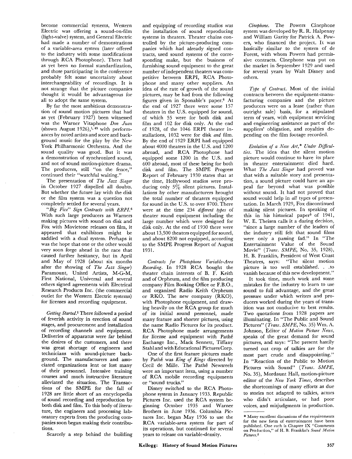
Fig.
4.
Mechanical filter systems
for
reducing
irregularities
in
film motion.
We tend, fortunately, to forget the
troubles that are past. Still more do we
forget the troubles other people had.
We who took part in the development of
sound equipment may be tempted to
think that we made the talking picture
possible. But if we give the credit they
deserve to the writers, directors, actors
and their bosses, and to the patient
guinea pigs who bought tickets, perhaps
the only bouquet left to hand ourselves
is to say that our stuff was not
so
bad as
to make the talkies impossible.
Mechanical Systems
Of
all the tell-tales that remind the
listener that the sound he hears is from
a
record and not “live pickup,” the
most unmistakable is that due to speed
variations
-
known as “wow” or
“flutter,” and it is probably the most
painful and devastating to realism. The
importance of correct and constant
speed was recognized by Edison and
all his successors in sound recording,
but standards were not very high.
Phonographs sold despite their short-
comings. But sound for pictures could
succeed only by providing better enter-
tainment than silent pictures. In those
systems which gained eventual accept-
ance by the motion picture industry, the
engineers spent much effort on providing
constant speed. In his story of the de-
velopment of the Fox-Case system, for
example, Sponable6 tells of having to
rebuild cameras, and of mounting
a
fly-
wheel on the sprocket shaft and driving
the combination through damped
springs.
The literature dealing with speed
fluctuations has been devoted largely
to discussions of measures for improving
the performance of recorders and re-
producers in this respect.?O Until the re-
cent important contribution by Frank
A.
C~merci,~~” such information as
has been published regarding subjective
thresholds or tolerances has been limited
largely to continuous tones. Further sys-
tematic quantitative studies with typical
program material are very desirable.
There is no question however that all
the present and future improvements
in equipment performance are well justi-
fied in terms of more satisfying sound re-
production. Some of the more general
discussions of the subject will be found
in the literature.
70
3
79
-84a
Wow
Meters.
Of prime importance
toward improving recording and repro-
ducing machines is ability to measure
the departures from uniform speed.
One of the first such meters was built
about
1928
by M.
S.
Meads5 of the
General Engineering Laboratory at Sche-
nectady. It was improved by
H.
E.
Roys
and used extensively at Camden,
N.J.,
being the basis of the flutter-measuring
equipment described by Morgan and
Kelloggs6 This meter made an oscillo-
graphic recording of the fluctuations.
An
extremely simple and light-weight in-
dicating flutter bridge used in RCA
servicing is described in the
Journal.87
Flutter-measuring instruments are de-
scribed by Scoville.8s These are of
the indicating type with band filters, by
which flutter at different rates can be
separated. Another design is described
by Herrnfeld.89
A
widely used wow
meter designed by
U.
R. Furst of Furst
Electronics, Chicago, has been commer-
cially available since
1947
or earlier.g0
Disk
System.
In the disk system the
change from
78
to 33Q rpm increased the
difficulties, for at the low speed even a
very heavy turntable (although very
helpful toward eliminating rapid flutter)
was not a practical answer.
A
flywheel
driven through springs, or what we
call a “mechanical filter,” was a well-
known expedient, but such a system is
oscillatory and will multiply rather
than reduce the speed fluctuations if
the disturbances are
of
a frequency
anywhere near that of the reso-
nance, unless the system is damped
by adequate mechanical resist-
ment that the transient disturbance of
starting shall disappear in not more than
one revolution is more difficult to meet
with extremely large inertia. The ac-
ceptable 334-rpm reproducing turntables
had much more inertia than had been
customary for 78-rpm machines, and
were driven through springs, with enough
damping to reach equilibrium reasonably
quickly, and dependence was not placed
on making the natural frequency low
in comparison with that of the slowest
disturbance (once per revolution). Damp-
ing in some designs was provided by ap-
plying friction to the
spring^,^^^^
and
in others by a viscous drag on the turn-
table. In either case it was essential to
have high indexing accuracy in the low
speed gear or worm-wheel.
For 339-rpm recording turntables,
the Western Electric engineers went
to extraordinary refinement.70sg1 On
the theory that it would not be practically
possible to produce gears with no ec-
centricity or indexing errors, they made
their 33Q-rpm worm-wheel in four lami-
nae, all cut together in one operation.
Then they separated and reassembled
them, each rotated
90”
with respect to
its
neighbor. Each had its own spring
connections to the turntable. Damping
was by means of vanes in oil. Four vanes
ance.
69,70.81,91,94,100,102,104,105
The require-
358
July
1955
Journal
of
the
SMPTE
Volume
64
were rigidly connected to the turntable,
while the pot and four other vanes were
driven from the gears through a system
of equalizing levers (which might be
compared to whiffletrees) which im-
parted to the pot and its vanes a rotation
which was the average of that of the
four gear laminae. The effect of this
was to divide by four the magnitude of
each disturbance due to imperfection in
the cutting of the gear, but to make it
occur four times per revolution instead
of once, and both of these effects are
helpful toward filtering out irregularities.
Filtering Systems
for
Film.
In a very
judicial appraisal of the relative advan-
tages of film and disk,
P.
H. Evansa
speaks of the disk system as giving
better speed constancy. He was of
course referring to the experience up
to the time of writing. There can be no
question that film presents
a
more diffi-
cult problem. Synchronous drive and
the maintenance of free loops require
that it be propelled by sprockets. In the
earlier systems of driving the film, it seems
to have been regarded as sufficient to
provide constant rotational speed for
the sprocket (often called the “sound
sprocket”) which carries the film through
the point of recording
or
reproduction.
To obtain such constant sprocket speed
it was practically necessary to use
mechanical filtering to take out irregu-
larities originating in the gea~-ing.~,’O
But the spring-driven sprocket was very
sensitive to jerks from the film,
so
that it
was necessary to employ extra sprockets
with slack film between to isolate the
filtered sound sprocket. It was also
necessary to have an unusual degree of
precision and concentricity in the sound
sprocket. (Fig. 4A).
But there remained the question of
what imperfections there might be in
the film perforations,
or
how much it
had shrunk since the holes were punched.
Shrinkages up to
1
yo
were not uncommon.
A
sprocket can propel
a
film at uniform
speed only when the pitch of the teeth
and that of the holes match perfectly.*
Otherwise there are continual readjust-
ments of the film on the sprocket, pro-
ducing in general 96-cycle flutter, plus
random small variations. A paper by
Herbert Belar and myselP2 shows
graphically the startling breaking up
of single tones into a multiplicity of
side tones by
a
96-cycle speed change
such as might result from
a
shrinkage of
about
3%.
Recorders, since they are working
with fresh film, may give very little
96-cycle flutter at the sprocket. The
*
Sprocket propulsion of the film through the
light beam has certain advantages for printers,
as will be explained in the section on printer
improvements. This mechanical section, how-
ever, seems the logical place
for
a brief review of
studies by
J.
S.
Chandler and
J.
G.
Streiffert
of the Eastman Co., directed to the reduction of
sprocket-tooth flutter.
Dec.
27,
1932.
E.
W.
KELLOGC
P!WI
SUPPORTING
AND
DRIVING APPARATUS
Filed
July
27.
1928
Fis.
I.
Fis.
2.
1,892,554
Fis.
3.
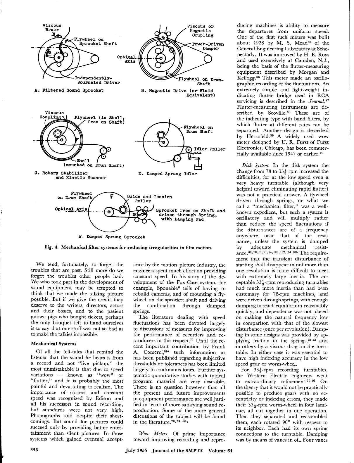
Film
5.
Schematic representation
of
the magnetic drive for film motion, showing
also
provision for damping
by
use of a movable roller with dashpot.
Western Electric recorders of the earlier
1930’s were designed on this basi~.~~$~
The large sprocket was of precise con-
struction and a nearly perfect fit for
unshrunk film. It was on the shaft with
a flywheel, and driven through damped
springs. Another sprocket (unfiltered)
drew the film from the magazine and
resisted the pulls from the take-up
magazine.
The engineers who designed the re-
corders supplied by
RCA
took no chances
with sprocket teeth. In the first General
Electric recording machines the film
was carried past the recording light on
a
smooth drum (with
a
flywheel on its
shaft) and a soft-tired pressure-roller
prevented
lipp ping.^'
Between the drum
and the sprocket which fed the film
through the machine at synchronous
speed were flexible loops of film which
(so
long as they remained under suffi-
ciently low tension to retain their
flexibility) would not transmit appre-
ciable disturbances from the sprocket to
the drum. Because of uncertain shrinkage
the drum must be free to choose its
own speed. The simplest expedient was
to let the film pull the drum, like
a
belt.
Machines built this way worked
so
well
at times that they delayed the effort to
design something on sounder principles.
My own part in the development of a
better machine lay originally in the
recognition that the stretch of film which
pulled the drum, in combination with
the inertia of the flywheel, constituted
an oscillatory system, although its period
varied
so
greatly that the irregular
action did not look like that of any
oscillator we were accustomed to seeing.
Another trouble was that the film loop
Kellogg: History
of
Sound Motion Pictures
359
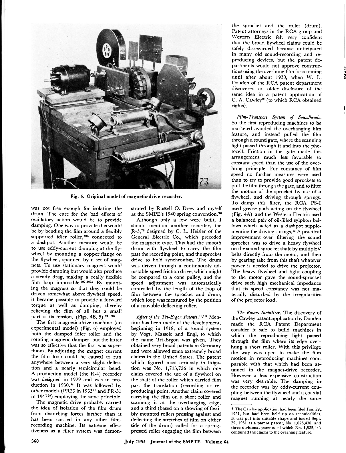
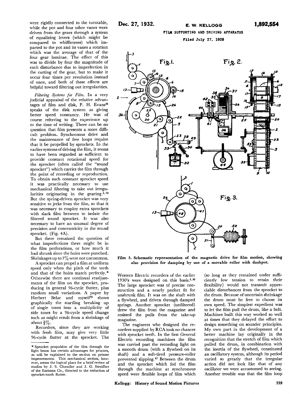
Fig.
6.
Original
model
of
magnetic-drive recorder.
was not free enough for isolating the
drum. The cure for the bad effects of
oscillatory action would be to provide
damping. One way to provide this would
be by bending the film around a flexibly
supported idler roller,’05 connected to
a dashpot. Another measure would be
to use eddy-current damping at the fly-
wheel by mounting a copper flange on
the flywheel, spanned by
a
set of mag-
nets. To use stationary magnets would
provide damping but would also produce
a steady drag, making
a
really flexible
film loop impo~sible.’~J~*~ By mount-
ing the magnets
so
that they could be
driven somewhat above flywheel speed,
it became possible to provide a forward
torque as well as damping, thereby
relieving the film of all but a small
part of its tension. (Figs. 4B,
5).94-96
The first magnetic-drive machine (an
experimental model) (Fig. 6) employed
both the damped idler roller and the
rotating magnetic damper, but the latter
was
so
effective that the first was super-
fluous. By adjusting the magnet current
the film loop could be caused to run
anywhere between
a
very slight deflec-
tion and a nearly semicircular bend.
A production model (the R-4) recorder
was designed in 1929 and was in pro-
duction in 1930.94
It
was followed by
other models (PR23 in 19339* and PR-31
in 1 94799) employing the same principle.
The magnetic drive probably carried
the idea of isolation of the film drum
from disturbing forces farther than it
has been carried in any other film-
recording machine. Its extreme effec-
tiveness as a filter system was demon-
strated by Russell
0.
Drew and myself
at the
SMPE’s
1940 spring conventi~n.~~
Although only a few were built,
I
should mention another recorder, the
.R-3,’O designed by
C.
L.
Heisler of the
General Electric Co., which preceded
the magnetic type. This had the smooth
drum with flywheel to carry the film
past the recording point, and the sprocket
drive to hold synchronism. The drum
was driven through a continuously ad-
justable-speed friction drive, which might
be compared to
a
cone pulley, and the
speed adjustment was automatically
controlled by the length of the loop of
film between the sprocket and drum,
which loop was measured by the position
of a movable deflecting roller.
Effect
of
the Tri-Ergon
patent^.^^^"^
Men-
tion has been made of the development,
beginning in 1918, of a sound system
by Vogt, Massole and Engl, to which
the name Tri-Ergon was given. They
obtained very broad patents in Germany
and were allowed some extremely broad
claims in the United States. The patent
which figured most seriously in litiga-
tion was
No.
1,713,726 in which one
claim covered the use of a flywheel on
the shaft of the roller which carried film
past the translation (recording
or
re-
producing) point. Another claim covered
carrying the film on a short roller and
scanning it at the overhanging edge,
and a third (based on a showing of flexi-
bly mounted rollers pressing against and
deflecting the stretches of film on either
side of the drum) called for a spring-
pressed roller engaging the film between
the sprocket and the roller (drum).
Patent attorneys in the RCA group and
Western Electric felt very confident
that the broad flywheel claims could be
safely disregarded because anticipated
in many old sound-recording and re-
producing devices, but the patent de-
partments would not approve construc-
tions using the overhung film for scanning
until after about 1930, when
W.
L.
Douden of the RCA patent department
discovered an older disclosure of the
same idea in a patent application
of
C.
A.
Cawley* (to which RCA obtained
rights).
L
E
I
I
Film-
Transport System
of
Soundheads.
So
the first reproducing machines to be
marketed avoided the overhanging film
feature, and instead pulled the film
through a sound gate, where the scanning
light passed through it and into the pho-
tocell. Friction in the gate made this
arrangement much less favorable to
constant speed than the use of the over-
hung principle.
For
constancy of film
speed no further measures were used
than to try to provide good sprockets to
pull the film through the gate, and to filter
the motion of the sprocket by use of a
flywheel, and driving through springs.
To
damp this filter, the RCA PS-1
used grease-pads acting on the flywheel
(Fig. 4A) and the Western Electric used
a balanced pair of oil-filled sylphon bel-
lows which acted as a dashpot supple-
menting the driving springs.“ A practical
improvement over filtering the sound
sprocket was to drive
a
heavy flywheel
on the sound-sprocket shaft by multipleV
belts directly from the motor, and then
by gearing take from this shaft whatever
power is needed to drive the projector.
The heavy flywheel and tight coupling
to the motor gave the sound-sprocket
drive such high mechanical impedance
that its speed constancy was not ma-
terially disturbed by the irregularities
of the projector load.
The Rotary Stabilizer.
The discovery of
the Cawley patent application by Douden
made the RCA Patent Department
consider it safe to build machines in
which the reproducing light passed
through the film where its edge over-
hung
a
short roller. With this privilege
the way was open to make the film
motion in reproducing machines com-
parable with that which had been at-
tained in the magnet-drive recorder-
However
a
less expensive construction
was very desirable. The damping in
the recorder was by eddy-current cou-.
pling between the flywheel and a coaxial
magnet running at nearly the same
*
The Cawley application had been filed Jan. 28,
1921, but had been held up on technicalities.
It
was put into suitable shape and issued Sept.
29, 1931 as a parent patent,
No.
1,825,438, and
three divisional patents,
of
which
No.
1,825,441
contained the claims to the overhang feature.
360
July
1955
Journal
of
the
SMPTE
Vulume
64
speed. The functional equivalence of
eddy-current coupling and viscous-fluid
coupling was well recognized.
I
had
tried some experiments with viscous
coupling to a coaxial member which
was not independently driven but was
free to pick up the flywheel speed. The
>
I
inertia of the viscously coupled member
would tend to keep its speed constant
1
so
that a change in flywheel speed would
cause relative movement and hence en-
ergy loss.’O0 But I gave up in view of
the feebleness of the damping
I
obtained.
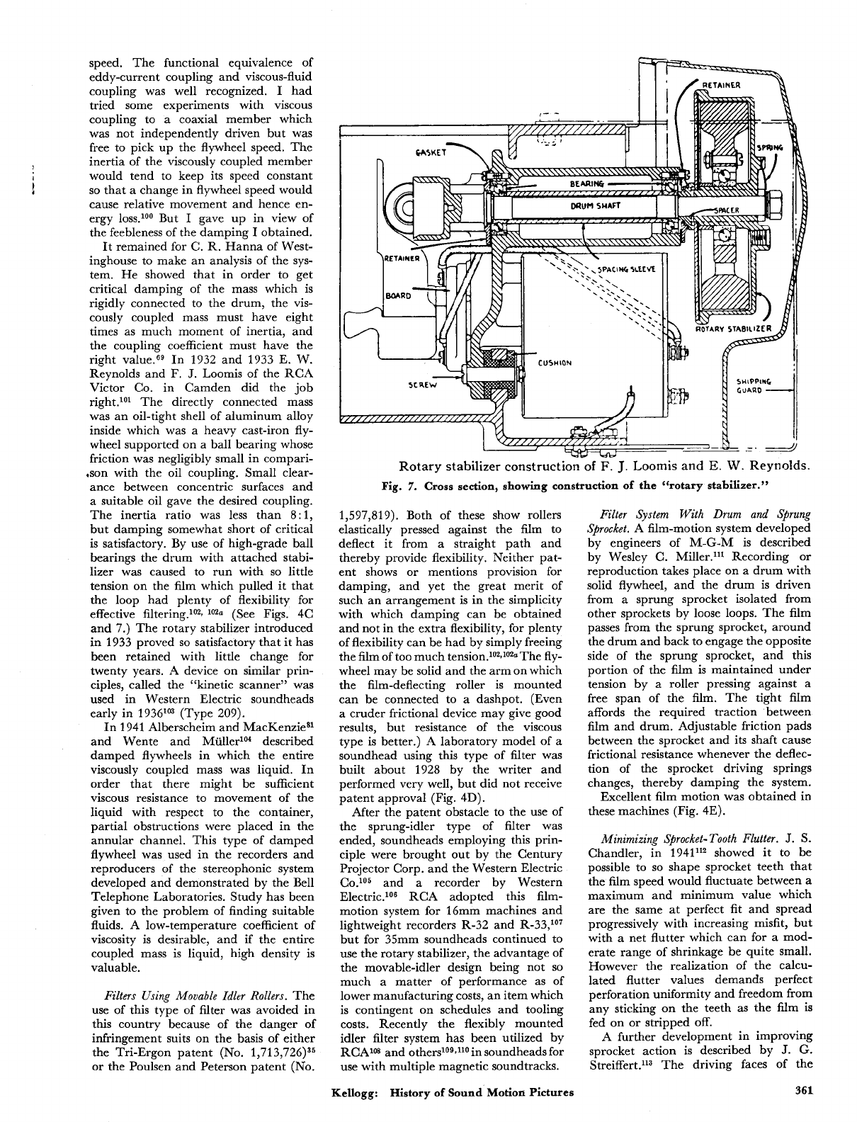
It remained for C. R. Hanna of West-
inghouse to make an analysis of the sys-
tem. He showed that in order to get
critical damping of the mass which is
rigidly connected to the drum, the vis-
cously coupled mass must have eight
times as much moment of inertia, and
the coupling coefficient must have the
right value.69 In 1932 and 1933 E. W.
Reynolds and F.
J.
Loomis of the RCA
Victor Co. in Camden did the job
right.lol The directly connected mass
was an oil-tight shell of aluminum alloy
inside which was a heavy cast-iron fly-
wheel supported on a ball bearing whose
friction was negligibly small in compari-
.son with the oil coupling. Small clear-
ance between concentric surfaces and
a suitable oil gave the desired coupling.
The inertia ratio was less than 8:1,
but damping somewhat short of critical
is satisfactory. By use of high-grade ball
bearings the drum with attached stabi-
lizer was caused to run with
so
little
tension on the film which pulled it that
the loop had plenty of flexibility for
effective filtering.lo2!
lo20
(See Figs. 4C
and 7.) The rotary stabilizer introduced
in 1933 proved
so
satisfactory that it has
been retained with little change for
twenty years.
A
device on similar prin-
ciples, called the “kinetic scanner” was
used in Western Electric soundheads
early in 1936‘” (Type
209).
In 1941 Alberscheim and MacKenziesl
and Wente and MUllerlo4 described
damped flywheels in which the entire
viscously coupled mass was liquid. In
order that there might be sufficient
viscous resistance to movement of the
liquid with respect to the container,
partial obstructions were placed in the
annular channel. This type of damped
flywheel was used in the recorders and
reproducers of the stereophonic system
developed and demonstrated by the Bell
Telephone Laboratories. Study has been
given to the problem of finding suitable
fluids. A low-temperature coefficient of
viscosity is desirable, and if the entire
coupled mass is liquid, high density is
valuable.
Filters Using Movable Idlcr
Rollers.
The
use of this type of filter was avoided in
this country because of the danger of
infringement suits on the basis of either
the Tri-Ergon patent
(No.
1,713,726)35
or the Poulsen and Peterson patent
(No.
Rotary stabilizer construction
of
F.
J.
Loomis
and
E.
W.
Reynolds.
Fig.
7.
Cross
section, showing construction
of
the “rotary stabilizer.”
1,597,819). Both of these show rollers
elastically pressed against the film to
deflect it from a straight path and
thereby provide flexibility. Neither pat-
ent shows or mentions provision for
damping, and yet the great merit of
such an arrangement is in the simplicity
with which damping can be obtained
and not in the extra flexibility, for plenty
of flexibility can be had by simply freeing
the film of too much ten~ion.~~~J~~~The fly-
wheel may be solid and the arm on which
the film-deflecting roller is mounted
can be connected to a dashpot. (Even
a
cruder frictional device may give good
results, but resistance of the viscous
type is better.)
A
laboratory model of
a
soundhead using this type of filter was
built about 1928 by the writer and
performed very well, but did not receive
patent approval (Fig. 4D).
After the patent obstacle to the use of
the sprung-idler type of filter was
ended, soundheads employing this prin-
ciple were brought out by the Century
Projector Corp. and the Western Electric
C0.105 and
a
recorder by Western
Electric.lo6 RCA adopted this film-
motion system for l6mm machines and
lightweight recorders R-32 and R-33,1°7
but for 35mm soundheads continued to
use the rotary stabilizer, the advantage of
the movable-idler design being not
so
much
a
matter of performance as of
lower manufacturing costs, an item which
is contingent on schedules and tooling
costs. Recently the flexibly mounted
idler filter system has been utilized by
RCAlM and others109J10 in soundheads for
use with multiple magnetic soundtracks.
Kellogg:
History
of
Sound
Motion
Pictures
Filter System With
Drum
and Sprung
Sprocket.
A film-motion system developed
by engineers of M-G-M is described
by Wesley C. Miller.ll1 Recording or
reproduction takes place on a drum with
solid flywheel, and the drum is driven
from
a
sprung sprocket isolated from
other sprockets by loose loops. The film
passes from the sprung sprocket, around
the drum and back to engage the opposite
side of the sprung sprocket, and this
portion of the film is maintained under
tension by
a
roller pressing against a
free span of the film. The tight film
affords the required traction between
film and drum. Adjustable friction pads
between the sprocket and its shaft cause
frictional resistance whenever the deflec-
tion of the sprocket driving springs
changes, thereby damping the system.
Excellent film motion was obtained in
these machines (Fig. 4E).
Minimizing Sprocket- Tooth Flutter.
J.
S.
Chandler, in 1941112 showed it to be
possible to
so
shape sprocket teeth that
the film speed would fluctuate between a
maximum and minimum value which
are the same at perfect fit and spread
progressively with increasing misfit, but
with a net flutter which can for a mod-
erate range of shrinkage be quite small.
However the realization of the calcu-
lated flutter values demands perfect
perforation uniformity and freedom from
any sticking on the teeth as the film is
fed on or stripped
off.
A
further development in improving
sprocket action is described by
J.
G.
Streiffert.ll3 The driving faces of the
361
F
R
1929.
H.
VOGT
ET
AL
1,713,726
DEVICE
FOR
FHONOGRAPHS
WITH
LINEAR PHONOGRAM
CARRIERS
Filed
March
20.
1922
3
Sheets-Sheet
3
..I
7roR.w-s
Fig.
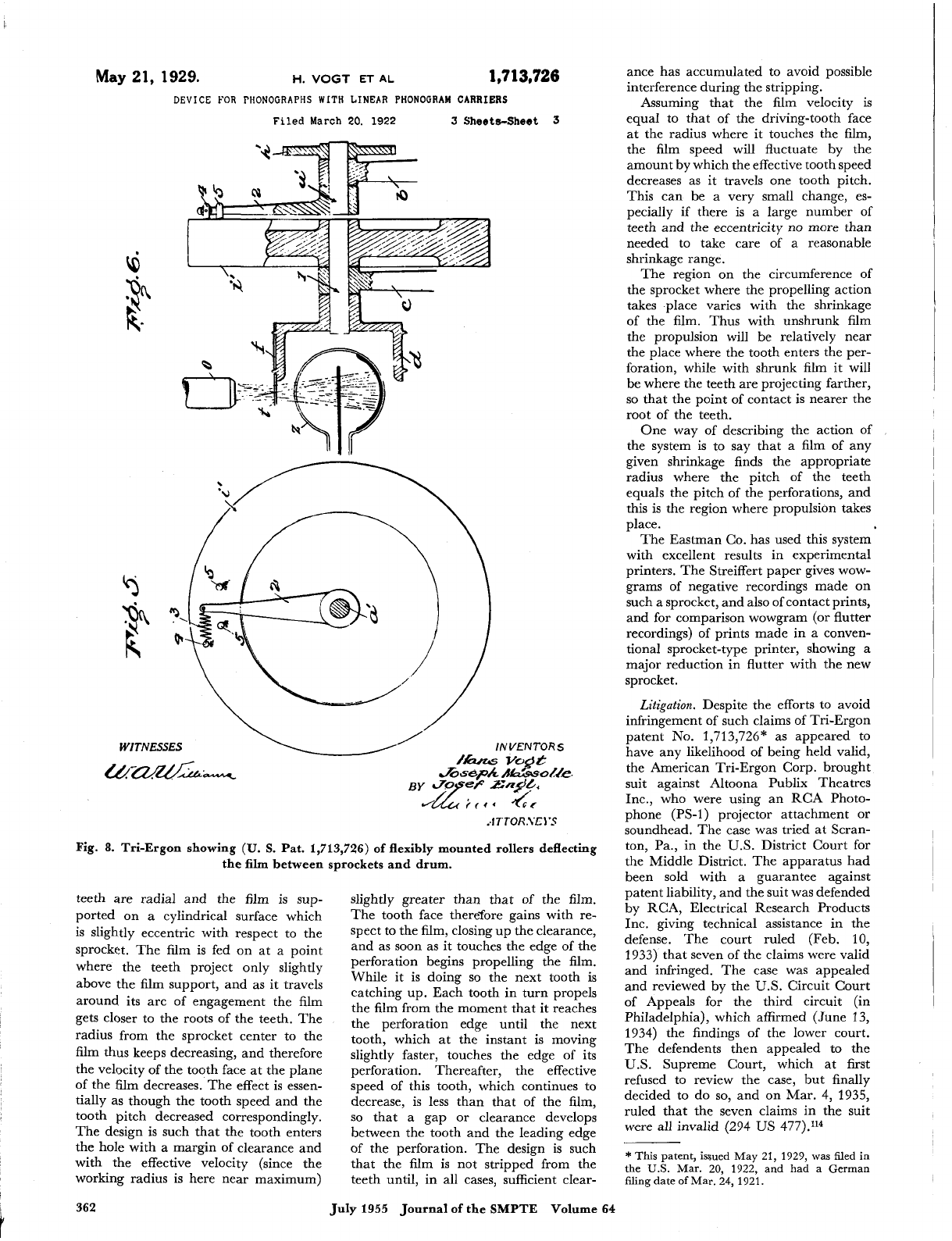
8.
Tri-Ergon showing
(U.
S.
Pat. 1,713,726)
of
flexibly mounted rollers deflecting
the
film
between sprockets and drum.
teeth are radial and the film is sup-
slightly greater than that of the film.
ported on a cylindrical surface which
is slightly eccentric with respect to the
sprocket. The film is fed on at a point
where the teeth project only slightly
above the film support, and as it travels
around its arc of engagement the film
gets closer to the roots of the teeth. The
radius from the sprocket center to the
film thus keeps decreasing, and therefore
the velocity of the tooth face at the plane
of the film decreases. The effect is essen-
tially as though the tooth speed and the
tooth pitch decreased correspondingly.
The design is such that the tooth enters
the hole with
a
margin of clearance and
with the effective velocity (since the
working radius is here near maximum)
The tooth face therefore gains with re-
spect to the film, closing up the clearance,
and as soon as it touches the edge of the
perforation begins propelling the film.
While it is doing
so
the next tooth is
catching up. Each tooth in turn propels
the film from the moment that it reaches
the perforation edge until the next
tooth, which at the instant is moving
slightly faster, touches the edge of its
perforation. Thereafter, the effective
speed of this tooth, which continues to
decrease, is less than that of the film,
so
that a gap or clearance develops
between the tooth and the leading edge
of the perforation. The design is such
that the film is not stripped from the
teeth until, in all cases, sufficient clear-
ance has accumulated to avoid possible
interference during the stripping.
Assuming that the film velocity is
equal to that of the driving-tooth face
at the radius where it touches the film,
the film speed will fluctuate by the
amount by which the effective tooth speed
decreases as it travels one tooth pitch.
This can be a very small change, es-
pecially if there is a large number
of
teeth and the eccentricity no more than
needed to take care of a reasonable
shrinkage range.
The region on the circumference of
the sprocket where the propelling action
takes place varies with the shrinkage
of
the film. Thus with unshrunk film
the propulsion will be relatively near
the place where the tooth enters the per-
foration, while with shrunk film it will
be where the teeth are projecting farther,
so
that the point of contact is nearer the
root of the teeth.
One way
of
describing the action of
the system is to say that a film of any
given shrinkage finds the appropriate
radius where the pitch of the teeth
equals the pitch of the perforations, and
this is the region where propulsion takes
place.
The Eastman Co. has used this system
with excellent results in experimental
printers. The Streiffert paper gives wow-
grams of negative recordings made on
such a sprocket, and also
of
contact prints,
and for comparison wowgram (or flutter
recordings) of prints made in
a
conven-
tional sprocket-type printer, showing
a
major reduction in flutter with the new
sprocket.
Litigation.
Despite the efforts to avoid
infringement of such claims of Tri-Ergon
patent
No.
1,713,726* as appeared to
have any likelihood of being held valid,
the American Tri-Ergon Corp. brought
suit against Altoona Publix Theatres
Inc., who were using an RCA Photo-
phone
(PS-1)
projector attachment
or
soundhead. The case was tried at Scran-
ton, Pa., in the
U.S.
District Court for
the Middle District. The apparatus had
been sold with a guarantee against
patent liability, and the suit was defended
by RCA, Electrical Research Products
Inc. giving technical assistance in the
defense. The court ruled (Feb.
10,
1933) that seven of the claims were valid
and infringed. The case was appealed
and reviewed by the
U.S.
Circuit Court
of Appeals for the third circuit (in
Philadelphia), which affirmed (June
13,
1934) the findings of the lower court.
The defendents then appealed to the
U.S.
Supreme Court, which at first
refused to review the case, but finally
decided to do
so,
and on Mar. 4, 1935,
ruled that the seven claims in the suit
were all invalid (294
US
477).'14
*
This patent, issued May 21, 1929, was filed in
the
U.S.
Mar.
20,
1922,
and had a German
filing date
of
Mar.
24,
1921.
362 July 1955
Journal
of
the SMPTE Volume 64
This removed the threat to the equip-
ment manufacturers of what might have
been almost crippling damages, for
had the findings of the lower courts been
sustained the plaintiffs would have been
in a position to bring suits for damages
for infringement by most of the recording
and reproducing equipment in this
country, and covering a period of over
five years.
The American Tri-Ergon Corp. ap-
plied on Feb. 18, 1937, for a reissue
patent with modified claims, and this
was granted Jan. 11, 1938, as Re.
No.
20,621. On Oct. 25, 1946, RCA reached
an agreement with American Tri-Ergon
Corp. whereby it was granted rights
under both theoriginaland reissuepatents.
Two other patents placed restrictions
on the film-motion systems which Ameri-
can engineers could safely employ,
namely Poulsen and Peterson
No.
1,597,819 (filed July
9,
1924, and
issued Aug. 31, 1926) and Poulsen
No.
2,006,719 (filed Germany Sept. 1, 1930,
and
U.
S.
Aug. 19, 1931, and issued July
2, 1935). These patents to Danish
inventors were owned by British Acoustic
Films Ltd., which brought infringement
suits against RCA Mfg. Co. and against
Electrical Research Products Inc. The
trial (in Wilmington, Del.) was before
the
U.S.
District Court for the District
of Delaware (43 USP-Q69). The ar-
rangement shown in the patent comprised
a
drum propelled by the film, the film
being passed around a flexibly mounted
idler roller. Some of the claims in suit
described the invention as “means con-
tacting the film for increasing its flexi-
bility.” The apparatus in suit was the
RCA PS-24 (rotary stabilizer type),
which has no flexibly mounted roller,
but was alleged to have the equivalent
in that the film loop was
so
formed by
the fixed rollers as to be very flexible.
The court ruled Sept. 22, 1939, that the
claims in suit were not infringed and
not valid (the flexibly mounted idler
having been disclosed in the earlier Tri-
Ergon patent).
Plaintiffs appealed and the case was
reviewed by the Circuit Court of Ap-
peals of the Third Circuit which affirmed
the findings of the lower court (46USP-
4107, June 27, 1940).
To forestall possible future trouble
RCA obtained rights under these pat-
ents by agreement with British Acoustic
Films Ltd., Dec. 21,1944.
Immediate Requirements
for
Sound
Our
historical story thus far has been
confined almost entirely to the three fun-
damental elements, sound pickup
(or
microphone), a recording and reproduc-
ing system and loudspeakers. These
represented the difficult phases of the
problem, but before sound could become
commercial certain items of equipment
had to be made available and techniques
established. Before discussing the ad-
’
vances in the art that followed commer-
cialization, we shall mention some of
these items.
Standard Track Position and Width.l15
Agreement between the makers of vari-
able-width and variable-density systems
was reached in 1928. The reproducing
light spot must cover more than the
extreme width of the clear area of
a
vari-
able-area track, with both ends on black
areas, but should fall entirely within the
width of
a
variable-density track. This
requirement is met with margins of safety,
by recording density tracks 0.100 in.
wide, while the scanning spot is 0.084
in. long. The modulated area of
a
vari-
able-width track is limited to 0.071 in.
with the black parts extending to the
0.100-in. width. The track center line is
to be 0.243 in.
f
0.002 in. from the edge
of the film.
Printers.
Continuous contact printers
previously used for pictures only could
be adapted to sound by providing masks
by which light could be confined to
either the picture
or
the soundtrack area.
Except for certain newsreel negatives,
the sound and picture were on separate
negatives,
so
that the print film had to be
run through the printer twice. Even
when the sound was on the same nega-
tive as the picture, the offset was not
usually the required 14.5-in. and inde-
pendent light controls were needed.
Combination printers were soon devel-
oped which were essentially two printers
in cascade,
so
that the print was com-
plete with one passage through the
machine.116-120
Bloops.
The development engineer can
overlook many defects so long as he
knows their cause and that the apparatus
he is testing is not at fault, but before
sound pictures could be shown the public,
these faults had to be corrected. The
noise which a splice makes as it passes
through the scanning beam can be made
almost inaudible by cutting off the light
gradually instead of suddenly. This was
accomplished at first by painting a black
spot with sloping edges over the splice.
Later, black patches which could be
quickly cemented in place where the
splice crosses the sound track were made
available. These are called “bloops.”
They are of trapezoid shape, masking
off the entire sound track for a distance
sufficient safely to cover the splice and
with end slopes designed to change the
light gradually enough to keep the noise
just below noticeability at normal gain
settings. The design of bloops is dis-
cussed in several To prevent
a
disturbance due to a printed-through
negative splice, SponablelZ4 described
a punch which made a hole in the nega-
tive, resulting in a suitably-shaped black
spot on the print.
Electrical blooping of splices in nega-
tives has come into extensive use. When
a negative splice goes through the printer
an auxiliary light exposes (through
the base) a suitable area of the print
film, an edge notch
or
other means
being employed to control the blooping
light.
Lewin (Apr. 1947)I24a describes a system
of silencing splices in re-recording posi-
tives in which the output is momentarily
suppressed in response to a punched hole.
Blimps.’25
Cameras which were en-
tirely satisfactory for silent pictures were
much too noisy for making sound
pictures. Much quieter cameras were
developed eventually,126-128 but for im-
mediate requirements it was necessary
to reduce the noise radiated by existing
cameras by building shells around them
with thick layers of sound-absorbing
material. These were called “blimps,”
or
sometimes “bungalows.” To smother
the sound and still give access for the
necessary operations was enough to
tax the skill and ingenuity of the de-
signer. Even with the quieter cameras it
is still common to resort to partial
or
complete sound-insulating housing.
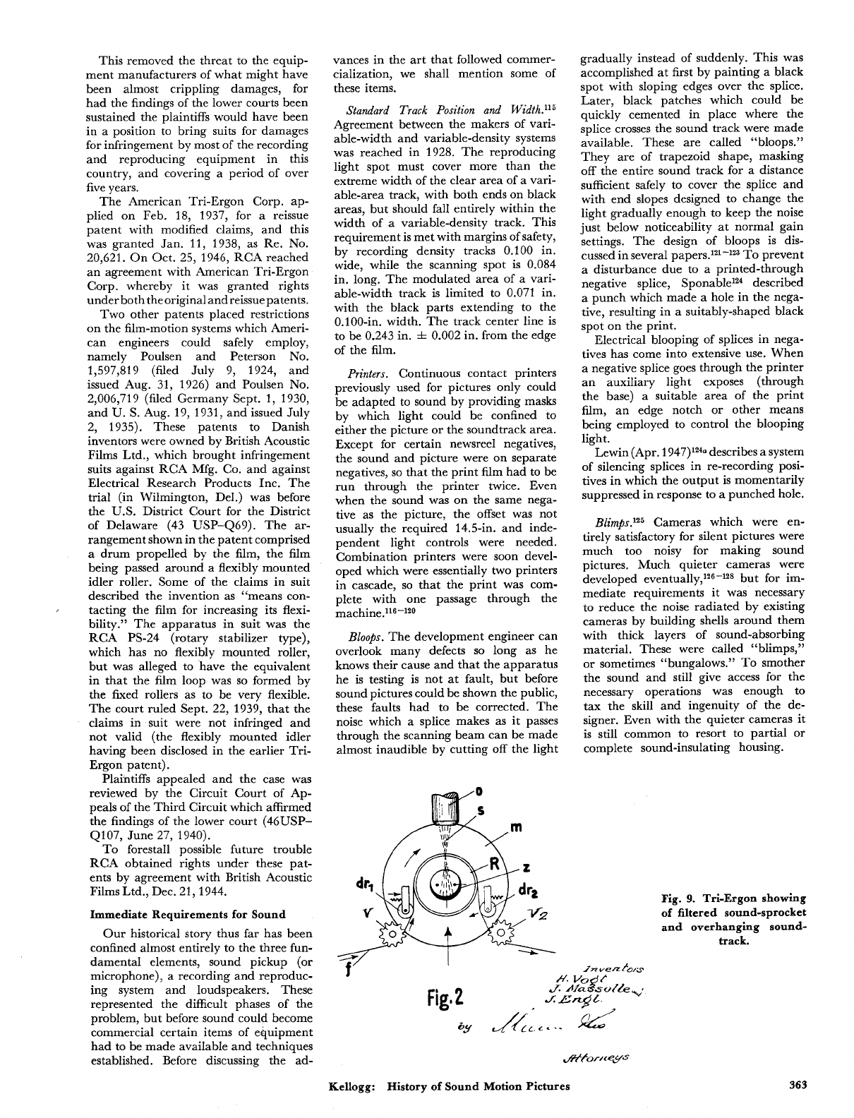
Fig.
9.
Tri-Ergon showing
of
filtered sound-sprocket
and overhanging sound-
track.
Kellogg:
History
of
Sound Motion Pictures
363
Sound Stage~.'~~J~~
The requirement of
freedom from noise necessitated the
building of sound stages in which ex-
treme measures were taken to exclude
noise of outside origin. Many of these
had double concrete walls and double
floors, with sound absorbing material
between, the inner walls and floor being
supported on cushion mounts to prevent
transmission of earth tremors. The roof
and ceiling structures were designed on
the same principle.
The high absorption
(or
short reverber-
ation time) desirable for recording pur-
poses helped control noises originating
inside, but
so
far as possible all sources
of noise were eliminated. Noisy arc
lights gave way to incandescent or
other quiet lamps, and all mechanisms
were made to operate as noiselessly as
possible. Ventilating systems required
extreme measures.
In recording dialogue, the better the
suppression of general rcom reverbera-
tion, the farther (within limits) from the
action can the microphone be placed,
thus affording more uniform coverage
and making it easier to keep the micro-
phone out of the field of the camera.
If
some echoes are wanted the "set"
can frequently be designed to produce
enough. Artificial reverberation using
echo chambers in the recording channel
or equivalent devices has many applica-
tions.
In contrast to the requirements for
speech, the recording of music calls in
general for rooms with considerable
re~erberation.'~'-'~~
Theater Acoustical Treatment.134J35
The
acoustical treatment of auditoriums has
probably received more study than any
other phase of architectural acoustics,
perhaps because the desired characteris-
tics are most difficult to attain. The re-
verberation must be sufficient to make
music pleasing and to help equalize
sound intensity in the various parts of the
space, but must be short enough not
appreciably to impair clarity
of
speech.
A high order of directivity in the loud-
speakers plus application of absorbent
materials to any large surfaces toward
which they are directed has helped
with this part of the problem.
In general every theater or auditorium,
many of which were built before the
era of sound pictures, presents its own
problems and calls for individual study.
For
new theaters there is optimum shape
to consider as well as best distribution
of
absorption. The multiple loudspeaker
systems (discussed later) besides making
new effects possible have given the
acoustical designer somewhat more free-
dom.
Booms and Dollies.
In order that micro-
phones might be suspended as near the
action as might be wanted but just above
the field of the camera, and in order
that their positions might be readily
changed, microphone booms of various
types came quickly into use. The more
elaborate of these were much like
derricks on platforms, with rubber-
tired wheels on which they could be
moved quickly and almost noiselessly.
Similarly, rubber-tired, battery-oper-
ated camera dollies enabled the camera-
man rapidly and quietly to change the
position
or
height of his camera.
Equipment of the kind just described
underwent improvements through the
years, but the main features were avail-
able from the start of commercial sound
pictures.
Monitoring and Leuel Contr01.'~~-~~~
An-
other line of equipment the essentials of
which were made available as soon as
recording machines, and which has been
improved from time to time, was that pro-
viding for monitoring and level controls
and (especially in re-recording opera-
tions) for adjusting the relative levels
from several sources, or "mixing." Vol-
ume indicat~rs'~~J~~ of several types
were in use in broadcasting stations, and
the design of mixing controls was well
established.
The man responsible for recording
judged the quality by means of
a
moni-
toring loudspeaker. He could check
quality as represented by the current
supplied to the light modulator,
or
by
means of a photocell, in terms of the
light reaching the film.1964,254 In the case
of the RCA Photophone system there
was a card on which the modulator pro-
jected a light-spot, the movements of
which showed the amplitude being re-
corded on the sound
It was for a time held by some that the
monitoring speaker should be of the same
type as a theater speaker, but high-
quality monitoring speakers of the direct-
radiator type were soon made available,
and these were much better suited to the
small rooms where the controls were
located. In terms
of
frequency range
covered, the cabinet-type monitoring
speakers kept pace with the improve-
ments in theater speakers (see section
on loudspeakers). High-quality head-
phones have also found wide use in moni-
toring.'",
211
Whatever type of listening
device is used, it should obviously be
designed to give the recordist about the
same range and tonal balance that a
theater patron would get.
Screens.
Our sense of the direction
from which sounds come is too keen for
us to be fooled by loudspeakers placed
alongside or above the screen. Sound
must come from directly behind the
screen to give a good illusion. This is
one of the lessons that was learned early.
Screens of the types developed for silent
pictures caused excessive loss and distor-
tion if placed between the loudspeaker
and the audience.
Mention has been made
of
a sound-
transmitting screen developed by E.
I.
Sponable in
1927.6
One
of
the first
papers in the SMPE
Journal
dealing
with screens for sound pictures was that in
1930
by
H.
F.
H0~kins.l~~ His curves of
measured transmission indicate good
results with screens having perforations
whose total area is
4%
or
5%
of the
screen area, and show definite advantage
in a thin (0.013-in.) screen rather than
a thicker (0.030-in.) material. With such
screens the loss of brightness need be
no greater than the proportion of the
area taken out by the holes. Allotment
of about
8%
of the area to holes has been
common, for example about
40
holes
of
0.050-in. diameter per square inch.145
Processing, Variable- Density
.146
In the
story of the work at Western Electric
and Bell Laboratories
I
said that it was
recognized by Wente and by MacKenzie
that for the correct, or linear, relation
between negative exposure and print
transmission, the product of the negative
and print gamma* should equal unity.t
This is in accordance with principles set
forth in early SMPE papers by
L.
A.
Jones62 and by A.
C.
Hardy.61 Since
practice in making pictures had been to
develop the print to a gamma of approxi-
mately two, and both sound and picture
would receive identical development, the
sound negative should be developed to a
gamma of about
0.5
or slightly higher.
Picture-positive film was used for a
number of years for sound negatives.
Developers of the types used for picture
negatives tend to give low contrast and
fine grain, and the use of such develop-
ers helped to give the desired low value
of
gamma for the sound
negative^.'*^*'^*
Ma~Kenzie~~ gives some information
about the harmonic distortion which
results from departures from the unity
product, and thus gives an indication of
tolerances with respect to development.
With the advent of sound, with its
requirement for more strict control of
development, control by use of sensito-
metric test strips, and by specified time,
temperature and developer f0rmulas'~9-'~
supplanted dependence on visual judg-
ments of operators, where that practice
had prevailed.'"J" Maintenance of de-
veloper activity received much atten-
ti or^,'^^-'^^
and stop baths assumed in-
creased importan~e.'~~*'~~ Rack-and-tank
methods, where these had been followed,
*
Gamma is the slope of the straight portion of a
curve plotted withdensity orlogof
as ordinates and log exposure as abscissae. This is
known as the Hurter and Driffield,
or
H
&
D curve. Gamma product is a measure of overall
contrast as compared with that in the original
exposure.
t
In practice, because
of
some
loss
of contrast
due to stray light in optical systems, best results
with pictures had been found with somewhat
higher gamma product.
(
transmission
364
July
1955
Journal of the
SMPTE
Volume
64
gave way to continuous machine proc-
essing.161-163
How generally the distinctions be-
tween specular and diffuse density,164 and
between exposure modulation by varying
time (light valve) and varying intensity
(as by glow lamp)‘65 were understood at
first is a question, but these points were
well covered in the literature. The
Eastman Capstaff Densitometer,166 which
was developed primarily for measuring
picture negatives for contact printing,
reads diffuse densities. This would be
appropriate for measuring the densities
cf sound negatives for use in contact
printers, but not for densities of sound-
track prints, for it is the specularly trans-
mitted light which reaches the photocell
in
a
reproducer.
The widely used EastmanIIb Sensitom-
eter, brought out about 1932,1‘j7 which
gives an accurately standardized series of
test exposures in the form of a step tablet
with exposure time increasing in the
ratio
d?
per step, and ranging from
about
0.004
sec to
4
sec, has been of
utmost vahe in maintaining controls.
However, it does not simulate sound-
track recording conditions, where the
intensity is extremely high and the time
for average exposure was approximately
1/18000 sec (1/36000 sec with a later
light-valve system and in present prac-
tice about 1/90000 sec) and still shorter
for low exposures. The 1934 paper by
Jones and Webb165 gives an indication
of the magnitude of the error. The East-
man Sensitometer on the other hand gives
exposures which approximate sufficiently
well those which
a
print receives, and
are thus suitable for determining gamma
of contact prints. For many purposes it
has been satisfactory to draw conclusions
by applying correction factors, if needed,
to the readings of these instruments.
In the course of a few years densitom-
eters employing photocells were de-
veloped which had the advantages of
greater accuracy and much faster op-
eration than the Capstaff visual-balance
type.168-1i2 For exposing sound negatives
for sensitometry purposes, the light valve
itself, with suitable calibration, can be
used. The subject is again discussed
under “Intermodulation Test.”
While the conditions for low distortion
were to keep both negative and positive
exposures on the straight parts of the
H
&
D characteristics, studies reported
in 1931 by D. MacKenzie17*~ showed that
low distortion was still possible while
using the “toe” range of both films
(“toe recording”) or that of the positive
only (“composite”). Toe recording using
positive stock for the sound negative
might, if the recording-system light was
limited, be preferable to resorting to
faster and coarser-grained recording
stock. In the case of single-film systems
(sound recorded on the picture negative)
where the development of both the nega-
tive and positive soundtracks is fixed
by picture requirements, MacKenzie
found that the composite system offered
best promise of low distortion. Both the
toe and composite systems give higher
output than
a
classical
or
straight-line
system, but poorer signal-to-noise ratios.
It took a number of years to bring
about the full transformation from the
methods (depending much on visual
judgments) which had been employed
for making silent pictures, to the close
controls and scientific precision needed
for satisfactory and consistent sound.
The constant and close checking of
every element exerted
a
pressure for
improvement along the whole front,
including the manufacture of the film,
in which departures from uniformity
were quickly detected. The story is inter-
estingly told by
J.
I.
Crabtree.146 An
early account is given by
J.
W. Coff-
man.153
Processing, Variable-Area.
Since the
ideal variable-area track
is
part clear
and part black with a sharp boundary
between, there is no question of preserv-
ing correct shades of gray, but in general
the higher the contrast (or gamma
product) the better.
As
in the case of
variable-density tracks it must be as-
sumed that the print development will
be that which is wanted for the picture,
and that has been taken in general to
give a gamma of about 2.0. Variable-
area negatives as well as the prints are
processed in high-contrast developers.
The variable-area system is noncritical
with respect to gamma product but, for
a given positive emulsion and processing,
there is for any given negative
a
best
setting of printer light.
A comprehensive study of available
sound-recording films and their process-
ing was published by Jones and Sand-
~ik.’?~ Another study was made by
J.
A.
Ma~rer.’~~ From his curves it ap-
peared that negative densities of 1.3 or
higher were desirable, and the prints
which gave maximum outputs were the
ones having densities (in the dark areas)
about equal to those of the negatives
from which they were made. This held
true for negative densities ranging from
0.6 to
1.3
and higher. The maxima
however were very broad.
In November 1931, Dimmi~kl~~ re-
ported the results of a series of deter-
minations of conditions for maximum
output from a 6000-cycle recording, using
Eastman positive 1301 for negatives and
prints, and
4,
6,
8
and 10 min in D-16
developer. The study covered an ade-
quate range of the four variables
-
nega-
tive (recording) exposure, negative de-
velopment or gamma, printing exposure
and print development. The results
showed that wide ranges in each
of the variables could be used with com-
paratively small loss of output, but for
any negative there was a print density
at which output was greatest.
It
made
Kellogg: History
of
Sound
Motion
Pictures
comparatively small difference (except
near the extremes) whether a given
density of either negative or print was
reached with small exposure and longer
development or more exposure and less
development, but in general the maxima
were broader with the higher values
of gamma, especially that of the print.
The two highest gamma values in the
series, 2 and 2.18 of both negative and
print, in general gave best results, with
negative densities (measured in the black
areas) in the range 1.5
to
2, and print
densities a little less in each case than
that
of
the negative.
While maximum high-frequency out-
put is of less consequence than avoidance
of cross-modulation (which is discussed
in the section on distortion) it is of in-
terest that recommended practices based
on the test just described come very
close to those found to be best in later
experience and after current testing
methods had become established. The
cross-modulation test did not come into
general use until 1938.176
For a number of years a print density
of
1.4
or
slightly higher, with appro-
priate corresponding negative density,
was taken as a practical objective. As
galvanometers and optical systems were
improved and finer grain films came into
use, the tendency was toward higher
densities for both negatives and prints,
especially for the negatives.
Evolution
in
a
Growing Industry
Greatb Expanded Deuelopmental Actiui-
ties.
The development work prior to com-
mercialization of sound was carried
on largely in laboratories supported by
manufacturers of supplies or equipment,
or in independent laboratories, and it
was done on the basis of hope for re-
turns which might be realized either
through patent royalties
or
through
sales of equipment
or
both.
Once sound pictures began to be made
and shown, developmental work was on
a different basis. Research and investiga-
tions of numerous incompletely solved
problems took on rather the character of
plowing in profits, with greatly increased
total expenditures for research and par-
ticipation by all the major picture-pro-
ducing organizations.
Of a11
of
the problems, the most fun-
damental and greatest in magnitude was
learning how to use sound pictures,
or
the evolution of a new art. This is dis-
cussed by
J.
E. Abbott.”? The expres-
sion “growing pains” aptly describes the
less successful phase of this evolution.
Capacity for readjustment is one of the
qualities of greatness in individuals and
in organizations, and the motion-picture
industry came through splendidly.
When any industry becomes large,
and especially if its requirements are as
diverse as those of sound pictures, it
provides a market for numerous special-
365
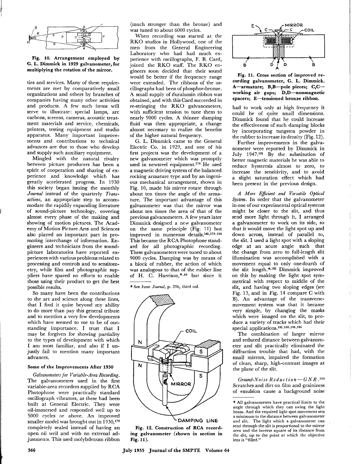
,,
Fig. 10. Arrangement employed by
6.
L.
Dimmick in 1929 galvanometer, for
multiplying the rotation of the mirror.
ties and services. Many of these require-
ments are met by comparatively small
organizations and others by branches of
companies having many other activities
and products. A few such items will
serve to illustrate
:
special lamps, arc
carbons, screens, cameras, acoustic treat-
ment materials and service, chemicals,
printers, testing equipment and studio
apparatus. Many important improve-
ments and contributions to technical
advances are due to those who develop
and supply such auxiliary equipment.
Mingled with the natural rivalry
between picture producers has been a
spirit
of
cooperation and sharing of ex-
perience and knowledge which has
greatly accelerated progress. In 1930
this society began issuing the monthly
Journal
instead of the quarterly
Trans-
actions,
an appropriate step to accom-
modate the rapidily expanding literature
of sound-picture technology, covering
almost every phase of the making and
showing of motion pictures. The Acad-
emy of Motion Picture Arts and Sciences
also played an important part in pro-
moting interchange of information. En-
gineers and technicians from the sound-
picture laboratories have reported ex-
periences with various problems related to
processing and controls and to sensitom-
etry, while film and photographic sup-
pliers have spared no efforts to enable
those using their product to get the best
possible results.
So
many have been the contributions
to the art and science along these lines,
that
I
find it quite beyond my ability
to do more than pay this general tribute
and to mention a very few developments
which have seemed to me to be of out-
standing importance.
I
trust that
I
may be forgiven for showing partiality
to the types of development with which
I
am most familiar, and also if
I
un-
justly fail to mention many important
advances.
Some of the Improvements After 1930
Galvanometers for Variable-Area Recording.
The galvanometers used in the first
variable-area recorders supplied by RCA
Photophone were practically standard
oscillograph vibrators, as these had been
built at General Electric. They were
oil-immersed and responded well up to
5000
cycles or above. An improved
smaller model was brought out in 1930,178
completely sealed instead of having an
open oil well and with no external ad-
justments. This used molybdenum ribbon
(much stronger than the bronze) and
was tuned to about
6000
cycles.
When recording was started at the
RKO studios in Hollywood, one of the
men from the General Engineering
Laboratory who had had much ex-
perience with oscillographs, F.
B.
Card,
joined the RKO staff. The RKO en-
gineers soon decided that their sound
would be better if the frequency range
were extended. The ribbons of the
os-
cillographs had been of phosphor-bronze.
A small supply
of
duralumin ribbon was
obtained, and with this Card succeeded in
re-stringing the RKO galvanometers,
with sufficient tension to tune them to
nearly 9000 cycles. A thinner damping
fluid was then appropriate,
a
change
almost necessary to realize the benefits
of the higher natural frequency.
G.
L.
Dimmick came to the General
Electric Co. in 1929, and one of his
first projects was the development of a
new galvanometer which was promptly
used in newsreel equipment.178 He used
a magnetic driving system of the balanced
rocking armature type and by an ingeni-
ous
mechanical arrangement, shown in
Fig.
10,
made his mirror rotate through
about ten times the angle of the arma-
ture. The important advantage of this
galvanometer was that the mirror was
about ten times the area of that of the
previous galvanometers. A few years later
Dimmick designed a new galvanometer
on the same principle (Fig.
11)
but
improved in numerous detail~.’~J~~J80
This became the RCA Photophone stand-
ard for all photographic recording.
These galvanometers were tuned to about
9000 cycles. Damping was by means
of
a block of rubber, the action of which
was analogous to that of the rubber line
of
H.
C. but since it
*
See June
Journal,
p.
296,
third col.
‘-DAMPING
LINE
Fig. 12. Construction of RCA record-
ing galvanometer (shown
in
section
in
Fig. 11).
Fig. 11.
Cross
section of improved re-
cording galvanometer,
G.
L.
Dimmick.
A-armature; B,B-pole pieces;
C,C-
working air gaps; D,D-nonmagnetic
spacers; E-tensioned bronze ribbon.
had to work only at high frequency
it
could be of quite small dimensions.
Dimmick found that he could increase
the effectiveness of such damping blocks
by incorporating tungsten powder in
the rubber to increase its density (Fig.
12).
Further improvements in the galva-
nometer were reported by Dimmick in
July 1947.18’ By the substitution of
better magnetic materials he was able to
reduce hysteresis almost to zero, to
increase the sensitivity, and to avoid
a slight saturation effect which had
been present in the previous design.
A
More Eficient and Versatile Optical
System.
In order that the galvanometer
in one of
our
experimental optical systems
might be closer to the slit, and thus
send more light through it,
I
arranged
a
galvanometer
to
work on its side,
so
that it would move the light spot up and
down across, instead of parallel to,
the slit.
I
used a light spot with a sloping
edge at an acute angle such that
the change from zero to full-length slit
illumination was accomplished with a
movement equal to only one-fourth
of
the slit length.
*,la2
Dimmick improved
on this by making the light spot sym-
metrical with respect to middle
of
the
slit, and having two sloping edges (see
Fig.
13,
and in Fig.
14
compare C with
B).
An advantage of the transverse-
movement system was that it became
very simple, by changing the masks
which were imaged on the slit, to pro-
duce a variety of tracks which had their
special
appli~ations.~~2~180~1~3~~~~
The combination of larger mirror
and reduced distance between galvanom-
eter and slit practically eliminated the
diffraction trouble that had, with the
small mirrors, impaired the formation
of clean, sharp, high-contrast images at
the plane
of
the slit.
Ground-Noise Reduction
-
G
NR
.Ia5
Scratches and dirt on film and graininess
of emulsion cause a background noise
*
All galvanometers have practical limits to the
angle through which they can swing the light
beam. And the required light spot movement sets
a minimum to the distance between galvanometer
and slit. The light which a galvanometer can
send through the slit is proportional to the mirror
area and the inverse square
of
its distance from
the slit, up to the point at which the objective
lens is “filled.”
366
July 1955 Journal oft& SMPTE Volume
64
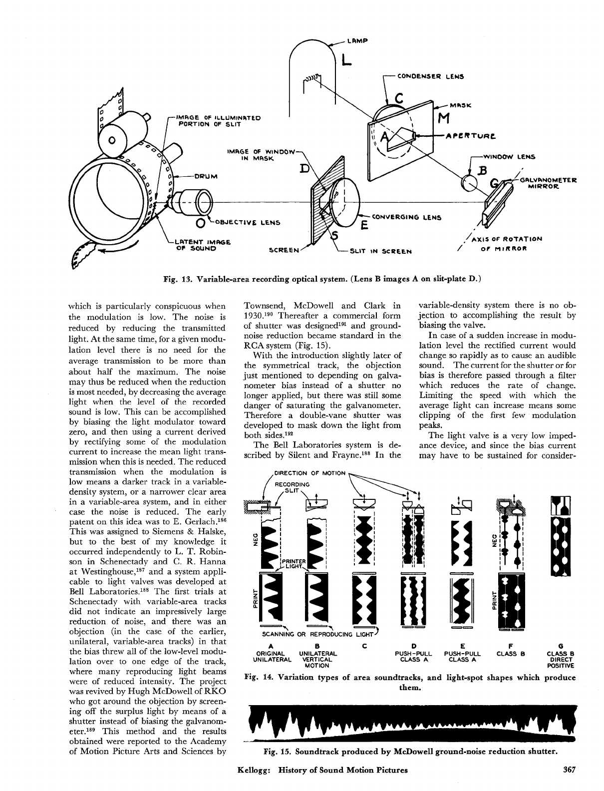
CONDCNSER
LENS
IMRGE
OF
ILLUMINRTED
PORTION
OF
SLIT
IMRGE
OF
WINDOW
WINOOW
LENS
RLVhNOMETER
CONVERGING
LENS
OBJECTIVL
LENS
LRTCNT
IMRGE
/
or
MIRROR
SLIT
IN
SCREEN
Fig.
13.
Variable-area recording optical system.
(Lens
B
images
A
on
slit-plate
D.)
which is particularly conspicuous when
the modulation is low. The noise is
reduced by reducing the transmitted
light. At the same time, for a given modu-
lation level there is no need for the
average transmission to be more than
about half the maximum. The noise
may thus be reduced when the reduction
is
most needed, by decreasing the average
light when the level of the recorded
sound is low. This can be accomplished
by biasing the light modulator toward
zero, and then using a current derived
by rectifying some of the modulation
current to increase the mean light trans-
mission when this is needed. The reduced
transmission when the modulation is
low means a darker track in a variable-
density system, or a narrower clear area
in a variable-area system, and in either
case the noise is reduced. The early
patent on this idea was to
E.
Gerlach.186
This was assigned to Siemens
&
Halske,
but to the best of my knowledge it
occurred independently to L.
T.
Robin-
son in Schenectady and
C.
R.
Hanna
at We~tinghouse,'~' and a system appli-
cable to light valves was developed at
Bell Laboratories.18* The first trials at
Schenectady with variable-area tracks
did not indicate an impressively large
reduction of noise, and there was an
objection (in the case of the earlier,
unilateral, variable-area tracks) in that
the bias threw all of the low-level modu-
lation over to one edge of the track,
where many reproducing light beams
were of reduced intensity. The project
was revived by Hugh McDowell of
RKO
who got around the objection by screen-
ing off the surplus light by means of a
shutter instead of biasing the galvanom-
eter.lsg This method and the results
obtained were reported to the Academy
of Motion Picture Arts and Sciences by
Townsend, McDowell and Clark in
1
930.lg0 Thereafter a commercial form
of shutter was designedxg1 and ground-
noise reduction became standard in the
RCA
system (Fig.
15).
With the introduction slightly later
of
the symmetrical track, the objection
just mentioned to depending on galva-
nometer bias instead of a shutter no
longer applied, but there was still some
danger of saturating the galvanometer.
Therefore
a
double-vane shutter was
developed to mask down the light from
both sides.x92
The Bell Laboratories system is de-
scribed by Silent and Frayne.188 In the
,DIRECTION
OF
MOl
.ION
I
I
variable-density system there is no ob-
jection to accomplishing the result by
biasing the valve.
In case of a sudden increase in modu-
lation level the rectified current would
change
so
rapidly as to cause an audible
sound. The current for the shutter or for
bias is therefore passed through a filter
which reduces the rate of change.
Limiting the speed with which the
average light can increase means some
clipping of the first few modulation
peaks.
The light valve is a very low imped-
ance device, and since the bias current
may have to be sustained for consider-
--
SCANNING
OR
REPRODUCING
LIGHT]
A
B
C
D
E
F
0
ORIGINAL UNILATERAL PUSH-PULL PUSH-PULL CLASS
B CLASS
B
UNILATERAL VERTICAL CLASS
A
CLASS A
DIRECT
MOTION POSITIVE
Fig.
14.
Variation types of area soundtracks, and light-spot shapes which produce
them.
Fig.
15.
Soundtrack produced by McDowell ground-noise reduction shutter.
Kellogg: History
of
Sound Motion Pictures
367
able periods of time transformers cannot
be used for impedance match coupling
to the output tube of the ground-noise
reduction amplifier. In the system
most widely used with light valves the
modulation current is rectified, passed
through the timing filter, and used to
modulate a 20,000-cycle oscillator, the
output of which is amplified and recti-
fied for supply to the valve. The design
of the timing filter is much simpler when it
can operate at interstage impedance.193
As compared with variable-area, the
variable-density system is characterized
by ground noise which is less in the
nature of “ticks” and “pops” and more a
continuous hiss. Another difference is
that in the density system the noise falls
more rapidly with reduced light trans-
mission,
so
that a given amount of noise
reduction is obtained with a smaller
change in transmission. The con-
tinuous hiss type of noise is especially
noticeable if it comes and goes, which
changing bias causes it to do. This is
often called the “hush-hush” effect, and
becomes noticeable if the valve opening
does not immediately fall when the
modulation drops to a low level. At
the same time the fact that smaller
changes in transmission suffice to control
the ground noise makes it possible to
change transmission
(or
bias) more
quickly without causing “thump.” The
filters for density systems are therefore
designed for much faster timing than
those of area systems, particularly in
closing down when modulation falls.
While clipping of initial modulation
peaks is a less serious problem in density
than in area recording (because of
faster opening and larger margin)
engineers working with both systems
have given much study to minimizing
such clipping. Increased margin will
decrease the frequency of occurrence of
clipping, but this would be at the price
of more noise. In all systems, opening
(increasing light) is about as fast as it
can be made without becoming audible,
while the closing is much slower
so
that
very brief reductions in level will not
produce incessant closing and opening.194
A nonlinear characteristic has been
given to RCA ground-noise reduction
amplifiers, which causes the opening, as
a
function of modulation amplitude, to
rise more steeply at first and then more
Relatively low-level modula-
tion is then sufficient to cause an increase
in margin and thus reduce subsequent
clipping. It is when the modulation
is
nearly zero that close margin is urgent.
Certain characteristics of speech sounds
have an important bearing on the design
of ground-noise reduction systems. The
positive pressure peaks are higher than
the negative, and it is important to
maintain correct polarity from micro-
phone to valve, or to shutter and galva-
n~meter.’~~J~~
R.
0.
Drew and
I
made
an investigation to determine how often
speech sounds build up rapidly.lg6
Instances in which maximum amplitude
was reached in less than three or four
waves (voice fundamental) were sur-
prisingly rare.
The ideal solution to the problem of
avoiding initial clipping would be to
anticipate increases in sound level. This
is discussed by
J.
G. Frayne.197
Anticipation by use of a second
microphone was used experimentally in
the stereophonic system described in the
October 1941
Journal
(p. 351) for
operation of the compre~sor.~~a A system
employing a 14-msec electrical delay
network is described (March 1950)
by Whitney and Thatcher.lg8
When reported it had been in use for
over a year by Sound Services Inc. with
very favorable results. Besides reduced
clipping, advantage was taken of the
system to increase ground-noise reduc-
tion in density recordings by
5
db, and in
area recordings to work with a bias line
only 1 to
1;
mils wide. A low-distortion
network good to
8000
cycles necessarily
employs many sections (several hundred).
Cost is probably the reason that this
expedient has not been widely employed.
A direct-positive variable-area recording
system with the anticipation effect
provided by means of an auxiliary
exposure was designed and demon-
strated by Dimmick and Blaney and
has been used in the Warners’ studios.’Qg
In the re-recording operation anticipa-
tion should be a simple matter, involving
only
a
double reproducing system (with
scanning points a fraction of an inch
apart) with separate amplifiers.
*
Mueller
and Groves (June 1949)200 mention use
of this system at Warners.
I
understand
however that little advantage has been
taken of this possibility, presumably on
account of costs. The explanation is
probably that when initial clipping
occurs in
a
well adjusted re-recording
system, there was probably also some
at the same spots in the original recording
and the possible gain from anticipation
in the re-recording operation is hard to
detect.
If
clipping, in systems using
ground-noise reduction, causes an ap-
preciable impairment to sound quality,
the ideal solution is to use for original
recording
a
system whose ground noise
is inherently
so
low that it needs no such
expedient, and then introduce the
ground-noise reduction when re-record-
ing to the photographic tracks. Similar
considerations apply to the use of com-
pressors. Among the systems which in
more
or
less measure meet this specifi-
cation are Class
B
area recording, wide-
track push-pull (with fine-grain film and
fast-acting noise reduction) direct posi-
tives with the auxiliary exposing light,lQQ
and direct-playback disks. A real answer
*
In a set-up
for
mixing numerous sounds, it
would
for
practical purposes be sufficient to equip
only the dialogue film-phonograph with double
scanner and amplifier.
to this problem seems to have come in
the recent adoption of magnetic record-
ing.
?
200,352
-388
Pre-
and
Post-Equalization.
The prac-
tice of electrically exaggerating the high-
frequency components in recording, as
compared with the low-frequency com-
ponents, in order to compensate for
inevitable losses, began early in the
recording of sound. Studies of the dis-
tribution of energy in program material
had indicated that this could be done
without resulting in overloads in the
high-frequency end of the scale.
A
large amount of high-frequency pre-
emphasis had been employed in cutting
transcription disk records. In film
records as well as disk records, ground
noise can be made less noticeable by
decreasing the gain at high frequency.
Therefore, in addition to such relative
attenuation of high-frequency sounds
as was caused by the imperfections of
reproducing systems and loudspeakers,
the practice became prevalent of produc-
ing a drooping characteristic in the
electrical circuits.
In order that all films might have good
balance in all theaters, a committee of
the Academy of Motion Picture Arts
and Sciences made recommendations for
a standard reproducing characteristic.201
With such a standard adopted, the
producers of sound pictures would have
incentive to use recording characteristics
which would give good balance when
their films were played in a theater with
the typical
or
standard reproducing
characteristic.
The problem is discussed by
J.
K.
Hilliard202,203 and by Morgan and
L0ye.20~
Better
Lumps.
Among the lamps used
in the late 1920’s for recording were some
of the ribbon-filament type. These were
ideal from the standpoint of uniformity,
but required an inconveniently large
current
(18
amp) and did not have as
long life at a given temperature as was
obtainable with lamps of the helical-
filament type. A series of lamps for sound
recording and reproduction was made
available by the lamp companies. The
filaments were close-wound helices, of
relatively heavy tungsten wire, and to
permit operation at high temperatures
with satisfactory life, the pressure of the
inert gas (argon) with which the bulbs
were filled was increased above that
employed in lamps from which less
intensity was required.
In the series of lamps described by
F.
E. Carlson of General Electric in
1939205 the recording lamps were rated
as operating at above 3100
K
(color
temperature) which is several hundred
degrees higher than that of common
t
Some experimenting has been done with a dou-
ble magnetic pickup for anticipation. Cross-tak
between the two heads was a problem. The diffi-
culties will undoubtedly
soon
be worked out.
368
July
1955
Journal
of
the
SMPTE
Volume
64
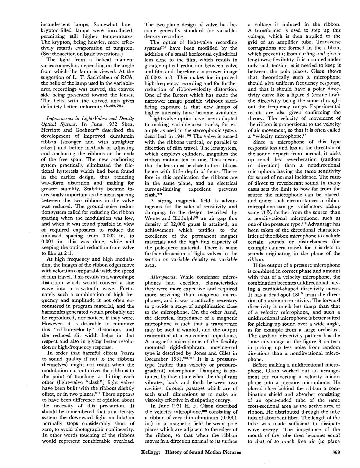
incandescent lamps. Somewhat later,
krypton-filled lamps were introduced,
permitting still higher temperatures.
The krypton, being heavier, more effec-
tively retards evaporation of tungsten.
(See the section on basic inventions.)
The light from a helical filament
varies somewhat, depending on the angle
from which the lamp is viewed. At the
suggestion of
L.
T.
Sachtleben of
RCA,
the helix of the lamp used in the variable-
area recordings was curved, the convex
side being presented toward the lenses.
The helix with the curved axis gives
definitely better unif~rmity.~~~-~~~~
205a
Improvements in Light-Valves
and
Density
Optical Systems.
In June 1932 Shea,
Herriott and GoehneP5 described the
development of improved duralumin
ribbon (stronger and with straighter
edges) and better methods of adjusting
and anchoring the ribbons at the ends
of
the free span. The new anchoring
system practically eliminated the fric-
tional hysteresis which had been found
in the earlier design, thus reducing
waveform distortion and making for
greater stability. Stability became in-
creasingly important as the mean spacing
between the two ribbons in the valve
was reduced. The ground-noise reduc-
tion system called for reducing the ribbon
spacing when the modulation was low,
and when it was found possible in view
of required exposures to reduce the
unbiased spacing from
0.002
in. to
0.001 in. this was done, while still
keeping the optical reduction from valve
to film at 2:l.
At high frequency and high modula-
tion, the images of the ribbon edges move
with velocities comparable with the speed
of
film travel. This results in a waveshape
distortion which would convert a sine
wave into a saw-tooth wave. Fortu-
nately such
a
combination of high fre-
quency and amplitude is not often en-
countered in program material, and the
harmonics generated would probably not
be
reproduced, nor noticed if they were.
However, it is desirable to minimize
thin
“ribbon-velocity’’ distortion, and
the reduced slit width helps in that
respect and also in giving better resolu-
tion or high-frequency response.
In order that harmful effects (harm
to sound quality if not to the ribbons
themselves) might not result when the
modulation current drives the ribbons
to
the point of touching or hitting each
other (light-valve “clash”) light valves
have been built with the ribbons slightly
offset, or in two planes.207 There appears
to have been difference of opinion about
the necessity of this precaution. It
should be remembered that in a density
system the downward light modulation
ncrmally stops considerably short of
zero, to avoid photographic nonlinearity.
In other words touching of the ribbons
would represent considerable overload.
The two-plane design of valve has be-
come generally standard for variable-
density recording.
The optics of light-valve recording
systems207 have been modified by the
addition of a small horizontal cylindrical
lens close to the film, which results in
greater optical reduction between valve
and film and therefore a narrower image
(0.0002 in.). This makes for improved
high-frequency recording and for further
reduction of ribbon-velocity distortion.
One of the factors which has made the
narrower image possible without sacri-
ficing exposure is that new lamps of
higher intensity have become available.
Light-valve optics have been adapted
to making variable-area tracks, for ex-
ample as used in the stereophonic system
described in 1941
.208
The valve is turned
with the ribbons vertical, or parallel to
direction of film travel. The lens system,
which employs cylinders, magnifies the
ribbon motion ten to one. This means
that the lens must be close to the ribbons,
hence with little depth of focus. There-
fore in this application the ribbons are
in the same plane, and an electrical
current-limiting expedient prevents
clash.20Q
A
strong magnetic field is advan-
tageous for the sake of sensitivity and
damping. In the design described by
Wente and Biddulphm an air gap flux
density of
32,000
gauss is attained, an
achievement which testifies
to
the
excellence of the permanent magnet
materials and the high flux capacity of
the pole-piece material. There is some
further discussion of light valves in the
section on variable density vs. variable
area.
Microphones.
While condenser micro-
phones had excellent characteristics
they were more expensive and required
more servicing than magnetic micro-
phones, and it was practically necessary
to provide a stage of amplification close
to the microphone.
On
the other hand,
the electrical impedance of a magnetic
microphone is such that a transformer
may be used if wanted, and the output
transmitted at
a
convenient impedance.
A
magnetic microphone of the flexibly
mounted rigid-diaphram, moving-coil
type is described by Jones and Giles in
December 1931.210*211 It is
a
pressure-
type (rather than velocity or pressure-
gradient) microphone. Damping is ob-
tained by flow of air when the diaphram
vibrates, back and forth between two
cavities, through passages which are of
such small dimensions as to make air
viscosity effective in dissipating energy.
In June 1931
H.
F.
Olson described
the velocity microphone,212 consisting of
a ribbon of very thin aluminum (0.0001
in.) in a magnetic field between pole
pieces which are adjacent to the edges of
the ribbon,
so
that when the ribbon
moves in a direction normal to its surface
a
voltage is induced in the ribbon.
A
transformer is used to step up this
voltage, which is then applied to the
grid of an amplifier tube. Transverse
corrugations are formed in the ribbon,
which prevent it from curling and give it
lengthwise flexibility. It is mounted under
only such tension as is needed to keep it
between the pole pieces. Olson shows
that theoretically such a microphone
should give uniform frequency response,
and that it should have a polar direc-
tivity curve like
a
figure
8
(cosine law),
the directivity being the same through-
out the frequency range. Experimental
results are also given confirming the
theory. The velocity of movement of
the ribbon is proportional to the velocity
of air movement,
so
that it is often called
a “velocity microphone.”
Since a microphone of this type
responds less and less as the direction of
the sound departs from normal, it picks
up much less reverberation (random
in direction) than
a
nondirectional
microphone having the same sensitivity
for sound of normal incidence. The ratio
of direct to reverberant sound in many
cases sets the limit to how far from the
source the microphone can be placed,
and under such circumstances a ribbon
microphone can get satisfactory pickup
some
70%
farther from the source than
a
nondirectional microphone, such as
one of the pressure t~pe.~l3 Advantage has
been taken of the directional character-
istics of the ribbon microphone to exclude
certain sounds or disturbances (for
example camera noise), for it is deaf to
sounds originating in the plane of the
ribbon.
If the output of a pressure microphone
is combined in correct phase and amount
with that of a velocity microphone, the
combination becomes unidirectional, hav-
ing
a
cardioid-shaped directivity curve.
It
has
a
dead-spot 180’ from the direc-
tion of maximum sensitivity. The forward
directivity is much less sharp than that
of
a
velocity microphone, and such
a
unidirectional microphone
is
better suited
for picking up sound over
a
wide angle,
as for example from a large orchestra.
The cardioid directivity pattern has the
same advantage as the figure
8
pattern
in picking up less noise from random
directions than a nondirectional micro-
phone.
Before making a unidirectional micro-
phone, Olson worked out an arrange-
ment for converting a velocity micro-
phone into a pressure microphone. He
placed close behind the ribbon a com-
bination shield and absorber consisting
of an open-ended tube of the same
cross-sectional area as the active area of
ribbon. He distributed through the tube
tufts of absorbent fiber. The length of the
tube was made sufficient to dissipate
wave energy. The impedance of the
mouth of the tube then becomes equal
to
that of
so
much free air (to plane
369
Kellogg:
History
of Sound
Motion
Pictures
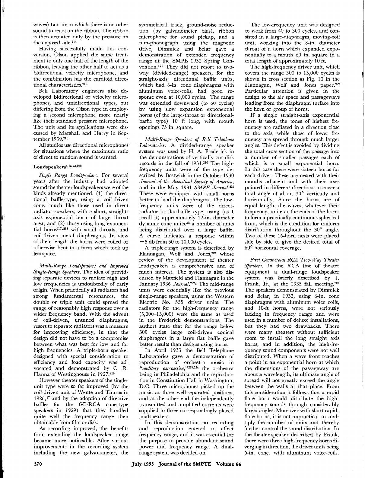
waves) but air in which there is no other
sound to react on the ribbon. The ribbon
is then actuated only by the pressure on
the exposed side.214
Having successfully made this con-
version, Olson applied the same treat-
ment to only one half of the length of the
ribbon, leaving the other half to act as a
bidirectional velocity microphone, and
the combination has the cardioid direc-
tional
characteristic^.^^^
Bell Laboratory engineers also de-
veloped bidirectional or velocity micro-
phones, and unidirectional types, but
differing from the Olson type in employ-
ing a second microphone more nearly
like their standard pressure microphone.
The unit and its applications were dis-
cussed by Marshall and Harry in Sep-
tember
1
939.216
All studios use directional microphones
for situations where the maximum ratio
of direct to random sound is wanted.
loudspeaker^^^^^^^^^^^
Single Range Loudspeakers.
For several
years after the industry had adopted
sound the theater loudspeakers were of the
kinds already mentioned,
(1)
the direc-
tional baffle-type, using a coil-driven
cone, much like those used in direct
radiator speakers, with a short, straight-
axis exponential horn of large throat
area, and (2) those using long exponen-
tial horns217,218 with small throats, and
coil-driven metal diaphragms. In view
of their length the horns were coiled or
otherwise bent to a form which took up
less space.
Multi-Range Loudspeakers and Improved
Single-Range Steakers.
The idea of provid-
ing separate devices to radiate high and
low frequencies is undoubtedly of early
origin. When practically all radiators had
strong fundamental resonances, the
double or triple unit could spread the
range of reasonably high response over a
wider frequency band. With the advent
of coil-driven, untuned diaphragms,
resort to separate radiators was a measure
for improving efficiency, in that the
design did not have to be a compromise
between what was best for low and for
high frequencies.
A
triple-horn speaker
designed with special consideration to
efficiency and load capacity was ad-
vocated and demonstrated by C. R.
Hanna of Westinghouse in 1927.219
However theater speakers of the single-
unit type were
so
far improved (by the
coil-driven unit of Wente and Thuras in
1926,57 and by the adoption of directive
baffles for the GE-RCA cone-type
speakers in 1929) that they handled
quite well the frequency range then
obtainable from film or disk.
As
recording improved, the benefits
from extending the loudspeaker range
became more noticeable. After various
improvements in the recording system
including the new galvanometer, the
symmetrical track, ground-noise reduc-
tion (by galvanometer bias), ribbon
microphone for sound pickup, and a
film-phonograph using the magnetic
drive, Dimmick and Belar gave
a
demonstration of extended frequency
range at the SMPE 1932 Spring Con-
~enti0n.l’~ They did not resort to two-
way (divided-range) speakers, for the
straight-axis, directional baffle units,
which had 6-in. cone diaphragms with
aluminum voice-coils, had good re-
sponse even at
10,000
cycles. The range
was extended downward (to 60 cycles)
by using slow expansion exponential
horns (of the large-throat or directional-
baffle type)
10
ft long, with mouth
openings 75 in. square.
Multi-Range Speakers
of
Bell
Telephone
Laboratories.
A divided-range speaker
system was used by
H.
A.
Frederick in
the demonstrations of vertically cut disk
records in the fall of 1931.220 The high-
frequency units were of the type de-
scribed by Bostwick in the October 1930
Journal
of
the Acoustical Society
of
America,
and in the May 1931
SMPE Journal.n1
These were equipped with small horns
better to load the diaphragms. The low-
frequency units were of the direct-
radiator or flat-baffle type, using (as
I
recall it) approximately 12-in. diameter
dynamic cone units,38 a number of units
being distributed over a large baffle.
A curve indicates a response within
rt
5
db from
50
to
10,000
cycles.
A triple-range system is described by
Flannagan, Wolf and Jones,% whose
review of the development of theater
loudspeakers is comprehensive and of
much interest. The system is also dis-
cussed by Maxfield and Flannagan in the
January 1936
Journa1.222a
The mid-range
units were essentially like the previous
single-range speakers, using the Western
Electric
No.
555
driver units. The
radiators for the high-frequency range
(3,000-13,000) were the same as used
in the Frederick demonstrations. The
authors state that for the range below
300 cycles large coil-driven conical
diaphragms in a large flat baffle gave
better results than designs using horns.
In April 1933 the Bell Telephone
Laboratories gave a demonstration of
reproduction of orchestra music in
“auditory per~pective,”~~~~~
the orchestra
being in Philadelphia and the reproduc-
tion in Constitution Hall in Washington,
D.C. Three microphones picked up the
music at three well-separated positions,
and at the other end the independently
transmitted and amplified currents were
supplied to three correspondingly placed
loudspeakers.
In this demonstration no recording
and reproduction entered to affect
frequency range, and it was essential for
the purpose to provide abundant sound
power and frequency range.
A
dual-
range system was decided on.
The low-frequency unit was designed
to work from
40
to 300 cycles, and con-
sisted in a large-diaphragm, moving-coil
unit, working into the %in. diameter
throat of a horn which expanded expo-
nentially to a mouth 60 in. square in a
total length of approximately
10
ft.
The high-frequency driver unit, which
covers the range
300
to 13,000 cycles is
shown in cross section as Fig.
10
in the
Flannagan, Wolf and Jones paper.n2
Particular attention is given in the
design to the air space and passageways
leading from the diaphragm surface into
the horn or group of horns.
If
a single straight-axis exponential
horn is used, the tones of highest fre-
quency are radiated in
a
direction close
to the axis, while those of lower fre-
quency are spread through much larger
angles. This defect is avoided by dividing
the total cross section of the passage into
a number of smaller passages each of
which is a small exponential horn.
In this case there were sixteen horns for
each driver. These are nested with their
mouths adjacent and with their axes
pointed in different directions to cover a
total angle of about 30’ vertically and
horizontally. Since the horns are of
equal length, the waves, whatever their
frequency, unite at the ends of the horns
to form a practically continuous spherical
front, which is the condition for uniform
distribution throughout the 30’ angle.
Two of these 16-horn nests were placed
side by side to give the desired total of
60’ horizontal coverage.
First Commercial
RCA
Two- Way Theater
Speakers.
In the RCA line of theater
equipment a dual-range loudspeaker
system was briefly described by
J.
Frank, Jr., at the 1935 fall meetingzz5
The speakers demonstrated by Dimmick
and Belar, in 1932, using 6-in. cone
diaphragms with aluminum voice coils,
and 10-ft horns, were not seriously
lacking in frequency range and were
used in a number of deluxe installations,
but they had two drawbacks. There
were many theaters without sufficient
room to install the long straight axis
horns, and in addition, the high-fre-
quency sound components were not well
distributed. When
a
wave front reaches
a point in an exponential horn at which
the dimensions of the passageway are
about a wavelength, its ultimate angle of
spread will not greatly exceed the angle
between the walls at that place. From
this consideration it follows that a rapid
flare horn would distribute the high-
frequency sounds through considerably
larger angles. Moreover with short rapid-
flare horns, it is not impractical to mul-
tiply the number of units and thereby
further control the sound distribution. In
the theater speaker described by Frank,
there were three high-frequency horns di-
verging in direction, the driver units being
6-in. cones with aluminum voice-coils.
370
July
1955
Journal
of
the
SMPTE
Volume
64
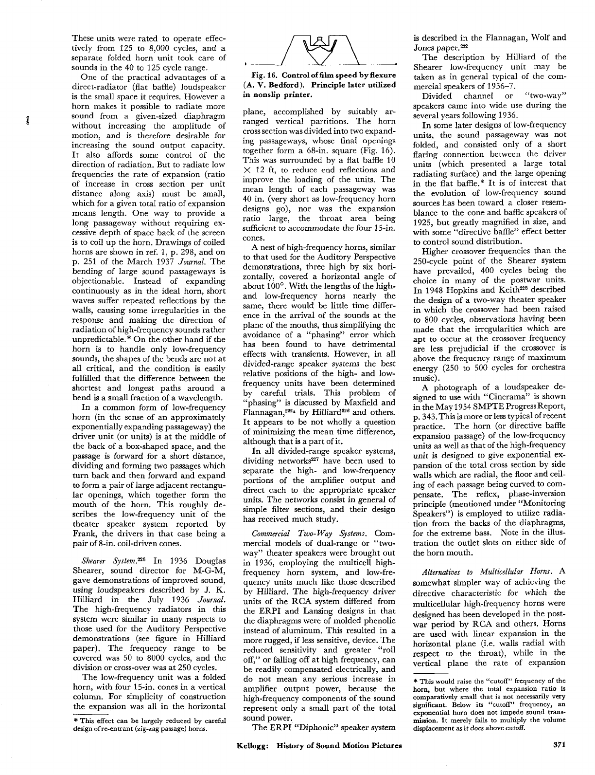
r
s
These units were rated to operate effec-
tively from 125 to 8,000 cycles, and a
separate folded horn unit took care of
sounds in the 40 to 125 cycle range.
One of the practical advantages of a
direct-radiator (flat baffle) loudspeaker
is the small space it requires. However a
horn makes it possible to radiate more
sound from a given-sized diaphragm
without increasing the amplitude of
motion, and is therefore desirable for
increasing the sound output capacity.
It
also affords some control of the
direction of radiation. But to radiate low
frequencies the rate of expansion (ratio
of increase in cross section per unit
distance along axis) must be small,
which for a given total ratio of expansion
means length. One way to provide a
long passageway without requiring ex-
cessive depth of space back of the screen
is to coil up the horn. Drawings of coiled
horns are shown in ref.
1,
p. 298, and on
p. 251 of the March 1937
Journal.
The
bending of large sound passageways is
objectionable. Instead of expanding
continuously as in the ideal horn, short
waves suffer repeated reflections by the
walls, causing some irregularities in the
response and making the direction of
radiation of high-frequency sounds rather
unpredictable.* On the other hand if the
horn is to handle only low-frequency
sounds, the shapes of the bends are not at
all critical, and the condition is easily
fulfilled that the difference between the
shortest and longest paths around a
bend is a small fraction of a wavelength.
In a common form of low-frequency
horn (in the sense of an approximately
exponentially expanding passageway) the
driver unit
(or
units) is at the middle of
the back of a box-shaped space, and the
passage is forward for
a
short distance,
dividing and forming two passages which
turn back and then forward and expand
to form a pair of large adjacent rectangu-
lar openings, which together form the
mouth of the horn.
This roughly de-
scribes the low-frequency unit of the
theater speaker system reported by
Frank, the drivers in that case being a
pair of 8-in. coil-driven cones.
Shearer
System.n6 In 1936 Douglas
Shearer, sound director for M-G-M,
gave demonstrations of improved sound,
using loudspeakers described by
J.
K.
Hilliard in the July 1936 Journal.
The high-frequency radiators in this
system were similar in many respects to
those used for the Auditory Perspective
demonstrations (see figure in Hilliard
paper). The frequency range to be
covered was 50 to 8000 cycles, and the
division or cross-over was at 250 cycles.
The low-frequency unit was a folded
horn, with four 15-in. cones in
a
vertical
column. For simplicity of construction
the expansion was all in the horizontal
*
This effect can be largely reduced by careful
design
of
re-entrant (zig-zag passage) horns.
Fig.
16.
Controloffilm speed
by
flexure
(A.
V.
Bedford). Principle later utilized
in
nonslip printer.
plane, accomplished by suitably ar-
ranged vertical partitions. The horn
cross section was divided into two expand-
ing passageways, whose final openings
together form a 68-in. square (Fig. 16).
This was surrounded by a flat baffle 10
X
12 ft, to reduce end reflections and
improve the loading of the units. The
mean length of each passageway was
40
in. (very short as low-frequency horn
designs
go),
nor was the expansion
ratio large, the throat area being
sufficient to accommodate the four 15-in.
cones.
A nest of high-frequency horns, similar
to that used for the Auditory Perspective
demonstrations, three high by six hori-
zontally, covered
a
horizontal angle of
about
looo.
With the lengths of the high-
and low-frequency horns nearly the
same, there would be little time differ-
ence in the arrival of the sounds at the
plane of the mouths, thus simplifying the
avoidance of
a
“phasing” error which
has been found to have detrimental
effects with transients. However, in all
divided-range speaker systems the best
relative positions of the high- and low-
frequency units have been determined
by careful trials. This problem of
“phasing” is discussed by Maxfield and
Flannagan,zza by Hilliardz6 and others.
It
appears to be not wholly
a
question
of minimizing the mean time difference,
although that is a part of it.
In all divided-range speaker systems,
dividing networksn7 have been used to
separate the high- and low-frequency
portions of the amplifier output and
direct each to the appropriate speaker
units. The networks consist in general of
simple filter sections, and their design
has received much study.
Commercial
Two-
Way
Systems. Com-
mercial models of dual-range or “two-
way” theater speakers were brought out
in 1936, employing the multicell high-
frequency horn system, and low-fre-
quency units much like those described
by Hilliard. The high-frequency driver
units of the RCA system differed from
the ERPI and Lansing designs in that
the diaphragms were of molded phenolic
instead of aluminum. This resulted in a
more rugged, if less sensitive, device. The
reduced sensitivity and greater “roll
off,” or falling off at high frequency, can
be readily compensated electrically, and
do not mean any serious increase in
amplifier output power, because the
high-frequency components of the sound
represent only a small part of the total
sound power.
The ERPI “Diphonic” speaker system
Kellogg:
History of Sound Motion Pictures
is described in the Flannagan, Wolf and
Jones paper.2n
The description by Hilliard of the
Shearer low-frequency unit may be
taken as in general typical of the com-
mercial speakers of
1936-7.
Divided channel or “two-way”
speakers came into wide use during the
several years following 1936.
In some later designs of low-frequency
units, the sound passageway was not
folded, and consisted only of
a
short
flaring connection between the driver
units (which presented a large total
radiating surface) and the large opening
in the flat baffle.* It is of interest that
the evolution of low-frequency sound
sources has been toward a closer resem-
blance to the cone and baffle speakers
of
1925, but greatly magnified in size, and
with some “directive baffle” effect better
to
control sound distribution.
Higher crossover frequencies than the
250-cycle point of the Shearer system
have prevailed, 400 cycles being the
choice in many of the postwar units.
In 1948 Hopkins and Keith228 described
the design of a two-way theater speaker
in which the crossover had been raised
to
800
cycles, observations having been
made that the irregularities which are
apt to occur at the crossover frequency
are less prejudicial if the crossover is
above the frequency range of maximum
energy (250 to 500 cycles for orchestra
music).
A photograph of a loudspeaker de-
signed to use with “Cinerama” is shown
in the May 1954 SMPTE ProgressReport,
p. 343.This is more or less typical of recent
practice. The horn (or directive baffle
expansion passage) of the low-frequency
units as well as that of the high-frequency
unit is designed to give exponential ex-
pansion of the total cross section by side
walls which are radial, the floor and ceil-
ing of each passage being curved to com-
pensate. The reflex, phase-inversion
principle (mentioned under “Monitoring
Speakers”) is employed to utilize radia-
tion from the backs
of
the diaphragms,
for the extreme bass. Note in the illus-
tration the outlet slots on either side of
the horn mouth.
Alternatives
to
Multicellular
Horns.
A
somewhat simpler way of achieving the
directive characteristic for which the
multicellular high-frequency horns were
designed has been developed in the post-
war period by RCA and others. Horns
are used with linear expansion in the
horizontal plane (i.e. walls radial with
respect to the throat), while in the
vertical plane the rate of expansion
~
*
This would raise the “cutoff” frequency of the
horn,
but
where the total expansion ratio is
comparatively small that is not necessarily very
significant. Below its “cutoff’ frequency, an
exponential horn does not impede sound trans-
mission. It merely fails to multiply the volume
displacement as
it
does above cutoff.
371
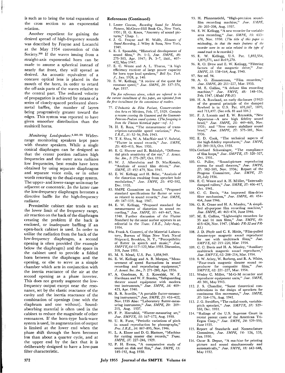
is such as to bring the total expansion of
the cross section to an exponential
relation.
Another expedient for gaining the
desired spread of high-frequency sounds
was described by Frayne and Locanthi
at the May
1954
convention of this
Society.229 If the waves issuing from a
straight-axis exponential horn can be
made to assume a spherical instead of
nearly flat front, they will spread as
desired. An acoustic equivalent of a
concave optical lens is placed in the
mouth of the horn, in order to retard
the off-axis parts of the waves relative to
the central part. The reduced velocity
of propagation is achieved by means of a
series of closely-spaced perforated sheet-
metal baffles, the number of layers
being progressively greater toward the
edges. This system was reported to have
given smoother distribution than the
multicell horns.
Monitoring
Loudspeakers.4,230.231
Wider-
range monitoring speakers kept pace
with theater speakers. While a single
conical diaphragm can be designed
so
that the center portion radiates high
frequencies and the outer area radiates
low frequencies, best results have been
obtained by using separate diaphragms
and separate voice coils,
or
in other
words resorting to the dual-range system.
The upper- and lower-range units may be
adjacent
or
concentric. In the latter case
the low-frequency diaphragm becomes a
directive baffle for the high-frequency
radiator.
Permissible cabinet size tends to set
the lower limit of the frequency range,
air reaction on the back of the diaphragm
creating the problem if the back
is
enclosed,
or
inadequate baffling if an
open-back cabinet is used. In order to
utilize the radiation from the back of the
low-frequency diaphragm, a second
opening is often provided (for example
below the diaphragm) and the space in
the cabinet used to provide a folded
horn between the diaphragm and the
opening, or else to serve as a simple
chamber which acts in conjunction with
the inertia reactance of the air at the
second opening as a phase inverter.
This does not greatly augment the low-
frequency output except near the reso-
nance, set by the elastic reactance of the
cavity and the inertia reactance of the
combination of openings (one with the
diaphram and one without). Sound-
absorbing material is often used in the
cabinet to reduce the magnitude of other
resonances.
If
the horn-type back-wave
system is used, its augmentation of output
is limited at the lower end when the
phase shift through the horn becomes
less
than about a quarter cycle, and at
the upper end by the fact that it
is
deliberately designed to have a low-pass
filter characteristic.
References (Continued)
1.
Lester Cowan,
Recording Sound
for
Motion
Pictures,
McGraw-Hill Book Co., New York,
1931
;
H.
G.
Knox, “Ancestry of sound pic-
tures,’’ Chap. 1.
4.
J.
G. Frayne and H. Wolfe,
Elements
of
Sound Recording,
J.
Wiley
&
Sons,
New York,
1949.
6. E.
I.
Sponable, “Historical development of
sound films,” Pt. 1-2,
Jour. SMPE,
48:
275-303, Apr. 1947; Pt. 3-7, ibid., 407-
422, May 1947.
57. E. C. Wente and A. L. Thuras, “A high
efficiency receiver of large power capacity
for horn type loud speakers,”
Bell
Sys. Tech.
J.,
Jan. 1928, p. 140.
70. E. W. Kellogg, “A review of the quest for
constant speed,”
Jour.
SMPE,
28:
337-376,
Apr. 1937.
The
fioe
references
above,
which
are
referred
to in
the current installment
of
this
paper,
are
reprinted from
the
first
installment
for
the convenience
of
readers.
77.
78.
79.
80.
81.
82.
83.
84.
L‘Industrie
du
Film Parlant,
Conservatoire
des Arts et Metiers, Feb. 17, 1929.
Contains
a
resume cowing the Gaumont and the Gaumont-
Peterson-Poulsen sound systems. (The foregoing
is
from the Theisen
historkal
paper-ref.
5.)
H. E. Roys, “The measurement of trans-
cription-turntable speed variation,”
Proc.
I.R.E.,
31:
52-56, Feb. 1943.
T.
E. Shea, W. A. MacNair and
V.
Suhrizi,
“Flutter in sound records,”
Jour. S.MPE,
E.
G.
Shower and R. Biddulph, “Differen-
tial pitch sensitivity of the ear,”
J.
Acoust.
Sac.
Am.,
3:
215-287, Oct. 1931.
W.
J.
Albersheim and D. MacKenzie,
“Analysis of sound film drives,”
Jour.
SMPE,
37:
452-479, Nov. 1941.
E. W. Kellogg and H. Belar, “Analysis of
the distortion resulting from sprocket hole
modulation,”
Jour. SMPE,
25:
492-502,
Dec. 1935.
SMPE Committee on
Sound,
“Proposed
standard specifications for flutter or
wow
as related to sound records,”
Jour.
SMPE,
E. W. Kellogg, “Proposed standard for
measurement of distortion in sound re-
cording,”
Jour.
SMPE,
51:
449-467, Nov.
1948. Further discussion of the Flutter
Standard by the same author appears in an
editorial in the
Trans. I.R.E.,
July-Aug.,
1954.
25:
403-415, NOV. 1935.
49:
147-159, Aug. 1947.
84a.
Frank A. Comerci, of the Material Labora-
tory, Bureau of Ships New York Naval
Shipyard, Brooklyn, N.
Y.,
“Perceptibility
of flutter in speech and music,”
Jour.
SMPTE,
64:
117-122, Mar. 1955.Discusnion,
318, June 1955.
85. M.
S.
Mead,
U.S.
Pat. 1,854,949.
86. E. W. Kellogg and A. R. Morgan, “Meas-
urement of speed fluctuations in sound
recording and reproducing equipment,”
J. Acoust.
Sac.
Am.,
7:
271-280, Apr. 1936.
87. A. Goodman, R.
J.
Kowalski,
W.
F.
Hardman and W.
F.
Stanko, “Safeguarding
theater sound equipment with modern
test instruments,”
Jour.
SMPE,
34:
409-
423, Apr. 1940.
88. R. R. Scoville, “A portable flutter-measur-
ing instrument,”
Jour. SMPE,
25:
41 6-422,
Nov. 1935 Also: “Laboratory flutter-meas-
uring instrument,”
Jour.
SMPE,
29:
209-
215, Aug. 1937.
89. F. P. Herrnfeld, “Flutter-measuring set,”
90.
U.
R. Furst, “Periodic variations of pitch
in sound reproduction by phonographs,”
91. L. A. Elmer and D.
G.
Blattner, “Machine
for cutting master disc records,”
Trans.
92. P.
H.
Evans, “A comparative study of
sound on disk and film,”
Jour. SMPE,
15:
Jour.
SMPTE,
55:
167-172, Aug. 1950.
Proc.
I.R.E.,
34:
887-895, NOV. 1946.
SMPE,
37:
227-246, 1929.
185-192, Aug. 1930.
93.
94.
95.
96.
97.
98.
99.
100.
101.
102.
H. Pfannenstiehl, “High-precision sound-
film recording machine,”
Jour.
S.I.IPE,
E. W. Kellogg, “A new recorder for variabl:
area recording,”
Jour. SMPE,
15:
653-
670, Nov. 1930.
(The title
of
this
paper
is
misleading,
in
that the main features
of
the
recorder were
in
no
wise related to the type
0,’
sound track to
be
recorded.)
E. W. Kellogg,
U.S.
Pat. 1,892,554,
1,899,571, and Re19,270.
R.
0.
Drew and E. W. Kellogg, “Filtering
factors of the magnetic drive,”
Jou~.
See ref. 94.
A.
G.
Zimmerman, “Film recorders,”
Jour. SMPE,
20:
211-227, Mar. 1933.
M. E. Collins, “A deluxe film recording
machine,”
Jour. SMPE,
48:
148-156,
Feb. 1947.
(Model PR-31)
H.
A. Rowland, an early disclosure (1902)
of the general principle of the damped
flywheel is in
U.S.
Pat. 691,667, 1899,
and 713,497. (See refs. 81 and 104.)
F. J, Loomis and E. W. Reynolds, “New
Apparatus-A new high fidelity sound
head,”
Jour. SMPE,
25:
449-460, Nov.
1935; and “New rotary stabilizer sound
head,”
Jour.
SMPE,
27:
575-581, Nov.
1936.
E. D. Cook, “The technical aspects of
the high-fidelity reproducer,”
Jour. SMPE,
25:
289-313, Oct. 1935.
29:
202-208, Aug. 1937.
SMPE,
35:
138-164, Aug. 1940.
102a.Gerhard Schwesineer. “The compliance
103.
104.
105.
106.
107.
108.
109.
110.
111.
112.
113.
114.
of
film loops,”
Jour-SMPTE,
57:
320-327,
Oct. 1951.
G. Puller, “Sound-picture reproducing
system for small theaters,”
Jour. SMPE,
27:
582-589, Nov. 1936; Report of the
Progress Committee,
Jour. SMPE,
27:
29, July 1936.
E. C. Wente and A. H. Miiller, “Internally
damped rollers,”
Jour. SMPE,
37:
406-417,
Oct. 1941.
C. C. Davis, “An improved film-drive
filter mechanism,”
Jour. SMPE,
46:
454-
464, June 1946.
G.
R.
Crane and H. A. Manley, “A simpli-
fied all-purpose film recording machine,”
Jour. SMPE,
46:
465-474, June 1946.
M. E. Collins, “Lightweight recorders for
35 and 16 mm films,”
Jour. SMPE,
49:
415-424, Nov. 1947.
(Models PR-32 and PR-
J.
D. Phyfe and
C.
E. Hittle, “Film-pulled
theater-type magnetic sound reproducer
for use with multitrack films,”
Jour.
SMPTE,
62:
215-220, Mar. 1954.
C. C. Davis and H. A. Manley, “Auxiliary
multitrack magnetic sound reproducer,”
Jour.
SMPTE,
62:
208-214, Mar. 1954.
S.
W. Athey, W. Borberg, and R. A. White,
“Four-track magnetic theater sound re-
producer for composite films,”
Jour.
SMPTE,
62:
221-227, Mar. 1954.
Wesley C. Miller, “M-G-M recorder and
reproducer equipment units,”
Jour. SMPE,
40:
301, May 1943.
J.
S.
Chandler, “Some theoretical con-
siderations in the design of sprockets for
continuous film movement,”
Jour.
SMPE,
37:
164-176, Aug. 1941.
J.
G. Streiffert, “The radial-tooth, variable-
pitch sprocket,”
Jour. SMPTE,
57:
529-
550, Dec. 1951.
“Rulings of the
U.S.
Supreme Court in
recent patent cases of the American Tri-
Ergon Corp.,”
Jour.
SMPE,
24:
529-550,
June 1935.
33.)
115. Report of Standards and Nomenclature
Committee,
Jour. SMPE,
14:
126, 133,
Jan. 1930.
116. Oscar B. Depue, “A machine for printing
picture and sound simultaneously and
automatically,”
Jour. SMPE,
18:
643-648,
May 1932.
372
July
1955
Journal
of
the
SMPTE
Volume
64
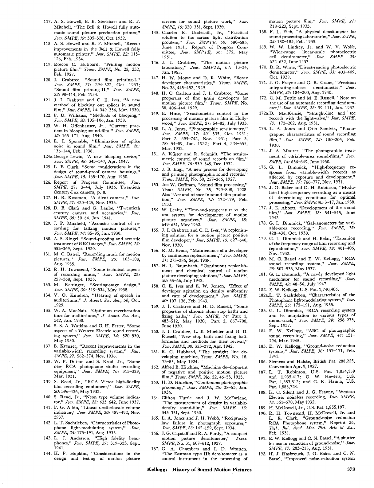
117. A.
S.
Howell, B. E. Steckbart and R. F.
Mitchell, “The Bell
&
Howell fully auto-
matic sound picture production printer,”
Jour.
SMPE,
19:
305-328, Oct. 1932.
118. A.
S.
Howell and R. F. Mitchell, “Recent
improvements in the Bell
&
Howell fully
automatic printer,”
Jour.
SMPE,
22:
115-
126, Feb. 1934.
119. Roscoe C. Hubbard, “Printing motion
picture film,”
Trans.
SMPE,
No. 28, 252,
Feb. 1927.
120.
J.
Crabtree, “Sound film printing-I,”
Jour.
SMPE,
21:
294-322, Oct. 1933;
“Sound film printing-11,”
Jour.
SMPE,
22:
98-114, Feb. 1934.
121.
J.
I. Crabtree and C. E. Ives, “A new
method
of
blocking out splices in sound
film,”
JOU7.
SMPE,
14:
349-356, Mar. 1930.
122. F. D. Williams, “Methods of blooping,”
Jour.
SMPE,
30:
105-106, Jan. 1938.
123. W.
H.
Offenhauser,
Jr.,
“Current prac-
tices in blooping sound-film,”
Jour.
SMPE,
124. E.
I.
Sponable, “Elimination
of
splice
noise in sound film,”
Jour.
SMPE,
26:
136-144, Feb. 1936.
124a.George Lewin, “A new blooping device,”
Jour.
SMPE,
48:
343-347, Apr. 1947.
125.
L.
E. Clark, “Some considerations in the
design of sound-proof camera housings,”
Jour.
SMPE,
15:
165-170, Aug. 1930.
126. Report of Progress Committee,
Jour.
SMPE,
27: 3-44, July 1936. Twentieth
Century-Fox camera, p. 8.
127. H. R. Kossman, “A silent camera,”
Jour.
SMPE,
21:
420-425, Nov. 1933.
128. D. B. Clark and G. Laube, “Twentieth
century camera and accessories,”
Jour.
SMPE,
36:
50-64, Jan. 1941.
129.
J.
P. Maxfield, “Acoustic control of re-
cording for talking motion pictures,”
Jour.
SMPE,
14:
85-95, Jan. 1930.
130. A.
S.
Ringel, “Sound-proofing and acoustic
treatment of RKO stages,”
Jour.
SMPE,
15:
352-369, Sept. 1930.
131. M. C. Batsel, “Recording music for motion
pictures,”
Jour.
SMPE,
25:
103-108,
Aug. 1935.
132. R. H. Townsend, “Some technical aspects
of recording music,’’
Jour.
SMPE,
25:
259-268, Sept. 1935.
133. M. Rettinger, “Scoring-stage design,”
Jour.
SMPE,
30:
519-534, May 1938.
134.
V.
0.
Knudsen, “Hearing of speech in
auditoriums,”
J.
Acoust.
Sac.
Am.,
56,
Oct.
1929.
135. W. A. MacNair, “Optimum reverberation
time for auditoriums,”
J.
Acoust.
Soc.
Am.,
242,
Jan. 1930.
136.
S. S.
A. Watkins and
C.
H. Fetter, “Some
aspects of a Western Electric sound record-
ing system,”
Jour.
SMPE,
14:
520-530,
May 1930.
137. B. Kreuzer, “Recent improvements in the
variable-width recording system,”
Jour.
138. W.
P.
Dutton and
S.
Read,
Jr.,
“Some
new RCA photophone studio recording
equipment,”
Jour.
SMPE,
16:
315-329,
Mar. 1931.
139.
S.
Read,
Jr.,
“RCA Victor high-fidelity
film recording equipment,”
Jour.
SMPE,
20:
396-436, May 1933.
140.
S.
Read,
Jr.,
“Neon type volume indica-
tor,”
Jour.
SMPE,
28:
633-642, June 1937.
141. F.
G.
Albin, “Linear decibel-scale volume
indicator,”
Jour.
SMPE,
29:
489-492, Nov.
1937.
142. L.
T.
Sachtleben, “Characteristics of Photo-
phone light-modulating system,”
Jour.
143.
L.
J.
Anderson, “High fidelity head-
phones,”
Jour.
SMPE,
37:
319-323, Sept.
1941.
144. H.
F.
Hopkins, “Considerations in the
design and testing of motion picture
35:
165-171, Aug. 1940.
SMPE,
27:
562-574, NOV. 1936.
SMPE,
25:
175-191, Aug. 1935.
screens for sound picture work,”
Jour.
SMPE,
15:
320-331, Sept. 1930.
145. Charles R. Underhill,
Jr.,
“Practical
solution to the screen light distribution
problem,”
Jour.
SMPTE,
56:
680-683,
June 1951; Report of Progress Com-
mittee,
Jour.
SMPTE,
56:
575, May
1951.
146.
J.
I.
Crabtree, “The motion picture
laboratory,”
Jour.
SMPTE,
64:
13-34,
Jan. 1955.
147. H. W. Moyse and
D.
R. White, “Borax
developer characteristics,”
Trans.
SMPE,
148. H. C. Carlton and
J.
I.
Crabtree, “Some
properties of fine grain developers for
motion picture film,”
Trans.
SMPE,
No.
38, 406-444,1929.
149.
E.
Huse, “Sensitometric control in the
processing of motion picture film in Holly-
wood,”
Jour.
SMPE,
21:
54-82, July 1933.
150. L. A. Jones, “Photographic sensitometry,”
Jour.
SMPE,
17:
491-535, Oct. 1931;
Part 2, 695-742, Nov. 1931; Part 3,
18:
54-89, Jan. 1932; Part 4, 324-355,
Mar. 1932.
151. A. Kiister and R. Schmidt, “The sensito-
metric control of sound records on film,”
Jour.
SMPE,
79:
539-545, Dec. 1932.
152.
J.
B. Engl, “A new process for developing
and printing photographic sound records,”
Trans.
SMPE,
No. 30, 257-266, 1927.
153. Joe W. Coffman, “Sound film processing,”
Trans.
SMPE,
No. 35, 799-808, 1928.
Also “Art and science in sound film produc-
tion,”
Jour.
SMPE,
14:
172-179, Feb.
1930.
154. W. Leahy, “Time-and-temperature vs. the
test system for development of motion
picture negatives,”
Jour.
SMPE,
18:
649-651, May 1932.
155.
J.
I.
Crabtree and C.
E.
Ives, “A replenish-
ing solution for a motion picture positive
film developer,”
Jour.
SMPE,
15:
627-640,
Nov. 1930.
156. R. M. Evans, “Maintenance of a developer
by continuous replenishment,”
Jour.
SMPE,
31:
273-286, Sept. 1938.
157. H.
L.
Baumbach, “Continuous replenish-
ment and chemical control of motion
picture developing solutions,”
Jour.
SMPE,
158. C. E. Ives and E. W. Jensen, “Effect
of
developer agitation on density uniformity
and rate of development,”
Jour.
SMPE,
40:
107-136, Feb. 1943.
159.
J.
I.
Crabtree and H. D. Russell, “Some
properties of chrome alum stop baths and
fixing baths,”
Jour.
SMPE,
14:
Part 1,
483-512, May 1930; Part 2, 667-700,
June 1930.
160.
J.
I.
Crabtree,
L.
E. Muehler and
H.
D.
Russell, “New stop bath and fixing bath
formulas and methods for their revival,”
Jour.
SMPE,
38:
353-372, Apr. 1942.
161. R. C. Hubbard, “The straight line de-
veloping machine,
Trans.
SMPE,
No.
18,
73-85, May 1924.
162. Alfred B. Hitchins, “Machine development
of negative and positive motion picture
film,”
Trans.
SMPE,
No. 22, 46-53, 1925.
163. H. D. Hineline, “Continuous photographic
processing,”
Jour.
SMPE,
26:
38-53, Jan.
1936.
164. Clifton Tuttle and
J.
W. McFarlane,
“The measurement of density in variable-
density sound-film,”
Jour.
SMPE,
15:
345-351, Sept. 1930.
165. L. A. Jones and
J.
H. Webb, “Reciprocity
law failure in photograph exposures,”
Jour.
SMPE,
23:
142-159, Sept. 1934.
166.
J.
G. Capstaff and R. A. Purdy, “A compact
motion picture densitometer,”
Trans.
SMPE,
NO. 31, 607-612, 1927.
167.
G.
A. Chambers and
I.
D. Wratten,
“The Eastman type IIb densitometer as a
control instrument in the processing of
NO. 38,445-452,1929.
39:
55-66, July 1942.
motion picture film,”
Jour.
SMPE,
21:
218-223, Sept. 1933.
168. F. L. Eich, “A physical densitometer for
sound processing laboratories,”
Jour.
SWPE,
24:
180-183, Feb. 1935.
169.
W.
W. Lindsey,
Jr.
and W. V. Wolfe,
“Wide-range, linear-scale photoelectric
cell densitometer,”
Jour.
SMPE,
28:
622-632, June 1937.
170.
D.
R. White, “Direct-reading photoelectric
densitometer,”
Jour.
SMPE,
33:
403-409,
Oct. 1939.
171.
J.
G.
Frayne and
G.
R. Crane, “Precision
integrating-sphere densitometer,”
Jour.
SMPE,
35:
184-200, Aug. 1940.
172. C.
M.
Tuttle and M. E. Russell, “Note on
the use of an automatic recording densitom-
eter,”
Jour.
SMPE,
28:
99-111, Jan. 1937.
172a.D.
MacKenzie, “Straight-line and
’
toe
records with the light-valve,”
Jour.
SMPE,
77:
172-202, Aug. 1931.
173. L. A. Jones and Otto Sandvik, “Photo-
graphic characteristics of sound recording
film,”
Jour.
SMPE,
14:
180-203, Feb.
1930.
174.
J.
A. Maurer, “The photographic treat-
ment of vririable-area sound-films,”
Jour.
SMPE,
14:
636-649, June 1930.
175.
G.
L. Dimmick, “High-frequency re-
sponse from variable-width records as
affected by exposure and development,”
Jour.
SMPE,
17:
766-777, Nov. 1931.
176.
J.
0.
Baker and D. H. Robinson, “Modu-
lated high-frequency recording as a means
of determining conditions for optimal
processing,”
Jour.
SMPE
30:
3-17, Jan. 1938.
177.
J.
E. Abbott, “Development of the sound
film,”
Jour.
SMPE,
38:
541-545, June
1942.
178.
G.
L.
Dimmick, “Galvanometers for vari-
able-area recording,”
Jour.
SMPE,
15:
179. G. L. Dimmick and H. Belar, “Extension
of the frequency range of film recording and
reproduction,”
Jour.
SMPE,
19:
401-406,
Nov. 1932.
180. M. C. Batsel and E. W. Kellogg, “RCA
sound recording system,”
Jour.
SMPE,
28:
507-533, May 1937.
181.
G.
L. Dimmick, “A newly developed light
modulator for sound recording,”
Jour.
428-438, Oct. 1930.
SMPE,
49:
48-56, July 1947.
182.
E.
W. Kellogg,
U.S.
Pat. 1,740,406.
182a.L.
T.
Sachtleben, “Characteristics of the
Photophone light-modulating system,”
Jour.
SMPE,
25:
175-191, Aug. 1935.
183.
G.
L.
Dimmick, “RCA recording system
and its adaptation to various types of
sound-track,”
Jour.
SMPE,
29:
258-273,
Sept. 1937.
184. E. W. Kellogg, “ABC of photographic
sound recording,”
Jour.
SMPE,
44:
151-
194, Mar. 1945.
185.
E.
W. Kellogg, “Ground-noise reduction
systems,”
Jour.
SMPE,
36:
137-171, Feb.
1941.
186. Siemens and Halske, British Pat. 288,225,
Convention Apr. 9,1927.
187. L.
T.
Robinson,
U.S.
Pat. 1,854,159
and 1,935,417; C. W. Hewlett,
U.S.
Pat. 1,853,812; and C. R. Hanna,
U.S.
Pat. 1,888,724.
188.
H.
C. Silent and
J.
G. Frayne, “Western
Electric noiseless recording,
Jour.
SMPE,
78:
551-570, May 1932.
189.
H.
McDowell,
Jr.,
US.
Pat. 1,855,197.
190.
R.
H. Townsend, H. McDowell,
Jr.
and
L.
E.
Clark, “Ground-noise reduction
RCA Photophone system,” Reprint 26,
Tech.
Bul.
Acad.
Mot. Pict.
Arts
&3
Sci.,
Feb. 1931.
191.
E.
W. Kellogg and C. N. Batsel, “A shutter
for use in reduction of ground-noise,”
Jour.
192. H.
J.
Hasbrouck,
J.
0.
Baker and
C.
N.
Batsel, “Improved noise-reduction system
SMPE,
17:
203-215, Aug. 1931.
Kellogg:
History
of
Sound
Motion
Pictures
373
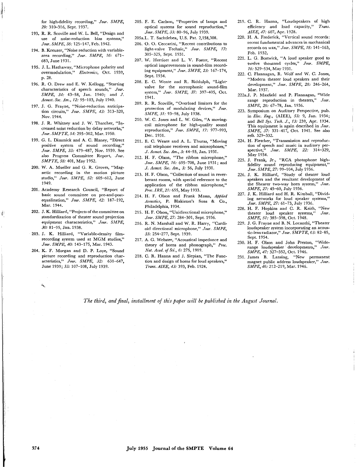
for high-fidelity recording,”
Jour. SMPE,
29:
310-316,
Sept.
1937.
193.
R. R. Scoville and W. L. Bell, “Design and
use of noise-reduction bias systems,”
Jour. SMPE, 38:
125-147,
Feb.
1942.
194.
B. Kreuzer, “Noise reduction with variable-
area recording,”
Jour. SMPE, 16:
671-
683,
June
1931.
195.
J.
L.
Hathaway, “Microphone polarity and
overmodulation,”
Electronics,
Oct.
1939,
p.
28.
196.
R.
0.
Drew and E. W. Kellogg, “Starting
characteristics of speech sounds,”
Jour.
SMPE, 34:
43-58,
Jan.
1940;
and
J.
Acoust. SOC.
Bm.,
72:
95-103,
July
1940.
197.
J.
G. Frayne, “Noise-reduction anticipa-
tion circuits,”
Jour. SMPE, 43:
313-320,
Nov.
1944.
198.
J.
R. Whitney and
J.
W. Thatcher, “In-
creased noise reduction by delay networks,”
Jour. SMPTE, 54:
295-302,
Mar.
1950.
199.
G. L. Dimmick and A. C. Blaney, “Direct
positive system of sound recording,”
Jour. SMPE, 33:
479-487,
Nov.
1939.
See
also Progress Committee Report,
Jour.
SMPTE,
58:
401,
May
1952.
200.
W. A. Mueller and G.
R.
Groves, “Mag-
netic recording in the motion picture
studio,”
Jour. SMPE, 52:
605-612,
June
1949.
201.
Academy Research Council, “Report of
basic sound committee on pre-and-post-
equalization,”
Jour. SMPE, 42:
187-192,
Mar.
1944.
202.
J.
K. Hilliard, “Projects of the committee on
standardization of theater sound projection
equipment characteristics,”
Jour. SMPE,
30:
81-95,
Jan.
1938.
203.
J.
K. Hilliard, “Variable-density film-
recording system used at MGM studios,”
Jour. SMPE, 40:
143-175,
Mar.
1943.
204.
K.
F. Morgan and D. P. Loye, “Sound
picture recording and reproduction char-
acteristics,”
Jour. SMPE, 32:
631-647,
June
1939;
33:
107-108,
July
1939.
205.
F. E. Carlson, “Properties
of
lamps and
optical systems for sound reproduction,”
Jour. SMPE, 33:
80-96,
July
1939.
205a.L.
T.
Sachtleben,
U.S.
Pat.
2,158,308.
206.
0.
0.
Ceccarini, “Recent contributions to
light-valve Technic,”
Jour. SMPE, 17:
305-325,
Sept.
1931.
207.
W. Herriott and L. V. Foster, “Recent
optical improvements in sound-film record-
ing equipment,”
Jour. SMPE, 23:
167-174,
Sept.
1934.
208.
E. C. Wente and
R.
Biddulph, “Light-
valve for the stereophonic sound-film
system,”
Jour. SMPE, 37:
397-405,
Oct.
1941.
209.
R. R. Scoville, “Overload limiters for the
protection of modulating devices,”
Jour.
SMPE, 31:
93-98,
July
1938.
210.
W. C. Jones and
L.
W. Giles, “A moving-
coil microphone for high-quality sound
reproduction,”
Jour. SMPE, 77:
977-993,
Dec.
1931.
211.
E. C. Wente and A.
L.
Thuras, “Moving
coil telephone receivers and microphones,”
J.
Acoust. Soc. Am., 3:
44-55,
Jan.
1931.
212.
H. F. Olson, “The ribbon microphone,”
Jour. SMPE, 16:
695-708,
June
1931;
and
J. Acoust. Soc. Am., 3:
56,
July
1931.
213.
H.
F. Olson, “Collection of sound in rever-
berant rooms, with special reference to the
application of the ribbon microphone,”
Proc. IRE, 21:
655,
May
1933.
214.
H.
F.
Olson and Frank Massa,
Aflfllicd
Acoustics,
P. Blakiston’s Sons
&
Co.,
Philadelphia,
1934.
215.
H.
F.
Olson, “Unidirectional microphone,”
Jour. SMPE, 27:
284-301,
Sept.
1936.
216.
R. N. Marshall and W. R. Harry, “Cardi-
oid directional microphone,”
Jour. SMPE,
33:
254-277,
Sept.
1939.
217.
A. G. Webster, “Acoustical impedance and
theory of horns and phonograph,”
Proc.
Nat. Acad.
of
Sci.,
6:
275, 1919.
218.
C.
R. Hanna and
J.
Slepian, “The Func-
tion and design of horns for loud speakers,”
Trans. AIEE, 43:
393,
Feb.
1924.
219.
C. R. Hanna, “Loudspeakers of high
efficiency and load capacity,”
Trans.
AIEE, 47:
607,
Apr.
1928.
220.
H. A. Frederick, “Vertical sound records:
recent fundamental advances in mechanical
records on wax,”
Jour.
SMPE,
18:
141-163,
Feb.
1932.
221.
L.
G.
Bostwick, “A loud speaker good to
twelve thousand cycles,”
Jour. SMPE,
16:
529-534,
May
1931.
222.
C.
Flannagan, R. Wolf and W.
C.
Jones,
“Modern theater loud speakers and their
development,”
Jour. SMPE,
28:
246-264,
Mar.
1937.
222a.J.
P. Maxfield and P. Flannagan, “Wide
range reproduction in theaters,”
Jour.
SMPE, 26:
67-78,
Jan.
1936.
223.
Symposium on Auditory Perspective, pub.
in
Elcc. Eng.,
(AIEE),
53:
9,
Jan.
1934;
and
BelI
Sys.
Tech. J., 13:
239,
Apr.
1934.
This equipment is again described in
Jour.
SMPE, 37:
331-417,
Oct.
1941.
See also
refs.
329-332.
224.
H. Fletcher, “Transmission and reproduc-
tion of speech and music in auditory per-
spective,”
Jour.
SMPE, 22:
314-329,
May
1934.
225.
J.
Frank, Jr., “RCA photophone high-
fidelity sound reproducing equipment,”
Jour. SMPE, 27:
99-104,
July
1936.
226.
J.
K.
Hilliard, “Study of theater loud
speakers and the resultant development of
the Shearer two-way horn system,”
Jour.
SMPE, 27:
45-60,
July
1936.
227.
J.
K. Hilliard and H. R. Kimball, “Divid-
ing networks for loud speaker systems,”
228.
H. F. Hopkins and C. R. Keith, “New
theater loud speaker systems,”
Jour.
229.
J.
G. Frayne and B. N. Locanthi, “Theater
loudspeaker system incorporating an acous-
tic-lens radiator,”
Jour. SMPTE, 63:
82-85,
Sept.
1954.
230.
H.
F. Olson and John Preston, “Wide-
range loudspeaker developments,”
Jour.
SMPE, 47:
327-352,
Oct.
1946.
231.
James B. Lansing, “New permanent
magnet public address loudspeaker,”
Jour.
SMPE, 46:
212-219,
Mar.
1946.
Jour. SMPE, 27:
61-73,
July
1936.
SMPE, 57:
385-398,
Oct.
1948.
The third, andjinal, installment
of
this Paper will be published in the
August
Journal.
374
July
1955
Journal
of
the
SMPTE
Volume
64
