
Cisco Catalyst 9200 Series Switches Hardware Installation Guide
First Published: 2018-11-19
Last Modified: 2022-07-19
Americas Headquarters
Cisco Systems, Inc.
170 West Tasman Drive
San Jose, CA 95134-1706
USA
http://www.cisco.com
Tel: 408 526-4000
800 553-NETS (6387)
Fax: 408 527-0883
©
2018–2022 Cisco Systems, Inc. All rights reserved.

CONTENTS
Product Overview 1
CHAPTER 1
Switch Models 1
Front Panel Components 3
10/100/1000 Ports 4
PoE and PoE+ Ports 4
Multigigabit Ethernet Ports 5
Management Ports 5
USB Type A Port 6
Uplink Ports 6
Rear Panel 8
RFID Tag 9
StackWise Ports 9
Power Supply Modules 9
Fan Modules 12
Ethernet Management Port 13
RJ-45 Console Port 13
Network Configurations 14
Preparing for Installation 15
CHAPTER 2
Safety Warnings 15
Installation Guidelines 17
Site Requirements 17
Temperature 18
Air Flow 18
Humidity 19
Altitude 20
Cisco Catalyst 9200 Series Switches Hardware Installation Guide
iii

Dust and Particles 20
Air Quality 20
Corrosion 21
EMI and Radio Frequency Interference 22
Shock and Vibration 22
Power Source Interruptions 22
System Grounding 23
Maintaining Safety with Electricity 24
Preventing ESD Damage 25
Tools and Equipment 26
Verifying Switch Operation 26
Installing the Switch 27
CHAPTER 3
Shipping Box Contents 27
Planning a Switch Data Stack 28
Switch Stacking Guidelines 28
Data Stack Cabling Configurations 30
Data Stack Bandwidth and Partitioning Examples 31
Power-On Sequence for Switch Stacks 33
Mounting the Switch 34
Rack-Mounting 34
Attaching the Rack-Mount Brackets 35
Mounting the Switch in a Rack 37
Installing the Switch on a Table or Shelf 37
After Switch Installation 38
Connecting to the StackWise Ports 39
Connecting Devices to the Ethernet Ports 40
10/100/1000/Multigigabit Ethernet Port Connections 40
Auto-MDIX Connections 41
PoE and POE+ Port Connections 41
Installing a Network Module 43
CHAPTER 4
Installing a Network Module in the Switch 43
Safety Warnings 43
Cisco Catalyst 9200 Series Switches Hardware Installation Guide
iv
Contents

Installing a Network Module 43
Removing a Network Module 47
Finding the Network Module Serial Number 48
Installing and Removing Pluggable Transceiver Modules 49
Installing a Cisco Pluggable Transceiver Module 49
Removing a Cisco Pluggable Transceiver Module 51
Installing a Power Supply Unit 53
CHAPTER 5
Power Supply Modules Overview 53
Finding the Power Supply Module Serial Number 56
Installation Guidelines 57
Installing or Replacing an AC Power Supply Module 58
Installing a Fan Module 61
CHAPTER 6
Fan Modules Overview 61
Installation Guidelines 62
Installing a Fan Module 63
Finding the Fan Module Serial Number 63
Configuring the Switch 65
CHAPTER 7
Configuring the Switch Using the Web User Interface 65
Configuring the Switch Using the CLI 65
Accessing the CLI Through the Console Port 65
Connecting the RJ45 Console Port 65
Connecting the USB Console Port 66
Installing the Microsoft Windows USB Device Driver 67
Installing the Cisco Microsoft Windows USB Driver 67
Installing the Silicon Labs Windows USB Device Driver 68
Uninstalling the Cisco Microsoft Windows USB Driver 68
Uninstalling the Cisco Microsoft Windows USB Driver 68
Technical Specifications 69
APPENDIX A
Environmental and Physical Specifications 69
AC Power Cord Specifications 73
Cisco Catalyst 9200 Series Switches Hardware Installation Guide
v
Contents

Specifications for the Power Supplies and Fans 76
Switch LEDs 79
APPENDIX B
LEDs 79
Console LED 80
System LED 80
ACTIVE LED 80
STACK LED 80
PoE LED 81
Port LEDs and Modes 82
Beacon LED 84
RJ-45 Console Port LED 85
Fan LED 85
Uplink Port LEDs 85
Full Cisco Trademarks with Hardware License ?
Cisco Catalyst 9200 Series Switches Hardware Installation Guide
vi
Contents

CHAPTER 1
Product Overview
• Switch Models, on page 1
• Front Panel Components, on page 3
• Rear Panel, on page 8
• Network Configurations, on page 14
Switch Models
The Cisco Catalyst 9200 Series switches have modular (C9200) and fixed (C9200L) switch models. The
following tables describe all the available Cisco Catalyst 9200 Series switches and the features supported.
Table 1: C9200L Switch Models and Descriptions
DescriptionSwitch Model
Stackable 24x1G PoE+ ports; 4x1G SFP fixed uplink ports; 2 power
supply slots; 2 fixed fans; supports StackWise-80.
C9200L-24P-4G
Stackable 24x1G PoE+ ports; 4x10G SFP+ fixed uplink ports; 2
power supply slots; 2 fixed fans; supports StackWise-80.
C9200L-24P-4X
Stackable 24x1G ports; 4x1G SFP fixed uplink ports; 2 power supply
slots; 2 fixed fans; supports StackWise-80.
C9200L-24T-4G
Stackable 24x1G ports; 4x10G SFP+ fixed uplink ports; 2 power
supply slots; 2 fixed fans; supports StackWise-80.
C9200L-24T-4X
Stackable 48x1G PoE+ ports; 4x1G SFP fixed uplink ports; 2 power
supply slots; 2 fixed fans; supports StackWise-80.
C9200L-48P-4G
Stackable 48x1G PoE+ ports; 4x10G SFP+ fixed uplink ports; 2
power supply slots; 2 fixed fans; supports StackWise-80.
C9200L-48P-4X
Stackable 48x1G ports; 4x1G SFP fixed uplink ports; 2 power supply
slots; 2 fixed fans; supports StackWise-80.
C9200L-48T-4G
Stackable 48x1G ports; 4x10G SFP+ fixed uplink ports; 2 power
supply slots; 2 fixed fans; supports StackWise-80.
C9200L-48T-4X
Cisco Catalyst 9200 Series Switches Hardware Installation Guide
1

DescriptionSwitch Model
Stackable 8xMultigigabit Ethernet PoE+ ports and 16x1G PoE+
ports; 4x10G SFP+ fixed uplink ports; 2 power supply slots; 2 fixed
fans; supports StackWise-80.
C9200L-24PXG-4X
Stackable 8xMultigigabit Ethernet PoE+ ports and 16x1G PoE+
ports; 2x25G SFP28 fixed uplink ports; 2 power supply slots; 2 fixed
fans; supports StackWise-80.
C9200L-24PXG-2Y
Stackable 12xMultigigabit Ethernet PoE+ ports and 36x1G PoE+
ports; 4x10G SFP+ fixed uplink ports; 2 power supply slots; 2 fixed
fans; supports StackWise-80.
C9200L-48PXG-4X
Stackable 8xMultigigabit Ethernet PoE+ ports and 40x1G PoE+
ports; 2x25G SFP28 fixed uplink ports; 2 power supply slots; 2 fixed
fans; supports StackWise-80.
C9200L-48PXG-2Y
Stackable 48x1G PoE+ ports with partial PoE support; 4x1G SFP
fixed uplink ports; 2 power supply slots; 2 fixed fans; supports
StackWise-80.
C9200L-48PL-4G
Stackable 48x1G PoE+ ports with partial PoE support; 4x10G SFP
fixed uplink ports; 2 power supply slots; 2 fixed fans; supports
StackWise-80.
C9200L-48PL-4X
Table 2: C9200 Switch Models and Descriptions
DescriptionSwitch Model
Stackable 24x1G PoE+ ports; 4x1G and 4x10G network modules
for uplink ports; 2 power supply slots; 2 field-replaceable fans;
supports StackWise-160.
C9200-24P
Stackable 24x1G PoE+ ports; 4x1G and 4x10G network modules
for uplink ports; 2 power supply slots; 2 field-replaceable fans;
supports StackWise-160.
C9200-24PB
Stackable 24x1G ports; 4x1G and 4x10G network modules for uplink
ports; 2 power supply slots; 2 field-replaceable fans; supports
StackWise-160.
C9200-24T
Stackable 48x1G PoE+ ports; 4x1G and 4x10G network modules
for uplink ports; 2 power supply slots; 2 field-replaceable fans;
supports StackWise-160.
C9200-48P
Stackable 48x1G PoE+ ports; 4x1G and 4x10G network modules
for uplink ports; 2 power supply slots; 2 field-replaceable fans;
supports StackWise-160.
C9200-48PB
Stackable 48x1G ports; 4x1G and 4x10G network modules for uplink
ports; 2 power supply slots; 2 field-replaceable fans; supports
StackWise-160.
C9200-48T
Cisco Catalyst 9200 Series Switches Hardware Installation Guide
2
Product Overview
Switch Models

DescriptionSwitch Model
Stackable 8 Multigigabit Ethernet and 16x1G PoE+ ports; supports
4x10G, 2x25G and 2x40G network modules for uplink ports; 2 power
supply slots; 2 field-replaceable fans; supports StackWise-160.
C9200-24PXG
Stackable 8 Multigigabit Ethernet and 40x1G PoE+ ports; supports
4x10G, 2x25G and 2x40G network modules for uplink ports; 2 power
supply slots; 2 field-replaceable fans; supports StackWise-160.
C9200-48PXG
Stackable 48x1G PoE+ ports with partial PoE support; 4x1G and
4x10G network modules for uplink ports; 2 power supply slots; 2
field-replaceable fans; supports StackWise-160.
C9200-48PL
Front Panel Components
This section describes the front panel components of Cisco Catalyst 9200 Series switches :
• 24 or 48 downlink ports of one of the following types:
• 10/100/1000
• 10/100/1000 PoE+
• 1G/10G Uplink ports
• USB Type A storage ports
• USB mini-Type B console port
• LEDs
• Blue Beacon
The Cisco Catalyst 9200 Series switches might have slight cosmetic differences on the bezels.
Note
Front Panel of a C9200L Switch
Cisco Catalyst 9200 Series Switches Hardware Installation Guide
3
Product Overview
Front Panel Components

USB Type A storage ports5Blue Beacon (UID button)1
10/100/1000 PoE+ ports6Mode button2
Fixed uplink ports7Status LEDs3
USB mini-Type B (console) port4
Front Panel of a C9200 Switch
USB Type A storage ports4Blue Beacon (UID button)1
10/100/1000 PoE+ ports5Mode button2
Network Module with
uplink ports
6USB mini-Type B (console)
port
3
10/100/1000 Ports
The 10/100/1000 ports use RJ-45 connectors with Ethernet pinouts. The maximum cable length is 328 feet
(100 meters). The 100BASE-TX and 1000BASE-T traffic requires twisted pair (UTP) cable of Category 5
or higher. The 10BASE-T traffic can use Category 3 cable or higher.
PoE and PoE+ Ports
The PoE and PoE+ ports provide the following functionality:
• PoE/PoE+ ports: Support for IEEE 802.3af-compliant powered devices (up to 15.4W PoE per port) and
support for IEEE 802.3at-compliant powered devices (up to 30W PoE+ per port).
• Support for pre-standard Cisco powered devices.
• Configurable support for Cisco intelligent power management, including enhanced power negotiation,
power reservation, and per-port power policing.
Cisco Catalyst 9200 Series Switches Hardware Installation Guide
4
Product Overview
10/100/1000 Ports

See the Power Supply Modules, on page 9 for the power supply matrix that defines the available PoE and
PoE+ power per port. The PoE circuit has been evaluated to meet the limits for Limited Power Source (LPS)
per Annex Q in IEC/UL 62368-1. It has also been evaluated as a class ES1, PS2.
Multigigabit Ethernet Ports
The Multigigabit (mGig) Ethernet ports can be configured to auto-negotiate multiple speeds on switch ports.
The ports support 100 Mbps, 1 Gbps, 2.5 Gbps, and 5 Gbps speeds on Category 5e (Cat5e) cables, and up to
10 Gbps over Category 6 (Cat6) and Category 6A (Cat6A) cables up to a maximum of 100 m. 10Gbps over
Cat6 cable is limited for distances up to 55 m. For 10GBASE-T, Cat6a can support up to 100 m when
transmitting 10Gbps. Due to the extra bandwidth requirements from the cable, additional limitations exist for
best performance. These limitations include, but are not limited to cable reach, cable bundling parameters
(tightness, frequency, number of cables, speed with respect to each cable) and cable termination quality.
The 802.3 channel requirements for interoperability typically limit the cable reach to 100 m, but other factors
can shorten this reach. In addition, for both Cisco UPOE and Cisco UPOE+ and data integrity, the 100 m total
should not include more than 10 m total stranded or patch cable. Therefore, it is assumed that a 100 m link
includes a maximum of two 5 m patch cables of the appropriate category, and 90 m of plenum or riser (i.e.
solid copper core) cables. Ensure that you follow the TIA guidance on cable dressing.
It is recommended to test the complete link using an appropriate cable tester for 10 Gbps as well as 5 Gbps
links. However, even if the link passes cable testing, it is still prone to occasional errors due to aggressors in
the bundle, and physical disturbances of the cables. As an example of bundling limitations, for 5 Gbps with
cat5e cable, only a total 45 m bundled length is supported; the remaining 55 m should be unbundled. For
bundling, follow Cisco Guidelines and Best Practices for the Installation and Maintenance of Data Networking
Equipment which recommends the use of Velcro ties every 1 to 2 m for bundled sections.
If you are upgrading the network gear but reusing the existing cable plant, note that at speeds above 2.5 Gbps
traditional Cat5e channel specifications do not support full 100 m reach. To ensure 5 Gbps link speeds, we
recommend using Cat6a cabling. For more information, see the Whitepaper from NBASE-T alliance, which
has now merged with Ethernet Alliance, archived at
https://archive.nbaset.ethernetalliance.org/library/white-paper-2/.
Multigigabit ports do not support half duplex mode. Use full duplex mode.
Note
Management Ports
The management ports connect the switch to a PC running Microsoft Windows or to a terminal server.
• Ethernet management port. See Ethernet Management Port, on page 13.
• RJ-45 console port (EIA/TIA-232). See RJ-45 Console Port, on page 13.
• USB mini-Type B console port (5-pin connector).
The 10/100/1000 Ethernet management port connection uses a standard RJ-45 crossover or straight-through
cable. The RJ-45 console port connection uses the supplied RJ-45-to-DB-9 female cable. The USB console
port connection uses a USB Type A to 5-pin mini-Type B cable. The USB console interface speeds are the
same as the RJ-45 console interface speeds.
Cisco Catalyst 9200 Series Switches Hardware Installation Guide
5
Product Overview
Multigigabit Ethernet Ports

If you use the USB mini-Type B console port, the Cisco Windows USB device driver must be installed on
any PC connected to the console port (for operation with Microsoft Windows). Mac OS X or Linux do not
require special drivers.
The 4-pin mini-Type B connector resembles the 5-pin mini-Type B connectors. They are not compatible. Use
only the 5-pin mini-Type B.
Figure 1: USB Mini-Type B Port
This illustration shows a 5-pin mini-Type B USB port.
With the Cisco Windows USB device driver, you can connect and disconnect the USB cable from the console
port without affecting Windows HyperTerminal operations.
The console output always goes to both the RJ-45 and the USB console connectors, but the console input is
active on only one of the console connectors at any one time. The USB console takes precedence over the
RJ-45 console. When a cable is connected into the USB console port, the RJ-45 console port becomes inactive.
Conversely, when the USB cable is disconnected from the USB console port, the RJ-45 port becomes active.
You can use the command-line interface (CLI) to configure an inactivity timeout which reactivates the RJ-45
console if the USB console has been activated and no input activity has occurred on the USB console for a
specified time.
After the USB console deactivates due to inactivity, you cannot use the CLI to reactivate it. Disconnect and
reconnect the USB cable to reactivate the USB console. For information on using the CLI to configure the
USB console interface, see the Software Configuration Guide.
USB Type A Port
The USB Type A port provides access to external USB flash devices (also known as thumb drives or USB
keys).
The port supports Cisco USB flash drives with capacities from 128 MB to 8 GB. USB devices with port
densities of 128 MB, 256 MB, 1 GB, 4 GB, and 8 GB are supported. When combined with stacking, you can
upgrade other switches in the stack from an USB key inserted in any switch within the stack. Cisco IOS
software provides standard file system access to the flash device: read, write, erase, and copy, as well as the
ability to format the flash device with a FAT file system.
It provides you with the ability to automatically upgrade the internal flash with the USB drive's configuration
and image for emergency switch recovery using USB auto-upgrade. This feature checks the internal flash for
a bootable image and configuration and if either image or the configuration is not available, then the USB
drive is checked for boot images and configuration. If the boot image and configuration are available, these
are copied to flash for the reboot.
Uplink Ports
The Cisco Catalyst 9200 Series switches support both fixed uplinks and modular uplinks. The C9200 switch
models support modular uplinks with one hot-swappable network module that provides uplink ports to connect
to other devices.
The fixed uplink ports on C9200L switch models support the following types of transceiver modules.
• 4x1G ports that support 1G SFP modules.
Cisco Catalyst 9200 Series Switches Hardware Installation Guide
6
Product Overview
USB Type A Port

• 4x10G ports that support either 1G SFP or 10G SFP+ modules.
• 2x25G ports that support SFP28 modules.
For supported Cisco pluggable transceiver modules (SFP, SFP, SFP28 and QSFP+ modules), refer to the
Cisco Transceiver Modules Compatibility Information at
http://www.cisco.com/en/US/products/hw/modules/ps5455/products_device_support_tables_list.html
For information about installing an (uplink) transceiver module, see Installing a Cisco Pluggable Transceiver
Module, on page 49.
Note
Figure 2: Network Module C9200-NM-4G
LEDs2Module slot1
The following table lists the optional Cisco Catalyst 9200 Series Switches uplink network modules with 4x1G,
4x10G, 2x25G, and 2x40G slots.
Table 3: Supported Network Modules
DescriptionNetwork Module
This module has four 1G SFP module slots. Any combination of standard
SFP modules is supported. SFP+ modules are not supported.
If you insert an SFP+ module in the 1G network module, the SFP+ module
does not operate, and the switch logs an error message. This module is not
supported on C9200 Multigigabit Ethernet switches.
C9200-NM-4G
Cisco Catalyst 9200 Series Switches Hardware Installation Guide
7
Product Overview
Uplink Ports
DescriptionNetwork Module
This module has four 10G SFP module slots. Each port supports a 1G or 10G
connection. Any combination of standard SFP modules is supported.
This module is supported on both 1G and Multigigabit Ethernet switch models
of C9200 switches.
C9200-NM-4X
This module has two 25 Gigabit Ethernet SFP28 module slots. Any
combination of SFP, SFP+, and SFP28 modules are supported.
This module is supported only on C9200 Multigigabit Ethernet switches.
C9200-NM-2Y
This module has two 40G slots with a QSFP+ connector in each slot.
This module is supported only on C9200 Multigigabit Ethernet switches.
C9200-NM-2Q
Insert this blank module when the switch has no uplink ports to enable
sufficient airflow.
C9200-NM-BLANK
For information about installing a network module, see Installing a Network Module, on page 43.
Note
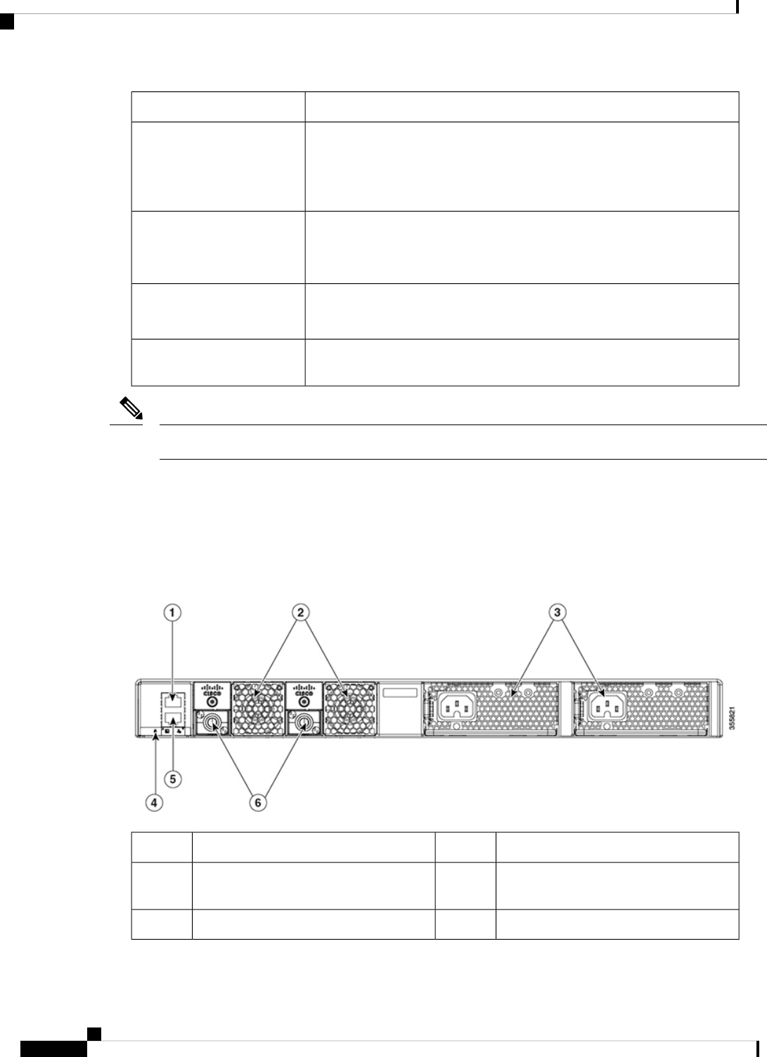
Rear Panel
The switch rear panel includes StackWise connectors, fan modules, and power supply modules.
Figure 3: Rear Panel of a C9200L Switch
Blue Beacon LED4RJ-45 console port1
MGMT (RJ-45 10/100/1000 management
port)
5Fixed fan modules on C9200L switches2
StackWise-80 port connectors6Power supply module slots3
Cisco Catalyst 9200 Series Switches Hardware Installation Guide
8
Product Overview
Rear Panel

Figure 4: Rear Panel of a C9200 Switch
Blue Beacon LED4RJ-45 console port1
MGMT (RJ-45 10/100/1000 management
port)
5Modular fan modules on C9200 switches2
StackWise-160 port connector slots with
stack blanks installed
6Power supply module slots3
RFID Tag
The switch has a built-in, front-facing, passive RFID tag that uses UHF RFID technology and requires an
RFID reader with compatible software. It provides auto-identification capabilities for asset management and
tracking. The RFID tags are compatible with the Generation 2 GS1 EPC Global Standard and are ISO 18000-6C
compliant. They operate in the 860- to 960-MHz UHF band. For more information, see Radio Frequency
Identification (RFID) on Cisco Catalyst 9000 Family Switches White Paper.
StackWise Ports
StackWise ports are used to connect switches in StackWise stacking configurations. The switch ships with a
0.5-meter StackWise cable that you can use to connect the StackWise ports. For more information on StackWise
cables, see Connecting to the StackWise Ports, on page 39.
Use only approved cables, and connect only to similar Cisco equipment. Equipment might be damaged if
connected to nonapproved Cisco cables or equipment.
Caution
Power Supply Modules
The switch has a field replaceable main AC power supply module and a redundant hot-swappable field
replaceable AC power supply module. The switch is powered through one or two internal power supply
modules. In switches with PoE capability, the redundant power supply can also be used for extra PoE power.
The following are the power supply modules supported on Cisco Catalyst 9200 Series Switches:
Cisco Catalyst 9200 Series Switches Hardware Installation Guide
9
Product Overview
RFID Tag

• PWR-C5-125WAC
• PWR-C5-600WAC
• PWR-C5-715WDC=
• PWR-C5-1KWAC
• PWR-C6-125WAC
• PWR-C6-600WAC
• PWR-C6-715WDC=
• PWR-C6-1KWAC
The switch has two internal power supply module slots. You can use two AC power supply modules or one
power supply module and a blank module (PWR-C5-BLANK).
The switch can operate with either one or two active power supply modules.
Switch Models, on page 1 shows the default power supply modules that ship with each switch model. All
power supply modules (except the blank modules) have internal fans. All switches ship with a blank power
supply module in the second power supply slot. Each AC power supply module has a power cord
(CAB-TA-XXX) for connection to an AC power outlet.
Do not operate the switch with one power supply module slot empty. For proper chassis cooling, both power
supply module slots must be populated with either a power supply or a blank module.
Caution
The power supply modules are autoranging units that support input voltages between 100 and 240 VAC. The
output voltage range is 12 to 12.5 V for 125W power supply and 54 to 56 V for 600W and 1000W power
supplies.
All the PoE-enabled switches when installed with both the power supplies support full PoE+; 1440W on a
48-port switch and 740W on a 24-port switch. The partial PoE-enabled switches support only 600W power
supply providing a PoE budget of 370W. If the switch is installed with one power supply, the available POE
budget is 370W and 740W, if there are two power supplies installed.
The following tables show the PoE available and PoE requirements for PoE switch models.
Table 4: Available PoE with AC Power Supply
Full PoE with Redundant
Power Supply
Available PoEDefault Power SupplyModels
C9200 Switches
740W370WPWR-C5-600WAC or
PWR-C6-600WAC
C9200-24P
740W485WPWR-C5-715WDC=
1440W
740WPWR-C5-1KWAC or
PWR-C6-1KWAC
C9200-48P
970W485WPWR-C6-715WDC=
Cisco Catalyst 9200 Series Switches Hardware Installation Guide
10
Product Overview
Power Supply Modules

Full PoE with Redundant
Power Supply
Available PoEDefault Power SupplyModels
-
-PWR-C5-125WAC or
PWR-C6-125WAC
C9200-24T
--PWR-C5-125WAC or
PWR-C6-125WAC
C9200-48T
740W370WPWR-C5-600WAC or
PWR-C6-600WAC
C9200-24PB
740W485WPWR-C6-715WDC=
1440W
740WPWR-C5-1KWAC or
PWR-C6-1KWAC
C9200-48PB
970W485WPWR-C6-715WDC=
740W
370WPWR-C5-600WAC or
PWR-C6-600WAC
C9200-48PL
970W485WPWR-C6-715WDC=
740W
370WPWR-C5-600WAC or
PWR-C6-600WAC
C9200-24PXG
740W485WPWR-C6-715WDC=
1440W
740WPWR-C5-1KWAC or
PWR-C6-1KWAC
C9200-48PXG
970W485WPWR-C6-715WDC=
C9200L Switches
740W370WPWR-C5-600WAC
C9200L-24P-4G
740W485WPWR-C5-715WDC=
740W
370WPWR-C5-600WACC9200L-24P-4X
740W485WPWR-C5-715WDC=
740W
370WPWR-C5-600WACC9200L-24PXG-2Y
740W485WPWR-C5-715WDC=
740W
370WPWR-C5-600WACC9200L-24PXG-4X
740W485WPWR-C5-715WDC=
—
—PWR-C5-125WACC9200L-24T-4G
——PWR-C5-125WACC9200L-24T-4X
Cisco Catalyst 9200 Series Switches Hardware Installation Guide
11
Product Overview
Power Supply Modules

Full PoE with Redundant
Power Supply
Available PoEDefault Power SupplyModels
1440W740WPWR-C5-1KWACC9200L-48P-4G
970W485WPWR-C5-715WDC=
1440W
740WPWR-C5-1KWACC9200L-48P-4X
970W485WPWR-C5-715WDC=
740W
370WPWR-C5-600WACC9200L-48PL-4G
970W485WPWR-C5-715WDC=
740W
370WPWR-C5-600WACC9200L-48PL-4X
970W485WPWR-C5-715WDC=
1440W
740WPWR-C5-1KWACC9200L-48PXG-2Y
970W485WPWR-C5-715WDC=
1440W
740WPWR-C5-1KWACC9200L-48PXG-4X
970W485WPWR-C5-715WDC=
—
—PWR-C5-125WACC9200L-48T-4G
——PWR-C5-125WACC9200L-48T-4X
The power supply modules have two status LEDs.
Table 5: Switch Power Supply Module LEDs
Description
←]
Description
→]
Output is disabled, or input is outside
operating range (AC LED is off).
OffNo AC input power.Off
Power output to switch active.GreenAC input power present.Green
Output has failed.Red
Fan Modules
The Cisco Catalyst 9200 Series Switches supports two internal fixed 12-V fan modules and two field-replaceable
fan modules (C9200-FAN=). The C9200 models support modular fans whereas the C9200L models provide
two internal fixed fans.
For information about the type of fan module supported on different switch models, see Switch Models, on
page 1.
Cisco Catalyst 9200 Series Switches Hardware Installation Guide
12
Product Overview
Fan Modules

The air circulation system consists of the fan modules and the power supply modules. The airflow patterns
vary depending on the power supply configuration. The switch can operate at ambient temperature if one of
the fans fail.
Figure 5: Switch Airflow Pattern
The following illustration shows the airflow pattern for the switches. The blue arrow shows cool airflow, and
the red arrow shows warm airflow.
Ethernet Management Port
You can connect the switch to a host such as a Windows workstation or a terminal server through the
10/100/1000 Ethernet management port or one of the console ports. The 10/100/1000 Ethernet out-of-band
management port is a virtual routing and forwarding (VRF) interface and uses a RJ-45 crossover or
straight-through cable.
The 10/100/1000 Ethernet management port is an RJ-45 connector that should be connected to a Windows
workstation or a terminal server. Do not connect this port to another port in the same switch or to any port
within the same switch stack.
Note
The following table shows the Ethernet management port LED colors and their meanings.
Table 6: Ethernet Management Port LED
DescriptionColor
Link up but no activity.Green
Link up and activity.Blinking green
Link down.Off
RJ-45 Console Port
The RJ-45 console port connection uses the supplied RJ-45-to-DB-9 female cable.
Cisco Catalyst 9200 Series Switches Hardware Installation Guide
13
Product Overview
Ethernet Management Port

The following table shows the RJ-45 console port LED colors and their meanings.
Table 7: RJ-45 Console LED
DescriptionColor
RJ-45 console port is active.Green
The port is not active.Off
Network Configurations
See the switch software configuration guide for network configuration concepts and examples of using the
switch to create dedicated network segments and interconnecting the segments through Fast Ethernet and
Gigabit Ethernet connections.
Cisco Catalyst 9200 Series Switches Hardware Installation Guide
14
Product Overview
Network Configurations

CHAPTER 2
Preparing for Installation
• Safety Warnings, on page 15
• Installation Guidelines, on page 17
• Site Requirements, on page 17
• Tools and Equipment, on page 26
• Verifying Switch Operation, on page 26
Safety Warnings
This section includes the basic installation caution and warning statements. Read this section before you start
the installation procedure. Translations of the warning statements appear in the Regulatory Compliance and
Safety Information guide on Cisco.com.
To prevent bodily injury when mounting or servicing this unit in a rack, you must take special precautions to
ensure that the system remains stable. The following guidelines are provided to ensure your safety:
• This unit should be mounted at the bottom of the rack if it is the only unit in the rack.
• When mounting this unit in a partially filled rack, load the rack from the bottom to the top with the
heaviest component at the bottom of the rack.
• If the rack is provided with stabilizing devices, install the stabilizers before mounting or servicing the
unit in the rack.
Warning
This product is a Class 1 laser product.
Warning
This unit is intended for installation in restricted access areas. Only skilled, instructed, or qualified personnel
can access a restricted access area.
Warning
Cisco Catalyst 9200 Series Switches Hardware Installation Guide
15
This unit might have more than one power supply connection. To reduce risk of electric shock, remove all
connections to de-energize the unit.
Warning
IMPORTANT SAFETY INSTRUCTIONS
Before you work on any equipment, be aware of the hazards involved with electrical circuitry and be familiar
with standard practices for preventing accidents. Read the installation instructions before using, installing, or
connecting the system to the power source. Use the statement number at the beginning of each warning
statement to locate its translation in the translated safety warnings for this device.
SAVE THESE INSTRUCTIONS
Warning
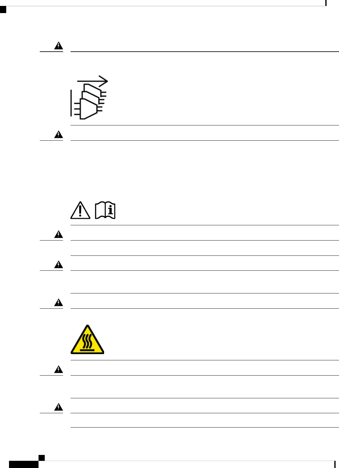
There are no serviceable parts inside. To avoid risk of electric shock, do not open.
Warning
To reduce risk of electric shock or fire, installation of the equipment must comply with local and national
electrical codes.
Warning
This icon is a hot surface warning. To avoid personal injury, do not touch without proper protection.
Warning
Read the wall-mounting instructions carefully before beginning installation. Failure to use the correct hardware
or to follow the correct procedures could result in a hazardous situation to people and damage to the system.
Warning
Ultimate disposal of this product should be handled according to all national laws and regulations.
Warning
Cisco Catalyst 9200 Series Switches Hardware Installation Guide
16
Preparing for Installation
Safety Warnings

Installation Guidelines
When determining where to install the switch, verify that these guidelines are met:
• Clearance to the switch front and rear panel meets these conditions:
• Front-panel LEDs can be easily read.
• Access to ports is sufficient for unrestricted cabling.
• AC power cord can reach from the AC power outlet to the connector on the switch rear panel.
• The SFP/SFP+ module minimum bend radius and connector length is met. See the SFP/SFP+ module
documentation for more information.
• Cabling is away from sources of electrical noise, such as radios, power lines, and fluorescent lighting
fixtures. Make sure that the cabling is safely away from other devices that might damage the cables.
• Make sure power-supply modules and fan modules are securely inserted in the chassis before moving
the switch.
• Airflow around the switch and through the vents is unrestricted. For more information, see Air Flow.
• For copper connections on Ethernet ports, cable lengths from the switch to connected devices can be up
to 328 feet (100 meters).
• Temperature around the unit does not exceed 113°F (45°C). If the switch is installed in a closed or
multirack assembly, the temperature around it might be greater than normal room temperature. For more
information, see Temperature.
• Humidity around the switch does not exceed 95 percent. For more information, see Humidity.
• Altitude at the installation site is not greater than 10,000 feet. For more information, see Altitude.
• Cooling mechanisms, such as fans and blowers in the switch, can draw dust and other particles causing
contaminant buildup inside the chassis, which can result in system malfunction. You must install this
equipment in an environment as free from dust and foreign conductive material (such as metal flakes
from construction activities) as possible. For more information, see Air Quality and Corrosion.
For more information on choosing a location for the switch installation, see Site Requirements.
The illustrations used in this section shows a C9200L switch. The C9200 switch installation is similar to
C9200L, follow the same steps for installing C9200 switches.
Note
Site Requirements
Planning a proper location for the switch and layout of the equipment rack or wiring closet is essential for
successful system operation. These sections describe some of the basic site requirements that you should be
aware of as you prepare to install your switch, including the following:
• Environmental factors can adversely affect the performance and longevity of your system.
Cisco Catalyst 9200 Series Switches Hardware Installation Guide
17
Preparing for Installation
Installation Guidelines

• Install the switch in an enclosed, secure area, ensuring that only qualified personnel have access to the
switch and control of the environment.
• Equipment that is placed too closely together or that is inadequately ventilated may cause system
over-temperature conditions, leading to premature component failure.
• Poor equipment placement can make chassis panels inaccessible and difficult to maintain.
• The switch requires a dry, clean, well-ventilated, and air-conditioned environment.
• To ensure normal operation, maintain ambient airflow. If the airflow is blocked or restricted, or if the
intake air is too warm, an over-temperature condition may occur. The switch environmental monitor may
then shut down the system to protect the system components.
• Multiple switches can be rack mounted with little or no clearance above and below the chassis. However,
when mounting a switch in a rack with other equipment, or when placing it on the floor near other
equipment, ensure that the exhaust from other equipment does not blow into the air intake vent of the
switch chassis.
Temperature
Temperature extremes may cause a system to operate at reduced efficiency and cause a variety of problems,
including premature aging and failure of chips, and failure of mechanical devices. Extreme temperature
fluctuations may also cause chips to become loose in their sockets. Observe the following guidelines:
• Ensure that the chassis has adequate ventilation.
• Do not place the chassis within a closed-in wall unit or on top of cloth, which can act as thermal insulation.
• Do not place the chassis where it will receive direct sunlight, particularly in the afternoon.
• Do not place the chassis next to a heat source of any kind, including heating vents.
• Adequate ventilation is particularly important at high altitudes. Make sure that all the slots and openings
on the system remain unobstructed, especially the fan vent on the chassis.
• Clean the installation site at regular intervals to avoid buildup of dust and debris, which may cause a
system to overheat.
• If system is exposed to abnormally low temperatures, allow a two hour warm up period, in ambient
temperature no lower than 32°F (0 °C) before turning on.
Failure to observe these guidelines may damage the chassis' internal components.
Air Flow
The switch is designed to be installed in an environment where there is a sufficient volume of air available to
cool the supervisor engines, modules, and power supplies. If there are any constraints with regard to the free
flow of air through the chassis, or if the ambient air temperature is elevated, the switch environmental monitor
may then shut down the system to protect the system components.
To maintain proper air circulation through the switch chassis, we recommend that you maintain a minimum
space of 6 inches (15 cm) between a wall and the chassis and power supply unit air intakes or a wall and the
chassis and power supply unit hot air exhausts. In situations where the switch chassis are installed in adjacent
racks, you should allow a minimum space of 12 inches (30.5 cm) between the air intake of one chassis and
Cisco Catalyst 9200 Series Switches Hardware Installation Guide
18
Preparing for Installation
Temperature

the hot air exhaust of another chassis. Failure to maintain adequate spacing between chassis may cause the
switch chassis that is drawing in the hot exhaust air to overheat and fail.
If you are installing your switch in an enclosed or partially enclosed rack, we strongly recommend that you
verify that your site meets the following guidelines:
• Verify that the ambient air temperature within the enclosed or partially enclosed rack is within the chassis
operating temperature limits. After installing the chassis in the rack, power up the chassis and allow the
chassis temperature to stabilize (approximately 2 hours).
Measure the ambient air temperature at the chassis air intake grill by positioning an external temperature
probe 1 inch (2.5 cm) away from the chassis left side, and centered on the chassis both horizontally and
vertically.
Measure the ambient air temperature at the power supply unit air intake grill by positioning an external
temperature probe 1 inch (2.5 cm) away from the chassis front, centered on the power supply unit section
located above the card slots.
• If the ambient intake air temperature is less than 109°F (45°C) at altitudes of 6,000 feet and below,
the rack meets the intake air temperature criterion. At altitudes above that threshold and up to 10,000
feet (3000 m), the air intake should not exceed 104°F (40°C).
• If the ambient intake air temperature exceeds this recommendation, the system may experience
minor temperature alarms and increase fan speeds in response.
• If the ambient intake air temperature equals or is greater than 131°F (55°C), the system may
experience a major temperature alarm with maximum fan speeds in response. If ambient temperature
continues to increase, system will respond with protective shut down.
• Plan ahead. A switch that is currently installed in an enclosed or partially enclosed rack might meet
ambient air temperature and air flow requirements at present. However, if you add more chassis to the
rack or more modules to a chassis in the rack, the additional heat generated might cause the ambient air
temperature at the chassis or power supply unit inlets to exceed recommended conditions which may
trigger thermal alarms.
If installation conditions for inlet temperature and airflow are marginal or not fully met, activate the fan
tray’s NEBS mode, which has more aggressive programming to address restricted spacing and elevated
ambient temperatures. This should result in reduced thermal alarms along with greater acoustic noise
and increased power consumption associated with higher fan speeds.
Humidity
High-humidity conditions may cause moisture to enter the system, and cause corrosion of internal components
and degradation of properties such as electrical resistance, thermal conductivity, physical strength, and size.
Extreme moisture buildup inside the system may result in electrical short circuit, which may cause serious
damage to the system. Each system is rated for storage and operation in 10 to 95 percent relative humidity,
non-condensing with a humidity gradation of 10 percent per hour. Buildings in which climate is controlled
by air-conditioning in the warmer months and by heat during the colder months usually maintain an acceptable
level of humidity for system equipment. However, if a system is located in an unusually humid location, a
dehumidifier should be used to maintain the humidity within an acceptable range.
Cisco Catalyst 9200 Series Switches Hardware Installation Guide
19
Preparing for Installation
Humidity

Altitude
Operating a system at high altitude (low pressure) reduces the efficiency of forced and convection cooling
and may result in electrical problems related to arcing and corona effects. This condition may also cause sealed
components with internal pressure, such as electrolytic capacitors, to fail or perform at reduced efficiency.
Dust and Particles
Fans cool power supplies and system components by drawing in room-temperature air and exhausting heated
air out through various openings in the chassis. However, fans also ingest dust and other particles, causing
contaminant buildup in the system and increased internal chassis temperature. A clean operating environment
can greatly reduce the negative effects of dust and other particles, which act as insulators and interfere with
the mechanical components in the system.
The standards listed below provide guidelines for acceptable working environments and acceptable levels of
suspended particulate matter:
• National Electrical Manufacturers Association (NEMA) Type 1
• International Electrotechnical Commission (IEC) IP-20
Air Quality
Dust is everywhere and often invisible to the naked eye. It consists of fine particles in the air that originate
from various sources, such as soil dust lifted by weather, from volcanic eruptions, or pollution. Dust at an
installation site may contain small amounts of textile, paper fibers, or minerals from outdoor soil. It may also
contain natural contaminants, such as chlorine from the marine environment and industrial contaminants such
as sulfur. Ionized dust and debris are dangerous and get attracted to electronic equipment.
The accumulation of dust and debris on electronic equipment has the following adverse effects:
• It increases the operating temperature of the equipment. According to the Arrhenius effect, an increase
in the operating temperature leads to a decrease in reliability and life of the equipment.
• The moisture and corrosive elements that are present in the dust can corrode the electronic or mechanical
components and cause premature board failure.
These adverse effects are further accelerated by the presence of fans in the data networking equipment that
ingest dust and other particles into the equipment. Higher the volume of air that is generated by the fans for
cooling, the higher the quantity of dust and particulates that get deposited and trapped inside the equipment.
Remove or minimize the presence of dust and particulates at the installation site by following the guidelines
mentioned in ANSI 71-04-2013 regulations.
In addition to the guidelines mentioned in ANSI 71-04-2013 regulations, follow all applicable guidelines as
per site conditions to remove or minimize other contaminants.
Note
Cisco Catalyst 9200 Series Switches Hardware Installation Guide
20
Preparing for Installation
Altitude

Corrosion
Corrosion is a chemical reaction that occurs between electronic components and gases which results in metal
deterioration. Corrosion attacks edge connectors, pin connectors, IC plug-in sockets, wirewraps, and all other
metal components. Depending on the type and concentration level of the corrosive gases, performance
degradation of the components occurs either rapidly or over a period of time. It also leads to blocked currents,
brittle connection points, and overheated electrical systems. Corrosion by-products form insulating layers on
circuits and causes electronic failure, short circuits, pitting, and metal loss.
A type of corrosion known as creep corrosion, that primarily affects PCBA (Printed Circuit Board Assembly)
occurs when the PCBA is subjected to a harsh, and sulfur-rich (hydrogen sulfide) end-use environment over
a prolonged period of time. The corrosion begins on certain exposed metals, such as copper and silver, and
then creeps along the remaining metal surface either causing electrical short circuits or creating holes. Creep
corrosion also occurs on electronic components such as resistors and PCBs.
To prevent corrosion, remove or minimize the presence of dust and particulates at the installation site by
following the guidelines mentioned in ANSI 71-04-2013 regulations.
Figure 6: A PCB with Corrosion on its Metal Contacts
Cisco Catalyst 9200 Series Switches Hardware Installation Guide
21
Preparing for Installation
Corrosion

EMI and Radio Frequency Interference
Electro-Magnetic interference (EMI) and radio frequency interference (RFI) from a system can adversely
affect devices such as radio and television (TV) receivers operating near the system. Radio frequencies
emanating from a system can also interfere with cordless and low-power telephones. Conversely, RFI from
high-power telephones can cause spurious characters to appear on the system monitor. RFI is defined as any
EMI with a frequency above 10 kilohertz (kHz). This type of interference can travel from the system to other
devices through the power cable and power source, or through the air in the form of transmitted radio waves.
The Federal Communications Commission (FCC) publishes specific regulations to limit the amount of harmful
interference emitted by computing equipment. Each system meets these FCC regulations. To reduce the
possibility of EMI and RFI, follow these guidelines:
• Always operate the system with the chassis covers installed.
• Ensure that all chassis slots are covered by a metal filler bracket and that an unused power supply bay
has a metal cover plate installed.
• Ensure that the screws on all peripheral cable connectors are securely fastened to their corresponding
connectors on the back of the chassis.
• Always use shielded cables with metal connector shells for attaching peripherals to the system.
When wires are run for any significant distance in an electromagnetic field, interference can occur between
the field and the signals on the wires. This fact has two implications for the construction of plant wiring:
• Bad wiring practice can result in radio interference emanating from the plant wiring.
• Strong EMI, especially when it is caused by lightning or radio transmitters, can destroy the signal drivers
and receivers in the chassis, and even create an electrical hazard by conducting power surges through
lines into equipment.
To predict and provide a remedy for strong EMI, consult experts in RFI.
Note
Higher-bandwidth twisted-pair cable and lower-loss connections, will result in better signal-to-noise ratio.
This higher-quality connection is more immune to the RF noise and also allows data transmission over longer
cable distances. Uninterrupted connections are preferred over breakouts and cable couplers.
Electromagnetic pulse caused by lightning or other high-energy phenomena can easily couple enough energy
into the unshielded conductors to destroy electronic devices. Ground potential rise can cause similar damage
when using poorly-shielded or poorly-terminated cables. A 360-degree shield and termination will greatly
reduce or eliminate these effects on shielded cables. If you have had problems of this sort in the past, you
may want to consult experts in electrical surge suppression and shielding.
Shock and Vibration
The equipment is designed for Earthquake, Office, and Transportation Vibration, and Equipment Handling.
Power Source Interruptions
The greatest threats to a system's power supply are surges or blackouts that are caused by electrical storms.
Whenever possible, turn off the system and peripherals, if any, and unplug them from their power sources
Cisco Catalyst 9200 Series Switches Hardware Installation Guide
22
Preparing for Installation
EMI and Radio Frequency Interference

during thunderstorms. If a blackout occurs—even a temporary one—while the system is turned on, turn off
the system immediately and disconnect it from the electrical outlet. Leaving the system on may cause problems
when the power is restored; turning on all appliances left on in the area at the same time may cause unsustainable
inrush current demand on the power grid.
System Grounding
Proper grounding practices ensure that the buildings and the installed equipment within them have
low-impedance ground connections and low-voltage differentials between chassis. When you install a system
ground, you reduce or prevent shock hazards, chances of equipment damage due to transients, and the potential
for data corruption.
Chassis AC third-prong ground, and third-ground wire on the DC input is considered sufficient for these units.
The following table lists some general grounding practice guidelines.
Table 8: Grounding Practice Guidelines
Grounding RecommendationsElectromagnetic Noise
Severity Level
Environment
All lightning protection devices must be
installed in strict accordance with
manufacturer recommendations.
Conductors carrying lightning current
should be spaced away from power and
data lines in accordance with applicable
recommendations and building codes. Best
grounding practices must be closely
followed.
HighCommercial building is subjected to
direct lightning strikes.
For example, some places in the United
States, such as Florida, are prone to
more lightning strikes than other areas.
Best grounding practices must be closely
followed.
HighCommercial building is located in an
area where lightning storms occur
frequently, but is not prone to direct
lightning strikes.
Best grounding practices must be closely
followed.
Medium to HighCommercial building contains a mix
of information technology equipment
and industrial equipment, such as
welding.
Best grounding practices must be closely
followed. Determine source and cause of
noise if possible, and mitigate as closely as
possible at the noise source or reduce
coupling from the noise source to the
victim equipment.
MediumExisting commercial building is not
subject to natural environmental noise
or man-made industrial noise. This
building contains a standard office
environment. This installation has a
history of malfunction due to
electromagnetic noise.
Cisco Catalyst 9200 Series Switches Hardware Installation Guide
23
Preparing for Installation
System Grounding

Grounding RecommendationsElectromagnetic Noise
Severity Level
Environment
Best grounding practices should be
followed as closely as possible.
Electromagnetic noise problems are not
anticipated, but installing a best-practice
grounding system in a new building is often
the least expensive route, and the best way
to plan for the future.
LowNew commercial building is not subject
to natural environmental noise or
man-made industrial noise. This
building contains a standard office
environment.
Best grounding practices should be
followed as much as possible.
Electromagnetic noise problems are not
anticipated, but installing a best-practice
grounding system is always recommended.
LowExisting commercial building is not
subject to natural environmental noise
or man-made industrial noise. This
building contains a standard office
environment.
In all situations, grounding practices must comply with Section 250 of the National Electric Code (NEC)
requirements or local laws and regulations.
Note
Always ensure that all of the modules are completely installed and that the captive installation screws are
fully tightened. In addition, ensure that all the I/O cables and power cords are properly seated. These practices
are normal installation practices and must be followed in all installations.
Note
Maintaining Safety with Electricity
When working on electrical equipment, follow these guidelines:
• Do not work alone if potentially hazardous conditions exist anywhere in your work space.
• Never assume that power is disconnected from a circuit; always check the circuit before working on it.
• When the power is switched off, put a lock-box on the circuit, so that no one can accidentally switch it
on.
• Look carefully for possible hazards in your work area, such as damp floors, ungrounded power extension
cables, frayed or damaged power cords, and missing safety grounds.
• If an electrical accident occurs, proceed as follows:
• Use extreme caution; do not become a victim yourself.
• Disconnect power from the system.
• Seek medical attention, if necessary.
• Use the product within its marked electrical ratings and product usage instructions.
• Install the product in compliance with local and national electrical codes.
Cisco Catalyst 9200 Series Switches Hardware Installation Guide
24
Preparing for Installation
Maintaining Safety with Electricity

• If any of the following conditions occur, contact the Cisco Technical Assistance Center:
• The power cable or plug is damaged.
• An object has fallen into the product.
• The product has been exposed to water or other liquids.
• The product has been dropped or shows signs of damage.
• The product does not operate correctly when you follow the operating instructions.
• Use the correct external power source. Operate the product only from the type of power source indicated
on the electrical ratings label. If you are not sure of the type of power source required, consult a local
electrician.
• To help prevent electrical shock, plug all the power cables into properly grounded electrical outlets.
These power cables are equipped with three-prong plugs to ensure proper grounding. Do not use adapter
plugs or remove the grounding prong from a power cable.
• Observe power strip ratings. Make sure that the total current rating of all products that are plugged into
the power strip does not exceed 80 percent of the power strip rating.
• Do not modify power cables or plugs yourself. Consult with a licensed electrician or your power company
for site modifications. Always follow your local and national wiring codes.
Preventing ESD Damage
ESD damage might occur when modules or other FRUs are improperly handled, resulting in intermittent or
complete failure of the modules or FRUs. Modules consist of printed circuit boards that are fixed in metal
carriers. EMI shielding and connectors are integral components of a carrier. Although the metal carrier helps
to protect the board from ESD, always use an ESD-grounding strap when handling modules. To prevent ESD
damage, follow these guidelines:
• Always use an ESD wrist or ankle strap and ensure that it makes good skin contact.
• Connect the equipment end of the strap to an unfinished chassis surface.
• When installing a component, use an available ejector lever to properly seat the bus connectors in the
backplane or midplane. These devices prevent accidental removal, provide proper grounding for the
system, and help to ensure that bus connectors are properly seated.
• When removing a component, use an available ejector lever to release the bus connectors from the
backplane or midplane.
• Handle carriers by available handles or edges only; avoid touching the printed circuit boards or connectors.
• Place a removed component board-side-up on an antistatic surface or in a static-shielding container. If
you plan to return the component to the factory, immediately place it in a static-shielding container.
• Avoid contact between the printed circuit boards and clothing. The wrist strap only protects components
from ESD voltages on the body; ESD voltages on clothing can still cause damage.
• Never attempt to remove the printed circuit board from the metal carrier.
Cisco Catalyst 9200 Series Switches Hardware Installation Guide
25
Preparing for Installation
Preventing ESD Damage

Tools and Equipment
Obtain these necessary tools:
• A Number-2 Phillips screwdriver.
Verifying Switch Operation
Before you install the switch in a rack or on a table or shelf, power on the switch and verify that it passes
POST.
To power on the switch, plug one end of the AC power cord into the switch AC power connector, and plug
the other end into an AC power outlet.
As the switch powers on, it begins the POST, a series of tests that runs automatically to ensure that the switch
functions properly. LEDs can blink during the test. POST lasts approximately 1 minute. The SYST LED
blinks green, and the other LEDs remain solid green.
When the switch completes POST successfully, the SYST LED remains green. The LEDs turn off and then
reflect the switch operating status. If a switch fails POST, the SYST LED turns amber.
POST failures are usually fatal. Call Cisco technical support representative if your switch fails POST.
After a successful POST, unplug the power cord from the switch and install the switch in a rack, on a table,
or on a shelf.
Cisco Catalyst 9200 Series Switches Hardware Installation Guide
26
Preparing for Installation
Tools and Equipment

CHAPTER 3
Installing the Switch
• Shipping Box Contents, on page 27
• Planning a Switch Data Stack , on page 28
• Mounting the Switch, on page 34
• Connecting to the StackWise Ports, on page 39
• Connecting Devices to the Ethernet Ports, on page 40
Shipping Box Contents
The shipping box contains the model of the switch you ordered and other components needed for installation.
Some components are optional, depending on your order.
Verify that you have received these items. If any item is missing or damaged, contact your Cisco representative
or reseller for instructions. Verify that you have received these items. If any item is missing or damaged,
contact your Cisco representative or reseller for instructions.
Note
Cisco Catalyst 9200 Series Switches Hardware Installation Guide
27

Figure 7: Components delivered in the shipping box
Cable guide8Cisco Catalyst 9200 Series switch
1
(power
supply modules are not displayed)
1
M4.0 x 20mm Phillips pan-head screw9AC power cord2
RJ-45 USB console cable
1
10Four rubber mounting feet3
(Optional) USB console cable
1
11Two 19-inch mounting brackets4
(Optional) StackWise cable
1
(0.5-meter,
1-meter, or 3-meter)
124 number-12 pan-head screw5
Power cord retainer134 number-10 pan-head screws6
--8 number-8 Phillips flat-head screws7
1. Item is orderable.
Planning a Switch Data Stack
Switch Stacking Guidelines
A StackWise adapter must be installed in the stacking port to enable stacking. The StackWise cable connects
to the StackWise adapter in the stacking port. If the switch is not ordered with stacking, the adapters must be
ordered separately and installed.
Before connecting the switches in a stack, observe these stacking guidelines:
Cisco Catalyst 9200 Series Switches Hardware Installation Guide
28
Installing the Switch
Planning a Switch Data Stack

• Number of switches in the stack. You can create data stacks with up to eight switches in a stack.
• Length of the cable. Order the appropriate cable from your Cisco sales representative. The length of the
cable depends on your configuration. These are the different sizes available:
• 0.5 meter cable (STACK-T4-50CM)
• 1 meter cable (STACK-T4-1M)
• 3 meter cable (STACK-T4-3M)
• Minimum bend radius and coiled diameter for StackWise cables. We recommend a minimum bend radius
and coiled diameter for each StackWise cable.
Table 9: StackWise Cables Minimum Bend Radius and Coiled Diameter
Minimum Coiled
Diameter
Minimum Bend RadiusCable LengthCable Part Number
5.20 in. (132 mm)2.60 in. (66 mm)1.64 feet (0.5 m)STACK-T4-50CM
5.20 in. (132 mm)2.60 in. (66 mm)3.28 feet (1.0 m)STACK-T4-1M
7.17 in. (182 mm)3.58 in. (91 mm)9.84 feet (3.0 m)STACK-T4-3M
Cisco Catalyst 9200 Series Switches Hardware Installation Guide
29
Installing the Switch
Switch Stacking Guidelines

StackWise 3.0 m cable4Power supply module1
StackWise 1.0 m and 0.5 m cable5Power cord retainer2
-Fan module3
Ensure that you maintain a proper clearance of 5.5 in. and 4.5 in. between the
StackWise cable and the switch as depicted in the image.
Note
Data Stack Cabling Configurations
This is an example of a recommended configuration that uses the supplied 0.5-meter StackWise cable. In this
example, the switches are stacked in a vertical rack or on a table. This configuration provides redundant
Cisco Catalyst 9200 Series Switches Hardware Installation Guide
30
Installing the Switch
Data Stack Cabling Configurations

connections. The configuration example uses the supplied 0.5-meter StackWise cable. The example shows
the full-ring configuration that provides redundant connections.
Figure 8: Data Stacking the Switches in a Rack or on a Table Using the 0.5-meter StackWise Cables
This example shows a recommended configuration when the switches are mounted side-by-side. Use the
1-meter and the 3-meter StackWise cables to connect the switches. This configuration provides redundant
connections.
Figure 9: Data Stacking in a Side-by-Side Mounting
Data Stack Bandwidth and Partitioning Examples
This section provides examples of data stack bandwidth and possible data stack partitioning. The figure shows
a data stack of switches that provides full bandwidth and redundant StackWise cable connections.
Figure 10: Example of a Data Stack with Full Bandwidth Connections
Cisco Catalyst 9200 Series Switches Hardware Installation Guide
31
Installing the Switch
Data Stack Bandwidth and Partitioning Examples

This figure shows an example of a stack of switches with incomplete StackWise cabling connections. This
stack provides only half bandwidth and does not have redundant connections.
Figure 11: Example of a Data Stack with Half Bandwidth Connections
The figures below show data stacks of switches with failover conditions. In this figure, the StackWise cable
is bad in link 2. Therefore, this stack provides only half bandwidth and does not have redundant connections.
Figure 12: Example of a Data Stack with a Failover Condition
In this figure, link 2 is bad. Therefore, this stack partitions into two stacks, and the top and bottom switches
become the active switch in the stack. If the bottom switch is a member (not active or standby switch), it
reloads.
Cisco Catalyst 9200 Series Switches Hardware Installation Guide
32
Installing the Switch
Data Stack Bandwidth and Partitioning Examples

Figure 13: Example of a Partitioned Data Stack with a Failover Condition
Power-On Sequence for Switch Stacks
Consider these guidelines before you power on the switches in a stack:
• The sequence in which the switches are first powered on might affect the switch that becomes the stack
master.
• There are two ways to elect an active switch:
• If you want a particular switch to become the active switch, configure it with the highest priority.
Among switches with same priority, the switch with the lowest MAC address becomes the active
switch.
• If you want a particular switch to become the active switch, power on that switch first. This switch
remains the active switch until a reelection is required. After 2 minutes, power on the other switches
in the stack. If you have no preference as to which switch becomes the active switch, power on all
the switches in the stack within 1 minute. These switches participate in the active switch election.
Switches powered on after 2 minutes do not participate in the election.
• Power off a switch before you add it to or remove it from an existing switch stack. If changes are made
to the stack without powering down the switches, the following results can occur:
• If two operating partial ring stacks are connected together using a stack cable, a stack merge can
take place. This situation reloads the whole stack (all switches in the stack).
• If some switches in the stack are completely separated from the stack, a stack split can occur.
• A stack split can occur on a full ring stack if:
• More than one running switch is removed without powering down.
• More than one stack cable is removed without powering down.
• A stack split can occur in a partial ring stack if:
• A switch is removed without powering down.
Cisco Catalyst 9200 Series Switches Hardware Installation Guide
33
Installing the Switch
Power-On Sequence for Switch Stacks

• A stack cable is removed without powering down.
• In a split stack, depending on where the active and standby switches are located, either two stacks might
be formed (with the standby taking over as the new active switch in the newly formed stack) or all the
members in the newly formed stack might reload.
These results depend on how the switches are connected. You can remove two or more switches from the
stack without splitting the stack.
Note
For conditions that can cause a stack reelection or to manually elect the active switch, see the stacking software
configuration guide Stack Managerand High Availability Configuration Guide for Cisco Catalyst 9200 Series
Switches on Cisco.com.
Mounting the Switch
The following sections explain the different mounting options.
Rack-Mounting
Installation in racks other than 19-inch racks requires a bracket kit not included with the switch.
To prevent bodily injury when mounting or servicing this unit in a rack, you must take special precautions to
ensure that the system remains stable. The following guidelines are provided to ensure your safety:
• This unit should be mounted at the bottom of the rack if it is the only unit in the rack.
• When mounting this unit in a partially filled rack, load the rack from the bottom to the top with the
heaviest component at the bottom of the rack.
• If the rack is provided with stabilizing devices, install the stabilizers before mounting or servicing the
unit in the rack.
Warning
Figure 14: Rack-Mounting Brackets
This figure shows the standard 19-inch brackets and other optional mounting brackets. You can order the
optional brackets (ACC-KIT-T1=) from your Cisco sales representative.
Cisco Catalyst 9200 Series Switches Hardware Installation Guide
34
Installing the Switch
Mounting the Switch

23-inch brackets (RACK-KIT-T1=)319-inch brackets (ACC-KIT-T1=)1
24-inch brackets (RACK-KIT-T1=)4ETSI brackets (RACK-KIT-T1=)2
Attaching the Rack-Mount Brackets
Before you begin
You can use the minimum recommended number of two screws for installing the rack-mount bracket to each
side of the switch. If required, while mounting, you can use the additional four screws provided in the accessory
kit.
Procedure
Use two Phillips flat-head screws to attach the long side of the bracket to each side of the switch for the front-
or rear-mounting positions.
Cisco Catalyst 9200 Series Switches Hardware Installation Guide
35
Installing the Switch
Attaching the Rack-Mount Brackets

The following illustration shows a C9200L switch. C9200 switches follow the same method for installing the
rack mount bracket.
Figure 15: Attaching Brackets for 19-inch Racks in a two-post rack front-mount position
Figure 16: Attaching Brackets for 19-inch Racks in a two-post rack rear-mount position
Cisco Catalyst 9200 Series Switches Hardware Installation Guide
36
Installing the Switch
Attaching the Rack-Mount Brackets

Number-8 Phillips flat-head screws2
Mounting the Switch in a Rack
Procedure
Step 1 Use the four supplied Phillips machine screws to attach the brackets to the rack.
Step 2 Use the black Phillips machine screw to attach the cable guide to the left or right bracket.
Figure 17: Mounting the Switch in a Rack
Front-mounting position3Phillips machine screw, black1
Number-12 or number-10 Phillips machine
screws
4Cable guide2
Installing the Switch on a Table or Shelf
Procedure
Step 1 To install the switch on a table or shelf, locate the adhesive strip with the rubber feet in the mounting-kit
envelope.
Step 2 Attach the four rubber feet to the four circular etches on the bottom of the chassis.
Cisco Catalyst 9200 Series Switches Hardware Installation Guide
37
Installing the Switch
Mounting the Switch in a Rack

Figure 18: Attaching the mounting feet for Table-Mounting or Shelf-Mounting
Rubber mounting feet1
Step 3 Place the switch on the table or shelf near an AC power source.
What to do next
When you complete the switch installation, see After Switch Installation, on page 38 for information on
switch configuration.
After Switch Installation
• Configure the switch using the Web User Interface. For more information, see "Configuring the Switch
Using the Web User Interface" topic in the Software Configuration Guide.
• Connect the required devices to the switch ports.
• Turn on the power supply switches to power up the system. While powering up, the switch performs a
series of bootup diagnostic tests.
The switch is designed to boot up in less than 30 minutes, provided that the
neighboring devices are in fully operational state.
Note
• Verify port connectivity after connecting devices to the switch ports. The LED turns green when the
switch and the attached device have a link.
Cisco Catalyst 9200 Series Switches Hardware Installation Guide
38
Installing the Switch
After Switch Installation

Connecting to the StackWise Ports
Before you begin
Before connecting the StackWise cables, read the "Planning a Switch Data Stack" section. Always use a
Cisco-approved StackWise cable to connect the switches.
Procedure
Step 1 Remove the dust covers from the StackWise cables and StackWise ports, and store them for future use.
A StackWise adapter must be installed in the StackWise port to enable stacking. In the default setup, the
StackWise adapter blanks are installed in the StackWise ports. If StackWise stacking is ordered with the
switch, StackWise adapters are already installed in the StackWise ports, and you can proceed to step 4.
Step 2 Remove the StackWise adapter blanks from each destination StackWise port using the Torx T15 Allen key
provided in the stacking kit (or a Torx T15 screwdriver). Store them for future use.
Step 3 Install a StackWise adapter in each destination StackWise port, and secure it in place using the supplied Torx
T15 key, or a Torx T15 screwdriver.
Figure 19: Installing the StackWise Adapter in a StackWise Port
StackWise port2StackWise adapter1
Step 4 Connect the cable to the StackWise port on the switch rear panel.
a) Align the StackWise cable connector with the StackWise adapter in the StackWise port.
b) Insert the StackWise cable connector into the StackWise port. Make sure that the Cisco logo is on the top
side of the connector.
Cisco Catalyst 9200 Series Switches Hardware Installation Guide
39
Installing the Switch
Connecting to the StackWise Ports

Figure 20: Connecting the StackWise Cable in a StackWise Port
StackWise cable2Connector screws1
c) Finger-tighten the screws in clockwise direction.
Step 5 Connect the other end of the cable to the port on the other switch and finger-tighten the screws. Avoid
over-tightening the screws.
Removing and installing the StackWise cable can shorten its useful life. Do not remove and insert the
cable more often than is absolutely necessary (installing and removing it up to 200 times is supported).
Caution
When you need to remove the StackWise cable from the connector, make sure to fully unscrew the correct
screws. When the connectors are not being used, replace the dust covers.
Connecting Devices to the Ethernet Ports
10/100/1000/Multigigabit Ethernet Port Connections
The switch 10/100/1000 and Multigigabit Ethernet port configuration changes to operate at the speed of the
attached device. If the attached ports do not support autonegotiation, you can manually set the speed and
Cisco Catalyst 9200 Series Switches Hardware Installation Guide
40
Installing the Switch
Connecting Devices to the Ethernet Ports

duplex parameters. Connecting devices that do not autonegotiate or that have the speed and duplex parameters
manually set can reduce performance or result in no linkage.
To maximize performance, choose one of these methods for configuring the Ethernet ports:
• Let the ports autonegotiate both speed and duplex.
• Set the interface speed and duplex parameters on both ends of the connection.
Auto-MDIX Connections
The autonegotiation and the auto-MDIX features are enabled by default on the switch.
With autonegotiation, the switch port configurations change to operate at the speed of the attached device. If
the attached device does not support autonegotiation, you can manually set the switch interface speed and
duplex parameters.
With auto-MDIX, the switch detects the required cable type for copper Ethernet connections and configures
the interface accordingly.
If auto-MDIX is disabled, use the guidelines in this table to select the correct cable.
Table 10: Recommended Ethernet Cables (When Auto-MDIX is Disabled)
Straight-Through CableCrossover CableDevice
NoYesSwitch to switch
NoYesSwitch to hub
YesNoSwitch to computer or server
YesNoSwitch to router
YesNoSwitch to IP phone
1
100BASE-TX and 1000BASE-T traffic requires twisted four-pair, Category 5 or higher. 10BASE-T
traffic can use Category 3 cable or higher.
PoE and POE+ Port Connections
The 10/100/1000 PoE and PoE+ ports have the same autonegotiation settings and cabling requirements that
are described in the 10/100/1000 Ports, on page 4. These ports can provide PoE and PoE+ inline power.
PoE inline power supports devices compliant with the IEEE 802.3af standard, as well as prestandard Cisco
IP Phones and Cisco Aironet Access Points. Each port can deliver up to 15.4 W of PoE. PoE+ inline power
supports devices compliant with the IEEE 802.3at standard, by delivering up to 30 W of PoE+ power per port
to all switch ports.
See Power Supply Modules, on page 9 for the power supply modules required to support PoE and PoE+ on
24- and 48-port switches.
Cisco Catalyst 9200 Series Switches Hardware Installation Guide
41
Installing the Switch
Auto-MDIX Connections

Category 5e and Category 6 cables can store high levels of static electricity. Always ground the cables to a
suitable and safe earth ground before connecting them to the switch or other devices.
Caution
Noncompliant cabling or powered devices can cause a PoE port fault. Use only standard-compliant cabling
to connect Cisco prestandard IP Phones and wireless access points, IEEE 802.3af, or 802.3at (PoE+)-compliant
devices. You must remove any cable or device that causes a PoE fault.
Caution
Cisco Catalyst 9200 Series Switches Hardware Installation Guide
42
Installing the Switch
PoE and POE+ Port Connections

CHAPTER 4
Installing a Network Module
• Installing a Network Module in the Switch, on page 43
• Removing a Network Module, on page 47
• Finding the Network Module Serial Number, on page 48
• Installing and Removing Pluggable Transceiver Modules, on page 49
Installing a Network Module in the Switch
Safety Warnings
This section includes the installation cautions and warnings. Translations of the safety warnings are available
in the Regulatory Compliance and Safety Information for Cisco Catalyst 9200 Series Switches .
Read this section before you install a network module.
Proper ESD protection is required whenever you handle equipment. Installation and maintenance personnel
should be properly grounded by grounding straps to eliminate the risk of ESD damage to the equipment.
Equipment is subject to ESD damage whenever you remove it.
Caution
Installing a Network Module
The switch can operate without a network module, but a blank module (with no ports or SFP slots) is available
and should be installed when uplink ports are not required.
Note
The switch generates logs when you insert or remove a network module with SFP/SFP+ slots.
Note
Use only supported network modules and Cisco pluggable transceivers. Each module has an internal serial
EEPROM that is encoded with security information.
Cisco Catalyst 9200 Series Switches Hardware Installation Guide
43

The network module is hot-swappable. If you remove a module, replace it with another network module or
a blank module.
The switch complies with EMC, safety, and thermal specifications when a network module is present. If no
uplink ports are required, install a blank network module.
Note
Before you begin
When installing network modules, observe these precautions:
• Do not remove the blank module from the slot unless you are installing a network module. A module
must be in the uplink slot at all times.
• Do not remove the dust plugs from the pluggable transceivers or the rubber caps from the fiber-optic
cable until you connect the cable. The plugs and caps protect the module ports and cables from
contamination and ambient light.
• Removing and installing a network module can shorten its useful life. Do not remove and insert a network
module more often than is necessary.
• To prevent ESD damage, follow your normal board and component handling procedures when connecting
cables to the switch and other devices.
Procedure
Step 1 Attach an ESD-preventive wrist strap to your wrist and to an earth ground surface.
Step 2 Remove the module from the protective packaging.
Step 3 Remove the blank module from the switch and save it.
Cisco Catalyst 9200 Series Switches Hardware Installation Guide
44
Installing a Network Module
Installing a Network Module

Figure 21: Removing the Blank Module
Verify the correct orientation of your module before installing it. Incorrect installation can damage
the module.
Caution
Do not install the network module with connected cables or installed pluggable transceivers. Always
remove any cables and transceiver modules before you install the network module.
Caution
A module interface might become error-disabled when a network module with connected fiber-optic
cables is installed or removed. If an interface is error-disabled, you can reenable the interface by using
the shutdown and no shutdown interface configuration commands.
Caution
Step 4 Position the module face up to install it in the module slot. Slide the module into the slot until the screw makes
contact with the chassis. Fasten the captive screws to secure the network module in place.
Cisco Catalyst 9200 Series Switches Hardware Installation Guide
45
Installing a Network Module
Installing a Network Module

Figure 22: Installing the Network Module in the Switch
Step 5 While installing C9200 network modules, position the module face up to install it in the module slot. Slide
the module into the slot until the screw makes contact with the chassis. Fasten the captive screws to secure
the network module in place.
Cisco Catalyst 9200 Series Switches Hardware Installation Guide
46
Installing a Network Module
Installing a Network Module

Figure 23: Installing the C9200 Network Module in the Switch
Network module2Ejector1
Removing a Network Module
The switch complies with EMC, safety, and thermal specifications when a network module is present. If no
uplink ports are required, install a blank network module.
Note
To avoid authentication failure and non-detection of modules, wait for a minimum of 6-8 seconds between
the online insertion and removal (OIR) of network modules.
Note
Procedure
Step 1 Attach an ESD-preventive wrist strap to your wrist and to an earth ground surface
Cisco Catalyst 9200 Series Switches Hardware Installation Guide
47
Installing a Network Module
Removing a Network Module

Do not remove the network module with connected cables or installed pluggable transceiver modules.
Always remove any cables and modules before you remove the network module.
Caution
A module interface might become error-disabled when a network module with connected fiber-optic
cables is installed or removed. If an interface is error-disabled, you can reenable the interface by using
the shutdown and no shutdown interface configuration commands.
Caution
Step 2 Disconnect the cables from the pluggable transceiver module.
Step 3 Remove the pluggable transceiver module from the network module.
Step 4 Loosen the captive screws that hold the network module in place until it completely disengages from the
chassis.
Step 5 Carefully slide the network module out of the slot.
Step 6 Install a replacement network module or a blank module in the slot.
Step 7 Place the module that you removed in an antistatic bag or other protective environment.
Finding the Network Module Serial Number
If you contact Cisco Technical Assistance regarding a network module, you need to know its serial number.
Cisco Catalyst 9200 Series Switches Hardware Installation Guide
48
Installing a Network Module
Finding the Network Module Serial Number

Figure 24: Network Module Serial Number Location
Installing and Removing Pluggable Transceiver Modules
Installing a Cisco Pluggable Transceiver Module
Before you begin
See the switch release notes on Cisco.com for the list of supported a Cisco pluggable transceiver modules
(SFP, SFP, SFP28 and QSFP+ modules). Use only supported modules on the switch. For the latest information
about the supported modules, refer to the Cisco Transceiver Modules Compatibility Information.
For information about installing, removing, cabling, and troubleshooting transceiver modules, see the module
documentation that shipped with your device.
Cisco Catalyst 9200 Series Switches Hardware Installation Guide
49
Installing a Network Module
Installing and Removing Pluggable Transceiver Modules

This product is a Class 1 laser product.
Warning
• Do not remove the dust plugs from the transceiver modules or the rubber caps from the fiber-optic cable
until you are ready to connect the cable. The plugs and caps protect the module ports and cables from
contamination and ambient light.
• Removing and installing a transceiver module can shorten its useful life. Do not remove and insert any
module more often than necessary.
• To prevent ESD damage, follow your normal board and component handling procedures when connecting
cables to the switch and other devices.
• When you insert several transceiver modules in multiple switch ports, wait for 5 seconds between inserting
each transceiver module. This will prevent the ports from going into error disabled mode. Similarly,
when you remove a transceiver module from a port, wait for 5 seconds before reinserting it.
Procedure
Step 1 Attach an ESD-preventive wrist strap to your wrist and to an earth ground surface.
Step 2 Find the send (TX) and receive (RX) markings that identify the top of the transceiver module.
On some transceiver modules, the send and receive (TX and RX) markings might be shown by arrows that
show the direction of the connection.
Step 3 If the transceiver module has a bale-clasp latch, move it to the open, unlocked position.
Step 4 Align the module in front of the slot opening, and push until you feel the connector snap into place.
Figure 25: Installing a Transceiver Module into the Network Module
Step 5 If the module has a bale-clasp latch, close it to lock the transceiver module in place.
Step 6 Remove the transceiver module dust plugs and save.
Cisco Catalyst 9200 Series Switches Hardware Installation Guide
50
Installing a Network Module
Installing a Cisco Pluggable Transceiver Module

Step 7 Connect the transceiver module cables.
Figure 26: Installing a Transceiver Module in the Uplink Module Slot
Removing a Cisco Pluggable Transceiver Module
Procedure
Step 1 Attach an ESD-preventive wrist strap to your wrist and to an earth ground surface.
Step 2 Disconnect the cable from the transceiver module. For reattachment, note which cable connector plug is send
(TX) and which is receive (RX).
Step 3 Insert a dust plug into the optical ports of the transceiver module to keep the optical interfaces clean.
Step 4 If the module has a bale-clasp latch, pull the bale out and down to eject the module. If you cannot use your
finger to open the latch, use a small, flat-blade screwdriver or other long, narrow instrument to open it.
Step 5 Grasp the transceiver module and carefully remove it from the slot.
Step 6 Place the transceiver module in an antistatic bag or other protective environment.
Cisco Catalyst 9200 Series Switches Hardware Installation Guide
51
Installing a Network Module
Removing a Cisco Pluggable Transceiver Module

Cisco Catalyst 9200 Series Switches Hardware Installation Guide
52
Installing a Network Module
Removing a Cisco Pluggable Transceiver Module

CHAPTER 5
Installing a Power Supply Unit
• Power Supply Modules Overview, on page 53
• Finding the Power Supply Module Serial Number, on page 56
• Installation Guidelines, on page 57
• Installing or Replacing an AC Power Supply Module, on page 58
Power Supply Modules Overview
The switch chassis has two power supply slots that operates with either one active power supply module and
a redundant power supply module. You can use two AC modules or one AC module and a blank cover. The
active and redundant modules must be of the same type.
All power supply modules have internal fans. All switches ship with a blank cover in the second power supply
slot.
The main module is field replaceable and the redundant module is hot-swappable. The redundant power supply
can also be used for extra PoE power.
Two power supply modules can be powered up from two different phases.
The following table describes the supported internal power supply modules.
Table 11: Power Supply Module Part Numbers and Descriptions
DescriptionPart Number
125 W AC power supply modulePWR-C5-125WAC
600 W AC power supply modulePWR-C5-600WAC
1000 W AC power supply modulePWR-C5-1KWAC
125 W AC power supply modulePWR-C6-125WAC
1
600 W AC power supply modulePWR-C6-600WAC
1
1000 W AC power supply modulePWR-C6-1KWAC
1
Blank coverPWR-C5-BLANK
1. Supported from Cisco IOS XE Gibraltar 16.11.1.
Cisco Catalyst 9200 Series Switches Hardware Installation Guide
53

All the switches ship with a blank cover in the second power supply slot if the switches are ordered with only
one power supply module.
For information about available PoE and PoE+ requirements, see these sections the Power Supply Modules,
on page 9.
The power supply modules are autoranging units that support input voltages between 100 and 240 VAC. Each
AC power supply module has a power cord for connection to an AC power outlet. The modules use an 18-AWG
power cord.
The following illustrations show the power supply modules.
Figure 27: 1000W AC Power Supply
Cisco Catalyst 9200 Series Switches Hardware Installation Guide
54
Installing a Power Supply Unit
Power Supply Modules Overview

Figure 28: 125W AC Power Supply
→] LED
3Release latch1
←] LED
4AC power cord connector2
If no power supply is installed in a power supply slot, install a power supply slot cover.
Figure 29: Power Supply Slot Cover
Cisco Catalyst 9200 Series Switches Hardware Installation Guide
55
Installing a Power Supply Unit
Power Supply Modules Overview

Retainer clips2Release handles1
Table 12: Switch Power Supply Module LEDs
Description
←]
Description
→]
Output is disabled, or input is outside
the operating range (LED is off).
OffNo AC input power.Off
Power output to switch active.GreenAC input power present.Green
Output has failed.Red
Finding the Power Supply Module Serial Number
If you contact Cisco Technical Assistance regarding a power supply module, you need to know the serial
number. See the following illustrations to find the serial number. You can also use the CLI to find out the
serial number.
Cisco Catalyst 9200 Series Switches Hardware Installation Guide
56
Installing a Power Supply Unit
Finding the Power Supply Module Serial Number

Figure 30: AC Power Supply Serial Number
Installation Guidelines
Observe these guidelines when removing or installing a power supply module.
• Do not force the power supply module into the slot. This can damage the pins on the switch if they are
not aligned with the module.
• A power supply module that is only partially connected to the switch can disrupt the system operation.
• Remove power from the power supply module before removing or installing the module.
• The power supply module is hot-swappable. In some configurations, such as full PoE+ or power sharing
mode, removing a power supply module causes powered devices to shut down until the power budget
matches the input power of a single power supply module. To minimize network interruption, ensure
that an active backup is in progress.
For the switch commands that display available power budget, see the software configuration guide.
Cisco Catalyst 9200 Series Switches Hardware Installation Guide
57
Installing a Power Supply Unit
Installation Guidelines

Do not operate the switch with one power-supply module slot empty. For proper chassis cooling, both module
slots must be populated, with either a power supply or a blank module.
Caution
This equipment must be grounded. To reduce the risk of electric shock, never defeat the ground conductor or
operate the equipment in the absence of a suitably installed ground conductor. Contact the appropriate electrical
inspection authority or an electrician if you are uncertain that suitable grounding is available.
Warning
Blank faceplates and cover panels serve three important functions: they reduce the risk of electric shock and
fire, they contain electromagnetic interference (EMI) that might disrupt other equipment, and they direct the
flow of cooling air through the chassis. Do not operate the system unless all cards, faceplates, front covers,
and rear covers are in place.
Warning
Installing or Replacing an AC Power Supply Module
Procedure
Step 1 Turn off the power at its source.
Step 2 Remove the power cord from the power cord retainer.
Step 3 Remove the power cord from the power connector.
Step 4 Press the release latch at the right side of the power supply module inward and slide the power supply out.
Do not leave the power-supply slot open for more than 90 seconds while the switch is operating.
Caution
This unit might have more than one power supply connection. To reduce risk of electric shock, remove
all connections to de-energize the unit.
Warning
Step 5 Insert the new power supply into the power-supply slot, and gently push it into the slot. When correctly
inserted, the power supplies (excluding the power cord retainer) are flush with the switch rear panel.
Cisco Catalyst 9200 Series Switches Hardware Installation Guide
58
Installing a Power Supply Unit
Installing or Replacing an AC Power Supply Module

Figure 31: Inserting the AC-Power Supply in the Switch
Step 6 (Optional) Install the power cord retainer as follows:
Figure 32: AC-Power Supply with Power Cord Retainer
Retainer clamp4Power cord1
Cisco Catalyst 9200 Series Switches Hardware Installation Guide
59
Installing a Power Supply Unit
Installing or Replacing an AC Power Supply Module

The strap end that is fixed
to the power supply
module
5Tabs on the retainer clamp2
--Power cord retainer strip3
a) Fix the strap in the power cord retainer to the power supply module, to hold the clamp in place.
b) Slide the retainer clamp around the AC power cord and position the retainer closest to the power supply.
Depending on the width of the power cord, adjust the size of the retainer clamp, if required.
Note
c) Press the tabs on the retainer clamp towards each other to secure the AC power cord.
Step 7 Connect the power cord to the power supply and to an AC power outlet. Turn on the power at the power
source.
Step 8 Confirm that the power supply →] and [← LED are green.
Cisco Catalyst 9200 Series Switches Hardware Installation Guide
60
Installing a Power Supply Unit
Installing or Replacing an AC Power Supply Module

CHAPTER 6
Installing a Fan Module
• Fan Modules Overview , on page 61
• Installation Guidelines, on page 62
• Installing a Fan Module, on page 63
• Finding the Fan Module Serial Number, on page 63
Fan Modules Overview
Cisco Catalyst 9200 (C9200) Series switches support two field-replaceable fan modules providing N+1
redundancy support. The switch should be able to operate at ambient temperature if one of the fans fails.
Cisco Catalyst 9200 Series Switches Hardware Installation Guide
61

Figure 33: Fan Module
Retainer clip3Extraction handles1
Fan LED2
Installation Guidelines
Observe these guidelines when removing or installing a fan module:
• Do not force the fan module into the slot. This can damage the pins on the switch if they are not aligned
with the module.
• A fan module that is only partially connected to the switch can disrupt the system operation.
• The switch supports hot swapping of the fan module. You can remove and replace the module without
interrupting normal switch operation.
Cisco Catalyst 9200 Series Switches Hardware Installation Guide
62
Installing a Fan Module
Installation Guidelines

Installing a Fan Module
Procedure
Step 1 Pinch the fan module release handle, and slide the module out.
You should replace the fan module within 5 minutes to avoid overheating the switch.
Caution
Step 2 Install the fan module in the fan slot, and firmly push it into the slot, applying pressure to the end of the
module, not the extraction handles. When correctly inserted, the fan module is flush with the switch rear panel.
When the fan is operating, a green LED is on in the top left corner of the fan.
Figure 34: Installing a Fan Module
Finding the Fan Module Serial Number
If you contact Cisco Technical Assistance regarding a fan module, you need to know the fan module serial
number. See the following illustration to find the serial number.
Cisco Catalyst 9200 Series Switches Hardware Installation Guide
63
Installing a Fan Module
Installing a Fan Module

Figure 35: Fan Module Serial Number
Cisco Catalyst 9200 Series Switches Hardware Installation Guide
64
Installing a Fan Module
Finding the Fan Module Serial Number

CHAPTER 7
Configuring the Switch
• Configuring the Switch Using the Web User Interface, on page 65
• Configuring the Switch Using the CLI, on page 65
Configuring the Switch Using the Web User Interface
For instructions on setting up the switch using the WebUI, refer to the required version of the software
configuration guide. In the guide, go to Configuring the Switch Using the Web User Interface.
Configuring the Switch Using the CLI
Accessing the CLI Through the Console Port
You can access the CLI on a configured or unconfigured switch by connecting the RJ-45 console port or USB
console port of the switch to your PC or workstation and accessing the switch through a terminal emulation
program.
If you have stacked your switches, connect to the console port of one of the switches in the stack. You can
initially configure the entire stack from any member switch.
Note
Connecting the RJ45 Console Port
Procedure
Step 1 Connect the RJ45 port adapter to the serial port on the terminal server or your PC using the optional
RJ45-to-DB9 adapter cable. Connect the other end of the cable to the switch console port.
Step 2 Start the terminal-emulation program on the PC or the terminal. The program, frequently a PC application
such as Putty or TeraTerm, makes communication between the switch and your PC or terminal possible.
Step 3 Configure the baud rate and character format of the PC or terminal to match the console port default
characteristics:
Cisco Catalyst 9200 Series Switches Hardware Installation Guide
65

• 9600 baud
• 8 data bits
• 1 stop bit
• No parity
• None (flow control)
Step 4 Power on the switch.
Step 5 The PC or terminal displays the bootloader sequence. Press Enter to display the setup prompt.
Connecting the USB Console Port
Before you begin
The Cisco Catalyst 9200 Series Switches will either have the Cisco USB Device or Silicon Labs USB Device
(CP2102N). To identify which USB device is in the switch, do the following:
1. Connect a USB cable from the Windows-based PC or Mac-based PC to the USB console port.
2. On the Windows-based PC, open the Device Manager or on the Mac-based PC, open the System Report
and view the following:
Device NameType of USB Device
Cisco USB Console or USB Serial DeviceCisco USB device
Silicon Labs CP210x USB to UART Bridge or CP2102N USB to UART BridgeSilicon Labs USB
device
Procedure
Step 1 To install the USB driver to a Windows-based PC or Mac-based PC for the first time, do the following:.
Windows-based PC
• For Cisco USB Device, see Installing the Microsoft Windows USB Device Driver, on page 67.
• For Silicon Labs USB Device. you can either download the USB driver from the Silicon Labs website
or see Installing the Silicon Labs Windows USB Device Driver, on page 68.
Mac-based PC
• For Cisco USB Device, no driver installation is required.
• For Silicon Labs USB Device. you can download the USB driver from the Silicon Labs website. Once
the installation is completed, a virtual COM port session, "tty.SLAB_USBtoUART", will be started.
Do not use the generic USB serial driver available on the Mac-based PC.
Note
Cisco Catalyst 9200 Series Switches Hardware Installation Guide
66
Configuring the Switch
Connecting the USB Console Port

USB Type A port on the switch provides file system support and is NOT a console port. See USB
Type A Port section.
Note
Step 2 Connect a USB cable to the PC USB port. Connect the other end of the cable to the switch (5-pin-connector)
USB console port.
Step 3 Start the terminal-emulation program on the PC or the terminal. The program, frequently a PC application
such as Putty or TeraTerm, makes communication between the switch and your PC or terminal possible.
Step 4 Configure the baud rate and character format of the PC or terminal to match the console port default
characteristics:
• 9600 baud
• 8 data bits
• 1 stop bit
• No parity
• None (flow control)
Step 5 Power on the switch as described in the switch getting started guide.
Step 6 The PC or terminal displays the bootloader sequence. Press Enter to display the setup prompt. Follow the
steps in the Setup program.
Installing the Microsoft Windows USB Device Driver
A USB device driver must be installed the first time a Microsoft Windows-based PC is connected to the USB
console port on the switch.
Installing the Cisco Microsoft Windows USB Driver
Procedure
Step 1 Obtain the Cisco USB console driver file from the Cisco.com web site and unzip it.
You can download the driver file from the Cisco.com site for downloading the switch software.
Note
Windows 10 includes a USB to RS232 driver. However for added functionality, download the USB Console
Software from the Software Download Center at cisco.com.
Step 2 If using 32-bit Windows, double-click the setup.exe file in the Windows_32 folder. If using 64-bit Windows,
double-click the setup(x64).exe file in the Windows_64 folder.
Step 3 The Cisco Virtual Com InstallShield Wizard begins. Click Next.
Step 4 The Ready to Install the Program window appears. Click Install.
If a User Account Control warning appears, click Allow - I trust this program to proceed.
Note
Step 5 The InstallShield Wizard Completed window appears. Click Finish.
Cisco Catalyst 9200 Series Switches Hardware Installation Guide
67
Configuring the Switch
Installing the Microsoft Windows USB Device Driver

Step 6 Connect the USB cable to the PC and the switch console port. The USB console port LED turns green, and
the Found New Hardware Wizard appears. Follow the instructions to complete the driver installation.
Installing the Silicon Labs Windows USB Device Driver
Procedure
Step 1 Connect a USB cable to the PC USB port. Connect the other end of the cable to the switch mini-B
(5-pin-connector) USB console port.
Step 2 Launch the Windows Update page by clicking on the Update & Security button on the Windows Settings.
Step 3 Click View optional updates.
Step 4 Expand Driver updates and select Silicon Laboratories Inc. – Ports 10.x.x.x.
Step 5 Click Download and install button.
Once the driver installation is complete, disconnect the USB cable from the PC USB port and the switch.
Windows assigns different COM ports to Silicon Labs USB device. To view the COM port assignment,
see Device Manager.
Note
Uninstalling the Cisco Microsoft Windows USB Driver
Uninstalling the Cisco Microsoft Windows USB Driver
Before you begin
Disconnect the switch console terminal before uninstalling the driver.
Procedure
Step 1 Run setup.exe for Windows 32-bit or setup(x64).exe for Windows-64bit. Click Next.
Step 2 The InstallShield Wizard for Cisco Virtual Com appears. Click Next.
Step 3 When the Program Maintenance window appears, select the Remove radio button. Click Next.
Step 4 When the Remove the Program window appears, click Remove.
If a User Account Control warning appears, click Allow - I trust this program to proceed.
Note
Step 5 When the InstallShield Wizard Completed window appears, click Finish.
Cisco Catalyst 9200 Series Switches Hardware Installation Guide
68
Configuring the Switch
Installing the Silicon Labs Windows USB Device Driver

APPENDIX A
Technical Specifications
• Environmental and Physical Specifications, on page 69
• AC Power Cord Specifications, on page 73
• Specifications for the Power Supplies and Fans, on page 76
Environmental and Physical Specifications
This table describes the environmental specifications.
Table 13: Environmental Specifications for the Switch
Environmental Ranges
23 to 113°F (–5 to 45°C)Operating temperature
2
–40 to 158°F (–40 to 70°C)Storage temperature
5 to 90% (noncondensing)Relative humidity
Up to 10,000 ft (3000 m)Operating altitude
Up to 15,000 ft (4500 m)Storage altitude
2
Minimum ambient temperature for cold start is 32°F (0°C)
This table describes the environmental specifications.
Table 14: Environmental Specifications for the Power Supplies
Environmental Ranges
23°F to 113°F (–5°C to 45°C) up to 5000 feet (1500m)
23°F to 104°F (–5°C to 40ºC) up to 10,000 feet (3000m)
Operating temperature
–40 to 158°F (–40 to 70°C)Storage temperature
5% to 90% (noncondensing)Relative humidity
Cisco Catalyst 9200 Series Switches Hardware Installation Guide
69

Environmental Ranges
10,000 ft (3,000 m) up to 45°CAltitude
This table describes the physical specifications.
Table 15: Physical Specifications for the Switch
Dimensions (H x W x D)
Chassis Dimensions with the FAN FRUs and the
power supplies installed
Chassis Dimensions
1.73 x 17.5 x 15.4 in. (4.4 x 44.4 x 39.1 cm)
C9200-24P
1.73 x 17.5 x 13.8 in. (4.4 x 44.4 x 35 cm) C9200-24P
1.73 x 17.5 x 15.4 in. (4.4 x 44.4 x 39.1 cm)
C9200-24PB
1.73 x 17.5 x 13.8 in. (4.4 x 44.4 x 35 cm)
C9200-24PB
1.73 x 17.5 x 15.4 in. (4.4 x 44.4 x 39.1 cm)
C9200-48P
1.73 x 17.5 x 13.8 in. (4.4 x 44.4 x 35 cm) C9200-48P
1.73 x 17.5 x 15.4 in. (4.4 x 44.4 x 39.1 cm)
C9200-48PB
1.73 x 17.5 x 13.8 in. (4.4 x 44.4 x 35 cm)
C9200-48PB
1.73 x 17.5 x 15.4 in. (4.4 x 44.4 x 39.1 cm)
C9200-48PL
1.73 x 17.5 x 13.8 in. (4.4 x 44.4 x 35 cm)
C9200-48PL
1.73 x 17.5 x 15.4 in. (4.4 x 44.4 x 39.1 cm)
C9200-48T
1.73 x 17.5 x 13.8 in. (4.4 x 44.4 x 35 cm) C9200-48T
1.73 x 17.5 x 15.4 in. (4.4 x 44.4 x 39.1 cm)
C9200-24PXG
1.73 x 17.5 x 13.8 in. (4.4 x 44.4 x 35 cm)
C9200-24PXG
1.73 x 17.5 x 15.4 in. (4.4 x 44.4 x 39.1 cm)
C9200-48PXG
1.73 x 17.5 x 13.8 in. (4.4 x 44.4 x 35 cm)
C9200-48PXG
1.73 x 17.5 x 12.9 in. (4.4 x 44.5 x 32.9 cm)
C9200L-24P-4G
1.73 x 17.5 x 11.3 in. (4.4 x 44.5 x 28.8 cm)
C9200L-24P-4G
1.73 x 17.5 x 12.9 in. (4.4 x 44.5 x 32.9 cm)
C9200L-24P-4X
1.73 x 17.5 x 11.3 in. (4.4 x 44.5 x 28.8 cm)
C9200L-24P-4X
1.73 x 17.5 x 12.9 in. (4.4 x 44.5 x 32.9 cm)
C9200L-24T-4G
1.73 x 17.5 x 11.3 in. (4.4 x 44.5 x 28.8 cm)
C9200L-24T-4G
1.73 x 17.5 x 12.9 in. (4.4 x 44.5 x 32.9 cm)
C9200L-24T-4X
1.73 x 17.5 x 11.3 in. (4.4 x 44.5 x 28.8 cm)
C9200L-24T-4X
1.73 x 17.5 x 12.9 in. (4.4 x 44.5 x 32.9 cm)
C9200L-48P-4G
1.73 x 17.5 x 11.3 in. (4.4 x 44.5 x 28.8 cm)
C9200L-48P-4G
1.73 x 17.5 x 12.9 in. (4.4 x 44.5 x 32.9 cm)
C9200L-48P-4X
1.73 x 17.5 x 11.3 in. (4.4 x 44.5 x 28.8 cm)
C9200L-48P-4X
Cisco Catalyst 9200 Series Switches Hardware Installation Guide
70
Technical Specifications
Technical Specifications

1.73 x 17.5 x 12.9 in. (4.4 x 44.5 x 32.9 cm)
C9200L-48PL-4G
1.73 x 17.5 x 11.3 in. (4.4 x 44.5 x 28.8 cm)
C9200L-48PL-4G
1.73 x 17.5 x 12.9 in. (4.4 x 44.5 x 32.9 cm)
C9200L-48PL-4X
1.73 x 17.5 x 11.3 in. (4.4 x 44.5 x 28.8 cm)
C9200L-48PL-4X
1.73 x 17.5 x 12.9 in. (4.4 x 44.5 x 32.9 cm)
C9200L-48T-4G
1.73 x 17.5 x 11.3 in. (4.4 x 44.5 x 28.8 cm)
C9200L-48T-4G
1.73 x 17.5 x 12.9 in. (4.4 x 44.5 x 32.9 cm)
C9200L-48T-4X
1.73 x 17.5 x 11.3 in. (4.4 x 44.5 x 28.8 cm)
C9200L-48T-4X
1.73 x 17.5 x 15.4 in. (4.4 x 44.5 x 39.1 cm)
C9200L-24PXG-4X
1.73 x 17.5 x 13.8 in. (4.4 x 44.5 x 35 cm)
C9200L-24PXG-4X
1.73 x 17.5 x 15.4 in. (4.4 x 44.5 x 39.1 cm)
C9200L-24PXG-2Y
1.73 x 17.5 x 13.8 in. (4.4 x 44.5 x 35 cm)
C9200L-24PXG-2Y
1.73 x 17.5 x 15.4 in. (4.4 x 44.5 x 39.1 cm)
C9200L-48PXG-4X
1.73 x 17.5 x 13.8 in. (4.4 x 44.5 x 35 cm)
C9200L-48PXG-4X
1.73 x 17.5 x 15.4 in. (4.4 x 44.5 x 39.1 cm)
C9200L-48PXG-2Y
1.73 x 17.5 x 13.8 in. (4.4 x 44.5 x 35 cm)
C9200L-48PXG-2Y
Weight measurement is calculated with one power supply installed.
Table 16: Weight Measurements
WeightSwitch Model
11 lb (5 kg)C9200-24T
11 lb (5 kg)C9200-24P
11 lb (5 kg)C9200-24PB
11.5 lb (5.2 kg)C9200-48T
11.5 lb (5.2 kg)C9200-48P
11.5 lb (5.2 kg)C9200-48PB
11.5 lb (5.2 kg)C9200-48PL
11.4 lb (5.15 kg)C9200-24PXG
11.9 lb (5.44 kg)C9200-48PXG
9.6 lb (4.35 kg)C9200L-24T-4G
10.4 lb (4.71 kg)C9200L-24P-4G
10 lb (4.53 kg)C9200L-48T-4G
10.6 lb (4.8 kg)C9200L-48P-4G
Cisco Catalyst 9200 Series Switches Hardware Installation Guide
71
Technical Specifications
Technical Specifications

WeightSwitch Model
10 lb (4.53 kg)C9200L-48T-4X
10.6 lb (4.8 kg)C9200L-48P-4X
10.4 lb (4.71 kg)C9200L-24P-4X
9.6 lb (4.35 kg)C9200L-24T-4X
10.6 lb (4.8 kg)C9200L-48PL-4G
10.6 lb (4.8 kg)C9200L-48PL-4X
12 lb (5.44 kg)C9200L-24PXG-4X
12 lb (5.44 kg)C9200L-24PXG-2Y
12.6 lb (5.71 kg)C9200L-48PXG-4X
12.6 lb (5.71 kg)C9200L-48PXG-2Y
This table describes the physical specifications.
Table 17: Physical Specifications for the Power Supplies
Weight
1.5 lb (0.68 kg)
PWR-C5-125WAC
1.7 lb (0.77 kg)PWR-C5-600WAC
2 lb (0.9 kg)PWR-C5-1KWAC
1.5 lb (0.68 kg)PWR-C6-125WAC
1.7 lb (0.77 kg)PWR-C6-600WAC
2 lb (0.9 kg)PWR-C6-1KWAC
Dimensions (H x D x W)
The dimensions shown include the extraction handle and the keying feature.
1.58 x 4.0 x 7.6 in. (40.1 X 101.6 X 193 mm)
PWR-C5-125WAC
PWR-C5-600WAC
PWR-C5-1KWAC
PWR-C6-125WAC
PWR-C6-600WAC
PWR-C6-1KWAC
Cisco Catalyst 9200 Series Switches Hardware Installation Guide
72
Technical Specifications
Technical Specifications

AC Power Cord Specifications
This table lists the specifications for the AC power cords that are available for the AC-input power supplies.
Table 18: AC Power Cords Power Supplies
AC Source Plug TypeLengthCordset
Rating
Part NumberLocale
Figure 36: CAB-TA-AR= (Argentina)
2.5 m250 VAC, 10
A
CAB-TA-ARArgentina
Figure 37: CAB-TA-AP= (Australia)
2.5 m250 VAC, 10
A
CAB-TA-APAustralia
Figure 38: CAB-ACBZ-12A= (Brazil)
2.5 m125 VAC, 12
A
CAB-ACBZ-12ABrazil
Figure 39: CAB-ACBZ-10A= (Brazil)
2.5 m250 VAC, 10
A
CAB-ACBZ-10ABrazil
Cisco Catalyst 9200 Series Switches Hardware Installation Guide
73
Technical Specifications
AC Power Cord Specifications

AC Source Plug TypeLengthCordset
Rating
Part NumberLocale
Figure 40: CAB-TA-CN= (China)
2.5 m250 VAC, 10
A
CAB-TA-CNChina
Figure 41: CAB-TA-DN= (Denmark)
2.5 m250 VAC, 10
A
CAB-TA-DNDenmark
Figure 42: CAB-TA-EU= (Europe)
2.5 m250 VAC, 10
A
CAB-TA-EUEurope
Figure 43: CAB-TA-IN= (India)
2.5 m250 VAC, 10
A
CAB-TA-INIndia
Figure 44: CAB-TA-IS= (Israel)
2.5 m250 VAC, 16
A
CAB-TA-ISIsrael
Cisco Catalyst 9200 Series Switches Hardware Installation Guide
74
Technical Specifications
Technical Specifications

AC Source Plug TypeLengthCordset
Rating
Part NumberLocale
Figure 45: CAB-TA-IT= (Italy)
2.5 m250 VAC, 10
A
CAB-TA-ITItaly
Figure 46: CAB-TA-JP= (Japan)
2.5 m125 VAC, 12
A
CAB-TA-JP
3
Japan
Figure 47: CAB-TA-250V-JP= (Japan)
2.5 m250 VAC, 12
A
CAB-TA-250V-JPJapan
-2.5 m125 VAC, 12
A
CAB-TA-125V-JP
4
Japan
Figure 48: CAB-TA-NA= (North America)
2.5 m125 VAC, 12
A
CAB-TA-NANorth
America
Figure 49: CAB-TA-SW= (Switzerland)
2.5 m250 VAC, 10
A
CAB-TA-SWSwitzerland
Figure 50: CAB-TA-UK= (United Kingdom)
2.5 m250 VAC, 10
A
CAB-TA-UKUnited
Kingdom
Cisco Catalyst 9200 Series Switches Hardware Installation Guide
75
Technical Specifications
Technical Specifications

AC Source Plug TypeLengthCordset
Rating
Part NumberLocale
Figure 51: CAB-C15-CBN=
1.22 m250 VAC, 13
A
CAB-C15-CBNCabinet
jumper
power
cord,
C14-C15
connectors
3
Note
This power cord is not rated for use with PWR-C1-1100WAC or PWR-C1-1100WAC-P power
supplies.
4
Note
48 port only.
Specifications for the Power Supplies and Fans
Table 19: Power Specifications for the AC Power Supplies
Power Requirements
• PWR-C5-125WAC and PWR-C6-125WAC: 125 W
• PWR-C5-600WAC and PWR-C6-600WAC: 600 W
• PWR-C5-1KWAC and PWR-C6-1KWAC: 1000 W
Maximum output power
100 to 240 VAC(autoranging) 50-60 HzInput voltage and Frequency
• PWR-C5-125WAC and PWR-C6-125WAC: 1.6-0.7A
• PWR-C5-600WAC and PWR-C6-600WAC: 7-2.8A
• PWR-C5-1KWAC and PWR-C6-1KWAC: 12-6A
Input current
• PWR-C5-125WAC and PWR-C6-125WAC: 12V @ 10.5A
• PWR-C5-600WAC and PWR-C6-600WAC: 54V @ 11.1A
• PWR-C5-1KWAC and PWR-C6-1KWAC: 54V @ 16.5A
Output ratings
• PWR-C5-125WAC and PWR-C6-125WAC: 426.5 BTUs per hour,
125W
• PWR-C5-600WAC and PWR-C6-600WAC: 2047.3 BTUs per
hour, 600W
• PWR-C5-1KWAC and PWR-C6-1KWAC: 3412 BTUs per hour,
1000W
Total output BTU
Cisco Catalyst 9200 Series Switches Hardware Installation Guide
76
Technical Specifications
Specifications for the Power Supplies and Fans

Table 20: Fan Module Environmental and Physical Specifications
Environmental Ranges
23 to 176°F (–5 to 80°C)
Operating temperature
–40 to 185°F (–40 to 85°C) up to 15,000 ft (4500 m)Storage temperature
5 to 95% (noncondensing)Relative humidity
Up to 13,000 ft (4000 m)Altitude
Physical Specification
1.62 x 1.73 x 4.24 in. (4.11 x 4.39 x 10.76 cm)
Dimensions (H x D x W)
0.48 lb (0.21 kg)Weight (for three fans)
Operating Specification
20 cfm
Airflow
Cisco Catalyst 9200 Series Switches Hardware Installation Guide
77
Technical Specifications
Technical Specifications

Cisco Catalyst 9200 Series Switches Hardware Installation Guide
78
Technical Specifications
Technical Specifications

APPENDIX B
Switch LEDs
• LEDs, on page 79
• Console LED, on page 80
• System LED, on page 80
• ACTIVE LED, on page 80
• STACK LED, on page 80
• PoE LED, on page 81
• Port LEDs and Modes, on page 82
• Beacon LED, on page 84
• RJ-45 Console Port LED, on page 85
• Fan LED, on page 85
• Uplink Port LEDs, on page 85
LEDs
Switch Front Panel LEDs
You can use the switch LEDs to monitor switch activity and its performance.
Cisco Catalyst 9200 Series Switches Hardware Installation Guide
79

Console LED
The console LED indicates whether the USB console port or the bluetooth console is enabled.
Table 21: Console LED
DescriptionColorLED
USB Mini-Type B console port is active.Solid greenConsole
USB cable not connectedOff
System LED
Table 22: System LED
System StatusColor
System is not powered on.Off
System is operating normally.Green
System is loading the software.Blinking green
System is receiving power but is not functioning properly.Amber
ACTIVE LED
Table 23: ACTIVE LED
DescriptionColor
Switch is not the active switch.Off
Switch is the stack's active switch or a standalone switch.Green
Switch is in stack standby mode.Fast blinking green
STACK LED
The STACK LED shows the sequence of member switches in a stack. Up to eight switches can be members
of a stack. The first eight port LEDs show the member number of a switch in a stack.
Cisco Catalyst 9200 Series Switches Hardware Installation Guide
80
Switch LEDs
Console LED

Figure 52: STACK LED
This figure shows the LEDs on for each switch. When you press the Mode button to select the STACK LED,
the corresponding port LEDs will blink green for each switch. For example, for switch 1, port 1 will blink
green and the rest of the LEDs will be off. On switch 2, port 2 will blink green and the rest of the LEDs will
be off. The same behavior will be seen with the remaining switches in the stack.
LED blinks green to show that this is
switch 1 in the stack.
4Stack member 11
LED blinks green to show that this is
switch 2 in the stack.
5Stack member 22
LED blinks green to show that this is
switch 3 in the stack.
6Stack member 33
PoE LED
The PoE LED indicates the status of the PoE mode: either PoE or PoE+.
Cisco Catalyst 9200 Series Switches Hardware Installation Guide
81
Switch LEDs
PoE LED

Table 24: PoE LED
DescriptionColor
PoE mode is not selected. None of the 10/100/1000 ports have been denied power
or are in a fault condition.
Off
PoE mode is selected, and the port LEDs show the PoE mode status.Green
Port LEDs and Modes
Each Ethernet port, 1-Gigabit Ethernet module slot, and 10-Gigabit Ethernet module slot has a port LED.
These port LEDs, as a group or individually, display information about the switch and about the individual
ports. The port mode determines the type of information shown by the port LEDs.
To select or change a mode, press the Mode button until the desired mode is highlighted. When you change
port modes, the meanings of the port LED colors also change.
When you press the Mode button on any switch in the switch stack, all the stack switches change to show the
same selected mode. For example, if you press the Mode button on the active switch to show the SPEED
LED, all the other switches in the stack also show the SPEED LED.
Table 25: Port Mode LEDs
DescriptionPort ModeMode LED
The port status. This is the default mode.Port statusSTAT
The port operating speed: 10, 100, or 1000 Mb/s.Port speedSPEED
The port duplex mode: full duplex or half duplex.Port duplex modeDUPLX
The active switch status.ActiveACTV
Stack member status.
The StackWise port status. See STACK LED, on page 80.
Stack member status
StackWise port status
STACK
The PoE+ port status.The PoE+ port status.PoE
5
5
Only switches with PoE+ ports.
Cisco Catalyst 9200 Series Switches Hardware Installation Guide
82
Switch LEDs
Port LEDs and Modes

Table 26: Meaning of Switch LED Colors in Different Modes
MeaningPort LED ColorPort Mode
No link, or port was administratively shut down.OffSTAT (port status)
Link present, no activity.Green
Activity. Port is sending or receiving data.Blinking green
Link fault. Error frames can affect connectivity, and errors
such as excessive collisions, CRC errors, and alignment
and jabber errors are monitored for a link-fault indication.
Alternating green-amber
Port is blocked by Spanning Tree Protocol (STP) and is
not forwarding data.
After a port is reconfigured, the port LED can be amber
for up to 30 seconds as STP checks the switch for possible
loops.
Amber
Port is operating at 10 Mb/s.
OffSPEED
Port is operating at 100 Mb/s.Green
Port is operating at 1000 Mb/s.Blinking green (on for 100
ms, off for 1900 ms)
Port is operating at 2500 Mb/s.Blinking green (on for 200
ms, off for 1800 ms)
Port is operating at 5000 Mb/s.Blinking green (on for 400
ms, off for 1600 ms)
Port is operating at 10 G.Blinking green (on for 800
ms, off for 1200 ms)
Port is operating at 25 G.Blinking green (on for
1200 ms, off for 800 ms)
Port is operating at 40 G.Blinking green (two
intervals)
(First Interval: on for 200
ms, off for 200 ms)
(Second Interval: on for
200 ms, off for 1400 ms)
Port is operating in half duplex.
OffDUPLX (duplex)
Port is operating in full duplex.Green
Cisco Catalyst 9200 Series Switches Hardware Installation Guide
83
Switch LEDs
Switch LEDs

MeaningPort LED ColorPort Mode
The switch is not the active switch.
For a standalone switch, this LED is off.
Note
OffACTV (data active
switch)
The switch is the active switch.Green
Error during active switch election.Amber
Switch is a standby member of a data stack and assumes
active responsibilities if the current active switch fails.
Blinking green
No stack member corresponding to that member number.
OffSTACK (stack
member)
Stack member number.Blinking green
PoE+ is off.
If the powered device is receiving power from an AC
power source, the port LED is off even if the device is
connected to the switch port.
OffPoE+
6
PoE+ is on. The port LED is green when the switch port
is providing power.
Green
PoE+ is denied because providing power to the powered
device will exceed the switch power capacity.
Alternating green-amber
PoE+ is off due to a fault or because it has exceeded a
limit set in the switch software.
PoE+ faults occur when noncompliant cabling or
powered devices are connected to a PoE+ port.
Use only standard-compliant cabling to connect
Cisco prestandard IP Phones and wireless access
points or IEEE 802.3af-compliant devices to PoE+
ports. You must remove from the network any
cable or device that causes a PoE+ fault.
Caution
Blinking amber
PoE+ for the port has been disabled.
PoE+ is enabled by default
Note
Amber
6
Only switches with PoE or PoE+ ports.
Beacon LED
The beacon LED on the front panel of the switch can be turned on by the administrator to indicate that the
switch needs attention. It helps the administrator identify the switch. The beacon can be turned on by either
pressing the button on the switch front panel, or by using the CLI.
Cisco Catalyst 9200 Series Switches Hardware Installation Guide
84
Switch LEDs
Beacon LED

RJ-45 Console Port LED
Table 27: RJ-45 Console Port LED
RJ-45 Console Port StatusColor
RJ-45 console is disabled. USB console is active.Off
RJ-45 console is enabled. USB console is disabled.Green
Fan LED
Table 28: Fan LED Indicator
DescriptionColor/State
The fan is not receiving power; the fans have stopped.Off
The fan is operating normally.Green
The fan has encountered a fault.Amber
Uplink Port LEDs
The uplink ports have various status LEDs. Each port LED is labeled according to its module status.
• For SFP ports, a G labeling nomenclature is used, where G = 1 Gigabit. The The G label appears to the
left of the uplink port LED.
• For SFP+ ports, a 10G labeling nomenclature is used, where 10G = 10 Gigabit. The 10G label appears
to the left of the uplink port LED. SFP+ module ports support both SFP+ and SFP modules
• For SFP28 ports, a 25G labeling nomenclature is used, where 25G = 25 Gigabit. The The G label appears
to the left of the uplink port LED.
• For QSFP+ ports, a 40G labeling nomenclature is used, where 40G = 40 Gigabit. The The G label appears
to the left of the uplink port LED.
Cisco Catalyst 9200 Series Switches Hardware Installation Guide
85
Switch LEDs
RJ-45 Console Port LED

Figure 53: SFP+ Port LEDs
Network Module Link StatusColor
Link is off.Off
Link is on; no activity.Green
Activity on a link; no faults.
The LED will blink green even when there is very little control traffic.
Note
Blinking green
Link is off due to a fault or because it has exceeded a limit set in the switch software.
Link faults occur when non-compliant cabling is connected to an SFP/SFP+ port.
Use only standard-compliant cabling to connect to Cisco SFP/SFP+ ports. You
must remove from the network any cable or device that causes a link fault.
Caution
Blinking amber
Link for the SFP/SFP+/SFP28/QSFP+ has been disabled.Amber
Cisco Catalyst 9200 Series Switches Hardware Installation Guide
86
Switch LEDs
Switch LEDs
THE SPECIFICATIONS AND INFORMATION REGARDING THE PRODUCTS IN THIS MANUAL ARE SUBJECT TO CHANGE WITHOUT NOTICE. ALL STATEMENTS,
INFORMATION, AND RECOMMENDATIONS IN THIS MANUAL ARE BELIEVED TO BE ACCURATE BUT ARE PRESENTED WITHOUT WARRANTY OF ANY KIND,
EXPRESS OR IMPLIED. USERS MUST TAKE FULL RESPONSIBILITY FOR THEIR APPLICATION OF ANY PRODUCTS.
THE SOFTWARE LICENSE AND LIMITED WARRANTY FOR THE ACCOMPANYING PRODUCT ARE SET FORTH IN THE INFORMATION PACKET THAT SHIPPED WITH
THE PRODUCT AND ARE INCORPORATED HEREIN BY THIS REFERENCE. IF YOU ARE UNABLE TO LOCATE THE SOFTWARE LICENSE OR LIMITED WARRANTY,
CONTACT YOUR CISCO REPRESENTATIVE FOR A COPY.
The following information is for FCC compliance of Class A devices: This equipment has been tested and found to comply with the limits for a Class A digital device, pursuant to part 15
of the FCC rules. These limits are designed to provide reasonable protection against harmful interference when the equipment is operated in a commercial environment. This equipment
generates, uses, and can radiate radio-frequency energy and, if not installed and used in accordance with the instruction manual, may cause harmful interference to radio communications.
Operation of this equipment in a residential area is likely to cause harmful interference, in which case users will be required to correct the interference at their own expense.
The following information is for FCC compliance of Class B devices: This equipment has been tested and found to comply with the limits for a Class B digital device, pursuant to part 15 of
the FCC rules. These limits are designed to provide reasonable protection against harmful interference in a residential installation. This equipment generates, uses and can radiate radio
frequency energy and, if not installed and used in accordance with the instructions, may cause harmful interference to radio communications. However, there is no guarantee that interference
will not occur in a particular installation. If the equipment causes interference to radio or television reception, which can be determined by turning the equipment off and on, users are
encouraged to try to correct the interference by using one or more of the following measures:
• Reorient or relocate the receiving antenna.
• Increase the separation between the equipment and receiver.
• Connect the equipment into an outlet on a circuit different from that to which the receiver is connected.
• Consult the dealer or an experienced radio/TV technician for help.
Modifications to this product not authorized by Cisco could void the FCC approval and negate your authority to operate the product.
The Cisco implementation of TCP header compression is an adaptation of a program developed by the University of California, Berkeley (UCB) as part of UCB’s public domain version of
the UNIX operating system. All rights reserved. Copyright
©
1981, Regents of the University of California.
NOTWITHSTANDING ANY OTHER WARRANTY HEREIN, ALL DOCUMENT FILES AND SOFTWARE OF THESE SUPPLIERS ARE PROVIDED "AS IS" WITH ALL FAULTS.
CISCO AND THE ABOVE-NAMED SUPPLIERS DISCLAIM ALL WARRANTIES, EXPRESSED OR IMPLIED, INCLUDING, WITHOUT LIMITATION, THOSE OF
MERCHANTABILITY, FITNESS FOR A PARTICULAR PURPOSE AND NONINFRINGEMENT OR ARISING FROM A COURSE OF DEALING, USAGE, OR TRADE PRACTICE.
IN NO EVENT SHALL CISCO OR ITS SUPPLIERS BE LIABLE FOR ANY INDIRECT, SPECIAL, CONSEQUENTIAL, OR INCIDENTAL DAMAGES, INCLUDING, WITHOUT
LIMITATION, LOST PROFITS OR LOSS OR DAMAGE TO DATA ARISING OUT OF THE USE OR INABILITY TO USE THIS MANUAL, EVEN IF CISCO OR ITS SUPPLIERS
HAVE BEEN ADVISED OF THE POSSIBILITY OF SUCH DAMAGES.
Any Internet Protocol (IP) addresses and phone numbers used in this document are not intended to be actual addresses and phone numbers. Any examples, command display output, network
topology diagrams, and other figures included in the document are shown for illustrative purposes only. Any use of actual IP addresses or phone numbers in illustrative content is unintentional
and coincidental.
All printed copies and duplicate soft copies of this document are considered uncontrolled. See the current online version for the latest version.
Cisco has more than 200 offices worldwide. Addresses and phone numbers are listed on the Cisco website at www.cisco.com/go/offices.
Cisco and the Cisco logo are trademarks or registered trademarks of Cisco and/or its affiliates in the U.S. and other countries. To view a list of Cisco trademarks, go to this URL:
https://www.cisco.com/c/en/us/about/legal/trademarks.html. Third-party trademarks mentioned are the property of their respective owners. The use of the word partner does not imply a
partnership relationship between Cisco and any other company. (1721R)
©
2018–2022 Cisco Systems, Inc. All rights reserved.
