OPERATOR MANUAL
IMPORTANT INFORMATION, KEEP FOR OPERATOR
888-994-7636, fax 888-864-7636
uniedbrands.net
PART NUMBER PP MNL1803, REV. H (08/23)
This manual provides information for:
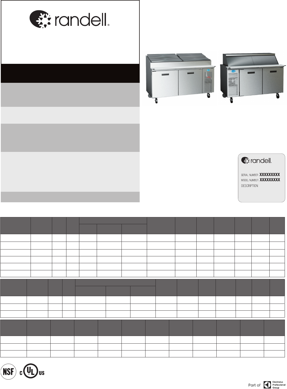
8000-290 & 9000W-290 SERIES
PREP TABLES
THIS MANUAL MUST BE RETAINED FOR FUTURE REFERENCE. READ,
UNDERSTAND AND FOLLOW THE INSTRUCTIONS AND WARNINGS CONTAINED
IN THIS MANUAL.
FOR YOUR SAFETY Do not store or use gasoline or other ammable vapors
and liquids in the vicinity of this or any other appliance.
WARNING R290 ammable refrigerant in use. Improper installation,
adjustment, alteration, service or maintenance can cause property damage,
injury or death. Read the installation, operating and maintenance instructions
thoroughly before installing or servicing this equipment.
NOTIFY CARRIER OF DAMAGE AT ONCE It is the responsibility of the
consignee to inspect the container upon receipt of same and to determine
the possibility of any damage, including concealed damage. Randell suggests
that if you are suspicious of damage to make a notation on the delivery
receipt. It will be the responsibility of the consignee to le a claim with the
carrier. We recommend that you do so at once.
Manufacture Service/Questions 888-994-7636.
RETAIN THIS MANUAL FOR FUTURE REFERENCE
NOTICE: Due to a continuous program of product improvement, Randell reserves the
right to make changes in design and specications without prior notice.
NOTICE: Please read the entire manual carefully before installation. If certain
recommended procedures are not followed, warranty claims will be denied.
MODEL NUMBER _________________________
SERIAL NUMBER _________________________
INSTALLATION DATE ______________________
The serial number is located behind the hinged vented
door of the compressor machine compartment. An
example is shown here.
EQUIPMENT DESCRIPTION
MODEL PAN
CAPACITY
1/3 SIZE
L D H DOORS STORAGE
CU. FT.
HP VOLT AMPS NEMA SHIP
WT.
WORK
SURFACE
REAR OF UNIT
(CLOSED COVER)
OVERALL
(COVER OPEN)
8148N-290 6 48” 33” 35” 44” 52.5” (1)27” 9.0 1/3 115/60/1 6 5-15P 405
8260N-290 8 60” 33” 35” 44” 52.5” (2)24” 14.67 1/3 115/60/1 6 5-15P 459
8268N-290 9 68” 33” 35” 44” 52.5” (2)27” 17.76 1/3 115/60/1 6 5-15P 484
8383N-290 11 83” 33” 35” 44” 52.5” (2)24”,(1)21” 23.55 (2) 1/4 115/60/1 5.8 5-15P 585
8395N-290 13 95” 33” 35” 44” 52.5” (3)27” 28.18 (2) 1/4 115/60/1 5.8 5-15P 630
84111N-290 15 111” 33” 35” 44” 52.5” (3)24”,(1)21” 32.81 (2) 1/4 115/60/1 5.8 5-15P 675
MODEL PAN
CAPACITY
1/6 SIZE
L D H DOORS STORAGE
CU. FT.
HP VOLT AMPS NEMA SHIP
WT.
WORK SURFACE
(NO CUTTING BOARD)
REAR OF UNIT
(NO COVER)
OVERALL
8148W-290 21 48” 33” 35” 46.5” 53.5” (1)27” 9.0 1/3 115/60/1 6 5-15P 530
8268W-290 30 68” 33” 35” 46.5” 53.5” (2)27” 17.76 1/3 115/60/1 6 5-15P 595
8395W-290 42 95” 33” 35” 46.5” 53.5” (3)27” 28.18 (2) 1/4 115/60/1 5.8 5-15P 785
MODEL PAN
CAPACITY
1/6 SIZE
L D H DOORS STORAGE
CU. FT.
HP
(BASE &
RAIL)
VOLT AMPS NEMA SHIP WT.
9148W-290 18 48" 33" 46.5" (1) 27" 5.5 1/3 115/60/1 6 5-15P 405
9260W-290 24 60" 33" 46.5" (2) 24" 9.8 1/3 115/60/1 6 5-15P 465
9272W-290 30 72" 33" 46.5" (2) 27" 11.2 1/3 115/60/1 6 5-15P 510
Information contained in this document is known to be current and accurate at the time of printing/creation. Reference our product line website for the most
updated product information and specications. © 2023 Electrolux Professional, Inc. All Rights Reserved.
2 OM-8000 & 9000W SERIES PREP TABLES
INSTALLATION
CAUTION: THIS UNIT CONTAINS R290 FLAMMABLE REFRIGERANT. USE CAUTION
WHEN HANDLING MOVING AND USE OF THE REFRIGERATOR OR FREEZER.
AVOID DAMAGING THE REFRIGERANT TUBING OR INCREASE THE RISK OF A
LEAK.
WARNING:
FAILURE TO FOLLOW INSTALLATION GUIDELINES AND
RECOMMENDATIONS MAY VOID THE WARRANTY ON YOUR UNIT.
WARNING: IT IS IMPORTANT THAT YOUR UNIT HAS ITS OWN DEDICATED LINE.
CONDENSING UNITS ARE DESIGNED TO OPERATE WITH A VOLTAGE
FLUCTUATION OF PLUS OR MINUS 10% OF THE VOLTAGE INDICATED ON
THE UNIT DATA TAG. BURN OUT OF A CONDENSING UNIT DUE TO EXCEEDING
VOLTAGE LIMITS WILL VOID THE WARRANTY.
THE DANFOSS CONTROLLER HAS LOW VOLTAGE PROTECTION AND WILL
NOT OUTPUT VOLTAGE TO THE COMPRESSOR IF VOLTAGE IS LESS THAN
104V.
WARNING: IT IS IMPORTANT THAT A VOLTAGE READING BE MADE AT THE COMPRESSOR
MOTOR ELECTRICAL CONNECTIONS, WHILE THE UNIT IS IN OPERATION
TO VERIFY THE CORRECT VOLTAGE REQUIRED BY THE COMPRESSOR IS
BEING SUPPLIED. LOW OR HIGH VOLTAGE CAN DETRIMENTALLY AFFECT
OPERATION AND THEREBY VOID ITS WARRANTY.
WARNING: EVAPORATOR FANS RUN CONTINUOUSLY WHILE THE BASE IS POWERED
ON.
WARNING: THIS UNIT IS INTENDED FOR USE IN LABORATORIES IN COMMERCIAL,
INDUSTRIAL, OR INSTITUTIONAL OCCUPANCIES AS DEFINED IN THE
SAFETY STANDARD FOR REFRIGERATION SYSTEMS, ASHRAE 15.
SELECTING A LOCATION FOR YOUR NEW UNIT
The following conditions should be considered when selecting a location for
your unit:
1. Floor Load: The area on which the unit will rest must be level, free of vibration,
and suitably strong enough to support the combined weights of the unit plus
the maximum product load weight. All casters must be in contact with the oor
to support the weight. Casters may require shims in order for the caster to be
in contact with the oor. NOTE: If there is a question pertaining to weight load
limits, consult the factory at 1-888-994-7636.
2. Clearances: Unit shall have a clearance of 0 inches at the top, 0 inches at
the rear and 0 inches at each side.
3. Ventilation: The air cooled self contained unit requires a sufcient amount
of cool clean air. Avoid surrounding your unit around other heat generating
equipment and out of direct sunlight. Also, avoid locating in an unheated
room or where the room temperature may drop below 70° F (21°C) or above
86°F (32°C). Do not place any object that can block the ventilation exhaust
from the machine compartment register.
INSTALLATION CHECKLIST
After the nal location has been determined, refer to the following checklist prior
to start-up:
1. Check all exposed refrigeration lines to ensure that they are not kinked,
dented, or rubbing together or rubbing against any steel.
2. Check all visible components for any potential damage.
3. Check that the condenser and evaporator fans rotate freely without striking
any stationary members.
4. Unit must be property leveled; Check all legs or casters ensure they all are
in contact with the oor while maintaining a level work surface. Adjusting
bullet feet height or shimming casters may be necessary if the oor is not
level. NOTE: Damage to equipment may result if not followed. Randell is
not responsible for damage to equipment if improperly installed.
5. Plug unit into power source. Unit will come on. If unit does not turn on, refer
to controller operation section of this manual to manually turn on the unit.
6. Allow unit time to cool down to holding temperature. If temperature
adjustments are required, the control is located on the front panel. Conrm
that the units is holding the desired temperature.
7. If unit has drawers, check drawer to ensure the drawer slides freely and fully
extents along with seating in the cabinet properly when closed.
8. Refer to the front of this manual for serial number location. Please record
this information in your manual on page 1 now. It will be necessary when
ordering replacement parts or requesting warranty service.
9. Allow your unit to operate for approximately 45 minutes before putting in
food in the rail. Allow 2 hours for base of the unit to cool down to storage
temperature, prior to loading product. NOTE: All motors are oiled and sealed.
ELECTRICAL SUPPLY
The wiring should be done by a qualied electrician in accordance with local
electrical codes. A properly wired and grounded outlet will assure proper
operation. Please consult the data tag attached to the compressor to ascertain
the correct electrical requirements. Supply voltage and amperage requirements
are located on the serial number tag located on the rear interior wall.
IMPORTANT - READ FIRST - IMPORTANT
INTERIOR EVAPORATOR COVER
EXTERIOR OF UNIT
RISK OF FIRE OR EXPLOSION.
FLAMMABLE REFRIGERANT USED.
DO NOT USE MECHANICAL DEVICES
TO DEFROST REFRIGERATOR. DO NOT
PUNCTURE REFRIGERANT TUBING.
RIESGO DE INCENDIO O EXPLOSIÓN. REFRIGERANTE INFLAMABLE UTILIZADO. NO
UTILICE DISPOSITIVOS MECÁNICOS PARA DESCONGELAR EL REFRIGERADOR. NO
PERFORE LA TUBERÍA DEL REFRIGERANTE.
RISQUE D’INCENDIE OU
D’EXPLOSION.
INFLAMMABLE
RÉFRIGÉRANT UTILISÉ.
NE PAS UTILISER DE
DISPOSITIFS
MÉCANIQUES POUR
DÉGIVRER LE
RÉFRIGÉRATEUR. NE
FAIRE AUCUN TUBE
RÉFRIGÉRANT DE
PONCTION.
DANGER
SB6.1.2
WARNING ALERTE
CAUTION ATTENTIÓN
DO NOT REMOVE PANEL - HIGH VOLTAGE -
QUALIFIED PERSONNEL ONLY
NE PAS RETIRE LE PANNEAU - HAUTE TENSION -
PERSONNEL QUALIFIÉ SEULEMENT
NO RETIRE EL PANEL - ALTA TENSIÓN -
CALIFICADO PERSONAL
MOVING PARTS, DO NOT OPERATE
WITH COVER REMOVED
PIÉCES MOBILES NE PAS FAIRE
FONCTIONNER SANS COUVERCLE
LAS PIEZAS DE MOVIMIENTO NO FUNCIONAN
CON LA CUBIERTA RETIRADA
PP LBL1701 REV B
LABEL DIMENSION: 9 in x 3.25 in
RISK OF FIRE OR EXPLOSION.
DISPOSE OF PROPERLY IN
ACCORDANCE WITH FEDERAL OR
LOCAL REGULATIONS.
FLAMMABLE REFRIGERANT USED.
PRECAUCIÓN RIESGO DE INCENDIO O EXPLOSIÓN. DESÉCHELO ADECUADAMENTE CONFORME
A REGLAMENTOS FEDERALES O LOCALES. REFRIGERANTE INFLAMABLE UTILIZADO.
MISE EN GARDE RISQUE
D’INCENDIE OU
D’EXPLOSION. ÉLIMINER
(or DISPOSER)
CORRECTEMENT
CONFORMÉMENT AUX
RÉGLEMENTATIONS
FÉDÉRALES OU LOCALES.
RÉFRIGÉRANT
INFLAMMABLE UTILISÉ.
SB6.1.4
LABEL DIMENSION: 6 in x 2.75 in
PP LBL1704 REV B
CAUTION
RISK OF FIRE OR EXPLOSION DUE TO
PUNCTURE OF REFRIGERANT TUBING; FOLLOW
HANDLING INSTRUCTIONS CAREFULLY.
FLAMMABLE REFRIGERANT USED.
PRECAUCIÓN RIESGO DE INCENDIO O EXPLOSIÓN DEBIDO A LA PERFORACIÓN DE LA TUBERÍA DE
REFRIGERANTE; SIGA CUIDADOSAMENTE LAS INSTRUCCIONES DE MANEJO. REFRIGERANTE
INFLAMABLE UTILIZADO.
MISE EN GARDE RISQUE
D’INCENDIE OU
D’EXPLOSION EN RAISON
DE LA PERFORATION DU
TUBE RÉFRIGÉRANT;
SUIVEZ ATTENTIVEMENT
LES INSTRUCTIONS DE
MANIPULATION.
RÉFRIGÉRANT
INFLAMMABLE UTILISÉ.
CAUTION
SB6.1.5
PP LBL1705 REV B
LABEL DIMENSION: 6.25 in x 2.8 in
RISK OF FIRE OR EXPLOSION. FLAMMABLE
REFRIGERANT USED. CONSULT REPAIR MANUAL
/ OWNER’S GUIDE BEFORE ATTEMPTING TO
INSTALL OR SERVICE THIS PRODUCT. ALL
SAFETY PRECAUTIONS MUST BE FOLLOWED.
PRECAUCIÓN RIESGO DE INCENDIO O EXPLOSIÓN. REFRIGERANTE INFLAMABLE UTILIZADO. CONSULTE EL MANUAL DE REPARACIÓN /
MANUAL DEL USUARIO ANTES DE INSTALAR O REPARAR ESTE PRODUCTO. DEBEN SEGUIRSE LAS PRECAUCIONES DE SEGURIDAD.
MISE EN GARDE RISQUE
D’INCENDIE OU
D’EXPLOSION. RÉFRIGÉRANT
INFLAMMABLE UTILISÉ.
CONSULTER LE MANUEL DE
RÉPARATION / GUIDE DE
L’UTILISATEUR AVANT
D’ESSAYER D’INSTALLER OU
DE RÉPARER CE PRODUIT.
TOUTES LES PRÉCAUTIONS
DOIVENT ÊTRE RESPECTÉES.
SB6.1.3.b
PP LBL1703 REVB
LABEL DIMENSION: 7.5 in x 5.36 in
SB6.1.3.a
RISK OF FIRE OR EXPLOSION. FLAMMABLE
REFRIGERANT USED. TO BE REPAIRED ONLY
BY TRAINED SERVICE PERSONNEL. DO NOT
PUNCTURE REFRIGERANT TUBING.
PELIGRO RIESGO DE INCENDIO O EXPLOSIÓN. REFRIGERANTE INFLAMABLE UTILIZADO. DEBE SER REPARADO
SOLAMENTE POR PERSONAL DE SERVICIO CAPACITADO. NO PERFORE LA TUBERÍA DEL REFRIGERANTE.
DANGER RISQUE
D’INCENDIE OU
D’EXPLOSION.
RÉFRIGÉRANT
INFLAMMABLE UTILISÉ.
POUR ÊTRE RÉPARÉ QUE
PAR UN TECHNICIEN
QUALIFIÉ. NE PAS
PERFORER LE TUBE
RÉFRIGÉRANT.
CAUTION
DANGER
NEAR EXPOSED REFRIGERANT TUBING
NEAR MACHINE COMPARTMENT AND NAMEPLATE
3 OM-8000 & 9000W SERIES PREP TABLES
OPERATION
MECHANICAL COMPARTMENT
WARNING: BASE EVAPORATOR FANS ARE ALWAYS IN OPERATION WHEN THE UNIT IS
ENERGIZED. DISCONNECT POWER TO THE UNIT PRIOR TO PERFORMING
MAINTENANCE.
1. To power on the base, press and hold the base control power button until the
LED display turns on. To power on the rail, press and hold the rail control
power button until the LED display turns on. The power controls are located
above the louver panel.
2. To power off the base press and hold the base control power button until the
LED display turns off. To power
off the rail press and hold the rail
control power button until the
LED display turns off. The power
controls are located above the
louver panel.
3. The drain valve for the upper
rail is found behind the hinged
vented door. The rail may be
drained by placing a pan under the drain valve and opening the valve. (See
Evening Shut Down of Prep Rail).
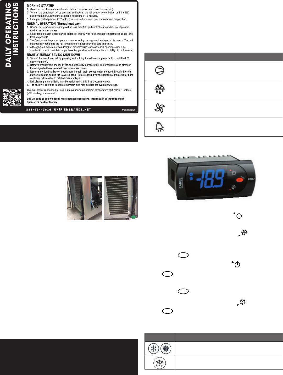
MORNING STARTUP OF PREP RAIL
1. Unit cleaning may be performed at this time.
2. Turn on unit. See item 2 under the Mechanical Compartment section above for
powering on the rail.
3. Allow a minimum 45 minutes for your unit to cool down before loading product.
A uniform frost pattern will appear on side walls and bottom of prep rail area.
4. Load the product and proceed with food preparation. NOTE: Product entering
unit must be at 35°F +/- 2°F.
EVENING SHUT DOWN OF PREP RAIL
1. Remove product from unit at the end of the day’s preparation.
2. Turn off unit. See item 3 under the Mechanical Compartment section above for
powering on the rail.
3.
Unit cleaning may be performed at this time if the frost has melted off the surface.
4. Once defrosted, the rail drain may be opened to remove any water that has
resulted from the defrosting procedure.
WARNING: IT IS RECOMMENDED TO ONLY MAKE CHANGES OF 2 DEGREE INCREMENTS
AT A TIME. ALLOW FOR THE UNIT TO OPERATE 24 HOURS BETWEEN
ADJUSTMENTS. IF THE 2 DEGREE ADJUSTMENT IS NOT ENOUGH ANOTHER
ADJUSTMENT CAN BE MADE. IF THE SETTINGS NEED TO GO ABOVE OR
BELOW THIS POINT THERE MAY BE OTHER CONTRIBUTING FACTORS AS
TO THE CAUSE OF THE TEMPERATURE VARIANCES, PLEASE CONTACT THE
FACTORY AT 1-800-621-8560.
AMBIENT CONDITIONS
Unit is designed for normal operating temperatures between 70° F (21°C) - 86°F
(32°C). Operating outside of those temperatures may cause premature product
wear or failure.
Randell has attempted to preset the temperature control to ensure that your
unit runs at an optimum temperature, but due to varying ambient conditions,
including elevation, food type and your type of operation, you may need to alter
this temperature using control adjustment until desired temperature is reached.
CAREL CONTROLLER OPERATION
LED FUNCTION
Compressor energized
Defrost in progress
Evaporator fan energized
An alarm is occurring
POWER ON / OFF: Press and hold the Power Button
for more than 3
seconds or until LED display turns On/Off.
MANUAL DEFROST: Press and hold the Defrost Button
for more than 3
seconds (melting snowake will light).
CHANGE SET POINT: To raise temperature
1. Press and hold
set
button for 1 second to access set point.
2. When set point starts ashing, press up button
to adjust set point.
3. Press
set
button for 3-seconds to save set point.
CHANGE SET POINT: To lower temperature
1. Press and hold
set
button for 1 second to access set point.
2. When set point starts ashing, press down button
to adjust set point.
3. Press
set
button for 3-seconds to save set point.
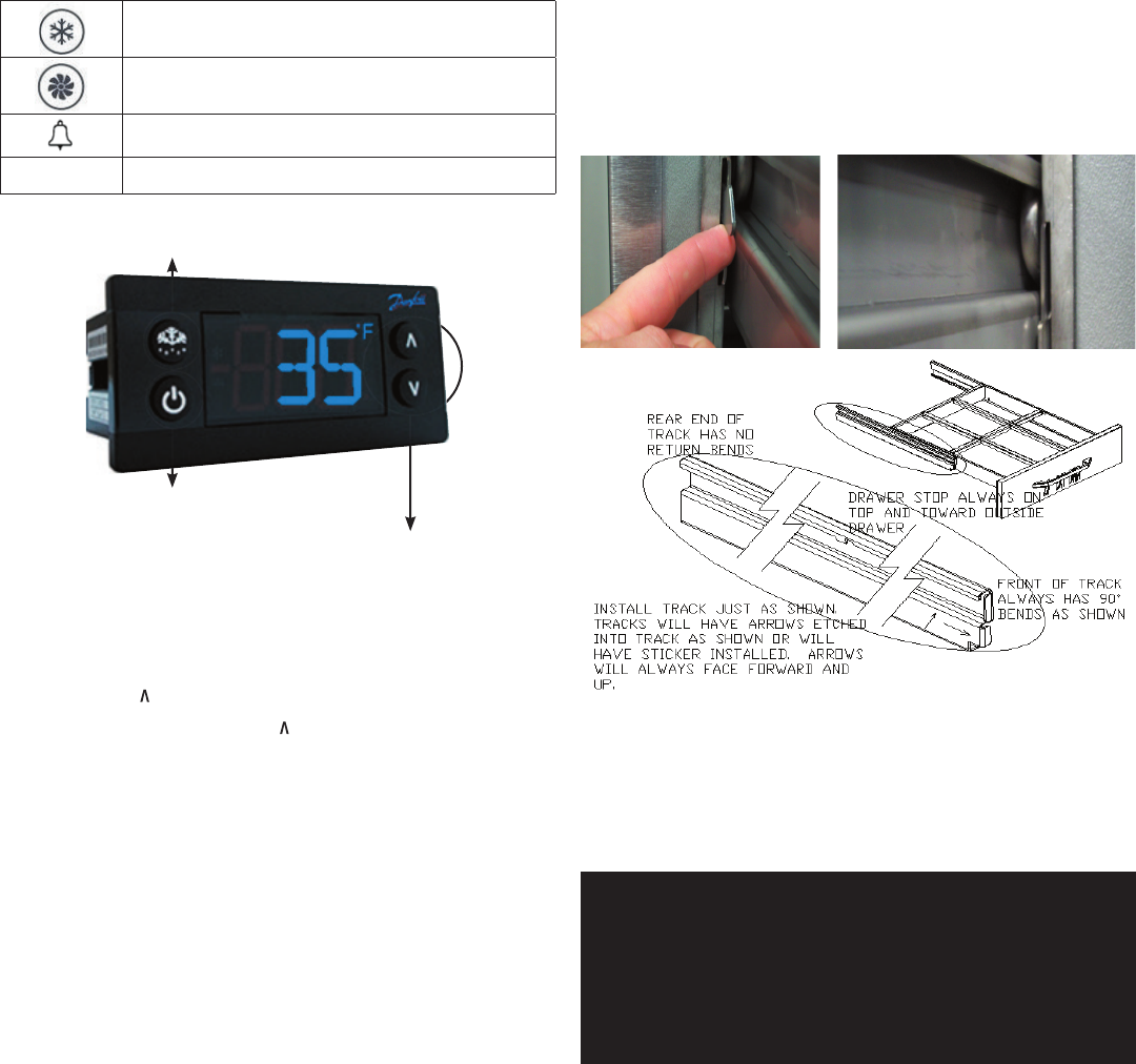
DANFOSS CONTROLLER OPERATION
LED FUNCTION
Compressor energized & Evaporator fan de-energized
Defrost in progress
4 OM-8000 & 9000W SERIES PREP TABLES
Fans delay after defrost completion
Evaporator fan energize
An alarm is occurring
ºC / ºF
Temperature unit
POWER ON / OFF
MANUAL DEFROST
CHANGE SET POINT
POWER ON / OFF: Press and hold the power button until LED display turns On / Off
MANUAL DEFROST: Press and hold “Defrost” Button
CHANGE SET POINT: To raise temperature
1. Press and hold “ ” to access set point.
2. When set point start ashing, Press “ ” to adjust set point.
3. After 30 seconds, the display automatically reverts to showing the current
temperature.
CHANGE SET POINT: To lower temperature
1. Press and hold “v” to access set point.
2. When set point start ashing, Press “v” to adjust set point.
3. After 30 seconds, the display automatically reverts to showing the current
temperature.
CHANGE FROM ºF /ºC :
1. Press the up/down buttons simultaneously for 5 seconds to access the menu.
2. Password is requested. Password is 000.
3. Press the bottom left button to OK the password.
4. Using the up/down buttons, navigate to the “diS” level. Press the bottom left
button to OK the selection.
5. Using the up/down buttons, navigate to the “CFu” level. Press the bottom left
button to OK the selection.
a. “-F” designates Fahrenheit.
b. “-C” designates Celsius.
6. Press the top left button repeatedly to return to exit and return to the home
screen.
DRAINING THE RAIL
1. Open hinged mechanical compartment door
2. Place container under drain valve
3. Open valve until all water has drained
4. Close valve
5. Discard water
DRAWER REMOVAL
1. Fully extend the drawer that is to be removed.
2. Remove product pans from drawer.
3. Lift up the drawer stop tabs on each side of drawer track.
4. Pull drawer out while lifting the tabs.
DRAWER INSTALLATION
To remove and re-install individual drawers and drawer tracks, please refer to the
gure above for proper installation instructions.
MAINTENANCE
WARNING: DO NOT USE SHARP UTENSILS AND/OR OBJECTS.
WARNING: DO NOT USE STEEL PADS, WIRE BRUSHES, SCRAPERS, OR CHLORIDE
CLEANERS TO CLEAN YOUR STAINLESS STEEL.
CAUTION: DO NOT USE ABRASIVE CLEANING SOLVENTS, AND NEVER USE
HYDROCHLORIC ACID (MURIATIC ACID) ON STAINLESS STEEL.
WARNING: DO NOT PRESSURE WASH EQUIPMENT AS DAMAGE TO ELECTRICAL
COMPONENTS MAY RESULT.
Randell strongly suggests a preventive maintenance program which would include
the following monthly, weekly, and daily procedures:
If a failure of the equipment is a direct result of any of the Preventative Maintenance
guidelines being neglected, the repairs and parts replacements will not be covered
under warranty.
It is recommended that the customer contact the local Authorized Service Agent to
provide a quote to perform periodic Preventative Maintenance.
WEEKLY PM PROCEDURES
1. Clean all gaskets on a weekly if not daily basis with a solution of warm water
and a mild detergent to extend gasket life. Do not use bleach for cleaning
gaskets. Bleach will cause the gaskets to become brittle and not reach their
normal life expectancy.
2. Clean and disinfect rail drains with a solution of warm water and mild
detergent on a weekly basis. It is recommended to open and close the drain
valve as the hot water is owing through to clean any debris from the internal
valve components.
5 OM-8000 & 9000W SERIES PREP TABLES
MONTHLY PM PROCEDURES
1. Cleaning of all condenser coils on a monthly basis. Condenser coils are a
critical component in the life of the compressor and must remain clean to
assure proper air ow and heat transfer. Failure to maintain this heat transfer
will affect unit performance and eventually destroy the compressor. Clean the
condenser coils with coil cleaner and/or a vacuum, cleaner and brush. NOTE:
Brush coil in direction of ns, normally vertically as to not damage or restrict
air from passing through condenser.
2. Clean and disinfect drain lines and evaporator pan with a solution of warm
water and mild detergent on a monthly basis. Remove clear plastic drain line
from plastic tray of condensing unit and place pan under end of drain tube.
Discard waste water from pan when cleaning is complete. Re-insert plastic
drain tube into position on condensing unit.
3. Remove drawer tracks as per instructions on Drawer Installation guidelines.
Once drawers are removed wipe away any debris buildup from the drawer
tracks.
The roller bearings come lubricated from the factory. Excessive oils and or
water may remove the oils. It may be required to add lithium grease from time
to time on bearings that appear dry.
4. Inspect all silicone seams at interior of the rail and refrigerated base cabinet
on a monthly basis. Re-apply food grade silicone sealant as needed to any
seams where silicone has peeled away or cracked. Apply silicone to a clean
dry surface. Allow sufcient drying time to assure best adhesion of sealant.
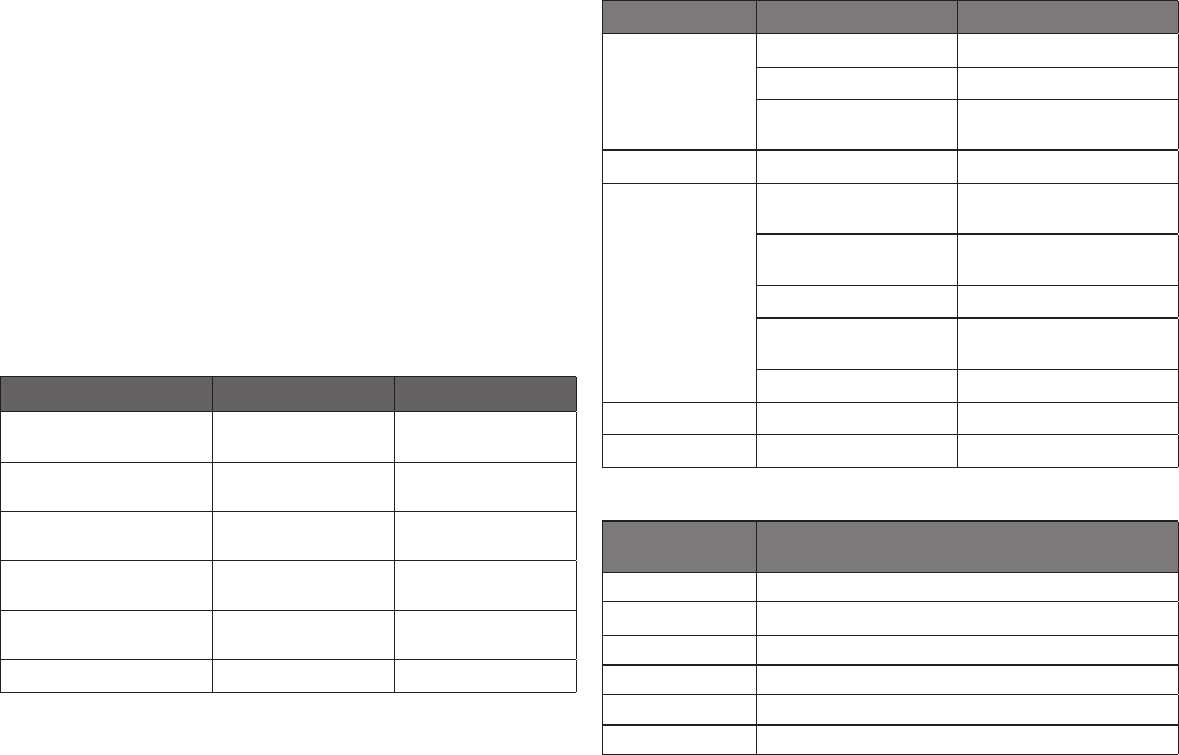
RECOMMENDED CLEANERS FOR YOUR STAINLESS STEEL INCLUDE THE
FOLLOWING:
JOB CLEANING AGENT COMMENTS
Routine cleaning
Soap, ammonia,
detergent Medallion
Apply with a sponge or
cloth
Fingerprints and smears
Arcal 20, Lac-O-Nu,
Ecoshine
Provides a barrier lm
Stubborn stains and
discoloration
Cameo, Talc, Zud,
First Impression
Rub in the direction of
the polish lines
Greasy and fatty acids, blood,
burnt-on foods
Easy-Off, Degrease It,
Oven Aid
Excellent removal on all
nishes
Grease and Oil
Any good commercial
detergent
Apply with a sponge or
cloth
Restoration/Preservation Benet, Super Sheen Good idea monthly
Reference: Nickel Development Institute, Diversey Lever, Savin, Ecolab, NAFEM
Proper maintenance of equipment is the ultimate necessity in preventing costly
repairs. By evaluating each unit on a regular schedule, you can often catch
and repair minor problems before they completely disable the unit and become
burdensome on your entire operation.
For more information on preventive maintenance, consult your local service
company or CFESA member. Most repair companies offer this service at very
reasonable rates to allow you the time you need to run your business along with
the peace of mind that all your equipment will last throughout its expected life.
These services often offer guarantees as well as the exibility in scheduling or
maintenance for your convenience. For a complete listing of current Randell ASA
please visit www.uniedbrands.net.
Randell believes strongly in the products it manufactures and backs those
products with one of the best warranties in the industry. We believe with the
proper maintenance and use, you will realize a protable return on your investment
and years of satised service.
REPLACEMENT PARTS
To order parts, contact your Authorized Service Agent. Supply the model
designation, serial number, part description, part number, quantity, and when
applicable, voltage and phase.
CONTACT US
If you have questions pertaining to the content in this manual, contact Randell
at 888-994-7636.
TROUBLESHOOTING
This unit is designed to operate smoothly and efciently if properly maintained.
However, the following is a list of checks to make in the event of a problem. Wir-
ing diagrams are found at the end of this manual. When in doubt, turn unit off
and contact service at 888-994-7636.
SYMPTOM POSSIBLE CAUSE PROCEDURE
Unit does not run
No power to unit Plug in unit
Control in OFF position Turn controller on
Faulty control
Call for service at 888-994-
7636
Unit too cold Incorrect set point Adjust control set point
Unit too warm
Door / drawer ajar
Ensure door / drawer is fully
closed
Gasket torn or out of place
Inspect the gasket for wear
and position
Incorrect set point Adjust control set point
Warm product introduced
to cabinet
Pre-chill product 37ºF
Ice on the coil Initiate manual defrost
Unit noisy Ice on the coil Initiate manual defrost
Unit does not defrost Excessive ice on the coil Initiate manual defrost
CAREL CONTROLLER CODES
DISPLAYED
ALARM CODE
ALARM
E0 Control probe
E1 Defrost probe
dOr Open door
LO Low temperature
HI High temperature
CHt Dirty condenser
6 OM-8000 & 9000W SERIES PREP TABLES
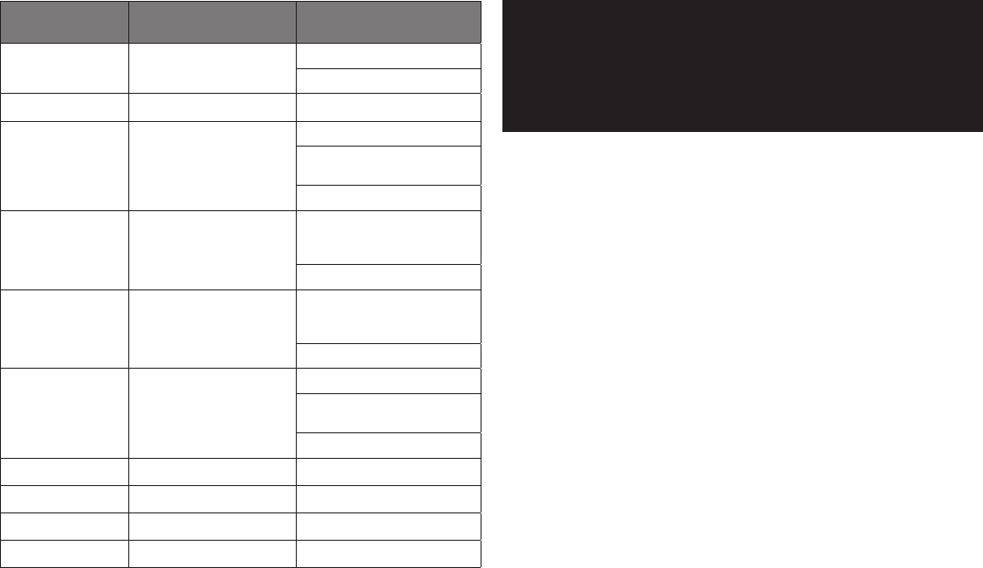
DANFOSS CONTROLLER CODES
DISPLAYED
ALARM CODE
ALARM ACTION
Hi High Temperature Alarm
Inspect door/drawer sealing
Contact service
Lo Low Temperature Alarm Contact service
CON
Condenser Temperature
High Limit
Clean condenser coil
Inspect coil for any objects
obstruction hindering airow
Contact service
uHi Line Voltage Too High
Verify voltage of power source,
to be performed by qualied
technician
Contact service
uLi Line Voltage Too Low
Verify voltage of power source,
to be performed by qualied
technician
Contact service
LEA
Continuous Compressor
Runtime
Inspect door/drawer sealing
Inspect condenser coil, clean if
necessary
Contact service
E01 S1 Sensor Failure Contact service
E02 S2 Sensor Failure Contact service
E03 S3 Sensor Failure Contact service
E04 S4 Sensor Failure Contact service
SERVICE
CAUTION: COMPONENT PARTS SHALL BE REPLACED WITH FACTORY OEM PARTS.
SERVICE WORK SHALL BE DONE BY FACTORY AUTHORIZED SERVICE
PERSONNEL, SO AS TO MINIMIZE THE RISK OF POSSIBLE IGNITION DUE TO
INCORRECT PARTS OR IMPROPER SERVICE.
CAUTION: BEFORE MAKING ANY REPAIRS, ENSURE THE UNIT IS DISCONNECTED
FROM ITS POWER SOURCE.
This piece of equipment uses a R290 Refrigeration system. This equipment has
been clearly marked on the serial tag the type of refrigerant that is being used.
There is also a warning labels stating that the unit contains R290 refrigerant. R290
is safe to use as long as you follow these warning labels.
No smoking or open ames when servicing this equipment. If needed, use a CO2
or powder type re extinguisher.
Replacement parts used on any R290 Refrigeration system cabinet must have
specic UL certication for non-sparking components.
Only authorized service technician, certied in R290 system should service this
equipment.
MANIFOLD SET
A R134A manifold set can be used for servicing this equipment.
REFRIGERANT RECOVERY
Follow all national and local regulations for R-290 refrigerant recovery.
LEAKING CHECKING AND REPAIR
Leak check an R-290 system the same way you would an R-134a or R-404A
system with the following exceptions.
1. Do not use a Halid leak detector on a R290 system.
2. Electronic leak detector must be designated specically for combustible gas.
Use of a bubble solution or an ultrasonic leak detector are acceptable.
When repairing a leak, it is recommended using oxygen free dry nitrogen with a
trace gas not exceeding 200PSI.
When accessing an R290 system, piercing valves are not to remain on the
equipment in a permanent manner. After charge is recovered, Schrader valves
are to be installed on the process stubs. Proper charge is to be weighed into the
system and the system is to be leak checked afterwards.
The R290 equipment must have red process tubes and other devices through
which the refrigerant is serviced, such as any service port. This color marking
must remain on the equipment. If marking is removed, it must be replace and
extend at least 2.5 centimeters (1”) from the compressor.
CHARGING
Follow the charge amount specied on the data tag. It is recommended to use the
shortest hoses possible to prevent undercharging.
• Ensure the system is sealed and leak checked
• Evacuate system to a minimum 500 micron
• Weigh in correct charge
• Leak check the system again
• Bleed the refrigerant from the high side hose to the low side hose
• Disconnect the hoses
• Remove line taps

7 OM-8000 & 9000W SERIES PREP TABLES
Parts List
CONTROLS
CALL FACTORY FOR REPLACEMENT PARTS:
888-994-7636
8148N-290
8260N-290
8268N-290
8383N-290
8395N-290
84111N-290
8148W-290
8268W-290
8395W-290
9148W-290
9260W-290
9272W-290
SERVICE PART DANFOSS CONTROLLER DESCRIPTION
RP CNT1720BC CONTROLLER, DANFOSS, PROGRAMMED - BASE - SGL COMPR SYSTEM X X X
- - -
X X
-
X X X
RP CNT1720RC CONTROLLER, DANFOSS, PROGRAMMED - RAIL - SGL COMPR SYSTEM X X X
- - -
X X
-
X X X
RP CNT1805B CONTROLLER, DANFOSS, PROGRAMMED - BASE - DBL COMPR SYSTEM
- - -
X X X
- -
X
- - -
RP CNT1805R CONTROLLER, DANFOSS, PROGRAMMED - RAIL - DBL COMPR SYSTEM
- - -
X X X
- -
X
- - -
RF CNT1602 THERMISTOR, DANFOSS, QTI, COIL SENSOR, MOLDED END, BLUE, 10' X X X X X X X X X X X X
RF CNT1603 THERMISTOR, DANFOSS, QTI, AIR SENSOR, MODLED END, BLACK, 10' X X X X X X X X X X X X
PP STK1802 OVERLAY, CONTROL PANEL, 8000N COMMON X X X X X X X X X X X X
8148N-290
8260N-290
8268N-290
8383N-290
8395N-290
84111N-290
8148W-290
8268W-290
8395W-290
9148W-290
9260W-290
9272W-290
SERVICE PART CAREL CONTROLLER DESCRIPTION
RP CNT1720BCAR CONTROLLER, CAREL, PROGRAMMED - BASE - SGL COMPR SYSTEM X X X X X X X X
RP CNT1720RCAR CONTROLLER, CAREL, PROGRAMMED - RAIL - SGL COMPR SYSTEM X X X X X X X X
RP CNT1805BCAR CONTROLLER, CAREL, PROGRAMMED - BASE - DBL COMPR SYSTEM X X X X
RP CNT1805RCAR CONTROLLER, CAREL, PROGRAMMED - RAIL - DBL COMPR SYSTEM X X X X
RF CNT2103 THERMISTOR, CAREL, QTI, AIR SENSOR, BARE LEADS, BLACK, 10' X X X X X X X X X X X X
RF CNT2104 THERMISTOR, CAREL, QTI, COIL SENSOR, BARE LEADS, BLUE, 10' X X X X X X X X X X X X
PP STK1802 OVERLAY, CONTROL PANEL, 8000N COMMON X X X X X X X X X X X X
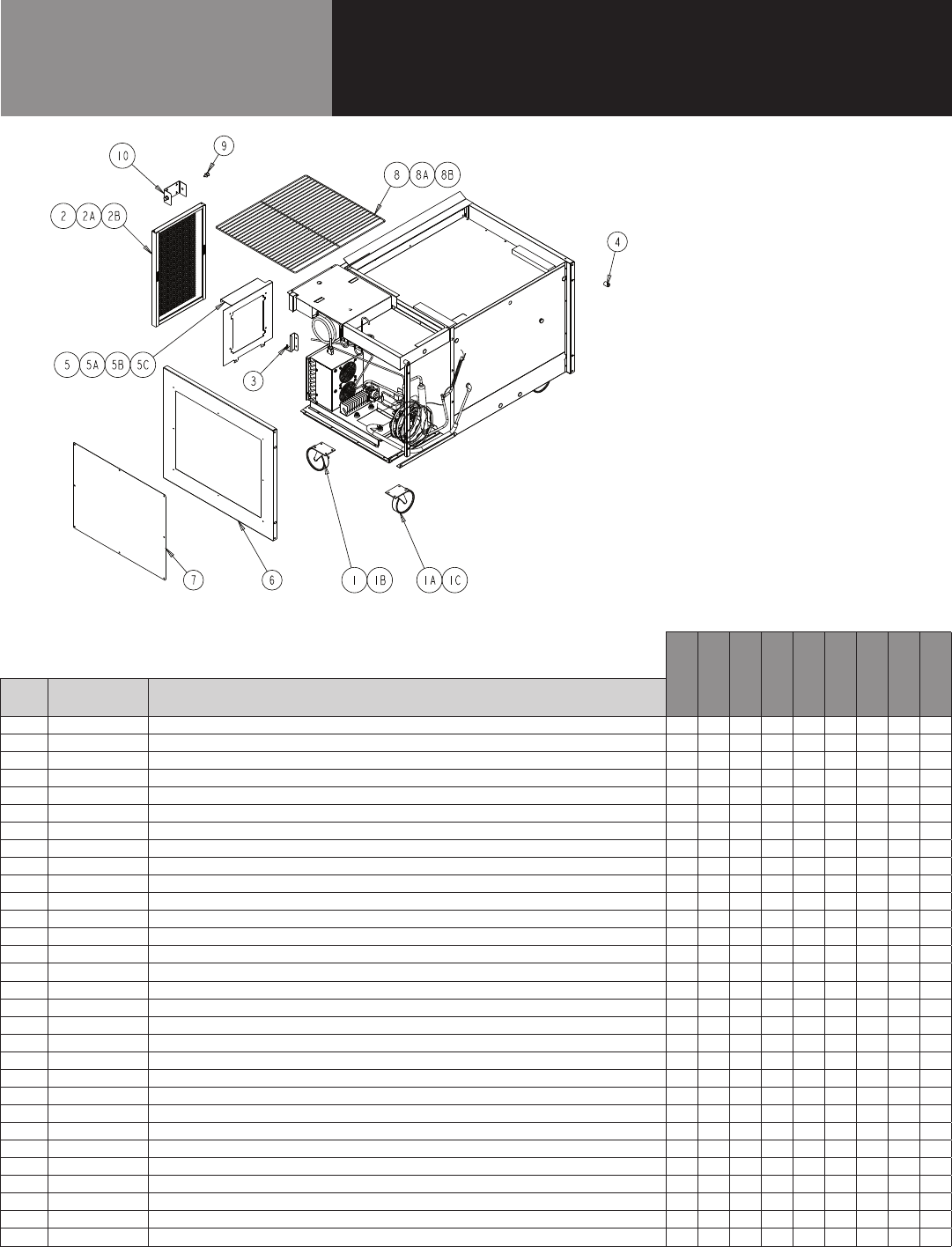
8 OM-8000 & 9000W SERIES PREP TABLES
Parts List
BASE UNIT, 8000N-290 & 8000W-290
CALL FACTORY FOR REPLACEMENT PARTS:
888-994-7636
8148N-290
8260N-290
8268N-290
8383N-290
8395N-290
84111N-290
8148W-290
8268W-290
8395W-290
ITEM SERVICE PART DESCRIPTION
1 HD CST060 6" CASTERS W/ BRAKE X X X X X X X X X
1A HD CST061 6" CASTERS W/O BRAKE X X X X X X X X X
1B HD CST040HD 4" CASTERS W/ BRAKE X X X X X X X X X
1C HD CST041HD 4" CASTERS W/O BRAKE X X X X X X X X X
2 RP LVR1803 LOUVER, HINGED X - X X X X X X
2A RP LVR1804 LOUVER, HINGED - X - - - - - - -
2B RP LVR1805 LOUVER, HINGED - - - - - X - - -
3 HD CTH9901 LOUVER MAGNET X X X X X X X X X
4 HD BMP034 BUMPER, RUBBER X X X X X X X X X
5 RP SHD1805 SHROUD, COND UNIT X - X - X - X X -
5A RP SHD1806 SHROUD, COND UNIT - X - - - - - - -
5B RP SHD1807 SHROUD, COND UNIT - - - X X - - - X
5C RP SHD1808 SHROUD, COND UNIT - - - - - X - - -
6 RP PNL1803 COVER, ACCCESS SIDE CMPR, L OR R - - - X X X - - X
7 HD SHL180 SHELF 22" X 25" X - X - X - X - X
7A HD SHL160 SHELF 19" X 25" - X - X - X - - -
7B HD SHL9912 SHELF 16.15" X 25" - - - X - X - - -
8 HD PIN0102 SHELF SUPPORT PIN X X X X X X X X X
9 RP BRK0107 SHELF SUPPORT - FRT & BACK - - - X X X - - X
10 RP BRK0108 SHELF SUPPORT BETWEEN DOORS X X X X X X X X X
11 RP BRK1811 LOUVER MOUNTING HINGE BRACKET X X X X X X X X X
12* EL WIR1703 POWER CORD 16/3 - 9' - 90 X X X X X X X X X
13* HD LEG9902 6" LEG W/ BULLET FOOT X X X X X X X X X
14* RP BCK0107 S/S BACK PANEL 48" X - - - - - X - -
14A* RP BCK0108 S/S BACK PANEL 60" - X - - - - - - -
14B* RP BCK0109 S/S BACK PANEL 68" - - X - - - - X -
14C* RP BCK0110 S/S BACK PANEL 83" - - - X - - - - -
14D* RP BCK0111 S/S BACK PANEL 95" - - - - X - - - X
14E* RP BCK0112 S/S BACK PANEL 111" - - - - - X - - -
15 RP END1901 SIDE PANEL X X X X X X X X X
* = NOT SHOWN
9 OM-8000 & 9000W SERIES PREP TABLES
Parts List
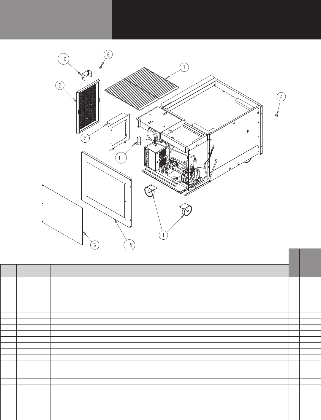
BASE UNIT, 9000W-290
CALL FACTORY FOR REPLACEMENT PARTS:
888-994-7636
9148W-290
9260W-290
9272W-290
ITEM SERVICE PART DESCRIPTION
1 HD CST060 6" CASTERS W/ BRAKE X X X
1A HD CST061 6" CASTERS W/O BRAKE X X X
1B HD CST040HD 4" CASTERS W/ BRAKE X X X
1C HD CST041HD 4" CASTERS W/O BRAKE X X X
2 RP LVR1807 LOUVER, HINGED X - -
2A RP LVR1808 LOUVER, HINGED - X -
2B RP LVR1809 LOUVER, HINGED - - X
3 HD CTH9901 LOUVER MAGNET X X X
4 HD BMP034 BUMPER, RUBBER X X X
5 RP SHD1814 SHROUD, COND UNIT X - -
5A RP SHD1815 SHROUD, COND UNIT - X -
5B RP SHD1816 SHROUD, COND UNIT - - X
6 HD SHL160 SHELF 19" X 25" X - X
6A HD SHL180 SHELF 22" X 25" - X -
7 HD PIN001 SHELF SUPPORT PIN X X X
8* RP SPT007 SHELF SUPPORT X X X
9 RP BRK1811 LOUVER MOUNTING HINGE BRACKET X X X
10* RP BRK0108 SHELF SUPPORT BETWEEN DOORS - X X
11* HD LEG9902 6" LEG W/ BULLET FOOT X X X
12* RP BCK0301 S/S BACK PANEL 48" X - -
12A* RP BCK0304 S/S BACK PANEL 60" - X -
12B* RP BCK0113 S/S BACK PANEL 72" - - X
13* EL WIR469A CORD, 14 GA 18” FEMALE 000469-14 X X X
14* EL WIR1703 POWER CORD, 9’ 16/3 W/90*-45* ANGLE PLUG (SJTO WIRE) X X X
* = NOT SHOWN
10 OM-8000 & 9000W SERIES PREP TABLES
Parts List
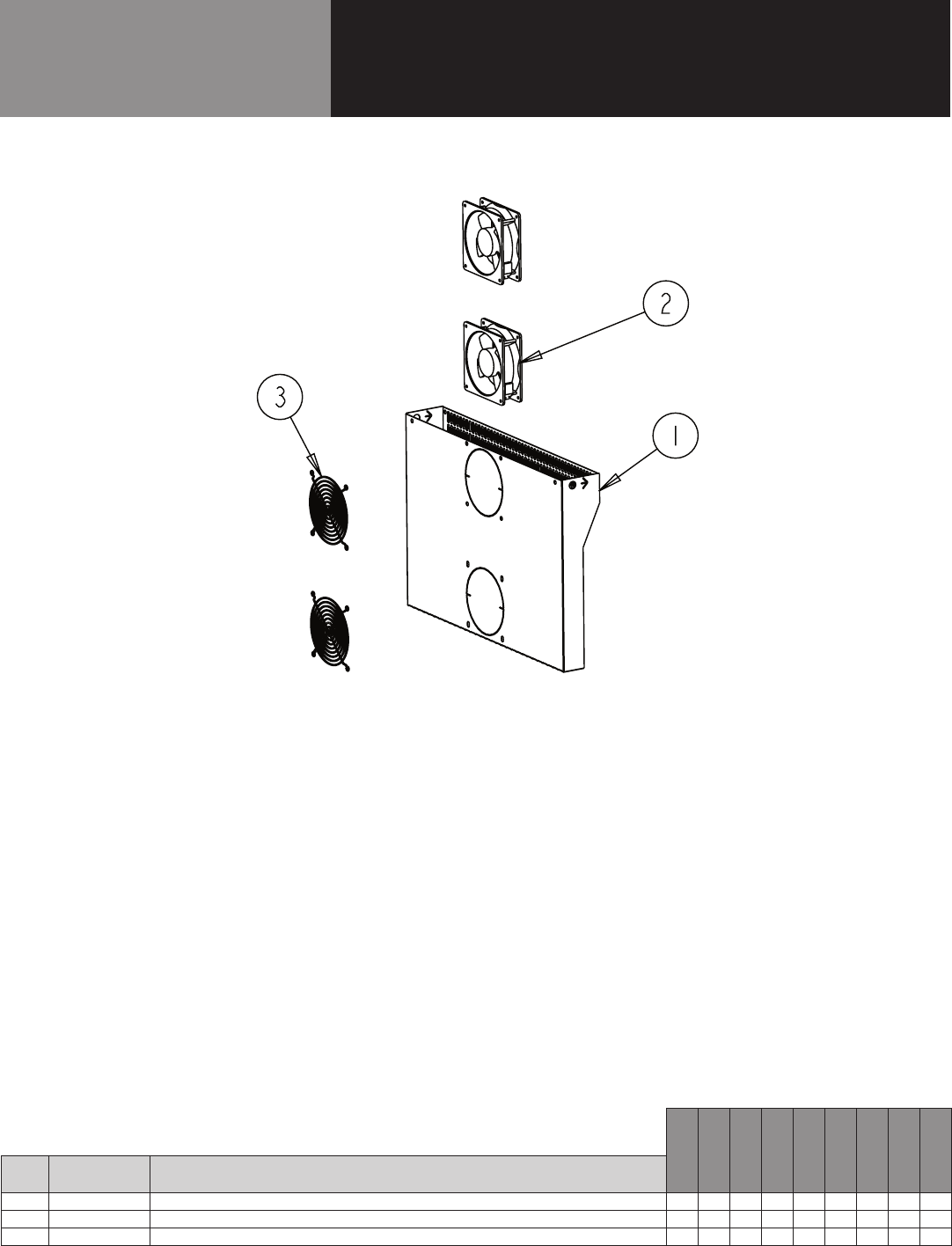
FAN ASSIST
CALL FACTORY FOR REPLACEMENT PARTS:
888-994-7636
8148N-290
8260N-290
8268N-290
8383N-290
8395N-290
84111N-290
8148W-290
8268W-290
8395W-290
ITEM SERVICE PART DESCRIPTION
1 RP FAN1801 FAN ASSIST ASSY - - - - X X - - X
2 RF FAN1401 FAN ASSIST MOTOR - - - - X X - - X
3 RF FAN0703 FAN ASSIST FAN GUARD - - - - X X - - X
* = NOT SHOWN
11 OM-8000 & 9000W SERIES PREP TABLES
Parts List
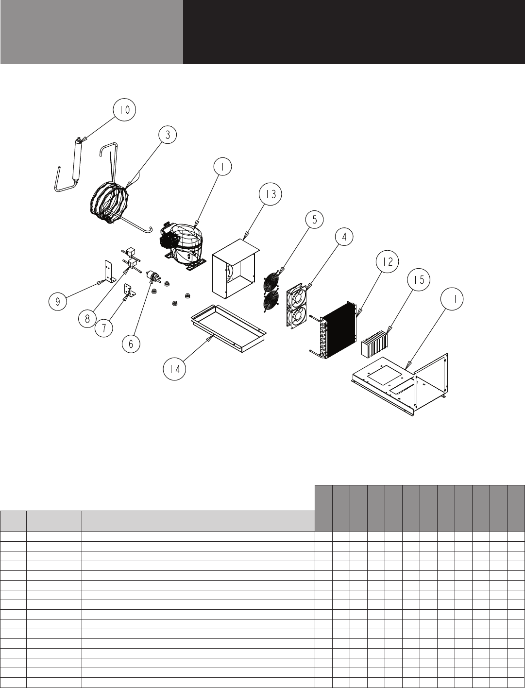
MECH COMPARTMENT -
SINGLE COMPRESSOR
CALL FACTORY FOR REPLACEMENT PARTS:
888-994-7636
8148N-290
8260N-290
8268N-290
8383N-290
8395N-290
84111N-290
8148W-290
8268W-290
8395W-290
9148W-290
9260W-290
9272W-290
ITEM SERVICE PART DESCRIPTION
1 RF CMP1702 COMPRESSOR, 1/3HP, R290, EMBRACO FFU130UAX X X X - - - X X - X X X
2* RF CMP1702SC COMPRESSOR, START COMPONENTS X X X - - - X X - X X X
3 RP CAP1801 CAP, TUBE - RAIL X X X - - - X X - X X X
4 RF FAN1401 CONDENSER FAN X X X - - - X X - X X X
5 RF FAN0703 FAN GUARD X X X - - - X X - X X X
6 RF FLT251 FILTER DRIER, 1/4" DBL INLET X X X - - - X X - X X X
7 RP BRK1720 MOUNTING CLIP, FILTER DRIER (T07-1167) X X X - - - X X - X X X
8 RF SOL9801 SOLENDOID VALVE X X X - - - X X - X X X
9 RP BRK1812 BRACKET, SOLENOID VALVE (T07-1173) X X X - - - X X - X X X
10 RF ACM1702 ACCUMULATOR X X X - - - X X - X X X
11 RP MNT1802 COMPRESSOR ASM STAND X X X - - - X X - X X X
12 RF COI1603 CONDENSER COIL X X X - - - X X - X X X
13 RP SHD1809 CONDENSER FAN SHROUD (T07-1179) X X X - - - X X - X X X
14 RP CPN1802 DRAIN PAN - (T07-1146) X X X - - - X X - X X X
15 HD WCK1702 PAD, WICKING X X X - - - X X - X X X
16* EL WIR470 POWER CORD, 16GA 2' MALE X X X - - - X X - X X X
* = NOT SHOWN
12 OM-8000 & 9000W SERIES PREP TABLES
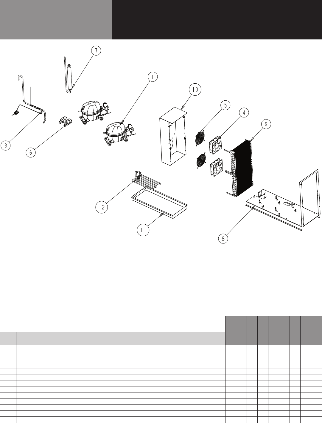
Parts List
MECH COMPARTMENT -
DOUBLE COMPRESSOR
CALL FACTORY FOR REPLACEMENT PARTS:
888-994-7636
8148N-290
8260N-290
8268N-290
8383N-290
8395N-290
84111N-290
8148W-290
8268W-290
8395W-290
ITEM SERVICE PART DESCRIPTION
1 RF CMP1604 COMPRESSOR, 1/4 HP, R290, EMBRACO, 115V-60HZ - - - X X X - - X
2* RF CMP1604SC COMPRESSOR, START COMPONENTS - - - X X X - - X
3 RP CAP1802 CAP, TUBE - RAIL - - - X X X - - X
4 RF FAN0601 CONDENSER FAN - - - X X X - - X
5 HD GRD1610 FAN GUARD - - - X X X - - X
6 RF FLT251 FILTER DRIER, 1/4" DBL INLET - - - X X X - - X
7 RF ACM1701 ACCUMULATOR - - - X X X - - X
8 RP MNT1803 COMPRESSOR ASM STAND (T07-1168) - - - X X X - - X
9 RF COI1603 CONDENSER COIL - - - X X X - - X
10 RP SHD1810 CONDENSER FAN SHROUD (T07-1169) - - - X X X - - X
11 RP CPN1803 DRAIN PAN (T07-1170) - - - X X X - - X
12 EL WIR274 HEATER, DRAIN PAN - - - X X X - - X
13* EL WIR470 POWER CORD, 16GA 2' MALE - - - X X X - - X
* = NOT SHOWN
13 OM-8000 & 9000W SERIES PREP TABLES
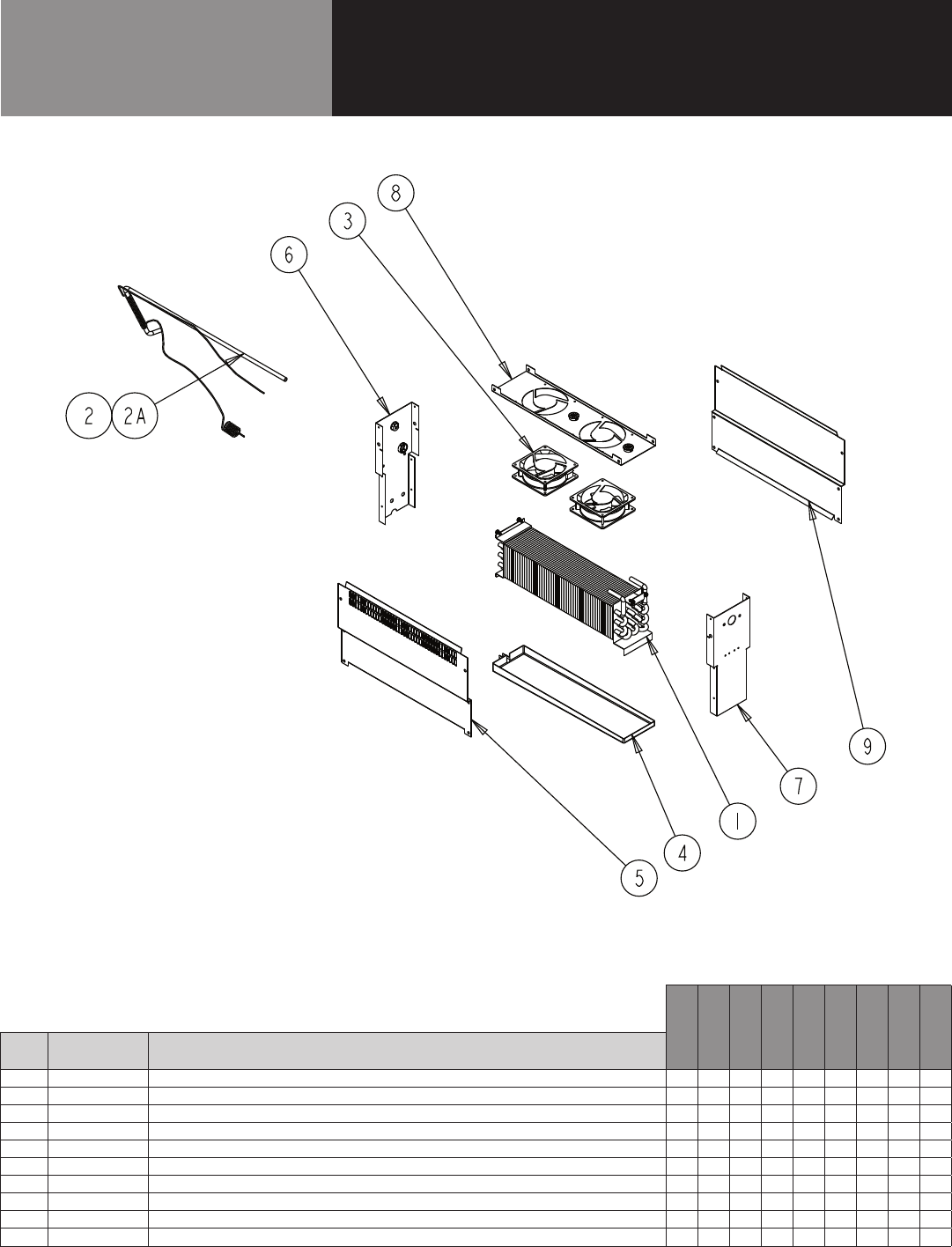
Parts List
EVAPORATOR COIL
CALL FACTORY FOR REPLACEMENT PARTS:
888-994-7636
8148N-290
8260N-290
8268N-290
8383N-290
8395N-290
84111N-290
8148W-290
8268W-290
8395W-290
ITEM SERVICE PART DESCRIPTION
1 RF COI107 EVAPORATOR COIL X X X X X X X X X
2 RP CAP1804 CAP, TUBE - BASE - - - X X X - - X
2A RP CAP1803 CAP, TUBE - BASE X X X - - - X X -
3 RF FAN1401 FAN, EVAPORATORS X X X X X X X X X
4 RP DRP107 EVAPORATOR DRAIN PAN X X X X X X X X X
5 RP PNL107-290 SIDE, COIL, 8000N COMMON X X X X X X X X X
6 RP PNL108-290 BACK, COIL, 8000N COMMON X X X X X X X X X
7 RP PNL109-290 FRONT, COIL, 8000N COMMON X X X X X X X X X
8 RP SHD1811 PLATE, FAN, 8000N COMMON X X X X X X X X X
9 RP PNL1804 SIDE, COIL, NO PERF, 8000N COMMON X - - - - - X - -
* = NOT SHOWN
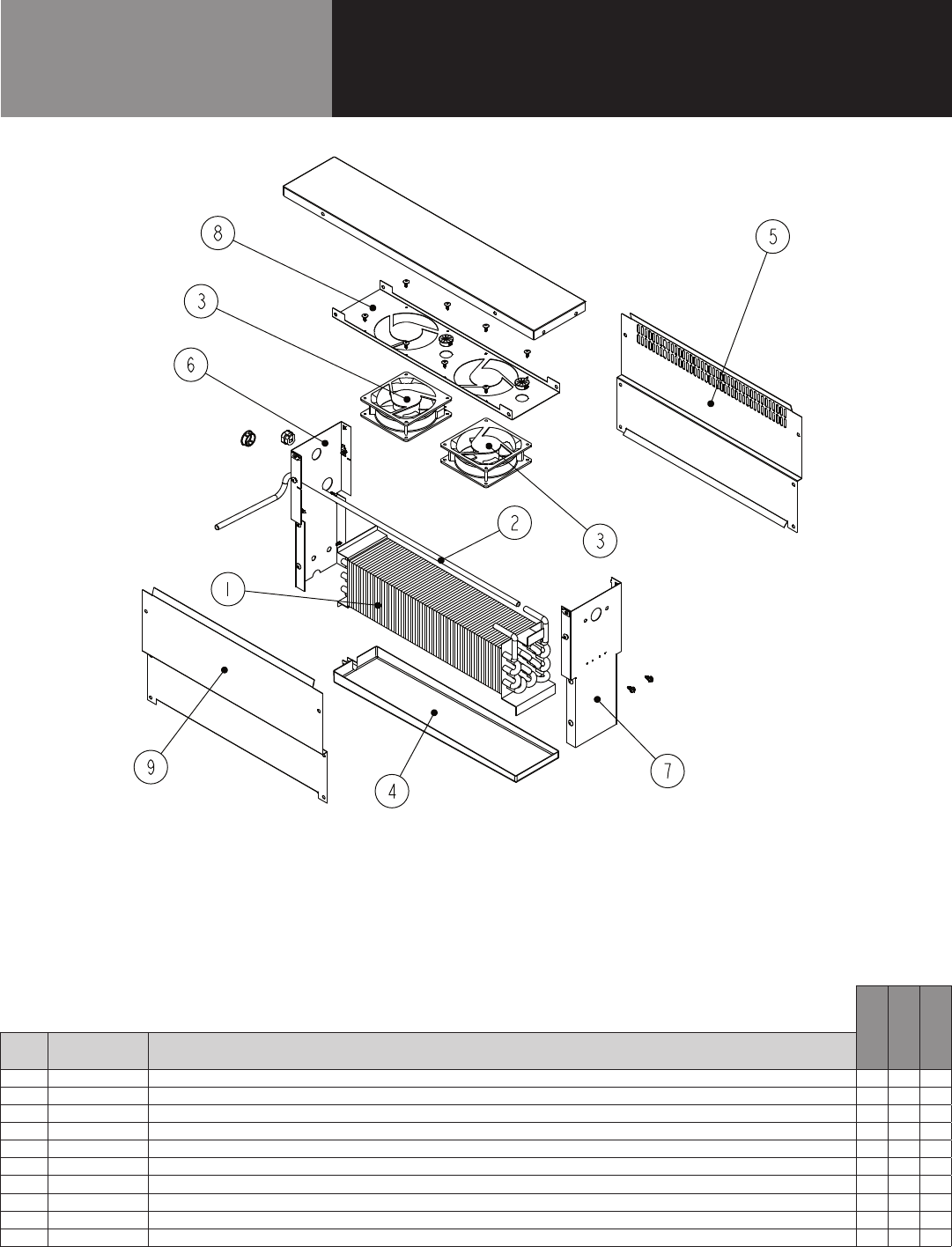
14 OM-8000 & 9000W SERIES PREP TABLES
Parts List
EVAPORATOR COIL
CALL FACTORY FOR REPLACEMENT PARTS:
888-994-7636
9148W-290
9260W-290
9272W-290
ITEM SERVICE PART DESCRIPTION
1 RF COI107 EVAPORATOR COIL X X X
2 RP CAP1803 CAP, TUBE - BASE X X X
3 RF FAN1401 FAN, EVAPORATORS X X X
4 RP DRP107 EVAPORATOR DRAIN PAN X X X
4A RP DRP107S EVAPORATOR DRAIN PAN/STAINLESS STEEL X X X
5 RP PNL107-290 SIDE, COIL, 8000N COMMON X X X
6 RP PNL108-290 BACK, COIL, 8000N COMMON X X X
7 RP PNL109-290 FRONT, COIL, 8000N COMMON X X X
8 RP SHD1811 PLATE, FAN, 8000N COMMON X X X
9 RP PNL1804 SIDE, COIL, NO PERF, 8000N COMMON X - -
* = NOT SHOWN
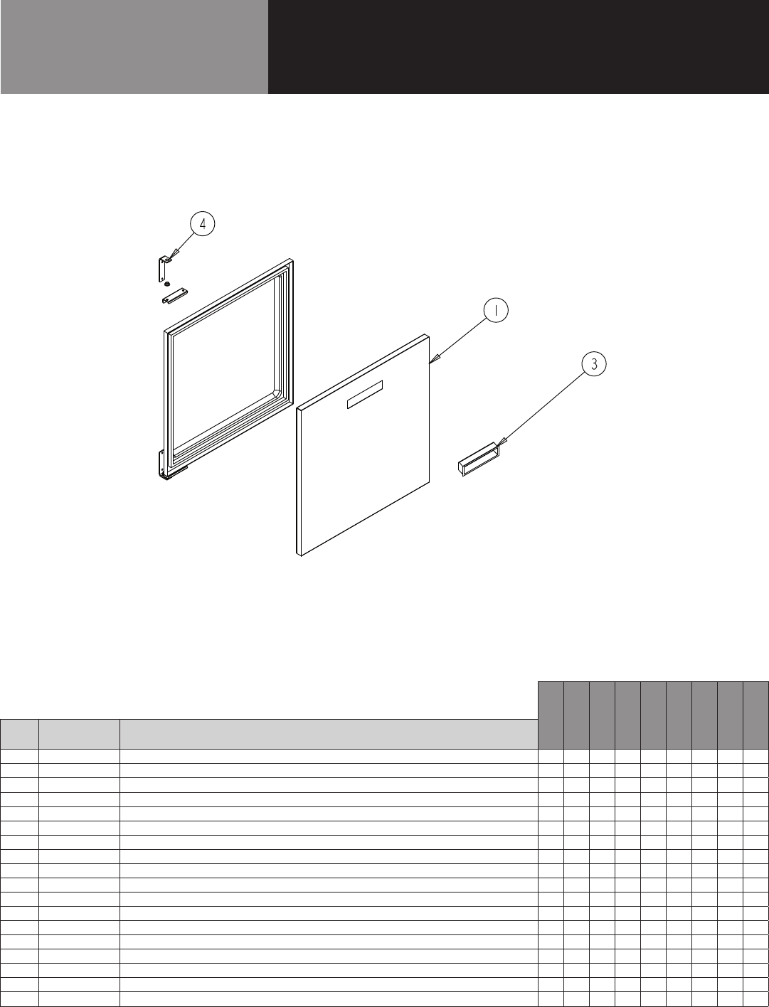
15 OM-8000 & 9000W SERIES PREP TABLES
Parts List
DOOR ASSEMBLY
CALL FACTORY FOR REPLACEMENT PARTS:
888-994-7636
8148N-290
8260N-290
8268N-290
8383N-290
8395N-290
84111N-290
8148W-290
8268W-290
8395W-290
ITEM SERVICE PART DESCRIPTION
1 RF DOR0321 DOOR HINGED LEFT, 21" - - - X - X - - -
1A RF DOR0320 DOOR HINGED RIGHT, 21" - - - X - X - - -
1B RF DOR0323 DOOR HINGED LEFT, 24" - X - X - X - - -
1C RF DOR0322 DOOR HINGED RIGHT, 24" - X - X - X - - -
1D RF DOR0324 DOOR HINGED LEFT, 27" X - X - X - X - X
1E RF DOR0325 DOOR HINGED RIGHT, 27" X - X - X - X - X
2* IN GSK9902 GASKET, 18.5" X 24.5" PUSH IN - - - X - X - - -
2A* IN GSK1025 GASKET, 21.75" X 24.5" PUSH IN - X - X - X - - -
2B* IN GSK1030 GASKET, 24.5" X 24.5" PUSH IN X - X - X - X - X
3 HD HDL0103 DOOR HANDLE (recessed) X X X X X X X X X
4 RP HNG9900 HINGE ASSY, UNIVERSAL, LEFT/RIGHT X X X X X X X X X
4A RP HNG026 HINGE, STRAP L BRACKET TOP/BOTTOM X X X X X X X X X
4B RP HNG027 HINGE, BOTTM l BRACKET W/ COLLOR X X X X X X X X X
4C RP HNG023 HINGE, TOP L BRACKET W/O X X X X X X X X X
4D RP HNG034 HINGE, TOP DOOR LH CHANNEL X X X X X X X X X
4E RP HNG035 HINGE, TOP DOOR RH CHANNEL X X X X X X X X X
5* HD BSH050 BUSHING, NYLON DOOR X X X X X X X X X
6* RP HNG025 HINGE, SPRING LOAD ASSEMBLY X X X X X X X X X
* = NOT SHOWN
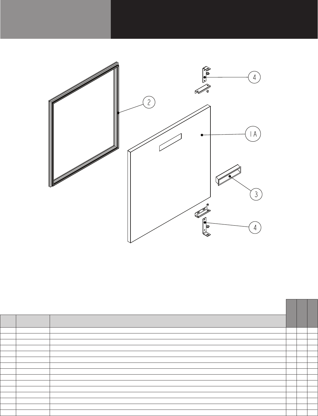
16 OM-8000 & 9000W SERIES PREP TABLES
Parts List
DOOR ASSEMBLY
CALL FACTORY FOR REPLACEMENT PARTS:
888-994-7636
9148W-290
9260W-290
9272W-290
ITEM SERVICE PART DESCRIPTION
1 RP DOR0323 DOOR HINGED LEFT, 24" - X -
1A RP DOR0322 DOOR HINGED RIGHT, 24" - X -
1B RP DOR0324 DOOR HINGED LEFT, 27" X - X
1C RP DOR0325 DOOR HINGED RIGHT, 27" X - X
2 IN GSK1025 GASKET, 21.75" X 24.5" PUSH IN - X -
2A IN GSK1030 GASKET, 24.5" X 24.5" PUSH IN X - X
3 HD HDL0103 DOOR HANDLE (recessed) X X X
4 RP HNG9900 HINGE ASSY, UNIVERSAL, LEFT/RIGHT X X X
4A RP HNG026 HINGE, STRAP L BRACKET TOP/BOTTOM X X X
4B RP HNG027 HINGE, BOTTM l BRACKET W/ COLLOR X X X
4C RP HNG023 HINGE, TOP L BRACKET W/O X X X
4D RP HNG034 HINGE, TOP DOOR LH CHANNEL X X X
4E RP HNG035 HINGE, TOP DOOR RH CHANNEL X X X
5* HD BSH050 BUSHING, NYLON DOOR X X X
6* RP HNG025 HINGE, SPRING LOAD ASSEMBLY X X X
* = NOT SHOWN
17 OM-8000 & 9000W SERIES PREP TABLES
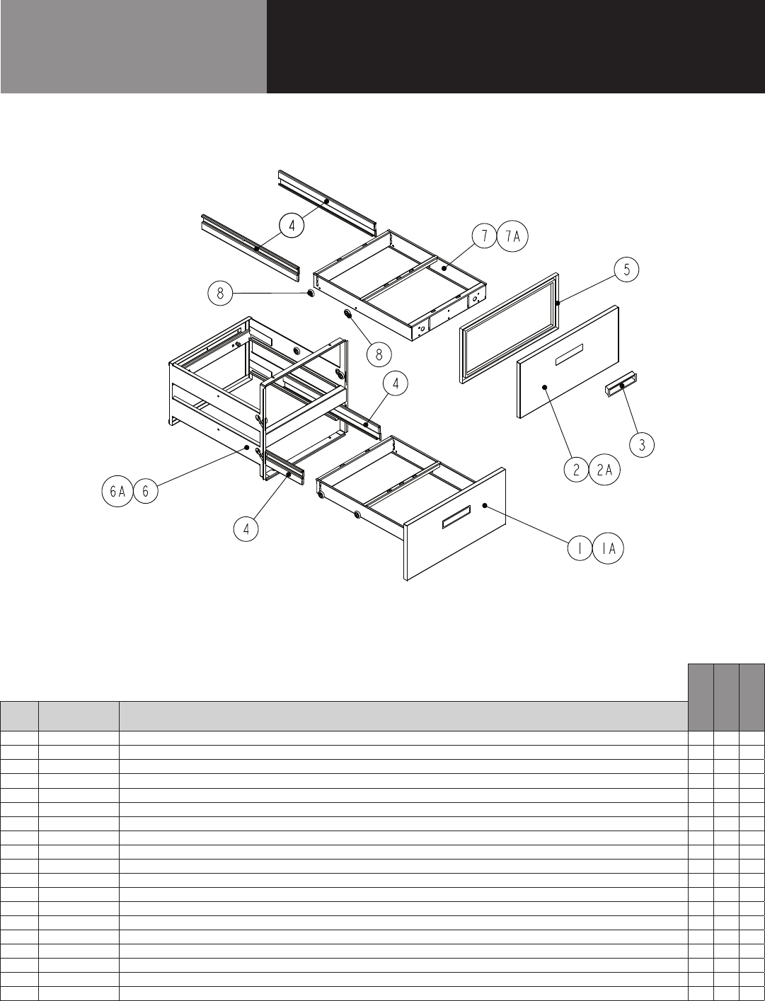
Parts List
DRAWER ASSEMBLY
CALL FACTORY FOR REPLACEMENT PARTS:
888-994-7636
8148N-290
8260N-290
8268N-290
8383N-290
8395N-290
84111N-290
8148W-290
8268W-290
8395W-290
ITEM SERVICE PART DESCRIPTION
1 RP DRW0206 DRAWER ASSEMBLY - 21" - - - X - X - - -
1A RP DRW0201PT DRAWER ASSEMBLY - 24" - X - X - X - - -
1B RP DRW0202 DRAWER ASSEMBLY - 27" X - X - X - X - X
2 RP MOD050A DRAWER CARTRIDGE - 21" - - - X - X - - -
2A RP MOD030A DRAWER CARTRIDGE - 24" - X - X - X - - -
2B RP MOD029A DRAWER CARTRIDGE - 27" X - X - X - X - X
3 RF FRT9903 DRAWER FRONT - 21" - - - X - X - - -
3A RF FRT9904 DRAWER FRONT - 24" - X - X - X - - -
3B RF FRT9905 DRAWER FRONT - 27" X - X - X - X - X
4 RP FRM0301 DRAWER FRAME - 21" - - - X - X - - -
4A RP FRM0302 DRAWER FRAME - 24" - X - X - X - - -
4B RP FRM0303 DRAWER FRAME - 27" X - X - X - X - X
5* IN GSK9903 DRAWER GASKET - 18.75" - - - X - X - - -
5A* IN GSK1041 DRAWER GASKET - 21.75" - X - X - X - - -
5B* IN GSK1046 DRAWER GASKET - 24.75" X - X - X - X - X
6 RP TRK05SM DRAWER TRACKS (1L & 1R) X X X X X X X X X
7 HD HDL130 DRAWER HANDLE X X X X X X X X X
8 HC BRG210 DRAWER BEARING X X X X X X X X X
9* FA SCW5002 DRAWER BEARING BOLT X X X X X X X X X
* = NOT SHOWN
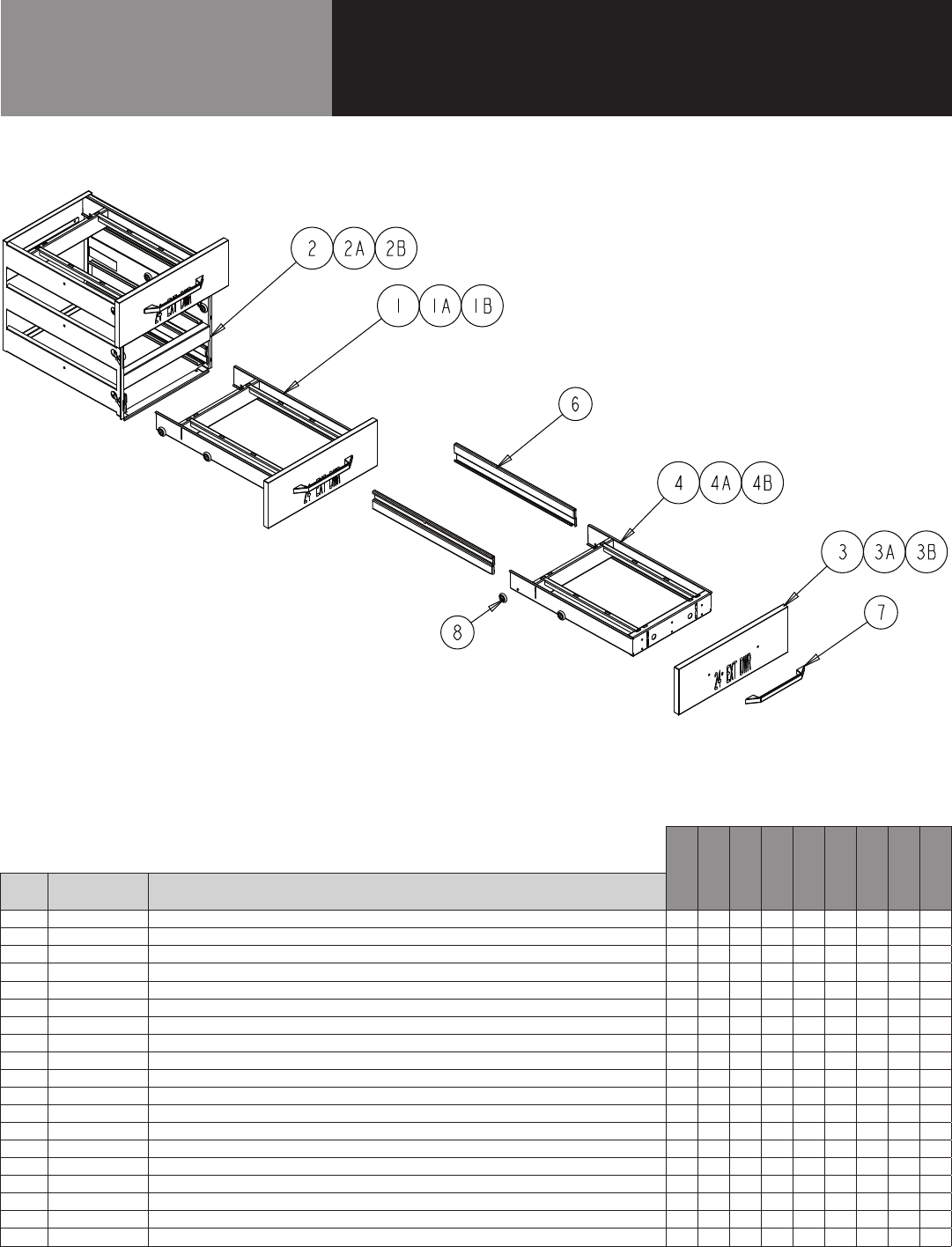
18 OM-8000 & 9000W SERIES PREP TABLES
Parts List
DRAWER ASSEMBLY
CALL FACTORY FOR REPLACEMENT PARTS:
888-994-7636
9148W-290
9260W-290
9272W-290
ITEM SERVICE PART DESCRIPTION
1 RP FRT0304 DRAWER FRONT - BOTTOM - 24" - X -
1A RP FRT0306 DRAWER FRONT - BOTTOM - 27" X - X
2 RP FRT0303 DRAWER FRONT - TOP - 24" - X -
2A RP FRT0305 DRAWER FRONT - TOP - 27" - - -
3 HD HDL0130 DRAWER HANDLE X X X
4 RP TRK05SM DRAWER TRACKS (1L & 1R) X X X
5* IN GSK1042 DRAWER GASKET - 24" Top - X -
5A* IN GSK1043 DRAWER GASKET - 24" Bottom - X -
5B* IN GSK1048 DRAWER GASKET - 27" Top X - X
5C* IN GSK1047 DRAWER GASKET - 27" Bottom X - X
6 RP MOD1701A DRAWER CARTRIDGE - 24" - X -
6A RP MOD1603A DRAWER CARTRIDGE - 27" X - X
7 RP FRM0103 DRAWER FRAME - 24" - X -
7A RP FRM127E DRAWER FRAME - 27" X - X
8 HD BRG210 DRAWER BEARING X X X
9* FA SCW5002 DRAWER BEARING BOLT X X X
7 HD HDL130 DRAWER HANDLE X X X
8 HC BRG210 DRAWER BEARING X X X
9* FA SCW5002 DRAWER BEARING BOLT X X X
* = NOT SHOWN
19 OM-8000 & 9000W SERIES PREP TABLES
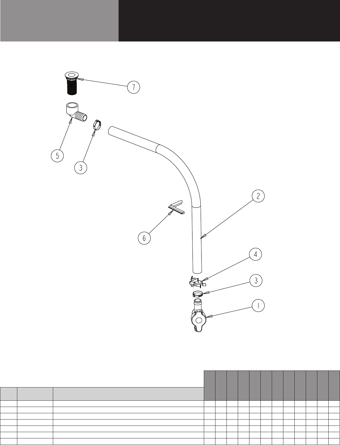
Parts List
DRAIN ASSEMBLY
CALL FACTORY FOR REPLACEMENT PARTS:
888-994-7636
8148N-290
8260N-290
8268N-290
8383N-290
8395N-290
84111N-290
8148W-290
8268W-290
8395W-290
9148W-290
9260W-290
9272W-290
ITEM SERVICE PART DESCRIPTION
1 PB VLV1803 VALVE, GREEN BACK, 25 MM X X X X X X X X X X X X
2 PL TBG1801 TUBING, 1” VINYL, BLACK X X X X X X X X X X X X
3 HD CLM1801 CLAMP, 1-1/4” OETIKER X X X X X X X X X X X X
4 HD CLP1902 CLIP, SPRING, 1 TO 1-7/8 NICKEL PLATED STEEL X X X X X X X X X X X X
5 PB ELB1801 ELBOW, 90 DEG X X X X X X X X X X X X
6 EL GRM1801 GROMMET, PUSHON, DRAIN ASSY X X X X X X X X X X X X
7 HD DRN1702 DRAIN, ABS, GRAY, 1.375”, 1.00” NPS X 2.875” LG W/NUT & WASHER X X X X X X X X X X X X
* = NOT SHOWN
20 OM-8000 & 9000W SERIES PREP TABLES
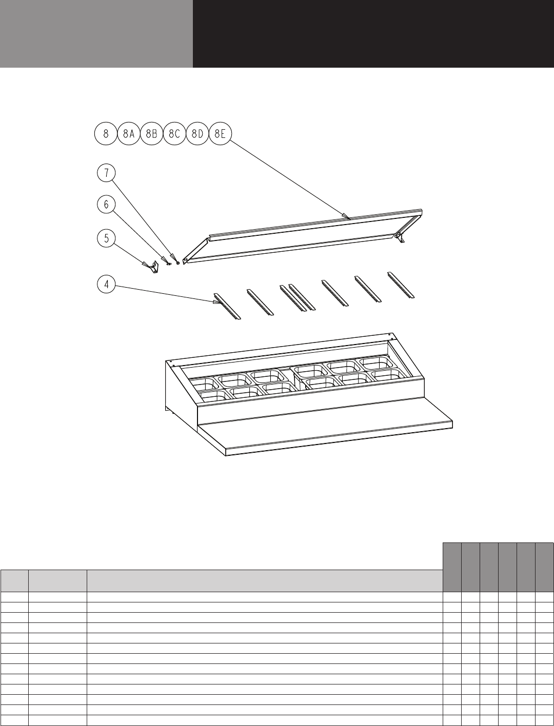
Parts List
RAIL ASSEMBLY - NARROW HOOD COVER
CALL FACTORY FOR REPLACEMENT PARTS:
888-994-7636
8148N-290
8260N-290
8268N-290
8383N-290
8395N-290
84111N-290
ITEM SERVICE PART DESCRIPTION
1* HD PIN107 PIN, THREADED SOUTHCO X X X X X X
2* HD PIN107I INSERT, THREADED SOUTCHO X X X X X X
3* HD PIN001 PIN, KEY PAN RAIL X X X X X X
4 RP DSN001 DRAIN SCREEN, 2" X X X X X X
5 RP HNG006 HINGE, PAN COVER SET OF 2 X X X X X X
6 HD PIN0101 PIN, LOCATING 0.875 LENGTH X X X X X X
7 FA NUT0403SS NUT, 1/4-20 CAP NUT 18-8 SS X X X X X X
8 RP PCR0115 COVER, HINGED PAN X - - - - -
8A RC PCR0117 COVER, HINGED PAN - X - - - -
8B RC PCR0118 COVER, HINGED PAN - - X - - -
8C RC PCR0114 COVER, HINGED PAN - - - X - -
8D RC PCR0115 COVER, HINGED PAN - - - - X -
8E RC PCR0116 COVER, HINGED PAN - - - - - X
* = NOT SHOWN
21 OM-8000 & 9000W SERIES PREP TABLES
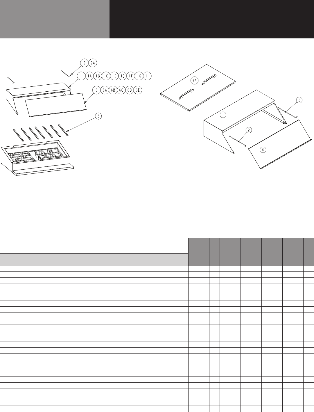
Parts List
RAIL ASSEMBLY - WIDE HOOD COVER
CALL FACTORY FOR REPLACEMENT PARTS:
888-994-7636
8148N-290
8260N-290
8268N-290
8383N-290
8395N-290
84111N-290
8148W-290
8268W-290
8395W-290
9148W-290
9260W-290
9272W-290
ITEM SERVICE PART DESCRIPTION
1 RP HOD0101 HOOD COVER X - - - - - - - - X - -
1A RPHOD1801 HOOD COVER - - - - - - X - - - X -
1B RP HOD0301 HOOD COVER - X - - - - - - - - - X
1C RP HOD0202 HOOD COVER - - X - - - - - - - - -
1D RP HOD1802 HOOD COVER - - - - - - - X - - - -
1E RP HOD0407 HOOD COVER - - - X - - - - - - -
1F RP HOD0310 HOOD COVER - - - - X - - - - - - -
1G RP HOD1803 HOOD COVER - - - - - - - - X - - -
1H HP HOD0609 HOOD COVER - - - - - X - - - - - -
2 HD ROD100 HOOD COVER, ROD W/ SINGLE BEND X - - - X - X - X X - -
2A HD ROD200 HOOD COVER, ROD W/ DOUBLE BEND - - - - X - - - X - - -
3* HD PIN107 PIN, THREADED SOUTHCO X X X X X X X X X X X X
4* HD PIN107I INSERT, THREADED SOUTCHO X X X X X X X X X X X X
5* RP DSN001 DRAIN SCREEN, 2" X X X X X X X X X X X X
6 RP LID048 COVER (IMAGE ON LEFT) X - - - - - - - - - - -
6 RP HNG017 SLIDE BACK COVER (IMAGE ON RIGHT) - - - - - - - - - X X X
6A RP LID1502 COVER - X - - - - - - - - X -
6B RP LID068 COVER - - X - - - - - - - - X
6C RP LID083 COVER - - - X - - - - - - - -
6D RP LID095 COVER - - - - X - - - - - - -
6E RP LID111 COVER - - - - - X - - - - - -
6F RP LID1801 COVER - - - - - - X - - - - -
6G RP LID1802 COVER - - - - - - - X - - - -
6H RP LID1803 COVER - - - - - - - - X - - -
7* HD PIN001 PIN, KEY PAN RAIL - - - - - - X X X - - -
* = NOT SHOWN
22 OM-8000 & 9000W SERIES PREP TABLES
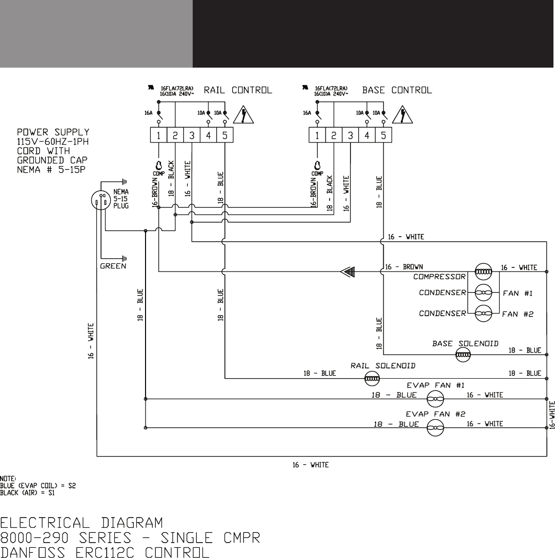
Wiring Diagram
8000-290
SINGLE COMPRESSOR
CAREL
12 3
16FLA(96LRA)
16(10)A 240V~
5
16A
G
EVAP FAN #2
NEMA
5-15P
PLUG
GREEN
CONDENSER
16 - BROWN
16 - WHITE
16 - WHITE
16 - WHITE
16 - WHITE
16-WHITE
18 - WHITE
18 - WHITE
4
18 - BLACK
COMP
18 - BLUE
16 - WHITE
16 - BROWN
EVAP FAN #1
FAN #1
CONDENSER
FAN #2
12 3
16FLA(96LRA)
16(10)A 240V~
5
16A
4
18 - BLACK
COMP
18 - BLUE
16 - WHITE
16 - BROWN
BASE SOLENOID
RAIL SOLENOID
18 - BLUE
18 - BLUE
18 - BLUE
18 - BLUE
RAIL CONTROL BASE CONTROL
18 - BLUE
COMPRESSOR
16 - BLACK
16-WHITE
BLACK
BLACK
BLACK
BLACK
16 - BLACK
18 - BLACK
18 - BLACK
18 - BLUE18 - BLUE
NEMA 5-15
18 - BLACK
18 - BLUE
18 - GREEN 18 - GREEN
EL WIR0005
EL WIR469A
EL WIR470
6
7
6
7
18 - BLACK
16 - BLACK
18 - BLACK
16 - WHITE
8
9
10 11
8
9
10 11
RAIL
BASE
AIR
SENSOR CONNECTIONS
10K NTC
RAIL SENSING
TUBE
COIL
(DEF)
CONDENSER
(OPTION)
CONDENSER
(OPTION)
POWER SUPP
LY
115V
-60HZ-1PH
C
ORD WITH
GROUNDED CA
P
EL
WIR461-90
23 OM-8000 & 9000W SERIES PREP TABLES
Wiring Diagram
8000-290
DOUBLE COMPRESSOR
CAREL
12 3
16FLA(96LRA)
16(10)A 240V~
5
16A
4
RAIL CONTROL
6
7
8
9
10 11
8
9
10 11
RAIL
BASE
AIR
SENSOR CONNECTIONS
10K NTC
12 3
16FLA(96LRA)
16(10)A 240V~
5
16A
4
BASE CONTROL
6
7
RAIL SENSING
TUBE
COIL
(DEF)
CONDENSER
(OPTION)
CONDENSER
(OPTION)
G
RAIL COMPRESSOR
EVAP FAN #2
NEMA
5-15
PLUG
GREEN
POWER SUPP
LY
115V
-60HZ-1PH
C
ORD WITH
GROUNDED CA
P
NEMA # 5-15P
16-BROWN
16-WHITE
16-WHITE
16-WHITE
16-WHITE
16-WHITE
16-WHITE
16-BLACK
COMP
18-BLUE
16-WHITE
16-BROWN
EVAP FAN #1
18-BLACK
COMP
18-BLUE
16-WHITE
16-BROWN
CONDENSER FANS
18-BLUE
FAN ASSIST OPTION ONLY
18-BLACK
16-WHITE
18-BLACK
18-BLUE
BASE COMPRESSOR
16-BROWN
16-WHITE
BASE
RAIL
16-WHITE
COND HTR
18-BLACK
18-BLACK
18-BLACK
16-WHITE
(OPTIONAL LED LIGHT)
TIMER
21
53
(OPTIONAL TIMER)
16 - WHITE
16-BLACK
18-BLACK
18-BLUE
16-WHITE
24 OM-8000 & 9000W SERIES PREP TABLES
Wiring Diagram
9000W-290
CAREL
12 3
16FLA(96LRA)
16(10)A 240V~
5
16A
G
EVAP FAN #2
NEMA
5-15P
PLUG
GREEN
CONDENSER
16 - BROWN
16 - WHITE
16 - WHITE
16 - WHITE
16 - WHITE
16-WHITE
18 - WHITE
18 - WHITE
4
18 - BLACK
COMP
18 - BLUE
16 - WHITE
16 - BROWN
EVAP FAN #1
FAN #1
CONDENSER
FAN #2
12 3
16FLA(96LRA)
16(10)A 240V~
5
16A
4
18 - BLACK
COMP
18 - BLUE
16 - WHITE
16 - BROWN
BASE SOLENOID
RAIL SOLENOID
18 - BLUE
18 - BLUE
18 - BLUE
18 - BLUE
RAIL CONTROL BASE CONTROL
18 - BLUE
COMPRESSOR
16 - BLACK
16-WHITE
BLACK
BLACK
BLACK
BLACK
16 - BLACK
18 - BLACK
18 - BLACK
18 - BLUE18 - BLUE
NEMA 5-15
18 - BLACK
18 - BLUE
18 - GREEN 18 - GREEN
EL WIR0005
EL WIR469A
EL WIR470
6
7
6
7
18 - BLACK
16 - BLACK
18 - BLACK
16 - WHITE
8
9
10 11
8
9
10 11
RAIL
BASE
AIR
SENSOR CONNECTIONS
10K NTC
RAIL SENSING
TUBE
COIL
(DEF)
CONDENSER
(OPTION)
CONDENSER
(OPTION)
POWER SUPP
LY
115V
-60HZ-1PH
C
ORD WITH
GROUNDED CA
P
EL
WIR461-90
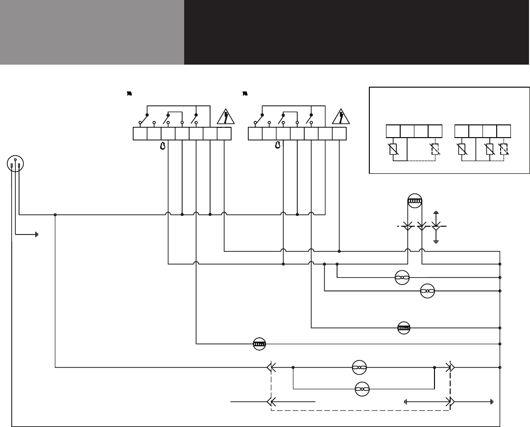
25 OM-8000 & 9000W SERIES PREP TABLES
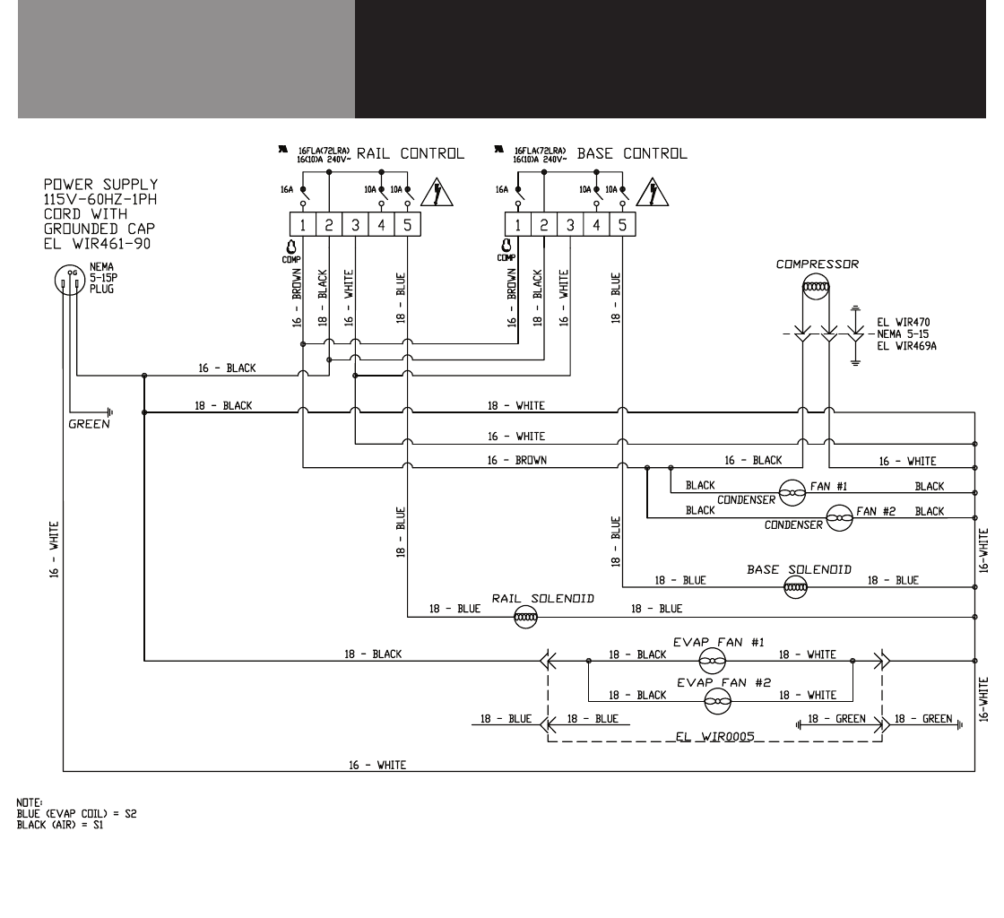
Wiring Diagram
8000-290
SINGLE COMPRESSOR
DANFOSS
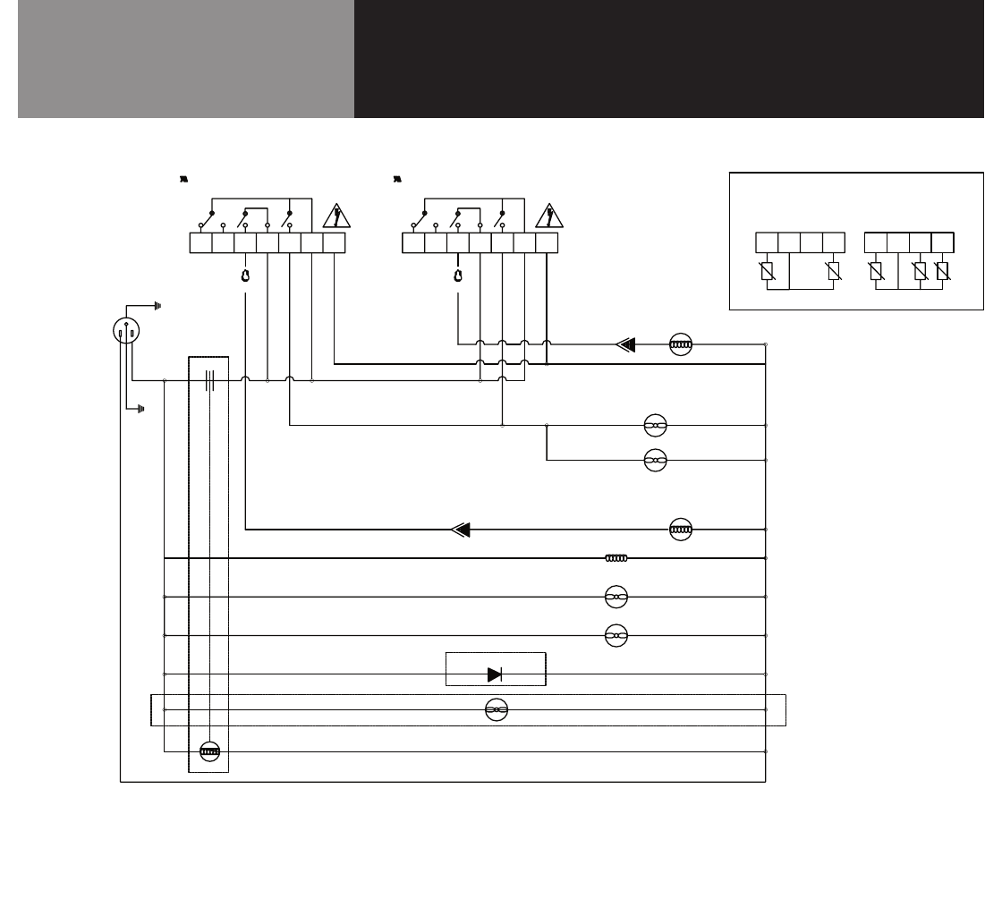
26 OM-8000 & 9000W SERIES PREP TABLES
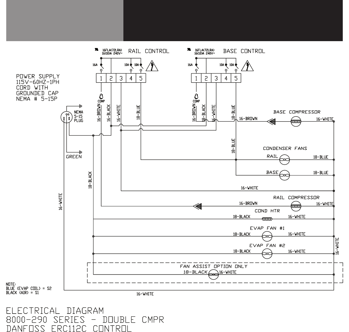
Wiring Diagram
8000-290
DOUBLE COMPRESSOR
DANFOSS
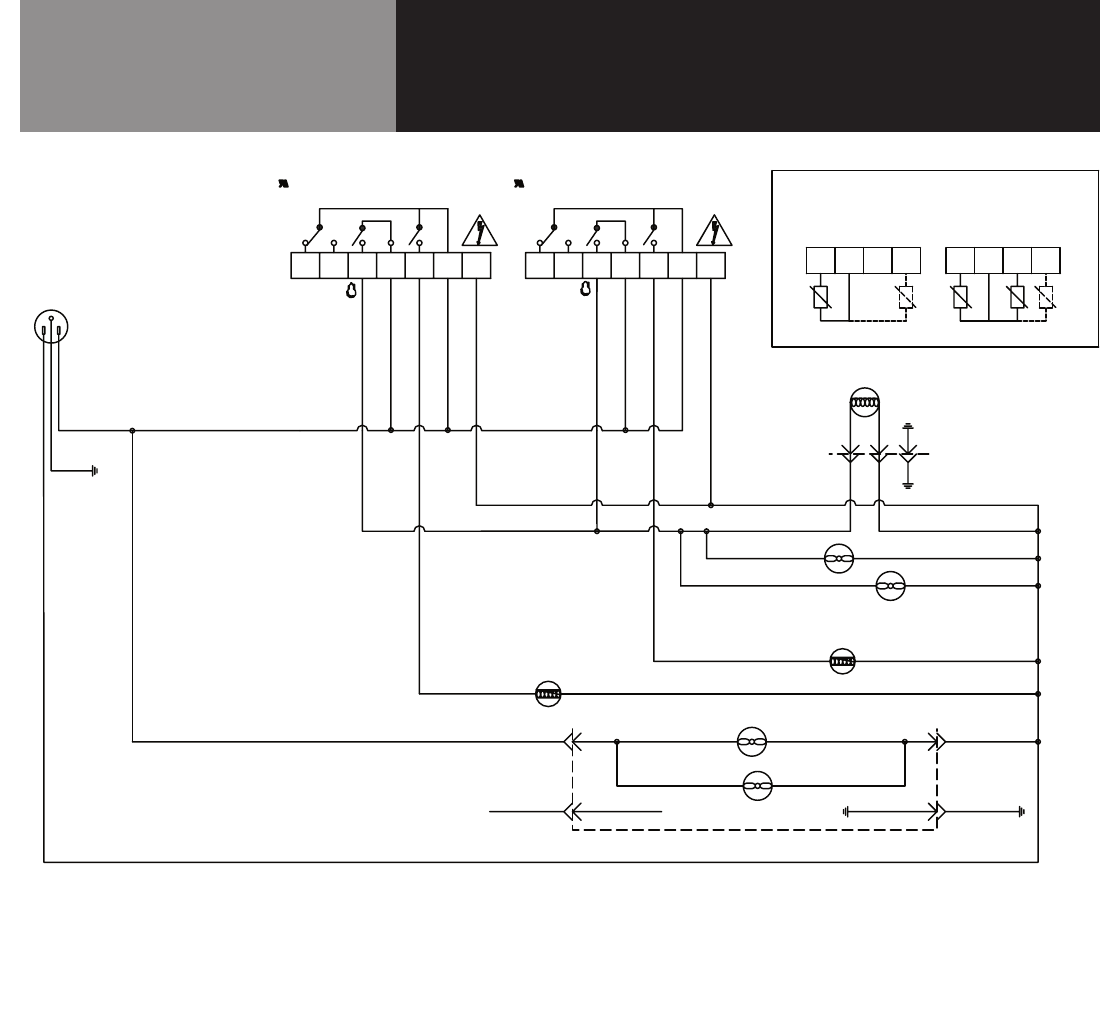
27 OM-8000 & 9000W SERIES PREP TABLES
Wiring Diagram
9000W-290
DANFOSS

28 OM-8000 & 9000W SERIES PREP TABLES
Service Log
Model No: Purchased From:
Serial No: Location:
Date Purchased: Date Installed:
Purchase Order No: For Service Call:
Date Maintenance Performed Performed By
