
Skills Development Series
Basic
Highway
Plan
Reading

Basic Highway Plan Reading
Basic Highway
Plan Reading
Reproduction of any or all portions of this Manual is prohibited without the written consent of
the Georgia Department of Transportation.
developed in conjunction with
Revised October 1, 2020

List of Figures .............................................................................................................................................. vi
Forward ........................................................................................................................................................ ix
A Note on Safety ........................................................................................................................................... x
Nuts and Bolts of the Course ...................................................................................................................... xi
Chapter 1
Beginning to Read Plans .............................................................................................................................. 1
General Information ................................................................................................................................... 1
Requirements and Specifications ..................................................................................................... 1
What Part of The Contract Applies? ................................................................................................. 1
In Case of A Discrepancy, Certain Parts of The Contract Govern Over Others ............................... 1
Sheet Order ....................................................................................................................................... 1
Errors or Omissions .......................................................................................................................... 2
Cover Sheet ................................................................................................................................................ 2
Description ................................................................................................................................................. 4
Project Location Sketch ............................................................................................................................. 5
Layout View .............................................................................................................................................. 5
Sheet Identification .................................................................................................................................... 6
Plans Revised and Plans Completed .......................................................................................................... 8
Scale ........................................................................................................................................................... 8
Project Length .......................................................................................................................................... 10
Cover Sheet Questions ............................................................................................................................. 10
Design Data ............................................................................................................................................. 10
Chapter 2
Index and Revision Summary Sheet ......................................................................................................... 11
Index ........................................................................................................................................................ 11
Revision Summary Sheet ......................................................................................................................... 11
Chapter 3
Typical Sections .......................................................................................................................................... 13
Introduction to Typical Sections .............................................................................................................. 13
Horizontal Distance ................................................................................................................................. 14
Chapter 4
Summary & Detailed Estimate Quantities ............................................................................................... 15
Summary of Quantities ............................................................................................................................ 15
(Continued on page ii)
Table of Contents
i
Table of Contents

2
Table of Contents
Drainage Summary ...................................................................................................................................15
Detailed Estimate ......................................................................................................................................16
Chapter 5
Views .............................................................................................................................................................19
Introduction to Views ...............................................................................................................................19
Longitudinal Cross Section .......................................................................................................................19
Cross Section ............................................................................................................................................20
Profile View ..............................................................................................................................................20
Chapter 6
Stationing, Symbols, And Abbreviations ...................................................................................................23
Stationing .................................................................................................................................................23
Half Stations ....................................................................................................................................24
Station Equations (Equalities) .........................................................................................................26
Determining of The Project Length .................................................................................................27
Symbols and Abbreviations
Introduction to Symbols ..................................................................................................................28
Introduction to Plan Abbreviations .................................................................................................28
Conventional and Right of Way (ROW) Symbols ................................................................................29
Utility Symbols
Water Mains ....................................................................................................................................30
Gas Mains and Petroleum Product Pipe Lines ................................................................................31
Sanitary Sewer and Steam Lines .....................................................................................................32
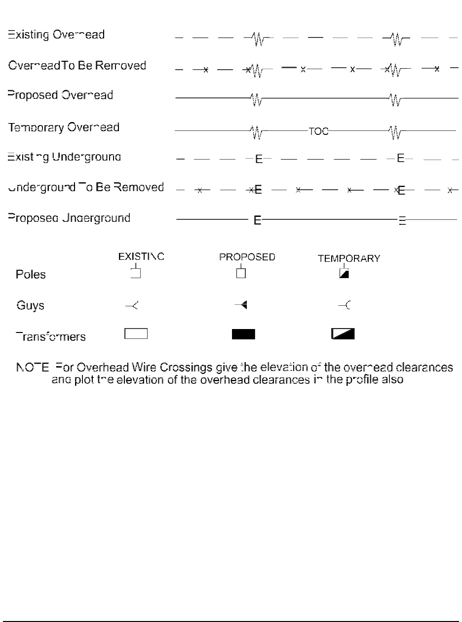
Electrical Power ..............................................................................................................................33
Telephone and Telegraph ................................................................................................................34
Television/ and Microwave Cable ...................................................................................................35
Utility Abbreviations and Railroad .................................................................................................36
Chapter 7
Plan and Profile Sheets ..........................................................................................................................37
Plan View .................................................................................................................................................37
Horizontal Alignment ......................................................................................................................39
Superelevation .................................................................................................................................41
Bearings ..........................................................................................................................................42
(Continued on page iii)

Table of Contents
iii
Profile View (Vertical Alignment) .........................................................................................................45
Elevations ........................................................................................................................................46
Grade ...............................................................................................................................................47
Vertical Curves and Grade Point .....................................................................................................48
Paving Limits ............................................................................................................................................49
Construction Limits ..................................................................................................................................50
Fencing .....................................................................................................................................................50
Guard Rail.................................................................................................................................................50
Right of Way Markers ..............................................................................................................................50
Chapter 8
Drainage .......................................................................................................................................................53
Pipe Culverts .............................................................................................................................................53
Box Culverts .............................................................................................................................................54
Plan View .................................................................................................................................................57
Wing Walls ...............................................................................................................................................58
Bridges ......................................................................................................................................................60
Bents .........................................................................................................................................................62
Utility Accommodations ...........................................................................................................................64
Chapter 9
Utilities ..........................................................................................................................................................67
Chapter 10
Signing, Pavement Markings, Signals, Highway Lighting, Landscaping. .........................................69
Traffic Signals ..........................................................................................................................................69
Lighting. ...................................................................................................................................................69
Landscaping ..............................................................................................................................................69
Chapter 11
Maintenance of Traffic, Sequence of Operations, and Staging...........................................................71
Chapter 12
Erosion, Sedimentation, And Pollution Control Plans (ESPCP) ............................................................ 73
Introduction to Erosion Control ................................................................................................................73
When Are ESPCP Necessary? ..................................................................................................................73
What Is Included in the ESPCP? ..............................................................................................................74
(Continued on page iv)

4
Table of Contents
Contractor Responsibilities .......................................................................................................................74
Examples from the Plans ..........................................................................................................................75
Chapter 13
Cross Sections
Introduction to Cross Sections ..................................................................................................................77
Earthwork .................................................................................................................................................77
Grade ........................................................................................................................................................80
Slopes .......................................................................................................................................................80
Slope Stakes ..............................................................................................................................................81
Chapter 14
Standards & Details
Introduction to Standards & Details......................................................................................................... 85
Intersection Details ...................................................................................................................................85
Chapter 15
Right of Way
Introduction ..............................................................................................................................................87
Right of Way Terms and Definitions ........................................................................................................88
Right of Way Plan Sheets .........................................................................................................................91
Questions for Appendices ...........................................................................................................................95
Appendix A: Definitions ..............................................................................................................................97
Appendix B: Abbreviations ......................................................................................................................107
Answers to Chapter Questions
Chapter 1 ................................................................................................................................................117
Chapter 2 ................................................................................................................................................117
Chapter 3 ................................................................................................................................................117
Chapter 4 ................................................................................................................................................117
Chapter 5 ................................................................................................................................................117
Chapter 6 ................................................................................................................................................118
Chapter 7 ................................................................................................................................................118
Chapter 8 ................................................................................................................................................120
Chapter 9 ................................................................................................................................................120
Chapter 10 ..............................................................................................................................................121
Chapter 11 ..............................................................................................................................................121
Chapter 12 ..............................................................................................................................................121
Chapter 13 ..............................................................................................................................................121

Table of Contents
v
Chapter 14 ..............................................................................................................................................121
Chapter 15 ..............................................................................................................................................121
Appendices ................................................................................................................................................ 121
Index ...........................................................................................................................................................123

List of Figures
6
Chapter 1
Figure 1-1. Plan View of Project ............................................................................................................... 4
Figure 1-2. Description of Project. ............................................................................................................ 4
Figure 1-3. Location Sketch ..................................................................................................................... 5
Figure 1-4. Plan View of a Project ............................................................................................................ 5
Figure 1-5. Standard Identification Box. ................................................................................................... 6
Figure 1-6. Cover Sheet note and legality. ................................................................................................. 6
Figure 1-7. Cover Sheet Box for signatures and titles of those responsible for the plans .......................... 7
Figure 1-8. Cover Sheet Plans Revised box............................................................................................... 8
Figure 1-9. Civil Engineer’s Scale and Architect’s Scale. ......................................................................... 9
Figure 1-10. Detail of the Civil Engineer’s Scale. ..................................................................................... 9
Figure 1-11. Bar Scale from Plan Sheet 60. ............................................................................................... 9
Figure 1-12. Length of Project. ................................................................................................................ 10
Figure 1-13. Cover Sheet Design Data. ................................................................................................... 10
Chapter 2
Figure 2-1. Index. .................................................................................................................................... 11
Figure 2-2. Revision Summary Sheet. ..................................................................................................... 12
Chapter 3
Figure 3-1. Typical Roadway Section. .................................................................................................... 13
Figure 3-2. Required Pavement ............................................................................................................... 14
Figure 3-3. Horizontal Distance compared with Slope Distance ............................................................ 14
Chapter 4
Figure 4-1. Summary of Quantities. ........................................................................................................ 15
Figure 4-2. Drainage Summary. .............................................................................................................. 16
Figure 4-3. Detailed Estimate. ................................................................................................................. 17
Chapter 5
Figure 5-1. Plan View .............................................................................................................................. 19
Figure 5-2. Side and Rear Elevations ...................................................................................................... 19
Figure 5-3. Longitudinal Cross Section and Standard Cross Section ...................................................... 19
Figure 5-4. Views of a Boat for Question 5-1.......................................................................................... 20
Figure 5-5. Profile View: Sectioning of a Pencil ..................................................................................... 21
Figure 5-6. Sections Views of a Pencil. ................................................................................................... 21
List of Figures

List of Figures
vii
Chapter 6
Figure 6.1 How to Think about Stations. ..................................................................................................23
Figure 6-2. Stationing Example Illustrating Halfway. ..............................................................................24
Figure 6-3. Plan Sheet Stationing. ........................................................................................................... 25
Figure 6-4. Station Equality. .................................................................................................................... 26
Figure 6-5. Stationing Exercise ................................................................................................................27
Figure 6-6. Symbols for Proposed and Existing Right-of-Way ............................................................... 28
Figure 6-7. Conventional and Right-of-Way (ROW) Symbols ............................................................... 29
Figure 6-8. Water and Non Potable Water Mains or Lines .......................................................................30
Figure 6-9. Gas Mains and Petroleum Product Pipe Lines .......................................................................31
Figure 6-10. Sanitary Sewer and Steam Lines ..........................................................................................32
Figure 6-11. Electrical Power .................................................................................................................. 33
Figure 6-12. Telephone and Telegraph .....................................................................................................34
Figure 6-13. Television and Microwave Cables .......................................................................................35
Figure 6-14. Utility Symbol Abbreviations and Railroad Symbols ..........................................................36
Chapter 7
Figure 7-1. Plan View of a Roadway. .......................................................................................................37
Figure 7-2. North-South Arrow. .............................................................................................................. 38
Figure 7-3. Types of Curves .................................................................................................................... 40
Figure 7-4. Spiral Curve .......................................................................................................................... 41
Figure 7-5. Compass Bearing. ................................................................................................................. 42
Figure 7-6. Bearing Question. ................................................................................................................. 43
Figure 7-7. Profile Grade Lines ............................................................................................................... 46
Figure 7-8. Positive and Negative Grades. ...............................................................................................47
Figure 7-9. Vertical Curves and P.V.I.’s ..................................................................................................48
Figure 7-10. Grade Points. ........................................................................................................................48
Figure 7-11. Symbols for Proposed (Left) and Existing (Right) ROW. ...................................................50
Chapter 8
Figure 8-1. Drainage Table from Sheet 198. ............................................................................................53
Figure 8-2. Box Culvert Sections ............................................................................................................ 54
Figure 8-3. Culverts with Multiple Barrels. ..............................................................................................55
Figure 8-4. Longitudinal Section of a Box Culvert. .................................................................................56
Figure 8-5. Plan View of a Box Culvert ...................................................................................................57

List of Figures
viii
Figure 8-6. Skewed View of a Box Culvert. .............................................................................................57
Figure 8-7. Partial Plan View of Wing Wall .............................................................................................58
Figure 8-8. Wing Wall Section. ................................................................................................................58
Figure 8-9. Box Culvert on 60 degree skew .............................................................................................59
Figure 8-10. Partial Plan Showing Angles of Wings and Barrel. ............................................................ 59
Figure 8-11. Plan and Elevation Views of a Bridge .................................................................................60
Figure 8-12. End Bent Elevations .............................................................................................................62
Figure 8-13. Cross Section of Bridge. ......................................................................................................64
Figure 8-14. End Bent Elevation and Section ...........................................................................................65
Chapter 12
Figure 12-1. Erosion, Sediment & Pollution Control Plan .......................................................................73
Figure 12-2. Stage 1 BMP Plan Sheet: Location Details. .........................................................................74
Chapter 13
Figure 13-1. Typical terrain for a Two-Lane Roadway ............................................................................77
Figure 13-2. Examples of Cut and Fill Cross Sections .............................................................................78
Figure 13-3. Typical Cross Section. .........................................................................................................78
Figure 13-4. Typical Cross Section along Centerline. ..............................................................................79
Figure 13-5. Typical Cross Section and Cross Section of the Original Ground, along Centerline. ..........79
Figure 13-6. Volume of Cut. ....................................................................................................................79
Figure 13-7. Views of Slopes in Cross Section ........................................................................................80
Figure 13-8. Slope Cross Section. ............................................................................................................81
Figure 13-9. Slope Stake Positioning .......................................................................................................82
Figure 13-10: Station Numbering on Slope Stake. ...................................................................................83
Figure 13-11. Offset Distance on Slope Stake. .........................................................................................83
Chapters 14
Figure 14-1. Ramp Identification by Letter ..............................................................................................85
Chapters 15
Figure 15-1. Right of Way Plan Sheet: Cover Sheets 1 and 2. .................................................................91
Figure 15-2. Right of Way Plans Sheet 1. ................................................................................................93
Figure 15-3. Right of Way Plan Sheet 3, Parcel 4. ...................................................................................93
Figure 15-4. Parcel Required Right of Way. ............................................................................................94

Basic Highway Plan Reading
9
Forward
This Plan Reading Course is to present a step-by-step procedure on how to read, interpret, and relate to a standard
set of roadway plans; to help identify and interpret symbols used in a standard set of plans; and to help develop the
necessary skills to interpret a set of plans in non-technical terms to laypersons (property owners and others). Along
with this manual you will use plan sheets and standards that specifically relate to a project. The plan sheets/
standards included have been reduced to half their original size so they can be handled more easily.
A partnership of Transportation entities, The Georgia Partnership for Transportation Quality (GPTQ), works
together to improve the quality of the nation’s highways and as one of the initiatives, the GPTQ Steering
Committee created a team from public and private sector organizations to jointly focus on the improvement of
highway construction plans. The team determined that quality improvements were attainable by developing a Plan
Presentation Guide to assist designers in the presentation of the work to be accomplished and thereby making
plans more efficient for the user. This guide can be found on the Georgia DOT Web Pages for further information.
Since it is our intent to provide you, the student, with a “well rounded” exposure to highway construction plans,
you may be asked to look at a plan sheet from a particular project. Please be sure that you are looking at the correct
set of plans for the text that you are reading and the questions you may be asked to answer.

x
Basic Highway Plan Reading
A Note on Safety
As an employee of the Georgia Department of Transportation, it is your responsibility to direct your concern to one
goal, which is to provide the traveling public with the best and safest roadway system that can be constructed.
With this goal constantly in mind, it is the responsibility of each DOT employee to observe, suggest, and act to
achieve a safe system of roadways throughout the State. Regardless of a specific assigned duty, it is the
responsibility of all the employees of the Georgia Department of Transportation to call to his/her supervisor’s
attention any item, whether in design or construction, which appears to be an obvious hazard to the motoring
public.
Safety is our business and will remain the primary factor in designing and constructing highways.

Basic Highway Plan Reading
11
Nuts and Bolts of the Course
This is a self-instructional study course. The subject matter is arranged so that you the student may work at your
own speed. Each part of the course builds on the information that has preceded it and prepares for information to
follow. Most of the parts present new information. Some parts review important concepts that have been
introduced to you earlier in the program and apply these concepts in new ways.
The idea behind this method is for you to read and study the information, actively participate by writing or
checking off answers to questions, then find out immediately if you are correct. This method reinforces what you
have read and enables you to retain what you have learned for a longer period of time. The retention of information
from a self-instructional study course should be far greater than from a lecture or textbook.
To get the most from this course, start at the beginning. Read each section as it comes; preparing you for the next
section. You will find questions within each section. By answering these questions, you will be able to retain what
you have just read longer than by lecture or discussion.
The answers to these questions appear at the end of the text.

xii
Basic Highway Plan Reading

Chapter 1: Beginning to Read Plans
1
GENERAL INFORMATION
REQUIREMENTS AND SPECIFICATIONS
A requirement occurring in one of the parts of a Georgia DOT contract is as binding as though occurring in all. The
Specifications, Supplemental Specifications, Plans, Special Provisions, and all supplementary documents are all
part of the contract.
WHAT PART OF THE CONTRACT APPLIES?
In case of a discrepancy, certain parts of the contract govern over others. The governing order will be as follows:
1. Special Provisions
2. Project Plans including Special Plan Details
3. Supplemental Specifications
4. Standard Plans including Standard Construction Details
5. Standard Specifications
Calculated dimensions will govern over scaled dimensions.
The Contractor shall take no advantage of any apparent error or omissions in the Plans or Specifications. In the
event the Contractor discovers such an error or omission, he shall immediately notify the Engineer. The Engineer
will then make such corrections and interpretations as may be deemed necessary for fulfilling the intent of the
Plans or Specifications.
SHEET ORDER
When the plans for a contract are completed, the sheets are normally placed in a specific order. (The following list
is used as a general guide and is sometimes changed to better fit an individual project).
•
01-Cover
•
02-Index (it may be shown on the Cover Sheet, if it’s a smaller project with few sheets)
•
03-Revision Summary Sheet
•
04-General Notes
•
05-Typical Sections
•
06-Summary of Quantities (Roadway and Signing & Marking)
•
07- Quantities Required by Amendment Drawing
•
08-Quantities Required on Construction Drawing
•
10-Traffic Diagram Drawings
•
11- Construction Layout Drawing /Stakeout Drawing
•
12-Corridor Location map or Aerial Photo Mosaics (on new location)
Chapter 1: Beginning to Read Plans

2
Chapter 1: Beginning to Read Plans
•
13- Mainline Roadway, Crossroad, Side Street, Frontage Road and Ramp Plan Drawings (plan & profile
may be on same drawings)
•
15- Mainline Roadway Profile Drawing
•
16- Crossroad, Side Street, Frontage Road, and Ramp Profile Drawing
•
17- Driveway Profile Drawing
•
18- Special Grading Drawings (Sediment/Detention Basins, Parking Lots, etc…)
•
19- Construction Staging Plan Drawings and Staging Cross-Section Drawings
•
20- Construction Staging Details (Detours, Haul Roads, Drainage, etc…)
•
21-Drainage Map
•
22-Drainage Profiles
•
23-Cross-Sections
•
24- Utility Plans
•
25- Lighting Plans and Details
•
26- Signing and Marking Plans and Details
•
27- Signal Plans
•
28- ATMS/ITS Plans
•
29- Landscaping Plans and Details
•
30- Mitigation Plans (wetland, stream, etc…)
•
31- Retaining Wall Envelopes
•
32- Retaining Wall Plans
•
33- Noise Barrier Envelopes
•
34- Noise Barrier Plans
•
35- Bridge Plans
•
36- Bridge Culvert Plans
•
37- Miscellaneous Structural Plans (Buildings, tollbooths, ice canopies, etc…)
•
38- Special Construction Details (Project Specific - ADA, Special Design Drainage Structures, Post-
Construction Stormwater BMPs, etc…)
•
39- Special Design Box Culverts
•
40- Construction Details
•
41-Georgia Standards
•
44- UTILITY RELOCATION PLANS – Water/Sewer, Electric, Gas, Communications, Cable
•
50- Erosion Control Plans – Cover Drawing
•
51- Erosion Control Plans – Erosion, Sedimentation and Pollution Control General Notes Drawing
•
52- Erosion Control Plans – Erosion Control Legend and Uniform Code Drawing
•
53- Erosion Control Plans – Drainage Area Map
•
54- Erosion Control Plans – Construction Best Management Practices (BMP) Location Details
•
55- Erosion Control Plans – Erosion Control Watershed Map and Site Monitoring Location
•
56- Erosion Control Plans – Construction Standards and Details (for Erosion Control only)
•
60- Right of Way Plans
ERRORS OR OMISSIONS
The Contractor is not supposed to take advantage of any apparent error or omission in the plans or specifications.

Chapter 1: Beginning to Read Plans
3
In the event such errors or omissions are discovered, the Engineer will then make such corrections and
interpretations, as may be determined necessary for the fulfillment of the intent of the Plans and Specifications.
Cover Sheet
The front sheet of a set of plans is called the COVER SHEET. The information shown on it is
•
Project name
•
Project number
•
Project identification number (P.I. No.)

4
Chapter 1: Beginning to Read Plans
•
County
•
Congressional district
•
Standard note directing attention to the Georgia DOT Standard Specification Book
•
Project location sketch
•
Box containing revisions
•
Project limits (shown in large scale)
•
Box containing the length of the project
•
Federal Route Number (if applicable)
•
State Route Number (if applicable)
•
Signature Boxes for those responsible for the Design of the Plans
•
Signature Box for the Chief Engineer or Responsible Official
•
Date the Plans were completed
•
Professional Engineer’s Stamp
If room is available, the following is included:
•
Legend of Items used in the Plans
•
Sheet Layout Diagram
•
An Index, if the project is small enough

Chapter 1: Beginning to Read Plans
5
Figure 1-1. Plan View of Project
Turn to the COVER SHEET, Construction Plan Sheet 1 and see how many of the above features you can identify
on your own.
Please answer the following questions:
1-1 What gives you the basic description of the project?
1-2 What gives you the beginning and ending project limits?
DESCRIPTION
Looking at your set of plans you should have found this description.
Figure 1-2. Description of Project.
You will note that the proposed project is for construction of SR 16 in Spalding and Butts Counties.
PLAN AND PROFILE OF PROPOSED
S.R. 16
REHOBOTH ROAD TO INTERSTATE 75

6
Chapter 1: Beginning to Read Plans
The next thing to be noted is the Project Identification Number (P.I. No.) The project Program Identification
Number is 332520.
This project also has a second P.I. No. (0000523) for the interstate bridge widening project. Not all projects will
have multiple PIs. This plan set only covers P.I. No. 332520.
The project number for P.I. No. 332520 is STP-IM-022-1(26) and the project number for P.I. No. 0000523 is IM-
0000-001 (523). Questions in this text only refer to P.I. No. 332520 which is project number STP-IM-022-1(26).
Lastly, note that this project has does not have a Federal Route Number, only a State Route Number of 16.
PROJECT LOCATION SKETCH
In the upper left corner of the Cover Sheet is a Location Sketch, which shows the general geographical area of the
project. This map shows the approximate limits of the project. An example is shown at the right in Figure 1-3.
LAYOUT VIEW
In the center and under the title of the Cover Sheet is a LAYOUT VIEW. This view shows the beginning station
and the ending station of the project.
Figure 1-4 above is a “Plan View” of the project. You will be exposed to a PLAN VIEW in another section of this
manual. If you were flying over this project in an airplane and looking down, the PLAN VIEW is what you would
see.
Figure 1-4. Plan View of a Project
Figure 1-3. Location

Chapter 1: Beginning to Read Plans
7
SHEET IDENTIFICATION
Now look in the upper right corner of the Cover Sheet and see the box like the one shown below. Each sheet in a
set of plans has a similar box for standard identification for each sheet of a set of plans for a given project. The box
lists the project number of the Plan Sheet being looked at, the number of the Plan Sheet, and the total number of
sheets in the plans.
STATE
PROJECT NUMBER
SHEET
NO.
TOTAL
SHEETS
GA.
STP-IM-022-1(26)
1
770
Figure 1-5. Standard Identification Box.
On the Cover Sheet, there is included a statement referring to the Department’s responsibility about the work.
Figure 1-6. Cover Sheet note and legality.
Other notes may be found that call attention to the legality of the data shown on the plans. Although not found on
the sample construction plans cover sheet, the following signatures and titles of those responsible for the
preparation and approval of the plans under the authority of the State Highway Engineer are often found on plans.
THE DATA, TOGETHER WITH ALL OTHER INFORMATION SHOWN ON THESE PLANS OR IN
ANYWAY INDICATED THEREBY, WHETHER BY DRAWINGS OR NOTES, OR IN ANY OTHER
MANNER, ARE BASED UPON FIELD INVESTIGATIONS AND ARE BELIEVED TO BE
INDICATIVE OF ACTUAL CONDITIONS. HOWEVER, THE SAME ARE SHOWN AS
INFORMATION ONLY, ARE NOT GUARANTEED, AND DO NOT BIND THE DEPARTMENT OF
TRANSPORTATION IN ANY WAY. THE ATTENTION OF BIDDER IS SPECIFICALLY DIRECTED
TO SUBSECTIONS 102.04, 102.05, AND 104.03 OF THE SPECIFICATIONS.

8
Chapter 1: Beginning to Read Plans
PREPARED BY: DATE
RECOMMENDED FOR SUBMISSION BY: DATE
TRANSPORTATION ENGINEER
SUBMITTED BY: DATE
RECOMMENDED FOR APROVAL DATE
DISTRICT ENGINEER DATE
APPROVED DATE
CHIEF ENGINEER DATE
Figure 1-7. Cover Sheet Box for signatures and titles of those responsible for the plans.

Chapter 1: Beginning to Read Plans
9
Please answer the questions concerning the COVER SHEEET:
1-3 What Standard Specifications shows the Georgia Department of Transportation’s responsibility
concerning the quantities on these plans?
1-4 Where is the location of the project found?
1-5 What does the Layout view show?
PLANS REVISED AND PLANS COMPLETED
A box is provided on the cover sheet to list each time the plans have been revised. A date is placed in the box for
each of these occurrences. Above this box you will also find a place for a date to be placed when the plans were
completed. Note that these plans show one revision, 12-29-04.
FINAL 9-10-2004
PLANS COMPLETED 03-01-2004
REVISIONS 12-29-04 SHEETS 4, 422, & 450
Figure 1-8. Cover Sheet Plans Revised box.
SCALE
Roadway and structure plans are drawn to scale in order that they might be presented on easy-to-use sheets.
Roadway plans are normally drawn with an engineer’s scale while structure plans use both engineer’s and
architect’s scales.

10
Chapter 1: Beginning to Read Plans
A civil engineer’s scale has divisions of 10, 20, 30, 40, 50 and 60 to
the inch.
An architect’s (or mechanical engineer’s) scale expresses scale as
fraction of an inch to one foot. Sample scales would be 1/4” = one
foot, 3/8” = 1 foot, 1/8” = 1 foot, or similar.
The engineer’s scale is one that expresses “scale” as 1 inch = 10 feet;
1 inch = 20 feet, 1 inch = 30 feet, 1 inch = 40 feet, 1 inch = 50 feet, 1
inch = 60 feet, or some multiple of these numbers. It is usually 1 foot
long and may be triangular or flat.
Figure 1-9. Civil engineer’s scale (above top)
and architect’s scale (above bottom).
The scales are divided into decimal parts of an inch such as 1/10th inch, 1/20th inch, etc.
The triangular, or six-scale scale, has scales with 10, 20, 30, 40, 50, and 60 divisions to the inch. In the next
drawing, each division equals 1-foot - in the 1” = 10’ scale, there are 10 divisions to the inch. Each division can be
treated in multiples of 10 as well, for example, 1” = 100’, 1” = 1000’, etc.
Figure 1-10. Detail of the Engineer’s Scale.
The scale on which the Cover Sheet was plotted is shown graphically
above the Length of Project Box. The cover sheet for this plan set is
1”=2000’. Plan sheets, however, are plotted on various scales
depending on the need for detail, etc., and are notated as such on the
respective plan sheets. Turn to Sheet No. 60 and note the scale. A bar
scale is shown and stated in feet.
Figure 1-11. Bar Scale from Plan Sheet 60.
IF ANY EXERCISE IN THIS MANUAL CALLS FOR MEASUREMENTS, YOU MUST REMEMBER
THESE ARE HALF-SIZE PLAN SHEETS AND YOU WILL HAVE TO DOUBLE THE LENGTH.
10
10
0
1
2
3
0
2
4
6
20

Chapter 1: Beginning to Read Plans
11
PROJECT LENGTH
A Length of Project box is shown on the Cover Sheet noting the length of the project, bridges and exceptions,
when applicable.
STP-IM-022-1(26)
IM-0000-00(523)
SPALDING CO.
BUTTS CO.
TOTAL
SPALDING CO.
BUTTS CO.
TOTAL
CO. NO. 126
CO. NO. 018
CO. NO. 126
CO. NO. 018
LENGTH OF PROJECT
MILES
MILES
MILES
MILES
MILES
MILES
NET LENGTH OF ROADWAY
6.73
0.88
7.61
0.00
1.05
1.05
NET LENGTH OF BRIDGES
0.03
0.00
0.03
0.00
0.05
0.05
NET LENGTH OF PROJECT
6.76
0.88
7.64
0.00
1.10
1.10
NET LENGTH OF EXCEPTIONS
0.00
0.00
0.00
0.00
0.00
0.00
GROSS LENGTH OF PROJECT
6.76
0.88
7.64
0.00
1.10
1.10
Figure 1-12. Length of Project.
Please answer the questions concerning the COVER SHEET:
1-6 What is the total gross length for this project?
1-7 What type of scale are roadway plans normally drawn with?
DESIGN DATA
In the design of a highway, traffic data is
used to determine the number of lanes and
the depth of paving. This data is shown on
the Cover Sheet as well.
Figure 1-13. Cover Sheet Design Data.
DESIGN DATA: A POLICY ON GEOMETRIC DESIGN FOR
HIGHWAYS AND STREETS
TRAFFIC A.D.T.: 31,900 (2027)
TRAFFIC A.D.T.: 19,100 (2007)
TRAFFIC D.H.V.: 2880
DIRECTIONAL DIST.: 50/50
% TRUCKS: 13%
24 HR. TRUCKS %: 16.5%
SPEED DESIGN: 55 mph / 45 mph
FUNCTIONAL CLASSIFICATION: RURAL ARTERIAL
PROJECT DESIGNATION: FULL OVERSIGHT

11
Chapter 2: Index and Review Summary Sheet
INDEX
An index is required for each set of construction plans to help the user in identifying what sheets are in the set of
plans. The index can be included on the cover sheet on smaller projects with few sheets, but normally it will be
included as a separate sheet directly following the cover sheet.
The index sheet includes a description of each plan sheet with each corresponding sheet number. A listing of all the
Georgia DOT standards and construction drawings relating to that particular project, are also shown along with the
corresponding standard number, the most recent revision date of the standard, and the sheet number.
An area is usually available on the sheet for later additions or deletions of sheets and the total number of all sheets
are shown.
REVISION SUMMARY SHEET
At times after the final set of plans have been drawn up, it will be necessary to revise (change) the design for a
portion of the plans. A Revision Summary Sheet is used for the purpose of keeping a record of those revisions. For
this reason, a revision summary sheet is a required element of a set of construction plans.
Figure 2-1. Index Sheet.
Chapter 2: Index and Revision Summary Sheet

Chapter 2: Index and Review Summary Sheet
12
The Revision Summary Sheet consists of three columns (in addition to the normal project information in the title
blocks). The first column is for the date on which the revision was made; the second column is for the plan sheet
number; and the third column contains a description of the revision, described in enough detail to quickly
understand the nature of the revision. The Revision Summary Sheet will typically follow directly behind the Index
Sheet or the Cover Sheet.
Please identify the question as True or False:
2-1 True False An Index is required for each set of Construction Plans.
2-2 True False A Revision Summary Sheet is part of the contract.
2-3 True False A listing of all Standards and Construction Drawings are included in the index.
Figure 2-2. Revision Summary Sheet.

Chapter 3: Typical Section
13
INTRODUCTION TO TYPICAL SECTIONS
The typical section is a picture, with dimensions, of how the cross-sectional view of the roadway would appear
after the construction is completed. A cross section is how the view of the road would look if cut from side to side.
Figure 3-1 shows an idealized roadway typical section with the various elements identified.
The left side of Figure 3-1 below illustrates how the roadway is to be constructed in a fill area. The right side of
this typical section illustrates how the roadway is to be constructed in a cut area (the road will be below existing
grade). We will talk in more detail about “cut” and “fill” later. However, the right and left sides of the Typical
Section are interchangeable.
Figure 3-1. Typical Roadway Section.
Look at Construction Plan Sheet #7 and find some of the significant features you should know about this Typical
Section:
1. This is a dual-lane roadway with a median.
2. The travel lanes for each side of the roadway are 24 ft. wide.
3. There is a 6’6” paved shoulder on the outside of each roadway and a two foot paved shoulder on the
inside (median) side of each roadway.
4. The profile grade point is at the construction centerline ( C
L
CONST).
5. The location where the typical section is to be used is shown.
6. Paving requirements are also spelled out under the Normal Tangent Section. Refer to Figure 3-2 on
the following page for a detail of “REQUIRED PAVEMENT” from Sheet 7.
1. FILL SLOPE 8. SHOULDER 15. DITCH
2. ORIGINAL GROUND BASE 16. SLOPE STAKE
3. SHOULDER SURFACING 9. SLOPE LIMITS
4. BASE COURSE 10. SUBGRADE 17. RIGHT OF WAY
5. SURFACE COURSE 11. EMBANKMENT 18. PROFILE GRADE
6. DITCH SLOPE (FRONT 12. SHOULDER POINT
SLOPE) SLOPE 19. BERM DITCH
7. BACK SLOPE 13. TRAVEL LANES 20. SURFACE DITCH
Chapter 3: Typical Sections

Chapter 3: Typical Section
14
C
L
24'
HORIZONTAL DISTANCE 24'
Figure 3-2. Required Pavement
HORIZONTAL DISTANCE
The dimensions given for Typical Sections are
Horizontal dimensions. This means that the distances
are not measured along the slopes of the roadway.
For example, the distance from the profile grade of
the left lane of the Typical Section to the edge of the
pavement is written as 24’. The distance measured
along the 1/4” per foot slope would be slightly longer
than 24’. Figure 3-3 exaggerates that difference. All
the dimensions shown by level lines are Horizontal
Distances. Explanations of Slopes will be discussed
later in this book.
Figure 3-3. Horizontal Distance compared with Slope Distance.
Use Construction Plan Sheet 7, Tangent Section (Section 3), and answer these questions:
3-1 What is the total thickness of the Asphaltic Concrete?
3-2 What is the material used under the Asphaltic Concrete?
3-3 How wide is the outside unpaved shoulder?
3-4 What is the slope required on the outside paved shoulder?
3-5 How many lanes make up the normal section for each side of this roadway?
3-6 How wide is the median ditch?

Chapter 4: Summary & Detailed Estimate Quantities
15
SUMMARY OF QUANTITIES
The Summary of Quantities Construction Plan Sheets show all the items of construction that are indicated on the
Plan and Profile Sheets. The items are normally lumped together into like categories and then the categories are
placed in boxes on the sheet with their representative quantities. An exception to this is if it’s stated that an item is
included in the cost of another item. Another exception would be on a small bridge replacement project where
quantities are small and pay items are very limited. In this case, the quantities are placed on the Detailed Estimate
only.
Turn to the Summary of Quantities for Sheets 12 through 19. The Summary of Quantity notes the location, size,
etc., where the item is required.
Figure 4-1. Summary of Quantities.
Using Construction Plan Sheets number 18-30, answer these questions:
4-1 How many tons of aggregate surface course is required?
4-2 How many total linear feet of woven wire field fence is needed?
4-3 Between Sta. 153+00 and 159+25, how many feet of guard rail are required?
4-4 How much concrete and steel reinforcing bar are required at structure 23, Sta. 233+20?
DRAINAGE SUMMARY
A numerical drainage summary is used in most project plans. This part of the summary is usually on its own sheet
in a set of Plans and follows after the Summary of Quantities Plan Sheet. Storm drain pipe, drainage structures,
culverts, etc., that are to be placed on the project are listed in a chart format with the quantities needed and then
consecutively numbered. The numbers correspond with the numbers on the Plan View Plan Sheets and the
Drainage Cross Section sheets so that project personnel are able to cross-reference them from one view to another.
Sheet 30 provides an example of drainage quantities, and box culvert information is found on Sheet 21.
Chapter 4: Summary & Detailed
Estimate Quantities

Chapter 4: Summary & Detailed Estimate Quantities
16
DETAILED ESTIMATE
If included in your plan set,the Detailed Estimate lists the required pay item numbers and the quantity for each
item. The Office of Contracts Administration also uses this sheet in preparing the bid proposal.
Figure 4-2. Drainage Summary, Sheet 30.
Remember that these quantities are estimates: the contractor will be paid for the actual quantities used in the
project construction. If there are any items in the contract that are not to be paid for the Department usually lists
them in a separate column labeled “Non-Participatory Items”. The Detailed Estimate plan sheet is listed in
numerical order by the item number.
The pay item number, description, and units are shown verbatim from the Department’s “Pay Item Index”.
Quantities are usually shown in whole units and rounded up unless it is measured “per each.”

Chapter 4: Summary & Detailed Estimate Quantities
17
Figure 4-3. Detailed Estimate.
Using the Detailed Construction Plan Sheets number 51-53, answer the questions. Remember that this project
covered two P.I. Nos. 332520 and 0000523. Questions for this text only cover P.I. No. 332520, which is project
number STP-IM-022-1(26). The detailed estimate shows both projects.
4-5 How many right of way markers are required for this project?
4-6 How many linear feet of 18” Storm Drain Pipe is set up for this project?

Chapter 4: Summary & Detailed Estimate Quantities
18

Chapter 5: Views
19
INTRODUCTION TO VIEWS
Before going any further, you need to know more about the different viewing angles from which various things are
shown in a set of plans. A view is the way you look at or “see” the different items that are shown on a set of plans.
A view may show something observed from the inside or from the outside. These views are drawn to give you
clear and complete pictures of how the fence, pipe, ditch, or culvert, etc., should be built or placed. To get the
information you need, you must be able to look at the view and “see” what is being pictured. You need to know
from which angle the item is shown. To help you “see” the different views, a chair will be used as the object
pictured because of its familiarity to the reader.
The views here show this chair in the same way that the “real” views show things more appropriate to road and
structure building.
A Plan View is a view from directly above the object. A top view looking down on a chair is
pictured. Dotted lines show parts of the chair you would not see because the seat would hide
the legs and crosspieces and you would not see them.
Figure 5-1.
Plan View
Now look at the set of plans you were given with this material. The first sheet, cover sheet,
shows a Plan View of the entire project. If you were flying in an airplane over this project
and looked down, the plan view is what you would see.
The next set of views shows the elevation or height of the chair from the side and rear. The
view might also be shown from the other side or from the front.
Figure 5-2. Side and Rear Elevations
LONGITUDINAL CROSS SECTION
As you face the side of the chair, a section has been “sliced” away. You see the inside of the seat from the side.
Also note the inside of the crosspieces at the top and bottom of the chair.
Figure 5-3. Longitudinal Cross Section (Left),
Standard Cross Section (Right).
Chapter 5:Views

Chapter 5: Views
20
CROSS SECTION
As you face the front of the chair, a section has been “sliced” away. Here the chair was sliced across the seat. You
see the layers of the cushion and seat inside the seat. The rest of the chair, shown by dotted lines, is behind the
point where the “slice” was made.
PROFILE VIEW
A Profile View is a lot like a longitudinal cross section of the roadway. Rather than left to right, the profile view
shows the “hills and valleys” of the roadway running along the centerline of the road. It is how the road would look
if you were actually riding on the surface of the road. (Profile view will be further discussed in another chapter,
where you will see example images using the profile view.)
5-1 Below is a drawing of an old boat. Five of the six views mentioned previously are shown on it.
Write the name of the view above each drawing.
•
CROSS SECTION
•
LONGITUDINAL CROSS SECTION
•
PLAN
•
REAR ELEVATION
•
SIDE ELEVATION
Figure 5-4. Views of a Boat for Question 5-1.
If you missed any of the names of the views, be sure you correct them. Make sure that you understand your
corrections. When you are reading plans, you will not be required to name the views. However, you should know
what the names mean so that when looking at a plan, you will know whether you are seeing the item from the rear
(rear elevation), from the inside (cross-section), etc. This will help you “see” the item better.
Of course, the actual views on a set of plans also give dimensions, materials used in construction, and many other
construction details.
1. _ _ _ _ _ _ _ _ 2. _ _ _ _ _ _ _ _
_ _ _ _ _ _ _ _ _ _ _
Hint–
Hint– from the top A section has been sliced
away, cross the boat
3. _ _ _ _ _ _ _ _ 4. _ _ _ _ _ _ _ _
_ _ _ _ _ _ _ _ _ _ _
Hint– A section has been Hint– You're looking at
sliced away, longways it from the side
5. _ _ _ _ _ _ _ _
_ _ _ _ _ _
Hint– Rear View

Chapter 5: Views
21
Eraser
Lead
Wood
Metal Cylinder
Section A-A
Section B-B
Lead
Wood
Paint
Section C-C
The ELEVATIONS generally show the items from the OUTSIDE. These views are
usually very clear drawings, almost like a picture.
The CROSS-SECTIONS always show an inside view - something has been “sliced”
away to show you how the inside part should be. These slices may be made at any
point and would be compared to cutting an apple into two parts with a knife. The next
pages show you how you can sometimes tell where the section is or where the “cut”
was made.
Suppose, for example, sections of a pencil were used to show the inside materials at
different places along the length. See how this is shown in Figure 5-5. The lines be-
tween the letters A-A, B-B, and C-C show where the section is taken. These arrows
on the ends of the lines show which way you’re looking toward when you look at the
section.
Figure 5-5. Profile View:
Sectioning of a Pencil.
The sections are labeled, A-A, B-B, and C-C, etc., to correspond with the letters on the overall diagram, will al-
ways be close by as shown here:
Figure 5-6. Sections Views of a Pencil.
Using the drawing of the pencil Figure 5-6, answer the questions:
5-2 Consider the eraser end the “back” of the pencil and the pointed end the “front”. Is section A-A
looking toward the back or the front of the pencil?
5-3 What direction are you looking toward in Section B-B?
A
A
B
B
C
C

Chapter 5: Views
22
5-4 What direction are you looking toward in Section C-C?
5-5 In Section C-C, what material is shown in the center of the pencil?
5-6 What material surrounds the lead?
5-7 Is the lead in front of or behind the eraser in Section C-C?

Chapter 6: Stationing, Symbols and Abbreviations
23
Each fifth Station
Mark crosses
100' between each "tick" mark
100
290
Each fifth
station is
numbered
295
Note that
each fifth
300
SUR.
C
L
station mark
crosses
STATIONING
Stationing is fundamental to highway plans. A station is the horizontal measurement along the Construction Survey
Line of a project. Distances are measured and points are identified on plans with reference to station numbers. One
hundred feet is equivalent to one station. Highway stationing might be compared with a rope having knots at 100-
foot intervals. The beginning end of the rope would be 0, the first knot at 100 feet would be Station Number 1 and
would be written as 1+00. The second station number would be 2 (which is 200 feet from the beginning) and
would be written as 2+00, and so on.
Station numbers usually increase from the beginning of the project to the end of the project with the convention of
South to North or from West to East. The beginning station of a project can be assumed or referenced to a previous
project. If assumed, it generally starts with 10+00 or 100+00. If there was a project for this road in the past, the
beginning station number may be much higher than the previous example.
Two types of centerline are used. A survey centerline is used to denote the existing alignment, and a construction
centerline is used to denote the proposed alignment. In
this text, a reference to centerline generally indicates
construction line unless the survey centerline is shown
and specifically referenced.
The length of the project in feet may be arrived at by
subtracting the beginning station from the ending
station and multiplying by one hundred.
For instance, if a project begins at station 650 (written
650+00) and ends at station 920 (written 920+00), the
Figure 6.1 How to Think about Stations.
length is (920-650) X 100 = 27,000 feet. This can easily be converted to miles by dividing by 5280 feet per mile.
Think of stations in this way (refer to Figure 6.1).
Just as 12 inches make one foot, 100 feet make one station. It is 100 feet from Station 1+00 to Station 2+00 or
Sta. 493 to Sta. 494, etc.
Answer the question:
6-1 How many feet make up a station?
Chapter 6: Stationing, Symbols
and Abbreviations

Chapter 6: Stationing, Symbols and Abbreviations
24
HALFWAY
HALF STATIONS
A half station is 50 feet and is located halfway between stations. It is written as +50 after the station number.
Figure 6-2 shows you how station numbers and half stations are written. Any point between two stations is shown
in this same manner.
Figure 6-2. Stationing Example Illustrating Halfway.
For example, two feet forward of station 500+00 is written as 500+02. Numbers less than 10 are indicated as 01,
02, 03, etc. Ninety nine feet ahead of station 500+00 is written as 500+99. Of course, 100 feet ahead of STA.
500+00 is STA. 501+00.
In other words, to show that a point is exactly on a station write it as +00.
To find the distance between any two stations (Except where station equations or equalities are involved) simply
subtract the lower station from the higher one, ignoring the plus sign. You will get the answer in feet.
Example
To find the distance from Station 20+60 to Station
12+80, you can write the numbers without the + sign like
this:
2060
- 1280
780
It is 780 feet from Station 20+60 to Station 12+80.
To check:
From Station 12+80 to 13+00
From 13+00 to 20+00 (7 stations)
From 20+00 to 20+60
20
700
+ 60
780
Please calculate the following:
6-2 The distance from Station 14+10 to 15+00 is feet
6-3 The distance from Station 80+10 to 85+20 is feet
6-4 The distance between Station 48+76.2 and Station 51+24.8 is feet.
Construction
C
L
STA. 5+00
STA. 5+50
STA. 6+00

Chapter 6: Stationing, Symbols and Abbreviations
25
00 69
+0
00 00 00 00 00
09+ 09+
00
11+ 12+ 13+ 14+ 15+
4
4 41
4 4 4 4
4
Construction C
L
On the Plan Sheets, the Station Numbers are usually written along the Construction Centerline. Stationing is
sometimes along a baseline, or along one lane of a multiple lane highway. On a project, AHEAD means in the
direction in which Station Numbers increase (usually toward the END of a project) BACK means in the direction
in which Station Numbers decrease (usually towards the BEGINNING of the project).
Ahead is sometimes abbreviated FWD (for FORWARD), and BACK is abbreviated BK.
On a plan sheet, stationing would be similar to that shown above on Figure 6-3
Figure 6-3. Plan Sheet Stationing.
Please answer the following questions based on this figure:
6-5 How far is it from Station 410+00 to Station 411+00? feet
6-6 How far is it from Station 409+00 to Station 409+69? feet
6-7 How far is it from Station 410+30.17 to Station 412+89.29? feet
6-8 What is the Station Number of a point on Survey C/L 50 feet AHEAD of Station 412+00?
6-9 What is the Station Number of a point 50 feet BACK of Station 412+00?
6-10 What is the distance between Station 411+50 and Station 412+50? feet
Generally, station numbers progress (increase) from WEST to EAST or from SOUTH to NORTH. Since highways
curve and change direction, the above statement is not always true on any one segment of the road.
Just remember that when you say AHEAD you mean toward a higher or “up” station. When you say BACK, you
mean toward a lower or “down” station.

Chapter 6: Stationing, Symbols and Abbreviations
26
00
15+
1
STATION EQUATIONS (EQUALITIES)
Sometimes it is necessary to relate a system of stationing to another system as the connection between two projects
or to account for an increase or decrease in the project’s length due to a change in horizontal alignment.
Figure 6-4. Station Equality.
Equalities are written to describe a point on a Construction C
L
the station numbers of another system.
Here is one equality:
where the station numbers of one system change to
Station 138+49.42 BACK = Station 114+11.00 AHEAD as shown in Figure 6-4.
The first number is the stationing that is ending. The next number is the beginning station number.
Please answer the following questions:
6-11 If you are walking along the reading the station numbers written on the stakes and these numbers
are getting larger as you go, there is a good chance that you are walking toward what direction?
6-12 If this station equation is given:
Station 550+00 BACK = 2+00 AHEAD
a. What is the Station Number of a point 50 feet BACK of the equation?
b. What is the Station Number of a point 50 feet AHEAD of the equation?
Any point pertaining to a project may be located on the ground and on the plans by its Station and the number of
feet LT/RT (LEFT or RIGHT) of the Construction
C
L
(centerline). Left and Right of the Construction Line
C
L
is orientated to increasing stationing (facing ahead). Note that Left and Right are often abbreviated as LT and
RT.
Construction
C
L
138+00
138+49.42 BACK =
114+11.00 AHEAD
1
16+00

Chapter 6: Stationing, Symbols and Abbreviations
27
Refer to the following sketch and answer the questions:
6-13 What is the station location of point A on the previous sketch?
6-14 What is the station location of point B on the previous sketch?
6-15 Station numbers generally increase toward the or .
6-16 How far (in feet) is Sta. 15+88.60 from Sta. 15+00?
6-17 Is Sta. 13+00 ahead of or back of Sta. 14+00?
6-18 How far is it from Sta. 13+50 to Sta. 16+00?
6-19 What station is 100 ft. AHEAD of Sta. 1142+40 BK = STA. 1+00 AHD (AHEAD)?
6-20 What station is 100 ft. BACK of a point at which the equation in question number 6-19 is given?
DETERMINING OF THE PROJECT LENGTH
If there are NO STATION EQUALITIES on the project, you can subtract the beginning station from the ending
station and have the length of the project.
This project ends at station
This project begins at station
Equals the length of the project
701+50.00
409+69.00
291+81.00
Always remember that this length, 291+81.00 (or 291+80 X 100 ft/station) is the length of the project only if no
equalities occur between the beginning and the end of the project. To determine the mileage in a project, you
divide the feet in the project by 5280 ft. (the number of feet in a mile). In this case you would divide 29,181.00 by
5280 and you would get 5.526 miles.
Figure 6-5. Stationing Exercise
POINT “A”
C
L
25 ’
1
3+00
13+50
40’
14+00
15+00
POINT “B”
15+88.6
16+00

Chapter 6: Stationing, Symbols and Abbreviations
28
INTRODUCTION TO SYMBOLS
A legend of symbols and abbreviations is not included in the plans. However, certain symbols and abbreviations
are common to a set of highway plans. For example, see Figure 6-6.
Figure 6-6. Symbols for Proposed (Left) and
Existing (Right) ROW Markers.
Refer to pages 28-35 for excerpts from the Department’s Manual of Guidance (MOG) which define the symbols
used by the Georgia Department of Transportation. You should become familiar with the location of the MOG’s
used by your unit.
Introduction to Plan Abbreviations
It is often necessary to abbreviate words on plan sheets. Some standard abbreviations are:
Ahd/FWD = Ahead
Beg = Begin
Emb = Embankment
Hwy = Highway
Pd = Pond
R/W = Right-of-Way
If you run across an abbreviation you don’t understand, turn to Appendix B: Abbreviations in this book.
Find the abbreviation/symbol:
6-21 The symbol below is:
6-22
UC is an abbreviation for:
6-23
SNG is an abbreviation for:

Chapter 6: Stationing, Symbols and Abbreviations
29
Begin Limit of Access
End Limit of Access
Limit of Access
R/W and Limit of Access
BLA
ELA
Property and Existing R/W Line
Required R/W Line
C = Cut
Construction Limits
F = Full
Easement For Constr & Maintenance Of Slopes (Permanent)
Easement For Constr Of Slopes (Temporary)
Easement For Const Of Drives (Temporary)
CONVENTIONAL SYMBOLS
RIGHT OF WAY (ROW) SYMBOLS
Figure 6-7. Conventional and Right of Way (ROW) Symbols
State or County Line
City Limit Line
Property Line
Survey or Base Line
Right of Way Line
{
Existing
Required
Limit of Access
R/W & Limit of Access
R/W Marker
Fence
Railroads
Power Line
Telephone Line
Power Poles
Telephone or Telegraph Poles

Chapter 6: Stationing, Symbols and Abbreviations
30
UTILITY SYMBOLS
X X X X
X X X
Figure 6-8. Water and Non Potable Water Mains or Lines.
NON POTABLE WATER MAINS OR LINES
WATER MAINS

Chapter 6: Stationing, Symbols and Abbreviations
31
Figure 6-9. Gas Mains and Petroleum Product Pipe Lines.
GAS MAINS

Chapter 6: Stationing, Symbols and Abbreviations
32
SANITARY SEWER
Figure 6-10. Sanitary Sewer and Steam Lines.
STEAM LINES
Chapter 6: Stationing, Symbols and Abbreviations
33
Figure 6-11. Electrical Power.
ELECTRICAL POWER

Chapter 6: Stationing, Symbols and Abbreviations
34
TELEPHONE AND TELEGRAPH
Figure 6-12. Telephone and Telegraph.
Manholes

Chapter 6: Stationing, Symbols and Abbreviations
35
Figure 6-13. Television and Microwave Cables.
Microwave Cable
TELEVISION CABLE

Chapter 6: Stationing, Symbols and Abbreviations
36
UTILITY SYMBOL ABBREVIATIONS
SNG
_
WUO
_
Figure 6-14. Utility Symbol Abbreviations and Railroad Symbols.
RAILROAD

Chapter 7: Plan and Profile Sheets
37
Introduction to Plan and Profile Sheets
Roadway Plan Sheets depict details of the project’s horizontal alignment. They may be presented in conjunction
with the corresponding profile on the lower half of the sheet called a Plan/Profile Sheet, or the Profile Plan Sheets
will be a separate sheet from the Plan Sheet.
Existing features and roadway design elements such as pavement and shoulder widths, medians, curbs, drainage
elements, tapers, turning provisions, and intersecting roadways are shown on these sheets. All horizontal geometry
is depicted and labeled to fully define the design intent. Separate Plan Sheets may be required for details, which
cannot be adequately shown on the Roadway Plan Sheets.
Both separate Plan & Profile Sheets and combinations Plan/Profile Sheets give a view of the entire project. They
both begin with the lowest station number and the beginning of the project and show the entire roadway ahead to
the end of the project.
PLAN VIEW
Remember that a PLAN VIEW shows the roadway as if you were flying over the project and were looking down.
Turn to Construction Plan Sheet 60. On this Plan Sheet, the PAVEMENT LINES (edges of the pavement) are
shown.
You can also see the SURVEY LINE running from the left of the sheet “AHEAD” to the right of the sheet, then
continuing on the Construction Plan Sheet 61. Above Construction
C
L
, on the Plan Sheet, is considered left of
the
Survey Line.
Below the survey
C
L
is considered right of the Survey Line. Either case will be as though you were standing on the
Survey Line facing ahead.
Remember throughout this course and when speaking of plans that LEFT refers to LEFT of the Construction Line
C
L
and RIGHT refers to the Right of the Construction Line
C
L
, relative to increasing stationing as, shown in the
previous drawing, not the left and right side of the Plan Sheet.
Figure 7-1. Plan View of a Roadway.
Chapter 7: Plan and Profile Sheets

Chapter 7: Plan and Profile Sheets
38
On all construction plans and right of way plans, there is an arrow-like symbol with the point indicating North.
The north arrow will be orientated on the plans to north (not necessarily to the top of the page) and will indicate the
basis of north. Figure 7.2 shows a north arrow referenced to magnetic north and one referenced to the Georgia
Figure 7-2. North-South Arrow.
State Plane Coordinate System West Zone.
The direction of all control and boundary lines is in reference to this North arrow.
The direction of a Construction Line as you are advancing in stationing, as expressed by a bearing, defines the
relationship between the direction of the survey line and a North line. It is customary to orient drawings so that the
North direction is to the TOP of the plan. However, since plans for a complete highway project can seldom be
confined to a single sheet, and must be a series of sheets, it is an accepted practice to make the plans so as to
extend from left to right without regard to the North direction. Look again at Construction Plan Sheet 61 and see
the NORTH ARROW at the top right corner of the sheet. Remember that Station Numbers usually increase from
SOUTH to NORTH.
Circle the correct answer:
7-1 There is an arrow-like symbol with the point indicating (north / south) on all construction plans.
7-2 (Roadway Plan Sheets / Drainage Cross Section Sheets) depict details of the project’s horizontal
alignment.
7-3 Below the Centerline is considered (left / right) of the survey line.

Chapter 7: Plan and Profile Sheets
39
HORIZONTAL ALIGNMENT
Horizontal Alignment consists of tangents (straight sections of road) and curves and is shown on the Plan View.
Plan views are shown on the construction and right of way plan sheets. Construction Plan Sheet 60 shows the
Horizontal Alignment. Construction Plan Sheet 106 shows the Vertical Alignment or Profile View of the same
section of roadway. (Vertical Alignment will be discussed more later).
•
Point on Curve: A point on a curved segment of roadway
•
Superelevation: Elevating the outside edge of pavement; this compensates for centrifugal force in a
curved segment of roadway.
•
Delta Angle: The angle that intersects between the forward and back angle.
•
Superelevation Rate: Percent slope required on a pavement surface in a curve segment of roadway
•
Superelevation Runoff: The distance of the transition area where the road goes from a normal crown to
full superelevation.
•
Tangent Distance: The distance measured from the P.C. (point of curve) or P.T. (point of tangent) to the
P.I. (point of intersection)
•
Length of Curve: The distance measured along the curve from the P.C. (point of curve) to P.T. (point of
tangent)
•
Degree of Curve: Angle to express how quickly a curve turns.
•
Tangent: A straight segment of roadway
•
Point of intersection: The point where 2 tangents intersect
•
Curve: Segment of roadway joining two tangent segments
•
Point of curvature: Beginning of a horizontal curve
•
Point of Tangent: The end of a curve.

Chapter 7: Plan and Profile Sheets
40
Tangents and Curves
TANGENT
CURVE
∆
TANGENT
Horizontal Curves
P.O.T. TANGENT
P.O.T. = Point on Tangent
P.C. = Point on Curve
P.I. = Point of Intersection
P.T. = Point of Tangency
∆ = Delta Angle
P.C.
∆
P.T.
Spiral Curves
E
∆
P.T.
S.C.
A
T.S
Figure 7-3. Types of Curves
True or False
7-4 True False A tangent is an arc or segment of a circle joining two lines.
7-5 True False A circular curve is an arc or segment of a circle joining two tangents.
Turn to Construction Plan Sheet 60 and see the CURVE DATA in the lower middle part of the sheet. Locate curve
KC46.
P.I. = 17+81.45
D = 14º - 59’ - 59.99”
T = 329.03’
L = 543.22’
SE = 6%
Point of Intersection (The place where two tan-
gents intersect.)
Degree of Curve
Tangent Distance (P.T. to P.I. & P.I. to P.T.)
Length of Curve (P.C. to P.T.)
Superelevation Rate (the amount the road needs
to be elevated on the surface of a curve in order to
overcome the centrifugal force that acts on a motor
vehicle.)

Chapter 7: Plan and Profile Sheets
41
Turn to Construction Plan Sheet 60 and answer the questions:
7-6 At what station does the project begin?
7-7 What do we call the sheets that give horizontal alignment information?
Turn to Construction Plan Sheets 60 and 61 and answer the questions:
7-8 What is the station number of the P.C. for curve 42?
7-9 What is the degree of curve for this curve?
SPIRAL CURVES (Transition Curves) are introduced for the purpose of connecting a tangent with a circular curve
in such a manner that the change of direction and elevation from one to the other takes place gradually. A spiral is
a curve in which the degree of curve increases directly with the length of curve measured from the point where the
curve leaves the tangent. The degree of curve is zero at the tangent and at the point at which the spiral meets the
circular, it is equal to the degree of circular curve.
Spiral curves are always used in railroad work, but are seldom used in new construction highway work.
Figure 7-4 shows the following significant spiral curve stations.
TS—Tangent to spiral station
SC—Spiral to curve station
CS—Curve to spiral station
ST—Spiral to tangent station
∆ —Deflection angle for the curve system
Figure 7-4. Spiral Curve.
SUPERELEVATION
Superelevation of Curves - “superelevate” may be defined as the rotating of the roadway CROSS SECTION in
such a manner as to overcome the centrifugal force that acts on the motor vehicle while it is traversing curved
sections.
In other words, when you are in a curve, your car tends to be thrown to the outside of the curve. So, in order to
overcome centrifugal force, it will be readily seen that the normal roadway cross section will have to be “tilted” to
the superelevate cross section. This tilting is accomplished by means of rotating the cross section about the inner
edge of the pavement for divided highways so that the inner edge retains its normal grade but the centerline grade
is varied. On two (2) lane pavements, the tilting is accomplished by means of rotating the section about the center-
line axis.
The distance required for accomplishing the transition from a NORMAL to SUPERELEVATED SECTION is
called a “transitional runoff” (t) and is a function of the design speed, degree of curvature, and the rate of
superelevation. Transitional runoff is between the beginning of superelevation and the beginning of full
superelevation.
Turn to Sheet 690 (Standard 9028C) and look at the methods for obtaining superelevation for 2 lane pavements and
divided highways.
∆
P.T.
S.C.
T.S.

Chapter 7: Plan and Profile Sheets
42
SUPERELEVATION ABBREVIATIONS
ENC end normal crown
BSE begin superelevation
BRC begin reverse crown
BFSE begin full superelevation
EFSE end full superelevation
ERC end reverse crown
ESE end superelevation
BNC begin normal curve
BEARINGS
A bearing is a method used to express direction. Bearings are used on a set of plans to indicate the magnetic
direction
of the Construction Line
C
L
and the magnetic direction of survey lines and property lines.
Bearings may be referenced to true north, magnetic north or grid north (state plane grid).
Angular measurement is referenced to a circle, and the circle can be broken into more precise measurements of
minutes and seconds. There are 360 degrees in a full circle. There are 60 minutes for each degree and 60 seconds
in each minute. When shown as a compass circle, the circle is divided at North, East, West, and South points into
four section of 90
o
each. The four 90
o
sections are called QUADRANTS and designated: Northeast (N.E.), North-
west (NW), Southeast (SE) and Southwest (SW). This is illustrated by Figure 7-5.
Figure 7-5. Compass Bearing.
All Bearings on the plans must be definitely described as to direction, degrees, minutes, and seconds. It is not
sufficient to describe a line or bearing simply as Northeast or Southwest. The bearing must be described as so
many degrees, minutes, and seconds in the direction in which the line is progressing. The accuracy of calculations
is dependent on exact measurements of distances and bearings. A bearing might be written as N 65º 15’ 30” E.
Bearings are the angular measurements of a line running East or West of due North; and East or West of due
South. Highway bearings do not go beyond 89º 59’ 59”, which is read as 89 degrees, 59 minutes, 59 seconds. After
the aforementioned bearing, they are either due East or due West, or in another quadrant.

Chapter 7: Plan and Profile Sheets
43
Answer the questions:
7-10 Bearings on plans have to be described by , , , and
.
7-11 There are degrees in a full circle.
7-12 In a compass circle, the four 90º sections called .
7-13 A bearing is used to express .
Turn to Construction Plan Sheet No. 60 and note that the bearing on the Construction Centerline is N 81º 18’ 11.24”
E in reference to the North Arrow. This means the line is running 81 degrees, 18 minutes, and 11.24 seconds east of
North/South line.
Figure 7-6. Bearing Question
Answer the questions using Construction Plan Sheet 61.
7-14 What is the bearing of the Construction Centerline after curve 42?
7-15 What angle does this bearing make with the North direction?
7-16 Match the definitions with the words in the columns:
NORTH
WEST
EAST
SOUTH

Chapter 7: Plan and Profile Sheets
44
COLUMN A
1. The point where two tangents intersect
2. A point on a curved segment of roadway
3. The point at the beginning of a tangent section of
roadway coming to a curve
4. Segment of roadway joining two tangent segments
5. The distance measured from the P.C. (point of curve)
or P.T. (point of tangent) to the P.I. (point of intersection)
6. The distance measured along the curve from the P.C.
to P.T.
7. The distance of the transition area where the road
goes from a normal crown to full superelevation
8. The rotating pavement surface slope to compensate
for centrifugal force in a curved segment of roadway
9. The angle that intersects between the forward and
back angle
10. The beginning of a curved segment of roadway
coming from a tangent.
11. The arc between two tangents, measured in degrees
12. A point on a tangent (straight) segment of roadway
13. A straight segment of roadway
14. Percent slope required on a pavement surface in a
curve segment of roadway
COLUMN B
A. Point on Curve
B. Superelevation
C. Point of curve
D. Delta Angle
E. Superelevation Rate
F. Superelevation Runoff
G. Tangent
H. Length of Curve
I. Degree of Curve
J. Point on Tangent
K. Point of Intersection
L. Tangent Distance
M. Curve
N. Point of tangent

Chapter 7: Plan and Profile Sheets
45
PROFILE VIEW (VERTICAL ALIGNMENT)
Now turn to Construction Plan Sheet 106. Look at the profile shown on the sheet. The next few pages in this book
are about the PROFILE VIEW or VERTICAL ALIGNMENT.
A profile is like a longitudinal (length-wise) cross section of the roadway; rather than the left to right width of the
roadway. The profile shows vertical alignment along the roadway at the centerline, survey line, construction
centerline, or another point. The cut or fill on the point shown on the profile does not necessarily mean that the
cut or fill will be the same at this or at any other point on the cross section. For instance, the left side of the
roadway might be in a cut section while the right side might be in a fill section.
Please note that on your reduced plan sheets, in the PLAN VIEW, scale is ½” = 50’ (1” = 100’) in the PRO-
FILE VIEW - VERTICAL ALIGNMENT scale is ½” = 10’ (1” = 20’). Keep this difference in mind when
you look at the VERTICAL ALIGNMENT sections of the Plan Sheets.
On the Profile View, a heavy dark solid line usually shows the proposed Profile Grade Line. It is a regular and
smooth line, just as the top of the roadway will be when finished being built. Look at the Profile Grade Line in the
bottom section of Construction Plan Sheet No. 106. The Original Ground Line is usually shown by a dashed line
and is very irregular since the original ground is irregular (or bumpy) before construction begins.
The primary purpose of the profile (grid) Profile Sheet is to show the relationship between the proposed Profile
Grade and the Original Ground Line.
Circle the correct answers:
7-17 Another name for profile view is (vertical alignment / horizontal alignment).
7-18 A profile can show the vertical alignment along the roadway at the (centerline / cross-over).
7-19 The cut or fill on the profile (does / does not) always mean that the cut or fill will be the same on
each side of the roadway.
7-20 The proposed profile grade line is usually shown as a (solid / dashed line).

Chapter 7: Plan and Profile Sheets
46
Please refer to Figure 7-7 above and answer the questions:
7-21 In sketch A above, is the area beneath the Grade Line a cut or a fill area?
7-22 Does sketch B, above, show a cut or a fill area?
ELEVATIONS
Elevations are given in feet above a datum. A datum is a reference surface such as sea level. These are numbers
shown on the right and left edge of the Profile Sheet. Looking at Construction Plan Sheet No. 106, look at the
station numbers at the bottom of the page. On each side of the gridline that is drawn from the station number are
two elevation numbers. On the left side of each line is the existing grade elevation at that station number and on
the right side of the line is the proposed grade elevation at that station. Note that these numbers are elevations (in
feet) ABOVE sea level.
The surveyors set reference points of known elevations so that they measure differences in elevations (vertical
distances). Sometimes, markers will be set in trees or in structures and their elevations determined and recorded.
These markers are called BENCH MARKS(BM) and are shown by Numbers (BM #1, BM#2, etc.) These Bench
Marks may be listed on the Plan’s Profile Sheets.
Figure 7-7. Profile Grade Lines.
A
B
Original
Ground Line
Original
Ground Line

Chapter 7: Plan and Profile Sheets
47
GRADE
Grade is the slope of the roadway. It is expressed as a percentage of the horizontal distance.
That is, a +3% grade means a RISE of 3 feet per 100 feet of horizontal distance.
The grade is considered to be + (positive) or - (negative) depending upon whether it rises or falls as you proceed
along the GRADE LINE in the direction of increasing stations.
Circle the correct answers:
7-23 Elevations are given in (feet / yards).
Figure 7-8. Positive and Negative Grades.
7-24 The elevation numbers are shown on the (bottom / left & right) edge of the Profile Sheet.
7-25 Reference point markers of known elevations are
called (ground points / bench marks)
7-26 (Grade / Elevation) is the slope of the roadway with a vertical rise and fall.
Look at Construction Plan Sheet 106 at the PROFILE VIEW and answer the questions:
7-27
What is the existing elevation at Sta. 170+00?
7-28
What is the proposed elevation at Sta. 170+00?

Chapter 7: Plan and Profile Sheets
48
SAG
VALLEY
PVC
PVC
PVT
PVT
P.V.I.
VERTICAL CURVES
When a road goes over a hill or mountain, it must curve over the top, (crest), or down in a valley (sag). These are
VERTICAL (up and down) CURVES and are shown on the PROFILE SHEETS. They differ from horizontal
curves in two ways.
1. They are parabolic and not circular curves.
2. They define neither vertical and nor horizontal alignment.
A small triangle at the intersection of the tangents shows the P.V.I. or Point of Vertical Intersection. These P.V.I.s
Figure 7-9. Vertical Curves and P.V.I.s.
are similar to the P.I.s (Point of Intersection) for horizontal curves. Look at the P.V.I.s in Figure 7-9, and notice
that the P.V.I.s are NEVER on the actual grade. They will be either above or below grade.
The beginning point of the curve is the PVC (Point of Vertical Curve), and the end of the curve is the PVT (Point
of Vertical Tangent). The length between the PVC and PVT is the length of vertical curve (LVC). Almost always,
the PVC to P.V.I. and P.V.I. to PVT is 1/2 of the LVC. The grade into the P.V.I. is g
1
, and the grade out of the
P.V.I. is g
2
. A negative grade is downhill.
GRADE POINT
The Grade Point is a point where the profile grade line (proposed roadway surface) crosses the original ground
line. Refer to Figure 7-10 below.
Figure 7-10. Grade Points.

Chapter 7: Plan and Profile Sheets
49
Fill in the blanks:
7-29 A vertical curve over a hill is referred to as a .
7-30 A vertical curve that goes in a valley is referred to as a .
7-31 The Point of Vertical Intersection is shown by a at the intersection of the tangents.
7-32 The is a point where the profile grade line crosses the original ground
line.
Using Construction Plan Sheet No. 106, answer the questions:
7-33 What is the P.V.I. elevation at Sta. 171+00?
7-34 Is the elevation above or below the construction profile?
7-35 What is the percent of grade from Sta. 171+00 forward?
Using Construction Plan Sheet No. 111, answer the questions:
7-36 Is this vertical curve between Stations. 302+50 and 315+50 a sag or a crest?
7-37 Where are the PVC, PVT and the P.V.I. Stations?
7-38 What is the length of this vertical curve?
PAVING LIMITS
Paving limits are the LENGTH AND WIDTH of the roadway to be paved. Look at Construction Plan Sheet 13.
Typical sections for the crossroads are shown. Note that a different cross section is used for tangent and super
elevated sections.
Using Construction Plan Sheet 13, answer the questions:
7-39 What are the tangent section paving limits for the following crossroads?
a. Jackson RD
b. Glad RD
7-40
What are the paving widths?

Chapter 7: Plan and Profile Sheets
50
Construction Limits
The Construction Limits of grading represent either the toe of the fill or limits of the cut slopes or lateral ditches,
berm ditches or surface ditches showing where the limits of the construction should be. These limits of grading are
usually shown as dashed lines on the plans. Looking at Construction Plan Sheet 60, left of the survey line at Station
155+00, you will notice that the letters “F” are part of that dashed line. This indicates that in this area, the limits
will be in a fill section of the terrain. At Station 159+00, left and right of the centerline a dashed line is shown with
the letter “C.” This indicates that in this area, the limits will be in a cut section of the terrain. It is possible to have
cut on one side of the centerline and fill on the other.
FENCING
Fencing is used to physically delineate the right of way of a controlled/limited access roadway or to replace fence
that is along the right of way and personal property. A separate “Fencing Plan” may be included in a set of plans if
the amount of fence warrants it. In most plans, fencing is pictured on the construction plans, as any other
construction item would be, however, the quantities and locations are listed on the Quantity & Summary Sheets of
the plans.
GUARD RAIL
Turn to Construction Plan Sheet 676 of your set of sample plans and note the details for Guard Rail location under
the various conditions. Please note that this one sheet covers only a few of many different conditions. Look at
Construction Plan Sheet 77 near the bridge. The beginning, end and type of guard rail locations are shown. The
Summary of Quantities would also show this information.
RIGHT OF WAY MARKERS
Right of Way (ROW) Markers are used to physically mark the limits of the land, property, etc. that was acquired
for highway purposes on the ground. Normally right of way markers are placed where there is a break in the right
of way such as a PC or PT.
Figure 7-11. Symbols for Proposed (Left) and
Existing (Right) ROW Markers.
Refer to Figure 7-11 for the symbols for proposed and existing Right of Way Markers.
In addition to the symbol used, the locations are flagged with a station number and the distance from the
construction centerline.

Chapter 7: Plan and Profile Sheets
51
Fill in the blanks:
7-41 Plan Sheets and Profile Sheets contain a horizontal alignment, vertical alignment and a
and of construction items of the work to be done on the
project.
7-42 The are the length and width of the roadway to
be paved.
7-43 The of grading are shown as dashed lines on a set of plans.
7-44 Fencing is either pictured on a plan sheet of its own or pictured on the regular
.
7-45 Guardrail quantities are found on the of Plan Sheet.
7-46 Right of Way Markers mark the ground showing the limits of the land acquired for
purposes.
Using Construction Plan Sheet 92, answer the following questions:
7-47 How many Right of Way Markers are proposed on the right side of the project from Sta.
31+35.06 to 37+25?
7-48 What is the distance from the survey line to the Right of Way Marker on the right side of Station
33+00?

Chapter 7: Plan and Profile Sheets
52

Chapter 8: Drainage
53
INTRODUCTION TO DRAINAGE
Project drainage is accomplished by means of ditches, pipe culverts, box culverts, bridges and minor drainage
structures such as drop inlets, junction boxes, man-holes, spring boxes, endwalls, etc. The amount of water to be
drained determines the type of drainage structure(s) to be built.
Although the terms of culvert and bridge are sometimes used interchangeably, they are different structures.
•
A culvert is a structure not classified as a bridge that
provides an opening under a roadway - usually for
water drainage. Standard Specifications 101.21
defines a culvert as any structure under the roadway
with a clear opening of 20 feet or less.
•
A bridge is a structure having a length of over a
twenty foot span that is erected over a roadway,
stream, railroad, depression, or combination of
these.
Each drainage structure is pictured in the Plan Sheets
(Refer to Figure 8-1 at right). Also included in plans will
be a cross section view of each of the drainage structures
to be installed.
PIPE CULVERTS
Figure 8-1. Drainage Table from Sheet 198.
Several examples of pipe culverts are found on Sheet 62. Look near station 192+50. An 18” slope drain (SD) pipe
culvert is used to drain a portion of the median and incorporates a median drop inlet. The pipe flows to a flared end
section at the outfall (left side of road). Note also the profile view. This structure is identified as 10A. Construction
Plan Sheet 214, median drain profiles, shows pipe profiles.
At station 192+29.09 a 5’x4’ box culvert is shown. It is identified as structure 10. A portion of the existing culvert
will be removed and rebuilt to accommodate the road widening. Construction Plan Sheet 202, Drainage Profiles,
shows the culvert profile.
On Construction Plan Sheet No. 198, Drainage Map Plan Sheets, note the culvert details. Station location, skew
angle, size, drainage area, Q
50
(water flow rate) and receiving stream are shown.
Circle the correct answers:
8-1 Drainage structures (are / are not) pictured in the Plan /Profile Plan Sheet
8-2 A culvert (is / is not) classified as a bridge.
8-3 A bridge is a structure having a span length (over / under) 20 feet.
Chapter 8: Drainage
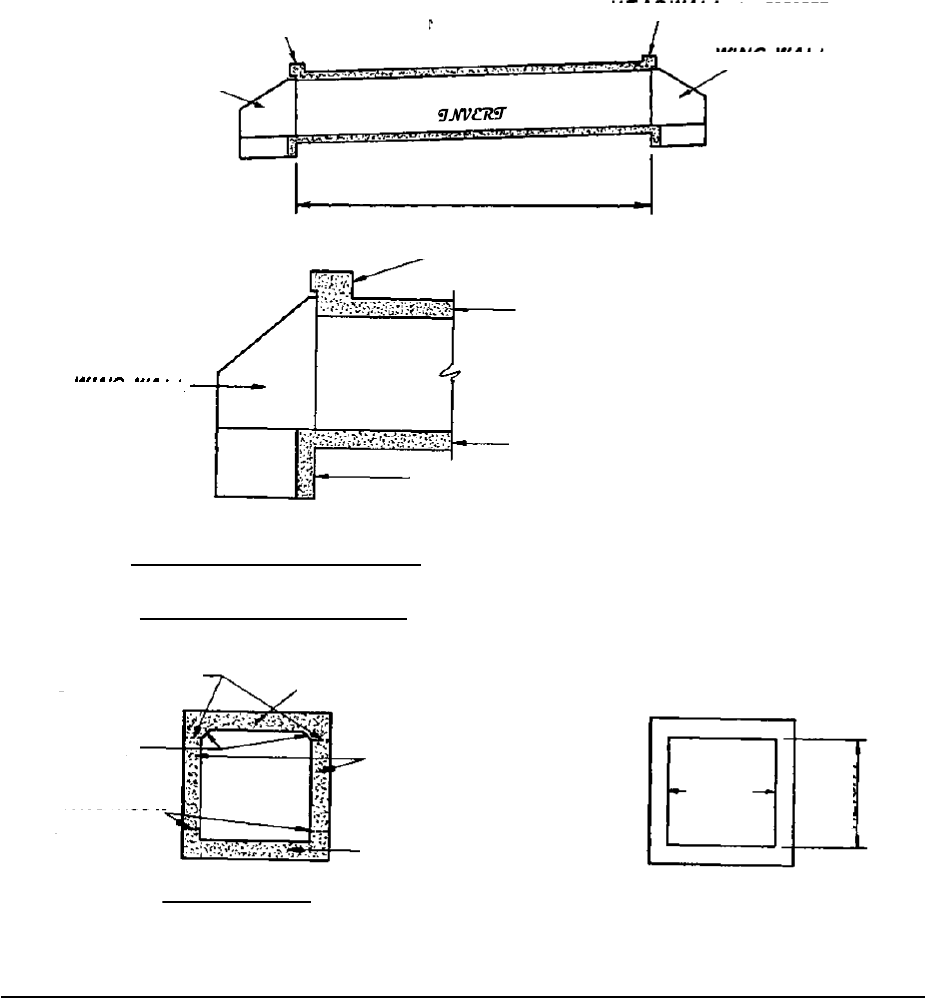
Chapter 8: Drainage
54
BOX CULVERTS
You need to know the names of the different box culvert parts. Examine the following diagrams very carefully.
You should be aware of the fact that culverts can be built with more than one barrel also.
Figure 8-2. Box Culvert Sections.
PARAPET
PARAPET
WING WALL
WING WALL
BARREL
PARAPET
TOP SLAB
WING WALL
The barrel is shaped rather like a
rectangular barrel. It may be
long or short.
BOTTOM SLAB
TOE WALL
LONGITUDINAL CROSS SECTION
The “BARREL” has these parts
CONSTRUCTION
JOINTS
TOP SLAB
The dimensions are measured like
this:
FILLETS
EXTERIOR WALLS
CONSTRUCTION
JOINTS
SPAN
BOTTOM SLAB
CROSS SECTION
Note: A 7’x5’ Box Culvert means
the SPAN is 7’ and the HEIGHT is
5’. The span is always the first
dimension shown.
HEIGHT

Chapter 8: Drainage
55
Figure 8-3. Culverts with Multiple Barrels.
Using the previous drawings, answer the questions:
8-4 What are the three MAJOR parts of a box culvert?
8-5 What “hangs down” below the bottom slab at each end of the barrel?
8-6 The barrel walls become walls at each end of the barrel.
8-7 Is the horizontal or vertical distance considered to be the box culvert SPAN?
8-8 Is the horizontal or vertical distance considered to be the box culvert HEIGHT?
8-9 What is the SPAN and HEIGHT of each barrel of a DOUBLE 10’ X 8’ Box Culvert?
and
DOUBLE CULVERT
INTERIOR
WALLS
TRIPLE CULVERT
INTERIOR
WALL
QUADRUPLE CULVERT

Chapter 8: Drainage
56
Figure 8-4. Longitudinal Section of a Box Culvert.
Notice these things particularly about the above. Shown above is a longitudinal section of a box culvert:
a. The INLET and OUTLET ends - water goes in the INLET and flows to the OUTLET end of a culvert.
The INLET end is always HIGHER than the OUTLET end.
b. The CENTERLINE FLOWLINE - is the elevation of the top of the bottom slab at the centerline of the
roadway. Also known as INVERT.
c. The PERCENT OF SLOPE for the culvert BARREL - this is shown in the longitudinal section on the
drainage cross section sheet. It is established from elevations set for the inlet and outlet elevations.
d. The SLOPE OF THE FILL - is controlled by the height of fill from the shoulder line to the toe of the
slope - see typical sections.
e. The CONSTRUCTION JOINTS - show where one concrete pour may end, and another may begin.
C
L
FILL SLOPE
SHOULDER POINT
ROADWAY
PARAPET
% SLOPE (GRADE)
OUTLET
INLET
CONSTRUCTION
CENTERLINE
FLOWLINE (INVERT)
FILL
FLOW
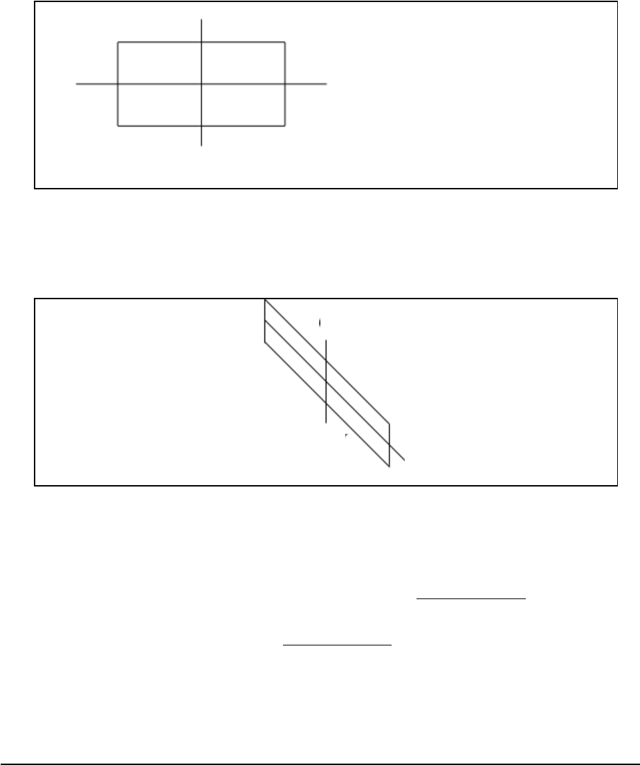
Chapter 8: Drainage
57
PLAN VIEW
Look at the PLAN VIEW shown below for the box culvert. Wing Walls and Parapet are not shown. This plan view
shows the culvert from the top. See the centerline of the roadway? Notice that the culvert is on a line perpendicular
to the roadway centerline. This culvert is said to be on a 90 degree SKEW.
Figure 8-5. Plan View of a Box Culvert
This SKEW ANGLE is the angle that the centerline of the culvert makes with the centerline of the roadway as
measured in a clockwise or counterclockwise direction from the centerline of the roadway looking ahead. Look at
the next drawing of a 45 degree skew condition.
Figure 8-6. Skew View of a Box Culvert.
Using the preceding drawings of a culvert, answer the questions and/or choose the right answer:
8-10 The end of the culvert that the water goes IN is called the end. This is the
(higher / lower) end.
8-11 The culvert slopes DOWN to the end.
C
L
of Roadway
45° Skew
C
L
of Culvert
C
L
of Roadway
C
L
of Culvert
Below Roadway
90° Skew

Chapter 8: Drainage
58
8-12 A place at which one concrete pour may end and join another concrete pour is called the
.
8-13 The toe of the fill slope meets the back of the .
8-14 A skew angle is the angle formed by what two lines?
and
Using Construction Plan Sheets 62, 198 and 202 for culvert structure 10, answer the questions:
8-15 What is the SKEW ANGLE of the CULVERT as shown on the plans at Station 192+24.02?
8-16 Does water flow from left to right, or from right to left in this culvert?
to
8-17 What is the inlet elevation?
8-18 What is the outlet elevation?
8-19 What is the % grade of the new portion of the culvert?
What is the % grade of the old portion of the culvert?
WING WALLS
The barrel of the culvert is the portion of the
structure that conveys the water. Wing walls are
on both ends of the barrel.
The purpose of wing walls is to keep the earth “fill”
above the culvert from spilling into the stream bed.
At right is a section of the wing wall on the previous
drawing of a culvert.
Figure 8-7. Part Plan View of Wing Wall
Footing
C of Roadway
L
C
L
Wing wall
C of Culvert
L
The Wing Walls on
this end of the culvert
are similar to those
shown on the other
end.
Figure 8-8. Wing Wall Section.
Fill Face
of Wall
Fill Slope
Wall Stream
Face of Wall
Footing
Toe Wall
Height
Varies

Chapter 8: Drainage
59
Figure 8-8. Part Plan of Box Culvert on 60 degree Skew.
Wing walls are extensions of the
barrel walls that flare out away from
the stream. Figure 8-9 shows a box
culvert on a 60-degree skew. Notice
how one wing is shorter than the other.
Notice that the length of each wing is
such that the fill slope, as indicated by
the arrowed lines, proceeds down the
slope from the shoulder line of the
roadway.
Therefore, the wing lengths will vary
from culvert to culvert - depending
upon the height of the culvert, the
slope of the fill, and skew of the
culvert. Turn to Standard 2328 on
Sheet 655 of your example plans. Plan
views for different skew angles are
Figure 8-9. Box Culvert on 60 degree skew.
shown. Notice the lengths of Wing M and Wing N. These varying wing lengths are examples of short and long
wings.
The angles that the wings make with the barrel are illustrated in the part plan shown below. Note that the wings are
parallel to lines that cut in half (bisect) the interior corner angles of the culvert.
This procedure is the normal or standard method of establishing the direction of the wings. There are special
occasions (not very often) when the wings are not placed as shown in the “Part Plan” (Figure 8-10) above.
Circle the correct answers:
8-20 The purpose of a wing wall is to keep the earth (fill / cut) from entering the stream.
8-21 Wing wall wings (are / are not) different lengths if the culvert is built on a skew.

Chapter 8: Drainage
60
BRIDGES
A bridge is constructed over a roadway, stream, or railroad, or a combination of these. Refer to Figure 8-11 below
for two views of a three span bridge over a roadway. Look this structure over carefully.
Figure 8-11. Plan and Elevation Views of a Bridge
Notice these things particularly on the views of the bridge:
1. Look at SPANS A, B, and C - These Spans make up the riding surface of the bridge and consist of a
reinforced concrete deck (slab) supported on steel or concrete BEAMS or GIRDERS that is supported on
the end by BENTS.
2. BEAMS OR GIRDERS - These are placed lengthwise along the bridge (parallel to the Centerline of the
Bridge as shown in the PLAN VIEW) with each end resting on the BENT CAP. They can be made of
steel or concrete. They directly support the roadway slab.
3. BENT - considered to be composed of the BENT CAP, COLUMN, FOOTING, AND THE PILES,
beneath the footing or the Bent Cap and the Pile supporting the cap (in some instances, there are no
columns or footings such as a stream crossing, this is known as a pile bent).
4. BENT CAPS - These are constructed of reinforced concrete and are supported either by means of
concrete or steel PILES or reinforced concrete columns. End Bents normally use Piles.
Roadway
Below
C of
B
L
ridge
L
Plan View of Bridge
C Roadway Below
Span A
Span B
Span C
Cap
Original
Ground Line
Horizontal
Clearance
Shoulder
Column
Beam or Girder
Vertical
Clearance
Pile
Roadway
Shoulder
Fill Slope
Fill
End Bent
Piles
Footing
Interior
Bent or Pier
End
Bent
Interior
Elevation View of Bridge
Width of
Bridge

Chapter 8: Drainage
61
5. FOOTINGS - These support the Columns and are constructed of reinforced concrete. Footings are sup-
ported either on Piles or firm soil. Footings are not seen once the bridge has been constructed since they
will be covered with earth.
6. PILES - Piles are used when there is no firm material available to support a footing. Steel piles are used in
areas where rock is found; concrete piles are also used in areas where steel piles would corrode easily
such as in coastal areas.
7. SUPERSTRUCTURE OF A BRIDGE - This is the part of the bridge that is above the top of the bent
caps.
8. SUBSTRUCTURE OF A BRIDGE - This is the part of the bridge that is below the top of the Bent Caps.
9. FILL - This is the earth that was required to be placed on top of the existing ground to provide the
foundation for the roadway.
10. FILL SLOPE - This is the slope of the earth which has been placed on existing ground. Fill slope is
normally 2:1 for bridges over highways and streams.
11. CUT SLOPE - The slope beneath a bridge can also be a cut slope. This would be the case where the
bridge is to be built on an existing roadway and the earth below the bridge must be removed to provide for
the roadway below.

Chapter 8: Drainage
62
BENTS
The following are views of the most common types of Interior and End Bents that you will find in structure plans.
The views show what you would see if you cut a section across a bridge between bents.
Turn to Construction Plan Sheet 535. This bridge is a bridge widening. The existing bridge is being constructed for
the widening. The elevation, left bridge, shows the new pile foundation. The elevation, bent 3 right bridge shows
angle iron supports being added.
Superstructure
Substructure
C of Bridge
L
Width of
Bridge
Concrete Deck
Beams or
Girders
Bent Cap
Column
Ground Line
This Bent is sometimes
called a POST and
BEAM BENT.
Footing
C
L
of Bridge
INTERIOR BENT
ELEVATION
C
L
of Bridge
Concrete Deck
Beams or Girders
Concrete Deck
Beams or
Girders
Bent Cap
Bent Cap
Piles
Piles
PILE END BENT
ELEVATION
INTERIOR BENT
ELEVATION
Figure 8-12. End Bent Elevations.

Chapter 8: Drainage
63
Using the previous drawings and information, answer the questions:
8-22 The two main parts of a bridge are and . (Hint - Above &
Below Bent Cap)
8-23 The supporting members that hold up (directly support) the roadway slab and the traffic on this
slab are or .
8-24 The supporting members in Question 8-23 are supported at each end by a or
.
8-25 The portion of the bridge that supports the Superstructure is called the .
8-26 Depending on the ground, Bent Footings may be supported in two ways. These are
or .
8-27 What are the two types of piles normally used? and
8-28 What two materials are beams or girders made of? or

Chapter 8: Drainage
64
UTILITY ACCOMMODATIONS
Often it is necessary for UTILITIES such as water lines, gas lines, telephone lines, power lines and others to cross
the roadway spanned by a bridge. The cross section below shows how utilities are supported below a bridge slab.
Figure 8-13. Cross Section of Bridge.
C
L
of Bridge
A
d
1
d
2
d
3
Concrete Rail
Concrete
Inserts
Concrete
Deck
Concrete Inserts
8 centers
(Can be Metal Rail )
3/4” Ø Hangers
Concrete Diaphragm
Steel Diaphragm
Steel Beams
6” Gas
Main
2 4” Telephone
Conduits
3/4” Ø Hanger
Lateral
Restraint
8” Water
Line
B
1
d
4
B
2
B
3
Concrete Bent Cap
A
B
4
Columns
Concrete
Edge Beams
Cross Section of Bridge
(Showing Diaphragms At Interior Bents)
Slab
Concrete Insert
Steel
Diaphragm
Hanger
Steel Beam
8” Water Line
Bearing
Plates
Bent Cap
Section A-A
(See Cross Section of Bridge Above)

Chapter 8: Drainage
65
Notice the following things shown on the preceding drawing of a cross section of a bridge. Remember that you are
looking at a cross sectional side view of Section A-A.
1. The concrete inserts are placed in the slab when the concrete is poured. The ¾” hangers are then
screwed into the bottom of the insert when the utility is put in place.
2. The utilities are normally placed inside the exterior beams and above the bottom of the beam so they
cannot be readily seen by anyone passing under the bridge in a vehicle.
3. The utilities must clear the steel diaphragm. At times the diaphragm may have to be adjusted up or
down to permit the utility to be placed on the bridge.
4. The lines or conduits are normally located by the dimensions d1, d2, d3, and d4 as shown.
Using the previous bridge cross sections, answer the questions:
8-29 What three utilities are shown in the cross-section?
8-30 How many and what size telephone conduits are shown?
Utility details are more difficult at the end of a bridge. The view below is one looking at the beginning or the
ending end of a bridge which shows the end wall that pipes and conduits must pass through. The bottom section is
a profile view at the end bent.
Examine each diagram carefully.
Figure 8-14. End Bent Elevation and Section

Chapter 8: Drainage
66
Notice the following things shown on the previous End Elevation drawing:
1. The end wall that the utilities must pass through is a reinforced concrete wall that is poured at the same
time as the concrete slab is poured.
2. Note the pipe sleeves that are cast in the end wall for the pipes to pass through. Also, see the opening that
is left for the telephone conduits.

Chapter 9: Utilities
67
Utility plans are used primarily to facilitate coordination between the construction contractor and utility companies
having facilities in the roadway corridor. (The DOT is not involved in the relocation of utilities unless it is done
under a Force Account). These plans show the contractor the approximate locations of existing, relocated, and pro-
posed new utilities aiding the designer and contractor in identifying and/or avoiding conflicts or damage to
facilities. Information is typically obtained from either field survey data and/or the affected utility owner.
Construction Plan Sheet 419 is an example utility plan. Note the gas lines shown before Station 180+00. One gas
line is being relocated, and the other remains in the original location. Also note the Colonial Pipeline dig
notification requirement.
Please identify the following statement as True or False.
9-1 True False Utility plans show the exact location of the utilities of the project.
Plans are also prepared consisting of signs and pavement markings. These plans are normally in the same general
format as the roadway plans.
All permanent roadway signs and pavement markings are placed on the plans as they are supposed to appear upon
completion of the project. See Construction Plan Sheet No. 474 for an example of this.
Chapter 9: Utility Plans

68
Chapter 9: Utilities

Chapter 10:Signing, Pavement Markings, Signals, Highway Lighting & Landscaping
69
All required pavement markings are depicted on the plans including the color, width, and spacing, etc. Call-outs
may be provided to identify the type of each line on Plan Sheet. All required arrows and hatching in accordance
with Department Standards are included. Each arrow may not be labeled but at least one note referencing the
applicable standard is included on each sheet.
A summary of the quantities for any overhead signs typically follow the sign/pavement marking plans. For post
mounted signs, a summary is included with the normal Summary of Quantities Plan Sheets discussed previously in
Chapter 4. It lists the location, installation number, sign codes, etc. for each sign.
TRAFFIC SIGNALS
The signalization plans will show the complete site layout, equipment details, electrical circuitry, signal phasing,
and other relevant data for the installation of traffic signal(s). A separate plan sheet(s) for each intersection
requiring signalization will be provided. A summary table of items needed for each of intersection will be included
showing the name of the item, the method of payment and the quantity to be used for each of the installation(s).
See Construction Plan Sheet 523 for a sample of an installation.
LIGHTING
Highway lighting plans are required when a project involves lighting improvements. The lighting plans are to
provide a comprehensive set of construction details, electrical circuit tabulations, pole data summaries, conduit
descriptions, service point locations, luminaire type and intensity, foundations and details, and all other specific
data relevant to the construction of all lighting related features and components.
If the project consists of high mast lighting towers, it is also required that a soil survey and foundation design is
done.
LANDSCAPING
Projects which require landscaping may require a separate set of plans, at the Department’s direction. These plans
may be included in the roadway contract or as a stand-alone set of plans.
The following information is usually provided in landscape plans:
1. An overall Site Plan and an area map depicting the roadway corridor in relation to the surrounding
environment
Chapter 10: Signing and Pavement Markings,
Signals, Highway Lighting & Landscaping

2. A Planting Plan
3. A Planting Plan Detail
4. An Irrigation Plan
Circle the correct answers:
10-1 Sign and Pavement Marking Plans (are /are not) normally in the same format as roadway plans.
10-2 Plans (do / do not) indicate the color, width and/or spacing of the pavement markings.
10-3 Traffic Signal Plans (do / do not) have a summary of items needed for each intersection.
10-4 Lighting Plans (are / are not) required when the project involves extensive lighting
improvements.
10-5 List two (2) things that are to be included in a set of Landscape Plans.
1.
2.
Using Construction Plan Sheet 474, answer the following questions:
10-6 What size skip stripe is to be placed on the right side of the project centerline from Station
153+00 to 165+00?
10-7 What size and color stop bar is to be placed on Rehoboth Road?
The Traffic Control Plan consists of the plans and specifications developed for each individual construction
project, supplemented by such detailed plans as required by the contract. The Traffic Control Plan complements
the Traffic Control Specifications and the Manual of Uniform Traffic Control Devices (MUTCD).
70
Chapter 10:Signing, Pavement Markings, Signals, Highway Lighting & Landscaping

Chapter 10:Signing, Pavement Markings, Signals, Highway Lighting & Landscaping
71
Special attention is given to constructability, traffic handling, detours, restrictions to traffic, hours of closure/lane
loss, and responsibility of the contractor. Signing and markings for the Traffic Control Plans are included for
projects such as off-site detours and projects of unusual complexity. Routine projects do not necessarily identify
specific signs, markings, and other devices ordinarily required by the Specifications and Standard Drawings.
Preliminarily, specific Traffic Control Plan sheets for each stage of construction using information from the plan
sheets and intersection and interchange layout sheets are prepared. For each construction stage, plans show the
roadway areas and major drainage structure to be constructed, along with traffic flow patterns, including lane
widths, for the stage. Indicate on the plan areas of temporary pavement, locations of temporary barriers, and any
temporary drainage structures.
Also included on these plan sheets is a narrative of the sequence of construction and of the handling of traffic for
each stage. Where necessary, cross sections of the stage indicating the area to be constructed along with the area to
be used to maintain traffic are included, showing any areas of temporary pavement and any temporary barriers.
If an on-site detour is required, detour plans with cross sections and signing are usually included showing detour
centerline/baseline with curve and alignment data, detour profile, pavement edges, pavement width, construction
limits of the detour, required right-of-way and easements, temporary drainage, and temporary barriers if necessary.
If a road closing and an off-site detour is required, there will be a plan showing a layout of the local roads with the
road closure points and the detour route.
Please answer the following true/false questions:
11-1
True False
Traffic Control Plans are general and are used from project to project.
11-2
True False
Detours are not given any attention in a set of Traffic Control Plans.
11-3
True False
Cross sections of each construction stage are always included in the plans.
Chapter 11: Maintenance of Traffic, Sequence of
Operations, and Staging

72
Chapter 11: Maintenance of Traffic, Sequence of Operations, and Staging

Chapter 12: Erosion, Sedimentation, and Pollution Control Plans
73
INTRODUCTION
Steep embankments, ditches, or other exposed surfaces adjacent to a roadway require some means to be taken to
keep exposed soil from eroding away by the action of wind, water, and freezing and thawing action of the weather.
Depending upon the need, erosion control measures such as grassing, silt fence, paved ditches, straw mulch, silt
gates, baled straw, and other devices such as bituminous treated glass fiber, soil reinforcing mats, etc. may be used.
In creating the Erosion, Sedimentation and Pollution Control Plans (ESPCP), references such as the most recent
Department’s Uniform Code System For Soil Erosion And Sediment Control Design Guidelines (Section 161 of the
Department Specifications), the Department’s Manual On Drainage Design For Highways, the Department’s Standard
Specifications Construction of Roads and Bridges, the Department’s Construction Details, and the Georgia State Soil
And Water Conservation Commission Manual For Erosion And Sediment Control in Georgia, to name a few, may be
used in preparing the Erosion, Sedimentation and Pollution Control Plans (ESPCP) and/or package.
WHEN ARE ESPCP NECESSARY?
If the total project disturbs less than one (1) acres only a set of BMP (Best Management Practices) Location Details
are prepared and included in the project construction plans. BMP’s are either structural or vegetative. Structural
measures are structures that control erosion such as rip-rap or paved ditches. Vegetative measures are methods
such as grassing, sod or soil matting.
Figure 12-1. Erosion, Sediment & Pollution Control Plan
Chapter 12: Erosion, Sedimentation, and
Pollution Control Plans (ESPCP)

Chapter 12: Erosion, Sedimentation, and Pollution Control Plans
74
If the total project disturbs 1 acre or more, there will be a standalone erosion control package. This package will
be placed at the back of a set of final construction plans.
WHAT IS INCLUDED IN THE ESPCP?
Included in ESPCP standalone package you should find the following sheets:
•
Cover Sheet (Construction Type)
•
General Note Sheet
•
Drainage Area Map
•
BMP Plan Sheets (Best Management
Practices)
•
Comprehensive Monitoring Program
General Note Sheet
•
Topographical Sheet
•
Erosion Control Item Construction
Details and Standards
•
NOI (Notice of Intent)
The BMP Plan Sheets (Figure 12-2, below) contain the recommended types and locations for permanent and
temporary erosion control items. The types of temporary items that should be shown on the plans include silt
control gates, sediment basins, temporary slope drains and sediment barriers, or any other items deemed necessary
and designated as “Temporary Erosion Control” on the uniform code sheets. Any staging to be done on the project
must also be included in these sheets.
The sheets are designed with the same scale and matchlines as the construction plans.
Figure 12-2. Stage 1 BMP Plan Sheet: Location Details.

Chapter 12: Erosion, Sedimentation, and Pollution Control Plans
75
CONTRACTOR RESPONSIBILITIES
The Department of Transportation provides all these plans; however, if there are any changes to the staging, the
contractor is responsible for revising the plans. In addition, the contractor is responsible for the ESPCP for borrow
pits, haul roads, and waste pits.
EXAMPLES
Berm ditches may require concrete ditch paving as erosion control measures. The limits and quantities are noted in
the Summary of Quantities.
Erosion control measures are identified by standard symbols. Measures shown on Construction Plan Sheet 721
include Co (construction exit), Sd3 (temporary sediment basin), and Ch (channel stabilization). These measures are
considered structural BMPs. All measures required for the project are found in the construction details.
Circle the correct answers:
12-1 If a total project is (greater / less) than one (1) acres a set of Erosion Control Plans will be
included in a separate package and attached to the back of the project plans.
12-2 The Department of Transportation has to develop and submit erosion control plans according to
Specification Section (161 / 611)
12-3 Name three (3) erosion control measures that can be used on a project.
1.
2.
3.

Chapter 12: Erosion, Sedimentation, and Pollution Control Plans
76

Chapter 13: Cross Sections
77
INTRODUCTION TO CROSS SECTIONS
Cross Sections depict the existing ground conditions, including all man-made features, as sections perpendicular to
the construction centerline or baseline. The proposed cross-sectional outline of the new roadway with all its
elements is also shown on the cross sections. Standard Cross Section Plan Sheets are used for showing the roadway
cross sections. The recommended scale is 1” = 100’ or 1” = 200’. If the entire cross section cannot be shown on
one sheet, the sheets may be turned horizontally or more sheets with appropriate match lines shown are used.
Existing ground lines are shown with a dashed line. A note of the existing ground line elevation at the profile grade
line (PGL) just below the ground line is shown. The surface and subgrade of the existing construction such as
pavements, curbs, and sidewalks are shown also with a dashed line. If present, the limits of unsuitable material are
shown. The station number of the section is normally shown in heavy numbers to the right of or below the cross
section.
The proposed roadway template is shown with a solid line. The proposed profile grade elevation is vertically
shown just above the profile grade line. If there are any special ditches, the elevations are normally included as
well. Any and all station equations are shown, even if a cross section may not be plotted at that point.
Roadway Cross Section Plan sheets are usually lined up in a similar way to the list below:
1. Mainline
2. Cross Streets
3. Side Streets
4. Ramps
5. Major Driveways
EARTHWORK
Figure 13-1 is an illustration of typical terrain upon which a two-lane roadway is shown. The illustration can only
be a general picture, but it does convey a third dimension-depth, which a plan view cannot show. Within the
illustration, you can see one item of construction that is changing from station to station and that item is
earthwork (cubic yards of dirt).
Figure 13-1. Typical terrain for a Two-Lane Roadway
Because earthwork is usually a costly item in highway construction, it must be accounted for in the estimate pre-
pared for the project. Since it would be extremely difficult to measure the exact amount of earthwork in a project,
the designer resorts to approximation. This is accomplished by using the Cross Section Plan Sheets.
Remember that the cross section shows what you would see if the highway were cut at right angles to the center-
line.
Chapter 13: Cross Sections

Chapter 13: Cross Sections
78
See the next illustration with examples of cross sections taken in cut and in fill:
The cross section is not always all cut or all fill as shown previously; it may also be part cut and part fill.
Many factors are considered before combining a typical section of the roadway with a cross section of the ground.
Figure 13-2. Examples of Cut and Fill Cross Sections
Figure 13-3. Typical Cross Section.
TYPICAL CROSS SECTION
C
B
A
2006.5
H
1” = 5’ Horizontal
1” = 5’ Vertical
I
E
D
H
F
J
13+00
G
The following is a listing of fundamental items to be recognized on cross-sections.
A. Typical section template
B. Fill slope
C. Elevation of finished roadway at center line (Profile Grade)
D. Side slope (ditch front slope)
E. Cut slope (ditch back slope)
F. Elevation of original ground line at center line
G. Station number of this particular cross section
H. Area of cut (in c.y. per 100 ft)
I. Area of fill (in c.y. per 100 ft)
J. Original ground line
Existing Ground
700
Cut Area
690
Typical Section Template
680
40 30 20 10 10 20 30 40
C
L
AA Cross Section—Earth Cut Area
A
A
Fill Area
B
670
660
650
30 20
B
Typical Section Template
Existing Ground
10
C
L
10
20
30
40
50
BB Cross Section—Earth Fill Area

Chapter 13: Cross Sections
79
The typical section represents an end view of the pavement necessary to carry the type and volume of traffic
established in the highway design.
Figure 13-4. Typical Cross Section along Centerline.
The cross section of the original ground is distinctive for every location along the centerline.
By combining the typical section and the cross section of the original ground, a determination is made of the area
of cut, fill, or both.
Figure 13-5. Cross Section at Station 194+50.
The drawing on Figure 13-6 shows how depth (100 ft.) is multiplied by an averaging of end areas to give a
“volume” answer. The vertical point of reference for a typical section at a particular location along the roadway is
called the profile grade.
Figure 13-6. Volume of Cut.
On projects where the amount of dirt is over a set amount by the Department, the earthwork is paid for as a Cubic
Yard item and not Lump Sum. The District Earthwork Coordinator will verify the cubic yard amount of earthwork
at the beginning of each project. Project personnel will pay up to 95% of the verified quantity of earthwork per the
Standard Specifications until final dressing, etc. is complete.
C
L
1+00
2+00
P.G.
P.G.

Chapter 13: Cross Sections
80
Upon completion of the final dressing, project personnel should submit to the District Earthwork Coordinator a list
of all areas where the contractor deviated from the plan template with approval of the Department. This form is the
“Earthwork Template Exceptions List”. In the case that the project was built without any exceptions, project
personnel should send a letter stating such to the District Earthwork Coordinator as well.
GRADE
Look at Construction Plan Sheet 236, a Cross Section Plan Sheet, and note that the profile grade elevation (top
elevation) listed for 196+00 is 880.82. The lower elevation is the finished grade for the ditch. The smaller
elevation just below and right of the profile grade elevation is the existing grade. Turn to Construction Plan Sheet
106 and verify the elevations at Sta. 196+00. Now turn to Construction Plan Sheet 8 for the typical section and
compare the required grading template to the plotted cross section. Note that the profile grade is at the center of the
median.
SLOPES
Slopes are usually referred to as “cut slopes” (back slopes), “fill slopes” and “side slopes” (front slopes). A cut
slope is that portion of the roadway between the side drainage ditch and the top of the cut. A fill slope is that
portion of roadway between the shoulder point of the roadway and the toe of the fill. The side slope is that portion
of the roadway between the shoulder point and the adjacent drainage ditch. These slopes are measured as a ratio of
horizontal distance (from and to edge of pavement) versus each foot of decrease or increase in elevation (height).
Figure 13-7. Views of Slopes in Cross Section
Figure 13-7 shows some views of the various slopes used on cross sections.
ORIGINAL GROUND
ROADWAY
SHOULDER
B
DITCH
A
A
B
Cut slope (back slope)
Side slope (front slope)
C
TOE OF FILL

Chapter 13: Cross Sections
81
A 2:1 slope means that for every 2 feet of horizontal distance, the elevation (or vertical distance) increases (cut
section) or decreases (fill section) 1 foot, depending on the type of slope shown on the previous drawing.
Using Cross Section Construction Plan Sheet No. 236, look at Sta. 194+50. Notice that the left side slopes shown
here is a 2:1 slope which is a “fill slope”. Look now at Construction Plan Sheet 8 - Typical Section - and notice
that a fill slope over 10 feet will have a 2:1 slope and that guardrail will be required in this section because of the
depth of fill.
Figure 13-8. Slope Cross Section.
10’ 4’
16’
19.5’
VARIABLE SLOPES
6:1 TO 2:1
14’

Chapter 13: Cross Sections
82
SLOPE STAKES
The following information is a general guide only. Information on these stakes varies with various contractors,
surveyors, and districts. Stakes contain information that tells the Contractor how much “cut” or “fill” is required
from the point of the stake to the ditch line (or shoulder point) of the roadway, depending on whether the stake is in
a cut or in a fill section.
Slope stakes are placed at the point of intersection of the cut or fill slope and the natural ground line.
Figure 13-9. Slope Stake Positioning

Chapter 13: Cross Sections
83
The following information may be shown on the side of the slope stake facing the roadway (this would be the front
of the stake). Refer to Figure 13-10 below.
1. Indicates cut (C) or fill (F)
2. The amount of cut (to the bottom of the ditch) or the amount of fill (to the shoulder point).
3. The distance from the stake to the centerline of the roadway or some other reference line.
4. The rate of slope (such as 2:1)
5. The rate of super elevation (only required when roadway is in a curve section).
Figure 13-10: Station Numbering on Slope Stake.
The station number is shown on the side of the stake away from the roadway or back of the stake. Refer the right
side of Figure 13-10 above.
Often, slope stakes are offset in order to allow the Contractor to perform his work without destroying the slope
stakes. In this case, information should be shown in the same manner as the in-place slope stake except that the
following additional information should be shown encircled on the front of the offset stake.
•
The distance from the offset stake location to the slope stake location.
•
The change in elevation between the slope stake location and the offset location as indicated by a + or a -
depending on whether the offset stake location is higher + or lower - than the slope stake location.
Figure 13-11. Offset Distance on Slope Stake.
10
+0.1
C
10.0
60.0
2:1
0.03
•
OFFSET DISTANCE
•
DIFFERENCE IN ELEVATION BETWEEN OFFSET
STAKE AND SLOPE STAKE
1.
2.
3.
4.
5.
Front View
C
10.0
60.0
2:1
0.03
Rear View
48+00

Chapter 13: Cross Sections
84
Please identify the following statements as True or False:
13-1 True False Roadway cross sections depict existing ground only.
13-2 True False Existing ground lines are shown as solid lines on roadway cross sections
13-3 True False The proposed roadway template is not shown on the roadway cross sections
Circle the correct answers:
13-4 Cross sections show what you would see if the highway were cut at a right angle to the
(centerline / station).
13-5 Cross sections of the original ground (is / is not) distinctive for every location along the center
line.
13-6 Top elevation listed on the cross sections (is / is not) the original ground line.
13-7 Cut slopes (are / are not) usually referred to as back slopes.
13-8 Slope stakes (do / do not) contain information that tells the contractor how much “cut” or “fill” is
required for a certain part of the roadway.

Chapter 14: Standards & Details
85
INTRODUCTION TO STANDARDS AND DETAILS
“Georgia Construction Standard Drawings” or Standards are generalized construction drawings that are applicable
to most construction projects. Think of Standards as drawings of the normal way the Department of Transportation
wants something built or to be done.
“Georgia Construction Detail Drawings” or Details are a more specific and specialized way that the Department
wants something built. It will usually be something that is not as common a way of doing something on most
construction projects.
“Georgia Special Construction Details” are drawings that are specific and specialized to that project only.
Turn to the Index Sheet and note that Construction Plan Sheets 566-631 are Construction Details and Sheets 632-
707 are Construction Standards and are to be used on the job. Two of these Standard Drawings, Construction Plan
Sheet No. 690 (9028C Superelevation) and Construction Plan Sheet No. 694 (9031S Median Drop Inlet), are
included as examples.
INTERSECTION DETAILS
Intersection details are larger scale views
showing detailed information that could not be
shown clearly on a smaller scale normal Plan
Sheet.
Figure 14-1. Ramp Identification by Letter.
Each ramp in an interchange is identified by a letter designation. These are usually assigned as shown in Figure 14-
1.
Interior ramps or loops are designated with a Subscript A1, A2, etc. or as Loop A, Loop B, etc. At this particular
interchange, Ramps A & B were constructed under a previous contract and would be shown by a dashed line,
indicating existing conditions.
4-1 Match the Columns
Column A
A. Georgia Construction Standard Drawings
B. Georgia Construction Detail Drawings
C. Georgia Special Construction Details
Column B
1. Project specific construction drawings
2. Generally used construction drawings
3. Not the common way on all projects
Chapter 14: Standards & Details
B
C
CONST.
B
1
STATION AHEAD
C
L
D
1
A D

86
Chapter 14: Standards & Details

Chapter 15: Right of Way
87
INTRODUCTION
In order to construct any highway, the Right of Way Office must be successful in securing the needed land for
right of way purposes. The Right of Way Office personnel, in most instances, are the first official contact that the
property owner will have with the Department. It is imperative that they also be competent in highway plan
reading so that the plans can properly be interpreted for a highway project to the property owner.
The property owner, above anyone else, is most vitally concerned as to how a proposed highway will affect his
own property. The Right of Way specialist will be required to answer questions concerning the plans in addition to
the general questions concerning the right of way acquisition procedure. On the initial contact with the property
owner, it is of prime importance to properly interpret the highway plans for the owner as well as explain other
phases of the right of way acquisition procedure.
Many times the owner will ask questions regarding ingress (enter in) and egress (exit from) of a proposed highway;
how cuts and fills will affect his property; and how his residence or business will be affected by the highway
project. The farmer is particularly interested in such matters as how his fields and pastures will be divided by a
proposed highway; how his woodland will be affected; how the access to water will be affected; and the
appropriation and relocation of fencing.
Farmers will also ask questions regarding the movement and protection of livestock; how the construction schedule
of the project will affect his planting, growing, and harvesting seasons; and many other questions such as the
appropriation of farm outbuildings and his access to the proposed highway facility. These are only a few of the
questions that a Right of Way Specialist may be asked by a property owner, and the importance of highway plan
reading cannot be stressed too much. If a Right of Way Specialist is hesitant about answering questions regarding
the plans, due to his lack of knowledge, the property owner is apt to become defensive and the Specialist will have
a difficult time in acquiring the property.
In Urban areas, the Right of Way Specialist should be particularly careful in noting the “cuts” and “fills” as
indicated on the plans. Major “cuts” and “fills” can affect locations as to where driveways can be reconnected. It is
entirely possible that the depth of a cut or the height of a fill could eliminate a driveway from being reconnected
even though the project has no limited or control of access.
Urban property owners are particularly interested in such matters as to the appropriation of landscaping, how close
a roadway is to a dwelling or business, driveway reconnections, and parking on a proposed street. Property owners
may have more questions regarding highway construction. In many instances, a property owner will move a
residence or commercial building, which is located within the right of way limits of a highway project to a new
location.
For these reasons, it is imperative that the Right of Way Specialist properly and accurately interprets the plans and
read slope stakes. Highway plan reading is of vital importance to employees of all sections of the Right of Way
Office and all employees should take full advantage of this Plan Reading Course.
Chapter 15: Right of Way

Chapter 15: Right of Way
88
RIGHT OF WAY TERMS AND DEFINITIONS
ABANDONMENT - the act of the cessation of use of a right of way with no intention to reclaim or use the right
of way again for highway purposes.
ACQUISITION OR TAKING - the acquiring of a property in its entirety or a portion thereof, for highway
purposes.
ABUTTING LAND OWNERS - the owners whose land adjoin or abut the land spoken of.
BORROW PIT - an area or pit from which suitable material from sources outside the project limits is excavated
and generally used for embankments.
CATTLE PASS - an opening under the roadway, which allows the movement of livestock from one side of the
road to another. Cattle passes consist of a pipe or box culvert or a provision made under a structure to allow the
movement of livestock from one side of the roadway to another.
CHANNEL CHANGE - a man-made change or diversion in the natural flow of water or man-made change in the
channel of a ditch, stream, creek, or river.
CONDEMNED PROPERTY - power of eminent domain (Stoppage).
CONSTRUCTION EASEMENT - an easement that extends to the farthest limits of construction, beyond the
right of way limits as shown on the plans.
CONSTRUCTION LIMITS - the limits shown on the plans by symbols which designates the limits of
construction.
CONTROL OF ACCESS - the condition whereby the Transportation Department controls the right of property
owners or occupants of abutting property to enter or leave a highway.
CUL-DE-SAC - a street or road which is open to traffic at one end only with a special provision for turning
around at the other end.
DEED OF EASEMENT - an instrument by which a right is acquired by the Department to use or control property
for highway purposes.
DRAINAGE EASEMENT - an instrument or easement granting the Department the necessary property beyond
the right of way limits as shown on the plans to provide for the proper drainage of a highway.
EGRESS - the act of leaving.
ENCROACHMENT - the use of highway right of way for an indefinite term with or without permission of the
Transportation Department. Encroachments usually involve man-made obstruction either above or below the
highway.
FEE SIMPLE TITLE - absolute ownership of property including also the unlimited right to control same for any
purpose whatsoever.
IMPROVEMENT DESIGNATIONS - designations or symbols shown on the plans which identify specific
improvements or items of real or personal property.

Chapter 15: Right of Way
89
INGRESS - the act of entering.
LIMITED ACCESS - ingress and egress to a highway is at points designated by the Department of
Transportation.
OWNERSHIP - the legal right of possession of real or personal property. Ownership of property designated on
the plans is shown by the owner’s name appearing in print on the plans.
PARCEL NUMBER - the number designated on the plans generally enclosed by a circle, which designates a
parcel or tract of land.
PARTIAL CONTROL OF ACCESS - similar to Limited Access in that the Department of Transportation will
give preference to through traffic. Access connection may be provided with selected public roads. There may be
grade crossings and some private driveway connections allowed at designated locations.
PARTIAL TAKE - the acquiring of a portion of a property for highway purposes.
PERMANENT EASEMENT - an easement in perpetuity that gives the Department the right to utilize property
for an unlimited time.
PERSONAL PROPERTY - the right or interest in personal things which are moveable or transferable from one
place to another.
PROPERTY LINE - the boundaries or limits outlining the ownership of a tract or parcel of land.
REAL PROPERTY - the rights and interests in land and those items or things of a permanent nature affixed to the
land and generally whatever is growing upon the land.
REQUIRED RIGHT OF WAY BOUNDARY OR LIMITS - the limits or boundaries as shown on the plans
which show how much property is to be acquired for right of way in order to properly construct the highway.
RIGHT OF ACCESS - the right of ingress (entering into) or egress (leaving from) to a highway from abutting
property.
RIGHT OF WAY - this is a term denoting land, interest therein, or property which is acquired for highway
purposes.
RIGHT OF WAY MONUMENT - a marker, usually concrete, placed on the ground that shows or indicates the
limits of the right of way.
RIGHT OF WAY PLANS -are plans which contain all necessary information for the acquisition of right of way
as found on design plans with the addition of any additional information that may be helpful in the acquisition of
right of way.
SIGHT DISTANCE - the length of roadway visible to the driver of a vehicle at any given point on the roadway
when the view is unobstructed. That area or property designated on the plans to be acquired for sight distance
purposes in order to grant the driver of a vehicle an unobstructed view.
SYMBOLS - a conventional sign used in writing or printing which relates or represents quantities, items, or
things.

Chapter 15: Right of Way
90
TEMPORARY EASEMENT - an easement granted to the Transportation Department on a temporary basis
usually for a specified time and specified purpose.
THE LOCATION OF MONUMENTS AND TIES IN RELATION TO PROPERTY LINES - those locations
designated on the plans by distance from and/or reference to a point on the survey line which designates the
location of a property line intersecting a right of way boundary or which designates the location of a right of way
monument on the right of way boundary.
TOTAL TAKE - the acquiring of a property in its entirety for highway purposes.
UTILITY - physical plants and operating facilities which provide public or private utilities consisting mainly of
communication lines, electric power lines, gas lines, water mains, sewer mains, and other pipe lines, and the
supporting structures for these facilities.
WASTE PIT - an area or location in which excess or unsuitable material obtained during construction is
deposited.

Chapter 15: Right of Way
91
RIGHT OF WAY PLAN SHEETS
Right of Way Plans are a separate set of plans from the construction Plans. In going through this section of the
manual, you will find yourself being referenced to a sample set of a Right of Way Plans. You will find those sheets
at the back of your sample pack of Plan Sheets that you received when you began this manual.
In your set of plans, you will find two (2) Cover Sheets for “Proposed Right of Way SR 16—Arthur K. Bolton
Parkway.” Notice the Sheet Number differences for the Cover Sheet. The Right of Way information begins on
Cover Sheet Number 1 and finishes on Sheet number 2. The construction plans had one coversheet. Similar to
construction plans, a revision summary sheet is also included (Sheet 3).
Figure 15-1. Right of Way Plan Sheet: Cover Sheets 1 and 2.

Chapter 15: Right of Way
92
While there are similarities between a Construction Cover Sheet (page 4) and a Right of Way Cover Sheet, there
are also differences.
A. Similarities
1. Title of Description - “SR16—Arthur K. Bolton Parkway” in Spalding and Butts counties. It is a federal-
aid project, but the project involved partial limited access and is not on a Federal route. The interstate
improvements are on I-75.
2. Project Number - you will notice that the Right of Way Sheets included in your sample pack of plans is
STP-IM022-1(26) and IM-0000-00(523), the same as the construction plans. Between the time the Right
of Way plans are developed, in the Preconstruction phase of a project, and the time the project reaches the
Construction phase, slight changes may be made, such as an administrative or funding source change.
This could cause a change in the Project Number.
3. Location Sketch - both Cover Sheets have a location sketch on them.
4. Sheet Identification Block - both have blocks in the upper right corner showing the project number, the
sheet number, and the total number of sheets. This set of Right of Way plans has 82 sheets compared with
the 770 sheets in the construction plans.
5. Scale & Length of Project - both have a Scale Box & a Length Box. Sometimes the Gross length of
Construction plans may be different than the Right of Way Length. It is likely that a difference is the
distance needed to tie into the existing construction where the right of way was already purchased and
the new construction.
6. Miscellaneous - both sets of cover sheets have information attesting to their legal status and the basis on
which they are developed.
B. Differences
1. Property Owners - instead of an Index, the Right of Way Cover Sheet shows adjoining parcels and a
number identifying the parcel (rectangular boxes with numbers).
2. Plan View - the Plan View shows the project in the relationship to the affected property lines rather than
the topographical landmarks of a Construction Cover Sheet.
3. Conventional Symbols - notice, particularly, the block in the upper right side. You should pay close
attention to the slight variations among the various types of lines. Refer to Figure 15-2 for an example of
a Conventional Symbol block.

Chapter 15: Right of Way
93
Figure 15-2. Right of Way Plans Sheet 1.
Refer to Sheet 3 of the Right of Way Plans included with your set
of sample plans, which shows the following information. Parcels
are identified by a rectangular box with the name of the owner
underneath (See Figure 15-3 at right). These circled numbers
correspond to the circled numbers on the cover sheet and show
the location of the property owned by that person or company
who will be affected by the project.
Land Lot Lines are thin, dashed lines distinguished from “Req’d
R/W & Limit of Access” lines by the thickness and the letters
L.L.L. (Right of Way Limit Lines are thicker or “blacker” than the
Land Lot Lines (L.L.L.).
Notice the group of four (4) numbers that occur on the Cover
Sheet at the intersection of each of the L.L.L.’s. The numbers refer
to the Land Lots that are adjoining at that point.
Figure 15-3.
Right of Way Plan Sheet 3, Parcel 4.
Using the Cover Sheet, answer the question:
15-1 What are the Land Lot Numbers in which parcel 4 is located?

Chapter 15: Right of Way
94
Figure 15-4. Parcel Required Right of Way.
The letters P & L written on the line identifies property lines. Usually a property line is a thin solid line broken by
a single dash. Notice that the symbol for existing Right of Way is the same as that for a property line, but without
the P.L. This applies to the Right of Way Plans. On Construction Plans, existing Right of Way is shown by long,
broken thin lines. Look at Construction Right of Way Plan Sheet 61, near Station 175+00, either to the right or left
for an example of this.
Using Right of Way Plan Sheet 31, answer the questions:
15-2 Locate the property of Frank Chen, Parcel 37. At what station point and offset does the property
line between Chen and Holcomb intersect the required right of way?
Property information that details the right of way
taking is either shown on the same plan sheet on
which the property is shown, or on a separate
plan sheet. The property being taken will be
described by a point, offset/distance,
station/bearing and alignment. The point
reference is shown on the right of way plan
sheet. The offset/distance is the offset from
centerline, and the distance is to the next right of
way point. The station/bearing is the station of
the point, and the bearing is to the next right of
way point. The alignment indicates what
construction centerline is being used (mainline
or side road). Using Figure 15-4 from KC25004
to KC25005 is 48.252
feet at a bearing of N 88° 34’ 56.99” E. Point
KC25004 is 38.630 feet left of Rehoboth Road at
Station 10+75.
Similar information is also given for required
drive easements, temporary easements,
construction easements, and limited access.
On this project, there are a number of
construction and/or drive easements. An easement is giving permission to temporarily use a part of someone’s
private property to perform an act of construction for a set amount of time.
By looking at the Right of Way Plan Sheets, you can identify most of the locations at a glance. They are marked
with diagonal shadings. To see one of these locations, look at Right of Way Plan Sheet Number 3 at Parcel Num-
ber 3.
Using Right of Way Plan Sheet 31and 32 (data on Parcel No. 37) to answer the questions:
15-3 How much right of way is required on Frank Chen’s property (Parcel No. 37)?
15-4 How many feet of limited access is required for the same property?

Appendices
95
1 Based on the information in the Definitions section beginning on page 91, match the columns.
COLUMN A
A. Plan View
B. Slope Stake
C. Culvert
D. Bearing
E. Station Equation
COLUMN B
1. A stake that contains information that tells the contractor how much
“cut” or “fill” is required from the point of the stake to the ditch line (or
shoulder point) of the roadway.
2. A two dimensional view (length and width) from directly above the
object or project.
3. A structure not classified as a bridge which provides an opening un-
der a roadway - usually for water drainage
4. A point on the centerline where the station numbers of one system
change to the station numbers of another system
5. A method used to express direction. The angle and direction, which
the line makes with respect to a North-South line
2 Based on the information in the Abbreviations section beginning on page 103, match the columns.
COLUMN A
A. HWY
B. FES
C. PRIV
D. NBL
E. BLA
F. MP
COLUMN B
1. Begin Limited Access
2. Highway
3. Flared end section
4. Private
5. Milepost
6. Northbound lane
Questions for Appendices

Appendices 96

Appendix A: Definitions
97
A
ABANDONMENT - the act of the cessation (stoppage) of use of a right-of-way with no intentions to reclaim or
use the right of way again for highway purposes.
ABUTTING LAND OWNERS - the owners whose land adjoin (abut) the land spoken of.
ACCELERATION LANE - a connecting lane leading from a ramp to a freeway and designed to enable the
motorist to merge into freeway traffic.
ACQUISITION OR TAKING - the acquiring of a property in its entirety, or a portion thereof, for highway
purposes.
ACRE -a measure of land area 1.e. 160 square rods; 4,840 square yards; 43,560 square feet.
ALIGNMENT - SEE “Horizontal Alignment” and Vertical Alignment”.
ANGLE - the figure formed by the intersection of two straight lines.
ARC -a segment of a circle.
AREA DATA SHEETS - sheets in a set of plans which show the areas of the property to be appropriated and the
remaining areas shown in acreage or square feet or portions thereof.
AZIMUTH -the angle between true meridian (North) through an observer and the line of sight to an object. In
surveying, the azimuth is measured clockwise from the North.
B
BACKFILL - material used to replace (or act of replacing) material used during the construction of a project.
BACKSLOPE - that portion of roadway between the side drainage ditch and the top of the cut - usually measured
as a ratio of horizontal distance versus each foot of increase of elevation i.e. 4 to 1 slope.
BALANCE STATIONS - stations between which excavated earth material approximately equals the amount of
embankment material required.
BARREL - the part of a culvert that water flows through.
BASE COURSE - a part of the pavement structure between the surface course and the subgrade.
BEAM - member spanning from bent to bent along the bridge with its end resting on a cap or a bent - made of
steel or concrete.
BEARING - a method used to express direction. The bearing of a line is the angle and direction, which the line
makes with respect to a North-south line.
BENCH MARKS (B.M.) - a point of known elevation, usually a mark of some durable material such as a stone, a
concrete post, or a bronze plate to serve as a reference point in running a line of levels for the determination of the
elevation.
Appendix A: Definitions

Appendix A: Definitions
98
BENT CAP - a part of a bridge - constructed of reinforced concrete and supported either by means of columns or
piles.
BERM DITCH - any open water course constructed for the collection and handling of surface drainage.
BORROW - suitable material from sources outside the project limits used primarily for embankments.
BORROW PIT - an area or pit from which suitable material from sources outside the project limits is excavated.
This material is generally used for embankments.
BOUNDARY - that which fixes or indicates a limit or extent to a parcel of land.
BOX CULVERT - (see culvert)
BRIDGE - a structure having a length of over a twenty feet span, erected over a roadway, stream, railroad,
depression, or combination of these. Multiple lines of pipe culvert regardless of their length are not considered a
bridge.
C
CATCH BASIN - a minor drainage structure
CATTLE PASS - an opening under the roadway which allows the movement of livestock from one side of the
road to another. A cattle pass consists of a pipe or box culvert or a provision made under a structure to allow the
movement of livestock from one side of the roadway to another.
CENTERLINE - the longitudinal mid-point of all contiguous travel lanes. Surveyed stations are normally on the
centerline if the roadway is two lanes.
CHANNEL CHANGE - a man-made change or diversion in the natural flow of water or man-made change in the
channel of a ditch, stream, creek, or river.
CIRCULAR CURVE - an arc or segment of a circle joining two tangents (straight lines)
CLEARING - the work done by the contractor to remove and dispose of all trees, stumps, brush, trash, buildings,
fence, signs, etc. within the limits of the total project.
COARSE AGGREGATE BASE COURSE - crushed stone used as a part of the roadway base to support
pavement.
COMMUNICATION LINE - a utility.
CONDEMNED PROPERTY - property which has been acquired for highway purposes by the exercise of the
right or power of eminent domain (stoppage).
CONSTRUCTION EASEMENT - an easement that extends to the furthest limits of construction, beyond the
right of way limits as shown on the plans.

Appendix A: Definitions
99
CONSTRUCTION ITEMS - work to be done on a project i.e. paving limits, grading, structures, etc.
CONSTRUCTION JOINT - -the place where one concrete pour ends, and another begins.
CONSTRUCTION LIMITS - the limits shown on the plans by symbols which designate the limits of
construction.
CONTRACT - an agreement between two or more persons or parties to build a section of roadway or structure.
CONTROL OF ACCESS - the condition whereby the Transportation Department controls the right of property
owners or occupants of abutting property to enter or leave a highway.
CONVENTIONAL SIGNS - symbols used by the designer to convey a meaning to whoever is reading a set of
plans.
CROSS SECTIONS - a view of an object where the object has been “sliced away” - produced by a vertical plane
cutting through the roadway at right angles to the centerline showing the profile of existing and proposed earth.
CROWN SLOPE - the slope on the top surface of a roadway.
CUL-DE-SAC - a street or road which is open to traffic at one end only with a special provision for turning
around at the other end.
CULVERT - a structure not classified as a bridge which provides an opening under a roadway - usually for water
drainage.
CURVE - an arc (segment of a circle) joining two tangents.
CUT - a term used to describe an excavation or removal of earth.
D
DATUM PLANE - an assumed plane of reference above or below which elevations are measured. Sea level is
often used as the datum plane.
DEED OF EASEMENT - an instrument by which a right is acquired by the Department to use or control property
for highway purposes.
DEFLECTION - a change in the horizontal direction of a line, the magnitude of which is expressed in degrees.
DEGREE - a unit of angular measurement - a degree represents 1/360th part of a circle.
DELTA ANGLE - it is the angle formed by the intersection of the forward and back tangent; represented by the
symbol: ∆
DIAPHRAGM - steel or concrete members found on the bridge that are wed (joined) to connect beams or girders
together for the purpose of distribution loads to all supporting members. Diaphragms are normally placed
perpendicular to the beams of the bridge.
DITCH SLOPE - see Side Slope

Appendix A: Definitions
100
DRAINAGE EASEMENT - an instrument or easement granting the Department the necessary property beyond
the right of way limits as shown on the plans to provide for the proper drainage of a highway.
DITCH - an open water course constructed for the collection and handling of surface drainage.
E
EARTHWORK - amount of cut and fill earth to be worked with between any two specific stations (measured in
cubic yards of earth).
EASEMENT - a property right to use or control the real property of another person.
EGRESS - the act of leaving.
ELEVATION - the height above or below the average level of the sea or other datum plane.
EMBANKMENT - a wall of material, such as dirt, to raise the height of a roadway - or where a “cut” section has
been made through an undulating (up and down) surface.
EMINENT DOMAIN - the government’s acquiring private property for public use by virtue of the superior
dominion of the government over all lands within its jurisdiction.
ENCROACHMENT - the use of highway right of way for an indefinite term with or without permission of the
Transportation Department. Encroachments usually involve man-made obstruction either above or below the
highway.
END BENT - that part of a bridge, on either end, that supports the beams.
ENDWALL - a minor drainage structure.
EQUALITY - see Station Equation.
F
FEDERAL HIGHWAY ADMINISTRATION - the office within the Department of Transportation in the U.S.
Government which reviews, recommends, and approves the details concerning Federal participation on our
highway system.
FEE SIMPLE TITLE - absolute ownership of property including also the unlimited right to control same for any
purpose whatsoever.
FENCE - an item, usually made of barbed wire, chain link, or woven wire, to keep animals off a controlled access
roadway.
FILL - use of suitable material (usually earth or gravel) to equalize or raise topography to a certain elevation; to
build up with fill; to fill low ground with sand, gravel, or earth, etc.
FILL SLOPE - that portion of a roadway between the outside of the shoulder and the toe of the slope.

Appendix A: Definitions
101
FINISHED GRADE LINE - proposed elevations along the finished surface of the roadway.
FLARED END SECTION - an end treatment that is part of a minor drainage structure.
FOOTING - that part of a bridge that supports the column and is usually constructed of reinforced concrete.
FRONT ELEVATION - a view from the front side of an object.
G
GUARDRAIL - a protective barrier placed between travel lanes of the roadway and a safety hazard (such as high
fill, bridge piers, etc.).
H
HANGER - usually located below a bridge to hold a water line, gas line, or telephone line.
HEADWALL - that part of a culvert that retains fill.
HORIZONTAL ALIGNMENT - a series of tangent and curves on the “Plan View” which show the direction of
the road.
HORIZONTAL DISTANCE - a measurement on a Typical Section from the Centerline of a roadway to the edge
of the pavement - the slope is not taken into consideration in a horizontal distance - all horizontal measurements
are level lines.
I
IMPROVEMENT DESIGNATIONS - designations or symbols shown on the plans which identify specific
improvements or items of real or personal property.
INDEX OF SHEETS - a brief summary of each sheet or series of sheets in a set of plans.
INGRESS - the act of entering.
INLET END OF A CULVERT - the end that the water enters.
INSERT - an item embedded in the concrete of a structure. A hanger screwed into an insert to hold water lines,
gas line, or telephone conduit.
INTERIOR BENT - that part of a bridge that supports the beam and is not at either end of the bridge.
INTERSECTION - a place where two roads join at a common point.
INTERSECTION DETAILS - sheets on a set of plans showing a larger scale view of detailed information of
proposed intersection in a particular project.

Appendix A: Definitions
102
J
JUNCTION BOX - a minor drainage structure.
L
LIMITED ACCESS - Ingress and egress to a highway is at points designated by the Department of
Transportation.
LOCATION MAP - a small map found on the Cover Sheet which shows the location of the project. (The
beginning and ending of the project).
LONGITUDINAL CROSS SECTION - a view of the side of an object that has been “sliced away”.
M
MANHOLE - a minor drainage structure.
MEDIAN - the center section of a divided highway which separates the traffic lanes in one direction from the
traffic lanes in the opposite direction.
MEDIAN EDGE OF PAVEMENT - on a dual lane road, the inside pavement edge or line.
MILE - 5,280 feet.
MINOR DRAINAGE STRUCTURE - an inlet, junction box, manhole, spring box, catch basin, endwall, flared
end section, etc.
N
NATURAL GROUND LINE - see “Original Ground Line”.
NORTH ARROW - on all construction and right of way plans, there is an arrow-like symbol with the point
indicating North. The direction of all control and boundary lines are in reference to this North-South arrow.
O
OFFSET SLOPE STAKE - sometime, in order to allow the contractor to perform his work without destroying the
slope stake, slope stakes are placed farther back from the Centerline of the roadway.
ORIGINAL GROUND LINE - shows how the land was before construction began.

Appendix A: Definitions
103
OUTLET END OF A CULVERT - the end of a culvert that the water flows from.
OWNERSHIP - the legal right of possession of real or personal property. Ownership of property designated on
the plans is shown by the owner’s name appearing in print on the plans.
P
PARCEL NUMBER - the number designated on the plans generally enclosed by a circle which designates a
parcel or tract of land.
PART PLAN - a plan view of an item when only a part of the item is shown.
PARTIAL CONTROL OF ACCESS - similar to Limited Access in that the Department of Transportation will
give preference to through traffic. Access connection may be provided with selected public roads. There may be
grade crossings and some private driveway connections allowed at designated locations.
PARTIAL TAKE - the acquiring of a portion of a property for highway purposes.
PAVEMENT LINES - the edge of the pavement on a roadway.
PAVEMENT SCHEDULE - a statement showing the type and thickness of pavement to be used in a Typical
Section.
PAVING LIMITS - the total length and width to be paved on any portion of a project.
PERMANENT EASEMENT - an easement in perpetuity that gives the Department the right to utilize property
for an unlimited time.
PERPENDICULAR - a line at right angles to a given line or plane.
PERSONAL PROPERTY - the right or interest in personal things which are movable or transferable from one
place to another.
PILES - used in construction of a bridge when subsoil is not firm enough to support a footing of a bridge bent;
materials may be wood, steel, or concrete.
PLAN SHEET - a sheet in a set of plans showing the “Plan View” of a part of a particular project.
PLAN VIEW - a two dimensional view (length and width) from directly above the object or project.
PROFILE GRADE - a longitudinal length of the roadway showing the “up and down” (rise and fall) of the
roadway.
PROFILE GRADE LINE - the trace of a vertical plane intersecting the top surface of the proposed roadway
(wearing surface) usually along the longitudinal centerline of the roadbed.
PROFILE VIEW - a side (longitudinal) view of an object (roadway) showing an elevation of the original ground
line and an exaggerated elevation of the proposed roadway.
PROPERTY LINES - the boundaries or limits outlining the ownership of a tract or parcel of land.

Appendix A: Definitions
104
R
REAL PROPERTY - the rights and interests in land and those items or things of a permanent nature affixed to the
land and generally whatever is growing upon the land.
REAR ELEVATION - a view from the back side of an object.
RETAINING WALL - a vertical wall constructed for the purpose of supporting fill in areas of limited right of
way.
RIGHT OF ACCESS - the right of ingress (entering in) or egress (leaving from) to a highway from abutting
property.
RIGHT OF WAY - This is a term denoting land, interest therein, or property which is acquired for highway
purposes.
REQUIRED RIGHT OF WAY BOUNDARY OR LIMITS - the limits or boundaries as shown on the plans
which show how much property is to be acquired for right of way in order to properly construct the highway.
RIGHT OF WAY MONUMENT - a marker, usually concrete, placed on the ground that shows or indicates the
limits of the right of way.
RIGHT OF WAY PLANS - are plans which contain all necessary information for the acquisition of right of way
as found on design plans with the addition of any additional information that may be helpful in the acquisition of
right of way.
S
SCALE - the measurement (length) used on a set of plans to represent a larger measurement. For instance, 1” in a
set of plans may mean (or equal) 100’.
SHOULDER - the portion of roadway adjacent to the traveled surface for accommodation of stopped vehicles for
emergency use, and for lateral (side) support of base and surface courses.
SHRINKAGE - when earth is taken from its original position and placed in a fill area, it is compacted. Shrinkage
takes place due to the decrease in volume from the earth’s being compacted.
SIGHT DISTANCE - the length of roadway visible to the driver of a vehicle at any given point on the roadway
when the view is unobstructed.
SIDE ELEVATION - a view from the right or left of an object.
SIDE SLOPE - that portion of the roadway between the shoulder point and the adjacent drainage ditch.
SIGHT DISTANCE - the length of roadway visible to the driver of a vehicle at any given point on the roadway
when the view is unobstructed.
SKEW ANGLE - the angle that a pipe, culvert, bridge, or other structure makes with the centerline of the roadway
as measured in a clockwise direction from the centerline.
SLOPE - a ratio of horizontal distance versus each foot of decrease or increase in elevation.

Appendix A: Definitions
105
SLOPE STAKE - a stake that contains information that tells the contractor how much “cut” or “fill” is required
from the point of the stake to the ditch line (or shoulder point) of the roadway.
SPAN - a portion of a bridge made up of the bridge slab and beams that cross over the roadway or stream below.
The span is supported on each end by bents. A culvert span is that portion of the top slab between the walls of a
barrel.
SPRING BOX - a minor drainage structure.
STANDARD DRAWINGS - a group of plan sheets for the construction of various items in a project.
STANDARD SPECIFICATIONS - a book published by the Georgia Department of Transportation which gives
various standards for different items.
STATION - the horizontal measurement along the survey line of a project from West to East or South to North.
Stations are measured in 100-foot intervals. When used as a location, a station is a designated point on the project.
STATION AND OFFSETT - those locations designated on the plans by distance from and/or reference to a point
on the survey line which designates the location of a property line intersecting a right of way boundary or which
designates the location of a right of way monument on the right of way boundary.
STATION EQUATION - a point on the centerline where the station numbers of one system change to the station
numbers of another system.
STRUCTURE - consists of a bridge, culvert, or retaining wall.
SUBGRADE - the top surface of a roadbed that is prepared as a foundation for the pavement structure.
SUBSTRUCTURE OF A BRIDGE - that part of the bridge that is below the top of the bent cap.
SUMMARY OF QUANTITIES - a plan sheet which shows the total amounts of all items included in a particular
contract.
SUPERELEVATION - that amount of elevation required on the surface of a curve in order to overcome the
centrifugal force that acts on a motor vehicle. The difference in elevation between the edges of a traffic lane
applied where curves in the roadway alignment are used.
SUPERSTRUCTURE OF A BRIDGE - that part of the bridge that is above the top of the bent cap.
SURFACE COURSE - the top layer of the pavement structure.
SURVEY LINE - a line established by surveying to mark the location of a highway as the boundaries of property.
SYMBOLS - a conventional sign used in writing or printing which relates or represents quantities, items, or
things.
T
TANGENT - any straight section of the roadway (alignment). A tangent to a curve is a line that touches the curve
at one point and is also at right angles to the radius at the point of contact with the curve.

Appendix A: Definitions
106
TEMPORARY EASEMENT - an easement granted to the Transportation Department on a temporary basis
usually for a specified time and specified purpose. A right to use the land during construction which, upon
completion, the land reverts back to the owner.
TOTAL TAKE - the acquiring of a property in its entirety for highway purposes.
TRAVEL LANES - lanes in which vehicles move.
TYPICAL SECTION - a cross sectional view of a roadway showing how the roadway would appear after the
roadway is completed.
U
UTILITY - physical plants and operating facilities which provide public or private utilities consisting mainly of
communication lines, electric power lines, gas lines, water mains, sewer mains, and other pipe lines, and the
supporting structures for these facilities.
V
VERTICAL - perpendicular to the plane of the horizon or to a primary axis.
VERTICAL ALIGNMENT - see “Profile View”.
VERTICAL CURVE - a parabolic curve drawn tangent to intersecting grade lines to provide a smooth transition
from one grade to another.
VIEW - the way you look at or “see” the different items that are shown in a set of plans.
W
WASTE - that portion of excavated material from a project that is not used in the construction of the project.
WASTE AREA - an area or location in which excess or unsuitable material obtained during construction is
deposited.
WASTE PIT - area or location in which excess or unsuitable material obtained during construction is deposited.
WINGWALL - a part of a culvert that extends at an angle to keep earth from spilling into the stream bed.

Appendix B: Abbreviations
107
A
Aban - abandoned
Ac - acre
ADT - average daily traffic
Ahd or Ah - ahead
Asph - asphalt
Ave - avenue
Az - azimuth
B
Bd - board
Beg - begin
BFSE - begin full superelevation
Bk - back
BLA - Begin Limited Access
BLK - block
Blvd. - boulevard
BM - bench mark
Bn - beacon
BNC - begin normal curve
Br - bridge, branch
BRC - begin reverse crown
Brg - bearing
BSE - begin superelevation
BST - bituminous surface treatment
BW - barbed wire
Appendix B: Abbreviations

Appendix B: Abbreviations
108
C
C/A - control of access
CB - catch basin
Cem - cemetery
CH - courthouse
Ch - church
C/L - centerline
CM - corrugated metal
CMP - corrugated metal pipe
Co - county
Comb - combination
Conc - concrete
Const - construction
Coord - coordinate
Cor - corner
Cr - creek
CY - cubic yards
D
D - dwelling, degree of curve
DI - drop inlet
Dist - district
Div - division
Dr - drive

Appendix B: Abbreviations
109
E
E - east
EFSE - end full superelevation
ELA - End Limited Access
Elev - elevation
EMB - embankment
ENC - end normal crown
ERC - end reverse crown
ESE - end superelevation
EXCAV - excavation
Expwy - expressway
Ext - extension
F
F - frame, face of curb
Fd - ford
FES - flared end section
FL - focal length
For - forest
FR - frame
Ft - fort
Fwy - freeway
Fy - ferry

Appendix B: Abbreviations
110
G
GABC - graded aggregate base course
Gals - gallons
G - garage, gutter
GI - grated inlet
Gr - gravel
H
Hyd - hydrant
Hdqtrs - headquarters
Horiz - horizontal
Hosp - hospital
H Tr - house trailer
Hwy - highway
I
ID - inside diameter
Ind - Indian
IP - iron pin
J
JB - junction box.
Junc - junction

Appendix B: Abbreviations
111
L
L - lake, line, location, lane
Lbs - pounds
Ldg - landing
LF - linear feet
LH - lighthouse
LS - lump sum
Lt - light, left
M
M - masonry
Max - maximum
Med - median
MH - manhole
Mi - mile
Mil - military
Min - minimum
Mon - monument
MP - milepost
MPOC - (midpoint) point on curve
Mt, mts - mountain, mountains
N
N - North
Nat - national
NBL - northbound lane
No - number

Appendix B: Abbreviations
112
O
Obs - observation
OH - outside toilet, outhouse
Orch - orchard
P
P - property line
Pav’t - pavement
PC - point of curve
Pd - pond
PG - profile grade point
PGL - profile grade line
PH - powerhouse
PI - point of intersection of tangents (curve)
PIS - point of intersection of tangents (spiral)
Pk - peak
Pkwy - parkway
PL - property line
Plan - planimetry
PO - post office
POC - point on curve
MPOC - point on curve (midpoint)
POS - point on spiral
POST - point on sub-tangent
PP - power pole
PRC - point of reverse curve

Appendix B: Abbreviations
113
Priv - private
Prop - proposed
PT - point of tangent
Pt - point
PVC - point of vertical curvature
PVI - point of vertical intersection
PVT - point of vertical tangency
R
R - river
RC - reinforced concrete
RCBC - reinforced concrete box culvert
Rd - road
Rem - remove
Res - reservation, reservoir
RR - railroad
Rt - right
R/W - right of way
S
S - sewer, shack, shed, South, storm, strand
SBL - southbound lane
Sch - school
SE - super elevation
Spr - spring
Sq Yds - square yards

Appendix B: Abbreviations
114
SR - secondary road
SS - sanitary sewer
St - street
Sta - station
Stk - stock
SY or Sq Yds - square yards
T
TBM - temporary bench mark
TC - terra cotta
TCP - terra cotta pipe
Tel - telephone, telegraph
Temp - temporary
Topo - topography
TP - telephone pole
Trans - transmission
U
UC - under construction
UG - underground
UNCL - unclassified
V
V - valve
VA - vertical angle
VC - vertical curve, viterous slay
Vert - vertical
VPT - vertical photo tie

Appendix B: Abbreviations
115
W
W - water, well, well house, West
WL - water level
WM - water main
WW - waterworks, woven wire

Appendix B: Abbreviations
116

Answers to Chapter Questions
117
CHAPTER 1
1-1. The name of the project: SR 16 from Rehoboth RD to I75.
1-2. The project limits, begin and ending project stations.
1-3. 102.04, 102.05, 1.4.03
1-4. Project location map
1-5. Beginning and ending station of the project
1-6. 8.74 miles
1-7. Engineer’s
CHAPTER 2
2-1. true
2-2. false, part of the construction plans
2-3. true
CHAPTER 3
3-1. 9.5” or 237.5 mm
3-2. graded aggregate base
3-3. 3’6” or 3.5’
3-4. 6 percent
3-5. 2
3-6. varies 2’ to 32’ (1’0” to 16’0” x 2 = 2’ to 32’)
CHAPTER 4
4-1. 8000, Sheet 19
4-2. 3308, Sheet 19
4-3. 625 LT to 450 RT = 1075 FT total
4-4. 128 yd
3
, 16,619 lbs. Sheet 21.
4-5. 180
4-6. 7400 linear feet
CHAPTER 5
5-1.
1.plan
2.cross section
3.longitudinal cross section
4.side elevation
5.rear elevation
5-2. front
5-3. front
5-4. back
5-5. lead
5-6. wood
5-7. front
Answers to Chapter Questions

Answers to Chapter Questions
118
CHAPTER 6
6-1. 100 feet
6-2. 90 feet
6-3. 510 feet
6-4. 248.6
6-5. 100
6-6. 69
6-7. 259.12
6-8. 412+50
6-9. 411+50
6-10. 100
6-11. East or North
6-12. a)549+50; b) 2+50
6-13. 14+00
6-14. 15+25
6-15. north or east
6-16. 88.6
6-17. back of
6-18. 250 feet
6-19. 2+00
6-20. 1141+40
6-21. proposed pole
6-22. underground cable
6-23. Southern Natural Gas
CHAPTER 7
7-1. north
7-2. roadway plan sheets
7-3. right
7-4. false
7-5. true
7-6. 152+50 [STP-IM-022-1(26)]
7-7. plan sheets
7-8. 156+93.39
7-9. 1° 00' 11.98"
7-10. direction, degrees, minutes, seconds
7-11. 360
7-12. quadrants
7-13. direction
7-14. N 63° 29' 40.78" E
7-15. 63° 29' 40.78"

Answers to Chapter Questions
119
7-16.
1. K
2. A
3. N
4. M
5. L
6. H
7. F
8. B
9. D
10. C
11. I
12. J
13. G
14. E
7-17. vertical alignment
7-18. Centerline
7-19. Does not
7-20. Solid
7-21. Fill
7-22. Cut
7-23. Feet
7-24. left & right
7-25. Bench mark
7-26. Grade
7-27. 893.81
7-28. 894.46
7-29. Crest
7-30. Sag
7-31. triangle
7-32. Grade point
7-33. 892.90
7-34. Below
7-35. –0.67%
7-36. Sag
7-37. PVC = 302+50, PVT = 315+50, PVI = 309+00
7-38. 1300 feet
7-39. A) Jackson RD 23+02 to 26+50 = 348’
B) Glade RD 21+11 to 21+50 = 39’
7-40. Variable, existing to 12’
7-41. Picture and description
7-42. Paving limits
7-43. Construction limits
7-44. Construction plans
7-45. Summary of quantities
7-46. Highway
7-47. 7
7-48. 50 feet

Answers to Chapter Questions
120
CHAPTER 8
8-1. are
8-2. is not
8-3. over
8-4. wing wall, barrel, headwall (parapet)
8-5. toe wall
8-6. wing
8-7. horizontal
8-8. vertical
8-9. span=10 feet; height= 8 feet
8-10. inlet higher
8-11. outlet
8-12. construction joints
8-13. headwall (parapet)
8-14. centerline of culvert, centerline of roadway
8-15. 83.05 degrees
8-16. left; right
8-17. 836.64
8-18. 833.64
8-19. 0.77% 1.44%
8-20. fill
8-21. are
8-22. superstructure, substructure
8-23. beams or girders
8-24. bent, bent cap
8-25. substructure
8-26. piles or earth
8-27. steel; concrete
8-28. steel; concrete
8-29. gas; telephone; water
8-30. 2, 4”
CHAPTER 9
9-1. false, approximate location
CHAPTER 10
10-1. are
10-2. do
10-3. do
10-4. are
10-5. Site Plan; Planting Plan; Planting Plan Detail; Irrigation Plan
10-6. 5 inch skip white
10-7. 24inch white

Answers to Chapter Questions
121
CHAPTER 11
11-1. false
11-2. false
11-3. false
CHAPTER 12
12-1. greater
12-2. 161
12-3. 1) grassing; 2) silt fence; 3) straw mulch or
1) silt gates; 2) baled straw; 3) soil reinforcing mats
CHAPTER 13
13-1. false
13-2. false, dashed
13-3. false, template is shown
13-4. centerline
13-5. is
13-6. is not
13-7. are
13-8. do
CHAPTER 14
14-1. A-2; B-3; C-1
CHAPTER 15
15-1. 211
15-2. KC 20026; STA 394+27.05, 197.643 RT
15-3. 0.097 AC
15-4. 1295.11 FT
APPENDICES
1.A-2; B-1; C-3; D-5; E-4
2.A-2; B-3; C-4; D-6; E-1; F-5

Answers to Chapter Questions
122

Index
123
A
Abbreviations 23, 28, 36, 42, 95, 109
Superelevation abbreviations 42
Alignment
Horizontal 26, 37-39, 41 , 48, 51, 97, 101
Vertical 45, 48, 51, 97, 106, 121
B
Bearings 42,
Bents 60-62, 64, 105
Box culverts 54
Bridges 10, 53, 60-61, 73
C
Construction limits 29, 50, 71, 88, 99, 121
Cover/coversheet 1-12, 19, 91, 92-93, 102
Cross section 2, 13, 16, 19-20, 38, 41, 45, 49, 53, 56, 64-65, 67, 71, 72, 79-81, 84, 99, 102, 106
Culvert 19, 51-59, 97,-99, 101,103, 105, 107, 122
Curves 39-41, 48, 101, 105
D
Design data 10
Detailed estimate 1, 15-17
Drainage 2, 37-38, 53, 56, 71, 73-74, 80, 88, 95, 97-102, 105
Drainage summary 15-16
E
Earthwork 2, 77, 79-80, 100
Elevations 19, 21, 46-47, 56, 62, 77, 80, 99, 101
Equalities 24, 26-27
Erosion 2, 73-75
Errors 2
Index

F
Fencing 50-51, 87
G
Grade 13-14, 45-49, 56, 58, 77-80, 89, 101, 103, 106, 114, 121
Grade point 13, 48, 114, 121
Guard rail 15, 50
H
Highway lighting 69
Horizontal distance 14, 47, 80, 97, 101, 105
I
Index sheet 11-12, 85
Intersection details 85, 101
L
Land lots 93
Landscaping 69, 87
Layout view 5, 8
Lighting 2, 69-70
Longitudinal cross section 19-20, 54, 102
M
Markings 69-71
O
Omissions 1-2
P
Pavement markings see Markings
Paving limits 49, 99, 103
Pipe culverts 53
Pollution 73
Project length 10, 27
Project location sketch 3, 5
124
Index

Index
125
R
Revision summary sheet 1, 11-12, 91
Right of way 13, 29, 37-39, 50-51, 87-94, 97, 99, 100, 102, 104-105, 115
S
Scale 3, 8, 10, 45, 74, 77, 85, 92, 101, 104
Sedimentation 75
Signing 1-2, 69, 71
Slope stakes 82-84, 87, 103
Station equations (equalities) 24, 26, 77
Stationing 23-26, 37-38
Summary of quantities 1, 15, 50, 69, 75, 105
Superelevation 39-42, 44, 85, 105, 109, 111
Symbols 23, 28-29, 30, 36, 50, 75, 88-89, 92, 99, 101, 106
T
Telephone and Telegraph symbols 34
Traffic signals 69
Typical section 1, 13-14, 49, 56, 78-81, 101, 103, 106
U
Utility accommodations 64
Utility plans 2, 67
Utility symbols 30
V
Vertical alignment 45, 48, 51, 97, 106, 121
Vertical curves 48
Views 19-21, 39, 59, 60, 62, 80, 85
W
Water mains 30, 90, 106
Wing walls 58-59
