
USER MANUAL
CHRONOS 1.4 & CHRONOS 2.1-HD
Software Version 0.7.0
RE-PDEV-10009 Rev 1.2

Page | 2
Preface
Thank you for choosing a Chronos high-
speed camera!
This camera was designed to be accessible to everyone, and we
hope that you will experiment, explore, and create.
Please share videos, pictures, publications, and details about
your use-cases with our team at any time. We would love to see
what you’re creating, and perhaps share it with our audience on
social media, monthly newsletter, or even our website if you
would like!
This guide will help you operate, troubleshoot, and get the most
out of your camera and its accessories. We also advise you to
read the separate document, Terms of Sale and Warranty (see
website). If you have any questions about either document,
please contact info@krontech.ca.
Also, to receive important news about software updates, release
of new products, major company announcements, or special
discounts, please sign up for our monthly newsletter by:
• Visiting https://www.krontech.ca/chronos-newsletter/.
OR
• Scanning this QR code:

Page | 3
Support Contacts
DIRECT SUPPORT
If you have questions or concerns regarding the hardware or software
of your Chronos camera or its accessories, please don’t hesitate to
contact us at: supp[email protected].
WEB SITE LINKS
FAQ https://krontech.ca/faq
Shipping Policy https://krontech.ca/shipping-policy
Warranty & Return https://krontech.ca/warranty-return
Chronos 1.4
Resources https://krontech.ca/chronos-1-4-resources
Chronos 2.1-HD
Resources https://krontech.ca/chronos-2-1-resources
USER FORUM
The User Forum is a great way to share questions with other Chronos
users, as well as get support directly from Kron Technologies staff;
use the search function on the forum to find answers to your
questions.
User Forum: https://forum.krontech.ca
Page | 4
Table of Contents
Preface ......................................................................................................................................................... 2
Support Contacts ........................................................................................................................................ 3
Unboxing ...................................................................................................................................................... 8
WHAT’S INCLUDED ..................................................................................................................................................... 8
First Look ..................................................................................................................................................... 9
Setup .......................................................................................................................................................... 11
DISABLING THE SHIPPING MODE .............................................................................................................................. 11
LENS INSTALLATION ................................................................................................................................................ 12
POWERING UP THE CAMERA .................................................................................................................................... 12
POWERING DOWN THE CAMERA .............................................................................................................................. 13
BATTERY CHARGING ................................................................................................................................................ 13
Getting Ready ............................................................................................................................................ 14
SETTING RESOLUTION & FRAME RATE .................................................................................................................... 14
BLACK CALIBRATION ............................................................................................................................................... 15
PERFORMING A BLACK CALIBRATION ....................................................................................................................... 15
WHITE BALANCE ...................................................................................................................................................... 16
WHITE BALANCE CALIBRATION ................................................................................................................................ 16
Recording ................................................................................................................................................... 18
RING BUFFER CONCEPT .......................................................................................................................................... 18
SIMULTANEOUS RECORDING OF REAL-TIME FOOTAGE ............................................................................................ 19
CHEAT SHEET TO YOUR FIRST RECORDING ............................................................................................................. 20
RECORD BUTTON .................................................................................................................................................... 21
EXTERNAL TRIGGERS ............................................................................................................................................... 21
SIGNAL CONDITIONING ............................................................................................................................................ 22
SYNCHRONIZING TO EXTERNAL SOURCES ............................................................................................................... 22
TRIGGER MODES ..................................................................................................................................................... 22
TOGGLE TRIGGER ................................................................................................................................................ 22
RECORD END TRIGGER ........................................................................................................................................ 23
EXPOSURE TRIGGER ............................................................................................................................................ 23
SHUTTER GATING ................................................................................................................................................ 24
SHUTTER GATING TIMING REQUIREMENTS .......................................................................................................... 25
Playback ..................................................................................................................................................... 26
Saving ......................................................................................................................................................... 27
Page | 5
Network Interface ...................................................................................................................................... 29
STATIC IP ADDRESS CONFIGURATION ..................................................................................................................... 29
DYNAMIC IP ADDRESS CONFIGURATION VIA DHCP ................................................................................................ 29
ETHERNET OVER USB ............................................................................................................................................. 29
SAVING TO NETWORK STORAGE ............................................................................................................................. 29
Web Control ............................................................................................................................................... 31
ACCESSING THE CAMERA’S WEBPAGE .................................................................................................................... 31
NAVIGATING THE CAMERA’S WEBPAGE: MAIN ........................................................................................................ 32
NAVIGATING THE CAMERA’S WEBPAGE: PLAY & SAVE ........................................................................................... 33
NAVIGATING THE CAMERA’S WEBPAGE: SETTINGS ................................................................................................. 34
NAVIGATING THE CAMERA’S WEBPAGE: I/O CONFIG - SIMPLE ................................................................................ 35
NAVIGATING THE CAMERA’S WEBPAGE: I/O CONFIG - ADVANCED .......................................................................... 36
Annex A – Hardware .................................................................................................................................. 38
CAMERA’S BACK ..................................................................................................................................................... 38
POWER BUTTON .................................................................................................................................................. 38
RECORD BUTTON ................................................................................................................................................ 38
RECORD INDICATORS (2) ..................................................................................................................................... 38
POWER STATUS INDICATOR ................................................................................................................................. 39
JOG WHEEL ......................................................................................................................................................... 39
SD CARD SLOT ................................................................................................................................................... 39
CAMERA’S SIDE ....................................................................................................................................................... 40
HDMI .................................................................................................................................................................. 40
AUDIO IO ............................................................................................................................................................. 40
USB/ESATA ....................................................................................................................................................... 40
BNC .................................................................................................................................................................... 41
MICRO USB OTG ............................................................................................................................................... 41
ETHERNET ............................................................................................................................................................ 41
AUX IO ................................................................................................................................................................ 41
POWER INPUT ...................................................................................................................................................... 41
CAMERA’S BOTTOM ................................................................................................................................................ 42
SYSTEM SD SLOT & CARD ................................................................................................................................. 42
MOUNT POINT ..................................................................................................................................................... 42
BACK-FOCUS LOCK SCREW ................................................................................................................................ 42
BATTERY COMPARTMENT .................................................................................................................................... 42
Annex B - Lenses ....................................................................................................................................... 43
Page | 6
LENS MOUNT & ADAPTER ....................................................................................................................................... 43
LENS SELECTION ..................................................................................................................................................... 44
BACK-FOCUS ADJUSTMENT .................................................................................................................................... 44
PRIME LENSES (NON-ZOOM) ................................................................................................................................... 44
ZOOM LENSES (PARFOCAL LENSES ONLY) .............................................................................................................. 45
Annex C – IR Filter ..................................................................................................................................... 46
IR FILTER ................................................................................................................................................................. 46
REMOVING THE IR FILTER ........................................................................................................................................ 46
Annex D – Trigger Inputs/Outputs ........................................................................................................... 47
TRIGGER INPUTS/OUTPUTS ..................................................................................................................................... 47
TRIGGER IO 1 AND 2 ................................................................................................................................................ 47
TRIGGER IN 3 ........................................................................................................................................................... 48
Annex E – Troubleshooting....................................................................................................................... 49
Annex F – Specifications ........................................................................................................................... 51
CHRONOS 1.4 ...................................................................................................................................................... 51
CHRONOS 2.1-HD ............................................................................................................................................... 54
Annex G – Maintenance & Care ................................................................................................................ 57
OPTICS .................................................................................................................................................................... 57
CAMERA BODY ........................................................................................................................................................ 57
SCREEN ................................................................................................................................................................... 57
Annex H – Record Rates & Times ............................................................................................................. 58
RECORD PRESET VS RECORD DURATION ................................................................................................................. 58
CHRONOS 1.4 .................................................................................................................................................. 58
CHRONOS 2.1-HD ........................................................................................................................................... 59
RECORD FPS VS RECORD DURATION ...................................................................................................................... 60
CHRONOS 1.4 .................................................................................................................................................. 60
RECORD RESOLUTION VS RECORD DURATION ......................................................................................................... 61
CHRONOS 1.4 .................................................................................................................................................. 61
Annex I – Storage & Shipping ................................................................................................................... 62
Annex J – Mechanical Drawing ................................................................................................................ 63
CHRONOS 1.4 / CHRONOS 2.1-HD .............................................................................................................. 63
Annex K – Spectral Response .................................................................................................................. 64
CHRONOS 1.4 .................................................................................................................................................. 64
CHRONOS 2.1-HD ........................................................................................................................................... 65
Annex L – Software Functions .................................................................................................................. 66
Page | 7
MAIN WINDOW ........................................................................................................................................................ 66
RECORD SETTINGS .................................................................................................................................................. 68
RECORD MODE – NORMAL ...................................................................................................................................... 71
RECORD MODE - SEGMENTED ................................................................................................................................. 72
RECORD MODE – LIVE SLOW MOTION .................................................................................................................... 76
TRIGGER / IO SETTINGS ........................................................................................................................................... 78
TRIGGER DELAY ....................................................................................................................................................... 80
BLACK CALIBRATION ............................................................................................................................................... 82
WHITE BALANCE (COLOR CAMERAS ONLY) ............................................................................................................ 83
CUSTOM COLOR MATRIX WINDOW ......................................................................................................................... 85
PLAY ........................................................................................................................................................................ 86
SAVE SETTINGS ....................................................................................................................................................... 88
COMPARISON OF SAVE FORMATS ........................................................................................................................... 90
UTILITIES SCREEN - MAIN ........................................................................................................................................ 91
STORAGE TAB ......................................................................................................................................................... 94
SOFTWARE UPDATES............................................................................................................................................... 96
NETWORK TAB ....................................................................................................................................................... 100
ABOUT TAB ........................................................................................................................................................... 101
FACTORY TAB........................................................................................................................................................ 102

Page | 8
Unboxing
IMPORTANT: The camera ships with a dust cap and installed CS-C Adapter Ring (above). Make
sure you don’t accidentally remove the CS-C Adapter Ring when removing the cap.
Unpack the camera and accessories, and check that all ordered accessories are included. If
anything is missing or damaged, please notify us immediately at [email protected].
What’s included
The following items are included as standard with all cameras:
• Chronos Camera
• EN-EL4a Battery
• 19V 40W AC Adapter
• AC Power Cord (plug depends on region)
• 32GB SanDisk SD Card
• CS-C Adapter Ring (installed on camera)
• C Mount Dust Cap (installed on camera)
• 2mm Allen Wrench
• User Manual
If you have ordered lenses and other accessories, please check your package contents
against the invoice to make sure that your order is complete.
AC Power Cord
Chronos Camera
User Manual
EN-EL4a Battery
19V 40W AC Adapter
2mm Allen Wrench
CS-C Adaptor Ring
CS Mount Dust Cap
32GB SD Card

Page | 9
First Look
Record Button
Start or Stop Recording
Immediately
Power Status Indicator
Microphone
Speaker
Video Record Indicator
Video Record Indicator
Power Button
Jog Wheel
Playback Control
UI Navigation
Shutter Adjustment
User SD Card Slot
800x480 LCD Screen
With capacitive touchpad
C-Mount Lens Adaptor
Increases the Focal Distance for a
C-Mount Lens
Back-Focus
Adjustment Ring
Adjust the Focal Distance to
the sensor surface
Back-Focus Ring Adjustment
Screw
Battery Compartment Door
Camera Firmware Micro SD Card Slot
1/4-20 Mounting Point

Page | 10
Power Input
17V to 20V, 40W
2.5mm Barrel Connector
Positive Tip
Aux IO / Analog Input
Trig 2 and Trig 3 supported
IO 2 and IO 3 in Trigger Settings
0-6Volts Adjustable Threshold
30Volts - DC/AC - 50Vpk Max
Ethernet
1Gbits/100Mbits/10bits
Network Connectivity
API Camera Control
Webpage Camera Control
Micro USB
On-The-Go USB Port for Computer
Connectivity
USB / eSATAp
FAT32 and EXT2/3 Storage support
BNC
IO 1
0-6Volts Adjustable Threshold
30Volts - DC/AC - 50Vpk Max
Headphone Output Jack
Microphone Input Jack
HDMI
1080p & 720p Resolutions supported

Page | 11
Setup
DISABLING THE SHIPPING MODE
After the camera is unpacked and ready to be fired up, the first thing to do is to disable
the shipping mode. The shipping mode disables the power on button so the camera
doesn’t accidentally get activated during transit which would drain the battery.
In order to disable that safety feature, connect your AC Power Adapter to a power outlet
and connect the barrel connector to the camera.
If the AC power adapter is correctly installed and you press the power button to power up
the camera, the camera should boot up normally.
Once the camera has booted normally, the shipping mode will automatically be disabled,
so that subsequent power-ups of the camera do not require an external power source.
It is recommended that the AC power supply remains connected until the battery is fully
charged.
IMPORTANT: If Shipping Mode was enabled and needs to be disabled prior to a power cycle, the
checkbox in the Util -> Factory menu can be de-selected.

Page | 12
LENS INSTALLATION
Remove the body cap and install the lens by screwing it onto the mount.
IMPORTANT: For the COMPUTAR 12.5-75mm Zoom Lens, the CS-C Adapter needs to be left on.
If you're using another lens, refer to the table below for types and support materials to determine
whether the CS-C Adapter is needed.
Lens Model
Lens Mount
Adapter Required
COMPUTAR 12.5-75mm f/1.2 Zoom
C
CS - C
COMPUTAR 12mm f/1.4 Prime
C
CS - C
6-60mm f/1.7 Zoom*
CS
None
2.8-12mm f/1.4 Zoom*
CS
None
COMPUTAR 8mm f/1.4 Prime
C
CS - C
FUJIAN 35mm f/1.7
C
CS - C
Microscope Lens
C
CS - C
SIGMA 24-70mm f/2.8 Zoom
F
F - C
IMPORTANT: * Zoom lenses have the side effect of not covering the entire sensor, which will create
a black ring around the periphery of the image. This phenomenon is also called “VIGNETTING”.
Please also note that the only lenses that will not cause “VIGNETTING” with the Chronos 2.1-HD
are the FUJIAN and SIGMA models in the list above.
POWERING UP THE CAMERA
To turn on the camera, simply press and release the power-on button. Give about a minute
for the camera to boot and to initialize itself. When the process is complete you will be
greeted by the screen below.

Page | 13
POWERING DOWN THE CAMERA
To turn off the camera, press the power on button for at least 0.5 but less than 4 sec**.
Like a computer, the camera needs to shut down properly to avoid problems with the
operating system. Don't force a “hard power down” unless the camera is unresponsive
and will not power down normally.
IMPORTANT: ** Do not continue to hold the button; holding it for more than 4 seconds will force a
“hard power down”. A “hard power down” will shut down the camera without the OS knowing about
it and possibly create instability in the system.
BATTERY CHARGING
Before you run the camera on battery power, charge the new battery up to at least 80%
(LED flashes green/orange, or is solid green). This should take less than 2 hours.
Battery Capacity and Voltage Level
Indicators

Page | 14
Region of Interests
Interest
List of presets
Custom
Resolution
Entry Field
Record Settings
Getting Ready
SETTING RESOLUTION & FRAME RATE
The Chronos camera allows you to trade image resolution for
frame rate. In many applications, temporal resolution (frame
rate) is far more important than spatial resolution (image
resolution).
The image resolution can be adjusted in two ways. Common
pre-set resolutions are available from the drop-down menu
on the bottom left of the Record Settings page. There are also direct resolution controls
at top right. Resolutions can be adjusted in increments of 2 pixels vertically, and 16 pixels
horizontally on the Chronos 1.4, or 32 pixels horizontally on the Chronos 2.1-HD.
Tap on the text box to enter a resolution using the keyboard, or use the up/down buttons
to adjust in minimum increments. As the resolution is changed, the Region of Interest (ROI)
display shows the resulting image size within the full resolution of the image sensor. The
maximum frame rate and minimum frame period are displayed under the ROI display.
Once the desired resolution is set, the frame rate can be adjusted from 60fps to the
maximum shown under the ROI display. The Max buttons will set the frame rate and
exposure to their respective maximum values for the current resolution.
IMPORTANT: When using resolutions other than those shown in the Common Resolutions drop-
down box, it is important to do a Black Calibration, as only common resolutions are calibrated at
the factory. When an un-calibrated resolution is selected, a basic Black Calibration is automatically
taken with the shutter speed at minimum. This allows a reasonable image display for immediate
use, but a full Black Calibration is recommended for best quality.
Full Frame
Chronos 1.4: 1280x1024
Chronos 2.1-HD: 1920x1080

Page | 15
Black Calibration
BLACK CALIBRATION
For best image quality, the camera automatically subtracts a
black reference image from all captured frames correcting for
pixel variations that occur on the image sensor.
This is unique for each resolution, gain setting, and frame rate;
i.e. a Black Calibration performed at 1280x1024 with 0dB gain
does not apply to 1280x1024 with 6dB gain. Black Calibration
issues manifest as lines across the video, or as a negative image of an object that was in
frame.
PERFORMING A BLACK CALIBRATION
First, let the camera reach normal operating temperature by letting it run for 15-25
minutes. Fully close the iris or put the lens cap on. Once all light is completely blocked
from the image sensor, tap the Black Cal button on the main screen.
This will discard any unsaved video. Once the “Performing Black Calibration…” message
goes away, you can safely open the iris or remove the lens cap. The black calibration has
been saved.
Depending on resolution, a Black Calibration can take up to 15 seconds. It is persistent
across restarts and will be remembered the next time you select the same resolution.
IMPORTANT: Perform a Black Calibration after changing the resolution, frame rate or shutter
speed.

Page | 16
White Balance
Tap
“Set Custom”
To let Camera,
calculate the
necessary color
correction.
Make sure to select “Custom” in the presets
Tap here to select a preset
WHITE BALANCE
White Balance is an adjustment in electronic and film imaging
that corrects for the color characteristics of the lighting - so
that white objects appear white, rather than colored (for
example) yellow when lit by tungsten filament lights, or
excessively blue under sunlight.
Most digital cameras have automatic compensation for
white balance, and the more advanced ones allow for some
manual adjustment - either to fixed settings or balancing on
a particular image (e.g. a grey card). The white balance is
adjusted by applying different weights to the red, green and
blue (RGB) components of the image coming from the
sensor - based on the color temperature.
WHITE BALANCE CALIBRATION
1
st
Method:
The easiest and fastest way to adjust the white
balance is by evaluating the environmental light
around the subject. Put a white piece of paper in front
of the camera, go to the “White Balance” option, and
select the preset from the drop-down menu that most
closely matches the type of light used. Ensure that
the white of the paper come out as white as possible
on the camera screen without any blue or orange tint.
2
nd
Method:
The second way to adjust the color
temperature with a properly lit white
piece of paper in front of the camera is
to visit the “Custom” sub-menu. Simply
tap the “Set Custom” button for the
camera to automatically estimate the
right amount of correction to obtain
the best neutral white possible.

Page | 17
Make sure to select “Custom” in the presets
3
rd
Method:
Another way to adjust the White Balance
while in custom mode is to select a
standard “illuminant” matrix from the
presets list.
4
th
Method:
For more flexibility when it comes
to adjusting the White Balance,
consider using the “Custom Color
Matrix” to fine-tune each element of
the color conversion matrix. Kron
Technologies recommends using
this method only when an
understanding of White Balance
has been mastered by the user.

Page | 18
7 Frames of
video recorded
into an 8 frame
Ring Buffer.
8 Frames of video
recorded into an
8 frame Ring
Buffer.
Recording
RING BUFFER CONCEPT
Before starting to record, it is important to understand the concept of how the images are
stored in the camera. Considering that the camera needs to capture an immense amount
of data in a very short time, the quantity of very fast memory is limited, hence it is
paramount to manage that memory properly to mitigate the loss of frames after the
camera has been set to record.
In order to capture all these images, the Chronos camera records to what is called a Ring
Buffer in the internal high-speed RAM. The ring buffer is a data structure that holds frames
of recorded video. Once it’s full, the oldest frames are overwritten as new frames are
captured. This allows the camera to record for unlimited periods, but only the most recent
frames are kept.
The length of the buffer depends on the Record settings.
Reducing the frame rate below maximum will increase the
record time proportionally.
For example, if the maximum frame rate for your resolution is 3000fps, setting the rate to
1000fps will result in 3x the record time available at maximum frame rate.
9 Frames of video
recorded into an 8
frame Ring
Buffer.

Page | 19
Another way to record for
longer is to record a lower
resolution video.
If 4 frames of 800×600
video fit into a Ring Buffer,
then 8 frames of 800×300
video will fit into the same
Ring Buffer because the
total resolution is halved.
SIMULTANEOUS RECORDING OF REAL-TIME FOOTAGE
While the camera excels at recording high-speed footage, it can also be used to
simultaneously record the 60 FPS version of an event. To enable this feature, navigate to
Util, then select the Live Record @ 60 FPS checkbox.
Once enabled, the camera will save a MPEG-4 video with audio to the specified location
whenever the record light is on. The camera will automatically switch from the built-in
microphone to the Microphone Input Jack if it detects a line input.
IMPORTANT: If this mode is enabled, the camera may take a few seconds longer to allow
interaction with the back-of-camera controls after the recording is stopped. Do not disconnect the
external storage device until it can be Safely Removed via the Storage menu in the Util screen.
8 Frames of
800x300 fit in
the same Ring
Buffer.
4 Frames of
800x600 fit in a
Ring Buffer.

Page | 20
Set the desired resolution.
On the first boot:
-
Defaults to 1280x1024
-
Defaults to 1920x1080
Turning the resolution down will get
you a higher frame rate. However,
horizontal resolution below 320 pixels
does not increase speed.
Perform a Black Cal with
the desired Resolution &
Frame Rate to ensure
best image quality
White Balance
Lens & Focus
Black Calibration
Record Settings
For maximum sharpness on the
COMPUTAR 12.5-75mm lens, use
an iris of F/2 or above
Perform a white card test on your
scene and select the proper white
balance illuminant to achieve a neutral
white. (For Color Sensor Only)
To Start or to Stop recording, tap
Record on the LCD, or click the red
button on top of the camera.
Review Footage
Stop Recording
Start Recording
To immediately enjoy the captured
footage, visit the playback menu by
tapping on the “Play” button.
For more details on the playback
mode, see the section dedicated to it.
In normal Record mode, the camera
records continuously until stopped
(either by the Record button, the
Record/Stop button, or an external
trigger).
Please see the next section for
more information about the
different triggering modes.
Use the slider to go through the
captured footage.
CHEAT SHEET TO YOUR FIRST RECORDING

Page | 21
Trigger/IO Settings
Trig 1
(Input / Output 1)
The BNC
Connector
Trig 2
(Input / Output 2)
The Phoenix
connector
(Green or Black)
Trig 3
(Input 3 - Isolated)
The Phoenix
Connector
(Green or Black)
COM
TRIG2 - IO
TRIG3 -
TRIG3 +
Input Voltage
Threshold
Trigger Modes
Input Signal Conditioning
Input / Output
Direction Control
Pullup Settings
Input / Output Status
Trigger Modes
Input Signal Conditioning
Triggering
RECORD BUTTON
The red record button on top of the
camera will toggle between starting
and stopping the Recording.
IMPORTANT: Trigger delays do not apply to the record button; pressing the button while recording
will start/stop the recording immediately, regardless of any pre-set trigger delay.
EXTERNAL TRIGGERS
Triggers can be configured to either stop a recording (with configurable trigger delay),
start a recording (via BNC cable), or control the camera shutter.
The Chronos 1.4 and Chronos 2.1-HD have 3 available external trigger inputs:
Triggers are configured in the “Trigger/IO Settings” menu:

Page | 22
No Conditioning Applied
Changes the Edge Detection
Checked: Falling Edge
Unchecked: Rising Edge
Enable when using a
Physical Switch like
Push-button, Relay, etc.
The Input will be sampled
at 10ms to avoid spurious
triggers.
TRIG1 and TRIG2 can also change direction and output a frame sync signal (a signal
synchronized with the exposure of the sensor).
To trigger the camera with a BNC trigger switch from our
store, go to the IO settings screen and adjust the following
for IO 1 (BNC):
• Enable a pullup (20mA preferably)
• Set Signal Conditioning for Debounce
• Set Trigger Type to Record End Trigger
• Hit Apply to ensure the changes are saved
• Plug the Trigger cable into the BNC Connector
• Make sure IO1 Status shows as Hi when the button is not pressed
• Press on the trigger button to verify that the status goes from Hi to Lo
• You are ready to go
IMPORTANT: For more information on triggering, see our tutorials here:
https://www.krontech.ca/chronos-1-4-resources/
https://www.krontech.ca/chronos-2-1-resources/
SIGNAL CONDITIONING
SYNCHRONIZING TO EXTERNAL SOURCES
TRIGGER MODES
TOGGLE TRIGGER
With Toggle mode, the trigger is configured to start a
recording on one push of the BNC trigger switch, and stop a
recording on the subsequent push in Normal recording
mode

Page | 23
IMPORTANT: When using Toggle mode, you will not be prompted before overwriting footage by
starting a recording. (Using Toggle mode can easily accidentally overwrite your footage)
RECORD END TRIGGER
When selected, the trigger is set up to terminate the
recording. Depending on the state of the Invert flag,
either pushing or releasing the button will stop the
recording.
EXPOSURE TRIGGER
In this mode, an external trigger connected to TRIG1,
TRIG2, or TRIG3 controls the start of exposure for
each frame. The exposure duration, however, is
controlled by the camera. In other words, Exposure
Trigger controls the frame rate but not the shutter.
Steps to follow to configure the camera properly to use the Exposure trigger:
1. In Record Settings, select the desired resolution
and maximum frame. The exposure Time is
limited to 1/[Frame Rate]; if longer exposures are
desired, you must reduce the frame rate.
IMPORTANT: If you select a frame rate lower than the maximum, the sensor may be set to a low
frame rate mode. This will limit the maximum achievable frame rate from the Exposure Trigger.
2. In Triggers/IO Settings, select Exposure
Trigger for the desired input. With Invert
unchecked, exposure will start on the rising edge
of the input.
IMPORTANT: The frequency of the external triggering signal MUST NOT be higher than the frame
rate specified in Record Settings. Frames will be dropped if this requirement is not met.
NOTE: In this mode, Black Calibration can only be performed when a stable and repetitive trigger
is received by the camera. If a stable trigger source isn't available, set the mode to None in
Trigger/IO Settings, perform a Black Calibration, and then set the mode back to Triggered
Exposure.

Page | 24
SHUTTER GATING
Shutter gating allows TRIG1, TRIG2, or TRIG3 to directly
control the shutter. Exposure occurs for as long as the signal
is active. In other words, Shutter Gating controls both the
frame rate and the shutter.
Steps to follow to configure the camera properly to use the Shutter Gating:
1. In Record Settings, select the desired resolution
and maximum frame. The exposure Time is limited
to 1/Frame Rate; if longer exposures are desired,
you must reduce the frame rate.
2. In Triggers/IO Settings, select Shutter Gating for the
desired input. With Invert unchecked, exposure will start on
the rising edge of the input.
NOTE: In this mode, Black Calibration can only be performed when a stable and repetitive trigger is
received by the camera. If a stable trigger source isn't available, set the mode to None in Trigger/IO
Settings, perform a Black Calibration, and then set the mode back to Shutter Gating.

Page | 25
SHUTTER GATING TIMING REQUIREMENTS
Shutter gating fundamentally places some limitations on the input signal; listed below are
the conditions that need to be maintained for perfect integrity of the capture:
1. A minimum exposure of 1us must be maintained; undefined operation may occur
with a pulse width below 1us.
2. To allow time for sensor read-out, Exposure End must occur at least one frame period
(1 / frame rate) after the previous exposure. An example is shown below.
3. Sensor read-out time can be assumed to be the shortest frame period for the
configured resolution and can be determined for your current resolution in the Record
Settings window, under ROI display.

Page | 26
PLAY
Use the Forward/Backward play
buttons, Slider, or Jog Wheel to
review the video.
When held down, the Left/Right
buttons will play video forward or
backward, at the frame rate specified
in the Play Rate box.
The Up/Down buttons will adjust the playback
rate, from 10 up to 1920fps.
This Play Rate is for on-camera playback only;
it does not affect the frame rate of the saved
video.
Quick navigation is achieved with the Vertical
Slider;
the top of the slider is the most forward in time
(newest frames).
Precise and quick playback control is available with the Jog
Wheel. Turning the wheel moves playback by one frame per
detent (rotational click), or 24 frames per turn. Pushing in the
wheel while turning it moves playback by 40 frames per detent, or
960 frames per turn.
Playback
Playback and Save are accessed through the play button
on the main screen.
The Playback screen only plays back the most recently recorded
video segment(s) stored in RAM.
NOTE: If One-touch Playback was enabled on the Util screen, you will see a Play button just to the
left of the Close button. This will activate One-touch Playback mode where, once the button is
tapped on the Play screen, the playback will loop between the marked start and end points.

Page | 27
SAVE
SD Card
USB
eSATA
Media Storage
Choice
File Format Choice
Use Mark Start at the bottom
Use Mark Stop at the top
When the marks are set, press Save, and
wait for saving to complete
Saving
Video can be saved in compressed H.264 (mp4), RAW,
CinemaDNG, and TIFF formats to removable storage such
as SD cards, USB drives, and external hard drives.
Plug an SD card, USB drive, or eSATA drive into the
camera. The device must contain a partition formatted as
FAT32, EXT2 or EXT3. For fastest saving, an eSATA 2.5”
SSD or HDD is recommended.
After connecting a storage device, open the Save Settings menu and select the device
as the save location.
From the Play screen, use the navigation controls
and Mark Start/Mark End buttons to select the
region of video you want to save. The desired save
region is marked by a colored bar. Please refer to
Annex L – Save Settings for more details.
Repeat to save another range of video. Each saved region will be highlighted with a
different color.
NOTE: Saving the entire buffer can take a long time, especially at high frame rates.

Page | 28
If the video is one that you won’t be able to re-create, safely remove the storage device
and plug it into your computer to check that the video has saved properly without dropped
frames before turning off your camera or recording again. This is especially important
when using a new brand of SD card for the first time. (To remove the SD card, press down
until a click occurs. It will pop out.)
IMPORTANT: Always attempt to Safely Remove the storage device prior to disconnecting it from the
camera.
Page | 29
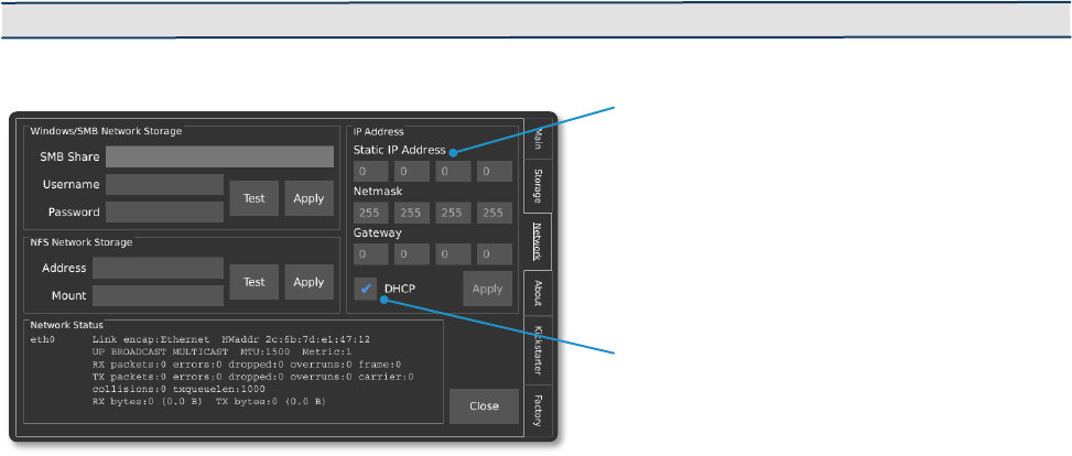
Static IP address configuration
area
DHCP Setting for dynamically
assigned IP Address
Network Interface
IMPORTANT: This networking feature is only available with the software versions 0.4.0 and above.
STATIC IP ADDRESS CONFIGURATION
The camera can be configured with a static IP address. To enter a static IP address, enter
the Util menu and then navigate the Network tab. A box in the upper-right corner of the
display offers fields for the IP, Netmask, and Gateway. To use a static IP address, the
DHCP checkbox must be cleared (disabled).
DYNAMIC IP ADDRESS CONFIGURATION VIA DHCP
The camera can automatically acquire an IP address via DHCP (enabled by default). To
enable DHCP, ensure that the DHCP checkbox is checked (enabled). The acquired IP
address will be shown in the Network Status area once it successfully connects.
ETHERNET OVER USB
The camera supports a virtual ethernet interface over the USB mini or USB micro
connector. In Windows, this is referred to as a Remote Network Driver Interface
Specification (RNDIS). If the camera is connected to the host computer using this method,
the IP address will be a fixed value of 192.168.12.1 .
SAVING TO NETWORK STORAGE
The camera supports the ability to save footage directly to a computer over the network
via SMB v1.0 and NFS network protocols. Credentials to an SMB or NFS share can be
entered by navigating to the Util menu, and then selecting the Network tab.

Page | 30
In order to use the Network Storage functionality, the SMB v1.0 or NFS share must first
be configured on the Host PC. Kron Technologies provides detailed step-by-step
instructions on how to configure a Host PC’s network share on the Chronos 1.4 and
Chronos 2.1-HD resource pages at https://www.krontech.ca.
NOTE: When testing a Network Storage connection on the Network tab in the Util screen, tap Apply
prior to using the Test button to test the configuration.

Page | 31
IP Address from camera
entered into the web browser
of PC on the same network
Web Control
ACCESSING THE CAMERA’S WEBPAGE
The Chronos can be controlled remotely via a webpage that is served by the camera itself.
There are two methods to connect to the camera:
1. Establish a connection to a network via the ethernet port. Then navigate to the
Network tab in the Util screen and find the IP address of the camera listed as
“inet.addr:” (see image below). The camera can either use DHCP to obtain an IP
address dynamically or be configured with a static IP address.
2. Connect the camera directly to a computer via the USB mini or USB micro
connector. When connected directly to a computer in this fashion, the camera will
simulate an ethernet connection using the USB RNDIS Gadget Driver on Windows
and will have the IP address 192.168.12.1.
To access the webpage, enter the IP address from either method 1 or 2 above into the
URL entry area of a browser. Kron Technologies recommends Chrome or Firefox as the
preferred browser for using the web control page.

Page | 32
Display of live sensor output
at 1 frame per second.
Web Application Programming
Interface (API) Documentation
Record Settings
Full Video Save
Shortcut
Dropdown menu for narrow
screens (ie. Smartphones)
NAVIGATING THE CAMERA’S WEBPAGE: MAIN
The Main page of the Chronos control webpage offers similar functionality to the back of
camera interface with an alternative layout of configuration and control settings that will
adapt to the size of a PC, smartphone, or tablet screen size.
The viewfinder window on this page updates at approximately 1 frame per second. For a
real-time view of the camera’s viewfinder over the network, please see instructions on
how to configure an RTSP network stream.

Page | 33
Download Files
Directly to PC
Frame Position Slider
NAVIGATING THE CAMERA’S WEBPAGE: PLAY & SAVE
Navigating to the Play & Save page of the Chronos control webpage offers similar
functionality to the Play screen on the back of camera interface. Additionally, the Storage
Device section of this page offers insight into the remaining storage space on connected
external storage devices.
The Download From Camera dropdown menu provides a list of image and video files on
the connected external storage device. After the desired footage is saved to the external
storage device, selecting a file in Download From Camera dropdown menu will download
the file to the PC.
IMPORTANT: You have to save the footage on the camera before you can download it!
NOTE: The video output on the camera’s LCD display, as well as any connected HDMI displays, will
be switched to the Playback mode if the Play & Save page is accessed from the web control interface.
It will be switched back to the live display of the image sensor’s output upon navigating to the Main
page.

Page | 34
Reset All Settings to Default
NAVIGATING THE CAMERA’S WEBPAGE: SETTINGS
Navigating to the Settings page of the Chronos control webpage allows for the
configuration of commonly used settings from the Util, White Balance, and Record
Settings -> Trigger Delay screens on the back of camera interface.
Additionally, this page allows for the configuration of the webpage’s behavior and
theming.

Page | 35
Real-time level indicator (HIGH/LOW)
Preset Triggering Configurations
NAVIGATING THE CAMERA’S WEBPAGE: I/O CONFIG - SIMPLE
The I/O Config screen is separated into two sections: Simple Configuration and
Advanced Configuration. Simple Configuration corresponds closely to the Trigger I/O
Settings screen on the back of camera interface, while Advanced Configuration allows
for full control over each input, action, and output of the camera’s I/O system.
For parameters that can be configured under the Simple Configuration section, it is
sufficient to follow guidelines as discussed in the Triggering section of this user manual.
Additionally, the Preset Configurations dropdown allows for fast and convenient
configuration of two common cases.
The BNC Trigger Button >> End
Recording preset will configure the
camera’s I/O system to end a recording
once the external trigger button is pushed
on I/O1 (BNC).

Page | 36
The BNC Trigger Button >> Toggle Recording preset will configure the camera’s I/O
system to start a recording on the first push of the external trigger button, and then stop
the recording on the subsequent push of the button.
NAVIGATING THE CAMERA’S WEBPAGE: I/O CONFIG - ADVANCED
Selecting a Preset Configuration will automatically change certain parameters under the
Advanced Configuration section of the webpage, which provides a good set of examples
for users who wish to use the advanced sections to configure the camera.
The Input Status and Output
Status boxes show the status of
each connection in real time. The
arrows will change to signify a
HIGH or LOW signal based on
how the Camera is configured
with parameters on the rest of
the I/O Config page. Note that
some of these indicators might
not update fast enough to display
very rapidly changing signals.
NOTE: If advanced configurations of the I/O settings for the camera result in unintended operation,
the settings can be reverted to defaults by selecting Reset All to Defaults from the Preset
Configurations dropdown list.

Page | 37
The Combinatorial Block section of the Advanced Configuration allows users to
connect the logic of multiple input sources together to produce an output that triggers a
recording. Changing parameters will change the arrows depicted in the logic gate legend
in real-time to reflect the most current configuration.
Under the Advanced Configuration individual preferences for behaviors titled in each
box below can be configured. Each box contains a descriptor, an option to select the
source responsible for the action, the ability to set a Debounce to mitigate against
mechanical contact bounce, and an Invert signal.

Page | 38
Annex A – Hardware
CAMERA’S BACK
POWER BUTTON
• Press to turn on the camera
• To shut down the camera, press the Power button for 1 second, then release.
A press lasting for less than 0.5 seconds will be ignored.
• Holding for 4 seconds forces a hard power down. Do this only if the software
has crashed and the camera is not responding. Like a PC, the camera needs
to shut down properly or file system damage may occur, requiring a re-flash of
the OS SD card.
RECORD BUTTON
• Starts or stops recording. The record button is not affected by trigger settings,
including trigger delay.
RECORD INDICATORS (2)
• Illuminate (red) to indicate that the camera is recording.
Record Button
Start or Stop Recording
Immediately
Power Status Indicator
Video Record Indicator
Power Button
Jog Wheel
Playback control
UI Navigation
User SD Card Slot
800x480 LCD Screen
With capacitive touchpad

Page | 39
POWER STATUS INDICATOR
• Indicates the presence of AC power and the charge status of the battery.
LED
Indication
Un-Lit
No AC Power Connected
Solid Yellow
Charging, less than 80% charged
Alternating
Green/Yellow
Charging, more than 80% charged
Green
Battery fully charged
JOG WHEEL
• Used for playback control, adjusting shutter, and UI navigation and input.
• On the Main screen, rotation adjusts the shutter.
• During playback, rotation moves playback 1 frame per detent (rotation click).
• Press and hold the dial clicked in to move fast (40 frames per detent)
• During UI navigation, rotation cycles through the widgets on the user interface,
and a click will activate the highlighted widget.
SD CARD SLOT
• Videos can be saved to the card in this slot.
• For fastest saving, a Class 10 or faster SD card is recommended, however,
any properly formatted SD card will work. (FAT32, EXT2 and EXT3 file systems
are supported)

Page | 40
CAMERA’S SIDE
HDMI
• When connected to a monitor via HDMI (requires software version 0.3.1 and
above), the camera will automatically output a video signal during live video
feed, recording, and playback, but not during saving. It will output a 1080p
signal over HDMI by default.
• If the monitor supports 720p, but not 1080p, then 720p will be used.
AUDIO IO
• Not supported in current software, but the hardware is present in all cameras.
• Please sign up for the Krontech newsletter here:
https://www.krontech.ca/chronos-newsletter/.
• You will receive emails about software updates, including those for audio
support.
USB/ESATA
• This port accepts both USB type A and eSATA devices. USB mass storage
devices such as flash drives and hard drives can be connected to this port.
• This port is also able to supply power using an eSATAp cable.
NOTE: Most 2.5” hard drives and SSDs will work with the Chronos, but most 3.5” drives
will not. This is because the eSATAp port only supplies 5v, not 12v.
Power Input
17V to 20V, 40W
2.5mm Barrel Connector
Positive Tip
Aux IO / Analog Input
Trig 2 and Trig 3 supported
IO 2 and IO 3 in Trigger Settings
0-6Volts Adjustable Threshold
30Volts - DC/AC - 50Vpk Max
Ethernet
1Gbits/100Mbits/10bits
Network Connectivity
API Camera Control
Webpage Camera Control
Micro USB
On-The-Go USB Port for Computer
Connectivity
Headphone Output Jack
Microphone Input Jack
USB / eSATAp
FAT32 and EXT2/3 Storage support
BNC
IO 1
0-6Volts Adjustable Threshold
30Volts - DC/AC - 50Vpk Max
HDMI
1080p & 720p Resolutions supported
Pin 1

Page | 41
BNC
• The BNC connector can be used to synchronize multiple cameras, or to
connect the camera to a variety of equipment, including trigger cables.
MICRO USB OTG
• Can be used to connect a camera directly to a computer, and to control it from
the computer using a USB-A to Micro-USB cable.
• A tutorial on setting up a camera for network control can be found here:
https://www.krontech.ca/tutorials/
NOTE: USB mass storage devices, such as flash drives and hard drives, will not work on this port.
ETHERNET
• Can be used to remotely control the camera using the Krontech API or by using
the webserver interface. See the Network Interface (Pg. 29) section of the
manual for more details.
AUX IO
• Trigger and Analog inputs.
• Only trigger inputs are supported in the current software.
• The mating plug is Phoenix Contact part number 1778890
Pin
Function
1
Analog In 1
2
Common
3
Analog In 2
4
Common
5
Trigger IO 2
6
Common
7
Isolate Trigger Input 3 (+)
8
Isolate Trigger Input 3 (-)
POWER INPUT
• 17-20V DC 40W, 5.5/2.5mm barrel jack, positive tip (center positive).
Pin 1
Pin 8

Page | 42
CAMERA’S BOTTOM
SYSTEM SD SLOT & CARD
• Bootable media for the camera that holds the camera’s operating system.
• During software upgrades, the camera writes new files to this card.
IMPORTANT: A Class 10 or faster SD card is recommended for the fastest video saving. However,
any properly formatted SD card will work. (FAT32, EXT2 and EXT3 file systems only.)
WARNING: Make sure the card is correctly oriented when inserting it into the System SD Card
Slot. The card is very difficult to retrieve if flipped or forced. Make sure you insert the micro SD
card with the pins oriented toward the front of the camera (as shows in image above)
MOUNT POINT
• Standard (1/4”-20) mount point to attach tripods or other equipment.
BACK-FOCUS LOCK SCREW
• Prevents the Back-Focus ring from moving. See Back-Focus Adjustment (see
page 44).
BATTERY COMPARTMENT
• To open, push latch up and pull out.
• Holds an EN-EL4a 11.1V 2500mAh or 3100mAh battery during normal
operation.
Back Focus Ring Tightening
Screw
Battery Compartment Door
Slide Latch and pull to open
Camera Firmware Micro SD Card Slot
Mount Point
Insertion Side

Page | 43
Annex B - Lenses
LENS MOUNT & ADAPTER
The Chronos 1.4 & 2.1-HD are CS mount cameras. C mount lenses can be used with the
included adapter. Other lens types such as F, EF, and PL can be used with appropriate
adapters to convert them to C mount. Common lenses available for the camera are listed
below, along with the adapters required to use them.
Lens Model
Lens Mount
Adapter Required
COMPUTAR 12.5-75mm f/1.2 Zoom**
C
CS - C
COMPUTAR 12mm f/1.4 Prime**
C
CS - C
6-60mm f/1.7 Zoom***
CS
None
2.8-12mm f/1.4 Zoom***
CS
None
COMPUTAR 8mm f/1.4 Prime**
C
CS - C
FUJIAN 35mm f/1.7
C
CS - C
Microscope Lens**
C
CS - C
SIGMA 24-70mm f/2.8
F
F - C
IMPORTANT: * Lens vignettes with the Chronos 1.4
** Lens vignettes with the Chronos 2.1-HD
COMPUTAR
12.5-75mm f/1.2 Zoom
COMPUTAR
12mm f/1.4 Prime
2.8-12mm f/1.4 Zoom
COMPUTAR
8mm f/1.4 Prime
FUJIAN
35mm f/1.7
6-60mm f/1.7 Zoom
SIGMA
24-70mm f/2.8
Microscope Lens

Page | 44
LENS SELECTION
Lenses vary in their image circle, which is the amount of the image sensor they can cover:
• The Chronos 1.4 uses a 2/3" image sensor (actual sensor dimensions are 8.45mm x 6.76mm).
• The Chronos 2.1-HD uses 4/3” image sensor (actual sensor dimensions are 19.2mm x 10.8mm).
Lenses designed for smaller sensors can be used, however the image will not cover the
entire sensor. This results in ‘Vignetting’, which is a black ring around the border of the
video.
While choosing the right lenses for your application, remember that the Chronos 1.4
sensor has a crop factor of 3.9X and the Chronos 2.1-HD a crop factor of 2X.
NOTE: Sample images for each lens offering by Kron Technologies may be found at
https://www.krontech.ca/store/Lenses-c21981409
IMPORTANT: The auto control mode certain lenses offer isn’t directly usable on the Chronos
camera. All lenses will need to be set to Manual mode or be provided an external source of power
and synchronization.
BACK-FOCUS ADJUSTMENT
• Back-Focus is the distance between the lens mounting flange and the image
sensor. It controls how lenses focus and must be set correctly.
• The camera is set from the factory for a COMPUTAR 12.5-75mm zoom lens. This
setting is correct for most other lenses, but if you are experiencing problems with
focus, this is the first thing to check.
To correctly set Back-Focus for your lens, follow these steps:
PRIME LENSES (NON-ZOOM)
1. Use a lens that has graduated focus (markings showing the focal distance). You
cannot properly adjust Back-Focus on non-graduated-focus lenses.
2. Set the lens to focus at infinity.
3. Loosen the Back-Focus lock screw on the bottom of the camera by about 1 turn
using the included 2mm Allen key.
4. Aim the camera at an object very far away, such as a distant tree.
5. Rotate the entire lens, allowing the CS ring to screw in or out. Adjust the rotation
until best focus is obtained on the distant object.
a. Do not adjust the focus ring on the lens.
b. If the CS ring will not rotate far enough, check to see if your lens requires a
CS-C adapter. Please refer to Pg. 43 for additional details.
6. Tighten the Back-Focus lock screw, finger-tight.
Page | 45
ZOOM LENSES (PARFOCAL LENSES ONLY)
A parfocal lens is a lens that stays in focus when magnification/focal length is changed.
1. Zoom the lens into maximum zoom.
2. Adjust for best focus on an object within the normal focus range, perhaps a few
meters away.
3. Zoom the lens all the way out.
4. Loosen the Back-Focus lock screw on the bottom of the camera by about 1 turn
using the included 2mm Allen key.
5. Rotate the entire lens allowing the CS ring to screw in or out. Adjust the rotation
until best focus is obtained on the same object.
• Do not adjust the focus ring on the lens.
• If the CS ring will not rotate far enough, check to see if your lens requires a
CS-C adapter. Please refer to Pg. 43 for additional details.
6. Tighten the Back-Focus lock screw, finger-tight.
7. Repeat steps 1 to 6 until the lens is in focus when zoomed in and when zoomed
out, without adjusting the focus control while zooming.

Page | 46
Annex C – IR Filter
IR FILTER
An IR Filter (Infrared Cut-Off Filter) is standard on all cameras. This filter will cut-off
wavelengths above 650nm.
The Color Chronos 1.4 benefits from the IR Filter because of improved color reproduction.
All color pixels (red, green, and blue) have some parasitic sensitivity to IR light, which
results in washed-out images, especially in daylight or under incandescent lamps. The IR
Filter removes this invisible light.
The Monochrome Chronos 1.4 benefits from the IR filter when recording objects that emit
large amounts of IR light, such as glowing objects or sparks. The IR light will focus
differently than visible light in most lenses, resulting in blur. The IR Filter removes this
light, less total light hits the image sensor, and sensitivity is reduced. The result is sharper
images.
REMOVING THE IR FILTER
• You can remove the IR Filter for cleaning, or for applications that require IR
sensitivity.
• You can also add your own filter, of any desired wavelength.
• The camera accepts 24x16mm rectangular filters, of 1.1mm thickness.
WARNING: When handling, it is important that you do not scratch the filter. Use the necessary tools
and cleaning products to avoid damage.
To remove the filter, follow the steps below, or see the tutorial at:
https://www.krontech.ca/wp-content/uploads/2020/01/IR-Filter-.pdf
1. Loosen the Back-Focus adjustment screw on the bottom of the camera about 1 turn using the
included 2mm Allen key.
2. Unscrew the CS ring from the camera.
3. Using a 1.5mm Allen key (not included), remove the two screws that hold in the IR Filter case.
4. Using tweezers, remove the IR Filter case.
5. Remove the IR Filter. To avoid damaging it, a vacuum pick-up tool is best, but tweezers can be
used, if you are careful. It is important to remember which side of the filter faces out of the
6. camera, as the filter has an optimum direction for light travel.
7. Store the IR filter where it will not be scratched, such as in a paper envelope.
8. Reinstall the filter case using the two screws.
9. Reinstall the CS ring.
10. Tighten the Back-Focus adjustment screw, finger-tight. Be careful not to over-tighten it.
11. Perform a Back-Focus adjustment. Reinstalling the CS ring to its original position will not work, as
12. the Back-Focus is changed by refraction in the IR Filter glass.

Page | 47
Annex D – Trigger
Inputs/Outputs
TRIGGER INPUTS/OUTPUTS
The Chronos 1.4 & Chronos 2.1-HD have two trigger input/outputs, and one isolated
trigger input. Trigger IO is used by the camera to send/receive signals to/from other
equipment such as external triggers, lights, or other cameras. For example, if you have
several cameras set up, you can use a trigger to start or stop all of them at once.
TRIGGER IO 1 AND 2
• These non-isolated triggers are referenced to the camera's power and chassis
ground and can provide either input functionality with adjustable threshold (0-
6.6V), or 5V TTL level output.
• They are protected against damage when connected to voltages of 30V DC/AC
RMS and +/- 50V peak, but voltages outside this range may cause damage.
• The 20mA output is suitable to directly drive terminated coaxial cable, and will
produce 1V into 50Ω, with rise and fall times of (typically) 10ns or faster.
Unterminated operation will result in a much slower fall time.

Page | 48
TRIGGER IN 3
• This input is isolated via an optocoupler.
• A logic low input is a voltage from -30 to 1V, and a high-level input is a voltage
of 3 to 30V.
• Voltages between these ranges (1 to 3V) are undefined.
• This input has built-in resistors to correctly drive the optocoupler and is
protected from differential voltages up to 30V DC/RMS AC and +/- 50V peak.
• Trigger In 3 is rated for SELV (Safety Extra Low Voltage) circuits only, up to a
maximum common mode voltage of 60V above ground. Voltages beyond this
range may damage the camera.
DANGER: The isolated input is not rated for safety isolation. Never use any of these inputs to
connect directly to mains-reference circuits. If triggering from AC mains is needed, external safety
isolation (such as a transformer) is required.

Page | 49
Annex E – Troubleshooting
Symptom
Possible Problem
Solution
Camera won’t power on
No Power
Insert battery or connect to mains power
Crash
Remove battery and AC adapter for 10 seconds, then
reconnect and power on.
Wrong AC Adapter
Voltage
Ensure that the AC Adapter is providing between 17V
and 20V DC, positive tip.
Camera won’t power on, and
Power Status indicator
flashes orange when power
button is pressed
Shipping Mode is
enabled
The AC adapter must be plugged in to turn the
camera on while in Shipping Mode, even if a battery is
inserted. It will not be required for subsequent power-
ons.
Battery won’t charge
Battery inserted after AC
connected
Unplug AC adapter from camera, then re-plug.
Wrong AC Adapter
voltage
Ensure that the AC Adapter is providing between 17V
and 20V DC, positive tip.
Battery indicator drops very
fast
low quality or failing
battery
Replace battery.
Power status indicator
flashes red/green
continuously
Power controller in
recovery mode
Turn the camera off, remove the battery and
disconnect the AC adapter for 10 seconds. When
reconnecting power or inserting battery, ensure the
power button is not pressed until after the LED
flashing stops.
Power controller
firmware corrupt
If the above solution doesn’t fix the problem, contact
Kron Technologies at [email protected]
Can’t trigger recording end.
IO screen has extra
pullup on
Confirm that the only pullup enabled is the one for the
trigger that is in use.
Trigger Delay is set to a
long time
On the camera, navigate to Trigger/IO Settings ->
Trigger Delay, press “Reset To Defaults”, and press
“OK”. You can also access this screen from Record
Settings -> Trigger Delay
Horizontal or vertical lines
show up in video.
A Black Calibration was
not done after changing
shutter speed, resolution
or gain
Perform a Black Calibration after every change of
resolution, shutter speed or gain. Please see the
Black Calibration section for more details on how to
calibrate the camera.
Extremely blurry image,
can’t get close to proper
focus.
Incorrect lens adapter
installed.
Check if lens is CS or C mount to determine proper
adapter to use. Please see the “Annex B” for more
details.
Focus slightly wrong, proper
focus out of range.
Back-Focus mis-adjusted
Re-adjust Back-Focus. Please see the “Annex B” for
more details.

Page | 50
Lens limitation
The Computar 12.5-75mm lens, among others, is
slightly soft at fully wide aperture. Close aperture
slightly and retry. Try f/2 or smaller.
Lens doesn’t maintain
consistent focus while
zooming.
Back-Focus mis-adjusted
Re-adjust Back-Focus. Please see the “Annex B” for
more details.
Lens is not parfocal
Some lenses, especially lower-end lenses such as the
6-60mm and 2.8-12mm lenses, do not maintain focus
during zoom, so focus needs to be adjusted after
zooming.
Black ring around
image/Corners of image are
dark. (Vignetting)
Lens is too small for the
sensor
Some lenses, especially lower-end lenses such as the
6-60mm and 2.8-12mm lenses don’t cover the image
sensor. Change to a different lens with a larger image
circle.
Negative ghost image visible
over normal image
Black Calibration was
done without lens cap on,
or with aperture open
Perform Black Calibration again by closing the
aperture fully or covering the lens. Please see the
Black Calibration section for more details on how to
calibrate the camera.
Camera shows a black or
still image
Trigger mode is either
‘Exposure Trigger’ or
‘Shutter Gating’, but
there is no external signal
being received
If you do not wish to use either of these modes, go to
Trigger/IO Settings and switch back to Record End
Trigger for normal operation
If you do wish to use one of these modes, check that
you have the correct input selected, or connect a
signal generator and send a signal of frequency equal
to the desired frame rate.
Dark band when there is a
bright object shown on the
image
Extreme exposure
Reduce exposure, or move the bright object out of
frame.

Page | 51
Annex F – Specifications
CHRONOS 1.4
Camera
Imaging
1280x1024 1069FPS
Memory
8GB, 16GB, or 32GB
Record Time
4 seconds (8GB), 8 seconds (16GB), 16 seconds
(32GB)
Lens Mount
CS/C (CS mount, C mount with included adapter)
Back-Focus
Field adjustable
IR Filter
650nm, user removable, 24mm x 16mm x 1.1mm
Display
5” 800x480 capacitive touchscreen, 1000 nit
daylight visible
Enclosure
Anodized CNC machined aluminum
Cooling
Active cooling, variable-speed fan (fan-off option
supported)
Dimensions
155mm x 96mm x 67.3mm
(6.11” x 3.78” x 2.65”) without lens
Weight
1.06Kg (2.34lbs) without lens
Video Formats
H.264
Industry standard mp4 (MPEG-4) files at bitrates
up to 60Mbps
CinemaDNG Raw
Standard Adobe CinemaDNG raw files
Tiff
Standard TIFF raw files with timestamps
Storage Devices
SD, USB, SSD, or SMB/NFS network drives
Image Sensor
Resolution
1280x1024 @ 1069FPS
Speed
1.4Gpx/s - full throughput down to 320-pixel
image width.
Dimensions
8.45mm x 6.76mm (2/3” format, 1.3Megapixel,
3.9x Crop Factor)
Pixel Pitch
6.6um

Page | 52
Image Sensor
Sensitivity (ISO)
Color: ISO 320 to 5120
(Continued)
Mono: ISO 740 to 11840
Shutter
Electronic global shutter,
1/fps to 1us (1/1,000,000s)
Dynamic Range
56.7 dB
Bit Depth
12-bit
Battery
Type
EN-EL4a
Max. Run Time
1.5 hours recording (typical)
Charge Time
2 hours (0-80%) with in-camera charger
IO
Power Input
17-20V 40W (5.5/2.5mm barrel jack, positive tip)
Network
Gigabit Ethernet
Trigger
Two Trigger inputs/frame strobe outputs
(BNC & Aux)
Adjustable Input Threshold 0 to 6.6Volts
Electrically isolated trigger input (Aux
Connector)
Trigger with sound, laser, and lighting using
accessories
Audio
Microphone/Line input using continuous live
mode @60fps
Video
HDMI output 720p or 1080p (default) @ 60FPS,
video only
USB
USB type A (host) and micro-B (device)
SATA
eSATA 3Gbps to SATA 2.5” III SSD (5V power)
Trigger Modes
End Trigger
Camera records until a defined delay after
trigger
Toggle
Camera starts recording with one button press,
and stops recording with a subsequent button
press
Exposure Trigger
External signal sets the frame rate for
synchronization
Shutter Gating
External signal sets the frame rate and controls
the exposure for synchronization

Page | 53
Frame Sync Output
The camera outputs a signal indicating its frame
rate and exposure
Trigger Ports
BNC
Female BNC connector
Phoenix
Pluggable black phoenix terminal block (8-pins)
Network Control
Through web page or REST API based interface
with USB or CAT ethernet cable
Recording Modes
Normal
Records into the ring buffer. Once a trigger
occurs, video can be reviewed and saved.
Segmented
Video memory is divided into segments, each
recording as in the Normal mode above. Number
of segments is user selectable.
Gated Burst
Frames are captured while trigger is active
Live Slow Motion
Continuously records a short slow-motion video
and immediately plays it back then repeats
Normal Speed
Recording
Continuous
Video is saved continuously at up to 60FPS to
mp4 (MPEG-4) files on removable storage.
Operates like a normal video camera.
Assistive
Focus Aid
Highlights sharp edges to aid focusing
Zebras
Rolling diagonal lines indicate clipped
(overexposed) areas
Viewfinder Zoom
Zooms in to allow easier focusing
Overlay
Displays frame and time information on top of
footage
Environmental
Operating
Temperature
-20°C to +40°C (-4°F to +104°F)

Page | 54
CHRONOS 2.1-HD
Camera
Imaging
1920x1080 1000FPS
Memory
8GB, 16GB, or 32GB
Record Time
2.7 seconds (8GB), 5.5 seconds (16GB), 11
seconds (32GB)
Lens Mount
CS/C mount (provided). Nikon F-C and Canon
EF-C adapters (optional accessories)
Back-Focus
Field adjustable
IR Filter
650nm, user removable, 24mm x 16mm x 1.1mm
Display
5” 800x480 Capacitive touchscreen, 1000nit
daylight visible
Enclosure
Anodized CNC machined aluminum
Cooling
Active cooling, variable-speed fan (fan-off option
supported)
Dimensions
155mm x 96mm x 67.3mm
(6.11” x 3.78” x 2.65”) without lens
Weight
1.06kg (2.34lbs) without lens
Video Formats
H.264
Industry standard mp4 (MPEG-4) files at bitrates
up to 60Mbps
CinemaDNG Raw
Standard Adobe CinemaDNG raw files
Tiff
Standard Tiff raw files with timestamps
Storage Devices
SD, USB, SSD, or SMB/NFS network drives
Image Sensor
Resolution
1920x1080 @ 1000FPS
Speed
2.1Gpx/s
Dimensions
19.2mm x 10.8mm (4/3” format, 2.1 Megapixel,
2x Crop Factor)
Pixel Pitch
10um
Sensitivity (ISO)
Color: ISO 500 to 8000
Mono: ISO 1000 to 16000

Page | 55
Image Sensor
(Continued)
Shutter
Electronic global shutter,
1/fps to 10us (1/100 000s)
Dynamic Range
10.3 stops (62.4 dB)
Bit Depth
12-bit
Battery
Type
EN-EL4a
Max. Run Time
1 hour recording (typical)
Charge Time
2 hours (0-80%) with in-camera charger
IO
Power Input
17-20V 40W (5.5/2.5mm barrel jack, positive tip)
Network
Gigabit Ethernet
Trigger
Two Trigger inputs/frame strobe outputs
(BNC & Aux)
Adjustable Input Threshold 0 to 6.6V
Electrically isolated trigger input (Aux
Connector)
Trigger with sound, laser, and lighting using
accessories
Audio
Microphone/Line input using continuous live
mode @60FPS
Video
HDMI output 720p or 1080p (default) @60FPS,
video only
USB
USB type A (host) and micro-B (device)
SATA
eSATA 3Gbps to SATA 2.5” III SSD (5V power)
Trigger Modes
End Trigger
Camera records until a defined delay after
trigger
Toggle
Camera starts recording with one button press,
and stops recording with a subsequent button
press
Exposure Trigger
External signal sets the frame rate for
synchronization
Shutter Gating
External signal sets the frame rate and controls
the exposure for synchronization
Frame Sync
Output
The camera outputs a signal indicating its frame
rate and exposure

Page | 56
Trigger Ports
BNC
Female BNC connector
Phoenix
Pluggable black phoenix terminal block (8-pins)
Network Control
Through web page or REST API based interface
with USB or CAT ethernet cable
Record Modes
Normal
Records into the ring buffer. Once a trigger
occurs, video can be reviewed and saved.
Segmented
Video memory is divided into segments, each
recording as in the Normal mode above. Number
of segments is user selectable.
Gated Burst
Frames are captured while trigger is active
Live Slow Motion
Continuously records a short slow-motion video
and immediately plays it back then repeats
Normal Speed
Recording
Continuous
Video is saved continuously at up to 60FPS to
mp4 (MPEG-4) files on removable storage.
Operates like a normal video camera.
Assistive
Focus Aid
Highlights sharp edges to aid focusing
Zebras
Rolling diagonal lines indicate clipped
(overexposed) areas.
Viewfinder Zoom
Zooms in to allow easier focusing
Overlay
Display frame and time information on top of
footage
Environmental
Operating
Temperature
-20°C to +40°C (-4°F to +104°F)
Page | 57
Annex G – Maintenance & Care
OPTICS
• Keep the optical area clean when changing lenses by keeping the body and lens
mount caps on when the lens is separated from the camera.
• If the lens or sensor/IR filter is dusty, remove the dust using clean, dry compressed
air, dusting gas, or a dusting squeeze bulb. If dust persists, use a brush or lens pen.
• If there is dust under the IR filter, you can remove the filter for cleaning. See
Removing the IR Filter in Annex C.
CAMERA BODY
• Do not expose the camera to moisture or excessively dusty environments.
• Do not expose the camera to molten metal.
• The camera body can be cleaned with a lint-free cloth, and optionally a small
amount of rubbing alcohol. Do not use excessive liquids as they may enter the
camera body.
SCREEN
• The touchscreen surface is breakable glass. Do not strike it with hard objects or
put excessive pressure on it.
• The screen should be cleaned with a lint-free or microfiber cloth.
• A small amount of glass cleaner or rubbing alcohol may be applied to the cloth if
required. Do not use excessive amounts, and don't spray glass cleaner directly on
the camera.

Page | 58
Annex H – Record Rates &
Times
RECORD PRESET VS RECORD DURATION
Maximum recording time for a sample of common resolutions at max FPS.
CHRONOS 1.4
Resolution
Max FPS
Record Time (Sec)
(8 GB)
Record Time (Sec)
(16 GB)
Record Time (Sec)
(32 GB)
1280 x 1024
1069
4.08
8.16
16.33
1280 x 720
1519
4.08
8.17
16.35
1024 x 768
1770
4.11
8.22
16.45
1024 x 576
2357
4.11
8.23
16.47
800 x 600
2871
4.14
8.29
16.59
800 x 480
3586
4.14
8.29
16.58
640 x 480
4434
4.20
8.40
16.81
640 x 240
8810
4.21
8.42
16.85
320 x 240
16682
4.40
8.82
17.64
320 x 180
22086
4.41
8.82
17.66
320 x 96
40413
4.51
9.02
18.04
• Record duration stays relatively constant as the resolution is lowered because
the maximum frame rate is raised.
• There is some overhead associated with each frame, so the increase in FPS is
not quite linear.

Page | 59
CHRONOS 2.1-HD
Resolution
Max FPS
Record Time (Sec)
(8 GB)
Record Time (Sec)
(16 GB)
Record Time (Sec)
(32 GB)
1920 x 1080
1000
2.76
5.51
11.02
1920 x 720
1495
2.77
5.53
11.06
1920 x 512
2095
2.78
5.55
11.11
1920 x 360
2963
2.79
5.58
11.16
1920 x 240
4403
2.80
5.60
11.21
1920 x 120
8569
2.89
5.78
11.56
1920 x 96
10569
2.94
5.87
11.74
1440 x 1280
1434
2.56
5.12
10.25
1440 x 720
2142
2.57
5.14
10.29
1440 x 512
2997
2.59
5.18
10.36
1440 x 240
6265
2.63
5.26
10.53
1440 x 96
14825
2.77
5.54
11.08
1280 x 1024
1434
2.88
5.77
11.53
1280 x 720
2142
2.90
5.79
11.59
1280 x 512
2996
2.91
5.82
11.65
1280 x 360
4230
2.93
5.86
11.72
1280 x 240
6265
2.97
5.94
11.89
1280 x 120
12075
3.07
6.14
12.28
1280 x 96
14825
3.14
6.28
12.56
1024 x 768
2531
2.88
5.75
11.50
1024 x 576
3358
2.89
5.77
11.55
800 x 600
4352
2.73
5.47
10.94
800 x 480
5406
2.73
5.47
10.94
640 x 480
5406
3.44
6.88
13.76
640 x 360
7135
3.48
6.95
13.90
640 x 240
10488
3.54
7.07
14.14
640 x 120
19783
3.72
7.43
14.86
640 x 96
24046
3.87
7.74
15.49

Page | 60
RECORD FPS VS RECORD DURATION
Recording time for a set of resolutions at max FPS, half FPS and one-quarter
FPS.
CHRONOS 1.4
Resolution
Max FPS
Record Time (Sec)
(8 GB)
Record Time (Sec)
(16 GB)
Record Time (Sec)
(32 GB)
1280 x 1024
1069
4.08
8.16
16.33
1280 x 1024
534
8.16
16.33
32.67
1280 x 1024
267
16.31
32.65
65.33
800 x 600
2871
4.14
8.29
16.59
800 x 600
1435
8.29
16.58
33.18
800 x 600
717
16.57
33.17
66.36
640 x 480
4434
4.20
8.40
16.81
640 x 480
2217
8.39
16.80
33.62
640 x 480
1108
16.79
33.60
67.23
• The duration that can be recorded is doubled every time the frame rate is
halved.
• The recording time increase is linear as the frame rate decreases.

Page | 61
RECORD RESOLUTION VS RECORD DURATION
Recording time for a sample of frame rates as resolution decreased.
CHRONOS 1.4
Resolution
Max FPS
Record Time (Sec)
(8 GB)
Record Time (Sec)
(16 GB)
Record Time (Sec)
(32 GB)
1280 x 1024
1069
4.08
8.16
16.33
640 x 480
1069
16.31
32.65
65.33
320 x 256
1069
65.26
130.62
261.33
800 x 600
2871
4.14
8.29
16.59
400 x 300
2871
16.57
33.17
66.36
192 x 150
2871
66.29
132.67
265.44
640 x 480
4434
4.20
8.40
16.81
320 x 240
4434
16.57
33.16
66.35
• As the resolution is halved in both height and width, the duration of the recording
increases by multiples of 4.
• Halving the resolution results in ¼ the number of pixels, so 4 times the number of
frames can be stored – 800 × 600 = 480k pixels, while 400 × 300 = 120k pixels.
Page | 62
Annex I – Storage & Shipping
• Store the camera in a cool, dry, clean location.
• When shipping the camera, it's recommended to put it in a plastic bag with
desiccant to avoid problems with condensation during temperature changes.
• If the camera will be stored for more than a few weeks, charge or discharge the
battery to a 40% charge (approximately), then turn off the camera and remove
the battery. This will minimize battery capacity degradation during storage.
• Before shipping, always enable Shipping Mode, found on the Util menu, under
the Factory Tab, to avoid the possibility of the camera turning on in-transit. This
mode requires the AC adapter to be connected the next time the camera is
turned on.

Page | 63
Annex J – Mechanical Drawing
CHRONOS 1.4 / CHRONOS 2.1-HD
NOTE: The Chronos 1.4 and 2.1-HD have identical enclosure dimensions.

Page | 64
Annex K – Spectral Response
CHRONOS 1.4
NOTE: These spectral response curves are in units of quantum efficiency.

Page | 65
CHRONOS 2.1-HD
NOTE: These spectral response curves are in units of quantum efficiency.

Page | 66
Annex L – Software Functions
This Annex discusses each screen shown on the camera in detail. While the User Interface
on the Chronos is designed to be intuitive and to follow common operating modes found
in many other cameras, this section provides concise descriptions on the action
performed by each button shown on various screens.
MAIN WINDOW
Control
Function
Record
Settings
Shows the Record Settings window, which allows adjustment of resolution,
frame rate, analog gain (ISO), digital gain, exposure, record modes, and trigger
delay.
Trigger I/O
Settings
Shows the Trigger Settings window, which allows for the selection of trigger and
synchronization input/output (I/O) signals.
Black Cal
Performs a Black Calibration. This increases image quality by removing noise
and sensor artifacts due to fluctuations in temperature. Each resolution and gain
must be Black Calibrated separately prior to use. The image sensor should not
be exposed to light during a calibration.

Page | 67
MAIN WINDOW [CONTINUED]
Control
Function
White Bal
(Color
Cameras)
Shows the White Balance dialog box, which allows setting the color temperature
of the recorded footage.
Focus Aid
Enables or disables focus peaking, which highlights sharp edges in a
conspicuous color. This can be used when adjusting focus is challenging. The
color and sensitivity are adjustable from the Util menu.
Record/Stop
Starts and stops recording. Performs the same function as the physical record
button on the top of the camera.
Util
Shows the utility menu, which contains various functions such as storage
management, network connection information, power management, display
behavior, and software updates.
Shutter
Drag and slide to adjust the image sensor’s exposure level. Rotating the jog
wheel will also adjust this slider. Pressing the jog wheel in while rotating will
cause the shutter to adjust at finer intervals.
The exposure readout in the bottom right corner of the display will change
accordingly. Units can be changed between temporal, angular, or fractional in
the Util menu.
Viewfinder
Zoom Mode
Double tap the video output region on the display to zoom by a factor of 2.5x.
This can be used as a focusing aid. Double tap the zoomed view again to return
to the normal video display mode.

Page | 68
RECORD SETTINGS
The Record Settings screen allows for the adjustment of the size and position of the
recorded area on the image sensor and the frame rate at which the recording is taken.
Lower resolutions can be captured at higher frame rates and/or longer record times.
Control
Function
Resolution
(width, height)
Sets the recorded video size.
Chronos 1.4: Adjustable in multiples of 16 pixels horizontally, 2 pixels vertically.
Chronos 2.1-HD: Adjustable in multiples of 32 pixels horizontally, 2 pixels
vertically.
Offset
(horizontal,
vertical)
Adjusts the position of the recorded video relative to the top left corner of the
image sensor, in multiples of 16 pixels horizontally for the Chronos 1.4, 32 pixels
horizontally for the Chronos 2.1-HD, and 2 pixels vertically.
When the Center box is checked, the offset is set automatically and cannot be
adjusted.

Page | 69
RECORD SETTINGS [CONTINUED]
Control
Function
Center
Affects the position of the image when using a resolution below maximum
resolution. When checked, the offset is calculated automatically to center the
image on the sensor.
Frame Rate
Sets the frame rate. Can be set as framerate (FPS) or period (Sec) which is
equivalent to 1/framerate. Setting one will automatically update the other.
Can be set to the maximum for the resolution by pressing Max.
To increase the record time and maximum exposure time, manually enter a
frame rate lower than the maximum.
Exposure
Sets the exposure (shutter speed) in microseconds. Range is 1μs to slightly less
than 1/framerate. Can be set to the maximum for the current frame period by
pressing Max.
Analog Gain
Adjusts the ISO setting. A higher gain results in increased sensitivity (less
lighting required), but increased image noise.
For the best image quality, use the lowest possible gain, and increase light level
or lens aperture if more light is required.
Gain
Chronos 1.4
Chronos 2.1-HD
Color ISO
Mono ISO
Color ISO
Mono ISO
0 dB (x1)
320
740
500
1000
6 dB (x2)
640
1480
1000
2000
12 dB (x4)
1280
2960
2000
4000
18 dB (x8)
2560
5920
4000
8000
24 dB (x16)
5120
11840
5000
10000

Page | 70
RECORD SETTINGS [CONTINUED]
Control
Function
Digital Gain
Increases the brightness in the scene by automatically modifying White Balance
and Color Matrix settings. As starting points, this function uses CIECAM16/D55
and a color temperature of 3200K (Tungsten). A setting of None will not modify
existing settings.
Common
Resolutions
Select a pre-set from common picture sizes and frame rates.
The frame rate will automatically be set to the maximum for the selected pre-set.
Recorded Area
Display
Shows the size and position of the recorded area in relation to the sensor’s full
resolution. The outer box represents the sensor’s maximum resolution, and the
inner box represents the area on the image sensor that will be recorded, given
the currently selected resolution and offset.
Max Rate
Display
Shows the maximum frame rate and minimum period for the current resolution
setting.
Trigger Delay
Button
Opens a screen to configure the amount of record time before and after a
triggered event. Trigger delay only applies to external triggers through the BNC
connector or the Auxiliary I/O connector on the side of the camera, but it does
not apply to the red record button on top of the camera.
Record Mode
Button
Opens a screen to switch between Normal, Segmented, Gated Burst, and Live
Slow-Motion modes.
OK Button
Applies changes and closes window.
Cancel Button
Discards changes and closes window.

Page | 71
RECORD MODE – NORMAL
Control
Function
Record Length
(Seconds)
Set the duration of the triggered recording, in seconds. The timing of this
recording can be changed in the Trigger Delay window.
Record Length
(frames)
Set the duration of the triggered recording, in recorded frames. The timing of
this recording can be changed in the Trigger Delay window.
Max Button
Sets record length to the maximum available. This is dependent on your
camera’s memory capacity and the resolution settings, which can be changed in
Record Settings.
OK Button
Applies changes and closes window. OK must also be selected in the Record
Settings window after the Record Mode window has closed, otherwise the
changes will be discarded.
Cancel Button
Discards changes to the Record Mode.

Page | 72
RECORD MODE - SEGMENTED
In Segmented mode, the record buffer is split into multiple video segments which are kept
in memory. This is different from Normal mode, in which only one continuous video clip
can be kept in memory.
In Segmented mode, when the recording is started, and with each activation of the trigger
(physical trigger switch or input signal only), a new segment is stored in memory. The
segments of video are concatenated during playback and saving. If the desired save
format is either H.264 or TIFF, the Text Overlay feature can be enabled in Playback
Settings to label the frames with which segment they belong to.
Segmented Memory Timing Chart
By default, the Ring Buffer is enabled. In this mode, the earliest segment will be
overwritten with a new one as soon as the record buffer is full. New segments will be
created until the recording is stopped via the red record button on the top or the camera,
or the stop button on the Main screen. This behavior can be changed by checking the

Page | 73
Disable Ring Buffer option. When the Ring Buffer is disabled, the camera will stop
recording when the buffer is full, and segments will not be overwritten.
Control
Function
Record Length
(Seconds)
Set the duration of the total recorded segments, in seconds. The timing of this
recording can be changed in the Trigger Delay window.
Record Length
(frames)
Set the duration of the total recorded segments, in frames. The timing of this
recording can be changed in the Trigger Delay window.
Max Button
Sets record length to the maximum available for your camera model and the
selected number of segments.
Number of
Segments
The maximum number of full-size segments that can be held in memory is
65,536.
Each time a recording is triggered, it is saved into a subsequent region of
memory. If a recording is stopped early, the unused recording time is returned
for future segments to use. For example, two 0.5-second segments can be
recorded instead of one 1-second segment.
Disable Ring
Buffer
When the buffer is full of segments, stop recording instead of overwriting the
oldest segment with new frames. This feature works while triggering with an
input signal or using a BNC trigger switch cable.
OK Button
Applies changes and closes window. OK must also be selected in the Record
Settings window after the Record Mode window has closed, otherwise the
changes will be discarded.
Cancel Button
Discards changes to the Record Mode.
NOTE: In Segmented Mode, new recordings can only be started using either the record button
on top of the camera, or the Record button on the main screen. New segments are only started
when a trigger signal configured as a Record End Trigger is active.

Page | 74
RECORD MODE – GATED BURST
In Gated Burst mode, multiple videos are kept in memory. New video is recorded only
while the trigger input is active. Record mode only affects which frames are stored in
memory; it does not affect exposure time.
Gated Burst Memory Timing Chart
As frames are recorded, they are stored in the Ring Buffer. The oldest frames are
overwritten with new frames as the trigger continues to be active. Recorded frames are
concatenated during playback and saving.

Page | 75
RECORD MODE – GATED BURST [CONTINUED]
Control
Function
Prerecord
(seconds)
Sets the amount of video to save before the trigger becomes active, in seconds.
Prerecord
(frames)
Sets the amount of video to save before the trigger becomes active, in recorded
frames.
OK Button
Applies changes and closes window. OK must also be selected in the Record
Settings window after the Record Mode window has closed, otherwise the
changes will be discarded.
Cancel Button
Discards changes to the Record Mode.

Page | 76
RECORD MODE – LIVE SLOW MOTION
In Live Slow Motion mode, a short segment of video is recorded, and then played back in
a loop. The interface allows you to set the desired loop time, and the choice of playback
rate can be either 15, 30, or 60 FPS. The length of the recorded segment is calculated
based on the loop length and the recording frame rate; it is displayed on the screen.
Control
Function
Playback Loop
Time (seconds)
Sets the desired playback length of the loop, in seconds.
Recording
Time
Displays the recording time, calculated from the loop length and the frame rate
setting, in milliseconds.
Recording
Frames
Displays the number of frames to be recorded, calculated from the loop length
and the frame rate setting, in frames.
Slowdown
Factor
Displays the factor by which the loop playback will be slowed down, using the
current settings, as a ratio.

Page | 77
RECORD MODE – LIVE SLOW MOTION [CONTINUED]
Control
Function
Playback Rate
(FPS)
Set the desired playback frame rate. This setting affects the recording time,
recording frames, and slowdown factory, even when the recording frame rate is
not changed. The options are 15, 30, and 60 frames per second.
Continuous
When this Loop Record Mode is selected, a short segment is recorded and
played back immediately for the duration specified. This method of capture and
playback is repeated continuously.
One Shot
When this Loop Record Mode is selected, the camera records a short segment
only once, and then plays back the same segment continuously without
acquiring new footage.
OK Button
Applies changes and closes window. OK must also be selected in the Record
Settings window after the Record Mode window has closed, otherwise the
changes will be discarded.
Cancel Button
Discards changes to the Record Mode.

Page | 78
CAUTION: The Toggle option will not offer a warning when starting a new recording
from a trigger. This can result in overwriting the record buffer and losing footage.
TRIGGER / IO SETTINGS
The Trigger I/O screen allows for the configuration of external inputs, and control over
how external inputs affect the recording process. This section describes the function of
each selection on the Trigger I/O screen. For a detailed description of each triggering
mode, please refer to the Triggering section in the main manual.
Multiple triggers of the same effect are combined with a logical OR. Edge detection, which
is used as a record-end trigger, is applied after this operation.
Control
Function
Threshold
Sets the input voltage threshold for the associated IO interface. This is the
voltage where the input will transition between high and low.
Acceptable voltage thresholds are from 0 V to 6.6 V.
Toggle
(Switch/Button)
Only to be used with a button or switch in Normal or Segmented Record Mode.
Starts a recording when the button is first pressed and stops the recording when
the button is pressed again.
Record End
Trigger
Sets function of the IO to trigger the end of a recording or to be used with the
Segmented or Gated Burst record modes.
Exposure
Trigger
Sets function of IO to control the start of exposure for each frame.
Normal recording is prevented if this mode is selected without a valid signal.

Page | 79
TRIGGER / IO SETTINGS [CONTINUED]
Control
Function
Shutter Gating
Sets function of IO to control the start and length of exposure for each frame.
Normal recording is prevented if this mode is selected without a valid signal.
Frame Sync
Output
Sets function of IO to frame sync output. Output will be active when the shutter
is open. Can be inverted with by selecting the Invert checkbox.
Pullup
Enables 1mA or 20mA pullup on trigger input. Enabling both will result in a
21mA pullup. There is a 5k-ohm pulldown resistor on the input, which defaults to
a low-level.
When pullups are enabled, current is driven into the trigger and the logic level
rises. The input can be pulled low externally by shorting the BNC connector to
ground. Pullups will bring the voltage level to 4-5V, with no load.
A tutorial on this subject can be found at https://www.krontech.ca/tutorials/.
None
Disables the associated IO.
Invert
When checked, the trigger input will be sensitive to a low logic level, as opposed
to a high logic level.
Example: The recording would end when the external trigger cable button is
pressed, rather than when it is released.
Debounce
Use a 10 millisecond debounce filter on the input. This is recommended when
using a physical button or switch as the trigger source to avoid glitches due to
mechanical contact bounce.
Input Status
Shows the real-time level of 3 inputs, after optional inversions are applied.
Apply Button
Applies IO settings without closing the window.
Trigger Delay
Button
Opens a screen to configure the amount of record time before and after a
triggered event.
OK Button
Applies IO settings and closes the window.
Cancel Button
Discards changes and closes the window.

Page | 80
TRIGGER DELAY
The Trigger Delay page lets the user configure when video is captured relative to an
external trigger. The delays configured in this screen do not apply to recordings started
by the record button on the top or the camera and the record button on the display.
NOTE: If delays are used in conjunction with Segmented Recording Mode, the trigger delay
affects the time between the trigger and the beginning/end of each segment.
Control
Function
0%, 50%, 100%
Move the slider to the start, middle, or end of the red Recording This region. This
sets the pre-record delay, pre-trigger, and post trigger values.
A value of 0% means that all video saved will be saved after the trigger (post-
trigger mode). A value of 100% means that all video saved will be saved before
the trigger (pre-trigger mode).
Slider
Drag to set when the saved video starts and stops relative to a trigger. The time
and frames in each text box below will automatically change as the slider is
adjusted.

Page | 81
TRIGGER DELAY [CONTINUED]
Control
Function
Pre-Record
Delay
Sets the amount of time to wait after a trigger occurs, but before filling the
record buffer. When the waiting period ends, the record buffer will fill and then
finish.
This delay can be specified in seconds or frames.
Example: If a 0.5 second recording is being made, and the pre-record delay has
been set to 0.2 seconds, the camera will wait for 0.2 seconds after being
triggered, then fill the record buffer (0.5 seconds), and then stop a total of 0.7
seconds after the trigger was initially activated.
Pre-Trigger
Sets the amount of time kept in the record buffer from before a trigger occurs.
Example: If a 5000 frame recording is being made, and the pre-trigger is set to
2000 frames, when the trigger occurs the camera will keep 2000 frames from
before the trigger, and then the rest of the record buffer (3000 frames) after the
trigger.
Post-Trigger
Sets the amount of time between a trigger and its actual effect. If both pre-
record delay and pre-trigger are 0, post-trigger is the total length of the recorded
video.
Example: If a 0.5 second recording is being made, and the post-trigger delay is
set to 0.3 seconds, then the pre-trigger delay will be 0.2 seconds.
Example: No matter the length of a recording, if the post-trigger delay is set to
2.0 seconds, and I’m using a Record End Trigger, the camera will keep
recording for 2.0 seconds after I activate the input trigger (I flip a switch) and
then stop.
More Pre-
Record Time
Add or increase margin to the left of the record region, represented in red, to set
a delay between the trigger and the beginning of the recording.
Reset to
Default
Set pre-record delay to 0, post-trigger to 0, and pre-trigger to either the
maximum record time for the given Chronos model, or the maximum record
length as set in Record Modes.
OK Button
Applies the trigger delay changes and closes the window. Changes will still be
applied even if OK is not selected in the Record Settings window.
Cancel Button
Discards the trigger delay changes and closes the window.

Page | 82
BLACK CALIBRATION
Image sensors often exhibit small non-uniformities across pixels due to variances in
temperature and electrical signal characteristics. To compensate for these non-
uniformities, commonly referred to as Fixed Pattern Noise, a Black Calibration is
performed.
During a Black Calibration, the camera automatically collects a black reference image,
and then subtracts that reference image from all frames captured subsequently,
correcting for pixel variations that occur on the image sensor. Pressing the Black
Calibration button updates the black reference image.
Black Calibration is unique to both resolution and gain. The Chronos will attempt to
perform an automatic “quick” black calibration when changing to a resolution that
contains no prior black calibration reference frame. For the best image quality when
recording, perform a Black Calibration as close to the start of filming as possible.
IMPORTANT: The image sensor must not be exposed to light when a Black Calibration is in
progress. Many lens apertures do not close the iris completely, so installing the lens cover prior to a
Black Calibration is recommended.

Page | 83
WHITE BALANCE (COLOR CAMERAS ONLY)
Use White Balance to correct for lighting temperature or tint. White Balance is only applied
directly when saving in the H.264 and TIFF formats. It is also applied to the live display.
To use a pre-set White Balance, open the drop-down list in the top right of the screen and
select the pre-set closest to your current lighting conditions. The numerical component
(5600K pictured above) is the color temperature in which a white object will appear white
(not too blue or too orange). A description follows the number (“Avg Daylight” as pictured
above) of when light of this color is usually encountered.
To auto-set a custom White Balance based on a reference white (ideally an 80% gray
card), close the Custom Color Matrix window, aim the camera so the crosshair is over the
reference, and tap the Set Custom button. To manually enter a custom White Balance,
use the Custom Color Matrix window (press the << Matrix Button).

Page | 84
WHITE BALANCE [CONTINUED]
Control
Function
White Balance
Choose from pre-set and custom White Balances.
Set Custom
White Balance
Sets custom White Balance based on white reference.
If the Custom Color Matrix window is open, the White Balance will be set
according to manually entered values.
White Balance values derived from either of the above methods will be stored as
Custom in the drop-down menu.
Reset Custom
White Balance
Resets the custom White Balance to the value to the value it had when the White
Balance dialog box was opened.
Color Matrix
Displays the color matrix that is being applied. This can either be
CIECAM16/D55, CIECAM02/D55, or Custom on the 1.4, and it can be many
other options (including Custom) on the 2.1-HD.
The White Balance pre-sets will produce the most correct colors under a D55
illuminant.
For more information regarding standard illuminants, visit:
https://en.wikipedia.org/wiki/Standard_illuminant
Matrix
Opens and closes the Custom Color Matrix Window.
Close Button
Closes the White Balance dialog box.

Page | 85
CUSTOM COLOR MATRIX WINDOW
This window allows manual editing of the values used to process colors. These values are
applied directly only when saving in the H.264 and TIFF formats. They will also be applied
to the live display.
Control
Function
Custom Color
Matrix
These 9 values are used in the process of converting between color spaces.
Edits to them will be visible on the image immediately but will be reset unless the
Apply button is pressed before closing the window.
Default
Resets color matrix values back to default (CIECAM16/D55 on the 1.4 and
ACESWPP/D55 on the 2.1-HD).
Apply
Stores either the Color Matrix or Custom White Balance values so they will be
applied after a reboot, and on subsequent uses of the Custom setting for the
Color Matrix or White Balance.
Custom White
Balance
These 3 values are used to counteract slight variations in color temperature and
tint. Stores the Custom White Balance values so they will be applied each time
the Custom pre-set is selected as the White Balance, and on reboots.

Page | 86
PLAY
The Playback Window allows reviewing, trimming, and saving of recorded frames. The
preview on the left displays the frames that have been recorded.
The colored bar to the right of the slider indicates the region to be saved. When saving
more than one region, the colored bars will change colors to denote the regions that have
previously been saved.
IMPORTANT: After saving the desired footage, always unmount the storage device properly by
going into Settings, then tapping Safely Remove. Similar to a PC, this tells the camera’s operating
system to flush any remaining data from internal memory to external storage.

Page | 87
PLAY [CONTINUED]
Control
Function
Playback
Slider
The scroll bar controls the playback position over the entire recording. The
bottom is the beginning of the buffer, while the top is the end.
Jog Wheel
(Physical Dial)
Rotate to control current frame position. Turning the wheel clockwise will
advance playback by one frame per detent. Pushing the wheel in while turning
will advance playback by 40 frames per detent.
Forward/Back
Arrows
Advances the frame position forwards of backwards.
Play Rate
Forward/Back
Arrows
Increases or decreases playback rate when play button or forward/back arrows
are pressed. Range: 10 to 1920 fps.
This setting only affects the preview. To set the playback rate for saving, use the
Settings button in the Play screen.
Frame/Mark
Indicators
Show the current frame, number of frames recorded, and the current Mark Set
and Mark End frame positions.
Mark Start/End
Buttons
Set the Save Start or Save End position to the currently displayed frame. Only
the marked region will be saved.
Settings
Button
Opens the Save Settings pop-up. This is where the frame rate, save format and
text overlay are set.
Play Button
If One-touch Playback is enabled in the Util menu, the Play button automatically
advances frames without the need to hold down the forward arrow.
Save Button
Starts saving the marked region of video.
Close Button
Returns to live video mode. This does not erase the recording; it will remain in
memory until a new recording is started, a Black Calibration is performed, the
resolution is changed, or the video is otherwise cleared.
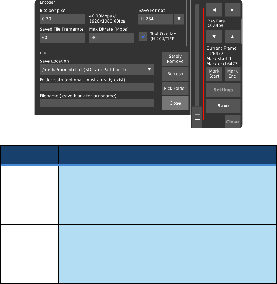
Page | 88
SAVE SETTINGS
The Save Settings pop-up allows for the configuration of the file before it is written to an
external storage device. By default, frames are encoded as H.264 MPEG-4 files and saved
to the last storage device that was attached to the camera. Bits per pixel, Saved File
Framerate and Max Bitrate are only used when saving as H.264.
Control
Function
Bits Per Pixel
Primary quality control for H.264 (MPEG-4) encoded saved video.
Defaults to 0.70 Bits per pixel.
Max Bitrate
Sets a limit to the playback data rate in megabits per second. [H.264 only]
Defaults to 40 Mbps.
__.__ Mbps @
_x_ _fps
Shows the bitrate and framerate calculated from the Bits per pixel setting and
frame resolution.
Saved File
Frame Rate
Sets the playback framerate for saved video files.
Defaults to 60 frames per second.

Page | 89
SAVE SETTINGS [CONTINUED]
Control
Function
Text Overlay
(H.264/TIFF)
When enabled, the timestamp overlay will be shown on top of the image in
Playback mode, videos saved as H.264 MPEG-4, and images saved as TIFF.
Information about each frame’s position within the recording will be overlaid
across the bottom left corner of each frame of encoded video or TIFF image.
Save Location
Selects the storage device for saved video. The list automatically refreshes and
switches to the most recently attached device. Please note that it may take
several seconds for a newly connected storage device to appear in the list.
Folder Path
Specifying a Folder Path will make the camera save the video into that folder
once Save is pressed. If saving in DNG, TIFF, or TIFF RAW, an image for each
frame will be saved into a sub-folder within the folder specified.
Filename
Sets the filename for saved video on the device selected in Save Location. If this
field is left blank, the files will be named vid_YYYY-MM-DD_HH-MM-SS.mp4
according to the current date and time.
Safely Remove
Finish any outstanding writes to selected storage device. When this has
completed, the storage device can be unplugged from the camera without the
risk of lost data, like the Eject or Safely Remove action on a PC.
Pick Folder
Opens a file browser window to allow for easy selection of a save destination.
Close Button
Closes the Save Settings dialog. Settings are applied automatically upon being
set.
NOTE: In the rare event that a save operation is unsuccessful and it is critical to recover high-
speed footage that was captured, an internal tool can be used to attempt the recovery and saving
of frames in the CinemaDNG format. DO NOT power off the camera if a recovery attempt is to be
made, as rebooting the camera will clear the acquisition memory in which the last capture of high-
speed footage resides. Please contact s[email protected] for more information.

Page | 90
COMPARISON OF SAVE FORMATS
Save
Format
Usage Notes
Details
H.264
H.264 is the fastest and easiest way to
save videos that can then be watched on
a wide variety of devices.
This format results in MPEG-4 (.mp4)
video, which will sacrifice small amounts
of quality for compression. Parameters
related to compression can be changed
in the Encoder section of Play Settings.
• Text overlays are possible
• Bitrates up to 60 Mbps
• Video saved as single file
Raw 12 bit
Raw 16 bit
Raw12 is the fastest way to get raw
video off the camera since it produces
files 75% the size of Raw 16 bit.
Raw16 has been kept for legacy support
purposes.
• DNG images can be extracted
from the raw file using an external
tool, such as our pyraw2dng
python script found here:
https://github.com/krontech/chronos-
utils/
CinemaDNG
CinemaDNG has the best image quality
and compatibility with video editing
software.
• Individual frames saved in one
folder
TIFF
TIFF is compatible with a wide variety of
software and can be opened on PCs
without the need for extra software.
On monochrome cameras, TIFF is
generally preferred over CinemaDNG.
On color cameras, image quality is
slightly lower than CinemaDNG because
built-in demosaic and color corrections
are performed as oppose to advanced
corrections that can be made on modern
editing software.
• Text overlays are possible
• Individual frames saved in one
folder
TIFF Raw
TIFF Raw is primarily for scientific use,
since brightness is linear-encoded,
instead of gamma-encoded.
• No on-camera demosaic
• Individual frames saved in one
folder

Page | 91
UTILITIES SCREEN - MAIN
The Utilities page, referred to in short as Util, contains general settings and information
about the camera.
Control
Function
Focus Peaking
Enable
Enables Focus Peaking, which highlights objects that are in-focus with the color
shown in the dropdown box to the right. This feature can also be enabled or
disabled via the Focus Aid checkbox on the main screen.
Focus Peaking
Color
Selects the color used to highlight edges that are in focus when Focus Peaking
is enabled.
Focus Peaking
Sensitivity
Select either Low, Med, or High to configure the sensitivity of the Focus Peaking
feature. Increased sensitivity will lead to more noise in the detection result but is
ideal for dark edges. Reduced sensitivity will allow for more accurate focusing on
bright edges.
Exposure Unit
Display
Sets the units in which Exposure is displayed on the main screen. This can either
be Fractional Time (μs), Shutter Angle (°), or Percentage (%).

Page | 92
UTILITIES SCREEN – MAIN [CONTINUED]
Control
Function
Ask Before
Discarding
Unsaved Video
in RAM
Select for warnings about overwriting video stored in memory. When the Record
button is pressed, the warning manifests as a pop-up titled ‘Unsaved Video in
RAM’. Selecting OK continues while Cancel prevents new video from being
recorded so that the previous recording can be saved via the Play screen.
One of three options can be set:
Always: Prompts before starting a recording.
If Not Reviewed: Prompts when a new recording is started, but only when the
previous recording was not opened in the Play screen.
Never: Disables the prompt entirely.
Auto Power
Mode
Useful in cases where the camera’s power button is in a location that is not
easily accessible during filming, this feature can configure the power
management system in the camera to power on when AC power is applied,
power off when AC power is removed, or both.
Please note: If the power button is pressed to turn the camera off while the Turn
on if AC inserted option is enabled, the camera will reboot instead of shutting
down.
Auto Save
When a recording ends, the camera automatically saves the entire recording to
an external storage device. If Auto Record is selected as well, the camera will
record and save in a continuous loop, which can be interrupted by tapping any
of the Main screen buttons (except for Focus Aid or Record) and then choosing
to stop the recording.
Prior to enabling Auto Save, set a save location manually in Save Settings. It is
not necessary to set a filename, as videos will be named automatically with the
date and time upon saving.
One-touch
Playback
Enables a Play button in the bottom-right corner of the Play screen which will
play through the marked region without the need to press and hold the frame
forward or frame backward button.
Auto Record
Automatically starts a recording after the camera has booted and again
whenever it finishes saving video to an external storage device.

Page | 93
UTILITIES SCREEN – MAIN [CONTINUED]
Control
Function
Enable Zebras
Enables the over-exposure indicator, which shows a rolling pattern of black lines
(referred to as “Zebra stripes”) over over-exposed areas of the image.
Live Record
@60fps
Records the footage as seen on the viewfinder to an external storage device as
specified by Live Record Location in parallel with the current high-speed
recording. In this mode, an external storage device must be connected prior to
recording, or else a warning message will be displayed, and only high-speed
footage will be recorded.
Audio is also recorded in this mode. The Chronos will automatically switch
between the built-in microphone and the line input jack if a line input is detected.
The resulting file is an MPEG-4 video with bitrates up to 6 Mbps and audio
sampled at 48 kHz. The maximum file size per clip is 4 GB. Please note that
some audio drift may occur with recordings that exceed 15 seconds.
Live Record
Location
Selects the storage device for saved video at 60 FPS. The list automatically
refreshes and switches to the most recently attached device. Please note that it
may take several seconds for a newly connected storage device to appear in the
list.
Videos saved using the Live Record mode will be named live_YYYY-MM-
DD_HH-MM-SS.mp4.
Close Button
Returns to the Main window. Settings are applied automatically as they are
changed.

Page | 94
STORAGE TAB
The Storage page allows for interactions with storage devices that are attached to the
camera. This page is also used to backup and restore camera settings and calibration
files, as well as to search for software updates over the internet.
Control
Function
Backup
Settings
Backs up the user’s configuration preferences, such as resolution, focus
peaking, and triggering settings to a USB flash drive.
It is recommended that a backup of your camera’s configuration be taken prior
to each software update, or prior to replacing the system’s microSD card.
Restore
Backup
Settings
Restore saved settings from a USB flash drive.
Revert to
Defaults
Set the camera’s settings back to the factory default.
Backup
Calibration
Data
Saves the camera’s factory calibration data to a USB flash drive. It is
recommended that the user keep a copy if the system’s microSD card must be
replaced. This excludes black calibration data that was generated by the user,
which can be restored by performing a black calibration prior to recording at the
desired resolution and analog gain. The file is named cal_<serial number>.tar.

Page | 95
STORAGE TAB [CONTINUED]
Control
Function
Restore
Calibration
Data
Restore saved settings from a USB flash drive.
Eject Disk/
SD Card
Finish any outstanding writes to the selected storage device and unmount the
filesystem from the camera’s control. This is equivalent to the “Safely Remove”
option on PCs and protects against the loss of unwritten data.
Format Disk/
SD Card
Formats the selected storage device with a FAT32 filesystem, which can be used
for saving video.
Apply Software
Update
Starts the software update utility, which will use the internet to search for any
applicable updates.
List Files
Opens a file browser window to display files and folders on each connected
storage device that has been recognized by the camera.

Page | 96
SOFTWARE UPDATES
Selecting the Apply Software Update button from the Storage tab in the Util screen will
start an update utility that provides a way to search for and install software updates. This
screen also allows the User Interface of the camera to be switched between normal use
and headless mode.
Control
Function
Update From
Local Media
If update files exist on an external storage device, this option allows for the
installation of the updates.
Update From
Package
Repository
This dropdown list contains a list of the package repositories that the camera
can search for updates. Voyager is a codename by Kron Technologies that
specifies software packages that are tested and stable.
Check for
Updates
Attempts to connect to the package repository via an internet connection to
search for new updates. The update procedure is discussed in the subsequent
pages of this section.
User Interface
This dropdown list allows for the selection of the Graphical User Interface (GUI)
that will be displayed on the back of the camera.
Selecting headless mode will disable the Graphical User Interface on the
subsequent boot, and a blank screen will be shown, but the camera will remain
fully functional. This is to accommodate cases where the camera is to be
installed in an area where remote control is configured, and user interaction is
not desired.
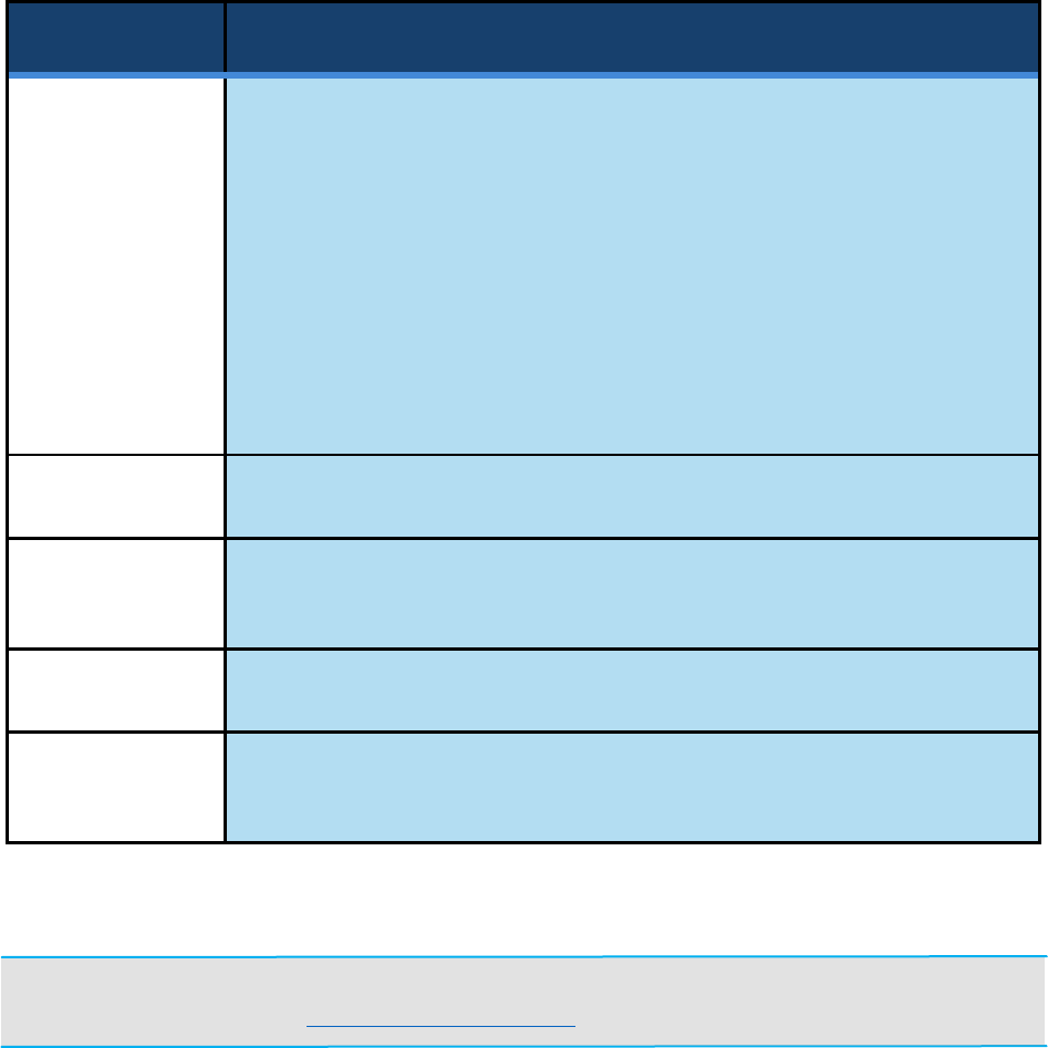
Page | 97
SOFTWARE UPDATES [CONTINUED]
Control
Function
User Interface
(Continued)
A recovery mode is built-in to the camera in the case that a software update has
failed, or the user wishes to exit headless mode and restore the factory user
interface.
To enter recovery mode:
1. Shut the camera down.
2. Press-in and hold both the record button and the rotary encoder wheel.
3. Boot the camera by pressing the power button.
4. Release the record button and rotary encoder wheel once the Chronos
logo is shown.
5. The Software Updates screen will be shown after a few seconds.
Apply
Applies the selected User Interface.
List Packages
Opens a list of Debian Linux software packages that are currently installed on
the camera, along with a description of the function of each package.
Reboot
Causes a soft reboot of the camera.
Quit
Exits the Software Update tool and reloads the camera’s user interface and
video system.
NOTE: Kron Technologies provides source code for many of the camera’s software components,
which can be found at https://github.com/krontech.

Page | 98
SOFTWARE UPDATES [CONTINUED]
The following section provides a step-by-step demonstration of the camera’s online
software update procedure. Prior to starting this procedure, please ensure that the
camera is connected to the internet via the ethernet port. Network status can be found by
navigating to the Network tab in the Util screen.
WARNING: Always back up configuration and calibration data prior to a software update.
Ensure the camera is either connected to AC power or ensure that the battery is charged over
25%. DO NOT power off the camera while an update is in progress.
In the case that an update is also applied to the camera’s power manager, the fan will run at full
speed and the status LED will blink green and red until this is complete.
Step 1. Tap the Check for Updates button.
Step 2. The camera will attempt to search package lists for applicable updates.

Page | 99
SOFTWARE UPDATES [CONTINUED]
Step 3. If packages are eligible for upgrade, select Yes to continue.
Step 4. The camera will begin to install new packages.
Step 5. If the update is successful, the camera will automatically reboot.

Page | 100
NETWORK TAB
The network interface on the Chronos camera can serve as a powerful and flexible way
to use the camera. Over the network, the camera can be controlled via its webpage,
footage can be saved via Server Message Block (SMB) and Network File System (NFS)
mounts, and a Real Time Streaming Protocol (RTSP) feed of the live output can be viewed.
Please refer to the Networking and Web Control sections of the main manual for detailed
guidelines on how to operate these features.
In advanced use cases where the user wishes to adapt the camera to a specific process,
it is possible to log into the command line interface on the camera via SSH. SSH Port 22
is exposed on the USB network interface by default and can be accessed by connecting
to the IP Address 192.168.12.1 with username: root and password: chronos.
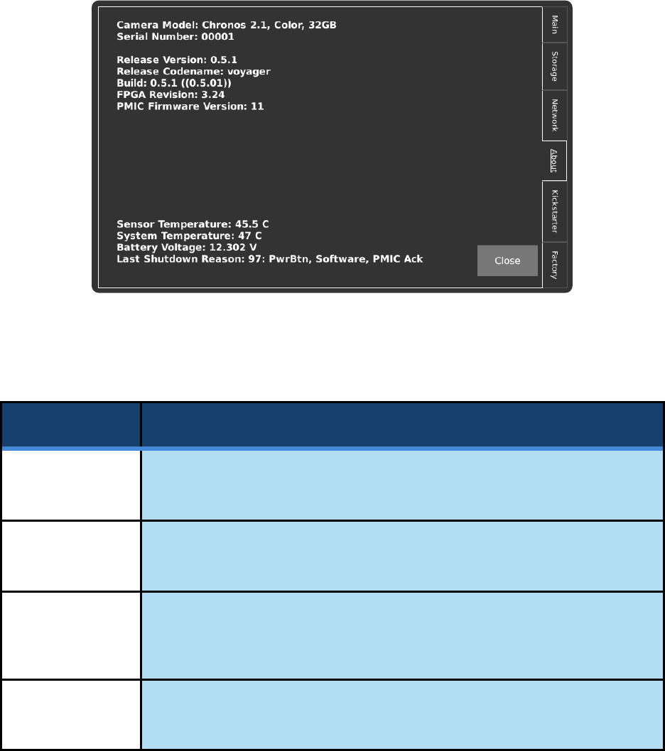
Page | 101
ABOUT TAB
This tab contains information about the camera hardware, software, and current operating
conditions. In the event that support from Kron Technologies is required, it is useful to
provide a photo of this screen along with the rest of the inquiry if possible.
The lower left-hand side of the display shows live information pertaining to the camera’s
internal systems. The table below describes these parameters in more detail.
Label
Description
Sensor
Temperature
The surface temperature of the image sensor inside the camera. Typical values
at room temperature are between 40 and 55 degrees Celsius.
System
Temperature
The internal temperature at a more central point inside the camera. This value
typically equalizes close to that of the Sensor Temperature.
Battery
Voltage
The current battery voltage. This value depends on the condition of the battery
and the charge and can be helpful in determining whether a battery can no
longer function properly.
Last Shutdown
Reason
The reason for the last shutdown that had occurred. Each tag separated by a
comma signifies a stage in the shutdown sequence that was acknowledged.

Page | 102
FACTORY TAB
This tab contains functionality related to the manufacturing and factory calibration of the
camera, as well as user settings that are less likely to be changed during normal operation.
Control
Function
Service
Password
Enters service mode.
If used without the direction of Kron Technologies, the warranty is void.
Remove User
Calibration
Data (Revert to
Factory)
Removes the saved Black Calibration data. Each time the Black Cal button on
the Main screen is pressed, a calibration file is added to the system for the
current combination of resolution and analog gain. This file is loaded the next
time the prior combination of resolution and analog gain is used.
Black Calibrate
All Resolutions
Performs Black Calibration at each level of analog gain for all the standard
resolutions at their maximum frame rates. Standard resolutions can be found
under the Common Resolutions dropdown box in the Record Settings screen.
Please note that this may take up to 10 minutes.
Clock
Allows for the camera’s date and time to be set. Press the Save button to assure
that the settings persist on the next reboot of the camera.

Page | 103
FACTORY TAB [CONTINUED]
Control
Function
GUI Mode
Provides an option to change the theme of the Graphical User Interface (GUI)
between dark and light modes.
UI on Left Side
Moves the vertical bar of controls on the Main screen to the left-hand side of the
screen.
Upside-down
Display
Rotates all contents of the display 180 degrees.
Column Gain
Calibration
Performs a calibration for all resolutions and analog gain levels.
This is performed at the factory but can be performed again if the camera is
being used in climates below 15°C or above 40°C, or if there is a perceived
degradation in image quality.
If the camera does not detect calibration files on boot, it will automatically
prompt the user and recommend that a calibration take place.
Please note that Column Gain Calibration only applies to Chronos 2.1.
Shipping Mode
Disables the power button from starting the camera until an AC adapter is
plugged in. This is to simplify transport of the camera when the battery is
installed. Once the camera has been powered on with the AC adapter plugged
in, the camera will automatically disable Shipping Mode for subsequent power
cycles.
