JOINT FLEET MAINTENANCE MANUAL (JFMM)
COMUSFLTFORCOMINST 4790.3
VOLUME V
QUALITY MAINTENANCE
DEPARTMENT OF THE NAVY
COMMANDING OFFICER SUBMEPP
PO BOX 2500
PORTSMOUTH NAVAL SHIPYARD
PORTSMOUTH, NH 03804-2500

COMUSFLTFORCOMINST 4790.3 REV D CHG 3
07 Nov 2023
ii
JOINT FLEET MAINTENANCE MANUAL
VOLUME V
QUALITY MAINTENANCE
LIST OF EFFECTIVE CHAPTERS
Chapter Number Change in Effect Chapter Number Change in Effect
Part I Part III
FWD Change 3 FWD Change 3
1 Change 3 1 Change 1
2 Change 3 2 Change -
3 Change 1 3 Change -
4 Change 2 4 Change -
5 Change 3 5 Change 3
6 Change 3 6 Change 2
7 Change 2 7 Change -
8 Change 3 8 Change 3
9 Change 2 9 Change 1
10 Change 3 10 Change -
11 Change 3 11 Change 3
12 Change -
13 Change -
Part II
None

COMUSFLTFORCOMINST 4790.3 REV D CHG 3
07 Nov 2023
iii
JOINT FLEET MAINTENANCE MANUAL
VOLUME V
QUALITY MAINTENANCE
TABLE OF CONTENTS
PART I
FOREWORD - QUALITY MAINTENANCE
1.1 Purpose ................................................................................................................. V-I-FWD-1
1.2 Scope .................................................................................................................... V-I-FWD-1
1.3 Manual Organization ............................................................................................ V-I-FWD-1
1.3.1 Basic Maintenance Principles .............................................................. V-I-FWD-1
1.3.2 Special Circumstances and Maintenance Support ............................... V-I-FWD-2
1.3.3 Order of Precedence ............................................................................ V-I-FWD-2
1.3.4 Advisories ............................................................................................ V-I-FWD-4
1.4 Need for Quality Maintenance Processes ............................................................. V-I-FWD-4
1.5 Changes and Corrections ...................................................................................... V-I-FWD-5
Appendices
A Glossary of Terms ........................................................................... V-I-FWD-A-1
CHAPTER 1 - ORGANIZATIONAL RESPONSIBILITIES
1.1 Purpose ....................................................................................................................... V-I-1-1
1.2 Quality Assurance Organizations ………………………………………….………...V-I-1.2
1.3 Fleet Commander Responsibilities .............................................................................. V-I-1-2
1.4 Type Commander Responsibilities ............................................................................. V-I-1-2
1.5 Immediate Superior In Command Responsibilities .................................................... V-I-1-4
1.6 Ship Responsibilities .................................................................................................. V-I-1-8
1.6.1 Ship’s Commanding Officer ....................................................................... V-I-1-8
1.6.2 Ship’s Executive Office .............................................................................. V-I-1-9
1.6.3 Ship’s Department Head ........................................................................... V-I-1-10
1.6.4 Ship’s Supply Officer ............................................................................... V-I-1-11
1.6.5 Ship’s Engineer Officer (Submarines only) ............................................. V-I-1-11
1.6.6 Availability Coordinator (Submarines only) ............................................ V-I-1-12
1.6.7 Ship’s Maintenance Manager (Aircraft Carriers only) ............................. V-I-1-13
1.6.8 Ship’s Principal Assistant ......................................................................... V-I-1-13
1.6.9 Ship’s Division Officer ............................................................................. V-I-1-13
1.6.10 Ship’s Work Center Supervisor ................................................................ V-I-1-14
1.6.11 Ship’s Craftsman ...................................................................................... V-I-1-15
1.6.12 Ship’s Quality Assurance Officer ............................................................. V-I-1-15
1.6.13 Ship’s Assistant Quality Assurance Officer ............................................. V-I-1-18
COMUSFLTFORCOMINST 4790.3 REV D CHG 3
07 Nov 2023
iv
1.6.14 Ship’s Quality Assurance Supervisor ....................................................... V-I-1-18
1.6.15 Ship’s Quality Assurance Inspectors ........................................................ V-I-1-18
1.6.16 Ship’s Controlled Material Petty Officer ................................................. V-I-1-19
1.6.17 Ship’s Cleanliness Inspector or Certifier .................................................. V-I-1-20
1.6.18 Ship’s Nondestructive Test Examiner ...................................................... V-I-1-20
1.6.19 Ship’s Nondestructive Test Inspector ....................................................... V-I-1-21
1.6.20 Ship’s Maintenance Planner (Submarines and Aircraft Carriers only) .... V-I-1-21
1.7 Regional Maintenance Center or Fleet Maintenance Activity Responsibilities........ V-I-1-22
1.7.1 RMC Commander or FMA Commanding Officer ................................... V-I-1-22
1.7.2 RMC Deputy Commander or FMA Executive Officer ............................ V-I-1-22
1.7.3 RMC Production Officer or FMA Repair Officer .................................... V-I-1-23
1.7.4 FMA Supply Officer ................................................................................. V-I-1-25
1.7.5 FMA Nuclear Repair Officer .................................................................... V-I-1-25
1.7.6 RMC or FMA Planning and Estimating Officer ...................................... V-I-1-26
1.7.7 RMC or FMA Division Officer ................................................................ V-I-1-26
1.7.8 RMC or FMA Work Center Supervisor ................................................... V-I-1-27
1.7.9 RMC or FMA Craftsman .......................................................................... V-I-1-27
1.7.10 RMC Quality Assurance Department Head (Code 130) or Industry
Management Department (Code 400 at Puget Sound Naval Shipyard
and Intermediate Maintenance Facility) ................................................... V-I-1-28
1.7.11 RMC Code 133 Division Head or FMA Quality Assurance Officer ....... V-I-1-28
1.7.12 RMC or FMA Assistant Quality Assurance Officer ................................ V-I-1-30
1.7.13 RMC or FMA Quality Assurance Supervisor .......................................... V-I-1-30
1.7.14 RMC or FMA Quality Assurance Inspector ............................................. V-I-1-31
1.7.15 RMC or FMA Controlled Material Petty Officer or Controlled
Material Handler ....................................................................................... V-I-1-31
1.7.16 RMC or FMA Cleanliness Inspector or Certifier ..................................... V-I-1-32
1.7.17 RMC or FMA Nondestructive Test Division Officer .............................. V-I-1-32
1.7.18 RMC or FMA Command Examiner……………………………………. V-I-1-32
1.7.19 Nondestructive Test Examiner ................................................................. V-I-1-32
1.7.20 RMC or FMA Nondestructive Test Inspector .......................................... V-I-1-33
1.8 Other Activity Responsibilities ................................................................................. V-I-1-33
Appendices
A Format for Submarine QA Pre-Underway Checklist ...................................... V-I-1A-1
CHAPTER 2 - QUALITY MAINTENANCE PROCESSES
2.1 Purpose ........................................................................................................................ V-I-2-2
2.2 Technical Work Documents ........................................................................................ V-I-2-2
2.2.1 Minimum Requirements for using Technical Work Documents ............... V-I-2-2
2.2.2 Maintenance Procedure .............................................................................. V-I-2-4
2.2.3 Formal Work Package ................................................................................ V-I-2-5
2.2.4 Controlled Work Package ........................................................................... V-I-2-5
2.2.5 Maintenance Certification Record and Controlled Work Package
(Non-SUBSAFE) ........................................................................................ V-I-2-8
COMUSFLTFORCOMINST 4790.3 REV D CHG 3
07 Nov 2023
v
2.2.6 Sequencing Document ................................................................................ V-I-2-9
2.3 Formal Work Package Development ........................................................................ V-I-2-10
2.3.1 Responsibility for Preparation of Formal Work Packages and Controlled
Work Packages ......................................................................................... V-I-2-10
2.3.2 Security Classification .............................................................................. V-I-2-10
2.3.3 Formal Work Package Format .................................................................. V-I-2-10
2.3.4 Formal Work Package Approval .............................................................. V-I-2-17
2.3.5 Controlled Work Package Approval ........................................................ V-I-2-18
2.3.6 Formal Work Package In Process Use ..................................................... V-I-2-18
2.3.7 Formal Work Package Changes ............................................................... V-I-2-18
2.4 Troubleshooting ........................................................................................................ V-I-2-25
Appendices
A Technical Work Document Illustration ................................................... V-I-2A-1
B Work Package Decision Process .............................................................. V-I-2B-1
C Certification Signature Requirements for Reactor Plant, Nuclear Support
Facility and Controlled Industrial Facility Work ..................................... V-I-2C-1
D Formal Work Package Approval and Revision Sheet ............................. V-I-2D-1
E Technical Work Document Review and Approval Matrix ....................... V-I-2E-1
CHAPTER 3 - PERSONNEL QUALIFICATION AND TRAINING
3.1 Purpose ........................................................................................................................ V-I-3-1
3.2 General ........................................................................................................................ V-I-3-1
3.3 Qualification ................................................................................................................ V-I-3-2
3.3.1 Re-qualification .......................................................................................... V-I-3-2
3.3.2 Required Service Record Entries ................................................................ V-I-3-2
3.4 Qualification Requirements ......................................................................................... V-I-3-2
3.4.1 Ship’s Quality Assurance Officer ............................................................... V-I-3-2
3.4.2 Ship’s Assistant Quality Assurance Officer ............................................... V-I-3-3
3.4.3 Immediate Superior In Command .............................................................. V-I-3-3
3.4.4 Regional Maintenance Center and Fleet Maintenance Activity Quality
Assurance Officer ....................................................................................... V-I-3-4
3.4.5 Regional Maintenance Center and Fleet Maintenance Activity Assistant
Quality Assurance Officer .......................................................................... V-I-3-4
3.4.6 Quality Assurance Supervisor .................................................................... V-I-3-4
3.4.7 Quality Assurance Inspector ....................................................................... V-I-3-4
3.4.8 Controlled Material Petty Officer and Controlled Material Handler ......... V-I-3-5
3.4.9 Steam Plant Cleanliness Inspector and Certifier ........................................ V-I-3-5
3.4.10 Gas Systems Cleanliness Inspector and Certifier ....................................... V-I-3-5
3.4.11 Oxygen Clean Instructors ........................................................................... V-I-3-5
3.4.12 Ship’s and Fleet Maintenance Activity Oxygen Clean Workers ................ V-I-3-5
3.4.13 Oxygen Calibration Technicians ................................................................ V-I-3-5
3.4.14 Work Center Supervisors and Planners ...................................................... V-I-3-6
COMUSFLTFORCOMINST 4790.3 REV D CHG 3
07 Nov 2023
vi
3.4.15 Qualification Requirements for Submarine Nuclear Propulsion Plant
Operator Welders (Navy Enlisted Classification Code 3351 and
Supervisor Welders 3361) .......................................................................... V-I-3-6
3.4.16 Qualification Requirements for Submarine Fly-By-Wire Ship Control
System Maintenance Technician ................................................................ V-I-3-6
3.5 Training ....................................................................................................................... V-I-3-6
3.5.1 Maintenance Personnel Training ................................................................ V-I-3-6
3.5.2 Requirements .............................................................................................. V-I-3-7
3.5.3 Submarine Safety Awareness Training (Submarines and Submarine
Repair Facilities only) ................................................................................ V-I-3-7
Appendices
A NAVEDTRA 43523 Qualification Matrix .............................................. V-I-3A-1
B Outlines of Typically Effective Training Topics ...................................... V-I-3B-1
C Recommended Training Topics for Selected Positions ............................ V-I-3C-1
CHAPTER 4 - WELDER, BRAZER AND NONDESTRUCTIVE TESTING QUALIFICATIONS
4.1 Purpose ....................................................................................................................... V-I-4-1
4.1.1 General Requirements ................................................................................ V-I-4-2
4.1.2 Training ...................................................................................................... V-I-4-2
4.2 General Requirements for Brazers and Welders ......................................................... V-I-4-2
4.2.1 Eye Examination ........................................................................................ V-I-4-3
4.2.2 Brazing and Welding Procedures ............................................................... V-I-4-3
4.2.3 Brazing and Welding Personnel Knowledge .............................................. V-I-4-3
4.2.4 Brazer and Welder Identification Numbers ................................................ V-I-4-3
4.2.5 Validation of Qualification ......................................................................... V-I-4-4
4.2.6 Qualification Records ................................................................................. V-I-4-4
4.2.7 Effective Date of Qualification .................................................................. V-I-4-5
4.3 Brazer Qualifications ................................................................................................... V-I-4-5
4.3.1 Prerequisite ................................................................................................. V-I-4-5
4.3.2 Qualification Test ....................................................................................... V-I-4-5
4.3.3 Limitations .................................................................................................. V-I-4-5
4.3.4 Test Assembly Evaluation .......................................................................... V-I-4-5
4.3.5 Maintenance of Qualification ..................................................................... V-I-4-5
4.3.6 Qualification Renewal ................................................................................ V-I-4-5
4.3.7 Transfer of Qualification ............................................................................ V-I-4-6
4.4 Qualification Requirements for Welders ..................................................................... V-I-4-6
4.4.1 Navy Enlisted Classification Code Achievement ....................................... V-I-4-6
4.4.2 Specific Qualifications ............................................................................... V-I-4-6
4.4.3 Aluminum, Metal Boat and Craft Qualifications ....................................... V-I-4-6
4.4.4 Maintenance of Qualification ..................................................................... V-I-4-6
4.4.5 Qualification Renewal ................................................................................ V-I-4-6
4.4.6 Transfer of Qualification ............................................................................ V-I-4-6
COMUSFLTFORCOMINST 4790.3 REV D CHG 3
07 Nov 2023
vii
4.5 Assemblies Where the Possibilities of Failure is Remote and Would Not Result
in Danger of Ship Personnel, Ship, Boat, Craft, Plant, or Structure ............................ V-I-4-6
4.5.1 Authorization .............................................................................................. V-I-4-6
4.5.2 Requirements .............................................................................................. V-I-4-6
4.6 Qualification Requirements for Nondestructive Test Personnel ................................. V-I-4-7
4.6.1 Purpose ....................................................................................................... V-I-4-7
4.6.2 Levels of Certification ................................................................................ V-I-4-7
4.6.3 Certification of Nondestructive Test Personnel ......................................... V-I-4-8
4.6.4 Renewal of Certification ............................................................................. V-I-4-8
4.6.5 Maintenance of Qualification ..................................................................... V-I-4-8
4.6.6 Qualification Administration ...................................................................... V-I-4-8
4.6.7 Approval of Nondestructive Testing Qualification Examinations ............. V-I-4-8
4.6.8 Transfer of Qualification ............................................................................ V-I-4-8
4.6.9 Nondestructive Testing Personnel Records ................................................ V-I-4-8
4.6.10 Nondestructive Testing Qualification Log ................................................. V-I-4-8
4.6.11 Qualification of Generic Material Identity Testing Personnel ................... V-I-4-8
CHAPTER 5 - IN-PROCESS CONTROL
5.1 Purpose ........................................................................................................................ V-I-5-2
5.2 Test, Measurement and Diagnostic Equipment ........................................................... V-I-5-2
5.2.1 General Requirements ................................................................................ V-I-5-2
5.2.2 Torque Wrenches ........................................................................................ V-I-5-2
5.2.3 Gauges ........................................................................................................ V-I-5-5
5.3 Torque ......................................................................................................................... V-I-5-5
5.3.1 General Requirements ................................................................................ V-I-5-5
5.3.2 Torque Requirements ................................................................................. V-I-5-5
5.4 Inspections ................................................................................................................... V-I-5-5
5.4.1 General Requirements ................................................................................ V-I-5-5
5.4.2 Inspection Records ..................................................................................... V-I-5-5
5.4.3 Critical Inspections ..................................................................................... V-I-5-5
5.4.4 Cleanliness Inspections .............................................................................. V-I-5-7
5.4.5 Nuclear Propulsion Plant and Nuclear Support Facility General
Cleanliness Requirements .......................................................................... V-I-5-8
5.4.6 General Shipboard Steam Plant Systems Cleanliness Requirements ....... V-I-5-10
5.4.7 Set Stud Inspection ................................................................................... V-I-5-12
5.5 Software Acceptability .............................................................................................. V-I-5-13
5.6 Submarine Safety Maintenance Certification and Re-Entry Control,
Nuclear and Non-Nuclear .......................................................................................... V-I-5-14
5.6.1 Purpose ..................................................................................................... V-I-5-14
5.6.2 Re-Entry Control Program ....................................................................... V-I-5-15
5.6.3 Nuclear Submarine Safety System Re-Entry ........................................... V-I-5-16
5.6.4 Re-Entry Control Administrative Procedures .......................................... V-I-5-16
COMUSFLTFORCOMINST 4790.3 REV D CHG 3
07 Nov 2023
viii
5.6.5 Using a Controlled Dive Departure from Specification to Close a
Maintenance Certification Record or Re-Entry Control .......................... V-I-5-20
5.6.6 Voyage or At Sea Repairs ........................................................................ V-I-5-20
5.6.7 Exceptions to Re-Entry Control ............................................................... V-I-5-21
5.6.8 Certification Continuity Report ................................................................ V-I-5-21
5.7 Reactor Plant Work Accomplishment Report (Submarines Only) ........................... V-I-5-22
5.7.1 Purpose ..................................................................................................... V-I-5-22
5.7.2 Specific Instructions for Completing Reactor Plant Work
Accomplishment Report Cover Sheet ...................................................... V-I-5-23
5.7.3 Specific Instructions for Completing Reactor Plant Certification
When New or Previously Uncertified Material is Installed in a
Submarine Safety Application .................................................................. V-I-5-23
5.7.4 Specific Instructions for Completing Reactor Plant Certification
When Previously Certified Material is Reinstalled .................................. V-I-5-24
5.8 Material Condition Monitoring Unrestricted Operations Maintenance
Requirement Card Program (Submarines Only) ....................................................... V-I-5-24
5.9 Submarine Fly-By-Wire Maintenance Certification ................................................. V-I-5-25
5.9.1 Purpose ..................................................................................................... V-I-5-25
5.9.2 Submarine Flight Critical Component Boundary Work Control
Procedures ................................................................................................ V-I-5-26
5.9.3 Submarine Flight Critical Component Boundary Work Control
Closeout .................................................................................................... V-I-5-26
5.9.4 Objective Quality Evidence to Support Controlled Work on Fly-By-
Wire Ship Control System Submarine Flight Critical Component .......... V-I-5-27
5.10 Aircraft Carrier Maintenance Document ................................................................... V-I-5-28
5.10.1 Purpose ..................................................................................................... V-I-5-28
5.10.2 Non-Nuclear Deviations, Waivers and Departure from Specifications ... V-I-5-28
5.10.3 Liaison Action Requests - Nuclear Cognizant Areas ............................... V-I-5-29
5.10.4 Nuclear Liaison Inquiry - Nuclear Cognizant Areas ................................ V-I-5-30
5.10.5 Steam Plant Action Request - Non-Nuclear Cognizant Areas ................. V-I-5-30
5.10.6 Steam Plant Liaison Inquiry - Non-Nuclear Cognizant Areas ................. V-I-5-32
5.10.7 Reactor Plant Configuration Change Report ............................................ V-I-5-33
5.10.8 Technical Manual Deficiencies and Manual Change Requests ............... V-I-5-36
5.10.9 Fleet COSAL Feedback Report ................................................................ V-I-5-37
Appendices
A Determining Software Usability .............................................................. V-I-5A-1
B Format for Submarine Certification Continuity Report ........................... V-I-5B-1
C Format for Fleet Maintenance Activity Certification Report to Tended
Submarine ................................................................................................. V-I-5C-1
D Format for Non-Fleet Maintenance Activity Certification Report to
Tended Submarine ................................................................................... V-I-5D-1
E RPCCR Cover Letter for SHIPALTs (Sample) ....................................... V-I-5E-1
COMUSFLTFORCOMINST 4790.3 REV D CHG 3
07 Nov 2023
ix
CHAPTER 6 - MATERIAL CONTROL
6.1 Purpose ........................................................................................................................ V-I-6-1
6.1.1 Discussion ................................................................................................... V-I-6-1
6.2 Nuclear ........................................................................................................................ V-I-6-2
6.2.1 Controlled Material Determination ............................................................ V-I-6-2
6.2.2 Controlled Material Procurement ............................................................... V-I-6-3
6.2.3 Receipt Inspection of Nuclear Controlled Material .................................... V-I-6-4
6.2.4 Marking of Nuclear Repair Parts ................................................................ V-I-6-8
6.2.5 Nuclear Repair Parts Downgrading .......................................................... V-I-6-11
6.2.6 Storage, Issue and Handling of Nuclear Repair Parts .............................. V-I-6-11
6.3 Non-Nuclear .............................................................................................................. V-I-6-18
6.3.1 Controlled Material Determination .......................................................... V-I-6-18
6.3.2 Quality Assurance List (Submarines only) ............................................... V-I-6-25
6.3.3 Controlled Material Procurement ............................................................. V-I-6-25
6.3.4 Receipt Inspection of Controlled Material ............................................... V-I-6-27
6.3.5 Receipt Inspection of Open Purchase (Non-Supply System) or Locally
Manufactured Material or Upgrading Supply System Material to
Level I (Fleet Maintenance Activity only). .............................................. V-I-6-35
6.3.6 Authorized Material Certification Activities ............................................ V-I-6-37
6.3.7 Marking of Level I Stock Program Material and Controlled Material ..... V-I-6-38
6.3.8 Level I Submarine Flight Critical Component Stock Program Material
Downgrading ............................................................................................ V-I-6-43
6.3.9 Storage, Issue and Handling of Level I, Scope of Certification or
Submarine Flight Critical Component Stock Program Material .............. V-I-6-43
CHAPTER 7 - TESTING REQUIREMENTS
7.1 General ........................................................................................................................ V-I-7-1
7.1.1 Key Element ............................................................................................... V-I-7-2
7.1.2 Testing Requirements for Systems, Portions of Systems and
Components ................................................................................................ V-I-7-2
7.2 Testing ......................................................................................................................... V-I-7-4
7.2.1 Test Procedures .......................................................................................... V-I-7-4
7.2.2 Test Requirements ...................................................................................... V-I-7-5
7.2.3 Test Pressure Source References ................................................................ V-I-7-6
7.2.4 Non-Nuclear Pressure Drop Tests .............................................................. V-I-7-6
7.3 Weight Handling Equipment ....................................................................................... V-I-7-8
7.4 Exemptions or Alternative Test Requirements (Non-Nuclear) ................................. V-I-7-10
7.4.1 General ..................................................................................................... V-I-7-10
7.4.2 Exemptions and Alternatives to Test Requirements (Non-Nuclear unless
Specifically Addressed in Nuclear Technical Documents) ..................... V-I-7-11
7.5 Reactor Plant and Nuclear Support Facility Testing ................................................. V-I-7-13
7.5.1 Hydrostatic Tests, Pneumatic Tests or Drop Tests ................................... V-I-7-13
7.5.2 Mechanical Joint Fasteners ....................................................................... V-I-7-14
COMUSFLTFORCOMINST 4790.3 REV D CHG 3
07 Nov 2023
x
7.5.3 Valve Seat Leak Tests .............................................................................. V-I-7-14
7.6 Supplemental Test Criteria (Non-Nuclear) .............................................................. V-I-7-14
Appendices
A Testing Requirements for Surface Ship Systems .................................... V-I-7A-1
B Testing Requirements for Submarine Systems ......................................... V-I-7B-1
CHAPTER 8 - DEPARTURE FROM SPECIFICATION (DFS, WAIVERS, NUCLEAR
LIAISON ACTION REQUEST, AND STEAM PLANT ACTION REQUESTS)
8.1 Purpose ........................................................................................................................ V-I-8-1
8.1.1 Background ................................................................................................. V-I-8-1
8.1.2 Terminology ............................................................................................... V-I-8-1
8.1.3 Specification ............................................................................................... V-I-8-2
8.2 Departure From Specification ..................................................................................... V-I-8-3
8.2.1 Reporting Departures from Specification ................................................... V-I-8-4
8.2.2 Reporting Departures from Specification while Conducting a
CNO Availability Sea Trial (Submarines Only) ........................................ V-I-8-4
8.2.3 Types of Departures from Specification ..................................................... V-I-8-4
8.2.4 Permanent and Temporary Approval of Departure from Specification ..... V-I-8-4
8.2.5 Major Departure from Specification .......................................................... V-I-8-5
8.2.6 Minor Departure from Specification .......................................................... V-I-8-9
8.3 Departure From Specification Procedures ................................................................ V-I-8-11
8.3.1 General Administrative Requirements ..................................................... V-I-8-11
8.3.2 Review of Outstanding Departures from Specification ............................ V-I-8-13
8.3.3 Clearing of Departure from Specification by Exposing Sea Connected
Systems and Hull Integrity Boundary Items to Submergence Pressure
(Submarines only) .................................................................................... V-I-8-13
8.3.4 Incorporation of Departure from Specification in Selected Record
Drawings, Data or Technical Variance Documentation ........................... V-I-8-13
8.3.5 Preparations for Correction of Departure from Specification and
Clearance During Depot Level Availabilities .......................................... V-I-8-14
8.3.6 Numbering of Departures from Specification .......................................... V-I-8-14
8.3.7 Submission and Approval of Departures from Specification ................... V-I-8-14
8.3.8 Departure from Specification Approval and Reporting for Ships
While at Sea or at a Port Without a Fleet Maintenance Activity ............. V-I-8-17
8.3.9 Extending a Temporary Departure ........................................................... V-I-8-17
8.3.10 Electronic Non-Conformance Administration ......................................... V-I-8-18
8.4 Nuclear Cognizant Areas .......................................................................................... V-I-8-19
8.4.1 Nuclear Powered Surface Ships ............................................................... V-I-8-19
8.4.2 Reactor Plant Systems .............................................................................. V-I-8-19
8.4.3 Propulsion Plant Systems (Aircraft Carriers only) .................................. V-I-8-20
Appendices
A Departure From Specification Request Message Format ........................ V-I-8A-1
B Departure From Specification Clearance or Cancellation Report Message
Format ....................................................................................................... V-I-8B-1
COMUSFLTFORCOMINST 4790.3 REV D CHG 3
07 Nov 2023
xi
CHAPTER 9 - AUDITS, SURVEILLANCE, EVALUATIONS AND ASSESSMENTS
9.1 Purpose ........................................................................................................................ V-I-9-1
9.2 General ........................................................................................................................ V-I-9-1
9.2.1 Audits ......................................................................................................... V-I-9-1
9.2.2 Surveillance ................................................................................................ V-I-9-2
9.2.3 Evaluation ................................................................................................... V-I-9-2
9.2.4 Assessments ................................................................................................ V-I-9-2
9.2.5 Key Elements .............................................................................................. V-I-9-2
9.2.6 Record Retention ........................................................................................ V-I-9-2
9.3 Responsibilities and Procedures .................................................................................. V-I-9-3
9.3.1 Ship’s Force Audits, Surveillance and Evaluation Program ...................... V-I-9-3
9.3.2 Fleet Maintenance Activity Audit, Surveillance and Evaluation
Program ...................................................................................................... V-I-9-4
9.3.3 Immediate Superiors in Command Assessments, Audits and
Surveillance ................................................................................................ V-I-9-6
9.3.4 Type Commander Assessments .................................................................. V-I-9-9
9.4 Reporting Audit, Surveillance and Assessment Results and Corrective Action ......... V-I-9-9
9.4.1 Reporting Requirements for External Audits, Surveillances and
Assessments ................................................................................................ V-I-9-9
9.4.2 Correcting Deficiencies in Certified Controlled Work Packages or
Objective Quality Evidence Records ........................................................ V-I-9-11
Appendices
A Vertical Audits ......................................................................................... V-I-9A-1
B Horizontal Audits ..................................................................................... V-I-9B-1
C Surveillances ............................................................................................. V-I-9C-1
D Submarine Quality Assurance Assessment Evaluation Criteria .............. V-I-9D-1
E Quality Assurance Audit, Assessments and Surveillance
Discrepancy Form .................................................................................... V-I-9E-1
CHAPTER 10 - QUALITY ASSURANCE RECORDS
10.1 Purpose ...................................................................................................................... V-I-10-1
10.2 General ...................................................................................................................... V-I-10-1
10.2.1 Quality Assurance Record Requirements ................................................. V-I-10-1
10.2.2 Record Retention in General .................................................................... V-I-10-2
10.3 Type Commander Quality Assurance Record Retention .......................................... V-I-10-4
10.3.1 Assessment Record Retention .................................................................. V-I-10-4
10.3.2 Departure from Specification Record Retention ...................................... V-I-10-4
10.3.3 Material Certification Statement Retention (Submarines only) ............... V-I-10-4
10.4 Immediate Superior In Command Quality Assurance Record Retention ................. V-I-10-4
10.4.1 Assessment and Surveillance Record Retention ...................................... V-I-10-4
10.4.2 Departure from Specification Record Retention ...................................... V-I-10-4
10.4.3 Material Certification Statement Retention (Submarines only) ............... V-I-10-5
COMUSFLTFORCOMINST 4790.3 REV D CHG 3
07 Nov 2023
xii
10.5 Ship’s Quality Assurance Record Retention ............................................................. V-I-10-5
10.5.1 Controlled Work Package Log ................................................................. V-I-10-5
10.5.2 Completed Controlled Work Packages .................................................... V-I-10-5
10.5.3 Controlled Material Records .................................................................... V-I-10-5
10.5.4 Qualification Records ............................................................................... V-I-10-6
10.5.5 Departure from Specification Records ..................................................... V-I-10-6
10.5.6 Assessments, Evaluations and Audits ...................................................... V-I-10-7
10.5.7 Training .................................................................................................... V-I-10-7
10.6 Additional Submarine and Nuclear Unique Quality Assurance Record Retention
Requirements ............................................................................................................. V-I-10-7
10.6.1 Submarine Safety, Nuclear, Level I, Submarine Flight Critical
Component, Scope of Certification and Other Certification .................... V-I-10-7
10.7 Fleet Maintenance Activity Quality Assurance Record Retention ........................... V-I-10-9
10.7.1 Submarine Safety, Nuclear, Level I, Scope of Certification and Other
Certification .............................................................................................. V-I-10-9
10.7.2 Reactor Plant Work Accomplishment Report (Submarines only) ........... V-I-10-9
10.7.3 Controlled Work Package Log ................................................................. V-I-10-9
10.7.4 Completed Controlled Work Packages .................................................... V-I-10-9
10.7.5 Controlled Material Records .................................................................... V-I-10-9
10.7.6 Assessment, Audits, Surveillance and Evaluations ................................ V-I-10-10
10.7.7 End of Fleet Maintenance Activity Certification Report to Tended
Submarines (Submarines only) ............................................................... V-I-10-10
10.7.8 Nuclear, Submarine Safety and Scope of Certification Work ................ V-I-10-10
10.7.9 Qualification Record .............................................................................. V-I-10-10
CHAPTER 11 - QUALITY ASSURANCE FORMS AND FORM INSTRUCTIONS
11.1 Purpose ...................................................................................................................... V-I-11-1
11.2 Use of QA Forms ...................................................................................................... V-I-11-1
11.3 National Item Identification Number ........................................................................ V-I-11-1
11.4 Certification Signatures on QA Forms ...................................................................... V-I-11-1
11.5 List of Forms ............................................................................................................. V-I-11-1
CHAPTER 12 - SUBMARINE PRESERVATION
12.1 Purpose ...................................................................................................................... V-I-12-1
12.2 General Preservation Requirements .......................................................................... V-I-12-1
12.3 Submarine Preservation Maintenance Processes ...................................................... V-I-12-1
12.3.1 Maintenance Processes ............................................................................. V-I-12-1
12.3.2 Coating System Maintenance Authorization ............................................ V-I-12-2
12.4 Quality Assurance for Critical Coated Areas ............................................................ V-I-12-2
12.4.1 Critical Coated Areas ............................................................................... V-I-12-2
12.4.2 Requirements for Critical Coated Areas .................................................. V-I-12-2
12.4.3 Test and Inspection Records .................................................................... V-I-12-2

COMUSFLTFORCOMINST 4790.3 REV D CHG 3
07 Nov 2023
xiii
12.4.4 Blaster and Painter Certification .............................................................. V-I-12-3
12.4.5 Coating Inspector Certification ................................................................ V-I-12-3
12.4.6 Coating Inspector Responsibilities .......................................................... V-I-12-3
12.4.7 Inspection of Final Coating System ......................................................... V-I-12-4
12.4.8 Review of Records for Final Coating Evaluation .................................... V-I-12-4
12.4.9 Acceptance or Rejection of Final Coating Systems ................................. V-I-12-4
CHAPTER 13 - WIRE REMOVAL AND REPLACEMENT
13.1 Purpose ...................................................................................................................... V-I-13-1
13.2 Action ........................................................................................................................ V-I-13-1
Appendices
A Wire Removal and Replacement Form MAT-2 .................................... V-I-13A-1
PART III
FOREWORD - SCOPE OF CERTIFICATION
1.1 Purpose ............................................................................................................... V-III-FWD-1
1.2 Scope .................................................................................................................. V-III-FWD-1
1.3 Need For Scope of Certification Quality Maintenance Processes ..................... V-III-FWD-1
Appendices
A Glossary of Terms ......................................................................... V-III-FWD-A-1
CHAPTER 1 – ORGANIZATIONAL RESPONSIBILITIES
1.1 Purpose ...................................................................................................................... V-III-1-1
1.2 Responsibilities ......................................................................................................... V-III-1-1
1.2.1 Type Commander ..................................................................................... V-III-1-1
1.2.2 Immediate Superior In Command ............................................................ V-III-1-2
1.2.3 Sustaining Activity or User Activity ........................................................ V-III-1-5
CHAPTER 2 - QUALITY MAINTENANCE PROCESSES
2.1 Applicability .............................................................................................................. V-III-2-1
2.2 Controlled Work Package ......................................................................................... V-III-2-1
CHAPTER 3 - PERSONNEL QUALIFICATION AND TRAINING
3.1 Applicability .............................................................................................................. V-III-3-1
3.2 General ...................................................................................................................... V-III-3-1
3.3 Discussion ................................................................................................................. V-III-3-1
3.4 Qualification Requirements ....................................................................................... V-III-3-1
3.4.1 Qualifications ........................................................................................... V-III-3-1
3.4.2 Scope of Certification Quality Maintenance Qualifications .................... V-III-3-1
COMUSFLTFORCOMINST 4790.3 REV D CHG 3
07 Nov 2023
xiv
3.5 Training ..................................................................................................................... V-III-3-1
3.5.1 Scope of Certification Awareness Training (Submarines and
Submarine Repair Facilities Only) ........................................................... V-III-3-1
3.5.2 Immediate Superior in Command and Type Commander Training ......... V-III-3-1
CHAPTER 4 - WELDER, BRAZER AND NONDESTRUCTIVE TESTING
QUALIFICATIONS
4. Applicability .............................................................................................................. V-III-4-1
CHAPTER 5 - IN PROCESS CONTROL
5.1 Purpose ...................................................................................................................... V-III-5-1
5.2 Exceptions to Re-Entry Control ................................................................................ V-III-5-1
5.3 Planned Maintenance ................................................................................................ V-III-5-1
5.4 Test, Measurement and Diagnostic Equipment ......................................................... V-III-5-2
5.5 Torque ....................................................................................................................... V-III-5-2
5.6 Inspections ................................................................................................................. V-III-5-2
5.6.1 General Requirements .............................................................................. V-III-5-2
5.6.2 Inspection Records ................................................................................... V-III-5-2
5.6.3 Critical Inspections ................................................................................... V-III-5-2
5.6.4 Cleanliness Inspections ............................................................................ V-III-5-4
5.7 Software .................................................................................................................... V-III-5-5
5.8 Scope of Certification Maintenance Certification and Re-Entry Control ................. V-III-5-5
5.8.1 Purpose ..................................................................................................... V-III-5-5
5.8.2 Re-Entry Control Program ....................................................................... V-III-5-6
5.8.3 Re-Entry Control Administrative Procedures .......................................... V-III-5-6
5.8.4 Using a Departure from Specification to Close a Maintenance
Certification Record Re-Entry Control .................................................. V-III-5-10
5.8.5 Voyage or At Sea Repairs ...................................................................... V-III-5-11
5.8.6 Exceptions to Re-Entry Control ............................................................. V-III-5-11
5.8.7 Certification Continuity Report .............................................................. V-III-5-12
5.9 Material Condition Monitoring Hull Integrity Procedures Program
(Submarines only) ................................................................................................... V-III-5-13
5.10 Temporary Modifications ........................................................................................ V-III-5-14
5.10.1 Temporary Modification Program .......................................................... V-III-5-14
5.10.2 Configuration Control ............................................................................ V-III-5-14
Appendices
A Message Format for Certification Continuity for DSS .......................... V-III-5A-1
B Letter Format for Certification Report to Tended DSS ......................... V-III-5B-1
C Message Format for DDS Transfer of Custody Certificate of
Continuity for Off-loads ........................................................................ V-III-5C-1
D Message Format for DDS Transfer of Custody Certificate of Continuity
for On-loads .................................................................................................. V-III-5D-1
COMUSFLTFORCOMINST 4790.3 REV D CHG 3
07 Nov 2023
xv
E Message Format for DDS Acceptance of Custody ....................................... V-III-5E-1
CHAPTER 6 - MATERIAL CONTROL
6.1 Purpose ...................................................................................................................... V-III-6-1
6.1.1 Material Control Divisions ....................................................................... V-III-6-1
6.1.2 Deep Submergence Systems-Scope of Certification ................................ V-III-6-1
6.2 Controlled Material Determination ........................................................................... V-III-6-1
6.2.1 General Requirements .............................................................................. V-III-6-1
6.2.2 Scope of Certification Material Control Divisions ................................... V-III-6-2
6.3 Receipt Inspection of Controlled Material ................................................................ V-III-6-3
6.3.1 General Requirements .............................................................................. V-III-6-3
6.3.2 Quality Assurance Forms for Receipt Inspections ................................... V-III-6-6
6.3.3 NAVSUP WSS DSS-SOC Stock Program Material ................................ V-III-6-6
6.3.4 General Requirements for Receipt of Scope of Certification Material .... V-III-6-7
6.3.5 Verification of Completion of Required Testing .................................... V-III-6-14
6.3.6 Authorized Material Certification Activities .......................................... V-III-6-15
6.3.7 Marking of DSS-SOC Stock Program Material ..................................... V-III-6-15
6.4 Storage, Issue and Handling of Scope of Certification Material ............................. V-III-6-16
6.5 Re-use of Previously Certified Scope of Certification Material ............................. V-III-6-16
6.5.1 Material Removed from a Deep Submergence System or Operating
Ship ......................................................................................................... V-III-6-16
6.5.2 Reuse of Scope of Certification Material ............................................... V-III-6-17
6.5.3 Material Recertification Required .......................................................... V-III-6-18
6.5.4 Material Recertification Following Transfer to Outside Agency
(Excluding Naval Shipyards) ................................................................. V-III-6-19
6.5.5 Material Recertification Following Transfer to a Naval Shipyard ......... V-III-6-19
CHAPTER 7 - TESTING REQUIREMENTS
7.1 Purpose ...................................................................................................................... V-III-7-1
7.2 Testing Requirements ................................................................................................ V-III-7-1
CHAPTER 8 - DEPARTURE FROM SPECIFICATIONS
8.1 Purpose ...................................................................................................................... V-III-8-1
8.2 Departure from Specification .................................................................................... V-III-8-1
8.2.1 Reporting Departures from Specification ................................................. V-III-8-1
8.2.2 Approval of Departures from Specification ............................................. V-III-8-1
8.2.3 Major and Minor Departure from Specification Classification ................ V-III-8-1
8.2.4 General Administrative Requirements ..................................................... V-III-8-2
8.2.5 Submission and Approval of Departures from Specification ................... V-III-8-2
8.2.6 Departure from Specification Approval and Reporting for DSSs
While at Sea .............................................................................................. V-III-8-3
COMUSFLTFORCOMINST 4790.3 REV D CHG 3
07 Nov 2023
xvi
CHAPTER 9 - AUDITS, SURVEILLANCE, EVALUATIONS, ASSESSMENTS AND
SURVEYS
9.1 Purpose ...................................................................................................................... V-III-9-1
9.2 Responsibilities and Procedures ................................................................................ V-III-9-1
9.2.1 User Activity Surveillance and Evaluation Program ................................ V-III-9-1
9.2.2 Sustaining Activity Audit, Surveillance and Evaluation Program ........... V-III-9-1
9.2.3 Immediate Superiors In Command Assessments, Audits and
Surveillance .............................................................................................. V-III-9-1
9.2.4 Type Commander Assessments…………… ............................................ V-III-9-2
9.3 System Certification Authority Certification Surveys and Functional Audits .......... V-III-9-2
9.3.1 Certification Process ................................................................................. V-III-9-2
9.3.2 Certification Survey Cards ....................................................................... V-III-9-2
9.3.3 Administration of Survey and Audit Findings ......................................... V-III-9-3
9.3.4 Administration of Surveys for Initial Certification or Reinstatement
of Certification .......................................................................................... V-III-9-3
9.3.5 Manned Use in Pursuit of Certification or Reinstatement of
Certification .............................................................................................. V-III-9-5
9.3.6 Sustaining Certification Surveys .............................................................. V-III-9-6
9.3.7 Continuation of Certification .................................................................... V-III-9-8
CHAPTER 10 - QUALITY ASSURANCE RECORDS
10.1 Purpose .................................................................................................................... V-III-10-1
10.2 Departure from Specification Record Retention ..................................................... V-III-10-1
10.3 User and Sustaining Activity Quality Assurance Record Retention ....................... V-III-10-1
CHAPTER 11 - QUALITY ASSURANCE FORMS AND FORM INSTRUCTIONS
11.1 Purpose .................................................................................................................... V-III-11-1
11.2 List of Forms ........................................................................................................... V-III-11-1
COMUSFLTFORCOMINST 4790.3 REV D CHG 3
07 Nov 2023
V-I-FWD-1
VOLUME V
PART I
FOREWORD
QUALITY MAINTENANCE
LISTING OF APPENDICES.
A Glossary of Terms
REFERENCES.
(a) NAVSEAINST 5400.95 - Waterfront Engineering and Technical Authority Policy
1.1 PURPOSE. To provide procedures and guidance to ensure, with a reasonable level of
confidence, that work performed on or for Navy ships is accomplished with first time quality.
Further, it is to give the sailors who serve on U.S. Navy ships the confidence that their equipment
and systems will operate reliably and safely, in peace or when in harm’s way.
1.2 SCOPE.
a. The guidance contained in this volume is applicable to every ship and activity of the
fleet. The requirements are applicable to Ship’s Force when performing maintenance
on their own ship, to each Fleet Maintenance Activity (FMA) when performing work
on tended ships, and to outside organizations (shipyards, contractors, Regional
Maintenance Centers) performing work on ships. This volume does not currently
apply to outside organizations (shipyards, contractors) when an availability is
conducted in a depot facility and the contract specifies the use of other specifications.
b. This volume is directive in nature and may be cited as authority for action as the need
dictates. Where higher authority imposes more stringent requirements or conflicts
exist with previously issued Fleet directives, such requirements must have precedence.
When such conflicts are identified, they should be reported immediately to the Fleet
and Type Commanders (TYCOM).
c. The ultimate authority for risk acceptance (and all other matters pertaining to a ship
regardless of platform) is the operational commander. Reference (a) contains the
NAVSEA policy on what constitutes a non-conformance with technical requirements,
and how those non-conformances are adjudicated. This manual defines how the
operational commander implements the Departure From Specification process to
originate a non-conformance and trigger the adjudication policy contained in reference
(a).
1.3 MANUAL ORGANIZATION.
1.3.1 Basic Maintenance Principles. In order for repairs to be conducted reliably and with first
time quality, several principles must be adhered to:
a. The worker must have a process that guides him or her in the performance of
maintenance (see Part 1 Chapter 2 of this volume).

COMUSFLTFORCOMINST 4790.3 REV D CHG 3
07 Nov 2023
V-I-FWD-2
b. The worker must be trained so that work can be done safely and effectively (see Part I
Chapter 3 of this volume).
c The worker must have the proper technical direction (see Part I Chapter 5 of this
volume).
d. The worker must have the proper material (see Part I Chapter 6 of this volume).
e. For essential and critical systems, confidence must be established by appropriate
testing (see Part I Chapter 7 of this volume).
1.3.2 Special Circumstances and Maintenance Support. In the course of conducting
maintenance, special actions are required if technical requirements cannot be met. Other actions
not directly related to conducting maintenance are required to support the conduct of
maintenance. Other chapters in this volume discuss these:
a. Resources (Organization) (see Part I Chapter 1 of this volume).
b. Departure from Specification (DFS, Waivers and Nuclear Liaison Action Request)
(see Part I Chapter 8 of this volume).
c. Audits and surveillance (see Part I Chapter 9 of this volume).
d. Retention of records (see Part I Chapter 10 of this volume).
e. Blank reproducible forms and form instructions (see Part I Chapter 11 of this volume).
1.3.3 Order of Precedence. Guidance documents originate from a variety of sources. When a
conflict exists, the following tables are provided to assist in determining precedence of the
governing document on a case-by-case basis. However, the tables may not be exact for a
particular case and may require adjudication by your Immediate Superior In Command.
Equipment and material under the cognizance of Naval Sea Systems Command Nuclear
Propulsion Directorate (NAVSEA 08) is maintained per NAVSEA 08 directives.
NOTE 1: TABLE 1 AND 2 ESTABLISH THE ORDER OF PRECEDENCE FOR
OPERATIONS AND MAINTENANCE TECHNICAL DOCUMENTATION
GUIDANCE.
NOTE 2: THE EXAMPLES PROVIDED IN THE TABLES ARE NOT LISTED IN ANY
PARTICULAR ORDER OF PRECEDENCE.
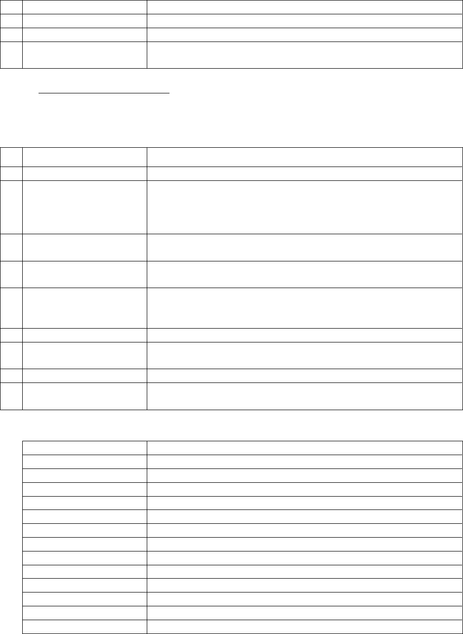
1.3.3.1 Operations. Table 1 identifies guidance for aligning, starting, stopping and changing
modes of operation of systems and equipment.
Table FWD-1 Operating Systems and Equipment
Precedence Examples
1 Operating Setting
Advisories Issued
Before October 2009
Operating Advisories (Fleet Advisories, Class Advisories). Gas
Turbine Technical Directives (GTBs, AYBs, etc.)
2 Operating Procedures Operating Sequence Systems (EOSS, CSOSS, AFOSS, etc.)
Reactor Plant Manual, Steam Plant Manual, Steam & Electric
Plant Manual, Ships System Manuals
3 Technical Manuals Component Technical Manuals, NSTM, OEM Technical
COMUSFLTFORCOMINST 4790.3 REV D CHG 3
07 Nov 2023
V-I-FWD-3
Manual
4 Directives SORM, EDORM, NAVORDS
5 Instructions NAVSEA Letters
6 Locally Generated OSS Following the Operating Sequencing Systems (OSS) Users
Guide
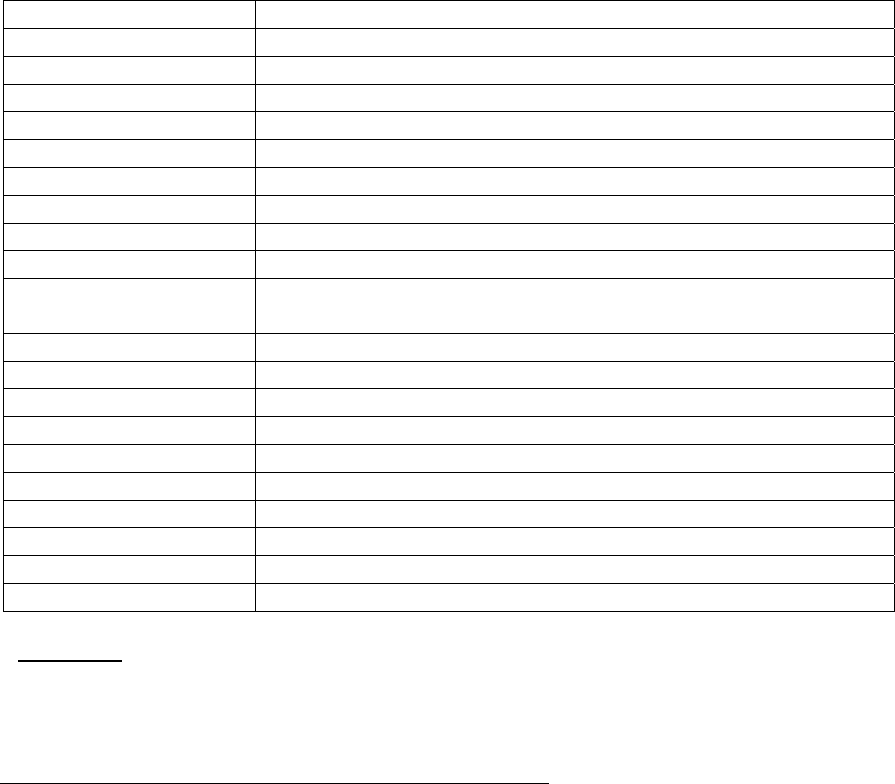
1.3.3.2 Maintenance and Technical. Table 2 identifies guidance used for preventive
maintenance, troubleshooting, assessment, alignment, calibration, non-permanent changes and
TEMPALTs.
Table FWD-2 Maintenance and Technical Documents
Precedence Examples
1 DFS and Requirement
Setting Advisories
Issued before October
2009
DFS, LA
R
-Waiver, Fleet Advisories, Class Advisories, Gas
Turbine Technical Directives (GTBs, AYBs, etc.)
2 PMS MRCs, PMRs, Steam Plant Manual, Steam & Electric Plant
Manual, Maintenance Requirements
3 Requirements JFMM, P9290, 7010, 0010, SSCB, FBW, CRL, CMP, DDGOS,
GSO, URO-MRC, SOC Noteboo
k
4 Drawings NAVSHIP drawings, BUSHIP Drawings, NAVAIR Drawings
TVDs, SYSCOM Approved Vendor Drawings, DDS Approved
Drawings
5 Technical Manuals Component Technical Manuals, NSTMs
6 Directives SORM, EDOM, NAVORD, SYSCOM Technical Bulletins,
Type Commander Technical Notes
7 Instructions NWPs, SYSCOM Instructions
8 Maintenance
Procedures
FWPs, CWPs, TWDs, UIPIs, PPIs, Maintenance Standards,
Handbooks
The following abbreviations are used in Table FWD-2:
0010 SUBSAFE Manual
7010 Material Control Standar
d
AFOSS Aviation Fuels Operational Sequencing Syste
m
AYB Ancillary Equipment Bulleti
n
CMP Class Maintenance Pla
n
CRL Calibration Requirements List
CSOSS Combat Systems Operational Sequencing System
CWP Controlled Work Package
DDGOS Deep Diving General Overhaul Specifications
DDS Dry Deck Shelte
r
DFS Departures From Specificatio
n
EDOM Engineering Department Organizational Manual
EOSS Engineering Operational Sequencing System
FBW Fly-By-Wire
COMUSFLTFORCOMINST 4790.3 REV D CHG 3
07 Nov 2023
V-I-FWD-4
FWP Formal Work Package
GSO General Specifications for Overhaul
GTB Gas Turbine Bulletins
JFMM Joint Fleet Maintenance Manual
LA
R
Liaison Action Requests
NAVORD Naval Ordinance
NSTM Naval Ships Technical Manual
NWPs Naval Warfare Publications
OEM Original Equipment Manufacture
r
OSS Operational Sequencing System
P9290 System Certification Procedures and Criteria Manual for Deep
Submergence Systems
PM
R
Planned Maintenance Requirements
PPI Portsmouth Process Instructio
n
SOC Scope of Certificatio
n
SORM Ships Organization Requirements Manual
SSCB SUBSAFE Certification Boundary Boo
k
SYSCOM System Command
TVD Technical Variance Document
TWD Technical Work Document
UIPI Uniform Industrial Process Instruction
URO MRC Unrestricted Operations Maintenance Requirement Car
d
1.3.4 Advisories. Commencing with Revision B CH-2, advisories (bulletins, class advisories,
Fleet advisories, In-Service Engineering Activity advisories, etc.) will no longer be used to
change or set requirements. Any change to requirements will be done by an appropriate
document change form (e.g., Advance Change Notice (ACN)).
1.4 NEED FOR QUALITY MAINTENANCE PROCESSES.
a. Quality maintenance processes play a vital role in the mission capability and personnel
safety of many organizations. The three examples in sub-paragraphs (1) through (3)
demonstrate how actions, which seem small and insignificant can result in severe
consequences. In all cases, if a strong and effective quality process had been in effect,
the tragic results may have been averted.
(1) On April 10, 1963, while engaged in a sea trials deep dive off the coast of
Maine, a flooding casualty occurred in the engine room of the USS
THRESHER (SSN 593). A piping failure in one of the salt water systems was
subsequently determined to be the most likely cause for the loss of the ship and
all personnel onboard. The comprehensive investigation, which followed,
recommended numerous changes in the design and maintenance processes for
submarines resulting in the Submarine Safety (SUBSAFE) Program, as it is
known today.
(2) On January 28, 1986 the space shuttle Challenger was launched from Cape
Canaveral Florida. Seventy-three seconds into flight, the spacecraft exploded
and seven astronauts lost their lives. Subsequently, on June 6, 1986 a

COMUSFLTFORCOMINST 4790.3 REV D CHG 3
07 Nov 2023
V-I-FWD-5
Presidential Commission concluded that the cause of the Challenger accident
was the failure of the pressure seal in the aft field joint of the right solid rocket
motor. Neither the National Aeronautics Space Administration nor the rocket
engine builder developed a solution to the unexpected occurrences of O-ring
erosion and blow-by, even though this problem was experienced frequently
during shuttle flight history. The commission further concluded that a quality
program would have tracked and discovered the reason for increasing erosion
and blow by. Additionally, the commission found that the pressure to fly a
launch schedule of 24 flights a year created pressure throughout the agency
that directly contributed to unsafe launch operations. In short, the syndrome of
“they’ve operated with that problem before and the risk is small” prevailed.
The safety and technical requirements became secondary to operational
commitments.
(3) On October 30, 1990, a major steam leak occurred in the fire room on board
USS IWO JIMA (LPH 2) resulting in the deaths of ten watch standers. The
investigation determined the cause to be failure of the bonnet fasteners of a
ship service turbine generator root valve. The valve had just been repaired by
a shipyard where the bonnet fasteners were replaced with mis-matched and
incorrect material. The required fasteners were heat-treated steel studs and
nuts. The fasteners installed during the maintenance were a mixture of bolts,
studs and black oxide coated brass nuts. The high temperature and pressure
placed on the fasteners during plant light off caused the brass nuts to fail
catastrophically, which allowed the valve bonnet assembly to separate from the
body. The replacement fasteners were furnished by Ship’s Force, but no one
(ship or shipyard) checked the fasteners, prior to installation, to ensure that the
requirements of the technical manual and drawings were met.
b. The examples in sub-paragraph “a” clearly demonstrate that, with the technical
complexity of present day surface ships and submarines, the need for special
administrative and technical controls necessary to ensure conformance to technical
specifications during maintenance and testing is necessary. The necessity to perform
the work correctly and following technical specifications is paramount in order to
preclude loss of life or loss of a ship. The quality program was developed to assure
maintenance of the modern day Fleet is performed following technical specifications,
thus ensuring the highest state of material readiness.
c. The fundamental rule for all maintenance is that technical specifications must be met
at all times. If for some reason the specified technical requirements cannot be met,
acceptable alternatives must be approved by the appropriate authority and documented
as a Departure from Specification or Liaison Action Request (LAR) prior to the
continued operation of the ship.
1.5 CHANGES AND CORRECTIONS. Changes, corrections and updates to this volume will
be made by the Fleet as required to maintain the volume current with higher authority technical
requirements. When higher authority directives are issued which impose more stringent
requirements, the Fleet will issue implementing instructions. Comments and suggestions for
improving this volume are encouraged from all users. Address comments, recommendations and
COMUSFLTFORCOMINST 4790.3 REV D CHG 3
07 Nov 2023
V-I-FWD-6
proposed changes to Submarine Maintenance Engineering, Planning and Procurement Activity
using the manual change request form in the front of this volume. If changes are submitted in
electronic format, faxed or E-mail, each change request must contain the information required on
the Change Request Form.

COMUSFLTFORCOMINST 4790.3 REV D CHG 3
07 Nov 2023
V-I-FWD-A-1
APPENDIX A
APPENDIX A
GLOSSARY OF TERMS
TERM DEFINITION
Acceptance Trials Trials and material inspections conducted underway by the INSURV
Board for ships constructed in a private industrial activity to determine
suitability for acceptance of a ship by the Navy.
Accepting Authority The officer designated by the Chief of Naval Operations (CNO) to
accept a vessel for the Navy, normally NAVSEA.
Acid Spot Test See Generic Material Verification or Identification.
Additive
Manufacturing
Additive manufacturing, also known as 3D printing, is a process used
to create a physical (or 3D) object by layering materials one by one
based on a digital model. Unlike subtractive manufacturing that
creates its final product by cutting away from a block of material,
additive manufacture adds parts to form its final product.
Alpha Trial Builders Propulsion Trial; Acceptance Trial for SSN, SSBN, SSGN
Propulsion Plant; Initial Tightness Dive (SSN, SSBN, SSGN); Dive to
Maximum Authorized Depth (Selected SSN platforms).
Annual Within 12 calendar months beginning on January 1 at 0000hr and
ending on December 31 at 2359hr.
As Built Drawing Drawings approved by the Planning Yard (PY), used for installation,
and revised to indicate the actual “as installed” configuration on the
ship.
Assist Work Center The Work Center or group on board ship or at a repair activity with
responsibility for accomplishment of a work or maintenance
procedure as assist to or under direction of a Lead Work Center.
Audit
A detailed analysis and evaluation of records to determine compliance
with existing requirements.
Backup Valve A valve which, when closed, provides, in part or in whole, the
secondary isolation boundary to sea pressure.
Boundary The specific limits of the physical area involved in work and testing
accomplished. That line, point or location identified as the border
between controlled and uncontrolled areas. Depending on the type of
system involved, it means the system component nearest to the work
area which is operated to regulate or shut off the flow of fluid or de-
energize electricity to the portion of the system which is being
worked.

COMUSFLTFORCOMINST 4790.3 REV D CHG 3
07 Nov 2023
V-I-FWD-A-2
APPENDIX A
TERM DEFINITION
Bravo Trial Normally the initial Dive to Test Depth; Noise Trial (SSN, SSBN,
SSGN); Strategic Weapons System Missile Testing (SSBN); Weapons
testing (Surface Combatants).
Builder’s Trials Evaluation trials and inspections conducted underway by the builder
to assure the builder and the Navy that the ship is, or will be, ready for
Acceptance Trials. These trials should be a comprehensive test of all
ship’s equipment and be similar in scope to Acceptance Trials. For
nuclear powered surface ships, this is the Acceptance Trial for the
Nuclear Propulsion plant.
Casting A part formed by pouring molten metal into a mold.
Certification To provide assurance, in writing, that the component or system
conforms to the technical requirements.
Certification
(Material)
The process of receipt inspection of material received from the Naval
Supply System, which establishes the correct level of essentiality and
acceptability of the material following the appropriate specifications
and material control standard.
Certified Oxygen
Clean
Certified Oxygen Clean applies to material, which is intended for or
installed in shipboard oxygen generating, storage and distribution
systems. The Naval Sea Systems Command (NAVSEA) source
document, which governs certification of oxygen cleanliness, is MIL-
STD-1330, Standard Practice for Precision Cleaning and Testing of
Shipboard Oxygen, Helium, Helium-Oxygen, Nitrogen and Hydrogen
Systems.
Certifying Activity The activity, approved by Systems Command, that is qualified to
complete all of the necessary certifying requirements of the particular
specification or standard.
Change In
Configuration
Ship’s configuration is defined by drawings and drawing revisions
specified in the Ship’s Drawing Index and by equipment technical
manuals applicable to equipment installed in the ship following these
drawings. Changes, which do not conform to these documents are a
change in configuration. For example:
a. Material substitutions.
b. Pipe joint additions or deletions.
c. Significant rerouting or relocation of piping, cabling and
equipment.

COMUSFLTFORCOMINST 4790.3 REV D CHG 3
07 Nov 2023
V-I-FWD-A-3
APPENDIX A
TERM DEFINITION
d. Seal welding of normally mechanically sealed assemblies.
e. Changes in piece dimensions.
Charlie Trial Combat Systems and retesting (SSN, SSBN, SSGN); Acceptance
Trials (DDG).
Cleanliness a. Reactor Plant - Minimum reactor plant cleanliness requirements
according to NAVSEA 0989-064-3000; Cleanliness
Requirements For Nuclear Propulsion Plant Maintenance and
Construction.
b. Steam Plant - Minimum steam plant cleanliness requirements
according to NAVSEA 0989-064-3000.
c. Commercial Cleanliness - A term that is used to describe the
minimum level of cleanliness, which should be maintained during
work on propulsion plant systems and equipment not covered by
NAVSEA 0989-064-3000. Commercial cleanliness is the
absence of foreign material, which could, if present, interfere with
the function of these systems and components.
d. Oxygen System - Minimum oxygen system cleanliness
requirements according to MIL-STD-1330, Standard Practice for
Precision Cleaning and Testing of Shipboard Oxygen, Helium,
Helium-Oxygen, Nitrogen and Hydrogen Systems.
Cleanliness Inspector
or Certifier
Individuals trained and qualified to perform cleanliness inspections
required by work procedures for systems or components requiring
cleanliness controls.
Coaming (Submarine) The structure surrounding holes in, and extending through one or both
sides of the pressure hull structure. They are usually connected by a
corner or tee weld. They provide complete or partial strength
compensation for the hole. Coamings are used for items like
manholes. Hull valves generally use an insert.
Combined Trials Combined Trials are a combination of an Acceptance Trial with a
Final Contract Trial. The INSURV Board normally conducts
Combined Trials for nuclear powered submarines.
Component A self-contained combination of parts, subassemblies, or assemblies
which performs a distinctive function in the overall operation of an
equipment.

COMUSFLTFORCOMINST 4790.3 REV D CHG 3
07 Nov 2023
V-I-FWD-A-4
APPENDIX A
TERM DEFINITION
Component Drawing A vendor, NAVSEA, or shipbuilder drawing which shows the
assembly and details of a component such as a valve or pump.
Sometimes it is divided into two drawings, one showing the assembly
and the other the details. The component drawing list of material
usually has a column entitled Material Identification and Control
(MIC) level. It is this column on the list of material that is the source
of information on whether a piece has a non-nuclear designation of
Level I or Level NA (Not Applicable). A material designation does
not normally appear on a component drawing list of material. It is
shown instead on a Quality Assurance List (QAL). If a component
drawing list of material has no MIC level column, then drawing notes
should be reviewed to determine if one or more parts are Level I.
Continuity of
Submarine Safety
Certification
A status defined by those procedures, tests, and inspections required
when hardware is renewed or replaced within the Submarine Material
Certification Boundary, as well as the periodic checks or inspections
required to assure continued satisfactory material condition for
certification.
Controlled Assembly Process used for Re-Entry Control (REC) Exceptions or Exceptions to
Retest Requirements for Mechanical Joints and consists of:
a. Verification that surface finishes of gasket and O-ring sealing
surfaces are following applicable specifications.
b. Verification that fastener material and installation is following
applicable specifications.
c. Verification that gaskets and O-rings are properly installed and
following applicable specifications.
d. Assembly is documented on a Quality Assurance (QA) form 34.
e. Inspected by a Quality Assurance Inspector (QAI) or Quality
Assurance Supervisor (QAS).
Controlled Dive Conduct of a dive in incremental stages by a submarine to maximum
authorized operating depth as measured to the keel to accomplish
inspections of those joints and penetrations worked within certified
boundaries and not tested prior to ship’s underway.
Controlled Material Any material which must be identified, verified and regulated
throughout the manufacturing, installation or repair process in order to
meet the specifications required of the end product. Controlled
material is comprised of the following:

COMUSFLTFORCOMINST 4790.3 REV D CHG 3
07 Nov 2023
V-I-FWD-A-5
APPENDIX A
TERM DEFINITION
a. Three special classes of material requiring NAVSEA or Naval
Inventory Control Point mandated controls while held in the
supply system and control and certification by the end user by use
of the procedures in Part I, Chapter 6 of this volume:
1. Non-Nuclear Level I.
2. Submarine Flight Critical Component.
3. Nuclear Level I.
b. Material which NAVSEA considers to be of sufficient criticality
to warrant basic receipt inspection by the end user and segregated
storage while in supply or a work center, but not necessarily the
control and certification required by Part I, Chapter 6 of this
volume:
1. Naval Nuclear Propulsion Plant Material stocked with SMIC
X1, X3 or X5 (instrumentation drawers, low chloride
lagging).
2. Non-Nuclear Materials stocked with SMIC SQ, CP, DG, QA,
SP or VG.
3. HY-80, 100 or 130 plate.
Controlled Material
Handler
An individual at the TRIDENT Refit Facilities who is qualified to
perform the duties of a Controlled Material Petty Officer.
Controlled Material
Petty Officer
An individual responsible for the receipt inspection and control of
SUBSAFE, Level I, SAED, SAQAM, Project Target, Nuclear Level I
and Scope of Certification materials after issue from the supply
system.
Controlled Work
Package
The records that provide the Objective Quality Evidence (OQE)
necessary to certify that the completed maintenance was authorized,
required tests were completed and work was certified. This consists of
the Formal Work Package (FWP) and OQE.
Craftsman A mechanic or other individual trained in QA methods and procedures
(i.e., inspections, cleanliness, testing, documentation) to perform
maintenance on ship’s systems or components.
Deep Dive The first dive to maximum operating depth. This depth will not
necessarily coincide with the design test depth of the hull. See

COMUSFLTFORCOMINST 4790.3 REV D CHG 3
07 Nov 2023
V-I-FWD-A-6
APPENDIX A
TERM DEFINITION
definition of Maximum Operating Depth.
Defect An imperfection that impairs completeness or quality or does not meet
required specification.
Delivery The date the Navy accepts the ship from the ship builder. This
requires a recommendation from the INSURV Board to accept or
deliver the ship. Delivery of the ship is based on Acceptance Trials
and satisfactory correction or resolution of deficiencies.
Departure From
Specification
A lack of compliance with any authoritative document, plan,
procedure, instruction, etc. See Part I, Chapter 8 of this volume for
more information.
Design Intent The revision of a drawing from which the original equipment or part
was intended to be built, or the revision to which design intends the
ship to be built. This revision is typically reserved for use by planning
yards and should not be used by Organizational and Intermediate level
maintenance activities.
Detrimental Material A material which, when contacting hardware, may have a deleterious
effect on the hardware.
Deviation Any non-conformance of a component or product with specified
requirements.
Dock Trial Dock Trials are those ship trials conducted at the Industrial Activity to
determine the ability of the ship, from a material standpoint, to
conduct Sea Trials safely.
Documentation The records of OQE establishing the requisite quality of the material,
component or work accomplished. Documentation should be
traceable from the item to the records and be filed in an auditable
manner.
Downgrading The formal process used to decertify (removal of MIC mark(s),
general identification marks, and in some cases demilitarize)
controlled material for general use or disposal.
Electrode A consumable filler metal which fuses during the welding process and
becomes an integral part of the material or non-consumable electrode
that fuses the metal during the welding process, but does not become
an integral part of the material (e.g., tungsten).
Emergent Work,
Emergent Repair,
A task which requires immediate repair in order to correct mission

COMUSFLTFORCOMINST 4790.3 REV D CHG 3
07 Nov 2023
V-I-FWD-A-7
APPENDIX A
TERM DEFINITION
Emergent
Maintenance
impacting maintenance.
Face Feeding The manual addition of brazing alloy at the intersection of the fitting
face and the pipe. Supplemental face feeding is the addition of
brazing material to increase fillet size.
Fast Cruise A period immediately prior to underway trials during which Ship’s
Force operates the ship for dockside training. Fast Cruise must, as far
as is practical, simulate at-sea operating conditions.
Final Contract Trials Trials that are conducted prior to the end of the guarantee period to
determine if there are any defects, failures, or deterioration other than
that due to normal wear and tear.
Fleet Introduction
Team
A team of personnel assembled to support a pre-commissioning crew
by monitoring progress of construction and coordinating training and
facilities. They provide administrative support in all facets of new
construction.
Fleet Maintenance
Activity
FMAs include tenders, shore based maintenance activities (Regional
Maintenance Centers, Naval Ship Repair Facilities, Naval Submarine
Support Facilities, Naval Intermediate Maintenance Facilities
(NAVIMFAC), TRIDENT Refit Facilities, Weapons Repair Facilities
and other activities of that type) and supporting activities (port
services, etc. that perform maintenance on Fleet assets).
Fly-By-Wire Ship
Control System
A Ship Control System in which the controls are actuated by electrical
impulses, as from a computer.
Foreign Material Any material or object that should not be on or within clean hardware.
Examples include, grit, chips, particles, oil, slag, scale, fibers, tape,
tools, and loose articles.
Forging Defined as a part formed by hammering or pressing a piece of heated
metal to form a shape.
Formal Work Package Written instructions, prepared per Part I, Chapter 2 of this volume for
use in production and repair, delineating all the essential elements and
guidance necessary to produce acceptable and reliable products.
Gas System
Cleanliness Inspector
or Certifier
Any person qualified under the requirements of this manual to
perform the tasks of initial, in-process and final Cleanliness
Certification Inspections for Gas systems.
Generic Material A broad identification of materials by simple, direct and rapid analysis

COMUSFLTFORCOMINST 4790.3 REV D CHG 3
07 Nov 2023
V-I-FWD-A-8
APPENDIX A
TERM DEFINITION
Verification or
Identification
methods or a combination of methods (e.g., Color, Magnetic
Properties Test, Acid Spot Tests, Metal Comparator Tests). These
tests are designed for simple screening and identification of materials
by alloy family (as opposed to classification of specific alloys within a
family).
Group Normally that first 1-Star organization or Command above the
Squadron before to TYCOM.
Guarantee Material
Inspection
A material inspection, conducted in port prior to Post Shakedown
Availability (PSA) by a Trial Board prior to the end of the guarantee
period when CNO has authorized a Combined Trial to determine if
contractor responsible equipment has operated satisfactorily during
the guarantee period. It must include the opening and inspection of
equipment designated by the Board together with the operation and
visual inspection of equipment and the review of material
maintenance records.
Guarantee Period
(New Construction)
The period of time immediately following preliminary acceptance
(delivery), normally eight or nine months (six months for nuclear
powered ships), for which the industrial activity is responsible for the
correction of deficiencies.
Guarantee Period (Post
Shakedown
Availability)
The guarantee period following PSA varies with the type of contract.
Historically, a “cost plus” type contract has had a guarantee period of
six months and a “fixed price” type contract a period of 90 days. The
Supervising Authority will advise at the time of PSA the guarantee
that applies.
Homogeneous Lot
a. Nuclear: A lot of material in which each piece is manufactured
from the same heat, batch, or melt or has the same vendor
traceability code number.
b. Non-Nuclear: A group of like items that are produced in a
common heat or batch or are produced under continuous cast or
pour process with the same vendor traceability numbers, are of
the same nominal size, and are received in a single shipment. For
batch or continuous cast or pour processes, samples for chemical
and mechanical properties must be taken no less than once in
every 8 hours of operation. If additional production processes are
used that alter the mechanical properties of the material (e.g.,
heat-treat, cold or hot forge, extrusion), then all items of the same
“Heat” number and additionally processed under the same
conditions at the same time must be considered as a homogeneous
lot.

COMUSFLTFORCOMINST 4790.3 REV D CHG 3
07 Nov 2023
V-I-FWD-A-9
APPENDIX A
TERM DEFINITION
Hull Integrity
Boundary
Pressure hull plating (shell plate), pipe, components, etc., NPS 1/2
inch and larger, from the inboard joint of the backup valve (or
equivalent) outboard to the hull.
Hull Integrity
Fasteners
Hull Integrity Fasteners (HF) are male threaded type items such as
bolts, socket head cap screws, studs and bolt studs which are loaded
by the differential sea pressure and internal hull pressure, and which
are a part of pressure hull integrity components or of systems
penetrating the Pressure Hull Structure, from the pressure hull to and
including the inboard joint of the backup valve or its equivalent. Nuts
and lock-washers are specifically excluded.
Hull Valve A valve which, when closed, provides, in part or in whole, the first
isolation boundary to sea pressure. The hull valve may also be
referred to as the primary closure.
Immediate Superior In
Command
The ISIC is defined as:
a. For Submarines - The Squadron or Group.
b. For Aircraft Carriers - The TYCOM. The TYCOM may
designate a representative in carrying out certain Immediate
Superior in Command functions.
c. For Surface Forces - The Command holding administrative
control.
Industrial Activity The activity responsible for accomplishing construction or repair of
ships whether private or public. This includes Naval shipyards,
private shipyards, shipbuilders, vendors, Naval Aviation Depots,
Naval Ship Repair Facilities, and other Naval Repair and Technical
Activities (Naval Underwater Weapons Center, Naval Ships Weapons
Center, etc.).
Initial Dive For purposes of seawater valve and system testing, as defined in
NAVSEAINST C9094.2, the first dive to a depth not previously
reached during the trials.
Initial Tightness Dive First submergence (a submarine’s Alpha Trial).
In-Process
Surveillance
The review of work in progress by personnel not directly involved
with the work to assess such attributes as tagging and installation of
controlled material, compliance with technical procedures, and
recording of required data.

COMUSFLTFORCOMINST 4790.3 REV D CHG 3
07 Nov 2023
V-I-FWD-A-10
APPENDIX A
TERM DEFINITION
In-Service Nuclear powered ships are assigned an active status of In-Service
approximately two to four weeks (two to four months for aircraft
carriers) prior to the commencement of Sea Trials and maintain this
status until commissioning.
Inspection A certification conducted by a separate individual qualified as an
inspector (QAS, QAI, Cleanliness Certifier or Cleanliness Inspector,
Nondestructive Test (NDT), Radiological Controls Monitor,
Radiological Controls Shift Supervisor) on any system or component,
which by its nature, is critical to the successful completion of the task.
Inspection Record Record data showing the results of an inspection with appropriate
identifying information as to the characteristics inspected and item
inspected.
INSURV Prior to the acceptance and delivery of a new ship, whether built by a
private or naval industrial activity, all machinery, electronics and
weapons systems installed must be subjected to acceptance trials to
determine that the installations are capable of meeting performance
specifications. Depending upon your platform, these trials are
referred to as either Acceptance Trials, Combined Trials or INSURV.
This independent verification of the ship’s readiness for acceptance
and recommendation for fleet introduction is the responsibility of the
President, Board of Inspection and Survey.
Latest Revision The most recent authorized revision and change level of a drawing.
The latest revision of a hull applicable drawing may not identify
current configuration for a specific hull.
Leading Petty Officer
or Work Center
Supervisor
That person as defined by the appropriate Organization and
Regulations Manual, responsible for ensuring the quality of work
performed by his or her work center.
Lead Work Center The Work Center or group on board ship or at a repair activity with
prime responsibility for accomplishment of a work or maintenance
procedure.
Level I A designation for systems and components for which the Navy requires
a high degree of assurance that chemical composition and mechanical
properties of the installed materials meet the specified requirements.
Level of Essentiality A range of controls in two broad categories representing a high degree
of confidence that procurement specifications for piping system
components have been met. These categories are:

COMUSFLTFORCOMINST 4790.3 REV D CHG 3
07 Nov 2023
V-I-FWD-A-11
APPENDIX A
TERM DEFINITION
a. Verification of material, which ensures that the manufacturer has
complied with procurement requirements for chemical
composition and physical properties of the material.
b. Confirmation of satisfactory completion of tests and inspections
required by the ordering data (e.g., Liquid Penetrant Testing (PT),
dimensions, hydrostatic strength and porosity).
Liaison Action
Request
A request for technical concurrence from Planning Yard or NAVSEA.
Procedures for requesting information from the Reactor Plant Planning
Yard are contained in Commissioned Submarine General Reactor Plant
Overhaul and Repair Specification (NAVSEA 0989-LP-037-2000),
Nuclear Support Facilities Overhaul and Repair Specification
(NAVSEA 0989-LP-058-1000), Commissioned Surface Ship General
Reactor Plant Overhaul and Repair Specification (NAVSEA 0989-043-
0000) and TYCOM instructions. For non-nuclear systems and
components, the LAR can be in any format which is convenient for the
user, provided that it is identified as a LAR, clearly defines the exact
information needed, lists the drawings in question, and states the date
by which a reply is requested to support ship schedules. Volume II of
the Fleet Modernization Program Management and Operations Manual
contains a format for a non-nuclear LAR which FMAs may adapt for
their use.
Loss of Traceability A situation in which controlled material cannot be positively traced to
the results of chemical and physical testing performed to prove that the
material is that required by the specification to which it was made or
bought. In each instance of loss of traceability, the FMA or ship
Quality Assurance Officer must initiate action to restore traceability or
use alternate, traceable material.
Maintenance
Certification Record
The record (QA form 9) used to document the physical work
boundaries, define the work involved, specify the material control and
fabrication control procedures, specify inspection and test
requirements, list the certification records involved, and provide
approval and acceptance signatures and dates for work within the
SUBSAFE boundary, a nuclear system or a Level I system or
component.
Maintenance Manager Those persons, such as Port Engineers, Ship Superintendents, Ship’s
Coordinators, and Maintenance Planning Managers, assigned to assist
Ship’s Force in the tracking of work candidates, development of work
packages, and tracking of FMA or Industrial Activities assigned jobs.
Maintenance Defines maintenance inspections and actions associated with the

COMUSFLTFORCOMINST 4790.3 REV D CHG 3
07 Nov 2023
V-I-FWD-A-12
APPENDIX A
TERM DEFINITION
Requirement Card Planned Maintenance System (PMS).
Maintenance Standard (Submarines only) A document which specifies minimum technical
requirements for acceptable refurbishment of submarine components,
including inspection and testing criteria and parts replacement
information, following NAVSEA maintenance plans.
Major Repair Non-nuclear major repairs are those repairs which:
a. Structurally affect the pressure-containing portion of a piping
system or component through welding (except as defined under
Minor Repair), brazing or other fabrication process, including new
mechanical joints in which a flange or union tailpiece is replaced
using a weld or braze.
b. Involve installation of new pressure boundary parts or components
which have not been previously strength tested.
Mapping Drawing A diagrammatic drawing, verified by ship check, that identifies and
specifies the location of elements which must meet a SUBSAFE
requirement of NAVSEA
0924-062-0010, SUBSAFE Requirements Manual. Pipe joints, flexible
connections and castings are examples of items identified on the
mapping drawing. Pipe joints are each numbered (e.g., MSW-56178)
and the type of joint identified (e.g., WB - butt weld). The mapping
drawing will also reference a QAL as applicable. Mapping drawings
are discussed in the introductions of the SUBSAFE Certification
Boundary Book. Most of the symbols seen on a mapping drawing are:
BF - Brazed joint, face fed SL - Seal
BP - Brazed joint, pre-inserted
ring
U - Threaded pipe union
CN - Casting WA - Welded attachment
F or FG - Flange WB - Butt weld
FH - Flexible connection WF - Fillet weld
HF - Hull Integrity Fastener WL - Seal weld
IN - Pressure hull insert WM - Bimetallic weld
PE - Penetration WN - Welded nozzle

COMUSFLTFORCOMINST 4790.3 REV D CHG 3
07 Nov 2023
V-I-FWD-A-13
APPENDIX A
TERM DEFINITION
PF - Pressure hull fitting WR - Root connection (or boss)
PM - Pressure hull penetrating
mast
WS - Socket weld
Material Identification
and Control Number
or Marking
A unique number assigned to certified material by the Certifying
Activity (for material) which provides traceability to OQE following
the applicable Material Control Standard.
Maximum Operating
Depth (Also
Maximum Authorized
Operating Depth)
The depth to the keel for a particular submarine which is authorized by
Commander Submarine Forces Atlantic or Commander Submarine
Forces Pacific upon the recommendation of NAVSEA, as the depth not
to be exceeded in operations. This depth is normally the Test Depth
but may be reduced in specific cases. The depth authorized may be
less than, but in no case exceed, the depth recommended by NAVSEA.
Minor Repair Minor repairs are operations that could be considered maintenance
such as replacing packing and pressure seal ring, lubricating, lapping or
grinding of seats, and replacing damaged parts such as stems and discs.
For the purpose of this manual the definition in Naval Ships’ Technical
Manual Chapter 505 or NAVSEA S9074-AR-GIB-010/278, whichever
is applicable, is used for the term “Minor” repair.
Moderate Speed The range of speed that allows the submarine optimum recovery (as
shown on applicable submerged operating envelope curves) if loss of
stern plane control, flooding, or both, occurs. Normally 8-15 knots.
Naval Supervisory
Authority or
Supervisory Authority
The officer designated to represent the Navy Department at an
industrial activity; normally a Supervisor of Shipbuilding (new
construction), Regional Maintenance Center (Conversion and Repair)
or the Commander of a Naval Shipyard.
New Mechanical Joint A joint where either a flange or union is replaced. A new mechanical
joint is a major repair and requires a hydrostatic test to the specific
requirements of a particular system.
Nominal Operating
Pressure
The approximate pressure at which an essentially constant pressure
system operates when performing its normal function. This pressure is
used for the system basic pressure identification.
Nondestructive
Testing
All methods of testing used to detect or measure the significant
properties or performance capabilities or material, parts, assemblies,
equipment, or structures which do not impair the service ability of the
parts tested. These tests include:

COMUSFLTFORCOMINST 4790.3 REV D CHG 3
07 Nov 2023
V-I-FWD-A-14
APPENDIX A
TERM DEFINITION
a. Radiographic Testing (RT).
b. Magnetic Particle Testing (MT).
c. Liquid Penetrant Testing (PT).
d. Ultrasonic Testing (UT).
e. Visual Testing (VT).
f. Eddy Current Testing (ET).
Nondestructive
Testing (NDT)
Supervisor
The NDT Supervisor is the individual designated by the respective
Division Officer and is qualified in specific methods for which they
are designated NDT Supervisor. (There may be more than one NDT
Supervisor in an organization.)
Nuclear Regional
Maintenance
Department (NRMD)
NRMD performs intermediate level nuclear maintenance and repair
work, consolidating efforts in a regional area, thus eliminating
duplication of infrastructure and maximizing effective use of funds.
This is accomplished by the use of military personnel integrated into
the experienced nuclear production, radiological and engineering
resources of the parent shipyard. NRMDs are an expansion of their
parent shipyard.
Objective Quality
Evidence
Any statement of fact, either quantitative or qualitative, pertaining to
the quality of a product or service based on observations,
measurements, or tests which can be verified. (Evidence will be
expressed in terms of specific quality requirements or characteristics.
These characteristics are identified in drawings, specifications, and
other documents which describe the item, process, or procedure).
a. Tests can be based on heat, batch, continuous cast or pour, or
other manufacturing processes, providing the manufacturer can
prove the test sample was representative of the material supplied.
b. Material supplied will bear a unique traceability marking and
report of supporting test quantitative data will bear an identical
marking.
Oxygen Clean
Inspector
A Cleanliness Inspector or Cleanliness Certifier qualified by the
Oxygen Clean Instructor and certified by the Department Head or
Commanding Officer to perform cleanliness inspections on systems
under the requirements of MIL-STD-1330.
Oxygen Clean An individual certified by his or her Commanding Officer to train and

COMUSFLTFORCOMINST 4790.3 REV D CHG 3
07 Nov 2023
V-I-FWD-A-15
APPENDIX A
TERM DEFINITION
Instructor qualify personnel in the procedures and requirements of MIL-STD-
1330.
Oxygen Clean Worker An individual qualified by the Oxygen Clean Instructor and certified
by the Department Head to perform maintenance on systems under the
requirements of MIL-STD-1330.
Planning Yard The Naval Shipyard or other activity designated by NAVSEA to
perform the following tasks pertaining to specifically assigned ships:
a. To provide, or coordinate the provision of technical and other
services in design matters.
b. To be responsible for the availability of a complete up-to-date file
of working drawings, Selected Record Drawings, and Data.
c. To provide a central repository, reproduction, and distribution
services, or to coordinate such services, for working drawings,
Selected Record Drawings, and Data.
d. To provide these services to the fullest extent possible within the
limits of the funds provided.
Positive Material
Identification
Process by which the craftsman ensures that the material to be or
being installed is the correct material as specified by the plan,
technical manual, etc. This process is also referred to as “Positive
Material Identification and Verification”.
Post Shakedown
Availability
An industrial activity availability following Final Contract Trials or
Guarantee Material Inspection assigned to correct deficiencies found
during the shakedown period or to accomplish other authorized
improvements.
Pressure Boundary
Part
An item which separates an internal fluid from the atmosphere (or
another fluid at reduced pressure) or which joins two other pressure
boundary parts.
Pressure Hull Fittings All items and assemblies which penetrate the hull integrity boundary
and are attached either mechanically or by welds to penetrations,
inserts or plating. This includes structural, piping, mechanical and
electrical pressure hull fittings and mechanical stuffing boxes;
specifically excluded are all cables, O-Rings, V type packing or
packing around mechanical shafts.
Procedure Written instruction designed for use in production and repair,
delineating all the essential elements and providing guidance

COMUSFLTFORCOMINST 4790.3 REV D CHG 3
07 Nov 2023
V-I-FWD-A-16
APPENDIX A
TERM DEFINITION
necessary to produce acceptable and reliable products. The term
“procedure” includes PMS Maintenance Requirement Card (MRC),
technical manuals, reactor plant manuals, standard operating
procedures, ship’s instructions, etc.
Product Quality
Deficiency Reporting
A method for reporting deficiencies in new or newly reworked
material which may be attributable with contractual or specification
requirements or substandard workmanship performed by depots, naval
shipyards, contractors or subcontractors.
Q-Point Critical Quality Control Point. A work process, regardless of type
(maintenance, training, administrative, etc.), whose proper
accomplishment overwhelmingly affects the ultimate first time quality
success of the process.
Quality Assurance A systematic review of Quality Maintenance records and all
production actions which will provide adequate proof and confidence
that work performed or material manufactured will perform as
designed and that there is documentary evidence to this effect.
Quality Assurance
Inspector
The designated individual(s) in FMA and ship work centers who
inspect the work of other individuals, not their own work. Certified as
qualified by the Commanding Officer or Repair Officer.
Quality Assurance List (Submarines only) QAL on NAVSEA Drawings specify NDT
requirements for items scheduled for installation within the SUBSAFE
boundary during new construction. The QALs should only be utilized
for guidance subsequent to a ships’ commissioning, since they will not
necessarily reflect current NDT requirements.
Quality Assurance
Officer
An individual assigned the responsibility for the organization,
administration, training and execution of the QA Program.
Quality Assurance
Supervisor or
Specialists
Personnel assigned to the FMA Quality Assurance Officer to assist in
implementing the QA Program. QASs are certified as qualified by the
FMA Commanding Officer. A Quality Assurance Specialist is an
individual at the TRIDENT Refit Facilities who is qualified to
perform the duties of a QAS.
Quality Control On the job supervision, management and inspection which identifies
and ensures proper workmanship or materials are being produced.
Reactor Plant
Cleanliness Inspector
or Certifier
Any person qualified under the requirements of the manual to perform
the tasks of initial, in-process and final Cleanliness Certification
Inspections for Reactor Plant Systems.

COMUSFLTFORCOMINST 4790.3 REV D CHG 3
07 Nov 2023
V-I-FWD-A-17
APPENDIX A
TERM DEFINITION
Reactor Plant Work
Accomplishment
Report
A report submitted to the Reactor Plant Planning Yard by ships,
FMAs and shipyards which certifies work accomplished by them on
reactor plant hull integrity areas. These areas, identified on the ship
specific Reactor Plant Work Accomplishment Report, are nuclear and
are usually within the SUBSAFE boundary.
Re-Entry Includes any and all work and testing in a SUBSAFE certified system
including penetration of the pressure hull from the first breaching
through final grooming, testing and return to final operation, (e.g.,
breaking a mechanical flange, a sil-braze, or welded joint, removal of
a valve bonnet, repacking a gland).
Re-Entry Control The controls used to document the re-entry and re-certification of
SUBSAFE systems or components. The QA form 9 (Maintenance
Certification Record) is used to document the acceptance of a
completed SUBSAFE system Re-entry.
Reinstall To use or install the previously installed item or component.
Re-Made Mechanical
Joint
A flange or union joint which has been reassembled using existing or
new threaded fasteners on which no brazing or welding was
accomplished on the joint parts during the repair or modification
process.
Repair Refurbishment other than mere disassembly or cleaning.
Replace To install a new item or component.
Rework The unplanned repetition of a step or a series of steps in a Formal
Work Package.
Sample One or more units of a product selected at random from the material
or process represented.
Selected Record Data Tables, charts, drawing indices, allowance lists, damage control books
and other data (excluding drawings) specifically selected for their
reference value and maintained current throughout the life of the ship.
Selected Record
Drawing
A designated group of drawings made applicable to an individual ship
by illustrating final shipboard installations of important features,
systems and arrangements that must be maintained up to date and
correct throughout the life of the ship.
Ship Any submarine, surface ship, tender, or other vessel assigned to the
Fleet.

COMUSFLTFORCOMINST 4790.3 REV D CHG 3
07 Nov 2023
V-I-FWD-A-18
APPENDIX A
TERM DEFINITION
Ship’s Drawing Index A list of drawings, normally on microfiche, or Compact Disc Read
Only Memory (CD ROM) which applies to each ship. It lists ship
construction drawings, ship modification drawings and manufacturer
(vendor) component drawings. It is here that system diagrams,
mapping drawings and in some cases, QALs are identified by drawing
title or by a code in a column after the drawing title and number. The
SDI is located in ATIS and TVD applicability data.
Small Item Items that have a marking surface less than 3/8 of a square inch area.
Software Gaskets, packing and seals used in mechanical flange or union joints
in piping systems.
Special Cleanliness A requirement for components used in oxygen and nitrogen systems to
prevent combustion of contaminants and maintain purity of the gas.
The cleaning requirements are discussed in Naval Ships’ Technical
Manual Chapter 550, Industrial Gases: Generating, Handling and
Storage.
Special Material
Identification Code
A two-digit letter or number code at the end of the National Stock
Number or Navy Item Control Number to provide visibility to
designated items to ensure maintenance of their technical integrity.
The following SMICs from Appendix C of SPCCINST 4441.170 or
Appendix B of SPCCINST 4441.176 are for material commonly used
in the Fleet.
CP An item that requires special cleaning and packaging for oxygen
or nitrogen service (e.g., valves, piping system, generators).
C1 An item that requires special cleaning and packaging for oxygen
or nitrogen service (e.g., valves, piping system, generators) which
also must meet the requirements of Level I.
DG An item that requires special cleaning and packaging for oxygen
or hydrogen service (e.g., valves, piping system, generators).
D1 An item that requires special cleaning and packaging for oxygen
or hydrogen service (e.g., valves, piping system, generators)
which also must meet the requirements of Level I.
LI (Level I) An item that supports either a SUBSAFE or Level I
system that has undergone the extreme material control or QA
techniques that provide OQE of its acceptance for its appropriate
application. Each item has certification papers (or special
markings that provide traceability to the certification) that
pedigree its material and physical properties, provide traceability

COMUSFLTFORCOMINST 4790.3 REV D CHG 3
07 Nov 2023
V-I-FWD-A-19
APPENDIX A
TERM DEFINITION
to manufacturer, contract list and lot, and document the QA
system or test requirements applied to the item.
NT Annular ball bearings for quiet operation applicable to submarine
usage (noise tested bearings).
QA Equipment or parts requiring special material control and QA
which supports surface ship or submarine applications.
Q3 Items that support a Level I or SUBSAFE critical component or
system that has undergone QA during the acquisition process
(e.g., a ball and seat assembly utilized in a Level I or SUBSAFE
ball valve based on ship system application). This, however, does
not include Trash Disposal Unit, Signal Ejector, Salvage Air, and
open ended applications which are procured as Level I or
SUBSAFE. “Q3” SMIC invokes chemical and mechanical
certifications traceable to the heat code permanently marked on
the material. It should be noted that “Q3” SMIC coded material is
not receipt inspected or MIC marked by the receipt inspection
activities.
SP An item which is unique to the Navy Strategic Systems Program
Office controlled fleet ballistic missile weapon system. The
SMIC SP establishes a weapons system relationship but does not
signify the technical considerations as described in definition X2,
X3 and LI.
SQ SAQAM, which is administered by the SAED of the Naval Ship
System Engineering Station, Mechanicsburg Detachment. It
includes whole components and repair parts.
SW SEAWOLF Class Ship Control System approved Ships Flight
Critical Components.
S1 An item which is unique to surface ship applications which also
meets the requirements of Level I.
TR TRIDENT Ship’s Program.
VG Equipment or parts requiring special material control and QA
which support surface ship or submarine applications. Special
cleaning and packaging for oxygen or hydrogen service is
required.
VU VIRGINIA Class Ship Control System approved Ships Flight

COMUSFLTFORCOMINST 4790.3 REV D CHG 3
07 Nov 2023
V-I-FWD-A-20
APPENDIX A
TERM DEFINITION
Critical Components.
X1 NAVSEA Nuclear Propulsion Directorate (08) controlled material
identified as “2S” cognizance material with an “X1” SMIC.
X2 Naval Reactor Plant material which is specially designed,
manufactured or treated for use in a Naval Reactor Plant. In
addition, this material is inspected (or sample inspected) by a
Naval shipyard prior to being placed in Navy Supply System
Stock.
X3 Naval Reactor Plant material specially designed, manufactured or
treated for use in a Naval Reactor Plant.
X4 Naval Reactor Plant valves and auxiliary equipment used in
secondary Nuclear Level I applications which are technically
receipt inspected and certified as ready for use by a receipt
inspection activity.
X5 Naval Reactor Plant component level items not qualifying for X1,
X2, X4 or X6 SMIC assignment. This material is not inspected
by a Naval shipyard prior to being placed in Naval Supply Stock
and will not have a Ready-For-Issue tag attached.
X6 Naval Reactor Plant items specifically designed, manufactured or
treated for use in Level I Naval Reactor Plant applications. All
Level I items which do not qualify for SMIC X1, X2 or X4
assignment are assigned SMIC X6. Since the outer packaging of
material received from the Naval Supply System may not be
marked with an X6 SMIC, end users should consult applicable
logistics information (e.g., the Q Coordinated Shipboard
Allowance List, FEDLOG, Haystack, etc.) to determine the
current applicable SMIC assignment. If an X6 SMIC is currently
assigned in any of the applicable logistics information, the
material is considered pre-certified Level I material and does not
require a Ready-For-Issue tag.
X7 Naval Reactor Plant material qualified and marked as acceptable
for use in reactor plant clean and steam plant clean applications
under the technical cognizance of the Naval Sea Systems
Command (Directorate, Naval Nuclear Propulsion Program;
NAVSEA 08) that is managed by Navy Supply Systems
Command Weapon Systems Support and is specially designed,
manufactured or treated for use in both reactor plant clean and
steam plant clean applications.

COMUSFLTFORCOMINST 4790.3 REV D CHG 3
07 Nov 2023
V-I-FWD-A-21
APPENDIX A
TERM DEFINITION
Specification Any directive, whether technical or administrative, in any format, such
as instruction, technical manual, drawing, standard or publication.
Steam Plant
Cleanliness Inspector
or Certifier
Any person qualified under the requirements of this manual to perform
the tasks of initial, in-process and final Cleanliness Certification
Inspections for Steam Plant Systems.
Submarine Antenna
Engineering
Directorate -
Submarine Antenna
Quality Assured
Material
Submarine antenna material which is quality assured by the SAED,
(formerly the Submarine Antenna Quality Assurance Division) and
marked or recorded to ensure proper documentation and traceability
Submarine Safety
Certification
Investigative effort and corrective action developed under the
certification requirements for safety of submarine operations which
has as its specific aim an order of magnitude increase in the safety of
submarine operations. Accomplishment provides reasonable
assurance that the integrity of defined critical systems and
components, and the casualty recovery capabilities are adequate to
permit unrestricted operations to test depth.
SUBSAFE The acronym for Submarine Safety which applies to all submarine
classes. The SUBSAFE program provides a high level of confidence
in the material condition of the hull integrity boundary and in the
ability of submarines to recover from flooding and control surface
(e.g., bow, rudder, stern plane) casualties.
SUBSAFE Attribute Test and inspection requirements for SUBSAFE systems and
components.
SUBSAFE
Certification
That area within which the requirements of the SUBSAFE
Requirements Manual apply. It includes those inboard piping and
mechanical systems maintaining watertight integrity and recovery
capability from a flooding casualty.
SUBSAFE
Certification Boundary
Book
A book presenting simplified diagrams or sketches which show the
hull non-nuclear integrity and certified system boundaries for a
specific submarine, class of submarine or group of submarines within
a class.
SUBSAFE System A submarine system or component designed, installed and maintained
to:
a. Prevent flooding of the submarine (e.g., failure would cause

COMUSFLTFORCOMINST 4790.3 REV D CHG 3
07 Nov 2023
V-I-FWD-A-22
APPENDIX A
TERM DEFINITION
flooding of ship).
b. Enhance recovery in the event of flooding (e.g., flood control).
c. Ensure reliable submerged ship control (e.g., certain parts of the
steering and diving system).
d. SUBSAFE systems are shown in the SUBSAFE Certification
Boundary Book.
Surveillance Observations and analysis of actual work procedures and methods to
verify compliance with technical requirements.
System All components, piping, fittings, including electrical and mechanical
items, which together form and contribute to the operation of an
integrated functional arrangement. The “system” as used in this
manual is not limited to piping only unless “piping” is specified. Any
part which receives the fluid, controls, or is controlled by the fluid is
included.
System Design
Pressure (Non-
Nuclear)
System design pressure is the pressure used in the calculation of
piping and piping components minimum wall thickness and will not
be less than the maximum system pressure (for general guidance,
design pressure may be estimated within 2 to 3% by multiplying
maximum operating pressure by 112%).
Target Material or
Project Target
Material
As defined in NAVSEA S9213-45-MAN-000. All material issued
with a “Project Target Ready-For-Issue” tag for use as Nuclear Level I
is either X1, X2 or X4 SMIC coded.
Technical Data Recorded information (regardless of the form or method of recording)
of a scientific or technical nature (including computer databases and
computer software documentation). This term does not include
computer software or financial, administrative, cost or pricing, or
management data or other information incidental to contract
administration. The term includes recorded information of a scientific
or technical nature that is included in computer databases. For these
purposes, technical data includes the characteristic of a particular
science, trade or profession.
Technical Repair
Standard
See Maintenance Standard. Document which provides minimum
requirements for the acceptable repair and refurbishment of submarine
equipment and components and identifies planned and contingency
material necessary to ensure satisfactory operation until the next
planned maintenance action.

COMUSFLTFORCOMINST 4790.3 REV D CHG 3
07 Nov 2023
V-I-FWD-A-23
APPENDIX A
TERM DEFINITION
Technical Variance
Document
(Submarines Only) The documentation used to document
configuration changes made during an availability or refit that
influence a maintenance, alteration and repair, but will not be
incorporated in a revision to a drawing as accomplished on the ship.
Some examples of types of TVD:
1. Design-TVDs (DTVDs) are used in many instances, to identify
updates to design drawings in order to correct drawing errors, capture
changes, clarify information, provide alternate installation methods or
procedures or alternate material for those instances when it is not
warranted or cost effective to complete a drawing revision. DTVDs
should not be utilized when significant changes have occurred and are
not authorized as the sole means to change information for
provisioned items. Design-TVD is typically provided through a
Liaison Action Request or Reverse Liaison Action Request or through
a D-Type Engineering Report in New Construction. Work performed
in accordance with Design-TVD is not considered a non-conformance
and is not subject to additional approvals as a non-conformance.
Incorporation of drawing updates associated with DTVDs as official
revision to ship drawings will be accomplished as directed by the
Program Executive Officer - SSBN, Strategic Submarines and
Program Executive Officer - SSN, Attack Submarines Program
Offices in accordance with their Configuration Management Plans.
“DT” is used in Advanced Technical Information System to identify
drawings with Design-TVD. DT should not be used as a general
abbreviation for Design-TVD anywhere else.
2. “As Built” TVDs are used to specify which ships the change is
actually installed on.
Technical Work
Document
The work procedure that will provide the craftsman with clear,
concise and technically correct instructions to complete the
maintenance task while conforming to technical specifications.
Technical Work Documents consist of three general types:
Maintenance Procedures, Formal Work Packages and Controlled
Work Packages.
Test Depth For the purpose of the proper method of measuring and specifying Test
Depth, the following applies: Test Depth must be measured to the
bottom of the keel for all types of submarine operations. Builders trials
and trials following major industrial activity availabilities greater than
six months, must be at a tolerance of plus zero (0), minus twenty (20)
feet of Test Depth when specified. All other trials can be conducted at
95% to 100% of Test Depth to satisfy all the requirements specified for

COMUSFLTFORCOMINST 4790.3 REV D CHG 3
07 Nov 2023
V-I-FWD-A-24
APPENDIX A
TERM DEFINITION
100% Test Depth.
Test-Drop A pressure test used to determine the integrity of a system. It is
performed upon satisfactory completion of the strength and porosity
hydrostatic test and is accomplished by pressurizing the system to its
system working pressure while it is arranged for normal operation.
Pressure is applied using either air or an inert gas as applicable. The
test is held and monitored for a specified period of time and the system
tightness is determined by correcting the pressure drop for temperature
change.
Test Equipment or
Working Level
Instruments
For purposes of this manual, test equipment will be interpreted as
comprising all general purpose equipment (standard measuring
instruments), special testing equipment, including such classes as
checkout equipment, acceptance equipment, inspection equipment,
gauges and associated accessories.
Test-Hydrostatic A test where the system or a portion of the system is filled with fluid
and pressurized above normal operating pressure to a specified
hydrostatic test pressure and inspected for leaks and visible permanent
deformation.
Test-Joint Completion See Test-Mechanical Joint Tightness.
Test-Mechanical Joint
Tightness
A pressure test where a portion of a system or the entire system is
pressurized to its system nominal operating pressure or “J” test
pressure to determine leak tightness after closing a mechanical joint
where leak tightness is obtained by gaskets, seal welding or threads.
Test-Operational (Non-Nuclear)
a. A test of a system to nominal operating pressure using the system
fluid, pumps and installed system gages vice test instrumentation
to determine leak tightness; or
b. A test of a system to assure that all items, components, controls
and indications function as designed and following specifications.
Test-Pneumatic A test where a portion of the system or the entire system is pressurized
with gas and inspected for leaks.
Test Pressure Drawing Drawings which have been developed from system diagrams for
classes of submarines and contain strength and mechanical joint
tightness pressures for all portions of piping systems. These pressures
are displayed in “indicators” which contain two test pressure values as
illustrated in the Submarine Non-Nuclear Piping Systems Test Manual,

COMUSFLTFORCOMINST 4790.3 REV D CHG 3
07 Nov 2023
V-I-FWD-A-25
APPENDIX A
TERM DEFINITION
NAVSEA S9505-AF-MMA-010/PIPING SYSTEMS.
Test-Shop A test performed on a section of piping or a system by an FMA work
center when the subassembly piping or component is not installed in an
onboard system.
Test-Soap A method of determining the tightness of a system by applying a soap
and water solution to the system joints while the system is being either
pressure or vacuum tested. The test is held a sufficient length of time
to permit a thorough examination for leaks. When vacuum testing the
leak, the testing solution should be compatible with the system to
preclude contamination and will be specified on the applicable Test
Pressure Drawings.
Test-Strength and
Porosity
A hydrostatic test conducted at a specified strength test or “H”
pressure that is above nominal or system operating pressure.
Torque The twisting force exerted multiplied by the distance through which
the force acts. In the Navy, torque is usually measured in foot-pounds
or inch-pounds.
a. Breakaway Torque. The torque required to start the self-locking
fastener moving when the locking element is fully engaged and
with no axial load.
b. Final Torque. When construction drawings specify that running
torque has been incorporated into the required torque, final
torque is the torque value specified in the construction drawing
and running torque is NOT added to the required torque during
joint assembly.
c. Required Torque. The torque following the design drawing or
technical manual requirements, the torque from appropriate
torque tables in Submarine Fastening Criteria (Non-Nuclear),
Description, Design, and Maintenance, NAVSEA S9505-AM-
GYD-010 or the torque following an applicable approved process
instruction.
d. Running Torque. The torque required to continue turning a self-
locking fastener prior to contact with the seating surface.
Traceability A positive capability of finding all objective evidence, including
receipt inspection data, for a particular piece of material given only
the piece of material, marked following applicable material control
standards.

COMUSFLTFORCOMINST 4790.3 REV D CHG 3
07 Nov 2023
V-I-FWD-A-26
APPENDIX A
TERM DEFINITION
Unrestricted Operation
Maintenance
Requirement Card
Unrestricted Operations Maintenance Requirement Card for continued
unrestricted submarine operations to design test depth. Refer to the
SUBSAFE Requirements Manual, NAVSEA 0924-062-0010.
Upgrading The process of conducting the certification of open-purchased material
to controlled material following the appropriate military and material
control standard.
Valve Repair,
Restoration, Overhaul
a. Repair. Any work done to improve the material condition or
operation of the valve correcting deficient conditions such that the
component may be returned to service, but which, in total does
not meet the full intent of the applicable restoration or overhaul
technical standard, is considered a repair.
b. Restoration or Overhaul. All valve parts replaced or restored to
the requirements of the applicable technical standard (e.g., the full
intent of the restoration or overhaul technical standard is
invoked).
Verification Certification required to be performed by the craftsman.
Waterline The term “waterline” in this manual refers to where the hull of a ship
meets the surface of water when afloat.
Welded Fabrication or
Weldment
The construction, alteration or repair of any welded assembly, or parts
thereof, by welding and allied processes. Included are all operations
such as pre-heat and post-heat treatments, forming, fairing and NDT
that must be controlled to obtain weldments suitable for intended
service.
Work a. Any action that actually or potentially changes (including
disassembly for the purposes of inspection or repair) the approved
configuration of any part, component or ship’s system.
b. Any action that removes or affects the ship’s ability to operate
ship’s systems or components following ship’s systems or
operating manuals or reactor plant manuals.
c. Any testing or inspections required to establish, maintain or
reestablish certification.
d. Any design, engineering, planning or configuration management
functions that involve the final review or approval of technical
information.
Examples of work include the following:

COMUSFLTFORCOMINST 4790.3 REV D CHG 3
07 Nov 2023
V-I-FWD-A-27
APPENDIX A
TERM DEFINITION
1. Action which disassembles or removes any part, component or
ship’s system.
2. Action specified in a Technical Work Document.
3. Any action that removes or affects the ship’s ability to operate
ship’s systems or components following ship’s systems manuals,
operating manuals or reactor plant manuals, excluding tagout per
the Tagout User’s Manual, including but not limited to:
(a) Component or system tests.
(b) Intrusive inspections (such as breaking the plane of
electrical panels requiring electrical safety).
(c) Valve line ups that alter the normal system line up not
governed by operating procedures.
(d) Removing valve hand wheels, disconnecting of reach rods.
Work Center For FMAs, the individual shops within divisions of the Repair,
Weapons Repair Departments, etc. (e.g., 38A, 91A, 72A, 25A). For
ships, usually the divisions within a department (e.g., Machinery
Division, Sonar Division).
Working Standards
(Calibration)
These standards comprise a wide variety of equipment used
throughout the laboratory in support of all measurements performed in
the laboratory. These standards are used day-by-day in performing
calibrations in the Fleet Electronic Calibration Laboratory or
Mechanical Instrument Repair and Calibration Shop. Contrast,
reference and transfer standards are used less frequently to support
and assure the accuracy of working standards within the Fleet
Electronic Calibration Laboratory, Mechanical Instrument Repair and
Calibration Shop, Fleet Meter Calibration Laboratory or Field
Calibration Activity.

COMUSFLTFORCOMINST 4790.3 REV D CHG 3
07 Nov 2023
V-I-1-1
VOLUME V
PART I
CHAPTER 1
ORGANIZATIONAL RESPONSIBILITIES
REFERENCES.
(a) NAVSEA T9044-AD-MAN-010 - Requirements Manual for Submarine Fly-By-Wire
Ship Control Systems
(b) NAVSEA SS800-AG-MAN-010/P-9290 - System Certification Procedures and
Criteria Manual for Deep Submergence Systems
(c) NAVSEA 0924-062-0010 - Submarine Safety (SUBSAFE) Requirements Manual
(d) COMSUBLANT/COMSUBPACINST 3502.1 - Continuous Improvement in the
Submarine Force
(e) NAVEDTRA 43523 - Personnel Qualification Standard for Quality Maintenance
Program
(f) NAVSEAINST 4790.23 - Baseline Project Management Plan (BPMP)
(g) COMSUBFORINST C5400.30 - Engineering Department Organization Manual
(h) NAVSEA 0948-LP-045-7010 - Material Control Standard
(i) NAVSEA S9086-CH-STM-020 - NSTM Chapter 074 V2 (Nondestructive Testing of
Metals Qualification and Certification Requirements for Naval Personnel (Non-
nuclear))
(j) NAVSEA T9074-AS-GIB-010/271 - Requirements for Nondestructive Testing
Methods
(k) SECNAVINST 4855.3 - Product Data Reporting and Evaluation Program (PDREP)
(l) NAVSEA S9074-AQ-GIB-010/248 - Welding and Brazing Procedures and
Performance Qualification
(m) NAVSEA 0900-LP-001-7000 – Fabrication and Inspection of Brazed Piping Systems
(n) NAVSEANOTE 5000 - Activities Authorized to Perform SUBSAFE, FBW-SCS and
DSS-SOC Work
(o) CNRMCINST 4700.3 - Unplanned Events, Critiques and Trouble Reports
(p) OPNAVINST 4790.15 - Aircraft Launch and Recovery Equipment Maintenance
Program (ALREMP)
(q) COMSUBLANT/COMSUBPACINST 4790.16 - Maintenance and Material
Management (3M)
LISTING OF APPENDICES.
A Format for Submarine QA Pre-Underway Checklist
1.1 PURPOSE. To provide a list of responsibilities and duties of key personnel within the
organizations that are involved in the Fleet Quality Assurance (QA) Program. Responsibilities
and duties listed in this section are further amplified in other sections of this volume.
1.2 QUALITY ASSURANCE ORGANIZATION. The QA Program for the Fleet is organized
into five levels of responsibility:

COMUSFLTFORCOMINST 4790.3 REV D CHG 3
07 Nov 2023
V-I-1-2
a. Fleet.
b. Type Commander (TYCOM).
c. Immediate Superior in Command (ISIC).
d. Ship Commanding Officer or Officer in Charge.
e. Regional Maintenance Center (RMC) Commander or Fleet Maintenance Activity
(FMA) Commanding Officer.
1.3 FLEET COMMANDER RESPONSIBILITIES. The Fleet is responsible to provide policy
and direction for the implementation and operation of the QA program as listed in sub-
paragraphs “a” through “f”.
a. Promulgate the QA program through the guidelines and procedures of Volume V
(Quality Maintenance) of the Joint Fleet Maintenance Manual.
b. Promote effective and consistent use of Volume V (Quality Maintenance) of the Joint
Fleet Maintenance Manual by TYCOMs.
c. Ensure the scope of training through fleet schools provides the necessary skills for
maintenance and management personnel to successfully support the QA program.
d. Jointly authorize changes to this volume after evaluation and analysis of proposed
changes by each TYCOM.
e. Review TYCOM QA program by sponsoring an annual Quality Assurance Officer
(QAO) Conference or Symposium, inviting TYCOM QAO and Naval Sea Systems
Command (NAVSEA) technical authorities. The stated purpose should be to establish
common trends, discussions of various QA concerns, improvements, and required
actions.
f. Ensure assessments of FMAs and RMCs occur per Volume IV, Chapter 2, paragraph
2.1.1 of this manual.
1.4 TYPE COMMANDER RESPONSIBILITIES.
a. (Submarines only) Obtain NAVSEA approval for exception to Re-Entry Control
(REC) requirements.
b. Administer a Departure from Specification (DFS) system to:
(1) Establish and maintain an auditable method of processing requests for approval
of DFS.
(2) Review and evaluate DFS requests and obtain clarification of technical
specifications from NAVSEA where appropriate.
(3) Approve or disapprove DFS requests.
(4) Obtain NAVSEA approval of DFS when required by the appropriate NAVSEA
technical specification or manual.
(5) Keep NAVSEA informed of all major DFS requests.
COMUSFLTFORCOMINST 4790.3 REV D CHG 3
07 Nov 2023
V-I-1-3
(6) Provide a periodic status report of all outstanding major DFS to ISIC Material
Officers for their action to ensure their records agree with TYCOMs and to
pursue DFS clearance.
(7) Conduct liaison with NAVSEA on outstanding major DFS requiring NAVSEA
action. Provide a periodic status report to NAVSEA of those DFS for which
NAVSEA action is overdue.
(8) Ensure outstanding DFS for deploying or returning ships are passed between
parent and deployed ISICs as required by paragraph 1.5.1.g.(6) of this chapter.
(9) (Surface Force Ships and Aircraft Carriers only). Maintain a file of all
outstanding DFSs.
c. Perform assessments of nuclear FMAs annually, not to exceed 18 months.
d. (Submarines only) Perform assessments of ISICs annually not to exceed 18 months.
e. Perform assessments of FMAs non-nuclear programs annually not to exceed 18
months.
f. At the discretion of the TYCOM perform random, unannounced ISIC, FMA and ship
QA assessments and monitor visits.
g. Review and evaluate FMA and ISIC reports of corrective action taken on QA
assessments to ensure compliance with this program.
h. (Submarines only) Maintain a system to provide Submarine Safety (SUBSAFE)
certification for submarines.
i. Perform an annual self-evaluation of the QA program and provide a copy to the Fleet
QAO.
j. Evaluate and analyze proposed changes to this volume.
k. (Submarines Only) Perform annual SUBSAFE, Scope of Certification (SOC) and
FBW SCS awareness training for staff members that routinely review SUBSAFE,
SOC or FBW SCS Objective Quality Evidence, make determinations on SUBSAFE,
SOC or FBW SCS DFSs and perform other SUBSAFE, SOC or FBW SCS work
oversight functions.
l. (Submarines only) For FBW SCS, DSS-SOC, and SUBSAFE, develop and implement
the necessary instructions and procedures to meet the requirements of references (a),
(b) and (c), to ensure these requirements are adhered to during the life cycle of the
ship.
m. (Submarines only) Maintain FBW SCS certification per reference (a). In relation to
the planning and performance of post Upgrade, Alteration or Major Repair Work Sea
Trials for maintaining FBW SCS certification of previously certified submarine FBW
SCS, TYCOM must:
(1) Approve at-sea testing developed by the In-Service Engineering Activity
(ISEA) following Upgrade, Alteration or Major Repair Work and apply
appropriate restrictions and in each message state that ship’s speed is restricted
to 20 knots or less when an FBW SCS fault condition results in a major

COMUSFLTFORCOMINST 4790.3 REV D CHG 3
07 Nov 2023
V-I-1-4
nonconformance affecting control of ship’s pitch, heading, depth and control
surfaces. The ship’s speed is restricted to 20 knots or less until satisfactory
resolution of the major non-conformance and TYCOM approval to operate the
FBW SCS to previously authorized conditions is granted, unless specifically
addressed in the Sea Trial agenda or as stated in Departure From
Specifications, Deviations or Waivers.
(2) Following verification from the ISIC of satisfactory completion of all at-sea
testing, correction of all mandatory deficiencies, receipt of certification that the
FBW SCS material condition of those parts of the ship installed, repaired or
tested by the ISEA or activity performing the work is satisfactory, and upon
confirmation that FBW SCS certification was not affected for those portions of
ship FBW SCS not affected by the ISEA or activity performing the work, issue
a message to the ship, with copies to Chief of Naval Operations (CNO), ISIC
and NAVSEA, certifying the FBW SCS and authorizing FBW SCS
unrestricted use in support of submarine unrestricted operations or specifically
identify any operating restrictions of the ship or system.
n. (Submarines only) For assigned activities, provide NAVSEA 07Q informational
copies of critiques, trouble reports and incident reports for SUBSAFE, FBW SCS,
Deep Submergence System (DSS) or SOC issues that result in a problem severity
level of Level 1 (critical) or Level 2 (serious) as defined in reference (d).
1.5 IMMEDIATE SUPERIOR IN COMMAND RESPONSIBILITIES. ISICs are responsible to
the TYCOM for the following:
NOTE: (SUBMARINES ONLY) WHEN ISIC FUNCTIONS ARE DELEGATED OUTSIDE
OF THE SQUADRON (NAVAL SUBMARINE SUPPORT COMMAND,
SUBMARINE SQUADRON SUPPORT CENTER, ETC.) THERE MUST BE A
FORMAL TRANSFER OF RESPONSIBILITY VIA A MEMORANDUM OF
AGREEMENT (MOA) OR OTHER FORMAL METHOD.
a. Organize and implement a QA program to carry out the provisions of this volume.
b. (Submarines only) Organize and implement a program to verify performance of
required maintenance to sustain the material condition necessary to support
Unrestricted Operations (URO) to authorized operating depth per the applicable class
URO Maintenance Requirement Card (MRC) manual, and this volume.
c. (Submarines, Aircraft Carriers, Readiness Support Groups and RMCs only) Organize
and implement a work request screening process such that those jobs requiring special
controls are recognized and the supporting technical documentation is provided to the
maintenance activity as required by this volume.
d. (Submarines only) Review Ship’s Force Controlled Work Packages (CWP) for FMA
accomplished nuclear work as required by Part I, Chapter 2, Appendix E, Technical
Work Document (TWD) Review and Approval matrix, of this volume.
e. (Submarines only) Ensure ship’s certification continuity report, when required by this
volume, is received before the ship is underway. Review the ship’s underway
certification continuity report to ensure that it is in the proper format and includes all
COMUSFLTFORCOMINST 4790.3 REV D CHG 3
07 Nov 2023
V-I-1-5
reports required. In particular, the ISIC will ensure all URO planned maintenance is
up to date. Discrepancies noted must be resolved prior to underway.
f. Review and sign the MOA required by Volume II, Part I, Chapters 3 and 4, of this
manual. This agreement will list the responsibilities and actions of each party before
start of any availability (e.g., unscheduled availabilities, Tiger Team repairs, technical
assist visits) that involves work within SUBSAFE, FBW SCS, nuclear or Level I
certification boundaries to ensure responsibilities for recertification of work performed
is not split between maintenance activities and that each activity is responsible to
certify the work they performed.
g. (Submarines only) Administer a DFS system to:
(1) Establish and maintain system of processing requests for DFSs.
(2) Review and evaluate DFS requests and obtain clarification of technical
specifications from TYCOM or NAVSEA where appropriate.
(3) Approve or disapprove DFS requests.
(4) Obtain TYCOM or NAVSEA approval of DFS when required by the
appropriate TYCOM, NAVSEA directive, technical specification or manual.
(5) Ensure the deployed ISIC directing the supporting FMA will act as the
cognizant ISIC for those actions required to approve, review and track DFSs
for ships deployed. The parent ISIC, with concurrence from the deployed
ISIC, may, on a case-by-case basis, perform these functions. In such cases, the
parent ISIC will inform the deployed ISIC when such action(s) concurred upon
is or are complete.
(6) The parent ISIC will provide a complete file of all outstanding DFSs to the
deployed ISIC, prior to any ship deployment. The deployed ISIC will provide
a complete file of all outstanding DFSs to the parent ISIC at the end of
deployment.
(7) Specify procedures for:
(a) Submission of OPNAV form 4790/2K for DFS that require a future
maintenance action to clear the departed condition.
(b) Submission of OPNAV form 4790/CK for permanent repair DFS which
result in new Allowance Parts List and Coordinated Shipboard
Allowance List support requirements.
(8) Keep parent ISIC apprised on the status of DFSs for deployed units.
(9) Maintain files of outstanding DFSs.
(10) Aggressively pursue clearing of DFSs.
h. Monitor the QA program and procedures of assigned FMA periodically and monitor
corrective actions on discrepancies noted during the last TYCOM audit.
i. Schedule and conduct a QA Program assessment in conjunction with the Fleet
Readiness Training Plan (or as determined by each TYCOM) of all assigned ships to
COMUSFLTFORCOMINST 4790.3 REV D CHG 3
07 Nov 2023
V-I-1-6
ensure the repair actions undertaken by Ship’s Force conform to the provisions of the
QA Program as well as pertinent technical requirements.
j. Review and endorse TYCOM audit report of assigned FMA(s).
k. Conduct periodic monitoring of Ship’s Force work and QA program on all assigned
ships during maintenance periods.
(1) Perform at least one surveillance during each refit, upkeep or FMA
availability.
(2) Conduct monitoring during industrial availabilities (e.g., Selected Restricted
Availability, Drydocking Selected Restricted Availability, Extended Refit
Period, Post Shakedown Availability, Phased Maintenance Availability,
Docking Phased Maintenance Availability, Depot Modernization Period,
Engineered Refueling Overhaul and Regular or Refueling Overhaul).
l. (Submarines only) Perform annual SUBSAFE, SOC and FBW SCS awareness
training for staff members (Submarine Squadrons and associated Naval Submarine
Support Centers and Performance Monitoring Teams to include Weapons, Combat
Systems and Material Departments with the associated Chain of Command) that
routinely review SUBSAFE, SOC or FBW SCS objective quality evidence, make
determinations on SUBSAFE, SOC or FBW SCS DFSs, perform other SUBSAFE,
SOC or FBW SCS work oversight functions.
m. (Submarines only) Conduct an oral interview of relieving Ship’s Force QAO which
covers the following topics as a minimum:
(1) URO Program Management including a review of the ship’s current URO
Schedules and Inventories and completion procedures.
(2) DFS Program Management including a review of all outstanding departures.
(3) QA Training and Qualification Program.
(4) QA Surveillance and Assessment Program including a review of the ship’s last
ISIC QA Assessment and corrective actions.
(5) CWP opening and closing review processes.
n. Ensure fact-finding critiques are held to establish underlying causes and pursue
corrective actions when necessary. When major errors or problems occur during
maintenance that affect Nuclear, Level I, FBW SCS, Submarine Flight Critical
Components (SFCC), DSS, SOC or SUBSAFE work, a critique may be necessary.
Examples include when significant problems or trends occur or those that did result or
could result in incidents, significant unplanned rework, serious equipment damage,
malfunction or personnel injury. Minor problems are isolated deficiencies with
minimal overall impact and no significant consequences; these should normally be
corrected on the spot and without expending much time and effort.
(1) (Submarines only) Contact the TYCOM immediately for issues which will
result in a SUBSAFE, FBW SCS, DSS or SOC critique, SUBSAFE, FBW
SCS, DSS or SOC trouble report, or SUBSAFE, FBW SCS, DSS or SOC fact-
COMUSFLTFORCOMINST 4790.3 REV D CHG 3
07 Nov 2023
V-I-1-7
finding. On the same calendar day, the ISIC will provide the TYCOM an
email outlining the issue reported by the Ship or Activity.
(2) (Submarines only) Additional guidance and direction for critiques is contained
in reference (d).
(3) (Submarines only) Copies of critiques and incident reports for SUBSAFE,
FBW SCS, DSS or SOC issues that result in a problem severity level of Level
1 (critical) or Level 2 (serious) will be sent to the TYCOM electronically.
NOTE: THE ISIC IS ONLY RESPONSIBLE TO AUDIT FBW WORK PERFORMED BY
FORCES AFLOAT OR TYCOM MANAGED ACTIVITIES.
o. (Submarines only) ISIC responsibilities. Maintain FBW SCS certification per
reference (a). In relation to the planning and performance of post Upgrade, Alteration
or Major Repair Work Sea Trials, for maintaining FBW SCS certification of
previously certified submarine FBW SCS, the ISIC must:
(1) Provide sufficient time for crew training during the Upgrade, Alteration or
Major Repair Work period to permit Ship’s Force to attain a level of
knowledge and proficiency of the FBW SCS adequate to ensure proper
operation and safety of the ship and its personnel during Sea Trials. ISIC must
also ensure crew has proper number of trained operators.
(2) Conduct FBW SCS Certification Audits of Upgrade, Alterations or Major
Repair Work and issue report to the activity. Audits must be conducted using
the TYCOM provided FBW Certification Audit Checklist at a minimum.
Provide a copy of the FBW SCS Certification Audit Report to the Supervising
Authority, ship’s Commanding Officer, TYCOMs, Fleet Commanders and
NAVSEA.
(3) Following Upgrade, Alteration or Major Repair Work report, by message, crew
readiness and prior to each underway until certified, verification from the
ISEA or activity performing the work that all work performed by the ISEA or
activity performing the work necessary for at-sea testing or Sea Trials has been
completed, including resolution of ISIC FBW SCS Certification Audit
Deficiencies recommendations and status of incomplete ISIC FBW SCS
Certification Audit Category Deficiencies, and that the material condition of
those parts of the ship installed, repaired, or tested by the ISEA or activity
performing the work is satisfactory, certify to the TYCOM, with information
copies to the CNO, the appropriate Fleet Commander and NAVSEA, that the
FBW SCS material condition of those parts of the ship installed, repaired or
tested by the ISEA or activity performing the work is satisfactory for Sea
Trials following approved at-sea tests or Sea Trial agenda.
(4) Following verification from the ISEA or activity performing the work of
satisfactory completion of all at-sea testing or trials, completion of controlled
dives, correction of all mandatory Sea Trial deficiencies, and resolution of all
ISIC FBW SCS Certification Audit Category IA recommendations, certify to
the TYCOM, with information copies to CNO, the appropriate Fleet
Commander and NAVSEA, the FBW SCS material condition of those parts of

COMUSFLTFORCOMINST 4790.3 REV D CHG 3
07 Nov 2023
V-I-1-8
the ship installed, repaired, or tested by the ISEA or activity performing the
work is satisfactory, and recommend authorization for FBW SCS unrestricted
use in support of submarine unrestricted operations, subject to ISIC
verification that FBW SCS certification of areas outside ISEA or activity
performing the work tasking has been sustained, or specifically identify any
operating restrictions of the ship or system.
p. (Submarines only) The ISIC will transmit a Submarine Material Transfer Message to
the gaining ISIC for deploying or deployed submarines when the unit out chops to
include the following:
(1) Status of outstanding Casualty Reports.
(2) Status of outstanding Z0ZZ.
(3) Status of outstanding (SUBS).
(4) Status of active DFS actions.
(5) Status of Periodic Maintenance Requirements (Integrated Maintenance and
Modernization Plans and UROs) for accomplishment.
(6) Status of Alterations for accomplishment.
(7) Status of Pre-Overhaul Tests or Pre-Availability Testing for ships within 12
months of a scheduled CNO availability.
(8) Current Operational Interval or Operational Cycle expiration dates.
(9) Status of Material Condition Assessment if in progress.
(10) (SOC Only) Report the following information for assigned DSS (LOT, LOC,
DDS):
(a) Date of last Internal Survey.
(b) Date of last Sustaining Certification Survey.
(c) Status of any outstanding survey audit cards.
q. (Submarines only) Prior to submerged underway operations when submarines are in a
port with an ISIC, or when a submarine is in an availability such as Continuous
Maintenance Availability, Interim Drydocking, Emergent Availability or CNO
Availability, the ISIC QAO must complete a QA Pre-Underway Checklist. Appendix
A of this chapter provides the minimum requirements for the QA Pre-Underway
Checklist.
1.6 SHIP RESPONSIBILITIES.
1.6.1 Ship’s Commanding Officer. Commanding Officer is responsible to:
a. Designate a QAO in writing who will have sufficient time on board to maintain
program continuity.
b. Approve Technical Work Document (TWD) as required in Part I, Chapter 2,
Appendix E, TWD Review and Approval matrix, of this volume.

COMUSFLTFORCOMINST 4790.3 REV D CHG 3
07 Nov 2023
V-I-1-9
c. (Submarines only) Provide the ISIC a written report of ship’s certification continuity
prior to underway, as specified in Part I, Chapter 5, paragraph 5.6.8 of this volume.
d. (Submarines only) Organize and implement a program to ensure performance of
required maintenance to sustain the material condition necessary to support URO to
authorized operating depth per the applicable class URO MRC manual and Volume VI
of this manual.
e. (Submarines only) Organize and implement a program to ensure performance of
required maintenance to sustain the material condition necessary to support FBW
unrestricted operations per reference (a).
f. (Submarines only) Organize and implement a program to ensure performance of
required maintenance to sustain the material condition necessary to support DSS-SOC
certification (if required) per reference (b).
g. (Submarines only) Approve and sign all recertification Reactor Plant Work
Accomplishment Reports (RPWAR) and ensure these documents are forwarded to the
Reactor Plant Planning Yard with copy to NAVSEA Nuclear Propulsion Directorate
(08), TYCOM and ISIC.
h. Certify all QA personnel qualifications (respective Department Head on Aircraft
Carriers).
i. Review and sign with the shipyard or other industrial activity, RMC, FMA and ISIC,
an MOA on responsibilities and action of each party with respect to work
accomplishment prior to start of SUBSAFE, nuclear, FBW SCS or Level I work per
this manual.
j. Approve DFSs per Part I, Chapter 8 of this volume.
1.6.2 Ship’s Executive Officer. Executive Officer is responsible for the following:
a. Monitoring the QAO’s administration of the ship’s QA Audit, surveillance, training
and qualification programs.
b. Providing senior command level authority to back-up the QAO in the performance of
the QAO’s duties.
c. Spot checking performance of QA training by attending or monitoring training
periodically.
d. Assigning an Assistant Quality Assurance Officer (AQAO) who is an E-6 or above to
be an administrative assistant to the QAO.
e. (Submarines only) Ensure Department Heads, Division Officers and Work Center
Supervisors are meeting all quality maintenance requirements for the control and
documentation of material deficiencies. This should include verification that the ship,
departments and work centers have an adequate process to ensure that Quality
Maintenance deficiencies reported by outside agencies (e.g., PMT, TSRA, INSURV)
are promptly and properly documented.
1.6.3 Ship’s Department Head. Department Heads are responsible to:
COMUSFLTFORCOMINST 4790.3 REV D CHG 3
07 Nov 2023
V-I-1-10
a. Ensure area(s) in or adjacent to their work centers, divisions and spaces are designated
for the stowage of controlled material per Part I, Chapter 6 of this volume.
b. Review or approve Formal Work Package (FWP) and TWD as required in Part I,
Chapter 2, Appendix E, TWD Review and Approval matrix, of this volume.
c. Ensure personnel in their departments involved in performing, planning, approving or
supervising shipboard maintenance on SUBSAFE, nuclear, FBW SCS and Level I
systems participate in QA training.
d. Verify the department maintains sufficient numbers of qualified Quality Assurance
Inspectors (QAI) and Controlled Material Petty Officers (CMPO).
e. Participate in oral examination of shipboard QAI and Quality Assurance Supervisor
(QAS) assigned to their departments.
f. Ensure personnel within their departments perform QA surveillance, qualification,
training, etc. as defined in this volume.
g. Review and approve information submitted to the FMA for identification of controlled
work. This information must include a TWD serial number when required by Part I,
Chapter 2 of this volume. This review will also ensure that the work request identifies
specific categories applicable in each of the following situations as required by this
volume:
(1) SUBSAFE.
(2) Level I.
(3) Submarine Antenna Engineering Directorate (SAED).
(4) Nuclear.
(5) Special cleanliness requirements.
(6) Special testing requirements.
(7) Special fabrication requirements.
(8) DFS.
(9) SOC.
(10) SFCC.
h. Ensure fact-finding critiques are held to establish underlying causes and pursue
corrective actions when necessary. When major errors or problems occur during
maintenance that affect Nuclear, Level I, FBW SCS, SFCC, DSS, SOC or SUBSAFE
work, a critique may be necessary. Examples include when significant problems or
trends occur or those that did result or could result in incidents, significant unplanned
rework, serious equipment damage, malfunction or personnel injury. Minor problems
are isolated deficiencies with minimal overall impact and no significant consequences;
these should normally be corrected on the spot and without expending much time and
effort.

COMUSFLTFORCOMINST 4790.3 REV D CHG 3
07 Nov 2023
V-I-1-11
(1) (Submarines only) Contact the ISIC immediately for issues which will result in
a SUBSAFE, FBW SCS, DSS or SOC critique, SUBSAFE, FBW SCS, DSS or
SOC trouble report, or SUBSAFE, FBW SCS, DSS or SOC fact-finding.
(2) (Submarines only) Additional guidance and direction for critiques is contained
in reference (d).
(3) (Submarines only) Copies of critiques and incident reports for SUBSAFE,
FBW SCS, DSS or SOC issues that result in a problem severity level of Level
1 (critical) or Level 2 (serious) will be sent to the TYCOM electronically.
i. Review DFS for technical accuracy and sign.
j. Spot check performance of QA training by attending or monitoring training at least
quarterly.
k. (Aircraft Carriers only) Certify QA qualifications for personnel assigned to their
department by signing the applicable Personnel Qualification Standard cover sheet of
reference (e).
1.6.4 Ship’s Supply Officer. The Supply Officer is responsible to:
a. Ensure procurement, receipt and stowage of Nuclear, SOC, SFCC, SAED - Submarine
Antenna Quality Assured Material and Level I materials are in compliance with this
volume, applicable material control standards and instructions.
b. Designate and maintain areas for stowage of Level I (LI) and SOC stock program
material, SFCC and Nuclear Repair Parts (NRP) in the custody of the supply
department.
c. File the Supervisor of Shipbuilding letter of certification for Level I, SFCC and NRP
which are in the custody of the supply department.
d. Turn over the material certification documentation (or copy of, when only partial issue
of lot) for LI, SOC, SEAWOLF Class Component (SW) or VIRGINIA Class
Component (VU) stock program material and NRP to the customer.
e. Send LI, SOC stock program material, NRP, SW, VU and copies of material
certification documents to FMA work centers when the ship is providing the material.
f. Ensure copies of the material certification documents are forwarded to the requesting
activity, when LI, SOC stock program material, SFCC and NRP items are removed
from own ship’s systems or from onboard repair parts.
g. Return defective LI, SOC stock program material, SW, VU and NRP to the Navy
supply system and submit defective material reports following supply department
procedures.
h. Ensure appropriate supply department personnel receive training on nuclear and non-
nuclear controlled material certification, procurement, receipt inspection and LI, SOC
stock program material, SW, VU and NRP stowage requirements.
1.6.5 Ship’s Engineer Officer (Submarines only). The Engineer Officer is responsible to:

COMUSFLTFORCOMINST 4790.3 REV D CHG 3
07 Nov 2023
V-I-1-12
a. Submit blank RPWAR forms to the FMA with each work request and CWP serial
number, when FMA assistance is necessary for reactor plant SUBSAFE work. Ensure
all work requests requiring special reactor plant SUBSAFE work controls are properly
identified.
b. Verify continuity of reactor plant SUBSAFE certification by controlling and
documenting work and tests performed for each Re-Entry.
c. Review and sign the necessary recertification information on the applicable RPWAR
pages for repairs requiring RPWAR submission and forward the original to the
Reactor Plant Planning Yard with a copy to NAVSEA 08, TYCOM and ISIC.
d. Maintain current the reactor plant hull integrity records using the completed RPWAR,
filed in an auditable manner with the latest revision of the NAVSEA drawing “Status
of Reactor Plant Work Accomplishment Reports for (individual ship)”. Reproducible
blank RPWAR will also be maintained in this same file to support future maintenance.
Documentation of the actual maintenance performed and testing accomplished by
Ship’s Force is to be maintained in the ship’s completed CWP file required by this
volume.
e. Review or approve Oxygen, Nuclear and SUBSAFE CWPs as required by Part 1,
Chapter 2, Appendix E of this volume.
f. Coordinate with the Ship’s QAO and Engineering Department Master Chief to
incorporate QA training as required by Part I, Chapter 3 and Part III, Chapter 3 (as
applicable) of this volume and reference (a) (as applicable) into the Engineering
Department Training Plan.
1.6.6 Availability Coordinator (Submarines only). A submarine served, nuclear-trained Limited
Duty Officer will be assigned to augment the normal ship’s complement during Depot
Modernization Periods, Engineered Refueling Overhauls, or Engineered Overhauls and will act
as the Availability Coordinator for the ship. The Availability Coordinator’s responsibilities
include:
a. Become a knowledgeable member of the availability project team.
b. To support these requirements, the Availability Coordinator will be assigned as early
as possible during the pre-availability test and inspection period, nominally 15 months
before the availability starts. Prior to reporting to the submarine, the Availability
Coordinator will be trained in shipyard processes and Availability Work Package
requirements per reference (f), Appendix H. After reporting to the submarine, the
Availability Coordinator should spend a significant portion of his time working with
the shipyard project team prior to the start of the availability. This may require that
they remain ashore during key pre-availability planning phases while the submarine is
at sea. Finally, to prevent interference with his responsibilities for availability
planning and execution, the Availability Coordinator should not be assigned routine
watch standing duties. Availability Coordinator should maintain proficiency
requirements (about two watches per month), but their watch standing duties should
not interfere with daily project management routine or the increased pace of
coordination associated with major key events (e.g., undocking).
COMUSFLTFORCOMINST 4790.3 REV D CHG 3
07 Nov 2023
V-I-1-13
c. Educate or train Ship’s Force on shipyard tools and processes to be used during the
availability. This responsibility does not circumvent the requirements placed on the
industrial activity to train Ship’s Force, but the Availability Coordinator will
coordinate and complement the training provided by the industrial activity.
d. Coordinate the integration and execution of Ship’s Force responsibilities during the
availability planning and execution.
e. Act as the primary liaison between Ship’s Force and the shipyard project team.
1.6.7 Ship’s Maintenance Manager (Aircraft Carriers only). Maintenance Manager is
responsible to establish and maintain a Quality Deficiency Reporting Program for resolving
quality issues for work performed by outside activities and to ensure that each work request or
job order is screened for Quality Control and QA requirements and marked up or stamped as to
specific category applicable in each of the following situations as required by this volume:
a. Nuclear.
b. Level I.
c. Special cleanliness requirements.
d. Special testing requirements.
e. Special fabrication requirements.
1.6.8 Ship’s Principal Assistant. Principal Assistants will be responsible for duties as assigned
by the Engineer or Reactor Officer.
1.6.9 Ship’s Division Officer. Division Officers are responsible to:
a. Review TWD as required in Part I, Chapter 2 Appendix E, TWD Review and
Approval matrix, of this volume.
b. Review the FWP as required in Part I, Chapter 2, paragraph 2.3.4 of this volume.
c. Verify controlled work is accomplished following an approved CWP.
d. Ensure personnel assigned to their divisions perform QA surveillance, qualification,
training, etc. as defined in this instruction.
e. Supervise QA training of division personnel.
f. Provide timely response to QA 14, indicating root cause analysis and actions taken.
g. Issue unique identification numbers for brazers and welders.
h. Maintain a log of unique identification numbers assigned to brazers or welders.
i. Ensure annual validation of qualification is performed for brazers or welders and
entries are entered into the individual service records.
j. Maintain an auditable file for each brazer or welder assigned.
k. Maintain an auditable log of each brazer or welder for proper maintenance of
qualification.

COMUSFLTFORCOMINST 4790.3 REV D CHG 3
07 Nov 2023
V-I-1-14
l. (Submarines Only) Perform frequent reviews of the division’s CSMP to ensure all
quality maintenance requirements for control and documentation of material
deficiencies have been properly entered.
m. Ensure the CSMP references the active DFS and maintain a record of active DFS’s in
their work center.
1.6.10 Ship’s Work Center Supervisor. Work Center Supervisor is responsible to:
a. Review the FWP as required in Part I, Chapter 2, paragraph 2.3.4 of this volume.
b. Have TWD prepared, when designated the Lead Work Center (LWC), and as required
by Part I, Chapter 2, paragraph 2.2 of this volume:
(1) Verify the FWP provides the correct written instructions, both in sequence and
requirements, to satisfactorily accomplish the controlled work.
(2) Verify the FWP contains or lists the correct technical specifications or
requirements (e.g., torque values, dimensions, Nondestructive Testing (NDT)
inspection, special cleanliness, recertification test) for certification attributes to
be documented on the appropriate QA form.
(3) Ensure signatures for repair work attributes are annotated as requiring
Certification Signature Block (CSB) or signature, as applicable, on the QA
form and in the FWP as discussed in Part I, Chapter 2 of this volume by use of
(R), (S), (C), (I), (Q) and (V) in the margin by the appropriate step.
c. Ensure all controlled work is accomplished following approved CWP.
d. Ensure proper work authorizations have been obtained prior to starting work.
e. Ensure tools, measuring and test equipment used during maintenance and testing are
of proper range, scale and in calibration.
f. Conduct QA training of work center personnel.
g. Ensure work center personnel are properly trained and qualified, if required, prior to
assignment to tasks requiring QA or special cleanliness (e.g., oxygen, hydrogen,
reactor plant, steam plant) certifications.
h. Ensure only material specified by the applicable drawings, standards, or specifications
is ordered and installed.
i. Submit request for use of rejected material using a Reject Tag (QA form 3).
j. Obtain written permission from the QAO to downgrade LI stock program material,
NRP, or controlled material for non-level use.
k. Supervise QA programs within assigned work centers.
l. Review work for satisfactory completion.
m. Ensure CWPs for completed controlled work are complete, properly reviewed and
forwarded with all certifying documents.

COMUSFLTFORCOMINST 4790.3 REV D CHG 3
07 Nov 2023
V-I-1-15
n. Initiate a DFS for non-nuclear or Liaison Action Request (LAR) for nuclear tests,
inspections, material or other requirements of any maintenance action in which the
requirements were not met.
o. (Submarines Only) Frequently review all material deficiencies identified within the
work center to ensure all quality maintenance requirements for control and
documentation of material deficiencies are properly documented in the CSMP with
emphasis on SUBSAFE, FBW-SCS and DSS-SOC as applicable. Verify deficiencies
have an active DFS when required.
p. Provide inputs to the QAO for any changes in CSMP entries for active DFS’s.
1.6.11 Ship’s Craftsman. Craftsman is responsible to:
a. Perform all maintenance actions following the approved procedure. If that guidance is
either incorrect, incomplete or unclear, stop and seek clarification from the work
center or shift supervisor.
b. Ensure QA forms associated with the maintenance are correctly completed per the
applicable sections of this volume.
c. Enter signature, printed name and date on all QA data forms completed.
d. Initiate a DFS for non-nuclear or LAR for nuclear tests, inspections, material or other
requirements of any maintenance action in which the requirements were not met.
e. Ensure only Test, Measuring and Diagnostic Equipment (TMDE) (i.e., measuring
devices, instruments, inspection tools, gauges, jigs or fixtures), which have current
calibration stickers or records attached or available, are used for production,
acceptance and testing. Uncalibrated or untested TMDE will be tagged and removed
from service immediately.
1.6.12 Ship’s Quality Assurance Officer. QAO is responsible to:
a. Administer the ship’s QA program.
b. Review TWD as required in Part I, Chapter 2, Appendix E, TWD Review and
Approval matrix, of this volume.
c. Review the FWP as required in Part I, Chapter 2, paragraph 2.3.4 of this volume.
d. Verify the FWP, in the CWP, specifies the correct OQE that is to be generated to
prove recertification of the system or component.
e. Verify the testing requirements for controlled work, called out in the FWP, are correct
and per the latest applicable specifications as required by Part I, Chapter 2, paragraph
2.3 of this volume.
f. Verify completed test results for controlled work fully satisfy test requirements, or
corrective action is taken.
g. Review and close out all TWDs for work on systems or components required for
reactor plant startup, propulsion plant startup or ship’s underway operations (e.g., if
the work is on a spare component it may not be necessary to close the TWD) prior to
startup or getting underway.
COMUSFLTFORCOMINST 4790.3 REV D CHG 3
07 Nov 2023
V-I-1-16
h. Maintain the following record files per Part I, Chapter 10, paragraph 10.5 of this
volume:
(1) Completed CWPs.
(2) QA Assessments, audits, surveillance and deficiency correction.
(3) Controlled material.
i. Determine suitability for use of Level I, SOC, SFCC or Nuclear Level I material from
another ship in own ship’s system, when the transfer is directly from the donating
ship.
j. Provide disposition instructions for material rejected at receipt inspection.
k. Obtain chemical analysis, NDT, destructive testing and generic materials identity
testing results as required by Part I Chapter 6 of this volume to certify material for use
in a certified (e.g., Level I, SUBSAFE, Nuclear, Scope of Certification) system.
l. Provide technical services to the Supply Officer for determining material
requirements.
m. Authorize downgrading of LI stock program material, NRP or controlled material for
non-level use.
n. Review requests for DFS for accuracy and technical merit, and forward to Department
Head.
o. Maintain an auditable file of outstanding DFS and the record of DFS numbers
assigned. Prior to each underway following any scheduled Fleet or CNO Maintenance
Availability, the ship’s QAO will audit active DFSs against associated Job Control
Numbers to verify a current up to date entry in the Current Ship’s Maintenance Project
exists.
p. Maintain a file of DFS which have been approved as permanent repairs and result in
change in configuration until they are reflected in ship’s drawings.
q. Verify ship’s mapping plans and selected records and drawings are updated (marked
up) when approved DFS authorize a change in configuration as a permanent repair.
r. Submit DFS clearance reports, using Departure Clearance Report (QA form 12A) to
the approving authority when the work was done which corrects specific DFS. DFS
clearance reports, using a QA-12A, may also be submitted by the ISIC or authorized
repair NSA correcting the specific DFS. If unable to use a QA form 12A, use the
message format of Part I, Chapter 8, Appendix B, of this volume.
s. Manage the ship’s internal QA Audit and Surveillance program as required by Part I
Chapter 9 of this volume. Coordinate with the ship’s Executive Officer to resolve
surveillance scheduling and accomplishment problems.
t. The QAO will create and manage a long range training plan ensuring that QA training
is conducted as required by Part I, Chapter 3 and Part III, Chapter 3 (as applicable) of
this volume and reference (a) (as applicable). The QAO will attend QA training when
practical.
COMUSFLTFORCOMINST 4790.3 REV D CHG 3
07 Nov 2023
V-I-1-17
u. Assess QA training and provide input to Engineering Department Master Chief and
Ship’s Engineer for incorporation into the periodic Engineering Department Training
assessment as required by reference (g).
v. Implement a formal qualification program for QAIs, CMPOs, Cleanliness Inspector,
Certifiers, QASs, Work Center Supervisors and Maintenance Planners (if assigned).
w. Conduct oral qualification interviews for QAIs, QASs, CMPOs, Cleanliness Inspector
and Certifiers, Work Center Supervisors and Maintenance Planners.
x. Maintain a current master list of qualified CMPOs, Controlled Material Handlers
(CMH), Cleanliness Inspectors, QAIs, QASs (if assigned), Oxygen Clean Workers,
Oxygen Clean Instructors, Work Center Supervisors and Maintenance Planners as
specified in Part I, Chapter 10 of this volume.
y. (Submarines only) Verify all reactor plant hull integrity area maintenance is
accomplished following appropriate directives.
z. (Submarines only) Verify the appropriate work control is initiated for work within the
SUBSAFE, SOC and FBW SCS certification boundary.
aa. (Submarines only) Maintain SUBSAFE and SOC RECs and FBW CWP records
including the CWP log.
ab. (Submarines only) Coordinate with the ISIC and the FMA to ensure the
administration, scheduling and reporting of the URO MRC program is per the
applicable class URO MRC manual, and this volume.
ac. (Submarines only) Retain any QA form 34 generated in connection with controlled
assembly performed as a REC exception per Part I, Chapter 5, paragraph 5.6.7, Note 3
of this volume.
ad. Review in detail as many non-nuclear NDT weld records as possible (minimum of 10
percent per year) to ensure that all of the requirements of the applicable fabrication
documents have been and are continuously being met.
ae. Verify an active Job Control Number exists for all active temporary DFSs at the
completion of all scheduled Fleet Maintenance Activity Availabilities, major or minor,
CNO availabilities or at least quarterly and maintain an auditable record of the
verification until superseded.
af. (Submarines only) At the end of a scheduled FMA upkeep, verify all SUBSAFE
deficiencies documented in the ship’s Current Ship’s Maintenance Project have been
corrected or have an appropriate DFS.
ag. (Submarines only) Prior to submerged underway operations when submarines are in a
port with an ISIC, or when a submarine is in an availability such as Continuous
Maintenance Availability, Interim Drydocking, Emergent Availability or CNO
Availability, the ship’s QAO will complete a QA Pre-Underway Checklist with the
ISIC QAO. Appendix A of this chapter provides the minimum requirements for the
QA Pre-Underway Checklist.
COMUSFLTFORCOMINST 4790.3 REV D CHG 3
07 Nov 2023
V-I-1-18
1.6.13 Ship’s Assistant Quality Assurance Officer. A QAO is responsible to perform duties as
assigned by the QAO.
1.6.14 Ship’s Quality Assurance Supervisor. QAS, if assigned, will perform the duties as
specified in paragraph 1.7.13 of this chapter.
1.6.15 Ship’s Quality Assurance Inspectors. QAIs are responsible for coordinating and
administering the QA Program within their respective work centers. The QAI will:
a. Develop a thorough understanding of the QA program.
b. After verifying work completed, enter initials or signature (as required by the form,
tag or procedure), and the date on all applicable QA forms, tags and CWP steps.
c. Verify QA form 2 is filled out correctly and attached to items removed from a
controlled system for transfer to another Fleet activity and ensure items received from
another ship have QA form 2 tags attached.
d. As LWC QAI, review each CWP prepared which requires QAI CSBs to verify
inspection requirements are adequately addressed before submission to QAO or
Department Head as required by Part I, Chapter 2, Appendix E, of this volume.
e. Verify all work inspected meets the minimum requirements set forth in latest
applicable plans, specifications and directives of higher authority as stated in the FWP.
f. Perform QA inspections of certification attributes as required by Part I, Chapter 5, of
this volume.
g. Ensure all inspections beyond the capability of the QAI are performed by FMA
inspectors prior to final acceptance or installation of the product by the ship.
h. Ensure only TMDE (i.e., measuring devices, instruments, inspection tools, gauges, jigs
or fixtures), which have current calibration stickers with records attached or available,
are used for production, acceptance and testing. Uncalibrated or untested TMDE will
be tagged and removed from service immediately.
i. Ensure items removed from controlled systems are tagged with QA form 2 when
required by Part I, Chapter 6 of this volume. Tags are not required if material is
nuclear non-Level (Level N/A) or non-nuclear non-level.
j. Ensure controlled material (Level I, Nuclear Level I, Material Control Division A &
B, SFCCs) delivered to a RMC or FMA work center for work is tagged with a QA
form 2.
k. Report all work and testing discrepancies or deficiencies to the department head and
the QAO via chain of command. Ensure the deficiency is resolved before work
continues.
l. Sign QA form 2 when controlled material is installed for SUBSAFE and nuclear
systems.
m. As LWC QAI, review all completed QA forms and data sheets for accuracy,
completeness and technical correctness.

COMUSFLTFORCOMINST 4790.3 REV D CHG 3
07 Nov 2023
V-I-1-19
n. Reject untraceable, damaged, or unclean controlled material using a material reject tag
(QA form 3).
o. Witness controlled assemblies, as a second party not involved in the actual work.
p. (Submarines only) Complete the necessary recertification information for maintenance
performed by Ship’s Force; for material changes, replacement, material generic
identification (if not previously documented) or fastener torque on the applicable
blank RPWAR pages and submit to the Engineer Officer for review prior to approval
by the Commanding Officer. The general notes for report preparation and use,
supplied with each RPWAR, will be used in completing the recertification form.
q. Review certification testing as part of CWP preparation.
r. Witness and document results of tests (hydrostatic, drop, joint tightness). Work center
tests of components conducted by the FMA need not be witnessed, unless directed by
the Department Head or FMA CWP. Promptly inform supervisors of unsatisfactory
test results. Ensure test documentation is complete and accurate.
s. Review DFS and LARs prepared by the work center for accuracy and technical merit,
and forward to the Division Officer and QAO.
t. Brief maintenance personnel and appropriate supervisors on applicable requirements
before starting work. The brief must include at least the following:
(1) Inspection requirements.
(2) Acceptance criteria.
(3) Methods to maintain cleanliness.
(4) Required actions for a loss of cleanliness.
1.6.16 Ship’s Controlled Material Petty Officer. CMPOs are responsible to:
a. Ensure all material under their cognizance is stored and controlled to the requirements
of references (a) or (f).
b. Receipt inspect all LI stock program material, SFCC and NRP received by work
center or division.
c. Request disposition instructions for rejected material.
d. Remove QA form 3 from previously rejected and now accepted controlled material,
annotate the material acceptance on the QA form 2 and file the QA form 3 with the
CWP.
e. Maintain custody of controlled material in segregated stowage per reference (h).
f. Inspect controlled material storage areas of their work center quarterly, as a minimum
per part I, chapter 6 of this volume.
g. Ensure controlled material is properly stowed and handled so the identification of the
subject material and its certification are always maintained.
h. Ensure nuclear material received without Ready for Issue tags is certified to the
required "Level of Essentiality".

COMUSFLTFORCOMINST 4790.3 REV D CHG 3
07 Nov 2023
V-I-1-20
i. Reject unsatisfactory material. Fill out and attach QA form 3 and request disposition
instructions.
j. Send any material certification documents for material which has been provided by the
ship to the RMC or FMA QA office. Ship should retain original.
k. Perform receipt inspection of package alteration kits that contain controlled material
when ready for use.
l. Ensure controlled material markings are on all pieces when cutting a smaller piece
from a larger one.
m. Ensure controlled material markings are moved to an unaffected area, if the controlled
material item will lose the markings due to a fabrication process (e.g., welding,
machining) prior to the fabrication process.
n. Ensure all controlled material is identified, color coded, marked and tagged as
required by this volume and the applicable material control standard.
1.6.17 Ship’s Cleanliness Inspector or Certifier. Cleanliness Inspectors or Certifiers are
responsible to perform initial, in process and final cleanliness inspections during maintenance or
repairs for those systems requiring cleanliness controls per Part I, Chapter 5, paragraph 5.4, of
this volume.
1.6.18 Ship’s Nondestructive Test Examiner. The ship’s NDT Examiner must be appointed in
writing by the Commanding Officer and must be responsible for all aspects of the command’s
Nondestructive testing program. NDT Examiner qualification and certification requirements are
specified in reference (i). The following must comprise the core responsibilities of the ship’s
NDT Examiner:
a. Coordinate the efforts of other assigned NDT examiners at the activity.
b. Act as the command’s point of contact for NDT technical issues. In addition, act as
the command’s point of contact with NAVSEA for NDT issues.
c. Develop the command’s NDT examiner guidelines, to include the command’s written
practice for NDT certification when required by reference (j) utilizing the input of all
participating NDT examiners.
d. Ensure submittal of required reports of certification or recertification to higher
authority as required by reference (k).
e. Review all requests for NDT training courses and examiner certification services.
Provide recommendations to the chain of command regarding eligibility of the
requestor, and the need for such training or certification based on current and
projected NDT personnel resources.
f. Approve examination material for all NDT methods utilized at the activity for which
they are certified. Ensure examination material reflects changes made to applicable
fabrication documents.
g. Approve, and qualify NDT procedures for each method utilized at the activity. Revise
and approve procedures as necessary when changes are made to applicable fabrication
documents.

COMUSFLTFORCOMINST 4790.3 REV D CHG 3
07 Nov 2023
V-I-1-21
h. Schedule and perform NDT Inspector surveillance. Maintain records of surveillance
in order to perform trend analysis of inspector abilities and program effectiveness.
i. Schedule and administer NDT examinations. Maintain records of examinations
sufficient to trace inspector qualifications to original examination material. Maintain a
matrix of high miss questions in order to assess inspector knowledge and program
effectiveness.
j. Train, certify and monitor NDT Inspectors as required by applicable specifications and
Part I, Chapter 3 paragraph 3.5.1.a of this volume.
k. Schedule eye examinations for NDT Inspectors.
l. Ensure each NDT Inspector’s service record is kept updated with qualification status.
m. Maintain individual records of qualification for NDT inspectors.
n. Monitor the welder qualification and training per reference (l). Monitor brazer
qualification and training per reference (l) or (m) as applicable to process used.
o. Review all welder or brazer qualification records for completeness, semi-annually.
p. Review completed NDT inspection reports for technical completeness and accuracy
and sign, where indicated on the report, on completion of work.
q. Review, approve and monitor the command’s welder training and qualification
program as required by reference (l). Review, approve and monitor the commands’
brazer training and qualification program as required by reference (l) or (m) as
applicable processes used.
r. Prepare and execute the training and qualification program for each NDT method that
leads to inspector certification in each method and maintains inspector competency in
each method.
1.6.19 Ship’s Nondestructive Test Inspector. NDT Inspectors are responsible to:
a. Verify CWPs which include NDT inspections properly identify the inspection
requirements and acceptance criteria.
b. Ensure NDT inspections are completed correctly and following the applicable
requirement and inspection reports are technically complete and accurate.
c. Ensure use of only TMDE (i.e., measuring devices, instruments, inspection tools,
gauges, jigs or fixtures), which have current calibration stickers with records attached
or available, for production, acceptance and testing. Uncalibrated or untested TMDE
will be tagged and removed from service immediately.
d. When no NDT Examiner is assigned, monitor the welder or brazer qualification and
training per reference (l).
1.6.20 Ship’s Maintenance Planner (Submarines and Aircraft Carriers only). Maintenance
Planners are responsible to:
a. Prepare the FWP or CWP as required in Part I, Chapter 2, paragraph 2.3.1.b of this
volume.

COMUSFLTFORCOMINST 4790.3 REV D CHG 3
07 Nov 2023
V-I-1-22
b. Perform ship check or job check to verify equipment configuration supports work
package development.
c. Develop FWPs or CWPs with the correct written instructions, both in sequence and
requirements, to satisfactorily accomplish the work.
d. Develop FWPs or CWPs with the correct technical specifications or requirements
(e.g., torque values, dimensions, NDT inspection, special cleanliness, recertification
test) for certification attributes to be documented on the appropriate QA form. Fill in
all preplaced data required by QA form instructions prior to routing CWP.
e. Ensure signatures for repair work attributes are annotated as requiring CSB or
signature, as applicable, on the QA form and in the FWP as discussed in Part I,
Chapter 2 of this volume by use of (R), (S), (C), (I), (Q) and (V) in the margin by the
appropriate step.
f. Ensure correct materials, spare parts and special test equipment to be used during
maintenance and testing are called out in the materials section of the FWP.
g. Initiate revisions to FWPs or CWPs when requirements of Part I, Chapter 2, paragraph
2.3.7.3.b(2)(b) and (d) of this volume are met.
h. Maintain file of Standardized FWPs per Part I, Chapter 2, paragraph 2.3.7.10.e. of this
volume, for their respective divisions. Submit Standardized FWPs to LWC
Supervisor for approval prior to use.
i. Initiate procurement of material specified by the applicable drawings, standards or
specifications to complete the designated repairs.
j. Prepare and route a DFS for non-nuclear or LAR for nuclear tests, inspections,
material or other requirements of any maintenance action in which the requirements
were not met.
1.7 REGIONAL MAINTENANCE CENTER OR FLEET MAINTENANCE ACTIVITY
RESPONSIBILITIES.
1.7.1 RMC Commander or FMA Commanding Officer. Responsible for QA in the
maintenance, repair and alteration of fleet ships as listed in sub-paragraphs “a” through “f”.:
a. Designate the RMC or FMA QAO in writing.
b. (Submarines only) Provide a written report of certification to the tended ship, at the
conclusion of a maintenance period and prior to a tended ship’s next underway.
c. Certify the qualifications of QA personnel.
d. Ensure the RMC or FMA has an effective audit and surveillance program capable of
assessing work performance and identifying areas of poor performance.
e. Initiate a semi-annual evaluation of the RMC or FMA QA Program by the QAO.
f. (Submarines only) Implements all aspects of the SUBSAFE and FBW-SCS programs
as delineated by references (a), (c), (d) and (n).
1.7.2 RMC Deputy Commander or FMA Executive Officer. Responsible for the following:

COMUSFLTFORCOMINST 4790.3 REV D CHG 3
07 Nov 2023
V-I-1-23
a. Monitoring the QAO’s administration of the RMC or FMA’s QA surveillance,
training and qualification programs.
b. Providing senior command level authority to back-up the QAO in the performance of
the QAO’s duties.
c. Spot checking performance of QA training by attending or monitoring training
periodically.
d. Assigning an AQAO who is an E-7 or above or a senior civilian to be an
administrative assistant to the QAO.
e. Assigning sufficient QASs and QAIs to the QA Division.
1.7.3 RMC Production Officer or FMA Repair Officer. Production Officer or Repair Officer is
responsible to:
NOTES: 1. AT TRIDENT REFIT FACILITIES SOME OF THESE RESPONSIBILITIES
MAY BE UNDER THE COGNIZANCE OF THE PLANNING OFFICER.
HOWEVER, THEY WILL NOT BE DELEGATED TO A LEVEL LESS THAN
A DEPARTMENT HEAD.
2. WHERE NOTED, SOME OF THESE RESPONSIBILITIES MAY BE UNDER
THE COGNIZANCE OF THE ENGINEERING DEPARTMENT HEAD AT AN
RMC.
a. Implement a work request screening process such that jobs requiring special controls
are recognized.
b. Implement a QA Program that ensures all work accomplished by the Production or
Repair Department meets the material and workmanship requirements of approved
plans and specifications.
c. Provide liaison with other department heads when their functions are directly or
indirectly related to the QA requirements of the Production or Repair Department.
d. Review and approve TWD as required in Part I, Chapter 2, Appendix E, TWD Review
and Approval matrix, of this volume.
e. Review and approve the FWP as required in Part I, Chapter 2, paragraph 2.3.4 of this
volume.
f. (Submarines only) Approve and sign all recertification RPWAR and ensure these
documents are forwarded to the Reactor Plant Planning Yard with copy to NAVSEA
08, TYCOM and tended ship’s parent ISIC.
g. Review all DFS initiated by the RMC or FMA.
h. (Submarines only) Review and approve all LARs initiated by the FMA.
i. Maintain a sufficient number of qualified personnel to adequately staff the QA
Division. At RMCs this may be performed by the Quality Assurance Department
Head.
COMUSFLTFORCOMINST 4790.3 REV D CHG 3
07 Nov 2023
V-I-1-24
j. Implement a formal training and qualification program for all personnel assigned to
the Production or Repair Department who perform, plan, or supervise controlled work,
covering QA requirements and practices.
k. Designate nuclear or non-nuclear Metallographic Test Method Examiner and Generic
Material Alloy Identification Examiners (as applicable). At RMCs this may be
performed by the Quality Assurance Department Head.
l. Verify the RMC or FMA has an effective audit and surveillance program capable of
assessing work performance and identifying areas of poor performance. At RMCs,
this may be performed by the Quality Assurance Department Head.
m. Ensure fact-finding critiques are held to establish underlying causes and pursue
corrective actions when necessary. When major errors or problems occur during
maintenance that affect Nuclear, Level I, FBW SCS, SFCC, DSS, SOC or SUBSAFE
work, a critique may be necessary. Examples include when significant problems or
trends occur or those that did result or could result in incidents, significant unplanned
rework, serious equipment damage, malfunction or personnel injury. Minor problems
are isolated deficiencies with minimal overall impact and no significant consequences;
these should normally be corrected on the spot and without expending much time and
effort. At RMCs, this may be performed by the Engineering or Quality Assurance
Department Head.
(1) (Submarines only) Contact the ISIC immediately for issues which will result in
a SUBSAFE, FBW SCS, DSS or SOC critique, SUBSAFE, FBW SCS, DSS or
SOC trouble report, or SUBSAFE, FBW SCS, DSS or SOC fact-finding.
(2) (Submarines only) Additional guidance and direction for critiques is contained
in reference (d).
(3) (Submarines only) Copies of critiques and incident reports for SUBSAFE,
FBW SCS, DSS or SOC issues that result in a problem severity level of Level
1 (critical) or Level 2 (serious) will be sent to the TYCOM electronically.
n. Ensure that each work request or job order is screened for Quality Control and QA
requirements and marked up or stamped as to specific category applicable in each of
the following situations as required by this manual:
(1) SUBSAFE.
(2) Level I.
(3) SAED.
(4) Nuclear.
(5) Special cleanliness requirements.
(6) Special testing requirements.
(7) Special fabrication requirements.
(8) SOC.
(9) SFCC.

COMUSFLTFORCOMINST 4790.3 REV D CHG 3
07 Nov 2023
V-I-1-25
o. (Submarine Repair Facilities). Oversees the implementation of the SUBSAFE, DSS-
SOC and FBW-SCS programs as directed by references (a), (b), (c) and (n).
1.7.4 FMA Supply Officer. Supply Officer is responsible to:
a. Designate area(s) for stowage of LI, SOC, SW or VU stock program material and
NRP in the custody of the supply department.
b. Ensure procurement, stowage, and issue of SAED – Submarine Antenna Quality
Assured Material, Nuclear, SOC, SFCC and Level I materials are in compliance with
the applicable material control standards, instructions and this volume.
c. Ensure accompanying certification documents remain with the LI, SOC stock program
material, SW, VU and NRP for which the supply department has custody.
d. Turn over material certification documentation (or copy, if issuing other than the
entire lot) for LI, SOC stock program material, SFCC and NRP to the customer.
e. Return defective LI, SOC stock program material, SW, VU and NRP to the Navy
supply system following supply department procedures. Submit defective material
reports.
f. Ensure appropriate supply personnel receive training on nuclear and non-nuclear
material covering material certification, material procurement, receipt inspection, and
LI, SOC stock program material, SW, VU and NRP stowage requirements.
g. Ensure semiannual inventories of supply’s LI, SOC stock program material, SW, VU
and NRP are conducted.
1.7.5 FMA Nuclear Repair Officer. When assigned, the Nuclear Repair Officer is responsible
to:
a. Determine and specify the material requirements and the certification requirements for
the NRP to be used in nuclear controlled work.
b. Initiate procurement action for NRP required for accomplishment of nuclear tasks.
c. Review and approve the FWP as required in Part I, Chapter 2, paragraph 2.3.4 of this
volume.
d. Prepare and issue the CWP, when OQE is required at the conclusion of the nuclear
work and as required by Part I, Chapter 2 of this volume.
(1) Verify the FWP is the correct procedure, both in sequence and requirements, to
satisfactorily accomplish the controlled work.
(2) Verify the CWP contains or lists the correct technical specifications or
requirements (e.g., torque values, dimensions, NDT inspections, special
cleanliness, test) for certification attributes to be documented on the
appropriate QA form.
(3) Ensure test requirements for controlled work comply with the latest applicable
specifications.
(4) Ensure signatures for repair work attributes are annotated as requiring CSB or
signature, as applicable, on the QA form and in the FWP as discussed in Part I,

COMUSFLTFORCOMINST 4790.3 REV D CHG 3
07 Nov 2023
V-I-1-26
Chapter 2 of this volume by use of (R), (S), (CI), (G), (C), (I), (Q) and (V) in
the margin by the appropriate step.
e. (Submarines only) Review and sign the necessary recertification RPWAR pages, as
required by Part I, Chapter 5, paragraph 5.7, of this volume for repair or maintenance
actions performed in Reactor Plant SUBSAFE or Hull Integrity areas by the FMA and
forward to the QAO for review.
f. (Submarines only) Maintain copies of approved RPWAR forwarded to the Reactor
Plant Planning Yard in an auditable fashion.
g. Provide the tended ship the test requirements and joints or components to be tested for
recertification of FMA work prior to commencing work on the tended ship.
h. Conduct oral examinations for qualification of personnel as reactor plant Cleanliness
Inspector or Certifier.
i. Ensure only appropriately trained or qualified personnel perform nuclear work.
1.7.6 RMC or FMA Planning and Estimating Officer. Planning and Estimating Officer is
responsible to:
a. Determine and specify the material requirements and the certification requirements for
the LI, SFCC and other materials to be used in non-nuclear controlled work.
b. Initiate procurement action for LI, SFCC stock program material and other materials
required for accomplishment of non-nuclear tasks assigned.
c. Review the FWP as required in Part I, Chapter 2, paragraph 2.3.4 of this volume.
d. Prepare and issue the CWP when OQE is required at the conclusion of the non-nuclear
controlled work and as required by Part I, Chapter 2 of this volume.
(1) Verify the FWP is the correct procedure, both in sequence and requirements, to
satisfactorily accomplish the controlled work.
(2) Verify the CWP contains or lists the correct technical specifications or
requirements (e.g., torque values, dimensions, NDT inspections, special
cleanliness, tests) for certification attributes to be documented on the
appropriate QA form.
(3) Ensure test requirements comply with the latest applicable specifications.
(4) Ensure signatures for repair work attributes are annotated as requiring CSB or
signature, as applicable, on the QA form and in the FWP as discussed in Part I,
Chapter 2, paragraph 2.3 of this volume by use of (R), (S), (CI), (G), (C), (I),
(Q) and (V) in the margin by the appropriate step.
e. Provide the tended ship the test requirements and joints or components to be tested for
recertification of FMA work prior to commencing work on the tended ship.
1.7.7 RMC or FMA Division Officer. Division Officers are responsible to:
a. Supervise and direct QA program within work centers under their cognizance.
b. Ensure divisional personnel understand the requirements for and of a CWP.

COMUSFLTFORCOMINST 4790.3 REV D CHG 3
07 Nov 2023
V-I-1-27
c. Ensure all repair actions performed by their division conform to applicable
specifications and any deviation from specifications is reported as a DFS for non-
nuclear work or LAR for nuclear work.
d. Ensure CMPOs are assigned, qualified and executing their duties for each work center
handling or stowing controlled material.
e. Ensure areas are designated and are appropriate for proper stowage of controlled
material.
f. Review the FWP as required in Part I, Chapter 2, paragraph 2.3.4 of this volume.
g. Review each TWD as required in Part I, Chapter 2, Appendix E, of this volume.
h. Conduct or monitor divisional and work center QA training.
i. Obtain written permission from the QAO to downgrade LI Stock Program Material or
NRP for non-level use.
1.7.8 RMC or FMA Work Center Supervisor. Work Center Supervisors are responsible to:
a. Ensure controlled and non-controlled material to be installed is correct per plan,
drawing or other specification.
b. Review each TWD for the work center as required in Part I, Chapter 2, Appendix E, of
this volume.
c. Review the FWP as required in Part I, Chapter 2, paragraph 2.3.4 of this volume.
d. Supervise QA programs within assigned work centers.
e. Review work for satisfactory completion.
f. Ensure CWPs for completed controlled work are complete, properly reviewed and
forwarded with all certifying documents, when work is completed.
g. Ensure work center personnel are properly trained and qualified, if required, prior to
assignment to tasks requiring QA or special cleanliness (e.g., oxygen, hydrogen,
reactor plant, steam plant) certifications.
h. Ensure all personnel use only TMDE (i.e., measuring devices, instruments, inspection
tools, gauges, jigs or fixtures), which have current calibration stickers with records
attached or available, for production, acceptance and testing. Uncalibrated or untested
TMDE will be tagged and removed from service immediately.
i. Prepare DFS or LAR for non-conforming conditions found or caused by the work
center, sign, and forward to QAO.
1.7.9 RMC or FMA Craftsman. Craftsman is responsible to:
a. Perform all maintenance actions following the FWP. If that guidance is either
incorrect, incomplete or unclear, stop and seek clarification from the work center or
shift supervisor.
b. Ensure QA forms associated with the maintenance are correctly completed as required
by the applicable sections of this volume.
COMUSFLTFORCOMINST 4790.3 REV D CHG 3
07 Nov 2023
V-I-1-28
c. Enter signature, printed name and date on all QA data forms completed.
d. Ensure only TMDE (i.e., measuring devices, instruments, inspection tools, gauges, jigs
or fixtures), which has current calibration stickers with records attached or available,
is used for production, acceptance and testing. Uncalibrated or untested TMDE will
be tagged and removed from service immediately.
1.7.10 RMC Quality Assurance Department Head (Code 130) or Industry Management
Department (Code 400 at Puget Sound Naval Shipyard and Intermediate Maintenance Facility).
(For NAVSEA managed RMCs) These departments are responsible to:
a. Implement a QA program per this volume that ensures all work accomplished by the
Production or Repair Department meets the material and workmanship requirements
of approved plans and specifications.
b. Provides liaison with other department heads when their functions are directly or
indirectly related to the QA requirements of the Production or Repair Department.
c. Provide the Commander or Commanding Officer with a semi-annual evaluation of the
overall adequacy and effectiveness of the RMC’s QA program.
d. Verify the RMC or FMA has an effective audit and surveillance program capable of
assessing work performance and identifying areas of poor performance.
e. Maintain sufficient number of qualified personnel to adequately staff the QA
Department.
f. Designate nuclear or non-nuclear Metallographic Test Method Examiner and Generic
Material Alloy Identification Examiners (as applicable) (Code 130 responsibility at
Puget Sound Naval Shipyard and Intermediate Maintenance Facility).
g. Ensure fact-finding or critiques (as applicable) are held to establish underlying causes
and pursue corrective actions when major errors, mistakes or problems occur during
maintenance, or result in serious damage to equipment or injury to personnel. Notify
Commander Navy Regional Maintenance Center of critiques and trouble reports per
reference (o).
h. Assign a qualified Quality Assurance Officer to the Code 133 division (RMC) or Code
450 (Puget Sound Naval Shipyard and Intermediate Maintenance Facility).
1.7.11 RMC Code 133 Division Head or FMA Quality Assurance Officer. Code 133 or QAO is
responsible to:
a. Organize and implement a QA program within the RMC or FMA to carry out
provisions of this volume.
b. Provide guidance and evaluate efforts to produce work of acceptable standards.
c. Prepare QA procedures, where necessary, to implement the provisions of this volume.
d. Assist the TYCOM or ISIC as requested in performing QA audits on tended ships.
e. Assist the TYCOM or ISIC as requested in providing indoctrination training on the
QA program to the Engineer Officers and QAOs of assigned ships. Provide QA
training for tended ship’s personnel qualifying as CMPO, CMH, QAS and QAI.
COMUSFLTFORCOMINST 4790.3 REV D CHG 3
07 Nov 2023
V-I-1-29
f. Approve downgrading of controlled material.
g. Determine suitability for use of controlled material received from one ship, for use on
another ship, when the transfer is via an RMC or FMA work center.
h. Provide disposition instructions for rejected material.
i. Institute a formal qualification program for QA personnel.
j. Train and qualify work center CMPOs or CMHs. Inform the appropriate Division
Officer and the Production or Repair Officer in writing of those qualified and any
changes.
k. QAO will review FMA generated DFS for accuracy and technical merit, sign and
forward to the Repair Officer. At an RMC, this function will be the responsibility of
the NAVSEA Technical Authority Warrant Holder in Engineering Department.
l. Obtain chemical analysis, NDT and destructive testing required to upgrade or certify
material for nuclear and non-nuclear applications for both the RMC or FMA and
tended ships.
m. Establish and coordinate RMC or FMA procedures for material control as delineated
in this volume.
n. Review, open and close out TWDs as required in Part I, Chapter 2, Appendix E, TWD
Review and Approval matrix of this volume. Establish positive controls to ensure that
repairs which are not in conformance with specification are not accepted without an
approved DFS for non-nuclear systems or LAR for nuclear systems.
o. Review the FWP as required in Part I, Chapter 2, paragraph 2.3.4 of this volume.
p. (Submarines only) Review and sign RPWAR.
q. Develop a QA training program, in conjunction with the Training Officer, which
includes training for personnel who perform, plan or supervise controlled work.
(1) Supervise training and qualification of:
(a) QAS.
(b) QAIs.
(c) CMPOs or CMHs.
(d) Cleanliness Inspectors or Certifiers.
(2) Review and evaluate training of all personnel performing controlled work.
Ensure that the continuing training is in sufficient detail and depth to provide
effective training in all topics and areas specified in Part I, Chapter 3 of this
volume.
r. Maintain a current master list of qualified QASs (if assigned), QAIs, CMPOs, CMHs,
Cleanliness Inspectors, Oxygen Clean Workers and Oxygen Clean Instructors as
specified in Part I, Chapter 10 of this volume.
s. Establish and administer a comprehensive RMC or FMA QA audit and surveillance
program capable of assessing the work performance, training and qualifications and

COMUSFLTFORCOMINST 4790.3 REV D CHG 3
07 Nov 2023
V-I-1-30
identifying areas of poor performance. Enlist the assistance of other repair department
officers and senior enlisted personnel for audits and surveillance in the repair and
supply departments.
(1) Prepare and update a written surveillance and annual audit schedule.
(2) Provide the Quality Assurance Department Head (for RMC) and Commander
or Commanding Officer (for FMA) with a semi-annual evaluation of the
overall adequacy and effectiveness of the RMC’s or FMA’s QA program.
t. Ensure record files are maintained for CWP, controlled material, audits, surveillance,
audit deficiency corrections, qualifications and training.
u. Ensure all testing required for completion of TWD is complete and reviewed prior to
the tended ship reactor plant startup, propulsion plant startup, or getting underway or a
DFS for non-nuclear systems or LAR for nuclear systems has been submitted and
approved.
v. Perform opening reviews of CWP as assigned to assure OQE generated will support
work recertification. Perform closing reviews of CWP as assigned to assure technical
accuracy and satisfactory OQE exists for record history.
w. Supervise QASs, QAIs, Cleanliness Inspectors, Certifiers, CMPOs, CMHs and other
personnel, involved in controlled work, in the performance of their QA duties.
x. Conduct QA audits, surveillance and coordinate corrective actions to ensure
compliance with specifications.
y. Maintain QA records and files, which includes completed CWPs including
radiography film (if radiography used for acceptance of work), controlled material
records (e.g., QA form 1, certification papers received with the material), training and
qualification, etc.
1.7.12 RMC or FMA Assistant Quality Assurance Officer. AQAO is responsible to perform
duties as assigned by the QAO.
1.7.13 RMC or FMA Quality Assurance Supervisor. QAS is responsible to:
a. Ensure all testing required for completion of CWP is complete and reviewed prior to
the tended ship reactor plant startup, propulsion plant startup, or getting underway or a
DFS for non-nuclear systems or LAR for nuclear systems has been submitted and
approved.
b. Perform opening reviews of CWP as assigned to assure OQE generated will support
work recertification. Perform closing reviews of CWP as assigned to assure technical
accuracy and satisfactory OQE exists for record history.
c. Train and supervise QAIs, Cleanliness Inspectors, Certifiers, CMPOs, CMHs and
other personnel, involved in controlled work, in the performance of their QA duties.
d. Conduct QA audits, surveillance and coordinate corrective actions to ensure
compliance with specifications.

COMUSFLTFORCOMINST 4790.3 REV D CHG 3
07 Nov 2023
V-I-1-31
e. Maintain QA records and files including completed CWPs (including radiography film
if radiography used for acceptance of work), controlled material records (e.g., QA
form 1, certification papers received with the material), training and qualification, etc.
f. Review DFS for accuracy and technical merit and forward to QAO (FMA only).
1.7.14 RMC or FMA Quality Assurance Inspector. QAIs are responsible to:
a. Review steps in CWP which require QAI signatures to verify all requirements are
adequately addressed.
b. Ensure all work inspected meets the requirements set forth in the latest applicable
plans, specifications and directives of higher authority as stated in the CWP.
c. Perform QA inspections of certification attributes.
d. Verify permanent markings on controlled material are properly transferred and new
material control tags are affixed.
e. Ensure all personnel use only TMDE (i.e., measuring devices, instruments, inspection
tools, gauges, jigs or fixtures), which have current calibration stickers with records
attached or available, for production, acceptance and testing. Uncalibrated or untested
TMDE will be tagged and removed from service immediately.
f. Sign QA form 2 as controlled material is correctly installed for SUBSAFE, SOC and
nuclear systems.
g. Witness and verify testing and inspections. Promptly inform supervisors of
unsatisfactory test results.
h. Ensure all test results are completed, properly documented and the QA forms are
returned to the CWP except for those specifically designated as work center records.
i. Review DFS for accuracy and technical merit and forward to QAO.
1.7.15 RMC or FMA Controlled Material Petty Officer or Controlled Material Handler. CMPO
or CMHs are responsible to:
a. Receipt inspect all controlled material received by their work center or division.
b. Ensure all material under their cognizance is stored and controlled to the governing
material control requirements.
c. Inspect controlled material storage areas of their work center quarterly, as a minimum,
per Part I, Chapter 6 of this volume.
d. Ensure controlled material is properly stowed and handled so the identification of the
subject material and its certification are always maintained.
e. Reject unsatisfactory material. Fill out and attach QA form 3 and request disposition
instructions.
f. Send any material certification documents for material which has been provided by a
ship along with the QA form 1 to the QA office. Ship must retain originals when the
material has been issued for installation.
COMUSFLTFORCOMINST 4790.3 REV D CHG 3
07 Nov 2023
V-I-1-32
g. Receipt inspect package alteration kits that contain controlled material when ready for
use.
h. Remove QA form 3 from previously rejected and now accepted controlled material,
annotate the material acceptance on the QA form 2 and file the QA form 3 with the
CWP.
i. Retain custody of controlled material when it is not in the custody of a craftsman or in
a controlled material storage area.
j. Ensure controlled material markings are on all pieces when cutting a smaller piece
from a large one.
k. Ensure controlled material markings are moved to an unaffected area, if the controlled
material item will lose the markings due to a fabrication process (e.g., welding,
machining) prior to the fabrication process.
1.7.16 RMC or FMA Cleanliness Inspector or Certifier. Cleanliness Inspectors or Certifiers are
responsible to perform initial, in process and final cleanliness inspections during maintenance or
repairs for those systems requiring cleanliness controls per Part I, Chapter 5, paragraph 5.4 of
this volume.
1.7.17 RMC or FMA Nondestructive Test Division Officer. The following must comprise the
core responsibilities of the FMA NDT Division Officer:
a. Coordinate the efforts of assigned NDT Examiners.
b. Ensure submittal of required reports of certification or recertification to higher
authority as required by reference (i).
c. Review all requests for NDT training courses and examiner certification services.
Provide recommendations to the chain of command regarding eligibility of the
requestor and the need for such training or certification based on current and projected
NDT personnel resources.
d. Review completed NDT inspection reports for technical completeness and accuracy
and sign, where indicated on the report on completion of work.
e. Schedule eye examinations for NDT Inspectors.
1.7.18 RMC or FMA Command Examiner. When more than one NDT Examiner is assigned to
the RMC or FMA, the Commander or Commanding Officer will designate (in writing) one of the
NDT Examiners as the Command Examiner who will perform the following core responsibilities
in addition to the responsibilities in paragraph 1.7.19.
a. Perform the duties of the NDT Division Officer if one is not assigned.
b. Act as the Command’s point of contact for NDT technical issues. In addition, act as
the Command’s point of contact with NAVSEA for NDT issues.
c. Develop the Command’s NDT Examiner guidelines, to include the Command’s
Written Practice for NDT certification when required by reference (j) utilizing the
input of all participating NDT examiners.
1.7.19 Nondestructive Test Examiner. RMC or FMA NDT Examiner is responsible to:

COMUSFLTFORCOMINST 4790.3 REV D CHG 3
07 Nov 2023
V-I-1-33
a. Approve examination material for all NDT methods utilized at the activity for which
they are certified. Ensure examination material reflects changes made to applicable
fabrication documents.
b. Approve and qualify NDT procedures for each method utilized at the activity. Revise
and approve procedures as necessary when changes are made to applicable fabrication
documents.
c. Schedule and perform NDT Inspector surveillance. Maintain records of surveillance
in order to perform trend analysis of inspector abilities and program effectiveness.
d. Schedule and administer NDT examinations. Maintain records of examinations
sufficient to trace inspector qualifications to original examination material. Maintain a
matrix of high miss questions in order to assess inspector knowledge and program
effectiveness.
e. Train, certify and monitor NDT Inspectors as required by applicable specifications.
f. Ensure each NDT Inspector’s service record is kept updated with qualification status.
g. Maintain individual records of qualification for NDT inspectors.
h. Monitor the welder qualification and training per reference (l). Monitor brazer
qualification and training per reference (l) or (m) as applicable to process used.
i. Review all welder or brazer records for completeness semi-annually. This review may
be performed by the welding engineers at Trident Refit Facilities (TRF).
j. Review, approve and monitor the commands’ welder training and qualification
program as required by reference (l). Review, approve and monitor the commands’
brazer training and qualification program as required by reference (l) or (m) as
applicable to processes used.
k. Prepare and execute the training and qualification program for each NDT method that
leads to inspector certification in each method and maintains inspector competency in
each method.
1.7.20 RMC or FMA Nondestructive Test Inspector. NDT Inspectors are responsible to:
a. Verify CWPs which include NDT inspections properly identify the inspection
requirements and acceptance criteria.
b. Ensure NDT inspections are completed correctly and following the applicable
requirement and inspection reports are technically complete and accurate.
c. Ensure use of only TMDE (i.e., measuring devices, instruments, inspection tools,
gauges, jigs or fixtures), which have current calibration stickers with records attached
or available, for production, acceptance and testing. Uncalibrated or untested TMDE
will be tagged and removed from service immediately.
d. Sign QA form 2 as controlled material is correctly installed.
1.8 OTHER ACTIVITY RESPONSIBILITIES. Activities other than RMC or FMAs will
conform to the requirements of this volume through a formal MOA, as defined in Volume II,
Part I of this manual, with the ISIC while conducting maintenance on fleet activities. This

COMUSFLTFORCOMINST 4790.3 REV D CHG 3
07 Nov 2023
V-I-1-34
includes work performed by naval shipyards, government agents, civilian contractors and other
activities not specifically mentioned in other sections of this instruction. NSA representative
must sign MOA(s) as assurance that any civilian contractor requirements detailed in MOA are
contained within applicable contracts.
a. Ship’s Force is ultimately responsible for all work accomplished on board their ship.
b. Ship’s Force is responsible for the development of TWDs for use in technical assist
visits.
c. In some cases, technical assists may provide troubleshooting services or complete
equipment changes. Technical representatives are expected to utilize approved QA
procedures or observe the requirements of this manual. The contractor or
representative must be able to explain what controls they will place on a given job,
including testing and documentation to be provided for OQE.
d. Technical support agencies and contracted organizations may not perform work inside
the SUBSAFE boundary. Only activities that are listed in reference (n) are authorized
to perform SUBSAFE work. In cases where RMCs or other activities are assisting on
maintenance inside the SUBSAFE, DSS-SOC and FBW boundary, sub-paragraphs
1.8.a and 1.8.b of this chapter will be strictly adhered to.
e. Product Quality Deficiency Reporting must be per reference (k), with the exception of
Aircraft Launch and Recovery Equipment. Quality Deficiency Reporting associated
with Aircraft Launch and Recovery Equipment is addressed in reference (p).
COMUSFLTFORCOMINST 4790.3 REV D CHG 3
07 Nov 2023
V-I-1A-1
APPENDIX A
APPENDIX A
FORMAT FOR SUBMARINE QA PRE-UNDERWAY CHECKLIST
SSGN, SSBN, SSN ____________________________________
Date __________________________
URO Review (*with ISIC) (48-24 Hours Prior to Underway)
(init)
All URO Data for UROs done for periodicity received and reviewed.
No URO will become due prior to next scheduled INPORT period with the exception of a scheduled
URO-22 rise blow.
Plan approved to complete UROs due next INPORT, availability or underway (e.g. URO 022 rise blow).
* URO Schedules and Inventories are up to date.
Retests to certify URO parameter due to maintenance reviewed by QAO or Department Head.
* Latest URO MRC Change on hand and verified current. Latest Change _______.
* Review SUBMEPP URO and HIPs web site and the Schedules and Inventories to verify no URO or
HIPs (as applicable) are due or will become due prior to return to port (This review is to be completed by
the URO-PMR Coordinator and ISIC QAO).
Other Reviews (48-24 Hours Prior to Underway)
REC Exception Binder, including QA-11A, updated for work performed this availability.
No underway limiting OSARs exist or any underway limiting OSAR has been adjudicated via an
approved DFS. In addition to OSARs that may impose operational limitations for ships at sea, all
deficiencies documented in an OSAR that require a DFS per Chapter 8 of this Volume are considered
underway limiting.
No outstanding Audit, Assessment or Survey ICARS (CAT 1) exist ______. No overdue AS&E
responses due. Next report of corrective actions due: ________________.
DEI date_______, next DEI due date (18 months) ______ (DFS__________________), Major
Deficiencies corrected or not due (30 days and No RBOs).
The ship’s QAO shall complete a QA Pre-Underway Checklist with the ISIC QAO.
Designated SOC Ships - If Manned Operations are scheduled, verify no SOC PMRs will become due prior
to Manned Operations. Perform the PMR or submit a major DFS if the PMR will come due during
scheduled manned operations.
Verify there is no rescue seating surface (Escape Trunks, Logistics Escape Trunk and Lockout Trunks)
Periodic Maintenance Requirements (PMRs) that will become due prior to underway. Perform the PMR or
submit a major DFS if the PMR will come due during underway.
COMUSFLTFORCOMINST 4790.3 REV D CHG 3
07 Nov 2023
V-I-1A-2
APPENDIX A
Ship’s QAO shall review MIP/MRC data sheets for each Rescue Seating Surface (RSS). Document any
discrepancies on a Minor DFS (one per RSS), approved per part I, chapter 8 of this volume.
Ship’s QAO shall review CSMP deficiencies for submarine escape components (e.g., IPHO and intensifier
system; SCV, HIS, and AVV valves; sea sensing line; escape trunk and cavity drain and strainer or orifice;
or upper hatch hydraulic hand pump (688CL only)). Document any discrepancies on a Minor DFS (one
per compartment), approved per part I, chapter 8 of this volume.
The ship’s QAO will be relieved on ____________________ (DD MMM YYYY)
QA-11 Log Review (Within 24 Hours of Underway)
FMA QA-11 Log Closed Ship’s QA-11 Log
Closed Out
DDS QA-11 Log
Received and Closed Out
Custody Transfers (Within 24 Hours of Underway)
DDS Custody Transfer Msg or letter Received or Issued.
Copy of DDS Continuity Message or Letter received following installation or removal received and
reviewed.
DFS Review (includes waiver and deviations) (Within 24 Hours of Underway)
No active DFS will expire prior during the ship’s scheduled underway period without an approved plan to
clear or extend the DFS to support ship’s schedule.
All SUBSAFE, SOC, or FBW-SCS AT-SEA TESTING departures verified against Continuity Letter.
Ship has completed DFS to JCN audit.
All identified non-conformances adjudicated (no outstanding DFS awaiting approval).
Verify all CSMP entries are properly documented per references (q) and all SUBSAFE, Fly-by-Wire and
DSS-SOC deficiencies are either cleared or documented on an approved DFS. The Ship’s QAO will use
the current maintenance management tool for this review and report completion to ISIC QAO prior to
ship’s underway. Submarine Maintenance Coordinator will use the shore based CSMP for this review and
report completion to ISIC Material Officer and ISIC QAO prior to ship’s underway.
Continuity Letters, Certification or Completion Letter Separate letters required from each activity performing
SS, SOC, FBW-SCS SFCC work on ship system. For DDS installation or removal (only), Ship’s Continuity Letter
issued as USER and Sustaining Activity.
Lead NSA CERT (PHNSY/
PSNS/PNSY/NNSY)
EB/SOSG
(SS/FBW)
NGNN/SOSN
(SS/FBW)
OII/NSWCCD
(SS/FBW)
Lead FMA/RMC
EB/SOSG
(SOC)
NGNN/SOSN
(SOC)
OII/NSWCCD
(SOC)
FMA/RMC Ship (SS or FBW)
Continuity letter
Ship (SOC)
Continuity letter
Blue text can be tailored to list the regional activities.

COMUSFLTFORCOMINST 4790.3 REV D CHG 3
07 Nov 2023
V-I-2-1
VOLUME V
PART I
CHAPTER 2
QUALITY MAINTENANCE PROCESSES
REFERENCES.
(a) OPNAVINST C9210.2 - Engineering Department Manual for Naval Nuclear
Propulsion Plants
(b) Not Used
(c) NAVSEA S9213-33-MMA-000 - Radiological Controls for Ships
(d) NAVAIR AD-700A1-MDB-000 - Recovery Assistance Traversing (RAST) System
(e) NAVSEA T9044-AD-MAN-010 - Requirements Manual for Submarine Fly-By-Wire
Ship Control Systems
(f) NAVSEA S0300-B2-MAN-010 - Supervisor of Shipbuilding, Conversion and Repair
Operations Manual
(g) NAVSEA 389-0317 - Procedures for Maintenance and Repairs to Naval Reactor
Plants
(h) NAVSEA 0387-LP-046-8000 - System Hydrostatic Test Requirements
(i) NAVSEA 0924-062-0010 - Submarine Safety (SUBSAFE) Requirements Manual
(j) NAVSEA S9074-AR-GIB-010/278 - Requirements for Fabrication Welding and
Inspection, and Casting Inspection and Repair for Machinery, Piping and Pressure
Vessels
(k) NAVSEA 0900-LP-001-7000 - Fabrication and Inspection of Brazed Piping Systems
(l) NAVSEA S9086-CH-STM-010 - NSTM Chapter 074 V1 (Welding and Allied
Processes)
(m) NAVSEA S9AA0-AB-GOS-010 - General Specifications for Overhaul of Surface
Ships (GSO)
(n) NAVSEA T9074-AD-GIB-010/1688 - Requirements for Fabrication, Welding and
Inspection of Submarine Structure
(o) NAVSEA S9086-T4-STM-010 - NSTM Chapter 589 (Cranes)
(p) NAVSEA SS800-AG-MAN-010/P-9290 - System Certification Procedures and
Criteria Manual for Deep Submergence Systems
(q) NAVSEA SS521-AA-MAN-010 - U.S. Navy Diving and Manned Hyperbaric Systems
Safety Certification Manual
(r) NAVSEA SG420-EG-IEM-190 – Weapon Delivery System Equipment Manual, Vol 6
(s) SL720-AA-MAN-030 - Navy Modernization Process - Management and Operations
Manual (NMP-MOM)
(t) COMSUBLANT/COMSUBPACINST 6470.5 - Submarine Radiation Health Manual
(u) NAVSEAINST 9210.23 - Naval Nuclear Work at Naval Activities and Private
Shipyards - Certification of Work Accomplishment and Data Retention of Associated
Records and Retention of Design Records - Requirements for
(v) NAVSEA 0989-LP-058-1000 - Tender Nuclear Support Facilities Preventive
Maintenance Index

COMUSFLTFORCOMINST 4790.3 REV D CHG 3
07 Nov 2023
V-I-2-2
(w) NAVSEA 0989-064-3000 - Cleanliness Requirements for Naval Nuclear Plant
Maintenance and Construction
(x) MIL-STD-2041 - Control of Detrimental Materials
(y) NAVSEA 250-1500-1 - Welding Standard
(z) NAVSEA 392-0755 - Seal Weld Manual (Nuclear)
(aa) NAVSEA 389-0288 - Radiological Controls
(ab) MIL-STD-1627 - Bending of Pipe or Tube for Ship Piping Systems
(ac) NAVSEA 0348-LP-159-0000 - Freeze Sealing Manual (Nuclear)
(ad) NAVSEA 0989-LP-037-2000 - Commissioned Submarine General Reactor Plant
Overhaul and Repair Specification
(ae) NAVSEA 0989-LP-043-0000 - Commissioned Surface Ship General Reactor Plant
Overhaul and Repair Specification
(af) NAVSEA 0989-LP-040-6000 - Air Flask Inspection and Maintenance Requirements
(Nuclear)
(ag) NAVSEA T9074-AS-GIB-010/271 - Requirements for Nondestructive Testing
Methods
(ah) MIL-STD-2132 - Nondestructive Testing Examination Requirements
LISTING OF APPENDICES.
A Technical Work Document Illustration
B Work Package Decision Process
C Certification Signature Requirements for Reactor Plant, Nuclear Support Facility and
Controlled Industrial Facility Work
D Formal Work Package Approval and Revision Sheet
E Technical Work Document Review and Approval Matrix
2.1 PURPOSE. To provide the requirements for generating work procedures that will provide
the craftsman with clear, concise, and technically correct instructions to complete the
maintenance task while conforming to technical specifications. The work instructions will vary
in complexity depending on the type of work to be performed, the amount of existing guidance
available, the extent of preparation and system restoration required, and the technical ability of
the craftsman.
2.2 TECHNICAL WORK DOCUMENTS. Technical Work Documents (TWD) consist of three
general types: Maintenance Procedures (MP), Formal Work Packages (FWP) and Controlled
Work Packages (CWP). Refer to Appendices A and B to determine which type of TWD is
required.
2.2.1 Minimum Requirements for using Technical Work Documents.
a. Nuclear Propulsion plant maintenance as defined in reference (a). This includes non-
nuclear systems and components that could affect reactor plant operation.
b. Repair or troubleshooting to Fleet Maintenance Activity (FMA) Nuclear Support
Facility systems or components.
c. Radioactive repair work as discussed in reference (c). Major work accomplished in
reactor compartments or high radiation areas as required by reference (c).
COMUSFLTFORCOMINST 4790.3 REV D CHG 3
07 Nov 2023
V-I-2-3
d. Manufacture and corrective maintenance of electrical or electronic nuclear support and
test equipment (e.g., switchgear test equipment, scram breaker time response
equipment).
e. Propeller or propulsor replacement or repair.
f. Any Freon systems including self-contained units when the gas path is penetrated.
g. FMA work on tended ship’s systems.
h. Level I or Submarine Safety (SUBSAFE) system work.
i. Tests for FMA non-nuclear controlled work, which requires hydrostatic testing for
recertification.
j. All flammable liquid shipboard systems.
k. Electric motor rewind.
l. (Submarines only) Repair of Masts and Antennas.
m. Other Ship’s Force repair or troubleshooting as determined by the Department Head.
n. Troubleshoot and repair of Gas Turbines when:
(1) Repairs affect the gas path.
(2) Removal, repair or replacement of accessory gearbox and components.
(3) Repairs to bleed air piping.
o. Troubleshoot and repair of Main Propulsion Turbines or Generator Turbines.
p. Troubleshoot and repair of Propulsion and Generator Lube Oil systems.
q. Troubleshoot and repair of Propulsion and Generator Reduction Gearing or Drive
Train Assemblies.
r. Troubleshoot and repair of Auxiliary Turbines and pumps in which disassembly is
required.
s. Troubleshoot and repair of Boilers, Diesel Engines and their support systems.
t. Any work within the Scope of Certification boundary.
u. Troubleshoot and repair to submarine towed array handling systems.
v. Welding and brazing requiring a CWP per paragraph 2.2.4 of this chapter.
w. Maintenance on Weight Handling Equipment.
x. Maintenance on Recovery Assist, Securing and Traversing systems, per reference (d).
y. Maintenance performed which invokes MIL-STD 1330 or MIL-STD 1622 cleanliness
standards.
z. Maintenance on Fly-By-Wire Ship Control Systems, per reference (e).
aa. Steering Gear Systems
ab. (Submarines only) Special Valves
COMUSFLTFORCOMINST 4790.3 REV D CHG 3
07 Nov 2023
V-I-2-4
ac. (SSBN only) Troubleshooting and repair of Missile Gas, Missile Hydraulic and
Missile Tube systems that remove the ability to inert and jettison the tube contents.
ad. Any work on sea-connected (seawater) systems.
ae. Any work on systems or components required to support ship recoverability.
af. Any work on installed damage control systems or components.
ag. (Carriers Only) Troubleshoot and repair of JP-5 purifiers and service pumps.
NOTE: THE HEX PLUGS (MS PLUGS) DISCUSSED IN THESE PARAGRAPHS ARE
NOT EQUIVALENT TO THE MS PLUGS DESCRIBED IN THE RE-ENTRY
CONTROL EXCEPTIONS OF REFERENCE (i). THE FOLLOWING
PARAGRAPHS REFER TO TABLE 2-1.
Table 2-1 Types of PTS and TPS Fittings
Style Description Ship or Class Drawing or Specification
Style 1 Rectangular block assembly SSN 688 Class NGNN 2300-818
Style 2 Integral assembly or
TRIDENT style fitting
SSBN 726 Class
SSN 774 Class
NAVSEA 845-4687601
Style 3
Threaded boss assembly or
Shroeder test fitting
SSN 21 Class
SSN 774 Class
MIL-V-24695
Pressure Test Stations (PTS) and Test Pressure Stations (TPS) in the SUBSAFE boundary refer to components
of different design that perform a similar function.
(1) Style 1 and 2 PTSs and TPSs hex plugs form part of the secondary pressure boundary and
serve as contaminant protection. Removal and reinstallation of the hex plug requires a
TWD but does not require Re-Entry Controls or controlled assembly. The TWD must
verify that seat leakage criteria and seating surface and hex plug inspections are performed
following applicable technical specifications.
(2) Re-Entry Controls are not required when operating Style 1 or 2 PTSs or TPSs associated
needle valves following normal operating procedures identified in Ship Safety Manuals,
Steam and Electric Plant Manuals or other NAVSEA-approved procedures. If a ship’s
operating procedure is unavailable, a locally prepared FWP will be generated to operate the
valve.
(3) Style 3 PTSs and TPSs have a Delrin cap. Removal and reinstallation of the Delrin cap
requires a TWD but does not require Re-Entry Controls or controlled assembly. The TWD
must verify that seat leakage criteria and seating surface and Delrin cap inspections are
performed following applicable technical specifications.
(4) Any disassembly for major or minor repair of Style 1, 2 or 3 PTSs or TPSs requires a
SUBSAFE Re-Entry Control CWP.
2.2.2 Maintenance Procedure. MPs may be fully usable in their existing form. The minimum
requirements to perform any work are a valid MP and permission to perform maintenance.

COMUSFLTFORCOMINST 4790.3 REV D CHG 3
07 Nov 2023
V-I-2-5
a. (Submarines only) If an approved NAVSEA Submarine Maintenance Standard (SMS)
is invoked to perform an emergent repair and there is no intention to reset the
maintenance interval, then the SMS can be used as a guide to the extent necessary to
perform repair. Parts removed can be inspected following the SMS. Inspection
criteria for parts not addressed by the SMS (e.g., those parts identified as mandatory
replacement parts) must be inspected following general acceptance criteria or the
system drawing or the component technical manual. Additionally, the torque,
lubrication, and test criteria cited in the SMS may provide revised values which differ
from NAVSEA drawings or component technical manuals.
b. The following are examples of existing MPs:
(1) Planned Maintenance System Maintenance Requirement Cards.
(2) SMSs.
(3) Ship Systems Manuals.
(4) Component Technical Manuals.
(5) Shipyard Process Instructions.
(6) Ship Alteration Instructions.
(7) Reactor Plant Manual Operating Procedures, Operating Instructions,
Maintenance and Replacement Instructions, and Reactor Maintenance
Requirement Page.
(8) Alteration and Improvement Instructions.
(9) Naval Sea Systems Command (NAVSEA) Drawings which include
disassembly or reassembly instructions.
(10) Shipyard Task Group Instructions (TGI).
(11) Steam and Electric Plant Manual.
(12) (Surface Force ships only) Reference (f) Appendix 4E specifications.
2.2.3 Formal Work Package. An FWP coordinates in a single document materials required,
initial conditions, MP, test and inspections, and system restoration for the selected maintenance
task. In some instances, the maintenance task will not have an existing MP. This will require
the activity to develop an FWP in order to ensure first time quality accomplishment of the
maintenance task. FWPs should be only as detailed as required by the complexity of the work,
craftsman knowledge, technical requirements, extent of tests, and level of worker supervision
required (see Appendix B).
2.2.4 Controlled Work Package. A CWP is required when higher authority requires a record
(Objective Quality Evidence (OQE)) of repairs, maintenance for fabrication, repair, installation,
inspection and testing process for specific systems or components, such as Level I, SUBSAFE,
Submarine Flight Critical Components (SFCC) or nuclear. CWPs may be necessary when
required by the level of work control of the system (nuclear, SUBSAFE, SFCC and Level I) or
when other extensive and formal Quality Assurance (QA) or test requirements exist (weight test,
crane repairs, etc.). In its simplest form a CWP will consist of, as a minimum, a MP and the
required QA forms. Examples of required CWPs:
COMUSFLTFORCOMINST 4790.3 REV D CHG 3
07 Nov 2023
V-I-2-6
a. Level I.
(1) Manufacture, installation, and repair of Level I components or systems except
for the following actions, which may be controlled with TWDs other than
CWPs.
(a) Software replacement (e.g., O-rings, packing glands, body to bonnet
gaskets, silver seal replacements).
(b) Inspections to support routine maintenance programs or
troubleshooting.
(c) Replacement of any non-pressure boundary parts which are non-
Material Identification and Control (MIC) level pieces.
(2) Repair by welding, brazing, machining, lapping or manufacture of Level I
fittings or components.
b. Reactor Plant, Nuclear Support Facility or Controlled Industrial Facility.
(1) Manufacture, installation, and repair of nuclear Level I systems and
components. The following actions may be controlled with TWDs other than
CWPs provided all assembly procedures and inspections (Quality Assurance
Inspector (QAI)) requirements specified in reference (g) are delineated in the
procedure section of the FWP:
(a) Software replacement (e.g., O-rings, packing, body to bonnet gaskets,
silver seal replacements).
(b) Inspections to support routine maintenance programs or
troubleshooting.
(c) Replacement of any non-pressure boundary parts which are non-
Material Identification and Control (MIC) level pieces.
(2) Hydrostatic testing as required by reference (h) to certify reactor plant work
conducted.
(3) Welding and Nondestructive Testing (NDT) which provides OQE of the
integrity of reactor plant piping, and structural welding.
(4) Work affecting the integrity of permanent shielding installations.
(5) Work affecting reactor plant brazed joints that are inaccessible during reactor
operations.
(6) Manufacture and corrective maintenance of mechanical nuclear support and
test equipment whose configuration is specified by NAVSEA technical
manuals or drawings (e.g., brittle fracture pressure limit rigs, nitrogen sparging
rigs).
(7) Ship’s Force retests of FMA or Ship’s Force performed nuclear work that
requires hydrostatic testing or an external pressure source to perform the test or
retest, including Pre-Overhaul Tests except a CWP is NOT required for routine
gage or instrument calibrations.
COMUSFLTFORCOMINST 4790.3 REV D CHG 3
07 Nov 2023
V-I-2-7
c. Work within SUBSAFE or hull integrity boundary.
(1) Work within SUBSAFE or hull integrity boundary, identified in reference (i),
including:
(a) Submarine pressure hull grinding, cutting and welding.
(b) Adjustments that affect valve timing associated within the flood control
system components or Unrestricted Operations Maintenance
Requirement Card affected components to include cap removal or
reinstallation of hydraulic variable restrictors.
(c) Pressure testing salvage air valves via the external connection.
(2) Any disassembly for major or minor repair of PTSs or TPSs in the SUBSAFE
boundary.
d. Welding or Brazing.
(1) P-1, P-LT, P-3a Special Category or Critical Piping Systems repair, alteration
or fabrication, by welding and brazing per reference (j) and reference (k).
(Small self-contained Freon units, such as ice cream machines, ice machines,
etc., are excluded.)
(2) Pressure Vessel Class A-F, A-1, A-2, A-3, A-LT, M-1, T-1 repair, alteration or
fabrication by welding and brazing per reference (j).
(3) Permanent repairs and alterations of the primary structure of surface ships,
including ballistic plating and superstructure designed for blast loading.
Records must be made and retained for category “C” repairs as required by
references (l) and (m).
(4) Welding on submarine hull and structures per reference (n) as listed:
(a) Pressure hull envelope.
(b) Pressure hull structure.
(c) Support structure.
(d) Containment structure.
(e) Extended pressure hull structure.
(f) Interface structure.
e. Weight Handling Equipment Manufacture and Repair except for cranes.
f. Corrective maintenance within the certified boundaries (envelope) of cranes as defined
in reference (o).
g. Maintenance within SUBSAFE boundaries of submarine antennas and masts.
h. Maintenance on Recovery Assist, Securing and Traversing systems per reference (d).
i. Maintenance on systems requiring cleanliness controls as defined by MIL-STD 1330
or MIL-STD 1622 (e.g., diver’s air, oxygen, nitrogen, hydrogen, helium-oxygen). For
MIL-STD 1622 applications, only systems defined as “critical” require a CWP for

COMUSFLTFORCOMINST 4790.3 REV D CHG 3
07 Nov 2023
V-I-2-8
cleanliness controls. If repair or replacement of any component requires a record of
OQE (pressure testing, new Level I (LI) or Scope of Certification (SOC) material,
welding, etc.), a Re-Entry Control (REC) or CWP as appropriate is required.
However, the following exceptions apply:
(1) A CWP is not required for inspections specified in MIL-STD 1330 during
maintenance of cleanliness when performed by Type Commander or Ship’s
Force personnel on systems and equipment not certified by reference (i),
reference (p) or reference (q).
(2) A REC or CWP is not required for maintenance performed following an
approved Planned Maintenance System Maintenance Requirement Card by
Ship’s Force personnel that states that performance of the maintenance does
not require REC.
(3) A CWP is not required for inspections on systems defined as “critical” as
specified in MIL-STD-1622 during maintenance of cleanliness when
performed by Type Commander or Ship’s Force personnel and the
maintenance of cleanliness is authorized to be performed as a REC Exception
in the applicable Deep Submergence Systems SOC Notebook.
j. Maintenance within the FBW SCS certification boundary, per reference (e).
2.2.5 Maintenance Certification Record or Controlled Work Package (Non-SUBSAFE).
Various sea water system components and portions of the Virginia Class submarine Virginia
Payload Tube (VPT) System require frequent entry into the system boundary for routine
operations or maintenance actions in order to enable the ship to carry out its mission. Table 2-2
of this paragraph includes certain systems and equipment which require Level I work controls (or
similar type controls) that are frequently entered but must be exempt from Maintenance
Certification Record (MCR) or CWP Controls. The VPT System (where installed) is not Level I
but due to its design and system applications requires additional controls for those portions
specified in reference (r). The operational requirements for these systems and equipment have
been reviewed. Inherent operational controls and maintenance procedures in the present system
are considered adequate and the items listed in Table 2-2 are considered safe exceptions to the
formalized MCR or CWP system. The operational control which is considered as meeting the
intent of the MCR or CWP requirements is listed beside each item and must be in effect in order
to use the exception.

COMUSFLTFORCOMINST 4790.3 REV D CHG 3
07 Nov 2023
V-I-2-9
NOTE: MCR EXCEPTIONS ARE FOR SHIP’S FORCE USE ONLY AND ARE NOT
AUTHORIZED FOR USE BY REPAIR ACTIVITIES. REPAIR ACTIVITIES
MUST NOT REQUEST THE SHIP TO INVOKE A MCR OR CWP
EXCEPTION IN CONJUNCTION WITH REPAIR ACTIVITY WORK.
NOTE: MCR EXCEPTIONS ARE NOT AUTHORIZED TO BE USED FOR THE
INSTALLATION OF NEW LEVEL I HARDWARE WITHIN THE LEVEL I
BOUNDARY.
NOTE: EXCEPTIONS FROM MCRs OTHER THAN THOSE LISTED ARE NOT
AUTHORIZED.
Table 2-2 Submarine Seawater & VPT System (where installed) MCR EXCEPTION ITEM
(Non-SUBSAFE)
Submarine Seawater MCR &
VPT System EXCEPTION ITEM
OPERATIONAL CONTROL
REQUIREMENT
RECERTIFICATION TESTING
VPT System Applicable Portions Controlled Assembly (Notes 1 and 2) As specified in reference (r)
Cleaning Shaft Seal Cooling
Water strainers or filters
Controlled assembly (Notes 1 and 2) None
Cleaning of Auxiliary Sea Water
system strainers
Controlled assembly (Notes 1 and 2) None
Cleaning evaporator, distilling
plant and Reverse Osmosis
supply water strainers
Controlled assembly (Notes 1 and 2) None
Shaft Seal Cooling Water
Cyclone Separators
Controlled assembly (Notes 1 and 2) None
Notes:
(1) An FWP, per paragraph 2.2.3 of this chapter, will be used to control and
document all work performed as a MCR exception.
(2) Controlled assembly requirements are:
(a) Verification that surface finishes of gasket or o-ring sealing surfaces are
following applicable specifications.
(b) Verification that fastener material and installation is following
applicable specifications.
(c) Verification that gaskets or o-rings are properly installed and following
applicable specifications.
(d) Assembly is documented on a QA form 34.
(e) Inspected by a QAI or Quality Assurance Supervisor (QAS).
2.2.6 Sequencing Document. A sequencing document is used to tie two or more TWDs together
when a single TWD is insufficient (as determined by the Department Head or Principal Assistant
for Aircraft Carriers) to complete a maintenance task. If the Department Head (Principal
Assistant for Aircraft Carriers) determines a single TWD is insufficient to complete the task, a

COMUSFLTFORCOMINST 4790.3 REV D CHG 3
07 Nov 2023
V-I-2-10
sequencing document should be developed, which provides the craftsman with directions for
going from one TWD to another. Normally, this sequencing document will be in outline format.
The sequencing document will be approved as directed by the Department Head (Principal
Assistant for Aircraft Carriers).
2.3 FORMAL WORK PACKAGE DEVELOPMENT.
2.3.1 Responsibility for Preparation of Formal Work Packages or Controlled Work Packages.
a. For Ship’s Force work processes, the FWP or CWP is prepared by the work center
responsible for accomplishing the work.
b. For submarines and aircraft carriers, the FWP or CWP is to be prepared by a qualified
Maintenance Planner. The FWP or CWP may also be prepared by any member of the
work center as long as it is reviewed by a qualified Maintenance Planner in that work
center.
c. For FMA work processes, the FWP or CWP is prepared by the appropriate planning
division.
2.3.2 Security Classification. Attention must be paid to proper classification, handling, and
marking of an FWP. As initially prepared, the FWP itself or as used in a CWP, is frequently
unclassified and becomes classified as data is recorded. FWPs for nuclear propulsion plant
systems are frequently CONFIDENTIAL, and almost always contain Naval Nuclear Propulsion
Information and should be marked and controlled as required by the appropriate NAVSEA,
Naval Operations (OPNAV), and Department of Energy Security instructions (e.g.,
NAVSEAINST 5510.45 Series, OPNAVINST N9210.3, OPNAVINST 5510.11 Series, CG-RN-
1).
2.3.3 Formal Work Package Format. The FWP format in this paragraph identifies elements that
may be beneficial when writing an FWP. Asterisk (*) elements are required for all FWPs. This
format is a general guide and each element may not be required depending on the task being
performed.
a. List of References.
b. List of Enclosures.
c. List of Effective Pages (LOEP).
d. General Information.
e. Material. *
f. Responsibilities.
g. Precautions.
h. Budgeted Man-Rem (if required by the Radiation Health Manual).
i. Initial Conditions (plant or system conditions, prerequisites including tagouts). *
j. Procedure. *
k. Test and Inspection. *
l. System Restoration. *

COMUSFLTFORCOMINST 4790.3 REV D CHG 3
07 Nov 2023
V-I-2-11
2.3.3.1 Formal Work Package Elements Defined.
a. List of References. All references used must be listed in a manner which will allow
positive identification of the references and will state the revision and advance change
notice utilized for planning the FWP.
(1) Reference publications such as Component Technical Manuals, Planned
Maintenance System Maintenance Requirement Cards, Maintenance
Standards, Naval Ships’ Technical Manuals, Standardized Class Shipboard
Test Procedures, Ship System Manuals, and Reactor Plant Manuals must be
the latest revision and advanced change notice when the FWP was prepared.
(2) Ship configuration drawings such as Selected Record Diagrams, piping
arrangement drawings, structural drawings, welding and NDT maps, and
mapping drawings should be the “As Built” revision as listed within the Ship’s
Drawing Index (SDI) per reference (s). All Technical Variance Documents
(TVDs) contained within the SDI must be reviewed for applicability during the
maintenance planning process. While the “as-built” should be used, it would
be prudent to review the change summary of the latest revision of the drawing
to determine if changes contained within later revisions are applicable for the
specific ship work is being planned for.
(3) Component and equipment drawings will typically be the latest revision when
the FWP was prepared; however, an earlier revision of the drawing may be
applicable based on the currently installed component or equipment. It is
incumbent to positively identify the currently installed component or
equipment configuration and the scope of work to determine if the latest
revision is applicable. The SDI must be used for verification of TVD. Of
note, the latest revision of the drawing listed within the SDI may not be
accurate and should be validated using the generic (non-SDI) portion of the
ATIS system or other applicable drawing index and repository.
b. List of Enclosures. Enclosures are any technical documents which are not readily
available to the craftsman and are used to provide information, direct or document
work, or direct contingency work. Each enclosure page will contain, as a minimum,
the FWP (file) number, enclosure number, and enclosure sheet number for traceability
purposes. Enclosures are not required to be listed as references. Examples of
enclosures are:
(1) Diagrams, prints or applicable portions of technical manuals.
(2) Necessary QA forms (CWP only).
(3) Contingency repair (predictable event).
c. LOEP. The LOEP is an accounting of every page, including enclosures that make up
the FWP. Each time a change or revision adds, modifies, or deletes a page of the
FWP, the LOEP sheet must also be revised. Original pages will be marked “-”.
Subsequent changes or revisions will reflect latest change or revision number.
d. General Information. This section is used to provide useful information, clarifying
remarks, and sequencing allowances.

COMUSFLTFORCOMINST 4790.3 REV D CHG 3
07 Nov 2023
V-I-2-12
NOTE: NATIONAL ITEM IDENTIFICATION NUMBER (NIIN) MAY BE USED
WHENEVER NATIONAL STOCK NUMBER (NSN) IS CALLED FOR,
INCLUDING ALL QA FORMS. THE NATIONAL ITEM IDENTIFICATION
NUMBER UNIQUELY IDENTIFIES MATERIAL IN SUPPLY SYSTEM AND
IS ADEQUATE FOR OQE PURPOSES.
e. Materials Required (required element). This section is used to list all material, spare
parts, and special tools required to accomplish the job. Material listed in this section
should be verified on hand prior to starting work. A Job Material List may be attached
as a supplement to the Material List. Lead Work Center (LWC) Supervisor or
Division Officer may add materials after the FWP is open that does not constitute a
revision per paragraph 2.3.7.3 of this chapter using a non-technical pen and ink
change. Example of a line in the materials required list or table:
Item
Name
Size/Class/Type Qty Matl MIL-SPEC Level PC#/
REF
Step/End Use NSN/
NIIN
Bolt ½ -13UNCx2½ 6ea. Cr-Mo MIL-S-1222 Level I 12/E H.3/ASW-504
NOTE: THE RESPONSIBILITIES SECTION OF THE FWP IS MANDATORY IF
MORE THAN ONE REPAIR ACTIVITY IS INVOLVED IN THE WORK.
f. Responsibilities. List the general responsibilities of all involved ship’s divisions or
FMA Work Centers and tended ship personnel. Examples are:
(1) “38N will establish and maintain freeze seals as specified in the Freeze Seal
Agreement.”
(2) “51A will provide motor rewind and balancing services.”
g. Precautions. List precautions for personnel and equipment protection that are specific
to the job. Three examples of precautions are:
(1) Personnel: Hazards (e.g., toxic or explosive mixtures), stressors (e.g., high
noise levels, high heat operations), and protective requirements needed to
ensure personnel safety.
(2) Equipment: Safeguards, protective equipment, operating restrictions necessary
to prevent equipment damage.
(3) Prevention of the loss of cleanliness: Specific precautions to prevent the loss
of cleanliness for the task being performed.
h. Budgeted Man-Rem. In this section, establish the Man-Rem estimate for
accomplishment of the task. (See reference (t) for submarines.
i. Initial Conditions (required element). This section contains those prerequisites and
plant conditions that must be completed prior to commencing the MP. Examples are
material certification, job briefings and actions required for safety precautions listed in
the Precautions Section.
(1) Prerequisites must be completed prior to starting the MP and include actions
necessary to certify the material, conduct briefings and state safeguards taken

COMUSFLTFORCOMINST 4790.3 REV D CHG 3
07 Nov 2023
V-I-2-13
against hazards identified in the Precautions Section. Production work, other
than shop work will not be performed as a prerequisite. Examples of
prerequisites:
(a) “EM01 or 38A: Record name plate data from component to be worked.
Verify the FWP is consistent with the name plate data.”
(b) “Division Officer, Leading Petty Officer (LPO), Nuclear Repair Officer
(NRO), Radiological Control (RADCON) Officer: Conduct a pre-work
briefing. Complete attendance sheet provided as Enclosure ( ).”
(2) List the initial plant or system conditions required to properly and safely
accomplish the work to be done. This should include work boundaries which
will be specified by the Ship or FMA depending on the job. The isolation
boundaries will be determined and established by the duty officer or tagout
authorizing officer prior to authorizing commencement of the maintenance
(this includes the isolation valve lineup, power isolation, etc.). The extent of
this section will vary depending upon the type of job.
(a) For a Ship’s Force job, this section should identify work boundaries
and plant or system conditions (e.g., Pressure or Temperature Band,
cold iron). The duty officer or tagout authorizing officer will determine
and set the isolation boundaries.
(b) For an FMA ship to shop job, this element is not applicable.
(c) For an FMA job on a tended ship, the FMA must determine the work
boundaries and identify to the ship any plant conditions that must be
maintained during the work. The ship will determine and set the
isolation boundaries.
j. Procedure (required element). This section contains the instructions on how to
accomplish the work. Concentrate on putting the steps of the job in proper sequence.
Don’t describe technically how to do a step (unless past experience has shown some of
this type of information is required). The following steps describe how to write this
section of the FWP:
(1) Outline the various steps necessary to accomplish the work to be done.
Whenever there is a need to provide information, or caution the reader, write
the word (NOTE or CAUTION) in capital letters followed by a colon and the
text of the note or caution in ALL CAPITAL LETTERS. The NOTE or
CAUTION is to appear immediately before the step or section it is applicable
to. NOTES and CAUTIONS do not perform work, but are used as the first
sentence(s) in a work step. Where NOTES and CAUTIONS are used in the
same work step, the CAUTION will be specified first.
(a) CAUTIONS should only be used whenever a specific danger to
personnel, equipment, or the potential for loss of cleanliness exists.
1 CAUTION: THE ANTI-SEIZE COMPOUND USED IN
THIS STEP IS A HAZARDOUS MATERIAL AND
REQUIRES SPLASH PROOF GOGGLES AND RUBBER

COMUSFLTFORCOMINST 4790.3 REV D CHG 3
07 Nov 2023
V-I-2-14
GLOVES TO BE WORN WHILE HANDLING OPEN
CONTAINER OR USING THE MATERIAL.
2 CAUTION: ENSURE CLEANLINESS PLUGS ARE
STAGED FOR USE PRIOR TO BONNET REMOVAL.
(b) NOTES should inform the reader about key information, sequence
allowance or direct him or her to additional information.
1 NOTE: STEPS 8, 9, AND 10 MAY BE PERFORMED IN
ANY SEQUENCE.
2 NOTE: STEPS 1 THROUGH 4 MAY BE PERFORMED
SIMULTANEOUSLY.
(2) Work Center Designations. This is not mandatory for Ship’s Force work if a
single Work Center is performing all steps contained in the FWP. Otherwise,
each work step of the procedure must have a Work Center (i.e., 31A, EM01,
etc.) designated responsible for performing that step. A specific designation
(e.g., NRO, Engineering Officer of the Watch, Engineering Duty Officer, LPO
or LWC Supervisor, LPO) may be substituted for Work Center designations
where appropriate. More than one Work Center Designation may be used
where dual responsibilities are needed. Examples of Work Center
Designations:
(a) “38A/93B: Perform a final disc-to-seat blue check. Verify that a
satisfactory final seat-to-disc blue check has been performed.”
(b) “38N: NOTE: SEE FIGURE [1] OF ENCLOSURE (3) FOR
CANOPY JOINT INFORMATION AND LOCATION. Fit-up the
upper and lower body-to-bonnet canopy joints.”
(3) Symbols. These symbols are located in the margin of the FWP and indicate
the following:
(a) (R) = Steps requiring verification or inspection as defined in
references (c).
(b) (S) = Steps in an FMA procedure requiring verification by a
member of Ship’s Force.
(c) (C) = Steps requiring Cleanliness Inspection by craftsman.
(d) (I) = Steps requiring inspection by a QAI or NDT Inspector.
(e) (CI) = Steps requiring independent Cleanliness Inspectors (SCI,
RCI).
(f) (Q) = Critical Quality Control Points (Q-Point).
(g) (V) = Steps requiring verification by a craftsman.
(h) (G) = Government notification required.
(4) Signature Requirements in FWPs and CWPs. Certain steps require positive
assurance that the step was actually performed or completed in a prescribed

COMUSFLTFORCOMINST 4790.3 REV D CHG 3
07 Nov 2023
V-I-2-15
manner. Signatures are also required for assurance of critical requirements,
critical measurements, or requirements for OQE. If the step requires
completion of a data form (e.g., inspection, NDT record, hydrostatic test data
sheet), the signature block must be on the data form, not the procedure step.
The following is a list of typical steps or examples requiring signatures:
(a) Steps which require performance of QA checks or NDT that are
documented on a QA form in order to provide traceability of
signatures. Personnel who sign QA forms or other OQE documents
will print their name along with their signature, badge number (where
applicable) and date. These types of steps must include a statement of
satisfactory compliance adjacent to the signature block in the associated
QA form.
(b) Completion of a strength test.
(c) Hull and backup valve blue checks of seat and disc and stack height
measurements.
(d) Completion of Controlled Assembly steps.
(5) For nuclear work, Certification Signature Blocks are required where
specifically called out in NAVSEA technical documents as defined in
Appendix C.
NOTE: WHEN INVOKING A SMS WHEN OTHER THAN A COMPLETE
COMPONENT OVERHAUL IS PLANNED, THE SMS MAY BE USED AS A
GUIDE. THERE IS NO NEED TO INVOKE THE ENTIRE SMS FOR
SPECIFIC REPAIRS: E.G., PUMP MECHANICAL SEAL REPLACEMENT
NEED NOT INVOLVE COMPLETE BREAKDOWN AND INSPECTION OF
THE PUMP.
(6) Procedure Detail. The procedure should be used to list the various tasks to be
performed and the sequence in which they should be accomplished. Notes on
proven craftsmanship skill techniques that significantly aid in first-time quality
and are not addressed in other reference documents should be included. A
well-written procedure is designed for use by trained personnel who have a
requisite level of knowledge about their specialty and the work to be
performed. A procedure must have sufficient detail to allow a determination of
exactly what was done, material used, inspections required, and allow re-
certification of the system or component.
(7) Sequencing of Work. As the work package is being prepared, the steps of the
job should be placed in a logical and proper sequence. In instances where
work can be performed in parallel, identify those steps by use of a sequencing
note. For welded and mechanical assemblies, the sequence must ensure inside
or backside surfaces receive immediate workmanship checks, required NDT, or
other inspections prior to welding other joints or closing of mechanical joints
when further welding, or assembly would render the surface inaccessible for
testing and inspection.

COMUSFLTFORCOMINST 4790.3 REV D CHG 3
07 Nov 2023
V-I-2-16
(8) Q-Points. Work processes, regardless of type (maintenance, training,
administrative, etc.), have critical execution points whose proper
accomplishment overwhelmingly affects the ultimate first-time quality success
of the process. Quality Maintenance Program work processes identify these
crucial work process points as Q-Points. These concepts apply to Q-Points:
(a) Q-Points in a work process are typically characterized by requiring
high-level skills, proficiency, strong knowledge, working within
narrow tolerances, or difficult environmental conditions which mandate
close supervision.
(b) Q-Points are determined by the organizational unit (Work Center,
division, command, etc.) having cognizance over the specific work
process.
(c) Maintenance managers must give strong focus to Q-Points in work
scheduling, personnel assignments, and appropriate supervision.
(d) Scheduling a Q-Point to occur late at night, with tired, fatigued
personnel or with less than adequate supervision places the successful
execution of that Q-Point at a great risk and compromises first-time
quality completion of the work process.
(e) Q-Points are annotated in FWPs whether the FWP is used as a stand-
alone or as the core of CWP. Not all FWPs will require the use of Q-
Points. Q-Points are process control aids and do not require signatures.
k. Tests and Inspections (required element). Only tests that are required to recertify the
system or component after the repair work is complete will be listed in the test and
inspection section of the FWP. Repair process tests, such as seat leakage tests or joint
tightness tests performed in the shop, will be considered part of in process work and
will be contained within the procedure section. If the testing results are required for
OQE, then the necessary QA forms will be enclosures to the FWP.
(1) Ship to shop work and FMA work on board tended units. For FMA work on
tended units where components are removed from the ship and repaired in the
shop and or repaired on board the tended unit:
(a) All testing and inspections that can be performed in the shop will be
performed in the shop by the FMA. The FMA will write and conduct
all shop tests and inspections. Nondestructive testing is not an
inspection. It is a test per the Part I, Foreword of this Volume.
(b) The FMA will provide the tended unit with all required testing and
inspection requirements and QA forms for the shipboard testing needed
to certify the work performed by the FMA. The FMA work package
will specify the joints or components that require testing and the type of
test(s) required that the tended unit must perform. The tended unit will
review the test requirements and is responsible for writing the test FWP
and conducting the test(s). The original completed test documents will
be provided to the FMA for inclusion in their work package (FWP or

COMUSFLTFORCOMINST 4790.3 REV D CHG 3
07 Nov 2023
V-I-2-17
CWP) for re-certification.
(c) The original completed test documents provided to the FMA will be
reviewed by the FMA QAI or QAS for completeness, accuracy and will
validate the test result satisfy the certification attributes or attributes
required to certify the maintenance or repairs performed by the FMA.
(2) Careful planning and review prior to beginning work is needed to ensure all
tests and inspections are identified before starting work. Various TWDs
include tests and inspections required. Further guidance is also provided in
Volume IV, Chapter 9 (System Test Check List) and Volume IV, Chapter 18
(Distressed Submarine and Salvage Inspection) of this manual, and should be
consulted when preparing and performing this section for the FWP.
(3) The range, serial numbers and calibration due date of any calibrated measuring
and test equipment used for conducting the test must be documented on the QA
form.
l. System Restoration (required element). This section contains those steps necessary to
restore the system to normal operating status. If the FWP resulted in an approved
change to the equipment or component configuration (such as the performance of an
approved Alteration and Improvement), this section must direct the ship to submit a
Ship’s Configuration Change Report (OPNAV 4790/CK) and a Fleet COSAL
Feedback Report (NAVSUP 1371) to ensure accurate configuration accounting and
technical or supply support are maintained. Ensure the requirements contained within
Part I Chapter 8 of this volume are followed if the FWP resulted in an unapproved
change to the equipment or component configuration.
m. (Submarines only) Ship’s Force test FWPs for non-shipyard associated FMAs nuclear
work will be provided to the Immediate Superior In Command (ISIC) for review.
2.3.3.2 Use and Transcribing of Source Documents. Retyping or scanning extensive step-by-
step procedures from source documents into FWPs is discouraged. Ideally, the procedure should
reference the source document. A reproduced copy of the appropriate section may be included in
the work package as an Enclosure. If the source document steps are not lengthy, they may be
written directly into the procedure. When work is per a referenced procedure or enclosure,
specify the precise steps of the reference or enclosure that are to be performed. The applicable
portion of an enclosure to be used by the craftsman must be marked or highlighted and portions
not used will be marked out.
2.3.4 Formal Work Package Approval.
a. FWPs developed for a job are routed and approved prior to the performance of the
work. The appropriate work authorization and reference material, (including QA
documents for CWPs), to conduct the FWP must accompany this routing.
b. Review of the FWP by the Chemical RADCON Assistant or Quality Assurance
Officer (QAO) may be appropriate.
c. For FMAs, the FWP is reviewed by the Planning Officer, LWC and Assist Work
Centers. The FWP can be approved by the Repair Officer as the standard FWP for
that work process.

COMUSFLTFORCOMINST 4790.3 REV D CHG 3
07 Nov 2023
V-I-2-18
d. Approval signatures are made on the FWP approval sheet (see Appendix D).
Signature blocks not required will be marked NA. Signature blocks that are signed
will be accompanied by a legible printed name and date.
e. For Ship’s Force standardized FWPs the LPO or LWC supervisor must verify that all
references are current. For FMA Standardized FWPs the Planning Officer must
perform the verification. If changes are required, the FWP must be revised and routed
for approval.
f. For FWPs that are part of a CWP, see CWP approval matrix, Appendix E.
g. QAO will review all FWPs for components or systems assembled as a controlled
assembly and performed as a REC or MCR exception. REC or MCR exceptions will
be tracked using the REC or MCR Exception Controlled Assembly Log QA form 11A
located in Part I, Chapter 11 of this volume.
2.3.5 Controlled Work Package Approval. When the FWP has been prepared, the following
actions are required to prepare and approve the CWP:
a. For controlled (i.e., Level I, Nuclear, Scope of Certification, SFCC) or SUBSAFE
work to be performed by Ship’s Force only, the ship’s QAO will issue the CWP or
REC numbers sequentially for entry in Block 4 of the ship’s QA form 9. For
controlled or SUBSAFE work performed by the repair activity on, or for a tended
ship, the ship’s QAO will issue CWP or REC numbers sequentially to the repair
activity for entry in Block 4 of the repair activity’s QA form 9. For controlled or
SUBSAFE work to be performed by the repair activity only (in repair activity shops
and the repair activity does no work onboard the ship, examples include ship to shop
work; rotatable pool assets), the repair activity’s QAO will issue the CWP or REC
numbers sequentially for entry in Block 4 of the repair activity’s QA form 9. The
format of the CWP or REC serial numbers will be the serial number followed by the
year (e.g., 1-90, 123-01).
b. An MCR/REC (QA form 9), will be prepared by the planner or CWP preparer. A QA
form 10 may be required as a supplement to the QA form 9.
c. CWP approval is per Appendix E.
2.3.6 Formal Work Package In Process Use. The FWP or TWD will be at the job site during the
performance of work. For multiple work sites, the FWP may be copied but all signatures and
data will be recorded on the original or master FWP.
2.3.7 Formal Work Package Changes.
2.3.7.1 Pen and Ink Changes. Pen and ink changes to an FWP may be made for minor
administrative changes that do not change the scope or intent of the FWP. Changes of this nature
include additions or deletions of a Work Center assigned to a step, typographical or editorial
errors, amplifying additional information to clarify a step, or a change in the sequence of steps.
a. Pen and ink changes to an FWP will be made with the approval of the LPO or LWC
Supervisor or Division Officer responsible for the affected step in the FWP.
b. Pen and ink changes to the QA forms in a CWP must be made with the approval of
QAO, QAS or QAI. Examples are: Additions or deletions of Work Centers assigned

COMUSFLTFORCOMINST 4790.3 REV D CHG 3
07 Nov 2023
V-I-2-19
on a QA form, correction of typographical or editorial errors on a QA form, addition
of information to clarify a QA form.
c. Pen and ink changes must be accomplished by drawing a single line through the
portion to be changed, and entering the necessary change adjacent to that portion. The
person making the change will initial, date, and print the name of the approving
authority for the change. If the change is per verbal direction, the name or title of the
person authorizing the change will be annotated (per telcon with Division Officer,
Repair Officer, etc.).
d. Technical pen and ink changes are used to correct a technical error and must be
approved by the department head. The same process will be used as in a non-technical
pen and ink change except that it is documented in the “instructions for entering
revision” area of the FWP revision sheet.
e. When an error is made in the data recorded on a QA form (e.g., Craftsman records the
wrong NSN), it will be corrected by the craftsman or individual who created the error
by drawing a single line through the error, recording the correct entry, initialing,
dating and printing the name of the person making the correction. A counter signature
by a QAI, QAS or QAO is not required unless the correction is made after a QAI or
QAS or QAO has signed the QA form.
2.3.7.2 Rework Addendum. Rework is the unplanned repetition of a step, or a series of steps in
a CWP or FWP. A rework addendum specifies which steps must be repeated in a CWP or FWP
and may be used in lieu of a revision when rework is required and the scope of the original work
will not be changed. Any additional actions that were not included in the originally approved
CWP or FWP constitute a change in scope or work boundaries and must be issued as a revision
to the CWP or FWP. All rework must be documented.
a. The craftsman doing the work must stop the work and notify the LPO or Work Center
Supervisor (WCS) that rework is required.
b. Clear directions on which steps are to be repeated must be provided. Reproducing QA
forms may be required. All original and rework QA forms will be retained with the
CWP. In addition to the page numbering format used in the TWD, documents and QA
forms reproduced to perform rework will be annotated with the term “REWORK” and
associated numbering or lettering used in the LOEP at the top of the documents or
form(s) (for example - REWORK A, or REWORK 1.1).
c. An updated LOEP is required when rework requires additional QA forms.
d. A rework addendum is approved by the Division Officer (for CWPs, concurrence is
obtained from the Production Officer or QA Officer).
e. When rework is identified following signing blocks 17 and 18 of the QA-9, new
signature and date blocks for blocks 17 and 18 must be documented on QA form 10.
2.3.7.3 Revisions. Revisions are any change to a CWP, FWP or TWD that meets the criteria
listed in this paragraph. Revisions require formal review and approval.
a. Reasons requiring a revision to a FWP or TWD:
COMUSFLTFORCOMINST 4790.3 REV D CHG 3
07 Nov 2023
V-I-2-20
(1) Scope of the work changes (e.g., replace software changed to machine the
valve).
(2) Boundary of the work changes (e.g., change location of or additional
disconnected joints).
(3) Change in test requirements unless authorized by a Departure from
Specification.
(4) Any change in material requirements, which result in a change in testing
requirements.
(a) The LWC Division Officer or LWC Planner may add materials after
the FWP is open that do not change testing requirements.
(b) For FWPs executed as a part of the CWP, the QAO or QAS will concur
with the addition of material. Concurrence will be by initialing the new
line item.
(c) At job completion the material list must accurately reflect new
materials installed in the system or component.
(5) If RADCON is insufficient for the work, based on actual conditions at the
worksite, and to change the type of contamination enclosure specified for the
work (e.g., to use a drape in lieu of glove bag as specified in the FWP).
(6) MCR/REC form must be revised.
b. Steps for making a revision to a CWP, FWP or TWD:
(1) Work must stop immediately and the LPO or WCS must be notified when the
need for a revision is identified.
(2) The revision is then initiated.
(a) For Surface Force Ships, an FWP revision is initiated by the originating
Work Center and reviewed by the Division Officer responsible for the
work associated with the revision.
(b) For submarines and aircraft carriers, an FWP revision is initiated by the
originating Work Center Maintenance Planner and reviewed by the
Division Officer responsible for the work associated with the revision.
(c) For Surface Force Ships, a CWP revision is initiated by the LWC and
approved per the requirements of Appendix E of this chapter.
(d) For submarines and aircraft carriers, a CWP revision is initiated by the
LWC Maintenance Planner and approved per the requirements of
Appendix E of this chapter.
(3) A revision is normally made by page substitution. Revisions must be lettered
consecutively starting with “A” with the revision letter entered on all affected
sheets of the FWP. Revised portions of the FWP must be marked with a
vertical line and the revision letter in the margin. New or replacement sheets
may be added by labeling the added sheet with the number of the preceding

COMUSFLTFORCOMINST 4790.3 REV D CHG 3
07 Nov 2023
V-I-2-21
page and a sub-letter (e.g., Page 5A of 15). Superseded pages (without
signatures or recorded data) must be retained until the FWP is closed out.
(4) A cover sheet for the revision is attached. The FWP revision sheets will be
placed on top of the previous cover sheet with the most current cover sheet on
top.
(5) Routing and authorization of the FWP or TWD is performed.
(a) The revised FWP or TWD must be routed only to and reviewed by the
divisions affected by the revision process.
(b) For an FWP concurrence with the revision is obtained from the
Department Head prior to executing the revision. A revision, as a
minimum, must be approved by the same level of personnel who
approved the original FWP.
(c) CWP revisions must be approved by the QAO and officer(s) who
approved the original (e.g., Repair Officer, Department Head and
Commanding Officer).
c. Other guidance on making revisions to an FWP or TWD.
(1) Revisions to issued FWPs may include non-technical modifications (e.g.,
lineouts). In addition, the following instructions are those permitted to be
made in the Instructions for Entering Revisions area of Appendix D.
(a) Remove: Physically take out the page(s) as specified in the change
instruction.
(b) Replace: Physically take out the page(s) specified in the change
instruction. Put the replacement page(s) provided by the revision in
place of the removed page(s) as specified.
(c) Insert: Physically insert the page(s) specified in the change instruction
into the FWP as specified.
(2) A revision will not remove pages with or QA forms from the CWP, FWP or
TWD with signatures or recorded data. The portion not yet complete on pages
with signatures or data, including QA forms, will be lined out.
(3) Each activity affected will ensure that revisions are made and accounted for in
an exact manner. The following intent will be adhered to regarding the
revision process:
(a) All revisions will be entered into the body of the original FWP or will
be added as an enclosure or attachment to the original FWP.
(b) Revisions must be numbered such that accountability is maintained.
(c) The LOEP will be modified each time a change is made.
2.3.7.4 Attachment. If additional work must be added to the FWP and it is relatively extensive
but does not require a change in plant conditions or work boundary, it can be accomplished by
using an attachment to the FWP. In this case, the attachment would be written and added to the

COMUSFLTFORCOMINST 4790.3 REV D CHG 3
07 Nov 2023
V-I-2-22
FWP after the enclosures using the revision process (at a minimum, as a technical pen and ink
change). This page would have an additional step that directs performance of the attachment. It
would also indicate work sequence, for example whether the attachment would be worked in
series or parallel with original FWP work. The composition of an attachment is identical to an
addendum except it is prepared after the FWP is issued based on an unexpected problem.
Example: Upon disassembly of a valve, it is determined the back seat of the bonnet must be
repaired. This repair could be accomplished by attachment.
2.3.7.5 Supplement. Where additional work is required that is similar to or greater in scope to
that on the original FWP or involves changes in plant conditions, testing, or major support
equipment changes, a supplement could be used. A supplement is another stand-alone FWP
containing detailed instructions to perform the additional work. A supplement will comply with
the requirements of paragraph 2.2.3 of this chapter. The original FWP should indicate the
additional work accomplished in the supplement, if required, to make the original FWP continue
to stand alone.
Example: Recovery from loss of cleanliness where work boundaries are increased, additional
components opened to obtain flush paths, etc. The original FWP would direct work to the
supplemental FWP for recovery and then direct resumption of work per the original FWP. Once
cleanliness is reestablished, the original work would continue. In this case, it is necessary to
indicate satisfactory completion of the supplement, so that it is clear the condition is corrected.
2.3.7.6 Voiding. There are times during the performance of an FWP where events occur that
render the rest of the FWP unnecessary. In this case, a revision would be issued to the FWP
providing instructions such as directing work to a new FWP and would void the remainder of the
original FWP. For a CWP traceability will be provided to the replacement REC. The document
being voided must maintain traceability to the new activity’s repair procedure when RECs are
being transferred to another activity. Voided CWPs must retain traceability or continuity to the
follow-on procedure.
Example: During the repair of a valve, defects are discovered that cannot be repaired, requiring
the valve to be replaced instead of repaired as originally intended. Once it is determined the
repair is no longer necessary, the repair instructions would be voided.
2.3.7.7 Formal Work Package Closeout. FWPs are reviewed and approved for closing by the
LPO or LWC supervisor and designated assist LPO or WCSs for satisfactory completion.
Signatures will be accompanied by a legibly printed name and date. The closeout review verifies
these attributes:
a. Maintenance was completed as specified in the FWP.
b. Required signatures were made and names printed.
c. Cleanliness requirements were satisfactorily met.
d. Correct materials were used.
e. Post-maintenance testing was properly completed.
f. Equipment and systems were restored to normal conditions and configurations.
g. Data was recorded properly and within specifications.

COMUSFLTFORCOMINST 4790.3 REV D CHG 3
07 Nov 2023
V-I-2-23
2.3.7.7.1 Completed Formal Work Packages. FWPs executed as stand-alone documents are not
required to be retained following:
a. Completion of the availability in which the work was performed.
b. Completion of closeout reviews as required by paragraph 2.3.7.7 of this chapter.
c. Recording of all required data (e.g., Material History).
2.3.7.8 Controlled Work Package Closeout. Upon completion of the maintenance task, each of
the cognizant work centers and the QAO will perform a comprehensive review of CWP
documentation for correctness and completeness. Once a satisfactory review is completed,
CWPs will be closed out subject to the following guidance:
a. CWPs required to support reactor plant or propulsion plant startup, equipment startup
or ship’s underway will normally be closed prior to the event.
b. CWPs for spare equipment, equipment requiring reactor plant or propulsion plant
operations to test, equipment requiring retest at sea or for equipment not required for
reactor plant, propulsion plant or at-sea operations may be left open with the
Department Head and Commanding Officer’s concurrence.
c. All nuclear CWPs must be reviewed for compliance with requirements and closed out
prior to reactor plant or propulsion plant startup or ship’s underway unless the
Department Head and Commanding Officer’s concurrence has been obtained to keep
the CWP open to perform a critical heat up or critical operations to accomplish system
or component retest. Prior to reactor plant or propulsion plant startup or ship’s
underway, any activities performing controlled maintenance on the ship will provide
the status of the maintenance to the ship (and the ISIC for submarines). When critical
operations or at sea testing is required to complete the task the following procedures
will be used:
(1) The testing must be required by an approved NAVSEA procedure (e.g.,
Maintenance and Replacement Instruction).
(2) All open CWPs will be logged and tracked in the CWP REC Log.
(a) All deferred (follow-on) actions will be annotated in the CWP REC
Log of the tended ship.
(b) The CWP must include documented transfer of responsibility for
accomplishment of deferred actions from the FMA to the tended ship
and must be signed by the Commanding Officer, Reactor Officer or
Engineer Officer of the tended ship.
(c) The closeout review of the CWP will verify that the required
documentation is contained in the CWP for all deferred actions.
(3) A copy of the test results will be provided to the FMA (as applicable) for final
review and CWP closeout as soon as practical.
d. In the event a CWP is prepared, the job is planned to be accomplished, but for some
reason the job is cancelled or deferred the following actions should be taken:

COMUSFLTFORCOMINST 4790.3 REV D CHG 3
07 Nov 2023
V-I-2-24
(1) If work was authorized to start, the CWP must be revised to reflect that no
work was accomplished and then administratively closed. The QA form 11 log
will be annotated to show that the job was “Cancelled”.
(2) If work was not authorized to start, and the job was cancelled, annotate the
remaining blocks of the QA form 9 with “N/A” and note that the CWP was
cancelled and no work was accomplished. Blocks 20 (and 21 if the CWP has
an REC) will be signed to formally cancel the CWP. If the CWP was prepared
by a Repair Facility, a copy of the QA form 9 will be provided to the Tended
unit. If a Certification Continuity Letter is required, the cancelled CWP must
be provided with the Certification Continuity Letter. The QA form 11 log will
be annotated to show that the job was “Cancelled”.
(3) If work was not authorized to start and the job is deferred to a future
maintenance period, the CWP is not required to be cancelled. The QA form 11
log will be annotated as “Deferred”. This is not considered to be an open CWP
REC.
e. There are no retention requirements for a CWP if work was not authorized to start and
the job was cancelled.
f. The closed CWP will be retained by the QAO per Part I, Chapter 10 of this volume.
2.3.7.9 Emergent Controlled Work. On those occasions when a component fails and the normal
practice of processing a CWP would preclude meeting the ship’s operational commitment, work
may begin without formal approval of the CWP, provided the concurrence of the FMA Repair
Officer (if an FMA is involved), and the ship’s Commanding Officer and ISIC (if an FMA is
involved) is obtained. The following is required:
a. The MCR REC must be properly approved and, to the maximum extent possible, a
CWP will be prepared prior to commencement of work.
b. The task must be continuously monitored and all actions taken recorded by:
(1) QAS, if an FMA is involved or
(2) Ship’s Work Center LPO and a QAI, if the LPO is not a qualified QAI.
c. All OQE must be completed and inspected as required by Part I, Chapter 5 of this
volume.
d. All records must be reviewed and verified complete and correct.
e. Departure from Specification will be processed per Part I, Chapter 8 of this volume for
any specifications not met during the repair.
2.3.7.10 Standardized Formal Work Package.
a. FWPs, which have been performed and proven, may be retained on file to lessen the
effort in preparing for a future task of a similar nature.
b. Standardized FWPs can be used to accomplish the same maintenance task without
routing for approval provided the LPO or LWC supervisor and Planning Officer (if
assigned) verify that no changes to the reference documents have been issued since
initial approval. When initially routed for approval as a standardized FWP, the

COMUSFLTFORCOMINST 4790.3 REV D CHG 3
07 Nov 2023
V-I-2-25
RADCON OFFICER or Chemistry and Radiological Controls Assistant (CRA) will
determine the need for evaluating RADCON for future maintenance actions. If the
RADCON OFFICER or CRA determined it is necessary to evaluate RADCON for
each future maintenance action the RADCON OFFICER or CRA will check “YES” in
CHOP FOR FURTHER USE. When “YES” is checked RADCON personnel are
required to review the standardized FWP prior to each instance of use to verify
RADCON controls in the standardized FWP are appropriate for the work. If the
RADCON OFFICER or CRA determined it is not necessary to evaluate RADCON for
each future maintenance action the RADCON OFFICER or CRA will check “NO” in
CHOP FOR FURTHER USE? When “NO” is checked no additional RADCON
review is required prior to use of the standardized procedure. If the LPO or LWC
supervisor or RADCON personnel (when required) determine the FWP requires a
change, it must be routed for approval as a revision to the FWP.
c. Standardized FWPs developed by FMAs may be used by Ship’s Force.
Implementation requires Division Officer recommendation and Department Head
approval.
d. Standardized FWPs developed by an FMA may be used at any FMA. Implementation
requires Planning Officer recommendation and Department Head approval.
e. Use of standardized FWPs requires a system to ensure the FWP is current.
(1) Maintain a master listing of standardized FWPs by name and revision number.
(2) Once approved as a standard FWP the cover sheet will be removed, the FWP
will be annotated as the master copy, and retained on file.
(3) A copy of the approved master cover sheet will be attached to the standard
FWP when work is in progress.
(4) All revision cover sheets will be retained with the previous master cover sheet.
2.3.7.11 Lost Controlled Work Packages Following Controlled Work Package Approval.
a. Formally inform the ISIC and Type Commander.
b. Conduct a formal critique for CWPs approved or opened and not closed, and provide a
copy to the ISIC and Type Commander.
c. Initiate corrective action using a QA form 14.
2.4 TROUBLESHOOTING.
a. Troubleshooting a system which is being operated following the normal ship’s
operating procedures in normal operation in response to a request for on-site Fleet
Technical Assistance does not require an FWP provided the troubleshooting is non-
obtrusive (i.e., visual inspection or observations only) and intended to evaluate the
nature of the reported problem. Any manipulation of the system outside normal
operating conditions requires an FWP.
COMUSFLTFORCOMINST 4790.3 REV D CHG 3
07 Nov 2023
V-I-2-26
b. Troubleshooting equipment normally controlled by using an FWP or TWD, whether
done by Ship’s Force or by an outside activity, can seldom be precisely defined at the
start of corrective maintenance. An FWP for troubleshooting must include well-
defined initial conditions, boundaries and stop points within which troubleshooting
can be accomplished. Detailed procedural steps are not required. Troubleshooting
procedure may require some form of trial and error process of elimination. In order to
determine the proper tests following troubleshooting, a record of actions performed
must be kept. Once the problem is identified, the FWP must be revised to properly
repair and test the affected equipment.
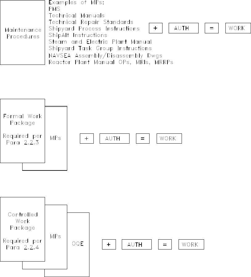
COMUSFLTFORCOMINST 4790.3 REV D CHG 3
07 Nov 2023
V-I-2A-1
APPENDIX A
APPENDIX A
TECHNICAL WORK DOCUMENT ILLUSTRATION
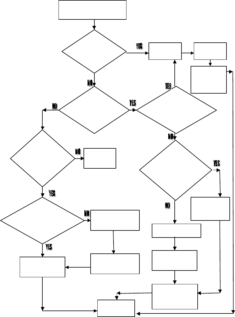
COMUSFLTFORCOMINST 4790.3 REV D CHG 3
07 Nov 2023
V-I-2B-1
APPENDIX B
APPENDIX B
WORK PACKAGE DECISION PROCESS
MAINTENA NCE
ACTION REQUIR ED
Consult WCS
or DIV Off
for direction
Write FWP per
SECT 2.3
Obtain Work
Aut horizat ion per
Obtain FWP
Approval per
PA RA 2. 3.4
PERFORM
WORK
Verify FWP
Current per
Appro ve S equenci ng
Document per
PARA 2. 2. 6
Obtain Authorization
to Start Work, WCS
as a Minimu
m
Generate Sequencing
Document per
PARA 2. 2. 6
Is a CWP
Required per
PARA 2. 2.
4
Is OQE Req u ired
p
er PARA 2.2. 4
(Second Chance)
Is There a
Standardized
FWP per
Are T her e
Existing
Maintenance
Procedures p e
r
PARA 2.2.2
Is a n FWP
Required per
PARA 2. 2. 3
Ob tai n W ork
Authorization
Obtain CWP
Approva
l
CWP
=
FWP + OQE
Is a Single
TWD Sufficient
to Accompli sh Tas k
(as Determined by
the DH)
p
er IV-10
SECT 10.4
PARA 2.3.7.10
PAR A 2.3.7. 10 .e
IV -1 0 SE CT 10 .4

COMUSFLTFORCOMINST 4790.3 REV D CHG 3
07 Nov 2023
V-I-2C-1
APPENDIX C
APPENDIX C
CERTIFICATION SIGNATURE REQUIREMENTS FOR REACTOR PLANT,
NUCLEAR SUPPORT FACILITY AND CONTROLLED INDUSTRIAL FACILITY
WORK
1. General Requirements. This appendix lists the instances when a signature is required to
certify data or accomplishment of maintenance items. All attributes will be certified by
verification or inspection. Appendix C is meant to be comprehensive. However, there could be
a maintenance item performed by forces afloat and not listed in this appendix where a NAVSEA
document requires a verification with a certification signature; in that event, the certification
signature requirement should be met following the NAVSEA document.
a. Certification signatures in Nuclear Controlled Work Packages, required by this
chapter, that record OQE must be documented on QA forms and kept as required by
references (u) and (v), as applicable. Certification signatures listed in this appendix,
which are not required to be documented on QA Forms, are not OQE and have no
specific retention requirement.
b. Items that require inspection or verification documented in TWDs other than a CWP
will require a certification signature only and are not OQE. Therefore, they do not
need to be kept after the maintenance is complete and accepted.
c. Where it is convenient to use a locally generated form to accomplish specific
certifications, the CWP must refer to the form and the signatures will be on the form.
These forms need not be kept unless a record is required.
d. Indicate the individual responsible for performing the certification and the specific
attributes being certified at the signature block.
e. Certification signature statements must be referenced on each page, or in the General
Information element of the associated locally prepared TWD, where a certification
signature is required using references (u) and (v), as applicable, for reactor plant and
Nuclear Support Facility maintenance respectively:
(1) “Direct report from watch standers” may be deleted from the second (**)
Certification Signature Block statement for work where such an option would
not be applicable.
(2) Single asterisk (*) or double asterisk (**) must be used at each Certification
Signature Block to indicate the type of certification that is expected.
2. Specific Requirements.
a. Cleanliness. Nuclear propulsion plant cleanliness, foreign material, and detrimental
material control must be according to Table 2.4-6.1 of reference (w). Cleanliness
certification signatures are not required to be documented on QA Forms.
(1) Reactor Plant:
(a) Inspection following entry into clean hardware where dirt producing
(e.g., machining or grinding) or potentially dirt producing operations

COMUSFLTFORCOMINST 4790.3 REV D CHG 3
07 Nov 2023
V-I-2C-2
APPENDIX C
(e.g., clean cuts of pipes) are used.
(b) Inspection prior to final closure of each opening in clean hardware
where the closure will prevent visual access to surfaces which contact
system fluid.
(c) Inspection during any operation in which a loss of cleanliness could
occur that is not easily detected and corrected.
(d) Inspection for re-verification of hardware cleanliness per section 2.6 of
reference (w).
(e) Final inspection following fabrication of hardware or dirt producing
modification to hardware.
(f) After removal of a controlled product as defined in reference (x) for
internal surfaces of installed hardware and internal surfaces of
hardware that contains crevices and inaccessible areas. (Applicable to
shipyards and Nuclear Regional Maintenance Departments only.)
(g) Following the cleaning of internal surfaces when crevices or
inaccessible areas are exposed.
(h) During assembly or disassembly of joints with thread sealant
downstream of cleanliness filters to verify there is no visible thread
sealant on internal surfaces following assembly.
(i) Following dirt-producing modification to hardware with crevices and
inaccessible areas.
(j) The following require certification by a craftsman qualified to perform
the verifications and will be documented by the craftsman by signing a
certification signature. An independent inspection is not required.
1 Verification of cleanliness following entry into clean hardware,
except entry that is dirt producing (e.g., machining, grinding) or
potentially dirt producing (e.g., clean cuts of pipe).
2 Verification of cleanliness prior to and during assembly
(including assembly that creates crevices).
3 Verification of cleanliness prior to thermal treatment.
4 Verification of cleanliness after any test that uses soft metal
probes or tips; for example, alloy identity testing.
5 Verification of cleanliness following cleaning except when
performed for paragraphs (a) through (d) of this paragraph or
when crevices or inaccessible areas are exposed.
6 Verification of cleanliness following tape removal.
7 Verification of cleanliness prior to closure of support system
openings and connection of a clean support system to clean
hardware.

COMUSFLTFORCOMINST 4790.3 REV D CHG 3
07 Nov 2023
V-I-2C-3
APPENDIX C
8 Verification of final review of the accountability log.
9 Verification of cleanliness prior to installation of support
equipment to any vent and drain valve, other than a pressurized
discharge.
10 Verification of final cleanliness of cleanliness plugs provided
the plugs are assembled from clean parts or sub-assemblies
without crevices or inaccessible areas and if the assembly
occurs in a clean room or clean area.
(2) Steam Plant. Verification of cleanliness whenever cleanliness has been lost.
b. Welding and Brazing. The following signature requirements apply:
(1) Inspections where records are required by reference (y) with the exception of
in-process visual inspections, which may be verifications. These inspections
will be documented on QA forms.
(2) Inspections where records are required by reference (z) with the exception of
in-process visual inspections, which may be verifications. Inspection that
gaskets, O-rings, or seals are either removed or scored as required before
welding, so that they no longer function as a seal. These inspections will be
documented on QA forms.
(3) Inspections for parameters or data where records are required by sections of
reference (y) involving welding, with the exception of in-process visual
inspections, which may be verifications. This information will be documented
on QA forms.
(4) Inspections, where records are required, associated with reactor plant welds on
piping systems and on components which are nuclear Level I or non-level
piping system applications when welds are qualified, performed and inspected
according to NAVSEA Nuclear Propulsion Directorate (08) documents other
than those included in paragraphs 2.b.(1), (2) and (3) of this paragraph, with
the exception of in-process visual inspections, which may be verifications.
These inspections will be documented on QA forms.
(5) Inspections required by reference (k) for class P-3a brazed joints in nuclear
Level I piping systems, where records are required. These inspections will be
documented on QA forms.
(6) Verification that proper purge path is established before welding, both inlet
and exit.
c. Shielding. Inspections to verify the proper replacement of permanent shielding
according to reference (c) or (aa), as applicable.
d. Mechanical Joint Assembly.
(1) Verification of the following applicable attributes is required if maintenance is
accomplished using a FWP or CWP.
(a) Joint identification.
COMUSFLTFORCOMINST 4790.3 REV D CHG 3
07 Nov 2023
V-I-2C-4
APPENDIX C
(b) Condition of flange faces, O-ring grooves, and other sealing surfaces.
(c) Joint alignment.
(d) Installation of O-rings or gaskets.
(e) Lubrication of fasteners.
(f) Thread engagement and standout.
(g) Final torque on fasteners.
(h) Gasket compression and flange parallelism.
(2) For joints in Nuclear Level I systems, inspection of the following applicable
attributes is required whether the maintenance is accomplished by a CWP or
FWP.
(a) Final torque on fasteners when a torque is specified.
(b) Gasket compression and flange parallelism. (Gap measurement is only
required when mating surfaces are not in contact).
e. Pipe Bending. For pipe bending according to reference (ab), the following signature
requirements apply:
(1) Inspection (NDT) of bent pipe. These inspections will be documented on QA
forms.
(2) Visual inspections of bent pipe.
f. Freeze Seal Operations. For freeze sealing according to reference (ac) the following
signature requirements apply:
(1) Verification of dimensional measurements before and after freeze seal
operations.
(2) Verification that the variation between before and after dimensional
measurements does not exceed the allowed tolerance.
(3) Verification that the freeze seal is established.
g. Hydrostatic Testing. The following signature requirements apply: Inspections
required during hydrostatic testing according to reference (h) and the applicable
reactor plant manual. The results of these inspections will be documented on QA
forms.
h. Locking devices. The following signature requirements apply:
(1) Internal locking devices. The proper installation of locking devices inside the
pressure boundary of components containing primary coolant and all locking
devices (internal and external) associated with reactor vessels, closure heads,
and control rod drive mechanisms must be confirmed by inspection. The
results of such inspection, including dimensions and clearances measured to
confirm proper installation, will be documented on QA forms.
COMUSFLTFORCOMINST 4790.3 REV D CHG 3
07 Nov 2023
V-I-2C-5
APPENDIX C
(2) Verification of the proper installation of other reactor plant component locking
devices. This verification is by the craftsman unless the component drawing
requires an inspector to perform the check.
i. Valve Repair. The following signature requirements apply:
(1) Inspection of the final measurement of the bellows restraint gap “x-dimension”
of pilot actuated relief valves where required by applicable technical manuals.
(2) Verification of the final blue check of the disc-to-seat.
j. Valve Testing. The following signature requirements apply to inspection during post
installation testing and periodic testing of primary, steam generator, and charging
pump relief valves:
(1) Proper blocking (gagging) and subsequent return to normal service.
(2) Locking devices, if required, on manual lift mechanism, locked.
(3) Manual lift mechanism removed, if so designed, after testing.
k. Miscellaneous. The following signature requirements apply:
(1) Inspections required before, during, or after repair to remove surface
discontinuities according to reference (v), (ad) or (ae), as applicable.
Document these inspections on QA forms.
(2) Inspections required on reactor plant air flasks according to reference (af).
(3) Inspections required for determining reactor plant material acceptability
according to the specifications requirements when the inspections specify
reference (ag) or reference (ah).
(4) Inspection of penetrations in tanks to ensure all temporary plugs have been
removed and the penetrations are free from obstruction, if maintenance has
been performed in the tank.
(5) Inspections required by Article 242 of reference (aa) or Appendix D of
reference (c), as applicable.
(6) Verification of removal of installed temporary reactor plant support equipment.
(7) Verification of satisfactory completion of reactor compartment closure tests
including tests on individual penetrations.
(8) Verification of the Reactor Plant Work Accomplishment Report by designated
officers.
COMUSFLTFORCOMINST 4790.3 REV D CHG 3
07 Nov 2023
V-I-2D-1
APPENDIX D
APPENDIX D
FORMAL WORK PACKAGE APPROVAL AND REVISION SHEET
FWP NUMBER _____________ REVISION _____________
TASK ________________________________________________________________________
______________________________________________________________________________
______________________________________________________________________________
LEAD DIVISION OR WORK CENTER _______________ ORIGINATOR _______________
REVIEWED BY:
WORK CENTER PLANNER (REQUIRED IF
ORIGINATOR IS NOT A QUALIFIED PLANNER) ______________________
AWC LPO or SUPERVISOR ______________ AWC DIVISION OFFICER ______________
AWC LPO or SUPERVISOR ______________ AWC DIVISION OFFICER ______________
AWC LPO or SUPERVISOR ______________ AWC DIVISION OFFICER ______________
NRO __________________________________ P&E OFFICER ________________________
RADCON OFFICER or CRA _____________
CHOP FOR FURTHER USE?____YES____NO
DIVISION LPO or LWC SUPERVISOR ________ LWC DIVISION OFFICER ___________
APPROVED: __________________________________________________________________
DEPT HEAD DATE
THIS STANDARDIZED FWP HAS BEEN VERIFIED TO BE THE LATEST REVISION
AND CONTAINS THE CURRENT REFERENCES. THE RADCON OFFICER or CRA
HAS/HAS NOT (CIRCLE ONE) VERIFIED THIS FWP FOR CURRENT RADIOLOGICAL
CONDITIONS.
______________________________________________________________________________
LWC SUPERVISOR or LPO DATE
______________________________________________________________________________
PLANNING OFFICER (IF APPLICABLE) DATE
______________________________________________________________________________
REVISIONS, CHANGES AND SUMMARY: (APPROVAL SHEET) OR INSTRUCTIONS
FOR ENTERING REVISION:
LTR: ______________ DESCRIPTION__________________ DATE ENTERED___________
REVIEWED FOR SATISFACTORY COMPLETION AND CLOSEOUT
AWC LPO or SUPERVISOR_______________ LWC LPO or SUPERVISOR ____________
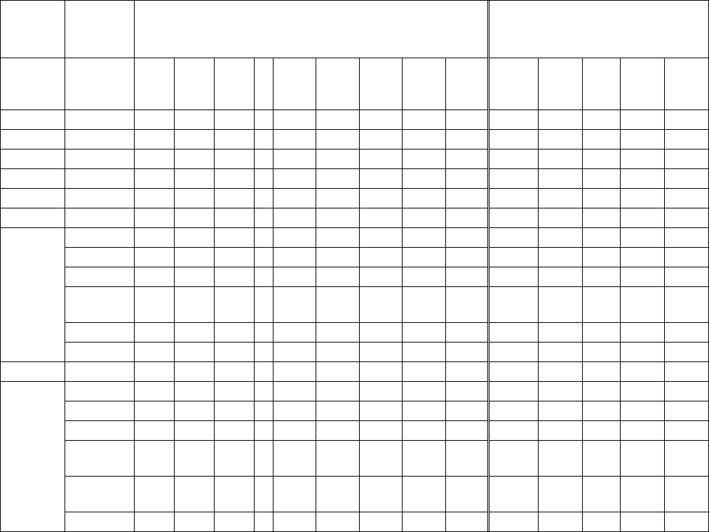
COMUSFLTFORCOMINST 4790.3 REV D CHG 3
07 Nov 2023
V-I-2E-1
APPENDIX E
APPENDIX E
TECHNICAL WORK DOCUMENT REVIEW AND APPROVAL MATRIX
TWD
TYPE
Work
Performed
By
Opening (1) Closing (1)
P&E
OFF
AWC
DIV
OFF
LWC
DIV
OFF
QAO
DEPT
HEAD
(4)
SHIP
ENG
SHIP
CO
ISIC
AWC
DIV
OFF
LWC
DIV
OFF
QAO
DEPT
HEAD
SHIP
CO
MP
SF R R (8)
FMA R R R R (8)
FWP
SF R R (2) R (11) A R (8) A (8) R (11)
FMA R (2) R R A R (8) A (8)
SF
Prepared
CWP
Other R R R A R R R A (4)
LI R R R A R R R A (4)
O2 R R R R A R R R A
NUC
R R R R A A (3)
R (6)
(10)
R R R R (4) A (3)
SS or SOC R R R R A R R R A (5) S(12)
SFCC R R R R A R R R A (5) S(12)
RMC or
FMA
Prepared
CWP
Other R R R R A R R R A (4)
LI R R R R A R R R A (4)
O2 R R R R A S (7) R R R A (4) S (7)
NUC
R (9) R R R A
S
(3)(7)
R (6)
(10)
R R R A (4) S (3)(7)
SS or SOC
R R R R A S (7) R R R A (4)
S
(7)(12)
SFCC R R R R A S (4) R R R A S(12)
Notes:
1. R = Review (May require signature on FWP Cover Sheet, QA-9, or both),
A = Approve (Approval Signified by signature on FWP Cover Sheet, QA Form 9, or
both),
S = Acknowledgement signature noting that the REC or CWP has been opened or closed
by the approving authority. For opening, this signature also grants permission for
work to be conducted. Review or Approval signifies the following:
The FWP is correct both in sequence and requirements to satisfactorily
accomplish the maintenance.
The CWP provides the correct technical specifications or requirements (e.g.,
torque values, dimensions, NDT inspections, cleanliness requirements, critical
inspections, recertification tests) for certification attributes on the appropriate QA
form.
COMUSFLTFORCOMINST 4790.3 REV D CHG 3
07 Nov 2023
V-I-2E-2
APPENDIX E
2. For FWPs previously approved by the Department Head, the FWP may be authorized and
issued as a standardized FWP per paragraph 2.3.7.10 of this chapter.
3. (Nuclear aircraft carriers only) The Reactor Officer will sign.
4. For items requiring Department Head approval the following signature requirements must
apply:
FMA - Repair Officer (unless formally delegated for Other and LI)
SF - Cognizant Department Head (Principal Assistant for aircraft carriers)
5. Entries are to be signed by the Ship’s Engineer only.
6. (Submarines only) ISIC Material Officer will review SF CWPs for retesting FMA
accomplished nuclear work.
7. This block is not applicable for FMA only MCR RECs.
8. Accomplished by WC Supervisor.
9. Nuclear Repair Officer if assigned.
10. Applicable to Fleet I-Level activities only. Does not apply to I-Level activities controlled
by Naval Shipyards.
11. QAO will review opening and closing of all FWPs for components or systems assembled
and performed as a REC MCR exception.
12. (Submarines only) This signature is REQUIRED to complete certification of Re-Entry
into SUBSAFE, Scope of Certification and Fly-by-Wire systems and components.

COMUSFLTFORCOMINST 4790.3 REV D CHG 1
15 JAN 2021
V-I-3-1
VOLUME V
PART I
CHAPTER 3
PERSONNEL QUALIFICATION AND TRAINING
REFERENCES.
(a) NAVEDTRA 43523 - Personnel Qualification Standard for Quality Maintenance
Program
(b) MIL-STD-1330 - Standard Practice for Precision Cleaning and Testing of Shipboard
Oxygen, Helium, Helium-Oxygen, Nitrogen and Hydrogen Systems
(c) OPNAVINST N9210.3 - Safeguarding Naval Nuclear Propulsion Information
(d) NAVSEAINST 9210.39 - Submarine Nuclear Propulsion Plant Operator Welders:
Procedures for Maintenance of Qualification
(e) NAVSEA 389-0317 - Procedures for Maintenance and Repair of Naval Reactor Plants
(Nuclear)
(f) COMSUBFORINST C5400.30 - Engineering Department Organization Manual
(g) NAVSEA T9044-AD-MAN-010 - Requirements Manual for Submarine Fly-By-Wire
Ship Control Systems
(h) NAVSEA SS800-AG-MAN-010/P-9290 - System Certification Procedures and
Criteria Manual for Deep Submergence Systems
(i) NAVSEA 0924-062-0010 - Submarine Safety (SUBSAFE) Requirements Manual
(j) NAVSEANOTE 5000 - Activities Authorized to Perform SUBSAFE, FBW-SCS and
DSS-SOC Work
LISTING OF APPENDICES.
A NAVEDTRA 43523 Qualification Matrix
B Outlines of Typically Effective Training Topics
C Recommended Training Topics for Selected Positions
3.1 PURPOSE. To define the requirements and guidance necessary to establish a standard
qualification and training program for personnel who plan, perform, inspect or supervise the
maintenance tasks listed in Part I, Chapter 2, paragraph 2.2.1 of this volume.
3.2 GENERAL. Personnel who screen, plan, perform, inspect and supervise the maintenance
performed to the following requirements must be trained and qualified per this volume and
reference (a).
a. Maintenance requiring a Technical Work Document per Chapter 2, paragraph 2.2.1 of
this volume.
b. Maintenance listed as Material Certification Record (MCR) exceptions per Part I,
Chapter 2, paragraph 2.2.5 of this volume.
c. Maintenance listed as Re-Entry Control (REC) exceptions per Part I, Chapter 5,
paragraph 5.6.7 of this volume.

COMUSFLTFORCOMINST 4790.3 REV D CHG 1
15 JAN 2021
V-I-3-2
NOTE: A CONTINUING TRAINING AND QUALIFICATION PROGRAM IS ESSENTIAL
FOR ALL MAINTENANCE PERSONNEL TO ACHIEVE A MAINTENANCE
PROGRAM WITH HIGH STANDARDS OF QUALITY. PERSONNEL
INVOLVED IN THE APPROVAL, SUPERVISION, PLANNING OR
PERFORMANCE OF SHIPBOARD MAINTENANCE WILL BE PARTICIPANTS
IN THE TRAINING AND QUALIFICATIONS ASSOCIATED WITH THIS
VOLUME.
3.3 QUALIFICATION. Qualification procedures established herein must be formal, and
designed to heighten awareness of those tasked with the responsibility of administering,
managing and executing the Fleet Quality Maintenance (QM) program.
a. Each organization must maintain a personnel qualification list per Part I, Chapter 10,
of this volume.
b. Each organization must maintain a list of personnel authorized to sign off portions of
reference (a).
c. Maintenance personnel must be qualified through completion of formal qualification
programs (e.g., Job Qualification Requirements or Personnel Qualification Standard
(PQS), written exams, oral boards and formal schools). Reference (a) provides the
standard PQS for the majority of QM qualifications. Appendix A provides a
qualification matrix for maintenance personnel PQS requirements.
d. All personnel performing the maintenance identified in Part I, Chapter 2, paragraph
2.2.1 of this volume must be 3-M 301 qualified and Craftsman 301 qualified or an
equivalent Quality Assurance (QA) qualification for non-naval personnel.
3.3.1 Re-qualification. Personnel with prior documented qualifications may be re-qualified by
written exam or oral board as directed by Quality Assurance Officer (QAO) or Department
Head. Personnel found to be deficient in level of knowledge will be required to complete an
upgrade program established by the QAO prior to re-qualification.
3.3.2 Required Service Record Entries. Record of qualification will be inserted in the
individual's service record.
3.4 QUALIFICATION REQUIREMENTS.
3.4.1 Ship’s Quality Assurance Officer.
a. Should be a commissioned officer with engineering or repair experience.
b. (Submarines only) Submarine officer must have completed submarine qualification
and for nuclear powered ships should be nuclear trained.
c. Designated in writing by the Commanding Officer.
d. QA Officer course requirements are:
(1) A surface ship QAO must be a qualified Quality Assurance Supervisor (QAS)
and must be a graduate of a QAO course.
(2) A submarine QAO must be a graduate of the Submarine Officers’ and
Supervisors’ Quality Maintenance course, F-4H-0182. No other formal PQS
qualification is required.

COMUSFLTFORCOMINST 4790.3 REV D CHG 1
15 JAN 2021
V-I-3-3
(3) An aircraft carrier QAO must be a graduate of the 5-week Quality Assurance
Officer Course (S-4H-0001) for CVN officers. No other formal PQS
qualification is required. With a formal waiver (Naval message or letter)
endorsed by the ISIC and approved by the TYCOM, this requirement can be
temporarily waived but the waiver may not exceed 6 months. The waiver must
list the interim QAO and qualifications, the perspective QAO and graduation
date from S-4H-0001 or the report date.
e. (Submarines only) Complete an oral interview with the ISIC or submarine support
component QAO.
f . (Submarines only) Only an officer meeting the QAO qualification requirements of
sub-paragraph d. may sign documents requiring a QAO signature.
(1) A qualified QAO must be onboard during underway operations.
(2) A qualified QAO must be onboard (i.e. not TAD or on leave) any time Quality
Maintenance is being performed when in port.
(a) The QAO may be TAD in the same geographic location as the ship as
long as the they can still perform all responsibilities assigned per Part I,
Chapter 1, paragraph 1.5.12 of this volume, and when in port, or when
in port available by phone (i.e. not TAD or on leave) when Quality
Maintenance is being performed.
(b) If the QAO cannot perform these duties while TAD or on leave, an
acting QAO meeting the requirements of sub-paragraphs a. through e.
must be assigned except as exempted here.
(i) The Ship’s Commanding Officer may waive the sub-paragraph
d.(2) requirement to a period of time up to but not exceeding 2
calendar weeks to allow the QAO leave or short duration TAD.
(ii) With a formal waiver (Naval message or letter) endorsed by the
Immediate Superior In Command (ISIC) and approved by the
Type Commander (TYCOM), the sub-paragraph d.(2)
requirement can be temporarily waived by the TYCOM but the
waiver may not exceed 6 months. The waiver must list the
interim QAO and qualifications, the perspective QAO and
graduation date from F-4H-0182 or the report date.
3.4.2 Ship’s Assistant Quality Assurance Officer.
a. Normally E-6 or higher with engineering or repair experience.
b. Designated in writing by the Commanding Officer.
c. (Submarines only) Complete an oral interview with the ISIC or Submarine Support
Component QAO.
3.4.3 Immediate Superior In Command.
a. Quality Assurance Officer.

COMUSFLTFORCOMINST 4790.3 REV D CHG 1
15 JAN 2021
V-I-3-4
(1) Should be a commissioned officer, but may be a civilian with engineering or
repair experience.
(2) Should be a graduate of a QAO course. No other formal PQS qualification is
required.
(3) Designated in writing by the ISIC.
b. Assistant Quality Assurance Officer.
(1) Military personnel will be an E-7 or higher, but could be a senior civilian with
engineering or repair experience.
(2) Should be a graduate of a QAO course.
(3) Qualified as QAS. QAS qualification is not required if he or she is a graduate
of the Norfolk Naval Shipyard Fleet Maintenance Support Branch QAO
course.
(4) Designated in writing by the Commanding Officer. The duties assigned,
including signature authority, must be clearly delineated.
3.4.4 Regional Maintenance Center or Fleet Maintenance Activity Quality Assurance Officer.
a. Should be a commissioned officer, but may be a civilian with engineering or repair
experience.
b. Will not be assigned collateral duties or responsibilities that divert attention from
primary duties of QM.
c. Should be a graduate of a QAO course. No other formal PQS qualification is required.
d. Designated in writing by the Commanding Officer.
3.4.5 Regional Maintenance Center or Fleet Maintenance Activity Assistant Quality Assurance
Officer.
a. Military personnel will be an E-7 or higher, but could also be a senior civilian with
engineering or repair experience.
b. Qualified as QAS or a graduate of a QAO course.
c. Designated in writing by the Commanding Officer.
3.4.6 Quality Assurance Supervisor.
a. Normally E-6 or higher, but may be a civilian.
b. Complete PQS for QAS, and pass a written examination and oral board.
c. QAS is a mandatory qualification for Fleet Maintenance Activities (FMA).
Qualification of QAS for ships is at the TYCOM’s discretion.
3.4.7 Quality Assurance Inspector.
a. Normally a petty officer, but may be a civilian.
b. Complete PQS for Quality Assurance Inspector (QAI) and pass a written exam and
oral board.

COMUSFLTFORCOMINST 4790.3 REV D CHG 1
15 JAN 2021
V-I-3-5
c. The qualification card may be split into separate nuclear and non-nuclear QAI
qualifications. If this is done, the command must ensure QAIs do not inspect areas
excluded from their qualifications.
3.4.8 Controlled Material Petty Officer or Controlled Material Handler.
a. Normally a petty officer, but may be a civilian.
b. Complete PQS for Controlled Material Petty Officer (CMPO) or Controlled Material
Handler (CMH), and pass a written exam and oral board.
c. Activities may modify the qualification card to allow CMPO or CMH qualification for
specific materials only. If this is done, commands must have a method to ensure
CMPOs or CMHs do not handle material excluded from their qualification.
3.4.9 Steam Plant Cleanliness Inspector or Certifier.
a. Normally a petty officer, but may be a civilian.
b. Complete PQS for Steam Plant Cleanliness Inspector and pass a written exam and oral
board.
3.4.9.1 Qualification Requirements for Reactor Plant Cleanliness Inspector or Certifier.
a. Normally a petty officer, but may be a civilian.
b. Complete PQS, per reference (a), for Reactor Plant Cleanliness Inspector, pass written
exam and oral board.
3.4.10 Gas Systems Cleanliness Inspector or Certifier.
a. Normally a petty officer, but may be a civilian.
b. Satisfactorily complete an Oxygen Clean Worker course of instruction per reference
(b).
3.4.11 Oxygen Clean Instructors. An Oxygen Clean Instructor will be certified per reference
(b). Oxygen Clean Instructors will re-qualify every three years. If an individual is scheduled for
transfer within six months after the expiration of qualification, it is permissible to extend the
qualification until transfer. The local command may exempt the senior instructor from re-
qualification.
3.4.12 Ship's and Fleet Maintenance Activity Oxygen Clean Workers. Oxygen Clean Workers
will be certified per reference (b). Oxygen Clean Workers will re-qualify every three years. If
an individual is scheduled for transfer within six months after the expiration of qualification, it is
permissible to extend the qualification until transfer.
3.4.13 Oxygen Calibration Technicians. Oxygen Calibration Technicians qualify to perform
oxygen instrument cleaning and calibration by satisfactory completion of Oxygen Calibration
School at the direction of the Naval Sea Systems Command (NAVSEA) Metrology and
Calibration (METCAL) Quality Manager. Naval Sea Systems Command certifies successful
candidates for two years following a report of satisfactory completion of Oxygen Calibration
School. Local Regional Maintenance Center re-certifies Oxygen Calibration Technicians during
the calibration capability reviews of FMAs or Strategic Systems Program Office capabilities and
proficiency evaluation of SSBN and SSGN FMAs.

COMUSFLTFORCOMINST 4790.3 REV D CHG 1
15 JAN 2021
V-I-3-6
3.4.14 Work Center Supervisors and Planners. The qualification of QA Maintenance Planners
and QA Work Center Supervisors is required in all work centers that perform maintenance tasks
outlined in Part I, Chapter 2, paragraph 2.2.1 of this volume. Work Center Supervisors and
Maintenance Planners will, as a minimum, complete the applicable qualifications of reference (a)
prior to performing any unsupervised maintenance tasks. QA Maintenance Planners prerequisite
fundamentals (QAI and Cleanliness Inspector) may be deleted in work centers that do not
perform controlled work. Activities with separate planning organizations are exempt from
having planners assigned to individual work centers. (Submarines Only) For work centers
requiring a QA Work Center Supervisor, either the 3-M Work Center Supervisor or Leading
Chief Petty Officer must be qualified QA Work Center Supervisor and have completed 3M PQS
NAVEDTRA 43241 for Work Center Supervisor.
3.4.15 Qualification Requirements for Submarine Nuclear Propulsion Plant Operator Welders
(Navy Enlisted Classification Code 3351 and Supervisor Welders 3361).
NOTE: INFORMATION ON THIS SUBJECT IS SAFEGUARDED PER REFERENCE
(c). SPECIFIC PROGRAM REQUIREMENTS ARE IDENTIFIED IN
REFERENCES (d) AND (e).
3.4.16 Qualification Requirements for Submarine Fly-By-Wire Ship Control System
Maintenance Technician. Must be a graduate of the Ship Control System Maintenance
Technician School (A-623-0118 for SSN 21 Class, A-623-0131 for SSN 774 Class).
3.5 TRAINING.
3.5.1 Maintenance Personnel Training. All personnel involved with planning, performing and
supervising maintenance specified in Section 3.2 of this chapter will be trained using the
following guidance:
a. Appendices B and C of this chapter provide information on program elements
normally contained in effective maintenance training programs. Appendix B is
applicable to Ship’s Force whereas Appendix C is applicable to Fleet Maintenance
Activities (e.g., mechanics, Nondestructive Test (NDT) technicians, welders and
planners). All appendices identified in this paragraph are provided as information
only and are not to be considered mandatory listings.
b. Findings from QA form 14s, audits, assessments and surveillance should be included,
when appropriate, to re-emphasize the most recent problems experienced in the
department.
c. Include the training with existing topics where possible (i.e., CMPO training held with
Repair Parts Petty Officer training or Steam Plant Cleanliness training held in
conjunction with Machinery Divisions training on the Steam Plant). However, some
areas may require separate training to be held.
d. Joint training between departments and organizations is acceptable. The Department
Head will coordinate with the QAO on training concerning QM. It is not the intent to
create a separate training program, nor is the intent to hold one annual training session
that covers all of the topics.
e. In order to assess the effectiveness of the training program, the QAO should:

COMUSFLTFORCOMINST 4790.3 REV D CHG 1
15 JAN 2021
V-I-3-7
(1) Periodically monitor training.
(2) Assess knowledge level retention in conjunction with the conduct of annual
QA and welder training and qualification program audit required by reference
(a), Part I, Chapter 9 paragraph 9.3.1 of this Volume.
3.5.2 Requirements. The QAO will create a Long Range Training Plan (LRTP), approved by
the Executive Officer, to track topics desired to be given on a periodic basis. Reference (f)
provides guidance on effective training planning and LRTP use.
a. For personnel qualified 301 (craftsman) and above, in accordance with reference (a),
the QAO will include applicable training topics using Appendices B and C of this
chapter as a guide. These topics must be reviewed and updated annually or whenever
a new long-range training plan is generated.
b. For personnel responsible for planning, approving, inspecting or supervising
maintenance on systems or equipment included in the QM Program, the QAO will
include the following items in the LRTP.
(1) Requirements and generation of a controlled work package and formal work
package including objective quality evidence, required inspections and critical
QM points.
(2) Material certification, control and stowage requirements.
(3) In-process control including torqueing, controlled assembly, system cleanliness
requirements for specific systems (e.g., air systems, hydraulic systems) and
common mistakes noted in completed QA forms.
(4) Testing.
(5) Departure from specifications.
c. The Ship’s Supply Officer will ensure supply department personnel receive training on
nuclear and non-nuclear controlled material certification, procurement, receipt
inspection and LI/SOC stock program material, SW, VU and NRP stowage
requirements.
3.5.3 Submarine Safety Awareness Training (Submarines and Submarine Repair Facilities only).
All hands must receive Submarine Safety (SUBSAFE) awareness and Fly-By-Wire Ship Control
(if assigned to, work on or over-see 21 Class or 774 Class submarines) training during initial
indoctrination and annually thereafter, not to exceed 12 months. Personnel at Submarine Repair
Facilities who supervise or manage SUBSAFE, Deep Submergence System-Scope of
Certification or Fly-By-Wire-Ship Control System work will receive training on parent
requirements to include (at a minimum) references (g), (h), (i) and (j). ISIC and TYCOM staff
members that routinely review SUBSAFE and Fly-By-Wire Ship Control (if assigned to, work
on or over-see 21 Class or 774 Class submarines) objective quality evidence, make
determinations on SUBSAFE Departures from Specifications and perform other SUBSAFE work
oversight will receive annual SUBSAFE awareness training to keep knowledge and proficiency
levels high.

COMUSFLTFORCOMINST 4790.3 REV D CHG 1
15 JAN 2021
V-I-3A-1
APPENDIX A
APPENDIX A
NAVEDTRA 43523 QUALIFICATION MATRIX
WATCHSTATION PRE-REQUISITE
WATCHSTATIONS
PRE-REQUISITE
FUNDAMENTALS
301 Craftsman None 101 Quality Maintenance Safety
Precautions
102 Quality Maintenance Administration
103 Quality Maintenance Program
104 Craftsman
302 Controlled Material Petty
Handler (CMPO or CMH)
301 Craftsman 105 Controlled Material Petty
Officer or Controlled Material
Handler (CMPO or CMH)
303 Steam Plant Cleanliness
Inspector or Certifier
(SCI)
301 Craftsman 106 Steam Plant Cleanliness
Inspector or Certifier (SCI)
304 Reactor Plant Cleanliness
Inspector or Certifier
(RCI)
303 Steam Plant Cleanliness
Inspector or Certifier (SCI)
107 Reactor Plant Cleanliness
Inspector or Certifier (RCI)
305 Quality Assurance
Inspector (QAI)
301 Craftsman
302 Controlled Material Petty
Officer or Controlled
Material
Handler (CMPO or CMH)**
303 Steam Plant Cleanliness
Inspector or Certifier (SCI)**
304 Reactor Plant Cleanliness
Inspector or Certifier (RCI)**
109 Quality Assurance Inspector (QAI)
306 Maintenance Planner 301 Craftsman 106 Steam Plant Cleanliness
Inspector or Certifier (SCI)
107 Reactor Plant Cleanliness
Inspector or Certifier (RCI)
108 Gas Systems Cleanliness
109 Quality Assurance Inspector
110 Planner
307 Work Center Supervisor
(WCS)
301 Craftsman 105 Controlled Material Petty
Officer or Controlled Material
Handler (CMPO or CMH) **
106 Steam Plant Cleanliness
Inspector or Certifier (SCI)
107 Reactor Plant Cleanliness
Inspector or Certifier (RCI)
108 Gas Systems Cleanliness
109 Quality Assurance Inspector
110 Planner
111 Work Center Supervisor
308 Quality Assurance
Supervisor (QAS)
305 Quality Assurance Inspector
(QAI)
108 Gas System Fundamentals
110 Planner
112 Quality Assurance Supervisor
** Noted in the PQS as Command Specific. For these items, the necessity for the pre-
requisites will be determined by the type of work the individual or command
performs and that individual’s PQS should be tailored accordingly.
COMUSFLTFORCOMINST 4790.3 REV D CHG 1
15 JAN 2021
V-I-3B-1
APPENDIX B
APPENDIX B
OUTLINES OF TYPICALLY EFFECTIVE TRAINING TOPICS
1. Work Authorization.
a. Topic.
(1) Work authorization forms.
(2) Tag-outs.
(3) Safety requirements.
(4) Ship responsibility for outside activity maintenance.
b. Reference: COMUSFLTFORCOMINST 4790.3; Joint Fleet Maintenance Manual,
Volume V.
2. Formal Work Package or Controlled Work Package documentation.
a. Topic.
(1) Record retention requirements.
(2) Mandatory documents.
(3) Routing of documents and signature documents.
(4) Test requirements for FMA work.
b. Reference: COMUSFLTFORCOMINST 4790.3; Joint Fleet Maintenance Manual,
Volume V.
3. In Process Control.
a. Topic.
(1) Torqueing.
(2) Controlled assembly.
(3) Cleanliness requirements for:
(a) Air systems.
(b) Hydraulic systems.
(c) Reactor plant (nuclear powered ships only).
(d) Steam plant (non-nuclear and nuclear powered ships).
(e) Oxygen or Nitrogen systems.
(f) Seawater systems.
(g) Lubricating systems.
(h) Gas Turbine systems.
(i) Fuel systems.
COMUSFLTFORCOMINST 4790.3 REV D CHG 1
15 JAN 2021
V-I-3B-2
APPENDIX B
(j) Diesel systems.
(4) Use of formal work packages.
(5) Control of fasteners. (Include avoidance of carbon steel in seawater systems.)
(6) Material control.
(7) Re-work.
(a) Administration.
(b) Root cause and corrective action.
(8) Revisions: Administration.
(9) Critical QM points.
(10) Procedural compliance.
(11) Submarine antenna work including mast clamps.
(12) Departure from specifications.
(13) Submarine Flight Critical Components
b. References.
(1) COMUSFLTFORCOMINST 4790.3; Joint Fleet Maintenance Manual,
Volume V.
(2) NAVSEA 0902-018-2010; General Overhaul Specifications for Deep Diving
SSBN/SSN Submarines (DDGOS).
(3) NAVSEA S9505-AM-GYD-010; Submarine Fastening Criteria (Non-
Nuclear), Description, Design and Maintenance.
(4) NAVSEA S9520-AA-MMA-010; Repair of Submarine Seawater Ball Valves
(Non-Nuclear).
(5) Naval Ship's Technical Manuals (NSTM).
(6) MIL-STD 1330; Standard Practice for Precision Cleaning and Testing of
Shipboard Oxygen, Helium, Helium-Oxygen, Nitrogen and Hydrogen
Systems.
(7) NAVSEA 0900-LP-016-6080; QA Standard for Submarine Antenna and Mast
Assemblies.
(8) NAVSEA S9AA0-AB-GOS-010/020/030; General Specifications for Overhaul
of Surface Ships (GSO); AEGIS Supplement.
(9) NAVSEA T9044-AD-MAN-010 - Requirements Manual for Submarine Fly-
By-Wire Ship Control Systems.
4. Testing.
a. Topic.
(1) Hydrostatic test rig requirements including calibration.
COMUSFLTFORCOMINST 4790.3 REV D CHG 1
15 JAN 2021
V-I-3B-3
APPENDIX B
(2) Test pressure drawings.
(3) Air blast, vacuum and other tests.
(4) Use of FMA and shipyard test plans or procedures.
(5) Conducting hydrostatic tests and completing hydrostatic test forms (including
common mistakes).
(6) NDT alternative in testing.
b. References.
(1) COMUSFLTFORCOMINST 4790.3 Joint Fleet Maintenance Manual, Volume
V.
(2) Test Pressure Drawings.
(3) NAVSEA S9505-AF-MMA-010; Submarine Non-Nuclear Piping System Test
Manual.
(4) NAVSEA 0902-018-2010; General Overhaul Specifications for Deep Diving
SSBN/SSN Submarines (DDGOS).
(5) NAVSEA S9086-RK-STM-010; NSTM Chapter 505 (Piping Systems).
(6) NAVSEA S9AA0-AB-GOS-010/020/030); General Specifications for
Overhaul of Surface Ships (GSO); AEGIS Supplement.
5. Material Certification.
a. Topic.
(1) Level I material requirements.
(2) Level I material exceptions.
(3) Use of drawings for Quality Assurance Lists.
(4) Submarine antenna material.
(5) Upgraded systems to Level I requirements.
(6) Upgrading components to meet Level I and SUBSAFE requirements.
(7) Submarine Flight Critical Components requirements.
b. References.
(1) SUBSAFE Certification Boundary Book.
(2) Joint Identification Plans or Mapping Plans.
(3) COMUSFLTFORCOMINST 4790.3; Joint Fleet Maintenance Manual,
Volume V.
(4) Ship's Coordinated Shipboard Allowance List (COSAL).
(5) NAVSEA 0948-LP-045-7010; Material Control Standard (Non-Nuclear).
COMUSFLTFORCOMINST 4790.3 REV D CHG 1
15 JAN 2021
V-I-3B-4
APPENDIX B
(6) NAVSEA/NAVSUPINST 4855.1; Quality Assured Submarine Antenna
Material: Policy and Procedures for Control and Implementation.
(7) Applicable Class Material Identification and Control of Piping Systems
Boundary Book.
(8) NAVSEA T9044-AD-MAN-010 - Requirements Manual for Submarine Fly-
By-Wire Ship Control Systems.
6. Material Procurement or Receipt Inspection.
a. Topic.
(1) SUBSAFE, Level I or Submarine Flight Critical Component material.
(2) Material substitution.
(3) Stowage requirements for controlled material.
(4) Ship's COSAL.
b. References.
(1) COMUSFLTFORCOMINST 4790.3; Joint Fleet Maintenance Manual,
Volume V.
(2) NAVSEA 0948-LP-045-7010; Material Control Standard (Non-Nuclear).
(3) NAVICPINST 4355.5; Receipt, Inspection, Storage and Issue of Level I
Material.
(4) NAVSEA 0948-LP-103-6010; Level I Stock Program Catalog, (Part I -
Submarine Items, Part II - Surface Ship Items).
(5) Applicable Class Material Identification and Control of Piping Systems
Boundary Book.
(6) NAVSEA T9044-AD-MAN-010 - Requirements Manual for Submarine Fly-
By-Wire Ship Control Systems.
7. SUBSAFE.
a. Topic.
(1) Determination of SUBSAFE or Hull Integrity boundaries.
(2) Use of QA forms and tags.
(3) Torqueing of hull integrity fasteners.
(4) Generation of an MCR/REC.
(5) Unrestricted Operation or Periodic Maintenance Requirement.
(6) Departure from Specification requirements.
(7) REC exceptions.
(8) Positive material identification requirements for hull integrity fasteners.
COMUSFLTFORCOMINST 4790.3 REV D CHG 1
15 JAN 2021
V-I-3B-5
APPENDIX B
b. References.
(1) SUBSAFE Certification Boundary Book.
(2) NAVSEA 0924-062-0010; Submarine Safety (SUBSAFE) Requirements
Manual.
(3) COMUSFLTFORCOMINST 4790.3; Joint Fleet Maintenance Manual,
Volume V.
(4) Applicable Unrestricted Operation Maintenance Requirement Card program
technical manual.
8. Audit and Surveillance (for personnel performing).
a. Topic.
(1) Audit or surveillance requirements.
(2) Purpose of audit or surveillance program.
(3) Preparing for and conducting an audit including specific discussion of
techniques to be used to make audits effective and useful to the organization.
(4) Preparing for and conducting a surveillance includes a specific discussion of
techniques to be used to make surveillance effective and useful to the
organization.
(5) Documenting an audit or surveillance.
(6) Root cause identification.
(7) Trends and trend analysis.
b. Reference: COMUSFLTFORCOMINST 4790.3; Joint Fleet Maintenance Manual,
Volume V.
9. Additional Training Topics.
a. Weight handling equipment testing, use and safety.
b. Oxygen or Nitrogen plant maintenance.
c. Working aloft and Sail Safety.
d. Combat systems maintenance requirements.
e. Electrical safety.
f. Welding.
g. Brazing.
h. REC requirements on diving systems.
i. Cleanliness requirements for diving systems.
j. Controlled material requirements for diving systems.
NOTE: WHERE THERE ARE SIMILAR LECTURE TOPICS, IT IS SUGGESTED
THAT THE TRAINING PRESENTED TO NUCLEAR TRAINED PERSONNEL

COMUSFLTFORCOMINST 4790.3 REV D CHG 1
15 JAN 2021
V-I-3B-6
APPENDIX B
CONSIST OF BOTH THE INFORMATION FROM TOPICS 1-9 OF THIS APPENDIX
AND THE NUCLEAR SPECIFIC INFORMATION CONTAINED IN SECTION 10.
10. Nuclear Training Topics.
a. Material Certification.
(1) This lecture should include discussion of Nuclear Level I requirements.
(2) The following references provide information on this topic:
(a) NAVSEA 0948-LP-045-7010; Material Control Standard.
(b) NAVSEAINST C9210.34; Material Identification and Control
Requirements for Naval Nuclear Reactor Plant Piping Systems.
(c) NAVSEA S9213-45-MAN-000 - Naval Nuclear Material Management
Manual.
(d) NAVSEA 0989-LP-037-2000; Commissioned Submarine General
Reactor Plant Overhaul and Repair Specification.
(e) NAVSEA 0989-LP-043-0000; Commissioned Surface Ship General
Reactor Plant Overhaul and Repair Specification.
(f) NAVSEA 0989-LP-058-1000; Destroyer Tender and Submarine
Tender Nuclear Support Facilities Overhaul and Repair Specification.
(g) NAVSEA 0989-064-3000; Cleanliness Requirements for Naval
Nuclear Plant Maintenance and Construction.
(h) NAVSEAINST 9210.23; Naval Nuclear Work at Naval Activities and
Private Shipyards - Certification of Work Accomplishment and Data,
Retention of Associated Records and Retention of Design Records,
Requirements for.
b. Material Procurement or Receipt Inspection. This lecture should include discussion
of:
(1) Nuclear Material.
(2) Material Substitutions. Certifying material for use to Nuclear Level I.
(3) The list of references in paragraph 10.a (2) of this appendix provides
information on the topic.
c. In-Process Control.
(1) This lecture should include discussion of:
(a) Cleanliness requirement for:
1 Reactor Plant (nuclear powered ships only).
2 Steam Plant (fossil and nuclear powered ships).
(b) Requirements for a work package.
(c) Generation of a work package.
COMUSFLTFORCOMINST 4790.3 REV D CHG 1
15 JAN 2021
V-I-3B-7
APPENDIX B
(d) Use of QA forms and tags.
(e) Setting plant conditions.
(f) Certification signature requirements.
(g) Use of material control tags.
(h) Reactor Plant Work Accomplishment Reports (RPWAR).
(2) The list of references in paragraph 10.a.(2) of this appendix provides
information on the topic.
d. Testing.
(1) This lecture should include discussion of:
(a) Hydrostatic test rig requirements including calibration.
(b) Hydrostatic test forms.
(c) Conducting hydrostatic test.
(d) Setting plant conditions.
(e) Use of Reactor Plant Manual for test requirements.
(f) Weight Handling Equipment Testing.
(2) The following references provide information on this topic:
(a) Reactor Plant Manual.
(b) NAVSEA 0989-028-5000; Manual for the Control of Testing and Plant
Conditions.
(c) NAVSEA 0387-LP-046-8000; System Hydrostatic Test Requirements.
(d) NAVSEA 0989-LP-058-0000; AS/AD Tender Nuclear Support
Facilities Preventive Maintenance Index.
(e) NAVSEA 0989-LP-037-2000 - Commissioned Submarine General
Reactor Plant Overhaul and Repair Specification.
(f) NAVSEA 0989-LP-043-0000 - Commissioned Surface Ship General
Reactor Plant Overhaul and Repair Specification.
e. Final work package documentation. This lecture should include discussion of:
(1) Record retention requirements.
(2) Mandatory documents.
f. Reactor Plant Fundamentals. This should be slanted toward the worker so that he or
she understands the possible consequences of faulty workmanship, loss of cleanliness,
etc., in the Reactor Plant.
g. FMA Nuclear Planning Yard Basic Trade Skills Lesson Plans (when available).
COMUSFLTFORCOMINST 4790.3 REV D CHG 1
15 JAN 2021
V-I-3C-1
APPENDIX C
APPENDIX C
RECOMMENDED TRAINING TOPICS FOR SELECTED POSITIONS
1. Experience has shown that effective training should be related to job skills required by the
individual.
a. Mechanical craftsmen should cover areas like:
(1) Tools and their uses.
(2) Shop safety.
(3) Work authorization.
(4) Material identification.
(5) Rework and their causes.
(6) Valve construction and methods to perform:
(a) Stack height measurements.
(b) Blue checks.
(c) Lapping of a valve seat.
(7) Pump construction and methods to perform:
(a) Mechanical seal replacement.
(b) Alignments.
(8) Testing requirements.
(9) Cleanliness requirements.
(10) Technical manuals and their usage.
(11) Drawings and their usage.
(12) Work packaging administration.
b. NDT inspectors and welders should cover the following areas:
(1) NAVSEA S9074-AR-GIB-010/278; Requirements for Fabrication Welding
and Inspection, and Casting Inspection and Repair for Machinery Piping and
Pressure Vessels.
(2) NAVSEA T9074-AD-GIB-010/1688; Fabrication, Welding and Inspection of
Submarine Structures.
(3) MIL-STD-1689 (for Surface Ships only); Fabrication, Welding and Inspection
of Ship's Structures.
(4) NAVSEA 0900-LP-001-7000; Fabrication and Inspection of Brazed Piping
Systems.
(5) NAVSEA T9074-AS-GIB-010/271; Requirements for Nondestructive Testing
Methods.
COMUSFLTFORCOMINST 4790.3 REV D CHG 1
15 JAN 2021
V-I-3C-2
APPENDIX C
(6) MIL-STD-2132; Nondestructive Examination Requirements for Special
Applications.
(7) Material control.
(8) Cleanliness.
(9) Work package administration.
c. Planners should cover the following areas:
(1) SUBSAFE program.
(2) Level I program.
(3) QA forms.
(4) Welding requirements.
(5) Manufacturing specifications.
(6) Cleanliness requirements and specifications.
(7) Hydrostatic testing.
(8) Material control.
(9) Manufactured fittings specifications.
(10) Plant conditions.
(11) System flushes.
(12) NDT requirements.
(13) Testing requirements.
(14) Index of technical publications.
(15) Military standards and specifications.
(16) Selected record drawings or ship's drawing index.
(17) Maintenance data systems.
(18) Blue print reading.
(19) For activities involved in Scope of Certification maintenance:
(a) NAVSEA SS800-AG-MAN-010/P-9290, System Certification
Procedures and Criteria Manual for Deep Submergence System.
(b) Scope of Certification material control classification.
(c) Implodability.
(20) Submarine Flight Critical Components.
2. Proven training methods include the use of mockups and training aids that show practical
application of the lecture material. Hands on mockup training, performed by the workers is the
most highly effective method followed by the demonstration of skills by the instructor.
COMUSFLTFORCOMINST 4790.3 REV D CHG 1
15 JAN 2021
V-I-3C-3
APPENDIX C
NOTE: WHERE THERE ARE SIMILAR LECTURE TOPICS, IT IS SUGGESTED
THAT THE TRAINING PRESENTED TO NUCLEAR TRAINED
PERSONNEL CONSIST OF BOTH THE INFORMATION FROM TOPICS 1-2
AND THE NUCLEAR SPECIFIC INFORMATION CONTAINED SECTION 3.
3. Nuclear Training Topics.
a. Job Skill Training. Each work center should determine the skill requirements and incorporate
their own training requirements. Examples are:
(1) Nuclear planners should cover areas like:
(a) RPWAR.
(b) Manufactured fittings specifications.
(c) Freeze seal requirements.
(d) Plant conditions.
(e) Welding requirements.
(f) Radiological Controls.
(g) System flushes.
(h) Nondestructive Testing (NDT) requirements.
(i) Hydrostatic testing requirements.
(2) The following references provide information on the topics of section 3.a(1):
(a) NAVSEA 0387-LP-046-8000; System Hydrostatic Test Requirements.
(b) NAVSEA 0348-LP-159-1000; Freeze Sealing Manual.
(c) NAVSEA 0989-064-3000; Cleanliness Requirements for Naval
Nuclear Plant Maintenance and Construction.
(d) Valve Manuals.
(e) NAVSEA 0989-LP-037-2000; Commissioned Submarine General
Reactor Plant Overhaul and Repair Specification.
(f) Reactor Plant Manual.
(g) NAVSEA 0989-028-5000; Manual for the Control of Testing and Plant
Conditions.
(h) NAVSEA 389-0317; Procedures for Maintenance and Repair of Naval
Reactor Plants.
(i) NAVSEA 0989-LP-043-0000; Commissioned Surface Ship General
Reactor Plant Overhaul and Repair Specification.
(j) NAVSEA 0989-LP-058-1000; Destroyer Tender and Submarine
Tender Nuclear Support Facilities Overhaul and Repair Specification.

COMUSFLTFORCOMINST 4790.3 REV D CHG 2
31 MAR 2022
V-I-4-1
VOLUME V
PART I
CHAPTER 4
WELDER, BRAZER AND NONDESTRUCTIVE TESTING QUALIFICATIONS
REFERENCES.
(a) NAVSEA S9086-CH-STM-010 - NSTM Chapter 074 Volume 1 (Welding and Allied
Processes)
(b) NAVSEA S9074-AQ-GIB-010/248 - Welding and Brazing Procedures and
Performance Qualification
(c) NAVSEA 0900-LP-001-7000 - Fabrication and Inspection of Brazed Piping Systems
(d) NAVSEA T9074-AS-GIB-010/271 - Requirements for Nondestructive Testing
Methods
(e) NAVPERS 18068 - Manual of Navy Enlisted Manpower and Personnel Classification
and Occupational Standards
(f) NAVSEA S9086-CH-STM-020 - NSTM Chapter 074 Volume 2 (Nondestructive
Testing of Metals Qualification and Certification Requirements for Naval Personnel
(Non-nuclear))
(g) MIL-STD-1689A (SH) - Fabrication, Welding, and Inspection of Ships Structure
(h) NAVSEA T9074-AD-GIB-010/1688 – Requirements for Fabrication, Welding, and
Inspection of Submarine Structure
(i) NAVSEA S9074-AR-GIB-010/278 - Requirements for Fabrication Welding and
Inspection, and Casting Inspection and Repair for Machinery, Piping, and Pressure
Vessels
(j) NAVSEA 0900-LP-060-4010 - Fabrication, Welding and Inspection of Metal Boat
Craft Hulls
(k) NAVSEA TO300-AU-SPN-010 - Fabrication, Welding and Inspection of Small Boats
and Craft, Aluminum Hulls
(l) NAVSEA S6240-A9-MAN-010 - Welding and Inspection Manual for Landing Craft,
Air Cushion (LCAC)
(m) NAVSURFWARCEN LAR PC-1301 – Patrol Coastal (PC) Craft Structural
Fabrication and Non Destructive Testing Requirements (PC-2 thru PC-14)
(n) NSTM S9086-UF-STM-010 CH600 - Structural Closures
(o) SWRMC DM 10623B - Quality Assurance Requirements for Welding 5xxx Series
Aluminum Structures for CG-47 Class
(p) NAVSEA 0948-LP-045-7010 - Material Control Standard
4.1 PURPOSE. This chapter provides the requirements for qualification of Shipboard and Fleet
Maintenance Activity Welders, Brazers, Nondestructive Testing (NDT), and Generic Material
Testing personnel. Also included are qualification record requirements. The provisions of
references (a) through (p) are amplified and expanded herein to ensure that all provisions of
higher authority are implemented.

COMUSFLTFORCOMINST 4790.3 REV D CHG 2
31 MAR 2022
V-I-4-2
NOTE: ALTHOUGH THIS CHAPTER COVERS THE REQUIREMENTS FOR NAVY
WELDERS, BRAZERS AND NDT PERSONNEL, THE PERFORMANCE
QUALIFICATIONS FOR CIVILIAN WELDERS, BRAZERS AND NDT
PERSONNEL WILL BE PER REFERENCES (b), (c) AND (d)
RESPECTIVELY.
4.1.1 General Requirements. Each activity is responsible for establishing that each welder or
brazer is qualified by demonstrating their ability to produce sound and satisfactory joints per
references (a) through (c). References (a), (e) and (f) define welder and NDT qualifications by
Navy Enlisted Classification (NEC) codes.
4.1.2 Training.
NOTE: NO WELDER WILL PERFORM QUALIFICATION OR PRODUCTION
FABRICATION UNTIL AFTER RECEIPT OF THIS TRAINING AND PASS A
WRITTEN EXAMINATION WITH A SCORE OF AT LEAST 75%.
a. Activities must have a training program per references (b) and (d). Activities without
a Level III examiner should obtain assistance from a Fleet Maintenance Activity.
b. For those welds or brazes not frequently performed for production, proficiency should
be demonstrated by satisfactory completion of a mock-up of the weld or braze prior to
performing production work.
4.2 GENERAL REQUIREMENTS FOR BRAZERS AND WELDERS.
a. The extent of welder qualification resulting from tests will be governed by references
(a) and (b). The extent of brazer qualification will be governed by reference (c) for
piping and pressure vessel applications.
NOTE: THE REQUIREMENTS ARE TAILORED TO THOSE OF REFERENCE (c),
AS QUALIFIED PIPE BRAZERS ARE ALSO CONSIDERED QUALIFIED
FOR ALL OTHER BRAZING WITHIN THE SCOPE OF THEIR PIPE
QUALIFICATIONS (I.E., PROCESS, MATERIAL AND THICKNESS
LIMITATIONS).
b. To provide uniformity and enhance the effectiveness of the welder or brazer program
the following conditions will apply:
(1) Once started, all qualifications must be completed as expeditiously as possible.
Therefore, personnel attempting to qualify must be given ample opportunity to
complete the qualification test in a timely manner. Qualification testing must
not be assigned if anticipated workload, leave schedules, shiftwork or other
controllable factors will delay test assembly completion.
(2) No more than three qualification tests per welder or brazer will be in progress
at any one time.
(3) For training purposes, the Welding or Brazing Shop Supervisor must make
arrangements with the NDT Supervisor to review the records (including
radiographic film) of failed qualification test assemblies. The NDT Supervisor
will discuss the results with the qualifier, focusing on the reasons for rejection,
types and locations of defects found, and possible corrective actions. The
COMUSFLTFORCOMINST 4790.3 REV D CHG 2
31 MAR 2022
V-I-4-3
arrangements should include welder or brazer observation of actual test results
whenever possible.
(4) Because the fact that a welder or brazer meets the qualification requirements of
a particular specification or standard does not always assure their proficiency
in all phases of diversified production tasks for which he or she is qualified.
To this end, activities should strive for continual improvement, both in the
qualification and proficiency of its welders and brazers.
c. Stud or Spot Welders. NEC welder or welding operator qualification is not required
for operators of stud or spot welding equipment.
4.2.1 Eye Examination. Annual vision tests must be passed by each brazer and welder. Vision
tests will be conducted by the medical department, cognizant NDT Examiner or delegated
personnel, using standard methods for determining visual acuity. The standard for acceptance
will be natural or corrected near distance acuity such that the brazer or welder is capable of
reading J1 letters on a standard Jaeger type chart. Equivalent visual tests may be used.
Corrective aids used during the visual test must be worn during qualification testing and
production fabrication. Reference (b) contains the color test requirement for Titanium welders.
4.2.2 Brazing and Welding Procedures. Brazing and Welding procedures, qualified per
references (b) or (c), as applicable, must be on hand for all applications for which performance
qualification is intended. Although not specifically required, the brazer or welder should use the
procedural requirements for training and familiarity purposes during qualification testing.
4.2.3 Brazing and Welding Personnel Knowledge. Each brazer and welder must receive
documented training on the workmanship and detailed visual inspection requirements of
fabrication documents used by the activity.
4.2.4 Brazer and Welder Identification Numbers. Upon meeting the requirements of this
section, brazers and welders receive a unique identification number, issued by the respective
Division Officer, for identification of brazing or welding performance.
a. Brazer and Welder Identification Number Log. The Division Officer must maintain a
log of unique identification numbers assigned to brazers or welders. The number
assigned must be alphanumeric as illustrated in the following example:
A -12 -B or W.
Where: A = First letter in a brazer or welder’s last name.
12 = Sequential number alphabetical in list of personnel.
B or W = B for brazer or W for welder.
b. Each entry must contain the date the number was assigned, the brazer or welder’s
name and signature, the identification number, the date the brazer or welder completed
the initial training specified in paragraph 4.2.3 of this chapter and the brazer or
welder’s projected rotation date.

COMUSFLTFORCOMINST 4790.3 REV D CHG 2
31 MAR 2022
V-I-4-4
4.2.5 Validation of Qualification. All brazer or welder qualifications, re-qualification and
maintenance of qualification will be valid only if original qualification is recorded in the
individual’s service record per reference (a). A service record entry (NAVPERS 1070/613) must
be made upon initial qualification, annually (not to exceed 12 months) and before transfer. This
service record entry must include all subsequent re-qualifications and the most current vision test
results. The brazer or welder’s Division Officer will be responsible for ensuring these entries are
made.
4.2.6 Qualification Records.
4.2.6.1 Individual Brazer or Welder Qualification File. In order to achieve proper monitoring of
brazer or welder qualifications, the individual’s Division Officer will maintain an auditable file
for each brazer or welder assigned. This file is to be maintained for each brazer or welder for as
long as he or she is assigned to a command and transferred with the welder or brazer to their next
command. These files must include all information that is required by references (a), (b) and (c)
and include the following:
a. Brazer or Welder identification number (name, rate, individual identification number).
b. Test date or Use of process date.
c. Qualification test number, process, position, base material type, filler material type
and size, or brazing alloy type and size.
d. Test results (i.e., Accept or Reject). A statement as to the cause of rejection will be
entered, if appropriate.
e. Record of omission of space restriction when not used on pipe tests.
f. Workmanship and visual inspection requirements examination results per reference
(b).
g. Certifying signature (Division Officer or designated representative).
h. Vision test form:
(1) Identification.
(2) Test date.
(3) Test description.
(4) Test results.
(5) Corrective aids as required.
(6) Certifying signature (medical department, cognizant NDT Examiner or
delegated personnel).
4.2.6.2 Maintenance of Qualification. Detailed records of maintenance of qualification need
only be retained for the current and preceding quarter. In order to ensure proper maintenance of
brazer or welder qualifications, a log will be maintained by each Division Officer. This log must
include items a., b., d. and g. of paragraph 4.2.6.1 of this chapter. In addition, this log will also
include the brazing or welding process (i.e., H-101, SMAW, GTAW, etc.) used during
maintenance of qualification. This maintenance of qualification log may be a separate log from

COMUSFLTFORCOMINST 4790.3 REV D CHG 2
31 MAR 2022
V-I-4-5
the brazer or welder file or it may be incorporated into the brazer or welder file as part of the file
itself.
NOTE: FOR WELDERS AND BRAZERS, THE VERIFICATION OF PROCESS FOR
USE WILL BE DONE BY THE DIVISION OFFICER, OR THEIR
REPRESENTATIVE, AND DOCUMENTED.
4.2.6.3 Method of Qualification Maintenance. Brazers and welders should maintain their
qualifications on production jobs. If production work is unavailable, a brazing test assembly or
test assembly weld joint meeting the requirements of reference (b) for welders and reference (c)
for brazers may be used. Only joints meeting all applicable acceptance criteria will be used for
this purpose. Surface Ships lacking NDT personnel may only allow the brazer or welder
qualification to lapse with Type Commander approval. If a joint is assembled by personnel
whose qualifications have lapsed or without the support of qualified NDT personnel, a Departure
from Specification must be submitted and the joint must be reassembled using qualified
personnel during the next maintenance support opportunity.
4.2.6.4 Renewal of Qualification. Renewal of qualification will be per reference (b) for welders
and reference (c) for brazers.
4.2.7 Effective Date of Qualification. Effective date of qualification must be from the date that
the test assembly brazing or welding is complete. Initial qualification is effective only after the
final NDT is completed but the date of qualification is the date the weld or braze was completed.
For re-qualification the re-qualification is only effective after the final NDT is completed but the
effective qualification date will be the day the weld or braze was completed. The NDT
Supervisor will ensure that:
a. Qualification results are forwarded to the brazer or welder Division Officer.
b. Each test assembly is marred, marked, or otherwise identified so as to preclude its re-
use.
4.3 BRAZER QUALIFICATIONS.
4.3.1 Prerequisite. Prior to performing any qualification or production brazing the brazer must
have successfully completed training in workmanship and detailed visual inspection
requirements and passed a written examination with a grade of no less than 75%. The training
and examinations for all brazers will be based on the requirements set forth in reference (c).
4.3.2 Qualification Test. A brazer qualification will be per reference (c) for piping and pressure
vessels.
4.3.3 Limitations. Limitations will be per reference (c).
4.3.4 Test Assembly Evaluation. Test assemblies must be visually and ultrasonically inspected
or a peel test may be conducted as specified in reference (c).
4.3.5 Maintenance of Qualification. A brazer maintains his or her qualifications by using the
process(es) he or she used during initial qualification at least once in each calendar quarter
subsequent to the quarter in which he or she qualified and four times in each subsequent calendar
year.
4.3.6 Qualification Renewal. A brazer must renew his or her qualifications per reference (c).

COMUSFLTFORCOMINST 4790.3 REV D CHG 2
31 MAR 2022
V-I-4-6
4.3.7 Transfer of Qualification. Qualifications may be transferred from one activity to another
when the requirements of reference (c) are met.
4.4 QUALIFICATION REQUIREMENTS FOR WELDERS.
4.4.1 Navy Enlisted Classification Code Achievement. To achieve a welding NEC the welder
must successfully meet all the requirements of reference (a).
4.4.2 Specific Qualifications. Qualifications for specific additional welding processes, filler
metal groups and welding positions may be obtained per reference (a).
4.4.3 Aluminum, Metal Boat and Craft Qualifications. Qualifications for aluminum welders,
and boat and craft welders will be obtained in accordance with applicable fabrication documents.
4.4.4 Maintenance of Qualification. For each qualified process, qualification will be maintained
per reference (b), with at least one verification of process use within 6 months after the month
the person last used the process. In addition, for titanium welders and welding operators,
verification of process used on titanium base metal within the 6-month period will also be
maintained.
4.4.5 Qualification Renewal. A welder must renew his or her qualifications per reference (b).
4.4.6 Transfer of Qualification. Qualifications may be transferred from one activity to another
when the requirements of reference (b) are met.
4.5 ASSEMBLIES WHERE THE POSSIBILITY OF FAILURE IS REMOTE AND WOULD
NOT RESULT IN DANGER TO SHIP PERSONNEL, SHIP, BOAT, CRAFT, PLANT, OR
STRUCTURE.
4.5.1 Authorization. Navy Enlisted Classification code is not required for welding performance
per reference (a) and welding performance qualification tests may be omitted per reference (b).
4.5.2 Requirements. Assemblies where the possibility of failure is remote and would not result
in danger to ship personnel, ship, boat, craft, plant, or structure are defined and specific
qualification requirements are identified, per the applicable fabrication documents listed below.
a. Shipboard structure and specific non-structural components as listed in reference (g).
b. Submarine minor structure as defined in reference (h).
c. For machinery, piping, and pressure vessels, weldments made principally of sheet
metal, welds on vents, overflows and drains, and as otherwise defined in reference (i).
d. Metal boat and craft hulls, when specifically approved, per reference (j).
e. Aluminum hull boats and craft as defined in reference (k).
f. Landing Craft, Air Cushion (LCAC) component welding requires qualification per
reference (l).
g. Patrol Costal (PC) class craft structure and specific non-structural components as
listed in reference (m).
h. Watertight/Airtight door repair and wedge welding per reference (n).
i. CG-47 aluminum structure welding shall be in accordance with reference (o).
COMUSFLTFORCOMINST 4790.3 REV D CHG 2
31 MAR 2022
V-I-4-7
4.6 QUALIFICATION REQUIREMENTS FOR NONDESTRUCTIVE TEST PERSONNEL.
4.6.1 Purpose.
a. To provide guidance on the procedures that must be followed to maintain NDT
qualifications or attain NDT re-qualification per references (d) and (f).
b. Naval NDT personnel are qualified by being examined by a NDT Examiner per
references (d) and (f).
4.6.2 Levels of Certification. NDT personnel are certified per references (d) or (f). Military
personnel certified per reference (f) will be assigned NECs per reference (e).
a. Level I (NDT Operator): An individual certified to NDT level I is qualified to carry
out NDT operations following written instructions and under the supervision of level
II or level III personnel. The individual must have the skills and knowledge to
properly perform specific calibrations, specific tests, set up equipment, carry out
specific inspections, record the results obtained, classify the results following written
criteria and report the results. He or she must not be responsible for the choice of the
test method, technique to be used or for the final assessment of the test results.
b. Level II (NDT Inspector): An individual certified to NDT level II is qualified to
perform and direct non-destructive testing following established or recognized
techniques. The individual must be competent to choose the test techniques to be
used; to set up and calibrate equipment; to interpret and evaluate results following
applicable codes, standards and specifications; to carry out all duties for which a level
I individual is qualified; to organize and report the results of non-destructive tests.
The individual must also be familiar with the scope and limitations of the methods for
which he or she is qualified, and be able to exercise assigned responsibility for on-the-
job training and guidance of trainees and level I personnel.
c. Level III (NDT Examiner): An individual certified to NDT level III must be capable
of assuming full responsibility for a test facility and staff; establishing techniques and
procedures; interpreting codes, standards, specifications and procedures; and
designating the particular test methods, techniques and procedures to be used. Must
develop NDT procedures per reference (d), adapted to the problems that are the
subject of an NDT inspection; and to prepare written instructions. The individual
must have the competence to interpret and evaluate results following existing codes,
standards and specifications; have a sufficient practical background in applicable
materials, fabrication and product technology to select methods, establish techniques
and to assist in establishing acceptance criteria where none are otherwise available;
have general familiarity with other NDT methods and have the ability to train level I
and level II personnel.
4.6.3 Certification of Nondestructive Test Personnel. Only those individuals who have
successfully completed the Naval NDT of Metals course or commercial equivalent for civilian
personnel can be certified by a NDT Examiner. NDT Inspectors will re-certify per reference (d)
or (f).
4.6.4 Renewal of Certification. NDT Examiners will re-certify per reference (d) or (f).
4.6.5 Maintenance of Qualification.

COMUSFLTFORCOMINST 4790.3 REV D CHG 2
31 MAR 2022
V-I-4-8
a. NDT personnel will maintain qualification per reference (d).
b. NDT testing personnel must pass an annual vision test per reference (d).
4.6.6 Qualification Administration.
a. Command NDT Examiners must be designated in writing.
b. Service Record Entries. Each NDT Inspector will have his or her service record
updated to reflect current qualifications annually, as a minimum, and immediately
prior to transfer. These periodic service record updates will be accomplished by entry
on (NAVPERS 1070/613).
c. NDT Examiner or Division Officer, as appropriate, will maintain an individual NDT
personnel record per reference (d) for each NDT Examiner and Inspector.
4.6.7 Approval of Nondestructive Testing Qualification Examinations. A NDT Examiner must
approve the NDT Inspector Qualification Examinations and visual test materials.
4.6.8 Transfer of Qualification. Qualifications being transferred from one naval facility to
another must be evaluated to the satisfaction of the NDT Examiner of the new facility.
4.6.9 Nondestructive Testing Personnel Records. NDT Inspector or Operator records will be
maintained by the NDT Examiner per reference (d) and will consist of:
a. All qualification documentation must be per reference (d) (e.g., training and
qualification documents).
b. Copy of current eye examination.
4.6.10 Nondestructive Testing Qualification Log. The NDT Supervisor will maintain an NDT
personnel qualification log that will be used to record and maintain qualifications for each
individual assigned. Each operator or inspector will have a separate section in the NDT
qualification log that satisfies the requirements of paragraph 4.6.9 of this chapter. The NDT
Supervisor or designated representative will update the NDT personnel qualification log. This
will be based upon the completion of NDT performed as shown by completed NDT reports.
This log may be maintained either as a hard copy or electronic copy.
4.6.11 Qualification of Generic Material Identity Testing Personnel. Personnel who perform
generic materials identity testing will be qualified as required by local procedure which will
include the following minimum requirements:
a. An eye examination satisfying the requirements of reference (a).
b. Training on the procedures of reference (p).
c. Training on the procedures for materials not in reference (p) used by the command.
d. Training on standard requirements.
e. Training on safety precautions associated with generic testing.
f. Training on reagent requirements and shelf life.
g. Testing requirements and designation of who performs the examinations.
h. Certification by the Quality Assurance Officer.

COMUSFLTFORCOMINST 4790.3 REV D CHG 2
31 MAR 2022
V-I-4-9
i. Re-qualification or qualification updating requirements.
j. For other than chemical testing programs, qualification will be per applicable
equipment technical manuals.
4.6.11.1 Qualification Administration. Command Generic Material Identity Examiners must be
designated in writing and must approve Generic Material Identity Test Inspectors qualification
examinations and test materials.
4.6.11.2 Transfer of Qualification. Generic Material Identity Testing Personnel. Since
qualification is by local procedure, testing personnel must perform at a level of proficiency
which is satisfactory to the Test Examiner at the new activity.

COMUSFLTFORCOMINST 4790.3 REV D CHG 3
07 Nov 2023
V-I-5-1
VOLUME V
PART I
CHAPTER 5
IN-PROCESS CONTROL
REFERENCES.
(a) NAVSEA S9510-AB-ATM-010/020 - Nuclear Powered Submarine Atmosphere
Control Manual
(b) NAVSEA S9086-RJ-STM-010 - NSTM Chapter 504 (Pressure, Temperature and
other Mechanical and Electromechanical Measuring Instruments)
(c) NAVSEA 389-0317 - Procedures for Maintenance and Repair of Naval Reactor Plants
(Nuclear)
(d) NAVSEA 0989-LP-043-0000 - Commissioned Surface Ship General Reactor Plant
Overhaul and Repair Specification
(e) NAVSEA 0989-LP-037-2000 - Commissioned Submarine General Reactor Plant
Overhaul and Repair Specification
(f) NAVSEA S9505-AM-GYD-010 - Submarine Fastening Criteria (Non-Nuclear),
Description, Design and Maintenance
(g) NAVSEA S9086-CJ-STM-010 - NSTM Chapter 075 (Threaded Fasteners)
(h) MIL-STD-1330 - Standard Practice for Precision Cleaning and Testing of Shipboard
Oxygen, Helium, Helium-Oxygen, Nitrogen and Hydrogen Systems
(i) NAVSEA S9086-T4-STM-010 - NSTM Chapter 589 (Cranes)
(j) SMS 7650-081-091 - Submarine Hull Inspection and Repairs
(k) SMS 6310-081-015 - Submarine Preservation General Painting
(l) NAVSEA 0989-064-3000 - Cleanliness Requirements for Nuclear Propulsion Plant
Maintenance and Construction
(m) NAVSEA 0989-LP-058-1000 - Destroyer Tender and Submarine Tender Nuclear
Support Facilities Overhaul and Repair Specification
(n) MIL-STD-767 - Cleaning Requirements for Special Purpose Equipment, Including
Piping Systems
(o) NAVSEAINST 9210.41 - All Naval Nuclear Propulsion Plants - Use of Standard
Lubricants and Penetrating Fluid; Requirements for
(p) NAVSEA S9086-CM-STM-010 - NSTM Chapter 078 (Gaskets, Packing and Seals)
(q) ISO-3601-1 - Fluid Power Systems-O-Rings – Quality Acceptance Criteria
(r) NAVSEA 0924-062-0010 - Submarine Safety (SUBSAFE) Requirements Manual
(s) COMSUBLANTNOTE C3120 - Submarine Operating Restrictions and Depth
Authorizations
(t) COMSUBPACNOTE C3120 - Submarine Operating Restrictions and Depth
Authorizations
(u) OPNAVINST N9210.3 - Safeguarding Naval Nuclear Propulsion Information
(v) NAVSEA T9044-AD-MAN-010 - Requirements Manual for Submarine Fly-By-Wire
Ship Control Systems
(w) Fly-By-Wire Ship Control System Certification Boundary Book (ship specific)

COMUSFLTFORCOMINST 4790.3 REV D CHG 3
07 Nov 2023
V-I-5-2
(x) NAVSEA SL720-AA-MAN-020 - Fleet Modernization Program (FMP) Management
and Operations Manual
(y) NAVICPINST 4441.170 - COSAL Use and Maintenance Manual
LISTING OF APPENDICES.
A Determining Software Usability
B Format for Submarine Certification Continuity Report
C Format for Fleet Maintenance Activity Certification Report to Tended Submarine
D Format for Non-Fleet Maintenance Activity Certification Report to Tended Submarine
E RPCCR Cover Letter for SHIPALTS (Sample)
5.1 PURPOSE. To provide the requirements or direct the user to the appropriate references to
ensure that maintenance performed during the ship’s life cycle (new construction through
decommissioning) supports certification at all times. All material used within any nuclear and
non-nuclear submarine pressure hull must be certified for use per reference (a).
5.2 TEST, MEASUREMENT AND DIAGNOSTIC EQUIPMENT.
5.2.1 General Requirements. Test, Measuring and Diagnostic Equipment (TMDE) for in-
process work must be properly selected and used. TMDE requiring periodic calibration must be
within its calibration periodicity when in use. All TMDE should be selected ensuring the
equipment is of the proper range to perform the test, inspection or repair. The craftsman and
Quality Assurance Inspector (QAI) should inspect all TMDE prior to use and reject questionable
equipment. When inspections or measurements using TMDE are performed with the results
documented on a Quality Assurance (QA) form, the type of equipment, range, serial numbers
and calibration due dates for TMDE used will be recorded on the QA form as part of the
Objective Quality Evidence (OQE).
5.2.2 Torque Wrenches.
NOTE: THE FOLLOWING APPLIES TO TORQUE WRENCHES USED ABOVE WATER
OR SUBMERGED IN WATER (FRESH WATER OR SALTWATER).
a. Selection. Torque wrenches should be selected in such a manner that the required
final torque falls within 20% to 90% of the torque wrench maximum value. For
example:
(1) A torque wrench with a maximum indicating value of 100 ft-lbs can be used
for a maximum torque of 90 ft-lbs and a minimum torque of 20 ft-lbs.
(2) A torque wrench with a maximum indicating value of 250 ft-lbs can be used
for a maximum torque of 225 ft-lbs and a minimum torque of 50 ft-lbs.
b. Calibration. Calibration should be verified to be within the required periodicity (based
on due date on the calibration label) prior to use. Most Navy torque wrenches are
calibrated for use in one direction only. These tools will have a label affixed stating,
“Use Clockwise Only” or “Use Counterclockwise Only”. The tool can be used only in
the direction indicated. Torque tools calibrated for bi-directional use will bear a
yellow “SPECIAL CALIBRATION” tag or label indicating that the tool was
calibrated for use in both directions. Navy torque wrenches can be calibrated for bi-

COMUSFLTFORCOMINST 4790.3 REV D CHG 3
07 Nov 2023
V-I-5-3
directional use only if specifically authorized by model number in the latest Naval Sea
Systems Command (NAVSEA) OD 45845.
c. Micrometer adjustable torque wrenches. To ensure acceptable performance of
micrometer adjusted torque wrenches, users must adhere to the following
requirements:
(1) Exercise the wrench (apply pressure until snap mechanism activates) six times
at approximately 60 percent of the rated maximum value before each use. This
procedure minimizes the erratic readings often experienced with this type of
wrench during the first few activations.
(2) Micrometer-type wrenches to be used in counterclockwise applications should
be calibrated in the counterclockwise direction and marked as such.
(3) Some micrometer “click” type torque wrenches do not accommodate torque
values down to 20 percent of the maximum rated capacity. Requests to use a
specific torque wrench or meter, outside of the ranges specified in sub-
paragraph a. of this paragraph, require an engineering evaluation and written
authorization from a technical warrant.
d. Extensions or Adapters. Torque wrenches are calibrated based on the specific length
of the wrench as established by the wrench manufacturer. Use of an extension
changes the effective length of the wrench. The actual torque being applied to the
fastener will be different than that indicated on the wrench dial. Any time extensions
are used, the following mathematical formulas should be used to determine the wrench
dial reading required for the required applied torque:
NOTE: EXTENSIONS CAN SIGNIFICANTLY AFFECT THE APPLIED TORQUE TO
INDICATED TORQUE RELATIONSHIP. ANY EXTENSION OTHER THAN
A DIRECT ATTACHMENT (I.E., CROWSFOOT) MUST BE TAKEN INTO
ACCOUNT.
Tind = Tact X L1
L1 + L2
Where: Tact = Applied torque required
Tind = Torque indicated on dial
L1 = Length of torque wrench
L1 + L2 = Length of torque wrench plus length of extension
When an adapter or extension is used on a torque wrench, it increases the torque range
of the wrench. The formula for computing torque when using an adapter or extension
is explained in Figure 5-1 of this chapter.
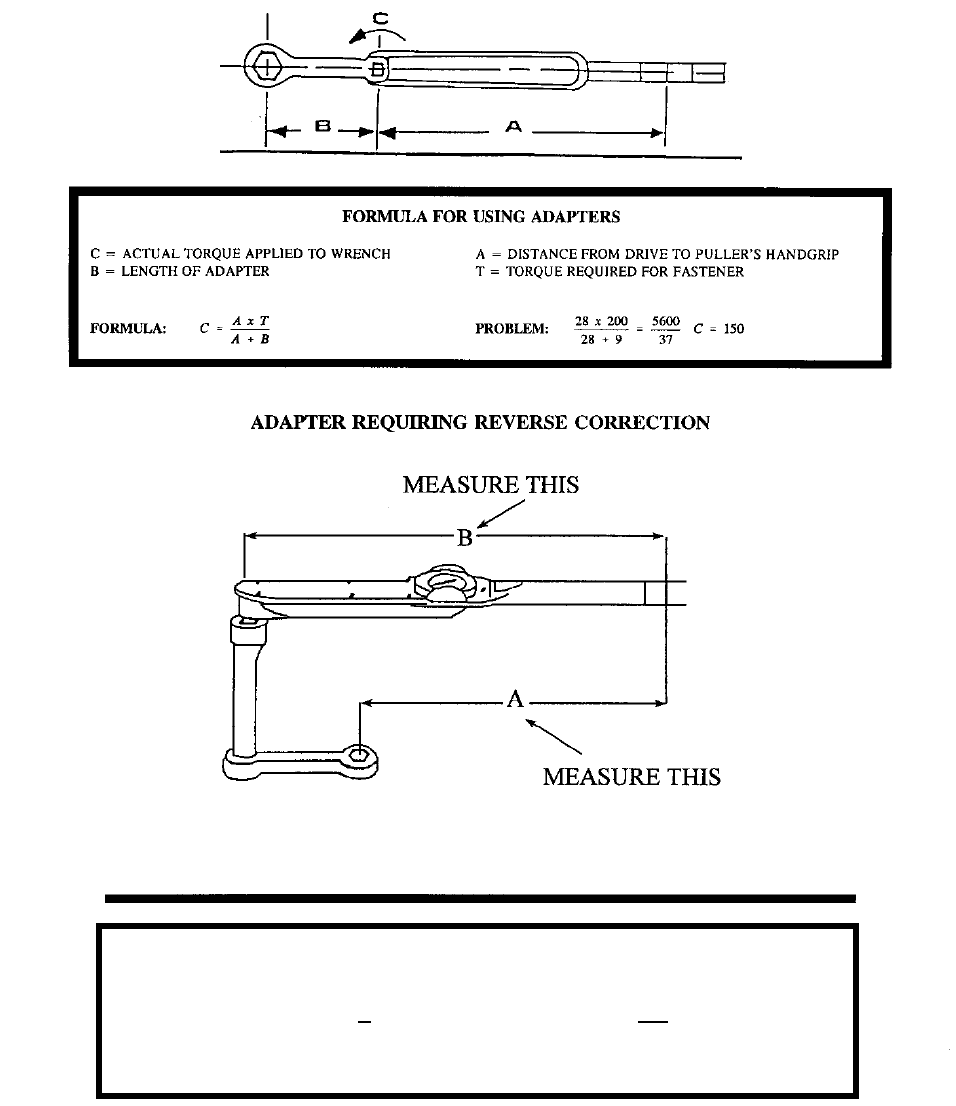
COMUSFLTFORCOMINST 4790.3 REV D CHG 3
07 Nov 2023
V-I-5-4
Figure 5-1 Use of Torque Wrench Adapters
FORMULA FOR USE OF CORRECTION FACTOR
D = Actual Torque Applied to Wrench C = Correction Factor = A ÷ B
Formula: D = T Problem: 200 = 266
C .75
A = TOTAL LENGTH = 18” B = TORQUE WRENCH LENGTH = 24” C = CORRECTION FACTOR = A ÷ B = 18 ÷ 24 = 0.75
T = TORQUE REQUIRED FOR FASTENER

COMUSFLTFORCOMINST 4790.3 REV D CHG 3
07 Nov 2023
V-I-5-5
5.2.3 Gauges.
a. General. Gauges used for in-process functions, whether installed in the system or
temporary, must be verified to be within calibration periodicity prior to use.
Craftsmen should ensure the appropriate calibration information is recorded on the QA
form.
b. Non-Nuclear Hydrostatic Testing. Master test gauges and backup gauges used for
hydrostatic testing must be selected and the calibration verified current per reference
(b) and Volume IV, Chapter 9 of this manual.
5.3 TORQUE.
5.3.1 General Torque Requirements. Care must be used when torquing fasteners or plugs.
Special attention is required to select the proper torque specification for a given application or
specification as it is specifically selected to reduce the tendency for the fastener to loosen in
service and to improve the fastener fatigue life.
5.3.2 Actual Torque Requirements. Torque requirements found in drawings, Submarine
Maintenance Standards (SMS) or technical manuals, etc. will be used in preference to general
guides for torquing. If no specific torque requirement exists, references (c), (d), (e), (f) or
reference (g) may be used as guidance but ensure that the information applies exactly to the
system and fastener type being torqued.
5.4 INSPECTIONS.
5.4.1 General Requirements. This section provides the minimum requirements and guidance for
the performance of inspections. Inspections during the performance of maintenance form one of
the fundamental elements essential in assuring that the task is completed properly and in
compliance with all specifications. Inspections occur during the in-process phase of repair or
maintenance (disassembly, repair, and re-assembly) and the re-certification phase (testing).
Inspections serve to provide a careful and critical examination of the areas being inspected and
form one of the cornerstones of a successful QA Program. Use of inspections have and will
continue to establish the OQE necessary for ensuring compliance to technical requirements.
5.4.2 Inspection Records. Inspection records provide a lasting record that the inspection was
performed and completed according to the applicable specifications. Inspection records will be
maintained when required for OQE and will be documented on appropriate QA forms contained
in this volume, or as Certification Signature Blocks in the Formal Work Package (FWP).
5.4.3 Critical Inspections. An inspection on any system or component, which by its nature is so
critical to the successful completion of the task, that the inspection requires verification by a
separate individual, other than the craftsman, qualified as an inspector. These inspections will be
annotated in the written work procedure by the presence of an (I) or circle I, or in the case of
Cleanliness Inspections (CI) or circle CI in the margin next to the applicable paragraph requiring
the inspection and will be documented either as a Certification Signature Block (for those
nuclear work items in Part I Chapter 2 Appendix C of this volume) or signature, as applicable, in
the FWP or on the appropriate QA form.
COMUSFLTFORCOMINST 4790.3 REV D CHG 3
07 Nov 2023
V-I-5-6
NOTE: THESE ARE CONSIDERED MINIMUM REQUIREMENTS FOR USAGE OF
AN INDEPENDENT INSPECTOR DURING THE PERFORMANCE OF
CONTROLLED WORK. IT MUST BE UNDERSTOOD THAT THE
REQUIREMENTS FOR AN INDEPENDENT INSPECTOR DO NOT
NECESSARILY MEAN THAT THE DATA PROVIDED IS RETAINABLE AS
OQE. VARIOUS SOURCE DOCUMENTS ADDRESS RECORD RETENTION
AND MUST BE FOLLOWED FOR ENSURING THE PROPER OQE IS
RETAINED.
a. Critical Inspections applicable to all platforms are:
(1) Inspections performed for all acceptance testing (e.g., hydrostatic testing, drop
tests, joint tightness tests, weight tests) for certification of work completed
under a Controlled Work Package (CWP). (Nuclear and non-nuclear manually
operated valves which have adjustable packing do not require certification by
an independent inspector.)
(2) Inspections performed to verify permanent markings of Level I material (those
which the Fleet Maintenance Activity (FMA) manufacture, upgrade, or transfer
to smaller pieces of controlled material). These inspections may also be
performed by a Controlled Material Petty Officer.
(3) Mechanical measurements used to verify wall thickness of components for
work performed using a CWP.
(4) Inspections performed for post machining of any Level I component.
(5) All sealing surface inspections for work performed as a Controlled Assembly.
(6) Inspections for oxygen, nitrogen, and hydrogen systems cleanliness as required
by reference (h). These independent inspections are performed by personnel
qualified as Oxygen Clean Workers per reference (h).
(7) Material receipt inspection. These inspections may also be performed by a
Controlled Material Petty Officer.
(8) Weight testing to certify or re-certify shipboard cranes when repairs are
performed per reference (i).
(9) Performance of Emergent Controlled Work per Part I, Chapter 2 of this
volume.
(10) Verification of body bound stud standout measurements and break away torque
for stud installations in Submarine Safety (SUBSAFE) and Level I systems.
b. Additional Critical Inspections applicable to submarines only.
(1) Sealing surface inspections for all SUBSAFE Hull Integrity joints.
(2) Hull Integrity joint body bound stud inspections. For new stud installations,
this includes stud standout measurements and break away torque verification.
For studs that were not removed and are to be reused, this includes verification
of markings of significance (K. or KM) or completion of generic material
identification check.

COMUSFLTFORCOMINST 4790.3 REV D CHG 3
07 Nov 2023
V-I-5-7
(3) Final torque verification of SUBSAFE Hull Integrity joints.
(4) Verification of new controlled material installed into the SUBSAFE boundary.
(5) Verification of proper software installation in SUBSAFE Hull joints.
(6) Stack height measurement verification for hull packing installation (e.g.,
periscope, rudder, planes).
(7) Seat tightness tests of SUBSAFE hull and backup valves.
c. Visual inspection of submarine structure in between Unrestricted Operations (URO)
MRC 003 Inspections.
NOTE: NOT APPLICABLE TO SUBMARINES AT SEA OR SHIP’S FORCE
MAINTENANCE ACTIONS OUTSIDE A SCHEDULED REFIT, FLEET
MAINTENANCE AVAILABILITY OR CHIEF OF NAVAL OPERATIONS
AVAILABILITY. THE SHIP MUST REPORT ANY UNUSUAL,
UNEXPECTED OR POTENTIALLY DANGEROUS CONDITIONS OR
LARGE PRESERVATION FAILURES TO THE TYPE COMMANDER
(TYCOM) AS SOON AS POSSIBLE. CURRENT SHIP’S MAINTENANCE
PROJECT ENTRIES MUST DOCUMENT DEFICIENCIES FOUND AND
DEPARTURES FROM SPECIFICATION (DFS) MUST BE WRITTEN IF SO
DIRECTED BY TYCOM.
(1) Inspection, scheduling and reporting of inspection of URO MRC 003 structure
which is not otherwise due for a URO MRC 003 inspection must be per
reference (j) sections 1.j and 1.k. Defects identified during the Unscheduled
Visual Inspection must be evaluated and corrected or adjudicated by the
cognizant Technical Authority.
(2) Inspection, scheduling and reporting of normally wetted, previously obscured
URO MRC 003 structure must be per reference (j) sections 1.j and 1.k.
Defects identified during the Unscheduled Visual Inspection must be evaluated
and corrected or adjudicated by the cognizant Technical Authority.
5.4.4 Cleanliness Inspections. Cleanliness controls are required to prevent the entry of foreign
material which could interfere with the operation of any system or component. Cleanliness
controls are essential during maintenance with the degree of control depending upon the system
and work to be accomplished. Steam plant system cleanliness controls are necessary to
minimize corrosion of steam plant materials and prevent the entry of foreign materials into the
steam plant. Improper cleanliness controls can result in damage to operating machinery, chloride
contamination, or fouling of system components. The time spent making sure the work site is
clean and system openings are properly controlled will help prevent premature component failure
and rework.
a. Cleanliness Inspectors are individuals who are trained and qualified to perform CI
required by work procedures for systems or components requiring cleanliness controls.
At the TRIDENT Refit Facilities, they are called Cleanliness Certifiers.
NOTE: ALL SYSTEMS REQUIRE VARYING DEGREES OF CLEANLINESS
CONTROLS, BUT MAY NOT REQUIRE AN INDEPENDENT INSPECTOR.

COMUSFLTFORCOMINST 4790.3 REV D CHG 3
07 Nov 2023
V-I-5-8
CRITICAL QUALITY CONTROL POINT INSPECTIONS BY SUPERVISORY
PERSONNEL SHOULD BE USED WHERE APPROPRIATE.
b. Acceptance inspections of cleanliness by an independent inspector (Cleanliness
Certifier or Inspector) are required for the following as a minimum:
(1) Oxygen, nitrogen, and hydrogen systems per reference (h).
(2) Naval Nuclear Propulsion systems as required by reference (l).
c. Results of cleanliness acceptance inspections required by paragraph 5.4.4.b of this
chapter must be documented in the Technical Work Document and certified by a
signature for those inspections requiring independent inspection.
d. There are no specific requirements for independent cleanliness inspection acceptance
by a Cleanliness Certifier or Inspector, during steam plant (nuclear or fossil fuel)
system maintenance. However, for maintenance involving steam plant (nuclear)
systems, the cleanliness requirements for steam plant (nuclear) systems from Chapters
1 and 3 of reference (l) apply. For steam plant (fossil fuel) or general shipboard
systems listed in paragraph 5.4.6 of this chapter, the cleanliness requirements must be
determined during the work-planning phase. Many jobs may be performed using
craftsman to verify cleanliness vice requiring independent Cleanliness Inspector
presence. When the risk or consequence of loss of cleanliness is minimal during a
maintenance action, such as work requiring bonnet removal from a small steam valve,
maintenance of cleanliness may be verified by the craftsman. When the risk or
consequences of loss of cleanliness is significant, such as when removing the bonnet
from a main steam root valve, work involving opening of turbine throttles, or when the
type or quantity of detrimental materials (e.g., cutting oils) pose a significant risk, the
use of an independent inspector to verify maintenance of cleanliness should be
considered by the Department Head, Quality Assurance Officer (QAO) and Planning
Officer (if assigned).
e. It is the responsibility of Ship’s Force to ensure the appropriate cleanliness control
requirements are incorporated in any maintenance for which clear responsibility for
cleanliness is not assigned.
5.4.5 Nuclear Propulsion Plant and Nuclear Support Facility General Cleanliness Requirements.
5.4.5.1 Reactor Plant. For work involving the cleanliness requirements of Chapters 1, 2 and 3 of
reference (l), inspector presence is required for initial opening of a reactor plant system when the
opening is accomplished using a dirt producing procedure such as a butt weld cut or pipe cut.
For non-dirt producing methods, such as socket weld cuts, cuts on canopy seals and the opening
of a flange, the worker may verify cleanliness without the presence of a Cleanliness Inspector.
For either case, the worker will first establish a clean area and then open the system. The system
will then be inspected for cleanliness by the worker or inspector depending on the method used
for opening the system. The worker will then install cleanliness plugs, disestablish the clean area
and perform the required repair. Upon completion of the repair, the worker will clean the area
and inspector presence is again required for system inspection prior to closure of the opening.

COMUSFLTFORCOMINST 4790.3 REV D CHG 3
07 Nov 2023
V-I-5-9
a. Maintenance personnel and appropriate supervisors must be briefed by a QAI on
applicable requirements before starting work. The brief must include at least the
following:
(1) Inspection requirements.
(2) Acceptance criteria.
(3) Methods to maintain cleanliness.
(4) Required actions for a loss of cleanliness.
b. Cleanliness plugs that are locally manufactured or procured through the Navy supply
system must meet the requirements of reference (l). A logbook must be kept by the
appropriate work center or work center supervisor recording all cleanliness plugs by
serial number. Additionally, a QAI must document that the requirements of Chapter 1
of reference (l) for Temporary Seals and Plugs have been met regardless of
procurement method or each plug recorded in the logbook.
c. If a loss of cleanliness occurs as explained in reference (l), then cleanliness must be re-
established according to the requirements and procedures of reference (l). Upon a loss
of cleanliness, the Lead Work Center Division Officer, QAO and appropriate
Department Head(s) will approve the recovery procedures.
d. Use a Tool and Material Accountability Log to document the required accountability
whenever foreign material exclusion controls are established. A formal written record
must be maintained for all material (e.g., tools, equipment, temporary plugs and seals
and tape) taken inside the physical boundary that are small enough to fit inside the
material openings in the hardware and do not have lanyards attached. The record must
describe the material, where it was introduced and when it was removed. Except for
eyeglasses and goggles, accountability is required for all clear plastic material
regardless of size.
e. Control of tools must be as specified in reference (l) and this volume. Work center
supervisors will be responsible for control of handling equipment and metal removal
and finishing tools. Additionally, the following requirements consistent with
reference (l) apply for metal removal and finishing tools: Except for cutting tools
(drills, bits, taps, etc.), metal removal and finishing tools (files, wire brushes, grinding
wheels, etc.) used on corrosion-resistant or carbon steel materials will be segregated
from general work center metal removal and finishing tools and fasteners.
5.4.5.2 Steam Plant. Reference (l) provides a list of applicable steam plant systems and the
minimum steam plant cleanliness requirements. It applies to all steam plant work performed in
naval nuclear powered ships when not at a shipyard. This chapter also applies to steam plant
work performed by forces afloat when at a shipyard.
a. Nuclear powered ship steam plant maintenance affecting those systems listed in
Chapter 1 of reference (l) must be assigned only to activities that have reference (l) in
force.
b. The Steam Plant Manual or Steam and Electric Plant Manual must be consulted for
cleanliness requirements when performing steam plant maintenance.

COMUSFLTFORCOMINST 4790.3 REV D CHG 3
07 Nov 2023
V-I-5-10
c. If a loss of cleanliness occurs as explained in reference (l), then cleanliness must be
reestablished according to the requirements and procedures of reference (l).
Additionally, upon a loss of cleanliness the QAO, the Lead Work Center Division
Officer, and appropriate Department Head(s) will approve the recovery procedure.
d. Control of tools and maintenance products will be per reference (l).
e. Reference (l) cleanliness requirements for Nuclear Aircraft Carrier catapult steam and
drain systems must be complied with regardless of which Department Head has
responsibility for the system.
5.4.5.3 Nuclear Support Facility.
a. Reference (m) provides specific cases that invoke reference (l) and reference (n).
b. Where the references do not address a specific Nuclear Support Facility system or
component, reference (l) may be used for guidance as determined to be appropriate.
The component technical manuals and NSTMs should also be consulted for
cleanliness requirements as appropriate.
5.4.5.4 Standard Lubricants and Penetrating Fluid. General overhaul specifications for reactor
plants and Nuclear Support Facility Manuals for Submarine Tenders require the use of reference
(o). Reference (l) contains requirements to control detrimental materials.
5.4.6 General Shipboard Steam Plant Systems Cleanliness Requirements.
5.4.6.1 Purpose. To define the general requirements for cleanliness controls during maintenance
or repair of steam plant systems on Surface Force ships.
5.4.6.2 Applicability. The requirements of this paragraph are applicable to the following steam
plant systems:
a. Main Steam.
b. Auxiliary Steam (Defined as steam which returns to the boiler).
c. Feedwater.
d. Condensate.
e. High Pressure Drains.
f. Reserve Feedwater.
g. Heating steam and condensate return piping from distilling units.
h. Steam drains.
5.4.6.3 Discussion. Significant contamination of boilers with chlorides or other detrimental
materials has resulted from the introduction of foreign materials into steam plant systems during
maintenance onboard conventionally powered ships. The guidance for foreign material
exclusion and general cleanliness controls for steam plant system components (e.g., boilers,
turbines, condensers) are formally published by NSTMs. However, there is no definitive
NAVSEA guidance for many of the steam plant systems piping on conventionally powered ships
during maintenance and repair. Therefore, the guidance for cleanliness controls provided in the
following paragraphs is for those instances where there is no definitive NAVSEA guidance.

COMUSFLTFORCOMINST 4790.3 REV D CHG 3
07 Nov 2023
V-I-5-11
5.4.6.4 Requirements. During general maintenance that breaks the system boundaries, the
following cleanliness controls will be implemented:
a. Maintenance of cleanliness.
(1) Temporary covers or plugs will be installed on all steam system piping,
components, and tanks opened for work except during the time that the
opening must actually be uncovered to perform the work. Covers and plugs
will be designed to preclude loose pieces from entering the steam system.
Covers and plugs will be rubber, metal, or rigid plastic and will be securely
fastened to the component or piping.
(2) Following maintenance and prior to removing plugs or covers from inside
piping or components, inspect and thoroughly clean the work area to ensure
that no tools, rags, lubricants, or other foreign materials are left inside. This
includes removal of loose scale and other easily removed corrosion products,
as well as removal of residue from grinding, chipping, welding, or other
maintenance.
b. Control of foreign material introduction.
(1) New or repaired components should be cleaned to the maximum extent
practical without disassembly prior to installation into the system to ensure
preservatives, desiccants, etc. are removed.
(2) Assembly and maintenance may require the use of lubricants, sealants, and
other compounds. Those compounds should be used only as authorized and
only applied in the flow path, if authorized by the process instruction.
(3) During all maintenance, ensure action is taken to ensure all foreign materials
are removed following the maintenance and prior to system operations.
(4) Water used for cleaning or flushing steam plant systems must meet the criteria
for steam plant makeup or feedwater.
c. Verification of cleanliness. When verification of cleanliness is required, verification
should be accomplished by visual inspection. If configuration of the system or
component precludes visual inspection, and cleanliness has not been maintained, then
flushing may be used to verify cleanliness.
(1) Visual inspections will be conducted using normal reading level lighting.
Mirrors and borescopes may be used provided resolution is sufficient to verify
cleanliness.
(2) Components should not be disassembled just to conduct visual cleanliness
verification. Instead, a flush may be used to verify cleanliness. Valves may
have the visual inspection performed on the accessible portions of the flow
area.
(3) Flushes will be conducted for period of not less than five minutes.
(4) Visual inspection acceptance criteria.
(a) No grease, oil, or other foreign material.

COMUSFLTFORCOMINST 4790.3 REV D CHG 3
07 Nov 2023
V-I-5-12
(b) For uncoated surfaces, tightly adherent corrosion products typical for
the type of material (e.g., carbon steel) are acceptable. No loose
corrosion products may be present.
(c) For coated surfaces, the coating must be acceptable to the process
instruction used to apply the coating. No loose corrosion products may
be present.
(5) Flush acceptance criteria (Visual).
(a) For water flushing, the water sample must be free of foreign material.
(b) For steam flushing, a sample of condensate downstream of the area
being flushed must be free of foreign material.
(c) For lines flushed with compressed gas, place a white filter cloth at the
outlet to collect debris. After flushing, the cloth must contain only light
speckling or staining due to rust and dirt and must contain no readily
apparent quantities of foreign materials (e.g., metal shavings, abrasive
grit, oil).
(d) For piping where direct sampling of the flush effluent is not possible,
the following requirements apply:
1 For lines that cannot be directly sampled during flushing (e.g.,
lines that discharge into a tank or condenser without drains or
sample taps between the area being flushed and the tank), flush
for five minutes. Sample the collected discharge from the tank,
the water sample must be free of foreign material.
2 Dead-ended piping in a line being flushed by opening a
mechanical connection, will have water, steam, or gas (as
applicable) flushed past the dead end connection to the main
stream for a minimum of five minutes at the maximum practical
flow rate. When cleanliness is verified for the main stream, it is
also verified for the dead-ended piping.
3 For piping which cannot be sampled because it discharges
overboard, flush for at least five minutes. No acceptance
criteria are applicable.
NOTE: CLASS 3 STUDS KNOWN TO BE SET WITH ANAEROBIC SEALING
COMPOUND BASED UPON DRAWINGS REQUIREMENTS OR OTHER
OQE MAY USE THE “IN-SERVICE ANAEROBIC STUD ROTATION”
CHECKS FROM QA FORM 34 TO DETERMINE THE ACCEPTABILITY
FOR USE WITHOUT RESETTING.
5.4.7 Set Stud Inspection. During disassembly or reassembly, inspect set studs to ensure no
rotation is exhibited during nut loosening and tightening. Where direct visual inspection is not
possible, marking the top of the stud (e.g., felt tip marker) to a reference point on the assembly
may be used. Rotation of any stud during disassembly is cause for rejection (except studs known
to be class 3 studs set with anaerobic sealing compound) and the stud must be reset prior to final

COMUSFLTFORCOMINST 4790.3 REV D CHG 3
07 Nov 2023
V-I-5-13
assembly. If marking is used, use care to not remove material markings such as material color-
coding during marking removal.
5.5 SOFTWARE ACCEPTABILITY. To assist in the determination of acceptability of non-
metallic packing materials (e.g., O-Rings, wall seals) for installation in non-nuclear and nuclear
systems, decision aids have been developed from reference (p) and are provided in Appendix A.
In case of question or conflict, the requirements of reference (p) apply. Additional guidance
regarding non-metallic seals is provided in the following paragraphs.
a. It is Fleet policy that software (e.g., O-Rings, gaskets) will be reused only as a last
resort. If new software is not available, software may be used after satisfactory
inspection for damage, resiliency, discoloration, or cracking per reference (p).
b. In all cases, the guidance provided in applicable NAVSEA technical documents (e.g.,
drawings, component technical manuals, references (p) and (q) for nuclear and non-
nuclear applications) will be followed.
c. Reuse of software during daily Planned Maintenance System (PMS) or other specified
situations. The practice of not reusing software does not apply to items of daily PMS
(e.g., drain pump strainer, lubricating oil strainers) or the Logistics Escape Trunk on
submarines and, therefore, the O-Ring or gaskets may be reused provided the software
has been inspected and is not damaged.
d. Software which have exceeded their recommended shelf life may be used in naval
reactor plant applications provided the following criteria are met:
(1) The software has been properly stored in its original package.
(2) Software must be inspected as part of issuing the software for a job or prior to
installation. Inspection by a QAI or Controlled Material Petty Officer is not
required. No certification signatures are required. The user activity must
define who must test software with expired shelf lives to ensure they are
adequately tested.
(3) Except for tubing, each surface of the material must be examined. For tubing,
only the outside surface must be examined. The software must be resilient and
show no evidence of cracking, discoloration, flaking, tackiness, brittleness,
surface contaminants, or other physical damage. Further, each surface must be
inspected and must exhibit no cracks under 5X magnification when it is
deformed.
(a) For flat pieces, strips, and O-Rings, bend material onto itself over a rod
of diameter (d) no greater than the cross sectional thickness (t) as
illustrated in Figure 5-2:
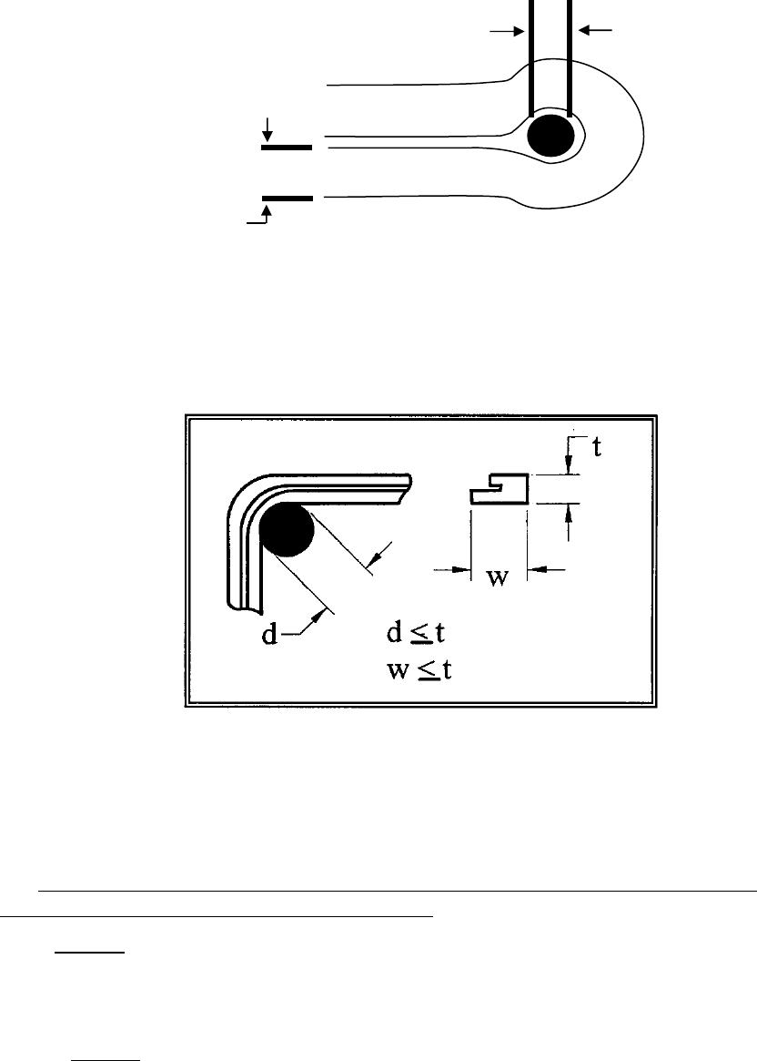
COMUSFLTFORCOMINST 4790.3 REV D CHG 3
07 Nov 2023
V-I-5-14
Figure 5-2 Simple Software Deformation Inspection
d ≤ t
(b) For complex shapes or parts with non-uniform cross section which
closely resemble flat pieces, strips, or O-Rings, bend the material at
least 90 degrees over a rod of diameter (d) no greater than the
maximum cross sectional thickness (t or w) as illustrated in Figure 5-3.
Figure 5-3 Complex Software Deformation Inspection
(c) For parts which do not fall into the categories and parts which are too
stiff to be deformed as required, approval must be obtained on a case
basis from the respective Reactor Plant Planning Yard via a Liaison
Action Request per Part I, Chapter 8, Section 8.4 of this volume.
5.6 SUBMARINE SAFETY MAINTENANCE CERTIFICATION AND RE-ENTRY
CONTROL, NUCLEAR AND NON-NUCLEAR.
5.6.1 Purpose. To issue the policy and procedures for:
a. Maintaining continuity of SUBSAFE certification during the operating cycle.
b. General Maintenance Certification Record administrative requirements.
5.6.1.1 General.
d
t

COMUSFLTFORCOMINST 4790.3 REV D CHG 3
07 Nov 2023
V-I-5-15
a. Reference (r) establishes the SUBSAFE certification criteria which must be
accomplished on submarines in order for NAVSEA to recommend UROs to design
test depth. Once the certification criteria are satisfied, NAVSEA will make a
recommendation to the appropriate TYCOM that the submarine be authorized for
URO to design test depth. Based upon the NAVSEA recommendation, TYCOM will
authorize the submarine to operate to design test depth, or some lesser depth
depending upon specific conditions. Each TYCOM summarizes the authorized
operating depths and restrictions for ships in reference (s) or (t).
b. Continued URO to design test depth is dependent on:
(1) The positive control and re-certification of all re-entries into the SUBSAFE or
hull integrity boundaries of the ship and
(2) The satisfactory and timely completion of URO MRC requirements.
5.6.2 Re-Entry Control Program.
a. Applicability. This section is applicable whenever work is accomplished within a
SUBSAFE boundary as defined by SUBSAFE Requirements Manual, reference (r),
and as depicted in the SUBSAFE Certification Boundary Book.
NOTE: SUBSAFE REQUIREMENTS MANUAL IS THE FINAL AUTHORITY FOR
DETERMINING IF AN ITEM IS WITHIN THE SUBSAFE BOUNDARY. THE
SUBSAFE CERTIFICATION BOUNDARY BOOK IS AN ILLUSTRATED
REFERENCE TO AID IN THE DETERMINATION OF WHETHER AN ITEM
IS SUBSAFE OR NOT.
b. General. The Re-Entry Control (REC) Program includes those elements associated
with maintenance or repair necessary to maintain the certification established by
NAVSEA. The program provides auditable OQE of the following:
(1) What work was accomplished, including material and components used, re-test
requirements, tests performed, and test data.
(2) Why work was required.
(3) Who authorized and accepted the REC.
(4) Who did the work.
(5) When and where the work was accomplished, including the work and re-test
boundaries.
c. When it becomes necessary to re-enter a SUBSAFE certified system or structure, it
will be accomplished per the requirements and procedures of paragraph 5.6.4 of this
chapter. Specific direction on completing the Maintenance Certification Record
(MCR) (QA form 9) is contained in the instructions for QA form 9.
d. Some exceptions to RECs are allowed due to frequent entry into the certified boundary
for routine operations or maintenance actions. These exceptions and administrative or
operational control requirements are contained in paragraph 5.6.7 of this chapter.
e. NAVSEA SUBSAFE and FBW SCS Grams are not authorized for use by submarines,
submarine ISICs, submarine Groups or maintenance activities managed by the
COMUSFLTFORCOMINST 4790.3 REV D CHG 3
07 Nov 2023
V-I-5-16
TYCOM. SUBSAFE and FBW SCS Grams will be engineered into the Joint Fleet
Maintenance Manual where appropriate.
5.6.3 Nuclear Submarine Safety System Re-Entry. When Re-Entry of a nuclear SUBSAFE
system or a portion of a nuclear SUBSAFE system is necessary, the applicable Reactor Plant
Manual, reference (e), and the ship’s specific Reactor Plant Work Accomplishment Report
(RPWAR) will be reviewed and used to provide technical guidance. Nuclear SUBSAFE Re-
Entry will be per the requirements and procedures of Section 5.7 of this chapter. Nuclear
SUBSAFE RECs must be marked in Block 2 of the QA-9 as SUBSAFE and NUCLEAR.
Approval to open and close the Nuclear REC will be per Part I, Chapter 2, Appendix E of this
volume using the “NUC” review and approval matrix.
5.6.3.1 Reactor Plant Planning Yard Liaison Action Requests.
NOTE: INFORMATION ON THIS SUBJECT IS SAFEGUARDED PER REFERENCE
(u).
5.6.4 Re-Entry Control Administrative Procedures.
a. General. REC procedures provide a continuous, auditable record of work done on
fully certified systems to provide positive assurance that they remain “certified”.
Continuity of Certification is mandatory throughout the operational life of the ship to
ensure URO to design test depth.
b. REC. When re-entry of a SUBSAFE system or a portion of a SUBSAFE system (or
component) is necessary, the work and re-certification of the work will be documented
using the MCR/REC, QA form 9.
(1) A MCR/REC will be used for each re-entry of the pressure hull or each
certified system, certified component or portion thereof as defined by the
SUBSAFE certification boundaries.
(2) A MCR/REC will be restricted to a single system within a single mapping
plan, a single component removed from a system, or a single component
removed or worked that requires multiple mapping plans (e.g., trash disposal
unit, Main Sea Water hull or backup valves and hydraulic actuators, modified
after signal ejectors).
(3) When a MCR/REC is opened by a ship to permit removal of a component by
Ship’s Force for repair by an FMA as a “ship to shop” job, a MCR/REC must
be opened by the FMA to cover the work and retesting of the work center work
performed by the FMA.
(4) Where other certified systems must be re-entered to accomplish a MCR/REC,
each system will have its own MCR/REC, except as described in paragraph
5.6.4.b.(2) of this chapter.
(5) The MCR/REC and records of MCR/REC will contain all of the OQE
necessary to comply with paragraph 5.6.2.b of this chapter.
(6) The work procedures associated with a MCR/REC will contain sufficiently
detailed instructions to assure that all requirements for certification are
properly accomplished and documented.
COMUSFLTFORCOMINST 4790.3 REV D CHG 3
07 Nov 2023
V-I-5-17
(7) Work and test boundaries will be defined in terms that are unique and directly
identifiable with the specific mapping plan or task involved.
(8) When work and test boundaries are different, both boundaries will be set forth.
The work boundaries, test boundaries and pressure boundaries should be
specified and should not be confused. Work boundaries define the limits to
which work was performed. Test boundaries define the limits for testing to
certify the work; these tests may involve actuators, indicators or components
other than those actually repaired. Pressure boundaries define (perhaps by
valve lineups) the limits of the system which were pressurized to
hydrostatically test the work. The pressure boundaries and test boundaries
may be the same.
(9) On a “ship to shop” job the work boundaries may be best described by system
joint designators even though those joints were not “disturbed” by the FMA
(e.g., rebuild a Rubber Insert Sound Isolation Coupling (RISIC), the work or
test boundaries will be the end flanges that bolt up to the system, the joint
identification numbers may be clearest identification of that boundary point).
(10) Previously certified hardware will be reused when certification is not affected
by the re-entry, or when it can be recertified. The words “replace”, “repair”,
and “re-install” should be used carefully. “Replace” means the use of a
different or new component, while “re-install” indicates the use of the
previously installed component, whether repaired or not. “Repair” indicates
that some refurbishment, other than mere disassembly or cleaning, was
performed.
(11) Associated supporting documents such as Nondestructive Testing (NDT)
records, material certification, test data, etc., will be specifically identified and
referenced on the MCR/REC.
(12) When it becomes necessary for an FMA to re-enter a certified component
(periscopes, Auxiliary Sea Water pumps, Electronic Warfare Support
Measures masts) which will not be returned to the ship from which it was
removed, or when a component is re-entered when the ship on which it will be
installed is not present, the FMA will control the work and document the re-
entry using a QA form 9, MCR/REC. The MCR/REC will be initiated and
closed out by the FMA. A copy of the completed MCR/REC will accompany
the component when it is installed in a certified SUBSAFE submarine or
shipped to another activity as proof of certification. These controls are
required whether the certified component is to be installed in a SUBSAFE
certified ship or stored. Each component must retain its certification. These
RECs are separate from and in addition to any MCR/REC required for removal
of a component from SUBSAFE system and are only necessary whenever the
original component will not be returned during the current availability to the
ship from which it was removed.
(13) The CWP/REC Log, QA form 11 will be established and maintained by the
QAO per the detailed instructions for QA form 11 in Part I, Chapter 11 of this

COMUSFLTFORCOMINST 4790.3 REV D CHG 3
07 Nov 2023
V-I-5-18
volume. The QA form 11 must be reviewed by the QAO to verify all
MCR/RECs are closed prior to submerged operations. The FMA QAO will
maintain a log for the FMA only and one for each tended ship RECs. The QA
form 11 must be reviewed by the FMA QAO to verify all FMA MCR/RECs
are closed prior to underway operations of each tended ship.
(14) Revisions to the MCR/REC are required for the following:
(a) Change in work boundaries (e.g., breaking additional or new
mechanical joints not previously identified on the MCR/REC). A
MCR/REC revision is not required to delete undisturbed joints.
Deletion of joints must be authorized by cognizant technical authority
and documented in the REC package. Block 14 must be annotated to
reflect joint deletions prior to signing MCR/REC Block 17.
(b) Change in NDT or test requirements (e.g., “J” vice H hydrostatic test,
when “H” was originally specified). This does not include a DFS for
unaccomplished testing. A MCR/REC revision is not required for
NDT incidental to minor repairs as defined in paragraph 5.6.4.b.(14)
(d) of this chapter. NDT results must be documented in the MCR/REC
package.
(c) Scope of work changes (e.g., originally replace software changed to
weld repair sealing surfaces, originally replace software changed to
metallic pressure boundary part replacement).
(d) The MCR/REC does not require revision in order to conduct minor
repairs in support of the original scope of work. These minor repairs
must be authorized by cognizant authority and documented in the
MCR/REC package, with appropriate OQE generated and added to
Block 16 prior to the signing of Block 17 of the QA form 9. Hot work
is not classified as a minor repair. Minor repairs authorized to be
performed without a revision are:
1 Minor machining such that the machining is within the limits of
the technical drawing, SMS, or technical manual (e.g., taking a
skim cut on an O-Ring groove such that the final machined
dimensions are within the tolerances of the technical reference).
2 Epoxy repairs.
3 Electroplate repairs.
4 Preventive coating application.
(15) A revision cannot be used when a new MCR/REC is required (e.g., different
system must be entered to conduct repair).
(16) REC Cancellation and REC Administrative Closeout. In the event a CWP is
prepared and the job is planned to be accomplished but for some reason it was
cancelled or deferred the following actions should be taken:
COMUSFLTFORCOMINST 4790.3 REV D CHG 3
07 Nov 2023
V-I-5-19
(a) If work was authorized to start, the CWP/REC must be revised to
reflect that no work was accomplished and the REC was revised to
close administratively. The QA form 11 log will be annotated that the
job was “Cancelled”.
(b) If work was not authorized to start, and the job has been cancelled,
annotate the remaining blocks of the QA form 9 with NA and note that
the REC was cancelled and no work was accomplished. Blocks 20 and
21 will be signed to formally close the REC. If the REC was prepared
by a Repair Facility, a copy of the QA form 9 will be provided to the
tended unit with the Certification Continuity Letter. QA form 11 log
will be annotated that the job was “Cancelled”.
(c) If work was not authorized to start and the job has been deferred to a
future maintenance period, the REC is not required to be cancelled.
The QA form 11 log will be annotated as “Deferred”. This is not
considered an open REC.
(17) As a policy, RECs for work within the SUBSAFE certification boundary or
test documents within the SUBSAFE Boundary must not be closed out until
resolution of all actions necessary to verify certification has been maintained
when any breach of the boundary has occurred. An acceptable alternative,
however, is to close out a REC or test documents within the SUBSAFE
Boundary by transferring remaining at sea testing actions to a separate
auditable accountability system (i.e. DFS or the Deep Dive Test Procedure).
All RECs closed in this manner must be annotated by the activity with the
reference documents that contained the transfer actions. This policy must be
verified by the activity accomplishing the work, supervising authority,
submarine Commanding Officer and ISIC.
(18) Prior to every underway for submerged operations, all SUBSAFE RECs must
be closed. Commanding Officers of submarines will certify and acknowledge
REC closure by signing the REC and submit to Immediate Superior In
Command (ISIC) a written report per paragraph 5.6.8 of this chapter.
SUBSAFE certification letter is only required after an inport period in which
SUBSAFE work was performed.
(19) Ship’s Force is responsible for providing “Buddy” SUBSAFE, FBW-SCS or
DSS-SOC REC serial numbers to outside repair activities performing
SUBSAFE, FBW-SCS or DSS-SOC work on shipboard SUBSAFE, FBW-SCS
or DSS-SOC systems. The Buddy REC number is issued from ship’s QA-11
log and will be documented on repair activities RE-ENTRY CONTROL
FORM. The use of the Ship’s Force Buddy REC number is NOT required for
Chief of Naval Operations or TYCOM scheduled availabilities. The issue of
the Ship’s Force Buddy REC is an administrative tool to make REC Log
keeping easier and ensure the required certification letters are received prior to
underway. The Ship’s Force Buddy REC does not result in a Ship’s Force
REC Form, does not require Ship’s Force Record Retention and does not allow
Ship’s Force to participate in the assigned activities work or certification

COMUSFLTFORCOMINST 4790.3 REV D CHG 3
07 Nov 2023
V-I-5-20
process, except performance of testing. Ship’s Force will only issue Buddy
RECs to SUBSAFE, FBW-SCS or DSS-SOC certified activities performing
SUBSAFE Work.
5.6.5 Using a Controlled Dive Departure from Specification to Close a Maintenance
Certification Record or Re-Entry Control. If a MCR/REC is closed by transferring at sea testing
to a DFS (e.g., controlled dive to test depth for retest of a periscope hull gland, controlled dive
for retest of a sea connected system in lieu of joint tightness test to “J” pressure of Test Pressure
Drawing (TPD)), the ship will be restricted, as required by reference (r), as indicated in sub-
paragraphs a through d of this paragraph.
NOTE: IF AN UNSATISFACTORY CONDITION OR SEAWATER LEAKAGE IN
EXCESS OF THE SPECIFICATION IS FOUND DURING THE CONDUCT OF
THE CONTROLLED DIVE TO TEST DEPTH, THE SHIP MUST CONTINUE
TO TEST DEPTH UNLESS THE COMMANDING OFFICER DETERMINES
IT APPROPRIATE TO ABORT THE DIVE.
a. Except for the controlled dive to test depth to retest the system or component, ship’s
depth will be limited to one half test depth plus fifty feet until satisfactory completion
of inspections during the controlled dive. The ship will stay at test depth for the time
required as detailed in the normal retest procedure (i.e., 30 minutes if the normal joint
tightness test is for 30 minutes) plus adequate time to permit inspections.
b. If inspections of the system or component during the controlled dive are satisfactory,
the ship is released for UROs with no immediate report required. Clearance of the
DFS will be reported as required by Part I, Chapter 8 of this volume.
c. If inspections of the system or component during the controlled dive are
unsatisfactory, the ship is restricted to one half test depth plus fifty feet as indicated in
paragraph 5.6.5a. of this chapter, unless specific authorization is received from
TYCOM approving URO or changing the depth restriction. The DFS approved to
perform the controlled deep dive must be cancelled and a new major DFS for the
failed testing must be initiated by the ship. An immediate report of unsatisfactory
inspections will be made to ISIC and, if required, a request, including Commanding
Officer’s evaluation of unsatisfactory conditions and justification for request, for
approval to conduct operations at depths deeper than one half test depth plus fifty feet
will be made to TYCOM with information copy to ISIC and NAVSEA (07T).
Deficiencies discovered that are not joints specified for inspection in the MCR/REC
and DFS are dispositioned as required by Part I, Chapter 8 of this volume and are not
cause for depth restrictions unless the Commanding Officer deems necessary.
d. Should the presence of an installed Dry Deck Shelter preclude a component requiring
deep dive testing from seeing submergence pressure, the requirements of paragraph
5.6.5a. of this chapter must apply upon removal of the Dry Deck Shelter and must be
so annotated in the approval comments of the deep dive DFS.
5.6.6 Voyage or At Sea Repairs. If emergent repairs or at-sea repairs involve REC work, the
ship is limited to 200 feet or less until the ship’s Commanding Officer has signed for the closed
REC.

COMUSFLTFORCOMINST 4790.3 REV D CHG 3
07 Nov 2023
V-I-5-21
a. If equipment malfunctions (except for casualties affecting recoverability, salvage,
watertight integrity, or operation of ship’s control surfaces), or seawater leakage in
excess of the specification is found during the conduct of the initial tightness dive or
the controlled dive to test depth, the ship should continue to the required depth and
execute the sea trial agenda unless the Commanding Officer determines it appropriate
to abort the dive. The Commanding Officer should be particularly circumspect in the
case of leakage locations not isolable by flood control or other closures (e.g., electrical
hull penetrators, periscope hoist rods, etc.).
b. Following completion of the initial tightness dive and the controlled dive to test depth,
SUBSAFE deficiencies which result in seawater leakage exceeding the specification
for acceptance must be reported to the TYCOM, NAVSEA and info to all concerned.
c. If leakage is from an unisolable joint, ship’s depth will be limited to 1/2 test depth plus
50 feet until approval from the TYCOM is received to continue trials at depths greater
than 1/2 test depth plus 50 feet.
NOTE 1: REPAIR ACTIVITIES WILL NOT REQUEST THE SHIP TO PERFORM A
REC EXCEPTION TO CIRCUMVENT THE REPAIR ACTIVITIES USE OF
REC CONTROLS IN CONJUNCTION WITH REPAIR ACTIVITY WORK.
NOTE 2: REC EXCEPTIONS ARE NOT AUTHORIZED TO BE USED FOR THE
INSTALLATION OF NEW LEVEL I HARDWARE WITHIN THE SUBSAFE
BOUNDARY.
5.6.7 Exceptions to Re-Entry Control. Exceptions to Re-Entry Control (REC) are listed in
reference (r). The reference includes certain systems and equipment within the certified
SUBSAFE boundary which require frequent entry into the certified boundary for routine
operations or maintenance actions in order to enable the ship to carry out its mission. The
operational requirements for these systems and equipment have been reviewed. Inherent
operational controls in the present system are considered adequate. The operational control
which is considered as meeting the intent of the REC requirements is listed beside each item and
must be in effect in order to use the exception. Some REC exceptions permit removal of
material from the installed system to perform maintenance or testing. The original material must
be reinstalled or a complete REC (controlled work package) must be used to capture the
installation of new Level I material or certification testing for new material.
5.6.8 Certification Continuity Report. In order to ensure continued certification of each
submarine, periodic reports are required as indicated in sub-paragraphs a through c:
a. Prior to each underway for submerged operations, all SUBSAFE RECs or REC
exceptions requiring a controlled assembly must be closed. Commanding Officers of
submarines will submit to ISIC (deployed ISIC, if deployed), a written certification
continuity report, which addresses the status of Ship’s Force SUBSAFE, Submarine
Flight Critical Component (SFCC) CWPs or REC exceptions requiring a controlled
assembly, testing of SUBSAFE, Fly-By-Wire Ship Control Systems (FBW SCS)
systems, URO maintenance completed and RECs closed by transferring actions to a
DFS. SSBN and SSGN class potable water shore service connection cap installation
performed as a controlled assembly is exempt from reporting under this paragraph.
Appendix B provides the minimum requirements for the letter. If no SUBSAFE,

COMUSFLTFORCOMINST 4790.3 REV D CHG 3
07 Nov 2023
V-I-5-22
SFCC controlled work, REC exceptions requiring a controlled assembly, testing or
URO MRCs were accomplished, no report is required. Certification Continuity
Reports may be delivered in person by a command representative, transmitted as a
naval message, transmitted via e-mail as an electronically signed PDF, transmitted via
e-mail as a signed letter scanned as a PDF.
b. Prior to the ship’s underway after an FMA availability, refit or inport period when
SUBSAFE, SFCC work was performed, the FMA Commanding Officer will issue a
letter report to each tended submarine, with a copy to parent ISIC, which addresses the
status of SUBSAFE, SFCC CWPs, testing of SUBSAFE, FBW SCS systems, URO
maintenance requirements completed and SUBSAFE non-conformances (i.e., DFS and
LAR). Appendix C provides the minimum requirements for the letter.
c. Prior to ship’s underway, activities other than FMAs which perform SUBSAFE or
SFCC maintenance on submarines will issue a letter report to the submarine with a
copy to the parent ISIC, certifying that the maintenance performed meets the
requirements of applicable specifications invoked by the governing document (e.g.,
unscheduled availabilities, contract) and the Memorandum of Agreement. Appendix
D provides the minimum requirements for the letter.
5.7 REACTOR PLANT WORK ACCOMPLISHMENT REPORT (SUBMARINES ONLY).
5.7.1 Purpose.
a. The RPWAR form is a listing of those pipe and components of the reactor plant which
are SUBSAFE. It is specific for each ship and is provided by the Reactor Plant
Planning Yard via the TYCOM. The RPWAR consists of:
(1) Status sheet.
(2) Cover sheet.
(3) RPWAR Master Pages.
(4) Addendum Sheet.
(5) RPWAR general notes.
b. The reactor plant hull integrity area is comprised of those items on the RPWAR. Each
ship must maintain the RPWAR current. Each completed RPWAR will be filed in an
auditable manner along with the latest revision for the ship of the NAVSEA RPWAR
status drawing. The reproducible blank RPWAR will be maintained in the same file.
The ship will reproduce blanks as necessary to support reactor plant work.
c. To properly complete the RPWAR, the preparer must review the general notes of the
applicable RPWAR and the instructions in reference (e).
d. To certify (or recertify) a nuclear SUBSAFE item, a RPWAR must be completed by
the activity performing the maintenance (ship, FMA or shipyard) per reference (e) and
forwarded as soon as possible to the Reactor Plant Planning Yard with copies to
NAVSEA 08, TYCOM, ISIC and the ship. The RPWAR is to be signed in ink and the
signed in ink copy should be forwarded to the Reactor Plant Planning Yard. Initials or

COMUSFLTFORCOMINST 4790.3 REV D CHG 3
07 Nov 2023
V-I-5-23
typed signatures are not permitted. When work is complete, submit only those pages
of the RPWAR line items that certify the work accomplished.
e. The RPWAR does not, in any way, relieve the FMA or ship of its responsibility to
comply with all applicable requirements specified in technical manuals, plans, and
other NAVSEA documents.
f. When the FMA works in an area covered by the RPWAR, the ship’s Engineer Officer
will provide the FMA with a reproduced RPWAR with the number filled in, notes,
applicable certification forms and addenda sheet.
g. Instructions contained in this section are in amplification of those included in
reference (e) and the RPWAR drawing itself.
5.7.2 Specific Instructions for Completing Reactor Plant Work Accomplishment Report Cover
Sheet.
a. The ship’s hull number must be specified in the space provided (if not already pre-
printed).
b. The reporting activity (ship, FMA or shipyard) must be listed.
c. The report number must be included. The report number is the next consecutive
number to that indicated on the latest completed RPWAR held by the ship.
d. The report must be dated.
e. The applicable block specifying when the work was accomplished must be checked.
f. The signatures and titles of the personnel preparing, reviewing, and approving the
RPWAR must be included. Each RPWAR submitted by ships is prepared by the Lead
Work Center QAI, reviewed by the QAO and Engineer Officer, and approved by the
Commanding Officer. Each RPWAR submitted by an FMA is prepared by the nuclear
Planning and Estimating Work Center (10D), reviewed by the Nuclear Repair Officer
and QAO, and approved by the Repair Officer.
5.7.3 Specific Instructions for Completing Reactor Plant Certification When New or Previously
Uncertified Material is Installed in a Submarine Safety Application.
a. The applicable revision of the drawing or plan must be referenced in the “DWG. NO.
AND REV” block for each item worked on.
NOTE: IF A DRAWING OR PLAN OTHER THAN THAT REFERENCED IN THE
“DWG. NO. AND REV” BLOCK IS USED BY THE REPORTING ACTIVITY,
THE ACTUAL DRAWING OR PLAN USED SHOULD BE SPECIFIED IN
EITHER THE “REMARKS” BLOCK OR ON THE ADDENDA SHEET AS A
REFERENCED NOTE. THE REASON FOR USING A DIFFERENT
DRAWING OR PLAN SHOULD ALSO BE SPECIFIED.
b. The identification of the reporting activity’s detailed record should be entered in the
“DETAILED RECORD IDENTIFICATION” block if the inspections required by the
applicable inspection category were performed by the reporting activity (ship or
FMA).

COMUSFLTFORCOMINST 4790.3 REV D CHG 3
07 Nov 2023
V-I-5-24
NOTE: THE RECORD RETAINING ACTIVITY, IF OTHER THAN THE
REPORTING ACTIVITY, SHOULD BE IDENTIFIED IN THIS BLOCK.
c. Where sufficient space does not exist for entry of information, refer to the addenda
sheet in the “REMARKS” block and enter the required information on the addenda
sheet.
d. The report number will be entered in “REMARKS” block for each line item worked
on by the reporting activity.
e. The signature block must be completed, indicating that the corresponding line item
work has been satisfactorily completed and that records substantiating this are on file.
f. Where SUBSAFE work is accomplished following an Alteration, the reporting activity
will reference, for each work item, the applicable Alteration with revision number in
the “REMARKS” block.
g. Waiver, if any, previously granted for each item must be identified, including
reference to the NAVSEA approval letter.
NOTE: IF THE WORK PERFORMED ON THE SUBSAFE ITEM IS SUCH THAT
THE PREVIOUS CERTIFICATION IS VOIDED (SUCH AS REPLACEMENT
OF A SUBSAFE VALVE TAILPIECE), THE REPAIRED OR ALTERED ITEM
MUST BE CERTIFIED AS NEW MATERIAL.
5.7.4 Specific Instructions for Completing Reactor Plant Certification When Previously
Certified Material is Reinstalled.
a. Reinstallation of previously certified material does not require a RPWAR unless
specifically called out as a line item on the RPWAR requiring torque or installation
verification.
b. The fastener torque sheet is filled out in the following manner:
(1) The inspection document is the QA form 34, the FWP or CWP serial number
and job sequence number.
(2) The signature block is signed by the QAI who verified the torque.
(3) If sufficient space is not available in the QA form 34, the addenda sheet should
be used with the appropriate line item listed.
5.8 MATERIAL CONDITION MONITORING UNRESTRICTED OPERATIONS
MAINTENANCE REQUIREMENT CARD PROGRAM (SUBMARINES ONLY).
a. The URO MRC program provides the minimum material condition requirements for
URO to design test depth, with an established periodicity to accomplish. It is one of
the programs required to maintain SUBSAFE certification. Accomplishment of the
URO MRC will identify changes within the SUBSAFE or hull integrity boundaries of
the ship, which result from the degradation caused by the service environment.
b. Administration, scheduling and reporting of the URO MRC program will be per the
requirements of Chapter 25, Volume VI of this manual. A summary of URO MRC
status will be reported by the submarine Commanding Officer per paragraph 5.6.8 of
this chapter.

COMUSFLTFORCOMINST 4790.3 REV D CHG 3
07 Nov 2023
V-I-5-25
c. When performing corrective maintenance, the following guidance is provided with
regard to URO MRC:
(1) When performing corrective maintenance, associated URO MRCs should be
reviewed to determine if the URO MRCs should be accomplished concurrently
ahead of scheduled periodicity to preclude having to disassemble equipment
again to accomplish the URO MRCs. Ship’s schedule or FMA resources may
preclude concurrent, early accomplishment of URO MRCs.
(2) If URO MRC criteria are used, in total or in part, during corrective
maintenance, and a measured parameter is found out of tolerance and not
restored, a major DFS must be submitted, per Part I, Chapter 8 of this volume,
even though the periodicity of the URO MRC has not expired.
(3) When performing corrective maintenance that does affect a URO MRC
measured parameter, perform that portion of the applicable URO MRC. A
URO MRC measured parameter is any parameter that is documented on the
Data Report Form during the performance of the URO MRC. The following
are examples of corrective maintenance that may affect a URO MRC measured
parameter:
(a) When the retest of the corrective maintenance is a documented URO
MRC measured parameter (i.e., Emergency Flood Control Accumulator
Tightness Test - URO MRC 026).
(b) When maintenance (such as opening mechanical joints or replacing
hardware, adjustments, tests) affects the operation of a system inspected
or tested by a URO MRC (i.e., Emergency Flood Control - URO MRC
025).
d. Following installation of an alteration (Ship Alteration (SHIPALT), Alteration and
Improvement, Temporary Alteration) that modifies the structure of the Ship, such that
access to vital equipment is or may be impacted, the Ship must evaluate the need to
perform URO MRC 029. If access to vital equipment could be restricted, the Ship
must perform URO MRC 029 and provide a copy to the installing activity and the
ISIC. Partial accomplishment of URO MRC 029 is acceptable if appropriate for the
alteration. If partial accomplishment of the URO MRC is performed, provide a copy
to the installing activity and the ISIC. If the complete URO MRC is accomplished,
provide a copy to normal distribution.
5.9 SUBMARINE FLY-BY-WIRE MAINTENANCE CERTIFICATION.
5.9.1 Purpose. To issue the policy and procedure for:
a. Maintaining continuity of the FBW SCS certification during the operating cycle.
b. General Maintenance Certification Record administrative requirements.
5.9.1.1 General.
a. Reference (v) establishes the FBW SCS certification criteria which must be
accomplished on all applicable submarines in order to maintain system certification
throughout the operating cycle of the ship. Once a submarine FBW SCS has been

COMUSFLTFORCOMINST 4790.3 REV D CHG 3
07 Nov 2023
V-I-5-26
certified for unrestricted use or is accepted by the shipbuilder, all work within the
FBW SCS certification boundary and testing to support that work must be
accomplished, controlled and documented per reference (v).
b. All other Performance testing within the FBW SCS Boundary, for work within the
FBW SCS Boundary must be accomplished to support system certification and
documented using the activity’s normal work control processes.
c. Work is defined as an action that actually or potentially changes (including
disassembly and testing) the approved configuration of any part of the FBW SCS or
SFCC Boundaries.
d. The objective of this work control process for work within the FBW SCS certification
boundary is to provide maximum confidence that any work and all applicable testing
is authorized, controlled, identifiable, and auditable. It provides positive assurance
that all SFCC equipment and FBW SCS is restored and tested to a fully certified
condition.
5.9.1.2 Applicability. The requirements in this section must apply to Seawolf and Virginia Class
Submarine FBW SCSs.
5.9.1.3 Submarine Flight Critical Component Boundary. The Submarine FBW SCS Boundary
must consist of electronic hardware and software within the submarine FBW Boundary (see
reference (v)) that process safety critical functions and data elements.
a. Safety critical electronic components within the FBW SCS certification boundary
must be determined per references (v) and (w) and must be identified as SFCCs.
b. Safety critical software units within the FBW SCS certification boundary must be
determined per references (v) and (w). Safety critical software units must require
additional testing or analysis, be marked, configuration managed, and controlled per
the requirements in reference (v).
5.9.2 Submarine Flight Critical Component Boundary Work Control Procedures.
a. All fleet activities, In-Service Engineering Activity, repair activities or shipyards
(public or private) must use REC to document the accomplishment of work within the
FBW SCS certification boundary. RECs must provide greater assurance that any work
accomplished is authorized, documented and executed per specifications and
requirements, and is supported by OQE.
b. Some exceptions to RECs are allowed due to frequent entry into the certified boundary
for routine operations or maintenance actions. These exceptions and administrative or
operational control requirements are contained in reference (v).
c. Closed RECs must be retained by the work accomplishing activity and are subject to
audit by cognizant activities (TYCOM, ISIC, shipyard, supervising authority or
NAVSEA) during audits such as functional or certification audits.
5.9.3 Submarine Flight Critical Component Boundary Work Control Closeout.
a. All RECs for work in the FBW SCS certification boundary must be closed prior to the
system being released for unrestricted use, Fast Cruise or Sea Trials. As part of the

COMUSFLTFORCOMINST 4790.3 REV D CHG 3
07 Nov 2023
V-I-5-27
work control procedure closeout process, RECs must receive an independent review
within the activity performing the work to verify:
(1) Work was authorized and approved.
(2) Work stayed within the authorized boundaries.
(3) Post work or maintenance testing was accomplished satisfactorily.
(4) Appropriate Quality Assurance Forms are included to document Certification
of Maintenance, and all forms are completed with required signatures.
b. All testing of the FBW SCS Boundary must be verified closed prior to the system
being released for unrestricted use, Fast Cruise or Sea Trials.
c. As a policy, RECs for work within the FBW SCS certification boundary or test
documents within the FBW SCS Boundary must not be closed out until resolution of
all actions necessary to verify certification has been maintained when any breach of
the boundary has occurred. An acceptable alternative, however, is to close out a REC
or test documents within the FBW SCS Boundary by transferring remaining at sea
testing actions to a separate auditable accountability system (i.e. DFS). All RECs
closed in this manner must be annotated by the activity with the reference documents
that contained the transfer actions. This policy must be verified by the activity
accomplishing the work, supervising authority, submarine Commanding Officer and
ISIC.
d. Prior to each underway for submerged operations, Commanding Officers of FBW SCS
submarines will submit to ISIC (deployed ISIC, if deployed), a written certification
continuity report, which addresses the status of Ship’s Force FBW SCS REC, testing
of FBW SCS, URO maintenance requirements in the format of Appendix B. If no
FBW SCS controlled work or testing were accomplished, no report is required.
5.9.4 Objective Quality Evidence to Support Controlled Work on Fly-By-Wire Ship Control
System Submarine Flight Critical Component. To standardize maintenance OQE, the sub-
paragraphs a through c provide guidance on the key elements needed to be documented to certify
the work process, whether routine maintenance, major repairs, system upgrades or alterations.
Reference (v) provides OQE requirements including additional attributes to be included as part
of the FBW SCS certification boundary work control process.
NOTE: THE ISIC IS ONLY RESPONSIBLE TO AUDIT FBW WORK PERFORMED
BY FORCES AFLOAT OR TYCOM MANAGED ACTIVITIES.
a. Activities performing work on FBW SCS within the FBW SCS certification boundary
should use this information, along with source documents, as a guide in developing
OQE records that document work, inspections and tests performed within the FBW
SCS certification boundary.
b. The elements listed are technical specifications and process documents required for a
typical repair or system upgrade or alteration process.
c. If Upgrades, Alterations or Major Repair Work of the FBW SCS was performed, the
ISIC will accomplish a 100% audit, as defined in Part I, Chapter 9 of this volume, of
the work. ISIC and TYCOM will use the FBW message reporting process for

COMUSFLTFORCOMINST 4790.3 REV D CHG 3
07 Nov 2023
V-I-5-28
certification specified in Volume II, Part I, Chapter 3 of this manual, for availabilities
of less than six months duration.
5.10 AIRCRAFT CARRIER MAINTENANCE DOCUMENTS.
5.10.1 Purpose. The purpose of this section is to provide amplifying or clarifying information
on the processes involved and appropriate use of specific aircraft carrier maintenance related
documents. Including:
a. Request for Departure from Specification (DFS), Waivers or Deviation.
b. Nuclear Liaison Action Request (LAR).
c. Nuclear Liaison Inquiry (NLI).
d. Steam Plant Action Request (SPAR).
e. Steam Plant Liaison Inquiry (SPLI).
f. Reactor Plant Configuration Change Report (RPCCR).
g. Planned Maintenance System (PMS) Technical Feedback Reports (TFBR).
h. Tech Manual Deficiencies & Manual Change Requests.
i. Fleet Coordinated Shipboard Allowance List (COSAL) Feedback Reports.
5.10.2 Non-Nuclear Deviations, Waivers and Departure from Specifications. The terms
“deviation” and “waiver” are often used synonymously. However, the principle difference is a
deviation is requested prior to conducting work that will result in a non-conformance, where a
waiver is requested after a non-conformance has been discovered. Requests for deviation and
waivers must be retained and tracked within the DFS system by Ship’s Force and the ISIC or
TYCOM until permanent documentation is confirmed to reflect the specific non-conforming
condition. Use of the Web Based Electronic Departure from Specification or Electronic Waiver
and Deviation programs facilitate meeting these requirements. A DFS (non-nuclear system or
components only) is used specifically to identify a lack of compliance with plans, procedures,
instructions, or authoritative documents during a maintenance action or operations.
5.10.2.1 During a Maintenance Action. A DFS is required for any lack of compliance with
cognizant documents or drawings. For an “as found” condition during maintenance, the
TYCOM, the ship and the Regional Maintenance Center (if involved) must evaluate the non-
compliance using the guidance of paragraphs 8.2.5 and 8.2.6, of Part I, Chapter 8 of this volume
to determine if the nonconforming condition meets the criteria as a Major or Minor DFS.
NOTE: IF THE SHIP IS AT SEA THE GUIDANCE OF PARAGRAPH 8.3.8 OF PART
I, CHAPTER 8 OF THIS VOLUME APPLIES.
5.10.2.2 During Operations. A DFS is required for any lack of compliance with cognizant
documents or drawings. For any “as found” conditions or equipment failures that result in a non-
compliance, the ship (or TYCOM if in port) must evaluate the condition or failure using the
guidance of paragraphs 8.2.5 and 8.2.6 of Part I, Chapter 8 of this volume to determine if the
nonconforming condition meets the criteria as a Major or Minor DFS.
a. If the nonconforming condition does not meet the criteria as a Major or Minor DFS,
no DFS is required and the nonconforming condition will be entered in the ship’s

COMUSFLTFORCOMINST 4790.3 REV D CHG 3
07 Nov 2023
V-I-5-29
Current Ship’s Maintenance Project (CSMP). This CSMP entry must include the DFS
serial number, On-Site Analysis Report serial number (if applicable) or other technical
references documenting or tracking the non-conformance.
b. If a DFS is required, the request should be processed as soon as possible to enable an
engineering evaluation of the non-conformance and subsequent approval or
disapproval issued without disrupting ship’s operations.
c. Requests for DFS will be submitted, approved and cleared per paragraph 8.3.7 or 8.3.8
of Part I, Chapter 8 of this volume. Use of the Web Based Electronic Departure from
Specification and Electronic Waiver and Deviation programs are acceptable unless
directed otherwise by TYCOM.
d. If a DFS is approved as “temporary” and requires rework to correct the discrepant
condition at a later date, a new CSMP entry for correction of the discrepant condition
will be initiated by the ship. This CSMP entry must include the DFS serial number,
On-Site Analysis Report serial number (if applicable) or other technical references
documenting or tracking the non-conformance. The ship’s QAO must ensure this
action is accomplished.
e. The QAO must verify that an active Job Control Number (JCN) exists for all active
temporary DFSs at the completion of all scheduled maintenance availabilities or at
least quarterly and must ensure that an auditable record of such verification is
maintained until superseded.
f. For all DFSs, deviations or waivers that have been adjudicated, the approving activity
is required to provide a copy of the DFS, deviation or waiver to the ship’s QAO for
retention and tracking per Part I, Chapter 8, paragraph 8.3.1.e of this volume.
5.10.3 Liaison Action Requests – Nuclear Cognizant Areas.
5.10.3.1 Technical Responsibilities. A memorandum of agreement exists between NAVSEA
Nuclear Propulsion Directorate (08) and NAVSEA PMS 312/335 that details the division of
responsibilities within the propulsion plants of nuclear powered ships. If a nuclear powered ship
is unable to comply with specifications for reactor plant systems or components and also those
systems identified as nuclear by the appropriate nuclear or non-nuclear interface diagram, then a
review of NAVSEA 08 requirements must be requested via a LAR. A formal resolution of all
LARs is generally required prior to reactor plant or propulsion plant startup.
5.10.3.2 Technical Resolution. In general, technical resolution to questions or problems for
reactor plant systems or components requires the submission of a LAR for nuclear powered
surface ships per the requirements set forth in Appendix 4 (Liaison Services) of reference (d).
a. Request for DFSs for nuclear systems will neither be requested nor approved. If a
ship has a question, problem, or is unable to comply with any nuclear specification, a
request for technical resolution will be made using a LAR.
b. A LAR should not be submitted for cases of out of specification seat leakage of
nuclear valves following repairs. The Reactor Plant Planning Yard and Reactor Plant
Prime Contractors do not have the authority to waive valve leakage specifications.
When valve seat leakage exceeds reactor plant manual specification after attempted
COMUSFLTFORCOMINST 4790.3 REV D CHG 3
07 Nov 2023
V-I-5-30
Ship’s Force or FMA repairs, the guidance of Part I, Chapter 8, paragraph 8.4.2.c. of
this volume may be used to defer any rework to a later date and close out the CWP.
c. A LAR is also never used for removing or reprogramming work, to or from, an
Availability Work Package (AWP).
(1) AWPs for Chief of Naval Operations availabilities are developed or changed
per Section 5.1.1 and Appendix D or F of the Aircraft Carrier Class
Maintenance Plan (ACCMP).
(2) The ACCMP can be found on the Carrier Team One web site under
“Resources/Library”.
d. An auditable LAR file must be maintained by the originating activity. A copy of the
status of all liaison actions LAR must be kept as part of this file with a copy
maintained in the applicable Controlled or Formal Work Package, as required.
5.10.4 Nuclear Liaison Inquiry – Nuclear Cognizant Areas. Refer to reference (d) for Nuclear
Liaison Inquiry information.
NOTE: INFORMATION ON THIS SUBJECT IS SAFEGUARDED PER REFERENCE
(U).
5.10.5 Steam Plant Action Request - Non-Nuclear Cognizant Areas. In 2003, the Propulsion
Plant Engineering Activity (PPEA) was formed as an additional resource for assisting
operational aircraft carriers with technical or operational issues, not associated with Ship
Alteration Installation or configuration control.
a. The Steam Plant Action Request (SPAR) is designed to allow the fleet and
maintenance activities to submit requests for technical assistance on non-Ship
Alteration related issues. The Carrier Engineering Team (CET) will assist in
providing solutions which satisfy specification requirements, supply a technical
evaluation or the basis for concurrence or non-concurrence with a deviation or
proposed change. Where sufficient information is not available to resolve the
problem, the CET may request additional information in a reply. Each SPAR will be
categorized based on the type of action taken in the proposed reply.
b. As with a LAR, if a ship or FMA has a question or technical problem or is unable to
comply with a non-nuclear specification, technical assistance is available from the In-
Service CET. CET Liaison services are requested using the SPAR discussed in detail
in Appendix 4 of reference (d).
5.10.5.1 Usage. SPARs requesting changes or deviations from specification must not be
submitted or approved by the CET. The SPAR is not a substitute for a Request for DFSs
described in Part I, Chapter 8 of this volume.
a. SPAR should be submitted by the ship or FMA to the PPEA to address technical,
logistical or operational problems with the steam and electric plant systems. It is the
intent of these requirements to ensure consistency between fleet units and overhaul
and repair activities in the content, format and completeness of SPAR submissions.
The SPAR is not intended to replace Ship’s Force and Overhaul or Repair Yard
communication with the CVN68 class Engineering Configuration Manager for

COMUSFLTFORCOMINST 4790.3 REV D CHG 3
07 Nov 2023
V-I-5-31
drawing and Ship Change Document or ShipAlt installation and configuration control
issues using LARs prepared per reference (x).
b. Examples of when generation of a SPAR is appropriate are:
(1) Receipt of spurious De-Aerating Feed Tank level alarms during maneuvering
transients that the performance of available preventive maintenance and
technical manual troubleshooting does not correct.
(2) Failure of the Emergency Diesel Generator to parallel across the Emergency
Diesel Generator output breaker during a normal Emergency Diesel Generator
feedback per the Steam Plant Manual and troubleshooting do not correct or
identify the cause of the failure.
(3) Failure of a normal seeking Automatic Bus Transfer to transfer to its normal
source upon a return of the normal power supply and Ship’s Force is unable to
identify the cause through available troubleshooting methods.
c. The SPAR is not intended to replace:
(1) The CSMP for work requests or candidates.
(2) TFBRs for discrepancies with the PMS System.
(3) Technical Manual Deficiency/Evaluation Reports (TMDER) or Manual
Change Requests for identifying discrepancies in technical manuals.
(4) Reporting changes to ship’s configuration as a result of the Navy
Modernization Program.
d. A SPAR is also never used for removing or reprogramming work to or from an AWP.
e. AWPs for Chief of Naval Operations availabilities are developed per Section 5.1.1 and
Appendix D or F of the ACCMP. The ACCMP can be found on the Carrier Team
One web site under the “Resources/Library” tab.
5.10.5.2 Validation. Upon receipt of a SPAR, the PPEA makes a determination, with NAVSEA
concurrence as needed, as to whether the SPAR is a valid request. Once validated, the PPEA
will route the SPAR to the appropriate cognizant engineering activity for resolution. If the
appropriate activity is not clear, i.e. in the case of overlapping areas of cognizance, NAVSEA
05V will determine which organization will provide resolution. SPAR responses meeting the
following criteria DO NOT require NAVSEA approval and the PPEA has the authority to
provide a final resolution to the requesting activity.
a. The request concerns a PPEA cognizant system or component as defined in Enclosure
(1) to PPEA-1.
b. The request does not change:
(1) Engineering System Diagrams.
(2) System diagram attributes, such as system design or performance
characteristics, material, pipe size, etc.
(3) Steam Plant Manual.

COMUSFLTFORCOMINST 4790.3 REV D CHG 3
07 Nov 2023
V-I-5-32
(4) Component Procurement Specifications.
(5) Component Technical Requirement documents.
(6) Component technical manuals.
(7) System testing requirements.
(8) GSO requirements.
c. The request has no impact on Reactor Plant systems or components.
5.10.5.3 Categories. Actionable SPARs fall into one of four categories: Emergency, Urgent,
Routine, and Date Needed By. Informational SPARs typically do not require a response.
Emergency, Urgent, Routine and Date Needed By SPARs require an approved response
delivered to the originator as indicated here:
a. Routine – within 20 business days.
b. Urgent – within 5 business days.
c. Emergency – within 1 business day (24 hours).
d. Date Needed by: Date specified by the originating activity to support upcoming
evolutions or ship’s schedule.
5.10.5.4 Coordination. Once a CVN SPAR response is developed, it is subsequently forwarded
to NAVSEA 05V for approval. NAVSEA 05V1 coordinates the review and approval process for
the various NAVSEA agencies. Any NAVSEA comments to the SPAR response are
communicated directly to the responding activity during the approval process and then
adjudicated. The approved SPAR response is returned to PPEA, who distributes the response to
the ships and appropriate activities. The PPEA provides record retention services for all SPAR
responses.
5.10.5.5 Routing. In addition to preparing SPAR responses, the PPEA is tasked as the Process
Manager for both the SPAR and SPLI Programs. This involves dispositioning SPARs received,
routing to the appropriate activity for resolution, routing of responses to NAVSEA for approval
and distribution of approved responses to the requestor and other activities as appropriate.
5.10.5.6 Status. The EFORMS application maintains the status of all SPARs. This application
includes the date the SPAR was received, the date the responding activity approved the response,
the date the SPAR response was sent to NAVSEA, the current responsible party and current
routing status. Reports listing all outstanding and completed SPARs for a desired time period
can be retrieved from the application via the search engine function.
5.10.5.7 Software. Naval Sea Logistics Center is responsible for maintaining the EFORMS
application that tracks SPAR status from receipt to completion, maintaining a historical file of
completed SPARs, and having the ability to provide CET and PPEA management with
meaningful statistics on SPAR processing.
5.10.5.8 Process Map. The PPEA SPAR Process Map is shown in detail in Figure 5-4 of this
chapter.
5.10.6 Steam Plant Liaison Inquiry – Non-Nuclear Cognizant Areas. SPLIs are the Steam Plant
equivalent of an NLI. SPLIs are used by the CET to request information, disseminate technical

COMUSFLTFORCOMINST 4790.3 REV D CHG 3
07 Nov 2023
V-I-5-33
information associated with the Steam Plant, or direct work that does not require a drawing
change or affect system configuration control, to the Fleet and overhaul activities. This
document is intended to be a data collection tool only, and in general will not direct Forces
Afloat to accomplish any repair, modification, or alteration to systems or components.
Following NAVSEA approval, a SPLI is issued to the applicable TYCOM(s), who will forward
the request to the appropriate ships via official letter. Each activity must maintain an auditable
file, containing all information associated with each incoming and outgoing (answered) inquiry.
A SPLI may be necessary to obtain specific data and other information from Forces Afloat
during development of SPAR responses and other CET products.
5.10.6.1 Process Manager. In addition to preparing SPLI’s, the PPEA is tasked as the Process
Manager for both the SPAR and SPLI Programs. Additionally, the PPEA is responsible for
maintaining an SPLI logbook or database and providing a historical file of completed SPLIs.
a. The PPEA is responsible for keeping track of SPLIs in routing for concurrence, SPLIs
issued to the fleet for accomplishment and ensuring the logbook is updated as SPLIs
are completed.
b. The PPEA will route a copy of all SPLI responses received to the SPLI originator and
other parties as applicable. If a SPLI request has exceeded the requested due date
without the required response, the applicable CET representative must contact the
TYCOM to establish a revised due date. The final status of an SPLI must be noted in
the SPLI logbook or database.
c. The status of outstanding SPLIs will be reported monthly. The activity’s report will
be maintained by the PPEA SPAR or SPLI Process Manager and will list only those
SPLIs which require a response.
5.10.6.2 Amplifying Information. Amplifying information is provided in the NLI or SPLI
Process Map (Figure 5-5 of this chapter).
5.10.7 Reactor Plant Configuration Change Report. RPCCRs are used to report any and all
changes to the configuration of any NAVSEA 08 cognizant space. This includes SHIPALTs,
Ship Class Drawings, NLIs or any other form of authorized change. Addresses can be found in
reference (d) or obtained through the TYCOM as needed.
a. Formal instructions for completion of RPCCRs is found in Appendix 11 of reference
(d). Blocks 1 - 30 (31 if needed) must be filled out per the instructions found in
Appendix 11.
b. Commanding Officers are directed to forward RPCCR(s) to NAVSEA 08 by official
letter, similar to the sample in Appendix E of this chapter, using ship’s letterhead with
copies to the TYCOM, ANSTR Pittsburgh and A4W/A1G RPPY.
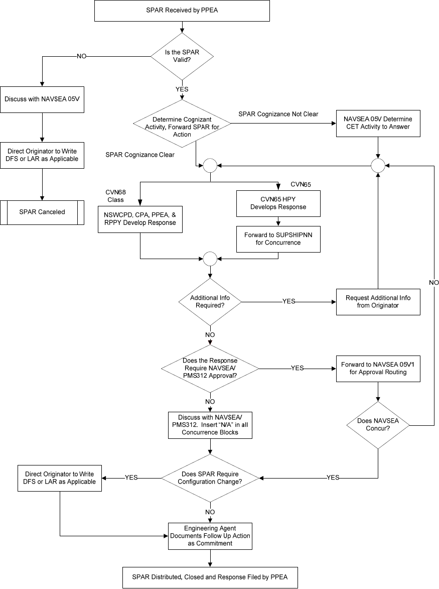
COMUSFLTFORCOMINST 4790.3 REV D CHG 3
07 Nov 2023
V-I-5-34
Figure 5-4 - PPEA SPAR Process Map
COMUSFLTFORCOMINST 4790.3 REV D CHG 3
07 Nov 2023
V-I-5-35
Figure 5-5 Overall NLI or SPLI Process Map
TYCOM (N9-N43) / CPA / RPPY / PPEA
SF
N9 determines
NLI is SF
capable
CNAF tracks
until NLI is
RFA
Are Parts
Available?
NO
Contact
NAVICP
DSN: 430-6225
YES
Ship schedule
supports due date?
N9 issue tasking letter,
for accomplishment of
NLI/SPLI to SF. Assigns
due date. Provides
feedback to CPA/RPPY
NRMD
Receives
Material
NRMD
Orders
Material
SF Completes NLI/
SPLI. Complete
eRPCCR or SPLI
Response form
MPM Screen
NLI/SPLI to
SY or SFWP.
NLI / SPLI
screened to
shipyard
SY Completes
NLI / SPLI
SF NLI
NLI/SPLI Closed.
Applicable databases
updated including CSMP
(NLI’s go thru BPMI)
SPLI
SY Prepares and
submits eRPCCR
or SPLI Completion
Notice to SF
SF-SPLI
SF-NLI
YES
CET issues SF
capable SPLIs
to SF
NO
NLI/SPLI
SF-NLI
Is NLI RFA
NLI-SPLI
SY-SPLI
SF Approve and
submit eRPCCR
IAW GRPORS
Submit SPLI
Response Form
to PPEA & N9
TYCOM assigns new due date
Provides to CPA/RPPY via
Change Management Process
SF propose new
completion date
NLI / SPLI
screened to
SFWP for
next avail
SF-NLI
SF-SPLI
NO
BPMI generate
JCN in P-OMMS
for submitting
eRPCCR
YES
CPA/RPPY
Assign ALL NLI’s and SPLI’s to the
applicable BAWP or AWP. Provide
JCN to TYCOM for tracking
SPLI Process
Start
NLI (Title F
ShipAlt) start
ALL NLI’s
RPPY generate
CARPWP item
YESSF-NLI
SF-SPLI
ALL SPLI’S
NLI-SPLI
Shipyard procures
parts as needed
thru Project Team
SY -NLI
NLI/SPLI
SY

COMUSFLTFORCOMINST 4790.3 REV D CHG 3
07 Nov 2023
V-I-5-36
5.10.8 Technical Manual Deficiencies and Manual Change Requests.
5.10.8.1 Technical Manual Maintenance. Technical Manuals (TM) must be maintained current
at all times. TMs associated with hardware must reflect current hardware configurations.
Changes to hardware accordingly, must be accompanied by changes or revisions to the TMs.
TMs must also be changed or revised to correct known deficiencies in the technical content in
instances not related to hardware modifications.
5.10.8.2 Technical Manual Deficiency/Evaluation Report. The TMDER, (NAVSEA Form
4160/1), is used to identify technical and non-technical discrepancies or deficiencies (non-
nuclear cognizant) in NAVSEA or NAVWAR technical manuals. It may be that a paragraph or
page is missing, that measurements or troubleshooting procedures are incorrect, a safety step is
omitted, instructions are unclear or that the text or illustrations are not legible. Whatever the
issue, it must be corrected. The TMDER is a quick and efficient tool for reporting problems with
technical manuals that are used every day.
5.10.8.3 URGENT Deficiencies.
a. URGENT deficiencies should be reported to the Naval Systems Data Support Activity
(NSDSA) by priority Naval Message addressed to:
COMMANDING OFFICER
CODE 310 TMDERs
NAVSURFWARCENDIV NSDSA
4363 Missile Way,
Port Hueneme, CA 93043-4307
b. An editable TMDER (NAVSEA form 4106/1) can be downloaded from Navy Forms
Online web site at https://forms.documentservices.dla.mil/order/ and submitted
hardcopy or completed online from the Navy 311 web site at
http://www.public.navy.mil/navwar/navy311/Pages/Links.html#EquipmentTechnical
under the Equipment/Maintenance section.
c. For users with a Technical Data Management Information System (TDMIS) account,
the most expedient manner of TMDER submission is via the TDMIS Web Site.
d. Unclassified TMDERs can be submitted from the TDMIS database via the “deficiency
module”. This method is strongly encouraged.
5.10.8.4 Routine Deficiencies.
a. Routine TM documentation deficiencies and concerns are reported via the web or
using a paper TMDER. The paper form should be available in the back of any ship,
NAVSEA or NAVWAR system tech manual.
b. An editable TMDER (NAVSEA form 4106/1) can be downloaded from Navy Forms
Online web site at https://forms.documentservices.dla.mil/order/ and submitted
hardcopy or completed online from the Navy 311 web site at
http://www.public.navy.mil/navwar/navy311/Pages/Links.html#EquipmentTechnical
under the Equipment/Maintenance section.
c. Again, TDMIS users may submit routine TMDERs via the “deficiency module” of
TDMIS. Attachments may be uploaded in TDMIS.

COMUSFLTFORCOMINST 4790.3 REV D CHG 3
07 Nov 2023
V-I-5-37
5.10.8.5 Technical Manual Deficiency/Evaluation Report Process. TMDERs are received at
NSDSA, logged into the TMDER tracking module and provided to the Technical Manual
Maintenance Activity (TMMA) for review and response. The TMMA must:
a. Review, analyze and resolve TMDERs for all assigned TMs.
b. Determine the accuracy and criticality of a reported deficiency.
c. Inform the TMDER originator and update the deficiency data in the deficiency module
of TDMIS: Urgent reports - 3 working days. Routine reports - 90 calendar days.
d. Prepare or procure Field Change Bulletins, change packages and revisions or prepare
changes, to correct TMDER reported deficiencies, using the Rapid Action Change
process.
e. Letters of response should include the appropriate status and must be similar to the
following:
(1) Your TMDER # __________ for TM # __________ has been received by this
activity for action. The TMMA has determined that a change to the manual is
required. A change package (or revision) is in work or work is planned to start
this fiscal year. Distribution is scheduled on (Mo/Yr).
(2) Your TMDER # __________ for TM # __________ has been received by this
activity for action. The TMMA has determined that a change to the manual is
not required for the following reason(s):
(3) Your TMDER # __________ for TM # ___________ has been received by this
activity for action. The TMMA has determined that the deficiency reported
will not impede the operation or maintenance of the equipment, and that it is
not cost effective to prepare a change at this time. The deficiency will be
considered for incorporation with the next change package or revision.
f. Notify NSDSA and the Acquisition Manager, TMDER originator or Designated Ship
Program Management Office when a TMDER for the assigned TM cannot be
reviewed, resolved, or TM updated. This notification can be completed via the on-line
TMDER form in the TDMIS deficiency module.
5.10.9 Fleet COSAL Feedback Report.
5.10.9.1 Usage. This report is used specifically to call attention to and seek correction of any
technical deficiencies found on Allowance Parts Lists (APL) or Allowance Equipage Lists
(AEL), including those covered under P-OMMS. For example:
a. The part or item is not listed on the APL or AEL, but is considered to be a
“maintenance significant item”.
b. APL is incomplete or is missing information, such as characteristics data, technical
manual number, etc.
c. Incorrect part or item listed on APL or AEL.
d. Allowed quantity insufficient for PMS requirements.
e. Part number in technical manual does not agree with APL.

COMUSFLTFORCOMINST 4790.3 REV D CHG 3
07 Nov 2023
V-I-5-38
f. Non-allowed part required for PMS.
g. APL technical problem such as incorrect Minimum Replacement Unit assignment.
h. Source, Maintenance and Recoverability Codes and Allowance Note Codes noted on
APL or AEL are not defined in any publication held.
i. Suspected error in code assignments, e.g., Source, Maintenance and Recoverability
Codes, Note Codes, etc.
j. Circuit symbol number in Electronics APL (Section B) crosses to incorrect reference
number or stock number.
5.10.9.2 Misuse. This report is not to be used to:
a. Address any matters relating to Nuclear Reactor Plant COSAL (“Q” COSAL).
Matters relating to Q-COSAL should be addressed by LAR through A4W RPPY
b. Report equipment configuration changes. Ship’s Configuration Change Form,
OPNAV Form 4790/CK, is to be used for this purpose. RPCCR for nuclear cognizant
systems.
c. Request changes in allowance for repair parts or equipage. Use NAVSUP Form 1220-
2, except in cases when the allowance problem is caused by technical deficiencies in
the COSAL, such as incorrect Minimum Replacement Unit assignment, PMS
requirement not reflected in Standard Navy Stock List or Installation Sequence List
etc. See reference (y) for further details concerning this form.
5.10.9.3 Form Location. An editable Fleet COSAL Feedback Report (NAVSUP Form 1371)
can be downloaded from Navy Forms Online web site at
https://forms.documentservices.dla.mil/order/ and submitted hardcopy or completed online from
the Navy 311 web site at
http://www.public.navy.mil/navwar/navy311/Pages/Links.html#EquipmentTechnical under the
Equipment/Maintenance section. Distribution of the form should be:
a. Original to NAVSEALOGCEN Code N42.
b. Copy to Ship’s Supply Officer.
c. Copy retained by Originator.
COMUSFLTFORCOMINST 4790.3 REV D CHG 3
07 Nov 2023
V-I-5A-1
APPENDIX A
APPENDIX A
DETERMINING SOFTWARE USABILITY
EXPIRATION DATE ON PACKAGE
(SHELF LIFE MANAGED)
NO
YES
YES
BEFORE EXPIRATION DATE
USE
DETERMINE SEAL SPECIFICATION
REFER TO SAE ARP5316
FOR CURRENT SHELF LIFE
SHELF LIFE IN
SAE ARP5316
NUCLEAR
NO
USABILITY SUBJECT TO
CRITERIA OF PARAGRAPH 5.5
NO
REFER TO SAE ARP5316
FOR SHELF LIFE
MIL SPEC MATERIAL
MIL-G-23652 FLUOROCARBON
MIL-R-25987 RUBBER
MIL-R-83485 (VITON, FLUOREL)
MIL-R-83248
AMS 7276 (AS3208, AS3209)
AMS 7259
MIL-G-22050 ETHYLENE-PROYLENE
RUBBER
NAS-1611/1612/1613
MIL SPEC (STANDARD) MATERIAL
MIL-P-5315 (MS-29512&29513) NITRILE
MIL-P-5510 (AN-6290) OR BUNA
MIL-P-5516 (AN-6627/6630)
MIL-P-25732 (MS28775/28778)
COMPOUND P-52-2
MIL-P-83461
SHELF LIFE IN
SAE ARP5316
UNLIMITED SHELF LIFE
15 YEARS OLD FROM
CURE DATE
URGENT NEED
EVALUATE USABILITY PER NSTM
CH-078-VOL 1 para 2.4.3
USE
NON-NUCLEAR
YES
USE
YES
USE
NO
DISCARD
NO
YES
NO
REFERENCES: NAVSEA S9086-CM-STM-010/CH78
NAVSEA 0989-037-2000
COMUSFLTFORCOMINST 4790.3 REV D CHG 3
07 Nov 2023
V-I-5A-2
APPENDIX A
“USE BEFORE” DATE ON PACKAGE
DETERMINE SEAL SPECIFICATION
REFER TO SAE ARP5316
FOR CURRENT SHELF LIFE
SHELF LIFE IN
SAE ARP5316
NUCLEAR
USABILITY SUBJECT TO
CRITERIA OF PARAGRAPH 5.5
NO
REFER TO SAE ARP5316
FOR SHELF LIFE
MIL SPEC MATERIAL
MIL-G-23652 FLUOROCARBON
MIL-R-25987 RUBBER
MIL-R-83485 (VITON, FLUOREL)
MIL-R-83248
AMS 7276 (AS3208, AS3209)
AMS 7259
MIL-G-22050 ETHYLENE-PROYLENE
RUBBER
NAS-1611/1612/1613
MIL SPEC (STANDARD) MATERIAL
MIL-P-5315 (MS-29512&29513) NITRILE
MIL-P-5510 (AN-6290) OR BUNA
MIL-P-5516 (AN-6627/6630)
MIL-P-25732 (MS28775/28778)
COMPOUND P-52-2
MIL-P-83461
SHELF LIFE IN
SAE ARP5316
UNLIMITED SHELF LIFE
15 YEARS OLD FROM
CURE DATE
URGENT NEED
EVALUATE USABILITY PER
NSTM CH-078-VOL 1, para 078-2.4.3.
YES
USE
NON-NUCLEAR
YES
USE
YES
USE
NO
DISCARD
NO
YES
NO
DATE INDICATED ON PACKAGE
USE
YES
NO
NO
REFERENCES: NAVSEA S9086-CM-STM-010/CH78
NAVSEA 0989-037-2000
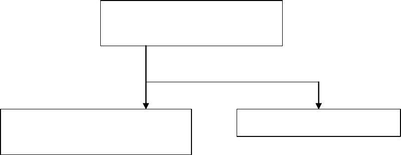
COMUSFLTFORCOMINST 4790.3 REV D CHG 3
07 Nov 2023
V-I-5A-3
APPENDIX A
ITEM OF UNKNOWN AGE OR MATERIAL
NO "CURE DATE", "USE BEFORE"
DATE ON PACKAGE, OR MATERIAL
UNKNOWN
REPORT IMPROPER MATERIAL
MARKING TO INVENTORY CONTROL
POINT PER S9086-CM-STM-010/CH78
NAVSEA APPROVAL REQUIRED
REFERENCES: NAVSEA S9086-CM-STM-010/CH78
NAVSEA 0989-037-2000
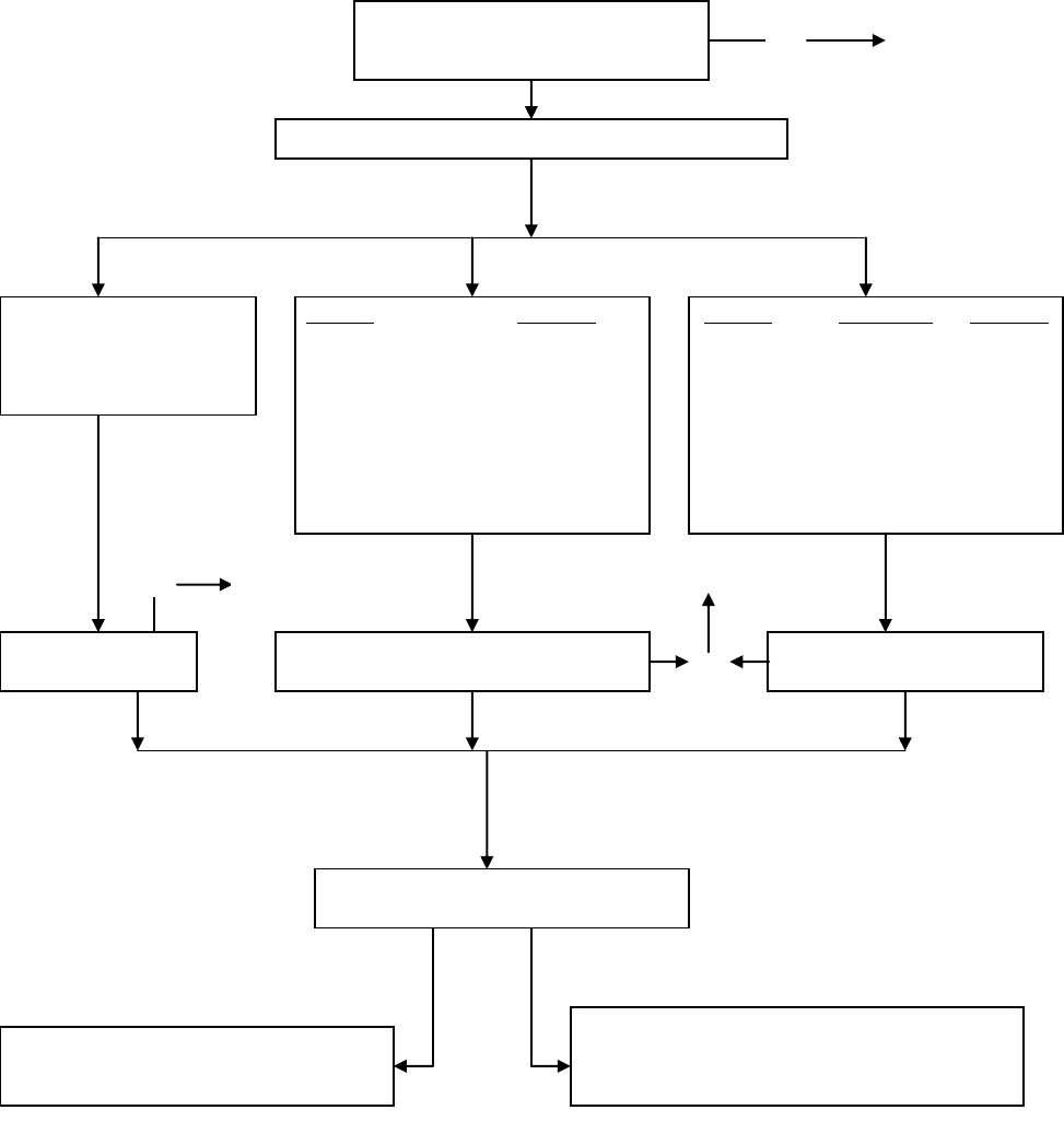
COMUSFLTFORCOMINST 4790.3 REV D CHG 3
07 Nov 2023
V-I-5A-4
APPENDIX A
CURE DATE ON PACKAGE
NO
NUCLEAR OR NON-NUCLEAR
USABILITY SUBJECT TO GUIDANCE OF
NAVSEA S9086-CM-STM-010/CH78 Vol 1, para
078-2.4.3
YES
USE
USABILITY SUBJECT TO CRITERIA OF
PARAGRAPH 5.5
NUCLEAR
NON-NUCLEAR
REFER TO SAE ARP5316
FOR SHELF LIFE
MIL SPEC MATERIAL
MIL-G-23652 FLUOROCARBON
MIL-R-25897 RUBBER
SAE-AMS-R-83485 (VITON, FLUOREL)
AMS 7276 (AS3208, AS3209)
AMS 7259
MIL-G-22050 ETHYLENE-PROYLENE
RUBBER
MIL-R-83248
MIL SPEC (STANDARD) MATERIAL
SAE-AMS-P-5315 (MS-29512&29513) NITRILE
MIL-P-5510 (AN-6290) OR BUNA
SAE-AMS-P-5516 (AN-6627/6630)
MIL-P-25732 (MS28775/28778)
COMPOUND P-52-2
NAS-1611/1612/1613
MIL-P-83461
SHELF LIFE IN
SAE ARP5316
UNLIMITED SHELF LIFE
15 YEARS OLD FROM
CURE DATE
YES
USE
NO
NO
15 YRS OLD FROM CURE DATE
ON PACKAGE
DETERMINE SEAL SPECIFICATION
YES
USE
NO
REFERENCES: NAVSEA S9086-CM-STM-010/CH78
NAVSEA 0989-037-2000

COMUSFLTFORCOMINST 4790.3 REV D CHG 3
07 Nov 2023
V-I-5B-1
APPENDIX B
APPENDIX B
FORMAT FOR SUBMARINE CERTIFICATION CONTINUITY REPORT
From: USS (Ship’s Name)
To: ISIC (Note 1) Deployed ISIC (If applicable)
Info: Parent ISIC (Applicable in all cases when deployed)
Additional Addees (Note 2)
Subj: CERTIFICATION CONTINUITY
Ref: (a) COMUSFLTFORCOMINST 4790.3 - Joint Fleet Maintenance Manual,
Volume V
(b) NAVSEA 0924-062-0010 - Submarine Safety (SUBSAFE) Requirements
Manual
(c) NAVSEA T9044-AD-MAN-010 - Requirements Manual for Submarine Fly-
By-Wire Ship Control Systems
1. Per reference (a) and (b), all work performed within the SUBSAFE Boundary has been
completed and satisfactorily retested except as noted in paragraph 2. There are no outstanding
RECs for equipment or systems required for underway operations.
2. The following Controlled Work Packages or RECs were closed by transferring the remaining
at-sea testing to a Departure from Specifications.
CWP/REC Serial No. DFS Serial No. Type Component
3. All URO MRC mandatory tests or inspections have been successfully accomplished within
the required periodicity. The following URO MRC requirements which have become due since
the last underway period or which would have become due during this scheduled at-sea period
have been completed during the preceding inport period as indicated or require at-sea operations
and will be accomplished prior to the listed due date:
URO MRC Component Ident Next Due (MO/YR)
4. A copy of Ship’s Force completed URO MRC completion letters and data report forms have
been provided to the ISIC.
5. Per reference (a) and (c), all work performed within the Submarine Fly-By-Wire Ship Control
System Boundary has been completed and satisfactorily retested. There are no outstanding
MCRs for equipment or systems required for underway operations.
NOTE 1: THIS CERTIFICATION REPORT MAY BE PROVIDED TO THE ISIC IN
THE FORM OF A MEMORANDUM, MESSAGE, OR LETTER.
NOTE 2: ADDITIONAL ADDEES SHOULD BE ADDED AS NECESSARY BASED ON
SITUATION (E.G., REPORT FOR UNDERWAY TRIALS DURING MAJOR
INDUSTRIAL AVAILABILITIES WOULD NORMALLY INCLUDE
SHIPYARD, NAVSEA AND TYCOM).
NOTE 3: IF NONE WAS ENTERED IN PARAGRAPH 3 THEN OMIT PARAGRAPH 4.
PARAGRAPH 4 IS ONLY REQUIRED IF URO MRC ITEMS WERE
COMPLETED BY SHIP’S FORCE.
COMUSFLTFORCOMINST 4790.3 REV D CHG 3
07 Nov 2023
V-I-5B-2
APPENDIX B
NOTE 4: IF NO WORK ON THE SUBMARINE FLY-BY-WIRE SHIP CONTROL
SYSTEM WAS PERFORMED, PARAGRAPH 5 IS NOT REQUIRED.
PARAGRAPH 5 IS ONLY REQUIRED IF WORK ON THE SUBMARINE
FLY-BY-WIRE SHIP CONTROL SYSTEM WAS PERFORMED.
NOTE 5: DELIVER THE CERTIFICATION CONTINUITY REPORT VIA ANY
MEANS SUITABLE FOR OFFICIAL CORRESPONDENCE AGREED TO BY
THE ISIC.

COMUSFLTFORCOMINST 4790.3 REV D CHG 3
07 Nov 2023
V-I-5C-1
APPENDIX C
APPENDIX C
FORMAT FOR FLEET MAINTENANCE ACTIVITY CERTIFICATION REPORT TO
TENDED SUBMARINE
Ser
From: Commanding Officer, (FMA)
To: Commanding Officer, (Tended Submarine)
Subj: CERTIFICATION CONTINUITY OF USS (
Tended Submarine)
Ref: (a) COMUSFLTFORCOMINST 4790.3 - Joint Fleet Maintenance Manual,
Volume V
(b) NAVSEA 0924-062-0010 - Submarine Safety (SUBSAFE) Requirements
Manual
(c) NAVSEA T9044-AD-MAN-010 - Requirements Manual for Submarine Fly-
By-Wire Ship Control Systems
Encl: (1) Copies of completed Re-entry Controls (REC)
(2) Copies of approved Departures from Specification (DFS) and Liaison Action
Requests (LAR)
(3) Copies of completed MCRs for Submarine Fly-By-Wire Ship Control System
1. Per reference (a), (b) and (c), certification of those SUBSAFE or Fly-By-Wire Ship Control
Systems or portions of SUBSAFE or Fly-By-Wire Ship Control Systems, on which the FMA
performed maintenance, has been sustained by the FMA. All required re-certification of the
maintenance has been completed except as noted in paragraphs 2 and 3.
2. All CWPs for SUBSAFE or Fly-By-Wire Ship Control Systems opened by the FMA for
maintenance have been closed and a copy of each completed REC/MCR is forwarded as
enclosures (1) and (3) respectfully:
CWP Serial No. Task Description Reason Deferred
3. The following Departures from Specifications (DFS) and Liaison Action Requests (LAR) for
deviations from specification were approved as part of FMA maintenance in the SUBSAFE or
Fly-By-Wire Ship Control System boundary. Copies of each are provided as enclosure (2):
CWP Serial No. DFS or LAR Serial No. Type Component
4. The following URO maintenance requirements were satisfied and are reported as complete by
the FMA. The original data report forms will be mailed to SUBMEPP with copies to your ISIC
within 30 days.
URO MRC EGL (if applicable) Component Identification JCN
Copy to:
Parent ISIC for ship
Parent ISIC for FMA

COMUSFLTFORCOMINST 4790.3 REV D CHG 3
07 Nov 2023
V-I-5D-1
APPENDIX D
APPENDIX D
FORMAT FOR NON-FLEET MAINTENANCE ACTIVITY CERTIFICATION REPORT
TO TENDED SUBMARINE
From: Commander, <Activity Name>
To: Commanding Officer, <USS
Ship Name and Hull Number> Commander <Squadron
Number>
Subj: CERTIFICATION CONTINUITY OF USS <Ship Name and Hull Number>,
<Availability Number>
Ref: (a) NAVSEA 0924-062-0010 <Insert Rev>, Submarine Safety (SUBSAFE)
Requirements Manual
(b) SS800-AG-MAN-010/P-9290 <Insert Rev> - System Certification Procedures
and Criteria Manual for Deep Submergences Systems (DSS)
(c) NAVSEA T9044-AD-MAN-010 <Insert Rev>, Requirements Manual for
Submarine Fly-By-Wire Ship Control System (FBW SCS)
(d) COMUSFLTFORCOMINST 4790.3 <Insert Rev>, Joint Fleet Maintenance
Manual
Encl: (1) List of Closed Re-Entry Controls <optional>
(2) List of Approved Departure From Specification (DFS) <optional>
(3) List of Scheduled URO-MRCs or HIPs Accomplished by the Activity
<optional>
1. Per references (a), (b), (c) and (d), certification of SUBSAFE, DSS or FBW SCS systems on
which <Activity Name> performed maintenance has been sustained. All required recertification
of the maintenance has been completed as noted in paragraphs 2 through 6.
2. All REC/MCRs for SUBSAFE, DSS or FBW SCS (SFCC) systems opened by <Activity
Name> for maintenance have been closed as noted:
REC/MCR Serial No Task Description
<See enclosure (1) if needed>
3. The following Departures From Specifications (DFSs) for SUBSAFE, DSS or FBW SCS
(SFCC) systems were approved as part of <Insert Activity Name> maintenance:
DFS Serial No. Type Component
<See enclosure (2) Part A if needed>
4. In addition to the DFSs listed in paragraph 3, the following DFSs were generated for work
accomplished by <Activity Name> for the purpose of testing at Sea. If at sea testing is required,
request Ship’s Force report via naval message and inform <Maintenance Activity> of the results
of at sea testing.

COMUSFLTFORCOMINST 4790.3 REV D CHG 3
07 Nov 2023
V-I-5D-2
APPENDIX D
DFS Serial No. Type Component
<See enclosure (2) Part B if needed>
5. The following Scheduled URO-MRCs or HIPs were completed. URO-MRC or HIP data will
be forwarded by <Activity Name> to SUBMEPP:
URO-MRC or HIPs
EGL (if applicable) Component ID JCN
<See enclosure (3) if needed>
6. <Note: This paragraph is only applicable to those activities acting as a NSA or LMA>
Per reference (d) <Activity Name>, as Naval Supervisory Authority, reports that certification of
SUBSAFE, DSS or FBW SCS systems for work accomplished by outside activities has been
maintained based on the SUBSAFE, DSS or FBW SCS Certification Continuity letters as
identified here:
Supervising Activity Letter Ser No./Naval Message Description ALT
SY Commander
Copy to:
COMSUBRON XXX <Assigned Squadron>
NSSC QAO or RSG QAO <as applicable>
NSRO <Shipyard performing work>
NRRO <Shipyard performing work>

COMUSFLTFORCOMINST 4790.3 REV D CHG 3
07 Nov 2023
V-I-5E-1
APPENDIX E
APPENDIX E
RPCCR COVER LETTER FOR SHIPALTS (SAMPLE)
9210
Ser CVN XX-RX/
DD MMM YY
NOFORN (When Filled in)
From: Commanding Officer, USS __________ (CVN XX)
To: Commander, Naval Sea Systems Command (NAVSEA 08P)
Subj: CHANGES TO REACTOR PLANT CONFIGURATION STATUS (SHIPALT)
Ref: (a) NAVSEA 0989-043-0000, Commissioned Surface Ship General Reactor
Plant Overhaul and Repair Specification (U)
Encl: (1) End of Availability Reactor Plant Configuration Change Letter
(2) RPCCR JCN_____________
1. The following reactor plant SHIPALTs are hereby reported per reference (a) and the
SHIPALT Approval Record.
SHIPALT BRIEF
COMPLETION STATUS
2. Enclosures (1) through (X) attach a Reactor Plant Configuration Change Report for each
change in the period _________ through____________ including each completed or partially
completed SHIPALT.
3. Ship’s Material History Records have been revised per NAVSEAINST 9210.37 to reflect
these modifications and changes to onboard repair part support have been initiated.
X. X. XXXXXX
By direction
Copy to:
COMNAVAIRLANT/COMNAVAIRPAC (Code N9)
ANSTR, Pittsburgh
NAVICP, Mechanicsburg (Code 87)
A4W RPPY /A1B PPPY
RMO
(Place NOFORN statement)

COMUSFLTFORCOMINST 4790.3 REV D CHG 3
07 Nov 2023
V-I-6-1
VOLUME V
PART I
CHAPTER 6
MATERIAL CONTROL
REFERENCES.
(a) NAVSEA 0948-LP-045-7010 - Material Control Standard
(b) NAVSEA SS800-AG-MAN-010/P-9290 - System Certification Procedures and
Criteria Manual for Deep Submergence Systems
(c) NAVSEAINST C9210.34 - All Nuclear Projects - Material Identification and Control
Requirements for Naval Nuclear Reactor Plant Piping Systems
(d) NAVSEAINST C9210.4 - Changes, Repairs and Maintenance to Nuclear Powered
Ships
(e) NAVSEA S9213-45-MAN-000 - Naval Nuclear Material Management
(f) NAVSEA 0989-LP-037-2000 - Commissioned Submarine General Reactor Plant
Overhaul and Repair Specification
(g) NAVSEA 0989-LP-043-0000 - Commissioned Surface Ship General Reactor Plant
Overhaul and Repair Specification
(h) NAVSEAINST 9210.23 - Naval Nuclear Work at Naval Activities and Private
Shipyards - Certification of Work Accomplishment and Data Retention of Associated
Records and Retention of Design Records - Requirements for
(i) NAVSEA 0387-LP-046-8000 - System Hydrostatic Test Requirements
(j) MIL-STD-792 - Identification Marking Requirements for Special Purpose
Components
(k) NAVSEA T9044-AD-MAN-010 - Requirements Manual for Submarine Fly-By-Wire
Ship Control Systems
(l) NAVSEA 0924-062-0010 - Submarine Safety (SUBSAFE) Requirements Manual
(m) NASM 7838 - Bolts, Internal Wrenching
(n) NAVSEA S9425-CF-STD-010 - Submarine Antenna/Periscope and Mast Materials
(o) NAVSEA 0900-LP-016-7008 - Submarine Antenna Technical Documentation
(p) NUSC 551 - Handbook for Submarine Antenna Systems
(q) NAVICPINST 4355.5 - Receipt, Inspection, Storage and Issue of Level I/SUBSAFE
Material
6.1 PURPOSE. To define responsibility and provide guidance for material control which
includes procurement, receipt inspection, stowage, issue, in-process control, and records for
controlled material used in maintenance.
6.1.1 Discussion. Controlled material is the term used in this manual to describe those materials
designated for use in or removed from Submarine Safety (SUBSAFE), Level I (LI), Scope of
Certification (SOC), Submarine Flight Critical Components (SFCC), and Nuclear LI systems
which are in the custody of the end-user work center, division Controlled Material Petty Officer
(CMPO) or are undergoing receipt inspection, have been certified for use and are tagged with the
appropriate Quality Assurance (QA) forms of this manual. In this manual, material in the

COMUSFLTFORCOMINST 4790.3 REV D CHG 3
07 Nov 2023
V-I-6-2
custody of the Naval supply system, which includes the supply departments onboard ships and
Fleet Maintenance Activities (FMA), is identified as LI stock program materials or nuclear repair
parts. Reference (a) provides the special administrative and technical requirements that are
levied by Naval Sea Systems Command (NAVSEA) for materials from fabrication to final
installation for non-nuclear and nuclear controlled material, respectively. Section 6.3 of this
chapter for non-nuclear material control provides direction for implementation of higher
authority requirements pertaining to material control. Reference (b) and Part III, Chapter 6 of
this volume provide specific requirements for receipt inspection and control of SOC material.
6.2 NUCLEAR.
NOTE: INFORMATION ON THIS SUBJECT IS SAFEGUARDED IN ACCORDANCE
WITH OPNAVINST N9210.3.
6.2.1 Controlled Material Determination. This section describes the use of the specific
references used to identify proper material for repair work. It is important that the difference
between system and part Level of Essentiality be understood. A system may be LI, but this does
not mean that every part in the system will be LI. This section also provides references and
guidance necessary to obtain this understanding and to determine if controlled material is
required, and if so, the proper level of control.
6.2.1.1 General Requirements. In order to determine the correct material to be installed in a ship
and to properly certify the material prior to installation, the work center responsible for the
specific area of the ship must first gather the appropriate reference material:
a. Drawings that specifically define the system and component.
b. System or Component Technical Manual.
c. Applicable Allowance Parts List (APL) from the ship’s Coordinated Shipboard
Allowance List (COSAL).
d. Component replacement manuals, etc.
e. NAVSEA Instructions.
f. Military Standards.
6.2.1.2 Determination of Required Repair Parts. Using the reference materials, the required
repair parts will be determined by comparing the appropriate part number from the technical
manual or drawing (if no technical manual) to the part numbers listed in the APL and therefore
obtaining the National Stock Number (NSN) with associated Special Material Identification
Code (SMIC), if assigned or listed on the APL.
NOTE: THE USE OF NUCLEAR REPAIR PARTS (NRP) WILL BE RESTRICTED TO
THOSE SPECIFIC APPLICATIONS WHERE REQUIRED.
6.2.1.3 Determination of Level of Control. The next step is to determine if the material
identified by the NSNs in paragraph 6.2.1.2 of this chapter is certifiable, if required, as controlled
material for the system or component. In order to determine level of control required for the
parts, the Level of Essentiality for the system and component must be determined for nuclear
systems. Controlled material is used in systems designated with a Level of Essentiality per
reference (c) for Nuclear LI.

COMUSFLTFORCOMINST 4790.3 REV D CHG 3
07 Nov 2023
V-I-6-3
NOTE: A SMIC (E.G., X1, X2, X3, X4, X5, X6, X7), IS ADDED TO THE END OF THE
NSN. IT IS ASSIGNED TO SELECTED COMPONENTS AND REPAIR
PARTS BY THE NAVAL SUPPLY SYSTEM AND IS USED FOR
CONTROLLING THE ISSUANCE AND STOCKING OF THESE
COMPONENTS AND REPAIR PARTS WITHIN THE NAVY SUPPLY
SYSTEM. IT SHOULD NOT BE CONFUSED WITH THE LEVEL OF
ESSENTIALITY. A SMIC IS AN ADMINISTRATIVE TOOL FOR THE
SUPPLY SYSTEM. LEVEL OF ESSENTIALITY IS A TECHNICAL
DESIGNATION APPLICABLE TO SPECIFIC PIPING SYSTEMS.
6.2.1.4 Nuclear Material Level Determination. The following can be used to assist in
determining the required “Level of Essentiality” for the material:
a. Determine if the system to be repaired is nuclear. References (f) or (g) provide the
process to determine if a system or component is considered part of the reactor plant
and provide a listing of all nuclear and non-nuclear interface drawings.
b. Determine if the nuclear system and repair part is Nuclear LI by reviewing reference
(c) and the piping system drawing. If the drawing designates the component as LI, or
II, the component is equivalent to LI. Systems, material, or components designated as
Nuclear Level III should be considered non-Level. In the absence of specific level
designations, or if questionable or conflicting Levels of Essentiality exist, refer to
references (a) and (c) for proper determination.
6.2.2 Controlled Material Procurement. This section provides general guidance for procurement
of nuclear controlled material. It should be noted that NAVSEA and Naval Supply Weapon
Systems Support (NAVSUP WSS) have adequate programs in place for procurement of
controlled material for nuclear applications. Therefore, ships and repair activities should always
obtain controlled material from the Navy supply system. This section also provides:
a. Background regarding NAVSEA and NAVSUP WSS controlled material procurement
programs.
b. Summary of or reference to the NAVSEA and NAVSUP WSS requirements for
nuclear controlled material procurement.
6.2.2.1 General Requirements.
a. NRP are procured by several Nuclear Material Procurement Programs and certified,
when required by certain NAVSEA specifications (e.g., reference (e) for 2S-X1
components). NRP are generally identified in the supply system by SMIC codes X1,
X2, X3, X4, X5, X6 and X7.
b. Nuclear LI material which meets acceptance criteria will be marked with a permanent
Material Identification and Control (MIC) code when required by reference (a). A
manufacturer’s marking which provides traceability may be used in lieu of a MIC
number.
6.2.2.2 Controlled Material Procurement.
a. Material for Nuclear Level I applications should be procured per references (a), (c)
and (e). For reactor plant components and equipment, identified by a “2S” cognizance

COMUSFLTFORCOMINST 4790.3 REV D CHG 3
07 Nov 2023
V-I-6-4
NSN and “X1” SMIC, requisitions should include supplementary information required
by reference (e). When substitute material must be used because the original material
is no longer available, refer to references (f) and (g). Section 9020-0 of reference (f)
for Submarines and Chapter 5 of reference (g) for Surface Ships identifies the Reactor
Plant Replacement Component Technical Manual for each reactor plant.
b. When ordering nuclear material, the Q-COSAL and reference (e) should be used.
c. Nuclear Material Procured Outside the Supply System. Reference (e) states, “Fleet
activities will not locally procure material for use in NRP applications. If non-stocked
items are required, activities must submit non-standard requisitions to NAVSUP WSS
according to Naval Supply Systems Command (NAVSUP) P-485”. Requisitions for
NAVSUP WSS managed NRP material must be prepared according to NAVSUP P-
485 and applicable Type Commander (TYCOM) directives. Requisitions for
NAVSEA Nuclear Propulsion Directorate (08) managed 2S/X1 components must be
prepared according to reference (e).
6.2.3 Receipt Inspection of Nuclear Controlled Material. This section provides the guidance and
procedures for forces afloat and FMAs to conduct and document receipt inspections to certify
controlled material as acceptable for installation.
6.2.3.1 General Requirements. Once the material ordered for use in LI systems is received, the
material must be receipt inspected per reference (a). Receipt inspection of this material is
required to establish positively that the material is the correct material for the job.
NOTE: THE TECHNICAL INSPECTION REQUIREMENTS OF THE APPLICABLE
TECHNICAL MANUAL, DRAWING OR OTHER TECHNICAL REFERENCE
AND PIPING SYSTEM MATERIAL REQUIREMENTS (E.G.,
CLEANLINESS, DIMENSIONS, SURFACE FINISH) ARE THE
RESPONSIBILITY OF THE END-USER (WORK CENTER SUPERVISOR OR
CRAFTSMAN) TO ACCOMPLISH PRIOR TO INSTALLATION AND ARE
NOT PART OF THE RECEIPT INSPECTION OF THIS MANUAL.
a. Reference (a) provides the controls and certain testing requirements that are levied by
NAVSEA to cover the material from fabrication to final installation for nuclear
material.
b. For Nuclear LI material, the unique requirement for “traceability” is invoked, meaning
that a marking system is employed which links the material to Objective Quality
Evidence (OQE). OQE for the material is the quantitative and qualitative data proving
that the material conforms to specified requirements. To meet the requirements for
traceability, the following requirements are instituted:
(1) Receipt inspection of the material.
(2) Use of QA tags in association with the item(s).
(3) Segregated stowage for Nuclear LI.
(4) Custody by CMPOs, Controlled Material Handlers (CMH), Quality Assurance
Inspectors (QAI) or qualified craftsman.

COMUSFLTFORCOMINST 4790.3 REV D CHG 3
07 Nov 2023
V-I-6-5
(5) Use of material verification procedures, as required by reference (a), during
installation of the material.
c. For Nuclear LI material, all signatures made on QA-form 2 (Material Identification
and Control Tag) are considered to be certification signatures as defined in reference
(h). The individual responsible for performing the certification must be indicated in
each signature block on the QA form 2 and that person must understand his or her
signature to indicate the following: “The person designated to sign for an action
verifies, based on personal observation, and certifies by their signature that the action
has actually been performed following the specified requirements.”
6.2.3.2 Quality Assurance Forms for Receipt Inspections. The QA forms necessary to complete
and document receipt inspections (QA form 1 and QA form 2) are addressed in paragraph 6.2.3.5
of this chapter.
6.2.3.3 Nuclear Receipt Inspection. The receipt inspection requirements for NRP as required by
reference (a) are provided in paragraph 6.2.3.5, and will be used for the receipt inspection of
Nuclear LI material.
6.2.3.3.1 Receipt Inspection of Nuclear Material. Controlled material for nuclear applications is
designated as Nuclear LI. Reference (c) discusses the Nuclear Systems and the associated Level
of Essentiality as either Nuclear LI or Level-none. Project Target Ready for Issue (RFI) tag
(NAVSEA 9210/2, Figure 6-1 of this chapter or NAVSEA 9210/2, Figure 6-2 of this chapter)
will be attached to all SMIC X1, X2 or X4 Nuclear LI RFI material. X1 material components
and repair parts furnished by NAVSEA 08 prime contractor may not have RFI tags attached;
however, this material is considered pre-certified and ready for use. The RFI tags depicted in
Figure 6-3 and Figure 6-4 of this chapter will be attached to Nuclear LI or non-LI material,
respectively, previously inspected by a Naval shipyard. SMIC X6 components and repair parts
will not have RFI tags attached. X6 includes material formerly classified as X3 and X5 items
that were procured as LI Material per NAVSEA 0900-070-6010. Additionally, material may be
received with other tags (e.g., hydrostatic test tags per reference (i)).
a. Project Target is a NAVSEA nuclear material procurement program.
b. NAVSEA Prime Contractor. Material supplied by NAVSEA prime contractors may
or may not have an RFI tag attached, but such material should be receipt inspected and
handled the same as material received with an RFI tag. Material supplied by
NAVSEA prime contractors is identified by a 2S cognizance or X1 SMIC NSN and
N00024 in the contract number.
c. It should be noted that reference (a) only contains requirements for nuclear piping
system MIC. Nuclear piping system material requirements (e.g., cleanliness,
dimensions, surface finish) and requirements to perform technical inspections per the
applicable material technical manuals are not included in reference (a).
6.2.3.4 General Requirements for Nuclear Material.
a. Supply departments of Fleet activities will perform the basic receipt inspection
required by the appropriate NAVSEA, NAVSUP WSS instruction prior to placing the
material into stock inventory. QA forms of this manual are not required to be
completed or placed on the material by supply department personnel.

COMUSFLTFORCOMINST 4790.3 REV D CHG 3
07 Nov 2023
V-I-6-6
b. Material identification must remain on or with the material throughout all stages of
stowage, fabrication and installation.
c. Material awaiting or undergoing receipt inspection will be segregated from accepted
material.
d. If guidance in addition to that specified in paragraph 6.2.3.5 of this chapter is required,
reference (a), Section 3.4 and reference (e), specifies the certification and receipt
inspection requirements for Nuclear LI material.
e. The certification of the material, or verification the material is certified for use, will be
accomplished by the end-user.
f. New Construction Ships. During outfitting, Nuclear LI material may be received
without an RFI tag. The Supervisor of Shipbuilding must provide a “by-serial-
number” list of NAVSEA Prime Contractor SMIC X1 components provided to the
shipbuilder directly by the prime contractor. Additionally, the letter should state that
since the material is from a prime contractor, it is exempt from the requirements to
perform a generic material identity verification. A copy of this letter must be kept on
file for reference by the ship and this letter should be treated as a permanent record.
g. Unit of Issue. QA form 2 (Material Identification or Control tag) will be attached to
each accepted unit of issue (e.g., a valve, can of weld wire, length of barstock).
h. Package Alteration Kits. Package alteration kits should not normally be opened until
the ship or FMA is ready to proceed with the installation, provided that a certification
of the contents and a copy of the installation instructions are in the envelope on the
outside of the box. When the ship or FMA is ready to proceed with the installation,
the lead work center CMPO will open the kit and perform the receipt inspection.
6.2.3.5 Nuclear Material Receipt Inspection Procedures. The following tables are to be used as
a guide in conducting a proper receipt inspection per reference (a). Disassembly of the item is
not required or intended by any of these procedures.
a. Navy supply system material requisitioned for Nuclear LI applications.
NOTE: SHIP’S FORCE IS NOT REQUIRED TO USE A QA FORM 1 TO DOCUMENT
RECEIPT INSPECTION OF NUCLEAR LI MATERIAL TO BE
IMMEDIATELY INSTALLED FOR A SPECIFIC MAINTENANCE ACTION.
A QA FORM 2 WILL BE USED TO DOCUMENT RECEIPT INSPECTION OF
MATERIAL TO BE IMMEDIATELY INSTALLED.
Procedure Responsibility
Visually check for damage. CMPO or CMH
Visually check the item to ensure the item is what was specified
or ordered and retain any supplied OQE (None is required to be
provided).
CMPO or CMH
Check markings or nameplate on the item for correct
correspondence with the shipping papers (or Ready for Issue
CMPO or CMH

COMUSFLTFORCOMINST 4790.3 REV D CHG 3
07 Nov 2023
V-I-6-7
Tag, NAVSEA 9210/2). (Figures 6-1, 6-2 and 6-3 of this
chapter).
FMA assistance is required or another activity with a LI
Certifying Activity Designator: If the Nuclear LI item has no
permanent markings, (serial number, heat lot or batch number,
etc.), the FMA will mark the item with a FMA nuclear MIC
marking to allow traceability.
CMPO, QAI or
CMH
Fill out QA form 1. CMPO or CMH
Fill out and attach a QA form 2 to the item. CMPO or CMH
NOTE: THE RFI TAG AND QA FORM 2 MUST REMAIN ON THE MATERIAL
UNTIL INSTALLATION.
Procedure Responsibility
If the item does not pass the receipt inspection, attach a QA
form 3 (Material Reject tag) to the material and reject the
material.
CMPO or CMH
Verify that the item is what is required for intended use and has
satisfactorily completed receipt inspection and is certified for
use. Complete the appropriate blocks on the QA form 2 and
print name and sign the QA form 2. Turn over the material to a
craftsman for fabrication or installation or stow in a controlled
material storage area.
CMPO or CMH
Forward QA form 1 to QA Office when material is issued for
installation.
CMPO or CMH
b. Material supplied from the NAVSEA Prime Contractor received by the ship at new
construction.
Procedure Responsibility
Visually check for damage. CMPO or CMH
Visually check the item to ensure the item is what was specified
or ordered and retain any supplied OQE. (None is required to
be provided).
CMPO or CMH
Visually check the material to ensure that material is as stated
on the Supervisor of Shipbuilding supplied list including
verification of serial number if provided.
CMPO or CMH

COMUSFLTFORCOMINST 4790.3 REV D CHG 3
07 Nov 2023
V-I-6-8
Fill out QA form 1. Attach all supporting documentation. CMPO or CMH
Fill out and attach a QA form 2 to the item. CMPO or CMH
Fill out applicable portion of QA form 2. CMPO or CMH
If the item does not pass the receipt inspection, attach a QA
form 3 (Material Reject Tag) to the material and reject the
material.
CMPO or CMH
Verify that the item is what is required for intended use and has
satisfactorily completed receipt inspection and is certified for
use. Complete the appropriate blocks on the QA form 2, print
name and sign the QA form 2. Turn over the material to
craftsman for fabrication or installation or stow in a controlled
material storage area.
CMPO or CMH
Forward QA form 1 to QA Office when material is issued for
installation.
CMPO or CMH
c. Nuclear LI material procured from a shipyard. (Does not include Naval supply system
material with NSN and SMIC X1, X2, X4 or X6 material). Material which was
procured or manufactured by a shipyard and which is then transferred to another
activity may be accepted for use by the receiving activity if the shipyard provides
certification that the material passed receipt inspection requirements (i.e., a tag or form
that is equivalent to the NAVSEA 9210/2 (Figures 6-1 and 6-2) is acceptable proof of
receipt inspection per reference (a)).
Procedure Responsibility
Check item received to ensure that it is the one ordered or
specified. Retain any OQE received.
CMPO or CMH
Check markings or nameplate data for correct correspondence
with shipping papers.
CMPO or CMH
Fill out QA form 1. Attach all supporting documentation. CMPO or CMH
Fill out and attach a QA form 2 to the item. CMPO or CMH
Verify that the item is what is required for intended use and has
satisfactorily completed receipt inspection and is certified for
use. Complete the appropriate blocks on the QA form 2, print
name and sign the QA form 2. Turn over the material to
craftsman for fabrication or installation or stow in a controlled
material storage area.
CMPO or CMH

COMUSFLTFORCOMINST 4790.3 REV D CHG 3
07 Nov 2023
V-I-6-9
Forward QA form 1 to QA office when the material has been
issued for installation.
CMPO or CMH
6.2.4 Marking of Nuclear Repair Parts.
6.2.4.1 General Requirements. SMIC X1, X2, X4 and X6 NRP (except for SMIC X1 material
provided by a prime contractor to the installing activity), passes from the manufacturers into the
Navy supply system by way of Navy receipt inspection activities, which examine the material
and subject it to a number of tests. Nuclear LI material which meets acceptance criteria is
marked with a permanent MIC number. In some cases, the manufacturer’s marking is used for
material identification.
a. The purpose of MIC marking is:
(1) To denote that the marked material has been inspected, verified and accepted.
(2) To provide traceability from the installed material to OQE.
(3) To preclude complete re-inspection of material accepted by an approved
activity.
b. Two problems arise in application which can defeat the purpose of the MIC marking.
(1) Internal components of an assembly which is MIC marked on the exterior, are
usually not marked individually, and can lose their identity as NRP if separated
during disassembly. Strict adherence to “bag and tag” requirements, using
Fleet QA forms, overcomes this problem. Any part which becomes separated
from its QA form (a loss of traceability), must be treated as uncontrolled
material.
(2) Reference (a) permits the use of shortened MIC numbers in cases where the
entire marking cannot be applied due to space limitations.
This problem is circumvented by a tag affixed by the receipt inspection activity
directly to the material or to its container, which lists the complete MIC
number. The complete MIC marking is recorded during receipt inspection.
Although the complete MIC marking would not be visible once the item was
installed, traceability is maintained through the retained QA paperwork and
tags associated with the job, which will list the full MIC number.
c. The MIC markings are in addition to the required manufacturer’s marking.
d. Altering of a MIC marking is prohibited except to make documented corrections.
e. Method of Marking Controlled Material. Nuclear physical marking methods are
described in reference (j).
f. Items not physically capable of being marked. Nuclear items such as small parts are
packaged in homogeneous lots (i.e., same heat, batch or melt; and same vendor
traceability) and the package is marked. If the package is opened, the individual items
removed must be tagged with a QA form 2. The remaining items in the package will
be controlled by the use of a single QA form 2 attached to the package.
6.2.4.2 Marking Requirements for Nuclear Repair Parts.
COMUSFLTFORCOMINST 4790.3 REV D CHG 3
07 Nov 2023
V-I-6-10
a. Nuclear LI material is permanently marked by the manufacturer with the following
information:
(1) The manufacturer’s name, trademark or symbol.
(2) Kind of material. Normally the generic material designations contained in the
Material Designator Catalog, Volume II of reference (a).
(3) Traceability information. The traceability information enables the
manufacturer to trace a LI component back to the chemical and physical test
results which prove that the material fabricated meets procurement
specifications.
b. If the entire manufacturer marking cannot be affixed due to space limitations, then the
following priority applies:
(1) Kind of material.
(2) Traceability code number.
(3) Manufacturer’s name, trademark or symbol.
c. Navy receipt inspection activities, which are primarily shipyards in the case of NRP,
add their own marking to Nuclear LI items they accept. This MIC mark consists of:
(1) Kind of material.
(2) Traceability number.
(3) Activity identification letter.
d. If a complete receipt inspection MIC mark cannot be affixed due to space limitations,
then the following priority applies:
(1) Kind of material.
(2) Traceability number.
(3) Procurement identification letter.
e. RFI Material.
(1) NRP, which have the SMICs X1, X2, and X4 associated with the NSN, are
tagged as RFI once accepted by Navy receipt inspection activities. The RFI
tag clearly marks the item as properly receipt inspected and RFI. Receipt
inspection by end user is still required by reference (a).
(2) The X1 SMIC identifies high value reactor plant components. The X2 SMIC
applies to pipe, tubing, fittings, flanges, barstock, welding consumables and
some LI fasteners that are used in reactor plants. The X4 SMIC covers high
pressure components used in reactor plant applications.
(3) There are four types of RFI tags. NAVSEA 9210/2 (Figure 6-1 of this chapter)
is attached to all Nuclear LI RFI material except that which is SMIC coded X4.
Nuclear LI RFI material coded X4 is tagged with NAVSEA 9210/2 (Figure 6-2
of this chapter). Nuclear LI material previously inspected by a Naval shipyard
is tagged with the RFI tag depicted in Figure 6-3 of this chapter. Non-LI

COMUSFLTFORCOMINST 4790.3 REV D CHG 3
07 Nov 2023
V-I-6-11
nuclear material previously inspected by a Naval shipyard is tagged with the
RFI tag depicted in Figure 6-4 of this chapter.
f. Sample MIC Markings.
(1) IN-804-8801-C 159 (N)
IN 804 8801 C 159 (N)
Generic Lot Date of Certifying Inspection Nuclear
Material Number Inspection Activity Lot
Designation
NOTE: ADDITIONAL INFORMATION, SUCH AS INSPECTION LOT NUMBER, IS
PERMITTED TO BE PART OF THE MIC MARK.
(2) CSA-(4-056-001)-N
CSA 4-056-001 N
Material Receipt Inspection
Code inspection Activity
package (Norfolk Naval Shipyard)
number (traceability
number)
(3) 7150-001-A-VBA
7150 001 A VBA
Julian Lot CAD Material
Date #
of
Inspection
(4) ST-00259-A01-S
ST 00 259 A01 S
Generic Year Julian Lot # Inspection
Type Date (A for Activity
Nuclear (PSNS)
LI)
6.2.4.3 Assignment of Material Identification and Control Numbers for Items Manufactured
from Certified Raw Materials. Nuclear LI items manufactured using certified Nuclear LI raw
material (e.g., barstock, plate, forged shape) may be assigned the same MIC markings as the raw
stock provided no work is done on the base material that would alter its chemical, physical or
mechanical properties (machining and welding may be done).
6.2.5 Nuclear Repair Parts Downgrading. It is recognized that occasionally NRP and controlled
material must be downgraded in order to support training or production work due to the
unavailability of non-certified material. In order to maintain accountability of the end use of
NRP and controlled material, the following procedure is required:
Procedure Responsibility

COMUSFLTFORCOMINST 4790.3 REV D CHG 3
07 Nov 2023
V-I-6-12
Obtain written authorization to downgrade the material
from the Quality Assurance Officer (QAO).
Leading Petty Officer
or Work Center
Supervisor
Remove all MIC markings from the controlled material
as well as all controlled material tags and forms. The
QA forms with RFI tag will be forwarded to the QAO
(ship) or QA office (FMA) with the approved
authorization.
CMPO or CMH
6.2.6 Storage, Issue and Handling of Nuclear Repair Parts.
6.2.6.1 Storage Requirements.
a. The Supply Department onboard an FMA or a ship will stow, handle and issue NRP as
required by the governing NAVSEA, or NAVSUP WSS instruction.
NOTE: NRP BECOMES CONTROLLED MATERIAL, FOR THE PURPOSES OF
THIS MANUAL, WHEN THE MATERIAL HAS BEEN RECEIVED BY THE
CMPO or CMH OF THE WORK CENTER OR DIVISION.
b. Nuclear controlled material in the custody of customers (ship or FMA work centers)
will be segregated by a physical barrier, in clearly marked dry, secure, clean stowage
and handling areas.
NOTE: THE SEGREGATION AND PHYSICAL CONTROL REQUIREMENTS OF
PARAGRAPHS 6.2.6.1.b.(1), (2), and (3) OF THIS CHAPTER DO NOT APPLY
TO NUCLEAR COMPONENTS WHICH ARE NOT SUBJECT TO MIX UP
NOR TO NUCLEAR MATERIAL WHILE IT IS CLEARLY MARKED OR
TAGGED TO INDICATE ITS LEVEL OF ESSENTIALITY AND GENERIC
MATERIAL TYPE.
(1) Use of separate boxes, shelves, roped off or marked (e.g., painted lines) areas
are acceptable methods of segregation or stowage, provided they are clearly
marked, allowing separation of the following materials:
(a) Nuclear LI.
(b) Material staged for a specific job or process.
(2) These materials must be segregated from each other and from other materials.
Segregation will be maintained from receipt through staging. Access to
controlled material will be positively controlled.
(3) Within a given level of material, different generic materials will be segregated
from each other physically such that similar appearing materials of different
generic types are not mixed.
(4) Unidentified material or rejected material will be segregated from acceptable
controlled material.
(5) Material waiting receipt inspection will be segregated from controlled material
and from rejected material.

COMUSFLTFORCOMINST 4790.3 REV D CHG 3
07 Nov 2023
V-I-6-13
c. Controlled material will be handled and stored in a manner to prevent damage and be
sealed for cleanliness when applicable.
d. Material received not meeting the receipt inspection requirements of paragraph 6.2.3
of this chapter will be rejected, tagged with QA form 3, and placed in segregated
stowage to await disposition.
e. CMPOs or CMHs will inspect controlled material storage areas of their work center,
quarterly as a minimum to ensure:
(1) Material is in designated area.
(2) Material is properly identified.
(3) Material properly marked and tagged.
(4) Material is protected from damage.
(5) Material is kept clean.
(6) Material segregated as required.
6.2.6.2 Staging Requirements. Controlled materials of different Levels of Essentiality and non-
controlled material may be co-located when staging material for a specific job provided that:
a. All QA forms or identification tags attached to the material are annotated with the
same Job Control Number and
b. Material is segregated from material staged for other jobs or processes.
6.2.6.3 Issue of Nuclear Controlled Material. Nuclear controlled material should be issued for
only those specific applications for which the nuclear material is required.
6.2.6.4 Handling of Nuclear Controlled Material. All controlled material received by a work
center, whether received from the supply department as onboard stock, work center stores or
from a tended ship must be controlled as required by reference (a).
a. Controlled material must at all times be in physical custody of either the work center
CMPO or CMH, QAI, a craftsman or stowed in a work center controlled material
stowage area.
b. Lots of material (e.g., box of bolts) broken down for end use, will maintain the same
identification and control as the parent controlled item using QA form 2 as
appropriate.
c. The QA form 2, or any other identification (e.g., RFI tag), must stay with the material
at all times until it is installed or reinstalled in the system.
d. Transfer of MIC marking during issue of barstock or pipe will be accomplished by
transferring the MIC to a new location on the piece to be sectioned, prior to sectioning,
and be verified by the work center CMPO or CMH or a QAI before the original
marking is lost.
e. If, during fabrication, the original piece must be broken down (such as cutting off a
piece of barstock) or the MIC marking will be lost by machining, welding, etc., the
proper MIC markings will be transferred to the piece(s) prior to cutting or to the
COMUSFLTFORCOMINST 4790.3 REV D CHG 3
07 Nov 2023
V-I-6-14
container, in case of small parts, and a QA form 2 as appropriate will be attached to
each new piece.
f. On completion of shop or ship fabrication or assembly stage, the QAI will check the
finished product against the attached material identification tags for required material
markings. The QAI will inspect the finished product for conformance to
specifications. If satisfactory and if the required markings are present, the QAI will
print name and sign the QA form 2 as applicable.
g. If for any reason at any time the product fails inspection, the QAI will reject the
material, attach a QA form 3 and inform the QAO.
h. The lead work center will be responsible for installation and the final acceptance block
on all QA forms associated with a particular product. Assist work centers or divisions
will be responsible for control of material which they use on a job.
i. Material consumed (e.g., welding electrode, brazing alloy) in the fabrication process
must have its identity (MIC number) recorded on the appropriate QA form that
documents the weld or braze (e.g., QA form 18, QA form 20).
j. Existing parts of certified Nuclear LI systems, retain their certification provided their
traceability is maintained.
k. All material, parts or components from controlled systems which are removed from
the ship by Ship’s Force, to be worked on by the FMA, must have a QA form 2
properly filled out and attached. If it is necessary for the FMA to disassemble such
components, identification must be retained on each part which is controlled material
using additional QA forms 2. The original QA form 2 will remain with the part or
component until it is re-installed in the ship and then be removed and filed until final
Controlled Work Package closeout. The QA-2 may then be disposed of.
l. Each controlled component removed from a ship’s system in order to allow repair or
maintenance will be tagged with a QA form 2 as appropriate to maintain identification
and traceability. If a nuclear component is further disassembled, each pressure
boundary part will be tagged with a QA form 2. Controlled components (e.g., valves
and valve bonnets, pumps, etc.) disassembled and reassembled in a temporary
controlled jobsite (established in a work space or at a jobsite) do not require individual
QA tags to be filled out and attached to each controlled component (controlled
components are defined in reference (a)), provided that:
(1) Access to the temporary controlled jobsite is controlled by a physical boundary
and is marked with a posted sign stating “Temporary Controlled Jobsite”.
(2) Rejected material must be identified, tagged with QA form 3 and removed
from the area.
(3) Work must be actively in progress and not be longer than a shift or one normal
working day on a job site vice in a FMA repair shop.
COMUSFLTFORCOMINST 4790.3 REV D CHG 3
07 Nov 2023
V-I-6-15
FIGURE 6-1
Tags similar to those shown in Figure 6-1 and Figure 6-2 were previously used to identify
material receipt inspected and certified RFI. Therefore, material received with RFI tags similar
to Figures 6-1 and 6-2 is acceptable for use without re-tagging.
NAVSEA 9210/2 Project Target Ready for Issue Tag
FRONT BACK
White tag with black printing
READY FOR ISSUE
PROJECT TARGET
MATERIAL
CERTIFIED BY (INDIVIDUAL)
________________________________________
INSPECTOR
________________________________________
ACTIVITY
________________________________________
DATE
________________________________________
NSN
________________________________________
SERIAL NUMBER
________________________________________
REMARKS
NAVSEA 9210/2 (5
-
77) S/N 0116
-
LF
-
092
-
1006
COMPONENT CERTIFIED RFI ______ BY NNSY
REQUIRED TEST(S) HAVE BEEN PERFORMED PER
APPLICABLE N/S T/M. RECEIPT INSPECTION
RECORDS ARE AVAILABLE AT NNSY CODE 2320.10
R.I. PACKAGE NUMBER. _______________________
REMARKS: __________________________________
____________________________________________
____________________________________________
COMUSFLTFORCOMINST 4790.3 REV D CHG 3
07 Nov 2023
V-I-6-16
FIGURE 6-2
SMIC X4
NAVSEA 9210/2 Project Target Ready for Issue Tag for X-4 Material
FRONT BACK
White tag with black printing
PRE-INSTALLATION PREPARATIONS SUCH
AS FINAL CLEANING, CALIBRATION, WELD
END PREPARATIONS, IS THE RESPONSIBILITY
OF THE INSTALLING ACTIVITY.
READY FOR ISSUE
PROJECT TARGET
MATERIAL
CERTIFIED BY (INDIVIDUAL)
________________________________________
INSPECTOR
________________________________________
ACTIVITY
________________________________________
DATE
________________________________________
NSN
________________________________________
SERIAL NUMBER
________________________________________
REMARKS
NAVSEA 9210/2 (5
-
77) S/N 0116
-
LF
-
092
-
1006
4
X
COMUSFLTFORCOMINST 4790.3 REV D CHG 3
07 Nov 2023
V-I-6-17
FIGURE 6-3
In order to support the identification of Level I material previously inspected by a Naval
shipyard, the following RFI tag must be used:
Nuclear Level I Ready for Issue Tag
TAG FRONT
LEVEL-1
Ready for Issue
STOCK No.:
MIC No.:
[ ] MAINTAINED BY TAG ONLY
VENDOR SERIAL No.:
DESCRIPTION:
_
__________________________________________
_
_
__________________________________________
_
_
__________________________________________
_
GENERIC MATERIAL:
CERTIFYING ACTIVITY & DATE:
REMARKS/WAIVERS:
_
__________________________________________
_
_
__________________________________________
_
_
__________________________________________
_
_
__________________________________________
_
[ ] SEE BACK
MATERIAL EXHIBITING THIS TAG HAS BEEN TECHNICALLY
RECEIPT INSPECTED BY A NAVSEA CERTIFIED ACTIVITY
TO MEET LEVEL-I REQUIREMENTS AS DEFINED IN
NAVSEAINST C9210.34 (SERIES)
COMUSFLTFORCOMINST 4790.3 REV D CHG 3
07 Nov 2023
V-I-6-18
FIGURE 6-4
In order to support the identification of Non-Level I material previously inspected by a Naval
shipyard, the following RFI tag must be used:
Non-Level Nuclear Ready for Issue Tag
TAG FRONT
(Left Blank)
6.3 NON-NUCLEAR.
6.3.1 Controlled Material Determination. This section describes the use of the specific
references used to identify proper material for repair work. It is important that the difference
between system and part Level of Essentiality be understood. A system may be LI, but this does
not mean that every part in the system will be LI. This section also provides references and
NON-LEVEL NUCLEAR
Ready For Issue
STOCK No.:
RIN:
VENDOR SERIAL No.:
DESCRIPTION:
_
__________________________________________
_
_
__________________________________________
_
_
__________________________________________
_
GENERIC MATERIAL:
CERTIFYING ACTIVITY & DATE:
REMARKS/WAIVERS:
_
__________________________________________
_
_
__________________________________________
_
_
__________________________________________
_
_
__________________________________________
_
[ ] SEE BACK
MATERIAL EXHIBITING THIS TAG HAS BEEN
TECHNICALLY RECEIPT INSPECTED BY A NAVSEA
CERTIFIED ACTIVITY FOR NON-LEVEL APPLICATIONS.
IT IS NOT FOR USE IN LEVEL-I APPLICATIONS AS
DEFINED IN NAVSEAINST C9210.34
(
SERIES
)
SHELF-LIFE EXP:

COMUSFLTFORCOMINST 4790.3 REV D CHG 3
07 Nov 2023
V-I-6-19
guidance necessary to obtain this understanding and to determine if controlled material is
required, and if so, the proper level of control.
6.3.1.1 General Requirements. In order to determine the correct material to be installed in a ship
and to properly certify the material prior to installation, the work center responsible for the
specific area of the ship must first gather the appropriate reference material:
a. Drawings that specifically define the system and component.
b. System or Component technical manual.
c. Applicable APL from the ship’s COSAL.
d. Ship’s SUBSAFE Certification Boundary Book.
e. LI Boundary Book.
f. Military Standards (MIL-STD).
g. Applicable ship class Fly-By-Wire Ship Control System Certification Boundary Book,
per reference (k).
6.3.1.1.1 Determination of Required Repair Parts. Using the reference materials, the required
repair parts will be determined by comparing the appropriate part numbers from the drawing to
the part numbers or drawings listed in the APL and thereby obtaining the NSN with associated
SMIC, if assigned or listed on the APL.
NOTE: THE USE OF LI STOCK PROGRAM MATERIALS AND CONTROLLED
MATERIAL WILL BE RESTRICTED TO THOSE SPECIFIC
APPLICATIONS WHERE REQUIRED.
6.3.1.1.2 Determination of Level of Control. The next step is to determine if the material
identified by the NSNs in paragraph 6.3.1.1.1 of this chapter is certifiable, if required, as
controlled material for the system or component. In order to determine level of control required
for the parts, the Level of Essentiality for the system and component must be determined for
non-nuclear systems:
a. Controlled material is used in systems designated with a Level of Essentiality per
reference (a) for LI. The definitions of LI systems and material per reference (a) are
provided to the users of this manual as paragraph 6.3.1.3 and 6.3.1.4 of this chapter.
b. The applicable LI material control boundary book provides an interpretation of the
latest reference (a) requirements.
NOTE: A SMIC (E.G., S1, SB, LI, C1, VIRGINIA CLASS COMPONENT (VU),
SEAWOLF CLASS COMPONENT (SW)), IS ADDED TO THE END OF THE
NSN. IT IS ASSIGNED TO SELECTED COMPONENTS AND REPAIR
PARTS BY THE NAVAL SUPPLY SYSTEM AND AIDS IN CONTROLLING
THE ISSUANCE OF THESE COMPONENTS AND REPAIR PARTS WITHIN
THE NAVY SUPPLY SYSTEM. SMIC IS AN ADMINISTRATIVE TOOL FOR
THE SUPPLY SYSTEM. LEVEL OF ESSENTIALITY IS A TECHNICAL
DESIGNATION APPLICABLE TO SPECIFIC PIPING SYSTEMS.

COMUSFLTFORCOMINST 4790.3 REV D CHG 3
07 Nov 2023
V-I-6-20
6.3.1.2 Non-Nuclear Material Level Determination. The crux of the controlled material
program at the maintenance level is establishing the required Level of Essentiality for repair
parts, to include determination of whether a specific part is LI. This is important for three
reasons:
a. To serve as a partial check that the supply system has provided the correct part.
b. To determine record-keeping requirements. This is particularly important in the case
of alterations, where drawings may provide no Level of Essentiality for the parts and
systems involved, and also on older ships, where the drawings may reflect no Level of
Essentiality information at all or may use previous revisions of references (a) or (l).
c. To determine the correct SMIC in the case of non-nuclear repair parts where the
COSAL and the applicable drawing conflict over the required Level of Essentiality.
6.3.1.2.1 Systems and Components. Paragraph 6.3.1.3 of this chapter provides the LI systems
and paragraph 6.3.1.4 of this chapter provides the LI components of reference (a).
6.3.1.2.2 Emergent Situation Upgrading. Upgrading the Level of Essentiality of a repair part
provided by the supply system may become necessary during the course of maintenance and can
be done in emergent situations using the procedures specified in reference (a) and paragraph
6.3.5 of this chapter.
6.3.1.3 Non-Nuclear Level I Systems and Boundaries.
a. Submarines.
(1) Air, nitrogen and other gas systems, except oxygen and hydrogen, with design
pressures of 1500 psig and above. Oxygen and hydrogen systems with a
design pressure of 100 psig and above.
(2) Feedwater system with a design pressure of 600 psig and above.
(3) Main steam system, and all branch piping from this system which is designed
to the main steam system design pressure, up to and including the first valve
downstream of pressure reducing valves and their by-pass valves. Included
will be high-pressure steam drains up to and including the first valve
downstream of the trap or orifice.
(4) Hydraulic systems for any steering or diving control surface, failure of which
would cause loss of both the normal and emergency modes of operation for the
control surface. Exceptions are internal wrenching bolts per reference (m), and
Naval Aerospace Standard cap screws with NAS 1347, Type IV identification
need not be to LI requirements.
(5) All circulating seawater systems (e.g., main seawater, auxiliary seawater, shaft
seal water), or portions thereof, continually open to the sea below 200 feet.
The brine and seawater feed portion of the distilling or reverse osmosis system
which provides the through path of the shaft seal water to the main or auxiliary
seawater system.
COMUSFLTFORCOMINST 4790.3 REV D CHG 3
07 Nov 2023
V-I-6-21
(6) All seawater and sea connected systems or portions thereof, which are
intermittently subject to submergence pressure below 200 feet, and which are
within the SUBSAFE Certification Boundary as defined by reference (l).
(7) Torpedo, signal ejector, launcher and trash disposal unit tubes. Included are
the breech and muzzle doors and associated piping system components
installed between the breech and muzzle doors that form part of the pressure
boundary, up to and including the inboard joint of the backup closure.
b. Surface Force Ships.
(1) Gaseous oxygen systems above 100-psig design pressure except for both the
diver’s recompression chamber and the diver’s surface supplied oxygen
systems, which are excluded from LI unless specifically invoked by NAVSEA
in writing.
(2) Gaseous oxygen piping from the oxygen and nitrogen producer plant, storage
tanks and fill station above 100 psig design pressure, including low pressure
gaseous oxygen vent piping which is or can be cross-connected with high
pressure gaseous oxygen piping.
(3) Surface Force. Main steam and all branch piping designed for temperatures
above 775F. Included will be high-pressure steam drains up to and including
the last valve downstream of the trap or orifice designed for temperatures
above 775F.
c. Aircraft Carriers.
(1) Feed systems with design pressure of 600 psig and above.
(2) Main steam, catapult steam (including the trough heating system), and reboiler
systems, and all branch piping connected to these systems designed for main
steam system design pressure. Included will be high-pressure steam drains up
to and including the last valve downstream of the trap or orifice designed for
main steam system design pressure.
(3) Gaseous oxygen systems above 100-psig design pressure except for both the
diver’s recompression chamber and the diver’s surface supplied oxygen
systems, which are excluded from LI unless specifically invoked by NAVSEA
in writing.
(4) Gaseous oxygen piping from the oxygen and nitrogen producer plant, storage
tanks and fill station above 100 psig design pressure, including low pressure
gaseous oxygen vent piping which is or can be cross-connected with high
pressure gaseous oxygen piping.
d. Submarine, Aircraft carrier and Surface Force Ship Requirements. The LI boundary
requirements listed in this paragraph apply to new construction, repairs, modifications,
alterations and conversions for all submarines and surface ships regardless of the
material identification and control requirements invoked, or not invoked, by the
original shipbuilding specifications or system diagrams and component drawings.

COMUSFLTFORCOMINST 4790.3 REV D CHG 3
07 Nov 2023
V-I-6-22
NOTE: IT IS NOT THE INTENT TO REMOVE NON-LI MATERIAL SOLELY FOR
THE PURPOSE OF INSTALLING LI MATERIAL. LI MATERIAL MUST BE
INSTALLED IN NEW LI SYSTEMS OR COMPONENTS OR WHEN
REPLACING MATERIAL INCIDENT TO THE REPAIR OR
REFURBISHMENT OF A LI SYSTEM COMPONENT(S).
e. LI Designated Systems. Cognizant NAVSEA technical codes are responsible for
determining any additional scope and boundary of individual systems, including the
components and parts of components, that are to be controlled as LI material.
6.3.1.4 Level I Components.
a. Pressure Boundary Parts. Pressure boundary parts of components within LI systems
must be controlled. LI pressure boundary parts include piping, tubing and the
following:
(1) Bodies. In general, these are the parts of a component that are the pressure
boundaries of the component, including end connections. Examples are:
(a) Valve bodies.
(b) Strainer bodies.
(c) Cylinders (flasks, reservoirs).
(d) Pipe fittings (elbows, tees, couplings, union assemblies, separately
furnished union tailpieces).
(e) Trap bodies (housings).
(f) Orifice plates.
(2) Covers. In general, these are component parts which act as pressure
boundaries for the bodies listed and other items. Examples are:
(a) Valve bonnets.
(b) Valve caps.
(c) Strainer caps.
(d) Closure plates for cylinders.
(e) Oxygen and nitrogen valve cartridges.
(3) Plugs. All plugs, including submarine zinc anode plugs, set screws, adjusting
screws and vent and drain plugs which form a part of the LI pressure boundary,
or otherwise opened to the sea below 200 feet.
(4) Fasteners. Bolts, nuts, studs, stud-bolts, and screws used when joining two
pressure boundary parts. All hull integrity fasteners must be LI. Fasteners
used for joining non-LI machinery or equipment to LI material must be LI
when the component is located within the LI boundary.

COMUSFLTFORCOMINST 4790.3 REV D CHG 3
07 Nov 2023
V-I-6-23
(5) Extension Pieces. In general, these are branch systems connecting “bodies”
and “covers” which are subject to piping system pressures and temperatures.
In many cases, they are furnished with end connections for installing into
either main or branch system piping. Examples are:
(a) Blowdown or drain nipples (e.g., pipe, including pipe fittings or
flanges).
(b) Union tailpieces when part of a component end connection (including
flange union connections).
(c) Separate bosses (attached to “bodies” or “covers” and providing
connections for external piping).
(6) Miscellaneous.
(a) Portions of submarine pressure hull penetrations, excluding hull
structure items, which isolate seawater from the submarine atmosphere.
Examples of hull penetrations are: hull fittings (electrical and fiber
optic), rodmeters, periscopes, and periscope hoist cylinders, radar masts
and antennas, main propulsion shaft seal housings, floating wire and
towed array shear valve assemblies, and lubrication distribution valves.
(b) Brazing alloys and welding filler metals, including consumable inserts.
(c) Union nuts (both bonnets and end-connection unions).
(d) Hose assembly end fittings and the nipple, flange, and body of sound
isolation couplings (e.g., Rubber Insert Sound Isolation Couplings
(RISIC)) which form a part of the pressure boundary.
(e) All submarine seawater or sea connected hull and backup valve internal
metallic pressure containing parts that serve to directly isolate seawater
from the atmosphere or downstream connected system(s) (e.g., balls,
disks, flappers, and poppets).
(f) Valve stems which penetrate the pressure boundary.
(g) Oxygen charging lines and assemblies.
(h) In-line instrumentation components and parts:
INSTRUMENTS LEVEL I PARTS
Temperature Thermowell (welded and flanged bare bulb)
Flow Meter casing
Liquid level Tank penetration fitting
Pressure Root valve of pressure instrument piping
Gage column
(MIL-I-20037)
Isolation valve
(i) Propulsion shafts for submarines.
(j) Through hull operating shafts for submarines.
COMUSFLTFORCOMINST 4790.3 REV D CHG 3
07 Nov 2023
V-I-6-24
(k) Fasteners and plugs for the components listed in paragraph 6.3.1.4.b.(9)
of this chapter, and LI systems as defined in paragraph 6.3.1.3 of this
chapter, which satisfy the description of a LI pressure boundary part.
b. Exclusions. Items and components specifically excluded from the classification of LI
are:
(1) Packing gland assemblies located in the systems and their components
identified in paragraph 6.3.1.3 of this chapter and stuffing boxes. This
includes their associated flanges, fasteners, followers, and retainers.
(2) Pressure seal rings, gaskets, O-Rings, packing and similar sealing members
used in conjunction with joining two pressure boundary parts.
(3) Silver braze flux.
(4) Flexible hoses and RISIC rubber elements.
(5) Gages, gage valves, pressure indicators, measuring instruments, and their
associated piping installed downstream of root valves in instrumentation piping
or that which does not form a part of the pressure boundary.
(6) Pipes, fittings, mufflers and Quiet Pressure Release Devices for the high
pressure air system etc., continuously open to ambient conditions and only
transiently subjected to pressures in excess of paragraph 6.3.1.3 of this chapter
criteria (e.g., open-ended ballast tank piping outboard of the pressure hull
penetration, open-ended vents and drains).
(7) Valve yokes and bonnet retainers restrained by the body inside diameter that
do not directly form the pressure boundary, but retain parts that do form the
pressure boundary, unless otherwise specified.
(8) Items not permanently installed (portable) and designated only for dockside
use.
(9) Pumps, distilling plants, compressors, heat exchangers, oxygen generators,
steam turbines, condensers, hydraulic accumulators and dehydrators.
(10) Washers.
(11) Valve stem retaining nuts that do not come in direct contact with system fluid
and serve no other function than to retain the stem.
(12) Valve seat retainers and other internal parts that are totally enclosed within the
pressure boundary except for those parts described in paragraph 6.3.1.4.a.(6)(e)
of this chapter.
(13) Non-consumable weld backing rings.
(14) Piping system sleeves.
(15) Non-pressure boundary parts (e.g., label plates, locking devices, lockwire,
lock-tabs, etc., that are attached to external portions of a pressure boundary,
piping hangers, mechanical operators such as handwheels, wrenches, reach
rods, gears, motors, etc).

COMUSFLTFORCOMINST 4790.3 REV D CHG 3
07 Nov 2023
V-I-6-25
6.3.2 Quality Assurance List (Submarines only). Quality Assurance Lists (QAL) on NAVSEA
drawings specify Nondestructive Test (NDT) requirements for items scheduled for installation
within the SUBSAFE boundary during new construction. The QALs should only be utilized for
guidance subsequent to ship’s commissioning, since they will not necessarily reflect current
NDT requirements.
6.3.3 Controlled Material Procurement. This section provides general guidance for procurement
of controlled material. It should be noted that NAVSEA and Naval Inventory Control Point
(NAVICP) have adequate programs in place for procurement of controlled material for non-
nuclear applications. Therefore, ships and repair activities should always obtain controlled
material from the Navy stock system. This section also provides:
a. Background regarding NAVSEA and NAVICP controlled material procurement
programs.
b. Summary of or reference to the NAVSEA and NAVICP requirements for controlled
material procurement.
6.3.3.1 General Requirements.
a. The LI material procurement program procures and certifies materials that are
generally identified in the supply system by SMIC SB, LI, C1, D1, S1, etc. Stock
system or installed items that fall under the SUBSAFE category are generally
restricted to castings and fasteners. Stock system or installed items that fall under the
LI category are generally restricted to metallic pressure boundary parts and
components.
b. The SFCC material procurement program procures and certifies materials that are
identified in the supply system by SMIC VU and SW. Stock system or installed items
that fall under SFCC are generally electronic circuit cards with embedded software.
c. LI stock program material pass from the manufacturers into the Navy supply system
by way of Navy receipt inspection activities, which examine the material and subject it
to a number of tests. LI material which meets acceptance criteria is marked with a
permanent MIC code as required by reference (a). Not all material within the
SUBSAFE boundary supplied by the shipyard during new construction is required to
be marked. SUBSAFE castings receive a permanent LI marking. The MIC
markings are in addition to the required manufacturer’s marking, which need
not be maintained after the MIC marking is added, except in the case of non-
nuclear fasteners.
NOTE: PER REFERENCE (l), ANY LI STOCK SYSTEM SUPPLIED ITEMS WITH LI
1990 OR LATER MIC ARE ACCEPTABLE FOR USE WITHIN THE
SUBSAFE CERTIFICATION BOUNDARY WHEN THE APL OR DRAWINGS
INDICATE LI SMIC MATERIAL IS REQUIRED. SS SMIC CODED ITEMS
CURRENTLY IN STOCK MAY BE USED IN SUBSAFE APPLICATIONS
WITHOUT FORMAL DOWNGRADING.
6.3.3.2 Controlled Material Procurement.
COMUSFLTFORCOMINST 4790.3 REV D CHG 3
07 Nov 2023
V-I-6-26
a. Material Procurement. Requisitioning of LI or SFCC controlled material is done per
standard supply instructions. Determination of the systems that require the use of LI
or SFCC material is addressed in paragraph 6.3.1 of this chapter.
b. Stock System LI or SFCC Material. Stock system LI or SFCC materials will be
requisitioned per normal supply department procedures ensuring that the SMIC is
identified, if assigned to the item.
c. (Submarines only) Submarine Antenna Engineering Directorate (SAED)-Submarine
Antenna Quality Assured Material (SAQAM) LI Material. SAED-SAQAM LI
material will be requisitioned per normal supply procedures with the additional
guidance from references (n), (o) and (p). The supply and QA standards are discussed
in references (p) and (q).
d. Other Controlled Material. Material procured for structural repairs, modifications or
fabrication will be compatible with existing structure as specified in applicable plans
and MIL-STDs.
e. LI material to be procured outside the supply system.
(1) Requisitions for non-nuclear LI stock program material must be prepared
according to reference (q) and other applicable NAVSUP documents.
(2) Reference (q) states in part:
(a) “Local purchases or manufacture of non-nuclear LI Stock Program
stock numbered material, not available from the supply system, will be
reported to NAVICP for demand recording purposes. The local
purchase or manufacture action will be reported via a Demand Only
Transaction (DOC ID DHA) per the procedures established in NAVSUP
437. A DHA will not be submitted when the original requisition was
submitted with advice code 2C or 5C since NAVICP records demand
for 2C/5C requisitions returned for local action.”
NOTE: THERE ARE NO LI STOCK PROGRAM ITEMS THAT ARE CODED FOR
LOCAL PURCHASE.
(b) “Local purchases or manufacture of LI Stock Program non-stock
numbered material will be reported to NAVICP to record demand and
usage to determine whether the item should be stock numbered. The
local purchase or manufacture action will be reported via a Report of
Local Purchase for Non-stock Numbered Items (DOC ID BHJ) per the
procedures established in NAVSUP 437. A BHJ will not be submitted
when the requisition for a non-stock numbered item is submitted to a
stock point or to NAVICP for supply action.”
(3) Procurement of non-nuclear LI material from other than the Navy stock system
is not permitted except in emergent situations as discussed in Section 3 of
reference (a). Such procurement will be through NAVICP Mechanicsburg
only. Requisitions to NAVICP will include all of the information listed here:

COMUSFLTFORCOMINST 4790.3 REV D CHG 3
07 Nov 2023
V-I-6-27
(a) If material certification requirements of reference (a) call for destructive
tests, enough material must be procured in the lot for performance of
such testing.
(b) Complete specifications must be provided for all LI material
requisitions for non-Navy stock system material. These specifications
must include:
1 Marking requirements, if applicable.
2 Material designation.
3 Military or federal specifications, that must be met (e.g.,
ultrasonic testing inspection of a fitting).
4 Grade, class, type, form and manufacturing process (e.g., plate,
class B, Type I, hot forged).
5 American Society for Testing and Materials, American Iron and
Steel Institute, Society of Automotive Engineers (whether item
is procured in whole or in part).
6 Request for a certification of compliance or detailed analysis if
required.
7 All ordering data required by applicable military or federal
specifications or industry standards or specifications must be
provided in the requisition.
(c) Descriptive language on all documents will be clear and detailed so that
no choice is left, either to the vendor or the activity concerned, as to
what material is to be furnished.
(d) The vendor will also be required to provide the following
documentation with the material, to enable the material to be certified
for “Level” application.
1 Chemical: Quantitative analysis for principal constituent
elements according to reference (a).
2 Physical: Mechanical properties (e.g., yield strength, tensile
strength, elongation or hardness testing) as specified in
reference (a).
3 Fabrication: Documented compliance with fabrication
procedures including NDT (e.g., seamless tubing).
6.3.4 Receipt Inspection of Controlled Material. This section provides the guidance and
procedures for forces afloat and FMAs to conduct and document receipt inspections to certify
controlled material as acceptable for installation.
6.3.4.1 General Requirements. Once the material ordered for use in SUBSAFE and LI systems
is received, the material must be receipt inspected per reference (a). Once the material ordered
for use within the submarine Fly-By-Wire Ship Control System Certification Boundary is

COMUSFLTFORCOMINST 4790.3 REV D CHG 3
07 Nov 2023
V-I-6-28
received, the material must be receipt inspected per reference (k). Receipt inspection of these
materials is required to establish positively that the material is the correct material for the job.
NOTE: THE TECHNICAL INSPECTION REQUIREMENTS OF THE APPLICABLE
TECHNICAL MANUAL, DRAWING OR OTHER TECHNICAL REFERENCE
AND PIPING SYSTEM MATERIAL REQUIREMENTS (E.G.,
CLEANLINESS, DIMENSIONS, SURFACE FINISH) ARE THE
RESPONSIBILITY OF THE END-USER (WORK CENTER SUPERVISOR or
CRAFTSMAN) TO ACCOMPLISH PRIOR TO INSTALLATION AND ARE
NOT PART OF THE RECEIPT INSPECTION OF THIS MANUAL.
a. Reference (a) provides the controls and certain testing requirements that are levied by
NAVSEA to cover the material from fabrication to final installation for LI material.
Reference (k) provides the controls and certain testing requirements that are levied by
NAVSEA to cover the material from certification to final installation for SFCCs.
b. For LI and SFCC material, the unique requirement for “traceability” is invoked,
meaning that a marking system is employed which links the material to OQE. OQE
for the material is the quantitative and qualitative data proving that the material
conforms to specified requirements. To meet the requirements for traceability, the
following requirements are instituted:
(1) Receipt inspection of the material.
(2) Use of QA tags in association with the item(s).
(3) Segregated stowage for LI or SFCC stock program material, and controlled
material.
(4) Custody by CMPO or CMHs, QAIs or qualified craftsman.
(5) Use of material verification procedures, as required by reference (a), during
installation of the material.
6.3.4.2 Quality Assurance Forms for Receipt Inspections. The QA forms necessary to complete
and document receipt inspections (QA form 1 and QA form 2) are addressed in paragraphs
6.3.4.5.q and 6.3.5 of this chapter.
6.3.4.3 Receipt Inspection and Certification of Valve Balls. New stock system LI balls are
certified for use prior to placing a “LI” SMIC on them. Refurbished Teflon coated valve balls
also are certified for use according to the indicated SMIC (“LI”, “Q3” or “QA”).
a. Balls received with a SMIC code “LI” are acceptable for use in SUBSAFE or LI
system applications as specified by the applicable APL or drawing without further
tests prior to installation.
b. Balls received with a SMIC code “QA” or “Q3” are acceptable for use in SUBSAFE
or LI system applications unless required to be LI per paragraph 6.3.1.4.a.(6)(e) of this
chapter.
c. Balls received with a SMIC code “QA” or “Q3” may be certified as acceptable for use
in SUBSAFE or LI system applications defined in paragraph 6.3.1.4.a.(6)(e) of this
chapter by either:

COMUSFLTFORCOMINST 4790.3 REV D CHG 3
07 Nov 2023
V-I-6-29
(1) Request certification papers from NAVICP code 8452 based on the heat and
lot data etched in the fluid flow path of the ball, if available, and based on the
certification papers and satisfactory receipt inspection locally assign a MIC
number or
(2) If certification papers are not available or heat and lot data is not present in
fluid flow path, conduct a generic material identity test, hardness test, perform
applicable NDT and obtain TYCOM approval of a major Departure from
Specification (DFS) per Part I, Chapter 8 of this volume.
d. Balls certified as acceptable for use per paragraph 6.3.4.3.c of this chapter must be
marked with a locally assigned MIC marking in the fluid flow path of the ball per
paragraph 6.3.7.1 of this chapter, providing traceability to applicable certification
papers, test documentation, and approved DFS.
6.3.4.4 Level I and Submarine Flight Critical Component Receipt Inspection. The receipt
inspection requirements for LI material from reference (a) are provided in paragraph 6.3.4.5 of
this chapter and will be used for the receipt inspection of SUBSAFE and LI material. The
receipt inspection requirements for SFCC material from reference (k) are provided in paragraph
6.3.4.5 of this chapter and will be used for the receipt inspection of SFCC material.
6.3.4.5 General Requirements for Level I and Submarine Flight Critical Component Material.
a. Traceability for LI, and SAED-SAQAM material is to be maintained from the material
back to its certification records. Material losing its identity will be considered
unsuitable for use until identification can be positively re-established. It will be
segregated from other controlled material, tagged and handled as rejected material.
Traceability for SFCCs having a SMIC code of (VU) or (SW) is to be maintained from
the material back to its certification records. Material losing its identity will be
considered unsuitable for use until identification can be positively re-established. It
will be segregated from other controlled material, tagged and handled as rejected
material. Upon determination that the SFCC is nonconforming and unusable for Fly-
By-Wire Ship Control Systems (FBW SCS) Flight Critical applications, the SFCC
must be clearly identified as rejected with a QA Form 3 tag.
b. Supply departments of Fleet activities will perform the basic receipt inspection
required by the appropriate NAVSEA, NAVICP, or NAVSUP instruction prior to
placing the material into stock inventory. QA forms of this manual are not required to
be completed or placed on the material by supply department personnel.
NOTE: LI OR SFCC STOCK PROGRAM MATERIAL BECOMES CONTROLLED
MATERIAL, FOR THE PURPOSES OF THIS MANUAL, WHEN THE
MATERIAL HAS BEEN RECEIVED BY THE CMPO OF THE WORK
CENTER OR DIVISION.
c. Material identification must remain on or with the material throughout all stages of
stowage, fabrication and installation. SFCC Certification OQE must be kept with the
SFCC until the part is installed in the system.
d. Material awaiting or undergoing receipt inspection will be segregated from accepted
material.
COMUSFLTFORCOMINST 4790.3 REV D CHG 3
07 Nov 2023
V-I-6-30
e. Material which met specifications at the time of procurement, but cannot be used in
the system for which it was procured because of a change in requirements occurring
after submission of material requests, will be returned to the supply department with a
QA form 3.
f. LI. Material NAVICP procured for the LI Stock Program which meets the required
SUBSAFE attributes will be inscribed with a MIC number which provides traceability
back to the certification documents or certifying activity.
NOTE: NON-LI STOCK PROGRAM MATERIAL WILL NOT BE MARKED WITH A
LI SMIC.
g. (Submarines only) SAED-SAQAM Material with a “LI” SMIC. A “Certification
Statement” required by reference (o) must accompany the material unless the material
is certified and marked by an NAVICP certifying activity, and is received from the LI
stock program.
(1) Submarine Periscope or Antenna SUBSAFE parts received after 31 July 1979
will be marked per reference (a).
(2) SUBSAFE Periscope or Antenna parts received prior to 31 July 1979 were
marked “Ser 1991-921A <SS>” by Portsmouth Naval Shipyard or “Ser 1991-
921A-061 <SS>” by Naval Surface Warfare Center, Carderock Division
(Submarine Antenna Engineering Directorate).
(3) Parts not marked per paragraph 6.3.4.5.g.(1) of this chapter may be used
providing the certification can be positively traced to certification records via
certificate of conformance which records a traceable number on the material as
recorded on the certificate of conformance. If certification records cannot be
located, then an approved major DFS per Part I, Chapter 8 of this volume is
required if the part must be used in lieu of a certified part.
h. Transfer of LI and SFCC Material Between Activities. Material which is procured or
manufactured and certified by an authorized certifying activity and which is then
transferred to another activity may be accepted for use by the receiving activity after
satisfactory receipt inspection per paragraph 6.3.4.5.q of this chapter.
i. Non-Standard Stock Certification Documentation. Material procured from non-
government sources or shipped direct from the manufacturer and not certified by the
LI stock program must be receipt inspected per paragraph 6.3.5.1 of this chapter.
j. Accepted Material. Each acceptable unit of issue (e.g., valve, fitting, can of welding
rod) will have a Material Identification/Control Tag (QA form 2) attached.
k. New Construction. The acceptable certification for LI and SFCC material provided to
new construction ships by shipbuilders as on board repair parts consists of a written
statement from the cognizant Supervising Authority. The letter will certify that the
material is acceptable and has been proven by a sampling audit. The letter will also
list the certified material furnished. A copy of this letter will be kept by the ship as a
permanent record. After receipt of the initial letter during new construction and
delivery of the ship, additional material will not be accepted without a letter being
provided with or prior to receipt of the items. SUBSAFE, LI and SFCC on board
COMUSFLTFORCOMINST 4790.3 REV D CHG 3
07 Nov 2023
V-I-6-31
repair parts, received with Certificates of Conformances after the start of Fast Cruise,
do not require additional certification letters from the Supervising Authority.
l. Package Alteration Kits. Package alteration kits should not normally be opened until
the ship or FMA is ready to proceed with the installation, provided that a certification
of the contents and a copy of the installation instructions are in the envelope on the
outside of the box. When the ship or FMA is ready to proceed with the installation,
the lead work center CMPO will open the kit and perform the receipt inspection.
m. Installed material or upgraded existing material on a ship originally built or upgraded
to SUBSAFE or LI standards involved in a repair will be assumed acceptable.
CAUTION: MATERIAL REMOVED FROM A SHIP UNDERGOING INACTIVATION
CANNOT BE REINSTALLED IN A LI APPLICATION WITHOUT
FOLLOWING THE GUIDELINES IN REFERENCE (a).
n. Reuse of Previously Certified LI or SFCC Material. Material removed from a ship
originally built or upgraded to LI or SFCC certified, which is subsequently installed in
another ship, will be assumed acceptable provided control (traceability) is available in
FMA or ship records proving the item was removed from a ship built or upgraded to
LI or SFCC certified and verification of the following:
(1) The level of certification of the system in the ship from which the part was
removed is the same as the level of certification required for end use.
(2) DFS log (for the ship from which the material is removed) does not identify
any outstanding DFS against the item that would preclude end use. Copies of
outstanding DFS must be provided with the material. Those outstanding DFS
for the material on the supplying ship will be cleared and the receiving ship
will process new DFS on board per Part I, Chapter 8 of this volume.
(3) The files of DFS approved as permanent repairs (for the ship from which the
material was removed) have been reviewed and copies of applicable DFS
provided with the material.
(4) Ship’s plans (for the ship from which the material was removed) do not
identify any drawing differences from the ship’s plans for the ship onto which
the material will be installed.
(5) End use installation is consistent with the previous service parameters such as
the design pressure rating, design temperature rating, or system applicability of
the component.
CAUTION: MATERIAL REMOVED FROM A SHIP UNDERGOING INACTIVATION
CANNOT BE REINSTALLED IN A SUBSAFE APPLICATION WITHOUT
FOLLOWING THE GUIDELINES IN REFERENCE (l).
o. Reuse of Previously Certified SUBSAFE Material. (For commissioned ships only)
Material removed from a ship originally built or upgraded to SUBSAFE, which is
subsequently installed in another ship, will be acceptable under the following
conditions:
COMUSFLTFORCOMINST 4790.3 REV D CHG 3
07 Nov 2023
V-I-6-32
(1) A Maintenance Certification Record or Re-Entry Control is used to document
removal from the supplying ship. The supplying ship must be SUBSAFE
certified and re-entry control must be in effect.
(2) All DFS (active and those accepted as permanent repairs that are not yet
reflected in ship’s selected record drawings or data or technical variance
documentation), applicable technical variance documentation, the last
accomplishment date and category of all applicable Unrestricted Operation
(URO) Maintenance Requirement Card (MRC) inspections, and all legible
component markings will be documented and supplied to the receiving activity
along with a copy of the supplying ship’s Maintenance Certification Record or
Re-Entry Control. This documentation will be maintained and filed with the
SUBSAFE Controlled Work Package that installed the component on the
receiving ship. Those outstanding DFS for the material on the supplying ship
will be cleared and the receiving ship will process a new DFS on board per
Part I, Chapter 8 of this volume.
(3) The receiving activity will conduct material inspection to verify the following
conditions:
(a) Received component came from a ship that has been previously
SUBSAFE certified and for which Re-Entry Control has been
maintained since initial certification.
(b) Material marking on hardware matches material marking on supporting
documentation.
(c) Applicable URO MRC inspections are current for the intended end use.
(d) End use installation is consistent with the previous service parameters
such as the design pressure rating, design temperature rating, or system
applicability of the component.
(4) Receiving activity will update applicable technical data to document
information and records provided by paragraph 6.3.4.5.o.(2) of this chapter
(e.g., ship’s drawing index for drawing revision, date of last URO MRC
periodicity accomplishment, and documentation of outstanding DFS) into
ship’s Current Ship’s Maintenance Project and other records.
(5) Material which does not meet the requirements of paragraph 6.3.4.5.o.(3) of
this chapter will be acceptable for use under the following conditions:
(a) For material which does not meet the requirements of paragraph
6.3.4.5.o.(3)(c) of this chapter, the material will be subjected to and
comply with the applicable URO MRC inspections required for the
receiving ship’s end use application.
(b) For material which does not meet the requirements of paragraph
6.3.4.5.o.(3)(d) of this chapter, the material will be subjected to and
satisfy the pressure and operability tests that would be required for a
new component installed in the receiving ship, provided the design
rating is consistent with the intended end use.

COMUSFLTFORCOMINST 4790.3 REV D CHG 3
07 Nov 2023
V-I-6-33
p. Reuse of material in the previously certified SUBSAFE work control boundary from a
ship whose SUBSAFE certification has lapsed by virtue of inactivation availability
commencement, must be per reference (l). Reuse of SFCC material from inactivated
ships must be per reference (k).
q. Material received from Navy stock system. LI or SFCC material received from the
Navy supply system will be receipt inspected by the CMPO using the following
procedure:
Procedure Responsibility
Visually inspect the material. CMPO or
CMH
Check that quantity received is same quantity ordered. CMPO or
CMH
Check for completeness (i.e., are all parts of a component
present); disassembly is not required or desired.
CMPO or
CMH
Verify item has MIC number and MIC number is correct per
paragraph 6.3.7 of this chapter (reference (k), Appendix E for
SFCC).
CMPO or
CMH
For Fasteners: Document the markings from the fastener to
include either:
(1) The color code and the heat or lot number, material type and
manufacturer’s symbol (for nuts containing a self-locking insert,
the color of the insert is the manufacturer’s symbol).
CPO or CMH
(2) The MIC number (when MIC number is on the fastener or on
the individual tag for some small fasteners).
For Flight Critical Components, verify that the SFCC certifying
activity identified on the accompanying OQE is traceable to one
of the NAVSEA approved activities listed in paragraph 2.4.1 of
reference (k).
CMPO or
CMH
For Flight Critical Components, ensure applicable SMIC marking
is listed on supply documentation or component.
CMPO or
CMH
For TRIPER Program Components, verify that the TRIPER
Serial # identified on the component and TRIPER Program
issued QA Form 2 match and that the material identified on
associated Supply document(s) matches the component on-hand.
CMPO or
CMH
NOTE: MORE THAN ONE MIC NUMBER MAY BE ON A COMPONENT (E.G.,
VALVE BODY MAY HAVE ONE MIC NUMBER AND THE BONNET MAY

COMUSFLTFORCOMINST 4790.3 REV D CHG 3
07 Nov 2023
V-I-6-34
HAVE ANOTHER MIC NUMBER). IF THE COMPONENT HAS A
SHORTENED MIC MARKING, ENSURE THE FULL MIC MARKING IS
AVAILABLE ON THE SHIPPING DOCUMENTS, TAGS, OR PACKAGING.
VERIFY THAT THE SHORTENED MIC MARKING IS CORRECT PER
PARAGRAPH 6.3.7 OF THIS CHAPTER AND REFERENCE (a).
For LI material, verify MIC number including proper “LI’’
markings.
CMPO or CMH
Check that the MIC number is traceable to a NAVSEA
authorized certifying activity, (e.g., Is there an “A’’ for
Portsmouth Naval Shipyard?). See paragraph 6.3.6 of this
chapter for list of authorized certifying activities and paragraph
6.3.7.2 of this chapter for additional guidance on MIC marking.
CMPO or CMH
Check NSN on part and verify that it is the NSN ordered. CMPO or CMH
For oxygen clean material, verify that the package is sealed and
marked with a certified oxygen clean tag.
CMPO or
Cleanliness
Inspector or
CMH
Fill out QA form 1 and attach the shipping papers, if provided. CMPO or CMH
NOTE: QA FORM 1 IS NOT REQUIRED FOR SHIP’S FORCE WHEN
PERFORMING RECEIPT INSPECTION OF MATERIAL TO BE
IMMEDIATELY INSTALLED FOR A SPECIFIC JOB. IF ALL MATERIAL
IS NOT UTILIZED IN THE ONGOING JOB, QA FORM 1 MUST BE FILLED
OUT PRIOR TO PLACING THE MATERIAL IN A STOWAGE LOCKER OR
AREA.
NOTE: IF THE COMPONENT HAS A SHORTENED MIC MARKING, ENSURE THE
FULL MIC MARKING FROM THE SHIPPING DOCUMENTS, TAGS, OR
PACKAGING IS ENTERED ON QA FORM 1 AND QA FORM 2.
Procedure Responsibility
Fill out and attach QA form 2 to each unit of issue accepted. CMPO or CMH
If material fails any of the steps, reject and attach QA form 3. CMPO or CMH
Verify that the item is what is required for intended use and turn
the material over to craftsman for fabrication or installation or
stow in a controlled material storage area.
CMPO or CMH
Forward QA form 1 to the QA office when the material has been
issued for installation.
CMPO or CMH
COMUSFLTFORCOMINST 4790.3 REV D CHG 3
07 Nov 2023
V-I-6-35
NOTE: LI MATERIAL RECEIVED FROM THE NAVY SUPPLY SYSTEM WITH
PROPER MATERIAL MARKINGS DO NOT REQUIRE “H” PRESSURE
TESTING AFTER RECEIPT INSPECTION.
r. FBW Diagnostic and Maintenance Computers (DMAC) will be receipt inspected per
sub-paragraph q. of this paragraph. The following are unique requirements specific to
the DMAC:
(1) A QA form 1 will be used to document the DMAC receipt inspection.
(2) A QA form 2 is not required for the DMAC during or after receipt inspection.
(3) A QA form 3 is required for a DMAC that fails receipt inspection or is out of
commission.
(4) The QA form 1 must be completed per the QA form 1 instructions in Part 1
Chapter 11 of this volume. The QA form 1 must be retained in the ship Re-
Entry Control exception folder until superseded by a new DMAC receipt
inspection.
s. SFCCs may be downgraded for use in non-SFCC, however, the component must not
be subsequently reinstalled into any SFCC application if it was ever installed in a non-
SFCC application. The SMIC markings on the SFCC must be obliterated and the
certification records for the item annotated to indicate the item is no longer a certified
SFCC prior to being installed.
6.3.5 Receipt Inspection of Open Purchase (Non-Supply System) or Locally Manufactured
Material or Upgrading Supply System Material to Level I (Fleet Maintenance Activity only).
6.3.5.1 Uncertified Material Required for Level I Applications. For uncertified material
required for use in a LI application, the item must comply with the requirements of reference (a).
Fleet activities must not certify open purchase (non-supply system or no NSN) materials to LI
requirements without specific authorization from TYCOM or NAVSEA. Additionally, unless
authorized in advance, a major DFS per Part I, Chapter 8 of this volume must be processed.
a. Uncertified material (supply system or NSN assigned) received or used as a starting
material for a manufactured part for LI requirements must be receipt inspected per
reference (a) by a certifying activity (e.g., shipyard, FMA).
b. Upon completion of the requirements of reference (a) the following procedure will be
used:
Procedure Responsibility
Review vendor data (if provided with material), MIL-STD, or
FMA manufacturing and test data to ensure that it all
matches. See note at end of this table regarding vendor data.
FMA QAO
Place certifying FMA MIC markings on the item. FMA CMPO,
CMH, QAI
Fasteners will be appropriately marked and color-coded if FMA CMPO,

COMUSFLTFORCOMINST 4790.3 REV D CHG 3
07 Nov 2023
V-I-6-36
required. CMH, QAI
Fill out QA form 1 to document the receipt inspection. FMA CMPO,
CMH, QAI
File QA form 1 with all applicable documents. FMA Quality
Assurance
Supervisor
Verify that the item is what is required for intended use and
turn the material over to craftsman for fabrication or
installation or stow in a controlled material storage area.
FMA CMPO,
CMH, QAI
Forward QA form 1 to QA Office when the material has been
issued for installation.
CMPO or CMH
NOTE: VENDOR DATA - MATERIAL RECEIVED DIRECTLY FROM THE
MANUFACTURER REQUIRES THE FOLLOWING CERTIFICATION
DOCUMENTATION AS A MINIMUM:
(1) CHEMICAL: QUANTITATIVE ANALYSIS FOR PRINCIPAL
CONSTITUENT ELEMENTS PER REFERENCE (a).
(2) PHYSICAL: MECHANICAL PROPERTIES (YIELD STRENGTH,
TENSILE STRENGTH, ELONGATION OR
HARDNESS TESTING) AS SPECIFIED IN
REFERENCE (a).
(3) FABRICATION: DOCUMENTED COMPLIANCE WITH
FABRICATION PROCEDURES INCLUDING NDT
(E.G., SEAMLESS CONDITION OF TUBING).
c. If all testing required by reference (a) cannot be accomplished, then, as a minimum, a
generic materials identity test, hardness test, and visual inspection will be
accomplished and a major DFS must be processed per Part I, Chapter 8 of this volume.
6.3.5.2 Uncertified Material Required for SUBSAFE Applications. For uncertified material
required for use in a SUBSAFE application and requiring an “LI” certification, the item must
first comply with the requirements for LI discussed and the requirements of reference (l). Fleet
activities must not certify non-level materials to SUBSAFE requirements without specific
authorization from TYCOM or NAVSEA and, unless authorized in advance, a major DFS per
Part I, Chapter 8 of this volume must be processed.
6.3.5.3 Uncertified Material Required for Submarine Flight Critical Component Applications.
Fleet activities must not install non-certified SFCC materials within the FBW SCS certification
boundary without specific authorization from TYCOM or NAVSEA and, unless authorized in
advance, a major DFS per Part I, Chapter 8 of this volume must be processed.
a. Upon completion of the requirements of reference (k) the following procedure will be
used:

COMUSFLTFORCOMINST 4790.3 REV D CHG 3
07 Nov 2023
V-I-6-37
Procedure Responsibility
Fill out QA form 1 to document the receipt inspection FMA CMPO, CMH, QAI
NOTE: QA FORM 1 IS NOT REQUIRED FOR SHIP’S FORCE WHEN
PERFORMING RECEIPT INSPECTION OF MATERIALS TO BE
IMMEDIATELY INSTALLED FOR A SPECIFIC JOB. IF ALL MATERIAL
IS NOT UTILIZED IN THE ONGOING JOB, QA FORM 1 MUST BE FILLED
OUT PRIOR TO PLACING MATERIALS IN A STORAGE LOCKER OR
AREA.
File QA form 1 with all applicable documents FMA Quality Assurance
Supervisor
Verify that the item is what is required for intended use and turn
the material over to craftsman for installation or stow in a
controlled material storage area.
FMA CMPO, CMH, QAI
Forward QA form 1 to QA Office when the material has been
issued for installation.
CMPO or CMH
6.3.6 Authorized Material Certification Activities. This section provides a list of those activities
that are currently authorized or have been authorized previously to receipt inspect and accept LI
controlled materials. This list is provided as a reference to be used in performance of receipt
inspections of paragraph 6.3.4 of this chapter.
6.3.6.1 Currently or Previously Authorized Material Certification Activities.
a. For material ordered from NAVICP by forces afloat for SUBSAFE or LI applications.
The following activities are authorized to receipt inspect and stock material for the LI
Stock Program:
Activity Identification Code
Portsmouth Naval Shipyard A
Naval Weapons Station Yorktown YT
b. If material is not available through the activities listed in paragraph 6.3.6.1.a. of this
chapter, NAVSEA has authorized the following activities to certify material as LI per
reference (a) and this material may be used for SUBSAFE applications without further
receipt inspection, other than normal receipt inspection of paragraph 6.3.4.5.q. of this
chapter. The activities and their designator are:
Activity Identification Code
Newport News Shipbuilding NN
Naval Undersea Warfare Systems Center - Newport
(NUWC)
NUSC
Norfolk Naval Shipyard N
Charleston Naval Shipyard C

COMUSFLTFORCOMINST 4790.3 REV D CHG 3
07 Nov 2023
V-I-6-38
Puget Sound Naval Shipyard S
Pearl Harbor Naval Shipyard P
c. Listed here are some of the LI activity designators assigned by NAVSEA to various
activities.
Activity Identification Code
Naval Shipyard
Charleston C
Long Beach L
Mare Island MS
Norfolk N
Pearl Harbor P
Philadelphia H
Portsmouth A
Puget Sound S
Supervisor of Shipbuilding
Groton SSG
Activity Identification Code
Naval Weapons Station
Naval Surface Warfare Center Division, Crane
WQC
Naval Surface Warfare Center Ordnance
Station, Louisville
NSL
Naval Weapons Station, Yorktown YT
Other NAVSEA Activities
Other JCR
SRF, Guam SRFG
SRF, Yokosuka SRFY
Naval Undersea Warfare Center Detachment, New
London
NUWC
Naval Inventory Control Point (formerly Navy
Ships Parts Control Center)
X
Naval Submarine Support Facility, NLON SFNL
Submarine Base, Pearl Harbor SBPH
Activity Identification Code
TRIDENT Refit Facility, Kings Bay TRFK
TRIDENT Refit Facility, Bangor TRFB
SIMAs or Tenders AS-32, 33, 34,

COMUSFLTFORCOMINST 4790.3 REV D CHG 3
07 Nov 2023
V-I-6-39
36, 37, 39, 40, 41,
etc.
6.3.7 Marking of Level I Stock Program Material and Controlled Material.
6.3.7.1 General Requirements. LI Stock Program Material passes from the manufacturers into
the Navy supply system by way of Navy receipt inspection activities, which examine the
material and subject it to a number of tests. LI material which meets acceptance criteria is
marked with a permanent MIC number. SUBSAFE material supplied by the shipyard as onboard
repair parts during new construction is required to be MIC marked. On older ships, the
SUBSAFE material supplied as onboard repair parts during new construction may not have been
MIC marked, but will be listed on the Supervisor of Shipbuilding’s letter of certified material.
a. The purpose of MIC marking is four-fold:
(1) To denote that the marked material has been inspected, verified and accepted.
(2) To verify the material in hand by comparing it to the applicable drawings,
plans, ordering requirements, and installing documents.
(3) To provide traceability from the installed material to OQE.
(4) To preclude complete re-inspection of material accepted by an approved
activity.
b. Two problems arise in application that can defeat the purpose of the MIC marking:
(1) Internal components of an assembly which is MIC marked on the exterior, are
usually not marked individually, and can lose their identity as LI material, if
separated during disassembly. Strict adherence to “bag and tag” requirements,
using fleet QA forms, overcomes this problem. Any part that becomes
separated from its QA form (a loss of traceability) must be treated as
uncontrolled material.
(2) Reference (a) permits the use of shortened MIC numbers in cases where the
entire marking cannot be applied due to space limitations. It is possible that
some LI material will lack the traceability number providing the critical link to
the OQE, which in turn serves as the basis for the designation “LI material or
controlled material”. This problem is circumvented by a tag affixed by the
receipt inspection activity directly to the material or to its container, which lists
the complete MIC number. The complete MIC marking is recorded during
receipt inspection. Although the complete MIC marking would not be visible
once the item was installed, traceability is maintained through the retained QA
paperwork and tags associated with the job, which will list the full MIC
number.
c. SUBSAFE castings and aluminum bronze components receive a permanent LI
marking.
d. The MIC and SUBSAFE markings are in addition to the required manufacturer’s
marking.
e. Altering of a MIC marking is prohibited except to make documented corrections.

COMUSFLTFORCOMINST 4790.3 REV D CHG 3
07 Nov 2023
V-I-6-40
f. Method of marking controlled material. Physical marking methods are described in
references (a) and (j).
g. Items not physically capable of being marked. Items such as small parts are packaged
in homogeneous lots (i.e., same heat, batch or melt; and same vendor traceability) and
the package is marked. If the package is opened, the individual items removed must
be tagged with QA form 2. The remaining items in the package will be controlled by
the use of a single QA form 2 attached to the package.
6.3.7.2 Level I Material. LI material has a MIC marking affixed to it by the activities which
certify the material for the Navy supply system. The activities are listed in paragraph 6.3.6 of
this chapter. Authorized FMAs may apply a MIC marking to a component prior to installation in
a ship. MIC markings will be applied per reference (a). The following paragraphs provide
general guidance regarding MIC marks and marking:
a. Elements of the MIC Marking. The normal MIC marking consists of three elements:
(1) Material designator. The material designation comes from Volume II of
reference (a) with the two or three letter code (e.g., KMA).
NOTE: MIC MARKINGS ON OLDER STOCK PIPING MATERIAL, VALVES,
FITTINGS, ETC., RECEIVED FROM THE SUPPLY SYSTEM MAY
CONTAIN FOUR LETTER MATERIAL DESIGNATORS. FOUR LETTER
MIC MARKING MATERIAL DEFINITIONS ARE CONTAINED IN
VOLUME II OF REFERENCE (a).
(2) Traceability number. The traceability number is used by the marking activity
to relate the piece to inspection records and consists of the last two digits of the
year, Julian date when the material was inspected, a hyphen and lot number
(e.g., 89364-043).
(3) Certifying Activity Designator (CAD). The CAD denotes the activity that
performed the certification testing and marking. The CAD indicates
acceptance of the material. Only the government activities and private
shipyards which are authorized by NAVSEA to certify inspect and mark LI
material are assigned CADs. NAVSEA periodically issues a letter containing
the list and identity code of government activities and private shipyards
authorized to certify LI material. A listing of those activities authorized to
certify LI material is provided in paragraph 6.3.6 of this chapter.
b. If all the markings cannot be affixed because of space limitations, then they are affixed
per reference (a).
c. Sample MIC Markings. Three marking systems are in effect. Samples of MIC marks
affixed to non-nuclear LI material from each of the marking systems follow:
(1) CNB-91301-123 A (LI material, new marking system)
CNB 91301 123 A
Material
code. 70/30
copper
Julian date
of
inspection
Inspection
lot number
(3 digits
Inspection
Activity
(Portsmouth

COMUSFLTFORCOMINST 4790.3 REV D CHG 3
07 Nov 2023
V-I-6-41
nickel (from
the Material
Designator
Catalog)
maximum) Naval
Shipyard)
(2) KMD-90204-123 A (LI material, new marking system)
KMD 90204 123 A
Material
code. K
Monel
(from the
Material
Designator
Catalog)
Julian date
of
inspection
Inspection
lot number
(3 digits
maximum)
Inspection
Activity
(Portsmouth
Naval Shipyard)
(3) 7150 001 A VBA (LI material, old marking system)
7150 001 A VBA
Julian Date
of
inspection
Inspection
lot number
Inspection
activity
(Portsmouth
Naval
Shipyard)
Material code.
Valve bronze
alloy
(4) 7100 005 CNB (LI material, old marking system)
7100 005 CNB
Julian date
of
inspection
Inspection
lot number
Material
code.
Copper
nickel alloy
(5) SER 1991-921A LI (Marked by Portsmouth Naval Shipyard)
SER 1991-921A-061 LI (Marked by Naval Surface Warfare Center, Carderock
Division Ship Systems Engineering Station (Submarine Antenna Engineering
Directorate) (now NSWCPD))
d. Examples of LI MIC marks for periscope and antenna parts marked prior to 31 July
1979:
(1) NCD 8249-584 QQ LI
NCD 8249 584 QQ
Material
code Nickel
copper alloy
Julian date
of
inspection
Inspection
lot number
(3 digits
Inspection
Activity
(Naval Surface Warfare
Center, Carderock

COMUSFLTFORCOMINST 4790.3 REV D CHG 3
07 Nov 2023
V-I-6-42
maximum) Division)
(2) SER 1991-921A-AS18
FMA marking applied to previously unmarked antenna, mast or periscope parts
within the SUBSAFE boundary documented by receipt inspection record (QA
form 1) as being received prior to 31 July 1979 or are parts removed from an
antenna, mast or periscope from an in-service SUBSAFE certified submarine.
(3) Fasteners are identified and color-coded per Appendix C of reference (a).
6.3.7.3 Assignment of Material Identification and Control Numbers for Items Manufactured
from Certified Raw Materials.
NOTE: HEADED FASTENERS (CAPSCREWS, BOLTS, MACHINE SCREWS, ETC.)
MANUFACTURED FROM LI MATERIAL REQUIRE ADDITIONAL
TESTING (i.e., WEDGE TENSILE OR AXIAL TENSILE TESTING AND
HARDNESS TESTING).
a. LI items manufactured using certified LI raw material (e.g., barstock, plate, forged
shape) except fasteners with heads may be assigned the same MIC markings as the
raw stock provided no work is done on the base material that would alter its chemical,
physical or mechanical properties (machining and welding may be done).
b. Headed fasteners will be assigned a unique MIC marking following local manufacture
from existing LI material and satisfactory completion of certification testing. A DFS
is required if certification testing is not completed.
NOTE: A NEW MIC MARKING MUST BE ADDED WHENEVER LI MATERIAL IS
HEAT TREATED OR WORKED IN SUCH A WAY AS TO ALTER
CHEMICAL, PHYSICAL OR MECHANICAL PROPERTIES. THE NEW MIC
NUMBER MUST PROVIDE TRACEABILITY TO THE ORIGINAL MIC
NUMBER AND RECERTIFICATION TEST REPORTS FOR CHEMICAL,
PHYSICAL OR MECHANICAL PROPERTIES.
c. The following procedures will be used by a FMA authorized to certify and assign MIC
markings, per reference (a), to items manufactured from certified raw material that
have had their chemical, physical or mechanical properties altered:
(1) Prepare a new QA form 1 for each new item.
(a) Complete Blocks 1, 2, 5, and 6 of QA form 1.
(b) Blocks 7 and 8 of QA form 1 will be marked “NA”.
(c) In Block 9 of QA form 1, check “no”, then print name, sign and date.
(d) Enter the appropriate codes for the required tests and inspections in
Block 10 of QA form 1.
(e) Enter signed and dated statements in Block 11 of the QA form 1 that
provides:
COMUSFLTFORCOMINST 4790.3 REV D CHG 3
07 Nov 2023
V-I-6-43
1 The MIC number of the raw material and Controlled Work
Package serial number used in manufacture, inspection and test
of the item.
2 The results of the tests and inspections designated in Block 10
of QA form 1
(f) Check the appropriate boxes in Blocks 12, 13 and 14, print name and
sign Block 15 of QA form 1.
(g) If the item was found to be acceptable and certified to the appropriate
Level of Essentiality, assign a new MIC number in the format shown in
paragraphs 6.3.7.2.c.(1) or (2) of this chapter for non-nuclear material.
1 Volume II of reference (a) should be consulted for the material
designator since the fabrication processes may have altered the
material.
2 The date will be the date that the MIC number is assigned.
3 Each item manufactured will be assigned a lot number and the
appropriate test and inspection records for that item will be
annotated with the lot number to ensure traceability.
(2) Complete the new QA form 2 using the new MIC number.
(a) Mark the certified material with the new MIC markings per paragraph
6.3.7.2 of this chapter. Block 5 of QA form 2 will be N/A.
(b) Remove the original QA form 2 with the raw stock MIC number. Enter
a statement in the installation block that the item has been certified and
the new MIC number that was assigned. The tag should then be filed
with the new QA form 1.
6.3.8 Level I Submarine Flight Critical Component Stock Program Material Downgrading.
NOTE: MATERIAL CODED AS “SS” DOES NOT REQUIRE DOWNGRADING FOR
USE IN LI APPLICATIONS.
6.3.8.1 Material Downgrading. Occasionally LI or SFCC Stock Program controlled material
must be downgraded in order to support training or production work due to the non-availability
of uncertified material. In order to maintain accountability of the end use of LI or SFCC Stock
Program controlled material, the following procedure is required:
Procedure Responsibility
For LI or SFCC, obtain written authorization
to downgrade the material from the QAO.
Leading Petty Officer or
Work Center Supervisor
Remove all MIC markings from the LI
material and SMIC and SFCC markings from
SFCC material as well as controlled material
tags and forms. The QA forms will be
CMPO or CMH

COMUSFLTFORCOMINST 4790.3 REV D CHG 3
07 Nov 2023
V-I-6-44
forwarded to the QAO (ship) or QA office
(FMA) with the approved authorization.
6.3.9 Storage, Issue, and Handling of Level I, Scope of Certification and Submarine Flight
Critical Component Stock Program Material.
6.3.9.1 Storage Requirements.
a. The supply department onboard the FMA or a ship will stow, handle and issue LI,
SOC or SFCC stock program material as required by the governing NAVSEA,
NAVICP, or NAVSUP instruction.
NOTE: LI, SOC AND SFCC STOCK PROGRAM MATERIAL BECOMES
CONTROLLED MATERIAL, FOR THE PURPOSES OF THIS MANUAL,
WHEN THE MATERIAL HAS BEEN RECEIVED BY THE CMPO OF THE
WORK CENTER OR DIVISION.
b. Controlled material in the custody of customers (ship or FMA work centers) will be
segregated by a physical barrier, in clearly marked, dry, secure, clean stowage and
handling areas.
(1) Use of separate boxes, shelves, roped off or marked (e.g., painted lines) areas
are acceptable methods of segregation or stowage, provided they are clearly
marked, allowing separation of the following materials:
(a) Material within the SUBSAFE boundary.
(b) LI.
(c) SFCC.
(d) SOC MCD-A and MCD-B.
(e) Material undergoing receipt inspection.
(f) Rejected materials.
(g) Material staged for a specific job or process. Controlled materials of
different Levels of Essentiality and non-controlled material may be co-
located when staging materials for a specific job as long as all
identification tags attached to the material are annotated with the same
Job Control Number.
(2) These materials must be segregated from each other and from other materials.
Segregation will be maintained from receipt through staging. Unidentified
material or rejected material will be segregated from acceptable controlled
material. Access to controlled material will be positively controlled.
(3) LI materials of different material types, grades or condition must be segregated
through physical separation unless readily differentiated by other attributes,
such as size or physical appearance. When physical segregation cannot be
accomplished, an alternative positive system of control must be used. The
method used must assure that different materials that appear to be similar are

COMUSFLTFORCOMINST 4790.3 REV D CHG 3
07 Nov 2023
V-I-6-45
not mixed (unless the materials are approved alternates for each other as
indicated by part or stock number).
c. Controlled material will be handled and stored in a manner to prevent damage and be
sealed for cleanliness when applicable (e.g., Oxygen Clean).
d. Material received, or modified after receipt, not meeting the receipt inspection
requirements of paragraph 6.3.4 of this chapter will be rejected, tagged with QA form
3, and placed in segregated controlled stowage to await disposition. Disposition
examples:
(1) Disposal.
(2) Repair.
(3) Retention of components for future use.
e. Material awaiting receipt inspection will be segregated from material accepted or
material rejected.
f. CMPOs and CMHs will inspect controlled material storage areas of their work center,
quarterly, as a minimum, to ensure:
(1) Material is in designated area.
(2) Material is properly identified.
(3) Material is properly marked and tagged.
(4) Material is protected from damage.
(5) Material is kept clean.
(6) Material is segregated as required.
g. The QAO will, at a minimum of frequency of semi-annually, assign a surveillance of
all work center controlled material storage areas.
6.3.9.2 Staging Requirements. Controlled materials of different Levels of Essentiality and non-
controlled material may be co-located when staging material for a specific job provided that:
a. All QA forms or identification tags attached to the material are annotated with the
same Job Control Number.
b. Material is segregated from material staged for other jobs or processes.
6.3.9.3 Issue of Level I, Scope of Certification and Submarine Flight Critical Component
Controlled Material. LI or SOC controlled material issue will be restricted to those specific
applications that have controlled material requirements. SFCC controlled material may be issued
for non-Flight Critical applications without written authorization but must not be subsequently
installed into components within the SFCC Certification Boundary.
6.3.9.4 Handling of Material. All controlled material received by a work center, whether
received from the supply department as onboard stock, work center stores or from a tended ship
must be controlled as required by reference (a) for LI, reference (b) for SOC or reference (k) for
SFCC.
COMUSFLTFORCOMINST 4790.3 REV D CHG 3
07 Nov 2023
V-I-6-46
a. Controlled material must at all times be in physical custody of either the work center
CMPO, QAI, a craftsman or stowed in a work center controlled material stowage area.
b. Lots of material (e.g., box of bolts) broken down for end use, will maintain the same
identification and control as the parent controlled item using QA form 2 as
appropriate.
c. The QA form 2, or any other identification must stay with the material at all times
until it is installed or reinstalled in the system or returned to the custody of Ship’s
Force.
d. Transfer of a MIC marking during issue of barstock or pipe will be accomplished by
transferring the MIC to a new location on the piece to be sectioned, and be verified by
the work center CMPO, CMH or a QAI before the original marking is lost.
e. If, during fabrication, the original piece must be broken down (such as cutting off a
piece of barstock) or the MIC marking will be lost by machining, welding, etc., the
proper material identification markings will be transferred to the piece(s) prior to
cutting or to the container, in case of small parts, and QA form 2 will be attached to
each new piece.
f. On completion of shop or ship fabrication or assembly stage, the QAI will check the
finished product against the attached material identification tags for required material
markings. The QAI will inspect the finished product for conformance to
specifications. If satisfactory and if the required marking is present, the QAI will print
name and sign the QA form 2.
g. If for any reason at any time the product fails inspection, the QAI will reject the
material, attach QA form 3 and inform the QAO.
h. The lead work center will be responsible for installation and the final acceptance block
on all QA forms associated with a particular product. Assist work centers or divisions
will be responsible for control of material that they use on a job.
i. Material consumed (e.g., welding electrode, brazing alloy) or installed (e.g., studs,
valve ball) in the repair process must have its identity (MIC number, type or grade of
the material) recorded on the appropriate QA form (e.g., QA form 18, QA form 20,
QA form 34).
j. For previously installed material in a SUBSAFE, LI, SOC or SFCC system which is
removed and is to be re-installed, positive control and identification of the material
must be maintained from removal through reinstallation by use of a QA form 2. Non-
controlled material will be tagged with a QA form 2 or other positive means of
traceability until reinstallation.
k. Damaged existing material removed from a SUBSAFE, LI, SOC or SFCC system
which will not be repaired or reused, and is immediately disposed of as trash, does not
require a QA form 2 or QA form 3 to be attached. All MIC markings on damaged
material that meets this criterion must be removed prior to disposal to prevent
inadvertent reuse. If there is any potential for repair or re-use of the removed material,
then paragraph 6.3.9.4.j applies and QA form 2 must be attached. Do not remove MIC
numbers from controlled material that is required to be turned-in. Damaged controlled

COMUSFLTFORCOMINST 4790.3 REV D CHG 3
07 Nov 2023
V-I-6-47
material that is required to be turned-in, such as depot level repairable items, must be
rejected using the QA form 3 process.
l. All material, parts or components from controlled systems which are removed from
the ship by Ship’s Force, to be worked by the FMA, must have a QA form 2 properly
filled out and attached. If it is necessary for the FMA to disassemble such
components, identification must be retained on each part which is controlled material
using additional QA form 2. The original QA form 2 will remain with the part or
component until it is re-installed in the ship.
m. Material control tags (i.e., QA forms 2) must be used to positively identify controlled
material in transit to avoid unauthorized movement, co-mingling and improper use.
n. Each controlled component removed from a ship’s system in order to allow repair or
maintenance will be tagged with QA form 2 to maintain identification and traceability.
Controlled components (e.g., periscopes, valves and valve bonnets, pumps, etc.)
disassembled and reassembled in a temporary controlled jobsite (established in a work
space or at a jobsite) do not require individual QA tags to be filled out and attached to
each controlled component (controlled components are defined in reference (a)),
provided that:
(1) Access to the temporary controlled jobsite is controlled by a physical boundary
and is marked with a posted sign stating “Temporary Controlled Jobsite”.
(2) Rejected material must be identified, tagged with QA form 3 and removed
from the area.
(3) Work must be actively in progress and not be longer than a shift or one normal
working day on a job site vice in a FMA repair shop.
6.3.9.5 Maintaining Accountability. All controlled material received by a work center and
stored in a controlled material locker must have an attached QA form 2 and may have an
associated QA form 1. The following process must be used when issuing material:
COMUSFLTFORCOMINST 4790.3 REV D CHG 3
07 Nov 2023
V-I-6-48
Procedure Responsibility
Issuing a lot (single or multiple items) with no material
remaining:
Update original existing QA form 2 to annotate the
Name of the craftsman and work center or shop or
organization the material is issued to.
CMPO
Update associated QA form 1 (if applicable) per QA
form 1 instructions. Submit the associated QA form 1
with zero amount remaining to the QAO.
CMPO
Issuing a portion of a lot with material remaining:
Initiate a new QA form 2 for each quantity less than the
entire lot of material to be issued specifically annotating
the amount to be issued. Annotate the Name of the
craftsman and work center or shop or organization the
material is issued to. Do not modify the original QA
form 2.
CMPO
Issuing a portion of a lot with material remaining:
Quantity less than the entire lot of material to be issued
specifically annotating the amount to be issued.
Annotate the Name of the craftsman and work center or
shop or organization the material is issued to. Do not
modify the original QA form 2.
CMPO
Update associated QA form 1 to annotate amount issued
and amount remaining in accordance with QA form 1
instructions.
CMPO
When the last material of a lot is issued, destroy the
original QA form 2 with zero amount remaining.
Submit the associated QA form 1 with zero amount
remaining to the QAO.
CMPO

COMUSFLTFORCOMINST 4790.3 REV D CHG 2
31 MAR 2022
V-I-7-1
VOLUME V
PART I
CHAPTER 7
TESTING REQUIREMENTS
REFERENCES.
(a) NAVSEA 0387-LP-046-8000 - System Hydrostatic Test Requirements
(b) NAVSEA S9505-AF-MMA-010 - Submarine Non-Nuclear Piping Systems Test Manual
(c) NAVSEA S9086-RK-STM-010 - NSTM Chapter 505 (Piping Systems)
(d) NAVSEA S9074-AR-GIB-010/278 - Requirements for Fabrication Welding and Inspection,
and Casting Inspection and Repair for Machinery, Piping and Pressure Vessels
(e) NAVSEA S9086-RJ-STM-010 - NSTM Chapter 504 (Pressure, Temperature and other
Mechanical and Electromechanical Measuring Instruments)
(f) NAVSEA T9044-AD-MAN-010 - Requirements Manual for Submarine Fly-By-Wire Ship
Control Systems
(g) NAVSEA S9221-C1-GTP-010/020 - Main Boiler Repair and Overhaul, Volumes I and II
(h) NAVSEA 0989-LP-037-2000 - Commissioned Submarine General Reactor Plant Overhaul
and Repair Specification
(i) NAVSEA 0989-LP-043-0000 - Commissioned Surface Ship General Reactor Plant
Overhaul and Repair Specification
(j) NAVSEA S9086-XG-STM-010 - NSTM Chapter 700 (Shipboard Ammunition Handling
and Storage)
(k) NAVSEA 0924-062-0010 - Submarine Safety (SUBSAFE) Requirements Manual
(l) NAVSEA 0902-018-2010 - General Overhaul Specifications for Deep Diving SSBN/SSN
Submarines (DDGOS)
(m) NAVSEA 0989-LP-058-0000 - AS/AD Tender Nuclear Support Facilities Preventive
Maintenance Index
(n) NAVSEA 0900-LP-001-7000 - Fabrication and Inspection of Brazed Piping Systems
(o) NAVSEA 0989-150-0000 - Standard Naval Nuclear Valves and Auxiliary Equipment
(p) MIL-STD-1330 - Standard Practice for Precision Cleaning and Testing of Shipboard
Oxygen, Helium, Helium-Oxygen, Nitrogen and Hydrogen Systems
(q) NAVSEA S9086-CN-STM-040 - NSTM Chapter 079 V4 (Damage Control; Compartment
Testing and Inspection)
(r) NAVSEA T9512-AC-TRQ-010 SS/SSN/SSBN - Submarine Snorkel Systems
(s) NAVSEA S9425-AW-PRO-010 - Submarine Pressure Test, Evacuation/Charge and Dew
Point Test Procedures
LISTING OF APPENDICES.
A Testing Requirements for Surface Ship Systems
B Testing Requirements for Submarine Systems
7.1 GENERAL.

COMUSFLTFORCOMINST 4790.3 REV D CHG 2
31 MAR 2022
V-I-7-2
7.1.1 Key Element. Testing is a key element in the certification process of work accomplished by
Ship’s Force, Fleet Maintenance Activities (FMA), shipyards and private organizations on ships or
submarines. It is the final physical check that the system or component has been returned to its normal
operational state and will function as designed. Excessive re-testing of system components will cause
unnecessary cycling stresses on system components and is not desired. Test only what has been
repaired.
NOTE: THE PRESSURE TEST REQUIREMENTS FOR REACTOR PLANT FLUID
SYSTEMS ARE DELINEATED IN REFERENCE (a).
7.1.2 Testing Requirements for Systems, Portions of Systems and Components. Research is necessary
to determine all applicable test requirements prior to conducting repairs. It is important to note that all
required tests may not be identified by a single source (e.g., a fitting or component that has been
manufactured locally will have to satisfy both the testing required by the original manufacturing
specifications as well as any installation tests). Unless specific guidance to the contrary is given, the
following requirements will be followed:
a. Shipboard (in place) testing. The following requirements apply:
(1) All valve lineups and operations necessary to meet the testing requirements and
performance of the test will be accomplished by Ship’s Force to include the
generation and approval of a Formal Work Package detailing the test procedure.
(2) The FMA will provide the test equipment required for in place testing, if requested.
(3) For testing to recertify FMA work, the FMA will provide Ship’s Force with the test
requirements, Quality Assurance (QA) data forms for Controlled Work Packages
(CWP) only, and list of affected joints (if applicable). The FMA will review the test
records to verify the satisfactory accomplishment of the test(s) and maintain the
original Objective Quality Evidence (OQE) in the FMA CWP for testing to re-certify
work.
(4) The System Test Check List of Volume IV, Chapter 9 of this manual will be used in
the preparation, conduct, and recovery from hydrostatic tests and tests above normal
operating test pressure when an external pressure source is required.
b. Shop or bench testing. To the maximum extent possible, all components to be installed in a
ship’s system will be work center or bench tested and inspected prior to installation, when
required. This includes weld joint radiography, strength tests of welds or manufactured
pressure boundary parts, valve seat leakage tests, etc. This results in a reduced number of
cyclic stresses on the systems. The applicable portions of the System Test Check List of
Volume IV, Chapter 9 of this manual will be used in preparation, conduct, and recovery
from shop hydrostatic testing. QA form 28 will be used to document the OQE for shop
testing.
c. Hydrostatic or pneumatic testing. A QA form 26 will be used to document the OQE that the
hydrostatic or pneumatic testing was completed satisfactorily. Nuclear hydrostatic, joint or
pneumatic testing will be per reference (a) and paragraph 7.5.1 of this chapter. Non-nuclear
hydrostatic, joint or pneumatic testing will be per reference (b) and (c) and Section 7.2 of
this chapter.
COMUSFLTFORCOMINST 4790.3 REV D CHG 2
31 MAR 2022
V-I-7-3
d. Miscellaneous testing, such as operational testing, will be documented on a QA form 17
when higher test authority requires a record and for which there is no other QA form.
e. Drop testing. Used to test the integrity of a system by applying pressure and holding for a
specified time and correcting the pressure drop for temperature changes. A QA form 27 will
be used to document the OQE that the drop test was completed satisfactorily.
f. Nondestructive Testing (NDT). Used to determine the integrity of metals with no
detrimental effects to the subject metal. Specific guidance on NDT and required OQE is
contained in reference (d) and Part I, Chapter 11 of this volume.
g. Test instrumentation. Test instrumentation will be per the source documents.
(1) Installed master or primary and backup test pressure gages, including shop
hydrostatic test stands, must be calibrated for accuracy as required by references (a),
(c) and (e). These references may not include special test gage requirements and
other source documents (e.g., Reactor Plant Manual (RPM), special test procedures,
maintenance and replacement instruction requirements) may have to be consulted.
(2) Non-nuclear test instruments will be per references (c) and (e). Local exceptions to
gage range and increments, or both, specified in references (c) and (e) will be
approved by an individual with a technical warrant.
h. Duration of tests. The duration of a shop or shipboard test will normally be established by
the applicable technical reference (e.g., Test Pressure Drawing (TPD), technical manual,
RPM, maintenance and replacement instructions), references (b) and (c) for non-nuclear
piping systems, or reference (a) for nuclear systems. The following are general guidelines
for duration of tests:
(1) Mechanical joint tightness tests. All operating pressure tests performed to verify the
integrity of a remade mechanical joint, which has only software (e.g., Flexitallic
gasket, gasket, O-ring) replaced, a 30-minute soak period at test pressure prior to
commencement of inspections is required to permit weepage or seepage to
accumulate.
(2) Strength and porosity tests. Tests performed per references (a) or (b) and (c) to
verify the integrity of untested pressure boundary parts (e.g., flanges, bonnets, valve
cartridges) or newly brazed or welded joints must be soaked at test pressure for a
minimum of 30 minutes prior to commencement of inspections.
(3) Periodic system hydrostatic tests. Periodic hydrostatic tests performed to verify the
integrity and leak tightness of entire systems must be conducted per references (b)
and (c), which require a minimum 30-minute soak at test pressure prior to
commencement of inspections.
(4) Operational tests. All operational tests performed to assure that all items,
components, controls and indications function as designed and per specifications will
be conducted for as long as required to prove the operability of the item being tested.
(5) The pressurization time prior to commencing inspections for leakage may be reduced
from the normal 30-minute period when pressurization for 30 minutes using installed
system equipment is impractical or undesirable (e.g., to avoid generation of

COMUSFLTFORCOMINST 4790.3 REV D CHG 2
31 MAR 2022
V-I-7-4
radioactive liquid waste or hazardous waste, to avoid undesirable start or stop
cycling of the normal system pressure source). In such cases where no minimum
pressurization time is specified or it is impractical, maintain pressure for at least five
minutes before inspecting joints.
(6) When performing operating pressure tests on gas systems (e.g., air, oxygen,
nitrogen) using a soap bubble leak test method, a 15-minute hold period at test
pressure is required. If system configuration makes it impossible to pressurize the
joints continuously for 15 minutes, they should be pressurized for as long as
possible.
i. Testing of valve stems. Replaced stems in non-nuclear valves do not require a strength or
porosity test, but the re-assembled valves do require a mechanical joint tightness test after
assembly as discussed in reference (c). This includes stems manufactured by an FMA from
certified Level I barstock.
j. Testing of new flanged valves received without drilled bolt holes. New valves (e.g.,
Submarine Safety (SUBSAFE), Level I, nuclear Ready for Issue, and other valves received
with certification) without bolt holes in the flanges require only mechanical joint tightness
and operational testing in system, not strength testing, following machining bolt holes into
flanges.
k. Following routine maintenance and repair work performed on submarine Fly-By-Wire Ship
Control Systems following submarine class maintenance plan, testing must be performed as
identified in class Fly-By-Wire Ship Control System Technical Work Document and
reference (f). Work impacting Unrestricted Operations/Maintenance Requirement Card 019
measured parameters must invoke conduct of applicable portions of Unrestricted
Operations/Maintenance Requirement Card 019.
7.2 TESTING.
7.2.1 Test Procedures. Non-nuclear testing will comply with the detailed system or component plans
of the source documents. TPDs have been developed for some classes of ships and contain strength
test pressures, designated as “H” on the TPD, and mechanical joint tightness test pressures, designated
as “J” on the TPD, for all portions of piping systems. Revisions and modifications to TPDs are
documented in the SUBMEPP Strength and Tightness Standardized Test Procedure between periodic
revisions to the TPDs. The Test Procedure should be reviewed for changes to the TPD. If TPDs do
not exist, and test pressures are not identified on applicable system drawings, particular attention must
be devoted to system design pressures and configuration. Technical Repair Standard (TRS) or
Submarine Maintenance Standard (SMS) provide requirements for testing of many piping system
components and generally are the source document for testing of those components. General
guidelines for use of TPD “H” or “J” pressures and Appendices A and B Column 1 or Column 2
pressures are:
a. TPD “H” or Appendices A and B Column 1 pressure is used following:
(1) Major repairs.
(2) Installation of new piping, components or fittings that have not been previously
strength tested. DO NOT assume that new uncontrolled material from the Navy
Supply System has been previously strength tested. Exceptions to the strength test

COMUSFLTFORCOMINST 4790.3 REV D CHG 2
31 MAR 2022
V-I-7-5
requirement exist only for reduced energy criteria systems, installation of approved
mechanically attached fittings, seals (gaskets, including pressure seal rings and O-
rings), fasteners, valve stems and material meeting the requirements of Note
1following this sub-paragraph. A strength test is not required if the end user obtains
adequate documentation that a strength test has been previously completed for a
specific item.
(3) (Submarines only) Re-making the mechanical joint between the hull and hull valve.
NOTE: “H” PRESSURE TESTING FOR NEW MATERIAL IS NOT REQUIRED IF ALL
THE FOLLOWING ARE MET:
1. MATERIAL IS SUBSAFE SPECIAL MATERIAL IDENTIFICATION CODE
(SMIC) OR LEVEL I MATERIAL RECEIVED FROM THE NAVY SUPPLY
SYSTEM PROPERLY MARKED.
2. A SATISFACTORY RECEIPT INSPECTION IS COMPLETED BY THE
END USER.
3. MATERIAL IS RECEIVED IN THE CONFIGURATION REQUIRED FOR
USE WITHOUT REQUIRING ADDITIONAL MACHINING, WELDING OR
OTHER MAJOR REPAIR. (BAR, INGOTS, PLATE, FORGINGS, ETC.,
WHICH ARE MACHINED, WELDED OR HAVE A MAJOR REPAIR,
REQUIRE AN “H” PRESSURE TEST TO CERTIFY THE COMPONENT.)
b. TPD “J” or Appendices A and B Column 2 pressure is used following:
(1) Minor repairs.
(2) Re-made mechanical joints meeting requirements of reference (c).
(3) Repairs, replacements and modifications of piping, components and fittings in
reduced energy criteria systems (those operating at 500 psig or less and 200°F or
less); the work must meet all applicable specifications and requirements and
satisfactorily pass all other required non-destructive testing.
(4) Installation of approved mechanically attached fittings meeting the requirements of
reference (c).
7.2.2 Test Requirements. The following requirements pertain to non-nuclear testing:
a. Reference (b), (c) and (e) contain the test rig, test gauges, and testing procedure
requirements for performing non-nuclear testing. Additionally, ship or system specific
manuals such as a Steam Plant Manual should be consulted where applicable. Test,
Measuring and Diagnostic Equipment documentation for operating pressure tests is not
required if normally installed system gages are used.
b. When a test gauge is not listed in reference (e), a gauge where the test pressure falls within
50-90% of the gauge range will be used (not applicable for operating pressure tests using
normally installed system gages).
c. Portions of systems that are not designed for full test pressure will be isolated and provided
with a relief or vent path to prevent over pressurization during testing.

COMUSFLTFORCOMINST 4790.3 REV D CHG 2
31 MAR 2022
V-I-7-6
d. Hydrostatic or pneumatic test results will be documented on a QA form 26 and system drop
tests will be documented on a QA form 27. Miscellaneous testing will be documented on a
QA form 17.
e. Where test requirements cannot be met, a Departure from Specification (DFS) will be
processed per Part I, Chapter 8 of this volume.
f. Shop test of replacement components will be conducted per reference (c).
g. Renewal or replacement of non-nuclear mechanical joint fasteners. If mechanical joint
fasteners are removed and re-installed or replaced one at a time, torqued following an
approved procedure and using approved thread lubricants, the integrity of the mechanical
joint has not been violated and a test for strength or tightness is not required. For
submarines, this applies to joints both within and outside of hull integrity areas.
Replacement must be controlled by a Technical Work Document.
7.2.3 Test Pressure Source References. Mechanical joint tightness tests are performed to test work
performed on piping systems and components. The following list provides typical documents used to
determine test pressures and operational requirements:
a. TPD. The applicable TPD, if issued for a particular class of ship, can be found through the
use of the TPD Index or Ship’s Drawing Index or referenced in the Record of Shipboard
Tests.
b. RPM.
c. Steam and Electric Plant Manual Maintenance and Replacement Instructions requirements.
d. Component technical manual.
e. Ship valves technical manual.
f. Ship System Manual.
g. Naval Ships’ Technical Manual (NSTM) chapter dealing with the appropriate system.
h. Record of Shipboard Tests.
i. Standardized Class Shipboard Test Procedures.
j. System diagrams or drawings.
k. Vendor drawings.
l. SMSs.
m. Steam Plant Manual.
n. Boiler Repair Manual (reference (g)).
o. References (a), (b), (c), (d), (h), (i), (j), (k) and (l) of this chapter. In each case, every effort
should be made to conform to the latest applicable specifications and detailed test
requirements.
7.2.4 Non-Nuclear Pressure Drop Tests. (Submarines only)
7.2.4.1 General Instructions.

COMUSFLTFORCOMINST 4790.3 REV D CHG 2
31 MAR 2022
V-I-7-7
a. When accomplishing pneumatic mechanical joint tightness tests on air, compressed gas
systems, tanks or compartments as specified by the procedure, pressurize the space or
system with the test medium (air, nitrogen, etc.) to the pressure specified. Isolate the test rig
from the test area and allow the system to stabilize and remain isolated for the specified
amount of time. The actual drop in test pressure corrected for temperature change must be
calculated.
b. This method of testing may also be used when testing valves for tightness or seat tightness
using water. When test pressure is reached, lock in test pressure and isolate the pressure
source from the test rig, and allow the system to stabilize and remain isolated for the
specified amount of time. Acceptance criteria is no drop in pressure over the specified time
(unless a specific drop in pressure is specified). Test duration must be as specified in the
TWD. Generally, calculations for correction due to temperature changes are not required.
7.2.4.2 Calculations.
a. METHOD: Pressure Drop, (psi) Temperature Corrected =
)460 (T
460) 14.7)(T (P
1
21
- (P2 + 14.7)
WHERE:
T
1
= Initial Measured Temperature
o
F
T
2
= Final Measured Temperature
o
F
P
1
= Initial Measured Pressure, psig from Test Gage
P
2
= Final Measured Pressure, psig from Test Gage
14.7 = Atmospheric Pressure, psi (added to gage pressure to convert to absolute
pressure)
460 = Absolute Temperature Scale (added to Fahrenheit temperature to convert to
absolute temperature)
b. The temperature value used for calculations must be the net effective temperature for the
tested volume. For a submarine high-pressure air system under test, most of the system gas
is in the flasks located in the main ballast tanks. Therefore, temperatures most nearly
representing the flask(s) internal temperature(s) are required. The net effective temperature
of a high-pressure air system on a waterborne submarine is calculated by a weighted average
of temperatures using a weighing factor of nine (9) for seawater temperature and one (1) for
average compartment temperature.
Tnet = (SEA WATER TEMP X 9) + (COMPARTMENT TEMP)
10
7.2.4.3 Example. This paragraph provides a typical example of a Pressure Drop Test corrected for a
temperature change:
Ships Air Bank Initial Pressure 4500 psig
* Sea Water Temperature Outside
Ballast Tank at Start of Test 44
o
F

COMUSFLTFORCOMINST 4790.3 REV D CHG 2
31 MAR 2022
V-I-7-8
* Sea Water Temperature Outside
Ballast Tank at End of Test 50
o
F
** Ship’s Compartment Air
Temperature at Start of Test 70
o
F
Ship’s Compartment Air
Temperature at End of Test 72
o
F
Ship’s Air Bank Final Pressure 4520 psig
Allowable Pressure Drop in 24 Hours at 1 % 45 psi
Actual Pressure Drop =
)460 (T
460
)
14.7)(T (P
1
21
– (P
2
+ 14.7)
T
1
Net =
10
1) x (70 9) x (44
+ 460 = 507
T
2
Net =
10
1) x (72 9) x (50
+ 460 = 512
(507)
(512) 14.7) (4500
= 4559.2
Actual Pressure Drop = 4559.2 – 4534.7
= 24.5
RESULT: Final pressure drop in 24 hours corrected for temperature change is 24.5 psi, which is less
than the allowable 45 psi; therefore, test is satisfactory.
* Sea water temperature should preferably be taken at one-half (1/2) keel depth in proximity to air
banks. For a ship in drydock, substitute air flask surface temperatures in the main ballast tanks in
lieu of seawater temperatures.
** Compartment temperatures should be taken in close proximity to the air system piping and should
include surface temperature of air flasks within compartments which are included in the test
boundaries.
7.3 WEIGHT HANDLING EQUIPMENT. All weight handling equipment, fittings and fixtures, must
be tested and marked or tagged to indicate completion of test prior to being placed into service.
a. Shipboard Equipment. The following are sources of test procedures for shipboard
equipment or systems that require tests upon completion of manufacture or repairs:
Equipment or System Governing Document(s)
Davits
NSTM 583,
Planned Maintenance System (PMS)
Cranes NSTM 589, PMS
General stores & provisions
handling (i.e., dumbwaiters,
hoists, conveyors)
NSTM 572, PMS
COMUSFLTFORCOMINST 4790.3 REV D CHG 2
31 MAR 2022
V-I-7-9
Booms NSTM 573, PMS
Underway replenishment NSTM 571, PMS
Anchors & anchoring NSTM 581, PMS
Elevators NSTM 588, NSTM 772, PMS
Deck fittings NSTM 9120, PMS
Deck edge safety nets PMS, Naval Sea Systems Command (NAVSEA) Dwgs
53711-803-5000902 and 53711-803-5184097
Trunk nets PMS, NAVSEA Dwg 53711-804-5184163
Ordnance handling NAVSEA SG420-AP-MMA-010, NSTM 700
Slings:
- General Purpose
- Specialized
NSTM 572
Per drawing or In-Service Engineering Activity guidance
Padeyes
(temporary - installed
for rigging purposes)
Install per NAVSEA S9AA0-AB-GOS-010
Portable weight handling
equipment; chain falls
(pneumatic or manual)
and come-alongs
PMS, NSTM 572, ASME HST-3, MIL-H-904*
*MIL-H-904 is inactive and used only for replacement
parts. ASME HST-3 is used for new procurement.
Aircraft securing and
engine run-up fittings
803-191630, PMS
Cargo tie down fittings NSTM 572, PMS
Landing craft tie downs NSTM 584, PMS
Vehicle tie downs NSTM 575, PMS
Bridge cranes NSTM 700
Hoists NSTM 700
NOTE: PER NAVSEA DIRECTION, STATIC, DYNAMIC AND RATED LOAD TESTING
OF MAIN STORAGE BATTERY LIFTING GEAR INSTALLED IN SUBMARINE
BATTERY COMPARTMENTS IS NOT REQUIRED UNLESS REPAIRS TO
STRUCTURAL OR WEIGHT SUPPORTING COMPONENTS HAVE BEEN
ACCOMPLISHED. FOLLOWING REPAIRS, LOAD TESTING WILL BE
ACCOMPLISHED DURING BATTERY REPLACEMENT AFTER THE BATTERY
CELLS HAVE BEEN REMOVED.
b. Reactor plant and Nuclear Support Facility (NSF) lifting and handling equipment testing
requirements.

COMUSFLTFORCOMINST 4790.3 REV D CHG 2
31 MAR 2022
V-I-7-10
(1) In addition to the respective ship class RPM, references (h) and (i) must be consulted
for reactor plant lifting and handling tests and inspection requirements.
(2) The applicable NAVSEA drawing, the respective ship class NSF manual and
reference (m), specify the lifting and handling tests and inspection requirements for
NSFs or CIFs.
7.4 EXEMPTIONS OR ALTERNATIVE TEST REQUIREMENTS (NON-NUCLEAR).
7.4.1 General. In some instances, the required test may not be able to be performed. The following
exemption or alternative tests have been developed in order to properly recertify the system or
component. These tests are non-nuclear unless specifically addressed in nuclear technical documents.
A DFS will be used to document non-performance of the required testing or deferral of certification of
the system to an at sea test.
NOTE: THE DFS APPROVAL WILL BE PER CHAPTER 8, PART I, PARAGRAPH 8.2.6.b
OF THIS VOLUME TO IDENTIFY APPLICABLE RESTRICTIONS TO SHIP
OPERATIONS (IF ANY) REQUIRED UNTIL SATISFACTORY COMPLETION OF
THE CONTROLLED DEEP DIVE.
a. (Submarines only) Technical Work Documents for maintenance or repair of seawater
interface systems which require a “J” pressure test, equivalent to test depth pressure, to
certify the maintenance boundaries must be closed prior to underway operations, if at sea,
prior to operations below 200 feet. When controlled deep dive testing is required in lieu of a
joint tightness test to “J” pressure, a QA form 12 must be used to establish accountability for
the controlled deep dive test. If certification of the maintenance associated with the
exception or alternative for non-SUBSAFE controlled systems or components (such as L1,
O2, etc.) retest requires a controlled deep dive test in lieu of a joint tightness test to “J”
pressure of TPD, the DFS will:
(1) Identify completion of the controlled assembly (if required).
(2) Identify results of the exception or alternative testing.
(3) Identify the at-sea testing requirements, acceptance criteria and restrictions, if any,
for unsatisfactory testing. Generally, failed testing of work on a non-SUBSAFE
system does not result in depth limitations.
b. (Submarines only) If a Maintenance Certification Record/Re-Entry Control is closed by
transferring at sea testing to a DFS (e.g., controlled dive to test depth for test of a periscope
hull gland, controlled dive for test of a sea connected system (e.g., Main Sea Water (MSW),
Auxiliary Sea Water (ASW)) in lieu of joint tightness test to “J” pressure of TPD), the ship
will be restricted to the requirements of Part I, Chapter 5, Section 5.6.5a of this volume until
satisfactory completion of a controlled deep dive per Volume VI, Chapter 26 of this manual.
c. (Submarines only) If work on a non-controlled system requires an exception, alternative
retest or at sea testing, the work must be performed in the following manner:
(1) A Formal Work Package per Part I, Chapter 2 of this volume, (e.g., PMS
Maintenance Requirement Card, technical manual pages, detailed maintenance
outline), will be used to control and document all work performed.

COMUSFLTFORCOMINST 4790.3 REV D CHG 2
31 MAR 2022
V-I-7-11
(2) If a controlled assembly is required, the QA form 34 must be retained per Part I,
Chapter 10 of this volume. Controlled assembly requirements are:
(a) Verification that surface finishes of gasket or o-ring sealing surfaces are
following applicable specifications.
(b) Verification that fastener material and installation is following applicable
specifications.
(c) Verification that gaskets or o-rings are properly installed and following
applicable specifications.
(d) Assembly is documented on a QA form 34.
(e) Inspected by a Quality Assurance Inspector or Quality Assurance Supervisor.
(3) If certification of the maintenance associated with the exception or alternative retest
requires a controlled deep dive test in lieu of a joint tightness test to “J” pressure of
TPD, the DFS will:
(a) Identify completion of the controlled assembly (if required).
(b) Identify results of the exception or alternative testing.
(c) Identify the at sea testing requirement(s) and acceptance criteria and
restrictions, if any, for unsatisfactory testing. Generally, failed testing of
work on a non-SUBSAFE system does not result in depth limitations.
7.4.2 Exemptions and Alternatives to Test Requirements (Non-Nuclear unless Specifically Addressed
in Nuclear Technical Documents).
NOTE: 1. “H” PRESSURE TESTING FOR NEW MATERIAL IS NOT REQUIRED IF BOTH
THE FOLLOWING ARE MET:
1. MATERIAL IS SUBSAFE SMIC OR LEVEL I MATERIAL RECEIVED
FROM THE NAVY SUPPLY SYSTEM PROPERLY MARKED.
2. A SATISFACTORY RECEIPT INSPECTION IS COMPLETED BY THE
END USER.
NOTE: 2. MATERIAL IS RECEIVED IN THE CONFIGURATION REQUIRED FOR USE
WITHOUT REQUIRING ADDITIONAL MACHINING, WELDING OR OTHER
MAJOR REPAIR. (BAR, INGOTS, PLATE, FORGINGS, ETC., WHICH ARE
MACHINED, WELDED OR HAVE A MAJOR REPAIR, REQUIRES A “H”
PRESSURE TEST TO CERTIFY THE COMPONENT.)
a. Mechanical joints. For minor repairs on those mechanical joints previously strength tested
(e.g., an “H” test has been conducted on the pressure boundary parts in the past) including
hull joints, where system configuration makes mechanical joint tightness testing impractical,
the following is considered a satisfactory alternate testing method.
(1) Perform a controlled assembly of the joint(s).
(2) Visually inspect the joint for leakage during first system pressurization to nominal or
system operating pressure and document on a QA form 17.
COMUSFLTFORCOMINST 4790.3 REV D CHG 2
31 MAR 2022
V-I-7-12
(3) (Submarines only) For submarine sea connected systems, initiate a minor DFS to
document the lack of retest. Clearance will require joints to be visually inspected at
each incremental depth during the first controlled dive. No leakage is allowed.
b. Valve test. Following the in place repair of valves where configuration precludes
mechanical joint tightness testing or seat tightness testing after minor repairs, the following
is considered a satisfactory alternate testing method.
NOTE: (SUBMARINES ONLY) EXCEPT FOR EMERGENCY MAIN BALLAST TANK
(EMBT) PARKER CHECK VALVES, THE FOLLOWING EXEMPTIONS DO NOT
APPLY TO SUBMARINE HULL AND BACKUP VALVES OR ASSOCIATED
HULL INTEGRITY JOINTS OUTBOARD OF THE BACKUP VALVE.
(1) For lack of seat tightness testing, measure and document the following as applicable:
(a) A seat blue check for non-ball valves (100% contact required).
(b) For soft seated valves, such as Parker check valves, where a blue check is not
practical, re-assemble the valve, perform the appropriate mechanical joint
tightness test, and applicable portions of the Unrestricted Operation
Maintenance Requirement Card (if applicable). A minor DFS is required to
document the lack of seat tightness testing and the requirements to conduct
inspections during a controlled dive to test depth to verify seat tightness.
(c) Dimensional verification or stack height for ball valves (satisfactory seat
compression required).
(d) For welded or brazed in-line SUBSAFE valves (hull and backup valves are
specifically excluded) and all non-nuclear, non-SUBSAFE valves repaired in
place, no DFS is required.
(e) For bolted-in SUBSAFE valves repaired in place, initiate a major DFS to the
Type Commander per Part I, Chapter 8 of this volume to document the lack
of seat tightness test.
(2) For lack of mechanical joint tightness testing for valves in submarine sea connected
systems, perform a controlled assembly of the valve(s) mechanical pressure
boundary joints and initiate a minor DFS to document the lack of test. Clearance
will require that the affected joints be visually inspected during the first controlled
dive.
c. Welded joint options. Reference (c) contains options for testing welded joints.
NOTE: ELECTION TO INVOKE THE OPERATING PRESSURE TEST OPTION
REQUIRES A CLEAR UNDERSTANDING OF THE SYSTEM OPERATING, TEST
AND INSPECTION REQUIREMENTS OF REFERENCES (c), (d) AND
APPLICABLE TEST METHODS. CONSIDERATION MUST BE GIVEN TO
SAFETY, MAINTENANCE COST, TIME AND THE SPECIFIC SYSTEM
UNDERGOING REPAIR. THE OPERATING PRESSURE TEST OPTION MUST
BE PART OF THE PRE-PLANNED REPAIR PROCESS INCORPORATED INTO
THE TECHNICAL WORK DOCUMENT.
d. Nuclear interface systems. Nuclear interface systems should be tested per reference (a).

COMUSFLTFORCOMINST 4790.3 REV D CHG 2
31 MAR 2022
V-I-7-13
e. Brazed joints.
(1) A hydrostatic test is not required after brazed repairs or replacements if all of the
following criteria are met:
(a) System is a reduced energy system. (Normal operating pressure 200 psig or
less and normal operating temperature 200 degrees F or less). Joints are not
in “lethal” system as defined in reference (n). Joints are not in seawater or
sea connected systems or portions thereof, which are subject to submergence
pressure below 200 feet or to sections of piping that pass through sea pressure
rated bulkheads and which are rated for submergence pressures greater than
200 feet.
(b) All applicable NDT on brazed joints is performed.
(c) Visually inspect for leakage during the first system pressurization to normal
operating pressure.
(2) When a brazed joint of a system or component cannot be strength tested due to
configuration, the following is considered to be an acceptable alternative:
(a) Initiate a major DFS to document the lack of strength test.
(b) Visually inspect the joint for leakage during first system pressurization to
nominal or system operating pressure and document on a QA form 17.
f. Mechanically attached fittings are not welded or brazed fittings. They must meet all QA
requirements as specified in the applicable Uniform Industrial Process Instruction or Process
Instruction for mechanically attached fitting installation per reference (c). Election of the
operating pressure test option will not require a DFS if pre-planned into the repair process to
ensure all original QA requirements and additional NDT required by reference (c) are
performed.
g. (Submarines only) When post deep dive passive or pre-energize testing is required by
system specific Technical Manuals or Maintenance Index Pages/Maintenance Requirement
Cards, outboard electrical connections subject to full submergence sea pressure will be
documented on a QA form 12 as a minor departure to accomplish post deep dive passive or
pre-energize testing. The departure will also indicate if a controlled assembly was
performed.
h. (Submarines only) For lack of mechanical joint tightness testing following replacement of
BPS-16 upper RADAR mast seals, perform a controlled assembly of the mast mechanical
pressure boundary joints and initiate a minor DFS to document the lack of test. Clearance
will require that the affected joints be visually inspected during the first controlled dive.
7.5 REACTOR PLANT AND NUCLEAR SUPPORT FACILITY TESTING.
7.5.1 Hydrostatic Tests, Pneumatic Tests or Drop Tests. A QA form 26 or QA form 27 will be used to
document the OQE that the hydrostatic, pneumatic, or drop testing was completed satisfactorily.
Miscellaneous testing will be documented on a QA form 17 when higher test authority requires a
record and for which there is no other QA form.

COMUSFLTFORCOMINST 4790.3 REV D CHG 2
31 MAR 2022
V-I-7-14
a. When unable to accomplish the required test, a Liaison Action Request will be initiated per
Part I, Chapter 8, of this volume.
b. When unable to satisfactorily test repaired valves due to out of specification seat leakage,
Part I, Chapter 8, of this volume describes the procedure to defer work and close out the
CWP.
c. Reference (a) contains the hydrostatic test requirements for reactor plant fluid systems and
portions of systems. It contains requirements for test rigs, test gauges, and test precautions.
d. Some reactor plant fluid systems have specific system hydrostatic test instructions and
special test requirements in the RPM. Others must have local procedures prepared based on
the requirements of reference (a) and the RPM.
e. The Immediate Superior in Command will review Ship’s Force test procedures for FMA
accomplished nuclear work and will resolve questions or problems with test requirements.
f. The System Test Check List in Volume IV, Chapter 9 of this manual will be used in
preparation, conduct and recovery from test.
g. Test, Measuring and Diagnostic Equipment documentation for operating pressure tests is not
required if normally installed system gages are used.
7.5.2 Mechanical Joint Fasteners.
a. When mechanical joint fasteners are removed and re-installed or replaced one at a time and
torqued per an approved procedure, refer to reference (a) to determine the extent of test
required.
b. Test requirements for mechanical fasteners within the reactor plant SUBSAFE boundary are
contained in Appendix 8 of reference (h).
c. Replacement of fasteners must be controlled by a CWP per Part I, Chapter 2, of this volume,
for hydrostatic tests and tests above normal operating pressure when an external source is
required.
7.5.3 Valve Seat Leak Tests. Periodically and following any repair which affects seat tightness,
installed valves (i.e., valves repaired in-place) seat leak tests must be performed per reference (o), in
conjunction with the cognizant RPM. The necessity for seat tightness testing of replaced valves (with
or without Ready for Issue) should be determined using the requirements of reference (o) and the
cognizant RPM. Prior to installation or recertification as Ready for Issue, valves removed from the
system for overhaul or refurbishment must be tested per the applicable component technical manual.
Fleet Maintenance Support Branch Quality Engineering Division Note 18 provides information for
troubleshooting and leak testing reactor plant valves.
7.6 SUPPLEMENTAL TEST CRITERIA (NON-NUCLEAR). This section is provided along with
section 7.4 of this chapter to identify test requirements that may be used when more authoritative
requirements are not available, or are incomplete. The performance of tests per these requirements will
constitute satisfactory testing. A DFS will not be required unless specifically required as part of the
alternative test. The applicable ship class source documents take precedence over Appendices A and
B. Appendix A applies to Surface ships systems and Appendix B applies to Submarines.
COMUSFLTFORCOMINST 4790.3 REV D CHG 2
31 MAR 2022
V-I-7-15
a. Appendices A and B are intended as a general guide for testing where specific guidance is
not provided. All portions of a given system may not necessarily be tested to the pressure
specified (e.g., the 30 psig portions of a submarine Fuel Oil Filling, Transfer, and
Compensating Water System should not be tested to 150% of test depth pressure).
b. For component testing, where a TRS or SMS has been used for restoration or overhaul, TRS
or SMS testing requirements should be followed. TRS or SMS requirements may differ
from the test specifications on the drawing for the component. The drawing specifications
are generally intended as manufacturing acceptance tests. Though no specific guide to
precedence can be made, good engineering judgment and conservative approach to testing
should prevail. If only part of a TRS or SMS was used in component maintenance, the
testing requirements in the TRS or SMS may not apply. The use of submarine TRS or SMS
in the testing phase of maintenance has, in the past, required an inordinate amount of work
during submarine upkeep and refit periods. Where only minor repairs (as defined in the
glossary) are accomplished using a TRS or SMS, only the applicable test requirements
should be accomplished.
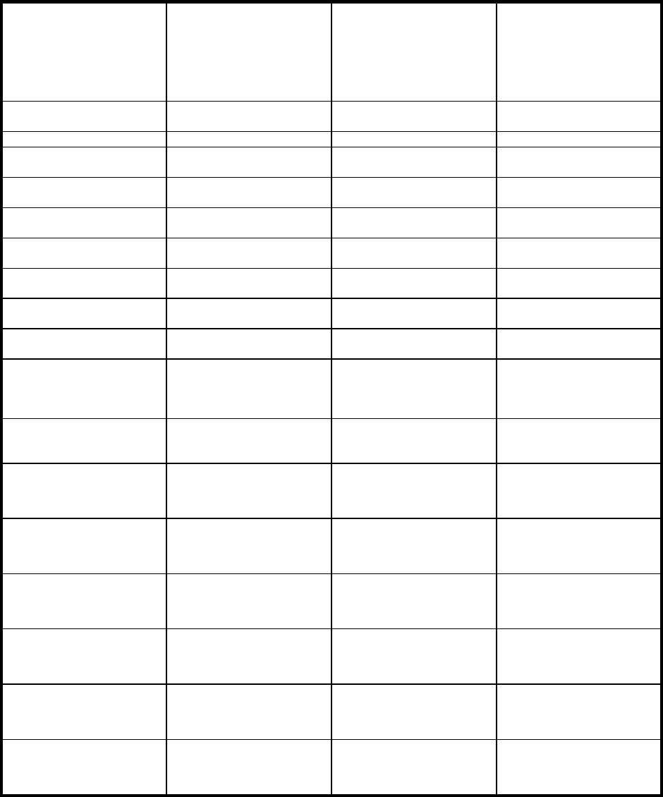
COMUSFLTFORCOMINST 4790.3 REV D CHG 2
31 MAR 2022
V-I-7A-1
APPENDIX A
APPENDIX A
TESTING REQUIREMENTS FOR SURFACE SHIP SYSTEMS
System
Note 1
Column 1
Strength and Porosity
Test Pressure
Notes 2, 3, and 4
Column 2
Mechanical Joint
Tightness Test Pressure
Notes 3, 4, and 5
Special Notes
Steam 135% system design
pressure
100% nominal operating
pressure
Non-Nuclear structural tanks
Feed and condensate 135% system design
pressure
100% nominal operating
pressure
Fuel oil service 135% system design
pressure
100% nominal operating
pressure
Lube oil fill, transfer, and
service
135% system design
pressure
100% nominal operating
pressure
Note 3
Oxygen (except surface ship
divers’ life support systems)
135% system design
pressure
100% nominal operating
pressure
Notes 6, 7, and 8
Nitrogen 135% system design
pressure
100% nominal operating
pressure
Note 7
Fresh water cooling, chilled
water, potable water
135% system design
pressure
100% nominal operating
pressure
Fuel oil filling and transfer 135% system design
pressure
100% nominal operating
pressure
Compressed air (except
surface ship divers’ life
support systems, bleed air,
and starting air)
135% system design
pressure
100% nominal operating
pressure
Hydraulic (e.g., ship service,
controllable pitch propeller,
windlass)
135% system design
pressure
100% nominal operating
pressure
Notes 3 and 9
Boiler (within boundary
valves)
See Note 10 See Note 10
Fire main and flushing 135% system design
pressure
100% nominal operating
pressure
Sea water cooling 135% system design
pressure
100% nominal operating
pressure
Deck and plumbing drains,
sound tubes open to the
atmosphere
Not required See Note 11
Countermeasures wash down 50 psig Operational test
Divers’ life support system
(air, oxygen, helium)
135% system design
pressure
100% nominal operating
pressure
Notes 7, and 8
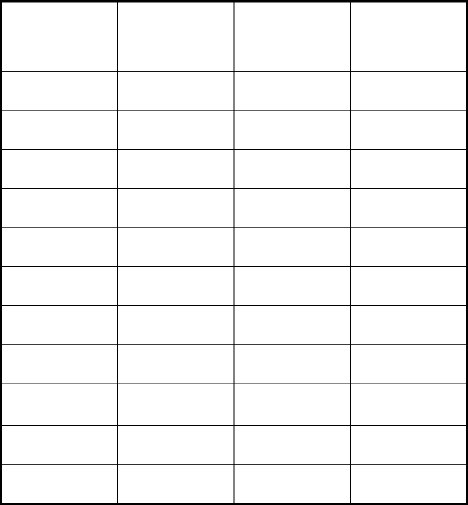
COMUSFLTFORCOMINST 4790.3 REV D CHG 2
31 MAR 2022
V-I-7A-2
APPENDIX A
System
Note 1
Column 1
Strength and Porosity
Test Pressure
Notes 2, 3, and 4
Column 2
Mechanical Joint
Tightness Test Pressure
Notes 3, 4, and 5
Special Notes
Sewage 135% system design
pressure
100% nominal operating
pressure
Ballasting, sea water transfer 135% system design
pressure
100% nominal operating
pressure
Primary and secondary
drainage from pump
50 psig Operational test
Primary and secondary
drainage from eductor
135% system design
pressure
100% nominal operating
pressure
Bilge stripping system 50 psig Operational test
Main steam drain system Relief valve setting Operational test
Feedwater drain collecting
system
Fill with water and let stand
Feedwater drain collecting
tank and discharge from tank
135% system design
pressure
Operational test
Gage lines (all systems) 135% system design
pressure for welded and
brazed joints visual
inspection for other joints
Operational Test
Freon, Halon, hydrocarbons 135% system design
pressure
See Note 12
Valves 135% system design
pressure
Note 13
NOTE 1: Testing requirements for surface ship piping and components not specified in this
appendix will be 135% of system design pressure where repairs meet the criteria of a major
repair.
NOTE 2: Strength and porosity test - Where a major repair is accomplished on the pressure
boundary of a piping system or component, that portion of the system or component will be
hydrostatically tested as indicated in column 1. Strength and porosity test duration is 30 minutes
unless otherwise specified on a component, system, or TPD. The strength and porosity test
pressure is identified on a TPD as the “H” pressure.
COMUSFLTFORCOMINST 4790.3 REV D CHG 2
31 MAR 2022
V-I-7A-3
APPENDIX A
a. Strength and porosity test pressure must be not less than 50 psig.
b. New mechanical joints (as defined in the Glossary of Terms) are subjected to a
strength and porosity test.
NOTE 3: Test fluids.
a. If the test fluid for a mechanical joint tightness test is not specified, either clean fresh
water or system fluid must be used. System fluid must be used for hydraulic and
lubricating oil systems. Compressed gasses may be used for mechanical joint
tightness tests provided they can be used safely.
b. Observe safety precautions for air, industrial gases, and hydraulic systems found in
NSTM, as well as the notesin this appendix, if system fluid or gas is used.
NOTE 4: Exceptions or alternatives to hydrostatic test requirements are provided in Section 7.4
of this chapter.
NOTE 5: Mechanical joint tightness test duration is 30 minutes unless otherwise specified on a
component, system, or TPD. The mechanical joint tightness test pressure is indicated on a TPD
as the “J” pressure or nominal operating pressure if performing an operational pressure test.
Zero visual external leakage is normally the tightness acceptance criterion.
a. Re-made mechanical joints (as defined in the glossary) are subjected to a mechanical
joint tightness test.
b. The tightness test must be performed with the thermal insulation removed from
mechanical joints to be examined.
NOTE 6: Where oxygen piping or system components are re-installed by mechanical joints,
these portions of the system will be tested to 100% operating pressure using nitrogen per
reference (p). System fluid (oxygen) may be used in at-sea situations when use of nitrogen is not
practical. The test pressure will be held for a minimum of 15 minutes plus the time required to
conduct inspection of joints under test.
NOTE 7: Refer to reference (p) for testing requirements and procedures for oxygen, nitrogen,
and hydrogen systems.
NOTE 8: Before testing oxygen stop valves with Kerotest Co. cartridges per Kerotest Drawing
72594765, ensure the valve is assembled per Kerotest Instruction K-673 and that the union is
torqued to 160 - 170 ft.-lbs. This is necessary to ensure the cartridge is not damaged.
CAUTION: CARE MUST BE EXERCISED WHEN HYDRAULIC OIL IS USED AS A
TEST LIQUID TO PREVENT SPRAY OR LEAKAGE FROM BECOMING
A FIRE OR CONTAMINATION HAZARD.
NOTE 9: Where shop pre-tested hydraulic system components or hydraulic system piping are
reinstalled by mechanical joints, those portions will be tested to column 2 requirements using
hydraulic oil as the test fluid.
NOTE 10: All testing within the boundary valves of boilers must be accomplished per reference
(g).
COMUSFLTFORCOMINST 4790.3 REV D CHG 2
31 MAR 2022
V-I-7A-4
APPENDIX A
NOTE 11: System must be open to the atmosphere. Fill system with water and allow to stand
for a minimum of 30 minutes. Examine disturbed joints for leakage; none is allowed.
NOTE 12: Refer to system, equipment, or component technical manual. Final test involves
performance of pressure drop tests over various time periods. See also reference (p).
NOTE 13: Cycle valve during hydrostatic testing as required by NSTM.
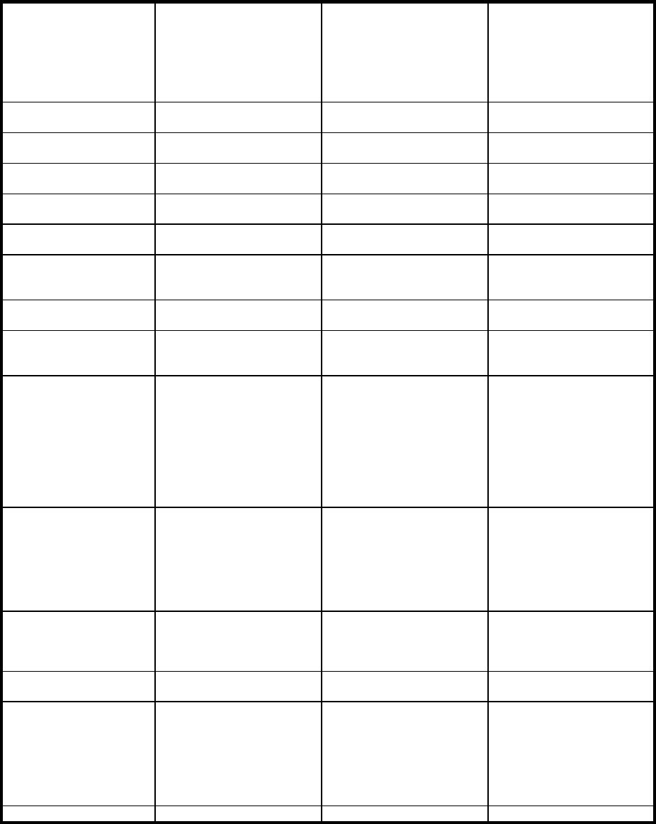
COMUSFLTFORCOMINST 4790.3 REV D CHG 2
31 MAR 2022
V-I-7B-1
APPENDIX B
APPENDIX B
TESTING REQUIREMENTS FOR SUBMARINE SYSTEMS
System
Note 1
Column 1
Strength and Porosity
Test Pressure
Notes 2, 3 and 4
Column 2
Mechanical Joint
Tightness Test Pressure
Notes 3, 4 and 5
Special Notes
Steam 135% system design
pressure
100% nominal operating
pressure
Non-Nuclear structural
tanks
Notes 13 and 18
Feed and condensate 135% system design
pressure
100% nominal operating
pressure
Fuel oil service 135% system design
pressure
100% nominal operating
pressure
Lube oil fill, transfer, and
service
135% system design
pressure
100% nominal operating
pressure
Note 3
Oxygen (except surface
ship divers’ life support
systems)
135% system design
pressure
100% nominal operating
pressure
Notes 10, 11 and 12
Nitrogen 135% system design
pressure
100% nominal operating
pressure
Note 11
Fresh water cooling,
chilled water, potable
water
135% system design
pressure
100% nominal operating
pressure
Fuel oil filling and
transfer
135% system design
pressure (135% test depth
pressure for those portions
of submarine systems
exposed to submergence
pressure)
100% nominal operating
pressure (100% test depth
pressure for those portions
of submarine systems
exposed to submergence
pressure)
Compressed air including
EMBT blow (except
surface ship divers’ life
support systems, bleed air,
and starting air)
135% system design
pressure
100% nominal operating
pressure. For submarines,
this is up to the pressure hull
cutout valve if the airline
penetrates the pressure hull
Notes 6, 8 and 24
Hydraulic (e.g., ship
service, steering and
diving, windlass, flood
control)
135% system design
pressure
100% nominal operating
pressure
Notes 3, 23 and 24
Hull glands, cables,
shafts, masts
Notes 13, 25, 26 and 29
Escape trunks, hatches
(including missile tube
muzzle hatches on SSBN
and SSGN Class
Submarines), watertight
bulkhead doors, Sonar
Spheres
Notes 14, 21, 27, 28, 29, 32,
33 and 34
Periscopes Note 16

COMUSFLTFORCOMINST 4790.3 REV D CHG 2
31 MAR 2022
V-I-7B-2
APPENDIX B
System
Note 1
Column 1
Strength and Porosity
Test Pressure
Notes 2, 3 and 4
Column 2
Mechanical Joint
Tightness Test Pressure
Notes 3, 4 and 5
Special Notes
Antennas Per NAVSEA
0900-LP-016-7007 and
SS-404-1971420
Note 31
Diesel Sea Water (DSW) Notes 6 and 9
Hydrogen 135% design pressure 100% nominal operating
pressure
Note 11
Hovering or depth
control, sea water
circulating (e.g., ASW,
MSW, Air Conditioning
Seawater)
150% test depth plus pump
shutoff pressure
100% test depth pressure Notes 6, 7, 24, and 30
Plumbing system
subjected to submergence
pressure
150% test depth 100% test depth pressure Note 6
Trim and drain systems
subjected to submergence
pressure
150% test depth pressure 100% test depth pressure Notes 6, 7 and 24
Torpedo tube system,
including the entire
SUBSAFE portion of the
system
100% test depth pressure
plus 90 psig
100% test depth pressure
plus 90 psig
Notes 17 and 24
Signal ejectors Notes 20, 24 and 32
SSBN and SSGN
bulkhead penetrator holes
and covers
Note 22
Snorkel induction and
exhaust lines
Notes 15 and 32
Cable plugs to EHFs,
EHPs, antennas, masts,
radars and other
component connection
or
joint exposed to
submergence sea pressure
(excluding photonics,
shore power connectors
and pressure proof caps
used on EHFs and EHPs)
Notes 31 and 35
SONAR Hydrophone,
Transducer, Projectors
and Outboard
Components
Note 35
NOTE 1: Testing requirements for submarine ship piping and for submarine pressure hull
envelope systems and components not specified in this appendix will be 135% of system design
pressure where repairs meet the criteria of a major repair.
NOTE 2: Strength and porosity test - Where a major repair is accomplished on the pressure
boundary of a piping system or component, that portion of the system or component will be
pressure tested as indicated in the applicable TPD. The strength and porosity test pressure is
identified on a TPD as the “H” pressure. In the absence of specific test pressure direction on a
COMUSFLTFORCOMINST 4790.3 REV D CHG 2
31 MAR 2022
V-I-7B-3
APPENDIX B
TPD, test pressure must be per Note 1. Strength and porosity test duration is 30 minutes unless
otherwise specified in a technical reference.
a. Strength and porosity test pressure must be not less than 50 psig unless otherwise
specified in the TPD.
b. New mechanical joints (as defined in the Glossary of Terms) are subjected to a
strength and porosity test.
NOTE 3: Test fluid.
a. If the test fluid for a mechanical joint tightness test is not specified, either clean fresh
water or system fluid must be used. System fluid must be used for hydraulic and
lubricating oil systems. Compressed gases may be used for mechanical joint tightness
tests provided they can be used safely.
b. Observe safety precautions for air, industrial gases, and hydraulic systems found in
NSTM, as well as the notes in this appendix, if system fluid or gas is used.
NOTE 4: Exceptions and alternatives to hydrostatic test requirements are provided in Section
7.4 of this chapter.
NOTE 5: Mechanical joint tightness test duration is 30 minutes unless otherwise specified on a
component, system, or TPD. The mechanical joint tightness test pressure is indicated on a TPD
as the “J” pressure or nominal operating pressure if performing an operational pressure test.
Zero visual external leakage is normally the tightness acceptance criterion.
a. Re-made mechanical joints (as defined in the glossary) are subjected to a mechanical
joint tightness test.
b. The tightness test must be performed with the thermal insulation removed from
mechanical joints to be examined.
c. This note does not apply to submarine hull and backup valves. (See NOTE 6 of this
appendix)
NOTE 6: Where hull valves and backup valves are repaired or replaced, they will be tested in
the following manner:
a. Valves removed for repair. Hull valve or backup valves that are removed completely
from the system for repair or maintenance will be tested in the following manner:
(1) Prior to installing in the system:
(a) Conduct a strength and porosity test to column 1 requirements with the
valve ball or disc positioned such that the unproven pressure boundary
parts and disturbed joints are exposed to test pressure.
(b) With the valve shut, test from seaside to column 1 requirements to test
for seat leakage.
(c) If a mechanical joint leaks at column 1 pressure, decrease to column 2
pressure and verify no leakage.
(d) For minor repairs, test as in steps a.(1) (a) through a.(1) (c) of this Note,
but to column 2 requirements.
COMUSFLTFORCOMINST 4790.3 REV D CHG 2
31 MAR 2022
V-I-7B-4
APPENDIX B
(e) Where valve internals can be visually inspected for leakage, seat
tightness test pressure need only be maintained for three minutes unless
specified otherwise in the applicable maintenance document.
(2) After re-installation in system, test disturbed mechanical joints in the following
manner:
(a) Apply test pressure of column 1 requirements to all mechanical joints to
which major repairs were conducted and not strength tested prior to
valve installation.
(b) Apply external (seaside) test to column 1 requirements of all
mechanical joints between hull valve and hull. For other disturbed
mechanical joints, test to column 2 requirements.
(c) For hull joints where testing is not feasible, controlled assembly
followed by a controlled dive per paragraph 7.4.2 a of this chapter is a
satisfactory alternative to the test.
b. Valves repaired in place.
(1) If major repairs have been accomplished:
(a) Conduct a strength test to column 1 requirements with the valve ball or
disc positioned such that the unproven pressure boundary parts and
disturbed joints are exposed to test pressure.
(b) With the valve shut, test from seaside to column 1 requirements to test
for seat leakage.
(c) If a mechanical joint leaks at column 1 pressure, decrease to column 2
pressure and verify no leakage.
(2) If minor repairs have been accomplished, test as in step b.(1) of this Note, but
to column 2 requirements. If test to column 2 requirements is not possible,
controlled assembly followed by a controlled dive per paragraph 7.4.2 of this
chapter, is a satisfactory alternative to the test.
(3) For those mechanical joints in sea connected systems where testing is not
feasible, controlled assembly followed by a controlled dive per paragraph 7.4.2
a. of this chapter, is a satisfactory alternative to the test.
c. Operational test. In addition to the hydrostatic testing required by steps a. or b. of this
Note, after repairs have been completed on the valve or hydraulic actuator, in-place
operational testing of Emergency Flood Control hydraulic components or EMBT
Blow valves will be conducted by performing applicable portions of the operational
Unrestricted Operation.
d. Trash Disposal Units (TDU). The TDU is a special purpose device which requires
tests beyond those normally required of hull or backup valves. The specific testing
required for the re-certification of the TDU after maintenance must be determined
from SMSs or other reference documentation. A good reference to ensure adequate
testing is the Index of Submarine Maintenance Engineering, Planning and
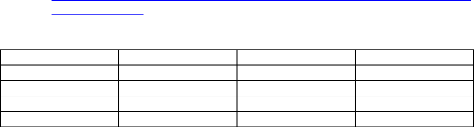
COMUSFLTFORCOMINST 4790.3 REV D CHG 2
31 MAR 2022
V-I-7B-5
APPENDIX B
Procurement (SUBMEPP) Standardized Test Procedures SSN/SSBN/SSGN
Submarines.
NOTE 7:
A. For testing work performed on portions of the sea connected systems including the
joint between the hull and hull valve, tests must be conducted for strength and porosity
and mechanical joint tightness to the pressures specified on the applicable ship or class
drawing. In some instances, the pressures specified will not reflect those on the
individual TPDs provided to the ship. Errors in any TPD should be reported to
SUBMEPP via SUBMEPP Feedback Form available at
https://ebiz.submepp.navy.mil/feedback/FOUO%20SUBMEPP%20Product%20Feedb
ack%20Form.docx (FOUO Only). For SSN 688, SSBN and SSGN 726 Class ships,
the applicable TPDs must be used. The applicable ship or class drawings listed here
should be used if TPDs are not available.
Ship or Class Drawing Strength Tightness
SSN 21 830-6404016 #Item 18 plus 50 psi Item 1
SSN 688 845-4456141 Item 3 Item 6
SSBN and SSGN 726 845-4640418 *Item 11 Item 1
SSN774 801-6984058 **Item 12 Item 18
# Except for SSN23 LDT hull insert for TD-704 and 705 valve assembly which is tested to
Item 1 of NAVSEA Dwg 830-6404016.
* Except valves TD-2021 and TD-2022 and associated piping which are tested to Item 2 of
NAVSEA Dwg 845-4640418.
** Except valves TD-116, TD-138 and TD-554 and associated piping which are tested to Item
2 of NAVSEA Dwg 801-6984058.
B. Re-made mechanical joints, using existing material, in the following piping must be
assembled using a controlled assembly, no additional testing is required:
(1) Permanent blanks installed in piping (SSN 688 Class) P168 and P169
downstream of ASW-35 and ASW-36
(2) Permanent blanks installed in piping (SSN 21 Class) P81 and P82 downstream
of ASW-39 and ASW-40.
CAUTION: CRYSTALLIZATION OR MELTING OF MAIN BALLAST TANK HULL
STOP VALVE SEATS AND DOWNSTREAM EMBT BLOW VALVE
SEATS MAY RESULT FROM RAPID PRESSURIZATION OF THE
EMBT BLOW PIPING AGAINST SHUT MAIN BALLAST TANK HULL
STOP VALVES.
NOTE 8: 4500 psig air system hull stop and bank stop valves will not be used as a boundary for
hydrostatic test pressures greater than 4500 psig unless valve seats and software are replaced
after the test and a mechanical joint tightness is performed.
NOTE 9: For repairs to the DSW system, inboard of the hull and backup valve, the column 1
test pressure is 122 psig and the column 2 test pressure is 88 psig. This is to prevent damaging
the attached DSW pump.
COMUSFLTFORCOMINST 4790.3 REV D CHG 2
31 MAR 2022
V-I-7B-6
APPENDIX B
NOTE 10: Where oxygen piping or system components are re-installed by mechanical joints,
these portions of the system will be tested to 100% operating pressure using nitrogen per
reference (p). System fluid (oxygen) may be used in at-sea situations when use of nitrogen is not
practical. The test pressure will be held for a minimum of 15 minutes plus the time required to
conduct inspection of joints under test.
NOTE 11: Refer to reference (p) for testing requirements and procedures for oxygen, nitrogen,
and hydrogen systems.
NOTE 12: Before testing oxygen stop valves with Kerotest Co. cartridges per Kerotest Drawing
72594765, ensure the valve is assembled per Kerotest Instruction K-673 and that the union is
torqued to 160 - 170 ft.-lbs. This is necessary to ensure the cartridge is not damaged.
CAUTION: WHEN TESTS INVOLVE NUCLEAR BOUNDARIES, REFER TO
REFERENCE (h), REFERENCE (q), AND THE APPLICABLE RPM
BEFORE TESTING.
NOTE 13: When packing glands, stuffing tubes, manhole covers, etc., in hull envelope
boundary tanks are entered and remade, the assembled unit will be tested by conducting a 12
psig air tightness test. With 12 psig air within the tank, apply soap solution to the work area and
inspect for leakage. No leakage is allowed.
NOTE 14: Escape trunk penetrations not exposed to sea pressure during normal ship operation,
escape and access lower hatches, and watertight bulkhead doors require only a completion test.
The completion test is a 12 psig air test with no pressure drop allowed in 10 minutes. If unable
to accomplish the completion test, perform an alternate test per note 25 of this Appendix. No
inspection following the controlled dive is required.
NOTE 15: Where repairs are performed on the snorkel induction or exhaust piping or valves,
refer to reference (r) for test requirements.
NOTE 16: Submarine Periscope Pressure testing, evacuation, charge and dew point testing will
be per reference (s).
NOTE 17: Where minor repairs have been accomplished on torpedo tubes (including attached
piping) or impulse tanks, the applicable portion of the system will be tested by performing sub-
paragraph a., b. or c. of this note.
NOTE: WHEN REMOVAL OF THE TORPEDO TUBE SIGHT GLASS (SSN688 OR
SSB(G)N726 CLASS) OR LIGHT PIPE (SSN21 AND 774 CLASSES)
ASSEMBLIES IS REQUIRED TO INSTALL TEST INSTRUMENTATION,
REINSTALLATION OF THE SIGHT GLASS MUST INCLUDE A VISUAL
INSPECTION OF THE GLASS (CHECK FOR CHIPPING, CRACKS, ETC.)
OR IF THE SIGHT GLASS HAS BEEN REMOVED FOR REPAIRS (LEAKS,
BROKEN GLASS, STRIPPED THREADS, ETC.), TESTING MUST BE
ACCOMPLISHED PER SUB-PARAGRAPH b.
a. “J” pressure hydrostatic test pierside.
b. Controlled assembly of components exposed to sea pressure, completion test and a
watertight integrity test.
COMUSFLTFORCOMINST 4790.3 REV D CHG 2
31 MAR 2022
V-I-7B-7
APPENDIX B
NOTE: DUE TO HIGH IN-SERVICE ALLOWABLE LEAKAGE RATES FOR AIR
TURBINE PUMPS, TIGHTNESS TEST MAY NOT BE POSSIBLE. IT IS
PERMISSIBLE TO UTILIZE THE AIR TURBINE PUMP INFLATABLE
SEAL TO AID WITH TESTING. IF THE AIR TURBINE PUMP TEST IS
STILL NOT ACHIEVABLE, A MAJOR DFS MUST BE SUBMITTED FOR
FAILED TESTING.
NOTE: FOR SUBMARINES EQUIPPED WITH AIR TURBINE EJECTION PUMPS
(SS(G)BN726 CLASS, SSN21 AND 774 CLASS), THERE IS AN ALLOWABLE
LEAKAGE RATE (FRESH WATER OR SEAWATER) PAST THE TURBINE
PUMP MECHANICAL SEALS. MAXIMUM ALLOWED LEAKAGE RATE
FOR NEW AND RESTORED TURBINE PUMPS IS 55 CC PER HOUR.
MAXIMUM ALLOWED LEAKAGE RATE FOR IN-SERVICE TURBINE
PUMPS IS 5 GALLONS PER MINUTE.
(1) For Torpedo Tubes and piping: The affected joints must be assembled as a
controlled assembly and subjected to a 12 psig air tightness test for 10 minutes.
Accomplish a soap bubble test of the affected joints. In addition, a minor DFS
will be used to document requirement for inspections during a controlled dive
in order to verify re-establishment of the watertight integrity for those repaired
joints.
(2) If air soap test is impractical, or if the affected joint is inaccessible: The
affected joints must be assembled as a controlled assembly and subjected to a
drop test by pressurizing to 12 psig air. Allow time for pressure or temperature
to stabilize. Hold for 10 minutes. No drop allowed. In addition, a minor DFS
will be used to document the requirement for inspections during controlled
dive in order to verify re-establishment of the watertight integrity for those
repaired joints.
c. For Impulse Tank: The affected joints must be assembled as a controlled assembly
and subjected to a drop test by pressurizing to 12 psig air. Allow time for pressure or
temperature to stabilize, hold for 10 minutes. No drop allowed. In addition, a minor
DFS will be used to document requirement for inspections during a controlled dive in
order to verify re-establishment of the watertight integrity for those repaired joints.
(1) When drop test is conducted in drydock, record the highest pressure held.
Minimum pressure must be five psig. No drop allowed. Repeat at 12 psig
when waterborne.
(2) In lieu of drop test, the affected joints must be assembled as a controlled
assembly and the tank subjected to a 12 psig air tightness test for 10 minutes.
Accomplish a soap bubble test of the affected joints. In addition, a minor DFS
will be used to document requirement for inspections during controlled dive in
order to verify re-establishment of the watertight integrity for those repaired
joints.
CAUTION: WHEN PERFORMING TESTING OF TANKS, COMPLY WITH
REFERENCE (q), SECTIONS 50 THROUGH 54.
COMUSFLTFORCOMINST 4790.3 REV D CHG 2
31 MAR 2022
V-I-7B-8
APPENDIX B
NOTE 18: NAVSEA drawing 126-5792666 provides the detailed requirements and guidance for
tank testing.
NOTE 19: DELETED
NOTE 20: Signal ejectors and launchers are special purpose devices, which require tests beyond
those normally required of hull or backup valves. The specific testing required for the re-
certification of signal ejector or launcher after maintenance must be determined from ship’s
plans or other reference documentation. A good reference to ensure adequate testing is the Index
of SUBMEPP Standardized Test Procedures SSN/SSBN/SSGN Submarines.
NOTE 21: Upper escape and access hatches (including missile tube muzzle hatches on SSBN
and SSGN Class Submarines) and escape trunk penetrations exposed to sea pressure during
normal ship operation require a completion test and a controlled dive to test depth. The
completion test is a 12 psig air test conducted per Note 25 of this Appendix for 10 minutes. In
addition, a minor DFS will be used to document the requirement to inspect for leakage by
opening the escape trunk drain at depths for hull valve cycling per NAVSEA Instruction
C9094.2B to verify re-establishment of the watertight integrity for the repaired items.
NOTE 22: Bulkhead penetration hole covers will be tested using the air hose test alternative of
Note 25, step c. of this appendix. Upon successful completion of the air hose test, document test
on a QA Form 17 and submit to the ship’s Quality Assurance Officer. A DFS is not required.
CAUTION: CARE MUST BE EXERCISED WHEN HYDRAULIC OIL IS USED AS A
TEST LIQUID TO PREVENT SPRAY OR LEAKAGE FROM BECOMING
A FIRE OR CONTAMINATION HAZARD.
NOTE 23: Where shop pre-tested hydraulic system components or hydraulic system piping are
reinstalled by mechanical joints, those portions will be tested to column 2 requirements using
hydraulic oil as the test fluid.
NOTE 24: For maintenance involving a system or component monitored under the Unrestricted
Operation Maintenance Requirement Card program, partial or full performance of in-periodicity
operational Unrestricted Operation Maintenance Requirement Cards may be required as a retest.
Consult NAVSEA 0924-062-0010, Submarine Safety Requirements Manual, Section 6.4.5 for
additional information. Perform applicable portions of Unrestricted Operation-Maintenance
Requirement Card 025. For “O” and “I” level activities, when a component in the Emergency
Flood Control System is disturbed, the retest must consist of testing the entire Emergency Flood
Control System, e.g., if a component in the Engine Room was disturbed, a retest of the entire
Engine Room is required. If a component in the Forward Emergency Control System is
disturbed, a retest of the entire Emergency Flood Control System in the Forward compartment is
required.
NOTE: NAVSEA DRAWING 126-5792666 ALSO CONTAINS INFORMATION
REGARDING TESTING OF SUBMARINE TANKS AND COMPARTMENTS.
NOTE 25: Hull Glands (e.g., cable stuffing tubes, shaft or mast packing glands, electrical or
electronic hull fittings excluding the inboard packing assembly and pressure proof caps screwed
onto EHF cable connection). Hull glands require a completion test (12 psig compartment test)
and an acceptance or structural watertight integrity test (where the joint is exposed to full
submergence depth pressure). If the structural watertight integrity test will be accomplished by
COMUSFLTFORCOMINST 4790.3 REV D CHG 2
31 MAR 2022
V-I-7B-9
APPENDIX B
performing a controlled dive to test depth, the work is required to be accomplished using a
controlled assembly, and a minor DFS for the controlled deep dive is required. The affected
joints will be inspected during the first controlled dive. Performance of alternate completion tests
are acceptable in lieu of a 12 psi compartment test and do not require a DFS. In the event that a
12 psig compartment test or an alternate completion test cannot be accomplished and the
structural watertight integrity test will be accomplished by performing a controlled dive to test
depth, the work is required to be accomplished using a controlled assembly and a major DFS for
the controlled deep dive is required. The affected joints will be inspected during the first
controlled dive. If required, perform one of the following alternate completion test methods
when a 12 psi compartment test is not scheduled or practical.
a. Cofferdam Test Method.
(1) A pressure cofferdam can be used to verify the tightness of hull or bulkhead
patches or components after re-installation where it is physically possible to
cover the item. A simple cofferdam can be constructed from six-inch diameter
or larger pipe with length determined by item to be tested. One end of the pipe
is capped and the other fitted with a suitable gasket to provide a seal.
Sufficient pipe threaded penetrations should be provided for air supply, gauge,
and relief valve fittings.
(2) Cofferdam tests, used in lieu of 12-psig compartment air tests, will be
performed in the following manner:
(a) Install the cofferdam over joint or fittings to be tested so that the
pressure differential will be in the same direction as a full compartment
or tank test. Secure the cofferdam by use of shores and wedges or
hydraulic jacks braced against sound structure. Attach air supply and
non-isolable gauge and relief valves.
(b) Pressurize the air space inside the cofferdam to the test pressure
specified for the test of the applicable tank or compartment, as shown
in the ship’s test drawing.
(c) Apply a soapy solution to the opposite side of the structure and inspect
for leakage.
(d) Acceptance criteria for cofferdam tests will be no evidence of leakage.
(e) Where the opposite side of the structure is inaccessible, an alternate
method of providing tightness is to measure the drop in pressure within
the cofferdam over a ten-minute period. The gasket and fittings in the
cofferdam should be checked for leakage using a soapy solution.
(f) Acceptance criteria for this alternate cofferdam test will be no drop in
pressure.
b. Vacuum Box Test Method.
(1) A vacuum box can be used to test the same items tested by the cofferdam
method. However, since the pressure differential is now in the opposition
direction, it may be used in many locations where a cofferdam is not suitable.
COMUSFLTFORCOMINST 4790.3 REV D CHG 2
31 MAR 2022
V-I-7B-10
APPENDIX B
Several portable vacuum pumps capable of pulling a vacuum in a small
displacement test vessel are commercially available. An air eductor can be
used to pull a vacuum for testing penetrations through the deck over a
submarine battery space.
(2) Vacuum box tests used, in lieu of 12 psig compartment air tests, will be
performed in the following manner:
(a) Apply a soapy solution to the joint to be tested.
(b) Install the vacuum box over the joint or fitting to be tested so that the
pressure differential will be in the same direction as a full compartment
or tank test.
CAUTION: PROVIDE SUPPORT FOR THE VACUUM BOX WHERE A CHANGE IN
THE INTERNAL PRESSURE COULD CAUSE THE BOX TO FALL.
(c) Draw a vacuum to obtain a pressure differential comparable to the test
pressure specified in the ship’s test drawings.
(d) Inspect the joint or fitting for leakage by observing through the
Plexiglas cover of the vacuum box for the formation of bubbles which
would indicate leakage.
(e) Acceptance criteria for vacuum box tests will be no evidence of
leakage.
(f) An alternate test method of proving tightness with the vacuum box is to
measure the rise in pressure within the vacuum box over a ten-minute
period.
NOTE: A SOAPY SOLUTION SHOULD BE APPLIED TO THE GASKET, COVER,
AND FITTINGS INSIDE THE VACUUM BOX. FORMATION OF BUBBLES
ON THE INTERIOR OF THE VACUUM BOX INDICATES A LEAK IN THE
BOX.
(g) Acceptance criteria for this alternate vacuum box test will be no rise in
pressure.
c. Air Hose Test Method.
(1) An air hose test may be used to verify the tightness of piping or electrical
penetrations directly accessible on both sides of the bulkhead or pressure hull
for observation. Extreme caution will be used when this method is used to test
periscopes, hydraulic control rods or other movable cylinders that penetrate
bulkheads or the pressure hull due to the possibility of blowing abrasive
material into the seals. Also, ensure that openings exist to prevent ambient
pressure buildup.
(2) Air hose tests will be performed in the following manner:
(a) The air hose nozzle must be about 3/8 inch in diameter and the pressure
at the nozzle must be about 90 psig.
COMUSFLTFORCOMINST 4790.3 REV D CHG 2
31 MAR 2022
V-I-7B-11
APPENDIX B
(b) Apply a soapy solution to the structure on the side opposite from the
side the stream of air is to be applied. Communications are to be
established to ensure air hose nozzle position and soap test are being
accomplished at the same location (i.e., top, bottom, port, starboard).
WARNING: HIGH VELOCITY AIR IS A PERSONNEL HAZARD. ALL NON-
ESSENTIAL PERSONNEL WILL BE CLEARED FROM THE AREA
BEING TESTED. SAFETY GLASSES WILL BE WORN AT ALL TIMES.
CARE MUST BE TAKEN SO THAT THE AIR STREAM IS NOT
DIRECTED TOWARD ANY PERSONNEL.
(c) The air hose must be located so as to produce a pressure differential in
the same direction as would occur if a full compartment or tank test
were performed. Hold the nozzle as close as possible, within two
inches, if possible, to the joint or fitting under test and direct the air
stream in the manner most likely to reveal leakage. The test must be
accomplished for a minimum of 30 to 45 seconds on each quadrant or
area.
(d) Inspect the soapy solution for the formation of bubbles during the test,
which would indicate leakage.
(e) Acceptance criteria for air hose tests will be no evidence of leakage.
d. Pressurized Water Testing Method for Submarine Main Propulsion Shaft Primary
Seals (Shaft Seal Cavity Testing in advance of Controlled Deep Dive).
(1) Conduct pressurized water testing of the shaft seal cavity following assembly
of any seal repaired following applicable tech manual or maintenance standard.
(2) If no pressurized water test procedure is available,
(a) Pressurize the repaired shaft seal cavity with fresh water to 100 (95 to
105) psig.
(b) Measure leakage rate past the affected seal into the ship. Allowable
leakage is 16 oz per minute maximum. Test pressure must be held for a
30 minute minimum.
NOTE 26: For steering and diving penetrations (and other hull V-Ring packing installations
including associated o-rings), perform a controlled assembly and initiate a minor DFS to
document the requirement for inspections during a controlled dive to test depth in order to verify
re-establishment of the watertight integrity for those joints.
NOTE 27: Removable Logistics Escape Trunks and Logistics Plug Trunks require an inter seal
tightness test and a controlled dive to test depth. The inter seal tightness test will be
accomplished using air or nitrogen to 100% test depth pressure with no pressure drop allowed in
10 minutes. In addition, immediately following the first controlled dive to test depth, enter the
trunk and remove the cleanliness cap from the drain or test connection and verify no leakage has
occurred. A minor DFS will be used to document the requirement to inspect for leakage
immediately following the dive to verify re-establishment of the watertight integrity for the
reinstalled trunk.
COMUSFLTFORCOMINST 4790.3 REV D CHG 2
31 MAR 2022
V-I-7B-12
APPENDIX B
NOTE 28: The Sonar Sphere requires a completion test and a controlled dive to test depth. The
completion test is a 12-psig air test with no pressure drop allowed in 10 minutes. If unable to
accomplish the completion test, perform an alternate test per note 25 of this Appendix. In
addition, immediately following the first controlled dive to test depth, enter the sonar sphere and
inspect for evidence of leakage. A minor DFS will be used to document the requirement to
inspect for leakage immediately following the dive to verify re-establishment of the watertight
integrity.
NOTE 29: Electrical/electronic hull fitting pressure proof caps manufactured per MIL-C-
24231/12, 13 or 14 are not Level I or boundaries within the SUBSAFE Systems and do not
require REC or testing when installed or operated.
NOTE 30: For preventative maintenance (e.g., PMS) to inspect and replace seawater heat
exchanger pencil and disc type zinc anodes closed with an o-ring threaded plug with a nominal
diameter of 1-5/8” or less accomplished without additional testing, the following conditions must
be met:
a. Work will be performed using a CWP within the SUBSAFE boundary and a Formal
Work Package when performing work outside the SUBSAFE boundary.
b. The joint will be assembled as a controlled assembly and documented on QA form 34.
c. Complete a surfaced condition maximum operating pressure test with zero leakage for
5 minutes. Operate seawater pumps at maximum speed without causing cavitation or
violating operating procedure restrictions.
d. List “SURFACED” as the actual pressure on QA forms.
e. No new pressure boundary parts are installed (excluding software).
f. No testing is required for other maintenance or repair (e.g., ASW valve repairs) which
would subject the zinc anode area to at least mechanical joint tightness pressure.
CAUTION: APPLYING POWER TO ANTENNA CONTROL CABLES OR
TRANSMITTING ON RADIO FREQUENCY CABLES THAT HAVE NOT
HAD THE ELECTRICAL CHECKS COMPLETED CAN SIGNIFICANTLY
DAMAGE EQUIPMENT OR COMPONENTS. IF THE APPROPRIATE
ELECTRICAL CHECKS CANNOT BE COMPLETED, CONSIDERATION
OF AN EQUIPMENT TAG-OUT MAY BE APPROPRIATE.
NOTE 31: Submarine SubHDR and Photonics systems outboard cable removal and
replacement.
a. Insert plugs with new O-ring each time the cable is unplugged and assemble using a
controlled assembly. The QA form 34 is required to be retained until the availability
is complete or if accomplished outside of an availability, the QA form 34 will be
retained until the package is closed and reviewed by the Quality Assurance Officer.
b. After performing a deep dive, passive or pre-energize testing must be performed
following the system specific Technical Manual, SUBMEPP approved Maintenance
Standard, SUBMEPP approved Standard Test Procedure or Maintenance Requirement
Card to ensure the system is not grounded prior to use.
COMUSFLTFORCOMINST 4790.3 REV D CHG 2
31 MAR 2022
V-I-7B-13
APPENDIX B
c. Controlled Assembly Process used for Re-Entry Control (REC) Exceptions or
Exception to Retest Requirements for Mechanical Joints consists of:
(1) Verification that surface finishes of gasket or O-ring sealing surfaces are
following applicable specifications.
(2) Verification that fastener material and installation is following applicable
specifications.
(3) Verification that gaskets or O-rings are properly installed and following
applicable specifications.
(4) Assembly is documented on a Quality Assurance (QA) form 34.
(5) Inspected by a Quality Assurance Inspector (QAI) or Quality Assurance
Supervisor (QAS).
NOTE 32: A partial distressed submarine and salvage inspection must be accomplished per
Volume IV, Chapter 18 of this manual for any item worked during an availability (i.e., hatches,
salvage air valves, etc.).
NOTE 33: Repairs of SSGN Class Lockout Chamber and SSN 774 Class Lockout trunks and
hatches within the certified Scope of Certification boundary require an 89-psig completion test.
Minor repairs, in addition to an 89-psi completion test, require a minor DFS for a controlled dive
to test depth to certify structural watertight integrity. Major repairs require a hydrostatic test at
“H” pressure or an 89-psi completion test and a major DFS to perform a controlled dive to test
depth to certify structural watertight integrity. Hydrostatic testing at “H” pressure satisfies all
mechanical joint testing requirements for minor repairs.
NOTE 34: Specific repair and acceptance criteria for submarine watertight doors and hatches is
defined in the following SUBMEPP Maintenance Standards:
a. 1000-081-774
b. 1000-081-726
c. 1000-081-688
d. 1000-081-021
NOTE 35: Post installation testing must be conducted following the applicable SUBMEPP
Maintenance Standard or Combat System Test Procedure. Post deep dive testing must be
accomplished per the applicable Combat System Test Procedure or Maintenance Requirement
Card. For transducer or hydrophone replacements for spherical arrays (excluding SSBNs), a
dental chart, or equivalent test, performed following the applicable technical manual or
Maintenance Requirement Card must be performed prior to getting underway.

COMUSFLTFORCOMINST 4790.3 REV D CHG 3
07 Nov 2023
V-I-8-1
VOLUME V
PART I
CHAPTER 8
DEPARTURE FROM SPECIFICATION
(DFS, WAIVERS, NUCLEAR LIAISON ACTION REQUEST,
AND STEAM PLANT ACTION REQUESTS)
REFERENCES.
(a) NAVSEAINST 5400.95 - Waterfront Engineering and Technical Authority Policy
(b) NAVSEA 0989-LP-037-2000 - Commissioned Submarine General Reactor Plant
Overhaul and Repair Specification
(c) NAVSEA 0989-LP-043-0000 - Commissioned Surface Ship General Reactor Plant
Overhaul and Repair Specification
(d) NAVSEA 0989-LP-058-1000 - Destroyer Tender and Submarine Tender Nuclear
Support Facilities Overhaul and Repair Specification
(e) NAVSEAINST N9254.1 - Inspection of Condensers, Reboilers, and Heat Exchangers
in Nuclear Surface Ships and Submarines
(f) NAVSEA S9086-T4-STM-010 - NSTM Chapter 589 (Cranes)
(g) NAVSEA T9044-AD-MAN-010 - Requirements Manual for Submarine Fly-By-Wire
Ship Control Systems
(h) NAVSEA 5100.12-M - System Safety Engineering (SSE) Manual
(i) NAVSEA S9086-HB-STM-010 - NSTM Chapter 233 (Diesel Engines)
(j) NAVSEAINST C9210.4 - Changes, Repairs and Maintenance to Nuclear Powered
Ships
(k) NAVSEA SL720-AA-MAN-030 - Navy Modernization Process Management and
Operations Manual (NMP-MOM)
LISTING OF APPENDICES.
A Departure From Specification Request Message Format
B Departure From Specification Clearance or Cancellation Report Message Format
8.1 PURPOSE. To establish standard procedures to be used by the Fleet and all maintenance
activities for reporting, requesting approval and clearance, at the earliest opportunity, of all non-
conforming or departable conditions, Departures from Specification (DFS).
8.1.1 Background. Specifications are engineered requirements such as type of materials,
dimensional clearances, vibration levels, flow rates, and physical arrangement to which ship
components are purchased, installed, tested, and maintained. All ships are designed and
constructed to specific technical and physical requirements. It is imperative that every effort be
made to maintain all ship systems and components to their designed specifications. There are
occasions when the applicable specifications cannot be met. In these cases, the nonconformance
to specifications is controlled with a DFS.
8.1.2 Terminology.

COMUSFLTFORCOMINST 4790.3 REV D CHG 3
07 Nov 2023
V-I-8-2
a. A DFS is the mechanism used to document and resolve a lack of compliance with any
authoritative document, plan, procedure, instruction, etc., except in instances where
NAVSEA has signed and issued formal correspondence adjudicating one of the
preceding such as a Liaison Action Request (LAR), Engineering Request (ER), or
similar documents.
b. Authorized Technical Authority. An Authorized Technical Authority is a
representative designated by reference (a) to act for Naval Sea Systems Command
(NAVSEA) in dispositioning nonconformance issues. They are also charged with
providing technically sound maintenance alternatives to the Fleet upon which
maintenance and operational decisions can be made.
c. As determined by the ship and ISIC, temporary nonconformances, except SUBSAFE,
Scope of Certification, and Fly-by-Wire nonconformances, that are minor which
would not benefit from an engineering analysis or risk assessment will be entered into
the CSMP. CSMP entries of this type do not require a corresponding DFS to
adjudicate the condition and will be scheduled for repair in a future maintenance
availability.
d. The terms deviation and waiver are often used synonymously. The principle
difference being that deviations are requested prior to conducting work that will result
in a nonconformance and waivers are requested after a nonconformance has been
discovered.
8.1.3 Specification. Technical specifications originate from a variety of sources. When a
conflict exists between specifications, the governing requirement has to be determined on a case-
by-case basis. The following listing is provided to assist in determining the governing
specification. This listing may not be exact for a particular case and all pertinent technical
documents will require review:
a. Non-Nuclear listing of specifications which may be consulted when determining the
governing specification:
(1) Volume V (Quality Maintenance) of the Joint Fleet Maintenance Manual.
(2) Fleet or Type Commander (TYCOM) Technical Notes.
(3) Ship’s plans or drawings, NAVSEA Standard and Type drawings, and
approved Technical Repair Standard or Maintenance Requirement Procedure,
or Maintenance Standard.
(4) NAVSEA letters and Liaison Action Requests (LAR).
(5) The Military Standard (MIL-STD) and Military Specification (MIL-SPEC)
series. MIL-SPEC for specific components being procured or manufactured,
MIL-STD for specific processes being performed.
(6) NAVSEA approved component technical manuals.
(7) NAVSEA 0902-018-2010; General Overhaul Specifications for Deep Diving
SSBN/SSN Submarines.
(8) TYCOM Instructions.

COMUSFLTFORCOMINST 4790.3 REV D CHG 3
07 Nov 2023
V-I-8-3
(9) Naval Ships’ Technical Manuals and Technical Specifications.
(10) NAVSEA Instructions.
(11) NAVSEA S9AA0-AB-GOS-010; General Specifications for Overhaul of
Surface Ships.
NOTE: WHERE THIS MANUAL IS MORE RESTRICTIVE THAN OTHERS, THIS
MANUAL WILL TAKE PRECEDENCE UNLESS SPECIFICALLY STATED
THAT IT PROVIDES GUIDANCE ONLY. UNRESOLVED QUESTIONS ON
PRECEDENCE SHOULD BE REFERRED TO THE TYCOM FOR
RESOLUTION. IN SOME INSTANCES A SPECIFICATION OF LESSER
PRECEDENCE MAY MODIFY OR SUPERSEDE A MORE SENIOR
SPECIFICATION, I.E., A NAVSEA LETTER OR LAR RESPONSE COULD
SPECIFICALLY MODIFY A TECHNICAL STANDARD PENDING
REVISION.
b. Nuclear listing of specifications which may be consulted when determining the
governing document:
(1) Reactor Plant Manual.
(2) Reactor plant component technical manuals.
(3) NAVSEA technical manuals (e.g., NAVSEA 250-1500-1 Welding Standard).
(4) Reference (b).
(5) Reactor Plant Drawings.
(6) NAVSEA instructions.
(7) TYCOM instructions.
(8) Reference (c).
(9) Reference (d).
8.2 DEPARTURE FROM SPECIFICATION. A DFS (non-nuclear only) is a lack of
compliance with any authoritative document, plan, procedure, instruction, etc. General guidance
regarding DFS is:
NOTE: FOR SURFACE FORCE SHIPS AND AIRCRAFT CARRIERS, THE TYCOM
WILL PERFORM THE IMMEDIATE SUPERIOR IN COMMAND (ISIC)
FUNCTIONS OF THIS CHAPTER.
a. During a maintenance action, including temporary repairs, a DFS is required for lack
of compliance with cognizant documents, drawings, etc. For “as found” conditions
during maintenance, the ISIC, ship and Fleet Maintenance Activity (FMA) (if
involved) must evaluate the non-compliance using the guidance of paragraph 8.2.5 and
8.2.6 of this chapter.
b. For “as found” conditions or equipment failures during operations that result in non-
compliance with cognizant documents, drawings, etc., the ship or ISIC (if in port)
must evaluate the condition or failure using the guidance of paragraph 8.2.5 and 8.2.6
of this chapter to determine if the non-conforming condition meets the criteria as a
COMUSFLTFORCOMINST 4790.3 REV D CHG 3
07 Nov 2023
V-I-8-4
Major or Minor DFS. Nonconformances meeting the criteria as a major or minor DFS
must be submitted to the ISIC for adjudication when in a port with a FMA and must
be approved by the Commanding Officer if at sea or in a port without an FMA. If at
sea, the guidance of paragraph 8.3.8 of this chapter will be followed.
8.2.1 Reporting Departures from Specification. It is incumbent upon ships, FMAs, and ISICs to
discuss potential DFS as early as possible (prior to the work close out or component assembly if
possible) to determine direction of actions, and alternatives to the DFS. Every effort must be
made to correct each deficiency prior to equipment or system operation or underway of the ship.
If a DFS has to be submitted, the request for it must be processed as soon as possible to enable a
technical evaluation of the DFS request and final adjudication from the TYCOM.
8.2.2 Reporting Departures from Specification while Conducting a CNO Availability Sea Trial.
(Submarines Only) Any failed inspection, test or as found deficient condition that would
normally be documented on a DFS will be documented and reported in the daily Submarine Sea
Trial Situation Report (SITREP) as required by Volume II, Part I, Chapter 3 of this manual. The
only DFS required to be written during CNO Availability SEA TRIALs are those DFS used to
close Re-Entry Controlled (REC) work performed at sea during the trials to accomplish testing
below 200 ft.
8.2.3 Types of Departures from Specification. A DFS is classified as either Major or Minor
depending on its significance. Major DFS are described in paragraph 8.2.5 of this chapter.
Minor DFS are described in paragraph 8.2.6 of this chapter. Care must be exercised in
evaluating and determining the type of DFS. All submarine DFS submitted for evaluation must
be adjudicated prior to ship’s underway operations except when executing berth shifts that do not
involve open ocean movements (i.e. movements within a harbor or river). All submarine DFS
submitted for evaluation must be adjudicated prior to operating the affected equipment except:
a. A ship is in a Chief of Naval Operations availability and the affected system or
component has been turned over to the Shipyard for maintenance or operation.
OR
b. The system or component is entered into a formal test or test program, which controls
operation.
8.2.4 Permanent and Temporary Approval of Departure from Specification. DFSs are approved
as either permanent or temporary depending on the nature of the non-compliance and technical
determination of whether the condition needs to be repaired.
a. A temporary DFS requires subsequent action to correct the non-compliance and is
approved with specific direction regarding duration and actions necessary to clear. A
Major DFS accepting a temporary repair or condition is approved by the TYCOM
following concurrence by an Authorized Technical Authority. A Minor DFS
accepting a temporary repair will be approved by the TYCOM or ISIC as specified in
paragraph 8.2.6 of this chapter.
b. Temporary deviation or waivers initiated by the Authorized Technical Authority per
reference (a) require TYCOM concurrence prior to approval.
c. A permanent DFS requires no additional repair effort and is approved by NAVSEA.
Technical Authority within NAVSEA for approval of a permanent DFS is specified in

COMUSFLTFORCOMINST 4790.3 REV D CHG 3
07 Nov 2023
V-I-8-5
reference (a). As an exception, a permanent DFS may be approved only by the
TYCOM or ISIC as specifically allowed in paragraph 8.2.6.a. of this chapter when
previously approved precedent setting documentation that directly applies to the DFS
exists. The specific NAVSEA precedent must be referenced in the DFS approval.
d. Reference (e) requires that a DFS be written and provided to NAVSEA 05 by the Lead
Maintenance Activity for adjudication whenever eddy current inspections are not
completed within a window of 12 months prior to, or 6 months after, their scheduled
due date as directed by the applicable Class Maintenance Plan. Lead Maintenance
Activities must submit departures from specification that technically support
scheduling requests. The DFS must use prior inspection reports and establish
individual component condition-based recommendations. This requirement applies to
main condensers, turbine generator condensers, auxiliary gland exhaust condensers,
reboilers, and reboiler feed heater drain coolers in nuclear surface ships and
submarines.
NOTE: PARAGRAPH 8.2.5 OF THIS CHAPTER DOES NOT APPLY TO THE
CATEGORY OF DFSs FOR CRANES COVERED UNDER REFERENCE (f).
REFERENCE (f) LISTS THE CATEGORY REQUIREMENTS AND LEVEL
OF APPROVAL FOR CRANE RELATED DFSs.
NOTE: AN OUT-OF SPECIFICATION PARAMETER IN A SUBMARINE FLY-BY-
WIRE SHIP CONTROL SYSTEM FUNCTION MEASURED BY URO/MRC
019 IS ALSO CONSIDERED A MAJOR NONCONFORMANCE WHETHER
OR NOT THE URO/MRC IS DUE FOR ACCOMPLISHMENT. URO MRC
019 PROVIDES THE REQUIREMENTS FOR PROCESSING URO MRC
RELATED NONCONFORMANCES.
NOTE: THIS LISTING IS NOT ALL INCLUSIVE AND SITUATIONS MAY ARISE
WHERE DEFICIENCIES NOT LISTED MAY BE OF SUCH A NATURE TO
WARRANT A MAJOR DFS. FOR EACH DEFICIENCY DETERMINED TO
DIRECTLY INVOLVE SAFETY OF SHIP, SAFETY OF PERSONNEL, OR
CAUSE A REDUCTION IN THE INTEGRITY OR OPERABILITY OF
EQUIPMENT ESSENTIAL TO SHIP’S MISSION, A MAJOR DFS MUST BE
ISSUED.
8.2.5 Major Departure from Specification. A major DFS is one that affects performance,
durability, reliability or maintainability, interchangeability, effective use or operation, weight or
appearance (where they are a factor), health or safety, system design parameters such as
schematics, flow, pressures, or temperatures, or compartment arrangements or assigned function.
The following list identifies some deficient conditions which require a major DFS:
NOTE: IN SOME INSTANCES, THESE MAJOR DEPARTURES MAY
SUBSEQUENTLY BE RECATEGORIZED BY THE LOCAL TECHNICAL
AUTHORITY FROM MAJOR TO A MINOR PER REFERENCE (a).
a. Use of unapproved joint design or additional joints.
b. Nonconformances to plan specifications that result in a change in configuration.
Examples are:
COMUSFLTFORCOMINST 4790.3 REV D CHG 3
07 Nov 2023
V-I-8-6
(1) Nonconformances to plan specifications resulting in a change in configuration
or dimensions to pressure boundary parts or components. Examples would be
“as found” dimensional or clearance differences from plan requirements for a
Submarine Safety (SUBSAFE) valve bonnet and no authorization (e.g., Ship
Alteration, Alteration and Improvement, Engineering Change Notice or
NAVSEA letter) is available.
(2) Nonconformances to plan specification resulting in a change in configuration
considered to be a permanent repair to pressure boundary parts. An example
would be replacement of a failed valve of older design with one of more recent
design because valves of the older design are no longer available and no
authorization (e.g., Ship Alteration, Alteration and Improvement, Engineering
Change Notice, NAVSEA letter) is available.
c. Failure to meet all applicable standards for major repairs unless other alternatives are
authorized by this volume. Examples are linear indications, failed tightness test,
hydrostatic test, use of unqualified welder or brazer, failed radiography, inadequate
bond during brazing, etc.
d. Pipe or component wall thickness below minimum specification without restoration.
Epoxy and shim methods for ball valve repairs are not considered restorations of
component wall thickness.
e. Manufacture of a part or component without use or availability of applicable technical
documentation (e.g., manufactured per sample due to non-availability of detailed
drawings), regardless of whether the repair is considered temporary or permanent. A
DFS is not required if the part or component is non-level and in a non-controlled
system, it is fabricated from the correct material and the lack of technical
documentation does not affect performance, durability, reliability or maintainability,
interchangeability, use or operation, weight or appearance (where a factor), health or
safety, or system design parameters.
f. Failure to complete required retest of a SUBSAFE, Level I or Submarine Flight
Critical Component (SFCC) component or system.
g. Leakage from a SUBSAFE or Level I hull fitting, piping system, or component:
(1) Hull valve or fitting to hull flange leakage.
(2) Leakage or weepage through a component body or pipe wall. Completion of
temporary repairs (e.g., plastic pipe patch) does not negate the requirement for
a DFS.
(3) Leakage or weepage from a welded or brazed joint. Completion of temporary
repairs (e.g., plastic pipe patch) does not negate the requirement for a DFS.
(4) Leakage upper escape and access hatches, leakage from hull glands (e.g., cable
stuffing tubes, shaft or mast packing glands, electrical or electronic hull fittings
excluding the inboard packing assembly and pressure proof caps screwed onto
Electrical Hull Fitting cable connection) that is in excess of the allowable
specification that cannot be repaired, immediately, by a packing adjustment or
greasing.
COMUSFLTFORCOMINST 4790.3 REV D CHG 3
07 Nov 2023
V-I-8-7
h. Installation of new pressure boundary parts which do not meet all applicable material
certification requirements. The following are some departable conditions:
(1) (Submarines only) Non-Level I valve internals (e.g., ball, disc, poppet, flapper)
installed in seawater or sea-connected hull valves and backup valves.
(2) Non-Level I weld rod, insert material, brazing filler, etc. installed in a
SUBSAFE or Level I system welded or brazed joint.
(3) Non-Level I pressure boundary parts (e.g., stem, bonnet, studs, nuts) installed
in or on SUBSAFE or Level I components or systems.
i. (Submarines only) For any Unrestricted Operation (URO) Maintenance Requirement
Card (MRC) measured parameter found out of tolerance and not restored, whether the
MRC is due or not.
j. (Submarines only) Failure to complete any URO MRC within required periodicity.
(1) Nonconformance requests that result in a change of the URO MRC inspection
periodicity (not authorized by the MRC), a change in a URO MRC technical
requirement, or deferral of required work require NAVSEA approval.
TYCOM or Authorized Technical Authority approval is not authorized for
these nonconformances.
(2) To support operational commitments, TYCOMs may authorize temporary
periodicity extensions (not authorized by MRC) after consultation with
NAVSEA 07T. The periodicity extensions should be limited to the next
availability or in port period, where a submarine maintenance activity is
available, and must be documented by a major DFS.
(3) When a URO/MRC periodicity becomes due during a maintenance
availability, a DFS is not required when the TYCOM or ISIC takes positive
actions to restrict submerged operations. Prior to the ship conducting
underway surfaced or conducting submerged operations (except when
executing berth shifts that do not involve open ocean movements (i.e.
movements within a harbor or river), all operational URO/MRC must be
within periodicity (URO MRC 016, 019, 022, 025, 026, 029 and 036) and
requirements must be complied with or a Major DFS must be approved.
Surfaced operations with an expired URO 036 do not require a DFS or waiver.
k. (Submarines only) For all submarine hatch (Logistics Escape Trunks, Lock Out
Chambers, Logistic Plug Trunks, etc.) deficiencies which will not be repaired prior to
ships underway involving the following:
(1) Non-operational submarine access hatch. (Upper Hatch Operability and
Remote Operating Devices)
(2) Hatch clearance reading out of specification. (Hatch-to-Seat Clearance)
(3) Locking ring hatch lug alignment out of specification. (Coaming Lugs and
Locking Rings)
COMUSFLTFORCOMINST 4790.3 REV D CHG 3
07 Nov 2023
V-I-8-8
(4) Locking ring hatch or trunk coaming lug metal-to-metal contact out of
specification. (In Service Lug Engagement)
(5) Hatch gasket groove and hatch trunk seating surface out of specification.
(Gasket and seating surface inspection)
l. (Submarines only) Non-operational Emergency Main Ballast Tank Blow Valve,
seawater system hull or backup valve, Modified After Signal Ejector or signal ejector
muzzle ball valve, salvage air valve, etc.
m. (Submarines only) A fault condition or unsatisfactory test within the FBW SCS
certification boundary indicates a deficiency with a safety critical function per
reference (g) and must be classified as a Major nonconformance under the following
conditions:
(1) When the system design employs more than two redundant SFCCs and a
deficiency degrades the redundancy to only two remaining SFCCs.
(2) When the system design employs two redundant SFCCs or a non-redundant
SFCC and a deficiency results in the loss of a SFCC.
n. Headed fasteners locally manufactured from Level I material (i.e., cap screws, bolts,
machine screws, etc.) which have not been certified by tensile and hardness testing
specified in MIL-DTL-1222 (Studs, Bolts, Screws and Nuts for Applications Where a
High Degree of Reliability is Required; General Specification for) or FF-S-86 (Federal
Specification, Screw, Cap, Socket Head) as applicable.
o. (Submarines only) All high pressure compressed gas flasks designed to MIL-F-22606
specifications must be recertified at intervals not to exceed 20 years for SSN 688, SSN
21 and SSN 774 Classes and 21 years for SSBN and SSGN 726 Class. High-pressure
air moisture separator flasks must be recertified at an interval not to exceed ten years
for SSN 688, SSN 21, SSBN, SSGN 726 and SSN 774 Classes. All oxygen and gas
management separator flasks designed to MIL-F-24032 specifications must be
recertified at an interval not to exceed nine years for SSN 688, SSN 21 Class, SSBN
and SSGN 726 Class. A major DFS, approved by NAVSEA, is required for any flask
that will exceed the recertification periodicity.
p. (Submarines only) Propulsion shafts must be replaced at intervals not to exceed six
years for SSBN and SSGN 726 Class, seven years for SSN 688 and SSN 774 Classes
and ten years for SSN 21 Class. A major DFS, approved by NAVSEA, with
supporting operating information, including shaft turn count since shaft installation is
required for shafts that will exceed planned replacement periodicity.
q. (Submarines only) A Major DFS is required to document missing or damaged Special
Hull Treatment removed from external structure only when the coating system beneath
the Special Hull Treatment is missing or delaminated resulting in bare metal that is not
repaired. Missing or damaged Special Hull Treatment removed from external
structure is to be tracked using the CSMP process as long as the remaining coating
system is intact or repaired (i.e., no bare metal) when the following conditions are met:
(1) The submarine is not currently in a Depot Level availability.

COMUSFLTFORCOMINST 4790.3 REV D CHG 3
07 Nov 2023
V-I-8-9
(2) Temporary repairs are performed following the requirements of the class
specific hull treatment repair and maintenance manual.
(3) The CSMP item is scheduled to be cleared no later than the next scheduled
Depot Level availability.
r. (Submarines only) Torpedo Tube Muzzle Door K-Monel linkage components must be
replaced every eight (8) years on all submarine classes. A major DFS, approved by
NAVSEA, with supporting information including total waterborne exposure time of
existing components and torpedo tube recess anode type (LVA or Zinc), is required
for any instance where this periodicity is exceeded. Note that this requirement is not
applicable to SSN 688 Class submarines with Ordalt 18000 and SSBN and SSGN 726
class submarines with TZ-0932.
s. Additive manufactured (AM) components with a NAVSEA Environment,
Safety and Occupational Health
Risk Matrix level of severity 1 thru 6 per
reference (h). (Submarines only) AM components must not be used for production
of replacement components for any ship system that may affect ship safety, operation,
integrity, or classified equipment which includes, but not limited to, SUBSAFE,
LEVEL I, Fly-By-Wire, Scope of Certification, and other NAVSEA approved ship
system components. The following information will be listed in the submarine DFS.
(1) The risk factor derived from table 10-3 of reference (h).
(2) The end use application of the AM part.
(3) The compartment the AM part is located.
(4) Weight of the AM part.
(5) All package label data from AM polymer feedstock or filament used.
t. Diesel Inspector Inspection Findings documenting a severe degradation.
u. Any of the following associated with a shipboard diesel engine:
(1) Inoperative alarms or safety devices.
(2) Low lube oil pressure.
(3) Readings that exceed the limits of PMS or manufacturer specifications
that during unrestricted operation would present a hazard to equipment.
(4) Lube oil fuel dilution above safe levels.
(5) Controllable exhaust leaks as defined in new reference (i).
8.2.6 Minor Departure from Specification. A DFS which is not a Major DFS as defined in
paragraph 8.2.5 of this chapter is considered to be a Minor DFS. All permanent Minor (and
Major) DFSs will be approved by NAVSEA except those identified in paragraph 8.2.6.a. of this
chapter, which may be dispositioned by the TYCOM or the ISIC. Temporary Minor DFSs
identified in paragraph 8.2.6.b. of this chapter may also be dispositioned by the TYCOM or the
ISIC. All other temporary Minor DFSs will be approved by the TYCOM. For submarines,
TYCOM approval will follow the QA form 12 block 19 table. Temporary nonconformances,
except SUBSAFE, Scope of Certification, and Fly-by-Wire nonconformances, that are minor
COMUSFLTFORCOMINST 4790.3 REV D CHG 3
07 Nov 2023
V-I-8-10
which would not benefit from an engineering analysis or risk assessment will be entered into the
CSMP and are not required to be submitted as a DFS. Paragraphs 8.2.6.a. through f. of this
chapter identify some deficient conditions which require a Minor DFS:
a. Any condition which could be considered a Major DFS except for the fact that specific
and definite (TYCOM or NAVSEA) guidance is available based on documented
action for another identical (same component, same application, and same class ship)
request in which no restriction was imposed. An example would be a previous DFS
which was approved as a precedent setting DFS.
b. Any condition which is associated with exemptions or alternatives to non-nuclear
retest requirements in section 7.4 of part I, chapter 7, of this volume on testing, except
where noted. Examples are:
NOTE: IF A MAINTENANCE CERTIFICATION RECORD/RE-ENTRY CONTROL
IS CLOSED BY TRANSFERRING AT SEA TESTING TO A DFS (E.G.,
CONTROLLED DIVE TO TEST DEPTH FOR RETEST OF A PERISCOPE
HULL GLAND, CONTROLLED DIVE FOR RETEST OF A SEA
CONNECTED SYSTEM (E.G., MAIN SEAWATER, AUXILIARY
SEAWATER) IN LIEU OF JOINT TIGHTNESS TEST TO “J” PRESSURE OF
TEST PRESSURE DRAWING (TPD)), THE SHIP WILL BE RESTRICTED IN
DEPTH AS REQUIRED IN PART I, CHAPTER 5, PARAGRAPH 5.6.5 OF
THIS VOLUME.
(1) (Submarines only) DFS for controlled dive following re-installation of a
periscope.
(2) (Submarines only) DFS for controlled dive following work on a hatch exposed
to sea pressure.
(3) (Submarines only) DFS for controlled dive following work on an Electrical or
Electronic Hull Fitting.
(4) (Submarines only) DFS for installation of TYWRAPS in lieu of cable banding
following waterborne cable replacement by divers.
(5) (Submarine only) DFS for controlled dive following for work lacking
Mechanical Joint Tightness Testing of Torpedo Tube Flood and or Drain
Electrodes.
(6) (Submarine only) DFS for conducting at sea operational testing such as Main
Sea Water Fast Speed operations, shooting water slugs from 3" Launcher, Trim
and or Drain Pump operations to measure Heat during operations.
(7) (Submarine only) DFS for deferral of System Operability Verification Testing.
c. Any condition that requires at sea operations to certify planned maintenance or repairs
excluding structural watertight integrity testing except as previously discussed.
d. Associated with a temporary repair to a system or component not involving ship or
personnel safety or not involving integrity or operability of equipment essential to
ship’s mission.

COMUSFLTFORCOMINST 4790.3 REV D CHG 3
07 Nov 2023
V-I-8-11
e. For a material deficiency discovered during a maintenance action that will not be
corrected prior to the ship’s underway, and is not categorized as a Major DFS per
paragraph 8.2.5 of this Chapter.
f. AM components with a NAVSEA Environment, Safety and Occupational Health Risk
Matrix severity level of severity 7 or “N/A” per reference (h). (Submarines only)
AM components must not be used for production of replacement components for any
ship system that may affect ship safety, operation, integrity, or classified equipment
which includes, but not limited to, SUBSAFE, LEVEL I, Fly-By-Wire, Scope of
Certification, and other NAVSEA approved ship system components. The following
information will be listed in the submarine DFS.
(1) The risk factor derived from table 10-3 of reference (h).
(2) The end use application of the AM part.
(3) The compartment the AM part is located.
(4) Weight of the AM part.
(5) All package label data from AM polymer feedstock or filament used.
g. (Submarines only) For all rescue seating surface (Escape Trunks, Logistics Escape
Trunks and Lockout Trunks) Periodic Maintenance Requirements (PMRs) not
completed within periodicity. A minor DFS, approved by TYCOM, is required for
rescue seats that will exceed planned PMR periodicity.
h. (Submarines only) For all rescue seating surface (Escape Trunks, Logistics Escape
Trunks and Lockout Trunks) paint or surface finish defects, not corrected prior to
ships underway require a minor DFS approved by TYCOM.
i. (Submarines only) For all submarine escape component (e.g., IPHO and
intensifier system; SCV, HIS and AVV valves; sea sensing line; escape trunk and
cavity drain and strainers or orifice; or upper hatch hydraulic hand pump (688
Class only)) deficiencies, not corrected prior to underway.
8.3 DEPARTURE FROM SPECIFICATION PROCEDURES.
NOTE: FOR SURFACE FORCE SHIPS AND AIRCRAFT CARRIERS, THE TYCOM
WILL PERFORM THE ISIC FUNCTIONS OF THIS CHAPTER.
8.3.1 General Administrative Requirements. The following requirements pertain to all DFSs:
a. Requests for DFS will be submitted, approved and cleared per paragraph 8.3.7 or 8.3.8
of this chapter. The Web Based Electronic Departure from Specification (eDFS)
program is acceptable for use unless directed otherwise by the respective TYCOM.
NOTE: THE FORMS (QUALITY ASSURANCE (QA) FORM 12, QA FORM 12A)
MENTIONED IN THE FOLLOWING DISCUSSION ARE COMPLETED
ELECTRONICALLY WHEN USING eDFS.
NOTE: WHEN USING A NAVAL MESSAGE TO REQUEST A DFS OR REPORT A
COMMANDING OFFICER APPROVED DFS THE EXACT FORMAT SHOWN
IN APPENDIX A WILL BE USED. EACH PARAGRAPH IN THE NAVAL
MESSAGE WILL HAVE A PARAGRAPH NUMBER, THE PARAGRAPH
COMUSFLTFORCOMINST 4790.3 REV D CHG 3
07 Nov 2023
V-I-8-12
TITLE AND A COLON. ANY DEVIATION IN THE FORMAT MAY CAUSE A
PROBLEM WITH THE AUTOMATIC DFS PROCESSOR. IF THE SHIP IS
UNABLE TO CONNECT TO EDFS, A DEPARTURE MAY BE REQUESTED
BY NAVAL MESSAGE USING THE FORMAT OF APPENDIX A.
b. Requests for DFS will be normally submitted on a QA form 12. The approval of the
DFS will normally be made on the QA form 12. If unable to use QA form 12, use the
message format of Appendix A. Surface ships that are not able to generate a DFS
using eDFS have the option of generating DFS per existing message based system or
Command E-mail. The Command E-mail must be approved by the ship’s
Commanding Officer or his designated representative.
c. The ship is responsible for all approved DFS relating to its systems or components
until cleared or canceled. When a DFS is approved as a temporary repair requiring
rework to correct the discrepancy, a CSMP entry for correction of the discrepant
condition will be initiated by the ship or ISIC. This CSMP entry must include the
DFS serial number, On-Site Analysis Report serial number (if applicable), or other
technical references documenting or tracking the nonconformance. The ship’s Quality
Assurance Officer (QAO) will ensure that this action is done. Verify an active Job
Control Number (JCN) exists for all active temporary DFSs at the completion of all
scheduled Fleet maintenance activity availabilities, major or minor, Chief of Naval
Operations availabilities or at least quarterly and maintain an auditable record of the
verification until superseded.
d. The ISIC is responsible for all DFSs which have been approved or forwarded to
TYCOM for approval until the DFS is cleared, canceled or formally transferred to
another TYCOM. The ISIC is also responsible for ensuring that the CSMP entry is
annotated on the DFS for temporary repairs.
e. All DFS must be reported and controlled. Each activity must have an auditable system
for reporting and controlling DFS. Deviation or waivers will be retained and tracked
in an auditable fashion within the DFS system by Ship’s Force and the ISIC or
TYCOM until permanent documentation is confirmed to reflect the specific non-
compliance. Use of the Web Based eDFS program will facilitate meeting these
requirements.
f. When work performed results in a DFS and requires future action (e.g., re-inspection,
repair), the ship will submit an OPNAV 4790/2K (or equivalent) with a new Job
Sequence Number. The CSMP Job Sequence Number will be included in Block 17 of
the DFS. This Job Sequence Number will be added to the DFS prior to submission to
the ISIC. The DFS or waiver will be retained in an auditable fashion with the DFS
file. DFSs and waivers written exclusively to transfer accountability for testing do not
require an OPNAV 4790/2K (or equivalent) with a new Job Sequence Number.
g. To preclude last minute ship’s operational delays, DFS should be processed as early as
possible. Any request for approval for a DFS must contain all pertinent information
on materials, processes, testing and procedures used, so that a complete and educated
engineering evaluation can be made by the TYCOM, Local Technical Authority or
System Command.

COMUSFLTFORCOMINST 4790.3 REV D CHG 3
07 Nov 2023
V-I-8-13
(1) (Carriers and Surface Force Ships) DFS serial numbers for Ship’s Force
initiated departures will be automatically supplied by eDFS (0000 series). For
departures initiated by a depot level activity, the serial numbers will be
automatically supplied by eDFS (1000 series). All outstanding departures
must be submitted to the TYCOM for evaluation by a Local Technical
Authority prior to a ship’s underway. However, if the Local Technical
Authority evaluation is not complete prior to the underway, the ship is
responsible to ensure adequate temporary precautions or standing orders are in
effect until the DFS evaluation is complete. For temporary departures expiring
during an underway, as discussed in paragraph 8.3.9 of this chapter, the
extension request must be made sufficiently in advance to allow the evaluation
process to be completed before the expiration date and preferably prior to the
underway in which the DFS expires.
(2) (Submarines only) DFS serial numbers for Ship’s Force initiated departures
will be maintained either in a handwritten or electronic log. For DFS serial
numbers for work performed by NAVSEA managed activities, to include
Public and Private shipyards or activities directed by TYCOM, must use 1000
series DFS numbers auto initiated by the eDFS software. For temporary
departures expiring during an underway, as discussed in paragraph 8.3.9 of this
chapter, the extension request will be made sufficiently in advance to allow the
evaluation process to be completed before the expiration date (Temporary
Approved Until Date) and prior to the underway in which the DFS expires.
h. The activity originally requesting the DFS will track the DFS until it is approved or
disapproved.
i. For any DFS, Nonconformance, deviation or waiver that has been adjudicated, the
approving activity is required to provide a copy of the DFS, Nonconformance,
deviation or waiver to the ship’s QAO for retention and tracking per paragraph 8.3.1e.
of this chapter.
j. (Submarines only) All departures must be adjudicated prior to the ship getting
underway for submerged operations except as authorized by TYCOM where the
approved existing DFS has a “Temporary Approved Until Date” that is the same or
later than the unit's anticipated return to port date or has an approved plan to clear or
extend the DFS to support ship's schedule.
8.3.2 Review of Outstanding Departures from Specification. Commands responsible for
tracking approved DFS will review them prior to each upkeep to establish FMA or shipyard
work requirements to clear the DFS. DFSs should be cleared as soon as possible based on:
a. Approval as a permanent repair.
b. Condition has been corrected.
c. Condition is no longer applicable as a result of an alteration.
d. Condition is no longer applicable as a result of a change in the specification that
originally resulted in the DFS request.

COMUSFLTFORCOMINST 4790.3 REV D CHG 3
07 Nov 2023
V-I-8-14
8.3.3 Clearing of Departure from Specification by Exposing Sea Connected Systems and Hull
Integrity Boundary Items to Submergence Pressure (Submarines only). SUBSAFE certified
submarines will submerge to 95% of design test depth, as a minimum, as measured to the keel,
for clearing certain “Controlled Dive” DFSs. Satisfactory completion of the test and clearance of
the DFS will be in the format of QA form 12A. If unable to use QA form 12A, use message
format of Appendix B.
8.3.4 Incorporation of Departure from Specification in Selected Record Drawings, Data or
Technical Variance Documentation.
a. Those DFSs for a change in configuration, which NAVSEA accepts as a permanent
repair, will be maintained in an auditable file by the ship and the ISIC until reflected in
ship’s selected record drawings, data or technical variance documentation. Examples
are:
(1) An oversized shaft and bushing.
(2) A seal welded mechanical joint.
(3) Addition of piping joints or fittings.
(4) Different style or type valve.
b. The activity submitting the DFS for permanent approval will inform the ship of the
configuration change and provide sufficient data to support submission of Ship’s
Configuration Change Report (OPNAV 4790/CK) and a Fleet COSAL Feedback
Report (NAVSUP 1371).
c. For DFS approved as a permanent repair for material or component substitution
resulting in a configuration change, the ship will submit a Ship’s Configuration
Change Report (OPNAV 4790/CK) and a Fleet COSAL Feedback Report (NAVSUP
1371) to ensure accurate configuration accounting and technical or supply support are
maintained.
d. The activity causing or discovering the nonconformance or departable condition that
the DFS approved as a permanent repair, and affects selected drawings and records,
will provide a copy of the marked up drawing to Ship’s Force prior to underway and
will forward a copy of the applicable portions of the work package and a marked up
copy of the affected drawing or record to the planning yard as soon as practical. The
ship and accomplishing activity will maintain a copy of the correspondence until the
technical variance documentation or selected record drawing is issued.
8.3.5 Preparations for Correction of Departure from Specification and Clearance During Depot
Level Availabilities. The following procedures will be used to schedule DFS for correction and
report correction of DFS in depot level availabilities:
a. Ship’s Force or the parent ISIC will provide copies of DFS outstanding at the
Availability Planning Conferences for incorporation into the work package as required
by the Availability Baseline Work Package.
b. DFS deferred to a Depot Availability for correction must be cleared by the submission
of a QA form 12A as the shipyard accomplishes the work, provided that the shipyard
“scope of work” corrected the DFS. Completion reports from shipyards are not

COMUSFLTFORCOMINST 4790.3 REV D CHG 3
07 Nov 2023
V-I-8-15
required. These forms are submitted by Ship’s Force to the ISIC or the NSA
correcting the nonconformance. If unable to use a QA form 12A, use the message
format of Appendix B.
8.3.6 Numbering of Departures from Specification. All DFSs will be identified by a unique
sequential number issued by the affected ship. The sequential number will consist of the ship’s
designation and hull number, a hyphen, the sequential number portion, a hyphen, and the last two
digits of the year (e.g., SSN 674-13-90, CVN 70-30-94). DFSs already assigned a number under
another numbering system will be retained, as there is no intent to revise the numbers already
used. DFSs established using the Web Based eDFS program will use the numbering conventions
of those systems. Approved temporary departures requiring extension will not be assigned new
Departure numbers.
8.3.7 Submission and Approval of Departures from Specification. The activity finding or
causing a DFS will normally report the DFS to the appropriate approval authority using either a
QA form 12, a naval message or electronically using the eDFS program. The DFS Request will
be completed per the instructions. If unable to use QA form 12 or the electronic web based
programs, use the naval message request format of Appendix A.
NOTE: IN THE FOLLOWING SECTION, IF USING eDFS, WHEN IT IS DIRECTED
THAT THE QA FORM 12 IS SIGNED, AN ELECTRONIC SIGNATURE IS
IMPLIED. ISIC AND UNITS ASSIGNED TO TYCOMs UTILIZING THE
eDFS SYSTEM WILL SUBMIT DFSs TO THE TYCOM VIA THE eDFS
PROGRAM. THIS PROGRAM REQUIRES A USER IDENTIFICATION AND
PASSWORD SUPPLIED BY THE TYCOM. THE FOLLOWING PROCESSES
WILL BE EXECUTED UNDER THE eDFS PROGRAM USING THE
ELECTRONIC VERSION OF THE QA FORM 12 AND QA FORM 12A. THE
SIGNATURES WILL BE ONLY THE PRINTED NAME AND TITLE OF THE
INDIVIDUAL. SHIPS WITHOUT UNCLASSIFIED INTERNET ACCESS
MAY SUBMIT DFSs AND DFS CLEARANCES TO THE ISIC VIA A
MANUALLY PREPARED QA FORM 12 OR QA FORM 12A, THE STAND-
ALONE MS ACCESS DATABASE FORMAT OR MESSAGE FORMAT IF AT
SEA.
a. The Work Center Supervisor, Leading Petty Officer, Craftsman or Quality Assurance
Inspector will fill out the applicable portion of the QA form 12, ensuring the extent of
the DFS and the recommendation for repair and re-certification must be clearly and
completely stated, and deliver, after review by the cognizant division officer, to:
(1) For ship initiated DFS, the Ship’s QAO or in his or her absence the Ship’s
Duty Officer.
(2) For FMA initiated DFS, the FMA QAO or in his or her absence the FMA
Repair Duty Officer.
b. The QAO or designated representative will:
(1) Review the QA form 12 for technical adequacy, accuracy, and completeness.
(2) Determine the latest time the answer must be received in order to carry out the
ship’s schedule, obtain and enter the next consecutive number from the
COMUSFLTFORCOMINST 4790.3 REV D CHG 3
07 Nov 2023
V-I-8-16
affected ship’s DFS log. For aircraft carriers, the numbering convention
assigned by the Web Based eDFS program when submitting the DFS will be
used.
(3) Deliver or forward to Department Head (ship) or Repair Officer (FMA).
c. For ship initiated DFS, Ship Department Head (in his or her absence Ship’s Duty
Officer) will:
(1) Review the QA form 12 for technical adequacy, accuracy, and completeness.
(2) Sign the QA form 12 and deliver or forward to the cognizant ISIC QAO (in his
or her absence ISIC Duty Officer).
d. For FMA initiated DFS, FMA Repair Officer (in his or her absence his or her
designated representative) will:
(1) Review the QA form 12 for technical adequacy, accuracy, and completeness.
(2) Sign the QA form 12 and deliver or forward it to the cognizant ISIC QAO (in
his or her absence ISIC Duty Officer).
e. For Depot initiated temporary waivers and deviations, responsible Depot personnel
will:
(1) Review the waiver or deviation for technical accuracy, adequacy, and
completeness.
(2) Prepare and electronically sign a QA form 12 via eDFS and deliver or forward
it to the cognizant ISIC representative QAO (in his or her absence the ISIC
Duty Officer) for review and concurrence prior to approval. For a DFS
initiated by a depot level activity, the ISIC will provide the JCN to the depot
level activity when requested. For carrier repair activities, eDFS will
automatically supply the next open DFS serial number. See paragraph
8.3.1g.(1) of this chapter for carriers and surface force ships and paragraph
8.3.1g.(2) of this chapter for submarines for a description of the current process
for assigning DFS serial numbers.
(3) The ISIC representative QAO will review and concur with the waiver or
deviation by signing the ISIC block of the QA form 12 or electronically
signing in eDFS prior to Depot approval and return the waiver or deviation to
the Depot. For temporary waivers and deviations, the ISIC representative will
contact the Ship’s Maintenance Planner or the Ship’s QAO for a JCN and a
Departure serial number (if required) prior to returning the waiver or deviation
to the Depot.
f. The cognizant ISIC QAO (in his or her absence his or her designated representative)
will:
(1) Review the QA form 12 for technical adequacy, accuracy, and completeness.
(2) Issue instructions regarding clearance and approve or disapprove and return
QA form 12 to the Department Head (Ship) or Repair Officer (FMA) for
action, filing in QA files, or both.
COMUSFLTFORCOMINST 4790.3 REV D CHG 3
07 Nov 2023
V-I-8-17
(3) Deployed Ships ISICs will ensure parent ISIC is an information addressee on
all QA form 12s.
g. Approval or disapproval of a DFS by the TYCOM or NAVSEA will be noted on the
QA form 12.
h. Upon completion of corrective action, the DFS will be cleared by the ship using the
format of QA form 12A. The NAVSEA or TYCOM approval of a permanent repair
requires no further administrative action.
NOTE: DO NOT DELETE ANY INFORMATION FROM AN eDFS ITEM THAT HAS
RECEIVED TEMPORARY APPROVAL FROM EITHER THE ISIC, TYCOM
OR AUTHORIZED TECHNICAL AUTHORITY.
NOTE: THE ABILITY TO ADD COMMENTS TO AN APPROVED DFS IS LIMITED
BY THE ELECTRONIC SYSTEM’S ASSIGNED LEVEL OF ACCESS (I.E.,
ISICs CAN ADD COMMENTS ONLY TO THE ISIC PORTION OF THE DFS
FORM).
8.3.8 Departure from Specification Approval and Reporting for Ships While at Sea or at a Port
Without a Fleet Maintenance Activity.
8.3.8.1 Evaluation. The Commanding Officer will evaluate any DFS and approve the corrective
action to be taken including any necessary restrictions. The Commanding Officer will issue
directions regarding clearance and approve or disapprove the DFS and return the QA form 12 to
the Department Head for action, filing, or both. For any Commanding Officer approved DFS, a
report of the condition and intended action will be made at the first opportunity to the ship’s ISIC
or TYCOM utilizing either a naval message in the “EXACT” format of Appendix A or the eDFS
program.
8.3.8.2 Condition not Corrected. If the condition is not planned to be corrected or cannot be
corrected during the next inport period (a port with a fleet maintenance facility), the
Commanding Officer approved DFSs must be submitted to the applicable approval authority for
adjudication prior to getting underway.
a. (Submarines only) All departures must be adjudicated prior to the ship getting
underway.
b. (Aircraft Carriers and Surface Force Ships only) In the event the DFS evaluation is not
completed prior to the ship’s underway, the Commanding Officer approved DFS will
remain in effect until the evaluation is completed and disposition provided.
NOTE: AN EXTENDED DEPARTURE WILL NOT BE ASSIGNED A NEW
DEPARTURE NUMBER THAT CANCELS OR SUPERSEDES THE
ORIGINAL DEPARTURE NUMBER.
8.3.9 Extending a Temporary Departure. In the event that a departed condition will not be
corrected by the expiration date, the Ship’s QAO is responsible to submit the departure(s) to the
ISIC requesting an extension. The extension request will explain why the departure will not be
corrected. The extension request must be made sufficiently in advance to allow the evaluation
process to be completed before the expiration date. The Departure extension will be routed to
the same level of approval authority as the original Departure.

COMUSFLTFORCOMINST 4790.3 REV D CHG 3
07 Nov 2023
V-I-8-18
a. Nonconformances are expected to expire. It is acceptable for nonconformances to
expire while the ship or Deep Submergence System (DSS) or Scope of Certification
(SOC) asset is in a scheduled availability except as listed here:
(1) Nonconformances must not be permitted to expire for equipment or systems
that are in operation or will be operated during the availability except:
(a) A ship is in a Chief of Naval Operations availability and the affected
system or component has been turned over to the Shipyard for
maintenance or operation.
OR
(b) The system or component is entered into a formal test or test program
which control operation.
(2) Nonconformances associated with UROs must be approved and or extended
prior to submarine underway operations unless the submarine is repositioned
by tug or similar craft.
b. (Submarines, DSS and SOC assets only) Must not get underway with expired
nonconformances unless the submarine, DSS or SOC asset is repositioned by tug or
similar craft.
c. Extension requests via the eDFS program must be accomplished using the Request
Extension feature accessed by clicking the associated button at the top of the QA form
12 for the most recent approved active DFS extension. If allowed by the TYCOM,
changes to an existing nonconformance in the eDFS program may be accomplished by
submittal of an “UPDATE” as directed in paragraph 8.3.10.c of this chapter. All
changes to an existing nonconformance in the eDFS program that require NAVSEA
approval must be accomplished by submittal of a DFS extension.
8.3.10 Electronic Nonconformance Administration.
a. User access requires TYCOM or initiating agencies Point of Contact (POC) approval
for all levels of access.
b. All attachments to the electronic nonconformances are preferred to be in Adobe
Acrobat PDF format. If another format is used, ensure it is one that is readily
available on government computers, such as Microsoft Word or Excel format.
Nonconformances with attachments that cannot be opened by the ISIC or TYCOM
will be rejected.
c. Changes to an existing electronic nonconformance is normally accomplished by
submittal of an “UPDATE” to the QA form 12.
(1) Changes must be disseminated via an e-mail alert.
(2) Deletion of QA form 12s will not be supported. Clear or cancel QA form 12s
with a QA form 12A.
d. The DFS CLEARANCE STATUS entry block must contain a brief description and
status of the nonconformance (e.g., REPAIR GREASE DISTRIBUTION VALVE).

COMUSFLTFORCOMINST 4790.3 REV D CHG 3
07 Nov 2023
V-I-8-19
e. Naval Sea Logistics Center (NAVSEALOGCEN) assistance is required to change an
archived nonconformance. NAVSEALOGCEN will use the following process to
change an electronic nonconformance:
(1) Database nonconformance changes (change to a QA form 12) will only be
accomplished if requested by the TYCOM or the initiating agencies POC.
(2) Archived nonconformances requiring changes which were signed by multiple
TYCOMS or multiple initiating agencies:
(a) Requires e-mail concurrence of all POC signatory users to the
nonconformance prior to NAVSEALOGCEN making database changes
or unarchiving the nonconformance (i.e., Supervisor of Shipbuilding,
TYCOM and NAVSEA signed QA form 12).
(b) If a nonconformance is unarchived to allow TYCOMs or agency users
to make changes, change will be accomplished per the requirement
cited in paragraph 8.3.10.c. of this chapter.
(c) Each signatory level user should indicate their concurrence to the
change per the requirement cited in paragraph 8.3.10.c. of this chapter.
(3) Archived nonconformances requiring change which were signed by a single
TYCOM or single initiating agency:
(a) Requires e-mail concurrence of the POC signatory user to the
nonconformance prior to NAVSEALOGCEN making database changes
or unarchiving the nonconformance (i.e., Supervisor of Shipbuilding,
TYCOM or NAVSEA signed QA form 12).
(b) If a nonconformance is unarchived to allow a TYCOM or agency user
to make changes, change will be accomplished per the requirement
cited in paragraph 8.3.10.c. of this chapter.
8.4 NUCLEAR COGNIZANT AREAS. Request for DFS for nuclear systems will be neither
requested nor approved. If a ship or FMA has a question, problem, or is unable to comply with
nuclear specifications, request for technical resolution will be made using a LAR. Formal
resolution of the LAR is required prior to reactor plant or propulsion plant startup.
8.4.1 Nuclear Powered Surface Ships. A memorandum of agreement exists between NAVSEA
Nuclear Propulsion Directorate (08) and NAVSEA PMS 312 or 335 that details the division of
responsibilities within the propulsion plants of nuclear powered ships. This may be useful to
Forces Afloat as an aid in directing inquiries and correspondence and has been distributed to all
nuclear surface ships as a NAVSEA letter Ser 08J/C90-5873, dated 7 AUG 90.
8.4.2 Reactor Plant Systems. If a nuclear powered ship or nuclear capable FMA is unable to
comply with specifications for reactor plant systems or components listed in enclosure (1) to
reference (j) and also those systems identified as nuclear by the appropriate nuclear or non-
nuclear interface diagram (references (b) and (c)), then a review of NAVSEA 08 requirements
must be requested. In general, technical resolution to questions or problems for reactor plant
systems or components requires use of a liaison inquiry according to the requirements of
references (b) and (c).
COMUSFLTFORCOMINST 4790.3 REV D CHG 3
07 Nov 2023
V-I-8-20
a. References (b) and (c) provide the requirements on submission of LARs for nuclear
powered surface ships and submarines.
NOTE: LARs SUBMITTED MUST CONTAIN ALL INFORMATION REQUIRED BY
REFERENCE (b) AND REFERENCE (c) TO ENSURE A RAPID, ACCURATE
RESPONSE.
b. Reference (d) provides the requirements on submissions of LARs for nuclear support
facilities.
c. A LAR should not be submitted for cases of out of specification seat leakage of
nuclear valves after repairs. The Reactor Plant Planning Yard and Reactor Plant
Prime Contractors do not have the authority to waive valve leakage specifications.
When valve seat leakage exceeds reactor plant manual specification after attempted
Ship’s Force or FMA repairs, the following method may be used to defer rework and
close out the Controlled Work Package (CWP):
NOTE: THIS ALTERNATIVE TO SATISFACTORY COMPLETION OF RETEST IS
APPLICABLE ONLY TO VALVE SEAT LEAKAGE.
(1) The ship must inform TYCOM (via squadron or group for submarines) by
message with an info copy to NAVSEA 08. The message must include a
description of the initial problem, repairs conducted, seat leakage rate, leak
specification, dates of next availability, status of the following sub-paragraphs
(2) through (5), and request for authorization to continue operation with out-of-
specification seat leakage.
(2) All hydrostatic and tightness test requirements must be satisfactorily
completed.
(3) All other portions of the CWP must be properly completed.
(4) A new maintenance deferred action must be submitted to the ISIC for repair of
the valve seat leakage at the next FMA availability.
(5) The valve seat leakage must not constitute an operational problem (for
submarines, Group or Squadron’s determination and justification statement
required).
(6) Based on Ship’s justification statement, TYCOM will respond by message to
all concerned regarding deferral of corrective maintenance. After satisfactory
final review, closeout of the CWP can be made with an approved deferral of
corrective maintenance in lieu of a satisfactory seat leakage test.
d. A liaison action file, with a sequential index and containing all submitted Nuclear
LARs, must be maintained by the originating activity. The file must contain a copy of
LARs submitted. A copy of the liaison action must be kept with liaison requests in the
Answered LARs section and in the CWP or Formal Work Package if applicable.
e. Request for DFS for nuclear systems will be neither requested nor approved. If a ship,
FMA or shipyard has a question, problem or is unable to comply with nuclear
specifications, request for technical resolution will be made using an LAR or Trouble
Record.

COMUSFLTFORCOMINST 4790.3 REV D CHG 3
07 Nov 2023
V-I-8-21
8.4.3 Propulsion Plant Systems (Aircraft Carriers only). If a ship or FMA has a question,
problem or is unable to comply with non-nuclear specifications, technical assistance is available
from the Propulsion Plant Engineering Activity (PPEA). The PPEA was formed to provide an
additional technical resource for assisting operational aircraft carriers with technical or
operational issues not associated with Ship Alteration installation and configuration control.
PPEA Liaison services are requested using the Steam Plant Action Request (SPAR). The SPAR
allows the Fleet and overhaul activities to submit requests to the PPEA for technical assistance
on non-Ship Alteration related issues; the SPAR is not intended to replace the LAR process
described in this chapter or non-nuclear LARs submitted to the Hull Planning Yard per reference
(k). The PPEA can request information, disseminate technical information associated with the
Steam Plant to the Fleet or overhaul activities, or direct work that does not require a drawing
change or affect system configuration control using the Steam Plant Liaison Inquiry. Procedures
for preparing SPARs are discussed in reference (c).
COMUSFLTFORCOMINST 4790.3 REV D CHG 3
07 Nov 2023
V-I-8A-1
APPENDIX A
APPENDIX A
DEPARTURE FROM SPECIFICATION REQUEST MESSAGE FORMAT
RTTUZYUW RUCBSRF0001 DDHHMM-UUUU--RUCBSUU.
ZNR UUUUU
R DDHHMMZ MMM YY ZYB
FM (COMMAND REQUESTING DFS)//
TO ISIC/TYCOM// (NOTE 1)
NAVSEALOGCEN MECHANICSBURG PA//
INFO COMNAVSEASYSCOM WASHINGTON DC// (NOTE 2 and 3)
ISIC//
COGNIZANT IMA//
SHIP//
SUBMEPP PORTSMOUTH NH//(URO PROGRAM MANAGER)// (NOTE 4)
PEO CARRIERS (AS APPLICABLE FOR CARRIERS)//
PEO THEATER SURFACE COMBATANTS (AS APPLICABLE FOR COMBATANTS)//
PEO EXW (AS APPLICABLE FOR AUXILIARIES, LITTORALS AND PATROL CRAFT)//
PEO MUW (AS APPLICABLE FOR MINE WARFARE)//
NAVSPECWARCOM (WHEN DDS IS INSTALLED)//
BT
UNCLAS (OR CLAS)//N04855//
MSGID/GENADMIN/ (COMMAND REQUESTING DFS)/0000/FEB//
SUBJ/DFS REQUEST FOR (SHIP AND HULL NUMBER AND DEPARTURE NUMBER
ASSOCIATED WITH (COMPONENT/SHORT DESCRIPTION))/(NOTE 5)//
OR FOR A CO APPROVED DEPARTURE
NOTIFICATION OF COMMANDING OFFICER APPROVED DFS (SHIP AND HULL
NUMBER AND DEPARTURE NUMBER ASSOCIATED WITH (COMPONENT/SHORT
DESCRIPTION))/(NOTE 5)//
REF/A/DOC/COMUSFLTFORCOMINST 4790.3// (NOTE 6)
POC//
AMPN/REF A IS THE JOINT FLEET MAINTENANCE MANUAL// (NOTE 7)
NARR//(NOTE 7)
RMKS/1. DFS NUMBER:
2. SHIP & HULL NUMBER:
3. JCN:
4. CWP NUMBER:
5. DATE OF DFS:
6. ORIGINATOR:
7. DEPARTURE TYPE
A. MAJOR:
B. MINOR:
C. SUBSAFE:
D. SOC:
E. URO:
F. FBW:
G. SFCC:

COMUSFLTFORCOMINST 4790.3 REV D CHG 3
07 Nov 2023
V-I-8A-2
APPENDIX A
8. DEPARTURE CLASSIFICATION
A. DEVIATION:
B. WAIVER:
C. FBWDR:
9. SYSTEM/COMPONENT/LOCATION/ESWBS:
10. NAVSEA DRAWING/PLAN NUMBER/PIECE NUMBER:
11. REFERENCES:
12. APPLICABLE SPECIFICATIONS:
13. SITUATION/DEGREE OF NON-COMPLIANCE: (NOTES 8, 9 AND 10)
14. COMMENTS/RECOMMENDATION:
15. DATE ANSWER REQUESTED BY:
16. SUBMITTING ACTIVITY:
17. NEW JCN:
18. CO APPROVED DFS:
DECL: ODAR//
BT
NOTE: ENSURE MESSAGES ARE PER CURRENT MESSAGE FORMAT AND
CURRENT PLAIN LANGUAGE ADDRESS DIRECTORY (PLAD) IS
UTILIZED.
NNNN
NOTES:
1. Office codes for TYCOMs are: COMNAVAIRLANT N43/N9; COMNAVAIRPAC N434;
COMNAVSURFLANT N434; COMNAVSURFPAC N434;
COMNAVSURFLANT/AIRLANT SNPMTT N02NB; COMNAVSURFPAC N434 AND
COMNAVAIRPAC N9/N434; PACIFIC FLEET CVNs – COMNAVAIRPAC N9/N434;
COMNAVSURFLANT N434 AND COMNAVAIRLANT N9/N43; ATLANTIC FLEET
CVNs - COMNAVAIRLANT N9/N43; COMSUBLANT N4322; COMSUBPAC N4,
N4322.
2. Office codes for NAVSEA are: PMS 392 and SEA 07TC (All SSN and SSBN/SSGN); PMS
390N (DEEPSUBM and DDS); OOC (DDS and DLSS). For URO related DFS, also include
the appropriate NAVSEA codes listed in the URO MRC.
3. Include NAVSEA 07Q for informational purposes on all SUBSAFE DFS messages. Include
the applicable Program Manager at NAVSEA for informational purposes on all SOC DFS
messages. Include the NAVSEA 07T for informational purposes on all Fly-By-Wire Ship
Control System (FBW SCS) DFS messages.
4. Include SUBMEPP only on URO related DFS.
5. Comply with current annotation and declassification requirements for classified messages.
6. Year/Month/Day.
7. Enter date of latest revision.
8. When non-approved parts are used, identify part by NSN, Mil Spec, drawing and piece
number and MIC level.
9. When DFS is the result of part non-availability, identify APL and NSN or drawing and piece
number and state that the part is not available until (year, month, day) or unknown.
10. Where new welded or brazed pipe joints are added, state the welding or brazing procedure
used. State the NDT procedure(s) used (if applicable). State completed, or to be completed
tests.
COMUSFLTFORCOMINST 4790.3 REV D CHG 3
07 Nov 2023
V-I-8A-3
APPENDIX A
INSTRUCTIONS:
1. From Line - Command requesting or submitting the DFS.
2. To Line - List the respective ISIC, TYCOM and NAVSEALOGCEN Mechanicsburg PA.
(see note 1)
3. Info Line - Any additional activities that should receive a copy of this DFS message. (see
notes 2, 3 and 4)
4. Subject Line - Must include one of the following:
For a standard DFS request, the subject line will start out with:
DFS REQUEST FOR (SHIP’S NAME AND HULL NUMBER, THE DEPARTURE NUMBER
ASSOCIATED WITH THE REQUEST, THE COMPONENT AND SHORT DESCRIPTION)
For a notification of a CO approved DFS the subject line will start out with:
NOTIFICATION OF COMMANDING OFFICER APPROVED DFS (SHIP’S NAME AND
HULL NUMBER, THE DEPARTURE NUMBER ASSOCIATED WITH THE
NOTIFICATION, THE COMPONENT AND SHORT DESCRIPTION)
5. Reference Line - List all required references. (see note 6)
6. AMPN Line - Used if only one reference is listed. (see note 7)
7. NARR Line - Used if there are two or more references listed. (see note 7)
8. RMKS Section - Must be completed exactly as shown here:
NOTE: THE COLONS MUST BE INSERTED EXACTLY AS SHOWN.
RMKS/1. DFS NUMBER: (enter the next sequential DFS number from the ship’s DFS log.
Note, this number may be changed during the input process due to previously entered
departures that were entered prior to receipt of this message)
2. SHIP & HULL NUMBER: (enter the ship’s name and hull number)
3. JCN: (enter JCN of task that resulted in a discrepant condition or the lack of compliance)
4. CWP NUMBER: (enter the CWP serial number if a CWP was used or mark N/A if no
CWP used)
5. DATE OF DFS: (enter the date the DFS was initiated)
6. ORIGINATOR: (name of person initiating the DFS)
7. DEPARTURE TYPE (at least one item under departure type will be YES. For submarines
a yes will be entered by SUBSAFE, SOC, FBW and SFCC as needed)
A. MAJOR: (enter either YES or leave blank)
B. MINOR: (enter either YES or leave blank)
C. SUBSAFE: (enter either YES or leave blank)
D. SOC: (enter either YES or leave blank)
E. FBW: (enter either YES or leave blank)
COMUSFLTFORCOMINST 4790.3 REV D CHG 3
07 Nov 2023
V-I-8A-4
APPENDIX A
F. SFCC: (enter either YES or leave blank)
8. DEPARTURE CLASSIFICATION (either DEVIATION or WAIVER will have a YES after
it. FBWDR will be followed by YES if applicable for submarines)
A. DEVIATION: (enter either YES or leave blank)
B. WAIVER: (enter either YES or leave blank)
C. FBWDR: (enter either YES or leave blank)
9. SYSTEM/COMPONENT/LOCATION/ESWBS: (enter the system/component affected,
location and ESWBS if known)
10. NAVSEA DRAWING/PLAN NUMBER/PIECE NUMBER: (enter the NAVSEA
drawing number, plan number and piece number)
11. REFERENCES: (enter applicable references)
12. APPLICABLE SPECIFICATIONS: (enter the applicable specifications citing the
reference from block 11. Be descriptive and specific. Enter the reference that provided the
specification. This block should fully explain the specifications and include the Job
Identification Number or part applicable (e.g., perform “J” pressure test to test pressure
depth after mechanical assembly of joints “XXXX” in which software was replaced). This
block must be explicit, so that no reference is required to the work procedure to understand
the specifications.)
13. SITUATION/DEGREE OF NON-COMPLIANCE: (enter what the actual condition is.
(enter qualitative/quantitative deviation description from block 12 including variations based
on ship’s conditions.) Sketches, drawings, QA forms, etc., may be attached, if they clarify the
description of the non-conforming condition.)
14. COMMENTS/RECOMMENDATION: (enter justification, course of action, tests
conducted, affected systems, ECD (if known))
15. DATE ANSWER REQUESTED BY: (MMDDYYYY enter the month, day and year that
an answer to the DFS request is required by. For a Notification of a CO Approved DFS
leave blank, no date is required)
16. SUBMITTING ACTIVITY: (enter the name of the activity submitting the departure)
17. NEW JCN: (enter the JCN that will be used to correct the non-compliance or discrepant
condition)
18. CO APPROVED DFS: (enter either YES (if this is a Notification of a CO Approved
DFS) or leave blank)

COMUSFLTFORCOMINST 4790.3 REV D CHG 3
07 Nov 2023
V-I-8B-1
APPENDIX B
APPENDIX B
DEPARTURE FROM SPECIFICATION CLEARANCE OR CANCELLATION REPORT
MESSAGE FORMAT
RTTUZYUW RUCBSRF0001 DDHHMM-UUUU--RUCBSUU.
ZNR UUUUU
R DDHHMMZ MMM YY ZYB
FM (COMMAND REQUESTING DFS CLEARANCE/CANCELLATION)
TO ISIC/TYCOM//(NOTE 1)
INFO COMNAVSEASYSCOM WASHINGTON DC//(NOTE 2)
ISIC//
COGNIZANT IMA//
SHIP//
SUBMEPP PORTSMOUTH NH//(URO PROGRAM MANAGER)//(NOTE 3)
PEO CARRIERS (AS APPLICABLE FOR CARRIERS)//
PEO THEATER SURFACE COMBATANTS (AS APPLICABLE FOR COMBATANTS)//
PEO EXW (AS APPLICABLE FOR AUXILIARIES, LITTORALS AND PATROL CRAFT)//
PEO MUW (AS APPLICABLE FOR MINE WARFARE)//
NAVSPECWARCOM (WHEN DDS IS INSTALLED)//
BT
UNCLAS (OR CLAS)//N04855//
MSGID/GENADMIN/(REQUESTING COMMAND)/0000/FEB//
SUBJ/MAJOR DFS (TYCOM NUMBER) FOR (COMPONENT/SHORT DESCRIPTION) ON
(SHIP AND HULL NUMBER)/DFS NUMBER/(NOTE 4)/(*)//
REF/A/DOC/COMUSFLTFORCOMINST 4790.3//(NOTE 5)
REF/B/GENADMIN/ORIGINATOR OF DFS/DTG//
REF/C/GENADMIN/ORIGINATOR OF DFS APPROVAL/DTG//
REF/D/GENADMIN/-/DTG// (USE AS APPROPRIATE)
POC//
AMPN/REF A IS THE JOINT FLEET MAINTENANCE MANUAL//(NOTE 6)
RMKS/ 1. PER REF A REQUEST THE FOLLOWING DFS BE CLEARED FOR USS <SHIP
NAME/HULL NO>:
DFS NO. DESCRIPTION JUSTIFICATION
766-012-02 DSW-5 DEEP DIVE SAT
766-013-02 STBD IMPULSE TK DEEP DIVE SAT
2. CLEAR(CANCEL) SUBJECT DFS. REFS A, B, C AND D REFER.//
DECL: ODAR//
BT
NOTE: ENSURE MESSAGES ARE PER CURRENT MESSAGE FORMAT AND
CURRENT PLAD IS UTILIZED.
NOTES
1. Office codes for TYCOMs are: COMNAVAIRLANT N43/N9; COMNAVAIRPAC N43;
COMNAVSURFLANT N434; COMNAVSURFPAC N434; COMNAVSURFLANT/AIRLANT

COMUSFLTFORCOMINST 4790.3 REV D CHG 3
07 Nov 2023
V-I-8B-2
APPENDIX B
SNPMTT N02NB; COMNAVSURFPAC N434 AND COMNAVAIRPAC N9/N432N;
PACIFIC FLEET CVNs - COMNAVAIRPAC N9/N432N/N432; COMNAVSURFLANT N434
AND COMNAVAIRLANT N9/N43; ATLANTIC FLEET CVNs - COMNAVAIRLANT
N9/N43; COMSUBLANT N4322; COMSUBPAC N4, N4322.
2. Office codes for NAVSEA are: SEA 07TC (All SSN and SSBN/SSGN); PMS 390N -
(DEEPSUBM and DDS); OOC (DDS and DLSS). For URO related DFS, also include the
appropriate NAVSEA codes listed in the URO MRC. Include the NAVSEA 07T for
informational purposes on all Fly-By-Wire Ship Control System (FBW SCS) DFS messages.
3. Include SUBMEPP only on URO related DFS.
4. Subject line should be identical to subject line of TYCOM approval message.
5. Year/Month/Day.
6. Enter date of latest revision.
(*) Comply with current annotation/declassification requirements for classified messages.
COMUSFLTFORCOMINST 4790.3 REV D CHG 2
31 MAR 2022
V-I-9-1
VOLUME V
PART I
CHAPTER 9
AUDITS, SURVEILLANCE, EVALUATIONS AND ASSESSMENTS
REFERENCES.
(a) NAVSEA ST700-AM-GYD-010 - Metrology and Calibration (METCAL) Laboratory
Requirements and Certification Guide
(b) NAVAIR 17-35QAL-15 - Naval Aircraft Carrier and Amphibious Assault Ships
Metrology and Calibration (METCAL) Program Manual
(c) OPNAVINST 3120.33 - Submarine Extended Operating Cycle (SEOC) Program
(d) NAVSEA T9044-AD-MAN-010 - Requirements Manual for Submarine Fly-By-Wire
Ship Control Systems
(e) NAVSEAINST 4790.23 – Baseline Project Management Plan, Improved Planning and
Execution for SSN/SSBN Class Depot Level CNO Submarine Availabilities
LISTING OF APPENDICES.
A Vertical Audits
B Horizontal Audits
C Surveillances
D Submarine Quality Assurance Assessment Evaluation Criteria
E Quality Assurance Audit, Assessments and Surveillance Discrepancy Form
9.1 PURPOSE. Provide requirements, procedures, and criteria for audits, surveillance,
evaluations and assessments of the Fleet Quality Assurance (QA) Program.
9.2 GENERAL. Command evaluation is necessary in order to ensure that positive and effective
corrective actions are determined and taken in any deficient areas. Audit, surveillance,
evaluation and assessment programs are objective and constructive evaluations of the quality,
effectiveness and efficiency with which repairs are being accomplished. The purpose of these
programs is to determine the activity’s compliance with established directives and to serve as
tools to reduce rework, improve efficiency and produce permanent improvement in operational
readiness. The internal audit and surveillance program must be flexible and dynamic. Specific
grooming, concentrating on any recent problems, should be done on a regular basis to increase
the benefit of the audit or surveillance. Infrequent repair efforts, components which have
repetitive failures, first time repair efforts or time critical work are excellent examples of the
types of jobs where extra monitoring could prove most beneficial. Guides used should lend
themselves to evaluate recent command or division issues. Involvement of the highest levels of
the command is essential to a highly effective program. QA form 14 can be a valuable tool to
accomplish the tracking of corrective actions.
9.2.1 Audits. Audits are an internal systematic comparison of records and requirements to
ensure compliance with technical and administrative requirements. Different types of audits may
COMUSFLTFORCOMINST 4790.3 REV D CHG 2
31 MAR 2022
V-I-9-2
be performed depending on the area to be audited and the purpose of the audit. The audit
categories are:
a. Vertical Audit. These audits review all aspects of one repair or maintenance action.
They track the system or component task from start to finish. This is done by
verifying all aspects of the technical, material, process and documentation
requirements associated with the work. These audits include attributes covering the
entire spectrum of the task (e.g., training and qualification of personnel, technical and
production requirements, cleanliness, material control). Appendix A provides
guidelines for the preparation and conduct of vertical audits.
b. Horizontal Audit. These audits are conducted on only one specific area or aspect of
the QA program (e.g., Re-Entry Control (REC), welding, training, qualification, and
testing). They focus on the particular area and do not track a job from start to finish.
Appendix B provides guidelines for preparation and conduct of horizontal audits.
9.2.2 Surveillance. Surveillance involves observation of actual work in progress or specific
areas of concern. Appendix C provides general guidance for the preparation and conduct of a
surveillance.
9.2.3 Evaluation. Evaluations provide the Commanding Officer with an internal review of the
overall adequacy and effectiveness of the QA program.
9.2.4 Assessments. Assessments are an external programmatic review of processes to ensure
compliance with parent directives. Assessments are normally conducted by the Command’s
Immediate Superior In Command (ISIC) with participation of other commands, as determined by
the ISIC.
9.2.5 Key Elements. Fleet Activities will use, as a minimum, the following key elements to
assure the effectiveness of their audit or surveillance program.
a. Conduct training on techniques for preparation, execution and the evaluation of
findings prior to conducting an audit or surveillance for the first time.
b. Development and use of attribute sheets and guides. These should be based on key
attributes from the source documents and are not meant to limit the scope of the
review.
c. Selective use of QA form 14. QA form 14 is an effective tool to document and track
those deficiencies that require further investigation and programmatic evaluation.
Deficiencies that are minor in nature, or that do not indicate a weak area in the ship’s
or Fleet Maintenance Activity’s (FMA) QA program, should be documented in the
audit or surveillance conducted along with corrective action taken.
NOTE: CORRECTION OF SOME DEFICIENCIES ASSOCIATED WITH THE
AUDITS OF RECORDS FOR CONTROLLED WORK MAY RESULT IN
REWORK.
d. Develop a thorough review process focusing on audit and surveillance deficiencies to
identify adverse trends and recurring deficiencies.
9.2.6 Record Retention. The retention of records for audits and surveillance will be per Part I,
Chapter 10 of this volume.

COMUSFLTFORCOMINST 4790.3 REV D CHG 2
31 MAR 2022
V-I-9-3
9.3 RESPONSIBILITIES AND PROCEDURES.
NOTE: THE WELDER REQUIREMENTS OUTLINED IN THIS CHAPTER ARE FOR
PRODUCTION WELDERS ONLY AND DO NOT APPLY TO SUBMARINE
NUCLEAR PROPULSION PLANT OPERATOR WELDERS (NEC Code 3351
and 3361).
9.3.1 Ship’s Force Audits, Surveillance and Evaluation Program.
a. Ship’s Force personnel will conduct internal QA Audit and Surveillance as scheduled
by the Quality Assurance Officer (QAO) as part of the ship’s overall monitoring
program. This program should focus on in-process controlled work and must use the
guidance of Appendices A, B and C. QA form 14 should be used to document and
track those deficiencies that require further investigation and programmatic
evaluation. Minor deficiencies which do not affect certification of a component or
system or the nature of the finding does not warrant specific follow up action, may be
entered into a deficiency-tracking system for trend analysis or corrected without causal
analysis or long-term corrective action unless recurring in nature.
b. Ship’s Force will schedule and conduct the following audits:
(1) Annual audits to be conducted:
(a) Material control.
(b) QA Audit and Surveillance program.
(c) QA and welder training and qualification programs.
(d) QA records and record retention.
(e) Departure from Specification (DFS).
(f) Cleanliness controls to include:
1 Training and qualification.
2 Local directives.
(g) Technical documentation availability and controls.
(h) Shipboard calibration facilities. (Aircraft Intermediate Maintenance
Department calibration facilities only.)
(i) (Submarines only) Submarine Safety (SUBSAFE), REC, Fly-By-Wire
(FBW) and Scope of Certification (SOC) program compliance.
(j) (Submarines only) Unrestricted Operation (URO) Maintenance
Requirement Card (MRC) Program.
(2) Perform a closeout audit.
(a) Perform a closeout vertical audit of all Controlled Work Packages
(CWP) on a quarterly basis, except RECs, when not in a Chief of Naval
Operations availability.
(b) Perform a post closeout audit of all RECs within 60 days following

COMUSFLTFORCOMINST 4790.3 REV D CHG 2
31 MAR 2022
V-I-9-4
availability completion or within 60 days of work completion if work
was not accomplished in availability.
(3) Written audit guides must be used for each audit. The QAO will develop audit
guides for all audits. The audit guides should be tailored and customized for
the specific organization or area being audited. One successful technique is to
acquire a collection of audit findings from previous audits or other ships and
incorporate these into the audit guides.
(4) All audits should be conducted on an annual basis unless a shorter period is
specified. Those areas identified as weak should be audited more frequently.
The periodicity of these audits must be adjusted by the QAO based upon the
results of previous audits or surveillance.
(5) Maintain an auditable record of the most current Job Control Number to DFS
verification.
c. Administer an aggressive QA surveillance program to ensure compliance with all QA
requirements and to support work process improvements. The surveillance program
must include the following elements:
(1) Surveillance of in-process work of all types.
(2) Surveillance of shipboard calibration facilities.
(3) Surveillance of all work center controlled material storage areas at a minimum
frequency of semi-annually. This surveillance must be conducted by a
qualified CMPO, QAI, QAS, or QAO.
d. Report results of all audits and Surveillances to the Commanding Officer with copies
to the Executive Officer and cognizant Department Head or Division Officer.
e. Annually, the ship’s QAO will evaluate the effectiveness of the QA Audit and
Surveillance program. This reviews the results of the internal Audit and Surveillance
program to identify trends or areas requiring additional monitoring. It should also
review external inspections or monitoring deficiencies to determine if immediate and
permanent corrective actions have been effective or if additional surveillance is
required in a specific area.
f. (Submarines only). During Inactivation Availabilities, the ship may reach certain
milestones where assigned audits and surveillances become obsolete. After the
Inactivation Availability begins, the audits and surveillances required by section
9.3.1.b and 9.3.1.c of this chapter are no longer required when the milestones of
reference (e) Section V are met. When each required audit or surveillance is secured,
a letter, signed by the Commanding Officer or their designated representative, stating
that the milestone is met must be retained with the QA audit and surveillance records
until decommissioning.
9.3.2 Fleet Maintenance Activity Audit, Surveillance and Evaluation Program.
a. FMAs will schedule and conduct the following audits:
(1) Annual audits to be conducted:

COMUSFLTFORCOMINST 4790.3 REV D CHG 2
31 MAR 2022
V-I-9-5
(a) Material control.
(b) QA audit and surveillance program.
(c) QA, NDT, and brazer or welder training and qualification.
(d) QA records and record retention.
(e) Cleanliness controls to include:
1 Training and qualification.
2 Local directives.
3 Facilities such as permanent oxygen clean work areas, oxygen
clean material storage areas and special clean or cleaning rooms
(except for oxygen clean instrument room).
(f) Technical documentation availability and controls.
(g) Test equipment (mechanical, electrical and electronic) control, issue,
receipt and maintenance.
(h) Audits of calibration facilities per references (a) and (b).
(i) (Submarine repairs only) Submarine Safety (SUBSAFE), REC, SOC
and FBW program compliance.
(2) Perform a post closeout audit of all CWPs.
(a) Perform a post closeout audit of all CWPs quarterly except RECs.
(b) Perform a post closeout audit of all RECs within 60 days following
availability completion.
(3) Written audit guides must be used for each audit. The FMA will develop audit
guides for all audits. The audit guides should be tailored and customized for
the specific organization or area being audited. One successful technique is to
acquire a collection of audit findings from other FMAs and incorporate these
into the audit guides.
(4) All audits should be conducted on an annual basis unless a shorter period is
specified. Those areas identified as weak should be audited more frequently.
The periodicity of these audits must be adjusted by the QAO based upon the
results of previous audits or surveillance.
(5) Report results of all audits to the Commanding Officer with copies to the
Repair Officer (Planning Officer at TRIDENT Refit Facilities) and cognizant
Department Head or Division Officer.
b. Administer an aggressive FMA QA surveillance program to ensure compliance with
requirements and to support FMA work process improvements. The surveillance
program must include the following elements:
(1) Surveillance of in-process work of all types.
(2) Surveillance of calibration facilities per references (a) and (b).

COMUSFLTFORCOMINST 4790.3 REV D CHG 2
31 MAR 2022
V-I-9-6
c. Evaluations. The FMA QAO will conduct a semi-annual evaluation of the overall
adequacy and effectiveness of the FMA’s QA program.
(1) This evaluation should include the following areas:
(a) Findings of the annual internal audits.
(b) Results of the FMA’s internal surveillance program.
(c) An evaluation of trends identified by the FMA QA audit and
surveillance programs. Areas requiring additional monitoring should
be identified.
(d) A review of external inspections or monitoring deficiencies (ISIC,
Radiological Controls Practices Evaluation and Naval Reactors
Representative’s Office surveillance) that relate to the FMA QA
program or QA records.
(e) The previous semi-annual evaluation to determine the effectiveness of
corrective actions.
(f) Review of the last FMA assessment to check for recurring deficiencies
and effectiveness of corrective action.
(2) Results of this evaluation will be provided to the Repair Officer, Department
Head (Planning Officer at TRIDENT Refit Facilities) and Commanding
Officer.
NOTE: IN THE CASE OF SHIPS WITH MULTIPLE CREWS (SUCH AS LCS, SSBN
OR SSGN), ISIC APPENDIX D PROGRAM AREA EVALUATIONS MUST BE
SUBMITTED FOR EACH CREW VICE A SINGLE REPORT REQUIRED BY
THE TYCOM.
9.3.3 Immediate Superiors in Command Assessments, Audits, and Surveillance.
a. QA Program Assessment.
(1) ISICs must schedule and conduct a QA Program assessment in conjunction
with the Fleet Readiness Training Plan (or as determined by each Type
Commander (TYCOM)) of all assigned ships. This assessment will review
these areas:
(a) Vertical audit of CWPs, to include Level I, Submarine Flight Critical
Components per reference (d) and nuclear work (i.e., CWPs), as
applicable.
(b) Material identification and control, including procurement, receipt
inspection, marking, storage, issuing and in-process use.
(c) Qualification and training of QA personnel.
(d) Metal fabrication, including welding, brazing, NDT qualification and
processes.
(e) DFS.
COMUSFLTFORCOMINST 4790.3 REV D CHG 2
31 MAR 2022
V-I-9-7
(f) Cleanliness program.
(g) Audit and surveillance programs (to include QA-14 Binder).
(h) QA records and record retention.
(i) Effectiveness of corrective actions for previous audit findings.
(j) (Submarines only) SUBSAFE, SOC and FBW program compliance, to
include REC exceptions.
(k) (Submarines only) URO MRC Program.
(2) (Submarines only) Assessments will be evaluated using the criteria provided in
Appendix D. Electronic copies of the assessment reports will be forwarded to
the TYCOM. Submission of the assessment may be via e-mail with
appropriate cover letter.
(3) (Surface Force Ships) Copies of the assessment reports will be forwarded to
the TYCOM noting completion of assessment as satisfactory with findings
documenting corrective action taken or proposed corrective action or
corrective action required to be taken by the TYCOM or higher authority.
b. ISICs will conduct the following additional periodic audits and surveillance:
(1) Conduct periodic monitoring of Ship’s Force controlled work and QA program
on all assigned ships during maintenance periods.
(a) Perform at least one surveillance during each refit, upkeep or FMA
availability.
(b) Conduct monitoring during industrial availabilities.
(2) Conduct monitoring of assigned FMA’s QA. This monitoring will include:
(a) Review of work procedures including opening and closing practices.
(b) Monitoring of in progress work both on tended ships and in FMA work
centers.
c. (Submarines only) Additional ISIC Requirements.
(1) On completion of a Selected Restricted Availability (SRA), Pre-Inactivation
Restricted Availability (PIRA), Major Maintenance Period (MMP), Extended
Refit Period (ERP), Docking Phased Maintenance Availability (DPMA) or
Interim Drydocking (IDD), the ISIC will conduct an audit to include the
following:
(a) Conduct a 100% audit of CWPs for SUBSAFE work accomplished by
Forces Afloat (FMA and Ship’s Force).
(b) Conduct an audit of UROs assigned to Forces Afloat (Ship’s Force and
the FMA) by the Availability Work Package (AWP) and ensure all
URO MRCs have been satisfactorily completed and documented within
the required periodicity. Verify that all URO MRC items coming due
within six months of availability completion are complete or assigned

COMUSFLTFORCOMINST 4790.3 REV D CHG 2
31 MAR 2022
V-I-9-8
to a follow-on fleet availability. ISICs are not responsible for auditing
UROs assigned to the depot in the AWP.
(c) Conduct a review of all outstanding Forces Afloat DFSs.
NOTE: UPON COMPLETION, PROVIDE THE SHIP’S COMMANDING OFFICER
AND THE FMA COMMANDING OFFICER A COPY OF THE RESULTS
FROM THE REVIEWS CONDUCTED PER PARAGRAPH 9.3.3 OF THIS
CHAPTER AND IDENTIFY ANY DEFICIENCY THAT MUST BE
CORRECTED OR RESOLVED PRIOR TO UNDERWAY. REPORT
SIGNIFICANT DEFICIENCIES TO THE TYCOM.
(2) For submarines scheduled to and undergoing a Post Shakedown Availability
(PSA), Depot Modernization Period (DMP), Extended Docking Selected
Restricted Availability (EDSRA), Engineered Overhaul (EOH), Engineered
Refueling Overhaul (ERO), Refueling Overhaul (RFOH) or Regular or
Refueling Overhaul (ROH), the following audits will be performed:
(a) Vertical audits of all Forces Afloat (including FMA) CWPs done since
commencement of the PSA, DMP, EDSRA, EOH, ERO, RFOH or
ROH prior to cold operations and prior to Fast Cruise. CWPs audited
for cold operations do not have to be re-audited for Fast Cruise. These
audits must be done sufficiently early to avoid impact on the PSA,
DMP, EDSRA, ERO, EOH, RFOH or ROH schedule. If deemed
necessary by the ISIC or based on the amount of Forces Afloat work,
the ISIC may conduct vertical audits prior to other Key Events (e.g.,
hot operations, criticality, undocking).
(b) Prior to commencement of Fast Cruise for the PSA, DMP, EDSRA,
EOH, ERO, RFOH or ROH conduct an audit of the following:
1 Conduct an audit of UROs assigned to Forces Afloat (Ship’s
Force and the FMA) by the AWP and ensure all URO MRCs
have been satisfactorily completed and documented within the
required periodicity. Verify that all URO MRC items coming
due within six months of availability completion are complete
or assigned to a follow-on fleet availability. ISICs are not
responsible for auditing UROs assigned to the depot in the
AWP.
2 All outstanding Forces Afloat DFS.
3 Verify any non-conformance of a temporary nature has been
correctly resolved per Part I, Chapter 8 of this volume.
(3) The ISIC will perform a Submarine Operating Cycle Extension Assessment of
each submarine per reference (c) when required by TYCOM.
NOTE: THE ISIC IS ONLY RESPONSIBLE TO AUDIT FBW WORK PERFORMED
BY FORCES AFLOAT OR TYCOM MANAGED ACTIVITIES.

COMUSFLTFORCOMINST 4790.3 REV D CHG 2
31 MAR 2022
V-I-9-9
(4) Conduct a 100% audit if Upgrades, Alterations or Major Repair Work of the
FBW system were performed. Use the FBW message reporting process for
certification specified in Volume II, Part I, Chapter 3 of this manual for
availabilities of less than six months duration.
9.3.4 Type Commander Assessments. TYCOM QA Assessments of ISICs, where applicable,
and submarine maintenance FMAs will be conducted annually, not to exceed 18 months.
Assessments by TYCOMs will be accomplished concurrently with FMA assessments, explained
in Volume IV, Chapter 2 of this manual, when scheduled in the same calendar year.
Assessments will include review of the following areas as applicable:
a. Level I, Submarine Flight Critical Components per reference (d) and nuclear work
(i.e., CWPs).F
b. Material identification and control including procurement, receipt inspection, marking,
storage, issuing, and in-process use.
c. Qualification and training of QA personnel.
d. (FMA Only) Metal fabrication including welding, brazing, NDT, qualification, and
processes.
e. DFS program.
f. Cleanliness program.
g. Audit and surveillance program.
h. QA records and record retention.
i. Effectiveness of corrective actions for previous audit findings.
j. (Submarines only) SUBSAFE, REC, SOC and FBW program compliance.
k. (Submarines only) URO MRC program.
9.4 REPORTING AUDIT, SURVEILLANCE AND ASSESSMENT RESULTS AND
CORRECTIVE ACTION.
NOTE: WHEN REPEAT FINDINGS ARE NOTED, THE AUDITOR MUST DECIDE
IF ROOT CAUSE ANALYSIS IS REQUIRED FOR THE SPECIFIC
DEFICIENCY.
9.4.1 Reporting Requirements for External Audits, Surveillances and Assessments. Each Audit,
Assessment and Surveillance Report finding should be a concise statement of the situation,
complete to the extent that it will stand on its own as a summary of the condition. It should
include the requirement for immediate corrective action where such action is indicated. In the
event the finding is not a direct violation of a requirement or the nature of the finding does not
warrant specific oversight from the auditing activity, yet it offers room for process improvement,
no official response is required. These findings are offered to commands as a tool to improve
their processes. Such findings will be clearly identified in the audit report reflecting that no
official response is required. A discussion should generally be included to amplify the nature of
the finding. If not included in the finding, identify positively what directives were violated.
TYCOM, ISIC audit, assessment or surveillance findings will be reported using the format of
Appendix E. The TYCOM or ISIC cover letter forwarding the QA Audit, Assessment or
COMUSFLTFORCOMINST 4790.3 REV D CHG 2
31 MAR 2022
V-I-9-10
Surveillance Discrepancy forms (Appendix E) will include a summary of all areas. When repeat
findings are noted, the effectiveness of the corrective action taken in response to previous audits
should be addressed.
a. Ship’s Force will provide a report to the ISIC of completed corrective action, proposed
corrective action and schedule of accomplishment within 60 days of receipt of the
ISIC Official Audit, Assessment or Surveillance Report. Specifically, the Ship’s
Force report must:
(1) For individual findings that require immediate corrective action, include a root
cause, causal analysis, immediate corrective action and permanent corrective
action.
(2) For areas evaluated as weak (i.e., Below Standards) or areas where repeat
findings indicate that previous corrective action was not effective include:
(a) A discussion of the fundamental root causes.
(b) A discussion of action taken to correct the causes and an evaluation of
the effectiveness of this action.
(c) A discussion of the reasons why previous corrective action was not
successful in improving any area where repeat findings indicate that
previous corrective action was not effective.
(3) For all other individual findings requiring an official response, include, at a
minimum, a permanent corrective action taken to correct the deficiency.
b. (Submarines and Submarine Repair Activities) For immediate corrective action items
(items that must be corrected prior to certain operations):
(1) (Within the SUBSAFE Boundary) The immediate corrective action must be
complete and verified with the ISIC prior to the ship’s next underway for
submerged operations or within 15 days of receipt of the ISIC Official Audit,
Assessment or Surveillance Report, whichever is sooner. All deficiencies
which affect certification must be categorized as “IMMEDIATE
CORRECTIVE ACTION”.
(2) (Within the SOC Boundary) The immediate corrective action must be clearly
identified as to whether it must be completed prior to manned operations
whether in-port or at-sea, or prior to unmanned operations at-sea or within 15
days of receipt of the ISIC Official Audit,
Assessment or Surveillance Report, whichever is sooner. This may require
discussions with the Program Manager or the System Certification Authority
(SCA). The corrective action must be complete and verified with the ISIC
prior to the operation being conducted that was restricted.
(3) (Within the Level I Boundary) The immediate corrective action must be
clearly identified as to what system operation restrictions must be in place
prior to the completion of the corrective actions. The corrective action must be
complete and verified with the ISIC prior to the operation of the system if

COMUSFLTFORCOMINST 4790.3 REV D CHG 2
31 MAR 2022
V-I-9-11
restricted or prior to at-sea operations or within 15 days of receipt of the ISIC
Official Audit, Assessment or Surveillance Report, whichever is sooner.
(4) (Within the FBW Boundary) The immediate corrective action must be
complete and verified with the ISIC prior to the ship’s next underway for
surfaced or submerged operations or within 15 days of receipt of the ISIC
Official Audit, Assessment or Surveillance Report, whichever is sooner. All
deficiencies which affect certification must be categorized as “IMMEDIATE
CORRECTIVE ACTION”.
c. FMAs will provide a report to TYCOM via ISIC (if applicable) on completed
corrective action, assessment of root cause, proposed permanent corrective action, and
schedule of accomplishment within 60 days of receipt of the TYCOM QA Audit,
Assessment or Surveillance Official Report. Those items determined to need
immediate correction should be addressed on a case basis. No official response is
required for those items indicated as not requiring a response.
d. Naval Sea Systems Command (NAVSEA) Deep Submergence System and SOC
Surveys. Findings for Deep Submergence System and SOC Surveys are reported per
Part III paragraphs 9.3.4.2 or 9.3.6.3 of this volume, as applicable. Survey findings
will be formally forwarded to the Sustaining Activity via the ISIC and an
informational copy to the respective TYCOM and maintenance activity, as applicable.
The Sustaining Activity response will be provided to the SCA via the operational
chain of command. Survey findings to allow manned operations will be processed as
indicated here:
(1) When action identified by a specific card has been completed, a brief summary
of the corrective action must be written on the card and the card must be signed
by the Command responsible for the corrective action. All applicable
Objective Quality Evidence (OQE) documenting the corrective action taken
must be attached to the signed card and forwarded to the SCA via the ISIC and
an informational copy to the respective TYCOM.
(2) For Category 1A, Category 1B and applicable Category 1C findings affecting
manned operations, the corrective action must be completed and verified with
the SCA prior to manned operations whether in-port or at-sea, or prior to
unmanned operations at-sea, or within 30 days of receipt of the Official
NAVSEA Survey Report, whichever is shorter.
(3) For all other findings, the Sustaining Activity will provide a report to
NAVSEA, via the ISIC, of completed corrective action, proposed corrective
action and schedule of accomplishment within 60 days of receipt of the
Official NAVSEA Survey Report.
9.4.2 Correcting Deficiencies in Certified Controlled Work Packages or Objective Quality
Evidence Records. Deficiencies identified in OQE of certified (closed) CWPs or OQE records
(such as retained for REC exceptions) require action to update or correct the OQE to support
continued certification of the system. No changes are permitted to a certified CWP, the certified
supporting documents listed on the Maintenance Certification Record/REC or certified OQE
record except as noted below. Additional OQE that is generated to clarify the certified
COMUSFLTFORCOMINST 4790.3 REV D CHG 2
31 MAR 2022
V-I-9-12
documents can include providing additional administrative information to clarify the OQE
documentation, re-performance of the maintenance or performance of certification testing. The
CWP OQE record must be annotated to associate the additional information to the document(s).
a. A QA form 14 must be generated for each OQE deficiency identified. Each QA form
14 must identify the deficiency, root cause and corrective action required or
completed. The corrective action taken must clearly identify the revised OQE
attributes such as data, an attached certified QA form, a separate CWP number (to
document a rework such as performance of a required test, inspection or assembly
process) or approved DFS (if applicable).
b. The QA form 14 serial number(s) must be annotated at the top of the QA form 9 or
QA form to clearly indicate a QA form 14 has been generated to revise or update the
OQE.
c. Once all required actions are completed to revise or update the OQE, a copy of the
completed QA 14 forms and any additional documentation generated must be attached
to the CWP QA form record such that it is clear that the OQE was revised or updated
and certification of the system was restored. The QA form 14 index log must be
updated to indicate the action was completed and the log must be retained per Part I,
Chapter 10 paragraph 10.5.6 of this volume.
COMUSFLTFORCOMINST 4790.3 REV D CHG 2
31 MAR 2022
V-I-9A-1
APPENDIX A
APPENDIX A
VERTICAL AUDITS
1. The function of a vertical audit is to determine if a single job has been completed following
the required specifications. It tracks the job from start to finish by using the documentation
used to perform and certify the job. The following steps are considered the minimum
requirements to conduct an audit:
a. Assemble the documentation for the job being audited.
b. Assemble the references.
c. Assign auditors who are familiar with the job being audited.
d. Develop (if not already existing) attribute sheets to be used during conduct of audit.
e. Assemble previous audit discrepancies, if applicable.
f. Brief auditors on the following:
(1) Purpose of vertical audit.
(2) Common discrepancies from previous audits.
(3) Audit attributes.
g. Conduct audit in the following manner:
(1) Review procedure against the governing references or documentation to ensure
they reflect what was supposed to be accomplished, if it was accomplished,
and how it was accomplished.
(2) Review all documentation pertaining to OQE to ensure that it actually reflects
that the job was done correctly. Additionally, a check for accuracy and
completeness of forms is required.
(3) All deficiencies noted, that require investigation or program evaluation to
identify root cause and permit effective and permanent corrective action, will
be documented on a QA Audit Discrepancy form (Appendix E), or QA form
14, as appropriate, and presented to the activity being audited.
2. There is no specific formula for the successful completion of a vertical audit other than time
and attention to detail. If properly performed, this audit provides an excellent method to
assess the effectiveness of the QA program, since it provides small concise snap-shots of
several areas of the entire program.
COMUSFLTFORCOMINST 4790.3 REV D CHG 2
31 MAR 2022
V-I-9B-1
APPENDIX B
APPENDIX B
HORIZONTAL AUDITS
1. The function of a horizontal audit is to review one specific area or part of an area to ensure
compliance with the governing requirements. It focuses only on the documentation used to
certify the area of concern. The following steps should be considered minimum requirements
for an audit:
a. Assemble the source documents and references for the area being audited.
b. Assemble the documentation and records of area being audited.
c. Develop (if not already existing) attribute sheets and audit guide to be used during
conduct of the audit.
d. Assemble previous audit findings (if available) for area being audited.
e. Assemble and brief auditors on the following:
(1) Purpose of audit.
(2) Audit attributes.
(3) Common discrepancies from previous audits (if available).
f. Conduct audit in the following manner:
(1) Review area being audited using attribute sheets and audit guide.
(2) Review the organization’s implementation and adherence to the source
documents.
(3) Review the documentation used to certify that the organization is in
compliance with the governing requirements.
(4) Document deficiencies which require investigation or program evaluation to
determine root cause and permit effective and permanent corrective action on a
QA Audit Discrepancy form (Appendix E), or QA form 14, as appropriate, and
present it to the organization being audited.
2. If properly performed this type audit provides an excellent assessment of a specific area
within the overall QA program.
COMUSFLTFORCOMINST 4790.3 REV D CHG 2
31 MAR 2022
V-I-9C-1
APPENDIX C
APPENDIX C
SURVEILLANCES
1. Surveillance programs provide an excellent method for activities to review in-process work
and every day practices to determine if deficient conditions or areas exist. A surveillance is
designed to observe in-process work on a particular job.
2. The following steps should be considered minimum requirements for surveillance:
a. Personnel assigned to conduct a surveillance must be knowledgeable and trained in
how to conduct surveillance.
b. Personnel assigned to conduct a specific surveillance must be knowledgeable in the
area to be monitored.
c. Once assigned, the individual should prepare for the surveillance in the following
manner:
(1) Assemble the reference material for the surveillance (e.g., Technical Work
Document, Formal Work Package, Planned Maintenance System MRC, URO
MRC and process instruction).
(2) Review reference material. This review may indicate other documentation that
must be reviewed. This review should concentrate on the specific steps or
portions of the procedure, which will be monitored during the surveillance.
(3) Based on the review, attribute checklists may be developed and used, which
are tailored to the area to be monitored.
(4) Individual assigned must stay abreast of the job progress to ensure that the
surveillance is conducted as required to observe the critical aspects. It serves
no purpose to conduct the surveillance, if the job has progressed to a point of
insignificant importance (e.g., surveillance of a valve repair after valve is
repaired and being reassembled).
d. Once all preparations are complete, the surveillance should proceed in the following
manner:
(1) Upon arrival at the job site, inform individuals performing the job that a
surveillance is being conducted.
(2) Position yourself so the job can be monitored but not to interfere with
individual(s) performing the work.
(3) Ensure that all key elements and attributes are observed. The focus must be on
technical requirements and adherence to it. In those instances, where a safety
issue, incorrect assembly, or violation of a technical requirement critical to the
job is noted, identify this to the individuals performing the job and request they
stop until the problem can be resolved.
(4) Look beyond the items on the checklist, if used, for evidence that work is
being done correctly.
COMUSFLTFORCOMINST 4790.3 REV D CHG 2
31 MAR 2022
V-I-9C-2
APPENDIX C
(5) Once the surveillance is completed, inform the individuals performing the job
of any violations or comments noted during the surveillance. Findings will
also be discussed with appropriate supervisor.
(6) Write up surveillance findings and provide them to the QAO with copy to the
division officer in charge of the work surveyed.
e. It is important that personnel involved in the surveillance program understand that
they must focus their efforts towards improvement of the program by being objective
and thorough when performing a surveillance. Identification of deficiencies should
lead to effective corrective action and an overall improvement in the QA program.
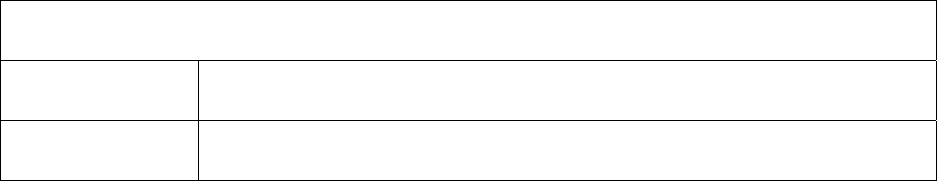
COMUSFLTFORCOMINST 4790.3 REV D CHG 2
31 MAR 2022
V-I-9D-1
APPENDIX D
APPENDIX D
SUBMARINE QUALITY ASSURANCE ASSESSMENT EVALUATION CRITERIA
1. The following guidance is provided to establish consistent grading standards across the
Submarine Force. This will enable consistent evaluation of QA assessments in the Submarine
Force and provide specific feedback to commands thus improving their ability to
independently assess and maintain readiness in Undersea Warfare. The areas are based on the
requirements of this chapter. The overall assessment will be graded as satisfactory or
unsatisfactory. A grade of unsatisfactory will be assigned by the ISIC if any of the following
criteria are met:
a. Unsatisfactory in any of the following areas:
SUBSAFE, REC, DSS-SOC, FBW-SCS Program or URO MRC Program or,
b. Unsatisfactory in Vertical Audit of CWPs and Audit, Surveillance, Evaluation and
Assessment Program or,
c. Unsatisfactory in Vertical Audit of CWPs and QA Training and Qualification. Any
additional trending may be provided by the ISIC. An overall grade of unsatisfactory
will result in the ISIC restricting the ship from processing any controlled work and the
ISIC will issue specific guidance for controlled work processing and performance up
to and including assuming certification responsibilities for controlled work. This
assumption of certification responsibilities by the ISIC will remain until the ISIC has
deemed that adequate actions have been taken to correct the significant programmatic
issues.
2. Quality Assurance Program Assessment area criteria.
NOTE: WHERE NOT PREVIOUSLY DEFINED BY REFERENCE (A), ISICS
SHOULD GENERALLY REVIEW 20%, BUT NO LESS THAN 10 CWPS, OF
THE TOTAL CWPS WORKED BY THE SHIP SINCE THE PREVIOUS
AUDIT.
a. Vertical Audit of CWPs: This review encompasses a sampling of RECs, REC
Exceptions and Maintenance Certification Records. Deficiencies noted during the
review that affect certification and require an Immediate Corrective Action Report
(ICAR) are generally the grade drivers for this area of the assessment. Additionally,
systemic weaknesses in documentation of OQE, determination of technical
requirements (e.g., torque, retest) and ineffective supervisor reviews may also require
an ICAR.
Vertical Audit of CWPs
Grade Attributes
Above Standards No ICARs.
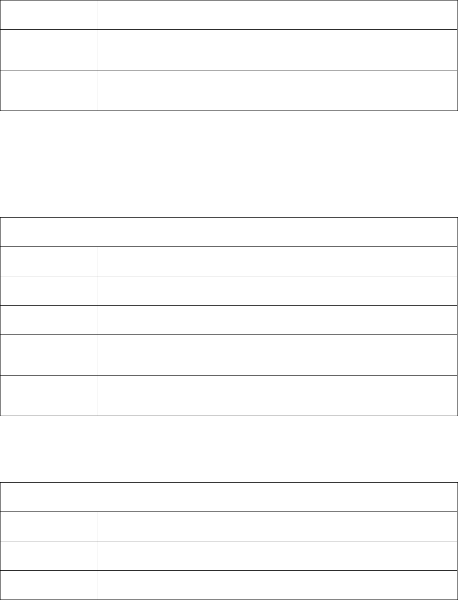
COMUSFLTFORCOMINST 4790.3 REV D CHG 2
31 MAR 2022
V-I-9D-2
APPENDIX D
At Standards ≤ 2 ICAR.
Below Standards ≥ 3 ICARs or systemic problems in specific areas of work package development or
review (i.e., inadequate supervisory reviews, inability to properly determine retest).
Unsatisfactory ICARs written on four or more CWPs or ICARs written on 40% of the CWPs audited,
whichever is greater.
b. Material Control: This review focuses on storage, handling and documentation.
Inspections of lockers are the usual source of deficiencies in this area. Cards are
written based on the magnitude of deficiencies. The magnitude should be determined
by taking the total items with deficiencies and dividing by the number of items in the
inventory. Additionally, systemic failures to follow both local and Joint Fleet
Maintenance Manual (JFMM) requirements or installation of uncertified material into
a controlled system may require an ICAR.
Material Control
Grade Attributes
Above Standards No Locker deficiencies.
At Standards < 10% deficiencies No ICAR on material Control.
Below Standards
≤ 25% deficiencies or one ICAR on Material Control (Controlled work or Program
Coordination).
Unsatisfactory > 25% deficiencies or one ICAR on Material Control (Controlled work or Program
Coordination).
c. DEPARTURES FROM SPECIFICATION: This program review consists of a review
of active DFSs and necessary OQE supporting clearance of DFSs against JFMM
requirements. Deficiencies are normally centered on improper administration (e.g.,
incorrect Job Control Numbers) or inadequate record retention.
DFS
Grade Attributes
Above Standards No deficiencies noted.
At Standards Only minor (< 10) administrative deficiencies noted with program administration.
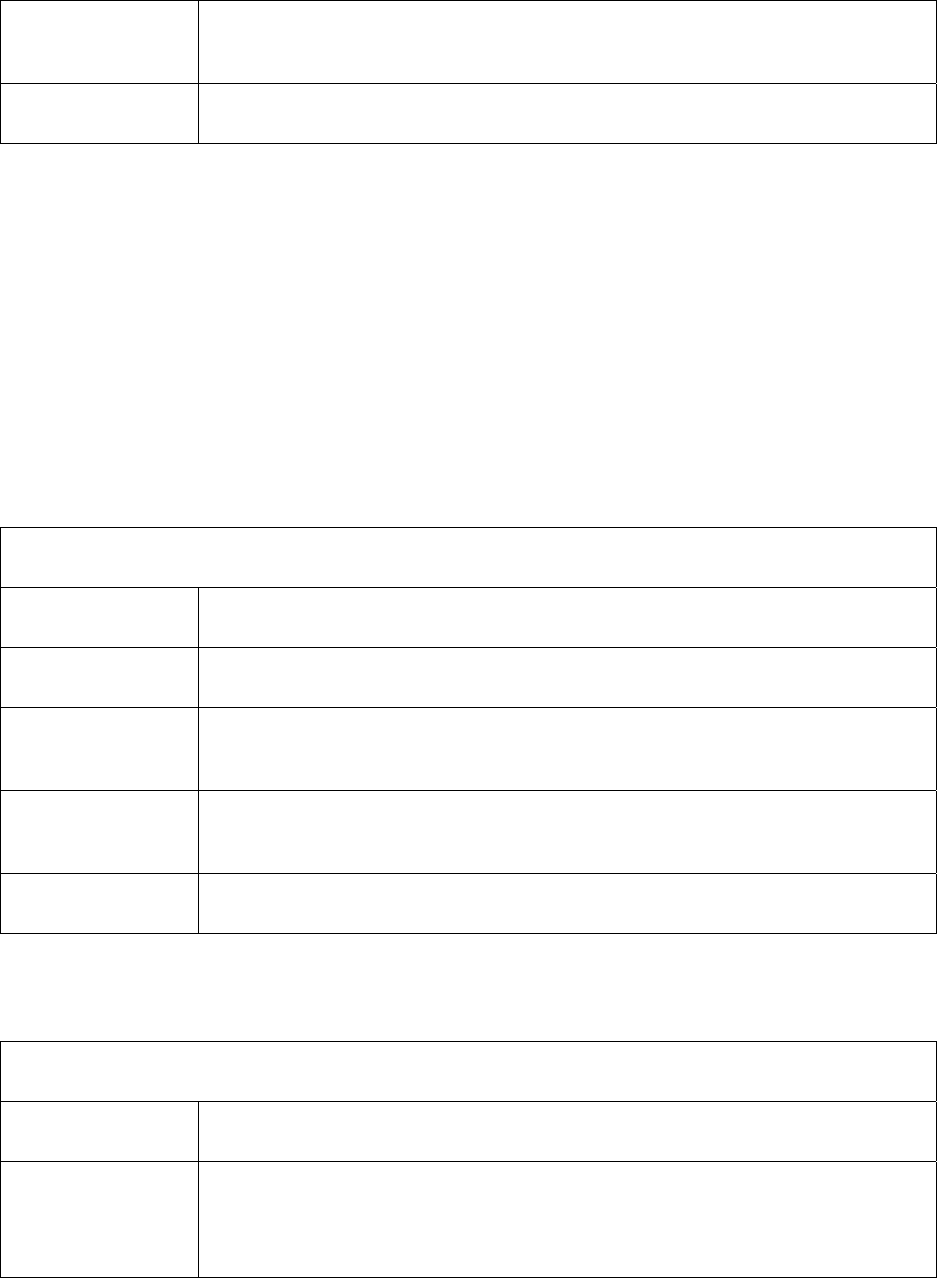
COMUSFLTFORCOMINST 4790.3 REV D CHG 2
31 MAR 2022
V-I-9D-3
APPENDIX D
Below Standards Multiple deficiencies with records (≥ 10) or systemic failure to follow JFMM and ISIC
requirements for administration of program.
Unsatisfactory Any ICAR assigned based on failure to follow DFS policies.
d. Audit, Surveillance, Evaluations and Assessment: This review is an in-depth review of
how the ship's ability to monitor, assess and determine corrective actions to prevent re-
occurrence. This review is one of the more subjective areas and the auditor will have
to be consistent in his methodology and provide specific comments. In general, the
grades will be based on the ability to meet the requirements (e.g., conduct the required
audits as required by the JFMM). Other driving factors may include repeat poor
performance and systemic failure to follow both local and JFMM administrative
requirements. An aggressive program is defined as one where the QAO demonstrates
his surveillance schedule is dynamic and focuses on infrequent repair efforts, first time
repairs and components that have repetitive failure in addition to previously noted
weak areas. An aggressive program will also demonstrate how weak areas are
assessed, assigned corrective actions that affect change and have been adequately re-
assessed.
Audit, Surveillance, Evaluation and Assessment Program
Grade Attributes
Above Standards All audits performed as scheduled or required. Aggressive surveillance program.
At Standards ≤ 1 Audit not performed. Only minor (< 10) administrative deficiencies noted with
program administration.
Below Standards
≤ 2 Audits not performed. Multiple deficiencies with records (≥10) or systemic failure to
follow JFMM and ISIC requirements for administration of program.
Unsatisfactory > 5 Audits not performed. Continued below standards performance with program.
e. QA Training and Qualification: This review will validate that the ship has an
auditable qualification program and that the ship is maintaining the qualification (i.e.,
continuing training) as required by Part I, Chapter 3 of this volume.
QA Training and Qualification
Grade Attributes
Above Standards
Demonstrated QAO involvement in the QA Program.
Demonstrated ability to incorporate lessons learned in QA Training Program.
Demonstrated accountability in SUBSAFE, FBW-SCS and DSS-SOC awareness training
COMUSFLTFORCOMINST 4790.3 REV D CHG 2
31 MAR 2022
V-I-9D-4
APPENDIX D
for all required personnel.
At Standards Only minor (< 10) administrative deficiencies noted with program administration.
Adequate number of qualified personnel.
Below Standards Multiple deficiencies with records (≥ 10) or systemic failure to follow JFMM
requirements for administration of program (e.g., QA training plan not incorporated into
Engineering Training Plan, qualification of personnel not auditable).
Unsatisfactory Continued below standards performance with program.
f. QA Records and Record Retention: Review will ensure that OQE and program records
are being maintained per Part I, Chapter 10 of this volume.
QA Records and Record Retention
Grade Attributes
Above Standards All required records are available and auditable.
At Standards Records retained in an auditable fashion. Only minor (< 10) administrative deficiencies
or missing records noted.
Below Standards Multiple deficiencies with records (≤ 25) or systemic failure to maintain records as
required by JFMM requirements.
Unsatisfactory Records completely un-auditable or loss of a controlled work package.
g. SUBSAFE, REC, DSS-SOC and FBW-SCS Program: This review ensures that the
ship has maintained certification of SUBSAFE, REC, FBW-SCS and DSS-SOC
systems following the applicable manuals. When ships utilize more than one level of
control (e.g., SUBSAFE and FBW) then individual grades will be provided. ICARs of
SUBSAFE, REC, FBW-SCS or DSS-SOC may influence the grade for this area as
indicated here:
SUBSAFE, REC, SOC and FBW Program
Grade Attributes
Above Standards No deficiencies noted.
At Standards Only minor (< 10) administrative deficiencies noted with program administration.
Below Standards
Multiple deficiencies with records (≥ 10) or systemic failure to follow JFMM
COMUSFLTFORCOMINST 4790.3 REV D CHG 2
31 MAR 2022
V-I-9D-5
APPENDIX D
requirements for administration of program.
Missing one or two REC Exception Documents.
Unsatisfactory Failure to issue certification of continuity letters or failure to use REC controls when
performing SUBSAFE, REC, DSS-SOC or FBW-SCS work when re-entry controls are
required.
Missing three or more REC Exception Documents.
h. URO MRC Program: This program review is to ensure that the ship maintains
certification on all systems that contain URO measured parameters. Ships are required
to call out the correct retest and maintain appropriate documentation for the program
per Volume VI, Chapter 25 of this manual.
URO MRC Program
Grade Attributes
Above Standards Not applicable.
At Standards All documentation on hand. All UROs within periodicity. All maintenance affecting
URO parameters properly retested.
Below Standards
Missing or un-auditable URO documentation (records were recovered from other
organizations). Failing to properly document a URO retest for associated maintenance
(retest performed for some other reason, e.g., periodicity).
Unsatisfactory Operated at sea with an Out of Specification, untested or overdue URO parameter.
3. The following metrics will be identified in the Quality Assurance Assessment report issued by
the ISIC:
CWPs REC EXCEPTIONS Total
ISSUED AUDITED ON-FILE AUDITED ICARS CARS
QAO History (since previous audit)
Rank/Name Duration Assigned (mm/yy-mm-yy)
Current
Prior
Assistant QAO History (since previous audit)

COMUSFLTFORCOMINST 4790.3 REV D CHG 2
31 MAR 2022
V-I-9D-6
APPENDIX D
Rank/Name Duration Assigned (mm/yy-mm-yy)
Current
Prior
Qualification Status
Actual Fleet Standard for Area
Craftsman
Planner
CMPOs
QAI
WCS
Welders
O2 Clean
STP Clean
RP Clean

COMUSFLTFORCOMINST 4790.3 REV D CHG 2
31 MAR 2022
V-I-9E-1
APPENDIX E
APPENDIX E
QUALITY ASSURANCE AUDIT, ASSESSMENTS AND SURVEILLANCE
DISCREPANCY FORM
( ) IMMEDIATE CORRECTIVE ACTION REQUIRED
( ) REPEAT FINDING
ITEM:
AREA:
AUDITOR:
DISCUSSED WITH:
REFERENCE:
FINDING:
DISCUSSION:
CORRECTIVE ACTION:
A. ROOT CAUSE(S):
B. ROOT CAUSE DISCUSSION(S):
C. IMMEDIATE CORRECTIVE ACTION(S):
D. PERMANENT CORRECTIVE ACTION(S):

COMUSFLTFORCOMINST 4790.3 REV D CHG 3
07 Nov 2023
V-I-10-1
VOLUME V
PART I
CHAPTER 10
QUALITY ASSURANCE RECORDS
REFERENCES.
(a) SECNAVINST 5239.24 - Department of the Navy Digital Signature Policy
(b) NAVSEAINST 9210.23 - Requirements for Naval Nuclear Work at Naval Activities
and Private Shipyards - Certification of Work Accomplishment and Data Retention of
Associated Records and Retention of Design Records
(c) SECNAV M-5210.1 - Department of the Navy, Navy Records Management Program,
Records Management Manual
(d) NAVSEA T9044-AD-MAN-010 - Requirements Manual for Submarine Fly-By-Wire
Ship Control Systems
(e) COMSUBLANT/COMSUBPAC NOTE C3120 - Submarine Operating Restrictions
and Depth Authorizations
(f) NAVSEAINST 9210.39 - Submarine Nuclear Propulsion Plant Operator Welders:
Procedures for Maintenance of Qualification
(g) NAVSEA 0924-062-0010 - Submarine Safety (SUBSAFE) Requirements Manual
10.1 PURPOSE. Provide record keeping and retention requirements for the Quality Assurance
(QA) records used by the Fleet.
10.2 GENERAL. QA records provide the only lasting records and Objective Quality Evidence
(OQE) that repairs and alterations performed on ships of the fleet were accomplished and
subsequently tested following applicable specifications. The accuracy of these records will be
beyond reproach and the record for each job will be complete so as to "stand alone", that is, the
record will be understood without additional explanation.
10.2.1 Quality Assurance Record Requirements. Record keeping methods are of concern
because they affect the apparent validity of a completed record. In order to ensure continued
validity of Fleet maintenance records, and to provide the necessary OQE, the following record
keeping rules are specified:
a. Hand written Record and Certification Signature Block or signature will be legible, in
ink and per reference (a). Erasures, write-overs, white outs, ditto marks, continuation
arrows, signature stamps, etc., are not acceptable.
b. Neatness and readability of the original record is paramount. Copying records to
"make them neat" is prohibited.
c. When an error is made, it will be corrected by drawing a single line through the error,
recording the correct entry, initialing, dating and printing the name of the person
making the correction.
d. When a questionable item is recognized and is subsequently justified or accepted,
remarks explaining the decision will be added or appended as appropriate.

COMUSFLTFORCOMINST 4790.3 REV D CHG 3
07 Nov 2023
V-I-10-2
e. QA records pertaining to certification of nuclear work will be kept per the
requirements of reference (b).
10.2.2 Record Retention in General. The following paragraphs summarize the general QA
records that will be retained by each organizational group and how long they will be retained:
a. Reduced Size Records. Records (except radiographic film) required to be maintained
may be reduced in size (such as by microfilming or CD-ROM in .pdf format only).
However, the activity (ship or Fleet Maintenance Activity (FMA)) responsible for the
record will ensure that the reduced size records are clearly legible, reproducible, and
will so certify prior to destroying the original records. The following procedure will
be followed for record reduction:
(1) Record reduction must be per reference (c).
(2) Compare the reduced size record against the original record to ensure each
page of the original record has been reduced. This comparison must ensure
that the front and the associated back of QA forms and tags have been
reproduced.
(3) Reproduce two randomly selected pages of the reduced record into paper copy.
Verify completeness and legibility of reproduced pages by comparing against
the original record.
(4) Person making comparison will sign the logbook or some other permanent
record to certify that the reduced size record is complete and legible after being
reproduced.
(5) After steps (1) through (4) are satisfactorily completed, the original record may
be destroyed.
b. Storage and Disposal.
(1) Nuclear Records.
(a) Records that are required to be retained for the life of the ship by
reference (b) require Naval Sea Systems Command Nuclear Propulsion
Directorate (NAVSEA 08) approval prior to record disposal.
(b) Records of nuclear controlled work will be retained at the activity (ship
or FMA) for at least three years following completion of the work per
reference (b). They may then be transferred to a Federal Records
Center (FRC) or other designated records repository per reference (c),
after these records are no longer required on board.
(c) Records stored at a FRC. Records stored at FRC will be per reference
(c). Those records stored at a FRC or other designated repository will
be appropriately cataloged to allow prompt retrieval if necessary. A
copy of the list of records transferred to storage will be sent to the
applicable Type Commander (TYCOM). TYCOM will retain these
lists until the ship is stricken from Navy rolls. Activities may forward
reactor plant work records to FRCs specifying that the records be
destroyed 75 years from the date the records are sent to the FRC.
COMUSFLTFORCOMINST 4790.3 REV D CHG 3
07 Nov 2023
V-I-10-3
(2) Level I Records.
(a) Non-Nuclear and Non-Submarine Safety (SUBSAFE) Level I Records
will be maintained for a minimum of 75 years from the ship's delivery
date for new construction or 75 years from the availability completion
date for repairs, overhauls, conversions, etc. Disposition instructions
will be requested from NAVSEA 05P via the appropriate TYCOM
after that time.
(b) Records of Level I work will be retained at the activity (ship or FMA)
for at least three years following the completion of the work. After
three years, the records may be stored ashore.
(3) Submarine Safety and Submarine Flight Critical Component (SFCC) Records.
(a) SFCC records must be kept per reference (d). The re-entry control log,
completed Re-Entry Controls Forms (MCR/REC), and supporting
documentation for SUBSAFE and SFCC work must be maintained for
the life of the ship.
(b) Records of SUBSAFE and SFCC work will be retained at the activity
(ship or FMA) for at least three years following the completion of the
work. After three years the records, including completed RECs and
supporting documentation, may be stored ashore or at a FRC in an
auditable condition.
(c) Records stored at a FRC will be per reference (c). Those records stored
at a FRC or other designated repository will be appropriately cataloged
to allow prompt retrieval if necessary. Activities may forward
SUBSAFE and SFCC records to FRCs specifying that the records be
destroyed 75 years from the date the records are sent to the FRC.
(d) Approval to destroy non-ship-specific completed RECs, REC logs,
completed RECs, and supporting documentation must be obtained from
NAVSEA 07Q via the appropriate submarine TYCOM.
(4) Scope of Certification (SOC) Records.
(a) The REC log, completed RECs and supporting documentation must be
maintained for the operational life of the Deep Submergence System.
(b) The REC log, completed RECs, and supporting documentation of work
performed by the Sustaining Activity must be maintained by the
Sustaining Activity in an auditable condition for the period between
major availabilities and between sustaining surveys. When work
requiring REC is accomplished by an activity other than the Sustaining
Activity, the Sustaining Activity’s REC log must reflect this work and
the Sustaining Activity must maintain a copy of the completed REC
form (QA form 9 and QA form 10 when applicable). After this period,
the records, including completed RECs and supporting documentation,
may be stored ashore or at a FRC in an auditable condition.

COMUSFLTFORCOMINST 4790.3 REV D CHG 3
07 Nov 2023
V-I-10-4
10.3 TYPE COMMANDER QUALITY ASSURANCE RECORD RETENTION.
10.3.1 Assessment Record Retention. Retain copy of last assessment of FMAs and Immediate
Superiors in Command (ISIC), where applicable, including the report of root causes and
corrective action.
10.3.2 Departure from Specification Record Retention.
a. Maintain outstanding Departure from Specification (DFS) File. This file may be
maintained on electronic media.
(1) An index that reflects the major DFS unique serial number assigned, date
approved, the system or component including brief description and status.
(2) A copy of each outstanding major DFS and all applicable correspondence.
b. (Submarines only) A hard or electronic copy of cleared major SUBSAFE and SFCC
DFSs with an index will be retained for life of ship.
10.3.3 Material Certification Statement Retention (Submarines only).
a. A hard or electronic copy of the TYCOM and NAVSEA SUBSAFE Material
Certification message from new construction, Depot Modernization Period (DMP),
Engineered Overhaul (EOH), Engineered Refueling Overhaul (ERO), Refueling
Overhaul (RFOH) and Regular or Refueling Overhaul (ROH) will be retained for life
of ship.
b. A hard or electronic copy of the Operating Cycle Extension Assessment used as basis
for granting TYCOM extension of operating interval or operating cycle will be
retained until the ship enters the next Selected Restricted Availability (SRA), DMP,
EOH, ERO, RFOH or ROH for which the TYCOM extension applies.
10.4 IMMEDIATE SUPERIOR IN COMMAND QUALITY ASSURANCE RECORD
RETENTION.
10.4.1 Assessment and Surveillance Record Retention.
a. Copy of last ISIC or TYCOM assessment of assigned ships and FMA including report
of root causes and corrective action.
b. (Submarines only) Copy of the ISIC monitor surveillance reports of the FMA and
assigned ships and the corrective action. Retain the past 18 months of monitor
surveillance reports. These records may be kept with the other ISIC monitor program
records.
c. (Submarines only) Copy of the last TYCOM assessment of the ISIC and corrective
actions.
d. All SUBSAFE and Fly-By-Wire Certification Audit Reports of ships must be retained
for the life of the ship per paragraph 10.2.2b. of this chapter.
10.4.2 Departure from Specification Record Retention.
a. Outstanding DFS Files.

COMUSFLTFORCOMINST 4790.3 REV D CHG 3
07 Nov 2023
V-I-10-5
(1) A hard copy or electronic media index that reflects the DFS unique serial
number assigned, TYCOM major DFS number (if assigned), date approved,
system or component including brief description and status.
(2) A copy of each outstanding DFS and all applicable correspondence.
b. A hard or electronic copy of cleared DFS with an index will be retained for 24 months.
10.4.3 Material Certification Statement Retention (Submarines only).
a. The SRA or Tiger Team certification statements from industrial activities will be
retained until the next SRA, DMP, EOH, ERO, RFOH or ROH of the affected ship.
b. The ISIC request for Sea Trials (Volume II, Part I, Chapter 3, Appendix BK, and if
used, Appendix BF of this manual) and the TYCOM message authorizing Sea Trials
(Volume II, Part I, Chapter 3, Appendix BD, and if used, Appendix BG of this
manual) for CNO availabilities less than 6 months until the next SRA, DMP, EOH,
ERO, RFOH or ROH of the affected ship.
c. The most recent FMA end of upkeep statement.
d. The most recent ship generated, prior to underway, certification continuity report will
be retained.
e. The audit guide and justification used for any Operating Cycle Extension Assessment
of assigned ships will be retained per paragraph 10.3.3 of this chapter.
10.5 SHIP'S QUALITY ASSURANCE RECORD RETENTION.
10.5.1 Controlled Work Package Log. The Quality Assurance Officer (QAO) will maintain a
Controlled Work Package (CWP) log, using the QA form 11, for the life of the ship. Re-copying
or consolidation of this log is not to be done.
10.5.2 Completed Controlled Work Packages. All CWPs (retain onboard per paragraph 10.2.2
of this chapter), which includes:
a. Maintenance Certification Record (MCR/REC) (QA forms 9 and 10).
b. References unique to this task (e.g., NAVSEA letters, Liaison Action Requests) will
be retained with the CWP unless specifically identified to allow recall, if necessary.
c. All enclosures documenting the OQE (e.g., QA forms and Ready for Issue (RFI) tags
(NAVSEA 9210/2 and 9210)) will be retained.
d. FWPs executed as the core of a CWP must be retained with the CWP. After three
years when CWPs are moved ashore or placed in storage, the FWP portion of the
CWP may be discarded.
10.5.3 Controlled Material Records. Controlled material records will be maintained with the
associated CWP. Those records not associated with a CWP will be maintained on file by the
QAO.
a. The Supply Officer will maintain on file the letter of certification from the Supervisor
of Shipbuilding, for all lots of Level I, SFCC Stock Program material and Nuclear
Repair Parts during the new construction period. When the material is issued, a copy
of this letter should be attached to the QA form 1.

COMUSFLTFORCOMINST 4790.3 REV D CHG 3
07 Nov 2023
V-I-10-6
NOTE: MATERIAL CONTROL RECORDS (E.G., QA FORM 2s) ARE NOT
REQUIRED TO BE RETAINED FOR REMOVED AND REINSTALLED
CONTROLLED MATERIAL AFTER THE CWP IS CLOSED.
b. The QAO will maintain controlled material records as outlined here. These records
should be included in the appropriate CWP to the maximum extent practical. Retain
material certification files for all Nuclear Level I, SFCC and Level I material installed.
(1) RFI tags for Nuclear Level I items installed.
(2) For any Nuclear Level I items received and installed without a RFI tag retain
all OQE used to certify.
(3) All OQE used to upgrade material for non-nuclear “Level” use.
(4) All QA forms 3 for any rejected items accepted for use.
(5) A file of QA forms 1 with certification documentation.
10.5.4 Qualification Records. The QAO will maintain a master list of qualified Work Center
Supervisors and Maintenance Planners, Controlled Material Petty Officers (CMPO), Cleanliness
Inspectors, Quality Assurance Inspectors (QAI), Quality Assurance Supervisors (QAS), Oxygen
Clean Workers and Oxygen Clean Instructors. The records will be retained for the duration the
individual is onboard. Records in the case of re-qualifications must consist of a written plan and
sub-paragraphs a. through d., as applicable, based upon the plan defined by the QAO or
Department Head. The file will consist of:
a. Date Personnel Qualification Standard completed. For Oxygen Clean Workers and
Oxygen Clean Instructors, the date the required course of instruction is completed.
b. Qualification test results. This includes a copy of the examination cover sheet. In
addition, a copy of the examination given with answers must be available either in
electronic medium or hard copy. For Oxygen Clean qualifications, this entry is not
required.
c. A copy of the signed Final Qualification Page from the Personnel Qualification
Standard.
d. Copy of the signed oral interview sheets for each qualification record.
e. (Submarines only) A master list of qualified Oxygen Clean Workers must be retained
for the life of the ship.
10.5.5 Departure from Specification Records.
a. Outstanding DFS Files.
(1) An index that reflects the DFS unique serial number assigned, date approved,
the system or component including brief description, annotation for SUBSAFE
and status.
(2) A copy of each outstanding DFS and all applicable correspondence.
b. A copy of cleared DFS with an index will be retained for 24 months.

COMUSFLTFORCOMINST 4790.3 REV D CHG 3
07 Nov 2023
V-I-10-7
c. A copy of all DFS approved as permanent repairs, with an index, will be retained until
they are reflected in the ship’s selected records and drawings or technical variation
documents.
10.5.6 Assessments, Evaluations and Audits. The QAO will retain records of assessments,
evaluation and surveillance for the past 24 months (unless otherwise stated). The records will
consist of:
a. QA form 14 index log that has the item numbers, work center responsible to correct
and estimated date corrective action is due.
b. Copy of last higher authority assessment and the corrective action for all items.
c. Results of all Audits and Surveillances of the QA Program, including the root cause,
immediate and permanent corrective action. (This may be kept with the rest of the
monitor program records).
d. Last annual QA Program evaluation performed.
e. Maintain an auditable record of the most current Job Control Number to DFS
verification.
10.5.7 Training.
a. (Submarines only) The ship must maintain a record of completion for each member of
the crew indicating the date of completion for annual SUBSAFE Awareness, Fly-by-
Wire Awareness and SOC Awareness Training, as applicable.
b. A hard or electronic copy of the record of lectures and seminars conducted during the
past 12 months must be retained.
c. The record should show the topic, the lecturer or seminar leader, the monitor, and the
number of personnel in attendance. Topics should include a brief listing of material
covered where appropriate.
d. Attendance records by name are not required, except as noted in sub-paragraph a.
e. This record should be kept in a format that enables it to be compared against the Long
Range Training Plan to determine the utilization of that plan.
10.6 ADDITIONAL SUBMARINE NUCLEAR AND UNIQUE QUALITY ASSURANCE
RECORD RETENTION REQUIREMENTS.
10.6.1 Submarine Safety, Level I, Submarine Flight Critical Component, Scope of Certification
and Other Certification (Submarines Only). The ship will retain the following records for the life
of the ship or as indicated in this manual:
10.6.1.1 Reactor Plant Work Accomplishment Report. A copy of all completed Reactor Plant
Work Accomplishment Reports.
10.6.1.2 Submarine Safety Material Certification. Copy of the TYCOM and NAVSEA
SUBSAFE Material Certification message from new construction, DMP or overhaul until the
ship’s current status is reflected in reference (e). When the ship’s current status is reflected in
the notice, the messages may be destroyed, and the current notice will be retained.

COMUSFLTFORCOMINST 4790.3 REV D CHG 3
07 Nov 2023
V-I-10-8
10.6.1.3 End of Fleet Maintenance Availability Certification. Retain the last end of FMA
Availability letter from the FMA.
10.6.1.4 Certification Continuity Reports. Retain the last certification continuity report sent by
the ship.
10.6.1.5 Industrial Activity Certification Reports. A copy of all industrial activity and shipyard
certification letters or messages from all SRA conducted between overhauls. In addition, a copy
of the ISIC audit of SUBSAFE work performed by the industrial activity should also be kept.
These may be disposed of at the next Extended Refit Period, SRA, DMP, EOH, ERO, RFOH or
ROH.
10.6.1.6 Other Certification Reports . A copy of any other correspondence or messages that
affect the certification of the ship or hull integrity should be retained until:
a. Resolved via inspection or maintenance or DFS as required or
b. As defined within the applicable correspondence or message.
10.6.1.7 Controlled Material. Except for Fly-By-Wire Diagnostic and Maintenance Computers
(DMAC), Ship's Force is not required to use a QA form 1 to document receipt inspection of
Level I, SFCC or SOC material to be immediately installed for a specific maintenance action. A
QA form 2 will be used to document receipt inspection of material to be immediately installed.
DMACs require a QA form 1 to document receipt inspection but do not require a QA form 2.
The QA form 1 for the DMAC will be retained in the ship REC exception folder.
10.6.1.8 Scope of Certification. Retain a copy of the NAVSEA and TYCOM, if applicable,
Scope of Certification or Sustaining Survey Certification letter or message.
10.6.1.9 Unrestricted Operations. Retain records related to the Unrestricted Operations Program
as defined by volume VI, chapter 25 of this manual.
10.6.2 Nuclear Records.
10.6.2.1 Nuclear Record Retention. Nuclear records will be retained as required by reference
(b). Reference (b) defines which nuclear records must be retained and length of retention as well
as specifies requirements for retention of existing records. It is not intended to create new
records for record retention requirements, if they do not already exist.
10.6.2.2 Nuclear Propulsion Plant Operator Welder Records (Submarines only). The Main
Propulsion Assistant will retain the following qualification records per reference (f), for each
welder as long as the welder is qualified onboard.
a. Documentation certifying original weld school completion.
b. QA form 20 for most current proficiency welds and qualification welds (the four most
recent test assemblies).
c. Copy of current eye examination report.
10.6.3 Re-Entry Control/Maintenance Certification Record Exception Objective Quality
Evidence and Other Controlled Assembly Records.

COMUSFLTFORCOMINST 4790.3 REV D CHG 3
07 Nov 2023
V-I-10-9
a. Retain a file of the most recent QA form 34 generated for each component or system
assembled as a controlled assembly and performed as a REC exception per reference
(g) and part III, chapter 5, paragraph 5.8.6.1.b of this volume.
b. Retain a file of the most recent QA form 34 generated for each component or system
assembled as a controlled assembly and performed as a MRC exception per part I,
chapter 2, paragraph 2.2.5 Note 2 and part I, chapter 2, paragraph 2.3.7.7.1 of this
volume.
c. Retain a file of the most recent QA form 34 record generated per Part I, Chapter 7,
paragraph 7.4.1.c of this volume for non-controlled systems or components until the
system or component testing is completed satisfactory (e.g. completion of a controlled
deep dive).
10.7 FLEET MAINTENANCE ACTIVITY QUALITY ASSURANCE RECORD
RETENTION.
10.7.1 Submarine Safety, Nuclear, Level I, Scope of Certification and Other Certification. The
QAO or designated officer will retain material certification (SUBSAFE, Nuclear, Level I, Scope
of Certification and CWP category "Other") records for the life of each tended ship.
10.7.2 Reactor Plant Work Accomplishment Report (Submarines only). The Nuclear Repair
Officer will retain a legible copy of all FMA generated Reactor Plant Work Accomplishment
Reports.
10.7.3 Controlled Work Package Log. The QAO will maintain a CWP log, using the QA form
11, for the life of the ship. Re-copying or consolidation of this log is not to be done.
10.7.4 Completed Controlled Work Packages. All CWPs (retain onboard per paragraph 10.2.2
of this chapter), which includes:
a. MCR/REC (QA forms 9 and 10).
b. References unique to this task (e.g., NAVSEA letters, Liaison Action Requests) will
be retained with the CWP unless specifically identified to allow recall, if necessary.
c. All enclosures documenting the OQE (e.g., QA forms and RFI tags (NAVSEA 9210/2
and 9210)) will be retained.
d. FWPs executed as the core of a CWP must be retained with the CWP. After three
years when CWPs are moved ashore or placed in storage, the FWP portion of the
CWP may be discarded.
NOTE: MATERIAL CONTROL RECORDS (E.G., QA FORM 2s) ARE NOT
REQUIRED TO BE RETAINED FOR REMOVED AND REINSTALLED
CONTROLLED MATERIAL AFTER THE CWP IS CLOSED.
10.7.5 Controlled Material Records. Controlled material records will be maintained with the
associated CWP. Those records not associated with a CWP will be maintained on file by the
QAO. The QAO will maintain controlled material records as outlined in this paragraph. These
records should be included in the appropriate CWP to the maximum extent practical. Retain
material certification files for all Nuclear Level I, SFCC, Level I and SOC material installed.
a. RFI tags for nuclear Level I items installed.

COMUSFLTFORCOMINST 4790.3 REV D CHG 3
07 Nov 2023
V-I-10-10
b. For any Nuclear Level I items received and installed without a RFI tag retain all OQE
used to certify the material for installation.
c. All OQE used to upgrade material for non-nuclear "Level" use.
d. All QA forms 3 for any rejected items accepted for use.
e. A file of QA forms 1 with certification documentation.
f. All material control records from receipt inspection through installation will be
maintained throughout the life of Deep Submergence Systems.
10.7.6 Assessment, Audits, Surveillance and Evaluations. The QAO will retain records for the
past 18 months (unless otherwise stated). The records will consist of:
a. Last year and present year internal audit schedule.
b. Completed audit plans and guides and results (Associated QA forms 14 or other
discrepancy reports).
c. QA form 14 index log that has the item numbers, work center responsible to correct
and estimated date corrective action is due.
d. Copy of last higher authority assessment, surveillance and the corrective action for all
items.
e. Schedule and results of internal surveillance of the QA Program, including the
corrective action. (This may be kept with the rest of the monitor program records).
f. Last two semi-annual QA Program evaluations.
g. Two years’ worth of records for calibration laboratory spot checks or sampling of
outgoing work.
h. Two years’ worth of records for Field Calibration Activity spot checks or sampling of
outgoing work, as applicable.
10.7.7 End of Fleet Maintenance Activity Certification Report to Tended Submarines
(Submarines only). The QAO will retain a copy of the last End of Fleet Maintenance Activity
Certification Report to tended submarines issued per part I, chapter 5, paragraph 5.6.8.b. or part
III, chapter 5, paragraph 5.8.7.b of this volume, as applicable.
10.7.8 Nuclear, Submarine Safety and Scope of Certification Work. The master lists of
qualified CMPO or Controlled Material Handler, Cleanliness Inspector, Cleanliness Certifier,
QAI and QAS (if assigned), will be maintained by name, for the duration the individual is
assigned to the repair activity.
NOTE: AT A FMA, CIVILIAN EMPLOYEE CONTINUING TRAINING
KNOWLEDGE EXAMINATION QUESTIONS AND ANSWERS WILL BE
RETAINED FOR TWO YEARS.
10.7.9 Qualification Record. The QAO will maintain a master list of qualified CMPOs,
Controlled Material Handlers, Cleanliness Inspectors, QAIs, QASs, Oxygen Clean Workers and
Oxygen Clean Instructors and a qualification file on each CMPO, Controlled Material Handler,
Cleanliness Inspector, QAI and QAS. The records will be retained for the duration the
individual is onboard. The file will consist of:
COMUSFLTFORCOMINST 4790.3 REV D CHG 3
07 Nov 2023
V-I-10-11
a. Date Personnel Qualification Standard completed. For Oxygen Clean Workers and
Oxygen Clean Instructors, the date the required course of instruction is completed.
b. Qualification test results. For Oxygen Clean qualifications, this entry is not required.
c. A master list of all qualified Oxygen Clean Workers must be retained for the life of
the FMA.

COMUSFLTFORCOMINST 4790.3 REV D CHG 3
07 Nov 2023
V-I-11-1
VOLUME V
PART I
CHAPTER 11
QUALITY ASSURANCE FORMS AND FORM INSTRUCTIONS
REFERENCES.
(a) NAVSEAINST 9210.23 - Requirements for Naval Nuclear Work at Naval Activities
and Private Shipyards - Certification of Work Accomplishment and Data Retention of
Associated Records and Retention of Design Records
11.1 PURPOSE. Provide Quality Assurance (QA) forms and tags with instructions for
preparation and usage. QA forms for DSS and SOC use are located in Part III, Chapter 11 of this
Volume.
11.2 USE OF QA FORMS. QA forms are used to create Objective Quality Evidence (OQE)
when required by higher authority. While QA form instructions identify requirements for usage,
they are not self-invoking. The use of a QA form is initiated from requirements of previous
chapters within Part I and Part III of this Volume. Examples of when QA forms are required by
this volume include:
a. To support capturing OQE for a Controlled Work Package (CWP) as required by
Chapter 2.
b. To support documenting a controlled assembly required by Maintenance Certification
Record (MCR) exceptions (Chapter 2), SUBSAFE Re-Entry Control (REC)
exceptions (Chapter 5), Alternate Testing (Chapter 7) or as specified in an approved
Departure from Specification (DFS).
c. Documenting receipt inspections and end usage as required by Chapter 6.
d. Documenting DFS as required by Chapter 8.
e. Correcting certified OQE as required by Chapter 9.
11.3 NATIONAL ITEM IDENTIFICATION NUMBER. National Item Identification Number
(NIIN) may be used whenever National Stock Number (NSN) is called for, including all QA
forms. The NIIN uniquely identifies material in supply system and is adequate for OQE
purposes.
11.4 CERTIFICATION SIGNATURES ON QA FORMS. When certification signatures, as
defined in reference (a) and Part I, Chapter 2, Appendix C of this volume, are documented on
QA forms of Nuclear CWPs, the single “*” or double “**” and associated statement are not
required on the individual form.
11.5 LIST OF FORMS. This chapter provides copies of the QA forms and tags discussed
throughout this volume
a. QA form 1. - Material Receipt Control Record.
b. QA form 2. - Material ID/Control Tag.
COMUSFLTFORCOMINST 4790.3 REV D CHG 3
07 Nov 2023
V-I-11-2
c. QA form 3. - Controlled Material Reject Tag.
d. QA form 9. - Maintenance Certification Record/Re-Entry Control.
e. QA form 10. - Maintenance Certification Record/Re-Entry Control
Supplement Sheet.
f. QA form 11. - Controlled Work Package (CWP)/Re-Entry Control
(REC) Log.
g. QA form 11A. - REC/MCR Exception Controlled Assembly Log
h. QA form 12. - Departure From Specification Request.
i. QA form 12A. - Departure Clearance Report.
j. QA form 14. - Surveillance/Monitoring/Audit Discrepancy Record.
k. QA form 17. - Test and Inspection Record.
l. QA form 17A. - Epoxy Repair Record.
m. QA form 17B. - Electroplating Repair Record.
n. QA form 17C. - Component Repair Record.
o. QA form 17D. - Submarine Flight Critical Component (SFCC) Access,
Removal and Installation Record.
p. QA form 17SI. - Stud Installation Record.
q. QA form 17W. - Handling Equipment Test Record.
r. QA form 18. - Silver Braze Fabrication and Inspection Record.
s. QA form 18A. - Ultrasonic Inspection Record.
t. QA form 20. - Welding In Process Control/Nondestructive Test
Record.
u. QA form 20A. - Radiographic Test Inspection Record.
v.
QA form 20B.
(Part A)
- Structural Primary Record.
w. QA form 20B.
(Part B)
- Structural Weld History.
x. QA form 20B.
(Part C)
- Structural Defect Record.
y. QA form 20C. - Pipe, Machinery and Pressure Vessel Weld
Record/Weld Defect Repair Sheet.
z. QA form 26. - Hydrostatic/Pneumatic Test Record.
aa. QA form 26A. - Hydrostatic/Pneumatic Test Record for Deep
Submergence Systems. See Note (1).
ab. QA form 27. - Drop Test Record.
COMUSFLTFORCOMINST 4790.3 REV D CHG 3
07 Nov 2023
V-I-11-3
ac. QA form 27A. - Drop Test Record for Deep Submergence Systems.
See Note (1).
ad. QA form 28. - Shop Test Record.
ae. QA form 34. - Joint/Component Torque and Assembly Record.
af. QA form 34A. - Joint/Component Assembly Record.
ag. QA form 34B. - Electrical/Electronic Cable Connector Assembly and
Test Record. See Note (1).
ah. QA form 35. - Thickness Measurement Record.
ai. MAT-1. - Ship to Shop Tag MAT-1 (General Use).
Note (1): For DSS and SOC applications, QA Forms 26A, 27A, and 34B are located in
Part III, Chapter 11 of this Volume.
COMUSFLTFORCOMINST 4790.3 REV D CHG 3
07 Nov 2023
V-I-11-4
MATERIAL RECEIPT CONTROL RECORD
QA FORM 1 (FRONT)
1. MATERIAL NOMENCLATURE
2. LEVEL OF ESSENTIALITY
3. MIC NO./ID NO.
4. REQUISITION NUMBER (REQ. NO.)
5. JULIAN DATE
6. NUMBER RECEIVED
7. NSN/SMIC
8. VENDOR’S MARKINGS
9. REQUIRED CERTIFICATION DOCUMENTS FURNISHED (SIGNATURE AND DATE)
[ ] YES [ ] NO
10. ENTER APPROP CODE
X – RECORDS REQ’D
O – RECORDS NOT REQ’D
MT PT RT UT VT CHEM PHYS GENERIC MATERIAL
IDENTITY CHECK
HARDNESS DIMEN
11. INSPECTION RESULTS, REMARKS, SIGNATURES AND DATE:
12. DISPOSITION
[ ] ACCEPT [ ] REJECT
13. CERTIFIED
[ ] LI [ ] NUC LI [ ] SOC MCD __ [ ] OTHER
14. DOWNGRADE
[ ] GENERAL STOCK
[ ] REJECT TO SOURCE
15. SIGNATURE AND DATE
COMUSFLTFORCOMINST 4790.3 REV D CHG 3
07 Nov 2023
V-I-11-5
MATERIAL RECEIPT CONTROL RECORD
QA FORM 1 (BACK)
16. MATERIAL NOMENCLATURE: 17. LEVEL OF ESSENTIALITY: 18. MIC NO./ID NO.:
19. REQUISITION NUMBER: 20. NSN/SMIC: 21. ORIGINAL NUMBER RECEIVED:
22. DATE 23A. UIC 23B. WC 23C. JSN 24. SYSTEM 25. CWP# 26. AMT
ISSUED
27. AMT
REMAINING
28. CMPO/CMH
(PRINT NAME)
29. MATERIAL
DOWNGRADE
30. NEW
LEVEL
31. QAO AUTHORIZATION FOR
DOWNGRADE

COMUSFLTFORCOMINST 4790.3 REV D CHG 3
07 Nov 2023
V-I-11-6
QA FORM 1 INSTRUCTIONS
MATERIAL RECEIPT CONTROL RECORD
PURPOSE: To document the proper receipt, control, end use and certification of material to
the required “Level of Essentiality” for controlled material.
PROCEDURE: The numbered blocks on QA form 1 correspond with the block instructions
listed.
NOTE: ATTACH SHIPPING PAPERS, IF PROVIDED, TO QA FORM.
NOTE: WITH THE EXCEPTION OF FLY-BY-WIRE DIAGNOSTIC AND
MAINTENANCE COMPUTERS, SHIP’S FORCE IS NOT REQUIRED TO
COMPLETE A QA FORM 1 TO DOCUMENT THE RECEIPT INSPECTION
OF CONTROLLED MATERIAL IF THE ITEM(S) IS TO BE IMMEDIATELY
INSTALLED FOR A SPECIFIC MAINTENANCE ACTION. IN THESE
CASES, THE RECEIPT INSPECTION WILL BE CAPTURED ON A QA FORM
2. IF THE MATERIAL IS NOT UTILIZED DURING THE SPECIFIC
MAINTENANCE ACTION FOR WHICH IT WAS PROCURED IT SHOULD
BE TURNED BACK IN TO SUPPLY. IF THE MATERIAL IS TO BE
RETAINED FOR A FUTURE MAINTENANCE ACTION, A QA FORM 1
MUST BE FILLED OUT PRIOR TO PLACING THE MATERIAL IN A
CONTROLLED MATERIAL STORAGE LOCKER OR STORAGE AREA.
NOTE: IF THE COMPONENT HAS A SHORTENED MATERIAL IDENTIFICATION
AND CONTROL (MIC) MARKING, ENSURE THE FULL MIC MARKING
FROM THE SHIPPING DOCUMENTS, TAGS, OR PACKAGING IS
ENTERED ON QA FORM 1 AND QA FORM 2.
NOTE: IF PORTIONS OF A COMPONENT WILL BE CANNABALIZED FOR
INSTALLATION VICE INSTALLING THE ENTIRE COMPONENT,
DISPOSITION IN ACCORDANCE WITH PART I, CHAPTER 6,
PARAGRAPH 6.3.9.1.D OF THIS VOLUME.
BLOCK 1 - MATERIAL NOMENCLATURE
Enter the noun name of the material (e.g., 5/8” - 11 NICU studs, 10” O.D. CUNI Barstock).
BLOCK 2 - LEVEL OF ESSENTIALITY
Enter the applicable Level of Essentiality (SUBSAFE, Level I, Nuclear Level I, Submarine
Flight Critical Component (SFCC) or Scope of Certification (SOC) Material Control Division
(MCD)) for the material received. For assemblies such as valves, the Level of Essentiality
will be the Level of Essentiality for the entire assembly, not individual parts.
a. Nuclear Level I:
(1) Material received with a “Target” Ready for Issue (RFI) tag or Naval Sea
Systems Command (NAVSEA) Prime Contractor Material determined to be
Nuclear Level I.
(2) Material from stock system required to be certified as Nuclear Level I.
b. SUBSAFE:

COMUSFLTFORCOMINST 4790.3 REV D CHG 3
07 Nov 2023
V-I-11-7
(1) Special Material Identification Code (SMIC) material with valid MIC
markings.
(2) Submarine Antenna Engineering Directorate (SAED), (Submarine Antenna
Quality Assurance Material) SMIC material.
(3) Open purchased and stock system non-level material required to meet
SUBSAFE requirements.
c. Level I:
(1) LI, C1, S1 or D1 SMIC material with valid MIC markings.
(2) Non-level material required to be upgraded to Level I requirements.
d. SOC MCD A or MCD B: The entry will be based on the SOC Level of Essentiality as
determined in Part III, Chapter 6 of this volume.
BLOCK 3 - MIC NO./I.D. NO.
NOTE: THE PNSY “TRACE CODE” RESEMBLES A MIC NUMBER BUT DOES
NOT INCLUDE THE GENERIC MATERIAL DESIGNATOR (E.G., 98205-
003A).
a. Enter the MIC or the identification number or name plate data (I.D. No. if no MIC
No.) etched on the major part of the assembled material received (some individual
parts may also have MIC numbers that need not be recorded). Fleet Maintenance
Activity (FMA) will enter MIC upon completion of upgrading for FMA certified or
upgraded material. Ships (Non-FMA) will enter the FMA MIC No. for material that
the FMA certifies for the ship. For rotatable items, enter the appropriate rotatable pool
serial number (e.g., rp-148a, tin-292-11893, etc.).
b. For fasteners enter either the MIC number (when MIC number is marked on the
fastener or the individual tag for some small fasteners) or the color code and the PNSY
“trace code” provided on the shipper and the package or box.
c. If the material is MCD B, enter Markings on the material or documented on the
shipping papers providing identification to material type or military specification.
d. If the material is MCD A, enter the Traceability Number.
BLOCK 4 - REQUISITION NUMBER (REQ. NO.)
Enter the Requisition No. (invoice number) that was used to order the material or appears on
shipping documents (if provided).
BLOCK 5 - JULIAN DATE
Enter the five digit Julian Date (e.g., 90121, 91200, 92030) the material is received.
BLOCK 6 - NUMBER RECEIVED
Enter the total number received (must agree with the invoice). If the material is, for example,
“Barstock” enter the number of pieces and total length. Only one QA form 1 is required if the
entire lot has the same MIC number and is receipt inspected on the same day.
BLOCK 7 - NSN/SMIC

COMUSFLTFORCOMINST 4790.3 REV D CHG 3
07 Nov 2023
V-I-11-8
Enter the National Stock Number (NSN), including the SMIC, of material received. If
material is identified only by drawing and piece number, enter them.
BLOCK 8 - VENDOR’S MARKINGS
a. Enter any Vendor’s Marking (heat, lot) present on the material.
b. For fasteners, enter the heat or lot number, material type, and manufacturer’s symbol
(for nuts containing a self-locking insert, the color of the insert is the manufacturer’s
symbol).
BLOCK 9 - REQUIRED CERTIFICATION DOCUMENTS FURNISHED
(SIGNATURE AND DATE)
a. If required certification documentation is provided, and the item passes receipt
inspection per Chapter 6, enter an “X” in the “YES” block. Controlled Material Petty
Officer (CMPO) or Controlled Material Handler (CMH) print name, sign and date the
block to certify the item passed receipt inspection. Blocks 10 through 15 are
completed as required, incomplete blocks are left blank. Attach a QA form 2. A copy
of any certification documentation will be attached to the QA form 1.
b. If the certification documentation is unacceptable or the material fails receipt
inspection or the item is non-level material undergoing upgrading, enter an “X” in the
“NO” block, attach a QA form 3 to the item, and notify the Quality Assurance Officer
(QAO) or Quality Assurance Supervisor (QAS). CMPO or CMH print name, sign and
date the block.
BLOCK 10 - ENTER APPROPRIATE CODE
QAO or QAS will mark the applicable blocks signifying attributes that must be verified for
receipt inspection, by referring to the appropriate references, using the appropriate code; “X”
(whenever records are required) or “O” (whenever records are not required, e.g., visual
inspection).
BLOCK 11 - INSPECTION RESULTS, REMARKS, SIGNATURE AND DATE
a. CMPO or Quality Assurance Inspector (QAI) or QAS will enter the results of all
inspections and, if unsatisfactory, state the reason for failure.
b. Print name, sign and date all entries which certifies the inspections, issues, and
records.
NOTE: BLOCKS 12, 13 AND 14 ARE COMPLETED AS REQUIRED, INCOMPLETE
BLOCKS ARE LEFT BLANK.
BLOCK 12 - DISPOSITION
Check the appropriate block based upon inspection results documented in Block 11 and fill
out Blocks 13 or 14 as applicable.
BLOCK 13 - CERTIFIED
Check the appropriate block signifying the level of essentiality to which the material has been
inspected or certified. For SOC material, enter the applicable MCD designator (A or B) in the
blank.

COMUSFLTFORCOMINST 4790.3 REV D CHG 3
07 Nov 2023
V-I-11-9
NOTE: NON-LEVEL ITEMS UPGRADED OR CERTIFIED WILL HAVE THE
ASSIGNED MIC NUMBER ENTERED IN BLOCK 3 ABOVE PRIOR TO
SIGNATURE IN BLOCK 15.
BLOCK 14 - DOWNGRADE
Check the appropriate block, if “reject” is checked in Block 12.
BLOCK 15 - SIGNATURE AND DATE
QAO or QAS responsible for Blocks 10-14 will print name, sign and date certifying the
record as correct.
BLOCK 16 - Same as Block 1.
BLOCK 17 - Same as Block 2.
BLOCK 18 - Same as Block 3.
BLOCK 19 - Same as Block 4.
BLOCK 20 - Same as Block 7.
BLOCK 21 - Same as Block 6.
BLOCK 22 - Enter the date that the material is issued.
BLOCKs 23A, Enter the Unit Identification Code (UIC), Work Center (WC), and the
23B, AND 23C job sequence number that the material is issued against.
BLOCK 24 - Enter the system that the material is issued for.
BLOCK 25 - Enter the Controlled Work Package (CWP) serial number that the material
is issued for.
BLOCK 26 - Enter the amount of material issued.
BLOCK 27 - Enter the amount of material remaining after issue.
BLOCK 28 - CMPO or CMH issuing material, print name.
BLOCK 29 - Enter “Yes” or “No” as appropriate.
BLOCK 30 - Enter Level the material was downgraded to.
BLOCK 31 - QAO sign, signifying authorization to downgrade material.
NOTE: THE COMPLETED QA FORM 1 WILL BE FORWARDED TO THE QA
OFFICE, WHEN THE MATERIAL HAS BEEN ISSUED FOR
INSTALLATION.
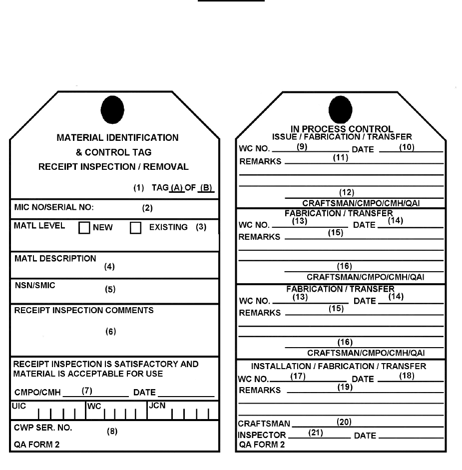
COMUSFLTFORCOMINST 4790.3 REV D CHG 3
07 Nov 2023
V-I-11-10
QA FORM 2
MATERIAL ID/CONTROL TAG
LANTFLT 4790/2 (8-01) S/N 0103-LF-981-0300
Green tag with black lettering
LI / NUC LI SFCC SOC OTHER

COMUSFLTFORCOMINST 4790.3 REV D CHG 3
07 Nov 2023
V-I-11-11
QA FORM 2 INSTRUCTIONS
MATERIAL IDENTIFICATION (ID)/CONTROL TAG
LANTFLT 4790/2 (8-01) S/N 0103-LF-981-0300
PURPOSE:
1. Used for receipt inspection, certification and traceability of new controlled material.
2. Used to maintain traceability and identification of Level I, Nuclear Level I, SOC, SFCC and
non-level controlled items removed from a controlled system or component during
maintenance including transfer between organizations until reinstalled.
PROCEDURE: The numbered blocks on QA form 2 correspond with the block instructions
listed. Two sets of instructions are provided depending on purpose.
PURPOSE 1: RECEIPT OF NEW MATERIAL FROM SUPPLY SYSTEM. CMPO OR
CMH WILL COMPLETE BLOCKS 1-7 DURING THE RECEIPT
INSPECTION.
NOTE 1: FOR NUCLEAR MATERIAL, ANY RFI OR OTHER CERTIFICATION
TAGS ATTACHED TO THE ITEM WILL REMAIN ATTACHED UNTIL
THE MATERIAL IS INSTALLED.
NOTE 2: IF PORTIONS OF A COMPONENT WILL BE CANNABALIZED FOR
INSTALLATION VICE INSTALLING THE ENTIRE COMPONENT,
ATTACH A QA FORM 2 (PURPOSE 1 INSTRUCTIONS) TO THE
PORTIONS OF THE COMPONENT OR ASSEMBLY TO BE INSTALLED
IN THE SYSTEM. REMOVE THE ORIGINAL QA FORM 2 (DISCARD)
AND ATTACH A NEW QA FORM 2 (PURPOSE 1 INSTRUCTIONS)
DOCUMENTING THE ACTUAL CONFIGURATION OF THE
REMAINING PORTION OF THE ORIGINAL ASSEMBLY.
DISPOSITION IN ACCORDANCE WITH PART I, CHAPTER 6,
PARAGRAPH 6.3.9.1.D OF THIS VOLUME.
BLOCK 1 - TAG (A) OF (B)
a. Block A – Enter “1”. For additional tags used during the fabrication, transfer or
installation process, number the tags in sequential order as used (2, 3, 4, etc.).
b. Block B - The last number reflects the total number of tags used for this item during
this maintenance action. This block is filled in by the craftsman at the time Block 20
is signed for non-SUBSAFE or non-SOC systems. For SUBSAFE, Nuclear or SOC
systems, this block is filled in by the QAI at the time Block 21 is signed on the last tag
(e.g., 3 of 3).
BLOCK 2 - MIC NO./SERIAL NO.
NOTE: THE INFORMATION ENTERED FOR FASTENERS MAY NEED TO
INCLUDE INFORMATION FROM BLOCKS 3 AND 8 FROM QA-1. DO NOT
ENTER THE PNSY TRACE NUMBER FROM BLOCK 3 OF THE QA-1.

COMUSFLTFORCOMINST 4790.3 REV D CHG 3
07 Nov 2023
V-I-11-12
a.
(1) New Material: Enter the MIC etched on the material. If the component has no
MIC or a shortened MIC marking, ensure the full MIC marking from the
shipping documents, tags or packaging is entered.
(2) For Flight Critical Components, enter the component serial number.
(3) For TRIPER Program Components, enter the TRIPER component serial
number (e.g., tin-292-11893).
b. Fasteners: Document the markings from the fastener to include either:
(1) The color code and the heat or lot number, material type, and manufacturer’s
symbol (for nuts containing a self-locking insert, the color of the insert is the
manufacturer’s symbol).
(2) The MIC number (when MIC number is on the fastener or on the individual
tag for some small fasteners).
c. If the material is MCD B, enter Markings on the material or documented on the
shipping papers providing identification to material type or military specification.
d. If the material is MCD A, enter the Traceability Number.
BLOCK 3 - MAT LEVEL
Check the NEW block and the appropriate block for Level of Essentiality [e.g., check LI,
NUC LI, if Level I or Nuclear Level I, or check SOC, if Scope of Certification, or check
SFCC if Submarine Flight Critical Component or check “OTHER” (e.g., SAED Controlled)].
This block should be the same as the “Level” on the QA form 1.
BLOCK 4 - MATL DESCRIPTION
Enter the quantity, size and noun name of the material (e.g., (6 each) 5/8” - 11 NICU studs,
10” O.D. CUNI barstock 6” long).
BLOCK 5 - NSN/SMIC
Enter the NSN, including SMIC, of the material. If none, enter “NONE”.
BLOCK 6 - RECEIPT INSPECTION COMMENTS
Enter receipt inspection results (i.e., SAT or UNSAT). If inspection results are UNSAT in
Block 6, initiate a QA form 3. For UNSAT results in Block 6, the CMPO will only sign
Block 7 of the QA form 2 if the QAO dispositions the item suitable for use on Block 12 of the
QA form 3. For SAT receipt inspection of SOC MCD Level A or B material received without
an RFI tag or an EB Blue tag, enter the following statement with the blank having the
appropriate A or B entered:
“Material Receipt Inspected SAT and is certified as SOC MCD ___.”
This entry will be signed by the QAO.
For SAT receipt inspection of SOC MCD A or B material received with an RFI tag or an
EB Blue tag, enter the MCD Level (i.e., MCD A or MCD B) after the receipt inspection
results.

COMUSFLTFORCOMINST 4790.3 REV D CHG 3
07 Nov 2023
V-I-11-13
BLOCK 7 - CMPO/CMH
CMPO or CMH certifying the entries in Blocks 1-7 print name, enter signature and date.
NOTE 1: THE CMPO WILL VERIFY THAT THE ITEM IS WHAT IS REQUIRED
FOR INTENDED USE PRIOR TO TURNING THE MATERIAL OVER TO
CRAFTSMAN FOR FABRICATION OR INSTALLATION AND FILL IN
BLOCKS 8 THROUGH 12 AT THE TIME THE MATERIAL IS ISSUED.
NOTE 2: IF A PARTIAL ISSUE IS MADE (E.G., A SECTION OF BARSTOCK IS
CUT OFF A LARGER PORTION OR ONLY 4 OF 12 NUTS IN A BOX ARE
USED), THE CMPO MAKING THE ISSUE WILL COMPLETE BLOCKS 1-
12 OF A NEW QA FORM 2 FOR THE PARTIAL ISSUE PER PART I,
CHAPTER 6, PARAGRAPH 6.3.9 OF THIS VOLUME AND UPDATE THE
ASSOCIATED QA-FORM 1. THE ORIGINAL OR “PARENT” QA-FORM 2
DOCUMENTING ORIGINAL RECEIPT OF MATERIAL WILL NOT BE
MODIFIED. THE QA-FORM 1 WILL TRACK DISTRIBUTION OF
MATERIAL.
BLOCK 8 - UIC, WC, JSN AND CWP SERIAL NO.
At the time of issue, enter the Job Control Number (JCN) [UIC, WC and Job Sequence
Number (JSN)] and CWP serial number. If removal or installation of existing material is
authorized as a REC exception, CWP serial number may be marked “N/A”.
BLOCK 9 - WC NO.
Enter the number of the WC receiving material (e.g., EM01, 10C, 38A).
BLOCK 10 - DATE
Enter date the WC received the material.
BLOCK 11 - REMARKS
Enter the reason for issue (e.g., issued to 31A for manufacture of fitting, issued to EM01 for
installation).
BLOCK 12 - CRAFTSMAN/CMPO/CMH/QAI
For Initial Material Issue: Print name, enter signature signifying issue of material by CMPO
or CMH. For Fabrication or Transfer (Additional QA form(s) 2 required). Print name, enter
signature signifying receipt of material.
NOTE: THE REMAINING SECTIONS OF THE TAG ARE COMPLETED BY THE
COGNIZANT CRAFTSMAN, CMPO, CMH OR QAI DURING THE
FABRICATION OR +INSTALLATION PROCESSES.
NOTE: SATISFACTORY CONDITION OF MATERIAL EXCHANGED BETWEEN
WCs IS ASSUMED, UNLESS AN ENTRY IS MADE IN REMARKS
INDICATING MATERIAL IS REJECTED.
BLOCK 13 - WC NO.
Enter the number of the WC receiving material (e.g., 56A or EA01).

COMUSFLTFORCOMINST 4790.3 REV D CHG 3
07 Nov 2023
V-I-11-14
BLOCK 14 - DATE
Enter date material received.
BLOCK 15 - REMARKS
Record work performed while the material was in the custody of the WC (e.g., drilled screws
and installed Nyloc pellets).
BLOCK 16 - CRAFTSMAN/CMPO/CMH/QAI
Cognizant craftsman print name and sign to certify the blocks are complete and correct.
NOTE: IF 2 OR MORE WCs ARE INVOLVED IN THE FABRICATION PROCESS,
ADDITIONAL QA FORMS 2 WILL BE FILLED OUT AND NUMBERED IN
ACCORDANCE WITH THE INSTRUCTIONS ABOVE FOR BLOCK 1.
NOTE: IF FOR ANY REASON THE COGNIZANT CRAFTSMAN REJECTS THE
MATERIAL THEY WILL COMPLETE AND ATTACH A MATERIAL
REJECT TAG (QA FORM 3) AND LEAVE THE QA FORM 2 ATTACHED.
NOTE: BLOCKS 17 THROUGH 21 WILL CONTAIN THE RECORD OF FINAL
INSTALLATION. IF ADDITIONAL TAGS ARE REQUIRED FOR THE
MATERIAL DURING THE FABRICATION AND TRANSFER PROCESS
(MORE THAN TWO WCs OR PROCESSES INVOLVED IN THE REPAIR),
BLOCKS 9 THROUGH 12 AND BLOCKS 17 THROUGH 21 MAY BE USED.
BLOCK 17 - WC NO.
Enter the number of the WC responsible for installation of the material (e.g., 56A or EA01).
BLOCK 18 - DATE
Enter the date of installation.
BLOCK 19 - REMARKS
Enter the location where the material was installed into the system or component (e.g.,
installed in AHP-514, installed in system at joints ASW-70014(F) and ASW-70015(F), etc.).
BLOCK 20 - CRAFTSMAN
Cognizant craftsman print name and enter signature signifying that the material is the correct
material, is installed correctly and per the applicable technical specifications. Remove the QA
form 2 and file with the CWP if a QAI is not required.
NOTE: A QAI INSPECTION IS REQUIRED FOR NEW MATERIAL
INSTALLATIONS FOR JOINTS AND ASSEMBLIES WITHIN THE HULL
INTEGRITY BOUNDARY (INCLUDING ELECTRICAL HULL FITTING
(EHF) TO PRESSURE HULL JOINTS), SOC JOINTS AND COMPONENTS,
SUBSAFE SEAWATER OR SEA-CONNECTED FLANGED PIPE JOINTS,
AND ALL NUCLEAR LEVEL I SYSTEM JOINTS AND COMPONENTS.
BLOCK 21 - INSPECTOR

COMUSFLTFORCOMINST 4790.3 REV D CHG 3
07 Nov 2023
V-I-11-15
When required, inspector print name and enter signature and date certifying that the material
is the correct material, acceptable for application and correctly installed. Enter NA in QAI
signature space when QAI is not required. Remove the QA form 2 and file with the CWP.
NOTE: IF, FOR ANY REASON, A CRAFTSMAN, CMPO, CMH OR QAI REJECTS
MATERIAL, THEY WILL COMPLETE AND ATTACH A QA FORM 3,
LEAVING THE QA FORM 2 ATTACHED. TAG USED ITEMS WHICH
MUST BE TURNED IN TO SUPPLY AND ANY ITEM WHICH IS NOT
PROPERLY DISCARDED (E.G., AT THE END OF WORK DAY OR SHIFT).
NOTE: WHEN EXISTING CONTROLLED MATERIAL IS REINSTALLED INTO
THE SYSTEM, THE QA FORM 2 WILL BE COMPLETED AND RETAINED
WITH THE CWP UNTIL THE CWP IS CLOSED OUT. THE
ACCOUNTABILITY FOR CONTROLLED MATERIAL REINSTALLATION
IS ON THE APPLICABLE OBJECTIVE QUALITY EVIDENCE (OQE)
RECORD (E.G., JOINT OR COMPONENT REPAIR RECORD, QA FORM
34). THE QA FORM 2 MAY BE DISCARDED AFTER THE CWP IS CLOSED
OUT.
PURPOSE 2: UPON REMOVAL FROM SYSTEM OR COMPONENT (EXISTING
MATERIAL).
NOTE 1: DAMAGED EXISTING MATERIAL REMOVED FROM CONTROLLED
SYSTEMS WHICH IS NOT INTENDED TO BE REPAIRED OR REUSED
AND IS INTENDED TO BE DISPOSED OF AS TRASH DOES NOT REQUIRE
A QA FORM 2 TO BE ATTACHED PROVIDED THE MATERIAL IS
IMMEDIATELY DISCARDED. EXAMPLES OF THIS ARE DAMAGED
VALVE STEMS, DAMAGED COMPONENT FASTENER NUTS AND STUDS.
DOES NOT APPLY TO TURN-IN ITEMS SUCH AS DEPOT LEVEL
REPAIRABLE.
BLOCK 1 - TAG (A) OF (B)
a. Number the tags in sequential order as used (e.g., 1, 2, 3, etc.).
b. The last number reflects the total number of tags written for each part removed from a
disassembled component or system. This block is filled in by the craftsman at the
same time Block 20 is signed for final installation of non-SUBSAFE or non-SOC
systems. For SUBSAFE, Nuclear or SOC systems, the QAI will fill in this block at
the time Block 21 is signed on the last tag (e.g., 3 of 3).
BLOCK 2 - MIC NO./SERIAL NO.
Enter the MIC etched on the material. Where there is no visible MIC number, enter existing
material marking, such as color code for fasteners, heat or lot number, and manufacturer's
symbol (for nuts containing a self-locking insert, the color of the insert is the manufacturer's
symbol). If none, enter “NONE.” For rotatable items, enter the appropriate rotatable pool serial
number (e.g., rp-148a, tin-292-11893, etc.). For Flight Critical Components, enter the
component serial number. For periscopes, enter the registry number. For mast, enter the MIC
etched on the outer housing.
BLOCK 3 - MAT LEVEL

COMUSFLTFORCOMINST 4790.3 REV D CHG 3
07 Nov 2023
V-I-11-16
Check the EXISTING block and the appropriate block for Level of Essentiality [e.g., check
LI, NUC LI, if Level I or Nuclear Level I, or check SOC if Scope Of Certification, SFCC, or
check “OTHER” (e.g., SAED Controlled)].
BLOCK 4 - MATL DESCRIPTION
Enter the quantity, size and noun name of the material (e.g., 6 each, 5/8” - 11 NICU studs,
AHP-56 4500/2000 PSI Reducer).
BLOCK 5 - NSN/SMIC
Enter “NA”.
BLOCK 6 - RECEIPT INSPECTION COMMENTS
Enter “NA”.
BLOCK 7 - CMPO/CMH
Enter “NA”.
BLOCK 8 - UIC, WC, JCN AND CWP SERIAL NO.
Enter the JCN, consisting of the UIC, WC, JSN, and CWP serial number in the appropriate
blocks. If removal or installation of existing material is authorized as a REC exception, JCN
and CWP serial number may be marked “N/A”.
NOTE: CAUTION MUST BE TAKEN WHEN USING THE WORDS “REPAIRED”,
“REINSTALLED” TO ENSURE THAT THESE WORDS ARE USED
PROPERLY.
TAG BACK SIDE
(This side is filled out by the QAI, CMPO, CMH or craftsman).
BLOCK 9 - WC NO.
Enter the number of the WC which completed Blocks 1-8 of the tag (e.g., 56X, EA01).
BLOCK 10 - DATE
Enter date material removed from system or component.
BLOCK 11 - REMARKS
Enter information regarding why component was removed (e.g., removed for repair of valve
seats, removed for transfer to AS-40 for repair and testing).
BLOCK 12 - CRAFTSMAN/CMPO/CMH/QAI
The cognizant craftsman will print name and sign.
NOTE: IF MORE THAN ONE WC IS INVOLVED IN THE FABRICATION OR
REPAIR PROCEDURE, BLOCKS 13-16 WILL BE FILLED OUT BY THE
COGNIZANT CRAFTSMAN IN THE SAME MANNER AS BLOCKS 9
THROUGH 12 AS THE ITEM IS TRANSFERRED FROM ONE WC TO
ANOTHER FOR FABRICATION, ETC. FOR A TOTAL SHIP’S FORCE JOB,
THESE BLOCKS ARE NORMALLY “NA”, UNLESS ANOTHER WC HAS TO
DO SOMETHING TO THE MATERIAL.

COMUSFLTFORCOMINST 4790.3 REV D CHG 3
07 Nov 2023
V-I-11-17
If used for transfer of material between organizations, blocks 13-16 will be filled out by
the receiving activity.
BLOCK 13 - WC NO.
Enter the number of the WC receiving material (e.g., 56A, 38C).
BLOCK 14 - DATE
Enter date material received.
BLOCK 15 - REMARKS
Record work performed while in the custody of the WC.
BLOCK 16 - CRAFTSMAN/CMPO/CMH/QAI
Cognizant individual will print name and sign that all work performed was completed
satisfactorily and per applicable technical requirements. This signature will be made prior to
transferring the material back to the original organization from which it was received.
NOTE: BLOCKS 17 THROUGH 21 WILL CONTAIN THE RECORD OF FINAL
INSTALLATION. IF ADDITIONAL TAGS ARE REQUIRED FOR THE
MATERIAL DURING THE FABRICATION AND TRANSFER PROCESS
(MORE THAN TWO WCs OR PROCESSES INVOLVED IN THE REPAIR),
BLOCKS 9 THROUGH 12 AND BLOCKS 17 THROUGH 21 MAY BE USED.
BLOCK 17 - WC NO.
Enter WC responsible for installation.
BLOCK 18 - DATE
Enter date of final installation.
BLOCK 19 - REMARKS
Enter the location where the material was installed into the system or component (e.g.,
installed in AHP-514, installed in system at joints ASW-70014(F) and ASW-70015(F), etc.).
BLOCK 20 - CRAFTSMAN
Cognizant craftsman print name and enter signature signifying that the material is installed
correctly and per applicable technical specifications. Remove the QA form 2 and file with the
CWP.
NOTE: QAI VERIFICATION IS REQUIRED FOR NUCLEAR LEVEL I PRESSURE
BOUNDARY JOINTS OR WHEN TRANSFERRED OR CANNIBALIZED
MATERIAL IS INSTALLED WITHIN THE SUBSAFE OR SOC BOUNDARY.
BLOCK 21 - INSPECTOR
When required, inspector print name, and enter signature and date certifying that the material
is the correct material, acceptable for application and correctly installed. Remove the QA
form 2 and file with the CWP.
NOTE: IF, FOR ANY REASON, A CRAFTSMAN, CMPO, CMH OR QAI REJECTS
MATERIAL THEY WILL COMPLETE AND ATTACH A QA FORM 3,
COMUSFLTFORCOMINST 4790.3 REV D CHG 3
07 Nov 2023
V-I-11-18
LEAVING THE QA FORM 2 ATTACHED. TAG USED ITEMS WHICH
MUST BE TURNED IN TO SUPPLY AND ANY ITEM WHICH IS NOT
PROMPTLY DISCARDED (E.G., AT THE END OF WORK DAY OR SHIFT).
NOTE: WHEN EXISTING CONTROLLED MATERIAL IS REINSTALLED INTO
THE SYSTEM THE QA-2 WILL BE COMPLETED AND RETAINED WITH
THE CWP UNTIL THE CWP IS CLOSED OUT. THE ACCOUNTABILITY
FOR CONTROLLED MATERIAL REINSTALLATION IS ON THE
APPLICABLE OQE RECORD (E.G., JOINT OR COMPONENT REPAIR
RECORD, QA-34). THE QA-2 MAY BE DISCARDED AFTER THE CWP IS
CLOSED OUT.
COMUSFLTFORCOMINST 4790.3 REV D CHG 3
07 Nov 2023
V-I-11-19
QA FORM 3
CONTROLLED MATERIAL REJECT TAG
Red tag with black lettering.
PART I
1. MIC/ID NUMBER
2. L/I NUC L/I
3. REASON
4. REJECTED BY DATE
MIL-SPEC OTHER
PART III
FINAL DISPOSITION BY QA
9. ACCEPT AS:
10. DOWNGRADE TO:
11. RETURN TO SOURCE
12. REMARKS
13. QAO APPROVED
PART II
QA DISPOSITION REQUEST
5. MIC NO.
6. LOCATION
7. REASON
8. DIVISION OFFICER DATE
CONTROLLED MATERIAL
REJECT TAG
QA FORM 3

COMUSFLTFORCOMINST 4790.3 REV D CHG 3
07 Nov 2023
V-I-11-20
QA FORM 3 INSTRUCTIONS
CONTROLLED MATERIAL REJECT TAG
S/N 0103-LF-655-1300
PURPOSE: This tag provides visual evidence and identification of rejected material or
material in a hold status, and a request for QAO evaluation for final disposition.
NOTE: DAMAGED EXISTING MATERIAL REMOVED FROM CONTROLLED
SYSTEMS WHICH IS NOT INTENDED TO BE REPAIRED OR REUSED
AND IS INTENDED TO BE DISPOSED OF AS TRASH DOES NOT REQUIRE
A QA FORM 3 TO BE ATTACHED PROVIDED THE MATERIAL IS
IMMEDIATELY DISCARDED. EXAMPLES OF THIS ARE DAMAGED
VALVE STEMS, DAMAGED COMPONENT FASTENER NUTS AND STUDS.
DOES NOT APPLY TO TURN-IN ITEMS SUCH AS DEPOT LEVEL
REPAIRABLE. ALL MIC MARKINGS ON DAMAGED MATERIAL WILL
BE REMOVED OR OBSCURED TO PREVENT INADVERTENT REUSE.
NOTE: QA FORM 3 FOR PREVIOUSLY REJECTED AND NOW ACCEPTED
CONTROLLED MATERIAL MUST BE FILED WITH THE APPLICABLE
CWP.
PROCEDURE:
a. Part I and Blocks 5 through 7 of Part II are filled out by personnel attaching the tag.
b. Attach filled out tag to the material.
c. Person attaching the tag will remove Part II, and forward to the QAO or QAS via the
division officer.
d. The QAO will determine the final disposition and fill out Part III.
e. The numbered blocks on QA form 3 correspond with the block instructions listed.
PART I
BLOCK 1 - MIC/SERIAL NO.
Enter the MIC, serial number or other identifying permanent marking etched on the material,
or if the item does not have a MIC number, serial number or other identifying marking visible,
enter none or existing, as appropriate. Enter the same in Block 5.
BLOCK 2 - MATL LEVEL
Check the appropriate block indicating the Level of Essentiality for the material or fill in the
blank for “other”. When “other” is selected, enter in the amplifying remarks why the material
is being tagged (e.g., SAED, Controlled or SOC).
BLOCK 3 - REASON
Enter the reason for rejection of the material (be explicit). Example: “Invalid MIC marking”,
“Linear indications on weld”. Provide as much applicable information as possible concerning
the item (e.g., rejection form(s) (Departure From Specification (DFS), Quality Deficiency
Report, etc.), Drawing No., Piece No., Contract, Stock No., Control Work Procedure, etc.).

COMUSFLTFORCOMINST 4790.3 REV D CHG 3
07 Nov 2023
V-I-11-21
BLOCK 4 - REJECTED BY/DATE
Cognizant individual print name, enter signature and date rejected.
PART II - QA DISPOSITION REQUEST
BLOCK 5 - MIC/SERIAL NO.
Enter the same information that is in Block 1.
BLOCK 6 - LOCATION
Enter exact location of material (e.g., Rejected Material Locker WC 38A).
BLOCK 7 - REASON
Enter the reason why the rejected material should be released (e.g., located Nondestructive
Test (NDT) records for material, etc.).
BLOCK 8 - REQUESTED BY
Cognizant division officer print name and enter signature.
NOTE: REMOVE AND FORWARD THE COMPLETED PART II OF THE REJECT
FORM TO THE QAO VIA THE DIVISION OFFICER. SHIPS MAY NEED
ASSISTANCE FROM THE FMA QAO IN DISPOSITIONING THE
MATERIAL.
PART III - FINAL DISPOSITION BY QA
Enter all data used to determine final disposition.
BLOCK 9 - ACCEPT AS
Enter the level of essentiality to which the item is to be accepted (e.g., Non-Level to Level I)
A DFS may be required. If this item will not be accepted, mark this blank “NA”.
BLOCK 10 - DOWNGRADE TO
Enter Level of Essentiality to which the item is to be downgraded. If it is to be returned to its
source, enter “NA” or “None”.
BLOCK 11 - RETURN TO SOURCE
If to be returned to source, place an “X” or check in the block.
BLOCK 12 - REMARKS
Enter any remarks needed to explain the disposition of the material or why a particular
decision was made. Identify the Objective Quality Evidence (OQE) or technical justification
or documentation which authorizes use or disposal of material (e.g., DFS, Liaison Action
Record (LAR), waivers, deviations, etc.).
BLOCK 13 - QA OFFICER SIGNATURE AND DATE
QAO who made the disposition decision print name, enter signature and date. The tag must
stay with the material. Upon installation of the material, remove the tag and return to the
QAO.
COMUSFLTFORCOMINST 4790.3 REV D CHG 3
07 Nov 2023
V-I-11-22
MAINTENANCE CERTIFICATION RECORD/RE-ENTRY CONTROL
QA FORM 9
1. PAGE OF
2. [ ] SUBSAFE/RE-ENTRY [ ] NUCLEAR [ ] LEVEL I [ ] SCOPE OF CERTIFICATION [ ] FBW-SCS/RE-ENTRY [ ] OTHER
3. SHIP
HULL
4. CWP/REC SERIAL NO. REV.
5. J.O./JCN
6. ASSOCIATED CWP(s)/REC(s)
7. ORIGINATOR BADGE/GRADE/RANK
8. ORGANIZATION
9. SYSTEM REPAIRED/RE-ENTERED
10. REPAIR/RE-ENTRY LOCATION
11. COMPONENT(s)
WORK DESCRIPTION INCLUDING BOUNDARIES
12. JID MAP/DWG WITH REV
13. WORK AND TESTING TO BE PERFORMED AND WORK AND TEST REFERENCE DOCUMENTS
14. APPLICABLE JOINT NO(s), OR IF NOT SUPPLIED. SPECIFIC BOUNDARIES
APPROVAL FOR CONTROLLED WORK/RE-ENTRY
15A. PRIME APPROVAL SIGNATURE LEGIBLY PRINTED, TYPED OR STAMPED NAME & BADGE/GRADE/RANK DATE
15B. PRIME APPROVAL SIGNATURE LEGIBLY PRINTED, TYPED OR STAMPED NAME & BADGE/GRADE/RANK DATE
15C. PRIME APPROVAL SIGNATURE LEGIBLY PRINTED, TYPED OR STAMPED NAME & BADGE/GRADE/RANK DATE
15D. PRIME APPROVAL SIGNATURE LEGIBLY PRINTED, TYPED OR STAMPED NAME & BADGE/GRADE/RANK DATE
VERIFICATION AND CERTIFICATION
16. SUPPORTING DOCUMENTATION
VERIFICATION OF WORK COMPLETION
17. THE PRODUCTION WORK DESCRIBED BY THIS MCR / REC HAS BEEN ACCOMPLISHED IN ACCORDANCE WITH THE SPECIFIED INSTRUCTIONS AND THE
REQUIRED DOCUMENTATION LISTED IN BLOCK 16 HAS BEEN COMPLETED, REVIEWED AND IS CORRECT.
APPROVAL SIGNATURE LEGIBLY PRINTED, TYPED OR STAMPED NAME & BADGE/GRADE/RANK DATE
CERTIFICATION OF DOCUMENTATION OF PRODUCTION WORK
18. ALL DOCUMENTATION AND CERTIFICATION FOR PRODUCTION WORK SPECIFIED IN BLOCK 16 HAS BEEN COMPLETED. THE DOCUMENTATION HAS BEEN
REVIEWED FOR ACCURACY AND COMPLETENESS.
APPROVAL SIGNATURE LEGIBLY PRINTED, TYPED OR STAMPED NAME & BADGE/GRADE/RANK DATE
CERTIFICATION OF TESTING RESULTS
19. THE TESTING INVOKED FOR THIS MCR HAS BEEN COMPLETED. THE TEST DOCUMENTATION SPECIFIED IN BLOCK 16 HAS BEEN REVIEWED FOR
ACCURACY AND COMPLETENESS.
APPROVAL SIGNATURE LEGIBLY PRINTED, TYPED OR STAMPED NAME & BADGE/GRADE/RANK DATE
FINAL MCR CLOSEOUT CERTIFICATION
20. ALL CERTIFICATIONS RELATED TO THIS MCR HAVE BEEN REVIEWED FOR CORRECTNESS AND VERIFIED TO BE COMPLETE. I CERTIFY THIS QA
CERTIFICATION/RE-ENTRY IS CLOSED.
PRIME APPROVAL SIGNATURE LEGIBLY PRINTED, TYPED OR STAMPED NAME & BADGE/GRADE/RANK DATE
21. SHIP’S COMMANDING OFFICER SIGNATURE LEGIBLY PRINTED, TYPED OR STAMPED NAME & GRADE/RANK DATE

COMUSFLTFORCOMINST 4790.3 REV D CHG 3
07 Nov 2023
V-I-11-23
QA FORM 9 INSTRUCTIONS
MAINTENANCE CERTIFICATION RECORD/RE-ENTRY CONTROL
PURPOSE:
NOTE: “N/A” ALL UNUSED BLOCKS.
1. This form is used to authorize and certify maintenance within SUBSAFE, Nuclear Level I,
Level I, SOC or SFCC boundaries and is used as a CWP cover sheet.
2. The instructions are broken down into two separate situations.
SITUATION 1. CONTROLLED WORK OR SUBSAFE RE-ENTRY CONTROL BY
SHIP’S FORCE ONLY.
a. The following instructions contain the minimum information and controls necessary to
maintain certified systems on board ship when work is performed by Ship’s Force on a
certified ship.
b. Each block number on the Maintenance Certification Record (MCR)/Re-Entry Control
(REC), QA form 9 corresponds to the same block number in the instructions. The
number identifies the purpose and use of the entry on the MCR/REC.
c. Each block will be filled in or signed by the personnel assigned or their authorized
representatives. Such authorized representatives will be designated in writing in an
approved ship’s instruction.
BLOCK 1 - PAGE OF
NOTE A TECHNICAL WORK DOCUMENT MAY CONTAIN MULTIPLE QA
FORMS OF THE SAME TYPE, (E.G. MORE THAN ONE QA-26). THE PAGE
ENTRY IS FOR THIS SPECIFIC FORM, NOT THE TOTAL NUMBER OF
PAGES ON ALL FORMS OF THE SAME TYPE.
Enter the page number, starting with page 1, of total number of QA form pages (e.g., 1 of ,
2 of ). The last number reflects the total number of QA Form pages written. This block is
filled in by a QAI or the QAO after all certification testing is complete before block 19 on the
QA-9 is signed. (e.g., 1 of 3, 2 of 3, 3 of 3).
Enter the total number of pages (QA form 9 plus any QA form 10 used as a supplement,
should normally be 1 of 2).
BLOCK 2 - [ ] SUBSAFE/RE-ENTRY [ ] NUCLEAR [ ] LEVEL I [ ] SCOPE OF
CERTIFICATION [ ] FBW-SCS/RE-ENTRY [ ] OTHER
Check or “X” the appropriate block(s) and, if “OTHER” is checked, will enter the appropriate
level of control (e.g., P-1, P-3a, P-LT).
BLOCK 3 - SHIP HULL NO.
Enter ship’s name and hull number.
BLOCK 4 - CWP SERIAL NO.
Obtain the next CWP serial number from the ship’s QAO and enter in the block. Revision
“-” (dash) will be entered on the initial version of all MCR/RECs. When a revision is

COMUSFLTFORCOMINST 4790.3 REV D CHG 3
07 Nov 2023
V-I-11-24
required, enter the next revision letter. If necessary, prepare a new MCR/REC using the
original numbers plus the next revision letter. Upon issuance of each REC revision, all prior
revisions are canceled and superseded and must be so annotated and retained as OQE. A REC
revision must go through the same approval process as the original REC. REC Supplement or
continuation sheets (QA-10) must not be used as an alternate to revision of the REC.
BLOCK 5 - J.O./JCN
Enter the JCN for the maintenance action.
BLOCK 6 - ASSOCIATED CWP(s)/REC(s)
Shipyard use only.
BLOCK 7 - ORIGINATOR
Enter the name (and badge, grade or rank) of the person preparing the CWP.
BLOCK 8 - ORGANIZATION
Enter the division of the person preparing the CWP.
BLOCK 9 - SYSTEM REPAIRED/RE-ENTERED
Enter the system(s) being repaired or re-entered.
BLOCK 10 - REPAIR/RE-ENTRY LOCATION
Enter the physical location of the work.
BLOCK 11 - COMPONENT(s)
Enter the noun name of the component(s) being repaired or re-entered.
BLOCK 12 - JID MAP/DWG WITH REV
a. Enter the number and revision of the appropriate mapping drawing(s) for the work. If
no mapping drawing is available, list the most appropriate arrangement or component
drawing or diagram. For component repair, enter the applicable document (Standard
Navy Valve Drawing, Vendor Drawing, etc.) which depicts the disturbances of the
item (work in place or shop work). Based on the scope of work planned, several
drawings may need to be referenced. If necessary, local sketches are authorized.
b. The general order of precedence for entering Joint Identification (JID) is:
(1) JID number from the SUBSAFE Joint Mapping Plan, if there is one.
(2) JID number from the Joint Index Drawing, ship or class, for welding.
(3) Joint description or JID from Assembly or Arrangement or Installation
Drawing. The drawing chosen must adequately portray the joints to be broken.
(4) Drawings or diagrams from technical manual.
(5) A locally prepared sketch where other alternatives do not adequately describe
the joints to be broken. Since the sketch will not be retrievable elsewhere, it
must be kept in the REC package as OQE and must be documented on a QA-
10.

COMUSFLTFORCOMINST 4790.3 REV D CHG 3
07 Nov 2023
V-I-11-25
BLOCK 13 - WORK AND TESTING TO BE PERFORMED AND WORK AND
TEST REFERENCE DOCUMENTS
Enter the total scope of work and testing required for certification of this repair or re-entry
(e.g., ripout, repair, restore, replace, reinstall). Enter the work and test description and make
positive reference to the TWD, which contains the detailed work procedure, material
requirements, testing and certification to be performed. Work and testing references will be
identified for each action listed in this block. If additional space is needed to properly identify
all elements, then a QA form 10 will be used to supplement this block. The information
provided in Block 6 does not need to be repeated in Block 13. The description of work on
each REC revision must detail the total revised Scope of Work. Cumulative partial
descriptions do not satisfy this requirement.
BLOCK 14 - APPLICABLE JOINT NO(s), OR, IF NOT SUPPLIED, SPECIFIC
BOUNDARIES
Enter the JID to be repaired or re-entered. If joint numbers are not supplied, specify
boundaries in specific terms (e.g., body to bonnet joint of valve ASW-29) or assign local joint
numbers. If local joint numbers are assigned, the sketch used to identify the joints must be
included as OQE in the completed CWP. Listing of work boundary “end points” in lieu of
listing discrete individual joints does not satisfy this requirement.
BLOCK 15 - PRIME APPROVAL SIGNATURE
a. BLOCK 15A. The QAO will sign, legibly print or stamp their name and badge, grade
or rank and enter the date indicating the package is technically correct.
b. BLOCK 15B. The Department Head will sign, legibly print or stamp their name and
badge, grade or rank and enter the date granting permission for work to be conducted.
No work can start prior to this signature.
c. BLOCK 15C. For nuclear system work, the ship’s Commanding Officer (Reactor
Officer for CVNs) will sign, legibly print or stamp their name and badge, grade or
rank and enter the date granting permission for work to be conducted per Part I,
Chapter 2, Appendix E of this Volume. No nuclear work can start prior to this
signature. The Immediate Superior In Command (ISIC) Material Officer will counter
sign and enter their badge, grade or rank to indicate review for testing of repair
activity accomplished nuclear work per Part I, Chapter 2, Appendix E of this Volume.
For oxygen, SUBSAFE, Scope of Certification or Safety of Flight Critical Component
work, the ship’s Engineer Officer (Chief Engineer for CVNs) will sign, legibly print or
stamp their name and badge, grade or rank and enter the date, granting permission for
work to be conducted per Part I, Chapter 2, Appendix E of this Volume. No nuclear,
oxygen system, SUBSAFE, Scope of Certification or Safety of Flight Critical
Component work can start prior to this signature.
d. BLOCK 15D. The Officer Of the Deck, Duty Officer or Engineering Officer of the
Watch or Engineering Duty Officer, depending on the work to be performed, will sign,
legibly print or stamp their name and badge, grade or rank and enter the date
authorizing the work to start. The signature establishes the work and CWP start date
and signifies that the system or component is in a condition to accomplish the work.

COMUSFLTFORCOMINST 4790.3 REV D CHG 3
07 Nov 2023
V-I-11-26
NOTE: COMPLETE BLOCKS 16, 17 AND 18 BEFORE PERFORMING ANY
SHIPBOARD TESTING. IF REWORK BECOMES NECESSARY AS THE
RESULT OF SHIPBOARD TESTING, THE REQUIREMENTS OF PART I,
CHAPTER 2, PARAGRAPH 2.3.7.2 OF THIS VOLUME MUST BE
FOLLOWED. FOR SHIP-TO-SHOP MAINTENANCE, BLOCKS 16, 17 AND
18 DO NOT NEED TO BE COMPLETED FOR IN-PROCESS TESTING
IDENTIFIED AS PART OF THE CWP “PROCEDURE” SECTION. AFTER
COMPLETING THE PROCEDURE AND BEFORE PERFORMING THE
CWP “TESTING AND INSPECTION” SECTION, COMPLETE BLOCKS 16,
17, AND 18.
NOTE: RFI “TAGS” FOR MCD-A AND MCD-B MATERIAL MAY CONSIST OF A
PHYSICAL TAG ATTACHED TO THE COMPONENT OR MARKINGS ON
THE PACKAGING THAT CONTAIN THE RECEIPT INSPECTION SERIAL
NUMBER, MCD LEVEL, NATIONAL STOCK NUMBER (NSN) WITH SMIC
(D0, D4, D5, D6, D7, OR D8) AND CONTRACT NUMBER. WHEN THE RFI
MARKINGS ARE CONTAINED ON THE PACKAGING, A PHOTO-COPY OF
THE PACKAGING IS ACCEPTABLE FOR RECORD RETENTION
PURPOSES.
BLOCK 16 - SUPPORTING DOCUMENTATION
The Lead Work Center (LWC) Division Officer will identify all supporting documentation
required and generated as established by the CWP. For example, a typical entry would be:
QA2(3), QA12(1), QA26(1), QA34(1), RFI Tag(1), LAR(2). List only QA form 2s for new
material installed in the system or component. The cumulative documentation (OQE) must be
listed on the latest revision. (The QA-10 is a continuation sheet for the QA-9 and is not
required to be listed in Block 16.)
BLOCK 17 - VERIFICATION OF WORK COMPLETION
The LWC Division Officer will sign, legibly print or stamp their name (and badge, grade or
rank) and enter the date certifying that the production work described by the MCR/REC has
been accomplished per the specified instructions and that the required documentation for the
production work as described in Block 16 has been completed, reviewed and is correct. When
rework is identified following signing blocks 17 and 18, new signature and date blocks for
blocks 17 and 18 must be documented on a QA form 10.
BLOCK 18 - CERTIFICATION OF DOCUMENTATION OF PRODUCTION WORK
The QAO will sign, legibly print or stamp their name and badge, grade or rank and enter the
date certifying that all documentation for the production work specified in Block 16 has been
reviewed for accuracy and completeness and is complete and accurate. When rework is
identified following signing blocks 17 and 18, new signature and date blocks for blocks 17
and 18 must be documented on a QA form 10.
BLOCK 19 - CERTIFICATION OF TESTING RESULTS
The QAO will sign, legibly print or stamp their name and badge, grade or rank and enter the
date certifying that the testing invoked for this MCR/REC has been completed satisfactorily.

COMUSFLTFORCOMINST 4790.3 REV D CHG 3
07 Nov 2023
V-I-11-27
The test documentation specified in Block 16 has been completed, has been reviewed, and is
complete and accurate.
BLOCK 20 - FINAL MCR/REC CLOSEOUT CERTIFICATION
The Department Head will sign, legibly print or stamp their name and badge, grade or rank
and enter the date certifying that all documentation related to this MCR/REC has been
reviewed for accuracy and completeness and is complete and accurate. For oxygen,
SUBSAFE, Scope of Certification or Safety of Flight Critical Component work, the ship’s
Engineer Officer (Chief Engineer for CVNs) must perform this certification and sign, legibly
print or stamp their name and badge, grade or rank and enter the date.
BLOCK 21 - SHIP’S COMMANDING OFFICER SIGNATURE
The ship’s Commanding Officer (Reactor Officer for CVNs) will sign, legibly print or stamp
their name and grade or rank and enter the date per Part I, Chapter 2, Appendix E of this
Volume. (Submarines only) This signature is REQUIRED to complete certification of Re-
Entry into SUBSAFE, Scope of Certification and Fly-by-Wire systems and components.
SITUATION 2. CONTROLLED WORK (NUCLEAR, LEVEL I, SOC, OTHER) OR
SUBSAFE REC BY REPAIR ACTIVITY AND SHIP OR REPAIR
ACTIVITY ONLY.
a. The following instructions contain the minimum information and controls necessary to
maintain certified systems on board ship, or to document new work for eventual
certification when work is performed by Ship’s Force and a repair activity or by a
repair activity only on a certified ship or component.
b. Each block number on the MCR/REC, QA form 9 corresponds to the same block
number in the instructions. The number identifies the purpose and use of the entry on
the MCR/REC.
c. The planner will fill in Blocks 1 – 14. All other blocks will be filled in or signed by
the personnel assigned or their authorized representatives. Such authorized
representatives will be designated in writing in an approved ship’s or activity’s
instruction.
BLOCK 1 - PAGE 1 OF
Enter the total number of pages (QA form 9 plus any QA form 10 used as a supplement).
BLOCK 2 - [ ] SUBSAFE/REC [ ] NUCLEAR [ ] LEVEL I [ ] SCOPE OF
CERTIFICATION [ ] FBW-SCS/RE-ENTRY [ ] OTHER
Check or “X” the appropriate block(s) and, if “OTHER” is checked, will enter the appropriate
level of control (e.g., P-1, P-3a, P-LT).
BLOCK 3 - SHIP HULL NO.
Enter ship’s name and hull number.
BLOCK 4 - CWP SERIAL NO.
a. For Ship’s Force and FMA work, obtain the next CWP serial number from the ship’s
QAO and enter it in the block. For controlled or SUBSAFE work to be performed by

COMUSFLTFORCOMINST 4790.3 REV D CHG 3
07 Nov 2023
V-I-11-28
the repair activity only (in repair activity shops and the repair activity does no work
onboard the ship, examples include ship to shop work; rotatable pool assets) obtain
the next CWP serial number from the FMA QAO and enter it in the block. Revision
“-” (dash) will be entered on the initial version of all MCR/RECs. When a revision is
required, enter the next revision letter. If necessary, prepare a new MCR/REC using
the original numbers plus the next revision letter.
b. For FMA work on a SUBSAFE system, the REC number will be obtained from the
ship’s QAO and entered after the CWP number (e.g., CWP/REC number). Upon
issuance of each REC revision, all prior revisions are canceled and superseded and
must be so annotated and retained as OQE. A REC revision must go through the
same approval process as the original REC. REC Supplement or continuation sheets
(QA-10) must not be used as an alternate to revision of the REC.
BLOCK 5 - J.O./JCN
Enter the JCN for the maintenance action.
BLOCK 6 - ASSOCIATED CWP(s)/REC(s)
Shipyard use only.
BLOCK 7 - ORIGINATOR
Enter the name (and badge, grade or rank) of the person preparing the CWP.
BLOCK 8 - ORGANIZATION
Enter the division of the person preparing the CWP.
BLOCK 9 - SYSTEM REPAIRED/RE-ENTERED
Identify the system(s) being repaired or re-entered.
BLOCK 10 - REPAIR/RE-ENTRY LOCATION
Identify the physical location (i.e., ship or shop) of the work.
BLOCK 11 - COMPONENT(s)
Identify the noun name of the component(s) being repaired or re-entered.
BLOCK 12 - JID MAP/DWG WITH REV
a. Enter the number and revision of the appropriate mapping drawing(s) for the work. If
no mapping drawing is available, list the most appropriate arrangement or component
drawing or diagram. For component repair, enter the applicable document (Standard
Navy Valve Drawing, Vendor Drawing, etc.) which depicts the disturbances of the
item (work in place or shop work). Based on the scope of work planned, several
drawings may need to be referenced. If necessary, local sketches are authorized.
b. The general order of precedence for entering JID is:
(1) JID number from the SUBSAFE Joint Mapping Plan, if there is one.
(2) JID number from the Joint Index Drawing, ship or class, for welding.

COMUSFLTFORCOMINST 4790.3 REV D CHG 3
07 Nov 2023
V-I-11-29
(3) Joint description or JID from Assembly or Arrangement or Installation
Drawing. The drawing chosen must adequately portray the joints to be broken.
(4) Drawings or diagrams from technical manual.
(5) A locally prepared sketch where other alternatives do not adequately describe
the joints to be broken. Since the sketch will not be retrievable elsewhere, it
must be kept in the REC package as OQE and must be documented on a QA-
10.
BLOCK 13 - WORK AND TESTING TO BE PERFORMED AND WORK AND
TEST REFERENCE DOCUMENTS
Enter the total scope of work and testing required for certification of this repair or re-entry
(e.g., ripout, repair, restore, replace, reinstall). Enter the work and test description and make
positive reference to the TWD, which contains the detailed work procedure, material
requirements, testing and certification to be performed. Work and testing references will be
identified for each action listed in this block. If additional space is needed to properly identify
all elements, then a QA form 10 will be used to supplement this block. The information
provided in Block 6 does not need to be repeated in Block 13. The description of work on
each REC revision must detail the total revised Scope of Work. Cumulative partial
descriptions do not satisfy this requirement.
BLOCK 14 - APPLICABLE JOINT NO(s), OR, IF NOT SUPPLIED, SPECIFIC
BOUNDARIES
Enter the JID to be repaired or re-entered. If joint numbers are not supplied, specify
boundaries in specific terms (e.g., body to bonnet joint of valve ASW-29) or assign local joint
numbers. If local joint numbers are assigned, the sketch used to identify the joints must be
included as OQE in the completed CWP. Listing of work boundary “end points” in lieu of
listing discrete individual joints does not satisfy this requirement.
BLOCK 15 - PRIME APPROVAL SIGNATURE
a. BLOCK 15A. The QAO will sign, legibly print or stamp their name and badge, grade
or rank and enter the date indicating the package is technically correct. No work can
start prior to this signature.
b. BLOCK 15B. The Department Head will sign, legibly print or stamp their name and
badge, grade or rank and enter the date granting permission for work to commence.
No SUBSAFE work can start prior to this signature.
c. BLOCK 15C. For nuclear, oxygen, SUBSAFE, Scope of Certification or Safety of
Flight Critical Component work, the ship’s Engineer Officer (Reactor Officer for
CVNs) will sign, legibly print or stamp their name and badge, grade or rank and enter
the date, granting permission for work to be conducted. No nuclear, oxygen system,
SUBSAFE, Scope of Certification or Safety of Flight Critical Component work
can start prior to this signature.
d. BLOCK 15D. The Officer Of the Deck or Duty Officer or Engineering Officer of the
Watch or Engineering Duty Officer, depending on the work to be performed, will sign,
legibly print or stamp their name and badge, grade or rank and enter the date,

COMUSFLTFORCOMINST 4790.3 REV D CHG 3
07 Nov 2023
V-I-11-30
authorizing the work to start. This signature establishes the work and CWP start date
and signifies that the system or component is in a condition to accomplish the work.
This signature is not required for repair activity generated MCR/RECs to repair ship to
shop items from tended ships (e.g., periscopes, relief valves, antennae).
NOTE: COMPLETE BLOCKS 16, 17, AND 18 BEFORE PERFORMING ANY
SHIPBOARD TESTING. IF REWORK BECOMES NECESSARY AS THE
RESULT OF SHIPBOARD TESTING, THE REQUIREMENTS OF PART I,
CHAPTER 2, PARAGRAPH 2.3.7.2 OF THIS VOLUME SHALL BE
FOLLOWED. FOR SHIP-TO-SHOP MAINTENANCE, BLOCKS 16, 17, AND
18 DO NOT NEED TO BE COMPLETED FOR IN-PROCESS TESTING
IDENTIFIED AS PART OF THE CWP “PROCEDURE” SECTION. AFTER
COMPLETING THE PROCEDURE AND BEFORE PERFORMING THE
CWP “TESTING AND INSPECTION” SECTION, COMPLETE BLOCKS 16,
17, AND 18.
NOTE: RFI “TAGS” FOR MCD-A AND MCD-B MATERIAL MAY CONSIST OF A
PHYSICAL TAG ATTACHED TO THE COMPONENT OR MARKINGS ON
THE PACKAGING THAT CONTAIN THE RECEIPT INSPECTION SERIAL
NUMBER, MCD LEVEL, NATIONAL STOCK NUMBER (NSN) WITH SMIC
(D0, D4, D5, D6, D7, OR D8) AND CONTRACT NUMBER. WHEN THE RFI
MARKINGS ARE CONTAINED ON THE PACKAGING, A PHOTOCOPY OF
THE PACKAGING IS ACCEPTABLE FOR RECORD RETENTION
PURPOSES.
BLOCK 16 - SUPPORTING DOCUMENTATION
a. The LWC Division Officer will identify all supporting documentation required and
generated as established by the CWP. For example, a typical entry would be: QA2(3),
QA12(1), QA26(1), QA34(1), RFI Tag(1), LAR(2). List only QA form 2s for new
material installed in the system or component. The cumulative documentation (OQE)
must be listed on the latest revision. The QA-10 is a continuation sheet for the QA-9
and is not required to be listed in Block 16.)
b. For activities using the Task Group Instruction (TGI) process. Deficiency Logs (DL)
do not have to be listed in this block since DLs are integral to the TGI. The TGI
should be cited in Block 16 if not already cited in Block 13. QA forms and other
individual OQE records must be listed.
BLOCK 17 - VERIFICATION OF WORK COMPLETION
The LWC Division Officer will sign, legibly print or stamp their name (and badge, grade or
rank) and enter the date, certifying that the production work described by the MCR/REC has
been accomplished per the specified instructions and that the required documentation for the
production work as described in Block 16 has been completed, reviewed and is correct. When
rework is identified following signing blocks 17 and 18, new signature and date blocks for
blocks 17 and 18 must be documented on a QA form 10.
BLOCK 18 - CERTIFICATION OF DOCUMENTATION OF PRODUCTION WORK

COMUSFLTFORCOMINST 4790.3 REV D CHG 3
07 Nov 2023
V-I-11-31
The QAO will sign, legibly print or stamp their name and badge, grade or rank and enter the
date, certifying that all documentation for the production work specified in Block 16 has been
reviewed for accuracy and completeness and is complete and accurate. When rework is
identified following signing blocks 17 and 18, new signature and date blocks for blocks 17
and 18 must be documented on a QA form 10.
BLOCK 19 - CERTIFICATION OF TESTING RESULTS
The QAO will sign, legibly print or stamp their name and badge, grade or rank and enter the
date, certifying that the testing invoked for this MCR/REC has been completed satisfactorily.
The test documentation specified in Block 16 has been completed, reviewed, and is complete
and accurate.
BLOCK 20 - FINAL MCR/REC CLOSEOUT CERTIFICATION
The Department Head will sign, legibly print or stamp their name and badge, grade or rank
and enter the date, certifying that all documentation related to this MCR/REC has been
reviewed for accuracy and completeness and is complete and accurate.
BLOCK 21 - SHIP’S COMMANDING OFFICER SIGNATURE
For “Ship’s Force and FMA” MCR/REC, the ship’s Commanding Officer (Reactor Officer for
CVNs) will sign, legibly print or stamp their name and grade or rank and enter the date, per
Part I, Chapter 2, Appendix E of this Volume. For “FMA ONLY” MCR/REC, this block is
marked N/A.
COMUSFLTFORCOMINST 4790.3 REV D CHG 3
07 Nov 2023
V-I-11-32
HULL NO. ________
CWP SER. NO. ________
REV. NO. ________
PAGE ___ OF ___
MAINTENANCE CERTIFICATION RECORD/RE-ENTRY CONTROL SUPPLEMENT
SHEET
QA FORM 10

COMUSFLTFORCOMINST 4790.3 REV D CHG 3
07 Nov 2023
V-I-11-33
QA FORM 10 INSTRUCTIONS
MAINTENANCE CERTIFICATION RECORD/RE-ENTRY CONTROL SUPPLEMENT
SHEET
PURPOSE: MCR/REC Supplement Sheets are used to record supplemental data required by
the MCR/REC, QA form 9. Examples of supplemental data are:
a. Continuation of Blocks 12 (including local sketches), 13, 14 and 16 of the QA form 9.
b. When rework is identified following signing blocks 17 and 18 of the QA form 9, new
signature and date blocks for blocks 17 and 18 must be documented on a QA form 10.
PROCEDURE: The MCR/REC Supplement Sheet, QA form 10 may be used, as required, to
record supplemental data required by the MCR/REC, QA form 9 (page number
will normally be 2 of _). Record the QA form 9 block number and
supplemental data. Record name and signature of the person recording the
information (normally the person who is signing QA form 9) and date, except
where the entry is preprinted by Planning prior to initial review for approval or
opening.
COMUSFLTFORCOMINST 4790.3 REV D CHG 3
07 Nov 2023
V-I-11-34
CONTROLLED WORK PACKAGE (CWP)/RE-ENTRY CONTROL (REC) LOG
QA FORM 11
1. Page No. 2. Ship
3.
CWP/REC
SER NO.
4.
LEVEL
OF
WORK
5.
REVISIONS
6.
SYSTEM/COMPONENT
7.
PRIME RESPONSIBILITY
WORK CENTER OR GROUP
8.
DATE
Issued Started Closed
9.
REMARKS.
-
D
A
E
B
F
C
G
-
D
A
E
B
F
C
G
-
D
A
E
B
F
C
G
-
D
A
E
B
F
C
G
-
D
A
E
B
F
C
G
-
D
A
E
B
F
C
G
-
D
A
E
B
F
C
G
-
D
A
E
B
F
C
G
-
D
A
E
B
F
C
G
-
D
A
E
B
F
C
G
-
D
A
E
B
F
C
G
-
D
A
E
B
F
C
G
-
D
A
E
B
F
C
G
-
D
A
E
B
F
C
G
-
D
A
E
B
F
C
G
-
D
A
E
B
F
C
G
-
D
A
E
B
F
C
G
-
D
A
E
B
F
C
G
-
D
A
E
B
F
C
G
-
D
A
E
B
F
C
G

COMUSFLTFORCOMINST 4790.3 REV D CHG 3
07 Nov 2023
V-I-11-35
QA FORM 11 INSTRUCTIONS
CONTROLLED WORK PACKAGE (CWP)/RE-ENTRY CONTROL (REC) LOG
PURPOSE: To provide a record of ship and repair activities entries into SUBSAFE, nuclear,
Level I, Deep Submergence SOC and other certified systems or components.
The CWP/REC Log will summarize the chronological record of CWP and REC
for the life of the ship.
PROCEDURE: The numbered blocks on the CWP/REC Log, QA form 11 correspond to the
same block number in the instructions. A CWP/REC Log will be maintained by
each ship, FMA and naval shipyard per sub-paragraphs a through d.
a. The log is maintained by the QAO for ships and repair activities.
b. When the CWP/REC is performed by the ship alone, the serial number will be
recorded in the ship’s CWP/REC Log.
c. The FMA will also have a tended ship CWP/REC Log that records entries for work on
each tended ship.
d. When the CWP/REC is a Ship’s Force provided serial number, it will be recorded in
both the ship’s CWP/REC Log and in the FMA’s tended ship CWP/REC Log.
BLOCK 1 - PAGE NO.
As each new page is started, the QAO will enter the appropriate page number(s).
BLOCK 2 - SHIP
The QAO will enter the ship’s name and hull number. Locally pre-printed forms with the
ship’s name and hull number are acceptable.
BLOCK 3 - CWP/REC NUMBER
For controlled (i.e., Level I, Nuclear, Scope of Certification) or SUBSAFE work to be
performed by Ship’s Force only, the ship’s QAO will issue the CWP/REC numbers
sequentially for entry in Block 4 of the ship’s QA form 9. For controlled or SUBSAFE work
performed by the repair activity on, or for a tended ship, the ship’s QAO will issue CWP/REC
numbers sequentially to the repair activity for entry in Block 4 of the repair activity’s QA
form 9. For controlled or SUBSAFE work to be performed by the repair activity only, not
associated with a specific ship (example – rotatable pool assets), the repair activity’s QAO
will issue the CWP/REC numbers sequentially for entry in Block 4 of the repair activity’s QA
form 9. The format of the CWP/REC serial numbers will be the serial number followed by
the year (e.g., 1-90, 123-01).
NOTE: SOC IS A LEVEL OF WORK TERM FOR DEEP SUBMERGENCE SYSTEM
WORK IN ACCORDANCE WITH NAVSEA SS800-AG-MAN-010/P9290 USED
IN CONJUNCTION WITH WORK ON HOST SYSTEMS FOR DRY DECK
SHELTERS.
BLOCK 4 - LEVEL OF WORK
The QAO will enter the level of the work (e.g., SUBSAFE, Nuclear, Level I, SFCC or SOC).
For SUBSAFE or SOC work on a tended unit by a repair activity other than during a

COMUSFLTFORCOMINST 4790.3 REV D CHG 3
07 Nov 2023
V-I-11-36
scheduled Chief of Naval Operations Availability, the repair activity will obtain a REC
number from the ship’s QAO and record it in this block (e.g., SUBSAFE/REC No.).
NOTE: IF THE MCR IS REVISED BEYOND REVISION “G”, THE ADDITIONAL
REVISION LETTERS WILL BE ENTERED AND CROSSED OUT IN THE
REMARKS BLOCK, BLOCK 9.
BLOCK 5 - REVISIONS
The QAO will circle, cross out, and record the applicable revision. This column controls the
revisions, with the first version being “-” (dash), the first revision being A, second revision
being B, etc. When the initial CWP/REC number is issued the dash (-) will be circled, when
subsequent revisions of the MCR are issued the appropriate letter (A, B, C) will be circled and
the previously circled Revision Letter will be crossed out using an “X”.
BLOCK 6 - SYSTEM/COMPONENT
The QAO will enter the same system as in Block 9 or component as in Block 11 of the QA
form 9.
NOTE: COMPONENT IS PREFERRED IF IT IS A VALVE OR EQUIPMENT WITH
A UNIQUE IDENTIFIER (e.g., ASW-617, NO. 1 MAIN CONDENSER, ETC.).
BLOCK 7 - PRIME RESPONSIBILITY WORK CENTER OR GROUP
The QAO will enter the division or organization responsible for the work. For a repair
activity, this is the LWC as assigned by the Planning Officer. For the ship, this is the WC
initiating the QA form 9.
NOTE: IF THE COMMANDING OFFICER OF THE SHIP IS REQUIRED TO
REVIEW FOR CLOSING THE QA FORM 9, THEN THE DATE IN BLOCK 21
OF THE QA FORM 9 DOCUMENTING THE CO’s REVIEW MUST BE
DOCUMENTED IN BLOCK 8 OF THE QA FORM 11.
BLOCK 8 - DATE
The QAO will enter the date the MCR serial number is assigned in the column “ISSUED”. In
the column “STARTED”, the QAO will enter the same date as in Block 15D of the MCR for
Situation 1 or block 15B for Situation 2 as soon as Block 15 is dated. In the column
“CLOSED”, the QAO will enter the same date documented in Block 20 or 21, as applicable,
of the QA form 9.
BLOCK 9 - REMARKS
This column is to be used to record revisions of the MCR/REC, if more revisions are issued
after revision “G”, and to summarize the work description and any other pertinent information
(e.g., repair ASW-22, accomplish Unrestricted Operation (URO) Maintenance Requirement
Card (MRC) 008 on ASW-7, overhaul number 2 periscope).
COMUSFLTFORCOMINST 4790.3 REV D CHG 3
07 Nov 2023
V-I-11-37
REC/MCR EXCEPTION CONTROLLED ASSEMBLY LOG
QA FORM 11A
1. Page No. 2. Ship
3.
TWD
4.
LEVEL
OF
WORK
5.
SYSTEM/COMPONENT
6.
PRIME RESPONSIBILITY
WORK CENTER OR GROUP
7.
DATE FILED
8.
REMARKS

COMUSFLTFORCOMINST 4790.3 REV D CHG 3
07 Nov 2023
V-I-11-38
QA FORM 11A INSTRUCTIONS
REC/MCR EXCEPTION CONTROLLED ASSEMBLY LOG
PURPOSE: To provide a record for the completion of maintenance on components or
systems assembled as a controlled assembly and performed as a REC/MCR
exception.
PROCEDURE: The numbered blocks on QA Form 11A correspond to the same block number
in the instructions. A REC/MCR Exception Controlled Assembly log will be
maintained by each ship.
a. The log is maintained by the QAO for ships.
b. The REC/MCR Exception and Controlled Assembly Log will summarize the
chronological record of REC/MCR exceptions and controlled assemblies until all
maintenance on the log sheet has been superseded.
NOTE: EACH REC/MCR EXCEPTIONS LOG PAGE MUST BE RETAINED IN THE
FRONT OF THE REC EXCEPTION BINDER UNTIL ALL ITEMS LISTED
ON THAT PAGE ARE SUPERSEDED.
BLOCK 1: - PAGE NO.
As each new page is started, the QAO will enter the appropriate page number(s).
BLOCK 2: - SHIP
The QAO will enter the ship’s name and hull number. Locally pre-printed forms with
the ship’s name and hull number are acceptable.
BLOCK 3: - TWD
QAO will identify the TWD used to perform the REC/MCR exception controlled
assembly, (i.e. FWP serial number, PMS MRC, component technical manual, etc.).
BLOCK 4: - LEVEL OF WORK
The QAO will enter the level of work (e.g. SUBSAFE, Level I, SOC).
BLOCK 5: - SYSTEM OR COMPONENT
The QAO will enter the system or component for the maintenance (e.g. Salvage Air
SA-1 thru SA-8, RO Unit Wye Strainer).
BLOCK 6: - PRIME RESPONSIBILITY WORK CENTER OR GROUP
The QAO will enter the divisionor workcenter responsible for the work. This is the
workcenter conducting the controlled assembly.
BLOCK 7: - DATE
QAO will enter date QA-34 was filed in REC Exception binder.
BLOCK 8: - REMARKS
This column is to be used to summarize the work description and any other pertinent
information (e.g., Salvage Air SA-1 through 8, RO Unit Wye Strainer PMS, External
Air Charging Conn). Enter “N/A” if block is not used.
COMUSFLTFORCOMINST 4790.3 REV D CHG 3
07 Nov 2023
V-I-11-39
DEPARTURE FROM SPECIFICATION REQUEST
QA FORM 12
AVAILABILITY:
1. DEPARTURE NUMBER 2. SHIP NAME HULL NUMBER
SHIPYARD/ACTIVITY
3. JCN 4. CWP/REC SER NUMBER 5. DATE
Serial Number
4A. TECHNICAL WORK DOC
6. ORIGINATOR
7. DEPARTURE TYPE
MINOR SUBSAFE
SOC
URO
FBW SFCC
FGC:
7A. EXPECTED CLEARANCE DATE
7B. TEMPORARILY APPROVED UNTIL DATE
8. ADDITIONAL CLASSIFICATION
WAIVER DEVIATION
SSDR
TVD
FBWDR
CONDITIONAL DFS - ISIC CONCURRENCE REQUIRED?
YES
NO N/A
CONDITIONAL DFS - TYCOM CONCURRENCE REQUIRED?
YES
NO N/A
CONDITIONAL DFS - LTA CONCURRENCE REQUIRED?
YES
NO N/A
9. SYSTEM / COMPONENT / LOCATION & SHORT DESCRIPTION
10. NAVSEA DRAWING/PLAN NUMBER/PIECE NUMBER
11. REFERENCES
12. APPLICABLE SPECIFICATIONS
13. SITUATION/DEGREE OF NON-COMPLIANCE
14. COMMENTS/RECOMMENDATION (TEST CONDUCTED, AFFECTED SYSTEM
15. DATE ANSWER REQUESTED BY:
16. SUBMITTING ACTIVITY (NAME, RANK, BILLENT/CODE)
17. NEW JCN FOR CONDITIONAL DEPARTURES (IF NECESSARY):
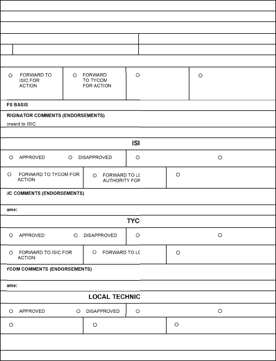
COMUSFLTFORCOMINST 4790.3 REV D CHG 3
07 Nov 2023
V-I-11-40
18. APPROVAL ACTIVITY
19. COPY TO
ATTACHMENTS
ATTACHMENT OWNER
1
ORIGINATOR
FORWARD TO
ISIC FOR
ACTION
FORWARD
TO TYCOM
FOR ACTION
FORWARD TO
LOCAL TECH
AUTHORITY
FOR ACTION
FORWARD TO NAVSEA
FOR ACTION
DFS BASIS
ORIGINATOR COMMENTS (ENDORSEMENTS)
Forward to ISIC
Date:
ISIC
APPROVED DISAPPROVED
TEMPORARY PERMANENT
FORWARD TO TYCOM FOR
ACTION
FORWARD TO LOCAL TECH
AUTHORITY FOR ACTION
FORWARD TO NAVSEA FOR ACTION
ISIC COMMENTS (ENDORSEMENTS)
Name: Date:
TYCOM
APPROVED DISAPPROVED
TEMPORARY PERMANENT
FORWARD TO ISIC FOR
ACTION
FORWARD TO LOCAL TECH
FORWARD TO NAVSEA FOR ACTION
TYCOM COMMENTS (ENDORSEMENTS)
Name: Date:
LOCAL TECHNICAL AUTHORITY
APPROVED DISAPPROVED
TEMPORARY PERMANENT
FORWARD TO ISIC FOR
ACTION
FORWARD TO TYCOM FOR
ACTION
FORWARD TO NAVSEA FOR ACTION
LOCAL COMMENTS (ENDORSEMENTS)
Name: Date:
COMUSFLTFORCOMINST 4790.3 REV D CHG 3
07 Nov 2023
V-I-11-41
NAVSEA/NAVAIR TECHNICAL AUTHORITY
APPROVED DISAPPROVED
TEMPORARY PERMANENT
FORWARD TO ISIC FOR ACTION
FORWARD TO TYCOM FOR
ACTION
FORWARD TO LOCAL TECH
AUTHORITY FOR ACTION
PRECEDENT SETTING
NAVSEA COMMENTS (ENDORSEMENTS)
Name:
Date:
TYCOM
APPROVED
DISAPPROVED
TEMPORARY
PERMANENT
FORWARD TO ISIC FOR
ACTION
FORWARD TO LOCAL
TECH AUTHORITY
FOR ACTION
FORWARD TO NAVSEA FOR
ACTION
TYCOM COMMENTS (ENDORSEMENTS)
Name:
Date:
NAVSEA/NAVAIR TECHNICAL AUTHORITY
APPROVED
DISAPPROVED
TEMPORARY
PERMANENT
FORWARD TO ISIC FOR
ACTION
FORWARD TO TYCOM FOR
ACTION
FORWARD TO LOCAL TECH
AUTHORITY FOR ACTION
PRECEDENT SETTING
NAVSEA COMMENTS (ENDORSEMENTS)
Name:
Date:

COMUSFLTFORCOMINST 4790.3 REV D CHG 3
07 Nov 2023
V-I-11-42
QA FORM 12 INSTRUCTIONS
DEPARTURE FROM SPECIFICATION REQUEST
NOTE: THE QA-12 WHEN PRINTED WILL DISPLAY AT A MINIMUM THE
FIELDS DEPICTED IN THE QA-12 FORM BUT MAY BE ARRANGED OR
SEQUENCED IN A DIFFERENT VIEW.
PURPOSE: Used to report and request approval of a DFS.
PROCEDURE:
1. The activity finding or causing a DFS will immediately report the DFS to the appropriate
approval authority using this form.
2. The numbered blocks on QA form 12 correspond with block instructions listed.
BLOCK 1 - DEPARTURE NO.
Enter the next sequential number from the affected ship serial file.
BLOCK 2 - SHIP HULL NO.
Enter the name and hull number of the ship on which the DFS occurred.
NOTE: BLOCK 3 OR BLOCK 17 HAS TO BE FILLED IN TO SUPPORT A
TEMPORARY DEPARTURE IF THERE IS SUBSEQUENT ACTION TO
CLEAR A TEMPORARY DEPARTURE.
BLOCK 3 - JCN
Enter the JCN for the job that is intended to correct the DFS condition.
BLOCK 4 - CWP / REC SER. NO.
Enter the CWP / REC serial number or enter N/A if no CWP / REC is required. Do not list
the CWP / REC revision.
BLOCK 4A - TECHNICAL WORK DOCUMENT
(SHIPYARD USE ONLY) Enter the technical work document that identified the non-
conformance.
BLOCK 5 - DATE
Enter the date the DFS request is filled out.
BLOCK 6 - ORIGINATOR
Print or type the name of the originator of the DFS.
BLOCK 7 - DEPARTURE TYPE
Enter the applicable departure type. (Major or Minor) and classification as necessary
(SUBSAFE, SOC, URO, FBW or SFCC).
BLOCK 7A - EXPECTED CLEARANCE DATE
The activity performing final approval must enter an expected clearance date in conjunction
with approving the non-conformance. This date will normally be the expiration date but may

COMUSFLTFORCOMINST 4790.3 REV D CHG 3
07 Nov 2023
V-I-11-43
be a date earlier than the expiration of the non-conformance. The Ship, ISIC or TYCOM may
revise this date to be earlier than the expiration date of the non-conformance.
BLOCK 7B - TEMPORARILY APPROVED UNTIL DATE
The Approval Activity will fill in the “TEMPORARILY APPROVED UNTIL DATE” for
non-Electronic Departure from Specification departures. Electronic Departures from
Specification will automatically populate with the TEMPORARILY APPROVED UNTIL
DATE in conjunction with the approval authority signature.
BLOCK 8 - ADDITIONAL CLASSIFICATION (SHIPYARD AND SOC USE
ONLY)
Enter the necessary information as required. If the departure is conditional, mark the
appropriate block to indicate that ISIC concurrence is required.
BLOCK 9 - SYSTEM/COMPONENT/LOCATION
Enter the affected system, component, and location. A short description may be added if
needed to fully identify the system, component and location.
BLOCK 10 - NAVSEA DRAWING/PLAN NUMBER/PIECE NUMBER
Enter the NAVSEA drawing number, plan number and piece number, as applicable, that
shows the component or system on which the DFS is initiated.
BLOCK 11 - REFERENCES
Enter additional references used (e.g., Training Aid Booklet, Ships Information Book, Ships
Systems Manual, Steam and Electric Plant Manual, SUBSAFE Certification Boundary Book,
Tech Manual) as applicable.
BLOCK 12 - APPLICABLE SPECIFICATIONS
Enter the applicable specifications. Be descriptive and specific. Enter the reference that
provided the specification. This block should fully explain the specifications and include the
JID or part applicable (e.g., perform “J” pressure test to test pressure depth after mechanical
assembly of joints “XXXX” in which software was replaced). This block must be explicit, so
that no reference is required to the work procedure to understand the specifications.
BLOCK 13 - SITUATION/DEGREE OF NON-COMPLIANCE
Enter what the actual condition is. Sketches, drawings, QA forms, etc., may be attached, if
they clarify the description of the non-conforming condition.
BLOCK 14 - COMMENTS/RECOMMENDATION (TEST CONDUCTED,
AFFECTED SYSTEMS)
Enter comments and recommendations pertinent to the job. The comments will include
recommendation and justification for approval of the DFS. Enter tests conducted and the
results, SAT or UNSAT.
BLOCK 15 - DATE ANSWER REQUESTED BY
Enter date.
BLOCK 16 - SUBMITTING ACTIVITY
COMUSFLTFORCOMINST 4790.3 REV D CHG 3
07 Nov 2023
V-I-11-44
Type or print name and enter signature.
NOTE: BLOCK 3 OR BLOCK 17 HAS TO BE FILLED IN TO SUPPORT A
TEMPORARY DEPARTURE IF THERE IS SUBSEQUENT ACTION TO
CLEAR A TEMPORARY DEPARTURE.
BLOCK 17 - NEW JCN NUMBER FOR CONDITIONAL DEPARTURES
If the JCN in block 3 does not include all the work necessary to clear the DFS condition, enter
the JCN(s) for the additional work necessary to clear the DFS.
BLOCK 18 - APPROVAL ACTIVITY
List the activity who will be the final approval.
BLOCK 19 - COPY TO
Enter activities to receive copy.
For the ISIC, TYCOM, LOCAL TECHNICAL AUTHORITY and NAVSEA or NAVAIR
TECHNICAL AUTHORITY blocks, the applicable activity will request, concur, approve,
disapprove and indicate temporary, permanent or precedent setting as applicable. In the case of
temporary non-conformances, specify the TEMPORARILY APPROVED UNTIL DATE
(dd/mm/yyyy) that the noncompliance is acceptable prior to correction and list any restrictions.
ISIC: Check the appropriate blocks. Check the FWD to TYCOM/LOCAL TECH.
AUTHORITY FOR ACTION block for any DFS requiring TYCOM action and print name, sign
and date.
a. (Surface Forces only) The originator of the non-conformance will check the
appropriate blocks to forward the non-conformance to the appropriate activity for
action.
b. For an at sea generated DFS, the Commanding Officer will use the ISIC section to
indicate approval of the DFS.
c. In the instances where a depot activity forwards a conditional departure to the ISIC for
concurrence, the ISIC will check the block labeled CONCUR, FORWARDED TO
TYCOM FOR ACTION. The ISIC will type or print name, sign and date.
TYCOM: Check the appropriate blocks. Type or print name, sign and date. ((Submarines only)
See QA-12 Block 19 table for approval guidance).
LOCAL TECHNICAL AUTHORITY: When appropriate, check the appropriate blocks and type
or print name, sign and date. Check the FWD TO NAVSEA FOR ACTION BLOCK for any
DFS requiring NAVSEA final approvals.
NAVSEA/NAVAL AIR SYSTEMS COMMAND (NAVAIR) action: The appropriate blocks
will be checked and signed by NAVSEA.
NAME/SIGNATURE/DATE: The ISIC Material Officer, ISIC QAO, TYCOM Representative,
Local Technical Authority Chief Engineer or Commanding Officer (for an at-sea initiated DFS)
will type or print name and title, sign and date in the appropriate block signifying technical
acceptance of the DFS. In the case of shipyard conditional departures, the ISIC signature only
signifies acceptance that work to clear the deficient condition is acceptable to be delayed to a

COMUSFLTFORCOMINST 4790.3 REV D CHG 3
07 Nov 2023
V-I-11-45
future time period. The ISIC signature in this case does not signify acceptance of the technical
merit of the departure.
TYCOM: Check the appropriate blocks. Type or print name, sign and date.
NOTE: WHEN ANY OF THE FOLLOWING BLOCKS IN SECTION 7 ARE
CHECKED, THE TYCOM MAY APPROVE THE DFS AS DEFINED IN THE
FOLLOWING TABLE:
QA-12 Block 19 Table (Submarines Only)
MAJOR TYCOM may approve MAJOR non-conformances on a temporary basis with concurrence from
the appropriate NAVSEA technical authority.
MINOR
TYCOM may approve all MINOR non-conformances not also marked SUBSAFE, FBW, SFCC,
or SOC.
SUBSAFE TYCOM may approve the following MINOR departures:
(1) Departures to which a NAVSEA approved PRECEDENT-setting departure clearly
applies. The NAVSEA approved departure cited as the PRECEDENT must be
referenced and retained with the approved departure.
(2) Departures administered solely for the purpose of transferring accountability to an
alternative accountability system in support of at-sea testing.
The TYCOM may approve all other MAJOR or MINOR non-conformances within the
SUBSAFE Certification Boundary following discussion with the designated NAVSEA technical
authority or regional Chief Engineer.
URO
With the exception of at-sea portions of URO MRC 022, the TYCOM must obtain NAVSEA
technical approval of all URO MRC non-conformances.
FBW or
SFCC
TYCOM may approve the following MINOR departures:
(1) Departures to which a NAVSEA approved PRECEDENT-setting departure clearly
applies. The NAVSEA approved departure cited as the PRECEDENT must be
referenced and retained with the approved departure.
(2) Departures in the FBW SCS Certification Boundary when the system design employs
four (or more) SFCCs with the same function (quad redundant) and a deficiency
degrades the operation of only one SFCC.
(3) Departures in the FBW SCS Certification Boundary administered solely for the purpose
of meeting the alternative accountability system requirement for at-sea testing.
The TYCOM may approve all other MAJOR or MINOR non-conformances within the FBW SCS
Certification Boundary following discussion with NAVSEA 05U7.
SOC
MINOR non-conformances: Following agreement from NAVSEA that a condition is MINOR,
may be approved by the TYCOM as a temporary SOC non-conformance provided that it does not
affect the watertight integrity of the DDS and no DDS manned operations will be conducted.
Non-conformances affecting any system, equipment or component within the SOC boundary,
which are determined to be required by Part III, Chapter 8 of this volume, must be categorized
and processed as a MAJOR departure, unless otherwise directed by NAVSEA, will require
NAVSEA approval.
COMUSFLTFORCOMINST 4790.3 REV D CHG 3
07 Nov 2023
V-I-11-46
DEPARTURE CLEARANCE REPORT
QA FORM 12A
1. FROM:
2. DATE
3. TO:
4. SUBJECT
DFS NUMBER __________________________________________________ DATED _____
ON SYSTEM/COMPONENT _______________________________________ IN USS _____
5. REFERENCE(s):
(A) COMUSFLTFORCOMINST 4790.3 - JOINT FLEET MAINTENANCE MANUAL
(B)
(C)
(D)
6. JUSTIFICATION
7. CLEAR / CANCEL SUBJECT DFS IN ACCORDANCE WITH REFERENCE (A). (CIRCLE ONE)
8. SIGNATURE TITLE DATE

COMUSFLTFORCOMINST 4790.3 REV D CHG 3
07 Nov 2023
V-I-11-47
QA FORM 12A INSTRUCTIONS
DEPARTURE CLEARANCE REPORT
PURPOSE: Provide document for reporting the clearance of a DFS.
PROCEDURE: The numbered blocks on QA form 12A correspond with the block instructions
listed. QA form 12A should be completed by the ship, ISIC or the NSA
correcting the non-conformance on which the DFS exists as soon as the
discrepant condition has been corrected.
BLOCK 1 - FROM
Enter the ship’s name and hull number or enter the name and activity of person clearing DFS.
BLOCK 2 - DATE
Enter date the DFS was cleared or cancelled.
BLOCK 3 - TO
Enter the appropriate ISIC or, if clearing ship approved DFS, enter “CO”. For all others, enter
the name and activity of person clearing DFS.
BLOCK 4 - SUBJECT
Enter the required data taken from the QA form 12.
BLOCK 5 - REFERENCE(s)
Enter all applicable references.
BLOCK 6 - JUSTIFICATION
Enter detailed justification for the clearance or cancellation listing all references, tests and
inspections used for the DFS clearance.
BLOCK 7 - CLEAR/CANCEL
Circle or check the appropriate action.
BLOCK 8 - SIGNATURE
QAO or the activity correcting the non-conformance, print name, enter signature, title and
date. For EDFS this must be an electronic signature.
COMUSFLTFORCOMINST 4790.3 REV D CHG 3
07 Nov 2023
V-I-11-48
SURVEILLANCE/MONITORING/AUDIT DISCREPANCY RECORD
QA FORM 14
1. DATE
2. SERIAL NUMBER 3. WC
4. PART 1 - DISCREPANCY DESCRIPTION
5. ORIGINATOR SIGNATURE
6. QA OFFICER/QA SUPERVISOR REVIEW SIGNATURE
QA RETAIN ORIGINAL AND FORWARD COPY TO DIVISION
7. PART 2
–
CORRECTIVE ACTION
ROOT CAUSE(s):
IMMEDIATE CORRECTIVE ACTION(s): ECD
PERMANENT CORRECTIVE ACTION(s): ECD
OBJECTIVE QUALITY EVIDENCE CORRECTIONS:
8. DIVISION OFFICER (SIGNATURE) DATE
DIVISION RETAIN COPY AND FORWARD COPY TO QA OFFICER
9. QA OFFICER/QA SUPERVISOR (QAO/QAS) (SIGNATURE) DATE
10. PART 3 - EFFECTIVENESS REINSPECTION/AUDIT
ECD 11. EFFECTIVENESS
(
YES/NO
)
QA FORM
14
12. EFFECTIVENESS REVIEW QA OFFICER/QA SUPERVISOR (QAO/QAS) (SIGNATURE) DATE
COMPLETED ORIGINAL TO: QA-14 BINDER
COPY TO: DIVISION RECORD FILE
CWP, QA FORM AND/OR REC
(
IF CORRECTING OQE OR PACKAGE
)

COMUSFLTFORCOMINST 4790.3 REV D CHG 3
07 Nov 2023
V-I-11-49
QA FORM 14 INSTRUCTIONS
SURVEILLANCE/MONITORING/AUDIT DISCREPANCY RECORD
PURPOSE: a. To provide as a result of conducting audits and surveillances, a method or
means of reporting a discrepancy and ensuing corrective actions are taken
by the WC or division.
b. To provide a method of recording discrepancies, reworks and processing
actions until final clearance.
c. To provide the only approved method to correct or add Objective Quality
Evidence to a certified CWP or closed QA Form.
d. To provide, when maintained in an auditable fashion, a record of
completed corrective actions.
e. To provide, when completed, an ability to conduct trend analysis to
improve overall FMA and ship’s maintenance quality.
NOTE: A COPY OF ALL ASSOCIATED QA FORMS 14 MUST BE INCLUDED WITH
THE CWP, QA FORM OR REC. DEFICIENCIES FOUND IN A CLOSED
CWP, QA FORM OR REC THAT REQUIRE CORRECTION MUST BE
DOCUMENTED ON A QA FORM 14. NO CHANGE TO THE CLOSED CWP,
QA FORM OR REC IS PERMITTED EXCEPT AS CITED IN THIS NOTE.
THE QA FORM 14 SERIAL NUMBER WILL BE ANNOTATED AT THE TOP
OF THE QA FORM 9 OR QA FORM TO CLEARLY INDICATE A QA FORM
14 WAS WRITTEN AFTER THE CWP, QA FORM OR REC WAS CLOSED
OR CERTIFIED AND THAT ADDITIONAL OQE IS ASSOCIATED WITH
THE CLOSED CWP, QA FORM OR REC PACKAGE.
PROCEDURE: The numbered blocks in QA form 14 correspond with the block instructions
listed.
BLOCK 1 - DATE
The person discovering or documenting the discrepancy will enter the date the report was
initiated.
BLOCK 2 - SERIAL NUMBER
The QAS or QAO will enter the next sequential number from the QA form 14 Log.
BLOCK 3 - WC
Person discovering or documenting the discrepancy will enter the WC responsible.
BLOCK 4 - PART 1 - DISCREPANCY DESCRIPTION
Person discovering the discrepancy will enter a description of the discrepancy and the
associated reference. If associated with a CWP, enter the CWP serial number.
BLOCK 5 - ORIGINATOR SIGNATURE
The individual discovering or documenting the discrepancy will sign, and legibly print, type
or stamp their name.

COMUSFLTFORCOMINST 4790.3 REV D CHG 3
07 Nov 2023
V-I-11-50
BLOCK 6 - QA OFFICER/QA SUPERVISOR REVIEW SIGNATURE
The QAO or a QAS will sign and legibly print, type or stamp their name signifying a review
of and concurrence with the validity of the discrepancy.
NOTE: BLOCK 7, WHEN COMPLETE, WILL SIGNIFY A COMPREHENSIVE
PROCESS BY WHICH THE BLOCK 4 DISCREPANCY’S CAUSE,
CORRECTION AND PREVENTION ARE IDENTIFIED AND TRACKED TO
COMPLETION.
BLOCK 7 - PART 2 - CORRECTIVE ACTION
a. ROOT CAUSE: When this form is used to document a deficiency or when required
by the QAO, the Division Officer of the WC responsible (Block 3) for causing the
discrepancy will enter the root cause and a brief supporting discussion.
b. IMMEDIATE CORRECTIVE ACTION: The Division Officer of the WC responsible
for causing the discrepancy will enter a description of the IMMEDIATE
CORRECTIVE ACTIONS (if applicable) that have been taken or are planned and
indicate their Estimated Completion Date (ECD).
c. PERMANENT CORRECTIVE ACTION: The Division Officer of the WC
responsible for causing the discrepancy will enter a description of the PERMANENT
CORRECTIVE ACTIONS (to prevent recurrence) that have been taken or are planned
and indicate their ECD. Examples include process improvements and policy or
procedural changes.
d. OBJECTIVE QUALITY EVIDENCE CORRECTIONS: The Division Officer of the
WC responsible for causing an Objective Quality Evidence discrepancy will enter all
required information that adds or corrects existing discrepant OQE (described in Block
4) to a closed CWP, QA FORM or REC. In the event the deficiency identified in
Block 4 is not related to OQE, this area must be marked NA.
NOTE: UPON SIGNING BLOCK 8, THE DIVISION OFFICER MUST RETAIN A
COPY FOR TRACKING PURPOSES, UNTIL RESOLVED, AND PROVIDE A
COPY OF THE QA FORM 14 TO THE QAO OR QAS.
BLOCK 8 - DIVISION OFFICER SIGNATURE
The Division Officer of the WC responsible for causing the discrepancy will sign, date and
legibly print, type or stamp their name signifying comment validity and accurate corrective
action or OQE correction (if applicable) exists.
NOTE: UPON SIGNING BLOCK 9, THE QAO OR QAS MUST FILE A COPY OF
THE SIGNED QA FORM 14 WITH THE DISCREPANT CLOSED CMP, QA
FORM OR REC (AS APPLICABLE) TO ALLOW IT TO STAND ALONE.
BLOCK 9 - QA OFFICER/QA SUPERVISOR SIGNATURE
The QAO or QAS will sign, date and legibly print, type or stamp their name indicating full
acceptance of the Block 7 comments.
BLOCK 10 - PART 3 - EFFECTIVENESS RE-INSPECTION/AUDIT

COMUSFLTFORCOMINST 4790.3 REV D CHG 3
07 Nov 2023
V-I-11-51
When required by the QAO, the QAO or QAS will enter a description of the necessary QAO
or QAS re-inspections or audits that will support determining effectiveness of each Block 7
Corrective Action and indicate an ECD for each re-inspection or audit action. Examples
include but are not limited to audits, surveillances, exams and level of knowledge interviews.
BLOCK 11 - EFFECTIVENESS
Upon completion of a Re-inspection / Audit (Block 10), the QAO or QAS will enters its
effectiveness as “YES or NO”. If the effectiveness has been determined to be “NO”, the QAO
or QAS must transfer the issue to a new QA form 14 (for further root causal analysis and
corrective actions) and enter that new QA FORM 14 serial number in the space provided.
NOTE: UPON CLOSURE, THE QAO OR QAS MUST FILE THE COMPLETED AND
CLOSED QA FORM 14 IN THE QA FORM 14 BINDER WITH A COPY
FILED WITH THE DISCREPANT CLOSED CWP, QA FORM OR REC (AS
APPLICABLE) TO ALLOW IT TO STAND ALONE.
BLOCK 12 - EFFECTIVENESS REVIEW QA OFFICER/QA SUPERVISOR
SIGNATURE
Upon completion of all re-inspections or audits (Block 10), determination of effectiveness and
deferral (by QA-14 for any corrective actions deemed NOT effective), the QAO or QAS must
enter signature and date, and legibly print, type or stamp their name indicating acceptance and
closure of the QA form 14.
COMUSFLTFORCOMINST 4790.3 REV D CHG 3
07 Nov 2023
V-I-11-52
TEST AND INSPECTION RECORD
QA FORM 17
Planning must fill in blocks identified by a prior to issuing
Page____ of ____
1. SHIP HULL NO. 2. JCN 3. LWC/SHOP 4. CWP/REC SER NO. 5. SYSTEM/COMPONENT
6. REFERENCES (COMPONENT DETAIL/ASSEMBLY DRAWING AND REV)
A. B. C.
D. E. F.
7. PART DESCRIPTION/PIECE NO.:
8. DESCRIPTION OF TEST AND/OR INSPECTION:
9. RESULTS
10. CRAFTSMAN SIGNATURE DATE 11. QA INSPECTOR SIGNATURE DATE
12. RECORD HAS BEEN REVIEWED FOR COMPLETENESS
QA WCS SIGNATURE (QAO/QAS SIGNATURE FOR SUBSAFE/SOC/SFCC ONLY) DATE

COMUSFLTFORCOMINST 4790.3 REV D CHG 3
07 Nov 2023
V-I-11-53
QA FORM 17 INSTRUCTIONS
TEST AND INSPECTION RECORD
PURPOSE: To provide a report form for work, tests and inspections not covered by other
QA forms. This form can be used for flushes, operational testing, shop
inspections, cleanliness inspections, generic material identity test, and other
tests, inspections, and information deemed necessary. The QA form 17 will
not be used in lieu of a QA form 26A in DSS or SOC applications.
TOP OF FORM: Page ___ of ___
NOTE A TECHNICAL WORK DOCUMENT MAY CONTAIN MULTIPLE QA
FORMS OF THE SAME TYPE, (E.G. MORE THAN ONE QA-26). THE PAGE
ENTRY IS FOR THIS SPECIFIC FORM, NOT THE TOTAL NUMBER OF
PAGES ON ALL FORMS OF THE SAME TYPE.
Enter the page number, starting with page 1, of total number of QA form pages (e.g., 1 of ,
2 of ). The last number reflects the total number of QA Form pages written. This block is
filled in by a QAI or the QAO after all certification testing is complete before block 19 on the
QA-9 is signed. (e.g., 1 of 3, 2 of 3, 3 of 3).
PROCEDURE. The numbered blocks on QA form 17 correspond with the block instructions
listed. The planning organization must fill in Blocks 1 through 8 (identified by a ) prior to
issuing the CWP.
BLOCK 1 - SHIP HULL NO.
Enter the ship’s name and hull number.
BLOCK 2 - JCN
Enter the JCN.
BLOCK 3 - LWC
Enter the shop number of the LWC.
BLOCK 4 - CWP/REC SERIAL NO.
Enter the CWP/REC serial number or enter N/A if no CWP/REC is required. Do not list the
CWP/REC revision.
BLOCK 5 - SYSTEM/COMPONENT
Enter the noun name of the system or component to be tested or inspected.
BLOCK 6 - REFERENCES (COMPONENT ASSY/DETAIL DRAWING AND
REVISION)
Enter all references used to identify component parts, material information, and required test
or inspection including revision letter and if applicable, the assembly number (Assy D, Assy
RA, etc.). For original issue drawings (no revisions) enter a dash (-). For vendor drawings,
include vendor name. Revisions for technical manuals are not required.
BLOCK 7 - PART DESCRIPTION/PIECE NO.

COMUSFLTFORCOMINST 4790.3 REV D CHG 3
07 Nov 2023
V-I-11-54
Enter the part number or description (pc 5, bonnet, stem bore, backseat, etc.).
BLOCK 8 - DESCRIPTION OF TEST AND/OR INSPECTION
Enter a detailed description of tests, inspections or work to be performed or note the reference
used and paragraph or note number that specifies the inspection or test. Enter the required
pressure, duration, medium and acceptance criteria of the test. If the test or inspection has a
numerical value (e.g., maximum or minimum value), the values will be written in. If listing
the pressure values would classify the work procedure, then the symbols “J” or “H” (with the
applicable reference including paragraph, table, section or item number) may be used instead
of classifying the document.
NOTE: WHEN MANUFACTURING PARTS, ENTER THE MATERIAL
SPECIFICATION OR NSN FOR RAW STOCK AND RECORD THE PLAN
AND WHEN APPLICABLE, THE PIECE NUMBER OF THE PART
MANUFACTURED.
NOTE: FOR URO MRCs TO BE PERFORMED AS A RETEST, LIST THE SPECIFIC
APPLICABLE PORTIONS OF THE URO MRC (TO INCLUDE APPLICABLE
PRE-REQUISITE STEPS) REQUIRED TO RECERTIFY THE SYSTEM.
BLOCK 9 - RESULTS
Enter the specific results of the test, inspection or work specified in Block 8. Indicate
satisfactory or unsatisfactory results or completion. If UNSAT, the craftsman will:
a. Initiate action to resolve the condition.
b. Record actions taken in this block to correct the unsatisfactory condition.
c. Sign in this block (Block 9).
Do not sign Block 10 unless signing for satisfactory results or completion are obtained or for
an UNSAT condition that has been accepted.
NOTE: IF THE TEST OR INSPECTION REQUIRES THE USE OF TMDE, RECORD
THE INSTRUMENT, RANGE AND SERIAL NUMBER AND CAL DUE DATE
IN THE RESULTS BLOCK.
NOTE: WHEN VULCANIZING O-RINGS, ENTER THE STOCK NUMBER AND
EXPIRATION DATE (IF PROVIDED).
NOTE: IF SKETCHES, DRAWINGS, URO DATA REPORT FORMS OR
ADDITIONAL INFORMATION IS REQUIRED TO SUPPLEMENT THIS
REPORT, EACH DRAWING, ETC., WILL BE LABELED AS AN
ATTACHMENT TO ITS RESPECTIVE QA FORM 17, INCLUDING THE
PAGE NUMBER, WHICH MUST BE SIGNED (INCLUDE PRINTED NAME,
DATE) BY THE CRAFTSMAN AND QAI FILLING OUT THE QA FORM 17.
(FOR ATTACHMENTS WITH MULTIPLE PAGES, ONLY THE FIRST PAGE
REQUIRES SIGNATURES.)
NOTE: FOR OPERATIONAL JOINT TIGHTNESS TESTS, ENTER ACTUAL
PRESSURE AND DURATION. TEST DURATION WILL INCLUDE THE
REQUIRED TEST PERIOD AND THE TIME REQUIRED TO COMPLETE
THE INSPECTION. IF LISTING THE ACTUAL TEST PRESSURE VALUE

COMUSFLTFORCOMINST 4790.3 REV D CHG 3
07 Nov 2023
V-I-11-55
WOULD CLASSIFY THE WORK PROCEDURE, THEN THE SYMBOLS “J”
OR “H” (WITH THE APPLICABLE REFERENCE, INCLUDING
PARAGRAPH, TABLE, SECTION AND ITEM NUMBER) MAY BE USED
INSTEAD OF CLASSIFYING THE DOCUMENT. FOR URO MRCs
PERFORMED AS A RETEST, COMPLETE REQUIRED PORTIONS OF THE
URO MRC DATA FORMS AND ENTER SATISFACTORY OR
UNSATISFACTORY IN BLOCK 9.
BLOCK 10 - CRAFTSMAN/DATE
Craftsman print name, enter signature and date after completing Block 9. Do not sign Block
10 unless satisfactory results or completion are obtained or the UNSAT condition has been
accepted.
NOTE: FOR NDT INSPECTIONS, THE NDT INSPECTOR WILL SIGN BLOCK 10
AS THE CRAFTSMAN AND THE NDT SUPERVISOR WILL SIGN BLOCK
11 FOLLOWING REVIEW OF THE FORM.
BLOCK 11 - QA INSPECTOR/DATE
Inspector print name, enter signature and date verifying the accuracy of the data recorded in
Block 9.
BLOCK 12 - RECORD HAS BEEN REVIEWED FOR COMPLETENESS
QAS or QAO will print name, enter signature and date for final review, signifying the
accuracy of the completed form for SUBSAFE, SOC or SFCC items only. For other
components, the QA Work Center supervisor must sign and date the form signifying the
accuracy of the completed form.
COMUSFLTFORCOMINST 4790.3 REV D CHG 3
07 Nov 2023
V-I-11-56
EPOXY REPAIR RECORD
QA FORM 17A Planning must fill in blocks identified by a prior to issuing
Page ____ of ____
1. SHIP HULL NO. 2. JCN 3. LWC/SHOP
4. CWP/REC SER
NO.
5. SYSTEM/COMPONENT/ROTATABLE POOL SER NO.
6. REFERENCES (COMP DETAIL/ASSY DWG &
REV)
A.
7. EPOXY REPAIRS ARE PER:
UIPI 2560-107
UIPI 6300-905
OTHER ___________________________________
8. LEGEND FOR EPOXY METHOD (ENTER APPLICABLE SYMBOL(S) IN BLOCK 9)
B.
SH – SHIM
PE – POWDER EPOXY
REPAIR
CP –- COLD PATCH
OT - OTHER (specify):
______________
B – BUSHING
CE – COLD EPOXY
COATING
SL – SLEEVE C.
9. DESCRIPTION OF REPAIR(S) 10. REPAIR(S) & TEST ACCOMPLISHED
10A. PRE-EPOXY DIMENSIONS 10B. EPOXY APPLIED 10C. REQUIRED TESTS/RESULTS
PART NO./NAME &
DESCRIPTION OF
DEFECT AREA(S) (USE
BLOCK 11 FOR
ADDITIONAL INFO, IF
REQUIRED)
REF
DWG
LTR
UIPI 2560-107
METHOD OR
EPOXY METHOD
(See Block 8)
DEPTH OF
MACHINING
(INCHES)
DEPTH
(INCHES) OF
REMAINING
DEFECTS
SHIM/SLEEVE
THICKNESS
(INCHES) &
MAT’L USED
EPOXY MATERIAL & BATCH NO. USED
REQUIRED TEST LEGEND
(Enter number below)
1. TAP
2. PULL
3. SPARK
4. VT CURE
5.OTHER (Specify)
REMAINING
WALL
THICKNESS
(INCHES)
A.
REQUIRED TEST (See Test Legend)
TEST RESULTS SAT UNSAT
FINAL SURFACE FINISH MEETS REQUIREMENTS
SIGNATURE/BADGE/DATE SIGNATURE/BADGE/DATE SIGNATURE/BADGE/DATE
B.
REQUIRED TEST (See Test Legend)
TEST RESULTS SAT UNSAT
FINAL SURFACE FINISH MEETS REQUIREMENTS
SIGNATURE/BADGE/DATE SIGNATURE/BADGE/DATE SIGNATURE/BADGE/DATE
11. ADDITIONAL INFORMATION/SKETCHES: This block may be used to provide additional information, signatures, and sketches to clarify EPOXY repair area(s). Use the back of the sheet for additional space. (CRAFTSMAN/QAI SUBMIT
A DF TO RESOLVE UNSAT DATA)
12. QA INSPECTOR/SHOP SUPERVISOR SIGNATURE/BADGE NO. (RECORD REVIEWED FOR FINAL ACCEPTANCE) 13. QAS SIGNATURE /BADGE NO. (RECORD HAS BEEN REVIEWED FOR
COMPLETENESS)
DATE
DATE

COMUSFLTFORCOMINST 4790.3 REV D CHG 3
07 Nov 2023
V-I-11-57
QA FORM 17A INSTRUCTIONS
EPOXY REPAIR RECORD
PURPOSE: To document the proper OQE for epoxy repairs on components when directed by
the Technical Work Document.
NOTES:
1. EACH FORM ALLOWS FOR TWO EPOXY REPAIRS TO BE
DOCUMENTED, BUT MUST BE LIMITED TO A SINGLE COMPONENT
(E.G., TD-29/30 VALVE ASSEMBLY).
2. REWORK: IN CASES WHERE REWORK IS REQUIRED AFTER
CRAFTSMAN CERTIFICATION OF A RECORD, A NEW RECORD AND
WORK AUTHORIZING DOCUMENT IS REQUIRED.
3. IN CASES WHERE REWORK IS REQUIRED DUE TO AN IN-PROCESS
FAILURE, THE FOLLOWING PROCESS MUST BE USED:
a. CHECK THE “UNSAT” BOX IN THE “TEST RESULTS” SECTION
OF BLOCK 10 ALONG WITH AN EXPLANATION OF FAILURE IN
BLOCK 11. LEAVE REMAINING UNSIGNED BLOCKS BLANK.
b. ENTER “REWORK FOR ITEM 9X” (WHERE X IS THE LETTER
DESIGNATOR FOR THE BLOCK 9 ITEM LINE (E.G., 9A, 9B)) OR
SIMILAR WORDS IN THE NEXT BLANK “PART NO./NAME/
DESCRIPTION OF DEFECT AREAS” BLOCK, ALONG WITH AN
ASTERISK OR OTHER MARK WITH A CORRESPONDING
EXPLANATION IN BLOCK 11 WITH SIGNATURE, BADGE
NUMBER AND DATE. IF THERE IS NO EMPTY ITEM LINE,
ANOTHER QA FORM 17A MAY BE USED AS A CONTINUATION
SHEET. IF THE RECORD CONTAINS MULTIPLE PAGES,
IDENTIFY THE PAGE THAT CONTAINS THE ITEM LINE FOR
WHICH THE REWORK IS ACCOMPLISHED (E.G., 9A OF PAGE 1).
c. RE-ENTER ALL OF THE ORIGINALLY REQUIRED TESTS IN THE
NEW ITEM LINE AND COMPLETE ALL BLOCKS EXCEPT THE
“PART NO./NAME/DESCRIPTION OF DEFECT AREAS” BLOCK
WHICH IS ANNOTATED AS DESCRIBED IN PARAGRAPH B.
ABOVE. IT IS ACCEPTABLE FOR THE CRAFTSMAN TO COPY
ENTRIES INTO PLANNING BLOCKS FROM THE ORIGINAL
PLANNING ENTRIES.
SCOPE: Documentation with this QA form is required for epoxy repair of the following:
SUBSAFE components
Scope of Certification (SOC) components
Seawater ball valves
TOP OF FORM: - Page _____ of _____

COMUSFLTFORCOMINST 4790.3 REV D CHG 3
07 Nov 2023
V-I-11-58
NOTE A TECHNICAL WORK DOCUMENT MAY CONTAIN MULTIPLE QA
FORMS OF THE SAME TYPE, (E.G. MORE THAN ONE QA-26). THE PAGE
ENTRY IS FOR THIS SPECIFIC FORM, NOT THE TOTAL NUMBER OF
PAGES ON ALL FORMS OF THE SAME TYPE.
Enter the page number, starting with page 1, of total number of QA form pages (e.g., 1 of ,
2 of ). The last number reflects the total number of QA Form pages written. This block is
filled in by a QAI or the QAO after all certification testing is complete before block 19 on the
QA-9 is signed. (e.g., 1 of 3, 2 of 3, 3 of 3).
PROCEDURE: Planning Department: Provide guidance per UIPI 2560-107 or UIPI 6300-905,
and provide QA-17A records as part of the TWD or DL. The numbered blocks on QA form 17A
correspond with the block instructions listed. Planning must fill in blocks identified by a prior
to issuing QA form 17A. The shop craftsman is responsible for all other blocks on the form
unless otherwise specified.
BLOCK 1 - SHIP HULL NO.
Enter the ship’s name and hull number or enter the appropriate rotatable pool system
designator (e.g., TRIPER, CCRP, AERP, SSN 688CL, etc.).
BLOCK 2 - JCN
Enter the Job Control Number (JCN). Naval shipyards enter Job Order and Key Op.
BLOCK 3 - LWC/SHOP
Enter the lead shop (e.g., X38, outside machinist).
BLOCK 4 - CWP/REC SERIAL NO.
Enter the CWP/REC serial number or enter NA if no CWP/REC is required. Do not list the
REC revision.
BLOCK 5 - SYSTEM/COMPONENT/ROTATABLE POOL SER NO.
Enter the noun name of the system and component (if applicable) (e.g., MSW-25). If the
record is for in-shop restoration of rotatable or factory pool material, enter the serial number
of the material.
NOTE: ROTATABLE POOL OR FACTORY SERIAL NUMBERS MAY BE
ENTERED BY THE PLANNER, IF KNOWN, OR THE CRAFTSMAN AS
SPECIFIED BY LOCAL INSTRUCTIONS.
BLOCK 6 - REFERENCES (COMP DETAIL/ASSY DWG & REV)
Enter all references used to identify component parts, material information and test or
inspection requirements. Include revision letter and if applicable, identify the assembly
number (e.g., Assy D, Assy RA, etc.). For original issue (non-revised) drawings, enter a dash
(-). Revisions for Technical Manuals are not required. Include vendor name for vendor
drawings.
BLOCK 7 - EPOXY REPAIRS ARE PER
Check the “UIPI 2560-107” or “UIPI 6300-905” box when applicable; otherwise check the
“OTHER” box and specify the procedure. Do not enter revision or change of procedure.

COMUSFLTFORCOMINST 4790.3 REV D CHG 3
07 Nov 2023
V-I-11-59
BLOCK 8 - LEGEND FOR EPOXY METHOD
Identifies the designators for Block 9 (EPOXY METHOD). Planning must specify the type of
epoxy repair on the line following the “OT - OTHER” designator when a required repair
method is not listed.
BLOCK 9 - DESCRIPTION OF REPAIR(S)
NOTE: PLANNING MUST COMPLETE ALL SECTIONS OF BLOCK 9.
ADDITIONAL QA 17A FORMS MAY BE ADDED AS CONTINUATION
SHEETS IF NECESSARY.
PART NO./NAME & DESCRIPTION OF DEFECT AREA(S)
Enter part number or name (e.g., pc 5, bonnet; pc 3, body, etc.) and description of defect
areas (e.g., O-ring groove pitted, stem bore, backseat, etc.). Ensure each surface area
being epoxy repaired is clearly identified.
NOTE: USE BLOCK 11, THE BACK OF THE SHEET, OR BOTH, FOR
ADDITIONAL INFORMATION AND SKETCHES.
REF DWG LTR(S)
Enter the letters corresponding to the reference listed in Block 6 which provides the
material, dimensional and testing or inspection information for the items listed in the
“PART NO./NAME & DESCRIPTION OF DEFECT AREA(S)” block.
UIPI 2560-107 METHOD OR EPOXY METHOD
Enter the epoxy repair method code from UIPI 2560-107 when applicable, or use a
symbol from the legend in Block 8 that identifies the method of epoxy repair being
accomplished when UIPI 6300-905 or OTHER instruction is identified in Block 7. For
an epoxy repair method not identified in the Block 8 legend, enter “OT” and specify the
epoxy repair method on the line following “OT - OTHER” in Block 8.
BLOCK 10 - REPAIR(S) & TEST ACCOMPLISHED
NOTE: CRAFTSMAN MUST COMPLETE ALL SECTIONS OF BLOCKS 10A AND
10B. PLANNING MUST COMPLETE BLOCK 10C.
BLOCK 10A. - PRE-EPOXY DIMENSIONS
DEPTH OF MACHINING
When required by the TWD, record the thickness of the material removed during
machining. Enter “NA” when not required by the TWD or material removal is not
accomplished.
REMAINING WALL THICKNESS
When required by the TWD, enter the wall thickness dimensions after machining or
removing material. Dimensions must take into account the depth of remaining defects.
Enter “NA” when material is not removed or wall thickness documentation is not
required by the TWD.
DEPTH OF REMAINING DEFECTS

COMUSFLTFORCOMINST 4790.3 REV D CHG 3
07 Nov 2023
V-I-11-60
Enter the maximum depth of remaining defects. Enter “No Defects Remain” if there are
no remaining defects after machining.
SHIM/SLEEVE THICKNESS & MAT’L USED
Enter “NA” when shims are not used. Enter the thickness of the shim or sleeve (or
bushing used as a sleeve) used (e.g., 0.032, 1/8 or 3/32, etc.). When installing “S”, “L”,
or top hat shims, enter the thickness of the upper, the middle and the lower legs as
applicable. Enter the generic material (e.g., titanium) or a stock number of the shim
when provided by the naval or local stock program. When this block is being used to
document installation of the shim in lieu of a QA form 34, then the stock number (NSN),
part number, drawing and piece number, generic or material spec marking, or results of
generic material identity testing must be documented here also. If reinstalling an existing
shim, enter “Reinstalled existing”.
SIGNATURE/BADGE/DATE
Craftsman enter signature, badge number and date for pre-epoxy dimensions recorded in
Block 10A.
BLOCK 10B. - EPOXY APPLIED
EPOXY MATERIAL & BATCH NO. USED
Enter the epoxy material (e.g., 3M Epoxy Adhesive EC-2216B/A) used and the batch
number when provided on the container (e.g., Batch 1234).
SIGNATURE/BADGE/DATE
Craftsman enter signature, badge number and date signifying the epoxy was applied per
the requirements and the data recorded in Block 10B.
BLOCK 10C. - REQUIRED TESTS/RESULTS
Enter the number(s) for the required test(s) from the legend.
TEST RESULTS FINAL SURFACE FINISH MEETS REQUIREMENTS
The craftsman must check the SAT or UNSAT block to indicate test.
SIGNATURE/BADGE/DATE
Craftsman enter signature, badge number and date signifying that each epoxy repair has
been satisfactorily accomplished and tested per the requirements and the OQE
documented in Blocks 7, 9, 10A, 10B and 11, and the surface finish meets requirements.
If UNSAT, the craftsman will initiate action to resolve the unsat condition and indicate
the action taken in Block 11 and sign in Block 11. Do not sign Block 10 (for the specific
line item) unless a satisfactory repair is completed or the unsat condition is accepted. If
the condition is accepted, identify the document that grants acceptance in Block 11.
BLOCK 11 - ADDITIONAL INFORMATION/SKETCHES
This block can be used to provide additional information, signatures, and sketches (if required
to clarify epoxy repair area(s) or shim or sleeve). If there is insufficient room, the back of the
form or the addition of a second page is allowed for use. Include a signature, badge number

COMUSFLTFORCOMINST 4790.3 REV D CHG 3
07 Nov 2023
V-I-11-61
and date with any additions to this block. Initials may be entered in lieu of an employee’s
signature and badge number, if a corresponding employee’s signature and badge number
appears elsewhere on the same page.
NOTE: IF MORE THAN ONE EPOXY REPAIR IS BEING ACCOMPLISHED,
IDENTIFY THE ADDITIONAL INFORMATION, SIGNATURES AND
SKETCHES BY THE LINE ITEM LETTERS IN BLOCK 9 (E.G., 9A, 9B).
BLOCK 12 - QA INSPECTOR/SHOP SUPERVISOR SIGNATURE/BADGE
NO./DATE
Naval Shipyards: Production Shop Supervisor must sign that the records have been reviewed
for completeness.
BLOCK 13 - QAS SIGNATURE/BADGE NO./DATE
For SUBSAFE or SOC Components Only, QAS or cognizant QA representative as defined by
local instructions will sign, enter badge number and date in this block to indicate the
completeness of the entries.
COMUSFLTFORCOMINST 4790.3 REV D CHG 3
07 Nov 2023
V-I-11-62
ELECTROPLATING REPAIR RECORD
Page of
QA FORM 17B Planning must fill in blocks identified by a prior to issuing
1. SHIP
HULL NO.
2. JCN 3. .LWC/SHOP 4. CWP/ REC SER NO. 5. REFERENCES (COMP DETAIL/ASSY DWG & REV)
A.
6. SYSTEM/COMPONENT/ROTATABLE POOL SER NO.
7. ELECTROPLATING PROCESSES ARE IAW:
UIPI 0810-451
OTHER ____________________________
8. LEGEND FOR TYPE OF REPAIR, SEE
BLOCK 9
D = DYNAMIC SURFACES (CL 3)
S = STATIC SURFACES (CL 2)OT = OTHER
(SPECIFY)(e.g., CL-1, CL-3A, etc.)
B.
C.
9. DESCRIPTION OF DEFECT & TYPE OF REPAIR 10. MATERIAL VERIFICATION & REPAIR (S) ACCOMPLISHED
11. REQD
TEST (S)
12. TEST (S) RESULTS
ITEM A. PART NO./
NAME/DESCRIPTION
OF DEFECT (S)
REF
DWG
LTR
BASE
MATL
TYPE OF
REPAIR
(SEE
BLOCK 8
ABOVE)
PLATING
MATL REQD
BASE MATL
VERIFIED
SAT
APPLIED
PLATING
THICKNESS
WITHIN
MAX
ALLOWED
OR RANGE
SAT
ELECTROPLATING HAS BEEN
ACCOMPLISHED IN ACCORDANCE WITH
REQUIREMENTS
(Use Block 13 for clarification)
SIGNATURE/BADGE/DATE
1. ADHESION
2. VT
3. PT
4. THICK
5. OTHER
(SPECIFY)
2
ND
OPERATOR VERIFICATION OF
SATISFACTORY TEST ACCOMPLISHED
SIGNATURE/BADGE /DATE
AFTER
MACHINING
DIMENSIONS:
____________
REMAINING
DEFECTS
DEPTH
________
NONE
EXISTING
PLATING MATL
_______________
NONE
H2
BAKE
REQD
YES
NO
MAX
THICKNESS
OR RANGE
PLATING
MATL
APPLIED:
ITEM B. PART NO./
NAME/DESCRIPTION
OF DEFECT (S)
REF
DWG
LTR
BASE
MATL
TYPE OF
REPAIR
(SEE
BLOCK 8
ABOVE)
PLATING
MATL REQD
BASE MATL
VERIFIED
SAT
APPLIED
PLATING
THICKNESS
WITHIN
MAX
ALLOWED
OR RANGE
SAT
ELECTROPLATING HAS BEEN
ACCOMPLISHED IN ACCORDANCE WITH
REQUIREMENTS
(Use Block 13 for clarification)
SIGNATURE/BADGE /DATE
1.ADHESION
2. VT
3. PT
4. THICK
5. OTHER
(SPECIFY)
2
ND
OPERATOR VERIFICATION OF
SATISFACTORY TEST ACCOMPLISHED
SIGNATURE/BADGE/DATE
AFTER
MACHINING
DIMENSIONS
:
____________
REMAINING
DEFECTS
DEPTH_______
NONE
EXISTING
PLATING MATL
NONE
H2
BAKE
REQD
YES
NO
MAX
THICKNESS
OR RANGE
PLATING
MATL
APPLIED:
13. ADDITIONAL INFORMATION/SKETCHES: USE THE BACK OF THE SHEET FOR ADDITIONAL SPACE TO PROVIDE ADDITIONAL INFORMATION, AND SKETCHES TO CLARIFY ELECTROPLATE REPAIR AREA (S)
(CRAFTSMAN/QAI SUBMIT A DF TO RESOLVE UNSAT DATA)
14. QA INSPECTOR/SHOP SUPERVISOR SIGNATURE / BADGE NO. (RECORD REVIEWED FOR FINAL ACCEPTANCE)
15. QAS SIGNATURE / BADGE NO. (RECORD HAS BEEN REVIEWED FOR COMPLETENESS)
DATE
DATE

COMUSFLTFORCOMINST 4790.3 REV D CHG 3
07 Nov 2023
V-I-11-63
QA FORM 17B INSTRUCTIONS
ELECTROPLATING REPAIR RECORD
PURPOSE: To document the proper OQE for electroplating repairs on components when
directed by the work procedure.
TOP OF FORM: Page ___ of ___
NOTE A TECHNICAL WORK DOCUMENT MAY CONTAIN MULTIPLE QA
FORMS OF THE SAME TYPE, (E.G. MORE THAN ONE QA-26). THE PAGE
ENTRY IS FOR THIS SPECIFIC FORM, NOT THE TOTAL NUMBER OF
PAGES ON ALL FORMS OF THE SAME TYPE.
Enter the page number, starting with page 1, of total number of QA form pages (e.g., 1 of ,
2 of ). The last number reflects the total number of QA Form pages written. This block is
filled in by a QAI or the QAO after all certification testing is complete before block 19 on the
QA-9 is signed. (e.g., 1 of 3, 2 of 3, 3 of 3).
PROCEDURE: The numbered blocks on QA form 17B correspond with the block instructions
listed. The planner must fill in blocks identified by a (1 through 9 and 11) prior to issuing the
CWP.
BLOCK 1 - SHIP HULL NO.
Enter the ship’s name and hull number, or enter the appropriate rotatable pool system
designator (e.g., TRIPER, CCRP, AERP, SSN 688CL, etc.).
BLOCK 2 - JCN
Enter the Job Control Number (JCN). Naval shipyards enter Job Order and Key Op.
BLOCK 3 - LWC/SHOP
Enter the lead shop (e.g., X38, outside machinist).
BLOCK 4 - CWP/REC SERIAL NO.
(Work Packaging, Planning Organization or Craftsman) Enter the CWP or REC serial number
or enter NA if no CWP/REC is required. Do not list the REC revision.
BLOCK 5 - REFERENCES (COMP DETAIL/ASSY DWG & REV)
Enter all references used to identify component parts, material information, and test or
inspection requirements including revision letter and if applicable, the assembly number (e.g.,
Assy D, Assy RA, etc.). For original issue (non-revised) drawings, enter a dash (-).
Revisions for Technical Manuals are not required. Include vendor name for vendor drawings.
BLOCK 6 - SYSTEM/COMPONENT/ROTATABLE POOL SER NO
Enter the noun name of the system and component (if applicable) being plated, (e.g., MSW-
25). If the record is for in-shop restoration of rotatable pool material, enter the serial number
of the material when known.
NOTE: ROTATABLE POOL SERIAL NUMBERS MAY BE ENTERED BY THE
CRAFTSMAN IF NOT ENTERED BY PLANNING ORGANIZATION.

COMUSFLTFORCOMINST 4790.3 REV D CHG 3
07 Nov 2023
V-I-11-64
BLOCK 7 - ELECTROPLATING PROCESSES ARE IN ACCORDANCE WITH
Mark the applicable box for the electroplating process. Specify the process when OTHER is
marked. Do not enter revision or change of procedure.
BLOCK 8 - LEGEND FOR TYPE OF REPAIR
Identifies the designators for Block 9 (TYPE OF REPAIR). For other than DYNAMIC (D) or
STATIC (S) surfaces, PLANNING ORGANIZATION must specify the type of repair on the
line following the “OT=OTHER” designator, or in Block 13 if additional space is needed.
BLOCK 9 - DESCRIPTION OF DEFECT & TYPE OF REPAIR
NOTE: PLANNING ORGANIZATION MUST COMPLETE ALL SECTIONS OF
BLOCK 9 EXCEPT AS NOTED. ADDITIONAL QA 17B FORMS MAY BE
ADDED AS CONTINUATION SHEETS IF NECESSARY.
PART NO./NAME/DESCRIPTION OF DEFECT AREA(S)
Enter part number or name (e.g., pc. 5, bonnet, body, etc.) and description of defect areas.
Include dimension after machining and maximum depth of remaining defects prior to
plating (e.g., Stem bore O-ring groove pitted, machined 0.010”, removed all defects). For
more than one of a kind component (XYZ fitting, threaded end) enter the total number of
items (e.g., XYZ fitting, threaded end, 6 ea.). Identify each surface area being plated as a
separate line item.
NOTE: USE BLOCK 13 AND THE BACK OF THE SHEET FOR ADDITIONAL
INFORMATION, SKETCHES, OR BOTH.
REFERENCE DRAWING LETTER
Enter the letter(s) corresponding to the reference(s) listed in Block 5 which provided the
material, dimensional, and test and inspection information for the items listed in the
“PART NO./NAME/DESCRIPTION OF DEFECT(S)” block(s).
BASE MATERIAL
Enter the required base material.
EXISTING PLATING MATERIAL
Identify any known existing plating or mark the NONE box.
TYPE OF REPAIR
Enter the symbol from the legend in Block 8 that identifies the type of electroplating
repair being accomplished.
HYDROGEN BAKE REQUIRED
Mark the YES box when hydrogen bake is required; otherwise mark the NO box.
PLATING MATERIAL REQ’D
Enter the plating material to be applied.
MAXIMUM THICKNESS OR RANGE ALLOWED
Enter the maximum plating thickness allowed or the allowable thickness range (minimum
or maximum).
BLOCK 10 - MATERIAL VERIFICATION & REPAIR(S) ACCOMPLISHED

COMUSFLTFORCOMINST 4790.3 REV D CHG 3
07 Nov 2023
V-I-11-65
NOTE: THE CRAFTSMAN MUST COMPLETE ALL SECTIONS OF BLOCK 10.
BASE MATERIAL VERIFIED
Craftsman must visually compare the required base material identified and the base
material to be plated for obvious discrepancies such as color of material or material
markings, and ensure that all existing plating has been removed or identified as being
existing. Perform a generic material test if existing material cannot be identified. Check
the “SAT” block if no discrepancies are found. Report any discrepancies to PLANNING
ORGANIZATION for resolution.
AFTER MACHINING DIMENSIONS
When required by the TWD, record the dimensions after machining.
REMAINING DEFECTS DEPTH
Record the depth of any remaining defects. If no defects remain, mark the NONE box.
APPLIED PLATING THICKNESS WITHIN MAX ALLOWED OR RANGE
Mark SAT if the thickness of plating meets the maximum thickness or range identified by
PLANNING ORGANIZATION in Block 9.
PLATING MATERIAL APPLIED
Enter the generic plating material applied (e.g., nickel cap, copper fill, etc.).
NOTE: IF THE APPLIED PLATING THICKNESS IS BEYOND THE MAXIMUM
ALLOWED OR NOT WITHIN THE SPECIFIED RANGE, STOP WORK AND
OBTAIN FURTHER TECHNICAL DIRECTION.
ELECTROPLATING REPAIR HAS BEEN ACCOMPLISHED IN ACCORDANCE WITH
REQUIREMENTS
Craftsman(s) must sign, record badge number, print name and date verifying that each
ELECTROPLATING application has been satisfactorily accomplished per the
requirements and the OQE documented in Blocks 7, 9 and 10 (and 13 when used) and is
complete and accurate. For cases where further machining is required, the electroplating
craftsman that completed the plating must sign this block to indicate application of
electroplating only, prior to sending the component to the machining craftsman. After
the machining and test have been accomplished, a final signature must be made
indicating satisfactory completion of the form and the testing. The last signature
indicates final acceptance. Use Block 13 for clarification of requirements.
BLOCK 11 - REQUIRED TEST(S)
Enter the designator(s) (i.e., 1-5) for the test(s) required to ensure proper installation or
bonding. For “Other” (5), enter the type of test required in the block or in Block 13 if
additional space is needed.
BLOCK 12 - TEST(S) RESULTS
2ND Operator, Inspector, or other person qualified to the plating procedure (other than the
workpiece craftsman) must sign, record badge number, print name and date to indicate the
coating meets the acceptance criteria of the required test(s).
NOTE: SATISFACTORY LIQUID PENETRANT TEST RESULTS MUST BE
DOCUMENTED IN ONE OF THE FOLLOWING MANNERS:

COMUSFLTFORCOMINST 4790.3 REV D CHG 3
07 Nov 2023
V-I-11-66
1. A QUALIFIED NDT INSPECTOR OR QAI MAY SIGN, RECORD BADGE
NUMBER AND DATE TO INDICATE SATISFACTORY TEST RESULTS.
2. THE CRAFTSMAN MAY ENTER THE NON-DESTRUCTIVE TEST (NDT)
RECORD NUMBER (OR ATTACH A COPY OF THE RECORD) THAT
DOCUMENTS THE SATISFACTORY RESULTS OF NDT PERFORMED
BY A QUALIFIED NDT INSPECTOR. THE CRAFTSMAN MUST SIGN
(NAME, BADGE, DATE) FOR EACH ENTRY.
BLOCK 13 - ADDITIONAL INFORMATION/SKETCHES
This block may be used to provide additional information, signatures, and sketches (if
required to clarify electroplate repair area(s)). If there is insufficient room, use of the back of
the form or the addition of a second page is allowed. Include signature, badge number and
date (except where the entry is pre-printed on the form by PLANNING ORGANIZATION
with any entries in this block). Initials may be entered in lieu of an employee’s signature and
badge number, if a corresponding employee’s signature and badge number or printed name
appears elsewhere on the same page.
NOTE: IF MORE THAN ONE ELECTROPLATING REPAIR IS BEING
ACCOMPLISHED, IDENTIFY THE ADDITIONAL INFORMATION,
SIGNATURES, AND SKETCHES BY THE LINE ITEM NUMBERS IN
BLOCK 9 (e.g., 9a, 9b, etc.). IF THE RECORD CONTAINS MULTIPLE
PAGES, INCLUDE THE PAGE NUMBER OF THE REFERENCED ITEM
LINE NUMBER.
BLOCK 14 - QUALITY ASSURANCE INSPECTOR/SHOP SUPERVISOR
SIGNATURE/BADGE NO.
Production shop supervisor must sign and print name that the record has been reviewed for
completeness.
BLOCK 15 - QAS SIGNATURE/BADGE NUMBER/RECORD HAS BEEN
REVIEWED FOR COMPLETENESS
For SUBSAFE or SOC Components Only: QAS or authorized QAO representative, as
defined by local instructions, will sign, enter badge number, print name and date this block to
indicate the completeness of the entries.
COMUSFLTFORCOMINST 4790.3 REV D CHG 3
07 Nov 2023
V-I-11-67
COMPONENT REPAIR RECORD – (MACHINING/MANUFACTURING/MODIFICATIONS)
QA FORM 17C
Planning must fill in blocks identified by a prior to issuing Page of
1. SHIP
HULL NO
.
2. JCN 3. LWC/SHOP 4. CWP/REC SER NO. 5. SYSTEM / COMPONENT / ROTATABLE POOL SER NO.
6. REFERENCES (COMPONENT DETAIL / ASSEMBLY DRAWING AND REV, SPECIFY ASSEMBLY NO. IF APPLICABLE)
A.
B.
C.
D.
E.
F.
7. DESCRIPTION OF REPAIR(S)
8. RESULT OF REPAIR(S)
LINE
NO.
PART NO./
DESCRIPTION
REF
DWG
LTR
QTY
DESCRIPTION OF MODIFICATION(S) /
MANUFACTURING PROCESS /
SUPPLEMENTAL INFORMATION /
INSTRUCTION
REQUIRED/
MINIMUM
FINAL
DIMENSION(S)
AND
TOLERANCE
ACTUAL
FINAL
DIMENSION(S)
NEW MATERIAL
MANUFACTURED/INSTALLED
TEST
REQ’D
PROCESS IDENTIFIED, MATERIAL AND TEST
HAS BEEN SATISFACTORILY ACCOMPLISHED
IN ACCORDANCE WITH REQUIREMENTS.
MATERIAL NOT LISTED AS NEW IS
EXISTING AND IS ACCEPTABLE FOR RE-
USE & IS INSTALLED.
Describe action or use the following legends:
MM-Minor Machining HW–Hand Working
MF– Manufacturing V – Vulcanizing O-rings
QTY
L
O
E
MATERIAL IDENT/
DESCRIPTION
CRAFTSMAN SIGNATURE/
BADGE NO.
DATE
1
2
3
4
9. ADDITIONAL INFORMATION/SKETCHES: This block can be used to provide additional information, signatures and sketches (if required). Use back of the sheet for additional space. If NDT is required, record satisfactory NDT report number in
this block or attach a copy of the report. (CRAFTSMAN/QAI SUBMIT A DF TO RESOLVE UNSAT DATA)
10. QA INSPECTOR/SHOP SUPERVISOR SIGNATURE /BADGE NO.
11. QAS SIGNATURE/ BADGE NO. (RECORDS HAVE BEEN REVIEWED FOR COMPLETENESS)
(RECORD REVIEWED FOR FINAL ACCEPTANCE) DATE DATE

COMUSFLTFORCOMINST 4790.3 REV D CHG 3
07 Nov 2023
V-I-11-68
QA FORM 17C INSTRUCTIONS
COMPONENT REPAIR RECORD
PURPOSE: To document the proper OQE for multiple repairs to a single component (i.e.,
machining, manufacturing, modifications) when directed by the work
document.
NOTE: THIS FORM ALLOWS MULTIPLE REPAIRS TO BE ACCOMPLISHED,
BUT SHOULD BE LIMITED TO A SINGLE COMPONENT (E.G., TD-29/30
VALVE ASSEMBLY).
TOP OF FORM: Page ___ of ___
NOTE A TECHNICAL WORK DOCUMENT MAY CONTAIN MULTIPLE QA
FORMS OF THE SAME TYPE, (E.G. MORE THAN ONE QA-26). THE PAGE
ENTRY IS FOR THIS SPECIFIC FORM, NOT THE TOTAL NUMBER OF
PAGES ON ALL FORMS OF THE SAME TYPE.
Enter the page number, starting with page 1, of total number of QA form pages (e.g., 1 of ,
2 of ). The last number reflects the total number of QA Form pages written. This block is
filled in by a QAI or the QAO after all certification testing is complete before block 19 on the
QA-9 is signed. (e.g., 1 of 3, 2 of 3, 3 of 3).
PROCEDURE: The numbered blocks on QA form 17C correspond with the block instructions
listed. Planning must fill in blocks identified by a prior to issuing the CWP.
BLOCK 1 - SHIP HULL NO.
PLANNER - Enter the ship’s name and hull number, or enter the appropriate rotatable pool
system designator (e.g., TRIPER, CCRP, AERP, SSN 688CL, etc.).
BLOCK 2 - JCN
PLANNER - Enter the Job Control Number (e.g., 20884-EM01-2947, 3872556103/R01).
Naval Shipyards enter Job Order and Key Op.
BLOCK 3 - LWC/SHOP
PLANNER - Enter the lead shop (e.g., X56, outside machinist).
BLOCK 4 - CWP/REC SERIAL NO.
(REC Originator or PLANNER as defined by local instructions) Enter the CWP/REC serial
number if applicable; otherwise mark NA. Do not list the REC Revision.
BLOCK 5 - SYSTEM/COMPONENT/ROTATABLE POOL SER NO.
PLANNER - Enter the noun name of the system, component (e.g., MSW-25). If the record is
for in-shop repair or manufacture of rotatable pool item, enter the serial number of the item
when known.
NOTE: ROTATABLE POOL SERIAL NUMBERS MAY BE ENTERED BY THE
CRAFTSMAN IF NOT ENTERED BY THE PLANNER.
BLOCK 6 - REFERENCES (COMPONENT DETAIL/ASSEMBLY DRAWING
AND REVISION)

COMUSFLTFORCOMINST 4790.3 REV D CHG 3
07 Nov 2023
V-I-11-69
PLANNER - Enter all references used to identify component parts, material information and
required testing or inspection. Include revision letter and if applicable, the assembly number
(e.g., Assy D, Assy RA, etc.). For original issue (non-revised) drawings, enter a dash (-). For
vendor drawings, include vendor name. Revisions for technical manuals are not required.
BLOCK 7 - DESCRIPTION OF REPAIR(S)
NOTE: PLANNING MUST COMPLETE ALL SECTIONS OF BLOCK 7.
LINE NO. Pre-filled. A number to provide traceability to new material
documented in Block 8.
PART NO./ Enter part number, description or component assembly (e.g., pc 5,
DESCRIPTION bonnet, body, stem bore, backseat, etc.).
NOTE: USE BLOCK 9 AND THE BACK OF THE SHEET FOR ADDITIONAL
INFORMATION, SKETCHES, OR BOTH.
REF DWG LTR Enter applicable reference letter(s) of the drawing or document
listed in Block 6 that provides the material or dimensional
information for the items listed in the “PART
NO./DESCRIPTION” block.
QTY Enter quantity of items to repair. Enter NA if not applicable.
DESCRIPTION OF MODIFICATION(S) / MANUFACTURING PROCESS /
SUPPLEMENTAL INFORMATION / INSTRUCTION
Enter description of action to perform (e.g., drill and Nyloc per reference (b), MF stem
per reference (c), V per reference (d), MM .005” to remove pits, splice o-rings, etc.).
The description must clearly identify the surface(s) to be machined. Use legend for
abbreviation.
NOTE: USE BLOCK 9 AND THE BACK OF THE SHEET FOR ADDITIONAL
INFORMATION, SKETCHES, BOTH. IF ADDITIONAL SPACE IS
REQUIRED, ADDITIONAL SHEETS MUST HAVE CONTINUING PAGE
NUMBERS AND INFORMATION FROM BLOCKS 1 THROUGH 5 ON EACH
SHEET.
REQUIRED MINIMUM/FINAL DIMENSION(S) AND TOLERANCE
When minimum or final dimension documentation is required, Planning must specify the
final dimension(s) and tolerance(s) numerically, do not cite a drawing detail or other
reference. Enter NA in this block and the Block 8 ACTUAL FINAL DIMENSIONS
section if not applicable.
BLOCK 8 - RESULT OF REPAIR(S)
NOTE: THE CRAFTSMAN MUST COMPLETE ALL SECTIONS OF BLOCK 8 EXCEPT
THE SECTION TITLED “TEST REQ’D”.
ACTUAL FINAL DIMENSION(S)
When final dimension documentation is required by Planning, the craftsman must record
the actual final dimension(s) identified in Block 7. If final dimension documentation is
not required, Planning must enter NA in the block.
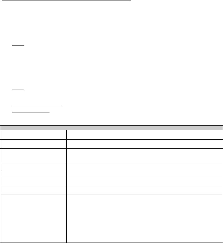
COMUSFLTFORCOMINST 4790.3 REV D CHG 3
07 Nov 2023
V-I-11-70
NOTE: CRAFTSMAN MAY ENTER “NA” IF REQUIRED OR MINIMUM FINAL
DIMENSION(S) AND TOLERANCE SECTION OF BLOCK 7 IS MARKED
“NA” BY PLANNING.
NEW MATERIAL - MANUFACTURED/INSTALLED
Enter the following information for any parts or material, Level I and non-level, in the
appropriate blocks. If a portion of a new valve is used to replace parts (e.g., bonnet and
disc assembly), document the Level I number of the new valve and list the parts that the
assembly consists of in the remarks block with a note that the stem and disc assembly
were taken from the new valve.
QTY Enter the quantity of the replacement parts installed. Enter NA for
raw material used in manufacture.
NOTE: THE TERM “ASSEMBLY” REFERS TO ONE PACKAGE OF PARTS (E.G.,
STEM AND DISC ASSEMBLY OR BALL AND SEAT ASSEMBLY) WHERE
THE ITEM IS ORDERED UNDER ONE STOCK NUMBER, AND IS
ASSIGNED ONE LEVEL I NUMBER.
LOE (Level of Essentiality, Level I) – Enter the MIC level (e.g., “I” or
“LI”) for the part or assembly. Enter NA or dash (-) for non-Level.
MATERIAL IDENT/ Identification must be per Table 1 or Forces Afloat.
DESCRIPTION Record one of the following for raw material used to manufacture
components:
TABLE 1- DOCUMENTATION REQUIREMENTS
Material Control Level Required Information
Level I Material Other Than
Fasteners
MIC Number and any other traceability number, including any local traceability number
(e.g., PNSY MLN – examples Z142, AB12).
Level I Fasteners
Either the MIC number or Material Marking, Color Code, Heat
or Lot Number, and
Manufacturers Symbol (Note: For nuts containing a self-locking insert, the color of the
insert is the Manufacturer’s symbol).
Controlled Structural Material And
SOC Control Division “A” Material
Traceability Number
SOC Control Division “B” Material Markings providing identification to material type or specification
AERP And Other Rotatable Pool
Material (688 Class, TRIPER, Etc.)
Enter the appropriate rotatable pool serial number (e.g. RP-148A, 4810-013-5812-A3-
0113, TIN -292-11893, etc.)
Transferred And Cannibalized
Material
Enter the Equipment Removal List No. or other material History
or
Traceability number (ERL# XXXX, SSBN-600 EHF #24, etc.)
Other Material Within The LEVEL
I/SUBSAFE Boundary And SOC
Control Division “C” Material
1. Enter at least one of the following documentation attributes:
a. Stock Number (from package or container)
b. Part Number (from package or piece)
c. Part Number and associated Manufacturing Work Procedure (for manufactured
items)
d. Local Traceability Number (from piece or tag)
e. Drawing and Piece Number (from piece or tag)
f. Generic, MIL-SPEC, or Material Specification Marking (from piece)
g. NDT record numbers or test results for items verified by generic material testing.
2. For SOC components only: Enter the stock number of the “O-ring lubricant or any
sealant used during assembly.
MIC NUMBER
RAW MATERIAL NSN
GENERIC MATERIAL

COMUSFLTFORCOMINST 4790.3 REV D CHG 3
07 Nov 2023
V-I-11-71
MIL-SPEC
MATERIAL SPECIFICATION MARKING
NDT RECORD OR TESTING RESULTS FOR GENERIC MATERIAL TESTING
NOTE: IF NDT IS REQUIRED, RECORD SATISFACTORY NDT REPORT NUMBER
OR ENCLOSURE NUMBER IN THIS BLOCK AND ATTACH OR INCLUDE
A COPY OF THE REPORT.
TEST REQ’D Planning must enter the test(s) (e.g., NDT, hydrostatic pressure
testing, etc.) required to ensure proper certification.
PROCESS IDENTIFIED, MATERIAL AND TEST HAS BEEN SATISFACTORILY
ACCOMPLISHED IN ACCORDANCE WITH REQUIREMENTS
Craftsman must sign, record badge number and date of the signature, verifying that each
repair process, material installed or utilized, and test has been satisfactorily accomplished
per the requirements and the OQE documented in Blocks 7 and 8, respectively.
NOTE: IF UNSATISFACTORY, THE CRAFTSMAN WILL INITIATE ACTION TO
RESOLVE THE UNSATISFACTORY CONDITION (E.G., SUBMIT A DF).
INDICATE THE ACTION TAKEN TO RESOLVE THE UNSATISFACTORY
CONDITION ALONG WITH A SIGNATURE, BADGE NUMBER AND DATE
IN BLOCK 9. DO NOT SIGN BLOCK 8 (FOR THE SPECIFIC LINE NO.)
UNLESS A SATISFACTORY REPAIR IS COMPLETED OR THE
UNSATISFACTORY CONDITION IS ACCEPTED.
BLOCK 9 - ADDITIONAL INFORMATION/SKETCHES
This block can be used to provide additional information, signatures, and sketches (if required
to clarify repair area(s)). If there is insufficient room, the back of the form or the addition of a
second page is allowed. Include a signature, badge number, and date with any additions to
this block. Initials may be entered in lieu of an employee’s signature and badge number, if a
corresponding employee’s signature and badge number appears elsewhere on the same page.
NOTE: IF MORE THAN ONE REPAIR IS BEING ACCOMPLISHED, IDENTIFY
THE ADDITIONAL INFORMATION, SIGNATURES, AND SKETCHES BY
THE LINE ITEM NUMBERS IN BLOCK 7.
BLOCK 10 - QA INSPECTOR/SHOP SUPERVISOR/BADGE NO./DATE
NA if inspection is not required by the technical work document (e.g., TGI, FWP).
BLOCK 11 - QAS SIGNATURE/BADGE NO. (RECORDS HAVE BEEN
REVIEWED FOR COMPLETENESS)
For SUBSAFE or SOC Components Only: QAS or cognizant QA representative as defined
by local instructions, will sign, enter badge number, and date in this block to indicate the
completeness of the entries.
For other components: the Production Shop or Work Center Supervisor must sign that the
records have been reviewed for completeness.
COMUSFLTFORCOMINST 4790.3 REV D CHG 3
07 Nov 2023
V-I-11-72
SUBMARINE FLIGHT CRITICAL COMPONENT (SFCC) ACCESS, REMOVAL AND INSTALLATION RECORD
QA FORM 17D
Planning must fill in blocks identified by a prior to issuing Page ____ of ____
1. SHIP
HULL
NO.
2. JCN 3. LWC/SHOP 4. CWP/REC SER NO.
5. SYSTEM(S) COMPONENT 6. NOMENCLATURE 7. REFERENCE DESIGNATION
8. REFERENCES
A.
B.
C.
D.
E.
F.
9. DIAGNOSTICS BLOCK CONTINUED ON REVERSE
ALERT MESSAGE(S)
SYSTEM STATUS DISPLAY FAULT
STATUS
LINE REPLACEABLE UNIT (LRU)
CALLOUT(S)
ADDITIONAL DIAGNOSTIC
INDICATIONS
EXISTING PERTINENT FAULT DATA
10. EXISTING SFCC REMOVAL
SFCC NSN with SMIC SFCC PART NUMBER
SFCC SERIAL
NUMBER
CHASSIS LOCATION & INFO
SW VERSION
REMOVED
11. NEW SFCC INSTALLATION/SFCC PROGRAMMED IN PLACE
SFCC NSN with SMIC SFCC PART
NUMBER
SFCC SERIAL
NUMBER
CHASSIS LOCATION
& INFO
SW VERSION
INSTALLED
SFCC
CONFIGURED
PROPERLY
INSTALLED &
ENGAGED /
CABLE
RECONNECTED
SAT
UNSAT
SAT
UNSAT
12. SFCC RESTORATION 13. OPERATIONAL VERIFICATION
SFCC POWERED UP ONLINE/AVAILABLE SYSTEM STATUS
OK
BUILT IN TEST SFCC ENGAGED OPERABILITY
TEST
SAT / UNSAT SAT / UNSAT SAT / UNSAT SAT / UNSAT
SAT / UNSAT
SAT / UNSAT
14. SOFTWARE INSTALLATION 15. SOFTWARE VERIFICATION
INSTALLATION
SOFTWARE REV
SFCC SOFTWARE
REV
VDD CHECKSUM INSTALLATION CHECKSUM NEW SFCC CONFIGURED
SIMILARLY AS REMOVED SFCC
SAT / UNSAT
16. REMARKS
17. CRAFTSMAN SIGNATURE DATE 18. AIT LEADER/INSPECTOR SIGNATURE DATE
19. RECORD HAS BEEN REVIEWED FOR COMPLETENESS
OSIC / QAS / QAO SIGNATURE DATE

COMUSFLTFORCOMINST 4790.3 REV D CHG 3
07 Nov 2023
V-I-11-73
QA FORM 17D INSTRUCTIONS
SUBMARINE FLIGHT CRITICAL COMPONENT (SFCC) ACCESS, REMOVAL AND
INSTALLATION RECORD
REFERENCES:
(a) NAVSEA T9044-AD-MAN-010 - Requirements Manual for Submarine Fly-By-
Wire Ship Control Systems
NOTE: PLANNING MUST FILL IN BLOCKS IDENTIFIED BY A PRIOR TO
ISSUING.
PURPOSE: To provide a standard form to document the SFCC access, replacement, removal
and installation record capturing the requirements of reference (a), Appendix H.
REQUIREMENTS:
1. The FORM 17D is required for all SFCC work within the boundary specified in reference (a).
2. Form 17D must be used for each component that requires controlled access, replacement,
removal or installation.
NOTE: ANY BLOCK NOT USED WILL BE MARKED “N/A”.
TOP OF FORM: Page ___ of ___
NOTE A TECHNICAL WORK DOCUMENT MAY CONTAIN MULTIPLE QA
FORMS OF THE SAME TYPE, (E.G. MORE THAN ONE QA-26). THE PAGE
ENTRY IS FOR THIS SPECIFIC FORM, NOT THE TOTAL NUMBER OF
PAGES ON ALL FORMS OF THE SAME TYPE.
Enter the page number, starting with page 1, of total number of QA form pages (e.g., 1 of ,
2 of ). The last number reflects the total number of QA Form pages written. This block is
filled in by a QAI or the QAO after all certification testing is complete before block 19 on the
QA-9 is signed. (e.g., 1 of 3, 2 of 3, 3 of 3).
BLOCK 1 - SHIP/HULL NO.
Planner enter the ship’s name and hull number.
BLOCK 2 - JCN
Planner enter the Job Control Number (JCN).
BLOCK 3 - LWC/SHOP
Planner enter the lead shop assigned to install the component.
BLOCK 4 - CWP/REC SER NO.
Planner enter the CWP/REC serial number or enter NA if no CWP/REC is required. Do not
list the CWP/REC revision.
BLOCK 5 - SYSTEM(S)/COMPONENT
Planner enter the noun name of the system and component (if applicable) (e.g., SCPU
CHANNEL A CPU#2 or CIRCUIT 1DB). If record is for in-shop restoration, enter the serial
number of the material if known.

COMUSFLTFORCOMINST 4790.3 REV D CHG 3
07 Nov 2023
V-I-11-74
BLOCK 6 - NOMENCLATURE
Planner enter the system or component nomenclature as described in the technical
documentation.
BLOCK 7 - REFERENCE DESIGNATION
Planner enter the reference designation of the component as described in the technical
documentation.
BLOCK 8 - REFERENCES
Planner enter the applicable component technical reference documents.
BLOCK 9 - DIAGNOSTICS
Check the block if diagnostic codes or data are continued on reverse of form. If necessary,
additional diagnostic codes or data may be listed on reverse of form.
Craftsman record diagnostic data as appropriate for SFCC being replaced as part of repair
efforts. Mark “N/A” if repair effort is not being performed.
• Alert Messages - Enter any observed Alert Messages displayed by the Ship Control
Station
• Fault Status - Enter any fault status message observed at the system status display
• LRU Callout - Enter any Line Replaceable Unit (LRU) Callouts
• Additional Diagnostic Indications - Record any additional diagnostic information
• Existing pertinent fault data - Record any existing pertinent fault data identified on the
MC/DMAC
NOTE: SFCC MATERIAL WILL HAVE CERTIFICATE OF COMPLIANCE (COC)
OR A SMIC; EITHER IS ACCEPTABLE.
BLOCK 10 - EXISTING SFCC REMOVAL
List data required as appropriate for each of the provided blocks. Record the specific
components software revision level. If software is pre-programmed on SFCC, record the
software revision level identified on the applicable SFCC Certificate of Conformance.
NOTE: SFCC MATERIAL WILL HAVE CERTIFICATE OF COMPLIANCE (COC)
OR A SMIC; EITHER IS ACCEPTABLE.
BLOCK 11 - NEW SFCC INSTALLATION
Craftsman mark as “SAT”, “UNSAT” or list data required as appropriate for each of the
provided blocks. Record the specific components software revision level. If software is pre-
programmed on SFCC, record the software revision level identified on the applicable SFCC
Certificate of Conformance.
BLOCK 12 - SFCC RESTORATION
Craftsman mark as “SAT” or “UNSAT” as appropriate.
BLOCK 13 - OPERATIONAL VERIFICATION

COMUSFLTFORCOMINST 4790.3 REV D CHG 3
07 Nov 2023
V-I-11-75
Craftsman mark as “SAT” or “UNSAT” as appropriate.
BLOCK 14 - SOFTWARE INSTALLATION
NOTE: BLOCK 14 ONLY USED DURING SYSTEM OR SOFTWARE UPGRADES
OR ALTERATIONS.
Craftsman list data required as appropriate for each of the provided blocks (N/A if not used).
• Installation Software Rev - Record the Ship Control System operational software revision
level identified in the change vehicle.
• VDD Checksum - Record the checksum value identified in the Version Description
Document (VDD). Should match Installation Checksum.
BLOCK 15 - SOFTWARE VERIFICATION
NOTE: “INSTALLATION CHECKSUM” IS ONLY USED FOR PROGRAMMED SW
SMIC SFCC COMPONENTS OR DURING VU SMIC UPGRADES OR
ALTERATION (N/A IF NOT USED).
• Installation Checksum - Record the checksum as observed during installation. Should
match VDD Checksum from original installation.
• New SFCC Configured Similarly as Removed SFCC - Verify that the SFCC is
configured similarly as the SFCC removed from the FBW SCS chassis per the controlled
work package documentation. This includes satisfactory VDD Checksum verification (if
applicable).
BLOCK 16 - REMARKS
Craftsman or Alteration Installation Team (AIT) Lead will record amplifying information as
required or additional space is required, and will sign, print name and date Block 16.
BLOCK 17 - CRAFTSMAN SIGNATURE
Craftsman must sign this block signifying that the work has been accomplished.
BLOCK 18 - AIT LEADER/INSPECTOR SIGNATURE
(SHIP’S FORCE) INSPECTOR or QAI will enter signature, date and badge number for final
review, signifying the accuracy of the completed form and witnesses testing associated with
Blocks 13, 14 and 15 (as applicable). If any entry is UNSAT, initiate action to resolve the
UNSAT condition and indicate the action taken in the “Remarks” block. Do not sign unless a
satisfactory repair is completed or the UNSAT condition is accepted.
BLOCK 19 - RECORD HAS BEEN REVIEWED FOR COMPLETENESS
The OSIC, QAS or QAO must sign, date and enter badge number for final review, signifying
entries are complete and that the data agrees with the listed requirements.
COMUSFLTFORCOMINST 4790.3 REV D CHG 3
07 Nov 2023
V-I-11-76
STUD INSTALLATION RECORD Planning must fill in blocks identified by a prior to issuing
Page _____ of _____
Q
A FORM 17SI
1. SHIP
HULL
NO.
2. JCN 3. LWC / SHOP 4. CWP / REC SER NO.
5. SYSTEM/COMPONENT / ROTATABLE POOL
NO.
6. NEW MATERIAL DESCRIPTION QTY LOE IDENT (E.G., MIC NO/NSN/TRACEABILITY NO.)
7. DESCRIPTION OF STUD DATA REQUIREMENTS:
JOINT MAPPING DRAWING & REV JOINT NO/JOINT DESCRIPTION REQUIRED STUD DIAMETER AND THREAD SERIES
DETAIL DRAWING & REV STUD PIECE NO. REQUIRED STUD LENGTH
AUTHORIZED INSTALLATION METHOD:
CLASS 3 FIT: ANAEROBIC THREAD LOCKING COMPOUND
CLASS 5 FIT: INTERFERENCE FIT
REQUIRED MIN BREAKAWAY TORQUE OR STUD SETTING TORQUE (List
Torque Reference)
FT-LB IN-LB
8. STUD INSTALLATION DOCUMENTATION
REQUIRED ANAEROBIC LOCKING COMPOUND: GRADE
ACTUAL ANAEROBIC LOCKING COMPOUND: MANUFACTURER OR PRODUCT
NAME & GRADE OR MANUFACTURER PRODUCT NUMBER
(Leave blank for class 5 fit)
(Leave blank for class 5 fit)
REQUIRED STUD STANDOUT & TOLERANCE
ACTUAL STUD(S) STANDOUT:
9. SKETCH/REMARKS: PROVIDE A SKETCH OF THE FASTENER CIRCLE, SHOWING ALL THE STUDS INSTALLED & ORIENTATION TO COMPONENT:
(CRAFTSMAN/QAI SUBMIT A DF TO RESOLVE UNSAT DATA)
CRAFTSMAN SIGNATURE VERIFIES:
1. FASTENER SIZE, LENGTH, AND CLASS OF FIT IS IAW STATED
REQUIREMENTS.
2. MINIMUM BREAKAWAY TORQUE OR STUD SETTING TORQUE IS
SATISFACTORY.
3. STUD INSTALLATION COMPLIES WITH ALL INSTALLATION REQUIREMENTS.
4. ALL NEW MATERIAL MEETS SPECIFIED REQUIREMENTS, IS INSTALLED &
LISTED ABOVE. MATERIAL NOT LISTED AS NEW IS EXISTING AND IS
ACCEPTABLE FOR RE-USE & IS INSTALLED.
10. CRAFTSMAN SIGNATURE / BADGE NO. DATE
11. QAI/SHOP SUPERVISOR SIGNATURE /BADGE NO. (RECORD REVIEWED FOR FINAL ACCEPTANCE) DATE
12. QAS SIGNATURE / BADGE NO. (RECORDS HAVE BEEN REVIEWED FOR COMPLETENESS)
DATE

COMUSFLTFORCOMINST 4790.3 REV D CHG 3
07 Nov 2023
V-I-11-77
QA FORM 17SI INSTRUCTIONS
STUD INSTALLATION RECORD
PURPOSE: To document the proper OQE for installing Level One studs in a SOC,
SUBSAFE or Level One application when directed by the work procedure.
TOP OF FORM: Page ___ of ___
NOTE A TECHNICAL WORK DOCUMENT MAY CONTAIN MULTIPLE QA
FORMS OF THE SAME TYPE, (E.G. MORE THAN ONE QA-26). THE PAGE
ENTRY IS FOR THIS SPECIFIC FORM, NOT THE TOTAL NUMBER OF
PAGES ON ALL FORMS OF THE SAME TYPE.
Enter the page number, starting with page 1, of total number of QA form pages (e.g., 1 of ,
2 of ). The last number reflects the total number of QA Form pages written. This block is
filled in by a QAI or the QAO after all certification testing is complete before block 19 on the
QA-9 is signed. (e.g., 1 of 3, 2 of 3, 3 of 3).
PROCEDURE. The numbered blocks on QA form 17SI correspond with the block instructions
listed. Blocks marked with a must be completed by the planner prior to issue.
BLOCK 1 - SHIP HULL NO.
Enter the ship’s name and hull number.
BLOCK 2 - JCN
Enter the JCN.
BLOCK 3 - LWC
Enter the shop number of the LWC.
BLOCK 4 - CWP/REC SERIAL NO.
Enter the CWP/REC serial number or enter N/A if no CWP/REC is required. Do not list the
CWP/REC revision.
BLOCK 5 - SYSTEM/COMPONENT
Enter the noun name of the system and component being repaired. (e.g., MSW-25 Hull
Insert). If the record is for in-shop repair or manufacture of rotatable pool item, enter the
serial number of the item.
BLOCK 6 - NEW MATERIAL DESCRIPTION
NOTE: THE CRAFTSMAN MUST COMPLETE ALL SECTIONS OF BLOCK 6.
MATERIAL DESCRIPTION
Enter a description of the new studs installed in the joint. Include diameter, thread, and
length (e.g., Stud, 5/8”-11x3”).
QTY - Record the quantity of the new studs installed.
LOE - Enter the Level of Essentiality as “I” or “NA” as appropriate.
IDENTIFICATION/MIC/TRACEABILITY NO.

COMUSFLTFORCOMINST 4790.3 REV D CHG 3
07 Nov 2023
V-I-11-78
Document the markings from the fastener to include either:
(1) The color code and the heat or lot number, material type and manufacturer’s
symbol (for nuts containing a self-locking insert, the color of the insert is the
manufacturer’s symbol).
(2) The MIC number (when MIC number is on the fastener or on the individual tag
for some small fasteners).
BLOCK 7 - DESCRIPTION OF STUD DATA REQUIREMENTS
NOTE: THE PLANNER MUST COMPLETE ALL SECTIONS OF BLOCK 7.
JOINT MAPPING DRAWING & REV
Enter the joint mapping drawing and revision. Enter NA when no mapping drawing
exists.
JOINT NO/JOINT DESCRIPTION
Enter the joint number if applicable or clearly describe the installation location. If joint
numbers are assigned via a sketch in the TWD, identify the sketch enclosure number and
TWD number.
REQUIRED STUD DIAMETER & THREAD SERIES
Enter the required diameter and thread series of the replacement stud.
DETAIL DRAWING & REV
Enter the detailed drawing and revision number. For original issue (non-revised)
drawings, enter a dash (-). Include vendor name for vendor drawings. Revisions for
Technical Manuals are not required.
STUD PIECE NO.
Enter the detailed drawing pertaining to the stud.
REQUIRED STUD LENGTH
Enter the required length of the stud.
REQUIRED CLASS OF FIT AUTHORIZED INSTALLATION METHOD
Mark the appropriate block for the required class of fit.
TORQUE REFERENCE
Enter the source for the torque value (e.g., NAVSEA S9505-AM-GYD-010, SAE J2270,
drawing, SMS, etc.).
REQUIRED MIN BREAKAWAY TORQUE OR STUD SETTING TORQUE
Enter the required minimum breakaway torque, the tolerance or range, and mark the
appropriate torque units box (ft-lb or in-lb).
BLOCK 8 - STUD INSTALLATION DOCUMENTATION
REQUIRED ANAEROBIC LOCKING COMPOUND: GRADE

COMUSFLTFORCOMINST 4790.3 REV D CHG 3
07 Nov 2023
V-I-11-79
Planner enter the required grade of anaerobic locking compound. Leave blank for Class
5 installation method.
ACTUAL ANAEROBIC LOCKING COMPOUND MANUFACTURER OR PRODUCT
NAME & GRADE OR MANUFACTURER PRODUCT NUMBER
Record either the manufacturer or the product name in addition to the material grade or
manufacturer product number of the thread locking compound used. Leave blank for
Class 5 installation method.
REQUIRED STUD STANDOUT & TOLERANCE
Enter the required stud standout and tolerance.
ACTUAL STUD(S) STANDOUT
Record the actual stud standout for each new or reset existing stud.
BLOCK 9 - SKETCH/REMARKS
Provide a sketch of the fastener circle, showing all the newly installed and all re-installed
existing studs and their orientation to the component.
BLOCK 10 - CRAFTSMAN SIGNATURE/BADGE NO./DATE
Craftsman print name, enter signature, badge number and date after completing Blocks 6, 8
and 9. Do not sign Block 10 unless signing for satisfactory results. If unsat, the craftsman
will report the unsat condition and document the rework on the applicable QA form. If only
one fastener is unsat, the craftsman may sign for completing the installation of the remaining
studs but must clearly annotate in Block 9 the location of the stud and reason for the
unsatisfactory condition.
Craftsman signature signifies the following:
Fastener size, length, and class of fit are per the stated requirements
Minimum breakaway torque or stud setting or stud setting torque (as applicable) is
satisfactory
Stud installation complies with all installation requirements
All new material meets specified requirements, is installed and listed in Block 6
Material not listed as new is existing, and is acceptable for re-use and is installed
BLOCK 11 - QAI/SHOP SUPERVISOR SIGNATURE/BADGE NO./DATE
NOTE: REQUIRED FOR SOC, SUBSAFE AND LEVEL I COMPONENTS ONLY.
Inspector or shop supervisor print name, enter signature, badge number and date certifying the
accuracy of the data recorded in Block 6, 8 and 9. This signature is only required for SOC,
SUBSAFE and Level I components.
BLOCK 12 - RECORDS HAVE BEEN REVIEWED FOR COMPLETENESS
QAS or QAO will print name, enter signature, badge number and date for final review,
signifying the accuracy of the completed form for SUBSAFE or SOC items only. For other
COMUSFLTFORCOMINST 4790.3 REV D CHG 3
07 Nov 2023
V-I-11-80
components, the Work Center supervisor must sign and date the form signifying the accuracy
of the completed form.
COMUSFLTFORCOMINST 4790.3 REV D CHG 3
07 Nov 2023
V-I-11-81
HANDLING EQUIPMENT TEST RECORD Page____ of ____
QA FORM 17W (Front) For CWPs, planning must fill in blocks identified by a prior to issuing.
1. SHIP HULL NO. 2. JCN 3. LWC / SHOP 4. CWP / REC SER NO.
5. Equipment Description:
6. Log I.D. Number: 7. Manufacturer or Local Serial Number (Hull No.- Work Center-
Number):
8. NAVSEA Drawing Number/Revision used for Test:
9. Safe Working Load (SWL) in pounds: 10. Dynamic Test Load (DTL) in pounds:
11. Static Test Load (STL) in pounds: 12. STL Frequency in months:
13a. Test Type 13b. Testing Activity 13c. Test Activity Witness 13d. Quality Assurance
Action
Signature Signature
Date Print Name Print Name
Action
Signature Signature
Date Print Name Print Name
Action
Signature Signature
Date Print Name Print Name
Action
Signature Signature
Date Print Name Print Name
Action
Signature Signature
Date Print Name Print Name
14. Remarks:
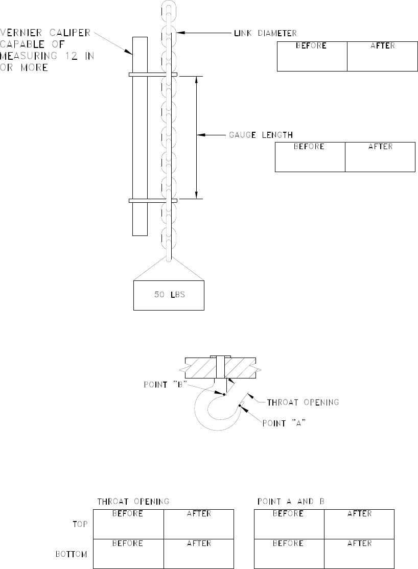
COMUSFLTFORCOMINST 4790.3 REV D CHG 3
07 Nov 2023
V-I-11-82
HANDLING EQUIPMENT TEST RECORD
QA FORM 17W (Back) FIGURE 1

COMUSFLTFORCOMINST 4790.3 REV D CHG 3
07 Nov 2023
V-I-11-83
QA FORM 17W INSTRUCTIONS
HANDLING EQUIPMENT TEST RECORD INSTRUCTIONS
PURPOSE: To provide a report form for work, tests and inspections not covered by other
QA forms. This form can be used for handling equipment weight testing
except cranes and strategic weapons handling equipment.
TOP OF FORM: Page ___ of ___
NOTE A TECHNICAL WORK DOCUMENT MAY CONTAIN MULTIPLE QA
FORMS OF THE SAME TYPE, (E.G. MORE THAN ONE QA-26). THE PAGE
ENTRY IS FOR THIS SPECIFIC FORM, NOT THE TOTAL NUMBER OF
PAGES ON ALL FORMS OF THE SAME TYPE.
Enter the page number, starting with page 1, of total number of QA form pages (e.g., 1 of ,
2 of ). The last number reflects the total number of QA Form pages written. This block is
filled in by a QAI or the QAO after all certification testing is complete before block 19 on the
QA-9 is signed. (e.g., 1 of 3, 2 of 3, 3 of 3).
PROCEDURE: The numbered blocks on QA form 17W correspond with the block instructions
listed. When this form is used to certify manufacture or repair of handling
equipment, the planning organization must fill in Blocks 1 through 11
(identified by a ) prior to issuing a procedure requiring use of this form.
When this form is used to perform periodic handling equipment testing, the
weight test supervisor or shop supervisor must fill in Blocks 1 through 12
(identified by a ) prior to performing testing.
BLOCK 1 - SHIP HULL NO.
Enter the ship’s name and hull number.
BLOCK 2 - JCN
Enter the JCN.
BLOCK 3 - LWC/SHOP
Enter the shop number of the LWC.
BLOCK 4 - CWP/REC SERIAL NO.
Enter the CWP serial number or enter NA if no CWP/REC is required. Do not list the
CWP/REC revision.
BLOCK 5 - EQUIPMENT DESCRIPTION
Enter the name and a readily understood description of the equipment or component name
from the Test Load Methods Drawing (TLMD). If the equipment is permanently installed
(e.g., a monorail or pad eye, etc.), enter the compartment location, (e.g., torpedo room, port,
overhead, and frame 21.)
BLOCK 6 - LOG I.D. NUMBER
Enter log identification number from the TLMD when applicable.
BLOCK 7 - MANUFACTURER OR LOCAL SERIAL NUMBER

COMUSFLTFORCOMINST 4790.3 REV D CHG 3
07 Nov 2023
V-I-11-84
Enter the manufacturer or Local Serial Number when applicable (i.e., Hull No. - Work Center
- Number).
BLOCK 8 - NAVSEA DRAWING NUMBER/REVISION
Enter NAVSEA drawing number and revision for drawing used to conduct the test.
BLOCK 9 - SAFE WORKING LOAD (SWL)
Enter the item’s Safe Working Load (SWL), in pounds, from the TLMD.
NOTE: LIST THE SWL FOR BOTH THE SHORT AND LONG POSITIONS FOR
LOADING POLES.
BLOCK 10 - DYNAMIC TEST LOAD (DTL)
Enter the item’s Dynamic Test Load (DTL), in pounds, from the TLMD.
BLOCK 11 - STATIC TEST LOAD (STL)
Enter the item’s Static Test Load (STL), in pounds, from the TLMD.
BLOCK 12 - STL FREQUENCY
Enter the frequency required for the static test in months.
NOTE: STRATEGIC WEAPONS HANDLING EQUIPMENT COVERED UNDER THE
PREVENTIVE MAINTENANCE MATERIAL PROGRAM (PMMP) DOES
NOT REQUIRE A QA FORM 17W. EQUIPMENT NOT COVERED UNDER
THE PMMP MUST MEET THE REQUIREMENTS OF THIS MANUAL.
BLOCK 13 - TEST TYPE
Enter the test date, the action taken (e.g., STL, DTL, MT, VT, tension, compression, short or
long for loading poles) and the name or hull number of the testing facility. Print the name
(e.g., first name, middle initial and last name) of the test facility witness. The test facility
witness must then sign the block above the name. If test facility witness signature or QA
signature cannot be obtained, the source document bearing that signature will be obtained and
retained in the weapons handling test record log. Only the latest source document applicable
to any particular piece of equipment or component need be retained.
BLOCK 14 - REMARKS
(Craftsman, QAI, QAS or Planning) Enter any pertinent remarks or additional information
related to the repair or assembly of the component. Each entry must contain signature, badge
number and date except where the entry is pre-printed on the form by Planning.
FIGURE 1 Record measurement in blocks provided on the back of the QA form 17W when
applicable.
a. Hook throat opening measurements and tram point pre-test or post-test measurements
when new, or as first recorded, per NSTM 700 or PMS.
b. Length and link diameters of hoist load chains when new, or as first recorded, per
NSTM 700 or PMS.
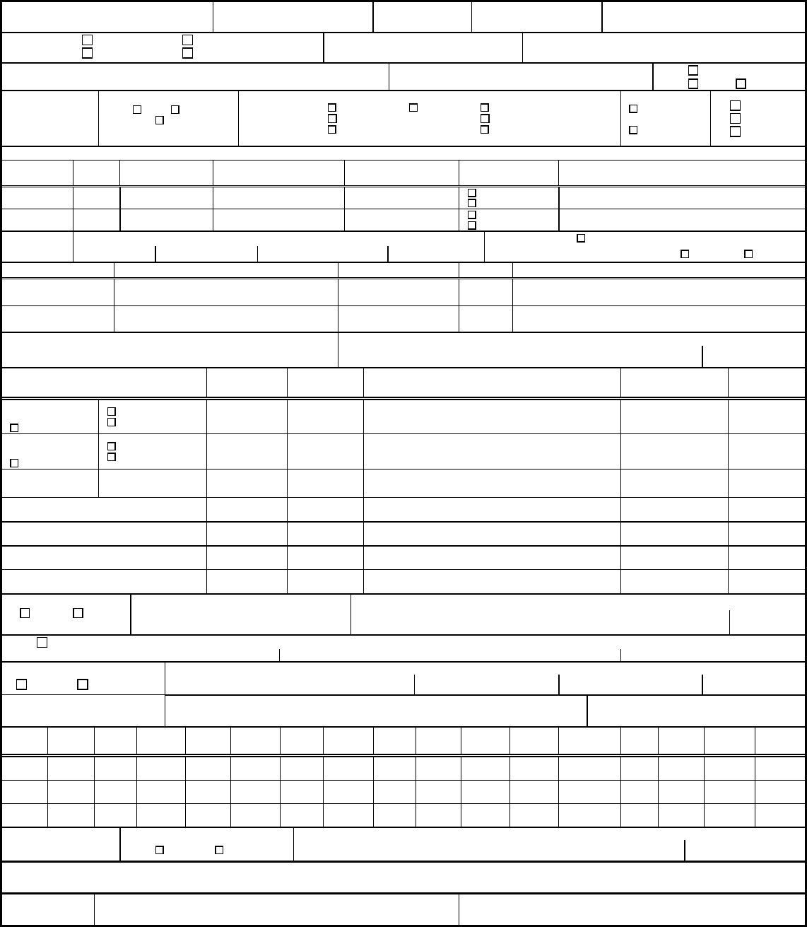
COMUSFLTFORCOMINST 4790.3 REV D CHG 3
07 Nov 2023
V-I-11-85
SILVER BRAZE FABRICATION & INSPECTION RECORD
QA FORM 18 (Work planning to fill in blocks/evaluate block options identified by a prior to release)
PAGE
OF
1. SHIP
HULL NO.
2. JCN 3. LWC / SHOP 4. CWP / REC SER NO. 5. SYSTEM / COMPONENT
6.
PURPOSE:
PRODUCTION QUAL 7. INSTALLATION DWG. 8. JOINT ID/DESCRIPTION
RE-QUAL MAINTENANCE OF QUAL
9. JOB DESCRIPTION 10. MAP JOINT DWG 11. P-3A SPECIAL
P-3A P-3B
12. BRAZE
PROC.
13. BRAZE PROCESS
H101 H103
NA
14. JOINT
DESIGN
SOCKET SLEEVE
FACE FEED
SINGLE INSERT
DOUBLE INSERT
EQUAL LAND
UNEQUAL LAND
15. ACCESS
RESTRICTED
(<4”)
UNRESTRICTED
16. ORIGINAL
REPAIR (1)
REPAIR (2)
17. FITTING, PIPE, AND TUBE MATERIALS
DWG PC
NO.
SIZE
THICKNESS
MIL-SPEC P-NUMBER NEW OR EXIST
IDENT (E.G., MIC NO./NSN/TRACEABILITY NO.)
NEW
EXISTING
NEW
EXISTING
18. LAND
WIDTH
PIPE FITTING
CENTER
SOCKET DEPTH
19. FLUX
MINIMUM FLUX
FED SPEC O-F-499: TYPE A TYPE B
20. BRAZE ALLOY MIL-SPEC F- NUMBER GRADE IDENT (E.G., MIC NO./NSN/TRACEABILITY NO.)
INSERT RING
ROD
JOINT DATA IS CORRECT, JOINT AND MATERIAL
MEETS SPECIFIED REQUIREMENTS
21. CRAFTSMAN SIGNATURE/BADGE DATE
22. INSPECTION TYPE
23. ACCEPT 24. REJECT 25. SIGNATURE (Inspector/Craftsman) BADGE NO. DATE
NDT EXISTING
PPG
NOT REQD
VT5X
PT
NDT EXISTING
FTG
NOT REQD
VT5X
PT
DIAMETRICAL
CLEARANCE
FIT UP INSPECTION
ALLOY DRAW
EVIDENCE OF ALLOY
BOTTOM CLEARANCE
26. BRAZED POSITION
VERT HORZ
BRAZING REQUIREMENTS ARE
SATISFACTORY
27. BRAZER SIGNATURE/BADGE NO. DATE
28. NO. UT INSPECTION REQUIRED
NDT PROCEDURE NO. ACCEPTANCE STANDARD:
(NON P-3 A SPECIAL) NAVSEA 0900-LP-001-7000
29. SCANNING METHOD 30. EQUIPMENT MFG. MODEL SERIAL NO. CAL DUE DATE
STATIC CONTINUOUS
31. TRANSDUCER MFG. SIZE TYPE SERIAL NO. FREQUENCY 32. COUPLANT TYPE
33.
LAND
1 2 3 4 5 6 7 8 9 10 11 12 13 14 TOT. AVG.
PPG
MID
FTG
34. TOTAL % BOND 35. DISPOSITION 36. UT INSPECTOR/BADGE DATE
ACCEPT REJECT
37. REMARKS (SHOP REMARKS ALSO)
FINAL
DISPOSITION
38. SUPERVISOR (Signature / Badge / Date) 39. WCS (QAS For SUBSAFE/SOC Only) (Signature / Badge / Date)

COMUSFLTFORCOMINST 4790.3 REV D CHG 3
07 Nov 2023
V-I-11-87
QA FORM 18 INSTRUCTIONS
SILVER BRAZE FABRICATION AND INSPECTION RECORD
PURPOSE: To provide a standard form for documenting OQE for a silver brazed joint.
NOTE: BLOCKS 13, 17, P-NUMBER, 20, F-NUMBER, AND 26 ARE FOR
QUALIFICATION USE ONLY AND ARE NOT REQUIRED FOR
PRODUCTION BRAZES.
TOP OF FORM: Page ___ of ___
NOTE A TECHNICAL WORK DOCUMENT MAY CONTAIN MULTIPLE QA
FORMS OF THE SAME TYPE, (E.G. MORE THAN ONE QA-26). THE PAGE
ENTRY IS FOR THIS SPECIFIC FORM, NOT THE TOTAL NUMBER OF
PAGES ON ALL FORMS OF THE SAME TYPE.
Enter the page number, starting with page 1, of total number of QA form pages (e.g., 1 of ,
2 of ). The last number reflects the total number of QA Form pages written. This block is
filled in by a QAI or the QAO after all certification testing is complete before block 19 on the
QA-9 is signed. (e.g., 1 of 3, 2 of 3, 3 of 3).
PROCEDURE: The numbered blocks on QA form 18 correspond with the block instructions
listed. The planner preparing the work procedure will complete blocks identified with the
diamond symbol. The craftsman will complete blocks without the diamond symbol. The NDT
Supervisor will verify the completed form and sign in Block 38. A QA form 18A will be
attached to this form to complete each brazed joint record.
BLOCK 1 - SHIP HULL NO.
Enter the tended ship’s name and hull number.
BLOCK 2 - JCN
Enter the JCN.
BLOCK 3 - LWC/SHOP
Enter the shop number for the LWC.
BLOCK 4 - CWP/REC SER NO.
Enter the CWP/REC serial number or enter N/A if no CWP/REC is required. Do not list the
CWP/REC revision.
BLOCK 5 - SYSTEM/COMPONENT
Enter the system or component noun name.
BLOCK 6 - PURPOSE
Check appropriate block.
BLOCK 7 - INSTALLATION DRAWING
Enter the installation drawing number and revision.
BLOCK 8 - JOINT ID/DESCRIPTION

COMUSFLTFORCOMINST 4790.3 REV D CHG 3
07 Nov 2023
V-I-11-88
Enter the map joint number from the applicable plan (Block 10). If not a mapped joint, assign
a local unique joint ID number or enter a description of the joint.
BLOCK 9 - JOB DESCRIPTION
Enter a brief statement describing the work.
BLOCK 10 - MAP JOINT DWG
Enter ship’s plan number and revision, which show and identify the map number of the joint
being brazed or enter “NA” if there isn’t a map drawing.
BLOCK 11 - P-3A SPECIAL/P-3A/P 3B
Enter an “X” in the appropriate box.
BLOCK 12 - BRAZE PROCEDURE
Enter the braze procedure used, including revision and change.
BLOCK 13 - BRAZE PROCESS
Enter an “X” in the appropriate block per NAVSEA 0900-LP-001-7000.
BLOCK 14 - JOINT DESIGN
Enter an “X” in the appropriate boxes.
BLOCK 15 - ACCESS
Enter an “X” in the appropriate box.
BLOCK 16 - ORIGINAL/REPAIR
Enter an “X” in the appropriate box.
BLOCK 17 - FITTING, PIPE AND TUBE MATERIALS
a. Enter the fitting piece and pipe or tube piece number from the installation drawing
(Block 7) or NA if not available.
b. Enter the size of the fitting and pipe or tube (e.g., 1/2 Normal Pipe Size (NPS)).
c. Enter the thickness (.127 inches).
d. Enter the actual thickness (minimum value) of the fitting and pipe or tube.
e. Enter the material specification of the component (from Table 4-4 of NAVSEA 0900-
LP-001-7000), when known. If existing, enter “existing”.
f. For qualification purposes, enter the applicable P-number from Table 4-4 of NAVSEA
0900-LP-001-7000.
g. Enter an “X” in the appropriate New or Exist box.
h. Enter the material marking of the component. Enter the MIC Number for new level I
material installed or N/A. Enter other material markings if material is not required to
be level I and marking is present. If fitting is existing and is not marked, an acid
check when required by the TWD to ensure generic material is correct must be
accomplished and documented in remarks block.

COMUSFLTFORCOMINST 4790.3 REV D CHG 3
07 Nov 2023
V-I-11-89
BLOCK 18 - LAND WIDTH
Enter the land width or socket depth for fittings without inserts. N/A blocks that are not
applicable.
BLOCK 19 - FLUX
a. Enter an “X” if minimum flux technique was used.
b. Enter an “X” for flux type per FED-SPEC O-F-499.
BLOCK 20 - BRAZE ALLOY
Enter the Mil-Spec and the alloy grade. Enter the MIC Number when new level I brazing
material is installed in a Level I application or enter “NA” for non-level applications when
material is not required to be level I.
BLOCK 21 - JOINT DATA IS CORRECT/CRAFTSMAN SIGNATURE
Verify data entered is correct and actual material to be used or installed is as specified. Sign
name, enter date and badge number to certify information is correct.
BLOCK 22 - INSPECTION TYPE
a. Mark the appropriate type of inspection.
b. Diametrical Clearance – Enter the actual measurement. Acceptance criteria is per
Table 5.2 of NAVSEA 0900-LP-001-7000.
c. Fit up Inspection-Acceptance criteria of paragraph 7.2.1.a of NAVSEA 0900-LP-001-
7000.
d. Alloy Draw-Acceptance criteria per paragraph 7.2.1.d of NAVSEA 0900-LP-001-
7000.
e. Evidence of Alloy-Acceptance criteria per paragraph 7.2.1.e of NAVSEA 0900-LP-
001-7000.
f. Clearance Acceptance criteria per paragraph 7.2.1.f of NAVSEA 0900-LP-001-7000.
BLOCK 23/24 - ACCEPT/REJECT
Mark the appropriate column.
BLOCK 25 - SIGNATURE
Enter the signature, badge number and date.
BLOCK 26 - BRAZED POSITION
Mark the appropriate block for position brazing performed.
BLOCK 27 - BRAZE PROCEDURE IS SATISFACTORY
Brazer sign name and enter Brazer badge number and date to certify all joint information is
correct.
BLOCK 28 - NDT REQUIREMENTS
a. Enter an “X” if Ultrasonic Testing (UT) is not required.

COMUSFLTFORCOMINST 4790.3 REV D CHG 3
07 Nov 2023
V-I-11-90
b. Enter the NDT procedure number.
BLOCK 29 - SCANNING METHOD
Enter an “X” in the appropriate box.
BLOCK 30 - EQUIPMENT MANUFACTURER
Enter Equipment Manufacture Name, Model, Serial number and calibration Due Date of
Equipment.
BLOCK 31 - TRANSDUCER MANUFACTURER
Enter Equipment Manufacture Name, Size, Type, Serial number, and Frequency of
Equipment.
BLOCK 32 - COUPLANT TYPE
Enter the name of the fluid used.
BLOCK 33 - LAND/PIPE/MID/FTG
Enter the percent of bond, X, NA or NP, as applicable. Enter the total for all segments used
and the average percent bond for the lands (or passes of a non-insert fitting).
BLOCK 34 - TOTAL % BOND
Calculate and enter the total % bond for the joint.
BLOCK 35 - DISPOSITION
Enter an “X” in the appropriate box to accept or reject the joint.
BLOCK 36 - INSPECTOR/BADGE/DATE
UT inspector will sign, enter badge number and date, signifying the technical accuracy of the
data recorded and acceptance or rejection of the joint.
BLOCK 37 - REMARKS
Enter any additional information.
BLOCK 38 - FINAL DISPOSITION/SUPERVISOR
NDT Supervisor print name, badge number, enter signature and date signifying all
information in Blocks 1 through 36 is technically and administratively correct.
BLOCK 39 - FINAL DISPOSITION/RECORD HAS BEEN REVIEWED FOR
COMPLETENESS/QAS
QAS or QAO will print name, enter signature and date for final review, signifying the
accuracy of the completed form for SUBSAFE or SOC items only. For other components, the
Work Center supervisor must sign and date the form signifying the accuracy of the completed
form.
p
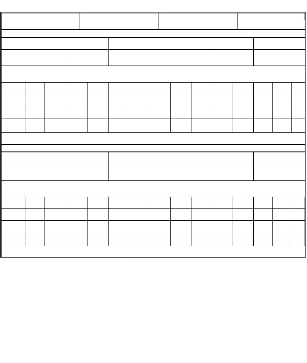
COMUSFLTFORCOMINST 4790.3 REV D CHG 3
07 Nov 2023
V-I-11-91
ULTRASONIC INSPECTION RECORD
QA FORM 18A
1.
PAGE ____ OF ____
2. SHIP HULL 3. JCN 4. LWC/SHOP 5. CWP/REC SERIAL NO.
ULTRASONIC EQUIPMENT AND INSPECTION DATA
6. EQUIPMENT MANUFACTURER
7. MODEL NO. 8. SERIAL NO. 9. TRANSDUCER MANUF. 10. SIZE/FREQ/TYPE 11. SERIAL NO.
12. SCANNING METHOD
[ ] STATIC
[ ] CONTINUOUS
13. COUPLANT TYPE
14. CAL EXP DATE 15. JOINT ID NO. 16. DWG NO.
17. REMARKS/NOTES
18. LAND%
1 2 3 4 5 6 7 8 9 10 11 12 TOTAL
TOTAL
BOND
PIPE
MIDDLE
FITTING
19. DISPOSITION
[ ] ACCEPT [ ] REJECT
20. TOTAL % BOND 21. INSPECTOR/DATE
ULTRASONIC EQUIPMENT AND INSPECTION DATA
6. EQUIPMENT MANUFACTURER
7. MODEL NO. 8. SERIAL NO. 9. TRANSDUCER MANUF. 10. SIZE/FREQ 11. SERIAL NO.
12. SCANNING METHOD
[ ] STATIC
[ ] CONTINUOUS
13. COUPLANT TYPE
14. CAL EXP DATE
15. JOINT ID NO. 16. DWG NO.
17. REMARKS/NOTES
18. LAND%
1 2 3 4 5 6
7 8 9 10 11 12 TOTAL
TOTAL
BOND
PIPE
MIDDLE
FITTING
19. DISPOSITION
[ ] ACCEPT [ ] REJECT
20. TOTAL % BOND 21. INSPECTOR/DATE
NOTES: 1. INCREMENTS FOR WHICH NO ULTRASONIC READING CAN BE OBTAINED WILL BE
MARKED AS FOLLOWS:
“X” - INCREMENTS THAT ARE INACCESSIBLE DUE TO FITTING CONFIGURATION.
“NA” - INCREMENTS THAT ARE INACCESSIBLE DUE TO PIPING CONFIGURATION
OR LOCATION.
“NP” - INCREMENTS IN WHICH THERE IS NO ULTRASONIC PENETRATION.
2. INCREMENTS OF THE ABOVE TYPE WILL BE ASSIGNED PERCENT BOND VALUES
AS FOLLOWS:
“NA” = 0% BOND.
“NP” AND “X” = INCREMENTS UP TO A TOTAL LENGTH NOT EXCEEDING 20% OF
THE CIRCUMFERENCE OF THE LAND WILL BE ASSIGNED A % BOND VALUE
EQUAL TO THAT OF THE LOWEST READABLE INCREMENTS ADJACENT TO THE
“X” OR “NP” INCREMENTS OR 60% WHICHEVER IS THE LEAST. “X” AND “NP”
INCREMENTS IN EXCESS OF 20% OF CIRCUMFERENCE WILL BE ASSIGNED A BOND
VALUE OF 0%. THE INSPECTOR MAY AT THEIR DISCRETION, SHIFT THE
INCREMENTAL SCALE SO THAT THE MINIMUM NUMBER OF INCREMENTS
CONTAIN “X”, “NP” OR “NA” VALUES.

COMUSFLTFORCOMINST 4790.3 REV D CHG 3
07 Nov 2023
V-I-11-92
QA FORM 18A INSTRUCTIONS
ULTRASONIC INSPECTION RECORD
PURPOSE: To supplement the QA form 18 to document UT inspection date, equipment
used, and acceptability of UT results.
BLOCK 1 - PAGE ____ OF _____
NOTE A TECHNICAL WORK DOCUMENT MAY CONTAIN MULTIPLE QA
FORMS OF THE SAME TYPE, (E.G. MORE THAN ONE QA-26). THE PAGE
ENTRY IS FOR THIS SPECIFIC FORM, NOT THE TOTAL NUMBER OF
PAGES ON ALL FORMS OF THE SAME TYPE.
Enter the page number, starting with page 2, of total number of QA forms 18A associated with
the joint (e.g., 2 of 3, 3 of 3). The associated QA form 18 is always page 1 of __. The last
number reflects the total number of QA Form pages written. This block is filled in by a QAI or
the QAO after all certification testing is complete before block 19 on the QA-9 is signed. (e.g., 1
of 3, 2 of 3, 3 of 3).
PROCEDURE: QA form 18A will be completed by the planner, UT NDT Inspector, or both.
The numbered blocks on QA form 18A correspond with the block instructions
listed.
BLOCK 2 - SHIP HULL NO.
Enter the tended ship’s name and hull number.
BLOCK 3 - JCN
Enter the JCN.
BLOCK 4 - LWC/SHOP
Enter the LWC/Shop.
BLOCK 5 - CWP/REC SERIAL NO.
Enter the CWP/REC serial number or enter N/A if no CWP/REC is required. Do not list the
CWP/REC revision.
BLOCKS 6-11 - EQUIPMENT MANUFACTURER/MODEL NO./SERIAL
NO./TRANSDUCER MANUFACTURER/SIZE/TYPE/
FREQUENCY/SERIAL NO.
Enter the information for the equipment used to conduct the inspection.
BLOCK 12 - SCANNING METHOD
Place an “X” in the appropriate box.
BLOCK 13 - COUPLANT TYPE
Enter the name of fluid used.
BLOCK 14 - CAL EXP DATE
Enter the calibration expiration date of the equipment listed in Blocks 6-11.

COMUSFLTFORCOMINST 4790.3 REV D CHG 3
07 Nov 2023
V-I-11-93
BLOCK 15 - JOINT ID NO.
Enter the JID of the joint being UT inspected. If it is a qualification joint and not an actual
production joint, enter the individual’s name performing the qualification.
BLOCK 16 - DWG. NO.
Enter the number of the drawing or plan that identifies the joint listed in Block 15 if a production
braze.
BLOCK 17 - REMARKS/NOTES
Enter any applicable remarks or notes.
BLOCK 18 - LAND/PIPE/MIDDLE/FITTING
Enter percent bond, X, NA or NP as applicable. Enter the total for all segments used and the
average percent bond for the lands (or passes of a no-insert fitting).
BLOCK 19 - DISPOSITION
Place an “X” in the appropriate box to accept or reject the joint.
BLOCK 20 - TOTAL % BOND
Calculate and enter the total % bond for the joint.
BLOCK 21 - INSPECTOR/DATE
NDT Inspector print name, enter signature and date, signifying the technical accuracy of the data
recorded and acceptance or rejection of the joint.
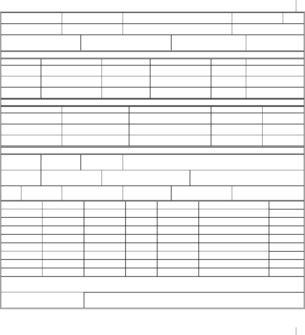
COMUSFLTFORCOMINST 4790.3 REV D CHG 3
07 Nov 2023
V-I-11-94
WELDING IN PROCESS CONTROL/NONDESTRUCTIVE TEST RECORD
QA FORM 20 (FRONT)
When the form is used for production welding, the blocks marked with a
must be completed by the planner. 1. PAGE 1 OF ___
2. SHIP
HULL NO.
3. JCN
4. CWP/REC SER. NO.
5. LWC
6. DATE
7. SYSTEM
8. COMPONENT
9. DWG NO.
10. CWP STEP NO.
11. JOINT ID
12. JOINT DESIGN
13. INST LOCATION: [ ] STBD
COMPT: [ ] C/L
FR: [ ] PORT
14. WELDED LOCATION:
[ ] SHOP
[ ] FIELD
BASE MATERIAL DATA
15. COMP DATA 16. MATERIAL 17. SIZE 18. THICKNESS 19. MATL SPEC 20. MIC NO.
COMPONENT A:
COMPONENT B:
21. [ ] SEAL RING
[ ] BACK RING/STRIP
22. MATERIAL
23. SIZE
24. THICKNESS
25. MATL SPEC
26. MIC NO.
WELDING MATERIAL SPECIFICATIONS AND DATA
27. TYPE OF FILLER(S) 28. SIZE 29. MATL 30. MIL-SPEC 31. MIC NO.
WELD HISTORY
32. WELDING
STANDARD:
33. WELDING
PROCEDURE:
34. DATA SHEET
35. POSITION: [ ] VERT [ ] FLAT [ ] FIXED [ ] 45 DEG
[ ] HORZ [ ] OVHD [ ] ROLLED
36. ACCESSIBILITY:
[ ] 12”OR LESS
[ ] UNRESTRICTED
37. PREHEAT TEMP
38. PREHEAT METHOD
39. POST HEAT. START TIME:
TEMP REQD: STOP TIME:
40. PURGE
GAS:
41. FLOW RATE
42. SHIELD GAS
43. FLOW RATE
44. CUP SIZE
45. TUNGSTEN SIZE
46. WELD LAYER 47. PROCESS 48. QUAL EXP DATE 49. AMPS 50. INTERPASS TEMP 51. WELDER SIGNATURE 52. DATE
53. INSPECTION DATA CONTAINED ON REVERSE OF THIS PAGE
REMARKS:
94. FINAL DISPOSITION:
[ ] ACCEPT
[ ] REJECT
95. NDT SUPERVISOR DATE
THE PERSON DESIGNATED TO SIGN FOR AN ACTION VERIFIES, BASED ON
PERSONAL OBSERVATION OR CERTIFIED RECORDS, AND CERTIFIES BY THEIR
SIGNATURE THAT THE ACTION HAS BEEN PERFORMED IN ACCORDANCE WITH
THE SPECIFIED REQUIREMENTS.
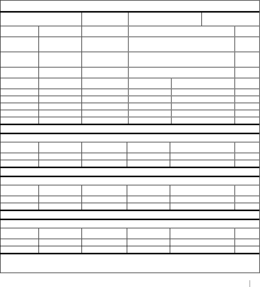
COMUSFLTFORCOMINST 4790.3 REV D CHG 3
07 Nov 2023
V-I-11-95
WELDING IN PROCESS CONTROL/NONDESTRUCTIVE TEST RECORD
QA FORM 20 (BACK) PAGE __OF___
NDT INSPECTION DATA
54. INSPECTION STANDARD 55. WELD CLASS 56. ACCEPTANCE STANDARD 57. ACCEPT CLASS
58. WELD PREP 59. INSP METHOD 60. ACCEPT/REJECT 61. NDT INSPECTOR SIGNATURE 62. DATE
COMPONENT A
[ ] ACCEPT [ ] REJECT
COMPONENT B
[ ] ACCEPT [ ] REJECT
63. JOINT FITUP [ ] ACCEPT [ ] REJECT
64. INSP LAYER 65. INSP METHOD 66. INSP PROC NO 67. ACCEPT/REJECT 68. NDT INSPECTOR SIGNATURE 69. DATE
[ ] ACCEPT [ ] REJECT
[ ] ACCEPT [ ] REJECT
[ ] ACCEPT [ ] REJECT
[ ] ACCEPT [ ] REJECT
[ ] ACCEPT [ ] REJECT
70. NDT INSPECTION DATA REPAIR NO._____ Defect: L W D
71. Repair Method: Excavation: L W D
72. INSP LAYER 73. INSP METHOD 74. INSP PROC NO. 75. ACCEPT/REJECT 76. NDT INSPECTOR SIGNATURE 77. DATE
[ ] ACCEPT [ ] REJECT
[ ] ACCEPT [ ] REJECT
78. NDT INSPECTION DATA REPAIR NO._____ Defect: L W D
79. Repair Method: Excavation: L W D
80. INSP LAYER 81. INSP METHOD 82. INSP PROC NO. 83. ACCEPT/REJECT 84. NDT INSPECTOR SIGNATURE 85. DATE
[ ] ACCEPT [ ] REJECT
[ ] ACCEPT [ ] REJECT
86. NDT INSPECTION DATA REPAIR NO._____ Defect: L W D
87. Repair Method: Excavation: L W D
88. INSP LAYER 89. INSP METHOD 90. INSP PROC NO. 91. ACCEPT/REJECT 92. NDT INSPECTOR SIGNATURE 93. DATE
[ ] ACCEPT [ ] REJECT
[ ] ACCEPT [ ] REJECT
53. REMARKS (Continued):
THE PERSON DESIGNATED TO SIGN FOR AN ACTION VERIFIES, BASED ON
PERSONAL OBSERVATION OR CERTIFIED RECORDS, AND CERTIFIES BY THEIR
SIGNATURE THAT THE ACTION HAS BEEN PERFORMED IN ACCORDANCE WITH
THE SPECIFIED REQUIREMENTS.

COMUSFLTFORCOMINST 4790.3 REV D CHG 3
07 Nov 2023
V-I-11-96
QA FORM 20 INSTRUCTIONS
WELDING IN PROCESS CONTROL/NONDESTRUCTIVE TEST RECORD
PURPOSE: To document in process controls for welding and NDT of a completed weld.
BLOCK 1 - PAGE 1 OF_____
NOTE A TECHNICAL WORK DOCUMENT MAY CONTAIN MULTIPLE QA
FORMS OF THE SAME TYPE, (E.G. MORE THAN ONE QA-26). THE PAGE
ENTRY IS FOR THIS SPECIFIC FORM, NOT THE TOTAL NUMBER OF
PAGES ON ALL FORMS OF THE SAME TYPE.
Enter the page number, starting with page 1, of total number of QA form pages (e.g., 1 of ,
2 of ). The last number reflects the total number of QA Form pages written. This block is
filled in by a QAI or the QAO after all certification testing is complete before block 19 on the
QA-9 is signed. (e.g., 1 of 3, 2 of 3, 3 of 3).
PROCEDURE:
1. QA form 20 will be completed by the planner preparing the CWP, welder and NDT
Inspector(s) observing or performing tests.
2. The numbered blocks on QA form 20 correspond to the block instructions listed. When the
form is used for production welding, the blocks marked with a must be completed by the
planner.
BLOCK 2 - SHIP HULL NO.
Enter the ship’s name and hull number.
BLOCK 3 - JCN
Enter the JCN.
BLOCK 4 - CWP/REC SER. NO.
Enter the CWP/REC Serial Number or enter N/A if no CWP/REC is required. Do not list the
CWP/REC revision.
BLOCK 5 - LWC
Enter the shop number of the LWC.
BLOCK 6 - DATE
Enter the date this form is initiated.
BLOCK 7 - SYSTEM
Enter the noun name of the system.
BLOCK 8 - COMPONENT
Enter the noun name of component.
BLOCK 9 - DWG NO.

COMUSFLTFORCOMINST 4790.3 REV D CHG 3
07 Nov 2023
V-I-11-97
Enter the JID or mapping drawing, if applicable. If not applicable, the planner will enter the
applicable arrangement drawing, system diagram, or component drawing number, or locally
prepared JID sketch.
BLOCK 10 - CWP STEP NO.
Enter the appropriate step number(s) of the CWP.
BLOCK 11 - JOINT ID
Enter the JID from the joint identification or map plan if JID is unavailable, assign local JID.
If for a qualification joint (and not production joint identification) enter individual name
performing the qualification.
BLOCK 12 - JOINT DESIGN
Enter the joint design (e.g., P-73, PN-1A, P-14, PN-7) to be used.
BLOCK 13 - INST LOCATION
Enter the compartment, frame number, and check port, starboard or centerline where the
component is located.
BLOCK 14 - WELDED LOCATION
Check the appropriate block.
BLOCK 15 - COMPONENT A/B
Enter the component name (e.g., pipe, valve).
BLOCK 16 - MATERIAL
Enter the material type (e.g., CUNI, CRES).
BLOCK 17 - SIZE
Enter the iron pipe size or NPS.
BLOCK 18 - THICKNESS
For nuclear welds, enter the design material thickness. For non-nuclear welds, enter the
nominal thickness or the actual measured thickness, if taken, for determining penetrameter
selection for radiographed piping joints per NAVSEA T9074-AD-GIB-010/271, NAVSEA
S9074-AR-GIB-010/278, and NAVSEA T9074-AD-GIB-010/1688 and for determining fillet
legs on partial penetration welds per NAVSEA T9074-AD-GIB-010/271, NAVSEA T9074-
AD-GIB-010/1688 and MIL-STD-1689 (for Surface Force Ships only).
BLOCK 19 - MATL SPEC
Enter the appropriate material specification for the material.
BLOCK 20 - MIC NO.
Enter the MIC number for component A and B, if applicable. Verify the MIC number from
the QA form 2 for new material. For existing material, if the required MIC number is not
readable enter “existing”.
BLOCK 21 - [ ] SEAL RING [ ] BACK RING/STRIP

COMUSFLTFORCOMINST 4790.3 REV D CHG 3
07 Nov 2023
V-I-11-98
Check the appropriate block for the type of backing.
BLOCK 22 - MATERIAL
Enter the material type (e.g., CUNI, CRES).
BLOCK 23 - SIZE
Enter the ring size.
BLOCK 24 - THICKNESS
Enter the actual measured thickness of the ring or strip.
BLOCK 25 - MIL-SPEC
Enter the appropriate MIL-SPEC for the ring or strip.
BLOCK 26 - MIC NO.
Enter the MIC number of the ring or strip, if applicable. Verify the number from the QA form
2.
BLOCK 27 - TYPE OF FILLER(S)
Enter the type of the filler material(s) used (e.g., 9010, 11018, 304, RN62).
BLOCK 28 - SIZE
Enter the size rod, wire, insert, etc.
BLOCK 29 - MATL
Enter the material type (e.g., CUNI, CRES).
BLOCK 30 - MIL-SPEC
Enter the appropriate MIL-SPEC for the filler and insert (if applicable) material.
BLOCK 31 - MIC NO.
Enter the appropriate MIC number for the filler and insert (if applicable) material. Verify the
number from the QA form 2.
BLOCK 32 - WELDING STANDARD
Enter the applicable welding standard.
BLOCK 33 - WELDING PROCEDURE
Enter the weld procedure number.
BLOCK 34 - DATA SHEET
Enter the weld procedure technique sheet number.
BLOCK 35 - POSITION
Check the appropriate block for the weld position.
BLOCK 36 - ACCESSIBILITY
Check the proper block for the actual accessibility.

COMUSFLTFORCOMINST 4790.3 REV D CHG 3
07 Nov 2023
V-I-11-99
BLOCK 37 - PREHEAT TEMP
Enter the actual preheat temperature as measured just prior to welding.
BLOCK 38 - PRE-HEAT METHOD
Enter the required pre-heat method.
BLOCK 39 - POST HEAT TEMP START TIME AND STOP TIME
Enter the temperature required for the post weld heat and the start and stop time for post heat.
BLOCK 40 - PURGE GAS
Enter the type of purge gas.
BLOCK 41 - FLOW RATE
Enter the actual flow rate of the purge gas.
BLOCK 42 - SHIELD GAS
Enter the type of shield gas.
BLOCK 43 - FLOW RATE
Enter the actual flow rate of the shield gas.
BLOCK 44 - CUP SIZE
Enter the gas cup size.
BLOCK 45 - TUNGSTEN SIZE
Enter the tungsten size.
BLOCK 46 - WELD LAYER
Enter the layer of welding (i.e., tacks, root, intermediate, and final).
BLOCK 47 - PROCESS
Enter the type of welding process used (e.g., SMAW, GTAW).
BLOCK 48 - QUAL EXP DATE
Enter qualification expiration date.
BLOCK 49 - AMPS
Enter the welding amperage actually used.
BLOCK 50 - INTERPASS TEMP
Enter the maximum interpass temperature as measured during the process.
BLOCK 51 - WELDER SIGNATURE
Print name and enter signature certifying the data recorded in Blocks 46-51 for the layer
welded.
BLOCK 52 - DATE
Enter the date Block 51 is signed.

COMUSFLTFORCOMINST 4790.3 REV D CHG 3
07 Nov 2023
V-I-11-100
BLOCK 53 - REMARKS
Enter additional remarks or sketches. Enter the appropriate Test, Measuring and Diagnostic
Equipment as defined in Part I, Chapter 5, paragraph 5.2.1 of this volume. If required, a
continuation of Block 53 is on the back of the form at the bottom for additional information.
BLOCK 54 - INSPECTION STANDARD
Enter the applicable inspection standard.
BLOCK 55 - WELD CLASS
Enter class 1 or 2, per the requirements of NAVSEA 250-1500-1, for nuclear welds. The
class (e.g., A-1, A-2, A-F, A-LT, M-1, P-1, PL-T, T-1) for non-nuclear welds.
BLOCK 56 - ACCEPTANCE STANDARD
Enter the applicable acceptance standard.
BLOCK 57 - ACCEPT CLASS
Enter acceptance class 1 or 2, per the requirements of NAVSEA 250-1500-1, for nuclear
welds. The class (e.g., I, II, III) for non-nuclear welds.
BLOCK 58 - WELD PREP - COMPONENT A/B
Enter the component names (e.g., pipe, valve) in the blocks titled Component A and
Component B.
BLOCK 59 - INSPECTION METHOD
Enter the type and method of inspection performed (e.g., VT 5X, PT).
BLOCK 60 - ACCEPT/REJECT
Enter accept or reject to indicate disposition of the weld preps.
BLOCK 61 - NDT INSPECTOR SIGNATURE
NDT Inspector print name and enter signature certifying the disposition of the weld prep.
BLOCK 62 - DATE
Enter the date Block 61 is signed.
BLOCK 63 - JOINT FIT-UP
Enter results (i.e., inspection method, Accept or Reject, Inspector and date) of joint fit up
inspections.
BLOCK 64 - INSP LAYER
Enter the weld layer inspected (i.e., tacks, root, intermediate, final, inside, backside, accessible
or inaccessible).
BLOCK 65 - INSP METHOD
Enter the type and method of inspection performed (e.g., VT 5X, PT).
BLOCK 66 - INSP PROC NO.

COMUSFLTFORCOMINST 4790.3 REV D CHG 3
07 Nov 2023
V-I-11-101
Enter the inspection procedure number.
BLOCK 67 - ACCEPT/REJECT
Enter accept or reject to indicate disposition of the weld layer. If final disposition of the weld
is rejectable, document reason(s) for rejection, description and location of the defect(s) in
Block 53. Document the repair number, length, width and depth of the defect(s) in Block 70,
78, or 86, as applicable.
BLOCK 68 - NDT INSPECTOR SIGNATURE
NDT Inspector print name and enter signature certifying the disposition of the weld layer.
BLOCK 69 - DATE
Enter the date Block 68 is signed.
NOTE: IF REPAIRS ARE REQUIRED TO THE JOINT, RECORD THE
INSPECTIONS IN BLOCKS 72 THROUGH 77, 80 THROUGH 85, AND 88
THROUGH 93 IN THE SAME MANNER AS BLOCKS 64 THROUGH 69.
BLOCKS NOT COMPLETED WILL BE LEFT BLANK EXCEPT AS
DIRECTED BELOW.
BLOCK 70 - REPAIR NUMBER/L W D
The NDT Inspector will enter the repair number, length, width and depth of the defect(s) if
known. Enter N/A for length, width or depth if unknown based on the limitations of the
inspection method performed.
BLOCK 71 - REPAIR METHOD/L W D
The welder will record the method of repair (e.g., file, excavate and weld, weld only).
Document the length, width and depth of the excavation. If excavation was not required for
weld repair, enter N/A for L W D.
BLOCK 78 - REPAIR NUMBER/L W D
The NDT Inspector will enter the repair number, length, width and depth of the defect(s) if
known. Enter N/A for length, width or depth if unknown based on the limitations of the
inspection method performed.
BLOCK 79 - REPAIR METHOD/L W D
The welder will record the method of repair (e.g., file, excavate and weld, weld only).
Document the length, width and depth of the excavation. If excavation was not required for
weld repair, enter N/A for L W D.
BLOCK 86 - REPAIR NUMBER/L W D
The NDT Inspector will enter the repair number, length, width and depth of the defect(s) if
known. Enter N/A for length, width or depth if unknown based on the limitations of the
inspection method performed.
BLOCK 87 - REPAIR METHOD/L W D

COMUSFLTFORCOMINST 4790.3 REV D CHG 3
07 Nov 2023
V-I-11-102
The welder will record the method of repair (e.g., file, excavate and weld, weld only).
Document the length, width and depth of the excavation. If excavation was not required for
weld repair, enter N/A for L W D.
BLOCK 94 - FINAL DISPOSITION
The NDT Inspector who completed the final inspection of the final weld will check acceptable
or rejectable.
BLOCK 95 - NDT SUPERVISOR SIGNATURE DATE
NDT Supervisor print name, enter signature and date signifying all information in Blocks 1
through 93 is technically and administratively correct.
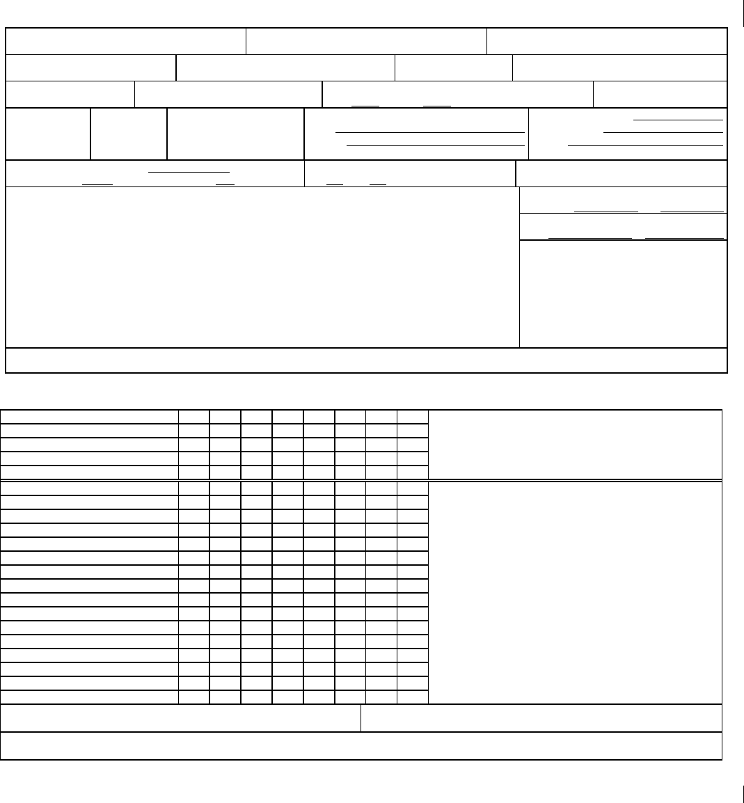
COMUSFLTFORCOMINST 4790.3 REV D CHG 3
07 Nov 2023
V-I-11-103
RADIOGRAPHIC TEST INSPECTION RECORD
QA FORM 20A
1
PAGE ____ OF ____
2. SHIP AND HULL NO. 3. JCN: 4. CWP/REC SERIAL NO.
5. CWP STEP NO. 6. JOINT ID 7. REPAIR NO. 8. INSP STD & CLASS
9. QUALITY LEVEL 10. RT COVERAGE REQD:
( )60 DEG ( )360 DEG ( )100%
11. PENETRAMETER: SOURCE SIDE ( )
SIZE GROUP FILM SIDE ( )
12. SPECIMEN MATL
13. TM 14. TS 15. EXPOSURE TECH
( ) SWE/SWV
( ) DWE/DWV
( ) DWE/SWV
16. FILM:
TYPE
BRAND
LOADED ( ) SINGLE ( ) DOUBLE
17. ISOTOPE: TYPE
DIMENSIONS
CURIE
18. X-RAY MACHINE MFG
MODEL/TYPE VOLTAGE RATING
19. X-RAY PARAMETERS
KV MA FFS ____
20. SFD
21. RADIOGRAPHIC SHOOTING SKETCH 22. SHIM
MATL TM
Depict the following:
(1) Direction of radiation
(2) Placement of penetrameter
(3) Location of location marker
(4) Location of shims (if used)
(5) Location of Pb “B”
(6) Location & thickness of back filter
(7) Location of film
(8) Blocking/masking technique used (if applicable)
NOTE: REFERENCE TO A STANDARD SETUP IS ACCEPTABLE
23. LEAD SCREENS THICKNESS
F B
24. REMARKS
25. RADIOGRAPHER DATE:
26. RADIOGRAPHIC INTERPRETATION
LOCATION MARKERS REMARKS:
VISIBLE T-HOLE
LIGHTEST DENSITY
DARKEST DENSITY
SHIM DENSITY
CRACK DESCRIPTION AND SIZE OF INDICATIONS
SLAG/OXIDE
POROSITY
LOP
LOF
MELT THROUGH
BURN THROUGH
ROOT OX
CRATER PIT
TUNGSTEN
ROOT SUR CONCAVITY
ROOT SUR CONVEXITY
UNDERCUT
ROOT C/L CREASE
INCOMPLETE INSERT MELT
OTHER
27. ( ) ACCEPT ( ) REJECT
28. RT INSPECTOR DATE
29. RT EXAMINER IDENT DATE
THE PERSON DESIGNATED TO SIGN FOR AN ACTION VERIFIES, BASED ON PERSONAL
OBSERVATION OR CERTIFIED RECORDS, AND CERTIFIES BY THEIR SIGNATURE THAT THE
ACTION HAS BEEN PERFORMED IN ACCORDANCE WITH THE SPECIFIED REQUIREMENTS.

COMUSFLTFORCOMINST 4790.3 REV D CHG 3
07 Nov 2023
V-I-11-104
QA FORM 20A INSTRUCTIONS
RADIOGRAPHIC TEST INSPECTION RECORD
PURPOSE: To provide a supplement to the QA form 20 to document the technical aspects
of the radiograph and the acceptance or rejection of the item radiographed.
Both the QA form 20 and QA form 20A are required for a complete
radiographic record of a joint.
PROCEDURE: QA form 20A will be completed by the radiographer and the RT inspector.
The numbered blocks on QA form 20A correspond with the block instructions
listed.
BLOCK 1 - PAGE ____ OF ____
NOTE A TECHNICAL WORK DOCUMENT MAY CONTAIN MULTIPLE QA
FORMS OF THE SAME TYPE, (E.G. MORE THAN ONE QA-26). THE PAGE
ENTRY IS FOR THIS SPECIFIC FORM, NOT THE TOTAL NUMBER OF
PAGES ON ALL FORMS OF THE SAME TYPE.
Enter the page number, starting with page 1, of total number of QA form pages (e.g., 1 of ,
2 of ). The last number reflects the total number of QA Form pages written. This block is
filled in by a QAI or the QAO after all certification testing is complete before block 19 on the
QA-9 is signed. (e.g., 1 of 3, 2 of 3, 3 of 3).
BLOCK 2 - SHIP AND HULL NO.
Enter the tended ship’s name and hull number.
BLOCK 3 - JCN
Enter the JCN.
BLOCK 4 - CWP/REC SERIAL NO.
Enter the CWP/REC serial number or enter N/A if no CWP/REC is required. Do not list the
CWP/REC revision.
BLOCK 5 - CWP STEP NO.
Enter the CWP step number(s).
BLOCK 6 - JOINT ID
Enter JID.
BLOCK 7 - REPAIR NO.
Enter ORIG or repair number (e.g., R-1, R-2).
BLOCK 8 - INSP STD & CLASS
Enter the inspection standard and class.
BLOCK 9 - QUALITY LEVEL
Enter the quality level required.
BLOCK 10 - RT COVERAGE REQ’D

COMUSFLTFORCOMINST 4790.3 REV D CHG 3
07 Nov 2023
V-I-11-105
Indicate the RT coverage required.
BLOCK 11 - PENETRAMETER
Record the penetrameter size and group. Indicate use of source or film side penetrameter.
BLOCK 12 - SPECIMEN MATL
Enter the material type of the item being radiographed (e.g., NICU, CFE).
BLOCK 13 - TM
Enter the nominal or actual, or design material thickness of the item being radiographed per
NAVSEA 250-1500-1 or NAVSEA T9074-AS-GIB-010/271.
BLOCK 14 - TS
Enter the total specimen thickness.
BLOCK 15 - EXPOSURE TECH
Check the appropriate technique used (e.g., if a pipe was radiographed through two walls and
the image of both walls are to be viewed for acceptance, enter an “X” in the brackets next to
DWE/DWV).
BLOCK 16 - FILM
Enter the film type and brand. “X” the appropriate method used to load the film cassette.
BLOCK 17 - ISOTOPE
Record the listed information when using the source.
BLOCK 18 - X-RAY MACHINE MFG
Record the listed information when using the X-ray machine.
BLOCK 19 - X-RAY PARAMETERS
Record the listed information when using the X-ray machine.
BLOCK 20 - SFD
Enter the source to film distance used.
BLOCK 21 - RADIOGRAPHIC SHOOTING SKETCH
The radiographer will draw a sketch indicating the items listed.
BLOCK 22 - SHIM
Enter the shim material used and thickness.
BLOCK 23 - LEAD SCREENS THICKNESS
Record thickness, front and back of the intensifying screens.
BLOCK 24 - REMARKS
The radiographer will use this block to record any unusual technique requirements.
BLOCK 25 - RADIOGRAPHER

COMUSFLTFORCOMINST 4790.3 REV D CHG 3
07 Nov 2023
V-I-11-106
The radiographer will print name, sign and date upon verifying that all the information in
Blocks 1 through 24 is correct.
BLOCKS 26 thru 28- RADIOGRAPHIC INTERPRETATION
NOTE: BLOCK 26 WILL BE COMPLETED BY THE RT INSPECTOR AS THE FILM
IS READ.
a. One RT Inspector will evaluate the radiograph, check ACCEPT/REJECT as
appropriate in Block 27, print name, enter signature and date in Block 28.
b. It is important to note that all indications read must be recorded on the QA form 20A
and dispositioned in the appropriate block.
c. Additional sheets may be added to the report by the RT Inspector. The additional
sheets will be properly numbered and will be authenticated with printed name and
signature on each sheet by the RT Inspector making up the report.
BLOCK 29 - RT EXAMINER
The Command RT Examiner will review the weld record (including radiographic film) for
completeness accuracy and compliance with applicable standards, print name, enter signature,
unique identification number, and date.
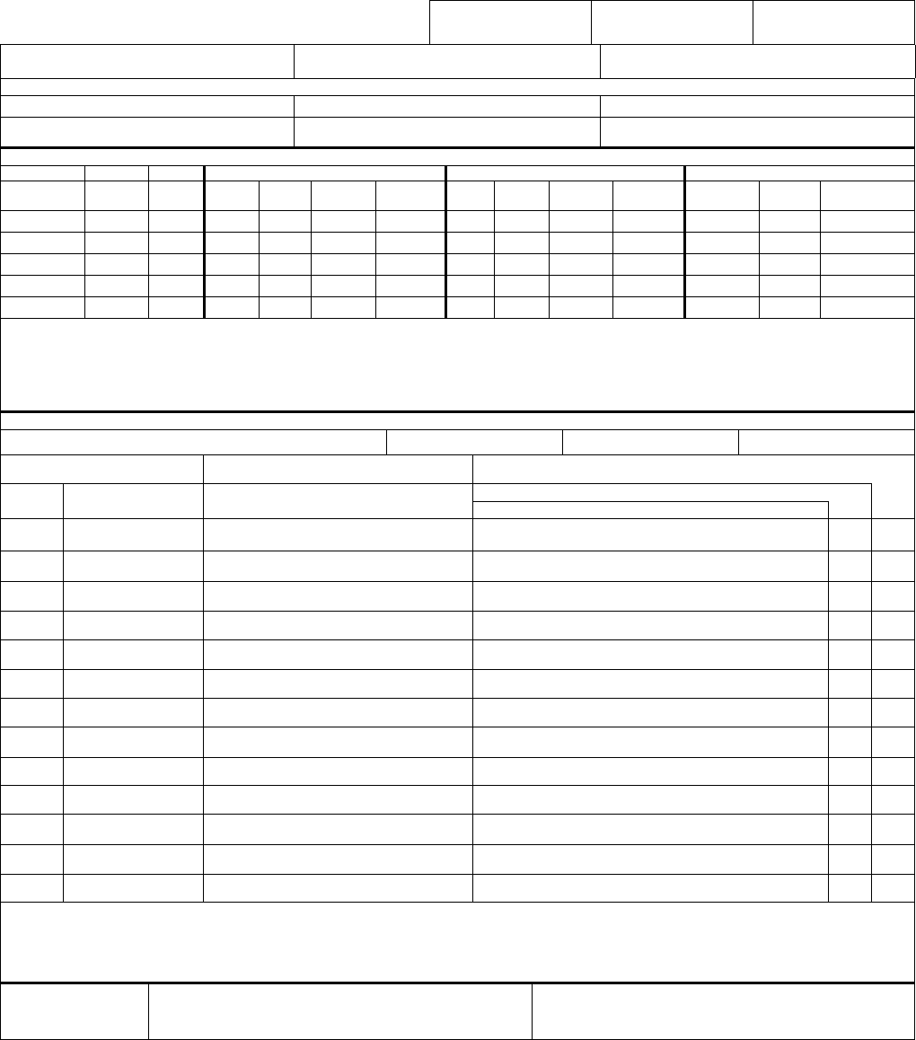
COMUSFLTFORCOMINST 4790.3 REV D CHG 3
07 Nov 2023
V-I-11-107
STRUCTURAL PRIMARY RECORD
QA FORM 20B (PART A)
1. RECORD NO. A- 2. LWC/SHOP: 3. SHEET OF
4. SHIP HULL NO. 5. JCN 6. CWP/REC SER NO.
7. REFERENCES
A.
B.
C.
D.
E.
F.
JOINT IDENTIFICATION
8. 9. 10. 11. COMPONENT NUMBER 1 12. COMPONENT NUMBER 2 13. WELD INFO
JOINT
NUMBER
SS/
SOC
REC REF
PC
NO.
MATL
TYPE
MATL
THICK
REF
PC
NO.
MATL
TYPE
MATL
THICK
JOINT
DESIGN
WELD
SIZE
REMARKS
14. REMARKS
NDT REQUIREMENTS AND CERTIFICATION DATA
19. NDT METHODS & ACCEPTANCE PROCEDURES/REV/CHG VT: MT: PT:
ET: UT/RT: 25. RECORD NO. OF REPAIR CYCLES: (SURFACE SHIPS ONLY)
20. JT
NO.
21. NDT OR DATA
REQUIREMENT
22. CERTIFICATION OF DATA ENTRY or
SAT NDT (SIGNATURE/DATE)
24. SUPPLEMENTAL RECORD (CHECK IF REQD)
23. DATA ENTRY OR ADDITIONAL NDT RQMT
26. REMARKS:
FINAL
DISPOSITION
27. SUPERVISOR SIGNATURE/DATE 28. (SS/SOC ONLY) QAS SIGNATURE/DATE
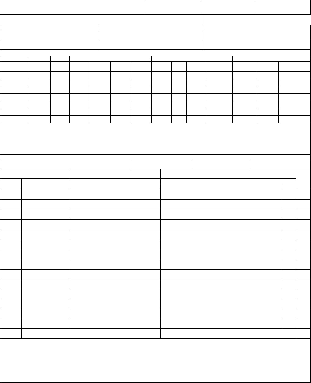
COMUSFLTFORCOMINST 4790.3 REV D CHG 3
07 Nov 2023
V-I-11-108
STRUCTURAL PRIMARY RECORD (cont. sheet)
QA FORM 20B (PART A)
1. RECORD NO. A- 2. LWC/SHOP: 3. SHEET OF
4. SHIP HULL NO. 5. JCN 6. CWP/REC SER NO.
7. REFERENCES
A.
B.
C.
D.
E.
F.
JOINT IDENTIFICATION
8. 9. 10. 11. COMPONENT NUMBER 1 12. COMPONENT NUMBER 2 13. WELD INFO
JOINT
NUMBER
SS/
SOC
REC REF
PC
NO.
MATL
TYPE
MATL
THICK
REF
PC
NO.
MATL
TYPE
MATL
THICK
JOINT
DESIGN
WELD
SIZE
REMARKS
14. REMARKS
NDT REQUIREMENTS AND CERTIFICATION DATA
19. NDT METHODS & ACCEPTANCE PROCEDURES/REV/CHG VT: MT: PT:
ET: UT/RT:
25. RECORD NO. OF REPAIR CYCLES: (SURFACE SHIPS ONLY)
20. JT
NO.
21. NDT OR DATA
REQUIREMENT
22. CERTIFICATION OF DATA ENTRY or
SAT NDT (SIGNATURE/DATE)
24. SUPPLEMENTAL RECORD (CHECK IF REQD)
23. DATA ENTRY OR ADDITIONAL NDT RQMT
26. REMARKS

COMUSFLTFORCOMINST 4790.3 REV D CHG 3
07 Nov 2023
V-I-11-109
QA FORM 20B (PART A) INSTRUCTIONS
STRUCTURAL PRIMARY RECORD
PURPOSE: To provide a standard form and instruction for documenting required structural
welding and NDT completion data.
NOTES:
1. PLANNING AND ESTIMATING (P&E) MUST COMPLETE BLOCKS 1-14,
20, 21, 22-24 (PARTIAL), AND 26 (IF NECESSARY) FOR SUBMARINE
RECORDS. ANNOTATED PERSONNEL MUST COMPLETE ALL
REMAINING BLOCKS.
2. RECORD OF ACCOMPLISHMENT DEFINITION: A RECORD USED FOR
SOME SUBMARINE WELDS THAT NAVSEA TECH PUB T9074-AD-
GIB-010/1688 ALLOWS REDUCED NDT DATA REQUIREMENTS. IT IS
PRIMARILY USED FOR MAGNETIC PARTICLE TESTING (MT)
INSPECTION. MT INSPECTIONS THAT MAY USE A RECORD OF
ACCOMPLISHMENT FOR COMPLETION DATA ARE DEFINED IN
TABLES 6-1 AND 6-2 OF NAVSEA TECH PUB T9074-AD-GIB-010/1688,
BY REFERENCE TO NOTE 8. NDT COMPLETION DATA FOR A
RECORD OF ACCOMPLISHMENT IS DEFINED IN NAVSEA TECH PUB
T9074-AD-GIB-010/1688, PARAGRAPH 5.3.1.
3. BLOCKS AND ROWS OF THIS RECORD MAY BE EXPANDED OR
DELETED TO SUIT THE WORK BEING DOCUMENTED.
4. EACH SIGNATURE WILL BE ACCOMPANIED BY A PRINTED NAME
AND DATE. AN EMPLOYEE MAY USE THEIR INITIALS PROVIDED
THEIR SIGNATURE AND PRINTED NAME APPEAR ELSEWHERE ON
THE SAME PAGE.
SCOPE: The scope of this instruction is limited to structural welding and NDT for
overhaul and repair governed by NAVSEA Tech Pub T9074-AD-GIB-010/1688,
or MIL-STD-1689A as invoked by Naval Ships Tech Manual S9086-CH-STM-
010/CH-074, through NAVSEA
S9AA0-ABGOS-010/GSO, NAVSEA 0902-018-2010 or
COMUSFLTFORCOMINST 4790.3 Joint Fleet Maintenance Manual.
BLOCK 1 - RECORD NO.
Enter the Part A record number. The numbering convention is A-01, A-02, A-03 etc., in
numerical order, depending on how many Part A records are generated for the TWD. Keep
the number of Primary Records generated to a minimum.
BLOCK 2 - LWC/SHOP
Enter local work center or lead shop.
BLOCK 3 - SHEET ____ OF ____
NOTE A TECHNICAL WORK DOCUMENT MAY CONTAIN MULTIPLE QA
FORMS OF THE SAME TYPE, (E.G. MORE THAN ONE QA-26). THE PAGE

COMUSFLTFORCOMINST 4790.3 REV D CHG 3
07 Nov 2023
V-I-11-110
ENTRY IS FOR THIS SPECIFIC FORM, NOT THE TOTAL NUMBER OF
PAGES ON ALL FORMS OF THE SAME TYPE.
Enter the sheet number, starting with sheet 1, of total number of QA form sheets (e.g., 1 of ,
2 of ). The last number reflects the total number of QA Form sheets written. This block is
filled in by a QAI or the QAO after all certification testing is complete before block 19 on the
QA-9 is signed. (e.g., 1 of 3, 2 of 3, 3 of 3).
BLOCK 4 - SHIP/HULL NO.
Enter the ship name, hull type, SSN, SSBN, SSGN, CVN, etc., and unique hull number for the
ship, 759, 732, or 65, etc.
BLOCK 5 - JCN
Enter the Job Control Number (JCN).
BLOCK 6 - CWP/REC
Enter the CWP/REC serial number or enter N/A if no CWP/REC is required. Do not list the
CWP/REC revision.
BLOCK 7 - REFERENCES
Enter references, drawings etc. that are to be used to describe joints. Do not enter references
that are associated only with joints that require a Part B record.
BLOCK 8 - JOINT NUMBER
Enter the Joint Numbers.
BLOCK 9 - SS/SOC
Check the block associated with each joint number if it is SUBSAFE or Scope Of
Certification (SOC). All joints that involve the SUBSAFE boundary must be checked
whether they require re-entry control or not. For example, attachment welds to the boundary
must be checked even though this work is not subject to re-entry control. For surface ship
welds, enter NA.
BLOCK 10 - REC (SHIPYARD USE ONLY)
Check the block associated with each joint number if the joint requires re-entry control.
BLOCK 11 - COMPONENT NUMBER 1 (Leave blocks blank for joints that require a
Part B Record.)
Enter the letter associated with the drawing number in Block 7, which describes the
component and enter the piece number (if necessary to describe the joint) for the component.
For joints that may require explanation, enter “See remarks” as a reference in a Block 7, refer
to this note as the craftsman would a drawing and give the explanation in remarks.
The term “EXISTING” may be used to describe existing ship structure, provided the other
component in the joint defines the joint location. To do this, add “EXISTING” as a reference
in Block 7, refer to it as the craftsman would a drawing, and “N/A” the piece number. Enter
the base material type (OSS, HY-80, HSS, etc.), S-Group Number from Table 1 of NAVSEA
S9074-AQ-GIB-010/248, and the drawing material thickness (decimal or fraction).

COMUSFLTFORCOMINST 4790.3 REV D CHG 3
07 Nov 2023
V-I-11-111
BLOCK 12 - COMPONENT NUMBER 2
Make entries for Component 2 as described in Block 11. For repair sites, enter N/A in
Component 2 columns.
BLOCK 13 - WELD INFO (Leave blocks blank for joints that require a Part B Record.)
JOINT DESIGN: Enter the joint design in terms of MIL-STD-22 joint numbering system
(PT2S.1, PT2V.1, C2V.2, B2V.3 etc.). Use Remarks (Block 14) to describe “Special Joints”,
as described in paragraph 11.4.7 of NAVSEA Tech Pub T9074-AD-GIB-010/1688 or
paragraph 11.2.7 of MIL-STD-1689A, including any special weld buildup required for the
joint.
WELD SIZE: Enter the weld size in terms of fractions. Enter N/A for butt welds, plug welds,
base material repairs, weld surfacing, corner welds with no reinforcing fillet, clad welds, and
edge welds. For PT2V.3 and PT2V.4, enter sizes for both reinforcing fillets. Use Remarks
blocks for local joint clarification or joint or sketch numbers.
BLOCK 14 - REMARKS
Enter any joint clarifying comments. This block may also be used to specify any special heat
restriction instructions (e.g., preheat and interpass requirements). Each entry must contain
signature, printed name and date except where the entry is pre-printed on the form by P&E.
NOTE: BLOCKS 15-18 ARE RESERVED FOR FUTURE USE.
BLOCK 19 - NDT METHODS & ACCEPTANCE PROCEDURES/REV/CHG
(INSPECTOR) Enter the NDT methods and acceptance standard procedure, revision, and
change for NDT listed in Block 21 as the inspection is performed. This entry is not required
for joints that do not list required NDT or that have Block 24 checked off. Leave unused
blocks blank.
BLOCK 20 - JOINT NO.
(P&E) Repeat joint numbers listed in Block 8.
BLOCK 21 - NDT OR DATA REQUIREMENT
NOTE: LEAVE THIS BLOCK BLANK IF A PART B RECORD IS REQUIRED. IF A
PART B RECORD IS NOT USED, ENTER REQUIRED NDT OR DATA
REQUIREMENTS AS FOLLOWS:
a. DATA REQUIREMENTS: List WELD COMPL (weld complete) as the first entry for
each joint listed in Block 20 that does not require a Part B record.
b. NDT REQUIREMENTS: List required NDT for the joint. List each required NDT as
a separate line item in approximate order in which they will occur. Use the following
convention: List NDT Type first (VT, 5X VT, MT, PT, ET, RT or UT), Wait Time
second (8HR, 24HR, 7DAY, or AH (for after hydro) etc.), and Phase last (EXCAV,
BACKGOUGE or FINAL). It is not necessary to give a wait time for ambient
temperature NDT; it is assumed if not given. Typical examples are: MT EXCAV, MT
BACKGOUGE, MT FINAL, ET FINAL, PT FINAL, RT 8HR FINAL, MT 24HR
FINAL, MT 7DAY FINAL, MT AH FINAL, and VT FINAL.

COMUSFLTFORCOMINST 4790.3 REV D CHG 3
07 Nov 2023
V-I-11-112
c. WORKMANSHIP AND VT SPECIAL REQUIREMENTS:
1) Workmanship inspections are not normally listed as required NDT.
Certification of satisfactory completion is made either by TWD signature when
the joint does not require documentation using a Part A or Part B record, or by
signature on the Part A or Part B record when the joint does require
documentation.
2) Joints that require VT only do not require a structural record. The VT is
specified and certified by TWD. Certification of satisfactory VT completion
for VT only welds can be made by a NDT inspector signature in the body of
the TWD.
BLOCK 22 - CERTIFICATION OF DATA ENTRY OR SAT NDT
a. (P&E) Enter “See Part B record” for joints that require a Part B record.
b. (WELDER) Enter signature, printed name, and date beside each WELD COMPL data
entry to certify that the weld is complete, and that fit-up and weld workmanship
inspection requirements have been met. The weld is complete when all weld metal
has been deposited, required weld soaks are completed, preheat is removed, weld has
cooled to ambient temperature and the weld has been prepared to ensure the weld is
ready for final NDT. When required, include the ambient temperature time in Block
23 as described in Block 23 instructions.
c. (NDT INSPECTORS) Enter signature, printed name, and date for each NDT when the
NDT is satisfactory. Except when a Part C record is required, this signature is made
when the weld is complete and the NDT is satisfactory. Part C records are required
only if local instructions require them or if the note “Initiate a Part C record if NDT
fails” appears in Block 23. If a Part C record is required and the NDT rejects the
weld, enter an X in Block 24 for the NDT that generated the reject and initiate a Part C
record. Your signature in Block 22, in this case, indicates the NDT failed and a Part C
record was generated. If indications are cleared by grinding or polishing only and the
subsequent VT (final) is satisfactory, a Part C record is not required.
BLOCK 23 - DATA ENTRY OR ADDITIONAL NDT REQMT
a. (P&E)
1) Enter any NDT clarifying comments, (i.e., partial inspections or expansion
requirements).
2) Enter “AMB TIME:” for each WELD COMPL data requirement listed in
Block 21.
NOTE: THE AMBIENT TIME IS ONLY REQUIRED IF SUBSEQUENT NDT HAS A
WAIT TIME, SUCH AS A 24 HOUR MT.
3) Enter “PENETRANT:” for each PT requested in Block 21.
4) Enter “EQUIP No:” for each ET requested in Block 21.
5) For submarine envelope attachment weld MT inspections, enter “Initiate a Part
C record if NDT fails” and “EQUIP No:”.

COMUSFLTFORCOMINST 4790.3 REV D CHG 3
07 Nov 2023
V-I-11-113
6) For submarines, enter “Initiate a Part C record if NDT fails” for RT or UT
listed in Block 21 (expansions are required when repair welding is required as
a result of RT or UT inspection).
b. (WELDERS) Enter military time when the weld reaches ambient temperature beside
the “AMB TIME:” entry associated with each WELD COMPL data requirement. If
this data is entered by someone other than who signed Block 22, a signature, printed
name and date is required.
NOTE: THE AMBIENT TIME IS ONLY REQUIRED IF SUBSEQUENT NDT HAS A
WAIT TIME, SUCH AS A 24 HOUR MT.
c. (NDT INSPECTORS)
1) Enter penetrant used, manufacturer’s brand and type, beside each
“PENETRANT:” entry.
2) Enter equipment information beside each MT or ET with “EQUIP No:” entry:
(a) ET: Enter unique equipment identification, or instrument manufacturer
and model number used.
(b) MT: if AC yoke is used, enter the word “Yoke”. Otherwise, enter
unique equipment identification, or instrument manufacturer and model
number used.
BLOCK 24 - SUPPLEMENTAL RECORD (CHECK IF REQD)
(NDT INSPECTORS) When required by local procedures to document deficiencies, or if the
note “Initiate a Part C record if NDT fails” is listed in Block 23, a Part C record must be
initiated to document defects. If a part C record is initiated, check the box in the row
associated with the required NDT.
BLOCK 25 - RECORD NO. OF REPAIR CYCLES (SURFACE SHIPS ONLY)
(INSPECTOR or WELDER) Enter the number of repair cycles required to obtain a
satisfactory NDT, (i.e., “1” for the first cycle, “2” for the second, etc.).
BLOCK 26 - REMARKS
(ALL) Enter any clarifying comments associated with the record. Add or refer to any
expansion requirements here or in Block 14. Each entry must contain signature, printed name,
and date except where the entry is pre-printed on the form by P&E.
BLOCK 27 - SUPERVISOR
(WELD SUPERVISOR) Certify final disposition of all welding and NDT for all joints listed
in Block 20 (including continuation sheets) by entering signature, printed name, and date.
This includes certification of any Part C records generated. Ensure that page numbering is
correct.
BLOCK 28 - QAS (SUBSAFE/SOC ONLY)
(QAS) Enter signature, printed name, and date to certify completeness of entries. To aid the
certification process, this block is repeated on the Part B record in Block 34. For joints being
documented by Part B record, the individual signing for all joints must review the certification
COMUSFLTFORCOMINST 4790.3 REV D CHG 3
07 Nov 2023
V-I-11-114
signature(s) on the Part B record(s) and sign the Part A record based on the Part B
signature(s).
STRUCTURAL PRIMARY RECORD CONTINUATION SHEET: Follow corresponding block
instructions in this attachment.
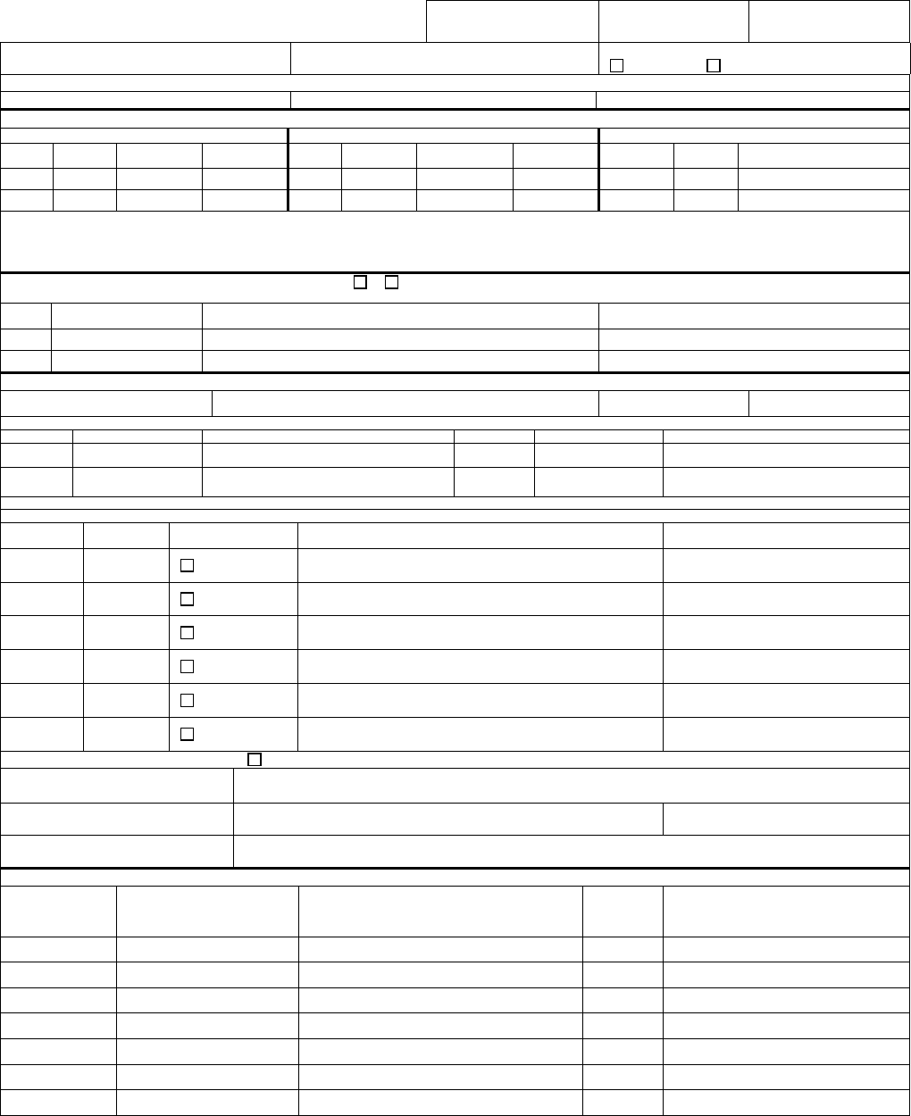
COMUSFLTFORCOMINST 4790.3 REV D CHG 3
07 Nov 2023
V-I-11-115
STRUCTURAL WELD HISTORY
QA FORM 20B (PART B) (FRONT)
1. JOINT NO. 2. LWC/SHOP: 3. SHEET OF
4. SHIP HULL NO. 5. JCN 6. CWP/REC:
YES NO
7. REFERENCES
A. B. C.
JOINT IDENTIFICATION
8. COMPONENT NUMBER 1 9. COMPONENT NUMBER 2 10. WELD INFO
REF
PC
NO.
MATL
TYPE
MATL
THICK
REF
PC
NO.
MATL
TYPE
MATL
THICK
JOINT
DESIGN
WELD
SIZE
REMARKS
11. REMARKS
12. NEW MATERIAL: MATL DOCUMENTATION REQUIRED Y N CRAFTSMAN/QAI: ENTER TRACEABLE MATERIAL MARKING (E.G., MIC NO., TCSM NO.,
HEAT NO., OR OTHER) FOR THE PIECE NUMBER (PC NO.) BELOW, UNLESS USE OF EXISTING MATERIAL IS SPECIFIED.
REF PC NO. TRACEABLE MATL MARKING
CRAFTSMAN/QAI: MATERIAL VERIFICATION
(SIGNATURE/DATE)
WELD HISTORY
13. WELD PROCEDURE, REV.,
CH, AND TECHNIQUE SHEETS:
14. MIN
PREHEAT:
15. MAX
INTERPASS:
16. WELD FILLER MATERIAL (WELDER) ENTER TRACEABLE FILLER MARKING (MIC NO.)
LETTER GRADE/TYPE MIC NO. LETTER GRADE/TYPE MIC NO.
A
C
B
D
17. FITUP SAT: CRAFTSMAN/QAI (SIGNATURE/DATE)
18. PHASE LETTER KEY: F=BUILDUP OF BASE MATERIAL FOR FIT-UP; W=TACKING OR WELDING JOINT; BG=BACKGOUGE WORKMANSHIP SAT. (VERIFY BG NDT PRIOR TO WELD IF REQD)
19. PHASE
LETTER
20. FILLER
LETTER
21. PREHEAT &
INTERPASS TEMP
22. WELDER & WELD WORKMANSHIP
(WELDER SIGNATURE/DATE)
23. REMARKS
SAT
SAT
SAT
SAT
SAT
SAT
SEE STRUCTURAL WELD HISTORY CONTINUATION SHEET
24. WELDING COMPLETE
WELDER (SIGNATURE/DATE)
25. JOINT IS AT AMBIENT TEMP
WELDER (SIGNATURE/DATE) MILITARY TIME
AT AMBIENT TEMP:
26. JOINT IS COMPLETE AND READY FOR
FIN AL NDT
CRAFTSMAN/CRAFTSMAN SUPERVISOR (SIGNATURE/DATE)
REQUIRED NDT
27. REQD NDT
(TYPE, WAIT TIME,
& PHASE)
28. NDT & ACCEPTANCE
PROCEDURE, REV, CH
29. NDT RPT/EQPT (FOR ET OR MT, RECORD SERIAL
# OF MANF & MODEL NO.) (FOR MT BY YOKE,
ENTER “YOKE”). FOR PT, ENTER TYPE OF LIQUID
PENETRANT, FOR RT/UT, ENTER REPORT #
30. RESULTS
A OR R
(NOTE 1)
31. INSPECTOR (SIGNATURE/DATE)
MT EXCAV
(NOTE 2)
ENTRY NOT REQUIRED
MT BACKGOUGE
(NOTE 2)
ENTRY NOT REQUIRED
MT EVERY LAYER
(NOTE 2&3)
ENTRY NOT REQUIRED
VT FINAL NA
RT 8 HR FINAL
UT 8 HR FINAL
MT AMBIENT
FINAL
COMUSFLTFORCOMINST 4790.3 REV D CHG 3
07 Nov 2023
V-I-11-116
QA FORM 20B (PART B) (BACK)
REQUIRED NDT (CONT.)
27. REQD NDT
(TYPE, WAIT TIME,
& PHASE)
28. NDT & ACCEPTANCE
PROCEDURE, REV, CH
29. NDT RPT/EQPT (FOR ET OR MT, RECORD SERIAL
# OF MANF & MODEL NO.) (FOR MT BY YOKE, ENTER
“YOKE”). FOR PT, ENTER TYPE OF LIQUID
PENETRANT, FOR RT/UT, ENTER REPORT #
30. RESULTS
A OR R
(NOTE 1)
31. INSPECTOR (SIGNATURE/DATE)
MT 24 HR FINAL
MT 7 DAY FINAL
PT FINAL
MTAH FINAL
ET FINAL
ETAH FINAL
NOTE 1: ANY WORK & FINAL NDT INSPECTIONS TO RESOLVE DOCUMENTED REJECTS ON THIS RECORD MUST BE DOCUMENTED ON PART C RECORDS UNLESS NOTE 2 IS
INVOKED IN BLOCK 27. DEFECTS REMOVED IN-PROCESS OF ANY VT, MT, OR PT DO NOT HAVE TO BE DOCUMENTED ON A PART C RECORD.
NOTE 2: DEFECTS DO NOT HAVE TO BE DOCUMENTED. A PART C RECORD IS NOT REQUIRED. CERTIFY AFTER ALL DEFECTS ARE REPAIRED AND THE NDT IS SATISFACTORY.
NOTE 3: MT EVERY LAYER SIGNIFIES MT INSPECTION AFTER DEPOSITION OF EACH LAYER, OR 3/8 INCH THICKNESS, WHICHEVER IS GREATER.
32. REMARKS
FINAL
DISPOSITION
33. WELD SUPERVISOR (SIGNATURE/DATE)
34. (SUBSAFE/SOC/REC ONLY) QAS: (SIGNATURE/DATE)
COMUSFLTFORCOMINST 4790.3 REV D CHG 3
07 Nov 2023
V-I-11-117
STRUCTURAL WELD HISTORY CONTINUATION SHEET
QA FORM 20B (PART B)
1. JOINT NO.
3. SHEET OF
4. SHIP HULL NO. 5. JCN 6. CWP/REC:
YES NO
WELD HISTORY
13. WELD PROCEDURE, REV., CH, AND
TECHNIQUE SHEETS:
SAME AS ORIGINAL
14. MIN
PREHEAT:
15. MAX
INTERPASS:
16. WELD FILLER MATERIAL (WELDER) ENTER TRACEABLE FILLER MARKING (MIC NO.)
LETTER GRADE/TYPE MIC NO. LETTER GRADE /TYPE MIC NO.
A
C
B
D
18. PHASE LETTER KEY: F=BUILDUP OF BASE MATERIAL FOR FIT-UP; W=TACKING OR WELDING JOINT; BG=BACKGOUGE WORKMANSHIP SAT. (VERIFY BG NDT PRIOR TO WELD IF REQD)
19. PHASE
LETTER
20. FILLER
LETTER
21. PREHEAT &
INTERPASS TEMP
22. WELDER & WELD WORKMANSHIP
(WELDER SIGNATURE/DATE)
23. REMARKS
SAT
SAT
SAT
SAT
SAT
SAT
SAT
SAT
SAT
SAT
SAT
SAT
SAT
SAT
SAT
SAT
SAT
SAT
SAT
SAT
SEE STRUCTURAL WELD HISTORY CONTINUATION SHEET
32. REMARKS

COMUSFLTFORCOMINST 4790.3 REV D CHG 3
07 Nov 2023
V-I-11-118
QA FORM 20B (PART B) INSTRUCTIONS
STRUCTURAL WELD HISTORY
NOTE: P&E PERSONNEL MUST COMPLETE BLOCKS 1, 2, 4, 5, 7-11, 12
(PARTIAL), 14-15 (IN SPECIAL SITUATIONS), 27, AND 32 (IF
NECESSARY). ANNOTATED PERSONNEL MUST COMPLETE ALL
REMAINING BLOCKS. FOR CONTINUATION SHEETS GENERATED
DURING PLANNING, P&E MUST COMPLETE BLOCKS 1, 4, 5 AND 32 (IF
NECESSARY). ANNOTATED PERSONNEL MUST COMPLETE ALL
REMAINING BLOCKS. FOR CONTINUATION SHEETS GENERATED
DURING EXECUTION, ANNOTATED PERSONNEL MUST COMPLETE
ALL BLOCKS.
NOTE: BLOCKS AND ROWS OF THIS RECORD MAY BE EXPANDED OR
DELETED TO SUIT THE WORK BEING DOCUMENTED.
BLOCK 1 - JOINT NO.
Enter Joint Number. If the Part B record is referenced from a Part A record, the joint number
on both records must match.
BLOCK 2 - LWC/SHOP
Enter lead work center.
BLOCK 3 - SHEET ___ OF ___
NOTE A TECHNICAL WORK DOCUMENT MAY CONTAIN MULTIPLE QA
FORMS OF THE SAME TYPE, (E.G. MORE THAN ONE QA-26). THE PAGE
ENTRY IS FOR THIS SPECIFIC FORM, NOT THE TOTAL NUMBER OF
PAGES ON ALL FORMS OF THE SAME TYPE.
Enter the sheet number, starting with sheet 1, of total number of QA form sheets (e.g., 1 of ,
2 of ). The last number reflects the total number of QA Form sheets written. This block is
filled in by a QAI or the QAO after all certification testing is complete before block 19 on the
QA-9 is signed. (e.g., 1 of 3, 2 of 3, 3 of 3).
BLOCK 4 - SHIP/HULL NO.
Enter the ship name, hull type, SSN, SSBN, SSGN, CVN, etc., and unique hull number for the
ship, 759, 732, or 65, etc.
BLOCK 5 - JCN
Enter the Job Control Number (JCN).
BLOCK 6 - CWP/REC
Check the [ ] Y box if CWP or REC is required, and enter CWP or REC number. Check the [
] N box if a CWP or REC is not required.
BLOCK 7 - REFERENCES
Enter references, drawings etc. that are to be used to describe joints or material requiring
traceability.

COMUSFLTFORCOMINST 4790.3 REV D CHG 3
07 Nov 2023
V-I-11-119
BLOCK 8 - COMPONENT NUMBER 1
Enter the letter associated with the drawing number in Block 7, which describes the
component and enter the piece number (if necessary to describe the joint) for the component.
For joints that may require explanation, enter “See remarks” as a reference in Block 7, refer to
this note as the craftsman would a drawing and give the explanation in remarks. When piece
number, material type, or material thickness is provided in Remarks, these columns should be
left blank, or a dash entered.
The term “EXISTING” may be used to describe existing ship structure, provided the
application is not SUBSAFE or SOC, and provided the other component in the joint defines
the joint location. To do this, add “EXISTING” as a reference in Block 7, refer to it as the
craftsman would a drawing, and “N/A” the piece number.
Enter the base material type (OSS, HY-80, HSS, etc.), S-Group Number from Table I of
NAVSEA S9074-AQ-GIB-010/248 and the component thickness (decimal or fraction). If a
component has more than one thickness or material type, enter each one on a separate row, or
use Block 11 (Remarks).
BLOCK 9 - COMPONENT NUMBER 2
Make entries for Component 2 as described in Block 8. For repair sites, enter N/A in
Component 2 columns.
BLOCK 10 - WELD INFO
Enter the joint design in terms of MIL-STD-22 joint numbering system (PT2S.1, PT2V.1,
C2V.2, B2V.3, etc.). Use Remarks (Block 11) to describe “Special Joints”, as described in
paragraph 11.4.7 of NAVSEA Tech Pub T9074-AD-GIB-010/1688, including any special
weld buildup required for the joint. For base material repairs and weld surfacing, enter N/A,
or describe the repair or surfacing in Remarks (Block 11).
Enter the weld size in terms of fractions. Enter N/A for butt welds, plug welds, corner welds
with no reinforcing fillet, weld surfacing, base material repairs, and edge welds. For PT2V.3
and PT2V.4, enter sizes for both reinforcing fillets. Use Remarks for local joint clarification
or joint numbers.
BLOCK 11 - REMARKS
Enter any joint clarifying comments. Add or refer to any expansion requirements here or in
Block 32. Each entry must contain signature, printed name and date except where the entry is
pre-printed on the form by P&E.
BLOCK 12 - NEW MATERIAL
a. (P&E) Check the box “[ ] Y or [ ] N”, to indicate that material documentation is or is
not required and enter reference letter from Block 7 and the associated piece number
to describe the material requiring traceability. Block 12 is marked “No” when
electrode only is installed (e.g., repair of a pit, or for cladding) because electrode is
entered in Block 16.
b. (CRAFTSMAN or QAI) At the time of installation, enter traceable material marking
(e.g., MIC No., TSCM No., Heat No., or other) for the piece number listed and certify
(signature, printed name, and date). If existing material is being reinstalled, enter

COMUSFLTFORCOMINST 4790.3 REV D CHG 3
07 Nov 2023
V-I-11-120
“EXISTING” in the TRACEABLE MATERIAL-MARKING column and sign. If
“No” is Checked by P&E, no entry is required.
BLOCK 13 - WELD PROCEDURE, REV, CH, AND TECHNIQUE SHEET(S)
(WELDER) Before welding, enter the Weld Procedure to be used. Include Technique Sheet if
applicable.
BLOCK 14 - MINIMUM PREHEAT
(WELDER) Before welding, enter the required minimum preheat. In certain situations, when
heat must be controlled using non-standard temperatures, P&E may complete this block.
BLOCK 15 - MAXIMUM INTERPASS
(WELDER) Before Welding, enter the required maximum interpass temperature. In certain
situations, when heat must be controlled, P&E may complete this block.
BLOCK 16 - WELD FILLER MATERIAL
(WELDER) Just prior to welding, enter grade or type (e.g., MIL-11018-M or 11018-M) and
MIC Number (e.g., WCAF 9093 202A) of electrode used. Filler letters, A, B, C, etc., are
provided so that the data needs only to be entered once for that electrode and its
corresponding traceability number. Enter the filler letter, A, B, C, etc., corresponding to the
electrode used during the weld process in the FILLER LTR block, Block 20. The filler
material information recorded in this block only applies to weld phases being documented on
this sheet. If a continuation sheet is used, the filler material used to document welding on that
continuation sheet must be recorded in Block 16 of that sheet.
BLOCK 17 - FITUP SAT
(CRAFTSMAN or QAI) Enter signature, printed name, and date when the workmanship
inspection for fit-up or base material preparation for weld surfacing or repair is satisfactory.
This signature certifies that the joint or base metal surface is ready for welding. For weld
repairs, the signature certifies the excavation is ready for NDT (if required).
BLOCK 18 - PHASE LETTER KEY
No entry is required for this block. Use Phase Letter Key given to complete Block 19.
BLOCK 19 - PHASE LETTER
(WELDER) Using the Phase Letter Key given, enter the phase being accomplished during the
weld process in the PHASE LETTER blocks provided. Check the box, “[ ] (See Structural
Weld History Continuation Sheet)” when the record has insufficient room for the number of
entries, and a continuation sheet is needed.
BLOCK 20 - FILLER LETTER
(WELDER) Enter the letter corresponding to the filler material information entered in Block
16 of the sheet being completed. If the phase does not involve the addition of filler metal,
enter N/A.
BLOCK 21 - PREHEAT & INTERPASS TEMP

COMUSFLTFORCOMINST 4790.3 REV D CHG 3
07 Nov 2023
V-I-11-121
(WELDER) Check Preheat and Interpass Temperature for the phase being accomplished.
Mark the block when satisfactory. Take corrective action if it is not satisfactory. Enter “NA”
for phases that do not involve welding, (e.g., back-gouge phases).
BLOCK 22 - WELDER AND WELD WORKMANSHIP
(WELDER) Enter signature, printed name, and date for the associated phase. Signing of this
block certifies that all welding has been performed per the welding procedure entered in Block
13; the MIC number of welding rod(s) used is recorded in Block 16; Blocks 19, 20, and 21 are
completed and required information is correct and that all weld workmanship inspection
requirements have been satisfied. For back-gouge phase, the signature certifies that the weld
has been back-gouged and the root meets the workmanship requirements. Block 22 signatures
must be made based on personal observation.
BLOCK 23 - REMARKS
(WELDER) Enter remarks if necessary. If the remark is made by someone other than the
welder who signed Block 22, entry must contain signature, printed name, and date except
where the entry is pre-printed on the form by P&E.
BLOCK 24 - WELDING COMPLETE
(WELDER or WELDER SUPERVISOR) Enter signature, printed name, and date when
welding is complete, all metal has been deposited, required weld soaks are completed, preheat
is removed and weld meets workmanship inspection requirements. This signature must be
made based on personal observation or by normal trade supervisory controls.
BLOCK 25 - JOINT IS AT AMBIENT TEMP
(WELDER OR WELDER SUPERVISOR) Enter military time weld reached ambient
temperature and sign name (include name and date). The ambient time is only required if
subsequent NDT has a wait time, such as a 24 hour MT.
BLOCK 26 - JOINT IS COMPLETE AND READY FOR FINAL NDT
(CRAFTSMAN) Enter signature, printed name, and date when the joint is complete and ready
for final NDT (i.e., meets workmanship inspection requirements).
BLOCK 27 - REQUIRED NDT
(P&E) Choose the required NDT from the menu given or add NDT if necessary. The NDT
menu given lists most NDT required by NAVSEA Tech Pub T9074-AD-GIB-010/1688.
Choose the NDT desired by deleting the rows from the form for NDT that is not required.
Include the Notes block at the bottom of the menu. After deleting NDT that is not required,
ensure that the required NDT list will fit on a single page. If “MT EXCAV”, “MT
BACKGOUGE”, and “MT EVERY LAYER” are not used, delete Note 2 from the note block.
If “MT EVERY LAYER” is not used, delete Note 3 from the Note block.
BLOCK 28 - NDT & ACCEPTANCE PROCEDURE REV, CH
(INSPECTOR) Enter the NDT methods and acceptance standard procedure used.
BLOCK 29 - NDT REPORT, EQUIPMENT

COMUSFLTFORCOMINST 4790.3 REV D CHG 3
07 Nov 2023
V-I-11-122
(INSPECTOR) Enter NDT Report number or equipment used as directed on the form. Enter
“Yoke” when performing an MT by yoke method. Equipment information is not required for
MT by yoke. If “MT EXCAV”, “MT BACKGOUGE” or “MT EVERY LAYER” is the NDT
listed in Block 27, “Entry Not Required” may be entered in Block 29. (See example of Part B
form).
BLOCK 30 - RESULTS A OR R
(INSPECTOR) Enter “A” for accept or “R” for reject to indicate the inspection result. If
indications are cleared by grinding or polishing only, and the subsequent VT (final) is
satisfactory, a Part C record is not required.
BLOCK 31 - INSPECTOR
(INSPECTOR) Enter signature, printed name, and date for the inspections performed. When
a NDT results in a deficiency, the results of any other NDT not performed yet in the process
will be documented on the Part C record generated for the failed NDT. All blocks for NDT
not yet performed will be left blank on this sheet.
BLOCK 32 - REMARKS
(ALL) Enter remarks. Add or refer to any expansion requirements here or in Block 11. Each
entry must contain signature, printed name, and date except where the entry is pre-printed on
the form by P&E.
BLOCK 33 - WELD SUPERVISOR
(WELD SUPERVISOR) Certify final disposition of all welding and NDT for the joint listed
in Block 1 by entering signature, printed name and date.
NOTE: WHEN PERFORMING RECORD REVIEW, ALL CERTIFICATION DATA
TO REPAIR DEFECTS (I.E., DEFECT EXCAVATION INFORMATION,
REPAIR WELD HISTORY, FINAL NDT OF DEFECTS AND
CERTIFICATION SIGNATURES, ETC.) ARE DOCUMENTED ON
ASSOCIATED PART C RECORDS FOR THE JOINT AND PAGE
NUMBERING IS CORRECT, INCLUDING ANY PART C RECORDS.
BLOCK 34 - QAS (SUBSAFE/SOC/REC ONLY)
(QAS) Enter signature, printed name, and date to certify completeness of entries for joints
listed in Block 1.
STRUCTURAL WELD HISTORY CONTINUATION SHEET:
Follow corresponding block instructions in this attachment except as noted:
(WELDER) Transcribe entries from the associated Part B record (sheet 1) onto the
continuation sheet for Blocks 1, 4, 5 and 6.
BLOCK 13 - WELD PROCEDURE, REV, CH, AND TECHNIQUE SHEET(S)
(WELDER) Check the box provided if the weld procedure and technique sheet (if applicable)
used for the Block 19 phase(s) is the same as shown on the associated Part B record (sheet 1).
Otherwise, enter the weld procedure and technique sheet (if applicable) used for the Block 19
phase(s) being documented on the continuation sheet.
COMUSFLTFORCOMINST 4790.3 REV D CHG 3
07 Nov 2023
V-I-11-124
STRUCTURAL DEFECT RECORD
QA FORM 20B (PART C)
1. JOINT NO. 2. SHEET OF
3. SHIP HULL NO. 4. JCN 5. CWP/REC:
YES NO
6. METHOD OF REJECTED INSPECTION: PT MT UT VT RT OTHER (SPECIFY):
7. DESCRIPTION OF DEFICIENCY (NUMBER EACH DEFICIENCY WITH AN INDICATION NUMBER):
SEE REPORT NO.
8. ALL AREAS REQUIRING INSPECTIONS ARE
SATISFACTORY EXCEPT AS NOTED IN BLOCK 7
INSPECTOR (SIGNATURE/DATE):
REPAIR
9. NDT EQUPMENT (FOR ET OR MT, RECORD SERIAL # OR MANF & MODEL NO.) (FOR MT BY YOKE, ENTER “YOKE”, FOR PT, ENTER TYPE OF LIQUID PENETRANT).
A: B: C:
10.
IND
NO.
11. DEFECT REMOVAL
(SIGNATURE/DATE)
12.
NDT
13. NDT
EQUIP
LTR
14. REASON FOR REJECT OR EXCAVATION
(LENGTH, WIDTH, DEPTH)
15. FINAL NDT FOR DEFECT REMOVAL. ENTER “A”, “R”
OR “W”. SEE BLOCK INSTRUCTIONS.
SIGNATURE/DATE
(SEE ADDITIONAL STRUCTURAL DEFECT RECORD)
WELD HISTORY
16. WELD PROCEDURE, REV., CH, AND
TECHNIQUE SHEETS: SAME AS ORIGINAL
17. MIN
PREHEAT:
18. MAX
INTERPASS:
19. WELD FILLER MATERIAL (WELDER) ENTER TRACEABLE FILLER MARKING (MIC NO.)
LETTER GRADE/TYPE MIC NO. LETTER GRADE/TYPE MIC NO.
A
C
B
D
20. PHASE LETTER KEY: F=BUILDUP OF BASE MATERIAL FOR FIT-UP; W=TACKING OR WELDING JOINT; BG=BACKGOUGE WORKMANSHIP SAT. (VERIFY BG NDT PRIOR TO WELD IF REQD)
21. IND
NO.
22. PHASE
LETTER
23. FILLER
LETTER
24. PREHEAT &
INTERPASS TEMP
25. WELDER (SIGNATURE/DATE) 26. REMARKS
SAT
SAT
SAT
SAT
SAT
SAT
(SEE ADDITIONAL STRUCTURAL DEFECT RECORD)
27. IND NO(S). 28. COMPLETE & READY FOR NDT - CRAFTSMAN
(SIGNATURE/DATE)
27. IND NO(S). 28. COMPLETE & READY FOR NDT - CRAFTSMAN
(SIGNATURE/DATE)
REQUIRED NDT
29. IND
NO.
30. REQD
NDT (TYPE &
METHOD)
31. NDT &
ACCEPTANCE
PROCEDURE, REV, CH
32. NDT RPT/EQPT (FOR ET OR MT, RECORD SERIAL
# OF MANF & MODEL NO.) (FOR MT BY YOKE,
ENTER “YOKE”). FOR PT, ENTER TYPE OF LIQUID
PENETRANT, FOR RT/UT, ENTER REPORT #
33. RESULTS
A OR R
34. INSPECTOR (SIGNATURE/DATE)
(SEE ADDITIONAL STRUCTURAL DEFECT RECORD)
35. REMARKS
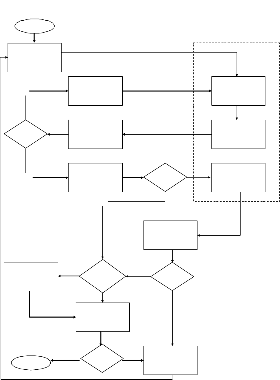
COMUSFLTFORCOMINST 4790.3 REV D CHG 3
07 Nov 2023
V-I-11-126
QA-20B PART C FLOWCHART
ST AR T
Complete Blocks 1-8
D ocumentin g the
NDT p er for med a nd
defects.
Complete Blocks
12-15 documenting
the defects in
Block 7
Verify defect
removal using
MT /PT.
Document results in
Block 9, 12 - 15.
Defect
Additi onal NDT
Required?
Perf orm r e qu ir ed
NDT.
VT SAT?
Document results of
all re qu ir ed NDT f or
joint in Blocks 29-34.
Put “W” in Block 15,
Weld Repair.
Complete Blocks
16-2 8 .
Complete Blocks
10 & 11
Shop remove defect.
Inspect repair.
Document NDT in
Blocks 29-34.
NDT SAT?
Ac ceptable ?
Document defect on
new Part C.
No
COMPLETE
Yes
No
Yes
Yes Y es
No
No
No
SHOP
Yes
NDT INSPECTOR

COMUSFLTFORCOMINST 4790.3 REV D CHG 3
07 Nov 2023
V-I-11-127
QA FORM 20B (PART C) INSTRUCTIONS
STRUCTURAL DEFECT RECORD
PURPOSE: To document defect completion data noted by failed NDT associated with a
QA Form 20B Part A, Part B, or (if continued repair cycles are necessary)
other Part C records. This form is only required for defects on the skin of the
ship.
PROCEDURE. The numbered blocks on the QA Form correspond with block instructions listed.
The P&E organization must complete Blocks 17, 18 (in special situations) and 35 (if necessary).
The blocks and rows of this record may be expanded to suit the work being documented.
Unused rows for multiple entries (i.e., Blocks 10-15) may be deleted as necessary such that the
form fits on a single page. If unable to keep on a single page a continuation sheet must be used.
NOTE: EACH SIGNATURE WILL BE ACCOMPANIED BY A PRINTED NAME AND
DATE. AN EMPLOYEE’S INITIALS MAY BE USED PROVIDED THEIR
SIGNATURE AND PRINTED NAME APPEAR ELSEWHERE ON THE SAME
PAGE.
NOTE: BLOCKS 1 - 10 WILL BE FILLED IN BY THE NDT INSPECTOR.
BLOCK 1 - JOINT NO.
Enter Joint Number.
BLOCK 2 - SHEET ____ OF ____
NOTE A TECHNICAL WORK DOCUMENT MAY CONTAIN MULTIPLE QA
FORMS OF THE SAME TYPE, (E.G. MORE THAN ONE QA-26). THE PAGE
ENTRY IS FOR THIS SPECIFIC FORM, NOT THE TOTAL NUMBER OF
PAGES ON ALL FORMS OF THE SAME TYPE.
Enter the sheet number, starting with sheet 1, of total number of QA form sheets (e.g., 1 of ,
2 of ). The last number reflects the total number of QA Form sheets written. This block is
filled in by a QAI or the QAO after all certification testing is complete before block 19 on the
QA-9 is signed. (e.g., 1 of 3, 2 of 3, 3 of 3).
BLOCK 3 - SHIP/HULL NO.
Enter the ship name and hull number.
BLOCK 4 - JCN
Enter the Job Control Number (JCN).
BLOCK 5 - CWP/REC NO.
Check the [ ] N box if a CWP or REC is not required. Check the [ ] Y box if CWP or REC is
required, and enter CWP or REC number. This information can be obtained from the
associated Part A or B record.
BLOCK 6 - METHOD OF REJECTED INSPECTION
Check the box or indicate what NDT method has rejected.
BLOCK 7 - DESCRIPTION OF DEFICIENCY

COMUSFLTFORCOMINST 4790.3 REV D CHG 3
07 Nov 2023
V-I-11-128
Sketch, describe, or reference supporting documents to show defects. Label defects with an
indication number. The numbering scheme must be consistent throughout the record.
BLOCK 8 - INSPECTOR
The inspector that rejected the NDT must sign name and date for the NDT with exceptions for
defects noted. (Signature certifies that all areas requiring inspection are satisfactory, except as
noted in Block 7). If associated records are used to document acceptance, refer to the
applicable records (e.g., RT, UT records).
BLOCK 9 - NDT EQPT
Enter equipment number or “YOKE” when MT is performed by Yoke method, or PT
penetrant as directed on the form. The letters are to be annotated in Block 13 to correlate the
equipment used with the NDT being performed. Check the box “[ ] (SEE ADDITIONAL
STRUCTURAL DEFECT RECORD)” in the REPAIR section of the form when Block 10 has
insufficient rows for the required number of entries.
BLOCK 10 - IND NO.
For each NDT performed on the repair excavation, list the indication number associated with
the NDT being performed.
BLOCK 11 - DEFECT REMOVAL
(CRAFTSMAN) Enter signature and date for defect removal certifying the defect has been
removed and the site is ready for VT and other NDT to verify defect removal.
NOTE: THE PURPOSE OF BLOCKS 12-15 IS TO DOCUMENT THE STEPS TAKEN
TO EITHER BRING THE DEFECT TO THE POINT OF BEING CLEARED
WITH NO ADDITIONAL ACTION OR TO THE POINT THAT REQUIRES
WELD REPAIR.
BLOCK 12 - NDT
(INSPECTOR) Enter the NDT performed on the excavation site using one line per NDT
entry. This must include all VT and other NDT performed to verify defect removal. Unless
otherwise directed by TWD or DL, NDT of the excavation site to verify defect removal must
be as indicated in sub-paragraph’s a and b.
a. For defects discovered by VT, MT or PT, defect removal must be verified by the NDT
method (VT, MT or PT) that discovered the defect. All original required NDT must
be accomplished and meet requirements to certify the weld.
b. For defects discovered by ET, RT, or UT, defect removal must be verified by MT
(Ferrous) or PT (Non-Ferrous). All original required NDT must be accomplished and
meet requirements to certify the weld.
NOTE: THE MT OR PT PROVES SOUND METAL AFTER THE DEFECT IS
REMOVED. ACTUAL DEFECT REMOVAL IS VERIFIED BY THE
VOLUMETRIC INSPECTION THAT FOUND THE DEFECT (AFTER WELD
REPAIR).
BLOCK 13 - NDT EQUIP LTR

COMUSFLTFORCOMINST 4790.3 REV D CHG 3
07 Nov 2023
V-I-11-129
(INSPECTOR) Enter the letter from Block 9 that corresponds to the equipment or penetrant
used in the inspection. Enter N/A if not applicable.
BLOCK 14 - REASON FOR REJECT OR EXCAVATION
(INSPECTOR) If the inspection fails, indicate reason for failure (e.g., type, dimensions and
location of indication). If it is a VT failure, indicate length, width, and depth of excavation.
To show locations, modify sketch or description in Block 7 if possible. Such modifications
must contain signature, printed name, and date.
BLOCK 15 - FINAL NDT FOR DEFECT REMOVAL
(INSPECTOR) Enter “A”, “R”, or “W” to indicate results of inspection and enter signature
and date. “A” means the inspection is acceptable. “R” means reject, (i.e., defect is not
removed). “W”, which is entered by the VT inspector and means weld repair is required, (i.e.,
defect is removed but the weld does not meet criteria for completed weld). Check the box “[ ]
(SEE ADDITIONAL STRUCTURAL DEFECT RECORD)” in the REPAIR section of the
form when Block 10 has insufficient rows for the required number of entries.
BLOCK 16 - WELD PROCEDURE, REV, CH, & TECHNIQUE SHEET(S)
(WELDER) Check the box provided if Weld Procedure and Technique Sheet (if applicable) to
be used for repair welding is the same as shown on the associated Part B record. Otherwise,
before welding enter the Weld Procedure (including Revision and Change used for repair
welding). Include Technique Sheet if applicable.
BLOCK 17 - MINIMUM PREHEAT
(WELDER) First, see Part A (Block 14) or B record (Block 14), to verify that no special heat
restrictions apply. If no special restrictions apply, before welding enter the required minimum
preheat temperature. If special heat restrictions apply, before welding, enter the preheat
temperature applied as specified by the Part A or Part B record.
BLOCK 18 - MAXIMUM INTERPASS
(WELDER) First, see Part A (Block 14) Part B record, (Block 15), to verify that no special
heat restrictions apply. If no special restrictions apply, before welding, enter the required
maximum interpass temperature. If special heat restrictions apply, before welding, enter the
interpass temperature applied as specified by the Part A or Part B record.
BLOCK 19 - WELD FILLER MATERIAL
(WELDER) Just prior to welding, enter grade or type (e.g., MIL-11018-M or 11018-M) and
MIC Number (e.g., WCAF 9093 202A) of electrode used in repair welding. Filler letters A
and B are provided so that the data needs only to be entered once for that electrode and its
corresponding traceability number. Enter the filler letter, A or B, corresponding to the
electrode used during the weld repair process in Block 23. The filler material recorded here is
only applicable to this sheet. If an additional Part C sheet is used, the filler material used to
document weld phases on that sheet is recorded in Block 19 of that sheet.
BLOCK 20 - PHASE LETTER KEY
No entry is required for this block. Use Phase Letter Key given to complete Block 22.
NOTE: Check the box

COMUSFLTFORCOMINST 4790.3 REV D CHG 3
07 Nov 2023
V-I-11-130
“[ ] (SEE ADDITIONAL STRUCTURAL DEFECT RECORD)” in the REPAIR section of
the form when Block 21 or 22 has insufficient rows for the required number of entries.
BLOCK 21 - IND NO.
(WELDER) Enter the indication number(s) for the defect(s) that is or are being worked on.
BLOCK 22 - PHASE LETTER
(WELDER) Using the Phase Letter Key given, enter the phase being accomplished during the
weld repair process in the PHASE LETTER blocks provided. For most repairs, the last
entries for each indication must be “WC” (weld complete) and “AMB” (ambient temperature).
Multiple phases may be accomplished and certified as one line item entry (e.g., “WC/AMB”).
BLOCK 23 - FILLER LTR
(WELDER) Enter the letter corresponding to the filler material information entered in Block
19 of this sheet. If the phase does not involve the addition of filler material, enter NA.
BLOCK 24 - PREHEAT & INTERPASS TEMP
(WELDER) Check Preheat and Interpass Temperature for the phase being accomplished.
Mark the block when satisfactory. Take corrective action if it is not satisfactory. Enter NA
for phases that do not involve welding (e.g., WC and AMB).
BLOCK 25 - WELDER
(WELDER or WELDER SUPERVISOR) Enter signature, printed name, and date for the
associated phase. Signing of this block certifies that all welding has been performed per the
applicable welding procedure entered in Block 16, the traceability number of the filler
material used is recorded in Block 19, Blocks 21 through 24 are completed and required
information is correct, and that all weld workmanship inspection requirements have been
satisfied. This signature must be made based on personal observation. For Phase Welding
Complete (WC), signature indicates welding is complete, all metal has been deposited,
required weld soaks are completed, preheat is removed and weld meets workmanship
inspection requirements. This signature must be made based on personal observation or by
normal trade supervisory controls. For Phase “AMB” enter military time that the weld
reached ambient temperature (less than 125 Deg. F) in Block 26 and sign Block 25.
NOTE: THE AMBIENT TIME IS ONLY REQUIRED IF SUBSEQUENT NDT HAS A
WAIT TIME, SUCH AS A 24 HOUR MT.
BLOCK 26 - REMARKS
(WELDER) Enter remarks if necessary. Ensure ambient temperature time is noted for the
ambient temperature (AMB) phase after reaching ambient temperature (See note in Block 25).
Each entry must contain signature, printed name and date except, (1) where the entry is pre-
printed on the form by P&E, or (2) for ambient temperature time if “AMB” is listed in Block
22. These signature requirements are not necessary if the Block 26 entry is made by the
welder who has signed for the acceptance requirements in Block 25.
BLOCK 27 - IND NO(S).
(CRAFTSMAN or SUPERVISOR) Enter indication numbers being certified ready for NDT in
Block 28. The block is large enough to enter several indication numbers. Two blocks are

COMUSFLTFORCOMINST 4790.3 REV D CHG 3
07 Nov 2023
V-I-11-131
provided if different craftsmen are signing for different indications. Unused blocks may be
left blank.
BLOCK 28 - COMPLETE & READY FOR NDT
(WELDER, WELDER SUPERVISOR or CRAFTSMAN) Enter signature, printed name, and
date when the weld is ready for final NDT (i.e., meets workmanship inspection requirements).
This signature must be made based on personal observation or by normal trade supervisory
controls. This block may be signed by other than welder for non-weld issues.
NOTE: THE PURPOSE OF BLOCKS 29-34 IS TO PICK-UP THE JOINT NDT
PROCESS AT THE POINT THE PART C RECORD WAS GENERATED AND
TO DOCUMENT THE PROCESS FROM THAT POINT FORWARD. CHECK
THE BOX “[ ] (SEE ADDITIONAL STRUCTURAL DEFECT RECORD)” IN
THE REPAIR SECTION OF THE FORM WHEN BLOCK 29 OR 30 HAS
INSUFFICIENT ROWS FOR THE REQUIRED NUMBER OF ENTRIES.
BLOCK 29 - IND NO.
(INSPECTOR) At the point the Part C record was generated, some required NDT may have
already been completed and certified except for indications noted in Block 7. Other required
NDT may yet need to be performed on the entire joint. Make block entries using this criteria:
a. For inspections of repairs to clear indications in Block 7, list the indication number
being inspected.
b. For inspections on the entire joint that are not yet completed on a Part A or Part B
Record, enter “N/A” beside the required NDT. The N/A entry means the required
NDT applies to the entire joint.
BLOCK 30 - REQUIRED NDT
(INSPECTOR) List all required NDT to certify the defect being inspected.
a. Ensure all the required NDT for the entire joint is documented and certified, including
NDT previously certified on previous Part A, Part B, or Part C records (if required by
local instruction), and all other NDT required to complete the joint, plus repair NDT.
On the Part C record, at a minimum, list all NDT required to clear the defect and any
remaining (not previously certified) NDT required to certify the joint. All NDT
required, (previously certified and repair NDT) may be listed if required by local
instructions. Required NDT can be found in Block 21 of the Part A record, in Block
27 of the Part B record, or in Block 30 of other Part C records generated for previous
repair cycles. See discussion on expansion requirements in Block 35.
b. On rare occasion the required NDT may change. In this case, the substituted NDT
must be listed, not the original required NDT. These changes may be specified by
P&E through TWD revisions.
BLOCK 31 - NDT & ACCEPTANCE PROCEDURE REV, CH
(INSPECTOR) Enter the NDT methods and acceptance standard procedure used for the NDT
listed in Block 30.
BLOCK 32 - NDT REPORT, EQUIPMENT

COMUSFLTFORCOMINST 4790.3 REV D CHG 3
07 Nov 2023
V-I-11-132
(INSPECTOR) The purpose of this block is to record data for equipment or PT penetrant
used. Enter equipment or PT penetrant information for the required NDT listed in Block 30 as
directed on the form or list the NDT Report number that gives this information. Enter “Yoke”
when performing an MT by yoke method. Equipment information is not required for MT by
yoke. If the NDT listed is NDT previously completed satisfactorily and does not have to be
repeated, enter “See Part (A or B or C)” as applicable. If “MT EXCAV”, “MT
BACKGOUGE” or “MT EVERY LAYER” is the NDT listed in Block 27, “Entry Not
Required” may be entered in Block 29. (See example of Part B form). NA VT only
inspections.
BLOCK 33 - RESULTS A OR R
(INSPECTOR) Enter “A” for accept or “R” for reject to indicate the inspection result. For
NDT that has been accepted up to this point in the process enter “A”. In this case, your entry
is based on entries and certification signatures made on associated Part A, B, or C records.
BLOCK 34 - INSPECTOR
Enter signature, printed name, and date for entries in Blocks 29 through 33. Your signature
for previous, acceptable NDT is based on entries and certification signatures made on
associated Part A, B, or C records.
BLOCK 35 - REMARKS
(ALL) Enter remarks. Expansion requirements should be documented or referred to in this
block. Each entry must contain signature, printed name and date except where the entry is
pre-printed on the form by P&E.
NOTE: EXPANSION REQUIREMENTS MAY BE SPECIFIED BY P&E THROUGH
TWDS.
COMUSFLTFORCOMINST 4790.3 REV D CHG 3
07 Nov 2023
V-I-11-133
PIPE, MACHINERY AND PRESSURE VESSEL WELD RECORD
QA FORM 20C
(WORK PLANNING TO FILL IN BLOCKS/EVALUATE BLOCK OPTIONS IDENTIFIED BY A PRIOR TO
RELEASE)
Page
1
of
____
1. SHIP HULL NO.
2. JCN 3. LWC/SHOP 4. CWP/REC SER NO.
5. SYSTEM/COMPONENT 6. FABRICATION STD:
278 250-1500-1
7.
WELD
CLASS
8. JT DESIGN
9. SSMAP/JT ID DWG &
REV
10. JOINT NO.
MARK JNT
11. PART
NO. 1
DESCRIPTION
SIZE (NPS) SCHED/CLASS
PART
NO. 2
DESCRIPTION
SIZE (NPS) SCHED/CL.
DWG NO. & REV. PC. NO. MATL. DWG NO. & REV. PC. NO. MATL.
INSTALLATION
12. PART NO. 1
NEW
EXISTING EXST MATL MKS GEN MATL TEST
MATERIAL MRKS/TEST RESULT
:
PART NO. 2
NEW
EXISTING EXST MATL MKS GEN MATL TEST
MATERIAL MRKS/TEST RESULT:
NEW MATERIAL (INCLUDING CONSUMABLE INSERTS, BACKING MATERIAL, ETC.)
13. PART
NO.
14. DESCRIPTION 15. LEVEL I NO./OTHER TRACEABILITY NUMBER/
MATERIAL/SPECIFICATION MARKINGS
16. FITTER/INSPECTOR (Signature, Badge, Date)
17. PART WALL THICKNESS:
20. FITUP
21. VERIFICATION
18. REQD
19. ACTUAL PREWELD
NDT
COMP
JOINT DESIGN
INSTALLED
FITUP:
SAT
FITUP
AFTER
TACK
SAT
NA
FITTER (Signature, Badge, Date)
NO. 1
Nom:
Min:
Min:
NO. 2
Nom:
Min:
Min:
NA
INSPECTOR (250-1500-1 welds) (Signature, Badge, Date)
WELDING
22. WELD PROC/REV/CH & TECH DATA SHEET
23. POSITION
HFP VFP OOP
24. MIN PREHEAT
TEMP:
MAX INTERPASS
TEMP:
25. FABRICATION LOCATION: SHOP/BLDG _________________
SHIPBOARD
COMPT: FRAME LEVEL P C S
26. LAYER(S)
(T/R/I/F)
27. FILLER
TYPE
28. FILLER SERIAL NO.
(e. g., Level I No.)
29. WELDER (Signature, Badge, Date)
SAT
SAT
SAT
SAT
30. STRESS RELIEF REQD
YES NO
31. PROCEDURE: ___________________________
TEMPERATURE: DURATION HR MIN
32. HEAT TREATER (Signature, Badge, Date)
33. WELDING COMPLETE, SURFACE IS PREPPED AND READY FOR
FINAL NDT, AND JOINT NUMBER IS PERMANENTLY MARKED NEAR
JT IF “MARK JT” BOX IN BLOCK 10 IS CHECKED.
WELDER or FITTER (Signature, Badge, Date)
WELD INSPECTIONS: (I) = INTERMEDIATE, (F) = FINAL # = PREWELD INSPECTION (EXCAVATION, END-PREP, ETC.) ## = NUCLEAR ONLY
34. ACCEPTANCE STANDARD: CLASS
35. INSP 36. INSPECTION TYPE
37. PROCEDURE USED
38. INSPECTOR (Signature, Badge, Date)
_______#
NA
5X RT
PT TYPE II-C MT EQPT NO: _______________
SAT
REJ
TACK ##
NA
VT 5X
PT TYPE II-C MT EQPT NO: _______________
SAT
REJ
ROOT
NA
VT 5X
PT TYPE II-C MT EQPT NO: _______________
SAT
REJ
BKGOUGE
NA
5X
PT TYPE II-C MT EQPT NO: _______________
SAT
REJ
PT/MT (I)
NA
PT TYPE II-C MT EQPT NO: _______________
SAT
REJ
VT (F)
NA
OUTSIDE (ALL VTs)
INSIDE INACCESSIBLE
INSIDE PARTIAL INSIDE INSP
SAT
REJ
PT/MT (F)
NA
24 HR. MT
PT TYPE II-C MT EQPT NO: _______________
SAT
REJ
PT/MT-ID
NA (F)
PT TYPE II-C MT EQPT NO: _______________
INACCESSIBLE PARTIAL INSP DONE
SAT
REJ
RT (F)
NA
8 HR.
60 360 100%
SAT
REJ
39. REMARKS (SHOP REMARKS ALSO)
FINAL
DISPOSITION
40. SUPERVISOR (Signature, Badge, Date)
41. LOCAL GOVERNMENT INSP./QAS (Signature, Badge, Date)
COMUSFLTFORCOMINST 4790.3 REV D CHG 3
07 Nov 2023
V-I-11-134
PIPE, MACHINERY AND PRESSURE VESSEL WELD RECORD - CONTINUATION SHEET
QA FORM 20C-1
SHIP: DWG/JCN: JOINT NO.: PAGE OF
WELD HISTORY (CONTINUATION SHEET) T = TACK R= ROOT I = INTERMEDIATE LAYER F = FINAL
42. LAYER
T/R/I/F
43. FILLER
TYPE
44. FILLER SERIAL NO. (MIC NO.)
45. WELD TEMPS DEG F
PREHEAT INTERPASS
46. WELDER (SIGNATURE/DATE)
WELD INSPECTIONS (CONTINUATION SHEET) I = INTERMEDIATE F= FINAL
47. INSPECTION 48. INSPECTION TYPE 49. PROCEDURE USED 50. INSPECTOR (SIGNATURE/DATE)
SAT
REJ
SAT
REJ
SAT
REJ
SAT
REJ
SAT
REJ
SAT
REJ
SAT
REJ
SAT
REJ
51. REMARKS
COMUSFLTFORCOMINST 4790.3 REV D CHG 3
07 Nov 2023
V-I-11-135
PIPE, MACHINERY AND PRESSURE VESSEL WELD RECORD – WELD DEFECT REPAIR SHEET
QA FORM 20C-2
SHIP: DWG/JCN: JOINT NO.: PAGE OF
52. DEFECT DESCRIPTION
CRACK INCOMP INSERT FUSION INCOMPLETE FUSION ARC STRIKE ROUNDED
SLAG CRATER PIT BURN THRU WELD SPLATTER OTHER: (ENTER BELOW)
POROSITY INTERNAL CONCAVITY MELT THRU ROOT EDGE FUSION COND
UNDERCUT INTERNAL CONVEXITY TUNGSTEN LINEAR
OXIDATION CENTERLINE CREASE INCOMPLETE PENETRATION LINEAR DISPOSED
53. DEFECT LOCATION(S) AND EXTENT
SEE SKETCH IN REMARKS
54. INSPECTOR (SIGNATURE/DATE)
DEFECT REPAIR
55. TYPE OF REPAIR
GRIND ONLY
GRIND AND WELD
WELD ONLY
OTHER (SEE REMARKS)
56. REPAIR LOCATION(S) AND EXTENT
SEE SKETCH IN REMARKS
57. WELD PROC AND REV/CH
NA
SAME AS ORIGINAL
58. EXCAV NDT
REQUIRED
Y (MARK REQD INSP
BLK 65/66)
N
59. ROOT PASS INSP
REQUIRED
Y (MARK REQD INSP
BLK 65/66)
N
60. LAYER
T/R/I/F
61. FILLER
TYPE
62. FILLER SERIAL NO. (MIC NO.)
63. PREHEAT/
INTERPASS TEMP
64. WELDER (SIGNATURE/DATE)
SAT
SAT
SAT
REPAIR INSPECTIONS
REPAIR WELD REQUIRES THE SAME INSPECTIONS AS THE ORIGINAL WELD. CARRY OVER ALL REJECTED OR VOIDED INSPECTIONS FROM PAGE 1.
65. INSPECTION 66. INSPECTION TYPE 67. PROCEDURE USED 68. INSPECTOR (SIGNATURE/DATE)
EXCAV
NA
5X PT TYPE IIC
MT/EQUIP NO.:
SAT
REJ
ROOT
NA
VT 5X PT TYPE IIC
MT/EQUIP NO.:
SAT
REJ
BACKGOUGE
NA
5X PT TYPE IIC
MT/EQUIP NO.:
SAT
REJ
PT/MT ( I )
NA
PT TYPE IIC
MT/EQUIP NO.:
SAT
REJ
VT (F)
NA
OUTSIDE (ALL VTs) INSIDE INACCESSIBLE
INSIDE PARTIAL INSIDE INSP
SAT
REJ
PT/MT(F)
NA
PT TYPE IIC
24 HOUR MT/EQUIP NO.:
SAT
REJ
PT/MT – ID(F)
NA
PT TYPE IIC MT/EQUIP NO.:
INACCESSIBLE PARTIAL INSP DONE
SAT
REJ
RT (F)
NA
8 HOUR
60 360 100%
SAT
REJ
69. REMARKS

COMUSFLTFORCOMINST 4790.3 REV D CHG 3
07 Nov 2023
V-I-11-136
QA FORM 20C INSTRUCTIONS
PIPE, MACHINERY AND PRESSURE VESSEL WELD RECORD/WELD DEFECT REPAIR
SHEET
PURPOSE: This instruction provides a form to document in process controls for welding and
NDT of piping, machinery, pressure vessels, shafting and propellers including
base metal repair and repair of castings per NAVSEA S9074-AR-GIB-010/278
(NSTP-278), MILSTD-2191, DOD-STD-2185 or per NAVSEA 250-1500-1.
This Form does not contain all required data for accomplishment of Titanium
Welds. Additional data is required as specified in local documents.
NOTES:
1. WHEN ADDITIONAL NDT AND OPERATIONAL TESTING (IN LIEU OF
HYDROSTATIC STRENGTH TESTING) OF WELDED PIPE JOINTS IS
SPECIFIED PER CHAPTER 505 OF NAVSEA S9086-RK-STM-010/CH505,
PIPING SYSTEMS FOR NSTP-278 CLASS P-1 JOINTS, THE CWP OR TGI
MUST CLEARLY SPECIFY THAT ADDITIONAL NDT IN LIEU OF
HYDROSTATIC TESTING IS REQUIRED. ROOT LAYER MUST BE PT
OR MT INSPECTED. THE 5X VISUAL INSPECTION SUBSTITUTION
ALLOWED BY NSTP-278 IS NOT PERMITTED. THE FINAL LAYER
MUST BE PT INSPECTED; MT IS NOT PERMITTED.
2. PLANNER MUST COMPLETE THE BLOCKS IDENTIFIED BY A RED
DIAMOND PRIOR TO ISSUING.
3. PER NAVSEA S9074-AR-GIB-010-278, WHEN A SPECIFIC ITEM ON A
RECORD IS NOT APPLICABLE THE LETTERS “NA” MUST BE
ENTERED. IF A LINE ITEM HAS A “NA” BLOCK, CHECKING THE
BLOCK MEETS THE INTENT OF ENTERING “NA” FOR THE
REMAINDER OF THE BLOCKS FOR THAT LINE.
SCOPE: This weld record is required for NSTP-278 A-F, A-1, A-2, A-3, A-LT, P-1, P-LT,
M-1, and T-1 welds, SUBSAFE welds, SOC welds, welding per MIL-STD-2191
(Main Shafts) and DOD-STD-2185 (Propellers) and other welds as required by
the local Engineering authority.
TOP OF FORM: Page ___ of ___
NOTE A TECHNICAL WORK DOCUMENT MAY CONTAIN MULTIPLE QA
FORMS OF THE SAME TYPE, (E.G. MORE THAN ONE QA-26). THE PAGE
ENTRY IS FOR THIS SPECIFIC FORM, NOT THE TOTAL NUMBER OF
PAGES ON ALL FORMS OF THE SAME TYPE.
Enter the page number, starting with page 1, of total number of QA form pages (e.g., 1 of ,
2 of ). The last number reflects the total number of QA Form pages written. This block is
filled in by a QAI or the QAO after all certification testing is complete before block 19 on the
QA-9 is signed. (e.g., 1 of 3, 2 of 3, 3 of 3).
PROCEDURE. Production and QA personnel make entries in QA form 20C as required.
Signatures verify that all entries in the associated line item are correct. When adding
Continuation or Repair Sheets, enter the Ship (from Block 1), Map Drawing Number (from

COMUSFLTFORCOMINST 4790.3 REV D CHG 3
07 Nov 2023
V-I-11-137
Block 9) or JCN (from Block 2) if there is no Map Drawing and the Joint Number (from Block
10). Enter the page number, starting with page 2, for each supplemental sheet (Continuation
Sheet or Defect Repair Sheet) associated with the joint.
PIPE, MACHINERY AND PRESSURE VESSELS WELDING DETAIL AND NDT
RECORD IDENTIFICATION SECTION
BLOCK 1 - SHIP HULL
Enter ship’s name and hull number.
BLOCK 2 - JCN
Enter Job Control Number.
BLOCK 3 - LWC/SHOP
Enter LWC.
BLOCK 4 - CWP/REC SER NO.
Enter REC serial number or NA as applicable. Do not list the REC Rev.
BLOCK 5 - SYSTEM/COMPONENT
Enter system or component to be welded, (e.g., Main Sea Water, 1MS-V23, HP Air flask, or
#2 propulsion shaft).
BLOCK 6 - FABRICATION STD.
Mark the governing fabrication standard, NSTP-278 or NAVSEA 250-1500-1. For other
fabrication standards (MIL-STD 2191, DOD-STD-2185) enter an asterisk or other identifying
mark and record procedure in the Remarks block.
BLOCK 7 - WELD CLASS
Enter applicable weld class from NSTP-278 fabrication standard (e.g., P-1, A-2). Enter
classification for NAVSEA 250-1500-1 welds.
BLOCK 8 - JT DESIGN
Enter joint design. This can be a MIL-STD-22D or NAVSEA 250-1500-1 joint number, a
joint design from a drawing or technical manual or a description such as “Build-up” or “Seal
Weld”. More than one joint design may be entered if allowed by drawing, NSTP-278, the
Weld Procedure and local policy. If necessary, enter “RMKS” and list allowed joint design(s)
in the Remarks section.
BLOCK 9 - SSMAP/JT ID DWG & REV
Enter map drawing or joint identification drawing. Enter NA if there is no map or joint
identification drawing. Note that most submarine work requires that P-1 joints are mapped to
a drawing that is included in the Ship’s Drawing Index. See Deep Diving General Overhaul
Specifications (DDGOS) 9480-0-I.
BLOCK 10 - JOINT NO.
Enter joint number, including type (WB, WS etc.) if listed, from joint map drawing. Check the
“Mark JT” block if the weld is not mapped. NSTP-278 requires weld joint marking of class A-

COMUSFLTFORCOMINST 4790.3 REV D CHG 3
07 Nov 2023
V-I-11-138
F, A-1, A-2, A-3, A-LT, P-1, P-LT, M-1 and T-1 welds if not mapped. Fabrication, repair or
cladding welds within components do not require marking if the weld location is clearly defined
on the record such that the record is clearly applicable to only that location.
If there is no joint number or map drawing or other traceability from joint to record:
Check the “MARK JT” block if required by TWD or local instruction. This box identifies to
the fitter that the joint must be marked, usually by vibra-tool, scribe or etch.
Example: Enter the Level I Certifying Activity Designator (CAD) letter(s) followed by a
five-digit date number and a joint number. The date number is the two-digit year plus the
Julian day when the record is created. A job at Norfolk Naval Shipyard that installs one
elbow would need two joint numbers for records created on May 14 1999, N-99134-1 and N-
99134-2. (The joint number is unique to the applicable job (JCN). Each job starts a new
series so there is no need for joint number logs or pre-allocation of joint numbers).
BLOCK 11 - PART DESCRIPTION
a. Enter information for each part to be joined or repaired.
b. Enter description of piece (e.g., pipe, valve, clevis, plate, etc.).
c. Enter NPS pipe size and schedule or class (pipe welds only, NA others including
pipefittings).
d. Enter arrangement drawing (preferred) or diagram and applicable revision.
e. Enter piece number from drawing just entered (enter NA if there is no pc no.).
f. Enter the base material type (normally from drawing) and the S-Group Number (e.g.,
ASTM A 178, Grade A (S-1), CUNI-70:30 (S-34), CRES 316 (S-8), 1-1/4Cr 1/2Mo
(S-4)). S-group numbers are obtained from Table (1) of NSTP 278. Specify CRES by
grade, Aluminum by grade and temper and Inconel (S-43) as either 600 or 625. In
addition, for carbon steels (Group S-1) with carbon content greater than 0.30%, make
a note of the maximum carbon content in the Remarks block. Include material spec if
known (e.g., QQ-N-281, ASTM A182 F11). For new material, P&E verifies that
information in Block 11, especially for material type, matches material ordering
information in TWD. Use the Remarks block if additional space is needed.
NOTE: FOR BASE METAL REPAIRS, NORMALLY ONLY INFORMATION FOR
PART 1 IS COMPLETED. ENTER “NA” IN PART 2 BLOCKS. FOR BASE
METAL REPAIRS INVOLVING MORE THAN ONE MATERIAL TYPE,
SUCH AS A REPAIR TO CU-NI BASE MATERIAL THAT TIES INTO AN
ADJACENT NI-CU CLADDING, INFORMATION FOR BOTH MATERIALS
MUST BE COMPLETED AS PART 1 AND PART 2.
INSTALLATION SECTION
NOTE: THE PURPOSE OF BLOCK 12 IS TO CONFIRM THE MATERIAL OF EACH
PART IS THE SAME AS LISTED IN BLOCK 11.
BLOCK 12 - PART NO.1 AND PART NO.2
(Welder) Check New or Existing for each part. If the part is new, no further action is
required. If existing, check the method used to verify the material and annotate the existing
COMUSFLTFORCOMINST 4790.3 REV D CHG 3
07 Nov 2023
V-I-11-139
material markings found or the results of the generic material test in the results section. For
base metal repairs, Part 2 will be left blank if Part 2 of Block 11 is blank as only one part
exists.
BLOCK 13 - PART NO.
(Welder) Enter part number from Block 11 for each new part. Enter “NA” for backing rings
or consumable inserts which are not included in Block 11.
BLOCK 14 - DESCRIPTION
(Welder) Enter piece description either from Block 11 or for additional pieces, such as
backing rings or consumable inserts which do not have a part number.
BLOCK 15 - LEVEL I NO./OTHER TRACE NO./MATERIAL/SPECIFICATION
MARKINGS
(Welder) For all new material, enter the material type (e.g., 316L, Inconel 625, ASTM A106
Grade B, etc.) when this information is on the piece or its accompanying tag or
documentation. In addition, the following information is required:
a. For new material in applications requiring traceability markings (e.g., Level I, SOC,
etc.), enter the traceability marking.
b. For new material not requiring traceability marking and not having a material type
evident, enter the information required by Table 1 (this would normally be the stock
number).
TABLE 1- DOCUMENTATION REQUIREMENTS
Material Control Level Required Information
Level I Material Other Than Fasteners MIC Number and any other traceability number, including any local traceability number (e.g.,
PNSY MLN – examples Z142, AB12)
Level I Fasteners Either the MIC number or Material Marking, Color Code, Heat or Lot Number, and Manufacturers
Symbol (Note: For nuts containing a self-locking insert, the color of the insert is the
Manufacturer’s symbol)
Controlled Structural Material And
SOC Control Division “A” Material
Traceability Number
SOC Control Division “B” Material Markings providing identification to material type or specification
AERP And Other Rotatable Pool
Material (688 Class, TRIPER, Etc.)
Enter the appropriate rotatable pool serial number (e.g., RP-148A, 4810-013-5812-A3-0113,
TIN -292-11893, etc.)
Transferred And Cannibalized Material Enter the Equipment Removal List No. or other material History or Traceability number (ERL#
XXXX, SSBN-600 EHF #24, etc.)
Other Material Within The LEVEL
I/SUBSAFE Boundary And SOC
Control Division “C” Material
1. Enter at least one of the following documentation attributes:
a. Stock Number (from package or container)
b. Part Number (from package or piece)
c. Part Number and associated Manufacturing Work Procedure (for manufactured items)
d. Local Traceability Number (from piece or tag)
e. Drawing and Piece Number (from piece or tag)
f. Generic, MIL-SPEC, or Material Specification Marking (from piece)
g. NDT record numbers or test results for items verified by generic material testing
2. For SOC components only: Enter the stock number of the “O”-ring lubricant or any sealant used
during assembly
c. If an alternate material is authorized enter an asterisk or other identifying symbol and
provide authorization (e.g., DFS #) in Block 39 (Remarks).
d. For consumable inserts, enter the type (e.g., MIL-67) marked on the insert, the insert
size and the Level I or certified material number from the tag.
BLOCK 16 - FITTER/INSPECTOR

COMUSFLTFORCOMINST 4790.3 REV D CHG 3
07 Nov 2023
V-I-11-140
Sign to verify that Block 15 entries match the markings on the piece or tag and to verify that
the material matches that required by Block 11. Where material type is not annotated on the
piece or its accompanying tag or documentation, material verification is accomplished by
matching the identifying marking on the tag or documentation against the ordering
information specified in the TWD.
BLOCK 17 - PART
No entry. Part numbers correspond to Block 11.
BLOCK 18 - WALL THICKNESS REQUIRED
Enter nominal wall thickness for piping and piping fittings.
NA may be entered for non-piping applications which are greater than ½ inch thick, or pipe
socket fittings, valves, piping drilled after boss installation or piping passing through sleeves.
Nominal wall thickness is the nominal wall thickness for the associated system piping.
Minimum allowable piping installation wall thickness is that provided by the installation
drawing or can be calculated by subtracting 10% from the nominal wall thickness. Tubing
specifications generally specify a minimum wall thickness only. For NAVSEA 250-1500-1
welds and if required by local direction for NSTP-278 welds, the nominal wall thickness for
tubing should be calculated by adding 10% to the tubing minimum wall thickness. If the basis
for minimum wall thickness is different, document the special basis in the Remarks.
Enter minimum allowable installation thickness.
BLOCK 19 - WALL THICKNESS ACTUAL
(Welder) Enter minimum measured thickness after end preparation. “NA” may be entered for
non-piping applications which are greater than ½ inch thick, or pipe socket fittings, valves,
piping drilled after boss installation or piping passing through sleeves.
For casting repairs, record the wall thickness adjacent to the defect (excavation area). A
sketch showing the size (length, width, and depth) and location of all nominal and special
repair will be entered per the directions for the REMARKS section (Block 39).
BLOCK 20 - FITUP
Planner mark PREWELD NDT and FITUP AFTER TACK blocks “NA” when not applicable.
Fitter check other appropriate blocks or make entry for:
a. Completion of any required pre-weld NDT - See Block 35 and 36 and the TWD.
b. Installed joint design - Annotate the joint design installed. The installed joint design
must be as specified in Block 8. If an alternate joint design is authorized, enter an
asterisk or other identifying symbol and provide authorization (e.g., DFS #) in Block
39 (Remarks). For base metal repair, sketch excavation in Remarks section. Sketches
should include location, dimensioned from a reference surface or line, and length
width and depth of excavation.
c. Satisfactory fit-up - This means that the fit-up meets the procedure requirements for
the joint design, and that any scribe line or joint number marking (required if “MARK
JT” in Block 10 is checked) is complete.

COMUSFLTFORCOMINST 4790.3 REV D CHG 3
07 Nov 2023
V-I-11-141
d. Satisfactory fit-up after tacking - If NA is not checked in advance by P&E, the SAT
block will be checked after satisfactory fit-up after tacks by the NDT Inspector.
BLOCK 21 - VERIFICATION
(Fitter or NDT Inspector) Sign verification of proper fit-up.
WELDING SECTION
BLOCK 22 - WELD PROC/REV/CH & TECH DATA SHEET
(Welder) Enter weld procedure (including revision and change), tech data sheet or other
welding instruction.
BLOCK 23 - POSITION
(Welder) Circle HFP (Horizontal Fixed Pipe), VFP (Vertical Fixed Pipe) or OOP (Out Of
Position pipe) as applicable by local instruction.
BLOCK 24 - MIN PREHEAT
PREHEAT - (Welder) Enter minimum preheat temperature just prior to welding.
INTERPASS - (Welder) Enter maximum interpass temperature as measured during the
process.
BLOCK 25 - FABRICATION LOCATION
(Welder) Enter location where work is performed. Compartment can be the damage control
number or the common name such as UL MMR1, or Aux Machinery Space. Circle Port (P),
Centerline (C), or Starboard (S).
BLOCK 26 - LAYER(S)
(Welder) Enter type of weld layer(s) (e.g., Tack (T), Root (R), Intermediate (I), or Final (F)).
Record one line for each different welder or filler metal combination. (If a complete weld is
done by the same welder, on the same day, using filler metal with the same traceability
numbers, the layer may be indicated as T, R, I, F using only one line). However, the welder’s
signature is required prior to each specified inspection, (e.g., If a root PT or 5X is required,
the R and I layers cannot be on the same line). Intermediate layers must be numbered (I1, I2,
I3…) if needed, to record more than one filler metal lot or welder. Use continuation sheet if
needed.
BLOCK 27 - FILLER TYPE
(Welder) Enter type of filler material used, (e.g., RN60, 9N10, etc.).
BLOCK 28 - FILLER SERIAL NO.
(Welder) Enter filler serial number (Level I numbers, traceability numbers) from filler or tag.
Enter, “Non-Level I”, for Non-level filler material.
BLOCK 29 - WELDER
(Welder) Sign, enter badge number and Date to verify that the entries made are correct and the
weld is per the required procedure. For HY or HSLA welds enter the time and date that the
weld reached ambient temperature in the remarks.

COMUSFLTFORCOMINST 4790.3 REV D CHG 3
07 Nov 2023
V-I-11-142
BLOCK 30 - STRESS RELIEF REQUIRED
Planner mark “Yes” if stress relief is desired for distortion control or is required by tech
manual or drawing, otherwise mark “NO” block. If Block 30 is marked “NO”, “NA” Blocks
31 and 32.
BLOCK 31 - PROCEDURE
Welder enter stress relief procedure used, temperature range and duration. Planner mark
“NA” if Block 30 is marked “NO”.
BLOCK 32 - HEAT TREATER
Heat Treater, sign to verify that the heat treatment was accomplished per the required
procedure, temperature range and duration. Planner, mark “NA” if Block 30 is marked “NO”.
BLOCK 33 - WELDER/FITTER
(Welder) (Fitter includes other trades as applicable). For welds that are machined or ground
flush, include a sketch in the Remarks section including weld location from a reference
surface or line, and the length and width of the weld prior to requesting NDT. Sign that all
welding and surface preparation is correctly completed, reference line(s) and joint number (if
checked in Block 10) are marked and weld is ready for NDT. The welder must sign this block
for weld workmanship if welding is performed and should be co-signed by the shop
performing the final action on the joint (if other than the welder) prior to inspection as
specified by local direction.
WELD INSPECTIONS SECTION
BLOCK 34 - ACCEPTANCE STANDARD/CLASS
Planner enter NDT acceptance standard (e.g., MIL-STD-2035 or NAVSEA 250-1500-1) and
acceptance standard class (if applicable). (NDT acceptance standard classes for NSTP-278
welds are found in NSTP-278 Table XI).
BLOCK 35 - INSPECTION
Planner mark inspection(s) required. Mark NA for inspections that are not required. Note
that first line allows writing in inspections, especially pre-weld inspections like excavations or
end-preps. Mark MT/PT-ID for joints which require MT or PT and have an inside accessible
surface (e.g., non-backing ring butt welds).
BLOCK 36 - INSPECTION TYPE
Planner mark the types of NDT (VT, 5X, PT, MT or RT). Mark “Inside” when required for
welds that allow for inside inspections. For welding of HY, HSLA and STS materials indicate
when 8 hour RT or 24 hour MT are required by marking appropriate box.
(Inspector) Record equipment numbers as appropriate. Line out Type II [Method] C if that
type penetrant dye and method are not used and record substitute PT types and methods in the
Procedure or Remarks block. If a yoke is used for MT write “Yoke” in place of the unique
equipment identification. Mark “inaccessible” or “partial inspection done”, as appropriate, if
full inspection of inside surface cannot be accomplished.
BLOCK 37 - PROCEDURE USED

COMUSFLTFORCOMINST 4790.3 REV D CHG 3
07 Nov 2023
V-I-11-143
(Inspector) Record inspection procedure used.
BLOCK 38 - INSPECTOR
(Inspector) Mark “SAT” for satisfactory or “REJ” for rejection of required inspections. Do
not mark either for inaccessible inspections. Sign verification for inspections required by
Blocks 35 and 36. Rejection is required if an inspection shows rejectable conditions that have
not been satisfactorily repaired by polishing or light grinding and reinspected. If an inspection
is rejected, add a Weld Defect Repair Sheet and complete Blocks 52-54. Carry rejected,
voided, and incomplete inspections to Block 65 and 66. See Header instructions for adding a
Repair Sheet. If PT or MT-ID (F) in Block 36 is marked “inaccessible”, the Inspector will
enter signature and leave “SAT” and “REJ” check box blank.
BLOCK 39 - REMARKS
(All) Record additional relevant information as directed in this instruction, by work document
or identified in-process. Appropriate remarks entries or sketches include defect size and
location, special weld joint designs, records of material weldability tests for casting repairs, or
the additional records required for Titanium welding. Use a continuation sheet for additional
space or reference a separate record. Each entry must contain a signature, printed name and
date except where the entry is pre-printed on the form by P&E.
FINAL DISPOSITION
BLOCK 40 - SUPERVISOR
The NDT Supervisor will enter printed name, signature, badge number and date signifying all
information on the record (including any rejects and repairs) is technically acceptable and
administratively correct. Enter total pages in the Heading.
BLOCK 41 - LOCAL GOVERNMENT INSP./QAS
For shipyard use only.
WELD HISTORY
BLOCKS 42 - 46 - LAYER, FILLER TYPE, FILLER SERIAL NO.,
PREHEAT/INTERPASS TEMP, WELDER
(Welder) See instructions for Blocks 24 and 26-29. Note any changes in Remarks on
continuation sheet.
WELD INSPECTION
BLOCKS 47 - 50 - INSP, INSPECTION TYPE, PROCEDURE USED,
INSPECTOR
(Engineering, Planning, Inspector) See instructions for Blocks 35-38. Write out inspection
type in Block 48. General instruction may be written in the Remarks section.
BLOCK 51 - REMARKS
(All) See Block 39 instructions for remarks. Each entry must contain signature, badge
number and date except where the entry is pre-printed on the form by P&E. Initials may be
entered in lieu if an employee’s signature appears elsewhere on the same page.

COMUSFLTFORCOMINST 4790.3 REV D CHG 3
07 Nov 2023
V-I-11-144
QA FORM 20C - WELD DEFECT REPAIR SHEET
DEFECT DESCRIPTION
BLOCK 52 - DEFECT DESCRIPTION
(Inspector) Place an “X” in the applicable defect description block that describes the defect.
BLOCK 53 - DEFECT LOCATION(S) AND EXTENT
(Inspector) Describe or sketch in remarks (Block 69) the defect location(s) and size(s). Defect
location in reference to a permanent landmark is recommended.
BLOCK 54 - INSPECTOR
(Inspector) Verify that rejected inspections from page 1, continuation sheet or previous repair
sheet are marked in Block 65 and 66 to be redone. Verify defect identification by signature.
DEFECT REPAIR
BLOCK 55 - TYPE OF REPAIR
(Welder) Mark type(s) of repair. Identify repair type (grind only, grind and weld, etc.). More
than one repair type may be marked.
BLOCK 56 - REPAIR LOCATION(S) AND EXTENT
(Welder) Describe or sketch in Remarks section the repair locations and size (length, width
and depth). Descriptions must include distances, degrees, or both, from “0” reference points
or lines to locate repairs. Note that generally, the repair extends beyond the defect and this
must be recorded.
BLOCK 57 - WELD PROC & REV/CH
(Welder) Mark “NA” if only grinding is needed for repair. Enter the weld procedure, revision
and data sheet or mark “Same as original weld” if welding is required.
BLOCK 58 - EXCAVATION NDT REQUIRED
(Welder) Check if MT, PT or 5X VT is required for the excavation area. Also, mark Blocks
65 and 66. Any weld repair which originally required final MT or PT requires MT, PT or 5X
VT of repair excavations. Consult P&E or local facility engineering if there is any uncertainty
about the repair inspection requirements.
BLOCK 59 - ROOT PASS INSPECTION REQUIRED
(Welder) Mark if a new root pass inspection is required (when all or part of the root is
replaced), also mark Blocks 65 and 66 root pass inspections. Repaired root welds which
originally required inspections must require the same inspections when replaced or repaired.
Consult P&E or local facility engineering if there is any uncertainty about the repair
inspection requirements.
BLOCKS 60 - 64 - LAYER, FILLER TYPE, FILLER SERIAL NO.,
PREHEAT/INTERPASS, WELDER
See instructions for Blocks 24 and 26-29.

COMUSFLTFORCOMINST 4790.3 REV D CHG 3
07 Nov 2023
V-I-11-145
REPAIR INSPECTIONS
BLOCKS 65 - 68 - INSP, INSPECTION TYPE, PROCEDURE USED,
INSPECTOR
(As Appropriate) In-process repairs of weld rejects generally require the same inspections as
the original weld with the addition of inspection of the excavation needed to remove the
defect.
The inspector is responsible to carry forward all inspections, from page 1, a Continuation
Sheet or a previous Repair Sheet, which were rejected (see Block 38).
The welder will mark any additional inspections required due to the extent of the repair.
Excavations must be 5X VT, MT or PT inspected if MT or PT is a requirement of the finished
weld. Root inspections must be accomplished if all or part of the root is redone. Also, mark
any intermediate layer inspections for repeat if these layers are removed by repair. These
inspections must be done prior to covering by the repair. Blocks 58 and 59 serve to remind
welders of this before the welding phase of the repair.
Previously accepted inspections must be redone if a subsequent inspection requires rework
that could affect the previous inspection result. Voided inspections must be marked to be
redone in the repair area. Any weld material removal for repair voids the completed finished
surface inspections (F), VT, PT, MT, or RT inspections in Block 35.
Consult P&E, NDT Supervisor, or local facility engineering for repair inspection details.
Note that your local activity may require that a discrepancy be clarified by a Liaison Action
Request for formal direction or approved by a Departure from Specification prior to
proceeding with in-process repair of welding defects.
BLOCK 69 - REMARKS
(All) Record additional details here, especially sketches of defect areas and repairs. Each
entry must contain signature, printed name and date except where the entry is preprinted on
the form by P&E. Initials may be entered if a corresponding employee’s signature appears
elsewhere on the same page. Use a continuation sheet for additional space. See Block 39.
COMUSFLTFORCOMINST 4790.3 REV D CHG 3
07 Nov 2023
V-I-11-146
HYDROSTATIC/PNEUMATIC TEST RECORD
QA FORM 26
Planning must fill in blocks identified by a prior to issuing
Page ___ of ___
1. SHIP
HULL NO.
2. JCN 3. LWC/SHOP 4. CWP/REC SER NO. 5. SYSTEM/COMPONENT
6. REFERENCES (TEST PRESSURE DRAWINGS, REFERENCE MANUALS OR OTHER APPLICABLE REFERENCES)
A. B. C.
7. REQUIRED TEST AND INSPECTION – SPECIFY TEST REQUIREMENTS [i.e., TYPE OF TEST, TEST FLUID, SPECIAL VALVE POSITIONS, DURATION,
ACCEPTANCE CRITERIA, JOINTS TO BE TESTED (IF ENTIRE COMPONENT/SYSTEM IS TESTED, SO STATE)].
8. DIAGRAM OF TEST AREA INCLUDING GAGS AND BLANKS INSTALLED, VALVE POSITIONS, AND TEST GAGES/INSTR USED (DOCUMENT BELOW).
9. GAGE DATA RANGE (PSIG) SERIAL # CAL DUE DATE
PRIMARY
BACKUP
10. REQUIRED TEST PRESSURE
(PSIG) AND TEST DURATION:
11. ACTUAL TEST PRESSURE (PSIG) AND
TEST DURATION:
12. TEST RESULTS (CHECK ONE):
SAT UNSAT
13. REMARKS:
14. CERTIFICATION
PERFORMED BY INSPECTED BY
CRAFTSMAN SIGNATURE/BADGE NO. DATE QA INSPECTOR/SHIPYARD REP SIGNATURE/BADGE NO. DATE

COMUSFLTFORCOMINST 4790.3 REV D CHG 3
07 Nov 2023
V-I-11-147
QA FORM 26 INSTRUCTIONS
HYDROSTATIC/PNEUMATIC TEST RECORD
PURPOSE: To document hydrostatic or pneumatic tests accomplished on piping systems or
portions of a system to recertify the system after maintenance. It also provides
a method for the FMA to specify the required retests for work they performed.
The QA form 26 will not be used in DSS or SOC applications. Use QA form
26A located in Part III, Chapter 11 of this Volume.
TOP OF FORM: Page ___ of ___
NOTE A TECHNICAL WORK DOCUMENT MAY CONTAIN MULTIPLE QA
FORMS OF THE SAME TYPE, (E.G. MORE THAN ONE QA-26). THE PAGE
ENTRY IS FOR THIS SPECIFIC FORM, NOT THE TOTAL NUMBER OF
PAGES ON ALL FORMS OF THE SAME TYPE.
Enter the page number, starting with page 1, of total number of QA form pages (e.g., 1 of ,
2 of ). The last number reflects the total number of QA Form pages written. This block is
filled in by a QAI or the QAO after all certification testing is complete before block 19 on the
QA-9 is signed. (e.g., 1 of 3, 2 of 3, 3 of 3).
PROCEDURE: The numbered blocks on QA form 26 correspond with the block instructions
listed. Any block not used will be marked NA. The planning organization
must fill in blocks identified with the diamond symbol prior to issuing the
CWP.
BLOCK 1 - SHIP HULL NO.
Enter the ship’s name and hull number.
BLOCK 2 - JCN
Enter the JCN.
BLOCK 3 - LWC
Enter the shop number of the LWC.
BLOCK 4 - CWP/REC SER. NO.
Enter the CWP/REC serial number or enter N/A if no CWP/REC is required. Do not list the
CWP/REC revision.
BLOCK 5 - SYSTEM/COMPONENT
Enter the name of the system and component to be tested.
BLOCK 6 - TEST REFERENCES
Enter the applicable test reference or other applicable references (e.g., drawing number and
revision used to obtain the required test pressure and conducting of the test).
NOTE: (FOR SUBMARINES ONLY) ENTER “S9505-AF-MMA-010/PIPING
SYSTEMS” WHICH PROVIDES REQUIREMENTS FOR SHIP’S FORCE TO
SET-UP AND CONDUCT TESTING.
BLOCK 7 - REQUIRED TEST AND INSPECTION POINTS

COMUSFLTFORCOMINST 4790.3 REV D CHG 3
07 Nov 2023
V-I-11-148
Enter the specific test requirements necessary to recertify the work. Specify test requirements
(i.e., type of test, test fluid, special valve positions, duration, acceptance criteria, joints to be
tested (if entire component or system is tested, so state)).
BLOCK 8 - DIAGRAM OF TEST AREA
Enter a diagram of the test area. Be specific. Include such things as relief valve locations,
gage locations, blanks, gags, and valve positions, etc. The QAI will verify the diagram prior
to performance of the test. For nuclear tests, identify major components to be isolated or
vented to preclude unnecessary pressurization.
NOTE: ALL VALVES WITHIN THE TEST BOUNDARIES MUST BE IDENTIFIED
AND THEIR POSITION (OPEN OR SHUT) DURING THE TEST
ANNOTATED.
NOTE: IF DRAWINGS OR ADDITIONAL INFORMATION IS REQUIRED TO
SUPPLEMENT THIS REPORT, EACH DRAWING, ETC., WILL BE
NUMBERED AND AUTHENTICATED WITH THE SIGNATURE BY THE
CRAFTSMAN AND QAI MAKING UP THE REPORT.
NOTE: LOCAL EXCEPTIONS TO GAGE RANGE AND OR INCREMENTS WILL
BE APPROVED BY AN INDIVIDUAL WITH A TECHNICAL WARRANT.
NOTE: SHIPS, FLEET MAINTENANCE ACTIVITIES AND REGIONAL
MAINTENANCE CENTERS MANAGED BY UNITED STATES FLEET
FORCES COMMAND OR TYCOMS MUST DISREGARD THE BLOCK 8
DIAMOND WHEN TESTING IS PERFORMED BY AN ACTIVITY OTHER
THAN THE ACTIVITY PERFORMING REPAIR. THE ACTIVITY
PERFORMING THE TESTING MUST COMPLETE THE DIAGRAM
REQUIRED BY BLOCK 8.
BLOCK 9 - GAGE DATA
Enter the primary and backup gage data.
BLOCK 10 - REQ’D TEST PRESSURE (PSIG) AND TEST DURATION
Enter the required test pressure and test duration. If listing the test pressure would classify the
CWP, enter “J”, “H”, Item 1 of Ref (a), etc. as appropriate from the applicable reference
instead of classifying the document.
BLOCK 11 - ACTUAL TEST PRESSURE (PSIG) AND TEST DURATION
Enter the actual test pressure and the duration the test pressure was applied. Test duration will
include the required test period and the time required to complete the inspection. If listing the
test pressure would classify the CWP enter “J”, ”H”, Item 1 of Ref (a), etc. as appropriate
from the applicable reference instead of classifying the document.
BLOCK 12 - TEST RESULTS
a. Check “SAT” block, if all inspections specified by Block 7 are complete and
satisfactory.
b. Check “UNSAT” block, if test results are unsatisfactory. Identify the specific
inspection and reason for failure in the remarks section.

COMUSFLTFORCOMINST 4790.3 REV D CHG 3
07 Nov 2023
V-I-11-149
NOTE: IF A SATISFACTORY TEST CANNOT BE ACHIEVED, A DFS FOR NON-
NUCLEAR TESTS OR LAR FOR NUCLEAR TESTS MUST BE PROCESSED
IN ACCORDANCE WITH PART 1 CHAPTER 8 OF THIS VOLUME OR THE
TASK MUST BE REWORKED AND RETESTED.
BLOCK 13 - REMARKS
Remarks pertinent to this test will be entered in this block.
BLOCK 14 - CERTIFICATION
PERFORMED BY
Person performing the test print name, enter signature, badge number and date signifying
accuracy of data recorded.
INSPECTED BY
QAI or Shipyard Representative print name, enter signature, badge number and date verifying
the accuracy of test results recorded and inspection performed satisfactory.
COMUSFLTFORCOMINST 4790.3 REV D CHG 3
07 Nov 2023
V-I-11-150
DROP TEST RECORD
QA FORM 27
Planning must fill in blocks identified by a prior to issuing Page _____ of _____
1. SHIP
HULL NO.
2. JCN 3. LWC/SHOP 4. CWP/REC SER NO. 5. SYSTEM/COMPONENT
6. REFERENCES (TEST REFERENCE MANUAL(S) AND/OR OTHER APPLICABLE REFERENCES)
A. B. C.
7. REQUIRED TEST AND INSPECTION – SPECIFY TEST REQUIREMENTS [i.e. TYPE OF TEST, SPECIAL VALVE POSITIONS, DURATION, ACCEPTANCE
CRITERIA, JOINTS TO BE TESTED (IF ENTIRE COMPONENT/SYSTEM IS TESTED, SO STATE)].
8. DIAGRAM OF TEST AREA INCLUDING GAGS AND BLANKS INSTALLED, VALVE POSITIONS, INITIAL & FINAL TEMPERATURE (IF APPLICABLE) AND
TEST GAGES/INSTR USED (DOCUMENT BELOW).
9. GAGE DATA RANGE (PSIG) SERIAL # CAL DUE DATE
PRIMARY
BACKUP
10. a. REQUIRED TEST PRESSURE (PSIG):
b. ACTUAL TEST PRESSURE:
a.
b.
11. a. FINAL PRESSURE AT END OF TEST:
b. ACTUAL DURATION:
a. b.
12. ALLOWABLE PRESSURE DROP% IN MINUTES/HOURS
13. FINAL PRESSURE DROP CORRECTED FOR TEMPERATURE CHANGE
14. TEST RESULTS (CHECK ONE):
SAT UNSAT
15. REMARKS:
16. CERTIFICATION
PERFORMED BY: INSPECTED BY:
CRAFTSMAN SIGNATURE DATE QA INSPECTOR /SHIPYARD REP DATE
SIGNATURE/BADGE NO.

COMUSFLTFORCOMINST 4790.3 REV D CHG 3
07 Nov 2023
V-I-11-151
QA FORM 27 INSTRUCTIONS
DROP TEST RECORD
PURPOSE: To document drop tests accomplished on piping systems or portions of a
system to recertify the system after maintenance actions have been
accomplished. The QA form 27 will not be used in DSS or SOC applications.
Use QA form 27A located in Part III, Chapter 11 of this Volume.
TOP OF FORM: Page ___ of ___
NOTE A TECHNICAL WORK DOCUMENT MAY CONTAIN MULTIPLE QA
FORMS OF THE SAME TYPE, (E.G. MORE THAN ONE QA-26). THE PAGE
ENTRY IS FOR THIS SPECIFIC FORM, NOT THE TOTAL NUMBER OF
PAGES ON ALL FORMS OF THE SAME TYPE.
Enter the page number, starting with page 1, of total number of QA form pages (e.g., 1 of ,
2 of ). The last number reflects the total number of QA Form pages written. This block is
filled in by a QAI or the QAO after all certification testing is complete before block 19 on the
QA-9 is signed. (e.g., 1 of 3, 2 of 3, 3 of 3).
PROCEDURE. The numbered blocks on QA form 27 correspond with the block instructions
listed. Any block not used will be marked NA. The planning organization must fill in blocks
identified with the diamond symbol, the Required Initial Test Pressure of Block 10 and the
maximum allowable pressure drop in Block 12 prior to issuing the CWP.
BLOCK 1 - SHIP HULL NO.
Enter ship’s name and hull number.
BLOCK 2 - JCN
Enter the JCN.
BLOCK 3 - LWC
Enter the shop number for the LWC.
BLOCK 4 - CWP/REC SER NO.
Enter the CWP/REC serial number or enter N/A if no CWP/REC is required. Do not list the
CWP/REC revision.
BLOCK 5 - SYSTEM/COMPONENT
Enter the name of the system or component (i.e., FWD ESCAPE TRUNK) to be tested.
BLOCK 6 - REFERENCES
Enter the applicable test reference or other applicable references (e.g., drawing number and
revision used to obtain the required test pressure and conducting of the test).
NOTE: ENTER “S9505-AF-MMA-010/PIPING SYSTEMS” WHICH PROVIDES
REQUIREMENTS FOR SHIP’S FORCE TO SET-UP AND CONDUCT
TESTING.
BLOCK 7 - REQUIRED TEST AND INSPECTION POINTS

COMUSFLTFORCOMINST 4790.3 REV D CHG 3
07 Nov 2023
V-I-11-152
Enter the specific test requirements, including inspection points, necessary to recertify the
work. FMAs will fill in this block and then provide the QA form 27 to Ship’s Force so they
can prepare the test procedure to retest FMA work.
BLOCK 8 - DIAGRAM OF TEST AREA
Enter a diagram of the test area. Be specific. Include such things as relief valve locations,
gage locations, blanks, gags, valve positions, initial and final temperature (if applicable), etc.
The QAI will verify the diagram prior to performance of the test. For nuclear tests, identify
major components to be isolated or vented to preclude unnecessary pressurization.
NOTE: ALL VALVES WITHIN THE TEST BOUNDARIES MUST BE IDENTIFIED
AND THEIR POSITION (OPEN OR SHUT) DURING THE TEST
ANNOTATED.
NOTE: IF DRAWINGS OR ADDITIONAL INFORMATION IS REQUIRED TO
SUPPLEMENT THIS REPORT, EACH DRAWING, ETC., WILL BE
NUMBERED AND AUTHENTICATED WITH THE SIGNATURE BY THE
CRAFTSMAN AND QAI MAKING UP THE REPORT.
NOTE: LOCAL EXCEPTIONS TO GAGE RANGE AND OR INCREMENTS WILL
BE APPROVED BY AN INDIVIDUAL WITH A TECHNICAL WARRANT.
NOTE: SHIPS, FLEET MAINTENANCE ACTIVITIES AND REGIONAL
MAINTENANCE CENTERS MANAGED BY UNITED STATES FLEET
FORCES COMMAND OR TYCOMS MUST DISREGARD THE BLOCK 8
DIAMOND WHEN TESTING IS PERFORMED BY AN ACTIVITY OTHER
THAN THE ACTIVITY PERFORMING REPAIR. THE ACTIVITY
PERFORMING THE TESTING MUST COMPLETE THE DIAGRAM
REQUIRED BY BLOCK 8.
BLOCK 9 - GAGE DATA
Enter the primary and backup gage data.
NOTE: IF LISTING THE TEST PRESSURE WOULD CLASSIFY THE CWP, ENTER
“J”, “H”, “ITEM 1 OF REF (A)”, OR ETC., AS APPROPRIATE FROM THE
APPLICABLE REFERENCE INSTEAD OF CLASSIFYING THE
DOCUMENT.
BLOCK 10a - REQUIRED TEST PRESSURE
Enter the required test pressure (psig).
BLOCK 10b - ACTUAL TEST PRESSURE
Enter the actual test pressure.
BLOCK 11a - FINAL PRESSURE AT END OF TEST
Record final pressure reading when the required test time is completed.
BLOCK 11b - ACTUAL DURATION
Enter the actual duration of the test.
BLOCK 12 - ALLOWABLE PRESSURE DROP % IN MINUTES/HOURS
COMUSFLTFORCOMINST 4790.3 REV D CHG 3
07 Nov 2023
V-I-11-153
Enter the allowable pressure drop as a percentage of the test pressure in minutes or hours.
Cross out time measure not used.
BLOCK 13 - FINAL PRESSURE DROP CORRECTED FOR TEMPERATURE
CHANGE
Record final pressure drop calculated with corrections for temperature change in the same
units as Blocks 11 and 12.
BLOCK 14 - TEST RESULTS
Check “SAT” block, if all inspections specified by Block 7 are complete and satisfactory.
Check “UNSAT” block, if test results are unsatisfactory. Identify the specific inspection and
reason for failure in the remarks section.
NOTE: IF A SATISFACTORY TEST CANNOT BE ACHIEVED, A DFS FOR NON-
NUCLEAR TESTS OR LAR FOR NUCLEAR TESTS MUST BE PROCESSED
IN ACCORDANCE WITH PART I CHAPTER 7 OF THIS VOLUME OR THE
TASK MUST BE REWORKED AND RETESTED.
BLOCK 15 - REMARKS
Enter any comments pertinent to the test.
BLOCK 16 - CERTIFICATION
PERFORMED BY
Person performing the test print name, enter signature and date signifying accuracy of data
recorded.
INSPECTED BY
QAI or Shipyard Representative print name, enter signature, badge number and date verifying
the accuracy of test results recorded and inspection performed satisfactory.

COMUSFLTFORCOMINST 4790.3 REV D CHG 3
07 Nov 2023
V-I-11-154
SHOP TEST RECORD
Page
of
QA FORM 28 Planning must fill in blocks identified by a prior to issuing
1. SHIP
HULL NO.
2. JCN 3. LWC/SHOP 4. CWP/REC SER NO.
5. SYSTEM/COMPONENT/ROTATABLE POOL SER NO.
6. REFERENCES: TEST REF (E.G., MS, TECH MAN) & OTHER REFS (E.G., VLV DWG)
7. TEST GAGE RANGE /INSTRUMENT USED SERIAL NO. CAL DUE DATE 8. RELIEF VLV SET POINT
A.
B.
C.
D.
9. TEST REQUIREMENTS & RESULTS
TEST TYPE KEY H = STRENGTH AND POROSITY/ELEVATED PRESSURE TEST J = MECHANICAL JOINT TIGHTNESS ST = SEAT TIGHTNESS OP = OPERATIONAL
O = OTHER
(SPECIFY):
______________________
TEST TYPE
(SEE KEY)
PARAGRAPH
DESCRIBING
VALVE POSITION
AND POINT OF
ENTRY
REF
LTR
GAGE
USED
(LTR
FROM
BLK 7)
REQUIRED
MEDIUM
MEDIUM
USED
REQUIRED
PRESSURE
ACTUAL
PRESSURE
MINIMUM
DURATION
ACTUAL
DURATION
ALLOWED
LEAKAGE
ACTUAL
LEAKAGE
SAT/UNSAT SIGNATURE, BADGE NO. & DATE
10. REMARKS. (CRAFTSMAN/QAI SUBMIT A DF TO RESOLVE UNSAT DATA)
11. QA INSPECTOR/SHOP SUPERVISOR SIGNATURE/BADGE NO. (RECORD
REVIEWED FOR FINAL ACCEPTANCE)
DATE 12. QAS SIGNATURE/BADGE NO. (RECORD HAS BEEN REVIEWED FOR
COMPLETENESS)
DATE

COMUSFLTFORCOMINST 4790.3 REV D CHG 3
07 Nov 2023
V-I-11-155
QA FORM 28 INSTRUCTIONS
SHOP TEST RECORD
PURPOSE: To document the OQE required when performing in-shop testing.
TOP OF FORM: Page ___ of ___
NOTE A TECHNICAL WORK DOCUMENT MAY CONTAIN MULTIPLE QA
FORMS OF THE SAME TYPE, (E.G. MORE THAN ONE QA-26). THE PAGE
ENTRY IS FOR THIS SPECIFIC FORM, NOT THE TOTAL NUMBER OF
PAGES ON ALL FORMS OF THE SAME TYPE.
Enter the page number, starting with page 1, of total number of QA form pages (e.g., 1 of ,
2 of ). The last number reflects the total number of QA Form pages written. This block is
filled in by a QAI or the QAO after all certification testing is complete before block 19 on the
QA-9 is signed. (e.g., 1 of 3, 2 of 3, 3 of 3).
PROCEDURE. The numbered blocks on QA form 28, SHOP TEST RECORD, correspond with
the block instructions listed. The form will become part of the TWD, and the responsibilities for
filling out the form are:
a. Planning must fill in blocks identified by a prior to issuing QA form 28.
b. QAI will complete Block 11 (when required by this manual).
c. QAS must complete Block 12 for SUBSAFE or SOC Testing.
d. Shop Supervisor must complete Block 12 for other testing.
BLOCK 1 - SHIP/HULL
Enter the ship’s name and hull number, or enter the appropriate rotatable pool system
designator (e.g., TRIPER, CCRP, AERP, SSN 688CL, etc.).
BLOCK 2 - JCN/Job Order & Key-Op
Enter the Job Control Number (e.g., 20884-EM01-2947, 3872556103/R01). Naval Shipyards
enter Job Order and Key Op.
BLOCK 3 - LWC/SHOP
Enter the shop number of the Lead Work Center or the Assigned Key Shop.
BLOCK 4 - CWP/REC SERIAL NO.
Enter the CWP/REC serial number if applicable, otherwise NA. Do not list the CWP/REC
revision.
BLOCK 5 - SYSTEM/COMPONENT/ROTATABLE POOL SER NO.
Planner enter the noun name of the system and component, or the name of the component
being tested (e.g., ASW-80/81). If the record is for testing rotatable pool material, Planner or
Craftsman enter the serial number of the material when available or known.
BLOCK 6 - TEST REFERENCES

COMUSFLTFORCOMINST 4790.3 REV D CHG 3
07 Nov 2023
V-I-11-156
Enter the document number that provides the test requirements other than those test
requirements listed in the Task Group Instruction, JCN or Job Order listed in Block 2: (e.g.,
SUBMEPP Maintenance Standard (SMS) or Technical Repair Standard or (TRS) Revision
and Change, Task Group Instruction, Technical Manual and Section No., Assembly Drawing
Number & Revision, etc.).
BLOCK 7 - TEST GAGE RANGE/TEST INSTRUMENT USED, SERIAL NO. &
CALIBRATION DUE DATE
Enter each test gage and each instrument (normally enter the gage or instrument range) used
for testing any item or component. Enter the serial number of the gage or instrument, and
Calibration Due Date. If the items are part of a computerized test stand, indicate the serial
number of the test stand.
BLOCK 8 - RELIEF VALVE SET POINT
Enter the relief valve set point and verification signature of person setting the relief. The
signature(s) in Block 8 include that the test was accomplished with the proper calibrated test
equipment. Use Block 10 for additional space. If listing the test pressure would classify the
CWP, enter “J”, “H”, Item 1 of Ref (a), etc. as appropriate from the applicable reference
instead of classifying the document.
BLOCK 9 - TEST REQUIREMENTS & RESULTS
Planner enter all test requirements Test Procedure, Type of Test and Paragraph, required valve
position and entry point (if not described by Test procedure, SUBMEPP Maintenance
Standard or Technical Repair Standard, that is invoked in the Technical Work Document),
Required Medium, Required Pressure, Minimum Duration, Allowable Leakage and any other
test requirements. NA blocks if not applicable. Enter other test requirements, if applicable, in
Block 9 or the Remarks Block 10. If listing the test pressure would classify the CWP, enter
“J”, “H”, Item 1 of Ref (a), etc. as appropriate from the applicable reference instead of
classifying the document.
NOTES:
1. For Scope of Certification Tests requiring Divers Air Clean Requirements, Planning add a
SOC Cleanliness Maintained Test Requirement (annotate to verify that system cleanliness
has been maintained) with signature, badge number and date for the craftsman.
2. For hydraulic actuators with relief valves which must be removed for the hydrostatic or
tightness tests, relief valve reinstallation must be documented in one of the following
manners:
a. On a QA form 34A
b. On a QA form 17C
c. Planning: Enter “Relief valve removed for test and reinstalled after test” in the QA
Form 28 Remarks block and provide an area for the mechanic to record the following
attributes for all new material installed:
Piece number
Drawing number or reference letter

COMUSFLTFORCOMINST 4790.3 REV D CHG 3
07 Nov 2023
V-I-11-157
Part description
Quantity
LOE
Mechanic: Record the data for each attribute listed for all new material installed. Provide
signature, badge number and date for Objective Quality Evidence that the relief valve and o-
ring were reinstalled after the test; all new material meets specified requirements, is installed
and listed; and after verifying existing material is acceptable for re-use and is installed.
3. For hydraulic 2 position valve orientation, enter a requirement in the Remarks block for the
operation of the valve (“PRESSURIZE C1 TO OPEN, PRESSURIZE C2 TO CLOSE”),
signature, badge number and date for Objective Quality Evidence of the proper operation if
not already identified in the Maintenance Standard Test requirements.
Test or Production personnel enter the results of testing (Actual Medium Used, Actual
Pressure, Actual Duration (including inspection time), Actual Leakage, and the results of
testing (SAT or UNSAT) and enter signature, badge number and date. Signature also verifies
that test instrumentation was calibrated, the correct test configuration was used to perform
the test and any sequencing (e.g., valve cycling) listed in Block 9 or 10 was accomplished. If
the results are unsatisfactory, enter the deficiency report number or DL serial number which
documents the test deficiency or work accomplished to correct the deficiency. If unsat, the
craftsman will report the condition on a Deficiency Form or document the re-work on the
applicable QA Form. Further testing of the component should not continue until the unsat
condition is resolved. NA blocks if not applicable.
NOTES:
1. For Test Procedure steps that require testing from both directions, annotate or record Actual
Pressure, Duration, Leakage, and Results for each direction.
2. For SOC work, valves that act as a boundary closure between two distinct operating pressure
systems or subsystems must have the test pressure of each port identified by a temporary tag
when testing is performed in a shop or on a test bench, when the valve configuration is such
that it could be installed two ways into the system, and the ports are not otherwise marked or
identified. The temporary tags can be removed after the valves have been installed. The
purpose of the tag is to alert personnel of the correct orientation of the valve into the system.
(P9290 Appendix J, Paragraph J8 refers).
Enter any remarks in Block 10. Remarks must be accompanied by a signature, badge
number and date, if not part of the original technical direction.
BLOCK 10 - REMARKS
Enter any remarks. Identify which test the remarks apply to. Remarks must have a signature,
badge number and date except where the entry is pre-printed on the form by Planning, unless
the pre-printed entry requires signature for OQE. Initials may be entered in lieu of an
employee’s signature and badge number, if a corresponding employee’s signature and badge
number appears elsewhere on the same page.
BLOCK 11 - QA INSPECTOR/SHOP SUPERVISOR SIGNATURE/BADGE NO

COMUSFLTFORCOMINST 4790.3 REV D CHG 3
07 Nov 2023
V-I-11-158
Quality Assurance Inspector or Shipyard Representative enter signature, badge number and
date verifying the completeness of the data recorded in Blocks 7 through 9 and that the data
agrees with the listed requirements (as implemented by local Shipyard instruction).
BLOCK 12 - QAS SIGNATURE/BADGE NO.
For SUBSAFE or SOC components only, QAS or cognizant QA representative as defined by
local instructions, will sign, enter badge number and date in this block to indicate the
completeness of the entries.
For other components, the Production Shop Supervisor must sign that the records have been
reviewed for completeness.
COMUSFLTFORCOMINST 4790.3 REV D CHG 3
07 Nov 2023
V-I-11-159
JOINT/COMPONENT ASSEMBLY RECORD
PAGE
OF
QA FORM 34
Planning must fill in blocks identified by a prior to issuing
1. SHIP
HULL NO.
2. JCN 3. LWC/SHOP 4. CWP/REC SER NO. 5. SYSTEM/COMPONENT/ROTATABLE
POOL SER NO.
6. REFERENCES (Specify Assembly Number, if applicable. For Torque References, include paragraph number/step no., or Table no. as applicable.)
A.
B.
C.
7. NEW MATERIAL
PC
NO.
REF. JOINT
BLK ID
DESCRIPTION
(Include thickness for shims; diameter and thread
pitch for fasteners)
QTY LOE IDENT (E.G., MIC NO./NSN/ROTATABLE POOL
NO.)
(FOR LEVEL I FASTENERS: Include Material
Marking, Color Code, Heat/Lot Number, and
Manufacturer’s Symbol)
CRAFT INT
8. BLUE/CHALK CHECK AND OR VALVE BALL COMPRESSION DATA
REQ. STACK HEIGHT
ACTUAL HEIGHT
BALL COMPRESSION
SAT UNSAT
NA
BLUE/CHALK CHECK
SAT UNSAT
N/A
CRAFTSMAN SIGNATURE/BADGE/DATE
REQ. BACK SEAT
CAVITY
ACTUAL CAVITY
QAI SIGNATURE/BADGE/DATE
9_. JOINT DATA FOR JOINTS REQUIRING TORQUE DOCUMENTATION
JOINT ID/JOINT TYPE JOINT
REF
REQ. THREAD LUBE
APPLIED THREAD
LUBE
HI
FSTNR
EXISTING HI MALE
FASTENER MARKING
STUD ROTATION
SAT N/A
UNSAT
YES
NO
FASTENER
SIZE/TYPE
REQUIRED TORQUE
AND TOLERANCE
TORQUE
REF.
AVERAGE
RUNNING
TORQUE
FINAL TORQUE
(INCLUDES RUNNING
TORQUE IF APPL)
TORQUE DEVICE/INSTRUMENT USED
RANGE SER. NO. CAL DUE DATE
IN-LB
IN-LB
IN-LB
IN-LB FT-LB
FT-LB FT-LB FT-LB
JOINT DATA IS CORRECT AND JOINT MEETS REQUIREMENTS FOR SEALING SURFACE FINISH, ALIGNMENT, PARALLELISM AND GAP. ALL NEW
MATERIAL ASSOCIATED WITH THIS JOINT MEETS SPECIFIED REQUIREMENTS, IS INSTALLED & LISTED IN BLOCK 7. EXISTING MATERIAL
ASSOCIATED WITH THIS JOINT IS ACCEPTABLE AND CORRECTLY INSTALLED. EXISTING FASTENERS MEET SPECIFIED REQUIREMENTS.
CRAFTSMAN SIGNATURE/BADGE DATE QAI SIGNATURE/BADGE
DATE
10. LOCKWIRE/LOCKING
CABLE/DEVICE INSTALLED OR
REQD ACTION:
NA
MATL. DESCRIPTION/NSN/PC NO. JT. ID.
CRAFTSMAN SIGNATURE/BADGE SAT
DATE
11. REMARKS (CRAFTSMAN/QAI SUBMIT A DF TO RESOLVE UNSAT DATA) (FOR USE WHEN SIGNATURE DOES NOT ALREADY APPEAR ON FORM)
INITIAL SIGNATURE/BADGE NO.
12. LWC SUPERVISOR/SHOP SUPERVISOR SIGNATURE/BADGE NO. (RECORD
REVIEWED FOR FINAL ACCEPTANCE)
13. QAS/QAO SIGNATURE/BADGE NO. (RECORD HAS BEEN REVIEWED
FOR COMPLETENESS)
COMUSFLTFORCOMINST 4790.3 REV D CHG 3
07 Nov 2023
V-I-11-160
JOINT/COMPONENT ASSEMBLY RECORD
PAGE
OF
QA FORM 34 CONTINUATION SHEET Planning must fill in blocks identified by a prior to issuing.
1. SHIP
HULL NO.
2. JCN 4. CWP/REC SER NO./ROTATABLE POOL
SER NO
6. REFERENCES (Specify Assembly Number, if applicable. For Torque Reference, include Para/Step no. Note no. or Table no., as applicable)
D.
E.
F.
G.
H.
I.
7. NEW MATERIAL
PC
NO.
REF. JOINT
BLK ID
DESCRIPTION
(Include thickness for shims; diameter and thread pitch for
fasteners)
QTY LOE IDENT (E.G., MIC NO/NSN/ROTATABLE POOL NO)
(FOR LEVEL I FASTENERS: Include Material Marking,
Color Code, Heat/Lot Number, and Manufacturer’s Symbol)
CRAFT
INT
9.___ JOINT DATA FOR JOINT REQUIRING TORQUE DOCUMENTATION
JOINT ID/JOINT TYPE JOINT
REF
REQ. THREAD LUBE
APPLIED THREAD LUBE
HI
FSTNR
EXISTING HI MALE
FASTENER MARKING
STUD
ROTATION
SAT N/A
UNSAT
YES
NO
FASTENER
SIZE /TYPE
REQUIRED TORQUE
AND TOLERANCE
TORQUE
REF.
AVERAGE
RUNNING
TORQUE
FINAL TORQUE
(INCLUDES RUNNING
TORQUE IF APPL)
TORQUE DEVICE/INSTRUMENT USED
RANGE SER. NO CAL DUE DATE
IN-LB
IN-LB
IN-LB
IN-LB
FT-LB
FT-LB FT-LB FT-LB
JOINT DATA IS CORRECT AND JOINT MEETS REQUIREMENTS FOR SEALING SURFACE FINISH, ALIGNMENT, PARALLELISM AND GAP. ALL NEW MATERIAL
ASSOCIATED WITH THIS JOINT MEETS SPECIFIED REQUIREMENTS, IS INSTALLED & LISTED IN BLOCK 7. EXISTING MATERIAL ASSOCIATED WITH THIS
JOINT IS ACCEPTABLE AND CORRECTLY INSTALLED. EXISTING FASTENERS MEET SPECIFIED REQUIREMENTS.
CRAFTSMAN SIGNATURE / BADGE DATE QAI SIGNATURE / BADGE
DATE
14. JOINT DATA FOR JOINTS NOT REQUIRING TORQUE DOCUMENTATION AND/OR OTHER SPECIFIC ATTRIBUTE DOCUMENTATION
FOR OTHER THAN JOINT MAKE-UP, DESCRIBE THE SPECIFIC ATTRIBUTE
AND LOCATION OF THE ACCEPTANCE CRITERIA
CRAFTSMAN ONLY: JOINT SEALING SURFACES, ALIGNMENT, GAP & PARALLELISM IS
SAT PER SPECIFIED REQUIREMENTS, AND STUDS HAVE BEEN CHECKED FOR ROTATION
IF APPLICABLE; OR ATTRIBUTE IS ACCEPTABLE PER SPECIFIED CRITERIA.
CRAFTSMAN & INSPECTOR: ALL NEW MATERIAL ASSOCIATED WITH THIS JOINT
MEETS SPECIFIED REQUIREMENTS, IS INSTALLED & LISTED IN BLOCK 7. EXISTING
MATERIAL ASSOCIATED WITH THIS JOINT IS ACCEPTABLE AND CORRECTLY
INSTALLED.
JOINT ID / JOINT TYPE OR ATTRIBUTE DESCRIPTION
JOINT
REF
(C) FOR
CRAFTSMAN
OR (I) FOR
INSPECTOR
CRAFTSMAN SIGNATURE/BADGE/DATE (FOR EACH JOINT/ATTRIBUTE)
INSPECTOR SIGNATURE/BADGE/DATE (FOR EACH JOINT/ATTRIBUTE
WHEN REQD)
A
B
C
D

COMUSFLTFORCOMINST 4790.3 REV D CHG 3
07 Nov 2023
V-I-11-162
QA FORM 34 INSTRUCTIONS
JOINT/COMPONENT TORQUE AND ASSEMBLY RECORD
NOTE: PLANNING MUST FILL IN BLOCKS IDENTIFIED BY A PRIOR TO
ISSUING.
PURPOSE: To provide a standard form to document the assembly and torquing of Nuclear
Level I system piping joints, SUBSAFE, and SOC mechanical joints and
assemblies listed in the requirements. All other mechanical joints requiring
assembly OQE, not listed, may be documented on a QA form 34A.
NOTE: ALTHOUGH JOINTS FOR CONTROLLED ASSEMBLIES AND
NUCLEAR LEVEL I SYSTEM
PIPING AND COMPONENT
MECHANICAL JOINTS ARE CERTIFIED ON THIS FORM, TORQUE
VALUES MAY NOT APPLY TO
ALL JOINTS.
REQUIREMENTS:
1. Torque documentation is required for the following joints and must be documented on a QA
form 34.
a. All nuclear Level I system piping and components mechanical joints.
b. All joints assembled as a Controlled Assembly.
c. SUBSAFE:
(1) Sea Connected or Seawater bolted pressure boundary joints NPS 1/2 inch and
larger from the inboard joint of the backup valve (or equivalent) outboard (i.e.,
Hull Integrity (HI) joints).
(2) All sea connected or Seawater bolted pressure boundary piping and component
joints from systems NPS 4 inches and larger inboard of the inboard joint of the
backup valve.
(3) Electrical Hull Fitting Installation joints including EHF to pressure hull and
EHF Shore Power joints.
NOTE: BOLTED PRESSURE BOUNDARY JOINTS ARE DEFINED AS JOINTS
WHICH UTILIZE BOLTS, NUTS, STUDS, STUD-BOLTS, OR SCREWS TO
JOIN TWO PRESSURE BOUNDARY PARTS.
d. Scope of Certification:
(1) All SOC bolted pressure boundary piping and SOC component joints.
(2) In-line SOC union piping joints with torque values specified on drawing or
document.
PLANNING THE SCOPE OF A QA 34 FORM: In order to support the execution process, it is
necessary to properly limit the scope of Assembly Records. The following rules are
provided to ensure proper breakdown:
a. Each shipboard piping joint must have a unique joint record consisting of separate
Block 9 entries.

COMUSFLTFORCOMINST 4790.3 REV D CHG 3
07 Nov 2023
V-I-11-163
b. All Level I material must be traceable to a specific joint. To ensure unique joint
traceability, if any identical Level I parts are used in multiple joints within an
assembly (normally this applies to fasteners), the craftsman will annotate which joint
(Block 9A, 9B, etc.) the material was installed in.
c. For complex assemblies (e.g., Shaft Seal installations), assembly records should be
scoped to support testing evolutions.
TOP OF FORM: Page ___ of ___
NOTE A TECHNICAL WORK DOCUMENT MAY CONTAIN MULTIPLE QA
FORMS OF THE SAME TYPE, (E.G. MORE THAN ONE QA-26). THE PAGE
ENTRY IS FOR THIS SPECIFIC FORM, NOT THE TOTAL NUMBER OF
PAGES ON ALL FORMS OF THE SAME TYPE.
Enter the page number, starting with page 1, of total number of QA form pages (e.g., 1 of ,
2 of ). The last number reflects the total number of QA Form pages written. This block is
filled in by a QAI or the QAO after all certification testing is complete before block 19 on the
QA-9 is signed. (e.g., 1 of 3, 2 of 3, 3 of 3).
PROCEDURE: The numbered blocks on QA form 34 correspond with block instructions listed.
Any block not used will be marked N/A. Planning must fill in blocks identified by a prior to
issuing the CWP. For QAI signatures, the planner will determine the need for a QAI prior to the
start of the job. If no QAI is required, the planner will enter NA in the QAI signature block.
BLOCK 1 - SHIP/HULL NO.
Planner enter the ship’s name and hull number, or enter the appropriate rotatable pool system
designator (e.g., TRIPER, CCRP, AERP, SSN 688CL, etc.).
BLOCK 2 - JCN
Planner enter the Job Control Number (JCN).
BLOCK 3 - LWC/SHOP
Planner enter the lead shop assigned to assemble the joint (e.g., X31, X58, X56).
BLOCK 4 - CWP/REC SER. NO.
Planner enter the CWP/REC serial number or enter NA if no CWP/REC is required. Do not
list the CWP/REC revision.
BLOCK 5 - SYSTEM/COMPONENT/ROTATABLE POOL SER NO.
Planner enter the noun name of the system and component (if applicable), (e.g., MSW-25).
For Rubber Insert Sound Isolation Coupling (RISIC) enter the Selected Record Drawing
(SRD) Line Item No. If Record is for in-shop restoration of rotatable pool material, enter the
serial number of the material if known.
NOTE: ROTATABLE POOL SERIAL NUMBERS MAY BE ENTERED BY THE
CRAFTSMAN IF NOT ENTERED BY THE PLANNER.
BLOCK 6 - REFERENCES

COMUSFLTFORCOMINST 4790.3 REV D CHG 3
07 Nov 2023
V-I-11-164
Planner enter all references used to identify component parts, joint, material and assembly
information. Include revision letter and, when applicable, the assembly number (e.g., Assy D,
Assy RA, etc.). Revisions for technical manuals are not required. If joint numbers are
assigned via a sketch in a TWD or Planning sketch, include the TWD or Planning sketch
number. Include both the assembly drawing and electrical holes’ assignment drawing for
Electrical Hull Fittings. NAVSEA Technical Manual S9502-AM-GYD-010 may be
abbreviated as “GYD-010” if needed.
BLOCK 7 - NEW MATERIAL
Craftsman
PC NO: Enter the piece numbers of parts. List only the new parts being installed. New body
bound studs documented on a QA form 17SI should not be documented on a QA form 34.
REF: Enter the letter corresponding to the reference listed in Block 6 that provides the
material specification or assembly information for the piece listed in the “PC NO.” block.
JOINT BLK ID: Enter the alphanumeric designator corresponding with the particular Block 9
or Block 14 entry (9A, 9B, 14A, 14B, etc.) that identifies the joint where the material is
installed.
DESCRIPTION: Describe all new parts associated with the assembly or joint. For fasteners
and nuts, include diameter and thread (e.g., bolt, ½”-13; stud, ½”-12; SHCS, ½”-13, etc.).
Record shim thickness when shims are installed unless the installation is already documented
on another QA form (not required for shims installed as a part of an epoxy repair).
NOTE: IF A PORTION OF A NEW VALVE OR COMPONENT IS USED TO
REPLACE PARTS (E.G., BONNET AND DISC ASSEMBLY), ENTER A
DESCRIPTION OF THE PART OR ASSEMBLY OF PARTS AND
DOCUMENT THE LEVEL I NUMBER OF THE NEW VALVE OR
COMPONENT IN THE IDENT SECTION. LIST THE PARTS THAT THE
ASSEMBLY CONSISTS OF IN THE REMARKS BLOCK (A SINGLE
COMPONENT MAY BE LISTED IN BLOCK 7) WITH A NOTE THAT THE
PART(S) WERE TAKEN FROM THE NEW VALVE OR COMPONENT.
QTY: Record quantity of new material installed. Each quantity must be unique to one Block
9 joint.
LOE: Identify the Level of Essentiality (MIC Level). The material control level must be as
identified by craftsman. Example: LI, NA. For SOC material, enter the appropriate Material
Control Division (A, B, or C).
IDENT: Enter the marking on the part or on the packaging, container or tag (when the part is
not marked) as shown in Table 1.
CRAFT INT: Craftsman: Installing craftsman enter initials for material installed. The
initials must correspond to the related Block 9 craftsman’s signature unless otherwise noted
with a corresponding signature elsewhere on the form (e.g., Remarks block entry and
signature).
NOTE: IF THE CRAFTSMAN INSTALLING THE MATERIAL IS OTHER THAN
THE CRAFTSMAN SIGNING FOR JOINT DATA IN BLOCK 9 OR BLOCK
COMUSFLTFORCOMINST 4790.3 REV D CHG 3
07 Nov 2023
V-I-11-165
14, A CORRESPONDING SIGNATURE, PRINTED NAME AND DATE MUST
BE ENTERED IN THE REMARKS BLOCK.
TABLE 1- DOCUMENTATION REQUIREMENTS
Material Control Level Required Information
Level I Material Other Than
Fasteners
MIC Number and any other traceability number, including any local traceability number
(e.g., PNSY MLN – examples Z142, AB12).
Level I Fasteners NOTE: THE INFORMATION ENTERED FOR FASTENERS MAY NEED TO
INCLUDE INFORMATION FROM BLOCKS 3 AND 8 FROM QA FORM 1.
DO NOT ENTER THE PNSY TRACE NUMBER FROM BLOCK 3 OF THE
QA FORM 1.
Document the markings from the fastener to include either:
(1) The color code and the heat or lot number, material type, and
manufacturer’s symbol (for nuts containing a self-locking insert, the
color of the insert is the manufacturer’s symbol).
(2) The MIC number (when MIC number is on the fastener or on the
individual tag for some fasteners).
Controlled Structural Material And
SOC Control Division “A” Material
Traceability Number
SOC Control Division “B” Material Markings providing identification to material type or specification
AERP And Other Rotatable Pool
Material (688 Class, TRIPER, Etc.)
Enter the appropriate rotatable pool serial number (e.g. RP-148A, 4810-013-5812-A3-
0113, TIN -292-11893, etc.)
Transferred And Cannibalized
Material
Enter the Equipment Removal List No. or other material History or Traceability number
(ERL# XXXX, SSBN-600 EHF #24, etc.)
Other Material Within The LEVEL
I/SUBSAFE Boundary And SOC
Control Division “C” Material
1. Enter at least one of the following documentation attributes:
a. Stock Number (from package or container)
b. Part Number (from package or piece)
c. Part Number and associated Manufacturing Work Procedure (for manufactured
items)
d. Local Traceability Number (from piece or tag)
e. Drawing and Piece Number (from piece or tag)
f. Generic, MIL-SPEC, or Material Specification Marking (from piece)
g. NDT record numbers or test results for items verified by generic material testing.
2. For SOC components only: Enter the stock number of the “O-ring lubricant or any
sealant used during assembly.
BLOCK 8 - BLUE/CHALK CHECK AND/OR VALVE BALL COMPRESSION
DATA
NOTE: A QA-34 FORM IS NOT REQUIRED TO BE GENERATED SOLELY FOR
CAPTURING BLOCK 8 DATA IF THE REMAINDER OF THE COMPONENT
IS TO BE ASSEMBLED USING A QA-34A FORM. USE A QA-17 OR OTHER
APPROPRIATE METHOD.
(PLANNING) A documented blue or chalk check or valve ball compression check is required
for all controlled assemblies and is allowed by the DDGOS in lieu of a seat tightness test for
welded in-line valves and components where a seat tightness test is not practical. Enter an X
in the applicable NA box when Blue or Chalk Check or Valve Ball Compression is not
applicable. When a Valve Ball Compression check is required, enter the required stack height
and ball cavity dimensions. These dimensions should include maximum and minimum
requirements.
(CRAFTSMAN) Record actual ball or seat stack heights and cavity dimensions when
Planning has provided the required dimensions. If more than one blue check is required, enter
additional checks in Remarks. For hull and back up valves where more than one ball or seat
stack height dimension is required, enter in the following manner:
(3.213 or 3.567) where the first dimension is for one ball or seat combination and the second
dimension is for the other one. Identify each dimension to its associated valve. Sign, date and

COMUSFLTFORCOMINST 4790.3 REV D CHG 3
07 Nov 2023
V-I-11-166
print name after satisfactory accomplishment of a Blue or Chalk Check or Valve Ball
Compression check.
BLOCK 9 - JOINT DATA FOR JOINTS REQUIRING TORQUE
DOCUMENTATION
NOTE: WHEN MULTIPLE JOINTS ARE DOCUMENTED ON ONE QA 34 FORM,
ENTER A SUCCESSIVE LETTER FOR EACH BLOCK 9_ USED (E.G., 9B,
9C, ETC.).
NOTE: THIS BLOCK MAY BE USED FOR SPECIFIC ATTRIBUTES THAT ARE
NOT COVERED BY THE STANDARD ATTRIBUTES ON THE FORM.
JOINT ID/JOINT TYPE: Planner enter the joint identification number including joint type
(e.g., ASW-5744 F). For joint types, use “F” for flanged bolted
joints, “U” for union joints, and “S” for screw joints. When a
joint identification number is not available, a joint description
(e.g., Tailpiece-to-Body (F)) must be used. Locally assigned
joint numbers may be used when a joint description is not
practicable and clarity is required. When additional attribute(s)
applies to a component (e.g., hatches, etc.) that are not covered
by the attributes already on the form, list the attribute and
location (applicable reference) for the acceptance criteria (e.g.,
TWD, technical manual, etc.). For hatches, at a minimum list
the “Seat Clearance Measurement”.
JOINT REF: Planner enter the letter corresponding to the reference listed in
Block 6 that identifies where the joint number or description
information is found (e.g., Mapping Diagram, Drawing, Tech
Manual, Work Procedure, etc.).
REQ THREAD LUBE: Planner enter the type(s) of thread lubricant(s) that are authorized
(e.g., MOLYKOTE P37, Fel-Pro C5A, etc. or options (e.g.,
MOLYKOTE P37 or Fel-Pro C5A)). Enter “None” if no lubricant
is required.
APPLIED THREAD Craftsman enter the thread lubricant actually used during
assembly.
LUBE: Enter “None” if no lubricant was used.
HI FSTNR: Planner indicate (Yes or No) whether the joint contains Hull
Integrity Male Fasteners. When “NO” is checked, enter “NA”
in the “EXISTING HI MALE FASTENER MARKING” block.
EXISTING HI MALE (Craftsman) When the “HI FSTNER” block is marked
“FASTENER MARKING: Yes”, record the quantity of reused or existing male
fasteners and the symbols of recognizable significance,
as required by Part I, Chapter 5, paragraph 5.4.3.b(2) of
this volume (e.g., 6 ea. .K., 2 ea. unmarked).
NOTE: (CRAFTSMAN) IF HULL INTEGRITY MALE FASTENERS (DRIVEN
STUDS) ARE UNMARKED, ILLEGIBLE, OR THE SYMBOLS ARE NOT

COMUSFLTFORCOMINST 4790.3 REV D CHG 3
07 Nov 2023
V-I-11-167
RECOGNIZABLE PER CRITICAL INSPECTION REQUIREMENTS OF
PART I, CHAPTER 5, PARAGRAPH 5.4.3.b(2) OF THIS VOLUME, AND
THEY WERE NOT REMOVED FROM THE HULL INSERT OR
COMPONENT BODY:
a. DOCUMENT THE QUANTITY
b. ENTER THE WORDS “STUDS NOT REMOVED” IN THE REMARKS
BLOCK
c. REQUEST QAI PERFORM A GENERIC MATERIAL
IDENTIFICATION TEST (E.G., ACID SPOT TEST).
NOTE: (QUALITY ASSURANCE INSPECTOR) PERFORM A GENERIC MATERIAL
IDENTIFICATION TEST ON HULL INTEGRITY MALE FASTENERS
(DRIVEN STUDS) THAT ARE UNMARKED, ILLEGIBLY MARKED, OR
MARKED WITH SYMBOLS THAT ARE NOT RECOGNIZABLE PER
CRITICAL INSPECTION REQUIREMENTS OF PART I, CHAPTER 5,
PARAGRAPH 5.4.3.b(2) OF THIS VOLUME AND FOR WHICH THE
CRAFTSMAN HAS ANNOTATED “STUDS NOT REMOVED”. MARK
STUDS THAT ARE IDENTIFIED AS HAVING THE CORRECT MATERIAL
(I.E., K. OR KM). IF THE STUDS CANNOT BE MARKED DUE TO SIZE OR
CONFIGURATION, ETC., ENTER THE RESULTS OF THE GENERIC
MATERIAL IDENTIFICATION TEST IN THE REMARKS BLOCK.
Planner enter “NA” if not an HI joint or if no existing pressure boundary male fasteners are to
be reused.
STUD ROTATION: Planner enter an X in the NA box of the Stud Rotation block when not
applicable (e.g., when joint does not contain studs).
Craftsman record SAT after verifying all set studs to be tight during nut
installation and torquing per Part I, Chapter 5, paragraph 5.4.7 of this
volume.
a. Anaerobic Stud Bonding Inspection - Newly Installed Studs. The following test
procedures must be performed to ensure proper bonding after curing has been
completed:
(1) Mark the end of the studs using a felt tip marker, paint pen or other appropriate
marking pen by making a line in the direction of the center of the bolt circle.
(2) All newly installed studs must be tested using one of the following methods.
Either method may be used unless otherwise specified. Both methods utilize
the same lubricant as required for final assembly of the joint. Studs must not
be restrained from turning during the test by any method other than the locking
compound in the set end of the stud.
(3) Torque Method. Apply the minimum breakaway torque on each newly
installed stud per TABLE 2. Double nuts or a stud extractor (Colette) must be
used to apply the required torque. Acceptance criteria is per paragraph b.
(4) Self Locking Nut Method. Apply torque to each newly installed stud by
installing and removing an unused self-locking nut per NASM 25027 or

COMUSFLTFORCOMINST 4790.3 REV D CHG 3
07 Nov 2023
V-I-11-168
commercial spec IFI-100/107 with plastic elements. Install the nut to a point
of stud thread protrusion that is at least 3 threads beyond the self-locking
insert. Acceptance criteria is per paragraph b.
b. The assembly is considered acceptable if there is no turning of the stud during the
Breakaway Torque or Self-Locking Nut check. The assembly may also be considered
acceptable if a slight initial turning motion (up to 1/4 turn) of the stud is observed, and
no further turning motion is observed during torquing or nut installation or removal.
(A small turning of the set stud represents a breaking or powdering of the locking
compound which actually increases resistance to further turning motion.) Report any
failures to Engineering.
c. In some cases, work-authorizing TWDs may specify that studs set with an anaerobic
locking compound in submarine hull integrity applications be subjected to an
ultraviolet light inspection. Engineering requests for this test will be based on
accessibility and ability to view the stud hole. When ultraviolet light inspection is
specified, properly installed anaerobic compounds should appear as a red dye and
should fully encircle the stud. This is considered to be an extra line of defense above
and beyond performance proof testing of paragraphs a.(1) through b. Under no
circumstances should ultraviolet light inspection be used as a substitute for
performance proof testing.
d. In-Service Anaerobic Stud Rotation. Rotation of in-service Class 3 studs with
anaerobic locking compound on subsequent tightening to the required torque is
permissible, as long as the following check is performed:
(1) If the stud does rotate up to 1/4 turn during in-service nut tightening, then back
off the nut 1/4 turn before continuing to torque it.
(2) If the stud does not rotate while backing off the nut or when torquing the nut
afterwards, the stud is acceptable as long as the stud does not violate the
standoff requirement for that application. In this case, the stud rotation
represents further breaking or powdering of the locking compound which
increases resistance to any further turning motion.
(3) If the stud rotates while backing off the nut, rotates when torquing the nut
afterwards or violates the standoff requirement for that application, the stud
must be removed and replaced. In this case, the stud rotation represents
locking compound failure.
NOTE: IF ANY STUD ROTATION CAUSES THE STUD STANDOFF TO VIOLATE
THE STANDOFF REQUIREMENTS FOR THAT APPLICATION, THEN THE
STUD MUST BE REMOVED. THE STUD MAY BE CLEANED AND
REINSTALLED IF IN ACCEPTABLE CONDITION OR REPLACED BY A
NEW STUD.
TABLE 2 - Resistance Test Breakaway Torque Values for Anaerobic Locking Compounds
STUD
SIZE
MIN
TORQUE
(FT-LBS.)
STUD SIZE
MIN
TORQUE
(FT-LBS.)
STUD SIZE
MIN TORQUE (FT-
LBS.)
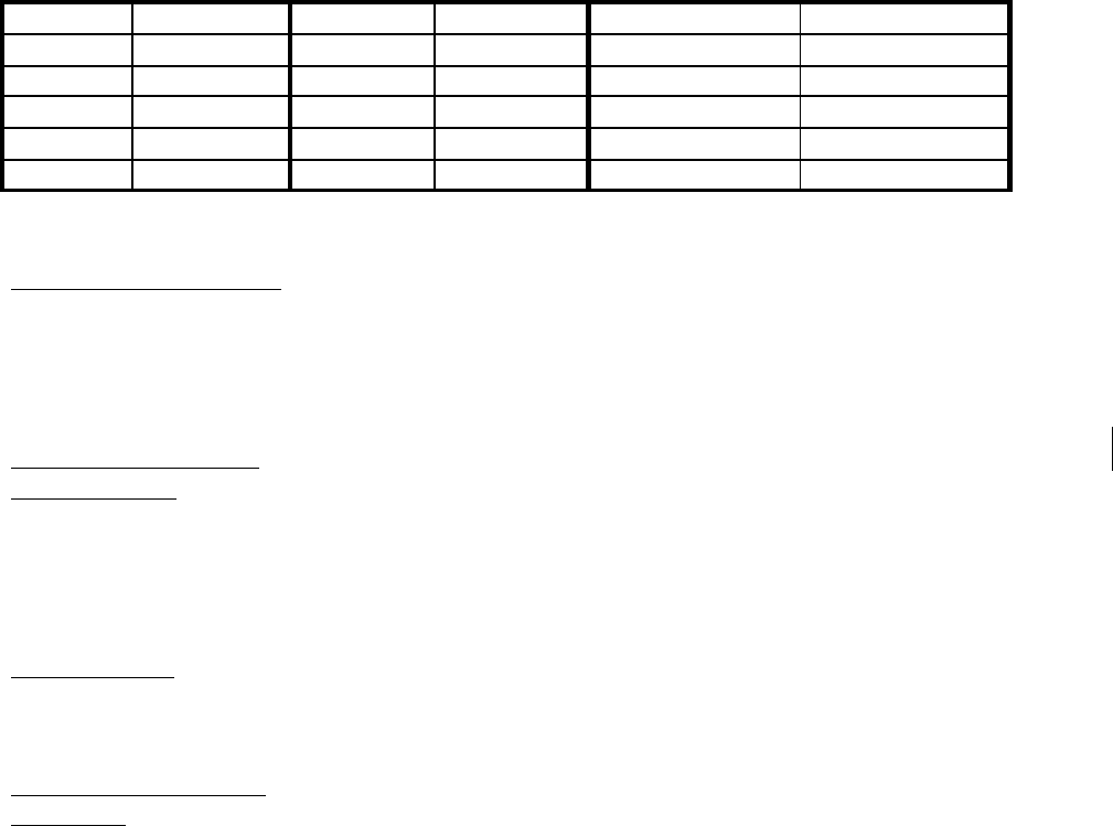
COMUSFLTFORCOMINST 4790.3 REV D CHG 3
07 Nov 2023
V-I-11-169
1/4 2.5 5/8 25 1-3/8 100
5/16 5 3/4 33 1-1/2 115
3/8 6.7 7/8 50 1 ¾-5 150
7/16 8.3 1 67 1 ¾-8 160
1/2 12.5 1-1/8 75 2 180
9/16 17 1-1/4 83 2-1/4 215
FASTENER SIZE/TYPE: Planner enter the type, size and thread of the male fastener
(e.g., 1-1/4”-7 Stud, 9/16”-18 SHCS, 3/4”-10 bolt, etc.).
Planner enter “N/A” if the joint being assembled does not
contain male threaded fasteners (bolts, studs, or stud-bolts,
bolt-studs).
REQUIRED TORQUE
TOLERANCE:
Planner enter the torque and tolerance required for the
component or fastener. Mark the appropriate block (in-lbs
or ft-lbs). When special tightening or assembly instructions
apply in lieu of torque, enter tightening or assembly
instructions and reference document or drawing; use
Remarks if additional space is required.
TORQUE REF: Planner enter the letter of the reference listed in Block 6
that identifies where the torque value was obtained,
including paragraph or table when applicable.
AVERAGE RUNNING
TORQUE:
Craftsman enter the average running torque as measured.
Mark the appropriate block (in-lbs or ft-lbs).
(Planning) Enter “N/A” in the block for joint assemblies
where construction drawings specify that running torque
has been incorporated into the required torque.
NOTE: RUNNING TORQUE DOES NOT NEED TO BE TAKEN INTO ACCOUNT
FOR FASTENERS GREATER THAN 5/8 INCH DIAMETER UNLESS
SPECIFIED IN THE TWD. THE INTENT IS TO ENSURE PROPER TORQUE
IS APPLIED, TAKING RUNNING TORQUE INTO CONSIDERATION WHEN
IT IS A SIGNIFICANT FACTOR WITH REGARD TO THE FINAL TORQUE.
IF RUNNING TORQUE DOCUMENTATION IS NOT REQUIRED BY THE
TWD FOR FASTENERS GREATER THAN 5/8”, PLANNING SHOULD
ANNOTATE THE BLOCK “NR” FOR NOT REQUIRED.
NOTE: CLICKER STYLE TORQUE WRENCHES AND HYTORC DEVICES ARE
NOT TO BE USED TO MEASURE RUNNING TORQUE.
NOTE: THE AVERAGE RUNNING TORQUE MAY BE OBTAINED BY USING THE
SAME DIAL TYPE TORQUE WRENCH THAT WILL BE USED FOR
MEASURING THE FINAL TORQUE. A LOW RANGE DEVICE IS NOT
REQUIRED AND RUNNING TORQUE DOES NOT HAVE TO FALL WITHIN

COMUSFLTFORCOMINST 4790.3 REV D CHG 3
07 Nov 2023
V-I-11-170
THE 20% TO 90% SCALE REQUIREMENT. IF RUNNING TORQUE IS NOT
MEASURABLE USING THIS DEVICE, ENTER “0” (ZERO) FOR THE
AVERAGE RUNNING TORQUE.
NOTE: DOCUMENTATION OF THE TORQUE WRENCH USED FOR
DETERMINING THE AVERAGE RUNNING TORQUE IS NOT REQUIRED.
IF A DIFFERENT WRENCH IS USED TO TAKE THE RUNNING TORQUE
BECAUSE THE FINAL TORQUE IS MEASURED WITH A CLICKER STYLE
OR HYTORC DEVICE, THEN THE TORQUE WRENCH DATA MUST BE
RECORDED.
FINAL TORQUE: Craftsman record the final torque observed on the torque device.
The final torque observed must be the average running torque, as
required, plus the required torque. When construction drawings
specify that running torque has been incorporated into the required
torque, final torque is the torque value specified in the construction
drawing and running torque is NOT added to the required torque
during joint assembly. Mark the appropriate block (in.-lbs or ft-
lbs). Request QAI to verify final torque by direct observation for
all Controlled Assemblies and hull integrity pressure boundary
joints which contain Hull Integrity fasteners (as required in Table
3). In the event that a multiplier or HYTORC machine is used,
place an asterisk or other symbol in this block and refer to the
remarks block. In the remarks block add a statement such as
“Torque multiplier was used, actual torque reading was XXX PSI.
This converts to a torque value of XXX Ft-lbs.” When a
combination of torquing methods (e.g., torque wrench, turn-of-the-
nut method, etc.) is used for a single joint, record the final torque
applied, and document the alternate torquing process. Record the
quantity of fasteners that were tightened using the alternate
method. When special tightening or assembly instructions apply in
lieu of torque, as identified in the required torque block, document
the actual special tightening or assembly applied to the joint
(tightened, wrench tight, cap installed, etc.).
TORQUE DEVICE/ Craftsman enter the range, serial number and calibration due
INSTRUMENT USED: date of the torque device used during assembly for the final
increment. For HYTORC machine, enter “HYTORC”, the
HYTORC’s head data (i.e., serial number), serial number of the
pressure gauge used to read actual pressure applied for final torque
and the calibration due date of that pressure gauge. If other
calibrated instruments (e.g., torque multiplier, torque meter) are
used, also enter data for these instruments.
CRAFTSMAN SIGNATURE/BADGE: Craftsman sign and date after satisfactory assembly
of the joint.
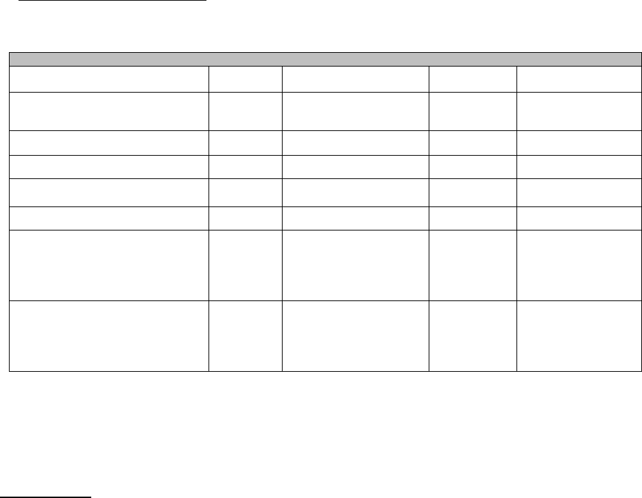
COMUSFLTFORCOMINST 4790.3 REV D CHG 3
07 Nov 2023
V-I-11-171
QAI SIGNATURE/BADGE: When required, QAI must sign and date after the satisfactory
completion of assembly per the requirements.
Planner enter NA when QAI is not required.
Table 3 - QAI Inspection Requirements
Location
Software
Installation
Material Installations
Torque
Sealing Surface &
Fasteners
Nuclear Level I piping system
mechanical joints
Note 1 Yes - Existing and New LI
Yes (when a
torque is
specified)
No
Controlled Assemblies Yes Yes - New LI Only Yes Yes
SUBSAFE Hull Integrity Joints Yes Yes - New LI Only Yes Yes
SUBSAFE Bolted Pressure Boundary
Joints
No Yes - New LI Only No No
EHF Installations Yes Yes - New LI Only Yes Yes
SOC Bolted Pressure Boundary
Joints
Yes
Yes - New LI
Yes - MCD-A
Yes - MCD-B
Yes - MCD-C
Yes Yes
SOC Unions Yes
Yes - New LI
Yes - MCD-A
Yes - MCD-B
Yes - MCD-C
Yes
(When source
is specified)
Yes
NOTE: YES - IF A FLEXATALLIC GASKET IS USED AND THE MATING
SURFACES ARE NOT IN CONTACT. THE QAI IS NOT REQUIRED TO
WITNESS INSTALLATION OF THE GASKET BUT MUST INSPECT
THE MATING SURFACE GAP AND PARALLELISM AFTER
SOFTWARE INSTALLATION AND FINAL TORQUE.
FOR JOINTS: CRAFTSMAN or QAI signature(s) certifies that the joint meets the requirements
for the following:
a. The applied lubricant is acceptable per the technical direction.
b. All existing Hull Integrity Male Fasteners have been examined for markings of
significance or have been verified by a generic material identification test to
ensure they are of proper material. All markings have been recorded and if
required, the results of any material identification testing are recorded in the
Remarks block.
c. All set studs have been verified to be tight during assembly per Part I, Chapter
5, paragraph 5.4.7 of this volume.
d. The final required pre-load torque has been applied per specified requirements.
e. Sealing surfaces meet the acceptance criteria of the applicable Maintenance
Standard.
f. Alignment, gap and parallelism meet the specified requirements for the joint.
g. Male fasteners type and size agree with entries in the “FASTENER
SIZE/TYPE” block and the specified criteria.

COMUSFLTFORCOMINST 4790.3 REV D CHG 3
07 Nov 2023
V-I-11-172
h. Existing fasteners are reinstalled in the same joint and are not obviously
incorrect based on markings, color, corrosion or other visual indication.
i. Thread protrusion is satisfactory. Thread protrusion is the number of threads
protruding above the nut. Minimum thread protrusion is one thread on non-
self-locking fasteners or flush for self-locking fasteners. Maximum thread
protrusion is ten threads unless authorized by drawing or technical manual.
j. All new material associated with the joint meets specified requirements and is
listed in Block 7. Existing material associated with the joint is acceptable and
is correctly installed.
k. The Craftsman will perform a visual check of new Level I material at the time
of installation to verify the material meets the requirements of the TWD used
to install the new material.
FOR OTHER THAN JOINTS: CRAFTSMAN or QAI signature(s) indicates compliance with
the attribute(s) listed and the corresponding listed acceptance criteria. All new material
associated with the joint meets specified requirements and is listed in Block 7. Existing
material associated with the joint is acceptable and is correctly installed.
If UNSAT, the craftsman or QAI will initiate action to resolve the UNSAT condition
(e.g., submit a DF) and indicate the action taken in the Remarks block. Do not sign
unless a satisfactory repair is completed or the UNSAT condition is accepted.
BLOCK 10 - LOCKWIRE/LOCKING CABLE/DEVICE INSTALLED OR REQD
ACTION
(Only required for SUBSAFE, DSS or SOC joints)
NOTE: THIS BLOCK APPLIES TO LOCKING DEVICES THAT ARE INSTALLED
AFTER JOINT MAKE-UP OR FOR CASES WHEN AN ACTION MUST BE
TAKEN AFTER JOINT MAKE-UP TO ENGAGE THE LOCKING DEVICE
(E.G., FLIPPING OF A LOCKTAB, STAKING A FASTENER, ETC.) TO
ALLOW JOINT MAKE-UP AND TESTING PRIOR TO INSTALLING OR
ENGAGING THE LOCKING DEVICE. THIS DOES NOT INCLUDE SELF
LOCKING NUTS, SELF LOCKING BOLTS, CAP SCREWS,
LOCKWASHERS, ETC. THAT ARE PART OF THE JOINT MAKE-UP AND
ARE LISTED IN BLOCK 7.
Planner enter an X in the NA box when not applicable. When an action is required to engage
the locking device, enter a description of the required action.
Craftsman sign, date and check SAT when lockwire, locking cable or required locking device
(e.g., locking ring for EHFs, barrel nut locking device, etc.) has been properly installed, or
the required action has been accomplished. Enter description (e.g., lockwire, locking cable,
lock tab) and ident (e.g., stock number, to include SMIC if given, MIL-SPEC, or piece
number) of the lockwire, locking cable or locking device. Enter description and “Existing”
for existing locking devices. If more than one locking device type (e.g., lockwire and lock
tab washers) exists on the assembly, record additional information in the “Remarks block”.
When the installation of more than one of the same type of locking device is being
documented in Block 10 (e.g., 2 setscrews), record the quantity in addition to the description

COMUSFLTFORCOMINST 4790.3 REV D CHG 3
07 Nov 2023
V-I-11-173
(Block 11 may be used if additional space is needed). Recording the quantity is not required
for lockwire or locking cable, nor when the locking device quantity is documented in Block
7. QAI sign, print and date in Block 11 for new MCD-C material installed by craftsman in
Block 10 to ensure material conforms to specified requirements.
BLOCK 11 - REMARKS
(Craftsman, QAI, QAS or Planning) Enter any pertinent remarks or additional information
related to the repair or assembly of the component. Each entry must contain signature, badge
number and date except where the entry is pre-printed on the form by Planning (adding an
“N/A” does not require signature, badge number and date). For controlled assemblies on
systems requiring MIL-STD-1622 for critical applications or MIL-STD-1330, document
“Cleanliness maintained per (MIL-STD-1622 Critical Applications or MIL-STD-1330 (as
applicable))” and include the Craftsman’s signature and date.
BLOCK 12 - LWC SUPERVISOR/SHOP SUPERVISOR SIGNATURE/BADGE NO.
LWC Supervisor will enter signature, date and badge number for final review, signifying the
accuracy of the completed form. If any entry is UNSAT, initiate action to resolve the unsat
condition and indicate the action taken in the “Remarks” block. Do not sign unless a
satisfactory repair is completed or the UNSAT condition is accepted.
BLOCK 13 - QAS/QAO SIGNATURE/BADGE NO.
QAS or QAO sign, date and enter badge number for final review, signifying entries are
complete and that the data agrees with the listed requirements.
BLOCK 14 - JOINT DATA FOR JOINTS NOT REQUIRING TORQUE
DOCUMENTATION
NOTE: THIS BLOCK MAY BE USED FOR SPECIFIC ATTRIBUTES THAT ARE
NOT COVERED BY THE STANDARD ATTRIBUTES ON THE FORM.
NOTE: (SUBMARINES ONLY) THIS BLOCK MUST NOT BE USED FOR
CONTROLLED ASSEMBLIES OR SOC PRESSURE BOUNDARY JOINTS.
JOINT ID/JOINT TYPE OR ATTRIBUTE DESCRIPTION: Planner enter the joint
identification number including joint type (e.g., ASW-5744 F). For joint types, use “F” for
flanged bolted joints, “U” for union joints, and “S” for screw joints. When a joint
identification number is not available, a joint description (e.g., Bonnet-to-Body (S)) must be
used. Locally assigned joint numbers may be used when a joint description is not practicable
and clarity is required. When additional attribute(s) applies to a component (e.g., hatches,
etc.) that are not covered by the attributes already on the form, list the attribute and location
(applicable reference) for the acceptance criteria (e.g., TWD, technical manual, etc.). For
hatches, at a minimum list the “Seat Clearance Measurement”.
JT. REF: Planner enter the corresponding reference listed in Block 6 that identifies where the
joint number or description information is found (e.g., Mapping Diagram, Drawing, Tech
Manual, Work Procedure, etc.).
(C) FOR CRAFTSMAN OR (I) FOR INSPECTOR: Planner enter “C” on one line for each
joint or attribute. Enter “I” on the remaining line for each joint or attribute that requires an
inspector signature; leave blank if inspector signature is not required.

COMUSFLTFORCOMINST 4790.3 REV D CHG 3
07 Nov 2023
V-I-11-174
CRAFTSMAN SIGNATURE/BADGE/DATE: Craftsman sign and enter badge number and
date on the line associated with the “C” after satisfactory assembly of the joint. If UNSAT, the
craftsman will initiate action to resolve the UNSAT condition and indicate the action taken in
the Remarks block. Do not sign unless a satisfactory repair is completed or the UNSAT
condition is accepted.
FOR JOINTS: This signature provides certification that the joint meets the requirements for
the following:
a. All driven studs have been verified to be tight during assembly. Stud rotation
during torquing (and break away) is limited to 1/4 turn, but no more turning
during installation or removal of the nut for newly installed Class 3 studs
installed with locking compound.
b. The joint has been tightened using an approved method. Recording of torque
value is not required.
c. Sealing surfaces meet the acceptance criteria of the applicable Maintenance
Standard.
d. Alignment, gap and parallelism meet the specified requirements for the joint.
e. All new material associated with the joint meets specified requirements and is
listed in Block 7. Existing material associated with the joint is acceptable and
is correctly installed.
f. The Craftsman will perform a visual check of new Level I material at the time
of installation to verify the material meets the requirements of the TWD used
to install the new material.
g. The applied lubricant is acceptable per the technical direction.
h. Existing fasteners are reinstalled in the same joint and are not obviously
incorrect based on markings, color, corrosion or other visual indication.
i. Thread protrusion is satisfactory. Thread protrusion is the number of threads
protruding above the nut. Minimum thread protrusion is one thread on non-
self-locking fasteners or flush for self-locking fasteners. Maximum thread
protrusion is ten threads unless authorized by drawing or technical manual.
FOR OTHER THAN JOINTS: This signature indicates compliance with the attribute(s) listed
and the corresponding listed acceptance criteria. All new material associated with the joint
meets specified requirements and is listed in Block 7. Existing material associated with the
joint is acceptable and is correctly installed.
INSPECTOR SIGNATURE/BADGE/DATE: (Inspector) When required, Inspector sign and
enter badge number and date on the line associated with the “(I)” for verification that all new
material associated with the joint meets specified requirements and is listed in Block 7.
Existing material associated with the joint is acceptable and is correctly installed.
COMUSFLTFORCOMINST 4790.3 REV D CHG 3
07 Nov 2023
V-I-11-175
JOINT/COMPONENT ASSEMBLY RECORD Planning must fill in blocks identified by a prior to issuing.
QA FORM 34A
(For Assemblies Not Requiring Torque Documentation)
PAGE _____ OF _____
1. SHIP
HULL
NO.
2. JCN 3. LWC/SHOP 4. CWP/REC
NO.
5. SYSTEM/COMPONENT/ROTATABLE POOL
NO
6. REFERENCES (Specify Assembly Number if applicable.)
A.
B.
C.
D.
E.
F.
7. NEW MATERIAL
PC
NO.
REF. JOINT
ID
DESCRIPTION
(Include thickness for shims; diameter and
thread pitch for fasteners)
QTY LOE IDENT (E.G., MIC NO/NSN/ROTATABLE POOL
NO)
(FOR LEVEL I FASTENERS: Include Material
Marking, Color Code, Heat/Lot Number, and
Manufacturer’s Symbol)
CRAFT
INT
8. JOINT DATA
FOR OTHER THAN JOINT MAKE-UP, DESCRIBE
THE SPECIFIC ATTRIBUTE AND LOCATION OF
THE ACCEPTANCE CRITERIA. IDENTIFY
JOINTS THAT REQUIRE CONTROLLED
ASSEMBLY PROCEDURES.
INSPECTOR (SHIPYARDS ONLY - FOR CONTROLLED ASSEMBLY JOINTS ONLY) & CRAFTSMAN
SIGNATURE CERTIFIES:
(1) JOINT SEALING SURFACES, ALIGNMENT, GAP AND PARALLELISM ARE SAT PER
SPECIFIED REQUIREMENTS AND STUDS HAVE BEEN CHECKED FOR ROTATION IF APPLICABLE, OR
ATTRIBUTE IS ACCEPTABLE PER SPECIFIED CRITERIA.
(2) ALL NEW MATERIAL ASSOCIATED WITH THIS JOINT MEETS SPECIFIED REQUIREMENTS, IS
INSTALLED & LISTED IN BLOCK 7; EXISTING MATERIAL ASSOCIATED WITH THIS JOINT IS
ACCEPTABLE AND CORRECTLY INSTALLED.
FOR FLEET ONLY: FOR NON-CONTROLLED ASSEMBLIES WHEN NO SPECIFIC ATTRIBUTE IS
SPECIFIED, INSPECTOR SIGNATURE CERTIFIES ACCEPTANCE OF LEVEL I MATERIAL ONLY.
JOINT ID & JOINT TYPE OR ATTRIBUTE
DESCRIPTION
JT.
REF
(C) FOR
CRAFTSMAN OR
(I) FOR
INSPECTOR
CRAFTSMAN SIGNATURE/BADGE/DATE (FOR EACH JOINT/ATTRIBUTE)
INSPECTOR SIGNATURE/BADGE/DATE (FOR EACH (I) JOINT/ATTRIBUTE)
A.
B.
C.
D.
E.
9. LOCKING DEVICE INSTALLED
OR REQD ACTION:
NA
MATL. DESCRIPTION/NSN/PC. NO. JT. ID. CRAFTSMAN SIGNATURE/BADGE/DATE
SAT
10. REMARKS (CRAFTSMAN/QAI SUBMIT A DF TO RESOLVE UNSAT DATA) (FOR USE WHEN SIGNATURE DOES NOT ALREADY
APPEAR ON FORM)
INITIAL SIGNATURE/BADGE NO.
11. LWC SUPERVISOR/SHOP SUPERVISOR SIGNATURE/BADGE NO (RECORD
REVIEWED FOR FINAL ACCEPTANCE)
12. QAS SIGNATURE /BADGE NO (RECORD HAS BEEN REVIEWED FOR
COMPLETENESS)

COMUSFLTFORCOMINST 4790.3 REV D CHG 3
07 Nov 2023
V-I-11-176
QA FORM 34A INSTRUCTIONS
JOINT/COMPONENT ASSEMBLY RECORD
FOR ASSEMBLIES NOT REQUIRING TORQUE DOCUMENTATION
PURPOSE: To provide a standard form to document the assembly of joints that do not require
torque documentation. Planning must fill in blocks identified by a prior to
issuing. The QA form 34A is not to be used in Nuclear or SOC applications.
REQUIREMENTS:
1. A QA form 34A is required for:
a. All non-nuclear Level I pressure boundary joints (e.g., “F”, “S”, and “U” type joints.
b. The following submarine applications:
(1) (Pre-688 Class) Submarine SUBSAFE Bolted Pressure Boundary Joints
including in-line pipe joints as well as component (bonnet to body) joints less
than 4-inch NPS inboard of the inboard joint of the backup valve.
(2) Other SUBSAFE joints:
(a) Non-Seawater or Non-Sea Connected piping and component joints to
include non-pressure boundary joints (e.g., EMBT Blow, Artic Blow,
Emergency Flood Control, Stern Diving).
(b) Non-bolted pressure boundary piping and component joints within the
hull integrity boundary (e.g., Union (“U”) Bonnet Joints on Hull and
Backup Valves, Hull and backup valve stem retainers (“S”), Boiler type
Manhole Covers (“BTMC”) on Impulse Tanks).
(c) Non-bolted pressure boundary piping and components (e.g., “U” and
“S” joints) not within the hull integrity boundary.
(d) Linkage or mechanical interlock joints.
(e) SUBSAFE or Non-SUBSAFE interface piping joints (e.g., “F” and “U”
joints).
PLANNING THE SCOPE OF A QA 34A FORM: In order to support the execution process, it is
necessary to properly limit the scope of Assembly Records.
a. Each joint must have a unique joint record consisting of separate Block 8 entries.
b. All Level I material must be traceable to a specific joint. To ensure unique joint
traceability, if any identical Level I parts are used in multiple joints within an
assembly (normally this applies to fasteners), the craftsman will annotate which joint
(Block 8A, 8B, etc.) the material was installed in.
c. For complex assemblies (e.g., Shaft Seal installations), assembly records should be
scoped to support testing evolutions.

COMUSFLTFORCOMINST 4790.3 REV D CHG 3
07 Nov 2023
V-I-11-177
TOP OF FORM: Page ___ of ___
NOTE A TECHNICAL WORK DOCUMENT MAY CONTAIN MULTIPLE QA
FORMS OF THE SAME TYPE, (E.G. MORE THAN ONE QA-26). THE PAGE
ENTRY IS FOR THIS SPECIFIC FORM, NOT THE TOTAL NUMBER OF
PAGES ON ALL FORMS OF THE SAME TYPE.
Enter the page number, starting with page 1, of total number of QA form pages (e.g., 1 of ,
2 of ). The last number reflects the total number of QA Form pages written. This block is
filled in by a QAI or the QAO after all certification testing is complete before block 19 on the
QA-9 is signed. (e.g., 1 of 3, 2 of 3, 3 of 3).
PROCEDURE: The numbered blocks on QA form 34A correspond with block instructions
listed. Any block not used will be marked N/A. Planning must fill in blocks
identified by a prior to issuing the CWP. For QAI signatures, the planner will
determine the need for a QAI prior to the start of the job. If no QAI is required,
the planner will enter NA in the QAI signature block.
BLOCK 1 - SHIP HULL NO.
Planner - Enter the ship’s name and hull number, or enter the appropriate rotatable pool
system designator (e.g., TRIPER, CCRP, AERP, SSN 688CL, etc.).
BLOCK 2 - JCN
Planner - Enter the Job Control Number (JCN). Naval shipyards enter Job Order and Key Op.
BLOCK 3 - LWC/SHOP
Planner - Enter the LWC lead shop assigned to assemble the joint (e.g., X31, X38, X56).
BLOCK 4 - CWP/REC SER. NO.
Planner - Enter the CWP/REC serial number or enter N/A if no CWP/REC is required. Do
not list the CWP/REC revision.
BLOCK 5 - SYSTEM/COMPONENT/ROTATABLE POOL NO.
Planner - Enter the noun name of the system and component (if applicable), (e.g., MSW-25).
For Rubber Insert Sound Isolation Coupling enter the Selected Record Drawing Line Item No.
NOTE: ROTATABLE POOL SERIAL NUMBERS MAY BE ENTERED BY THE
PLANNER, IF KNOWN, OR THE SHOP AS SPECIFIED BY LOCAL
INSTRUCTIONS.
BLOCK 6 - REFERENCES
Planner - Enter all references used to identify component parts, joint, material and assembly
information. Both the assembly drawing and electrical holes’ assignment drawing must be
listed for Electrical Hull Fittings (EHF). Include revision letter and, if applicable, the
assembly number (e.g., Assy D, Assy RA etc.).
BLOCK 7 - NEW MATERIAL
PC NO: Craftsman - Enter the piece number of parts. List only the new parts being installed.
COMUSFLTFORCOMINST 4790.3 REV D CHG 3
07 Nov 2023
V-I-11-178
REF: Craftsman - Record the reference letter of the drawing or document listed in Block 6
which provides the material specification or assembly information for the piece listed in the
“PC NO.” block.
JOINT ID: Craftsman - Enter the alphanumeric designator corresponding with the particular
Block 8 entry (8A, 8B, 8C, etc.) that identifies the joint where the material is installed.
DESCRIPTION: Craftsman - Describe all new parts associated with the assembly or joint.
For fasteners and nuts, include diameter and thread (e.g., bolt, ½”-13; stud, ½”-12; SHCS, ½”-
13; etc.). Record shim thickness when shims are installed unless the installation is already
documented on another QA form.
NOTE: IF A PORTION OF A NEW VALVE OR COMPONENT IS USED TO
REPLACE PARTS (E.G., BONNET AND DISC ASSEMBLY), ENTER A
DESCRIPTION OF THE PART OR ASSEMBLY OF PARTS AND
DOCUMENT THE LEVEL I NUMBER OF THE NEW VALVE OR
COMPONENT IN THE IDENT SECTION. LIST THE PARTS THAT THE
ASSEMBLY CONSISTS OF IN THE REMARKS BLOCK (A SINGLE
COMPONENT MAY BE LISTED IN BLOCK 7) WITH A NOTE THAT THE
PART(S) WERE TAKEN FROM THE NEW VALVE OR COMPONENT.
QTY: Craftsman - Record quantity of new material installed.
LOE: Craftsman - Identify the Level of Essentiality (MIC Level) as “I” or “NA”. The
material control level must be as identified by Planning in the TWD.
IDENT: Craftsman - Enter the marking on the part or on the packaging, container or tag
(when the part is not marked) as shown in Table 1.
CRAFT INT: Craftsman - Installing craftsman enter initials for material installed. The
initials must correspond to the related Block 8 craftsman’s signature unless otherwise noted
with a corresponding signature elsewhere on the form (e.g., Remarks block entry and
signature).
NOTE: IF THE CRAFTSMAN INSTALLING THE MATERIAL IS OTHER THAN
THE CRAFTSMAN SIGNING FOR JOINT DATA IN BLOCK 8, A
CORRESPONDING SIGNATURE, BADGE NUMBER AND DATE MUST BE
ENTERED IN THE REMARKS BLOCK.
TABLE 1- DOCUMENTATION REQUIREMENTS
Material Control Level Required Information
Level I Material Other Than
Fasteners
MIC Number and any other traceability number, including any local traceability number
(e.g., PNSY MLN – examples Z142, AB12).
Level I Fasteners NOTE: THE INFORMATION ENTERED FOR FASTENERS MAY NEED TO INCLUDE
INFORMATION FROM BLOCKS 3 AND 8 FROM QA FORM 1. DO NOT ENTER THE
PNSY TRACE NUMBER FROM BLOCK 3 OF THE QA FORM 1.
Document the markings from the fastener to include either:
(1) The color code and the heat or lot number, material type, and manufacturer’s
symbol (for nuts containing a self-locking
insert, the color of the insert is the
manufacturer’s symbol).
(2) The MIC number (when MIC number is on the fastener or on the individual tag
for some fasteners).
Controlled Structural Material Traceability Number
AERP And Other Rotatable Pool
Material (688 Class, TRIPER, Etc.)
Enter the appropriate rotatable pool serial number (e.g. RP-148A, 4810-013-5812-A3-
0113, TIN -292-11893, etc.)

COMUSFLTFORCOMINST 4790.3 REV D CHG 3
07 Nov 2023
V-I-11-179
Transferred And Cannibalized
Material
Enter the Equipment Removal List No. or other material History or Traceability number
(ERL# XXXX, SSBN-600 EHF #24, etc.)
Other Material Within The LEVEL
I/SUBSAFE Boundary
1. Enter at least one of the following documentation attributes:
a. Stock Number (from package or container)
b. Part Number (from package or piece)
c. Part Number and associated Manufacturing Work Procedure (for manufactured
items)
d. Local Traceability Number (from piece or tag)
e. Drawing and Piece Number (from piece or tag)
f. Generic, MIL-SPEC, or Material Specification Marking (from piece)
g. NDT record numbers or test results for items verified by generic material testing.
BLOCK 8 - JOINT DATA
NOTES:
(1) THIS BLOCK MAY BE USED FOR SPECIFIC ATTRIBUTES THAT ARE NOT
COVERED BY THE STANDARD ATTRIBUTES ON THE FORM.
(2) FOR OVERHAUL OF HYDRAULIC ACTUATORS AND HYDRAULIC
CONTROL VALVE ASSEMBLIES, ONLY ONE ENTRY IS REQUIRED FOR THE
ENTIRE ASSEMBLY IN LIEU OF LISTING INDIVIDUAL JOINTS AS LONG AS
A CLEAR DEFINITION OF WORK BOUNDARIES HAS BEEN IDENTIFIED IN
THE WORK PROCEDURE. FOR THESE CASES, LIST “ACTUATOR
ASSEMBLY” OR “CONTROL VALVE ASSEMBLY” IN THIS BLOCK.
(3) FOR FLEET ONLY: FOR NON-CONTROLLED ASSEMBLIES WHEN NO
SPECIFIC ATTRIBUTE IS SPECIFIED, INSPECTOR SIGNATURE CERTIFIES
ACCEPTANCE OF LEVEL I MATERIAL ONLY. NUCLEAR LEVEL 1,
INSPECTOR SIGNATURE CERTIFIES WITNESSING GASKET COMPRESSION
AND FLANGE PARALLELISM (GAP MEASUREMENT IS ONLY REQUIRED IF
MATING SURFACES DO NOT CONTACT).
JOINT ID & JOINT TYPE OR ATTRIBUTE DESCRIPTION: Planner - Enter the joint
identification number including joint type (e.g., ASW-5744 F). For joint types, use “F” for
flanged bolted joints, “U” for union joints, and “S” for screw joints. When a joint
identification number is not available, a joint description (e.g., Bonnet-to-Body (S)) must be
used. Locally assigned joint numbers may be used when a joint description is not practicable
and clarity is required. When an additional attribute(s) applies to a component (e.g., hatches,
etc.) that are not covered by the attributes already on the form, list the attribute and location
(applicable reference) for the acceptance criteria, (e.g., TWD, technical manual, etc.). For
hatches, at a minimum list the “Seat Clearance Measurement”.
JT. REF: Planner - Enter the corresponding reference listed in Block 6 that identifies where
the joint number or description information is found (e.g., Mapping Diagram, Drawing, Tech
Manual, Work Procedure, etc.).
(C) FOR CRAFTSMAN OR (I) FOR INSPECTOR: Planner - Enter “C” on one line for each
joint. Enter “I” on the remaining line for each joint requiring an inspector signature.
CRAFTSMAN SIGNATURE/BADGE/DATE: Craftsman sign and enter badge number and
date on the line associated with the “C” after satisfactory assembly of the joint.
For joints, this signature provides certification that the joint meets the requirements for the
following:

COMUSFLTFORCOMINST 4790.3 REV D CHG 3
07 Nov 2023
V-I-11-180
a. All set studs to be tight during nut installation and torquing per Part I, Chapter 5,
paragraph 5.4.7 of this volume.
b. The joint has been tightened using an approved method. Recording of torque value is
not required.
c. Sealing surfaces meet the acceptance criteria of the applicable Maintenance Standard
or drawing.
d. Alignment, Gap and Parallelism meet the specified requirements for the joint.
e. All new material associated with the joint meets specified requirements and is listed in
Block 7. Existing material associated with the joint is acceptable and is correctly
installed.
For other than joints, the signature indicates compliance with the attribute(s) listed and the
corresponding listed acceptance criteria. All new material associated with the joint meets
specified requirements and is listed in Block 7. Existing fasteners are installed in the same
joint and are not obviously incorrect based on markings, color, corrosion or other visual
inspection.
INSPECTOR SIGNATURE/BADGE/DATE: (QAI) When required, Inspector sign, print and
enter badge number and date on the line associated with the “(I)” for verification of the
following:
a. Controlled assemblies: All controlled assemblies must be documented on a QA Form
34.
b. Non-Controlled assemblies: Inspector signature certifies:
(1) That new Level I material meets the specification for use and is properly
documented in Block 7.
(2) That Hull integrity joint sealing surfaces for new or reused material meets
acceptance criteria.
(3) That all new material, including software, installed in Hull Integrity joints meets
specification, is properly installed and documented in Block 7.
If UNSAT, the craftsman or QAI will initiate action to resolve the UNSAT condition (e.g.,
initiate a DFS) and indicate the action taken in the Remarks block. Do not sign unless a
satisfactory repair is completed or the UNSAT condition is accepted.
BLOCK 9 - LOCKING DEVICE INSTALLED OR REQD ACTION
NOTE: THIS BLOCK APPLIES TO LOCKING DEVICES ON SUBSAFE
COMPONENTS THAT ARE INSTALLED AFTER JOINT MAKE-UP OR FOR
CASES WHEN AN ACTION MUST BE TAKEN AFTER JOINT MAKE-UP TO
ENGAGE THE LOCKING DEVICE (E.G., FLIPPING OF A LOCKTAB,
STAKING A FASTENER, ETC.) TO ALLOW JOINT MAKE-UP AND
TESTING PRIOR TO INSTALLING OR ENGAGING THE LOCKING
DEVICE. THIS DOES NOT INCLUDE SELF LOCKING NUTS, SELF
LOCKING BOLTS, CAP SCREWS, LOCKWASHERS, ETC. THAT ARE
PART OF THE JOINT MAKE-UP, AND ARE LISTED IN BLOCK 7.

COMUSFLTFORCOMINST 4790.3 REV D CHG 3
07 Nov 2023
V-I-11-181
Planner - Mark the NA box when not applicable. When an action is required to engage the
locking device, enter a description of the required action.
(CRAFTSMAN) Enter the Block 8 joint identifier (e.g., 8A) in the JT ID block, check the
“SAT” box and sign, enter badge number and date when lockwire or required locking device
(e.g., locking ring for EHFs, barrel nut locking device, etc.) has been properly installed, or the
required action has been accomplished. Enter description (e.g., lockwire, lock tab) and
identification (e.g., stock number, MIL-SPEC or piece number) of the lockwire or locking
device. Enter description and “Existing” for existing locking devices. If more than one locking
device type (e.g., lockwire and lock tab washers) exists on the assembly, record additional
information in the REMARKS block. When the installation of more than one of the same type
of locking device is being documented in Block 9 (e.g., 2 setscrews), record the quantity in
addition to the description (Block 10 may be used if additional space is needed). Recording the
quantity is not required for lockwire or locking cable, nor when the locking device quantity is
documented in Block 7.
BLOCK 10 - REMARKS
(CRAFTSMAN/QAI/QAS) Enter any pertinent remarks or additional information related to
the repair or assembly of the component. Each entry must contain signature and date except
where the entry is pre-printed on the form by Planning. Adding an “N/A” does not require
signature and date.
BLOCK 11 - LWC SUPERVISOR/SHOP SUPERVISOR SIGNATURE/BADGE NO.
LWC or shop LWC Supervisor will enter signature, badge number and date for final review,
signifying the accuracy of the completed form. If any entry is UNSAT, initiate action to
resolve the unsat condition and indicate the action taken in the “Remarks” block. Do not sign
unless a satisfactory repair is completed or the UNSAT condition is accepted.
BLOCK 12 - QAS SIGNATURE/BADGE NO.
QAS or QAO will print name, enter signature, badge number and date for final review,
signifying the accuracy of the completed form. If any entry is UNSAT, the QAS will initiate
action to resolve the unsat condition and indicate actions taken in the “Remarks” block. Do
not sign unless a satisfactory repair is completed or the UNSAT condition is accepted.
COMUSFLTFORCOMINST 4790.3 REV D CHG 3
07 Nov 2023
V-I-11-182
THICKNESS MEASUREMENT RECORD
QA FORM 35
1. SHIP HULL NO. 2. JCN 3. LWC/SHOP 4. CWP/REC SER NO 5. SYSTEM/COMPONENT
6. REFERENCES
A B C
7. ITEM(S) TO BE INSPECTED
PC
NO.
REF TYPE MAT MIL-SPEC
MATERIAL
PP – PIPE
C – CASTING
PL – PLATE
O- OTHER
INSPECTION
PROCEDURE
ACCEPTANCE
CRITERIA
DESIGN
THICKNESS
MIN/MAX
ACCEPT
THICKNESS
ACTUAL
THICKNESS
ACCEPT
REJECT
ACCEPT
REJECT
ACCEPT
REJECT
ACCEPT
REJECT
ACCEPT
REJECT
8. ULTRASONIC EQUIPMENT
INSTR (MOD/SER#) TYPE TRANSDUCER
DELAY
CONTACT
DUAL ELEMENT
SIZE FREQ CAL
STANDARD
COUPLANT
CAL DUE DATE:
12. SURFACE FINISH IS ACCEPTABLE IN ACCORDANCE WITH DRAWING:
PC NO____
SAT UNSAT PC NO____ SAT UNSAT PC NO____ SAT UNSAT PC NO____ SAT UNSAT
10. INSPECTION AREA SKETCH/REMARKS
11. INSPECTOR DATE
11. INSPECTOR DATE
12. NDT SUPERVISOR DATE NO.
Page _____ of _____

COMUSFLTFORCOMINST 4790.3 REV D CHG 3
07 Nov 2023
V-I-11-183
QA FORM 35 INSTRUCTIONS
THICKNESS MEASUREMENT RECORD
PURPOSE: To document UT thickness measurements and acceptability of material
measured based on design material thickness.
TOP OF FORM: Page ___ of ___
NOTE A TECHNICAL WORK DOCUMENT MAY CONTAIN MULTIPLE QA
FORMS OF THE SAME TYPE, (E.G. MORE THAN ONE QA-26). THE PAGE
ENTRY IS FOR THIS SPECIFIC FORM, NOT THE TOTAL NUMBER OF
PAGES ON ALL FORMS OF THE SAME TYPE.
Enter the page number, starting with page 1, of total number of QA form pages (e.g., 1 of ,
2 of ). The last number reflects the total number of QA Form pages written. This block is
filled in by a QAI or the QAO after all certification testing is complete before block 19 on the
QA-9 is signed. (e.g., 1 of 3, 2 of 3, 3 of 3).
PROCEDURE: The numbered blocks in QA form 35 correspond with the block instructions.
BLOCK 1 - SHIP HULL NO.
Enter the ship’s name and hull number.
BLOCK 2 - JCN
Enter the JCN.
BLOCK 3 - LWC
Enter the LWC.
BLOCK 4 - CWP/REC SER. NO.
Enter the CWP/REC serial number or enter N/A if no CWP/REC is required. Do not list the
CWP/REC revision.
BLOCK 5 - SYSTEM/COMPONENT
Enter nomenclature and NPS (if applicable) for component being measured and if known, the
end use (e.g., Valve body for ASW-352).
BLOCK 6 - REFERENCES
Enter the drawing number(s) or other references that show the material and design
specifications for the component being measured (e.g., 845-4385050), the NDT inspection
procedure number, and the drawing number and revision, material specification, or Military
Standard used for acceptance criteria.
BLOCK 7 - MATERIAL
PC NO: Enter piece number of the part or component to be checked.
REF: Record the reference letter of the drawing or document listed in Block 6
which provides the assembly information for the piece listed in the “PC
NO.” block.
TYPE MATERIAL: Enter the material type (e.g., CRES-304, 7030 CUNI, 9010 CUNI).

COMUSFLTFORCOMINST 4790.3 REV D CHG 3
07 Nov 2023
V-I-11-184
MIL-SPEC: Enter the material MIL-SPEC or equivalent (e.g., ASTM, ASME,
SPEC).
MATERIAL: Enter the abbreviation for the material being checked. If other than
pipe, casting, or plate, write it in the block (e.g., forged) in the blank
provided.
INSPECTION Enter the reference letter indicating the NDT inspection
PROCEDURE: procedure number.
ACCEPTANCE Enter the reference letter indicating the drawing, material
CRITERIA: specification or Military Standard used for acceptance.
DESIGN MATL Enter the design material thickness specified on the drawing,
THICKNESS: specification or standard.
MIN/MAX Enter the drawing minimum acceptable thickness and if applicable the
ACCEPT THK: maximum drawing acceptable thickness with a MAX subscript.
ACTUAL THK: Enter the actual thickness as measured.
ACCEPT/REJECT: Check the appropriate box to indicate the results of the inspection.
BLOCK 8 - ULTRASONIC EQUIPMENT
INSTR (MOD/ Enter the equipment model and serial number.
SER. NO):
CAL DUE DATE: Enter the calibration due date of the equipment used during the
measurement.
TYPE TRANSDUCER: Enter the type transducer used during the measurement. Check the
appropriate block.
SIZE: Enter the transducer size used during the measurement.
FREQ: Enter the transducer frequency used during the measurement.
CAL STANDARD: Enter the serial no. of the calibration standard used.
COUPLANT: Enter the couplant used during the measurement.
BLOCK 9 - SURFACE FINISH ACCEPTABILITY
Enter the piece number being inspected and check the appropriate block (SAT or UNSAT)
indicating the result of the surface finish inspection.
BLOCK 10 - INSPECTION AREA SKETCH/REMARKS
Enter a sketch of the area measured. In addition to the sketch, enter a list of any other
references to determine acceptability of material thickness. Enter grid spacing if applicable.
Enter a list of any other references to determine acceptability of material thickness. This
block may also be used to record the results of multiple thickness readings on the same
component. Enter remarks or comments pertinent to the inspection. Sign and date each entry.
BLOCK 11 - INSPECTOR/DATE

COMUSFLTFORCOMINST 4790.3 REV D CHG 3
07 Nov 2023
V-I-11-185
NDT Inspector(s) print name, enter signature and date signifying accuracy of the data
recorded.
BLOCK 12 - NDT SUPERVISOR ID NO./DATE
NDT examiner or supervisor print name, enter signature, and date signifying the report as
technically and administratively complete and accurate.

COMUSFLTFORCOMINST 4790.3 REV D CHG 3
07 Nov 2023
V-I-11-186
SHIP TO SHOP TAG MAT-1 (GENERAL USE)
(Tag color is blue)
MAT-1
SHIP TO SHOP TAG
(GENERAL USE)
TAG ____ OF ____
(PART 1)
_____________________________________________________________________
SHIP JCN
_____________________________________________________________________
EIC/APL SER. NO.
_____________________________________________________________________
JOB BRIEF/EQUIP NOMENCLATURE
_____________________________________________________________________
_____________________________________________________________________
_____________________________________________________________________
_____________________________________________________________________
LEAD W/C | DATE DELV’D | DELIVERED BY
____________|_____________________ _|_ ________________________________
- - - - - - - - - - - - - - - - - - - - - - - - - - - - - - - - - - - - - - - - - - - - - - - - - - - - - - - - - - -
(PART 2)
READY FOR PICK UP TAG
_____________________________________________________________________
SHIP* JCN*
_____________________________________________________________________
JOB BRIEF-WORK PERFORMED
_____________________________________________________________________
_____________________________________________________________________
_____________________________________________________________________
REPAIR ACTIVITY REP. DATE
_____________________________________________________________________
- - - - - - - - - - - - - - - - - - - - - - - - - - - - - - - - - - - - - - - - - - - - - - - - - - - - - - - - - -
(PART 3)
CUSTOMER MATERIAL RECEIPT
_____________________________________________________________________
SHIP* JCN*
_____________________________________________________________________
JOB BRIEF/EQUIP NOMENCLATURE*
_____________________________________________________________________
_____________________________________________________________________
_____________________________________________________________________
RECEIVED BY DATE
_____________________________________________________________________
DELIVERED BY DATE
____’________________________________________________________________
SHIP’S FORCE REMOVE AND RETAIN PART 3 AS RECEIPT FOR MATERIAL
DELIVERED TO THE REPAIR ACTIVITY

COMUSFLTFORCOMINST 4790.3 REV D CHG 3
07 Nov 2023
V-I-11-187
MAT-1 INSTRUCTIONS
SHIP TO SHOP TAG MAT-1 (GENERAL USE)
S/N 0103-LF-984-3400
NOTE 1: NOT TO BE USED FOR CONTROLLED MATERIAL.
NOTE 2: THE MAINTENANCE PROVIDER WILL ESTABLISH A PROCESS FOR
CONTROLLING MATERIAL BEING TRANSPORTED FROM SHIP TO
SHOP. IF A PROCESS IS USED OTHER THAN DESCRIBED BELOW, ISIC
APPROVAL IS REQUIRED.
1. PURPOSE: To maintain positive identification and control of ship to shop transfer of
equipment and components.
2. PROCEDURE:
a. Ship’s Force personnel will fill out all blocks in Part 1 and those marked with an
asterisk (*) in Parts 2 and 3, attach the tag to the equipment or component and deliver
to the Repair Activity. Verify correct EIC or APL is provided. Ensure accurate
description of desired work is included in Job Brief/Equip Nomenclature Block.
Example: No. 2 Main Lube Oil Pump Discharge Relief Valve Pop Test to 45 psi and
attach test tag.
b. When the component is delivered to the Repair Activity, ship’s representative will
sign and date Part 1 and 3 in the applicable blocks. The Repair Activity representative
will sign and date Part 3 to acknowledge receipt of the equipment or component. Part
3 will be detached from the tag and given to the ship’s representative.
c. Upon completion of repairs, the Repair Activity will record work performed, sign and
date Part 2 and forward Part 2 to the ship as notice that the equipment or component is
ready to be picked up.
d. The ship’s representative will present Part 3 to the Repair Activity Shop when picking
up the equipment or component. Ship’s Force should sign the Work Request for job
completion when the item is picked up. If desired, part 3 may be attached to the
completed work request.
3. BLOCK DESCRIPTION:
a. Part 1.
SHIP Ship’s name and hull number
JCN Job Control Number (UIC, Work Center and
JSN)
EIC/APL Equipment Identification Code or Allowance
Parts List of item worked
SER. NO. Equipment or Component Serial Number
JOB BRIEF/EQUIP
NOMENCLATURE
Job Description and name of equipment or
component
COMUSFLTFORCOMINST 4790.3 REV D CHG 3
07 Nov 2023
V-I-11-188
LEAD W/C Work center responsible for equipment or
component
DATE DELV’D Date delivered to Repair Activity
DELIVERED BY Signature of person delivering item
b. Part 2.
SHIP Ship’s name and hull number
JCN Job Control Number (UIC, Work Center and
JSN)
JOB BRIEF-WORK
PERFORMED
Job Description and brief explanation of work
performed by repair activity
REPAIR ACTIVITY REP. Signature of person verifying work complete
DATE Date of signature
c. Part 3.
SHIP Ship’s name and hull number
JCN Job Control Number (UIC, Work Center and
JSN)
JOB BRIEF/EQUIP
NOMENCLATURE
Job Description and name of equipment or
component
RECEIVED BY Signature of Repair Activity person
accepting item for work
DATE Date of signature
DELIVERED BY Signature of person delivering item to
Repair Activity
DATE Date of signature

COMUSFLTFORCOMINST 4790.3 REV D
16 Oct 2019
V-I-12-1
VOLUME V
PART I
CHAPTER 12
SUBMARINE PRESERVATION
REFERENCES.
(a) NAVSEA SI 009-32 - Cleaning and Painting Requirements Accomplishment
(b) NAVSEA S9086-VD-STM-010 - NSTM Chapter 631 (Preservation of Ships In-Service -
General)
(c) SMS 6310-081-015 - Submarine Preservation General Painting
(d) NAVSEA ltr Ser 396A23/0641 of 25 June 93 - Trident Preservation Maintenance
(e) NAVSEA ltr Ser 92T124/006 of 14 Mar 02 - Preservation QA Requirements for In-
Service Submarines
12.1 PURPOSE. The purpose of this chapter is to specify maintenance requirements for
preservation systems on submarines to the submarine maintenance community. This chapter
provides the requirements for the Trident Repair Facilities to be used in all instances of maintaining,
repairing, and replacing preservation systems on non-nuclear components and spaces of U.S. Navy
submarines.
12.2 GENERAL PRESERVATION REQUIREMENTS.
a. Reference (a) is the primary preservation document and complies with requirements of
reference (b), except where deviations are specifically approved by Naval Sea Systems
Command (NAVSEA). In instances where the requirements specified in reference (a)
conflict with requirements specified in other standards (including but not limited to Naval
Ships’ Technical Manuals, Deep Diving General Overhaul Specifications, Maintenance
Requirement Cards, Maintenance Standards, and Individual Ship’s Paint Schedules), the
criteria of reference (a) must govern. Supplemental information and requirements for
submarines can be found in reference (c).
b. To reduce overall maintenance and to help ensure that the maximum coating life is
obtained, Section 11 of reference (b) and reference (a), as applicable, are invoked by
reference (d) for all Ohio Class preservation maintenance. In that section, the term
“shipyard” is to be interpreted to mean “Refit Facility”.
c. Preservation maintenance must be performed as authorized by work statements in work
packages or as specifically authorized by NAVSEA or the Type Commanders. In process
inspections must be performed per reference (a).
12.3 SUBMARINE PRESERVATION MAINTENANCE PROCESSES.
12.3.1 Maintenance Processes. Reference (c) provides additional requirements for accomplishing
cleaning, surface preparation, inspection, and paint application to maintain or replace submarine
coatings. The individual maintenance processes are organized into separate attachments which can
be used independently to perform the particular maintenance, and provide guidance to accomplish

COMUSFLTFORCOMINST 4790.3 REV D
16 Oct 2019
V-I-12-2
the minimum amount of work that has been historically required to support the safe operation of
submarines.
12.3.2 Coating System Maintenance Authorization. Maintenance on a coating system is authorized
by the work package or by the Current Ship’s Maintenance Project, but it is the responsibility of the
repair activity to evaluate the existing coating system to determine whether the authorized
maintenance is adequate and proper to support reliable operation of the ship. When a repair activity
determines, by inspection, that the level of repair needed is greater than authorized, they must
obtain approval of the Type Commander for authorization to accomplish the additional work. The
existing coating must be evaluated by a qualified technical evaluator who has, at a minimum,
successfully completed the National Association of Corrosion Engineers (NACE) Level I Basic
Coating Inspector Training (or equivalent) per reference (a).
12.4 QUALITY ASSURANCE FOR CRITICAL COATED AREAS. The Quality Control
requirements of Section 11 of reference (b), and reference (a), as applicable, and reference (e) must
form an integral part of a shipyard’s overall Quality Control program. The maintenance activity
Quality Assurance organization must be responsible for ensuring all requirements of this section are
met.
12.4.1 Critical Coated Areas. Critical coated areas are areas where premature failure of the coating
system cannot be detected by routine observation due to inaccessibility (such as inside ship’s tanks)
and those areas where restoration of the failed system cannot be undertaken without laying up the
ship (e.g., nuclear space, ship’s underwater hull requiring dry docking, and ship’s tanks requiring
separation from associated systems for access, cleaning and represervation).
12.4.2 Requirements for Critical Coated Areas. Critical coated areas must have:
a. Surface preparation accomplished by certified blasters.
b. Coatings applied by certified painters.
c. Test and inspection records maintained per Table 631-11-1 of reference (b) and reference
(a), as applicable.
d. Key checkpoints signed off by certified coating inspectors. See additional Quality
Assurance requirements for potable water tanks and other high purity water tanks in
applicable sections of reference (b) and reference (a), as applicable.
e. Any out-of-specification condition found is to be mitigated per reference (c), paragraph 9.
12.4.3 Test and Inspection Records. The maintenance activity must maintain auditable records of
the tests and inspections listed in Table 631-11-1 of reference (b) and reference (a), as applicable,
for critical coated areas. The records must be designed to provide objective quality evidence that
applicable surface preparation and painting procedures were followed and that acceptable
conditions and quality attributes were achieved for each parameter defined in Table 631-11-1 of
reference (b) and reference (a), as applicable. A separate set of records must be maintained for each
area painted. Records applicable to painting reported in docking reports must be incorporated into
the docking report. The records must be available for three years after the delivery of the ship or
completion of an overhaul or refit, unless otherwise specified. At the expiration of the records
retention period, NAVSEA or its authorized representatives must be given a written notification. If
no disposition instructions are received within six months from the notification, the records may be
destroyed.

COMUSFLTFORCOMINST 4790.3 REV D
16 Oct 2019
V-I-12-3
12.4.4 Blaster and Painter Certification. The maintenance activity must maintain a certification
program for blasters and painters of critical coated areas. The program must include minimum
training requirements and provide for adequate records verifying the completion and currency of
training for each blaster or painter involved in surface preparation or application of coatings in
critical areas. Documentation must be maintained verifying that only certified blasters and painters
are used for preservation work in critical areas. Training must include all blasting and paint
application techniques and procedures appropriate to the surface preparation and coating materials
being used. These techniques and procedures include mixing, conditioning and thinning of paints,
proper selection, control and maintenance of blasting and application equipment, and blasting and
application techniques.
12.4.5 Coating Inspector Certification. The maintenance activity Quality Assurance Departments
must maintain a certification program for paint inspectors of critical coated areas. The program
must include minimum training requirements and provide for adequate records verifying the
completion and currency of training for each paint inspector involved in inspecting surface
preparation, or application of coatings in critical areas. Documentation must be maintained
verifying that only certified paint inspectors are used for inspecting preservation work in critical
areas. Training must include all techniques and procedures appropriate to inspecting the surface
preparation and coating application being used. These techniques and procedures include
determining the acceptability of surface preparation prior to commencement of paint application,
determining the degree of compliance with blasting and painting procedures appropriate to the
surface preparation and coating materials being used and determining the acceptability of finished
products following established standardized acceptance criteria. At a minimum, coating inspectors
must be certified and maintain certification to the NACE Level I Basic Coating Inspector training or
equivalent per reference (a). Activities using application procedures such as thermal spray,
resulting in deposition of flame sprayed aluminum or flame sprayed zinc, and other high technology
coatings, are required to have at least one coating inspector professionally certified to NACE Level
I or equivalent per reference (a). The coating inspector must be knowledgeable of the process and
requirements.
12.4.6 Coating Inspector Responsibilities. Coating inspectors are responsible for providing
reasonable confidence that material receipt and storage, surface preparation, paint application and
paint curing are done per the requirements of references (a) and (b) and paint manufacturer
instructions. These responsibilities require the coating inspector to:
a. Inspect material storage and receipt inspection facilities.
b. Ensure all inspection equipment requiring calibration certification is certified under
organization metrology calibration programs.
c. Perform in-process inspections of surface preparation and painting activities in critical
coated areas.
d. Verify successful completion of key checkpoints in the application process.
e. Inspect and accept or reject final paint systems in critical coated areas.
12.4.6.1 Inspection of Storage and Receipt Inspection Facilities. Inspections of these areas must be
done periodically to ensure paints are being stored and receipt inspected per manufacturer’s product
data sheets (American Society for Testing and Materials F718) and the requirements of reference
(b) and reference (a), as applicable. It is an organizational level responsibility to obtain American

COMUSFLTFORCOMINST 4790.3 REV D
16 Oct 2019
V-I-12-4
Society for Testing and Materials F718s and Material Safety Data Sheets for specified products.
These documents must reflect the properties and requirements of the specified product as of the date
of Navy approval for use. Records of inspection results must be maintained for NAVSEA audit, in
a manner similar to the test and inspection records of paragraph 631-11.4 of reference (b) and
reference (a), as applicable.
12.4.6.2 In-Process Inspections. Coating inspectors must be given notice and must perform an
inspection of each critical coated area when the following key checkpoints are reached:
a. Surface cleaned and ready for abrasive blasting.
b. Surface abrasive blasted and ready for priming.
c. Between each successive coat of paint and between stripe coats.
d. Final coat of paint applied and area ready for final inspection.
The inspector is required to examine all data maintained by the paint foreman concerning
environmental conditions, surface cleanliness, surface profile and paint thickness. Certain data
must always be verified, depending on the checkpoint in question, including surface cleanliness,
surface profile, dry film thickness and workmanship. Environmental data, such as temperatures,
relative humidity and dew point need only be verified if the inspector is doubtful of the recorded
values. Deficiencies in personnel training, certification, record maintenance, equipment
maintenance or any matter that is not following good painting practice must be recorded. The
coating inspector must verify successful completion of each checkpoint with a signature on an
appropriate form, which must then be maintained per the instructions of paragraph 631-11.4 of
reference (b) and reference (a), as applicable.
12.4.7 Inspection of Final Coating System. Inspection of final coating systems must be performed
per section IV.1.e of Table 631-11-1 of reference (b) and reference (a), as applicable, by certified
paint inspectors. The responsibility for proper application including all associated processes for the
application of the coating systems resides with the maintenance activity. Coating imperfections
found, which may cause premature coating failure, must be corrected before the paint system is
accepted using appropriate touch-up procedures. Slight imperfections in the coating system are
allowable, as long as they will not result in premature failure of the coating in the immediate
vicinity of the imperfection. Such slight imperfections should be left intact, as trying to correct
them could result in damage to the surrounding coating system. Failure to meet minimum dry film
thickness requirements must result in application of an additional coat or coats of paint in deficient
areas before the coating system is accepted.
12.4.8 Review of Records for Final Coating Evaluation. A certified paint inspector authorized to
represent NAVSEA must review the paint records of each critical area to ensure the maintenance
activity has maintained adequate control of the painting process. Records must include all the test
and inspection data required by reference (b) and reference (a), as applicable. Failure to produce
such records, or records which indicate that blasting and painting was done following governing
specifications or instructions, may be grounds for rejection.
12.4.9 Acceptance or Rejection of Final Coating Systems. Certified coating inspectors independent
of the group, shop or code accomplishing the preservation work are responsible for accepting or
rejecting completed coating systems in critical coated areas. Acceptance or rejection of coatings
COMUSFLTFORCOMINST 4790.3 REV D
16 Oct 2019
V-I-12-5
must be based on a review of the painting records for the area and an inspection of the area, per
paragraphs 631-11.11 and 631-11.12 of reference (b) and reference (a), as applicable.

COMUSFLTFORCOMINST 4790.3 REV D
16 Oct 2019
V-I-13-1
VOLUME V
PART I
CHAPTER 13
WIRE REMOVAL AND REPLACEMENT
LISTING OF APPENDICES.
A Wire Removal and Replacement Form MAT-2
13.1 PURPOSE. To establish requirements, procedures and administrative tools to control work
involving wire removal and connection. The disconnecting and reconnecting of electrical leads
must be formally controlled to preclude inadvertent equipment configuration changes. Improper
wire connections during maintenance have caused incidents of equipment malfunction and
damage, and may result in increased personnel hazard.
13.2 ACTION. All operations which involve the physical removal or connection of one or more
wires from their termination point will be documented using Appendix A of this chapter. A
separate form will be used for each separate component or system (e.g., maintenance on two
instrumentation drawers should be documented on two separate forms).
a. For maintenance actions which will result in an intentional wiring configuration
change (e.g., Ship Alteration installation) Appendix A of this chapter must be
documented such that the disconnecting of old wiring and the reconnecting of new
wiring is verified to be per print.
b. Blueprints, drawings and schematic diagrams will be reviewed prior to work. The
expected configuration must be entered on the Appendix A of this chapter before any
wires are disconnected or moved. This will identify any discrepancy between the
reference drawing and the ship’s wiring configuration. Temporary wire markings will
be used for positive identification if necessary and all checks will include proper
hardware stack-up (lugs, washers, fastener tightness, etc.).
c. A clear method of identifying wire connections must be used (e.g., a worker who was
not involved in the disconnection will be able to reconnect the wires without the need
for further information sources). If necessary, a simple sketch can be generated and
kept with the wire removal form to facilitate this, but the sketch is not intended to
replace the use of Appendix A.
d. Jumpers. Use of jumpers internal to cabinets requires use of Appendix A of this
chapter, and if more than one jumper is used, a marking system must be used to
identify them and prevent confusion (i.e., marked as Jumper-1, Jumper-2 or use
different colored wires). When installing jumpers, fill out the "Wires Reconnected"
blocks of Appendix A of this chapter first, then the "Wires Disconnected" blocks after
the jumpers are removed. These procedures are not intended to replace any of the
requirements of Section 4.d of Appendix F of the Tagout User’s Manual.
COMUSFLTFORCOMINST 4790.3 REV D
16 Oct 2019
V-I-13A-1
APPENDIX A
APPENDIX A
WIRE REMOVAL AND REPLACEMENT FORM MAT-2
Page____ of____
Job Description_______________________________________________________________ Date_________
Equipment or Component Affected____________________________________________________________
Wiring Diagram used________________________________________________________________________
WIRES TO BE DISCONNECTED DISCONNECTED WIRES TO BE RECONNECTED
RECONNECTED
Lead
Number
Terminal
Board#
Color
Code
1
st
CK
2
nd
CK
1
st
CK
2
nd
CK
Lead
Number
Terminal
Board#
Color
Code
1
st
CK
2
nd
CK
1
st
CK
2
nd
CK
Print name and initials for each 1
st
and 2
nd
checker listed.
Initials Print Name Initials Print Name
Supervisor Review ______________________Title________________________Date______________
COMUSFLTFORCOMINST 4790.3 REV D
16 Oct 2019
V-I-13A-2
APPENDIX A
NOTES
1. Maintenance personnel are to review diagrams, drawings, etc. Complete the “Lead Number”
and “Terminal Board” number columns on the “Wires To Be Disconnected” and the “Wires
To Be Reconnected” sections of the wire removal form. If colors are specified on the
drawing, that can also be filled in on the “Color Code” block of the “wires to be
disconnected” and “Wires To Be Reconnected” sections of the wire removal form.
2. The first checker will open the panel or component where the wires are to be removed and
check the configuration as compared to what was obtained from the drawings. If the colors
have not been entered, they should be entered at this time in the “Wires To Be Disconnected”
section of the form. The first checker should initial the 1st check block on the “Wires To Be
Disconnected” section indicating that the individual checked the configuration and the
identification of each wire compared to the form. The first checker will also complete the
lead number, terminal board number and color code blocks in the “Wires To Be
Reconnected” section and initial the “1st Check” block in the wires to be reconnected
section. If the required configuration is different than the actual configuration, the technician
will inform his appropriate chain of command and alter the wire removal form to reflect
actual condition.
CAUTION: ALTHOUGH IN MOST CASES THESE COLUMNS WILL BE IDENTICAL
TO THE WIRES REMOVED SECTION, THERE ARE SITUATIONS
WHERE THEY WILL NOT BE. EXAMPLES INCLUDE SWAPPING OF
FIELD LEADS DURING PERIODIC MAINTENANCE ON GENERATORS,
FINDING EQUIPMENT NOT WIRED PER THE DRAWING OR
REPLACING LEADS INSIDE EQUIPMENT. IF THE COLORS OF THE
WIRES TO BE RECONNECTED ARE CHANGED, THE FIRST
CHECKER SHOULD ANNOTATE THIS IN THE COLOR CODE BLOCK
OF THE WIRES TO BE RECONNECTED BLOCK.
3. The second checker will perform the same process as the first checker independently and
prior to removal of any wires. The intent of the 2nd check block is that an independent
person verifies the wire configuration, including the color code, before the wires are
removed.
4. The first checker will remove all of the wires and initial the “Disconnected 1st Check Block”
to the right of the “Wires To Be Disconnected” section of the form.
5. The second checker will verify that the correct wires were removed and initial the “2nd
Check” block to the right of the “Wires To Be Disconnected” section of the form.
6. When the work is completed, the first checker will re-attach each wire per the “Wires To Be
Reconnected” section of the form and initial the form as each wire is reconnected (vice
waiting until the end) to ensure there is no confusion or errors in reconnecting the wires.
This step includes entry of the wire color code just in case a wire was replaced with a
different color wire than what was removed. Once each wire is reconnected, the first checker
will initial the “reconnected 1st check” block to the right of the “Wires To Be Reconnected”
section.
COMUSFLTFORCOMINST 4790.3 REV D
16 Oct 2019
V-I-13A-3
APPENDIX A
7. The second checker will verify the wires were reconnected correctly one at a time and initial
in the “2nd Check” block to the right of the “Wires To Be Reconnected” section of the form.
8. The leading chief petty officer for the applicable division will review the completed form and
sign in the supervisor review block at the bottom of the form.

COMUSFLTFORCOMINST 4790.3 REV D CHG 3
07 Nov 2023
V-III-FWD-1
VOLUME V
PART III
FOREWORD
SCOPE OF CERTIFICATION
LISTING OF APPENDICES.
A Glossary of Terms
1.1 PURPOSE. Part III of this volume provides information to supplement Part I in the area of
Scope of Certification. It provides processes and guidance to ensure, with a reasonable level of
confidence, that work on Scope of Certification systems on Deep Submergence Systems (DSS)
and Host Submarines and ships is accomplished with first time quality. It contains the necessary
material and procedural requirements for DSS certification of manned noncombatant
submersible, submarine oriented DSSs including diving systems, and the man rated portion of
their handling systems.
1.2. SCOPE. This section is directive in nature and may be cited as authority for action. It is
applicable to every ship and DSS in the fleet. Where higher authority imposes more stringent
requirements, such requirements will have precedence. When such conflicts are identified they
should be reported immediately to the Type Commanders (TYCOM) or Immediate Superior In
Command as appropriate. In the absence of any guidance, refer to the order of precedence listed
in Part I, Foreword, paragraph 1.3.3 of this Volume.
1.3 NEED FOR SCOPE OF CERTIFICATION QUALITY MAINTENANCE PROCESSES.
a. The Deep Submergence Systems Program (DSSP) resulted from the Deep
Submergence System Review Group (DSSRG) which was formed after the loss of the
USS THRESHER (SSN 593) with all hands in April 1963. The Secretary of the Navy
directed the DSSRG to examine the Navy’s plans for the development and
procurement of components and systems related to location, identification, rescue
from and recovery of deeply submerged vessels from the ocean floor and to
recommend a program that would result in optimizing the future effectiveness of such
components and systems.
b. During the development of the DSSP, there were a number of mishaps that
emphasized the importance of such a program. These incidents emphasize the need
for properly designed systems, meeting design requirements and operating,
maintaining and monitoring systems following approved procedures.
(1) In the early 1970s, two separate commercial incidents claimed three lives. The
better known, the Johnson Sea Link entrapment, was where two lives were lost
when a DSV became entangled on a scuttled destroyer.
(2) In 1982, five divers lost their lives when a vacuum was inadvertently drawn
onboard USS GRAYBACK (SS 574). This led to redesign of diving systems
to ensure a vacuum could not be drawn. It also led to ensuring Naval Sea
Systems Command (NAVSEA) 00C is involved in the design of submarine

COMUSFLTFORCOMINST 4790.3 REV D CHG 3
07 Nov 2023
V-III-FWD-2
oriented diving systems, in the approval of diving equipment, and in NAVSEA
07 SCA surveys of diving systems when NAVSEA 00C deems it necessary.
Additionally, it led to requiring safety analysis during design for all systems
within the Scope of Certification.
(3) In the 1980s, two Navy submersibles had casualties that did not result in any
injuries but had the potential for serious implications. One DSS became
entangled on the ocean floor when it began operating in an unauthorized area.
In 1987, the other DSS lost buoyancy on sea trials after an overhaul as a result
of a ballast tank valve being installed backwards. In 1987 a civilian
submersible viewport failed due to improper design resulting in the death of
one of the operators.

COMUSFLTFORCOMINST 4790.3 REV D CHG 3
07 Nov 2023
V-III-FWD-A-1
APPENDIX A
APPENDIX A
GLOSSARY OF TERMS
TERM
DEFINITION
Atmospheric Diving System
The Atmospheric Diving System (ADS) is a one-man, one-atmosphere, dry,
submersible used primarily for submarine rescue. It is a surface supported
submersible with a primary mission of clearing debris from the hatch of a disabled
submarine and connecting the downhaul cable for the Submarine Rescue
Chamber.
Certification The process of certification application, review, survey and approval of all items
and procedures within a Deep Submergence System (DSS) Scope of Certification
(SOC) that affect the safety of DSS personnel. Written statement attesting that an
item, procedure or system meets specified requirements.
Certification Package
The certification package consists of the Objective Quality Evidence supporting
conformance to certification requirements.
Certification Survey Plan A detailed checklist derived from the SOC which is used to identify the
description of requirements and the supporting documentation to substantiate the
requirements. It is used as the basis for certification surveys. Certification Survey
Plans replace Pre-Survey Outline Booklets which were previously used for this
purpose.
Cognizant Technical Authority The organization which the NAVSEA Chief Engineer has designated as having
the authority to represent the Chief Engineer on a specific technical area.
Critical Explodable Item
Any explodable item, which by exploding, affects the safety of the DSS personnel.
Critical Implodable Item Any implodable item, which by imploding, affects the safety of the DSS
personnel.
Deep Submergence Rescue
Vehicle
A non-combatant submersible, consisting of three spheres with the internal
pressure of each sphere normally at one atmosphere, but slightly elevated internal
pressures may be experienced, which carries crewmembers of a disabled
submarine to the surface.
Deep Submergence System
Certification
The authorization granted by the System Certification Authority (SCA) to operate
a DSS within its prescribed parameters.
Deep Submergence System
Personnel
The occupants or operators of the DSS. The safety of personnel involved with the
external handling and external equipment operations of the DSS is not covered by
the certification process unless a danger to their well-being imperils DSS
personnel.
Deep Submergence System
Unit
Those systems and components which, when working together, provide the
capability for manned underwater operations. Elements may include a manned
vehicle, shore training facilities, designated support equipment, those systems that
are a temporary or permanent part of a submarine that are used to disembark or
recover personnel such as a Dry Deck Shelter (DDS) or Lockout Trunk, and
handling equipment.
Differential Loading The presence of pressure on the interior or exterior surface of a component, piping

COMUSFLTFORCOMINST 4790.3 REV D CHG 3
07 Nov 2023
V-III-FWD-A-2
APPENDIX A
TERM
DEFINITION
system, sphere, implodable or other object which is more or less than the pressure
located on the opposite surface.
Dry Deck Shelter A unit consisting of three spheres which can be attached to a submarine or
operated at designated shore base training facilities. The DDS has a specified
external test depth and has specific internal pressure limits to which each sphere is
operated. The DDS can deploy Special Operating Forces and their equipment,
including SEAL Delivery Vehicles, while submerged.
Explodable Volume Any pressure housing containing a volume of gas at a pressure above the external
ambient sea pressure (at any depth) which has the potential to burst. Note that
some volumes may be explodable at shallow depths and implodable at deeper
depths.
Flotation The materials, components or equipment that provide buoyancy to the DSS.
Syntactic foam is a type of generally used flotation or buoyancy material.
Functional Audits A functional audit is an audit of an activity performing SOC work. It is a review
of policies, processes, controls, procedures and associated functions used to
perform specific certification related tasks. The SCA will develop (define) an
audit plan. This audit supplements the DSS construction, availability and
sustaining surveys performed using the Certification Survey Plan.
Hull Envelope The external hull and its penetrations including plates, inserts, frames, tanks, etc.
It is the primary boundary between operators and the environment.
Hull Integrity Fasteners Hull Integrity Fasteners (HF) are male threaded items such as bolts, studs and cap
screws loaded by the differential between sea pressure and DSS internal
atmospheric pressure and which are a part of pressure hull integrity component or
of systems penetrating the pressure hull integrity boundary from the hull to and
including the inboard valve. Does not include nuts and lock washers.
Hull Integrity Procedures
(HIPs)
A group of procedures (currently DDS only) that must be performed as scheduled
to sustain certification. These procedures perform periodic tests and inspections
to:
1. Minimize the possibility of undetected degradation of hull integrity boundary
materials due to their service environment.
2. Provide evidence that acceptable material conditions are being maintained to
provide confidence that safe operations may be continued.
3. Provide specific guidance as to how the test or inspection must be conducted,
extent of inspection, procedure by which to measure the material conditions,
criteria of acceptance and the required intervals between inspections for
scheduling purposes.
Hull Openings Openings in the pressure hull used for access, escape and logistics, which are
designed to withstand the differential of sea pressure to internal hull pressure at
collapse depth.
Hyperbaric Chamber Pressure resistant structure, including reinforced openings, penetrations, hatches,
piping, boundary valves and medical lock that experience differential pressures

COMUSFLTFORCOMINST 4790.3 REV D CHG 3
07 Nov 2023
V-III-FWD-A-3
APPENDIX A
TERM
DEFINITION
and provides space for personnel. Recompression chambers are examples of
hyperbaric chambers.
Immediate Superior In
Command
For Submarine Type Commander (TYCOM) DSS assets it is the Squadron or
Group.
For DDS units it is Commander, Naval Special Warfare Group
(COMNAVSPECWARGRU) Three. When the DSS unit is attached to a host ship
the Immediate Superior In Command must be as identified in the Memorandum of
Agreement.
Implodable Volume Any pressure housing containing a non-compensated compressible volume at a
pressure below the external sea pressure (at any depth down to the maximum
operating depth) which has the potential to collapse. The outer shell volume is
used when calculating the volume of an implodable. Subtracting the volume of
items internal to the implodable is not allowed. Externally mounted lights,
gauges, bottles, flasks, spheres, tanks and beacons are examples of implodable
items.
Initial Certification A certification process conducted on all DSSs procured for Navy use following
demonstration of material and procedural adequacy.
Letter of Certification A letter, message or other formal correspondence issued by the SCA, stating the
terms and conditions of certification.
Life Support System
A structure (sphere, chamber or habitat at one atmosphere or greater internal
pressure) which provides a livable environment for personnel or a piping system
which provides or monitors a metabolic breathing mixture suitable and safe for
use by divers or operators of DDS, Submarine Rescue Chambers or
Recompression Chambers.
Manned Testing The act of enclosing personnel inside a DSS asset and isolating them from the
outside or host submarine atmosphere or environment, regardless of the time
period involved during testing or training following a certification plan for initial
certification or reinstatement of certification of the DSS as approved by the SCA
per NAVSEA SS800-AG-MAN-010/P-9290, section 2.9.
Manned Use The act of enclosing personnel inside a DSS asset and isolating them from the
outside or host submarine atmosphere or environment, regardless of the time
period involved during normal operations. This can include testing and training in
pursuit of certification or recertification of the DSS as described in NAVSEA
SS800-AG-MAN-010/P-9290, section 3.7.4.
Non-critical Explodable Item
Any explodable item, which by exploding, does not affect the safety of DSS
personnel.
Non-critical Implodable Item Any implodable item, which by imploding, does not affect the safety of DSS
personnel.
Objective Quality Evidence Any documented statement of fact, either quantitative or qualitative, pertaining to
the quality of a product or service based on observations, measurements or tests
that can be verified. Evidence will be expressed in terms of specific quality
requirements or characteristics. These characteristics are identified on drawings,
in specifications and other documents that describe the item, process or procedure.

COMUSFLTFORCOMINST 4790.3 REV D CHG 3
07 Nov 2023
V-III-FWD-A-4
APPENDIX A
TERM
DEFINITION
Planning Yard The Naval Shipyard or other activity designated by NAVSEA to perform technical
services in design matters, maintaining up to date files of working drawings and
Selected Record Drawings.
Program Manager The organization or activity that acts for the DSS Sponsor and provides overall
program management direction.
Reinstatement of Certification The SCA will reinstate certification when the cause of the suspension has been
thoroughly investigated and satisfactorily corrected and the material and
procedural adequacy of the DSS has been re-established.
Scope of Certification Those systems, subsystems and components and the associated maintenance and
operational procedures required to provide maximum reasonable assurance that
DSS personnel are not imperiled during system operations.
Scope of Certification
Notebook
A document containing simplified diagrams which outline those structures,
systems, subsystems and equipment within the DSS SOC and may provide
guidance to ensure compliance with the certification requirements.
Scope of Certification
Planned Maintenance System
PMS which must be satisfactorily performed within periodicity to maintain system
SOC certification.
Skirt A formed shape which is permanently attached to a sphere. The skirt is designed
to mate the sphere or DSS unit to another object and the interior of the skirt is
designed to be equalized to the same interior pressure as the sphere, allowing the
sphere to be opened. When mated, the skirt is subjected to the same differential
loading as the sphere.
Special Material Identification
Code (SMIC)
A two-digit letter or number code at the end of the National Stock Number or
Navy Item Control Number to provide visibility to designated items to ensure
maintenance of their technical integrity. The following SMICs from
NAVSUPWSSINST 4355.7 Series are for material commonly used in the Fleet
for DSS-SOC systems:
D0 An item that requires special cleaning and packaging for oxygen or nitrogen
service (MIL-STD-1330/MIL-STD-1622 critical clean) and is considered
Deep Submergence Program Scope of Certification MCD “B” material. Each
item has undergone receipt inspection to ensure it meets the requirements of
the applicable specification or drawing and is certified for use in DSS-SOC
applications. Items must have serialization markings identified on a securely
attached Ready For Issue (RFI) tag. Material coded with SMIC D0 requires
receipt inspection and segregated storage.
D4 An item that supports the Deep Submergence Program and is considered
Scope of Certification MCD “B” material. Each item has undergone receipt
inspection to ensure it meets the requirements of the applicable specification
AOR drawing and is certified for use in DSS-SOC applications. Items must
have serialization markings identified on a securely attached RFI tag.
Material coded with D4 SMIC requires receipt inspection and segregated
storage.
D5 An item that supports the Deep Submergence Program and is considered

COMUSFLTFORCOMINST 4790.3 REV D CHG 3
07 Nov 2023
V-III-FWD-A-5
APPENDIX A
TERM
DEFINITION
Scope of Certification MCD “A” material. Each item has undergone receipt
inspection to ensure it meets the requirements of the applicable specification
or drawing and is certified for use in DSS-SOC applications. Items must be
permanently marked or tagged with a unique number traceable to the OOE.
Material coded with D5 SMIC requires receipt inspection and segregated
storage.
D6 An item that requires special cleaning and packaging for oxygen or nitrogen
service (MIL-STD-1330/MIL-STD-1622 critical clean) and is considered
Deep Submergence Program Scope of Certification MCD “A” material.
Each item has undergone receipt inspection to ensure it meets the
requirements of the applicable specification or drawing and is certified for
use in DSS-SOC applications. Items must be permanently marked or tagged
with a unique number traceable to the OOE. Material coded with D6 SMIC
requires receipt inspection and segregated storage.
D7 An item that supports the Deep Submergence Program and is considered
Scope of Certification, MCD “C” material. Each item has undergone receipt
inspection to ensure it meets the requirements of the applicable specification
or drawing and is certified for use in DSS-SOC applications. Items must
have serialization markings identified on a securely attached RFI tag.
D8 An item that requires special cleaning and packaging for oxygen or nitrogen
service (MIL-STD-1330/MIL-STD-1622 critical clean) and is considered
Deep Submergence Program Scope of Certification MCD “C” material.
Each item has undergone receipt inspection to ensure it meets the
requirements of the applicable specification or drawing and is certified for
use in DSS-SOC applications. Items must have serialization markings
identified on a securely attached RFI tag.
Surveys Initial and sustaining surveys verify the adequacy of the DSS for manned use to
the limits for which certification is being requested or was issued. This is
accomplished by examining Objective Quality Evidence, reviewing processes and
procedures and inspecting equipment to validate compliance with approved
procedural, design, fabrication, test and maintenance requirements.
Suspension of Certification A prohibition on manned operation of the DSS until the cause of the prohibition
has been resolved.
Sustaining Activity The recipient of the Letter of Certification. The Sustaining Activity maintains and
operates the DSS in the as certified condition per the Letter of Certification
required by the appropriate NAVSEA technical specification or manual.
Sustaining Certification To sustain certification, the DSS must be operated and maintained in the as
certified condition per the Letter of Certification.
System Certification Authority The code within NAVSEA assigned the responsibility for the manned DSS
process by Naval Operations. The SCA has final authority and responsibility for
granting certification for DSSs covered by this manual. The SCA resides with the
Deputy Commander for Submarines (NAVSEA 07). The working responsibility
for certification is vested in NAVSEA 07Q.
Technical Assistance Review An overall or specific area review of certification related documentation,

COMUSFLTFORCOMINST 4790.3 REV D CHG 3
07 Nov 2023
V-III-FWD-A-6
APPENDIX A
TERM
DEFINITION
processes or practices conducted at the request of the Program Manager to provide
SCA guidance in support of the assigned DSS or facility certification.
Technical Data
Recorded information (regardless of the form or method of recording) of a
scientific or technical nature (including computer databases and computer
software documentation). This term does not include computer software or
financial, administrative, cost or pricing, or management data or other information
incidental to contract administration. The term includes recorded information of a
scientific or technical nature that is included in computer databases. For these
purposes, technical data includes the characteristic of a particular science, trade or
profession.
Type Commander
For Submarines and Submarine TYCOM DSS assets it is Commander Submarine
Force Atlantic and Commander Submarine Force Pacific. For DDS units it is
Commander, Naval Special Warfare Command. When the DSS unit is attached to
the host ship the TYCOM must be as identified in the Memorandum of
Agreement.
User Activity The activity that provides and exercises operational control for the DSS. In some
instances the User Activity and the Sustaining Activity will be the same.
Waterline The term “waterline” in this manual refers to where the hull of a ship meets the
surface of water when afloat.
Work a. Any action that actually or potentially changes (including disassembly for the
purposes of inspection or repair) the approved configuration of any part,
component or ship’s system.
b. Any action that removes or affects the ship’s ability to operate ship’s systems
or components following ship’s systems or operating manuals or reactor plant
manuals.
c. Any testing or inspections required to establish, maintain or reestablish
certification.
d. Any design, engineering, planning or configuration management functions
that involve the final review or approval of technical information.
Examples of work include the following:
1. Action which disassembles or removes any part, component or ship’s system.
2. Action specified in a Technical Work Document.
3. Any action that removes or affects the ship’s ability to operate ship’s systems
or components following ship’s systems manuals, operating manuals or
reactor plant manuals, excluding tagout per the Tagout User’s Manual,
including but not limited to:
(a) Component or system tests.
(b) Intrusive inspections (such as breaking the plane of electrical panels
requiring electrical safety).

COMUSFLTFORCOMINST 4790.3 REV D CHG 3
07 Nov 2023
V-III-FWD-A-7
APPENDIX A
TERM
DEFINITION
(c) Valve line ups that alter the normal system line up not governed by
operating procedures.
(d) Removing valve hand wheels, disconnecting of reach rods.

COMUSFLTFORCOMINST 4790.3 REV D CHG 1
15 JAN 2021
V-III-1-1
VOLUME V
PART III
CHAPTER 1
ORGANIZATIONAL RESPONSIBILITIES
REFERENCES.
(a) NAVSEA SS800-AG-MAN-010/P-9290 - System Certification Procedures and
Criteria Manual for Deep Submergence Systems
(b) COMSUBLANT/COMSUBPACINST 3502.1 - Continuous Improvement in the
Submarine Force
1.1 PURPOSE. To provide a list of responsibilities and duties of key personnel within the
organizations that are involved in the Scope of Certification (SOC) Program. Responsibilities
and duties listed in this section are SOC specific and are in addition to the responsibilities listed
in Part I, Chapter 1 of this volume. Scope of Certification Organization.
a. Type Commander (TYCOM).
b. Immediate Superior In Command (ISIC).
c. Sustaining Activity.
d. User Activity.
1.2 RESPONSIBILITIES.
1.2.1 Type Commander. The TYCOM for Deep Submergence Systems (DSS) is responsible for
the following items:
a. Obtain System Certification Authority (SCA) approval for exception to Re-Entry
Control (REC) requirements in SOC systems.
b. Administer a Departure from Specification (DFS) system to:
(1) Establish and maintain an auditable method of processing requests for approval
of DFS.
(2) Review and evaluate DFS requests and obtain clarification of technical
specifications from Naval Sea Systems Command (NAVSEA) where
appropriate.
(3) Approve or disapprove Non-SOC DFS requests.
(4) Monitor all outstanding major DFS and ensure ISIC records agree with
TYCOMs and pursue DFS clearance.
(5) Obtain Program Manager approval of all DFSs in DSS SOC systems, unless
the Program Manager has delegated, in writing, authority to approve specific
routinely recurring DSS SOC DFSs or authority to approve minor DSS SOC
DFSs.
(6) Keep the Program Manager and SCA informed of all DFS requests.

COMUSFLTFORCOMINST 4790.3 REV D CHG 1
15 JAN 2021
V-III-1-2
(7) Liaison with the Program Manager on any outstanding DFS items requiring
NAVSEA action. Provide a periodic status report to the Program Manager of
those DFSs for which NAVSEA action is overdue.
c. Perform assessments of ISICs responsible for DSSs annually not to exceed 18 months.
d. At the discretion of the TYCOM perform random, unannounced User or Sustaining
Activity Quality Assurance (QA) assessments and monitor visits.
NOTE: THE SCA, NOT THE TYCOM, ALSO APPROVES INITIAL DSS
CERTIFICATION.
e. Review and evaluate ISIC reports of corrective action taken on QA assessments to
ensure compliance with this program.
f. Perform an annual self-evaluation of the QA program.
g. Evaluate and analyze proposed changes to this volume.
h. Recommend to the SCA suspension and reinstatement of DSS certification as
appropriate.
i. Perform annual SOC awareness training for staff members that routinely review SOC
Objective Quality Evidence (OQE), make determinations on SOC DFSs and perform
other SOC work oversight functions.
1.2.2 Immediate Superior In Command. The ISIC for the DSS and host submarines and ships is
responsible for the following:
a. Organize and implement a QA program to carry out the provisions of this volume.
b. Organize and implement a program to verify performance of required maintenance to
sustain the material condition necessary to support Unrestricted Operations to
authorized operating depth following the applicable class Hull Integrity Procedure
Maintenance Requirement Card manual and Volume VI of this manual.
c. (Submarines only) Organize and implement a work request screening process such
that those jobs requiring special controls are recognized and the supporting technical
documentation is provided to the maintenance activity as required by this volume (not
applicable to COMNAVSPECWARCOM).
d. Ensure DSS certification continuity report, when required by this volume, is received
and reviewed before DSS manned use. In particular, the ISIC will ensure all Hull
Integrity Procedure planned maintenance is up to date. Discrepancies noted must be
resolved prior to underway.
e. In accordance with reference (a), paragraph 3.7.4, when performing manned
operations (manned use) in pursuit of certification or reinstatement of certification,
review and approve User or Sustaining Activity requests prior to conducting these
operations, as applicable.
f. Review and sign the Memorandum of Agreement (MOA) required by Volume II, Part
I, Chapters 3 and 4, of this manual and reference (a). This agreement will list the
responsibilities and actions of each party before start of any availability (e.g., Tiger
Team repairs, technical assist visits) that involves work within SOC boundaries to
COMUSFLTFORCOMINST 4790.3 REV D CHG 1
15 JAN 2021
V-III-1-3
ensure responsibilities for recertification of work performed is not split between
maintenance activities and that each activity is responsible to certify the work they
performed.
g. Administer a DFS system to:
(1) Establish and maintain system of processing requests for DFSs.
(2) Review and evaluate DFS requests and obtain clarification of technical
specifications from TYCOM or NAVSEA where appropriate.
(3) Approve or disapprove DFS requests as authorized by the applicable SOC
Notebook.
(4) Obtain TYCOM or NAVSEA approval of DFS when required by the
appropriate TYCOM or NAVSEA directive, technical specification or manual.
(5) (Submarines only) Ensure the deployed ISIC directing the supporting Fleet
Maintenance Activity (FMA) will act as the cognizant ISIC for those actions
required to approve, review and track DFSs for ships deployed. The parent
ISIC, with concurrence from the deployed ISIC, may, on a case-by-case basis,
perform these functions. In such cases, the parent ISIC will inform the
deployed ISIC when such action(s) concurred upon are complete.
(6) (Submarines only) The parent ISIC will provide a complete file of all
outstanding DFSs to the deployed ISIC, prior to any ship deployment. The
deployed ISIC will provide a complete file of all outstanding DFSs to the
parent ISIC at the end of deployment.
(7) Specify procedures for:
(a) Submission of OPNAV form 4790/2K for DFSs that require a future
maintenance action to clear the departed condition.
(b) Submission of OPNAV form 4790/CK for permanent repair DFSs
which result in new Allowance Parts List and Coordinated Shipboard
Allowance List support requirements.
(8) (Submarines only) Keep parent ISIC apprised on the status of DFSs for
deployed units.
(9) Maintain files of outstanding DFSs.
(10) Aggressively pursue clearing of DFSs.
h. (Submarines only) Monitor the QA program and procedures of assigned FMA
periodically and monitor corrective actions on discrepancies noted during the last
TYCOM audit.
i. (Submarines only) Schedule and conduct a QA Program assessment in conjunction
with the Fleet Readiness Training Plan (or as determined by each TYCOM) of all
assigned ships to ensure the repair actions undertaken by Ship’s Force conform to the
provisions of the QA Program as well as pertinent technical requirements.
j. (Submarines only) Review and endorse TYCOM audit report of assigned FMA(s).
COMUSFLTFORCOMINST 4790.3 REV D CHG 1
15 JAN 2021
V-III-1-4
k. Conduct periodic monitoring of Ship’s Force work and QA program on all assigned
DSS during maintenance periods.
(1) Perform at least one surveillance during each refit, upkeep or FMA
availability.
(2) Conducting monitoring during industrial availabilities (e.g., Selected
Restricted Availability, Drydocking Selected Restricted Availability, Extended
Refit Period, Post Shakedown Availability, Phased Maintenance Availability,
Docking Phased Maintenance Availability, Depot Modernization Period,
Engineered Refueling Overhaul and Regular or Refueling Overhaul).
l. Properly maintain certification on assigned DSS.
m. Review and evaluate User or Sustaining Activity reports of corrective action taken on
SCA Surveys to ensure compliance with this program. Retention of OQE to
substantiate reviews or evaluations is not required except in the case where the review
or evaluation of a Survey response was determined to be unsatisfactory.
n. Ensure the Sustaining Activities properly perform internal surveys per reference (a).
o. Ensure Sustaining Activities properly process requests for sustaining certification.
p. Perform QA assessments of the Sustaining Activities or User Activities associated
with the DSS and host submarines and ships annually not to exceed 18 months.
Forward results of the assessments to the TYCOM and Program Manager.
q. Route all appropriate DSS SOC DFSs to TYCOM and Program Manager for approval.
r. Conduct a vertical audit of assigned DSS unit's OQE for all work within the SOC
accomplished by the User Activity and the Sustaining Activity prior to the first sea
trials or manned operation at the end of each major availability and after completion of
any major repairs, modifications or alterations completed during non-depot level
availability periods. Not required if an SCA Survey is scheduled at the conclusion of
the availability.
s. Perform annual SOC awareness training for staff members that routinely review SOC
OQE, make determinations on SOC DFSs and perform other SOC work oversight
functions.
t. Ensure fact-finding critiques are held to establish underlying causes and pursue
corrective actions when necessary. When major errors or problems occur during
maintenance of DSS or SOC systems, a critique may be necessary. Examples include
when significant problems or trends occur or those that did result or could result in
incidents, significant unplanned rework, serious equipment damage, malfunction or
personnel injury. Minor problems are isolated deficiencies with minimal overall
impact and no significant consequences; these should normally be corrected on the
spot and without expending much time and effort.
(1) Contact the TYCOM immediately of issues which will be result in a
Submarine Safety (SUBSAFE), Fly-By-Wire (FBW) Ship Control System
(SCS), DSS or SOC critique, SUBSAFE, FBW SCS, DSS or SOC trouble
report or SUBSAFE, FBW SCS, DSS or SOC fact-finding.

COMUSFLTFORCOMINST 4790.3 REV D CHG 1
15 JAN 2021
V-III-1-5
(2) (Submarines only) Additional guidance and direction for critiques is contained
in reference (b).
(3) (Submarines only) Copies of critiques and incident reports for DSS or SOC
issues that result in a problem severity level of Level 1 (critical) or Level 2
(serious) will be sent to the TYCOM electronically.
1.2.3 Sustaining Activity or User Activity. Sustaining and User Activities in some cases may be
the same organization. The Sustaining Activity is responsible for ensuring that the requirements
established in the Letter of Certification and reference (a) are met. The Sustaining Activity and
User Activity will:
a. Follow REC procedures during re-entry of a certified component, system or a portion
of a system.
b. Document all deviations from the certification requirements in a form suitable for
survey.
c. Accomplish periodic maintenance actions as specified in the supporting requirements
developed for each DSS and ensure that adequate OQE is available during surveys in a
format conducive to review.
d. Ensure accountability of maintenance for each DSS and establish an auditable system
of scheduling, performing and reporting accomplishment of Maintenance Requirement
Cards.
e. Submit an official request to NAVSEA for continuation of certification for a specific
time period and include written rational for the continuation together with a status of
maintenance and system condition.
f. Sustaining Activities will conduct internal surveys per section 4.1.2 of reference (a)
and:
(1) If the SCA sustaining certification survey periodicity is 15 months or greater,
perform at least two internal surveys between the SCA surveys, not to exceed a
12-month periodicity.
(2) Prior to the SCA on-site survey, conduct an internal survey to evaluate
compliance with certification requirements.
(3) For other than overhaul or new construction, complete the Sustaining
Activity's internal survey and submit it to the Program Manager per the
applicable SOC notebook or reference (a) section 4.1.2.
(4) Overhaul and New Construction. The activity’s internal survey must be
completed not more than 30 days prior to the SCA survey and the results of the
internal survey must be submitted to NAVSEA at least 10 working days prior
to the start of the SCA survey.
(5) Obtain NAVSEA approval of an updated Certification Survey Plan at least two
weeks prior to the SCA survey for an SCA Certification Survey Only.
g. Report to NAVSEA resolution of all survey deficiencies.
COMUSFLTFORCOMINST 4790.3 REV D CHG 1
15 JAN 2021
V-III-1-6
h. Retain the completed maintenance and dive log, including, where required, pre-dive
and post-dive check-off procedures for all evolutions from survey to survey. The
procedures utilized must have prior Program Manager and SCA concurrence.
i. Obtain NAVSEA approval for alterations to items within the SOC. This includes the
addition of any mission-related equipment outside the defined lines of the DSS as
deemed necessary by the SCA.
j. Accomplish and report Maintenance Requirement Cards and Hull Integrity Procedures
following the assigned periodicities approved by the Program Manager and
immediately resolve any unacceptable conditions found as a result of conducting the
maintenance procedures or inspections.
k. Review and sign the MOA required by Volume II, Part I of this manual. This
agreement, as a minimum, must define the activity's functions and responsibilities for
implementing and administrating REC procedures. Volume II, Part I of this manual
contains specific requirements for MOAs. All applicable activities must sign the
MOA prior to the start of work.
l. The User Activity must issue the DSS certification continuity report before manned
operations (Not applicable when in pursuit of certification or reinstatement of
certification per reference (a) paragraph 3.7.4.). For vehicles loaded on submarines,
the certification continuity report must be issued prior to the underway of the host ship
(not required to issue DSS certification continuity report for work performed at sea).
m. Obtain formal approval for any temporary modifications prior to installation in a DSS
from the Program Manager. Submit the request to the Program Manager and include
the items listed in section 5.4.4 of reference (a) and any other items as required by the
Program Manager.
n. Operate the DSS within the limits specified as part of the requirements for each
sustaining certification.
o. The Sustaining Activity must report any violation of the DSS operating limits to
NAVSEA stating the cause or justification for the violation.
p. Keep the Program Manager and SCA advised of any failure or improper operation
experienced by, or damages sustained to, any item or system within the SOC.
q. The responsibilities listed in Part I, Chapter 1 Section 1.5 of this volume apply to the
User or Sustaining Activity. Each activity must comply with the applicable
responsibilities listed in this section. For instance, DSSs are responsible for the duties
listed in the Ship Commanding Officer section.
r. When the sustaining Activity is different than the user activity, the Sustaining Activity
will issue a written report to the User Activity, with a copy to parent ISIC, which
addresses the status of SOC RECs, testing of SOC systems, Hull Integrity Procedure
maintenance requirements completed and DFS items.
s. Ensure fact-finding critiques are held to establish underlying causes and pursue
corrective actions when necessary. When major errors or problems occur during
maintenance of DSS or SOC work, a critique may be necessary. Examples include
COMUSFLTFORCOMINST 4790.3 REV D CHG 1
15 JAN 2021
V-III-1-7
when significant problems or trends occur or those that did result or could result in
incidents, significant unplanned rework, serious equipment damage, malfunction or
personnel injury. Minor problems are isolated deficiencies with minimal overall
impact and no significant consequences; these should normally be corrected on the
spot and without expending much time and effort. Contact the ISIC immediately of
issues which will result in a SUBSAFE, FBW SCS, DSS or SOC critique, SUBSAFE,
FBW SCS, DSS or SOC trouble report or SUBSAFE, FBW SCS, DSS or SOC fact-
finding (Submarines only) Additional guidance and direction for critiques is
contained in reference (b). Copies of critiques and incident reports for DSS or SOC
issues that result in a problem severity level of Level 1 (critical) or Level 2 (serious)
will be sent to the TYCOM electronically.
Examples include, but are not limited to the following:
(1) Noncompliant work or technical direction resulting in nonacceptable material
within the DSS or SOC boundary (e.g., incorrect material installed, failure to
complete recertification actions, incorrect torque applied, improper conduct of
testing, wrong weld procedure, lack of or incorrect Nondestructive Test,
unqualified welder, failure to use specified measuring device, etc.).
(2) Inaccurate or missing information or data provided on deliverable DSS or SOC
technical documents affecting the certification status (e.g., certification
messages, Unrestricted Operations Maintenance Requirement Card data
reports).
(3) Conduct of work within the SOC boundary without required authorization or
re-entry control.
(4) Failure to accomplish mandatory SOC related PMS within the required
periodicity.
(5) Performance of DSS manned operations with an open Category 1A, Category
1B (unless as allowed by the card) or expired Category 1C system certification
survey card, or outside of the allowed sustaining certification periodicity.
(6) Operation of SOC systems contrary to or without a NAVSEA approved
procedure.

COMUSFLTFORCOMINST 4790.3 REV D
16 Oct 2019
V-III-2-1
VOLUME V
PART III
CHAPTER 2
QUALITY MAINTENANCE PROCESSES
REFERENCES.
(a) NAVSEA 0924-062-0010 - Submarine Safety (SUBSAFE) Requirements Manual
(b) NAVSEA SS800-AG-MAN-010/P-9290 - System Certification Procedures and
Criteria Manual for Deep Submergence Systems
2.1 APPLICABILITY. Use all of the quality maintenance processes specified in Part I, Chapter
2 of this volume.
2.2 CONTROLLED WORK PACKAGE. A Controlled Work Package is required for those
items listed in Part I, Chapter 2, Paragraph 2.2.4 of this volume and the following items:
a. Installation of Material Control Division A, B or C materials.
b. Manufacture Material Control Division A, B or C materials. Manufacture of Material
Control Division C materials may be made with a TWD other than a CWP if the part
is labeled or tagged with the required information necessary for verification at the time
of installation.
c. Work within Scope of Certification (SOC) hull integrity boundary, identified in
reference (a), (b) or the applicable Deep Submergence System (DSS) SOC Notebook,
including pressure hull grinding, cutting and welding.
d. Painting in excess of 10% of any DSS compartment including the interior of the
transition trunk on the host ship above the access hatch.
e. Installation and maintenance on implodable items within the SOC boundary and all
explodable items that meet the requirements of reference (b) or the applicable DSS
SOC Notebook.

COMUSFLTFORCOMINST 4790.3 REV D
16 Oct 2019
V-III-3-1
VOLUME V
PART III
CHAPTER 3
PERSONNEL QUALIFICATION AND TRAINING
REFERENCE.
(a) NAVEDTRA 43523 - Personnel Qualification Standard for Quality Maintenance
Program
3.1 APPLICABILITY. Use the training and qualification requirements specified in Part I,
Chapter 3 of this volume as modified in the following paragraphs.
3.2 GENERAL. Personnel who screen, plan, perform, inspect and supervise maintenance as
listed in Part I, Chapter 2, paragraph 2.2.1 and Part III, Chapter 2 of this volume must be trained
and qualified per this volume and reference (a).
3.3 DISCUSSION. For Deep Submergence Systems, modify the training specified in the
qualification standard of reference (a) and the appendices of Part I, Chapter 3, of this volume to
include Scope of Certification (SOC) knowledge and practical factors. Send the revised
qualification cards to the applicable Type Commander via the Immediate Superior In Command.
The Type Commander will standardize qualification requirements for all subordinate commands
dealing with SOC issues.
3.4 QUALIFICATION REQUIREMENTS.
3.4.1 Qualifications. Most User Activities are too small and do not have billets for Quality
Assurance Officers (QAO). However, the responsible Immediate Superior In Command will
have a QAO qualified per Part 1, Chapter 3, paragraph 3.4.3 of this volume. The Sustaining
Activity will have a QAO qualified per Part 1, Chapter 3, paragraph 3.4.4 of this volume.
3.4.2 Scope of Certification Quality Maintenance Qualifications. Use the qualification
requirements for other qualifications as listed in Part I, Chapter 3 of this volume. Note that not
all qualifications would apply.
3.5 TRAINING.
3.5.1 Scope of Certification Awareness Training (Submarines and Submarine Repair Facilities
only). All maintenance crewmembers required to qualify as craftsman on board submarines with
SOC systems or components must receive SOC awareness training during initial indoctrination
and annually thereafter. All personnel assigned to a command responsible for performing
maintenance on submarine system(s) within the SOC boundary must receive SOC awareness
training during initial indoctrination and annually thereafter.
3.5.2 Immediate Superior In Command and Type Commander Training. ISIC and TYCOM
staff members that routinely review SOC Objective Quality Evidence, make determinations on
SOC Departures from Specifications and perform other SOC work oversight will receive annual
SOC awareness training to keep knowledge and proficiency levels high.

COMUSFLTFORCOMINST 4790.3 REV D
16 Oct 2019
V-III-4-1
VOLUME V
PART III
CHAPTER 4
WELDER, BRAZER AND NON-DESTRUCTIVE TESTING QUALIFICATIONS
4. APPLICABILITY. Use all of the welder, brazer and non-destructive testing qualifications
specified in Part I, Chapter 4 of this volume.

COMUSFLTFORCOMINST 4790.3 REV D CHG 3
07 Nov 2023
V-III-5-1
VOLUME V
PART III
CHAPTER 5
IN-PROCESS CONTROL
REFERENCES.
(a) NAVSEA SS800-AG-MAN-010/P-9290 - System Certification Procedures and
Criteria Manual for Deep Submergence Systems
(b) NAVSEAINST 4790.8 - Ship's Maintenance and Material Management (3M) Manual
(c) MIL-STD-1330 - Standard Practice for Precision Cleaning and Testing of Shipboard
Oxygen, Helium, Helium-Oxygen, Nitrogen and Hydrogen Systems
(d) NAVSEA S9086-CM-STM-010 - NSTM Chapter 078 (Gaskets, Packing and Seals)
(e) NAVSEAINST 4720.23 - Deep Submergence Systems Temporary Modifications
LISTING OF APPENDICES.
A Message Format for Certification Continuity for DSS
B Letter Format for Certification Report to Tended DSS
C Message Format for DDS Transfer of Custody Certificate of Continuity for Off-loads
D Message Format for DDS Transfer of Custody Certificate of Continuity for On-loads
E Message Format for DDS Acceptance of Custody
5.1 PURPOSE. To provide the requirements or direct the user to the appropriate references to
ensure that maintenance performed during the Deep Submergence System's (DSS) life cycle
supports certification at all times. Sustaining Activities, User Activities and Maintenance
Activities should review specific system requirements for additional or superseding
requirements. All material used within any DSS must be as authorized for the specific DSS as
required by reference (a).
5.2 EXCEPTIONS TO RE-ENTRY CONTROL. Exceptions to Re-Entry Control (REC) must
be listed in the applicable DSS Scope of Certification (SOC) Notebook.
5.3 PLANNED MAINTENANCE. Completion of Planned Maintenance System (PMS) is
mandatory for continued certification of DSS units. Each DSS unit's PMS program will be
administered per reference (a), reference (b) and the applicable SOC Notebook. Any incomplete
SOC PMS or any SOC PMS not performed when scheduled requires a major Departure From
Specification (DFS) to be processed and adjudicated prior to executing manned SOC operations.
The Program Manager will determine SOC-REC implementation based on the maintenance task
complexity, system boundary and material control requirements. It is critically important to
realize that even though a particular maintenance procedure does not require a REC, any repair
or replacement of SOC components necessary to correct a deficient condition identified during
that maintenance may require a REC. There are two documentation categories for SOC PMS:
a. SOC - REC Required. Each SOC-REC PMS item requires the issuance of a REC
Form and associated Controlled Work Package (CWP).
(1) Each SOC PMS Maintenance Requirement Card (MRC) card will utilize the
following note or an equivalent note that has been approved by the System

COMUSFLTFORCOMINST 4790.3 REV D CHG 3
07 Nov 2023
V-III-5-2
Certification Authority (SCA): “This maintenance involves equipment within
the DSS SOC as defined by the SOC Notebook or applicable document.
Performance of this maintenance requires that REC be utilized.”
(2) This maintenance will be documented and audited using the REC as Objective
Quality Evidence.
b. SOC - NO REC Required. PMS items exempted from re-entry controls:
(1) Each SOC PMS Maintenance Requirement Card (MRC) will utilize the
following note or an equivalent note that has been approved by the SCA:
“This maintenance involves equipment within the DSS SOC as defined by the
SOC Notebook or applicable document. Performance of this maintenance does
not require REC. However, if repair or replacement of any component is
necessary, compliance with system certification requirements must be
documented.”
(2) The Sustaining Activity must, depending on the frequency and complexity of
the maintenance action, determine the methodology of documenting the
accomplishment and completion of SOC PMS in a form suitable for audit. The
maintenance requirements must identify that documentation is required.
5.4 TEST, MEASUREMENT AND DIAGNOSTIC EQUIPMENT. Follow the requirements
specified in Part I, Chapter 5, Section 5.2 of this volume regarding Test, Measuring and
Diagnostic Equipment for in-process work.
5.5 TORQUE. Follow the requirements specified in system drawings and Part I, Chapter 5,
Section 5.3 of this volume for torque applied to components.
5.6 INSPECTIONS.
5.6.1 General Requirements. This section provides the minimum requirements and guidance for
the performance of inspections. Inspections during the performance of maintenance form one of
the fundamental elements essential in assuring that the task is completed properly and in
compliance with all specifications. Inspections occur during the in-process phase of repair or
maintenance (disassembly, repair, and re-assembly) and the re-certification phase (testing).
Inspections serve to provide a careful and critical examination of the areas being inspected and
form one of the cornerstones of a successful Quality Assurance (QA) Program. Use of
inspections have and will continue to establish the Objective Quality Evidence (OQE) necessary
for ensuring compliance to technical requirements.
5.6.2 Inspection Records. Inspection records provide a lasting record that the inspection was
performed and completed according to the applicable specifications. Inspection records will be
maintained when required for OQE and will be documented on appropriate QA forms contained
in this volume or as Certification Signature Blocks in the Formal Work Package (FWP).
5.6.3 Critical Inspections. An inspection on any system or component, which by its nature is so
critical to the successful completion of the task, that the inspection requires verification by a
separate individual, other than the craftsman, qualified as an inspector. These inspections will be
annotated in the written work procedure by the presence of an (I) or circle I, or in the case of
Cleanliness Inspections (CI) or circle CI in the margin next to the applicable paragraph requiring
COMUSFLTFORCOMINST 4790.3 REV D CHG 3
07 Nov 2023
V-III-5-3
the inspection and will be documented as a signature in the FWP or on the appropriate QA form.
Critical Inspections applicable to all DSS Systems or components are:
NOTE: THESE ARE CONSIDERED MINIMUM REQUIREMENTS FOR USAGE OF
AN INDEPENDENT INSPECTOR DURING THE PERFORMANCE OF SOC
CONTROLLED WORK. IT MUST BE UNDERSTOOD THAT THE
REQUIREMENTS FOR AN INDEPENDENT INSPECTOR DO NOT
NECESSARILY MEAN THAT THE DATA PROVIDED IS RETAINABLE AS
OQE. VARIOUS SOURCE DOCUMENTS ADDRESS RECORD RETENTION
AND MUST BE FOLLOWED FOR ENSURING THE PROPER OQE IS
RETAINED.
a. Inspections performed for all acceptance testing (e.g., hydrostatic testing, drop tests,
joint tightness tests, weight tests) for certification of work completed under a CWP.
b. Inspections performed to verify permanent traceability markings of SOC Material
Control Division A material assigned and made locally at either a Fleet Maintenance
Activity (FMA), a Sustaining Activity or at the User Activity. These inspections may
also be performed by a Controlled Material Petty Officer.
c. Inspections performed to verify permanent markings of Level I or SOC material (those
which the FMA manufacture or transfer to smaller pieces of controlled material).
These inspections may also be performed by a Controlled Material Petty Officer.
d. Mechanical measurements used to verify wall thickness of components for work
performed using a CWP.
e. Inspections performed for post machining of any SOC component.
f. All sealing surface inspections for work performed as a Controlled Assembly.
g. Inspections for oxygen or nitrogen systems cleanliness as required by reference (c).
These independent inspections are performed by personnel qualified as Oxygen Clean
Workers per reference (c).
h. Material receipt inspection. These inspections may also be performed by a Controlled
Material Petty Officer.
i. Weight testing or Pull Testing of SOC components.
j. Performance of Emergent Controlled Work following the instructions of Part I,
Chapter 2 of this volume.
k. Sealing surface inspections for all SOC pressure boundary joints.
l. Hull Integrity joint body bound stud inspections. For new stud installations, this
includes stud standout measurements and break away torque verification. For studs
that were not removed and are to be reused, this includes verification of markings of
significance (.K. or KM) or completion of generic material identification check.
m. Verification of body bound stud standout measurements and breakaway torque for
new stud installations in SOC systems.
n. Final torque verification of SOC pressure boundary joints.

COMUSFLTFORCOMINST 4790.3 REV D CHG 3
07 Nov 2023
V-III-5-4
o. Verification of new controlled material installed into the SOC boundary.
p. Verification of proper software installation in SOC pressure boundary joints.
q. Stack height measurement verification for hull packing installation.
r. Seat tightness tests of SOC hull and backup valves. When seat tightness testing is
impractical, verification of stack height and cavity dimensions or seat blue checks as
applicable.
s. Surface finish inspection and final torque verification of SOC Host interface non-
pressure boundary bolted joints (i.e., DDS pedestals, etc.).
5.6.4 Cleanliness Inspections. Cleanliness controls are required to prevent the entry of foreign
material which could interfere with the operation of any system or component. Cleanliness
controls are essential during maintenance with the degree of control depending upon the system
and work to be accomplished. Hydraulic system cleanliness controls are necessary to minimize
degradation of components and system leaks. Life Support system cleanliness controls are
necessary to ensure the safety of personnel. Improper cleanliness controls can result in personnel
injury or damage to operating machinery or fouling of system components. The time spent
making sure the work site is clean and system openings are properly controlled will help prevent
premature component failure and rework.
a. Cleanliness Inspectors are individuals who are trained and qualified to perform CI
required by work procedures for systems or components requiring cleanliness controls.
At the TRIDENT Refit Facilities, they are called Cleanliness Certifiers.
NOTE: ALL SYSTEMS REQUIRE VARYING DEGREES OF CLEANLINESS
CONTROLS, BUT MAY NOT REQUIRE AN INDEPENDENT INSPECTOR.
CRITICAL QUALITY CONTROL POINT INSPECTIONS BY SUPERVISORY
PERSONNEL SHOULD BE USED WHERE APPROPRIATE.
b. Acceptance inspections of cleanliness by an independent inspector (Cleanliness
Certifier or Cleanliness Inspector) are required for the following as a minimum:
Oxygen or nitrogen systems per reference (c).
c. Results of cleanliness acceptance inspections required by paragraph 5.6.4.b of this
chapter must be documented in the Technical Work Document and certified by a
signature. These inspections will be identified by a (CI) or circle CI in the left margin,
if performed by an independent inspector.
d. There are no specific requirements for independent CI or acceptance by a Cleanliness
Certifier or Cleanliness Inspector, during many SOC maintenance actions. However,
many jobs may be performed using a craftsman to verify cleanliness vice requiring
independent Cleanliness Inspector presence. When the risk or consequence of loss of
cleanliness is minimal during a maintenance action, such as work requiring bonnet
removal from a small hydraulic valve, maintenance of cleanliness may be verified by
the craftsman. When the risk or consequences of loss of cleanliness is significant,
such as when removing the bonnet from an oxygen or nitrogen valve or when the type
or quantity of detrimental materials (e.g., cutting oils) pose a significant risk, the use
of an independent inspector to verify maintenance of cleanliness should be considered

COMUSFLTFORCOMINST 4790.3 REV D CHG 3
07 Nov 2023
V-III-5-5
by the Department Head, Quality Assurance Officer (QAO) and Planning Officer (if
assigned).
e. It is the responsibility of User Activity to ensure the appropriate cleanliness control
requirements are incorporated in any maintenance for which clear responsibility for
cleanliness is not assigned.
5.7 SOFTWARE. For SOC system maintenance, software should always be selected per the
approved plans and drawings. However, to assist in the determination of acceptability of non-
metallic packing materials (e.g., O-Rings, wall seals) for installation in SOC systems, decision
aids have been developed from reference (d) and are provided in Part I, Chapter 5, Appendix A
of this volume. Because software can contain critical attributes in SOC systems, a Liaison
Action Request (LAR) to the Planning Yard may be appropriate to resolve conflicts in
requirements.
a. It is Fleet policy that software (e.g., O-Rings, gaskets) will be reused only as a last
resort. If new software is not available, software may be used after satisfactory
inspection for damage, resiliency, discoloration or cracking per reference (d). This
inspection will be documented in the CWP or FWP.
b. In all cases, the guidance provided in applicable Naval Sea Systems Command
(NAVSEA) technical documents (e.g., drawings, component technical manuals) for
SOC systems and components will be followed.
c. Reuse of software during daily PMS or other specified situations. The practice of not
reusing software does not apply to items of daily PMS or items disturbed in the
normal operation of a component per an approved operating procedure and, therefore,
the O-Ring or gaskets may be reused provided the software has been inspected and is
not damaged and new software is not required per the procedure.
5.8 SCOPE OF CERTIFICATION MAINTENANCE CERTIFICATION AND RE-ENTRY
CONTROL.
5.8.1 Purpose. To issue the policy and procedures for:
a. Maintaining continuity of SOC certification during the operating cycle.
b. General Maintenance Certification Record administrative requirements.
5.8.1.1 General.
a. Reference (a) establishes the SOC certification criteria which must be accomplished
on DSS in order for NAVSEA to certify the DSS for operation. Once the certification
criteria are satisfied, NAVSEA will issue a letter of certification to the Sustaining
Activity. Based upon the NAVSEA letter of certification, the Sustaining Activity and
the User Activity will operate the DSS within the SOC as authorized by NAVSEA in
the SOC Notebook, Operating Instructions, Operating Procedures, Emergency
Procedures, technical manuals or other directives governing operations.
b. Sustaining Certification for continued operation is dependent on:
(1) The positive control and re-certification of all re-entries into the SOC or hull
integrity boundaries of the DSS, and

COMUSFLTFORCOMINST 4790.3 REV D CHG 3
07 Nov 2023
V-III-5-6
(2) The satisfactory and timely completion of Hull Integrity Procedure (HIP)
requirements, and
(3) Completion of SOC PMS within periodicity and as written.
5.8.2 Re-Entry Control Program.
a. Applicability. This section is applicable whenever work is accomplished within a
SOC boundary as defined by reference (a), and as depicted in the specific DSS SOC
Notebook.
NOTE: THE SCA IS THE FINAL AUTHORITY FOR DETERMINING IF AN ITEM IS
WITHIN THE SOC BOUNDARY. THE SOC NOTEBOOK IS AN
ILLUSTRATED REFERENCE TO AID IN THE DETERMINATION OF
WHETHER AN ITEM IS SOC OR NOT.
b. General. The REC Program includes those elements associated with maintenance or
repair necessary to maintain the certification established by NAVSEA. The program
provides auditable OQE of the following:
(1) What work was accomplished, including material and components used, re-test
requirements, tests performed and test data.
(2) Why work was required.
(3) Who authorized and accepted the REC.
(4) Who did the work.
(5) When and where the work was accomplished, including the work and re-test
boundaries.
c. When it becomes necessary to re-enter a SOC certified system or structure, it will be
accomplished following the requirements and procedures of paragraph 5.8.3 of this
chapter. Specific direction on completing the Maintenance Certification Record
(MCR) (QA form 9) is contained in the instructions for QA form 9 in Part I, Chapter
11 of this volume.
d. Some exceptions to RECs are allowed due to frequent entry into the certified boundary
for routine operations or maintenance actions. These exceptions and administrative or
operational control requirements are contained in paragraph 5.8.6 of this chapter.
e. NAVSEA DSS Grams are not authorized for use by sustaining activities or
maintenance activities managed by the Type Commander (TYCOM). DSS Grams
will be engineered into the Joint Fleet Maintenance Manual where appropriate.
5.8.3 Re-Entry Control Administrative Procedures.
a. General. REC procedures provide a continuous, auditable record of work done on
fully certified systems to provide positive assurance that they remain “certified”.
Continuity of Certification is mandatory throughout the operational life of the DSS to
ensure continued safe operation within design limits for personnel safety.
COMUSFLTFORCOMINST 4790.3 REV D CHG 3
07 Nov 2023
V-III-5-7
b. REC. When re-entry of a SOC system or a portion of a SOC system (or component) is
necessary, the work and re-certification of the work will be documented using the
MCR/REC, QA form 9.
(1) An MCR/REC will be used for each re-entry of each certified system, certified
component or portion thereof as defined by the SOC certification boundaries.
(2) An MCR/REC will be restricted to a single system within a single mapping
plan, a single component removed from a system or a single component
removed or worked that requires multiple mapping plans.
(3) When an MCR/REC is opened on a DSS to permit removal of a component by
Sustaining or User Activity for repair by an FMA as a “ship to shop” job, an
MCR/REC must be opened by the FMA to cover the work and retesting of the
work center work performed.
NOTE: AN AUTHORIZED CONTRACTOR MAY BE PERFORMING WORK AS
THE FMA OR DEPOT ACTIVITY. THE SPECIFIC MEMORANDUM OF
AGREEMENT WILL FURTHER AMPLIFY THESE PROCEDURES AND
THE INTERACTION WITH THE SUSTAINING OR USER ACTIVITY.
(4) Where other certified systems must be re-entered to accomplish an MCR/REC,
each system will have its own MCR/REC, except as described in paragraph
5.8.3.b.(2) of this chapter.
(5) The MCR/REC and records of MCR/REC will contain all of the OQE
necessary to comply with paragraph 5.8.2.b. of this chapter.
(6) The work procedures associated with an MCR/REC will contain sufficiently
detailed instructions to assure that all requirements for certification are
properly accomplished and documented.
(7) Work and test boundaries will be defined in terms that are unique and directly
identifiable with the specific mapping plan or task involved.
(8) When work and test boundaries are different, both boundaries will be set forth.
The work boundaries, test boundaries and pressure boundaries should be
specified and should not be confused. Work boundaries define the limits to
which work was performed. Test boundaries define the limits for testing to
certify the work; these tests may involve actuators, indicators or components
other than those actually repaired. Pressure boundaries define (perhaps by
valve lineups) the limits of the system which were pressurized to
hydrostatically test the work. The pressure boundaries and test boundaries
may be the same.
(9) On a “ship to shop” job the work boundaries may be best described by system
joint designators even though those joints were not “disturbed” by the FMA
(e.g., rebuild a Rubber Insert Sound Isolation Coupling, the work or test
boundaries will be the end flanges that bolt up to the system, the joint
identification numbers may be clearest identification of that boundary point).
COMUSFLTFORCOMINST 4790.3 REV D CHG 3
07 Nov 2023
V-III-5-8
(10) Previously certified hardware will be reused when certification is not affected
by the re-entry, or when it can be recertified. The words “replace”, “repair”
and “re-install” should be used carefully. “Replace” means the use of a
different or new component, while “re-install” indicates the use of the
previously installed component, whether repaired or not. “Repair” indicates
that some refurbishment, other than mere disassembly or cleaning, was
performed.
(11) Associated supporting documents such as Nondestructive Testing (NDT)
records, material certification, test data, etc., will be specifically identified and
referenced on the MCR/REC.
(12) When it becomes necessary for an FMA to re-enter NON-Depot Level
Repairable certified components (rotatable pool, bench spares) which will not
be returned to the DSS from which it was removed, or when a component is re-
entered when the DSS on which it will be installed is not present, the FMA
will control the work and document the re-entry using a QA form 9,
MCR/REC. The MCR/REC will be initiated and closed out by the FMA. A
copy of the completed MCR/REC will accompany the component when it is
installed in a SOC certified DSS or shipped to another activity as proof of
certification. These controls are required whether the certified component is to
be installed in certified SOC DSS or stored. Each component must retain its
certification. These RECs are separate from and in addition to any MCR/REC
required for removal of a component from a SOC system and are only
necessary whenever the original component will not be returned during the
current availability to the ship from which it was removed.
(13) The CWP/REC Log, QA form 11, will be established and maintained by the
QAO per the detailed instructions for QA form 11 in Part I, Chapter 11 of this
volume. The QA form 11 must be reviewed by the QAO to verify all
MCR/RECs are closed prior to manned or submerged operations of the DSS,
except as discussed in reference (a), paragraph 3.7.4. The FMA QAO will
maintain a log for the FMA only and one for each tended ship RECs. The QA
form 11 must be reviewed by the FMA QAO to verify all FMA MCR/RECs
are closed prior to manned or underway operations of each tended ship or DSS,
except as discussed in reference (a), paragraph 3.7.4.
(14) Revisions to the MCR/REC are required for the following:
(a) Change in work boundaries (e.g., breaking additional or new
mechanical joints not previously identified on the MCR/REC). A REC
revision is not required to delete undisturbed joints. Deletion of joints
must be authorized by cognizant technical authority and documented in
the REC package. Block 14 must be annotated to reflect joint deletions
prior to signing REC Block 17.
(b) Change in NDT or test requirements (e.g., “J” vice H hydrostatic test,
when “H” was originally specified). This does not include a DFS for
unaccomplished testing. A REC revision is not required for NDT

COMUSFLTFORCOMINST 4790.3 REV D CHG 3
07 Nov 2023
V-III-5-9
incidental to minor repairs as defined in paragraph 5.8.3.b.(14) (d) of
this chapter. NDT results must be documented in the REC package.
(c) Scope of work changes (e.g., originally replace software changed to
weld repair sealing surfaces, originally replace software changed to
metallic pressure boundary part replacement).
(d) The REC does not require revision in order to conduct minor repairs in
support of the original scope of work. These minor repairs must be
authorized by cognizant authority and documented in the REC package,
with appropriate OQE generated and added to Block 16 prior to the
signing of Block 16 of the QA form 9. Hot work is not classified as a
minor repair. Minor repairs authorized to be performed without a
revision are:
1 Minor machining such that the machining is within the limits of
the technical drawing, Maintenance Standard or technical
manual (e.g., taking a skim cut on an O-Ring groove such that
the final machined dimensions are within the tolerances of the
technical reference).
2 Epoxy repairs.
3 Electroplate repairs.
4 Preventive coating application.
(15) A revision cannot be used when a new MCR/REC is required (e.g., different
system must be entered to conduct repair).
(16) REC Cancellation and REC Administrative Closeout. In the event a CWP is
prepared and the job is planned to be accomplished but for some reason it was
cancelled or deferred, the following actions should be taken:
(a) If work was authorized to start, the CWP or REC must be revised to
reflect that no work was accomplished and the REC was revised to
close administratively. The QA form 11 log will be annotated that the
job was “Cancelled”.
(b) If work was not authorized to start, and the job has been cancelled,
annotate the remaining blocks of the QA form 9 with “NA” and note
that the REC was cancelled and no work was accomplished. Blocks 20
and 21 will be signed to formally close the REC. If the REC was
prepared by a Repair Facility, a copy of the QA form 9 will be provided
to the tended unit with the Certification Continuity Letter. QA form 11
log will be annotated that the job was “Cancelled”.

COMUSFLTFORCOMINST 4790.3 REV D CHG 3
07 Nov 2023
V-III-5-10
(c) If work was not authorized to start and the job has been deferred to a
future maintenance period, the REC is not required to be cancelled.
The QA form 11 log will be annotated as “Deferred”. This is not
considered an open REC.
(17) As a policy, RECs for work within the SOC certification boundary or test
documents within the SOC Boundary must not be closed out until resolution of
all actions necessary to verify certification has been maintained when any
breach of the boundary has occurred. An acceptable alternative, however, is to
close out a REC or test documents within the SOC Boundary by transferring
remaining at sea testing actions to a separate auditable accountability system
(e.g., DFS, Sea Trial Agenda). All RECs closed in this manner must be
annotated by the activity with the reference documents that contained the
transfer actions. This policy must be verified by the activity accomplishing the
work, supervising authority, submarine Commanding Officer and ISIC.
(18) Prior to manned operations (and each submarine underway for submerged
operations) except as discussed in reference (a) paragraph 3.7.4, the USER
ACTIVITY will submit to the Immediate Superior In Command (ISIC), a
written report per paragraph 5.8.7 of this chapter. An SOC certification letter
is only required.
(19) Ship's Force is responsible for providing “Buddy” SOC REC serial numbers to
outside repair activities performing SOC work on the DSS systems. The
Buddy REC number is issued from ship's QA form 11 log and will be
documented on repair activities SOC REC FORM.
5.8.4 Using a Departure from Specification to Close a Maintenance Certification Record Re-
Entry Control. If an MCR/REC is closed by transferring accountability for testing to an at-sea
testing DFS, the DSS will be restricted per the following requirements:
a. The unit must dive to the maximum depth at which it is to be certified or recertified to
operate. The affected joints must be inspected for joint tightness during initial
submergence and subsequently at 200-foot intervals. Operations are restricted to that
depth at which satisfactory joint tightness has been certified. Inspections must be
conducted at 200-foot intervals down to the maximum depth at which it is to be
certified or recertified to operate. The test dive may be a single dive or a series of
dives to accomplish the same purpose. The DSS will stay at test depth for the time
required as detailed in the normal retest procedure (i.e., 30 minutes if the normal joint
tightness test is for 30 minutes) plus adequate time to permit inspections.
NOTE: THE DSS MAY BE MANNED OR UNMANNED WHILE THE UNIT IS
PROGRESSING TO EACH DEPTH INCREMENT. IF THE UNIT IS
UNMANNED, BILGE ALARMS OR OTHER MEANS OF DETECTING
FAILURES MUST BE PROVIDED TO ALERT OPERATORS OF ANY DSS
SYSTEM FAILURE. SUFFICIENT TIME MUST BE ALLOTTED AT EACH
200 FOOT DEPTH INCREMENT FOR A POTENTIAL LEAK TO REGISTER
AN ALARM BEFORE PROCEEDING TO THE NEXT DEPTH. IF THE
BILGE ALARM (OR OTHER MEANS) INDICATES A FAILURE, THE

COMUSFLTFORCOMINST 4790.3 REV D CHG 3
07 Nov 2023
V-III-5-11
PROHIBITION AGAINST MANNED OPERATIONS AND DEPTH
LIMITATIONS OF 5.8.4C. BELOW APPLY. FINAL INSPECTIONS OF
AFFECTED JOINTS DURING UNMANNED TESTING WILL BE MADE AT
200 FEET OR SHALLOWER PROVIDING NO OTHER INDICATIONS OF
POTENTIAL FAILURE WERE NOTED AT THE DEEPER DEPTHS.
b. If inspections of the system or component during the controlled dive are satisfactory,
the DSS is released for operations with no immediate report required. Clearance of
the DFS will be reported as required by Part III, Chapter 8 of this volume.
c. If inspections of the system or component during the initial submergence or
subsequent deeper depths are unsatisfactory:
(1) The DSS is not authorized manned operations at any depth.
(2) The DSS is restricted to a depth of 200 feet unless specific authorization is
received from the TYCOM approving unmanned operations at depths deeper
than 200 feet.
(3) An immediate report of unsatisfactory inspections will be made to the ISIC.
d. If unmanned operations at depths greater than 200 feet are required, the Commanding
Officer or Officer-in-Charge must provide justification and request approval from the
TYCOM (info ISIC, NAVSEA, 07Q and applicable Program Executive Officer) to
conduct unmanned operations at depths deeper than 200 feet.
e. Deficiencies discovered that are not joints specified for inspection in the MCR/REC
and DFS must be dispositioned as required by Part III, Chapter 8 of this volume and
are not cause for depth restrictions unless the Commanding Officer or Officer-in-
Charge deem necessary.
5.8.5 Voyage or At-Sea Repairs. If emergent repairs or at-sea repairs involve REC work, the
ship or DSS is limited to 200 feet or less until the ship’s Commanding Officer has signed for the
closed REC.
5.8.6 Exceptions to Re-Entry Control. Certain systems and equipment within the certified SOC
boundary require frequent entry into the certified boundary for routine operations or maintenance
actions in order to enable the ship to carry out its mission. These systems and components are
listed in the DSS SOC Notebook. The operational requirements for these systems and equipment
have been reviewed. Inherent operational controls in the present system are considered adequate
and the items are considered safe exceptions to the formalized REC system. The operational
control which is considered as meeting the intent of the REC requirements is specified in the
DSS SOC Notebook and must be in effect in order to use the exception. Some REC exceptions
permit removal of material from the installed system to perform maintenance or testing. The
original material must be reinstalled or a complete REC (controlled work package) must be used
to capture the installation of new Material Control Division A, B or C material or certification
testing for new material.
NOTE: MCR/REC EXCEPTIONS ARE FOR USER ACTIVITY'S USE ONLY AND
ARE NOT AUTHORIZED FOR USE BY REPAIR ACTIVITIES. REPAIR
ACTIVITIES MUST NOT REQUEST THE SHIP TO INVOKE A REC
EXCEPTION IN CONJUNCTION WITH REPAIR ACTIVITY WORK

COMUSFLTFORCOMINST 4790.3 REV D CHG 3
07 Nov 2023
V-III-5-12
UNLESS SPECIFICALLY AUTHORIZED BY THE USER ACTIVITY'S SOC
NOTEBOOK.
5.8.6.1 Controlled Assembly Requirements for SOC REC Exceptions.
a. An FWP per Part I, Chapter 2 of this volume, (e.g., PMS MRC, technical manual
pages, detailed maintenance outline), will be used to control and document all work
performed as a REC exception.
b. Controlled Assembly requirements are:
(1) Verification that surface finishes of gasket or O-Ring sealing surfaces are per
applicable specifications.
(2) Verification that fastener material and installation is per applicable
specifications.
(3) Verification that gaskets or O-Rings are properly installed and per applicable
specifications.
(4) Assembly is documented on a QA form 34 or 34B as applicable.
(5) Inspected by a Quality Assurance Inspector or Quality Assurance Supervisor.
(6) Verification that cleanliness was maintained per MIL-STD-1622 for critical
applications or reference (c) (where applicable). Document “Cleanliness
maintained per [MIL-STD-1622 or reference (c) (as applicable)]” and include
the Craftsman’s signature and date in the remarks block of the QA form 34.
5.8.7 Certification Continuity Report. In order to ensure continued certification of each DSS,
periodic reports are required per the following requirements:
a. Prior to each manned operation, except as discussed in reference (a), paragraph 3.7.4,
the User Activity will submit to the ISIC (deployed ISIC, if deployed), a written
certification continuity report, which addresses the status of the DSS SOC RECs,
testing of SOC RECs, HIPs completed and RECs closed by transferring actions to a
DFS. Submarines must submit this report to the ISIC prior to dockside manned
operations or each underway for submerged operations (not required to issue DSS
certification continuity report for work performed at sea). Appendix A provides the
minimum requirements for the letter or message. If no SOC controlled work, testing
or HIPs were accomplished, no report is required.
b. Prior to the DSS submerged operations after an FMA availability, refit or inport period
when SOC work was performed, the FMA Commanding Officer will issue a letter
report to each tended DSS, with a copy to the Sustaining Activity and parent ISIC,
which addresses the status of SOC CWPs, testing of SOC systems, HIP maintenance
requirements completed and SOC non-conformances (i.e., DFS and LAR). Appendix
B provides the minimum requirements for the letter or message.
c. Prior to the DSS underway, activities other than FMAs which perform SOC
maintenance on a DSS will issue a report to the DSS with a copy to the Sustaining
Activity and parent ISIC, certifying that the maintenance performed meets the

COMUSFLTFORCOMINST 4790.3 REV D CHG 3
07 Nov 2023
V-III-5-13
requirements of applicable specifications invoked by the governing document and the
Memorandum of Agreement.
d. In order to ensure continued certification of those DSSs that frequently change custody
between activities such as the Dry Deck Shelters, off-loads and on-loads will use the
format of Appendix C and D respectively to transfer custody of the vehicle. The
receiving activity will conduct a review of the items identified in the transfer of
custody letter or message and then report acceptance of custody using the format of
Appendix E.
5.9 MATERIAL CONDITION MONITORING HULL INTEGRITY PROCEDURES
PROGRAM (SUBMARINES ONLY).
a. The HIP Program is applicable to specific DSS. The program provides the minimum
material condition requirements to Sustain Certification, with an established
periodicity to accomplish. It is one of the programs required to maintain SOC
certification. Accomplishment of the HIP will identify changes within the SOC or
hull integrity boundaries of the ship, which result from the degradation caused by the
service environment.
b. Administration, scheduling and reporting of the HIP program will be per the
requirements of Volume VI, Chapter 38 of this manual. A summary of HIP status will
be reported by the DSS User Activity per paragraph 5.8.7 of this chapter.
c. When performing corrective maintenance, the following guidance is provided with
regard to HIPs:
(1) When performing corrective maintenance, associated HIP should be reviewed
to determine if the HIP should be accomplished concurrently ahead of
scheduled periodicity to preclude having to disassemble equipment again to
accomplish the HIP. The DSS schedule or FMA resources may preclude
concurrent, early accomplishment of HIPs.
(2) If HIP criteria are used, in total or in part, during corrective maintenance, and a
measured parameter is found out of tolerance and not restored, a major DFS
must be submitted, following the instructions of Part III, Chapter 8 of this
volume, even though the periodicity of the HIP MRC has not expired.
(3) When performing corrective maintenance that does affect a HIP measured
parameter, perform that portion of the applicable HIP.
d. Following installation of an alteration (Field Change, Temporary Modification) that
modifies the structure of the DSS, such that access to vital equipment is or may be
impacted, the Sustaining Activity must evaluate the need to perform the Access to
Vital Equipment DSS HIP. If access to vital equipment could be restricted, the
Sustaining Activity must perform the applicable DSS HIP. Partial accomplishment of
the DSS HIP is acceptable if appropriate for the alteration. If partial accomplishment
is performed, provide a copy to the installing activity and the ISIC. If the complete
DSS HIP is accomplished, provide a copy to normal distribution.

COMUSFLTFORCOMINST 4790.3 REV D CHG 3
07 Nov 2023
V-III-5-14
5.10 TEMPORARY MODIFICATIONS. The User Activity or Sustaining Activity must obtain
formal approval from the Program Manager for any use of special equipment or modification of
a DSS unit on a temporary basis.
5.10.1 Temporary Modification Program. NAVSEA PMS 390N and 07 have established a
Temporary Modification Program. Each User Activity or Sustaining Activity must manage
Temporary Modifications to DSS as directed in reference (e).
NOTE: TEMPORARY MODIFICATIONS APPROVED FOR USE ON ONE DSS UNIT
WILL NOT BE INSTALLED ON ANOTHER DSS UNIT WITHOUT PRIOR
APPROVAL OF THE PROGRAM MANAGER WITH SCA CONCURRENCE.
5.10.2 Configuration Control. Installation of a previously approved temporary modification on
the same unit is authorized only when the approval documentation is available and contains
approval for re-installation for continuing use.
COMUSFLTFORCOMINST 4790.3 REV D CHG 3
07 Nov 2023
V-III-5A-1
APPENDIX A
APPENDIX A
MESSAGE FORMAT FOR CERTIFICATION CONTINUITY FOR DSS
FM (SUBMITTING UNIT)
TO (ISIC) (NOTE 1)
(SUSTAINING ACTIVITY)
(DEPLOYED ISIC) (IF APPLICABLE)
INFO (PARENT ISIC) (APPLICABLE IN ALL CASES WHEN DEPLOYED)
(ADDITIONAL ADDEES)
BT
(CLASSIFICATION)//N04790//
SUBJ/CERTIFICATION CONTINUITY//
MSGID/GENADMIN/_____________ (DSS UNIT)//
REF/A/DOC/COMUSFLTFORCOMINST 4790.3/DATE OF LATEST CHANGE//
REF/B/DOC/NAVSEA/DATE OF LATEST LETTER//
REF/C/DOC/NAVSEA/DATE OF LATEST LETTER//
REF/D/DOC/NAVSEA/DATE OF LATEST CHANGE//
AMPN/REF A IS JOINT FLEET MAINTENANCE MANUAL, REF B IS NAVSEA LTR FOR
MISSION CONFIGURATION MATRIX, REF C IS NAVSEA CERTIFICATION LETTER,
REF D IS SYSTEMS CERTIFICATION PROCEDURES AND CRITERIA MANUAL FOR
DEEP SUBMERGENCE SYSTEMS//
RMKS/1. IAW REF A ALL WORK PERFORMED WITHIN THE SCOPE OF
CERTIFICATION BOUNDARY FOR DESIGNATED MISSION CONFIGURATION(S) HAS
BEEN COMPLETED AND SATISFACTORILY RETESTED. ALL SYSTEM/SUB-
SECTIONS AND COMPONENTS REQUIRED BY THE MISSION CONFIGURATION
MATRIX ARE OPERATING WITHIN APPROVED PARAMETERS AS SPECIFIED IN REF
B. THERE ARE NO OUTSTANDING RECS FOR SCOPE OF CERTIFICATION
EQUIPMENT/SYSTEMS.
2. THE MISSION CONFIGURATION, AS DEFINED IN REF B FOR INTENDED DIVES IS
(ARE):
3. THE FOLLOWING EXTERNAL JOINT TIGHTNESS TESTS WILL BE CONDUCTED
DURING A CONTROLLED DIVE TO TEST DEPTH.
4. THE FOLLOWING APPROVED DFS ITEMS ARE IN EFFECT:
DEPARTURE NO./MAJOR/MINOR SYSTEM/COMPONENT OPERATIONAL
LIMITATIONS
5. THE FOLLOWING IS A LIST OF ALL APPROVED TEMPORARY MODIFICATIONS
(TEMP MODS) WHICH ARE INSTALLED IN _____ (DSS UNIT):
INCLUDE TEMP MOD NUMBER AND STATE COMBINED IMPACT OF INSTALLED
TEMP MODS ON VEHICLE STABILITY INCLUDING WEIGHT/MOMENT AND ANY
OPERATION RESTRICTIONS ASSOCIATED WITH A SPECIFIC TEMP MOD.
6. ALL REQUIRED PMS WITHIN THE SCOPE OF CERTIFICATION BOUNDARY FOR
______ (DSS UNIT) HAS BEEN COMPLETED WITHIN THE REQUIRED PERIODICITY
AND THE RESULTS ARE SATISFACTORY (EXCEPT AS NOTED BELOW).
7. ALL URO/HIP MRC MANDATORY TESTS/INSPECTIONS HAVE BEEN
SUCCESSFULLY ACCOMPLISHED WITHIN THE REQUIRED PERIODICITY. THE
COMUSFLTFORCOMINST 4790.3 REV D CHG 3
07 Nov 2023
V-III-5A-2
APPENDIX A
URO/HIP MRC DATA REPORT FORMS HAVE BEEN MAILED AND COPIES HAVE
BEEN PROVIDED TO THE ISIC.
8. THERE ARE NO OPEN CATEGORY IA, CATEGORY IB, OR CATEGORY IC SURVEY
CARDS THAT AFFECT MANNED OPERATIONS. OPEN SURVEY CARDS ARE LISTED
BELOW:
INCLUDE CARD NUMBER, CATEGORY, DESCRIPTION, DUE DATE//
BT
NOTE 1: THIS CERTIFICATION REPORT MAY BE PROVIDED TO THE ISIC IN
THE FORM OF A MEMORANDUM, MESSAGE OR LETTER. DELIVER
THE CONTINUITY CERTIFICATION REPORT VIA ANY MEANS
SUITABLE FOR OFFICIAL CORRESPONDENCE AGREED TO BY THE
ISIC.
NOTE 2: ENSURE MESSAGES ARE FOLLOWING CURRENT MESSAGE
FORMAT AND CURRENT PLAIN LANGUAGE ADDRESS DIRECTORY
(PLAD) IS UTILIZED.

COMUSFLTFORCOMINST 4790.3 REV D CHG 3
07 Nov 2023
V-III-5B-1
APPENDIX B
APPENDIX B
LETTER FORMAT FOR CERTIFICATION REPORT TO TENDED DSS
From: Commanding Officer, ________________ (Sustaining Unit/Fleet Maintenance Activity
(FMA)/Ship Yard/Contractor)
To: Commanding Officer/Officer in Charge ________________ (TENDED DSS UNIT)
Subj: CERTIFICATION CONTINUITY OF _____________________ (TENDED DSS
UNIT)
Ref: (a) COMUSFLTFORCOMINST 4790.3, Joint Fleet Maintenance Manual
Encl: (1) Copies of completed Quality Assurance Certification Form/Re-Entry Control
Forms
(2) Copies of approved Departures from Specification
1. Per reference (a), certification of those systems or portions of systems, on which (_________)
performed maintenance has been sustained. All required re-certification of the maintenance has
been completed except as noted in paragraph 2 and 3.
2. All CWPs opened for Scope of Certification maintenance have been closed. A copy of each
completed QA-form 9 is forwarded as enclosure (1). RECs closed by transferring testing to a
DFS are listed here:
CWP/REC Serial Number Task Description Testing Required
3. The following Departures from Specifications (DFS) and Liaison Action Requests (LAR) for
deviations from specification were approved as part of maintenance in this availability. Copies
of each are provided as enclosure (2):
CWP Serial No. DFS or LAR Serial No. Type Component
4. The following HIP maintenance requirements were satisfied and are reported as complete by
the (FMA/Ship Yard/Contractor). The original data report forms will be mailed to SUBMEPP
with copies to your ISIC and TYCOM within 30 days.
HIP EGL (if applicable) Component Identification JCN
Signed by Fleet Maintenance Activity/
Ship Yard/Contractor
Copy to:
Parent ISIC
TYCOM
COMUSFLTFORCOMINST 4790.3 REV D CHG 3
07 Nov 2023
V-III-5C-1
APPENDIX C
APPENDIX C
MESSAGE FORMAT FOR DDS TRANSFER OF CUSTODY
CERTIFICATE OF CONTINUITY FOR OFF-LOADS
FM (HOST SHIP)//
TO (DDS UNIT)//
INFO ISIC// (NOTE 1)//
TYCOM// (NOTE 2)//
(ADDITIONAL ADDEES)//
BT
(CLASSIFICATION)//
SUBJ/TRANSFER OF CUSTODY OF DDS-___//
MSGID/GENADMIN/(HOST SHIP)//
REF/A/DOC/COMNAVSPECWARCOM/DATE OF LATEST CHANGE//
REF/B/DOC/NAVSEA/DATE OF LATEST CHANGE//
REF/C/DOC/NAVSEA/DATE OF LATEST CHANGE//
REF/D/DOC/NAVSEA/DATE OF LATEST CHANGE//
AMPN/REF A IS MOA BETWEEN COMNAVSPECWARCOM, COMSUBLANT, AND
COMSUBPAC, REF B IS P-9290 SYSTEM CERTIFICATION PROCEDURES AND
CRITERIA MANUAL FOR DEEP SUBMERGENCE SYSTEMS, REF C IS DDS SCOPE OF
CERTIFICATION NOTEBOOK, REF D IS DDS (SSGN/688CL/VA CL) OPS AND EPS FOR
DDS OPERATIONS.//
POC/___/RANK/UNIT/LOCATION/EMAIL/
RMKS/1. IAW REF (A), REQUEST (DDS UNIT) ACCEPT CUSTODY OF DDS-( ).
2. DDS CERTIFICATION AND CLEANLINESS OF THE DIVERS AIR SYSTEM OF DDS-
( ) HAVE BEEN MAINTAINED PER THE REQUIREMENTS OF REFS (B) AND (C). ALL
MAINTENANCE AND REPAIRS PERFORMED WHILE IN CUSTODY OF (HOST SHIP)
HAVE BEEN COMPLETED FOLLOWING APPROVED SPECIFICATIONS AND TEST
PROCEDURES.
3. (HOST SHIP) WILL TURN OVER CUSTODY OF REC, DFS, EQUIPMENT STATUS
AND TEMPMOD LOGS; REC EXCEPTION RECORDS; PMS SCHEDULES AND MRCS;
CALIBRATION RECORDS; HIP RECORDS AND MRCS FOR DDS-( ) TO (DDS UNIT).
CURRENT STATUS OF REC AND DFS AS FOLLOWS:
A. IDENTIFY EACH OPEN REC INCLUDING A BRIEF DESCRIPTION OF THE
WORK INVOLVED. IF NO RECs ARE OPEN AT THE TIME OF CUSTODY
TRANSFER, STATE THIS FACT.
B. IDENTIFY ALL ACTIVE DFSs INCLUDING A BRIEF DESCRIPTION,
CRITERIA FOR CLEARANCE, ANY OPERATING RESTRICTIONS, APPROVAL
AUTHORITY ASSOCIATED WITH EACH DFS. IF NO DFSs ARE ACTIVE AT
THE TIME OF CUSTODY TRANSFER, STATE THIS FACT.
4. CERTIFICATION REQUIREMENTS PERFORMED DURING HOST CUSTODY
INCLUDE:
A. IDENTIFY EACH DDS INTERNAL AUDIT AND SCA SURVEY DUE DURING
THE CUSTODY PERIOD.
B. IDENTIFY EACH HIP PERFORMED DURING THE CUSTODY PERIOD.
C. IDENTIFY EACH OUTSTANDING SCA CAT IA, IB, AND IC SURVEY CARDS.

COMUSFLTFORCOMINST 4790.3 REV D CHG 3
07 Nov 2023
V-III-5C-2
APPENDIX C
5. GAS PODS (WILL/WILL NOT) BE INCLUDED IN THE TRANSFER.
6. STATE THAT EITHER ALL PMS FOR DDS-( ) IS CURRENT AT THE TIME OF
CUSTODY, OR IDENTIFY ANY REQUIRED PMS THAT HAS BEEN DEFERRED OR
RESCHEDULED.
7. DDS-( ) MUST BE REMOVED FOLLOWING THE APPROPRIATE STANDARD
OPERATING PROCEDURE OF REF (D). (DDS UNIT) IS RESPONSIBLE FOR ENSURING
THAT ALL DDS PORTABLE EQUIPMENT IS INSTALLED, ALL PIPING INTERFACES
AND ELECTRICAL HULL FITTINGS ARE PROPERLY HANDLED, AND ALL THREAD
SAVERS AND PORTABLE FAIRING ARE PROPERLY REINSTALLED.//
BT
NOTE: 1. Office codes for ISICs are: COMNAVSPECWARGRU THREE N9; NSSC
PEARL HARBOR HI N432; NSSC BANGOR WA N432; NSSC KINGS BAY GA
N40A; COMREGSUPPGRU GROTON CT N40. Include NSW ISIC, Host
Submarine home ISIC, and deployed ISIC (if applicable).
2. Office codes for TYCOMs are: COMNAVSPECWARCOM CORONADO CA
N844; COMSUBLANT NORFOLK VA N4322; COMSUBPAC PEARL
HARBOR HI N4322.
3. Include NAVSEA 07Q4 and PMS 390N Program Manager for informational
purposes.
4. Naval message is the preferred method to report transfer of custody. Naval
correspondence may be used only if message traffic is unavailable. If
correspondence is used, ensure message distribution list is followed.
NOTE: ENSURE MESSAGES ARE FOLLOWING CURRENT MESSAGE FORMAT
AND CURRENT PLAD IS UTILIZED.
COMUSFLTFORCOMINST 4790.3 REV D CHG 3
07 Nov 2023
V-III-5D-1
APPENDIX D
APPENDIX D
MESSAGE FORMAT FOR DDS TRANSFER OF CUSTODY
CERTIFICATE OF CONTINUITY FOR ON-LOADS
FM (DDS UNIT)//
TO (HOST SHIP)//
INFO ISIC// (NOTE 1)//
TYCOM// (NOTE 2)//
(ADDITIONAL ADDEES)//
BT
(CLASSIFICATION)//
SUBJ/TRANSFER OF CUSTODY OF DDS-___//
MSGID/GENADMIN/(DDS UNIT)//
REF/A/DOC/COMNAVSPECWARCOM/DATE OF LATEST CHANGE//
REF/B/DOC/NAVSEA/DATE OF LATEST CHANGE//
REF/C/DOC/NAVSEA/DATE OF LATEST CHANGE//
REF/D/DOC/NAVSEA/DATE OF LATEST CHANGE//
AMPN/REF A IS MOA BETWEEN COMNAVSPECWARCOM, COMSUBLANT, AND
COMSUBPAC, REF B IS P-9290 SYSTEM CERTIFICATION PROCEDURES AND
CRITERIA MANUAL FOR DEEP SUBMERGENCE SYSTEMS, REF C IS DDS SCOPE OF
CERTIFICATION NOTEBOOK, REF D IS DDS (SSGN/688CL/VA CL) OPS AND EPS FOR
DDS OPERATIONS.//
POC/___/RANK/UNIT/LOCATION/EMAIL/
RMKS/1. DDS-( ) IS SCHEDULED TO BE ON-LOADED TO (HOST SHIP) ON (ON-LOAD
DATE). UPON INSTALLATION OF THE DDS ONTO (HOST SHIP) REQUEST (HOST
SHIP) ACCEPT CUSTODY FROM (DDS UNIT) PER REF (A).
2. DDS CERTIFICATION AND CLEANLINESS OF THE DIVERS AIR SYSTEM OF DDS-
( ) HAVE BEEN MAINTAINED FOLLOWING THE REQUIREMENTS OF REFS (B) AND
(C). ALL MAINTENANCE AND REPAIRS PERFORMED WHILE IN CUSTODY OF (DDS
UNIT) HAVE BEEN COMPLETED FOLLOWING APPROVED SPECIFICATIONS AND
TEST PROCEDURES.
3. (DDS UNIT) WILL TURN OVER CUSTODY OF REC, DFS, EQUIPMENT STATUS AND
TEMPMOD LOGS; REC EXCEPTION RECORDS; PMS SCHEDULES AND MRCS;
CALIBRATION RECORDS; HIP RECORDS AND MRCS FOR DDS-( ) TO (HOST SHIP).
CURRENT STATUS OF REC AND DFS AS FOLLOWS:
A. IDENTIFY EACH OPEN REC INCLUDING A BRIEF DESCRIPTION OF THE
WORK INVOLVED. IF NO RECs ARE OPEN AT THE TIME OF CUSTODY
TRANSFER, STATE THIS FACT.
B. IDENTIFY ALL ACTIVE DFSs INCLUDING A BRIEF DESCRIPTION,
CRITERIA FOR CLEARANCE, ANY OPERATING RESTRICTIONS, APPROVAL
AUTHORITY ASSOCIATED WITH EACH DFS. IF NO DFSs ARE ACTIVE AT
THE TIME OF CUSTODY TRANSFER, STATE THIS FACT.
4. CERTIFICATION REQUIREMENTS DUE DURING HOST CUSTODY INCLUDE:
A. IDENTIFY EACH DDS INTERNAL AUDIT AND SCA SURVEY DUE DURING
THIS PERIOD.

COMUSFLTFORCOMINST 4790.3 REV D CHG 3
07 Nov 2023
V-III-5D-2
APPENDIX D
B. IDENTIFY EACH HIP DUE DURING THIS PERIOD.
C. IDENTIFY EACH OUTSTANDING SCA CAT IA, IB, AND IC SURVEY CARDS.
5. GAS PODS (WILL/WILL NOT) BE INCLUDED IN THE TRANSFER.
6. STATE THAT EITHER ALL PMS FOR DDS-( ) IS CURRENT AT THE TIME OF
CUSTODY, OR IDENTIFY ANY REQUIRED PMS THAT HAS BEEN DEFERRED OR
RESCHEDULED.
7. DDS-( ) IS BEING INSTALLED FOLLOWING THE APPROPRIATE STANDARD
OPERATING PROCEDURE OF REF (D). (DDS UNIT) IS RESPONSIBLE FOR ENSURING
THAT ALL DDS PORTABLE EQUIPMENT IS INSTALLED, ALL PIPING INTERFACES
AND ELECTRICAL HULL FITTINGS ARE PROPERLY HANDLED, AND ALL THREAD
SAVERS AND PORTABLE FAIRING ARE PROPERLY CONTROLLED.//
BT
NOTE: 1. Office codes for ISICs are: COMNAVSPECWARGRU THREE N9; NSSC
PEARL HARBOR HI N432; NSSC BANGOR WA N432; NSSC KINGS BAY GA
N40A; COMREGSUPPGRU GROTON CT N40. Include NSW ISIC, Host
Submarine home ISIC, and deployed ISIC (if applicable).
2. Office codes for TYCOMs are: COMNAVSPECWARCOM CORONADO CA
N844; COMSUBLANT NORFOLK VA N4322; COMSUBPAC PEARL
HARBOR HI N4322.
3. Include NAVSEA 07Q4 and PMS 390N Program Manager for informational
purposes.
4. Naval message is the preferred method to report transfer of custody. Naval
correspondence may be used only if message traffic is unavailable. If
correspondence is used, ensure message distribution list is followed.
NOTE: ENSURE MESSAGES ARE FOLLOWING CURRENT MESSAGE FORMAT
AND CURRENT PLAD IS UTILIZED.

COMUSFLTFORCOMINST 4790.3 REV D CHG 3
07 Nov 2023
V-III-5E-1
APPENDIX E
APPENDIX E
MESSAGE FORMAT FOR DDS ACCEPTANCE OF CUSTODY
FM (HOST SUBMARINE OR DDS UNIT)
TO (HOST SUBMARINE OR DDS UNIT)
INFO ISIC// (NOTE 1)
TYCOM// (NOTE 2)
COMNAVSEASYSCOM WASHINGTON DC// (NOTE 3)
(ADDITIONAL ADDEES)
BT
(CLASSIFICATION)//
SUBJ/ACCEPTANCE OF CUSTODY OF DDS-___//
MSGID/GENADMIN/_____________ (HOST SUBMARINE OR DDS UNIT)//
REF/A/ DOC/COMUSFLTFORCOMINST 4790.3/DATE OF LATEST CHANGE//
REF/B/ MSG OR DOC/HOST SUBMARINE OR DDS UNIT/DATE OF LETTER OR
MESSAGE DTG//
AMPN/REF A IS JOINT FLEET MAINTENANCE MANUAL, REF B IS TRANSFER OF
CUSTODY MESSAGE OR LETTER//
RMKS/1. PER REF A, ________ (HOST SUBMARINE OR DDS UNIT) HAS REVIEWED
THE CONTENT OF REF B AND ACCEPTS CUSTODY OF DDS-____.
BT
NOTE: 1. Office codes for ISICs are: COMNAVSPECWARGRU THREE N9; NSSC
PEARL HARBOR HI N432; NSSC BANGOR WA N432; NSSC KINGS BAY GA
N40A; COMREGSUPPGRUGROTON CT N40. Include NSW ISIC, Host
Submarine home ISIC, and deployed ISIC (if applicable).
2. Office codes for TYCOMs are: COMNAVSPECWARCOM CORONADO CA
N844; COMNAVSUBFOR NORFOLK VA N4322; COMSUBPAC PEARL
HARBOR HI N4322
3. Include NAVSEA 07Q4 and PMS 390N Program Manager for informational
purposes.
4. Naval message is the preferred method to report acceptance of custody. Naval
correspondence may be used only if message traffic is unavailable. If
correspondence is used, ensure message distribution list is followed.
NOTE: ENSURE MESSAGES ARE FOLLOWING CURRENT MESSAGE FORMAT
AND CURRENT PLAD IS UTILIZED.

COMUSFLTFORCOMINST 4790.3 REV D CHG 2
31 MAR 2022
V-III-6-1
VOLUME V
PART III
CHAPTER 6
MATERIAL CONTROL
REFERENCES.
(a) NAVSEA 0948-LP-045-7010 - Material Control Standard (Non-Nuclear)
(b) NAVSEA SS800-AG-MAN-010/P-9290 - System Certification Procedures and Criteria
Manual for Deep Submergence Systems
(c) NAVSUPWSSINST 4355.7 - Level I Systems Scope of Certification and Fly-By-Wire
Stock Program Material Procedures
(d) NAVSEALOGCENINST 4355.14 - Receipt Inspection Requirements for Deep
Submergence Systems-Scope of Certification (DSS-SOC) Stock Program Material
(e) NAVSEA 0924-062-0010 - Submarine Safety (SUBSAFE) Requirements Manual
6.1 PURPOSE. To define responsibility and provide guidance for material control which includes
procurement, receipt inspection, stowage, issue, in-process control and records for controlled material
used in maintenance.
6.1.1 Material Control Divisions (MCD). MCD will be used to define levels of control and Objective
Quality Evidence (OQE) within the Scope of Certification (SOC) boundary. Material will be
controlled as either MCD A, B or C depending on its application. Controlled material is the term
used in this manual to describe those materials designated for use in or removed from SOC boundary
which are in the custody of the end-user work center, division Controlled Material Petty Officer
(CMPO) or are undergoing receipt inspection, have been certified for use and are tagged with the
appropriate Quality Assurance (QA) forms of this manual.
6.1.2 Deep Submergence Systems (DSS)-SOC. DSS-SOC material in the custody of the Naval
supply system, which includes supply departments onboard ships, Fleet Maintenance Activities
(FMA) and contractors is identified as DSS-SOC stock program materials.
6.2 CONTROLLED MATERIAL DETERMINATION. This section describes the use of the
specific references used to identify proper material for repair work. This section also provides
references and guidance necessary to obtain this understanding and to determine if controlled
material is required, and if so, the proper level of control.
6.2.1 General Requirements. In order to determine the correct material to be installed in a DSS and
to properly certify the material prior to installation, the work center responsible for the specific area
of the DSS must first gather the appropriate reference material:
a. Naval Sea Systems Command (NAVSEA) approved “List of Material” or “Component
List” which may be part of a drawing, diagram or may be a separate document.
b. System or Component technical manual.
c. Applicable “Y” suffixed Allowance Parts List (APL) from the ship’s Coordinated
Shipboard Allowance List. Y suffixed APLs are specific to DSS-SOC systems and
components.

COMUSFLTFORCOMINST 4790.3 REV D CHG 2
31 MAR 2022
V-III-6-2
6.2.2 Scope of Certification Material Control Divisions. SOC components will be controlled as
MCD A, B or C. The definitions and scope of boundaries for each MCD are:
a. Material Control Division A: Any material in a manned DSS whose single failure would
result in DSS loss with DSS personnel on board or death of the DSS personnel. As such
MCD-A is assigned to any component for which back-up protection is not feasible and
therefore even a single failure is unacceptable. Types of MCD-A material are:
(1) Components exposed to the differential pressure between sea pressure and DSS
internal atmospheric pressure.
(2) Components that operate at greater than 400 psig which are internal to the DSS and
cannot be isolated from the pressure source either by a directly accessible or
remotely operated shut off valve.
(3) Any piping that penetrates the pressure hull from the pressure hull to and including
the inboard flange of the first directly accessible or remotely operated shut-off
valve.
(4) All oxygen and hydrogen systems with a design pressure of 100 psig and above.
(5) Components within an emergency or back-up system (e.g., jettison and emergency
life support systems and release devises for external appendages) where maximum
assurance that the system will operate when needed is essential to preventing a
single failure in a primary system from resulting in the death or injury of DSS
personnel.
(6) Components such as pressure hull (plate, forgings, castings, weld filler material,
inserts and penetrations) hard structure, pressure storage tanks and flasks located in
manned spaces, high pressure or sea connected piping components including
mechanical joints and associated fasteners.
b. Material Control Division B: Any material or component where failure would require
immediate emergency corrective action, the activation of any emergency system or
emergency return to the surface. MCD-B material includes:
(1) Low pressure (<400 psig) piping and component assemblies in the primary and
back-up life support systems.
(2) The portion of the electrical power distribution system exposed to sea pressure.
(3) Instruments and sensors used to monitor external ambient conditions.
(4) Instruments and sensors used to monitor or control DSS functions.
(5) Hoses, tethers and umbilical’s providing life support or thermal protection.
(6) All SOC piping and piping components external to manned spaces.
(7) All other low pressure (<400 psig) SOC piping and piping components within the
manned spaces not otherwise classified as MCD-A.
(8) Mechanical joints and fasteners, not otherwise classified as MCD-A, used on SOC
piping systems and piping components.

COMUSFLTFORCOMINST 4790.3 REV D CHG 2
31 MAR 2022
V-III-6-3
c. Material Control Division C: Any SOC material that is not classified as either MCD-A or
MCD-B. MCD-C material includes:
(1) Emergency electrical power distribution systems.
(2) Portions of the main electrical power distribution system and electrical components
not classified as MCD-A or MCD-B.
(3) Soft goods such as O-rings, gaskets and seals.
6.3 RECEIPT INSPECTION OF CONTROLLED MATERIAL. This section provides the guidance
and procedures for Sustaining Activities, User Activities and FMAs to conduct and document receipt
inspections to certify controlled material as acceptable for installation.
NOTE: THE TECHNICAL INSPECTION REQUIREMENTS OF THE APPLICABLE
TECHNICAL MANUAL, DRAWING OR OTHER TECHNICAL REFERENCE
AND PIPING SYSTEM MATERIAL REQUIREMENTS (E.G., CLEANLINESS,
DIMENSIONS, SURFACE FINISH) ARE THE RESPONSIBILITY OF THE END-
USER (WORK CENTER SUPERVISOR OR CRAFTSMAN) TO ACCOMPLISH
PRIOR TO INSTALLATION AND ARE NOT PART OF THE RECEIPT
INSPECTION OF THIS MANUAL.
NOTE: IN SOME PROGRAMS, A CERTIFICATE OF CONFORMANCE (COC) IS
ISSUED BY THE NAVY SUPPLY SYSTEM OR THE CONTRACTOR
MANAGING THE STOCK PROGRAM FOR THE NAVY. NAVSEA HAS
AUTHORIZED THE SUPPLY SYSTEM OR CONTRACTOR TO RETAIN ALL
REQUIRED DOCUMENTS AND ISSUE THE COC TO THE SUSTAINING OR
USER ACTIVITY AS SUPPORTING DOCUMENTATION FOR RECEIPT
INSPECTION. THE SUSTAINING OR USER ACTIVITY MAY REQUEST ALL
SUPPORTING DOCUMENTATION FROM THE CONTRACTOR AT ANYTIME.
6.3.1 General Requirements. Once the material ordered for use in SOC systems is received, the
material must be receipt inspected. Receipt inspection of this material is required to establish
positively that the material is the correct material for the job. For SOC MCD-A material, a unique
marking system is required for “traceability” which links the material to OQE. OQE for the material
is the quantitative and qualitative data proving that the material conforms to specified requirements.
To meet the requirements for traceability, the following requirements are instituted:
a. Receipt inspection of the material.
b. Use of QA tags in association with the item(s).
c. Segregated stowage for DSS-SOC stock program material and controlled material.
d. Custody by CMPO or Controlled Material Handlers (CMH), Quality Assurance Inspectors
(QAI) or qualified craftsman.
e. Use of material verification procedures, as required by reference (a), during installation of
the material.
f. SOC material directly procured from Electric Boat or Teledyne Brown Engineering
provided as interim spares or initial outfitting may be received with special tags, titled
“Record of DSS-SOC Receipt Inspection” (Figure 6-1 Electric Boat, Figure 6-2 Teledyne
COMUSFLTFORCOMINST 4790.3 REV D CHG 2
31 MAR 2022
V-III-6-4
Brown Engineering) that denote all inspection and certification attributes have been met
except for a physical inspection to confirm the material was not damaged in shipping.
SOC Material procured from Naval Surface Warfare Center Panama City Division can be
provided for use with a special tag (Figure 6-3 Naval Surface Warfare Center Panama City
Division) that denote all inspection and certification attributes have been met except for a
physical inspection to confirm the material was not damaged in shipping.
(1) The blue tags and yellow tags, if received, will be retained as OQE and used to
receipt inspect material.
(2) The Electric Boat blue tags must have the part number and stock number of the
material ordered and the material received must be the material ordered.
(3) The Teledyne Brown Engineering blue tag is acceptable for SWCS material only
and must have the applicable drawing number, part number, serial number (MCD
A must be a unique number), remarks, NSN or NICN, material order, purchase
order number, and certifying agent signature to include employee number and date.
(4) The Naval Surface Warfare Center Panama City Division yellow tag is acceptable
for SWCS material only and shall have the following:
(a) National Stock Number.
(b) Part number (include drawing number revision).
(c) Material description.
(d) Serial number.
(e) Condition code.
(f) Type and size of material (for raw stock only).
(g) Unit of issue and initial quantity inspected.
(h) MCD designation if SOC material.
(i) Contract number, purchase order number, and work instruction number, as
applicable (for shop or assembly).
(j) Remarks section to include Quality Control log number.
(k) Email contact ([email protected]).
(l) Any other pertinent information, and signature or stamp of person affixing
tag.
g. Level I Stock Program material ordered for a DSS-SOC application, as defined by the
ship’s Y-suffixed Allowance Parts List, and received from the Naval supply system with
Material Identification and Control (MIC) numbers, may be used in DSS-SOC applications
on all submarines.
h. Level I material that was not procured per sub-paragraph g. may be used in DSS-SOC
applications. Under this condition, the following conditions apply.
(1) The MIC satisfies:
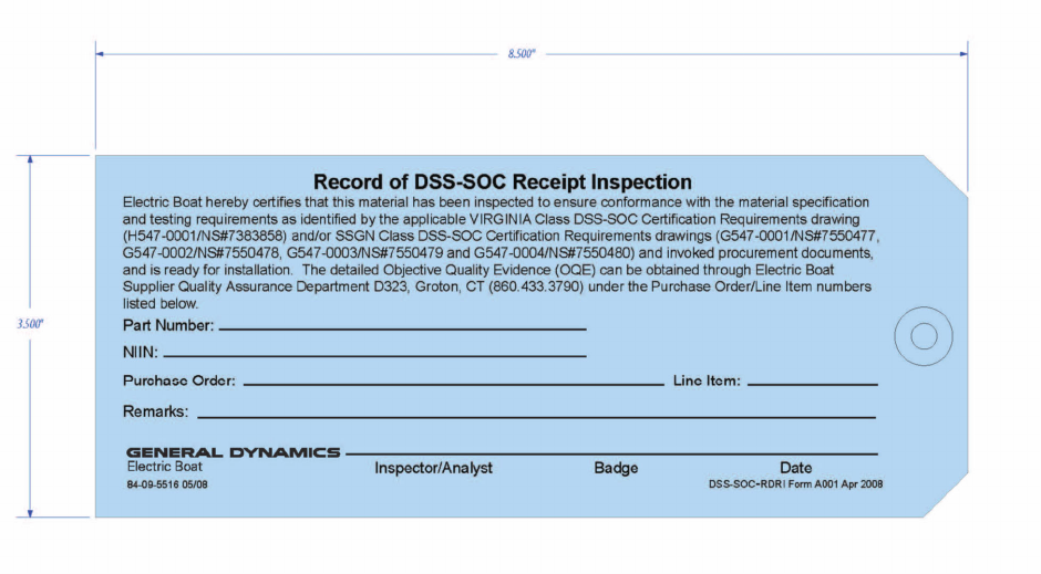
COMUSFLTFORCOMINST 4790.3 REV D CHG 2
31 MAR 2022
V-III-6-5
(a) Material Marking Requirements
(b) Records of Chemical and Mechanical Tests
(2) The MIC does not satisfy:
(a) Unique DSS-SOC OQE
(b) Lubrication and Thread Locking
(c) Paints
(d) Unique Clean Requirements
(e) DSS-SOC required as required by the specification
(f) DSS-SOC required Nondestructive Testing
(g) Certification of Compliance and when applicable, Certificate of Test
i. Navy supply stock program material with Special Material Identification Codes (SMIC)
L1, C1, Q3 or VG which are also used in DSS-SOC applications are identified by APLs
that reflect a Y-suffix, e.g., 887056021Y. This material has been procured to meet any
additional requirements of reference (b).
Figure 6-1 Electric Boat Record of DSS-SOC Receipt Inspection
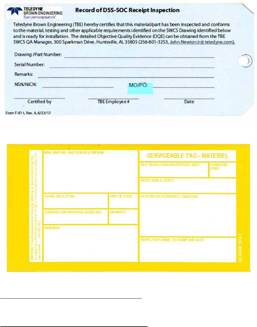
COMUSFLTFORCOMINST 4790.3 REV D CHG 2
31 MAR 2022
V-III-6-6
Figure 6-2 Teledyne Brown Engineering Record of DSS-SOC Receipt Inspection
Figure 6-3 Naval Surface Warfare Center Panama City Division
6.3.2 Quality Assurance Forms for Receipt Inspections. The QA forms necessary to complete and
document receipt inspections (QA form 1, QA form 2 and QA form 3) and instructions are found in
Part I, Chapter 11 of this volume and are further discussed in paragraph 6.3.4 of this chapter.
6.3.3 NAVSUP WSS DSS-SOC Stock Program Material. DSS-SOC Stock Program material
requires the material to be shipped to Portsmouth Naval Shipyard for Receipt Inspection prior to
issuance to the end user per references (c) and (d). Material received from Portsmouth Naval
Shipyard is shipped with Ready-for-Issue (RFI) tags (Figure 6-4) which contain the Receipt
Inspection serial number, MCD level, National Stock Number (NSN) with a SMIC (D0, D4, D5, D6,
D7, or D8) and contract number. RFI tag (Figure 6-4) denotes all inspection and certification
attributes have been met except a physical inspection to confirm the material was not damaged in
QCI log number:
NSWCPCD_SDV_CM@navy.mil
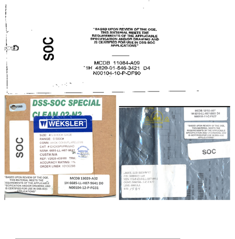
COMUSFLTFORCOMINST 4790.3 REV D CHG 2
31 MAR 2022
V-III-6-7
shipping. Material previously procured by the NAVSUP Weapons Systems Support (WSS) DSS-
SOC Stock Program required the OQE to be shipped with each item. Material currently held by
activities in condition code “A” is acceptable for use providing the required OQE is packaged with
the material.
Figure 6-4 DSS-SOC Stock Program Material Ready-For-Issue (RFI) Tag (examples)
6.3.4 General Requirements for Receipt of Scope of Certification Material. This section contains the
requirements for receipt inspection and control of new materials. Section 6.5 of this chapter contains
the requirements for handling controlled material removed from a DSS for maintenance purposes.
a. MCD-A material received from the Navy supply system with either a D5 or D6 SMIC and
an RFI tag, or an EB Blue tag, will be receipt inspected by the CMPO using the following
procedure:

COMUSFLTFORCOMINST 4790.3 REV D CHG 2
31 MAR 2022
V-III-6-8
Procedure Responsibility
Visually inspect the material. Sustaining or User Activity,
CMPO or CMH
Check that quantity received is same quantity
ordered.
Sustaining or User Activity,
CMPO or CMH
Check for completeness (i.e., are all parts of a
component present); disassembly is not required or
desired.
Sustaining or User Activity,
CMPO or CMH
Check NSN on part and verify that it is the NSN
ordered.
Sustaining or User Activity,
CMPO or CMH
Verify item has either 1) a RFI tag attached which
contains the Receipt Inspection serial number, MCD
level, NSN with a SMIC (D5 or D6), and contract
number, or 2) an EB Blue tag. Navy supply material
received that does not meet this criterion must be
receipt inspected using the receipt inspection process
for Navy supply material received without a RFI tag
attached per paragraph 6.3.4.c of this chapter.
Sustaining or User Activity,
CMPO or CMH
Verify item is permanently marked with a receipt
inspection number that matches the receipt inspection
number on the RFI tag, and that is formatted per
paragraph 6.3.7.2 of this chapter.
Sustaining or User Activity,
CMPO or CMH
Verify that material received with a SMIC of D6 is
packaged for special cleanliness (MIL-STD-1330 or
MIL-STD-1622) and that the package is securely
sealed and the proper cleanliness tag is present.
Sustaining or User Activity,
CMPO, Cleanliness Inspector
or CMH
Fill out QA form 1 and attach the shipping papers, if
provided.
Sustaining or User Activity,
CMPO or CMH
NOTE: QA FORM 1 IS NOT REQUIRED FOR SHIP'S FORCE WHEN
PERFORMING RECEIPT INSPECTION OF MATERIAL TO BE
IMMEDIATELY INSTALLED FOR A SPECIFIC JOB. IF ALL
MATERIAL IS NOT UTILIZED IN THE ONGOING JOB, QA FORM 1
MUST BE FILLED OUT PRIOR TO PLACING THE MATERIAL IN A
STOWAGE LOCKER.
File QA form 1 with all applicable documents. Sustaining or User Activity,
CMPO or CMH

COMUSFLTFORCOMINST 4790.3 REV D CHG 2
31 MAR 2022
V-III-6-9
Fill out and attach QA form 2 to each unit of issue
accepted. Turn over material to craftsman or stow in
approved storage area.
Sustaining or User Activity,
CMPO or CMH
If material fails any of the steps, reject and attach QA
form 3.
Sustaining or User Activity,
CMPO or CMH
Forward QA form 1 to QA Office when the material
has been issued for installation.
CMPO or CMH
b. MCD-B material received from the Navy supply system with either a D0 or D4 SMIC and
an RFI tag, or an EB Blue tag, will be receipt inspected by the CMPO using the following
procedure:
Procedure Responsibility
Visually inspect the material. Sustaining or User Activity,
CMPO or CMH
Check that quantity received is same quantity
ordered.
Sustaining or User Activity,
CMPO or CMH
Check for completeness (i.e., are all parts of a
component present); disassembly is not required or
desired.
Sustaining or User Activity,
CMPO or CMH
Check NSN on part and verify that it is the NSN
ordered.
Sustaining or User Activity,
CMPO or CMH
Verify item has either 1) a RFI tag attached which
contains the Receipt Inspection serial number, MCD
level, NSN with a SMIC (D0 or D4), and contract
number, or 2) an EB Blue tag. Navy supply material
received that does not meet this criterion must be
receipt inspected using the receipt inspection process
for Navy supply material received without a RFI tag
attached.
Sustaining or User Activity,
CMPO or CMH
Verify that material received with a SMIC of D0 is
packaged for special cleanliness (MIL-STD-1330 or
MIL-STD-1622) and that the package is securely
sealed.
Sustaining or User Activity,
CMPO, Cleanliness Inspector
or CMH
Fill out QA form 1 and attach the shipping papers, if
provided.
Sustaining or User Activity,
CMPO or CMH

COMUSFLTFORCOMINST 4790.3 REV D CHG 2
31 MAR 2022
V-III-6-10
NOTE: QA FORM 1 IS NOT REQUIRED FOR SHIP'S FORCE WHEN
PERFORMING RECEIPT INSPECTION OF MATERIAL TO BE
IMMEDIATELY INSTALLED FOR A SPECIFIC JOB. IF ALL
MATERIAL IS NOT UTILIZED IN THE ONGOING JOB, QA FORM 1
MUST BE FILLED OUT PRIOR TO PLACING THE MATERIAL IN A
STOWAGE LOCKER.
File QA form 1 with all applicable documents. Sustaining or User Activity,
CMPO or CMH
Fill out and attach QA form 2 to each unit of issue
accepted. Turn over material to craftsman or stow in
approved storage area.
Sustaining or User Activity,
CMPO or CMH
If material fails any of the steps, reject and attach QA
form 3.
Sustaining or User Activity,
CMPO or CMH
Forward QA form 1 to QA Office when the material
has been issued for installation.
CMPO or CMH
c. Receipt of MCD-A material without either an RFI tag, an EB Blue tag or received from a
contractor or activity assigned by the Program Manager to supply the specific DSS will be
receipt inspected by the CMPO and certified by the Quality Assurance Officer (QAO)
using the following procedure:
Procedure Responsibility
Review vendor data, Military Standard (MIL-
STD), or Naval Shipyard or FMA manufacturing
and test data to ensure that it all matches. See
note at end of this table regarding vendor data.
Sustaining or User Activity,
CMPO, CMH, QAI and
QAO
Transfer MIC markings from accompanying OQE
onto the item if the MIC is not already marked on
the item. Disassembly of the item is not allowed
or required.
Sustaining or User Activity,
CMPO, CMH or QAI
Fasteners will be appropriately marked and color-
coded if required.
Sustaining or User Activity,
CMPO, CMH or QAI
Fill out QA form 1 to document the receipt
inspection.
Sustaining or User Activity,
CMPO, CMH or QAI
COMUSFLTFORCOMINST 4790.3 REV D CHG 2
31 MAR 2022
V-III-6-11
NOTE: QA FORM 1 IS NOT REQUIRED FOR SHIP’S FORCE WHEN
PERFORMING RECEIPT INSPECTION OF MATERIAL TO BE
IMMEDIATELY INSTALLED FOR A SPECIFIC JOB. IF ALL MATERIAL
IS NOT UTILIZED IN THE ONGOING JOB, QA FORM 1 MUST BE
FILLED OUT PRIOR TO PLACING THE MATERIAL IN A STOWAGE
LOCKER.
NOTE: IF THE COMPONENT HAS A SHORTENED MIC MARKING, ENSURE
THE FULL MIC MARKING FROM THE SHIPPING DOCUMENTS, TAGS,
OR PACKAGING IS ENTERED ON QA FORM 1 AND QA FORM 2.
File QA form 1 with all applicable documents. Sustaining or User Activity,
Quality Assurance
Supervisor, QAI or CMPO
Fill out and attach QA form 2 to the item. Turn
over material to craftsman or stow in approved
storage area.
Sustaining or User Activity,
CMPO, CMH or QAI
Forward QA form 1 to QA Office when the
material has been issued for installation.
CMPO or CMH
If material fails any of the steps, reject the
material and attach QA form 3.
CMPO or CMH
NOTE: VENDOR DATA - MATERIAL RECEIVED DIRECTLY FROM THE
MANUFACTURER REQUIRES CERTIFICATION DOCUMENTATION PER
PARAGRAPHS 6.3.4.c.(1) THROUGH 6.3.4.c.(5) OF THIS CHAPTER AS A
MINIMUM. A THOROUGH REVIEW OF THE PROCUREMENTS
SPECIFICATIONS IS NECESSARY TO ENSURE ALL REQUIREMENTS ARE
MET.
NOTE
:
NAVAL SHIPYARDS AND FMAS MAY USE A LOCALLY GENERATED TASK
GROUP INSTRUCTION (TGI) OR CONTROLLED WORK PACKAGE (CWP) IN
LIEU OF A COC AND
COT FOR RECEIPT INSPECTION OF MCD A DSS SOC
COMPONENTS MANUFACTURED OR
FABRICATED BY THE ACTIVITY.
THE TGI OR CWP MUST CONTAIN ALL OQE NECESSARY TO
ESTABLISH
THAT THE PART HAS BEEN PROPERLY MANUFACTURED, FABRICATED
AND
TESTED TO THE REQUIREMENTS OF APPLICABLE DRAWINGS AND
SPECIFICATIONS, AS
WELL AS TO MEET THE CERTIFICATION CRITERIA
OF REFERENCE (B). THE TGI OR CWP HAS
THE SAME RETENTION
REQUIREMENTS AS A COC OR COT FOR A DSS SOC APPLICATION.
NOTE: IF ANY ITEM IS CERTIFIED AS LEVEL I, IT IS CONSIDERED AS MEETING
THIS REQUIREMENT.
COMUSFLTFORCOMINST 4790.3 REV D CHG 2
31 MAR 2022
V-III-6-12
(1) Chemical and mechanical testing is required for all metallic material. Chemical
and mechanical testing for non-metallic materials as required by material
specification.
(2) Records of Nondestructive Testing as required by the specification.
(3) Records of testing as required by the specification for implosion testing, cleanliness
testing, toxicity or flammability testing, etc.
(4) COC. Certifies that the components comply with the requirements of the
procurement documents, invoked specifications and drawings. Asserts that the
physical and chemical properties (material type, yield strength, tensile strength,
elongation or hardness testing) are as specified in the contract specifications. The
certificate will include:
(a) Contractors name, address, phone number and date.
(b) The issuing agency’s purchase order number.
(c) Item nomenclature of the purchased item (the product is identified by
description, amount, lot number, etc.).
(d) Contractor’s or authorized person’s signature.
NOTE: INSTALLATION OF MATERIAL ON THE BASIS OF A COC WILL NOT
RELIEVE THE INSTALLING ACTIVITY OF THE RESPONSIBILITY FOR
INCORPORATING MATERIAL WHICH CONFORMS TO THE
REQUIREMENTS OF THE DRAWINGS AND SPECIFICATIONS. MATERIAL
NOT CONFORMING TO THE REQUIREMENTS OF THE DRAWINGS AND
SPECIFICATIONS WILL BE SUBJECT TO REJECTION WHETHER IN PLACE
OR NOT.
(5) In some cases a Certificate of Test (COT) may be required as evidence that testing
was completed. The distinguishing characteristic of a COT is that it presents data
which is the result of positive, reproducible testing performed to determine the
quality of the product. It may be contained within the COC. The COT, issued by a
test laboratory, states that a certain product was tested for certain qualities and must
include:
(a) Contractors name, address, phone number and date.
(b) The issuing agency’s purchase order number.
(c) Item nomenclature of the purchased item (the product is identified by
description, amount, lot number, etc.).
(d) Contractor’s or authorized person’s signature.
(e) Test data is given along with the conclusion on conformance or non-
conformance.
NOTE: IF ALL TESTING REQUIRED BY REFERENCE (b) CANNOT BE
ACCOMPLISHED, THEN THE NEW COMPONENT CANNOT BE USED UNTIL
A DEPARTURE FROM SPECIFICATION (DFS) IS SUBMITTED PER PART I,
CHAPTER 8 OF THIS VOLUME.

COMUSFLTFORCOMINST 4790.3 REV D CHG 2
31 MAR 2022
V-III-6-13
NOTE: MORE THAN ONE MIC NUMBER MAY BE ON A COMPONENT (E.G., VALVE
BODY MAY HAVE ONE MIC NUMBER AND THE BONNET MAY HAVE
ANOTHER MIC NUMBER). IF THE COMPONENT HAS A SHORTENED MIC
MARKING, ENSURE THE FULL MIC MARKING IS AVAILABLE ON THE
SHIPPING DOCUMENTS, TAGS OR PACKAGING. VERIFY THAT THE
SHORTENED MIC MARKING IS CORRECT PER PARAGRAPH 6.3.7 OF THIS
CHAPTER AND REFERENCE (a).
d. Receipt of MCD-B material without an RFI tag, an EB Blue tag or received from a
contractor or activity assigned by the Program Manager to supply the specific DSS will be
receipt inspected by the CMPO and certified by the QAO using the following procedure:
Procedure Responsibility
Review vendor data (if provided with material),
MIL-STD, or Naval Shipyard or FMA
manufacturing and test data to ensure that it all
matches. See note at end of this table regarding
vendor data.
Sustaining or User Activity,
CMPO, CMH, QAI or QAO
Fill out QA form 1 to document the receipt
inspection.
Sustaining or User Activity,
CMPO, CMH or QAI
File QA form 1 with all applicable documents. Sustaining or User Activity
Quality Assurance
Supervisor, QAI or CMPO
NOTE: QA FORM 1 IS NOT REQUIRED FOR SHIP’S FORCE WHEN PERFORMING
RECEIPT INSPECTION OF MATERIAL TO BE IMMEDIATELY INSTALLED
FOR A SPECIFIC JOB. IF ALL MATERIAL IS NOT UTILIZED IN THE
ONGOING JOB, QA FORM 1 MUST BE FILLED OUT PRIOR TO PLACING
THE MATERIAL IN A STOWAGE LOCKER.
NOTE: IF THE COMPONENT HAS A SHORTENED MIC MARKING, ENSURE THE
FULL MIC MARKING FROM THE SHIPPING DOCUMENTS, TAGS, OR
PACKAGING IS ENTERED ON QA FORM 1 AND QA FORM 2.
Procedure Responsibility
Fill out and attach QA form 2 to the item. Turn
over material to craftsman or stow in approved
storage area.
Sustaining or User Activity,
CMPO, CMH or QAI
Forward QA form 1 to QA Office when the
material has been issued for installation.
CMPO or CMH
If material fails any of the steps, reject the material
and attach QA form 3.
CMPO or CMH

COMUSFLTFORCOMINST 4790.3 REV D CHG 2
31 MAR 2022
V-III-6-14
NOTE: VENDOR DATA - MATERIAL RECEIVED DIRECTLY FROM THE
MANUFACTURER REQUIRES CERTIFICATION DOCUMENTATION PER
PARAGRAPHS 6.3.4.d.(1) THROUGH 6.3.4.e. OF THIS CHAPTER AS A
MINIMUM. A THOROUGH REVIEW OF THE PROCUREMENTS
SPECIFICATIONS IS NECESSARY TO ENSURE ALL REQUIREMENTS ARE
MET.
NOTE: NAVAL SHIPYARDS AND FMAS MAY USE A LOCALLY GENERATED TGI OR
CWP IN LIEU OF A COC AND COT FOR RECEIPT INSPECTION OF MCD B
DSS SOC COMPONENTS MANUFACTURED OR FABRICATED BY THE
ACTIVITY. THE TGI OR CWP MUST CONTAIN ALL OQE NECESSARY TO
ESTABLISH THAT THE PART HAS BEEN PROPERLY MANUFACTURED,
FABRICATED AND TESTED TO THE REQUIREMENTS OF APPLICABLE
DRAWINGS AND SPECIFICATIONS, AS WELL AS TO MEET THE
CERTIFICATION CRITERIA OF REFERENCE (B). THE TGI OR CWP HAS
THE SAME RETENTION REQUIREMENTS AS A COC OR COT FOR A DSS
SOC APPLICATION.
(1) COC which indicates any of the tests, if required, for implosion testing, cleanliness
test, toxicity or flammability testing etc., have been satisfactorily accomplished.
(2) Certification that Hull, Mechanical and Electrical testing was accomplished as
required by the specification. The COC must state each contractually invoked test
by name and that it was performed satisfactorily. Actual test records are not
required to be sighted.
(3) COC that the components comply with the requirements of the procurement
documents, including invoked specifications and drawings.
e. There is no receipt inspection or unique storage requirements for MCD-C material. MCD-
C material must be inspected by the Craftsman and certified on the applicable QA form by
the QAI at installation.
Procedure Responsibility
Visual inspection at installation to ensure material
conforms to specified requirements such as stock
number, design dimensions, surface condition,
compliance with technical work instructions or any
vendor or manufacturer supplied information.
Sustaining or User Activity
Craftsman and QAI
NOTE: VENDOR DATA - MATERIAL RECEIVED DIRECTLY FROM THE
MANUFACTURER REQUIRES CERTIFICATION DOCUMENTATION PER
PARAGRAPH 6.3.5 OF THIS CHAPTER AS A MINIMUM.
6.3.5 Verification of Completion of Required Testing. This section is only applicable to DSS-SOC
material received without a D0, D4, D5, D6, D7, or D8 SMIC and associated RFI tag, received
without an EB Blue tag or contractor or activity assigned by NAVSEA. Regardless of the MCD, if
implosion testing, cleanliness testing, toxicity or flammability testing etc., are required by the

COMUSFLTFORCOMINST 4790.3 REV D CHG 2
31 MAR 2022
V-III-6-15
applicable specification or drawing, a review of the OQE for these tests will be conducted prior to
installation. If a COC is received with the component, it should be carefully reviewed to ensure that
testing was performed satisfactory.
6.3.6 Authorized Material Certification Activities. This section provides a list of those activities that
are currently authorized to receipt inspect and accept DSS-SOC controlled material. This list is
provided as a reference to be used in performance of receipt inspections of paragraph 6.3.4.a, 6.3.4.b,
and 6.3.4.c of this chapter. NAVSEA has authorized the following activity to certify material as
MCD-A, MCD-B and MCD-C per reference (b) and this material may be used for DSS-SOC
applications without further receipt inspection, other than normal receipt inspections of paragraph
6.3.4.a, 6.3.4.b, and 6.3.4.c of this chapter. The activity and their designator are:
Activity Identification Code
Portsmouth Naval Shipyard A
6.3.7 Marking of DSS-SOC Stock Program Material.
6.3.7.1 General Requirements. DSS-SOC Stock Program Material passes from the manufacturers
into the Navy supply system by way of a Navy receipt inspection activity, which examines the
material and subjects it to a number of tests. DSS-SOC material which meets acceptance criteria is
marked with a unique identifying number traceable to the OQE.
a. The purpose of the unique identifying number is four-fold:
(1) To denote that the marked material has been inspected, verified and accepted.
(2) To verify the material in hand by comparing it to the applicable drawings, plans,
ordering requirements, and installing documents.
(3) To provide traceability from the installed material to OQE.
(4) To preclude complete re-inspection of material accepted by an approved activity.
b. Two problems arise in application that can defeat the purpose of the unique identifying
number:
(1) Internal components of an assembly which is marked with a unique identifying
number on the exterior, are usually not marked individually, and can lose their
identity as DSS-SOC material if separated during disassembly. Strict adherence to
“bag and tag” requirements, using fleet QA forms, overcomes this problem. Any
part that becomes separated from its QA form (a loss of traceability) must be
treated as uncontrolled material.
(2) Reference (d) permits the use of a securely attached RFI tag in cases where material
is non-metallic, cannot be marked without disassembly, are too small for marking
(less than 3/8 square inch), oxygen clean items, welding consumables, plated parts
or hardened material and all MCD-B or MCD-C material. The complete unique
identifying number is recorded during receipt inspection. Although the unique
identifying number may not be visible once the item is installed, traceability is
maintained through the retained QA paperwork and tags associated with the job,
which will list the full unique identifying number.
c. The unique identifying number is in addition to the required manufacturer’s marking.

COMUSFLTFORCOMINST 4790.3 REV D CHG 2
31 MAR 2022
V-III-6-16
d. Altering of a DSS-SOC unique identifying number is prohibited.
e. Method of marking DSS-SOC material. The physical marking method is described in
reference (d).
f. Items not physically capable of being marked. Items such as small parts are packaged in
homogeneous lots (i.e., same heat, batch or melt; and same vendor traceability) and the
package is marked. If the package is opened, the individual items removed must be tagged
with QA form 2. The remaining items in the package will be controlled by the use of a
single QA form 2 attached to the package.
6.3.7.2 SMIC DSS-SOC Material Acceptance Identification. Per reference (d), MCD-A metallic
material must be permanently marked. Items that cannot be marked due to physical limitations, and
all MCD-B or MCD-C material, must be identified using the following instructions:
a. Serialization marking must be by use of a securely attached RFI tag. The RFI tag must
contain the Receipt Inspection serial number, MCD level, the NSN and the contract
number. The RFI tag must clearly state, “Based upon review of the OQE, this material
meets the requirements of the applicable specification and drawing and is certified for use
in DSS-SOC applications.”
b. Serialization of MCD-A material must bear a number consisting of a two-digit year, three
digit Julian day, a daily serial number between 001 and 099, the Receipt Inspecting
Activity Certifying Activity Designator followed by “MCDA”. For example: “08137-
001A-MCDA”.
c. Serialization of MCD-B and MCD-C material must utilize the Receipt Inspection
Management System for technical inspection with the prefix “MCDB” or “MCDC”,
followed by the two-digit year, a three digit Julian date, the Receipt Inspecting Activity
Certifying Activity Designator and a daily serial number. For example: “MCDB 08137-
A01” or “MCDC 08137-A06”.
6.4 STORAGE, ISSUE AND HANDLING OF SCOPE OF CERTIFICATION MATERIAL. Refer
to Part I, Chapter 6, paragraph 6.3.9 of this volume for process requirements related to storage,
staging, issue and handling of SOC material.
6.5 RE-USE OF PREVIOUSLY CERTIFIED SCOPE OF CERTIFICATION MATERIAL.
6.5.1 Material Removed from a Deep Submergence System or Operating Ship. Material removed
from a DSS or operating ship to be installed in a SOC application on another DSS or ship is
acceptable under the following conditions:
a. Re-Entry Control (REC) is used to document material removal from the supplying ship.
The supplying DSS or ship must be certified and REC must still be in effect.
b. The following must be supplied by the supplying ship to the receiving ship:
(1) All outstanding DFS on the component.
(2) Any applicable technical variance documentation.
(3) The last accomplishment date and category of all applicable Maintenance
Requirement Card (MRC) inspections.
(4) All legible component markings must be documented.

COMUSFLTFORCOMINST 4790.3 REV D CHG 2
31 MAR 2022
V-III-6-17
(5) A copy of the supplying ship’s REC.
c. Positive control and identification must be maintained from removal through reinstallation.
d. All documentation listed in sub-paragraph b of this paragraph must be maintained and filed
with the REC package that installs the component on the receiving ship.
e. The receiving activity must conduct a material receipt inspection to verify the following:
(1) Received component came from a certified system and REC has been maintained
and that positive control has been maintained since removal from the supplying
activity.
(2) Material marking or tagging on hardware matches material marking on supporting
software.
(3) Applicable MRC inspections or any other maintenance actions are current for the
intended end use.
(4) End use installation is consistent with the previous service parameters such as the
design pressure rating, design temperature rating or system applicability of the
component.
f. Receiving activity must update applicable software to document information and records
(e.g., DSS or Ship’s Drawing Index for drawing revision) date of last MRC periodicity
accomplishment and documentation of outstanding DFS into installing DSS or ship’s
Current Ship’s Maintenance Project.
g. Non-Conforming Material that is received from a DSS or operating ship to be installed in a
SOC application that does not meet all the requirements of paragraph 6.5.1 of this chapter
may be acceptable under the specific instances.
(1) Material received which is not current with respect to the applicable MRC
inspection or any other required maintenance actions that are not current for the
intended use must have the applicable maintenance actions completed. Any
inspection or maintenance action not completed must be departed using the process
of Part I, Chapter 8 of this volume.
(2) Material which has an end use that is not consistent with the previous service
parameters must be subject to and satisfy the testing requirements for a new
component installed in the receiving DSS or ship, provided the design is consistent
with the intended end use.
6.5.2 Reuse of Scope of Certification Material. Reuse of SOC material from a ship whose
certification has lapsed by virtue of inactivation availability is acceptable under the following
conditions:
a. Prior to commencement of system disassembly, material identified for transfer must be
included in an identification and transfer system designated for this application. This
system must provide a means for tagging components to be transferred to preclude
compromise of material control integrity through unauthorized re-entry. NAVSEA
considers existing tag-out systems as an adequate template for this identification system.

COMUSFLTFORCOMINST 4790.3 REV D CHG 2
31 MAR 2022
V-III-6-18
However, identification system tags must be durable and clearly discernible from existing
“tag-out” system tags.
b. The identification tags must include as a minimum:
(1) The statement that the component is SOC material and that the component is not to
be removed until the tag is uniquely marked by the facility conducting the
inactivation.
(2) The DSS or Ship hull number (e.g., SSN 752).
(3) System and item identification (e.g., MIC number, ASW-1, etc.).
(4) Activity unique identifier (e.g., PHNSY-657-001).
c. The following must be supplied by the supplying activity or ship to the receiving ship:
(1) All outstanding DFS on the component.
(2) Any applicable technical variance documentation.
(3) The last accomplishment date and category of all applicable MRC inspections.
(4) All legible component markings must be documented.
(5) A copy of the supplying ship’s REC.
d. All work completed on the material or component after removal from the supplying DSS
or ship must be documented and controlled by a REC.
e. Those fasteners removed which connect a transferred item to equipment or components
remaining on board, such as valve flange fasteners, must not be shipped with the item,
since to do so needlessly complicates the certification process.
f. The receiving activity must conduct material receipt inspection to verify the following:
(1) Attached material identification tag and material marking on the material matches
the documentation provided from the facility conducting the inactivation.
(2) End use installation is consistent with the previous service parameters such as the
design pressure rating, design temperature rating or system applicability of the
component.
g. The receiving activity must complete any maintenance due or overdue for the material.
Any inspection not performed or other maintenance action not completed must be
departed.
h. The receiving activity must maintain documentation of receipt, inspection, installation and
testing of the provided material.
i. The material will be installed using a REC.
6.5.3 Material Recertification Required.
a. Material which does not satisfy the requirements of paragraphs 6.5.1 or 6.5.2 of this
chapter must require full component certification to all DSS program requirements prior to
use. Documentation of this certification must be traceable from the installing activity’s
REC.

COMUSFLTFORCOMINST 4790.3 REV D CHG 2
31 MAR 2022
V-III-6-19
b. If the SOC material to be transferred is designated for non-SOC end use, and if the
removal is to be accomplished subsequent to the Inactivation Availability start date,
applicable non-SOC transfer requirements are in effect. These requirements for Submarine
Safety components are in reference (e) and the requirements for Level I components are in
reference (a).
6.5.4 Material Re-Certification Following Transfer to Outside Agency (Excluding Naval Shipyards).
Material transferred to and received from an outside maintenance organization which is not under
Joint Fleet Maintenance Manual controls (to exclude Naval Shipyards audited by NAVSEA) will be
handled in the following manner:
Procedure Responsibility
Remove existing attached QA form 2 and retain in
Controlled Work Package for OQE.
Sustaining or User Activity
Transfer existing material using DD 1149 to and
from the Outside Agency.
Sustaining or User Activity,
Department Head
Upon receipt, review vendor data, COC and test
data as required by applicable specifications.
Sustaining or User Activity,
CMPO, CMH, QAI or QAO
Fill out QA form 2 per Part III, Chapter 11 of this
volume and attach to the item. Turn over material
to craftsman or stow in approved storage area.
Sustaining or User Activity,
CMPO, CMH or QAI
Place COC in respective REC for material control
documentation.
Sustaining or User Activity,
QAI or Quality Assurance
Supervisor
If material fails any of the steps, reject the material
and attach QA form 3.
Sustaining or User Activity,
CMPO or CMH
6.5.5 Material Re-Certification Following Transfer to a Naval Shipyard. Material transferred to and
received from a Naval Shipyard which is not under Joint Fleet Maintenance Manual controls but is
audited by NAVSEA will be handled in the following manner:
Procedure Responsibility
Existing QA form 2 will remain attached to the
component. Fill out QA form 2 Blocks 13 through
16 to document transfer to the Naval Shipyard
Sustaining or User Activity
COMUSFLTFORCOMINST 4790.3 REV D CHG 2
31 MAR 2022
V-III-6-20
Attach Material Tracking Tag (MTT) or
equivalent. The MTT (or equivalent) must include
component identification, Shipyard Task Group
Instruction and any special requirements (e.g.,
maintain diver air clean per MIL-STD-1622 for
critical applications).
Naval Shipyard
Upon receipt, fill out QA form 2 Blocks 13 through
16 to document receipt from the Naval Shipyard.
Positively identify the material, review certification
or test data and verify proper cleanliness controls
have been met as required by applicable
specifications. Document results on QA form 2
Block 15. Shipyard certification or test data that
has been satisfactorily reviewed and recorded on
QA form 2 Block 15 may be discarded.
Sustaining or User Activity,
CMPO, CMH, QAI or QAO
Turn over material to craftsman or stow in
approved storage area.
Sustaining or User Activity,
CMPO, CMH or QAI
Place QA form 2 and MTT (or equivalent) in
respective REC for material control
documentation. QA form 2 and MTT (or
equivalent) may be discarded after the associated
REC has been closed.
Sustaining or User Activity,
QAI, Quality Assurance
Supervisor
If material fails any of the steps, reject the material
and attach QA form 3.
Sustaining or User Activity,
CMPO or CMH

COMUSFLTFORCOMINST 4790.3 REV D
16 Oct 2019
V-III-7-1
VOLUME V
PART III
CHAPTER 7
TESTING REQUIREMENTS
REFERENCES.
(a) NAVSEA SS800-AG-MAN-010/P-9290 - System Certification Procedures and
Criteria Manual for Deep Submergence Systems
(b) NAVSEA SS521-AA-MAN-010 - U.S. Navy Diving and Manned Hyperbaric
Systems Safety Certification Manual
(c) NAVSEA S9505-AF-MMA-010 - Submarine Non-Nuclear Piping Systems Test
Manual
7.1 PURPOSE. To provide additional guidance for Deep Submergence Systems (DSS) that
cannot be found in Part 1, Chapter 7 of this volume.
7.2 TESTING REQUIREMENTS. Testing must be per Part I, Chapter 7 of this volume with the
following additions and exceptions:
a. Hydrostatic Testing Requirements:
(1) Implodable and explodable testing must be per references (a) and (b), as
applicable. Additional implodable and explodable requirements may be
contained in the applicable Scope of Certification Notebook.
(2) Pipe and piping components whose pressure boundary is externally loaded by
sea pressure, but whose internal maximum operating pressure is equal to or
greater than DSS design test depth pressure, must only require an internal
hydrostatic test.
(3) Pipe and piping components whose pressure boundary is externally loaded by
sea pressure, but whose internal maximum operating pressure is less than DSS
design test depth pressure, must only require an external hydrostatic test.
Additional guidance on external hydrostatic test requirements is contained in
reference (a).
(4) Pipe and piping components that penetrate any hull integrity boundary where a
single failure could result in internal flooding of the DSS unit must be
hydrostatically tested from the hull integrity boundary penetration inboard to
the first isolation valve at a pressure equal to 150% of DSS design test depth or
150% of system maximum operating pressure, whichever is greater.
(5) Pipe and piping components open to internally pressurized tanks or enclosures
(including hyperbaric chambers) must be hydrostatically tested internally from
the tank or enclosure penetration outboard to the first isolation valve at a
pressure equal to the pressure used to hydrostatically test the tank or enclosure.
These requirements are not applicable to piping and piping components open
to compressed gas flasks.
COMUSFLTFORCOMINST 4790.3 REV D
16 Oct 2019
V-III-7-2
(6) External hydrostatic test acceptance criteria of “no permanent deformation” for
pipe must, in addition to a complete visual inspection, be verified by out of
roundness measurements. Out-of-roundness measurements not within the pipe
specification, approved drawing or Military Standard 1627 (for pipe bends)
must be cause for rejection of the item.
b. Joint Tightness Testing.
(1) Pipe and piping components whose pressure boundary is externally loaded by
sea pressure, but whose internal maximum operating pressure is equal to or
greater than DSS design test depth pressure, must only require an internal joint
tightness test.
(2) Pipe and piping components whose pressure boundary is externally loaded by
sea pressure, but whose internal maximum operating pressure is less than DSS
design test depth pressure, must require both external and internal joint
tightness testing. Note that the ability to conduct external joint tightness
testing is extremely limited. This testing is normally deferred using a
Controlled Assembly per Part I, Chapter 7 of this volume, documenting a
minor Departure from Specification and retesting during a dive to design test
depth.
(3) Pipe and piping components that penetrate any hull integrity boundary, where
a single failure could result in internal flooding of the DSS unit, must be joint
tightness tested from the hull integrity boundary penetration inboard to the first
isolation valve at a pressure equal to 100% of DSS design test depth pressure
or 100% of system maximum operating pressure, whichever is greater.
(4) Pipe and piping components open to internally pressurized tanks or structural
enclosures (including hyperbaric chambers) must be joint tightness tested
internally from the tank or enclosure penetration outboard to the first isolation
valve at a pressure equal to 100% of the maximum internal operating pressure
of the tank or enclosure. These requirements are not applicable to piping and
piping components open to compressed gas flasks.
c. Pressure Drop Testing.
(1) Pressure drop testing for oxygen, helium, helium-oxygen, nitrogen and
hydrogen diving systems must be as specified in reference (b).
(2) Pressure drop testing of submarine compressed air systems must be as
specified in reference (c).
d. Objective Quality Evidence. Objective Quality Evidence (OQE) documenting the
satisfactory accomplishment of all required testing must be available and maintained
in a format suitable for review and audit. Reference (a), Appendix J contains a
detailed list of information which must be documented as OQE for testing. Existing
forms contained in Part I, Chapter 11 of this volume do not capture all required OQE
data. Forms contained in Part III, Chapter 11 of this volume should be used to support
documentation of all reference (a), Appendix J OQE data. All mechanical joint
tightness and hydrostatic testing (both those utilizing an external pressure source or
COMUSFLTFORCOMINST 4790.3 REV D
16 Oct 2019
V-III-7-3
internal system pressure) should be documented on QA form 26A to ensure the
requirements of reference (a), Appendix J are met. In the event standardized forms are
not available, it is permissible to modify and use the forms in Part 1, Chapter 11 of this
volume and standardize these forms within the Sustaining Activity organization.
e. Operational Test. A test of a system to nominal operating pressure using the system
fluid, system pumps and installed system gage(s) vice test instrumentation to
determine leak tightness.
(1) A drop test meeting requirements of paragraph 7.2.c. may be performed as an
operational test.
(2) An operational test can be used to satisfy a mechanical joint tightness test.

COMUSFLTFORCOMINST 4790.3 REV D CHG 3
07 Nov 2023
V-III-8-1
VOLUME V
PART III
CHAPTER 8
DEPARTURE FROM SPECIFICATIONS
REFERENCES.
(a) NAVSEA SS800-AG-MAN-010/P-9290 - System Certification Procedures and
Criteria Manual for Deep Submergence Systems
8.1 PURPOSE. To establish standard procedures to be used for reporting and requesting
approval and clearance, at the earliest opportunity, of all non-conforming or departable
conditions, Departures from Specification (DFS) associated with Scope of Certification (SOC)
systems on Deep Submergence Systems (DSS). The guidance of part 1, chapter 8 of this volume
and reference (a) should be used for handling DFS situations with the modifications listed in this
chapter.
8.2 DEPARTURE FROM SPECIFICATION.
a. A DFS is a non-conformance of any certification attribute from the intended or as-
certified condition of the DSS. This includes non-conformances to approved
drawings, components, specifications, technical manuals, operating and emergency
procedures, maintenance procedures and any other authoritative document specifying
a certification attribute of the DSS. DFS are identified as either a Deviation or
Waiver.
(1) Deviation: A DFS which is requested prior to a planned non-conformance.
(2) Waiver: A DFS which is requested subsequent to the non-conformance
occurring.
b. Should any system, equipment or component within the SOC fail to operate within
specifications, regardless of how the deficiency is discovered, and repair at the
Sustaining Activity level is not practicable prior to a planned underway period or
manned operations, a Major DFS must be submitted.
8.2.1 Reporting Departures from Specification. It is incumbent upon User Activities, Sustaining
Activities, Fleet Maintenance Activities and Immediate Superiors In Command to discuss
potential DFS as early as possible (prior to the work close out or component assembly if
possible) to determine direction of actions and alternatives to the DFS. Every effort must be
made to correct each deficiency prior to equipment or system operation or underway of the DSS.
8.2.2 Approval of Departures from Specification. All SOC DFSs require Program Manager
approval with System Certification Authority (SCA) concurrence prior to manned use of the
DSS. Immediate Superiors In Command and Type Commanders are required to present all DFS
items to the Program Manager for approval, except as noted in the SOC Notebook.
8.2.3 Major and Minor Departure from Specification Classification. These are specified in part
1, chapter 8 of this volume and each activities SOC notebook.

COMUSFLTFORCOMINST 4790.3 REV D CHG 3
07 Nov 2023
V-III-8-2
8.2.4 General Administrative Requirements. The following requirements pertain to all DFS:
a. The User Activity and Sustaining Activity are responsible for all approved DFS
relating to their systems or components until cleared or canceled. When a DFS is
approved as a temporary repair requiring rework to correct the discrepancy, the ship
referencing the DFS sequential number will initiate a Current Ship’s Maintenance
Project entry for correction of the discrepant condition. The ship’s Quality Assurance
Officer will ensure that this action is done.
b. The Sustaining Activity must maintain a master departure log (or computer program
equivalent) of all waivers and deviations approved for each DSS. The log must
contain, as a minimum, the following:
(1) DSS unique identifier.
(2) Departure number.
(3) Departure title.
(4) Classification (Major or Minor).
(5) Type of departure (Deviation or Waiver).
(6) Date requested.
(7) Date resolved or approved.
(8) Approval or disapproval status.
(9) Conditional approval comments (if applicable).
(10) A copy of all applicable Naval Sea Systems Command correspondence
delegating local approval of DFSs.
c. Each activity must maintain all DFSs in a form suitable for audit including supporting
justification, technical documentation, calculations, rationale and related
correspondence.
d. When an activity performs work which results in a conditionally approved DFS or
waiver which requires future action (e.g., re-inspection, repair), the ship will submit an
OPNAV 4790/2K (or equivalent) with a new Job Sequence Number. This Job
Sequence Number will be added to the DFS prior to submission to the Immediate
Superior In Command. The Current Ship’s Maintenance Project Job Sequence
Number will be included in Block 17 of the DFS form.
8.2.5 Submission and Approval of Departures from Specification.
a. A copy of the waiver or deviation must be forwarded to the applicable asset and its
planning yard. This applies to both approved and disapproved waivers and deviations
to ensure the planning yard is kept fully informed and for maintenance of the asset
historical file.
b. The approval and routing actions are the same as listed in part 1, chapter 8, paragraph
8.3.7 of this volume with the User Activity performing the ship functions and the
Sustaining Activity performing the Fleet Maintenance Activity functions.

COMUSFLTFORCOMINST 4790.3 REV D CHG 3
07 Nov 2023
V-III-8-3
c. Unless specifically delegated by the Program Manager and approved by the SCA, the
Program Manager must approve all DFSs and obtain SCA concurrence.
8.2.6 Departure from Specification Approval and Reporting for DSSs While at Sea. The
Commanding Officer or Officer in Charge will evaluate any DFS and approve the corrective
action to be taken including any necessary restrictions.
a. The decision to continue manned operation of the DSS must be made only after a
careful review of the impact the deficiency will have on DSS personnel safety under
all normal and emergency conditions. A report to the Program Manager via the chain
of command will be made at the first opportunity.
b. As a minimum, the report must contain a description of the condition as well as the
intended actions. If continued operation of the DSS is intended, the report must
include a statement of impact on the ability of the system to operate safely, specifics
and any required temporary local changes to the operating and emergency procedures
made as a result of the deficiency and any imposed operating restrictions.
c. If the condition is not corrected during the next in-port period (i.e., a port with a fleet
maintenance facility), it must be forwarded as a DFS report for approval prior to the
next manned use of the DSS.

COMUSFLTFORCOMINST 4790.3 REV D CHG 1
15 JAN 2021
V-III-9-1
VOLUME V
PART III
CHAPTER 9
AUDITS, SURVEILLANCE, EVALUATIONS, ASSESSMENTS AND SURVEYS
REFERENCES.
(a) SS800-AG-MAN-010/P-9290 - System Certification Procedures and Criteria Manual
for Deep Submergence Systems
(b) NAVSEA SS521-AA-MAN-010 - U.S. Navy Diving and Manned Hyperbaric
Systems Safety Certification Manual
9.1 PURPOSE. Provide requirements, procedures and criteria for audits, surveillance,
evaluations and assessments for Scope of Certification (SOC) systems. The requirements of Part
1, Chapter 9 of this volume should be followed with the exception of the modified sections in
this chapter.
9.2 RESPONSIBILITIES AND PROCEDURES.
9.2.1 User Activity Surveillance and Evaluation Program. The responsibilities and procedures
listed for Ship's Force in Part I, Chapter 9, paragraph 9.3.1 of this volume should be used by the
User Activity.
9.2.2 Sustaining Activity Audit, Surveillance and Evaluation Program. The responsibilities and
procedures listed for the Ship’s Force Audits, Surveillance and Evaluation Program in Part I,
Chapter 9, paragraph 9.3.1 of this volume and reference (a) should be used by the Sustaining
Activity with the modifications listed in this chapter.
a. Deep Submergence Systems (DSS) Sustaining Activities must schedule and conduct
an internal survey within 12 months of the last sustaining survey. A second internal
survey must be performed not more than 30 days prior to the next sustaining survey
unless otherwise directed by the program SOC Notebook. Results of all internal
surveys must be forwarded to Naval Sea Systems Command (NAVSEA) for review.
NOTE: IF THE SYSTEM CERTIFICATION AUTHORITY (SCA) SURVEY
PERIODICITY FOR THE DSS IS 15 MONTHS OR GREATER, THE
SUSTAINING ACTIVITY WILL PERFORM AT LEAST TWO INTERNAL
SURVEYS BETWEEN THE SCA SURVEYS. THE SUSTAINING ACTIVITY
MUST COMPLETE THE FIRST INTERNAL SURVEY WITHIN 12 MONTHS
OF THE LAST SUSTAINING SURVEY.
b. Results of audits and evaluations will be provided to the Commanding Officer or
Officer in Charge.
9.2.3 Immediate Superiors In Command Assessments, Audits and Surveillance. The
responsibilities and procedures listed for Immediate Superiors In Command (ISIC) in Part I,
Chapter 9, paragraph 9.3.3 of this volume should be used with the modifications listed in this
chapter.

COMUSFLTFORCOMINST 4790.3 REV D CHG 1
15 JAN 2021
V-III-9-2
a. ISICs must schedule and conduct a Quality Assurance (QA) Program assessment of all
assigned User and Sustaining Activities. SOC and Hull Inspection Procedures should
be substituted for Submarine Safety and Unrestricted Operation/Maintenance
Requirement Cards respectfully where specified.
b. ISICs will conduct the following additional periodic audits and surveillance:
(1) Conduct periodic monitoring of User Activity controlled work and QA
program on all assigned DSSs during maintenance periods.
(a) Perform at least one surveillance during each refit, upkeep or fleet
maintenance availability.
(b) Conduct monitoring during industrial availabilities.
(2) Conduct monitoring of assigned Sustaining Activity QA. This monitoring will
include:
(a) Review of work procedures including opening and closing practices.
(b) Monitoring of in progress work both on tended ships and in Sustaining
Activity work centers.
9.2.4 Type Commander Assessments. Type Commanders (TYCOM) should follow the
guidance of reference (b) and Part 1, Chapter 9, paragraph 9.3.4 of this volume for assessments
of ISICs associated with DSSs. The assessment will include a review of SOC controlled work
packages.
9.3 SYSTEM CERTIFICATION AUTHORITY CERTIFICATION SURVEYS AND
FUNCTIONAL AUDITS.
9.3.1 Certification Process. The requirements define reference (a) certification processes for
TYCOM Activities and is the process the SCA and NAVSEA Program Managers will use when
certifying or auditing Fleet Deep Submergence System (DSS) Sustaining Activities. Surveys for
Certification (Initial Certification), Reinstatement of Certification and Sustaining Certification
(Sustaining Surveys) are performed by NAVSEA 07 as the SCA per reference (a). Functional
Audits may be performed at the discretion of the SCA. TYCOM assessments performed per Part
I, Chapter 9 of this volume meet Functional Audit requirements and must be submitted, copy to
the SCA, via the Program Manager.
9.3.2 Certification Survey Cards. SCA survey deficiencies noted during the survey and the
recommended corrective action must be documented in the form of certification survey cards.
9.3.2.1 Categorization of Certification Survey Cards. Survey cards for Certification or
Functional audits of the DSS must be categorized as:
a. Category IA. Findings of such importance that manned use of the system will not be
authorized and certification will be withheld until the deficiencies are satisfactorily
resolved. These deficiencies must be satisfactorily resolved and the resolutions
accepted by the Program Manager and SCA to ensure the material condition of the
DSS is verified as satisfactory prior to manned use.
b. Category IB. Findings which will allow manned use of the system for conduct of
specific controlled evolutions, but will not allow issuance of the Letter of Certification

COMUSFLTFORCOMINST 4790.3 REV D CHG 1
15 JAN 2021
V-III-9-3
until the deficiencies are satisfactorily resolved or required actions taken. These
findings must be satisfactorily resolved and the resolutions accepted by the Program
Manager and SCA to ensure the material condition of the system is verified as
satisfactory for use prior to the issuance of the Letter of Certification.
c. Category IC. Findings of such importance that satisfactory resolution must be
accomplished prior to a specific date or event specified on the survey card to sustain
certification. These items must be satisfactorily resolved and the resolutions accepted
by NAVSEA or be granted an extension approval from the SCA prior to the date or
event specified in order to sustain certification.
d. Category II. Findings which, while not mandatory for resolution to obtain or maintain
certification, identify systemic weaknesses in the DSS program. These deficiencies
should be resolved in a timely manner.
e. Category III. Items audited and found acceptable.
9.3.2.2 Categorization of Functional Audit Cards. Survey cards for functional audits of the DSS
activity must be categorized as:
a. Certification. A non-compliance that affects or potentially affects the certification of a
DSS; including a certified DSS. Resolution of a Certification item is mandatory prior
to certifying DSS for manned operations.
b. Non-Compliance. Any violation of documented requirements (e.g., local, NAVSEA
or higher-tier instructions, procedures, specifications or contracts).
c. Operational Improvements. A condition, that while not a specific requirement
violation, may cause a degradation in the effectiveness of the DSS program, or an
observation expected to offer significant improvement in the effectiveness of the DSS
program.
9.3.3 Administration of Survey and Audit Findings. Survey and audit findings must be
forwarded by official correspondence (i.e., letter). SCA surveys and Functional Audits of
TYCOM activities will be forwarded from the Program Manager to the Sustaining Activity via
the ISIC and an informational copy to the respective TYCOM. Responses from the Sustaining
Activity must be forwarded to the SCA via the ISIC and Program Manager, with an
informational copy to the respective TYCOM and the Program Manager. When a survey or
audit identifies program deficiencies at a TYCOM Fleet Maintenance Activity the routing of the
findings and responses must be made via the assigned chain of command. Findings identified at
NAVSEA managed activities or contractors will be forwarded as defined by the Program
Manager, copy to the Sustaining Activity and the assigned chain of command. Category IA,
Category IB and applicable Category IC findings affecting manned operations must be acted on
immediately by the activity surveyed or audited regardless of the status of the official
correspondence. While the Program Manager is responsible for the management and tracking of
Category IA, Category IB and Category IC survey items, the ISIC will also track status of all
survey findings.
9.3.4 Administration of Surveys for Initial Certification or Reinstatement of Certification.
Initial Certification surveys are performed for certification of a DSS during new construction or
new acquisition. Surveys performed to reinstate certification are performed following a

COMUSFLTFORCOMINST 4790.3 REV D CHG 1
15 JAN 2021
V-III-9-4
suspension, such as failure to perform a Sustaining Survey on time or due to an event that causes
decertification, such as a casualty or a major availability. The NAVSEA Program Manager will
suspend certification when a Sustaining Survey due date is exceeded, when a significant casualty
occurs or when major repairs, work or modifications defined during a maintenance period would
affect certification of the DSS. The SCA will reinstate system certification when the cause for
the suspension or decertification has been thoroughly investigated, satisfactorily corrected or
restored, and the material and procedural adequacy of the DSS has been reestablished. A
Certification Survey Plan (CSP) specified by the Program Manager and approved by the SCA
identifies all of the surveys and testing required to be met to fulfill the certification or
reinstatement of certification requirements of the DSS. When the CSP requirements are met, the
SCA will define certification for a specific period of time or identify when the next Sustaining
Survey will be performed.
9.3.4.1 Actions to Support Surveys for Initial Certification or Reinstatement of Certification.
Internal surveys for initial certification or reinstatement of certification following overhaul or
major availabilities, are normally performed by the Maintenance Activity to support the SCA
survey following the CSP. For all other reinstatement of certification scenarios, the Sustaining
Activity will submit a CSP tailored to ensure all SOC work and all operations performed since
the last survey receive an adequate review to the Program Manager for approval by the SCA via
the ISIC and an informational copy to the respective TYCOM. The Program Manager, with
SCA concurrence, will formally specify the requirements for reinstatement of certification. The
following prerequisites have been established to ensure an activity is ready to support a
certification survey:
a. For initial certification, 85 percent of SOC Re-Entry Control (REC) work must have
been completed. Complete work means all work, testing and recertification associated
with the document has been completed.
b. All SOC maintenance requirements must be current and, if requested, reports
submitted to the SCA prior to the start of the survey.
c. All maintenance logs must reflect the current status of maintenance actions.
d. Deferred maintenance requirements must be appropriately approved and documented
following existing documents.
e. At least 90 percent of the SOC portion of all strength and tightness tests must be
completed. All SOC operational tests and inspections which are possible to complete
must be complete. At-sea and manned testing is excluded from these requirements.
f. Provide a list of all open (unapproved or conditionally approved) Departures from
Specification.
g. Sustaining Activity must obtain NAVSEA approval of an updated Certification
Survey Plan at least two weeks prior to the SCA survey.
h. The activity’s internal survey must be completed not more than 30 days prior to the
SCA survey and the results of the internal survey must be submitted to NAVSEA at
least 10 working days prior to the start of the SCA survey.
i. An updated copy of the activity’s internal survey reflecting actions taken as a result of
the finding must be available to the SCA at the time of the SCA survey.

COMUSFLTFORCOMINST 4790.3 REV D CHG 1
15 JAN 2021
V-III-9-5
j. Key personnel must be present (Officer In Charge, Engineering Officer, etc.) to
support the survey. It is also essential that qualified personnel knowledgeable in all
aspects of the DSS be available and ready to assist the survey team.
9.3.4.2 Authorization of Operational Demonstration for Initial Certification or Reinstatement of
Certification. These surveys support Builder’s Trials or Sea Trials to complete the initial
certification or reinstatement of certification per reference (a), section 3.7. Satisfactory
completion of trials is mandatory to achieve final certification. Contingent upon the DSS
material condition and status of findings of the survey, the SCA will normally authorize manned
dockside testing and manned at-sea testing in pursuit of certification via the Program Manager to
the TYCOM of the Sustaining Activity. The TYCOM will forward the SCA recommendations
to the Sustaining Activity and authorize the applicable operations.
NOTE: MANNED USE OF THE DSS WILL NOT BE AUTHORIZED UNTIL THE
SCA CERTIFIES TO THE SUSTAINING ACTIVITY VIA THE ASSIGNED
TYCOM THAT THE SYSTEM IS CERTIFIED TO SUPPORT THE
REQUIRED TESTING.
a. Survey findings will be formally forwarded to the Sustaining Activity via the ISIC and
an informational copy to the respective TYCOM and maintenance activity as
applicable. The Sustaining Activity response will be provided to the SCA via the ISIC
and an informational copy to the respective TYCOM. Survey findings to allow
manned operations will be processed as:
(1) When action identified by a specific card has been completed, a brief summary
of the corrective action must be written on the card and the card must be signed
by the Command responsible for the corrective action. All applicable
Objective Quality Evidence documenting the corrective action taken must be
attached to the signed card, and forwarded to the SCA via the ISIC and an
informational copy to the respective TYCOM.
(2) Category IA, Category IB and applicable Category IC findings affecting
manned operations, will be accepted by the SCA per reference (a). The
Program Manager will provide copies of all completed survey cards to the
Sustaining Activity via the TYCOM or ISIC, as applicable.
b. The User Activity or Sustaining Activity, as applicable, must submit a trial schedule to
the operational chain of command for approval by the SCA via the Program Manager.
Included must be a description of general environmental considerations concerning
safety (e.g., sea state limits, visibility limits, DSS handling capabilities, limits on
diving under overhangs, cables, caves, etc.).
9.3.4.3 Certification or Reinstatement of Certification. Upon satisfactory completion of all
testing identified by the CSP, and completion of all SCA or Program Manager actions specified
to resolve any test deficiencies, the SCA will certify the DSS or reinstate certification of the DSS
to the TYCOM via a Letter of Certification. TYCOM must formally forward the Letter of
Certification to the designated Sustaining Activity, copy to the operational chain of command,
the Program Manager and the SCA.
9.3.5 Manned Use in Pursuit of Certification or Reinstatement of Certification.

COMUSFLTFORCOMINST 4790.3 REV D CHG 1
15 JAN 2021
V-III-9-6
a. When pursuing initial certification or reinstatement of certification there may be
occasion where manned testing or training is required prior to conducting operational
demonstration or trials testing. An assessment of items that could impact operator
safety is necessary prior to conducting manned testing or training without obtaining
formal SCA approval. The assessment must be provided to the activity immediately
senior to the User Activity for approval. A copy of the assessment must be provided
to the SCA, via the Program Manager, for information only, at least 24 hours prior to
the evolution. If conducting testing or training at greater than one atmosphere, this
section does not apply and formal SCA approval must be obtained.
b. For manned testing with the DSS wet, the system will be tethered and in a pool,
tethered to a certified lift system in port or in a certified captured lift system in port or
at sea. Any other configuration while wet requires SCA approval prior to conducting
the test. The following items must be assessed to support either wet or dry manned
testing:
(1) Provide an impact assessment for any open Category IA survey cards.
(2) Identify any outstanding deficiencies that may impact testing or dives.
(3) Identify all open RECs and their impact on planned testing or dives.
(4) Ensure life support and communications system testing has been completed
satisfactorily and are functioning properly.
(5) Ensure the results of the closed boat atmosphere analysis (bomb sample) are
satisfactory.
(6) Ensure Operating Procedures or Emergency Procedures that will be used
during the test or training, including pre-dive and post-dive procedures, have
been updated to reflect new installations and system modifications.
(7) Ensure preventive maintenance procedures that will be used prior to and during
the test or dive, have been updated to reflect new installations and system
modifications.
(8) Ensure the safety analysis of new installations or modified systems that will be
operated or tested during the dive has been evaluated by NAVSEA and that
there are no hazards that impact planned tests or dives.
(9) Ensure electrical system testing (e.g., continuity, insulation resistance and
ground checks) have been accomplished to the extent necessary to ensure
electrical hazards do not exist to the operators.
c. For other than one-atmosphere DSS systems, all manned testing or training conducted
at other than one atmosphere requires SCA authorization.
9.3.6 Sustaining Certification Surveys. Sustaining Surveys conducted by the SCA are
performed to verify that the DSS has been operated and maintained in the as-certified condition
following the Letter of Certification. These surveys are granted for a specific time frame or are
due on a specific date following initial certification or the last Sustaining Survey.

COMUSFLTFORCOMINST 4790.3 REV D CHG 1
15 JAN 2021
V-III-9-7
9.3.6.1 Scheduling. The Sustaining Survey must be scheduled for completion before the survey
due date on the Letter of Certification or the previous Sustaining Survey letter. The periodicity
of Sustaining Surveys is negotiated between the Program Manager and the SCA, is based upon
results of the last survey, with other oversight and performance indicators taken into account.
The periodicity must not be greater than that established in the DSSs Scope of Certification
Notebook. If the SCA Sustaining Surveys occur more than 15 months apart, the Sustaining
Activity must perform at least two internal surveys between the SCA surveys, not to exceed 12
months apart. The Sustaining Activity is responsible for scheduling Sustaining Surveys with the
SCA via the Program Manager and the ISIC or TYCOM (as applicable). If the Sustaining
Survey cannot be conducted prior to the survey due date due to operational circumstances, and
manned use is required, the Sustaining Activity must submit a request for Continuation of
Certification per section 9.3.7 of this chapter.
NOTE: IF THE SUSTAINING SURVEY DUE DATE IS EXCEEDED, MANNED
OPERATIONS OF THE DSS MUST BE SUSPENDED UNTIL AUTHORIZED
BY THE SCA AND TYCOM (AS APPLICABLE).
9.3.6.2 Actions to Maintain Certification. Internal surveys are performed by the Sustaining
Activity to support the SCA survey following the CSP. The Sustaining Activity will perform an
internal survey of DSSs on an annual basis and prior to the sustaining survey per section 9.2.2 of
this chapter. Copies of these internal surveys are to be forwarded to the SCA via the Program
Manager and the ISIC or TYCOM (as applicable). The following prerequisites have been
established to ensure an activity is ready to support a sustaining certification survey:
a. If the survey coincides with an availability with a duration of 30 days or less, 60
percent of SOC REC work must have been completed. If the availability is greater
than 30 days, 85 percent of SOC REC work must have been completed. Complete
work means all work, testing and recertification associated with the document has
been completed. If the sustaining survey does not coincide with an availability, no
work completion requirement exists, however, a complete list of all SOC work
performed since the last survey will be provided to the SCA.
b. All SOC maintenance requirements must be current and, if requested, reports
submitted to the SCA prior to the start of the survey.
c. All maintenance logs must reflect the current status of maintenance actions.
d. Deferred maintenance requirements must be appropriately approved and documented
following existing documents.
e. If the survey coincides with an availability, at least 90 percent of the SOC portion of
all strength and tightness tests must be completed. All SOC operational tests and
inspections which are possible to complete must be complete. At-sea and manned
testing is excluded from these requirements.
f. Provide a list of all open (unapproved or conditionally approved) Departures from
Specification.
g. Sustaining Activity must obtain NAVSEA approval of an updated Certification
Survey Plan at least two weeks prior to the SCA survey.

COMUSFLTFORCOMINST 4790.3 REV D CHG 1
15 JAN 2021
V-III-9-8
h. The activity’s internal survey must be completed and the results submitted to
NAVSEA at least two working days prior to the start of the SCA survey or as
specified in the specific DSS SOC Notebook.
i. Key personnel must be present (Officer In Charge, Engineering Officer, etc.) to
support the survey. It is also essential that qualified personnel knowledgeable in all
aspects of the DSS be available and ready to assist the survey team.
j. Deficiencies noted during the survey and recommended corrective actions must be
documented in the form of certification survey cards.
9.3.6.3 Authorization for Manned Use Following a Sustaining Survey. Following formal
reporting of the Sustaining Survey by the SCA, all Category IA, Category IB and applicable
Category IC findings must be completed and accepted by the SCA prior to continued manned
operations. If no Category IA, Category IB or Category IC audit cards are generated by the
survey, manned use of the DSS may continue with no reports. Upon completion of a Sustaining
Survey, manned use can be continued if the following actions are completed:
a. All Category IA, Category IB and Category IC findings affecting manned operations
with completed corrective actions must be presented to the SCA via the chain of
command as described previously in section 9.3.4.2.a(1) of this chapter.
b. Category IA, Category IB and Category IC findings affecting manned operations will
be accepted by the SCA per reference (a). The Program Manager will provide copies
of all completed survey cards to the Sustaining Activity via the TYCOM or ISIC, as
applicable.
9.3.7 Continuation of Certification. If the Sustaining Survey cannot be conducted prior to the
survey due date due to operational circumstances, and manned use is required, the Sustaining
Activity must submit a request for Continuation of Certification. The following actions are
required:
a. At least six weeks prior to the expiration date of certification, the Sustaining Activity
must submit an official request to NAVSEA via the operational chain of command for
continuation of certification for a specific time period, and include written rationale
for the continuation together with a status of maintenance and system condition.
b. NAVSEA may conduct on-site surveys to verify system material condition and ensure
that existing certification requirements have been properly sustained.
c. The Sustaining Activity reports by message to NAVSEA, via the ISIC and an
informational copy to the respective TYCOM, completion of any Category IA,
Category IB and applicable Category IC survey deficiencies affecting manned
operations, as applicable.
d. The SCA grants continuation of certification to the Sustaining Activity, via the
TYCOM for a specific period of time contingent on the overall DSS material
condition. TYCOM will authorize the operations noting all required restrictions
associated with the special case certification.
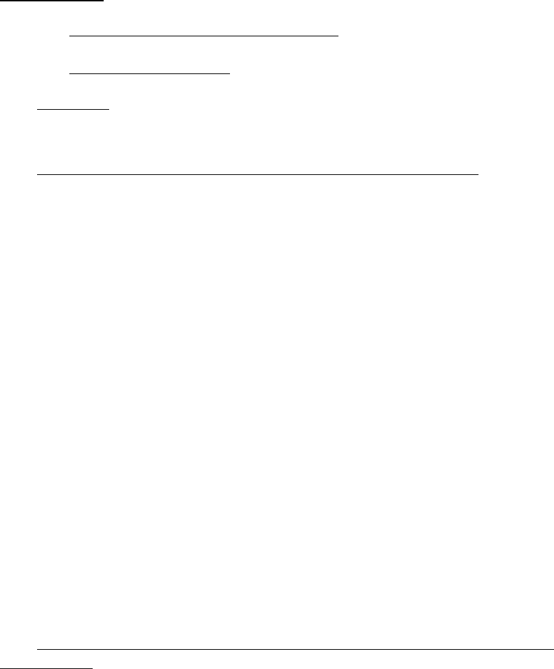
COMUSFLTFORCOMINST 4790.3 REV D
16 Oct 2019
V-III-10-1
VOLUME V
PART III
CHAPTER 10
QUALITY ASSURANCE RECORDS
REFERENCES.
(a) NAVSEA SS800-AG-MAN-010/P-9290 - System Certification Procedures and
Criteria Manual for Deep Submergence Systems
(b) NAVSEAINST 4720.23 - Deep Submergence Systems Temporary Modifications
10.1 PURPOSE. Provide record keeping and retention requirements for the Quality Assurance
records used in the Scope of Certification Program per reference (a). The requirements of Part I,
Chapter 10 of this volume apply as modified in this chapter.
10.2 DEPARTURE FROM SPECIFICATION RECORD RETENTION.
a. Each activity, Type Commander, Immediate Superior In Command, User Activity and
Maintaining Activity is required to maintain an outstanding Departure From
Specification (DFS) file. This file may be maintained on electronic media and will
contain the following information:
(1) An index that reflects a Deep Submergence System unique identifier.
(2) Departure number.
(3) Departure title.
(4) Classification (Major or Minor).
(5) Type of Departure (Deviation or Waiver).
(6) Date requested.
(7) Date resolved.
(8) Approval or disapproval status.
(9) Conditional approval comments (if applicable).
(10) A copy of all applicable Naval Sea Systems Command correspondence
delegating local approval of DFSs.
b. A copy of each outstanding DFS and all applicable correspondence.
c. A hard or electronic copy of cleared DFSs with an index will be retained for life of
ship.
10.3 USER AND SUSTAINING ACTIVITY QUALITY ASSURANCE RECORD
RETENTION. User and Sustaining Activities will maintain records per the record retention
requirements of this volume Part 1, Chapter 10, Section 10.6 for Submarines, and Section 10.7
for Fleet Maintenance Activities. Miscellaneous records to maintain include:
COMUSFLTFORCOMINST 4790.3 REV D
16 Oct 2019
V-III-10-2
a. Completed maintenance records dive log, including where required, pre-dive and post-
dive check-off procedures for all evolutions must be retained from certification survey
to survey or three years, whichever is longer.
b. The marked up laminated pre-dive and post-dive sign off sheets which show valve and
switch positions must be retained until commencement of the next dive.
c. Records of gas supply certifications required by the applicable Scope of Certification
Notebook must be retained for three years.
d. Record of Temporary Modifications will be maintained per reference (b) and Volume
II, Part I, Chapter 2 of this manual.

COMUSFLTFORCOMINST 4790.3 REV D CHG 3
07 Nov 2023
V-III-11-1
VOLUME V
PART III
CHAPTER 11
QUALITY ASSURANCE FORMS AND FORM INSTRUCTIONS
11.1 PURPOSE. Provide Quality Assurance (QA) forms for Scope of Certification items.
Forms listed in Part 1, Chapter 11 of this volume should be used except for the QA-26 and QA-
27 forms. Use the QA-26A and QA-27A forms listed in this chapter for Hydrostatic or
Pneumatic Test Records and Drop Test Records respectively, and the QA form 34B listed in this
chapter for the assembly of Electrical and Electronic Cable connector assemblies.
11.2 LIST OF FORMS. This chapter provides copies of the following QA forms with
instructions on how to complete each form.
a. Instructions for QA form 2 for existing controlled material received from an outside
vendor not under Joint Fleet Maintenance Manual controls.
b. QA form 26A - Hydrostatic or Pneumatic Test Record for Deep
Submergence Systems.
Instructions for QA form 26A
c. QA form 27A - Drop Test Record for Deep Submergence Systems.
Instructions for QA form 27A
d. QA form 34B - Electrical or Electronic Cable Connector Assembly
and Test Record.
Instructions for QA form 34B

COMUSFLTFORCOMINST 4790.3 REV D CHG 3
07 Nov 2023
V-III-11-2
QA FORM 2 INSTRUCTIONS
MATERIAL IDENTIFICATION (ID)/CONTROL TAG
LANTFLT 4790/2 (8-01) S/N 0103-LF-981-0300
PURPOSE: Used for receipt inspection, certification and traceability of existing controlled
material received from an outside vendor not under Joint Fleet Maintenance
Manual controls.
PROCEDURE: The numbered blocks on QA form 2 correspond with the instructions listed
here.
BLOCK 1 - TAG (A) OF (B)
a. Block A - Enter “1”. For additional tags used during the fabrication, transfer or
installation process, number the tags in sequential order as used (2, 3, 4, etc.).
b. Block B - The last number reflects the total number of tags used for this item during
this maintenance action. This block is filled in by the QAI at the time Block 21 is
signed on the last tag (e.g., 3 of 3).
BLOCK 2 - MIC NO./SERIAL NO.
NOTE: THE INFORMATION ENTERED FOR FASTENERS MAY NEED TO
INCLUDE INFORMATION FROM BLOCKS 3 AND 8 FROM QA-1. DO NOT
ENTER THE PNSY TRACE NUMBER FROM BLOCK 3 OF THE QA-1.
a. New Material: Enter the Material Identification and Control (MIC) etched on the
material. If the component has no MIC or a shortened MIC marking, ensure the full
MIC marking from the shipping documents, tags, or packaging is entered.
b. Fasteners: Document the markings from the fastener to include either:
(1) The color code and the heat or lot number, material type, and manufacturer’s
symbol (for nuts containing a self-locking insert, the color of the insert is the
manufacturer’s symbol).
(2) The MIC number (when MIC number is on the fastener or on the individual
tag for some small fasteners).
c. If the material is Material Control Division B, enter Markings on the material or
documented on the shipping papers providing identification to material type or
military specification.
BLOCK 3 - MAT LEVEL
Check the Existing block and the SOC block.
BLOCK 4 - MATL DESCRIPTION
Enter the quantity, size and noun name of the material (e.g., (6 each) 5/8” - 11 NICU studs,
10” O.D. CUNI barstock 6” long).
BLOCK 5 - NSN/SMIC
Enter “NA”.

COMUSFLTFORCOMINST 4790.3 REV D CHG 3
07 Nov 2023
V-III-11-3
BLOCK 6 - RECEIPT INSPECTION COMMENTS
Enter receipt inspection results (i.e., SAT or UNSAT). If inspection results are UNSAT in
Block 6, initiate a QA form 3. For UNSAT results in Block 6, the CMPO will only sign
Block 7 of the QA form 2 if the QAO dispositions the item suitable for use on Block 12 of the
QA form 3. For SAT receipt inspection, enter the following statement:
“Material Receipt Inspected SAT and is certified for re-use.”
This entry will be signed by the QAO.
BLOCK 7 - CMPO/CMH
CMPO or CMH certifying the entries in Blocks 1-7 print name, enter signature and date.
NOTE: THE CMPO WILL VERIFY THAT THE ITEM IS WHAT IS REQUIRED FOR
INTENDED USE PRIOR TO TURNING THE MATERIAL OVER TO
CRAFTSMAN FOR FABRICATION OR INSTALLATION AND FILL IN
BLOCKS 8 THROUGH 12 AT THE TIME THE MATERIAL IS ISSUED.
BLOCK 8 - UIC, WC, JSN AND CWP SERIAL NO.
At the time of issue, enter the Job Control Number (JCN) [UIC, WC and Job Sequence
Number (JSN)] and CWP serial number. If removal or installation of existing material is
authorized as a REC exception, CWP serial number may be marked “N/A”.
BLOCK 9 - WC NO.
Enter the number of the WC receiving material (e.g., EM01, 10C, 38A).
BLOCK 10 - DATE
Enter date the WC received the material.
BLOCK 11 - REMARKS
Enter the reason for issue (e.g., issued to 31A for manufacture of fitting, issued to EM01 for
installation).
BLOCK 12 - CRAFTSMAN/CMPO/CMH/QAI
For Initial Material Issue: Print name, enter signature signifying issue of material by CMPO
or CMH. For Fabrication or Transfer (Additional QA form(s) 2 required). Print name, enter
signature signifying receipt of material.
NOTE: THE REMAINING SECTIONS OF THE TAG ARE COMPLETED BY THE
COGNIZANT CRAFTSMAN, CMPO, CMH OR QAI DURING THE
FABRICATION OR INSTALLATION PROCESSES.
NOTE: SATISFACTORY CONDITION OF MATERIAL EXCHANGED BETWEEN
WCs IS ASSUMED, UNLESS AN ENTRY IS MADE IN REMARKS
INDICATING MATERIAL IS REJECTED.
BLOCK 13 - WC NO.
Enter the number of the WC receiving material (e.g., 56A or EA01).
BLOCK 14 - DATE

COMUSFLTFORCOMINST 4790.3 REV D CHG 3
07 Nov 2023
V-III-11-4
Enter date material received.
BLOCK 15 - REMARKS
Record work performed while the material was in the custody of the WC (e.g., drilled screws
and installed Nyloc pellets).
BLOCK 16 - CRAFTSMAN/CMPO/CMH/QAI
Cognizant craftsman print name and sign to certify blocks 1 through 15 are complete and
correct.
NOTE: IF 2 OR MORE WCs ARE INVOLVED IN THE FABRICATION PROCESS,
ADDITIONAL QA FORMS 2 WILL BE FILLED OUT AND NUMBERED PER
THE INSTRUCTIONS ABOVE FOR BLOCK 1.
NOTE: IF FOR ANY REASON THE COGNIZANT CRAFTSMAN REJECTS THE
MATERIAL, HE OR SHE WILL COMPLETE AND ATTACH A MATERIAL
REJECT TAG (QA FORM 3) AND LEAVE THE QA FORM 2 ATTACHED.
NOTE: BLOCKS 17 THROUGH 21 WILL CONTAIN THE RECORD OF FINAL
INSTALLATION. IF ADDITIONAL TAGS ARE REQUIRED FOR THE
MATERIAL DURING THE FABRICATION AND TRANSFER PROCESS
(MORE THAN TWO WCs OR PROCESSES INVOLVED IN THE REPAIR),
BLOCKS 9 THROUGH 12 AND BLOCKS 17 THROUGH 21 MAY BE USED.
BLOCK 17 - WC NO.
Enter the number of the WC responsible for installation of the material (e.g., 56A or EA01).
BLOCK 18 - DATE
Enter the date of installation.
BLOCK 19 - REMARKS
Enter the location where the material was installed into the system or component (e.g.,
installed in AHP-514, installed in system at joints ASW-70014(F) and ASW-70015(F), etc.).
BLOCK 20 - CRAFTSMAN
Cognizant craftsman print name and enter signature signifying that the material is the correct
material, is installed correctly and per the applicable technical specifications. Remove the QA
form 2 and file with the CWP if a QAI is not required.
NOTE: A QAI INSPECTION IS REQUIRED FOR MATERIAL INSTALLATIONS
FOR JOINTS AND ASSEMBLIES WITHIN THE SOC BOUNDARY.
BLOCK 21 - INSPECTOR
When required, inspector print name and enter signature and date certifying that the material
is the correct material, acceptable for application and correctly installed. Enter NA in QAI
signature space when QAI is not required. Remove the QA form 2 and file with the CWP.
COMUSFLTFORCOMINST 4790.3 REV D CHG 3
07 Nov 2023
V-III-11-5
HYDROSTATIC/PNEUMATIC TEST RECORD FOR DEEP SUBMERGENCE
SYSTEMS
QA FORM 26A (DSS) Planning must fill in blocks identified by a prior to issuing.
PAGE ____ OF ____
1. DSS
PLATFORM
HULL
NO.
2. JCN 3.
LWC/SHOP
4. CWP/REC SER NO. 5. SYSTEM/COMPONENT
6. REFERENCES (TEST PRESSURE DRAWINGS, REFERENCE MANUALS OR OTHER APPLICABLE REFERENCES)
A. B. C.
7. REQUIRED TEST AND INSPECTION – SPECIFY TEST REQUIREMENTS [i.e., TYPE OF TEST, ACCEPTANCE CRITERIA, JOINTS TO BE
TESTED (IF ENTIRE COMPONENT/SYSTEM IS TESTED, SO STATE)].
8. DIAGRAM OF TEST AREA INCLUDING GAGS AND BLANKS INSTALLED, VALVE POSITIONS, AND TEST GAGES/INSTR USED
(DOCUMENT BELOW OR ATTACH SKETCH).
9. GAGE
DATA
RANGE (PSIG) SERIAL # CAL DATE CAL DUE DATE
PRIMARY
BACKUP
10.
REQUIRED
TEST FLUID:
11. REQUIRED
TEST PRESSURE
(PSIG):
12. ACTUAL TEST
PRESSURE (PSIG):
13. REQUIRED TEST
DURATION:
14. ACTUAL TEST DURATION:
15. ALLOWABLE LEAKAGE: 16. MEASURED LEAKAGE:
17. INSPECTION RESULTS (CHECK ONE):
SAT UNSAT
18. OUT-OF-ROUNDNESS MEASUREMENTS (CHECK ONE):
EXTERNAL HYDROSTATIC TEST OF PIPE ONLY
SAT UNSAT NA
19. REMARKS:
20. CERTIFICATION
CERTIFICATION SIGNATURES MUST BE MADE BY THE CRAFTSMAN WHO PERFORMED THE TEST
AND THE QAI WHO WITNESSED THE TEST
PERFORMED BY INSPECTED BY
CRAFTSMAN SIGNATURE DATE (DATE TEST CONDUCTED) QA INSPECTOR SIGNATURE DATE
COMUSFLTFORCOMINST 4790.3 REV D CHG 3
07 Nov 2023
V-III-11-6
HYDROSTATIC/PNEUMATIC TEST RECORD FOR DEEP SUBMERGENCE SYSTEMS
QA FORM 26A (DSS) (CONTINUATION SHEET)
PAGE _____ OF ____
DSS PLATFORM HULL NO. JCN LWC/SHOP CWP/REC SER NO. SYSTEM/COMPONENT
21. VALVE/SYSTEM LINEUP FOR PRESSURE TESTING
VALVE/COMPONENT
DESIGNATOR AND/OR
NOMENCLATURE
REQUIRED
POSITION/CONDITION
POSITIONER 1
ST
CHECK 2
nd
CHECK
INITIALS INITIALS INITIALS
THE VALVE/SYSTEM LINEUP MUST INCLUDE THE POSITION/CONDITION OF SYSTEM COMPONENTS WHICH COMPOSE THE TEST BOUNDARY;
SYSTEM COMPONENTS WITHIN THE TEST BOUNDARY; TEMPORARY TEST FITTINGS, BLANKS AND JUMPERS INSTALLED IN THE SYSTEM FOR
TESTING; AND THE TEST ENTRY POINT WHEN AN EXTERNAL PRESSURE SOURCE IS USED FOR AN INTERNAL PRESSURE TEST.
POSITIONER NAME (PRINT) POSITIONER SIGNATURE POSITIONER
INITIALS
DATE
1
st
CHECK NAME (PRINT) 1
st
CHECK SIGNATURE 1
st
CHECK
INITIALS
DATE
2
ND
CHECK NAME (PRINT) 2
nd
CHECK SIGNATURE 2
nd
CHECK
INITIALS
DATE

COMUSFLTFORCOMINST 4790.3 REV D CHG 3
07 Nov 2023
V-III-11-7
QA FORM 26A INSTRUCTIONS
HYDROSTATIC/PNEUMATIC TEST RECORD
PURPOSE: To document hydrostatic or pneumatic tests accomplished on Scope of
Certification piping systems or portions of a system to recertify the system
after maintenance. It also provides a method for the Fleet Maintenance
Activity to specify the required retests for work they performed. This form
should be utilized to document mechanical joint tightness testing utilizing both
an external pressure source and internal system pressure.
TOP OF FORM: Page ___ of ___
NOTE A TECHNICAL WORK DOCUMENT MAY CONTAIN MULTIPLE QA
FORMS OF THE SAME TYPE, (E.G. MORE THAN ONE QA-26). THE PAGE
ENTRY IS FOR THIS SPECIFIC FORM, NOT THE TOTAL NUMBER OF
PAGES ON ALL FORMS OF THE SAME TYPE.
Enter the page number, starting with page 1, of total number of QA form pages (e.g., 1 of ,
2 of ). The last number reflects the total number of QA Form pages written. This block is
filled in by a QAI or the QAO after all certification testing is complete before block 19 on the
QA-9 is signed. (e.g., 1 of 3, 2 of 3, 3 of 3).
PROCEDURE: The numbered blocks on QA form 26A correspond with the instructions listed
here. Any block not used will be marked NA. The planning organization must
fill in blocks identified by a prior to issuing the Controlled Work Package
(CWP).
BLOCK 1 - DSS Platform/Hull Number
Enter the Deep Submergence System (DSS) or ship’s name and hull number.
BLOCK 2 - JCN
Enter the Joint Control Number (JCN).
BLOCK 3 - LWC
Enter the shop number of the Lead Work Center (LWC).
BLOCK 4 - CWP SER. NO.
Enter the CWP serial number.
BLOCK 5 - SYSTEM/COMPONENT
Enter the name of the system and component to be tested.
BLOCK 6 - TEST REFERENCES
Enter the applicable test reference and other applicable references (e.g., drawing number and
revision used to obtain the required test pressure and conducting of the test).
NOTE: ENTER “S9505-AF-MMA-010/PIPING SYSTEMS” WHICH PROVIDES
REQUIREMENTS FOR SHIP’S FORCE TO SET-UP AND CONDUCT
TESTING.

COMUSFLTFORCOMINST 4790.3 REV D CHG 3
07 Nov 2023
V-III-11-8
BLOCK 7 - REQUIRED TEST AND INSPECTION POINTS
Enter the specific test requirements necessary to recertify the work. Specify test requirements
(i.e., type of test, special valve position, duration, acceptance criteria, joints to be tested (if entire
component or system is tested, so state)).
BLOCK 8 - DIAGRAM OF TEST AREA
Enter a diagram of the test area. Be specific. Include such things as relief valve locations, gage
locations, blanks, gags, and valve positions, etc. The Quality Assurance Inspector (QAI) will
verify the diagram prior to performance of the test.
NOTE: ALL VALVES WITHIN THE TEST BOUNDARIES MUST BE IDENTIFIED
AND THEIR POSITION (OPEN OR SHUT) DURING THE TEST
ANNOTATED.
NOTE: IF DRAWINGS OR ADDITIONAL INFORMATION IS REQUIRED TO
SUPPLEMENT THIS REPORT, EACH DRAWING, ETC., WILL BE
NUMBERED AND AUTHENTICATED WITH THE SIGNATURE BY THE
CRAFTSMAN AND QAI MAKING UP THE REPORT.
NOTE: LOCAL EXCEPTIONS TO GAGE RANGE AND OR INCREMENTS WILL
BE APPROVED BY AN INDIVIDUAL WITH A TECHNICAL WARRANT.
NOTE: SHIPS, FLEET MAINTENANCE ACTIVITIES AND REGIONAL
MAINTENANCE CENTERS MANAGED BY UNITED STATES FLEET
FORCES COMMAND OR TYCOMS WILL DISREGARD THE BLOCK 8
DIAMOND WHEN TESTING IS PERFORMED BY AN ACTIVITY OTHER
THAN THE ACTIVITY PERFORMING REPAIR. THE ACTIVITY
PERFORMING THE TESTING MUST COMPLETE THE DIAGRAM
REQUIRED BY BLOCK 8.
BLOCK 9 - GAGE DATA
Enter the Primary and backup gage data. Backup gage data is not required when performing an
operational test as defined in Part I, Chapter 7 of this volume when a second system gage is not
available.
BLOCK 10 - REQUIRED TEST FLUID
Enter the required test fluid.
BLOCK 11 - REQ’D TEST PRESSURE (PSIG)
Enter the required test pressure. If listing the value would classify the CWP then the symbols “J”
or “H” with the applicable reference may be used instead of classifying the document.
BLOCK 12 - ACTUAL TEST PRESSURE (PSIG)
Enter the actual test pressure. If listing the value would classify the CWP then the symbols “J”
or “H” with the applicable reference may be used instead of classifying the document.
BLOCK 13 - REQUIRED TEST DURATION
Enter the required test duration including units.

COMUSFLTFORCOMINST 4790.3 REV D CHG 3
07 Nov 2023
V-III-11-9
BLOCK 14 - ACTUAL TEST DURATION
Enter the actual test duration including units.
BLOCK 15 - ALLOWABLE LEAKAGE
Enter the allowable leakage including units for the leakage.
BLOCK 16 - MEASURED LEAKAGE
Enter the actual measured leakage including units for the leakage.
BLOCK 17 - INSPECTION RESULTS
a. Check “SAT” block, if all inspections specified by Block 7 are complete and
satisfactory.
b. Check “UNSAT” block, if test results are unsatisfactory. Identify the specific
inspection and reason for failure in the remarks section.
NOTE: IF A SATISFACTORY TEST CANNOT BE ACHIEVED, A DEPARTURE
FROM SPECIFICATION MUST BE PROCESSED PER PART 1, CHAPTER 8
OF THIS VOLUME OR THE TASK MUST BE REWORKED AND
RETESTED.
BLOCK 18 - OUT-OF-ROUNDNESS MEASUREMENTS
Enter out-of-roundness measurements for external hydrostatic tests of pipes only.
BLOCK 19 - REMARKS
Remarks pertinent to this test will be entered in this block.
BLOCK 20 - CERTIFICATION
PERFORMED BY
Person performing the test print name, enter signature and date signifying accuracy of data
recorded.
INSPECTED BY
QAI print name, enter signature and date verifying the accuracy of test results recorded and
inspection performed satisfactory.
BLOCK 21 - VALVE/SYSTEM LINEUP FOR PRESSURE TESTING
List all the valves within the test boundary and those valves that make up the test boundary. The
required position for adequate testing of the component or system will be listed. Each valve will
have the initials of the initial positioner, or in the event the valve is in the correct position and
does not require positioning “NA” will be marked. Each valve will have 1
st
and 2
nd
checkers
initials. Personnel involved with initial positioning, 1
st
and 2
nd
checking will print their names,
sign, initial and date the required blocks at the bottom of the form.
NOTE: SHIPS, FLEET MAINTENANCE ACTIVITIES AND REGIONAL
MAINTENANCE CENTERS MANAGED BY UNITED STATES FLEET
FORCES COMMAND OR TYCOMS WILL DISREGARD THE BLOCK 21
DIAMOND WHEN TESTING IS PERFORMED BY AN ACTIVITY OTHER
COMUSFLTFORCOMINST 4790.3 REV D CHG 3
07 Nov 2023
V-III-11-10
THAN THE ACTIVITY PERFORMING REPAIR. THE ACTIVITY
PERFORMING THE TESTING MUST COMPLETE THE VALVE LINEUP
REQUIRED BY BLOCK 21.
COMUSFLTFORCOMINST 4790.3 REV D CHG 3
07 Nov 2023
V-III-11-11
DROP TEST RECORD FOR DEEP SUBMERGENCE SYSTEMS
QA FORM 27A (DSS)
Planning must fill in blocks identified by a prior to issuing.
PAGE ______ OF ______
1. DSS PLATFORM HULL NO. 2. JCN 3. LWC/SHOP 4. CWP/REC SER NO. 5.
SYSTEM/COMPONENT
6. REFERENCES (TEST REFERENCE MANUAL(S) AND/OR OTHER APPLICABLE REFERENCES)
A. B. C.
D. E. F.
7. REQUIRED TEST AND INSPECTION – SPECIFY TEST REQUIREMENTS [i.e., TYPE OF TEST, JOINTS TO BE TESTED (IF ENTIRE COMPONENT/SYSTEM
IS TESTED, SO STATE)].
8. DIAGRAM OF TEST AREA INCLUDING GAGS AND BLANKS INSTALLED, VALVE POSITIONS, AND TEST GAGES/INSTR USED (DOCUMENT BELOW
OR ATTACH SKETCH).
9. GAGE DATA RANGE (PSIG) SERIAL # CAL DATE CAL DUE DATE
PRIMARY
BACKUP
10. REQUIRED TEST FLUID:
11. REQUIRED
TEST PRESSURE:
12. INITIAL TEST
PRESSURE:
13. FINAL PRESSURE
AT END OF TEST:
14. TEMPERATURE
AT START OF TEST:
15. TEMPERATURE AT
END OF TEST:
16. CHANGE IN
TEMPERATURE:
17. REQUIRED
TEST DURATION:
18. ACTUAL TEST
DURATION:
19. ALLOWABLE PRESSURE DROP% IN MINUTES/HOURS: 20. FINAL PRESSURE DROP CORRECTED FOR TEMPERATURE CHANGE:
21. TEST RESULTS (CHECK ONE): SAT UNSAT
22. REMARKS:
23. CERTIFICATION
CERTIFICATION SIGNATURES MUST BE MADE BY THE CRAFTSMAN WHO PERFORMED THE TEST AND THE QAI WHO WITNESSED THE TEST
PERFORMED BY: INSPECTED BY:
CRAFTSMAN SIGNATURE DATE QA INSPECTOR SIGNATURE DATE
COMUSFLTFORCOMINST 4790.3 REV D CHG 3
07 Nov 2023
V-III-11-12
DROP TEST RECORD FOR DEEP SUBMERGENCE SYSTEMS
QA FORM 27A (DSS) (CONTINUATION SHEET)
PAGE ______ OF ______
DSS PLATFORM HULL NO. JCN LWC/SHOP CWP/REC SER NO. SYSTEM/COMPONENT
24. VALVE/SYSTEM LINEUP FOR PRESSURE TESTING
VALVE/COMPONENT
DESIGNATOR AND/OR
NOMENCLATURE
REQUIRED
POSITION/CONDITION
POSITIONER
1
ST
CHECK
2
nd
CHECK
INITIALS INITIALS INITIALS
THE VALVE/SYSTEM LINEUP MUST INCLUDE THE POSITION/CONDITION OF SYSTEM COMPONENTS WHICH
COMPOSE THE TEST BOUNDARY, SYSTEM COMPONENTS WITHIN THE TEST BOUNDARY, TEMPORARY TEST
FITTINGS, BLANKS AND JUMPERS INSTALLED IN THE SYSTEM FOR TESTING AND THE TEST ENTRY POINT
WHEN AN EXTERNAL PRESSURE SOURCE IS USED FOR AN INTERNAL PRESSURE TEST.
POSITIONER NAME (PRINT) POSITIONER SIGNATURE POSITIONER
INITIALS
DATE
1
st
CHECK NAME (PRINT) 1
st
CHECK SIGNATURE 1
st
CHECK
INITIALS
DATE
2
nd
CHECK NAME (PRINT) 2
nd
CHECK SIGNATURE 2
nd
CHECK
INITIALS
DATE

COMUSFLTFORCOMINST 4790.3 REV D CHG 3
07 Nov 2023
V-III-11-13
QA FORM 27A INSTRUCTIONS
DROP TEST RECORD
NOTE: PLANNING WILL FILL IN BLOCKS IDENTIFIED BY A PRIOR TO
ISSUING.
PURPOSE: To document drop tests accomplished on Scope of Certification piping systems
or portions of a system to recertify the system after maintenance actions have
been accomplished.
TOP OF FORM: Page ___ of ___
NOTE A TECHNICAL WORK DOCUMENT MAY CONTAIN MULTIPLE QA
FORMS OF THE SAME TYPE, (E.G. MORE THAN ONE QA-26). THE PAGE
ENTRY IS FOR THIS SPECIFIC FORM, NOT THE TOTAL NUMBER OF
PAGES ON ALL FORMS OF THE SAME TYPE.
Enter the page number, starting with page 1, of total number of QA form pages (e.g., 1 of ,
2 of ). The last number reflects the total number of QA Form pages written. This block is
filled in by a QAI or the QAO after all certification testing is complete before block 19 on the
QA-9 is signed. (e.g., 1 of 3, 2 of 3, 3 of 3).
PROCEDURE: The numbered blocks on QA form 27A correspond with the instructions listed
here. Any block not used will be marked NA. The planning organization must
fill in blocks identified by a prior to issuing the CWP.
BLOCK 1 - DSS Platform/Hull Number
Planner enter the DSS or ship’s name and hull number.
BLOCK 2 - JCN
Planner enter the JCN.
BLOCK 3 - LWC
Planner enter the shop number of the LWC.
BLOCK 4 - CWP SER. NO.
Planner enter the CWP serial number.
BLOCK 5 - SYSTEM/COMPONENT
Planner enter the name of the system and component to be tested.
BLOCK 6 - TEST REFERENCES
Planner enter the applicable test reference and other applicable references (e.g., drawing number
and revision used to obtain the required test pressure and conducting of the test).
NOTE: ENTER “S9505-AF-MMA-010/PIPING SYSTEMS” WHICH PROVIDES
REQUIREMENTS FOR SHIP’S FORCE TO SET-UP AND CONDUCT
TESTING.
BLOCK 7 - REQUIRED TEST AND INSPECTION POINTS

COMUSFLTFORCOMINST 4790.3 REV D CHG 3
07 Nov 2023
V-III-11-14
Planner enter the specific test requirements necessary to recertify the work. Specify test
requirements (i.e., type of test, special valve position, duration, acceptance criteria, and joints to
be tested (if entire component or system is tested, so state)).
BLOCK 8 - DIAGRAM OF TEST AREA
Planner enter a diagram of the test area. Be specific. Include such things as relief valve
locations, gage locations, blanks, gags, and valve positions, etc. The QAI will verify the diagram
prior to performance of the test. For nuclear tests identify major components to be isolated or
vented to preclude unnecessary pressurization.
NOTE: ALL VALVES WITHIN THE TEST BOUNDARIES MUST BE IDENTIFIED
AND THEIR POSITION (OPEN OR SHUT) DURING THE TEST
ANNOTATED.
NOTE: IF DRAWINGS OR ADDITIONAL INFORMATION IS REQUIRED TO
SUPPLEMENT THIS REPORT, EACH DRAWING, ETC., WILL BE
NUMBERED AND AUTHENTICATED WITH THE SIGNATURE BY THE
CRAFTSMAN AND QAI MAKING UP THE REPORT.
NOTE: LOCAL EXCEPTIONS TO GAGE RANGE AND OR INCREMENTS WILL
BE APPROVED BY AN INDIVIDUAL WITH A TECHNICAL WARRANT.
NOTE: SHIPS, FLEET MAINTENANCE ACTIVITIES AND REGIONAL
MAINTENANCE CENTERS MANAGED BY UNITED STATES FLEET
FORCES COMMAND OR TYCOMS WILL DISREGARD THE BLOCK 8
DIAMOND WHEN TESTING IS PERFORMED BY AN ACTIVITY OTHER
THAN THE ACTIVITY PERFORMING REPAIR. THE ACTIVITY
PERFORMING THE TESTING MUST COMPLETE THE DIAGRAM
REQUIRED BY BLOCK 8.
BLOCK 9 - GAGE DATA
Craftsman enter the Primary and backup gage data. Backup gage data is not required when
performing an operational test as defined in Part I, Chapter 7 of this volume when a second
system gage is not available.
BLOCK 10 - REQUIRED TEST FLUID
Planner enter the required test fluid.
NOTE: IF LISTING THE TEST PRESSURE WOULD CLASSIFY THE CWP,
ENTER “J”, “H”, “ITEM 1 OF REF (A)”, OR ETC., AS APPROPRIATE
FROM THE APPLICABLE REFERENCE INSTEAD OF CLASSIFYING
THE DOCUMENT.
BLOCK 11 - REQ’D TEST PRESSURE (PSIG)
Planner enter the required test pressure.
BLOCK 12 - INITIAL TEST PRESSURE
Craftsman enter initial test pressure achieved at start of test.

COMUSFLTFORCOMINST 4790.3 REV D CHG 3
07 Nov 2023
V-III-11-15
BLOCK 13 - FINAL PRESSURE AT END OF TEST
Craftsman enter final pressure reading when the required test time is completed.
BLOCK 14 - TEMPERATURE AT START OF TEST
Craftsman enter temperature at start of the test with units.
BLOCK 15 - TEMPERATURE AT END OF TEST
Craftsman enter temperature at the end of the test with units.
BLOCK 16 - CHANGE IN TEMPERATURE
Craftsman subtract temperature at the end of the test recorded in Block 15 from temperature at
the start of the test recorded in Block 14.
BLOCK 17 - REQUIRED TEST DURATION
Planner enter the required test duration including units.
BLOCK 18 - ACTUAL TEST DURATION
Craftsman record actual duration of the test.
BLOCK 19 - ALLOWABLE PRESSURE DROP % IN MINUTES/HOURS
Planner enter the allowable pressure drop as a percentage of the test pressure in minutes or hours.
Cross-out time measure not used.
BLOCK 20 - FINAL PRESSURE DROP CORRECTED FOR TEMPERATURE
CHANGE
Craftsman record final pressure drop calculated with corrections for temperature change in the
same units as Blocks 11 and 12.
BLOCK 21 - TEST RESULTS
Craftsman
a. Check “SAT” block if all inspections specified by Block 7 are complete and
satisfactory.
b. Check “UNSAT” block, if test results are unsatisfactory. Identify the specific
inspection and reason for failure in the remarks section.
NOTE: IF A SATISFACTORY TEST CANNOT BE ACHIEVED, A DEPARTURE
FROM SPECIFICATION MUST BE PROCESSED PER PART 1, CHAPTER 8,
OF THIS VOLUME OR THE TASK MUST BE REWORKED AND
RETESTED.
BLOCK 22 - REMARKS
Remarks pertinent to this test will be entered in this block.
BLOCK 23 - CERTIFICATION
PERFORMED BY

COMUSFLTFORCOMINST 4790.3 REV D CHG 3
07 Nov 2023
V-III-11-16
Craftsman performing the test print name, enter signature and date signifying accuracy of data
recorded.
INSPECTED BY
QAI print name, enter signature and date verifying the accuracy of test results recorded and
inspection performed satisfactory.
NOTE: SHIPS, FLEET MAINTENANCE ACTIVITIES AND REGIONAL
MAINTENANCE CENTERS MANAGED BY UNITED STATES FLEET
FORCES COMMAND OR TYCOMS WILL DISREGARD THE BLOCK 24
DIAMOND WHEN TESTING IS PERFORMED BY AN ACTIVITY OTHER
THAN THE ACTIVITY PERFORMING REPAIR. THE ACTIVITY
PERFORMING THE TESTING MUST COMPLETE THE VALVE LINEUP
REQUIRED BY BLOCK 24.
BLOCK 24 - VALVE/SYSTEM LINEUP FOR PRESSURE TESTING
List all the valves within the test boundary and those valves that make up the test boundary. The
required position for adequate testing of the component or system will be listed. Each valve will
have the initials of the initial positioner, or in the event the valve is in the correct position and
does not require positioning “NA” will be marked. Each valve will have 1
st
and 2
nd
checkers
initials. Personnel involved with initial positioning, 1
st
and 2
nd
checking will print their names,
sign, initial and date the required blocks at the bottom of the form.
COMUSFLTFORCOMINST 4790.3 REV D CHG 3
07 Nov 2023
V-III-11-17
ELECTRICAL/ELECTRONIC CABLE CONNECTOR
ASSEMBLY AND TEST RECORD
QA FORM 34B
(DSS)
PAGE ______ OF _____
A separate QA Form 34B must be used for each connector requiring controlled assembly documentation. The QA Form 34B must be used to
provide: 1) Standalone documentation for cable connector reconnection when controlled assembly is required by authorized REC exception;
or 2) QA Form 34B will be included in CWP/REC packages when documentation of controlled assembly is required as OQE for the work
performed. Planning must fill in blocks identified by a
prior to issuing.
1. DSS PLATFORM HULL
NO.
2. JCN 3. LWC/SHOP 4. CWP/REC SER NO. 5. SYSTEM(S)
COMPONENT
6. CONNECTOR DESIGNATION 7. CABLE DESIGNATION 8. CONNECTOR SIZE
9. REFERENCES
10. NEW MATERIAL
PC
NO.
REF. DESCRIPTION QTY LOE IDENT (e.g., MIC
NO/NSN/TRACEABILITY NO)
R/I
11. INSPECTION
PINS SEALING SURFACES [ ] NOT APPLICABLE THREADS [ ] NOT APPLICABLE
PLUG
SAT______
UNSAT____
JACK
SAT______
UNSAT____
PLUG
SAT______
UNSAT____
JACK
SAT______
UNSAT____
VENT SCREW
SAT______
UNSAT____
PLUG
SAT______
UNSAT____
JACK
SAT______
UNSAT____
VENT SCREW
SAT______
UNSAT____
12. TORQUE DOCUMENTATION [ ] TORQUE DOCUMENTATION NOT REQUIRED
VENT SCREW
[ ] NOT
APPLICABLE
REQUIRED TORQUE FINAL TORQUE TORQUE DEVICE/INSTRUMENT USED
RANGE SERIAL NUMBER CAL DUE DATE
IN-LB
FT-LB
IN-LB
FT-LB
IN-LB
FT-LB
COUPLING RING
REQUIRED TORQUE FINAL TORQUE TORQUE DEVICE/INSTRUMENT USED
RANGE SERIAL NUMBER CAL DUE DATE
IN-LB
FT-LB
IN-LB
FT-LB
IN-LB
FT-LB
CRAFTSMAN SIGNATURE DATE QAI SIGNATURE DATE
13. LOCKWIRE/LOCKING CABLE
INSTALLATION
MATL. DESCRIPTION/NSN/PC NO. CRAFTSMAN SIGNATURE DATE
SAT_________ NA_________
14. REMARKS/RECORD OF REPAIRS, MODIFICATIONS, INSPECTIONS (e.g., LIST OF ASSOCIATED RECORDS)
15. RECORD HAS BEEN REVIEWED FOR COMPLETENESS
QAS SIGNATURE DATE

COMUSFLTFORCOMINST 4790.3 REV D CHG 3
07 Nov 2023
V-III-11-18
QA FORM 34B INSTRUCTIONS
ELECTRICAL/ELECTRONIC CABLE CONNECTOR ASSEMBLY AND TEST RECORD
NOTE: PLANNING WILL FILL IN BLOCKS IDENTIFIED BY A PRIOR TO
ISSUING.
PURPOSE: To provide a standard form to document the assembly and test of Scope of
Certification electrical and electronic cable connector assemblies.
TOP OF FORM: Page ___ of ___
NOTE A TECHNICAL WORK DOCUMENT MAY CONTAIN MULTIPLE QA
FORMS OF THE SAME TYPE, (E.G. MORE THAN ONE QA-26). THE PAGE
ENTRY IS FOR THIS SPECIFIC FORM, NOT THE TOTAL NUMBER OF
PAGES ON ALL FORMS OF THE SAME TYPE.
Enter the page number, starting with page 1, of total number of QA form pages (e.g., 1 of ,
2 of ). The last number reflects the total number of QA Form pages written. This block is
filled in by a QAI or the QAO after all certification testing is complete before block 19 on the
QA-9 is signed. (e.g., 1 of 3, 2 of 3, 3 of 3).
PROCEDURE: The numbered blocks on QA form 34B correspond with instructions listed
here. Any block not used will be marked N/A. The planning organization
must fill in blocks identified by a * prior to issuing the CWP.
BLOCK 1 - DSS PLATFORM/HULL NO.
Planner enter the DSS or ship’s name and hull number.
BLOCK 2 - JCN
Planner enter the JCN.
BLOCK 3 - LWC
Planner enter the LWC.
BLOCK 4 - CWP/REC SER. NO.
Planner enter the CWP serial number.
BLOCK 5 - SYSTEM(S)/COMPONENT
Planner enter the noun name of the system(s) and component (if applicable).
BLOCK 6 - CONNECTOR DESIGNATION
Planner enter the designation of the connector as listed on prints or other reference material.
BLOCK 7 - CABLE DESIGNATION
Planner enter the designation of the cables entering the connector as listed on prints or other
reference material.
BLOCK 8 - CONNECTOR SIZE

COMUSFLTFORCOMINST 4790.3 REV D CHG 3
07 Nov 2023
V-III-11-19
Planner enter the type and size of the male connector (ex. M24231/13-001, where the M24231 is
the standard for the type of receptacle and the 13-001 is the size and number of contacts from the
standard).
BLOCK 9 - REFERENCES
Planner enter all references used to identify component parts, joint, material, and assembly
information. Include revision letter and, if applicable, the assembly number (e.g., Assy D, Assy
RA, etc.). Revisions for technical manuals are not required. If joint numbers are assigned in a
sketch in a Work Procedure, include the Work Procedure sketch number. For Electrical Hull
Fittings, include both the assembly drawing and electrical hole assignment drawing.
BLOCK 10 - NEW MATERIAL
Craftsman
PC NO: Enter piece numbers of parts. List only the new replacement parts actually being
installed.
REF: Record the reference letter of the drawing or document listed in Block 9 which provides
the material specification or assembly information for the piece listed in the “PC NO.” block.
DESCRIPTION: Describe all new parts associated with the assembly or joint. For O-rings:
record the MIL SPEC and the size. Enter the stock number of the O-ring lubricant or any sealant
used during assembly.
QTY: Record quantity of new material installed.
LOE: Identify the Level of Essentiality (MIC Level). Example: L1, NA. For SOC material,
enter the appropriate Material Control Division (A, B or C).
IDENT: Record the National Stock Number or traceability number of the new materials that
were used.
R/I (Receipt Inspection): Enter receipt inspection results from the QA form 2 (SAT). For non-
controlled material, enter “N/A”. For SOC MCD C material, the craftsman will perform a
receipt inspection per Part III Chapter 6 of this volume and document the inspection results in the
R/I column of Block 10.
BLOCK 11 - INSPECTION
PINS: Craftsman record “SAT” or “UNSAT” for the plug and jack inspection using
requirements of the references listed in Block 9.
SEALING SURFACE: Craftsman record “SAT” or “UNSAT” for the sealing surface inspection
using requirements of the references listed in Block 9.
Planning. If the sealing surface is not required to be checked, mark the “NOT APPLICABLE”
block.
THREADS: Craftsman record “SAT” or “UNSAT” for the fastening thread inspection using
requirements of the references listed in Block 9.
Planning. If the thread inspection is not required to be checked, mark the “NOT APPLICABLE”
block.

COMUSFLTFORCOMINST 4790.3 REV D CHG 3
07 Nov 2023
V-III-11-20
REMARKS: Enter any pertinent remarks or additional information related to the inspection of
the pins, thread or sealing surfaces in Block 14. Each entry must contain a signature and date
except where the entry is pre-printed on the form by planning.
BLOCK 12 - TORQUE DOCUMENTATION
Not all electrical or electronic cable connectors require torque documentation. For those joints
not requiring torque documentation, the Planner will mark the “NOT APPLICABLE” block.
The craftsman will still sign indicating that the joint was assembled following specification and
the correct O-ring was used.
For those electrical or electronic cable connectors which require torque documentation:
REQUIRED TORQUE: The Planner will list the required torque for the vent screw and
coupling ring as applicable per the requirements of the reference(s) listed in Block 9.
FINAL TORQUE: The craftsman will record the final torque applied to the vent screw or
coupling ring.
TORQUE DEVICE DATA: Craftsman record range, serial number and calibration due date for
the torque wrench or other device used during the assembly of the connector.
CRAFTSMAN(S) AND QAI CERTIFICATION BLOCK FOR JOINT DATA: Craftsman(s)
and QAI must sign, record badge number and date of the signature after the satisfactory
completion of assembly following the requirements. This signature provides certification that
the joint meets the requirements for the following:
(1) The applied lubricant is acceptable per the technical direction.
(2) The final required pre-load torque has been applied following specified requirements.
(3) Sealing surfaces meet the acceptance criteria of the applicable Maintenance Standard.
QAI CERTIFICATION BLOCK FOR JOINT DATA: QAI must sign and date the signature
after the satisfactory completion of assembly following the requirements. This signature
provides certification that the joint meets the requirements for the following:
(1) The applied lubricant is acceptable per the technical direction.
(2) The final required pre-load torque has been applied following specified requirements.
(3) Sealing surfaces meet the acceptance criteria of the applicable Maintenance Standard.
BLOCK 13 - LOCKWIRE/LOCKING CABLE/DEVICE INSTALLATION
NOTE: THIS BLOCK APPLIES TO LOCKING DEVICES OTHER THAN SELF-
LOCKING NUTS, SELF-LOCKING INSERTS OR SELF-LOCKING BOLT
OR CAP SCREWS.
Planner enter an X in the “NOT APPLICABLE” box when not applicable. When an action is
required to engage the locking device, enter a description of the required action.
NOTE: FOR MCD-C LOCKWIRE, LOCKING CABLE OR DEVICE, THE QAI WILL
UTILIZE SPACE IN BLOCK 14 TO DOCUMENT COMPLETION OF
INSPECTION OF MCD-C MATERIAL DURING INSTALLATION.

COMUSFLTFORCOMINST 4790.3 REV D CHG 3
07 Nov 2023
V-III-11-21
Craftsman sign, date and check SAT when lockwire, locking cable or required locking device
(e.g., locking ring for EHFs, barrel nut locking device, etc.) has been properly installed or the
required action has been accomplished. Enter description (e.g., lockwire, locking cable, lock
tab) and ident (e.g., stock number, MIL-SPEC or piece number) of the lockwire, locking cable or
locking device. Enter description and “Existing” for existing locking devices. If more than one
locking device type (e.g., lockwire and lock tab washers) exists on the assembly, record
additional information in the Remarks block. When the installation of more than one of the same
type of locking device is being documented in Block 13 (e.g., 2 locking devices), record the
quantity in addition to the description (Block 14 may be used if additional space is needed).
Recording the quantity is not required for lockwire or locking cable, nor when the locking device
quantity is documented in Block 10.
QAI sign, print and date in Block 14 for new MCD-C material installed by craftsman in Block
13, to ensure material conforms to specified requirements.
BLOCK 14 - REMARKS/RECORD OF REPAIRS/MODIFICATIONS/
INSPECTIONS
Enter any pertinent remarks or additional information related to the repair or assembly of the
component. Each entry must contain a signature and date except where the entry is pre-printed
on the form by planning.
BLOCK 15 - RECORD HAS BEEN REVIEWED FOR COMPLETENESS
Quality Assurance Supervisor or Quality Assurance Officer will print name, enter signature and
date for final review, signifying the accuracy of the completed form. If any entry is UNSAT, the
Quality Assurance Officer will initiate action to resolve the unsat condition and indicate the
action taken in the remarks block. Do not sign unless a satisfactory repair is completed or the
UNSAT condition is accepted.
