NASA
CR-I2O955
o
DEVELOPMENT
OF
SEAL RING
CARBON
-
GRAPHITE MATERIALS
(TASKS
Y
t
m,andTni)
by
N.J. Fechter
and
P.S. Petrunich
UNION CARBIDE CORPORATION
Carbon
Products Division
12900
Snow
Road
Parma,
Ohio
44130
prepared
for
NATIONAL AERONAUTICS
AND
SPACE
ADMINISTRATION
NASA
Lewis Research Center
Contract
NAS
3-13211
Lawrence
P.
Ludwig, Project Manager
1.
Report
No.
CR-120955
2.
Government
Accession
No.
4.
Title
and
Subtitle
DEVELOPMENT
OF
SEAL
RING
CAR
BON
-GRAPHITE
MATERIALS
(TASKS
V, VI, AND VU)
7.
Author(s)
N. J.
Fechter
and P. S.
Petrunich
9.
Performing
Organization Name
and
Address
Union
Carbide
Corporation
Carbon Products
Division
12900 Snow
Road
Parma,
Ohio
44130
12.
Sponsoring
Agency Name
and
Address
National
Aeronautics
and
Space
Administration
Washington
D. C.
20546
3.
Recipient's Catalog
No.
6.
Report
Date
August
10,
1972
6.
Performing Organization
Code
8.
Performing Organization Report
No.
10.
Work
Unit
No.
11.
Contract
or
Grant
No.
NAS-3-13211
13.
Type
of
Report
and
Period Covered
Contractor
Report
14.
Sponsoring
Agency
Code
16.
Supplementary
Notes
Project
Manager, Lawrence
P.
Ludwig,
Fluid
System Components Division,
NASA
Lewis Research Center, Cleveland,
Ohio
16.
Abstract
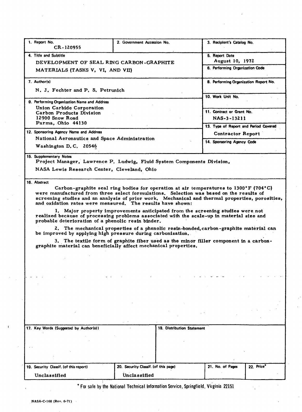
Carbon-graphite
seal
ring bodies
for
operation
at air
temperatures
to
1300°F
(704°C)
were manufactured
from
three
select
formulations. Selection
was
based
on the
results
of
screening studies
and an
analysis
of
prior work. Mechanical
and
thermal
properties,
porosities,
and
oxidation
rates
were
measured.
The
results
have shown:
1.
Major
property improvements anticipated from
the
screening studies
were,
not
realized
because
of
processing problems associated
with
the
scale-up
in
material
size
and
probable
deterioration
of a
phenolic
resin
binder.
2.
The
mechanical
properties
of a
phenolic resin-bonded, carbon-graphite
material
can
be
improved
by
applying high
pressure
during carbonization.
3. The
textile
form
of
graphite fiber used
as the
minor filler component
in a
carbon-
graphite
material
can
beneficially
affect
mechanical
properties.
17. Key
Words
(Suggested
by
Author(s))
19.
Security
dassif.
(of
this report)
Unclassified
18.
Distribution
Statement
20.
Security Classlf.
(of
this
page)
21. No. of
Pages
22.
Price*
Unclassified
* For
sale
by the
National Technical Information
Service,
Springfield, Virginia 22151
NASA-C-168
(Rev. 6-71)
FOREWORD
The
work described herein
was
conducted
at the
Parma
Technical
Center, Carbon Products,
Division
of
Union
Carbide Corporation, under
NASA
Contract NAS3-13211. Mr.. Lawrence
P.
Ludwig,
Fluid System
Components Division,
NASA
Lewis Research Center,
was the
Project
Manager.
Mr.
Leonard
W.
Schopen,
NASA-^Lewis
Research
Center,
was
the
Contracting Officer.
TABLE
OF
CONTENTS
Page
ABSTRACT
. i
FOREWORD.
. . ii
SECTION
I 1
SUMMARY
1
SECTION
II . 4
INTRODUCTION
-. . . . 4
SECTION
III
-....'
' " 7
CONCLUSIONS
-....'
7
SECTION
IV 8
SCREENING
STUDIES
AND
SEAL RING CARBON-GRAPHITE
MATERIAL FORMULATION (TASK
V) 8
A.
Screening Studies
8
1.
Study
of
Resin
Impregnants
17
2.
Study
of
Baking
Techniques
18
3.
Material
Subsystem Study
23
B.
Seal
Ring Carbon-Graphite
Material
Formulation
27
SECTION
V 31
MANUFACTURING
OF
CARBON-GRAPHITE MATERIALS
(TASK
VI) .31
A.
Identification
of
Materials
Manufactured
31
B.
Processing
of
Material,
Formulations
. 33
1.
Formulation-No.
1Y . . . 33
2.
Formulation
No. 1Z 36
3.
Formulation
No. 5 37
-----
-4.
Formulation
No.-
6
......
. . . . . . . . ; 7 7 . . . ' "39
5.
Formulation
No. 6Y 40
SECTION
VI 42
MATERIAL
PROPERTIES
(TASK VII)
42
A.
Property
Requirements
of
Seal
Ring
Carbon-
Graphite
Materials
42
B.
Mechanical
Properties
43
C.
Thermal
Properties
54
D.
Porosities
60
E.
Oxidation
Tests
83
.
111
TABLE
OF
CONTENTS (Cont'd)
Page
SECTION
VII 92
DISCUSSION
OF THE
RESULTS
. 92
APPENDIX
I 97
PROCEDURES USED
TO
CHARACTERIZE
RAW
MATERIALS
... 97
APPENDIX
II 98
PROCEDURES USED'TO MEASURE MATERIAL
PROPERTIES.
. . 98
APPENDDC
III .' 100
DEFINITION
OF
STATISTICAL TERMS
100
REFERENCES
102
DISTRIBUTION
LIST
104
IV

LIST
OF
TABLES
Table.
Page
I
Material Formulations Developed
Under
Tasks
I
Through
IV 9
II
Mechanical
Properties
-Resin
Impregnated
Materials
19
III
Mechanical Properties-Pressure
Cured
and
Baked
Formulation
No. 3
Material
21
IV...
Identification
of
Material Subsystems SS-47
to
SS-51
24
V
Mechanical Properties
-
SS-47,
SS-50,
and
Formulation
No.
4
Materials
26
VI
Oxidation
Test Results
27
VII
Material Formulations Nos.
1Y, 5Y, and 6Y . 28
VIII
Identification
of the
Three Basic Material Formulations
and
Their Impregnated Versions
32
IX
Mechanical Properties
-
Formulation
No. 1Z
material
....
45
X
Comparison
of
Mechanical Properties
-
Formulations
Nos.
1, IX, and 1Z
Material
46
XI
Mechanical Properties
-
Formulations
No. 5
Material. ....
48
XII
Comparison
of
Mechanical Properties
-
Formulations
Nos.
3 and 5
Material
49
XIII
Mechanical Properties
-
Formulation
No. 6Y
Material .....
51
XIV
Comparison
of
Mechanical Properties
-
Formulations
Nos.
4, 4X, and 6Y
Material
53
XV
Thermal
Conductivities
—-Formulations
Nos. IX,-
hZr - '
4X,
and 6Y
Material
. . . 55
XVI
Percent Total Porosities
-
Formulations Nos.
1, IX, 1Z,
4, 4X, and 6Y
Material
61
XVII
Pore
Volume
and
Distribution
by
Mercury Intrusion-
Formulation
No. 1Z
Material
63
XVIII
Pore
Volume
and
Distribution
by
Mercury Intrusion-
Formulation
No. 6Y
Material
66
LIST
OF
TABLES
.(Cont'd)
Table
Page
XIX
Pore
volume
and
Distribution
by
Mercury Intrusion
-
Grade
CDJ . 70
XX
Pore
Volume
and
Distribution
by
Nitrogen Desorption
-
Formulation
No. 1Z
Material
73
XXI
Pore
Volume
and
Distribution
by
Nitrogen Desorption
-
Formulation
No. 6Y
Material
.
.......;..
75
XXII
Pore
Volume
and
Distribution
by
Nitrogen Desorption
-
Grade
CDJ 78
XXIII Weight
Pickups
for
Materials
Impregnated with
No. 121
Oxidation-Inhibiting
Treatment
80
XXIV
Bulk Densities
of
Materials
Impregnated with
No. 121
Oxidation-Inhibiting Treatment (Grams/Cubic Centimeter)
... 82
XXV
Oxidation
Test
Data
for
Materials
Impregnated with
No. 121
Oxidation-Inhibiting Treatment
90
VI
LIST
OF
FIGURES
Figure
Page
1
Mean
Coefficient
of
Thermal
Expansion
-
Formulation
No. 1Z
Material
57
2
Mean
Coefficient
of
Thermal
Expansion-
Formulation
No. 6Y
Material
58
3
Mean
Coefficient
of
Thermal
Expansion-
Grade CDJ-83
59
4
Pore
Volume Versus
Pore
Diameter
by
Mercury
Intrusion-Formulation
No. 1Z
Material
. 64
5
Cumulative
Pore
Volume Versus
Pore
Diameter
by
Mercury
Intrusion-Formulation
No. 1Z
Material
...
T
....
65
6
Pore
Volume Versus.Pore Diameter
by
Mercury
Intrusion-Formulation
No. 6Y
Material
67
7
Cumulative
Pore
Volume Versus
Pore
Diameter
by
Mercury Intrusion-Formulation
No. 6Y
Material
68
8
Pore
Volume Versus
Pore
Diameter
by
Mercury
Intrusion-Grade
CDJ 71
9
Cumulative
Pore
Volume Versus
Pore
Diameter
by
Mercury IntrusionrGrade
CDJ 72
10
Percent
Pore
Volume
and
Cumulative
Percent
Pore
Volume
Versus
Pore
Diameter
by
Nitrogen Desorption-
Formulation
No. 1Z
Material
, 74
11
Percent
Pore
Volume
and
Cumulative
Percent
Pore
Volume
Versus
Pore
Diameter
by
Nitrogen Desoprtion-
Formulation
No. 6Y
Material
76
12
Percent
Pore
Volume
and
Cumulative
Percent
Pore
Volume
Versus
Pore
Diameter
by
Nitrogen Desorption-
Grade
CDJ 79
13
Oxidation Testing Apparatus
. . 84
14
Percent
Weight
Loss
Versus Exposure
Time
at
1300°F
(704°C)-Formulation
No.
1Z-121
Material
86
15
Percent
Weight
Loss
Versus Expsoure
Time
at
1300°F
(704°C)-Formulation
No.
5-121
Material.
87
16
Percent
Weight
Loss
Versus Exposure Time
at
1300°F
(704°C)-Formulation
No.
6Y-121
Material
88
SECTION
I
SUMMARY
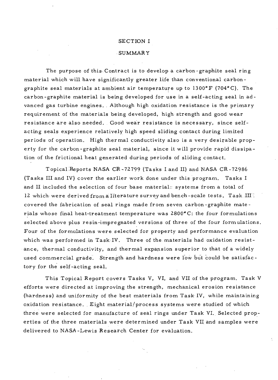
The
purpose
of
this Contract
is to
develop
a
carbon-graphite
seal
ring
material
which will have significantly greater
life
than conventional carbon-
graphite
seal
materials
at
ambient
air
temperature
up to
1300T
(704°C).
The
carbon-graphite
material
is
being developed
for use in a
self-acting
seal
in ad-
vanced
gas
turbine engines.
.
Although high oxidation resistance
is the
primary
requirement
of the
materials
being developed, high
strength
and
good
wear
resistance
are
also
needed.
Good
wear resistance
is
necessary, since self-
acting
seals
experience relatively high speed sliding contact
during
limited
periods
of
operation. High
thermal
conducti-vity
also
is a
very
desirable
prop-
erty
for the
carbon-graphite
seal
material,
since
it
will provide rapid dissipa-
tion
of the
frictional heat generated during periods
of
sliding contact.
Topical .Reports
NASA
CR-72799
(Tasks
I and II) and
NASA
C-R-72986
(Tasks
III and IV)
cover
the
earlier
work
done
under this program.
Tasks
I
and II
included
the
selection
of
four
base
material:: systems
from
a
total
of
12
which were derived from
a
literature
survey
and
bench-scale
tests.
Task III'.
covered
the
fabrication
of
seal
rings made from seven carbon-graphite
mate-
rials
whose final heat-treatment temperature
was
2800°C:
the
four
formulations
selected
above plus resin-impregnated versions
of
three
of the
four
formulations.
Four
of the
formulations were selected
for
property
and
performance evaluation
which
was
performed
in
Task;IV.
Three
of the
materials
had
oxidation
resist-
ance,
thermal
conductivity,
and
thermal
expansion superior
to
that
of a
widely
used
commercial grade. Strength.and hardness were
low but
could
be
satisfac-
tory
for the
self-acting
seal.
This
Topical Report covers
Tasks
V, VI, and VII of the
program. Task
V
efforts
were directed
at
improving
the
strength, mechanical erosion
resistance
(hardness)
and
uniformity
of the
best
materials
from
Task
IV,
while maintaining
oxidation
resistance.
.
Eight
material/process
systems were
studied
of
which
three
were selected
for
manufacture
of
seal
rings under
Task
VI.
Selected prop-
erties
of the
three
materials
were determined under
Task
VII and
samples
were
delivered
to
NASA-Lewis
Research Center
for
evaluation.
The
Task
V
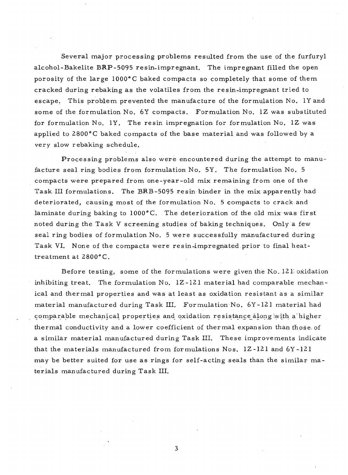
screening studies covered various resin impregnants
and
baking techniques. Graphite fibers were investigated
as a
minor filler com-
ponent
in a
carbon-graphite
seal
r.ing
material.
The
following
conclusions
were drawn:
a.
Bakelite
BRP-5095 phenolic
re-sin-furfuryl
alcohol
appears
to be
a
rnore suitable
resin
.impregnant than
the
Bakelite BRP-5095 resin-acetone
solution used during Task^III.
.
b.
Pressure
baking improved
the
mechanical properties
of a
resin-
bonded,
carbon-graphite
material;.
c. The
density
and
hardness
of
a.resin-bonded
material
containing
fibers
as its
minor filler component
can be
increased
by
substituting
Union
Carbide Corporation (UCC) Grade
WFA
graphite fibers
for
those pre-
pared from
UCC
Grade
WCA
graphite cloth.
For
Task
VI,
three
formulations listed below were selected
for the
manufacture
of
improved carbon-graphite
seal
ring bodies.
Particulate
raw
materials
included
UCC
Grade
CHP
artificial
graphite,UCC Grade
WFA
graphite fibers,
and
Commercial Solvents Corporation Thermax furnace
black.
Formulation
Filler
Material Binder Material
No.
1Y CHP
Artificial Graphite
(80
pbw)
Barret
No.
Medium
Pitch
Thermax
(20
pbw)
(60
pph)
No.
5Y CHP
Artificial Graphite
(80
pbw) Bakelite BRP-5095
Thermax
(20
pbw) Resin
(58
pph)
No.
6Y CHP
Artificial Graphite
(80
pbw) Bakelite BRP-5095
WFA
Graphite
Fibers
(20
pbw) Resin
(70
pph)
Compacts baked
to
1000°C
were impregnated with BRP-5095 resin
(35
pbw)-furfuryl
alcohol
(50
pbw) before heat-treatment
at
2800°
C.
pbw =
parts
by
weight
pph =
parts
(by
weight)
per
hundred
parts
filler
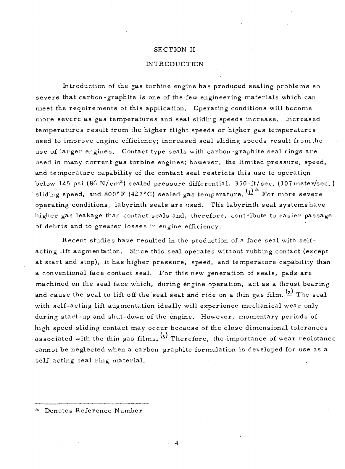
Several major processing problems resulted
from
the use of the
furfuryl
alcohol-Bakelite BRP-5095 resin-impregnant.
The
impregnant filled
the
open
porosity
of the
large
1000°C
baked compacts
so
completely that some
of
them
cracked
during
rebaking
as the
volatiles from
the
resin-impregnant tried
to
escape. This problem prevented
the
manufacture
of the
formulation
No. 1Y and
some
of the
formulation
No. 6Y
compacts.
Formulation
No. 1Z was
substituted
for
formulation
No. 1Y. The
resin impregnation
for
formulation
No. 1Z was
applied
to
2800°C
baked compacts
of the
base
material
and was
followed
by a
very
slow rebaking schedule.
Processing problems
also
were encountered during
the
attempt
to
manu-
facture
seal
ring bodies
from
formulation
No. 5Y. The
formulation
No. 5
compacts were prepared
from
one-year-old
mix
remaining
from
one of the
Task
III
formulations.
The
BRB-5095
resin binder
in the mix
apparently
had
deteriorated,
causing most
of the
formulation
No. 5
compacts
to
crack
and
laminate
during baking
to
1000°C.
The
deterioration
of the old mix was
first
noted
during
the
Task
V
screening studies
of
baking techniques. Only
a few
seal
ring bodies
of
formulation
No. 5
were successfully
manufactured
during
Task
VI.
None
of the
compacts were resin-impregnated prior
to
final heat-
treatment
at
2800°C.
Before
testing, some
of the
formulations were
given
the No. 12 L
oxidation
inhibiting
treat.
The
formulation
No.
1Z-1Z1
material
had
comparable mechan-
ical
and
thermal properties
and was at
least
as
oxidation resistant
as a
similar
material
manufactured during Task III. Formulation
No.
6Y-1Z1
material
had
comparable mechanical properties
and
oxidation
resistance_aLong
Iwith
a'higher
thermal
conductivity
and a
lower
coefficient
of
thermal
expansion than those,
of
a
similar
material
manufactured during Task III. These improvements indicate
that
the
materials
manufactured
from
formulations Nos.
1Z-121
and
6Y-121
may
be
better suited
for use as
rings
for
self-acting
seals
than
the
similar
ma-
terials
manufactured during Task III.
SECTION
II
INTRODUCTION
Introduction
of the gas
turbine engine
has
produced
sealing problems
so
severe that carbon-graphite
is one of the few
engineering materials
which
can
meet
the
requirements
of
this application. Operating conditions will become
more severe
as gas
temperatures
and
seal
sliding speeds increase. Increased
temperatures
result
from
the
higher
flight
speeds
or
higher
gas
temperatures
used
to
improve engine
efficiency;
increased
seal
sliding speeds result
fromthe.
use
of
larger
engines. Contact
type
seals
with
carbon-graphite
seal
rings
are
used
in
many current
gas
turbine engines;
however,
the
limited pressure, speed,
and
temperature capability
of the
contact
seal
restricts
this
use to
operation
below
125 psi (86
N/cm
E
)
sealed pressure
differential,
350-ft/sec.
(107 meter/sec.
)
/
) *
sliding speed,
and
800°F
(427°C)
sealed
gas
temperature.
— For
more severe
operating conditions, labyrinth
seals
are
used.
The
labyrinth
seal
systems have
higher
gas
leakage than contact
seals
and, therefore, contribute
to
easier
passage
of
debris
and to
greater
losses
in
engine
efficiency.
Recent
studies have resulted
in the
production
of a
face
seal
with
self-
acting
lift
augmentation. Since this
seal
operates
without
rubbing contact
(except
at
start
and
stop),
it has
higher pressure, speed,
and
temperature capability than
a
conventional face contact
seal.
For
this
new
generation
of
seals,
pads
are
machined
on the
seal
face
which,
during
engine operation,
act as a
thrust bearing
and
cause
the
seal
to
lift
off the
seal
seat
and
ride
on a
thin
gas
film.
— The
seal
with
self-acting
lift
augmentation ideally will experience mechanical wear
only
during
start-up
and
shut-down
of the
engine.
However,
momentary periods
of
high speed sliding contact
may
occur because
of the
close dimensional tolerances
associated
with
the
thin
gas
films.
-^
Therefore,
the
importance
of
wear resistance
cannot
be
neglected when
a
carbon-graphite formulation
is
developed
for use as a
self-acting
seal
ring
material.
*
Denotes Reference Number
High
hardness, strength,
and
modulus,
together with
the
proper selection
of
impregnants
and
mating
materials,
are
necessary
for
producing wear
resist-
ant
carbon-graphite
seal
ring
materials.
—
Increased" oxidation
resistance
will
become
a
major requirement
of
carbon-graphite
seal
rings
as
engine
gas
tem-
peratures
rise
to
1200°F
(649°C)
and
above. Development
of
improved carbon-
graphite
seal
ring
materials
which
can
operate
in
ambient
air
temperatures
up
to
1300°F
(704°
C)
will make feasible
seal
designs which will contribute
to im-
provements
in
engine performance.
Conventional
carbon-graphite
seal
ring
materials
are
prepared
by
mix-
ing
selected sizes
and
types
of
carbon
and
graphite fillers
with
a
binder such
as
coal
tar
pitch.
The
mixtures
are
formed
into
compacts
and
baked
to
tem-
peratures
which
are
adjusted
to
produce
the
desired physical properties
of the
finished
material.
Usually,
the
finished carbon-graphite
seal
ring contains
additives
or
impregnants which help
the
seal
to
meet particular performance
requirements (e.g., oxidation resistance). Specific
raw
materials
or
process-
ing
techniques
are
employed
to
obtain desired properties
of the
finished car-
bon-graphite
material.
Detailed descriptions
of the raw
materials
and
processes employed specifically
for the
preparation
of
carbon-graphite
seal
rings
are not
available
in the
literature.
Topical Report
NASA
CR-72799
-
covered
the
work
done
duringTasks
I
and II of
this Contract. Task
I
included
a
literature
search
for
information
relevant
to
carbon -graphite
materials
for
high-temperature
seal
ring applications.
Task
I
also
provided
for
selection
of
four
particulate
and
four
binder
raw
mate-
rials
for
experimental studies
and for the
selection, preparation,
and
screen
testing
of 12
material
systems. Forty-seven material/process subsystems
were
produced
and
evaluated
to
optimize
the
selected
12
material
systems.
Small
compacts measuring
2. 5
inch
x 1. 25
inch
x 1. 0
inch
(6.
35 cm x 3. 18 cm x 2. 54 cm)
were
prepared
from
the 12
optimized
material
systems
and
used
for all the
screen studies
conducted
during
Task
I. The
screen
testing
of the
compacts
of the 12
optimized
material
systems consisted
of
meas-
uring
their
bulk densities, flexural strengths,
and
hardnesses
at
room tempera-
ture
and
their
oxidation
rates
in air at
1300°F
(704°C).
The
experience gained during Task
I was
used
to
select
four
approaches
to the
manufacture
of
seal
ring carbon-graphite bodies during
Task
II.
Tests
indicated that
the
compacts prepared during
the
screen testing were significantly
more oxidation
resistant
than commercial
seal
ring Grade CDJ. Since
seal
ring
materials
must
be
made
as
strong
and
wear resistant
as
possible,
the
four
for-
mulations
that
would
produce
materials
with
the
best
combination
of
strength,
hardness,
and
oxidation resistance were selected.
Topical Report
NASA
CR-72986^-' covered
the
work
done
during Tasks
III
and IV of
this Contract. Task
III
included
the
manufacture
of
carbon-graphite
seal
ring bodies
from
the
four
formulations selected during Task
II. The
number,
size,
and
shape
of
these bodies were determined
by the
delivery requirements
of
Task
III and the
testing requirements
of
Task
IV.
Seven
materials
were ultimately
produced
during
Task
III:
the
selected
four
formulations
and a
second version
for
three
of
those formulations
in
which
the
1000°C
baked compacts were impregnated
with
a
phenolic
resin
prior
to
final heat treatment
at
2800°
C.
During
Task
IV,
four
of the
seven
materials
manufactured under Task
III
were selected
and
their
material
properties determined.
The
selection
was
based
on the
preliminary
mechanical property measurements made
on all
seven
materials.
This
Topical Report covers-Tasks
.V, VI, and VII of the
Contract.
The
scope
of
work
for
Task
V
consisted
of the
screen testing
of up to
eight
material/
process
systems
or
subsystems
for the
purpose
of
optimizing
the
particulate
systems, binder concentrations, carbonizable impregnants,
and
processing
techniques studied during Tasks
I
through
IV. The
experience gained during
the
Task
V
screening studies
was
used
to
select
three approaches
to the
manu-
facture
of
seal
ring
carbon-graphite
bodies with improved
properties.
Seal
ring
bodies were manufactured
during
Task
VI, but
processing problems necessitated
some
modification
of the
formulations. Selected
material
properties were
determined
for the
manufactured
materials
during
Task VII.
SECTION
III
CONCLUSIONS
1.
Improvements
in
mechanical properties anticipated
from
the
screen-
ing
studies were
not
realized
because
of
processing problems encountered during
scale-up
in
material
size.
Problems
Included
rupture
and
chipping
of
compacts
during
pyrolysis
of a
furfuryl
alcohol-phenolic resin^impregnant
and
lamination
during
baking
of
compacts
bonded
with
a
phenolic
resin.
2.
Pressure
curing
and
pressure baking
of a
phenolic resin-bonded
carbon-graphite
material
effects
improved
mechanical
properties.
3. A
phenolic resin-bonded,carbon-graphite
material
prepared with
chopped
graphite yarn
has
better mechanical
and
thermal
properties than
a
similar
material
prepared with chopped graphite cloth.
4.
The
materials
manufactured
from
formulations Nos.
1Z
(pitch binder)
and 6Y
(phenolic
resin
binder)
show
potential
as
useful
primary rings
for
self-
acting
seals.
.
Both formulations incorporate artificial graphite
as the
major
filler
component
(80
weight percent);
the
former contains
furnace
black
and the
latter
chopped graphite yarn
as the
minor filler component
(20
weight percent).
A
furfuryl
alcohol-phenolic
resin
impregnant
is
Introduced
prior
to
final heat-
treatment
at
2800°C.
SECTION
IV
SCREENING
STUDIES
AND
SEAL
RING
CARBON-GRAPHITE
MATERIAL
FORMULATION
(TASK
V)
A.
Screening Studies
The
carbon-graphite
seal
ring materials
developed
during
Tasks
I
through
IV
——
of
this Contract (Table
I)
have oxidation resistance several
times greater than that
of a
widely
used commercial grade,
but
their flex-
ural
strengths
are 40 to
50.percent lower than that
of the
commercial grade.
These oxidation
resistant
carbon-graphite materials were
developed
.for
use
as
self-acting
seal
rings.
Since self-acting
seals
normally employ metal
-
retaining bands,
the
strengths
of
these materials were
judged
acceptable.
Erosion resistance
may
also
be an
important requirement
for
self-acting
seal
materials.
.
Debris passing
through
the gas
film
formed
between
the
sealing
dam and the
seat
is
responsible
for the
erosion
of the
seal
face.
In-
creases
In
strength
would
mitigate
the
necessity
of
metal-retaining
bands
and
increases
in
hardness
would
improve erosion resistance. These
im-
provements
would
enable broader application
of the
carbon-graphite
seal
ring materials.
The
purpose
of
this phase
of the
Contract
was
thus
to im-
prove
the
uniformity,
strength,
and
hardness
of the
materials
manufactured
during
Task
III
—while
maintaining
or
improving
their oxidation resistance.
Included
in the new
effort
was a
review
and
analysis
of the
previous
Contract
work
and a
screening
study
to
optimize
the
particulate systems, binder con-
centrations, carbonizable impregnants,
and
processing
techniques
studied
during
Tasks
I
through.IV.
^-'^
The
Task
V
screening
study
consisted
of
three
parts.
A
study
of
vari-
ous
resin impregnants
and
baking techniques comprised
the
first
two
parts.
The
third part consisted
of the
manufacture
and
characterization
of
five
ma-
terial
subsystems aimed
at
improving
the
uniformity
and
properties
of the
formulation
No. 4
material.
The
composition
of the
formulation
No. 4 ma-
terial,
along
with
those
of the
other materials
produced
during Task III,
—is
displayed
in
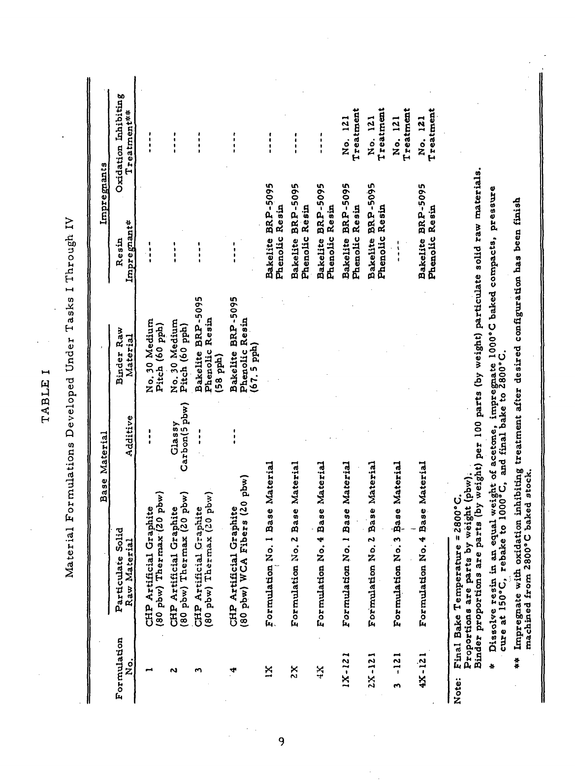
Table
I. All the
materials
presented
in
Table
I
were
manufactured
from
particulate
and
binder
raw
materials that
had
been characterized
during
Task
I.
*-§-'
The
results
for the
characterization
of the raw
materials also
are in-
cluded
in
this section
of the
report. Descriptions
of the
test procedures
used
to
characterize
the raw
materials
are
presented
in
Appendix
I.
8
w
n
I
Through
tn
x
to
ri
H
IH
(11
Uf'
"T3
G
t—
i
3
T3
0)
P-.
o
i
— i
(U
>
D
Q
(0
a
O
.^4
4-1
n)
-3
6
^
0
Cl4
HH
I—
1
Materia
0)
4J
r*
a
g
4)
In
a
6
M
'
t—
1
•t-f
t
.
M
4)
4_>
4)
CO
(4
m
bo
a
It
•r*
-*
1
•9
fi
^
4>
a c
a
«
O fl)
•H
«
rt **
•OH
•g
^
0
*
4J
C!
Resin
Impregnai
1*
K -H
h
^ 11)
a -M
•a «)
r>
"*1
.52
n
4)
+1
•
iH
•a
t^
<;
•o
Particulate
Soli
Raw
Material
a
o
•a
a •
7}
0
22
6
M
O
(K
i i i
i
i i
i i i
i i i
i i i
i i i
i i i
i i i
m
0^
o
in
S?
Ssr&-
.a lv .ri PI ed 4>
•b o, -o o^ Js oJ
4>
a)
W
"
*^
O M O M
A O
t&
*O
* .S •"»
o*"T
o""T
a o "p.
#r\
^ . *A J%
«%
^4 n.
u
y S S **
o'S o'S
•3JS*
20,
20,
«0,£.
?
>.-8.
•
mm,
01 •—
•
[
: ^g ;
o-e
M
n)
U
777
j> _Q _r>
£U «» P. «cL
jj| O "rt O JS O
p.Ci
p-2.
p<Ci
CHP
Artificial
Gra
(80
pbw) Thermax
CHP
Artificial
Gra
(80
pbw) Thermax
CHP
Artificial
Gra
(80
pbw)
Thermax
•-i M m
r
i
i
i
i
i
i
in
o^
0
in
a[
no!.-.
»j
'5S
4)
JJ Pi
3o£
41
rl "^
S
§ .
3.3s
«0,S
t
|
I
*—
•,
?
jD
P.
O
«JCi
S
J3 w
•Pi l-i
CHP
Artificial
Gra
(80
pbw)
WCA
Fibe
•*
i
i
t
i
in
o^
o
2'-a
0, w
SB!
Bakelite
Phenolic
3
M
4)
i
4)
0)
R)
«
Formulation
No. 1
i
X
•—
4
| |
| |
|
|
1 1
in in
0* O
1
*
o
o
^3^3
o,
« o, 5
Qj
4) oj 4)
goS
§o!
4)
O 41 O
a
a a a
a o a o
|8 |8
CQ
o, n o.
/*
?
Vi °M
4) 4)
44
4J
j3
,fl|
4) 4)
01 01
(4
ft
« n
Formulation
No. 2
Formulation
No. 4
X X
M
-r
^
M H
- B
4J
• ri
O 4)
2
h
H
in
c»
o
2«
Q>
4)
gas
Bakelite
Phenolic
3
't,
S
1
Q)
0)
(4
m
Formulation
No, 1
i**
t\.\
r\i
*««
|
X
^H
+*
ss
M f«
-
E
44
• n)
O 4)
2
M
H
in
•<t»
0
i-l
S2
Bakelite
Phenolic
•a
*r1
t,
4)
•f^
4)
01
<tf
«
Formulation
No. 2
«^4
fO
r*4
—
<
1
X
rg
44
-8
M .4
- E
44
• rt
0 4)
2 *
H
i
i
i
i
3
14
4)
+*
4)
m
d
-«-
-
Formulation
No. 3
fM
r-4
|
c<>
a?'
M r*
- E
44
• R>
0 V
Z
*
H
in
w>
o
2*
0,
«
3 2
Bakelite
Phenolic
3
M
4)
i
4)
m
n)
ffl
Formulation
No. 4
1-4
CNJ
'<»^
1
5
0)
1 g
S 3 .a
ri
01
n
8
s a
... M «M
£
ft
a
2 • «
o> 4>
•o
*», *
•rt U
If
I
II 'S
3
7 -S
13 IL
iS
1
—
* o O
"0 0
•So _
«M)
0 . "O
•2
^
c
i »
4)
v •-
? 4)° -H
i5 O 0)
X n) O 4)
£.
B,
0
^
^
*—
borj
«]
H
2 2° <S
^
p,*^
G
'
a. 6js *
i* .5 -5 44
o .Jo S
-^ *
*>**
M
2
S-a
i
K
™ £
M
K d • 'tt
MI
** ,3 Iw
S 4) !« 4>
°«'
y_, fc
—
d
^ **
tj
>4J
5 so .;
-^•§)
0 S -{j
^ -rt 4* " '-B n
&
S 5
u
*s
*•
u
-S?
* .?o * «
U
!».
d>
S J3 T)
05* »0 .S«
^^ ^J
ZL"~'-
^ ^^ *r< L/
O
hjn^^
^H
«•**
•
UU
j *^ ^ VIJ
en
*H m t! H ™
•S-s?
5s
.1^4
Bake
Temperature
=
rtions
are
parts
by w
r
proportions
are pai
i
solve
resin,
in an eqi
re at 150 "C,
rebake
1
ipregnate
with
oxidati
ichined
from
2800°
C
•a
S.-8
S 6 a a
TO
,v
" ^^ ^*
.5 2 .3 • » •
fe 0,
(Q
# #
4)
^J
0
2
Some
of the
carbon-graphite
materials
produced
during
the
Task
V
screening study employed
two
particulate
raw
materials
which
had
previously
not
been
used
during
the
Contract work.
The two new raw
materials
were
Grade VEA. carbon fibers
and
Grade'WFA graphite fibers. Both types
of
fibers
are
produced
by
pyrolyzing
continuous
filament rayon yarn which
is
subsequently
chopped
to the
desired lengths.
The
fibers previously used
for
the
Contract work were prepared
from
Grade
WCA
graphite cloth which
is
produced
by the
pyrolysis
of
rayon
cloth.
Although
the two new
types
of
fibers
were
not
characterized
during
Task
V,
some
of
their
properties were obtained
from
"Union Carbide Corporation Technical Information Bulletin
No.
465-213 cj."
The
brochure
lists
a
density
(water
immersion)
of 1". 8
g/cc and.a weight percent
ash of 0. 8 for the
Grade
VFA
carbon fibers. Grade.
WFA
graphite fibers
are
reported
to
have
a
density (water immersion
) of 1.4
g/cc,
a
surface
area
of
2m
2
/g, and.
a
weight percent
ash of 0. 01.
10
1.
Union
Carbide Corporation Grade
CHP
Artificial Graphite
Helium
Density
=
2.22 g/cc
Surface
Area
= 6.7
m
2
/g
Chemical
Analysis
%
Ash =
0.066
%
Moisture
=
0.039
Emission Spectrographic
Analysis
(Semi-Quantitative)
Screen Analysis
On 35
mesh
= 0%
On 65
mesh
= 0%
On
100
mesh
= 0%
On
150
mesh
=
0.08%
On
200
mesh
=
3.30%
On
Pan =
96.62%
Al
Ti
V
Fe
Ni
Cr
Si
Ca
Mg
Pb
Sn
Ag
B
Na
Cu
7 ppm
37
ppm
23
ppm
44
ppm
5 ppm
5
ppm
60
ppm
162 ppm
5
ppm
5
ppm
5
ppm
5
ppm
6 ppm
5
ppm
5
ppm
11
2.
Commercial Solvents Corporation Thermax Furnace Black
Helium Density
=1.84 g/cc
Surface Area
= 8.1
m
2
/g
Screen Analysis*
On
35
mesh
=
3.97%
On
65
mesh
=
36.91%
On
100
mesh
=
15.74%
On
150
mesh
=
13.44%
On
200
mesh
=
10.84%
On
Pan =
19.10%
Chemical
Analysis
%
Ash
=0.022
%
Moisture
=
0.027
Emission Spectrographic
Analysis
(Semi-Quantitative)
Al <
Ti <
V <
Fe <
Ni <
Cr <
Si
=
Ca
=
Mg
=
Pb
=
Sn <
Ag <
B =
Na
=
Cu <
5
5
5
5
5
5
33
11
5
5
5
5
5
23
5
ppm
ppm
ppm
ppm
ppm
ppm
ppm
ppm
ppm
ppm
ppm
ppm
ppm
ppm
ppm
* The
presence
of
aggregates
appears
to
have
a
significant
effect
on the
results
of the
screen
analysis.
12
3.
Lockheed
Company
LMSC
Glassy Carbon
(Ground)
Helium
Density
=
1.91
g/cc*
Surface
Area
= 5.6
m
2
/g
Screen Analysis
On 35
mesh
= 0%
On 65
mesh
= 0%
On 100
mesh
=
0.41%
On
150
mesh
=
18.42%
On 200
mesh
=
21.98%
On Pan =
59.19%
Chemical
Analysis
%
Ash
=0.92
%
Moisture =0.85
Emission
Spectrographic
Analysis (Qualitative)**
+
Major-
+
Minor-
+
Trace-
•Fe
Cr
Ni
Mn
Sn->-
Si
Al
Ca
Cu
Mg
Ag-
* A
prolonged period
was
required
for the
Beckman
pycnometer
to
reach equilibrium conditions and,
therefore,
the
results
are
questionable.
** No
standards
available
to run
semi-quantitative
analysis.
13
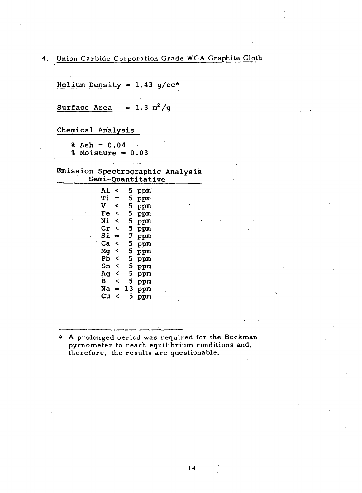
4.
Union
Carbide Corporation Grade
WCA
Graphite Cloth
Helium
Density
=
1.43
g/cc*
Surface
Area
= 1.3
m
2
/g
Chemical
Analysis
%
Ash
=0.04
-
%
Moisture
=
0.03
Emission
Spectrographic
Analysis
Semi-Quantitative
Al <
Ti
=
V <
Fe <
Ni <
Cr <
Si
=
Ca <
Mg <
Pb <
Sn <
Ag <
B <
Na
=
Cu <
5
5
5
5
5
5
7
5
5
5
5
5
5
13
5
ppm
ppm
ppm
ppm
ppm
ppm
ppm
ppm
ppm
ppm
ppm
ppm
ppm
ppm
ppm.
* A
prolonged period
was
required
for the
Beckman
pycnometer
to
reach
equilibrium conditions and,
therefore,
the
results
are
questionable.
14
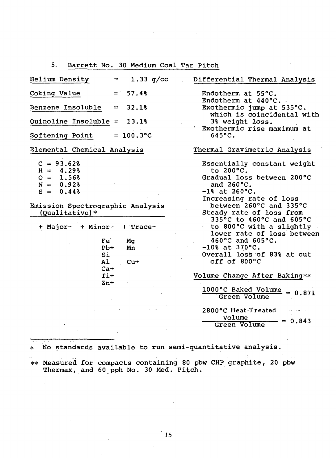
5.
Barrett
No. 30
Medium Coal
Tar
Pitch
Helium
Density
=
1.33 g/cc
Coking Value
=
57.4%
Benzene Insoluble
=
32.1%
Quinoline Insoluble
=
13.1%
Softening Point
=
100.3°C
Elemental Chemical Analysis
C =
93.62%
H =
4.29%
0 =
1.56%
N
=
0.92%
S =
0.44%
Emission Spectrographic Analysis
(Qualitative)*
+
Major-
+
Minor-
+
Trace-
Fe
Pb-»-
Si
Al
Ca->-
Zn->-
Mg
Mn
Cu-*-
Differential
Thermal Analysis
Endotherm
at
55°C.
Endotherm
at
440°C.
Exothermic jump
at
535°C.
which
is
coincidental with
3%
weight
loss.
Exothermic rise maximum
at
645°C.
Thermal Gravimetric Analysis
Essentially
constant weight
to
200°C.
Gradual loss between 200°C
and
260°C.
-1%
at
260°C.
Increasing rate
of
loss
between 260°C
and
335°C
Steady
rate
of
loss from
335°C
to
460°C
and
605°C
to
800°C with
a
slightly
lower rate
of
loss between
460°C
and
605°C.
-10%
at
370°C.
Overall loss
of 83% at cut
off of
800°C
Volume Change After Baking**
1000°C
Baked Volume
Green Volume
2800°C
He
at-Treated
Volume
Green Volume
=
0.871
=
0.843
* No
standards available
to run
semi-quantitative analysis.
**
Measured
for
compacts containing
80 pbw CHP
graphite,
20 pbw
Thermax,
and 60 pph No. 30
Med. Pitch.
15

6.
Bakelite BRP-5095 Phenol-formaldehyde Resin
Helium
Density
=
1.28 g/cc
Coking Value
=
65.4%
Elemental Chemical Analysis
C =
75.86%
H =
6.13%
0 =
16.80%
N
=
2.44%
S =
None
Emission Spectrographic Analysis
(Qualitative)*
+
Major- +Minor-
Si-
Mg
•fTrace-
t-Fe
Cu
Al
«-Ni
Cr-»-
Mn-»-
'Differential Thermal
Analysis
.
Small
exotherm
at
165°C
which
is
just
at the
beginning
of 5%
weight
loss.
Very
broad exothermic rise
beginning
at
540°C.
Thermal Gravimetric Analysis
Essentially constant
weight
to
160°C.
Gradual loss between
160°C
and
265°C.
Plateau between 265°C
and
370°C
at
approximately
5%
loss.
-10%
at
445°C.
Steady loss between 370°C
and
540°0....
Increasing rate
of
less
to
600°C.
Steady
loss rate
to cut
off
at
750°C.
Overall loss
of 88% at
cut
off of
750°C.
Volume Change After Baking**
1000°C
Baked Volume
Green Volume
2800°C
Heat Treated
Volume
Green
Volume
=
0.704
0.649
* No
standards available
to run
semi-quantitative analysis.
**
Measured
for
compacts containing
80 pbw CHP
graphite,
20 pbw
Thermax,
and 58 pph
Bakelite
BRP
5095 resin.
16
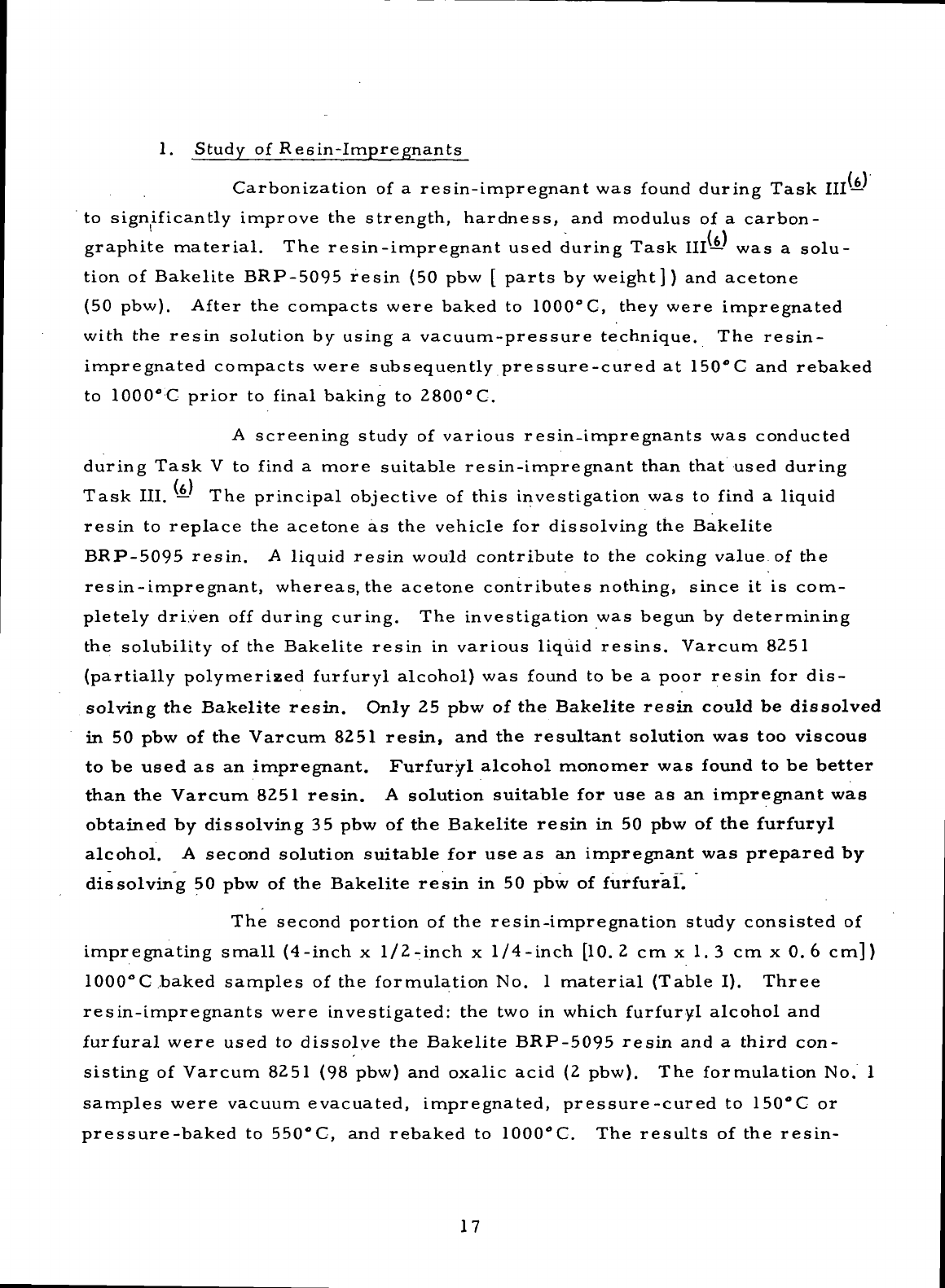
1.
Study
of
Resin-impregnants
Carbonization
of a
resin-impregnant
was
found
during
Task
III
—
to
significantly improve
the
strength,
hardness,
and
modulus
of a
carbon-
1
t \
graphite
material.
The
resin-impregnant used during
Task
III—
was a
solu-
tion
of
Bakelite BRP-5095
resin
(50 pbw [
parts
by
weight])
and
acetone
(50
pbw).
After
the
compacts were baked
to
1000°C,
they were impregnated
with
the
resin
solution
by
using
a
vacuum-pressure technique.
The
resin-
impregnated compacts were subsequently pressure-cured
at
150°C
and
rebaked
to
1000°
C
prior
to
final
baking
to
2800°
C.
A
screening
study
of
various resin-impregnants
was
conducted
during
Task
V to
find
a
more
suitable
resin-impregnant than that used during
Task
III.
— The
principal objective
of
this
investigation
was to
find
a
liquid
resin
to
replace
the
acetone
as the
vehicle
for
dissolving
the
Bakelite
BRP-5095
resin.
A
liquid
resin
would
contribute
to the
coking value
of the
resin-impregnant, whereas,
the
acetone contributes nothing,
since
it is
com-
pletely driven
off
during curing.
The
investigation
was
begun
by
determining
the
solubility
of the
Bakelite
resin
in
various liquid
resins.
Varcum 8251
(partially polymerized
furfuryl
alcohol)
was
found
to be a
poor
resin
for
dis-
solving
the
Bakelite
resin.
Only
25 pbw of the
Bakelite
resin
could
be
dissolved
in 50 pbw of the
Varcum
8251
resin,
and the
resultant
solution
was too
viscous
to be
used
as an
impregnant.
Furfuryl
alcohol
monomer
was
found
to be
better
than
the
Varcum
8251
resin.
A
solution
suitable
for use as an
impregnant
was
obtained
by
dissolving
35 pbw of the
Bakelite
resin
in 50 pbw of the
furfuryl
alcohol.
A
second
solution
suitable
for use as an
impregnant
was
prepared
by
dissolving
50 pbw of the
Bakelite
resin
in 50 pbw of
furfural.
The
second portion
of the
resin-impregnation study consisted
of
impregnating
small
(4
-inch
x 1/2
-inch
x
1/4-inch [10.2
cmx 1.3
cmxO.6 cm])
1000°C,baked
samples
of the
formulation
No. 1
material
(Table
I).
Three
resin-impregnants were investigated:
the two in
which
furfuryl
alcohol
and
furfural
were used
to
dissolve
the
Bakelite
BRP-5095
resin
and a
third con-
sisting
of
Varcum 8251
(98
pbw)
and
oxalic
acid
(2
pbw).
The
formulation
No. 1
samples
were vacuum evacuated, impregnated, pressure-cured
to
150°C
or
pressure-baked
to
550°C,
and
rebaked
to
1000°C.
The
results
of the
resin-
17
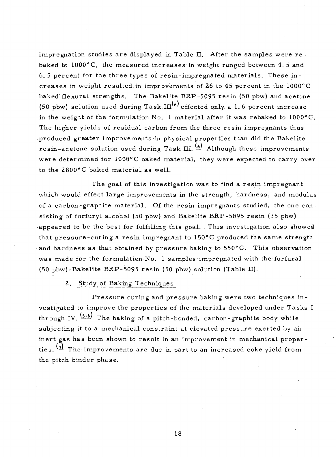
impregnation studies
are
displayed
in
Table
II.
After
the
samples, were
re-
baked
to
1000°Cj
the
measured
increases
in
weight ranged between
4. 5 and
6.
5
percent
for the
three
types
of
resin-impregnated
materials.
These
in-
creases
in
weight resulted.in improvements
of 26 to 45
percent
in the
1000°C
baked"flexural
strengths.
The
Bakelite BRP-5095
resin
(50
pbw)
and
acetone
(50
pbw) solution used during
Task
III—
effected
only
a 1.6
percent increase
in the
weight
of the
formulation
No. 1
material
after
it was
rebaked
to
1000°C.
The
higher yields
of
residual carbon
from
the
three
resin impregnants thus
produced
greater
improvements
in
physical properties than
did the
Bakelite
resin-acetone
solution used during Task
III.
—
Although these improvements
were determined
for
1000°C
baked
material,
they were expected
to
carry
over
to
the
2800°C
baked
material
as
well.
The
goal
of
this investigation
was to
find
a
resin
impregnaht
which
would
effect
large
improvements
in the
strength, hardness,
and
modulus
of
a
carbon-graphite
material.
Of the
resin
impregnants studied,
the one
con-
sisting
of
furfuryl
alcohol
(50
pbw)
and
Bakelite BRP-5095
resin
(35
pbw)
•appeared
to be the
best
for
fulfilling
this goal.
This
investigation
also
showed
that
pressure-curing
a
resin
impregnant
to
150°C
produced
the
same
strength
and
hardness
as
that obtained
by
pressure baking
to
550"C. This observation
was
made
for the
formulation
No. 1
samples
impregnated
with
the
furfural
(50
pbw)-Bakelite BRP-5095
resin
(50
pbw) solution (Table
II).
2.
Study
of
Baking Techniques
Pressure
curing
and
pressure baking were
two
techniques
in-
vestigated
to
improve
the
properties
of the
materials
developed
under
Tasks
I
through
IV.
——
The
baking
of a
pitch-bonded, carbon-graphite
body
while
subjecting
it to a
mechanical constraint
at
elevated pressure exerted
by ah
inert
gas has
been
shown
to
result
in an
improvement
in
mechanical
proper-
ties.
— The
improvements
are due in
part
to an
increased coke yield
from
the
pitch binder
phase.
18

TABLE
II
Mechanical
Properties
- Re
sin-Impregnated
Materials
1000°C
Baked
Density
(g/cc)
Flexural
(psi)
Strength
(N/cm
2
)
Rockwell
Rs
Hardness
Rm
Formulation
No.
1-No Impregnant
Maximum
Minimum
Average
Standard Deviation
n
1.657
1.650
1.653
0.003
4
5430
4880
5170
231
4
3740
3360
3560
159
4
97
94
96
1
8
61
55
59
2
8
Formulation
No.
1-Impregnated With Varcum 8251
(98
pbw)
+
Oxalic
Acid
(2
pbw)-Pressure Cured
Prior
to
Baking
to
lOOO'C
Maximum
1. 750
Minimum
1. 722
Average
1. 742
Standard Deviation
0. 013
7350
6150
6750
556
4
5060
4240
4650
383
4
118
116
117
1
8
Formulation
No.
1-Impregnated
With
Furfuryl Alcohol
(50
pbw)
+
Bakelite
BRP-5095
(35
pbw)-Pressure Cured
Prior
to
Baking
to
1000
0
C
Maximum
Minimum
Average
Standard Deviation
n
1. 748
1. 740
1.744
0. 004
4
7890
7160
7500
301
4
5440
4930
5170
207
4
116
108
114
3
8
Formulation
No.
1-Impregnated
With
Furfural
(50
pbw)
+
Bakelite BRP-5095
(50
pbw)-Pressure Cured
to
150"C
Prior
to
Baking
to
1000°C
Maximum
Minimum
Average
Standard Deviation
n
1.759
1. 754
1. 757
0.002
4
7050
6080
6510
411
4
4860
4190
4490
283
4
118
116
117
1
8
Formulation
No.
1-Impregnated
With
Furfural
(50
pbw)
+
Bakelite BRP-5095
(50
pbw)-Pressure Baked
to
550"C
Prior
to
Baking
to
1000"C
Maximum
Minimum
Average
Standard Deviation
n
1. 767
1. 763
1. 765
0. 002
4
7250
5740
6510
641
4
5000
3950
4490
442
4
-
-118
116
117
1
8
99
94
96
2
8
96
88
95
3
8
98
96
97
1
8
99
96
98
1
8
Note:
Density, flexural strength,
and
hardness measured
on
1/4"
x
1/2"
x 4"
(0.
6 cm x 1. 3 cm x 10. 2 cm)
samples.
Flexural
samples broken
on 1.
875"
(4.
76 cm)
span.
R
6
Scale
-
1/2" (1.3
cm)
Diameter
ball
and 100 Kg
Maj.
load.
Two
readings
per
sample.
R
m
Scale
=
1/4" (0.6
cm)
Diameter
ball
and 100 Kg
Maj. Load.
Two
readings
per
sample.
Pressure-curing
done
using
100
psig Air. While under
pressure,
temperature
maintained
for 1
hour
at
125°C
and 1
hour
at
150°C.
During
pressure-baking, temperature rushed
to
150°C,
followed
by a
10°C/hour
rate
between
150°C
and
550°C.
Temperature held
4
hours
at
550°C.
19
During
the
Task'V
baking.studies,-,.
the
.one-year -old
r,e,sinrhorid:e.d
formulation
No. 3 mix
(Table
I)
remaining
from
Task
III—
was
used. Twelve
green compacts measuring
2.
5-inch
x 1.
25-inch
x 1.
0-inch
(6.
35 cm x 3. 18 cm x 2. 54 cm)
were molded from
the
formulation
No. 3
mix.
The
compacts were molded
to a
green bulk density range
of
1.400
to
1.415 g/cc,
a
range
which
had
been determined during Task
III—
to be the
optimum molding
condition
for the
formulation
No. 3
material. Four
of the
green compacts sub-
sequently were pressure-cured
at
150°C
and
four
were pressure-baked
to
550°C,
These
eight compacts
and the
remaining
four
green compacts were then baked
to
1000°C
by
employing
the
standard packing procedure-and baking schedule
(10°C/hr)
used
to
bake
the
formulation
No. 3
material
during Task III.
^—'
The
twelver"
compacts were
not
baked
to
2800°C
but, .instead, were analyzed after
they
had
been baked
to
1000°C.
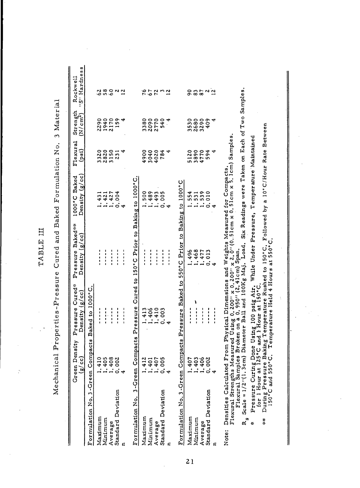
The
mechanical properties
of the
three
variations
of the
formu-
lation
No. 3
material
are
displayed
in
Table
III.
The
results
show
that both
the
pressure-curing
and
pressure-baking techniques yielded
improved
mechanical
properties.
Incorporation
of the two
techniques
into
the
processing
of the
for-
mulation
No. 3
material
resulted
in
increased coke yields
and
greater shrinkage
during
baking, both
of
which contributed
to the
improvements
in
mechanical
properties. However,
the
pressure baking
to
550°C
prior
to
baking
to
1000°C
resulted
in the
greater
improvement.
The
results presented
in
Table
III do
show
the
benefits
of em-
ploying
pressure baking,
but the
1000°C
baked density listed
for the
formulation
No.
3
standards
was
much lower than that
(1. 519
g/cc) measured
for the
same
material
during
Task
III.
— The
reduction
in
baked density indicated that
the
resin
in the
formulation
No. 3 mix may
have deteriorated during
the
one-year
period between
mix
manufacture (Task
III
—)
and the
Task
V
work.
20
r—
1
'£n
1)
nj
^
^
ro
o"
z
f—t
j
o
C^J
i~i
^
£
M
O
f
T1
T3
<l)
«J
pQ
»—
l
r"j
'U
M
c
W "*
•-] T3
rn a)
s s
^ u
D
0
^J
w
tn
Mechanical
Properties -Pre
0)
01
(1)
1 s
o _
/y* -•
Z
•fi-p
ec
Q)
O
4-1
^
w ^^
•3
P
-rH*
X 0)
4)
Pi
S
~
^^
^
'O O
(U
U
n)
^bj
W
^
."ti
0
0)
§g
"°
#
#
*o
^^
&
°
rt -^
(Q cm
" !>,
O)
0)
01 fl
(1)
4)
M
Q
pL)
TI
Green Density
Pressure
Cure
(g/cc)
Density (g/cc
0
n
No.
3-Green Compacts Baked
to
1000°
0
4J
R)
-3
g
M
O
fa
(M
OO O M
<VJ
vo in
v£>
—
O O O O
Tf
0
s
TI*
r—
in
cj ov
•—
'
•—
•
rg —i i\j
o o o -i •*
CM
rj in co
ro oo
«—
*
co
CO INJ CO
•
U
o
o
co
ro rj O ^
^J*
T}* ^* O
. . . • O
^
—
i
rt o
Tt<
*•
M
.S
nJ
m
o
h
•
lH
rt
0
o
in
t
O
T3
A\
1.410
1.405
1.408
aviation
0. 002
4
n No.
3-Green Compacts
Pressure
Cur<
P -2
§S
«iJ 3
2 =» S>H "3
|
-H
£
-S
1
ri J > J o
<5
*5 •< W C ti
xO
t- rq co M
t—
\o r-
—
<
o o o o
TJ-
oo
ov r- ^ .
co
o i^ in
co (M CM
O O O Tf
Tj<
O rj« pj oo
cy*
o o
t~~
U
O
O
o 0^
co
in o
o
oo
o^
o o
-H
^" ^ G ^ 0
M
|
n)
CQ
O
4-»
O
,
. . »r4
fc
i
! ! A
' ' ' r 1
i
i i *-*
o
O
in
in
o
•r)
1.412
1.413
1.401
'
1.406
1.407
1.410
aviation
0. 005 0. 003
4 4
n
No.
3-Green Compacts
Pressure
Bake
Q
'•§
ri .5 > § o
S S <! w c fo
O co
f—
c\l r4 oi
o- oo oo —i <u
r-H
a
g
rd
o
O
O O 0
s
^ j>
f)
GO
C^ O ^ r*
m o r\j T|* f-« .n
eo
rM
ft ^ JJ
en
'O ^
1 1 .9 «
OOO^^}*
C U-) 4^ <U
(\j
o^ I
s
* 0
s
rt C "*i
in
ro
-ef
^ C) ^ ptj
m
fi § ^
tj •-( *^ LJ o
•4
^ r< *T*
pMn
H -^ \
£ X v n V
O *" «> °
mcoco
1
"
1
vJC > ^ ^-t
ininmo
t,° C
M
•d
o .S -°
« M "° oT -0
5 c 2 § g
co
c pj* QJ ^"
rt
U
(!),_(
<U
'^ ^ (jj
i—
I
^ - CO ^ r
«o
. P* ^o
^S r- 2
*nio
C o T3 o in
^*^o
|
M
'
t
g<
1
-'
|D S^
_,
^
rt
o ^
^^^^.^
jj "*
^ - C j3 *"* P oi
C
o C ^ '^ j.
™
O ° IT T3P
tn
rg r* oo ? <u o
o
OM'
o
h
-
O 2
1.407
1.403
"
1.406
aviation 0.002
4
lities
Calculated
From
Physical
Dimens
ural
Strengths Measured Using 0.200"
x
Flexural
Samples Broken
on a 0.
950"
(
tale
=
1/2"(1.
3cm) Diameter
Ball
and 1(
Pressure
Curing Done Using
100
psig
Ai
for
1
Hour
at
125°C
and I
Hour
at
150'
During
Pressure
Baking Temperature
R
150°
C
arid
550°C.
Temperature Held
uj
y r/i
Q
c
6
g ~
aj
r" ^ *
^^-fljTJ
Q[u C£ &
-!{•
pgbfllj
M
«•«•
•a
.B t. "5 oi
S
-5
§
| S
S S <; w g 2
21
The
pressure baking
(550°C)
analysis discussed thus
far in-
volved
the use of the
small
samples
of the
formulation
No. 3
material.
No
problems were encountered
when
pressure-baking
the
small
samples.
Prob-
lems
occurred during
the
initial
pressure-baking
trials
with
large
compacts
of
the
formulation
No. 3.
material.
Several
of the
5-inch (12.
7 cm)
diameter
greenplugs :and
the
large
green ring blanks molded
from
the
formulation
No. 3
mix
during
Task
111^-'were pressure-baked
to
550°C
during
Task
V.
.All
the
large
compacts were
found
to
have cracked and/or laminated during pressure-
baking,
and
they
all
possessed
a
pungent
odor
characteristic
of
ammonia.
Ammonia
is one of the
compounds
formed
when
the
hexamethylene-tetramine
("hexa") hardening agent reacts
with
the
thermoplastic novolac
of the
first
stage
of the
Bakelite BRP-5095 resin binder
raw
material. Apparently,
the
products
of
reaction were given
off
suddenly
during
pressure-baking, resulting
in
cracking
and
laminating
of the
compacts.
The
large compacts
of the
for-
mulation
No. 3
material
could
be
successfully
pressure-baked
to
550°C
if
they
were
first pressure-cured
at
150°C
for
several hours.
The
pressure-curing
partially
decomposes
the
"hexa"
and
allows
the
reaction
by-products
to be
evolved
without
disrupting
the
internal structure
of the
molded
material.
The
formulation
No. 3
material
had the
lowest
oxidation rate
of
the
carbon-graphite materials characterized
during
Task
TV, — but
its.
mechanical properties
and
related wear resistance were rather poor.
The
results
of the
Task
V
study
of
baking techniques indicated that
the
pressure-
baking might
be
used
to
Improve
the
properties
of the
formulation
No. 3
material
in
spite
of the
apparent resin deterioration. Incorporation
of
pressure-baking
into
the
processing
of the
formulation
No. 3
material
would
increase
the
coke
yield
and
shrinkage
of the
material during baking, thus
producing
an
improvement
in
mechanical properties
and a
reduction
in
total
open
porosity. Increased oxidation resistance
should
result from
the
reduc-
tion
in
total
open porosity.
22
3.
Material
Subsystem
Study
The
compositions
of the
five
material
subsystems analyzed
during
Task
V are
listed
in
Table
IV. The
five
materials
were processed
in
an
attempt
to
optimize
the
composition
of the
formulation
No. 4
base
material
(Table
I).
Specifically, changes
in the
minor filler component
and
binder con-
centration were investigated which could yield improvements
in the
uniformity,
strength, hardness,
and
oxidation
resistance
of the
resultant
material.
All
five
material
subsystems were
similar
to
formulation
No.
4 in
that they included some form
of
fiber
as a
minor filler component.
Grade
WFA
graphite fibers chopped
from
yarn were used
in
subsystems SS-47,
SS-48, SS-49,
and
SS-51
rather
than
the
fibers prepared
from
Grade
WCA
graphite cloth.
The
latter
type
of
fiber
was
used
as the
minor filler component
in the
formulation
No. 4
material.
Subsystem SS-50 incorporated Grade
VFA
chopped
carbon fibers
as the
minor filler component.
The
individual Grade
VFA
and WFA
fiber filaments were approximately 1/4-inch (0.64
cm)
long
prior
to
milling.
Subsystems. SS-47
to
SS-51 were
all
bonded
with
Bakelite
BRP-5095
resin.
Small
green compacts measuring
2.
5-inch
x 1.
25-inch
x
1.0-
inch
(6. 35 cm x 3. 18 cm x 2. 54 cm)
were molded
from
the
mixes manufactured
from
subsystems SS-47
to
SS-51.
After
the
compacts were baked
to
1000°C,
their
bulk densities were measured
and
their
internal
structures examined.
The
1000°C
baked compacts
of
subsystems SS-48, SS-49,
and
SS-51 were
all
found
to be
extremely porous, apparently
due to an
outgassing problem.
This
same
outgassing problem
had
been noted during
Task
I,
\r_but
was
remedied
at
that time
by
revising
the
baking schedule.
The
binder levels
of
subsystems
SS-48, SS-49,
and
SS-51 were apparently
too
high
for the
respective particulate
filler
systems, since
the
revised baking schedule
did not
prevent
the
outgassing
problem. Based
on the
analysis
of the
1000°C
baked compacts, molding
pres-
sures
of
15,000
psiU-Q
340
N/cm
2
)
and 10, 000 psi
(6890
N/cm
2
)
were selected
as
the
optimum molding conditions
for the
SS-47
and
SS-50
materials,
respectively.
The
compacts molded
at
these
pressures were subsequently final baked
to
2800°C.
23
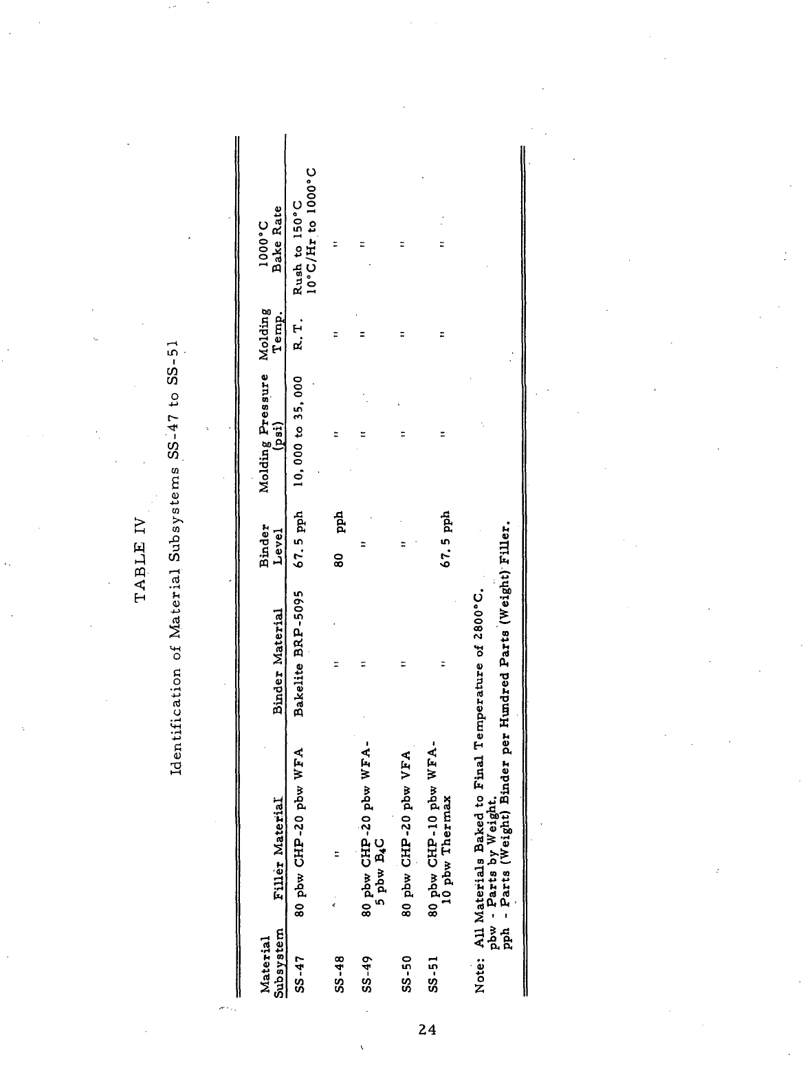
1—
i
w
PQ
H
»—
t
ui
i
CO
co
o
4-J
r~
tt<
co
w.
Cfl
6
(L)
j *
10
>,
CO
,0
3
CO
1—1
flj
• rH
!H
0)
4->
S
<*H
O
C
O
.^
.)-»
Ri
o
VH
JJ
c
<D
TD
i—
(
A)
u *
o a,
-2
&o
.
T3 fi
*o
^
5*
*^
0)
m
(0
*
A^
Mja
T3
f-H
O
S
h
•g
>
.3
«
pq
J
•a
•H
<D
^3
^*
h
0)
'O
.a
rt
.2
1
o
z>
Cxi
'M m
4)
!>
s|
u
o
O
0
"2
o
o
o
in
ii
rt
fc -
2K
IL
H
. . . .
o3
o
o '
0
in
ro
2 = r =
O
o
o
0
1—
I
la "I
in
:
- in
t-'
o f-
\O 00 vO
in
o
m
0,
rt
fl) - - - -
4-*
•—
)
OJ
1
. 1
to to £ to
^ ^ > £
,0 ^) J3 ,O «
O O O O C
M (M (M <-< M
U " U
W
O O ^
^ ^ "n, rO. ^>
&. . (X O< P.O
0 <
0^00^
00
00 00 00
r- oo a- o -H
"^
*^ ^f m in
i
ii ii
W
W W W W
w w tn w to
M
u
a
In
••I
0
$
0 fe
o C-
rS
»
^ •**
*O rt
A)
^H
h *rt
5 ^*
s
1
s.
|
G
<U
h
H S
13
*
to I
°5™
-O
bfi
1
^
•S|9
«t|
m
J2 C-
13
ra n
•rt -M +•
h h M
<u
n) rt
U&&
^ i r
<•§,&
0)
o
Z
24
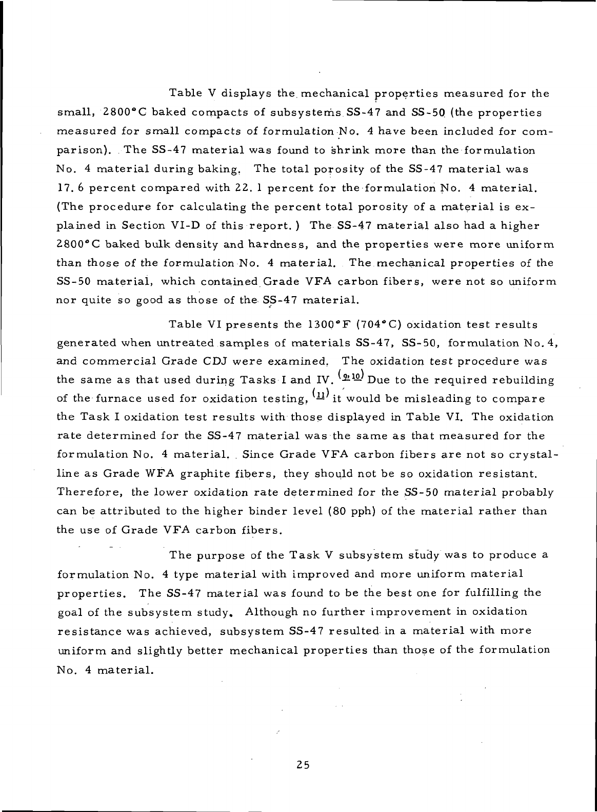
Table
V
displays the.
mechanical
properties measured
for the
small,
2800°C
baked compacts
of
subsystems SS-47
and
SS-5Q
(the properties
measured
for
small
compacts
of
formulation
No. 4
have been included
for
com-
parison).
The
SS-47
material
was
found
to
shrink
more than
the
formulation
No.
4
material
during baking.
The
total porosity
of the
SS-47
material
was
17.
6
percent compared with
22. 1
percent
for the
formulation
No. 4
material.
(The
procedure
for
calculating
the
percent total porosity
of a
material
is ex-
plained
in
Section VI-D
of
this report.
) The
SS-47
material
also
had a
higher
2800°C
baked bulk density
and
hardness,
and the
properties
were
more
uniform
than
those
of the
formulation
No. 4
material.
The
mechanical properties
of the
SS-50
material,
which contained Grade
VFA
carbon fibers, were
not so
uniform
nor
quite
so
good
as
those
of the
SS-47
material.
Table
VI
presents
the
1300°F
(704°C)
oxidation test results
generated
when untreated
samples
of
materials
SS-47, SS-50, formulation
No. 4,
and
commercial Grade
CDJ
were examined.
The
oxidation test procedure
was
the
same
as
that used during
Tasks
I and IV.
-Si
1
—
Due to the
required rebuilding
of
the
furnace used
for
oxidation testing,
— it
would
be
misleading
to
compare
the
Task
I
oxidation test results with those displayed
in
Table
VI. The
oxidation
rate
determined
for the
SS-47
material
was the
same
as
that measured
for the
formulation
No. 4
material.
.
Since Grade
VFA
carbon fibers
are not so
crystal-
line
as
Grade
WFA
graphite fibers, they should
not be so
oxidation resistant.
Therefore,
the
lower oxidation
rate
determined
for the
SS-50
material
probably
can be
attributed
to the
higher binder level
(80
pph)
of the
material
rather
than
the use of
Grade
VFA
carbon fibers.
The
purpose
of the
Task
V
subsystem
study
was to
produce
a
formulation
No. 4
type
material
with improved
and
more uniform
material
properties.
The
SS-47
material
was
found
to be the
best
one for
fulfilling
the
goal
of the
subsystem study. Although
no
further
improvement
in
oxidation
resistance
was
achieved, subsystem SS-47 resulted
in a
material
with more
uniform
and
slightly better mechanical properties than those
of the
formulation
No.
4
material.
25
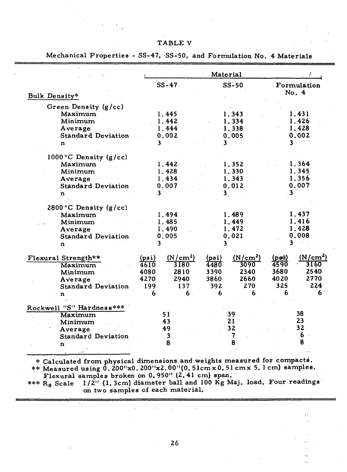
TABLE
V
Mechanical
Properties
-
SS-47, SS-50,
and
Formulation
No. 4
Materials
Material
Bulk
Density*
Green Density
(g/cc)
Maximum
Minimum
Average
Standard Deviation
n
1000°C
Density
(g/cc)
Maximum
Minimum
Average
Standard Deviation
n
2800
°C
Density
(g/cc)
Maximum
,
,
Minimum
Average
Standard Deviation
n
Flexural
Strength**
Maximum
Minimum
Average
Standard Deviation
n
Rockwell
"S"
Hardness***
Maximum
Minimum
Average
Standard Deviation
n
SS-47
1.445
1.442
1.444
0.002
3
1.442
1.428
1.434
0.007
3
1.494
1.485
1.490
0.005
3
(psi)
4610
4080
4270
199
6
(N/cm
2
)
3180
2810
2940
137
6
51
43
49
3
8
SS-50
1.343
1.334
1.
338
0.005
3
1.352
1.
330
1.343
0.012
3
1.489
1.449
1.472
0.021
3
(psi)
(N/cm
2
)
4480
3090
3390
2340
3860
2660
392 27Q
6 6
39
21
32
7
8
Formulation
No.
4
1.431
1.426
1.428
0.002
3
1.364
1.
345
1.356
0.007
3
1.437
1.416
1.428
0.008
3
(P*i)
4590
3680
4020
325
6
(N/cm
2
)
3160
2540
2770
224
6
38
23
32
6
8
*
Calculated from physical dimensions
and
weights measured
for
compacts'.
**
Measured using
0.
200"xO.
200"x2. 00"(0. Slcmx
0. 51 cmx 5.
1cm)
samples.
Flexural
samples broken
on
0.950" (2.41
cm)
span.
*** R
s
Scale 1/2"
(1.
3cm) diameter
ball
and 100 Kg
Maj. load.
Four
readings
on
two
samples
of
each
material.
26
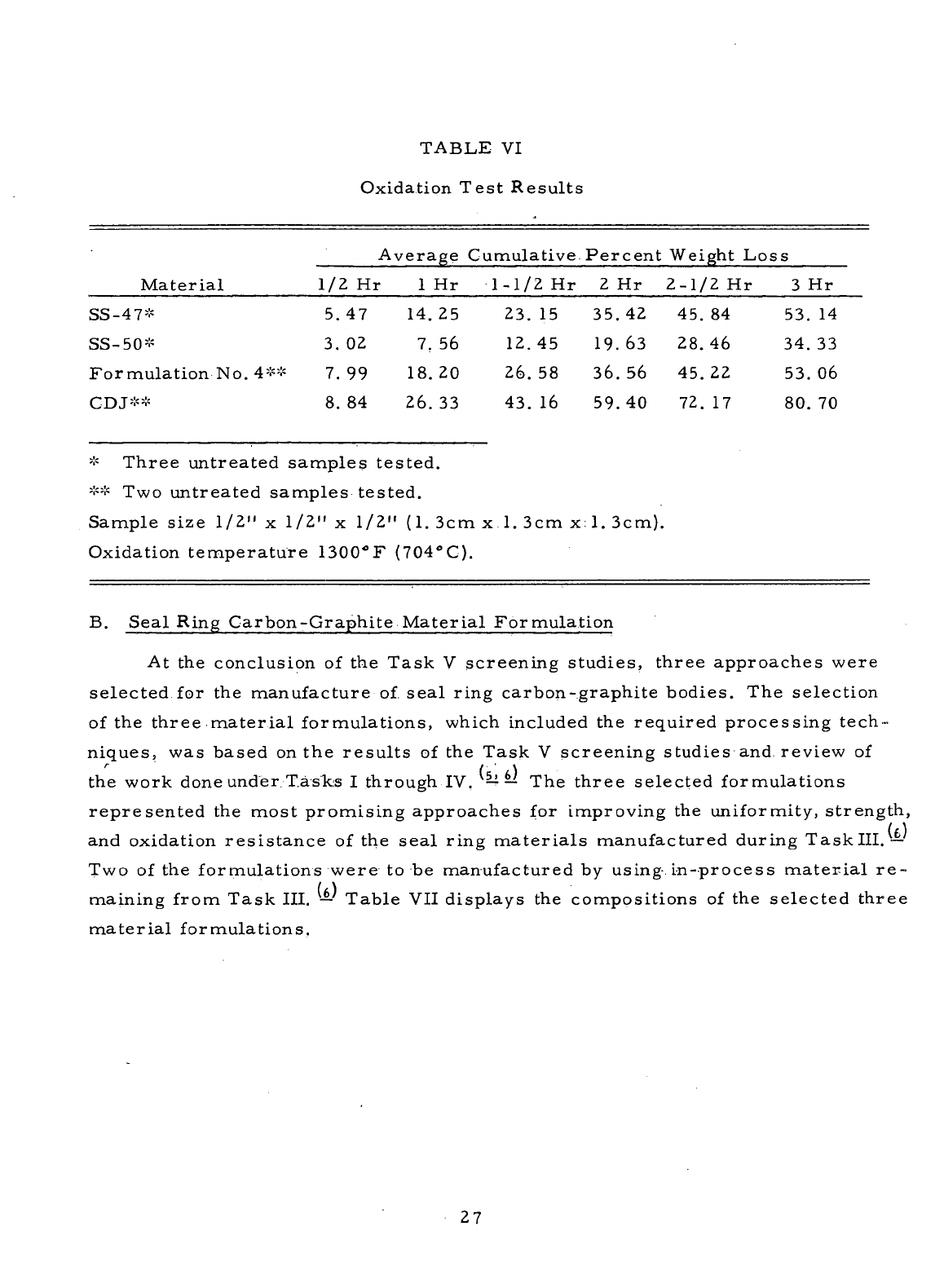
TABLE
VI
Oxidation
Test Results
Average
Cumulative.
Material
SS-47*
SS-50*
Formulation
No. 4**
CDJ**
1/2 Hr
5.47
3. 02
7.
99
8. 84
1
14
7
18
26
Hr
.25
. 56
.20
. 33
1-1/2
Hr
23.
12.
26.
43.
15
45
58
16
Percent
Weight
Loss
2
35
19
36
59
Hr
.42
.63
.56
.40
2-1/2
Hr
45.
28.
45.
72.
84
46
22
17
3
53
34
53
80
Hr
. 14
. 33
.06
. 70
*
Three untreated
samples
tested.
** Two
untreated
samples
tested.
Sample
size 1/2"
x
1/2"
x
1/2"
(1. 3cm
x.l.
3cm
x;l. 3cm).
Oxidation
temperature 1300°F
(704°C).
B.
Seal
Ring Carbon-Graphite Material Formulation
At
the
conclusion
of the
Task
V
screening studies, three approaches were
selected
for the
manufacture
of.
seal
ring carbon-graphite bodies.
The
selection
of
the
three
material
formulations, which included
the
required processing tech-
niques,
was
based
on the
results
of the
Task
V
screening studies
and
review
of
r
( \
the
work
done
under
T.aslcs
I
through
TV.
^=U
—
The
three selected formulations
represented
the
most promising approaches
for
improving
the
uniformity,
strength,
and
oxidation resistance
of the
seal
ring
materials
manufactured
during Tasklll.—
TWO
of the
formulations were
to be
manufactured
by
using-
i-n-process
material
re-
maining
from
Task III.
—
Table
VII
displays
the
compositions
of the
selected three
material
formulations.
27
vO
cU
>
H
PQ
H
W
O
en
C
o
•
-H
-l->
nt
r-H
'I
0)
4->
iti
Baking
Procedure
i
.36
™
4)
» K
«
n) •-<
(V <4
OH
.H
Binder
Mater
T)
^^,
53
» M
S <o
13
•iH
>
•M t>
M rt
(S^
_g
7J
^
gl
h^
™
SJ o t i
o
^
**
^
AJ
gj fl) °
&
"^ 0
Bake Green Compacts
tc
1000°C.
Impregnate
Cot
with
Re sin
-Solution,
Pr<
Cure
at
150°C,
and
Reb;
1000°C.
Final
Bake
to 2f
7.S
43 to
(X H)
O
^
in
m
Qfv
oS
"o
'
1—
1
p[J
<rt
3
U3 43
**<•**
in
^ rtj ^**
^4 pQ >Ii
•2^
*o
p,
* •*-*
7
(X
o
00
u
•"••
"?
•S 43
5s
^H
rt M
'o *^
•M
«
<H
X
o
i-H
JS
'
n)
M U
L CQ 4> *J °
g
<U
<D
a, C
rt
0
Pressure
Cure Green
Ci
pacts
at
150°
C.
Pressui
Compacts
to
550°
C. Bal
Compacts
to
1000°
C. Im
nate Compacts with Res:
Solution,
Pressure
Cur«
150°
C, and
Rebake
to 1C
Final
Bake
to
2800°C.
7.s
43 to
O. 0)
o "4
in m
~"
o-
"o
°
t
ftf'
**^
H •-* rQ
t£n <U Ct
^ .^i
S)
n) JJj
«.a
0)
S —
7
"fx
o
oo
<u
•S
"?
0^43
rt *^
oS
la
" 6
*^j
t;
<H
X
o
in
Same
as
that used
for
Formulation
No. 5Y.
T.S
(X V
u">
m
o^
"o
"^
_
1 Q*
<«
a
3
43
<«
a> P.
0
rt ^
Uj
D3
^
&
«.s
0}
a»
S^-
•H«5-S.
i-H
"
P<
«ui ft
l°°
03
mC
7^
tx
5
0
43
00
^
—
o
4)
d
'S <n
43 ™
(5e
2
*
2'2
<H
P.
*^j rt
^^
S
^
o
^
>o.
m
0)
d
fi
ft
rt
M
D
I
y
d
(X
^J*
43
00
'w
.0
m
i
0
o
l-H
V
o.
•«
?
00
43
'«
3 ?
77 >»
00
.^"
••-1
m
Q)
-M
I R
43
to M
S.
§
SI
C
0
0 fH
M
L,
o
5
2
1
p. (Q
0)
«
28
Formulation
No. 1Y is the
same
as
formulation
No. IX
(Table
I)
except
for
the
resin
impregnant.
The
letter
"Y"
following
the
formulation number
was
used
to
denote impregnation
of the
1000°
C
baked compacts with
a
solution
consisting
of
furfuryl
alcohol
(50
pbw)
and
Bakelite BRP-5095
resin
(35
pbw).
The
resin
impregnant
was
found
to be the
best
of
those studied during
Task
V
for
producing significant improvements
in the
density, strength,
and
hardness
of
the
formulation
No. 1
base
material.
Impregnation
of the
formulation
No. 1
base
material
with
the
furfuryl
alcohol
-
Bakelite
resin
solution yielded con-
siderably more residual carbon after baking
to
1000"C
than that obtained when
the
same
material
was
impregnated with
the
Bakelite BRP-5095
resin
(50
pbw)-
acetone
(50
pbw) solution during
Task
III.
— The
formulation
No.
IX.material,
which
was
impregnated with
the
Bakelite resin-acetone solution,
was
felt
to be
the
best
material
of
those characterized during Task
IV
—for
meeting
the re-
quirements
of a
self-acting
seal
material.
Due to the
higher residual carbon
yield resulting from
the use of the new
resin
impregnant,
the
formulation
No.
1Y
material
was
expected
to be a
significant improvement over
the
formu-
lation
No. IX
material.
The
formulation
No. 1Y
material
was to be
manufac-
tured
from
the
formulation
No. 1 mix
remaining
from
Task. III.
—
The
formulation
No. 5Y
material
was to be
manufactured,
from
the
for-
mulation
No. 3
mix.(Table
I)
remaining from Task.III.
— As
mentioned
previously
in
Section'IV^A-2,
the
resin
binder
in the
one-year-old formulation
No.
3 mix
apparently
had
degraded during
the
time
between
manufacture
of the
mix and
reuse during
the
Task
V
baking studies. Although
the
"aged"
formu-
lation
No. 3 mix
produced
a
low-density baked
material,
the use of the mix in
the
manufacture
of the
for-mulation
No. 5Y
material
was
felt
to be a
valuable
addition
to the
further
development
of
the
:
pressure baking
and
resin-impreg-
nation techniques.
The
formulation
No. 5
base
material
was the
same
as
that
manufactured
from formulation
No. 3
with
the
exception that formulation
No. 5
incorporated pressure curing
and
pressure baking,
in its
processing.
Pressure
baking
was
included.in
the
formulation
No. 5
processing, since that technique
had
been
found
during Task
V to
yield significant improvements
in the
mechani-
cal
properties
of the
resin-bonded formulation
No. 3
material.
Pressure
curing
was
included, since
it had
been
found
during
Task
V to be a
required step before
pressure
baking
large
compacts.
The use of the
furfuryl
alcohol-Bakelite BRP-
5095
resin
impregnating solution
was to be
extended
to the
processing
of the
formulation
No. 5Y
material.
29
Formulation
No. 6Y was
similar
to
formulation^No.
-4X
(Table
I)
from
whichmaterial
was
manufactured
during Task III.
— The
formulation
No. 6Y
material,
however,
was to be
impregnated
with
the
furfuryl
alcohol-Bakelite
BRP-5095
resin
solution rather than
the
Bakelite BRP-5095 resin-acetone
solution used
in the
processing
of the
formulation
No. 4X
material.
The use
of
pressure
curing
and
pressure
baking
was
extended
to the
processing
of the
formulation
No. 6
base
material. Unlike
the
formulation
No. 4
base
material
which
contained
a
minor filler
component
(20
pbw)
of
fibers prepared
from
Grade
WCA
graphite cloth,
the
formulation
No. 6
base
material
included
Grade
WFA
chopped graphite fibers
as a
minor filler
constituent
(20
pbw).
The
Task
V
subsystem
study
revealed
that
the use of
Grade
WFA
fiber
results
in
an
increase
in the
shrinkage
of the
material
during
baking.
Due to the in-
crease
in
shrinkage
and
reduction
in
porosity,
the
material
(SS-47)
containing
the
Grade
WFA
graphite fibers
had
more
uniform
and
slightly better mechani-
cal
properties than those
of the
formulation
No. 4
material.
Although
the
formulation
No. 6
base
material
also
was to be
bonded
with
Bakelite BRP-5095
resin,
its
binder level
(70
pph)
was
slightly higher than that
of the
formulation
No.
4
material
(67.
5
pph).
. The
binder level
was
increased
in an
attempt
to
further
improve
material
properties.
30
SECTION
V
MANUFACTURING,
OF
CARBON-GRAPHITE MATERIALS
(TASK
VI)
A. .
Identification
of
Materials
Manufactured
Carbon-graphite
seal
ring
bodies were
to be
manufactured during
Task
VI
from
material
formulations Nos.. 1Y,.
5Y, and 6Y.
Since processing
problems were encountered
during"
the
manufacture
of the
three
materials,
some adjustments
in
processing
had to
be.made.
The
processing problems
and
the
required, revisions
in the
processing procedures
are
discussed
in
Section
V-B
with
detailed descriptions
of the
techniques
employed
to
manu-
facture
the
carbon-graphite
materials
during
Task
VI. The
manufacturing
problems resulted primarily
from
the
scale-updn
the
size
of the
compacts
being
manufactured.
Many
of the
processing techniques employed
during
Task
VI had
been
developed
during
the
Task
V
sceening studies
in the
prep-
aration
of
small
2.
5-inch
x 1.
25-inch
x 1.
0-inch
(6.
35cm
x 3.
18cm
x 2.
54cm)
compacts.
Although
these processing techniques
had
been
used
successfully
to
.manufacture
the
small
compacts, they resulted
in
some problems
during
Task
VI
when
attempts were made
to
manufacture
considerably
larger
conn-
pacts: 5-inch (12.
7 cm)
diameter
x 1.
4-inch
(3. 6 cm)
thick solid plugs
and
8.
6-inc (21.
8 cm) o. d. x 5.
8-inch (14.
7 cm) i. d. x. 1.
3-inch
(3. 3 cm)
thick
ring
blanks.
All
dimensions
listed
are for the
green compacts.
Table VIII presents
the
identification
of the
three basic formulations
and
their impregnated versions
from
which carbon-graphite
seal
ring bodies
were.manufactured
during
Task
VI.
Formulation
No, 1Y was
replaced
by
formulation-No.
1Z
when
processing problems prevented
the
manufacture
of
the for
mulation.No.
1Y
material.
Except
for the use of the
Grade
WFA
graph-
ite
fibers,
the
carbon-graphite
materials
produced
during
Task
VI
were manu-
factured
from
the
particulate
and
binder
raw
materials characterized
during
Task
I. — The
results
of the
Task
I—characterization
tests
and
some
of the
properties
of the
Grade
WFA
graphite fibers were presented previously
in
Section IV-A
of
this
report.
31
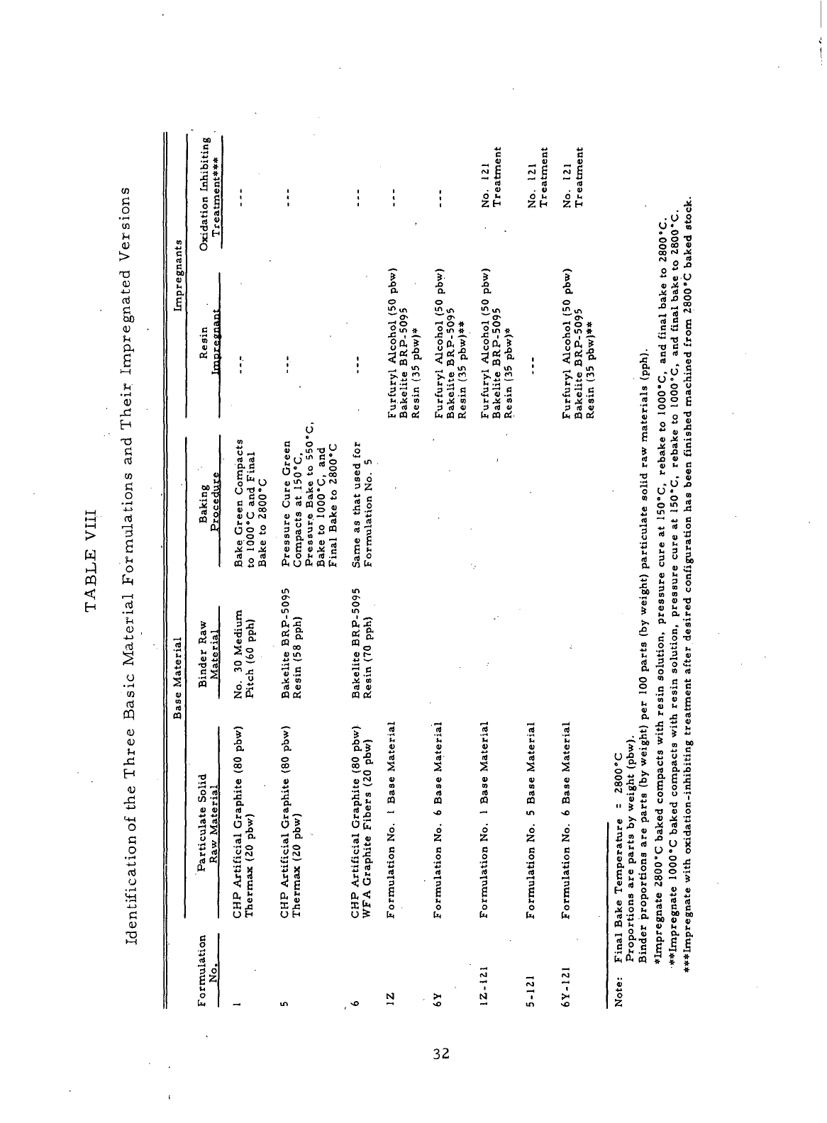
>—
f
n
f—
1
w
pq
*i^
H
rt
o
CO
H
>
T3
(U
4-)
n)
W)
a
r—
i
<U
^C
H
T3
C^
rt
CO
C
O
or
mulati
bn
3
?-t
^ ,
4-J
(TJ
•^
I^H
a
CO
rt
CQ
(L)
CU
t.
fH
H
^d
mtification
of t
<u
S
B
rt
00
41
a
&
DO
C
•(-f
X
*
11
gg
O 4-
•
r4
^
*S *•
•q
H
i
i
c
R
C C
••-» ft
Re a
mnrei
i.
i
.-t
n)
t,
«)
rt)
2
41
«
0
41
00
S
2 5
0 °
(X
m
o .-t
id id
D. B
G
£
"
Bo"
B
id O
» 00
41
U rj
5§o
VO 41
id
_ id
0 2«
Ji
5
•—•
QJ
^
'£
5>
5
*O rt
3
fi_
•rj
*5
M
O*
vO
o
—
o
*2
£
•d
"3 "3
w-
Parti
culate
Raw
Mate
-r*
•a
o
00
41
•S
CHP
Artificial
Gra
Thermax
(20
pbw)
B
O
.2
2
o
c
z
o
u.
—
i
r
U
B
0 ,,
4*
^ift
T3 Y
A" 0 *§
"-
1
O *• .00
s5lis
Pressure
C
Compacts
a
Pressur.e
B
Bake
to 100
Final
Bake
in
o
in
Qj r*
a' o-
S
a
00
41
m
.ti *"~
id 41
0 0!
-T-
•a
o
00
0>
a
CHP
Artificial
Gra
Thermax
(20
pbw)
m
i
i
i
i
h
3
<o
0)
O
^
Z
Same
as tha
Formulatiol
m
a*
o
in
CL
J«
tti Ou
S ^*
O
o r-
•ti
*""'
4^ to
(d
a)
CP ti
*r-
•8.7
8*
—
o
A ?•
CHP
Artificial
Gra
WFA
Graphite Fibe
,
"°
i
i
?
a.
o
o*
"°° *
^
OH
S
?*;
>.«e
M
.M
Is »
S id 41
u. m a;
2
«
rt
2
41
a
id
n
Formulation
No. 1
N
i
1'
a
o
>n
m
'
^
•S
O #
O
m »
!<*!
£~l-
t,
j: m
3 id o
U. CO Bi
'
id
«
Id
41
10
id
0
Formulation
No. 6
^,
xO
4J +*
c a
^41 ^ 41
~"
id "" id
.41
.4)
Oh
Ob
j*
D.
O
m
m
o»
"oS
*
JM
|
-•*.
8°-!
5^ •
^H
^ I
-2
"S S
t.
j< '3
? id 4>
Ui CQ 0^'
'
rt Id
41 41
*jj
•*•*
2
2
n m
0 0
Formulation
No. 1
Formulation
No. 5
IM
_
•^
cj
M 1
-«
in
^
g
4)
51
id
. 4)
0 b
?
a
o
m
u,
-<
"*
_o
in «_
|Si
11?
5^S
(x
0 a!
'rt
41
rt
41
a
rt
Formulation
No. 6
rvl
^
*n
sO
jj
. O
•
O S
U«
n
0 0 -0
O CO 41
So|
° U
M
* o
•o-
»
•~J
2
.S^o
.
^1-
~ B id TJ
O*
C C
•
— u° 2
n
• 0 o
-H
o o rt
rt o o g
41
"• o "J
6
** 4* m
o j!s .2
J4 id C
rt 5 "S ""
M
2 " S
!2
*
•Q
u • "£
rt -• *. fi
•g
*j « o
«
" » 'rt
•
s
£ a *
5 2 5 o
•j*
p
M
y
'3 oj O *O
b
« h »
? v, a M
r*^
^* *m
•£.
. c o
B
o -o
2 2 '- K
^ "5 5 »
rt) ^ O ii
O«
O « rt
O "B r; -W
o
c
.5 c
—
*
.S » <U
^ M « g
S-jiS
^*
•" '•>
h
•
x "S *
~ 00 S
m
00
U
X «
£o--
»
^ ? y rt -Z
? ™ ° -a e
lake
Temperature
=
tions
are
parts
by v
proportions
are pai
gnate
2800
°C
baked
agnate
1000
°C
bakei
sgnate
with
oxidatio:
" " ^ 41 M ^
ill
III
h ft 0 # ^ 3.
*
O
0
Z-
32
B.
Processing
of
Materials Formulations
Two
different
types
of
compacts were prepared,
for
the.
materials
manu-
factured
during Task
VI:
5-inch (12.
7. cm)
diameter
x
1.4-inch (3.6
cm)
thick
solid plugs
and 8.
6-inch (21. 8cm)
o. d. x 5.
8-inch (14.
7 cm) i. d. x 1.
3-inch
(3.3
cm)
thick ring blanks.
The
dimensions listed.are
for the
green compacts.
The
material
property
samples
and the rod
specimens submitted
to the
NASA
Project Manager were machined
from
the
solid plugs.
Several test bakes were
conducted
to
determine
the
best molding con-
ditions
for
each
of the
materials
manufactured during
Task
VI. The
mixes
of
formulations
Nos.
1 and 3,
which were employed during Task
VI for the
manu-
facture
of two
materials,
had
been test baked
when
they were
manufactured
during
Task III.
— The
formulation
No. 6 mix was
manufactured
and
test baked
during
Task
VI. The
test bake procedure consisted
of
molding
small
compacts
of
each
material
at
5000
psi
(3450
N/cm
2
) pressure increments between
10, 000
psi
(6890
N/cm
2
)
and 35, 000 psi
(24,
100
N/cm
2
).
After
the
compacts were baked
to
1000"C,
their densities were measured
and
their internal structures were
examined,
for
laminations.
The
green density that resulted
in a
1000°C
baked
compact having
the
highest baked density
and
sound
internal structure
was se-
lected
as the
molding condition
for
each
material.
The
processing techniques
employed
to
manufacture
compacts from
the
materials:produced during Task
VI
are as
follows:
1.
Formulation
No. 1Y - CHP
Artificial Graphite
(80
pbw)-
Thermax
(20
pbw) -No.
30
Medium Pitch
(60
pph)
-
1000°C
Baked
Compacts Impregnated
with
Solution
Consisting
of
Furfuryl
Alcohol
(50
pbw)
and
Bakelite BRP-5095 Resin
(35
pbw)
a)
Blend filler
raw
materials
for one
hour.
.
b)
Preheat
filler
and
mixer
to
150°C,
add
pitch,
and mix
filler
and
binder
in
sigma blade mixer
for one
hour.
c)
Crush cooled
mix by
using
a
hammer pulverizer.
d)
Micromill crushed mix.
e)
Blend milled
material
for one
hour.
f)
Mold
the
milled
material
at
room temperature
by
using
a
hydraulic
press.
33
g)
Pack
green compacts with coke
in a
sagger, place
a
layer
of
charcoal
on the top of the
pack,
and
bake green com-
pacts
between
room temperature
and
1000°C
at a
rate
of
5°C
per
hour,
followed
by a
4-hour hold
at
1000"C.
h)
Impregnate
100Q°C
baked compacts
with
a
furfuryl
alcohol
(50
pbw)
-
Bakeli.te BRP-5095
resin
(35
pbw) solution
by
using
the
following
procedure.
1.
Place-compacts
in
autoclave
and
evacuate
for 1
hour
at 27 to
29-inch (9.1
to 9. 8
N/cm
2
)
Hg
vacuum.
.
2.
Impregnate compacts with
resin
solution.
3.
Pressurize
autoclave containing compacts with
80
to
85
psig
(55 to 59
N/cm
2
)
air for 1
hour.
4.
Remove
compacts
from
solution.
5. .
Place
compacts
in an
autoclave, pressurize
with
100.psig
(69
N/cm
2
) air, rush temperature
to
125°C
and
hold
1
hour,
and
rush temperature
to
150°C
and
hold
1
hour.
.
Remove compacts
from
autoclave
and
.
place them
in a
150°C
circulating-air
oven
for 2
hours
to
complete
resin
cure.
i)
Pack
resin impregnated compacts
with
coke
in a
sagger
and
rebake
to
1000°C
according
to the
following
schedule: rush,
to
150°C,
150°C
to
1000°C
at
10°C
per
hour,
and
hold
4
hours
at
1000°C.
j)
Using graphite
particles
as the
packing medium, fire
the
1000°C
baked compacts
to
2800°C
in an
induction
furnace,
using
the
following
schedule: room temperature
to
900°C
at
400°C
per
hour,
900°C
to
1600°C
at
200°C
per
hour,
1600°C
to
2800"C
at
300°
C per
hour,
and
hold
1
hour
at
2800°C.
34

Processing problems were encountered during
the
manufacture
of the
formulation
No. 1Y
compacts. Eight 5-inch (12.
7 cm)
diameter
x
1.4-inch
(3.
6 cm)
thick
solid
green
plugs were successfully baked from room
tempera-
ture
to
1000°C.
The
1000°C
baked compacts were then impregnated
with
the
furfuryl
alcohol
-
Bakelite BRP-5095
resin
solution.
A 7. 7
percent average
increase
in
weight
was
measured
for the
resin-impregnated compacts
following
pressure curing
at
150°C.
After
they were pressure cured, these compacts
were
rebaked
to
1000"C
at a
rate
of
10*C
per
hour.
The
baking schedule
was
apparently
too
fast,
since
large
chips
of
material
broke
off
during baking.
The
force
produced
by the
volatiles
from
the
resin-impregnant trying
to
escape
through
the
internal structure
of the
compacts probably caused
the
shipping
..
The
10°C
per
hour
rate
was the
same
as
that used during
the
Task
V
resin
im-
pregnation studies
in
which
smaller
resin-impregnated samples
(4.
0-inch
x 0.
5-inch
x 0.
25-inch (10.
2 cm x 1. 3 cm x 0. 6
cm))
of
formulation
No.
1Y
were successfully rebaked
to
1000°C.
Final
baking
(Z800*C)of
the
damaged
1000°C
rebaked formulation
No. 1Y
compacts resulted
in
their com-
pletely breaking
apart,
apparently
due to
undetected
microcracks
which
had
formed
during
the
rebaking
of the
compacts
to
1000°C.
The
formulation
No. 1Y
compacts were being
manufactured
from
the
limited
quantity
of
formu-
lation
No. 1 mix
remaining
from
Task III.
—
This supply
of mix was
exhausted
with
the
manufacture
of the
solid plugs
of
formulation
No. 1Y.
The
processing problems encountered during
the
manufacture
of the
formulation
No. 1Y
compacts necessitated
the
revising
of the
original work
plan
for
Tasks
VI and
VII. Formulation
No. 1Y was
replaced
by
formulation
No.
1Z.
Formulation
No. 1Z was
basically
the
same
as
formulation
No. 1Y
with
the
exception that formulation
No. 1Z
specified
resin
impregnation
of
2800°C
baked compacts
and a
much slower baking schedule
to
rebake
the
resin-impregnated compacts
to
1000°C.
35
2.
Formulation
No. 1Z - CHP
Artificial Graphite
(80
pbw)
-
Thermax
(20
pbw)
- No. 30
Medium
Pitch
(60
pph)
-
2800°C
Baked Compacts Impregnated with Solution Consisting
of
Furfuryl
Alcohol
(50
pbw)
and
Bakelite BRP-5095 Resin
(35
pbw):
a)
Bake compacts
to
2800°C
by
using
the
same
processing
as
that used
for
formulation
No. 1Y
except
for the
elimination
of
steps
h and i.
b)
Impregnate 2800°C baked compacts with
the
furfuryl
alcohol
(50
pbw)
-
Bakelite
BRP-5095
resin
(35
pbw) solution, using
same
procedure
employed
to
resin
impregnate
1000°C
baked compacts
of
formulation
No. IY
(Step
h). ' . .
c)
Pack
resin impregnated compacts
with
coke
in a
sagger
and
bake
to
1000°C
according
to the
following
schedule: room temperature
to
500°C
at 2. 5°C per
hour,
500 to
1000°C
at 5°C per
hour,
and
hold
4
hours
at
1000°C.
d)
Using graphite
particles
as the
packing medium, fire
1000°C
baked compacts
to
2800°C
in an
induction-furnace
according
to the
firing
schedule
used
for the
formulation
No. IY
compacts.
Three
of the
large
ring
blanks
and
seven solid plugs were manu-
factured
from formulation
No. 1Z.
Existing
2800°C
baked formulation
No. 1
compacts remaining from Task
III—
were used
to
manufacture
the
formulation
No.
1Z
material.
A 10. 6
percent average increase
in
weight
was
measured
for
the
compacts following
resin
impregnation,
and
pressure curing
at
150°
C.
Although
the
resin-impregnated formulation
No. 1Z
compacts were rebaked
to
1000°C
by
using
a
very slow baking schedule,
the
large
resin
pickup resulted
in the
chipping
of
some
of the
compacts during baking. However,
the
resin-
impregnated compacts
of
formulation
No. 1Z
were
in
much better condition after
rebaking
to
lOOO^C
than those
of
formulation
No. IY. The
formulation
No. 1Z
compacts experienced
no
further damage
during
final baking
to
2800°C.
Although
some
of the
formulation
No. 1Z
compacts experienced chipping problems during
processing,
the
quantity
of
material
that
was
successfully manufactured
was
sufficient
to
fulfill
the
delivery
and
testing requirements
for
Tasks
VI and
VII.
36
3.
Formulation
No. 5 - CHP
Artificial Graphite
(80
pbw)
^
Thermax
(20
pbw)
-
Bakelite BRP-5095 Resin
(58
pph):
a)
Blend filler
raw
materials
for one
hour.
b)
Dissolve Bakelite BRP-5095
resin
binder
in
equal volume
of
acetone
and mix
with
filler
in a
sigma blade mixer
for one
hour
at
room
temperature.
c)
Dry
mixed
material
at
.75°C
for 16
hours.
d)
Crush
material
by
using
a
hammer pulverizer.
The
material
may
still
be
rather
soft
and
pliable
after Step
c, due to
entrapped acetone,
in
which
case
the mix
must
be
chilled
at
-20°C
to
harden
it
before
crushing.
e)
Place
crushed mix:in
an
autoclave
and
vacuum
-
evacuate.;
for
16
hours while maintaining
the
temperature
at
50"C.
The
step will remove
the
residual acetone.
f)
Crush
material
again
by
using
a
hammer pulverizer.
The
step
can be
omitted
if the mix
does
not
agglomerate during Step
e.
g)
Micromill crushed
material.
h)
Blend milled
material
for 1
hour.
i)
Mold
the
milled
material
at
room temperature
by
using
a hy-
draulic
press.
j)
Pressure
cure green compacts
at
150°
C by
using the,
follow-
ing
procedure: place compacts
in
autoclave, apply
100
psig
(69
N/cm
2
)
air
pressure, rush temperature
to
125°C, hold
for 1
hour, rush temperature
to
150°C
and
hold
3
hours.
. The
cure
Is
completed
by
heating
the
pressure cured
compacts
in a
circulating-air oven for-1 hour
at
100*C,
1
hour,
at
125°C,
and
3
hours
at
150°C.
k)
Pressure
bake cured compacts according
to the
following
schedule: rush
to
150°C
and
hold
1/2
hour,
raise
at 5°C per
hour between
150°C
and
550*C,
and
hold
at
550°C
for 4
hours.
.
During pressure baking,
an
inert
gas'
is.oisied.
to'apply
50
tp'.lOO
atmospheres
pressure;
;
37
1)
Pack
pressure baked compacts
with
coke
in a
sagger, place
a
layer
of
charcoal
on
the.
top of the
pack,
and
bake
to
1000°C
according
to the
following
schedule: rush
to
150°C,
raise
at
10*C.per
hour between
150°C
and
500
a
C, hold
2
hours
at
500*C,
.
raise
at 5°C per
hour
between
500°C
and
1000"C,
and
hold
4
hours
at
1000°C.
m)
Using graphite particles
as the
packing medium, fire
the
1000°C
baked compacts
to
2800°C
in an
induction
furnace
according
to the
firing
schedule used
for the
formulation
No. 1Y
compacts.
Since major processing pro.blems were encountered during
the
manufacture
of the
formulation
No. 5
base
material,
no
attempt
was
made
to
manufacture
the
resin
impregnated version
of the
material
(formulation
No.
5Y).
As
reported
for the
Task
V
baking'studies
(Section
IV-A-2),
scale
up in the
size
of the
compacts resulted,
in
cracking, problems.
The
large
green formulation
No.
3
compacts fractured when they were
pressure
baked
to
550°C.
At
that
time,
it was
discovered that
the
large green compacts
could
be
successfully pressure
baked
to
550°C
if
they
were first pressure cured
at
150°C.
The
large
green
formulation
No. 3
compacts
used
during
the
Task
V
baking studies
had
been
molded
a
year
before
during Task
III—
and had
since been resting
on a
bench
in an
air-conditioned room.
The
formulation
No. 3 mix
from
which
the
formu-
lation
No. "6
compacts were molded during Task
VI,.had
spent
the
past year
in
an
unheated storage
area.
Hence,
the mix had
been exposed
to
temperatures
ranging from 100°F
(38°C)
during
the
summer
to
below
0°F
(-18°C)
during
the
winter.
The
large
variation
in
temperature
may
have
affected
the
Bakelite
BRP-5095
resin
used
to
bond
the
formulation
No. 3 mix or the
resin binder
may
have deteriorated with age.
The
result
was
that
all 20 of the
5-inch (12.
7 cm)
diarnter
x
1.4-inch (3.6
cm)
thick green formulation
No. 5
compacts cracked
and/or
laminated
when
pressure cured
at
150"C
followed
by
pressure baking
to
550°C.
Absorbed
moisture
was
also
.suspected
as a
possible cause
of the
processing problems encountered during
the
manufacture
of the
formulation
No.
5
material.
However,.
an-
analysis
of
the'one-year-old
formulation
No. 3
mix
showed that
It
contained only
0. 6
percent
(by
weight)
absorbed moisture.
38
This
value
was
obtained
by
weighing
a
sample
of the mix
before
and
after
it had
been
vacuum
evacuated
for 7
hours
at a
temperature
of 50° C.
Furthermore,
the
dried sample
of mix was
found
to
re-absorb
0. 5
percent moisture during
its
first hour exposure
to
room temperature conditions.
Due to the
relatively
small
amount
of
absorbed moisture present
in the
mix,
it was
ruled
out as
being
a
major cause
of the
processing problems experienced during
the
manu-
facture
of the
formulation
No. 5
material.
In
view
of the
processing
difficulties
experienced
during
the
manufacture
of the
formulation
No. 5
material,
the
NASA
Project Manager
requested
that
the
work
on
this material
not be
continued.
The
remaining pro-
gram
efforts
were
to be
directed
to
completion
of the
manufacture
and
charac-
terization
of the
other
two
materials
(formulations Nos.
1Z and
6Y).
Only,
a
few
formulation
No. 5
compacts were completely processed through baking
to
2800°C.
The
compacts included
two
ring blanks
and
several
small
pieces
salvaged
from
the
solid plugs which
had
experienced cracking problems during
pressure baking.
The
formulation
No. 5
compacts were
not
resin-impregnated
prior
to
final
baking
to
2800°
C to
avoid
any
further
processing problems which
might
result
from
the use of the
furfuryl
alcohol-Bakelite BRP-5095
resin
im-
pregnant. Because
of the
processing problems encountered during Task':VI,
.,
the
quantity
of
formulation
No. 5
material
which
was
produced
was not
sufficient
to
fulfill
the
delivery requirements.
4.
Formulation
No. 6
-CHP Artificial Graphite
(80
pbw)-
WFA
Fibers
(20
pbw)
-
Bakelite BRP-5095 Resin
(70
pph):
a)
Blend Grade
WFA
chopped graphite fibers
with
the CHP
artificial graphite
for one
hour.
-
-.--_--__..
b)
Micromill
the
blended filler
material.
c.
Blend
milled
filler
material
for one
hour.
d)
Follow
the
other processing steps listed
for
formulation
No.
5,
starting
at
mixing (Step
b).
39
5.
Formulation
No. 6Y
--CHP Artificial Graphite
(80
pbw)-
WFA
Fibers
(20
pbw) -.Bakelite BRP-5095 Resin
(70
pph)-
1000°C
Baked Compacts Impregnated
with.
Solution Consisting
of
Furfuryl Alcohol
(50
pbw)
and
Bakelite BRP-5095 Resin
(35
pph):
;
'
a)
Bake
the
green compacts
to
1000°C
in the
same
manner
as
that used
for
formulation
No. 6.
b)
Follow
the
other processing steps listed
for
formulation
No.
1Y,
starting
at the
impregnation
of the
1000°C
baked compacts (Step
h).
Ring
blanks were
manufactured
.from
formulation
No. 6
after
processing problems prevented
the
manufacture
of the
resin-impregnated
formulation
No. 6Y
ring blanks.
The
processing problems resulted
from
the
large
resin
pickup experienced
by the
formulation
No. 6Y
ring blanks.
An in-
crease
in
weight
of 11. 1
percent
was
measured
for the
1000°C
baked ring
blanks
following
resin
impregnation
and
pressure curing
at
150°C.
This
resin
pickup
was ten
times
that measured
for the
5-inch (12.
7 cm)
diameter solid
plugs
of the
formulation
No. 6Y
material
at the
same
stage
in
processing.
The
impregnant apparently filled
the
open porosity
of the
1000°C
baked
ring
blanks
so
completely that they broke
apart
during rebaking
to
1000°C
as the
volatiles
from
the
resin
impregnant tried
to
escape
through
the
internal structures
of
the
compacts.
Due to
their
low
resin
pickup,
no
problems were encountered
during
the
processing
of the
formulation
No. 6Y
solid plugs through final baking
to
2800°C.
The
resin
pickups measured
for the
solid plugs
and
ring blanks
of
formulation
No. 6Y
indicated that there may. have been
a
difference
Ln the
surface
condition
of the two
types
of
compacts prior
to
impregnation.
The
1000°
C
baked solid plugs
of the
formulation
No. 6
base
material
apparently
had
a
very
low
porosity surface
condition
which prevented
the
res.in solution
from
freely
entering
the
stock during impregnation.
The
1000°C
baked ring blanks
of
the
formulation
No. 6
base
material
did not
appear
to
have
the low
porosity
surface
condition, since they readily accepted
the
resin during impregnation.
40
If
indeed
there
was a
difference
in the
surface porosity
of the two
types
of
compacts,
the
difference
would
probably
be
related
to the
difference
in
their
surface-to-volume
ratios.
The
surface-to-volume
ratio
of the
ring blanks
was
approximately
1.4
times
that
of the
solid plugs, indicating
that
the
vol-
atiles
would
experience
greater
difficulty
in
escaping from
the
resin
binder
through
the
solid plugs during baking.
The
difficulty
of
removing
the
vol-
atiles
and the
fact
that phenolic
resins
yield
low
porosity carbonaceous
:
materials
after pyrolysis possibly could account
for the
formation
of a low
porosity envelope around
the
solid
plugs
of
formulation No..
6
during baking
to
1000°C.
41
SECTION
VI
MATERIAL
PROPERTIES
.:•
(TASK
VII)
A.
Property Requirements of.Seal Ring-Carbon-Graphite Materials
The
goal
of
this contract
is the
development
of a
carbon-graphite
ma-
terial
for use as a
self-acting
seal
in
advanced
gas
turbine engines. High
oxidation resistance
is a
primary requirement
of the
material
if it is to
withr
stand
the
high operating temperatures. Since self-acting
seals
experience
relatively high speed sliding contact during limited periods
of
operation,
good
wear
resistance
is
also
a
requirement. High hardness, strength,
and
modulus',
.
together
with
the
proper selection
of
impregnants
and
mating
materials,
are
necessary
for
producing wear-resistant carbon-graphite
seal
ring
materials.
High
hardness
also
is
required
to
ensure
the
erosion resistance
of the
material.
Erosion
resistance
is an
important requirement
for a
self-acting
seal
material,
since
debris
passing through
the gas
film
formed
between
the
self-acting
seal
and
the
seat
during engine operation tends
to
score
and
erode
the
primary ring.
A
carbon-graphite
material
used
as a
self-acting
seal
must also have
a
high
thermal
conductivity
to
provide rapid transfer
of
deleterious
fricti-pnal'
heat
which
can
develop during periods
of
sliding contact. Dimensional stability
is
a
desirable property
of a
seal
ring
material,
although thermal expansion
is not
critical
for
this application, since
the
carbon will
be
controlled
by an
outer
shrink
ring during operation.
Aside
from
the
material
properties that
are
essential
for
good
performance,
a
seal
ring
material
should
also
be
readily machinable, since
seal
dam
widths
as
small
as 0.
020-inches
(. 05 cm)
often
are
present
in
seal
design.
The
compacts
manufactured
from
formulations Nos.
1Z, 5, 6, and 6Y
during
Task
VI
were
all
found
to be
more
easily
machinable than commercial
seal
ring Grade CDJ.
The
good
machinability
of the
carbon-graphite
articles
manufactured
during Task
VI
resulted from
the use of a
large
proportion
of
particulate graphite
in the
filler
systems
and a
final heat-treatment temperature
of
2800"G.
42
Under
the
scope
of
Task VII,
the
Contractor determined
the
following
material
properties
for the
carbon-graphite
seal
ring bodies
manufactured
during
Task
VI:
1.
Mechanical
Properties
a.
Density
before
and
after
impregnation
with
an
oxidation
inhibiting
treatment.
b.
Flexural
strength.
c.
Elastic
modulus.
2.
Thermal Properties
a.
Thermal
conductivity.
b.
Coefficient
of
thermal expansion.
3.
Oxidation Resistance
and
Related Porosity
a.
Oxidation resistance compared with that
of
carbon-graphite
seal
material
currently
in
use.
b.
Total
porosity, pore size
and
size distribution,
uniformity
of
impregnation,
and
structural
uniformity.
This section
of the
report
is
divided
into
subsections,
The
next sub-
section
discusses
the
mechanical properties determined
for the
materials
manufactured
during Task
VI. The
remaining subsections cover
the
thermal
properties,
the
porosities,
and the
oxidation
rates
determined
for the
materials.
B.
Mechanical
Properties
The
literature search
conducted
during
Task
I—
indicated
that high hard-
ness, strength,
and
modulus
are
necessary requirements
for
producing
wear-
resistant carbon-graphite
seal
ring materials. Hardness greatly
affects
performance,
since
the
load-carrying capacity
of a
carbon-graphite
seal
ring
material
is
directly related
to its
hardness. High hardness also
is
needed
to
prevent
scoring
and
erosion
of the
seal
face
when
debris
passes
between
the
self-acting
seal
and the
seat
during engine operation. Although
no
goal
was
established
for the
strength
of the
material
to be
developed
under
the
scope
43
of
this
Contract,
the
operating pressures, dimensional stability requirements,
and the
configuration
of the
seal
ring (7-12 inches (18-30
cm) in
diameter,
1/2-inch
(1. 3 cm) in
thickness,
and 0.
020-inch
(. 05 cm) in dam
width)
require
a
material
with maximum strength
and
hardness consistent with high oxidation
resistance.
Tables
IX, XI, and
XIII display
the
green,
1000°C
baked,
and
2800°C
baked bulk densities;
the
flexural strengths;
the
elastic moduli,
and the
hard-
nesses
determined
for the
carbon-graphite
seal
ring bodies manufactured
from
formulations Nos.
1Z, 5, and 6Y.
Except,for the.
hardness
measurement,
.these
mechanical
properties were
the
ones which
the
Contractor
was
required
to
measure.
The
hardness
measurement
was
included,
since
it is one of the
phys-
ical
properties commonly specified
for
commercially available carbon-graphite
seal
ring
materials.
Appendix
II
described
the
procedures used
to
determine
the
material
properties.
The
ASTM methods were used where applicable.
A
complete listing
of the
mechanical properties determined
for the
formu-
lation
No. 1Z
material
is
displayed
in
Table
IX.
Table
X
presents
a
comparison
of
the
average mechanical properties measured
for the
formulation
No. 1Z ma-
terial
with those determined during Task
IV
—
for the
materials
manufactured
from
formulations Nos.
1 and IX
(compositions listed
In
Table
I).
Although
the
formulation
No. 1Z
material
had a
significantly higher
2800°C
baked bulk density,
its
other mechanical properties were
not
quite
so
good
as
those determined
for
the
formulation
No. IX
material.
The
mechanical properties
of the
formulation
No.
1Z
material
were slightly more uniform than those
of the
formulation
No..
IX
material.
44.

r_|
rt
•~t
SH
0)
rt
N
r-H
B
0
2
a
o
nj
X -3
c
w E
tJ 0
CQ
h
<C t
V
4-1
(U
PH
O
£
1—
1
nJ
U
g
«J
U
(L)
S
•o
, (U
T3 rt
£ a,
.g ro pq *r
S
&>U
°
aJ
% ° "M
e-o'"-'
goo
M (M
•a
i <u
•o
a
fl) XI
fi rt
w
~
i>
o ^ ^
rt
K
O
,M
fo~
°
U
"S~
o -M^
OO
Jj h;
ro PQ
-*--
U-O —
§3^
2
CQ
*—
*
g
~
a)
^
^"5
"~*
»
«j
'rt
«
fl)
P
^
^
CQ
g
^
Tj*«-Hf\Jf>JOOTt*NO
^O
t—f-f^-o.f^t^-r
1
^
^4),
a)
S
"T
O
a
„
g *a
<d <3
« g
"3 °>
tic
*
*
•»
m
m
p~r~-f~o
i^i^F-
'o
rt
* ,j
_;
o ^ ^' ^; ^ ,,. S
K
-
!?
,_i
<u
-«ooo
ooo J4
t~
r~ t~ o
t~t-t—
o
-i -< -i 0
IT>
-4
-H'
-•' M Oj
S
a
i-g 00 O *-» ^O 0) C
00
h- CO S " ®
GO
01 °>
+j «i nJ
O
i—
4
(U
o
rt a g
1
1
§
i
>
o ^ H
u
-
Q t< c
§
6
« " ^ fa "S
6
g "5 « °. J
•H
.^ ^, *U M ^H
3
q «> S
3
™
Tj > <J B }{
.t-t
^2<;wc
.
SEo'
1
!
g
U
1
? "
bo
£~
£
PJ"
^
—
H
£ °° w U o
M
ri
0 '« « ^
oo^co
vot^rq
coooc^sO
.^oooO'-'t~
'i 6 2 11
55^0
^55 ^
SSrl^
^
^O^o'vO
-0 ^| S
•—
tf-Hf—
<oirt
^-i^^^Hrj
—
«—
i S • o ^
*~
» « °
rt
C ~~" (X
""**
O
- L,
•r4
7_
^j "
» S £
C
• "^ T~
—
c M
OT
6
M CO l*~ fO CO ^J CO *" C ^ rfj (**
O 0
s
CT^ CD O^ 0
1
* O^
*™
*| ^5 ^3 O M **O M O^ ^^ ^^ **^ •• - • ^
*O
IO IO ^3 lO IO lO "« I O t^
C**~
t*~ ^ ^J* fO M* ^3 *O ?^ f< *O
-<'
~ ~ 6
<r>
^^^^
^j?™?^
"o
-.'-H'-H'O'^
-^
rt
' a —
C 3
s
E „•
'S
* ^
m
^. in 01
m
g<
oo
a
••?•'•<
c
a
.
•* G . _,
^
tl ^^ fll
/T*
£ c ti f* bo ^ ~ ®
^o o
BSc^fM-H
^ w .. fi +3 l< m • **•
rt
fl)
n)
* n) rt'«™r-'~'h
fl) > J3
rt
Q
*
^
C
bo
C
s<
r -s 5
m tt! Ut
'>
t '> •« ^T " *
-^Q ™
e
^° rt £ °. -2
C3
g
fi
«-o
"3 | 6
.-a
"3 g«
-8
.
C
? «l! "S § ?
M
S ^ i •*
w
figrt^ ^
§22-3
^JJe
<»2
gg S K
S
X •§ S.| U S § rt^
2 2
<c
w c x! 2 -S <; w c
to
(4
•!(•
W
# * *
45
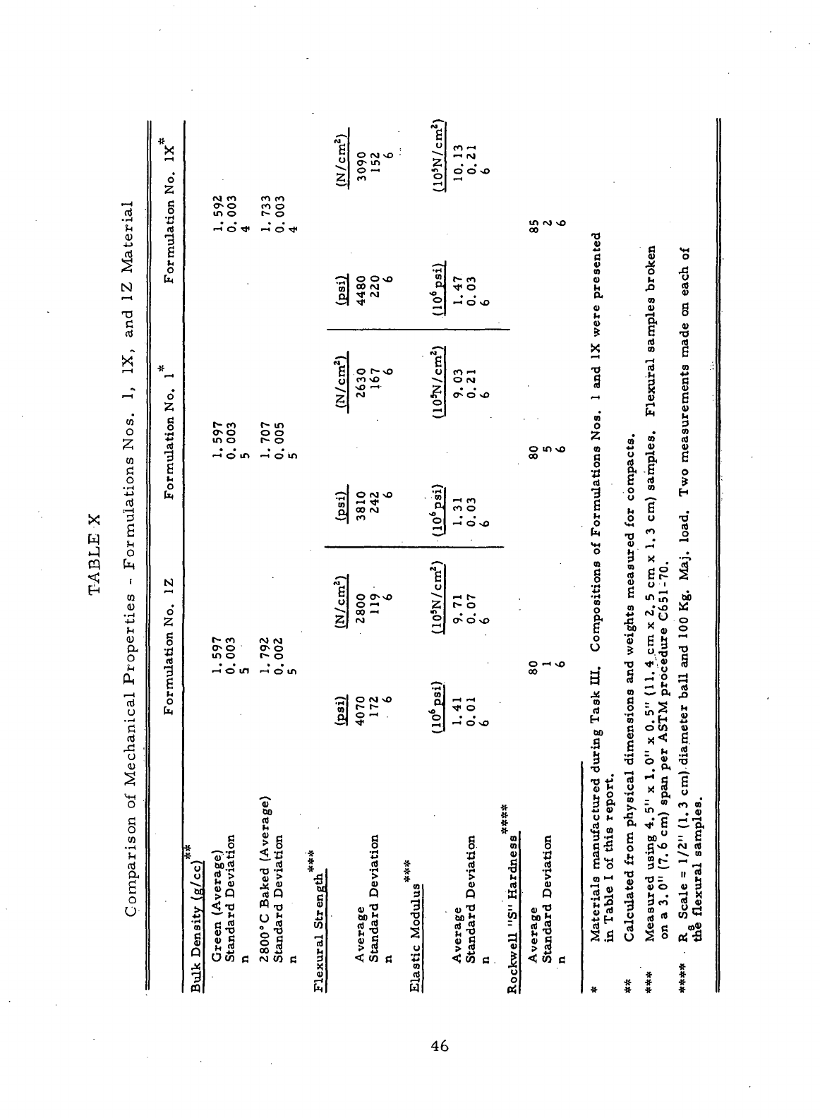
!X
W
cq
i—
H
(O
"^
H
0)
rt
I^H
C*0
^~<
T:
cj
nJ
^
X
i-H
i-H
'
u)
o
CO
Pi
o
• ^H
-J->
nj
[
—
i
^
b
i
CO
CO
1 \
^
0)
a
o
rt
u
•g
n)
o
0)
S
a..
Comparison
o
*
rS
o'
"
g
U
4_»
n)
-3
g
i<
o
fn
ft
o
2
g
Q
1
g
M
O
N
o'
>7
c
mulatic
o
N
-7 0
C
• "
p.
O fM
NO
;
7^
0
<Mn 2
^ O
«-«
«
2-
*° 2
<M
co m co
CO
i
—i r>J
!-•>
^^ ^Q
f-H
0* O
CO
O
IO ^3 t^" ^3
• • * • tn ro \o
*••*
^5 ^* ^H ^3 ^ OQ
TJ
•«->
(3 <«
c <u o
•
r4
-~J
o
ONO
2
S
00 oj J*-
& ?"* 2
4)
J*
01
O rd
^ n u i* y
^ o ^ 43 **
"°'
VD
g . 1 S
* H* <u
* 5 "5
i3""
•r-
a
H , ^? r"~ >o o
y
'fl
\O
--
^ IM *?
6-
°
i—
t
—
^
x S S
1—
1
**
n i-> "2 2 *3
0 N
S g
fi
0^
0
vO
„ S g
El
5
m'
W
»1
t*-
co f^ in O ^
o o o o z . • ">
inot~o
'-"cnOjni
....
oui^oa-"®*
-H
0 in — o tn oo C ^ "p, g
« & g 0
^^ «t c rt ^
Q| 00 f^J
r-H
•3
-8 Z H
CO
O G
M
£
•
•
^00*0
*™
•
o vo . o »i* rri
»«
0) _" ^
g
*£ • u
g O
O-xO
"^
2
S
=
5
""""
*~f
r- rn *M *M
OH
H W
.r-,
(D
So.?
£
-• C ? 5
.2
® o i
(-if-
. *
rt
^ lA |f| U)
r
~.°.
o 2 ^g M
0^0>0
fr JS
M
W
• 0
g
60 X „ 0
0 'Si CJ N "•
J_
^J . \J^ £f r
A
» ^. p^
in
o r- o °\7 fi
....
•
O«-HvO
TD^i^rt
-H
o in
—
i o tn co a § • o rn
CIj
"^2*3
i 0)1 tf 01 ^.^
CU
ri
^jocMvO
pJ^^
n fl _ «
CJ
rt0x£l
ooS
0
'^^
rt
*"
V < P
1 5 = 8 1
3 T) O J{ T3
•O
. P<
__^
•O
*> rt "^ fi g
Si
M O * 3 ~
-^ £ o '£ P<
y
.
8,
. S 3& xi^ « »
a
. ! s i
•§.
*
E
s-a,
J>
* "H
<B
^ u a
a
y a c a me rf'^Peorc
* ^5 rf°
#
2
8016
c^ggvofvirt
*sB
^ *** ? I II 1
S2||?;|
^ *S ^5 f S 3 S £ S 35 5 1°. 58
>
<-o «-« • g
W
T, 3 ^ •- ^ j,^ -p 3« S «
Z
*~
*
U
fc i ab^
"0
•
w>><
OTWI^
fliS"rt
rtW
s
s| -
0
| 2 a| 1 s| i s| |« g |g
--a
I S| Si 1 >1 « 5| 1 5|
2.s
u
50
rti}
OcofifMwc
d <ws *3
<!coc K<WC
J<
X 01 " X #
-d . <o rt w # #
^ r
1
rt 9 * # *
w
w w oi
###*
46
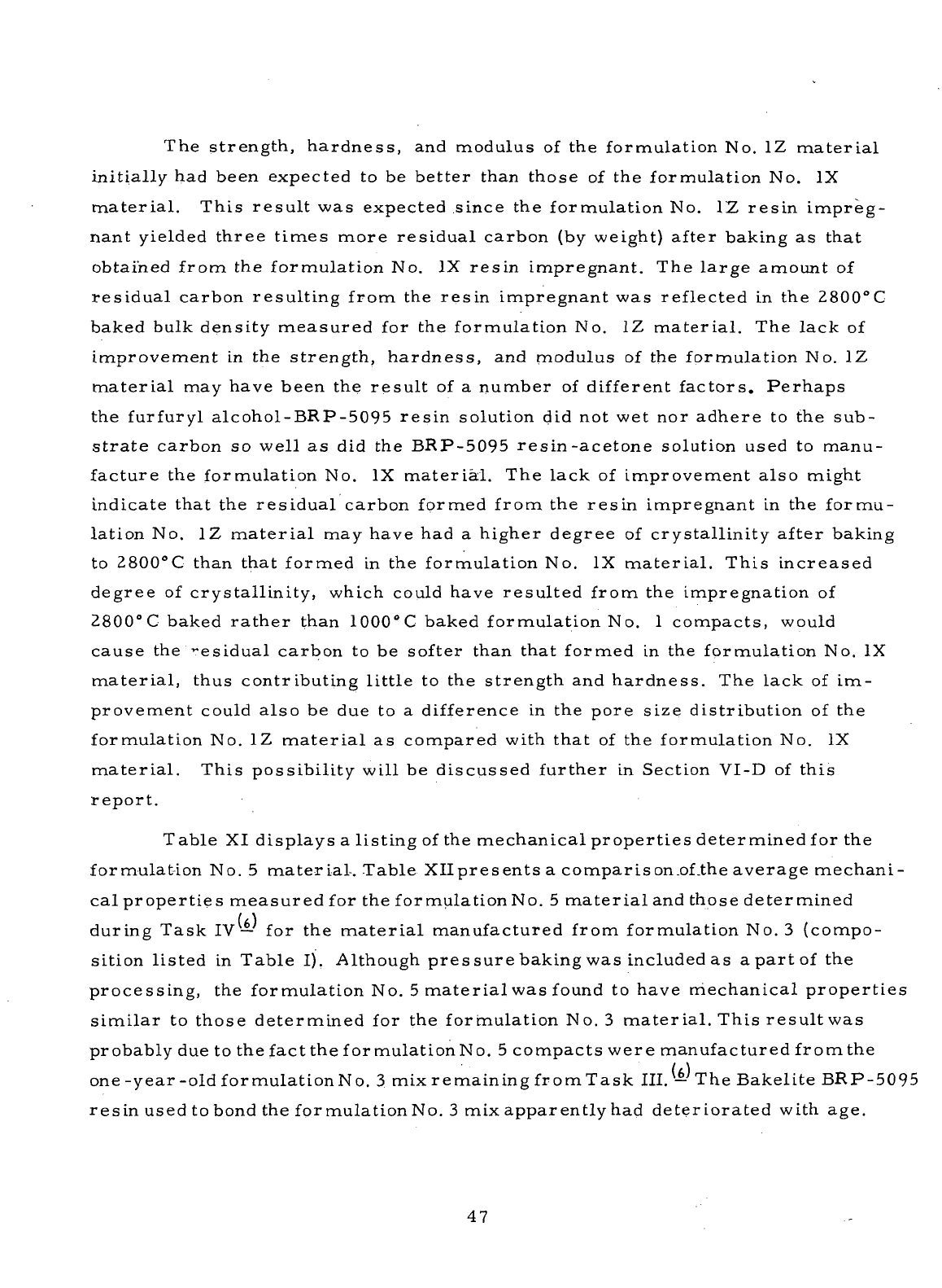
The
strength, hardness,
and
modulus
of the
formulation
No. 1Z
material
initially
had
been expected
to be
better than those
of the
formulation
No. IX
material.
This result
was
expected since
the
formulation
No. 1Z
resin
impreg-
nant yielded three
times
more residual carbon
(by
weight)
after baking
as
that
obtained
from
the
formulation
No. IX
resin
impregnant.
The
large
amount
of
residual carbon resulting from
the
resin impregnant
was
reflected
in the
2800°C
baked bulk density
measured
for the
formulation
No. 1Z
material.
The
lack
of
improvement
in the
strength, hardness,
and
modulus
of the
formulation
No. 1Z
material
may
have been
the
result
of a
number
of
different
factors.
Perhaps
the
furfuryl
alcohol-BRP-5095
resin
solution
did not wet nor
adhere
to the
sub-
strate
carbon
so
well
as did the
BRP-5095 resin-acetone
solution
used
to
manu-
facture
the
formulation
No. IX
material.
The
lack
of
improvement
also
might
indicate
that
the
residual carbon
formed
from
the
resin
impregnant
in the
formu-
lation
No. 1Z
material
may
have
had a
higher degree
of
crystallinity after baking
to
2800°C
than that
formed
in the
formulation
No. IX
material. This increased
degree
of
crystallinity, which
could
have resulted from
the
impregnation
of
2800°C
baked
rather
than
1000°C
baked formulation
No. 1
compacts,
would
cause
the
Residual carbon
to be
softer
than that
formed
in the
formulation
No. IX
material,
thus contributing
little
to the
strength
and
hardness.
The
lack
of im-
provement
could
also
be due to a
difference
in the
pore size distribution
of the
formulation
No. 1Z
material
as
compared
with
that
of the
formulation
No. IX
material.
This possibility will
be
discussed
further
in
Section VI-D
of
this
report.
Table
XI
displays
a
listing
of the
mechanical properties determined
for the
formulation
No. 5
material-. Table
Xllpresentsa
comparison
.of.the
average mechani-
cal
properties measured
for the
formulation
No. 5
material
and
those determined
during
Task
IV— for the
material
manufactured
from
formulation
No. 3
(compo-
sition listed
in
Table
I).
Although
pressure baking
was
included
as a
part
of the
processing,
the
formulation
No. 5
material
was
found
to
have mechanical properties
similar
to
those determined
for the
formulation
No. 3
material.
This result
was
probably
due to the
fact
the
formulation
No. 5
compacts were
manufactured
from
the
one
-year -old
formulation
No. 3 mix
remaining from Task III.
—
The
Bakelite
BRP-f
resin
used tobond
the for
mulationNo.
3 mix
apparently
had
deteriorated with age.
47
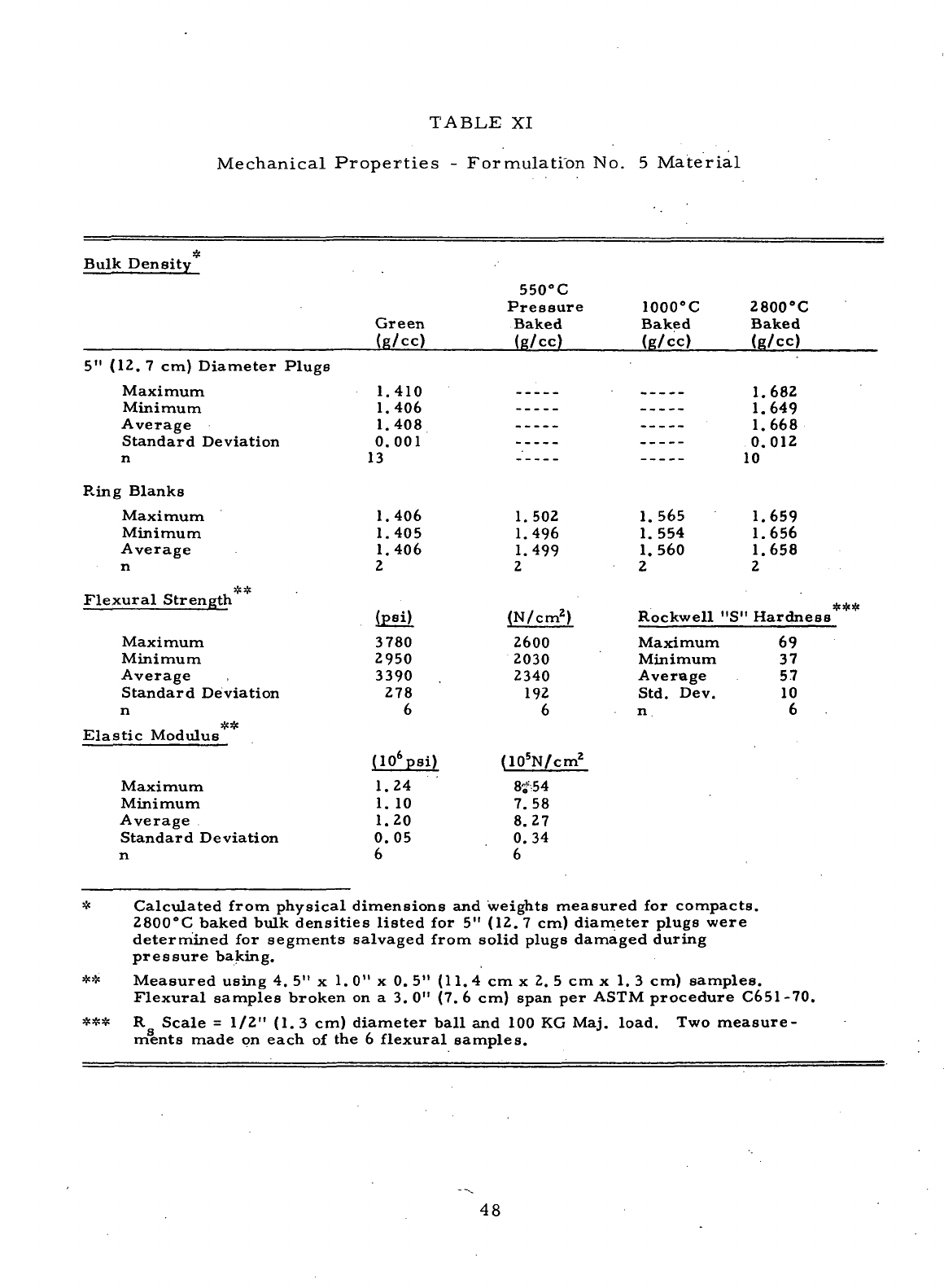
TABLE
XI
Mechanical
Properties
-
Formulation
No. 5
Material
Bulk
Density
Green
(g/cc)
550°C
Pressure
Baked
(g/cc)
1000'C
Baked
(g/cc)
2800"C
Baked
(g/cc)
5"
(12.
7 cm)
Diameter
Plugs
Maximum
Minimum
Average
Standard Deviation
1.410
1.406
1.408
0.001
13
1.682
1.649
1.668
0.012
10
R.ing
Blanks
Maximum
Minimum
Average
n
Flexural
Strength
Maximum
Minimum
Average
Standard Deviation
n
Elastic
Modulus
Maximum
Minimum
Average
Standard Deviation
n
1.406
1.405
1.406
2
si)
3780
2950
3390
278
6
(10
6
psi)
1.24
1. 10
1.20
0.05
6
1. 502
1.496
1.499
2
(N/cm
2
)
Z600
2030
2340
192
6
(10
5
N/cm
2
8*54
7.58
8.27
0.34
6
1.565
1.554
1.560
2
1.659
1.656
1.658
2
Rockwell
"S"
Hardness
***
Maximum
Minimum
Average
Std.
Dev.
69
37
57
10
6
*
Calculated
from
physical dimensions
and
weights measured
for
compacts.
2800°C
baked bulk densities
listed
for 5"
(12.
7 cm)
diameter plugs were
determined
for
segments salvaged
from
solid
plugs damaged during
pressure
baking.
**
Measured using
4. 5" x 1. 0" x 0. 5"
(11.
4 cm x 2. 5 cm x 1. 3 cm)
samples.
Flexural
samples broken
on a 3. 0" (7. 6 cm)
span
per
ASTM
procedure
C651-70.
*** R
g
Scale
=
1/2" (1.3
cm)
diameter
ball
and 100 KG
Maj. load.
Two
measure-
ments made
on
each
of the 6
flexural
samples.
48
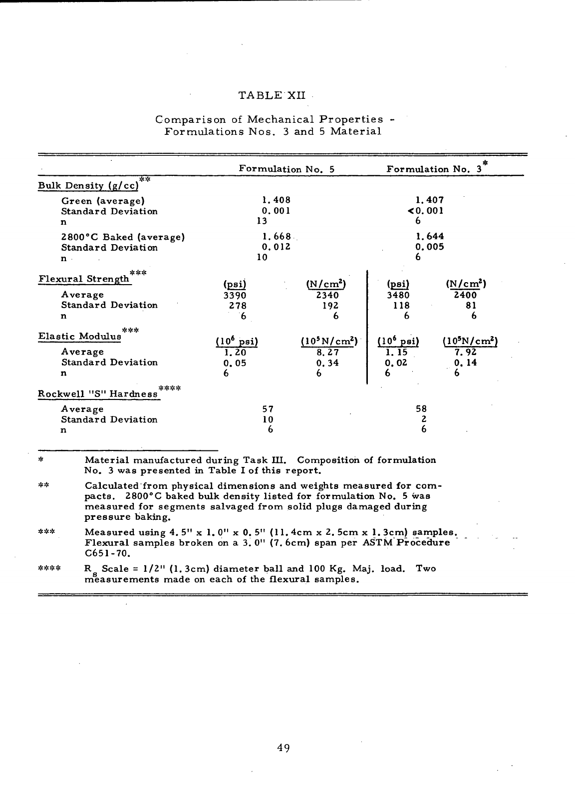
TABLE
XII
Comparison
of
Mechanical
Properties
-
Formulations
Nos.
3 and 5
Material
Formulation
No. 5
Flexural
Strength
Average
Standard Deviation
**#
Elastic
Modulus
Average
Standard Deviation
n
Rockwell
"S"
Hardness
Average
Standard Deviation
n
****
(psi)
3390
278
6
(10*
psi)
1.20
0.05
6
Formulation
No. 3
&&
Bulk
Density (g/cc)
Green (average)
Standard Deviation
n
2800°C
Baked (average)
Standard Deviation
n
1.408
0.001
13
1.668
0.012
10
1.407
<0. 001
6
1.644
0.005
6
57
10
6
(N/cm
2
)
2340
192
6
(10
5
N/cm
2
)
8.27
0.34
6
(psi)
3480
118
6
(10
6
psi)
1.
15
0.02
6
58
2
6
(10
5
N/cm
2
)
7.92
0. 14
6
***
Material
manufactured during
Task
III. Composition
of
formulation
No.
3 was
presented
in
Table
I of
this
report.
Calculated'from
physical dimensions
and
weights measured
for
com-
pacts.
2800°C
baked bulk density
listed
for
formulation
No. 5 was
measured
for
segments salvaged from solid plugs damaged during
pressure
baking.
Measured using
4. 5" x 1. 0" x 0. 5"
(11.
4cm x 2. 5cm x 1.
3cm)
samples.
Flexural
samples
broken
on a 3. 0" (7.
6cm) span
per
ASTM
Procedure
C651-70.
****
R
g
Scale
=
1/2" (1.3cm)
diameter
ball
and 100 Kg.
Maj.
load.
Two
measurements made
on
each
of the
flexural
samples.
49
The
apparent deterioration
of the
resin binder
was
reflected
in the
1000°C
baked
densities measured
for the
small
formulation
No. 3
compacts manufactured dur-
ing the
Task
V
baking studies (Section
IV-A-2).
These compacts,
which
had
been
molded
from
the
one-year-old formulation
No. 3
mix,
had an
average
1000°C
baked bulk density
of 1. 427
g/cc.
Although
the
same processing techniques
had
been
employed,
the
compacts
manufactured
from
the
formulation
No. 3 mix
dur-
ing
Task
III-
had an
average
1000°
C
baked bulk density
of 1. 519
g/cc.
The
apparent
deterioration
of the
resin
binder prohibited
the
formulation
No. 5 ma-
terial
from
gaining
the
full
benefit
of
pressure baking.
Since complete property characterization
of the
formulation
No. 5 ma-
terial
was not
warranted, only selected mechanical properties
and
oxidation
rate
were determined.
The
oxidation testing,
which
is
discussed
in a
later
section
of
this
report,
was
conducted
by
using
samples
impregnated
with
the No. 121
oxi-
dation-inhibiting treatment.
A
complete listing
of the
mechanical properties
of the
formulation
No. 6Y
material
is
presented
in
Table XIII. These mechanical properties were deter-
mined
for
samples
prepared
from
the
2800"
C
baked solid plugs
of
formulation
No.
6Y. Due to the
apparent formation
of a low
porosity surface
condition
dur-
ing
processing,
the
solid plugs
of
formulation
No. 6Y
experienced only
a 1. 1
percent average increase
In
weight after
resin
impregnation.
The
average increase
in
weight decreased
to>0.26
percent
after
the
resin-impregnated solid plugs were
rebaKed
to
1000°C.
Since
the
solid plugs
of
formulation
No. 6Y
experienced such
a
small
resin
pickup,
the
mechanical properties displayed
in
Table
XIII
are
essentially
the
same
as
those
which
would
be
measured
for the
solid plugs
of the
non-fesin-impregnated
formulation
No. 6
base
material.
The
formulation
No. 6
ring blanks
manufactured
during Task
VI had
2800°
C
baked bulk densities ranging
between
1. 564 and 1. 569
g/cc.
The
larger
surface-to-volume
ratio
of the
formu-
latioii
No. 6
ring blanks
may
have been responsible
for
their
2800°C
baked bulk
density being
higher
than
that
measured
for the
solid plugs
of the
same
material.
50
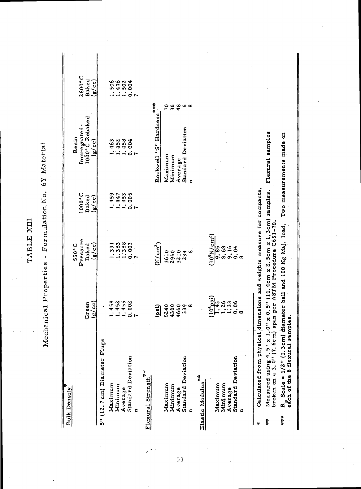
(
—
I
.5
<u
1
^
O
2
ri
o
i
*
K-(
ti
t—
1 TO
w £
t-J O
CQ fa
S '
CO
•
~H
"£
P*
o
&
,
—
i
u
'3
n)
u
*5
U
_
O
" M
°
tS
""••
rM«^5
T3
<u
4J fl)
ag«2J
jjo
0^
o S <j
0
™
~5t
-H
—
O
3 *" 'o
In
w
W *-•
Q!
M*
fl) ^*
**
~-i
(1
M
^
Density
^
3
ffl
O
ON
O O
in
T(«
in o
-»'
>-H
—
' o r-
* O sO
OO
NO
CO
*•
t-COTj.
to
m
o
i 1 5 §
co (M 00 Tf HH ro "2
voinino
- •£ c"
rfTfTfo
(/j m rt
•-T
'I-H
I-H
o !•- jj p Q 05 g
3 2 3
S,"2
la 2
1 II S| 2 S
s
li>i
1 g
*v*
^ ^
-**
r*^ v
•
. to
o-
1- co m r, s «
m
^ in o ,2 c
Tt<
rf Tf O Q, P<
-H'
—' -H' O 1- g S g
S
» H
S
|o ^
*"
£
<
*
1
-''
1
5
M
H . irt ^^
r*
^ *"*
C ^O
•->
co oo co ^ y 2 ^ O
••->
rOCOcOO
^OOOTfOO ^'OONO'-'O C^"^
rt
^H
rt p f-
—
-NOO^MCJ 'QONOOO»OOO
in ^ do
ZCOIMCO
•»< 2 • "2 ^
^ ~* •** ^ o r->
00
M o
&
E
CL
°
oo
ro m f\j 2 |co \p co
NO
.
ininmo
^-.0000^00
-oT**
r4 co o
•^TfrJtO
ojl^ONOcO
, o|
r-H
i—
i
i—
t
o r**
*ii^
in ^* ^ *^*
tn
00
^
£
»•
§ § §
£ 4J X! £
o>
ol n) n)
S
*H 4fr -H *H
>
# > «. >
rt
D
r< ^ S U
X
Q *3 Q * D
OCc w PC S Pf
? i I a*
s
i I a* 1 1 i a's
o^E
0
*^
i
c£(d^
TJ
ccrt^
I
s
*
iSfi^S
2(5^3
^ *3 CJ ^ Q
, flj *3 ^ (u ^H fl] »H ^ (0 ^
(TJ
>3 ^ (Q
C
WG
^
wc
-^
<wa
—
S S
u*>
__i *S
•o
4?S g
Sr<
1
•S f* Jj 9-t
0)
• n. O
§ ° a « «•
6
x
S fi S
.H
: g<
rt
-i
ni
"* g -7f rt
« X o fi «>
n _ NO o _i
•^
in
is.*
m
2
n *
"*•*
••* 3
Calculated
from
]
Measured using
4
broken
on a 3. 0"
R
Scale
=
1/2"
(
each
of the 8
flex
#
# «•
fe W
Table
XIV
shows
a
comparison
of the
average mechanical properties
measured
for the
formulation
No. 6Y
material
and
those determined
during
Task
IV—
for
similar
materials
manufactured
from
formulations Nos.
4.and
4X
(compositions listed
in
Table
I). . The
mechanical properties
of the
formu-
lation
No. 6Y
material
were significantly better than those determined
for the
non-resin-impregnated formulation
No. 4
material.
The
formulation
No. 6Y
material
had
mechanical properties
similar
to but
more
uniform
than those
of
the
resin-impregnated formulation
No. 4X
material,
even
though
the
latter
had
gained considerably more residual carbon
from
the
carbonization
of its
resin
impregnant.
An
average increase
of 4
percent
had
been measured during
Task
III—
after
the
resin-impregnated
formulation
No. 4X
compacts were
re-
baked
to
1000°C.
As
mentioned
.previously,
the
mechanical properties
of the
formulation
No. 6
base
material
should
be
approximately
the
same
as
those
measured
for the
resin-impregnated
formulation
No. 6Y
material. Formulation
No.
6
thus results
in a
non-resin-impregnated
material
with
properties
similar
to
those
of the
resin-impregnated formulation
No. 4X
material. This improve-
ment
is
significant,
since deletion'
of
resin-impregnation reduces processing,
The
goal
of the
Tasks
V, VI, and VII was to
develop
carbon-graphite
materials
having improved strength, hardness,
and
uniformity.
The
goal
was
not
completely achieved, since
the
scale-up
in the
size
of the
compacts prod-
uced
during Task
VI
resulted
in
processing problems. These processing prob-
lems
prevented
the
gains
in
mechanical properties anticipated
from
the
techniques
developed
during
the
Task
V
screening
study.
Seal ring bodies
manufactured
from
formulations
Nos.
1Z and 6Y
possessed mechanical properties
similar
to
those
determined
for the
compacts
of
formulations Nos.
IX and 4X,
respectively.
The
mechanical properties
of the
latter
two
materials
had
been
judged
during
TaskI"\r—•
to
be
adequate
for use as a
self-acting
seal
ring material.
Although
no
improve-
ments
in
strength
and
hardness were obtained,
the
formulation
No. 6
material
was
more
uniform
than
the
formulation
No. 4X
material
manufactured
during
Task
III.
— The
mechanical properties determined
for the
carbon-graphite
seal
ring
bodies
manufactured
from
formulations
Nos.
IX, 1Z, 4X, and
6.Ywere,
however,
all
lower than
the
corresponding values specified
for
commercial
seal
ring Grade
CDJ
-83.
52
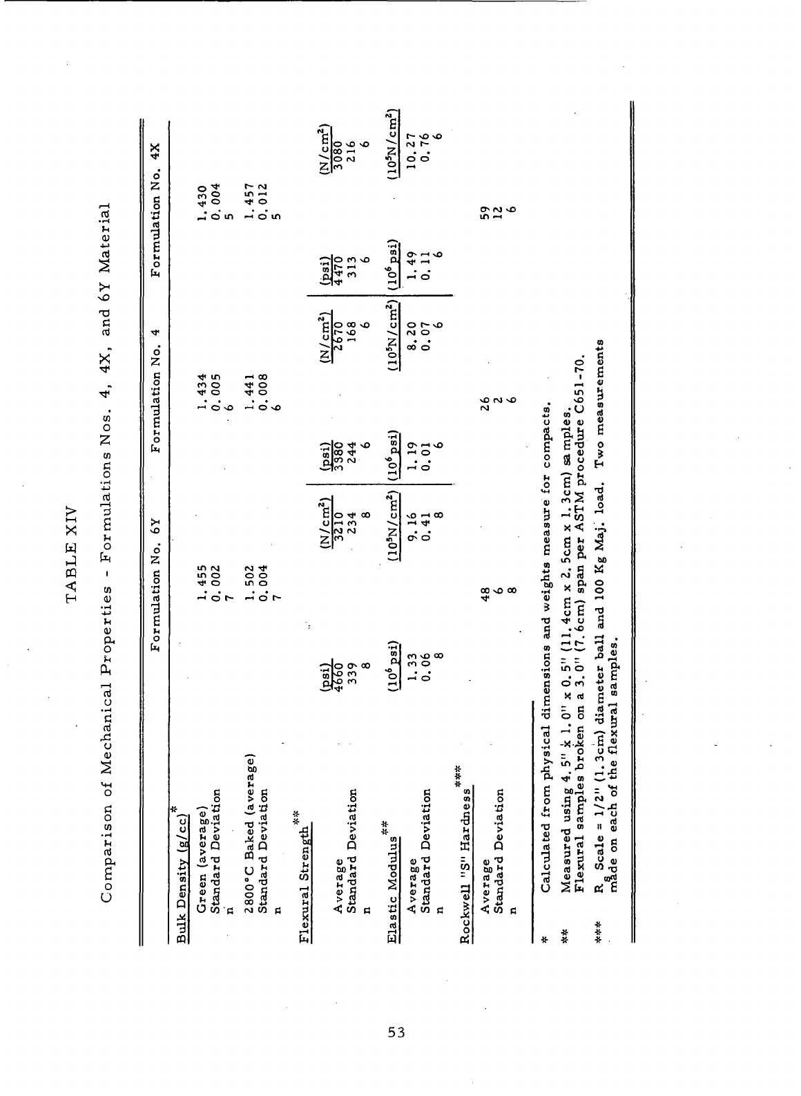
N
1—
1
rt
*t
cu
n)
S
vO
3
rtf
X
"*
w
^*
.
CO
o
CO
cj
o
•r-t
4->
nJ
i—
'
> 3
x S
* n
H
o
J k
CP i
~A
**l CO
H <u
•_£
IH
cu
o
QJ
r"i
"I!
O
• •-i
£
rd
u
0)
5
Comparison
of
X
N
<
o
2
g
rd
1
g
M
0
•*
.
o
2
c
o
*^j
cd
-3
g
o
vO
d
2
c
o
4j
cd
-3
g
O
t<
- g
fn
^
U
00
—<
2
-^ O M «
*y
-« O
5.°°
^H
r~
vo vo
(VJ
t^
o* c>
o
t
r-
r\j
ff,
o in 1-1
^ o •* o
^7 O m
•—
i
o in in
i—
«
>H
1
1
^l O^ •-< vO
^ O
CO
vO OJ ^f.
—
1
.(aJ
Tt<
co o
rt
" o"
^
f
C
o oo so o
o J^ ^2 2"
S.^ "2
o
r-
o
ra
o
00
O
Tf
in i-> oo
CO
O Tf O
Tf
O Tf O
•
• • • xO
C*t]
s
1—
1
O v£ ^-t O NO CNJ
•
H
-Ho Tf \o ">
wl°0
^ P
1
£lco
°
1—*
cjx
i^ \o
•-"
O
•-H
C>
^^
^-»-
N
C
O Tf 00 (J
O
•-•
CO
^
•^ (\J rg 21
2
CO
m
=•
o
-^
vO <-> 00
C>
0
in rj rj
TJ*
m
o o o
•*
o in o
....
00
vO
—i
O I
s
-
—•
O t-
•»*•
•H
0)
*^^Jco
CJN
oo
o)p^
^ O
Ji*Tt«
^^
CO
sD OO
CO
O
1—4
O
"S"
oo ^f
rd
#
_g
II g
Tt
?n rt "^ «l K *
O
60 -H rr) -H *
••-!
Jf.
Ocd>i,>
& > y.
~~- \t V> S<U -H (1)
ro
^ «Q -SQ « o "
5
CQ
_ «! _ rj
j^cdTJ
«>o «*
jj-o
3
•4-»
M O ^ *J
DO
^ *^
•
g-S
•
-3
M
g-S
|
|S| 11 1 |l a
Ow'crqwfl
?
<Jcna
x>
J<!
R m
•3 <u cd
3 r-4 r-H
CQ
h H
Average
Standard Deviation
n
ikwell
"S"
Hardness*
Average
Standard Deviation
u
o
ff!
D
CO
O O
T S
^H
^
in H
•O
vO ^
01
* O flt
O <U <U JJ
£ gl o
C
fli >
o
d r, *
o j» g H
*M
O *c< *^
•»
(^ i^I TO
fl) ^^ O
9
-S "
°>
><
<
>r
l
rt rt
C
« 4> S
^ m M
S
v*
bo
w P< ^
30
.H " 01 O
^
o"? •«
"°
•* ° a
rj » sO
(3
•-' .
i-H
.
<n
•
—
'*-'
cd ??
fi - - -°
JH
.2
ib M &
n
. . o H
C
om
•*••
_*
d
« ^
g c ,_,
•H
- C CO M
•OOO^g
•a
- g
-a-
§
.JJ
-X-J^
- C ^
2,
=
£ CO
jd
"*. -
0
• S
ft
•*
m C*
n
Calculated
from
Measured using
Flexural
sample
R
Scale
=
1/2"
made
on
each
of
#
#
* *
53
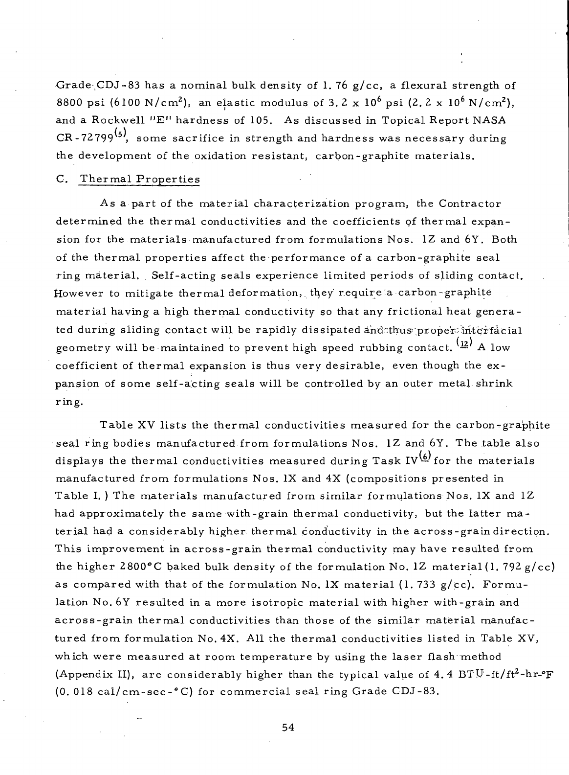
Grade-,CDJ-83
has a
nominal bulk density
of 1. 76
g/cc,
a
flexural strength
of
8800
psi
(6100
N/cm
z
)
5
an
elastic
modulus
of 3. 2 x 10
6
psi (2. 2 x 10
6
N/cm
2
),
and a
Rockwell
"E"
hardness
of
105.
As
discussed
in
Topical Report
NASA
CR-72799
,
some sacrifice
in
strength
and
hardness
was
necessary during
the
development
of the
oxidation
resistant,
carbon-graphite
materials.
C.
Thermal
Properties
As
a
part
of the
material
characterization
program,
the
Contractor
determined
the
thermal
conductivities
and the
coefficients
of
thermal
expan-
sion
for the
materials
manufactured from formulations Nos.
1Z and 6Y.
Both
of
the
thermal
properties
affect
the
performance
of a
carbon-graphite
seal
ring
material.
.
Self-acting
seals
experience limited periods
of
sliding contact.
However
to
mitigate
thermal
deformation,.
they
require
:a
carbon-graphite
material
having
a
high
thermal
conductivity
so
that
any
frictional heat genera-
ted
during sliding contact will
be
rapidly dissipated
ahdothus';prbper-tiite"rfacial
geometry will
be
maintained
to
prevent high speed rubbing contact.
— A low
coefficient
of
thermal
expansion
is
thus very
desirable,
even
though
the ex-
pansion
of
some self-aicting
seals
will
be
controlled
by an
outer
metal
shrink
ring.
Table
XV
lists
the
thermal
conductivities measured
for the
carbons-graphite
seal
ring bodies manufactured
from
formulations Nos.
1Z and 6Y. The
table
also
displays
the
thermal
conductivities measured during
Task
IV—
for the
materials
manufactured
from formulations Nos.
IX and 4X
(compositions presented
in
Table
I. ) The
materials
manufactured
from
similar
formulations Nos.
IX and 1Z
had
approximately
the
same
with-grain
thermal
conductivity,
but the
latter
ma-
terial
had a
considerably higher thermal
conductivity
in the
across-grain
direction.
This
improvement
in
across-grain
thermal
conductivity
may
have resulted from
the
higher 2800°C baked bulk density
of the
formulation
No. 1Z
material
(1. 792
g/cc)
as
compared with that
of the
formulation
No. IX
material
(1. 733
g/cc).
Formu-
lation
No. 6Y
resulted
in a
more isotropic
material
with
higher with-grain
and
across-grain
thermal
conductivities than those
of the
similar
material
manufac-
tured from formulation
No. 4X. All the
thermal
conductivities listed
in
Table
XV,
which
were measured
at
room temperature
by
using
the
laser
flash method
(Appendix
II),
are
considerably higher than
the
typical value
of 4.4
BTU-ft/ft
2
-hr-°F
(0.
018
cal/cm-sec-°C)
for
commercial
seal
ring Grade CDJ-83.
54
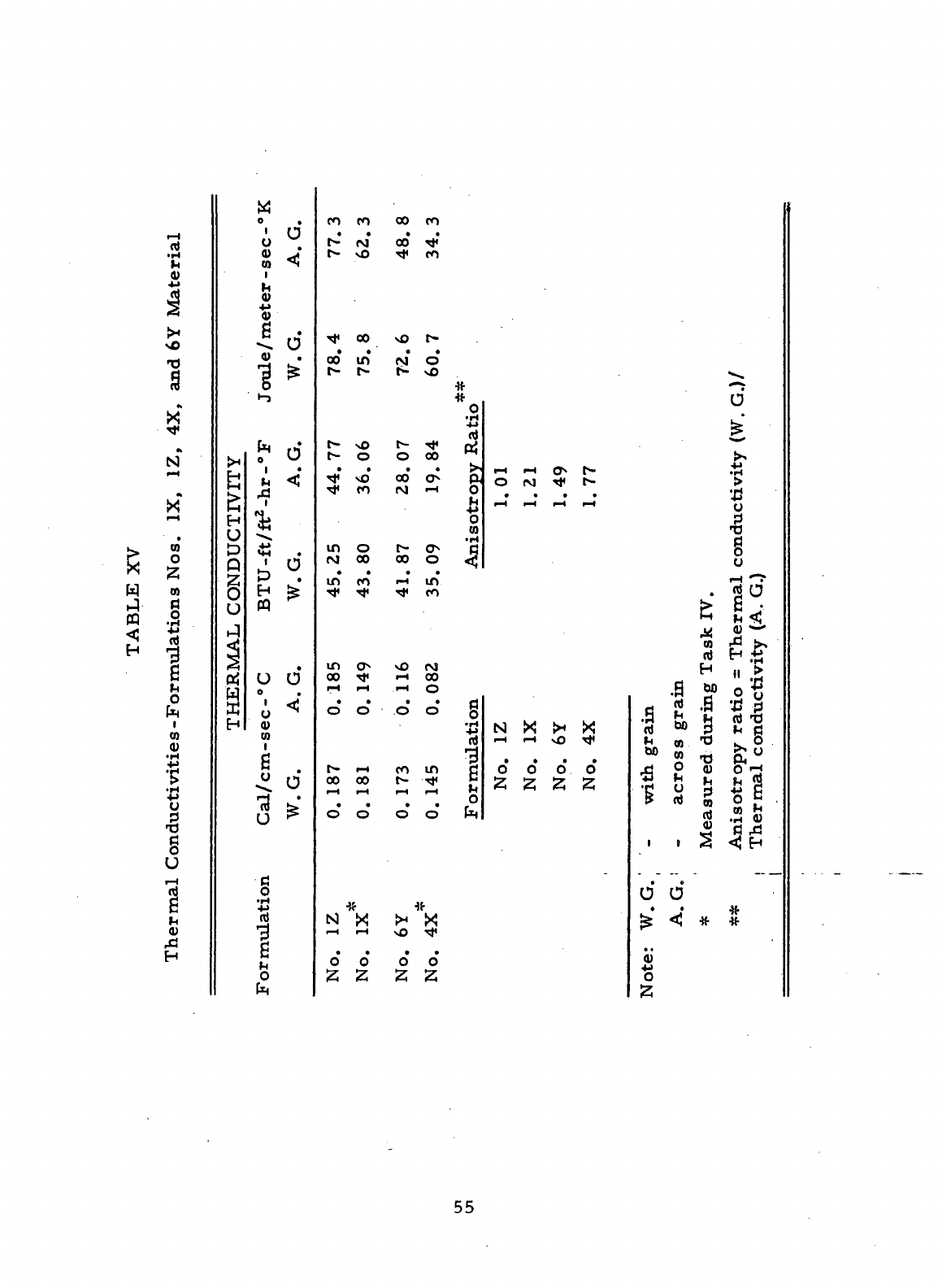
g
H
rH
PQ
<;
H
nt
•H
14
0)
NO
Tl
s
•k
X
N
1—4
^
X
rH
to
O
Z
CO
rt
luctivitie
s -
Formula
t:
^^
P!
0
U
i—
i
rt
H
l<
0)
H
{H
H
Jr*
^
f_i
r -\
CONDUC
THERMAL
M
o
.
' O
0
<u
j;
m
*S
^*
*•
4 0
V
1 *
•-»
* d
h <J
r]
1
*ii
*tH
«
.
0
°.
H te
«
U
O
o
•
i
<;
O
<u
CO
h
.
4i
o
•a !>•
u
^
c
o
*p
«J
*7J
g
o
to
m ro oo m
• • • >
r~ psj oo <*<
r- \o rt< ro
^t
oo \o r-
oo
m NO
C^ \O t*™ ^J^
r^
o o oo
^^ vQ QQ ^^
^f CO (VJ --I
in o t*- C?N
N 00 00 O
in*
ro
•-<*
in
m
o so tvj
00 Tj< ^1 00
rH
i—
1
i-H O
O O O O
r~
i-i to in
00 00 t^ ' ^^
i—
1
i—
1 rH
i—
1
o o o o
•»{•
*
N X >< X
i—
I
i—
1
\O rj<
o*
o
0*0'
z
z z z
#
XJ
5
ft
o
-4->
0
CO
1
Formulation
O fvj ^ t^
• • • •
rH
rH r-t rH
N X {H X
•
• • •
O O O O
^
with
grain
across grain
easured
during Task
i
i ^
• e
O O
• t
^ <J ^
0)
"o
z
"2z.
o
^
J
•H
is
u
p
*t3
g
U
1
s
s<
lisotropy
ratio
= The
lermal conductivity
(
«2
C
^S
r^
__.
•ft
•if-
55
Figures
1 and 2 are
plots
of the
coefficients
of
thermal expansion
deter-
mined
for the
compacts
of
formulations Nos.
1Z and 6Y.
Each plot represents
the
average
of two
tests
conducted
on
samples machined
on the
with-grain
direction.
.
Figure
3 is a
plot
of the
coefficient
of
thermal expansion
of
com-
mercial
seal
ring Grade CDJ-83, which
has
been
included
for
purposes
of
comparison.
All the
materials analyzed
showed
an
increasing
coefficient
of
thermal
expansion
with
increasing temperature.
The
coefficient
of
thermal
expansion
of
Grade CDJ-83
is
considerably higher than those
of the
other
ma-
terials
tested. Figure
1
presents
a
comparison
of the
coefficient
of
thermal
expansion
of the
formulation
No. 1Z
material
to
that determined during
Task
IV
—for
the
formulation
No. IX
material.
The
coefficients
of
thermal
expansion
of the two
materials
are
comparable. Figure
2
shows that
formu-
lation
No. 6Y
resulted
in a
material
having
a
considerably lower
coefficient
of
thermal
expansion than that
of the
similar
formulation
No.
4X--jnaterial.
Based
on the
measured thermal properties,
the
material
manufactured
from
formulation
No. 6Y is a
potentially better
seal
ring
material
than that
prepared
from
the
comparable formulation
No. 4X. The
higher thermal con-
ductivity
of the
formulation
No. 6Y
material
as
compared
with
that
of the
formulation
No. 4X
material will
provide
more rapid
dissipation::.of?
the
fric-
tional
heat
generated
during
periods
of
sliding contact.
The
lower
coefficient
of
the
thermal expansion
of the
formulation
No. 6Y
material
is
beneficial
from
a
thermal
deformation
standpoint.
Although
a
metallic shrink ring con-
trols
the
thermal
deformation
of the
carbon ring
in
some
cases,
if no
shrink
ring
is
used
(as on
small
turbine engine seals), thermal
deformation
is
miti-
gated
by
using high
thermal
conductivity
and low
thermal expansion carbon-
graphite
materials.
56
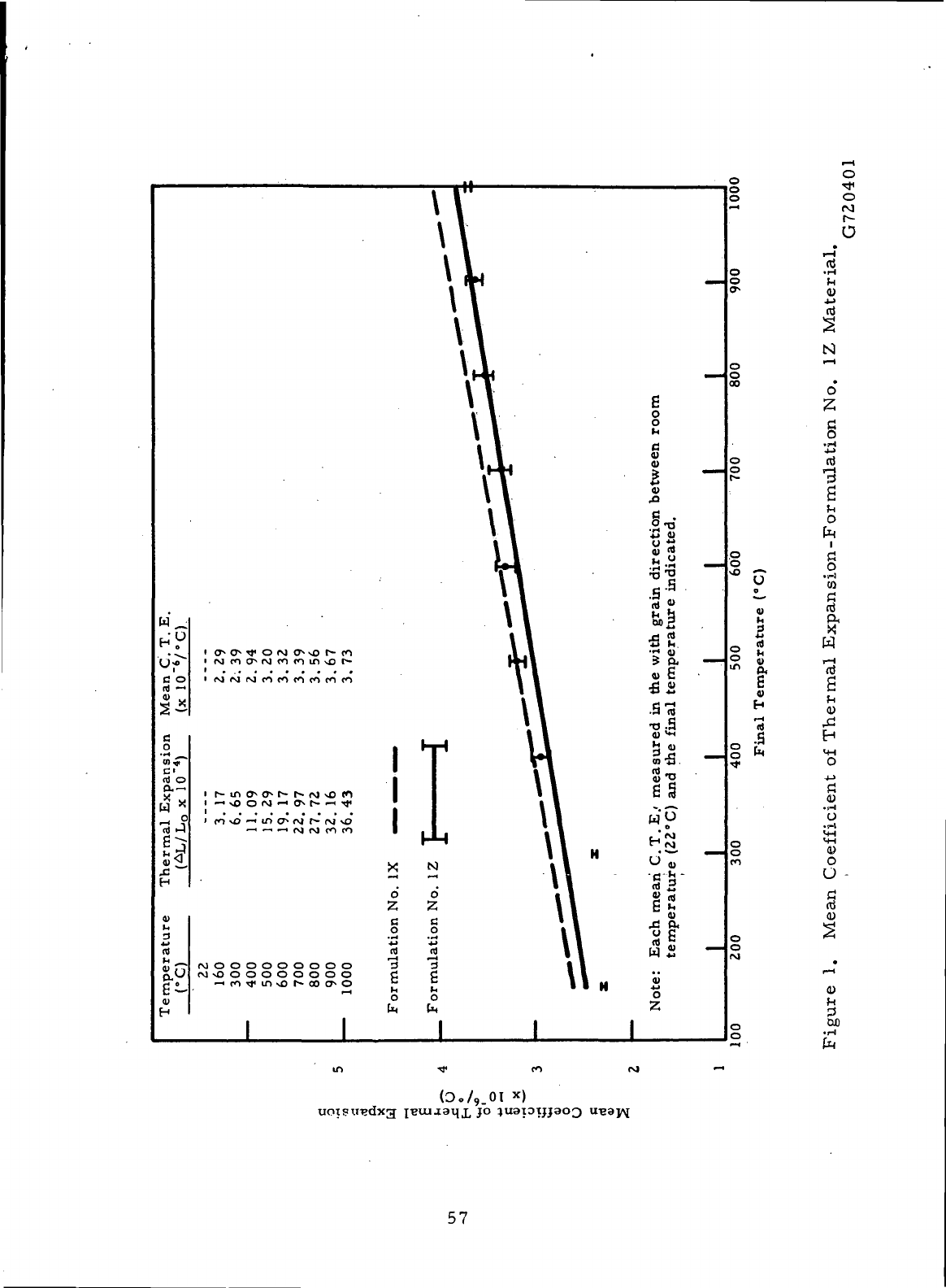
POOOOOOOOOO
ro\OOOOOOOOO
o
•*
o
M
r-
o
U
nt
.3
o
Z,
§
•
>p4
4_>
rt
•3
)H
O
g
•t-l
CO
C
nj
W
r-l
rt
a
^
0)
^1
H
<«
o
j->
fl
0)
.iH
O
•t-1
m
m
0)
O
O
00
•*
(0./9.0I
57
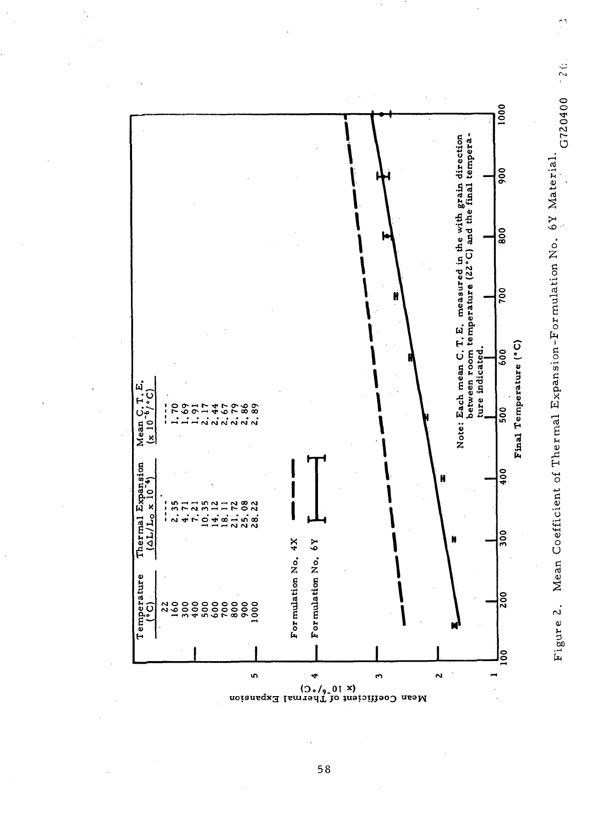
o
a?
tt
O
s *
1^°
H
(4
s^
a
-H ^H r-l f\J fM f\J
(MOOOOOOOOO
(VjvOOOOOOOOO
n)
nt
1 1
h M
O O
O
.
o
O
o
o*
o
o
ao
o
o
f--
o
o
o
o
tn
o
o
o
o
CO
o
o
rM
8
U
i
•a
.s
o
o
•*
o
(M
r~
o
a
o
ti
o
,~j
ID
ti
ni
H
"rt
0)
H
<+H
O
J->
ti
0)
'u
0)
o
O
0)
JH
3
ao
o
o
uotsundxg
•*
(D./9.01
58
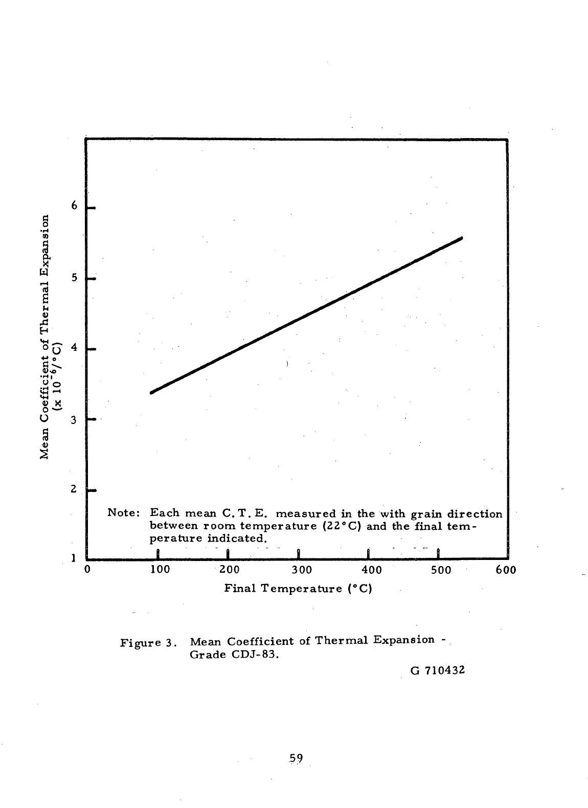
g
W
5
i—i
nt
6
h
u
rU
H
VI ^_ ^
°U
4
9
Note:
Each mean C.T.
E.
measured
in the
with
grain direction
between
room temperature
(22°C)
and the
final tem-
perature indicated.
B
i . " i i ' '" a
^___
100
200
300 400
Final
Temperature (°C)
500
600
Figure
3.
Mean
Coefficient
of
Thermal Expansion
-
Grade
CDJ-83.
G
710432
59
D.
Porosities
Carbon-graphite
seal
ring bodies must
be low
porosity
materials
so
that
they
will
be
impervious
to the
fluids which they
seal.
As
demonstrated
during
the
experimental portion
of
Task
I,
—the
mechanical
properties
and
oxidation
resistance
of a
carbon-graphite compact
are
greatly
affected
by the
choice
of raw
materials,
composition,
and
final baking temperature used
for
its
manufacture. Although
the
degree
of
crystallinity
of a
carbon-graphite
body
greatly
affects
its
material
properties,
the
porosity
of the
compact
also
has
some
effect.
Reducing
the
porosity
of a
formed
article
should
result
in
an
improvement
in the
mechanical
and
chemical properties.
The
carbonization
of
a
resin
Lmpregnant
has
been
found
to be a
good
way to
reduce
the
porosity
of
a
carbon-graphite compact. Resin impregnation
has
been
found
to be
better
than
the
conventional pitch-type impregnation, since
the
resins,
with
their
lower viscosities
and
increased
wettingn,
tend
to
block
the
pores,
as
well
as
the
larger
open volumes.
^Decreasing
the
porosity
of a
compact reduces
the
number
of
interconnected voids,
and the
remaining isolated voids
are
less
damaging
to the
mechanical properties.
Reducing
the
porosity
of a
carbon-
graphite compact
also
should
increase
Lts
oxidation
resistance.
Table
XVI
presents
the
percent total porosities calculated
for the
com-
pacts
of
formulations Nos.
1, IX, 1Z, 4, 4X, and 6Y. The
values presented
for
'the
materials
manufactured
from
formulations Nos.
1, IX, 4 and 4X
were
determined during Task.IV,
— but
have been
included.for
purposes
of
com-
parison.
Table
XVI
also
displays
the
percent total porosity determined
for
commercial
seal
ring Grade CDJ. These values were calculated
by
using
the
following
equation:
Helium
Density
-
Bulk Density
Percent
Total Porosity
=
100X
'•
Helium Density
>
The
value obtained
by
using
this
equation
is the
ratio
of the
total open pore
.volume
to the
volume
occupied
by the
pores
and the
carbonaceous
material
in the
compact being analyzed.
60
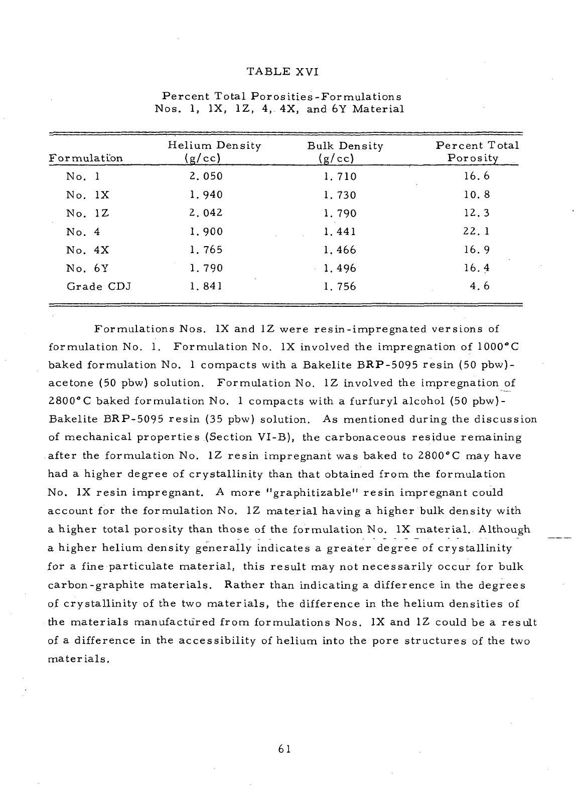
TABLE
XVI
Percent
Total
Porosities-Formulations
Nos.
1, IX, 1Z, 4, 4X, and 6Y
Material
Formulation
No.
No.
No.
No.
No.
No.
1
IX
1Z
4
4X
6Y
Grade
CDJ
Helium Density
(g/cc)
2.
1.
2.
1.
1.
1.
1.
050
940
042
900
765
790
841
Bulk
Density
(g/cc)
1.
1.
1.
1.
1.
1.
1.
710
730
790
441
466
496
756
Percent
Total
Porosity
16.
10.
12.
22.
16.
16.
4.
6
8
3
1
9
4
6
Formulations Nos.
IX and 1Z
were resin-impregnated versions
of
formulation
No. 1.
Formulation
No. IX
involved
the
impregnation
of
1000°C
baked formulation
No. 1
compacts
with
a
Bakelite BRP-5095
resin
(50
pbw)-
acetone
(50
pbw) solution. Formulation
No. 1Z
involved
the
impregnation
of
2800°C
baked formulation
No. 1
compacts
with
a
furfuryl
alcohol
(50
pbw)-
Bakelite BRP-5095
resin
(35
pbw) solution.
As
mentioned
during
the
discussion
of
mechanical properties (Section
VI-B),
the
carbonaceous residue remaining
after
the
formulation
No. 1Z
resin
impregnant
was
baked
to
2800°C
may
have
had a
higher degree
of
crystallinity than that obtained from
the
formulation
No.
IX
resin
impregnant.
A
more
"graphitizable"
resin
impregnant
could
account
for the
formulation
No. 1Z
material
having
a
higher bulk density with
a
higher
total
porosity than those
of the
formulation
No. IX
material.
Although
a
higher helium density generally indicates
a
greater
degree
of
crystallinity
for
a
fine
particulate
material,
this result
may not
necessarily occur
for
bulk
carbon-graphite
materials.
Rather than indicating
a
difference
in the
degrees
of
crystallinity
of the two
materials,
the
difference
in the
helium densities
of
the
materials
manufactured from formulations Nos.
IX and 1Z
could
be a
result
of
a
difference
in the
accessibility
of
helium into
the
pore structures
of the two
materials.
61
The
formulation
No. 1Z
material
may be
more oxidation resistant than
formulation
No. IX
material,
even
though
the
total
porosity
of the
former
is
slightly
greater.
The
helium density measurements indicate
the
formulation.;
No.
1Z.
material
is
less
accessible
to
helium than
the
formulation
No. IX ma-
terial
and, therefore,
may be
less
accessible
to
oxidizing gases. Greater
oxidation
resistance
also
would
be
expected
if the
formulation
No. 1Z
material
is
more
"graphitic"
than
the
formulation
No. IX
material,
since
the
degree
of
crystallinity greatly
affects
the
rate
at
which
a
carbon-graphite
material
oxidizes.
The
data displayed
in
Table
XVI
show
that
the
percent total porosity
of
the
formulation
No. 6Y
material
was
similar
to
that measured
for the
formu-
lation
No. 4X
material (Table
I) and
lower than that
of the
formulation
No. 4
material
(Table
I). The
reduced
porosity
of the
formulation
No. 6Y
material
was
probably primarily
effected
through processing changes other than
resin
impregnation,
since
the
resin pickup
of the
formulation
No. 6Y
compacts
was
low.
The
total porosities
of the
materials
manufactured
from
formulations
Nos.
4X and 6Y
related
to
their
mechanical
properties:
both
materials
had
significantly
better mechanical properties than those
of the
formulation
No. 4
material.
, The
total porosities
of all
these
materials
are
significantly
higher
than that
of
commercial Grade CDJ.
Tables:
XVII
and
XVIII
present
the
results
of the
pore
volume
and
pore
size distribution measurements made
on
compacts
of
formulations Nos.
l.Z
and 6Y by
using mercury intrusion. Figures
4 to 7 are the
corresponding
plots
of the
pore volume
and
cumulative pore volume versus pore diameter
for
the two
materials.
The
mercury
intrusion method
is
used
to
determine
the
distribution
of the
pores ranging between
0. 02 and
100.
0
microns
.(n.)
in
diameter.
For the
range
of
pores measured,
the
formulation
No. 1Z
material
was
found
to
have
the
largest
average pore diameter
(5.
2|J.)
with
an
intruded
pore volume
of 0. 082
cc/g.
62
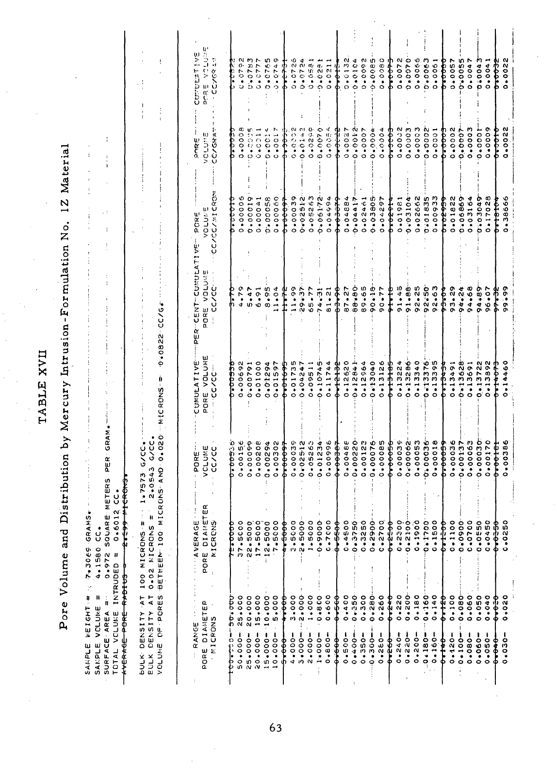
a
^>
k/*
?S
w
n
^*
H
"rt
•
(U
AJ
nj
^
^*
N
o"
*~7
^~*
a
O
a]
/d
6
)H
O
^*^
i
a
o
to
3
4J
H
h-4
^
3
U
^
(U
&
W^
_
rU
C
o
•H
4-*
3
jfj)
•rH
J_l
4->
(A
• «H
Q
T)
C
<U
6
3
•
'
iP
^
CU
O
OH
i
1
;
'
:
1
(
j j
'
; j
(
j
'
i
l
'
i
I
i
•
£
<f
'
o;
15
a
UJ
;
o.
'
'.
10 I
i or
Ul
• 1
H-
O (
UJ
O <
Z
i
» CM :
CO
UJ -<
$ a: o i
< • < «o <
or
o J • i
V9
O O O
CO <
l> O
tl) CO <V II
o in N
to
•" 0- Q
• • •
UJ
N
4 O D I
D
;.-
or •
II II : 2 •
II
>- I
H- UJ
I
£.
<
UJ
1
IP D UJ ^£ t
~ _l or D (
UJ
O < J (
i > . 0
UJ
> 1
UJ
UJ (J t
_l _l < -1 •
a o. u. < (
:£
u; o: i- i
< < D o ;
I/I CO 10 H •
t
i
I
i i
• 1
;
i
'
:
j
1
!
,
'
i«
19
!
X
i
O
i
o
! CM
;
Jj
;
' o
•
p
I)
in
2
O
:
a
!
u
;
2
i
:
1
« 6
• O
CM
ooo
ox.
X
0 0
o
<o
o
• ro •* 2
i r> u") <
: in o ,
)
r- • co
:
.
CM
2
1
-« O
•
or
o
n
«
. II £
CO
' (0 2 p
•
2 a o
i o
or
-
'or
o ,
o
« 2
« ^. UJ
Z Ul
CVI
i
>
O 0 1-
3
O • UJ
i -H 0
DJ
H 1- 10
I -I <
UJ
a.
J
> > O
:
t- H a
CO
10 U-
2 2 C
J
Ul Ul
Q Q (U
* * i§ •
J
-J -1 -J
D
^ O
J3
01 >
ir
W
.":
^. Ti ^i
"r
'-.'
fr
-
JJ
' N
Jj
in U
!•-
or o
b L. .
U 0
i
' UJ S
1 3 x
0.
O U
>
o
i i
1
[
1
i
?
-
p
: (X
III O
U.
1
L: 1^1
a D R
(J
-1 X
a
o o
>
u
i
X
Ml
U
>
o
.
ij ai •
5?
T
D
-/ U
o
a o
i
> x
K O
2 UJ O
.
UJ or
u o ;
:
a
m
9-
!
^
LU
2
> D !
" -I 0
1-
O O
< > X
J O
D UJ O
S. nt. •
D 0 :
y a ,
:
uj o
UJ
2 O
o _i u
Q.
U u
F
>
!
j
,
or
:
tu
•
i-
uj
ui in
o 2: 2
<
< o
or H- or
UJ
O O
^ »»4
< ID a
: or
o
;
a .
'
a .
UJ
: ^-
ui in
Ul
2 2
o
< o
2 « or
< Q O
a:
«
UJ
£
: or
o
a
.!
rvj ro t- in o>
c
o- » r- to <t 5
'.
N S N r~ N 1
J
O O 0 O O
>
U ^) O O O
'
3
cc ir-
—
*
%( N
)
o :• -« -. -, •
>
o o o o o
3
O (.' 0 O O
3
O p O O O '
•
i
j
j 1
3
tO O
1
~i CO C
••
o « <t if; tc
>
o P o o o
J
O O O O O
>
o o o o o
3
0 p 0 0 0
!
3
<?! |tv r-« (/7 <f (
-
r- t o o. o i
)
4 in to co •-• •
•~* *
)
CVI
M O O- r- 1
>
0* 0, O Ot 0* (
) to r- o cvi in t
3
O O -« *< — •
3
O O O O O (
3
O O O O O (
1
O tO 0i CO -it CVI 1
•i in'
o>
o o o i
1 -• O CM (M fO (
3
O O O O O t
3
O O O O O C
3
O O O O O <
3
O
P"O~o
O (
3
O O O O O <
3
U O O o O <
3
in in in in in i
)
r-
CVJ
N CM 1* •
-
n
CM
n -•
•
• i
b
o o o o o <
3
O O O O O (
3 O O O O O <
3
in o in o in •
n cu (vj — —
i
l i l l l
0 O O O O O (
>
o o o o o <
•>
o o o o o (
>
o in o in o i
,««,«--
,,04
«*<-
j
rti f\! no (T. — i
. N N If)
CVI
PI •
J
O O O O O <
>
o 6 o o o (
!
,
;
:
j C\J CM O- O tf C
>
O -:l 'J. (v
1C;
'
>
C* •-« CVI Cb O •
>
c c o e o <
>
o o o o o <
i i
1
i
j
;
. 0> <M 10 (M 4 <
N
ro ^ tc r> <?• i
>
o in
CM
•- o> '
>
o cvi in ,0 4 n
>
o o o 6 o <
3
O 6 O p O <
:
i
•
0^ (*) ^ ff) W i
• ••* 0» If) <f r« 1
«
—
* (\l vD /»- CO f
i
j
in N -i th •* <
s
n •* -» •* <f t
>
h- (VI IO f> N •
i ^ <t O* 0 -« (
>
O O O O O (
1
1
. U' (VI i
1
) 4- tO 1
>
ro -* to ro ot c
3
o in CM CM o* r
>
o
CM
in ^ o <
>
o o o o o <
)
O O O O O (
i o o o 6 o c
)
O O O O O <
i in in in
o>
f- i
i i«j
cvi
-< 6 o (
| ;
t
!
1
;
>
o 6 o o o <
>
o o o o o i
) O O O CO tO t
IO
(M -t O O <
1
1 1 1 1
)
O O O O O C
>
o o o o o <
3
O O O O <0 ,
•)
4 IO CM -H O c
,
CVJ
4 (VI m O 1
)
n c
1
•-, .
j o- <a
00
i
•"
O O O
>
o O O O O <
>
o p o 6 o
1 h~ C
1
1
;M -
i O C
>
0 «
i
1
1
'•
U
N 41 4 1
i O O O
5
0 O 0
toco
) O O O O O <
. 4 r
. CO «
) CU <
) -4 N
1
j
-
-« ib N
t, >c p 0>
J
4 00
CM
I
t CM to 4 <
>
o o o 6 o i
>
o 6 o p o
i N o in cb N c
i
CVJ
co ,0 — r-
)
r* cb O
1
P o
) 00 CO CO 0* 0*
i '
I 0 -
) CM -
i
tO'
Q
'
i -4 O
tO
1
t tO 4 CM 1
)
O* O
—
' •
1
CM CM (M to IO t
>
o c;
,
)
co r
)
4 f
>
0 C
a
o o o
1
.1
>
PI to in
vj
CM
h- co i
M
—
0 0 i
S
o o o (
i O O O O O <
i o o o o o (
i i
1
o p o o o <
o in in p o <
4
f
1 IO CM CM (
o o o 6 o (
i O c
3
O 6 O <
>
o in o co to
>
<t IO IO CVI CM ,
>
O O O p O I
1
I 0 C
1
1 1 1
3
0 O 0 <
o o in o oj t
in <t 10 ro CM c
o
o o o o i
i
1
) CM O tfl t
•
f*- P* t£>
)
O O O
0 —
r; (£}
3 O
I O p O O O
3
O O O 0 O
.
l
CM
ro ro
>
'3 O O
)
O O O
\J
- 1
3 O
D
0
3
O O O p O
3
O O O p O
•
i — <> (M in ro
«
03 O *C
,
CJt
—
i tO
1
— ro CM
o to
o o-
M
O
>
o 6 o o o
)
O p O p O
)
10 co m p ro
*
<f co CM in ,0
•
— M (VI (VI (VI 1
, C* 0 0- 0. 0>
i
•
,
)
4- tO O to' 10
) CM CD <t 1
• cvi CM to r
) ro ro ro i
^-
0t
o ro
o
to i
3
o o o p o i
i j
)
o> cvj ro to co
i
to
* in i
J
0 O 0 <
)
O O O
o
-«•
i
3
0
3
o
I O O O O O <
>
o o o b o
>
o-p o b o (
i O O O O O
>
o o o p o <
i
,
1
3060001
(M
O CO tO 4 <
3
O O O o O <
1 1 1
3
0 O 0 <
1
3
0 <
J
-ft W O 00 tO ' •
O O O O O (
i
I
!
>
N m N
)
in in <»
3
O O O
T
- i
tt 4 1
D
0 i
)
O O O O O :
>
o 6 o p o i
i
i
1
1
) CM |L (O
)
O O O
)
o O O
D
O .
D 0 •
3
O O O O O
>
o p o o o i
i
',
1
I
t
(M l> 4 0> CO
) CVI ,O tO
>
CO CD —
J
— o IO
tt (M ,
O O <
•o
r-- i
3
o o o b •* •
3
O p O p O
i-
0> <t co
>t
N (
3
(M (M tO CO O 1
) tO -ft 4 <t tO 1
*
O* (J* O* 0* ^
(
i
1
;
•
t •* 00 •-" (VI (M 1
) 0t (M Ot
r
4 to to
M 0> 1
•- CO 1
) to to to ro to •
3
O P O O O 1
i
i
! ••
t
to N P) b' O .
>
ro to to
>
O M O
>
o 6 o
O t-- (
D
— .
0 0 <
>
o o o o o (
)
0 p 0 P O (
i
>
o b o o o t
3
o o o in in i
>
o o o o o <
r
3060001
i o
co
to in 4 i
>
0 O 0 0 O 1
l i 1
>
O O O (
3
O <
t
CM
o co to in <
3
O O O O O t
J CVI
) (VI
?
o
3
O
3
O
3
CM
• CVI
>
O
3
O
3
0
i-
vD
>
tO
4
,0
3 CO
<
ro
>
0
;
o>
) 0*
• 0>
t 0>
)
O i
• <0
3
4-
f
*
>
O
<
tO
>
co
•
to
)
O
>
o
>
o
1
0
>
in
) (VI
3
O
I O
>
O
>
O
) CVI
>
o
>
o
I
3
O
IO
3
O
1
B
5
O
63
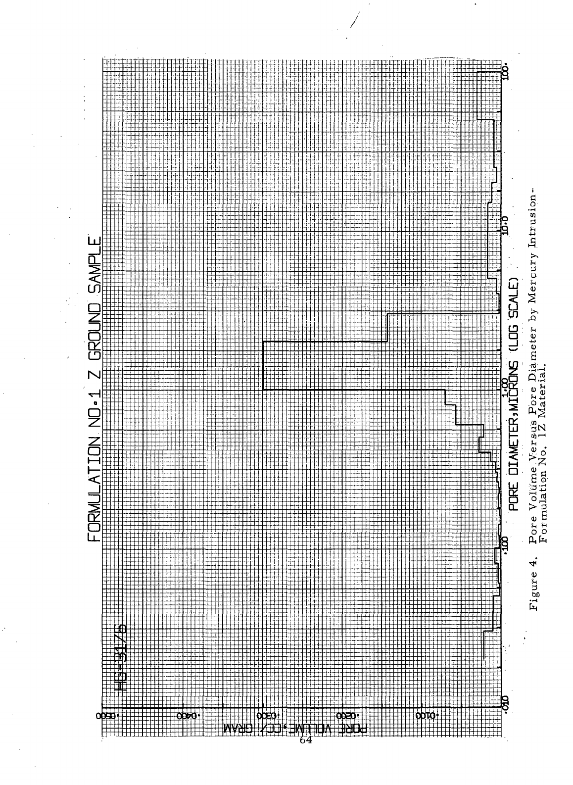
i
g-
• ^H
tn
3
i-,
(H
3
O
0)
<U
a
ti
OP-I
I
a.™
o o
<u
is
d
bO
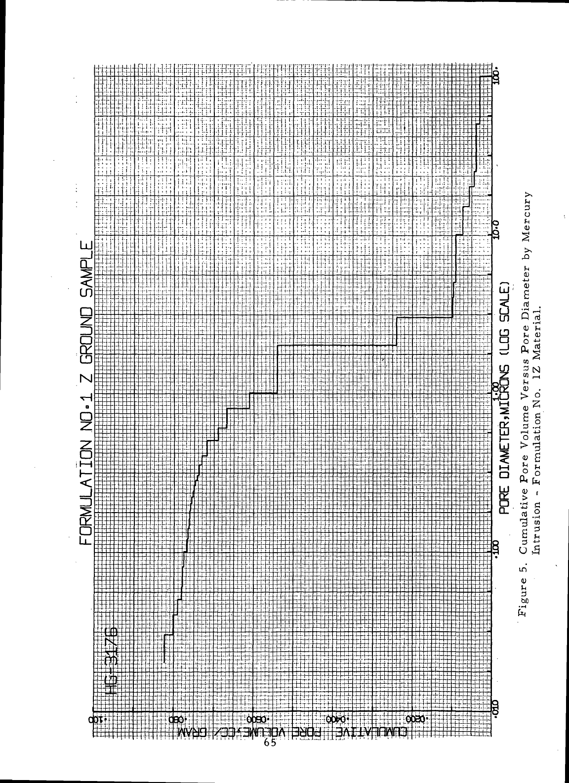

X
w
r—
1
n)
•r-t
fH
OJ
i
>-
sO
,
o
^_l
r^
o
*4_j
n)
F—
1
d
B
«.
o
f
T
,
r-H
1
£
0
•^
CO
3
In
^
.H
p
3
U
(H
<U
«^
^»
43
O
••^
"^T
J5
•
*H
•
£j
CO
Q
T)
C
rt
OJ
e
3
i—
i
O
OJ
M
O
.
1
•
X
:
4
a
or
ii!
to
(
ft .1
H O 1
Ul
U 1
.
X •
i
oo
:
10
Ul 00
x
a -
c
4*401
i>
in
W
4 h- 4 n
4 N
CM
in
4
03
a i
*
• t \ll
<0
4 4 O (
i
i * '
li
II | Z i
1
- t
H Ul i
X
X 4 Ul I
« 3 Ul X (
H
j a 3
c
1
Ul
> I
. uj Ul U V
'
J J 4 J «
: a a u. 4 c
i
S X a I- t
•443O:
. (A M M H «
1
i
f
19
N
U
U
in
in
••«
o
n
w
§
a
u
*•«
X
• o
• U (M
U
U 0
UN*
S
O 0
° 0 Q
*•*
O Z
00
CM
4
4 •
CO
*4
O
cr •
(S
z o
zoo
o
a -
<r
u
u
- z
- X Ul
X Ul
:
(VI
•
O O 1-
O
• Ul
- O
CO
.
4 4 Ul
•
or
H-
>- a
~ « ;
Ul
Ul ,
a o ui
j J
«f
330
CO
CO >
UJ
UJ
Z
>
3
t- O (
<>,
' 3
UJ
i
i
a
«
3 O
u a
UJ
•
Ul
Z [
a
3 i
o -J •
a
o i
>
i
i
UJ <
Ul
Z .
a
3 :
o
-i '
a
o i
> i
Ul
I
>
i
t~
5 10
3 S.
X
3
3
J I
U
O
I
> >
(- V
Z UJ «.
Ul Ct
U
0
a
QC'
SI
. Ul
Ul
I
> 3
?dl
3*;
3 Ul V
x
a
3
0
u o.
Ul
I
UJ
Z I
a. 3
•>
S
J V
0 V
>
a
Ul
t-
Ul Ul 0
o
x ;
4 4 C
£
«• d
0 «.
4 Ul 1
: Ct
•
o
:
a
a
Ul
i
UJ (J
x
;
Z
2S
4 O V
a
;
a
o
a
) PI OD «O O» 00 <
)
tn 4 4 W N c
>
tn in in in 4 P
>
o o o o o c
i tn ~ t~ ~ 4 P
>
o o - in
o>
P
I O O O O O C
>
o o o o o c
>
o o o o o c
I
.CM
4 O o C" (
i o o in in s <
>
o o o -«
CM
i
>
o o o o o <
1
O O O O O (
>
O O O O O (
1
tO
4 4 r*
03
I
i in
<o
N o o c
i o o - in ~ f
. 4
oo
o in o <
CM
4 o in tn u
.
~
—
4 - in <
P
O O O "
CM
f
>
o o o o o c
.00074
0.
00024
0.
.00251
0.
00754
0.
,
C1395
0.
I O o O O O c
o o o o o c
O
O O O O (
o o o o o (
in in in in in ii
P- CV| N CM l>- <
IO
CVI
f .M
. O O O O 0 c
o o o o o <
0 0 0 0 O
C
in o in o in <
)
(M
CM
f r«
1
i 1 j 1
i o o o 6 o <
O
O O O O (
o o o o o c
o in o in o ii
in
cvi
CM
••>
"
' '• i
o to
CM
tn in c
>
in n N o> 4 t
1 P) (M 0> <D <O II
i o o o o o e
1
"
<D
~O
O in £
ix * N m
<o
i
. ^
CM
CM
O O <
'
o o o o o (
I O O O O O 1
4 P)
<O
- P) (
i
in
P)
OD
in - i
! vO 0* O N 00 1
i -< O 4 10 4 I
i O O O O O <
i o o o o o <
1
4 4 O
1
in 4 1
i 4 in cvi tn r- (
04705
20.
08638
37.
12725
55.
13475
58.
14438
62.
.01654
0.
03933
0.
.04086
0.
0075O
0.
.00962
0.
c o 0 o O <
0 O 0 O 0 (
o o o o o <
o
o o o o i
in
in in
o>
N i
P)
(M " O O <
i
f
:
1 1
o o o o o <
O O O O O 1
0
0 0
03
« I
n
en
" o o <
Hill
0 O O O O <
o o o o o <
O O O O 00 v
4 P)
CVI
«. O (
i :
•
*
O N «O O O
t 4 — O
<Jv
N
t
o o o o o
)
o o o o o
*
P) o O O N 1
>
o o o o o <
>
o o o o o <
03444
0
03177
0.
04903
0
07647
. 0.
05215
0
t
o o o o o
I in 4 o s
<M
i
i r- 4 in "
<o
i
1
<0 N CO 0» 0> <
15360
15519
15764
15917
16021
.00344
0.
00158
0.
.00245
0.
00152
0.
.00104
0.
>
O o O O O <
) O O O o O <
>
o in in o o <
i at f- ft o> f- t
) 4 P) P)
CM
(M 1
>
O O O O O (
i
1
i j
1
O O O O O I
>
o in o oo <o '
) 4 PJ P)
CVI
CM
1
>
O O O O O 1
1
1 1 i 1
! 0 O O O O 1
>
o o in o oo ^
) in 4 P> p) (M (
>
o o o o o (
•i
i
i 1
\l N (M 00
CM
f> v
w
\o .0 4 P) •** '
3
O o O o O <
>
O O O O O <
) 4 4 <0 4 -• <
>
O O O O O <
>
O O O O O C
>
o o o o o <
>
oo — in o 4 c
t
O> 03 P) Q P) 1
. g 4
oo
o>
4)
i
t
p) o ** o oo •
)
0 - - - 0 J
>
o o o o o <
>
in h- a> in o t
£
M - - - o, a
>.
0 -•
CM
P) P) I
)
I" N PI 10 « t
>
<O
f- " 10 0 <
' " P)
<O
03
O (i
>
<0 «
<O
« N h
>
O,O O O O I
i ~ o> <o o>
cvi
r
i
<o
o to « r- i
>
O (M
CM
(V) ~ (
>
o o o o o c
>
o o o o o <
>
o o o o o <
»
O o O o O <
J
O O O O O (
1 [-1 -* O. f- in r
J
O O O O O <
>
O O O 6 O (
' CVI O CO <O 4 C
>
o o o o o <
.i .i.
I O O 0 O O <
1
4 (VI O 00 « <
1
O O O O O <
i ;
I !
)
* r- o> <o <0 I
>
CO <o PI O <0 1
•
10 P) 10 CM (VI .
>
O O O O O 0
>
0 0 0 0 O <
. » N
P>
O N 1
>
o o o o o c
>
o o o o o <
>
o o o o o <
1
N N CM o •* <
) CM 10 O (VI O •<
i)
4 in
oo
co
o i
r
4 o •* P> o c
i -
CM
P)
4 0 c
>
O O O O -I •
>
o o> in « o <
•
4 M o 03
CVI
t
1 \0
CO
O
CM
N n
17582
17993
18629
f
19067
I
20067
(
•0
OOOIO'
•O
8E*00
•0
9E900"
•0
11*00
•0
88200'
>
O O O O O (
>
O O O o O (
>
o o o m in u
)
"
o>
f* m 4 t
>
o o o o o <
I O O O O O <
j o
oo
« m 4 t
i
o o o o o <
:
i
1
i 1 1 1
>
O O O O O 1
CM
o oo o in <
>
o o o o o <
•1
i
1
99
1.71633 0.0116
0.0116
.01716
0.23011
99.
0.030-
0.020 0.0250
0
66
^^ffl^ffigffl
...±-±
Ef-Etft.
—
----:::::-::::::::::
--£---?-
._
_._ _! .
^
:EEEEEEEEEEEEEEE
Jif|
UD :EEEEEEEEE;EEEEEEEEE;EEEEEEEEE
a
.- .- X X.
CD
::
::::::::::;::::::::::::::::
Dull]
' II HTH
KH
::
i::::;::::::::::::::::::;::
iL
---
a
FORMULA"
iiiiiiM
:::::::::::::::::::::::::::::::::;: :::::::Tr:;:::::::;::::;;::::|::::;;::::
:
U" _. "
----
-- - ,
TTJT
: " : : : : i : . ;
..::i
'"XL
4- n
M
1 1
-H-i-
----
t
-::±:::::±::::::
I
. — . —
_i_._
._
—
i
— .
.IT .._
^A-tjVjW
"Hrl"
~ T "
-J-—
iui-
-
----lip
•
--in
jftilEEilEEE iEijf E;iS::if
!ii™:EEEEEEEEEE
67
||i|||||||||||||||||||||||||||W
i-oo
lo-o ido-
ICRONS
(LOG
SCALE)
Pore
Diameter,
by
Mercury
No.
6Y
Material.
::::i3:
:::::::::::::::::::::::::::::::::::::::::::::::::::::::::::::::::
•010
'100
PORE
DIAMETER
»M
Figure
6.
Pore Volume
Versus
]
Intrusion
-Formulation
68
The
similar
material
manufactured
from
formulation
No. IX had
been
found
during
Task
IV— to
have
an
average pore diameter
of 4.
4H-
with
an
intruded pore
volume
of 0. 076
cc/g.
The
larger
average pore diameter
and
greater intruded
pore volume
of the
formulation
No. 1Z
material
could
account
for the
slight
re-
duction
in
strength
and
hardness compared
with
those
of the
formulation
No. IX
material
(Section VlrB). Formulation
No. 6Y
produced
a
material having
an
average pore diameter
of 2. 6^,
which
was
approximately half
the
average pore
diameter
(5. 6^)
determined
during
Task
TV—
for the
similar
formulation
No.4X
material.
The
formulation
No. 6Y
material
had an
intruded pore volume
of
0.
156
cc/g, which
was a
little
larger
than
the 0. 139
cc/g value determined
for
the
formulation
No. 4X
material.
The
material
manufactured
from
formulation
No.
6Y
appears
to
have
a
larger
volume
of
pores measuring
less
than
0.
060u.
in
diameter than does
the
formulation
No. 4X
material.
Since
the
mercury intru-
sion method does
not
accurately measure
the
distribution
of
pores
smaller
than
0.
060u.
in
diameter,
a
more accurate determination
of
this
difference
was
made
by
the
nitrogen desorption method.
Table
XIX
displays
the
pore volume
and
pore size distribution determined
by
mercury intrusion
for
Grade CDJ. Figures
8 and 9 are the
corresponding
plots
of
pore volume
and
cumulative pore volume versus pore
dia^meter.
The
sample
of
Grade
CDJ had an
average pore diameter
of 1.
2fo.
and an
intruded
pore
volume
of 0. 025
cc/g, both
of
which
are
significantly
smaller
than
the
corres-
ponding
values determined
for the
seal
ring bodies
of
formulations Nos.
IX, 1Z,
4X,
and 6Y.
Tables
XX and XXI
display
the
results
of
nitrogen pore volume measure-
ments made
on
compacts
of
formulations Nos.
1Z and 6Y.
Figures
10
"and
IT are
the
corresponding plots
of
percent pore volume
and
cumulative
percent pore
volume
versus pore diameter..
The
nitrogen desorption method
is
used
to
measure
the
size distribution
of
pores with diameters
in the
range
of
20-600
Angstroms (A).
For the
range
of
pore sizes measured
by
nitrogen desorption (too
small
to be
accurately
measured
by
mercury
intrusion),
the
formulation
No. 1Z
material
was
found
to
have
an
aver
age
pore diameter
of 12 5 A
with
a
total pore volume
ofO.
0011 cc/g.
69
i-n
P
u
<U
TD
aJ
tH
o
1
o
tn
d
In
,£}
1^*»
•H
d
u
H
S
* S
w >>
•1 -°
PQ
a
< .2
H -g
,0
•
I—I
•4-»
CO
•
I—
1
p
T>
ro-
ll)
6
3
r-H
0
UJ
•H
o
r*4
in
z
4
•
or
o
00
«
«
0 Oi
N
4
II II
r- til
z z
O
3
uci
B
>
Ul UJ
ola
1
F.
X
<
4
in in
I
4
or
or
(U
a
in
or
u
•
u
o
z
Ol
Ul CM
or
01
4
—
3
.
O
0
in
—
n
•0
CM
O
•
UJ
00
or
z
n >-•
4 Ul
Ul
Z
or
3
4.J
o
UJ
>
0
4 -1
IL
4
or
H
3 O
in
t-
f
in
or
j
z
*
•o
o
II
in
3
4
a
UJ
or
3
a
UJ
o
4
or
u
4
•
0
U
0,
<J
N
\ 0
13
0>
CO
ro
in
-
ro co
^ ff
^
II
n
in
in
z
z
o
o or
I
0
- z
CM
O O
O
•
—
O
1-
r-
4 4
^ >•
—
^f
n tfi
•*
z
ss
X K
m m
.
o
<
o
U N
U
0
X
a
o
O.'-O
4 •
CO
-
n
n
v
i- in
- z
in uj
Z
0
Ul
o t-
z
Z Ul
3 or
M
4
-i
a
u
a
Z
4
o
X
u
u
r>-
4
CM
0
.
o
II
10
z
a •
a o
o x
—
o
z
o
O CO
OJ
0
o
o
o
o
0
Z II
4
tn
3 or
ac
o
U i-«
- z
z
o
o
0
OJ
•"
0
Z
0
UJ
ui or
?g
s§
in in
Ul
|U
or or
o o
a.
a.
u.
it
3
0
Ul UJ
E
Z
3 3
J -1
3 O
3
0
0
II
z
*
J
or
UL
.
0
3
.
til
UJ
S
>
3
CUMULATIVE
PORE PORE
CUWULAT
PLUME
VOLUME VOLUME PORE
VOL
RANGE AVERAGE PORE CUMULAYIVE
PER
CENY
PORE
DIAMETER
PORE DIAMETER- VOLUME PORE VOLUME PORE
\
I
CC
CCXCCXMICRON
CCXGRAM CCXGR/
U
U
U
U
X
u
J
i
u
u
in
5
c
z
5
or
u
z
r-
N
OJ CM
0 0
0 0
0 —
o
o
0
0
0
0
00000
0
00001
. 0
0 0
OJ O>
0 0>
0 0
0 0
o
o
.00010
o.
.00028
0.
0
0
0 0
O
0
0 0
o in
in N
N ro
0
0
O
0
0 0
o in
in
CM
1
I
o
o
0 0
0 0
0
0
3
in
in in
OJ OJ
o
o
o
o
0
0
o
o
0 0
0 0
0 0
o
o
0
0
0 0
0
0
o
o
o -<
0 0
o
o
0
0
o
o
r-
in
0
0
0 0
o o
0 O
0 O
0 0
0 O
0 O
in
in
IM
r»
CM
"
0 O
0 O
0
0
o tn
CM
—
I
i
0
0
0
0
0 O
n
o
IM
Ol
4 IM
OJ OJ
0 0
0
0
OJ
O
o
o
0 0
o
o
00013
0
.00009
0
o
o
-• ro
o o
0 0
0 0
ro
o
0
0
o o
0 0
0 0
0 0
0 0
o o
in in
ro
-
0 O
0 O
o o
Ol
•*
>
0
o
o
0
0
in CM
CM
OJ
OJ OJ
O O
0 0
O O
0 0
0
0
0 0
0 0
o o
o o
0 0
0 0
0 0
ro 10
o o
0 0
00
O
0
0 O
0 0
0 0
0 0
o o
So
in
0 Oi
0 O
O
0
o o
0 Oi
1 1
o o
o o
o o
—
o
OJ
OJ
OJ
OJ
o
o
o
o
o
o
o
o
0 0
o
o
0
0
0 0
o
o
0 0
0
0
0
0
o o
o
o
0 0
.ooooc
.ooooc
0
0
0 0
o in
09
N
o
o
o o
o in
CO
N
0§
0 0
O 00
OJ
~
OJ OJ
o o
o
o
o
o
o o
0 0
0 0
0 0
o o
0 0
0 0
00
0 0
CM
ro
o o
0
0
0 0
0 0
0 0
o o
0 O
0 0
0
0
in
in
0 O
0 0
o in
N •O
1 1
0
0
0 0
in
o
N
N
OJ OJ
o
o
o
o
0 0
0 0
0 0
o o
o o
- 0
o
o
o o
0 0
0 0
CO CO
0 0
o
o
o
o
0 O
O
0
0 0
0 0
o
o
o o
in tn
•o
in
0 O
O
0
o in
•0
in
1 1
0
0
0 O
in
o
•0 •O
OJ OJ
o o
o o
0 0
o o
0 0
o o
0 0
0000
10000
o o
CO
0
0 0
o o
.00000
b.
.00000
0.
0 0
0 O
in in
in
4
o o
0 O
o in
in
4
>
0
o o
n
o
t>
in
- 0
OJ OJ
0 0
0 0
o -•
o
o
0 0
0 0
0 0
•*
4
0
0
0 0
0
0
o o
CO
4
in 01
0 0
o
o
o
o
00
4
O
N
0
0
0 0
0
0
0 O
in
in
4 ro
o o
0 O
o in
4 (0
1
i
0 O
o o
in
o
4
4
o- 01
OJ OJ
o
o
o
o
o
o
0 0
0 0
o
o
0
0
0 0
o
o
0 0
0 0
0 0
4 O
O OJ
o
o
0
0
0
0
0 01
0 0
0 0
0 0
0 0
O
0
in
in
CO CM
0
0
o o
o tn
ro 01
1 1
in
o
10
ro
0> CO
OJ OJ
o
o
0
0
o
o
0 0
0 0
0
0
0 0
-
OJ
o
o
0
0
0 0
0 0
0
CO
-« ro
o
o
0 0
0
0
CO
01
0
"
o o
o o
0
0
0 0
0
0
in in
CM
r-
IM
~
O
0
0 O
o tn
CM
•*
1
1
0 O
o
o
in
o
CM
Ol
N m
OJ OJ
o o
0 0
CM
O
o ~
0 0
o
o
0 0
O 10
O
0
0 0
o o
in oo
Oi CM
CM
4
o
o
0
0
0 0
•o
n
4 <*
0
-
o o
0 O
0 0
o
o
in
o
01 Oi
" 0
o o
O
0
0
CO
- o
00
O
0
tn
o
** **
4 -0
CM
'-
0 0
0 0
•0
N
o
o
0 0
o
o
in ro
o —
o o
-
iO
ro n>
« '0
iO
Oi
~
CM
o o
.01193
0.
.01360
0.
0
0
0
0
0
0
o in
N
in
o o
o
o
0 O
« in
o
o
I
I
0
0
0
0
CO
«
O
0
CO
"
0 0
o
o
0
0
4
0
0
0
0 0
0 0
0837<
0335<
o o
- ,0
CO
Oi
4 OJ
CO
Oi
10
ro
o o
.00837
0.
.00167
0.
o
o
0 O
o in
in
N
4 ro
O
0
0 0
o m
4 ro
o o
1 1
o o
0 0
in <t
o o
-• f-
OJ
-
0
0
0 0
0 0
ro —
0 0
0 0
0 0
0 0
Oi iO
ro
4
O
0
0 0
N
4
en
a
o o
4 4
O
0
.00069
0.
.00029
0.
o o
M 0>
ro Ol
0 0
o o
O CO
ro CM
o o
00
m
o
to ro
o o
0 0
0 0
0 0
0 0
o
o
o
o
0
0
OJ
Oi
-
oo
_i
o
0 0
o o
in
0
ro
-•
o -<
4 4
o o
.00022
0.
.00017
0,
0 0
o
o
0 O
r>
in
CM
CM
0 O
o o
10
4
CM
01
o o
1
1
o o
00 <t>
CM
CM
O
0
ro
Ol
0
0
0
0
0
0
0
0
o
o
0
0
o
o
o
o
•-
«
0
0
0
0
0
0
ro
in
CO
"
4 4
0
0
0
0
in ro
0 O
o
o
0
0
0
0
0 0
ro —
01 CM
0
0
o
o
CM
0
CM
01
o
o
1 1
o
o
4 01
01
01
O
0
1
CM
o
o
0
o
o
o
o
Oi
o
0
0
r-
in
in
4
0
0
00
0
o
o
o
0
o
2
o.
o
00
0
1
o
o
CM
o
--
o o
o o
0 0
o o
0
-
0 O
0 0
o o
0 0
in oo
•C 00
0
0
0 0
o
p
fw
N
00 OJ
in -o
O>
Ol
CM
0
4 4
o
o
.00013
O
.00017
0
O
0
0 0
0
0
N
in
0
0
•0
4
o
o
1
I
0 0
0
«
o o
O CO
0
0
0 0
o
o
o
o
- 0
O
0
0
0
o
o
0
0
4 ro
O>
00
0 0
0 0
O
0
iO
N
ao
in
OJ OJ
o
o
.00018
0
.00016
0
o o
0
0
O
0
0
-
0 O
CM
0
O-O
1
1
0
0
4 01
O
0
r-
in
O
0
o o
0 O
0 0
0 O
0 O
0 0
o o
0>
N
OJ
01
"• O
0 0
0 O
co
ro
•0
-
DI 0>
CM CM
o o
.00025
0
.00019
0
0 0
0 0
O
0
01
r-
o o
o o
00
0
O
0
o o
1 1
o o
0 10
"
O
o o
*'
I*
So
O
0
0 O
0 O
o -«
0 O
0 0
o o
O
0
•O
0
CO
-
0
CM
0 0
o
o
10
Ol
ro co
00 00
Oi Oi
a*
o
CM
ro
0 0
0 0
00
-
0
CM
0 0
o
o
0 0
O
0
ss
tn
4
0 0
O
0
tn
4
0 O
o o
00
o m
0 O
o o
CM
OJ
o o
o o
O
0
0 0
0 IM
O
0
O
0
o
o
.01586
'. 0
03S47
0
o o
co
a
..
01
Oi Oi
0
CM
ro
ro
o
o
0 O
in in
-
ro
O
0
o o
0 0
o o
O
0
in
in
ro CM
0 0
o o
0 0
ro
oi
0 0
o
o
1 1
o o
4 ro
0 0
0 O
70
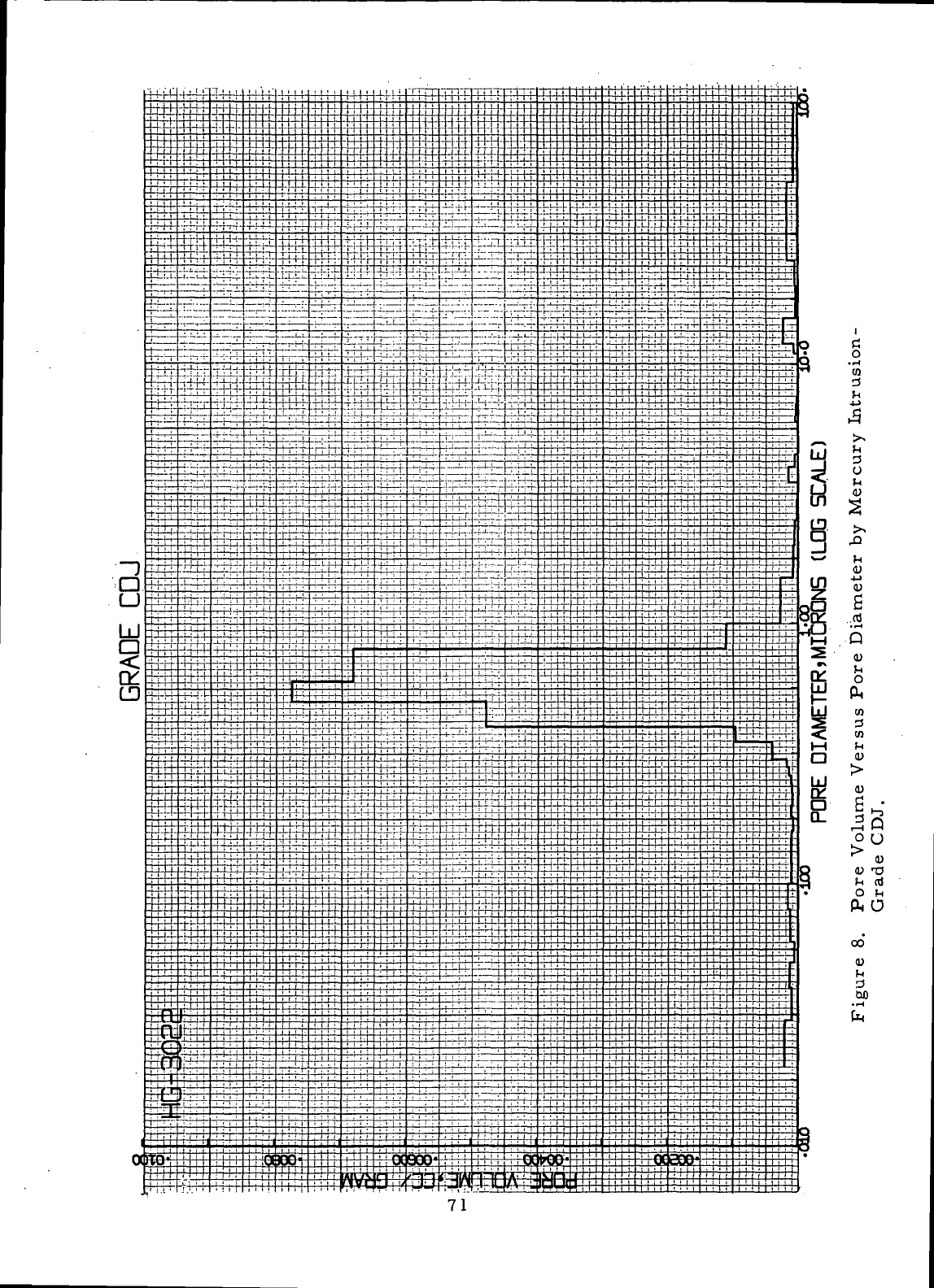
I
rt
o
• r-t
CO
d
d
o
4J
-i-i
0)
6
.rt
•
•-«
Q
CO
3
en
ft O
00°
CD
d
GO
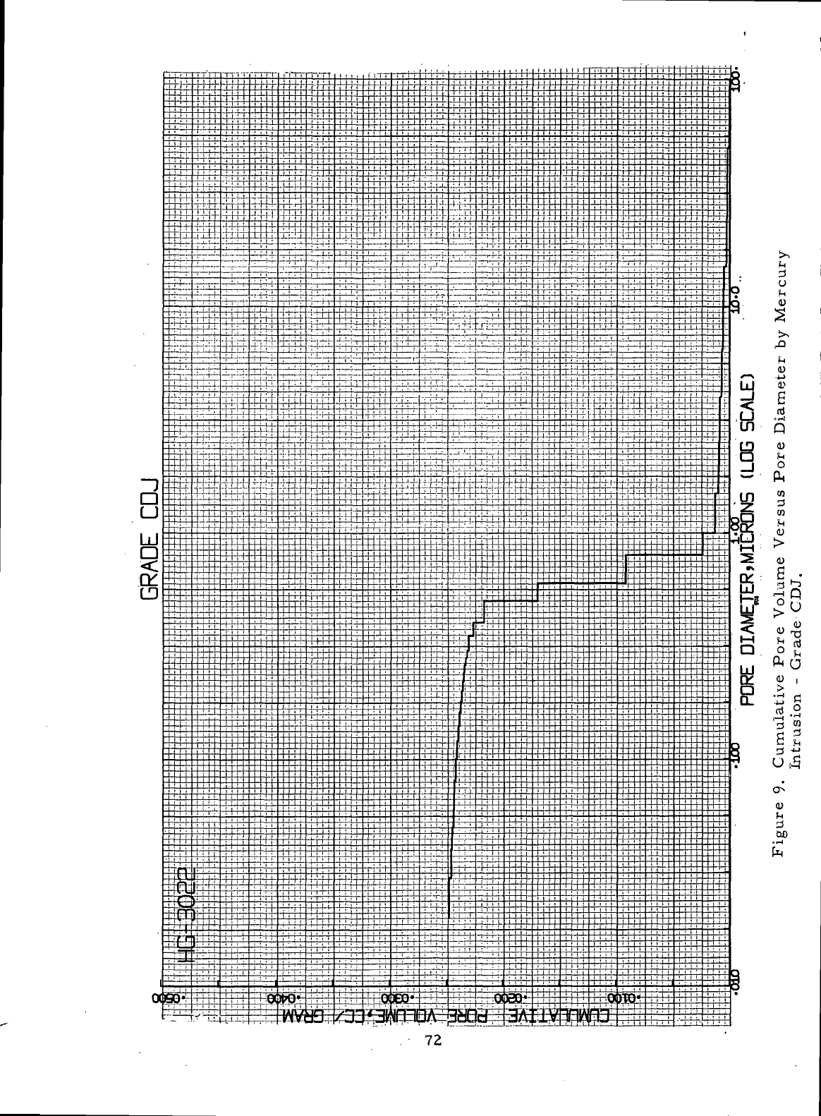
o
H
in
CO
i>
s
o*-}
Q
0)
b
PM
tn
3
en
I
o
/? Vi
ft O
0)
,
il
•g S
0)
JH
d
GO
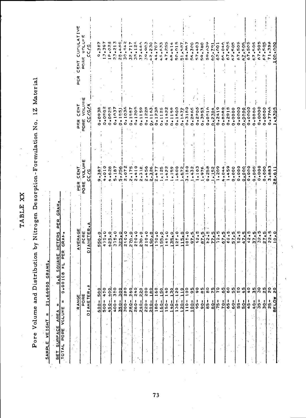
w
r-l
n)
M
0)
4-»
*t5
M
i—4
•
o
•x
<i
ri
o
j->
cd
•3
g
P
o
h
i
f-4
M
o
._*
4J
PH
p
0
co
u
Q
Ci
<U
00
o
M
4-1
._J
z
>>
43
d
O
.-i
.
3 $
-2
<
'£
«
i o
•
2
s
Q S
TJ
2
c
^
CtJ
CVI
OJ
fi II
3
r^ *~
o
i
> VS
"^ »-.
CO
' UJ
l_»
^
M
O UJ
* a
1
£
<
(0
.
S
<
a
o
<r
£
w
ff
UJ
H
tll
S
UJ
a
^
0
w
>o
•
o
"
II
<
, UJ
a
^
U)
u
<
u.
a
3
V)
-H
UJ
ID
•
^
<
a
o
QC
UJ
a
_i
i
CO
o
o
0
•
p
II
UI
£
3
•J
«_)
>
UI
.
a
o
a
j
<
K
a
t-
u>
>
>-
^j
J
^
o
H
Z
u:
.
u
a
!ll
a.
i-
z.
UJ
u
ct
u.:
a
K
Z
UI
(J
ct
UJ
a
UJ
0
1
^
CC
UJ
<
UJ
e>
<
ct
'
u
3
J
V5
C
S
> 1 1
-^ W
u:°
0
a
UJ
H
<
-I X
c
c
> S
, ,
<->
UJ
u
o:
o
a.
UI
z
D
d
o
X
>
o
o
UJ
ct
o
a
<
»
a
•JJ
UJ
a
i
r—
O UJ
a
s
<
o
«t
•
ct
UJ
UI
a
i-
O HI
a
s
<
0
N
CC
n
o
'
S
0<
o
o
N
00
n
o>
•
0
o
in
in
o
0
in
i
0
o
o
N >n
(f-
K
n o
P;
a.
cv:
ir,
O <\i
O::
0'
0 0
0 0
O 00
_
CVJ
O vO
•* <t
0 0
if)
in
<- CVI
<r
<t
o o
u-.
o
;;
0 0
o m
in • *i
U)
^
n o-
— >c
(V <J
<"•
a
cv:
rvi
f- •"
ro
if;
c
c
0
0
N C
oo
in
— CVi
in 10
.
0 0
ui m
1- CV
f>
n
0 0
Ul
0
fO
f*l
0 0
o in
,-* ff\
^ Fl
cv
r- ^ ,r. ft o
•d
~ cvi .3 en
K
N — <J O CVI
C-
CV If- N 0 (V
11
ri n n l'; <j
iC
N If- 0- 00 ti
n
or-
o in
cvj
ic
o c cv -< cv; —
o o c o o o
•
.
•
;-
cvi
m o co' <o >o
s
N
.
-• - in
cvi
o
—
* n ^ n
cvi cvi cvi cvi
cvj.
cvj
.
i i
' !
I • J
"
' . . "
•
I '
I
-
-
!
I
,
!
o oj o o; o o
o c! o o o o
o-
rJ di ri - »
CV)
CVJj
CVI
CVJj
(V) _
-
•
1
O
O O O; O 6
oj <r> <t cv) o oc
1 1 1 1 1 1
o o o o o o
o oc; vo •»! cvi o
f) CVI CVJ Cv CVJ CVJ
N
n
c
f.
I
s
- <C
<t
ir.
•*
^
«•
in
n
cvj
cv
«
0 0
•
s m
i^ cvj
*
-
CVI-
•
•
0
0
i
o ic
i" in
o o
o in
i
I
o
o
00 vO
'
'fi •* if. h-
'f.
- -
a-
<v
<» c -r
N CC C —
•* <J If! IfJ
.
.
cvi
0
. c cv
cvi
IT o r^
<)
-. vC vC
0 c 0 0
.
--
w - ..
cvi
if; o r-
* —
vO
>0
;
.
1
i
:
i
'1
I
0 oi 0 0
j«
in! ". m
:q~:
t
i
0000
4
n.
cvi
-
ill)
o
b o o
in
•* ii
cvi
N
o
>c
c
Cf.
(1
« >c
if, ir,
.0
if;
CC
vC
- a
n cvi
0 0
•
0
CVI
oo
n
-•<t
o m
j,
N
o o>
o m
o o\
o
o
- 0
ri o
O 33
<t
r,
1-
0
If If:
>0
(«•,
o in
cv
o
cvi
n
0
0
ro
*
0 N
-
O
•
u)
m
CVI
N
0- 00
o in
O CC
i i
m
o
O'
o
.
0-
-
ro CT
•C
N
0
C
in >c
•c <*
—
o
if.
r,
O
CVJ
0 0
*
CVI
m
in
CM
-
0
-
•
"-
if<
m
CVJ
N
A
N
b in
CO
N
I I
in
o
00 00
—
>r
o <t
C
0
CV v£
\O vO
•
.
,
a
a
"
CC
•*
c
cvj
cc
0 0
.
a.
4
0 4
cv)
o
-
<t
.
tf in
ivj
s
i~
«
o in
1- <O
i i
in
o
r- r^
if.
if.
0 0
if if.
N
S
\{,
^
CC
0
—
o
c.
o
CVJ
O
0 0
0»
O
in
o
<t
0
^ o
•
if' in
<V,N
* in
o m
<o
in
I I
m
o
•c >o
if-
if.
0 C
in
ir.
N N
^C
c
0 o
0 0
0
c
O
O
0 C
0 0
0 C
0
0
0 0
if)
in
cvj
r^
u)
«
o in
U)
<*
I
I
in
o
in m
If: in
C
0
in u".
s r^
vO <C
•
0 0
o o
C
o
o o
0 0
•
o
b
o o
0 O
00
,
in m
CM
r-
•»
M
0 If)
•»
M
1
1
in
o
•*
•*
sn
in
0 0
in
if.
N r-
<C
vt
•
0 0
0 0
c
c
0 0
0 0
0 0
O
0
O
0
0 0
•
.
in in
cv;
i»
«
CVJ
o in
n
cvi
i i
in
o
11
n
10
0
95
C
r, c
- c
S
0
*""
* If,
<C
0
N
r,
N
«
o
-
«•_
oo
—
00 vO
n oo
CVI
•
'
in
o
(VI
o
CVI
_
00
<VI CVI
1C
in.
J
CVJ
UJ
73
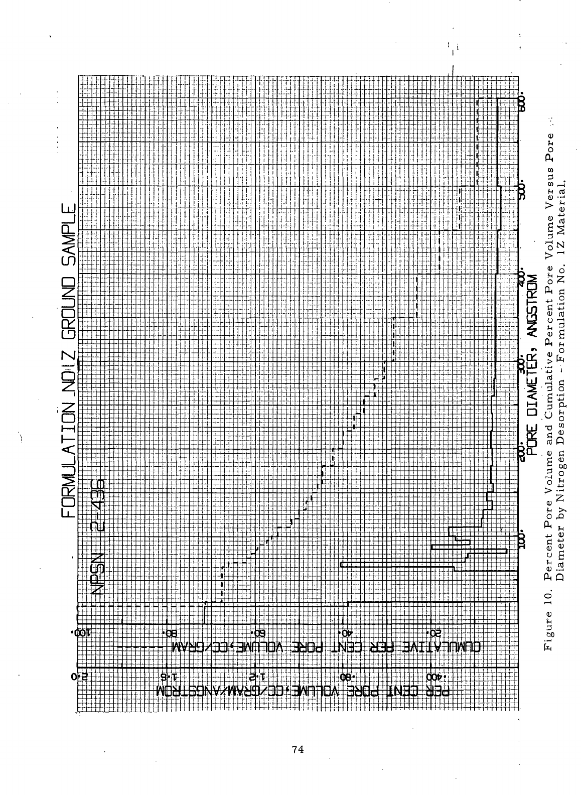
74
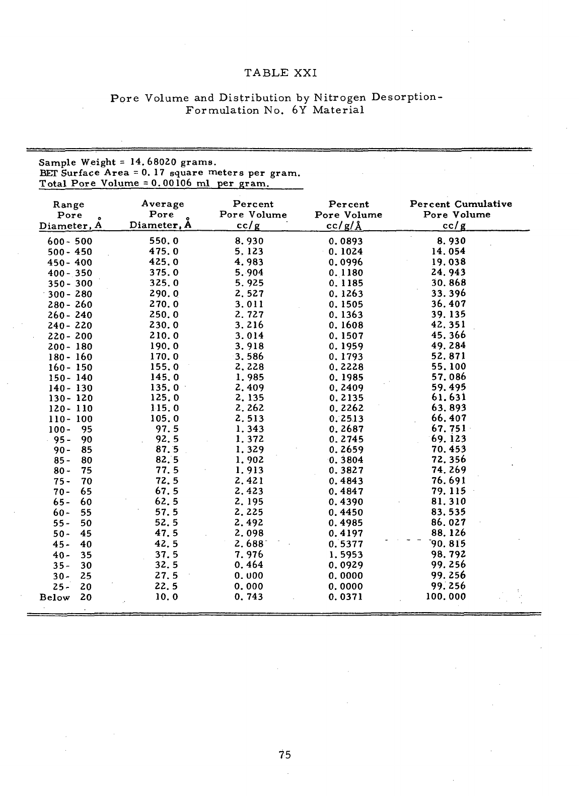
TABLE
XXI
Pore
Volume
and
Distribution
by
Nitrogen
Desorption-
Formulation
No. 6Y
Material
Sample
Weight
= 14
BET
Surface
Area
=
Total
Pore
Volume
.
68020
grams.
0.
17
square
meters
per
gram.
=
0.00106
ml per
gram.
Range Average
Pore
„
Pore
0
Diameter,
A
Diameter,
A
600-
500
500-
450
450-
400
400-
350
350-
300
300-
280
280-
260
260-
240
240-
220
220-
200
200-
180
180-
160
160-
150
150-
140
140-
130
130-
120
120-
110
110-
100
100-
95
95- 90
90- 85
85- 80
80- 75
75- 70
70- 65
65- 60
60- 55
55- 50
50- 45
45- 40
40- 35
35- 30
30- 25
25- 20
Below
20
550.0
475.0
425.0
375.0
325.0
290.0
270.
0
250.0
230.0
210.0
190.
0
170.
0
155.0
145.0
135.0
125.0
115.0
105.0
97.5
92. 5
87.5
82.5
77.
5
72.
5
67.5
62.5
57. 5
52.5
47.5
42.5
37.5
32.5
27.
5
22.5
10.
0
Percent
Pore
Volume
cc/g
8.930
5. 123
4.983
5.904
5. 925
2. 527
3.011
2. 727
3.216
3.014
3.918
3.586
2.228
1.985
2.409
2. 135
2.262
2.513
1.343
1. 372
1.329
1.902
1.913
2.421
2.423
2. 195
2. 225
2.492
2.098
2.688"
7.976
0.464
0.000
0.000
0. 743
Percent
Pore
Volume
CC/R/A
0.0893
0.
1024
0.0996
0.
1180
0.
1185
0.
1263
0.
1505
0.
1363
0.
1608
0.
1507
0.
1959
0.
1793
0.2228
0.
1985
0.
2409
0.2135
0.2262
0.2513
0.2687
0.2745
0.2659
0.
3804
0.
3827
0.4843
0.4847
0.4390
0.4450
0.4985
0.4197
0.5377
1.
5953
0.0929
0.
0000
0.0000
0.0371
Percent
Cumulative
Pore
Volume
cc/g
8. 930
14.054
19.038
24.
943
30.868
33.396
36.407
39. 135
42.351
45.366
49. 284
52.871
55. 100
57.086
59.495
61.631
63.893
66.407
67.751
69. 123
70.453
72.356
74.269
76.691
79. 115
81.310
83.535
86.027
88. 126
90.
815
98.792
99.256
99. 256
99. 256
100.000
75
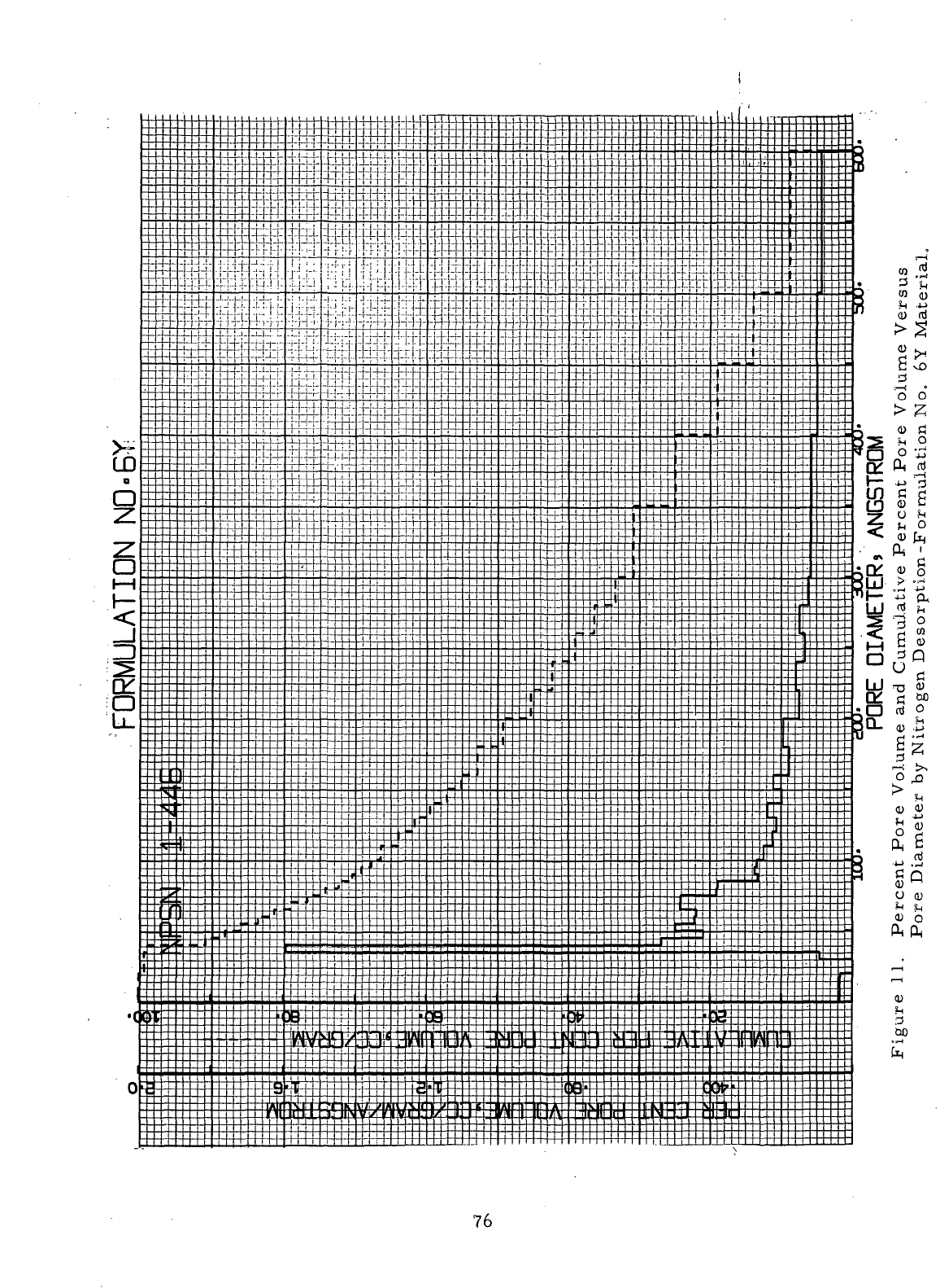
Y
76
The
similar
formulation
No. IX
material
had
been
found
during
Task
IV —
to
have both
a
larger
average pore diameter
and a
larger
total pore volume
(average
pore diameter
=
240A,
total pore volume
is 0.
0014 cc/g).
The
for-
mulation
No. 6Y
material
had an
average pore diameter
of
180A, which
was
considerably
larger
than
the 50A
value measured
during
Task IV*-
for the
similar
formulation
No. 4X
material.
However,
the
total pore volumes
of
the
materials
manufactured
from formulation Nos.
4X and 6Y
were very
similar,
i. e. , 0.
00099 cc/g
and 0. 001 1
cc/g, respectively.
Table
XXII presents
the
results
of the
nitrogen pore volume measure-
ment made
on a
sample
of
Grade CDJ.
Figure
12 is the
corresponding plot
of
percent pore volume
and
cumulative percent pore volume versus pore dia-
meter.
The
sample
of
Grade
CDJ was
found
to
have
an
average pore diameter
of
240A
and a
total pore volume
of 0.
0013 cc/g.
The
microporosity determined
for
Grade
CDJ is
almost identical
to
that
of the
formulation
No. IX
compact
examined during
Task
IV. —
The
internal structures
of the
carbon-graphite
seal
ring bodies manu-
factured
from
formulations Nos.
1Z and 6Y
appeared
by
visual examination
to
be
very homogeneous
and
fine-grained.
No
large
pores
or
voids
were
noted
in
the
compacts examined.
The
formulation
No. 5
compacts,
however,
were-found
to
have internal structures containing localized
areas
of
relatively high porosity.
These
!
'punky"
areas
were visible
to the
naked eye.
A
measure
of the
uniformity
of
the
structures
is
obtained
by
examining
the
percent Increases
in
weight
of the
compacts after impregnation with
the No. 121
oxidation-inhibiting treatment.
The
uniformity
of
impregnation reflects
the
uniformity
of the
internal structure
of
the
impregnated
material.
Table XXIII
lists
the
treat
pickups measured
for
the
1/2-inch ("1.3
cm)
cubes
of
formulations Nos.
IX, 1Z, 3, 5, 4X and 6Y
after
impregnation
with
the No. 121
oxidation-inhibiting treatment.
The
materials
im-
pregnated
with
the
oxidation-inhibiting treatment were
identified
(Tables
I and
VIII)
by the
formulation number
followed
by the
Number
121 (e. g. ,
formulation
No.
1X-121).
Table XXIII displays
the
coefficient
of
variation
for the
treat
pick-
ups
("V"
in
Table
XXIII).
Based
on the
calculated
coefficients
of
variation,
the
formulation
No. 1Z
material
was
more
uniform
than
the
similar
formulation
No.
IX
material,
the
formulation
No. 5
material
was
considerably
less
uniform
than
the
similar
formulation
No. 3
material,
and the
uniformity
of the
formulation
No.
6Y
material
was
comparable
with that
of the
formulation
No. 4X
material.
77
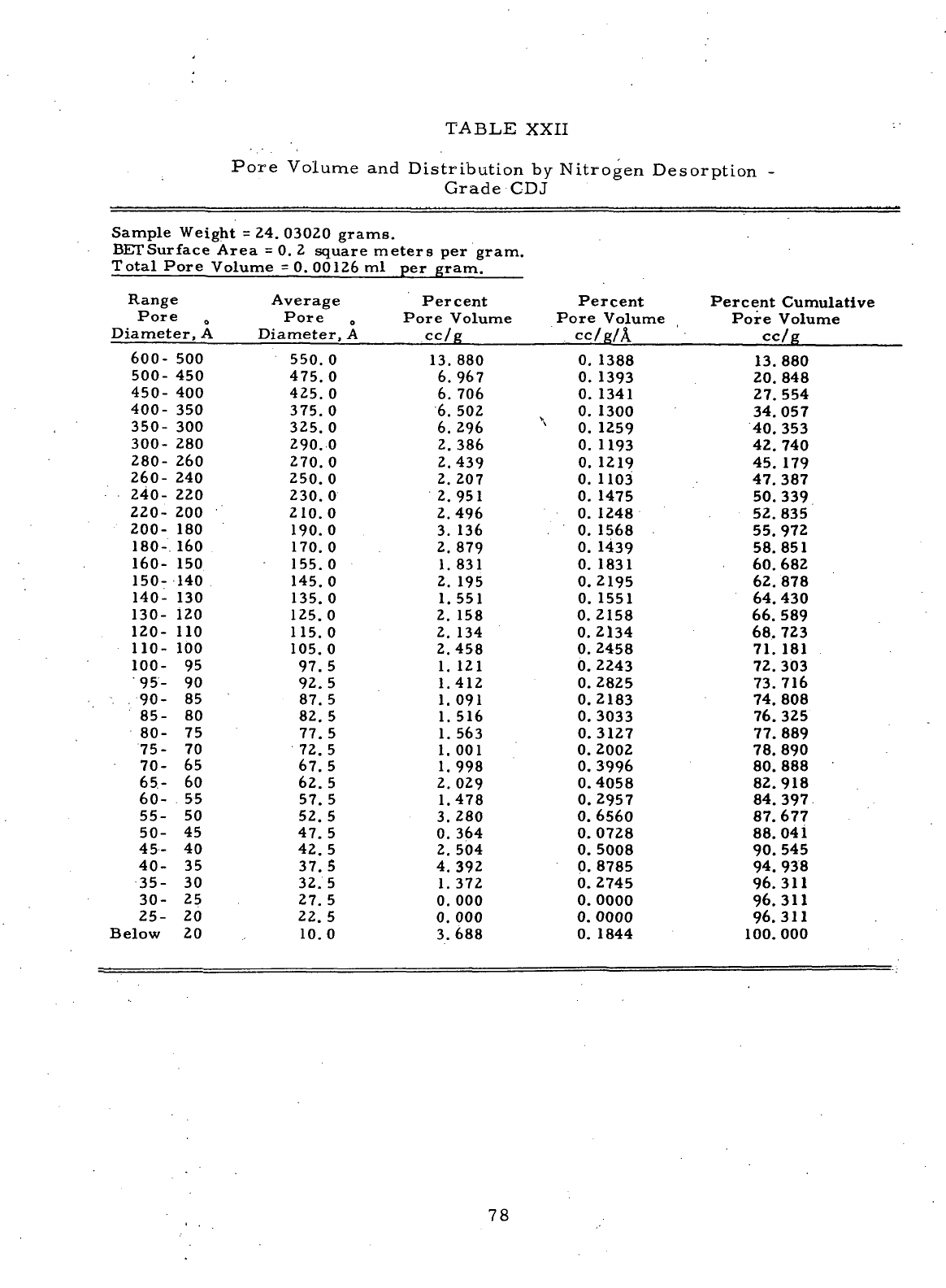
TABLE XXII
Pore
Volume
and
Distribution
by
Nitrogen
Desorption
-
Grade
CDJ
Sample
Weight
= 24.
03020
grams.
BETSurface
Area
= 0. 2
square
meters
per
gram.
Total
Pore
Volume
= 0.
00126
ml per
gram.
Range
Pore
Diameter,
A
600-
500
500-
450
450-
400
400-
350
350-
300
300-
280
280-
260
260-
240
240-
220
220-
200
200-
180
180-
160
160-
150
150-140
140-
130
130-
120
120-
110
110-
100
100-
95
95- 90
90- 85
85- 80
80- 75
75- 70
70- 65
65- 60
60- 55
55- 50
50- 45
45- 40
40- 35
35- 30
30- 25
25- 20
Below
20
Average
Pore
0
Diameter,
A
550.0
475.0
425.0
375.
0
325.0
290.0
270.0
250.0
230.0
210.0
190.0
170.0
155.0
145.0
135.
0
125.0
115.0
105.0
97.5
92.5
87.5
82. 5
77.
5
72.5
67.5
62. 5
57.5
52.5
47.5
42.5
37.5
32. 5
27.5
22.5
10.0
Percent
Pore
Volume
CC/B
13.880
6.967
6. 706
6. 502
6.296
2.386
2.439
2. 207
2.951
2.496
3. 136
2. 879
1.
831
2. 195
1.551
2. 158
2. 134
2.458
1.
121
1.412
1.
091
1.
516
1.
563
1.001
1.998
2.029
1.478
3.280
0. 364
2.
504
4.392
1. 372
0.000
0. 000
3.688
Percent
Pore
Volume
cc/g/A
0.
1388
0.
1393
0.
1341
0.
1300
X
0.
1259
0.
1193
0.
1219
0.
1103
0.
1475
0.
1248
0.
1568
0.
1439
0.
1831
0.2195
0.
1551
0.2158
0.2134
0.2458
0.2243
0.2825
0.2183
0.3033
0.3127
0.2002
0.
3996
0.4058
0.2957
0.
6560
0.0728
0.
5008
0.
8785
0.2745
0.
0000
0.
0000
0.
1844
Percent
Cumulative
Pore
Volume
cc/g
13.880
20.
848
27.554
34.057
40. 353
42. 740
45. 179
47.387
50.339
52.835
55.972
58.851
60.682
62.878
64. 430
66. 589
68. 723
71. 181
72.303
73.716
74.
808
76.325
77.
889
78. 890
80. 888
82.918
84.397
87.677
88.041
90. 545
94. 938
96.311
96.311
96.311
100.000
78
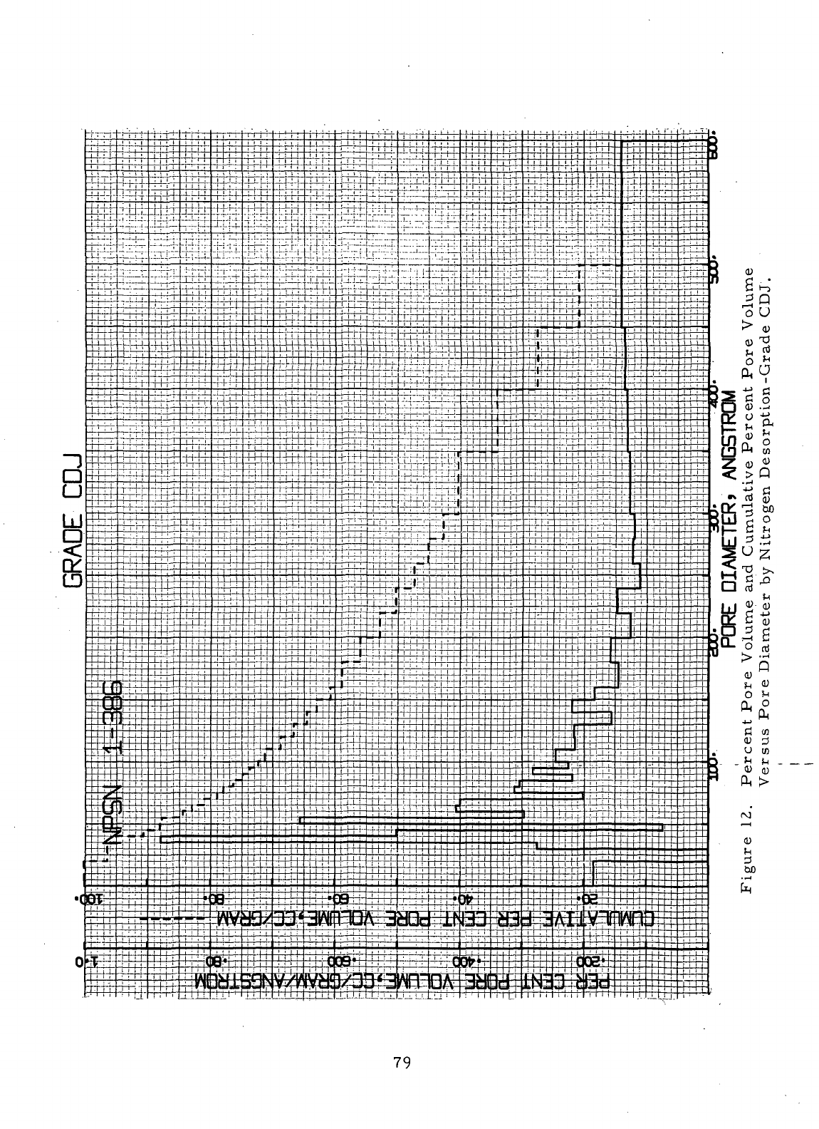
79
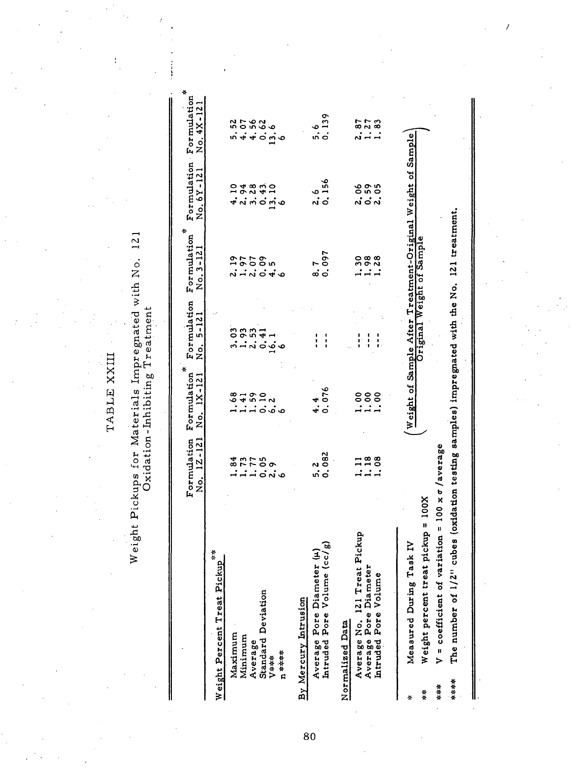
fNj
•—
i
d
2
^
4J
.—1
>
4_>
<U
<!)•
Iti £
d •"'
flj ^
HH
^ ^
*—
"t
O, F~l
><
£ &
0
1-1
.s
M t/3
-i-J
3
^ •«
1-1 Cti rQ
(-Q
"^ "Zj
<C
<y d
p. J-> hp
4j
g
*^
o
^ '^J
O rcj
<4H
rQ
!3 C^
U
£
^
,-C
0)
J^
^*
c
o *->
rt7
1^
H ^J"
c ^
°
^7
fj
O
-^
'rt
r\l
td "~*
^ '
E
0
-
£z
*
1^
97
d co
j, en
0
2
fc
C
O
rt^
"37
O
0
^ 2
*
fi *"*
O CM
•gx
s
o
°
t. 2
^
o IM
•H *"^
3
•—
1
g
.
h O
£
2
o
IM r~ sO rM CO
in o in so \o
NO
•~
l
in
TJ*
^j* o co so m o
f—
4
NO
o
TJ<
oo co o m
^IMCOOCOvO
M 0
.-«
<jv
o o in t~ o
(M—"rOOTt<vO
oo'o
CO
CO CO *"^
o
ON
in
TJ*
'-i it
CO
•—
t
0
s
- O f~
so
^t
4
in
•—
i IM ^ o
_4_,_iOvOvO
-*O
IM
Tt*
co t* in co .
>-«t-4rtO(Mvo
ino
"3
*
"i"^
* -3 o
0-
^ ^
3 4)
, ,
-"I"
" SB
0, g §
S S a -So
$
$ .2 Q>
H > " £ £ „,
w
/sj i o ° ™
s
15-2
f i; «
"g3boj;
>-oo<u
-o
« ^ c
<«
^ *
tjid-o
4»
n,
-
d -H M "3 * * H ^ 3 N
rt
c<u
rt*'*
>J
** ** '-'
£
|g4w>1j
^ <5 g
4)
>. 0
£
ffl 2
t- t^
CO
CO
rM oo ^—,
M*
-' ~' ,«
P.
id
co
**4
0
^o
o* ^ **
o i^ o -£
•
• • ^
rvi
0 ro ' J
£ g
id
g
'§• s
-f:
a "
o
oo
co
O c "
CO
O M -M rS '
H
•-<
"-
1
-
1
S «H •-'
g
°
is
•*->
o
SM
2
*<
'« "
H fe -S
•
M • _rt
2
« 2
i
: : <-i *
111
«'C "S
"So tJ
c ••*
Ml
$ 4)
m o.
000 ° g
ooo « .5
... 43
-1
-H
-« *f ^
0) <y
"ft
c
M
nj
4>
co
WJ
^ 00 00 2 C
^-:
o
s -a
rt
rt
^ > «>
id <u
b
g
S<>
tj °
s
K
-^
2 o €
H
^ '*
II O
O.
P-i „ ^-
1 fc
-S
1 s
o *-< y +j ^Q
o_.
^"* 'p. .*2 -^
^^ CO •_. O
j-»
^ rt ** -*
S»S
« H g 5 ^
sg|
j-S-sS
<*
^ -3 +J w NH
rt
-i-i
O H C rj O
2
Q>
I
S
1 °
4)
4) h O 4)
. h h 13 41 £ 43
ooo qi PI M! ri
2 (X & b -M S §
3
5 ° 2
4)
41 TJ to 'M O C
00
00 41 Id -H „ Q)
id
id *O 41 41 " ^
d)
fl) ^ i^ 1^ ^ fH
> > **
•W-
* ^f
#
# * •*
80
Comparison
of the
pore volume data determined
by
mercury intrusion
(Table
XXIII)
with that
of the No, 121
oxidation-inhibiting
treat
pickups shows
the
expected trend
of
increasing
treat
pickup with increasing pore volume.
As
noted
during
Task
IV,
—normalization
of the
data presented
in
Table
XXIII
with
respect
to the
formulation
No.
1X-121
material
shows
a
disproportionately
high
treat
pickup
for the
formulation
No. 4X
material
based
on its
intruded pore
volume.
The
similar
material
manufactured from formulation
No. 6Y
experi-
enced
a
treat
pickup directly proportional
to its
pore volume determined
by
mercury intrusion,
i. e. , the
formulation
No. 6Y
material
had a
normalized
intruded
pore volume
of 2. 05 and a
normalized
treat
pickup
of 2. 06.
This
phe-
nomenon
is
probably
related
to the
large
difference
in the
average pore dia-
meters
of the
materials
manufactured
from
formulations Nos.
4X and 6Y. The
treat
pickups
for the
for.mulations Nos. 1X-121, 1Z-121,
and
3-121
materials
also
were directly proportional
to
their respective pore volumes determined
by
mercury intrusion.
The
data listed
in
Table
XXIV
show
that
the
impregnation
of the
samples
of
formulations Nos.
1Z, 5, and 6Y
with
the No. 121
oxidation-inhibiting
treat-
ment increased
their
respective final densities.
The
impregnation with
the
No.
121
treatment probably
had
little
effect
on the
strengths
and
hardness
of
the
materials,
since
the
pickups
are
relatively
low and
since
no
additional
carbonaceous
material
was
added
to the
compacts
as in the
case
when
a
resin-
impregnant
is
carbonized.
The
densities listed
in
Table
XXIV
were measured
for
the
treated 1/2-inch (1.3
cm)
cubes which were
later
used
during
the
oxi-
dation
testing
of the
three
materials.
The
pore structures determined
for the
seal
ring bodies
of
formulations
Nos.
1Z and 6Y
indicate
that
both
are
potentially
good
carbon-graphite
seal
ring
materials.
Both
of the
formulations resulted
in
fine-grain
materials
with
relatively
low
porosity.
81
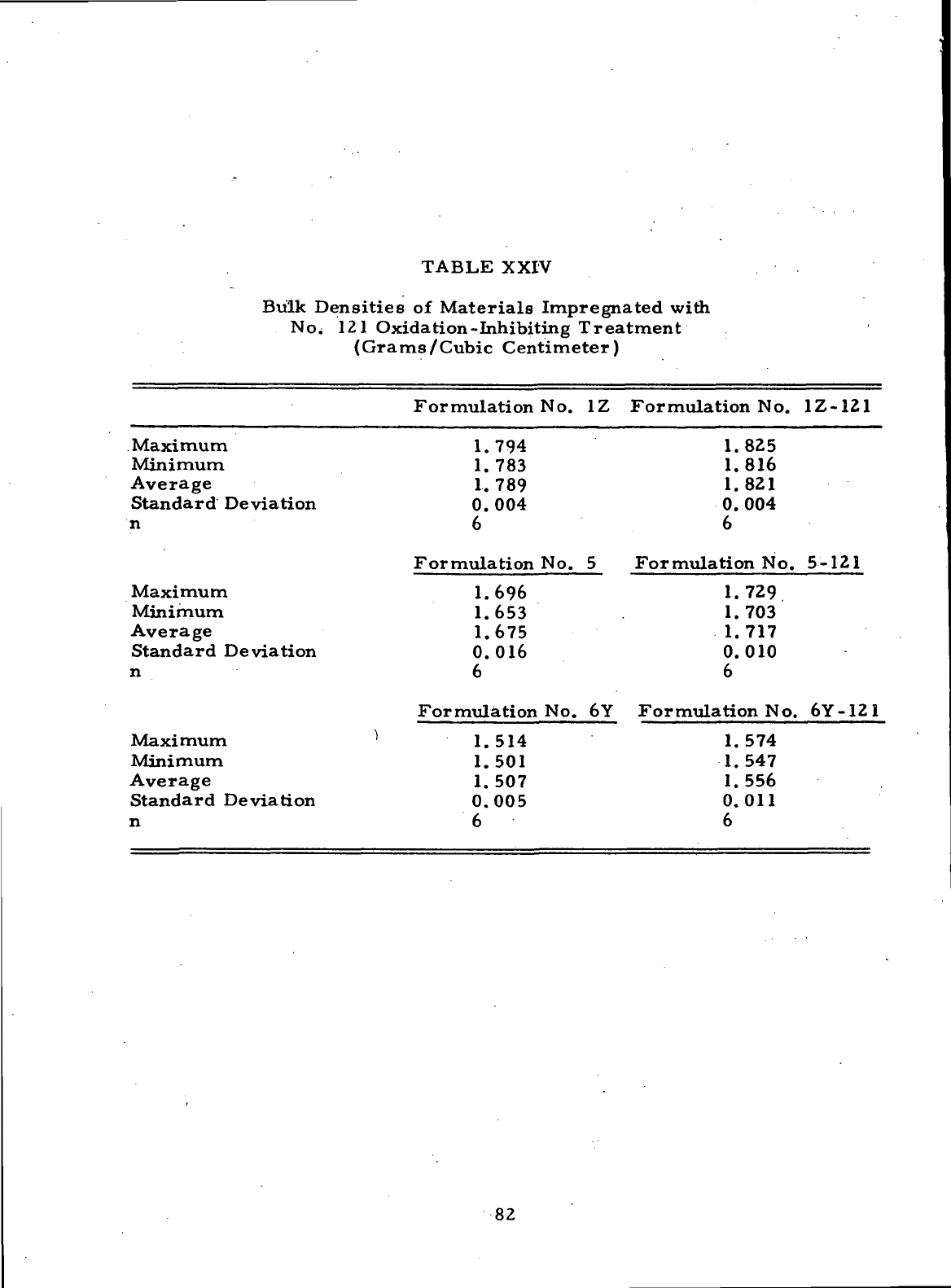
TABLE
XXIV
Bulk Densities
of
Materials
Impregnated
with
121
Oxidation-Inhibiting Treatment
(Grams/Cubic Centimeter)
Formulation
No. 1Z
Formulation
No.
1Z-121
Maximum 1.794 1.825
Minimum 1.783 1.816
Average
1.789 1.821
Standard
Deviation 0.004 0.004
n 6 6
Formulation
No. 5
Formulation
No.
5-121
Maximum 1.696 1.729
Minimum 1.653 1.703
Average 1.675 1.717
Standard Deviation 0.016 0.010
n
66
Formulation
No. 6Y
Formulation
No.
6Y-I21
Maximum
'
1.514 1.574
Minimum 1.501 1.547
Average 1.507 1.556
Standard Deviation 0.005 0.011
n 6 6
82
E.
Oxidation
Tests
High
oxidation resistance
is a
primary requirement
for a
carbon^
graphite
seal
ring material which
is
exposed.to ambient
air
temperatures
up
to
1300°F
(704°C).
A
material
with
a
high degree
of
crystallinity
is
needed,
since
the
crystallinity
of a
carbon-rgraphite
material
greatly
affects
the
rate
at
which
it
oxidizes. Formulation Nos.
1Z.~,
5, and 6Y
were designed
to
yield
carbon-graphite
seal
ring bodies
with
high degrees
of
crystallinity.
Further
increases
in
oxidation resistance
are
obtained
by
impregnating
the
seal
ring
bodies with oxidation-inhibiting treatments, such
as the No. 121
treatment.
Oxidation
tests
were
conducted
at
1300°F
(704°C)
with
1/2-inch
(1. 3 cm)
cubes
prepared
from
the
seal
ring bodies
of
formulation Nos.
1Z, 5, and 6Y.
Com-
mercial
seal
ring Grade
CDJ was
used
as a
standard
for the
oxidation testing.
The 1/2
T-ihch
(1. 3 cm)
cubes were impregnated
with
the No. 121
treatment
before
being exposed
to the
oxidizing conditions;
the No. 121
treat
pickups
were presented
in
Table XXIII.
The
oxidation test procedure
and
equipment employed during
Task
VII
were
the.same
as
those
us'ed
during the'-Tasks
land
IV
oxidation studies,
-
21
—
The
samples
were placed
in
one-inch
i. d.
quartz tubes, which subsequently were
supported
in a
small
electrically
heated furnace.
The
quartz tubes were used
to
keep
the
samples
from contacting
the
metal
support (which might have
acted
as an
oxidation catalyst)
and to
allow
the
removal
of the
oxidation
samples
from
the
furnace
without
damaging them.
Figure
13 is a
schematic
of the
oxidation
testing apparatus.
The
furnace
has a
split
door
which
was
propped open during
oxidation testing
so
that
a
3/8-inch
(0. 95 cm) gap was
maintained
across
the
entire
face
of the
furnace
between
the
upper
and
lower halves
of the
door.
The
quartz tubes containing
the
samples
were supported
so
that
the
samples
were
in
line
with
the gap
between
the two
sections
of the
door..
Air
passing through
the
gap
in the
door
also
flowed
around
the
samples,
as
shown
in
Figure
13. At the be-
ginning
of the
test,
the
samples
were weighed
and
placed into
the
quartz tubes, after
which
the
tubes containing
the
samples
were weighed
and
placed inside
the
1300°F
(704°
C)furnace
chamber.
After
1/2-hour exposure
to the
oxidizing condition,
the
quartz tubes containing
the
samples
were removed
from
the
furnace,
cooled
to
room temperature, weighed,
and
placed back inside
the
furnace
for
another 1/2-
hour period.
This
procedure
was
continued until
the
samples
had
been exposed
to
the
oxidizing conditions
for a
total
of
three hours.
A
preliminary testhad shown
that
the
weight
of the
empty quartz tubes remained constant
when
exposed
to the
1300°F
(704°C)
temperature.
83 '
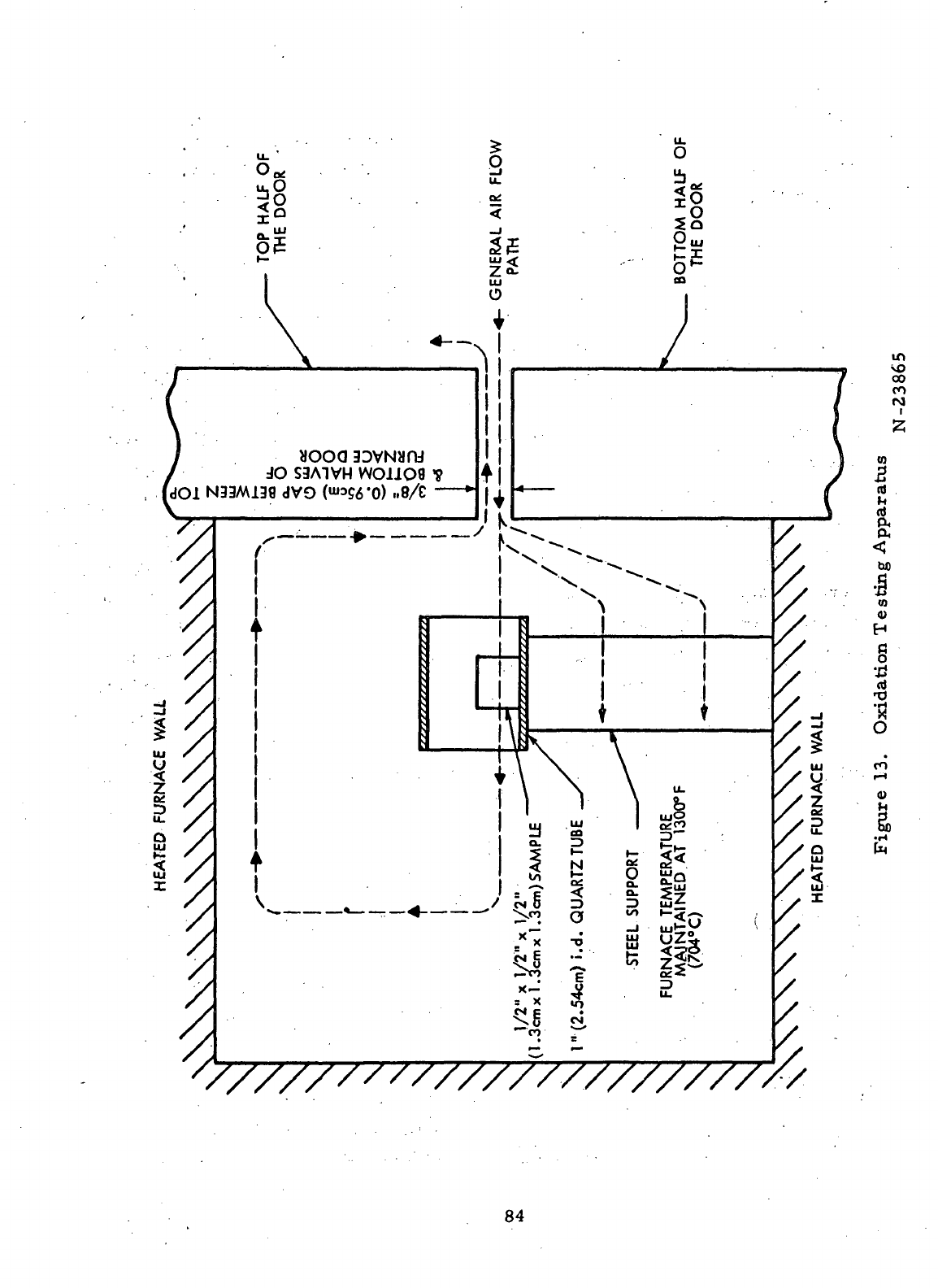
9
_
Of
UJ
o
I
'y
2
</
/,
*t
2
/>
*
/
HEATED
FURNACE
x\\\\\\\\\\v
I33MJ
t
i
aooa
SDVNum
JO
S3A1VH
WO11OS
L38dV9
(""3WO)
»8/£
•_,
k
k
•9
_-
i
1
1
i
4
|
i
y
'
K
l
v
\
\
r
•4-
•**.
X
|
:
^
N
X
^
r~
•M
^—
V '
>«..
N
N.,
•-,
|
1
1
1
t
(1.3cmxl.3cmx
1.3cm)
SAMPLE
1"
(2.54cm)
i.d.
QUARTZ
TUBE
^S
STEEL
SUPPORT
—^-^^
^-^
1
|
!
»
FURNACE
TEMPERATURE
MAJNTAINED
AT
1300°F
(704°C)
)
/
^.
/
'/
'',
',*
/.$
HEATED
FURNACE
\
\r\
<o
CO
CO
r-J
i
CO
5
nt
V.
nt
CO
(U
H
§
£
a)
CO
0)
84
Three
oxidation
tests
were conducted during
Task
VII
using
the No. 121
treated
samples.
During
each
test,
one
sample
of
each
of the
formulations Nos.
1Z-121,
5-121,
and
6Y-121
and one
sample
of
Grade CDJ-121 were exposed
to
the
1300°F
(704°C)
temperature
for a
three-hour period.
The
relative
positions
of
the
four
materials
in the
furnace were changed
for
each
test
to
avoid
any
possible
position-to-position variation
in the
oxidizing conditions.
One of the
tests
was
extended
to
include weight measurements after 4-1/2 hours:
and six
hours
of
exposure,
and two
tests
were extended
to
include seven-hour
readings.
The
agreement
between
the
oxidation
rates
determined
for the
Grade CDJ-121
standards during
the
Tasks
IV and VII
oxidation studies indicated that
the
oxida-
tion
results
from
the two
series
of
tests
can be
compared directly.
Figures
14 to 16 are
semi-logarithmic plots
of the
average percent
weight
loss
versus exposure time
at
1300°F
(704*0)
for the
samples
of
formu-
lations Nos. 1Z-121, 5-121,
and
6Y^121.
Each
figure
includes
the
control
Grade CDJ-121 oxidation curve.
The
oxidation
rates
for all
three
of
theNo.
121
treated
materials
manufactured during
Task
VI
were significantly lower than
that
of
Grade CDJ-121. Also included
in
each
figure
is the
oxidation curve
de-
termined during
Task
IV — for a
similar
material
manufactured
during
Task
III.
^
Figure
14 is a
plot
of the
oxidation
rate
for the
formulation
No.
1Z-121
material.
This
material
oxidized
at a
slower average
rate
than that determined
for
the
similar
formulation
No.
1X-121
material
manufactured during
Tasklll.
—
The
presence
of a
slightly greater amount
of
absorbed moisture probably
accounted
for the
higher weight
losses
experienced
with
the
formulation No.lZ-121
material
during
the
initial one-half hour
of
exposure. One" common method
of
characterizing
the
oxidation
resistance
of a
carbon-graphite
material
is to
specify
the
exposure time
at
temperature required
to
produce
a
5-percent
loss
in the
weight
of the
material.
The
formulation
No.
1Z-121
material
experienced
a
5-per-
cent weight
loss
after being exposed
to the
1300°F
(704°C)
ambient
air for 6. 7
hours.
This
result
was an
improvement over
the
formulation
No.
IX-121
material,
which
required only
4. 7
hours
to
achieve
the
5-percent weight
loss
when
tested under
the
same
conditions.
85
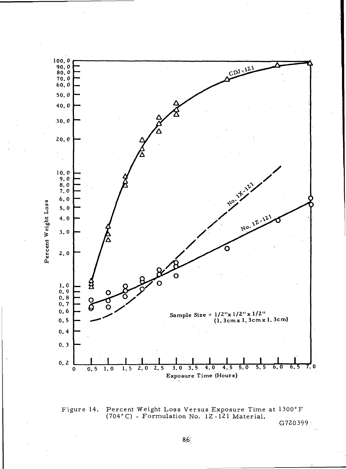
Sample Size
=
l/Z"x l/2"x 1/Z"
(1.
3cmx
1.
3cmx
1.
3cm)
I
I I I I
I I I
II II
o
1.5
2.0 2. 5 3.0 3. 5 4.0 4.5 5.0 5.5
Exposure
Time
(Hours)
6. 5 7. 0
Figure
14.
Percent
Weight
Loss
Versus
Exposure Time
at
1300°F
(704°Q
-
Formulation
No.
1Z-121
Material.
G720399
86'
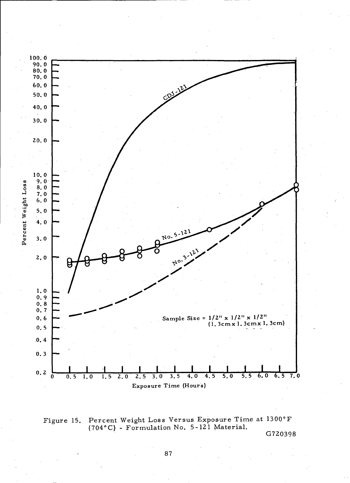
Sample Size
=
1/2"
x
1/2"
x
1/2"
(1.
3cmx
1.
3cmx
1.
3cm)
I
I I
II I I I II I I
0.3 h—
0.2
0.5 1.0 1.5 2.0 2.5 3.0 3.5 4.0 4. 5 5.0 5. 5 6. 0 6.5 7.0
Exposure
Time
(Hours)
Figure
15.
Percent
Weight
Loss
Versus
Exposure Time
at
1300°F
(704
9
C)
-
Formulation
No.
5-121 Material.
G720398
87
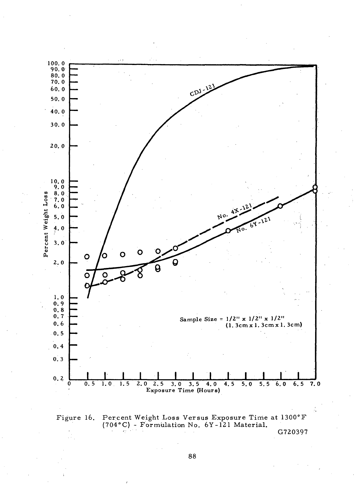
100.
0
90.0
80.0
70. 0
60. 0
50. 0
40.0
30. 0
20.
0
10.0
9.0
« 8.0
S
7.0
^ 6. 0
4-*
§5.0
<u
^ 4.0
4J
8
3.0
2.0
1.0
0.9
0.8
0. 7
0.6
0.5
0.4
0.3
0.2
Sample Size
=
1/2"
x
1/2"
x
1/2"
(1.
3cmx
1.
3cmx
1.
3cm)
I I I I I I I I I I I I I
0.5 1.0 1.5 2.0 2.5 3.0 3.5 4.0 4.5 5.0 5.5 6.0 6.5 7.0
Exposure Time
(Hours)
Figure
16.
Percent
Weight
Loss
Versus
Exposure
Tirrie
at
1300°F
(704°C)
-
Formulation
No.
6Y-121
Material.
•'.-••••
G720397
88
Figure
15 is a
plot
of the
1300°F
(704°
C)
oxidation
rate
determined
for
the
formulation
No.
5-121
material.
The
initial
weight
losses
measured
for
the
formulation
No.
5-121
material
were considerably
larger
than those deter-
mined during
Task
IV — for the
similar
formulation
No.
3-121
material.
The
weight
pickups measured after impregnation with
the No. 121
oxidation-
inhibiting
treatment
indicated
that
the
formulation
No. 5
material
was
more
porous
and
considerably
less
uniform than
the
material
manufactured from
formulation
No. 3. The
greater
porosity
of the
formulation
No. 5
material
and
the
resultant
higher
treat
pickup probably
increased
the
amount
of
adsorbed
moisture removed during
the
initial
one-half hour
of
exposure.
This
expulsion
of
moisture
may
account
for the
higher
initial
oxidation
rate
of the
formulation
No.
5
material
as
compared with that
of the
formulation
No. 3
material.
Although
their
initial
weight
losses
were different, both
the
formulation
No.
5-121
material
and the
formulation
No.
3-121
material
experienced
a
5-percent
weight
loss
after approximately
six
hours
of
exposure
to the
1300°F
(704°C)
ambient
air.
The
.oxidation curve
for the
formulation
No.
6Y-121
material
is
pre-
sented
in
Figure
16.
Comparison
of
this
oxidation curve with
that
determined
for
the
similar
formulation No.4X-121
material
during
Task
IV —
shows
that
the
two
materials
have
comparable
oxidation
resistance.
The
formulation
No.
6Y-121
material
experienced
a
5-percent
loss
Ln
weight after
5.4
hours
of
exposure
and the
formulation
No.
4X-121
material
required only
4. 7
hours
to
achieve
this
weight
loss.
The
difference between
the
oxidation
rates
of the
materials
manufactured
from formulations Nos. IX-121, l-Z-121,
3-121,
5-121,-
4X-121,
and6Y-121
were
relatively
small.
A
statistical
analysis
of
these oxidation data
was
con-
ducted
to
determine whether
the
observed differences were significant.
Table
XXV
lists
the
differences
in
percent weight
loss
measured after
1/2
hour
and
three
hours
of
exposure
to the
oxidizing conditions.
This
procedure
for
specifying oxi-
dation
losses
was
adopted during
Task
I
%•
when
the
evaporation
of
absorbed
moisture
was
found
to
distort
the
incremental
weight
losses
measured after
the
first
1/2
hour
of
exposure.
89
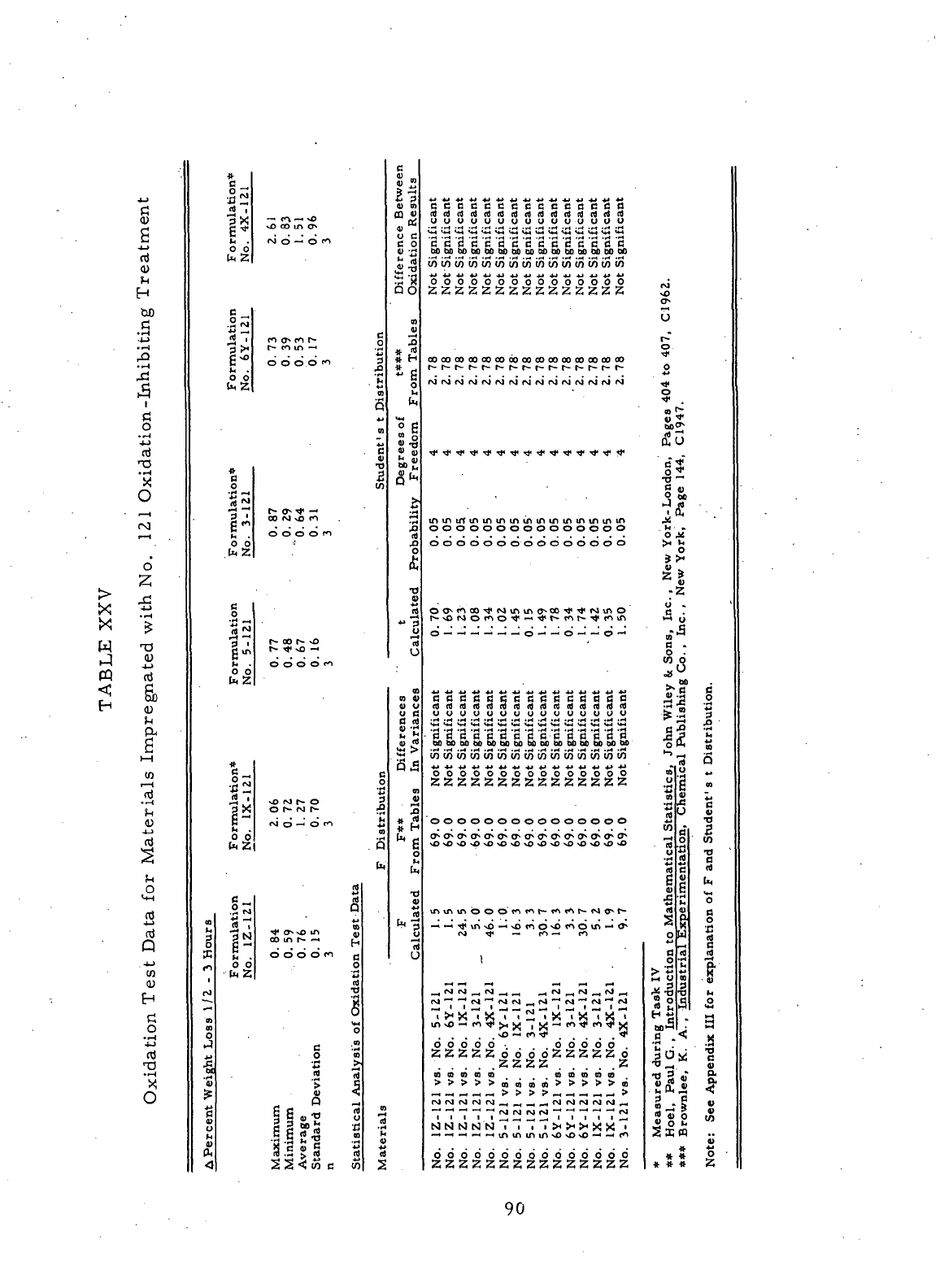
>
X
X
w
CQ
C
0)
^
H
do
ci
• •H
-•H
,0
(H
1
.2
"H
0
F-H
(M
o"
-^
(D
-U
Sb
I-H
erials
o
n!
j-j
&
tn
<u
E-I
o
rt
'x
O
E
_
jj-7
0 0
mulation
6Y-121
rmulation*
3-1Z1
O
0
B
O
Formula
No.
5-12
*
|x
o ~j
I - 3
Hours
Formula
No. 1Z-
—
m
m
O
'3
0>
u
fc
«>
ft
—
i f»
—
'
<O
<M
O
—
i O fl
CO
CT*
fl
f"~
o
r- m in
—
•
.*
O
O O O fl 3
m
S
m
V
•O
B
in
00
P*J
*O fl
d d d o fi
O
O O O fl
B
o
•a
vO
IM » O g
O
t- rJ t- 5
<vi
d -• d fl £
.3
b.
.
n
CO
IT) f- ~* r .
d d o d fi
c
O
rt
•O
1
0
o
c -.2
O
B
•g
>
.2
a
>
5
S
^
e C ~« rt J2
a c a) ™ 6 r2
JlaS
.= 1
X
S J B 2 jj
S S <! in B u5 2
ween
alts
O
tn
U C
B
0
4)
•!-<
5-3
So
m
3
# ">
* H
I ff
O
L,
ll
<U fli
0)
"
•H
•s
JD
O
£
a
«
4J
j;
U
n
U
tn
V
0)
U
u B
S
5
S
c
01
4
X
* H
a
til
F
CalcuJ
BBBBBCBBBBBBBBB
uuuuuuuuuuuuuuu
BBBBBBBBBBBBBB
bObobobobfibfiootioctDdOboboofibOoo
tntno5intn(ninu)inu)U)(ncnu)in
ooooooooooooooo
00 OO 00 OO 00 00 CO CO 00 OO 00 00 00 00 00
ooooooooooooooo
O—
. —
-.—.
—
. —
o—-<O-i-iO-
<
BBBBBBBBBBBBBBB
uuuuuuuuuouuuuu
•
'3 '3 '3 '3 '3 '3 '3 '3 'a '3 '3 '3 '3 '3 '3^
inwcnininOTOTtnininwintoujOT
ooooooooooooooo
ZZZZZZZZZZZZZZZ
\
£££££o'6dd£Z££Zo
^
2 % 2 2 IS T
aramacD
( (
. at m m m oa . t)
, .
__,_j_
-
"
H
^^™
H
^^
—
—
_j_j_j^^"*
"
r\i
fvj^jf^J^J
n
NNlxlNN7"7"7"T><><!H><!X"''
2
ooooooooooooooo
ZZZZZZZZZZZZZZZ
*
U
r-"
o
o
•*
"?
1;
o
&
rt
i p.
J<1
h • »
o
^
si
z s
-1
u »
t.'-
3
B
-
in o
o
. 00
**•
B 6
II 1
C
-° ^
O
A n
^•3
S
Statistics
,
Chemic
udent
' s t
ithematical
;rimentation
of
F and Sb
iuction
to N
iustrial
Ex;
r
explanatic
°a 2
OK
1
£
» ^
-g »
—
•
? u
§° w
an ..
0)
* 5 5
« « 2;
90
Table
XXV
also
displays
the
results
of the
Student's
t
distribution
15
''
1
^
used
to
compare
the
weight
losses
(A
Percent
Weight
Loss
1/2-3 hours)
deter-
mined
for the six
materials.
The
statistical
analysis
indicates
that
the
apparent
difference
in the
oxidation
rate
of
formulations
No.
1X^121
material
and
that
of
the
formulation
No.
1Z-121
material
is not
significant.
No
significant differences
were indicated
in the
oxidation
rates
of the
materials
manufactured from formu-
lations
Nos. 1X-121, 1Z-121, 3-121, 5-121, 4X-121, and6Y-121.
The
oxidation
rates
determined
for the
samples
of the
materials
manu-
factured
from formulations Nos. 1X-121, 5-121,
and
6Y-121
indicate
that
the
three
materials
are
potentially
good
carbon-graphite
seal
ring
materials.The
materials
manufactured from formulations Nos. 1Z-121
and
6Y-121
showed
oxidation
resistances
at
least
comparable
with those
of the
similar
materials
manufactured during
Task
III.
—'
91
SECTION
VII
DISCUSSION
OF THE
RESULTS
An
overall comparison
of the
material
properties
measured
for the
seal
ring
bodies
of
formulations Nos.
1Z, 5, and 6Y is
needed
to
determine which
materials
are
best
suited
for use as
self-acting
seals
which will
be
exposed
to
ambient
air
temperatures
up to
1300°F
(704°C).
The
results
of
Task
VII
have
shown that
the
materials
manufactured
from formulations Nos. 1Z-121
and
6Y-121
are
potentially better
seal
ring
materials
for
high temperature
use
than
commercial
Grade
CDJ-121. Although
the two
materials
are not so
strong
and
hard
as
Grade CDJ-121, they have much better
thermal
properties.
The
high
thermal
conductivities
of the
seal
ring bodies
of
formulations Nos.
1Z and 6Y
will provide
rapid
transfer
of the
deleterious frictional heat
which
can
develop
during periods
of
sliding
contact
After
they have been impregnated with
the
No.
121
oxidation-inhibiting treatment,
the two
materials
have significantly
better oxidation
resistance
than Grade CDJ-121.
The
seal
life
of the two ma-
terials,therefore,
should
surpass
that
of
Grade CDJ-121 under high ambient
air
temperature conditions where oxidation
is the
limiting performance factor.
Both
of the
materials
have
the
further advantage
of
being much more machinable
than Grade CDJ.
Good
machinability
is
very desirable
for a
seal
ring
material,
since
seal
dam
widths
as
small
as 0. 02
inches
(. 05 cm)
often
are
necessary
in
seal
design.
The
material
properties determined
for the
seal
ring bodies
of
formu-
lation
No..
1Z
indicate
that
it is a
potentially
good
material
for
meeting
the
goal
of
the
Contract.
In
some
respects,
the
formulation
No. 1Z
material
is a
better
seal
ring
material
than that manufactured from
the
similar
formulation
No. IX
during
Task
III.
— The
formulation
No. IX
material
had
been
judged
during
Task
IV— to be the
best
material
manufactured during Task
III—
for
meeting
the
goal
of
this Contract.
After
impregnation with
the No. 121
oxidation-inhibiting
treatment,
the
formulation
No. 1Z- 121
material
had an
oxidation
rate
at
least
as
low
as
that
of the
material
manufactured from formulation
No.
lX-121.The narrow
spread
in the No. 121
treat
pickups measured
for the
compacts
of
formulation
No.
1Z-121 indicates that
it was the
most
uniform
material
manufactured thus far.
Formulations Nos.
IX and 1Z
yielded carbon-graphite
materials
with
similar
thermal
and
mechanical
properties.
92
Formulation
No. 1Z was not
among
the
three
material
formulations
originally selected
for
the. manufacturing
of
carbon-graphite
seal
ring bodies
during
Task
VI.
Formulation
No. 1Z was
substituted
for
formulation
No. 1Y
after
processing, problems prevented
the
manufacture
of the
latter
.material.
Although
a
sufficient
quantity
of the
formulation
No. 1Z
material
was
success-
fully
produced
to
fulfill
the
.testing
and
delivery requirements prescribed
by
the: Contract,,
a
processing problem
also
was
encountered
during
its
manufacture.
This problem consisted
of the
chipping
of the
resin-impregnated
2800°C
baked
compacts
during
rebaking
to
1000°C.
The
chipping problem
was
attributed
to
the
furfuryl
alcohol
(50
pbw)-Bakelite BRP-5095
resin
(35
pbw) impregnant.
The
resin
solution apparently filled
the
open porosity
of the
large
compacts
so
com-
pletely that,
during
pyrolysis, volatiles
could
not
escape
without
disrupting
the
stock.
Although
this resin impregnant
was
successfully used during Task
V to
produce
small
(4 - in ch x 0. 5
-inch
x 0. 2 5-
inch (10.
2cm x 1.3 cm x 0. 6
cm))
1QGG°C
baked samples
of
formulation
No. 1Y, it is not a
good
impregnant
for
manufacturing
large
(5-inch (1Z.
7 cm)
diameter
x 1.
4-inch
(3. 6 cm)
thick)
compacts.
The
disruption
of the
large
resin
impregnated, compacts during
rebaking
to
1000°C
prevented
the
manufacture
of the
formulation
No. 1Y ma-
terial
and the
formulation
No. 6Y
ring blanks
during
Task .VI.
The
chipping
of
the
formulation
No. 1Z
material
was
reduced
to a
tolerable level
by
using
a
very slow
firing
schedule
to
rebake
the
resin
impregnated compacts
to
1000°C.
No
further damage
was
sustained
by the
formulation
No. 1Z
compacts during
final baking
to
2800°C.
Formulation
No.
5'was
the
base
material
for one of the
three formu-
lations
(No.
5Y)
originally
selected.for
the
manufacture
of
seal
ring bodies
during
Task
VI. The
formulation
No. 5
material
was the
same
as
that manu-
factured
from
formulation-No.
3
during Task
III—
except that formulation
No. 5
included
pressure
curing
and
pressure baking
as a
part
of its
processing.
The
two
baking procedures
had
been
found
during
the
Task
V
screening, studies
to
be
good
ways
to
improve
the
mechanical properties.
.
Major-processing problems
were encountered during
the
manufacture
of the
formulation
No. 5
material.
These
processing problems most probably resulted
from
the use of the
one-year-old
.formulation
No. 3 mix
remaining
from
Task
III.
—
The
Bakelite BRP-5095
resin
binder
in
this
mix.apparently
had
deteriorated
with
age.
The
apparent deterioration
93
of
the
resin
binder
had
first
been noted during the. Task
V
screening,
study.
The
1000°C
baked density
(1.427
g/cc)
of the
compacts prepared during Task
V
from
the
one-year-old
mix was
considerably lower than that
(1. 519
g/cc)
of the
formuv
lation
No. 3
compacts
produced
during
Task
III.
— In
view
of the
processing
difficulties
experienced,
only
a few of the
formulation
No. 5
compacts were com-
pletely processed during Task
V
through baking
to
2800°C.
The
formulation-No.
5
compacts were
not
resin-impregnated
prior
to
final baking
to
2800°C,
since
the
Contractor
wanted.to
avoid
any
further
processing
problems which might
result
from
the use of the
furfuryl
alcohol-Bakelite
BRP-5095 resin-impregnating
solution.
The
formulation
No. 5
material
was not
completely characterized during
Task
VII, since
the
apparent deterioration
of the
resin
binder
had
prevented
the
material
from gaining
the
full
benefit
of
pressure baking. Only
the
mechanical
properties
and
oxidation
rate
of the
formulation
No. 5
material
were determined.
The
oxidation testing.was.,carried
out by
using
samples
impregnated with
the
No.
121
oxidation-inhibiting treatment..
The
material
properties measured
for
the
pressure
baked formulation
No. 5
material
were approximately
the
same,
as
those measured during Task
IV—
for the
similar,
formulatipn
No. 3
material.
The
material
properties determined
for the
formulation
No. 6Y
material
indicate that
it is a
potentially better
seal
ring
material
than that manufactured
from
the
similar
formulation
No. 4X
during Task III;
—
Formulation
No. 6Y re-
sulted
in a
material
with mechanical
properties
approximately
the
same
as
those
determined
for the
formulation
No. 4X
material.
However,
the
formulation
No.
6Y
material
had
a.higher
thermal
conductivity than that measured
.for
the
formulation
No. 4X
material
and a
considerably lower
coefficient
of
thermal
expansion.
The
higher thermal,
conductivity
indicates that
the
formulation
No. 6Y
material
will
more rapidly, dissipate
the
frictional heat generated during limited
periods
of
sliding contact.
The
lower
coefficient
of
thermal expansion measured
.for
the
formulation
No. 6Y
material
is
beneficial
from
a
thermal
deformation
standpoint.
The
formulation
No.
6Y-12
1.
material
and
that manufactured
from
formulation
No.
4X-121 oxidized
at
approximately
the
same-rate.
94
No
manufacturing problems were encountered during
the
processing
of
the
solid plugs
of
formulation
No. 6Y
through final baking
to
2800°
G.
Formu-
lation
No. 6Y
specified
the
impregnation
of
1000°C
baked
formulation
No. 6
compacts'with
the
furfuryl
alcohol
(50
pbw)-Bakelite BRP-5095
resin
(35
pbw)
solution
prior
to
final baking
to
2800°C. However,
the
apparent formation
of
a low
porosity surface
on the
solid plugs during processing impeded
the
pene-
tration
of the
resin
impregnant.
Due to the low
resin
pickup.
(1.
1-percent),
very
little
carbonaceous
material
was
gained from
the
resin
Lmpregnant
after
rebaking
the
solid plugs. Since
the
solid plugs
of
formulation
No. 6Y
experi-
enced such
a
small
resin
pickup,
the
material
properties
determined
for the
formulation
No. 6Y
material
during
Task
VII
should
be, for all
practical
pur~
poses,
the
same
as
those which
would
be
measured
for the
non-resin-impreg-
nated formulation
No. 6
base
material.
Ring
blanks
were manufactured from formulation
No. 6
after processing
problems
prevented
the
manufacture
of the
resin-impregnated formulation
No.
6Y
ring
blanks.
The
processing problems resulted from
the
large
resin
pickup
(11.
1%)
obtained
for the
formulation
No. 6Y
ring
blanks.
Unlike
the
solid plugs
of the
formulation
No. 6Y
material,
the
ring
blanks
apparently
did
not
form
the low
porosity surface during processing;
a
result
which accounted
for
the
large
resin
pickup.
The
larger
surface-to-volume ratio
of the
ring
blanks,
as
compared with that
of the
solid plugs,
was
probably
in
some
way
responsible
for
preventing
the low
porosity surface condition from developing.
Due
to the
large
resin
pickup,
the
formulation
No. 6Y
ring
blanks
broke
apart
during
rebaking
to
1000°C.
The
processing experience
and
material
properties
determined
for the
seal
ring
bodies
of
formulations Nos. 1X-121, 1Z-121, 4X-121, and6Y-121
have been examined
and the
materials
ranked
as to
their suitability
for
fulfilling
the
goal
of
this
Contract. These
four
materials
were
the
best
of all the ma-
terials
manufactured during
Tasks
III—
and VI for use as
self-acting
seal
rings.
The
four
materials
can be
ranked
in the
following order
of
decreasing suitability.
This
comparison
is
exclusive
of
wear
effects,
since
the
materials
manufactured
from
formulations Nos. 1Z-121
and
6Y-121
were
not
wear-performance tested.
'95
1.
Formulation
No.
1Z-121.
2.
Formulation
No.
1X-121.
,3.
Formulation
No.
6Y-121.
4.
Formulation
No.
4X-121.
The
materials
manufactured
from
formulations Nos. lZ-121.and
1X-121
are
listed
first
and
second, since they
are
approximately twice
as
hard
as the
materials
manufactured
.from
formulations Nos.
6Y-121
and
4X-121.
. Due to
their-increased hardness,
the
first
two
materials
should
be
more erosion-
and
wear-resistant than
the
other
two
materials.
The for
mulation
No. 1Z - 121
material
is
listed
first, since
it is
more
uniform
and at
least
as
oxidation-
resistant
as the
formulation
No.
IX-121
material.
Of the two
materials,
however,
the
formulation
No.
1Z-121
was
found
to be the
more
difficult
to
manufacture.
Formulation
No.
6Y-121
is
listed third,
since
it
produced
a
material
with better
thermal
properties than that
of
the.
material
manufactured
from
formulation
No.
4X-121;
the
oxidation-resistance.was equal
to
that
of
formulation
No.
4X-121.
The
materials
manufactured from formulations
Nos. 4X-121
and
6Y-121
have approximately
the
same
mechanical properties.
Further
improvements
in the
strength,
uniformity,
hardness,
and
oxidation
resistance
of the
materials
developed
during
Tasks
I
through
VII
would
enable
broader
application
of
these
materials.
The use of
finer
par -
ticulate filler
materials
might
be one
method
of
obtaining
the
required
Im-
provements. Intensive mixing
may
also
be
beneficial, and,
when
used
in
combination
with
warm molding, might allow
for a
reduction
in the
binder
level
required
for
processing with attendant improvements
in
properties.
Pressure
baking
also
warrants
further
study.
The
pressure-baked formu-
lation
No. 5
material
might have been
one of the
best
materials
manufactured
thus
far if it had
been
produced
with
a
"fresh" batch
of the
Bakelite BRP-5095
resin
as the
binder
material.
96
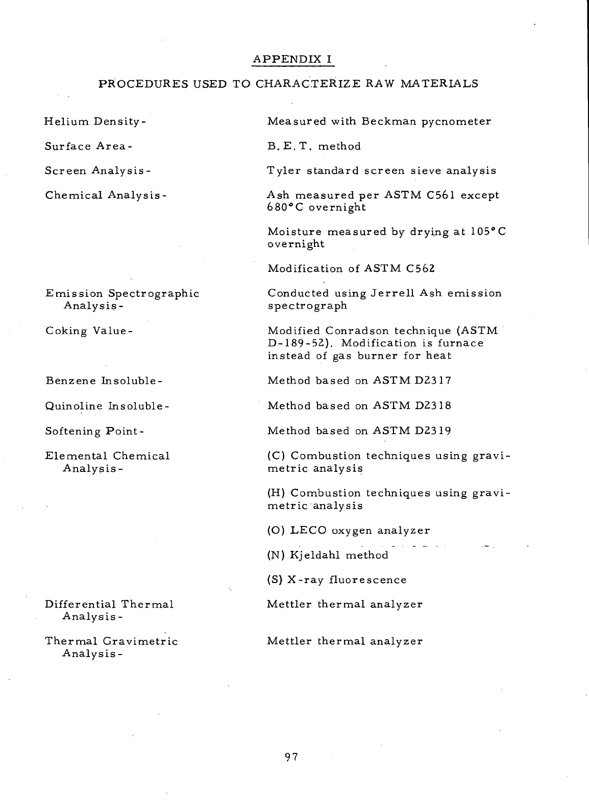
APPENDIX
I
PROCEDURES
USED
TO
CHARACTERIZE
RAW
MATERIALS
Helium
Density-
Surface
Area-
Screen Analysis-
Chemical Analysis-
Emission Spectrographic
Analysis
-
Coking
Value
-
Benzene Insoluble-
Quinoline
Insoluble-
Softening
Point
-
Elemental Chemical
Analysis
-
Differential
Thermal
Analysis-
Thermal
Gravimetric
Analysis-
Measured
with
Beckman pycnometer
B.
E. T.
method
Tyler standard screen sieve
analysis
Ash
measured
per
ASTM C561 except
680°C
overnight
Moisture
measured
by
drying
at
105°
C
overnight
Modification
of
ASTM
C562
Conducted
using
Jerrell
Ash
emission
spectrograph
Modified
Conradson technique
(ASTM
D-189-52).
Modification
is
furnace
instead
of gas
burner
for
heat
Method
based
on
ASTM
D2317
Method
based
on
ASTM
D2318
Method
based
on
ASTM
D2319
(C)
Combustion techniques using gravi-
metric
analysis
(H)
Combustion techniques using gravi-
metric
analysis
(O)
LECO oxygen analyzer
(N)
Kjeldahl method
(S)
X-ray fluorescence
Mettler
thermal
analyzer
Mettler thermal analyzer
97
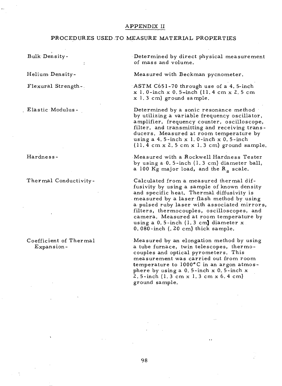
APPENDIX
II
PROCEDURES
USED
.TO
MEASURE MATERIAL PROPERTIES
Bulk Density-
Helium Density
-
Flexural
Strength-
Elastic
Modulus
-
Hardness
-
Thermal
Conductivity-
Coefficient
of
Thermal
Expansion-
Determined
by
direct physical measurement
of
mass
and
volume.
Measured with Beckman pycnometer.
ASTM
C651-70
through
use of a 4.
5-inch
x 1.
0-inch
x 0.
5-inch
(11.4cmx2.5cm
x 1.3 cm)
ground sample.
Determined
by a
sonic resonance method
by
utilizing
a
variable
frequency
oscillator,
amplifier,
frequency
counter, oscilloscope,
filter,
and
transmitting
and
receiving
trans-
ducers. Measured
at
room temperature
by
using
a 4.
5-inch
x 1.
0-inch
x 0.
5-inch
(11.4
cm x 2. 5 cmx 1.3 cm)
ground
sample.
Measured
with
a
Rockwell Hardness
Tester
by
using
a 0.
5-inch
(1. 3 cm)
diameter
ball,
a 100 Kg
major load,
and the R
scale.
Calculated from
a
measured thermal dif-
fusivity
by
using
a
sample
of
known
density
and
specific
heat.
Thermal
diffusivity
is
measured
by a
laser
flash method
by
using
a
pulsed ruby
laser
with associated
mirrors,
filters, thermocouples, oscilloscopes,
and
camera.
Measured
at
room temperature
by
using
a 0.
5-inch
(1. 3 cm)
diameter
x
0.
080-inch
(. 20 cm)
thick sample.
Measured
by an
elongation method
by
using
a
tube
furnace,
twin
telescopes, thermo-
couples
and
optical pyrometers. This
measurement
was
carried
out
from
room
temperature
to
1000°
C in an
argon
atmos-
phere
by
using
a 0.
5-inch
x 0.
5-inch
x
2.
5-inch (1.3
cmx 1.3
cmx6.4
cm)
ground
sample.
98
APPENDIX
II
(Cont'd)
Pore
Volume
and
Distribution
by
Mercury Intrusion-
Pore
Volume
b.yNitrpgen
Desorption-
The
sample
is
placed
in a
chamber
and
evacuated.
Mercury
from
an
external
reservoir
is
induced
into
the
sealed
chamber
as the
system
is
allowed
to
come
back
up to
atmospheric
pressure.
When
equilibrium
is
reached, increasing
amounts
of
pressure
are
applied
to the
mercury
in the
reservoir
and the
corres-
ponding
changes
in the
volume
of the
mercury
in the
reservoir
are
recorded
as the
mercury
is
intruded
into
the
sample.
Knowing
the
corresponding reservoir
volume
and
pressure changes allows
one
to
calculate
the
pore volume
and
distribution
of
the
sample, since
the
size
of the
pores
filled
by
mercury
is
inversely proportional
to the
applied
pressure.
Mercury does
not
wet
carbon-graphite
material.
o
The
volume
of
pores
smaller
than
600A
in
diameter
was
determined
from
the
nitrogen
desorption
isotherm
by
using
the
exact
form
of
the
equation attributed
to
Barrett, Joyner,
and
Halenda ^-'^-
with
no
simplifying
assumptions.
99
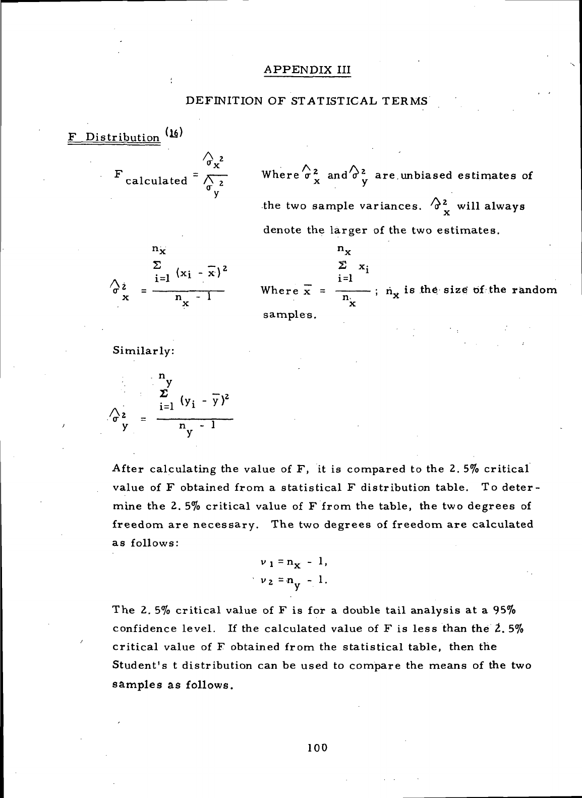
APPENDIX
III
DEFINITION
OF
STATISTICAL TERMS
F
Distribution
(1$)
A
calculated
n
X
- 1
Where
cr
2
and <r
2
are. unbiased
estimates
of
the
two
sample
variances,
a
2
will always
denote
the
larger
of the two
estimates.
n.
Where
x =
samples.
n-
x
;
ri is
the. size'
of the
random
Similarly:
n
n
- 1
y
After
calculating
the
value
of F, it is
compared
to the 2. 5%
critical
value
of F
obtained from
a
statistical
F
distribution
table.
To
deter-
mine
the 2. 5%
critical
value
of F
from
the
table,
the two
degrees
of
freedom
are
necessary.
The two
degrees
of
freedom
are
calculated
as
follows:
v
] = n
- 1 ,
The 2. 5%
critical
value
of F is for a
double
tail
analysis
at a 95%
confidence
level.
If the
calculated value
of F is
less
than
the 2. 5%
critical
value
of F
obtained from
the
statistical
table,
then
the
Student's
t
distribution
can be
used
to
compare
the
means
of the two
samples
as
follows.
100
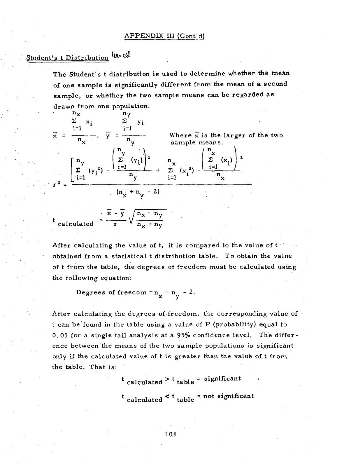
APPENDIX
III
(Cont'd)
Student's
t
Distribution
(is,,
16.J
The
Student's
t
distribution
is
used
to
determine whether
the
mean
of
one
sample
is
significantly
different
from
the
mean
of a
second
sample,
or
whether
the two
sample means
can be
regarded
as
drawn
from
one
population.
n.
n
yi
x =
<r
2
=
, y —
v»nt;iri;
3
n
- ' n ,
x y
sample
["
n,
r
y
S
(y.*)
-
n \
y
\
S
(y-)
n
1=1
> + -^
f,-
2
^
n
+
r.
U
i '
L
1-1 y 1-1
(.
ia LUG iax gci L
means.
(
n \
x I
S
(x.)
2
i=l
1
/
n
x
(n
+ n - 2)
x y
calculated
After
calculating
the
value
of t, it is
compared
to the
value
of t
obtained
from
a
statistical
t
distribution table.
To
obtain
the
value
of
t
from
the
table,
the
degrees
of
freedom
must
be
calculated using
the
following
equation:
Degrees
of
freedom
=n + n - 2.
6
x y
After
calculating
the
degrees
of-freedom,
the
corresponding
value
of
t can be
found
in the
table
using
a
value
of P
(probability)
equal
to
0.
05 for a
single tail analysis
at a 95%
confidence
level.
The
differ-
ence
between
the
means
of the two
sample
populations
is
significant
only
if the
calculated
value
of t is
greater
than
the
value
of t
from
the
table. That
is:
t ' i i .. j > t , ,, =
significant
calculated
table
6
t
i i -i j < t . , , = not
significant
calculated
table
6
101
REFERENCES
1.
Parks,
A. J. ,
McKibbin,
R. H. , and Ng, C. C. W. ,
"Development
of
Main
Shaft
Seals
for
Advanced
Air
Breathing Propulsion Systems,
"
NAS3-7609,
Final
Report
Phase
I
(August,
1967),
NASA
CR-72338,
page
49.
2.
Johnson, Robert
L. , and
Ludwig, Lawrence
P. ,
"Shaft
Face
Seal
with Self-
Acting
Lift
Augmentation
for
Advanced
Gas
Turbine Engines,
"
NASA-TN-
D-5170,
NASA
Lewis Research Center, Cleveland, Ohio, April, 1969.
3.
Strom,
Thomas
N. ,
Allen, Gordon
P. , and
Johnson, Robert
L. ,
"Wear
and
Friction
of
Impregnated Mechanical Carbons
at
Temperatures
to
1400°F
(760°C)
in Air or
Nitrogen, "NASA-TN -D-3958, page
2,
NASA
Lewis
Research
Center,, Cleveland, Ohio, May, 1967.
4.
Lauzau,
W. R. ,
Shelton
, B. R. , and
Waldheger,
R. A.,
"The
Use of
Carbon-Graphite
in
Mechanical
Seals,"
Lubrication Engineering, Volume
19,
pages 201-209, May, 1963.
5.
Fechter,
N. J. , and
Petrunich,
P. S. ,
"Development
of
Seal
Ring Carbon-
Graphite
Materials
(Tasks
I and
II),
"
Union
Carbide Corporation, Topical
Report
NASA
CR-72799
(Contract
NAS3-13211),
January, 1971.
6.
Fechter,
N. J. , and
Petrunich,
P. S. ,
"Development
of
Seal
Ring Carbon-
Graphite
Materials
(Tasks
III and
IV), "Union Carbide Corporation, Topical
Report
NASA
CR-72986
(Contract
NAS3-13211),
August,
197.1.
7.
"Pressure
Baked Graphite
Materials,"
Great
Lakes
Research Corporation,
Technical
Documentary Report
No.
ML-TDR-64-175 (Contract
No.
AF33
(657)-11738),
June, 1964.
8.
Loc. cit.
,
Reference
5,
pages 75-77.
9.
Loc. cit., Reference
5,
pages
84-89.
10.
Loc. cit.
,
Reference
6,
pages 77-87.
11.
Loc. cit., Reference
6,
page
79.
12.
Loc. cit., Reference
2,
page
17.
13. The
Industrial Graphite Engineering Handbook,
Union
Carbide Corporation,
pages
5A. 08.
OZ-5A.
08.
03,.
C1969.
102
REFERENCES
(Cont'd)
14.
JLoc.
cit.
,
Reference
6,
pages
73-75.
15.
Brownlee,
K. A.,
Industrial Experimentation, Chemical Publishing
Co. ,
Inc.
, New
York,
pages
28-32,
C1947.
16.
Hoel,
Paul
G. ,
Introduction
to
Mathematical Statistics,
John
Wiley
&
Sons,
Inc.,
New
York-London,
pages
271 to
288,
C1962.
17.
Barrett,
E. P. ,
Joyner,
L. G. , and
Halenda,
P. B. , The
Determination
of
Pore
Volume
and
Area Distributions
from
Nitrogen Isotherms, Journal
of
the
American Chemical Society, Volume
73,
page
373, 1951.
18.
Roberts,
B. F. , .A
Procedure
for
Estimating
Pore
Volume
and
Area
Distributions
by
Sorption Isotherms, Journal
of
Colloid
and
Interface
Science, Volume
23,
pages
266-273,
1967.
103
DISTRIBUTION
LIST
Addressee
". No. of
Copies
1.
NASA
Headquarters
.
Washington,
D. .G.
20546
•
Attn:
N. F.
Rekos (RL)
. 1
A.
J.
Evans (RH)
1
J.
Maltz (RMW)
1
J. J.
Gangler (RRM)
1
2.
NASA
Lewis Research Center
21000
Brookpark Road
Cleveland,
OH
4413-5
Attn:
A.
Ginsburg,
MS 5-3 1
E. E.
Bisson,
MS 5-3 1
G.
H.
Voit,
MS 5-3 1
B.
Lubarsky,
MS 3-3 . 1
R.
J.
Paginton,
MS
500-206
1
L. W.
Schopen,
MS
500-206
.1
R. L.
Johnson,
MS
23-2
1
M.
A.
Swikert,
MS
23-2
1
W.
R.
Loomis,
MS
23-2
1
L. P.
Ludwig,
MS-23-2
6
Report
Control
Office,
MS 5-5 1
Library,
MS
60-3
1
Technology
Utilization
Office,
MS
3-19
1
3.
NASA
Scientific
and
Technical Information
Facility
P. O. Box 33
College
Park,
MD
20740
Attn:
NASA
Representative
2
4.
NASA
Langley Research Center
Langley Station
Hampton,
VA
23365
Attn:
Mark
R.
Nichols
1
5.
Wright-Patterson
Air
Force
Base
Dayton,
OH
45433
Attn:
AFAPL (APFL),
K. L.
Berkey
and L.
DeBrohum
1
AFAPL (AFTC),
C..
Simpson
1
APTP,
I. J.
Gershon
1
SESHS,
J. L.
Wilkins
1
SEJDF,
S.
Prete
1
MANE,
R.
Headrick
1
MANE,
P.
House
1
AFML/XR,
R. L.
Adamczak
1
104
Addressee
No. of
Copies
6. FAA
Headquarters
800
Independence Ave.
, SW
Washington,
D. C.
20553
Attn:
F. B.
Howard
. 1
7.
U. S.
Naval
Air
Development Center
Aeronautical
Materials
Dept.
Warminster,
PA
18974
Attn:
A. L.
Lockwood
. 1
8. U. S.
Naval Research
Lab
Washington,
D. C.
.
Attn:
Charles
Murphy
1
9;
Department
of the
Navy
Washington,
D. C.
20013
.
Attn:
Bureau
of
Naval Weapons
A. D.
Nehman
• 1
C. C.
Singletorry
1
Bureau
of
Ships
Harry
King
1
10.
Department
of the
Navy
Naval
Air
Systems Command
AIR-330
Washington,
D. C.
20360
1
11. U. S.
Navy
Marine Engineering
Lab
Friction
&
Wear. Division
Annapolis
Academy
Annapolis,
MD
21490
Attn:
R. B.
Snapp
1
12.
Commanding
Officer
Eustis Directorate
U..
S.
Army Air.Mobility
R&D
.Lab
Ft.
Eustis,
VA
23604
Attn:
John
W.
White, SAVDL-TD
1
13. U. S.
Army Ordnance
Rock
Island Arsenal
Lab
Rock
Island,
IL
61201
Attn:
R.
LeMar
. 1
14.
AVCOM
AMSAVEGTT
Mart Building
.
405
S.
12th
St.
St.
Louis,
MO
63166
Attn:
E.
England
1
105
Addressee
No. of
Copies
15.
Aerojet Liquid Rocket Company
P..O.
Box
13222
Sacramento,
CA
95813
-
..Attn:
C. W.
Williams
- '1
16.
AiResearch Manufacturing Corp.
402.
S.
36th
St.
Phoenix,
AZ
85034
.Attn:
Dr. R.
Blake
Wallace
1
17. -
Advance Carbon Products, Inc.
Hampshire
&
Mariposa.Sts.
San
Francisco,
CA
94110
Attn:
W. J.
Grader
1
1
8.
Avco Corp.
Lycoming Division
Stratford,
CT
06497
Attn:
R.
Cuny
1
19. .
Battelle
Memorial
Institute
Columbus
Laboratories
505
King Ave.
.Columbus,
OH
43201
Attn:
C. M.
Allen
1
20.
Bendix Corp.
Bendix Ctr.
Southfield,
MI
48075
Attn:
. M. J.
Caparone
1
21.
B. F.
Goodrich Company
Aerospace
&
Defense-Products Div.
Troy,
OH
45373
Attn:
L.. S.
Blalkowski
. 1
22.
Boeing Aircraft
Co.
224
N.
Wilkinson
Dayton,
OH
45402
.Attn:
H. W.
Walker
1
23.
The
Boeing Company
Vertol Division
P. O. Box
16858
Philadelphia,
PA
19142
Attn:
A. J.
Lemanski,
MS
P-32-09
1
24.
Borg-Warner Corp.
Ingersoll
Research
Ctr.
Wolf
and
Algonquin Rds.
Des
Plaines,
IL
60018
1
106
Addressee
No. of
Copies
25.
Carborundum
Co.
Graphite
Products
Blank
&
Walmore Rds.
Sanborn,
NY
14132
Attn:
R. M.
Markel
1
26.
Cartiseal
Corp.
634
Glenn Ave.
Wheeling,
IL
60090
Attn:
R.
Voltik
1
27.
Chicago Rawhide Mfg.
Co.
900
N.
State
St.
Elgin,
IL
60121
Attn:
R.
Blair
1
28.
Gould,
Inc.
17000
St.
Clair Ave.
Cleveland,
OH
44110
Attn:
J.
Ross
1
29.
Teledyne/CAE
1330
Laskey
Rd.
Toledo,
OH
43601
Attn:
R. J.
Magrina
1
30.
Crane
Packing
Co.
6400
W.
Oakton
St.
Morton
Grove,
IL
60053
Attn:
Harry
Tankus
1
31.
Defense Ceramics Information Ctr.
Battelle Memorial Institute
.
Columbus,
Labs.
Room 11-9021
505
King
Avenue
Columbus,
OH
43201
1
32.
McDonnell-Douglas Corp.
333
West
First
St.
Dayton,
OH
45402
Attn:
R. G.
Donmoyer
1
33.
Durametallic Corp.
Kalamazoo,
MI
49001
Attn:
H.
Hummer
1
34..
Fairchild
Industries, Inc.
Republic
Aviation Div.
Farmingdale,
LI, NY
11735
Attn:
C.
Collis
1
107
Addressee
No. of
Copies
35.
Franklin
Institute-Research
Labs
20th
and
Parkway
Philadelphia,.
PA
19103
Attn:
W.
Shapiro
1
36.
Garlock, Inc.
Palmyra,
NY
14522
Attn:
E. W..
Fisher
1
37.
Garrett
Corp.
AiResearch Mfg. Div.
9851-9951
Sepulveda Blvd.
Los
Angeles,
CA
90009
Attn:
A.
Silver
1
38.
General Dynamics Corp.
1025
Connecticut Ave.
,. SW
Washington,
D..C.
20036
Attn: George
Villa
1
39.
General
Elect
ric
Company
Advanced
Engine
&
Technology Dept.
Cincinnati,
OH
45215
Attn:
L. B.
Venable
1
W.
McCarty
1
40.
General Motors Corp.
Allison Division
Plant
No. 3,
Dept.
7339
Indianapolis,.
IN
46206
1
41.
Great
Lakes
Research
Corp.
299
Park
Ave.
New
York,
NY
10017
Attn:
J. P.
Sachs
1
R.
Hillier
1
42.
Gulf
Oil
Corp.
P. O. Box 608
San
Diego,.
CA
92112
Attn:
J. C.
Bokros
1
43.
IIT
Research Institute
10
West 35th.
St.
Chicago,
IL
60616
Attn:
Dr.
Strohmeier
M.. A. .
Schwartz
. 1
44.
Kendall
Refining
Co.
Bradford,
PA
16701
Attn:
F. I. I.
Lawrence
1
108
Addressee
No. of
Copies
45.
Keystone Carbon Corp.
1935
State
Road
St.
Marys,
PA
15857
Attn:
B. R.
Reuscher
1
46.
Koppers
Co. ,
Inc.
Metal Products Division
Piston
Ring
&
Seal
Dept.
Baltimore,
MD
21203
Attn:
F. C.
Kuchler
1
E.
Taschenburg
1
J.
Heck
1
47.
Lockheed Aircraft
Co.
118
W.
First
St.
Dayton,
OH
45402
Attn:
R. W.
Witte
1
48.
Los
Alamos Scientific
Lab
University
of
California
Los
Alamos,
NM
87544
Attn:
M. C.
Smith
. 1
49.
Martin
Marietta
Corp.
P. O. Box
14153
Dayton,
OH
45414
Attn:
Z. G.
Horvath
1
50.
Mechanical Technology Inc.
968
Albany-Shaker Road
Latham,
NY
12110
Attn:
D. F.
Wilcock
1
51.
Midwest
Research
Institute
425
Volker Blvd.
Kansas
City,
MO
64110
Attn:
V.
Hopkins
1
52.
Monsanto Chemical
Co.
800
N.
Lindberg Blvd.
St.
Louis,
MO
63166
Attn:
Dr. W. R.
Richard
1
R.
Hatton
1
53.
Morganite, Inc.
33-02
48th
St.
Long
Island
City,
NY
11101
Attn:
S. A.
Rokaw
. 1
54.
National Technical Information Service
Springfield,
VA
22151
40
109

Addressee
. No. of
Copies
55.
North American Aviation Inc.
5100
W. 164 St.
Cleveland,
OH
44142
Attn:
George Bremer
1
56.
Northrop Corp.
1730
K
Street,
NW
Suite
903-5
Washington,
D. C.
20006
Attn:
S. 'W.
Fowler,
Jr. 1
57.
Pesco
Products Div.
Borg-Warmer Corp.
24700
N.
Miles
Bedford,
OH
44146
Attn:
W. J.
Cieslik
1
58.
Pressure
Technology Corp.
of
America
453
Amboy Ave.
Woodbridge,
NJ
07095
Attn:
A.
Bobrowsky
1
59.
Poco Graphite Inc.
P. O. Box
1,524
Garland,
TX
75040
Attn:
Dr. R. F.
Wehrmann
1
60.
Pure
Carbon
Co. ,
Inc.
441
Hall
Ave.
St.
Marys,
PA
15857
Attn:
Dr. R. R.
Paxton
1
J. J.
Sherlock
. 1
61.
Rocketdyne
Division
North
American Rockwell Corp.
6633
Canoga Ave.
Canoga
Park,
CA
91304
Attn:
R. E.
Burcham
1
62.
Sealol
Inc.
P. O. Box
2158
Providence,
RI
02905
Attn:
Justus Stevens
1
63. .
Sikorsky Aircraft
United
Aircraft Corp.
North
Main
St.
Stratford,
CT
06497
Attn:
L.
Burroughs
1
110

Addressee
No. of
Copies
64.
Sinclair
Refining
Co.
600
Fifth Ave.
. .
New
York,
NY
10020
•
Attn:
C. W.
McAllister
.. 1
65.
Sinclair
Research
Inc.
400
E.
Sibley Blvd.
Harvey,
IL
60426
Attn:
M. R.
Farille
1
66.
SKF
Industries, Inc.
1100
First
Ave.
King
of
Prussia,
PA
19406
Attn:
L. B.
Sibley
. 1
67.
Socony
Mobil
Oil
Company
Research Dept.
Paulsboro
Lab
Paulsboro,
NJ
08066
Attn:
E.
Oberright
1
68. St.
Marys
Co.
1939
State Road
.
St.
Marys,
PA
15857
Attn:
J. E.
Lanzel
. 1
69.
Director
Government
Research
Lab .
Esso
Research
&
Engineering
Co.
P. O. Box 8
Linden,
NJ
07036
1
70.
Southwest Research Institute
P. O.
Drawer
28510
San
Antonio,
TX
78284
Attn:
P
r
M. Ku 1
71.
Stanford Research Institute
Menlo
Park,
CA
94025
Attn:
R. C. Fey 1
72.
Stein
Seal
Company
20th
St. &
Indiana Ave.
Philadelphia,
PA
19132
Attn:
Dr. P. C.
Stein
. 1
73.
Sun Oil
Company
Automotive
Laboratory
Marcus Hook,
PA
19061
Attn:
J. L.
Griffith
1
111
Addressee
. •. No. of
Copies
74.
Ultra
Carbon Corp.
St.
Marys,
PA
15857
Attn:
Dr. E. I.
Shobert
1
75.
Ultra
Carbon
Corp.
1300
N. '
Madison Ave.
Bay
City,
MI
48706
Attn:
Del
Hughes
. 1
76.
United Aircraft Corp.
Pratt
&
Whitney Aircraft
East
Hartford,
CT
06108
Attn:
R.
Shevchenko,
Engr.
Bldg.
1
77.
United
States
Graphite
Company
1620
Holland
Saginaw,
MI
48601
Attn:
F. F.
Ruhl
1
78.
Westinghouse
Electric
Corp.
5100
W.
164th
St.
Cleveland,
OH
44142
Attn:
Lynn
Powers
1
79.
Wright-Aeronautical Division
Curtiss-Wright Corp.
333
West
First
St.
Dayton,
OH
45402
y
Attn:
D.
Lombardo
1
80.
Pennsylvania
State University
Dept.
of
Chemical
Engineering
University
Park,
PA
16802
Attn:
Dr. E. E.
Klaus
1
81. The
University
of
Tennessee
Dept.
of
Mechanical
&
Aerospace
Engr.
'
Knoxville,
TN
37916
Attn:
Prof.
W. K.
Stair
1
Dr. C.
Fisher
1
112
