

FAA Surveillance and Broadcast Services Surveillance and Broadcast Services Description Document
SRT-04, Rev. 04 – September 20, 2018 Page i
Revision History for
Surveillance and Broadcast Services Description Document
SRT-047, Revision 04
Revision #
Description
Document
Date
Rev. 01
CM Baseline Version, DCR-SE-002
October 24, 2011
Rev. 02
Numerous changes to clarify TIS-B and FIS-B
uplink behavior
November 15, 2013
Rev. 03
Updated to reflect new FIS-B MOPS DO-358
that was approved by RTCA and incorporate
service changes since last release.
March 31, 2018
Rev. 04
DCR-PMO-187: Corrected paragraph
3.3.3.2.2.3 to state TIS-B; Fixed link to figure
3-6; Updated reference documents to NAS-
RD-2013; Revised Table 3-16 FIS-B products
Update and Transmission Intervals; other
grammatical edits.
Updated Table 1-4 to include information on
the 6 new FIS-B products. Removed the six
new products from Table 1-5 “Future”
products. Updated Tables 3-15, 3-16, 3-18, C-
3 and C-4 for six new products. Extended
Section B.1 to include details on six new
products. Added Appendix G with a detailed
description for the 6 new FIS-B products.
Added information on the process for deleting
older NOTAMs.
Included description of the SBS No Services
Aircraft List (NSAL).
Updated METAR and TAF lists.
Incorporated DCR-PMO-187 comment
resolutions.
September 20, 2018

FAA Surveillance and Broadcast Services Surveillance and Broadcast Services Description Document
SRT-04, Rev. 04 – September 20, 2018 Page ii
TABLE OF CONTENTS
1 Scope 1
1.1 Summary: Background and Purpose 1
1.2 Subsystem Responsibility List: SBSS and External Interfaces 4
1.2.1 ADS-B Equipped Aircraft in the NAS 5
1.2.1.1 1090ES and UAT Equipages 5
1.2.1.2 Requirements of the Final Rule for ADS-B Equipage 5
1.2.1.3 Dual Technology Link Equipage 5
1.2.2 FAA SDP for Radar Data, ADS-B Target Delivery and Service
Monitoring 6
1.2.3 Meteorological and Aeronautical Data Source 6
1.3 SBSS Services Overview 6
1.3.1 ADS-B Surveillance Service 6
1.3.1.1 Air-to-Air ADS-B 7
1.3.1.2 Air-to-Ground ADS-B 7
1.3.2 ADS-R Service 7
1.3.3 TIS-B Service 9
1.3.4 FIS-B Service 10
1.3.4.1 Current FIS-B products 11
1.3.4.2 Growth Options: New FIS-B products 14
1.4 Message Interchange Summary 15
2 Referenced Documents 16
2.1 Government Documents 16
2.2 Non Government Documents 17
3 Air Interface Characteristics: Service Descriptions 19
3.1 General Air Interface Characteristics 19
3.2 Service Identification and Description 19
3.2.1 ADS-B Surveillance Service 22
3.2.2 ADS-R Service 23
3.2.2.1 ADS-R Concept of Operations 23
3.2.2.2 ADS-R Client Identification 23
3.2.2.3 ADS-R Target Identification 23
3.2.2.4 ADS-R in En Route and Terminal Airspace Domains 24
3.2.2.5 ADS-R in Surface Domains 24
3.2.2.6 Transmission of ADS-R Targets Over the Air Interface 25
3.2.2.7 ADS-R Service Status Notification 25
3.2.2.8 ADS-R Same Link Rebroadcast 26
3.2.3 TIS-B Service 27
3.2.3.1 TIS-B Service Concept of Operations 27
3.2.3.2 TIS-B in En Route and Terminal Airspace Domains 28
3.2.3.3 TIS-B in Surface Domains 28
3.2.3.4 Transmission of TIS-B Target Messages 29
3.2.3.5 TIS-B Service Status Notification 29
3.2.3.6 False Tracks and Incorrect Associations 29

FAA Surveillance and Broadcast Services Surveillance and Broadcast Services Description Document
SRT-04, Rev. 04 – September 20, 2018 Page iii
3.2.4 FIS-B Service 30
3.3 Service Messages and Performance 31
3.3.1 ADS-B Service Messages and Performance 31
3.3.1.1 ADS-B Information Units—Message Content 31
3.3.1.2 ADS-B Quality of Service 35
3.3.2 ADS-R Service Messages and Performance 37
3.3.2.1 ADS-R Information Units—Message Content 37
3.3.2.2 Quality of Service 38
3.3.3 TIS-B Service Messages and Performance 40
3.3.3.1 TIS-B Information Units—Message Content 40
3.3.3.2 TIS-B Quality of Service 45
3.3.4 FIS-B Service Messages and Performance 50
3.3.4.1 FIS-B Information Units—Message Content 51
3.3.4.2 FIS-B Information Units –FIS-B APDU 51
3.3.4.3 FIS-B Information Units –TIS-B/ADS-R Service Status 51
3.3.4.4 FIS-B Quality of Service 52
3.3.5 ADS-B Service 55
3.3.6 ADS-R Service 57
3.3.7 TIS-B Service 58
3.3.8 FIS-B Service 59
3.3.8.1 DO-358 Errata for FIS-B Services 60
3.4 Uplink Interface Design Characteristics Summary 61
3.5 No Services Aircraft List (NSAL) 61
4 Abbreviations and Acronyms 63
Appendix A. Coverage Maps and Radio Stations 65
A.1 Current Coverage 65
A.2 Radio Station Locations 65
Appendix B. FIS-B Quantity of Available Products and Other Aspects 66
B.1 FIS-B Quantity of Available Products 66
B.1.1 SIGMET / Convective SIGMET 66
B.1.2 AIRMET 66
B.1.3 METAR 66
B.1.4 CONUS NEXRAD 66
B.1.5 Regional NEXRAD 66
B.1.6 NOTAM 66
B.1.7 PIREP 66
B.1.8 SUA Status 66
B.1.9 TAF 67
B.1.10 Winds and Temperatures Aloft 67
B.1.11 Icing Forecast 68
B.1.12 Cloud Tops Forecast 68
B.1.13 Turbulence Forecast 68
B.1.14 Lightning 68
B.1.15 G-AIRMET 68
B.1.16 Center Weather Advisory 68

FAA Surveillance and Broadcast Services Surveillance and Broadcast Services Description Document
SRT-04, Rev. 04 – September 20, 2018 Page iv
Appendix C. FIS-B Tiering Configuration 69
C.1 TIS-B Site ID Field and Data Channel Assignment 69
C.2 Product Parameters for Low/Medium/High Altitude Tier Radios 70
C.3 Product Parameters for Surface Radios 72
Appendix D. Listing of Service Volumes (SV) 73
D.1 En Route SVs 73
D.2 Terminal SVs 73
D.3 Surface SVs 74
Appendix E. METAR Stations 76
Appendix F. TAF Stations 97
Appendix G. FIS-B Products 105
G.1 Background 105
G.1.1 Global Block Representation Products 105
G.1.1.1 General Formatting 105
G.1.1.2 Global Block Frame Formatting 108
G.1.1.3 Turbulence Forecast (Product ID #90 and #91) 115
G.1.1.4 Icing Forecast (Product ID #70 and #71) 121
G.1.1.5 Cloud Tops Forecast (Product ID #84) 126
G.1.1.6 Lightning (Product ID #103) 129
G.1.2 Text with Graphical Overlay FIS-B Products 132
G.1.2.1 General Formatting 132
G.1.2.2 G-AIRMET (Product ID #14) 148
G.1.2.3 Center Weather Advisory (CWA) Product ID #15 154
G.2 Current Report List 155
G.2.1 CRL Header Encoding 157
G.2.1.1 Product ID 157
G.2.1.2 TFR 157
G.2.1.3 Reserved 157
G.2.1.4 O Flag 157
G.2.1.5 L Flag 157
G.2.1.6 Product Range 158
G.2.1.7 LocID 158
G.2.1.8 Number of CRL Items Listed 158
G.2.2 CRL Payload Encoding 158
G.2.2.1 Reserved Bit 158
G.2.2.2 Report Year 158
G.2.2.3 Text 158
G.2.2.4 Graphic 158
G.2.2.5 Report Number 158
Appendix H. Background on the Lightning Uplink Product 160
H.1 Lightning Sources 160
H.2 Lightning Product APDU Header 160

FAA Surveillance and Broadcast Services Surveillance and Broadcast Services Description Document
SRT-04, Rev. 04 – September 20, 2018 Page v
LIST OF FIGURES
Figure 1-1. SBSS and External Interfaces ...................................................................................... 4
Figure 1-2. ADS-B Service Data Flows ......................................................................................... 7
Figure 1-3. ADS-R Service Data Flows ......................................................................................... 8
Figure 1-4. TIS-B Service Data Flows ........................................................................................... 9
Figure 1-5. FIS-B Service Data Flows .......................................................................................... 10
Figure 3-1. SBSS and ADS-B Aircraft Interconnectivity ............................................................. 19
Figure 3-2. SBS Service Volumes ................................................................................................ 21
Figure 3-3. ADS-R Client Proximity Determination .................................................................... 24
Figure 3-4. ADS-R SLR Example at PHL Airport ....................................................................... 26
Figure 3-5. TIS-B Client Proximity Determination ...................................................................... 28
Figure 3-6. Continuity Region around Airport with Surface SV .................................................. 49
Figure 3-7. ADS-B Air-to-Air Protocol Stack .............................................................................. 55
Figure 3-8. ADS-B Service Air-to-Ground Protocol Stack .......................................................... 56
Figure 3-9. ADS-R Service Protocol Stack .................................................................................. 57
Figure 3-10. TIS-B Service Protocol Stack .................................................................................. 58
Figure B-1. Locations of U.S Winds/Temperatures Aloft Forecast Locations ............................. 67
Figure D-1. En Route Service Volume Boundaries ...................................................................... 73
Figure G-1: Run Length Encoding Blocks Showing Constituent Bins ...................................... 106
Figure G-2: Global Block Numbering Plan ................................................................................ 107
Figure G-3: Decomposition Showing Global Block Product Formatting .................................. 108
Figure G-4: Block Reference Indicator Byte-Level Format ....................................................... 108
Figure G-5: Product Specific Bits Encoding Type 1 .................................................................. 109
Figure G-6: Product Specific Bits Encoding Type 2 .................................................................. 110
Figure G-7: Global Block Numbering Scheme by Scale Factor ................................................. 111
Figure G-8: Run Length Encoded Element Byte-Level Format ................................................. 112
Figure G-9: Empty Element Byte-Level Format ........................................................................ 113
Figure G-10: Global Block Forecast Product Timeline .............................................................. 118
Figure G-11: Turbulence Forecast Product Run Length Encoding for Single Byte Runs.......... 118
Figure G-12: Turbulence Forecast Product Run Length Encoding for Two Byte Runs ............ 119
Figure G-13: Example Block Containing Six Runs .................................................................... 119
Figure G-14: Icing Forecast Product Run Encoding................................................................... 123
Figure G-15: Example Block Containing Six Runs (Decimal values listed in order of
Icing Probability, Icing Severity, SLD) ................................................................... 123
Figure G-16: Cloud Tops Forecast Product Run Length Encoding for Single Byte
Runs ......................................................................................................................... 127
Figure G-17: Cloud Tops Product Run Length Encoding for Two Byte Runs .......................... 127
Figure G-18: Example Block Containing Six Runs (Cloud Top Height Value Listed as
Decimal) .................................................................................................................. 127
Figure G-19: Lightning Product Run Encoding.......................................................................... 130
Figure G-20: Example Block Containing 12 Runs (Polarity: Strike Count as Decimal
Values) ..................................................................................................................... 130
Figure G-21: Decomposition Showing TWGO FIS-B Payload ................................................. 132
Figure G-22: TWGO Header Byte-Level Format ....................................................................... 133
Figure G-23: Text Record Byte-Level Format ........................................................................... 134

FAA Surveillance and Broadcast Services Surveillance and Broadcast Services Description Document
SRT-04, Rev. 04 – September 20, 2018 Page vi
Figure G-24: Graphical Record Byte-Level Format ................................................................... 136
Figure G-25: Record Applicability Byte-Level Format .............................................................. 141
Figure G-26: Extended Range Circular Prism ............................................................................ 144
Figure G-27: G-AIRMET Issuance Timeline ............................................................................. 150
Figure G-28: Object Qualifier ..................................................................................................... 153
Figure G-29: Decomposition Showing the CRL ........................................................................ 156
Figure G-30: CRL Encoding ....................................................................................................... 156

FAA Surveillance and Broadcast Services Surveillance and Broadcast Services Description Document
SRT-04, Rev. 04 – September 20, 2018 Page vii
LIST OF TABLES
Table 1-1 .SBSS Supported and Complementary ADS-B Services ............................................... 2
Table 1-2. ADS-B Applications, Services, and Functions.............................................................. 3
Table 1-3. ADS-B Equipage Types in the NAS ............................................................................. 5
Table 1-4. FIS-B Products Provided by SBSS ............................................................................. 11
Table 1-5. Candidate Future FIS-B Products ................................................................................ 14
Table 1-6. Message Interchange Summary ................................................................................... 15
Table 3-1. Service Volume Boundaries and Airspace Domain .................................................... 20
Table 3-2. Target Provision to ADS-B-IN Aircraft: Dependence on Equipage ........................... 21
Table 3-3. Required ADS-B Out Performance to be an ADS-R Client ........................................ 23
Table 3-4. Required ADS-B Out Performance for ADS-R Traffic Uplink to Clients .................. 24
Table 3-5. Required ADS-B Out Performance to be a TIS-B Client ............................................ 27
Table 3-6. 1090ES ADS-B Message ME bit-mapping to SDP ADS-B Report Data
Items .......................................................................................................................... 33
Table 3-7. UAT ADS-B Message mapping to SDP ADS-B Report Data Items .......................... 34
Table 3-8. FAA SDP ADS-B Report ............................................................................................ 34
Table 3-9. 1090ES ADS-R Message Types to Encode Upon Receipt of UAT Message
Types ......................................................................................................................... 37
Table 3-10. Transmitted 1090 TIS-B Message Types .................................................................. 41
Table 3-11. Payload Composition of 1090ES TIS-B Messages ................................................... 42
Table 3-12. Payload Composition of UAT TIS-B Messages ....................................................... 44
Table 3-13. Requirements for Track Accuracy............................................................................. 47
Table 3-14. UAT TIS-B/ADS-R Service Status Format .............................................................. 51
Table 3-15. FIS-B Products Supported by SBSS.......................................................................... 52
Table 3-16. FIS-B Product Update and Transmit Intervals .......................................................... 53
Table 3-18. FIS-B Service Protocol Stack .................................................................................... 59
Table 3-20. 1090 Uplink Interface Requirements Table .............................................................. 61
Table 3-21. UAT Uplink Interface Requirements Table .............................................................. 61
Table C-1. TIS-B Site ID field values .......................................................................................... 69
Table C-2. FIS-B Data Channel Assignment ................................................................................ 69
Table C-3. Product Parameters for Low/Medium/High Altitude Tier Radios .............................. 70
Table C-4. Product Parameters for Surface Radios ...................................................................... 72
Table D-1. List of Airports Supported by Terminal SVs.............................................................. 74
Table D-2. List of Airports Supported by Surface SVs ................................................................ 75

FAA Surveillance and Broadcast Services Surveillance and Broadcast Services Description Document
SRT-047, Rev. 04 – September 20, 2018 Page 1 of 160
1 Scope
This document discusses the design of the air interface between the Surveillance and Broadcast
Services System (SBSS) and ADS-B equipped aircraft.
1.1 Summary: Background and Purpose
The overall purpose of this document is to describe the services provided by the Surveillance and
Broadcast Services System (SBSS) over the Air Interface to ADS-B Equipped aircraft. It is
oriented primarily to ADS-B avionics manufacturers. It documents the detailed design of the Air
Interface to help ensure that vendor offerings of ADS-B avionics are fully compatible with the
SBSS, and that they may be designed to take full advantage of the offered services.
In the NAS, there are two applicable ADS-B equipage types:
• 1090 Extended Squitter (1090ES): an extension of Mode-S technology in which
1090ES avionics periodically broadcast short messages at 1090 MHz that provide
their identity (24-Bit Address), target state vector (position, velocity) and other
aircraft status information.
• Universal Access Transceiver (UAT): a new technology in which UAT avionics
periodically broadcast messages at 978 MHz that provide their identity, target state vector
and other status information.
Each of the above equipage types may support only ADS-B-OUT services or may be more
comprehensive so that they support ADS-B-IN services as well. Table 1-1 introduces the ADS-B-
OUT and -IN services that are provided by SBSS to aircraft with the different equipage types. It
also describes ADS-B air-to-air surveillance, which is complementary to, but independent of the
broadcast services supported by SBSS. Each of these services will be described in further detail in
sections 1 and 3 of this document.

FAA Surveillance and Broadcast Services Surveillance and Broadcast Services Description Document
SRT-047, Rev. 04 – September 20, 2018 Page 2 of 160
Table 1-1 .SBSS Supported and Complementary ADS-B Services
Category Service Description
ADS-B-OUT Service
(to Air Traffic Control)
ADS-B
Surveillance
(Air to Ground)
An SBSS service to FAA Air Traffic Control (ATC) that
receives, formats, and forwards the received broadcast
information of 1090ES and UAT ADS-B-OUT equipped
aircraft
ADS-B-IN Services (to
aircraft equipped with
ADS-B-IN and ADS-B-
OUT)
ADS-B
Surveillance
(Air-to-Air)
An ‘in cockpit’ service to 1090ES/UAT ADS-B-IN equipped
aircraft that captures 1090ES/UAT squitters of proximate
aircraft (independent of SBSS)
ADS-B
Rebroadcast
(ADS-R)
An SBSS service to the cockpit of 1090ES/UAT ADS-B-IN
equipped aircraft that supports ADS-B message translation
and rebroadcast of the identity and state vector of proximate
aircraft with UAT/1090ES ADS-B equipage. This service also
supports Same Link Rebroadcast (SLR) that is utilized in
surface service volumes to address structural blockages on
near the movement area and multipath interference.
Traffic
Information
Services -
Broadcast (TIS-B)
An SBSS service to the cockpit of 1090 and UAT ADS-B-IN
equipped aircraft that broadcasts the state vector of proximate
aircraft that are not ADS-B equipped
Flight Information
Service –
Broadcast (FIS-B)
1
An SBSS service to the cockpit of UAT ADS-B-IN equipped
aircraft that provides Meteorological and Aeronautical
Information
The ADS-B-IN services of ADS-B (air-to-air), ADS-R and TIS-B, meet the requirements in the
Aircraft Surveillance Applications Systems MOPS (ASAS MOPS, RTCA/DO-317B) to support a
number of flight-deck based aircraft surveillance applications that may directly provide flight
crews with surveillance information as well as surveillance-based guidance and alerts.
Surveillance information consists of position and other state data about proximate aircraft, and,
when on or near the airport surface, position and other state data about appropriately equipped
surface vehicles. Numerous applications have been proposed, and it is expected that additional
applications will be developed and standardized. Table 1-2 lists the current applications with the
corresponding SBS Service and/or Function that supports the respective applications along with
the RTCA reference document(s).
1
FIS-B services could actually be obtained with only an ADS-B IN unit because this service broadcasts data to all
receivers within radio line of sight.
FAA Surveillance and Broadcast Services Surveillance and Broadcast Services Description Document
SRT-047, Rev. 04 – September 20, 2018 Page 3 of 160
Table 1-2. ADS-B Applications, Services, and Functions
SBS Services RTCA Reference(s)
ADS-B
ADS-R
TIS-B
FIS-B
Surveillance and Broadcast Services
Enabled Applications
ATC Surveillance for Enhanced Air Traffic Services in Radar-Controlled Areas Using ADS-B Surveillance
(ADS-B-RAD)
1
X
DO-318
ATC Surveillance for ADS-B in Non-Radar-Airspace (NRA)
X
DO-303
Ground-based Interval Management – Spacing (GIM-S)
2
X N/A
Enhanced Traffic Situational Awareness During Flight Operations (ATSA-AIRB)
X X X
DO-319, DO-317B
Enhanced Visual Separation on Approach (ATSA-VSA)
X X X
DO-314, DO-317B
Airport Traffic Situation Awareness (ATSA) for Surface (SURF) Operations
X X X
DO-322, DO-317B
In-Trail Procedure in Oceanic Airspace (ITP)
X DO-312, DO-317B
Weather and NAS Situation Awareness
X DO-358
Traffic Situation Awareness with Alerts (TSAA)
3
X X X DO-317B, DO-348
CDTI-Assisted Visual Separation (CAVS)
X X
DO-354, DO-317B
Airborne Spacing - Flight-Deck Based Interval Management–Spacing (FIM-S)
X X
DO-328A, DO-361
Notes:
(1) The FAA ADS-B Out Rule Performance Requirements are only defined to support the ATC Surveillance application including RAD and NRA. Different
requirements, which are more or less stringent, may apply to other applications.
(2) Requirements for GIM-S are contained in the SBS Arrival Interval Management – Spacing (IM-S) Operational Capability Specification, dated November 30,
2012.
(3) The FAA Technical Standard Order (TSO) that invokes the DO-317B requirements for TSAA refers to this application as the ADS-B Traffic Awareness
System (ATAS).

FAA Surveillance and Broadcast Services Surveillance and Broadcast Services Description Document
SRT-047, Rev. 04 – September 20, 2018 Page 4 of 160
1.2 Subsystem Responsibility List: SBSS and External Interfaces
Figure 1-1 illustrates the SBSS in context with interfacing systems. The interfacing systems are as
follows:
• ADS-B equipped aircraft in the National Airspace (NAS)
• The Meteorological and Aeronautical Data Source
• FAA service delivery points (SDP) for the pickup of target data (from radar and
other sensors)
• FAA SDPs for the delivery of ADS-B target reports and other data that enables
the FAA to independently monitor the status of services provides by the SBSS
Radio
Station
SBSS
All ADS-B equipped aircraft in the NAS
> 650 Radio Stations
FAA
FAA
Radio
Station
Regional Control
Stations (12)
Meteorological/
Aeronautical
Data
ADS-B Targets
Radar Targets
Communications
Network
Air
Interface
Air
Interface
Figure 1-1. SBSS and External Interfaces
The basic components of the SBSS are also illustrated in Figure 1-1.
These are the following:
• Radio Stations that provide both uplink and downlink coverage over the air
interface to all ADS-B equipped aircraft in the NAS
• Regional Control Stations (RCS) that process ADS-B reports, radar/sensor reports
and meteorological/aeronautical data for distribution to end users: 12 total; 11
operational + 1 disaster recovery
• A Communications network that provides the connectivity between all data
sources (target, meteorological and aeronautical) the data processing Control
Stations, and the end users

FAA Surveillance and Broadcast Services Surveillance and Broadcast Services Description Document
SRT-047, Rev. 04 – September 20, 2018 Page 5 of 160
1.2.1 ADS-B Equipped Aircraft in the NAS
1.2.1.1 1090ES and UAT Equipages
The FAA ADS-B-OUT rule selected two acceptable ADS-B equipage types with different link
technologies as indicated in Table 1-3 below. The requirements for 1090ES ADS-B avionics are
specified in Technical Standards Order (TSO)-C166b and RTCA DO-260B MOPS. The
requirements for UAT ADS-B avionics are specified in TSO-C154c and RTCA DO-282B MOPS.
Aircraft with the same link technology are interoperable insofar as they ‘see’ each other when
equipped with ADS-B-IN. Interoperability between aircraft with different ADS-B link
technologies is provided by the SBSS via the ADS-R service or through dual receive capability in
the aircraft.
Table 1-3. ADS-B Equipage Types in the NAS
Equipage
Type Description Applicability
ADS-B 1090
Extended
Squitter (ES)
An extension of Mode-S technology in which
1090ES avionics continuously broadcast short
messages at 1090 MHz that provide their identity
(24-Bit Address), target state (position, velocity,
time-of-applicability) and other aircraft status
information.
Aircraft that fly in high altitude airspace;
1090ES equipage has been coordinated
with EUROCONTROL and other ANSPs
as the globally harmonized interoperable
link for ADS-B.
Universal
Access
Transceiver
(UAT)
A technology in which UAT avionics broadcast
messages at 978 MHz that provide their identity,
target state and other status information
Mainly designated for GA aircraft that fly
below FL180
1.2.1.2 Requirements of the Final Rule for ADS-B Equipage
The compliance date for the ADS-B-OUT FAA rule is January 1, 2020. The final rule requires
aircraft flying at and above 18,000 feet MSL (flight level (FL) 180) (Class A airspace) to have
ADS–B Out performance capabilities using the 1090 MHz ES broadcast link. The rule also
specifies that aircraft flying in the designated airspace below 18,000 feet MSL may use either the
1090 MHz ES or UAT broadcast link.
In accord with the rule, compliant aircraft are only required to be equipped with ADS-B-OUT on
a single link technology. However, it is envisioned that, though not required by the current rule,
many aircraft would equip with ADS-B-IN as well in order to have access to the in-cockpit services
afforded by ADS-B air-to-air service, as well as the SBSS services of ADS-R, TIS-B and FIS-B.
1.2.1.3 Dual Technology Link Equipage
Use of dual-equipage by aircraft exists. While an aircraft may be fully dual equipped with ADS-
B-IN and -OUT using both 1090ES and UAT, partial dual equipped configurations have been seen
operating in U.S. airspace. For example, an aircraft equipped with 1090 ADS-B-OUT/IN and UAT
ADS-B-IN, would be afforded FIS-B Service on the UAT link and, in addition, would be capable
of receiving positions broadcast by UAT equipped aircraft in the vicinity without the need for
ADS-R. Dual receive capability provides a more optimal traffic picture, particularly in airspace

FAA Surveillance and Broadcast Services Surveillance and Broadcast Services Description Document
SRT-047, Rev. 04 – September 20, 2018 Page 6 of 160
not covered by ADS-B ground infrastructure wherein the aircraft can receive ADS-B direct air to
air regardless of the transmit link used by other aircraft.
1.2.2 FAA SDP for Radar Data, ADS-B Target Delivery and Service Monitoring
At selected SDPs, SBSS picks up non-ADS-B sensor target data that provides the basis for
provision of the TIS-B Service. The sensor target data sources include En route Radars, Terminal
Radars, ASDE-X, and MLAT systems. At some of the SDPs, the SBSS provides ADS-B targets
to ATC, which uses this surveillance data in support of separation assurance services. Finally, the
SBSS sends FAA Monitor SDPs a variety of data products that allow the FAA to independently
monitor the performance of SBSS in its provision of ADS-B, ADS-R, TIS-B and FIS-B Services.
1.2.3 Meteorological and Aeronautical Data Source
Harris Weather Data Services (HWDS) provides all FIS-B product data for the SBSS with the
exception of NEXRAD. The primary FIS-B Data Source, HWDS’ Melbourne FL facility, is a
hardened facility with internal redundancy with a design uptime of well over 0.9999. This is
complemented by the backup FIS-B Data Source at HWDS’ Smyrna GA facility. The NEXRAD
product is provided through Weather Service International (WSI) via a connection to their Andover
MA facility with a backup connection to the WSI Atlanta, GA facility.
1.3 SBSS Services Overview
1.3.1 ADS-B Surveillance Service
The Automatic Dependent Surveillance-Broadcast (ADS-B) service uses transmissions from
ADS-B equipped aircraft to provide surveillance information to ground systems for air traffic
control, and to other like-equipped aircraft with ADS-B-IN for use in aircraft situational
awareness. The high-level data flows for this service are highlighted in Figure 1-2 below. The
figure illustrates both the air-to ground and air-to-air ADS-B
2
.
2
In Figure 1-2 through Figure 1-5, the “Non-Equipped” aircraft refers to the lack of ADS-B equipage. These
aircraft do have transponders that reply to secondary radar and/or multilateration interrogations.

FAA Surveillance and Broadcast Services Surveillance and Broadcast Services Description Document
SRT-047, Rev. 04 – September 20, 2018 Page 7 of 160
Figure 1-2. ADS-B Service Data Flows
1.3.1.1 Air-to-Air ADS-B
ADS-B-IN equipped aircraft are capable of receiving ADS-B transmissions from other aircraft
equipped with the same link technology. This provides applications on board the aircraft with
information about aircraft within range of the radio transmissions. The double arrows between
aircraft in the above figure illustrate this transfer of position information between aircraft equipped
with the same link technology. Note that air-to-air ADS-B is a complementary service to those
provided by SBSS, but SBSS plays no part in air-to-air ADS-B other than to share access to the
same RF channel. For aircraft equipped with dual link receive capability, the traffic service for
seeing ADS-B Out equipped aircraft is provided directly by air to air without reliance on the SBS
ground infrastructure.
1.3.1.2 Air-to-Ground ADS-B
The SBSS infrastructure of radio stations provides the capability of capturing surveillance
information transmitted by ADS-B equipped aircraft anywhere in the NAS and providing the
information to SBSS control stations. The control stations process received ADS-B reports,
perform validity checks, and provide a low-latency feed of surveillance information to designated
FAA SDPs for use in separation assurance and other ATC services.
1.3.2 ADS-R Service
Automatic Dependent Surveillance-Rebroadcast (ADS-R) is a service that relays ADS-B
information transmitted by an aircraft using one link technology to aircraft within the proximity of
active users of an incompatible link technology. The high-level data flows supporting ADS-R are
1090ES
UAT
Non-Equipped
ADS-B
Radio
Station
Control
Station
FIS-B
Provider
FAA
Surveillance of ADS-B equipped aircraft for Air Traffic Control and Aircraft Situational Awareness
Surveillance of ADS-B equipped aircraft for Air Traffic Control and Aircraft Situational Awareness
1090ES
UAT
Non-Equipped
ADS-BADS-B
Radio
Station
Radio
Station
Control
Station
Control
Station
FIS-B
Provider
FIS-B
Provider
FAAFAA
Surveillance of ADS-B equipped aircraft for Air Traffic Control and Aircraft Situational Awareness
Surveillance of ADS-B equipped aircraft for Air Traffic Control and Aircraft Situational Awareness

FAA Surveillance and Broadcast Services Surveillance and Broadcast Services Description Document
SRT-047, Rev. 04 – September 20, 2018 Page 8 of 160
illustrated in Figure 1-3 below. The SBSS control station infrastructure monitors ADS-B
transmissions by active ADS-B equipped aircraft and continuously monitors the presence of
proximate aircraft with incompatible link technologies (i.e., UAT and 1090ES). When such aircraft
are in proximity of each other, the SBSS control station infrastructure instructs ground radio
stations within range of both aircraft to rebroadcast surveillance information received on one link
frequency to aircraft on the other link frequency. The ADS-R Service currently supports only
advisory level surveillance applications.
Figure 1-3. ADS-R Service Data Flows
1090ES
Non-Equipped
ADS-R
Radio
Station
Control
Station
FIS-B
Provider
FAA
Cross-Linking of ADS-B data for Aircraft Situational Awareness
Cross-Linking of ADS-B data for Aircraft Situational Awareness
UAT
1090ES
Non-Equipped
ADS-RADS-R
Radio
Station
Radio
Station
Control
Station
Control
Station
FIS-B
Provider
FIS-B
Provider
FAAFAA
Cross-Linking of ADS-B data for Aircraft Situational Awareness
Cross-Linking of ADS-B data for Aircraft Situational Awareness
UAT

FAA Surveillance and Broadcast Services Surveillance and Broadcast Services Description Document
SRT-047, Rev. 04 – September 20, 2018 Page 9 of 160
1.3.3 TIS-B Service
Traffic Information Service-Broadcast (TIS-B) is a service provided by the SBSS that provides
ADS-B equipped aircraft with surveillance information for aircraft that are not ADS-B equipped.
This allows the aircraft to receive surveillance information for aircraft not equipped with ADS-B.
The high-level data flows supporting TIS-B are illustrated in Figure 1-4 below. At FAA SDPs,
SBSS receives surveillance information from non-ADS-B surveillance systems, including radar,
ASDE-X and multilateration systems. Within SBSS, this non-ADS-B surveillance information
from multiple systems is fused with ADS-B and correlated to defined tracks. The SBSS system
used this information to transmit TIS-B targets for non-ADS-B-equipped aircraft that are in
proximity to active ADS-B-IN users. The TIS-B Service is complementary but orthogonal to the
ADS-R service and ADS-B air-to-air such that ADS-B-IN users will see a complete picture of the
nearby targets without redundancy. The TIS-B Service supports only advisory level surveillance
applications.
Figure 1-4. TIS-B Service Data Flows
1090ES
UAT
Non-Equipped
TIS-B
Radio
Station
Control
Station
FIS-B
Provider
FAA
Uplink of Surveillance Data of Non-ADSB equipped aircraft for Aircraft Situational Awareness
Uplink of Surveillance Data of Non-ADSB equipped aircraft for Aircraft Situational Awareness
1090ES
UAT
Non-Equipped
TIS-BTIS-B
Radio
Station
Radio
Station
Control
Station
Control
Station
FIS-B
Provider
FIS-B
Provider
FAAFAA
Uplink of Surveillance Data of Non-ADSB equipped aircraft for Aircraft Situational Awareness
Uplink of Surveillance Data of Non-ADSB equipped aircraft for Aircraft Situational Awareness

FAA Surveillance and Broadcast Services Surveillance and Broadcast Services Description Document
SRT-047, Rev. 04 – September 20, 2018 Page 10 of 160
1.3.4 FIS-B Service
Flight Information Service-Broadcast (FIS-B) service provides meteorological and aeronautical
data to the cockpit. The high-level data flows supporting FIS-B are illustrated in Figure 1-5 below.
The SBSS control station ingests weather and aeronautical data and broadcasts generated sets of
products specific to the location of a radio station. These products are broadcast over the UAT
link, so pilots have timely information of regional weather and NAS status/changes that might
impact flight.
Figure 1-5. FIS-B Service Data Flows
The baseline FIS-B products are described in detail in RTCA DO-358 Sections A.3 and A.4. The
newest six products (Icing, Lightning, Cloud Tops, Turbulence, Graphical AIRMETs, and Center
Weather Advisories) are described in Appendix G of this document since the RTCA revisions to
DO-358 are not yet published. Additional products are also being developed for inclusion in a
future release of this document and a subsequent revision to the MOPS.
1090ES
UAT
Non-
Equipped
FIS-
B
Radio
Station
Control
Station
FIS-B
Provider
FAA
Uplink of Weather and other Flight Information for UAT Equipped Aircraft
Uplink of Weather and other Flight Information for UAT Equipped Aircraft
1090ES
UAT
Non-
Equipped
FIS-
B
FIS-
B
Radio
Station
Radio
Station
Control
Station
Control
Station
FIS-B
Provider
FIS-B
Provider
FAAFAA
Uplink of Weather and other Flight Information for UAT Equipped Aircraft
Uplink of Weather and other Flight Information for UAT Equipped Aircraft

FAA Surveillance and Broadcast Services Surveillance and Broadcast Services Description Document
SRT-047, Rev. 04 – September 20, 2018 Page 11 of 160
1.3.4.1 Current FIS-B products
This subsection provides an overview of each of the currently-implemented FIS-B products in
Table 1-4 below.
Table 1-4. FIS-B Products Provided by SBSS
Product
Description
Upstream Data
Source
AIRMET Airmen's Meteorological Information (AIRMET) is a weather advisory
issued by a meteorological watch office for aircraft that is potentially
hazardous to low-level aircraft and/or aircraft with limited capability.
Compared to SIGMETs, AIRMETs cover less severe weather: moderate
turbulence and icing, surface winds of 30 knots, or widespread
restricted visibility.
NOAAport,
FAA AIDAP
SIGMET Significant Meteorological Information (SIGMET) is a concise
description of the occurrence or expected occurrence of specified En
Route weather phenomena which may affect the safety of aircraft
operations. SIGMETs are intended for dissemination to all pilots in
flight to enhance safety. SIGMETs will be issued by the responsible
MWO as soon as practical to give notice to operators and aircrews of
potentially hazardous en-route conditions.
NOAAport,
FAA AIDAP
Convective
SIGMET
A Convective SIGMET will be issued when the following conditions
are occurring or, in the judgment of the forecaster, are expected to
occur:
a. A line of thunderstorms at least 60 miles long with thunderstorms
affecting at least 40 percent of its length.
b. An area of active thunderstorms affecting at least 3,000 square miles
covering at least 40 percent of the area concerned and exhibiting a very
strong radar reflectivity intensity or a significant satellite or lightning
signature.
c. Embedded or severe thunderstorm(s) expected to occur for more than
30 minutes during the valid period regardless of the size of the area.
NOAAport,
FAA AIDAP
METAR METAR (aviation routine weather report) is a format for reporting
weather information. METARs are predominantly used by pilots in
fulfillment of a part of a pre-flight weather briefing. METARs typically
come from airports or permanent weather observation stations.
NOAAport,
FAA AIDAP
CONUS
NEXRAD
Next-Generation Radar (NEXRAD) is a nationwide network of high-
resolution Doppler weather radars, which detect precipitation and
atmospheric movement or wind. It returns data which when processed
can be displayed in a mosaic map which shows patterns of precipitation
and its movement. The “CONUS NEXRAD” FIS-B product is a
summary composite of available NEXRAD radar imagery across the 48
states.
Single site
NEXRAD Level 3
radar retrieved
from NOAAport,
the Radar Product
Central Collection
Dissemination

FAA Surveillance and Broadcast Services Surveillance and Broadcast Services Description Document
SRT-047, Rev. 04 – September 20, 2018 Page 12 of 160
Product
Description
Upstream Data
Source
Regional
NEXRAD
Next-Generation Radar (NEXRAD) is a nationwide network of high-
resolution Doppler weather radars, which detect precipitation and
atmospheric movement or wind. It returns data which when processed
can be displayed in a mosaic map which shows patterns of precipitation
and its movement. The “Regional NEXRAD” FIS-B product is a
composite of available NEXRAD radar imagery in a local area, showing
a more detailed image than the “CONUS NEXRAD” product.
Service
(RPCCDS), and
the NWS FTP.
NOTAM Notice To Airmen (NOTAM) is created and transmitted by government
agencies under guidelines specified by Annex 15: Aeronautical
Information Services of the Convention on International Civil Aviation.
A NOTAM is filed with an aviation authority to alert aircraft pilots of
any hazards En Route or at a specific location. The FIS-B NOTAM
product consists of NOTAM-Ds and NOTAM-FDCs (including TFRs).
NOTAMS also include Special Use Airspace (SUA) status information.
Text: FAA
AIDAP, Graphic:
NAIMES NIWS,
TFRs:
www.tfr.faa.gov
PIREP Pilot Report (PIREP) is a report of actual weather conditions
encountered by an aircraft in flight. This information is usually radioed
by a flight crew to the nearest Flight Service Station (FSS). The PIREP
is then encoded and made available to other weather offices and air
traffic service units.
NOAAport,
FAA AIDAP
SUA Status Special Use Airspace (SUA) is an area designated for operations of a
nature such that limitations may be imposed on aircraft not participating
in those operations. Often these operations are of a military nature. The
designation of SUAs identifies for other users the areas where such
activity occurs, provides for segregation of that activity from other
users, and allows charting to keep airspace users informed of potential
hazards. SUAs are usually depicted on aeronautical charts.
NAIMES
TAF Terminal Aerodrome Forecast (TAF) is a format for reporting aviation
weather forecast information. Generally, a TAF is a 9- or 12-hour
forecast, though some TAFs can cover an 18- or 24-hour period. TAFs
complement and use similar encoding to METAR reports. They are
produced by a human forecaster based on the ground. For this reason,
there are fewer TAF locations than there are METARs. TAFs can be
more accurate than Numerical Weather Forecasts, since they consider
local, small-scale, geographic effects.
NOAAport,
FAA AIDAP
Winds and
Temperatures
Aloft
Winds and Temperature Aloft Forecast is forecast for specific
atmospheric conditions in terms of wind and temperature in a specific
altitude measured mostly in feet (ft) above mean sea level (MSL). The
forecast is specifically used for aviation purposes.
NOAAport,
FAA AIDAP
Icing Forecast The Icing Forecast product provides icing forecast data for icing
severity, icing probability, and the potential of the presence of
Supercooled Large Droplet (SLD) formation at twelve discrete altitude
levels throughout the CONUS. This product is not available from radio
stations in Alaska, Hawaii, Guam, or Puerto Rico.
NWS Forecast
Icing Potential
(FIP) products
217, 233 & 234

FAA Surveillance and Broadcast Services Surveillance and Broadcast Services Description Document
SRT-047, Rev. 04 – September 20, 2018 Page 13 of 160
Product
Description
Upstream Data
Source
Cloud Tops
Forecast
The Cloud Tops Forecast product provides cloud top data representing a
1-hour forecast of the altitude of cloud tops across the CONUS. The
encoded cloud top data represents the height of the cloud top in feet.
This product is not provided from radio stations in Alaska, Hawaii,
Guam, or Puerto Rico.
NWS High
Resolution Rapid
Refresh (HRRR)
model
Turbulence
Forecast
The Turbulence Forecast product provides turbulence data representing
a 1-hour forecast of turbulence energy at twelve discrete altitude levels
throughout the CONUS. This forecast includes both a Mountain Wave
and Clear Air Turbulence product. This product is not provided in
Alaska, Hawaii, Guam, or Puerto Rico.
NWS Graphical
Turbulence
Guidance (GTG)
product
Lightning The Lightning product provides a graphical representation of the
observed lightning strike density and polarity across the CONUS every
five minutes. This product is not provided from radio stations in
Alaska, Hawaii, Guam, or Puerto Rico
Vaisala lightning
product
G-AIRMET The G-AIRMET product provides a graphical summary of weather that
may be hazardous to aircraft but are less severe than SIGMETs. The
text AIRMET, described above, contains the same basic set of
information as the G-AIRMET. However, the G-AIRMET product has
greater spatial and temporal resolution than the text AIRMET. The G-
AIRMET product provided by FIS-B only provides a graphical record.
The graphical record contains a sufficient set of metadata such that a
textual component is not necessary.
Aviation Weather
Center
Center Weather
Advisory
The Center Weather Advisory (CWA) product provides unscheduled
aviation weather warnings for conditions meeting or approaching in-
flight advisory criteria. CWA products are generated by the responsible
Center Weather Service Units (CWSUs) for events that are expected to
occur within two hours and either have not been previously forecast by
the Aviation Weather Center (AWC) or are useful in supplementing a
previously issued AWC product.
Aviation Weather
Center
TIS-B/ADS-R
Service Status
TIS-B Service Status provides users with a near real-time indication of
the availability of TIS-B and ADS-R Service in their immediate
operating area. The SBSS determines to which aircraft/vehicle the TIS-
B and ADS-R service will be made available and transfers this data to
the FIS-B Service, which formats and transmits the data in UAT
Ground Uplink Messages.
Derived by SBSS
TIS-B and ADS-R
services

FAA Surveillance and Broadcast Services Surveillance and Broadcast Services Description Document
SRT-047, Rev. 04 – September 20, 2018 Page 14 of 160
1.3.4.2 Growth Options: New FIS-B products
This subsection provides an overview of candidate FIS-B products in Table 1-5 below that may be
provided by SBSS in the future.
Table 1-5. Candidate Future FIS-B Products
Product Description
Temporary
Restricted Area
(TRA)
Special use airspace that is established on a temporary basis to accommodate
hazardous activities associated with military exercises. This airspace is governed by
the same rules as Restricted Areas (RA). It is established for a period of time
normally less than an en route charting cycle (56 days). A TRA is issued as a textual
Domestic NOTAM. While TRAs have a defined fixed geography, the geographical
coordinates are not part of the textual NOTAM but they are listed in the NOTAM
Publication. The TRA NOTAM identifies the days and times when it is active. TRAs
are NOT Charted which differs from RAs.
Temporary
Military
Operations
Area (TMOA)
Special use airspace that is established on a temporary basis to accommodate the
military's need for additional airspace to periodically conduct exercises that
supplement routine training. When existing airspace is inadequate to accommodate
these short-term military exercises, temporary MOAs may be established for a period
not to exceed 45 days. While TMOAs have a defined fixed geography, the
geographical coordinates are not part of the NOTAM but they are contained in the
NOTAM Publication. When active, this airspace is governed by the same rules as
Military Operations Areas (MOAs). TMOAs are NOT charted which differs from
MOAs that are depicted on aeronautical charts.

FAA Surveillance and Broadcast Services Surveillance and Broadcast Services Description Document
SRT-047, Rev. 04 – September 20, 2018 Page 15 of 160
1.4 Message Interchange Summary
Table 1-6. Message Interchange Summary
Applicable Service Report Type Format
Providing
System
Receiving
System
ADS-B Surveillance ADS-B 1090ES Squitters DO-260B MOPS 1090ES
Avionics
SBSS and
1090ES
Avionics
ADS-B UAT Transmissions DO-282B MOPS UAT
Avionics
SBSS and
UAT Avionics
ADS-R Broadcast ADS-R 1090ES Squitters DO-260B MOPS SBSS 1090ES
Avionics
ADS-R UAT Transmissions DO-282B MOPS SBSS UAT Avionics
TIS-B Broadcast TIS-B 1090ES Squitters DO-260B MOPS SBSS 1090ES
Avionics
TIS-B UAT Transmissions DO-282B MOPS SBSS UAT Avionics
FIS-B FIS-B Data Products DO-282B MOPS,
DO-358 MOPS,
SBSS UAT Avionics

FAA Surveillance and Broadcast Services Surveillance and Broadcast Services Description Document
SRT-047, Rev. 04 – September 20, 2018 Page 16 of 160
2 Referenced Documents
The documents listed in this section can be referenced to give further details on the material
provided in this document.
2.1 Government Documents
Externally Referenced Documentation
Organization Document Number Title Date
FAA NAS-IR-82530001 Surveillance and Broadcast Services (SBS)
Service Delivery Point (SDP)
Interface Requirements Document (IRD) –
Version 3.10
April 29, 2016
FAA FAA-E-3011 Automatic Dependent Surveillance-
Broadcast (ADS-B) / ADS-B Rebroadcast
(ADS-R) Critical Services Specification,
Version 3.2
May 6, 2016
FAA FAA-E-3006 Traffic Information Service – Broadcast
(TIS-B) / Flight Information Service –
Broadcast (FIS-B) Essential Services
Specification, Version 3.3
April 29, 2016
FAA FAA-STD-25F U.S. Department of Transportation, Federal
Aviation Administration, Standard,
Preparation of Interface Documentation
December 30,
2007
FAA FAA-STD-039C U.S. Department of Transportation, Federal
Aviation Administration, Standard Practice,
National Airspace System (NAS) Open
System Architecture and Protocols
August 14,
2003
FAA NAS-RD-2013 National Airspace System
System Requirements Specification
August 11,
2014
FAA TAF2007-2025 Terminal Area Forecast Summary 2007
FAA/DOT TSO-C166b Technical Standards Order - Extended
Squitter Automatic Dependent Surveillance -
Broadcast (ADS-B) and Traffic Information
Service - Broadcast (TIS-B) Equipment
Operating on the Radio Frequency of 1090
Megahertz
(MHz)
December 2,
2009
FAA/DOT TSO-C154c Technical Standards Order - Universal
Access Transceiver (UAT) Automatic
Dependent Surveillance-Broadcast (ADS-B)
Equipment Operating on
Frequency of 978 MHz
December 2,
2009
FAA/DOT TSO-C195b Avionics Supporting Automatic Dependent
Surveillance – Broadcast (ADS-B) Aircraft
Surveillance Applications (ASA)
Feb 29, 2012

FAA Surveillance and Broadcast Services Surveillance and Broadcast Services Description Document
SRT-047, Rev. 04 – September 20, 2018 Page 17 of 160
Externally Referenced Documentation
Organization Document Number Title Date
FAA SBS-006-06-20120626 National Airspace System Surveillance and
Broadcast Services Concept of Operations
(SBS CONOPS)
June 26, 2012
FAA/NWS AC 00-45G Change 1 Aviation Weather Services July 29, 2010
FAA AC 20-165B
Airworthiness Approval of Automatic
Dependent Surveillance – Broadcast OUT
Systems
December 17,
2015
FAA AC 20-172B
Airworthiness Approval for ADS-B In
Systems and Applications
May 20, 2015
FAA AC 90-114A, Change 1 Automatic Dependent Surveillance-
Broadcast Operations with Change 1
March 7, 2016
Copies of FAA specifications, standards, and publications may be obtained from The National
Airspace System (NAS) Documentation Control Center (DCC). Federal Aviation Administration
ACM-20-NAS Documentation Control Center 800 Independence Avenue, SW Washington, DC
20591 or http://www.faa.gov/ . Requests shall clearly identify the desired material by number and
date and state the intended use of the material.
2.2 Non-Government Documents
Externally Referenced Documentation
Organization Document Number Title Date
RTCA DO-260B 1090 ADS-B MOPS
Plus Corrigendum 1
December 2, 2009
December 13, 2011
RTCA DO-282B UAT ADS-B MOPS
Plus Corrigendum 1
December 2, 2009
December 13, 2011
RTCA DO-317B ASA and MOPS June 17, 2014
RTCA DO-358 Minimum Operational Performance
Standards (MOPS) for Flight Information
Services Broadcast (FIS-B) with Universal
Access Transceiver (UAT)
March 24, 2015
RTCA DO-338
Minimum Aviation System Performance
Standards (MASPS) for ADS-B
Traffic Surveillance Systems and
Applications (ATSSA)
June 13, 2012
RTCA DO-278A Guidelines for CNS/ATM Systems Software
Integrity Assurance
December 13, 2011

FAA Surveillance and Broadcast Services Surveillance and Broadcast Services Description Document
SRT-047, Rev. 04 – September 20, 2018 Page 18 of 160
Externally Referenced Documentation
Organization Document Number Title Date
RTCA
DO-318
Safety, Performance and Interoperability
Requirements Document for Enhanced Air
Traffic Services in Radar-Controlled Areas
Using ADS-B Surveillance
(ADS-B-RAD)
Sept 9, 2009
RTCA
DO-303
Safety, Performance and Interoperability
Requirements Document for the ADS-B
Non-Radar-Airspace (NRA) Application
Dec 13, 2006
RTCA
DO-319
Safety, Performance and Interoperability
Requirements Document for Enhanced
Traffic Situational Awareness During Flight
Operations (ATSA-AIRB)
March 17, 2010
RTCA
DO-314
Safety, Performance and Interoperability
Requirements Document for Enhanced
Visual Separation on Approach (ATSA-
VSA)
Dec 16, 2008
RTCA
DO-322
Safety, Performance and Interoperability
Requirements Document for ATSA-SURF
Application
Dec 8, 2010
RTCA
DO-312
Safety, Performance and Interoperability
Requirements Document for the In-Trail
Procedure in Oceanic Airspace (ATSA-ITP)
Application
June 19, 2008
RTCA
DO-312 Supplement
Supplement to DO-312 ATSA-ITP SPR March 21, 2012
RTCA
DO-328A
Safety, Performance and Interoperability
Requirements Document for Airborne
Spacing – Flight Deck Interval Management
(ASPA-FIM)
September 22, 2015
RTCA
DO-348
Safety, Performance and Interoperability
Requirements Document for Traffic Situation
Awareness with Alerts (TSAA)
March 18, 2014
RTCA
DO-354
Safety and Performance Requirements
Document for CDTI Assisted Visual
Separation (CAVS)
June 17, 2014

FAA Surveillance and Broadcast Services Surveillance and Broadcast Services Description Document
SRT-047, Rev. 04 – September 20, 2018 Page 19 of 160
3 Air Interface Characteristics: Service Descriptions
3.1 General Air Interface Characteristics
This section provides the characteristics of the air interface between the SBSS and ADS-B
equipped aircraft that defines the proper connectivity to support the offered services. A high-level
end-to-end picture is provided in Figure 3-1 below that highlights the SBSS and ADS-B equipped
aircraft end systems, and the message transfer that takes place between them over the air interface.
An aircraft or vehicle that is ADS-B-OUT and ADS-B-IN is considered to be an ADS-B Client
since they can receive ADS-B messages from ADS-B Targets on the same link air-to-air as well
as receive ADS-B data from the SBSS on that link.
Figure 3-1. SBSS and ADS-B Aircraft Interconnectivity
3.2 Service Identification and Description
This subsection provides a complete description of each of the SBSS-provided ADS-B service
from a user perspective.
As an introduction to the service descriptions, it is important to explain the concept of a Service
Volume. A Service Volume (SV) is a defined volume of airspace in the NAS within which a set
of ADS-B Services are provided and the required performance for the set of services is achieved.
A key SV attribute is its airspace domain. SVs in three different domains are defined in SBSS and
Surveillance
Transmit
Processing
ADS-B
Transmit
Subsystem
Navigation
Sensors
Barometric
Altitude, etc.
Pilot Input
FMS, etc.
Proximity ADS-B
Equipped Aircraft
ADS-B Messages
Surveillance
Data
SBSS
TIS-B Service
ADS-R Service
Meteorological/
Aeronautical Data
FAA ATC
FIS-B Service
ADS-B Service
Air Interface
Surveillance &
Information
Report
Processing
Navigation
Sensors
Barometric
Altitude, etc.
TCAS, FMS,
etc.
Client ADS-B
Equipped Aircraft
ADS-B
Transceiver
ADS-B/ADS-R/
TIS-B/FIS-B Reports
C
D
T
I
Flight
Crew

FAA Surveillance and Broadcast Services Surveillance and Broadcast Services Description Document
SRT-047, Rev. 04 – September 20, 2018 Page 20 of 160
described in Table 3-1 and Table 3-2 below. As indicated, each SV has horizontal boundaries, as
well as a ceiling and floor, between which, a specific ADS-B service or set of services is provided
by the SBSS. All traffic above a ceiling is filtered out of the respective SBS service, whereas
aircraft in En-route and Terminal domains are provided service to the lowest available coverage
until an aircraft/vehicle reports that it is “on the surface”. FIS-B data is available at altitudes above
the ceiling of FL240, but it there may be cross radio channel interference at higher altitudes.
Appendix D shows all En Route, Terminal and Surface SVs planned for implementation.
Table 3-1. Service Volume Boundaries and Airspace Domain
Domain Horizontal Boundaries Ceiling Floor
En Route En Route domain SVs are polygon
shapes with vertices that define
the SV boundaries – defined En
Route SVs are in accord with
division of airspace among En
Route centers.
ADS-B:FL600
ADS-R:FL240
TIS-B: FL240
FIS-B: FL240 (see note)
Defined by specified
set of En Route and
Terminal radars that
support surveillance in
the defined En Route
SV
Terminal Terminal domain SVs are
cylindrical in shape with a size
defined by the SV radius (60 NM)
relative to the fixed center point
defining the SV
ADS-B:FL600
ADS-R:FL240
TIS-B: FL240
FIS-B: FL240 (see note)
Defined by specified
set of Terminal radars
that support
surveillance in the
defined Terminal SV.
Surface Surface Domain SVs are
cylindrical in shape with a size
defined by the SV radius relative
to the fixed center point defining
the SV
ADS-B: 200 feet AGL over the
movement area and up to 2000 feet
AGL over all approach/departure
corridors out to five NM from the
runway thresholds.
ADS-R, TIS-B, FIS-B: 2000 feet
AGL over the movement area of
the airport and all approach /
departure corridors out to five NM
from the runway thresholds.
Defined as the
movement area of the
airport surface
Note: While the required ceiling for FIS-B is FL240, it is expected that users can utilize the FIS-
B service above that altitude. Some FIS-B products will only include data up to or near FL240
(e.g. Winds and Temps Aloft will extend up to FL390). In the present design, approximately 90%
of the area of implemented SVs would have FIS-B coverage at FL400.

FAA Surveillance and Broadcast Services Surveillance and Broadcast Services Description Document
SRT-047, Rev. 04 – September 20, 2018 Page 21 of 160
Figure 3-2. SBS Service Volumes
Another important concept to introduce is that while ADS-B air-to-air, ADS-R and TIS-B are
separate and distinct services, all three are required to provide a complete picture of traffic
situational awareness to the cockpit that contains all proximity aircraft regardless of their ADS-B-
IN link the aircraft utilizes. Given the two types and ADS-B equipage, as well as different link
versions (as defined in DO-260B and DO-282B), this is a complex task as illustrated in Table 3-2
below that shows which of the above services provides a proximity target to an ADS-B-IN client.
This table is applicable in SVs where both ADS-R and TIS-B services are provided.
Table 3-2. Target Provision to ADS-B-IN Aircraft: Dependence on Equipage
Client
Aircraft
Equipage
Proximity Target Aircraft Equipage
Non ADS-B
Radar (Mode
C/Mode S)
1090ES
(Version 0,
Version 1)
1090ES
(Version 2)
UAT
(Version 1)
UAT
(Version 2)
UAT
(Version 2)
TIS-B Service TIS-B Service ADS-R Service ADS-B Air/Air ADS-B Air/Air
1090 ES
(Version 2)
TIS-B Service ADS-B Air/Air ADS-B Air/Air TIS-B Service ADS-R Service
Dual UAT
(Version 2)
/1090ES
(Version 2)
TIS-B Service
(on UAT)
ADS-B Air/Air ADS-B Air/Air ADS-B Air/Air ADS-B Air/Air
Note:
1. 1090ES Version 2 (defined in DO-260B), and UAT Version 2 (defined in DO-282B) are supported.
2. 1090ES Version 1 (defined in DO-260A), and UAT Version 1 (defined in DO-282A) are currently provided
traffic through TIS-B and ADS-R. These will no longer be supported at or near the FAA rule effective date.
3. 1090ES as defined by DO-260, often referred to as Version 0, is not supported.
60 NM
Surface
Terminal
En-Route

FAA Surveillance and Broadcast Services Surveillance and Broadcast Services Description Document
SRT-047, Rev. 04 – September 20, 2018 Page 22 of 160
3.2.1 ADS-B Surveillance Service
The ADS-B service provides a surveillance capability that can enhance existing radar by providing
target data with higher update rates and accuracy and provide service in areas without radars. In
this Service, ADS-B equipped aircraft (and vehicles) broadcast their state vector (horizontal and
vertical position; and horizontal and vertical velocity) and other information over an approved
ADS-B link technology. The approved ADS-B link technologies for use in the NAS are 1090ES
and UAT data link. ADS-B message broadcasts may be received directly by other ADS-B
equipped aircraft. Additionally, these ADS-B messages on both link technologies are received and
processed by the SBSS. The SBSS formats and validates the received Messages for delivery to
ATC for use in separation assurance and other services. It also filters data to remove redundant
reports and non-compliant link versions (i.e. version 0) from the data stream delivered to ATC.
The provision of ADS-B Service by the SBSS includes two major SBSS subsystems, individual
Radio Stations which receive ADS-B Messages and ADS-B processors in centralized SBSS
processing (called “Control”) stations. The role of the Radio in ADS-B service provision to ATC
is to receive and decode ADS-B Messages; to perform a message “reasonableness” test; and to
forward all ADS-B reports (triggered by reception of either a 1090ES or UAT Message) to the
central processing facility in a common message format. Note that received 1090ES Messages
include those in the Version 0, 1 and 2 formats while received UAT Messages include those in the
Version 1 and 2 formats. All received ADS-B reports identify the source target through the use of
a 24-Bit address assigned to the aircraft/vehicle ADSB avionics. The 24-Bit address may be either
an ICAO address or a self-assigned address (applicable to UAT only). The “reasonableness” test
employed in the Radio Station identifies such conditions as incomplete ADS-B messages;
messages associated with a specific 24-Bit address whose reported position is not in line with
previously reported positions (called “position outlier” condition); and the anomalous condition of
when two separate aircraft/vehicles are using a common 24-Bit address (called “duplicate address”
condition).
When ADS-B reports are provided to the SBSS central processing facility, the ADS-B processing
subsystem groups and filters the ADS-B reports; performs ADS-B report validation; and formats
and sends ADS-B reports to ATC service delivery points (SDP) at specified update intervals. The
grouping and filtering functionality requires clustering of ADS-B reports resulting from a single
ADS-B transmission. This capability is required because the SBSS Radios provide overlapping
coverage and a single aircraft ADS-B transmission is received at multiple radios. Additionally,
filtering by geographically defined service regions or exclusion zones, or by a configured set of
24-Bit addresses, is performed by the ADS-B processing subsystem. The filtering process also
reapplies the algorithm for identifying position outliers and duplicate addresses (described in the
paragraph above). In this case, the test for outliers and duplicates is applied to ADS-B report
receptions from different Radio Stations. A configurable capability of the SBSS is to perform
ADS-B report validation. When implemented, the ADS-B processing subsystem uses one or more
of the following validation methods: radar validation (using primary radar, secondary radar or both
if available); passive ranging (if target report is based on a UAT ADS-B Message); and time-
difference of message arrival. After grouping, filtering and validation processing, ADS-B reports
are scheduled for delivery to the SDP. Reports are provided to the SDP in a common format and
at update intervals that are dependent on Service Volume classification.

FAA Surveillance and Broadcast Services Surveillance and Broadcast Services Description Document
SRT-047, Rev. 04 – September 20, 2018 Page 23 of 160
3.2.2 ADS-R Service
3.2.2.1 ADS-R Concept of Operations
Since two incompatible ADS-B link technologies are allowed, aircraft equipped with a single link
technology input will not be able to receive ADS-B transmissions from the other link technology,
and therefore will be unable to receive all ADS-B transmissions. The ADS-R service closes this
gap. In defined airspace regions, the ADS-R service will receive ADS-B transmissions on one link,
and retransmit them on the complementary link when there is an aircraft of the complementary
link technology in the vicinity
3
.
An aircraft or vehicle that is an active ADS-B user and is receiving ADS-R service is known as an
ADS-R Client. An ADS-B equipped aircraft or vehicle on the opposite link of the ADS-R Client
that has its messages translated and transmitted by the SBSS is known as an ADS-R Target.
3.2.2.2 ADS-R Client Identification
In order to receive ADS-R service an aircraft must be in an airspace region where the ADS-R
service is offered, must be ADS-B-OUT, must have produced valid position data (see §3.3.1.2.5)
within the last 30s to a SBSS ground station, must meet the ADS-B Out performance thresholds
defined in Table 3-3, and must be ADS-B-IN on only one link (If ADS-B-IN on both links, ADS-
R is not needed). The SBSS monitors the received ADS-B reports to identify active ADS-B users,
and the ADS-B-IN link technologies operating on the aircraft. In addition, ADS-B Out aircraft
must provide a sufficient performance level to ensure that their data will be displayed on certified
ADS-B IN avionics systems. Otherwise, they will not be assigned Client status because their ADS-
B OUT cannot be used by certified ADS-B IN installations.
Table 3-3. Required ADS-B Out Performance to be an ADS-R Client
Parameter
Threshold
Link Version
≥ 1
NAC
P
≥ 5
NIC
≥ 5
SDA (only applies to LV2)
≥ 1
SIL
≥ 1
NAC
V
≥ 0
Data History to Evaluate ADS-B Out (seconds)
60
Interval to Check Client Eligibility (seconds)
2
3.2.2.3 ADS-R Target Identification
The SBSS identifies all aircraft that need to receive ADS-R transmissions for each active ADS-B
transmitter. It does this by maintaining a list of all active ADS-B users, and their associated input
link technologies. For each transmitting ADS-B aircraft the SBSS determines all aircraft that do
not have ADS-B-IN of the same link technology that are within the vicinity and need to receive
3
Some checks are made on the received ADS-B messages being rebroadcast; those failing these checks will not be
rebroadcast.

FAA Surveillance and Broadcast Services Surveillance and Broadcast Services Description Document
SRT-047, Rev. 04 – September 20, 2018 Page 24 of 160
ADS-R transmissions. If these aircraft are determined to be ADS-R Clients based on the eligibility
criteria defined above, the ADS-R traffic will be transmitted to them. ADS-B target data for ADS-
R must also meet a defined performance level for it to be useable by Clients. The performance
thresholds for ADS-B data to be transmitted as traffic to Clients over ADS-R are identified in the
following table.
Table 3-4. Required ADS-B Out Performance for ADS-R Traffic Uplink to Clients
Parameter
Threshold
NAC
P
≥ 5
NIC
≥ 0
SDA (only applies to LV2)
≥ 1
SIL
≥ 0
NAC
V
≥ 0
History (seconds)
10
3.2.2.4 ADS-R in En Route and Terminal Airspace Domains
Proximity aircraft include all those within a 15 NM horizontal range and ± 5000 ft of altitude of a
client aircraft. However, ADS-B targets in a ground state are not provided to ADS-B-IN airborne
clients in En Route and Terminal SVs. The ADS-R client volume is independently configurable
and currently larger than the TIS-B client volume (specified in §3.2.3.2) to support spacing
applications which require an extended service volume. This ADS-R client volume is also
configurable to support future applications but set initially for the baseline ADS-B applications for
SBS.
Figure 3-3. ADS-R Client Proximity Determination
3.2.2.5 ADS-R in Surface Domains
In a surface domain SV, a client is provided all applicable ADS-R targets in the SV. This includes
all targets in the ground state within the movement area (runways and taxiways) as well as all
airborne targets within 5 NM and 2000 ft AGL of the airport reference point (ARP). In addition
to ADS-R between UAT and 1090ES, the surface domain includes a function known as ADS-R
30 NM
± 5000 ft

FAA Surveillance and Broadcast Services Surveillance and Broadcast Services Description Document
SRT-047, Rev. 04 – September 20, 2018 Page 25 of 160
SLR. This is necessary at some airports to overcome problems with blockage by structures and
multipath.
3.2.2.6 Transmission of ADS-R Targets Over the Air Interface
Each ADS-R Target aircraft may have one or more client aircraft that need to receive ADS-R
transmissions, possibly in different domains. The SBSS determines the ADS-R transmission rate
required by the client in the most demanding domain. The SBSS control station also determines
the radio or set of radios necessary to transmit ADS-R messages to all clients.
If a radio selected for transmissions to a client is also receiving transmissions from the client, the
SBSS prepares a transmission schedule and submits it to the radio. The transmission schedule
identifies the 24-Bit address of the target aircraft, and an update interval. When the radio receives
transmissions from the target aircraft it will retransmit the report on the opposite link, according
to the provided schedule. Most ADS-R transmissions are of this type. In the uncommon case where
a client and target are not served by a common radio, the SBSS will receive the ADS-B report
from the receiving radio, and forward the report to the transmitting radio.
A client aircraft that is receiving ADS-R service will receive reports for ADS-B aircraft on the
opposite link within its vicinity. Since a single target may have multiple clients, sometimes in
different domains, a client may receive ADS-R reports more frequently than required for the
client’s domain. An aircraft may also be in range of a ground radio station that is transmitting
reports required by other aircraft. When this is the case it will receive reports of aircraft that are
outside the altitude and horizontal range of its vicinity.
The cumulative number of messages transmitted by all SBSS radio stations within reception range
of any aircraft in the NAS will not exceed 1,000 1090ES messages per second with received signal
strength greater than -78 dBm. This limit applies to both the ADS-R and TIS-B Service combined
(although ADS-R transmissions are prioritized over TIS-B when approaching capacity limits). The
cumulative maximum number of UAT messages received by an aircraft will not exceed 400
messages per second with received signal strength greater than -82 dBm. These limits are achieved
through a combination of the client proximity filter size, the density of radios, radio transmit
power, the best radio selection algorithm, and the required update intervals.
3.2.2.7 ADS-R Service Status Notification
The SBSS will notify UAT Link Version 1 and 2 clients that ADS-R service is being provided.
This notification is provided through the TIS-B/ADS-R Service Status, provided as an information
product through FIS-B.
The SBSS will notify 1090ES link version 2 clients that ADS-R service is being provided. This
notification is provided through the TIS-B/ADS-R Service Status message
4
.
For message format descriptions and guidance on displaying this status message, see Appendix H
of RTCA DO-317B.
4
No Service Status Notification will be provided for 1090 ES v0 or v1 equipage because the service status message
was not defined in these earlier version of the ADS-B MOPS. Service Status Notification will be provided for
UAT v1 equipage.
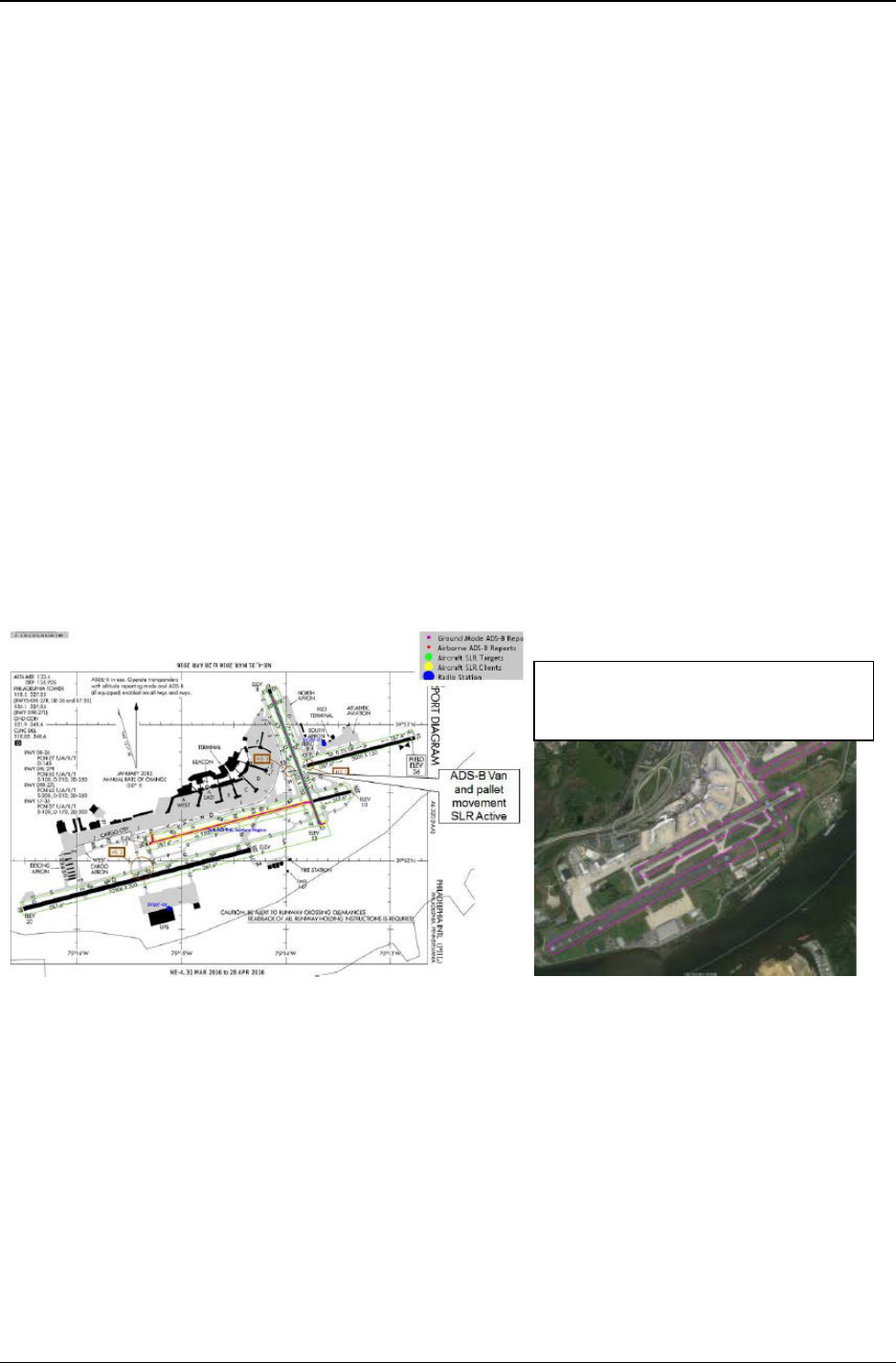
FAA Surveillance and Broadcast Services Surveillance and Broadcast Services Description Document
SRT-047, Rev. 04 – September 20, 2018 Page 26 of 160
3.2.2.8 ADS-R Same Link Rebroadcast
A special case of ADS-R is referred to as Same Link Rebroadcast (SLR) which is available in
FAA defined surface service volumes. This service is necessary for supporting ADS-B In
applications on the airport surface. Airport structures can block reception of direct air-to-air ADS-
B messages between aircraft that need to participate in an application such as SURF or SURF-IA.
In addition, severe multipath on direct air-to-air ADS-B messages may impact avionics reception
of ADS-B messages on the surface. SLR mitigates the effects of these blockages and multipath
issues that have been experienced on the surface before its implementation.
ADS-R SLR regions are defined on the surface movement area within which this service is
provided. Within these regions 1090ES Target messages received by the ground radios are
rebroadcast from one or more radios on the 1090 link, and UAT targets messages received by the
ground radios are rebroadcast from one or more radios on the UAT link. The selected radio(s) for
rebroadcast ensures unobstructed line of site to the rebroadcast regions. These rebroadcasts are
also less susceptible to multipath due to the radio heights and locations.
As implemented, any aircraft within the active movement area will receive rebroadcast
transmissions from ADS-R SLR for other ADS-B equipped aircraft/vehicles operating on the same
data link and also within the movement area. This capability provides target information to ADS-
B-In-equipped aircraft for another ADS-B aircraft/vehicle blocked by airport structures. In
addition, it provides improved detection in areas where multipath may be degrading aircraft-to-
aircraft/vehicle detection. Figure 3-4 provides an example SLR implementation at PHL.
Figure 3-4. ADS-R SLR Example at PHL Airport
In this example, same link aircraft on
runway 17-35 is provided via ADS-SLR
to client aircraft on runway 9R-27L.

FAA Surveillance and Broadcast Services Surveillance and Broadcast Services Description Document
SRT-047, Rev. 04 – September 20, 2018 Page 27 of 160
3.2.3 TIS-B Service
3.2.3.1 TIS-B Service Concept of Operations
The TIS-B service provides active ADS-B users with a low-latency stream of position reports of
non-ADS-B equipped aircraft. TIS-B service is available in supported Service Volumes when there
is both adequate surveillance coverage from non-ADS-B ground sensors and adequate Radio
Frequency (RF) coverage from SBSS ground radio stations.
An aircraft or vehicle that is an active ADS-B user and is receiving TIS-B service is known as a
TIS-B Client. A non-ADS-B equipped aircraft or vehicle that has its position transmitted in TIS-
B reports is known as a TIS-B Target.
3.2.3.1.1 TIS-B Client Identification
The SBSS control station monitors the ADS-B received reports to identify TIS-B Client aircraft.
In order to be considered a TIS-B Client, an aircraft must be ADS-B-OUT, must have produced
valid position data (see §3.3.1.2.5) within the last 30s to a SBSS ground station, must meet a
defined ADS-B performance level as shown in Table 3-5, and must be ADS-B-IN capable on at
least one link. Two key safety benefits for requiring TIS-B Clients to transmit ADS-B-OUT is
spectrum conservation by the SBSS system and the provision of the TIS-B Service Status message
by the SBSS to indicate service availability for specific aircraft. In addition, ADS-B Out aircraft
must provide a sufficient performance level to ensure that their data will be displayed on certified
ADS-B IN avionics systems such that additional TIS-B data does not need to be uplinked to
Clients.
Table 3-5. Required ADS-B Out Performance to be a TIS-B Client
Parameter
Threshold
Link Version
≥ 1
NAC
P
≥ 5
NIC
≥ 5
SDA (only applies to LV2)
≥ 1
SIL
≥ 1
NAC
V
≥ 0
Data History to Evaluate ADS-B Out (seconds)
60
Interval to Check Client Eligibility (seconds)
2
3.2.3.1.2 TIS-B Target Identification
The SBSS also monitors surveillance information from FAA and DoD secondary radars, and
correlates and merges information from multiple surveillance sources into individual aircraft
tracks. Aircraft tracks that are not correlated with an active ADS-B user are potential TIS-B
Targets.
Transponder based aircraft tracks identified by the multisensor tracker are uplinked as TIS-B
traffic with a tracker-assigned ID (e.g. address). The SBSS has numerous multisensor trackers,
deployed regionally such that there is an airborne tracker dedicated to the airspace of each FAA
En Route Center and each Surface Service Volume. For tracks to be eligible for transmission as

FAA Surveillance and Broadcast Services Surveillance and Broadcast Services Description Document
SRT-047, Rev. 04 – September 20, 2018 Page 28 of 160
TIS-B targets to Client aircraft, the performance of the TIS-B track must provide an accuracy
equivalent to a NAC
P
of ≥ 5. This threshold is selected because TIS-B tracks with performance
below this level are not eligible to be display on a DO-317B compliant traffic system. Further
details on identifying and managing the display of TIS-B tracks are provided in Sections 3.3.3.2.6
and 3.3.3.2.7.
3.2.3.2 TIS-B in En Route and Terminal Airspace Domains
The SBSS examines each potential TIS-B target to determine if it is within proximity of one or
more TIS-B clients. In order to become a TIS-B target, a potential target must be contained in a
cylinder defined by lateral and vertical distance from Client aircraft. The size of this cylinder
depends on the airspace domain of the Client aircraft. TIS-B Service is provided to aircraft
operating in the En Route and Terminal Service Volumes. There is a Service Ceiling of 24,000 ft,
above which TIS-B clients will not be provided TIS-B service (targets will be provided up to
27,500 ft).
In the En Route and Terminal domains, proximity aircraft include all aircraft within a 15 NM
radius and 3500 ft of altitude. Aircraft or vehicles determined to be operating on the surface will
not be considered valid targets for aircraft operating in En Route and Terminal Service Volumes.
TIS-B uses geographic filters to exclude surface coverage of airports in Terminal/En-Route
airspace which do not have surface service volumes. TIS-B service in airports with surface service
volume coverage is described in section 3.2.3.3.
Figure 3-5. TIS-B Client Proximity Determination
3.2.3.3 TIS-B in Surface Domains
In a surface domain SV, a client is provided all applicable TIS-B targets in the SV domain. This
includes all targets in the ground state within the movement area as well as those airborne targets
within 5 NM and 2000 ft AGL of the airport reference point (ARP) within an expanding volume
along the approach and departure corridors. Those airports that are planned to have Surface Service
Volumes are listed in Appendix D.
In some cases, airports that do not have Surface SV status may still have good SBSS and radar
coverage at low altitude. To prevent false radar tracks due to reflections etc., TIS-B traffic located
within the airport boundary up to 500’ above the airport surface will not be provided to clients.
However, once beyond this area, TIS-B data will be provided.
30 NM
± 3500
ft

FAA Surveillance and Broadcast Services Surveillance and Broadcast Services Description Document
SRT-047, Rev. 04 – September 20, 2018 Page 29 of 160
3.2.3.4 Transmission of TIS-B Target Messages
The SBSS transmits TIS-B reports for every TIS-B Target that is in proximity of one or more
Clients. An individual Target may be in proximity of multiple Clients, with the potential for the
Clients to be in separate airspace domains, with differing update rates. The SBSS will transmit
TIS-B reports for a Target aircraft at the highest rate required by any of the clients of that aircraft.
For example, if a Target aircraft has clients in both Terminal and En Route domains, TIS-B reports
for that Target aircraft will be transmitted at the rate required for the Terminal domain.
The cumulative number of messages transmitted by all SBSS radio stations within reception range
of any aircraft in the NAS will not exceed 1,000 1090ES messages per second with received signal
strength greater than -78 dBm. This limit applies to both the ADS-R and TIS-B Service combined
(although ADS-R transmissions are prioritized over TIS-B when approaching capacity limits). The
cumulative maximum number of UAT messages received by an aircraft will not exceed 400
messages per second with received signal strength greater than -82 dBm. These limits are achieved
through a combination of the client proximity filter size, the density of radios, radio transmit
power, the best radio selection algorithm, and the required update intervals.
The RS selected for uplink of TIS-B to client aircraft is based on the ADS-B reception for that
client.
3.2.3.5 TIS-B Service Status Notification
The SBSS will notify UAT Link Version 1 and 2 clients that are under surveillance of at least one
secondary radar that TIS-B service is being provided. This notification is provided through the
TIS-B/ADS-R Service Status, provided as an information product through FIS-B.
The SBSS will notify 1090ES link version 2 TIS-B clients that are under surveillance of at least
one secondary radar that TIS-B service is being provided. This service status notification will be
provided through the TIS-B/ADS-R Service Status message
5
.
More information on the UAT and 1090ES Service Status messages can be found in Appendix H
of RTCA DO-317B.
3.2.3.6 False Tracks and Incorrect Associations
False tracks and incorrect associations are unavoidable due to the uncertainty inherent in radar
systems. Although such artifacts are minimized they will happen. If an ADS-B aircraft is not
associated with its radar track it will be treated as a TIS-B Target, and its track information will be
transmitted in TIS-B reports. This will cause the aircraft to receive TIS-B transmissions for itself,
and aircraft in proximity will receive both ADS-B reports from that aircraft, and TIS-B reports for
the unassociated track for that aircraft. ADS-B-IN avionics should consider these situations in
processing of this traffic data.
Some examples of these false track scenarios in order of descending probability are:
5
No Service Status Notification will be provided for 1090 ES v0 or v1 equipage because the service status message
was not defined in these earlier version of the ADS-B MOPS. Service Status Notification will be provided for
UAT v1 equipage.

FAA Surveillance and Broadcast Services Surveillance and Broadcast Services Description Document
SRT-047, Rev. 04 – September 20, 2018 Page 30 of 160
1. When ADS-B aircraft incorrectly report the ground state but are truly airborne. This
causes the ADS-B reports to be ignored by the SBSS multi-sensor tracker for airborne
targets and the radar track data is uplinked as TIS-B potentially causing ghost targets.
2. A Radar has a position offset of a target far from the fused cluster of Radar tracks with
the ADS-B aircraft. This can lead to split tracks and ghost targets on the aircraft display.
3. An ADS-B aircraft truly in the ground state incorrectly reports airborne and a proximate
Radar only target becomes permanently associated with the ADS-B aircraft’s ICAO
address.
4. An ADS-B aircraft’s position reports have an accuracy that is worse than that reported by
its NAC
P
. This can result in a “good” Radar track being offset with a “bad” ADS-B track
and often leads to split tracks or ghost tracks on the aircraft display.
5. Sharp maneuvers by the aircraft in coverage volumes with few integrated radar sensors
can cause dual tracks. This can lead to split tracks and ghost targets on the aircraft
display.
3.2.4 FIS-B Service
The FIS-B service is a broadcast (not client based) service in which weather and aeronautical
information is broadcasted over the UAT link only (not 1090ES), regardless of whether or not
there are any SBSS clients within the Service Volume. The FIS-B CONOPS is that a single radio
station provides a specified set of data products, at a specified update, with a specified look-ahead
range through a fixed set of UAT ground uplink slots or channels. An ADS-B-IN UAT equipped
aircraft that captures all the allocated slots from a single radio station would be provided a set of
data representing weather, aeronautical conditions, and NAS status information in the surrounding
area.
FIS-B data consists of individual "FIS-B Products”, each of which represent a different type of
information. Currently implemented FIS-B products include: AIRMET, SIGMET, Convective
SIGMET, METAR, PIREP, TAF, Winds/Temperatures Aloft, CONUS NEXRAD, Regional
NEXRAD, NOTAM, SUA, Icing, Cloud Tops, Turbulence, Lightning, G-AIRMET, CWA and
TIS-B/ADS-R Service Status. Each of these products is broadcast at maximum update intervals
and transmission intervals, and with a minimum latency.
The geographic scope of the uplinked products is specified with each FIS-B Product in the form
of a minimum “look ahead” distance. This ensures that all available products of each type will be
broadcast at a specified geographic radius from each UAT ground radio station.
An empty FIS-B message will be sent as a heartbeat, once per second, if no other FIS-B product
messages are scheduled to be sent from a radio. This heartbeat takes the form of a valid UAT
header, but with no product data. This heartbeat is sent to inform aircraft of the availability of the
FIS-B service. A FIS-B heartbeat message can be distinguished from other FIS-B messages if the
I-Frame length is encoded as 0 for the first I-Frame. When this is the case, the remaining bytes in
the FIS-B message payload need not be processed (they will all be 0).
The radio stations that provide FIS-B service are configured in a tiered design. The general
structure of the tiered approach established for SBSS is described in RTCA DO-358 Appendix D.
A brief summary is given here.

FAA Surveillance and Broadcast Services Surveillance and Broadcast Services Description Document
SRT-047, Rev. 04 – September 20, 2018 Page 31 of 160
• Radio Stations will be grouped into four tiers as follows:
– Surface: these radio stations will service aircraft in the immediate vicinity of
major airports.
– Low-altitude: services aircraft at low altitude: up to 3000 ft AGL.
– Medium-altitude: services aircraft from low altitude up to 14,000 ft AGL.
– High-altitude: services aircraft from low altitude up to 24,000 ft AGL.
• The products provided from a Radio Stations will depend upon its Tier under the
following rules
– A higher tier radio station will contain all the data products provided by a
lower tier radio station.
– Higher tier radio stations will provide additional data products not provided
by lower tier radio stations that are of interest to the high-altitude user.
– Higher tier radio stations will provide greater ‘look-ahead’ ranges for data
products – the look ahead range is the distance between the radio station and
the geo-tagged products provided by the radio station.
– Higher tier radio stations will have a greater number of UAT ground uplink
slots assigned – the absolute maximum number of assigned slots allocated to a
single radio station is 5 slots, but 4 is likely the practical maximum to mitigate
co-channel interference.
The tier of a radio station which is being received can be identified through the use of the TIS-B
Site ID Field, as described in Section C.1.
While the required ceiling for FIS-B is FL240, it is expected that users can utilize the FIS-B service
above that altitude. In the present design, approximately 90% of the area of implemented SVs
would have FIS-B coverage at FL400. Although there are no practical RF propagation limitations
for receiving FIS-B at high altitudes, co-channel interference could cause some areas of spotty
coverage for A3 UAT avionics with high Desired/Undesired reception requirements (> 9dB).
3.3 Service Messages and Performance
3.3.1 ADS-B Service Messages and Performance
ADS-B is a Critical service as defined by the SBS Critical Services Specification. The objective
of the ADS-B Service is to provide ADS-B Reports to SDPs. To achieve this objective, the ADS-
B Service has to successfully receive and decode ADS-B Messages broadcast by aircraft and
vehicles. Some of the information received in an ADS-B Message is decoded and inserted directly
into the corresponding ADS-B Report fields. Other Message information requires some additional
processing before entering into the Report. Additionally, some Report information has to be
ascertained by the ADS-B Service. The performance that has to be achieved in delivering the ADS-
B Service is detailed in following paragraphs.
3.3.1.1 ADS-B Information Units—Message Content
The ADS-B Service SDP Report structure is shown in Table 3-6 with each data item associated
with a Field Reference Number (FRN). The specific data item formats are described in the FAA
SDP IRD (NAS-IR-82530001). For 1090ES, each SDP ADS-B Report is triggered by either a

FAA Surveillance and Broadcast Services Surveillance and Broadcast Services Description Document
SRT-047, Rev. 04 – September 20, 2018 Page 32 of 160
position message or a velocity message. The velocity message Report triggering is a configurable
system option, which is typically not implemented. For UAT, each SDP ADS-B Report is triggered
by either a “short” or a “long” UAT message. The SBSS maintains state variables, such as Flight
ID, from the other ADS-B messages over specified validity times. Table 3-7 and Table 3-8 show
how the specific ADS-B Messages and their content map to the SDP ADS-B Report data items.

FAA Surveillance and Broadcast Services Surveillance and Broadcast Services Description Document
SRT-047, Rev. 04 – September 20, 2018 Page 33 of 160
Table 3-6. 1090ES ADS-B Message ME bit-mapping to SDP ADS-B Report Data Items
Type (NIC)/Subtype
Surv. Status
NIC Supplement
Altitude
Time
CPR Format
Latitude
Longitude
Movement
H
eading/Ground Track
Emitter Categ
ory
Identity
NACv
E/W
Velocity
N/S Velocity
Vert Rate
Reserved/Ignored
Diff from Baro
Intent/Status
Ops Status
Mode 3/A Code
Emergency State
TCAS RA Broadcast
TOTAL
Airborne Position
5
2
1
12
1
1
17
17
56
Surface Position
5
1
1
17
17
7
8
56
Airborne Velocity
(1/2)
8
3
11
11
11
4
8
56
ID and Type
5
3
48
56
Target State and
Status
7
49
56
Operational Status
8
48
56
Aircraft Status (1)
8
32
13
3
56
Aircraft Status (2)
8
48
56
Flow to Report FRNs
6
14
6,
21
8
6
7
7
10
10
13
12
6
9
9
9
15
6,20
3,6
10,14
16,19
21
11
14
17

FAA Surveillance and Broadcast Services Surveillance and Broadcast Services Description Document
SRT-047, Rev. 04 – September 20, 2018 Page 34 of 160
Table 3-7. UAT ADS-B Message mapping to SDP ADS-B Report Data Items
Payload
Type Header State Vector (SV) Mode Status (MS) Target State (TS) AUX SV
Elements
Target
Address
Latitude
Longitude
Altitude
Velocity
Ground Movement
UTC Coupled
Uplink Feedback
Identity and Category
UAT MOPS Version
Emergency Status
SIL, NACp, NACv, etc.
Capability Codes
Operational Modes
Data Quality Parameters
Selected Altitude
Barometric Pressure Set.
Selected Heading
Mode I
ndicators
Secondary
Altitude
0
1
2
3
4
5
6
Report
FRNs
5 6, 7, 8/15, 9/10, 19, 21 3, 6, 11, 12, 13, 14, 16, 21 20 8/15
Table 3-8. FAA SDP ADS-B Report
FRN Data Item
1 Service Volume Identifier
2 Version Number
3 Link Technology Indicator
4 Time of Applicability
5 Target Address
6 Integrity and Accuracy Parameters
7 Latitude/Longitude
8 Pressure Altitude

FAA Surveillance and Broadcast Services Surveillance and Broadcast Services Description Document
SRT-047, Rev. 04 – September 20, 2018 Page 35 of 160
FRN Data Item
9 Velocity (Airborne)
10 Velocity (Surface)
11 Mode 3/A Code
12 Target Identification
13 Emitter Category
14 Target Status
15 Geometric Altitude
16 Modes and Codes
17 TCAS RA Messages
18 Time of Message Reception
19 GPS Antenna Offset
20 Target State Data
21 ADS-B Data Quality Parameters
22 Data Source Qualifier
3.3.1.2 ADS-B Quality of Service
3.3.1.2.1 ADS-B Integrity
The probability that ADS-B Service introduces any error into an ADS-B Report received at an
SDP is less than 10
-5
per Report (equivalent to a System Design Assurance level of 2 – Major).
The ADS-B service is also designed to meet Assurance Level 3 (AL3) objectives of RTCA DO-
278.
3.3.1.2.2 ADS-B Position Update Interval
The ADS-B position update interval is the maximum allowed time between successive ADS-B
Reports containing position information that are sent to each SDP for a specific aircraft/vehicle.
The update interval varies by airspace domain. The update interval is determined by the rate of
reception of ADS-B Messages containing position information. Even though the ADS-B Service
may be configured to generate an ADS-B Report on reception of velocity Messages this additional
reporting does not apply to the Update Interval.
3.3.1.2.2.1 Surface Update Interval
The ADS-B Service provides for each aircraft/vehicle in motion in the Surface domain an ADS-B
Report containing position information on average at least once every 1.0 second at each SDP.
The ADS-B Service provides for each stationary aircraft/vehicle in the Surface domain an ADS-
B Report containing position information at least once every 5.5 seconds (85%) for 1090-ES at
each SDP. The update interval for stationary UAT targets on the surface is typically 1.0 seconds
on average and cannot exceed 5.5 seconds (95%).

FAA Surveillance and Broadcast Services Surveillance and Broadcast Services Description Document
SRT-047, Rev. 04 – September 20, 2018 Page 36 of 160
3.3.1.2.2.2 Terminal Update Interval
The ADS-B Service provides for each aircraft/vehicle in the Terminal domain an ADS-B Report
containing position information with an update interval no greater than 3.0 seconds (95%) at each
SDP.
3.3.1.2.2.3 En-Route Update Interval
The ADS-B Service provides for each aircraft/vehicle in the En Route domain an ADS-B Report
containing position information with an update interval no greater than 6.0 seconds (95%) at each
SDP.
The ADS-B Service provides for each aircraft/vehicle in En Route domains identified as “En Route
High Update (HU)” an ADS-B Report containing position information with an update interval no
greater than 3.0 seconds (95%) at each SDP.
3.3.1.2.3 ADS-B Latency
The ADS-B Latency for the SBSS includes the ADS-B Service processing delay and the delay in
communicating the ADS-B Reports to the Service Delivery Points (SDP). Latency is measured
from the reception of the last bit of an ADS-B Message to the reception of the first bit of the
corresponding ADS-B Report at the SDP.
The maximum delay between the reception of the last bit of an ADS-B Message, containing a State
Vector or an emergency condition, and the reception of the first bit of the corresponding ADS-B
Report at the Service Delivery Point is less than or equal to 700 ms within the various operating
environments. UTC coupled aircraft allow the SBSS to compute the time of applicability of the
horizontal position within ± 200 msec.
3.3.1.2.4 ADS-B Service Availability
The ADS-B service is a safety-critical service as classified by NAS-RD-2013 for surveillance
services. This requirement is driven by the ATC Surveillance application.
The ADS-B Service meets a minimum Availability of 0.99999 in each defined service volume at
SDPs identified as critical.
3.3.1.2.5 Independent Validation
In certain Service Volumes, the FAA will require that the ADS-B Service provide independent
validation of the position information received in the ADS-B Messages. An independent ADS-B
validation capability may assure to a specified probability that each ADS-B Message, and the
position information contained within, is from a real aircraft/vehicle with a valid position source
rather than from a source broadcasting erroneous information or a spoofer. The independent
validation tolerances are defined to support 3NM separation in Terminal airspace and 5NM
separation for En-Route airspace. The validation process uses a combination of the methods listed
below:
1. Comparison to radar,
2. Comparing a one way “passive range” with range to target indicated by ADS-B
(available for UAT equipped targets),
3. Use of time difference of arrival techniques.

FAA Surveillance and Broadcast Services Surveillance and Broadcast Services Description Document
SRT-047, Rev. 04 – September 20, 2018 Page 37 of 160
Three validation states are possible when validation service is being provided: Valid, Invalid, and
Unknown. If sufficient information is not available for validation, (e.g. in the case of radar failure)
validation status will be Unknown. Valid and Unknown position reports are passed onto the FAA
SDP and to the ADS-R service.
3.3.1.2.6 Enhanced Validation
In Certain Service Volumes, the FAA will require that the ADS-B Service provide Enhanced
Validation as an independent check of the ADS-B reported position that is used to support avionics
conformance monitoring. This check is made to a tighter tolerance than the “standard” validation
described in Section 3.3.1.2.5 above. The default Enhanced Validation tolerance is 0.2 NM, which
equates to a NIC 7. Due to the tighter tolerance requirement, Enhanced Validation airspace is
limited to that within 15 NM of the center of the Terminal service volume. Enhanced validation is
only supported with radar. (TDOA and ranging are not used).
3.3.2 ADS-R Service Messages and Performance
ADS-R is a Critical service as defined by the SBS Critical Services Specification. The ADS-R
Service is dependent upon the ADS-B Service, in that the ADS-B Messages are first received on
one data link before they can be rebroadcast on the other. The performance that is required in
delivering the ADS-R Service is detailed in following paragraphs.
3.3.2.1 ADS-R Information Units—Message Content
UAT ADS-R Targets to 1090 Clients:
The ADS-R Service for 1090 Clients encodes the Message types contained in Table 3-9 and their
corresponding message elements per DO-260B §2.2.18 and §A.3. If a UAT Target has an
emergency condition (as indicated in its ADS-B message), then the 1090 Aircraft Status Subtype
1 message will also be broadcast for that Target during the course of the emergency. The 1090
ADS-R Downlink Format is 18 and the Control Field is set to 6. The ICAO/Mode A Flag field in
the position messages denote whether the target has an ICAO address.
Table 3-9. 1090ES ADS-R Message Types to Encode Upon Receipt of UAT Message Types
1090ES Message Type
UAT Message Payload Type
0 1 2 3 4 5 6
Position X X X X X X X
Aircraft ID and Category X X
Velocity X X X X X X X
Operational Status X X
Aircraft Status: Subtype 1
(Only during emergencies)
X X

FAA Surveillance and Broadcast Services Surveillance and Broadcast Services Description Document
SRT-047, Rev. 04 – September 20, 2018 Page 38 of 160
1090 ADS-R Targets to UAT Clients:
The ADS-R Service for UAT Clients could be “short” (Payload Type code 0) or “long” (Payload
Type code 1 and 2) messages. ADS-R transmissions follow the A1H equipment class transmission
cycle, which is a mixed population of short and long UAT messages (see §2.2.6.1.2 and §2.2.6.1.3
of RTCA DO-282B). The UAT ADS-R Address Qualifier is either set to 2 (target with ICAO
address) or 6 (target with non-ICAO address). When the UAT Address Qualifier is 2, there are no
other fields which convey whether the message is TIS-B or ADS-R.
3.3.2.2 Quality of Service
3.3.2.2.1 ADS-R Integrity and Accuracy
The probability that ADS-R Service introduces any error into a rebroadcast ADS-B Message is
less than or equal to 10
-5
per Message (equivalent to a System Design Assurance level of 2 –
Major). This probability of error includes the linear position extrapolation process using the
instantaneous velocity reported for a target on the opposite ADS-B data link.
The ADS-R Service limits the NIC value to 8 and NAC
P
value to 9 in ADS-R Message
transmissions. ADS-R uplink functions are not designed to support the precision mode of
operation, i.e., NIC values greater than 8 and NAC
P
values greater than 9.
3.3.2.2.2 ADS-R Position Update Interval
The ADS-R Service broadcasts state vector updates for aircraft/vehicles transmitting on one data
link to aircraft/vehicles on the other data link at an interval that will support the aircraft/vehicle
based applications that are to be performed in the Service Volume. The state vector update intervals
required to support each application are detailed in the SBS CONOPS and summarized as follows:
• ATSA-AIRB: 5 seconds
• ATSA-VSA: 5 seconds
• ATSA-SURF: 2 seconds
• Traffic Situation Awareness with Alerts (TSAA): 10 seconds
• Airborne Spacing - Flight-Deck Based Interval Management–Spacing (FIM-S):
10 seconds
The ADS-R update interval requirements are based upon the most stringent application that is to
be supported within each domain. The update intervals apply to the reception by a client aircraft
of all eligible ADS-R aircraft/vehicles within the range and altitude limits at any point within the
Service Volume. Thus, the 1090 interference environments had to be considered to meet the update
intervals.
The ADS-R update interval is limited by the ADS-B Message reception rate from each
aircraft/vehicle (as rebroadcasts may be made only when Messages are received), the UAT uplink
capacity, spectrum restrictions for 1090ES, the performance characteristics of the aircraft/vehicle
ADS-B equipment, and the interference environment.
The maximum message transmission rate for a 1090 Target ADS-R to a UAT client is 2 times per
second since a Ground Station will receive a 1090 position message approximately every 0.5

FAA Surveillance and Broadcast Services Surveillance and Broadcast Services Description Document
SRT-047, Rev. 04 – September 20, 2018 Page 39 of 160
seconds. The actual uplink rate may be configured to be less than this depending on the airspace
and applications to be supported. The expected minimum power received by UAT avionics is -93
dBm. The ADS-R link margin for UAT clients is expected to be > 11 dB for the majority of the
NAS airspace.
The nominal message packet transmission rate for a UAT Target ADS-R to a 1090 client is 1 time
per second since a Ground Station will receive a UAT message approximately every 1 second. A
1090 ADS-R message packet consists of 2 position messages, 1 Aircraft ID and Category message,
1 Velocity message (if airborne), and 1 Operational Status message. All of the 1090 ADS-R
messages in the packet are transmitted within milliseconds of each other. The expected minimum
power received by 1090 avionics is -79 dBm in low interference environments and -72 dBm in
high interference environments. The ADS-R link margin for 1090 clients is expected to be > 5 dB
for the majority of the NAS airspace.
As the system becomes loaded with more than 250 ADS-R targets on each link, these target
message transmission rates will decrease in a process known as Graceful Degradation. The purpose
of Graceful Degradation (GD) is to gradually throttle the ADS-R messages sent to
Aircraft/Vehicles based on load. The GD algorithm uses several configurable parameters to control
the flow of reports and messages until the maximum load is reached.
3.3.2.2.2.1 Surface Update Interval
The ADS-R Service transmits the number of ADS-R Messages necessary to meet an update
interval of no greater than 2 seconds (95%) for each client aircraft for all traffic within 5 NM and
within ± 2000 feet of each client within the Surface Service Volume.
3.3.2.2.2.2 Terminal Update Interval
The ADS-R Service transmits the number of ADS-R Messages necessary to meet an update
interval of no greater than 5 seconds (95%) for each client aircraft for all traffic within 15 NM and
within ± 5000 feet of each client within the Terminal Service Volume.
3.3.2.2.2.3 En-Route Update Interval
The ADS-R Service transmits the number of ADS-R Messages necessary to meet an update
interval of no greater than 10 seconds (95%) for each client aircraft for all traffic within 15 NM
and within ± 5000 feet of each client within the En-Route Service Volume.
3.3.2.2.3 ADS-R Latency
The additional latency introduced by the ground infrastructure is less than the latency required by
the most stringent applications in the SBS CONOPS minus the inherent airborne latencies on both
ends.
The maximum delay between the time of message received of an ADS-B Message that results in
the generation of ADS-R Uplink Messages and the transmission of the first bit of any
corresponding broadcast Message on the opposite link technology is less than or equal to 1 second.
The service provider ground infrastructure design is such that the time it takes for a received ADS-
B message to be processed into ADS-R format and sent to the ADS-R transmission scheduler is
400 milliseconds or less. This ADS-B to ADS-R transmission latency is compensated in the ADS-
R horizontal position by linearly extrapolating to the time of transmission.

FAA Surveillance and Broadcast Services Surveillance and Broadcast Services Description Document
SRT-047, Rev. 04 – September 20, 2018 Page 40 of 160
3.3.2.2.4 ADS-R Service Availability
The ADS-R service is currently a safety-essential service as classified by NAS-RD-2013 for
surveillance services. The ADS-R Service meets a minimum Availability of 0.999 at SDPs (in this
case, SDP refers to client aircraft that are receiving ADS-R).
3.3.2.2.5 ADS-R Media Access
1090 ADS-R transmissions contend with air-to-air 1090 ADS-B transmissions and potentially with
nearby SBSS Ground Station 1090 transmissions. However, 1090 transmissions are randomized
to minimize interference and each SBSS Ground Station has a maximum 1090 transmission duty
cycle of 6% (combines all 1090 TIS-B and ADS-R messages).
UAT ADS-R transmissions contend with air-to-air UAT ADS-B transmissions since they are in
the ADS-B segment of the UAT Frame (not the Ground Segment) and potentially with nearby
SBSS Ground Station UAT transmissions. However, UAT transmissions are randomized to
minimize interference and each SBSS Ground Station has a maximum UAT transmission duty
cycle of 12.5% (combines all UAT TIS-B and ADS-R messages).
Although ADS-R transmissions are event-driven by receptions of ADS-B messages, both 1090
and UAT have configurable minimum ADS-R transmit intervals (currently set to 1.5 ms) with an
added random time (up to 3 ms) appended to the minimum interval. Additionally, typically only
one radio rebroadcasts a particular target at any given time.
3.3.3 TIS-B Service Messages and Performance
TIS-B is an Essential service as defined by the SBS Essential Services Specification. The TIS-B
Service provides users equipped with ADS-B avionics the ability to receive, process, and display
state information on proximate traffic that are not ADS-B equipped and are only tracked by other
ground-based surveillance systems (i.e. radar and multilateration systems). The performance that
is required in delivering the TIS-B Service is detailed in following paragraphs.
3.3.3.1 TIS-B Information Units—Message Content
The 1090 TIS-B Service encodes the TIS-B Message types contained in Table 3-10 and their
corresponding message elements per DO-260B §2.2.17 and §A.2. The format of the DO-260B
TIS-B message is identical to the DO-260A TIS-B message with the exception of the Ground
Speed/Movement field encoding (see §2.2.3.2.4.2 in DO-260B). TIS-B Velocity messages are also
transmitted for Surface targets in order to convey the NAC
P
to ADS-B-IN users for surface
applications (although velocity data is ZERO’d out). The 1090 TIS-B Downlink Format is 18 and
the Control Field is either set to 2 (target with ICAO address) or 5 (target with track file identifier).
Three squitters (even position, odd position, and velocity) are sent for every TIS-B report
transmitted over the 1090 link. These transmissions are sent as a group, close together in time (as
specified in §3.3.3.2.5), and if necessary will be repeated to ensure probability of detection. The
1090 TIS-B/ADS-R Service Status message format is defined in DO-317B and will be broadcast
for 1090 ADS-B-IN Link Version 2 clients.

FAA Surveillance and Broadcast Services Surveillance and Broadcast Services Description Document
SRT-047, Rev. 04 – September 20, 2018 Page 41 of 160
Table 3-10. Transmitted 1090 TIS-B Message Types
Message Types
RTCA/DO-260B
Reference Paragraphs
TIS-B Fine Airborne Position §2.2.17.3.1 & §A.2.4.1
TIS-B Fine Surface Position §2.2.17.3.2 & §A.2.4.2
TIS-B Velocity §2.2.17.3.4 & §A.2.4.4
TIS-B/ADS-R Service Status
Management
§2.2.17.2 & §A.2

FAA Surveillance and Broadcast Services Surveillance and Broadcast Services Description Document
SRT-047, Rev. 04 – September 20, 2018 Page 42 of 160
Table 3-11. Payload Composition of 1090ES TIS-B Messages
TIS-B
Message Encoding Used
TIS-B Message
Field
MSG
Bit #
DO-260B
Reference
All
Set to decimal 18 (10010) for all TIS-B Messages DF TYPE 1-5 §2.2.17.2.1
“2” for Fine TIS-B Message with AA=24-bit ICAO
address and “5” for Fine TIS-B Message with
AA=TIS-B Service generated 24-bit track ID
Control Field (CF) 6-8 §2.2.17.2.2
A 24-bit address; ICAO address or service
generated track ID
Address
Announced (AA)
9-32 §2.2.17.2.3
Algorithm that operates on the first 88 bits of the
message
Parity / Identity
(PI)
89-
112
§2.2.3.2.1.7
TIS-B Fine Airborne Position
Determined from altitude type and NIC TYPE 33-37 §2.2.3.2.3.1
Set to 00 for all TIS-B Messages Surveillance Status 38-39 §2.2.3.2.3.2
“0” to indicate a 24-bit address
Note: This flag is always set to 0 since Mode 3/A
code is not allowed to be embedded in the 24-bit
address
ICAO Mode Flag
(IMF)
40 §2.2.17.3.1.2
12 bits of barometric altitude data. Pressure Altitude 41-52 §2.2.3.2.3.4.1
Set to ZERO Reserved 53 -
Transmit Function to alternate between “0” = even;
“1” = odd.
CPR Format 54 §2.2.3.2.3.6
CPR encoded Latitude and Longitude of target
position.
CPR Latitude 55-71 §2.2.3.2.3.7
CPR Longitude 72-88 §2.2.3.2.3.8
TIS-
B Fine Surface Position
Determined from altitude type and NIC TYPE 33-37 §2.2.3.2.4.1
Ground Speed of target on surface (Note: the
movement field is different in DO-260B)
Movement 38-44 §2.2.3.2.4.2
Validity of heading/ground track Heading Status 45 §2.2.3.2.4.3
Ground Track/Heading of target on surface Heading 46-52 §2.2.3.2.4.4
“0” to indicate 24-bit ICAO address ICAO Mode Flag 53 §2.2.17.3.1.2
Transmit Function to alternate between “0” = even;
“1” = odd.
CPR Format 54 §2.2.3.2.4.6
CPR encoded Latitude and Longitude of target
position.
Latitude 55-71 §2.2.3.2.4.7
Longitude 72-88 §2.2.3.2.4.8
TIS-B
Velocity
Set to 19 (10011) for all Velocity Messages TYPE 33-37 §2.2.3.2.6.1.1
Determined based on availability of data on target
velocity over ground and whether target is
supersonic
Subtype 38-40 §2.2.3.2.6.1.2

FAA Surveillance and Broadcast Services Surveillance and Broadcast Services Description Document
SRT-047, Rev. 04 – September 20, 2018 Page 43 of 160
TIS-B
Message Encoding Used
TIS-B Message
Field
MSG
Bit #
DO-260B
Reference
“0” to indicate 24-bit ICAO address ICAO Mode Flag 41 §2.2.17.3.1.2
TIS-B Service generated NAC
P
value NAC
P
42-45 §2.2.17.3.4.4
Velocity data on target
(Always set to ZEROs
for Surface Targets)
Subtype 1& 2
E/W Direction 46 §2.2.3.2.6.1.6
E/W Velocity 47-56 §2.2.3.2.6.1.7
N/S Direction 57 §2.2.3.2.6.1.8
N/S Velocity 58-67 §2.2.3.2.6.1.9
All Subtypes
Vertical Rate
Source
(GEO Flag)
68 §2.2.3.2.6.1.10
Vertical Rate Sign 69 §2.2.3.2.6.1.11
Vertical Rate 70-78 §2.2.3.2.6.1.12
Based on position TYPE codes and integrity
containment radius for target position
NIC Supplement 79 §2.2.17.3.4.3
For Messages with
GEO Flag = 0
NAC
V
is set based on the
actual velocity
performance of the
surveillance source
NAC
V
80-82
§2.2.3.2.6.1.14
Configured Value
(set to “2” for airborne;
“3” for surface)
SIL 83-84
Set to decimal 0 (0000) Reserved 85-88
For Messages with
GEO Flag = 1
Set to 0 Reserved 80
§2.2.3.2.6.1.15
Based on altitude
difference between
barometric and geometric
sources
Diff from Baro. Alt
Sign
81
Diff. from Baro.
Alt.
82-88
Note: The 1090 TIS-B Coarse Position and TIS-B Identification and Category Messages are not used by SBSS.
UAT TIS-B Messages transmit only a single “long” (Payload Type code 1) message. The UAT
TIS-B Address Qualifier is either set to 2 (target with ICAO address) or 3 (target with track file
identifier). When the UAT Address Qualifier is 2, there are no other fields which convey whether
the message is TIS-B or ADS-R.

FAA Surveillance and Broadcast Services Surveillance and Broadcast Services Description Document
SRT-047, Rev. 04 – September 20, 2018 Page 44 of 160
Table 3-12. Payload Composition of UAT TIS-B Messages
Encoding TIS-B Message Field
DO-282B
Reference
Always Encode as ONE “PAYLOAD TYPE CODE” §2.2.4.5.1.1
Encoded based on address type available consistent
with referenced section of DO-282B
“ADDRESS QUALIFIER” §2.2.4.5.1.2
A 24-bit ICAO address, or service-generated track
ID number
“ADDRESS” §2.2.4.5.1.3
Encoded consistent with referenced section of DO-
282B §2.2.4.5.2.1
“LATITUDE” and
“LONGITUDE”
§2.2.4.5.2.1
Encode as ZERO if Pressure Altitude data is
available; otherwise encode as ONE if the
“Geometric Altitude” data is available
“ALTITUDE TYPE” §2.2.4.5.2.2
Pressure Altitude if available, otherwise Geometric
Altitude if available.
“ALTITUDE” §2.2.4.5.2.3
Encoded based on determined NIC value
“NIC” §2.2.4.5.2.4
Service generated and encoding consistent with
DO-282B §2.2.4.5.2.5
“A/G STATE” §2.2.4.5.2.5
“HORIZONTAL VELOCITY” §2.2.4.5.2.6
“VERTICAL VELOCITY” §2.2.4.5.2.7
Service generated and encoding consistent with
DO-282B §2.2.4.5.3.1, excluding a value of “0000”.
Also, see Appendix C.2 of this document.
“TIS-B SITE ID” §2.2.4.5.3.1
Encoded per relevant section of DO-282B when
data available
“EMITTER CATEGORY AND
CALL SIGN CHARACTERS #1
AND #2”
§2.2.4.5.4.1,
§2.2.4.5.4.2
“CALL SIGN CHARACTERS #3,
#4 AND #5”
§2.2.4.5.4.2
“CALL SIGN CHARACTERS #6,
#7 AND #8”
§2.2.4.5.4.2
Encode as UNKNOWN “EMERGENCY/PRIORITY
STATUS”
§2.2.4.5.4.4
Encode as TWO “UAT MOPS VERSION” §2.2.4.5.4.5
Configured Value (set to “2” for airborne; “3” for
surface)
“SIL” §2.2.4.5.4.6
The 6 Least Significant Bits (LSBs) of the MSO
selected for this TIS-B Message
“TRANSMIT MSO” §2.2.4.5.4.7
Set to “2” “SDA” §2.2.4.5.4.8
Encoded consistent with DO-282B §2.2.4.5.4.9 “NAC
P
” §2.2.4.5.4.9

FAA Surveillance and Broadcast Services Surveillance and Broadcast Services Description Document
SRT-047, Rev. 04 – September 20, 2018 Page 45 of 160
Encoding TIS-B Message Field
DO-282B
Reference
NAC
V
is set based on the actual velocity
performance of the surveillance source
“NAC
V
” §2.2.4.5.4.10
Always encode as ZERO “NIC
BARO
” §2.2.4.5.4.11
Always encode as:
- CDTI Traffic Display Capability: NO
- TCAS/ACAS Installed and Operational: YES
(1)
“CAPABILITY CODES” §2.2.4.5.4.12
Always encode as ALL ZERO “OPERATIONAL MODES” §2.2.4.5.4.13
Always encode as ZERO “TRUE/MAG” §2.2.4.5.4.14
Always encode as ONE “CSID” §2.2.4.5.4.15
Set to ONE to indicate per sample “SIL
SUPP
” §2.2.4.5.4.16
Always encode as ZERO “GVA”, “SA Flag”, and
Encoded based on determined NIC value “NIC
SUPP
” §2.2.4.5.4.19
Always encode as ZERO Reserved §2.2.4.5.4.20
Notes:
1. TCAS Installed and Operational is set to “Yes” because the TCAS status of the aircraft being broadcast in
TIS-B is unknown and the DO-260A/282A MOPS assumed that ADS-B receiving subsystems could issue
vertical resolution advisories on aircraft that were not TCAS equipped. However, potential future ADS-B In
applications should not issue vertical resolution advisories on TIS-B without knowing the TCAS status of
aircraft. By setting the indication to “Yes” the TIS-B data indicates to potential ADS-B In applications that
there should not be a vertical resolution advisory issued. This issue was corrected in DO-260B/282B wherein
the avionics would not issue a vertical advisory without knowing the TCAS status of an aircraft.
3.3.3.2 TIS-B Quality of Service
The TIS-B Service supports several Surveillance and Broadcast Services applications identified in
the SBS CONOPS, including:
• Traffic Situation Awareness – Basic (12.1 seconds)
• Airport Traffic Situation Awareness (2 seconds)
• Airport Traffic Situation Awareness with Indications and Alerts (2 seconds)
• Traffic Situation Awareness for Visual Approach (5 seconds)
• Traffic Situation Awareness with Alerts (10 seconds)
• Flight-Deck Based Interval Management–Spacing (10 seconds)
• The TIS-B/ADS-R Service Status message will be broadcast such that each client
will receive this message with their 24-bit address with an update interval of 20
seconds (95%). The TIS-B/ADS-R Service Status message will only be provided
to clients that are eligible for both TIS-B and ADS-R service which requires that
the aircraft be within both radar and ADS-B coverage.

FAA Surveillance and Broadcast Services Surveillance and Broadcast Services Description Document
SRT-047, Rev. 04 – September 20, 2018 Page 46 of 160
3.3.3.2.1 TIS-B Integrity and Accuracy
The probability that TIS-B Service introduces any error into a TIS-B Message is less than or equal
to 10
-5
per Message (equivalent to a System Design Assurance level of 2 – Major). This probability
of error includes the linear position extrapolation process using the instantaneous velocity reported
for a target. The Source Integrity Level (SIL) is a SBSS-wide configured value and is set to 2 by
default. The Navigation Integrity Category (NIC) is computed for TIS-B messages based on the
configured SIL value, the target’s NAC
P
(described below), and the containment error ‘tail’ based
on radar plot error assumptions. Radar PARROTs and the ASDE-X system will be monitored for
faults and excessive biases. The SIL supplement will always be encoded as 1 to indicate that the
probability of a TIS-B target exceeding the NIC containment radius is calculated on a per sample
basis. Although the SDA and SIL supplement are not transmitted over the 1090ES link, they should
be assumed to be the values stated in this document by avionics processors in support of the
relevant applications.
The NAC
V
in TIS-B messages will be set based on the performance of the surveillance source.
TIS-B for surface Multilateration sources will support NAC
V
of 2 on the surface and NAC
V
of 1
on approach. TIS-B for targets detected by Terminal radars will likely support a NAC
V
of 1. TIS-
B for targets only detected by En Route radar sources are will likely have a NAC
V
of 0.
The altitude included in TIS-B reports is the uncorrected Mode C reported altitude transmitted by
the Target.
The TIS-B Service computes a NAC
P
, as defined in DO-242A Table 2-3 (excluding the Vertical
Estimated Position Uncertainty), for each target at each track state vector update. For the
applications supported by TIS-B, Navigation Accuracy Category - Position (NAC
P
) is limited to
the horizontal position information. NAC
P
for a TIS-B target is based on the surveillance sources
used to derive the target position rather than navigation sources used to supply ADS-B position.
Therefore, the derivation of NAC
P
for TIS-B will likely be different from that for ADS-B. For
example, the NAC
P
value must include the uncertainty in converting slant range measurements to
horizontal position estimates.
Track angle and position accuracy in the Surface environment are based upon the accuracy
provided by ASDE-X. The TIS-B Service sets the Track Angle to Invalid when the target ground
speed drops below a defined threshold (currently set to 11.84 Knots). Ground TIS-B Targets
provided by ASDE-X in the Surface domain will typically have a NAC
P
of 9 or better. Airborne
targets provided by ASDE-X in the Surface environment will typically have a NAC
P
of 6 or better.
In En Route and Terminal environments the track accuracy will meet or exceed the values shown
below.

FAA Surveillance and Broadcast Services Surveillance and Broadcast Services Description Document
SRT-047, Rev. 04 – September 20, 2018 Page 47 of 160
Table 3-13. Requirements for Track Accuracy
Central
Sensor
Flight Path
Speed
(kts)
Rng.
(NM)
Position Error (NM)
Heading Error (°)
Speed Error
(kts)
Peak
RMS
Position
Error
Mean
Position
Error
Peak
RMS
Heading
Error
Mean
RMS
Heading
Error
Peak
RMS
Speed
error
Mean
RMS
Speed
error
Short Range
Sensor
(ATCBI-5)
Linear
Acceleration†
650-
>250-
>650
Center 0.4
13 37
All 0.6 19 60
180°
100
48
(case 3)
0.4(0.4+) 97 (70+) 20 (10+)
250-700 0.4(0.4+) 32 (30+) 20 (10+)
Radial
100
50***
(case 2)
0.1 (0.1#) 7 (2#) 5 (4#)
Tangential
100 0.1 (0.1#) 5 (5#) 9 (7#)
Long Range
Sensor
(ATCBI-5)
Linear
Acceleration†
650-
>250-
>650
n/a 0.5
13 60
90° turn
100-400
84
(case 2)
1.1 (0.4+)
70 (38+) 60+
700*** 1.8 (0.4+) 34 (14+) 54 (14+)
Radial
100-700 100
0.5 11
Tangential
100-700 80 0.4 7 15
Notes:
1. Table symbology:
† These scenarios were generated and the values in this table are based on best engineering judgment.
+ These multisensor cases use existing scenarios (because they are not spatially distributed).
# These multisensor cases use a single target path from existing scenarios and are run multiple times through
the standalone filter algorithm, with independent noise generated each time (i.e., run Monte Carlo iterations).
3.3.3.2.2 TIS-B Position Update Interval
The TIS-B Service updates target position and velocity data based on surveillance measurement
events and is therefore dependent on the availability of source sensors for new data. The following
specifications apply only when sensor data is available to the TIS-B Service to support the
performance requirements. Under lightly-loaded conditions the TIS-B service may transmit
reports at a rate higher than the minimum specified rate. Graceful Degradation algorithms are
implemented which will throttle transmissions back to the required update rate as the system
reaches maximum capacity (see §3.3.2.2.2 for GD description). Sometimes it will be necessary to
transmit the same report multiple times in order to ensure the required update rate and probability
of detection.
The maximum message transmission rate for a TIS-B Target to a 1090 and UAT clients is 1 time
per second (this is the expected rate for targets in Surface Service volumes where ASDE-X sends
track updates at approximately 1 Hz). Transmit intervals outside of Surface Service volumes will
be less than or equal to 1 Hz depending on the number of radars tracking a target and their scan
rates. Similar to ADS-R, each TIS-B track update event triggers the transmission of a 1090 TIS-B
message packet. Each 1090 TIS-B message packet consists of 2 position messages and 1 velocity
message (both surface and airborne targets). All of the 1090 TIS-B messages in the packet are
transmitted within milliseconds of each other.

FAA Surveillance and Broadcast Services Surveillance and Broadcast Services Description Document
SRT-047, Rev. 04 – September 20, 2018 Page 48 of 160
The expected minimum power received by UAT avionics is -93 dBm. The TIS-B link margin for
UAT clients is expected to be > 11 dB for the majority of the NAS airspace.
The expected minimum power received by 1090 avionics is -79 dBm in low interference
environments and -72 dBm in high interference environments. The TIS-B link margin for 1090
clients is expected to be > 5 dB for the majority of the NAS airspace.
3.3.3.2.2.1 Surface Update Interval
The TIS-B Service transmits the number of TIS-B Messages necessary to meet an update interval
of no greater than 2 seconds (95%) for each client aircraft for all traffic within 5 NM and within ±
2000 feet of each client within the Surface Service Volume.
3.3.3.2.2.2 Terminal Update Interval
The TIS-B Service transmits the number of TIS-B Messages necessary to meet an update interval
of no greater than 6 seconds (95%) for each client aircraft for all traffic within 15 NM and within
± 3000 feet of each client within the Terminal Service Volume. Airborne TIS-B targets in a Surface
SV will also be provided to those in a Terminal SV. However, ground state targets will not be
provided to clients in Terminal SVs.
3.3.3.2.2.3 En-Route Update Interval
The TIS-B Service transmits the number of TIS-B Messages necessary to meet an update interval
of no greater than 12.1 seconds (95%) for each client aircraft for all traffic within 15 NM and
within ± 3000 feet of each client within the En-Route Service Volume.
3.3.3.2.3 TIS-B Latency
The latency for TIS-B Service processing of TIS-B data is less than 1.5 seconds as measured from
the FAA Surveillance SDP (for surveillance data to the Service Provider) to the start of the TIS-B
Message transmission. This SDP to TIS-B transmission latency is compensated in the TIS-B
horizontal position by linearly extrapolating to the time of transmission.
Overall end-to-end latency from sensor measurement to start of the TIS-B transmission is less than
3.25 seconds. The Essential Services Specification states: “This requirement applies to services
delivered to the airport surface, Terminal airspace and En Route airspace. The TIS-B MASPS
allocates 3.25 s from sensor measurement to TIS-B Message transmission. The expected maximum
delay associated with getting target measurements from a radar sensor is 1.725 seconds, leaving
the balance of time to the TIS-B Service.” Analysis of En-Route/Terminal tracker cross-
track/along-track errors indicates that the uncompensated latency for these Service Volume types
is typically less than 0.5 seconds. For Surface Service Volumes with ASDE-X, the uncompensated
latency is less than 0.5 seconds and the maximum total latency for ASDE-X data between aircraft
signal transmission and the arrival of the target reports at the SBSS control station is 1.6 seconds.
3.3.3.2.4 TIS-B Service Availability
The TIS-B service is a safety-essential service as classified by NAS-RD-2013 for surveillance
services. The availability of the TIS-B Service specified in this section is limited to the SBSS. It
includes the ADS-B Receive Function, but does not include FAA surveillance sensors providing
sensor data. The TIS-B Service meets a minimum Availability of 0.999 at SDPs.

FAA Surveillance and Broadcast Services Surveillance and Broadcast Services Description Document
SRT-047, Rev. 04 – September 20, 2018 Page 49 of 160
3.3.3.2.5 TIS-B Media Access
1090 TIS-B transmissions contend with air-to-air 1090 ADS-B transmissions and potentially with
nearby SBSS Ground Station 1090 transmissions. However, 1090 transmissions are randomized
to minimize interference and each SBSS Ground Station has a maximum 1090 transmission duty
cycle of 6% (combines all 1090 TIS-B and ADS-R messages).
UAT TIS-B transmissions contend with air-to-air UAT ADS-B transmissions since they are in the
ADS-B segment of the UAT Frame (not the Ground Segment) and potentially with nearby SBS
Ground Station UAT transmissions. However, UAT transmissions are randomized to minimize
interference and each SBSS Ground Station has a maximum UAT transmission duty cycle of
12.5% (combines all UAT TIS-B and ADS-R messages)
Although TIS-B transmissions are event-driven by receptions of radar/ASDE-X updates, both
1090 and UAT have configurable minimum TIS-B transmit intervals (currently set to 1.5 ms) with
an added random time (up to 3 ms) appended to the minimum interval. Additionally, typically only
one radio rebroadcasts a particular target at any given time.
3.3.3.2.6 TIS-B Track ID Changes
In En Route and Terminal SVs, the ground infrastructure will use a tracker assigned address for
all TIS-B traffic. This tracker-assigned address will change as the TIS-B traffic transitions En-
Route SV boundaries. To prevent the transient appearance of dual tracks at the transition avionics
will have to make a correlation of the 2 addresses. (see RTCA DO-317B section 2.2.3.2.4)
The surveillance system used in the Surface SVs is aware of the ICAO 24-bit address for TIS-B
traffic equipped with a Mode S transponder. TIS-B traffic equipped with a Mode S transponder
departing a Surface SV will use the ICAO 24-bit address until around 25 NM from the airport at
which time a tracker assigned address will be used. All arrival traffic destined for an airport with
a Surface SV will stay with its tracker assigned address to the gate area. See Figure 3-6.
Figure 3-6. Continuity Region around Airport with Surface SV

FAA Surveillance and Broadcast Services Surveillance and Broadcast Services Description Document
SRT-047, Rev. 04 – September 20, 2018 Page 50 of 160
3.3.3.2.7 Appearance of TIS-B Dual Traffic Tracks
Due to the client-based nature of the TIS-B service, certain TIS-B traffic near an En Route SV
border could be uplinked redundantly. This would occur when the same traffic is uplinked
separately to clients on each side of the boundary. The most uplink redundancy would occur at a
point where 3 separate En Route SV areas come together. In boundary areas it is possible one of
the clients could hear multiple uplinks for the same traffic. Each uplink will use a different tracker
assigned ID since a different tracker is used on each side of the boundary. To prevent the transient
appearance of multiple tracks at the transition, avionics will have to make a correlation of the
multiple uplinks (e.g. multiple tracker assigned addresses).
The surface surveillance system will not associate its tracks with ADS-B if the ADS-B installation
does not meet the requirements for surface operations
6
. This will cause the reception of direct
ADS-B as well as a TIS-B track for these aircraft. Since departing TIS-B tracks use the 24-bit
address as described, the 24-bit address will be identical so avionics can make the correlation using
the address. Arriving traffic will have a TIS-B address that is tracker assigned, resulting in different
addresses for the ADS-B and TIS-B tracks of the same aircraft. In this case avionics will need to
make the correlation spatially.
It is possible that individual radar sensors could (for numerous reasons) report a single aircraft as
two. The SBSS tracker used for TIS-B has requirements that the dual track rate output is less than
0.1% and that any dual tracks output will be eliminated within 30 seconds.
3.3.3.2.8 Determination of Air-Ground State for TIS-B in Surface Service Volumes
A/G state is determined based on a combination of speed and altitude of the traffic. For most traffic,
if the speed is >100 knots AND height above the surface is >100 feet the traffic is AIRBORNE;
otherwise it is determined to be ON GROUND. If the traffic can be determined to be a rotorcraft,
then it will always be reported as AIRBORNE.
Notes: 1. The ON GROUND/AIRBORNE status reported by the Mode S transponder can falsely
report the ON GROUND state in some aircraft. For this reason, the above speed and
altitude tests are used to determine the ON GROUND/AIRBORNE state for TIS-B in
surface SV.
2. The speed and altitude thresholds for the Air-Ground state algorithm are configurable
and may be adjusted in the future to better determine aircraft state.
3.3.4 FIS-B Service Messages and Performance
FIS-B is an Essential service as defined by the SBS Essential Services Specification. The FIS-B
service provides NAS users with accurate, reliable and timely data on weather phenomina occuring
in the NAS and non-control aeronautical information regarding the status of NAS systems and
resources. The performance that is required in delivering the FIS-B Service is detailed in following
paragraphs.
FIS-B is advisory in nature, and considered non-binding advice provided to assist in the safe and
legal conduct of flight operations. FIS-B is not intended to replace existing voice networks, Flight
Service Station (FSS) services, or usurp any joint duties or responsibilities required by part 121
6
For ADS-B transmissions to be used by SBSS in Surface SVs, they must meet all the requirements of FAR 91.227
including providing a NAC
P
of 8 or better.

FAA Surveillance and Broadcast Services Surveillance and Broadcast Services Description Document
SRT-047, Rev. 04 – September 20, 2018 Page 51 of 160
operators. Loss or non-receipt of FIS-B service would have no regulatory impact. (See DO-358
Section 1.3 through 1.5)
3.3.4.1 FIS-B Information Units—Message Content
RTCA DO-358 Appendix A details the complete formatting and structure of all elements of the
FIS-B Service Protocol Stack as depicted in Section 3.4.4
3.3.4.2 FIS-B Information Units –FIS-B APDU
RTCA DO-358 Appendix A details the complete formatting and structure of all elements of the
FIS-B Service Protocol Stack as depicted in Section 3.4.4
3.3.4.3 FIS-B Information Units –TIS-B/ADS-R Service Status
TIS-B/ADS-R Service Status over UAT is not considered part of FIS-B in RTCA DO-358 but is
included here since it is part of the UAT Ground Uplink Message. When the Frame Type is the
binary value “1111”, the Frame Data contains TIS-B/ADS-R Service Status data. The remaining
values are reserved for future application data.
The UAT TIS-B/ADS-R Service Status is conveyed in a UAT Ground Uplink Message as a list of
client addresses for aircraft/vehicles transmitting UAT ADS-B to which the status pertains. The
presence of a status message for a TIS-B/ADS-R client indicates that TIS-B and ADS-R Services
are available for traffic in the immediate proximity to the client. Upon entry into airspace where
the TIS-B and ADS-R Services have both surveillance coverage and UAT RF coverage (i.e., ADS-
B Messages received), these status messages are transmitted.
The format in Table 3-14 is used to represent the combined TIS-B and ADS-R Service Status to
individual aircraft/vehicle transmitting UAT ADS-B Messages. The Address Qualifier and
Address fields are populated with the same values reported by the ADS-B target. Each TIS-
B/ADS-R Service Status is client centric and packed sequentially into the Frame Data portion of
the UAT Information Frame. A single Ground Uplink message could convey a maximum of 105
TIS-B/ADS-R client addresses if the entire payload of the Ground Uplink message is used for this
data. Typically, the TIS-B/ADS-R Service Status message will pack the TIS-B/ADS-R client
addresses under a single Information Frame (instead of 1 I-Frame per address).
Table 3-14. UAT TIS-B/ADS-R Service Status Format
Tx order Bit 1 Bit 2 Bit 3 Bit 4 Bit 5 Bit 6 Bit 7 Bit 8
1
st
Reserved
)
Sig.
Type
Address Qualifier
2
nd
(MSB)
A1 A2 A3 . . .
3
rd
Address
4
th
. . . A22 A23 A24
(LSB)
The SIGNAL TYPE (Sig.) bit is always encoded as “1”.

FAA Surveillance and Broadcast Services Surveillance and Broadcast Services Description Document
SRT-047, Rev. 04 – September 20, 2018 Page 52 of 160
3.3.4.4 FIS-B Quality of Service
The FIS-B Products supported by the SBSS are shown in Table 3-15. The FIS-B quantity of
products are described in detail in Appendix B:
Table 3-15. FIS-B Products Supported by SBSS
Product Registry Product ID
AIRMET 11
SIGMET / Convective SIGMET 12
METAR, PIREP, TAF, and Winds/Temperatures Aloft 413
CONUS NEXRAD 64
Regional NEXRAD 63
NOTAM 8
SUA Status 13
Lightning 103
Turbulence Forecast 90 & 91
Icing Forecast 70 & 71
Cloud Tops Forecast 84
G-AIRMET 14
Center Weather Advisory 15
3.3.4.4.1 FIS-B Integrity
The probability that FIS-B Service introduces any error into a FIS-B Message is less than or equal
to 10
-5
per Message.
3.3.4.4.2 FIS-B Update Interval and Transmission Interval
Update interval is defined as the time between successive updates of FIS-B products with new
product data. Transmission Interval is defined as the time between the broadcast of a specified
FIS-B product from a radio station. These intervals depend upon the product as indicated in Table
3-16 below.

FAA Surveillance and Broadcast Services Surveillance and Broadcast Services Description Document
SRT-047, Rev. 04 – September 20, 2018 Page 53 of 160
Table 3-16. FIS-B Product Update and Transmit Intervals
Product Update Interval
Transmission Interval
(95%)
AIRMET
As Available
5 minutes
Convective SIGMET
As Available, then at 15 minute
intervals for 1 hour
5 minutes
METAR/SPECI
1 minute (where available), As
Available otherwise
5 minutes
NEXRAD Reflectivity
(CONUS)
5 minutes
15 minutes
NEXRAD Reflectivity
(Regional)
5 minutes
2.5 minutes
NOTAMs-D/FDC
As Available
10 minutes
NOTAMs-TFR
As Available
10 minutes
PIREP
As Available
10 minutes
SIGMET
As Available, then at 15 minute
intervals for 1 hour
5 minutes
SUA Status
As Available
10 minutes
TAF/AMEND
6 Hours (±15 minutes)
10 minutes
Temperature Aloft
12 Hours (±15 minutes)
10 minutes
Winds aloft
12 Hours (±15 minutes)
10 minutes
Lightning
5 minutes
5 minutes
Turbulence Forecast
60 minutes
15 minutes
Icing Forecast
60 minutes
15 minutes
Cloud Tops
60 minutes
15 minutes
Graphical-AIRMET
As available
5 minutes
Center Weather Advisory
As available
10 minutes
3.3.4.4.3 FIS-B NOTAM Filtering
Due to the potential large number of unnecessary NOTAMS consuming link bandwidth and the
lack of exact applicability times/dates for some NOTAMS, the FIS-B service filters some
NOTAMs that are older than 30 days. This NOTAM filter will purge NOTAM-D and NOTAM-
FDC messages from the FIS-B database after 30 days if the NOTAM-D or NOTAM-FDC does
not have an expiration date. Those that have an expiration date encoded in the NOTAM will be
uplinked through the identified expiration date and then purged from the FIS-B database. Once
purged from the FIS-B database, these NOTAMs will no longer be uplinked.
3.3.4.4.4 FIS-B Service Availability
The FIS-B service is a safety-essential service as classified by NAS-RD-2013 for surveillance
services. The service availability reflects the availability of each individual FIS-B product being
processed and broadcast to users in each designated Service Volume. The availability does not

FAA Surveillance and Broadcast Services Surveillance and Broadcast Services Description Document
SRT-047, Rev. 04 – September 20, 2018 Page 54 of 160
include product source data or the systems providing these data. The FIS-B Service meets a
minimum Availability of 0.999.
The FIS-B Service will notify aircraft/vehicles of a FIS-B Service outage in a Service Volume
within 30 seconds of the outage occurrence (via a NOTAM) and continue to provide the
notification until service is returned (assuming the communications link is still intact).
Requirements in the RTCA DO-358 accommodate lost link conditions. Service availability does
not apply to outages that may occur on individual aircraft or to individual product sources.
3.3.4.4.5 FIS-B Media Access
See RTCA DO-358 Appendix G for details on the media access approach used by UAT ground
stations.

FAA Surveillance and Broadcast Services Surveillance and Broadcast Services Description Document
SRT-047, Rev. 04 – September 20, 2018 Page 55 of 160
3.3.5 ADS-B Service
Figure 3-7 illustrates the communications protocols used in direct air-to-air ADS-B
communication between aircraft. This is not part of the SBS service, but is presented to offer a
complete picture of the ADS-B-IN function for the aircraft receiving state information provided
directly by another aircraft.
Figure 3-7. ADS-B Air-to-Air Protocol Stack
Airborne
Applications
ADS-B
Reports
ADS-B OUT/IN
Airborne Radio
RF
Modulation
Aircraft Aircraft
Air Interface
Frame
Assembly
ADS-B
Message
Assembly
ADS-B OUT/IN
Airborne Radio
RF
Modulation
Frame
Assembly
ADS-B
Message
Assembly
Airborne
Applications

FAA Surveillance and Broadcast Services Surveillance and Broadcast Services Description Document
SRT-047, Rev. 04 – September 20, 2018 Page 56 of 160
Figure 3-8 illustrates the communications protocols and path used in providing ADS-B reports to
the FAA SDP. The ADS-B service receives and processes ADS-B reports from aircraft radio
reports, processes them, formats them, and provides them to the SDP
7
.
Figure 3-8. ADS-B Service Air-to-Ground Protocol Stack
7
The arrows in the figure are shown bidirectional to represent that each aircraft is ADS-B IN and OUT capable
Air Interface
RF
Modulation
ADS-B Server
Airborne
Applications
ADS-B OUT
G
r
o
u
n
d
R
a
d
i
o
A
i
r
b
o
r
n
e
R
a
d
i
o
ADS- B
Aircraft
ADS-B
Message
Assembly
Frame
Assembly
ADS-B
Message
Assembly
Frame
Assembly
RF
Modulation
FAA
Applications
Service Delivery Point
ADS-B
Reports

FAA Surveillance and Broadcast Services Surveillance and Broadcast Services Description Document
SRT-047, Rev. 04 – September 20, 2018 Page 57 of 160
3.3.6 ADS-R Service
Figure 3-9 illustrates the communications protocols and path used by the ADS-R service in
receiving 1090ES ADS-B reports and preparing them for rebroadcast on UAT, as well as
receiving UAT reports and rebroadcasting them on 1090ES.
8
Figure 3-9. ADS-R Service Protocol Stack
8
The arrows in the figure are shown bidirectional to represent that each aircraft is ADS-B IN and OUT capable
RF
Modulation
ADS-R
Server
Airborne
Applications
ADS-R
Reports
ADS-B OUT/IN
A
i
r
b
o
r
n
e
R
a
d
i
o
RF
Modulation
1090ES Aircraft
UAT Aircraft
Air Interface
Message
Assembly
UAT Frame
Assembly
Frame
Assembly
ADS-B
Message
Assembly
ADS-B OUT/IN
A
i
r
b
o
r
n
e
R
a
d
i
o
RF
Modulation
Frame
Assembly
ADS-B
Message
Assembly
RF
Modulation
Message
Assembly
1090ES
Frame
Assembly
Ground Radio
Airborne
Applications
Air Interface

FAA Surveillance and Broadcast Services Surveillance and Broadcast Services Description Document
SRT-047, Rev. 04 – September 20, 2018 Page 58 of 160
3.3.7 TIS-B Service
Figure 3-10 illustrates the communications path and conversions used by the TIS-B service in
receiving non-ADS-B surveillance reports and transmitting them to ADS-B-IN equipped aircraft.
Figure 3-10. TIS-B Service Protocol Stack
RF
Modulation
TIS- B Server
Airborne
Applications
Tracker
Track
Reports
TIS-B
Reports
Radar
Reports
Radar
ADS-B IN
Ground
Radio
Airborne Radio
Target
Aircraft
Client
Aircraft
FAA SDP
SBSS Internal
Network
Air Interface
TIS-B
Message
Frame
Assembly
Frame
Assembly
TIS-B
Message
RF
Demodulation

FAA Surveillance and Broadcast Services Surveillance and Broadcast Services Description Document
SRT-047, Rev. 04 – September 20, 2018 Page 59 of 160
3.3.8 FIS-B Service
Table 3-17. FIS-B Service Protocol Stack
FIS-B Elements
Text/Graphic Products
Generic Text (DLAC)
Products (Prod. ID 413)
Graphical Products
Prod. ID 8
NOTAM
Prod. ID 11 AIRMET
Prod. ID 12
SIGMET /
Convective SIGMET
Prod. ID 13 SUA Status
Prod ID 14 G
-AIRMET
Prod ID 15 CWA
METAR
PIREP
TAF
Winds
/Temperatures Aloft
Prod. ID 63
Regional NEXRAD
Prod. ID 64
CONUS NEXRAD
Prod ID 70 & 71
Icing Forecast
Prod ID 84
Cloud Tops
Prod ID 90 & 91
Turbulence
Prod ID 103
Lightning
Segmented Messages Global Block Format Products
APDU
FIS-B Block Encoding
UAT RF transmission
The above table represents the protocol stack of the FIS-B service.
FIS-B products are divided into 3 overall product types:
• Text/Graphic products consist of the following:
– FIS-B Product ID 8: NOTAM
– FIS-B Product ID 11: AIRMET
– FIS-B Product ID 12: SIGMET / Convective SIGMET
– FIS-B Product ID 13: SUA Status
– FIS-B Product ID 14: G-AIRMET
– FIS-B Product ID 15: CWA
• Generic Text (DLAC) products consist of the following (all using FIS-B Product
ID 413):
– METAR
– PIREP
– TAF
– Winds/Temperatures Aloft
• Global Block Format products consist of the following:
– FIS-B Product ID 63: Regional NEXRAD

FAA Surveillance and Broadcast Services Surveillance and Broadcast Services Description Document
SRT-047, Rev. 04 – September 20, 2018 Page 60 of 160
– FIS-B Product ID 64: CONUS NEXRAD
– FIS-B Product ID 70 & 71: Icing Forecast (Low and High Altitudes)
– FIS-B Product ID 84: Cloud Tops
– FIS-B Product ID 90 & 91: Turbulence (Low and High Altitudes)
– FIS-B Product ID 103: Lightning
3.3.8.1 DO-358 Errata for FIS-B Services
The DO-358 MOPS and prior references to FIS-B products contained approximations of LSB
values for graphical overlay records. In addition, Latitude and Longitude encodings using the
Angular Weighted Binary Encoding may have previously utilized approximations in lieu of exact
values for the LSB of LAT and LONG fields. Manufacturers are cautioned that the use of
approximate LSB values can create errors in positioning of data on avionics displays.
Appropriate encodings that eliminate approximation errors need to utilize exact LSB values.
Table 3-18 contains the revised LSB encoding for the overlay geometries based on the specific
encoding option utilized by the product. In addition, the encoding of LAT and LONG that
utilizes Angular Weighted Binary Encoding for a 24-bit field needs to utilize an LSB of 360/2
24
degrees.
Table 3-18. Overlay Geometry Encodings
Geometry Vertex Coordinate Resolution (LSB) Value Range
Extended Range 3D
Polygon
LONG:
LAT:
19 bits (360/2
19
deg)
19 bits (360/2
19
deg)
(0..±180)
(0..±90)
Extended Range
Circular Prism
LONG
bot
:
LAT
bot
:
LONG
top
:
LAT
top
:
18 bits (360/2
18
deg)
18 bits (360/2
1 8
deg)
18 bits (360/2
1 8
deg)
18 bits (360/2
18
deg)
(0..±180)
(0..±90)
(0..±180)
(0..±90)
Extended Range 3D
Point
LONG:
LAT:
19 bits (360/2
19
deg)
19 bits (360/2
19
deg)
(0..±180)
(0..±90)
The planned revisions to DO-358, which will be published by RTCA as DO-358A, will include
these revisions to ensure the exact LSB encodings.

FAA Surveillance and Broadcast Services Surveillance and Broadcast Services Description Document
SRT-047, Rev. 04 – September 20, 2018 Page 61 of 160
3.4 Uplink Interface Design Characteristics Summary
SBSS air uplink interface characteristics are summarized below. For 1090, the Application Level
Data Payload Size contains 88 bits of data per message with parity bits excluded (see Table 3-19).
The Transmission Frequency peak for 1090 is the total number expected message receptions by a
given aircraft from ADS-R and TIS-B combined (not each).
For UAT, the Application Data Payload Size excludes Sync and FEC Parity bits and assumes 144
bits of data per basic message, 272 bits of data payload per long message, and 422 bytes of data
payload per FIS-B Ground Uplink message (see Table 3-20). The Transmission Frequency peak
for UAT is the number of expected message receptions by a given aircraft from ADS-R or TIS-B
of all targets combined (not each). TIS-B and ADS-R transmissions are always long UAT
messages.
UAT Avionics may receive FIS-B Ground Uplinks from more than one Radio Station depending
on altitude. Each Radio Station delivers a full complement of FIS-B products relative to its Tier.
The FIS-B Tiering implementation will limit the maximum number of slots, assigned to a
particular Radio Station, to 4. See Appendix C for more details on FIS-B Tiering and the
processing of FIS-B reports received from multiple Radio Stations.
Table 3-19. 1090 Uplink Interface Requirements Table
Report Type Format Type
Application Level Data
Payload Size per Message
Message Reception
Frequency (peak)
ADS-R/TIS-B 1090 Position 88 bits 400 msgs/s
ADS-R/TIS-B 1090 Velocity 88 bits 200 msgs/s
ADS-R 1090 ID & Cat 88 bits 200 msgs/s
ADS-R 1090 Ops Status 88 bits 200 msgs/s
Table 3-20. UAT Uplink Interface Requirements Table
Report Type Format Type
Application Level Data
Payload Size per Message
Message Reception
Frequency (peak)
ADS-R/TIS-B UAT Long 272 bits 400 msgs/s
FIS-B UAT Ground Uplink 422 bytes
4 slots/sec from one
Ground Station.
3.5 No Services Aircraft List (NSAL)
The FAA implemented a NSAL in the SBS system that contains the ICAO address codes for
certain non-performing ADS-B equipped aircraft. The aircraft on this list have been determined
to present a safety hazard to the NAS because of the transmission of incorrect and / or potentially
hazardously misleading information such as unassigned/invalid 24-bit ICAO addresses; incorrect
flight identification codes; erroneous position reports; improper avionics integrity and accuracy
levels; and missing data required by applicable regulations. Aircraft using ICAO addresses that
are on the NSAL will not be provided any services from the SBS ground system. The ADS-B data
for these ICAO addresses are filtered from ATC displays and are not utilized for providing any air

FAA Surveillance and Broadcast Services Surveillance and Broadcast Services Description Document
SRT-047, Rev. 04 – September 20, 2018 Page 62 of 160
traffic services. Aircraft using an ICAO address on the NSAL are also ineligible to receive uplink
traffic services through ADS-R, TIS-B, and ADS-R SLR. For more information, refer to the
federal register notice on the NSAL implementation at:
https://www.federalregister.gov/documents/2017/12/20/2017-27202/change-to-automatic-
dependent-surveillance-broadcast-services.

FAA Surveillance and Broadcast Services Surveillance and Broadcast Services Description Document
SRT-047, Rev. 04 – September 20, 2018 Page 63 of 160
4 Abbreviations and Acronyms
Acronym
Definition
1090ES
1090 MHz Extended Squitter
ADS-B
Automatic Dependent Surveillance - Broadcast
ADS-R
Automatic Dependent Surveillance –Rebroadcast
AGL
Above Ground Level
AIDAP
Aeronautical Information Data Access Portal
AIRMET
Airmen’s Metrological information
ANSP
Air Navigation Service Provider
APDU
Application Protocol Data Unit
ARP
Airport Reference Point
ASDE-X
Airport Surface Detection Equipment
ASSC
Airport Surface Surveillance Capability (i.e. ASDE-X)
ATC
Air Traffic Control
ATCRBS
Air Traffic Control Radar Beacon System
CDTI
Cockpit Display of Traffic Information
CONOPS
Concept of Operations
CONUS
Contiguous United States
CWA
Center Weather Advisory
D-ATIS
Digital Automated Terminal Information System
DLAC
Data Link Applications Coding
FIS-B
Flight Information Services - Broadcast
FRN
Field Reference Number
G-AIRMET
Graphical AIRMET
ICAO
International Civil Aviation Organization
IRD
Interface Requirement Document
LSB
Least Significant Bit
MASPS
Minimum Aviation System Performance Specifications
METAR
Metrological Aviation Report, (French origins)
MLAT
Multilateration
MSL
Mean Sea Level
MSO
Message Start Opportunity (for UAT media access)
MWO
Meteorological Watch Office
NAC
Navigational Accuracy Category, NAC
p
= position, NAC
v
= velocity
NAIMES
NAS Aeronautical Information Management Enterprise System
NAS
National Airspace System
NEXRAD
Next generation Radar
NIC
Navigation Integrity Category

FAA Surveillance and Broadcast Services Surveillance and Broadcast Services Description Document
SRT-047, Rev. 04 – September 20, 2018 Page 64 of 160
Acronym
Definition
NM
Nautical Mile
NOAA
National Oceanic and Atmospheric Administration
NOTAM
Notices to Airmen
NSAL
No Services Aircraft List
NWS
National Weather Service
OMO
One Minute Observations
PIREP
Pilot Reports as defined in FAA Order 7110
RF
Radio Frequency
RS
Radio Station
SBS
Surveillance and Broadcast Services (FAA program, program documents, services,
service volumes or applications)
SBSS
Surveillance and Broadcast Services System (the implementation)
SDP
Service Delivery Points
SIGMET
Significant Metrological Information
SIL
Source Integrity Level
SLR
Same Link Rebroadcast
SSR
Secondary Surveillance Radar
SUA
Special Use Airspace
SV
Service Volume
TAF
Terminal Aerodrome (Airport) Forecast
TIS-B
Traffic Information Services - Broadcast
UAT
Universal Access Transceiver
UTC
Coordinated Universal Time
WSI
Weather Services International
Z
Zulu time, Universal Coordinated Time

FAA Surveillance and Broadcast Services Surveillance and Broadcast Services Description Document
SRT-047, Rev. 04 – September 20, 2018 Page 65 of 160
Appendix A. Coverage Maps and Radio Stations
A.1 Current Coverage
A final end state coverage chart that includes the coverage provided by all radios currently
deployed in the NAS is provided at the FAA’s NextGen website located at the following url:
https://www.faa.gov/nextgen/programs/adsb/ICM/
A.2 Radio Station Locations
The radio station locations and other information on the SBS deployed radio network is available
at the following url:
https://www.faa.gov/foia/electronic_reading_room/media/ADS-B_Ground_Stations_as_of_12-
12-16.pdf

FAA Surveillance and Broadcast Services Surveillance and Broadcast Services Description Document
SRT-047, Rev. 04 – September 20, 2018 Page 66 of 160
Appendix B. FIS-B Quantity of Available Products and Other Aspects
B.1 FIS-B Quantity of Available Products
The following subsections will describe the typical quantity of products which are available within
the NAS for each of the current FIS-B products. Note that among this quantity of available product
data, the subset of product data which is actually transmitted from a particular ground station is a
function of the look-ahead range for each particular FIS-B product. Each of the below products
are described in more detail in RTCA DO-358 Appendix A
B.1.1 SIGMET / Convective SIGMET
SIGMET / Convective SIGMETs are issued on as as-needed basis, and thus do not have a finite
quantity of products. The SIGMET / Convective SIGMETs which are broadcast by FIS-B include
all valid SIGMET / Convective SIGMETs (within the applicable Look-Ahead Range).
B.1.2 AIRMET
AIRMETs are issued on as as-needed basis, and thus do not have a finite quantity of products. The
AIRMETs which are broadcast by FIS-B include all valid AIRMETs (within the applicable Look-
Ahead Range).
B.1.3 METAR
Appendix E of this document lists the domestic US METAR locations that are currently uplinked
by SBSS. This is the current SBSS adapted set of METAR stations being uplinked. This list will
be updated periodically as new METAR sites are commissioned or other changes are implemented
for METAR stations.
B.1.4 CONUS NEXRAD
See RTCA DO358 Appendix E for background on the source and details of the CONUS
NEXRAD. RTCA DO-358 Appendix I provides information on the uplink timing.
B.1.5 Regional NEXRAD
See RTCA DO358 Appendix E for background on the source and details of the Regional
NEXRAD. RTCA DO-358 Appendix I provides information on the uplink timing.
B.1.6 NOTAM
NOTAMs are issued on as as-needed basis, and thus do not have a finite quantity of products.
B.1.7 PIREP
PIREPs are issued on as as-needed basis, and thus do not have a finite quantity of products.
B.1.8 SUA Status
SUA Status is issued on as as-needed basis, and thus does not have a finite quantity of products.
The SUA Status products which are broadcast by FIS-B include the status of SUA within the
applicable Look-Ahead Range. FIS-B only broadcasts the SUA Status as a text product and does

FAA Surveillance and Broadcast Services Surveillance and Broadcast Services Description Document
SRT-047, Rev. 04 – September 20, 2018 Page 67 of 160
not broadcast the SUA Status graphic overlay. SUAs uplinked are the set of currently active SUAs
or those SUAs expected to be active within the next 24 hours. This set is then geographically
filtered for each RS.
Note: SUA Status reports are also uplinked as D-NOTAMS. The FIS-B MOPS recommends that
avionics process SUA status information from D-NOTAMS in lieu of this product to avoid
confusion or conflicting information concerning SUA Status.
B.1.9 TAF
Appendix E of this document lists the domestic US TAF locations that are currently uplinked by
SBSS. This is the current SBSS adapted set of TAF stations being uplinked. This list will be
updated periodically if TAF sites change.
B.1.10 Winds and Temperatures Aloft
There were a total of 233 domestic Winds and Temperatures Aloft forecast locations as of 11/24/08
(including CONUS, Alaska, Hawaii, Guam, Atlantic Ocean, and Gulf of Mexico). Note that there
are no Winds and Temperature Aloft forecasts produced for Puerto Rico and the U.S Virgin
Islands. A list of the Wind and Temp Aloft locations can be found in the file
“WindTempAloftLocations.doc”.
Figure B-1. Locations of U.S Winds/Temperatures Aloft Forecast Locations

FAA Surveillance and Broadcast Services Surveillance and Broadcast Services Description Document
SRT-047, Rev. 04 – September 20, 2018 Page 68 of 160
B.1.11 Icing Forecast
The Icing Forecast source product is issued every 60 minutes and broadcast by FIS-B every 15
minutes. To facilitate the delivery of information pertaining to 12 altitude levels this product is
split, by altitude levels, over products 70 and 71. This product only provides CONUS geographic
coverage.
B.1.12 Cloud Tops Forecast
The Cloud Tops Forecast source product is issued every 60 minutes and broadcast by FIS-B
every 15 minutes. This product only provides CONUS geographic coverage.
B.1.13 Turbulence Forecast
The Turbulence Forecast source product is issued every 60 minutes and broadcast by FIS-B
every 15 minutes. Like the Icing Forecast product, the information is split, by altitude, across
products 90 and 91. This product only provides CONUS geographic coverage.
B.1.14 Lightning
The lightning source product is issued every 5 minutes and is immediately broadcast by FIS-B.
This product only provides CONUS geographic coverage.
B.1.15 G-AIRMET
G-AIRMETs are issued on an as-needed basis and, thus, does not have a finite quantity of
products. The G-AIRMETs which are broadcast by FIS-B include all valid G-AIRMETs (within
the applicable Look-Ahead Range). It is anticipated that the G-AIRMET product will replace
the AIRMET product in the future.
B.1.16 Center Weather Advisory
CWAs are issued on an as-needed basis and, thus, does not have a finite quantity of products.
The CWAs which are broadcast by FIS-B include all valid CWAs (within the applicable Look-
Ahead Range).

FAA Surveillance and Broadcast Services Surveillance and Broadcast Services Description Document
SRT-047, Rev. 04 – September 20, 2018 Page 69 of 160
Appendix C. FIS-B Tiering Configuration
C.1 TIS-B Site ID Field and Data Channel Assignment
The 4-bit TIS-B Site ID field will be used to indicate to avionics the type of radio station which is
being received.
Table C-1. TIS-B Site ID field values
Tier 0 1 2 3 4 5 6 7 8 9 10 11 12 13 14 15
High-altitude X X X
Medium-altitude X X X
Low-altitude X X X X X
Surface X X X X
Reserved X
Different data channel blocks within each tier are represented by the multiple Site ID field values
available within each tier, i.e. values 13/14/15 will represent the 3 data channel blocks available
for high altitude radios. See Table C-2 for the FIS-B Data Channel Assignment mapping to the
TIS-B Site ID values.
Table C-2. FIS-B Data Channel Assignment
FIS-B Tier Block Name Assigned Data Channels TIS-B Site ID
High
H1 1 9 17 25 15
H2 2 10 18 26 14
H3 3 11 19 27 13
Med
M1 4 12 20
12
M2 28 5 13
11
M3 21 29 6
10
Low
L1 14 22
9
L2 30 7
8
L3 15 23
7
L4 16 31
6
L5 8 24
5
Surface
S1 32
4
S2 8
3
S3 16
2
S4 24
1
Unallocated
0

FAA Surveillance and Broadcast Services Surveillance and Broadcast Services Description Document
SRT-047, Rev. 04 – September 20, 2018 Page 70 of 160
C.2 Product Parameters for Low/Medium/High Altitude Tier Radios
The following table presents the product look-ahead ranges for radios stations supporting Low,
Medium, and High-altitude tiers, along with the subset of each product based on airport size.
Table C-3. Product Parameters for Low/Medium/High Altitude Tier Radios
Product
Product Look-ahead Range for Each Tier of Radio
Low-altitude Tier
Medium-altitude
Tier High-altitude Tier
CONUS NEXRAD
CONUS NEXRAD
not provided
entire CONUS NEXRAD imagery
Winds and Temps
Aloft
500 NM look-ahead
range
750 NM look-ahead
range
1,000 NM look-ahead range
METAR
All METAR* and
TAF within 250 NM
look-ahead range
All METAR* and
TAF within 375 NM
look-ahead range
CONUS:
All 158 CONUS Class B and
C
airport METARs + 500 NM
look ahead range for all
METARs
Outside of
CONUS:
500 NM look-ahead range
TAF
CONUS:
All 158 CONUS Class B and
C
airport TAFs + 500 NM look
ahead range for all TAFs
Outside of
CONUS:
500 NM look-ahead range
AIRMET,
SIGMET, PIREP,
and SUA Status
250 NM look-ahead
range
375 NM look-ahead
range
500 NM look-ahead range
Regional NEXRAD
150 NM look-ahead
range
200 NM look-ahead
range
250 NM look-ahead range
NOTAM 100 NM look-ahead range
Icing
150 NM look-ahead
range
200 NM look-ahead
range
250 NM look-ahead range
Cloud Tops
150 NM look-ahead
range
200 NM look-ahead
range
250 NM look-ahead range
Turbulence
150 NM look-ahead
range
200 NM look-ahead
range
250 NM look-ahead range

FAA Surveillance and Broadcast Services Surveillance and Broadcast Services Description Document
SRT-047, Rev. 04 – September 20, 2018 Page 71 of 160
Product
Product Look-ahead Range for Each Tier of Radio
Low-altitude Tier
Medium-altitude
Tier High-altitude Tier
Lightning
150 NM look-ahead
range
200 NM look-ahead
range
250 NM look-ahead range
G-AIRMET
250 NM look-ahead
range
375 NM look-ahead
range
500 NM look-ahead range
CWA
250 NM look-ahead
range
375 NM look-ahead
range
500 NM look-ahead range
*Note: Look ahead ranges for METAR may change in the future as more METAR reporting stations are
included
.

FAA Surveillance and Broadcast Services Surveillance and Broadcast Services Description Document
SRT-047, Rev. 04 – September 20, 2018 Page 72 of 160
C.3 Product Parameters for Surface Radios
The following table presents the product look-ahead ranges for Surface radio stations.
Table C-4. Product Parameters for Surface Radios
Product Product Look-ahead Range for Surface Radios
CONUS NEXRAD N/A
Winds and Temps Aloft 500 NM look-ahead range
METAR, TAF, AIRMET, SIGMET, NOTAM
100 NM look-ahead range
PIREP and SUA Status N/A
Regional NEXRAD 150 NM look-ahead range
Icing, Cloud Tops, Turbulence, Lightning N/A
G-AIRMET, CWA N/A

FAA Surveillance and Broadcast Services Surveillance and Broadcast Services Description Document
SRT-047, Rev. 04 – September 20, 2018 Page 73 of 160
Appendix D. Listing of Service Volumes (SV)
9
D.1 En Route SVs
The set of En Route SV boundaries can be seen in Figure D-1. The only significance of these
boundaries to the airborne user of SBSS is that within CONUS these boundaries represent the
domains of each multisensor tracker system used for TIS-B. This causes a TIS-B track transiting
a boundary to experience a change in its 24-bit address. All En Route SVs in AK are served by a
single multisensor tracker system so there are no TIS-B address transitions across these SV
boundaries.
Figure D-1. En Route Service Volume Boundaries
D.2 Terminal SVs
All airports supported by Terminal SVs are listed below. The major significance of a Terminal SV
to the airborne user is that in most cases TIS-B can be expected with an update interval of at most
5 seconds because these SVs are served by Terminal radars which scan at an approximate 4.8
second rate.
9
This appendix lists all Service Volumes planned for implementation under Segments 1 and 2 of the SBS Program.
All Terminal SVs listed in this appendix were implemented as of the date this document was published.

FAA Surveillance and Broadcast Services Surveillance and Broadcast Services Description Document
SRT-047, Rev. 04 – September 20, 2018 Page 74 of 160
Table D-1. List of Airports Supported by Terminal SVs
ABE BDL CID DTW FWA ICT LIT MLU ORF ROA SLC YUM
ABI BFL CKB DYS GCK ILM LNK MOB PBI ROC SMX NHK
ABQ BGM CLE ELM GEG ILN LYH MRY PDX ROW SNA WRI
ACK BGR CLT ELP GFK IND MAF MSN PHL RST SPI LSV
ACT BHM CMH ERI GGG ISP MBS MSO PIA RSW SRQ CBM
ACY BIL CMI EUG GJT ITO MCC MSP PIT SAT STL LUF
ADW BIS COF EVV GNV IWA MCE MTC PNS SAV STT SSC
AGS BNA COS EWR GPT JAN MCI MWH POB SAW SUX NQX
ALB BOI COU FAI GRB JAX MCN MXF PSC SBA SWF NFL
ALO BPT CPR FAR GRR JFK MDT MYR PSP SBN SYR OZR
AMA BTR CRP FAT GSO LAN MDW NFG PUB SCK TIK NYL
ANC BTV CRW FAY GSP LAS MEM NHK PVD SDF TLH
APN BUF CSG FHU GTF LBB MER NPA PVU SEA TOL
ASE BUR CYS FLL HRL LBF MFD NSE PWM SFB TRI
AUS BWI DAB FLO HSV LCH MFR OAK RDG SGF TUL
AVL CAE DAY FMH HTS LEX MHT OFF RDU SHV TUS
AVP CAK DCA FNT HUB LFI MIB OGG RFD SJC TYS
AZO CHA DFW FSD HUF LFT MKE OKC RIC SJT XNA
BAB CHO DLH FSI IAD LGA MKG OMA RME SJU YKM
BAD CHS DSM FSM IAH LIH MLI ONT RNO SKA YNG
D.3 Surface SVs
All airports supported by surface SVs are listed below. The main significance of a surface SV to
the airborne user is that within surface SVs TIS-B will be available for aircraft on the surface.

FAA Surveillance and Broadcast Services Surveillance and Broadcast Services Description Document
SRT-047, Rev. 04 – September 20, 2018 Page 75 of 160
Table D-2. List of Airports Supported by Surface SVs
ATL HOU MSP CLE
BDL IAD ORD CVG
BOS IAH PHL MCI*
BWI JFK PHX MSY*
CLT LAS PVD ANC*
DCA LAX SAN SFO
DEN LGA SDF PDX*
DFW MCO SEA
DTW MDW SLC
EWR MEM SNA
FLL MIA STL
HNL MKE PIT*
*Note: These SVs are approved for installation of surface surveillance services with multilateration and ADS-B.
These surveillance systems are currently being procured and are planned to be fully implement by 2020
.

FAA Surveillance and Broadcast Services Surveillance and Broadcast Services Description Document
SRT-047, Rev. 04 – September 20, 2018 Page 76 of 160
Appendix E. METAR Stations
The following list contains METAR Stations for which the FIS-B service will uplink METARS
when the data is available for these airports. The FAA will periodically update this list to include
any new METAR Stations or remove stations that may be decommissioned. Updated tables will
be provided as they become available.

FAA Surveillance and Broadcast Services Surveillance and Broadcast Services Description Document
SRT-047, Rev. 04 – September 20, 2018 Page 77 of 160
ID
LAT
LONG
K01M
34.492
-88.201
K04V
38.1
-106.167
K04W
46.017
-92.9
K05U
39.6
-116
K06D
48.883
-99.617
K08D
48.3
-102.4
K0A9
36.367
-82.167
K0CO
39.8
-105.767
K0E0
34.983
-106.017
K0F2
33.6
-97.783
K0J4
31.05
-86.3167
K0R0
31.297
-89.813
K0R4
31.5637
-91.5097
K0S9
48.05
-122.817
K0V4
37.15
-79.0167
K0VG
36.65
-83.217
K11R
30.2167
-96.3667
K12N
41.0167
-74.7333
K14Y
45.9
-94.867
K18A
34.35
-83.1333
K18H
26.125
-92.038
K19A
34.167
-83.567
K19S
37.48333
-100.833
K1A5
35.2167
-83.4167
K1A6
36.6167
-83.7333
K1A9
32.439
-86.513
K1B7
29.35
-89.433
K1F0
34.15
-97.117
K1H2
39.0667
-88.5333
K1II
39.342
-86.305
K1J0
30.846
-85.601
K1K1
37.76667
-97.1167
K1L0
30.08333
-90.5833
K1M4
34.2833
-87.6
K1M5
36.6
-86.4833
K1P1
43.7833
-71.75
K1QW
46.8
-120.167
K1R7
31.6
-90.417
K1S5
46.33333
-119.967
K1V4
44.4167
-72.0167
K1V6
38.433
-105.1
K1YT
46.667
-120.454
ID
LAT
LONG
K20U
46.93333
-103.983
K20V
40.05
-106.367
K21D
45
-92.85
K22N
40.8
-75.7667
K24A
35.31667
-83.2
K24J
30.3
-83.0167
K28J
29.667
-81.683
K2A0
35.48333
-84.9333
K2C8
48.783
-97.633
K2D5
46.167
-98.083
K2DP
35.667
-75.9
K2G4
39.583
-79.333
K2G9
40.03333
-79.0167
K2I0
37.35
-87.4
K2J9
30.6
-84.55
K2P2
45.38333
-86.9167
K2V5
40.1
-102.233
K2V6
40.1
-102.717
K2W6
38.317
-76.55
K2WX
45.5667
-103.517
K33V
40.75
-106.267
K36U
40.483
-111.433
K3AU
37.66667
-97.0833
K3D2
45.13333
-87.1833
K3F3
32.06667
-93.7667
K3I2
38.9167
-82.1
K3J7
33.6
-83.1333
K3K3
38
-101.75
K3LF
39.1667
-89.6833
K3MW
40.45
-106.75
K3N8
47.25
-95.8833
K3R7
30.243
-92.674
K3S8
42.5
-123.4
K3T5
29.9167
-96.95
K40B
46.61667
-69.5167
K40J
30.067
-83.567
K42J
29.85
-82.05
K46D
47.45
-99.15
K46U
43.18333
-111.05
K49A
34.63333
-84.5333
K4A6
34.689
-86
K4A7
33.38333
-84.3333
ID
LAT
LONG
K4A9
34.4667
-85.7167
K4BM
39.05
-105.517
K4I3
40.3333
-82.5167
K4I7
39.6333
-86.8167
K4M9
36.24
-90.65
K4MR
34.3
-103.8
K4O4
33.9167
-94.8667
K4R5
46.78333
-90.7667
K4S2
45.68333
-121.55
K54J
30.731
-86.154
K5A6
33.46667
-89.7333
K5C1
29.717
-98.7
K5H4
47.783
-99.933
K5M9
37.336
-88.11
K5R8
30.441
-93.474
K5SM
39.4333
-107.383
K5T9
28.85
-100.517
K5W8
35.705
-79.504
K65S
48.726
-116.295
K66R
29.65
-96.5167
K6A1
32.56667
-84.25
K6A2
33.233
-84.283
K6B0
43.986
-73.096
K6B9
42.91667
-76.4333
K6I2
37.63333
-85.25
K6L4
37.85
-81.9167
K6P9
32.43333
-98.6
K6R3
30.35
-95
K6R6
30.05
-102.217
K74V
40.28333
-110.05
K79J
31.3167
-86.4
K7BM
38.8
-106.217
K7L2
46.217
-100.25
K7N0
29.95
-90.0667
K7R3
29.7
-91.1
K7R4
29.783
-92.15
K7W4
37.96667
-77.75
K82C
43.83333
-90.1333
K82V
41.15
-104.133
K8A0
34.2333
-86.25
K8D3
45.6667
-96.9833
K8S0
48.6
-113.117

FAA Surveillance and Broadcast Services Surveillance and Broadcast Services Description Document
SRT-047, Rev. 04 – September 20, 2018 Page 78 of 160
ID
LAT
LONG
K8W2
38.65
-78.7
K96D
48.94
-97.903
K9A5
34.68333
-85.2833
K9D7
48.483
-99.233
K9F2
29.1
-90.2
K9L2
34.9833
-117.867
K9MN
44.02
-92.483
K9V9
43.8
-99.3167
KA08
32.51667
-87.3833
KA39
32.98333
-111.917
KAAA
40.167
-89.333
KAAF
29.733
-85.033
KAAO
37.75
-97.217
KAAT
41.483
-120.567
KABE
40.65
-75.4333
KABH
38.75
-104.3
KABI
32.4167
-99.6833
KABQ
35.05
-106.6
KABR
45.45
-98.4167
KABY
31.5333
-84.1833
KACB
44.9833
-85.2
KACJ
32.1167
-84.1833
KACK
41.25
-70.0667
KACP
30.75
-92.683
KACQ
44.0667
-93.55
KACT
31.6167
-97.2167
KACV
40.9833
-124.1
KACY
39.45
-74.5667
KADC
46.45
-95.2167
KADF
34.1
-93.066
KADG
41.867
-84.083
KADH
34.8
-96.667
KADM
34.3
-97.0167
KADS
32.967
-96.833
KADU
41.7
-94.9167
KADW
38.8167
-76.8667
KAEG
35.15
-106.8
KAEJ
38.8167
-106.117
KAEL
43.6833
-93.3667
KAEX
31.3333
-92.55
KAFF
38.967
-104.817
KAFJ
40.133
-80.3
ID
LAT
LONG
KAFK
40.6
-95.8667
KAFN
42.8
-72
KAFO
42.717
-110.933
KAFP
35.0167
-80.0833
KAFW
32.983
-97.317
KAGC
40.35
-79.933
KAGS
33.367
-81.967
KAHN
33.95
-83.3167
KAHQ
41.233
-96.6
KAIA
42.05
-102.8
KAIB
38.233
-108.567
KAID
40.1167
-85.6167
KAIG
45.15
-89.1167
KAIK
33.65
-81.6833
KAIO
41.4
-95.05
KAIT
46.55
-93.683
KAIZ
38.1
-92.55
KAJG
38.6
-87.7333
KAJO
33.9
-117.6
KAJR
34.5
-83.55
KAJZ
38.7833
-108.067
KAKH
35.2
-81.15
KAKO
40.1667
-103.217
KAKQ
36.983
-77
KAKR
41.033
-81.467
KALB
42.75
-73.8
KALI
27.7333
-98.0333
KALK
31.6
-110.433
KALM
32.8333
-105.983
KALN
38.8833
-90.05
KALO
42.55
-92.4
KALS
37.45
-105.867
KALW
46.1
-118.283
KALX
32.9
-85.95
KAMA
35.2333
-101.717
KAMG
31.533
-82.517
KAMN
43.3167
-84.6833
KAMW
42
-93.6167
KANB
33.5833
-85.85
KAND
34.5
-82.717
KANE
45.15
-93.217
KANJ
46.483
-84.367
ID
LAT
LONG
KANK
38.533
-106.05
KANQ
41.633
-85.083
KANW
42.5833
-99.9833
KAOH
40.7
-84.0167
KAOO
40.3
-78.3167
KAPA
39.567
-104.85
KAPC
38.2167
-122.283
KAPF
26.1333
-81.8
KAPG
39.45
-76.1667
KAPN
45.0667
-83.5667
KAPS
30.08333
-90.5833
KAPY
26.967
-99.25
KAQO
30.7833
-98.6667
KAQP
45.2333
-96
KAQR
34.4
-96.15
KAQV
31.4
-93.267
KAQW
42.7
-73.1833
KAQX
32.98333
-81.2667
KARA
30.0333
-91.8833
KARB
42.2167
-83.75
KARG
36.1333
-90.9333
KARM
29.25
-96.15
KARR
41.767
-88.467
KART
44
-76.0167
KARV
45.9333
-89.7333
KARW
32.417
-80.633
KASD
30.35
-89.817
KASE
39.2167
-106.867
KASG
36.183
-94.117
KASH
42.783
-71.517
KASJ
36.3
-77.1667
KASL
32.517
-94.3
KASN
33.56667
-86.05
KAST
46.15
-123.883
KASW
41.2667
-85.8333
KASX
46.55
-90.9167
KATL
33.65
-84.4167
KATP
27.2
-90.033
KATS
32.85
-104.467
KATT
30.3167
-97.7667
KATW
44.25
-88.517
KATY
44.9167
-97.15

FAA Surveillance and Broadcast Services Surveillance and Broadcast Services Description Document
SRT-047, Rev. 04 – September 20, 2018 Page 79 of 160
ID
LAT
LONG
KAUG
44.3167
-69.8
KAUH
40.9
-98
KAUM
43.6667
-92.9333
KAUN
38.95
-121.083
KAUO
32.617
-85.433
KAUS
30.2
-97.6667
KAUW
44.9333
-89.6333
KAVC
36.6833
-78.05
KAVK
36.767
-98.667
KAVL
35.4333
-82.55
KAVP
41.3333
-75.7333
KAVQ
32.4
-111.217
KAVX
33.4
-118.417
KAWG
41.2833
-91.6667
KAWM
35.1333
-90.2333
KAWO
48.1667
-122.15
KAXA
43.0833
-94.2667
KAXH
29.5
-95.483
KAXN
45.8667
-95.4
KAXO
29.25
-89.9667
KAXS
34.7
-99.3333
KAXV
40.494
-84.298
KAXX
36.4167
-105.283
KAYS
31.25
-82.4
KAZC
36.967
-113.017
KAZE
31.883
-82.65
KAZO
42.2333
-85.55
KBAB
39.1333
-121.433
KBAC
46.933
-98.017
KBAD
32.5
-93.667
KBAF
42.1667
-72.7167
KBAK
39.267
-85.9
KBAM
40.5667
-116.917
KBAN
38.467
-119.517
KBAX
43.7833
-82.9833
KBAZ
29.717
-98.05
KBBB
45.3333
-95.65
KBBD
31.1833
-99.3167
KBBF
27.833
-96.017
KBBG
36.533
-93.2
KBBP
34.617
-79.733
KBBW
41.4333
-99.6333
ID
LAT
LONG
KBCB
37.2
-80.417
KBCE
37.7
-112.15
KBCK
44.25
-90.85
KBCT
26.3833
-80.1
KBDE
48.7167
-94.6
KBDG
37.58333
-109.467
KBDH
45.117
-95.133
KBDL
41.9333
-72.6833
KBDN
44.1
-121.2
KBDR
41.1667
-73.1333
KBDU
40.033
-105.233
KBEA
28.367
-97.783
KBEC
37.7
-97.2167
KBED
42.467
-71.283
KBEH
42.1333
-86.4333
KBFD
41.8
-78.6333
KBFF
41.8667
-103.6
KBFI
47.5333
-122.3
KBFL
35.4333
-119.05
KBFM
30.633
-88.067
KBFW
47.25
-91.4167
KBGD
35.7
-101.4
KBGE
30.9667
-84.6333
KBGF
35.183
-86.067
KBGM
42.2
-75.9833
KBGR
44.8
-68.817
KBHB
44.45
-68.3667
KBHC
31.714
-82.394
KBHK
46.35
-104.267
KBHM
33.5667
-86.75
KBID
41.1667
-71.5833
KBIE
40.3167
-96.75
KBIF
31.85
-106.383
KBIH
37.3667
-118.367
KBIJ
31.4
-84.9
KBIL
45.8
-108.533
KBIS
46.7667
-100.767
KBIV
42.75
-86.1
KBIX
30.4167
-88.9167
KBJC
39.9
-105.117
KBJI
47.5
-94.9333
KBJJ
40.8667
-81.8833
ID
LAT
LONG
KBJN
37.617
-116.25
KBKB
31
-92.9667
KBKD
32.7167
-98.8833
KBKE
44.85
-117.817
KBKF
39.717
-104.75
KBKL
41.517
-81.683
KBKN
36.75
-97.35
KBKS
27.2
-98.1167
KBKT
37.06667
-77.95
KBKV
28.4667
-82.5
KBKW
37.7833
-81.1167
KBKX
44.28333
-96.8167
KBLF
37.3
-81.2167
KBLH
33.6167
-114.717
KBLI
48.8
-122.533
KBLM
40.1833
-74.1167
KBLU
39.2833
-120.7
KBLV
38.55
-89.85
KBMC
41.55
-112.067
KBMG
39.15
-86.6167
KBMI
40.4833
-88.9333
KBML
44.5833
-71.1833
KBMQ
30.733
-98.233
KBMT
30.07
-94.215
KBNA
36.1167
-86.6833
KBNL
33.25
-81.3833
KBNO
43.6
-118.95
KBNW
42.05
-93.85
KBOI
43.5667
-116.217
KBOK
42.0833
-124.283
KBOS
42.363
-71.006
KBOW
27.95
-81.7833
KBPC
35.883
-101.033
KBPG
32.2167
-101.517
KBPI
42.5667
-110.1
KBPK
36.367
-92.467
KBPT
29.95
-94.017
KBQK
31.25
-81.4667
KBQP
32.75
-91.8833
KBQX
28.314
-95.62
KBRD
46.4
-94.1333
KBRL
40.783
-91.117

FAA Surveillance and Broadcast Services Surveillance and Broadcast Services Description Document
SRT-047, Rev. 04 – September 20, 2018 Page 80 of 160
ID
LAT
LONG
KBRO
25.9167
-97.4167
KBTA
41.417
-96.117
KBTL
42.3
-85.25
KBTM
45.95
-112.5
KBTP
40.7833
-79.95
KBTR
30.5333
-91.15
KBTV
44.4667
-73.15
KBUF
42.95
-78.7333
KBUR
34.2
-118.35
KBUU
42.6833
-88.3
KBUY
36.05
-79.467
KBVE
29.3333
-89.4
KBVI
40.767
-80.4
KBVN
41.7333
-98.05
KBVO
36.767
-96.017
KBVS
48.467
-122.417
KBVU
35.95
-114.867
KBVX
35.7333
-91.65
KBVY
42.5833
-70.9167
KBWD
31.8
-98.95
KBWG
36.9667
-86.4167
KBWI
39.1833
-76.6667
KBWP
46.25
-96.6
KBXA
30.8167
-89.8667
KBXK
33.417
-112.683
KBYG
44.3833
-106.717
KBYH
35.9667
-89.95
KBYI
42.5333
-113.767
KBYL
36.8
-84.2
KBYS
35.283
-116.633
KBYY
28.967
-95.867
KBZN
45.7833
-111.15
KC07
40.3544
-106.699
KC09
41.4333
-88.4167
KC29
43.117
-89.533
KC35
43.533
-89.983
KC62
41.46667
-85.25
KC75
41.0167
-89.3833
KCAD
44.2833
-85.4167
KCAE
33.95
-81.1167
KCAG
40.5
-107.533
KCAK
40.9167
-81.4333
ID
LAT
LONG
KCAO
36.45
-103.15
KCAR
46.8667
-68.0167
KCAV
42.75
-93.767
KCBE
39.617
-78.767
KCBF
41.2667
-95.7667
KCBG
45.5667
-93.2667
KCBK
39.433
-101.05
KCBM
33.65
-88.45
KCCA
35.6
-92.45
KCCO
33.317
-84.767
KCCR
37.983
-122.05
KCCU
39.4667
-106.15
KCCY
43.0667
-92.6167
KCDA
44.567
-72.017
KCDC
37.7
-113.1
KCDD
48.2667
-92.4833
KCDH
33.6167
-92.7667
KCDI
39.96667
-81.5833
KCDJ
39.8167
-93.5833
KCDN
34.2833
-80.567
KCDR
42.8333
-103.1
KCDS
34.433
-100.3
KCDW
40.867
-74.283
KCEC
41.7833
-124.233
KCEF
42.2
-72.5333
KCEU
34.6667
-82.8833
KCEW
30.7833
-86.5167
KCEY
36.667
-88.367
KCEZ
37.3
-108.633
KCFD
30.716
-96.331
KCFE
45.1667
-93.85
KCFJ
39.98333
-86.9167
KCFS
43.4667
-83.45
KCFV
37.0833
-95.5667
KCGC
28.867
-82.567
KCGE
38.5333
-76.0333
KCGF
41.5667
-81.4833
KCGI
37.233
-89.567
KCGS
38.9833
-76.9167
KCGZ
32.95
-111.767
KCHA
35.0333
-85.2
KCHD
33.2667
-111.817
ID
LAT
LONG
KCHK
35.1
-97.9667
KCHO
38.1333
-78.45
KCHS
32.9
-80.0333
KCIC
39.783
-121.85
KCID
41.8833
-91.7
KCIN
42.05
-94.7833
KCIR
37.0667
-89.2167
KCIU
46.25
-84.4667
KCJR
38.5333
-77.8667
KCKB
39.3
-80.2333
KCKC
47.838
-90.383
KCKF
31.983
-83.767
KCKI
33.717
-79.85
KCKM
34.3
-90.517
KCKN
47.85
-96.6167
KCKP
42.7333
-95.55
KCKV
36.617
-87.417
KCKZ
40.38333
-75.2833
KCLE
41.4167
-81.8667
KCLI
44.6167
-88.7333
KCLK
35.5333
-98.9333
KCLL
30.583
-96.367
KCLM
48.1167
-123.5
KCLS
46.6833
-122.983
KCLT
35.2167
-80.9333
KCLW
27.98333
-82.75
KCMA
34.2167
-119.1
KCMD
34.267
-86.867
KCMH
40
-82.8833
KCMI
40.0333
-88.2833
KCMR
35.3
-112.2
KCMX
47.1667
-88.5
KCMY
43.9667
-90.7333
KCNB
44.7333
-96.2667
KCNC
41.017
-93.367
KCNI
34.311
-84.424
KCNK
39.55
-97.65
KCNM
32.3333
-104.267
KCNO
33.9667
-117.633
KCNU
37.6667
-95.4833
KCNW
31.6333
-97.0667
KCNY
38.75
-109.75

FAA Surveillance and Broadcast Services Surveillance and Broadcast Services Description Document
SRT-047, Rev. 04 – September 20, 2018 Page 81 of 160
ID
LAT
LONG
KCOD
44.5167
-109.017
KCOE
47.7833
-116.817
KCOF
28.233
-80.617
KCOM
31.833
-99.4
KCON
43.2
-71.5
KCOQ
46.7
-92.5
KCOS
38.8167
-104.717
KCOT
28.45
-99.2167
KCOU
38.8167
-92.2167
KCPC
34.2667
-78.7167
KCPK
36.6667
-76.3167
KCPR
42.9167
-106.467
KCPS
38.567
-90.15
KCPT
32.35
-97.4333
KCPW
37.45
-106.8
KCQB
35.7167
-96.8167
KCQC
35
-105.667
KCQF
30.467
-87.883
KCQM
47.8167
-92.6833
KCQT
34.0167
-118.283
KCQW
34.7167
-79.95
KCQX
41.683
-69.983
KCRE
33.8167
-78.7167
KCRG
30.333
-81.517
KCRP
27.7833
-97.5167
KCRQ
33.133
-117.283
KCRS
32.0333
-96.4
KCRW
38.3667
-81.6
KCRX
34.9167
-88.6
KCSG
32.5167
-84.9333
KCSM
35.3333
-99.2
KCSQ
41.0167
-94.3667
KCSV
35.95
-85.083
KCTB
48.6
-112.367
KCTJ
33.633
-85.15
KCTY
29.617
-83.1
KCTZ
34.9833
-78.3667
KCUB
33.967
-81
KCUH
35.95
-96.7667
KCUL
38.0833
-88.1167
KCUT
43.733
-103.617
KCVB
29.35
-98.85
ID
LAT
LONG
KCVC
33.632
-83.848
KCVG
39.05
-84.6667
KCVH
36.9
-121.417
KCVN
34.4333
-103.083
KCVO
44.5
-123.283
KCVS
34.3833
-103.317
KCVW
29.784
-93.3
KCVX
45.3
-85.2667
KCWA
44.7833
-89.6667
KCWC
33.85
-98.4833
KCWF
30.2167
-93.15
KCWI
41.8333
-90.3333
KCWN
38.75
-104.85
KCWV
32.2
-81.867
KCXE
36.78333
-78.5
KCXO
30.35
-95.4167
KCXP
39.2
-119.733
KCXU
31.21667
-84.2333
KCXW
35.01667
-92.55
KCXY
40.217
-76.85
KCYS
41.15
-104.8
KCZL
34.46667
-84.9333
KCZT
28.522
-99.824
KCZZ
32.6167
-116.467
KD07
45.0333
-102.017
KD25
46.12
-89.883
KD39
45.7
-94.933
KD50
48.933
-103.3
KD55
48.75
-98.4
KD57
46.813
-101.86
KD60
48.383
-102.9
KD95
43.067
-83.272
KDAA
38.7167
-77.1833
KDAB
29.183
-81.05
KDAG
34.85
-116.783
KDAL
32.85
-96.85
KDAN
36.5667
-79.3333
KDAW
43.2833
-70.9167
KDAY
39.9
-84.2
KDBN
32.5667
-82.9833
KDBQ
42.4
-90.7
KDCA
38.85
-77.0333
ID
LAT
LONG
KDCM
34.783
-81.2
KDCU
34.65
-86.95
KDCY
38.7
-87.13
KDDC
37.7667
-99.9667
KDDH
42.8833
-73.25
KDEC
39.8333
-88.8667
KDED
29.067
-81.283
KDEH
43.2833
-91.7333
KDEN
39.8333
-104.65
KDEQ
34.05
-94.4
KDET
42.417
-83.017
KDEW
47.967
-117.433
KDFI
41.3333
-84.4333
KDFW
32.9
-97.033
KDGW
42.8
-105.383
KDHN
31.3167
-85.45
KDHT
36.017
-102.55
KDIJ
43.75
-111.1
KDIK
46.8
-102.8
KDKB
41.9333
-88.7
KDKK
42.5
-79.2833
KDKR
31.3
-95.4
KDKX
35.96667
-83.8667
KDLF
29.3667
-100.783
KDLH
46.8333
-92.2167
KDLL
43.517
-89.767
KDLN
45.25
-112.55
KDLP
29.117
-89.55
KDLS
45.6167
-121.167
KDLZ
40.283
-83.117
KDMA
32.167
-110.883
KDMH
39.283
-76.617
KDMN
32.2667
-107.717
KDMO
38.7
-93.1833
KDMW
39.6167
-77
KDNL
33.4667
-82.0333
KDNN
34.7167
-84.8667
KDNS
41.9833
-95.3833
KDNV
40.2
-87.6
KDOV
39.1333
-75.4667
KDPA
41.917
-88.25
KDPG
40.2
-112.933

FAA Surveillance and Broadcast Services Surveillance and Broadcast Services Description Document
SRT-047, Rev. 04 – September 20, 2018 Page 82 of 160
ID
LAT
LONG
KDPL
35
-77.9833
KDQH
31.4833
-82.8667
KDRA
36.617
-116.033
KDRI
30.833
-93.333
KDRM
46.017
-83.75
KDRO
37.15
-107.75
KDRT
29.3667
-100.917
KDSF
28.343
-88.165
KDSM
41.5333
-93.65
KDSV
42.5667
-77.7167
KDTA
39.38333
-112.5
KDTL
46.8333
-95.8833
KDTN
32.5167
-93.75
KDTO
33.2
-97.2
KDTS
30.4
-86.467
KDTW
42.233
-83.333
KDUA
33.95
-96.4
KDUB
43.548
-109.09
KDUC
34.4667
-97.9667
KDUG
31.467
-109.6
KDUH
41.7333
-83.65
KDUJ
41.1833
-78.9
KDUX
35.85
-102.017
KDVK
37.5833
-84.7667
KDVL
48.1167
-98.9
KDVN
41.6167
-90.5833
KDVO
38.15
-122.55
KDVP
43.983
-95.783
KDVT
33.683
-112.083
KDWH
30.067
-95.55
KDWU
38.555
-82.738
KDWX
41.038
-107.497
KDXR
41.3667
-73.4833
KDXX
44.9833
-96.1833
KDYA
32.467
-87.95
KDYB
33.067
-80.283
KDYL
40.3333
-75.1167
KDYR
36.0167
-89.4
KDYS
32.417
-99.85
KDYT
46.7167
-92.05
KDZB
30.533
-98.367
KDZJ
34.85
-84
ID
LAT
LONG
KE11
32.331
-102.53
KE16
37.083
-121.6
KE38
30.383
-103.683
KE80
34.65
-106.833
KEAR
40.7333
-99
KEAT
47.4
-120.2
KEAU
44.8667
-91.4833
KEBA
34.1
-82.8167
KEBG
26.45
-98.133
KEBS
42.4333
-93.8667
KECG
36.267
-76.183
KECP
30.367
-85.8
KECS
43.883
-104.317
KECU
29.95
-100.167
KEDC
30.398
-97.566
KEDE
36.0333
-76.5667
KEDJ
40.3667
-83.8167
KEDN
31.3
-85.9
KEDU
38.533
-121.783
KEDW
34.9
-117.883
KEED
34.7667
-114.617
KEEN
42.9
-72.2667
KEEO
40.05
-107.883
KEET
33.1833
-86.7833
KEFD
29.6167
-95.1667
KEFK
44.9333
-72.2
KEFT
42.6167
-89.5833
KEGE
39.65
-106.917
KEGI
30.65
-86.5167
KEGV
45.9333
-89.2667
KEHA
37
-101.883
KEHC
28.433
-92.883
KEHO
35.25
-81.6
KEHR
37.8
-87.6833
KEHY
41.73333
-106.467
KEIK
40.017
-105.05
KEIR
28.633
-91.483
KEKM
41.717
-86
KEKN
38.8833
-79.85
KEKO
40.8333
-115.783
KEKQ
36.85
-84.85
KEKS
45.26667
-111.65
ID
LAT
LONG
KEKX
37.717
-85.8667
KEKY
33.31667
-86.9333
KELA
29.6
-96.3167
KELD
33.2167
-92.8167
KELK
35.43333
-99.4
KELM
42.1667
-76.9
KELN
47.0333
-120.533
KELO
47.817
-91.833
KELP
31.8
-106.4
KELY
39.2833
-114.85
KELZ
42.1
-77.9833
KEMK
27.817
-94.317
KEMM
41.833
-110.567
KEMP
38.3333
-96.2
KEMT
34.0833
-118.033
KEMV
36.6833
-77.4833
KEND
36.3333
-97.9167
KENL
38.5167
-89.1
KENV
40.7333
-114.033
KENW
42.6
-87.9333
KEOE
34.3167
-81.6333
KEOK
40.4667
-91.4333
KEPH
47.317
-119.517
KEQA
37.78333
-96.8167
KEQY
35.0167
-80.6167
KERI
42.0833
-80.1833
KERV
29.9833
-99.0833
KERY
46.3167
-85.45
KESC
45.7167
-87.1
KESF
31.4
-92.3
KESN
38.8
-76.0667
KEST
43.4
-94.75
KETB
43.4167
-88.1333
KETC
35.937
-77.546
KETH
45.7833
-96.55
KETN
32.41667
-98.8167
KEUF
31.95
-85.133
KEUG
44.1167
-123.217
KEUL
43.65
-116.633
KEVB
29.05
-80.95
KEVM
47.4333
-92.5
KEVU
40.35
-94.9167

FAA Surveillance and Broadcast Services Surveillance and Broadcast Services Description Document
SRT-047, Rev. 04 – September 20, 2018 Page 83 of 160
ID
LAT
LONG
KEVV
38.05
-87.5333
KEVW
41.2833
-111.033
KEWB
41.6833
-70.9667
KEWK
38.05
-97.2667
KEWN
35.0833
-77.05
KEWR
40.693
-74.169
KEXX
35.7833
-80.3
KEYE
39.833
-86.3
KEYF
34.6
-78.5833
KEYW
24.55
-81.7667
KEZF
38.2667
-77.45
KEZM
32.217
-83.133
KEZS
44.783
-88.567
KF00
33.61667
-96.1833
KF05
34.2333
-99.2833
KF17
31.83333
-94.15
KF44
32.164
-95.828
KF46
32.931
-96.436
KF70
33.583
-117.133
KFAF
37.1333
-76.6167
KFAM
37.7667
-90.4333
KFAR
46.9
-96.8
KFAT
36.7667
-119.717
KFAY
35
-78.8833
KFBG
35.133
-78.933
KFBL
44.3167
-93.3167
KFBR
41.4
-110.4
KFCH
36.71667
-119.817
KFCI
37.4
-77.5333
KFCM
44.833
-93.45
KFCS
38.683
-104.75
KFDK
39.4167
-77.3667
KFDR
34.3667
-98.9833
KFDW
34.317
-81.117
KFDY
41.0167
-83.6667
KFEP
42.25
-89.5833
KFET
41.45
-96.5167
KFEW
41.133
-104.867
KFFA
36.0167
-75.6667
KFFC
33.3667
-84.5667
KFFL
41.05
-91.9833
KFFM
46.2833
-96.15
ID
LAT
LONG
KFFO
39.8333
-84.05
KFFT
38.1833
-84.9
KFFX
43.433
-86
KFFZ
33.467
-111.733
KFGN
49.3167
-94.9
KFGX
38.55
-83.75
KFHB
30.617
-81.467
KFHR
48.517
-123.017
KFHU
31.583
-110.35
KFIG
41.05
-78.417
KFIN
29.46667
-81.2
KFIT
42.55
-71.75
KFKA
43.6833
-92.1833
KFKL
41.3833
-79.8667
KFKN
36.7
-76.9
KFKR
40.26667
-86.5667
KFKS
44.6333
-86.2
KFLD
43.7667
-88.4833
KFLG
35.1333
-111.667
KFLL
26.067
-80.15
KFLO
34.1833
-79.7167
KFLP
36.2833
-92.5833
KFLY
38.95
-104.567
KFME
39.0833
-76.7667
KFMH
41.65
-70.517
KFMM
40.333
-103.8
KFMN
36.75
-108.233
KFMY
26.5833
-81.8667
KFNB
40.083
-95.583
KFNL
40.45
-105.017
KFNT
42.9667
-83.75
KFOA
38.6667
-88.45
KFOD
42.55
-94.1833
KFOE
38.95
-95.667
KFOK
40.85
-72.6333
KFOT
40.554
-124.133
KFOZ
47.7833
-93.65
KFPK
42.5667
-84.8167
KFPR
27.5
-80.367
KFQD
35.4333
-81.9333
KFRG
40.7333
-73.4167
KFRI
39.05
-96.767
ID
LAT
LONG
KFRM
43.65
-94.4167
KFRR
38.91667
-78.25
KFSD
43.583
-96.733
KFSE
47.6
-95.7833
KFSI
34.65
-98.4
KFSM
35.3333
-94.3667
KFSO
44.9333
-73.1
KFST
30.9167
-102.917
KFSW
40.667
-91.333
KFTG
39.783
-104.55
KFTK
37.9
-85.9667
KFTN
28.217
-100.017
KFTW
32.817
-97.367
KFTY
33.7833
-84.5167
KFUL
33.8667
-117.983
KFVE
47.283
-68.317
KFVX
37.35
-78.4333
KFWA
41
-85.2
KFWB
36.697
-93.403
KFWC
38.3833
-88.4167
KFWN
41.2
-74.6333
KFWS
32.567
-97.3
KFWZ
42.513
-108.777
KFXE
26.2
-80.167
KFXY
43.233
-93.617
KFYE
35.2
-89.3833
KFYG
38.583
-91
KFYJ
37.5167
-76.7667
KFYM
35.06667
-86.5667
KFYV
36
-94.1667
KFZG
31.683
-83.267
KFZY
43.35
-76.3833
KGAD
33.96667
-86.0667
KGAF
48.405
-97.371
KGAG
36.3
-99.767
KGAI
39.1667
-77.1667
KGAO
29.45
-90.2667
KGBD
38.35
-98.8667
KGBG
40.9333
-90.4333
KGBK
27.2
-92.2
KGCC
44.35
-105.533
KGCD
44.4
-118.967

FAA Surveillance and Broadcast Services Surveillance and Broadcast Services Description Document
SRT-047, Rev. 04 – September 20, 2018 Page 84 of 160
ID
LAT
LONG
KGCK
37.9333
-100.733
KGCM
36.3
-95.4833
KGCN
35.95
-112.15
KGDB
44.75
-95.55
KGDJ
32.45
-97.817
KGDP
31.833
-104.817
KGDV
47.1333
-104.8
KGED
38.6833
-75.3667
KGEG
47.6333
-117.533
KGEU
33.533
-112.3
KGEV
36.4333
-81.4167
KGEY
44.5167
-108.083
KGEZ
39.5833
-85.8
KGFA
47.5
-111.183
KGFK
47.95
-97.183
KGFL
43.35
-73.617
KGGE
33.3167
-79.3167
KGGG
32.3833
-94.7167
KGGI
41.7167
-92.7333
KGGP
40.711
-86.373
KGGW
48.2
-106.617
KGHB
27.833
-91.983
KGHG
42.1
-70.6667
KGHW
45.65
-95.3167
KGIC
45.943
-116.123
KGIF
28.067
-81.75
KGJT
39.1167
-108.533
KGKJ
41.633
-80.217
KGKT
35.85
-83.5333
KGKY
32.667
-97.1
KGLD
39.3667
-101.7
KGLE
33.65
-97.2
KGLH
33.483
-90.983
KGLR
45.0167
-84.6833
KGLS
29.2667
-94.8667
KGLW
37.0333
-85.95
KGLY
38.35
-93.683
KGMJ
36.6
-94.7333
KGMU
34.85
-82.35
KGNA
47.8333
-90.3833
KGNC
32.6833
-102.65
KGNF
33.8333
-89.8
ID
LAT
LONG
KGNR
45.467
-69.6
KGNT
35.167
-107.9
KGNV
29.683
-82.267
KGOK
35.85
-97.4
KGON
41.3333
-72.05
KGOO
39.217
-121
KGOP
31.4167
-97.8
KGOV
44.6833
-84.7333
KGPC
39.63333
-86.8167
KGPH
39.333
-94.301
KGPI
48.3
-114.267
KGPM
32.7
-97.05
KGPT
30.4
-89.067
KGPZ
47.2
-93.5167
KGRB
44.5
-88.1167
KGRD
34.25
-82.15
KGRF
47.0833
-122.583
KGRI
40.9667
-98.3167
KGRK
30.7167
-97.3833
KGRN
42.8
-102.167
KGRR
42.9
-85.55
KGRY
27.617
-90.433
KGSB
35.3333
-77.9667
KGSH
41.5333
-85.8
KGSO
36.0833
-79.95
KGSP
34.8833
-82.2167
KGTB
44.05
-75.733
KGTF
47.4833
-111.367
KGTR
33.45
-88.5833
KGTU
30.6833
-97.6833
KGUC
38.55
-106.917
KGUL
27.3
-93.533
KGUP
35.5167
-108.783
KGUR
42.25
-104.717
KGUS
40.65
-86.15
KGUY
36.6833
-101.5
KGVE
38.15
-78.1667
KGVL
34.2667
-83.8333
KGVT
33.0667
-96.0667
KGWB
41.3
-85.0667
KGWO
33.5
-90.083
KGWR
46.217
-97.65
ID
LAT
LONG
KGWW
35.467
-77.967
KGXA
34.567
-117.67
KGXF
32.887
-112.72
KGXY
40.4333
-104.633
KGYB
30.1667
-96.9833
KGYH
34.767
-82.383
KGYI
33.717
-96.667
KGYL
44.75
-94.0833
KGYR
33.417
-112.383
KGYY
41.617
-87.417
KGZH
31.4167
-87.05
KGZL
35.283
-95.1
KGZN
32.36667
-99.0167
KGZS
35.15
-87.05
KH21
37.974
-92.691
KH78
28.1833
-88.4833
KHAE
39.717
-91.45
KHAF
37.517
-122.5
KHAI
41.9667
-85.6
KHAO
39.35
-84.5167
KHBE
39.33333
-86.0333
KHBG
31.2667
-89.25
KHBI
35.65
-79.9
KHBR
35
-99.05
KHBV
27.35
-98.7333
KHCD
44.8667
-94.3833
KHCO
48.75
-96.95
KHDC
30.517
-90.417
KHDE
40.45
-99.3333
KHDN
40.4833
-107.217
KHDO
29.3667
-99.1667
KHEF
38.717
-77.517
KHEI
46.017
-102.65
KHEQ
40.567
-102.267
KHEY
31.35
-85.65
KHEZ
31.6167
-91.3
KHFD
41.7333
-72.65
KHFF
35.0333
-79.5
KHFJ
36.9
-94.017
KHFY
39.63333
-86.0833
KHGR
39.7
-77.7333
KHHF
35.9
-100.4

FAA Surveillance and Broadcast Services Surveillance and Broadcast Services Description Document
SRT-047, Rev. 04 – September 20, 2018 Page 85 of 160
ID
LAT
LONG
KHHG
40.853
-85.457
KHHR
33.9167
-118.333
KHHV
26.933
-94.683
KHHW
34.033
-95.55
KHIB
47.3833
-92.85
KHIE
44.367
-71.55
KHIF
41.117
-111.967
KHII
34.567
-114.35
KHIO
45.533
-122.95
KHJH
40.15
-97.5833
KHJO
36.3167
-119.633
KHKA
35.9333
-89.8333
KHKS
32.333
-90.217
KHKY
35.75
-81.383
KHLC
39.3833
-99.8333
KHLG
40.1667
-80.65
KHLN
46.6
-112
KHLR
31.1333
-97.7167
KHLX
36.7667
-80.8167
KHMN
32.85
-106.1
KHMP
33.38333
-84.3333
KHMZ
40.08333
-78.5167
KHNB
38.25
-86.95
KHND
35.983
-115.133
KHNR
41.5833
-95.3333
KHNZ
36.3667
-78.5333
KHOB
32.6833
-103.217
KHOE
31.05
-82.7667
KHON
44.3833
-98.2167
KHOP
36.667
-87.5
KHOT
34.4833
-93.1
KHOU
29.65
-95.283
KHPN
41.0667
-73.7167
KHQG
37.16667
-101.367
KHQI
27.967
-93.667
KHQM
46.9667
-123.933
KHQU
33.5333
-82.5167
KHQZ
32.75
-96.5333
KHRI
45.833
-119.267
KHRJ
35.383
-78.733
KHRL
26.2333
-97.65
KHRO
36.267
-93.15
ID
LAT
LONG
KHRT
30.433
-86.683
KHRX
34.85
-102.333
KHSA
30.367
-89.45
KHSB
37.8167
-88.55
KHSE
35.233
-75.617
KHSG
43.71667
-108.383
KHSI
40.6
-98.4333
KHSP
37.95
-79.8333
KHST
25.4833
-80.3833
KHSV
34.65
-86.7667
KHTH
38.55
-118.633
KHTL
44.3667
-84.6833
KHTO
40.9667
-72.25
KHTS
38.3667
-82.55
KHUA
34.683
-86.683
KHUF
39.45
-87.3
KHUL
46.1333
-67.7833
KHUM
29.567
-90.65
KHUT
38.0667
-97.8667
KHVE
38.41667
-110.7
KHVN
41.2667
-72.8833
KHVR
48.55
-109.767
KHVS
34.4
-80.117
KHWD
37.65
-122.117
KHWO
26
-80.233
KHWV
40.817
-72.867
KHWY
38.583
-77.717
KHXD
32.2167
-80.7
KHYA
41.6667
-70.2833
KHYI
29.9
-97.8667
KHYR
46.0333
-91.45
KHYS
38.85
-99.2667
KHYW
33.8333
-79.1167
KHYX
43.4333
-83.8667
KHZD
36.08333
-88.4667
KHZE
47.283
-101.583
KHZL
40.983
-76
KHZR
30.718
-91.479
KHZX
46.6167
-93.3167
KHZY
41.783
-80.7
KI16
37.6
-81.5667
KI19
39.7
-83.9833
ID
LAT
LONG
KI23
39.56667
-83.4167
KI35
36.859
-83.359
KI39
37.633
-84.333
KI63
39.98333
-90.8
KI67
39.25
-84.7833
KI68
39.46667
-84.25
KI69
39.078
-84.613
KI75
41.05
-93.683
KIAB
37.6167
-97.2667
KIAD
38.95
-77.45
KIAG
43.1
-78.95
KIAH
29.9667
-95.35
KIBM
41.1833
-103.683
KICL
40.7167
-95.0333
KICR
43.383
-99.85
KICT
37.65
-97.45
KIDA
43.5167
-112.067
KIDI
40.6333
-79.1
KIDP
37.167
-95.783
KIEN
43.017
-102.517
KIER
31.7333
-93.1
KIFA
42.471
-93.27
KIFP
35.15
-114.567
KIGM
35.2667
-113.95
KIGQ
41.533
-87.533
KIGX
35.9333
-79.0667
KIIB
42.45
-91.95
KIIY
33.783
-82.817
KIJD
41.75
-72.1833
KIJX
39.7667
-90.2333
KIKG
27.55
-98.0333
KIKK
41.0667
-87.85
KIKT
28.517
-88.283
KIKV
41.7
-93.5667
KIKW
43.667
-84.267
KILE
31.0833
-97.6833
KILG
39.683
-75.6
KILM
34.2667
-77.9
KILN
39.4167
-83.8167
KIML
40.5167
-101.617
KIMM
26.433
-81.4
KIMS
38.75
-85.4667

FAA Surveillance and Broadcast Services Surveillance and Broadcast Services Description Document
SRT-047, Rev. 04 – September 20, 2018 Page 86 of 160
ID
LAT
LONG
KIMT
45.8167
-88.1167
KIND
39.7
-86.2833
KINF
28.803
-82.318
KINJ
32.083
-97.1
KINK
31.7833
-103.2
KINL
48.5667
-93.3833
KINS
36.583
-115.667
KINT
36.1333
-80.2333
KINW
35.0167
-110.733
KIOB
38.05
-83.983
KIOW
41.6333
-91.55
KIPJ
35.483
-81.167
KIPL
32.8333
-115.583
KIPT
41.25
-76.9167
KIRK
40.1
-92.55
KIRS
41.8167
-85.4333
KISM
28.2833
-81.4333
KISN
48.1833
-103.633
KISO
35.3333
-77.6167
KISP
40.8
-73.1
KISQ
45.9667
-86.1833
KISW
44.3667
-89.8333
KITH
42.4833
-76.4667
KITR
39.25
-102.283
KIWA
33.3
-111.65
KIWD
46.533
-90.133
KIWI
43.967
-69.717
KIXA
36.333
-77.633
KIXD
38.833
-94.883
KIYA
29.983
-92.083
KIZA
34.6
-120.067
KIZG
43.983
-70.95
KJAC
43.6
-110.733
KJAN
32.3167
-90.0833
KJAS
30.8833
-94.0333
KJAU
36.33333
-84.1667
KJAX
30.483
-81.7
KJBR
35.8333
-90.65
KJCA
34.18333
-83.5667
KJCT
30.5
-99.7667
KJDD
32.75
-95.5
KJDN
47.3333
-106.933
ID
LAT
LONG
KJEF
38.6
-92.15
KJER
42.7333
-114.45
KJES
31.55
-81.883
KJFK
40.64
-73.779
KJFX
33.9
-87.317
KJFZ
37.067
-81.8
KJGG
37.2333
-76.7167
KJHN
37.58333
-101.733
KJHW
42.15
-79.25
KJKA
30.28333
-87.6667
KJKJ
46.8333
-96.6667
KJKL
37.583
-83.317
KJLN
37.15
-94.5
KJMR
45.8833
-93.2667
KJMS
46.9333
-98.6833
KJNX
35.5333
-78.3833
KJOT
41.5167
-88.1667
KJQF
35.3833
-80.7167
KJRB
40.7
-74.0167
KJSL
26.233
-95.251
KJSO
31.867
-95.217
KJST
40.3167
-78.8333
KJSV
35.4333
-94.8
KJTC
34.133
-109.317
KJVL
42.6167
-89.0333
KJVW
32.3
-90.417
KJWG
35.8667
-98.4167
KJWN
36.18333
-86.8833
KJWY
32.45
-96.9167
KJXI
32.7
-94.95
KJXN
42.2667
-84.4667
KJYG
43.9833
-94.55
KJYL
32.65
-81.6
KJYM
41.9167
-84.5833
KJYO
39.0833
-77.5667
KJYR
40.9
-97.617
KJZI
32.7
-80
KJZP
34.45
-84.4667
KK88
37.86667
-95.3833
KKLS
46.1167
-122.9
KKY8
37.95
-86.8667
KL18
33.35
-117.25
ID
LAT
LONG
KL35
34.267
-116.85
KL38
30.173
-90.941
KLAA
38.0667
-102.683
KLAF
40.4167
-86.9333
KLAL
27.983
-82.017
KLAM
35.8833
-106.283
KLAN
42.7667
-84.6
KLAR
41.3167
-105.683
KLAS
36.0833
-115.167
KLAW
34.5667
-98.4167
KLAX
33.9333
-118.4
KLBB
33.65
-101.817
KLBE
40.2833
-79.4
KLBF
41.1333
-100.683
KLBL
37.05
-100.967
KLBO
37.65
-92.65
KLBR
33.6
-95.0667
KLBT
34.6
-79.0667
KLBX
29.117
-95.467
KLCG
42.25
-96.9833
KLCH
30.1333
-93.2167
KLCI
43.5667
-71.4167
KLCK
39.817
-82.933
KLCQ
30.18333
-82.5833
KLDJ
40.6167
-74.25
KLDM
43.9667
-86.4
KLEB
43.6333
-72.3
KLEE
28.8167
-81.8167
KLEW
44.05
-70.2833
KLEX
38.0333
-84.6
KLFI
37.0833
-76.3667
KLFK
31.2333
-94.75
KLFT
30.2
-91.9833
KLGA
40.777
-73.873
KLGB
33.8167
-118.15
KLGC
33.0167
-85.0667
KLGD
45.2833
-118
KLGU
41.7833
-111.85
KLHB
30.8667
-96.6167
KLHM
38.9167
-121.35
KLHQ
39.75
-82.65
KLHW
31.883
-81.567

FAA Surveillance and Broadcast Services Surveillance and Broadcast Services Description Document
SRT-047, Rev. 04 – September 20, 2018 Page 87 of 160
ID
LAT
LONG
KLHX
38.05
-103.517
KLHZ
36.017
-78.333
KLIC
39.2667
-103.667
KLIT
34.7333
-92.2333
KLJF
45.1333
-94.5167
KLKR
34.7167
-80.85
KLKU
38.017
-77.967
KLKV
42.167
-120.4
KLLJ
44.517
-114.217
KLLQ
33.6333
-91.75
KLMO
40.167
-105.167
KLMT
42.15
-121.733
KLNC
32.5833
-96.7167
KLND
42.8167
-108.733
KLNK
40.85
-96.75
KLNL
46.15
-89.2167
KLNN
41.66667
-81.3667
KLNP
36.9833
-82.5333
KLNR
43.2167
-90.1833
KLNS
40.133
-76.3
KLOL
40.0667
-118.567
KLOM
40.133
-75.267
KLOR
31.35
-85.75
KLOT
41.6
-88.0833
KLOU
38.233
-85.667
KLOZ
37.083
-84.067
KLPC
34.6667
-120.467
KLPR
41.35
-82.1833
KLQK
34.817
-82.7
KLRD
27.5333
-99.4667
KLRF
34.9167
-92.15
KLRJ
42.7833
-96.2
KLRO
32.9
-79.7833
KLRU
32.2833
-106.917
KLRY
38.61667
-94.35
KLSB
32.334
-108.692
KLSE
43.8667
-91.25
KLSF
32.3333
-84.9833
KLSK
42.75
-104.4
KLSV
36.2333
-115.033
KLTS
34.65
-99.2667
KLUA
38.667
-78.5
ID
LAT
LONG
KLUD
33.25
-97.5833
KLUF
33.533
-112.383
KLUK
39.1
-84.4167
KLUL
31.66667
-89.1667
KLUM
44.9
-91.867
KLUX
34.5
-81.833
KLVJ
29.517
-95.25
KLVK
37.7
-121.817
KLVL
36.78333
-77.8
KLVM
45.7
-110.45
KLVN
44.633
-93.233
KLVS
35.65
-105.15
KLWA
42.35
-86.25
KLWB
37.8667
-80.4
KLWC
39.0167
-95.2167
KLWD
40.633
-93.9
KLWM
42.7167
-71.1167
KLWS
46.3833
-117.017
KLWT
47.05
-109.467
KLWV
38.7667
-87.6
KLXL
45.95
-94.35
KLXN
40.7833
-99.7833
KLXT
38.967
-94.367
KLXV
39.2333
-106.317
KLXY
31.641
-96.515
KLYH
37.3333
-79.2
KLYV
43.6167
-96.2167
KLZU
33.9833
-83.9667
KLZZ
31.1
-98.2
KM04
35.58333
-89.5833
KM08
35.21667
-89.05
KM19
35.6333
-91.1833
KM21
37.21667
-87.15
KM25
36.767
-88.583
KM30
37.1833
-88.75
KM33
36.38333
-86.4167
KM40
33.867
-88.483
KM63
32.07
-106.15
KM75
48.36667
-107.917
KM91
36.53333
-86.9167
KMAE
36.9833
-120.117
KMAF
31.95
-102.183
ID
LAT
LONG
KMAI
30.833
-85.183
KMAN
43.583
-116.517
KMAO
34.1833
-79.3333
KMAW
36.6
-90
KMBG
45.55
-100.417
KMBL
44.267
-86.25
KMBO
32.43333
-90.1
KMBS
43.5333
-84.0833
KMCB
31.1833
-90.4667
KMCC
38.667
-121.4
KMCD
45.8667
-84.6333
KMCE
37.2833
-120.517
KMCF
27.85
-82.517
KMCI
39.3
-94.717
KMCJ
29.717
-95.4
KMCK
40.2
-100.583
KMCN
32.7
-83.65
KMCO
28.4333
-81.3167
KMCW
43.15
-93.3333
KMCX
40.709
-86.767
KMDD
32.0333
-102.1
KMDH
37.7833
-89.25
KMDJ
28.65
-89.8
KMDQ
34.867
-86.55
KMDS
44.017
-97.083
KMDT
40.2
-76.767
KMDW
41.7833
-87.75
KMDZ
45.1
-90.3
KMEB
34.783
-79.367
KMEH
45.5167
-118.417
KMEI
32.3333
-88.75
KMEM
35.05
-90
KMER
37.3833
-120.567
KMEV
38.98333
-119.75
KMEZ
34.55
-94.2
KMFD
40.817
-82.517
KMFE
26.1833
-98.2333
KMFI
44.6333
-90.1833
KMFR
42.3667
-122.867
KMFV
37.65
-75.7667
KMGC
41.7
-86.817
KMGE
33.917
-84.517

FAA Surveillance and Broadcast Services Surveillance and Broadcast Services Description Document
SRT-047, Rev. 04 – September 20, 2018 Page 88 of 160
ID
LAT
LONG
KMGG
45.2333
-93.9833
KMGJ
41.5167
-74.2667
KMGM
32.3
-86.4
KMGN
45.433
-84.917
KMGR
31.0833
-83.8
KMGW
39.65
-79.9167
KMGY
39.6
-84.233
KMHE
43.7667
-98.0333
KMHK
39.1333
-96.6833
KMHL
39.1
-93.2
KMHR
38.55
-121.3
KMHS
41.3167
-122.317
KMHT
42.9333
-71.4333
KMHV
35.05
-118.15
KMIA
25.8167
-80.2833
KMIB
48.4167
-101.35
KMIC
45.067
-93.35
KMIE
40.2333
-85.3833
KMIS
29.3
-88.85
KMIV
39.3667
-75.0667
KMIW
42.1167
-92.9167
KMJQ
43.65
-94.9833
KMJX
39.9333
-74.3
KMKC
39.1167
-94.6
KMKE
42.95
-87.9
KMKG
43.1667
-86.25
KMKJ
36.9
-81.35
KMKL
35.6
-88.9167
KMKN
31.9167
-98.6
KMKO
35.65
-95.3667
KMKS
33.18333
-80.0333
KMKT
44.2167
-93.9167
KMKY
26
-81.667
KMLB
28.1167
-80.65
KMLC
34.8833
-95.7833
KMLE
41.2
-96.117
KMLF
38.4167
-113.017
KMLI
41.4333
-90.5
KMLJ
33.15
-83.2333
KMLP
47.45
-115.667
KMLS
46.4333
-105.867
KMLT
45.65
-68.6833
ID
LAT
LONG
KMLU
32.5167
-92.0333
KMMH
37.617
-118.833
KMMI
35.4
-84.567
KMMK
41.5167
-72.8333
KMML
44.45
-95.8167
KMMT
33.9167
-80.8
KMMU
40.8
-74.4167
KMMV
45.2
-123.133
KMNE
32.65
-93.3
KMNH
39.2167
-104.633
KMNI
33.583
-80.217
KMNM
45.1333
-87.6333
KMNN
40.6167
-83.0667
KMNV
35.55
-84.3833
KMNZ
31.667
-98.15
KMOB
30.6833
-88.2333
KMOD
37.6333
-120.95
KMOP
43.6167
-84.7333
KMOR
36.18333
-83.3667
KMOT
48.2667
-101.283
KMOX
45.5667
-95.9667
KMPO
41.1333
-75.3833
KMPV
44.2
-72.5667
KMPZ
40.95
-91.5167
KMQB
40.5167
-90.65
KMQE
42.2167
-71.1167
KMQI
35.917
-75.7
KMQJ
39.85
-85.9
KMQS
39.983
-75.867
KMQY
36.017
-86.517
KMRB
39.4
-77.9833
KMRC
35.55
-87.183
KMRF
30.3667
-104.017
KMRH
34.733
-76.65
KMRJ
42.883
-90.233
KMRN
35.8167
-81.6167
KMRT
40.217
-83.35
KMRY
36.583
-121.85
KMSL
34.75
-87.6167
KMSN
43.1333
-89.3333
KMSO
46.9167
-114.083
KMSP
44.8833
-93.2167
ID
LAT
LONG
KMSS
44.9333
-74.85
KMSV
41.7
-74.8
KMSY
29.9833
-90.25
KMTC
42.617
-82.833
KMTH
24.7167
-81.0833
KMTJ
38.5
-107.9
KMTK
28.69667
-89.3958
KMTN
39.333
-76.417
KMTO
39.4667
-88.2667
KMTP
41.0667
-71.9167
KMTV
36.633
-80.017
KMTW
44.133
-87.683
KMUI
40.433
-76.567
KMUO
43.05
-115.867
KMUT
41.3667
-91.15
KMVE
44.9833
-95.7
KMVH
46.83333
-108.933
KMVL
44.5333
-72.6167
KMVN
38.3167
-88.8667
KMVY
41.4
-70.6167
KMWA
37.75
-89.0167
KMWC
43.1167
-88.0333
KMWH
47.2
-119.317
KMWK
36.467
-80.55
KMWL
32.7833
-98.0667
KMWM
43.9167
-95.1167
KMWN
44.267
-71.3
KMWO
39.5333
-84.4
KMWS
34.2167
-118.067
KMWT
34.55
-93.583
KMXF
32.3833
-86.3667
KMXO
42.2333
-91.1667
KMYF
32.8167
-117.133
KMYJ
39.15
-91.8167
KMYL
44.8833
-116.1
KMYP
38.48333
-106.317
KMYR
33.6833
-78.9333
KMYV
39.1
-121.567
KMYZ
39.85
-96.6333
KMZG
27.727
-96.191
KMZH
46.4167
-92.8
KMZZ
40.4833
-85.6833

FAA Surveillance and Broadcast Services Surveillance and Broadcast Services Description Document
SRT-047, Rev. 04 – September 20, 2018 Page 89 of 160
ID
LAT
LONG
KN03
42.593
-76.215
KN38
41.728
-77.397
KN60
47.65
-101.433
KNAK
38.967
-76.483
KNBC
32.483
-80.717
KNBG
29.833
-90.017
KNBT
35.017
-76.467
KNCA
34.7
-77.4333
KNDZ
30.7
-87.017
KNEL
40.033
-74.35
KNEW
30.05
-90.033
KNFE
36.7
-76.133
KNFG
33.3
-117.35
KNFL
39.4167
-118.7
KNFW
32.767
-97.45
KNGP
27.7
-97.283
KNGU
36.9333
-76.2833
KNHK
38.2833
-76.4
KNID
35.6833
-117.7
KNIP
30.233
-81.683
KNJK
32.8333
-115.667
KNJM
34.6833
-77.0333
KNKT
34.9
-76.883
KNKX
32.867
-117.15
KNLC
36.333
-119.95
KNMM
32.55
-88.567
KNOG
27.897
-98.044
KNOW
48.13333
-123.4
KNPA
30.35
-87.3167
KNQA
35.35
-89.8667
KNQI
27.5
-97.8167
KNQX
24.5833
-81.6833
KNRB
30.4
-81.4167
KNRS
32.5667
-117.117
KNSE
30.717
-87.017
KNSI
33.25
-119.45
KNTD
34.1167
-119.117
KNTU
36.8167
-76.0333
KNUC
33.0167
-118.583
KNUI
38.15
-76.433
KNUQ
37.417
-122.05
KNUW
48.35
-122.65
ID
LAT
LONG
KNXF
33.283
-117.45
KNXP
34.3
-116.167
KNY0
42.98333
-74.3333
KNYC
40.7833
-73.9667
KNYG
38.5
-77.3
KNYL
32.65
-114.6
KNZY
32.7
-117.217
KO22
38.033
-120.417
KO54
40.75
-122.917
KO69
38.25
-122.6
KO86
40.983
-122.694
KOAJ
34.8333
-77.6167
KOAK
37.7333
-122.217
KOBE
27.2667
-80.85
KOCF
29.1833
-82.2333
KOCH
31.5833
-94.7
KOCQ
44.874
-87.91
KOCW
35.5667
-77.05
KODO
31.9167
-102.4
KODX
41.6167
-98.95
KOEB
41.9333
-85.05
KOEO
45.3167
-92.6833
KOFF
41.1167
-95.9167
KOFK
41.9833
-97.4333
KOFP
37.717
-77.433
KOGA
41.1167
-101.767
KOGB
33.4667
-80.85
KOGD
41.2
-112.017
KOGS
44.66667
-75.4667
KOJA
35.55
-98.6667
KOJC
38.85
-94.7333
KOKB
33.217
-117.35
KOKC
35.4
-97.6
KOKK
40.5333
-86.0667
KOKM
35.6667
-95.95
KOKV
39.15
-78.15
KOKZ
32.967
-82.833
KOLE
42.233
-78.367
KOLF
48.1
-105.583
KOLG
46.3
-91.8167
KOLM
46.9667
-122.9
KOLS
31.4167
-110.85
ID
LAT
LONG
KOLU
41.45
-97.3333
KOLV
34.9833
-89.7833
KOLY
38.7167
-88.1833
KOLZ
42.6833
-91.9833
KOMA
41.3
-95.9
KOMH
38.25
-78.05
KOMK
48.4667
-119.517
KOMN
29.3
-81.1167
KONA
44.0833
-91.7
KONL
42.4667
-98.6833
KONM
34.017
-106.9
KONO
44.0167
-117.017
KONP
44.5833
-124.05
KONT
34.05
-117.6
KONX
36.4
-76.0167
KONZ
42.1
-83.167
KOOA
41.2333
-92.5
KOPF
25.917
-80.283
KOPL
30.567
-92.1
KOPN
32.95
-84.2667
KOQT
36.017
-84.233
KOQU
41.6
-71.4167
KORB
48.0167
-92.85
KORC
42.983
-96.067
KORD
41.9833
-87.9
KORE
42.5667
-72.2833
KORF
36.9
-76.2
KORG
30.0667
-93.8
KORH
42.267
-71.883
KORL
28.55
-81.3333
KORS
48.7
-122.917
KOSA
33.1
-94.9667
KOSC
44.45
-83.3833
KOSH
43.9667
-88.55
KOSU
40.0833
-83.0667
KOTG
43.65
-95.5833
KOTH
43.4167
-124.25
KOTM
41.1
-92.45
KOUN
35.25
-97.4667
KOVE
39.5
-121.617
KOVL
44.783
-95.033
KOVS
43.15
-90.6833

FAA Surveillance and Broadcast Services Surveillance and Broadcast Services Description Document
SRT-047, Rev. 04 – September 20, 2018 Page 90 of 160
ID
LAT
LONG
KOWA
44.1167
-93.25
KOWB
37.7333
-87.1667
KOWD
42.1833
-71.1833
KOWI
38.53333
-95.25
KOWP
36.183
-96.15
KOWX
41.03333
-83.9833
KOXB
38.317
-75.117
KOXC
41.4833
-73.1333
KOXI
41.333
-86.667
KOXR
34.2
-119.2
KOXV
41.3
-93.1167
KOZA
30.733
-101.2
KOZR
31.2833
-85.7167
KOZS
37.96667
-92.6833
KOZW
42.6333
-83.9833
KP08
32.933
-111.433
KP28
37.3
-98.5833
KP53
46.4
-86.65
KP58
44.0167
-82.8
KP59
47.4667
-87.8833
KP60
44.55
-110.417
KP68
39.6
-116
KP69
46.15
-115.6
KP92
29.5167
-91.55
KPAE
47.9167
-122.283
KPAH
37.0667
-88.7667
KPAM
30.0667
-85.5833
KPAN
34.25
-111.333
KPAO
37.4667
-122.117
KPBF
34.1667
-91.9333
KPBG
44.65
-73.4667
KPBH
45.7
-90.4
KPBI
26.6833
-80.1167
KPBX
37.56667
-82.5667
KPCM
28
-82.1667
KPCW
41.517
-82.867
KPCZ
44.3333
-89.0167
KPDC
43.017
-91.117
KPDK
33.883
-84.3
KPDT
45.6833
-118.85
KPDX
45.5833
-122.6
KPEA
41.4
-92.95
ID
LAT
LONG
KPEO
42.65
-77.05
KPEQ
31.3833
-103.517
KPEX
45.3667
-94.75
KPEZ
28.95
-98.5167
KPGA
36.9333
-111.45
KPGD
26.917
-81.983
KPGV
35.6333
-77.3833
KPHD
40.4667
-81.4167
KPHF
37.1333
-76.5
KPHL
39.8833
-75.25
KPHN
42.9167
-82.5333
KPHP
44.05
-101.6
KPHT
36.33333
-88.3833
KPHX
33.433
-112.017
KPIA
40.6667
-89.6833
KPIB
31.4667
-89.3333
KPIE
27.9167
-82.6833
KPIH
42.9167
-112.6
KPIL
26.1667
-97.3333
KPIM
32.83333
-84.8833
KPIR
44.383
-100.283
KPIT
40.5
-80.2167
KPKB
39.35
-81.4333
KPKD
46.9
-95.0667
KPKV
28.65
-96.6833
KPLN
45.5667
-84.8
KPLR
33.56667
-86.25
KPLU
47.1
-122.283
KPMD
34.6333
-118.083
KPMP
26.25
-80.117
KPMU
34.36667
-89.9
KPMV
40.95
-95.9167
KPNA
42.8
-109.8
KPNC
36.733
-97.1
KPNE
40.083
-75.017
KPNM
45.5333
-93.6
KPNS
30.4833
-87.1833
KPNT
40.917
-88.633
KPOB
35.1667
-79.0167
KPOC
34.1
-117.783
KPOE
31.045
-93.192
KPOF
36.7667
-90.3167
ID
LAT
LONG
KPOU
41.6333
-73.8833
KPOV
41.217
-81.25
KPOY
44.86667
-108.8
KPPA
35.6167
-101
KPPF
37.3333
-95.5167
KPPO
41.567
-86.733
KPPQ
39.6333
-90.7833
KPQI
46.6833
-68.05
KPQL
30.467
-88.533
KPQN
43.9833
-96.3
KPRB
35.6667
-120.633
KPRC
34.65
-112.417
KPRG
39.7
-87.6667
KPRN
31.85
-86.6167
KPRO
41.833
-94.167
KPRS
29.634
-104.362
KPRX
33.6333
-95.45
KPSC
46.2667
-119.117
KPSF
42.433
-73.3
KPSK
37.1333
-80.6833
KPSM
43.083
-70.817
KPSN
31.7833
-95.7
KPSO
37.283
-107.05
KPSP
33.8167
-116.5
KPSX
28.7167
-96.25
KPTB
37.1833
-77.5167
KPTK
42.6667
-83.4167
KPTN
29.7167
-91.3333
KPTS
37.45
-94.733
KPTT
37.7
-98.75
KPTV
36.0333
-119.067
KPTW
40.233
-75.55
KPUB
38.2833
-104.517
KPUC
39.6167
-110.75
KPUJ
33.917
-84.933
KPUW
46.75
-117.117
KPVB
42.683
-90.45
KPVC
42.0667
-70.2167
KPVD
41.7333
-71.4333
KPVE
35.65
-88.2
KPVF
38.717
-120.75
KPVG
36.783
-76.45

FAA Surveillance and Broadcast Services Surveillance and Broadcast Services Description Document
SRT-047, Rev. 04 – September 20, 2018 Page 91 of 160
ID
LAT
LONG
KPVJ
34.7167
-97.2167
KPVU
40.2167
-111.717
KPVW
34.1667
-101.717
KPWA
35.533
-97.65
KPWC
46.7333
-94.3833
KPWG
31.4833
-97.3167
KPWK
42.117
-87.9
KPWM
43.65
-70.3
KPWT
47.5
-122.75
KPXE
32.51667
-83.7667
KPYM
41.9167
-70.7333
KPYX
36.417
-100.75
KPZQ
45.4
-83.8167
KQBL
30.4167
-86.6833
KQHY
30.4167
-86.6833
KRAC
42.7667
-87.8167
KRAL
33.95
-117.45
KRAP
44.05
-103.067
KRAS
27.8167
-97.0833
KRBD
32.683
-96.867
KRBG
43.2333
-123.35
KRBL
40.15
-122.25
KRBO
27.7833
-97.6833
KRBW
32.9167
-80.6333
KRCA
44.15
-103.1
KRCE
35.483
-97.817
KRCM
38.783
-93.8
KRCR
41.067
-86.183
KRCV
37.71667
-106.35
KRCX
45.5
-91
KRCZ
34.8833
-79.7667
KRDD
40.5
-122.3
KRDG
40.3833
-75.9667
KRDK
41.0167
-95.2667
KRDM
44.25
-121.15
KRDR
47.967
-97.4
KRDU
35.8667
-78.7833
KREG
30.16667
-90.9333
KREO
42.5833
-117.867
KRFD
42.2
-89.1
KRFI
32.15
-94.85
KRGK
44.5833
-92.4833
ID
LAT
LONG
KRHI
45.6333
-89.4667
KRHP
35.2
-83.867
KRHV
37.3333
-121.817
KRIC
37.5
-77.3333
KRID
39.75
-84.85
KRIL
39.5333
-107.717
KRIV
33.8833
-117.267
KRIW
43.0667
-108.483
KRKD
44.067
-69.117
KRKP
28.083
-97.05
KRKR
35.0167
-94.6167
KRKS
41.6
-109.067
KRLD
46.3
-119.3
KRME
43.2333
-75.4
KRMG
34.35
-85.1667
KRMN
38.4
-77.45
KRMY
42.25
-84.95
KRNC
35.7
-85.85
KRND
29.5333
-98.2833
KRNH
45.15
-92.5333
KRNM
33.0333
-116.917
KRNO
39.5
-119.783
KRNP
43
-84.1333
KRNT
47.5
-122.217
KRNV
33.767
-90.75
KROA
37.3167
-79.9667
KROC
43.1167
-77.6667
KROG
36.3667
-94.1
KROS
45.7
-92.95
KROW
33.3
-104.533
KROX
48.85
-95.7
KRPD
45.4167
-91.7667
KRPH
33.1167
-98.55
KRPJ
41.9
-89.0833
KRQB
43.717
-85.5
KRQE
35.65
-109.067
KRQO
35.4667
-98
KRRL
45.2
-89.7167
KRRT
48.9333
-95.35
KRSL
38.8667
-98.8167
KRSN
32.5167
-92.5833
KRSP
39.65
-77.4667
ID
LAT
LONG
KRST
43.9167
-92.5
KRSV
39.0167
-87.65
KRSW
26.5333
-81.75
KRTN
36.75
-104.65
KRTS
39.667
-119.883
KRUE
35.25
-93.1
KRUG
48.383
-100.017
KRUQ
35.65
-80.517
KRUT
43.5333
-72.95
KRVS
36.05
-95.983
KRWF
44.55
-95.0833
KRWI
35.85
-77.9
KRWL
41.8
-107.2
KRWV
30.5167
-96.7
KRXE
43.8333
-111.8
KRYM
46.08998
-94.3599
KRYN
32.15
-111.167
KRYT
39.7333
-77.4333
KRYV
43.1667
-88.7167
KRYW
30.5
-97.967
KRYY
34.0167
-84.6
KRZL
40.95
-87.183
KRZN
45.817
-92.367
KRZR
35.212
-84.8
KRZT
39.43333
-83.0167
KS25
47.8
-103.25
KS32
47.417
-98.1
KS33
44.66667
-121.15
KS39
44.28333
-120.9
KSAA
41.45
-106.817
KSAC
38.5167
-121.5
KSAD
32.85
-109.633
KSAF
35.6167
-106.083
KSAN
32.7333
-117.167
KSAR
38.15
-89.7
KSAT
29.5333
-98.4667
KSAV
32.1333
-81.2
KSAW
46.35
-87.4
KSAZ
46.383
-94.8
KSBA
34.4333
-119.833
KSBD
34.1
-117.233
KSBM
43.7667
-87.85

FAA Surveillance and Broadcast Services Surveillance and Broadcast Services Description Document
SRT-047, Rev. 04 – September 20, 2018 Page 92 of 160
ID
LAT
LONG
KSBN
41.7
-86.3167
KSBO
32.617
-82.367
KSBP
35.2333
-120.633
KSBS
40.517
-106.867
KSBY
38.333
-75.517
KSCD
33.167
-86.3
KSCF
29.116
-91.871
KSCH
42.85
-73.9333
KSCK
37.9
-121.25
KSCR
35.7
-79.5
KSDA
40.75
-95.4167
KSDB
34.75
-118.717
KSDF
38.183
-85.733
KSDL
33.617
-111.917
KSDM
32.5667
-116.983
KSDY
47.7167
-104.2
KSEA
47.45
-122.3
KSEE
32.833
-116.967
KSEF
27.45
-81.35
KSEG
40.8167
-76.8667
KSEM
32.35
-86.983
KSEP
32.2167
-98.1833
KSET
38.933
-90.433
KSEZ
34.85
-111.783
KSFB
28.783
-81.233
KSFF
47.683
-117.317
KSFM
43.4
-70.7167
KSFO
37.6167
-122.383
KSFQ
36.6833
-76.6
KSFY
42.05
-90.1
KSFZ
41.9167
-71.4833
KSGF
37.2333
-93.4
KSGH
39.8333
-83.8333
KSGJ
29.967
-81.333
KSGR
29.617
-95.65
KSGS
44.85
-93.033
KSGT
34.6
-91.5833
KSGU
37.036
-113.51
KSHD
38.2667
-78.9
KSHL
43.217
-95.833
KSHM
38.8
-104.52
KSHN
47.2333
-123.15
ID
LAT
LONG
KSHR
44.7667
-106.967
KSHV
32.45
-93.8333
KSIF
36.4333
-79.85
KSIK
36.9
-89.5667
KSIY
41.7833
-122.467
KSJC
37.367
-121.933
KSJN
34.5333
-109.333
KSJS
37.75
-82.633
KSJT
31.3667
-100.5
KSJX
45.7
-85.5667
KSKA
47.6167
-117.65
KSKF
29.3833
-98.5833
KSKX
36.45
-105.667
KSLB
42.6
-95.2333
KSLC
40.7833
-111.967
KSLE
44.9167
-123
KSLG
36.2
-94.4833
KSLH
45.65
-84.5167
KSLI
33.7833
-118.05
KSLK
44.3833
-74.2
KSLN
38.8
-97.65
KSLO
38.65
-88.9667
KSLR
33.1667
-95.6167
KSME
37.05
-84.6167
KSMF
38.7
-121.6
KSMN
45.1167
-113.883
KSMO
34.0167
-118.45
KSMP
47.28333
-121.333
KSMQ
40.617
-74.667
KSMS
34
-80.367
KSMX
34.9
-120.45
KSNA
33.6833
-117.867
KSNC
41.3833
-72.5
KSNH
35.16667
-88.2167
KSNK
32.7
-100.95
KSNL
35.35
-96.95
KSNS
36.667
-121.6
KSNT
44.1667
-114.933
KSNY
41.1
-102.983
KSOA
30.5833
-100.65
KSOP
35.2333
-79.4
KSOW
34.267
-110
ID
LAT
LONG
KSPA
34.917
-81.95
KSPB
45.767
-122.867
KSPD
37.2833
-102.617
KSPF
44.4833
-103.783
KSPG
27.7667
-82.6333
KSPI
39.85
-89.6667
KSPL
26.067
-97.167
KSPR
28.6
-91.2
KSPS
33.9833
-98.5
KSPW
43.167
-95.2
KSQE
28.06667
-90.8167
KSQI
41.7333
-89.6833
KSQL
37.517
-122.25
KSRB
36.05
-85.533
KSRC
35.2167
-91.7333
KSRQ
27.4
-82.55
KSRR
33.467
-105.533
KSSC
33.9667
-80.4667
KSSF
29.333
-98.467
KSSI
31.15
-81.3833
KSTC
45.55
-94.0667
KSTE
44.55
-89.5333
KSTF
33.433
-88.85
KSTJ
39.767
-94.917
KSTK
40.617
-103.267
KSTL
38.75
-90.367
KSTP
44.9333
-93.0667
KSTS
38.5167
-122.817
KSUA
27.183
-80.217
KSUE
44.8333
-87.4167
KSUN
43.5
-114.3
KSUS
38.6667
-90.65
KSUT
33.933
-78.083
KSUU
38.267
-121.933
KSUW
46.6833
-92.1
KSUX
42.4
-96.3833
KSVC
32.633
-108.15
KSVE
40.36667
-120.567
KSVH
35.7667
-80.95
KSVN
32.0167
-81.15
KSWF
41.5
-74.1
KSWO
36.1667
-97.0833

FAA Surveillance and Broadcast Services Surveillance and Broadcast Services Description Document
SRT-047, Rev. 04 – September 20, 2018 Page 93 of 160
ID
LAT
LONG
KSWW
32.4667
-100.467
KSXS
31.36667
-85.85
KSXT
42.6167
-123.367
KSXU
34.93333
-104.65
KSYF
39.7667
-101.8
KSYI
35.56667
-86.45
KSYM
38.215
-83.588
KSYN
44.4833
-93.0167
KSYR
43.1167
-76.1167
KSZL
38.7333
-93.55
KSZT
48.3
-116.567
KSZY
35.2
-88.5
KT20
29.533
-97.467
KT35
30.879
-96.971
KT65
26.1833
-97.9667
KT70
29.11667
-100.483
KT82
30.25
-98.9167
KTAD
37.2667
-104.333
KTAN
41.883
-71.017
KTAZ
39.5333
-89.3333
KTBN
37.75
-92.1333
KTBR
32.4833
-81.7333
KTBX
43.465
-108.238
KTCC
35.183
-103.6
KTCL
33.2167
-87.6167
KTCM
47.15
-122.483
KTCS
33.2333
-107.267
KTDF
36.2833
-78.9833
KTDR
30.033
-85.533
KTDZ
41.5667
-83.4833
KTEB
40.85
-74.0667
KTEW
42.5667
-84.4167
KTEX
37.95
-107.917
KTFP
27.9167
-97.2167
KTHA
35.383
-86.25
KTHV
39.9167
-76.8833
KTIF
41.9667
-100.567
KTIK
35.417
-97.383
KTIP
40.3
-88.15
KTIW
47.2667
-122.583
KTIX
28.517
-80.8
KTKC
44.25
-95.6
ID
LAT
LONG
KTKI
33.1833
-96.5833
KTKV
45.467
-89.8
KTKX
36.21667
-90.0167
KTLH
30.4
-84.3333
KTMA
31.433
-83.483
KTMB
25.65
-80.4333
KTME
29.805
-95.898
KTMK
45.4167
-123.817
KTNB
36.2
-81.65
KTNU
41.6833
-93.0167
KTOA
33.8
-118.333
KTOB
44.0167
-92.8333
KTOC
34.6
-83.3
KTOI
31.8667
-86.0167
KTOL
41.6
-83.8
KTOP
39.0667
-95.6167
KTOR
42.0667
-104.15
KTPA
27.9667
-82.5333
KTPF
27.9167
-82.45
KTPH
38.0667
-117.083
KTPL
31.15
-97.4
KTQE
41.7667
-96.1833
KTQH
35.9333
-95
KTRI
36.483
-82.4
KTRK
39.317
-120.133
KTRL
32.717
-96.267
KTRM
33.6333
-116.167
KTSP
35.133
-118.433
KTTA
35.5833
-79.1
KTTD
45.55
-122.4
KTTF
41.9333
-83.4333
KTTN
40.2833
-74.8167
KTTS
28.617
-80.7
KTUL
36.2
-95.9
KTUP
34.2667
-88.7333
KTUS
32.1167
-110.933
KTVC
44.7333
-85.5833
KTVF
48.0667
-96.1833
KTVI
30.9
-83.883
KTVK
40.6833
-92.9
KTVL
38.9
-120
KTVR
32.35
-91.033
ID
LAT
LONG
KTVY
40.61667
-112.35
KTWF
42.4833
-114.483
KTWM
47.05
-91.75
KTXK
33.45
-94
KTYQ
40.0333
-86.25
KTYR
32.35
-95.4
KTYS
35.8167
-83.9833
KTZR
39.9
-83.1333
KU16
41.05
-113.067
KU42
40.61667
-111.983
KU68
44.91667
-108.45
KUAO
45.25
-122.767
KUBE
45.506
-91.981
KUCP
41.0333
-80.4167
KUCY
36.383
-88.983
KUDG
34.45
-79.8833
KUES
43.033
-88.233
KUGN
42.417
-87.867
KUIL
47.95
-124.55
KUIN
39.95
-91.2
KUKF
36.2167
-81.1
KUKI
39.1333
-123.2
KUKT
40.4333
-75.3833
KULM
44.3167
-94.5
KUNI
39.217
-82.233
KUNO
36.878
-91.903
KUNU
43.4333
-88.7
KUNV
40.85
-77.85
KUOX
34.3833
-89.5333
KUSE
41.61
-84.127
KUTA
34.683
-90.35
KUTS
30.75
-95.5833
KUUU
41.533
-71.283
KUVA
29.2167
-99.75
KUXL
30.1333
-93.3833
KUYF
39.93333
-83.4667
KUZA
34.983
-81.05
KVAD
30.967
-83.2
KVAF
27.35
-94.633
KVAY
39.933
-74.833
KVBG
34.733
-120.583
KVBS
29.483
-93.633

FAA Surveillance and Broadcast Services Surveillance and Broadcast Services Description Document
SRT-047, Rev. 04 – September 20, 2018 Page 94 of 160
ID
LAT
LONG
KVBT
36.35
-94.2167
KVCB
38.383
-121.95
KVCT
28.85
-96.9167
KVCV
34.6
-117.383
KVDF
28.017
-82.35
KVDI
32.2
-82.3667
KVEL
40.45
-109.517
KVER
38.947
-92.683
KVES
40.2
-84.533
KVGT
36.217
-115.2
KVIH
38.117
-91.767
KVIS
36.317
-119.4
KVJI
36.6833
-82.0333
KVKS
32.289
-90.928
KVKY
29.248
-88.441
KVLD
30.7833
-83.2833
KVLL
42.55
-83.1833
KVNC
27.067
-82.433
KVNY
34.217
-118.483
KVOA
29.229
-87.781
KVOK
43.933
-90.267
KVPC
34.1333
-84.85
KVPS
30.4833
-86.5333
KVPZ
41.45
-87
KVQQ
30.217
-81.883
KVQT
28.27
-92.264
KVRB
27.65
-80.417
KVSF
43.35
-72.5167
KVSH
30.78
-85.598
KVTA
40.0167
-82.4667
KVTI
42.2167
-92.0333
KVTN
42.8667
-100.55
KVTP
37.5
-105.167
KVUJ
35.4167
-80.15
KVUO
45.6167
-122.65
KVVG
28.95
-81.85
KVVV
45.3
-96.4167
KVWU
48.15
-94.5167
KVYS
41.35
-89.15
KW13
38.08333
-78.95
KW22
39
-80.2667
KW29
38.9833
-76.3333
ID
LAT
LONG
KW31
36.95
-78.1833
KW43
44.667
-104.567
KW63
36.6
-78.55
KW75
37.6
-76.45
KW78
36.68333
-78.85
KW81
37.18333
-78.1
KW96
37.5
-77.1167
KW99
39
-79.15
KWAL
37.9333
-75.4667
KWBF
26.931
-90.507
KWDG
36.3833
-97.8
KWDR
33.9833
-83.6667
KWHP
34.2667
-118.417
KWJF
34.7333
-118.217
KWLD
37.1667
-97.0333
KWMC
40.9
-117.8
KWRB
32.633
-83.6
KWRI
40.0167
-74.6
KWRL
43.9667
-107.95
KWST
41.35
-71.8
KWVI
36.9333
-121.783
KWVL
44.5333
-69.6667
KWWD
39.0167
-74.9167
KWWR
36.433
-99.517
KWYS
44.66667
-111.117
KX60
29.35
-82.4667
KXBP
33.1667
-97.8333
KXFL
29.467
-81.2
KXIH
29.181
-94.521
KXLL
40.567
-75.483
KXMR
28.467
-80.567
KXNA
36.283
-94.3
KXNT
42.509
-78.6586
KXPY
29.117
-90.205
KXSA
37.867
-76.9
KXVG
47
-94.2
KY19
46.767
-100.9
KY23
45.307
-91.637
KY31
44.25
-84.1833
KY49
47.13333
-94.65
KY50
44.05
-89.3
KY51
43.583
-90.9
ID
LAT
LONG
KY63
45.983
-96
KY70
42.933
-85.067
KYIP
42.233
-83.533
KYKM
46.5667
-120.533
KYKN
42.9167
-97.3833
KYNG
41.2667
-80.6667
KZAB
35.76667
-111.842
KZAK
37.4666
-121.934
KZAN
58.55
-135.867
KZAU
41.6667
-93.4667
KZBW
43.6333
-76.7917
KZDC
39.16667
-80.4
KZDV
44.95833
-103.167
KZFW
35.82917
-100
KZHN
20
-150
KZHU
29.76667
-102.558
KZID
40
-88.25
KZJX
31.28056
-87.4
KZKC
39.46667
-98.8
KZLA
34.5
-123.25
KZLC
49
-114.667
KZMA
27.5
-85.25
KZME
36.01667
-95.6125
KZMP
49
-103.167
KZNY
42.60833
-76.8028
KZOA
40.98333
-126.9
KZOB
42.87083
-82.4667
KZPH
28.233
-82.15
KZSE
48.33333
-128
KZSU
22.75
-68.4667
KZTL
36.18333
-85.4
KZUA
11.73611
148.7656
KZZV
39.95
-81.9
PAAD
70.13333
-146.283
PAAK
52.217
-174.2
PAAP
56.233
-134.65
PAAQ
61.6
-149.083
PABA
70.13333
-143.583
PABE
60.7833
-161.8
PABI
64
-145.733
PABL
65.983
-161.15
PABN
62.4
-143

FAA Surveillance and Broadcast Services Surveillance and Broadcast Services Description Document
SRT-047, Rev. 04 – September 20, 2018 Page 95 of 160
ID
LAT
LONG
PABR
71.28333
-156.8
PABT
66.9167
-151.517
PABV
61.4167
-149.517
PACD
55.2
-162.717
PACM
61.85
-165.567
PACV
60.5
-145.5
PACZ
61.7833
-166.033
PADE
66.067
-162.767
PADG
68.033
-162.9
PADK
51.8833
-176.65
PADL
59.05
-158.517
PADM
61.867
-162.033
PADQ
57.75
-152.5
PADU
53.9
-166.533
PAEC
62.8833
-149.833
PAED
61.25
-149.8
PAEG
64.7833
-141.15
PAEH
58.65
-162.067
PAEI
64.6667
-147.1
PAEL
58.2
-136.35
PAEM
62.767
-164.517
PAEN
60.5667
-151.25
PAER
61.2667
-153.8
PAFA
64.8167
-147.867
PAFB
64.8333
-147.617
PAFE
56.96667
-133.917
PAFK
62.55
-153.617
PAFM
67.1
-157.85
PAFR
61.26667
-149.65
PAFS
63.017
-154.367
PAFY
66.567
-145.267
PAGA
64.7333
-156.933
PAGB
68.4833
-149.483
PAGH
66.883
-157.167
PAGK
62.15
-145.45
PAGL
64.55
-163.033
PAGM
63.7667
-171.733
PAGN
57.5
-134.583
PAGS
58.4167
-135.733
PAGY
59.4667
-135.3
PAHC
62.183
-159.783
PAHL
65.7
-156.35
ID
LAT
LONG
PAHN
59.25
-135.517
PAHO
59.6333
-151.5
PAHP
61.5333
-166.15
PAHX
62.692
-159.569
PAHY
55.2
-132.833
PAIG
59.3167
-155.9
PAII
58.183
-157.383
PAIK
66.983
-160.433
PAIL
59.75
-154.917
PAIM
66
-153.7
PAIN
63.733
-148.917
PAIW
65.617
-168.1
PAJC
56.317
-158.367
PAJN
58.3667
-134.583
PAJZ
59.733
-157.267
PAKF
54.85
-163.417
PAKH
56.9333
-154.183
PAKI
59.933
-164.033
PAKK
64.94
-161.154
PAKN
58.6833
-156.65
PAKP
68.1333
-151.733
PAKT
55.35
-131.7
PAKU
70.31667
-149.583
PAKV
64.3333
-158.75
PAKW
55.583
-133.067
PALG
61.5333
-160.333
PALH
61.1833
-149.967
PALJ
60.2
-154.3
PALP
70.33333
-150.933
PALU
68.8833
-166.133
PAMB
58.98333
-159.05
PAMC
62.9667
-155.617
PAMD
59.4333
-146.333
PAMH
63.9
-152.267
PAMK
63.4833
-162.117
PAML
65
-150.65
PAMM
55.1333
-131.583
PAMO
62.1
-163.683
PAMR
61.2167
-149.85
PAMY
60.3667
-166.267
PANA
60.69
-161.979
PANC
61.1667
-150.017
ID
LAT
LONG
PANI
61.5833
-159.533
PANN
64.55
-149.083
PANT
55.0333
-131.567
PANV
62.65
-160.183
PANW
59.45
-157.333
PAOH
58.1
-135.417
PAOM
64.5
-165.433
PAOO
60.5333
-165.117
PAOR
62.9667
-141.933
PAOT
66.8667
-162.633
PAOU
56
-161.167
PAPB
56.583
-169.667
PAPC
65.25
-166.85
PAPG
56.8167
-132.967
PAPH
56.95
-158.617
PAPM
59.01667
-161.817
PAPN
57.583
-157.567
PAPO
68.35
-166.8
PAPR
66.81667
-150.65
PAPT
62.1
-152.75
PAQH
59.75
-161.9
PAQT
70.21667
-151
PARC
68.1167
-145.583
PARS
61.7833
-161.317
PARY
64.7333
-155.467
PASA
63.6833
-170.5
PASC
70.2
-148.467
PASD
55.3333
-160.5
PASH
66.2667
-166.033
PASI
57.0667
-135.35
PASK
66.6
-159.983
PASL
61.71667
-157.15
PASM
62.0667
-163.3
PASN
57.15
-170.217
PASO
59.45
-151.7
PASV
61.1
-155.567
PASW
61.9667
-151.2
PASX
60.4833
-151.033
PASY
52.71667
-185.883
PATA
65.1667
-152.1
PATC
65.5667
-167.917
PATE
65.233
-166.333

FAA Surveillance and Broadcast Services Surveillance and Broadcast Services Description Document
SRT-047, Rev. 04 – September 20, 2018 Page 96 of 160
ID
LAT
LONG
PATG
59.05
-160.383
PATK
62.3
-150.1
PATL
62.9
-155.983
PATO
60.7833
-148.85
PATQ
70.46667
-157.433
PAUN
63.8833
-160.8
PAUT
54.145
-165.604
PAVA
61.533
-165.583
PAVC
55.1167
-162.267
PAVD
61.1333
-146.25
PAVL
67.7333
-164.55
PAWD
60.117
-149.45
PAWG
56.4833
-132.367
PAWI
70.61667
-159.85
PAWM
64.683
-163.417
PAWN
67.5667
-162.983
PAWS
61.567
-149.533
PAYA
59.5167
-139.667
PAZK
61.9333
-147.167
PFCL
58.834
-158.529
PFEL
64.617
-162.267
PFKT
65.333
-166.467
PFKW
60.79
-161.444
PFNO
66.817
-161.017
PFSH
64.367
-161.217
PFWS
58.702
-157.003
PFYU
66.5667
-145.25
PGSN
15.117
145.733
PGUA
13.5833
144.917
PGUM
13.483
144.8
PGWT
14.98333
145.6167
PHBK
22.017
-159.783
PHHI
21.483
-158.033
PHJH
20.9667
-156.667
PHJR
21.317
-158.067
PHKO
19.7333
-156.05
PHLI
21.9833
-159.35
PHMK
21.15
-157.1
PHNG
21.45
-157.767
PHNL
21.35
-157.933
PHNY
20.7833
-156.95
PHOG
20.9
-156.433
ID
LAT
LONG
PHSF
19.767
-155.55
PHTO
19.7167
-155.067
PMDY
28.2
-177.383
PPIT
60.906
-162.441
PPIZ
69.7333
-163
TIST
18.3333
-64.9667
TISX
17.7
-64.8
TJBQ
18.5
-67.1333
TJIG
18.45
-66.1
TJMZ
18.2667
-67.15
TJNR
18.25
-65.6333
TJPS
18.0167
-66.5667
TJSJ
18.433
-66
TNCM
18.05
-63.1167
TUPJ
18.43333
-64.5167

FAA Surveillance and Broadcast Services Surveillance and Broadcast Services Description Document
SRT-047, Rev. 04 – September 20, 2018 Page 97 of 160
Appendix F. TAF Stations
The TAF stations listed in this Appendix are those that were actively providing forecasts through
the National Weather Service (NWS) as of February 1, 2017. The NWS may also add or remove
some TAFs in the future such as when special events require enhanced weather forecasts for an
airport. Therefore, the FIS-B service may uplink additional TAF reports if the report is from an
airport on the METARS list contained in Appendix E and is being provided by the NWS.

FAA Surveillance and Broadcast Services Surveillance and Broadcast Services Description Document
SRT-047, Rev. 04 – September 20, 2018 Page 98 of 160
ID
LAT
LONG
K36U
40.483
-111.433
KABE
40.65
-75.4333
KABI
32.4167
-99.6833
KABQ
35.05
-106.6
KABR
45.45
-98.4167
KABY
31.5333
-84.1833
KACK
41.25
-70.0667
KACT
31.6167
-97.2167
KACV
40.9833
-124.1
KACY
39.45
-74.5667
KADF
34.1
-93.066
KADW
38.8167
-76.8667
KAEG
35.15
-106.8
KAEX
31.3333
-92.55
KAFF
38.967
-104.817
KAFW
32.983
-97.317
KAGC
40.35
-79.933
KAGS
33.367
-81.967
KAHN
33.95
-83.3167
KAIA
42.05
-102.8
KALB
42.75
-73.8
KALI
27.7333
-98.0333
KALO
42.55
-92.4
KALS
37.45
-105.867
KALW
46.1
-118.283
KAMA
35.2333
-101.717
KANB
33.5833
-85.85
KAND
34.5
-82.717
KAOO
40.3
-78.3167
KAPA
39.567
-104.85
KAPF
26.1333
-81.8
KAPN
45.0667
-83.5667
KARA
30.0333
-91.8833
KART
44
-76.0167
KASD
30.35
-89.817
KASE
39.2167
-106.867
KASN
33.56667
-86.05
KAST
46.15
-123.883
KATL
33.65
-84.4167
KATW
44.25
-88.517
ID
LAT
LONG
KATY
44.9167
-97.15
KAUG
44.3167
-69.8
KAUS
30.2
-97.6667
KAUW
44.9333
-89.6333
KAVL
35.4333
-82.55
KAVP
41.3333
-75.7333
KAXN
45.8667
-95.4
KAZO
42.2333
-85.55
KBAB
39.1333
-121.433
KBAD
32.5
-93.667
KBAF
42.1667
-72.7167
KBBD
31.1833
-99.3167
KBBG
36.533
-93.2
KBCB
37.2
-80.417
KBCE
37.7
-112.15
KBDL
41.9333
-72.6833
KBDN
44.1
-121.2
KBDR
41.1667
-73.1333
KBED
42.467
-71.283
KBFD
41.8
-78.6333
KBFF
41.8667
-103.6
KBFI
47.5333
-122.3
KBFL
35.4333
-119.05
KBFM
30.633
-88.067
KBGM
42.2
-75.9833
KBGR
44.8
-68.817
KBHB
44.45
-68.3667
KBHM
33.5667
-86.75
KBIF
31.85
-106.383
KBIH
37.3667
-118.367
KBIL
45.8
-108.533
KBIS
46.7667
-100.767
KBIX
30.4167
-88.9167
KBJC
39.9
-105.117
KBJI
47.5
-94.9333
KBKE
44.85
-117.817
KBKF
39.717
-104.75
KBKW
37.7833
-81.1167
KBLF
37.3
-81.2167
KBLH
33.6167
-114.717
ID
LAT
LONG
KBLI
48.8
-122.533
KBLV
38.55
-89.85
KBMG
39.15
-86.6167
KBMI
40.4833
-88.9333
KBNA
36.1167
-86.6833
KBNO
43.6
-118.95
KBOI
43.5667
-116.217
KBOS
42.363
-71.006
KBPI
42.5667
-110.1
KBPK
36.367
-92.467
KBPT
29.95
-94.017
KBRD
46.4
-94.1333
KBRL
40.783
-91.117
KBRO
25.9167
-97.4167
KBTL
42.3
-85.25
KBTM
45.95
-112.5
KBTR
30.5333
-91.15
KBTV
44.4667
-73.15
KBUF
42.95
-78.7333
KBUR
34.2
-118.35
KBVE
29.3333
-89.4
KBVI
40.767
-80.4
KBVO
36.767
-96.017
KBWG
36.9667
-86.4167
KBWI
39.1833
-76.6667
KBYI
42.5333
-113.767
KBYS
35.283
-116.633
KBZN
45.7833
-111.15
KCAE
33.95
-81.1167
KCAK
40.9167
-81.4333
KCAR
46.8667
-68.0167
KCBM
33.65
-88.45
KCDC
37.7
-113.1
KCDR
42.8333
-103.1
KCDS
34.433
-100.3
KCEC
41.7833
-124.233
KCEF
42.2
-72.5333
KCGF
41.5667
-81.4833
KCGI
37.233
-89.567
KCHA
35.0333
-85.2

FAA Surveillance and Broadcast Services Surveillance and Broadcast Services Description Document
SRT-047, Rev. 04 – September 20, 2018 Page 99 of 160
ID
LAT
LONG
KCHO
38.1333
-78.45
KCHS
32.9
-80.0333
KCID
41.8833
-91.7
KCKB
39.3
-80.2333
KCKV
36.617
-87.417
KCKZ
40.38333
-75.2833
KCLE
41.4167
-81.8667
KCLL
30.583
-96.367
KCLM
48.1167
-123.5
KCLT
35.2167
-80.9333
KCMH
40
-82.8833
KCMI
40.0333
-88.2833
KCMX
47.1667
-88.5
KCNM
32.3333
-104.267
KCNU
37.6667
-95.4833
KCNY
38.75
-109.75
KCOD
44.5167
-109.017
KCOE
47.7833
-116.817
KCOF
28.233
-80.617
KCON
43.2
-71.5
KCOS
38.8167
-104.717
KCOU
38.8167
-92.2167
KCPR
42.9167
-106.467
KCPS
38.567
-90.15
KCRE
33.8167
-78.7167
KCRG
30.333
-81.517
KCRP
27.7833
-97.5167
KCRQ
33.133
-117.283
KCRW
38.3667
-81.6
KCSG
32.5167
-84.9333
KCSM
35.3333
-99.2
KCSV
35.95
-85.083
KCTB
48.6
-112.367
KCUB
33.967
-81
KCVG
39.05
-84.6667
KCVS
34.3833
-103.317
KCWA
44.7833
-89.6667
KCXO
30.35
-95.4167
KCXP
39.2
-119.733
KCYS
41.15
-104.8
ID
LAT
LONG
KDAA
38.7167
-77.1833
KDAB
29.183
-81.05
KDAG
34.85
-116.783
KDAL
32.85
-96.85
KDAN
36.5667
-79.3333
KDAY
39.9
-84.2
KDBQ
42.4
-90.7
KDCA
38.85
-77.0333
KDDC
37.7667
-99.9667
KDEC
39.8333
-88.8667
KDEN
39.8333
-104.65
KDET
42.417
-83.017
KDFW
32.9
-97.033
KDHN
31.3167
-85.45
KDHT
36.017
-102.55
KDIJ
43.75
-111.1
KDIK
46.8
-102.8
KDLF
29.3667
-100.783
KDLH
46.8333
-92.2167
KDLS
45.6167
-121.167
KDMA
32.167
-110.883
KDMN
32.2667
-107.717
KDNL
33.4667
-82.0333
KDOV
39.1333
-75.4667
KDPA
41.917
-88.25
KDRA
36.617
-116.033
KDRO
37.15
-107.75
KDRT
29.3667
-100.917
KDSM
41.5333
-93.65
KDTN
32.5167
-93.75
KDTW
42.233
-83.333
KDUG
31.467
-109.6
KDUJ
41.1833
-78.9
KDVL
48.1167
-98.9
KDWU
38.555
-82.738
KDYS
32.417
-99.85
KEAR
40.7333
-99
KEAT
47.4
-120.2
KEAU
44.8667
-91.4833
KECG
36.267
-76.183
ID
LAT
LONG
KECP
30.367
-85.8
KEDW
34.9
-117.883
KEED
34.7667
-114.617
KEET
33.1833
-86.7833
KEFD
29.6167
-95.1667
KEGE
39.65
-106.917
KEGI
30.65
-86.5167
KEKN
38.8833
-79.85
KEKO
40.8333
-115.783
KELD
33.2167
-92.8167
KELM
42.1667
-76.9
KELP
31.8
-106.4
KELY
39.2833
-114.85
KEND
36.3333
-97.9167
KENV
40.7333
-114.033
KENW
42.6
-87.9333
KEPH
47.317
-119.517
KERI
42.0833
-80.1833
KESF
31.4
-92.3
KEUG
44.1167
-123.217
KEVV
38.05
-87.5333
KEVW
41.2833
-111.033
KEWN
35.0833
-77.05
KEWR
40.693
-74.169
KEYW
24.55
-81.7667
KFAF
37.1333
-76.6167
KFAR
46.9
-96.8
KFAT
36.7667
-119.717
KFAY
35
-78.8833
KFBG
35.133
-78.933
KFCS
38.683
-104.75
KFDY
41.0167
-83.6667
KFFO
39.8333
-84.05
KFHU
31.583
-110.35
KFKL
41.3833
-79.8667
KFLG
35.1333
-111.667
KFLL
26.067
-80.15
KFLO
34.1833
-79.7167
KFMH
41.65
-70.517
KFMN
36.75
-108.233

FAA Surveillance and Broadcast Services Surveillance and Broadcast Services Description Document
SRT-047, Rev. 04 – September 20, 2018 Page 100 of 160
ID
LAT
LONG
KFMY
26.5833
-81.8667
KFNT
42.9667
-83.75
KFOD
42.55
-94.1833
KFOE
38.95
-95.667
KFPR
27.5
-80.367
KFRI
39.05
-96.767
KFSD
43.583
-96.733
KFSI
34.65
-98.4
KFSM
35.3333
-94.3667
KFST
30.9167
-102.917
KFTK
37.9
-85.9667
KFTW
32.817
-97.367
KFTY
33.7833
-84.5167
KFVE
47.283
-68.317
KFWA
41
-85.2
KFXE
26.2
-80.167
KFYV
36
-94.1667
KGAG
36.3
-99.767
KGBD
38.35
-98.8667
KGCC
44.35
-105.533
KGCK
37.9333
-100.733
KGCN
35.95
-112.15
KGDV
47.1333
-104.8
KGEG
47.6333
-117.533
KGFA
47.5
-111.183
KGFK
47.95
-97.183
KGFL
43.35
-73.617
KGGG
32.3833
-94.7167
KGGW
48.2
-106.617
KGJT
39.1167
-108.533
KGKY
32.667
-97.1
KGLD
39.3667
-101.7
KGLH
33.483
-90.983
KGLS
29.2667
-94.8667
KGMU
34.85
-82.35
KGNV
29.683
-82.267
KGON
41.3333
-72.05
KGPI
48.3
-114.267
KGPT
30.4
-89.067
KGRB
44.5
-88.1167
ID
LAT
LONG
KGRF
47.0833
-122.583
KGRI
40.9667
-98.3167
KGRK
30.7167
-97.3833
KGRR
42.9
-85.55
KGSB
35.3333
-77.9667
KGSO
36.0833
-79.95
KGSP
34.8833
-82.2167
KGTB
44.05
-75.733
KGTF
47.4833
-111.367
KGTR
33.45
-88.5833
KGUC
38.55
-106.917
KGUP
35.5167
-108.783
KGUS
40.65
-86.15
KGUY
36.6833
-101.5
KGWO
33.5
-90.083
KGYY
41.617
-87.417
KHBG
31.2667
-89.25
KHBR
35
-99.05
KHDC
30.517
-90.417
KHDN
40.4833
-107.217
KHIB
47.3833
-92.85
KHIE
44.367
-71.55
KHIF
41.117
-111.967
KHIO
45.533
-122.95
KHKS
32.333
-90.217
KHKY
35.75
-81.383
KHLG
40.1667
-80.65
KHLN
46.6
-112
KHMN
32.85
-106.1
KHND
35.983
-115.133
KHOB
32.6833
-103.217
KHON
44.3833
-98.2167
KHOP
36.667
-87.5
KHOT
34.4833
-93.1
KHOU
29.65
-95.283
KHPN
41.0667
-73.7167
KHQM
46.9667
-123.933
KHRL
26.2333
-97.65
KHRO
36.267
-93.15
KHRT
30.433
-86.683
ID
LAT
LONG
KHSA
30.367
-89.45
KHST
25.4833
-80.3833
KHSV
34.65
-86.7667
KHTS
38.3667
-82.55
KHUF
39.45
-87.3
KHUL
46.1333
-67.7833
KHUM
29.567
-90.65
KHUT
38.0667
-97.8667
KHVR
48.55
-109.767
KHYA
41.6667
-70.2833
KHYI
29.9
-97.8667
KHYR
46.0333
-91.45
KHYS
38.85
-99.2667
KIAB
37.6167
-97.2667
KIAD
38.95
-77.45
KIAG
43.1
-78.95
KIAH
29.9667
-95.35
KICT
37.65
-97.45
KIDA
43.5167
-112.067
KIFP
35.15
-114.567
KILG
39.683
-75.6
KILM
34.2667
-77.9
KILN
39.4167
-83.8167
KIND
39.7
-86.2833
KINK
31.7833
-103.2
KINL
48.5667
-93.3833
KINS
36.583
-115.667
KINT
36.1333
-80.2333
KINW
35.0167
-110.733
KIPL
32.8333
-115.583
KIPT
41.25
-76.9167
KISM
28.2833
-81.4333
KISN
48.1833
-103.633
KISO
35.3333
-77.6167
KISP
40.8
-73.1
KITH
42.4833
-76.4667
KIWA
33.3
-111.65
KIWD
46.533
-90.133
KIXD
38.833
-94.883
KJAC
43.6
-110.733

FAA Surveillance and Broadcast Services Surveillance and Broadcast Services Description Document
SRT-047, Rev. 04 – September 20, 2018 Page 101 of 160
ID
LAT
LONG
KJAN
32.3167
-90.0833
KJAX
30.483
-81.7
KJBR
35.8333
-90.65
KJCT
30.5
-99.7667
KJER
42.7333
-114.45
KJFK
40.64
-73.779
KJHW
42.15
-79.25
KJKL
37.583
-83.317
KJLN
37.15
-94.5
KJMS
46.9333
-98.6833
KJST
40.3167
-78.8333
KJXN
42.2667
-84.4667
KLAF
40.4167
-86.9333
KLAL
27.983
-82.017
KLAN
42.7667
-84.6
KLAR
41.3167
-105.683
KLAS
36.0833
-115.167
KLAW
34.5667
-98.4167
KLAX
33.9333
-118.4
KLBB
33.65
-101.817
KLBE
40.2833
-79.4
KLBF
41.1333
-100.683
KLBT
34.6
-79.0667
KLBX
29.117
-95.467
KLCH
30.1333
-93.2167
KLCK
39.817
-82.933
KLEB
43.6333
-72.3
KLEE
28.8167
-81.8167
KLEX
38.0333
-84.6
KLFI
37.0833
-76.3667
KLFK
31.2333
-94.75
KLFT
30.2
-91.9833
KLGA
40.777
-73.873
KLGB
33.8167
-118.15
KLGU
41.7833
-111.85
KLIT
34.7333
-92.2333
KLLQ
33.6333
-91.75
KLMT
42.15
-121.733
KLND
42.8167
-108.733
KLNK
40.85
-96.75
ID
LAT
LONG
KLNS
40.133
-76.3
KLOL
40.0667
-118.567
KLOZ
37.083
-84.067
KLRD
27.5333
-99.4667
KLRF
34.9167
-92.15
KLRU
32.2833
-106.917
KLSE
43.8667
-91.25
KLSF
32.3333
-84.9833
KLSV
36.2333
-115.033
KLTS
34.65
-99.2667
KLUF
33.533
-112.383
KLUK
39.1
-84.4167
KLVK
37.7
-121.817
KLVM
45.7
-110.45
KLVS
35.65
-105.15
KLWB
37.8667
-80.4
KLWS
46.3833
-117.017
KLWT
47.05
-109.467
KLYH
37.3333
-79.2
KMAF
31.95
-102.183
KMBG
45.55
-100.417
KMBL
44.267
-86.25
KMBS
43.5333
-84.0833
KMCB
31.1833
-90.4667
KMCE
37.2833
-120.517
KMCF
27.85
-82.517
KMCI
39.3
-94.717
KMCK
40.2
-100.583
KMCN
32.7
-83.65
KMCO
28.4333
-81.3167
KMCW
43.15
-93.3333
KMDT
40.2
-76.767
KMDW
41.7833
-87.75
KMEI
32.3333
-88.75
KMEM
35.05
-90
KMER
37.3833
-120.567
KMFD
40.817
-82.517
KMFE
26.1833
-98.2333
KMFR
42.3667
-122.867
KMGE
33.917
-84.517
ID
LAT
LONG
KMGM
32.3
-86.4
KMGW
39.65
-79.9167
KMHK
39.1333
-96.6833
KMHR
38.55
-121.3
KMHT
42.9333
-71.4333
KMIA
25.8167
-80.2833
KMIB
48.4167
-101.35
KMIV
39.3667
-75.0667
KMKC
39.1167
-94.6
KMKE
42.95
-87.9
KMKG
43.1667
-86.25
KMKL
35.6
-88.9167
KMLB
28.1167
-80.65
KMLC
34.8833
-95.7833
KMLI
41.4333
-90.5
KMLS
46.4333
-105.867
KMLU
32.5167
-92.0333
KMMH
37.617
-118.833
KMMT
33.9167
-80.8
KMOB
30.6833
-88.2333
KMOT
48.2667
-101.283
KMPV
44.2
-72.5667
KMRB
39.4
-77.9833
KMRY
36.583
-121.85
KMSL
34.75
-87.6167
KMSN
43.1333
-89.3333
KMSO
46.9167
-114.083
KMSP
44.8833
-93.2167
KMSS
44.9333
-74.85
KMSY
29.9833
-90.25
KMTC
42.617
-82.833
KMTH
24.7167
-81.0833
KMTJ
38.5
-107.9
KMTN
39.333
-76.417
KMTW
44.133
-87.683
KMUI
40.433
-76.567
KMUO
43.05
-115.867
KMWH
47.2
-119.317
KMXF
32.3833
-86.3667
KMYL
44.8833
-116.1

FAA Surveillance and Broadcast Services Surveillance and Broadcast Services Description Document
SRT-047, Rev. 04 – September 20, 2018 Page 102 of 160
ID
LAT
LONG
KMYR
33.6833
-78.9333
KNBC
32.483
-80.717
KNBG
29.833
-90.017
KNCA
34.7
-77.4333
KNEW
30.05
-90.033
KNFG
33.3
-117.35
KNFL
39.4167
-118.7
KNFW
32.767
-97.45
KNGP
27.7
-97.283
KNGU
36.9333
-76.2833
KNHK
38.2833
-76.4
KNID
35.6833
-117.7
KNIP
30.233
-81.683
KNJK
32.8333
-115.667
KNJM
34.6833
-77.0333
KNKT
34.9
-76.883
KNKX
32.867
-117.15
KNLC
36.333
-119.95
KNMM
32.55
-88.567
KNPA
30.35
-87.3167
KNQI
27.5
-97.8167
KNQX
24.5833
-81.6833
KNRB
30.4
-81.4167
KNSE
30.717
-87.017
KNTD
34.1167
-119.117
KNTU
36.8167
-76.0333
KNUW
48.35
-122.65
KNXP
34.3
-116.167
KNYG
38.5
-77.3
KNYL
32.65
-114.6
KNZY
32.7
-117.217
KOAJ
34.8333
-77.6167
KOAK
37.7333
-122.217
KOFF
41.1167
-95.9167
KOFK
41.9833
-97.4333
KOGB
33.4667
-80.85
KOGD
41.2
-112.017
KOKC
35.4
-97.6
KOLF
48.1
-105.583
KOLM
46.9667
-122.9
ID
LAT
LONG
KOLS
31.4167
-110.85
KOMA
41.3
-95.9
KONP
44.5833
-124.05
KONT
34.05
-117.6
KOPF
25.917
-80.283
KORD
41.9833
-87.9
KORF
36.9
-76.2
KORH
42.267
-71.883
KOSH
43.9667
-88.55
KOTH
43.4167
-124.25
KOTM
41.1
-92.45
KOUN
35.25
-97.4667
KOWB
37.7333
-87.1667
KOXR
34.2
-119.2
KOZR
31.2833
-85.7167
KPAE
47.9167
-122.283
KPAH
37.0667
-88.7667
KPAM
30.0667
-85.5833
KPBF
34.1667
-91.9333
KPBG
44.65
-73.4667
KPBI
26.6833
-80.1167
KPDK
33.883
-84.3
KPDT
45.6833
-118.85
KPDX
45.5833
-122.6
KPEQ
31.3833
-103.517
KPGA
36.9333
-111.45
KPGD
26.917
-81.983
KPGV
35.6333
-77.3833
KPHF
37.1333
-76.5
KPHL
39.8833
-75.25
KPHX
33.433
-112.017
KPIA
40.6667
-89.6833
KPIE
27.9167
-82.6833
KPIH
42.9167
-112.6
KPIR
44.383
-100.283
KPIT
40.5
-80.2167
KPKB
39.35
-81.4333
KPLN
45.5667
-84.8
KPMD
34.6333
-118.083
KPNA
42.8
-109.8
ID
LAT
LONG
KPNC
36.733
-97.1
KPNE
40.083
-75.017
KPNS
30.4833
-87.1833
KPOB
35.1667
-79.0167
KPOE
31.045
-93.192
KPOU
41.6333
-73.8833
KPQI
46.6833
-68.05
KPRB
35.6667
-120.633
KPRC
34.65
-112.417
KPSC
46.2667
-119.117
KPSF
42.433
-73.3
KPSM
43.083
-70.817
KPSP
33.8167
-116.5
KPTK
42.6667
-83.4167
KPUB
38.2833
-104.517
KPUW
46.75
-117.117
KPVD
41.7333
-71.4333
KPVU
40.2167
-111.717
KPVW
34.1667
-101.717
KPWM
43.65
-70.3
KRAP
44.05
-103.067
KRBG
43.2333
-123.35
KRBL
40.15
-122.25
KRCA
44.15
-103.1
KRDD
40.5
-122.3
KRDG
40.3833
-75.9667
KRDM
44.25
-121.15
KRDR
47.967
-97.4
KRDU
35.8667
-78.7833
KRFD
42.2
-89.1
KRHI
45.6333
-89.4667
KRIC
37.5
-77.3333
KRIL
39.5333
-107.717
KRIV
33.8833
-117.267
KRIW
43.0667
-108.483
KRKD
44.067
-69.117
KRKS
41.6
-109.067
KRME
43.2333
-75.4
KRND
29.5333
-98.2833
KRNH
45.15
-92.5333

FAA Surveillance and Broadcast Services Surveillance and Broadcast Services Description Document
SRT-047, Rev. 04 – September 20, 2018 Page 103 of 160
ID
LAT
LONG
KRNO
39.5
-119.783
KROA
37.3167
-79.9667
KROC
43.1167
-77.6667
KROG
36.3667
-94.1
KROW
33.3
-104.533
KRSL
38.8667
-98.8167
KRST
43.9167
-92.5
KRSW
26.5333
-81.75
KRUT
43.5333
-72.95
KRVS
36.05
-95.983
KRWF
44.55
-95.0833
KRWI
35.85
-77.9
KRWL
41.8
-107.2
KRYY
34.0167
-84.6
KSAC
38.5167
-121.5
KSAF
35.6167
-106.083
KSAN
32.7333
-117.167
KSAT
29.5333
-98.4667
KSAV
32.1333
-81.2
KSAW
46.35
-87.4
KSBA
34.4333
-119.833
KSBN
41.7
-86.3167
KSBP
35.2333
-120.633
KSBY
38.333
-75.517
KSCK
37.9
-121.25
KSDF
38.183
-85.733
KSDL
33.617
-111.917
KSDY
47.7167
-104.2
KSEA
47.45
-122.3
KSEZ
34.85
-111.783
KSFB
28.783
-81.233
KSFF
47.683
-117.317
KSFO
37.6167
-122.383
KSGF
37.2333
-93.4
KSGJ
29.967
-81.333
KSGR
29.617
-95.65
KSGU
37.036
-113.51
KSHR
44.7667
-106.967
KSHV
32.45
-93.8333
KSJC
37.367
-121.933
ID
LAT
LONG
KSJS
37.75
-82.633
KSJT
31.3667
-100.5
KSKA
47.6167
-117.65
KSKF
29.3833
-98.5833
KSLC
40.7833
-111.967
KSLE
44.9167
-123
KSLI
33.7833
-118.05
KSLK
44.3833
-74.2
KSLN
38.8
-97.65
KSME
37.05
-84.6167
KSMF
38.7
-121.6
KSMN
45.1167
-113.883
KSMX
34.9
-120.45
KSNA
33.6833
-117.867
KSNS
36.667
-121.6
KSNY
41.1
-102.983
KSOA
30.5833
-100.65
KSPI
39.85
-89.6667
KSPS
33.9833
-98.5
KSRQ
27.4
-82.55
KSSC
33.9667
-80.4667
KSSF
29.333
-98.467
KSSI
31.15
-81.3833
KSTC
45.55
-94.0667
KSTJ
39.767
-94.917
KSTL
38.75
-90.367
KSTS
38.5167
-122.817
KSUA
27.183
-80.217
KSUN
43.5
-114.3
KSUS
38.6667
-90.65
KSUU
38.267
-121.933
KSUX
42.4
-96.3833
KSVN
32.0167
-81.15
KSWF
41.5
-74.1
KSYM
38.215
-83.588
KSYR
43.1167
-76.1167
KSZL
38.7333
-93.55
KTCC
35.183
-103.6
KTCL
33.2167
-87.6167
KTCM
47.15
-122.483
ID
LAT
LONG
KTCS
33.2333
-107.267
KTEB
40.85
-74.0667
KTEX
37.95
-107.917
KTIK
35.417
-97.383
KTIX
28.517
-80.8
KTLH
30.4
-84.3333
KTMB
25.65
-80.4333
KTOI
31.8667
-86.0167
KTOL
41.6
-83.8
KTOP
39.0667
-95.6167
KTPA
27.9667
-82.5333
KTPH
38.0667
-117.083
KTRI
36.483
-82.4
KTRK
39.317
-120.133
KTRM
33.6333
-116.167
KTTD
45.55
-122.4
KTTN
40.2833
-74.8167
KTTS
28.617
-80.7
KTUL
36.2
-95.9
KTUP
34.2667
-88.7333
KTUS
32.1167
-110.933
KTVC
44.7333
-85.5833
KTVF
48.0667
-96.1833
KTVL
38.9
-120
KTWF
42.4833
-114.483
KTXK
33.45
-94
KTYR
32.35
-95.4
KTYS
35.8167
-83.9833
KUES
43.033
-88.233
KUIN
39.95
-91.2
KUKI
39.1333
-123.2
KUNV
40.85
-77.85
KUTS
30.75
-95.5833
KVAD
30.967
-83.2
KVBG
34.733
-120.583
KVCT
28.85
-96.9167
KVEL
40.45
-109.517
KVGT
36.217
-115.2
KVIS
36.317
-119.4
KVLD
30.7833
-83.2833

FAA Surveillance and Broadcast Services Surveillance and Broadcast Services Description Document
SRT-047, Rev. 04 – September 20, 2018 Page 104 of 160
ID
LAT
LONG
KVNY
34.217
-118.483
KVOK
43.933
-90.267
KVPS
30.4833
-86.5333
KVQQ
30.217
-81.883
KVRB
27.65
-80.417
KVTN
42.8667
-100.55
KWJF
34.7333
-118.217
KWMC
40.9
-117.8
KWRB
32.633
-83.6
KWRI
40.0167
-74.6
KWRL
43.9667
-107.95
KWWR
36.433
-99.517
KXNA
36.283
-94.3
KYIP
42.233
-83.533
KYKM
46.5667
-120.533
KYNG
41.2667
-80.6667
KZAK
37.4666
-121.934
KZZV
39.95
-81.9
PAAQ
61.6
-149.083
PABE
60.7833
-161.8
PABI
64
-145.733
PABR
71.28333
-156.8
PABT
66.9167
-151.517
PACD
55.2
-162.717
PACV
60.5
-145.5
PACZ
61.7833
-166.033
PADK
51.8833
-176.65
PADL
59.05
-158.517
PADQ
57.75
-152.5
PADU
53.9
-166.533
PAED
61.25
-149.8
PAEH
58.65
-162.067
PAEI
64.6667
-147.1
PAEN
60.5667
-151.25
PAFA
64.8167
-147.867
PAFB
64.8333
-147.617
PAGA
64.7333
-156.933
PAGK
62.15
-145.45
PAGS
58.4167
-135.733
PAGY
59.4667
-135.3
ID
LAT
LONG
PAHN
59.25
-135.517
PAHO
59.6333
-151.5
PAIL
59.75
-154.917
PAIM
66
-153.7
PAJN
58.3667
-134.583
PAKN
58.6833
-156.65
PAKT
55.35
-131.7
PAKW
55.583
-133.067
PALU
68.8833
-166.133
PAMC
62.9667
-155.617
PANC
61.1667
-150.017
PAOM
64.5
-165.433
PAOR
62.9667
-141.933
PAOT
66.8667
-162.633
PAPG
56.8167
-132.967
PAQT
70.21667
-151
PASC
70.2
-148.467
PASD
55.3333
-160.5
PASI
57.0667
-135.35
PASN
57.15
-170.217
PASV
61.1
-155.567
PASY
52.71667
-185.883
PATA
65.1667
-152.1
PATC
65.5667
-167.917
PATK
62.3
-150.1
PATL
62.9
-155.983
PAUN
63.8833
-160.8
PAVD
61.1333
-146.25
PAWG
56.4833
-132.367
PAYA
59.5167
-139.667
PGSN
15.117
145.733
PGUA
13.5833
144.917
PGUM
13.483
144.8
PGWT
14.98333
145.6167
PHHI
21.483
-158.033
PHJH
20.9667
-156.667
PHJR
21.317
-158.067
PHKO
19.7333
-156.05
PHLI
21.9833
-159.35
PHMK
21.15
-157.1
ID
LAT
LONG
PHNG
21.45
-157.767
PHNL
21.35
-157.933
PHNY
20.7833
-156.95
PHOG
20.9
-156.433
PHSF
19.767
-155.55
PHTO
19.7167
-155.067
PMDY
28.2
-177.383
TIST
18.3333
-64.9667
TISX
17.7
-64.8
TJBQ
18.5
-67.1333
TJMZ
18.2667
-67.15
TJNR
18.25
-65.6333
TJPS
18.0167
-66.5667
TJSJ
18.433
-66
TNCM
18.05
-63.1167
TUPJ
18.43333
-64.5167

FAA Surveillance and Broadcast Services Surveillance and Broadcast Services Description Document
SRT-047, Rev. 04 – September 20, 2018 Page 105 of 160
Appendix G. FIS-B Products
The material in this appendix will be copyrighted by RTCA, Inc. (www.rtca.org) when it is
published in DO-358A. It is used with permission from RTCA.
G.1 Background
FIS-B products are separated into three classes: Generic Text products, Global Block
Representation products, and Text with Graphical Overlay products.
Generic Text products are always assigned a Product ID of 413 and use the Data Link Application
Control (DLAC) 6-bit alphabet. These products are represented as strings of characters in a format
that is independent of the type of text product itself. Generic Text products include METAR,
PIREP, TAF and WINDS.
Global Block Representation products provide various weather data using an image format. GBR
products consist of Regional NEXRAD (Product ID #63), CONUS NEXRAD (Product ID #64),
Lightning (Product ID #103), Cloud Tops (Product ID #84), Icing Low (Product ID #70), Icing
High (Product ID #71), Turbulence Low (Product ID #90), and Turbulence High (Product ID #91).
TWGO products include a textual portion and an optional graphical portion. TWGO products
consist of NOTAMs (Product ID #8), FIS-B Product Updates Unavailable Reports (Product ID
#8), AIRMETS (Product ID #11), SIGMETs (Product ID #12), Convective SIGMETs (WST)
(Product ID #12), G-AIRMET (Product ID #14), and CWA (Product ID #15).
Note: This appendix only addresses the six new products (Lightning, Could Tops, Icing,
Turbulence, CWA and G-AIRMET). Details regarding the other products defined in this document
can be found in the “MOPS for FIS-B with UAT” RTCA document number DO-358.
Note: G-AIRMETs only consist of a Graphical Overlay Record and therefore do not include a Text
Record.
G.1.1 Global Block Representation Products
G.1.1.1 General Formatting
G.1.1.1.1 Background
A Global Block Representation data structure will be used for encoding the NEXRAD, Lightning,
Turbulence Forecast, Icing Forecast, and Cloud Tops Forecast images. This geo reference method
is based on a global grid of “blocks” and “bins.” It was developed to support piecewise uplink of
image products from multiple origins, i.e. radio stations, simultaneously in a globally seamless
manner with independent APDUs.
G.1.1.1.2 The Use of Bins and Blocks
The Global Block Representation approach employs a global grid of bins, which represent the
smallest granularity of uplink image data to be rendered on the cockpit display. For purposes of

FAA Surveillance and Broadcast Services Surveillance and Broadcast Services Description Document
SRT-047, Rev. 04 – September 20, 2018 Page 106 of 160
bandwidth efficient transmission, bins are run length encoded. To simplify and optimize run
length encoding, bins are grouped into blocks.
The coordinate system for bins is oriented to the axes of latitude and longitude. The relationship
between bins and blocks are shown in Figure G-1. In the latitude axis, bins always have a
dimension of 1 arc minute or 1 nautical mile (NM). In the longitude axis, bin width is constant in
minutes, which results in a variable distance proportional to the cosine of the bin’s latitude. In
order to prevent unnecessary over-sampling of image data at high latitude, the longitudinal bin
width is increased from 1.5 minutes below 60 degrees, to 3 minutes above 60 degrees. These bin
dimensions are designed to match the maximum resolution of the NEXRAD source data as closely
as possible, on average.
Figure G-1: Run Length Encoding Blocks Showing Constituent Bins
G.1.1.1.3 Global Block Numbering Plan
G.1.1.1.3.1 Grid Layout
The origin of the block numbering plan is at the prime meridian and the equator. Numbering is
symmetric about the equator; northern and southern hemispheres are distinguished with a sign bit.
Positive block numbering begins with the block just east and north of the prime meridian and
equator (block number 0). Block numbers increment in an easterly direction until the entire “ring”
of blocks is closed back at the prime meridian. Each ring will consist of 450 blocks below 60
degrees latitude and 225 blocks above 60 degrees. Block numbers continue to increment in each
successive ring in the direction of the poles. Note that above 60 degrees latitude, only even block
numbers are assigned. This is to maintain a globally consistent relationship of 48 minutes of
longitude per block increment. See Figure G-2 for a graphic representation of the assignment of
block numbers.

FAA Surveillance and Broadcast Services Surveillance and Broadcast Services Description Document
SRT-047, Rev. 04 – September 20, 2018 Page 107 of 160
Figure G-2: Global Block Numbering Plan

FAA Surveillance and Broadcast Services Surveillance and Broadcast Services Description Document
SRT-047, Rev. 04 – September 20, 2018 Page 108 of 160
G.1.1.2 Global Block Frame Formatting
The Application Data for a Global Block Representation product is usually broken into numerous
UAT Frames since the payload is usually much smaller than 424 bytes. Each Global Block UAT
Frame consists of an APDU Payload that is broken down into a 3-byte Block Reference Indicator
and a variable length global block encoding field as shown in Figure G-3. The Application Data
may consist of both Empty Block Encoded elements and Run-Length Encoded elements in any
order. Bit and byte transmission order is as described with the encoding description of each
element.
Figure G-3: Decomposition Showing Global Block Product Formatting
G.1.1.2.1 The Block Reference Indicator
Three bytes are used to encode the Block Reference Indicator as depicted in Figure G-4. The
Block Reference Indicator contains an Element Identifier bit, three Product Specific bits, and
twenty bits for the Block Number.
Figure G-4: Block Reference Indicator Byte-Level Format

FAA Surveillance and Broadcast Services Surveillance and Broadcast Services Description Document
SRT-047, Rev. 04 – September 20, 2018 Page 109 of 160
G.1.1.2.1.1 Element Identifier
The Element Identifier bit indicates the type of image data element that is represented relative to
the Block Number identified. The data elements are one of two types:
• A value of one (1) is a Run Length Encoded element: the encoded information associated
with the Block Number provided is a run length encoding of all bins within the identified
block.
• A value of zero (0) is the Empty Block Encoded element: the encoded information
represents multiple empty blocks with the identified Block Number representing both a
reference point and the location of the first empty block.
G.1.1.2.1.2 Product Specific Bits
Depending on the product, as identified by the Product ID in the APDU Header, the three Product
Specific Bits in the Block Reference Indicator have two different meanings as described in the
following sections.
G.1.1.2.1.2.1 Product Specific Bits Encoding Type 1
The Regional NEXRAD, CONUS NEXRAD, Lightning, and Cloud Tops products use one bit to
indicate the Hemisphere, either North or South, of the Global Block and two bits to indicate the
Scale of the Global Block as shown in Figure G-5.
Figure G-5: Product Specific Bits Encoding Type 1
G.1.1.2.1.2.1.1 Hemisphere N/S
For blocks in the Northern Hemisphere this bit will be set to zero (0). For blocks in the Southern
Hemisphere this bit will be set to one (1).
G.1.1.2.1.2.1.2 Scale Factor
The meaning of the Scale Factor encoding is shown in Table G-1.

FAA Surveillance and Broadcast Services Surveillance and Broadcast Services Description Document
SRT-047, Rev. 04 – September 20, 2018 Page 110 of 160
Table G-1: Scale Factor Encoding
Bit Number
3 4 Usage Label Meaning
0 0 High Resolution
Base encoding; each bin 1 min
(LAT), 1.5 min (LONG) 0-60 deg
LAT or 3 min (LONG) 60-90 deg
LAT
0 1 Medium Resolution
5X encoding; each bin 5 min
(LAT), 7.5 min (LONG) 0-60 deg
LAT or
15 min (LONG) 60-90 deg LAT
1 0 Low Resolution
9X encoding; each bin 9 min
(LAT), 13.5 min (LONG) 0-60 deg
LAT or
27 min (LONG) 60-90 deg LAT
1 1 Reserved
G.1.1.2.1.2.2 Product Specific Bits Encoding Type 2
The Icing and Turbulence products use all three bits to indicate the Altitude Level of the Global
Block as shown in Figure G-6. The Altitude Level encoded in the Block Reference Indicator
specifies the discrete altitude at which that global block encoding applies. The possible altitude
level encodings depend on the Product ID and are specified in the product specific sections of this
document. The Global Blocks for these two products are always defined to be in the Northern
hemisphere. The scale of these Global Blocks is always defined to Medium Resolution as defined
in Table G-1.
Figure G-6: Product Specific Bits Encoding Type 2
G.1.1.2.1.3 Block Number
Twenty bits are required to uniquely identify all blocks on the Northern Hemisphere with the
numbering plan defined above. Figure G-7 shows the size of the low-, medium- and high-
resolution global blocks. The numbers represent the block number of each high-resolution block.
The darker outlines represent the size of the low-, medium- and high-resolution global blocks.
FAA Surveillance and Broadcast Services Surveillance and Broadcast Services Description Document
SRT-047, Rev. 04 – September 20, 2018 Page 111 of 160
High-resolution global blocks are always divisible by one (1), medium-resolution global blocks
are always divisible by five (5) and low-resolution blocks are always divisible by nine (9). The
medium- and low-resolution blocks are anchored to and numbered to the high-resolution blocks
that align with its northwest corner. For example, the first northern hemisphere medium-resolution
block is numbered 1800 and continues numbering with 1805, 1810, etc. The first northern
hemisphere low-resolution block is numbered 3600 and continues numbering with 3609, 3618,
etc. The next row of northern hemisphere medium-resolution blocks starts numbering at 4050 and
the next row of low-resolution blocks starts numbering at 7650.
Figure G-7: Global Block Numbering Scheme by Scale Factor
G.1.1.2.2 Run Length Encoded Element
Creating “runs” of bins of identical data encoding (e.g. precipitation intensity) within a single
block forms a Run Length Encoded element. Multiple run length encoding schemes are used for
the different Global Block Representation products. A run may be represented by one or two bytes
depending on the scheme. The bits for a run are allocated to indicate the length of the run and the
data encoding for that run. Data is run-length encoded in west-to-east rows starting in the
northwest corner of the block. Runs may span rows of bins within the block. The Product Specific
Notes sections describe the specific run length encoding scheme used for each Global Block
Representation product. The complete encoding of a Run Length Encoded element is shown in
Figure G-8. Note that there is no explicit length field since the receiving application interprets
each successive byte(s) as an encoded run until all 128 bins of the Run Length Encoded block are
accounted for. Since two bytes may be used to represent a run, the Global Block Run Length
Encoding may be up to 256 bytes in length when each of the 128 bins has a different encoding.

FAA Surveillance and Broadcast Services Surveillance and Broadcast Services Description Document
SRT-047, Rev. 04 – September 20, 2018 Page 112 of 160
Figure G-8: Run Length Encoded Element Byte-Level Format
Bytes are transmitted in sequence beginning with byte 1. Within each byte, bits are transmitted in
sequence beginning with bit 1.
G.1.1.2.3 The Empty Element
Most uplink weather products of any size will usually contain large areas void of weather
conditions (e.g. precipitation, lightning, clouds). Unfortunately, the run encoding on a bin basis
described above will not fully exploit this fact and would result in inefficient bandwidth use for
these large areas void of precipitation. This is because with this approach even “empty” blocks
would require a run length encoded block with four (4) runs of 32 bins each. A better, more
compact approach for the special case of empty blocks is to use an Empty Block Encoded element.
The Empty Block Encoded element uses a bitmap encoding of all empty blocks that are contained
in a row of blocks. The Block Number encoded in the Block Reference Indicator identifies the
Starting Block Number, i.e. the first empty block, within a row of blocks. Figure G-9: shows the
format. Each row of blocks will require uplink of a separate Empty Element.

FAA Surveillance and Broadcast Services Surveillance and Broadcast Services Description Document
SRT-047, Rev. 04 – September 20, 2018 Page 113 of 160
MSB
↓
Global Block Empty Element Encoding
LSB
↓
Byte # Bit 1 Bit 2 Bit 3 Bit 4 Bit 5 Bit 6 Bit 7 Bit 8
1
Block Reference Indicator
2
3
4 Bitmap Bitmap Length (L)
5 Bitmap
. Bitmap
. Bitmap
. Bitmap
L+4 Bitmap
Figure G-9: Empty Element Byte-Level Format
Bytes are transmitted in sequence beginning with byte 1. Within each byte, bits are transmitted in
sequence beginning with bit 1.
G.1.1.2.3.1 Bitmap Length and Bytes
G.1.1.2.3.1.1 Bitmap Length
In the Global Block Representation encoding of an Empty Block Encoded element, bits 5-8 of byte
4 represent Bitmap Length (L) in Figure G-9: . This value, L, represents the integer number of
bitmapped bytes to follow byte 4. Bits 1-4 of byte 4 are described in the bitmap section below.
Valid values for this field are zero (0) through 15.
G.1.1.2.3.1.2 Bitmap
The value of the bits in the bitmap bytes determines the “emptiness” of the block it represents.
The block is empty when the bit is set to one (1). Each block represented by a zero conveys no
further information regarding that block but may usually be expected to be provided via a Run
Length Encoded element.
Bitmap bytes begin at byte 4 and extend to the end of the Empty Block Encoded element as shown
in Figure G-9: . There are a total of L additional bytes in the bitmap, per the Bitmap Length field
described above, after byte 4.
G.1.1.2.3.2 Number of Potential Empty Blocks
Number of potential empty blocks = (8 * L) + 4 + 1.

FAA Surveillance and Broadcast Services Surveillance and Broadcast Services Description Document
SRT-047, Rev. 04 – September 20, 2018 Page 114 of 160
Since the Bitmap Length field is four bits, the maximum value for L is binary 1111 or decimal 15.
Substituting, the maximum row size that can potentially be encoded: (8 * 15) + 4 + 1 = 125 blocks.
Conversely, with a minimum value for L being binary 0000, or decimal 0, and with the 4-bit
Bitmap field of byte 4 potentially not being utilized, and therefore also set to binary 0000, the
result is (8 * 0) + 0 + 1 = 1. In this minimum scenario only, the Block Number specified in the
Block Reference Indicator is conveyed as being empty.
G.1.1.2.3.3 Mapping Bits to Blocks
The emptiness of the blocks following the Block Number (BN) given in the Block Reference
Indicator is determined from the bit locations shown in Table G-3. The bitmap bits are set
according to the emptiness of the blocks following the Block Number. The Block Number value
associated with each bitmap depends on the Scale Factor and latitude location of the row of the
Block Number (see Section G.1.1.1.3.1 for a discussion on latitude location effects). The Scale
Factor and latitude location combine to create an increment (INCR) multiplier that is used to derive
block numbers. Table G-3 shows how the INCR value is determined.
Table G-2: Determining the Increment
Description Increment (INCR)
High Resolution Below 60 Degrees Latitude 1
High Resolution Above 60 Degrees Latitude 2
Medium Resolution 5
Low Resolution 9
Note: Medium and Low resolution formatted blocks are not provided above 60 degrees
latitude and, therefore, do not have Increment values given in the table.
Table G-3: Bit Map Blocks
Byte Bit L Empty Block Number
4 4 - BN + 1 x INCR
4 3 - BN + 2 x INCR
4 2 - BN + 3 x INCR
4 1 - BN + 4 x INCR
5 8 1 BN + 5 x INCR
5 7 1 BN + 6 x INCR
5 6 1 BN + 7 x INCR
5 5 1 BN + 8 x INCR
5 4 1 BN + 9 x INCR
5 3 1 BN + 11 x INCR

FAA Surveillance and Broadcast Services Surveillance and Broadcast Services Description Document
SRT-047, Rev. 04 – September 20, 2018 Page 115 of 160
Byte Bit L Empty Block Number
5 2 1 BN + 11 x INCR
5 1 1 BN + 12 x INCR
6 8 2 BN + 13 x INCR
6 7 2 BN + 14 x INCR
6 6 2 BN + 15 x INCR
6 5 2 BN + 16 x INCR
6 4 2 BN + 17 x INCR
6 3 2 BN + 18 x INCR
6 2 2 BN + 19 x INCR
6 1 2 BN + 20 x INCR
… … … …
L+4 8 L BN + (L x 8 - 3) x INCR
L+4 7 L BN + (L x 8 - 2) x INCR
L+4 6 L BN + (L x 8 - 1) x INCR
L+4 5 L BN + (L x 8 - 0) x INCR
L+4 4 L BN + (L x 8 + 1) x INCR
L+4 3 L BN + (L x 8 + 2) x INCR
L+4 2 L BN + (L x 8 + 3) x INCR
L+4 1 L BN + (L x 8 + 4) x INCR
Note: When a row of blocks spanning the Prime Meridian is encoded by the FIS-B ground system,
Empty Element encoding will include all blocks of the row on both sides of the Prime
Meridian. FIS-B avionics processing needs to account for this case and properly identify
the block numbers on the East side of the meridian using modulo arithmetic.
G.1.1.3 Turbulence Forecast (Product ID #90 and #91)
The FIS-B Turbulence Forecast product provides turbulence data representing a 1-hour forecast of
turbulence energy at twelve discrete altitude levels throughout the CONUS. The FIS-B
Turbulence Forecast product is not provided in Alaska, Hawaii, Guam, or Puerto Rico. Since only
three bits are allocated to indicate the twelve altitude levels of the product, the Turbulence Product
is split into two products. Product ID #90 represents the lower altitude levels and Product ID #91
represents the higher altitude levels.

FAA Surveillance and Broadcast Services Surveillance and Broadcast Services Description Document
SRT-047, Rev. 04 – September 20, 2018 Page 116 of 160
G.1.1.3.1 Turbulence Forecast Data Source
The FIS-B Ground System receives Graphical Turbulence Guidance (GTG) forecast products from
the NWS. This forecast includes both a Mountain Wave and Clear Air Turbulence product. GTG
data products are generated each hour. The FIS-B Ground System uplinks data nominally
corresponding to the 1-hour forecast of the GTG products. The encoded turbulence energy
represents the maximum turbulence severity in either the Mountain Wave (MW) or Clear Air
Turbulence (CAT) source products. If either MW or CAT are received with No Data, the NO
DATA value is encoded in the FIS-B uplink. The GTG product data is scaled to eddy dissipation
rate (EDR) on a range of 0-1. See the Aviation Weather Center (AWC) for more information
about the source GTG product.
G.1.1.3.2 Turbulence Forecast LOW and HIGH Altitude Products
Turbulence-Low Product (Product ID #90) Altitude Level encoding is shown in Table G-4. The
encoding indicates the conditions at that specified altitude (above Mean Sea Level). This encoding
is applied to the three Product Specific Bits in the Block Reference Indicator, as specified in
Section G.1.1.2.1.2.2.
Table G-4: Turbulence-Low Product Altitude Level Encoding
Bit Number Altitude
Level (feet
above MSL)
1 2 3
0 0 0 2000
0 0 1 4000
0 1 0 6000
0 1 1 8000
1 0 0 10000
1 0 1 12000
1 1 0 14000
1 1 1 16000
Turbulence-High Product (Product ID #91) Altitude Level encoding is shown in Table G-5. The
encoding indicates the conditions at that specified altitude (above Mean Sea Level).

FAA Surveillance and Broadcast Services Surveillance and Broadcast Services Description Document
SRT-047, Rev. 04 – September 20, 2018 Page 117 of 160
Table G-5: Turbulence-High Product Altitude Level Encoding
Bit Number Altitude
Level (feet
above MSL)
1 2 3
0 0 0 18000
0 0 1 20000
0 1 0 22000
0 1 1 24000
1 0 0 Reserved
1 0 1 Reserved
1 1 0 Reserved
1 1 1 Reserved
G.1.1.3.3 Turbulence Forecast Product APDU Header
The format of the APDU Header used for this product is the same as the format for the Regional
NEXRAD product. In this case, the time field encoded in the APDU Header is the valid time of
the Turbulence forecast product. This is a combination of the start time of the model run and the
forecast hour being used. For example, a model run that starts analysis at 10:00Z will indicate a
valid time of 11:00Z for the 1-hour forecast. The 1-hour forecast is valid for one hour, i.e. from
11:00Z to 12:00Z.
In most cases, the 1-hour forecast becomes available about 5 minutes before its valid time. In the
nominal situation, FIS-B will uplink the 1-hour forecast during its valid time window. In some
cases, the model run will be delayed and the FIS-B Ground System will not receive the 1-hour
forecast before its valid time starts. In this case, FIS-B implements a time limit cutoff at 18 minutes
after the hour. For example, if the next 1-hour forecast is not received by 12:18Z, FIS-B will begin
sending the 2-hour forecast for the model run that started at 10:00Z. The APDU Header Time
would indicate 12:00Z. If FIS-B has not received a new 1-hour forecast model run by 13:18Z, the
FIS-B Ground System will begin uplinking the FIS-B Product Updates Unavailable message for
the Turbulence product.

FAA Surveillance and Broadcast Services Surveillance and Broadcast Services Description Document
SRT-047, Rev. 04 – September 20, 2018 Page 118 of 160
Figure G-10: Global Block Forecast Product Timeline
G.1.1.3.4 Run Length Encoding Scheme for Turbulence Forecast Global Blocks
Either one or two bytes is used to represent each run depending on the run length. Runs up to 14
bins long are encoded in a single byte. Runs of 15-256 bins long are encoded using two bytes.
For runs requiring one byte, bits 1 through 4 represent the length of the run minus 1 with bits 5
through 8 representing the turbulence encoding value, as shown in Figure G-11.
Figure G-11: Turbulence Forecast Product Run Length Encoding for Single Byte Runs
For runs requiring two bytes, bits 1 through 4 of byte 1 are a flag field set at decimal value 14
(0xE). When decimal value 14 is encountered, the avionics then knows to expect a second byte to
interpret the run length encoding. Bits 5 through 8 of byte 1 represent the turbulence encoding
value. The 8 bits of byte 2 represent the length of the run minus 1, as shown in Figure G-12. For
byte 2, values of 0-13 and values greater than 127 are invalid.
FIS-B PRODUCT TIMELINE – NEW PRODUCT DATA NOT BEING RECEIVED FROM THE SOURCE
1000z
Start of Model Run
1050z
Data Available to FIS-B
Data Source for 1000z
Run. FIS-B Data Source
sends Forecast Hour 01 to
FIS-B
1100z
APDU Header: 1100
FIS-B uplinks Forecast
Hour 01 from 1000z Run
1200z
Product Update not received by
FIS-B. FIS-B continues to uplink
Forecast Hour 01 from 1000z Run
1210z
1100z Model Run not received by
FIS-B Data Source. FIS-B Data
Source sends Forecast Hour 02
from 1000z run to FIS-B.
1300z
Product Update not
received by FIS-B. FIS-B
continues to uplink
Forecast Hour 02 from
1000z Run
1310z
1200z Model Run not received by
FIS-B Data Source. FIS-B Data
Source sends Forecast Hour 03
from 1000z run to FIS-B.
1400z
Product Update not
received by FIS-B. FIS-B
continues to uplink
Forecast Hour 03 from
1000z Run
1410z
1300z Model Run not received
by FIS-B Data Source. FIS-B
Data Source sets Product as
Unavilable. FIS-B uplinks
Product Unavailable Message
1215z
APDU Header: 1200
FIS-B uplinks Forecast
Hour 02 from 1000z Run
1315z
APDU Header: 1300
FIS-B uplinks Forecast
Hour 03 from 1000z Run

FAA Surveillance and Broadcast Services Surveillance and Broadcast Services Description Document
SRT-047, Rev. 04 – September 20, 2018 Page 119 of 160
Figure G-12: Turbulence Forecast Product Run Length Encoding for Two Byte Runs
Figure G-13 shows an example block containing 6 runs of varying intensities. The run length
encoding information for this block is contained in Table G-6. The total number of bins encoded
per block will always be 128. In the worst case—minimum compression—scenario there would
be 128 runs of length 1 bin each.
Figure G-13: Example Block Containing Six Runs
Table G-6: Run Encoding for Example Block
Run Length Turbulence Value Encoded Run (binary) Cumulative Bins
9 2 1000 0010 9
15 5 1110 0101
0000 1110
24
6 6 0101 0110 30
62 11 1110 1011
0011 1101
92
28 0 1110 0000
0001 1011
120
8 15 0111 1111 128
G.1.1.3.5 Turbulence Forecast Data Encoding
Four bits are used to represent the encoding of each bin or run of bins. A range of Eddy
Dissipation Rate values are encoded as shown in Table G-7.

FAA Surveillance and Broadcast Services Surveillance and Broadcast Services Description Document
SRT-047, Rev. 04 – September 20, 2018 Page 120 of 160
Table G-7: Turbulence Forecast Data Encoding
Encoding EDR*100 Range
0000 (EDR * 100) < 7
0001 7 <= (EDR * 100) < 14
0010 14 <= (EDR * 100) < 21
0011 21 <= (EDR * 100) < 28
0100 28 <= (EDR * 100) < 35
0101 35 <= (EDR * 100) < 42
0110 42 <= (EDR * 100) < 49
0111 49 <= (EDR * 100) < 56
1000 56 <= (EDR * 100) < 63
1001 63 <= (EDR * 100) < 70
1010 70 <= (EDR * 100) < 77
1011 77 <= (EDR * 100) < 84
1100 84 <= (EDR * 100) < 91
1101 91 <= (EDR * 100) < 98
1110 98 <= (EDR * 100)
1111 No Data
When an entire Global Block contains the EDR encoding of less than a value of 7, the block is
sent with the Empty Element encoding. Reception of Empty Element encoded blocks indicates
No Turbulence in that region. Lack of reception of a Global Block indicates No Data in that region.
The FIS-B Ground System will round EDR values using the ceiling function. For example, if the
source data has an EDR value of 0.232, the EDR*100 value 23.2, and the value uplinked in FIS-
B is 24.
G.1.1.3.6 Scaling of Turbulence Forecast Global Blocks
The Turbulence run length encoding uses the medium resolution scale factor for the bins as
described in Table G-1. This is the same scale factor as is used with the CONUS NEXRAD
product.
G.1.1.3.7 Turbulence Forecast Product Status
As mentioned in Section G.1.1.5.3, the FIS-B Ground System will generate a FIS-B Product
Update Unavailable message if updates for two consecutive model runs have not been received.
This message may specify the individual altitude levels that are unavailable or can indicate that all
altitude levels are unavailable. Examples are below:
• TURBULENCE PRODUCT UPDATES UNAVAILABLE AT 12000FT AND 14000FT

FAA Surveillance and Broadcast Services Surveillance and Broadcast Services Description Document
SRT-047, Rev. 04 – September 20, 2018 Page 121 of 160
• TURBULENCE PRODUCT UPDATES UNAVAILABLE
G.1.1.4 Icing Forecast (Product ID #70 and #71)
The FIS-B Icing Forecast product provides icing forecast data for icing severity, icing probability,
and the potential of the presence of SLD formation at twelve discrete altitude levels throughout
the CONUS. This product is not provided from radio stations in Alaska, Hawaii, Guam, or Puerto
Rico. Since only three bits are allocated to indicate the twelve altitude levels of the product, the
Icing Product is split into two products. Product ID #70 represents the lower altitude levels and
Product ID #71 represents the higher altitude levels.
G.1.1.4.1 Icing Forecast Data Source
The FIS-B Ground System receives Forecast Icing Potential (FIP) products from the NWS. This
forecast includes an Icing Severity product, an Icing Probability product, and an SLD formation
potential product. FIP data products are generated each hour. The FIS-B Ground System uplinks
data corresponding to the 1-hour and 2-hour forecast of the FIP products. The encoded icing
severity represents the categorical severity of icing. The encoded SLD potential represents the
potential of encountering SLD. Guidance on interpreting these categories can be found at the
AWC.
G.1.1.4.2 Icing Forecast LOW and HIGH Altitude Products
Icing-Low Product (Product ID #70) Altitude Level encoding is shown in Table G-8. The
encoding indicates the conditions at that specified altitude (above Mean Sea Level). This encoding
is applied to the three Product Specific Bits in the Block Reference Indicator, as specified in
Section G.1.1.2.1.2.2.
Table G-8: Icing-Low Product Altitude Level Encoding
Bit Number Altitude
Level (feet
above MSL)
1 2 3
0 0 0 2000
0 0 1 4000
0 1 0 6000
0 1 1 8000
1 0 0 10000
1 0 1 12000
1 1 0 14000
1 1 1 16000
Icing-High Product (Product ID #71) Altitude Level encoding is shown in Table G-9. The
encoding indicates the conditions at that specified altitude (above Mean Sea Level).

FAA Surveillance and Broadcast Services Surveillance and Broadcast Services Description Document
SRT-047, Rev. 04 – September 20, 2018 Page 122 of 160
Table G-9: Icing-High Product Altitude Level Encoding
Bit Number Altitude
Level (feet
above MSL)
1 2 3
0 0 0 18000
0 0 1 20000
0 1 0 22000
0 1 1 24000
1 0 0 Reserved
1 0 1 Reserved
1 1 0 Reserved
1 1 1 Reserved
G.1.1.4.3 Icing Forecast Product APDU Header
The format of the APDU Header used for this product is the same as the format for the Regional
NEXRAD product. In this case, the time field encoded in the APDU Header is the valid time of
the Icing forecast product. This is a combination of the start time of the model run and the forecast
hour being used. For example, a model run that starts analysis at 10:00Z will indicate a valid time
of 11:00Z for the 1-hour forecast. The 1-hour forecast is valid for one hour, i.e. from 11:00Z to
12:00Z.
In most cases, the 1-hour forecast becomes available about 5 minutes before its valid time. In the
nominal situation, FIS-B will uplink the 1-hour forecast during its valid time window. In some
cases, the model run will be delayed and the FIS-B Ground System will not receive the 1-hour
forecast before its valid time starts. In this case, FIS-B implements a time limit cutoff at 15 minutes
after the hour. For example, if the next 1-hour forecast is not received by 12:15Z, FIS-B will begin
sending the 2-hour forecast for the model run that started at 10:00Z. The APDU Header Time
would indicate 12:00Z. If FIS-B has not received a new 1-hour forecast model run by 13:15Z, the
FIS-B Ground System will begin uplinking the FIS-B Product Updates Unavailable message for
the Icing product. Note that this is the same process that is used to time out the Turbulence product,
except a slightly different cutoff window of 15 minutes instead of 18 minutes was chosen based
on analysis of model run availability times.
G.1.1.4.4 Run Length Encoding Scheme for Icing Forecast Global Blocks
Two bytes are used to represent each run. The first byte is used to encode the run length. Bits 1
and 2 of byte 2 represent the SLD potential, bits 3 through 5 of Byte 2 represent the Icing Severity,
and bits 6 through 8 of Byte 2 represent the Icing Probability, as shown in Figure G-14.
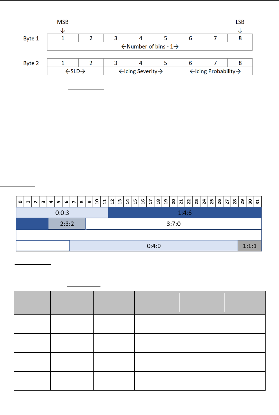
FAA Surveillance and Broadcast Services Surveillance and Broadcast Services Description Document
SRT-047, Rev. 04 – September 20, 2018 Page 123 of 160
Figure G-14: Icing Forecast Product Run Encoding
The Icing Probability bits drive the run length encoding. In other words, the FIS-B Ground System
determines a single run based on the number of consecutive bins with the same icing probability.
The highest icing severity and highest potential of SLD present is encoded in the respective SLD
and severity bins. No Data supersedes the highest icing severity and highest SLD potential. Note
that this implementation of run length encoding may cause a smearing effect for the Severity or
SLD values. This smearing may result in a higher SLD or Severity level depicted in some bins
when the Probability remains the same in a series of adjacent bins. The current implementation
will be revised in the future to minimize or eliminate this smearing without impacting the decoding
of the icing product.
Figure G-15 shows an example block containing six runs of varying icing intensities.
Figure G-15: Example Block Containing Six Runs (Decimal values listed in order of Icing
Probability, Icing Severity, SLD)
Table G-10: Run Encoding for Icing Example Block
Run
Length
SLD
Potential
Icing
Severity
Icing
Probability
Encoded Run
(binary)
Cumulative
Bins
12 0 0 3
00001011
00 000 011
12
24 1 4 6
00010111
01 100 110
36
5 2 3 2
00000100
10 011 010
41
62 3 7 0
00111101
11 111 000
103

FAA Surveillance and Broadcast Services Surveillance and Broadcast Services Description Document
SRT-047, Rev. 04 – September 20, 2018 Page 124 of 160
22 0 4 0
00010101
00 100 000
125
3 1 1 1
00000010
01 001 001
128
G.1.1.4.5 Empty Element Encoding Scheme
The Icing Forecast product uses the empty element encoding scheme described in Section
G.1.1.2.3. A global block is encoded with the Empty Element Encoding when the entire global
block satisfies the following conditions:
• Icing Probability value <=5%
• Icing Severity of None
• SLD value <=5%
Reception of Empty Element encoded blocks indicates No Icing in that region. Lack of reception
of a Global Block indicates No Data in that region.
G.1.1.4.6 Icing Forecast Data Encoding
The following tables describe the data encoding for Icing Severity, Icing Probability, and SLD.
The Icing Severity encoded values are shown in Table G-11. When Icing Probability is encoded
as No Data, Icing Severity and SLD will also be encoded as No Data. Encoding Icing Severity or
SLD as No Data does not have any effect on the encoding of the other Icing Forecast elements.
Table G-11: Icing Severity Encoding
Icing Severity
Encoding
Icing Severity
000 None
001 Trace
010 Light
011 Moderate
100 Severe
101 Heavy
110 Reserved
111 No Data
Note: At the time of publication of this document, the “Severe” Icing Severity value is not used
by the FIP product (the data source of the FIS-B Icing product). Avionics systems should
not expect to receive or decode a “Severe” indication for the Icing Severity.

FAA Surveillance and Broadcast Services Surveillance and Broadcast Services Description Document
SRT-047, Rev. 04 – September 20, 2018 Page 125 of 160
Table G-12: Icing Probability Encoding
Icing Probability
Encoding
Icing Probability Range
000 Icing Probability <= 5%
001 5% < Icing Probability <= 20%
010 20% < Icing Probability <= 30%
011 30% < Icing Probability <= 40%
100 40% < Icing Probability <= 60%
101 60% < Icing Probability <= 80%
110 80% < Icing Probability
111 No Data
Table G-13: SLD Potential Encoding
SLD Encoding SLD Potential Range
00
SLD Potential <= 5% or Icing is present
but there was not enough information to
determine whether SLD is present
01 5% < SLD Potential <= 50%
10 50% < SLD Potential
11 No Data
G.1.1.4.7 Scaling of Icing Forecast Global Blocks
The Icing run length encoding uses the medium resolution scale factor for the bins as described in
Table G-1. This is the same scale factor as is used with the CONUS NEXRAD product.
G.1.1.4.8 Icing Forecast Product Status
As mentioned in Section G.1.1.6.3, the FIS-B Ground System will generate a FIS-B Product
Update Unavailable message if updates for two consecutive model runs have not been received.
This message may specify the individual altitude levels that are unavailable or can indicate that all
altitude levels are unavailable. Examples are below:
• ICING PRODUCT UPDATES UNAVAILABLE AT 12000FT AND 14000FT
• ICING PRODUCT UPDATES UNAVAILABLE

FAA Surveillance and Broadcast Services Surveillance and Broadcast Services Description Document
SRT-047, Rev. 04 – September 20, 2018 Page 126 of 160
G.1.1.5 Cloud Tops Forecast (Product ID #84)
The FIS-B Cloud Tops Forecast product provides cloud top data representing a 1-hour forecast of
the altitude of cloud tops across the CONUS. This product is not provided from radio stations in
Alaska, Hawaii, Guam, or Puerto Rico.
G.1.1.5.1 Cloud Tops Forecast Source
The FIS-B Ground System receives cloud top data from the NWS High Resolution Rapid Refresh
Model (HRRR). HRRR provides both a cloud top product and a cloud amount product. The cloud
top product provides the height of the topmost cloud within a pixel. HRRR cloud top data products
are generated each hour. The FIS-B Ground System uplinks data corresponding to the 1-hour
forecast of the cloud top products. The encoded cloud top data represents the height of the cloud
top in feet.
G.1.1.5.2 Cloud Tops Forecast APDU Header
The format of the APDU Header used for this product is the same as the format for the Regional
NEXRAD product. In this case, the time field encoded in the APDU Header is the valid time of
the Cloud Tops forecast product. This is a combination of the start time of the model run and the
forecast hour being used. For example, a model run that starts analysis at 10:00Z will indicate a
valid time of 11:00Z for the 1-hour forecast. The 1-hour forecast is valid for one hour, i.e. from
11:00Z to 12:00Z.
In most cases, the 1-hour forecast becomes available about 10 minutes before its valid time. In
the nominal situation, FIS-B will uplink the 1-hour forecast during its valid time window. In some
cases, the model run will be delayed and the FIS-B Ground System will not receive the 1-hour
forecast before its valid time starts. In this case, FIS-B implements a time limit cutoff at 10 minutes
after the hour. For example, if the next 1-hour forecast is not received by 12:10Z, FIS-B will begin
sending the 2-hour forecast for the model run that started at 10:00Z. The APDU Header Time
would indicate 12:00Z. If FIS-B has not received a new 1-hour forecast model run by 13:10Z, the
FIS-B Ground System will begin uplinking the FIS-B Product Updates Unavailable message for
the Cloud Tops product. Note that this is the same process that is used to time out the Turbulence
product, except a slightly different cutoff window of 10 minutes instead of 18 minutes was chosen
based on analysis of model run availability times.
G.1.1.5.3 Run Length Encoding Scheme for Cloud Tops Forecast Global Blocks
The run length encoding scheme used for Cloud Tops is the same as that used to encode the
Turbulence product. Either one or two bytes is used to represent each run depending on the run
length. Runs up to 14 bins long are encoded in a single byte. Runs of 15 -256 bins long are
encoded using two bytes. For runs requiring one byte, bits 1 through 4 represent the length of the
run minus 1 with bits 5 through 8 representing the turbulence encoding value, as shown in Figure
G-16.

FAA Surveillance and Broadcast Services Surveillance and Broadcast Services Description Document
SRT-047, Rev. 04 – September 20, 2018 Page 127 of 160
Figure G-16: Cloud Tops Forecast Product Run Length Encoding for Single Byte Runs
For runs requiring two bytes, bits 1 through 4 of byte 1 are a flag field set at decimal value 14
(0xE). When decimal value 14 is encountered, the avionics then knows to expect a second byte to
interpret the run length encoding. Bits 5 through 8 of byte 1 represent the Cloud Top Height value.
The 8 bits of byte 2 represent the length of the run minus 1, as shown in Figure G-17. For byte 2,
values of 0-13 and values greater than 127 are invalid.
Figure G-17: Cloud Tops Product Run Length Encoding for Two Byte Runs
Figure G-18 shows an example block containing six runs of varying intensities using runs that
involve both one and two-byte schemes.
Figure G-18: Example Block Containing Six Runs (Cloud Top Height Value Listed as Decimal)

FAA Surveillance and Broadcast Services Surveillance and Broadcast Services Description Document
SRT-047, Rev. 04 – September 20, 2018 Page 128 of 160
Table G-14: Run Encoding for Cloud Top Heights Example Block
Run Length
Cloud Top Value
Encoded Run (binary)
Cumulative Bins
9
2
1000 0010
9
15 5
1110 0101
00001110
24
6
6
0101 0110
30
62 11
1110 1011
00111101
92
28 0
1110 0000
00011011
120
8
15
0111 1111
128
G.1.1.5.4 Cloud Tops Forecast Data Encoding
Four bits are used to represent the encoding of each bin or run of bins. A range of cloud top height
values are encoded as shown in Table G-15.
Table G-15: Cloud Tops Forecast Data Encoding
Encoding
Cloud Tops Range (above MSL)
0000 No Clouds
0001 Cloud Tops <= 1,500 ft
0010
1,500 ft < Cloud Tops <= 3,000 ft
0011 3,000 ft < Cloud Tops <= 4,500 ft
0100 4,500 ft < Cloud Tops <= 6,000 ft
0101 6,000 ft < Cloud Tops <= 7,500 ft
0110 7,500 ft < Cloud Tops <= 9,000 ft
0111 9,000 ft < Cloud Tops <= 10,500 ft
1000 10,500 ft < Cloud Tops <= 12,000 ft
1001
12,000 ft < Cloud Tops <= 13,500 ft
1010 13,500 ft < Cloud Tops <= 15,000 ft
1011 15,000 ft < Cloud Tops <= 18,000 ft
1100
18,000 ft < Cloud Tops <= 21,000 ft
1101 21,000 ft < Cloud Tops <= 24,000 ft
1110 24,000 ft < Cloud Tops
1111 No Data
When an entire Global Block contains No Clouds, the block is sent with the Empty Element
encoding. Reception of Empty Element encoded blocks indicates No Clouds in that region. Lack
of reception of a Global Block indicates No Data in that region.

FAA Surveillance and Broadcast Services Surveillance and Broadcast Services Description Document
SRT-047, Rev. 04 – September 20, 2018 Page 129 of 160
G.1.1.5.5 Scaling of Cloud Tops Forecast Global Blocks
The Cloud Tops run length encoding uses the high-resolution scale factor for the bins as described
in Table G-1. This is the same scale factor as is used with the Regional NEXRAD product.
G.1.1.5.6 Cloud Tops Forecast Product Status
As mentioned in Section G.1.1.7.2, the FIS-B Ground System will generate a FIS-B Product
Update Unavailable message if updates for two consecutive model runs have not been received.
If either the cloud amount or cloud tops source products are not available, the FIS-B Ground
System will create a Product Update Unavailable message for the Cloud Tops product. An
example is below:
• CLOUD TOPS PRODUCT UPDATES UNAVAILABLE
G.1.1.6 Lightning (Product ID #103)
The FIS-B Lightning product provides a graphical representation of the observed lightning strike
density and polarity across the CONUS. This product is not provided from radio stations in Alaska,
Hawaii, Guam, or Puerto Rico.
G.1.1.6.1 Lightning Source
The FIS-B Ground System receives lightning data from the Vaisala lightning product. FIS-B
receives an updated mosaic of CONUS lightning every 5 minutes. This mosaic is translated into
the Global Block Representation similar to the translation done for the NEXRAD product. The
encoded data represents the strike count within the global blocks and an indication of the polarity
of the strikes. If at least one strike within a bin is positive, then the entire bin is encoded with
positive polarity. If all strikes within a bin are negative, then the entire bin is encoded with negative
polarity.
G.1.1.6.2 Lightning Product APDU Header
The format of the APDU Header used for this product is the same as the format for the Regional
NEXRAD product. The time field encoded in the APDU Header is the time of mosaic creation.
G.1.1.6.3 Run Length Encoding Scheme for Lightning Global Blocks
A single byte is used to represent each run. Bits 1 through 4 of the run length encoded byte are
used to encode the run length, bit 5 is used to encode the polarity of the strikes in that run, with
bits 6 through 8 used to encode the number of lightning strikes of that run, as shown in Figure G-
19. The maximum run allowed is 16 bins. Encoding this maximum amount can be represented in
only four (4) bits if one considers that every run is greater than or equal to one (1). We therefore
subtract the value of one (1) from this maximum amount yielding an adjusted maximum value of
15, which can be delivered in four (4) bits.

FAA Surveillance and Broadcast Services Surveillance and Broadcast Services Description Document
SRT-047, Rev. 04 – September 20, 2018 Page 130 of 160
Figure G-19: Lightning Product Run Encoding
The Strike Count bits drive the run length encoding. In other words, the FIS-B Ground System
determines a single run based on the number of consecutive bins with the same encoded strike
count. If at least one bin in the run had a lightning strike with a positive polarity, then the entire
run is given a positive polarity. If all the bins in the run had lightning strikes with a negative
polarity, then the entire run is given a negative polarity.
Figure G-20 shows an example block containing 13 runs of varying intensities. The run length
encoding information for this block is contained in Table G-16. The total number of bins encoded
per block will always be 128. In the worst case—minimum compression—scenario there would
be 128 runs of length 1 bin each.
Figure G-20: Example Block Containing 12 Runs (Polarity: Strike Count as Decimal Values)

FAA Surveillance and Broadcast Services Surveillance and Broadcast Services Description Document
SRT-047, Rev. 04 – September 20, 2018 Page 131 of 160
Table G-16: Run Encoding for Lightning Example Block
Run
Length
Polarity Strike
Count
Encoded
Run
(binary)
Cumulative
Bins
9
0
0
1000 0 000
9
15 1 1 1110 1 001 24
6 0 2 0101 0 010 30
2 0 3 0001 0 011 32
8 0 0 0111 0 000 40
16 0 1 1111 0 001 56
8 0 2 0111 0 010 64
16
1
1
1111 1 001
80
10 0 2 1001 0 010 90
16 0 0 1111 0 000 106
16
0
0
1111 0 000
122
6 0 0 0101 0 000 128
G.1.1.6.4 Lightning Data Encoding
Four bits are used to represent the encoding of each bin or run of bins. The Strike Count and
Polarity encoded values are shown in Table G-17 and Table G-18.
Table G-17: Strike Count Encoding
Strike Count
Encoding
Strike Count
000 0
001
1
010 2
011 3 to 5
100 6 to 10
101 11 to 15
110 >15
111 No Data
When an entire Global Block contains zero lightning strikes, the block is sent with the Empty
Element encoding. Reception of Empty Element encoded blocks indicates No Lightning in that
region. Lack of reception of a Global Block indicates No Data in that region. When the strike
count is encoded with No Data, the polarity of that block cannot be determined and therefore
treated as No Data.

FAA Surveillance and Broadcast Services Surveillance and Broadcast Services Description Document
SRT-047, Rev. 04 – September 20, 2018 Page 132 of 160
Table G-18: Polarity Encoding
Polarity
Encoding
Polarity
0 Negative
1 Positive
G.1.1.6.5 Scaling of Lightning Global Blocks
The Lightning run length encoding uses the high-resolution scale factor for the bins as described
in Table G-1. This is the same scale factor as is used with the Regional NEXRAD product.
G.1.1.6.6 Lightning Product Status
The FIS-B Ground System will uplink Product Update Unavailable messages when the lightning
software process stops executing or the connection to the FIS-B Data Source is out during the 5-
minute collection window.
G.1.2 Text with Graphical Overlay FIS-B Products
This section describes the encoding format used for the TWGO product class.
Note: This class of FIS-B products employs an encoding framework that contains flexibility to
represent graphic objects not currently present in FIS-B uplink products. Many fields
documented here contain states that do not presently occur. Where this occurs, these states
are marked Future Use within this appendix. The encoding framework also includes some
optional fields that were not used at the time DO-358 was developed. These currently
unused optional fields are omitted in this appendix.
G.1.2.1 General Formatting
The APDU Payload for TWGO FIS-B Products supports textual and graphical overlay
representations. The payload consists of a header and one or more records. The APDU Payload
will contain either graphical records or text records. It will not contain both a text record and a
graphical record within the same payload. See Figure G-21.
Figure G-21: Decomposition Showing TWGO FIS-B Payload
G.1.2.1.1 TWGO Payload Header
The TWGO Payload Header is composed of Record Format, Product Version, Record Count,
Reserved, LocID and Record Reference Point fields. The reserved field is reserved for future use.

FAA Surveillance and Broadcast Services Surveillance and Broadcast Services Description Document
SRT-047, Rev. 04 – September 20, 2018 Page 133 of 160
The TWGO Payload Header information appears once in an APDU and always is at the beginning
of the APDU Payload field. In the case of segmentation, the TWGO Payload Header, for a given
TWGO Product File, appears in each segmented APDU and every segment’s TWGO Payload
Header is identical. The Payload Header stipulates the format and number of the records to follow
and the version of the format being used.
The organization of the TWGO Header fields is shown in Figure G-22.
Figure G-22: TWGO Header Byte-Level Format
G.1.2.1.1.1 Record Format
The Record Format field described in Table G-19: Record Format Options19 indicates what type
of product report is contained in the TWGO Record. There are two basic types of product reports,
textual and graphical overlay. This is the only place in the format that the report type is identified.
The Record Format field allows text reports that are organized in various forms to support existing
report formats used in the NAS today, but also to support the transition to ICAO standardized
formats.
Graphical overlay records are organized in only one form. The encoding of overlays is defined in
Section G.1.2.1.3.
Table G-19: Record Format Options
Meaning Value
Unformatted DLAC Text 2
Graphical Overlay 8
Future Use 0, 1, 3-7, 9-15
FIS-B avionics should ignore all Record Format values associated with a future use.
G.1.2.1.1.2
Product Version
This field should be ignored by FIS-B avionics conforming to this document. The Product Version
field is a one byte sequentially ordered number (1-15) used to maintain configuration control of
changes to the product definitions.

FAA Surveillance and Broadcast Services Surveillance and Broadcast Services Description Document
SRT-047, Rev. 04 – September 20, 2018 Page 134 of 160
G.1.2.1.1.3 Record Count
The Record Count field indicates the number of records using the same Record Format that can be
grouped together. Up to 15 (binary 0001 to 1111) Text or Graphical Overlay records can be
grouped with each TWGO product.
G.1.2.1.1.4 Reserved Bits
The Reserved field is reserved for future use and should be ignored by FIS-B avionics conforming
to this document.
G.1.2.1.1.5 Location Identifier
The LocID references the location or facility that the report applies to or the overlay has originated
from, such as an air traffic facility (e.g. airports, navigation aids or control facilities). The 3-byte
field contains four DLAC characters. In cases when less than four characters are needed for the
identifier or no identifier is present, the unused characters are set to the ETX DLAC character.
G.1.2.1.1.6 Record Reference Point
A value in this field of all zeros (0) or all ones (1) should cause this field to be ignored by FIS-B
avionics conforming to this document. Any other value should cause FIS-B avionics conforming
to this document to discard the TWGO Record.
G.1.2.1.2 TWGO Text Record
The Text Record fields provide a framework to support the communication of text reports. Figure
G-23 gives the byte-level format of the Text Record fields.
Figure G-23: Text Record Byte-Level Format
G.1.2.1.2.1 Text Record Length
The Text Record Length field (2 bytes) indicates the number of bytes (5..65,535) contained in a
single text record. The length includes all the fields contained in the 5-byte header.
Note: All Text Records for this product class are subject to truncation if necessary to 1500 DLAC
characters by the FIS-B ground system. The last eight characters of a truncated Text
Byte # Bit 1 Bit 2 Bit 3 Bit 4 Bit 5 Bit 6 Bit 7 Bit 8
1
2
3
4
5
Rpt Status
6
7
.
.
.
≤ 65,535
Report Year cont'd
Reserved
Text Data (Variable Length)
MSB
↓
LSB
↓
Text Record Length
Report Number
Report Year

FAA Surveillance and Broadcast Services Surveillance and Broadcast Services Description Document
SRT-047, Rev. 04 – September 20, 2018 Page 135 of 160
Record will contain “(INCMPL)” consistent with the truncation approach used for the
Generic Text product class.
G.1.2.1.2.2 Report Number
The Report Number field (14 bits) is one of the fields used to determine report uniqueness. This
field can accommodate a number in the range of 0 to 16,383 used to identify each report.
G.1.2.1.2.3 Report Year
The Report Year field (7 bits) indicates the last two digits of the year the report originated (e.g.
2014 is represented as “14”). Exceptions are NOTAM-TFR and NOTAM-FDC where the year
the report originated is represented by a single digit (e.g. 2014 is represented as “4”). In cases
when the source report does not contain a year value, this value will be provided by the FIS-B
ground system.
G.1.2.1.2.4 Report Status
The use of the Report Status enables the FIS-B ground system to confirm or update the status of
any previously uplinked report (text and associated overlay) and quickly purge those records that
are terminated prematurely, i.e. not in accordance with the period of validity that may be
provided in the record itself. Generally, reports reaching the end of their valid time are no longer
transmitted. As shown in Table G-20: Report StatusTable G-20, the Report Status is either
Cancelled or Active.
A cancellation overrides the period of validity contained in the original records. As long as a
report remains valid, the Report Status will be represented as “Active.”
Table G-20: Report Status
Meaning Value
Cancelled Report 0
Active Report 1
A key feature of the Report Status is that it enables the status of all records associated with a
previously uplinked report (including overlay records) to be updated without having to retransmit
the entire record or set of records. This is accomplished by only transmitting the first five (5) bytes
of the text record (see Section G.1.2.1.2), which includes only those fields necessary to reference
the record(s) and status.
G.1.2.1.2.5 Reserved Bits
Bits 7 through 8 of byte 5 are reserved for future use and should be ignored.
G.1.2.1.2.6 Text Data Field
The Text Data Field contains the DLAC encoded text for a single report.

FAA Surveillance and Broadcast Services Surveillance and Broadcast Services Description Document
SRT-047, Rev. 04 – September 20, 2018 Page 136 of 160
G.1.2.1.3 TWGO Graphical Overlay Record
The Graphical Overlay Record contains the fields for the graphical depictions of NAS Status
information (e.g. NOTAM-TFR and SIGMET reports). A byte-level format of the Graphical
Overlay Record is shown in Figure G-24.
Figure G-24: Graphical Record Byte-Level Format
G.1.2.1.3.1 Overlay Record Length
The Overlay Record Length field (10 bits) indicates the number of bytes in a single overlay record.
The length includes the Overlay Record Length field.
G.1.2.1.3.2 Report Number
The Report Number field (14 bits) is one of the fields used to determine report uniqueness. This
field can accommodate a number in the range of (0 to 16,383) used to identify each report.

FAA Surveillance and Broadcast Services Surveillance and Broadcast Services Description Document
SRT-047, Rev. 04 – September 20, 2018 Page 137 of 160
G.1.2.1.3.3 Report Year
The Report Year field (7 bits) indicates the last two digits of the year the report originated (e.g.
2014 is represented as “14”). Exceptions are NOTAM-TFR and NOTAM-FDC reports where the
year the report originated is represented by a single digit (e.g. 2014 is represented as “4”). In cases
when the source report does not contain a year value, this value will be provided by the FIS-B
ground system using the current year.
G.1.2.1.3.4 Record Applicability Year
The Record Applicability Year field is applicable to NOTAM-TFR, NOTAM-FDC, and NOTAM-
D. The Record Applicability Year field indicates the start year and end year for which a record is
considered active. This year may be different than the Report Year field described in Section
G.1.2.1.3.3, which indicates the year the report was issued. Bit 8 of byte 4 and bit 1 of byte 5
indicate the record applicability start year relative to the Report Year field. Bit 2-3 of byte 5
indicate the record applicability end year relative to the Report Year field.
Table G-21 shows an example. The Report Year field for an example NOTAM-TFR is encoded
as decimal value 7, indicating it was issued in 2017. Let’s assume the Record Applicability time
for the NOTAM-TFR is July 18, 2018 0900-1300 UTC. The first two bits of the Record
Applicability Year field are encoded with decimal value of 1, indicating the record applicability
start year is 1 year after the Report Year field. The last two bits of the Record Applicability Year
field are encoded with decimal value of 1, indicating the record applicability end year is 1 year
after the Report Year field.
Table G-21: Report Year & Record Applicability Year Example
Field Decimal Value Binary APDU Encoding
Report Year 7 0000111
Record Applicability Year 5 0101
When the Record Applicability Options field is set to:
• 0, the Record Applicability Year should be ignored
• 1, the last two bits of the Record Applicability Year will be set to zeros and should be
ignored
• 2, the first two bits of the Record Applicability Year will be set to zeros and should be
ignored
• 3, both start year and end year are valid
G.1.2.1.3.5 Overlay Record Identifier
The Overlay Record Identifier is a 4-bit sequence number (0..14) identifying each, of potentially
several, overlay records. There may be up to 15 related overlay records. The decoding of this
field requires that a one (1) be added to the Overlay Record Identifier value to get the decimal

FAA Surveillance and Broadcast Services Surveillance and Broadcast Services Description Document
SRT-047, Rev. 04 – September 20, 2018 Page 138 of 160
value. For example, a binary value of 0000 corresponds to Record ID of 1 (decimal) and a binary
value of 0001 corresponds to a Record ID of 2 (decimal).
G.1.2.1.3.6 Object Label Flag
The Object Label Flag controls the approach used to represent the Object Label. This field is a
binary field indicating whether the Object Label field is numeric (0) or alphanumeric (1).
For FIS-B avionics conforming to this document, a value of 0 indicates there is no Object Label
and a 1 indicates the text label is an airport LocID.
G.1.2.1.3.7 Object Label
FIS-B avionics conforming to this document should interpret the Object Label field as follows:
1. When the Object Label Flag is zero (0) this field is two (2) bytes in length and the Graphical Overlay
record should be processed ignoring the Object Label field.
2. When the Object Label Flag is one (1), this field is nine (9) bytes in length and represents a LocID
(e.g. airport or airspace) using the DLAC character set. If there are less than 12 letters in the field,
the least significant DLAC characters are filled with ETX.
G.1.2.1.3.8
Object Type
The Object Type field provides the notable parts of an airport or airspace environment. These
airport/airspace objects comprise the collection of regions or things that can have an impact on
flight operations if they become hazardous, if they fail or if they are unavailable for some reason.
FIS-B avionics conforming to this document should interpret only two values for this field as
shown in Table G-22. The presence of any other values should result in FIS-B avionics discarding
the Graphical Overlay Record.
Table G-22: Object Types
Object Type Value
Aerodrome (airport, heliport, helipad) 0
Airspace 14
Future Use 1-13, 15
G.1.2.1.3.9 Object Element Flag
The Object Element Flag field is a binary field used to indicate whether the Object Element field
is used (1) or not (0).
G.1.2.1.3.10 Object Element
The Object Element field provides a particular feature or element of an Object Type of interest.
FIS-B avionics conforming to this document should discard any Object Element associated with
an Aerodrome Object Type. An Object Element associated with the Airspace Object Type is
represented by the feature in Table G-23.

FAA Surveillance and Broadcast Services Surveillance and Broadcast Services Description Document
SRT-047, Rev. 04 – September 20, 2018 Page 139 of 160
Table G-23: Airspace Object Elements
Object Element Contraction Value
Temporary Flight Restriction TFR 0
G-AIRMET Turbulence TURB 1
G-AIRMET Low Level Wind Shear LLWS 2
G-AIRMET Surface Winds SFC 3
G-AIRMET Icing ICING 4
G-AIRMET Freezing Level FRZLVL 5
G-AIRMET IFR Conditions IFR 6
G-AIRMET Mountain Obscuration MTN 7
Future Use 8-15
G.1.2.1.3.11 Object Status
The Object Status field provides the state of an object. Possible values are listed in Table G-24.
Graphical Overlay records indicating any value other than 13 or 15 for this field should be
discarded by FIS-B avionics conforming to this document.
Table G-24: Object Status
Object Status Value
Cancelled 13
In Effect 15
Future Use 0-12 and 14
G.1.2.1.3.12 Object Qualifier Flag
The Object Qualifier Flag field is a binary field used to indicate whether the Object Qualifier field
is used (1) or not (0). The Object Qualifier flag bit may be set to one for certain conditions
associated with the G-AIRMET product. In all other cases, the Object Qualifier flag bit will be
set to zero.
G.1.2.1.3.13 Object Qualifier
The Object Qualifier field should only be interpreted when the Object Qualifier Flag bit is set to
one and the product type is G-AIRMET. In this case, the bits in this field should be interpreted
based on the bitmap encoding defined in Section G.1.2.2.5.3.
G.1.2.1.3.14 Object Parameter Flag
The Object Parameter Flag field is a binary value indicating whether the Object Parameter Type
and Object Parameter Value fields are present (1) or absent (0). FIS-B avionics conforming to this
document should discard any Graphical Overlay records that invokes the optional Object
Parameter Type and Object Parameter Value fields.

FAA Surveillance and Broadcast Services Surveillance and Broadcast Services Description Document
SRT-047, Rev. 04 – September 20, 2018 Page 140 of 160
G.1.2.1.3.15 Record Applicability Options
The Record Applicability Options provide information about the timing of the reported event.
Some events will have both beginning and ending times that the reported event is applicable. Other
reports will be valid as long as they are being reported. Table G-25 lists the options to cover
possible reporting approaches.
Note that the Record Applicability field (Section G.1.2.1.3.17) is specific to the contents of the
report and is independent of the product transmission time.
Table G-25: Record Applicability Options
Meaning Value Interpretation
No times given 0
The record does not have a specific active time period. The
record should be assumed to be active at all times of reception.
Start time only 1
The record should be assumed to be active at all times of
reception after the start time.
End time only 2
The record should be assumed to be active at all times of
reception until the specified end time.
Both start and
end times
3
The record should be assumed to be active only during the
time period specified between the start time and end time.
G.1.2.1.3.16 Date/Time Format
The Date/Time Format field provides format used in the Record Applicability fields (Section
G.1.2.1.3.17) enabling a subset of date/time information to be sent. Table G-26 provides the
format options available for tailoring the Record Applicability fields. The selected format
applies to both the start and end times (if both exist in the record).

FAA Surveillance and Broadcast Services Surveillance and Broadcast Services Description Document
SRT-047, Rev. 04 – September 20, 2018 Page 141 of 160
Table G-26: Date/Time Format
Meaning Value Interpretation
No Date/Time Used 0 No Date/Time format is provided.
Month, Day, Hours,
Minutes
1
All four elements, month, day, hour, and minute are
included in the Record Applicability field. Indicates a
single applicability time for the record.
Day, Hours, Minutes 2
The ground system does not currently utilize this
encoding.
Hours, Minutes 3
Only the hours and minutes elements are included in
the Record Applicability field. This encoding is used
for records that are valid for a recurring period of time
each day. The record should be assumed to be active
on all days for which the record is received.
G.1.2.1.3.17 Record Applicability
The Record Applicability fields include a starting time and ending time field that indicate the
period the data in the overlay record are in effect. The Record Applicability Options field controls
the inclusion of the Record Applicability Start and End fields in the record. The format for each
field is stipulated in the Date/Time Format field. When the Date/Time Format field is set to zero
(0) the Record Applicability field can be ignored by equipment conforming to this document.
When the Date/Time Format field is set to one (1) the Record Applicability field is broken down
into four one-byte sub-fields to represent month, day, hour and minute. When the Date/Time
format is set to two (2) or three (3), the Record Applicability field contains only the specified fields
associated with each respective encoded value.
Note: The sub-field data can be represented in fewer bits, but to preserve the byte boundary with
subsequent fields, there would be marginal savings and there would be additional
complexity in the format encoding/decoding processing.
Figure G-25 shows the byte-level format of the Record Applicability field.
Record Applicability
MSB
↓
LSB
↓
Byte #
Bit 1
Bit 2
Bit 3
Bit 4
Bit 5
Bit 6
Bit 7
Bit 8
1 Month (optional)
2 Day (optional)
3 Hours (optional)
4 Minutes (optional)
Figure G-25: Record Applicability Byte-Level Format

FAA Surveillance and Broadcast Services Surveillance and Broadcast Services Description Document
SRT-047, Rev. 04 – September 20, 2018 Page 142 of 160
G.1.2.1.3.18 Overlay Geometry Options
The Overlay Geometry Options indicates whether or not there is a geometry explicitly defined in
the record. The geometry option provides the geometry type, resolution and vertex encoding to be
used. Table G-27 presents the geometry types and possible number of vertices. Each vertex is
defined by the set of coordinates required to define a geometric point in space (e.g. x, y, z). Table
G-28 shows the vertex coordinates and the corresponding encoding for each geometry.
The encoding and decoding for each geometry is different due to the number and type of
coordinates and the resolution (LSB) for each coordinate. When encoding a coordinate into binary
form, the decimal coordinate value may need to be rounded toward zero to a value that is a multiple
of the resolution value. The procedure is necessary to ensure both encoding and decoding are
performed consistently. The procedure for rounding toward zero is to modulus the magnitude of
the coordinate value with the resolution and subtract the result from the magnitude of the
coordinate value. Then perform the encoding specified by each geometry in the following
sections.
The following is an example of the rounding procedure for any given geometry in Table G-28:
Y = sign(X) * (floor(|X|/R) * R), where:
X = original coordinate value in decimal
Y = rounded coordinate value in decimal
R = coordinate resolution as specified in Table G-28
FIS-B avionics conforming to this document should discard the Graphical Overlay record when
any fields or states from Table G-22, Table G-23, Table G-24, Table G-25, Table G-26 and
Table G-27 indicated as “Future Use” are encountered.
Table G-27: Overlay Geometry Options
Geometry Type Value Vertices Count Range
Extended Range 3D Polygon (MSL) 3 1-64
Extended Range 3D Polygon (AGL) 4 1-64
Extended Range Circular Prism (MSL) 7 1-64
Extended Range Circular Prism (AGL) 8 1-64
Extended Range 3D Point (AGL) 9 1-64
Extended Range 3D Point (MSL) 10 1-64
Extended Range 3D Polyline (MSL) 11 1-64
Extended Range 3D Polyline (AGL) 12 1-64
Future Use 0-2, 5-6, 13-15

FAA Surveillance and Broadcast Services Surveillance and Broadcast Services Description Document
SRT-047, Rev. 04 – September 20, 2018 Page 143 of 160
G.1.2.1.3.18.1 Extended Range Three-Dimensional Polygon
The Extended Range three-dimensional (3D) Polygon provides a connect-the-dot geometry
independent of the Record Reference Point. This option is useful in defining various airspace
objects in the airport terminal or en route domains.
The location of each vertex in this geometry is defined using latitude and longitude and is not tied
to the Record Reference Point. The latitude and longitude coordinate field values are each encoded
using a 19-bit unsigned integer providing approximately 0.000687 degrees of position resolution.
These fields are encoded using the Angular Weighted Binary Encoding, which is described in
Table G-30Error! Reference source not found..
The altitude (z) coordinate is encoded using a 10-bit unsigned integer providing 100 ft of resolution
and representing a range of 0 to 102,300 ft Mean Sea Level (MSL) or Above Ground Level (AGL).
The Overlay Geometry Option selected indicates the altitude reference used. Each z coordinate is
decoded by multiplying the field value by 100. See Table G-28 for encoding details. If this
geometry is describing a range of altitudes (e.g. 3000 ft to 17,999 ft), start with the higher altitude
and complete its geometry. After the first geometry is closed, move down to the lower altitude
and complete its geometry.
See Section G.1.2.1.3.18.4 for further encoding rules for this geometry.
G.1.2.1.3.18.2 Extended Range Circular Prism
The Extended Range Circular Prism provides a singular geometry. The Extended Range Circular
Prism geometry is intended to describe airspace objects in the terminal or en route domain. A
circular prism provides the flexibility to define a basic cylinder or a more complex parallelepiped
with an elliptical cross-section. The top and bottom ellipsoids are the same shape and orientation,
but the two centroids may not be aligned. The vertical boundaries of the prism are always parallel.
Figure G-26 shows graphically how the Extended Range Circular Prism is specified. The left side
shows the plan and profile view of a basic cylinder, where the radii are the same and the α
parameter is 0. The right side shows the plan and profile view of a parallelepiped with an elliptical
cross-section, where the radius in the North/South direction happens to be larger than the radius in
the East/West direction – before rotation. The α parameter then indicates a rotation 45 degrees
around magnetic North in a clockwise direction. In both examples, there happens to be no offset
in the center location between the top and bottom of the volumes, but an offset is supported via
separate “LAT” and “LONG” for both top and bottom.
The location of this geometry is defined using latitude and longitude and is not tied to the Record
Reference Point. The latitude and longitude coordinate field values are each encoded using an 18-
bit unsigned integer providing approximately 0.001373 degrees of position resolution (~150
meters positional accuracy). These fields are encoded using the Angular Weighted Binary
Encoding, which is described in Table G-29.
The radii, r
LONG
and r
LAT
, are each encoded using a 9-bit unsigned integer providing a fifth of a
nautical mile (0.20 NM) of position resolution. The radii have a range of up to approximately

FAA Surveillance and Broadcast Services Surveillance and Broadcast Services Description Document
SRT-047, Rev. 04 – September 20, 2018 Page 144 of 160
102.2 NM from the center of the ellipse. The r
LONG
and r
LAT
coordinates are each decoded by
dividing the field value by 5 to yield the coordinate in nautical miles.
The orientation of the elliptical cross-section is specified by a rotation angle, α, that originates at
magnetic North and increments in a clockwise direction between 0 and 179 degrees. The α
coordinate is represented by an 8-bit unsigned integer and has a resolution of 1 degree. The
rotation angle is obtained from the field value directly, i.e. no conversion necessary.
There are two altitude coordinates (z
bot
and z
top
), one for the bottom of the parallelepiped and one
for the top. Each z coordinate is encoded using a 7-bit unsigned integer providing 500 ft of
resolution and representing a range of 0 to 63,500 ft MSL or AGL. The Overlay Geometry Option
(Table G-27) selected indicates the altitude reference used. Each z coordinate is decoded by
multiplying the field value by 500. See Table G-28 for encoding details.
See Section G.1.2.1.3.18.4 for further encoding rules for this geometry.
Figure G-26: Extended Range Circular Prism
G.1.2.1.3.18.3 Extended Range 3D Point
The Extended Range 3D Point provides a singular geometry. This option is useful in defining
locations within the airspace to identify or reference points of interest to pilots.
The location the vertex in this geometry is defined using latitude and longitude and altitude. The
latitude and longitude coordinate field values are each encoded using a 19-bit unsigned integer

FAA Surveillance and Broadcast Services Surveillance and Broadcast Services Description Document
SRT-047, Rev. 04 – September 20, 2018 Page 145 of 160
providing approximately 0.000687 degrees of position resolution. These fields are encoded using
the Angular Weighted Binary Encoding, which is described in Table G-30.
The altitude (z) coordinate is encoded using a 10-bit unsigned integer providing 100 ft of resolution
and representing a range of 0 to 102,300 ft MSL or AGL. The Overlay Geometry Option selected
indicates the altitude reference used. Each z coordinate is decoded by multiplying the field value
by 100. See Table G-28 for encoding details.
When multiple Extended Range 3D Point geometries are packed in a single record, each is, by
definition, independent of each other. When multiple Extended Range 3D Point geometries are
packed across multiple records, each individual geometry is also independent.
See Section G.1.2.1.3.19 for further encoding rules for this geometry.
Table G-28: Overlay Geometry Encoding
Geometry
Vertex
Coordinate
Resolution (LSB) Value Range
Extended Range
3D Polygon
LONG:
LAT:
z:
19 bits (360/2
19
deg)
19 bits (
360/2
19
deg)
10 bits (100 ft)
(0..±180)
(0..±90)
(0..102,300)
Extended Range
Circular Prism
LONG
bot
:
LAT
bot
:
LONG
top
:
LAT
top
:
z
bot
:
z
top
:
r
major
:
r
minor
:
α:
18 bits (
360/2
18
deg)
18 bits (
360/2
18
deg)
18 bits (
360/2
18
deg)
18 bits (
360/2
18
deg)
7 bits (500 ft)
7 bits (500 ft)
9 bits (0.2 NM)
9 bits (0.2 NM)
8 bits (1 deg)
(0..±180)
(0..±90)
(0..±180)
(0..±90)
(0..63, 500)
(0..63, 500)
(0..102.2)
(0..102.2)
(0..179)
Extended Range
3D Point
LONG:
LAT:
z:
19 bits (360/2
19
deg)
19 bits (
360/2
19
deg)
10 bits (100 ft)
(0..±180)
(0..±90)
(0..102,300)
Extended Range
3D Polyline
LONG:
LAT:
z:
19 bits (360/2
19
deg)
19 bits (
360/2
19
deg)
10 bits (100 ft)
(0..±180)
(0..±90)
(0..102,300)
G.1.2.1.3.18.4 Extended Range 3D Polyline
The Extended Range 3D Polyline describes a line composed of line segments that do not close into
a polygon. This is useful for conditions that span a lateral or longitudinal range across a given
region, such as freezing levels across CONUS. The resolution of the latitude/longitude/altitude
components are the same as was described for the Extended Range 3D Point geometry.

FAA Surveillance and Broadcast Services Surveillance and Broadcast Services Description Document
SRT-047, Rev. 04 – September 20, 2018 Page 146 of 160
G.1.2.1.3.18.5 Angular Weighted Binary Encoding of Latitude and Longitude
Table G-29 shows the angular weighted binary 18-bit encoding of latitude and longitude.
Table G-29: Angular Weighted Binary Encoding of Latitude and Longitude
Note: Raw data used to establish the Latitude or Longitude fields will normally have more
resolution, i.e. more bits, than is required by the Latitude or Longitude fields. When
converting such data to the Latitude or Longitude subfields, the accuracy of the data is
maintained such that it is not worse than ±½ the LSB where the LSB is that of the Latitude
or Longitude field.
Table G-30 shows the angular weighted binary 19-bit encoding of latitude and longitude.
Table G-30: Angular Weighted Binary 19-Bit Encoding of Latitude and Longitude
Quadrant
“Latitude” or “Longitude”
bits
Meaning
(LSB = 360/2
19
≅
6.8664551 x 10
-4
degrees)
MSB LSB Latitude Longitude
1
st
quadrant
000 0000 0000 0000 0000 ZERO degrees (Equator) ZERO degrees (Prime Meridian)
000 0000 0000 0000 0001
LSB degrees North LSB degrees East
Quadrant
“Latitude” or “Longitude”
bits
Meaning
(LSB = 360/2
18
≅
1.373291 x 10
-3
degrees)
MSB LSB Latitude Longitude
1
st
quadrant
00 0000 0000 0000 0000 ZERO degrees (Equator) ZERO degrees (Prime Meridian)
00 0000 0000 0000 0001
LSB degrees North LSB degrees East
. . . . . . . . .
00 1111 1111 1111 1111
(90-LSB) degrees North (90-LSB) degrees East
2
nd
quadrant
01 0000 0000 0000 0000 90 degrees (North Pole) 90 degrees East
01 0000 0000 0000 0001 <Illegal Values>
(90+LSB) degrees East
. . . <Illegal Values> . . .
01 1111 1111 1111 1111 <Illegal Value>
(180-LSB) degrees East
3
rd
quadrant
10 0000 0000 0000 0000 <Illegal Value> 180 degrees East or West
10 0000 0000 0000 0001 <Illegal Value>
(180-LSB) degrees West
. . . <Illegal Values> . . .
10 1111 1111 1111 1111 <Illegal Values>
(90+LSB) degrees West
4
th
quadrant
11 0000 0000 0000 0000 90 degrees (South Pole) 90 degrees West
11 0000 0000 0000 0001
(90-LSB) degrees South (90-LSB) degrees West
. . . . . . . . .
11 1111 1111 1111 1111
LSB degrees South LSB degrees West

FAA Surveillance and Broadcast Services Surveillance and Broadcast Services Description Document
SRT-047, Rev. 04 – September 20, 2018 Page 147 of 160
Quadrant
“Latitude” or “Longitude”
bits
Meaning
(LSB = 360/2
19
≅
6.8664551 x 10
-4
degrees)
MSB LSB Latitude Longitude
. . . . . . . . .
001 1111 1111 1111 1111
(90-LSB) degrees North (90-LSB) degrees East
2
nd
quadrant
010 0000 0000 0000 0000 90 degrees (North Pole) 90 degrees East
010 0000 0000 0000 0001 <Illegal Values>
(90+LSB) degrees East
. . . <Illegal Values> . . .
011 1111 1111 1111 1111 <Illegal Value>
(180-LSB) degrees East
3
rd
quadrant
100 0000 0000 0000 0000 <Illegal Value> 180 degrees East or West
100 0000 0000 0000 0001 <Illegal Value>
(180-LSB) degrees West
. . . <Illegal Values> . . .
101 1111 1111 1111 1111 <Illegal Values>
(90+LSB) degrees West
4
th
quadrant
110 0000 0000 0000 0000 90 degrees (South Pole) 90 degrees West
110 0000 0000 0000 0001
(90-LSB) degrees South (90-LSB) degrees West
. . . . . . . . .
111 1111 1111 1111 1111
LSB degrees South LSB degrees West
Note: Raw data used to establish the Latitude or Longitude fields will normally have more
resolution, i.e. more bits, than is required by the Latitude or Longitude fields. When
converting such data to the Latitude or Longitude subfields, the accuracy of the data is
maintained such that it is not worse than ±½ the LSB where the LSB is that of the
Latitude or Longitude field.
G.1.2.1.3.19 Overlay Operators
This version of the document is limited to interpreting the Overlay Operators field set to zero,
indicating geometries are independent across records as shown in Table G-31. Any other value
encountered by FIS-B avionics conforming to this document should cause the record to be
discarded.
Table G-31: Overlay Operators
Operator Value Meaning
No Operator 0 Graphical Overlay Records are independent
Future Use 1-3
G.1.2.1.3.20 Rules for Encoding and Rendering Overlay Geometries
For Polygon Geometries:
• Vertices can span multiple records.

FAA Surveillance and Broadcast Services Surveillance and Broadcast Services Description Document
SRT-047, Rev. 04 – September 20, 2018 Page 148 of 160
• Pen stays down to connect vertices within a record.
• Pen lifts between records, however, the FIS-B ground system will repeat last vertex of the previous
record into the first vertex of the subsequent record to effectively keep the pen down—unless
starting a new geometry.
• All polygons will be closed by the FIS-B ground system (at least as it appears to the pilot) and each
polygon is a “geometry.”
For 3D point and Circular Prism Geometries:
• Each vertex point corresponds to a “geometry.”
• Each geometry/vertex is independent of others within a record and across records.
• Multiple geometries/vertices can be packed multiple per record.
For Polyline Geometries:
• Vertices can span multiple records.
• Pen stays down to connect vertices within a record.
• Pen lifts between records; however, the FIS-B ground system will repeat last vertex of the previous
record into the first vertex of the subsequent record to effectively keep the pen down—unless
starting a new geometry.
G.1.2.1.3.21
Overlay Vertices Count
The Overlay Vertices Count field indicates the number of vertices listed in the Overlay Vertices
List field. The Overlay Count field is an optional field that is only present when the Overlay
Geometry Option field is non-zero. The Overlay Vertices List can contain up to 64 polygon
vertices. Since the ellipse and circular prism geometries have a single vertex, up to 64 of these
geometries can be included in the Overlay Vertices List. The decoding of this field requires that
one be added to the Overlay Vertices Count value to get the decimal value.
G.1.2.1.3.22 Overlay Vertices List
The Overlay Vertices List field is a variable length field containing a list of vertices for the
geometry specified in the Overlay Geometry Options. Only one geometry type can be included
in each overlay record (e.g. polygon and prism geometries cannot exist in the same record). The
Overlay Vertices List field is optional and is only present when the Overlay Geometry Option
field is non-zero. The number of vertices in the list is specified in the Overlay Vertices Count
field.
G.1.2.2 G-AIRMET (Product ID #14)
The G-AIRMET product provides a graphical summary of weather that may be hazardous to
aircraft but are less severe than SIGMETs. The text AIRMET that is generated to produce FIS-B
Product ID 11 contains the same basic set of information as the G-AIRMET. However, the G-
AIRMET product has greater spatial and temporal resolution than the text AIRMET. The G-
AIRMET product provided by FIS-B is a part of the TWGO Product Class, however it only

FAA Surveillance and Broadcast Services Surveillance and Broadcast Services Description Document
SRT-047, Rev. 04 – September 20, 2018 Page 149 of 160
provides a graphical record. The graphical record contains a sufficient set of metadata such that a
textual component is not necessary.
G.1.2.2.1 G-AIRMET Issue and Valid Timing
G-AIRMET products are issued by the AWC four times per day and are valid at a specific point
in time. FIS-B provides the 00-hr, 03-hr, and 06-hr forecast for each of the four regular-issuance
update cycles. The Issue Time encoded in the APDU Header Time fields is, using the Month,
Day, Hour, and Minute fields. The Record Applicability Start and Record Applicability End fields
are used to encode the valid time of the product. The Record Applicability Start field is populated
with the valid time of the specific forecast hour. The Record Applicability End field is populated
with the time three hours after the valid time, except for the 06-hr forecast as indicated below.
For example, if a G-AIRMET was released by AWC at 0245Z, the Issue Time encoded in the
APDU Header Time field is 0245Z. The table below shows the Record Applicability Start and
End Times that would be encoded for each forecast hour in this example. The 06-hr forecast start
and end at the same time in order to match the legacy AIRMET. Table G-32 shows a timeline of
the G-AIRMET regular issuance uplink cycle.
Table G-32: -AIRMET Regular Issuance Uplink Cycle
Forecast Hour 00-hr forecast 03-hr
forecast
06-hr
forecast
Record Applicability Start Time 0300Z 0600Z 0900Z
Record Applicability End Time 0600Z 0900Z 0900Z

FAA Surveillance and Broadcast Services Surveillance and Broadcast Services Description Document
SRT-047, Rev. 04 – September 20, 2018 Page 150 of 160
Figure G-27: G-AIRMET Issuance Timeline
In some cases, an amendment or correction is issued by the AWC. These can be sent at any time
between the regular issuances. FIS-B identifies the original G-AIRMET that was amended, keeps
the report number and report year used to identify the product, and replaces the contents that were
amended. The Issue Time encoded in the APDU Header is amended to the issue time of the
amendment. Since the uplink does not indicate that a product was amended, it will be up to the
avionics to identify any changes that may have occurred each uplink cycle and make the
corresponding display changes.
G.1.2.2.2 G-AIRMET APDU Header
The Time Option bits are set to 2, indicating that Month, Day, Hour, and Minute fields are used.
The Segmentation Flag bit is never set for this product.
G.1.2.2.3 G-AIRMET Product Updates Unavailable
If FIS-B stops receiving G-AIRMET product information from the product source, FIS-B will start
sending the Product Update Unavailable product. An example is “FIS-B 2200Z ZMA, ZJX G-
AIRMET PRODUCT UPDATES UNAVAILABLE”. FIS-B will continue to send any unexpired
G-AIRMET products available in its database that it received before the product source outage.
G.1.2.2.4 G-AIRMET TWGO Payload Header
The G-AIRMET product is encoded using the Text with Graphical Overlay product class structure,
as defined in Section G.1.2. The Record Format field in the TWGO payload header is always set
to 8, indicating a graphical record, since the G-AIRMET does not contain an associated text record.

FAA Surveillance and Broadcast Services Surveillance and Broadcast Services Description Document
SRT-047, Rev. 04 – September 20, 2018 Page 151 of 160
The Location Identifier field in the TWGO Payload Header will always be set to zero. The Record
Reference Point will be set to value 255.
G.1.2.2.5 G-AIRMET TWGO Graphic Record
The G-AIRMET TWGO Graphic Record follows the format described in Section G.1.2.1.3. The
fields that have a unique meaning in the G-AIRMET context are described below.
G.1.2.2.5.1 G-AIRMET Report Number and Report Year
The Report Number field uses the full range of numbers that can be accommodated in a 14-bit
field, 0 to 16383. The Report Year indicates the year that the G-AIRMET product was issued.
G.1.2.2.5.2 G-AIRMET Overlay Record Identifier
When a G-AIRMET product indicates hazardous weather that spans more than 64 vertices, the
product is broken into multiple graphical records.
G.1.2.2.5.3 G-AIRMET Object Fields and Flags
The G-AIRMET Object Label Flag bit is always set to 0, and the subsequent Object Label field
should be treated as defined in Section G.1.2.1.3.7. The Object Element Flag bit is always set to
1. The Object Parameter Flag bit is set to 0. The Object Type is set to 14 indicating an Airspace
object, as defined in Section G.1.2.1.3.8. When the Object Status field is set to 13, it indicates the
G-AIRMET is cancelled.
Since the Object Element Flag bit is set to 1, the Object Element field is used. The G-AIRMET
product uses values 1-7 to indicate the type of hazardous condition associated with the graphical
record. These include turbulence, low level wind shear, surface winds exceeding 30 knots, icing
conditions, freezing level location, IFR conditions, and mountain obscuration. These conditions
are described in Table G-33.

FAA Surveillance and Broadcast Services Surveillance and Broadcast Services Description Document
SRT-047, Rev. 04 – September 20, 2018 Page 152 of 160
Table G-33: - G-AIRMET Hazard Conditions
Condition Description
Turbulence Areas of moderate turbulence, other than convectively induced,
including the vertical extent.
Low Level Wind
Shear
• Wind shear below 2000 ft AGL, other than convectively
induced, resulting in an air speed loss or gain of 20 knots or
more.
• LLWS potential information is included after AIRMETs for
moderate turbulence and/or sustained surface winds greater
than 30 knots or statements indicating no significant turbulence
is expected.
Strong Surface
Winds
Areas of sustained surface winds greater than 30 knots. In
received data, this value is actually 29.1 knots.
Icing Areas of moderate airframe icing, other than convectively induced,
including the areal extent.
Freezing Level
• The lowest freezing level above the ground or at the surface as
appropriate.
• Included after AIRMETs for moderating icing or statements
indicating that no significant icing is expected.
• Freezing levels above the ground are delineated at 4000 ft
intervals AMSL.
• Range of freezing levels across the forecast area is also
included.
IFR
• Areas of cloud ceilings with bases less than 1000 ft AGL and/or
areas of surface visibilities below 3 statute miles, including the
weather causing the visibility restriction.
• The cause of the visibility restriction includes only widespread
sand/dust storm, PCPN, FU, HZ, BR, FG, and/or BLSN.
Mountain
Obscuration
• Areas of widespread mountain obscuration where VMC cannot
be maintained, including the weather causing the obscuration.
• The weather causing the obscuration includes CLDS, PCPN,
FU, HZ, BR, and/or FG.

FAA Surveillance and Broadcast Services Surveillance and Broadcast Services Description Document
SRT-047, Rev. 04 – September 20, 2018 Page 153 of 160
When the Object Qualifier Flag bit is set to 1, the Object Qualifier field is used. The G-AIRMET
product uses a bitmap encoding of Object Qualifier associated with the IFR and Mountain
Obscuration conditions. The Object Qualifier is not used for any other conditions. A bitmapping
is used such that multiple qualifiers can be applied simultaneously to fully describe the condition.
When bit number one is set, the cause was not provided by the information source and none of the
other cause bits will be set. However, a graphical record will be provided and should be displayed.
Figure G-28 shows the 3-bytes of Object Qualifier field encoding. Bits 1-8 of Byte 1 correspond
to Bits 1-8 in Table G-34, Bits 1-8 of Byte 2 correspond to Bits 9-16 in Table G-34 and Bits 1-8
of Byte 3 correspond to Bits 17-24 in Table G-34.
MSB
LSB
↓
↓
Byte #
Bit 1
Bit 2
Bit 3
Bit 4
Bit 5
Bit 6
Bit 7
Bit 8
1
Object Qualifier
2
3
Figure G-28: Object Qualifier
Table G-34: - G-AIRMET Mountain Obscuration & IFR Conditions
Mountain Obscuration or IFR Cause(s) Bit
Unspecified 1
Future Use 2-15
Ash 16
Dust 17
Clouds 18
Blowing Snow 19
Smoke 20
Haze 21
Fog 22
Mist 23
Precipitation 24
G.1.2.2.5.4 G-AIRMET Record Applicability Fields
The Record Applicability Options field is set to 3, indicating both the start and end times are
encoded for the G-AIRMET product. The Date/Time Format field is set to 1, indicating the Month,
Day, Hour, and Minute fields will be provided for the start and end times. The Record
Applicability Start Time and End Time are defined in Section G-1.2.2.1.

FAA Surveillance and Broadcast Services Surveillance and Broadcast Services Description Document
SRT-047, Rev. 04 – September 20, 2018 Page 154 of 160
G.1.2.2.5.5 G-AIRMET Geometry Types
The G-AIRMET product uses the Extended Range 3D Polygon and Extended Range 3D Polyline
Overlay Geometry Options. The implementation of the 3D Polyline for the G-AIRMET product
places the polyline at a specific altitude for the entirety of the line. See Section G.1.2.1.3.18.
G.1.2.3 Center Weather Advisory (CWA) Product ID #15
The CWA product provides unscheduled aviation weather warnings for conditions meeting or
approaching in-flight advisory criteria. Due to the short lead-time and short duration of the product
advisory, this product is not typically used for flight planning purposes. CWA products are
generated by the responsible Center Weather Service Units (CWSUs) for events that are expected
to occur within two hours and either have not been previously forecast by AWC or are useful in
supplementing a previously issued AWC product. The CWA product provided in FIS-B is
encoded using the Text with Graphical Overlay product class.
G.1.2.3.1 CWA Issue and Valid Timing
CWA products are generated as needed and are valid for a variable time of up to two hours. The
active time of a CWA may start up to two hours after the issue time. The issue time is encoded in
the APDU Header Time field, using the Month, Day, Hour, and Minute fields. The Record
Applicability Start and Record Applicability End fields are used to encode the starting valid time
of the product and the expiration time of the product. If a CWA product is cancelled before the
expiration time, FIS-B will uplink a text record with the 5-byte TWGO Text Record Report Status
bit set to 0. This occurs for the next two transmissions of the cancelled CWA. FIS-B immediately
ceases uplink of the corresponding graphical record.
G.1.2.3.2 CWA APDU Header
The Time Option bits are set to 2, indicating that Month, Day, Hour, and Minute fields are used.
The segmentation flag bit is always set to 0 for this product.
G.1.2.3.3 CWA Product Updates Unavailable
If FIS-B stops receiving CWA product information from the product source, FIS-B will start
sending the Product Update Unavailable product. An example is “FIS-B 2200Z ZMA, ZJX CWA
PRODUCT UPDATES UNAVAILABLE”.
G.1.2.3.4 CWA TWGO Payload Header
The CWA product is encoded using the Text with Graphical Overlay product class structure, as
defined in Section G.1.3. The Record Format field in the TWGO Payload Header will be set to 2
when the payload is a text record and will be set to 8 when the payload is a graphic record. The
Location Identifier field in the TWGO Payload Header will always be zero filled (DLAC ETX).
The Record Reference Point will be set to 255.
G.1.2.3.5 CWA TWGO Text Record Encoding
The CWA product text record is encoded using the format described in Section G.1.2.1.2. The
Report Number is generated by FIS-B and uses the full range of decimal values 0 to 16,383. Since

FAA Surveillance and Broadcast Services Surveillance and Broadcast Services Description Document
SRT-047, Rev. 04 – September 20, 2018 Page 155 of 160
the report numbers are generated by FIS-B see Section B.3.3 of DO-358 for information on how
these report numbers should be processed.
The Report Status field indicates whether the CWA is active or has been cancelled. The text data
is DLAC encoded.
G.1.2.3.6 CWA TWGO Graphic Record Encoding
The CWA product graphical record is encoded using the format described in Section G.1.2.1.3.
The fields that have a unique meaning in the CWA context are described below.
G.1.2.3.6.1 CWA Overlay Record Identifier
When a CWA product indicates hazardous weather that spans more than 64 vertices, the product
is broken into multiple graphical records.
G.1.2.3.6.2 CWA Object Fields and Flags
The CWA Object Label Flag bit is always set to 0, and the subsequent Object Label field should
be treated as defined in Section G.1.2.1.3.7. The Object Element Flag bit is always set to 0 and
the Object Element field is not used. The Object Qualifier Flag bit is set to 0 and the Object
Qualifier field is not used. The Object Parameter Flag bit is set to 0. The Object Type is set to 14
indicating an Airspace object, as defined in Section G.1.2.1.3.8. Object Status field is set to 15
indicating the hazard is in effect.
G.1.2.3.6.3 CWA Record Applicability Fields
The Record Applicability Options field is set to 3, indicating both the start and end times are
encoded for the CWA product. The Date/Time Format field is set to 1, indicating the Month, Day,
Hour, and Minute fields will be provided for the start and end times. The Record Applicability
Start Time corresponds to the beginning of the valid time of the CWA. The Record Applicability
End Time corresponds to the expiration time of the CWA.
G.1.2.3.6.4 CWA Geometry Types
The CWA product only uses the Extended Range 3D Polygon Overlay Geometry Options. When
generated by the responsible CWSU, CWAs may be sent to the FIS-B ground system as either
points, lines, or polygons. Since CWAs are only encoded using the 3D polygon geometry, the
following describes how the FIS-B ground system translates these points into a polygon:
• When a point is received without a radius, FIS-B will approximate a circle around that
point with a 5 NM diameter (2.5 NM radius from the point).
• When a line is received without a width, FIS-B will create a polygon around the line using
a width of 10 NM (5 NM on each side of the line).
• When a polygon is received, FIS-B will use each point to recreate the polygon.
G.2 Current Report List
The CRL is conveyed within Frame Type 14. The CRL frame is encoded within the UAT Ground
Uplink Message as shown in Figure G-29.

FAA Surveillance and Broadcast Services Surveillance and Broadcast Services Description Document
SRT-047, Rev. 04 – September 20, 2018 Page 156 of 160
Figure G-29: Decomposition Showing the CRL
The CRL Frame is formatted as shown in Figure G-30.
Figure G-30: CRL Encoding
Byte # Bit 1 Bit 2 Bit 3 Bit 4 Bit 5 Bit 6 Bit 7 Bit 8
1
2 TFR O Flag L Flag
3
4
5
6
7
8
Reserved
9 Text
Graphic
10
n-2
Reserved
n-1 Text Graphic
n
CRL
Header
CRL
Item #1
CRL
Item
#m
Reserved
Report Identification Number
…
Product ID
CRL Items Listed
Report Year
Report Identification Number
Product Range
Location ID (LocID)
Report Year
MSB
↓
CRL Frame
LSB
↓

FAA Surveillance and Broadcast Services Surveillance and Broadcast Services Description Document
SRT-047, Rev. 04 – September 20, 2018 Page 157 of 160
Notes:
1. L = 7 + (N * 3) when LocID is included
2. L = 4 + (N * 3) when LocID is not included
3. A maximum of 138 CRL list items can fit in one CRL frame
A CRL Frame contains a CRL Header and either zero, one or multiple CRL Items. Each list item
will refer to the Report Year and Report Number for each report transmitted for a particular product
specified by the Product ID in the CRL Header. When no reports are currently being uplinked for
a given Product ID, a NULL CRL is uplinked. A NULL CRL consists of the seven (7) byte CRL
Header and zero (0) accompanying CRL Items in the CRL Payload. The CRL Header contains all
the pertinent header fields and encodes a value of zero (0) in the CRL Items Listed field. While it
is not expected that a CRL would exceed 138 reports, if more than 138 reports are available for a
particular product from a single radio station, the first 138 CRL Items will be listed in the CRL
frame and the Over-Flow (O) Flag will be set to one (1) to indicate that not all items are being
uplinked in the CRL.
G.2.1 CRL Header Encoding
G.2.1.1 Product ID
The Product ID field is an 11-bit field that corresponds to the Product ID of the Report Numbers
found in the CRL Items. The Product ID field is set to eight (8) for NOTAMs, 11 for AIRMETs,
12 for SIGMETs, 14 for G-AIRMETs, and 15 for CWA.
G.2.1.2 TFR
This bit is used to specify that the CRL for Product ID #8 (NOTAMs) refers to those NOTAMs
defined as TFRs. The CRL is only sent for these types of NOTAMs but may be expanded in the
future to include other types such as NOTAMs-D. This bit has no meaning for other Product ID
values.
G.2.1.3 Reserved
This 2-bit field is reserved for future use and is set to ALL zeros.
G.2.1.4 O Flag
This field indicates an overflow condition for the CRL. If more than 138 reports are transmitted
by a radio station for any single Product ID, then the OF Flag is set to one (1) to indicate that all
products being uplinked by the radio stations are not included in the CRL for this Product ID.
G.2.1.5 L Flag
The L Flag field indicates whether the LocID field is included in the CRL Header. The field is set
to one (1) if the LocID field is present and zero (0) if the LocID field is not present.

FAA Surveillance and Broadcast Services Surveillance and Broadcast Services Description Document
SRT-047, Rev. 04 – September 20, 2018 Page 158 of 160
G.2.1.6 Product Range
This field defines the look ahead range for the Product ID represented in this CRL. The CRL
encompasses all the reports with this product ID that are within this look ahead range relative to
the position of the broadcasting radio station. The Product Range is represented by an 8-bit value
with an LSB of 5 NM. Therefore, the Product Range has values from 0 to 1,275 NM on 5 NM
increments.
G.2.1.7 LocID
The LocID field indicates the local identifier associated with the reports found in the CRL List
Items. It is optional and for future use by the FIS-B service for NOTAMs-D.
G.2.1.8 Number of CRL Items Listed
This field indicates the number of items in the CRL Frame. When there are no reports currently
being uplinked, the FIS-B service will set this field to zero (0), to provide the avionics a positive
indication that there are no current reports being transmitted for this Product ID. The maximum
value possible for this field is 138 reports.
G.2.2 CRL Payload Encoding
The CRL Payload is made up of 1 to 138 CRL List Items. Each individual CRL List Item contains
the following fields.
G.2.2.1 Reserved Bit
This field is reserved and set to zero (0) to maintain byte boundary consistency.
G.2.2.2 Report Year
The Report Year field indicates the year of the report within each CRL List Item. The Report Year
is an exact match to the Report Year encoded in the corresponding report and described in Section
G.1.2.1.2.2.
G.2.2.3 Text
The Text bit is set to indicate this report is associated with a Textual record.
G.2.2.4 Graphic
The Graphic bit is set to indicate this report is associated with a Graphical record.
G.2.2.5 Report Number
The Report Number provides the unique report identifier for the Product ID report associated with
this CRL List Item. The Report Number is an exact match to the Report Number encoded in the
corresponding report and described in Section G.1.2.1.2.2.
Notes:
1. A text-only report will be uplinked as a single CRL List Item with the Text bit set to one
(1) and the Graphic bit set to zero (0).

FAA Surveillance and Broadcast Services Surveillance and Broadcast Services Description Document
SRT-047, Rev. 04 – September 20, 2018 Page 159 of 160
2. Each CRL List Item associated with a G-AIRMET report will have the Text bit set to zero
(0) and the Graphic bit set to one (1) since the G-AIRMET product only includes a
graphical record.
3. A CRL List Item representing a TWGO report with both a text and graphical record will
be uplinked as a single CRL List Item with both the Text and Graphic bit set to one (1).

FAA Surveillance and Broadcast Services Surveillance and Broadcast Services Description Document
SRT-047, Rev. 04 – September 20, 2018 Page 160 of 160
Appendix H. Background on the Lightning Uplink Product
The material in this appendix is copyrighted by RTCA, Inc. (www.rtca.org) and used with
permission.
H.1 Lightning Sources
Lightning strike data is received by the FIS-B Ground System continuously from the Vaisala
Lightning Detection Network. At each five-minute epoch (:00, :05, etc.) the FIS-B Ground System
generates a composite of all strikes over the previous five minutes. The encoded data represents
the strike count within the global blocks and an indication of the polarity of the strikes. If at least
one strike within a run of bins is positive, then the entire run of bins is encoded with positive
polarity. If all strikes within a run of bins are negative, then the entire run of bins is encoded with
negative polarity.
H.2 Lightning Product APDU Header
The format of the APDU Header used for this product is the same as the format for the Regional
NEXRAD product. The time field encoded in the APDU Header aligns with the five-minute epoch
when the FIS-B system creates the composite.
Note: The Lightning product timestamp and update timing achieves a basic synchronization with
the Regional NEXRAD update, which makes the two products more compatible for graphic
overlay.
