

_____________________________________________________________________________________________
All Public Road Geospatial Representation Study ARNOLD Reference Manual
Page i DOT Contract #GS-35F-0001P
September 2014
21BFOREWORD
On August 7, 2012, FHWA announced that the HPMS is expanding the requirement for State
Departments of Transportation (DOTs) to submit their LRS to include all public roads. This requirement
will be referred to as the All Road Network of Linear Referenced Data (ARNOLD). Many States will be
challenged by this requirement, and as such, FHWA has contracted with Applied Geographics, Inc. under
DOT Contract #GS-35F-0001P to produce guidance materials to help State DOTs implement ARNOLD.
The project deliverables are listed below, and tasks 2-6 represent the specific guidance that is offered to
States:
22BPROJECT DELIVERABLES
• Task 1: Project Schedule, Workplan, Risk Assessment and TFTN crosswalk
• Task 2: Local Road Collection Systematic Approach Report
• Task 3: LRS Components and Best Practices Report
• Task 4: LRS Temporal Maintenance Plan Report
• Task 5: LRS Technical Instructions, Rules and Diagrams Report
• Task 6: Reference Manual summarizing information gathered from tasks 2-5
23BPROJECT TEAM
• US DOT
• Joe Hausman (Project Manager)
• Tom Roff (ARNOLD Lead)
• Justin Clarke (Team Lead)
• Contractors
• Applied Geographics, Inc. (Prime Contractor)
• David R. Fletcher (Subcontractor)
• Michael Baker Jr., Inc. (Subcontractor)
• Expert Panel
• Mark Sarmiento – FHWA Planning
• Mike Neathery – FHWA Planning
• Robert Pollack – FHWA Safety
• Stuart Thompson – FHWA Safety
• Maria Chau – FHWA NY Division
• Christopher Chang – FHWA Office of Infrastructure
• Dave Blackstone – Ohio DOT
• Frank DeSendi – Pennsylvania DOT
• Keith Dotson – Kentucky Transportation
• Sharon Hawkins – Arkansas Highway and Transportation Department
• James Meyer – Arizona DOT
• Michele Barnes – University of Michigan
• Paul O'Rourke – Florida DOT
_____________________________________________________________________________________________
All Public Road Geospatial Representation Study ARNOLD Reference Manual
Page ii DOT Contract #GS-35F-0001P
September 2014
Table of Contents
EXECUTIVE SUMMARY ........................................................................................................................................... 1
1 0BINTRODUCTION ............................................................................................................................................. 3
1.1 6BWHY IS AN ALL ROADS OUTLOOK IMPORTANT? ........................................................................................................ 3
1.2 7BWHY THE U.S. DOT AND FHWA NEED ALL ROADS ................................................................................................ 4
1.3 8BWHAT IS THE ALL-ROADS GEOSPATIAL REPRESENTATION STUDY? .............................................................................. 4
2 1BIMPLEMENTATION PLANNING ....................................................................................................................... 5
2.1 9BTHE OPPORTUNITY TO REVIEW THE AGENCY'S OVERALL NETWORK AND LRS DATA MANAGEMENT ...................................... 5
2.2 10BWHAT KIND OF PLANNING DO WE NEED? ............................................................................................................... 6
2.3 11BIMPLEMENTATION PLANNING BEST PRACTICES ........................................................................................................ 8
3 2BDATA COLLECTION ....................................................................................................................................... 10
3.1 12BHOW DO WE COLLECT ALL ROADS ACROSS THE STATE? ............................................................................................ 10
3.2 13BWHAT COMPONENTS WILL OUR BASELINE CENTERLINE NETWORK CONTAIN? ............................................................... 15
3.3 14BDATA COLLECTION RECOMMENDATIONS ............................................................................................................. 16
4 3BINTEGRATING ALL-ROADS AND CONSTRUCTING THE LRS ............................................................................ 18
4.1 HOW DO WE CREATE THE LRS THAT WE NEED? ..................................................................................................... 21
4.2 16BWHAT TOOLS DO WE NEED TO CONSTRUCT AND MAINTAIN LRS? .............................................................................. 26
4.3 17BRECOMMENDATIONS FOR BUILDING THE LRS ....................................................................................................... 29
5 4BONGOING DATA MAINTENANCE ................................................................................................................. 31
5.1 18BWE'VE SPENT ALL THIS EFFORT BUILDING IT; HOW DO WE KEEP IT CURRENT? ............................................................... 31
5.2 19BMANAGING TEMPORALITY WITHIN THE LRS ......................................................................................................... 34
5.3 20BLRS MAINTENANCE RECOMMENDATIONS ............................................................................................................ 36
6 5BCONCLUSIONS AND THE PATH FORWARD ................................................................................................... 38
TECHNICAL APPENDICES ...................................................................................................................................... 40
APPENDIX A 25BBASICS OF LRS ............................................................................................................................. 41
A.1 30BOVERVIEW OF LINEAR REFERENCING SYSTEMS (LRS) ............................................................................................. 41
A.2 31BLINEAR REFERENCING SYSTEM BUSINESS FUNCTIONS ............................................................................................. 43
A.3 32BTYPES OF LRMS .............................................................................................................................................. 46
A.4 33BCOMMON BASELINE NETWORK REQUIREMENTS & MATURITY ASSESSMENTS ............................................................. 47
_____________________________________________________________________________________________
All Public Road Geospatial Representation Study ARNOLD Reference Manual
Page iii DOT Contract #GS-35F-0001P
September 2014
APPENDIX B 26BROADWAY GEOMETRY ............................................................................................................... 51
B.1 34BROADWAY SEGMENTATION ............................................................................................................................... 51
B.2 35BDUAL CARRIAGEWAYS ...................................................................................................................................... 53
B.3 36BTRAFFIC CIRCLES ............................................................................................................................................. 58
B.4 37BRAMPS .......................................................................................................................................................... 61
B.5 38BCUL-DE-SACS AND LOOPS ................................................................................................................................. 63
APPENDIX C 27BROADWAY ATTRIBUTES .............................................................................................................. 66
C.1 39BROUTE EVENTS VS. SEGMENTED ATTRIBUTES ........................................................................................................ 66
C.2 40BARNOLD SCHEMA ......................................................................................................................................... 67
C.3 41BROUTE ID NUMBERING .................................................................................................................................... 68
C.4 42BROAD NAMING ............................................................................................................................................... 69
C.5 43BMULTIPLE LINEAR ROUTE MEASURES .................................................................................................................. 72
C.6 44BPUBLIC VS. PRIVATE ROADWAYS ........................................................................................................................ 73
C.7 45BINSTALL DATE AND INSPECTION DATE.................................................................................................................. 74
C.8 46BADDRESSING .................................................................................................................................................. 75
APPENDIX D 28BMAINTENANCE ........................................................................................................................... 77
D.1 47BMETADATA STANDARDS FOR GIS AND ROADWAY ASSET DATA ................................................................................ 77
D.2 48BPLANNED, DESTROYED AND DECOMMISSIONED ROADWAYS .................................................................................... 78
D.3 49BGEOARCHIVING ROADWAY SEGMENTS ................................................................................................................ 79
D.4 50BROADWAY DATA DISTRIBUTION AND CHANGE COMMUNICATION ............................................................................. 80
APPENDIX E 29BCREATING AN INTEGRATED ALL-ROADS NETWORK..................................................................... 82
E.1 51BDATA COLLECTION & CATALOGING ..................................................................................................................... 83
E.2 52BDATA EXTRACTION FROM INPUT SOURCES ........................................................................................................... 84
E.3 53BDATA PROFILING ............................................................................................................................................. 85
E.4 54BDATA TRANSFORMATION AND LOADING .............................................................................................................. 85
E.5 55BEDGE-MATCHING AND MATCH POINTS ............................................................................................................... 86
E.6 56BLRS AND NETWORK TOPOLOGY ......................................................................................................................... 89
E.7 57BOUTPUT DATASETS .......................................................................................................................................... 91
LIST OF ACRONYMS ............................................................................................................................................. 93

_____________________________________________________________________________________________
All Public Road Geospatial Representation Study ARNOLD Reference Manual
Page 1 DOT Contract #GS-35F-0001P
September 2014
E X E C U T I V E S U M M A R Y
Although a rich body of work covering Linear Referencing Systems (LRS) and Geographic Information
Systems for Transportation (GIS-T) has been developed over the past 25 years, there is no national
consensus on LRS processes, data, or business rule standards. The Study team’s experience is that every
Department of Transportation (DOT) maintains a local, internal set of LRS rules, specific to their
organization and its business requirements. Moreover, those States that have begun to expand their
Geographic Information Systems (GIS) networks to encompass the all-roads requirements have, in many
cases, merely extended the LRS approach used on their State route network, which may or may not be
appropriate for local roads or multimodal applications. This approach is further complicated by the
functionality of various commercial off-the-shelf (COTS) packages, each of which provides a different
level of LRS support.
As a consequence of this evolutionary approach, no nationally endorsed or industry-wide LRS standard
practices or business rules have been officially and universally embraced. But certainly, there are many
existing local approaches to various LRS component-level issues that are satisfactory to meet specific
business needs. Therefore, the ARNOLD
1
Reference Manual is to be used as guidance, and is not
intended as a strict and enforceable standard. Its purpose is to report on the common conventions that
can be considered best practices, and to provide guidance for implementation.
This Reference Manual covers the four overarching steps for a statewide, all-roads LRS implementation
process, including:
Implementation planning
Data collection and integration
Building the LRS
Ongoing data maintenance
The content in this Reference Manual is based on interviews with several State DOTs and local/regional
agencies, as well as collaboration and discussion with the project expert panel, and is supplemented by
relevant subject matter research, all of which resulted in four individual reports that contain the findings
and recommendations of the All Public Roads Geospatial Representation Study.
While the four technical reports are comprehensive and detailed, the main body of this document is
synoptic and is aimed at walking a user through the overall process of planning and developing a
statewide, all roads network that includes LRS. This document highlights the most important content
1
All Road Network of Linear Referenced Data (ARNOLD)
_____________________________________________________________________________________________
All Public Road Geospatial Representation Study ARNOLD Reference Manual
Page 2 DOT Contract #GS-35F-0001P
September 2014
from the other four technical reports in the context of an overall implementation process workflow,
while also providing Technical Appendices that comprise much of the more detailed material that was
developed for the individual stand-alone technical reports.
Most importantly, this document provides practical guidance and a handy Reference Manual to assist
state DOTs in moving forward to meet the new Highway Performance Monitoring System (HPMS)
requirements for the submittal of complete, all roads inventories and linear-referenced networks for
every State and territory. This requirement is known as ARNOLD – the All Road Network of Linear
Referenced Data. ARNOLD replaces the previous requirement of only collecting Federally Aided Route
networks from each State.
24BOVERVIEW OF RECOMMENDATIONS
Each section in the document contains specific recommendations pertaining to the topic covered in that
section (data collection, maintenance, etc.). The following list represents an overview of these
recommendations and represents themes that came up repeatedly throughout the Study:
Collaborate with Stakeholders
Other States, State agencies, local agencies, non-government entities, etc.
Move Toward an Enterprise Approach
Build it once, use for many
Find Sustainable Practices
For collection, maintenance, dissemination, etc.
Expect and Manage Change
Emphasize flexibility and scalability for data, linear referencing methods, software, etc.
Build your LRS Incrementally
Be realistic about current needs, and allow for the system to grow

_____________________________________________________________________________________________
All Public Road Geospatial Representation Study ARNOLD Reference Manual
Page 3 DOT Contract #GS-35F-0001P
September 2014
1 0BI N T R O D U C T I O N
1 . 1 6BW H Y I S A N A L L R O A D S O U T L O O K I M P O R T A N T ?
Geospatial data for transportation is a key data theme within the National Spatial Data Infrastructure
(NSDI). The revision to the HPMS data submittal requirements that now require an "all roads network"
to be provided to U.S. DOT emanates from the simple fact that given today's technology and
transportation challenges, all roads datasets are needed by both the Federal government and the
States. Indeed, many States had developed and maintained all roads datasets long before this
requirement was formalized in 2012. Equally, and as documented in the U.S. DOT's 2011 Transportation
for the Nation0F
2
strategic plan, both the Federal government and States are already tracking and
managing infrastructure and activity that occur on all roads, such as bridges and accidents.
In addition, some of the most pressing transportation issues and concerns, such as safety, freight, aging
infrastructure and traffic management, demand nationwide data and an all roads outlook. The timing is
right for this evolution. This document aims to provide useful guidance on the planning, decisions and
approaches that will assist States in successfully meeting the new requirements.
Almost 100 years after the Federal Aid system was put in place through the Federal Aid Road Act of
1916, States and the Federal government are still working together to improve the transportation
infrastructure of the country1F
3
. In the early years, activity was focused on planning and constructing a
physical, national highway system based on the individual, yet coordinated, efforts of the States. In the
21st century, with modern technology and the increased use of data analysis to support planning and
management of the physical infrastructure, effort is focused on building a national road network dataset
that requires the same kind of coordinated work between the States and Federal government as
building the roads required. Indeed, this national road database will be an invaluable tool that will meet
current business needs while also paving the way for future advancements that range from Next
Generation 911 (NG911) and safety innovation to autonomous vehicles.
2
See: TFTN Strategic Plan
3
Earl Swift, The Big Roads: The Untold Story of the Engineers, Visionaries, and Trailblazers who Created the
American Super Highways, Houghton Mifflin Harcourt, Boston, 2011.

_____________________________________________________________________________________________
All Public Road Geospatial Representation Study ARNOLD Reference Manual
Page 4 DOT Contract #GS-35F-0001P
September 2014
1 . 2 7BW HY T H E U . S . D O T A N D F H W A N E E D A L L R O A D S
Requirements to meet the following business needs are driving the demand for all-roads LRS within the
U.S. DOT and FHWA:
Certified Public Miles
All public road centerlines
Bureau of Indian Affairs (BIA) and Tribal delineations
Fiscal Management Information System (FMIS)
All public roads, including dual carriageways
Highway project locations
Bridge project locations
Fatal and Serious Injury Crashes
All public roads, including dual carriageways
Link to Model Inventory of Roadway Elements (MIRE) and other safety data
Freight
Dual carriageways
Truck network
Traffic volumes and vehicle tracking
Routing topology
Performance Measures for Safety
Crash locations by Urban Area and Metropolitan Planning Organization (MPO)
Vehicle Miles Travelled (VMT) by Urban Area and MPO
Performance Measures for Pavement
Dual carriageways
Pavement condition
1 . 3 8BW H A T I S T H E A LL- R O A D S G E O S P A T I A L R E P R E S E N T A T I O N S T U D Y ?
Developing and maintaining a statewide, all roads network that includes LRS is a complex, technical
endeavor. This Reference Manual represents the findings and guidance, both general and technical, of

_____________________________________________________________________________________________
All Public Road Geospatial Representation Study ARNOLD Reference Manual
Page 5 DOT Contract #GS-35F-0001P
September 2014
the full All Roads Geospatial Representation Study. This study included four individual technical reports
that cover the activities necessary to realize the ARNOLD vision.
Local Road Collection Systematic Approach Report
LRS Components and Best Practices
LRS Temporal Maintenance Plan Report
LRS Technical Instructions, Rules and Diagrams Report
The Reference Manual is the culmination and compilation of the work done in these four interim
reports. In addition to the main body, it contains a set of Technical Appendices comprising details of the
topics covered throughout the main sections. It is assumed that the reader has a general understanding
of LRS, but if this is not the case, a basic introduction to LRS can be found in Appendix Section A.1.
This document is organized around the four key steps of a statewide, all roads LRS implementation
process, as follows:
Figure 1: All Roads LRS Implementation Process Diagram
2F
4
2 1BI M P L E M E N T A T I O N P L A N N I N G
2 . 1 9BT H E O P P O R T U N I T Y T O R E V I E W T H E A G E N C Y ' S O V E R A L L N E T W O R K A N D L R S
D A T A M A N A G E M E N T
It is well understood that the development and maintenance of a statewide, all roads network
containing LRS is an involved and complex process. It is also understood that state DOTs may have a
variety of existing road networks and LRS that are in current use throughout the agency. In short, there
may be an existing and complicated data and LRS environment and adding yet another road network
and LRS can be viewed as a chore. At the same time, the new ARNOLD requirements provide an
4
Applied Geographics, Inc., 2014

_____________________________________________________________________________________________
All Public Road Geospatial Representation Study ARNOLD Reference Manual
Page 6 DOT Contract #GS-35F-0001P
September 2014
opportunity for the DOT to review the existing data landscape and to have the ARNOLD requirements
catalyze a purposeful planning process that may go beyond simply building a new network, and may
involve a reconsideration of current practices. Options for approaching ARNOLD development include,
but are not limited to:
Building a new network from scratch
Adapting or enhancing an existing network
Consolidating multiple existing networks into a single, multi-purpose enterprise resource
Ultimately, the new ARNOLD requirement can be viewed as an opportunity and reason for a State to
review its overall network and LRS data management approach and to make investments that address
what may be a backlog of known issues and challenges.
2 . 2 10BW H A T K I N D O F P L A N N I N G D O W E N E E D ?
Planning processes can take a variety of forms, and written plans can be built to cover various levels of
detail. For example, a plan to build a new single-purpose ARNOLD network would differ from a plan that
involved consolidating multiple existing LRS into a multi-purpose, enterprise dataset that may power a
variety of applications. As such, there is no single way that implementation planning should proceed.
Rather, the most important point is that planning needs to happen. It will then be up to the DOT to
determine the appropriate level of detail and the resources necessary to carry out the planning.
Regardless of the level of detail chosen, the following list presents the most important questions that
any planning process should answer:
What are the requirements? Datasets are not constructed for the sake of creating data; rather, the data
are created to support business requirements and to support planning and decision making. There are at
least two categories of requirements that the ARNOLD data should meet:
FHWA HPMS submittal requirements: The HPMS program requires an annual data
submission of an all roads network that, among other things, can be used to validate a
State's road mileage figure.
Additional business requirements: As documented in Appendix A.2, LRS are versatile and
can be used to support a wide variety of DOT activities and business functions (as seen in
Figure 2). These activities range from Transportation Improvement Planning (TIP) to safety
management and crash reporting to asset inventory and management. As DOTs plan
potential expansions or improvements to the LRS, it is critical to fully catalog and
understand all potential uses of the LRS.

_____________________________________________________________________________________________
All Public Road Geospatial Representation Study ARNOLD Reference Manual
Page 7 DOT Contract #GS-35F-0001P
September 2014
What roles and responsibilities need to be
covered? Together, a statewide road network
and LRS are a complex database that changes
over time and requires human resources for
management. Additionally, as technology and
software continue to evolve there may be a
concomitant need for technical evolution of
the LRS. As such, planning for the LRS should
identify the human resource requirements,
the "organizational owners," and other
participants in managing and updating the LRS
on an ongoing basis.
Figure 2: DOT Business Functions
5
Is there an established change management strategy? Constructing a statewide network and
LRS is not a one-time activity. Indeed, both the network characteristics (e.g., additions and
changes in road alignment) and the technologies available for managing, storing, and accessing
LRS-based data will change. As such, change management should be part of any implementation
planning exercise, with a focus on:
Understanding and documenting the initial changes in current practices that are necessary
to develop the new, enhanced all roads network and LRS
Designing with flexibility in mind so as to accommodate inevitable technological
advancement and change
What are the desired outcomes of planning? The planning process will help the organization to
answer key questions and identify the resources that need to be marshaled to complete the
work of developing a statewide, all roads network. Several of the key issues that the planning
process will answer are highlighted in the succeeding sections of this report:
Identify a data collection approach and process, including a repeatable updating process
(Section 3)
Identify the data structure and underlying software for building and storing the network and
LRS (Section 4)
Establish sustainable maintenance processes for keeping the data current and useful to all
stakeholders (Section 5)
5
Applied Geographics, Inc., 2014

_____________________________________________________________________________________________
All Public Road Geospatial Representation Study ARNOLD Reference Manual
Page 8 DOT Contract #GS-35F-0001P
September 2014
2 . 3 11BI M P L E M E N T A T I O N P L A N N I N G B E S T P R A C T I C E S
Figure 3: Implementation Planning Key Recommendations3F
6
The recommendations below represent a synthesis and encapsulation of the best practices for
implementation planning gathered through research, interviews, and analysis.
Work toward a shared, enterprise-wide LRS foundation within a State’s DOT. Rather than the
proliferation of different methods of LRS implementation within an agency, the all-roads
integration requirement is a rare opportunity to not only expand the roadway geometry under
consideration, but also move a DOT towards constructing and utilizing a single, multi-purpose
network and LRS across the network. This includes developing an improved institutional,
organizational, and procedural context surrounding the all-roads network – including a shared
LRS foundation. It should be noted that while moving to a single LRS may not be feasible in the
short term, minimizing the number of LRS in use is strongly recommended, and a single network
and LRS should remain a long-term goal.
Assume that customer and business requirements and technology will change, so avoid over-
modeling the enterprise-wide LRS.
6
Applied Geographics, Inc., 2014
_____________________________________________________________________________________________
All Public Road Geospatial Representation Study ARNOLD Reference Manual
Page 9 DOT Contract #GS-35F-0001P
September 2014
Maintain a modern outlook embrace change and facilitate adoption
Monitor and control change to an appropriate degree to ensure the smooth operation of
interdependent systems (see next recommendation).
Implement Change Management and communication processes for both organizational and
technical components of the LRS implementation and maintenance.
Preparing for Change: Include activities to prepare the organization for the application of
change management strategies, to enable sponsors to support the change, and to help
architect a high-level change management strategy.
Managing Change: Include the design of the change management plans and activities, and
the implementation of those plans throughout the organization. These plans will be
customized based on the characteristics of the change and the unique attributes of the LRS
and related organizations.
Reinforcing Change: Include analysis of the results of the change management activities
and implementation of corrective actions. This phase also focuses on celebrating early
successes, conducting after-action reviews, and transferring ownership for change
management to the organization.
Design flexibility and scalability into the core system so that temporal features can be added as
modular extensions of the core system.
Employ a data structure that tracks inventory projects and roadway/route changes so that
questions regarding data changes can be answered.
Recognize that many downstream users and business processes depend on LRS. Any
changes to the LRS will cascade down to them and may have unintended effects.
Understand these relationships during the design and development stage.
Plan for education and training on LRS concepts, methods, tools and data objects, for both LRS
maintainers and end users.
Proactively manage the ARNOLD deployment and manage predictable resistance with
education, training, and positive reinforcement.
Adopt a customer orientation, with awareness and empathy for customer expectations.

_____________________________________________________________________________________________
All Public Road Geospatial Representation Study ARNOLD Reference Manual
Page 10 DOT Contract #GS-35F-0001P
September 2014
3 2BD A T A C O L L E C T I O N
The core difference between the previous HPMS road data submittal requirements and the new
ARNOLD requirements is that the State road network must now contain all roads within the State, not
just the Federally Aided routes. Thus, the core challenge for DOTs is identifying mechanisms and
repeatable processes for collecting the all roads data. State DOTs are not the only entities that map
roads within a State. Other local levels of government, such as counties and cities, are also involved in
road data collection and management. In addition, private sector companies collect and sell high-quality
road data. As such, there are significant opportunities for DOTs to partner with other entities to meet
the new requirements. The following sections lay out two key questions that State DOTs need to answer
as they embark on developing a statewide, all-roads network.
3 . 1 12BH O W D O W E C O L L E C T A L L R O A D S A C R O S S T H E S T A T E ?
There are four "local roads supply chain" patterns that can effectively deliver the information necessary
to build a statewide, all-road network. While each of these supply chains is feasible, they differ in how
important potential partnerships are, and also in the level of cash and direct DOT labor that may be
involved. The following information provides an overview of each of these supply chain patterns.
1. Local government supplies roads data to the State DOT: The DOT collects and assembles
centerline data from multiple governmental organizations, typically local and Federal
governments that have jurisdictional responsibility over some set of roads. Often, these
organizations have their own geospatial capacity and are already using geospatial technology to
manage their roads. At the local government level, these organizations typically include
municipalities and counties. At the Federal level, agencies such as the U.S. Forest Service,
National Park Service, Bureau of Land Management and the Bureau of Indian Affairs have
jurisdiction over the local roads in their geographic domains.

_____________________________________________________________________________________________
All Public Road Geospatial Representation Study ARNOLD Reference Manual
Page 11 DOT Contract #GS-35F-0001P
September 2014
Figure 4: Local Government Supply Chain Pattern4F
7
When this pattern is chosen, the core task is to establish outreach, communication and
collaboration with various partners. The communication is critical, and non-trivial amounts of
effort should be devoted to it so that a regular data exchange between partners occurs.
Nevertheless, collecting data on a regular basis is only the start of the process. This pattern also
requires that DOTs establish repeatable processes and workflows for assembling a cohesive
"whole" from the "parts" that are collected from local and Federal partners. Appendix E
provides detailed guidance on integrating local data into a statewide resource through
techniques such as: data profiling; data extraction, transformation and loading (ETL); edge-
matching; and the application of new LRS.
Pros:
Highest data quality emanates from obtaining data from local sources that know the
landscape best
Cons:
State DOT takes on the burden of data compilation and edge-matching
Update and maintenance involves many stakeholders
7
Applied Geographics, Inc., 2014

_____________________________________________________________________________________________
All Public Road Geospatial Representation Study ARNOLD Reference Manual
Page 12 DOT Contract #GS-35F-0001P
September 2014
Communication and collaboration with local entities, particularly larger counties and
cities, can be difficult
2. Commercial and third-party road centerline data supporting a State DOT: The third-party
entity collects and aggregates road data from a variety of agencies and makes these data
available to the State DOT. This third party may be another government or quasi-government
agency (e.g., a regional Metropolitan Planning Organization (MPO), a State GIS clearinghouse,
State E911 program) or a commercial data supplier (e.g., HERE, TomTom, or Google). In
addition, this third party could be a publicly available data source such as OpenStreetMap5F
8
(OSM) or a Federal data source, such as the U.S. Census TIGER6F
9
files. In essence, the third party
takes on the role of gathering and assembling a statewide dataset from a variety of sources that
it chooses.
Figure 5: Geodata Supplier Supply Chain Pattern7F
10
8
See: Open Street Map website
9
TIGER stands for Topologically Integrated Geographic Encoding and Referencing. TIGER products are published by
the U.S. Census Bureau and contain features such as roads, railroads, and rivers, as well as legal and statistical
geographic areas. See U.S. Census Bureau TIGER Products webpage
10
Applied Geographics, Inc., 2014

_____________________________________________________________________________________________
All Public Road Geospatial Representation Study ARNOLD Reference Manual
Page 13 DOT Contract #GS-35F-0001P
September 2014
Currently, several States, including Florida, Illinois, New York, and Massachusetts, have
developed relationships with commercial road centerline data suppliers. Others, such as
California, which uses TIGER, are using publicly available road data as a component of its
statewide, all roads networks. In addition, there is precedent for Federal agencies purchasing
commercially licensed street data, including the National Geospatial-Intelligence Agency (for the
Highway Safety Improvement Program) and the U.S. Geological Survey (for The National Map).
Pros:
The State does not need to carry the full costs and business processes associated with
assembling the dataset, as the third party takes these on
Cons:
State DOT does not have control over the data creation
When a commercial supplier is involved, licensing restrictions can limit distribution
3. The State DOT does it all: As illustrated in Figure 6
11
, the DOT creates and manages the
statewide, all roads data layer on its own, irrespective of whether other agencies are also
managing centerline data. The DOT becomes responsible for identifying and accurately mapping
all new roads and other road changes (alignments,
names, etc.). Because the State is wholly
responsible, this method may require considerable
resources for original data collection and mapping
on top of just managing the technical aspects of the
dataset and LRS. In some States, such as Delaware,
there is not a choice, as the DOT is administratively
responsible for all public roads in the State.
Pros:
The DOT is in complete control
Cons:
Cost can be higher as the DOT takes on more
data collection and mapping
Quality of data can suffer without proper local involvement to review and “ground
truth” the data
4. Hybrid approach: Given the three other patterns, a variety of hybrid approaches can be
pursued. Most typically, the DOT collects as much data as is available and useful from a geodata
11
Applied Geographics, Inc., 2014
Figure 6: State DOT creates and manages all data
11

_____________________________________________________________________________________________
All Public Road Geospatial Representation Study ARNOLD Reference Manual
Page 14 DOT Contract #GS-35F-0001P
September 2014
supplier (e.g., a regional agency or State GIS clearinghouse) and then fills in gaps as needed
through its own efforts and by working directly with local and/or Federal government agencies.
In essence, the State DOT can choose one approach whereby it can collect the most data in the
best condition, and then uses additional tactics and efforts to fill in gaps or address
shortcomings. Other examples may include a State with a strong MPO that provides data for the
metropolitan area and then direct outreach to rural counties and Federal agencies for the less
developed parts of the State.
Figure 7: Hybrid Supply Chain Pattern8F
12
Pros:
Blends the benefits of getting data from a strong third-party aggregator with having the
DOT remain directly involved in data collection from other partners
Cons:
State DOT takes on the burden of data compilation and edge-matching
Update and maintenance involves many stakeholders
12
Applied Geographics, Inc., 2014

_____________________________________________________________________________________________
All Public Road Geospatial Representation Study ARNOLD Reference Manual
Page 15 DOT Contract #GS-35F-0001P
September 2014
3 . 2 13BW H A T C O M P O N E N T S W I L L O U R B A S E L I N E C E N T E R L I N E N E T W O R K
C O N T A I N ?
All road centerline datasets are not equal in their content. Indeed, part of the power of the road
centerline is its versatility and the ability for it to house a wide variety of related information. As
Appendix Section A.4 details, five key classes of information may be present in a statewide, all roads
network:
1. Road centerline geometry
2. Basic road attributes (e.g., road names)
3. Address ranges9F
13
4. LRS control
5. Network topology to allow routing
Figure 8 provides details on each of these key classes of information.
Figure 8: Common Baseline Network Requirements10F
14
13
Increasingly, address points are being collected for emergency dispatch and routing applications, since they
produce more accurate address-matching and geocoding results. If they are available, they are preferred to
address ranges.
14
Applied Geographics, Inc., 2014

_____________________________________________________________________________________________
All Public Road Geospatial Representation Study ARNOLD Reference Manual
Page 16 DOT Contract #GS-35F-0001P
September 2014
Typically, more basic statewide networks will contain the first three components: geometry, basic
attributes and LRS. More advanced statewide networks will contain all five components. States that are
just embarking on their statewide, all roads networks may choose to start with a more basic set of three
components. Meanwhile, States that have had their own statewide, all roads networks for some time
and are contemplating the creation of more enterprise-oriented and multi-purpose networks may
choose to pursue all five components. (See Section A.4 for more on assessing network maturity.)
3 . 3 14BD A T A C O L L E C T I O N R E C O M M E N D A T I O N S
Figure 9: Data Collection Key Recommendations11F
15
The recommendations below represent a synthesis and encapsulation of the findings on best practices
gathered through research, interviews, and analysis. These recommendations provide an overall game
plan for effective approaches to collecting and integrating all-roads data into LRS that can be followed
by State DOTs and FHWA.
1. Create a conceptual framework based on supply-chain principles and best practices.
a. Define primary activities related to collecting and integrating all-roads data, and support
activities for a sustainable approach as part of the organizational approach.
15
Applied Geographics, Inc., 2014

_____________________________________________________________________________________________
All Public Road Geospatial Representation Study ARNOLD Reference Manual
Page 17 DOT Contract #GS-35F-0001P
September 2014
b. Articulate the drivers, facilitators, components, and desired outcomes for the State, as well
as for other levels of government and other sectors that may be stakeholders or part of the
supply chain.
2. Reach out to non-DOT suppliers of all roads data, and treat them as true partners in meeting
requirements and creating bilateral benefits.
a. Make the effort to understand their capabilities and needs.
b. Identify mutually beneficial outcomes.
3. Jointly develop repeatable processes and/or systems for data exchange.
a. Consider updates more frequently than once per year.
b. Leverage the Internet and Web applications.
4. Be cognizant of the costs to local levels of government and the burden of, and resistance to,
unfunded mandates.
a. Unlike State DOTs, not all suppliers of road data are LRS-centric. This is especially true for
local governments, and many will not want to change their existing practices, especially if
new requirements are unfunded.
b. The key to a sustainable supply chain of local road data, flowing from local governments to
the State DOT, is to identify the mutually beneficial products of a partnership approach,
and to provide funding for activities that are uniquely required to meet HPMS reporting
requirements.
c. The State DOT also needs to be prepared to add the required value-added elements (edge-
matching, the addition of LRS, etc.) as a DOT function.
5. Understand related statewide initiatives for geospatial data sharing in general, and participate
as appropriate. For example:
a. A non-DOT government entity, such as the State GIS Office (or GIO
16
), may be coordinating
or partnering in the collection and distribution of all-roads data.
b. A non-government entity (e.g., commercial data provider) may be working in collaboration
with a non-DOT government entity, such as the Department of Public Safety, to collect and
maintain all-roads data (public and private).
c. Volunteered geographic information (VGI), such as Open Street Map (OSM), may be well
regarded in some States as a legitimate source of all-roads data.
16
Geographic Information Officer

_____________________________________________________________________________________________
All Public Road Geospatial Representation Study ARNOLD Reference Manual
Page 18 DOT Contract #GS-35F-0001P
September 2014
4 3BI N T E G R A T I N G A L L - R O A D S A N D C O N S T R U C T I N G T H E L R S
Linear referencing systems are among the most important and complex datasets within a DOT. Thus,
great care needs to be taken in establishing new LRS or enhancing and extending the capabilities of
existing LRS.
This section highlights some of the key technical aspects of building LRS. The table below provides
summarized guidance for these technical details, along with the page number in the Technical
Appendices where additional background information, details, and diagrams can be found.
SUMMARIZED GUIDANCE FOR BUILDING LRS
ROADWAY GEOMETRY SUMMARIZED GUIDANCE
Roadway Segmentation
Implement an enterprise approach allowing multiple business
needs to be met. For example, maintain an intersection-based
network, and regularly generate the route-based network from it.
pg 51
Dual Carriageways
As defined, and in order to meet ARNOLD requirements, utilize a
dual-carriageway representation for divided roadways, ideally with
independent mileage calibration
17
.
pg 53
Traffic Circles
Model each traffic circle on a case-by-case basis, with the goal of
minimizing segment overlap and route segmentation.
pg 58
Ramps
Define the start and end of the ramp as the taper from and to the
mainline. Define deceleration and acceleration sections as LRS
events.
pg 61
Cul-de-Sacs and Loops
These roadway elements often have the same start and end point,
which can be problematic for at least one major vendor’s GIS
software to handle for LRS applications. The DOT will need to
establish standards for handling them consistently in the statewide
network, taking into account any software limitations.
pg 63
17
As described in the content in Appendix Section B.2, while the recommendation is for the mileage to be
independent, measures on both sides can be related. For example, as a road changes from divided to undivided
and back, a relationship between measures may be appropriate.
Tech. Appendix

_____________________________________________________________________________________________
All Public Road Geospatial Representation Study ARNOLD Reference Manual
Page 19 DOT Contract #GS-35F-0001P
September 2014
SUMMARIZED GUIDANCE FOR BUILDING LRS
ROADWAY ATTRIBUTES SUMMARIZED GUIDANCE
Route Events vs.
Segmented Attributes
Store a minimum set of “base” attributes on the segment, and save
everything else as route events within the LRS.
pg 66
ARNOLD Schema
State DOTs should maintain or be able to generate the key ARNOLD
fields to meet submission requirements.
pg 67
Route ID Numbering
Define a standardized route identification convention as the
framework for aligning all DOT and local agency roadway asset
data.
pg 68
Road Naming
All roadways should include at least one standardized name.
Roadway naming should also include roadway aliases, historical
names, honorary names, etc.
pg 69
Multiple Linear Route
Measures
The GIS network should have the capability to support multiple
LRMs, while standardizing to a single LRM (such as driven mileage)
as the preferred measure.
pg 72
Public vs. Private
Roadways
Although the HPMS only requires the roads that correspond to
certified road mileage, State DOTs should include private roads in
their network to support emergency response and safety
considerations.
pg 73
Installation Date and
Inspection/Inventory
Date
For maximum data evaluation capability, capture and manage both
the construction date and inventory dates.
pg 74
Addressing
For emergency response purposes, discrete address point locations
linked to the LRS are preferable to give first responders an exact
location.
pg 75
LRS MAINTENANCE SUMMARIZED GUIDANCE
Metadata Standards for
GIS and Roadways Asset
Data
All published and distributed datasets should include standardized
metadata, ideally at both the layer level and the object level, but at
least at the dataset level.
pg 77

_____________________________________________________________________________________________
All Public Road Geospatial Representation Study ARNOLD Reference Manual
Page 20 DOT Contract #GS-35F-0001P
September 2014
SUMMARIZED GUIDANCE FOR BUILDING LRS
LRS MAINTENANCE SUMMARIZED GUIDANCE (Cont.)
Planned, Destroyed and
Decommissioned
Roadways
Include planned, unbuilt facilities, as well as abandoned or
destroyed roadways, in the dataset.
pg 78
Geoarchiving Roadway
Segments
Always geoarchive data when significant updates and changes
occur.
pg 79
Roadway Data
Distribution and Change
Communication
Make data readily available to all users via web services, and
develop a consistent change communication mechanism.
pg 80
SUMMARIZED GUIDANCE FOR CREATING AN INTEGRATED ALL ROADS NETWORK
Data Collection and
Cataloging
Create a data inventory, including metadata, of all data sources to
be integrated.
pg 83
Data Extraction from
Input Sources
To streamline data loading and conflation, create a staging dataset
as needed for the ETL process, that contains the pertinent subset of
features from each source dataset.
pg 84
Data Profiling
Data should be evaluated for consistency and quality using a
combination of automated and manual procedures.
pg 85
Data Transformation and
Loading
When loading source data, only minor changes should be made
(e.g., re-projecting data, fixing obvious errors). Ideally, the source
data owner would take responsibility for needed data maintenance.
pg 85
Edge-Matching and
Match Points
Match points should be established to allow edge-matching and
data alignment between neighboring or overlapping transportation
agencies.
pg 86
LRS and Network
Topology
Topology rules and Open GIS Consortium (OGC) standards should
be applied to and enforced within the roadway network to ensure
data quality and stability, as well as to support routing and network
analysis.
pg 89
Output Datasets
The network should be built to meet the needs of routing, and then
be processed to support the needs of LRS.
pg 91
Tech. Appendix

_____________________________________________________________________________________________
All Public Road Geospatial Representation Study ARNOLD Reference Manual
Page 21 DOT Contract #GS-35F-0001P
September 2014
The following section provides some focused and practical guidance for making the key decisions
necessary to build a statewide, all roads network of linear referenced data.
4 . 1 H O W D O W E C R E A T E T H E LRS T H A T W E N E E D ?
There are several key sets of issues, with attendant decisions that need to be made:
1. Managing both segmented and route-based road data
Traditionally, most GIS road networks are created and maintained in “segmented” form. That is,
if two lines intersect, each of those lines is broken at the intersection, or segmented. This is
useful since road characteristics can vary from segment to segment (e.g., the number of lanes
changes) and the intersection itself may have various characteristics to record (e.g., a “no left
turn” restriction). At the same time, most LRS are created and maintained in “route-based”
form. That is, each unique street name is stored as a route that has the complete geometry of
the entire street, from beginning to end and through all intersections. Typically, within LRS,
when two routes intersect, they are not broken into segments.
These two modes of storing road network data have evolved for good reason, based on
different use cases and capabilities. For example:
Segment-based networks support details such as one-way streets and turn restrictions
at intersections, and these characteristics are critical in terms of vehicle routing and
emergency response.
Figure 10: Segment-Based Network Diagram12F
18
Route-based networks are more traditional within a DOT’s LRS, as they enable roads to
be mileposted, from beginning to end, in a continuous fashion.
18
Michael Baker Jr., Inc., 2014

_____________________________________________________________________________________________
All Public Road Geospatial Representation Study ARNOLD Reference Manual
Page 22 DOT Contract #GS-35F-0001P
September 2014
Figure 11: Route-Based Network Diagram13F
19
Each type of network also uses a different approach for storing attributes. In a segment-based
network, attributes are stored as database fields associated with each segment. In a route-
based network, attributes are stored as events that are measured along the route (see Appendix
Section C.1).
Currently, most DOTs recognize that both types of networks are valuable and support different
use cases. For example:
Segment-based networks support vehicle routing and are better for storing some types
of attributes, such as one-way streets
Route-based networks support the storage of attributes such as pavement condition,
which may cover only a portion of a segment, and can be used to store point events
(e.g., an accident) that occur along a network
Understanding that DOTs need both types of networks, the challenge becomes developing a
data maintenance workflow that doesn’t involve the need to complete an edit twice (i.e., once
in the segment-based network, and again in the route-based network). Thus, the recommended
approach is to implement an enterprise road dataset that contains both segment geometry and
comprehensive LRS that can meet multiple business needs. One approach for achieving this
would involve the following (see Figure 15 as well as Appendix Sections B.1 and E.7):
Maintain the segment-based network for the base geometry and enter all changes (e.g.,
new roads, realigned roads, etc.) into the segment based network
Use geospatial software, ideally automated routines, to regularly generate the route-
based network as a derivative of the segment based network
19
Michael Baker Jr., Inc., 2014
_____________________________________________________________________________________________
All Public Road Geospatial Representation Study ARNOLD Reference Manual
Page 23 DOT Contract #GS-35F-0001P
September 2014
2. What linear referencing method(s) (LRM) will we use? Do we need more than one?
One of the key characteristics of LRS is the ability to store “measures” along the network. A
measure allows locations along the network to be described in a unique way. For example, a
culvert could be described as existing “4.62 miles from the beginning for Route 495”. This
example uses a specific “linear referencing method” (LRM) for identifying the location of the
culvert. In this case, the LRM is “the absolute distance from the start of the road”.
There are several different LRM besides “absolute distance” and (Appendix Section A.3 provides
details on the most common LRMs in use by DOTs):
Absolute: Distance from the start of the route segment (e.g., 4.62 miles)
Relative: Distance from a reference location (e.g., 292 feet from milepost 101 on Route
495)
Interpolative: Proportional distance from start of segment (e.g., 68.2 percent)
Addresses: Can generally be done in two ways (see Appendix Section C.8 for more
details):
o Address Range: estimated distance based address range of a segment
o Address Points: location of an actual, measured address location
GPS route: Measured Global Positioning System (GPS) coordinates are projected onto a
segment/route in the network
Ideally, the statewide, all roads network should have the ability to support multiple LRMs, while
the DOT standardizes on a single LRM as the preferred, default measure (see Appendix Section
C.5). As such, identification of all of the LRMs in use by a DOT, as well as the most frequently
used ones should be an important aspect of planning the statewide, all roads network .

_____________________________________________________________________________________________
All Public Road Geospatial Representation Study ARNOLD Reference Manual
Page 24 DOT Contract #GS-35F-0001P
September 2014
Figure 12: Multiple Linear Route Measures Diagram14F
20
3. How will the LRS handle the most challenging geometric roadway elements?
Roadway networks can be extremely complex, and as highway construction and traffic
management techniques continue to evolve they will continue to increase in complexity.
Initially, digital representations of roadway networks, particularly those designed to house LRS,
were simplified, schematic representations. That is, every road was represented as a single line,
and every intersection was depicted as a single point/node where two lines intersected.
However, as technology has advanced and as the uses of electronic roadway data have
broadened, it has become increasingly important to more accurately depict the layout and
alignment of roadway networks.
As more State DOTs perform work on their road networks to meet the new ARNOLD
requirements, it may be appropriate to improve and enhance the existing networks to not just
contain all roads, but also to include more accurate roadway configurations. As detailed in
Sections B.2 – B.5 of the Appendix, the following describes some of the more challenging road
configurations that need to be modeled to create the most accurate LRS possible. Properly
handling these situations will help DOTs develop the most
accurate possible statewide roadway mileage by use of
their all roads network.
Dual carriageways: Store divided roadways as two
separate segments with each direction having its
own measurements
21
(see Appendix Section B.2).
20
Michael Baker Jr., Inc., 2014
21
Graphic by Michael Baker Jr., Inc., 2014

_____________________________________________________________________________________________
All Public Road Geospatial Representation Study ARNOLD Reference Manual
Page 25 DOT Contract #GS-35F-0001P
September 2014
Traffic circles/rotaries: Model each traffic circle on a case-by-case basis, with the goal of
minimizing segment overlap and route segmentation (see Appendix Section B.3).
Ramps: Model as a special form of
intersection containing unnamed
segments
22
(see Appendix Section B.4).
Cul-de-Sacs and Loops: These features
often have the same start/end point, which can be problematic for LRS. The DOT will
need to establish standards for handling them consistently in the statewide network
(see Appendix Section B.5).
4. Creating a seamless network using edge-matching and match points
Match points (also known as integration points, touch points, smart points, demarcation points,
agreement points, snap-to points, join points, etc.) are point locations established within the GIS
to mark the connection point between two (or more) geospatial datasets. These points allow
datasets to be seamlessly joined together without any overlap or gaps (which is essential to
network topology, as described in the section below). In terms of a nationwide ARNOLD,
establishing these points between neighboring States will be critical in facilitating the edge-
matching of data and ultimately stitching together a nationwide roadway dataset.
22
Graphic by Michael Baker Jr., Inc., 2014

_____________________________________________________________________________________________
All Public Road Geospatial Representation Study ARNOLD Reference Manual
Page 26 DOT Contract #GS-35F-0001P
September 2014
Figure 13: Edge Matching Scenarios15F
23
If match points to facilitate data integration have been agreed upon at the State or local levels,
they should be used. If they do not exist, then a set of recommended points should be
presented to the affected jurisdictions for negotiation and agreement. Feedback and
adjustments should be allowed for, and incorporated into an agreed-upon Statewide Match
Point Layer (see Appendix E.5 for more detail).
4 . 2 16BW H A T T O O L S D O W E N E E D T O C O N S T R U C T A N D M A I N T A I N L R S ?
The geospatial software industry - both for computer-aided design (CAD) and geographic information
systems (GIS) - has consistently advanced the toolsets that are available for developing, managing and
maintaining both linear networks and LRS. In short, a variety of commercial, off-the-shelf (COTS)
software solutions can provide the tools a State DOT needs, and most of these can be extended with
customization for particular situations in a given State.
The following list provides an overview of the core software capabilities that are necessary for the
construction and maintenance of a statewide, all road network and LRS:
1. Constructing and Maintaining the Centerline
Geometric editing of the centerline data: Having the core capabilities to create and edit
data and to maintain network topology ensures that new roads can be added, obsolete
23
See: Esri, ArcGIS Resources, About Edgematching
_____________________________________________________________________________________________
All Public Road Geospatial Representation Study ARNOLD Reference Manual
Page 27 DOT Contract #GS-35F-0001P
September 2014
features can be removed (and archived), and network connectivity and attributes can be
properly maintained.
Data import/export from/to common, standard formats: These tools are particularly
important when the chosen supply chain involves the collection and integration of data
from partners and other third parties.
Extract, transform, and load (ETL): These tools are also particularly important in the
process of integrating data obtained from multiple sources into a single statewide
dataset. The ETL process may involve taking data from one format and running it
through conversion routines that prepare it for loading into another dataset, in another
format.
Conflation: This feature involves the ability to transfer the geometry and/or attributes
from one dataset to another, including edge-matching functionality.
Multi-user editing and versioning: Given the size of statewide networks, it is highly
desirable to have a software environment that enables multiple people to edit the same
network simultaneously. When this takes place, advanced features such as feature
locking and data versioning (i.e., the ability to track and manipulate multiple versions of
the same dataset) become increasingly important.
2. Applying and Maintaining the LRS
LRM calibration: The baseline geometry of networks can change over time, or wholesale
improvements can occur in response to an event such as a new flyover. When the
underlying geometry changes, tools are necessary to re-calibrate the LRM to the new
geometry and to allow fixed assets, such as mileposts, to maintain their positions.
Applying an LRM: This capability involves taking a baseline geometric network and
applying the LRM so that it can calculate, house, and maintain measure-based values.
Storage of, and access to, measure-based information: Once the LRM is applied, the
software needs to be able to house derivative datasets/features that are based on
measurements. Typically, these additional features are stored as "events" that
reference the LRS. Thus, a user can access and manipulate datasets of "accidents" or
"culverts" or "pavement conditions" based on their measured values.
3. Publication and Sharing of LRS Data
Ability to publish web services: Increasingly, routine end user access to data of all
types, including LRS and derivative measures, is via web browser-based applications,
including access on mobile devices. As such, it is important that the chosen software
environment is able to publish the data as web services that can be consumed by
browser-based applications, mobile applications, and by many desktop geospatial

_____________________________________________________________________________________________
All Public Road Geospatial Representation Study ARNOLD Reference Manual
Page 28 DOT Contract #GS-35F-0001P
September 2014
environments. For greatest flexibility, the publication environments should support
open geospatial standards such as the Web Map Service16F
24
(WMS) from the Open
Geospatial Consortium17F
25
.
Programmatic access to LRS via APIs: Like web services, Application Programming
Interfaces (APIs) are an important tool for making LRS and measure-based data
accessible through web browser and mobile applications. Unlike web services, which
provide access to raw data, an API can provide tools to manipulate and query the data,
thus providing expanded capabilities to application developers.
Download of LRS information: Public availability of road network and LRS data is
important, and DOTs should anticipate creating a capability for public download, or
adding road centerline and LRS data to existing download capabilities. Broadly speaking,
the download capability can be considered an extension of the process of providing the
final data products to the HPMS program.
Ultimately, building and maintaining a statewide, all roads network is an involved process. As described
above, a variety of tools are required to perform the three core functions of centerline creation and
maintenance, application and management of the LRS, and the publication and use of LRS and measure
data. While some toolsets may be able to meet all of the requirements of State DOTs, it is feasible and
can be beneficial to combine tools to create “best of breed” solutions. For example, some tools are
highly specialized for activities such as ETL or high-performance web publication, and other tools are
tightly focused on the maintenance and management of LRS and measure data.
24
See Open Geospatial Consortium, Web Map Service
25
See Open Geospatial Consortium Standards

_____________________________________________________________________________________________
All Public Road Geospatial Representation Study ARNOLD Reference Manual
Page 29 DOT Contract #GS-35F-0001P
September 2014
4 . 3 17BR E C O M M E N D A T I O N S F O R B U I L D I N G T H E L R S
Figure 14: Building the LRS Key Recommendations18F
26
The recommendations below represent a synthesis and encapsulation of the LRS best practices gathered
through research, interviews, and analysis.
Build LRS incrementally. Due to its foundational nature, the all-roads LRS must be developed
with greater care and accuracy than almost any other data within a DOT. Practically speaking,
the magnitude of this effort may be somewhat mitigated using an incremental approach.
Ideally, the initial design would outline the ultimate LRS configuration, which would then be
incrementally achieved using a series of intermediate projects. Given the all-roads HPMS
reporting deadline, an incremental strategy may be a practical necessity.
Give proper consideration to specialized roadway elements, such as dual carriageways, traffic
circles, and ramps. For example:
Dual carriageways necessitate two or more sets of linework to adequately represent the
roadway geometry. As defined, and in order to meet ARNOLD requirements, utilize a dual-
carriageway representation for divided roadways, ideally with independent mileage
calibration.
26
Applied Geographics, Inc., 2014
_____________________________________________________________________________________________
All Public Road Geospatial Representation Study ARNOLD Reference Manual
Page 30 DOT Contract #GS-35F-0001P
September 2014
Traffic circles should be represented in a way that matches their use. The smaller, local road
traffic circles are best modeled in a simple way. Larger and more complex traffic circles may
require a more detailed linework representation.
Defining ramps can be a challenge due to their ambiguous nature. Define the start and end
of the ramp as the taper from and to the mainline. Define deceleration and acceleration
sections as LRS events.
Focus on interoperability when implementing LRS and LRM. It is not advisable that State all-
roads LRS efforts perpetuate the non-interoperable silos of the past.
One way to achieve improved interoperability is to have a smaller number of permissible
LRMs.
Interoperability is key, in terms of both the LRMs and the software tools.
Current business rules are a key driver of LRS software. LRS software choices within an agency
are typically driven by existing practices and workflows.
Whenever possible, pursue software and technology choices that match the existing
practices of the organization.
It can be easier to implement a new technology than to alter an established business
practice within a large agency.
When measuring mileage, actual driven measures that account for elevation and other
variability in roadways are more accurate than calculated measures. Since mileage is certified
for HPMS reporting purposes, this is an important consideration in terms of verification.

_____________________________________________________________________________________________
All Public Road Geospatial Representation Study ARNOLD Reference Manual
Page 31 DOT Contract #GS-35F-0001P
September 2014
5 4BO N G O I N G D A T A M A I N T E N A N C E
As described above, statewide, all road networks are inherently complex to create and are vital to State
DOTs for a wide variety of business purposes. This innate complexity carries over to the maintenance
activity, especially since physical roads are in a constant state of change based on new construction and
development. Thus, it is critically important that building the statewide, all roads network and LRS not
be considered a one-time task. Rather, regular maintenance and updates need to be considered a
fundamental part of an overall statewide, all roads data program.
5 . 1 18BW E ' V E S P E N T A L L T H I S E F F O R T B U I L D I N G I T ; H O W D O W E K E E P I T
C U R R E N T ?
There are at least three components to a statewide, all road network and LRS, and each of these may
change; thus, some level of updating attention is required for each component, including:
The baseline centerline geometry
Route system topologies that may be derived from the segmented centerline
Multiple LRS/LRM that are applied to the route system, and measured features derived from the
LRS
And, there are four key considerations when planning for or developing a program for LRS maintenance:
1. Identify actions/activities that trigger a need for maintenance
First, external events emanating from the DOT or from other road-building authorities in the
State may prompt a need for LRS maintenance. These events include:
New road construction by the DOT or a local authority
Construction that impacts alignment/roadway geometry
Roadway name changes
Other attribute changes (speed limit, number of lanes, etc.)
Second, internal DOT events may prompt LRS maintenance, including:
Improved base map accuracy (e.g., through a new flyover that allows a more accurate
representation of the linear geometry)
Improved geometry (e.g., adding dual-carriageway representation)
Routine error identification and corrections based on user reports

_____________________________________________________________________________________________
All Public Road Geospatial Representation Study ARNOLD Reference Manual
Page 32 DOT Contract #GS-35F-0001P
September 2014
The external events typically involve "feature by feature" maintenance to make sure individual
changes are represented in the network. The internal events may involve wholesale changes
that impact the entire dataset or large pieces of it, such as improving the geometry for all
divided highways.
2. Establish LRS maintenance best practices
It is strongly recommended that DOTs pursue an enterprise approach to their centerline and
LRS data development and management. To the extent practical, DOTs are well served by
moving to a single (or reduced number of) multi-purpose, enterprise road centerline and LRS.
Indeed, it is in the maintenance process where the largest payoff to this approach is realized. If
done properly, when roads change, that change will only need to be recorded once in the
enterprise road dataset. Otherwise, that change would need to be repeated in each of multiple
road centerlines and LRS.
Figure 15: Enterprise LRS Maintenance (base geometry supporting multiple business cases)19F
27
As discussed in Section 4.1 of this document as well as in Sections B.1 and E.7 of the Technical
Appendices, the ultimate goal is to maintain a single geometry that supports multiple business
cases (i.e. navigation/routing, as well as DOT/LRS). As depicted in Figure 15, node and segment
geometry are needed for the creation and maintenance of a roadway network (e.g., adding new
routes or new alignments). This geometry, along with its network topology, can be combined
with turn and flow restrictions and address points to satisfy routing and navigation use cases.
Similarly, LRS routes can be derived from the same updated roadway geometry and network
27
Applied Geographics, Inc., 2014
_____________________________________________________________________________________________
All Public Road Geospatial Representation Study ARNOLD Reference Manual
Page 33 DOT Contract #GS-35F-0001P
September 2014
topology. These newly derived routes can satisfy linear referencing use cases when combined
with point and line events along the LRS.
Under all maintenance scenarios, it is a best practice to record and maintain metadata that
describes the origins and maintenance history of the road network. As described in Appendix
D.1, it is optimal if Metadata Standards are followed. Best practices imply that all
published/distributed datasets should include standardized metadata, ideally at both the layer
level and the object level (e.g., individual road features within the dataset).
3. Emphasize collaboration with stakeholders and data suppliers
As described throughout this report, there are two key kinds of collaborators:
1. Collaborators who contribute data to the statewide, all roads network as part of the
supply chain
2. End-users, both inside and outside of the DOT, that utilize the LRS but may not be
directly involved in its development, management and update
It is critical for the first group of "supply chain collaborators," to continue to remain involved in
the updating process as part of the supply chain, by providing data on the new and newly
aligned roads within their jurisdiction. Achieving this goal will require clear communication and
ongoing outreach for data exchanges.
For the second group of "business user collaborators," it needs to be recognized that many
downstream users and business processes are dependent on LRS. Many types of changes to the
LRS cascade down to them and may have unintended impacts (e.g., calculated measures may
need to be re-calculated if alignments are changed). These kinds of relationships need to be well
understood, and once again, regular and active communication to the user community must
occur when updates are made.
4. Data distribution and change communication
As detailed in Appendix D.4, it is important to make data readily available to all users via web
services, and to develop a consistent change communication mechanism. Ultimately, one of the
major benefits of web services is that changes are automatically pushed to all users of the
service. In other words, the end user does not need to do anything special to access the latest
data. While it remains important to support a download capability, one shortcoming is that
users need to remember to periodically download the latest data that reflects changes.

_____________________________________________________________________________________________
All Public Road Geospatial Representation Study ARNOLD Reference Manual
Page 34 DOT Contract #GS-35F-0001P
September 2014
There are three important best practices for change communication:
1. Establish a readily accessible change log to allow users to review and understand the
changes that have been made. Users who require download would review the change
log to determine when downloading a new copy of the data is beneficial.
2. Establish a means to collect and track change requests from users. Ultimately, the
regular users of the data are in the best position to detect errors or inaccuracies, and
they should be encouraged to report what they find so that those issues can be
addressed in future update cycles.
3. Proactively notify users when changes occur to enhance awareness.
5 . 2 19BM A N A G I N G T E M P O R A L I T Y W I T H I N T H E L R S
Temporality involves notions of time. In the LRS context, this means storing information about roadway
characteristics over time as part of the database. State DOTs routinely face questions about roads that
involve a time element. Examples of these questions include the following:
Where are all the accidents within this construction boundary that occurred during the
construction period from June 2012 through October 2013?
Where are the locations of all the accidents that occurred after the construction project was
completed in February 2014?
Where are all the current road closures and temporary detours? What roads were closed on
December 15, 2012?
What was the Annual Average Daily Traffic (AADT) for this route in 2010?
What was the total statewide road mileage in 2012? In 2013?
Unlike Section 5.1, which describes techniques and activities for managing change within the LRS itself,
such as data updates and accuracy improvements, temporal LRS involves techniques for tracking and
archiving changes within the physical road systems as depicted by the centerline network and LRS. For
example, roadways may be planned, under construction, in use, or demolished at different points in
time. Routes may be renamed, reclassified, or transferred to other jurisdictions over time. Pavement
and bridges may have different condition indices as they wear-down over time and are refurbished or
replaced.
As such, it is key that the planning and development of a statewide, all road network consider how
temporal changes can be stored and managed. The following kinds of DOT programs require temporal
information:
_____________________________________________________________________________________________
All Public Road Geospatial Representation Study ARNOLD Reference Manual
Page 35 DOT Contract #GS-35F-0001P
September 2014
Travel demand forecasting
Highway planning
Asset tracking and management
Construction project management
Right-of-way (ROW) and property acquisition and disposal
Crash reporting and safety analysis
When planning the LRS, it is important to design flexibility and scalability into the system so that
complex data, such as temporally based information, can be added over time and as the LRS matures. As
detailed in Appendix Section C.7, the most basic storage of temporal data can involve adding
appropriate attribute tables and fields to the segment-based road network; such fields could include:
Construction date
Inspection date(s)
Maintenance date(s)
As detailed in Appendix Sections D.2 and D.3, more advanced incarnations of temporal data storage
include:
Geometric features for planned (i.e., “paper streets”), destroyed, and decommissioned
roadways in the statewide, all road network. These features should be readily identifiable
through their attributes and could be either included or filtered out, depending on use.
Development of a “geoarchive” of the road network and LRS that would enable users to go back
in time to view the entire dataset as it existed previously. Typically, geoarchives are created by
taking snapshots of the road geometry and associated LRS on a regular basis (monthly,
quarterly, annually, etc.) and then storing and providing access to them. A comprehensive
geoarchive over an extended period of time would enable the DOT to build an animation that
shows the development and evolution of the entire road network.

_____________________________________________________________________________________________
All Public Road Geospatial Representation Study ARNOLD Reference Manual
Page 36 DOT Contract #GS-35F-0001P
September 2014
5 . 3 20BLRS M A I N T E N A N C E R E C O M M E N D A T I O N S
Figure 16: LRS Maintenance Key Recommendations20F
28
The recommendations below represent a synthesis and encapsulation of the LRS maintenance best
practices gathered through research, interviews, and analysis.
Recognize that many downstream users and business processes depend on LRS. Any changes
to the LRS will cascade down to them and may have unintended effects. Understand these
relationships during the design and development stage.
Determine maintenance responsibilities internal to the enterprise. Often, although not always,
enterprise LRS maintenance responsibilities are assigned to the group responsible for base
mapping maintenance.
Consider data sharing and inter-governmental collaboration on LRS maintenance activities.
Although the road system changes every year, the workload for LRS maintenance is not uniform
statewide.
Almost all LRS maintenance (new or realigned roads) is driven by changes to local roads and
minor collectors in the system.
28
Applied Geographics, Inc., 2014
_____________________________________________________________________________________________
All Public Road Geospatial Representation Study ARNOLD Reference Manual
Page 37 DOT Contract #GS-35F-0001P
September 2014
Since local roads are usually the exclusive responsibility of local governments and are not
eligible for Federal aid (i.e., the DOT is not involved with their design or construction), inter-
governmental data-sharing relationships may be the most efficient way to perform much of
the required LRS maintenance.
Track and maintain key dates at the individual asset level, including the date of installation (or
construction) and the date of inventory.
The date of installation (or construction) is when the asset was built; this date may become
less critical if the data maintenance strategy is a periodic full asset inventory, but it can be
important for deterioration modeling and predicting asset lifespans.
The date of the inventory is the date of the field observation of the asset or object; when
using manual feature extraction from collected roadway photos, the stored date should be
the date of the photo capture.
Classify updates in terms of the nature of the data changes (e.g., roadway changes or improving
spatial accuracy) and the type of update (e.g., geometry or attributes), so that they can be
handled accordingly. In some cases, field verification might be required.
Maintain historical (i.e., archived), current (i.e., production) and proposed (i.e., development)
versions of the LRS. The proposed alignments can go ”live” – a real-time update – as soon as the
road is open for traffic.
Establish procedures for geoarchiving (i.e., storing snapshots of LRS data) and geopublishing
(i.e., disseminating LRS data to support various business needs).

_____________________________________________________________________________________________
All Public Road Geospatial Representation Study ARNOLD Reference Manual
Page 38 DOT Contract #GS-35F-0001P
September 2014
6 5BC O N C L U S I O N S A N D T H E P A T H F O R W A R D
The All-Roads Geospatial Data Representation Study (the Study) was focused on the challenges faced by
State DOTs to gather and integrate all roads data. The Study resulted in a set of individual technical
reports and a final Reference Manual (this document) that provide guidance and best practices (not
strict rules or formal standards) to State DOTs for implementing and maintaining an All Road Network of
Linear Referenced Data (ARNOLD).
In terms of timing, the requirement for ARNOLD data submittals as part of the HPMS reporting process
preceded the Study. Initial data submittals toward meeting this new requirement began in June 2014,
before the ARNOLD Reference Manual was published. Thus, the guidance in this Reference Manual is
relevant for the June 2015 HPMS submittal cycle.
While these submittals are for individual States, there is still the national challenge of creating an all-
roads network for the nation from these data as the basis for the Transportation data theme for roads
as part of the National Spatial Data Infrastructure (NSDI) – i.e., Transportation for the Nation (TFTN). The
Study focused on the creation and maintenance of all-roads networks within a State, and not on the
challenge of conflating the data from the 50 States and the Territories into a national network;
therefore, work is still required in this regard.
Based on feedback from the Expert Panel assembled to provide advice during the Study, the following
suggestions for “next steps” were made:
For States:
Leverage the AASHTO
29
GIS-T Survey to self-assess, to determine progress toward meeting the
ARNOLD findings and recommendations from the Study, such as:
What data collection type (i.e., supply-chain pattern) do you use, and who are your
partners?
Have you sufficiently collected data for all roads, including local roads?
Have you built repeatable processes to update and maintain the statewide all-roads LRS?
Have you adequately addressed the technical challenges and requirements of ARNOLD?
Have you gone beyond the base requirements to build a robust and sustainable statewide
LRS?
29
American Association of State Highway and Transportation Officials
_____________________________________________________________________________________________
All Public Road Geospatial Representation Study ARNOLD Reference Manual
Page 39 DOT Contract #GS-35F-0001P
September 2014
Based on the State’s self-assessment, begin a planning process for long-term success, for
example:
Understand what resources (e.g., funding sources), besides the technical guidance, are
available to support all-roads implementation effort (e.g., Highway Safety Improvement
Program funds)
For FHWA:
Profile the June 2014 HPMS all-roads submittals to understand the data issues for moving
forward with conflating multiple States into a national network
Provide clear feedback to State DOTs on enhancing their data where needed
Create a collaborative forum for State DOTs to share their experiences and ideas on ARNOLD
implementation
For example, build a website where each State has a log-in and can share ideas, input “self-
assessment” information, and connect with other States that fall into the same categories
(collection pattern, maturity level, etc.).
Publish information on available resources (including funding sources) for ARNOLD
implementation
Analyze findings from the individual State DOT self-assessments on the ARNOLD requirements,
and perform overall maturity assessments
Publish aggregated information based on overall findings
Tighten ARNOLD specifications where appropriate and needed
Update the ARNOLD guidance based on “day forward” implementation discoveries

_____________________________________________________________________________________________
All Public Road Geospatial Representation Study ARNOLD Reference Manual
Technical Appendix Page 40 DOT Contract #GS-35F-0001P
September 2014
T E C H N I C A L A P P E N D I C E S
APPENDIX A 25BBASICS OF LRS ............................................................................................................................. 41
APPENDIX B 26BROADWAY GEOMETRY ............................................................................................................... 51
APPENDIX C 27BROADWAY ATTRIBUTES .............................................................................................................. 66
APPENDIX D 28BMAINTENANCE ........................................................................................................................... 77
APPENDIX E 29BCREATING AN INTEGRATED ALL-ROADS NETWORK..................................................................... 82

_____________________________________________________________________________________________
All Public Road Geospatial Representation Study ARNOLD Reference Manual
Technical Appendix Page 41 DOT Contract #GS-35F-0001P
September 2014
Appendix A 25BB A S I C S O F L R S
A.1 30BO V E R V I E W O F L I N E A R R E F E R E N C I N G S Y S T E M S ( L R S )
Linear referencing is a method for storing and managing geospatial information along a linear feature,
with positional location defined by a distance measure along that linear feature. LRS is most frequently
implemented for roads and highways. In LRS, the locations of both data and events are determined
according to their distance along a road from some known point (e.g., the beginning of the road, a mile
marker, or an intersection). Linear reference measures can also be applied to other types of linear
features, such as bus routes, railways, waterways, pipelines, or power lines.
LRS is crucial for managing the vast and varied data collected and maintained by a DOT. As stated by the
AASHTO Technology Implementation Group (TIG), “The Linear Reference System (LRS) aligns the linear
reference points in all databases so information from crash statistics, pavement management, and other
business data can be accurately mapped and data more easily analyzed.”21F
30
The figures below depict first the base centerline geometry, segmented at intersections (see Section B.1
for more on this), and then this same geometry with LRS event data overlaid on it. In Figure A.2,
pavement condition data and accident locations are stored as LRS events in tables (also shown), which
are displayed on top of the base geometry.
Figure A.1: Example of Base Centerline Geometry22F
31
30
See AASHTO Innovation Initiative - Linear Referencing System
31
Applied Geographics, Inc., 2014

_____________________________________________________________________________________________
All Public Road Geospatial Representation Study ARNOLD Reference Manual
Technical Appendix Page 42 DOT Contract #GS-35F-0001P
September 2014
Figure A.2: Example of Base Geometry with LRS Events23F
32
32
Applied Geographics, Inc., 2014

_____________________________________________________________________________________________
All Public Road Geospatial Representation Study ARNOLD Reference Manual
Technical Appendix Page 43 DOT Contract #GS-35F-0001P
September 2014
A.2 31BL I N E A R R E F E R E N C I N G S Y S T E M B U S I N E S S F U N C T I O N S
Long before the widespread use of GIS technology, transportation organizations used linear referencing
methods to measure distances, describe routes, and locate objects along transportation routes such as
roadways, railways, and waterways. The approaches have been as diverse as using stationing and
staking methods during the design and construction of new facilities, to using mile marker signage and
straight line diagrams24F
33
(SLDs) as a framework for road inventory purposes. The large number of linear
referencing methods that have been developed over time, such as those described above, are a good
indicator of the ubiquity of LRS throughout the transportation industry, particularly in the DOT sector.
Although many classifying taxonomies for LRS use have been developed over time, the simplest and
most prevalent can be derived from the commonly understood transportation system life cycle.
33
Straight Line Diagrams (SLD) are linear depictions of roads and intersecting features (e.g., intersections, fixtures,
structures) where the line does not include alignment geometry (i.e., curves). The distances between features may
or may not be to scale. The route-based segments discussed in the text generally include scaled alignment
geometry.

_____________________________________________________________________________________________
All Public Road Geospatial Representation Study ARNOLD Reference Manual
Technical Appendix Page 44 DOT Contract #GS-35F-0001P
September 2014
Figure A.3: Transportation System Life Cycle25F
34
Each of these major life-cycle functions is supported by multiple business processes, which use and/or
share LRS. The following uses provide a sample of the wide variety and diversity of LRS used in State
DOTs today. Several of these, such as crash reporting, bridge inventory, and HPMS, already embody the
Federal all-roads requirements. Others, such as public information, over-legal permitting, incident
detection, and dispatch systems, commonly encompass an all-roads perspective as well.
58BBUSINESS FUNCTIONS THAT UTILIZE LRS
Planning
Safety Management, including crash location and reporting
Traffic Counting
Travel Demand Modeling
Corridor and System Planning
34
This diagram is based on several industry sources, including: Wisconsin DOT Enterprise Information Strategy Plan
(1991); Utah (1995) and Idaho (2000) Information Architectures; AASHTO Pooled Study business process model
(1993); and the National Cooperative Highway Research Program (NCHRP) 20-27 project.

_____________________________________________________________________________________________
All Public Road Geospatial Representation Study ARNOLD Reference Manual
Technical Appendix Page 45 DOT Contract #GS-35F-0001P
September 2014
Program Development
Environmental Impact Analysis
Transportation Improvement Program (TIP)
Program Delivery
Surveys
Roadway Design (CAD)
Operations
Winter Maintenance
Over-Legal Permitting
Public Information (511) Systems
Incident Detection and Emergency Dispatch
Asset Management
Pavement Inventory, including pavement condition surveys
Bridge Management Systems
Intermodal Management Systems
Local Road Aids
HPMS and other Highway Inventory Systems
Videolog/Photolog
Signing/Marking Inventory
In addition to supporting these and other business functions, transportation organizations are using LRS
(and related GIS-T26F
35
technology, such as dynamic segmentation) to support enterprise-level data
management, data integration, and data fusion initiatives27F
36
– all of which make an all-roads LRS network
more valuable.
35
GIS-T is the term used coined by Fletcher and Lewis in a TRB workshop circa 1986 and adopted by the American
Association of State Highway and Transportation Officials (AASHTO) circa 1987 to distinguish general-purpose
Geographic Information Systems (GIS) from those devoted to Transportation (T).
36
The term “data fusion” simply refers to the merger of different data, often from different sources, into a unified
dataset, using a variety of methods, depending on the data.

_____________________________________________________________________________________________
All Public Road Geospatial Representation Study ARNOLD Reference Manual
Technical Appendix Page 46 DOT Contract #GS-35F-0001P
September 2014
A.3 32BT Y P E S O F LRMS
A Linear Reference Method28F
37
(LRM) defines a specific way in which locations are described (i.e.,
measured) along linear geographic features such as roads, railroads, and bus routes. While the features
themselves do not need to be abstracted as linear geometry, an LRM must support measurements in a
one-dimensional linear sense. Over time, the term LRM has come to refer to real-world measurements
using various kinds of instruments (e.g., Electronic Distance Measuring, odometers, 5th-wheel sensors)
and also refers to measurements taken along cartographic linear features (e.g., polylines, curves, and
directed edges) using specialized geospatial software algorithms.
As documented by the International Organization for Standardization (ISO) Standard on Linear
Referencing,29F
38
All LRMs can be characterized as belonging to one of three types: absolute, relative, and
interpolative.
Absolute methods measure the total distance from the start of the segment to the event. Absolute
methods include Mile Point and Project stationing where the start point is location 0.0 and the end
value is equal to the total route or project distance.
Figure A.4: Absolute LRM30F
39
Relative methods locate events according to their distance from a known reference location. Examples
include Mile Post, Reference Post, and Feature-based (i.e., literal description, such as an intersection).
37
The concepts embedded in Linear Reference Methods are not synonymous with Linear Reference Systems, and
the terms are not synonymous with the much broader topic of Location Reference Systems. A Linear Reference
System typically encompasses multiple methods, plus the office and field procedures necessary to establish,
maintain, and use each method, and also includes the knowledge, skills, experience, and technology involved with
linear referencing. Location Reference has a still larger scope, encompassing all location issues in all dimensions
used within an agency.
38
ISO 19148:2012 - Geographic information -- Linear referencing
39
Adopted from a 2012 GIS-T presentation by Paul Scarponcini, “NCHRP 20-27 to ISO 19148: 18 Years of Progress
in Linear Referencing.”

_____________________________________________________________________________________________
All Public Road Geospatial Representation Study ARNOLD Reference Manual
Technical Appendix Page 47 DOT Contract #GS-35F-0001P
September 2014
Figure A.5: Relative LRM31F
40
Interpolative (i.e., proportional) methods measure distance as a fraction of the entire section distance.
Examples include Percentage, Normalized, and M Values.32F
41
Figure A.6: Interpolative LRM33F
42
A.4 33BC O M M O N B A S E L I N E N E T W O R K R E Q U I R E M E N T S & M A T U R I T Y A S S E S S M E N T S
From a DOT perspective, when aligning supplied data with business needs, the level of maturity can be
assessed by evaluating the following components of local road data:
Geometry (completeness, dual carriagemway representation, update cycle, scale, etc)
Existence of basic attributes
Existence/type of address information
40
Adopted from a 2012 GIS-T presentation by Paul Scarponcini, “NCHRP 20-27 to ISO 19148: 18 Years of Progress
in Linear Referencing.”
41
M values (or local interpolative methods) are a way of moving between map (i.e., page) distances and scale (i.e.,
real world) distances by interpolating linear measures in either map units or page units along a single polyline.
Note that because the scale factor for each polyline may be different, this method is considered a local
interpolation.
42
Adopted from a 2012 GIS-T presentation by Paul Scarponcini, “NCHRP 20-27 to ISO 19148: 18 Years of Progress
in Linear Referencing.”

_____________________________________________________________________________________________
All Public Road Geospatial Representation Study ARNOLD Reference Manual
Technical Appendix Page 48 DOT Contract #GS-35F-0001P
September 2014
LRS accuracy/precision
Network/linear topology
Figure A.7 details the baseline network requirements used to assess level of maturity. These baseline
requirements were derived from the FHWA network specification guidance, with some additions and
modifications based on the current recommended best practices. For example, the project team is
recommending that the baseline scale requirement be changed from 1:24,000 to 1:5,000 which is in line
with the linear precision and accuracy recommendation of 0.001 miles. Moreover, the degree of
cartographic generalization that occurs at 1:24,000-scale mapping makes dual-carriageway
discrimination problematic and obscures other roadside features.
Figure A.7: Common Baseline Network Requirements34F
43
59BMATURITY ASSESSMENTS
Common baseline network requirements can be characterized in one of three ways:
Needs investment to meet common baseline network requirements – Local road network is
incomplete and will require additional effort before submission to the State DOT
Satisfies common baseline network requirements – Local road network substantially meets the
minimal requirements established for the ARNOLD/HPMS national network
43
Applied Geographics, Inc., 2014. Regarding Addresses, address points are preferred when available.

_____________________________________________________________________________________________
All Public Road Geospatial Representation Study ARNOLD Reference Manual
Technical Appendix Page 49 DOT Contract #GS-35F-0001P
September 2014
Exceeds common baseline network requirements – Local road network meets all of the
minimal requirements for the ARNOLD/HPMS national network plus contains value-added
features supporting State-level business processes (e.g., address ranges)
Using the common baseline network requirements, the table below summarizes how different road data
components can be classified by their maturity and ability to meet these requirements.
Needs Investment to meet
common baseline network
requirements
Satisfies common baseline
network requirements
Exceeds common baseline
network requirements
Road Centerline Geometry
Data Inclusion
Some or all local roads, including
alleys, NOT included
Some or all private roads NOT
included
Some or all ramps, roundabouts,
frontage roads or other highway
geometry NOT included
All public and private
highways, roads and streets,
including ramps and
frontage roads
All public and private
highways, roads and streets,
including ramps and
frontage roads
+ Includes temporary,
emergency, construction
and/or evacuation roads
+ Contains historical and
future alignments
Dual
Carriageway
Single-carriageway representation
Dual-carriageway
representation where
positive barrier median or
median width > 4’
Dual-carriageway
representation where
positive barrier median or
median width > 4’
Scale
Scale smaller than 1:5,000
1:5,000 scale
Scale larger than 1:5,000
Update Cycle
> 1 year
Updated/certified annually
Updated more frequently
than annually
Coordinate
System
WGS 84
WGS 84
Road Attributes
Basic
One or more basic road attributes
missing
All basic road attribute
values exist:
• Persistent road ID
number
• Road/street name
• Functional class
• Year
• State
All basic road attribute
values exist
+ HPMS Section data

_____________________________________________________________________________________________
All Public Road Geospatial Representation Study ARNOLD Reference Manual
Technical Appendix Page 50 DOT Contract #GS-35F-0001P
September 2014
Needs Investment to meet
common baseline network
requirements
Satisfies common baseline
network requirements
Exceeds common baseline
network requirements
Advanced
No baseline network requirements for advanced road attributes have been established
Examples Include:
• Active vs. Planned; Public or Private; Improved vs. Unimproved
• X-section, pavement surface, signing & marking, traffic characteristics
• Certified mileage
• Political, administrative or census geographies
Street addresses35F
44
Right/Left
Address
ranges
No right side/left side address
ranges
Right side/left side address
ranges
Right side/left side address
ranges
E911
No rural addresses for E911
Urban and rural addresses
used for E911
Urban and rural addresses
used for E911
Site Address
N/A
N/A
Address points (i.e., actual
property locations)
Linear reference control
Linear
precision
> 0.001 mile (e.g.,, 0.01 mile)
0.001 mile
< 0.001 mile
End-end
centerline
mileage
accuracy
unknown or > 0.001 mile
0.001 mile
< 0.001 mile
Network/Linear Topology
Topology
Simple segments with no
topology
Common topology for road
network models (e.g., spatial
analysis, buffering)
Local road networks with
enhanced network/linear
topology for modeling
features such as grade
separations (i.e.,
over/underpasses), tunnels,
ferry routes, one-way traffic
flow, turn restrictions.
44
Most often, addresses are expressed as an "address range" (lowest address number to highest address number)
for each roadway segment. This allows any distinct address to be interpolated to a specific location along the
street. However, due to the inherent uncertainty of interpolation and the fact that addresses are often not
evenly distributed along a roadway -- particularly for longer, rural roads -- the interpolated location may not
accurately match the true location. This can adversely impact the routing of emergency vehicles to the correct
address location during dispatching. Due to these challenges, it is increasingly common for addresses to be
mapped as discrete address points for each location. When an address point dataset is used as a reference, the
addresses of facilities such as hospitals, daycare centers, police and fire stations, etc. can be matched precisely
to these discrete, accurate point locations, thereby facilitating routing and improving response time.

_____________________________________________________________________________________________
All Public Road Geospatial Representation Study ARNOLD Reference Manual
Technical Appendix Page 51 DOT Contract #GS-35F-0001P
September 2014
A P P E N D I X B 26BR O A D W A Y G E O M E T R Y
B.1 34BR O A D W A Y S EGM E N T A T I O N
Roadway segmentation (i.e., depicting the physical start, end, and length of each roadway segment) can
be accommodated by one or more methods: 1) intersection-based (segmented); or 2) route-based.
Ideally, the chosen solution would combine the two methods to meet multiple business needs.
It is important to select and maintain a consistent approach that aligns with the internal business
systems of the DOT, as well as with those of external systems that rely on the transportation data.
However, it also must be acknowledged that there are many different uses of centerline data, with
various business drivers for both segmented and route-based networks (e.g., emergency response and
roadway inventory, respectively). Thus, multiple sets of centerline geometry (often at different map
scales) are frequently created and maintained to meet various business needs defined by State DOTs. In
order to achieve optimal benefits from the LRS, a shared enterprise approach should be considered such
that the same solution can be used to support several business needs. For example, the production data
maintenance network might be intersection based,
where nodes are located at at-grade intersections and
ramps (to support segment-level attributes such as
address ranges, and to support routing and turn
restrictions); and then a derivative product or export
from this could be a route-based network to support
DOT needs.
60BINTERSECTION-BASED SEGMENTATION
Intersection-based or variable-length segmentation approaches are defined by segment endpoints
occurring at geometric or physical intersections (i.e. “transportation opportunities”) of two or more road
centerlines. Routes are defined by associating segments in a logical from/to node order (see Figure B.1).
The main advantage of using a segmented network is that updates to segment geometry are local and
limited in their cascading effects. Additionally, intersection-based networks can support details such as
one-way streets and turn restrictions at intersections- both of
which are critical in terms of vehicle routing and emergency
response. A disadvantage of this structure is that segmented
networks can become very large and challenging to maintain
at the statewide level, especially if one or more LRMs are
defined for the network.
Implement an enterprise approach
allowing multiple business needs to be
met. For example, maintain the
intersection-based network, and regularly
generate the route-based network from it.
Intersection-based networks should
be used when details such as one-
way streets and turn restrictions at
intersections are needed.

_____________________________________________________________________________________________
All Public Road Geospatial Representation Study ARNOLD Reference Manual
Technical Appendix Page 52 DOT Contract #GS-35F-0001P
September 2014
Figure B.1: Segment-Based Network36F
45
61BROUTE-BASED SEGMENTATION
A common alternative to variable-length segments is to create long polylines representing entire route
lengths and indexing various point locations along this line using one or more linear reference methods
(see Figure B.1). This approach is adopted from the Straight Line Diagram37F
46
(SLD) highway inventory
methods used by many DOTs. The advantage of using a route-based network is that it usually aligns with
legacy statewide systems and requires far fewer roadway segments in the GIS system to manage.
Disadvantages include increased complexity with routing, address ranging, and requiring a well-defined
LRM to assign roadway attributes. This approach also requires the underlying database or application
software to support some kind of “dynamic segmentation” functionality.
Figure B.2: Route-Based Network38F
47
45
Michael Baker Jr., Inc., 2014
46
Straight Line Diagrams (SLD) are linear depictions of roads and intersecting features (e.g., intersections, fixtures,
structures) where the line does not include alignment geometry (i.e., curves). The distances between features may
or may not be to scale. The route-based segments discussed in the text generally include scaled alignment
geometry.
47
Michael Baker Jr., Inc., 2014

_____________________________________________________________________________________________
All Public Road Geospatial Representation Study ARNOLD Reference Manual
Technical Appendix Page 53 DOT Contract #GS-35F-0001P
September 2014
As defined, and to meet ARNOLD
requirements, utilize a dual-
carriageway representation for
divided roadways, ideally with
independent mileage calibration.
62BA COMBINED ENTERPRISE APPROACH
Recognizing that each alternative has strengths and weaknesses relative to certain business needs,
many States have implemented a solution that includes both types. For production data maintenance
needs, a segmented centerline model is often used for flexibility, incorporating roadway aliasing,
shielding, and multiple Linear Route Measures. Understanding that this large and complex model may
not work for many supported agencies and systems, data collaborators can then develop workflows that
export the GIS network into different formats (e.g., route-based) using Extract, Transform, and Load
(ETL) processes. Using this dual approach for flexible reporting, the needs of various end-users can be
met. For example, if the DOT gets a route-based network, and Emergency Response gets a segment-
based network for NG911, and the State GIS office gets a network to support the need for
cartographically accurate labels – all derived from the same fundamental road geometry – then all use
case business needs can be met.39F
48
B.2 35BD U A L C A R R I A G E W A Y S
Dual Carriageways for a roadway typically involve a physically divided roadway that necessitates two or
more lines to adequately model the road when it has
become too complex to be represented by a single line. The
multi-line representation can also help meet more rigorous
business needs and application requirements for real-world
fidelity. Increasingly, States are collecting road
characteristics on both sides of a divided highway, which is
another consideration. A multi-centerline representation of
the roadway provides high accuracy in representing the actual roadway elements, but requires
additional complexity in processing and managing the roadway data. Figure B.3 depicts the necessity for
dual carriageway to accurately reflect the road geometry.
48
For an example on how this has been implemented in New Jersey, please see the New Jersey Geographic
Information Network https://njgin.state.nj.us/NJ_NJGINExplorer/jviewer.jsp?pg=ROADS

_____________________________________________________________________________________________
All Public Road Geospatial Representation Study ARNOLD Reference Manual
Technical Appendix Page 54 DOT Contract #GS-35F-0001P
September 2014
Figure B.3: Single-Centerline vs. Dual-Carriageway representation40F
49
63BDUAL CARRIAGEWAY MILEAGE CALIBRATION
Keeping in mind that roads represented by dual carriageways are still technically the same road, defining
LRMs on dual-carriageway centerlines can be done in different ways. The simplest option is to assign the
same linear measure to both roadways using the “primary” measure on both roadways. When the
lengths of the two roadways are equal (or nearly so), this simple approach may be adequate. However,
in many cases, the differences between the primary and
secondary roadway’s geometry result in significant differences
in the lengths of the segments. In this case, the preferred
method is to maintain a separate and independent linear
reference for each segment (see Figure B.4). This allows for the
use of true measured mileage when performing roadway
49
Michael Baker Jr., Inc., 2014
For dual carriageways, maintain a
separate and independent mileage
for each segment, while providing a
mileage conversion factor.

_____________________________________________________________________________________________
All Public Road Geospatial Representation Study ARNOLD Reference Manual
Technical Appendix Page 55 DOT Contract #GS-35F-0001P
September 2014
inventory, which is preferred. Be aware that a potential disadvantage of this approach occurs when
using small display or print scales. Distinguishing between the primary and secondary roadways can be
visually confusing.
Figure B.4: Secondary Independent Mileage41F
50
There are different options for handling measures on the non-cardinal (“secondary”) side of the
roadway (i.e., the blue line in Figure B.4). As shown, measures can be assigned in the same direction as
the cardinal side, using a similar (but separate) measure structure. Under this scenario, mile point values
increase in the direction of travel on primary roadways and decrease in the direction of travel on the
secondary side. This approach is used by all Interstate mile posts, and allows for tracking true mileage
on both sides of a dual carriageway, but with similar measures on both sides. Alternatively, measures
can be assigned in the direction of travel on the non-cardinal side, such that they would run opposite to
those of the cardinal side. This approach can help to simplify field inventory (e.g., using a Distance
Measuring Instrument, or DMI).
Ultimately, because most dual-roadway routes are on the Federal-Aid System, they will already be
included in a State's LRS, and the best approach would be for States to extend whatever business rule
that is in place for handling the non-cardinal measures on the Federal-Aid routes to any local dual-
carriageway roadways, in order to have a consistent, enterprise approach across the State. As described
below, mileage transformations can be used to convert secondary roadway "as-driven" mileages to
official mile points in either real-time or post-processing transactions.
50
Michael Baker Jr., Inc., 2014.

_____________________________________________________________________________________________
All Public Road Geospatial Representation Study ARNOLD Reference Manual
Technical Appendix Page 56 DOT Contract #GS-35F-0001P
September 2014
In many cases, roadway attributes are referenced to the primary (or cardinal) direction of travel for a
roadway. As such, it is advisable to create and maintain a mileage conversion process, for translation to
and from the LRMs. For this situation, translation from the primary (or cardinal) direction mileage to the
secondary (or non-cardinal) direction mileage can be performed as needed. See Figure B.5 for details on
the provisions required for the LRM conversion.
Figure B.5: LRM Conversion Diagram42F
51
64BDETERMINING WHEN TO REPRESENT A ROADWAY AS DUAL CARRIAGEWAY
When digitizing a roadway into appropriate carriageways
(divided, undivided, express/local lanes, etc.) the
challenge is determining when it is most appropriate to
model a roadway as divided or undivided. Within the
HPMS guidelines, FHWA defines a divided roadway as “A
multi-lane facility with a curbed or positive barrier median or a median that is 1.2 meters (4 feet) or
51
Michael Baker Jr., Inc., 2014
FHWA defines a divided facility as having
a median with a positive barrier or a
width of 4 feet or greater.

_____________________________________________________________________________________________
All Public Road Geospatial Representation Study ARNOLD Reference Manual
Technical Appendix Page 57 DOT Contract #GS-35F-0001P
September 2014
wider.” However, the State DOT may have other business needs (e.g., safety, NG 911, bridge inventory)
for representing facilities as dual carriageway differently than the HPMS guidance; the DOT should take
into account the predominant function of the roadway.
Situations with complex roadway geometry
or areas that may require a more simplified
model may warrant alternative models
beyond the basic HPMS guidance. For
example, a roadway island barrier to
delineate left turn lanes for an intersection
may not truly require the added complexity
of a dual carriageway (see Figure B.6 43F
52
).
Conversely, a roadway model strictly
following HPMS guidance should include
separate carriageways for roadways with
center striping. However, doing so would imply
a discontinuity between each travel-way, and would not accurately depict the ability to cross over to the
opposite direction of travel, particularly for emergency vehicle purposes). Ultimately, defining the
overall goal of the roadway data model and predominant function of the section of roadway can help
determine the most appropriate dual carriageway solution. If the goal is to create a topologically
detailed and accurate representation of the roadway, regardless of the additional complexities this
would introduce, then modeling divided roadways that strictly adhere to the guidelines may make the
most sense. In many cases, though, it is recommended
that States define a balance between an overly complex
model and an overly simplified model. For example,
implement a guideline that defines a divided roadway as a
continuous 500-foot divided physical barrier or median
(greater than 4 feet). This guidance also excludes a physical barrier that exists only for turning
channelization. This definition provides a good balance between overly simplified and overly complex
models.
52
Image from http://nacto.org/usdg/neighborhood-main-street/
Model a roadway as dual carriageway
when there is a divided physical
barrier or median greater than 4 feet
that continues for at least 500 feet.
Figure B.6: Roadway Island Barrier

_____________________________________________________________________________________________
All Public Road Geospatial Representation Study ARNOLD Reference Manual
Technical Appendix Page 58 DOT Contract #GS-35F-0001P
September 2014
Model each traffic circle on a
case-by-case basis, with the goal
of minimizing segment overlap
and route segmentation.
65BSPECIALIZED LANES
Specialized travel lanes, such as reversible
Lanes, HOV lanes, express lanes, through
lanes, etc., can also be a complicating factor
when it comes to dual-carriageway
representation. These types of lanes are
best handled tabularly, as LRS events.
Figure B.7: HOV Lane44F
53
B.3 36BT R A F F I C C I R C L E S
Traffic circles (also known as rotaries and roundabouts)45F
54
have proven to be a GIS challenge for
transportation agencies. Traffic circles are the intersection of two or more roadways in an uncontrolled
at-grade interchange, intended to keep traffic moving through the intersection. Defining this in GIS
terms and meeting the requirements of the LRS becomes much more challenging, and smaller traffic
circles might best be modeled differently than larger, more complex traffic circles. For small traffic
circles, even if the map geometry is generalized, the measured travel distance can be as driven. For large
traffic circles, involving higher-order roadways, the fundamental modeling debate becomes centered on
how to minimize roadway segmentation, while also minimizing segment overlap.
Due to the complex nature of how traffic circles interweave
different roadways, there are alternative ways of handling
various situations, rather than a single “one size fits all”
solution. Depending on the individual needs of the system,
options for modeling traffic circles include case-by-case
segment merging or more simplified configurations.
53
Image from http://transportationblog.dallasnews.com/2012/09/as-officials-mull-hov-lane-changes-north-texas-
toll-filled-future-comes-into-focus.html/
54
The difference between roundabouts and traffic circles is recognized in terms of traffic flow and safety concerns.
However, from an LRS modeling perspective, they are handled in a similar fashion.
Store specialized lanes
(HOV lanes, reversible lanes,
express lanes) as LRS events.

_____________________________________________________________________________________________
All Public Road Geospatial Representation Study ARNOLD Reference Manual
Technical Appendix Page 59 DOT Contract #GS-35F-0001P
September 2014
CASE-BY-CASE SEGMENT MERGING
Since many traffic circles are not perfectly symmetrical in design, each circle can be modeled on a case-
by-case basis, with the goals of minimizing segment overlap and route segmentation , minimizing breaks
for the highest order route entering/exiting the circle, and defining ramps where needed. Figure B.8
shows an example of this type of complex ramp configuration.
Figure B.8: Complex Traffic Circle Ramp Configuration46F
55
Additionally, larger circles can be configured as concurrent routes, where the overlapping roadways
share centerline geometry. In these cases, the lower-order route would show a gap in mileage where
coincident with the higher-order roadway. Figure B.9 provides an example of this alignment:
55
Michael Baker Jr., Inc., 2014

_____________________________________________________________________________________________
All Public Road Geospatial Representation Study ARNOLD Reference Manual
Technical Appendix Page 60 DOT Contract #GS-35F-0001P
September 2014
Figure B.9: Coincident Roadway Circle Configuration47F
56
66BSIMPLIFIED TRAFFIC CIRCLE CONFIGURATION
Some States have chosen non-traditional methods for representing smaller traffic circles. For example,
New Hampshire treats the circle as its own route, separate from the other participating routes. The
other routes show a segment break, but do not have a mileage gap in their LRM. See Figure B.10 for an
example of this method.
56
Michael Baker Jr., Inc., 2014. In this diagram, the small connecting pieces of Route 623 on either side of the
circle would best be modeled as connector ramps between the two divided I-95 segments. This approach would
minimize segmentation on the broken route (in this case, 623).
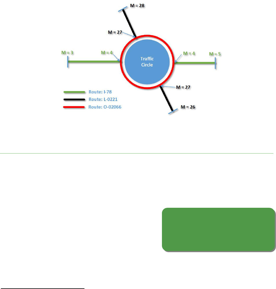
_____________________________________________________________________________________________
All Public Road Geospatial Representation Study ARNOLD Reference Manual
Technical Appendix Page 61 DOT Contract #GS-35F-0001P
September 2014
Define the start and end of the ramp
as the taper from and to the mainline.
Define deceleration and acceleration
sections as LRS events.
Figure B.10: Simple Traffic Circle Configuration48F
57
B.4 37BR A M P S
Ramps can be defined as connecting roadways that permit traffic to flow from one mainline highway to
another without crossing any other traffic stream49F
58
. The interchanges that use ramps may be grade-
separated (i.e., elevated) or at-grade (i.e., same elevation)
50F
59
. At-grade intersections can have a physical
barrier to separate the turn lane from the mainline. Depending on the ramp length, these can be
considered ramps. Ramps are generally not assigned mainline road names or address ranges, and they
typically have a single direction of travel. Defining ramp
start and end locations poses a special challenge to
transportation GIS networks. When building a GIS network,
ramps typically start and end at the point that the ramp
tapers from (or to) the mainline route (see Figure B.11).
57
Michael Baker Jr., Inc., 2014
58
Features such as “jug handles” are also handled as ramps within the network.
59
HPMS only requires that the ramp participates in a grade-separated interchange. However, this discussion of
ramps covers general guidance and best practices for both types of ramps, regardless of HPMS requirements.

_____________________________________________________________________________________________
All Public Road Geospatial Representation Study ARNOLD Reference Manual
Technical Appendix Page 62 DOT Contract #GS-35F-0001P
September 2014
Figure B.11: Ramp Alignment Diagram51F
60
To further clarify the physical sections of a ramp (e.g., if needed for inventory and field work), the
deceleration and acceleration lanes should be defined through LRS events on the roadway. The
deceleration area of the ramp is between the mainline taper and the start of a physical barrier when
entering the ramp. The acceleration area of the ramp is between the end of the physical barrier and the
mainline taper when exiting the ramp. See Figure B.12 for details. The ramp mileage would start and
end at the mainline taper locations.
Figure B.12: LRS Events on the Ramp Segment52F
61
60
Michael Baker Jr., Inc., 2014
61
Michael Baker Jr., Inc., 2014
MAINLINE

_____________________________________________________________________________________________
All Public Road Geospatial Representation Study ARNOLD Reference Manual
Technical Appendix Page 63 DOT Contract #GS-35F-0001P
September 2014
Minimum ramp length
recommendation: 25 feet
These roadway elements often have the
same start/end point, which can be
problematic for LRS. The DOT will need to
establish standards for handling them
consistently in the statewide network, taking
into account any software limitations.
Additionally, it is recommended that DOTs determine a minimum ramp length for modeling ramps
within their roadway network. Without a defined standard on when to create a ramp features (and
when not to), a statewide network can become overly complex, with
many small and relatively insignificant segments. It is recommended
that small connecting ramps of less than 25 feet (excluding
deceleration and acceleration sections) do not need to be modeled in the network. These situations can
instead be modeled as simple intersections.
B.5 38BC UL- DE- S A C S A N D L O O P S
As State DOTs begin to incorporate local road data into their network, they will likely encounter certain
roadway features that do not occur at the State level. Some prime examples of these are Cul-de-sacs
and loops. Cul-de-sacs and loops are generally
described as highway segments where one
continuous arc starts and ends at the same
coordinate (see Figure B.13 for examples). In
terms of LRS, having the same start and end point
can create issues (e.g., with topology, measures,
and mileage calibration) in certain vendor
products. As these features are incorporated into
a statewide all-roads network, the DOT will need to establish standards of handling them to ensure
consistency and data quality. A key aspect of this issue depends on how COTS software products handle
these types of situations, and DOTs should understand the limitations of any particular vendor software
as they develop standards.

_____________________________________________________________________________________________
All Public Road Geospatial Representation Study ARNOLD Reference Manual
Technical Appendix Page 64 DOT Contract #GS-35F-0001P
September 2014
Figure B.13: Cul-de-sacs and Loops53F
62
For certain looped roads (like the one shown in Figure B.13 on the right), the start/end point issue may
be unavoidable. However, cul-de-sacs can be modeled in a number of ways, depending on their nature
and the specific needs of the agency. A cul-de-sac without an island can terminate straight through to
the edge of the pavement, or terminate in the middle of the pavement. Cul-de-sacs with a physical
island may include a “lollipop” end (as is shown in Figure B.13 on the left). While “lollipop” ends may be
the cartographic preference, they are not recommended for use in LRS because self-connecting
segments can cause complications with topology checks, mileage calibration, and physical inventory.
Some DOTs have chosen to draw the “lollipop” for aesthetic purposes, but not connect it to the segment
(i.e., stop the loop 1 foot before it self-intersects). However, this approach can cause issues with
connectivity and network topology, which can inhibit routing and network analysis (see Appendix
Section E.6 for further detail). An alternative to the “lollipop” end is to create a separate loop segment
around the physical island, which will accommodate applications or uses that can’t handle the self-
intersecting segments. If address ranges are being stored, the circle can be made up of two segments,
one for each side (as seen in the lower diagram in Figure B.14). Ultimately, the agency will need to
determine the appropriate representation to match its specific needs, taking into account any software
or application limitations.
The State of Tennessee’s TIPS GIS Modeling Specifications document54F
63
contains some additional useful
guidance about modeling cul-de-sacs. Figure B.14 summarizes its recommendations, and distinguishes
between cul-de-sacs with and without a physical island.
62
VTrans Mapping Unit, 2014
63
TIPS GIS Modeling Specifications, State of Tennessee, Next Generation 9-1-1

_____________________________________________________________________________________________
All Public Road Geospatial Representation Study ARNOLD Reference Manual
Technical Appendix Page 65 DOT Contract #GS-35F-0001P
September 2014
Figure B.14: Cul-de-sac guidance from the State of Tennessee55F
64
64
TIPS GIS Modeling Specifications, State of Tennessee, Next Generation 9-1-1

_____________________________________________________________________________________________
All Public Road Geospatial Representation Study ARNOLD Reference Manual
Technical Appendix Page 66 DOT Contract #GS-35F-0001P
September 2014
A P P E N D I X C 27BR O A D W A Y A T T R I B U T E S
C.1 39BR O U T E E V E N T S V S . S E G M E N T E D A T T R I B U T E S
When developing a roadway GIS network, creating the network data schema (i.e., how attributes are
stored) can be a complex and involved task. One of the most important decisions that must be made
early in the design is whether roadway attributes will be related to the segments as route events, or
stored within the roadway segments. Route events are related to the segments through Linear
Referencing, allowing the flexibility to change extents without changing route segmentation. Segment
attributes are related directly to the GIS centerline segment database record. Figure C.1 depicts the
distinction between roadway events and segment attributes.
Figure C.1: Storing attributes as Roadway Events vs. Segments56F
65
Below is a brief description of each option, and some basic considerations.
Route Events are stored as separate roadway data, referenced to the road segments through Linear
Referencing. Any changes that affect the segment’s LRM would also need to be evaluated and changed
in the route event tables. Route events require additional considerations and necessitate well-
established, defined, and standardized Linear Reference Systems (LRS).
65
Applied Geographics, Inc., 2014

_____________________________________________________________________________________________
All Public Road Geospatial Representation Study ARNOLD Reference Manual
Technical Appendix Page 67 DOT Contract #GS-35F-0001P
September 2014
Local roadway attributes are often stored
within the segments; DOTs should keep
this in mind when integrating local data
into an ARNOLD dataset.
Store a minimum set of “base”
attributes on the segment, and
everything else as route events
within the LRS.
In Segment Attribution, roadway attributes are stored at the segment level of the database model. This
means that changes to these attributes would require additional roadway segmentation, which would in
turn increase the centerline data maintenance. As more attributes are included in the roadway network,
more line-work segmentation and maintenance would be required.
When deciding how to store attributes within a roadway
network, and how many to store, the DOT should choose a
minimum set of “base” attributes to store within the segment,
and then store everything else as route events in the LRS. At a
minimum, the base attributes should include the route ID,
beginning and end mileage, and data source for the segment.
The DOT may also choose to store other key attributes in the segments, such as route number, road
name, facility type, functional classification, ownership, etc. These “base” attributes should be
determined in collaboration with key stakeholders (both inside and outside the DOT, such as emergency
response), and take into account the ARNOLD schema (see next section). However, the goal should be to
minimize the overall number of “base” segment attributes and store the majority of the roadway
information (number of lanes, pavement condition, speed limit, etc.) as events. Automated routines can
then be created to export and publish centerline datasets that meet the needs of non-LRS users, such as
a GIS layer with speed limit information stored within the segments. Storing fewer attributes also results
in less costly data collection and maintenance.
Additionally, as DOTs are collecting much of the ARNOLD data from local agencies, the format of the
local data will need to be taken into consideration. Local transportation centerline data is typically
segment-based and stores attributes directly within the segments. Local streets and roads are, in many
cases, non-continuous and non-contiguous, which makes route-based schemes quite complicated.
Moreover, routes are often concurrent or coincident, adding to the complexity of route-based
approaches. Thus, it is anticipated that most local
attributes will be stored within segments, and the
DOT will need to accommodate this when creating
the ARNOLD dataset. Either way, attributes should be
evaluated to determine whether they are more
suitable for route-event storage or segment storage.
C.2 40BA R N O L D S C H E M A
As discussed in Section C.1, each State DOT likely stores similar information in its roadway dataset,
although in different attribute schemas (i.e., as part of the base, or as route events). This report is not
aimed at standardizing attributes across DOTs. Instead, the goal is to communicate the key, common
attributes needed for the ARNOLD requirements. As such, the following fields are critical for ARNOLD
and will need to be maintained and generated in some manner by the DOT:

_____________________________________________________________________________________________
All Public Road Geospatial Representation Study ARNOLD Reference Manual
Technical Appendix Page 68 DOT Contract #GS-35F-0001P
September 2014
State DOTs should maintain or be able
to generate the key ARNOLD fields to
meet submission requirements.
Define a standardized route
identification convention as the
framework for aligning all DOT and
local agency roadway asset data.
Route_ID – unique road ID number
Road Name
Functional Classification
Ownership
Facility Type
State Code
Year_Record
Source – the entity providing the data
Geometry- Well Known Binary (WKB) using (x,y,m) geometry. This should adhere to the OGC
specification for Simple Features57F
66
. The measures will be stored in Miles (with a recommended
minimum precision is to the nearest thousandth of a mile.)
C.3 41BR O U T E ID N U M B E R I N G
One of the most vital components of an enterprise GIS Roadway Network is a standardized and common
route numbering schema. DOTs should create a common route identification method as the framework
with which all units within a State transportation department (safety, traffic, pavement, etc.) and local
agencies (counties, municipalities, etc.) can align their respective roadway asset data.
Ideally, DOTs will implement a standardized route ID
convention58F
67
that can be utilized by all jurisdictions
(counties, municipalities, etc.) in the State. However, the
DOT will need to understand that local government
agencies (LGAs) are unlikely to adopt State-mandated
standards unless they have had meaningful input. The
benefit for LGAs that choose to adopt such standards is reduced duplicative overlap with other local
roadway names and numbers. Alternatively, the State DOT may want to create unique system IDs to
share with LGAs.
66
FHWA requires that HPMS submissions meet the OGC standard for simple features. See Open Geospatial
Consortium Standards, Simple Feature Access
67
DOTs may also want to consider implementing a multi-modal route ID convention that includes other
transportation methods (such as Rail and Waterways). Multi-modal data is an important consideration for the
future but outside the scope of this Study.

_____________________________________________________________________________________________
All Public Road Geospatial Representation Study ARNOLD Reference Manual
Technical Appendix Page 69 DOT Contract #GS-35F-0001P
September 2014
All roadways should include at least one
standardized name. Roadway naming
should also include roadway aliases,
historical names, honorary names, etc.
Modern best practices in database
management are to use IDs such as
GUIDs (Globally Unique Identifiers).
Traditionally, a route ID convention might include information
about the route type, county, municipality, route number, and
directionality. However, modern best practices in database
management are to use identifiers such as GUIDs (Globally
Unique Identifiers) rather than IDs comprising descriptive information. Regardless of the ID system
chosen, field values should be kept to a reasonable length (e.g., less than 30 characters).
C.4 42BR O A D N A M I N G
The roadway name is a core attribute for roadway systems. Excluding ramps, all roadways should
include at least one standardized name. Roadway
naming should also include roadway aliases,
historical names, and honorary names (if applicable),
ideally following a national standard (such as the
FGDC standard59F
68
). This level of detail is required for
proper geo-locating for addressing and emergency
services. In addition, route shielding (e.g., I-95) and coincidence (e.g., Route 1 & 9) should also be
accommodated for higher functional class roadways. In many cases, roadway names will not align with
route designations (or with each other). These situations typically arise from legacy route definitions
associated with older State and county route alignments. As shown in Figure C.2, County Route 612
covers multiple road names. Since road names may differ from the route designation, they should not
be part of the route definition as a rule, although they may be used as a surrogate when there is no
other route designation.
68
The Federal Geographic Data Committee (FGDC) standard is one example of an address standard. (See FGDC
project standards.) The National Emergency Number Association (NENA) also has a GIS Data Collection and
Maintenance standard with useful information relevant to emergency response data, including addresses and road
names. (See NENA GIS Collection & Maintenance.)

_____________________________________________________________________________________________
All Public Road Geospatial Representation Study ARNOLD Reference Manual
Technical Appendix Page 70 DOT Contract #GS-35F-0001P
September 2014
Figure C.2: Route Name Changes Diagram60F
69
For segmented roadway networks that are broken at physical or geometric intersections, road names
can be stored as attributes of the segments (although a separate database table with a one-to-many
relationship could be utilized to accommodate multiple names). For route-based networks, names
should be stored as a linear-referenced event.
The LRS database developer needs to be aware of several situations regarding multiple route names
associated with the same route segment.
1. Route aliases occur when two or more names are used for the same route segment in the same
route system). Route aliases are the simplest case of multiple names. In many cases, aliases are
not posted but are still recognized and used by travelers, local governments, or the U.S. Postal
Service.
2. Route concurrencies occur when two or more routes in the same route system share the same
road segment, as seen in Figure C.3.
69
Michael Baker Jr., Inc., 2014

_____________________________________________________________________________________________
All Public Road Geospatial Representation Study ARNOLD Reference Manual
Technical Appendix Page 71 DOT Contract #GS-35F-0001P
September 2014
Figure C.3: Route Concurrency61F
70
3. Route coincidence occurs when two or more routes from different route systems share the
same route segment:
Figure C.4: Route Coincidence62F
71
70
Photo from AAROADS Interstate Guide website
71
Photo from The New I-26 Virtual Tour Tennessee and North Carolina

_____________________________________________________________________________________________
All Public Road Geospatial Representation Study ARNOLD Reference Manual
Technical Appendix Page 72 DOT Contract #GS-35F-0001P
September 2014
The GIS network should have the
capability to support multiple
LRMs, while standardizing on a
single LRM as the preferred
measure (such as driven mileage).
C.5 43BM U L T I P L E L I N E A R R O U T E M E A S U R E S
As isolated data systems begin to adopt a standardized roadway network, they do not all follow the
same standards for route measures (see Figure C.5). For example, it is common for HPMS supporting
systems to use driven mileage measures63F
72
through a physical Distance Measuring Instrument (DMI),
while accident records and State police use mile-markers or intersection offsets.
Figure C.5: Multiple Linear Route Measures 64F
73
Forcing a standard convention for all dependent systems and
business functions can be counterproductive in fostering
widespread adoption. Alternatively, multi-linear route
measures should be allowable and be utilized to solve the
needs of multiple dependent systems, while encouraging a
single LRM as the preferred, standardized measure. To
support field data collection efforts, it is recommended that
driven mileage be used as the standardized measure.
Supporting multi-linear route measures requires calibration points or segments for each linear route
measure, as well as functionality to translate between reference systems (e.g., conversion of a driven
mile reference to a mile marker reference). Several types of transportation GIS software will
automatically support the management and dissemination of data on multi-linear route measures
(Intergraph GeoMedia, Esri Roads & Highways, etc.).
72
In modern LRS, an as-driven system is a necessity.
73
Michael Baker Jr., Inc., 2014

_____________________________________________________________________________________________
All Public Road Geospatial Representation Study ARNOLD Reference Manual
Technical Appendix Page 73 DOT Contract #GS-35F-0001P
September 2014
Figure C.6: LRM Transformation65F
74
As illustrated in Figure C.6, the location of an event can be described using multiple LRM types with no
loss of positional accuracy. A common example occurs when transferring roadway data from
construction files indexed by stationing (e.g., format STA XX+yy.yyy’) to a GIS-based asset inventory
database indexed by a statewide LRM such as Route Milepoint. The common linear element is the new
alignment, and the common reference object is usually the project terminus, generally located at a road
intersection, administrative boundary, or other geographic feature. The transformation aligns the
00+00.00 station with the corresponding route milepoint value and uses simple arithmetic to calculate
the station-to-milepoint conversion of each roadway object of interest.
C.6 44BP U B L I C V S . P R I V A T E R O A D W A Y S
Statewide roadway networks do not typically include private roadways; thus, State DOTs have not had
to manage or track private roadway data. But as the GIS network expands to include all local roads,
State DOTs will need to begin to manage the distinction66F
75
between public and private roads and store
this information in the roadway network. Although private roads are not required in the HPMS
submission67F
76
, Emergency Response is a key driver for including private roads in the network. Therefore,
74
Dave Fletcher, 2014
75
This distinction expands beyond simply public vs. private road, and can also include other non-public roads such
as military roads, Bureau of Land Management (BLM) roads, Forest Service roads, etc.
76
HPMS requires that the road geometry submitted correspond to the State-certified mileage, which is signed by
the Governor. In other words, if a State decides to include private roads in its certified mileage number, then the

_____________________________________________________________________________________________
All Public Road Geospatial Representation Study ARNOLD Reference Manual
Technical Appendix Page 74 DOT Contract #GS-35F-0001P
September 2014
Although HPMS only requires the
roads that correspond to certified
road mileage, State DOTs may include
private roads in their network to
support emergency response and
safety considerations.
For maximum data evaluation
capability, capture and
manage both the construction
date and inventory dates.
private roads should be properly attributed so that they can be removed from the HPMS submission, if
applicable. That said, if a State wants to submit private roads in its HPMS submission, they may be
accepted by FHWA.
The distinction between public and private roads is
typically defined at the local level, based on who is
responsible for maintenance and record keeping. For
example, a town/city/county-maintained road would
be “public,” while a road maintained by a
homeowners association within a gated community
would be “private.” Making this distinction between
public and private can be very difficult, particularly if
the only source is orthophotography. It is critical that this information come from an authoritative
source (e.g., the local jurisdiction).
C.7 45BI N S T A L L D A T E A N D I N S P E C T I O N D A T E
Implementing the ability to analyze transportation data over time (i.e., temporality) starts with the
inclusion of effective dates. However, an effective date can be more complex than a simple, single date.
The most obvious date to capture would be the installation or
creation date for the roadway. In reality, this information may not
be available to the group maintaining the GIS datasets. As such, it
may be more realistic to capture the inspection or field inventory
date of the roadway.
Installation date (or “Open for Traffic” date) is the date
that construction on the new or realigned roadway section
was completed.
Inspection or Inventory date is the date that the roadway
was inventoried or inspected to collect the newly
constructed alignment and attribution.
roads should be included in the HPMS geometry. If a State wants to include a private road in its submittal, the
facility type must be > 4.

_____________________________________________________________________________________________
All Public Road Geospatial Representation Study ARNOLD Reference Manual
Technical Appendix Page 75 DOT Contract #GS-35F-0001P
September 2014
C.8 46BA D D R E S S I N G
While addressing is not typically a mainstream DOT business function and is not required for HPMS
reporting, it is very practical and rational to include addresses with roads, when feasible. There are two
main methods of storing address information:
Address Range: Address locations are estimated by proportional relative distances determined
by the lowest address on the block (i.e., the “from address” attribute on the segment) to the
highest address on the block (i.e., the “to address” attribute on the segment). For example, if
the address range on one block of Main Street runs from 100 to 200, then the address of 150
Main Street would be located 50 percent of the distance along the street segment.
Figure C.7: Address Range LRM68F
77
Address Points: In this method, address information is stored as distinct locations, represented
by a point feature stored at or near the physical address (building centroid, driveway entrance,
property centroid, etc.), or as an LRS event.
Figure C.8: Address Points LRM69F
78
77
Applied Geographics, Inc., 2014
78
Applied Geographics, Inc., 2014

_____________________________________________________________________________________________
All Public Road Geospatial Representation Study ARNOLD Reference Manual
Technical Appendix Page 76 DOT Contract #GS-35F-0001P
September 2014
For emergency response purposes,
discrete address point locations linked
to the LRS are preferable to give first
responders an exact location.
Coordination between DOT and local
E911 agencies is critical in ensuring
that emergency responders have
access to accurate data.
Either method is workable, but the following issues should be considered:
For emergency response purposes, address point locations are preferable to give first
responders an exact location70F
79
, rather than an
approximated location based on the distance
along the segment. Particularly in rural areas,
approximated location based on address
ranges can be very far off from the exact
address due to long stretches of roadway and
irregular addresses. Whether using address ranges or points, field verification of house numbers
is strongly recommended for address-matching and geocoding applications.
When address points are used, the location of the placement of these points may vary,
depending on local needs and standards. This can cause data conflation issues, depending on
where the point is placed (e.g., at the centroid of the parcel, centroid of the structure, front
door of the structure, the end of the driveway all examples used by different localities for
placing address points).
If using an intersection-based network, implementing address ranges is possible as the segments
are broken at actual intersections.
If using a route-based network, it is recommended that address point locations be used;
implementing accurate address ranges along the entire length of a route segment would be very
difficult without segmentation to accommodate the assignment of address ranges.
Although address management is typically not a core DOT
function, it is needed for tracking crash and safety
information, as well for as several uses outside of the DOT
(e.g., emergency response). Address ownership and
origination are often outside of the DOT and usually at the
local (e.g., city or county) E911 agency. Thus, it is important
for the DOT and local E911 agencies to coordinate to ensure the most accurate data is available to
emergency first responders.
79
The National Emergency Number Association (NENA) has a GIS Data Collection and Maintenance standard with
useful information relevant to emergency response data, including addresses and road names. (NENA GIS Data
Collection)

_____________________________________________________________________________________________
All Public Road Geospatial Representation Study ARNOLD Reference Manual
Technical Appendix Page 77 DOT Contract #GS-35F-0001P
September 2014
All published or distributed
datasets should include
standardized metadata, ideally at
both the layer level and the object
level, but at least at the dataset
level.
Metadata should be embedded within
the GIS layer whenever possible. At a
minimum, complete the ISO metadata
sections containing Identification and
Metadata Reference.
A P P E N D I X D 28BM A I N T E N A N C E
D.1 47BM E T A D A T A S T A N D A R D S F O R G I S A N D R O A D W A Y A S S E T D A T A
A statewide GIS roadway network and associated data are typically distributed to stakeholders, both
internally to State agencies and externally to the public; therefore, having consistent and well-defined
metadata (i.e., information that describes the dataset and
dataset attributes) for all production data layers is critical
to data usability and widespread adoption. While metadata
creation is emphasized for GIS data layers, it is important to
include some form of metadata with any published
datasets, whether or not they are geospatial. End users
need the ability to reference important data facts, such as
data accuracy, collection methodologies, and data owners.
Data aggregators also need to know about such information.
Ideally, metadata is maintained at both the layer level and at the object level (i.e., for each geometric
object within the dataset). At a minimum, metadata is needed at the dataset level, which might contain
multiple data layers or themes. Whenever possible, the metadata should adhere to existing standards,
such as the Federal Geographic Data Committee (FGDC) Content Standard for Digital Geospatial
Metadata, or the Dublin Core Metadata Element Set71F
80
. States may want to work with their GIS data
clearinghouse on metadata standards as well. The metadata should be built into the GIS data layer,
without the need for additional data files. Additionally, the ability to export metadata information into a
report format is useful in communicating this information when sharing data, and for meeting HPMS
metadata reporting requirements.
It is recommended that all published data follow
International Organization for Standardization (ISO)
metadata standards, which should be embedded within
datasets using standard GIS software. The ISO metadata
sections containing Identification and Metadata
Reference elements are suggested to be included at a
minimum for all centerline data layers.
80
GIS metadata standardization is supported by the FGDC and International Organization for Standardization (ISO).
FGDC-endorsed ISO metadata standards can be found at: FGDC Geospatial Metadata Standards. The Dublin Core
Metadata Element Set can be found at: Dublin Core Metadata Element Set, Version 1.1.

_____________________________________________________________________________________________
All Public Road Geospatial Representation Study ARNOLD Reference Manual
Technical Appendix Page 78 DOT Contract #GS-35F-0001P
September 2014
Include planned, unbuilt
facilities as well as
abandoned or destroyed
roadways in the dataset.
To document published data where embedding metadata within the dataset is not available (e.g., Excel
files, text files), define and mandate metadata standards.
D.2 48BP L A N N E D , D E S T R O Y E D A N D D E C O M M I S S I O N E D R O A D W A Y S
When building and maintaining a roadway GIS network, it is
natural to consider only existing facilities and roadways. But in
many cases, it is important to be able to manage and reference
unbuilt, planned roadways (sometimes called “paper streets”), as
well as alignments that have been abandoned or destroyed.
Doing this allows DOTs to track and manage infrastructure and
assets throughout the entire roadway data lifecycle (see Figure D.1).
Figure D.1: Roadway Lifecycle Diagram
81
It is recommended that State agencies include planned, unbuilt facilities in their networks, assigning
route identifiers and approximate mileage. Likewise, abandoned or destroyed roadways should be
properly archived. These features should either be designated as such, or kept in a separate database, to
minimize confusion.
81
Applied Geographics, Inc., 2014

_____________________________________________________________________________________________
All Public Road Geospatial Representation Study ARNOLD Reference Manual
Technical Appendix Page 79 DOT Contract #GS-35F-0001P
September 2014
Always geoarchive data
when significant updates
and changes occur.
D.3 49BG E O A R C H I V I N G R O A D W A Y S E G M E N T S
Archiving the road geometry and associated LRS (e.g., a weekly, monthly, quarterly, or annual snapshot
of the data) is a process known as “geoarchiving.” The lower the amount of data that is included in the
LRS, the easier it is to store snapshots; with more data, different updates might be more appropriate.
For incorporating temporal functionality (i.e., the ability to do
time-based analysis) into a GIS network, it becomes important to
archive data when significant72F
82
changes occur to the system.
Geoarchiving allows stakeholders and supporting systems to track
changes, details on the changes, and potential impacts to other
data. Geoarchiving is also an important consideration for compliance with record retention rules and
regulations. Further, because most changes happen at the local level, proper geoarchiving procedures
will become even more critical as State DOTs begin incorporating local data.
The recommended means to perform geoarchiving is to have a separate archive data structure
reflecting the road geometry table(s). For geoarchiving, a new data column (ex. ARCHIVE_YEAR) should
be added to the archive table to track the archive date. See Figure D.2 for an example.
Figure D.2: Geoarchiving data structure73F
83
82
In this context, the term significant can be defined as changes that can impact dependent systems directly. For
example, a change to an attribute that only affects labeling may not be deemed significant. The meaning of this
term needs to be clearly defined and communicated to stakeholders.
83
Michael Baker Jr., Inc., 2014

_____________________________________________________________________________________________
All Public Road Geospatial Representation Study ARNOLD Reference Manual
Technical Appendix Page 80 DOT Contract #GS-35F-0001P
September 2014
Make data readily available to all
users via web services, and
develop a consistent change
communication mechanism.
Define a data retention policy
to dictate how long archived
data should be kept.
Data should be copied from the main production road geometry table to the archive table in its entirety
on a scheduled basis. Additionally, a data retention policy will need to be defined, which dictates when
data should be removed from the archive table. To group
changes together, an additional table can be linked to show a
logical data transaction. This structure includes the inherit ability
to “roll back” a grouped transaction if there was a problem with
the update.
D.4 50BR O A D W A Y D A T A D I S T R I B U T I O N A N D C H A N G E C O M M U N I C A T I O N
As external systems gain dependence on an enterprise GIS Roadway dataset, the distribution and
communication of data with dependent stakeholders becomes vital to a system’s success. As data
changes occur within the roadway network, these changes need to be communicated so that
dependencies can be reviewed and changed accordingly. This communication should include the
updated GIS dataset, as well as a change log that describes all
the changes that have been made to the network. Additionally,
dependent stakeholders need a means to communicate change
requests to the GIS roadway network, to maintain data
alignment between the systems.
The drivers and solutions of the three key components of data distribution and change communication
are further described below:
Data Publishing:
o Driver:
Dependent systems and users should have a way to directly connect to the most current
published version of the GIS network. It should be in a known, fixed location, easily
accessible to all users.
o Solutions:
Utilize a feature service or map service (i.e., a specialized web service) to distribute the GIS
network to end users.
Additionally, the agency may choose to distribute the network through a downloadable
geospatial data format. This would allow for off-line data use; however, it would put the
responsibility on the user to get the “most recent” version as needed. It is advisable that this
file format should not be vendor dependent but allow users to view the data using a variety
of different GIS tools.
_____________________________________________________________________________________________
All Public Road Geospatial Representation Study ARNOLD Reference Manual
Technical Appendix Page 81 DOT Contract #GS-35F-0001P
September 2014
Change Log:
o Driver:
Stakeholders need a way to review a descriptive change log detailing the date and reasons
for roadway changes. This allows users to understand roadway changes and determine how
the changes affect their particular business needs. For example, a roadway realignment may
require additional field inspection of asset installations, pavement conditions, and roadway
attribution. In contrast, the addition of a simple traffic signal to augment a non-signalized
intersection may not require a full field inspection.
o Solution:
A change log and complete metadata should be linked to the map service so that users can
view a detailed description of each change.
Change Requests:
o Driver:
Users should have a means to communicate change requests to the GIS network.
o Solution:
This can be accomplished through a variety of means. For example a “red-lining” map
interface would allow users to identify the area of change, mark a spatial location, and
provide details on the requested change to the GIS maintenance group.

_____________________________________________________________________________________________
All Public Road Geospatial Representation Study ARNOLD Reference Manual
Technical Appendix Page 82 DOT Contract #GS-35F-0001P
September 2014
A P P E N D I X E 29BC R E A T I N G A N I N T E G R A T E D A L L - R O A D S N E T W O RK
When creating an integrated all-roads network, whether at the State or national level, many of the same
processes will need to be completed in order to ensure data alignment and network continuity. This
integration of geospatial data is known as conflation. Conflation is the process used to reconcile datasets
from multiple sources, optimizing their quality and usability. For road data, the likely sources and
partners are described in Report 2 of this Study, on data collection.
Figure E.1 provides an overview of the entire process of integrating road data. The process is described
in detail in Sections E.1 through E.7.
Figure E.1. Overview of Roadway Data Integration74F
84
Once data is collected, conflation involves the unification of multiple datasets into a single dataset with
combined spatial features and attributes. The datasets may have common and uncommon features and
attributes, which require evaluation and reconciliation. There are decisions to be made about feature
matching (i.e., identifying corresponding features); feature additions and deletions (i.e., deciding what
to include or not include, such as removing obvious duplicates); spatial adjustments (i.e.,
rubbersheeting, adjusting gaps and overshoots); and attribute transfer (i.e., combining non-spatial
84
Applied Geographics, Inc., 2014

_____________________________________________________________________________________________
All Public Road Geospatial Representation Study ARNOLD Reference Manual
Technical Appendix Page 83 DOT Contract #GS-35F-0001P
September 2014
Create a data inventory,
including metadata, for all
data sources to be integrated.
descriptive data). The process is a combination of automated and manual steps for transforming and
aligning features and includes evaluating and validating changes and adjustments, which are based on
business rules about what is allowed. The following sections address the key issues and steps for
performing conflation and achieving data integration, which are also laid out in Figure E.2.
Figure E.2: Steps and Interim Outputs in Data Conflation and Integration Process75F
85
E.1 51BD A T A C O L L E C T I O N & C A T A L O G I N G
Different sources may have different map projections, levels of completeness,
currentness, and consistency. A cataloging or data inventory step to document the
contents of the datasets, including metadata generation, is important when
conflating data from different sources. The source data may be stored as
transactional data in a schema optimized for
performance during data collection operations
(e.g., insert, update, delete), but not necessarily
optimized for queries. These datasets are typically
part of an On-Line Transaction Processing (OLTP)
environment. Part of the cataloging step is to document the data schema as well as the actual populated
contents of the source datasets. This becomes useful in optimizing any aggregated datasets to support
indexing and a faster query response, which is typical of On-Line Analytical Processing (OLAP)
environments, such as data warehouses.
85
Applied Geographics, Inc., 2014
E.1
E.2
E.3
E.4
E.5
E.6
E.7
LRS & Routing

_____________________________________________________________________________________________
All Public Road Geospatial Representation Study ARNOLD Reference Manual
Technical Appendix Page 84 DOT Contract #GS-35F-0001P
September 2014
To streamline data loading and
conflation, create a staging dataset
that contains the pertinent subset of
features from each source dataset.
It is also important during data cataloging to understand and document any known issues or limitations
with certain datasets. The inventory and metadata that result from this step will inform the rest of the
processes described below.
E.2 52BD A T A E X T R A C T I O N F R O M I N P U T S O U R C E S
As described in task 2 of this report, source data can come from a wide variety of
agencies including:
Local Government (e.g., city, town, county)
Regional Entity (e.g., Regional Planning Agency (RPA) or Metropolitan Planning
Organization (MPO)
State GIS Clearinghouse
U.S. Census Bureau (TIGER Fdata)
Federal Agency (e.g., BIA, BLM, USFS, NPS, etc.77F
86
)
Commercial Data Provider (e.g., HERE, TomTom, Google)
Volunteered Geographic Information (e.g., Open Street Map (OSM))
These datasets will all be in varied formats and locations,
and they may contain extraneous data and geospatial layers
that are not pertinent to the integration project. Thus, it is
recommended that a “staging” dataset be created for each
source dataset that contains only the pertinent features to
be conflated. For example, if the data extends beyond the
geographic extent of a State (e.g., TIGER, OSM), it is recommended that the staging dataset be a subset
of only the features in the pertinent geographic extent. Or, if the plan is to conflate local roads from the
local government data with county roads from county data and State roads from the DOT, each staging
dataset might contain only the subset of features that will ultimately be integrated.
86
BIA = Bureau of Indian Affairs; BLM = Bureau of Land Management; USFS = United States Forest Service; NPS =
National Park Service.

_____________________________________________________________________________________________
All Public Road Geospatial Representation Study ARNOLD Reference Manual
Technical Appendix Page 85 DOT Contract #GS-35F-0001P
September 2014
Data should be evaluated for
consistency and quality using a
combination of automated and
manual procedures.
E.3 53BD A T A P R O F I L I N G
A data profiling step is recommended to evaluate the quality of each dataset, in advance
of data transformation and other pre-processing
steps. Incoming datasets may not be correct,
consistent, or complete. They should be reviewed
and evaluated using a combination of automated
and interactive procedures.
The following is a sample list of typical items to check for during profiling:
Database values
Dummy default values, such as 99999 for a zip code
Missing values, such as no projection parameters
Contradicting data values, such as when the road construction date is before the project
plan date
Violation of business rules
Multi-purpose fields, such as when the same field is used to store information with different
meanings
Cryptic data, such as when ad hoc abbreviations or truncated road names are used
Inappropriate use of an address line, such as splitting addresses across multiple lines
Reused primary keys, such as when an old road and a new road in different places have the
same key
No unique identifiers, such as when the same road element has several primary keys
Interoperability flaws, such as when data is inadvertently related but should not be
E.4 54BD A T A T R A N S F O R M A T I O N A N D L O A D I N G
All datasets are not the same. Loading data into the data integrator’s review and edit
environment very often requires transformation. For example, if datasets from local
sources are in a different projection than the State DOT data, a common projection
needs to be chosen, and the data re-projected as needed. Depending on a State DOT’s
workflow procedures and tools, data transformation may be automated as part of the
extraction process from the source. Also, depending on the technology being used, this
can be an intermediate staging database for performing the edge-matching of
features. Edge-matching is explained in a subsequent section.

_____________________________________________________________________________________________
All Public Road Geospatial Representation Study ARNOLD Reference Manual
Technical Appendix Page 86 DOT Contract #GS-35F-0001P
September 2014
When loading source data, only minor
changes should be made (e.g., re-projecting
data, fixing obvious errors). Ideally, the
source data owner would take responsibility
for needed data maintenance.
Match points should be established
to allow edge-matching between
neighboring or overlapping
transportation agencies.
Match points are not indicative of jurisdictional
boundaries or asset management and
maintenance responsibilities. They merely help to
delineate GIS data management responsibilities.
A data cleansing step may also be needed, in accordance with business rules, to assure the integrity of
the data. Such data cleansing may include de-duplication, for example, whereby common features and
attributes that are obvious duplicates are removed. Generally, only obvious discrepancies should be
changed during data cleansing, to assure fidelity
to the source data. Ideally, the supplier of the
data should make the changes, assuming that they
are also the party responsible for data
maintenance. Any changes made by someone
other than the data-provider should be tracked in
a change layer or change report for auditing
purposes.
E.5 55BE D G E - M A T C H I N G A N D M A T C H P O I N T S
Making sure that all road segments are properly edge-matched is a key step
in creating an integrated network. Many DOTs have already edge-matched
most major roadways, but this data enhancement needs to be extended to
local roads as part of the ARNOLD all-roads integration effort, to densify the
road network.
Match points (also known as
integration points, touch points,
demarcation points, smart points,
agreement points, snap-to points,
join points, etc.) are point locations
established within the GIS to mark the connection point
between two (or more) geospatial datasets. These points allow datasets to be seamlessly joined
together without any overlap or gaps (which is essential to proper topology, as described in Section E.6).
In terms of a nationwide ARNOLD, establishing these points between States will be critical in facilitating
the edge-matching of data between neighboring States, and ultimately stitching together a nationwide
roadway dataset.
It is important to note that in this context,
match points are not necessarily indicative of
actual jurisdictional boundaries or asset
management and maintenance responsibilities.
They merely help to delineate where the GIS
data management responsibilities start and stop for a particular agency. The essential idea is to locate
such points at unambiguous, verifiable locations that bordering jurisdictions can agree upon. The

_____________________________________________________________________________________________
All Public Road Geospatial Representation Study ARNOLD Reference Manual
Technical Appendix Page 87 DOT Contract #GS-35F-0001P
September 2014
agreement can be between the GIS data managers for the adjacent jurisdictions, and ideally would be
endorsed by their respective senior executives.
If match points to facilitate data integration have been agreed upon at the State or local levels, they
should be used. If they do not exist, then a set of recommended points should be presented to the
affected jurisdictions for negotiation and agreement. Feedback and adjustments should be allowed for,
and the points should be incorporated into an agreed-upon Statewide Match Point Layer.
Jurisdictions that have agreed upon match points should be identified during all-roads data collection.
Where they don’t exist, the State DOT can create these points based on evident criteria, and provide
them to Local Government Agencies (LGAs) for review; the LGAs should be given a reasonable amount
of time to review and to provide feedback to the DOT. Most DOTs do not have the resources to mediate
disputes between counties or cities, so the local jurisdictions will need to work this out between
themselves. If the LGAs cannot reach agreement, then the State DOT match points should be used.78F
87
While the FHWA has a business rule not to make spatial adjustments to the data received from State
DOTs, there are cases where DOTs make spatial adjustments within their State when combining datasets
from different sources. Such adjustments can be based on proximity, topology, and continuity analyses
and rules, as well as attribute comparisons. One method, commonly referred to as rubbersheeting,
adjusts input features to a target, based on rules. Another method involves the automatic correction of
gaps and overshoots, based on agreed-upon geometric tolerances. This method may be combined with
queued edit scenarios, where gaps and overshoots are presented to a human operator for a decision on
whether to make a change. Types of change in this context include: spatial change; attribute change;
spatial and attribute change; no change; new update features; and delete feature.
87
See: “State of Colorado Unified Road Layer Assessment,” September 30, 2012, p. 46.

_____________________________________________________________________________________________
All Public Road Geospatial Representation Study ARNOLD Reference Manual
Technical Appendix Page 88 DOT Contract #GS-35F-0001P
September 2014
Figure E.3: Edge Matching Scenarios79F
88
A number of States and jurisdictions (Arizona, the District of Columbia, Maryland, Washington, and
others) are working on using match points to help streamline data integration from multiple sources
(State, county, local, tribal, etc.).
Based on the One Maryland One Centerline initiative80F
89
, the following list provides an overview of the
Integration Points Workflow81F
90
:
Determine the road centerline segment recognized to be the authoritative source for the given
length of road (e.g., State, county, local)
Create initial integration points at any intersection of road centerline where the data provider
attribute changes
Intersect with a bridge polygon layer to identify and remove integration points where roads are
not intersecting
Provide integration points to local jurisdictions for review, comment and acceptance
State and locals edit their respective centerline data to coincide at integration points
88
See: ArcGIS Resources: About Edgematching
89
The Maryland State Highway Administration (SHA) is responsible for maintaining a statewide road centerline
dataset containing linear referencing route and measure information and an inventory of roadway characteristics.
More information can be found at Maryland iMAP.
90
From the One Maryland One Centerline initiative presentation at GIS-T 2014 by Erin Lesh and Marshall
Stevenson, Maryland SHA.

_____________________________________________________________________________________________
All Public Road Geospatial Representation Study ARNOLD Reference Manual
Technical Appendix Page 89 DOT Contract #GS-35F-0001P
September 2014
Topology rules and OGC standards should be
applied to and enforced within the roadway
network in order to ensure data quality and
stability, as well as to support routing and
network analysis.
Regardless of the datasets being joined (i.e., those of neighboring States or local and State data), the
same basic workflow can be applied.
E.6 56BLRS A N D N E T W O R K T O P O L O G Y
This step is where important decisions need to be made regarding whether the ARNOLD
baseline layer will support routing (path) topologies for routing and navigational
purposes (e.g., emergency management and traffic modeling) as well as traditional LRS.
To support the decision-making process, this section provides a discussion of topology.
Transportation systems have structure and flow that are commonly represented
graphically as a network. Geometrically, a network comprises an arrangement of nodes
(a.k.a. vertices or points) and links (a.k.a. edges or lines) between the nodes, which
typically represent roads (but also railways, waterways, flight paths, bicycle trails, pedestrian walkways,
etc.). A sequence of links that are traveled in the same direction is a path, which is a fundamental
attribute for measuring traffic flows and finding navigational routes.
The structural arrangement and connectivity of a network represent its topology. Topology is sometimes
referred to as “coordinate-free geometry,” since a topological network can be stretched as if it were a
rubber sheet without changing the “from/to” and “left/right” relationships of the nodes and links. More
appropriately, it should be described as the study of those geometric concepts that can be defined
independent of any coordinate system. Nonetheless, in a transportation context, location, direction, and
connectivity are all important.
Topology rules define key spatial relationships
between corresponding datasets. Examples of
topology rules include:
Prohibiting disconnected segments
Disallowing segments missing associated
measures
Not allowing segments to overlap
Not allowing segments to have gaps
The roadway network should allow for the creation and enforcement of topology rules, and should
follow the Open Geospatial Consortium (OGC) Standard for Simple Features82F
91
. Violations of topology
91
FHWA requires that HPMS submissions meet the OGC standard for simple features (See Open Geospatial
Consortium Standards, Simple Feature Access).

_____________________________________________________________________________________________
All Public Road Geospatial Representation Study ARNOLD Reference Manual
Technical Appendix Page 90 DOT Contract #GS-35F-0001P
September 2014
Routing and navigation applications
typically require a node at every
legitimate intersection in order to model
items such as vehicle turn restrictions
and directionality, and for geocoding.
rules are stored as errors, but exceptions can be marked accordingly. Network topology can be encoded
and its properties measured using graph theory, which is incorporated at a fundamental level in most
GIS products. Network analysis based on graph theory is commonly supported in GIS data models. LRS
are an extension to GIS, adding dynamic segmentation and allowing State DOTs to measure the location
of features and events on the road network, thus handling linear measurements along a road segment.
In this GIS-T case, the node geometry of a road network might be dissolved along logically continuous
routes. Conversely, in a non-GIS-T case, the road network might be subdivided into a multitude of
segments for graphic purposes to support cartographic representation, or geocoding. These approaches,
while valid for their own purposes, can adversely impact the topology needed for traffic flow and
routing applications. In other words, a dataset that is optimized for linear measurements, or
cartographic representation, or geocoding, is less than optimal for traffic flow modeling and routing.
Topology, particularly for connectivity, forms the basis for network analysis and routing. A routable
network is key to many GIS applications, such as fleet
management, drive-time analysis, and most notably
emergency response. Routing allows first responders to
determine the quickest route from their location to the
dispatch destination. Typically, routing applications
require a node at every legitimate intersection where a
turn can be made, which may differ from the data
structure of the LRS. For example, to achieve processing efficiencies for non-routing applications, State
DOTs have traditionally dissolved segmented networks into non-segmented networks, to reduce the
number of nodes and to define numbered routes with the minimum number of essential segments.
However, for routing purposes, nodes and related intersections are very important for modeling vehicle
restrictions (turns, heights, weights, speeds, direction, stop signs, traffic signals, congestion,
construction, detours, etc.); and for geocoding purposes for matching addresses with a location along a
street.
Routing applications require a network topology in which the relationships of each node and link with
other nodes and links are modeled in terms of constraints and possibilities. Fundamentally, two tables
are required to geospatially represent a network data model: 1) a node table, including unique IDs and X
and Y coordinates for each node; and 2) a link table, also with unique IDs, as well as the “from” node
(the origin or starting point), and the “to” node (the destination or ending point). When these tables are
relationally linked, the topological structure of the network can be built, and network analysis based on
graph theory can be applied.83F
92
92
Rodrigue, Comtois, and Slack. The Geography of Transportation Systems. Taylor & Francis Group: New York,
2009, pp. 76-77.

_____________________________________________________________________________________________
All Public Road Geospatial Representation Study ARNOLD Reference Manual
Technical Appendix Page 91 DOT Contract #GS-35F-0001P
September 2014
The network should be built to meet
the needs of routing, and then be
processed to support LRS needs.
E.7 57BO U T P U T D A T A S E T S
To create a road network that supports both routing and linear referencing use cases,
as described in Section 2.1, the network should combine roadway geometry with
network topology in order to meet the needs of routing and navigation, and then be
processed to “thin” the data to suffice for
the needs of LRS. If the network is built
only to support LRS (without topology), it
will be inadequate for routing. The goal
to “build once, use many times” can be achieved through this approach: the base
geometry and topology support multiple business needs.
Node and segment geometry is needed for the creation and maintenance (e.g., adding new routes or
new alignments) of a roadway network. As shown in the diagram below, this geometry, along with its
network topology, can be combined with turn and flow restrictions and address points to satisfy routing
use cases84F
93
. Similarly, the roadway geometry and network topology can be used to create LRS routes.
These routes, combined with point and line events, can satisfy linear referencing use cases. Frequently,
DOTs are focused on the LRS portion of the diagram (i.e., the bottom output), but through collaboration,
both use cases can be met.
93
There are different levels of complexity when it comes to routing and navigation. There are general/casual uses
for everyday navigation (e.g., generating directions given “from” and “to” locations), and more complex routing
scenarios, such as routing for heavy load purposes. The network should be designed to handle the full spectrum of
routing and navigation use cases.

_____________________________________________________________________________________________
All Public Road Geospatial Representation Study ARNOLD Reference Manual
Technical Appendix Page 92 DOT Contract #GS-35F-0001P
September 2014
Figure E.4: Routing and LRS Output Datasets85F
94
94
Applied Geographics, Inc., 2014

_____________________________________________________________________________________________
All Public Road Geospatial Representation Study ARNOLD Reference Manual
Technical Appendix Page 93 DOT Contract #GS-35F-0001P
September 2014
L I S T O F A C R O N Y M S
AADT – Annual Average Daily Traffic
AASHTO – American Association of State Highway and Transportation Officials
API – Application Programming Interface
ARNOLD – All Road Network of Linear Referenced Data
BIA – Bureau of Indian Affairs
BLM – Bureau of Land Management
CAD – Computer-aided design
COTS – Commercial-off-the-shelf
DOT – Department of Transportation
ETL – Extract, Transform and Load
FGDC – Federal Geographic Data Committee
FHWA – Federal Highway Administration
FMIS – Fiscal Management Information System
GIO – Geographic Information Officer
GIS – Geographic Information System
GIS-T – Geographic Information Systems for Transportation
GPS – Global Positioning System
HPMS – Highway Performance Monitoring System
ISO – International Organization for Standardization
LGA – Local Government Agency
_____________________________________________________________________________________________
All Public Road Geospatial Representation Study ARNOLD Reference Manual
Technical Appendix Page 94 DOT Contract #GS-35F-0001P
September 2014
LRM – Linear Referencing Method
LRS – Linear Referencing Systems
MIRE – Model Inventory of Roadway Elements
MPO – Metropolitan Planning Organization
NCHRP – National Cooperative Highway Research Program
NENA – National Emergency Number Association
NG911 – Next Generation 911
NPS – National Park Service
NSDI – National Spatial Data Infrastructure
OGC – Open GIS Consortium
OLAP –On-Line Analytical Processing
OLTA – On-Line Transaction Processing
OSM – Open Street Map
ROW – Right-of-way
RPA – Regional Planning Agency
SHA – State Highway Administration
SLD – Straight Line Diagram
TFTN – Transportation for the Nation
TIGER – Topologically Integrated Geographic Encoding and Referencing
TIP – Transportation Improvement Program
USFS – United States Forest Service
_____________________________________________________________________________________________
All Public Road Geospatial Representation Study ARNOLD Reference Manual
Technical Appendix Page 95 DOT Contract #GS-35F-0001P
September 2014
VGI – Volunteer Geographic Data
VMT – Vehicle Miles Travelled
WKB – Well Known Binary
WMS – Web Map Service

_____________________________________________________________________________________________
All Public Road Geospatial Representation Study ARNOLD Reference Manual
Technical Appendix Page 96 DOT Contract #GS-35F-0001P
September 2014
