Specifying Functional Requirements Dependency in the REWiki
Zhang Zhang
University of Tampere
School of Information Sciences
Computer Science
M.Sc. thesis
Supervisor: Zheying Zhang
June 2013

i
University of Tampere
School of Information Sciences
Computer Science
Zhang Zhang: Specifying Functional Requirements Dependency in the REWiki
M.Sc. thesis, 53 pages
June 2013
Abstract
Most of the individual requirements cannot be treated in isolation. Requirements may
affect each other in various ways. The dependency between requirements impacts a
number of software development aspects and activities. How to classify and specify
requirements dependency remains a classic research topic. This research aims at providing
an approach of specifying functional requirements dependency. In this thesis we generalize
a classification of functional requirements dependency. We also propose a process meta-
model to specify the semantic information of functional requirements dependency and
deploy it on a wiki platform named Semantic REWiki. Taken advantage of this system, we
can specify the functional requirements dependency semantically to support requirements
validation and provide an effective method to represent the functional flow of the software
system.
Keywords: Requirements, Requirements Dependency, Functional Requirements
Dependency, Semantic Information, Semantic Media Wiki.
ii
Contents
1. Introduction ..................................................................................................................... 1
2. Requirements and requirements engineering.................................................................. 4
2.1 Requirements ........................................................................................................ 4
2.2 Characteristics of good requirements.................................................................... 6
2.3 Requirements engineering..................................................................................... 7
2.4 Requirements validation ....................................................................................... 9
3. Requirements dependency ............................................................................................ 12
3.1 Pohl’s dependency model.................................................................................... 12
3.2 Requirements dependency models ...................................................................... 13
3.3 Feature dependencies .......................................................................................... 18
4. Functional requirements dependency ........................................................................... 22
4.1 A generalization of FRDs ................................................................................... 22
4.2 An FRD model .................................................................................................... 24
5. Specifying FRD in the Semantic REWiki .................................................................... 28
5.1 A Semantic REWiki ........................................................................................... 28
5.2 A set of adapted FRDs for REWiki .................................................................... 31
5.3 Functional process model.................................................................................... 31
5.4 An example of applying the meta-model to specify FRD .................................. 34
5.5 Specifying FRD................................................................................................... 36
5.5.1 Semantic model in wiki .......................................................................... 36
5.5.2 Using Semantic REWiki to specify FRD ............................................... 38
6. Evaluation and Discussion ........................................................................................... 41
6.1 Experimental analysis ......................................................................................... 41
6.1.1 Experiment background.......................................................................... 41
6.1.2 Process analysis ...................................................................................... 42
6.1.3 Feedback analysis ................................................................................... 43
6.2 Discussion ........................................................................................................... 43
7. Conclusion .................................................................................................................... 45
References .......................................................................................................................... 46
Appendix: Functional Requirements document of an online shopping system ………. . 49
1
1. Introduction
Requirements engineering (RE) refers to the process of formulating, documenting and
maintaining software requirements [Sommerville and Kotonya, 1998]. The aim of the RE
is to steer the development toward producing the right software [Lawrence et al., 2001],
and RE forms one important stage in the software development process [Damian et al.,
2005]. RE activities include requirement identification, requirement specification,
requirements validation and requirement management etc.
A software requirements specification is an important output of the requirements process in
the software development life cycle. It is an essential document supporting design,
implementation, verification and validation, and project monitoring and management
[IEEE Std 1074-1997]. A good software requirements specification should be correct,
unambiguous, complete, consistent, ranked for importance and/or stability, verifiable,
modifiable and traceable [IEEE, 1988].
Requirements validation is to check the requirements documentation for consistency,
completeness and accuracy before requirements are used as baseline for the downstream
software analysis and design. Various requirements problems are identified in the
requirements validation. Some requirements problems are concerned with individual
requirements such as incompleteness and ambiguity. Numerous studies are conducted to
improve the specification of individual requirements for resolving these problems such as
SCR [Heitmeyer et al., 1998], SOP [Decker et al., 2012] and REWiki [Yao, 2012].
Furthermore, some requirements problems are concerned with the interactions between
requirements such as conflict and inconsistency [Sommerville, 2004]. In order to resolve
such problems, the dependencies between requirements are also widely studied (e.g., Pohl’s
dependency model [Pohl, 1997], Dahlstedt and Persson’s requirements dependency model
[Dahlstedt and Persson, 2003]).
Most requirements are not entirely independent. Actions performed based on one
requirement may affect other requirements in ways not intended or not even anticipated.
The dependencies between requirements may affect a number of decisions and activities of
software development process, such as requirements validation, requirement change
management, release planning, requirement management, requirement reuse and
requirement implementation [Carlshamre et al., 2001].
In this research, we aim at understanding the dependency relationships of requirements and
analyze a variety of relationships between the requirements, with a focus on functional
requirements. On the basis of the analysis, we can understand better how requirements are
interrelated and coherent to specify a given software system; derive models to represent the
2
software systems from different viewpoints; and find out conflicts, omissions and
ambiguities remaining in the requirements. Since the requirement dependency specification
is a large and complex area to explore, the scope is further limited to focus on classification
and specification of functional requirements dependency (FRD). Taken these factors into
account, two research questions are proposed:
• What are the FRDs needed to be analysed in a functional model of the system?
• How to specify these FRDs on the REWiki?
Based on previous researches related to relationships between traceability objects,
requirements dependencies and feature dependencies, a classification of FRDs is
generalized to classify and analyze the dependencies between functional requirements.
Then a meta-model of the functional process is proposed to specify adapted FRDs in the
functional flow of the system. The meta-model divides functional process into several
components in the similar way as the Business Process Model and Notation [Object
Management Group, 2011]. Our approach aims at identifying various structural elements
of FRD and documenting the semantic information in classified units in order to facilitate
the graphical analysis of the functional model of the software systems.
In order to evaluate the approach of specifying adapted FRDs with the meta-model, a wiki
platform named semantic REWiki [Yao, 2012] is selected to construct the implementation
of the meta-model. Taken advantage of semantic REWiki, a set of properties, templates
and forms can be defined in wiki system to analyze FRD in the functional flow of the
system.
This thesis is composed of seven chapters. Chapter 2 starts with the basic background
information concerning with requirements, RE and requirements validation. It ends with
some technologies which have been widely used in the requirements validation process.
Chapter 3 analyses the preceding research findings about relationships between traceability
objects, requirements dependencies and feature dependencies. Chapter 4 generalizes the
preceding studies and presents an FRD model which can be used to describe the
dependencies among features and functional requirements. Chapter 5 starts with an
introduction of a requirement management tool named semantic REWiki. Then a model of
the functional process is presented after an analysis of the functional requirement model
which is proposed by Yao [2012]. At the end of Chapter 5, we combine this model with the
original model of functional requirements provided by Yao and specify FRDs in the
semantic REWiki. Chapter 6 evaluates the quality of documented requirements
3
dependencies and analyses the result of the experiment with REWiki. Finally, the thesis
ends up with concluding remarks in Chapter 7.

4
2. Requirements and requirements engineering
Thousands of software projects are being developed every day in the world. Their
customers, develop methods and develop languages are widely different since they are
designed for different requirements, which come from different industrial areas. However,
they all have a same goal “to develop quality software that meets customers’ real needs, on
time and on budget” [Dean and Widrig, 2003].
The goal is clear. However, the situation is not satisfied enough. According to the CHAOS
Summary 2009 [Crear, 2009], only 32% of the projects were succeeded; 44% were
challenged; and 24% failed in the year of 2009. The results were far more serious before:
the success rate was 19% in 2006 and only 15% in 2002. The same group has also
generated the three main reasons which cause the failure of the projects. They are the lack
of user input, the incomplete requirements and specification, and the changing
requirements and specification.
According to these studies, it is very clear that the requirements errors occupied the most
part of all the errors. It has also been shown that the cost of fixing requirement errors is
also high: as much as a 200:1 cost savings results from finding errors in the requirements
stage versus finding errors in the maintenance stage of the software life-cycle [Davis and
Leffingwell, 1996].
Since the requirements problem is so essential and complex in the software life-cycle, it is
necessary for us to explain some basic background knowledge. Hence, we will focus on the
requirements, RE and requirements dependency.
2.1. Requirements
Zave [1997] declares “Requirements are specifications of the services that the system
should provide, the constraints on the system and the background information that is
necessary to developing the system”.
In a similar way, Sommerville and Sawyer [1997] define requirements as the specification
of what should be implemented. They are descriptions of how the system should behave, or
of a system property or attribute. They may be a constraint on the development process of
the system.
Software requirements include three distinct levels: business requirements, user
requirements and functional requirements [Wiegers, 2009]. Business requirements
represent high-level objectives of the organization or customer who requests the system.
User requirements describe user goals or tasks that the users must be able to perform with

5
the product. Functional requirements specify the software functionality that the developers
must build into the product to enable users to accomplish their tasks, thereby satisfying the
business requirements.
Besides these abstract levels, the feature is also widely discussed in software development
activities. A feature is a set of logically related functional requirements that provides a
capability to the user and enables the satisfaction of a business objective. Feature and
functional requirements are widely used to describe the functionalities of the software
system from different abstraction levels in the software development process.
Furthermore, requirements can be divided into two classes: functional requirements (FRs)
and non-functional requirements (NFRs). This classification was first presented by Yeh
and Ng [1982].
The NFRs describe the overall qualities or attributes of the system. These qualities and
attributes include “portability, reliability, efficiency, human engineering, testability,
understandability, and modifiability [Davis, 1993]”. For example, “the system shall use
less than 50MB of memory” is a NFR. NFRs are often called qualities of a system. Other
terms for NFRs are "constraints", "quality attributes", "quality goals", "quality of service
requirements" and "non-behavioral requirements" [Andrew and Greene, 2008].
The FRs describe “a function that a system must be able to perform [IEEE, 1990]”, “what
the product must do [Roberson, 1999]”, “what the system should do [Sommerville, 2004]”.
For example, “the system shall display personal information to the user after the user
logins in” is an FR as it is describing what the system should do. An FR shall include
following information: the identification, the required actor, the initiator of the actor, the
inside limitations, the outside constraints and a complete description. The identification is
used to distinguish the FR from the others. The required behaviour is used to describe the
action and the target of it. The initiator is used to imply the source of the action. The inside
limitations and outside constraints are used to describe the whole environment of the FR.
The complete description is used to contain the further detail, the instruction, the rationale,
etc.
There are various methods to represent FRs. Graphical notations can be used to specify the
FRs, such as use case diagram in UML [Object Management Group, 1997] and BPMN
[Object Management Group, 2011]. UML combines techniques from data modelling,
business modelling, object modelling, and component modelling. It can be used with all
processes, throughout the software development life cycle, and across different
implementation technologies [Mishra, 1997]. Furthermore, use cases are also used to
model the FRs. A use case typically describes some function that the system should be able
6
to perform for the user [Sindre and Opdahl, 2000]. “Use cases capture who (actor) does
what (interaction) with the system, for what purpose (goal), without dealing with system
internals” [Malan and Bredemeyer, 2001]. Meanwhile, FRs can also be specified formally.
"A formal specification is the expression, in some formal language and at some level of
abstraction, of a collection of properties some system should satisfy" [Lamsweerde, 2000].
Due to the mathematical definition of the formal language, the ambiguity problem in
requirements specification can be avoided and the consistency could be automatically
checked [Gobbo, 2000]. These different technologies provide us with a number of choices
to represent the FRs. Each technology has its strength in specifying FRs.
As a summary, this section presents the background information about requirements
definition, classification and abstract levels. The methods for representing FRs are also
discussed. In order to better understand what kind of requirement is a good requirement,
we will discuss the characteristics of good requirements in the next section.
2.2. Characteristics of good requirements
It is a difficult process to obtain high quality requirements from the stakeholders. The
requirements specification contains ambiguity, incompleteness and conflict is a common
problem in software development process. A set of standards have been presented to
improve the quality of requirements specification. Good software requirements
specification (SRS) should include the following characteristics [IEEE, 1988]:
• Correct
An SRS is correct if, and only if, every requirement stated therein is one that the
software shall meet [IEEE, 1998]. It is an effective method to show the requirements
specification to the customers or users, and then they can determine if the requirements
specification reflects the actual needs correctly.
• Unambiguous
An SRS is unambiguous if, and only if, every requirement stated therein has only one
interpretation [IEEE, 1998]. SRS is always written in natural language, which is highly
prone to be ambiguous. However, several ways can be used to avoid ambiguity such as
conducting formal inspections of an SRS, writing test cases from requirements, etc.
• Complete
An SRS is complete if, and only if, it includes all significant requirements, definition of
the responses of the software to all realizable classes of input data, full labels and
references to all figures, tables, and diagrams [IEEE, 1998]. Wiegers [1999] suggest an
approach to discover the missing part of the requirements by paying more attention to
requirements hierarchy of an SRS.
7
• Consistent
An SRS is internally consistent if, and only if, no subset of individual requirements
described in it conflict. There are three types of conflicts, including conflict between
specified characteristics of real-world objects, logical or temporal conflict between two
specified actions and conflict in the terminology of the same real-world object [IEEE,
1998]. Requirements consistent can be improved by identifying the relationships
between the requirements and eliminating the conflict relationships.
• Ranked for importance and/or stability
An SRS is ranked for importance and/or stability if each requirement in it has an
identifier to indicate either the importance or stability of that particular requirement
[IEEE, 1998]. Typically, all the requirements that relate to a software product are not
equally important. A requirement which has higher rank shall be considered with a
higher priority.
• Verifiable
An SRS is verifiable if, and only if, every requirement stated therein is verifiable. A
requirement is verifiable if, and only if, there exists some finite cost-effective process
with which a person or machine can check that the software product meets the
requirement. In general any ambiguous requirement is not verifiable [IEEE, 1998].
• Modifiable
An SRS is modifiable if, and only if, its structure and style are such that any changes to
the requirements can be made easily, completely, and consistently while retaining the
structure and style [IEEE, 1998].
• Traceable
An SRS is traceable if the origin of each of its requirements is clear and if it facilitates
the referencing of each requirement in future development or enhancement
documentation [IEEE, 1998].
The IEEE standards describe the characteristic of good SRS. It resolves the problem about
what kind of requirements software systems need. The following section of this thesis
discusses the activities and processes about how to get these high performance
requirements.
2.3. Requirements engineering
RE is a systems and software engineering process which covers all of the activities
involved in discovering, documenting and maintaining a set of requirements for a

8
computer-based system [Sommerville and Kotonya, 1998]. Sommerville and Kotonya
[1998] describe the RE process as following.
1. Requirements elicitation
The system requirements are discovered through consultation with stakeholders
from system documents, domain knowledge and market studies.
2. Requirements analysis and negotiation
The requirements are analyzed in detail and different stakeholders negotiate to
decide on which requirements are to be accepted.
3. Requirements documentation
The agreed requirements are documented at an appropriate level of detail.
4. Requirements validation
There should be a careful check of requirements for consistency and
completeness. This process is intended to detect problems in the requirements
document before it is used as a basis of the system development.
Pohl [1994] identifies three main goals of the RE process:
1. To develop a complete system specification out of an opaque system
understanding.
2. To provide integrated representations and support the transformation between
them.
3. To accomplish a common agreement on the final specification allowing personal
views.
With these goals, Pohl presents RE framework from three dimensions. They are
specification, representation and agreement dimension. The specification dimension copes
with the degree of requirements understanding at a provided time. The representation
dimension concerns with the different representations used for expressing knowledge
concerning the system. The agreement dimension deals with the degree of the agreement
reached on a specification. Pohl also suggests a framework of the three dimensions of RE,
in which the initial input is characterized by personal views, opaque system specification
and informal representation and the desired output is characterized by common agreement,
complete system specification and formal representation. Pohl’s framework has been
widely discussed and used to analyse the RE problems since it appeared. It has been proved
as one of the most primary frameworks in RE research field.
In the description of RE, requirements validation is a process to check the problems which
may exist in requirements documents. The aim of this study is also to provide a method
9
which can be used to resolve the ambiguity, incompleteness and conflict problems of the
FRs. So it is necessary to discuss requirements validation in more detail in the following
section.
2.4. Requirements validation
Requirements validation is concerned with checking the requirements document for
consistency, completeness, and accuracy. The process involves system stakeholders,
requirements engineers and system designers who analyse the requirements for problem,
omissions and ambiguities. [Sommerville and Kotonya, 1998].
The inputs of requirements validation process includes the requirements document,
organisational standards and organisational knowledge. The outputs of the requirements
validation process are a problem list and agreed actions.
Requirements reviews is one of the most widely used techniques of requirements validation.
Requirements reviews involves a group of people to address the identified problem by
reading and analysing the requirements, looking for problems, meeting to discuss the
problem and agreeing on a set of actions. Sommerville and Kotonya [1998] represent a
process model for the requirements review process. The principle stages in the review
process are as follows:
1. Plan review
In this step, the members of the review team shall be selected. The time and place
for the review meeting will also be decided.
2. Distribute documents
The requirements documents and any other related documents will be distributed
to each member of review team.
3. Prepare for review
Every member of review team reads the requirements documents to identify any
problem may exist in the requirements documents, such as conflicts,
inconsistencies, etc.
4. Hold review meeting
The individual comments and problems are discussed and a set of actions to
address the problems is agreed.
5. Follow-up actions
The chair of the review team checks the agreed actions have been carried out.
6. Revise document
The requirements document is revised to reflect the agreed actions. If the result is
not satisfied enough, the requirements document will be re-reviewed.
10
The requirements review is a formal meeting. The problems are identified by analysing the
requirements documents and discussing with review team members. These requirements
are always written in natural language. The performance of requirements review depends
on the knowledge and experiences of review members. We believe that some kind of tools
or methods can be used in the process of “prepare for review” to improve the
comprehension of the system and to help the review members to identified the requirements
problems.
Prototyping is another technique which is always used in the requirements validation
process. A prototype of a system is an initial version of the system which is available early
in the development process [Sommerville and Kotonya, 1998]. It is very difficult for the
stakeholders to visualise a system which is written in statement of requirements. If a
prototype system is developed, the stakeholders will find it easier to understand the system
and discover the problems. The main activity of prototyping is to develop a reliable
prototype of the system. Meanwhile, some other process activities shall also been
performed in parallel with prototype development. Choosing prototype tester is an activity
to choose the correct people to act as the prototype testers. The best testers are users who
are experienced and open-minded about the new systems. Developing test scenarios is
another important activity. It draws up a set of test scenarios which provide broad coverage
of the requirements. Then executing scenarios activity will allow the users to try the system
by executing the planned scenarios. At last, documenting problems is an activity to
document the problems which user encounter. Compared with requirements documents
written in natural language, a set of related specification which includes requirements,
requirements relationships and system flow can provide the prototype system developers
with a more intuitive comprehension of the system.
Another widely used technology in requirements validation is model validation. Part of the
requirements specification for a system may consist of one or more system models. These
models may be data-flow models of the system’s functionality, object models, event models
and entity relation models [Sommerville and Kotonya, 1998]. There are three objectives to
validate these models:
1. To demonstrate that each individual model is self-consistent.
2. To demonstrate that these are internally and externally consistent, if there are
several models of the systems.
3. To demonstrate that the models accurately reflect the real requirements of system
stakeholders.
11
In model validation, system models are needed to be converted into natural language text.
Some kind of forms and tables are suggested to contain the different components in the
model by different fields or columns. In this research, we also consider how to use a set of
tables to contain the information about a system functional flow, which could also be
helpful for model validation process.
In requirements validation process, a number of requirements problems are identified. For
an individual requirement, the problems might be incompleteness, ambiguity, standards etc.
For the requirements interactions, there are also a number of problems such as redundancy,
conflict, completeness, etc. In this research, we provide a method to resolve the
requirements problems which may exist between the requirements interactions. For this
purpose, the next chapter will discuss the dependencies of requirements.
12
3. Requirements dependency
Most requirements cannot be treated isolated since they may affect each other in many
different ways. As Carlshamre et al. [2001] state, “only a few requirements are singular”.
A change of one requirement may cause a number of changes brought to other
requirements. Occasionally, these changes can be predicted and controlled while other
times these changes are even difficult to anticipate. Requirement dependencies may also
affect the various activities in the process of the software development. For example,
Karlsson et al. [1997] describe the implication that requirement dependencies carried to
release planning; Sommerville and Kotonya [1998] mention requirements dependencies in
requirements change management; Robinson et al. [2003] identify requirement
dependencies in the process of requirement implementation; Ramesh and Jarke [2001]
expound the usage of requirement dependencies in requirement management; and Knethen
et al. [2002] explain how requirement dependencies may be used in requirement reuse.
Requirement dependency forms the essential in requirement traceability. In this thesis, we
use it to describe the structural, constraint or operational relationships between the
requirements. By identifying the dependency relationship, we can trace from one
requirement to the others, and analyze the impacts of requirements change.
Pohl [1997] developed a traceability framework which includes 18 different types of
dependency links, not only between requirements but also between requirements and other
system elements generated during the development process.
3.1. Pohl’s dependency model
As shown in Figure 1, the dependency relationships are categorized into five groups, i.e.
Condition, Content, Documents, Evolutionary and Abstraction [Pohl, 1997]. They can be
described as following:
• Condition links are used to relate to a particular object. There are two links
under condition links. Constraint links are used to relate constraints to a
particular object. Precondition links are used to relate requirements with
conditions that must be fulfilled before the requirements can be implemented.
• Content links are used to express relationships concerning the content of objects.
Content links can be divided into four groups (similar, compares, contradicts and
conflicts).
• Documents links are used to link different types of documentation to a trace
object. Four sub links are contained in documents links (example_for,
test_case_for, purpose, background and comments).

13
• Evolutionary links are used to express that a certain requirement has been
replaced by another object. This makes it possible to see how the information has
evolved. Evolutionary links can be divided into five groups (elaborates,
formalizes, based_on, satisfies and replaces).
• Abstraction links are used to represent abstractions between trace objects. There
are two links belong to this type. Generalizes links are used to express that an
object represent a generalization of another object. Refines links are used to
represent that a particular requirements is defined in more detail by another
requirements.
Figure 1. The dependency model [Pohl, 1997]
Pohl’s dependency mode is not only including the requirements dependency, but also
including the dependency of all the other objects in the software development process.
Obviously, there are some dependencies types cannot be used between requirements. For
example, the category “documents” and all the underlying sub types. In spite of that,
Pohl’s dependency model is still regarded as a fundamental model for researching
requirement dependencies.
3.2. Requirements dependency models
Besides the model presented by Pohl [1997], a number of studies on requirements
dependency analysis and specification have been conducted, and different dependency
relationships are identified for a variety of purposes. In the following paragraphs, we
summarize the dependency models proposed by different researchers. Karlsson et al. [1997]
address six requirements dependency relationships to improve the practical support for the
large-scale requirements prioritising:

14
1. Cannot-exist. Given that requirement A has been chosen for implementation,
and then another requirement, requirement B, cannot be implemented.
2. Must-exist. Given that requirement A has been selected for implementation, then
requirement B has to be chosen, too.
3. Positive cost. Given that requirement A has been chosen for implementation,
then the cost of implementing requirement B falls.
4. Negative cost. Given that requirement A has been chosen for implementation,
then the cost of realizing requirement B increases.
5. Positive value. Given that requirement A has been chosen for implementation,
then requirement B becomes more valuable.
6. Negative value. Given that requirement A has been chosen for implementation,
then requirement B becomes less valuable.
Karlsson et al. focus on providing an effective process for prioritizing software
requirements. They define these relations between requirements in order to evaluate the
requirements priority in their cost-value supported tools. In their definitions of
requirements dependency, they pay more attention to the cost-value relations rather the
structure dependencies.
Based on the work of Karlsson et al. [1997] and the previews interviews with requirements in
two different companies, Carlshamre et al. [2001] create a preliminary set of dependency
types which are used to support the release planning. The priority, type and meaning of
dependencies are listed in Figure 2.
Figure 2. Preliminary set of dependencies [Carlshamre et al., 2001]
Furthermore, Carlshamre et al. [2001] state that the dependencies between two requirements
may be more than one type at the same time. For example, if requirement R1 requires
requirement R2, R2 will also increase the value of R1. To resolve this problem, he
contributes a priority for each dependency as showed in Figure 2. The number “1” denotes
the highest priority and “5” is the lowest priority. The priorities are derived for following
reasons:
15
1. Functional dependencies (AND, REQUIRES, TMPORAL and OR) should have
higher priority than value-related dependencies (CVALUE and ICOST).
2. AND dependency type has a higher priority than REQUIRES since AND
dependency is comprised of two REQUIRES relationship from both side of the
requirements.
3. Usually, TEMPORAL relationship is more like functional dependencies than
value-related dependencies as it frequently expresses such a situation that it is
very difficult or impossible to implement and test R2 until R1 is finished.
Therefore TEMPORAL is offered a higher priority than CVALUE and ICOST.
4. CVALUE and ICOST should have the same priority since both of them are
value-related dependency types and they trade-off against each other.
Release planning is a crucial activity in market-driven software development. It is a matter
of prioritizing the requirements, selecting a number of top priority requirements and the
delivery date at hand [Carlshamre et al., 2001]. In their research, they proposed a
classification scheme for requirements dependency. Then a visualization technology is
applied to the requirements and requirements dependency in their research in order to
support the release plan.
In addition, Ramesh et al. [1997] identify and analyse four different dependency link types
between requirements.
1. DERIVED. Lower level requirements are derived from higher level
requirements.
2. ELABORATED. Some requirements are elaborated by others, providing further
explanation or clarification.
3. DEPEND ON. Requirements also depend on others.
4. PART-OF. Some complex requirements may be specified by a number of
simper requirements, a part-of link can be used to understand how these various
simper requirements fit together and form a complex requirement.
Their research focuses on the requirements traceability, requirements management and
change management. The requirements dependency is not their main topic. But they also
document traceability links between requirements in order to support their model of
requirements traceability.
Requirements interact with each other, managing the conflict requirements efficiently is the
main aim of requirement interact management. Robinson et al. [2003] discuss the four
most general requirements interaction types which are found from the requirement

16
engineering related literature. Figure 3 shows the types of requirements interactions
discussed by Robinson.
Figure 3. Types of requirements interactions [Robinson et al., 2003]
And he also provides a basis of most interaction relationships after a more refined analysis
of literature, which is shown in Figure 4.
Figure 4. Basis of requirement relationships [Robinson et al., 2003]
Robinson et al. [2003] aim on managing conflicts between requirements and identifying
the problems with satisfying requirements at requirements definition time. They identify
these requirements dependencies to support their process of requirements interaction
management.
Dahlstedt and Persson [2003] provide an overview of the current research on requirements
dependency. They analyze preceding researches and propose a set of adapted requirements
dependency types. Figure 5 shows the requirements dependencies generalized by Dahlstedt
and Persson.

17
Figure 5. Requirements dependencies [Dahlstedt and Persson, 2003]
Dahlstedt and Persson [2003] divide requirements dependency types into two categories:
Structural Dependency and Cost/Value Dependency.
Structural Dependency
“Structural dependencies are concerned with the fact that given a specific set of
requirements, they can be organized in a structure where relationships are of a hierarchical
nature as well as of a cross structure nature” [Dahlstedt and Persson, 2003]. In RE process,
high-level business requirements are often decomposed into more detailed requirements.
Furthermore, requirements from different part of a hierarchy may influence each other.
There are five different requirement dependency types which are included in the Structural
Dependency category:
1. Requires. The implementation of one requirement depends on the
implementation of another requirement. This requirement dependency type can
be used to describe both the hierarchical relation between two requirements and
the relation across the hierarchical structure.
2. Explains. A general requirement can be explained by a number of more specific
child requirements. This requirement dependency type is used to describe the
hierarchical structures of a weaker nature than the dependency type of
“Requires” and related more detailed children requirements to their father
requirement.
3. Similar_to. One requirement is less or more similar to another requirement.
4. Conflict_with. There are two situations included in this dependency type. One is
that a requirement cannot exist with another requirement. The other one is that
18
increasing the satisfaction of one requirement may decrease the satisfaction of
another requirement.
5. Influences. A requirement has an influence on another requirement. This
general requirement dependency type is used to describe the relationship between
two requirements which is not belonged to the type “requires”,”explains” or
“conflicts_with” in the Structure Dependency category.
Cost/Value Dependency
“Cost/value dependencies are concerned with the costs involved in implementing a
requirement in relation to the value that the fulfilment of that requirement will provide to
the perceived customer/user” [Dahlstedt and Persson, 2003]. Cost/value dependencies are
responsible for describing the effect of cost or value changes. Cost/Value Dependency
category includes two different dependency types:
1. Increase/Decrease_cost_of. If one requirement is chosen for implementation,
the cost of another requirement will be increased or decreased.
2. Increase/Decrease_value_of. If one requirement is chosen for implementation,
the value of another requirement will be increased or decreased.
Dahlstedt and Persson [2003] focus on presenting a new classification of requirements
dependencies. Their research aim is to identify which types of requirements dependencies
are critical to take into consideration in specific development situations, e.g. release
planning or requirements management.
3.3. Feature dependencies
A feature is a set of logically related FRs. Features are not independent in the software
system and feature dependencies reflect requirements [Lee and Zhao, 2006]. A number of
studies are also implemented in order to identify the relationships between the features. In
this thesis, our aim is to analyze the dependencies between the FRs. The studies concerning
with feature dependencies can also provide us with revelations to the dependency of FRs.
Lee and Kang [2004] focus on extending the feature modeling to analyze feature
dependencies that are useful in the design of reusable and adaptable product line
components. They introduce two feature dependencies that may be found in the operational
process that have significant influences on the product line asset development:
1. Usage dependency. A feature may depend on other features for its correct
functioning or implementation. “If one feature (a client) requires other feature (a
supplier) for its correct functioning or implementation, we define that the first
19
feature depends on the second feature in terms of Usage dependency” [Lee and
Kang, 2004].
2. Modification dependency. The behavior of one feature may be modified by
another feature during its implementation. The first feature will be seen as a
modifyee and the second feature is a modifier. “Modification dependency
between two features denotes that the behavior of a modifyee may be modified
by a modifier, while it is in activation” [Lee and Kang, 2004].
Furthermore, Lee and Kang [2004] state four categories of feature dependency in the
active process of the feature:
1. Exclusive – Activation dependency. Some features must not be active at the
same time.
2. Subordinate – Activation dependency. A feature can only be active while the
other feature is active. For example, in the elevator control system, the
“passenger service” feature is consisted of several operation features such as
“door control”, “run control” and so on. These features can be active while the
“passenger service” feature is active. Subordinators may further depend on each
other in terms of concurrency or sequence [Lee and Kang, 2004].
3. Concurrent – Activation dependency. Some subordinators of a superior must
be active concurrently with each other while the superior is active.
4. Sequential – Activation dependency. Some subordinators of a superior must be
active in sequence.
By analyzing the feature dependencies, they make explicit connections between feature
dependency analyses and produce line component design. The explicit connections can
help assert designers to develop assets envisioned for a product line. They also find that
feature interactions also have significant influence on product line asset development.
Ye and Liu [2005] present a matrix-based approach to maintain the information about
feature dependencies, and to accommodate the generation of feature dependency diagrams.
In their research, identify and repent three hierarchical relationships between features:
composition, generalization and variation when they try to model feature variability and
dependencies in software product lines. They can be described as follows:
1. Composition. If a parent feature is composed of a number of children features,
there is a composition relationship from the parent to the children.
2. Generalization/specialization. If a parent feature is generalized from its
children features, there is a generalization/specialization dependency type
20
between the parent feature and the children features. And the children features
are called specialized features from their parent feature.
3. Variation point. If a parent feature has at least one direct child feature which is
variable feature, there is a variation dependency between the parent feature and
the child feature. The parent node and its direct child are named as a variation
point.
At the same time, they also represent three nonhierarchical relationships: Requires,
Excludes and Impacts:
1. Requires. If a feature requires or uses another feature when its implementation,
there is a “requires” dependency type between this feature and the feature which
it requires.
2. Excludes. If two features cannot be chosen for the same configuration at the
same time, they are excluding each other. There is a bi-directional excludes
dependency type between the two features.
3. Impacts. When a feature is selected for configuration, the feature will have an
impact on the other feature, it is called that there is an impacts relationship
between these two features.
Ye and Liu [2005] list these feature dependency types and use a semantic language to
describe them which is shown in Figure 6.

21
Figure 6. Feature relationships and notations
Composition and generalization/specialization can be reprinted by the standard UML
notations which are shown in Figure 6. Requires, Excludes and Impacts can also be
repented by standard UML notations. However, there is no standard UML notation type for
Variation point. Therefore, a circle notation is used to represent this relationship as Figure
6 shows.
Ye and Liu [2005] present their new feature-oriented approach to modeling feature
variability and dependencies with two steps. The first step is decomposing the model into
two views showing different feature relationships. The second step is decomposing the
dependency view into a set of dependency diagrams.
As a summary, this chapter presents a number of models that specify the relationships
between traceable objects, requirements, etc. These relationships are mainly presented from
the perspective of requirements traceability, requirements prioritizing, change management,
etc. They help to improve the practical support for the requirements management, release
planning, design of reusable and adaptable product line components. Besides, in order to
better understand the software system’s behavior and meet the stakeholder’s expectations
from the functional perspective, requirements shall be further studied. In the following
sections, we discuss the functional dependency relationships that are dispensable in
specifying the system’s functions and behavior.
22
4. Functional requirements dependency
In this research, we focus on the FRDs. The relationships between other traceability objects
listed in Pohl’s model are not taken into account. The dependencies about cost/value parts
of these studies are not further discussed since these dependencies have more effects with
the NFRs, while we are concentrating on the hierarchical, constraint and operational
dependencies between FRs in order to examine and validate their specifications in the
functional flow of the software system. Furthermore, our research objects are documented
FRs. We suppose that some relationships should have be resolved in the functional
specification stage, such as “similar_to” dependency which is presented in Dahlstedt and
Persson’s model [Dahlstedt and Persson, 2003]. The feature dependency has some
similarities with FRD. However, they also have a number of differences. We only concern
about those feature dependencies which can also be used to indicate the relationships
between the FRs.
4.1. A generalization of FRDs
In this chapter, we generalize the requirements dependency types from the literatures listed
in Chapter 3. We mainly consider the relationships between FRs from three parts –
hierarchical relations, constraint relations and implemented relations.
Firstly, we discuss the hierarchical relations between FRs from the view of different
hierarchy structures, on which FRs may stand.
Ramesh et al. [1997] identify a requirement dependency type named “elaborate”, which
indicates the fact that some requirements are elaborated by others. These elaborated
requirements can provide further explanation or clarification of other requirements.
Similarly, Ye and Liu [2005] describe a feature dependency type named “composition”,
which implies that “parent feature is composed of a number of children features”. These
two definitions are both used to present a hierarchical relationship between the
requirements. Taken these factors into account, we generalize first dependency type named
“elaboration”, which implies that a higher abstraction level requirement, such as a feature
or a user requirement can be refined by a number of concrete requirements.
Then, we analyze the relationships from the view of the conditions and constraints of FRs.
Karlsson et al. [1997] present a requirement relationship named “must-exist” dependency,
which is described as “given that requirement A has been selected for implementation, then
requirement B has to be chosen, too”. It is a constraint implying that one or several
requirements form a precondition of the fulfilment of another requirement. For example, if
the requirement “The system shall a user to pay the bill online” has to be fulfilled, the
23
requirement “The system shall provide three payment methods (e.g., PayPal, web bank
payment, credit card)” is a constraint and shall be met in order to ensure the prior
requirement can be fulfilled. The must-exit dependency indicates the fulfilment constraint
between requirements. We name such a relationship a “requiring” dependency. The same
kind of relationship has been discussed in several other researches, but with different names,
e.g., Carlshamre et al. [2001] and Dahlstedt and Persson [2003] present the relationship as
a “requires” dependency; Ramesh et al. [1997] use the word “depend on” to describe the
fact that requirements depend on others, etc. The “requiring” dependency implies the fact
that an FR requires or depends on another FR for its correct fulfillment. It is also possible
that one requirement is dependent on several other requirements for its implementation,
and thereby it is a many-to-many relationship. The Requiring relationship is widely used in
the change management process. When a requirement is modified, a set of other
requirements dependent on the changing requirement can be identified on the basis of such
a relationship, and the impact of changes can be analysed, too.
In the content category of Pohl’s dependency model, a dependency type named “conflicts”
is used to describe the situation that “one requirement has a negative influence on another
requirement” [Pohl, 1997]. Meanwhile, Karlsson et al. [1997] also discuss a dependency
type named “cannot-exist”, which is used to indicate the fact that “given that requirement
A has been chosen for implementation, and then another requirement, requirement B,
cannot be implemented”. For example, if the requirement “system should be locked” is
chosen, the requirement “user can access the internet” cannot be implemented. Moreover,
Dahlstedt and Persson [2003] also use “conflict-with” to present the fact that “a
requirement cannot exist with another requirement” or “increasing the satisfaction of one
requirement may decrease the satisfaction of another requirement”. Furthermore, in the
research area of feature dependency Lee and Kang [2004] use “exclusive” to describe the
situation that “some features must not be active at the same time”. For example, in the
elevator control system, the feature “elevator goes down” and the feature “elevator goes
up” cannot be active concurrently. Based on these studies, we generalized an FRD type
named “exclusion”, which is used to describe the fact that some FRs must not be
implemented at the same time.
At last, we analyze the relationships from the view of the implementation of FRs.
Lee and Kang [2004] describe the dependency type “sequential” as “some subordinators of
a superior must be active in sequence”. For example, in an elevator control software
system, the subordinators “call handling” and “run control” must be active in sequence
while the “fire fighting service” is active. They use this dependency to describe the
situation that one feature must be active immediately after the last feature is completed.

24
Taken these studies into account, we generalize this dependency type with the name of
“sequence”. It is used to indicate the relationship between two FRs which should be
implemented one after another.
On the contrary, a dependency type which is used to describe the state that two
requirements or features must be implemented concurrently is also be discussed by Lee and
Kang [2004]. They use the word “concurrent” to indicate that “some subordinators of a
superior must be active concurrently with each other while the superior is active”. For
example, in an elevator control software system, the subordinators “call handling” and
“run control” must be active concurrently while the “passenger service” is active. Based on
their research, we state an FRD named “parallelism”, which is used to present the fact that
two or more FRs should be performed in parallel.
After we generalized these FRDs, we analyze and classify them with an FRD model. We
will discuss it in the next section.
4.2. An FRD model
Next, we develop a dependency classification which could be used to describe and analyse
the relationships between the FRs. Figure 7 shows our classification for FRDs.
Figure 7. Functional requirements dependencies
In order to describe the FRDs which are listed in our dependency model, a proper example
of software system is required. Appendix presents a set of FRs which are taken from an
online shopping system. Table 1 lists the id, name and simple description of some features
and FRs identified from the online shopping system, which can be used as examples to
present the FRD in the following parts.

25
ID
Name
Description
REQ 2.1
Display products
The system displays all the products to the
customer.
REQ 2.2
Select product
The system allows the customer to select a
product from the product lists.
REQ 2.3
Define amount
The system queries the customer for the
amount of selected product.
REQ 2.4
Define colour
The system queries the customer for the
colour of selected product
REQ 2.5
Add product
The system puts the product which the
customer selected to his shopping cart.
REQ 3.1
Update amount
The system queries the customer to update
the amount of selected product.
REQ 3.2
Update colour
The system queries the customer to update
the colour of selected product
REQ 4.1
Display order
The system displays the detail information
of the order to the customer.
REQ 5.1
Confirm order
The system prompts the client to confirm
the acceptance of the order.
REQ 6.1
Send mail
The system sends an information mail to
the customer’s email address.
REQ 7.1
Display notice
The system displays a successful notice to
the customer in order to inform the
customer that the order has been accepted.
Table 1. Functional requirements in an online shopping system
In our dependency classification for FRs, generally the FRDs can be divided into three
categories: Structural Dependency, Constraint dependency and Operational
Dependency.
The Structural Dependency category is used to reflect the hierarchical relations which
may exist among FRs. The hierarchy structures can help us to describe a complex system
from higher levels to lower levels, from general to specific. It provides us with an effective
method to analyze the difficult systems since high level FRs can typically be decomposed
into low level FRs. We find one FRD type which could be classified into this category:
Elaboration Dependency
26
A feature can be refined by a number of concrete FRs. The relationship between the feature
and the concrete FRs is called “elaboration dependency”. The feature is named parent
feature, and the concrete FRs are named children FRs. For instance, in the online shopping
system a parent feature “make order” can be decomposed into three children FRs: “display
products”, “select product”, “define quantity”, “define colour”, “add product”.
The constraint dependency is used to reflect the constraint links between FRs. It contains
two dependency types:
1. Requiring Dependency
If the action of an FR requires or depends on another FR for its correct
implementation, the relationship between these two FRs is called “requiring
dependency”. Requiring dependency is a kind of unidirectional relationship. For
example, in the online shopping system, the FR “update order” depends on
another FR “make order”.
2. Exclusion Dependency
Some FRs cannot be implemented concurrently. The implementation of one FR
excludes others. The relation among these FRs is called “exclusion dependency”.
Exclusion dependency is a kind of bidirectional relationship. For instance, in the
online shopping system the FR “update order” cannot be active with “confirm
order” simultaneously since only one of them can be provided to the user at the
same time.
The operational dependency category is concerned with the relationships that may exist
among the FRs while they are active or implemented. It focuses on the variously dynamic
dependencies between the actions specified in individual FRs. Compared with the NFR, an
FR describes the functionality of a software system or its component. The key component
of an FR is the action, which is used to indicate what the FR fulfills. The other components
are extensions about the action, such as conditions and constraint of the environment. The
operational dependency is focus on the relationships between these actions of FRs. By
analyzing the preconditions, sequence of implementation, impact and result of these actions,
the operational dependency can provide us with a dynamic view to understand how a
software system shall run. Furthermore, the problems which may exist in the FRs
specification can also be identified by checking whether an FR can be implemented
correctly in the system functional flow. We identified two different FRDs which belong to
this category.
1. Sequence Dependency
27
If the action implied by FR A is activated following the completion of the action
implied by FR B, FR A and FR B have a sequence relationship. For example, in
the online shopping system, the FR B - “display order” should be active
immediately after FR A - “add product”.
2. Parallelism Dependency
Sometime, two or more actions implied by FRs can be performed in parallel. The
relationship between these FRs is called “parallelism dependency”. Parallelism
dependency is a kind of bidirectional relationship. For instance, in the online
shopping system the FR “display notice” should be active concurrently with the
FR “send mail”.
In our functional dependency model, totally five types of relationship are divided into three
categories. Among these categories, the operational dependency can only be used to imply
the relationships between FRs since it is focus on the action of the FRs. The other two
categories can also be used to imply the relationships between all kinds of requirements.
As a summary, this chapter presents an FRD model which is generalized from the literature.
After we generalized the dependencies of FRs, the next problem is how to specify these
dependencies. REWiki [Yao, 2012] provides us with a suitable platform which can be
used to analyze the FRD by a set of customized forms. However, not all the FRDs are
considered to be specified in the REWiki for some reasons. In the following chapters, we
will introduce REWiki platform. We will also choose a set of adapted FRDs and specify
these dependencies in the REWiki.

28
5. Specifying FRD in the Semantic REWiki
5.1. A Semantic REWiki
Semantic REWiki is a wiki system which allows user to input and manage the FRs. It is
deployed on an Apache server in the Linux system. It uses MySQL to manage the data in it.
Semantic REWiki features for its defined forms. The construction of the forms is based on
semantic form extension for semantic media wiki. SMW organizes the structure of data
into category, form, template and property [Yao, 2012].
The Semantic REWiki is based on a meta-model of FRs specification which is contributed
by Yao [2012]. There are four main entities in Yao’s FRs model: “Functional
Requirement”, “Entity”, “Condition” and “Constraint”. Figure 8 illustrates Yao’s meta-
model of FRs.
Figure 8. Meta-model of functional requirements representation [Yao, 2012]
According to this meta-model, a set of forms are defined in a media wiki platform to
specify the FRs. There are four different forms which include Feature,
FuncionalRequirement, Entity and Condition, as shown in Figure 9.

29
Figure 9. Mapping meta-model to wiki pages [Yao, 2012]
Figure 10 shows the screen shoots of REWiki with an online shopping application. Page 1
is an editing interface which enables users to document FRs in REWiki. Page 2 indicates
the view of the feature “place an order” which contains a list of requirements such as
“Create an order”. Page 3 represents the FR “Create an order” that is edited in page1. Page
4 presents an AND relation between two pre-condition in the requirement “Create an
order”. Page 5 and page 6 are further specifications of a condition.

30
Figure 10. Screenshots of Semantic REWiki
In REWiki, a condition consists of a name, description, entity and entity attribute. The
name is used to identify the conditions and the description is used to explain this condition.
There is a relation between condition and the entity class since it may reflect the effect
which happens to the entities. Considering that there may be a group of conditions which
with complex relationships between them, the conditions can be abstract into three
subclasses: trigger, precondition and post condition. A constraint has a name which is used
to identify itself, a description which is used to give the detail information about itself.
Further, a constraint has a constraint type which has three subclasses: instrument, temporal
and locative. An additional attribute – content is used to describe the detailed information
of a certain type of constraint. As shown in figure 10, conditions and constraints are listed
in the functional requirement page. By clicking the links of the name, the detail
information of conditions or constraints can be show in new pages.
31
Although REWiki is mainly designed to specify individual FRs, some FRDs are also
presented in REWiki. Firstly, REWiki provides three condition types. Among these
conditions types, the precondition and trigger can be used to specify the requiring
dependency in our functional dependency model. Then the precondition can also be used to
imply the sequence dependency by considering the last action as a precondition. At last,
elaborate dependency is also taken into account since all the related FRs are listed in the
feature page.
5.2. A set of adapted FRDs for REWiki
In Chapter 4, we have generalized and analysed various kinds of FRDs which exist
between FRs. It is a very difficult task for us to specify all those dependency types in
REWiki since the REWiki can only provide a limited support. REWiki is a wiki based
platform. It provides the user with structured text and untyped hyperlinks. By using text
and hyperlinks, the user can capture or identify information about the data within pages,
and the relationships between pages. Furthermore, considering the structure of the meta-
model on which the REWiki is based on and the research goal which we want to reach, a
set of adapted FRDs is chosen to be specified in REWiki.
In REWiki, we especially focus on the relationships which exist in the flow of the
implementation of FRs. The requiring dependency is not chosen to be specified in REWiki
as its value is limited in the flow analysis. Furthermore, in the FRs meta-model presented
by Yao [2012], the precondition and trigger can also be used to indicate the requiring
dependency. At last, we decide to discuss the following four kinds of FRDs in the REWiki:
1. Exclusion. Exclusion dependency is used to describe the alternative relation
between FRs when they are in flow. Only one of the paths can be taken at the
same time.
2. Sequence. Sequence dependency is used to represent the order in which the FRs
are performed.
3. Parallelism. Parallelism dependency represents the parallel paths in which the
FRs can be active at the same time.
4. Elaboration. A general feature can be refined by a number of concrete FRs.
After we decide the FRDs which we want to specify in the REWiki, we build a model
which can be used to describe these dependencies. In the next section, we represent a model
of functional process.
5.3. Functional process model
Considering the various characteristics of the adapted FRDs, we suggest to analyse these
relationships in a dynamic process. A functional process describes a sequence or flow of

32
FRs in a system. One of our aims is to provide a method to support the requirements
validation process. By specifying FRD in functional flow, we can identify the requirements
problems which exist between the interactions of FRs, such as redundancy and conflict.
Furthermore, we can also use the functional flow model to convert the functional flow
diagrams into a set of tables, which can also be used to support the model validation. As
shown in Figure 11, a meta-model of FRs process is proposed to provide semantic support
for specifying FRD in the REWiki.
Figure 11. Meta-model of functional process
There are five different objects in our functional process model: functionalProcess, event,
task, gateway and connection. The functionalProcess is defined to imply a graphical
representation of an enterprise's function within a defined scope. The task is used to imply
the feature or the FRs in the system. The event is defined as the start point, end point and
intermediate event of a period of system functional flow. Gateway is used to present the
exclusive and parallel relationships between FRs. At last, connection is defined to indicate
the routes and directions of the flow.
The funcitonalProcess is an abstract class of a process model which is used to represent the
functions and processes within a defined system. The functionalProcess is consisted of four
components: Event, Gateway, Task and Connection. A funcitonalProcess contains an id, a
name, a description, one or more tasks, and many connections and getaways. The id and
name attribute are used to identify itself and track a complete flow of a set of FRs. The
description attribute is provide to the user for adding comments and marks for this period
of process. Furthermore, A functionalProcess contains at least one task, several events, and
many connections and gateways.
33
The event has an id and name attribute to identify itself. An event may have three different
types: start, intermediate and end. A functionalProcess has one and only one start event
which is used to represent the start point of an FRs process. And only one end event which
is used to represent the end point of the process. Besides these two types, the intermediate
event is used to represent the trigger which is specified in Yao’s meta-model of FRs.
The task is the basic unit in a functionalProcess. A task encapsulates an FR and other
information. Furthermore, a task can be seen as a unit that includes an FR and some
expanding information which related to the FR such as the trigger and the sub process of
the FR. A task contains id and name attribute to identify itself, and an FR to interact with
other tasks. A subProcess is used to describe the Elaboration Dependency of FRs which has
been discussed in Chapter 3 and 4. A task with subProcess implies the FR which is
included in this task can be decomposed into a set of children FRs. Moreover, these
children FRs can also be analysed by using a sub functionalPrecess. A task may also
include an event. This event is used to represent the trigger which may be needed to
activate a FR. In addition, a task can only contain an event with intermediate event type.
The gateway is used to control how flows interact as they converge and diverge within a
process. The gateway is used to describe the exclusion and parallelism FRD which have
been discussed in Chapter 3 and 4. A gateway contains id and name which are used to
identify itself. Furthermore, a gateway type is used to indicate whether it is an exclusive
gateway or a parallel gateway.
The connection is used to connect tasks, events and gateways. A connection contains an id
and a name attribute which are used to identify itself firstly. A sourcePoint represents the
start point of the connection and a targetPoint indicates the end point of the connection.
They cannot appear individually. A connection can be used to connect events, tasks and
gateways. In additional, connection is divided into three types: sequential, condition and
default. A sequential is used to represent the sequence FRD type which has been discussed
in Chapter 4. The condition connection is used to describe activity with conditional flow.
And the condition attribute of connection is used to keep these conditions. Furthermore, a
default connection indicates the default flow among these conditions.
The meta-model explicitly defines the functional process which is depending on various
FRDs. Following the definition of the meta-model, we can identify the components of the
functional process easily. Then the components can be used to analyse and describe the
FRDs with various patterns. Moreover, the meta-model can also provide us an approach to
enhance the understanding the functional process of the system.
34
5.4. An example of applying the meta-model to specify FRD
In order to demonstrate the performance of the meta-model, the information of a set of FRs
of an online shopping system can be specified as an example. In this example, we take only
part of main FRs into account to reduce the complexity of the system and improve the
rapid comprehension of the system. The FRs are listed by the name and descriptions, which
is shown as Table 1 in Chapter 4.2.
BPMN [Object Management Group, 2011] is a standard for business process modelling
that provides a graphical representation of specifying business processes in business
process diagram. It provides a set of standard notations to the user to present the business
mode. The notations include events, activities, pool and so on. In order to provide enough
intuitionistic information to help us to understand the functional process of the system, a
set of graphical notations standard are suggested to specify the components of the meta-
model, which is similar to BPMN. Figure 12 illustrates these notations which include the
following:
• A start event is a circle that must be drawn with a single thin line.
• An end event is a circle that must be drawn with a single thick line.
• An intermediate event is a circle that must be drawn with a double thin line.
• An exclusive gateway uses a marker that is like an “X” and is placed within
the gateway diamond with a single thin line.
• A parallel gateway must use a marker that is in the shape of a plus sign and is
placed within the gateway diamond to distinguish it from other gateways.
• A task is a round corner rectangle that is drawn with a single thin line.
• A task with sub-process is a small square with a plus sign inside. The square
must be positioned at the bottom centre of shape.
• A sequence connection is represented with a solid line and arrowhead, and
show in which order the activities are performed.
• A condition connection is also represented with a solid line and arrowhead,
and with a condition above the line.
• A default connection is also represented with a solid line, with a diagonal slash
at the beginning of the connector.

35
Figure 12. Graphical notations for functional process meta-model
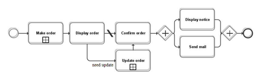
By using the set of graphical notations, the main process of the online shopping system can
be represented as Figure 13. The start event is the entrance of the process, followed by a
task with sub-process named “make order”. Then there are two connections which start
from the task “display order”. One default connection points to the task “confirm order” in
order to present the default choice given by the system. Another connection is a condition
connection which points to the task “update order”, which is used to provide the user with
an update order choice to change his order. After this, a parallel gateway is used to indicate
the fact that the task “display notice” and the task “send mail” shall be implemented
concurrently. At last, another parallel gateway is used to connect two FRs to the end event
of this process.
36
Figure 13. Main functional flow of an online shopping system
The example explicitly reflects the semantic information which is associated with FRD and
process. In order to evaluate the performance of the meta-model in practise, the adapted
semantic cases can be implemented in the REWiki platform. The following section will
discuss how to specify FRD in the REWiki.
5.5. Specifying FRD
We have introduced the Semantic Wiki in Chapter 5.1. Semantic Wiki organizes the
structure of data into category, form, template and property. In order to specify the FRD by
applying our meta-model into Semantic Wiki, a Semantic model is presented in the
following section.
5.5.1. Semantic model in wiki
According the meta-model defined in Chapter 5.3, five forms including FunctionalProcess,
Task, Gateway, Event and Connection are defined to support FRD specification process,
as shown in Figure 14.

37
Figure 14. Mapping process meta-model to wiki pages
Every form contains a template named description to identify and describe the contents of
the form in a free text field. As it is shown in Figure 14, there are some links between
forms and templates. The links indicate the value of a property which is used to link a page
type to another page in the wiki. The links can also represent the composition relation
between two forms. For example, A FunctionalProcess contains a list of Tasks.
A FunctionalProcess form contains a list of Tasks, Events, Gateways and connections.
As shown in Figure 14, the id and name property in the description template are used to
identify a process. The description property is a free text area which is provided to the user
to gain the complete information of the process. The task name property is used to link the
task name to the task page which includes full information of a task. The event name
property is used to link the event name to the event page. The gateway name property is
used to link the event name to the gateway page and the connection property is used to link
the connection name to the connection page. A FunctionalProcess form may contain a
number of tasks, gateways, events and connections, which depends on the complexity of
the process.
A task form is a basic unit of the functional process. A task form contains a description
template which is used to identify itself and provide comments to the user. Furthermore, a
task content template is used to store the structure and components of the task. A task form
contains one and only one functional requirement property. And a task form may contain
a functional process in order to represent the Elaboration Dependency type of FRD. The
38
sub process property is used to indicate the hierarchy relation between the FR which
included in a task form and a list of FRs which included in a sub functional process. The
event property is used to represent the trigger of the FR included in the task form, which
links the event name to the event page that is used to describe the event.
A gateway form contains a description template to identify itself. A type property in the
gateway content template is used to indicate the different types of a gateway: an exclusive
gateway or a parallel gateway.
An event form also contains a description template. Besides that, an event content
template which includes an event type property is used to distinguish the different type
events. The event type property can be selected from start, end, or intermediate.
A connection form contains a description template which includes three properties: id
name and description. Moreover, a connection form contains a connection content
template which is used to store the linked information of a connection. There are four
properties in the connection content template. The source point property is a page which
links to the start point of a connection. The start point of a connection may be an event, a
task or a gateway. Oppositely, the target point property indicate the end point of a
connection, the end point may also be event, task or gateway. A condition type property
represents the different types of the condition and a condition property provides a text field
to store the condition that must be satisfied for building the connection.
5.5.2. Using Semantic REWiki to specify FRD
The FRDs of an online shopping system introduced in Chapter 5.4 can be specified in the
Semantic REWiki as an example. Figure 15 explains the hierarchical relation of the
functional processes in the Semantic REWiki. All the dependencies between the FRs of the
system are specified through the functional processes. As it shown, there are several
projects in the wiki and one of them is the onlineshopping system. It contains a list of
processes and some processes have their sub process.

39
Figure 15. Processes documentation in the wiki
Figure 16 shows the screenshots of FRs process documented for the online shopping system.
Page 1 presents the view of the functional process “online shopping” which contains a list
of tasks, events, gateways and connections. The links of the components lead to different
representation wiki pages. Page 2 shows the semantic data of a task named “Make order”,
which contains a sub process - “process. make order”. The link of sub process leads to a
sub process page which is similar with page 1. Page 3 indicates a start event which is used
in process “online shopping” as an example to present the semantic content of the event.
Page 4 shows an instance of a gateway and Page 5 presents an example of connection.

40
Figure 16. Screenshots of “online shopping system” in Semantic REWiki
1
2
3
4
5
41
6. Evaluation and Discussion
In this chapter, we evaluate the Semantic REWiki with functional process component in
FRs dependency specification. We collect the feedback and comments from an experiment
in order to study how our system can be used in practice of specifying FRs dependency.
6.1. Experimental analysis
Two Computer Science students from the School of Information Sciences in the University
of Tampere were chosen as the subjects of the experiment since they have studied the
related knowledge concerning requirement engineering in university. The software system
they want to analyse is an online order system named “Kiinalainen Ravintola”.
6.1.1. Experiment background
The experiment was executed in the classroom of the university and it took approximately
4 hours. The following stages were executed:
1. Describe the system briefly and write down the FRs in normal language.
2. Obtain the detailed descriptions of FRs by filling the forms provided by REWiki.
3. Consider the dependencies between these FRs and the functional flow of the
system.
4. Document the dependencies of FRs in the semantic REWiki with process model
by following the instruction provided by semantic REWiki.
5. Evaluate and analysis the documented FRs dependencies and functional flow of
the system.
“Kiinalainen Ravintola” is an online order system which provides dish selections from the
website. Users can register and login in the system to watch all the dishes provided by the
restaurant and place their order online. The features and FRs of the system are shown in
Table 2.

42
Name
Description
Kr.display_dish_menu
System displays the entire dish in the menu
to the users.
Kr.order_a_dish
User orders a dish from the website.
Ksub.display.task
System displays the dishes to the user.
Ksub.choose.task
User chooses a dish from the menu page.
Ksub.inform.task
User gets the information of the dish, such
as name, price and materials.
Ksub.enter.task
User has chosen a dish and click enter for
the next steps.
Ksub.edit.task
User can edit his order for adding, updating
or deleting the selected dishes.
Ksub.cancel.task
User cancels the placed order.
Table 2. Features and FRs of “Kiinalainen Ravintola”
6.1.2. Process analysis
A brief introduction was provided to the subjects firstly in order to help them to understand
the basic background information of the system. After a short discussion on the online
order system, the subjects generalized a list of FRs on the paper. Then these FRs were
analysed semantically and documented in to REWiki by filling the various forms which
provided by semantic REWiki. When all FRs were identified and documented, they
considered the dependencies between the FRs and then documented the functional flow of
the system into REWiki. The main issues in the course of experiment are listed as
following:
1. The scale of prompt information makes them feeling difficult to work with the
system.
2. Some components of the model are not easy to be understood and used. For
example, the “intermediate event” of the model.
3. There are too many connections between the objects and it costs them much time
to document the connections.
4. Some properties in defined forms are confusing. For example, the “name”
property and “id” property.
5. The documentation process is time-consuming.
The subjects agreed that it was a necessary step to analysis the dependencies between the
FRs and document them. Furthermore, they believed that it was a creative method to
specify the FRs dependencies in the functional flow of the system.
43
The subjects also pointed out some shortcomings of our system. First of all, the prompt
information of our system is still insufficient. The subjects stated that they would not
understand the purpose of the properties without instant explanations. Moreover, they
agreed that they would not finish complete the functional flow documentation without a
provided example or a tutorial. Secondly, they suggested combining graphical notations
into the wiki forms, as they felt that it was difficult to consider the functional flow of the
system only by words and forms. Last but not least, they complained that there was not a
direct link for returning to the process page on the other pages. Occasionally, they had to
search the process page from the menu to continue the next steps, since they would not
return to the process page by clicking the “forward” button.
6.1.3. Feedback analysis
The subjects also proposed their suggestions to our system after the experiment:
1. Improve the meta-model of the functional process
2. Develop a graph based user interface to analysis FRs dependencies.
3. Provide adequate prompt and complete tutorial.
The subjects suggest improving the meta-model of the functional process since they want
to specify more FRs dependency types with this system. As we have discussed in Chapter 3
and 4, there still are some dependency types that we have not taken into account into our
system. Furthermore, the subjects stated their requirement of a graph based user interface.
In fact, we also considered this problem in the process of our research. However, for some
technical problems, we choose this set of form based user interface at last. This suggestion
will be taken into account in the further researches related to this topic.
The performance of our semantic REWiki with process model is initially tested with the
help of the experiment. It has been regarded as a really helpful platform to analysis FRs
dependencies and functional flow of the software system. The following section will
discuss the strengths and weaknesses of our system.
6.2. Discussion
Semantic REWiki provides us an appropriate platform to specify FRDs. By applying our
functional process meta-model into wiki pages, we indicate the adapted relationships
between FRs in the functional process of the system. There are many benefits to analyse
FRDs with our tools. Firstly, user can identify and specify the FRDs in REWiki directly
after they specified FRs in REWiki. There is no need to specify FRDs on another platform.
The working efficiency can be improved since much time and unnecessary data transacts
44
can be avoided. Secondly, we choose to specify FRs in the functional process of the system.
By identifying and specifying the dependencies between FRs, user also gains the functional
processes of the system at the same time. Finally, the data stored in REWiki can be applied
into further uses.
However, the method of specifying FRs in REWiki is on the on the initial stage. There are
still a number of aspects which should be improved. First, the definition of the meta-model
of functional process is not completed. In this research, we only take parts of dependency
types into account in order to decrease the complexity and insurance. We expect to analyse
and specify all the dependency types represented in Chapter 4 in the future. Second, we
have developed a set of graphical notations which are used to indicate the functional
process of the system. However, these graphical notations cannot be represented in REWiki
directly yet for many technical problems. The scare of graphical notations limit the user
experience and it should be improved in the future. Moreover, the usability of the tools
should also be improved. For example, more detailed instructions or examples should be
provided to the user in order to guild the user. At last, transforming the form based mode of
FRD specification into a graphical and dynamic approach is regarded as the most
important improvement to this research.
45
7. Conclusion
In this research, a classification for describing FRDs is presented to identify the possible
relationships which may exist between FRs. This category is based on the Pohl’s
dependency model for traceability objects and a fundamental dependency type for
requirements generalized by Dahlstedt and Persson. This classification divides FRDs into
two sub-categories: structural dependency and operational dependency. Then, five different
types of FRDs are generalized and discussed. Taken the complexity of specifying all these
dependencies and the limitation of our research platform into account, four adapted
dependency types are specified in a wiki platform named REWiki. We build meta-models
for these FRDs and realize them by defining a series of forms in REWiki. These defined
forms are able to specify the contextual information of FRD consistently and completely.
Furthermore, this documented information is storing in database and can be transferred
into XML files which can be used to build dependency maps with the standard of BPMB
2.0.
My contribution in this research includes two parts. On one hand, I generalized the
dependency types of FRs based on a careful literature review which contains the fields of
traceability objects dependencies, requirements dependencies and feature dependencies. On
the other hand, focus on the FRD which concerned with system flow process, I built meta-
models and specify four adapted FRDs in REWiki. By increasing the part of specifying
FRD to REWiki, I also provided a suitable platform which can be used to analyze FRs and
their dependencies.
There are still some limitations. Firstly, the classification of FRs is applicable. However,
there are still some relationships that have not been discovered. In the REWiki with FRD,
user can identify and describe the FRD by filling the dependency forms. It is acceptable.
However, it is not the best way. A graphical user interface is expected to be provided to
the users in order to display the visualized information on their system and improve the
maneuverability of our platform.
46
References
[Andrew and Greene, 2008] Andrew Stellman, Jennifer Greene, Applied Software Project
Management. O'Reilly Media, 2008.
[Concordia University, 2012] Semantic Software Lab, Concordia University, Montreal,
Canada, available at: http://www.semanticsoftware.info/reqwiki
[Carlshamre et al., 2001] Pär Carlshamre, Kristian Sandahl, Mikael Lindvall, Björn
Regnell, Johan Natt och Dag, An industrial survey of requirements interdependencies
in software product release planning. In: Proc. of Fifth IEEE International
Symposium on Requirements Engineering, 2001. IEEE, 2001, 84-91.
[Crear, 2009] Jim Crear, Chaos Summary 2009, Boston MA: Standish Group, 2009. Also
available as http://www.slideshare.net/AccelerateManagement/chaos-summary-
2009-the-standish-group
[Damian et al., 2005] Daniela Damian, James Chisan, Lakshminarayanan
Vaidyanathasamy, Yogendra Pal, Requirements engineering and downstream
software development: findings from a case study. Empirical Software Engineering
10 (3), 2005, 255-283.
[Decker et al., 2012] Bjoern decker, dazi, doppelmutzi, emmy82, eric_ras, iese-sop,
jaseeger, joerg_rech, macmillan78, oezzyu, SOP 2.0. Available at: http://iese-
sop.sourceforge.net/
[Dean and Widrig, 2003] Leffingwell Dean, Don Widrig, Managing Software
Requirements: A Use Case Approach. Addison-Wesley Professional, 2003.
[Davis and Leffingwell, 1996] Alan M. Davis, Dean A. Leffingwell, Using requirements
management to speed delivery of higher quality applications, Rational Software
Corporation, 1996. Available as
ftp://129.35.224.112/software/rational/web/whitepapers/2003/696wp.pdf
[Davis, 1993] Alan M Davis, Software requirements: objects, functions, and states.
Prentice-Hall, Inc., 1993.
[Dahlstedt and Persson, 2003] Asa G. Dahlstedt, Anne Persson. Requirements
interdependencies - moulding the state of research into a research agenda. In: Proc. of
Ninth International Workshop on Requirements Engineering: Foundation for
Software Quality, Klagenfurt/Velden, Austria. 2003, 55-64.
[Gobbo, 2000] Diego Del Gobbo, Formal Specification of Requirements for Analytical
Redundancy based Fault Tolerant Flight Control Systems. Doctoral Dissertation,
West Virginia University Morgantown, USA, 2000.
[Gorschek and Wohlin, 2006] Tony Gorschek, Claes Wohlin, Requirements abstraction
model. Requirements Engineering, 11 (1), 2006, 79-101.
[Heitmeyer et al., 1998] Constance Heitmeyer, Myla Archer, Ramesh Bharadwaj, Ralph
Jefford, SCR: A toolset for specifying and analyzing software requirements. In: Proc.
of Computer Aided Verification. Springer Berlin Heidelberg, 1998:526-531.
47
[IEEE, 1990] IEEE, Standard Glossary of Software Engineering Terminology. In: IEEE
Standard 610.12-1990, 1990.
[IEEE Std 1074-1997] IEEE, IEEE Standard for Developing Software Life Cycle
Processes. Software Engineering Standards Committee of the IEEE computer Society,
1999.
[IEEE, 1998] IEEE, IEEE Recommended Practice for Software Requirements
Specifications. In: IEEE Std 830-1998, 1998.
[IEEE Std 829-1998] IEEE, IEEE Standard for Software Test Documentation. In: IEEE
Std 830-1998, 1998.
[Karlsson et al., 1997] Joachim Karlsson, Stefan Olsson, Kevin Ryan, Improved Practical
Support for Large-scale Requirements Prioritisation, Requirements Engineering
Journal, 2 (1), 1997, 51-60.
[Knethen et al., 2002] A. von Knethen , B. Paech, F. Kiedaisch, F. Houdek, Systematic
requirements recycling through abstraction and traceability. In: Proc. of IEEE Joint
International Conference on Requirements Engineering, 2002. IEEE, 2002, 273-
281.
[Lawrence et al., 2001] Brian Lawrence, Karl Wiegers, Christof Ebert, The Top Risks of
Requirements Engineering. IEEE Software, 18 (6), November 2001 , 62-63.
[Lamsweerde, 2000] Axel van Lamsweerde, Formal Specification: a Roadmap. In: Proc.
of the Future of Software Engineering, ACM, 2000, 147-159.
[Lee and Kang, 2004]Kwanwoo Lee, Kyo C. Kang, Feature dependency analysis for
product line component design. Software Reuse: Methods, Techniques, and Tools.
Springer Berlin Heidelberg, 2004, 69-85.
[Lee and Zhao, 2006] Yuqin Lee, Wenyun Zhao. A feature oriented approach to managing
domain requirements dependencies in software product lines. In: Computer and
Computational Sciences, 2006. IMSCCS'06. First International Multi-Symposiums
on. Vol. 2. IEEE, 2006, 378-386.
[Mishra, 1997] Satish Mishra, Visual Modeling & Unified Modeling Language (UML) :
Introduction to UML. Rational Software Corporation, 1997.
[Malan and Bredemeyer, 2001] Ruth Malan and Dana Bredemeyer, Functional
Requirements and Use Cases, Bredemeyer Consulting, 2001.
[Object Management Group, 1997] Object Management Group, Unified Modeling
Language. Available at: http://www.uml.org/
[Object Management Group, 2011] Object Management Group, Business Process Model
and Notation. Available at: http://www.bpmn.org/
[Pohl, 1994] Klaus Pohl, The three dimensions of requirements engineering: a framework
and its applications. Information systems 19 (3), 1994, 243-258.
[Pohl, 1997] Pohl, Klaus. Process-centered requirements engineering. John Wiley &
Sons, Inc., 1997.
48
[Ramesh and Jarke, 2001] Balasubramaniam Ramesh, Matthias Jarke. Toward reference
models for requirements traceability. Software Engineering, IEEE Transactions on
27 (1), 2001, 58-93.
[Robinson et al., 2003] William N. Robinson, Suzanne D. Pawlowski, Vecheslav Volkov,
Requirements interaction management. ACM Computing Surveys (CSUR) 35 (2),
2003, 132-190.
[Ramesh et al., 1997] Balasubramaniam Ramesh, Curtis Stubbs, Timothy Powers,
Michael Edwards, Requirements traceability: Theory and practice. Annals of
software engineering 3 (1), 1997, 397-415.
[Sommerville and Sawyer, 1997] Ian Sommerville and Pete Sawyer, Requirements
Engineering: A Good Practice Guide. Wiley, 1997.
[Sommerville and Kotonya, 1998] Ian Sommerville, Gerald Kotonya, Requirements
engineering: processes and techniques. John Wiley & Sons, Inc., 1998.
[Sindre and Opdahl, 2000] Guttorm Sindre, Andreas L. Opdahl, Eliciting security
requirements by misuse cases. Technology of Object-Oriented Languages and
Systems, In: Proc. of TOOLS-Pacific 2000. Proceedings. 37th International
Conference on. IEEE, 2000. 120-131.
[Sommerville, 2004] Ian Sommerville, Software Engineering, Seventh Edition. Pearson
Education, 2004.
[Wiegers, 1999] Karl Wiegers, Writing Quality Requirements. Software Development
7(5), 1999.
[Wiegers, 2009] Karl E. Wiegers, Software requirements. Microsoft press, 2009.
[Yeh and Ng, 1982] Raymond Yeh , Peter Ng, Requirements analysis – a management
perspective. In: Proc. of IEEE Computer Software and Applications Conference.
Los Alamitos,1982,410-416.
[Ye and Liu, 2005] Huilin Ye, Hanchang Liu, Approach to modelling feature variability
and dependencies in software product lines. Software, IEE Proceedings-IET, 152 (3),
2005, 101-109.
[Yao, 2012] Wuping Yao, Specifying semantic information on functional requirements.
2012.
[Zave, 1997] Pamela Zave, Classification of research efforts in requirements engineering.
ACM Computing Surveys (CSUR) 29 (4), 1997, 315-321.
49
Appendix: Functional Requirements specification of online shopping system
1.1 Login into the online shopping system
……
2.1 Make an order from online shopping system
2.1.1 Description and priority
Customer makes an order from the online shopping system. This feature is
high priority.
2.1.2 Response Sequence
1. Customer chooses a product from the products list.
2. Customer chooses the amount of the selected product.
3. Customer chooses the colour of selected product.
4. Customer places an order.
2.1.3 Functional Requirements
REQ 2.1 The system shall display all the products to the customer.
REQ 2.2 The system shall allow the customer to select a product from the
product lists.
REQ 2.3 The system shall query the customer for the amount of selected
product.
REQ 2.4 The system shall query the customer for the colour of selected product.
REQ 2.5 The system shall put the product which the customer selected to his
shopping cart.
3.1 Update an order
3.1.1 Description and priority
Customer updates an order from the confirm/update page. This feature is high
priority.
3.1.2 Response Sequence
1. Customer updates the amount of the selected product.
2. Customer updates the colour of selected product.
3.1.3 Functional Requirements
REQ 3.1 The system shall query the customer to update the amount of selected
product.
REQ 3.2 The system shall query the customer to update the colour of selected
product.
4.1 Display an order
4.1.1 Description and priority
50
System displays the detail information of an order to the customer. This feature
is high priority.
4.1.2 Response Sequence
1. System displays the detail information of an order.
4.1.3 Functional Requirements
REQ 4.1 The system shall display the detail information of the order to the
customer.
5.1 Confirm an order
5.1.1 Description and priority
The customer confirms and accepts the order. This feature is high priority.
5.1.2 Response Sequence
1. System displays the detail information of an order.
5.1.3 Functional Requirements
REQ 5.1 The system shall prompt the client to confirm the acceptance of the
order.
6.1 Send information mail
6.1.1 Description and priority
The system sends an information mail to the customer’s email address. The
content includes the order date, price, product description, etc. This feature is
high priority.
6.1.2 Response Sequence
1. System sends an information mail to the customer’s email address.
6.1.3 Functional Requirements
REQ 6.1 The system shall send an information mail to the customer’s email
address, the content of the mail shall include all the detail information about
the order.
7.1 Display successful notice
7.1.1 Description and priority
The system displays a successful notice to the customer in order to inform the
customer that the order has been accepted. This feature is high priority.
7.1.2 Response Sequence
1. The system displays a successful notice to the customer.
7.1.3 Functional Requirements
REQ 7.1 The system displays a successful notice to the customer in order to
inform the customer that the order has been accepted.
