
CAMEO REQUIREMENTS
MODELER PLUGIN
18.0
No Magic, Inc.
2014
All material contained herein is considered proprietary information owned by No Magic, Inc. and is not to be
shared, copied, or reproduced by any means. All information copyright 2014 by No Magic, Inc. All Rights
Reserved.

CONTENTS
Copyright © 2011-2014 No Magic, Inc.
3
GETTING STARTED 5
Cameo Requirements Modeler Plugin 5
Compatibility 5
Installing Cameo Requirements Modeler Plugin 6
Requirement Concepts 6
Processes and Frameworks 8
Process Description 8
Templates 8
WORKING WITH REQUIREMENTS 10
Creating Requirements 10
Requirement Diagram 10
Requirement Table 13
Relating Requirements 16
Numbering Requirements 18
Editing Requirement Descriptions 21
Rich text formatting 21
Inserting images 23
Inserting hyperlinks 23
Glossary 24
Customizing Requirement Properties 25
Generating Requirement Reports 26
Importing Requirements 29
Importing ReqIF Files 29
Changing requirements importing options 31
Updating requirements 31
Applying automated post-processing scripts after ReqIF file import 33
Managing obsolete requirement elements 33
Importing from .CVS and MS Excel Files 34
Importing data using CSV Import Plugin 34
Importing data using Excel Import Plugin 35
Exporting Requirements 36
Changing Requirements Exporting Options 37
Applying automated pre-processing scripts before ReqIF file export 37
Interchanging of Requirements Using Cameo DataHub 38
Integrating Requirements into Models 39
Business Architecture 39
Software Architecture 39
System Architecture 39
User Interface Modeling 39
Analyzing Requirements 41
Coverage Analysis 42
Change Impact Analysis 42
Analyzing dependencies in Dependency Matrix 42
Analyzing dependencies in Relation Map 44
Tracing Requirements 45
Traceability relations in Specification window 46
Traceability relations in Properties panel 48
Representing traceability on Notes 50
Tracing relations using Go To command 50
Validation 51

Copyright © 2011-2014 No Magic, Inc.
5
GETTING STARTED
Cameo Requirements Modeler Plugin
Cameo Requirements Modeler Plugin provides full support for model-based requirements engineering. The
plugin implements the requirements part of the OMG SysML standard and provides a means to import and
manage requirements in the model. Requirements Interchange Format (ReqIF) makes the plugin open for
requirements interchange among different requirements management tools.
Model-based requirements engineering brings the value of:
• Easy identification of the scope and potential consequence of any change.
• Single and consistent data source: requirements, processes, and design.
• Increased quality of requirements due to the automatic validation and better visibility.
• Saved time and resources as you are working in the same environment where your models
are.
• Improved team communication with a simple and standard notation, clear diagrams, and a
web-based report.
With this plugin you can:
• Import and export requirements in a ReqIF file from/to other requirements management tools,
such as IBM DOORS 9.4, 9.5, and 9.6, IBM DOORS Next Generation, PTC Integrity, Polarion
REQUIREMENTS, Siemens Teamcenter, and Dassault Systemes Reqtify. ReqIF – industry
standard, dedicated to information exchange between Requirements Management tools. The
standard is managed by the Object Management Group and supported by major tool vendors.
• Trace from requirements to other model elements of business, software, or systems
architecture and align requirements with your model.
• Analyze the impact of a change.
• Track metrics.
• Capture requirements in dedicated diagrams, matrices, and tables.
• Document requirements.
• Extend the plugin by creating new requirement types and customizing the plugin’s functionality.
Plugin is dedicated for business analysts and architects, software engineers, enterprise architects, systems
engineers, and other users, who work with requirements.
Compatibility
The Cameo Requirements Modeler Plugin is compatible with the following MagicDraw editions:
• Enterprise
• Professional
• Standard
• Architect

GETTING STARTED
Installing Cameo Requirements Modeler Plugin
6
Copyright © 2011-2014 No Magic, Inc..
Installing Cameo Requirements Modeler Plugin
There are several ways to install the Cameo Requirements Modeler plugin. Choose one of the following:
• Download and install the plugin directly via the Resource/Plugin Manager dialog in the
MagicDraw program.
• Download the Cameo_Requirements_Modeler_Plugin_<version number>.zip file and then
install the plugin via the Resource/Plugin Manager dialog.
• Install the plugin manually, in case the direct downloading and installing via the Resource/
Plugin Manager dialog is not available.
To download and install the CRM plugin via the Resource/Plugin Manager dialog
1. From the MagicDraw main menu, select Help > Resource/Plugin Manager. The Resource/
Plugin Manager dialog opens and prompt you to check for the latest product updates and
resources. Click Check for Updates > Check.
2. Select the check box near the Cameo Requirements Modeler Plugin and click Download/
Install.
3. Restart MagicDraw.
To install the CRM plugin from the downloaded .zip file via the Resource/Plugin Manager dialog
1. From the MagicDraw main menu, select Help > Resource/Plugin Manager.
2. Click the Import button to specify the Cameo_Requirements_Modeler_Plugin_<version num-
ber>.zip file location. The plugin is extracted and installed automatically.
3. Restart MagicDraw.
To install the Requirements plugin manually
1. Download the Cameo_Requirements_Modeler_Plugin_<version number>.zip file.
2. Extract the downloaded file to the same directory wherein MagicDraw is installed.
3. Start MagicDraw. The Cameo Requirements Modeler Plugin is now applied to MagicDraw.
Requirement Concepts
Business Requirement
A Business Requirement is a requirement that specifies characteristics of the business process
that must be satisfied by the system.
Specify HTTP Proxy Settings for the connection to start MagicDraw
UML updates and resources.
Quit MagicDraw before installing the plugin.
If your operating system is other than Windows, use the command-
line prompt to go to the MagicDraw UML folder and extract the
Cameo_Requirements_Modeler_Plugin_<version number>.zip file
there.

GETTING STARTED
Requirement Concepts
7
Copyright © 2011-2014 No Magic, Inc..
Design Constraint
A Design Constraint is a requirement that specifies a constraint on the implementation of a
system or on a part of it.
Extended Requirement
An Extended Requirement is a standard Requirement subtype, which adds some properties to a
requirement element. These properties such as a source, risk, and verify method are important
for the requirement management. Specific projects should add their own properties. All these
properties are now available in the standard Requirement Specification window and
Requirements Table. If any of these property values is specified, a requirement is automatically
converted to ExtendedRequirement.
Functional Requirement
A Functional Requirement is a requirement that specifies a behavior that a system or a part of a
system must perform.
Interface Requirement
An Interface Requirement is a requirement that specifies the ports for connecting systems and
parts of a system. Optionally, it may include the items that flow across the connector and/or the
Interface constraints.
Performance Requirement
A Performance Requirement refers to a requirement that quantitatively measures the extent to
which a system or a system part satisfy a required capability or condition.
Physical Requirement
A Physical Requirement specifies the physical characteristics and/or physical constraints of a
system or a system part.
ReqIF
The Requirement Interchange Format (ReqIF) standard is an XML based international standard
adopted by Object Management Group (OMG) as a formal specification for exchanging
requirements between software tools from different vendors.
Requirement
A Requirement specifies a capability or a condition that must (or should) be satisfied.
Requirements are used to establish a contract between the customer (or other stakeholder) and
those responsible for designing and implementing the system. A requirement may specify a
function that a system must perform or a performance condition a system must achieve. A
requirement can also appear on other diagrams to show its relationship to other modeling
elements. A standard requirement includes properties to specify its unique identifier and text
requirement.
When a requirement nests other requirements, all the nested requirements apply as a part of the
container requirement (the requirement that contains all the nested requirements).
Requirement Diagram
Requirements Diagrams provide modeling constructs to represent text-based requirements and
relate them to other modeling elements. These requirement modeling constructs are intended to
provide a bridge between traditional requirement management tools and other UML models.
Requirements Diagrams display requirements, packages, other classifiers, test cases,
rationales, and relationships.
Requirement Specification
A represented collection of requirements that are related by a user decision or needs. A
Requirement Specification may represent requirements for a system, a component, or other
subjects. In a means of MagicDraw, a Requirement Specification is a package of requirements.

GETTING STARTED
Processes and Frameworks
8
Copyright © 2011-2014 No Magic, Inc..
A Usability Requirement specifies the fitness for use of a system for its users and other actors.
Requirement Table
A Requirements Table represents textual requirements in a table format: each row represent a
requirement and you can specify what columns could be in a table according your needs. A new
table consists of three columns by default: a requirement ID, name, and textual description.
Test Case
A Test Case (Activity / StateMachine / Interaction) is a method for verifying a requirement.
Usability Requirement
A Usability Requirement specifies the fitness for use of a system for its users and other actors.
Processes and Frameworks
Process Description
The Cameo Requirement Modeler Plugin implements the requirements part of the OMG SysML standard that is
widely used in the system engineering. All concepts and modeling approaches that are used in requirement
modeling with the plugin are from the requirement part of the SysML standard which can be found at http://
www.omgsysml.org/. The SysML requirement part provides clear essential means for the model-based
requirements management independently from the system engineering domain, so it could be easily adopted
for all other domains as software, business, and enterprise.
The article “Requirements Writing in SysML Guide” which can be found at http://blog.nomagic.com/
requirements-writing-in-sysml-guide/ presents one of a possible requirements modeling process which is
adopted by No Magic, Inc. company internally for the development of all the products.
Templates
A requirements template contains predefined packages and diagrams to start creating your requirements
model. Usually, business, functional, or non-functional requirements are created.
To create a requirement project from a template
1. Do one of the following:
• From the File menu, select New Project.
• On the main toolbar, click the New Project button.
• Press CTRL+N.
In all cases, the New Project dialog opens.
2. Type a project name and specify a project location.

GETTING STARTED
Processes and Frameworks
9
Copyright © 2011-2014 No Magic, Inc..
3. Under the General-Purpose Modeler group, double-click the Requirements Project icon. The
project template with predefined diagrams, samples, and resources opens.
Figure 1 -- Requirement project template structure

Copyright © 2011-2014 No Magic, Inc.
10
WORKING WITH REQUIREMENTS
Learn about using the Cameo Requirements Modeler plugin in the following sections:
• Creating Requirements
• Importing Requirements
• Exporting Requirements
• Interchanging of Requirements Using Cameo DataHub
• Analyzing Requirements
As with so many things in MagicDraw, there usually is more than one way to do the same thing. Just main or
typical procedure steps are described in the following sections, but feel free to use MagicDraw in the way you
prefer.
Creating Requirements
MagicDraw and Cameo Requirements Modeler Plugin provide modeling constructs to represent text-based
requirements and relate them to other modeling elements. The requirements can be depicted in graphical,
tabular, or tree structure format.
Diagram and tables are the most popular means for requirements specification and representation in modeling
tools. The following sections describe in details how to create and relate requirements in the model:
• Requirement Diagram
• Requirement Table
• Relating Requirements
• Numbering Requirements
• Editing Requirement Descriptions
• Glossary
• Customizing Requirement Properties
• Generating Requirement Reports
Requirement Diagram
The Requirement Diagram provides modeling constructs to represent text-based requirements and relate them
to other modeling elements. These requirement modeling constructs are intended to provide a bridge between
traditional requirement management tools and other models.
The Requirement diagram displays requirements, packages, other classifiers, test cases, rationales, and
relationships. Possible relationships available for Requirements diagrams are containments, deriveReqt and
requirement dependencies (‘Copy’, ‘Refine’, ‘Satisfy’, ‘Trace’, and ‘Verify’). The callout notation can also be
used to reflect the relationships of other models. Requirements can also be shown on other diagrams to

WORKING WITH REQUIREMENTS
Creating Requirements
11
Copyright © 2011-2014 No Magic, Inc..
illustrate their relationships to other modeling elements.See the example of a requirements diagram in the
following figure.
Figure 1 -- Example of Requirement Diagram
You can create requirements either directly on the Requirements Diagram or in the project Containment tree
and represent it on the diagram after then.
To create a requirement diagram
1. In the Containment tree, select an element that can be the owner of the requirement diagram.
2. Do one of the following:
• From the main menu, select Diagrams > Create Diagram. Type “reqDia” and press
Enter.
• On the main toolbars, click the Create Diagram button. Type “reqDia” and press
Enter.
• Press Ctrl+N. Type “reqDia” and press Enter.
• Right-click the element and from the shortcut menu select Create Diagram >
Requirement Diagrams > Requirement Diagram.
The newly created requirement diagram opens on the right side of the application window.
3. Type the name of the diagram.

WORKING WITH REQUIREMENTS
Creating Requirements
12
Copyright © 2011-2014 No Magic, Inc..
4. Add desired symbols on the diagram pane or drag desired elements from the project Contain-
ment tree.
To create requirements in the Containment tree
1. In the Containment tree, right-click the package wherein you want to create a requirement.
2. On the opened shortcut menu, click Select Element and then select an element you want to
create. In this case, usually it is Requirement or Other Requirement.
3. Type a requirement name.
To create requirements on the Requirement diagram
1. Open an existing or create a new Requirement Diagram.
2. On the diagram pallet, select a desired element and drag it on the diagram pane.
3. On the requirement shape, type a requirement name, ID, and description. The element is cre-
ated in the same package wherein the diagram is stored.
To add or edit requirement properties
1. Select the desired requirement in the project Containment tree or it’s shape on the diagram
pane.
2. Requirement properties are added or edited in the element’s Specification Window. To open the
Specification Window, do one of the following:
• Double-click the selected requirement.
• Right-click the selected element and, on the shortcut menu, click Specification.
• Select a requirement and press ENTER.
3. In the opened Specification Window, specify desired properties and click Close when you ar
done.
For more information about using Specification Window, see “Specification Window” in MagicDraw
UserManual.pdf.
To change a requirement type
1. Select the desired requirement in the project Containment tree or it’s shape on the diagram
pane.
2. Right-click the selected requirement and, on the opened shortcut menu, click Refactor > Con-
vert To > More Specific and select a desired requirement type from the list.
On the Requirement diagram, you can also represent already created requirements and relate them.
To represent requirements by creating a new Requirements diagram
1. In the Containment tree, right-click the requirement or package you want to draw on the dia-
gram.
2. From the shortcut menu, select New Diagram > Requirements Diagrams > Requirement
Diagram.
3. Type a diagram name in the Containment tree. The selected requirement is drawn on the dia-
gram.
To represent requirement on an existing Requirement diagram
1. Open an existing Requirement diagram.
If a Risk, Source, or Verify Method property is specified to a requirement,
the requirement is automatically converted to the Extended Requirement.

WORKING WITH REQUIREMENTS
Creating Requirements
13
Copyright © 2011-2014 No Magic, Inc..
2. In the Containment tree, select a desired requirement and drag it on the diagram pane.
To relate requirements on the Requirement diagram
1. Represent requirements on the Requirement diagram.
2. Select a relation type either from the diagram pane or the smart manipulator of the selected
requirement on the diagram pane.
3. Draw the selected relation from one requirement element to other.
MagicDraw provides an easy way to create a requirements diagram for sub-requirements of the selected
requirement.
To create requirements diagrams for sub-requirements
1. Select a requirement in the project Containment tree or it’s symbol on the diagram pane.
2. Depending on your selection do one of the following:
• Create a requirement diagram as usual. See the procedure “To create a
requirement diagram” on page 11
• If a symbol on a diagram pane is selected, click the Create diagram for sub-
requirements button on the smart manipulator.
A new requirements diagram for the sub-requirements is created having the same name as the
selected requirement. The selected requirement is an owner of sub-requirements diagram and is
marked with the diagram sign. As an example, you can see the requirement named “Project
Management GUI” in the Figure 1 on page 11.
For more information about diagramming, see “Diagram Basics” in MagicDraw UserManual.pdf.
Related procedures
Requirement Table
Relating Requirements
Numbering Requirements
Editing Requirement Descriptions
Requirement Table
A Requirement Table represents textual requirements in a table format: each row represent a requirement and
you can specify what columns could be in a table according your needs. With this table, you can:
Double click the owner symbol to open a diagram for sub-
requirements and use navigation buttons on the diagram toolbar to
move back or forward through diagrams.

WORKING WITH REQUIREMENTS
Creating Requirements
14
Copyright © 2011-2014 No Magic, Inc..
• Create requirements directly in the table
• Import existing requirements in the table
• Create sub-requirements directly in the table having their IDs automatically numbered
• Edit requirement properties
• Renumber requirements’ IDs
• Generate requirements reports
Export the table to Microsoft Excel (.xlsx), Comma Separated File (.csv) or Hyper Text Markup Language
(.html) formats.
Figure 2 -- Example of Requirement Table
To create a requirement table
1. In the Containment tree or on the diagram pane, select an element that can be the owner of the
requirement table.
2. Do one of the following:
• From the main menu, select Diagrams > Create Diagram. Type “reqT” and press
Enter.
• On the main toolbars, click the Create Diagram button. Type “reqT” and press
Enter.
• Press Ctrl+N. Type “reqT” and press Enter.
• Right-click the element and from the shortcut menu select Create Diagram >
Requirement Diagrams > Requirement Table.
The newly created requirement table opens on the right side of the application window.
3. Type a table name.
4. Specify a scope for table or simply drag desired requirements from the Containment tree to the
table.
To create a requirement in a requirement table
1. Create a Requirement table or open an exiting one.
2. On the Requirement table toolbar, click the Add New button or press INSERT. The list of
Requirement types opens.
3. Click a desired requirement type. A new line above the first numbered requirement appears.
4. In that empty line, type a requirement name and specify other requirement properties.

WORKING WITH REQUIREMENTS
Creating Requirements
15
Copyright © 2011-2014 No Magic, Inc..
To represent requirements in a requirement table
1. Create a Requirement table or open an exiting one.
2. On the Requirement table toolbar, click the Add Existing button or press CTRL+INSERT. The
Select Requirement dialog opens.
3. In the opened dialog, select requirements you want to represent in the table and click OK.
For more information about selecting elements in the Select Requirements dialog, see “Selecting an Element”
in MagicDraw UserManual.pdf.
To add or edit requirement properties
1. Select the desired requirement in the Containment tree or the requirement’s row or it’s ID in the
table.
2. Requirement properties are added or edited in the element’s Specification Window. To open the
Specification Window, do one of the following:
• Double-click the selected requirement in the Containment tree or the selected row in
the table.
• Right-click the selected element in the Containment tree, the row or requirement’s
ID in the table and, on the shortcut menu, click Specification.
• Press ENTER, if the requirement in the Containment tree or the row in the table is
selected.
3. In the opened Specification Window, specify desired properties and click Close when you ar
done.
To export requirements to other formats
1. Open a filled Requirement table.
2. On the Requirement table toolbar, click the Export button. The Choose file... dialog opens.
3. In the opened dialog, choose a location of the exported file, type a file name, and select a file
type the requirements will be exported. Files of .csv, .html, and .xlsx types are available to
select.
4. Click Save when you are done. Requirements are exported.
To create a requirements report
1. Open a filled Requirement table.
2. On the Requirement table toolbar, click the Report button. The list of available report formats
opens.
3. Click a desired report format. The Generate Report dialog opens.
4. In the opened dialog, specify a location of the report, an image format, and other properties, if
needed.
5. Click Generate when you are done. The report are generated.
For more information about generating reports and using Generate Report dialog, see “Generate Output
Pane” in MagicDraw ReportWizard UserGuide.pdf
Drag-and-drop the whole requirements package from the
Containment tree on the empty Requirement table to represent all
its content in the table.
If a Risk, Source, or Verify Method property is specified to a
requirement, the requirement is automatically converted to the
Extended Requirement.
Please notice some formatted text (for example, tables in a
requirement description) may be exported incorrectly

WORKING WITH REQUIREMENTS
Creating Requirements
16
Copyright © 2011-2014 No Magic, Inc..
The Requirement table supports a wide range of editing abilities. In this table, you can:
• Add or remove a desired column
• Edit a particular element’s property directly in a cell
• Use rich-text formatting abilities while editing a particular cell
• Filter table elements by using a quick filter feature
To edit requirement tables
• To edit a table, use a table toolbar.
• To edit a cell’s value, click the selected cell and then a small Edit button in an upper right
corner to open a particular dialog for editing value properties.
For more information about editing and managing Requirement tables, see “Generic Table” in MagicDraw
UserManual.pdf.
Related procedures
Requirement Diagram
Numbering Requirements
Editing Requirement Descriptions
Generating Requirement Reports
Relating Requirements
The following table describes relations that are used in working with requirements.
Relation Description Sample
Satisfy
It is a dependency between a requirement and a
model element that fulfills that requirement. As with
other dependencies, the arrow direction points from
the satisfying (client) model element to the (supplier)
requirement that is satisfied.

WORKING WITH REQUIREMENTS
Creating Requirements
17
Copyright © 2011-2014 No Magic, Inc..
Derive
It is a dependency between two requirements (a
derived requirement and a source requirement),
where the derived requirement is generated or
inferred from the source requirement.
Copy
It is a dependency between a supplier requirement
(master) and a client requirement (slave), specifying
that the client requirement text is a read-only copy of
the supplier requirement text.
Trace
It is a dependency between a requirement and an
arbitrary model element traced by this requirement.
Relation Description Sample

WORKING WITH REQUIREMENTS
Creating Requirements
18
Copyright © 2011-2014 No Magic, Inc..
You can create relations in the Requirement Diagram directly, see the procedure “To relate requirements on the
Requirement diagram” on page 13. Also you can relate requirements and other model elements in the Derive,
Refine, Satisfy, or Verify Requirement Matrix.
To create a relation in Requirement Matrixes
1. Create a corresponding matrix or open an existing one (see the procedure “To create a depen-
dency matrix” on page 43)
2. In the intersection cell do one of the following:
• Double click the intersection cell. The appropriate relation is created.
• Right-click the intersection cell and, on the shortcut menu, click the relation name.
The relation is created.
Related procedures
Requirement Diagram
Numbering Requirements
Each requirement has it’s unique ID or, in terms of MagicDraw, the element number. MagicDraw allows you for
using automatic or manual elements numbering. In requirement modeling, a requirement number is
understandable as a requirement ID. The requirement ID facilitates the search of a particular requirement and
can show the requirement’s place in the model element hierarchy.
Verify
It is a dependency between a requirement and a test
case or a model element that can determine whether
the system fulfills the requirement. As with other
dependencies, the arrow direction points from the
(client) test case to the (supplier) requirement.
Refine
This dependency describes how a model element or
a set of elements refine a requirement. For example,
a use case or activity diagram may be used to refine
a text-based functional requirement. Alternatively, it
may be used to show how a text-based requirement
refines a model element. In this case, some
elaborated text could be used to refine a less fine-
grained model element.
You can create more than one relation in the same cell if you need
it.
Relation Description Sample

WORKING WITH REQUIREMENTS
Creating Requirements
19
Copyright © 2011-2014 No Magic, Inc..
MagicDraw supports a wide range of number formats: you can use letters, prefixes, separator signs in
requirements IDs, and so you can constrain your specific numbering format. Also, you can choose which
numbering scheme to use—consecutive or multi-level numbers. Use the multi-level numbering for nested
requirements.
Figure 3 -- Example of numbered requirements
Requirements can be numbered automatically or manually. To number requirements automatically, the auto-
numbering property should be enabled. Requirements are numbered according to the numbering scheme that
is specified for the requirement owner. If you change the numbering scheme for owning requirements, just the
owner will be renumbered, all other requirements will use the old numbering scheme.
To enable automatic requirement numbering
1. From the main menu, select Options > Project. The Project Options dialog opens.
2. Select the General project options tab.
3. In the Numbering properties group, set the Use Element Auto-numbering property value to
true.
4. Click OK.
MagicDraw supports a special generic numbering feature allowing users to create and edit numbering formats
for element numbering.
To create or edit requirement numbering format
1. Open the Element Numbering dialog. Do one of the following:
• Right-click a selected requirement in the Containment tree or it’s shape on the
diagram pane to open a shortcut menu and select the Element Numbering menu
command.
• Open the Specification window of the selected requirement. Click the ID property
specification cell and then click the Edit button.
2. In the opened dialog:
2.1 Select a requirement you want to number or to change the numbering format.
2.2 Define a desired numbering format.

WORKING WITH REQUIREMENTS
Creating Requirements
20
Copyright © 2011-2014 No Magic, Inc..
2.3 Click the Create button to create a new requirement ID or click the Details button
to expand the dialog and click the Renumber or Renumber Recursively button to
change the existing requirement numbering format.
Figure 4 -- Element Numbering dialog
The numbering mechanism in details is described in the MagicDraw User Guide.
For more information about the generic numbering mechanism, see “Generic Numbering Mechanism” in
MagicDraw UserManual.pdf.
For more information about managing elements numbering, see “Automatic Numbering” and “Manual
Numbering” in MagicDraw UserManual.pdf.
For more information about using the Element Numbering dialog, see “Element Numbering dialog” in
MagicDraw UserManual.pdf.
In MagicDraw, you can also customize your own specific numbering. The creating of the numbering
customization is described in “Creating Numbering Customizations” in MagicDraw UML Profiling&DSL
UserGuide.pdf.
Related procedures
Requirement Diagram
In the project Containment tree, you can reorder elements just by
dragging a selected element to a desired place.

WORKING WITH REQUIREMENTS
Creating Requirements
21
Copyright © 2011-2014 No Magic, Inc..
Requirement Table
Customizing Requirement Properties
Editing Requirement Descriptions
MagicDraw allows you to edit requirement description text using various capabilities. You can use rich text
formatting, the spelling checker, insert an image or hyperlink in description texts.
Learn more in the following sections:
• Rich text formatting
• Inserting images
• Inserting hyperlinks
Rich text formatting
The requirement description text can be edited directly in the shape on the diagram, in the element’s
Specification window, or in the table’s cell. The rich text formatting allows you to make your descriptions easier
to read. understand, and get better visualization. In MagicDraw, the special rich text formatting toolbar is used
for text formatting.
To open the rich text formatting toolbar
• In the shape on the diagram, select a text you need to edit and click it with the left mouse key
once more. The rich text formatting toolbar appears.

WORKING WITH REQUIREMENTS
Creating Requirements
22
Copyright © 2011-2014 No Magic, Inc..
• Open the elements Specification window and click the Edit button in the Text property
specification cell.
• In the Requirements table, click the Edit button in the Text cell of the selected requirement
For mor information about editing textual properties, see “Editing textual properties” in MagicDraw
UserManual.pdf.
Related procedures
Inserting images
Inserting hyperlinks
Requirement Diagram
Requirement Table

WORKING WITH REQUIREMENTS
Creating Requirements
23
Copyright © 2011-2014 No Magic, Inc..
Inserting images
Images can be inserted not only into diagram, but directly into requirement descriptions. MagicDraw supports
*.gif, *.jpg, *.svg, and *.png image file types.
To insert images into descriptions
1. Open or select the requirement description for editing.
2. Select an image file in the file browser and drag it into the description text.
Related procedures
Rich text formatting
Inserting hyperlinks
Requirement Diagram
Requirement Table
Inserting hyperlinks
The hyperlink can be added directly into a requirement description text. Hyperlinks can help you to navigate
through the project, to access a model element, a web page, or an external file.
To add hyperlinks
1. Do one of the following:
• Open or select a requirement description for editing and, in the rich text formatting
toolbar, click the Insert Hyperlink button.
• Select a shape on the Requirement diagram and click the Hyperlinks/Go To smart
manipulator.
• In the Containment Tree, select an element you want to add a hyperlink. On the
shortcut menu, click Go To > Hyperlinks > Add Hyperlink.
2. In the opened Edit Hyperlink dialog, specify hyperlink properties.

WORKING WITH REQUIREMENTS
Creating Requirements
24
Copyright © 2011-2014 No Magic, Inc..
For more information inserting adding hyperlinks, see “Defining Hyperlinks” in MagicDraw UserManual.pdf.
Related procedures
Rich text formatting
Inserting images
Requirement Diagram
Requirement Table
Glossary
The glossary allows you create a list of all the specific terms used in the project. It is recommended to create a
separate package for the glossary in your project.
The glossary table allows for managing the terms of your model in a spreadsheet-like form. Each row in the
table represents a term. A word, phrase, or any element of the model can be a term.
Figure 5 -- Example of glossary

WORKING WITH REQUIREMENTS
Creating Requirements
25
Copyright © 2011-2014 No Magic, Inc..
All terms described in the glossary are underline when are used in the project. Hold the mouse pointer over that
term and you will get the term description in a pop-up table.
Figure 6 -- Example of term description usage
To create a glossary
1. Create a package for the glossary.
2. Right-click that package and, on the opened shortcut menu, click Create Diagram > Other Dia-
grams > Glossary Table. An empty table opens.
Use commands from the table toolbar to add and manage terms in the glossary. If you have terms described
already, you can select them in the Containment tree and drag to the glossary table.
For more information about using and managing glossaries, see “Glossary” in MagicDraw UserManual.pdf.
Related procedures
Requirement Diagram
Requirement Table
Customizing Requirement Properties
It is common to have specific properties in requirements specifications. Specific properties can be used to
identify the requirement’s version, complexity, priority, severity, status, and various other properties.
Requirements can be extended with custom properties by using the MagicDraw profiling and DSL mechanism.
Custom properties can be added to the general properties list by extending the ExtendedRequirement class.
To create custom properties
1. In your project, create a package for your custom properties.
2. In that package, create a new stereotype. On the package’s shortcut menu, click Create Ele-
ment > Stereotype and type a name.
Right-click the desired keyword in the requirement’s name or in the
description and select the Add to Glossary command. The selected
keyword is added to the existing glossary. Open the glossary table to
describe the added keyword.

WORKING WITH REQUIREMENTS
Creating Requirements
26
Copyright © 2011-2014 No Magic, Inc..
3. Apply a metaclass Class to the created stereotype. On the stereotype’s shortcut menu, click
Metaclass. In the opened Select Metaclass dialog, select a Class and click Apply.
4. In the stereotype with the metaclass Class applied, create desired properties. On the stereo-
type’s shortcut menu, click Create Element > Property. Type a property name and value type.
5. Expand the ExtendedRequirement class by properties created in the stereotype. You need to
relate the stereotype with the generalization relationship to ExtendedRequirement class. On the
stereotype’s shortcut menu, click Create Relation > Outgoing > Generalization. In the
opened Create New Generalization To dialog, select the ExtendedRequirement class.
Click OK when you are done. The following figure depicts how the stereotype related to the
ExtendedRequirement class looks in a diagram form.
6. Save and restart your project. Your custom properties are added to the general requirement
properties. You can assign values to them in the requirement’s Specification window or Proper-
ties panel.
Customizing procedures in details are described in “Creating Customization Data” and “Using Customization
Data” in MagicDraw UML Profiling&DSL UserGuide.pdf.
Generating Requirement Reports
After requirements are created, MagicDraw allows you generating requirement reports in the .rtf format. While
generating a report, you can select whether to publish all requirements or just a selected part: a requirement
diagram, table, matrix, or specification.
You can generate a report using the Report Wizard or generate them directly form the Containment tree. There
are four pre-defined requirement templates and a Web Portal Report template in MagicDraw:
• Requirement Dependencies Report. This report contains tables of requirement
dependencies, that is separate tables for Copy, Derive, Refine, Satisfy, Trace, and Verify
relations.
• Requirement Diagram. This report lists all requirement diagrams of a selected scope.
Diagram elements and dependencies are described in tables under each diagram.
• Requirement Report. This is a standard detailed requirement report, containing all
requirements attributes. This template may be used as a requirement specification report.
• Requirements Table Diagram Report. This report lists all requirement tables of a selected
scope.
Make sure the Include elements from modules into search
results button is active. The ExtendedRequirement class an
auxiliary and is stored in a module, not in the system profile.
To make a search quicker, click the Use camel case for searching
button (if it is not active) and, in a Search By Name text box, type
“exR”.

WORKING WITH REQUIREMENTS
Creating Requirements
27
Copyright © 2011-2014 No Magic, Inc..
• Web Portal Report. This report provides a capability of sharing model information in a
browsable, clean, and less-technical way.
Figure 7 -- Example of Web Portal Report template
To generate reports using the Report Wizard
1. Open the requirement project.
2. On the main menu, click Tools > Report Wizard or press CTRL+SHIFT+G. The Report Wiz-
ard opens.

WORKING WITH REQUIREMENTS
Creating Requirements
28
Copyright © 2011-2014 No Magic, Inc..
3. In the opened wizard, select a report template. For the requirement report, it is recommended
to select the one of the requirements template as depicted in the following figure. Click Next
4. In the Select Report Data list, select data that should be included in the report. Report data is
a set of variables that are included in the generated report. Each template has the pre-defined
set of such variables. It is named Built-in in the Report Data list. If you want to change vari-
ables to be published in the report, click the Variable button and edit the list of variables. After
you have finished the selection, click Next.
5. Select elements to be published in the report. In the Select Element Scope list, select desired
data packages and add them to the Selected Object list. Click Add to add just a selected pack-
age, Add All to add the selected package and one level packages inside, or Add Recursively
to add a selected and all it’s owned packages. After elements have been selected, click Next.
6. Type a report file name and specify it’s location, select a report image file format, and specify
other properties if it is needed. After properties are specified, click Generate. The report is gen-
erated.
To generate reports from the Containment tree
1. Open the requirement project.
2. In the Containment tree, right-click the selected requirement specification (package) or require-
ment.
3. On the opened shortcut menu, click Generate Report > Requirements and select a desired
requirement template.
4. In the opened Select Location dialog, specify a report location and enter a report file name.
Click Save when you are done. The report is generated.
The Report Wizard is a report engine and provides much more capabilities as described in this section. You can
create your own template for a requirement report or modify pre-defined ones to fit your needs best. For more
You can change or edit some values directly in the generated report. For
example, you can create a table of contents or a table of figures, enter a
name of an author, a version number, or other data.
WORKING WITH REQUIREMENTS
Importing Requirements
29
Copyright © 2011-2014 No Magic, Inc..
information about working with report templates, see MagicDraw ReportWizard UserGuide.pdf and
MagicDraw ReportWizard Template Creation Tutorial.pdf.
Related references
Requirement Diagram
Requirement Table
Importing Requirements
You can import requirements using the ReqIF importing capability or using one of the following add-ons:
• CSV Import Plugin
• Excel Import Plugin
• Cameo DataHub
Learn about import requirements into your project in the following sections:
• Importing ReqIF Files
• Importing from .CVS and MS Excel Files
Importing ReqIF Files
You can import ReqIF files from:
• IBM Rational DOORS 9.4, 9.5, 9.6
• IBM Rational DOORS NG
• PTC Integrity
• Polarion REQUIREMENTS
• Seamens Teamcenter
• Dassault Systemes Reqtify
To import a ReqIF requirement file
1. Open a project wherein you want to import requirements.
2. From the File menu, select Import From > Requirement Interchange Format (ReqIF) File.
3. In the opened Load dialog, browse for your ReqIF file and click Open. The ReqIF file is
imported.
When the ReqIF file is imported, a notification message appears, stating the quantity of imported or updated
elements. If you import a ReqIF file without specification, the message doesn't contain the line that indicates
new or updated specifications. You also see no option Show imported specification table(s).
If you imported a ReqIF file with specification, you can view the list of imported elements. To do that, click the
Show imported specification table(s) link in the opened notification message. The list is displayed in a
It is recommended to import requirements into separate project which
can be used in other models as a module.
You can import any ReqIF file – with or without specifications.

WORKING WITH REQUIREMENTS
Importing Requirements
30
Copyright © 2011-2014 No Magic, Inc..
generic table format. For more information about using generic tables, see “Generic Table” in MagicDraw
UserManual.pdf.
Figure 8 -- Notification window informing about imported requirements
To change import options, click the You can change import options here link in the opened notification
message. For more information about import options, see “Changing requirements importing options” on
page 31.
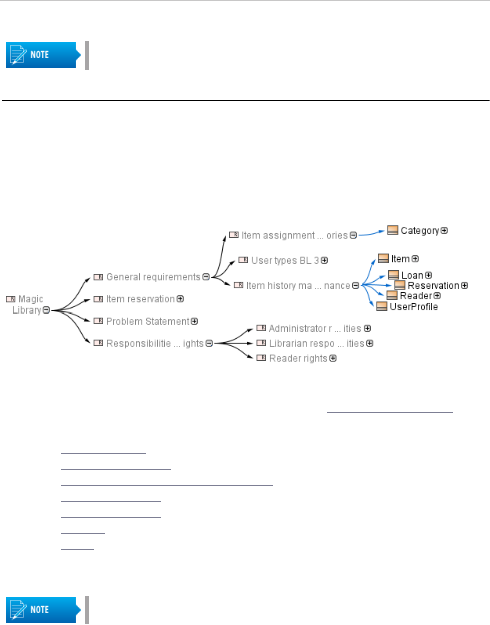
Imported requirements are presented in the Containment tree. The requirement specification is represented as
a model package and requirements are represented as model elements.
Figure 9 -- Representation of requirements in Containment tree
Related procedures
Changing requirements importing options
Updating requirements
Applying automated post-processing scripts after ReqIF file import
Managing obsolete requirement elements
The notification message is displayed for a fixed duration, but you can
find all project notification messages in the Notification Window. To open
the Notification Window, click Window > Notification Window, or press
CTRL + M. For more information about using the Notification Window,
see “Notification Window” in MagicDraw UserManual.pdf.

WORKING WITH REQUIREMENTS
Importing Requirements
31
Copyright © 2011-2014 No Magic, Inc..
Related references
Importing from .CVS and MS Excel Files
Interchanging of Requirements Using Cameo DataHub
Exporting Requirements
Changing requirements importing options
Changing requirements importing options is mostly expedient if you have a custom requirement type defined,
or you are importing not a requirement file but another type of data, for example, test cases.
You can change the following import options:
• Specify an element type to create for the objects you are importing
• Specify a relation type to create for the relations you are importing
• Specify a path to the resource location
• Choose weather to import all properties into the model or not and form a list of ignored and not
imported properties.
To change ReqIF File importing options
1. Click Options > Project. The Project Options dialog opens.
2. In the options group list, select General and, in the options list, scroll down to the ReqIF
options group.
3. Click a desired option specification cell to change it’s value.
4. Click OK after you are finished.
For more information about using Project Options, see “Setting project options” in MagicDraw
UserManual.pdf.
Related procedures
Importing ReqIF Files
Updating requirements
Applying automated post-processing scripts after ReqIF file import
Managing obsolete requirement elements
Updating requirements
It is common to modify requirements after importing them. Importing requirements in a ReqIF format allows
updating the requirements present in the model without any data loss – all changes are identified.
To updated the ReqIF file by importing a new file
1. Open a project wherein you want to update requirements.
2. Import a ReqIF file with updated requirements.
A requirement type is limited to class and class extended types.
We recommend to change importing options before requirements are
imported and any changes are not made in the project, because after you
have changed importing options, you will need to remove the
requirements you have imported and re-import it.

WORKING WITH REQUIREMENTS
Importing Requirements
32
Copyright © 2011-2014 No Magic, Inc..
To update requirements from the project
1. Open the project containing imported requirements.
2. In the Containment tree, select a requirement specification package and open it’s shortcut
menu.
3. Click Tools > ReqIF > Update From Requirements Interchange Format (ReqIF) File.
4. In the opened Load dialog, browse for your ReqIF file and click Open. The ReqIF file is
updated.
After requirements have been updated, you get a notification message informing about an update status. If you
update a ReqIF file without specification, the message doesn't contain the line that indicates new or updated
specifications. You also see no option Show imported specification table(s).
Figure 10 -- Notification window about updated requirements
In the change log table, you can see the detailed list of updated elements.
Figure 11 -- Change log table
During update, no elements are removed, only new elements are added and statuses of all elements are
updated. Elements not present in a updated ReqIF file are marked as obsolete.
Related procedures
Changing requirements importing options
Importing ReqIF Files
Applying automated post-processing scripts after ReqIF file import
Managing obsolete requirement elements

WORKING WITH REQUIREMENTS
Importing Requirements
33
Copyright © 2011-2014 No Magic, Inc..
Applying automated post-processing scripts after ReqIF file import
After the ReqIF file import, you can apply an automated post-processing script to your project in order to modify
requirements and create custom mapping upon requirements interchange through ReqIF.
To apply the post-processing rules
1. From the Options menu, select Project.
2. In the options group list, select General, then scroll down to the ReqIF options group.
3. Under the ReqIF Import category, find Post-processing rules and select the one you want to
apply.
4. Click OK.
Related procedures
Changing requirements importing options
Importing ReqIF Files
Updating requirements
Managing obsolete requirement elements
Managing obsolete requirement elements
In the model, obsolete elements are marked with an exclamation mark in a yellow triangle.
Figure 12 -- Obsolete elements in Containment tree
Removing Obsolete Elements
In the project, you can to choose to remove just a selected obsolete element or all obsolete elements at a time.
To remove one selected obsolete element, use a validating procedure that is described in a following section.
To remove all obsolete elements
1. In the Containment tree, right-click the requirements specification package.
2. From the shortcut menu, select Tools > ReqIF > Remove Obsolete Elements.
Searching for Obsolete Elements
To search for obsolete elements
1. In the Containment tree, right-click the requirements specification package.
2. From the shortcut menu, select Validation > Obsolete Elements and one of the following:
Post-processing Rule Description
Fill Empty Requirement
Name
When applied to a requirement with an unspecified Name property, the rule picks
the data from Element ID and uses it as the element name.
Set CustomID as ID
When applied to a requirement with an empty Element ID, the rule sets the
specified CustomID as an element ID.

WORKING WITH REQUIREMENTS
Importing Requirements
34
Copyright © 2011-2014 No Magic, Inc..
• Remove Obsolete Elements - removes the selected obsolete elements from a
project.
• Ignore - ignores obsolescence from the element and leaves it in the model.
• Select in Validation Results - opens the Active Validation Results panel wherein
you can perform appropriate validation actions. For more information about
validation actions, see “Validation” in MagicDraw UserManual.pdf.
Related procedures
Changing requirements importing options
Importing ReqIF Files
Updating requirements
Applying automated post-processing scripts after ReqIF file import
Importing from .CVS and MS Excel Files
With MagicDraw, you can import a requirement file from a .csv or Microsoft Excel file format. No Magic, Inc.
presents two plugins for importing files of .csv and Microsoft Excel file formats.
The CSV Import plugin is a MagicDraw plugin that reads values in a comma separated values (CSV) file and
create model elements, diagrams, and relationships from that data. With this plugin you have a capability to
create MagicDraw models from data stored in spreadsheets, relational databases, or other repositories.
The Excel Import plugin is an effective, which is designed to allow you to import data from any Excel (.xls and
.xlsx) or CSV (.csv and .txt) format files to MagicDraw and export data from a MagicDraw project into an Excel
or a CSV file. The plugin works with MagicDraw version 17.0.5 and later.
Importing data using CSV Import Plugin
To import requirements from a .csv file
1. Open an existing project or create a new one.
2. From the main menu, select File > Import From > Import CSV or press CTRL+SHIFT+C. The
Import CSV wizard opens. Follow the steps provided by this wizard to complete the import pro-
cedure.
For more information about using the CSV Import Plugin, see CSV Import Plugin Document.pdf.
Related procedures
Importing data using Excel Import Plugin
Importing ReqIF Files
To import files of a .csv or Microsoft Excel file formats, you should install
one of the following plugin:
• CSV Import Plugin allowing to import files just of a .csv file format.
• Excel Import Plugin allowing to import files of .csv and Microsoft Excel
file formats.
Both plugins are no cost.

WORKING WITH REQUIREMENTS
Importing Requirements
35
Copyright © 2011-2014 No Magic, Inc..
Importing data using Excel Import Plugin
To import requirements from a .csv or Microsoft Excel file format
1. Open an existing project or create a new one.
2. From the main menu, select File > Import From > Excel/CSV File. The Import Data from
Excel and Create Mapping wizard opens. Follow the steps provided by this wizard to complete
the import procedure.
The Excel Import Plugin allows you to import a table heading and data separately. The heading is imported as a
mapping class containing heading data as attributes and is used for mapping table data as instance
specifications.
Figure 13 -- Examples of mapping class and requirement imported from Microsoft Excel file
To import a table heading
1. Open an existing project or create a new one.
2. Create a new requirement diagram (see “Requirement Diagram” on page 10) and do one of the
following:
• Use the Import Data from Excel and Create Mapping wizard. See the description
in the preceding procedure.
• In the file browser, select the file you need to import and drag it on the diagram
pane.
If you already have the table heading imported as a mapping class or have your own created mapping class in
your model, you can import data from the Microsoft Excel table using a shortcut menu.
To import data according to mapping
1. In the Containment tree or on the diagram pane, right-click the mapping class.
2. In the opened shortcut menu, click Tools > Import Data from Excel. The Import Data from
Excel wizard opens. Follow the steps provided by this wizard to complete the import procedure.
For more information about using the Excel Import Plugin, see Excel Import User Guide.pdf.
Related procedures
Importing data using CSV Import Plugin
Importing ReqIF Files

WORKING WITH REQUIREMENTS
Exporting Requirements
36
Copyright © 2011-2014 No Magic, Inc..
Exporting Requirements
You can export ReqIF files to be used with:
• IBM Rational DOORS 9.4, 9.5, 9.6
• IBM Rational DOORS NG
• PTC Integrity
• Polarion REQUIREMENTS
• Seamens Teamcenter
• Dassault Systemes Reqtify
Exporting requirements to ReqIF files ensures that all html formatting, images and hyperlinks are represented
in ReqIF format file properly. You can choose to export project elements or specifications, also, advanced users
can create automated exports and scheduled exports from Teamwork Server projects.
It is recommended to export requirements into a separate project which can later be used in other models as a
used project.
To export requirements to a ReqIF file
1. Open a project from which you want to export requirements.
2. From the File menu, select Export To > Requirement Interchange Format (ReqIF) File.
3. Choose to export one of the following:
• Elements
• Specifications
4. In the opened Select Elements / Select Specification Package dialog, select the elements or
specification packages you want to export and click . They then appear in the
Selected elements list on the right.
5. When you're done selecting, click OK.
6. In the Select ReqIF file dialog, select the output location for the exported ReqIF file, then select
the file you want to export or type the file name to create a new one.
7. In the ReqIF Flavor pane on the right of the Select ReqIF file dialog, select the flavor of your
exported ReqIF file.
8. Click Export.
When the ReqIF file is exported, a notification message appears, stating the quantity of exported specifications,
elements and relationships. If you choose to export elements only, the message doesn't contain lines that
indicate exported specifications and relationships.

WORKING WITH REQUIREMENTS
Exporting Requirements
37
Copyright © 2011-2014 No Magic, Inc..
Click the Note: you can change import/export and mapping options here link in the notification message, if
you want to change these options.
Figure 14 -- Notification window informing about exported requirements
Related procedures
Changing Requirements Exporting Options
Applying automated pre-processing scripts before ReqIF file export
Importing ReqIF Files
Changing Requirements Exporting Options
Changing requirements exporting options is mostly expedient if you have a custom requirement type defined,
or you are exporting not a requirement file but another type of data, for example, test cases.
You can change the following export options:
• Specify an element type to create for the objects you are exporting
• Specify a relationship type to create for the relationships you are exporting
• Specify a path to the output location for exported resources (images, documents, etc.)
• Choose whether to export all properties or not and form a list of ignored and not exported
properties
To change ReqIF file exporting options
1. Click Options > Project. The Project Options dialog opens.
2. In the options group list, select General, then scroll down to the ReqIF options group.
3. Click a desired option specification cell to change it's value.
4. Click OK after you are finished.
Applying automated pre-processing scripts before ReqIF file export
Prior to the ReqIF file export, you can apply an automated pre-processing script to your project in order to
modify requirements and create custom mapping upon requirements interchange through ReqIF.
The notification message is displayed for a fixed duration, but you
can find all project notification messages in the Notification Window.
To open the Notification Window, click Window > Notification
Window, or press Ctrl + M.
A requirement type is limited to class and class extended types.

WORKING WITH REQUIREMENTS
Interchanging of Requirements Using Cameo DataHub
38
Copyright © 2011-2014 No Magic, Inc..
To apply the pre-processing rule
1. From the Options menu, select Project.
2. In the options group list, select General, then scroll down to the ReqIF options group.
3. Under ReqIF Export, find Pre-processing rules and select the one you want to apply.
4. Click OK.
Interchanging of Requirements Using Cameo
DataHub
The Cameo DataHub is a dedicated solution for the requirements synchronization between different sources,
such as MagicDraw, Rational DOORS
®
, Rational RequisitePro
®
, CSV files, and other. Cameo DataHub is a
data bridge that allows for data importing and exporting, automatic synchronization and creation of references
between requirements and other artifacts. It allows to use different import and synchronization methods while
importing or exporting requirements.
Figure 15 -- Interchanging of requirements using Cameo DataHub
Came DataHub allows to:
• Associate and synchronize data.
Pre-processing Rule Description
Restore Empty
Requirement Name
When applied to a requirement with a specified Name property, the rule removes
the element name upon export.

WORKING WITH REQUIREMENTS
Integrating Requirements into Models
39
Copyright © 2011-2014 No Magic, Inc..
• Change the monitoring statuses such as active, pending update, and pending delete whenever
associated data items are modified or deleted.
• Impact monitoring. Whenever the referenced data item changes, Cameo DataHub reports the
suspect status to direct traceability from each requirement to the respective design artifact.
• Define mappings between data and its’ properties.
To interchange of requirements using Cameo DataHub
1. Open an existing project or create a new one.
2. On the main menu, click Tools > Requirements > DataHub and select a desired action.
For more information about working with Cameo DataHub, see Cameo DataHub UserGuide.pdf and Cameo
DataHub Tutorial.pdf that are stored in the Cameo DataHub installation directory.
Related procedures
Importing ReqIF Files
Importing data using CSV Import Plugin
Importing data using Excel Import Plugin
Integrating Requirements into Models
As development of products and services becomes more complex, modeling of requirements starts to be more
significant part in the development process.
Business Architecture
Software Architecture
System Architecture
User Interface Modeling
In user interface modeling, it is very important to see how interface prototypes meets the requirements. A user
interface modeling capability for MagicDraw allows graphical user interface (GUI) mock-ups design in the same
The Cameo DataHub should be installed before taking the following
actions.

WORKING WITH REQUIREMENTS
Integrating Requirements into Models
40
Copyright © 2011-2014 No Magic, Inc..
domain and environment as the requirements specification. So you can integrate user interface with
requirements specifications or trace to requirements and design.
Figure 16 -- Fragment of UI requirements diagram

WORKING WITH REQUIREMENTS
Analyzing Requirements
41
Copyright © 2011-2014 No Magic, Inc..
The requirements diagram with mock-ups may take a huge amount of space in the diagram. We can trace
satisfaction relations in more compact way, that is to use matrixes. According to requirement and User Interface
relations, we can constrain the satisfaction matrix of requirements and user interface prototypes.
Figure 17 -- Example of satisfaction matrix
As we can see in the preceding figure, the “Take Test” requirement is satisfied by “Test”, “TestAssesment”, and
“TestResults” GUI prototypes, or we can call them simply dialogs.
Analyzing Requirements
The following table presents a summary of capabilities enabled by MagicDraw for the requirements analysis.
The following sections describe several cases and procedures of analyzing requirements:
• Coverage Analysis
• Change Impact Analysis
• Analyzing dependencies in Dependency Matrix
• Analyzing dependencies in Relation Map
• Tracing Requirements
Capability Purpose. type of analysis
Analyzing Usages
and Dependencies
Requirements usage and dependencies on other model parts discovery.
Traceability, change impact analysis.
Dependency Matrix
Gap analysis. Change Impact analysis. Requirements completeness and
correctness check.
Model validation
Requirements completeness and correctness check based on build in or custom
validation suites.
Traceability
Track, visualize, navigate, and analyze the elements involved in
traceability relations.
Relation Map
Multilevel requirements relation visualization - traceability, coverage analysis.
Generic and
Requirements
Tables
Coverage analysis in compact format
Report Wizard
Different kind of analysis (e.g. coverage) and estimation (e.g. functional points
method) based on build in or custom documentation generation templates.

WORKING WITH REQUIREMENTS
Analyzing Requirements
42
Copyright © 2011-2014 No Magic, Inc..
• Validation
• Metrics
Coverage Analysis
The Coverage analysis gives coverage information at immediate higher or lower levels. Coverage analysis
accomplishes by analyzing traceability properties values. The objective of coverage analysis is to visualize and
verify that requirements are covered with design, implementation, test cases, or other subjects.
For example, requirements which cannot be validated are really just wishes. An important task in not only
define test cases by planning how to verify each requirement, but also identify a relation between the
requirement and test case and show the coverage to ensure that each requirement will be appropriately tested.
Related references
Change Impact Analysis
Analyzing dependencies in Dependency Matrix
Analyzing dependencies in Relation Map
Tracing Requirements
Validation
Metrics
Change Impact Analysis
In order to minimize the risk of introducing undesirable effects to the system by increasing understanding of
how the proposed change might affect the elements in the system change impact analysis is used. Ones
change is proposed its impact should be identified.
Traceability links and visualization of related elements displays dependencies of a to be changed requirements
and helps users think through the full impacts of a possible change.
Related references
Coverage Analysis
Analyzing dependencies in Dependency Matrix
Analyzing dependencies in Relation Map
Tracing Requirements
Validation
Metrics
Analyzing dependencies in Dependency Matrix
You can create, analyze, and modify requirement relations in the matrix. The matrix provides a compact visual
view for such analysis. Using a dependency matrix you can also edit relations between a selected requirement
and model element, it means, you can add or remove a desired relation.
The Dependency Matrix enables:
The aim of this section is to introduce MagicDraw possibilities through
examples. As with so many things in MagicDraw, there usually is more
than one way to do the same thing. Just main or typical procedure steps
are described in the following sections, but feel free to use MagicDraw in
the way you prefer.

WORKING WITH REQUIREMENTS
Analyzing Requirements
43
Copyright © 2011-2014 No Magic, Inc..
• The visualization of many-to-many relations of the elements from different diagrams.
• The capability to create domain specific matrices and their templates.
• Ready-to-use matrix templates: traceability of elements and behavior diagrams, traceability of
requirements, traceability of requirements and elements refining, satisfying, verifying them, and
other.
• The faster creation of traceability links between elements, for example, between requirements
and the architecture or requirements and test cases. Such an improvement saves a huge
amount of time in comparison to linking elements in diagrams.
To create a dependency matrix
1. From a requirements specification package shortcut menu in the Containment tree, select New
Diagram > Requirements Diagrams and then select one of the following:
• Derive Requirement Matrix to create a Dependency Matrix to analyze, create, and
modify derivation relations between a derived requirement and a source
requirement.
• Refine Requirement Matrix to create a Dependency Matrix to analyze, create, and
modify refined relations between a requirement and a model element or a set of
elements refining the requirement.
• Satisfy Requirement Matrix to create a Dependency Matrix to analyze, create,
and modify satisfaction relations between requirements and model elements
fulfilling the requirements.
• Verify Requirement Matrix to create a Dependency Matrix to analyze, create, or
modify verification relations between requirements and named elements that can
determine whether the systems fulfil the requirements.
2. Type a diagram name.
3. Select criteria and a scope to be represented in the matrix. For example, you can specify
requirements to be represented as rows and class elements to be represented as columns.

WORKING WITH REQUIREMENTS
Analyzing Requirements
44
Copyright © 2011-2014 No Magic, Inc..
4. Click the Rebuild button. The following figure illustrates an example showing how particular
requirements satisfy particular model class elements.
Figure 18 -- Example of dependency matrix
Using dependency matrix you can also remove redundant or create missing dependencies. For detailed
instructions, how to use dependency matrixes, see “Dependency Matrix” in MagicDraw UserManual.pdf.
Related references
Coverage Analysis
Change Impact Analysis
Analyzing dependencies in Relation Map
Tracing Requirements
Validation
Metrics
Analyzing dependencies in Relation Map
A relation map allows you analyzing visually among multiple levels of abstraction how, for example,
requirements are satisfied by other model elements. Using the relation map you can discover existing
relationships, visualize multilevel relationships, observe traceability from requirements to the implementation, or
make other analysis you need.
The relation map is useful for:
• Making the fast analysis and overview of a model.
• Observing a traceability from requirements to the implementation all the way through different
levels of abstraction (for example, the analysis, design, or other).
WORKING WITH REQUIREMENTS
Analyzing Requirements
45
Copyright © 2011-2014 No Magic, Inc..
• Discovering the requirements structure.
To create a relation map
1. From a package or requirement shortcut menu in the Containment tree, select New Diagram >
Requirements Diagrams and then select one of the following:
• Requirement Containment Map.
• Requirement Derivation Map.
2. Type a diagram name.
3. Specify a relation criterion, element type, and scope.
4. Click the Rebuild button. The following figure illustrates an example showing how particular
requirements satisfy particular model class elements.
Figure 19 -- Example of relation map
For detailed instructions, how to use relation maps, see “Relation Map” in MagicDraw UserManual.pdf.
Related references
Coverage Analysis
Change Impact Analysis
Analyzing dependencies in Dependency Matrix
Tracing Requirements
Tracing Requirements
Validation
Metrics
Tracing Requirements
The traceability relations help to determine how your requirements or other model artifacts are satisfied. As
they may change, you can use traceability relations to monitor the impact of these changes. As it is described in
predecessor sections, you can visualize the traceability relations using MagicDraw features, such as
Dependency Matrix or Relation Map.
Requirements tracing is a background for analysis and concerned with recovering the sources of requirements
and predicting the effects of requirements. Tracing is fundamental to performing impact analysis when
requirements change. A requirement should be traceable backwards to the requirements and stakeholders,
You are not allowed editing relations in the relation map diagram.
The traceability solution is available in Architect and Enterprise editions.

WORKING WITH REQUIREMENTS
Analyzing Requirements
46
Copyright © 2011-2014 No Magic, Inc..
which motivated it (from functional requirements to business requirements, for example). Conversely, a
requirement should be traceable forwards into the design entities that satisfy it.
Traceability makes it easier for you to:
• Find, navigate and define the realization and specification of elements from different levels of
abstraction:
• Understand why an element exists, how the element is realized, and clarify the
purpose of the element.
• Validate the system functionality (check if it meets customer requirements and if any
superfluous functionality has been implemented).
• Improve a customer’s understanding of the system and thus his/her acceptance of
the system accordingly.
• Have single places for relations analysis used in traceability.
• Check artifacts coverage and completeness.
• Bridge the gap between levels of abstraction.
• Trace elements by using out-of-the-box predefined traceability suites.
For detailed instructions, how to use the traceability solution, see “Traceability” in MagicDraw UserManual.pdf.
Related procedures
Traceability relations in Specification window
Traceability relations in Properties panel
Representing traceability on Notes
Tracing relations using Go To command
Related references
Coverage Analysis
Change Impact Analysis
Analyzing dependencies in Dependency Matrix
Analyzing dependencies in Relation Map
Validation
Metrics
Traceability relations in Specification window
In the selected element’s Specification window, you can see traceability relations as properties. Here you can
also create your own specific properties and edit them.
To trace element relations in the Specification window
1. Open the Specification window of the selected element.
2. Scroll through the general requirement’s properties to get to the Traceability properties list.

WORKING WITH REQUIREMENTS
Analyzing Requirements
47
Copyright © 2011-2014 No Magic, Inc..
Figure 20 -- Traceability property group in element’s specification window
For more information about using a Specification window, see “Specification Window” in MagicDraw
UserManual.pdf.
Related procedures
Traceability relations in Properties panel
Representing traceability on Notes
Tracing relations using Go To command
Related references
Tracing Requirements

WORKING WITH REQUIREMENTS
Analyzing Requirements
48
Copyright © 2011-2014 No Magic, Inc..
Traceability relations in Properties panel
The same traceability properties are displayed in a Properties panel.
To trace element relations in the Properties panel
1. Select the element in the Model Browser or the shape on the diagram pane.
2. In the Model Browser, click the Properties panel > Element tab and scroll through the proper-
ties to get to the Traceability properties list.

WORKING WITH REQUIREMENTS
Analyzing Requirements
49
Copyright © 2011-2014 No Magic, Inc..
Figure 21 -- Traceability property group in element’s properties panel
For more information about using the Properties panel, see “Properties tab” in MagicDraw UserManual.pdf.
Related procedures
Traceability relations in Specification window
Representing traceability on Notes
Tracing relations using Go To command

WORKING WITH REQUIREMENTS
Analyzing Requirements
50
Copyright © 2011-2014 No Magic, Inc..
Related references
Tracing Requirements
Representing traceability on Notes
To trace element relations in a Note
1. Select the element’s shape on the diagram pane.
2. Connect a note to the selected shape.
3. Right-click the note and, on the shortcut menu, click Edit Compartments or select a note and
click the Edit Element Properties button that appears on the rite side of the note.
The Compartment Edit dialog opens.
4. Click the Element Properties tab, select traceability properties you want to represent on a note
and move them from the Hidden to Selected list.
5. Click OK when you are done. Selected traceability properties are presented on a note.
Figure 22 -- Traceability properties on note
Related procedures
Traceability relations in Specification window
Traceability relations in Properties panel
Tracing relations using Go To command
Related references
Tracing Requirements
Tracing relations using Go To command
The Go To command allows you to easily find and navigate to the related elements through the traceability
relations.
WORKING WITH REQUIREMENTS
Analyzing Requirements
51
Copyright © 2011-2014 No Magic, Inc..
To trace element relations using the Go To command
1. Select the requirement in the Containment tree or the shape on the diagram pane.
2. Right-click the selected requirement, and, on the shortcut menu, click Go To > Traceability >
Specification / Realization / Owner / Other and select the desired element. This element is
selected in the Containment tree.
For more information about traceability, see “Traceability” in MagicDraw UserManual.pdf.
Related procedures
Traceability relations in Specification window
Traceability relations in Properties panel
Representing traceability on Notes
Related references
Tracing Requirements
Validation
In MagicDraw, the validation functionality is designed to check the created models. It consists of:
• A set of validation rules. Each validation rule captures some imperative conditions, which must
be checked against the model. Validation rules are specified as invariant constraints in the
model.
• One or more validation suites (modeled as packages). A validation suite is a simple concept of
grouping the validation rules into meaningful groups, so that the collection of rules can be
applied.
To run the validation, select some suites and validation scope—either the entire model or some part of it. When
the validation is run, each rule from the suite is evaluated for each suitable element in the validation scope.
Each element that violates the rule (constraint evaluates to false) is reported in the results table.
To validate your model
1. From the main menu, select Analyze > Validation > Validate or click the Validate button
on the main toolbar.
2. In the opened Validation dialog, select the validation suite, validation scope, severity, and, if
needed, validation options.
3. After you have specified desired options, click the Validate button.
Validation results are presented in the Validation Results panel.
This functionality is available in Architect and Enterprise editions only.

WORKING WITH REQUIREMENTS
Analyzing Requirements
52
Copyright © 2011-2014 No Magic, Inc..
Another useful model checking feature is an Active Validation. The Active Validation instantly checks the
accuracy, completeness, and correctness of a model, displays errors in the model, and suggests solutions.
Figure 23 -- Example of active validation. Warning in the copy relation
Errors in the model are represented in the following ways:
• If an invalid or incomplete model is created, an error indicator will appear in the bottom right
corner of MagicDraw.
• Invalid elements are marked in the Containment tree and diagrams.
From the invalid element/symbol shortcut menu, you can analyze incorrect elements, and solve problems,
resulting from the errors, through the Active Validation Results panel.
The following table presents validation rules that are included in Cameo Requirments Modeler Plugin.
Type Name Description Solution
Copy
Missing Recursive
copy of sub-
requirement
If the supplier requirement has sub requirements,
copies of the sub requirements are made
recursively in the context of the client requirement
and Copy dependencies are created between each
sub requirement and the associated copy.
Manual
Invalid Copy of
requirement
*
A requirement can’t copy more than one
requirement.
Solver is
available
Invalid Slave
Requirement text
*
The text property of the client requirement is
constrained to be a copy of the text property of the
supplier requirement.
Solver is
available
Invalid stereotype(s)
of client/supplier of
Copy
*
A Copy dependency may only be created between
two classes that have the “requirement” stereotype,
or a subtype of the “requirement” stereotype
applied.
Solver is
available
Missing Recursive
copy of sub-
requirement
If the supplier requirement has sub requirements,
copies of the sub requirements are made
recursively in the context of the client requirement
and Copy dependencies are created between each
sub requirement and the associated copy.
Manual
Recursive loop of
Copy dependencies
Copy dependencies should not from a cyclic graph. Manual
DeriveReqt
Invalid source or
target of DeriveReqt
A DeriveReqt dependency may only be created
between two classes that have the "requirement"
stereotype, or a sub-type of the "requirement"
stereotype applied.
Manual

WORKING WITH REQUIREMENTS
Analyzing Requirements
53
Copyright © 2011-2014 No Magic, Inc..
*
This rule is active and performs instant checking while you are working on your requirement project. You are warned, if a violation is
detected.
You can create your own validation rules. For more information about the validation, validation process,
validation rules, validation suites, and active validation, see “Validation” and “Active Validation” in MagicDraw
UserManual.pdf.
Related references
Coverage Analysis
Change Impact Analysis
Analyzing dependencies in Dependency Matrix
Analyzing dependencies in Relation Map
Tracing Requirements
Metrics
Metrics
Metric is an item of information about some specific aspect of the model. The collection of various metrics can
be used to evaluate the current state of your model. Calculated at regular intervals they can help tracking the
evolution of the model development.
Figure 24 -- Example of metrics table
While working with requirements, it is useful to know what and how many requirements are covered by design
(with a «satisfy» relation), by test cases (with a «verify» relation), are user requirements covered with system
requirements, how many requirements are already implemented or tested. These are typical situations where
Metrics help you very much.
A requirement is supposed as covered, if it satisfies at least one of the following conditions:
Requirement
Invalid generalization
of Requirement
Classes stereotyped by «requirement» may not
participate in generalizations.
Manual
Invalid owned
attribute of
Requirement
The property ownedAttribute must be empty. Manual
Invalid owned
operation of
Requirement
The property ownedOperation must be empty. Manual
Missing requirement
stereotype
A nested classifier of a class stereotyped by
«requirement» must also be stereotyped by
«requirement».
Manual
TestCase
Invalid return
parameter type
*
The type of return parameter of the stereotyped
model element must be VerdictKind. (note this is
consistent with the UML Testing Profile).
Solver is
available
Type Name Description Solution

WORKING WITH REQUIREMENTS
Analyzing Requirements
54
Copyright © 2011-2014 No Magic, Inc..
1. A requirement has a «satisfy» relation with a design element.
2. The owning requirement is covered.
3. All owned requirements are covered.
Figure 25 -- Examples of covered requirements
To use metrics, you need to proceed two steps:
1. Create a metric suite according to your needs.
2. Calculate metrics.
You can create metrics using structured expressions or scripts. The detailed procedures, how to create metric
suites, calculate metrics, and manage metric results are described in “Metrics” in MagicDraw UserManual.pdf.
Related references
Coverage Analysis
Change Impact Analysis
Analyzing dependencies in Dependency Matrix
Analyzing dependencies in Relation Map
Tracing Requirements
Validation
